US8963450B2 - Adaptable biologically-adjusted indirect lighting device and associated methods - Google Patents
Adaptable biologically-adjusted indirect lighting device and associated methodsDownload PDFInfo
- Publication number
- US8963450B2 US8963450B2US14/148,298US201414148298AUS8963450B2US 8963450 B2US8963450 B2US 8963450B2US 201414148298 AUS201414148298 AUS 201414148298AUS 8963450 B2US8963450 B2US 8963450B2
- Authority
- US
- United States
- Prior art keywords
- light
- led dies
- led
- driver circuit
- light source
- Prior art date
- Legal status (The legal status is an assumption and is not a legal conclusion. Google has not performed a legal analysis and makes no representation as to the accuracy of the status listed.)
- Expired - Fee Related
Links
Images


Classifications
- H05B33/0863—
- F—MECHANICAL ENGINEERING; LIGHTING; HEATING; WEAPONS; BLASTING
- F21—LIGHTING
- F21K—NON-ELECTRIC LIGHT SOURCES USING LUMINESCENCE; LIGHT SOURCES USING ELECTROCHEMILUMINESCENCE; LIGHT SOURCES USING CHARGES OF COMBUSTIBLE MATERIAL; LIGHT SOURCES USING SEMICONDUCTOR DEVICES AS LIGHT-GENERATING ELEMENTS; LIGHT SOURCES NOT OTHERWISE PROVIDED FOR
- F21K9/00—Light sources using semiconductor devices as light-generating elements, e.g. using light-emitting diodes [LED] or lasers
- F21K9/20—Light sources comprising attachment means
- F21K9/23—Retrofit light sources for lighting devices with a single fitting for each light source, e.g. for substitution of incandescent lamps with bayonet or threaded fittings
- F21K9/13—
- F—MECHANICAL ENGINEERING; LIGHTING; HEATING; WEAPONS; BLASTING
- F21—LIGHTING
- F21S—NON-PORTABLE LIGHTING DEVICES; SYSTEMS THEREOF; VEHICLE LIGHTING DEVICES SPECIALLY ADAPTED FOR VEHICLE EXTERIORS
- F21S8/00—Lighting devices intended for fixed installation
- F21S8/02—Lighting devices intended for fixed installation of recess-mounted type, e.g. downlighters
- F21S8/022—Lighting devices intended for fixed installation of recess-mounted type, e.g. downlighters intended to be recessed in a floor or like ground surface, e.g. pavement or false floor
- F—MECHANICAL ENGINEERING; LIGHTING; HEATING; WEAPONS; BLASTING
- F21—LIGHTING
- F21V—FUNCTIONAL FEATURES OR DETAILS OF LIGHTING DEVICES OR SYSTEMS THEREOF; STRUCTURAL COMBINATIONS OF LIGHTING DEVICES WITH OTHER ARTICLES, NOT OTHERWISE PROVIDED FOR
- F21V7/00—Reflectors for light sources
- F21V7/22—Reflectors for light sources characterised by materials, surface treatments or coatings, e.g. dichroic reflectors
- F21V7/28—Reflectors for light sources characterised by materials, surface treatments or coatings, e.g. dichroic reflectors characterised by coatings
- F21V7/30—Reflectors for light sources characterised by materials, surface treatments or coatings, e.g. dichroic reflectors characterised by coatings the coatings comprising photoluminescent substances
- H—ELECTRICITY
- H05—ELECTRIC TECHNIQUES NOT OTHERWISE PROVIDED FOR
- H05B—ELECTRIC HEATING; ELECTRIC LIGHT SOURCES NOT OTHERWISE PROVIDED FOR; CIRCUIT ARRANGEMENTS FOR ELECTRIC LIGHT SOURCES, IN GENERAL
- H05B45/00—Circuit arrangements for operating light-emitting diodes [LED]
- H05B45/20—Controlling the colour of the light
- H05B45/22—Controlling the colour of the light using optical feedback
- F21K9/17—
- F—MECHANICAL ENGINEERING; LIGHTING; HEATING; WEAPONS; BLASTING
- F21—LIGHTING
- F21K—NON-ELECTRIC LIGHT SOURCES USING LUMINESCENCE; LIGHT SOURCES USING ELECTROCHEMILUMINESCENCE; LIGHT SOURCES USING CHARGES OF COMBUSTIBLE MATERIAL; LIGHT SOURCES USING SEMICONDUCTOR DEVICES AS LIGHT-GENERATING ELEMENTS; LIGHT SOURCES NOT OTHERWISE PROVIDED FOR
- F21K9/00—Light sources using semiconductor devices as light-generating elements, e.g. using light-emitting diodes [LED] or lasers
- F21K9/20—Light sources comprising attachment means
- F21K9/27—Retrofit light sources for lighting devices with two fittings for each light source, e.g. for substitution of fluorescent tubes
- F—MECHANICAL ENGINEERING; LIGHTING; HEATING; WEAPONS; BLASTING
- F21—LIGHTING
- F21K—NON-ELECTRIC LIGHT SOURCES USING LUMINESCENCE; LIGHT SOURCES USING ELECTROCHEMILUMINESCENCE; LIGHT SOURCES USING CHARGES OF COMBUSTIBLE MATERIAL; LIGHT SOURCES USING SEMICONDUCTOR DEVICES AS LIGHT-GENERATING ELEMENTS; LIGHT SOURCES NOT OTHERWISE PROVIDED FOR
- F21K9/00—Light sources using semiconductor devices as light-generating elements, e.g. using light-emitting diodes [LED] or lasers
- F21K9/60—Optical arrangements integrated in the light source, e.g. for improving the colour rendering index or the light extraction
- F21V29/2206—
- F—MECHANICAL ENGINEERING; LIGHTING; HEATING; WEAPONS; BLASTING
- F21—LIGHTING
- F21V—FUNCTIONAL FEATURES OR DETAILS OF LIGHTING DEVICES OR SYSTEMS THEREOF; STRUCTURAL COMBINATIONS OF LIGHTING DEVICES WITH OTHER ARTICLES, NOT OTHERWISE PROVIDED FOR
- F21V29/00—Protecting lighting devices from thermal damage; Cooling or heating arrangements specially adapted for lighting devices or systems
- F21V29/50—Cooling arrangements
- F21V29/70—Cooling arrangements characterised by passive heat-dissipating elements, e.g. heat-sinks
- F21V29/74—Cooling arrangements characterised by passive heat-dissipating elements, e.g. heat-sinks with fins or blades
- F—MECHANICAL ENGINEERING; LIGHTING; HEATING; WEAPONS; BLASTING
- F21—LIGHTING
- F21V—FUNCTIONAL FEATURES OR DETAILS OF LIGHTING DEVICES OR SYSTEMS THEREOF; STRUCTURAL COMBINATIONS OF LIGHTING DEVICES WITH OTHER ARTICLES, NOT OTHERWISE PROVIDED FOR
- F21V3/00—Globes; Bowls; Cover glasses
- F21V3/02—Globes; Bowls; Cover glasses characterised by the shape
- F21V3/0436—
- F21V3/0472—
- F—MECHANICAL ENGINEERING; LIGHTING; HEATING; WEAPONS; BLASTING
- F21—LIGHTING
- F21V—FUNCTIONAL FEATURES OR DETAILS OF LIGHTING DEVICES OR SYSTEMS THEREOF; STRUCTURAL COMBINATIONS OF LIGHTING DEVICES WITH OTHER ARTICLES, NOT OTHERWISE PROVIDED FOR
- F21V3/00—Globes; Bowls; Cover glasses
- F21V3/04—Globes; Bowls; Cover glasses characterised by materials, surface treatments or coatings
- F21V3/06—Globes; Bowls; Cover glasses characterised by materials, surface treatments or coatings characterised by the material
- F21V3/062—Globes; Bowls; Cover glasses characterised by materials, surface treatments or coatings characterised by the material the material being plastics
- F—MECHANICAL ENGINEERING; LIGHTING; HEATING; WEAPONS; BLASTING
- F21—LIGHTING
- F21V—FUNCTIONAL FEATURES OR DETAILS OF LIGHTING DEVICES OR SYSTEMS THEREOF; STRUCTURAL COMBINATIONS OF LIGHTING DEVICES WITH OTHER ARTICLES, NOT OTHERWISE PROVIDED FOR
- F21V3/00—Globes; Bowls; Cover glasses
- F21V3/04—Globes; Bowls; Cover glasses characterised by materials, surface treatments or coatings
- F21V3/10—Globes; Bowls; Cover glasses characterised by materials, surface treatments or coatings characterised by coatings
- F—MECHANICAL ENGINEERING; LIGHTING; HEATING; WEAPONS; BLASTING
- F21—LIGHTING
- F21V—FUNCTIONAL FEATURES OR DETAILS OF LIGHTING DEVICES OR SYSTEMS THEREOF; STRUCTURAL COMBINATIONS OF LIGHTING DEVICES WITH OTHER ARTICLES, NOT OTHERWISE PROVIDED FOR
- F21V7/00—Reflectors for light sources
- F21V7/0008—Reflectors for light sources providing for indirect lighting
- F—MECHANICAL ENGINEERING; LIGHTING; HEATING; WEAPONS; BLASTING
- F21—LIGHTING
- F21V—FUNCTIONAL FEATURES OR DETAILS OF LIGHTING DEVICES OR SYSTEMS THEREOF; STRUCTURAL COMBINATIONS OF LIGHTING DEVICES WITH OTHER ARTICLES, NOT OTHERWISE PROVIDED FOR
- F21V7/00—Reflectors for light sources
- F21V7/0058—Reflectors for light sources adapted to cooperate with light sources of shapes different from point-like or linear, e.g. circular light sources
- F—MECHANICAL ENGINEERING; LIGHTING; HEATING; WEAPONS; BLASTING
- F21—LIGHTING
- F21V—FUNCTIONAL FEATURES OR DETAILS OF LIGHTING DEVICES OR SYSTEMS THEREOF; STRUCTURAL COMBINATIONS OF LIGHTING DEVICES WITH OTHER ARTICLES, NOT OTHERWISE PROVIDED FOR
- F21V7/00—Reflectors for light sources
- F21V7/22—Reflectors for light sources characterised by materials, surface treatments or coatings, e.g. dichroic reflectors
- F21Y2101/02—
- F21Y2103/003—
- F—MECHANICAL ENGINEERING; LIGHTING; HEATING; WEAPONS; BLASTING
- F21—LIGHTING
- F21Y—INDEXING SCHEME ASSOCIATED WITH SUBCLASSES F21K, F21L, F21S and F21V, RELATING TO THE FORM OR THE KIND OF THE LIGHT SOURCES OR OF THE COLOUR OF THE LIGHT EMITTED
- F21Y2103/00—Elongate light sources, e.g. fluorescent tubes
- F21Y2103/10—Elongate light sources, e.g. fluorescent tubes comprising a linear array of point-like light-generating elements
- F21Y2113/005—
- F—MECHANICAL ENGINEERING; LIGHTING; HEATING; WEAPONS; BLASTING
- F21—LIGHTING
- F21Y—INDEXING SCHEME ASSOCIATED WITH SUBCLASSES F21K, F21L, F21S and F21V, RELATING TO THE FORM OR THE KIND OF THE LIGHT SOURCES OR OF THE COLOUR OF THE LIGHT EMITTED
- F21Y2113/00—Combination of light sources
- F21Y2113/10—Combination of light sources of different colours
- F21Y2113/13—Combination of light sources of different colours comprising an assembly of point-like light sources
- F—MECHANICAL ENGINEERING; LIGHTING; HEATING; WEAPONS; BLASTING
- F21—LIGHTING
- F21Y—INDEXING SCHEME ASSOCIATED WITH SUBCLASSES F21K, F21L, F21S and F21V, RELATING TO THE FORM OR THE KIND OF THE LIGHT SOURCES OR OF THE COLOUR OF THE LIGHT EMITTED
- F21Y2115/00—Light-generating elements of semiconductor light sources
- F21Y2115/10—Light-emitting diodes [LED]
Definitions
- the present inventionrelates to systems and methods of providing a lighting device to emit light configured to have various biological effects on an observer.
- Melatoninis a hormone secreted at night by the pineal gland. Melatonin regulates sleep patterns and helps to maintain the body's circadian rhythm. The suppression of melatonin contributes to sleep disorders, disturbs the circadian rhythm, and may also contribute to conditions such as hypertension, heart disease, diabetes, and/or cancer. Blue light, and the blue light component of polychromatic light, have been shown to suppress the secretion of melatonin. Moreover, melatonin suppression has been shown to be wavelength dependent, and peak at wavelengths between about 420 nm and about 480 nm. As such, individuals who suffer from sleep disorders, or circadian rhythm disruptions, continue to aggravate their conditions when using polychromatic light sources that have a blue light (420 nm-480 nm) component.
- blue light420 nm-480 nm
- Curve A of FIG. 1illustrates the action spectrum for melatonin suppression. As shown by Curve A, a predicted maximum suppression is experienced at wavelengths around about 460 nm. In other words, a light source having a spectral component between about 420 nm and about 480 nm is expected to cause melatonin suppression.
- FIG. 1also illustrates the light spectra of conventional light sources.
- Curve Bshows the light spectrum of an incandescent light source. As evidenced by Curve B, incandescent light sources cause low amounts of melatonin suppression because incandescent light sources lack a predominant blue component.
- Curve Cillustrating the light spectrum of a fluorescent light source, shows a predominant blue component.
- Curve Dillustrating the light spectrum of a white light-emitting diode (LED) light source, shows a greater amount of blue component light than the fluorescent or incandescent light sources.
- white LED light sourcesare predicted to cause more melatonin suppression than fluorescent or incandescent light sources.
- embodiments of the present inventionare related to light sources; and more specifically to a light-emitting diode (LED) lamp for producing a biologically-adjusted light.
- LEDlight-emitting diode
- a light-emitting diode (LED) lampcomprising a frame, a power circuit carried by the frame, and a driver circuit electrically coupled with the power circuit.
- the lampmay further include an optical member carried by the frame and comprising a reflective surface and a lower surface, the reflective surface defining an optical cavity, a light source support member carried by at least one of the optical member and the frame and defining a first aperture, and a light source carried by the light source support member and comprising a plurality of LED dies that are electrically coupled to and driven by the driver circuit.
- the light source support membermay be positioned proximate to the lower surface and generally conforms to a shape of the lower surface forming a gap therebetween defined as a second aperture.
- the light source support membermay be configured to carry the light source in an orientation such that light emitted by the plurality of LEDs is incident upon the reflective surface.
- the reflective surfacemay be configured to reflect light incident thereupon in the direction of at least one of the first aperture and the second aperture.
- the LED lampmay further comprising a plurality of suspension arms configured to attach to and carry the light source support member; wherein the plurality of suspension arms are attached to at least one of the frame and the optical member.
- the light source support membermay be formed of a thermally conductive material and positioned in thermal communication with the light source.
- the light source support memberfurther comprises a cavity formed therein.
- the optical membermay comprise a plurality of sections having associated therewith a section of the reflective surface configured to reflect light incident thereupon in a direction that differs from the direction of light reflected by the other sections of the reflective surface.
- the light source supportmay further comprise a plurality of sections, each of the plurality of sections of the light source support member being associated with a section of the reflective surface.
- Each section of the light source support memberhas associated therewith a subset of the plurality of LED dies, thereby associating each subset of the plurality of LED dies with a section of the reflective surface.
- the driver circuitis adapted to control the direction of light emitted by the LED lamp by selectively operating one or more subsets of the plurality of LED dies.
- each of the frame, the optical member, and the light source support memberhave a generally rectangular shape.
- the light sourcemay further comprise a plurality of LED boards, and the plurality of LED dies may be disposed upon the respective plurality of LED boards.
- the LED lampmay further comprise a secondary optic positioned adjacent to the plurality of LED dies.
- the plurality of LED diesmay be selectively operable by the driver circuit, and the driver circuit may be adapted to control the direction of light emitted by selective operation of the plurality of LED dies.
- the driver circuitmay be adapted to drive the plurality of LED dies to emit a pre-sleep light having a first spectral power distribution and a general illuminating light having a second spectral power distribution.
- the pre-sleep lightis configured to have a first biological effect in an observer.
- the driver circuitwhen the driver circuit drives the plurality of LED dies to emit the pre-sleep light, the driver circuit may be adapted to drive the plurality of LED dies such that a blue output intensity level, in a visible spectral output range of between about 380 nm and about 485 nm, is less than about 10% of a relative spectral power of any other peaks in the visible spectral output above about 485 nm.
- the driver circuitwhen the driver circuit drives the plurality of LED dies to emit the general illuminating light the driver circuit may be adapted to drive the plurality of LED dies such that a blue output intensity level, in a visible spectral output range of between about 380 nm and about 485 nm, is within a range from about 20% to about 100% of a relative spectral power of any other peaks in the visible spectral output above about 485 nm.
- the driver circuitmay be adapted to drive the plurality of LED dies to emit a phase shift light having a third spectral power distribution; and wherein the phase shift light is configured to have a second biological effect in an observer.
- the driver circuitwhen the driver circuit drives the plurality of LED dies to emit the phase-shift light, the driver circuit is adapted to drive the plurality of LED dies such that a blue output intensity level, in a visible spectral output range of between about 455 nm and about 485 nm, is greater than about 125% of a relative spectral power of any other peaks in the visible spectral output above about 485 nm.
- the driver circuitwhen the driver circuit drives the plurality of LED dies to emit the phase-shift light, the driver circuit may be adapted to drive the plurality of LED dies such that a blue output intensity level, in a visible spectral output range of between about 455 nm and about 485 nm, is within a range from about 150% to about 250% of a relative spectral power of any other peaks in the visible spectral output above about 485 nm.
- the driver circuitmay be configured to receive an input signal from at least one of the power circuit and an external signal source; Furthermore, the driver circuit may be adapted to operate the plurality of LED dies responsive to the input signal.
- FIG. 1illustrates the light spectra of conventional light sources in comparison to a predicted melatonin suppression action spectrum for polychromatic light.
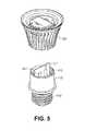
- FIG. 2is a perspective view of an LED lamp in accordance with one embodiment presented herein.
- FIG. 3is an exploded view of the LED lamp of FIG. 2 .
- FIG. 4is an exploded view of a portion of the LED lamp of FIG. 2 .
- FIG. 5is an exploded view of a portion of the LED lamp of FIG. 2 .
- FIG. 6is an exploded view of a portion of the LED lamp of FIG. 2 .
- FIG. 7is an exploded view of a portion of the LED lamp of FIG. 2 .
- FIG. 8is a schematic process diagram of an LED lamp in accordance with the present invention.
- FIG. 9illustrates a relative radiant power curve for a mint LED die used in one embodiment presented herein.
- FIGS. 10A and 10Bpresent color bin data for a mint LED die used III one embodiment presented herein.
- FIG. 11shows relative spectral power distributions for red, cyan, and blue LED dies that are used in one embodiment presented.
- FIG. 12shows a power spectral distribution of an LED lamp III a pre-sleep configuration, in accordance with another embodiment presented.
- FIG. 13shows a power spectral distribution of an LED lamp in a phase-shift configuration, in accordance with one embodiment presented.
- FIG. 14shows a power spectral distribution of an LED lamp in a general lighting configuration, in accordance with one embodiment presented.
- FIG. 15is an exploded view of an LED lamp in accordance with another embodiment presented.
- FIG. 16shows an alternative power spectral distribution for an LED lamp in a pre-sleep configuration.
- FIG. 17shows an alternative power spectral distribution for an LED lamp in a phase-shift configuration.
- FIG. 18shows an alternative power spectral distribution for an LED lamp in a general lighting configuration.
- FIG. 19shows a perspective view of an LED lamp according to an embodiment of the invention.
- FIG. 20shows a perspective view of an LED lamp according to an embodiment of the invention.
- FIG. 21shows an exploded view of the LED lamp of FIG. 20 .
- FIG. 22shows a perspective sectional view of the LED lamp of FIG. 20 taken through line 22 - 22 .
- FIG. 23shows a perspective view of an optical member of the LED lamp of FIG. 20 .
- the present inventionmay be referred to as relating to luminaires, digital lighting, light sources, and light-emitting diodes (LEDs).
- LEDslight-emitting diodes
- the present inventionmay just as easily relate to lasers or other digital lighting technologies.
- a person of skill in the artwill appreciate that the use of LEDs within this disclosure is not intended to be limited to any specific form of LED, and should be read to apply to light emitting semiconductors in general. Accordingly, skilled artisans should not view the following disclosure as limited to any particular light emitting semiconductor device, and should read the following disclosure broadly with respect to the same.
- An embodiment of the inventionprovides an LED lamp with commercially acceptable color rendering properties, which can be tuned to produce varying light outputs.
- the light outputproduces minimal melatonin suppression, and thus has a minimal effect on natural sleep patterns and other biological systems.
- the LED lampmay also be tuned to generate different levels of blue light, appropriate for the given circumstance, while maintaining good light quality and a high CRI in each case.
- the LED lampmay also be configured to “self-tune” itself to generate the appropriate light output spectrum, depending on factors such as the lamp's location, use, ambient environment, etc.
- the light output states/configurations achievable by the LED lamps presentedinclude: a pre-sleep configuration, a phase-shift configuration, and a general lighting configuration.
- the pre-sleep configurationthe lamp generates a reduced level of blue light in order to provide an adequate working environment while significantly lessening the suppression of melatonin.
- the spectrum of light produced by the lamp in the pre-sleep configurationprovides an environment appropriate for preparing for sleep while still maintaining light quality.
- the phase-shifting configurationthe lamp generates an increased level of blue light, thereby greatly diminishing melatonin production.
- the spectrum of light produced by the lamp in this phase-shifting configurationprovides an environment for shifting the phase of an individual's circadian rhythm or internal body clock.
- the general lighting configurationthe lamp generates a normal level blue light, consistent with a typical light spectrum (e.g., daylight). In all states, however, the lamp maintains high visual qualities and CRI, in order to provide an adequate working environment.
- the ability to tune, or adjust, the light outputis provided by employing a specific combination of LED dies of different colors, and driving the LED dies at various currents to achieve the desired light output.
- the LED lampemploys a combination of red, blue, cyan, and mint LED dies, such that the combination of dies produces a desired light output, while maintaining high quality light and high CRI.
- FIG. 2is a perspective view of an LED lamp (or bulb) 100 in accordance with one embodiment presented herein.
- LED lamp 100is appropriately designed to produce biologically-adjusted light, while still maintaining a commercially acceptable color temperature and commercially acceptable color rending properties.
- biologically-adjusted lightis intended to mean “a light that has been modified to manage biological effects on a user.”
- biological effectsis intended to mean “any impact or change a light source has to a naturally occurring function or process.”
- Biological effectsmay include hormone secretion or suppression (e.g., melatonin suppression), changes to cellular function, stimulation or disruption of natural processes, cellular mutations or manipulations, etc.
- LED lamp 100includes a base 110 , a heat sink 120 , and an optic 130 . As will be described below, LED lamp 100 further includes one or more LED chips and dedicated circuitry
- Base 110is preferably an Edison-type screw-m shell.
- Base 110is preferably formed of an electrically conductive material such as aluminum.
- base 110may be formed of other electrically conductive materials such as silver, copper, gold, conductive alloys, etc.
- Internal electrical leadsare attached to base 110 to serve as contacts for a standard light socket (not shown).
- base 110may be adapted to be any type of lamp base known in the art, including, but not limited to, bayonet, bi-post, bi-pin and wedge bases.
- heat sink 120serves as means for dissipating heat away from one or more of the LED chips within LED lamp 100 .
- heat sink 120includes fins to increase the surface area of the heat sink.
- heat sink 120may be formed of any configuration, size, or shape, with the general intention of drawings heat away from the LED chips within LED lamp 100 .
- Heat sink 120is preferably formed of a thermally conductive material such as aluminum, copper, steel, etc.
- Optic 130is provided to surround the LED chips within LED lamp 100 .
- the terms “surround” or “surrounding”are intended to mean partially or fully encapsulating.
- optic 130surrounds the LED chips by partially or fully covering one or more LED chips such that light produced by one or more LED chips is transmitted through optic 130 .
- optic 130takes a globular shape.
- Optic 130may be formed of alternative forms, shapes, or sizes.
- optic 130serves as an optic diffusing element by incorporating diffusing technology, such as described in U.S. Pat. No. 7,319,293 (which is incorporated herein by reference in its entirety).
- optic 130serves as a means for defusing light from the LED chips.
- optic 130may be formed of a light diffusive plastic, may include a light diffusive coating, or may having diffusive particles attached or embedded therein.
- optic 130includes a color filter applied thereto.
- the color filtermay be on the interior or exterior surface of optic 130 .
- the color filteris used to modify the light output from one or more of the LED chips.
- the color filteris a ROSCOLUX #4530 CALCOLOR 30 YELLOW.
- the color filtermay be configured to have a total transmission of about 75%, a thickness of about 50 microns, and/or may be formed of a deep-dyed polyester film on a polyethylene terephthalate (PET) substrate.
- PETpolyethylene terephthalate
- the color filtermay be configured to have transmission percentages within +/ ⁇ 10%, at one or more wavelengths, in accordance with the following table:
- FIG. 3is an exploded view of LED lamp 100 , illustrating internal components of the lamp.
- FIGS. 4-7are exploded views of portions of LED lamp 100 .
- FIGS. 3-7also serve to illustrate how to assemble LED lamp 100 .
- LED lamp 100also includes at least a housing 115 , a printed circuit board (PCB) 117 , one or more LED chips 200 , a holder 125 , spring wire connectors 127 , and screws 129 .
- PCBprinted circuit board
- PCB 117includes dedicated circuitry, such as power supply 450 , driver circuit 440 , and output-select controller 445 .
- the circuitry on PCB 117 and equivalents thereofserves as a means for driving the LED chips 200 (or individual LED dies) to produce a biologically-adjusted light output.
- each LED chip 200includes a plurality of LED dies.
- LED chips 200include an LED package comprising a plurality of LED dies, with at least two different colors, driven at varying currents to produce the desired light output and spectral power densities.
- each LED chip 200includes two red LED dies, three cyan LED dies, four mint LED dies, and three blue LED dies.
- FIG. 9illustrates a relative radiant power curve for a mint LED die used in one embodiment presented herein.
- FIG. 10A and 10Bpresent color bin data for a mint LED die used in one embodiment presented herein.
- FIG. 11shows relative spectral power distributions for red (or alternatively red-orange), cyan, and (two alternative) blue LED dies that are used in one embodiment presented (with alternative equivalent LED dies also being within the scope of the present invention).
- the tunable LED lampoperates in the pre-sleep configuration such that the radiant power emitted by the dies is in a ratio of: about 1 watt of radiant power generated by the mint LED dies, to about 0.5 watts of radiant power generated by the red-orange LED dies, to about 0.1 watts of radiant power generated by the cyan LED dies.
- the tunable LED lampoperates in the general lighting configuration such that the radiant power emitted by the dies is in a ratio about 1 watt of radiant power generated by the mint LED dies, to about 0.3 watts of radiant power generated by the red-orange LED dies, to about 0.4 watts of radiant power generated by the cyan LED dies, to about 0.2 watts of radiant power generated by the blue LED dies.
- the tunable LED lampoperates in the phase-shift configuration such that the radiant power emitted by the dies is in a ratio of about 1 watt of radiant power generated by the mint LED dies, to about 0.1 watts of radiant power generated by the red-orange LED dies, to about 0.2 watts of radiant power generated by the cyan LED dies, to about 0.4 watts of radiant power generated by the blue LED dies.
- the tunable LED lampoperates in the pre-sleep configuration such that the radiant power emitted by the dies is in a ratio of: about 1 watt of radiant power generated by the mint LED dies, to about 0.8 watts of radiant power generated by the red-orange LED dies, to about 0.3 watts of radiant power generated by the cyan LED dies.
- the tunable LED lampoperates in the general lighting configuration such that the radiant power emitted by the dies is in a ratio about 1 watt of radiant power generated by the mint LED dies, to about 0.2 watts of radiant power generated by the red-orange LED dies, to about 0.2 watts of radiant power generated by the blue LED dies.
- the tunable LED lampoperates in the phase-shift configuration such that the radiant power emitted by the dies is in a ratio of about 1 watt of radiant power generated by the mint LED dies, to about 0.1 watts of watts of radiant power generated by the red-orange LED dies, to about 0.5 watts of radiant power generated by the blue LED dies.
- driver circuit 440may be configured to drive the plurality of LED dies such that a blue output intensity level, in a visible spectral output range of between about 380 nm and about 485 nm, is less than about 10% of a relative spectral power of any other peaks in the visible spectral output above about 485 nm.
- driver circuit 440drives the plurality of LED dies such that about 150 mA of current is delivered to four mint LED dies; about 360 mA of current is delivered to two red LED dies; and about 40 mA of current is delivered to three cyan LED dies.
- the pre-sleep configurationis achieved by configuring driver circuit 440 to deliver about 510 MA of current to 4 mint LED dies.
- driver circuit 440may be configured to drive the plurality of LED dies such that a blue output intensity level, in a visible spectral output range of between about 455 nm and about 485 nm, is greater than about 125% (or greater than about 150%; or greater than about 200%) of a relative spectral power of any other peaks in the visible spectral output above about 485 nm.
- the color rendering index in the phase-shift configurationmay be greater than 80.
- driver circuit 440drives the plurality of LED dies such that about 510 mA of current is delivered to the mint LED dies; about 180 mA of current is delivered to the red LED dies; about 40 mA of current is delivered to the cyan LED dies; and about 100 mA of current is delivered to the blue LED dies.
- driver circuit 440may be configured to drive the plurality of LED dies such that a blue output intensity level, in a visible spectral output range of between about 380 nm and about 485 nm, is between about 100% to about 20% of a relative spectral power of any other peaks in the visible spectral output above about 485 nm.
- the color rendering index in the general lighting configurationmay be greater than 85.
- driver circuit 440drives the plurality of LED dies such that about 450 mA of current is delivered to the mint LED dies; about 230 mA of current is delivered to the red LED dies; about 110 mA of current is delivered to the cyan LED dies; and about 60 mA of current is delivered to the blue LED dies.
- driver circuit 440is configured to drive LED chips 200 with a ripple current at frequencies greater than 200 Hz.
- a ripple current at frequencies above 200 Hzis chosen to avoid biological effects that may be caused by ripple currents at frequencies below 200 Hz. For example, studies have shown that some individuals are sensitive to light flicker below 200 Hz, and in some instances experience aggravated headaches, seizures, etc.
- base 110is glued or crimped onto housing 115 .
- PCB 117is mounted within housing 115 .
- Insulation and/or potting compound(not shown) may be used to secure PCB 117 within housing 115 .
- Electrical leads on PCB 117are coupled to base 110 to form the electrical input leads of LED lamp 100 .
- base 110may be adapted to facilitate the operation of the LED lamp based upon receiving an electrical signal from a light socket that base 110 may be attached to.
- base 110may be adapted to receive electrical signals from a three-way lamp, as is known in the art.
- driver circuit 440may similarly be adapted to receive electrical signals from base 110 in such a fashion so as to use the electrical signals from the three-way lamp as an indication of which emitting configuration is to be emitted.
- the modes of operation of a three-way lampare known in the art.
- Base 110 and driver circuit 440may be adapted to cause the emission of the phase-shift configuration upon receiving a first electrical signal from a three-way lamp, the general illumination configuration upon receiving a second electrical signal from the three-way lamp, and the pre-sleep configuration upon receiving a third electrical signal from the three-way lamp.
- base 110may include a first terminal (not shown) and a second terminal (not shown), the first terminal being configured to electrically couple to a low-wattage contact of a three-way fixture, and the second terminal being configured to electrically couple to a medium wattage contact of a three-way fixture.
- Driver circuit 440may be positioned in electrical communication with each of the first and second terminals of base 110 . When base 110 receives an electric signal at the first terminal, but not at the second terminal, the driver circuit 440 may detect such and may cause the emission of light according to one of the phase-shift configuration, the general illumination configuration, and the pre-sleep configuration.
- the driver circuit 440may detect such and may cause the emission of light according to one of the phase-shift configuration, the general illumination configuration, and the pre-sleep configuration, but not the same configuration as when an electrical signal was detected at the first terminal and not the second. Finally, base 110 receives an electrical signal at both the first terminal and the second terminal, driver circuit 440 may detect such and may cause the emission of light according to one of the phase-shift configuration, the general illumination configuration, and the pre-sleep configuration, but not the same configuration as is emitted when an electrical signal is detected at only one of the first or second terminals of base 110 .
- the driver circuit 440may be configured to cause the emission of light according to any of the configurations as described hereinabove based upon the waveform of an electrical signal received by base 110 and detected by driver circuit 440 .
- driver circuit 440may be configured to cause the emission of light that is responsive to a TRIAC signal.
- a TRIAC signalis a method of manipulating the waveform of an AC signal that selectively “chops” the waveform such that only certain periods of the waveform within an angular range are transmitted to an electrical device, and is used in lighting.
- Driver circuit 440may be configured to cause the emission of light according to one of the various configurations of light responsive to varying ranges of TRIAC signals.
- a range of a TRIAC signalmay be considered as a portion of a continuous, unaltered AC signal.
- a first TRIAG signal rangemay be a range from greater than about 0% to about 33% of an AC signal. This range may correspond to a percentage of the total angular measurement of a single cycle of the AC signal. Accordingly, where the single cycle of the AC signal is approximately 27 radians, the first range may be from greater than about 0 to about 0.67 ⁇ radians. It is contemplated that angular measurement of the TRIAC signal is only one method of defining a range of a characteristic of the TRIAC signal.
- the driver circuit 440may include circuitry necessary to determine any of the phase angle, voltage, and RMS voltage of a received signal.
- the driver circuit 440may be configured to detect the TRIAC signal and determine it falls within this range, and may further be configured to cause the emission of light according to one of the phase-shift configuration, the general illumination configuration, and the pre-sleep configuration.
- a second TRIAC signal rangemay be from about 33% to about 67% of an AC signal, which may correspond to a range from about 0.67 ⁇ to about 1.33 ⁇ radians.
- the driver circuit 440may be configured to detect the TRIAC signal and determine it falls within this range, and may further be configured to cause the emission of light according to one of the phase-shift configuration, the general illumination configuration, and the pre-sleep configuration, but not the configuration that was emitted when the driver circuit determined the TRIAC signal was within the first TRIAC signal range.
- a third TRIAC signal rangemay be from about 67% to about 100% of an AC signal, which may correspond to a range from about 1.33 ⁇ to about 2 ⁇ radians.
- the driver circuit 440may be configured to detect the TRIAC signal and determine it falls within this range, and may further be configured to cause the emission of light according to one of the phase-shift configuration, the general illumination configuration, and the pre-sleep configuration, but not the configuration that was emitted when the driver circuit determined the TRIAC signal was within either of the first TRIAC signal range or the second TRIAC signal range.
- a first TRIAC signal rangemay be from about 0% to about 25% of an AC signal, corresponding to within a range from about 0 to about 0.5 ⁇ radians.
- Driver circuit 440may be configured to detect the TRIAC signal and determine if it falls within this range, and may further be configured to not emit light.
- a second TRIAC signal rangemay be from about 25% to about 50% of an AC signal, corresponding to within a range from about 0.5 ⁇ to about 1.0 ⁇ radians.
- Driver circuit 440may be configured to detect the TRIAC signal and determine if it falls within this range, and may further be configured to cause the emission of light according to one of the phase-shift configuration, the general illumination configuration, and the pre-sleep configuration.
- a third TRIAC signal rangemay be from about 50% to about 75% of an AC signal, corresponding to within a range from about 1.0 ⁇ to about 1.5 ⁇ radians.
- Driver circuit 440may be configured to detect the TRIAC signal and determine if it falls within this range, and may further be configured to cause the emission of light according to one of the phase-shift configuration, the general illumination configuration, and the pre-sleep configuration, but not the configuration that was emitted when the driver circuit determined the TRIAC signal was within the second TRIAC signal range.
- a fourth TRIAC signal rangemay be from about 75% to about 100% of an AC signal, corresponding to a range from about 1.5 ⁇ to about 2.0 radians.
- Driver circuit 440may be configured to detect the TRIAC signal and determine if it falls within this range, and may further be configured to cause the emission of light according to one of the phase-shift configuration, the general illumination configuration, and the pre-sleep configuration, but not the configuration that was emitted when the driver circuit determined the TRIAC signal was within either of the second or third TRIAC signal ranges.
- the inventionmay further comprise a retrofit wall-mounted switch (not shown).
- the retrofit wall-mounted switchmay operate substantially as the output selection device and the user input device described herein.
- the retrofit wall-mounted switchmay be configured to replace a standard wall switch for control of a light fixture, as is known in the art.
- the retrofit wall-mounted switchmay be configured to generate or manipulate a signal so as to control the operation of the LED lamp 100 .
- the retrofit wall-mounted switchmay be configured to generate a wireless signal that may be received by the LED lamp 100 that may result in the operation of the LED lamp 100 as described hereinabove.
- the retrofit wall-mounted switchmay be configured to manipulate a power source to which the retrofit wall-mounted switch is electrically coupled so as to generate a TRIAC signal, to which the LED lamp 100 may operate responsively to as described hereinabove.
- the retrofit wall-mounted switchmay be positioned electrically intermediate the power source and the LED lamp 100 .
- base 110may be configured to be a removably attachable member of LED lamp 100 , defined as an intermediate base.
- an intermediate basemay be included in addition the base 110 .
- Intermediate base 110may include structural elements and features facilitating the attachment of intermediate base 110 to a part of LED lamp 100 .
- intermediate base 110may be adapted to cooperate with a feature or structure of housing 115 so as to removably attach intermediate base 110 thereto.
- housing 115may include a threaded section (not shown) configured to engage with the threads of intermediate base 110 so as to removable attach with intermediate base 110 .
- each of intermediate base 110 and LED lamp 100may include electrical contacts so as to electrically couple LED lamp 100 to intermediate base 110 when intermediate base 110 is attached.
- the size, position, and configuration of such electrical contactsmay vary according to the method of attachment between LED lamp 100 and intermediate base 110 .
- intermediate base 110may include elements facilitating the transitioning of LED chips 200 between the various configurations, i.e. pre-sleep, phase shift, and general illuminating configurations.
- intermediate base 110may include a user input device (not shown) adapted to receive an input from a user. The input from the user may cause intermediate base 110 to interact with at least one of driver circuit 440 and a power circuit of the LED lamp 100 so as to cause the LED chips 200 to emit light according to any of the configurations recited herein.
- the user inputmay cause the LED lamp 100 to transition from the present emitting configuration to a selected emitting configuration, or to cease emitting light.
- the user inputmay cause the LED lamp 100 to progress from one emitting configuration to another emitting configuration according to a defined progression.
- An example of such a progressionmay be, from an initial state of not emitting light, to emitting the phase-shift configuration, to emitting the general illumination configuration, to emitting the pre-sleep configuration, to ceasing illumination.
- Such a progressionis exemplary only, and any combination and permutation of the various emitting configurations are contemplated and included within the scope of the invention.
- the base 110may include circuitry necessary to receive the input from the user and to communicate electrically with the various elements of the LED lamp 100 to achieve such function.
- the user input devicemay be a device that is physically accessible by a user when the base 110 is attached to the LED lamp 100 and when the LED lamp 100 is installed in a lighting fixture.
- the user input devicemay be a lamp turn knob operatively connected to circuitry comprised by the base 110 to affect the transitioning described hereinabove.
- a lamp turn knobis an exemplary embodiment only, and any other structure or device capable of receiving an input from a user based on electrical and/or mechanical manipulation or operation by the user is contemplated and included within the scope of the invention.
- the user input devicemay be an electronic communication device including a wireless communication device configured to receive a wireless signal from the user as the input.
- Such user input devicesmay be adapted to receive a user input in the form of an infrared signal, a visible light communication (VLC) signal, radio signal, such as Wi-Fi, Bluetooth, Zigbee, cellular data signals, Near Field Communication (NFC) signal, and any other wireless communication standard or method known in the art.
- the user input devicemay be adapted to receive an electronic signal from the user via a wired connection, including, but not limited to, Ethernet, universal serial bus (USB), and the like.
- the user input devicemay be adapted to receive power from the Ethernet connection, conforming to Power-over-Ethernet (PoE) standards.
- PoEPower-over-Ethernet
- the power received by the user input devicemay provide power to the LED lamp 100 enabling its operation.
- any of the lighting devices as described hereinmay be integrally formed with a lighting fixture, where the LED lamp 100 is not removably attachable to the lighting fixture. More specifically, in some embodiments, those aspects of the lighting devices described herein that are included to permit the attachability of the lighting device to a separately-produced lighting fixture may be excluded, and those aspects directed to the function of emitting light according to the various lighting configurations as described herein may be included.
- the base 110may be excluded, and the driver circuit 440 may be directly electrically coupled to an external power source or to an electrical conduit thereto.
- the geometric configuration of optic 130 , heat sink 120 , LED chips 200 , and all other elements of the LED lamp 100may be adapted to facilitate a desired configuration of an integrally-formed lighting fixture.
- heat sink 120is disposed about housing 115 .
- two LED chips 200are mounted onto a support surface (or directly to heat sink 120 ), and maintained in place by holder 125 . While two LED chips 200 are shown, alternative embodiments may include any number of LED chips (i.e., one or more), or any number of LED dies individually mounted.
- Screws 129are used to secure holder 125 to heat sink 120 . Screws 129 may be any screws known in the art.
- Spring wire connectors 127are used to connect LED chips 200 to the driver circuit 440 on PCB 117 .
- LED chips 200may be attached directly to heat sink 120 without the use of holder 125 , screws 129 , or connectors 127 . As shown in FIG. 7 , optic 130 is then mounted on and attached to heat sink 120 .
- FIG. 8is a schematic process diagram of an LED lamp in accordance with the present invention.
- FIG. 8also serves a depiction of the functional components mounted on PCB 117 , or otherwise associated with LED lamp 100 .
- a power supply 450is used to provide power to driver circuit 440 .
- Power supply 450may, for example, convert AC power to DC power, for driving the LED dies.
- Driver circuit 440receives power input from power supply 450 , and directional input from output-select controller 445 .
- driver circuit 440provides the appropriate current supply to drive the LED dies in accordance with the desired spectral output.
- Controller 445therefore serves to control the driving of LEDs 200 , and may control light output based on factors such as: time of day, ambient light, real time input, temperature, optical output, location of lamp, etc.
- a photo-sensor 860is included to monitor the light output of the LEDs 200 to insure consistency and uniformity. Monitoring the output of LEDs 200 allows for real time feedback and control of each die to maintain the desired output spectrum. Photo-sensor 860 may also be used to identify the ambient light conditions. Photo-sensor 860 thus provides an input to controller 445 .
- a thermal sensor 855is used to measure the temperature of the LED dies and/or board supporting the LED dies. Because the light output of the dies is a known function of temperature, the measured temperature can be used to determine the light output of each die. Thermal sensor 855 may also be used to measure the ambient temperature conditions. Thermal sensor 855 thus provides another input to controller 445 .
- a GPS chip 870 and/or clock 875is included and interfaced with controller 445 . Because lamps are shipped around the world to their end location, the ability to determine the expected/actual ambient light, daily light cycle, and seasonal light cycle variations is important in any lamp that may generate light to stimulate or alter circadian rhythms. GPS chip 870 and/or clock 875 provide inputs into controller 445 such that the time of day, seasonality, and other factors can be taken into account by controller 445 to control the lamp output accordingly. For example, by knowing the time of day based on location, the pre-sleep spectrum of the lamp can be generated during the later hours of the day.
- a user-interface 865is provided to allow a user to select the desired configuration.
- User-interface 865may be in the form of a knob, switch, digital input, or equivalent means. As such, user-interface 865 provides an additional input to controller 445 .
- the pre-sleep configuration spectrumincludes a portion of the spectrum that is reduced (e.g., notched/troughed) in intensity. This trough is centered at about 470 nm (or alternatively between about 470-480 nm, between about 460-480 nm, between about 470-490 nm, or between about 460-490 nm).
- Such wavelength rangesmay be the most important contributor to, and most effective at, suppressing melatonin. Thus minimizing exposure in such wavelength bands during pre-sleep phase will be efficacious.
- the notching of the pre-sleep spectrumis obtained using a phosphor-coated mint LED having a specific output spectrum to accomplish the notch in the pre-sleep spectrum.
- the mint LEDitself may include a notch/trough with a minimum in the 470-480 nm (or 460-490 nm range), and may be characterized by a maximum intensity in these wavelength ranges as a fractional percent of the peak intensity of the mint LED (e.g., the maximum of 470-480 emission is less than about 2.5% of the peak intensity; the max between about 460-490 nm is less than about 5% of the peak intensity).
- a relative radiant power curve for a mint LED dieused in one embodiment presented.
- the terms “mint LED” or “mint LED die” or “mint die”should be construed to include any LED source, LED chip, LED die (with or without photo-conversion material on the die), or any equivalent light source that is configured or capable of producing the relative radiant power curve shown in FIG. 9 , or a relative radiant power curve equivalent thereto.
- the spectral “notch”between about 460-490 nm, and more specifically between at about 470-480 nm.
- Said spectral notchprovides a relative intensity, with respect to the peak intensity, that allows the combination of LED dies (or equivalent light sources) to achieve their desired results (i.e., the desired output configuration).
- the maximum intensity of the mint LED between about 460-490 nmis less than about 5% of the peak intensity. In alternative embodiments the maximum intensity of the mint LED between about 460490 nm is less than about 7.5%, or about 10%, or about 15%, or about 20% of the peak intensity. Further, in one embodiment, the maximum intensity of the mint LED between about 470-480 nm is less than about 2.5% of the peak intensity. In alternative embodiments, the maximum intensity of the mint LED between about 470-480 nm is less than about 3.5%, 5%, 10%, or 20% of the peak intensity.
- FIGS. 12 , 13 , and 14show the power spectral distributions corresponding respectively to the pre-sleep, phase-shift, and general illumination configurations of the LED lamp in accordance with one embodiment of the invention.
- the LED lamp in this embodimentcomprises an LED board with a ratio of Cyan, Mint, Red, and Royal Blue dies of 3:3:2:1 respectively.
- the spectral output of the lamp according to each configurationis adjusted by generating radiant fluxes from multiple dies as described below.
- FIG. 12shows a power spectral distribution of an LED lamp III a pre-sleep configuration, in accordance with another embodiment presented.
- the pre-sleep configuration shown in FIG. 13is produced by an array of LED dies in the 3:3:2:1 ratio, driven as follows: (1) three cyan LEDs driven at 7.65V, 66 mA, 0.16679 radiant flux; (2) three mint LEDs driven parallel at 11.13V, 951 mA, 1.8774 radiant flux; (3) two red-orange LEDs driven at 4.375V, 998 mA, 0.96199 radiant flux; and (4) one royal blue LED driven at 2.582V, 30 mA, 0.0038584 radiant flux.
- the total luminous fluxis I.024e+003 1 m.
- the total radiant fluxis 3.023ge+000 W.
- the dominant wavelengthis 580.3 nm.
- the general CRIis 87.30.
- the color temperatureis 2871 K.
- the 1931 Coordinates (2°)are x: 0.4649, y: 0.4429.
- the luminous power per radiant wattis 338 lumens per radiant watt.
- FIG. 13shows a power spectral distribution of an LED lamp in a phase-shift configuration, in accordance with one embodiment presented.
- the phase-shift configuration shown in FIG. 14is produced by an array of LED dies in the 3:3:2:1 ratio, driven as follows: (1) three cyan LEDs driven at 8.19V, 235 mA, 0.47233 radiant flux; (2) three mint LEDs driven parallel at 1I.14V, 950 mA, I.9047 radiant flux; (3) two red-orange LEDs driven at 3.745V, 147 mA, 0.1845 radiant flux; and (4) one royal blue LED driven at 2.802V, 525 mA, 0.69093 radiant flux.
- the total luminous fluxis 9.87ge+002 1 m.
- the total radiant fluxis 3.2138e+000 W.
- the dominant wavelengthis 495.6 nm.
- the peak wavelengthis 449.7 nm.
- the general CRIis 87.42.
- the color temperatureis 6,599 K.
- the 1931 Coordinates (2°)are x: 0.3092, y: 0.3406.
- the luminous power per radiant wattis 307 lumens per radiant watt.
- the intensity levels of blue component in the 455 nm to 485 nm rangeis preferably greater than about 125% of the relative spectral power of any other peaks in the visible light spectrum higher than 485 nm.
- the blue component in the 455 nm to 485 nm rangemay be is preferably greater than about 150%; or about 175%; or about 200%; or about 250%; or about 300% of the relative spectral power of any other peaks in the visible light spectrum higher than 485 nm.
- the color rendering indexis preferably greater than 80.
- FIG. 14shows a power spectral distribution of an LED lamp in a general lighting configuration, in accordance with one embodiment presented.
- the general lighting configuration shown in FIG. 15is produced by an array of LED dies in the 3:3:2:1 ratio, driven as follows: (1) three cyan LEDs driven at 8.22V, 211 mA, 0.44507 radiant flux; (2) three mint LEDs driven parallel at 10.06V, 499 mA, 1.1499 radiant flux; (3) two red-orange LEDs driven at 3.902V, 254 mA, 0.34343 radiant flux; and (4) one blue LED driven at 2.712V, 190 mA, 0.27280 radiant flux.
- the total luminous fluxis 7.192e+002 1 m.
- the total radiant fluxis 2.2248e+000 W.
- the dominant wavelengthis 566.2 nm.
- the peak wavelengthis 625.9 nm.
- the general CRIis 93.67.
- the color temperatureis 4897 K.
- the 1931 Coordinates (2°)are x: 0.3516, y: 0.3874.
- the luminous power per radiant wattis 323 lumens per radiant watt.
- the intensity levels of blue component in the 380 nm to 485 nm rangeis preferably about 100% of the relative spectral power of any other peaks in the visible light spectrum higher than 485 nm.
- the intensity levels of blue component in the 380 nm to 485 nm rangeis preferably less than about 100%; or less than about 90%; or less than about 80%; or between about 20% to about 100% of the relative spectral power of any other peaks in the visible light spectrum higher than 485 nm.
- the color rendering indexis preferably greater than 85.
- FIG. 15is an exploded view of an LED lamp in accordance with another embodiment presented.
- FIG. 15shows an additional form factor in which the present invention may be applied.
- FIG. 15shows a lamp 1600 having an array of LEDs 1610 .
- the LEDs 1610may be provided in the 3:3:2:1 ratio of cyan:mint:red-orange:blue, as described above.
- the LEDs 1610may be provided in a 3:3:2:3 ratio of cyan:mint:red:blue, as described above.
- the LEDsare mounted on a support frame 1620 , which may serve as a heat-sink.
- LED circuitry 1630is used to drive the LEDs 1610 with appropriate drive currents to achieve two or more output configurations (e.g., pre-sleep, phase-shift, and general lighting configurations).
- An output-select controller 1640(and associated knob) are provided to allow an end-user to select the desired output configuration.
- An optic 1650is provided in front of the LEDs 1610 to provide diffusive effects.
- the form factormay be completed by fastening the components with means such as screws and/or nuts and bolts, as shown.
- FIGS. 16 , 17 , and 18show the power spectral distributions corresponding respectively to the pre-sleep, phase-shift, and general illumination configurations of the LED lamp in accordance with one embodiment of the invention.
- the LED lamp in this embodimentcomprises an LED board with a ratio of Cyan, Mint, Red, and Blue dies of 3:3:2:3 respectively.
- the spectral output of the lamp according to each configurationis adjusted by generating radiant fluxes from multiple dies as described below.
- FIG. 16shows a power spectral distribution of an LED lamp III a pre-sleep configuration, in accordance with another embodiment presented.
- the pre-sleep configuration shown in FIG. 13is produced by an array of LED dies in the 3:3:2:3 ratio, driven as follows: (1) three cyan LEDs driven at 7.83V, 91 mA, to generate 0.2048 radiant watts; (2) three mint LEDs driven parallel at 9.42V, 288 mA, 0.6345 radiant watts; (3) two red-orange LEDs driven at 4.077V, 490 mA, 0.5434 radiant watts.
- the dominant wavelengthis 581.4 nm.
- the general CRIis 71.
- the color temperatureis 2719 K.
- the luminous power per radiant wattis 331 lumens per radiant watt.
- the efficacyis 91 lumens per watt.
- FIG. 17shows a power spectral distribution of an LED lamp in a phase-shift configuration, in accordance with another embodiment presented.
- the phase-shift configuration shown in FIG. 18is produced by an array of LED dies in the 3:3:2:3 ratio, driven as follows: (1) three mint LEDs driven parallel at 11.27V, 988 mA, 1.679 radiant watts; (2) two red-orange LEDs driven at 3.78V, 180 mA, 1.971 radiant, and (3) three blue LEDs driven at 9.07V, 296 mA, 0.8719 radiant watts.
- the dominant wavelengthis 476.9 nm.
- the general CRIis 88.
- the color temperatureis 6235 K.
- the luminous power per radiant wattis 298 lumens per radiant watt.
- the efficacyis 63 lumens per watt.
- FIG. 18shows a power spectral distribution of an LED lamp in a general lighting configuration, in accordance with another embodiment presented.
- the general lighting configuration shown in FIG. 19is produced by an array of LED dies in the 3:3:2:3 ratio, driven as follows: (1) three cyan LEDs driven at 8.16V, 218 mA, to generate 0.4332 radiant watts; (2) three mint LEDs driven parallel at 11.23V, 972 mA, 1.869 radiant watts; (3) two red-orange LEDs driven at 3.89V, 295 mA, 0.3520 radiant watts.
- the dominant wavelengthis 565.6 nm.
- the general CRIis 90.
- the color temperatureis 4828 K.
- the luminous power per radiant wattis 335 lumens per radiant watt.
- the efficacyis 68 lumens per watt
- a tunable LED lampfor producing a biologically-adjusted light output with a color rendering index above 70.
- the LED lampcomprises: a base; a housing attached to the base; a power circuit disposed within the housing and having electrical leads attached to the base; a driver circuit disposed within the housing and electrically coupled to the power circuit; and a heat sink disposed about the housing.
- the LED lampfurther comprises: a plurality of LED dies mounted on a support coupled to the housing, wherein each of the plurality of LED dies is electrically coupled to and driven by the driver circuit.
- the plurality of LED diesincludes two red LED dies, three cyan LED dies, four mint LED dies, and three blue LED dies.
- the LED lampfurther comprises: an output-select controller electrically coupled to the driver circuit to program the driver circuit to drive the LED dies in one of a plurality of light output configurations.
- the plurality of light output configurationsincludes a pre-sleep configuration, a phase-shift configuration, and a general lighting configuration.
- the output-select controllermay include a user-input interface allowing a user to select the light output configuration.
- the LED lampmy further include an input sensor electrically coupled to the output-select controller to provide an input variable for consideration in the selection of the light output configuration.
- the input sensormay be a thermal sensor, a photo-sensor, and/or a GPS chip.
- the input variablemay be selected from the group consisting of: an ambient temperature, a support temperature, an LED die temperature, a housing temperature, the light output produced by the lamp, an ambient light, a daily light cycle, a location of the lamp, an expected ambient light, a seasonal light cycle variation, a time of day, and any combinations and/or equivalents thereof.
- the driver circuitdrives the plurality of LED dies such that a blue output intensity level, in a visible spectral output range of between about 380 nm and about 485 nm, is less than about 10% of a relative spectral power of any other peaks in the visible spectral output above about 485 nm.
- the driver circuitmay drive the plurality of LED dies such that about 150 mA of current is delivered to the mint LED dies; about 360 mA of current is delivered to the red LED dies; and about 40 mA of current is delivered to the cyan LED dies.
- the driver circuitdrives the plurality of LED dies such that a blue output intensity level, in a visible spectral output range of between about 455 nm and about 485 nm, is greater than about 125% of a relative spectral power of any other peaks in the visible spectral output above about 485 nm.
- the color rendering index in the phase-shift configurationmay be greater than 80.
- the driver circuitmay drive the plurality of LED dies such that about 510 mA of current is delivered to the mint LED dies; about 180 mA of current is delivered to the red LED dies; about 40 mA of current is delivered to the cyan LED dies; and about 100 mA of current is delivered to the blue LED dies.
- the driver circuitdrives the plurality of LED dies such that a blue output intensity level, in a visible spectral output range of between about 380 nm and about 485 nm, is between about 100% to about 20% of a relative spectral power of any other peaks in the visible spectral output above about 485 nm.
- the color rendering index in the general lighting configurationmay be greater than 85.
- the driver circuitmay drive the plurality of LED dies such that about 450 mA of current is delivered to the mint LED dies; about 230 mA of current is delivered to the red LED dies; about 110 mA of current is delivered to the cyan LED dies; and about 60 mA of current is delivered to the blue LED dies.
- an LED lampcomprising: a housing; a driver circuit disposed within the housing and configured to electrically couple to a power source; and a plurality of LED dies mounted on a support coupled to the housing, wherein each of the plurality of LED dies is electrically coupled to and driven by the driver circuit.
- the LED lampfurther includes an output-select controller electrically coupled to the driver circuit to program the driver circuit to drive the LED dies in one of a plurality of light output configurations.
- the output-select controllermay also include a user-input interface allowing a user to select the light output configuration.
- the plurality of light output configurationsincludes a pre-sleep configuration and a general lighting configuration.
- the plurality of light output configurationsmay further include a phase-shift configuration.
- the plurality of LED diesmay include red LED dies, cyan LED dies, mint LED dies, and blue LED dies. The ratio of red LED dies to cyan LED dies to mint LED dies to blue LED dies of 2:3:4:3, respectively.
- the LED lampmay be tunable to produce a biologically-adjusted light output with a color rendering index above 70.
- the LED lampmay further comprise an input sensor electrically coupled to the output-select controller to provide an input variable for consideration in the selection of the light output configuration.
- the input sensormay be a thermal sensor, a photo-sensor, and/or a GPS chip.
- the input variablemay be selected from the group consisting of: an ambient temperature, a support temperature, an LED die temperature, a housing temperature, the light output produced by the lamp, an ambient light, a daily light cycle, a location of the lamp, an expected ambient light, a seasonal light cycle variation, a time of day, and any combinations and/or equivalents thereof.
- the driver circuitdrives the plurality of LED dies such that a blue output intensity level, in a visible spectral output range of between about 380 nm and about 485 nm, is less than about 10% of a relative spectral power of any other peaks in the visible spectral output above about 485 nm.
- the driver circuitmay drive the plurality of LED dies such that about 150 mA of current is delivered to the mint LED dies; about 360 mA of current is delivered to the red LED dies; and about 40 mA of current is delivered to the cyan LED dies.
- the driver circuitdrives the plurality of LED dies such that a blue output intensity level, in a visible spectral output range of between about 455 nm and about 485 nm, is greater than about 125% (or greater than about 150%; or greater than about 200%) of a relative spectral power of any other peaks in the visible spectral output above about 485 nm.
- the color rendering index in the phase-shift configurationmay be greater than 80.
- the driver circuitmay drive the plurality of LED dies such that about 510 mA of current is delivered to the mint LED dies; about 180 mA of current is delivered to the red LED dies; about 40 mA of current is delivered to the cyan LED dies; and about 100 mA of current is delivered to the blue LED dies
- the driver circuitdrives the plurality of LED dies such that a blue output intensity level, in a visible spectral output range of between about 380 nm and about 485 nm, is between about 100% to about 20% of a relative spectral power of any other peaks in the visible spectral output above about 485 nm.
- the color rendering index in the general lighting configurationmay be greater than 85.
- the driver circuitmay drive the plurality of LED dies such that about 450 mA of current is delivered to the mint LED dies; about 230 mA of current is delivered to the red LED dies; about 110 mA of current is delivered to the cyan LED dies; and about 60 mA of current is delivered to the blue LED dies.
- a tunable LED lampfor producing a biologically-adjusted light output with a color rendering index above 70, comprising: a base; a housing attached to the base; a power circuit disposed within the housing and having electrical leads attached to the base; a driver circuit disposed within the housing and electrically coupled to the power circuit; a heat sink disposed about the housing; a plurality of LED dies mounted on a support coupled to the housing, wherein each of the plurality of LED dies is electrically coupled to and driven by the driver circuit, and wherein the plurality of LED dies includes a ratio of two red-orange LED dies to three cyan LED dies to three mint LED dies to one blue LED dies; and an output-select controller electrically coupled to the driver circuit to program the driver circuit to drive the LED dies in one of a plurality of light output configurations, wherein the plurality of light output configurations includes a pre-sleep configuration, a phase-shift configuration, and a general lighting configuration
- the driver circuitmay drive the plurality of LED dies such that about 950 mA of current is delivered to the mint LED dies, about 1,000 mA of current is delivered to the red-orange LED dies, about 65 mA of current is delivered to the cyan LED dies; and about 30 mA of current is delivered to the blue LED dies.
- the driver circuitmay drive the plurality of LED dies such that about 950 mA of current is delivered to the mint LED dies, about 150 mA of current is delivered to the red-orange LED dies, about 235 mA of current is delivered to the cyan LED dies, and about 525 mA of current is delivered to the blue LED dies.
- the driver circuitmay drive the plurality of LED dies such that about 500 mA of current is delivered to the mint LED dies, about 250 mA of current is delivered to the red-orange LED dies, about 210 mA of current is delivered to the cyan LED dies, and about 190 mA of current is delivered to the blue LED dies.
- alternative currentsmay be delivered to vary the radiant fluxes and achieve the desired spectral output.
- a method of manufacturing a tunable LED lamp for producing a biologically-adjusted light output with a color rendering index above 70comprises: (a) attaching a base to a housing; (b) electrically coupling leads of a power circuit within the housing to the base; (c) electrically coupling a driver circuit disposed within the housing to the power circuit; (d) mounting a plurality of LED dies on a support coupled to the housing such that each of the plurality of LED dies is electrically coupled to and driven by the driver circuit, and wherein the plurality of LED dies includes two red LED dies, three cyan LED dies, four mint LED dies, and three blue LED dies; and (e) configuring the driver circuit to drive the LED dies in one of a plurality of light output configurations, wherein the plurality of light output configurations includes a pre-sleep configuration, a phase-shift configuration, and a general lighting configuration.
- the methodmay further comprise: (f) configuring the driver circuit to drive the plurality of LED dies such that a blue output intensity level, in a visible spectral output range of between about 380 nm and about 485 nm, is less than about 10% of a relative spectral power of any other peaks in the visible spectral output above about 485 nm; (g) configuring the driver circuit to drive the plurality of LED dies such that a blue output intensity level, in a visible spectral output range of between about 455 nm and about 485 nm, is greater than about 125% of a relative spectral power of any other peaks in the visible spectral output above about 485 nm; and/or (h) configuring the driver circuit to drive the plurality of LED dies such that a blue output intensity level, in a visible spectral output range of between about 380 nm and about 485 nm, is between about 100% to about 20% of a relative spectral power of any other peaks in the visible spect
- the methodmay further comprise: (i) configuring the driver circuit to drive the plurality of LED dies such that about 150 mA of current is delivered to the mint LED dies, about 360 mA of current is delivered to the red LED dies, and about 40 mA of current is delivered to the cyan LED dies; (j) configuring the driver circuit to drive the plurality of LED dies such that about 510 mA of current is delivered to the mint LED dies, about 180 mA of current is delivered to the red LED dies, about 40 mA of current is delivered to the cyan LED dies, and about 100 mA of current is delivered to the blue LED dies; and/or (k) configuring the driver circuit to drive the plurality of LED dies such that about 450 mA of current is delivered to the mint LED dies, about 230 mA of current is delivered to the red LED dies, about 110 mA of current is delivered to the cyan LED dies, and about 60 mA of current is delivered to the blue LED dies.
- an LED lampcomprising: a housing; a driver circuit disposed within the housing and configured to electrically couple to a power source; a plurality of LED dies mounted on a support coupled to the housing, wherein each of the plurality of LED dies is electrically coupled to and driven by the driver circuit; and an output-select controller electrically coupled to the driver circuit to program the driver circuit to drive the LED dies in one of a plurality of light output configurations, wherein the plurality of light output configurations includes a pre-sleep configuration and a general lighting configuration.
- the plurality of LED diesincludes red-orange LED dies, cyan LED dies, mint LED dies, and blue LED dies.
- the plurality of LED diesincludes a ratio of red-orange LED dies to cyan LED dies to mint LED dies to blue LED dies of 2:3:3:1, respectively.
- a method of manufacturing a tunable LED lamp for producing a biologically-adjusted light output with a color rendering index above 70comprising: attaching a base to a housing; electrically coupling leads of a power circuit within the housing to the base; electrically coupling a driver circuit disposed within the housing to the power circuit; mounting a plurality of LED dies on a support coupled to the housing such that each of the plurality of LED dies is electrically coupled to and driven by the driver circuit, and wherein the plurality of LED dies includes two red-orange LED dies, three cyan LED dies, three mint LED dies, and one blue LED dies; and configuring the driver circuit to drive the LED dies in one of a plurality of light output configurations, wherein the plurality of light output configurations includes a pre-sleep configuration, a phase-shift configuration, and a general lighting configuration.
- the methodmay further comprises configuring the driver circuit to drive the plurality of LED dies such that about 950 mA of current is delivered to the mint LED dies, about 1,000 mA of current is delivered to the red-orange LED dies, about 65 mA of current is delivered to the cyan LED dies, and about 30 mA of current is delivered to the blue LED dies.
- the methodmay further comprise: configuring the driver circuit to drive the plurality of LED dies such that about 950 mA of current is delivered to the mint LED dies, about 150 mA of current is delivered to the red LED dies, about 235 mA of current is delivered to the cyan LED dies, and about 525 mA of current is delivered to the blue LED dies.
- the methodmay further comprise: configuring the driver circuit to drive the plurality of LED dies such that about 500 mA of current is delivered to the mint LED dies, about 250 mA of current is delivered to the red LED dies, about 210 mA of current is delivered to the cyan LED dies, and about 190 mA of current is delivered to the blue LED dies.
- a lighting device 500is depicted.
- the lighting device 500may be configured to emit light having a spectral power distribution as described hereinabove, including a phase-shift configuration, a general illumination configuration, and a pre-sleep configuration.
- the lighting device 500may be configured to conform to a troffer configuration as is known in the art.
- the lighting device 500has a generally elongate shape. In some other embodiments, other shapes and configurations may be utilized, including helixes, u-shapes, and any other configuration as is known in the art, including, but not limited to, T series bulb configurations.
- the lighting device 500may comprise a housing 502 .
- the housing 502may be configured to generally define the shape of the lighting device 500 .
- the housing 502may be configured to be at least one of transparent a translucent.
- the housing 502may be configured to be at least one of transparent and translucent in a first section, and generally opaque in a second section. Accordingly, in some embodiments, the housing 502 may be formed of two or more materials having the above-mentioned optical characteristics.
- the housing 502may be configured to be generally hollow in construction, defining an internal chamber 504 .
- the internal chamber 504may be configured to permit the positioning of various elements of the lighting device 500 therein, as will be discussed in greater detail.
- the housing 502is configured to have a generally tubular, cylindrical configuration with a hollow interior.
- the housing 502may comprise a color conversion layer (not shown).
- the color conversion layermay be positioned generally adjacent to an inside surface of the housing 502 .
- the color conversion layermay be configured to receive a source light within a source wavelength range and to emit a converted light within a converted wavelength range.
- the housing 502may comprise a filter material, such as a color filter as described hereinabove.
- the housing 502may include one or more caps 506 .
- the caps 506may be positioned at respective ends of the housing 502 .
- the housing 502may include a first cap 506 ′ at a first end and a second cap 506 ′′ at a second end.
- the capsmay include one or more electrical contacts 508 .
- the electrical contacts 508may be configured so as to position the lighting device 500 in electrical communication with a power supply.
- the electrical contactsmay be configured to conform to a standard design for a light fixture.
- the electrical contacts 508may be configured to conform to a troffer fixture having a bi-pin configuration.
- each of the caps 506may be configured to position the electrical contacts 508 in electrical communication with a tombstone of a troffer fixture.
- the electrical contacts 508may also be configured to electrically couple with an electrical device positioned within the internal chamber 504 .
- the electrical contacts 508may be configured so as to be accessible, either physically or electrically, or both, from within the internal chamber 504 .
- the electrical contacts 508may comprise internal contacts 508 ′ and external contacts 508 ′′.
- the external contacts 508 ′′may be configured to couple to a tombstone of a troffer fixture, as is known in the art.
- the electrical contacts 508may be configured to as to provide structural support to the lighting device 500 . More specifically, the electrical contacts 508 may be configured to permit the lighting device 500 to be carried by a troffer fixture when the lighting device 500 is installed within the troffer fixture. More specifically, the electrical contacts 508 may be configured to couple to a tombstone of the troffer fixture when the lighting device 500 is installed within the troffer fixture.
- the electrical contacts 508may be formed of material that, along to being sufficiently electrical conductive so as to deliver electricity to the various electrical components of the lighting device 500 , the electrical contacts 508 may also be formed of a material that may have imparted thereon the forces of installing and carrying the lighting device without bending, deflecting, or otherwise deforming so as to prevent or inhibit the installation or operation of the lighting device 500 into a fixture. Furthermore, the caps 506 may similarly be configured so as to withstand such forces.
- the lighting device 500may further include a driver circuit 510 .
- the driver circuitmay be substantially as described hereinabove, enabling the emission of light having desired spectral power distributions.
- the driver circuit 510may be configured to be electrically coupled to electrical contacts 508 of either of the first or second caps 506 ′, 506 ′′. More specifically, the driver circuit 510 may be electrically coupled to internal contacts 508 ′.
- the lighting device 500may comprise a power circuit (not shown).
- the power circuitmay be configured to be electrically coupled to the electrical contacts 508 of either of the first or second caps 506 ′, 506 ′′ and the driver circuit 510 such that the power circuit is electrically intermediate the electrical contacts 508 and the driver circuit 510 .
- the power circuitmay be configured to condition electricity received from the electrical contacts so as to be usable by the driver circuit 510 .
- the power circuitmay be included in and integral with the driver circuit 510 , such that they are positioned within the same printed circuit board. In other embodiments, the power circuit may be a separate and distinct element of the lighting device 500 .
- the lighting device 500may further include a plurality of LED dies 520 .
- the plurality of LED dies 520may be positioned within the internal chamber 504 and electrically coupled to the driver circuit 510 . Additionally, as in the present embodiment, the plurality of LED dies 520 may be electrically coupled to the electrical contacts 508 of one of the first and second caps 506 ′, 506 ′′. In the present embodiment, the plurality of LED dies 520 are electrically coupled to internal contacts 508 ′ of the first cap 506 ′.
- the plurality of LED dies 520may be positioned so as to emit light that propagates through the housing 502 into the environment surrounding the lighting device 500 .
- the plurality of LED dies 520may be positioned so as to emit light that passes through the transparent or translucent sections of the housing 502 and is generally not incident or is minimally incident upon opaque sections of the housing 502 .
- the plurality of LED dies 520may include LEDs necessary to emit the various lighting configurations as described hereinabove. More specifically, the plurality of LED dies 520 may be operated by the driver circuit 510 so as to emit light according to the various configurations of light as described hereinabove. Accordingly, all the various types, combinations, and ratios of LEDs as described hereinabove may be implements in the present embodiment of the invention.
- the housing 502comprises either of a color conversion layer or a color filter
- the plurality of LED dies 520may be operated so as to emit light that results in the lighting device 500 emitting light according to the various configurations of light as described hereinabove.
- the lighting device 500may include a wireless communication device (not shown) as described hereinabove.
- the driver circuit 510may be positioned in electrical communication with the wireless communication device and may operate the plurality of LED dies 520 responsive to signals received from the wireless communication device.
- the driver circuit 510may be configured to operate the plurality of LED dies 520 responsive to a TRIAC signal as described hereinabove.
- the lighting device 500may be configured not as a bulb to be installed in a lighting fixture, but as the lighting fixture itself. Accordingly, as described hereinabove, the lighting device 500 may be configured to conform to a troffer fixture as is known in the art. More information regarding the configuration of a troffer fixture including LED dies 520 may be found in U.S. patent application Ser. No. 13/842,998 titled Low Profile Light Having Elongated Reflector and Associate Methods filed Mar. 13, 2013, U.S. Pat. No. 8,360,607 entitled Lighting Unit with Heat-Dissipating Chimney filed Feb. 16, 2011, U.S. patent application Ser. No.
- the lighting device 2000may include a frame 2010 , an optical member 2020 , a light source support member 2030 , and a light source 2040 .
- the light source 2040may include a plurality of LED dies 2042 .
- the lighting device 2000may further include a power circuit and a driver circuit as recited for the various embodiments hereinabove. Each of the power circuit and the driver circuit may be positioned so as to be carried by either of the frame 2010 or the optical member 2020 .
- the power circuitmay be configured to be positioned in electrical communication with, and electrically coupled to, an external power source.
- the driver circuitmay be positioned in electrical communication with, and electrically coupled to, the power circuit. Similar to above, the plurality of LED dies 2042 may be positioned in electrical communication with, and electrically coupled to, either of the power circuit and the driver circuit, or both. Moreover, the plurality of LED dies 2042 may be electrically coupled to the driver circuit so as to be individually operable by the driver circuit.
- the frame 2010may include an upper section 2012 and a plurality of sidewalls 2014 .
- the number of sidewalls 2014 includedmay define the shape and geometric configuration of the frame 2010 .
- the frame 2010includes four sidewalls 2014 , a range in a generally rectangular configuration, more specifically, a generally square configuration. Any number of sidewalls 2014 is contemplated and included within the scope of the invention, and any shape of the frame 2010 is similarly contemplated, including, but not limited to, circles, triangles, and any other polygonal shape.
- each of the sidewalls 2014may be configured to have any length so as to form the shape of the frame.
- the sidewalls 2014may be configured to have a length so as to conform to a standard lighting fixture length, such as a troffer fixture. Accordingly, in some embodiments, the sidewalls 2014 may have a length of approximately two feet, or may have a length configured to permit the frame 2010 to be positioned within, or attached to, a standard square troffer fixture cutout, as is known in the art. In some embodiments, a first set of sidewalls 2014 may have a length of approximately two feet, and a second set of sidewalls 2014 may have a length of approximately four feet, so as to form a rectangle, and to be so configured as to permit the frame 2010 to be positioned within or attached to a standard rectangle troffer fixture cutout, as is known in the art.
- Various other modifications to the lighting device 2000are contemplated and included within the scope of the invention so as to enable the lighting device 2000 to be positioned within or attached to a standard troffer fixture cutout as described.
- Each sidewall 2014may include one or more attachment features 2016 configured to facilitate the attachment of the optical member 2020 to the frame 2010 , enabling the frame 2010 to carry the optical member 2020 .
- each sidewall 2014includes slots 2018 at opposite ends of each sidewall 2014 .
- the slots 2018may be configured to facilitate the positioning of a fastener therethrough.
- the fastenermay be so positioned so as to fixedly attach to a section of the optical member 2020 configured to receive the fastener, thereby attaching the optical member 2020 to the frame 2010 .
- any other means or method of attaching the optical member 2020 to the frame 2010is contemplated included within the scope of the invention, including, but not limited to, adhesives, glues, welding, and the like.
- the frame 2010may be integrally formed with the optical member 2020 , thereby obviating the need for any kind of attaching means or method therebetween.
- the upper section 2012may be configured to interface with an outer surface 2022 of the optical member 2020 .
- the upper section 2012may be configured to interface with the optical member 2020 so as to establish and maintain a selected orientation between the frame 2010 and the optical member 2020 .
- the upper section 2012may include a plurality of slots 2013 to facilitate the attachment of the frame 2010 to an external structure.
- the slots 2013may be configured to facilitate the attachment of the frame 2010 to a Troffer fixture structure, thereby enabling the lighting device 2000 be carried thereby.
- the frame 2010may be configured to facilitate the attachment of the lighting device 2000 to any type of external structure, specifically, to any type of structure configured to carry a lighting device.
- the shape and geometric configuration of the frame 2010may be configured so as to conform to the requirements and specifications of the structure to which it is intended to be attached.
- the lighting device 2000may include one or more suspension arms 2060 .
- the suspension arms 2060may be configured to be attachable to the frame 2010 .
- the suspension arms 2060may be configured to be attached to the frame 2010 through the use of a fastener.
- the suspension arms 2060may be configured to be attached to the frame 2010 through the use of the same fasteners used to attach the optical member 2020 to the frame 2010 .
- the suspension arms 2060may be configured to be positioned partially intermediate the frame 2010 and the optical member 2020 and may include an attachment section 2062 configured to receive the fasteners and interface with the outer section 2022 of the optical member 2020 and maintain a selected position relative to at least one of the frame 2010 , the optical member 2020 , or both.
- the suspension arms 2060may be configured to facilitate the attachment of the optical member 2020 to the frame 2010 .
- the fastener used to attach the suspension arm 2060 to the frame 2010may not engage with, or otherwise attached to, the optical member 2020 . More details regarding the suspension arms 2060 will be discussed hereinbelow.
- the optical member 2020may include an upper section 2026 and a plurality of sidewalls 2028 .
- the number of sidewalls 2028may be the same as the number of sidewalls 2014 of the frame 2010 . In some other embodiments, the number of sidewalls 2028 may be different from the number of sidewalls 2014 of the frame 2010 .
- the optical member 2020may include an outer surface 2022 including the outer surfaces of the upper section 2026 and the plurality of sidewalls 2028 .
- the optical member 2020may further include an inner surface 2024 including the inner surfaces of the upper section 2026 and the plurality of sidewalls 2028 .
- the inner surface 2024may be configured to be reflective.
- the reflectivity of the inner surface 2024may be accomplished by any means or method known in the art, including fabricating the optical member 2020 out of reflective material, or applying a reflective coating to the inner surface 2024 .
- the reflective inner surface 2024may be configured to have desirous reflective properties, including, but not limited to, reflection of at least 95% of light incident thereupon.
- the reflective inner surface 2024may be configured to reflect or diffusively reflect light incident thereupon.
- the plurality of sidewalls 2028may be configured to cooperate with the upper section 2026 to define an optical chamber of the optical member 2020 .
- the optical chambermay have a generally concave configuration.
- the plurality of sidewalls 2028may include a curvature, thereby defining the concavity of the optical chamber.
- the optical chamber, and the curvature of the plurality of sidewallsmay be configured to reflect, refract, or otherwise redirect light so as to cause light to be emitted from the lighting device 2000 in a selected distribution.
- the optical chambermay be configured to cooperate with one or more anticipated placements of the light source 2040 so as to result in light being emitted from the lighting device 2000 in one or more selected distributions.
- the reflective inner surface 2024may further comprise a plurality of sections 2025 in addition to the upper section 2026 .
- the plurality of sections 2025may be configured to reflect light incident thereupon in a direction that differs from the direction of light reflected by the other sections 2025 of the plurality of sections 2025 .
- the direction in which light is reflected from each of the plurality of sections 2025may be configured as a function of the position of the section 2025 relative to the other sections 2025 of the plurality of sections 2025 .
- the plurality of sections 2025may be configured to reflect light incident thereupon in the direction of a void 2027 defined between a lower surface 2023 of each sidewall 2028 of the plurality of sidewalls 2028 .
- the plurality of sections 2025may coincide with the plurality of sidewalls 2028 .
- each sidewall 2028 of the plurality of sidewalls 2028may include two or more sections 2025 configured to reflect light incident thereupon in differing directions. Additional detail regarding the reflection of light in the direction of the void 2027 and the emission of light by the lighting device 2000 will be provided hereinbelow.
- the reflective inner surface 2024may further include a color conversion material configured to convert light incident thereupon from a first wavelength range to a converted wavelength range.
- the reflective inner surface 2024may include multiple color conversion materials positioned at differing positions on the reflective surface, or they may overlap. Types of color conversion materials may include, but are not limited to, phosphor materials, dyes, quantum dot materials,
- the sidewalls 2028may include slots 2029 .
- the slots 2029 of the sidewalls 2028 of the optical member 2020may be configured to cooperate with at least one of the suspension members 2060 and the slots 2018 of the frame 2010 to facilitate the attachment of the optical member 2020 to the frame 2010 .
- the slots 2029may be configured to permit the suspension members 2060 past therethrough.
- the slots 2029may be configured to form an interference fit with the suspension members 2060 thereby attaching the optical member 2020 to the suspension members 2060 .
- the light source support member 2030may be configured to permit the light source 2040 to be positioned thereupon and carried thereby. Additionally, the light source support member 2030 may be configured to facilitate the electrical coupling of the light source 2040 to either of the drive circuit and the power circuit, or both. Additionally, the light source support member 2030 may be configured to be carried by at least one of the frame 2010 and the optical member 2020 , or both.
- the light source support member 2030may be configured to be carried by at least one of the frame 2010 and the optical member 2020 , or both, through the use of an intermediary structural element, such as the suspension arms 2060 .
- the light source support member 2030may be configured to be attached to a structural arms 2060
- the structural arms 2060may be configured to be attached to at least one of the frame 2010 or the optical member 2020 , or both, thereby enabling the light source support member 2030 to be carried by at least one of the frame 2010 and the optical member 2020 , or both.
- the light source support member 2030may comprise a suspension attachment sections 2032 configured to be attached to a support member attachment section 2064 of the suspension arms 2060 .
- the suspension attachment sections 2032may be configured to enable any means or method of attachment to the support member attachment section 2064 as is known in the art, including, but not limited to, fasteners, glues, adhesives, welding, magnetic attachment, electromagnetic attachment, slot-and-catch configuration, and the like.
- fastenersmay be used to attach the suspension attachment sections 2032 to the attachment section 2064 of the suspension arms 2060 .
- the light source support member 2030may include one or more sides 2034 .
- the sides 2034may be configured to define a shape of the light source support member 2030 .
- the sides 2034may be configured to define a shape of the light source support member 2030 the generally conforms to the shape of the optical member 2020 , while in other embodiments the shape may not conform to the shape of the optical member 2020 .
- the sides 2034may be configured to form a contiguous boundary defining an aperture 2036 .
- the aperture 2036 defined by the sides 2034may be proximate to the void 2027 of the optical member 2020 .
- the light source support member 2030may be configured to be positioned proximate to the lower surface 2023 of the optical member 2020 .
- the light source support member 2030may be configured to be positioned proximate to the lower surfaces 2023 of the optical member 2020 such that a gap 2038 may be defined as a space between the sides 2034 of the light source support member 2030 and the sidewalls 2028 of the optical member 2020 .
- the gap 2038may also be characterized as an aperture. Accordingly, the aperture 2036 defined by the sides 2034 may be referred to as a first aperture 2036 , and the gap 2038 may be referred to as a second aperture 2038 .
- the second aperture 2038may be configured to be present substantially about the entire perimeter of the light source support member 2030 , or at one or more point about the perimeter of the light source support member 2030 .
- Each of the first and second apertures 2036 , 2038may be positioned such that light reflected by the reflective inner surface 2024 may pass therethrough and be emitted from the lighting device 2000 .
- the light source support member 2030may be configured to facilitate the dissipation of heat and the light source 2040 . Accordingly, the light source support member 2030 may be formed of a thermally conductive material to provide the light source with generally increased thermal conductive properties. Additionally, the light source support member 2030 may be positioned in thermal communication with the light source 2040 and, more specifically, with any element of the light source 2040 that generates heat and/or has improved operational efficiency when its operating temperature is reduced.
- the light source support member 2030may include one or more cavities 2039 .
- the cavities 2039may be formed at any point in the light source support member 2030 .
- the cavities 2039may be configured to permit electrical connectors, such as wires, to be positioned therein and may also be configured to increase the thermal dissipation capacity of the light source support member 2030 .
- the light source support member 2030may include one or more grooves 2035 formed in a surface of the light source support member 2030 . In the present embodiment, the grooves 2035 are formed in a lower surface 2037 of the light source support member 2030 .
- the light source 2040may be any lighting device configured to emit light.
- the light source 2040may be a light-emitting diode (LED).
- the light source 2040may comprise a plurality of LED dies 2042 .
- the plurality of LED dies 2042may be dies configured to emit light having substantially the same wavelength range.
- an LED die 2042 of the plurality of LED dies 2042may be configured to emit light having a substantially different wavelength range as at least one other LED die 2042 of the plurality of LED dies 2042 .
- the light source 2040may comprise a plurality of subsets of LED dies 2044 of the plurality of LED dies 2042 , each subset of LED dies 2044 including a number of LED dies, at least one of the LED dies of the subset of LED dies 2044 being configured to emit light within a wavelength range that differs from at least one other LED die of the subset of LED dies 2044 .
- the plurality of LED dies 2042may be positioned so as to emit light generally in the direction of the reflective inner surface 2024 of the optical member 2020 . More specifically, where the plurality of LED dies 2042 are configured to emit light generally in one hemisphere adjacent to an emitting surface of the LEDs, the plurality of LED dies 2042 may be positioned such that the emitting hemisphere is generally in the direction of the reflective inner surface 2024 . Moreover, the plurality of LED dies 2042 may be positioned such that when they are operated to emit light, the light emitted thereby is incident upon the reflective inner surface and reflected thereby so as to be emitted by the lighting device 2000 in a selected distribution.
- the plurality of LED dies 2042may be positioned such that light emitted thereby may be incident upon various sections of the reflective inner surface 2024 so as to yield a selected emission distribution of the lighting device 2000 .
- the selected emission distributionwill be such that light is emitted generally evenly about a hemisphere and generally below the lighting device 2000 .
- the selected distributionwill be such that a greater proportion of light is directed directly beneath the lighting device 2000 than at an angle from directly beneath the lighting device 2000 .
- the selected distributionwill be such that a greater proportion of light is emitted towards one side of the hemisphere generally under the lighting device 2000 than another side of the hemisphere.
- the light source 2040may include any number of LED boards 2046 .
- Each LED board 2046may have a plurality of LED dies positioned thereupon, thereby associating each LED die positioned on an LED board 2046 with the same LED board 2046 .
- the number of LED boards 2046may comply with a number of sides 2034 of the light source support member 2030 , such that each LED board 2046 is associated with a side 2034 . Accordingly, the LED dies positioned on an LED board 2046 may be associated with the side 2034 associated with the same LED board 2046 .
- the driver circuitmay be configured to operate any number of LED dies of the plurality of LED dies 2042 independently of each other or simultaneously.
- the driver circuitmay be configured to operate each subset of LED dies 2044 independently of every other subset of LED dies 2044 .
- the driver circuitmay be configured to operate every subset of LED dies 2044 that is associated with an LED board 2046 simultaneously.
- the driver circuitmay be configured to operate every subset of LED dies 2044 that is associated with a given side 2034 .
- each subset of LED dies 2044may be associated with a section 2025 of the plurality of sections 2025 of the inner surface 2024 .
- the driver circuitmay be configured to operate each subset of LED dies 2044 associated with a given section 2025 simultaneously. In this way, the driver circuit may be configured to control the emission of light from the lighting device 2000 , as each section 2025 is configured to redirect light incident thereupon in a direction that differs from the other sections 2025 , where light is desirously emitted in the direction associated with a given section 2025 , the driver circuit may operate the subsets of LED dies 2044 associated with the section 2025 to cause the emission of light in the direction associated with the section 2025 .
- the driver circuitmay be configured to operate a first group of subsets of LED dies 2045 such that light emitted thereby is incident upon a first section 2025 ′, the light being reflected thereby and passing through at least one of the first aperture 2036 and the second aperture 2038 .
- This type of operationmay be applies to each of the other sections 2025 and the subsets of LED dies 2044 associated therewith.
- the driver circuitmay be configured to operate the plurality of LED dies 2042 so as to emit light from the lighting device 2000 in any configuration as described in the various embodiments hereinabove. More specifically, the driver circuit may be configured to operate the plurality of LED dies 2042 so as to emit light in at least one of a phase shift light configuration, a general illuminating light configuration, and a pre-sleep like configuration. Additionally, the plurality of LED dies 2042 may include LED dies in any ratio and of the types as described hereinabove. Moreover, the driver circuit may be configured to operate the plurality of LED dies 2042 so as to deliver current thereto as described hereinabove.
- the driver circuitmay be configured to operate the plurality of LED dies 2042 such that light emitted by the lighting device 2000 may have a relative spectral power distribution as described for the various lighting configurations hereinabove. Furthermore, the driver circuit may be configured to operate the plurality of LED dies 2042 to affect any biological effect in an observer as described hereinabove.
- the lighting device 2000may further comprise a secondary optic (not shown).
- the secondary opticmay be configured to protect the light source 2040 from the environment surrounding the lighting device 2000 .
- the optical chambermay be generally exposed to the environment, and the light source 2040 , being positioned in the optical chamber, may be similarly exposed.
- the secondary opticmay be attached to, and carried by, at least one of the light source support member 2030 and the light source 2040 so as to be generally adjacent to the light source 2040 , more specifically, the plurality of LED dies 2042 .
- the secondary opticmay form a seal with at least one of the light source support member 2030 and the light source 2040 so as to seal off the plurality of LED dies 2042 from the environment.
- the secondary opticmay include a color conversion layer configured to receive a source light within a source wavelength range from one or more of the plurality of LED dies 2042 and convert the source light to a converted light within a converted wavelength range. More information regarding color conversion materials is presented hereinabove and in references cited above.
Landscapes
- Engineering & Computer Science (AREA)
- General Engineering & Computer Science (AREA)
- Physics & Mathematics (AREA)
- Microelectronics & Electronic Packaging (AREA)
- Optics & Photonics (AREA)
- Circuit Arrangement For Electric Light Sources In General (AREA)
- Non-Portable Lighting Devices Or Systems Thereof (AREA)
Abstract
Description
| Wavelength | Transmission (%) | ||
| 360 380 400 | 66 64 49 30 22 | ||
| 420 440 | |||
Claims (20)
Priority Applications (1)
| Application Number | Priority Date | Filing Date | Title |
|---|---|---|---|
| US14/148,298US8963450B2 (en) | 2011-12-05 | 2014-01-06 | Adaptable biologically-adjusted indirect lighting device and associated methods |
Applications Claiming Priority (3)
| Application Number | Priority Date | Filing Date | Title |
|---|---|---|---|
| US13/311,300US8686641B2 (en) | 2011-12-05 | 2011-12-05 | Tunable LED lamp for producing biologically-adjusted light |
| US13/968,914US8841864B2 (en) | 2011-12-05 | 2013-08-16 | Tunable LED lamp for producing biologically-adjusted light |
| US14/148,298US8963450B2 (en) | 2011-12-05 | 2014-01-06 | Adaptable biologically-adjusted indirect lighting device and associated methods |
Related Parent Applications (1)
| Application Number | Title | Priority Date | Filing Date |
|---|---|---|---|
| US13/968,914Continuation-In-PartUS8841864B2 (en) | 2010-07-23 | 2013-08-16 | Tunable LED lamp for producing biologically-adjusted light |
Publications (2)
| Publication Number | Publication Date |
|---|---|
| US20140191686A1 US20140191686A1 (en) | 2014-07-10 |
| US8963450B2true US8963450B2 (en) | 2015-02-24 |
Family
ID=51060482
Family Applications (1)
| Application Number | Title | Priority Date | Filing Date |
|---|---|---|---|
| US14/148,298Expired - Fee RelatedUS8963450B2 (en) | 2011-12-05 | 2014-01-06 | Adaptable biologically-adjusted indirect lighting device and associated methods |
Country Status (1)
| Country | Link |
|---|---|
| US (1) | US8963450B2 (en) |
Cited By (3)
| Publication number | Priority date | Publication date | Assignee | Title |
|---|---|---|---|---|
| US20150085476A1 (en)* | 2013-09-24 | 2015-03-26 | Man-D-Tec, Inc. | Rectilinear Light Source For Elevator Interior |
| US10004122B1 (en) | 2016-04-22 | 2018-06-19 | Ledvance Llc | Solid-state circadian rhythm lamp and related control techniques |
| US10257902B2 (en) | 2015-08-13 | 2019-04-09 | Signify Holding B.V. | Sleepy light |
Families Citing this family (5)
| Publication number | Priority date | Publication date | Assignee | Title |
|---|---|---|---|---|
| US8760370B2 (en) | 2011-05-15 | 2014-06-24 | Lighting Science Group Corporation | System for generating non-homogenous light and associated methods |
| DE102013005932A1 (en)* | 2013-04-05 | 2014-10-23 | Cooper Crouse-Hinds Gmbh | LED module, luminaire with such and method for influencing a light spectrum |
| US9374854B2 (en)* | 2013-09-20 | 2016-06-21 | Osram Sylvania Inc. | Lighting techniques utilizing solid-state lamps with electronically adjustable light beam distribution |
| CA2991319A1 (en) | 2015-07-08 | 2017-01-12 | Performance Indicator, Llc | Led panel lighting system |
| US11788709B1 (en)* | 2022-10-12 | 2023-10-17 | Alphonso Baker, Jr. | Light color emission changing system and method |
Citations (250)
| Publication number | Priority date | Publication date | Assignee | Title |
|---|---|---|---|---|
| US5221877A (en) | 1992-03-10 | 1993-06-22 | Davis Controls Corporation | Power reduction control for inductive lighting installation |
| US5523878A (en) | 1994-06-30 | 1996-06-04 | Texas Instruments Incorporated | Self-assembled monolayer coating for micro-mechanical devices |
| US5680230A (en) | 1993-09-09 | 1997-10-21 | Canon Kabushiki Kaisha | Image processing method and apparatus thereof |
| US5704701A (en) | 1992-03-05 | 1998-01-06 | Rank Brimar Limited | Spatial light modulator system |
| EP0851260A2 (en) | 1996-12-16 | 1998-07-01 | Ngk Insulators, Ltd. | Display device |
| US5813753A (en) | 1997-05-27 | 1998-09-29 | Philips Electronics North America Corporation | UV/blue led-phosphor device with efficient conversion of UV/blues light to visible light |
| US5997150A (en) | 1995-10-25 | 1999-12-07 | Texas Instruments Incorporated | Multiple emitter illuminator engine |
| US6027225A (en) | 1997-12-24 | 2000-02-22 | Martin; William E. | Battery powered light having solar and inductive charging means |
| US6140646A (en) | 1998-12-17 | 2000-10-31 | Sarnoff Corporation | Direct view infrared MEMS structure |
| US6259572B1 (en) | 1996-02-21 | 2001-07-10 | Rosco Laboratories, Inc. | Photographic color effects lighting filter system |
| US6290382B1 (en) | 1998-08-17 | 2001-09-18 | Ppt Vision, Inc. | Fiber bundle combiner and led illumination system and method |
| US6341876B1 (en) | 1997-02-19 | 2002-01-29 | Digital Projection Limited | Illumination system |
| US6356700B1 (en) | 1998-06-08 | 2002-03-12 | Karlheinz Strobl | Efficient light engine systems, components and methods of manufacture |
| US6369517B2 (en) | 2000-06-27 | 2002-04-09 | Pericom Technology (Shanghai) Co., Ltd. | Infrared inductive light switch using triac trigger-control and early-charging-peak current limiter with adjustable power consumption |
| US6370168B1 (en) | 1999-10-20 | 2002-04-09 | Coherent, Inc. | Intracavity frequency-converted optically-pumped semiconductor laser |
| US20020151941A1 (en) | 2001-04-16 | 2002-10-17 | Shinichi Okawa | Medical illuminator, and medical apparatus having the medical illuminator |
| US6542671B1 (en) | 2001-12-12 | 2003-04-01 | Super Light Wave Corp. | Integrated 3-dimensional multi-layer thin-film optical couplers and attenuators |
| US6561656B1 (en) | 2001-09-17 | 2003-05-13 | Mitsubishi Denki Kabushiki Kaisha | Illumination optical system with reflecting light valve |
| US6586882B1 (en) | 1999-04-20 | 2003-07-01 | Koninklijke Philips Electronics N.V. | Lighting system |
| US6594090B2 (en) | 2001-08-27 | 2003-07-15 | Eastman Kodak Company | Laser projection display system |
| US6641283B1 (en) | 2002-04-12 | 2003-11-04 | Gelcore, Llc | LED puck light with detachable base |
| WO2003098977A1 (en) | 2002-05-21 | 2003-11-27 | Cellux Ab | Arrangement for activating or deactivating a light source and a group of light units which includes such an arrangement |
| US20040052076A1 (en) | 1997-08-26 | 2004-03-18 | Mueller George G. | Controlled lighting methods and apparatus |
| US6734639B2 (en) | 2001-08-15 | 2004-05-11 | Koninklijke Philips Electronics N.V. | Sample and hold method to achieve square-wave PWM current source for light emitting diode arrays |
| US6733135B2 (en) | 2002-04-02 | 2004-05-11 | Samsung Electronics Co., Ltd. | Image projection apparatus |
| US6762562B2 (en) | 2002-11-19 | 2004-07-13 | Denovo Lighting, Llc | Tubular housing with light emitting diodes |
| US6767111B1 (en) | 2003-02-26 | 2004-07-27 | Kuo-Yen Lai | Projection light source from light emitting diodes |
| US6787999B2 (en) | 2002-10-03 | 2004-09-07 | Gelcore, Llc | LED-based modular lamp |
| US6817735B2 (en) | 2001-05-24 | 2004-11-16 | Matsushita Electric Industrial Co., Ltd. | Illumination light source |
| US6870523B1 (en) | 2000-06-07 | 2005-03-22 | Genoa Color Technologies | Device, system and method for electronic true color display |
| US6871982B2 (en) | 2003-01-24 | 2005-03-29 | Digital Optics International Corporation | High-density illumination system |
| US6893140B2 (en) | 2002-12-13 | 2005-05-17 | W. T. Storey, Inc. | Flashlight |
| US6940101B2 (en) | 2002-11-25 | 2005-09-06 | Matsushita Electric Industrial Co., Ltd. | LED Lamp |
| US6945672B2 (en) | 2002-08-30 | 2005-09-20 | Gelcore Llc | LED planar light source and low-profile headlight constructed therewith |
| US20050218780A1 (en) | 2002-09-09 | 2005-10-06 | Hsing Chen | Method for manufacturing a triple wavelengths white LED |
| JP2005534155A (en) | 2002-07-25 | 2005-11-10 | コーニンクレッカ フィリップス エレクトロニクス エヌ ヴィ | Lamp system comprising a green-blue gas discharge lamp and a yellow-red LED |
| US6967761B2 (en) | 2000-10-31 | 2005-11-22 | Microsoft Corporation | Microelectrical mechanical structure (MEMS) optical modulator and optical display system |
| US20050267213A1 (en) | 2004-01-08 | 2005-12-01 | Dusa Pharmaceuticals, Inc. | Use of photodynamic therapy to enhance treatment with immuno-modulating agents |
| US6974713B2 (en) | 2000-08-11 | 2005-12-13 | Reflectivity, Inc. | Micromirrors with mechanisms for enhancing coupling of the micromirrors with electrostatic fields |
| US20060002108A1 (en) | 2004-06-30 | 2006-01-05 | Ouderkirk Andrew J | Phosphor based illumination system having a short pass reflector and method of making same |
| US20060002110A1 (en) | 2004-03-15 | 2006-01-05 | Color Kinetics Incorporated | Methods and systems for providing lighting systems |
| US7015636B2 (en) | 2002-10-23 | 2006-03-21 | Charles Bolta | Balanced blue spectrum therapy lighting |
| US7042623B1 (en) | 2004-10-19 | 2006-05-09 | Reflectivity, Inc | Light blocking layers in MEMS packages |
| US7058197B1 (en) | 1999-11-04 | 2006-06-06 | Board Of Trustees Of The University Of Illinois | Multi-variable model for identifying crop response zones in a field |
| US7072096B2 (en) | 2001-12-14 | 2006-07-04 | Digital Optics International, Corporation | Uniform illumination system |
| US7070281B2 (en) | 2002-12-04 | 2006-07-04 | Nec Viewtechnology, Ltd. | Light source device and projection display |
| US7075707B1 (en) | 1998-11-25 | 2006-07-11 | Research Foundation Of The University Of Central Florida, Incorporated | Substrate design for optimized performance of up-conversion phosphors utilizing proper thermal management |
| US20060164005A1 (en) | 2005-01-25 | 2006-07-27 | Chuan-Sheng Sun | Illumination apparatus having adjustable color temperature and method for adjusting the color temperature |
| US7083304B2 (en) | 2003-08-01 | 2006-08-01 | Illumination Management Solutions, Inc. | Apparatus and method of using light sources of differing wavelengths in an unitized beam |
| US7095053B2 (en) | 2003-05-05 | 2006-08-22 | Lamina Ceramics, Inc. | Light emitting diodes packaged for high temperature operation |
| US7144131B2 (en) | 2004-09-29 | 2006-12-05 | Advanced Optical Technologies, Llc | Optical system using LED coupled with phosphor-doped reflective materials |
| US20060285193A1 (en) | 2005-06-03 | 2006-12-21 | Fuji Photo Film Co., Ltd. | Optical modulation element array |
| US7157745B2 (en) | 2004-04-09 | 2007-01-02 | Blonder Greg E | Illumination devices comprising white light emitting diodes and diode arrays and method and apparatus for making them |
| US20070013871A1 (en) | 2005-07-15 | 2007-01-18 | Marshall Stephen W | Light-emitting diode (LED) illumination in display systems using spatial light modulators (SLM) |
| US7178941B2 (en) | 2003-05-05 | 2007-02-20 | Color Kinetics Incorporated | Lighting methods and systems |
| US20070041167A1 (en) | 2005-08-19 | 2007-02-22 | Dai-Ichi Shomei Co., Ltd. | Medical lighting apparatus |
| US7184201B2 (en) | 2004-11-02 | 2007-02-27 | Texas Instruments Incorporated | Digital micro-mirror device having improved contrast and method for the same |
| US7187484B2 (en) | 2002-12-30 | 2007-03-06 | Texas Instruments Incorporated | Digital micromirror device with simplified drive electronics for use as temporal light modulator |
| US7213926B2 (en) | 2004-11-12 | 2007-05-08 | Hewlett-Packard Development Company, L.P. | Image projection system and method |
| US7234844B2 (en) | 2002-12-11 | 2007-06-26 | Charles Bolta | Light emitting diode (L.E.D.) lighting fixtures with emergency back-up and scotopic enhancement |
| US20070159492A1 (en) | 2006-01-11 | 2007-07-12 | Wintek Corporation | Image processing method and pixel arrangement used in the same |
| US7246923B2 (en) | 2004-02-11 | 2007-07-24 | 3M Innovative Properties Company | Reshaping light source modules and illumination systems using the same |
| US7247874B2 (en) | 2003-05-26 | 2007-07-24 | Agfa-Gevaert Healthcare Gmbh | Device for detecting information contained in a phosphor layer |
| US7252408B2 (en) | 2004-07-19 | 2007-08-07 | Lamina Ceramics, Inc. | LED array package with internal feedback and control |
| US7255469B2 (en) | 2004-06-30 | 2007-08-14 | 3M Innovative Properties Company | Phosphor based illumination system having a light guide and an interference reflector |
| US7261453B2 (en) | 2005-01-25 | 2007-08-28 | Morejon Israel J | LED polarizing optics for color illumination system and method of using same |
| US7289090B2 (en) | 2003-12-10 | 2007-10-30 | Texas Instruments Incorporated | Pulsed LED scan-ring array for boosting display system lumens |
| US20070262714A1 (en) | 2006-05-15 | 2007-11-15 | X-Rite, Incorporated | Illumination source including photoluminescent material and a filter, and an apparatus including same |
| US7300177B2 (en) | 2004-02-11 | 2007-11-27 | 3M Innovative Properties | Illumination system having a plurality of light source modules disposed in an array with a non-radially symmetrical aperture |
| US7303291B2 (en) | 2004-03-31 | 2007-12-04 | Sanyo Electric Co., Ltd. | Illumination apparatus and video projection display system |
| US7306352B2 (en) | 2004-10-19 | 2007-12-11 | Samsung Electronics Co., Ltd. | Illuminator |
| US7319293B2 (en) | 2004-04-30 | 2008-01-15 | Lighting Science Group Corporation | Light bulb having wide angle light dispersion using crystalline material |
| US7325956B2 (en) | 2005-01-25 | 2008-02-05 | Jabil Circuit, Inc. | Light-emitting diode (LED) illumination system for a digital micro-mirror device (DMD) and method of providing same |
| US7342658B2 (en) | 2005-12-28 | 2008-03-11 | Eastman Kodak Company | Programmable spectral imaging system |
| US7344279B2 (en) | 2003-12-11 | 2008-03-18 | Philips Solid-State Lighting Solutions, Inc. | Thermal management methods and apparatus for lighting devices |
| US7344280B2 (en) | 2002-09-30 | 2008-03-18 | Teledyne Lighting And Display Products, Inc. | Illuminator assembly |
| US7349095B2 (en) | 2005-05-19 | 2008-03-25 | Casio Computer Co., Ltd. | Light source apparatus and projection apparatus |
| US7353859B2 (en) | 2004-11-24 | 2008-04-08 | General Electric Company | Heat sink with microchannel cooling for power devices |
| US7369056B2 (en) | 2005-11-16 | 2008-05-06 | Hendrix Wire & Cable, Inc. | Photoelectric controller for electric street lighting |
| US20080119912A1 (en) | 2006-01-11 | 2008-05-22 | Stephen Bryce Hayes | Phototherapy lights |
| US7382632B2 (en) | 2005-04-06 | 2008-06-03 | International Business Machines Corporation | Computer acoustic baffle and cable management system |
| US7382091B2 (en) | 2005-07-27 | 2008-06-03 | Lung-Chien Chen | White light emitting diode using phosphor excitation |
| US20080143973A1 (en) | 2006-10-12 | 2008-06-19 | Jing Miau Wu | Light source device of laser LED and projector having the same device |
| US20080170398A1 (en) | 2007-01-16 | 2008-07-17 | Led Folio Corporatioin | Circular LED panel light |
| EP1950491A1 (en) | 2007-01-26 | 2008-07-30 | Piper Lux S.r.l. | LED spotlight |
| US20080198572A1 (en) | 2007-02-21 | 2008-08-21 | Medendorp Nicholas W | LED lighting systems including luminescent layers on remote reflectors |
| US7427146B2 (en) | 2004-02-11 | 2008-09-23 | 3M Innovative Properties Company | Light-collecting illumination system |
| US20080232116A1 (en) | 2007-03-22 | 2008-09-25 | Led Folio Corporation | Lighting device for a recessed light fixture |
| US20080232084A1 (en) | 2007-03-19 | 2008-09-25 | Nec Lighting, Ltd | White light source device |
| JP2008226567A (en) | 2007-03-12 | 2008-09-25 | Yamaguchi Univ | Street light |
| US7429983B2 (en) | 2005-11-01 | 2008-09-30 | Cheetah Omni, Llc | Packet-based digital display system |
| US7436996B2 (en) | 2001-06-07 | 2008-10-14 | Genoa Color Technologies Ltd | Device, system and method of data conversion for wide gamut displays |
| US7434946B2 (en) | 2005-06-17 | 2008-10-14 | Texas Instruments Incorporated | Illumination system with integrated heat dissipation device for use in display systems employing spatial light modulators |
| US7438443B2 (en) | 2003-09-19 | 2008-10-21 | Ricoh Company, Limited | Lighting device, image-reading device, color-document reading apparatus, image-forming apparatus, projection apparatus |
| WO2008137732A1 (en) | 2007-05-04 | 2008-11-13 | Koninklijke Philips Electronics N V | Led-based fixtures and related methods for thermal management |
| US7476016B2 (en) | 2005-06-28 | 2009-01-13 | Seiko Instruments Inc. | Illuminating device and display device including the same |
| US7479861B2 (en) | 2003-06-10 | 2009-01-20 | Otis Elevator Company | Inductively coupled power, useful for wireless elevator hall fixtures |
| US20090027900A1 (en) | 2006-10-31 | 2009-01-29 | The L.D. Kichler Co. | Positionable outdoor lighting |
| US20090036952A1 (en) | 2007-07-30 | 2009-02-05 | National Yang-Ming University | Induction driven light module and use thereof |
| US7497596B2 (en) | 2001-12-29 | 2009-03-03 | Mane Lou | LED and LED lamp |
| WO2009029575A1 (en) | 2007-08-24 | 2009-03-05 | Photonic Developments Llc | Light emitting diode lamp free of melatonin-suppressing radiation |
| US20090059585A1 (en) | 2007-08-29 | 2009-03-05 | Young Optics Inc. | Illumination system |
| US7520607B2 (en) | 2002-08-28 | 2009-04-21 | Melcort Inc. | Device for the prevention of melationin suppression by light at night |
| US7521875B2 (en) | 2004-04-23 | 2009-04-21 | Lighting Science Group Corporation | Electronic light generating element light bulb |
| US7528421B2 (en) | 2003-05-05 | 2009-05-05 | Lamina Lighting, Inc. | Surface mountable light emitting diode assemblies packaged for high temperature operation |
| US7530708B2 (en) | 2004-10-04 | 2009-05-12 | Lg Electronics Inc. | Surface emitting light source and projection display device using the same |
| US20090128781A1 (en) | 2006-06-13 | 2009-05-21 | Kenneth Li | LED multiplexer and recycler and micro-projector incorporating the Same |
| US7537347B2 (en) | 2005-11-29 | 2009-05-26 | Texas Instruments Incorporated | Method of combining dispersed light sources for projection display |
| US7540616B2 (en) | 2005-12-23 | 2009-06-02 | 3M Innovative Properties Company | Polarized, multicolor LED-based illumination source |
| US20090141506A1 (en) | 2007-12-03 | 2009-06-04 | Shih-Chi Lan | Illumination Device for Kitchen Hood |
| US7556376B2 (en) | 2006-08-23 | 2009-07-07 | High Performance Optics, Inc. | System and method for selective light inhibition |
| US7556406B2 (en) | 2003-03-31 | 2009-07-07 | Lumination Llc | Led light with active cooling |
| US20090175041A1 (en) | 2007-01-07 | 2009-07-09 | Pui Hang Yuen | High efficiency low cost safety light emitting diode illumination device |
| EP2094064A1 (en) | 2006-12-08 | 2009-08-26 | Sharp Kabushiki Kaisha | Light source, light source system and illumination device |
| US7598686B2 (en) | 1997-12-17 | 2009-10-06 | Philips Solid-State Lighting Solutions, Inc. | Organic light emitting diode methods and apparatus |
| US7598961B2 (en) | 2003-10-21 | 2009-10-06 | Samsung Electronics Co., Ltd. | method and apparatus for converting from a source color space to a target color space |
| WO2009121539A1 (en) | 2008-03-31 | 2009-10-08 | Tridonicatco Schweiz Ag | System and method for controlling leds |
| US7605971B2 (en) | 2003-11-01 | 2009-10-20 | Silicon Quest Kabushiki-Kaisha | Plurality of hidden hinges for mircromirror device |
| US20090273931A1 (en) | 2007-01-15 | 2009-11-05 | Alps Electric Co., Ltd. | Illumination device and input unit with illumination device |
| US7619372B2 (en) | 2007-03-02 | 2009-11-17 | Lighting Science Group Corporation | Method and apparatus for driving a light emitting diode |
| US7626755B2 (en) | 2007-01-31 | 2009-12-01 | Panasonic Corporation | Wavelength converter and two-dimensional image display device |
| US7633093B2 (en) | 2003-05-05 | 2009-12-15 | Lighting Science Group Corporation | Method of making optical light engines with elevated LEDs and resulting product |
| US7633779B2 (en) | 2007-01-31 | 2009-12-15 | Lighting Science Group Corporation | Method and apparatus for operating a light emitting diode with a dimmer |
| US7637643B2 (en) | 2007-11-27 | 2009-12-29 | Lighting Science Group Corporation | Thermal and optical control in a light fixture |
| US20100001652A1 (en) | 2006-09-11 | 2010-01-07 | Jan Willy Damsleth | Control device, system and method for public illumination |
| US20100006762A1 (en) | 2007-03-27 | 2010-01-14 | Kabushiki Kaisha Toshiba | Scintillator panel and radiation detector |
| US7670021B2 (en) | 2007-09-27 | 2010-03-02 | Enertron, Inc. | Method and apparatus for thermally effective trim for light fixture |
| US20100053959A1 (en) | 2007-04-16 | 2010-03-04 | Koninklijke Philips Electronics N.V. | Optical arrangement |
| US20100051976A1 (en) | 2006-11-15 | 2010-03-04 | Lemnis Lighting Patent Holding B.V. | Led lighting assembly |
| US7677736B2 (en) | 2004-02-27 | 2010-03-16 | Panasonic Corporation | Illumination light source and two-dimensional image display using same |
| US7679281B2 (en) | 2007-03-19 | 2010-03-16 | Seoul Semiconductor Co., Ltd. | Light emitting device having various color temperature |
| US7678140B2 (en) | 2000-05-10 | 2010-03-16 | George Brainard | Photoreceptor system for melatonin regulation and phototherapy |
| US7684007B2 (en) | 2004-08-23 | 2010-03-23 | The Boeing Company | Adaptive and interactive scene illumination |
| US7705810B2 (en) | 2003-05-07 | 2010-04-27 | Samsung Electronics Co., Ltd. | Four-color data processing system |
| US7703943B2 (en) | 2007-05-07 | 2010-04-27 | Intematix Corporation | Color tunable light source |
| US20100103389A1 (en) | 2008-10-28 | 2010-04-29 | Mcvea Kenneth Brian | Multi-MEMS Single Package MEMS Device |
| US7709811B2 (en) | 2007-07-03 | 2010-05-04 | Conner Arlie R | Light emitting diode illumination system |
| US7708452B2 (en) | 2006-06-08 | 2010-05-04 | Lighting Science Group Corporation | Lighting apparatus including flexible power supply |
| CN101702421A (en) | 2009-10-23 | 2010-05-05 | 中外合资江苏稳润光电有限公司 | Manufacturing method of white light LED |
| US7719766B2 (en) | 2007-06-20 | 2010-05-18 | Texas Instruments Incorporated | Illumination source and method therefor |
| US7728846B2 (en) | 2003-10-21 | 2010-06-01 | Samsung Electronics Co., Ltd. | Method and apparatus for converting from source color space to RGBW target color space |
| US7732825B2 (en) | 2007-03-13 | 2010-06-08 | Seoul Opto Device Co., Ltd. | AC light emitting diode |
| US7748877B1 (en) | 2004-10-05 | 2010-07-06 | Colby Steven M | Multi-mode bulb |
| US7766490B2 (en) | 2006-12-13 | 2010-08-03 | Philips Lumileds Lighting Company, Llc | Multi-color primary light generation in a projection system using LEDs |
| US20100202129A1 (en) | 2009-01-21 | 2010-08-12 | Abu-Ageel Nayef M | Illumination system utilizing wavelength conversion materials and light recycling |
| US20100244735A1 (en) | 2009-03-26 | 2010-09-30 | Energy Focus, Inc. | Lighting Device Supplying Temporally Appropriate Light |
| US20100244740A1 (en) | 2007-08-24 | 2010-09-30 | Photonic Developments Llc | Multi-chip light emitting diode light device |
| US20100244700A1 (en) | 2007-12-24 | 2010-09-30 | Patrick Chong | System for Representing Colors Including an Integrating Light Capsule |
| US7806575B2 (en) | 2005-09-22 | 2010-10-05 | Koninklijke Philips Electronics N.V. | LED lighting module |
| EP2242335A1 (en) | 2007-12-07 | 2010-10-20 | Sharp Kabushiki Kaisha | Lighting apparatus |
| US7819556B2 (en) | 2006-12-22 | 2010-10-26 | Nuventix, Inc. | Thermal management system for LED array |
| US20100270942A1 (en) | 2009-04-24 | 2010-10-28 | City University Of Hong Kong | Apparatus and methods of operation of passive led lighting equipment |
| US7824075B2 (en) | 2006-06-08 | 2010-11-02 | Lighting Science Group Corporation | Method and apparatus for cooling a lightbulb |
| US20100277084A1 (en) | 2005-06-28 | 2010-11-04 | Seoul Opto Device Co., Ltd. | Light emitting device for ac power operation |
| US7828453B2 (en) | 2009-03-10 | 2010-11-09 | Nepes Led Corporation | Light emitting device and lamp-cover structure containing luminescent material |
| US7832878B2 (en) | 2006-03-06 | 2010-11-16 | Innovations In Optics, Inc. | Light emitting diode projection system |
| US7834867B2 (en) | 2006-04-11 | 2010-11-16 | Microvision, Inc. | Integrated photonics module and devices using integrated photonics modules |
| US7835056B2 (en) | 2005-05-13 | 2010-11-16 | Her Majesty the Queen in Right of Canada, as represented by Institut National d'Optique | Image projector with flexible reflective analog modulator |
| US7841714B2 (en) | 2008-02-07 | 2010-11-30 | Quantum Modulation Scientific Inc. | Retinal melatonin suppressor |
| US20100315320A1 (en) | 2007-12-07 | 2010-12-16 | Sony Corporation | Light source device and display device |
| US7855376B2 (en) | 2005-12-19 | 2010-12-21 | Institut National D'optique | Lighting system and method for illuminating and detecting object |
| US20100321641A1 (en) | 2008-02-08 | 2010-12-23 | Koninklijke Philips Electronics N.V. | Light module device |
| US7871839B2 (en) | 2004-06-30 | 2011-01-18 | Seoul Opto Device Co., Ltd. | Light emitting element with a plurality of cells bonded, method of manufacturing the same, and light emitting device using the same |
| US20110012137A1 (en) | 2004-08-31 | 2011-01-20 | Industrial Technology Research Institute | Structure of ac light-emitting diode dies |
| US7880400B2 (en) | 2007-09-21 | 2011-02-01 | Exclara, Inc. | Digital driver apparatus, method and system for solid state lighting |
| US7889430B2 (en) | 2006-05-09 | 2011-02-15 | Ostendo Technologies, Inc. | LED-based high efficiency illumination systems for use in projection systems |
| US7905637B2 (en) | 2008-01-30 | 2011-03-15 | Canlyte Inc. | Transformer assembly and light fixture assembly using same |
| US7906789B2 (en) | 2008-07-29 | 2011-03-15 | Seoul Semiconductor Co., Ltd. | Warm white light emitting apparatus and back light module comprising the same |
| US7906722B2 (en) | 2005-04-19 | 2011-03-15 | Palo Alto Research Center Incorporated | Concentrating solar collector with solid optical element |
| US20110080635A1 (en) | 2008-06-13 | 2011-04-07 | Katsuyuki Takeuchi | Image display device and image display method |
| US7922356B2 (en) | 2008-07-31 | 2011-04-12 | Lighting Science Group Corporation | Illumination apparatus for conducting and dissipating heat from a light source |
| US7928565B2 (en) | 2004-06-15 | 2011-04-19 | International Business Machines Corporation | Semiconductor device with a high thermal dissipation efficiency |
| US20110115381A1 (en) | 2009-11-18 | 2011-05-19 | Carlin Steven W | Modular led lighting system |
| US7964883B2 (en) | 2004-02-26 | 2011-06-21 | Lighting Science Group Corporation | Light emitting diode package assembly that emulates the light pattern produced by an incandescent filament bulb |
| US7972030B2 (en) | 2007-03-05 | 2011-07-05 | Intematix Corporation | Light emitting diode (LED) based lighting systems |
| US7976182B2 (en) | 2007-03-21 | 2011-07-12 | International Rectifier Corporation | LED lamp assembly with temperature control and method of making the same |
| US7976205B2 (en) | 2005-08-31 | 2011-07-12 | Osram Opto Semiconductors Gmbh | Light-emitting module, particularly for use in an optical projection apparatus |
| US20110205738A1 (en) | 2010-02-25 | 2011-08-25 | Lunera Lighting Inc. | Troffer-style light fixture with cross-lighting |
| US8016443B2 (en) | 2008-05-02 | 2011-09-13 | Light Prescriptions Innovators, Llc | Remote-phosphor LED downlight |
| US8040070B2 (en) | 2008-01-23 | 2011-10-18 | Cree, Inc. | Frequency converted dimming signal generation |
| US8038314B2 (en) | 2009-01-21 | 2011-10-18 | Cooper Technologies Company | Light emitting diode troffer |
| US8047660B2 (en) | 2005-09-13 | 2011-11-01 | Texas Instruments Incorporated | Projection system and method including spatial light modulator and compact diffractive optics |
| US8049763B2 (en) | 2007-08-13 | 2011-11-01 | Samsung Electronics Co., Ltd. | RGB to RGBW color decomposition method and system |
| US8061857B2 (en) | 2008-11-21 | 2011-11-22 | Hong Kong Applied Science And Technology Research Institute Co. Ltd. | LED light shaping device and illumination system |
| US8070302B2 (en) | 2005-05-10 | 2011-12-06 | Iwasaki Electric Co., Ltd. | Laminate type light-emitting diode device, and reflection type light-emitting diode unit |
| US20110299277A1 (en) | 2010-06-07 | 2011-12-08 | Sanken Electric Co., Ltd. | Illuminating apparatus and method of controlling illuminating apparatus |
| US8076680B2 (en) | 2005-03-11 | 2011-12-13 | Seoul Semiconductor Co., Ltd. | LED package having an array of light emitting cells coupled in series |
| US20110310446A1 (en) | 2010-06-21 | 2011-12-22 | Ricoh Company, Limited | Image forming apparatus, color adjustment method, and computer program product |
| US8083364B2 (en) | 2008-12-29 | 2011-12-27 | Osram Sylvania Inc. | Remote phosphor LED illumination system |
| US8096668B2 (en) | 2008-01-16 | 2012-01-17 | Abu-Ageel Nayef M | Illumination systems utilizing wavelength conversion materials |
| US20120051041A1 (en) | 2010-08-31 | 2012-03-01 | Cree, Inc. | Troffer-Style Fixture |
| US8164844B2 (en) | 2005-03-16 | 2012-04-24 | Panasonic Corporation | Optical filter and lighting apparatus |
| US20120106144A1 (en) | 2010-10-28 | 2012-05-03 | Hon Hai Precision Industry Co., Ltd. | Led tube lamp |
| US8172436B2 (en) | 2009-12-01 | 2012-05-08 | Ullman Devices Corporation | Rotating LED light on a magnetic base |
| US8182115B2 (en) | 2008-10-02 | 2012-05-22 | Fujinon Corporation | Light source device |
| US8192047B2 (en) | 2007-02-15 | 2012-06-05 | Lighting Science Group Corporation | High color rendering index white LED light system using multi-wavelength pump sources and mixed phosphors |
| US20120140440A1 (en) | 2009-08-14 | 2012-06-07 | Illinois Tool Works Inc. | Inductively powered lighting assembly |
| US20120140461A1 (en) | 2010-12-06 | 2012-06-07 | Cree, Inc. | Troffer-style optical assembly |
| US8201968B2 (en) | 2009-10-05 | 2012-06-19 | Lighting Science Group Corporation | Low profile light |
| US8212836B2 (en) | 2008-02-15 | 2012-07-03 | Panasonic Corporation | Color management module, color management apparatus, integrated circuit, display unit, and method of color management |
| WO2012064470A3 (en) | 2010-11-09 | 2012-07-05 | Biological Illumination, Llc | Sustainable outdoor lighting system for use in environmentally photo-sensitive area |
| US8227813B2 (en) | 2010-09-22 | 2012-07-24 | Bridgelux, Inc. | LED light source utilizing magnetic attachment |
| US20120188769A1 (en) | 2011-01-20 | 2012-07-26 | Kenneth Lau | Induction lighting luminaire installation |
| US20120201034A1 (en) | 2009-09-25 | 2012-08-09 | Chia-Mao Li | Wide-Range Reflective Structure |
| US8253336B2 (en) | 2010-07-23 | 2012-08-28 | Biological Illumination, Llc | LED lamp for producing biologically-corrected light |
| US8256921B2 (en) | 2008-05-16 | 2012-09-04 | Musco Corporation | Lighting system with combined directly viewable luminous or transmissive surface and controlled area illumination |
| US8272763B1 (en) | 2009-10-02 | 2012-09-25 | Genesis LED Solutions | LED luminaire |
| US8274089B2 (en) | 2006-09-30 | 2012-09-25 | Seoul Opto Device Co., Ltd. | Light emitting diode having light emitting cell with different size and light emitting device thereof |
| EP2199657A3 (en) | 2008-12-19 | 2012-10-03 | Panasonic Corporation | Light source apparatus |
| WO2012135173A1 (en) | 2011-03-28 | 2012-10-04 | Lighting Science Group Corporation | Mems wavelength converting lighting device and associated methods |
| US20120262902A1 (en) | 2011-04-18 | 2012-10-18 | Cree, Inc. | Led luminaire including a thin phosphor layer applied to a remote reflector |
| US8297798B1 (en) | 2010-04-16 | 2012-10-30 | Cooper Technologies Company | LED lighting fixture |
| US8297783B2 (en) | 2008-09-10 | 2012-10-30 | Samsung Electronics Co., Ltd. | Light emitting device and system providing white light with various color temperatures |
| US8304978B2 (en) | 2008-09-11 | 2012-11-06 | Samsung Display Co., Ltd. | Light source module and display apparatus having the same |
| US8310171B2 (en) | 2009-03-13 | 2012-11-13 | Led Specialists Inc. | Line voltage dimmable constant current LED driver |
| EP1888708B1 (en) | 2005-05-31 | 2012-11-21 | Universal Display Corporation | Triphenylene hosts in phosphorescent light emitting diodes |
| WO2012158665A2 (en) | 2011-05-15 | 2012-11-22 | Lighting Science | High efficacy lighting signal converter and associated methods |
| US8319445B2 (en) | 2008-04-15 | 2012-11-27 | Boca Flasher, Inc. | Modified dimming LED driver |
| US8324823B2 (en) | 2008-09-05 | 2012-12-04 | Seoul Semiconductor Co., Ltd. | AC LED dimmer and dimming method thereby |
| US8324840B2 (en) | 2009-06-04 | 2012-12-04 | Point Somee Limited Liability Company | Apparatus, method and system for providing AC line power to lighting devices |
| US8331099B2 (en) | 2006-06-16 | 2012-12-11 | Robert Bosch Gmbh | Method for fixing an electrical or an electronic component, particularly a printed-circuit board, in a housing and fixing element therefor |
| US8337029B2 (en) | 2008-01-17 | 2012-12-25 | Intematix Corporation | Light emitting device with phosphor wavelength conversion |
| US20120327650A1 (en) | 2011-06-27 | 2012-12-27 | Cree, Inc. | Direct and back view led lighting system |
| US8348492B2 (en) | 2008-05-06 | 2013-01-08 | Koninklijke Philips Electronics N.V. | Movable LED track luminaire |
| US20130021792A1 (en) | 2011-07-24 | 2013-01-24 | Cree, Inc. | Modular indirect suspended/ceiling mount fixture |
| US20130021803A1 (en) | 2011-07-24 | 2013-01-24 | Cree, Inc. | Light fixture with co-formed plenum component |
| US8378574B2 (en) | 2007-05-25 | 2013-02-19 | Koninklijke Philips Electronics N.V. | Lighting system for creating a biological effect |
| US8410725B2 (en) | 2007-06-05 | 2013-04-02 | Koninklijke Philips Electronics N.V. | Lighting system for horticultural applications |
| US8410717B2 (en) | 2009-06-04 | 2013-04-02 | Point Somee Limited Liability Company | Apparatus, method and system for providing AC line power to lighting devices |
| US8427590B2 (en) | 2009-05-29 | 2013-04-23 | Soraa, Inc. | Laser based display method and system |
| US20130099696A1 (en) | 2011-09-12 | 2013-04-25 | Lighting Science Group Corporation | System for inductively powering an electrical device and associated methods |
| US8441210B2 (en) | 2006-01-20 | 2013-05-14 | Point Somee Limited Liability Company | Adaptive current regulation for solid state lighting |
| US20130120963A1 (en) | 2009-10-05 | 2013-05-16 | Lighting Science Group Corporation | Low profile light having concave reflector and associated methods |
| US8454197B2 (en) | 2007-10-05 | 2013-06-04 | Trilux Medical Gmbh & Co. Kg | LED operating room light |
| US8465167B2 (en) | 2011-09-16 | 2013-06-18 | Lighting Science Group Corporation | Color conversion occlusion and associated methods |
| US20130223055A1 (en) | 2009-10-05 | 2013-08-29 | Lighting Science Group Corporation | Low profile light having elongated reflector and associated methods |
| US8531126B2 (en) | 2008-02-13 | 2013-09-10 | Canon Components, Inc. | White light emitting apparatus and line illuminator using the same in image reading apparatus |
| US20130278172A1 (en) | 2011-05-15 | 2013-10-24 | Lighting Science Group Corporation | System for generating non-homogenous light and associated methods |
| US20130293148A1 (en) | 2012-05-06 | 2013-11-07 | Lighting Science Group Corporation | Tunable Lighting Apparatus |
| US20130335962A1 (en)* | 2012-06-13 | 2013-12-19 | Kenmos Technology Co., Ltd. | Lighting assembly having a waveform reflector |
| US20140015438A1 (en) | 2012-05-06 | 2014-01-16 | Lighting Science Group Corporation | Tunable light system and associated methods |
| US20140049192A1 (en) | 2011-12-05 | 2014-02-20 | Biological Illumination, Llc | Tunable led lamp for producing biologically-adjusted light |
| US20140049191A1 (en) | 2011-12-05 | 2014-02-20 | Biological Illumination, Llc | Tunable led lamp for producing biologically-adjusted light |
| US20140055995A1 (en)* | 2012-08-27 | 2014-02-27 | Southern Taiwan University Of Science And Technology | Illumination apparatus |
| US8662672B2 (en) | 2007-10-08 | 2014-03-04 | Koninklijke Philips N.V. | Lighting device, array of lighting devices and optical projection device |
| US8674613B2 (en) | 2009-06-22 | 2014-03-18 | Richard Landry Gray | Power reforming methods and associated multiphase lights |
| US8672518B2 (en) | 2009-10-05 | 2014-03-18 | Lighting Science Group Corporation | Low profile light and accessory kit for the same |
| US8680457B2 (en) | 2012-05-07 | 2014-03-25 | Lighting Science Group Corporation | Motion detection system and associated methods having at least one LED of second set of LEDs to vary its voltage |
| US8678787B2 (en) | 2006-12-09 | 2014-03-25 | Murata Manufacturing Co., Ltd. | Piezoelectric micro-blower |
| US8686641B2 (en) | 2011-12-05 | 2014-04-01 | Biological Illumination, Llc | Tunable LED lamp for producing biologically-adjusted light |
- 2014
- 2014-01-06USUS14/148,298patent/US8963450B2/ennot_activeExpired - Fee Related
Patent Citations (262)
| Publication number | Priority date | Publication date | Assignee | Title |
|---|---|---|---|---|
| US5704701A (en) | 1992-03-05 | 1998-01-06 | Rank Brimar Limited | Spatial light modulator system |
| US5221877A (en) | 1992-03-10 | 1993-06-22 | Davis Controls Corporation | Power reduction control for inductive lighting installation |
| US5680230A (en) | 1993-09-09 | 1997-10-21 | Canon Kabushiki Kaisha | Image processing method and apparatus thereof |
| US5523878A (en) | 1994-06-30 | 1996-06-04 | Texas Instruments Incorporated | Self-assembled monolayer coating for micro-mechanical devices |
| US5997150A (en) | 1995-10-25 | 1999-12-07 | Texas Instruments Incorporated | Multiple emitter illuminator engine |
| US6259572B1 (en) | 1996-02-21 | 2001-07-10 | Rosco Laboratories, Inc. | Photographic color effects lighting filter system |
| EP0851260A2 (en) | 1996-12-16 | 1998-07-01 | Ngk Insulators, Ltd. | Display device |
| US6341876B1 (en) | 1997-02-19 | 2002-01-29 | Digital Projection Limited | Illumination system |
| US5813753A (en) | 1997-05-27 | 1998-09-29 | Philips Electronics North America Corporation | UV/blue led-phosphor device with efficient conversion of UV/blues light to visible light |
| US7845823B2 (en) | 1997-08-26 | 2010-12-07 | Philips Solid-State Lighting Solutions, Inc. | Controlled lighting methods and apparatus |
| US20040052076A1 (en) | 1997-08-26 | 2004-03-18 | Mueller George G. | Controlled lighting methods and apparatus |
| US7598686B2 (en) | 1997-12-17 | 2009-10-06 | Philips Solid-State Lighting Solutions, Inc. | Organic light emitting diode methods and apparatus |
| US6027225A (en) | 1997-12-24 | 2000-02-22 | Martin; William E. | Battery powered light having solar and inductive charging means |
| US6356700B1 (en) | 1998-06-08 | 2002-03-12 | Karlheinz Strobl | Efficient light engine systems, components and methods of manufacture |
| US6290382B1 (en) | 1998-08-17 | 2001-09-18 | Ppt Vision, Inc. | Fiber bundle combiner and led illumination system and method |
| US7075707B1 (en) | 1998-11-25 | 2006-07-11 | Research Foundation Of The University Of Central Florida, Incorporated | Substrate design for optimized performance of up-conversion phosphors utilizing proper thermal management |
| US6140646A (en) | 1998-12-17 | 2000-10-31 | Sarnoff Corporation | Direct view infrared MEMS structure |
| US6586882B1 (en) | 1999-04-20 | 2003-07-01 | Koninklijke Philips Electronics N.V. | Lighting system |
| US6370168B1 (en) | 1999-10-20 | 2002-04-09 | Coherent, Inc. | Intracavity frequency-converted optically-pumped semiconductor laser |
| US7058197B1 (en) | 1999-11-04 | 2006-06-06 | Board Of Trustees Of The University Of Illinois | Multi-variable model for identifying crop response zones in a field |
| US7678140B2 (en) | 2000-05-10 | 2010-03-16 | George Brainard | Photoreceptor system for melatonin regulation and phototherapy |
| US6870523B1 (en) | 2000-06-07 | 2005-03-22 | Genoa Color Technologies | Device, system and method for electronic true color display |
| US6369517B2 (en) | 2000-06-27 | 2002-04-09 | Pericom Technology (Shanghai) Co., Ltd. | Infrared inductive light switch using triac trigger-control and early-charging-peak current limiter with adjustable power consumption |
| US6974713B2 (en) | 2000-08-11 | 2005-12-13 | Reflectivity, Inc. | Micromirrors with mechanisms for enhancing coupling of the micromirrors with electrostatic fields |
| US6967761B2 (en) | 2000-10-31 | 2005-11-22 | Microsoft Corporation | Microelectrical mechanical structure (MEMS) optical modulator and optical display system |
| US20020151941A1 (en) | 2001-04-16 | 2002-10-17 | Shinichi Okawa | Medical illuminator, and medical apparatus having the medical illuminator |
| US20050033119A1 (en) | 2001-04-16 | 2005-02-10 | J. Morita Manufacturing Corporation | Medical illuminator, and medical apparatus having the medical illuminator |
| US6817735B2 (en) | 2001-05-24 | 2004-11-16 | Matsushita Electric Industrial Co., Ltd. | Illumination light source |
| US7436996B2 (en) | 2001-06-07 | 2008-10-14 | Genoa Color Technologies Ltd | Device, system and method of data conversion for wide gamut displays |
| US6734639B2 (en) | 2001-08-15 | 2004-05-11 | Koninklijke Philips Electronics N.V. | Sample and hold method to achieve square-wave PWM current source for light emitting diode arrays |
| US6594090B2 (en) | 2001-08-27 | 2003-07-15 | Eastman Kodak Company | Laser projection display system |
| US6561656B1 (en) | 2001-09-17 | 2003-05-13 | Mitsubishi Denki Kabushiki Kaisha | Illumination optical system with reflecting light valve |
| US6542671B1 (en) | 2001-12-12 | 2003-04-01 | Super Light Wave Corp. | Integrated 3-dimensional multi-layer thin-film optical couplers and attenuators |
| US7400439B2 (en) | 2001-12-14 | 2008-07-15 | Digital Optics International Corporation | Uniform illumination system |
| US7072096B2 (en) | 2001-12-14 | 2006-07-04 | Digital Optics International, Corporation | Uniform illumination system |
| US7497596B2 (en) | 2001-12-29 | 2009-03-03 | Mane Lou | LED and LED lamp |
| US6733135B2 (en) | 2002-04-02 | 2004-05-11 | Samsung Electronics Co., Ltd. | Image projection apparatus |
| US6641283B1 (en) | 2002-04-12 | 2003-11-04 | Gelcore, Llc | LED puck light with detachable base |
| WO2003098977A1 (en) | 2002-05-21 | 2003-11-27 | Cellux Ab | Arrangement for activating or deactivating a light source and a group of light units which includes such an arrangement |
| JP2005534155A (en) | 2002-07-25 | 2005-11-10 | コーニンクレッカ フィリップス エレクトロニクス エヌ ヴィ | Lamp system comprising a green-blue gas discharge lamp and a yellow-red LED |
| US7520607B2 (en) | 2002-08-28 | 2009-04-21 | Melcort Inc. | Device for the prevention of melationin suppression by light at night |
| US6945672B2 (en) | 2002-08-30 | 2005-09-20 | Gelcore Llc | LED planar light source and low-profile headlight constructed therewith |
| US20050218780A1 (en) | 2002-09-09 | 2005-10-06 | Hsing Chen | Method for manufacturing a triple wavelengths white LED |
| US7344280B2 (en) | 2002-09-30 | 2008-03-18 | Teledyne Lighting And Display Products, Inc. | Illuminator assembly |
| US6787999B2 (en) | 2002-10-03 | 2004-09-07 | Gelcore, Llc | LED-based modular lamp |
| US7015636B2 (en) | 2002-10-23 | 2006-03-21 | Charles Bolta | Balanced blue spectrum therapy lighting |
| US6762562B2 (en) | 2002-11-19 | 2004-07-13 | Denovo Lighting, Llc | Tubular housing with light emitting diodes |
| US6940101B2 (en) | 2002-11-25 | 2005-09-06 | Matsushita Electric Industrial Co., Ltd. | LED Lamp |
| US7070281B2 (en) | 2002-12-04 | 2006-07-04 | Nec Viewtechnology, Ltd. | Light source device and projection display |
| US7234844B2 (en) | 2002-12-11 | 2007-06-26 | Charles Bolta | Light emitting diode (L.E.D.) lighting fixtures with emergency back-up and scotopic enhancement |
| US6893140B2 (en) | 2002-12-13 | 2005-05-17 | W. T. Storey, Inc. | Flashlight |
| US7187484B2 (en) | 2002-12-30 | 2007-03-06 | Texas Instruments Incorporated | Digital micromirror device with simplified drive electronics for use as temporal light modulator |
| US6871982B2 (en) | 2003-01-24 | 2005-03-29 | Digital Optics International Corporation | High-density illumination system |
| US7520642B2 (en) | 2003-01-24 | 2009-04-21 | Digital Optics International Corporation | High-density illumination system |
| US6767111B1 (en) | 2003-02-26 | 2004-07-27 | Kuo-Yen Lai | Projection light source from light emitting diodes |
| US7556406B2 (en) | 2003-03-31 | 2009-07-07 | Lumination Llc | Led light with active cooling |
| US7178941B2 (en) | 2003-05-05 | 2007-02-20 | Color Kinetics Incorporated | Lighting methods and systems |
| US7528421B2 (en) | 2003-05-05 | 2009-05-05 | Lamina Lighting, Inc. | Surface mountable light emitting diode assemblies packaged for high temperature operation |
| US7095053B2 (en) | 2003-05-05 | 2006-08-22 | Lamina Ceramics, Inc. | Light emitting diodes packaged for high temperature operation |
| US7633093B2 (en) | 2003-05-05 | 2009-12-15 | Lighting Science Group Corporation | Method of making optical light engines with elevated LEDs and resulting product |
| US7705810B2 (en) | 2003-05-07 | 2010-04-27 | Samsung Electronics Co., Ltd. | Four-color data processing system |
| US7247874B2 (en) | 2003-05-26 | 2007-07-24 | Agfa-Gevaert Healthcare Gmbh | Device for detecting information contained in a phosphor layer |
| US7479861B2 (en) | 2003-06-10 | 2009-01-20 | Otis Elevator Company | Inductively coupled power, useful for wireless elevator hall fixtures |
| US7083304B2 (en) | 2003-08-01 | 2006-08-01 | Illumination Management Solutions, Inc. | Apparatus and method of using light sources of differing wavelengths in an unitized beam |
| US7438443B2 (en) | 2003-09-19 | 2008-10-21 | Ricoh Company, Limited | Lighting device, image-reading device, color-document reading apparatus, image-forming apparatus, projection apparatus |
| US7598961B2 (en) | 2003-10-21 | 2009-10-06 | Samsung Electronics Co., Ltd. | method and apparatus for converting from a source color space to a target color space |
| US7728846B2 (en) | 2003-10-21 | 2010-06-01 | Samsung Electronics Co., Ltd. | Method and apparatus for converting from source color space to RGBW target color space |
| US7605971B2 (en) | 2003-11-01 | 2009-10-20 | Silicon Quest Kabushiki-Kaisha | Plurality of hidden hinges for mircromirror device |
| US7289090B2 (en) | 2003-12-10 | 2007-10-30 | Texas Instruments Incorporated | Pulsed LED scan-ring array for boosting display system lumens |
| US7344279B2 (en) | 2003-12-11 | 2008-03-18 | Philips Solid-State Lighting Solutions, Inc. | Thermal management methods and apparatus for lighting devices |
| US20050267213A1 (en) | 2004-01-08 | 2005-12-01 | Dusa Pharmaceuticals, Inc. | Use of photodynamic therapy to enhance treatment with immuno-modulating agents |
| US7427146B2 (en) | 2004-02-11 | 2008-09-23 | 3M Innovative Properties Company | Light-collecting illumination system |
| US7300177B2 (en) | 2004-02-11 | 2007-11-27 | 3M Innovative Properties | Illumination system having a plurality of light source modules disposed in an array with a non-radially symmetrical aperture |
| US7246923B2 (en) | 2004-02-11 | 2007-07-24 | 3M Innovative Properties Company | Reshaping light source modules and illumination systems using the same |
| US7964883B2 (en) | 2004-02-26 | 2011-06-21 | Lighting Science Group Corporation | Light emitting diode package assembly that emulates the light pattern produced by an incandescent filament bulb |
| US7677736B2 (en) | 2004-02-27 | 2010-03-16 | Panasonic Corporation | Illumination light source and two-dimensional image display using same |
| US20060002110A1 (en) | 2004-03-15 | 2006-01-05 | Color Kinetics Incorporated | Methods and systems for providing lighting systems |
| US7303291B2 (en) | 2004-03-31 | 2007-12-04 | Sanyo Electric Co., Ltd. | Illumination apparatus and video projection display system |
| US7157745B2 (en) | 2004-04-09 | 2007-01-02 | Blonder Greg E | Illumination devices comprising white light emitting diodes and diode arrays and method and apparatus for making them |
| US7521875B2 (en) | 2004-04-23 | 2009-04-21 | Lighting Science Group Corporation | Electronic light generating element light bulb |
| US7319293B2 (en) | 2004-04-30 | 2008-01-15 | Lighting Science Group Corporation | Light bulb having wide angle light dispersion using crystalline material |
| US7928565B2 (en) | 2004-06-15 | 2011-04-19 | International Business Machines Corporation | Semiconductor device with a high thermal dissipation efficiency |
| US7255469B2 (en) | 2004-06-30 | 2007-08-14 | 3M Innovative Properties Company | Phosphor based illumination system having a light guide and an interference reflector |
| US20060002108A1 (en) | 2004-06-30 | 2006-01-05 | Ouderkirk Andrew J | Phosphor based illumination system having a short pass reflector and method of making same |
| US7871839B2 (en) | 2004-06-30 | 2011-01-18 | Seoul Opto Device Co., Ltd. | Light emitting element with a plurality of cells bonded, method of manufacturing the same, and light emitting device using the same |
| US7252408B2 (en) | 2004-07-19 | 2007-08-07 | Lamina Ceramics, Inc. | LED array package with internal feedback and control |
| US7684007B2 (en) | 2004-08-23 | 2010-03-23 | The Boeing Company | Adaptive and interactive scene illumination |
| US20110012137A1 (en) | 2004-08-31 | 2011-01-20 | Industrial Technology Research Institute | Structure of ac light-emitting diode dies |
| US7144131B2 (en) | 2004-09-29 | 2006-12-05 | Advanced Optical Technologies, Llc | Optical system using LED coupled with phosphor-doped reflective materials |
| US7530708B2 (en) | 2004-10-04 | 2009-05-12 | Lg Electronics Inc. | Surface emitting light source and projection display device using the same |
| US7748877B1 (en) | 2004-10-05 | 2010-07-06 | Colby Steven M | Multi-mode bulb |
| US7042623B1 (en) | 2004-10-19 | 2006-05-09 | Reflectivity, Inc | Light blocking layers in MEMS packages |
| US7306352B2 (en) | 2004-10-19 | 2007-12-11 | Samsung Electronics Co., Ltd. | Illuminator |
| US7184201B2 (en) | 2004-11-02 | 2007-02-27 | Texas Instruments Incorporated | Digital micro-mirror device having improved contrast and method for the same |
| US7213926B2 (en) | 2004-11-12 | 2007-05-08 | Hewlett-Packard Development Company, L.P. | Image projection system and method |
| US7353859B2 (en) | 2004-11-24 | 2008-04-08 | General Electric Company | Heat sink with microchannel cooling for power devices |
| US7325956B2 (en) | 2005-01-25 | 2008-02-05 | Jabil Circuit, Inc. | Light-emitting diode (LED) illumination system for a digital micro-mirror device (DMD) and method of providing same |
| US20060164005A1 (en) | 2005-01-25 | 2006-07-27 | Chuan-Sheng Sun | Illumination apparatus having adjustable color temperature and method for adjusting the color temperature |
| US7261453B2 (en) | 2005-01-25 | 2007-08-28 | Morejon Israel J | LED polarizing optics for color illumination system and method of using same |
| US8076680B2 (en) | 2005-03-11 | 2011-12-13 | Seoul Semiconductor Co., Ltd. | LED package having an array of light emitting cells coupled in series |
| US8164844B2 (en) | 2005-03-16 | 2012-04-24 | Panasonic Corporation | Optical filter and lighting apparatus |
| US7382632B2 (en) | 2005-04-06 | 2008-06-03 | International Business Machines Corporation | Computer acoustic baffle and cable management system |
| US7906722B2 (en) | 2005-04-19 | 2011-03-15 | Palo Alto Research Center Incorporated | Concentrating solar collector with solid optical element |
| US8070302B2 (en) | 2005-05-10 | 2011-12-06 | Iwasaki Electric Co., Ltd. | Laminate type light-emitting diode device, and reflection type light-emitting diode unit |
| US7835056B2 (en) | 2005-05-13 | 2010-11-16 | Her Majesty the Queen in Right of Canada, as represented by Institut National d'Optique | Image projector with flexible reflective analog modulator |
| US7349095B2 (en) | 2005-05-19 | 2008-03-25 | Casio Computer Co., Ltd. | Light source apparatus and projection apparatus |
| EP1888708B1 (en) | 2005-05-31 | 2012-11-21 | Universal Display Corporation | Triphenylene hosts in phosphorescent light emitting diodes |
| US20060285193A1 (en) | 2005-06-03 | 2006-12-21 | Fuji Photo Film Co., Ltd. | Optical modulation element array |
| US7434946B2 (en) | 2005-06-17 | 2008-10-14 | Texas Instruments Incorporated | Illumination system with integrated heat dissipation device for use in display systems employing spatial light modulators |
| US7476016B2 (en) | 2005-06-28 | 2009-01-13 | Seiko Instruments Inc. | Illuminating device and display device including the same |
| US20100277084A1 (en) | 2005-06-28 | 2010-11-04 | Seoul Opto Device Co., Ltd. | Light emitting device for ac power operation |
| US8188687B2 (en) | 2005-06-28 | 2012-05-29 | Seoul Opto Device Co., Ltd. | Light emitting device for AC power operation |
| US20070013871A1 (en) | 2005-07-15 | 2007-01-18 | Marshall Stephen W | Light-emitting diode (LED) illumination in display systems using spatial light modulators (SLM) |
| US7382091B2 (en) | 2005-07-27 | 2008-06-03 | Lung-Chien Chen | White light emitting diode using phosphor excitation |
| US20070041167A1 (en) | 2005-08-19 | 2007-02-22 | Dai-Ichi Shomei Co., Ltd. | Medical lighting apparatus |
| US7976205B2 (en) | 2005-08-31 | 2011-07-12 | Osram Opto Semiconductors Gmbh | Light-emitting module, particularly for use in an optical projection apparatus |
| US8047660B2 (en) | 2005-09-13 | 2011-11-01 | Texas Instruments Incorporated | Projection system and method including spatial light modulator and compact diffractive optics |
| US7806575B2 (en) | 2005-09-22 | 2010-10-05 | Koninklijke Philips Electronics N.V. | LED lighting module |
| US7429983B2 (en) | 2005-11-01 | 2008-09-30 | Cheetah Omni, Llc | Packet-based digital display system |
| US7369056B2 (en) | 2005-11-16 | 2008-05-06 | Hendrix Wire & Cable, Inc. | Photoelectric controller for electric street lighting |
| US7537347B2 (en) | 2005-11-29 | 2009-05-26 | Texas Instruments Incorporated | Method of combining dispersed light sources for projection display |
| US7855376B2 (en) | 2005-12-19 | 2010-12-21 | Institut National D'optique | Lighting system and method for illuminating and detecting object |
| US7540616B2 (en) | 2005-12-23 | 2009-06-02 | 3M Innovative Properties Company | Polarized, multicolor LED-based illumination source |
| US7342658B2 (en) | 2005-12-28 | 2008-03-11 | Eastman Kodak Company | Programmable spectral imaging system |
| US20070159492A1 (en) | 2006-01-11 | 2007-07-12 | Wintek Corporation | Image processing method and pixel arrangement used in the same |
| US20080119912A1 (en) | 2006-01-11 | 2008-05-22 | Stephen Bryce Hayes | Phototherapy lights |
| US8441210B2 (en) | 2006-01-20 | 2013-05-14 | Point Somee Limited Liability Company | Adaptive current regulation for solid state lighting |
| US7832878B2 (en) | 2006-03-06 | 2010-11-16 | Innovations In Optics, Inc. | Light emitting diode projection system |
| US7834867B2 (en) | 2006-04-11 | 2010-11-16 | Microvision, Inc. | Integrated photonics module and devices using integrated photonics modules |
| US7889430B2 (en) | 2006-05-09 | 2011-02-15 | Ostendo Technologies, Inc. | LED-based high efficiency illumination systems for use in projection systems |
| US20070262714A1 (en) | 2006-05-15 | 2007-11-15 | X-Rite, Incorporated | Illumination source including photoluminescent material and a filter, and an apparatus including same |
| US7824075B2 (en) | 2006-06-08 | 2010-11-02 | Lighting Science Group Corporation | Method and apparatus for cooling a lightbulb |
| US7708452B2 (en) | 2006-06-08 | 2010-05-04 | Lighting Science Group Corporation | Lighting apparatus including flexible power supply |
| US20090128781A1 (en) | 2006-06-13 | 2009-05-21 | Kenneth Li | LED multiplexer and recycler and micro-projector incorporating the Same |
| US8331099B2 (en) | 2006-06-16 | 2012-12-11 | Robert Bosch Gmbh | Method for fixing an electrical or an electronic component, particularly a printed-circuit board, in a housing and fixing element therefor |
| US7556376B2 (en) | 2006-08-23 | 2009-07-07 | High Performance Optics, Inc. | System and method for selective light inhibition |
| US20100001652A1 (en) | 2006-09-11 | 2010-01-07 | Jan Willy Damsleth | Control device, system and method for public illumination |
| US8274089B2 (en) | 2006-09-30 | 2012-09-25 | Seoul Opto Device Co., Ltd. | Light emitting diode having light emitting cell with different size and light emitting device thereof |
| US20080143973A1 (en) | 2006-10-12 | 2008-06-19 | Jing Miau Wu | Light source device of laser LED and projector having the same device |
| US20090027900A1 (en) | 2006-10-31 | 2009-01-29 | The L.D. Kichler Co. | Positionable outdoor lighting |
| US20100051976A1 (en) | 2006-11-15 | 2010-03-04 | Lemnis Lighting Patent Holding B.V. | Led lighting assembly |
| EP2094064A1 (en) | 2006-12-08 | 2009-08-26 | Sharp Kabushiki Kaisha | Light source, light source system and illumination device |
| US8678787B2 (en) | 2006-12-09 | 2014-03-25 | Murata Manufacturing Co., Ltd. | Piezoelectric micro-blower |
| US7766490B2 (en) | 2006-12-13 | 2010-08-03 | Philips Lumileds Lighting Company, Llc | Multi-color primary light generation in a projection system using LEDs |
| US7819556B2 (en) | 2006-12-22 | 2010-10-26 | Nuventix, Inc. | Thermal management system for LED array |
| US20090175041A1 (en) | 2007-01-07 | 2009-07-09 | Pui Hang Yuen | High efficiency low cost safety light emitting diode illumination device |
| US20090273931A1 (en) | 2007-01-15 | 2009-11-05 | Alps Electric Co., Ltd. | Illumination device and input unit with illumination device |
| US20080170398A1 (en) | 2007-01-16 | 2008-07-17 | Led Folio Corporatioin | Circular LED panel light |
| EP1950491A1 (en) | 2007-01-26 | 2008-07-30 | Piper Lux S.r.l. | LED spotlight |
| US7633779B2 (en) | 2007-01-31 | 2009-12-15 | Lighting Science Group Corporation | Method and apparatus for operating a light emitting diode with a dimmer |
| US7626755B2 (en) | 2007-01-31 | 2009-12-01 | Panasonic Corporation | Wavelength converter and two-dimensional image display device |
| US8192047B2 (en) | 2007-02-15 | 2012-06-05 | Lighting Science Group Corporation | High color rendering index white LED light system using multi-wavelength pump sources and mixed phosphors |
| US20080198572A1 (en) | 2007-02-21 | 2008-08-21 | Medendorp Nicholas W | LED lighting systems including luminescent layers on remote reflectors |
| US7619372B2 (en) | 2007-03-02 | 2009-11-17 | Lighting Science Group Corporation | Method and apparatus for driving a light emitting diode |
| US7972030B2 (en) | 2007-03-05 | 2011-07-05 | Intematix Corporation | Light emitting diode (LED) based lighting systems |
| JP2008226567A (en) | 2007-03-12 | 2008-09-25 | Yamaguchi Univ | Street light |
| US7732825B2 (en) | 2007-03-13 | 2010-06-08 | Seoul Opto Device Co., Ltd. | AC light emitting diode |
| US20080232084A1 (en) | 2007-03-19 | 2008-09-25 | Nec Lighting, Ltd | White light source device |
| US7679281B2 (en) | 2007-03-19 | 2010-03-16 | Seoul Semiconductor Co., Ltd. | Light emitting device having various color temperature |
| US7976182B2 (en) | 2007-03-21 | 2011-07-12 | International Rectifier Corporation | LED lamp assembly with temperature control and method of making the same |
| US20080232116A1 (en) | 2007-03-22 | 2008-09-25 | Led Folio Corporation | Lighting device for a recessed light fixture |
| US20100006762A1 (en) | 2007-03-27 | 2010-01-14 | Kabushiki Kaisha Toshiba | Scintillator panel and radiation detector |
| US20100053959A1 (en) | 2007-04-16 | 2010-03-04 | Koninklijke Philips Electronics N.V. | Optical arrangement |
| WO2008137732A1 (en) | 2007-05-04 | 2008-11-13 | Koninklijke Philips Electronics N V | Led-based fixtures and related methods for thermal management |
| US7828465B2 (en) | 2007-05-04 | 2010-11-09 | Koninlijke Philips Electronis N.V. | LED-based fixtures and related methods for thermal management |
| US7703943B2 (en) | 2007-05-07 | 2010-04-27 | Intematix Corporation | Color tunable light source |
| US8378574B2 (en) | 2007-05-25 | 2013-02-19 | Koninklijke Philips Electronics N.V. | Lighting system for creating a biological effect |
| US8410725B2 (en) | 2007-06-05 | 2013-04-02 | Koninklijke Philips Electronics N.V. | Lighting system for horticultural applications |
| US7719766B2 (en) | 2007-06-20 | 2010-05-18 | Texas Instruments Incorporated | Illumination source and method therefor |
| US7709811B2 (en) | 2007-07-03 | 2010-05-04 | Conner Arlie R | Light emitting diode illumination system |
| US20090036952A1 (en) | 2007-07-30 | 2009-02-05 | National Yang-Ming University | Induction driven light module and use thereof |
| US8049763B2 (en) | 2007-08-13 | 2011-11-01 | Samsung Electronics Co., Ltd. | RGB to RGBW color decomposition method and system |
| WO2009029575A1 (en) | 2007-08-24 | 2009-03-05 | Photonic Developments Llc | Light emitting diode lamp free of melatonin-suppressing radiation |
| US20100244740A1 (en) | 2007-08-24 | 2010-09-30 | Photonic Developments Llc | Multi-chip light emitting diode light device |
| US20090059585A1 (en) | 2007-08-29 | 2009-03-05 | Young Optics Inc. | Illumination system |
| US7880400B2 (en) | 2007-09-21 | 2011-02-01 | Exclara, Inc. | Digital driver apparatus, method and system for solid state lighting |
| US7670021B2 (en) | 2007-09-27 | 2010-03-02 | Enertron, Inc. | Method and apparatus for thermally effective trim for light fixture |
| US8454197B2 (en) | 2007-10-05 | 2013-06-04 | Trilux Medical Gmbh & Co. Kg | LED operating room light |
| US8662672B2 (en) | 2007-10-08 | 2014-03-04 | Koninklijke Philips N.V. | Lighting device, array of lighting devices and optical projection device |
| US7637643B2 (en) | 2007-11-27 | 2009-12-29 | Lighting Science Group Corporation | Thermal and optical control in a light fixture |
| US20090141506A1 (en) | 2007-12-03 | 2009-06-04 | Shih-Chi Lan | Illumination Device for Kitchen Hood |
| US20100315320A1 (en) | 2007-12-07 | 2010-12-16 | Sony Corporation | Light source device and display device |
| EP2242335A1 (en) | 2007-12-07 | 2010-10-20 | Sharp Kabushiki Kaisha | Lighting apparatus |
| US20100244700A1 (en) | 2007-12-24 | 2010-09-30 | Patrick Chong | System for Representing Colors Including an Integrating Light Capsule |
| US8096668B2 (en) | 2008-01-16 | 2012-01-17 | Abu-Ageel Nayef M | Illumination systems utilizing wavelength conversion materials |
| US8337029B2 (en) | 2008-01-17 | 2012-12-25 | Intematix Corporation | Light emitting device with phosphor wavelength conversion |
| US8115419B2 (en) | 2008-01-23 | 2012-02-14 | Cree, Inc. | Lighting control device for controlling dimming, lighting device including a control device, and method of controlling lighting |
| US8040070B2 (en) | 2008-01-23 | 2011-10-18 | Cree, Inc. | Frequency converted dimming signal generation |
| US7905637B2 (en) | 2008-01-30 | 2011-03-15 | Canlyte Inc. | Transformer assembly and light fixture assembly using same |
| US7841714B2 (en) | 2008-02-07 | 2010-11-30 | Quantum Modulation Scientific Inc. | Retinal melatonin suppressor |
| US20100321641A1 (en) | 2008-02-08 | 2010-12-23 | Koninklijke Philips Electronics N.V. | Light module device |
| US8531126B2 (en) | 2008-02-13 | 2013-09-10 | Canon Components, Inc. | White light emitting apparatus and line illuminator using the same in image reading apparatus |
| US8212836B2 (en) | 2008-02-15 | 2012-07-03 | Panasonic Corporation | Color management module, color management apparatus, integrated circuit, display unit, and method of color management |
| WO2009121539A1 (en) | 2008-03-31 | 2009-10-08 | Tridonicatco Schweiz Ag | System and method for controlling leds |
| US8319445B2 (en) | 2008-04-15 | 2012-11-27 | Boca Flasher, Inc. | Modified dimming LED driver |
| US8016443B2 (en) | 2008-05-02 | 2011-09-13 | Light Prescriptions Innovators, Llc | Remote-phosphor LED downlight |
| US8348492B2 (en) | 2008-05-06 | 2013-01-08 | Koninklijke Philips Electronics N.V. | Movable LED track luminaire |
| US8256921B2 (en) | 2008-05-16 | 2012-09-04 | Musco Corporation | Lighting system with combined directly viewable luminous or transmissive surface and controlled area illumination |
| US20110080635A1 (en) | 2008-06-13 | 2011-04-07 | Katsuyuki Takeuchi | Image display device and image display method |
| US7906789B2 (en) | 2008-07-29 | 2011-03-15 | Seoul Semiconductor Co., Ltd. | Warm white light emitting apparatus and back light module comprising the same |
| US7922356B2 (en) | 2008-07-31 | 2011-04-12 | Lighting Science Group Corporation | Illumination apparatus for conducting and dissipating heat from a light source |
| US8324823B2 (en) | 2008-09-05 | 2012-12-04 | Seoul Semiconductor Co., Ltd. | AC LED dimmer and dimming method thereby |
| US8297783B2 (en) | 2008-09-10 | 2012-10-30 | Samsung Electronics Co., Ltd. | Light emitting device and system providing white light with various color temperatures |
| US8304978B2 (en) | 2008-09-11 | 2012-11-06 | Samsung Display Co., Ltd. | Light source module and display apparatus having the same |
| US8182115B2 (en) | 2008-10-02 | 2012-05-22 | Fujinon Corporation | Light source device |
| US20100103389A1 (en) | 2008-10-28 | 2010-04-29 | Mcvea Kenneth Brian | Multi-MEMS Single Package MEMS Device |
| US8061857B2 (en) | 2008-11-21 | 2011-11-22 | Hong Kong Applied Science And Technology Research Institute Co. Ltd. | LED light shaping device and illumination system |
| EP2199657A3 (en) | 2008-12-19 | 2012-10-03 | Panasonic Corporation | Light source apparatus |
| US8083364B2 (en) | 2008-12-29 | 2011-12-27 | Osram Sylvania Inc. | Remote phosphor LED illumination system |
| US8038314B2 (en) | 2009-01-21 | 2011-10-18 | Cooper Technologies Company | Light emitting diode troffer |
| US20120002411A1 (en) | 2009-01-21 | 2012-01-05 | Cooper Technologies Company | Light Emitting Diode Troffer |
| US20100202129A1 (en) | 2009-01-21 | 2010-08-12 | Abu-Ageel Nayef M | Illumination system utilizing wavelength conversion materials and light recycling |
| US7828453B2 (en) | 2009-03-10 | 2010-11-09 | Nepes Led Corporation | Light emitting device and lamp-cover structure containing luminescent material |
| US8310171B2 (en) | 2009-03-13 | 2012-11-13 | Led Specialists Inc. | Line voltage dimmable constant current LED driver |
| US20100244735A1 (en) | 2009-03-26 | 2010-09-30 | Energy Focus, Inc. | Lighting Device Supplying Temporally Appropriate Light |
| US20100270942A1 (en) | 2009-04-24 | 2010-10-28 | City University Of Hong Kong | Apparatus and methods of operation of passive led lighting equipment |
| US8427590B2 (en) | 2009-05-29 | 2013-04-23 | Soraa, Inc. | Laser based display method and system |
| US8410717B2 (en) | 2009-06-04 | 2013-04-02 | Point Somee Limited Liability Company | Apparatus, method and system for providing AC line power to lighting devices |
| US8324840B2 (en) | 2009-06-04 | 2012-12-04 | Point Somee Limited Liability Company | Apparatus, method and system for providing AC line power to lighting devices |
| US8674613B2 (en) | 2009-06-22 | 2014-03-18 | Richard Landry Gray | Power reforming methods and associated multiphase lights |
| US20120140440A1 (en) | 2009-08-14 | 2012-06-07 | Illinois Tool Works Inc. | Inductively powered lighting assembly |
| US20120201034A1 (en) | 2009-09-25 | 2012-08-09 | Chia-Mao Li | Wide-Range Reflective Structure |
| US8272763B1 (en) | 2009-10-02 | 2012-09-25 | Genesis LED Solutions | LED luminaire |
| US8672518B2 (en) | 2009-10-05 | 2014-03-18 | Lighting Science Group Corporation | Low profile light and accessory kit for the same |
| US20130120963A1 (en) | 2009-10-05 | 2013-05-16 | Lighting Science Group Corporation | Low profile light having concave reflector and associated methods |
| US20130223055A1 (en) | 2009-10-05 | 2013-08-29 | Lighting Science Group Corporation | Low profile light having elongated reflector and associated methods |
| US8201968B2 (en) | 2009-10-05 | 2012-06-19 | Lighting Science Group Corporation | Low profile light |
| CN101702421A (en) | 2009-10-23 | 2010-05-05 | 中外合资江苏稳润光电有限公司 | Manufacturing method of white light LED |
| US20110115381A1 (en) | 2009-11-18 | 2011-05-19 | Carlin Steven W | Modular led lighting system |
| US8172436B2 (en) | 2009-12-01 | 2012-05-08 | Ullman Devices Corporation | Rotating LED light on a magnetic base |
| US20110205738A1 (en) | 2010-02-25 | 2011-08-25 | Lunera Lighting Inc. | Troffer-style light fixture with cross-lighting |
| US8297798B1 (en) | 2010-04-16 | 2012-10-30 | Cooper Technologies Company | LED lighting fixture |
| US20110299277A1 (en) | 2010-06-07 | 2011-12-08 | Sanken Electric Co., Ltd. | Illuminating apparatus and method of controlling illuminating apparatus |
| US20110310446A1 (en) | 2010-06-21 | 2011-12-22 | Ricoh Company, Limited | Image forming apparatus, color adjustment method, and computer program product |
| US8253336B2 (en) | 2010-07-23 | 2012-08-28 | Biological Illumination, Llc | LED lamp for producing biologically-corrected light |
| US20120051041A1 (en) | 2010-08-31 | 2012-03-01 | Cree, Inc. | Troffer-Style Fixture |
| US8227813B2 (en) | 2010-09-22 | 2012-07-24 | Bridgelux, Inc. | LED light source utilizing magnetic attachment |
| US20120106144A1 (en) | 2010-10-28 | 2012-05-03 | Hon Hai Precision Industry Co., Ltd. | Led tube lamp |
| US8401231B2 (en) | 2010-11-09 | 2013-03-19 | Biological Illumination, Llc | Sustainable outdoor lighting system for use in environmentally photo-sensitive area |
| WO2012064470A3 (en) | 2010-11-09 | 2012-07-05 | Biological Illumination, Llc | Sustainable outdoor lighting system for use in environmentally photo-sensitive area |
| US20130278148A1 (en) | 2010-11-09 | 2013-10-24 | Biological Illumination, Llc | Sustainable outdoor lighting system for use in environmentally photo-sensitive area |
| US20120140461A1 (en) | 2010-12-06 | 2012-06-07 | Cree, Inc. | Troffer-style optical assembly |
| US20120188769A1 (en) | 2011-01-20 | 2012-07-26 | Kenneth Lau | Induction lighting luminaire installation |
| WO2012135173A1 (en) | 2011-03-28 | 2012-10-04 | Lighting Science Group Corporation | Mems wavelength converting lighting device and associated methods |
| US8384984B2 (en) | 2011-03-28 | 2013-02-26 | Lighting Science Group Corporation | MEMS wavelength converting lighting device and associated methods |
| US20120262902A1 (en) | 2011-04-18 | 2012-10-18 | Cree, Inc. | Led luminaire including a thin phosphor layer applied to a remote reflector |
| US8547391B2 (en) | 2011-05-15 | 2013-10-01 | Lighting Science Group Corporation | High efficacy lighting signal converter and associated methods |
| US20130278172A1 (en) | 2011-05-15 | 2013-10-24 | Lighting Science Group Corporation | System for generating non-homogenous light and associated methods |
| WO2012158665A2 (en) | 2011-05-15 | 2012-11-22 | Lighting Science | High efficacy lighting signal converter and associated methods |
| US20120327650A1 (en) | 2011-06-27 | 2012-12-27 | Cree, Inc. | Direct and back view led lighting system |
| US20130021803A1 (en) | 2011-07-24 | 2013-01-24 | Cree, Inc. | Light fixture with co-formed plenum component |
| US20130021792A1 (en) | 2011-07-24 | 2013-01-24 | Cree, Inc. | Modular indirect suspended/ceiling mount fixture |
| US20130099696A1 (en) | 2011-09-12 | 2013-04-25 | Lighting Science Group Corporation | System for inductively powering an electrical device and associated methods |
| US8465167B2 (en) | 2011-09-16 | 2013-06-18 | Lighting Science Group Corporation | Color conversion occlusion and associated methods |
| US20140049192A1 (en) | 2011-12-05 | 2014-02-20 | Biological Illumination, Llc | Tunable led lamp for producing biologically-adjusted light |
| US20140049191A1 (en) | 2011-12-05 | 2014-02-20 | Biological Illumination, Llc | Tunable led lamp for producing biologically-adjusted light |
| US8686641B2 (en) | 2011-12-05 | 2014-04-01 | Biological Illumination, Llc | Tunable LED lamp for producing biologically-adjusted light |
| US20140015438A1 (en) | 2012-05-06 | 2014-01-16 | Lighting Science Group Corporation | Tunable light system and associated methods |
| US20130293148A1 (en) | 2012-05-06 | 2013-11-07 | Lighting Science Group Corporation | Tunable Lighting Apparatus |
| US8680457B2 (en) | 2012-05-07 | 2014-03-25 | Lighting Science Group Corporation | Motion detection system and associated methods having at least one LED of second set of LEDs to vary its voltage |
| US20130335962A1 (en)* | 2012-06-13 | 2013-12-19 | Kenmos Technology Co., Ltd. | Lighting assembly having a waveform reflector |
| US20140055995A1 (en)* | 2012-08-27 | 2014-02-27 | Southern Taiwan University Of Science And Technology | Illumination apparatus |
Non-Patent Citations (32)
| Title |
|---|
| Arthur P. Fraas, Heat Exchanger Design, 1989, p. 60, John Wiley & Sons, Inc., Canada. |
| Binnie et al. (1979) "Fluorescent Lighting and Epilepsy" Epilepsia 20(6):725-727. |
| Charamisinau et al. (2005) "Semiconductor laser insert with Uniform Illumination for Use in Photodynamic Therapy" Appl Opt 44(24):5055-5068. |
| EP International Search Report for Application No. 10174449.8; (Dec. 14, 2010). |
| ERBA Shedding Light on Photosensitivity, One of Epilepsy's Most Complex Conditions. Photosensitivity and Epilepsy. Epilepsy Foundation. Accessed: Aug. 28, 2009. http://www.epilepsyfoundation.org/aboutepilepsy/seizures/photosensitivity-/gerba.cfm. |
| Figueiro et al. (2004) "Spectral Sensitivity of the Circadian System" Proc. SPIE 5187;207. |
| Figueiro et al. (2008) "Retinal Mechanisms Determine the Subadditive Response to Polychromatic Light by the Human Circadian System" Neurosci Lett 438(2):242. |
| Gabrecht et al. (2007) "Design of a Light Delivery System for the Photodynamic Treatment of the Crohn's Disease" Proc. SPIE 6632:1-9. |
| H. A El-Shaikh, S. V. Garimella, "Enhancement of Air Jet Impingement Heat Transfer using Pin-Fin Heat Sinks", D IEEE Transactions on Components and Packaging Technology, Jun. 2000, vol. 23, No. 2. |
| Happawana et al. (2009) "Direct De-Ionized Water-Cooled Semiconductor Laser Package for Photodynamic Therapy of Esophageal Carcinoma: Design and Analysis" J Electron Pack 131(2):1-7. |
| Harding & Harding (1999) "Televised Material and Photosensitive Epilepsy" Epilepsia 40(Suppl. 4):65. |
| J. Y. San, C. H. Huang, M. H, Shu, "Impingement cooling of a confined circular air jet", In t. J. Heat Mass Transf., 1997. pp. 1355-1364, vol. 40. |
| Jones, Eric D., Light Emitting Diodes (LEDS) for General Lumination, an Optoelectronics Industry Development Association (OIDA) Technology Roadmap, OIDA Report, Mar. 2001, published by OIDA in Washington D.C. |
| Kuller & Laike (1998) "The Impact of Flicker from Fluorescent Lighting on Well-Being, Perfiormance and Physiological Arousal" Ergonomics 41(4):433-447. |
| Lakatos (2006) "Recent trends in the epidemiology of Inflammatory Bowel Disease: Up or Down?" World J Gastroenterol 12(38):6102. |
| N. T. Obot, W. J. Douglas, A S. Mujumdar, "Effect of Semi-confinement on Impingement Heat Transfer", Proc. 7th Int. Heat Transf. Conf., 1982, pp. 1355-1364. vol. 3. |
| Ortner & Dorta (2006) "Technology Insight: Photodynamic Therapy for Cholangiocarcinoma" Nat Clin Pract Gastroenterol Hepatol 3(8):459-467. |
| Rea (2010) "Circadian Light" J Circadian Rhythms 8(1):2. |
| Rea et al. (2010) "The Potential of Outdoor Lighting for Stimulating the Human Circadian System" Alliance for Solid-State Illumination Systems and Technologies (ASSIST), May 13, 2010, p. 1-11. |
| Rosco Laboratories Poster "Color Filter Technical Data Sheet: #87 Pale Yellow Green" (2001). |
| S. A Solovitz, L. D. Stevanovic, R. A Beaupre, "Microchannels Take Heatsinks to the Next Level", Power Electronics Technology, Nov. 2006. |
| Sengupta, Upal, "How to Implement A 5-W Wireless Power System", How2Power Today, pp. 1-8, (Jul. 2010). |
| Stevens (1987) "Electronic Power Use and Breast Cancer: A Hypothesis" Am J Epidemiol 125(4):556-561. |
| Tannith Cattermole, "Smart Energy Glass controls light on demand", Gizmag.com, Apr. 18, 2010 accessed Nov. 1, 2011. |
| Topalkara et al. (1998) "Effects of flash frequency and repetition of intermittent photic stimulation on photoparoxysmal responses" Seizure 7(13):249-253. |
| U.S. Appl. No. 13/832,969, filed Mar. 2013, Holland et al. |
| U.S. Appl. No. 13/842,998, filed Mar. 2013, Holland et al. |
| Veitch & McColl (1995) "Modulation of Fluorescent Light: Flicker Rate and Light Source Effects on Visual Performance and Visual Comfort" Lighting Research and Technology 27:243-256. |
| Wang (2005) "The Critical Role of Light in Promoting Intestinal Inflammation and Crohn's Disease" J Immunol 174 (12):8173-8182. |
| Wilkins et al. (1979) "Neurophysical aspects of pattern-sensitive epilepsy" Brain 102:1-25. |
| Wilkins et al. (1989) "Fluorescent lighting, headaches, and eyestrain" Lighting Res Technol 21(1):11-18. |
| Yongmann M. Chung, Kai H. Luo, "Unsteady Heat Transfer Analysis of an Impinging Jet", Journal of Heat Transfer-Transactions of the ASME, Dec. 2002, pp. 1039-1048, vol. 124, No. 6. |
Cited By (4)
| Publication number | Priority date | Publication date | Assignee | Title |
|---|---|---|---|---|
| US20150085476A1 (en)* | 2013-09-24 | 2015-03-26 | Man-D-Tec, Inc. | Rectilinear Light Source For Elevator Interior |
| US9453639B2 (en)* | 2013-09-24 | 2016-09-27 | Mandy Holdings Lllp | Rectilinear light source for elevator interior |
| US10257902B2 (en) | 2015-08-13 | 2019-04-09 | Signify Holding B.V. | Sleepy light |
| US10004122B1 (en) | 2016-04-22 | 2018-06-19 | Ledvance Llc | Solid-state circadian rhythm lamp and related control techniques |
Also Published As
| Publication number | Publication date |
|---|---|
| US20140191686A1 (en) | 2014-07-10 |
Similar Documents
| Publication | Publication Date | Title |
|---|---|---|
| US9131573B2 (en) | Tunable LED lamp for producing biologically-adjusted light | |
| US8866414B2 (en) | Tunable LED lamp for producing biologically-adjusted light | |
| US9024536B2 (en) | Tunable LED lamp for producing biologically-adjusted light and associated methods | |
| US8941329B2 (en) | Tunable LED lamp for producing biologically-adjusted light | |
| US8963450B2 (en) | Adaptable biologically-adjusted indirect lighting device and associated methods | |
| US9693414B2 (en) | LED lamp for producing biologically-adjusted light | |
| US9289574B2 (en) | Three-channel tuned LED lamp for producing biologically-adjusted light | |
| US8749131B2 (en) | Lamp using solid state source and doped semiconductor nanophosphor | |
| US8803412B2 (en) | Semiconductor lamp | |
| US8461752B2 (en) | White light lamp using semiconductor light emitter(s) and remotely deployed phosphor(s) | |
| CN110612610A (en) | Tunable White Lighting System | |
| CN106999723B (en) | Three-channel tuned LED lamp for biomodulated light generation | |
| HK1235846A1 (en) | Tunable led lamp for producing biologically-adjusted light | |
| HK1235846B (en) | Tunable led lamp for producing biologically-adjusted light | |
| WO2017155843A1 (en) | Led lamp for producing biologically-adjusted light including a cyan led |
Legal Events
| Date | Code | Title | Description |
|---|---|---|---|
| AS | Assignment | Owner name:BIOLOGICAL ILLUMINATION, LLC, FLORIDA Free format text:ASSIGNMENT OF ASSIGNORS INTEREST;ASSIGNORS:MAXIK, FREDRIC S.;BARTINE, DAVID E.;SOLER, ROBERT R.;AND OTHERS;SIGNING DATES FROM 20140324 TO 20140415;REEL/FRAME:032714/0995 | |
| STCF | Information on status: patent grant | Free format text:PATENTED CASE | |
| AS | Assignment | Owner name:ACF FINCO I LP, AS AGENT, NEW YORK Free format text:SECURITY INTEREST;ASSIGNORS:LIGHTING SCIENCE GROUP CORPORATION;BIOLOGICAL ILLUMINATION, LLC;REEL/FRAME:040555/0884 Effective date:20161031 | |
| AS | Assignment | Owner name:LIGHTING SCIENCE GROUP CORPORATION, A DELAWARE COR Free format text:RELEASE BY SECURED PARTY;ASSIGNOR:ACF FINCO I LP, A DELAWARE LIMITED PARTNERSHIP;REEL/FRAME:042340/0309 Effective date:20170425 Owner name:BIOLOGICAL ILLUMINATION, LLC, A DELAWARE LIMITED L Free format text:RELEASE BY SECURED PARTY;ASSIGNOR:ACF FINCO I LP, A DELAWARE LIMITED PARTNERSHIP;REEL/FRAME:042340/0309 Effective date:20170425 | |
| MAFP | Maintenance fee payment | Free format text:PAYMENT OF MAINTENANCE FEE, 4TH YR, SMALL ENTITY (ORIGINAL EVENT CODE: M2551) Year of fee payment:4 | |
| AS | Assignment | Owner name:HEALTHE INC, FLORIDA Free format text:ASSIGNMENT OF ASSIGNORS INTEREST;ASSIGNOR:BIOLOGICAL ILLUMINATION LLC;REEL/FRAME:052833/0906 Effective date:20200505 | |
| FEPP | Fee payment procedure | Free format text:MAINTENANCE FEE REMINDER MAILED (ORIGINAL EVENT CODE: REM.); ENTITY STATUS OF PATENT OWNER: SMALL ENTITY | |
| LAPS | Lapse for failure to pay maintenance fees | Free format text:PATENT EXPIRED FOR FAILURE TO PAY MAINTENANCE FEES (ORIGINAL EVENT CODE: EXP.); ENTITY STATUS OF PATENT OWNER: SMALL ENTITY | |
| STCH | Information on status: patent discontinuation | Free format text:PATENT EXPIRED DUE TO NONPAYMENT OF MAINTENANCE FEES UNDER 37 CFR 1.362 | |
| FP | Lapsed due to failure to pay maintenance fee | Effective date:20230224 |