US8961764B2 - Micro fluidic optic design - Google Patents
Micro fluidic optic designDownload PDFInfo
- Publication number
- US8961764B2 US8961764B2US13/273,947US201113273947AUS8961764B2US 8961764 B2US8961764 B2US 8961764B2US 201113273947 AUS201113273947 AUS 201113273947AUS 8961764 B2US8961764 B2US 8961764B2
- Authority
- US
- United States
- Prior art keywords
- dna
- light beam
- fluorescent
- microfluidic chip
- separation channel
- Prior art date
- Legal status (The legal status is an assumption and is not a legal conclusion. Google has not performed a legal analysis and makes no representation as to the accuracy of the status listed.)
- Active, expires
Links
- 238000013461designMethods0.000titledescription6
- 238000000926separation methodMethods0.000claimsabstractdescription128
- 239000013307optical fiberSubstances0.000claimsabstractdescription117
- 230000003287optical effectEffects0.000claimsabstractdescription81
- 239000012634fragmentSubstances0.000claimsabstractdescription49
- 238000010168coupling processMethods0.000claimsabstractdescription12
- 238000005859coupling reactionMethods0.000claimsabstractdescription11
- 230000008878couplingEffects0.000claimsabstractdescription10
- 238000001514detection methodMethods0.000claimsdescription84
- 238000000034methodMethods0.000claimsdescription78
- 239000000835fiberSubstances0.000claimsdescription7
- 238000001914filtrationMethods0.000claims1
- 108020004414DNAProteins0.000description230
- 238000004458analytical methodMethods0.000description57
- 239000003153chemical reaction reagentSubstances0.000description49
- 238000006243chemical reactionMethods0.000description47
- 230000008569processEffects0.000description39
- 239000000203mixtureSubstances0.000description37
- 239000000243solutionSubstances0.000description35
- 239000007791liquid phaseSubstances0.000description33
- 238000012408PCR amplificationMethods0.000description31
- 238000012545processingMethods0.000description31
- 238000002347injectionMethods0.000description22
- 239000007924injectionSubstances0.000description22
- 238000003752polymerase chain reactionMethods0.000description19
- 238000010790dilutionMethods0.000description18
- 239000012895dilutionSubstances0.000description18
- 238000010586diagramMethods0.000description17
- 238000001816coolingMethods0.000description14
- 108091093088AmpliconProteins0.000description13
- 238000007400DNA extractionMethods0.000description12
- 238000010438heat treatmentMethods0.000description12
- 238000000746purificationMethods0.000description12
- 239000000975dyeSubstances0.000description10
- 239000012528membraneSubstances0.000description10
- 238000003199nucleic acid amplification methodMethods0.000description10
- 230000003321amplificationEffects0.000description9
- 108700028369AllelesProteins0.000description8
- VYPSYNLAJGMNEJ-UHFFFAOYSA-NSilicium dioxideChemical compoundO=[Si]=OVYPSYNLAJGMNEJ-UHFFFAOYSA-N0.000description8
- 239000007788liquidSubstances0.000description8
- 230000005684electric fieldEffects0.000description7
- 238000007873sievingMethods0.000description7
- 239000007787solidSubstances0.000description7
- 230000003595spectral effectEffects0.000description7
- 239000006185dispersionSubstances0.000description6
- 238000000605extractionMethods0.000description6
- 239000011159matrix materialSubstances0.000description6
- 239000007790solid phaseSubstances0.000description6
- 229920000642polymerPolymers0.000description5
- 238000005382thermal cyclingMethods0.000description5
- ZHNUHDYFZUAESO-UHFFFAOYSA-NFormamideChemical compoundNC=OZHNUHDYFZUAESO-UHFFFAOYSA-N0.000description4
- 238000011529RT qPCRMethods0.000description4
- 230000000712assemblyEffects0.000description4
- 238000000429assemblyMethods0.000description4
- 239000011248coating agentSubstances0.000description4
- 238000000576coating methodMethods0.000description4
- 230000001427coherent effectEffects0.000description4
- 239000000284extractSubstances0.000description4
- 239000007850fluorescent dyeSubstances0.000description4
- 230000006870functionEffects0.000description4
- 238000005259measurementMethods0.000description4
- 238000002414normal-phase solid-phase extractionMethods0.000description4
- 229910052594sapphireInorganic materials0.000description4
- 239000010980sapphireSubstances0.000description4
- 239000004065semiconductorSubstances0.000description4
- 238000012163sequencing techniqueMethods0.000description4
- 239000000377silicon dioxideSubstances0.000description4
- 238000007399DNA isolationMethods0.000description3
- 239000012807PCR reagentSubstances0.000description3
- 230000001413cellular effectEffects0.000description3
- 230000006862enzymatic digestionEffects0.000description3
- 230000002255enzymatic effectEffects0.000description3
- 239000012530fluidSubstances0.000description3
- 230000007246mechanismEffects0.000description3
- 108090000623proteins and genesProteins0.000description3
- 102000004169proteins and genesHuman genes0.000description3
- 239000002699waste materialSubstances0.000description3
- 238000001712DNA sequencingMethods0.000description2
- 230000004075alterationEffects0.000description2
- 230000008901benefitEffects0.000description2
- 239000003086colorantSubstances0.000description2
- 238000004891communicationMethods0.000description2
- 238000011109contaminationMethods0.000description2
- 238000011038discontinuous diafiltration by volume reductionMethods0.000description2
- 238000001917fluorescence detectionMethods0.000description2
- 229910052736halogenInorganic materials0.000description2
- 150000002367halogensChemical class0.000description2
- 238000004519manufacturing processMethods0.000description2
- 239000000463materialSubstances0.000description2
- 230000005012migrationEffects0.000description2
- 238000013508migrationMethods0.000description2
- UUORTJUPDJJXST-UHFFFAOYSA-Nn-(2-hydroxyethyl)prop-2-enamideChemical compoundOCCNC(=O)C=CUUORTJUPDJJXST-UHFFFAOYSA-N0.000description2
- 230000004044responseEffects0.000description2
- 238000012360testing methodMethods0.000description2
- XLYOFNOQVPJJNP-UHFFFAOYSA-NwaterSubstancesOXLYOFNOQVPJJNP-UHFFFAOYSA-N0.000description2
- 241000193830Bacillus <bacterium>Species0.000description1
- 230000005457Black-body radiationEffects0.000description1
- 208000031872Body RemainsDiseases0.000description1
- 238000001353Chip-sequencingMethods0.000description1
- 230000004544DNA amplificationEffects0.000description1
- 108090000790EnzymesProteins0.000description1
- 102000004190EnzymesHuman genes0.000description1
- 102000035195PeptidasesHuman genes0.000description1
- 108091005804PeptidasesProteins0.000description1
- 239000011324beadSubstances0.000description1
- 239000008280bloodSubstances0.000description1
- 210000004369bloodAnatomy0.000description1
- 238000009529body temperature measurementMethods0.000description1
- 238000005119centrifugationMethods0.000description1
- 235000019504cigarettesNutrition0.000description1
- 238000007865dilutingMethods0.000description1
- 201000010099diseaseDiseases0.000description1
- 208000037265diseases, disorders, signs and symptomsDiseases0.000description1
- 230000000694effectsEffects0.000description1
- 238000005370electroosmosisMethods0.000description1
- 239000000499gelSubstances0.000description1
- 239000011521glassSubstances0.000description1
- 238000010348incorporationMethods0.000description1
- 230000001939inductive effectEffects0.000description1
- 238000012986modificationMethods0.000description1
- 230000004048modificationEffects0.000description1
- 244000052769pathogenSpecies0.000description1
- 230000001717pathogenic effectEffects0.000description1
- 239000012071phaseSubstances0.000description1
- 238000012805post-processingMethods0.000description1
- 235000019833proteaseNutrition0.000description1
- 230000008439repair processEffects0.000description1
- 210000003296salivaAnatomy0.000description1
- 238000010532solid phase synthesis reactionMethods0.000description1
- 238000001228spectrumMethods0.000description1
- 238000013024troubleshootingMethods0.000description1
- 239000002918waste heatSubstances0.000description1
Images


Classifications
- G—PHYSICS
- G01—MEASURING; TESTING
- G01N—INVESTIGATING OR ANALYSING MATERIALS BY DETERMINING THEIR CHEMICAL OR PHYSICAL PROPERTIES
- G01N21/00—Investigating or analysing materials by the use of optical means, i.e. using sub-millimetre waves, infrared, visible or ultraviolet light
- G01N21/62—Systems in which the material investigated is excited whereby it emits light or causes a change in wavelength of the incident light
- G01N21/63—Systems in which the material investigated is excited whereby it emits light or causes a change in wavelength of the incident light optically excited
- G01N21/64—Fluorescence; Phosphorescence
- G01N21/645—Specially adapted constructive features of fluorimeters
- G01N21/6452—Individual samples arranged in a regular 2D-array, e.g. multiwell plates
- G—PHYSICS
- G01—MEASURING; TESTING
- G01N—INVESTIGATING OR ANALYSING MATERIALS BY DETERMINING THEIR CHEMICAL OR PHYSICAL PROPERTIES
- G01N21/00—Investigating or analysing materials by the use of optical means, i.e. using sub-millimetre waves, infrared, visible or ultraviolet light
- G01N21/62—Systems in which the material investigated is excited whereby it emits light or causes a change in wavelength of the incident light
- G01N21/63—Systems in which the material investigated is excited whereby it emits light or causes a change in wavelength of the incident light optically excited
- G01N21/64—Fluorescence; Phosphorescence
- G01N21/6486—Measuring fluorescence of biological material, e.g. DNA, RNA, cells
- G—PHYSICS
- G01—MEASURING; TESTING
- G01N—INVESTIGATING OR ANALYSING MATERIALS BY DETERMINING THEIR CHEMICAL OR PHYSICAL PROPERTIES
- G01N27/00—Investigating or analysing materials by the use of electric, electrochemical, or magnetic means
- G01N27/26—Investigating or analysing materials by the use of electric, electrochemical, or magnetic means by investigating electrochemical variables; by using electrolysis or electrophoresis
- G01N27/416—Systems
- G01N27/447—Systems using electrophoresis
- G01N27/44704—Details; Accessories
- G01N27/44717—Arrangements for investigating the separated zones, e.g. localising zones
- G01N27/44721—Arrangements for investigating the separated zones, e.g. localising zones by optical means
- G—PHYSICS
- G01—MEASURING; TESTING
- G01J—MEASUREMENT OF INTENSITY, VELOCITY, SPECTRAL CONTENT, POLARISATION, PHASE OR PULSE CHARACTERISTICS OF INFRARED, VISIBLE OR ULTRAVIOLET LIGHT; COLORIMETRY; RADIATION PYROMETRY
- G01J3/00—Spectrometry; Spectrophotometry; Monochromators; Measuring colours
- G01J3/02—Details
- G01J3/0205—Optical elements not provided otherwise, e.g. optical manifolds, diffusers, windows
- G01J3/0218—Optical elements not provided otherwise, e.g. optical manifolds, diffusers, windows using optical fibers
- G—PHYSICS
- G01—MEASURING; TESTING
- G01J—MEASUREMENT OF INTENSITY, VELOCITY, SPECTRAL CONTENT, POLARISATION, PHASE OR PULSE CHARACTERISTICS OF INFRARED, VISIBLE OR ULTRAVIOLET LIGHT; COLORIMETRY; RADIATION PYROMETRY
- G01J3/00—Spectrometry; Spectrophotometry; Monochromators; Measuring colours
- G01J3/12—Generating the spectrum; Monochromators
- G01J3/18—Generating the spectrum; Monochromators using diffraction elements, e.g. grating
- G—PHYSICS
- G01—MEASURING; TESTING
- G01N—INVESTIGATING OR ANALYSING MATERIALS BY DETERMINING THEIR CHEMICAL OR PHYSICAL PROPERTIES
- G01N21/00—Investigating or analysing materials by the use of optical means, i.e. using sub-millimetre waves, infrared, visible or ultraviolet light
- G01N21/01—Arrangements or apparatus for facilitating the optical investigation
- G01N21/03—Cuvette constructions
- G01N2021/0346—Capillary cells; Microcells
- G—PHYSICS
- G01—MEASURING; TESTING
- G01N—INVESTIGATING OR ANALYSING MATERIALS BY DETERMINING THEIR CHEMICAL OR PHYSICAL PROPERTIES
- G01N21/00—Investigating or analysing materials by the use of optical means, i.e. using sub-millimetre waves, infrared, visible or ultraviolet light
- G01N21/62—Systems in which the material investigated is excited whereby it emits light or causes a change in wavelength of the incident light
- G01N21/63—Systems in which the material investigated is excited whereby it emits light or causes a change in wavelength of the incident light optically excited
- G01N21/64—Fluorescence; Phosphorescence
- G01N21/645—Specially adapted constructive features of fluorimeters
- G01N2021/6484—Optical fibres
Definitions
- DNAis recognized as the “ultimate biometric” for human identification. DNA analysis can provide evidence for solving forensic and medical cases, such as in areas of criminal justice, identifications of human remains, paternity testing, pathogen detection, disease detection, and the like.
- the DNA analyzerincludes an interface for coupling a microfluidic chip to the DNA analyzer.
- the microfluidic chipincludes a first separation channel for electrophoretic separation of DNA fragments in a first sample.
- the DNA analyzerincludes a first optical device.
- the first optical deviceincludes an illuminating path and a detecting path.
- the illuminating pathdirects a first input light beam received from a light source to a first separation channel of the microfluidic chip.
- the first input light beamcauses fluorescent labels attached on DNA fragments in the first separation channel to emit a first fluorescence light.
- the detecting pathcollects and directs the first fluorescent light to a first plurality of optical fibers.
- the DNA analyzerincludes a spectrometer configured to receive the first fluorescent light from the plurality of optical fibers and detect fluorescent components in the first fluorescent light. Further, in an embodiment, the illuminating path is configured to receive the first input light beam from the light source via a first input optical fiber.
- the first optical deviceincludes a first set of optic elements and a first motion control module configured to adjust the first set of optic elements to align the first set of optic elements to the first separation channel.
- the first motion control moduleis configured to adjust the first set of optic elements based on detection output of the spectrometer.
- the first optical deviceincludes an objective lens configured to focus the first input light beam to the first separation channel based on detection output of the spectrometer.
- the first optical deviceincludes an optical fiber connector configured to connect the first input optical fiber and the first plurality of output fibers with the first optical device.
- the optical fiber connectoris configured to connect the first input optical fiber at a center position, and connect the first plurality of output fibers around the center position.
- the first optical deviceincludes an input optical fiber connector configured to connect the first input optical fiber with the first optical device, and an output optical fiber connector configured to connect the first plurality of output fibers with the first optical device.
- the first optical deviceincludes a dichroic splitter configured split the first input light beam and the first output light beam to pass at least one different optic element.
- the first optical deviceincludes a filter configured to filter out fluorescence in the first input light beam.
- the spectrometerincludes an optical fiber connector configured to connect the first plurality of output optical fibers to the spectrometer. Then, the spectrometer includes a dispersive element, such as a grating module, configured to spatially separate the fluorescent components, and an array of photo detection units configured to detect the spatially separated fluorescent components.
- the array of photo detection unitsis within a charge coupled device (CCD).
- the microfluidic chipincludes a second separation channel for electrophoretic separation of DNA fragments in a second sample.
- the DNA analyzerincludes a second optical device.
- the second optical devicealso includes an illuminating path and detecting path.
- the illuminating pathdirects a second input light beam received from the light source to the second separation channel.
- the second input light beamcauses fluorescent labels attached on DNA fragments in the second separation channel to emit a second fluorescence light.
- the detecting pathcollects and directs the second fluorescent light to a second plurality of optical fibers.
- the spectrometerincludes an optical fiber connector configured to connect the first plurality of output optical fibers and the second plurality of output optical fibers with the spectrometer.
- the optical fiber connectoris configured to stack the first plurality of output optical fibers and the second plurality of output optical fibers in a line.
- FIG. 1shows a block diagram of an exemplary DNA analyzer according to an embodiment of the disclosure
- FIGS. 2A-2Cshow a swab example and a sample cartridge example according to an embodiment of the disclosure
- FIG. 3shows a schematic diagram of a microfluidic chip example according to an embodiment of the disclosure
- FIG. 4shows an implementation of a DNA analyzer according to an embodiment of the disclosure
- FIG. 5shows a flow chart outlining a process example for using a DNA analyzer to perform DNA analysis according to an embodiment of the disclosure
- FIG. 6shows a flow chart outlining a process example for a DNA analyzer to perform DNA analysis according to an embodiment of the disclosure
- FIG. 7shows a block diagram of a detection module 750 according to an embodiment of the disclosure.
- FIG. 8shows a block diagram of a set of optic components example 880 according to an embodiment of the disclosure
- FIG. 9shows a block diagram of a set of optic components example 980 according to an embodiment of the disclosure.
- FIG. 10shows a block diagram of a detector example 1090 according to an embodiment of the disclosure
- FIG. 11shows a schematic diagram of a multiple-sample microfluidic chip 1100 example according to an embodiment of the disclosure.
- FIG. 12shows a block diagram of a detection module 1250 according to an embodiment of the disclosure.
- FIG. 1shows a block diagram of an exemplary DNA analyzer 100 according to an embodiment of the disclosure.
- the DNA analyzer 100includes a microfluidic chip module 110 , a thermal module 120 , a pressure module 130 , a high voltage module 140 , a detection module 150 , a power module 160 , a computing module 170 , and a controller module 180 . Additionally, the DNA analyzer 100 can include a magnetic module 190 . These elements can be coupled together as shown in FIG. 1 .
- the DNA analyzer 100is capable of processing sample-to-answer DNA analysis on an integrated single-chip. Thus, using the DNA analyzer 100 to perform DNA analysis does not need substantial experience and knowledge of DNA processes. In an example, the appropriate procedures to use the DNA analyzer 100 to perform DNA analysis can be learned quickly. Additionally, the integrated single-chip DNA analysis requires a reduced volume of reagents, for example, in the order of a micro-liter. Further, the reduced volume of reagents can reduce thermal inputs for inducing thermal cycles in the DNA analysis, and thus reduce the time for DNA analysis.
- the microfluidic chip module 110includes a microfluidic chip 111 .
- the microfluidic chip 111can be suitably coupled with other elements of the DNA analyzer 100 to perform integrated single-chip DNA analysis.
- the microfluidic chip module 110is implemented as a disposable cartridge, and a cartridge interface that can couple the disposable cartridge with other components of the DNA analyzer 100 that are not included as part of the disposable cartridge.
- the disposable cartridgeincludes the microfluidic chip 111 and a micro-to-macro interface.
- the micro-to-macro interfacecouples the microfluidic chip 111 to macro structures on the disposable cartridge.
- the disposable cartridgecan be separately stored, and can be installed in the DNA analyzer 100 at a time of DNA analysis. After the DNA analysis, the disposable cartridge can be suitably thrown away.
- the microfluidic chip 111includes various domains that can be suitably configured to enable the integrated single-chip DNA analysis.
- DNA analysisgenerally includes a step of PCR amplification, and a step of electrophoretic separation.
- the microfluidic chip 111can include a first domain 111 a for the PCR amplification and a second domain 111 b for the electrophoretic separation.
- the microfluidic chip 111can include other domains that are suitably integrated with the first domain 111 a and the second domain 111 b .
- the microfluidic chip 111includes a purification domain fluidically coupled with the first domain 111 a .
- the purification domaincan be used to extract and purify a template DNA. It is noted that any suitable techniques, such as solid-phase extraction, liquid-phase extraction, and the like, can be used to purify the template DNA in the purification domain.
- the microfluidic chip 111includes a post-PCR clean-up/dilution domain that is fluidically coupled with the first domain 111 a and the second domain 111 b .
- the post-PCR clean-up/dilution domaincan be used for any suitable process after the PCR amplification and before the electrophoretic separation.
- the first domain 111 aincludes a reservoir configured for PCR amplification.
- the first domain 111 aincludes multiple separated reservoirs to enable simultaneous PCR amplification for multiple DNA samples.
- the temperature at the first domain 111 acan be controlled by the thermal module 120 to enable the PCR amplification.
- the PCR amplification on the microfluidic chip 111requires only a small volume of reagents, and the PCR amplification can achieve rapid thermal cycling.
- the volume of reagents used for the PCR amplificationcan be in the order of sub-micro-liter, and the time required for the PCR amplification can be under 20 minutes.
- the second domain 111 bcan include a plurality of micro channels.
- the plurality of micro channelscan be configured for electrophoretic separation. More specifically, each micro channel can be filled with, for example, polymer sieving matrix. Further, an electric field can be induced in the micro channel. Thus, when DNA fragments are injected in the micro channel, the DNA fragments can migrate by force of the electric field at different speeds based on the sizes of the DNA fragments.
- the second domain 111 bcan be configured to facilitate DNA fragments detection in the DNA analysis.
- DNA fragmentsare tagged with fluorescent labels during PCR, before being injected in the micro channels.
- the fluorescent labelscan emit fluorescence of pre-known wavelength when excited by a laser beam.
- the second domain 111 bincludes a detection window configured for detection. The laser beam can be directed to pass through the detection window to excite the fluorescent labels in the micro channels. The emitted fluorescence can pass through the detection window to be collected and detected.
- the microfluidic chip 111can include additional structures to facilitate the integrated single-chip DNA analysis.
- the microfluidic chip 111can include microfluidic channels that can direct DNA fragments from the first domain 111 a to the second domain 111 b . Through the microfluidic channels, the DNA fragments flow in a solution from the first domain 111 a to the second domain 111 b .
- the microfluidic chip 111can include inlets for receiving reagents and the template DNA.
- the microfluidic chip 111can also include additional reservoirs for additional processing steps, such as dilution, cleanup, and the like.
- the microfluidic chip 111can be constructed from any suitable material.
- the microfluidic chip 111is constructed from glass.
- the microfluidic chip 111is constructed from plastic or polymeric material.
- the disposable cartridgecan include a sample acceptor and a reagent carrier.
- the sample acceptoraccepts a swab used for taking DNA sample, such as from saliva, bloodstains, cigarettes, and the like. Further, the sample acceptor extracts a template DNA from the swab.
- the sample acceptorcan use any suitable mechanism, such as solid-phase extraction, liquid-phase extraction, and the like to obtain and/or purify the template DNA from the swab.
- the sample acceptoruses a solid-phase DNA extraction method, such as silica beads based DNA extraction.
- the sample acceptoruses a liquid-phase DNA extraction method.
- the liquid-phase DNA extraction methodcan simplify the purification and extraction process, and reduce a total cost of the DNA analyzer 100 .
- the sample acceptoruses an enzymatic DNA-isolation method to extract and purify the template DNA.
- the enzymatic DNA-isolation methodcan achieve liquid phase purification without a need of centrifugation.
- the sample acceptorcan be suitably designed to maintain sample integrity.
- the sample acceptorcan include a plurality of separated wells for taking swabs, for example.
- the DNA analysiscan simultaneously process multiple DNA samples.
- Each wellincludes a liquid phase mixture that is sealed by a membrane at a bottom portion of the well.
- the liquid phase mixturecan conduct enzymatic digestion of all proteins and other cellular interferences, with the exception of DNA.
- the liquid phase mixturecan include thermostable proteinases from thermophilic Bacillus species, such as disclosed in U.S. Patent Application Publication No. 2004/0197788, which is incorporated herein by reference in its entirety.
- the liquid phase mixturecan perform DNA extraction and purification when a swab is immersed in the liquid phase mixture.
- the liquid phase methodcan achieve comparable DNA quality to other methodologies in both DNA concentration and purity.
- a final DNA concentration by the liquid phase methodis in a range of 0.5-2 ng/ ⁇ L.
- liquid phase extraction methodinstead of the silica solid phase method can reduce the overall hydraulic pressure requirement to induce solution flow through the microfluidic chip 111 .
- the liquid phase extractioncan enable a valveless design for the microfluidic chip 111 .
- the liquid phase extractioncan simplify the DNA analyzer 100 and simplify the manufacturing and testing steps in association with the solid-phase extraction.
- a swabBefore taking DNA sample, a swab can be sealed in a hard case to avoid contamination.
- the swabcan be attached to a seal cap that can seal the hard case.
- the swabcan be identified by various mechanisms.
- a barcode labelis attached to the hard case to identify the swab.
- the seal caphas a radio frequency identification (RFID) tag implanted. The RFID tag can identify the swab attached to the seal cap throughout the process.
- RFID tagradio frequency identification
- the seal capis a stepped seal cap that can seal the well in a first step, and a second step.
- the seal capseals the well in the first step, the swab does not puncture the membrane.
- the seal capseals the well in the second step, the swab punctures the membrane and is immersed in the liquid phase mixture. The liquid phase mixture can then extract template DNA from the swab.
- the reagent carriercan house a plurality of reagents for DNA analysis, such as reagents for polymerase chain reaction (PCR) amplification, solutions for electrophoretic separation, and the like.
- the reagent carrierhouses reagents for multiplexed STR amplification.
- the reagentscan perform multiplexed STR amplification and can use multiple fluorescent dyes to label STR alleles.
- the reagentscan be commercially available reagent kits or can be tailored to the micro-scale chip environment to further facilitate the integrated single-chip DNA analysis.
- the reagent carrierhouses solutions that are suitable for electrophoretic separation in the micro-scale chip environment.
- the reagent carrierhouses a coating solution, such as poly-N-hydroxyethylacrylamide, and the like.
- the coating solutioncan be used to coat micro channel walls prior to the separation to reduce electro osmotic flow and enable single base pair resolution of amplified DNA fragments.
- the reagent carrierhouses a dilution solution, such as water and/or Formamide, and the like.
- the dilution solutioncan be used to reduce the ionic strength of the sample in order to promote better electro-kinetic injection.
- the reagent carrierhouses an internal lane standard (ILS).
- ILSinternal lane standard
- the reagent carrieralso houses a polymer solution for electrophoretic separation in the micro-scale chip environment.
- the polymer solutionis used as gels to provide a physical separation of DNA fragments according to chain length.
- the polymer solutioncan include a sieving or non-sieving matrix, such as that disclosed in U.S. Pat. Nos. 7,531,073, 7,399,396, 7,371,533, 7,026,414, 6,811,977 and 6,455,682, which are incorporated herein by reference in their entirety.
- a polymer-sieving matrixcan be used to yield a single-base resolution in a total separation length of 8 cm and in less than 400 seconds.
- the thermal module 120receives control signals from the controller module 180 , and induces suitable temperatures for DNA analysis, such as a temperature for DNA extraction, thermal cycles for the PCR amplification, a temperature for electrophoretic separation, and the like.
- the thermal module 120includes a resistance heater to control a temperature in the wells of the sample acceptor for the DNA extraction and purification.
- the thermal module 120includes another resistance heater to control a temperature at the second domain 111 b.
- the thermal module 120includes a heating unit, a cooling unit and a sensing unit to induce the thermal cycles for the PCR amplification at the first domain 111 a .
- the heating unitcan direct heat to the first domain 111 a
- the cooling unitcan disperse heat from the first domain 111 a
- the sensing unitcan measure a temperature at the first domain 111 a .
- the controller module 180can control the heating unit and the cooling unit based on the temperature measured by the sensing unit.
- the thermal module 120performs non-contact thermal controls.
- the thermal module 120includes an infrared light source as the heating unit, a cooling fan as the cooling unit, and an infrared pyrometer as the temperature sensing unit.
- the infrared light sourcesuch as a halogen light bulb, can excite, for example, the 1.7 ⁇ m vibrational band of liquid.
- the infrared light sourcecan heat a small volume of solution within a reservoir in the first domain 111 a independent of the reservoir to achieve rapid heating and cooling.
- the infrared pyrometermeasures blackbody radiation from an outside of the reservoir.
- the reservoiris designed to have a thinner side for the infrared pyrometer measurements.
- the infrared pyrometer measurements at the thinner sidecan more accurately reflect the temperature of solution within the reservoir.
- the DNA analyzer 100can achieve a precise temperature control along with rapid thermal cycles.
- the DNA analyzer 100can achieve a temperature fluctuation of less than ⁇ 0.1° C., and a time of the thermal cycles for the PCR amplification can be less than 20 minutes.
- the pressure module 130receives control signals from the controller module 180 , and applies suitable pressures to the microfluidic chip module 110 to enable fluid movement.
- the pressure module 130receives a sensing signal that is indicative of a pressure applied to the microfluidic chip module 110 , and suitably adjusts its operation to maintain the suitable pressure to the microfluidic chip module 110 .
- the pressure module 130can include a plurality of pumps.
- the plurality of pumpscontrol the injection of the various reagents and the template DNA solutions into the microfluidic chip 111 .
- the plurality of pumpscan be individually controlled to achieve any possible timing sequence.
- the pressure module 130may include other pressure components to suit the integrated single-chip integrated DNA analysis.
- the microfluidic chip 111has membrane valves.
- the pressure module 130can include a hydrodynamic pressure/vacuum system to suitably control the closing and opening of the membrane valves to enable fluid movement through the microfluidic chip 111 .
- the microfluidic chip 111is valveless.
- the DNA analyzer 100uses a liquid phase DNA extraction instead of a silica solid phase DNA extraction.
- the liquid phase DNA extractioncan be integrated with following DNA processes on a valveless microfluidic chip.
- the pressure module 130can be simplified to reduce the footprint, the weight, the cost, and the complexity of the DNA analyzer 100 .
- the power module 160receives a main power, and generates various operation powers for various components of the DNA analyzer 100 .
- the DNA analyzer 100is implemented using a modular design. Each module of the DNA analyzer 100 needs an operation power supply, which can be different from other modules.
- the power module 160receives an AC power input, such as 100-240 V, 50-60 Hz, single phase AC power from a power outlet. Then, the power module 160 generates 5 V, 12 V, 24 V, and the like, to provide operation powers for the various components of the DNA analyzer 100 .
- the power module 160generates high voltages, such as 1000 V, 2000 V, and the like, for suitable DNA processes on the microfluidic chip 111 , such as electro-kinetic injection, electrophoretic separation, and the like.
- the power module 160can implement various protection techniques, such as power outrage protection, graceful shut-down, and the like, to protect the various components and data against power failure. It is noted that the power module 160 may include a back-up power, such as a battery module, to support, for example, graceful shut-down.
- a back-up powersuch as a battery module
- the high voltage module 140can receive the high voltages from the power module 160 and suitably apply the high voltages on the microfluidic chip 111 .
- the high voltage module 140includes interfaces that apply the high voltages to suitable electrodes on the microfluidic chip 111 to induce electro-kinetic injection and/or electrophoretic separation.
- the detection module 150includes components configured to suit the integrated single-chip DNA analysis. In an embodiment, the detection module 150 is configured for multicolor fluorescence detection.
- the detection module 150includes a light source, a set of optic elements and a detector unit.
- the light source unitemits a light beam.
- the light sourceincludes an argon-ion laser unit.
- the light sourceincludes a solid state laser, such as a Coherent Sapphire optically pumped semiconductor laser unit.
- the solid state laserhas the advantages of reduced size, weight and power consumption.
- the light sourceincludes a splitter configured to split one light beam into a plurality of light beams.
- the light sourceincludes a plurality of light emitting diodes (LEDs) to emit a plurality of light beams.
- the light sourceincludes a filter to select a suitable spectral range.
- the set of optic elementscan direct the laser beam to pass through the detection window at the second domain 111 b of the microfluidic chip 111 .
- the laser beamcan excite fluorescent labels attached to DNA fragments to emit fluorescence.
- the set of optic elementscan collect and direct the emitted fluorescence to the detector unit for detection.
- STR allelesare separated in the second domain 111 b according to sizes. STR alleles of different sizes pass the detection window at different times.
- STR alleles of overlapping sizescan be tagged with fluorescent labels of different colors.
- the detector unitcan be configured to detect an STR allele having a fluorescent label based on a time of fluorescence emitted by the fluorescent label, and a color of the emitted fluorescence.
- ILSinternal lane standard
- the ILSincludes DNA fragments of known sizes, and can be tagged with a pre-determined fluorescent dye.
- the detector unitdetects fluorescence emitted from the ILS to set up a size scale.
- the detector unitdetects fluorescence emitted from the STR alleles.
- the detector unitcan suitably convert the detected fluorescence into electrical signals.
- the electrical signalscan be suitably stored and/or analyzed.
- a processorexecutes DNA analysis software instructions to identify the STR alleles by their sizes and emitted fluorescence colors (wavelengths).
- the computing module 170includes computing and communication units.
- the computing module 170includes a personal computer.
- the personal computercan be coupled with the controller module 180 to provide a user interface.
- the user interfacecan inform the status of the DNA analyzer 100 , and can receive user instructions for controlling the operation of the DNA analyzer 100 .
- the personal computerincludes various storage media to store software instruction and data.
- the personal computercan include DNA analysis software that can perform data processing based on raw data obtained from the detection module 150 .
- the personal computercan be coupled to external processing units, such as a database, a server, and the like to further process the data obtained from the DNA analyzer 100 .
- the magnetic module 190can enable a magnetic solid phase for the integrated single chip DNA analysis.
- the magnetic solid phasecan be suitably incorporated in the integrated single chip DNA analysis to facilitate a volume reduction to suit for low copy numbers of template DNAs.
- the magnetic solid phasecan be suitably incorporated into an integrated single chip sequencing DNA analysis.
- the controller module 180can receive status signals and feedback signals from the various components, and provide control signals to the various components according to a control procedure. In addition, the controller module 180 can provide the status signals to, for example, the personal computer, to inform the user. Further, the controller module 180 can receive user instructions from the personal computer, and may provide the control signals to the various components based on the user instructions.
- the controller module 180receives user instructions from the personal computer to perform a STR typing analysis, for example.
- the controller module 180then monitors the microfluidic chip module 110 to check whether a suitable disposable cartridge has been installed, and whether swabs have been identified and suitably immersed in the liquid phase mixture to extract template DNA.
- the controller module 180confirms the proper status at the microfluidic chip module 110
- the controller module 180starts a control procedure corresponding to the STR typing analysis.
- the controller module 180can control the thermal module 120 to maintain an appropriate temperature at the wells of the sample acceptor for a predetermined time.
- the liquid phase mixture in the wellscan extract template DNAs from the swabs.
- the controller module 180can control the pressure module 130 to pump the extracted template DNAs into the first domain 111 a of the microfluidic chip 111 .
- the controller module 180can control the pressure module 130 to pump reagents for multiplexed STR amplification into the first domain 111 a.
- controller module 180can control the thermal module 120 to induce thermal cycling for the multiplexed STR amplification at the first domain 111 a .
- the reagents and the thermal cyclingcan cause DNA amplification.
- the DNA ampliconscan be suitably tagged with fluorescent labels.
- the controller module 180can control the pressure module 130 to flow the DNA amplicons to the second domain 111 b .
- the controller module 180may control the pressure module 130 to pump a dilution solution into the microfluidic chip 111 to mix with the DNA amplicons.
- the controller module 180may control the pressure module 130 to pump an ILS into the microfluidic chip 111 to mix with the DNA amplicons.
- the controller module 180controls the high voltage module 140 to induce electro-kinetic injection to inject DNA fragments into the micro channels.
- the DNA fragmentsinclude the amplified targets, and the ILS. Then, the controller module 180 controls the high voltage module 140 to induce electrophoretic separation in the micro channels. Additionally, the controller module 180 can control the thermal module 120 to maintain a suitable temperature at the second domain 111 b during separation, for example, to maintain the temperature for denaturing separation of the DNA fragments.
- the controller module 180then controls the detection module 150 to detect the labeled DNA fragments.
- the detection module 150can emit and direct a laser beam to the micro channels to excite the fluorescent labels to emit fluorescence. Further, the detection module 150 can detect the emitted fluorescence and store detection data in a memory.
- the detection datacan include a detection time, and a detected color (wavelength), along with a detected intensity, such as a relative magnitude of the detected fluorescence.
- the detection datacan be transmitted to the personal computer for storage. Additionally, the controller module 180 can provide control statuses to the personal computer to inform the user. For example, the controller module 180 can send an analysis completed status to the personal computer when the control procedure is completed.
- the DNA analyzer 100can be suitably configured for various DNA analyses by suitably adjusting the reagents housed by the reagent carrier and the control procedure executed by the controller module 180 .
- the DNA analyzer 100can be suitably modified.
- multiple modulesmay be used to perform the functions of one module in the FIG. 1 .
- a module in FIG. 1may be removed if it is not needed anymore.
- functions of multiple modules in the FIG. 1may be combined and performed by a different module.
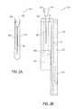
- FIG. 2Ashows a swab storage example 212
- FIGS. 2B-2Cshow a side elevation view and a front elevation view of a sample cartridge example 215 according to an embodiment of the disclosure
- the swab storage 212includes a case 203 , a seal cap 202 and a swab 205 .
- the seal cap 202 and the swab 205are attached together.
- the swab storage 212includes an identifier, such as a barcode label 204 that can be attached to the case 203 , an RFID tag 201 that can be implanted in the seal cap 202 , and the like.
- the swab 205Before taking DNA sample, the swab 205 is safely stored in the case 203 to avoid contamination. After taking DNA sample, the swab 205 can be placed in the sample cartridge 215 .
- the sample cartridge 215can include a microfluidic chip 211 , a sample acceptor 207 and a reagent carrier 206 .
- the sample acceptor 207includes a plurality of separated wells 207 A- 207 D for taking swabs. Each well includes a liquid phase mixture 214 that is sealed by a membrane 208 at a bottom portion of the well.
- the liquid phase mixture 214can conduct enzymatic digestion of all proteins and other cellular interferences, with the exception of DNA, and thus can perform DNA extraction and purification when a swab with DNA sample is inserted in the liquid phase mixture 214 .
- sample cartridge 215is described in the context of swabs, it should be understood that the sample cartridge 215 can be suitably adjusted to suit other DNA gathering methods, such as blood stain cards, airborne samples, fingerprints samples, and the like.
- the seal cap 202is a stepped seal cap that can seal the well in a first step, and a second step.
- the seal cap 202seals the well in the first step, the swab 205 does not puncture the membrane 208 , and can be safely sealed in the well to maintain sample integrity.
- the seal cap 202seals the well in the second step, the swab 205 punctures the membrane 208 and is immersed in the liquid phase mixture 214 .
- the reagent carrier 206houses various solutions for DNA analysis.
- the reagent carrierhouses reagents for multiplexed STR amplification.
- the reagent carrierhouses a coating solution, such as poly-N-hydroxyethylacrylamide, and the like. The coating solution can be used to coat micro channel walls prior to the separation.
- the reagent carrierhouses a dilution solution, such as water, formamide, and the like. The dilution solution can be used to reduce the ionic strength in order to promote better electro-kinetic injection.
- the reagent carrierhouses an internal lane standard (ILS). The ILS can be used for size measurement.
- the reagent carrieralso houses a polymer solution for electrophoretic separation in the micro-scale chip environment.
- a new disposable cartridge 215is taken from a storage package, and installed in a DNA analyzer, such as the DNA analyzer 100 . Then, a swab 205 can be used to take a DNA sample. The swab 205 is then identified and inserted into one of the wells 207 A- 207 D and sealed in the first step. Additional swabs 205 can be used to take DNA samples, and then identified and inserted into the un-used wells 207 A- 207 D.
- the DNA analyzer 100can include a mechanism that can push the seal caps 202 to seal the wells 207 A- 207 D in the second step, thus the swabs 205 can puncture the membrane 208 , and immerse in the liquid phase mixture 214 .
- FIG. 3shows a schematic diagram of a microfluidic chip example 311 according to an embodiment of the disclosure.
- the microfluidic chip 311includes various micro structures, such as inlets 312 - 314 , reaction reservoirs 315 - 316 , channels 317 a - 317 b , electrode reservoirs 318 , outlets (not shown), and the like, that are integrated for single-chip DNA analysis. It is noted that the various micro structures can be designed and integrated to suit for various DNA analyses, such as STR typing, sequencing, and the like. Further, while in the embodiment shown in FIG. 3 , reagents and solutions are introduced to the microfluidic chip 311 from an external supply, it should be understood that storing such reagents and solutions on or in the microfluidic chip 311 is envisioned.
- the inlets 312 - 314can be coupled to a pressure module to inject solutions in the microfluidic chip 311 . As described above, the connection can be made via a micro-macro interface.
- the inlet 312is for injecting a template DNA solution from a well of the sample acceptor 207
- the inlet 313is for injecting PCR reagents from the reagent carrier 206 .
- the inlet 313can be used for injecting dilution solution and ILS from the reagent carrier 206 .
- the reaction reservoirs 315 - 316are configured for various purposes.
- the reaction reservoir 315is configured for the PCR amplification
- the reaction reservoir 316is configured for the post-PCR processes, such as dilution, and the like.
- the reaction reservoir 315is located in a first domain 311 a , which is a thermal control domain.
- the temperature within the thermal control domain 311 acan be precisely controlled.
- an infrared heating unitdirects heat to the thermal control domain 311 a
- a cooling fandisperses heat from the thermal control domain 311 a
- an infrared sensing unitmeasures a temperature in the thermal control domain 311 a .
- the infrared heating unit and the cooling fancan be controlled based on the temperature measured by the infrared sensing unit.
- the infrared heating unit, the cooling fan, and the infrared sensing unitcan perform thermal control without contacting the thermal control domain 311 a.
- the temperature in the thermal control domain 311 ais measured by a thermal coupling technique.
- the microfluidic chip 311includes a thermal-coupler reservoir 319 within the first domain 311 a .
- the solution temperature within the thermal-coupler reservoir 319can be measured by any suitable technique. Based on the measured solution temperature within the thermal-coupler reservoir 319 , the solution temperature within the reaction reservoir 315 can be determined. Then, the infrared heating unit and the cooling fan can be controlled based on the temperature measured by the thermal coupling technique in order to control the solution temperature in the reaction reservoir 315 .
- the PCR mixtureis fluidically directed from the reaction reservoir 315 to a post-PCR clean-up/dilution domain, such as the reaction reservoir 316 .
- the reaction reservoir 316the PCR mixture is diluted.
- the PCR mixture and a dilutant solutionare mixed together according to a ratio from 1:5 to 1:20 (1 part of PCR mixture to 5-20 parts of dilutant).
- ILScan be added in the reaction reservoir 316 to mix with the PCR mixture.
- the channels 317 a - 317 bare located in a second domain 311 b . Electric fields can be suitably applied onto the channels 317 a - 317 b .
- the channels 317 a - 317 bare configured according to a cross-T design, having a short channel 317 a and a long channel 317 b.
- the electrode reservoirs 318can be used to apply suitable electric fields over the short channel 317 a and the long channel 317 b .
- the short channel 317 ais configured for electro-kinetic injection
- the long channel 317 bis configured for electrophoretic separation.
- DNA fragmentscan be injected from the reaction reservoir 316 into the short channel 317 a at the intersection of the short channel 317 a and the long channel 317 b .
- the long channel 317 bcan be filed with sieving matrix.
- the injected DNA fragmentscan migrate in the long channel 317 b to the positive side of the electric field induced by the high voltage, in the presence of the sieving matrix.
- the length of the long channel 317 bis about 8.8 cm with detection at about 8 cm from the intersection.
- the microfluidic chip 311can include other structures to assist DNA analysis.
- the microfluidic chip 311includes an alignment mark 321 .
- the alignment mark 321can assist a detection module to align to the long channel 317 b.
- the inlet 312can input a template DNA into the reaction reservoir 315 , and the inlet 313 can input PCR reagents into the reaction reservoir 315 . Then, thermal-cycling can be induced at the first domain 311 a , and PCR amplification can be conducted in the reaction reservoir 315 to amplify DNA fragments based on the template DNA and the PCR reagents. After the PCR amplification, the DNA amplicons in the reaction reservoir 315 can be mobilized into the reaction reservoir 316 in a liquid flow. In the reaction reservoir 316 , a dilution solution and ILS can be input to mix with the DNA fragments.
- the DNA fragments in the reaction reservoir 316can be injected across the short channel 317 a by electro-kinetic injection.
- the DNA fragmentsthen migrate in the long channel 317 b under the force of electric field applied over the long channel 317 b .
- the speed of migrationdepends on the sizes of the DNA amplicons, in the presence of the sieving matrix.
- the DNA fragmentsare separated in the long channel 317 b according to their sizes.
- FIG. 4shows an exemplary DNA analyzer 400 according to an embodiment of the disclosure.
- the DNA analyzer 400is packaged in a box.
- the boxincludes handles, wheels and the like, to facilitate transportation of the DNA analyzer 400 .
- the total weight of the DNA analyzer 400is less than 70 lb, and is appropriate for two persons to carry.
- the DNA analyzer 400is implemented in a modular manner.
- Each modulecan be individually packaged, and can include an interface for inter-module couplings. Thus, each module can be easily removed and replaced.
- the modular designcan facilitate assembly, troubleshooting, repair, and the like.
- the DNA analyzer 400includes a user module (UM) 410 , an active pressure module (APM) 430 , a detection module 450 , a power module (PM) 460 , a computing module 470 , and a controller module (CM) 480 .
- the DNA analyzer 400includes a sample cartridge storage 415 and a swab storage 412 .
- the UM 410includes a holder to hold a sample cartridge, such as the sample cartridge 215 , at an appropriate position when the sample cartridge is inserted by a user. Further, the UM 410 includes interface components to couple the sample cartridge 215 with, for example, the APM 430 , the detection module 450 , and the like.
- the UM 410includes thermal components, such as resistance heaters 421 , a cooling fan 422 , an infrared heating unit 423 , and the like. The thermal components can be suitably positioned corresponding to the sample cartridge 215 . For example, a resistance heater 421 is situated at a position that can effectively control a temperature of the liquid phase mixture within the plurality of separated wells on the sample cartridge 215 .
- the temperaturecan be determined to optimize enzyme activities of the liquid phase mixture to conduct enzymatic digestion of all proteins and other cellular interferences, with the exception of DNA.
- Another resistance heater 421is at a position that can effectively control a temperature of the separation channel on the microfluidic chip 211 .
- the infrared heating unitis at a position that can direct heat to the thermal control domain of the microfluidic chip 211 on the sample cartridge 215 .
- the cooling fanis at a position that can effectively disperse heat from the thermal control domain.
- the UM 410includes a high voltage module that can apply suitable high voltages via the electrode reservoirs of the microfluidic chip 211 .
- the UM 410can include other suitable components.
- the UM 410includes a magnetic module that can suitably apply magnetic control over a domain of the microfluidic chip 211 .
- the APM 430includes suitably components, such as pumps, vacuums, and the like, to apply suitable pressures to the microfluidic chip 211 to enable fluid movement.
- the PM 460receives an input main power, and generates various operation powers, such as 6 V, 12 V, 24 V, 1000V, 2000V, and the like, for various components of the DNA analyzer 400 .
- the detection module 450can include a laser module (LM) 451 , a passive optics module (POM) 452 , and an active optics module (AOM) 453 .
- the LM 451can include any suitable device to emit a laser beam.
- the LM 451includes an argon-ion laser.
- the LM 451includes a diode laser.
- the LM 451includes a solid state laser, such as a Coherent Sapphire optically pumped semiconductor laser.
- the solid state lasercan have a reduced size and weight, and can consume less power than the argon-ion laser.
- the solid state lasergenerates less waste heat, such that fan size can be reduced to reduce footprint of the DNA analyzer 400 .
- the AOM 453includes optical elements that may need to be adjusted with regard to each inserted microfluidic chip.
- the AOM 453includes motion control module to align the optical elements to one separation channel on the microfluidic chip. Further, in an example, the motion control module can align the optical elements based on detection results.
- the DNA analyzer 400performs an optical calibration procedure after an microfluidic chip is inserted in the DNA analyzer 400 . During the optical calibration procedure, a specific dye is sent to a separation channel. Then, the motion control module adjusts the AOM 453 to maximize a detection signal.
- the POM 452includes various optical elements, such as lens, splitters, photo-detectors, and the like, that do not need to be adjusted with regard to each inserted microfluidic chip.
- the POM 452is calibrated and adjusted with regard to the LM 451 and the AOM 453 when the detection module 450 is assembled. Then, the optical elements within the POM 452 are situated at relatively fixed positions, and generally do not need to be adjusted with regard to each inserted microfluidic chip.
- the LM 451 , the POM 452 , and the AOM 453are optically coupled via optical fibers.
- an optical fibertransmits a light beam emitted by the LM 451 to the AOM 453
- a plurality of optical fiberstransmit the fluorescence light beam collected by the AOM 453 to the POM 452 .
- Using optical fibersimproves layout flexibility.
- the controller module 480is coupled to the various components of the DNA analyzer 400 to provide control signals for DNA analysis.
- the controller module 480includes a control procedure that determines sequences and timings of the control signals.
- the computing module 470is implemented as a personal computer.
- the personal computerincludes a processor, a memory storing suitable software, a keyboard, a display, and a communication interface.
- the computing module 470can provide a user interface to ease user control and monitor of the DNA analysis by the DNA analyzer 400 .
- the DNA analyzer 400can be suitably modified.
- multiple modulesmay be used to perform the functions of one module in the FIG. 4 .
- a modulemay be removed if it is not needed anymore.
- functions of multiple modules in the FIG. 4may be combined and performed by a different module.
- FIG. 5shows a flow chart outlining a process example for using a DNA analyzer, such as the DNA analyzer 400 , to perform DNA analysis according to an embodiment of the disclosure.
- the processstarts at S 501 , and proceeds to S 510 .
- a user of the DNA analyzer 400plugs in a main power supply.
- the main power supplycan be a 110 V, 50 Hz, AC power supply, or can be a 220V, 60 Hz, AC power supply.
- the power module 460can convert the main power supply to a plurality of operation powers, and provide the plurality of operation powers to the various modules of the DNA analyzer 400 . Then, the process proceeds to S 515 .
- the userstarts up a user control interface.
- the userturns on the personal computer 470 , and starts a software package that interacts with the user and the controller module 480 .
- the software packageenables the personal computer 470 to provide a user control interface on the display. Further, the software package enables the personal computer 470 to receive user instructions via the keyboard or mouse.
- the software packagescan also enable the personal computer 470 to communicate with the controller module 480 . Then, the process proceeds to S 520 .
- the userinstructs the DNA analyzer 400 to initialize.
- the user control interfacereceives the initialization instruction, and the software package enables the personal computer 470 to send the initialization instruction to the controller module 480 .
- the controller module 480can then initialize the various components of the DNA analyzer 400 .
- the controller module 480can power on the various components, check the status and reset the status if needed. Then, the process proceeds to S 525 .
- the userinserts a sample cartridge 215 in the UM 410 .
- the sample cartridge 215can be positioned by a holder.
- the interface componentscan suitably couple the sample cartridge 215 to other components of the DNA analyzer 400 . Then, the process proceeds to S 530 .
- the usertakes a swab 205 , and lets the DNA analyzer 400 to identify the swab 205 .
- the DNA analyzer 400includes a barcode reader that can read the barcode label 204 attached to the case 203 for storing the swab 205 .
- the DNA analyzer 400excites the RFID 201 implanted in the seal cap 202 of the swab 205 to obtain a unique serial number of the swab 205 . Then, the process proceeds to S 535 .
- the useruses the swab 205 to take a DNA sample and inserts the swab 205 into a well of the sample cartridge 215 .
- the usermay repeat the steps S 530 and S 535 to insert multiple swabs 205 into the separated wells of the sample cartridge 215 .
- the processproceeds to S 540 .
- the userinstructs the DNA analyzer 400 to start a DNA analysis.
- the user control interfacereceives the start instruction, and the software package enables the personal computer 470 to send the start instruction to the controller module 480 .
- the controller module 480can start a control procedure corresponding to the DNA analysis.
- the controller module 480starts an STR typing procedure corresponding to a multiplexed STR typing analysis.
- the controller module 480starts a sequencing procedure corresponding to DNA sequencing analysis.
- control procedureincludes an optical calibration step that suitably aligns the optical elements the DNA analyzer 400 , such as the AOM 453 , and the like, to a suitable detection zone, such as a separation channel on a microfluidic chip of the sample cartridge 215 . Then, the process proceeds to S 545 .
- the userwaits and monitors the status of the DNA analysis.
- the control procedurecan specify sequences and timings of control signals to various components of the DNA analyzer 400 corresponding to the DNA analysis.
- the controller module 480automatically sends the control signals according to the sequences and the timings specified in the control procedure.
- the controller module 480receives status and feedback signals from the various components, and sends them to the personal computer 470 .
- the personal computer 470then provides the analysis status for the user to monitor. Then, the process proceeds to S 550 .
- the controller module 480finishes executing the control procedure, and sends an analysis-completed status to the personal computer 470 .
- the personal computer 470can inform the user of the analysis-completed status via the user control interface. Then, the process proceeds to S 555 .
- the userperforms post data processing.
- the usercan store the raw data of the DNA analysis, or transmit the raw data to a remote receiver.
- the usermay start a software package for post data processing.
- the software package for post data processingcan be suitably integrated with the control procedure.
- the software package for post data processingis executed automatically to perform post data processing. The process then proceeds to S 599 and terminates.
- the usermay throw away the sample cartridge and repeat S 520 -S 550 .
- the sequence of the DNA analysis stepscan be suitably adjusted.
- S 535 and S 530can be swapped, thus a swab can be first used to take a DNA sample, and then identified by the DNA analyzer 400 .
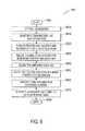
- FIG. 6shows a flow chart outlining a process example 600 for a DNA analyzer to perform multiplexed STR typing according to an embodiment of the disclosure. The process starts at S 601 and proceeds to S 605 .
- the DNA analyzerperforms optical calibration.
- the AOM 453includes a motion control module coupled with the optical elements. After a new sample cartridge 215 is installed in the DAN analyzer, the motion control module aligns the optical elements to a separation channel on a microfluidic chip within the sample cartridge 215 .
- a specific dye that does not interfere the fluorescent labelsis used.
- the fluorescent labelsemit fluorescence in the wavelength range of 530 nm to 650 nm, and the specific dye emits light of about 700 ⁇ m wavelength.
- the dyeis sent to the separation channel, the detection module 450 is activated to detect the light intensity.
- the motion control moduleis configured to position the optical elements to maximize the detected light intensity.
- the motion control moduleis configured to position the optical elements, such that the detected light intensity is larger than a threshold.
- the controller module 480controls the resistance heater 421 to maintain a temperature for template DNA extraction and purification. More specifically, the resistance heater 421 is positioned corresponding to the plurality of wells on the sample cartridge 215 .
- a wellcan accept a swab 205 .
- the swab 205can puncture the membrane that seals the liquid phase mixture at the bottom of the well, thus the swab 205 is immersed into the liquid phase mixture.
- the liquid phase mixturecan extract and purify a template DNA from the swab at the temperature according to enzymatic DNA isolation method.
- the liquid phase mixturecan achieve a compatible DNA concentration and purity to silica based solid phase extraction method in about 6 minutes. Then, the process proceeds to S 620 .
- the controller module 480controls the APM 430 to flow the extracted template DNA and reagents to a reaction reservoir for the PCR amplification.
- the reagent carrier 206houses reagents for multiplexed STR amplification.
- the controller module 480sends control signals to the APM 430 .
- a pumppumps the liquid phase mixture from the well to the reaction reservoir, and another pump pumps the reagents from the reagent carrier 206 to the reaction reservoir. Then, the process proceeds to S 630 .
- the controller module 480controls the cooling fan 422 and the infrared heating unit 423 to induce thermal cycling in the reaction reservoir for the multiplexed STR amplification.
- the reagentscan attach fluorescent labels to the DNA amplicons during the STR amplification process. The process then proceeds to S 640 .
- the solutioncan be diluted. More specifically, the controller module 480 sends control signals to the APM 430 after the PCR amplification. In response to the control signals, the APM 430 flows the DNA amplicons into a dilution reservoir. In addition, the APM 430 flows a dilution solution from the reagent carrier into the dilution reservoir. The process then proceeds to S 650 .
- the controller module 480sends control signals to the high voltage module in the UM 410 to inject the DNA amplicons across the injection aim (the short channel 317 a ). Then, the process proceeds to S 660 .
- the controller module 480sends control signals to the high voltage module in the UM 410 to apply appropriate high voltage over the separation channel (the long channel 317 b ) to separate the DNA amplicons based on sizes. The process then proceeds to S 670 .
- the controller module 480sends control signals to the detection module 450 to excite the fluorescent labels to emit fluorescence and detect the emitted fluorescence.
- the raw detection datacan be sent to the personal computer 470 for storage and post-processing. The process then proceeds to S 699 , and terminates.
- step S 660 and the step S 670can be executed in parallel.
- the controller module 480sends control signals to both the high voltage module in the UM 410 and the detection module 450 at about the same time.
- the control signals to the high voltage module in the UM 410cause the electrophoretic separation in the separation channel, while the control signals to the detection module 450 cause fluorescence detection.
- the optical calibration step S 605can be executed any time before the DNA amplicons are injected into the separation channel.
- process 600can be suitably adjusted along with reagents adjustments for other DNA analysis, such as qPCR DNA quantitation, sequencing, and the like.
- step S 601 to S 630are executed, and step S 640 to S 670 can be deleted.
- the controller module 480sends control signals to the detection module 450 to detect fluorescence emitted by the fluorescent labels in the qPCR reservoir.
- a magnetic solid phase purification process stepcan be suitably added into the process 600 to facilitate further volume reduction, thus the process 600 can be adjusted for DNA sequencing.
- FIG. 7shows a block diagram of an exemplary detection module 750 coupled with an exemplary sample cartridge 715 having a microfluidic chip 711 according to an embodiment of the disclosure.
- the detection module 750can be suitably installed in a DNA analyzer, such as the DNA analyzer 100 , or the DNA analyzer 400 . Further, the detection module 750 can be coupled with other components, such as a processor 771 .
- the processor 771processes signals received from the detection module 750 and provides processed signals to the detection module 750 .
- the detection module 750includes a light source module 751 , an active optics module 753 , and a detector 790 . These elements are coupled together using optical fibers 761 and 766 as shown in FIG. 7 .
- the microfluidic chip 711includes generally identical or equivalent components as the exemplary microfluidic chip 311 .
- the microfluidic chip 711includes a first domain configured for PCR amplification and a second domain having a separation channel configured for electrophoretic separation.
- the microfluidic chip 711includes one or more separation channel configured for electrophoretic separation, and the microfluidic chip 711 does not necessarily include the first domain.
- the detection module 750is optically coupled to the microfluidic chip 711 .
- the microfluidic chip 711includes a separation channel configured for electrophoretic separation of DNA fragments.
- the DNA fragmentsmigrate in the separation channel based on their sizes.
- the DNA fragmentscan be suitably tagged with fluorescent labels.
- the fluorescent labelscan be optically detected by the detection module 750 . Based on the detected fluorescent labels, DNA analyses, such as identification, sequencing, and the like, can be suitably performed.
- the detection module 750directs a light beam to a location of the separation channel along the migration direction of the DNA fragments.
- the light beamcan excite the fluorescent labels attached to the DNA fragments to emit fluorescence when the DNA fragments migrate through the location.
- the detection module 750collects the emitted fluorescence and detects properties of the fluorescence, such as intensity, wavelength, timing, and the like. The detected properties can be suitably stored and analyzed.
- the light source module 751can include any suitable light emitting device, such as an argon-ion laser device, a solid state laser, a laser diode (LD), and the like, to generate the light beam.
- the light source module 751includes a Coherent Sapphire optically pumped semiconductor laser (OPSL) that outputs a laser beam of 488 nm wavelength, and has an output power of 200 mW.
- OPSCoherent Sapphire optically pumped semiconductor laser
- the light source module 751provides the laser beam to the active optics module 753 via the input optical fiber 761 .
- the light source module 751includes an LD that emits light in a wavelength range, such as in the wavelength range of 472 nm to 495 nm. Further, the light source module 751 includes a collimating lens (not shown), a filter (not shown), and a coupling lens (not shown). The collimating lens collimates the emitted light from the LD. Then, the filter, such as a low pass filter, blocks a portion of the spectra that overlaps with fluorescent labels in use. Further, the coupling lens couples the filtered light to the input optical fiber 761 . The input optical fiber 761 provides an input light beam to the active optics module 753
- the input optical fiber 761 and the light beam transmitted by the input optical fiber 761are suitably configured to keep a relatively small numerical aperture.
- the input optical fiber 761 and the light beam transmittedare configured to keep the numerical aperture smaller than 0.1, such that the input light beam is at a center of the active optics module 753 to minimize aberration.
- the active optics module 753includes optical elements that may need to be adjusted for each sample cartridge 715 .
- the active optics module 753includes an optic assembly that includes a set of optic elements 780 and a motion control module 756 coupled to the set of optic elements 780 to move all or a portion of the modular component.
- the set of optic elements 780is configured to receive the input light beam from the input optical fiber 761 , and suitably directs the input light beam to the separation channel on the microfluidic chip 711 .
- the set of optic elements 780is also configured to collect fluorescence emitted by the fluorescent labels into an output light beam, and transmit the output light beam to the detector 790 via the output optical fibers 766 .
- the motion control module 756can adjust the set of optic elements 780 to align the set of optic elements 780 to the separation channel on the microfluidic chip 711 .
- the motion control module 756receives signals from the processor 771 to move the set of optic elements 780 .
- the set of optic elements 780 , the detector 790 , the processor 771 and the motion control module 756form a loop during an optical calibration to align the set of optic elements 780 to the separation channel.
- a specific dyesuch as a dye emitting light about 700 ⁇ m wavelength can be sent to a detection zone of the separation channel.
- the 700 ⁇ m wavelengthis much larger than the fluorescent labels wavelength range (e.g., 530 nm to 650 nm), thus the dye does not interfere the fluorescent labels.
- the set of optic elements 780directs the input light beam to the separation channel to stimulate the dye to emit light, and collects the resultant light emitted by the dye.
- the set of optic elementssends the emitted light to the detector 790 via the output optical fibers 766 .
- the detector 790generates electrical signals corresponding to the light intensity of the emitted light.
- the processor 771then signals the motion control module 756 to position the set of optic elements 780 to maximize the amount of emitted light that the set of optic elements 780 receives.
- a portion of the set of optic elements 780has adjustable features.
- an objective lens of the set of optic elements 780has adjustable focus.
- the objective lensis adjusted based on signals from the processor 771 to focus the input light beam onto the separation channel on the microfluidic chip 711 .
- the detector 790is configured to detect light properties of the output light beam, such as wavelength components, intensities corresponding to the wavelength components, and the like.
- the detector 790includes various optical elements (not shown) configured to cause spectral dispersion to spatially separate the wavelength components in the output light beam.
- the detector 790includes an array of photo detection units to detect the spatially separated wavelength components.
- the optical elementsinclude a dispersive element, such as a grating element, to cause spectral dispersion
- the detector 790includes a charge coupled device (CCD) system to detect light intensities at different locations.
- CCDcharge coupled device
- the light source module 751 , and the detector 790are situated at substantially fixed positions.
- the optical elements within the detector 790are pre-calibrated and fixed at their calibrated positions by the manufacture. Then, the optical elements are situated at their calibrated positions, and do not need to be adjusted for every sample cartridge 715 .
- the detection module 750can be implemented in a modular manner.
- Each of the light source module 751 , the detector 790 and the active optics module 753can be individually handled, such as manufactured, purchased, tested, and calibrated. Further, the light source module 751 , the detector 790 and the active optics module 753 can be suitably coupled together using the input optical fiber 761 and the output optical fibers 766 , and assembled in a DNA analyzer. During operation, when a new sample cartridge 715 is installed in the DNA analyzer, the active optics module 753 is calibrated with regard to a microfluidic chip 711 on the sample cartridge 715 . The light source module 751 and the detector 790 do not need to be adjusted for every sample cartridge 715 .
- the DNA analyzercan start an optical calibration procedure to calibrate the detection module 750 with regard to a microfluidic chip 711 on the sample cartridge 715 .
- the motion control module 756aligns the set of optic elements 780 to a separation channel on the microfluidic chip 711 .
- a specific dyeis sent into the separation channel to assist the alignment.
- the microfluidic chip 711includes an alignment mark to assist the set of optic elements 780 to align to a desired location along the separation channel.
- the DNA analyzerstarts a control procedure to control the various components of the DNA analyzer to act on the microfluidic chip 711 in order to perform an integrated single-chip DNA analysis.
- template DNAcan be suitably extracted and fluidically directed to the first domain of the microfluidic chip 711 ; a PCR amplification can be suitably induced in the first domain of the microfluidic chip 711 to amplify DNA fragments; then the amplified DNA fragments are suitably injected into the separation channel of the microfluidic chip 711 ; and then electrophoretic separation can be suitably induced in the separation channel.
- the detection module 750can be controlled to direct an input light beam to the separation channel to excite fluorescent labels used to tag the DNA fragments.
- the fluorescent labelsemit fluorescence.
- the detection module 750collects the fluorescence into an output light beam, and detects fluorescence information in the output light beam.
- the detected fluorescence informationcan be suitably stored, and further processed by the DNA analyzer, or can be transmitted to other device for further processing.
- FIG. 8shows an exemplary block diagram of a set of optic elements 880 according to an embodiment of the disclosure.
- the set of optic elements 880includes a first lens 881 , a second lens 882 , a pinhole 883 , a third lens 884 , a dichroic mirror 885 , a short pass filter 886 , a fourth lens 887 and a fifth lens 888 configured in a confocal optical system.
- the second lens 882 , the pinhole 883 and the third lens 884form a spatial filter.
- the set of optic elements 880are assembled together into an optic assembly.
- the optic assemblyincludes interfaces for coupling optical fibers with the set of optic elements 880 .
- FIG. 8shows an exemplary block diagram of a set of optic elements 880 according to an embodiment of the disclosure.
- the set of optic elements 880includes a first lens 881 , a second lens 882 , a pinhole 883 , a third lens 884 , a dichroic mirror
- the optic assemblyincludes a connector 889 A for coupling output optical fibers 866 , and a connector 889 B for coupling an input optical fiber 861 .
- the exemplary connector 889 Aaccepts seven optical fibers, arranges one optical fiber in the center, and arranges the other six optical fibers around the center optical fiber to form a hexagon shape.
- the connector 889 Baccepts one optical fiber. It should be understood that the connector 889 B can include more than one optical fiber, and the connector 889 A can include other numbers of optical fibers, and can arrange the optical fibers in various different shape.
- the set of optic elements 880forms an input optical path (illuminating path) and an output optical path (detecting path).
- the input optical pathincludes the input optical fiber 861 , the fourth lens 887 , the short pass filter 886 , the dichroic mirror 885 , the third lens 884 , the pinhole 883 , the second lens 882 , and the first lens 881 .
- the output optical pathincludes the first lens 881 , the second lens 882 , the pinhole 883 , the third lens 884 , the dichroic mirror 885 , and the fifth lens 888 .
- the input optical fiber 861emits the input light beam into the set of optic elements 880 .
- the fourth lens 887forms the input light beam into a substantially collimated light beam.
- the short pass filter 886reduces fluorescence components in the collimated input light beam.
- the input optical fiber 861generates auto-fluorescence.
- the auto-fluorescenceis a relatively large portion of noise to the whole system.
- the short pass filter 886reduces the auto-fluorescence in the collimated input light beam to improve signal to noise ratio.
- the dichroic mirror 885is configured to allow the filtered collimated input light beam to pass. Then, the third lens 881 forms the filtered collimated light beam into a narrowing conical input beam that is focused to pass the pinhole 883 .
- the conical input beampasses the second lens 882 and the first lens 881 .
- the second lens 882collimates the conical input light beam
- the first lens 881focuses the input light beam onto a detection zone of the separation channel.
- the fluorescence labels attached on the DNA fragmentsabsorb the input light beam, and emit fluorescence.
- the first lens 881collects the fluorescence emitted from the fluorescence labels, and forms collimated output light beam. Then, the second lens 882 forms the collimated output light beam into a narrowing conical output beam that is focused to pass the pinhole 883 .
- the spatial filter formed by the second lens 882 , the pinhole 883 and the third lens 884rejects scattered light from surrounding surfaces into the microfluidic chip. Then, third lens 884 collimates the conical output light beam.
- the dichroic mirror 885reflects the collimated output light beam to direct the output light beam to the fifth lens 888 .
- the fifth lens 888focuses the output light beam to the output optical fibers 866 connected on the connector 889 A.
- the input optical path and the output optical pathdo not completely overlap due to the dichroic mirror 885 .
- different optical elementscan be used on the input optical path and the output optical path to suit for different needs of the two optical paths.
- This configurationprovides flexibility, and different optics can be added on the two optical paths to improve performance.
- the short pass filter 886is used on the input optical path to reduce auto-fluorescence generated by input optical fiber 861 .
- FIG. 9shows a block diagram of another set of optic elements example 980 according to an exemplary embodiment of the disclosure.
- the set of optic elements 980includes a first lens 981 , a second lens 982 , a pinhole 983 , a third lens 984 , and a fourth lens 987 configured in a confocal optical system.
- the second lens 982 , the pinhole 983 and the third lens 984form a spatial filter.
- the set of optic elements 980includes a connector 989 for coupling both an input optical fiber 961 and output optical fibers 966 .
- the connector 989is configured to arranges the input optical fiber 961 in the center, and arranges six output optical fibers 966 around the center optical fiber to form a hexagon shape.
- the set of optic elements 980forms an input optical path (illuminating path) and an output optical path (detecting path) using the same optics.
- the input optical pathfollows the input optical fiber 961 , the fourth lens 987 , the third lens 984 , the pinhole 983 , the second lens 982 , and the first lens 981 .
- the output optical pathfollows the first lens 981 , the second lens 982 , the pinhole 983 , the third lens 984 , and the fourth lens 987 .
- the input optical fiber 961emits the input light beam into the set of optic elements 980 .
- the input optical fiber 961 and the light transmitted in the input optical fiber 961are configured to have a relatively small numerical aperture, such as smaller than 0.1.
- the input light emitted by the input optical fiber 961keeps in the center of the optics in the set of optic elements 980 to reduce aberration.
- the fourth lens 987forms the input light beam into a substantially collimated light beam. Then, the third lens 981 forms the filtered collimated light beam into a narrowing conical input beam that is focused to pass the pinhole 983 .
- the conical input beampasses the second lens 982 and the first lens 981 .
- the second lens 982collimates the conical input beam
- the first lens 981focuses the input light beam onto a detection zone of the separation channel.
- the fluorescence labels attached to the DNA fragmentsabsorb the input light beam, and emit fluorescence.
- the first lens 981collects the fluorescence emitted from the fluorescence labels, and forms collimated output light beam. It is noted that the fluorescence labels may emit the fluorescence in all directions.
- the first lens 981has a relatively large numerical aperture, such as greater than 0.5 to collect a relatively large portion of the fluorescence.
- the second lens 982forms the collimated output light beam into a narrowing conical output light beam that is focused to pass the pinhole 983 .
- the spatial filter formed by the second lens 982 , the pinhole 983 and the third lens 984rejects scattered light from surrounding surfaces.
- third lens 984collimates the conical output light beam.
- the fourth lens 987focuses the output light beam to the optical fibers 966 and 961 attached to the connector 989 .
- the fourth lens 987can be suitably configured that a relatively larger portion of the output light beam, such as more than 50% of the output light beam, can be aberrated onto the output optical fibers 966 .
- FIG. 10shows a block diagram of a detector example 1090 according to an exemplary embodiment of the disclosure.
- the detector 1090includes first lenses 1092 , a dispersive element 1093 , second lenses 1094 , and a CCD system 1098 . Further, the detector 1090 includes a connector 1091 configured to couple optical fibers 1066 with the detector 1090 .
- the optical fibers 1066include two ends. Each end is attached to a suitable connector.
- one end of the optical fibers 1066is attached to the connector 1091 and the other end of the optical fibers 1066 is attached to a connector 1089 .
- the connector 1089 and the connector 1091are in different configurations.
- the optical fibers 1066are in the form of a bundle of seven optical fibers.
- the connector 1089arranges one optical fiber in the center, and arranges the other six optical fibers around the center optical fiber to form a hexagon shape.
- the connector 1091stacks the seven optical fibers vertically to form a vertical slit.
- the optical fibers 1066transmit a light beam having the collected fluorescence from the connector 1089 to the connector 1091 .
- the optical fibers 1066emit the light beam in the form of a vertical line.
- the first lenses 1092collectively collimate the light beam.
- the dispersive element 1093is a grating element that has a large number of closely spaced vertical slits constituting a grating.
- the dispersive element 1093causes spectral dispersion to spatially spread the fluorescence components by wavelengths. It is noted that, for ease of illustration, the spectral dispersion onto a detection surface of the CCD system 1098 is shown in the horizontal direction.
- the second lenses 1094collectively focus the spread fluorescence components onto the CCD system 1098 at different horizontal locations.
- the CCD system 1098includes an array of photo sensitive devices configured to detect light intensities at the different horizontal locations. The light intensities, and the location information can be used to identify fluorescence labels, and identify DNA fragments.
- FIG. 11shows a schematic diagram of a multiple-sample microfluidic chip example 1100 according to an embodiment of the disclosure.
- the multiple-sample microfluidic chip 1100can be used to simultaneously perform DNA analysis for multiple samples. Similar to the microfluidic chip 311 in FIG.
- the multiple-sample microfluidic chip 1100includes various micro structures, such as inlets 1121 - 1124 , reaction reservoirs 1152 , 1162 and 1172 , connection channels 1151 , 1161 , 1171 , 1181 , 1153 , 1163 and 1173 , injection channels 1154 , 1164 , 1174 and 1184 , separation channels 1155 , 1165 , 1175 and 1185 (separation channel-A to separation channel-D), electrode reservoirs 1131 - 1140 , waste reservoirs 1124 and 1125 , and the like.
- These micro structurescan be similarly configured as their corresponding micro structures in FIG. 3 and can operate similarly as their corresponding micro structures in FIG. 3 .
- the multiple-sample microfluidic chip 1100includes a first domain 1111 a , and a second domain 1111 b .
- the first domain 1111 ais a thermal control domain, and the temperature within the first domain 1111 a can be controlled in a similar manner as the thermal control domain 311 a.
- the first domain 1111 acan include multiple reaction reservoirs that are respectively designated to multiple samples to perform simultaneous PCR amplification for the multiple samples.
- the reaction reservoirs 1152 , 1162 and 1172are located within the first domain 1111 a .
- the reaction reservoir 1152includes a first liquid mixture of a first template DNA extracted from a first sample and first reagents
- the reaction reservoir 1162includes a second liquid mixture of a second template DNA extracted from a second sample and second reagents
- the reaction reservoir 1172includes a third liquid mixture of a third template DNA extracted from a third sample and third reagents.
- thermal cyclesare generated within the first domain 1111 a , for example, by an infrared light source and a cooling fan, PCR amplifications can be simultaneously performed in the reaction reservoirs 1152 , 1162 and 1172 .
- the first domain 1111 aincludes a thermal coupler reservoir (not shown) for measuring a temperature within the first domain 1111 a .
- the temperature measurementis performed by an infrared sensing unit.
- the second domain 1111 bincludes multiple separation units that are respectively designated to multiple samples.
- each separation unitincludes a separation channel and an injection channel coupled together.
- the separation unitincludes electrode reservoirs that are in association with the injection channel and the separation channel to provide electric fields for electro-kinetic injection and electrophoretic separation. It is noted that separation units may share electrode reservoirs.
- the second domain 1111 bincludes four separation units.
- the first separation unitincludes the injection channel 1154 and the separation channel 1155 .
- the second separation unitincludes the injection channel 1164 and the separation channel 1165 .
- the third separation unitincludes the injection channel 1174 and the separation channel 1175 .
- the fourth separation unitincludes the injection channel 1184 and the separation channel 1185 .
- the multiple-sample microfluidic chip 1100can include other domains, such as post-PCR clean-up/dilution domain, and the like.
- a domaincan be configured to be a multi-purpose domain.
- the first domain 1111 acan be suitably configured for purification and/or post-PCR processing.
- the reaction reservoirs 1152 , 1162 and 1172can also be purification reservoirs and/or post-PCR reservoirs.
- the electrode reservoirs 1131 , 1133 and 1136are suitably configured for diluting PCR mixtures.
- the electrode reservoir 1131dilutes a first PCR mixture received from the reaction reservoir 1152 with a first dilutant, and prepares the first PCR mixture for electrophoretic separation in the separation channel 1155 .
- the electrode reservoir 1133dilutes a second PCR mixture received from the reaction reservoir 1162 with a second dilutant, and prepares the second PCR mixture for electrophoretic separation in the separation channel 1165 .
- the electrode reservoir 1136dilutes a third PCR mixture received from the reaction reservoir 1172 with a third dilutant, and prepares the third PCR mixture for electrophoretic separation in the separation channel 1175 .
- respective dilution ratiosare used in the electrode reservoirs 1131 , 1133 and 1136 .
- the dilution ratiosare from 1:5 to 1:20 (one part of PCR mixture to 5-20 parts of dilutant).
- the multiple-sample microfluidic chip 1100includes four processing units.
- the first processing unitincludes the inlets 1121 , the connection channel 1151 , the reaction reservoir 1152 , the connection channel 1153 , the injection channel 1154 , and the separation channel 1155 .
- the second processing unitincludes the inlets 1122 , the connection channel 1161 , the reaction reservoir 1162 , the connection channel 1163 , the injection channel 1164 , and the separation channel 1165 .
- the third processing unitincludes the inlets 1123 , the connection channel 1171 , the reaction reservoir 1172 , the connection channel 1173 , the injection channel 1174 , and the separation channel 1175 .
- the fourth processing unitincludes the inlet 1124 , the connection channel 1181 , the injection channel 1184 , and the separation channel 1185 .
- the micro structures of a processing unitcan be fluidically coupled together to enable liquid flow.
- the inlets 1121are suitably coupled to a pump module.
- the pump modulecan input the first template DNA and the first reagents into the reaction reservoir 1152 via the connection channel 1151 by a pressure force.
- PCR amplificationis performed based on the first template DNA and the first reagents.
- the DNA ampliconsflow through the connection channel 1153 by a pressure force.
- the DNA ampliconsare injected into the separation channel 1155 via the injection channel 1154 by an electro-kinetic force. Then, electrophoretic separation can be performed in the separation channel 1155 .
- the multiple processing unitscan be configured to fluidically separated from each other on the same multiple-sample microfluidic chip 1100 .
- the multiple processing unitscan be respectively used to perform DNA analysis for multiple samples using a single microfluidic chip.
- the processing unitscan be suitably configured to include branches.
- the branchescan be suitably enabled or disabled.
- the reaction reservoir 1152is also coupled to a connection channel 1156 directing to the waste reservoir 1124 .
- the connection channel 1153has a higher resistance than the connection channel 1156 , for example, by having a smaller cross-section area than the connection channel 1156 .
- the connection channel 1156includes a valve 1157 . When the valve 1157 is closed, the connection channel 1156 is closed, then liquid can be forced to the higher resistance connection channel 1153 . When the valve 1157 is open, liquid can flow through the connection channel 1156 to the waste reservoir 1124 .
- each of the first, second and third processing unitsincludes a reaction reservoir in the first domain 1111 a .
- corresponding connection channelssuch as the connection channels 1153 , 1163 and 1173 , are suitably routed, such as zigzagged, to have substantially the same length.
- the fourth processing unitdoes not include a reaction reservoir in the first domain 1111 a .
- the fourth processing unitcan be used to perform DNA analysis for a sample that does not need PCR amplification, or the PCR amplification for the sample is suitably performed previously.
- a multiple-sample microfluidic chipcan include multiple first domains, and/or second domains.
- a multiple-sample microfluidic chipmay suitably include four sets of the schematic diagram in FIG. 11 . Then, the multiple-sample microfluidic chip can be used to simultaneously perform DNA analysis for twelve samples, or can be used to simultaneously perform electrophoretic separation for sixteen samples.
- a multiple-sample microfluidic chipcan be configured to repeat the structure in a single sample microfluidic chip, such as the microfluidic chip 311 .
- the repeated structuresmay be coupled together, or may be independent of each other.
- two structuresare thermally coupled together.
- the PCR reaction reservoirs of the two structuresare thermally coupled together.
- two structuresare fluidically coupled together.
- the two structuresshare a same inlet.
- the repeated structuresare independent of each other.
- the PCR reaction reservoirs of the repeated structuresare thermally isolated, thus thermal cycles can be independently induced for the PCR reaction reservoirs.
- a DNA analyzercan be suitably configured for multiple-sample DNA analysis.
- a thermal module of the DNA analyzerhas a capability to generate thermal cycles within multiple first domains on a multiple-sample microfluidic chip, and the thermal module can be suitably configured to suit a multiple-sample microfluidic chip in use.
- a thermal module of the DNA analyzerincludes a halogen light bulb to direct heat to a first domain, such as the first domain 1111 a , including multiple thermally coupled reaction reservoirs for PCR amplification.
- a thermal module of the DNA analyzerincludes multiple heat sources that can independently direct heat to thermally isolated reaction reservoirs.
- a detection module of the DNA analyzerhas a capability to detect fluorescence from sixteen separation channels. The detection module can be suitably configured to suit a multiple-sample microfluidic chip in use.
- FIG. 12shows a block diagram of an exemplary detection module 1250 coupled with an exemplary sample cartridge 1215 having a microfluidic chip 1200 according to an embodiment of the disclosure.
- the detection module 1250can be suitably installed in a DNA analyzer, such as the DNA analyzer 100 , or the DNA analyzer 400 . Further, the detection module 1250 can be coupled with other components, such as a processor 1271 .
- the detection module 1250includes a light source module 1251 , an active optics module 1253 , and a detector 1290 . These elements are coupled together using optical fibers.
- the microfluidic chip 1200includes multiple separation channels, for example, separation channel-A to separation channel-D.
- the multiple separation channelscan be configured to perform, in parallel, electrophoretic separation of multiple DNA samples.
- the microfluidic chip 1200is configured identically or equivalently to the microfluidic chip 1100 to simultaneously perform integrated DNA analysis for multiple samples; the description of these components has been provided above and will be omitted here for clarity purposes.
- the microfluidic chip 1200includes the multiple separation channels and other suitable structures to merely perform electrophoretic separation of multiple DNA samples.
- the detection module 1250utilizes certain components that are identical or equivalent to those used in the detection module 750 ; the description of these components has been provided above and will be omitted here for clarity purposes.
- the active optics module 1253includes multiple optic assemblies, and each optic assembly includes a set of optic elements and a motion control module.
- a first optic assemblyincludes a set of optical elements 1280 -A and a motion control module 1256 -A; a second optic assembly includes a set of optical elements 1280 -B and a motion control module 1256 -B; a third optic assembly includes a set of optical elements 1280 -C and a motion control module 1256 -C; and a fourth optic assembly includes a set of optical elements 1280 -D and a motion control module 1256 -D.
- the light source module 1251can include any suitably light emitting device, such as an argon-ion laser device, a solid state laser, a laser diode (LD), and the like, to provide light beams to the multiple optic assemblies.
- the light source module 1251includes a laser module, such as a Coherent Sapphire optically pumped semiconductor laser (OPSL) outputting a laser beam of 488 nm wavelength.
- the light source module 1251includes a splitter configured to split the laser beam into multiple laser beams. The multiple laser beams are respectively provided to the multiple optic assemblies via the input optical fiber-A to input optical fiber-D.
- the light source module 1251includes multiple sets of LDs coupled with suitable optic elements to generate the multiple input light beams.
- the multiple light beamsare respectively provided to the multiple optic assemblies via the input optical fiber-A to input optical fiber-D.
- Each optic assembly in FIG. 12utilizes certain components that are identical or equivalent to those used in the optic assembly in FIG. 7 ; the description of these components has been provided above and will be omitted here for clarity purposes.
- Each optic assemblyreceives an input light beam from the light source module 1251 via an input optical fiber, and provides an output light beam to the detector 1290 via a group of output optical fibers.
- the detector 1290utilizes certain components that are identical or equivalent to those used in the detector 1090 ; the description of these components has been provided above and will be omitted here for clarity purposes.
- the connector 1291stacks all the output optical fibers in the four groups of output optical fibers vertically with space between groups to form a broken vertical slit.
- the connector 1291stacks optical fibers within a group together vertically as the connector 1091 , and stacks the four groups vertically with space between groups.
- each section in the broken vertical slitcorresponds to an output light beam collected from a separation channel.
- the dispersive element 1293is a grating element that has a large number of closely spaced vertical slits constituting a grating.
- the dispersive element 1293causes spectral dispersion to spatially spread fluorescence components in the broken vertical slit by wavelengths. It is noted that, for ease of illustration, the spectral dispersion onto a detection surface of the CCD system 1298 is shown in the horizontal direction. The spread fluorescence components are imaged onto the CCD system 1298 at different horizontal locations.
- the CCD system 1298includes an array of photo sensitive devices configured to detect light intensities at the different horizontal locations and vertical regions.
- the vertical region informationcan be used to identical separation channels, and the light intensities, and the horizontal location information can be used to identify fluorescence labels and to identify DNA fragments.
- the connector 1291may stack all the output optical fibers in the four groups of output optical fibers vertically in a line without any space between the groups.
Landscapes
- Health & Medical Sciences (AREA)
- Life Sciences & Earth Sciences (AREA)
- Chemical & Material Sciences (AREA)
- Pathology (AREA)
- General Physics & Mathematics (AREA)
- Immunology (AREA)
- Physics & Mathematics (AREA)
- Analytical Chemistry (AREA)
- Biochemistry (AREA)
- General Health & Medical Sciences (AREA)
- Molecular Biology (AREA)
- Nuclear Medicine, Radiotherapy & Molecular Imaging (AREA)
- Chemical Kinetics & Catalysis (AREA)
- Electrochemistry (AREA)
- Engineering & Computer Science (AREA)
- Biomedical Technology (AREA)
- Investigating, Analyzing Materials By Fluorescence Or Luminescence (AREA)
- Apparatus Associated With Microorganisms And Enzymes (AREA)
Abstract
Description
Claims (24)
Priority Applications (1)
| Application Number | Priority Date | Filing Date | Title |
|---|---|---|---|
| US13/273,947US8961764B2 (en) | 2010-10-15 | 2011-10-14 | Micro fluidic optic design |
Applications Claiming Priority (2)
| Application Number | Priority Date | Filing Date | Title |
|---|---|---|---|
| US39357410P | 2010-10-15 | 2010-10-15 | |
| US13/273,947US8961764B2 (en) | 2010-10-15 | 2011-10-14 | Micro fluidic optic design |
Publications (2)
| Publication Number | Publication Date |
|---|---|
| US20120090996A1 US20120090996A1 (en) | 2012-04-19 |
| US8961764B2true US8961764B2 (en) | 2015-02-24 |
Family
ID=44883417
Family Applications (1)
| Application Number | Title | Priority Date | Filing Date |
|---|---|---|---|
| US13/273,947Active2033-09-11US8961764B2 (en) | 2010-10-15 | 2011-10-14 | Micro fluidic optic design |
Country Status (6)
| Country | Link |
|---|---|
| US (1) | US8961764B2 (en) |
| AU (1) | AU2011315951B2 (en) |
| CA (1) | CA2814720C (en) |
| GB (1) | GB2497501A (en) |
| MX (1) | MX2013004184A (en) |
| WO (1) | WO2012051529A1 (en) |
Cited By (3)
| Publication number | Priority date | Publication date | Assignee | Title |
|---|---|---|---|---|
| US20130334407A1 (en)* | 2012-05-16 | 2013-12-19 | Cytonome/St, Llc | Large area, low f-number optical system |
| US10464065B2 (en) | 2009-02-03 | 2019-11-05 | Ande Corporation | Nucleic acid purification |
| US20230266271A1 (en)* | 2020-08-13 | 2023-08-24 | Hitachi High-Tech Corporation | Capillary electrophoresis device |
Families Citing this family (5)
| Publication number | Priority date | Publication date | Assignee | Title |
|---|---|---|---|---|
| US9322054B2 (en) | 2012-02-22 | 2016-04-26 | Lockheed Martin Corporation | Microfluidic cartridge |
| DE102014108143A1 (en)* | 2014-06-10 | 2015-12-10 | Kist Europe-Korea Institute of Science and Technologie Europe Forschungsgesellschaft mbh | An optical system for detecting fluorescent or luminescent signals of at least two samples |
| US9500588B2 (en) | 2014-09-30 | 2016-11-22 | Perkinelmer Health Sciences, Inc. | Flow cell modules and liquid sample analyzers and methods including same |
| US9581491B2 (en) | 2014-09-30 | 2017-02-28 | Perkinelmer Health Sciences, Inc. | Flow cell modules and liquid sample analyzers and methods including same |
| JP2024520470A (en) | 2021-05-27 | 2024-05-24 | ニコヤ ライフサイエンシーズ インコーポレイテッド | Microfluidic Systems, Apparatuses, and Cartridges Including Self-Aligning Optical Fiber Systems and Methods - Patent application |
Citations (503)
| Publication number | Priority date | Publication date | Assignee | Title |
|---|---|---|---|---|
| US2654387A (en) | 1952-03-19 | 1953-10-06 | American Cyanamid Co | Apparatus for controlling the flow of gases |
| US3357233A (en) | 1964-10-05 | 1967-12-12 | Phillips Petroleum Co | Fluid control system for analyzers |
| US3404869A (en) | 1966-07-18 | 1968-10-08 | Dow Chemical Co | Interfacial surface generator |
| US3459407A (en) | 1967-02-15 | 1969-08-05 | Austin Motor Co Ltd The | Devices for mixing liquids |
| US3799742A (en) | 1971-12-20 | 1974-03-26 | C Coleman | Miniaturized integrated analytical test container |
| US3857551A (en) | 1973-06-21 | 1974-12-31 | Nus Corp | Device to dampen fluctuations in the concentration of a substance in a flowing stream of fluid |
| US3918908A (en) | 1974-05-17 | 1975-11-11 | Geomet | Method for prothrombin testing |
| US3924989A (en) | 1972-10-25 | 1975-12-09 | Bayer Ag | Machine for producing moldings from chemical components which react quickly with one another |
| US3927868A (en) | 1974-05-28 | 1975-12-23 | Thomas B Moore | Static-type mixer, and receptacle and method of packaging utilizing same |
| US4088448A (en) | 1975-09-29 | 1978-05-09 | Lilja Jan Evert | Apparatus for sampling, mixing the sample with a reagent and making particularly optical analyses |
| US4390403A (en) | 1981-07-24 | 1983-06-28 | Batchelder J Samuel | Method and apparatus for dielectrophoretic manipulation of chemical species |
| US4443408A (en) | 1981-07-09 | 1984-04-17 | International Technidyne, Inc. | Apparatus for analyzing the influence of additive reagents upon the coagulation of blood |
| US4534659A (en) | 1984-01-27 | 1985-08-13 | Millipore Corporation | Passive fluid mixing system |
| US4554839A (en) | 1983-10-14 | 1985-11-26 | Cetus Corporation | Multiple trough vessel for automated liquid handling apparatus |
| US4675300A (en) | 1985-09-18 | 1987-06-23 | The Board Of Trustees Of The Leland Stanford Junior University | Laser-excitation fluorescence detection electrokinetic separation |
| US4680201A (en) | 1985-10-30 | 1987-07-14 | Stellan Hjerten | Coating for electrophoresis tube |
| US4729947A (en) | 1984-03-29 | 1988-03-08 | The Board Of Regents Of The University Of Nebraska | DNA sequencing |
| US4737464A (en) | 1985-09-26 | 1988-04-12 | Molecular Devices Corporation | Solid-state optical assay imaging apparatus |
| US4740708A (en) | 1987-01-06 | 1988-04-26 | International Business Machines Corporation | Semiconductor wafer surface inspection apparatus and method |
| US4756884A (en) | 1985-08-05 | 1988-07-12 | Biotrack, Inc. | Capillary flow device |
| US4790640A (en) | 1985-10-11 | 1988-12-13 | Nason Frederic L | Laboratory slide |
| US4849340A (en) | 1987-04-03 | 1989-07-18 | Cardiovascular Diagnostics, Inc. | Reaction system element and method for performing prothrombin time assay |
| EP0356160A2 (en) | 1988-08-24 | 1990-02-28 | The Board Of Trustees Of The Leland Stanford Junior University | Capillary device |
| US4908112A (en) | 1988-06-16 | 1990-03-13 | E. I. Du Pont De Nemours & Co. | Silicon semiconductor wafer for analyzing micronic biological samples |
| US4909919A (en) | 1988-11-22 | 1990-03-20 | The Regents Of The University Of Michigan | Velocity modulated capillary electrophoresis analysis system |
| US4952518A (en) | 1984-10-01 | 1990-08-28 | Cetus Corporation | Automated assay machine and assay tray |
| US4963498A (en) | 1985-08-05 | 1990-10-16 | Biotrack | Capillary flow device |
| US4978503A (en) | 1984-06-13 | 1990-12-18 | Ares-Serono Research & Development Limited Partnership | Devices for use in chemical test procedures |
| US5039617A (en) | 1989-04-20 | 1991-08-13 | Biotrack, Inc. | Capillary flow device and method for measuring activated partial thromboplastin time |
| US5073239A (en) | 1990-01-24 | 1991-12-17 | Bio-Rad Laboratories, Inc. | Fluid introduction into a capillary by electroendosmosis |
| US5077017A (en) | 1987-11-05 | 1991-12-31 | Biotrack, Inc. | Integrated serial dilution and mixing cartridge |
| US5089111A (en) | 1989-01-27 | 1992-02-18 | Bio-Rad Laboratories, Inc. | Electrophoretic sieving in gel-free media with dissolved polymers |
| US5092973A (en) | 1990-01-26 | 1992-03-03 | The Board Of Trustees Of The Leland Stanford Junior University | Rectangular capillaries for capillary electrophoresis |
| US5094793A (en) | 1990-12-21 | 1992-03-10 | The Dow Chemical Company | Methods and apparatus for generating interfacial surfaces |
| US5096807A (en) | 1985-03-06 | 1992-03-17 | Murex Corporation | Imaging immunoassay detection system with background compensation and its use |
| US5096554A (en) | 1989-08-07 | 1992-03-17 | Applied Biosystems, Inc. | Nucleic acid fractionation by counter-migration capillary electrophoresis |
| US5100627A (en) | 1989-11-30 | 1992-03-31 | The Regents Of The University Of California | Chamber for the optical manipulation of microscopic particles |
| US5108703A (en) | 1986-03-26 | 1992-04-28 | Beckman Instruments, Inc. | Automated multi-purpose analytical chemistry processing center and laboratory work station |
| US5110431A (en) | 1990-02-28 | 1992-05-05 | Applied Biosystems, Inc. | On-capillary gap junction for fluorescence detection in capillary electrophoresis |
| US5112460A (en) | 1986-10-21 | 1992-05-12 | Northeastern University | High performance microcapillary gel electrophoresis |
| US5122248A (en) | 1990-05-18 | 1992-06-16 | Northeastern University | Pulsed field capillary electrophoresis |
| US5126022A (en) | 1990-02-28 | 1992-06-30 | Soane Tecnologies, Inc. | Method and device for moving molecules by the application of a plurality of electrical fields |
| US5132012A (en) | 1988-06-24 | 1992-07-21 | Hitachi, Ltd. | Liquid chromatograph |
| US5140161A (en) | 1985-08-05 | 1992-08-18 | Biotrack | Capillary flow device |
| US5141621A (en) | 1990-01-26 | 1992-08-25 | The Board Of Trustees Of The Leland Stanford Junior University | Capillary electrophoresis injection device and method |
| US5144139A (en) | 1985-08-05 | 1992-09-01 | Biotrack, Inc. | Capillary flow device |
| US5147606A (en) | 1990-08-06 | 1992-09-15 | Miles Inc. | Self-metering fluid analysis device |
| US5154888A (en) | 1990-10-25 | 1992-10-13 | Eastman Kodak Company | Automatic sealing closure means for closing off a passage in a flexible cuvette |
| US5164598A (en) | 1985-08-05 | 1992-11-17 | Biotrack | Capillary flow device |
| US5165292A (en) | 1985-12-09 | 1992-11-24 | Ottosensors Corporation | Channel Device and tube connection and their fabrication procedures |
| US5171534A (en) | 1984-01-16 | 1992-12-15 | California Institute Of Technology | Automated DNA sequencing technique |
| US5171132A (en) | 1989-12-27 | 1992-12-15 | Seiko Epson Corporation | Two-valve thin plate micropump |
| US5180480A (en) | 1991-01-28 | 1993-01-19 | Ciba-Geigy Corporation | Apparatus for the preparation of samples, especially for analytical purposes |
| US5188963A (en) | 1989-11-17 | 1993-02-23 | Gene Tec Corporation | Device for processing biological specimens for analysis of nucleic acids |
| US5192405A (en) | 1991-01-11 | 1993-03-09 | Millipore Corporation | Process for effecting high efficiency separations by capillary electrophoresis |
| US5207880A (en) | 1984-03-29 | 1993-05-04 | The Board Of Regents Of The University Of Nebraska | DNA sequencing |
| US5223219A (en) | 1992-04-10 | 1993-06-29 | Biotrack, Inc. | Analytical cartridge and system for detecting analytes in liquid samples |
| US5225163A (en) | 1989-08-18 | 1993-07-06 | Angenics, Inc. | Reaction apparatus employing gravitational flow |
| US5229297A (en) | 1989-02-03 | 1993-07-20 | Eastman Kodak Company | Containment cuvette for PCR and method of use |
| US5230781A (en) | 1984-03-29 | 1993-07-27 | Li-Cor, Inc. | Sequencing near infrared and infrared fluorescence labeled DNA for detecting using laser diodes |
| US5242606A (en) | 1990-06-04 | 1993-09-07 | Abaxis, Incorporated | Sample metering port for analytical rotor having overflow chamber |
| US5250263A (en) | 1990-11-01 | 1993-10-05 | Ciba-Geigy Corporation | Apparatus for processing or preparing liquid samples for chemical analysis |
| US5253981A (en) | 1992-03-05 | 1993-10-19 | Frank Ji-Ann Fu Yang | Multichannel pump apparatus with microflow rate capability |
| US5268080A (en) | 1991-02-28 | 1993-12-07 | Hitachi, Ltd. | DNA detector and DNA detection method |
| US5271724A (en) | 1990-08-31 | 1993-12-21 | Westonbridge International Limited | Valve equipped with a position detector and a micropump incorporating said valve |
| US5274240A (en) | 1990-01-12 | 1993-12-28 | The Regents Of The University Of California | Capillary array confocal fluorescence scanner and method |
| US5278048A (en) | 1988-10-21 | 1994-01-11 | Molecular Devices Corporation | Methods for detecting the effect of cell affecting agents on living cells |
| US5277556A (en) | 1990-07-10 | 1994-01-11 | Westonbridge International Limited | Valve and micropump incorporating said valve |
| US5288463A (en) | 1992-10-23 | 1994-02-22 | Eastman Kodak Company | Positive flow control in an unvented container |
| US5290520A (en) | 1989-06-09 | 1994-03-01 | Ciba-Geigy Corporation | Analytic separation arrangement and method for the analysis of chemical samples |
| US5294323A (en) | 1993-05-26 | 1994-03-15 | Hitachi, Ltd. | Apparatus for gel electrophoresis |
| WO1994005414A1 (en) | 1992-08-31 | 1994-03-17 | The Regents Of The University Of California | Microfabricated reactor |
| US5296114A (en) | 1991-12-06 | 1994-03-22 | Ciba-Geigy Corporation | Electrophoretic separating device and electrophoretic separating method |
| US5296375A (en) | 1992-05-01 | 1994-03-22 | Trustees Of The University Of Pennsylvania | Mesoscale sperm handling devices |
| US5298134A (en) | 1988-08-24 | 1994-03-29 | Board Of Trustees Of The Leland Stanford Junior University | Capillary device |
| US5304487A (en) | 1992-05-01 | 1994-04-19 | Trustees Of The University Of Pennsylvania | Fluid handling in mesoscale analytical devices |
| US5314593A (en) | 1993-03-18 | 1994-05-24 | Hewlett-Packard Company | Capillary tube with reversible protein interaction and method |
| US5320139A (en) | 1993-03-30 | 1994-06-14 | Millipore Corporation | Fluid delivery system |
| US5320730A (en) | 1993-01-22 | 1994-06-14 | The Penn State Research Foundation | Capillary electrophoresis apparatus with improved electroosmotic flow control |
| US5322258A (en) | 1989-04-28 | 1994-06-21 | Messerschmitt-Bolkow-Blohm Gmbh | Micromechanical actuator |
| US5324401A (en) | 1993-02-05 | 1994-06-28 | Iowa State University Research Foundation, Inc. | Multiplexed fluorescence detector system for capillary electrophoresis |
| US5325170A (en) | 1990-05-31 | 1994-06-28 | Thermo Instrument Systems Inc. | Laser-based refractive index detector using backscatter |
| US5328578A (en) | 1993-06-15 | 1994-07-12 | Hewlett-Packard Company | Capillary electrophoresis with tracking separation field |
| US5338427A (en) | 1993-02-26 | 1994-08-16 | Biometric Imaging Inc. | Single use separation cartridge for a capillary electrophoresis instrument |
| US5346999A (en) | 1985-01-18 | 1994-09-13 | Applied Biosystems, Inc. | Method of nucleic acid extraction |
| US5360523A (en) | 1984-03-29 | 1994-11-01 | Li-Cor, Inc. | DNA sequencing |
| US5370782A (en) | 1992-05-29 | 1994-12-06 | Shimadzu Corporation | Electrophoretic apparatus |
| US5375979A (en) | 1992-06-19 | 1994-12-27 | Robert Bosch Gmbh | Thermal micropump with values formed from silicon plates |
| US5376252A (en) | 1990-05-10 | 1994-12-27 | Pharmacia Biosensor Ab | Microfluidic structure and process for its manufacture |
| US5384261A (en) | 1991-11-22 | 1995-01-24 | Affymax Technologies N.V. | Very large scale immobilized polymer synthesis using mechanically directed flow paths |
| US5395503A (en) | 1986-06-20 | 1995-03-07 | Molecular Devices Corporation | Zero volume electrochemical cell |
| US5410030A (en) | 1993-04-05 | 1995-04-25 | Molecular Probes, Inc. | Dimers of unsymmetrical cyanine dyes containing pyridinium moieties |
| US5429734A (en) | 1993-10-12 | 1995-07-04 | Massachusetts Institute Of Technology | Monolithic capillary electrophoretic device |
| US5441894A (en) | 1993-04-30 | 1995-08-15 | Abbott Laboratories | Device containing a light absorbing element for automated chemiluminescent immunoassays |
| US5445939A (en) | 1986-08-12 | 1995-08-29 | Anderson; Jeffrey E. | Method for assessment of the mononuclear leukocyte immune system |
| US5460709A (en) | 1993-06-21 | 1995-10-24 | Helena Laboratories Corporation | Automatic electrophoresis method and apparatus |
| US5478751A (en) | 1993-12-29 | 1995-12-26 | Abbott Laboratories | Self-venting immunodiagnositic devices and methods of performing assays |
| US5482608A (en) | 1993-01-19 | 1996-01-09 | Hewlett Packard Company | Capillary electrophoresis flow control system |
| US5486335A (en) | 1992-05-01 | 1996-01-23 | Trustees Of The University Of Pennsylvania | Analysis based on flow restriction |
| WO1996003206A1 (en) | 1994-07-25 | 1996-02-08 | E.I. Du Pont De Nemours And Company | Chemical mixing and reaction apparatus and processes for the preparation thereof |
| WO1996004547A1 (en) | 1994-08-01 | 1996-02-15 | Lockheed Martin Energy Systems, Inc. | Apparatus and method for performing microfluidic manipulations for chemical analysis and synthesis |
| US5495334A (en)* | 1990-07-26 | 1996-02-27 | Research Development Corporation Of Japan | Fourier transform spectroscope with quadrangular common path interferometer |
| US5496697A (en) | 1988-10-21 | 1996-03-05 | Molecular Devices Corporation | Methods and apparatus for detecting the effect of cell affecting agents on living cells |
| US5498392A (en) | 1992-05-01 | 1996-03-12 | Trustees Of The University Of Pennsylvania | Mesoscale polynucleotide amplification device and method |
| US5500187A (en) | 1992-12-08 | 1996-03-19 | Westinghouse Electric Corporation | Disposable optical agglutination assay device and method for use |
| WO1996012541A1 (en) | 1994-10-22 | 1996-05-02 | Central Research Laboratories Limited | Method and apparatus for diffusive transfer between immiscible fluids |
| DE19549052A1 (en) | 1994-12-28 | 1996-07-04 | Sumitomo Heavy Industries | Micro-machining of PTFE surfaces |
| US5540889A (en) | 1994-05-11 | 1996-07-30 | Whitehead Institute For Biomedical Research | Apparatus and method for a highly parallel pipetter |
| US5556790A (en) | 1994-12-05 | 1996-09-17 | Pettit; John W. | Method for Automated DNA sequencing |
| US5558998A (en) | 1992-02-25 | 1996-09-24 | The Regents Of The Univ. Of California | DNA fragment sizing and sorting by laser-induced fluorescence |
| US5560811A (en) | 1995-03-21 | 1996-10-01 | Seurat Analytical Systems Incorporated | Capillary electrophoresis apparatus and method |
| WO1996030113A1 (en) | 1995-03-30 | 1996-10-03 | Merck Patent Gmbh | Device for mixing small quantities of liquids |
| US5571410A (en) | 1994-10-19 | 1996-11-05 | Hewlett Packard Company | Fully integrated miniaturized planar liquid sample handling and analysis device |
| US5571680A (en) | 1994-01-21 | 1996-11-05 | Beckman Instruments, Inc. | Homogeneous immunoassays and enzyme based assays of analytes using capillary electrophoresis |
| US5573651A (en) | 1995-04-17 | 1996-11-12 | The Dow Chemical Company | Apparatus and method for flow injection analysis |
| US5585069A (en) | 1994-11-10 | 1996-12-17 | David Sarnoff Research Center, Inc. | Partitioned microelectronic and fluidic device array for clinical diagnostics and chemical synthesis |
| US5587128A (en) | 1992-05-01 | 1996-12-24 | The Trustees Of The University Of Pennsylvania | Mesoscale polynucleotide amplification devices |
| WO1997002357A1 (en) | 1995-06-29 | 1997-01-23 | Affymetrix, Inc. | Integrated nucleic acid diagnostic device |
| US5603351A (en) | 1995-06-07 | 1997-02-18 | David Sarnoff Research Center, Inc. | Method and system for inhibiting cross-contamination in fluids of combinatorial chemistry device |
| US5605262A (en) | 1995-06-01 | 1997-02-25 | Bond; James R. | Adjustable wrist band |
| US5605662A (en) | 1993-11-01 | 1997-02-25 | Nanogen, Inc. | Active programmable electronic devices for molecular biological analysis and diagnostics |
| WO1997012665A1 (en) | 1995-10-03 | 1997-04-10 | Danfoss A/S | Micro-mixer and mixing method |
| US5627643A (en) | 1992-04-07 | 1997-05-06 | Amersham Pharm Biotech Ab | Method and detector for separation processes |
| WO1997016239A1 (en) | 1995-10-28 | 1997-05-09 | Forschungszentrum Karlsruhe Gmbh | Static micromixer |
| US5632876A (en) | 1995-06-06 | 1997-05-27 | David Sarnoff Research Center, Inc. | Apparatus and methods for controlling fluid flow in microchannels |
| US5637458A (en) | 1994-07-20 | 1997-06-10 | Sios, Inc. | Apparatus and method for the detection and assay of organic molecules |
| US5637469A (en) | 1992-05-01 | 1997-06-10 | Trustees Of The University Of Pennsylvania | Methods and apparatus for the detection of an analyte utilizing mesoscale flow systems |
| US5645702A (en) | 1995-06-07 | 1997-07-08 | Hewlett-Packard Company | Low voltage miniaturized column analytical apparatus and method |
| US5650075A (en) | 1995-05-30 | 1997-07-22 | Motorola, Inc. | Method for etching photolithographically produced quartz crystal blanks for singulation |
| WO1997028894A1 (en) | 1996-02-07 | 1997-08-14 | Danfoss A/S | Micromixer |
| WO1997038300A1 (en) | 1996-04-04 | 1997-10-16 | Aclara Biosciences, Inc. | Acrylic microchannels and their use in electrophoretic applications |
| US5699157A (en) | 1996-07-16 | 1997-12-16 | Caliper Technologies Corp. | Fourier detection of species migrating in a microchannel |
| US5716825A (en) | 1995-11-01 | 1998-02-10 | Hewlett Packard Company | Integrated nucleic acid analysis system for MALDI-TOF MS |
| US5716852A (en) | 1996-03-29 | 1998-02-10 | University Of Washington | Microfabricated diffusion-based chemical sensor |
| US5726026A (en) | 1992-05-01 | 1998-03-10 | Trustees Of The University Of Pennsylvania | Mesoscale sample preparation device and systems for determination and processing of analytes |
| US5726404A (en) | 1996-05-31 | 1998-03-10 | University Of Washington | Valveless liquid microswitch |
| US5731212A (en) | 1994-12-20 | 1998-03-24 | International Technidyne Corporation | Test apparatus and method for testing cuvette accommodated samples |
| US5750015A (en) | 1990-02-28 | 1998-05-12 | Soane Biosciences | Method and device for moving molecules by the application of a plurality of electrical fields |
| US5770029A (en) | 1996-07-30 | 1998-06-23 | Soane Biosciences | Integrated electrophoretic microdevices |
| US5773298A (en) | 1994-03-31 | 1998-06-30 | Danfoss A/S | Successive samples analysis method and analysis apparatus |
| US5779868A (en) | 1996-06-28 | 1998-07-14 | Caliper Technologies Corporation | Electropipettor and compensation means for electrophoretic bias |
| US5780754A (en) | 1994-03-31 | 1998-07-14 | Danfoss A/S | Analysis method and analysis apparatus |
| US5783397A (en) | 1995-12-11 | 1998-07-21 | Northeastern University | Screening natural samples for new therapeutic compounds using capillary electrophoresis |
| US5788927A (en) | 1996-07-30 | 1998-08-04 | Bayer Corporation | Unified fluid circuit assembly for a clinical hematology instrument |
| US5800690A (en) | 1996-07-03 | 1998-09-01 | Caliper Technologies Corporation | Variable control of electroosmotic and/or electrophoretic forces within a fluid-containing structure via electrical forces |
| US5824204A (en) | 1996-06-27 | 1998-10-20 | Ic Sensors, Inc. | Micromachined capillary electrophoresis device |
| US5830681A (en) | 1989-11-06 | 1998-11-03 | Akzo Nobel N.V. | Immunoassays for and monoclonal antibodies to prothrombin activation peptide F1.2 |
| US5833926A (en) | 1994-10-24 | 1998-11-10 | Wita Gmbh | Analytical and dosing system |
| US5834314A (en) | 1994-11-07 | 1998-11-10 | Abbott Laboratories | Method and apparatus for metering a fluid |
| US5842787A (en) | 1997-10-09 | 1998-12-01 | Caliper Technologies Corporation | Microfluidic systems incorporating varied channel dimensions |
| WO1998054568A1 (en) | 1997-05-27 | 1998-12-03 | Perseptive Biosystems, Inc. | Improved separation columns and methods for manufacturing the improved separation columns |
| US5846396A (en) | 1994-11-10 | 1998-12-08 | Sarnoff Corporation | Liquid distribution system |
| US5849598A (en) | 1996-03-15 | 1998-12-15 | Washington University | Method for transferring micro quantities of liquid samples to discrete locations |
| US5858187A (en) | 1996-09-26 | 1999-01-12 | Lockheed Martin Energy Systems, Inc. | Apparatus and method for performing electrodynamic focusing on a microchip |
| US5863801A (en) | 1996-06-14 | 1999-01-26 | Sarnoff Corporation | Automated nucleic acid isolation |
| US5869004A (en) | 1997-06-09 | 1999-02-09 | Caliper Technologies Corp. | Methods and apparatus for in situ concentration and/or dilution of materials in microfluidic systems |
| US5872010A (en) | 1995-07-21 | 1999-02-16 | Northeastern University | Microscale fluid handling system |
| US5871628A (en) | 1996-08-22 | 1999-02-16 | The University Of Texas System | Automatic sequencer/genotyper having extended spectral response |
| WO1999009042A2 (en) | 1997-08-13 | 1999-02-25 | Cepheid | Microstructures for the manipulation of fluid samples |
| US5876675A (en) | 1997-08-05 | 1999-03-02 | Caliper Technologies Corp. | Microfluidic devices and systems |
| US5882465A (en) | 1997-06-18 | 1999-03-16 | Caliper Technologies Corp. | Method of manufacturing microfluidic devices |
| US5885470A (en) | 1997-04-14 | 1999-03-23 | Caliper Technologies Corporation | Controlled fluid transport in microfabricated polymeric substrates |
| EP0903638A1 (en) | 1997-09-19 | 1999-03-24 | MICROPARTS GESELLSCHAFT FÜR MIKROSTRUKTURTECHNIK mbH | Process for manufacturing microstructured bodies |
| US5900130A (en) | 1997-06-18 | 1999-05-04 | Alcara Biosciences, Inc. | Method for sample injection in microchannel device |
| US5919070A (en) | 1992-07-28 | 1999-07-06 | Philips Electronics North America Corporation | Vacuum microelectronic device and methodology for fabricating same |
| US5942443A (en) | 1996-06-28 | 1999-08-24 | Caliper Technologies Corporation | High throughput screening assay systems in microscale fluidic devices |
| US5945334A (en) | 1994-06-08 | 1999-08-31 | Affymetrix, Inc. | Apparatus for packaging a chip |
| US5948684A (en) | 1997-03-31 | 1999-09-07 | University Of Washington | Simultaneous analyte determination and reference balancing in reference T-sensor devices |
| US5948227A (en) | 1997-12-17 | 1999-09-07 | Caliper Technologies Corp. | Methods and systems for performing electrophoretic molecular separations |
| WO1999046591A2 (en) | 1998-03-10 | 1999-09-16 | Strategic Diagnostics, Inc. | Integrated assay device and methods of production and use |
| US5955028A (en) | 1996-08-02 | 1999-09-21 | Caliper Technologies Corp. | Analytical system and method |
| US5958203A (en) | 1996-06-28 | 1999-09-28 | Caliper Technologies Corportion | Electropipettor and compensation means for electrophoretic bias |
| US5959291A (en) | 1997-06-27 | 1999-09-28 | Caliper Technologies Corporation | Method and apparatus for measuring low power signals |
| US5958694A (en) | 1997-10-16 | 1999-09-28 | Caliper Technologies Corp. | Apparatus and methods for sequencing nucleic acids in microfluidic systems |
| US5969736A (en) | 1998-07-14 | 1999-10-19 | Hewlett-Packard Company | Passive pressure regulator for setting the pressure of a liquid to a predetermined pressure differential below a reference pressure |
| US5979868A (en) | 1998-04-30 | 1999-11-09 | Wu; Jean-Ton | High pressure hose coupling |
| US5985119A (en) | 1994-11-10 | 1999-11-16 | Sarnoff Corporation | Electrokinetic pumping |
| US5993634A (en) | 1995-05-09 | 1999-11-30 | Curagen Corporation | Apparatus and method for the generation, separation, detection, and recognition of biopolymer fragments |
| WO1999061894A1 (en) | 1998-05-25 | 1999-12-02 | Analyticon Ag Biotechnologie Pharmazie | Device for detecting substances in fluid phase |
| US5998217A (en) | 1994-07-11 | 1999-12-07 | Tekmar Company | Method of introducing standards into a vial |
| WO1999064620A2 (en) | 1998-06-10 | 1999-12-16 | Abbott Laboratories | Diagnostic assay requiring a small sample of biological fluid |
| US6012902A (en) | 1997-09-25 | 2000-01-11 | Caliper Technologies Corp. | Micropump |
| WO2000010015A1 (en) | 1998-08-10 | 2000-02-24 | Caliper Technologies Corp. | Improved high throughput microfluidic systems and methods |
| US6054277A (en) | 1996-05-08 | 2000-04-25 | Regents Of The University Of Minnesota | Integrated microchip genetic testing system |
| US6062261A (en) | 1998-12-16 | 2000-05-16 | Lockheed Martin Energy Research Corporation | MicrofluIdic circuit designs for performing electrokinetic manipulations that reduce the number of voltage sources and fluid reservoirs |
| US6086740A (en) | 1998-10-29 | 2000-07-11 | Caliper Technologies Corp. | Multiplexed microfluidic devices and systems |
| WO2000045172A1 (en) | 1999-01-28 | 2000-08-03 | Caliper Technologies Corp. | Devices, systems and methods for time domain multiplexing of reagents |
| US6110343A (en) | 1996-10-04 | 2000-08-29 | Lockheed Martin Energy Research Corporation | Material transport method and apparatus |
| US6117634A (en) | 1997-03-05 | 2000-09-12 | The Reagents Of The University Of Michigan | Nucleic acid sequencing and mapping |
| US6126804A (en) | 1997-09-23 | 2000-10-03 | The Regents Of The University Of California | Integrated polymerase chain reaction/electrophoresis instrument |
| US6132580A (en) | 1995-09-28 | 2000-10-17 | The Regents Of The University Of California | Miniature reaction chamber and devices incorporating same |
| US6134950A (en) | 1997-06-13 | 2000-10-24 | University Of Washington | Method for determining concentration of a laminar sample stream |
| US6143152A (en) | 1997-11-07 | 2000-11-07 | The Regents Of The University Of California | Microfabricated capillary array electrophoresis device and method |
| US6149787A (en) | 1998-10-14 | 2000-11-21 | Caliper Technologies Corp. | External material accession systems and methods |
| US6149815A (en) | 1999-11-23 | 2000-11-21 | Sauter; Andrew D. | Precise electrokinetic delivery of minute volumes of liquid(s) |
| US6153073A (en) | 1997-04-25 | 2000-11-28 | Caliper Technologies Corp. | Microfluidic devices incorporating improved channel geometries |
| US6168948B1 (en) | 1995-06-29 | 2001-01-02 | Affymetrix, Inc. | Miniaturized genetic analysis systems and methods |
| US6174675B1 (en) | 1997-11-25 | 2001-01-16 | Caliper Technologies Corp. | Electrical current for controlling fluid parameters in microchannels |
| US6176991B1 (en) | 1997-11-12 | 2001-01-23 | The Perkin-Elmer Corporation | Serpentine channel with self-correcting bends |
| WO2001006370A1 (en) | 1999-07-19 | 2001-01-25 | Tivo, Inc. | Self-test electronic assembly and test system |
| US6210882B1 (en) | 1998-01-29 | 2001-04-03 | Mayo Foundation For Medical Education And Reseach | Rapid thermocycling for sample analysis |
| US6235471B1 (en) | 1997-04-04 | 2001-05-22 | Caliper Technologies Corp. | Closed-loop biochemical analyzers |
| US6261431B1 (en) | 1998-12-28 | 2001-07-17 | Affymetrix, Inc. | Process for microfabrication of an integrated PCR-CE device and products produced by the same |
| US6266139B1 (en)* | 1996-04-23 | 2001-07-24 | Joachim Mannhardt | Capillary tube holder |
| US6267858B1 (en) | 1996-06-28 | 2001-07-31 | Caliper Technologies Corp. | High throughput screening assay systems in microscale fluidic devices |
| US6287850B1 (en) | 1995-06-07 | 2001-09-11 | Affymetrix, Inc. | Bioarray chip reaction apparatus and its manufacture |
| US6303343B1 (en) | 1999-04-06 | 2001-10-16 | Caliper Technologies Corp. | Inefficient fast PCR |
| US6306590B1 (en) | 1998-06-08 | 2001-10-23 | Caliper Technologies Corp. | Microfluidic matrix localization apparatus and methods |
| US6322683B1 (en) | 1999-04-14 | 2001-11-27 | Caliper Technologies Corp. | Alignment of multicomponent microfabricated structures |
| US20010046701A1 (en) | 2000-05-24 | 2001-11-29 | Schulte Thomas H. | Nucleic acid amplification and detection using microfluidic diffusion based structures |
| US20020012971A1 (en) | 2000-03-20 | 2002-01-31 | Mehta Tammy Burd | PCR compatible nucleic acid sieving medium |
| US6352838B1 (en) | 1999-04-07 | 2002-03-05 | The Regents Of The Universtiy Of California | Microfluidic DNA sample preparation method and device |
| US6358387B1 (en) | 2000-03-27 | 2002-03-19 | Caliper Technologies Corporation | Ultra high throughput microfluidic analytical systems and methods |
| US6366924B1 (en) | 1998-07-27 | 2002-04-02 | Caliper Technologies Corp. | Distributed database for analytical instruments |
| US6368871B1 (en) | 1997-08-13 | 2002-04-09 | Cepheid | Non-planar microstructures for manipulation of fluid samples |
| US6372484B1 (en) | 1999-01-25 | 2002-04-16 | E.I. Dupont De Nemours And Company | Apparatus for integrated polymerase chain reaction and capillary electrophoresis |
| US6379929B1 (en) | 1996-11-20 | 2002-04-30 | The Regents Of The University Of Michigan | Chip-based isothermal amplification devices and methods |
| US6387235B1 (en) | 1998-09-09 | 2002-05-14 | Hitachi, Ltd. | Apparatus for the separation and fractionation of differentially expressed gene fragments |
| WO2002038809A1 (en) | 2000-10-23 | 2002-05-16 | Ingeny Holding Bv | Method and apparatus for detecting a mutaiton in a nucleic acid fragment in a sample |
| US6395232B1 (en) | 1999-07-09 | 2002-05-28 | Orchid Biosciences, Inc. | Fluid delivery system for a microfluidic device using a pressure pulse |
| US20020068357A1 (en) | 1995-09-28 | 2002-06-06 | Mathies Richard A. | Miniaturized integrated nucleic acid processing and analysis device and method |
| US6408878B2 (en) | 1999-06-28 | 2002-06-25 | California Institute Of Technology | Microfabricated elastomeric valve and pump systems |
| US6420143B1 (en) | 1998-02-13 | 2002-07-16 | Caliper Technologies Corp. | Methods and systems for performing superheated reactions in microscale fluidic systems |
| US20020123050A1 (en) | 1999-10-06 | 2002-09-05 | Vladimir Poponin | Apparatus and method for analysis of nucleic acids hybridization on high density NA chips. |
| US20020127591A1 (en) | 2000-01-06 | 2002-09-12 | Caliper Technologies Corp. | Methods and systems for monitoring intracellular binding reactions |
| US6455682B1 (en) | 1999-01-20 | 2002-09-24 | Northwestern University | DNA mobility modifier |
| US6458259B1 (en) | 1999-05-11 | 2002-10-01 | Caliper Technologies Corp. | Prevention of surface adsorption in microchannels by application of electric current during pressure-induced flow |
| US6495363B2 (en) | 1998-08-18 | 2002-12-17 | Orchid Biosciences, Inc. | In-line complete spectral fluorescent imaging of nucleic acid molecules |
| US6495028B1 (en) | 1999-06-23 | 2002-12-17 | China Petroleum Corporation | Catalytic conversion process for producing isobutane and isoparaffin-enriched gasoline |
| US20030000835A1 (en) | 2001-06-28 | 2003-01-02 | Agilent Technologies, Inc. | Microfluidic system |
| US20030008308A1 (en) | 2001-04-06 | 2003-01-09 | California Institute Of Technology | Nucleic acid amplification utilizing microfluidic devices |
| US6506609B1 (en) | 1999-05-17 | 2003-01-14 | Caliper Technologies Corp. | Focusing of microparticles in microfluidic systems |
| US20030038248A1 (en) | 1999-05-12 | 2003-02-27 | Kevin Maher | Multiplexed fluorescent detection in microfluidic devices |
| US6534009B1 (en) | 2000-10-13 | 2003-03-18 | Industrial Technology Research Institute | Method and apparatus for frequency thermal control |
| US20030054384A1 (en) | 2000-01-11 | 2003-03-20 | Maxygen, Inc. | Integrated systems and methods for diversity generation and screening |
| US6544734B1 (en) | 1998-10-09 | 2003-04-08 | Cynthia G. Briscoe | Multilayered microfluidic DNA analysis system and method |
| US6558945B1 (en)* | 1999-03-08 | 2003-05-06 | Aclara Biosciences, Inc. | Method and device for rapid color detection |
| WO2003042410A1 (en) | 2001-11-10 | 2003-05-22 | Samsung Electronics Co., Ltd. | Apparatus for circulating carrier fluid |
| US6569382B1 (en) | 1991-11-07 | 2003-05-27 | Nanogen, Inc. | Methods apparatus for the electronic, homogeneous assembly and fabrication of devices |
| US20030104430A1 (en) | 1999-04-12 | 2003-06-05 | Nerenberg Michael I. | Amplification and separation of nucleic acid sequences using strand displacement amplification and bioelectronic microchip technology |
| US6576459B2 (en) | 2001-03-23 | 2003-06-10 | The Regents Of The University Of California | Sample preparation and detection device for infectious agents |
| US6592821B1 (en) | 1999-05-17 | 2003-07-15 | Caliper Technologies Corp. | Focusing of microparticles in microfluidic systems |
| US6597932B2 (en)* | 2000-02-18 | 2003-07-22 | Argose, Inc. | Generation of spatially-averaged excitation-emission map in heterogeneous tissue |
| US6602472B1 (en) | 1999-10-01 | 2003-08-05 | Agilent Technologies, Inc. | Coupling to microstructures for a laboratory microchip |
| US6632619B1 (en) | 1997-05-16 | 2003-10-14 | The Governors Of The University Of Alberta | Microfluidic system and methods of use |
| US6632655B1 (en) | 1999-02-23 | 2003-10-14 | Caliper Technologies Corp. | Manipulation of microparticles in microfluidic systems |
| US6642000B1 (en) | 1999-11-12 | 2003-11-04 | University Of Chicago | PCR amplification on microarrays of gel immobilized oligonucleotides |
| US6649358B1 (en) | 1999-06-01 | 2003-11-18 | Caliper Technologies Corp. | Microscale assays and microfluidic devices for transporter, gradient induced, and binding activities |
| US20030224436A1 (en) | 1996-07-30 | 2003-12-04 | Nelson Robert J. | Microfluidic apparatus and method for enriching and analyzing biological cells |
| US6670153B2 (en) | 2000-09-14 | 2003-12-30 | Caliper Technologies Corp. | Microfluidic devices and methods for performing temperature mediated reactions |
| US20040005582A1 (en) | 2000-08-10 | 2004-01-08 | Nanobiodynamics, Incorporated | Biospecific desorption microflow systems and methods for studying biospecific interactions and their modulators |
| US20040014117A1 (en) | 2002-06-20 | 2004-01-22 | Sention | Apparatus for polynucleotide detection and quantitation |
| US6681788B2 (en) | 2001-01-29 | 2004-01-27 | Caliper Technologies Corp. | Non-mechanical valves for fluidic systems |
| US20040018530A1 (en) | 2002-05-31 | 2004-01-29 | Bowser Michael T. | In vitro evolution of functional RNA and DNA using electrophoretic selection |
| US6685810B2 (en) | 2000-02-22 | 2004-02-03 | California Institute Of Technology | Development of a gel-free molecular sieve based on self-assembled nano-arrays |
| US20040043479A1 (en) | 2000-12-11 | 2004-03-04 | Briscoe Cynthia G. | Multilayerd microfluidic devices for analyte reactions |
| US6706519B1 (en) | 1999-06-22 | 2004-03-16 | Tecan Trading Ag | Devices and methods for the performance of miniaturized in vitro amplification assays |
| US6706473B1 (en) | 1996-12-06 | 2004-03-16 | Nanogen, Inc. | Systems and devices for photoelectrophoretic transport and hybridization of oligonucleotides |
| US6707548B2 (en) | 2001-02-08 | 2004-03-16 | Array Bioscience Corporation | Systems and methods for filter based spectrographic analysis |
| US20040053290A1 (en) | 2000-01-11 | 2004-03-18 | Terbrueggen Robert Henry | Devices and methods for biochip multiplexing |
| US20040081583A1 (en) | 2002-09-25 | 2004-04-29 | Agilent Technologies, Inc. | Fluid analyzer |
| US6744038B2 (en) | 2000-11-13 | 2004-06-01 | Genoptix, Inc. | Methods of separating particles using an optical gradient |
| US20040115794A1 (en) | 2002-12-12 | 2004-06-17 | Affymetrix, Inc. | Methods for detecting transcriptional factor binding sites |
| US20040131504A1 (en) | 2002-09-17 | 2004-07-08 | Landers James P. | Remote temperature sensing of small volume and related apparatus thereof |
| US6767706B2 (en) | 2000-06-05 | 2004-07-27 | California Institute Of Technology | Integrated active flux microfluidic devices and methods |
| US6778724B2 (en) | 2000-11-28 | 2004-08-17 | The Regents Of The University Of California | Optical switching and sorting of biological samples and microparticles transported in a micro-fluidic device, including integrated bio-chip devices |
| US6783647B2 (en) | 2001-10-19 | 2004-08-31 | Ut-Battelle, Llc | Microfluidic systems and methods of transport and lysis of cells and analysis of cell lysate |
| US6784420B2 (en) | 2000-11-13 | 2004-08-31 | Genoptix, Inc. | Method of separating particles using an optical gradient |
| US6800438B2 (en) | 2000-12-28 | 2004-10-05 | Xerox Corporation | Imager for DNA sequencer |
| US20040197788A1 (en) | 2001-05-14 | 2004-10-07 | Daniel Roy Mciver | Thermostable proteinases from thermophilic bacteria |
| US6811668B1 (en) | 1999-06-22 | 2004-11-02 | Caliper Life Sciences, Inc. | Apparatus for the operation of a microfluidic device |
| US6811977B2 (en) | 2000-07-27 | 2004-11-02 | California Institute Of Technology | Rapid, quantitative method for the mass spectrometric analysis of nucleic acids for gene expression and genotyping |
| US6815664B2 (en) | 2001-04-27 | 2004-11-09 | Genoptix, Inc. | Method for separation of particles |
| US6815671B2 (en) | 2000-06-09 | 2004-11-09 | The University Of Delaware | System and method for chemical analysis using laser ablation |
| US6814859B2 (en) | 2002-02-13 | 2004-11-09 | Nanostream, Inc. | Frit material and bonding method for microfluidic separation devices |
| US20040224325A1 (en) | 2002-12-20 | 2004-11-11 | Caliper Life Sciences, Inc. | Single molecule amplification and detection of DNA |
| US6821771B2 (en) | 2000-07-28 | 2004-11-23 | Genesystems | Device for thermo-dependent chain reaction amplification of target nucleic acid sequences, measured in real-time |
| US20040245445A1 (en) | 2003-05-30 | 2004-12-09 | Olympus Corporation | Laser microscope |
| US6833068B2 (en) | 2003-01-13 | 2004-12-21 | Sandia National Laboratories | Passive injection control for microfluidic systems |
| US6833542B2 (en) | 2000-11-13 | 2004-12-21 | Genoptix, Inc. | Method for sorting particles |
| US20040259100A1 (en) | 2003-06-20 | 2004-12-23 | Illumina, Inc. | Methods and compositions for whole genome amplification and genotyping |
| US6849411B2 (en) | 1997-04-04 | 2005-02-01 | Caliper Life Sciences, Inc. | Microfluidic sequencing methods |
| US6848462B2 (en) | 2001-12-06 | 2005-02-01 | Nanostream, Inc. | Adhesiveless microfluidic device fabrication |
| US20050032072A1 (en) | 2003-08-08 | 2005-02-10 | Perlegen Sciences, Inc. | Fragmentation and labelling with a programmable temperature control module |
| US20050042628A1 (en) | 1995-06-07 | 2005-02-24 | Affymetrix, Inc. | Methods for concurrently processing multiple biological chip assays |
| US20050053952A1 (en) | 2002-10-02 | 2005-03-10 | California Institute Of Technology | Microfluidic nucleic acid analysis |
| US20050053944A1 (en) | 1995-10-06 | 2005-03-10 | Perseptive Biosystems, Inc. | Methods and kit for hybridization anaylsis using peptide nucleic acid probes |
| US6866759B2 (en) | 2000-12-13 | 2005-03-15 | The Regents Of The University Of California | Stepped electrophoresis for movement and concentration of DNA |
| US6875403B2 (en) | 2001-02-09 | 2005-04-05 | Microchem Solutions | Method and apparatus for reproducible sample injection on microfabricated devices |
| US6878255B1 (en) | 1999-11-05 | 2005-04-12 | Arrowhead Center, Inc. | Microfluidic devices with thick-film electrochemical detection |
| US6884395B2 (en) | 2000-05-12 | 2005-04-26 | Gyros Ab | Integrated microfluidic disc |
| US6900021B1 (en) | 1997-05-16 | 2005-05-31 | The University Of Alberta | Microfluidic system and methods of use |
| US20050130213A1 (en) | 2003-12-10 | 2005-06-16 | Tom Morrison | Selective ligation and amplification assay |
| US6913697B2 (en) | 2001-02-14 | 2005-07-05 | Science & Technology Corporation @ Unm | Nanostructured separation and analysis devices for biological membranes |
| US6915679B2 (en) | 2000-02-23 | 2005-07-12 | Caliper Life Sciences, Inc. | Multi-reservoir pressure control system |
| US20050170362A1 (en) | 2003-04-14 | 2005-08-04 | Caliper Life Sciences, Inc. | Reduction of migration shift assay interference |
| US6929730B2 (en) | 2001-05-01 | 2005-08-16 | Cheng Sheng Lee | Two dimensional microfluidic gene scanner |
| US6939451B2 (en) | 2000-09-19 | 2005-09-06 | Aclara Biosciences, Inc. | Microfluidic chip having integrated electrodes |
| US20050196779A1 (en) | 2003-01-08 | 2005-09-08 | Ho Winston Z. | Self-contained microfluidic biochip and apparatus |
| US20050202504A1 (en) | 1995-06-29 | 2005-09-15 | Affymetrix, Inc. | Miniaturized genetic analysis systems and methods |
| US6951632B2 (en) | 2000-11-16 | 2005-10-04 | Fluidigm Corporation | Microfluidic devices for introducing and dispensing fluids from microfluidic systems |
| US6953676B1 (en) | 1992-05-01 | 2005-10-11 | Trustees Of The University Of Pennsylvania | Mesoscale polynucleotide amplification device and method |
| EP1584692A2 (en) | 2004-04-09 | 2005-10-12 | Taiyo Yuden Co., Ltd. | Method of nucleic acid analysis, nucleic acid analysis device and disk for nucleic acid analysis |
| WO2005094981A1 (en) | 2004-03-29 | 2005-10-13 | Agilent Technologies, Inc. | Cyclic pcr system |
| US6958119B2 (en) | 2002-02-26 | 2005-10-25 | Agilent Technologies, Inc. | Mobile phase gradient generation microfluidic device |
| US20050244933A1 (en) | 2004-04-28 | 2005-11-03 | International Business Machines Corporation | Method and apparatus for precise temperature cycling in chemical/biochemical processes |
| US20050250212A1 (en)* | 2004-05-07 | 2005-11-10 | Hormoz Azizian | FT-NIR fatty acid determination method |
| US6972173B2 (en) | 2002-03-14 | 2005-12-06 | Intel Corporation | Methods to increase nucleotide signals by raman scattering |
| US20050274618A1 (en)* | 2004-06-15 | 2005-12-15 | Gwo-Bin Lee | Assay chip |
| US20050287572A1 (en) | 2004-06-01 | 2005-12-29 | The Regents Of The University Of California | Microfabricated integrated DNA analysis system |
| US20050287661A1 (en) | 2002-10-08 | 2005-12-29 | James Landers | Methods and systems for multiplexing ir-mediated heating on a microchip |
| US20060019274A1 (en) | 2004-05-13 | 2006-01-26 | Anita Goel | Nano-PCR: methods and devices for nucleic acid amplification and detection |
| US6994826B1 (en) | 2000-09-26 | 2006-02-07 | Sandia National Laboratories | Method and apparatus for controlling cross contamination of microfluid channels |
| US7010391B2 (en) | 2001-03-28 | 2006-03-07 | Handylab, Inc. | Methods and systems for control of microfluidic devices |
| US7007710B2 (en) | 2003-04-21 | 2006-03-07 | Predicant Biosciences, Inc. | Microfluidic devices and methods |
| US20060057029A1 (en) | 1996-01-16 | 2006-03-16 | Affymetrix, Inc. | Analytical biochemistry system with robotically carried bioarray |
| US20060073484A1 (en) | 2002-12-30 | 2006-04-06 | Mathies Richard A | Methods and apparatus for pathogen detection and analysis |
| US7026414B1 (en) | 2001-12-06 | 2006-04-11 | Northwestern University | Methods for the preparation of monodisperse high polymers by mechanical degradation |
| US7037417B2 (en) | 2001-03-19 | 2006-05-02 | Ecole Polytechnique Federale De Lausanne | Mechanical control of fluids in micro-analytical devices |
| US7041481B2 (en) | 2003-03-14 | 2006-05-09 | The Regents Of The University Of California | Chemical amplification based on fluid partitioning |
| US7050208B2 (en) | 2001-11-28 | 2006-05-23 | Overbeck James W | Scanning microscopy, fluorescence detection, and laser beam positioning |
| US7049579B2 (en) | 2000-07-26 | 2006-05-23 | The Regents Of The University Of California | Manipulation of live cells and inorganic objects with optical micro beam arrays |
| US7056673B2 (en) | 2003-04-25 | 2006-06-06 | Janssen Pharmaceutica N.V. | Preservation of RNA in a biological sample |
| US7070681B2 (en) | 2001-01-24 | 2006-07-04 | The Board Of Trustees Of The Leland Stanford Junior University | Electrokinetic instability micromixer |
| US20060147905A1 (en) | 2001-11-26 | 2006-07-06 | Mirzabekov Andrei D | Method for the specific identification of orthopoxvirus with the aid of a miniature biological chip |
| US20060147912A1 (en) | 2002-05-30 | 2006-07-06 | Corbett John M | Dna amplification apparatus and method |
| US7081622B2 (en) | 2002-03-21 | 2006-07-25 | Cornell Research Foundation, Inc. | Electrospray emitter for microfluidic channel |
| US20060166243A1 (en) | 2001-09-24 | 2006-07-27 | Intel Corporation | Methods to increase nucleotide signals by raman scattering |
| US20060166223A1 (en) | 2005-01-26 | 2006-07-27 | Reed Michael W | DNA purification and analysis on nanoengineered surfaces |
| US20060177844A1 (en) | 2004-10-27 | 2006-08-10 | Cepheid | Closed-system multi-stage nucleic acid amplification reactions |
| US20060194306A1 (en) | 2003-08-25 | 2006-08-31 | Herr Amy E | System for gel electrophoretic immunoassay |
| US7105812B2 (en) | 2003-08-26 | 2006-09-12 | Predicant Biosciences, Inc. | Microfluidic chip with enhanced tip for stable electrospray ionization |
| US7111466B2 (en) | 2003-08-21 | 2006-09-26 | Yamaha Corporation | Microreactor and substance production method therewith |
| US20060228717A1 (en) | 2005-04-08 | 2006-10-12 | Joyce Timothy H | Microfluidic system and method of utilization |
| US20060246493A1 (en) | 2005-04-04 | 2006-11-02 | Caliper Life Sciences, Inc. | Method and apparatus for use in temperature controlled processing of microfluidic samples |
| US20060246501A1 (en) | 2004-09-09 | 2006-11-02 | Microfluidic Systems, Inc. | Apparatus and method of extracting and optically analyzing an analyte from a fluid-based sample |
| US20060260941A1 (en) | 2005-05-19 | 2006-11-23 | Eugene Tan | Ruggedized apparatus for analysis of nucleic acid and proteins |
| US7142738B2 (en) | 2002-10-01 | 2006-11-28 | National Cheng Kung University | Integrated analytical biochip and manufacturing method thereof |
| US7155344B1 (en) | 1998-07-27 | 2006-12-26 | Caliper Life Sciences, Inc. | Distributed database for analytical instruments |
| US7160423B2 (en) | 2002-03-05 | 2007-01-09 | Caliper Life Sciences, Inc. | Mixed mode microfluidic systems |
| US20070026421A1 (en) | 2000-11-16 | 2007-02-01 | Caliper Life Sciences, Inc. | Method and apparatus for generating thermal melting curves in a microfluidic device |
| US7179423B2 (en) | 2001-06-20 | 2007-02-20 | Cytonome, Inc. | Microfluidic system including a virtual wall fluid interface port for interfacing fluids with the microfluidic system |
| US20070042396A1 (en) | 2005-02-03 | 2007-02-22 | Jong-Myeon Park | Nucleic acid purification apparatus including photovoltaic device, microfluidic apparatus including the nucleic acid purification apparatus, and method of purifying nucleic acid using the nucleic acid purification apparatus |
| US7198701B2 (en) | 2000-11-29 | 2007-04-03 | Japan Science And Technology Corporation | Nucleic acid analyzing method |
| EP1769848A2 (en) | 2005-09-30 | 2007-04-04 | Yokogawa Electric Corporation | Chemical reaction cartridge and method of using same |
| US7211442B2 (en) | 2001-06-20 | 2007-05-01 | Cytonome, Inc. | Microfluidic system including a virtual wall fluid interface port for interfacing fluids with the microfluidic system |
| US7211184B2 (en) | 2004-08-04 | 2007-05-01 | Ast Management Inc. | Capillary electrophoresis devices |
| US20070099288A1 (en) | 2005-11-02 | 2007-05-03 | Affymetrix, Inc. | Microfluidic Methods, Devices, and Systems for Fluid Handling |
| US20070099211A1 (en) | 2005-07-15 | 2007-05-03 | Vissarion Aivazachvili | Detection of nucleic acid amplification |
| US7214299B2 (en) | 2000-06-23 | 2007-05-08 | Daniel Armstrong | Method for separation, identification and evaluation of microbes and cells |
| US7217542B2 (en) | 2002-10-31 | 2007-05-15 | Hewlett-Packard Development Company, L.P. | Microfluidic system for analyzing nucleic acids |
| US20070111303A1 (en) | 2005-09-01 | 2007-05-17 | Hiroshi Inoue | Method and molecular diagnostic device for detection, analysis and identification of genomic DNA |
| US20070117092A1 (en) | 2003-04-08 | 2007-05-24 | Daksh Sadarangani | Dna analysis system |
| US7231819B2 (en) | 2000-06-21 | 2007-06-19 | Schlumberger Technology Corporation | Chemical sensor for wellbore applications |
| US20070154895A1 (en) | 2005-12-30 | 2007-07-05 | Caliper Life Sciences, Inc. | Multi-assay microfluidic chips |
| US20070175768A1 (en) | 2005-06-30 | 2007-08-02 | Applera Corporation | Microfluidic systems including porous polymer electrodes |
| US20070184456A1 (en) | 1999-05-21 | 2007-08-09 | Illumina, Inc. | Use of microfluidic systems in the detection of target analytes using microsphere arrays |
| US7259965B2 (en) | 2005-04-07 | 2007-08-21 | Intel Corporation | Integrated circuit coolant microchannel assembly with targeted channel configuration |
| US20070196912A1 (en) | 2004-01-25 | 2007-08-23 | Fluidigm Corporation | Integrated chip carriers with thermocycler interfaces and methods of using the same |
| US7270786B2 (en) | 2001-03-28 | 2007-09-18 | Handylab, Inc. | Methods and systems for processing microfluidic samples of particle containing fluids |
| US20070231799A1 (en) | 2006-03-28 | 2007-10-04 | Canon U.S. Life Sciences, Inc. | Method and apparatus for applying continuous flow and uniform temperature to generate thermal melting curves in a microfluidic device |
| US20070238112A1 (en) | 1999-08-26 | 2007-10-11 | The Trustees Of Princeton University | Microfluidic and nanofluidic electronic devices for detecting changes in capacitance of fluids and methods of using |
| US20070243109A1 (en) | 2006-04-14 | 2007-10-18 | Industrial Technology Research Institute | Micro-scale heating module |
| US20070248958A1 (en) | 2004-09-15 | 2007-10-25 | Microchip Biotechnologies, Inc. | Microfluidic devices |
| US7297324B2 (en) | 2002-03-11 | 2007-11-20 | Battelle Memorial Institute | Microchannel reactors with temperature control |
| US20070292941A1 (en) | 2006-03-24 | 2007-12-20 | Handylab, Inc. | Integrated system for processing microfluidic samples, and method of using the same |
| US20070298429A1 (en) | 2006-06-14 | 2007-12-27 | Walter Gumbrecht | Process for determining the concentration of nucleic acids |
| US20080003588A1 (en) | 2006-06-30 | 2008-01-03 | Canon U.S. Life Sciences, Inc. | Real-time PCR in micro-channels |
| WO2008005248A2 (en) | 2006-06-30 | 2008-01-10 | Canon U.S. Life Sciences, Inc. | Real-time pcr in micro-channels |
| US20080014589A1 (en) | 2006-05-11 | 2008-01-17 | Link Darren R | Microfluidic devices and methods of use thereof |
| US20080014576A1 (en) | 2006-02-03 | 2008-01-17 | Microchip Biotechnologies, Inc. | Microfluidic devices |
| US7323140B2 (en) | 2001-03-28 | 2008-01-29 | Handylab, Inc. | Moving microdroplets in a microfluidic device |
| US20080038714A1 (en) | 2005-11-02 | 2008-02-14 | Affymetrix, Inc. | Instrument to Pneumatically Control Lab Cards and Method Thereof |
| US20080038713A1 (en) | 2005-11-02 | 2008-02-14 | Affymetrix, Inc. | System and Method for Biological Assay |
| US7344681B1 (en) | 2003-06-06 | 2008-03-18 | Sandia Corporation | Planar micromixer |
| US20080108122A1 (en) | 2006-09-01 | 2008-05-08 | State of Oregon acting by and through the State Board of Higher Education on behalf of Oregon | Microchemical nanofactories |
| US7371533B2 (en) | 2004-10-05 | 2008-05-13 | University Of Ottawa | Methods for separation of polymeric compounds |
| US20080124716A1 (en) | 2006-11-29 | 2008-05-29 | Northrop Grumman Systems Corporation | Method and device for time-effective biomolecule detection |
| US20080124726A1 (en) | 2006-05-26 | 2008-05-29 | Althea Technologies, Inc. | Biochemical analysis of partitioned cells |
| US7381317B2 (en) | 2002-08-12 | 2008-06-03 | Beckman Coulter, Inc. | Methods and compositions for capillary electrophoresis (CE) |
| US7391020B2 (en) | 2004-09-21 | 2008-06-24 | Luc Bousse | Electrospray apparatus with an integrated electrode |
| US20080160525A1 (en) | 1997-04-17 | 2008-07-03 | Cytonix | Method and device for detecting the presence of a single target nucleic acid in a sample |
| US20080160602A1 (en) | 2001-09-07 | 2008-07-03 | Lin He | Microcolumn-based, high-throughput microfluidic device |
| US20080166727A1 (en) | 2006-12-20 | 2008-07-10 | The Board Of Trustees Of The Leland Stanford Junior University | Heat and pH Measurement for Sequencing of DNA |
| US7399396B2 (en) | 2004-01-16 | 2008-07-15 | Northwestern University | Sparsely cross-linked nanogels: a novel polymer structure for microchannel DNA sequencing |
| US20080176757A1 (en) | 2006-07-28 | 2008-07-24 | Arjang Hassibi | Multiplex Q-PCR Arrays |
| US20080182301A1 (en) | 2006-03-24 | 2008-07-31 | Kalyan Handique | Microfluidic system for amplifying and detecting polynucleotides in parallel |
| US20080179555A1 (en) | 2004-10-13 | 2008-07-31 | Uva Patent Foundation | Electrostatic Actuation For Management of Flow in Micro-Total Analysis Systems (u-Tas) and Related Method Thereof |
| US20080193961A1 (en) | 2004-09-29 | 2008-08-14 | Easley Christopher J | Localized Control of Thermal Properties on Microdevices and Applications Thereof |
| US20080206758A1 (en) | 2006-10-17 | 2008-08-28 | Lcm Technologies, Inc. | Polynucleic acid-attached particles and their use in genomic analysis |
| US20080213770A1 (en) | 1998-05-01 | 2008-09-04 | Helicos Biosciences Corporation | Method of Determining The Nucleotide Sequence of Oligonucleotides and DNA Molecules |
| US20080219890A1 (en) | 2005-08-04 | 2008-09-11 | Helicos Biosciences Corporation | Sample loading and recovery |
| US7425700B2 (en) | 2003-05-22 | 2008-09-16 | Stults John T | Systems and methods for discovery and analysis of markers |
| US20080241844A1 (en) | 2007-02-06 | 2008-10-02 | Network Biosystems, Inc. | Devices and Methods for the Performance of Miniaturized In Vitro Assays |
| US20080241841A1 (en) | 2007-03-30 | 2008-10-02 | Hitachi, Ltd. | Method and apparatus for sample preparation |
| US20080277387A1 (en) | 2004-12-22 | 2008-11-13 | Landers James P | Use of Microwaves For Thermal and Non-Thermal Applications in Micro and Nanoscale Devices |
| US20080277595A1 (en) | 2007-05-10 | 2008-11-13 | Pacific Biosciences Of California, Inc. | Highly multiplexed confocal detection systems and methods of using same |
| US20080280285A1 (en) | 2005-05-11 | 2008-11-13 | Chen Zongyuan G | Systems and Methods For Testing using Microfluidic Chips |
| US7452713B2 (en) | 2000-02-29 | 2008-11-18 | Stmicroelectronics S.R.L. | Process for manufacturing a microfluidic device with buried channels |
| WO2008143646A2 (en) | 2006-11-29 | 2008-11-27 | Canon U.S. Life Sciences, Inc. | Device and method for digital multiplex pcr assays |
| US20090005259A1 (en) | 2003-02-26 | 2009-01-01 | Complete Genomics, Inc. | Random array DNA analysis by hybridization |
| US20090020427A1 (en) | 2007-04-04 | 2009-01-22 | Network Biosystems Inc. | Plastic microfluidic separation and detection platforms |
| US7485454B1 (en) | 2000-03-10 | 2009-02-03 | Bioprocessors Corp. | Microreactor |
| US20090035770A1 (en) | 2006-10-25 | 2009-02-05 | The Regents Of The University Of California | Inline-injection microdevice and microfabricated integrated DNA analysis system using same |
| US20090042241A1 (en) | 2007-04-06 | 2009-02-12 | California Institute Of Technology | Microfluidic device |
| US20090047713A1 (en) | 2006-11-14 | 2009-02-19 | Kalyan Handique | Microfluidic Cartridge and Method of Making Same |
| US20090061489A1 (en) | 2007-08-29 | 2009-03-05 | Canon U.S. Life Sciences, Inc. | Microfluidic devices with integrated resistive heater electrodes including systems and methods for controlling and measuring the temperatures of such heater electrodes |
| US20090082552A1 (en) | 2007-09-26 | 2009-03-26 | Magdalena Bynum | Microfluidic protein assay |
| US20090087884A1 (en) | 2007-09-27 | 2009-04-02 | Timothy Beerling | Microfluidic nucleic acid amplification and separation |
| US20090092989A1 (en) | 2007-10-09 | 2009-04-09 | Hsueh-Chia Chang | Microfluidic platforms for multi-target detection |
| US20090111115A1 (en) | 2007-10-15 | 2009-04-30 | Complete Genomics, Inc. | Sequence analysis using decorated nucleic acids |
| US7534623B2 (en) | 2002-06-11 | 2009-05-19 | University Of Virginia Patent Foundation | Apparatus and method for the purification of nucleic acids |
| US20090130719A1 (en) | 2007-07-13 | 2009-05-21 | Handylab, Inc. | Microfluidic Cartridge |
| US20090130658A1 (en) | 2004-10-15 | 2009-05-21 | Heike Barlag | Arrangement for integrated and automated dna or protein analysis in a single-use cartridge, method for producing such a cartridge and operating method for dna or protein analysis using such a cartridge |
| US7537807B2 (en) | 2003-09-26 | 2009-05-26 | Cornell University | Scanned source oriented nanofiber formation |
| US7544019B2 (en) | 2003-06-27 | 2009-06-09 | Imperial College Innovations Limited | Powder injection system and method |
| US20090148910A1 (en) | 2005-12-16 | 2009-06-11 | The Curators Of The University Of Missouri | Reusable pcr amplification system and method |
| US20090170092A1 (en) | 2005-10-12 | 2009-07-02 | Landers James P | Integrated microfluidic analysis systems |
| US20090186344A1 (en) | 2008-01-23 | 2009-07-23 | Caliper Life Sciences, Inc. | Devices and methods for detecting and quantitating nucleic acids using size separation of amplicons |
| US20090222212A1 (en) | 2006-04-03 | 2009-09-03 | Forensic Science Services Ltd. | analysis of mixed source dna profiles |
| US20090220984A1 (en) | 2008-03-03 | 2009-09-03 | Heatflow Technologies, Inc. | Heat flow polymerase chain reaction systems and methods |
| US20090220955A1 (en) | 2005-09-20 | 2009-09-03 | Veridex Llc | Methods and composition to generate unique sequence dna probes labeling of dna probes and the use of these probes |
| US7591883B2 (en) | 2004-09-27 | 2009-09-22 | Cornell Research Foundation, Inc. | Microfiber supported nanofiber membrane |
| US20090258415A1 (en) | 2002-07-26 | 2009-10-15 | Life Technologies Corporation | Fluid Manipulation Assembly |
| US20090255601A1 (en) | 2008-04-14 | 2009-10-15 | Agilent Technologies, Inc. | Fluidic conduit with repeated disturbance of laminar flow |
| US20090275034A1 (en) | 2008-03-05 | 2009-11-05 | Helicos Biosciences Corporation | Temperature control system |
| US20090286245A1 (en) | 2008-03-31 | 2009-11-19 | Pacific Biosciences Of California, Inc. | Two slow-step polymerase enzyme systems and methods |
| US20090291435A1 (en) | 2005-03-18 | 2009-11-26 | Unger Marc A | Thermal reaction device and method for using the same |
| US20090294287A1 (en) | 2005-05-24 | 2009-12-03 | Ebara Corporation | Microchip electrophoresis method and device |
| US7635454B2 (en) | 2003-11-28 | 2009-12-22 | Stmicroelectronics S.R.L. | Integrated chemical microreactor with separated channels |
| US20090317874A1 (en) | 2008-06-23 | 2009-12-24 | Canon U.S. Life Sciences, Inc. | Systems and methods for amplifying nucleic acids |
| US20090317806A1 (en) | 2008-06-23 | 2009-12-24 | Canon U.S. Life Sciences, Inc. | Systems and methods for monitoring the amplification of dna |
| US20090317824A1 (en) | 1999-07-16 | 2009-12-24 | Life Technologies Corporation | Fluid Processing Device Comprising Radial Channels |
| US7641860B2 (en) | 2006-06-01 | 2010-01-05 | Nanotek, Llc | Modular and reconfigurable multi-stage microreactor cartridge apparatus |
| US20100021910A1 (en) | 2008-07-18 | 2010-01-28 | Canon U.S. Life Sciences, Inc. | Methods and Systems for Microfluidic DNA Sample Preparation |
| US20100029915A1 (en) | 2008-08-04 | 2010-02-04 | General Electric Company | Method and system for selective isolation of target biological molecules in a general purpose system |
| US20100032582A1 (en) | 2008-08-07 | 2010-02-11 | General Electric Company | Fluorescence detection system and method |
| US20100056740A1 (en)* | 2006-06-14 | 2010-03-04 | Brigham Young University | Adsorption-resistant acrylic copolymer for fluidic devices |
| US20100055766A1 (en) | 2008-09-02 | 2010-03-04 | Samsung Electronics Co., Ltd. | Microfluidic cartridge for separating target molecules, and separator and method of separating target molecules using same |
| US20100068765A1 (en) | 2008-09-18 | 2010-03-18 | Canon U.S. Life Sciences, Inc. | Systems and methods for the amplification of dna |
| US20100086925A1 (en) | 2008-10-02 | 2010-04-08 | Samsung Electronics Co., Ltd. | Microfluidic structure for multi-assay and microfluidic device comprising the same |
| US20100086991A1 (en) | 2007-03-23 | 2010-04-08 | Koninklijke Philips Electronics N.V. | Integrated microfluidic device with reduced peak power consumption |
| WO2010041088A1 (en) | 2008-10-10 | 2010-04-15 | University Of Hull | Microfluidic apparatus and method for dna extraction, amplification and analysis |
| US20100112645A1 (en) | 2008-03-31 | 2010-05-06 | Pacific Biosciences Of California, Inc. | Generation of modified polymerases for improved accuracy in single molecule sequencing |
| US20100120129A1 (en) | 2008-08-27 | 2010-05-13 | Life Technologies Corporation | Apparatus for and method of processing biological samples |
| US20100129896A1 (en) | 2002-12-20 | 2010-05-27 | Caliper Life Sciences, Inc. | System for differentiating the lengths of nucleic acids of interest in a sample |
| US20100152066A1 (en) | 2008-12-16 | 2010-06-17 | Malik Imran R | Temperature control devices and methods |
| US20100159576A1 (en) | 2008-12-22 | 2010-06-24 | Electronics And Telecommunications Research Institute | Biochip and biomaterial detection apparatus |
| US7744762B2 (en) | 2006-08-24 | 2010-06-29 | Virginia Tech Intellectual Properties, Inc. | Microfluidic devices and methods facilitating high-throughput, on-chip detection and separation techniques |
| US7745221B2 (en) | 2003-08-28 | 2010-06-29 | Celula, Inc. | Methods and apparatus for sorting cells using an optical switch in a microfluidic channel network |
| US20100167288A1 (en) | 2006-11-14 | 2010-07-01 | University Of Utah Research Foundation | Methods and Compositions Related to Continuous Flow Thermal Gradient PCR |
| US20100167299A1 (en) | 2008-11-17 | 2010-07-01 | Pacific Biosciences Of California, Inc. | Phospholink nucleotides for sequencing applications |
| US7749737B2 (en) | 2003-04-03 | 2010-07-06 | Fluidigm Corporation | Thermal reaction device and method for using the same |
| US7749365B2 (en) | 2006-02-01 | 2010-07-06 | IntegenX, Inc. | Optimized sample injection structures in microfluidic separations |
| US20100173310A1 (en) | 2007-06-11 | 2010-07-08 | Luc Bousse | Microchip large-volume pcr with integrated real-time ce detection |
| US7752895B2 (en) | 2006-11-30 | 2010-07-13 | Chevron Oronite S.A. | Method for using an alternate pressure viscometer |
| US20100184020A1 (en) | 2007-12-27 | 2010-07-22 | Lawrence Livermore National Security, Llc. | Chip-Based Sequencing Nucleic Acids |
| US7768640B2 (en) | 2007-05-07 | 2010-08-03 | The Board Of Trustees Of The University Of Illinois | Fluorescence detection enhancement using photonic crystal extraction |
| US7784330B2 (en) | 2007-10-05 | 2010-08-31 | Schlumberger Technology Corporation | Viscosity measurement |
| US20100234237A1 (en) | 2005-04-30 | 2010-09-16 | Jae Chern Yoo | Bio disc, bio-driver apparatus, and assay method using the same |
| US20100233675A1 (en) | 2006-08-18 | 2010-09-16 | Iti Scotland Limited | Analyte manipulation and detection |
| US7797988B2 (en) | 2007-03-23 | 2010-09-21 | Advion Biosystems, Inc. | Liquid chromatography-mass spectrometry |
| US20100240044A1 (en) | 2007-10-12 | 2010-09-23 | Bigtec Private Limited | Micro Chip |
| US20100243916A1 (en) | 2009-03-30 | 2010-09-30 | Lockheed Martin Corporation | Modular optical diagnostic platform for chemical and biological target diagnosis and detection |
| US20100267585A1 (en) | 2009-04-01 | 2010-10-21 | Dxterity Diagnostics | Chemical ligation dependent probe amplification (CLPA) |
| US7829025B2 (en) | 2001-03-28 | 2010-11-09 | Venture Lending & Leasing Iv, Inc. | Systems and methods for thermal actuation of microfluidic devices |
| US7828954B2 (en) | 2004-09-21 | 2010-11-09 | Gamida For Life B.V. | Electrode based patterning of thin film self-assembled nanoparticles |
| US20100285578A1 (en) | 2009-02-03 | 2010-11-11 | Network Biosystems, Inc. | Nucleic Acid Purification |
| US7833709B2 (en) | 2004-05-28 | 2010-11-16 | Wafergen, Inc. | Thermo-controllable chips for multiplex analyses |
| US20100291666A1 (en) | 2004-12-23 | 2010-11-18 | Gordon Bruce Collier | Molecular diagnostics system and methods |
| US20100303687A1 (en) | 2009-06-02 | 2010-12-02 | Integenx Inc. | Fluidic devices with diaphragm valves |
| US7846315B2 (en) | 2002-01-28 | 2010-12-07 | Qiagen Sciences, Llc | Integrated bio-analysis and sample preparation system |
| US20100307921A1 (en) | 2001-09-19 | 2010-12-09 | Life Technologies Corporation | Microdevice with integrated memory |
| WO2010141139A1 (en) | 2009-06-04 | 2010-12-09 | Lockheed Martin Corporation | Multiple-sample microfluidic chip for dna analysis |
| US7854902B2 (en) | 2006-08-23 | 2010-12-21 | Nanotek, Llc | Modular and reconfigurable multi-stage high temperature microreactor cartridge apparatus and system for using same |
| US20100323912A1 (en) | 2009-06-12 | 2010-12-23 | Pacific Biosciences Of California, Inc. | Real-time analytical methods and systems |
| US20100331194A1 (en) | 2009-04-10 | 2010-12-30 | Pacific Biosciences Of California, Inc. | Nanopore sequencing devices and methods |
| US7867194B2 (en) | 2004-01-29 | 2011-01-11 | The Charles Stark Draper Laboratory, Inc. | Drug delivery apparatus |
| US7867193B2 (en) | 2004-01-29 | 2011-01-11 | The Charles Stark Draper Laboratory, Inc. | Drug delivery apparatus |
| US20110005932A1 (en) | 2009-06-05 | 2011-01-13 | Integenx Inc. | Universal sample preparation system and use in an integrated analysis system |
| US20110014605A1 (en) | 2009-07-17 | 2011-01-20 | Canon U.S. Life Sciences, Inc. | Methods and systems for dna isolation on a microfluidic device |
| US20110027873A1 (en) | 2008-04-11 | 2011-02-03 | Incyto Co., Ltd. | Micro-nano fluidic biochip for assaying biological sample |
| US20110033854A1 (en) | 2007-12-05 | 2011-02-10 | Complete Genomics, Inc. | Methods and compositions for long fragment read sequencing |
| US20110039303A1 (en) | 2007-02-05 | 2011-02-17 | Stevan Bogdan Jovanovich | Microfluidic and nanofluidic devices, systems, and applications |
| US20110045503A1 (en) | 2007-07-27 | 2011-02-24 | Life Technologies Corporation | The Use of Novel Coumarins as Glutathione and Thiol Labels |
| US20110143949A1 (en) | 2005-06-02 | 2011-06-16 | Fluidigm Corporation | Analysis using microfluidic partitioning devices |
| US20110165572A1 (en) | 2008-09-03 | 2011-07-07 | Quantumdx Group Limited | Methods and kits for nucleic acid sequencing |
| US7998418B1 (en) | 2006-06-01 | 2011-08-16 | Nanotek, Llc | Evaporator and concentrator in reactor and loading system |
| US8006554B2 (en) | 2007-12-14 | 2011-08-30 | Caliper Life Sciences, Inc. | Filter and SPE plate clogged well detection |
| US8007267B2 (en) | 2005-11-02 | 2011-08-30 | Affymetrix, Inc. | System and method for making lab card by embossing |
| US8021614B2 (en) | 2005-04-05 | 2011-09-20 | The General Hospital Corporation | Devices and methods for enrichment and alteration of cells and other particles |
| US8043581B2 (en) | 2001-09-12 | 2011-10-25 | Handylab, Inc. | Microfluidic devices having a reduced number of input and output connections |
| US8048623B1 (en) | 2002-04-24 | 2011-11-01 | The University Of North Carolina At Greensboro | Compositions, products, methods and systems to monitor water and other ecosystems |
| US8080422B2 (en) | 2004-12-03 | 2011-12-20 | Xy, Llc | Method of generating a fluid stream in a microfluidic device |
| US20110312751A1 (en) | 2010-06-17 | 2011-12-22 | Geneasys Pty Ltd | Microfluidic device for detection of mitochondrial dna via fluorescence modulated by hybridization |
| US20120082985A1 (en) | 2007-08-09 | 2012-04-05 | Frederic Zenhausern | Sensing And Identifying Biological Samples On Microfluidic Devices |
| US8222023B2 (en) | 2006-03-15 | 2012-07-17 | Micronics, Inc. | Integrated nucleic acid assays |
| US8241573B2 (en) | 2006-03-31 | 2012-08-14 | Illumina, Inc. | Systems and devices for sequence by synthesis analysis |
| US8263386B2 (en) | 2005-05-06 | 2012-09-11 | Samsung Electronics Co., Ltd. | Digital bio disc (DBD), DBD driver apparatus, and assay method using the same |
| US8268247B2 (en) | 2003-11-07 | 2012-09-18 | Princeton Biochemicals, Inc. | Electrophoresis extraction device |
| US20120313009A1 (en) | 2011-06-07 | 2012-12-13 | Analogic Corporation | Optical Detection System |
| US8361784B2 (en) | 1999-10-05 | 2013-01-29 | Hitachi, Ltd. | Method of inspecting a DNA chip and apparatus thereof |
| US8445217B2 (en) | 2007-09-20 | 2013-05-21 | Vanderbilt University | Free solution measurement of molecular interactions by backscattering interferometry |
- 2011
- 2011-10-14USUS13/273,947patent/US8961764B2/enactiveActive
- 2011-10-14GBGB1306848.1Apatent/GB2497501A/ennot_activeWithdrawn
- 2011-10-14WOPCT/US2011/056357patent/WO2012051529A1/enactiveApplication Filing
- 2011-10-14AUAU2011315951Apatent/AU2011315951B2/ennot_activeCeased
- 2011-10-14MXMX2013004184Apatent/MX2013004184A/enactiveIP Right Grant
- 2011-10-14CACA2814720Apatent/CA2814720C/ennot_activeExpired - Fee Related
Patent Citations (655)
| Publication number | Priority date | Publication date | Assignee | Title |
|---|---|---|---|---|
| US2654387A (en) | 1952-03-19 | 1953-10-06 | American Cyanamid Co | Apparatus for controlling the flow of gases |
| US3357233A (en) | 1964-10-05 | 1967-12-12 | Phillips Petroleum Co | Fluid control system for analyzers |
| US3404869A (en) | 1966-07-18 | 1968-10-08 | Dow Chemical Co | Interfacial surface generator |
| US3459407A (en) | 1967-02-15 | 1969-08-05 | Austin Motor Co Ltd The | Devices for mixing liquids |
| US3799742A (en) | 1971-12-20 | 1974-03-26 | C Coleman | Miniaturized integrated analytical test container |
| US3924989A (en) | 1972-10-25 | 1975-12-09 | Bayer Ag | Machine for producing moldings from chemical components which react quickly with one another |
| US3857551A (en) | 1973-06-21 | 1974-12-31 | Nus Corp | Device to dampen fluctuations in the concentration of a substance in a flowing stream of fluid |
| US3918908A (en) | 1974-05-17 | 1975-11-11 | Geomet | Method for prothrombin testing |
| US3927868A (en) | 1974-05-28 | 1975-12-23 | Thomas B Moore | Static-type mixer, and receptacle and method of packaging utilizing same |
| US4088448A (en) | 1975-09-29 | 1978-05-09 | Lilja Jan Evert | Apparatus for sampling, mixing the sample with a reagent and making particularly optical analyses |
| US4443408A (en) | 1981-07-09 | 1984-04-17 | International Technidyne, Inc. | Apparatus for analyzing the influence of additive reagents upon the coagulation of blood |
| US4390403A (en) | 1981-07-24 | 1983-06-28 | Batchelder J Samuel | Method and apparatus for dielectrophoretic manipulation of chemical species |
| US4554839A (en) | 1983-10-14 | 1985-11-26 | Cetus Corporation | Multiple trough vessel for automated liquid handling apparatus |
| US5171534A (en) | 1984-01-16 | 1992-12-15 | California Institute Of Technology | Automated DNA sequencing technique |
| US4534659A (en) | 1984-01-27 | 1985-08-13 | Millipore Corporation | Passive fluid mixing system |
| US4729947A (en) | 1984-03-29 | 1988-03-08 | The Board Of Regents Of The University Of Nebraska | DNA sequencing |
| US5360523A (en) | 1984-03-29 | 1994-11-01 | Li-Cor, Inc. | DNA sequencing |
| US5230781A (en) | 1984-03-29 | 1993-07-27 | Li-Cor, Inc. | Sequencing near infrared and infrared fluorescence labeled DNA for detecting using laser diodes |
| US5207880A (en) | 1984-03-29 | 1993-05-04 | The Board Of Regents Of The University Of Nebraska | DNA sequencing |
| US4978503A (en) | 1984-06-13 | 1990-12-18 | Ares-Serono Research & Development Limited Partnership | Devices for use in chemical test procedures |
| US4952518A (en) | 1984-10-01 | 1990-08-28 | Cetus Corporation | Automated assay machine and assay tray |
| US5346999A (en) | 1985-01-18 | 1994-09-13 | Applied Biosystems, Inc. | Method of nucleic acid extraction |
| US5096807A (en) | 1985-03-06 | 1992-03-17 | Murex Corporation | Imaging immunoassay detection system with background compensation and its use |
| US5144139A (en) | 1985-08-05 | 1992-09-01 | Biotrack, Inc. | Capillary flow device |
| US5164598A (en) | 1985-08-05 | 1992-11-17 | Biotrack | Capillary flow device |
| US4963498A (en) | 1985-08-05 | 1990-10-16 | Biotrack | Capillary flow device |
| US4756884A (en) | 1985-08-05 | 1988-07-12 | Biotrack, Inc. | Capillary flow device |
| US5140161A (en) | 1985-08-05 | 1992-08-18 | Biotrack | Capillary flow device |
| US4675300A (en) | 1985-09-18 | 1987-06-23 | The Board Of Trustees Of The Leland Stanford Junior University | Laser-excitation fluorescence detection electrokinetic separation |
| US4737464A (en) | 1985-09-26 | 1988-04-12 | Molecular Devices Corporation | Solid-state optical assay imaging apparatus |
| US4790640A (en) | 1985-10-11 | 1988-12-13 | Nason Frederic L | Laboratory slide |
| US4680201A (en) | 1985-10-30 | 1987-07-14 | Stellan Hjerten | Coating for electrophoresis tube |
| US5165292A (en) | 1985-12-09 | 1992-11-24 | Ottosensors Corporation | Channel Device and tube connection and their fabrication procedures |
| US5108703A (en) | 1986-03-26 | 1992-04-28 | Beckman Instruments, Inc. | Automated multi-purpose analytical chemistry processing center and laboratory work station |
| US5395503A (en) | 1986-06-20 | 1995-03-07 | Molecular Devices Corporation | Zero volume electrochemical cell |
| US5445939A (en) | 1986-08-12 | 1995-08-29 | Anderson; Jeffrey E. | Method for assessment of the mononuclear leukocyte immune system |
| US5112460A (en) | 1986-10-21 | 1992-05-12 | Northeastern University | High performance microcapillary gel electrophoresis |
| US4740708A (en) | 1987-01-06 | 1988-04-26 | International Business Machines Corporation | Semiconductor wafer surface inspection apparatus and method |
| US4849340A (en) | 1987-04-03 | 1989-07-18 | Cardiovascular Diagnostics, Inc. | Reaction system element and method for performing prothrombin time assay |
| US5658723A (en) | 1987-04-03 | 1997-08-19 | Cardiovascular Diagnostics, Inc. | Immunoassay system using forced convection currents |
| US5077017A (en) | 1987-11-05 | 1991-12-31 | Biotrack, Inc. | Integrated serial dilution and mixing cartridge |
| US4908112A (en) | 1988-06-16 | 1990-03-13 | E. I. Du Pont De Nemours & Co. | Silicon semiconductor wafer for analyzing micronic biological samples |
| US5132012A (en) | 1988-06-24 | 1992-07-21 | Hitachi, Ltd. | Liquid chromatograph |
| US5298134A (en) | 1988-08-24 | 1994-03-29 | Board Of Trustees Of The Leland Stanford Junior University | Capillary device |
| US5318680A (en) | 1988-08-24 | 1994-06-07 | Board Of Trustees Of The Leland Stanford Junior University | On-column derivatization in capillary electrophoresis |
| EP0356160A2 (en) | 1988-08-24 | 1990-02-28 | The Board Of Trustees Of The Leland Stanford Junior University | Capillary device |
| US5496697A (en) | 1988-10-21 | 1996-03-05 | Molecular Devices Corporation | Methods and apparatus for detecting the effect of cell affecting agents on living cells |
| US5278048A (en) | 1988-10-21 | 1994-01-11 | Molecular Devices Corporation | Methods for detecting the effect of cell affecting agents on living cells |
| US4909919A (en) | 1988-11-22 | 1990-03-20 | The Regents Of The University Of Michigan | Velocity modulated capillary electrophoresis analysis system |
| US5089111A (en) | 1989-01-27 | 1992-02-18 | Bio-Rad Laboratories, Inc. | Electrophoretic sieving in gel-free media with dissolved polymers |
| US5229297A (en) | 1989-02-03 | 1993-07-20 | Eastman Kodak Company | Containment cuvette for PCR and method of use |
| US5039617A (en) | 1989-04-20 | 1991-08-13 | Biotrack, Inc. | Capillary flow device and method for measuring activated partial thromboplastin time |
| US5322258A (en) | 1989-04-28 | 1994-06-21 | Messerschmitt-Bolkow-Blohm Gmbh | Micromechanical actuator |
| US5290520A (en) | 1989-06-09 | 1994-03-01 | Ciba-Geigy Corporation | Analytic separation arrangement and method for the analysis of chemical samples |
| US5096554A (en) | 1989-08-07 | 1992-03-17 | Applied Biosystems, Inc. | Nucleic acid fractionation by counter-migration capillary electrophoresis |
| US5225163A (en) | 1989-08-18 | 1993-07-06 | Angenics, Inc. | Reaction apparatus employing gravitational flow |
| US5830681A (en) | 1989-11-06 | 1998-11-03 | Akzo Nobel N.V. | Immunoassays for and monoclonal antibodies to prothrombin activation peptide F1.2 |
| US5188963A (en) | 1989-11-17 | 1993-02-23 | Gene Tec Corporation | Device for processing biological specimens for analysis of nucleic acids |
| US5100627A (en) | 1989-11-30 | 1992-03-31 | The Regents Of The University Of California | Chamber for the optical manipulation of microscopic particles |
| US5171132A (en) | 1989-12-27 | 1992-12-15 | Seiko Epson Corporation | Two-valve thin plate micropump |
| US5274240A (en) | 1990-01-12 | 1993-12-28 | The Regents Of The University Of California | Capillary array confocal fluorescence scanner and method |
| US5073239A (en) | 1990-01-24 | 1991-12-17 | Bio-Rad Laboratories, Inc. | Fluid introduction into a capillary by electroendosmosis |
| US5141621A (en) | 1990-01-26 | 1992-08-25 | The Board Of Trustees Of The Leland Stanford Junior University | Capillary electrophoresis injection device and method |
| US5092973A (en) | 1990-01-26 | 1992-03-03 | The Board Of Trustees Of The Leland Stanford Junior University | Rectangular capillaries for capillary electrophoresis |
| US5126022A (en) | 1990-02-28 | 1992-06-30 | Soane Tecnologies, Inc. | Method and device for moving molecules by the application of a plurality of electrical fields |
| US5750015A (en) | 1990-02-28 | 1998-05-12 | Soane Biosciences | Method and device for moving molecules by the application of a plurality of electrical fields |
| US5110431A (en) | 1990-02-28 | 1992-05-05 | Applied Biosystems, Inc. | On-capillary gap junction for fluorescence detection in capillary electrophoresis |
| US5858188A (en) | 1990-02-28 | 1999-01-12 | Aclara Biosciences, Inc. | Acrylic microchannels and their use in electrophoretic applications |
| US5376252A (en) | 1990-05-10 | 1994-12-27 | Pharmacia Biosensor Ab | Microfluidic structure and process for its manufacture |
| US5122248A (en) | 1990-05-18 | 1992-06-16 | Northeastern University | Pulsed field capillary electrophoresis |
| US5325170A (en) | 1990-05-31 | 1994-06-28 | Thermo Instrument Systems Inc. | Laser-based refractive index detector using backscatter |
| US5242606A (en) | 1990-06-04 | 1993-09-07 | Abaxis, Incorporated | Sample metering port for analytical rotor having overflow chamber |
| US5277556A (en) | 1990-07-10 | 1994-01-11 | Westonbridge International Limited | Valve and micropump incorporating said valve |
| US5495334A (en)* | 1990-07-26 | 1996-02-27 | Research Development Corporation Of Japan | Fourier transform spectroscope with quadrangular common path interferometer |
| US5147606A (en) | 1990-08-06 | 1992-09-15 | Miles Inc. | Self-metering fluid analysis device |
| US5271724A (en) | 1990-08-31 | 1993-12-21 | Westonbridge International Limited | Valve equipped with a position detector and a micropump incorporating said valve |
| US5154888A (en) | 1990-10-25 | 1992-10-13 | Eastman Kodak Company | Automatic sealing closure means for closing off a passage in a flexible cuvette |
| US5250263A (en) | 1990-11-01 | 1993-10-05 | Ciba-Geigy Corporation | Apparatus for processing or preparing liquid samples for chemical analysis |
| US5094793A (en) | 1990-12-21 | 1992-03-10 | The Dow Chemical Company | Methods and apparatus for generating interfacial surfaces |
| US5192405A (en) | 1991-01-11 | 1993-03-09 | Millipore Corporation | Process for effecting high efficiency separations by capillary electrophoresis |
| US5180480A (en) | 1991-01-28 | 1993-01-19 | Ciba-Geigy Corporation | Apparatus for the preparation of samples, especially for analytical purposes |
| US5268080A (en) | 1991-02-28 | 1993-12-07 | Hitachi, Ltd. | DNA detector and DNA detection method |
| US5314602A (en) | 1991-02-28 | 1994-05-24 | Hitachi, Ltd. | DNA detector and DNA detection method |
| US6569382B1 (en) | 1991-11-07 | 2003-05-27 | Nanogen, Inc. | Methods apparatus for the electronic, homogeneous assembly and fabrication of devices |
| US5384261A (en) | 1991-11-22 | 1995-01-24 | Affymax Technologies N.V. | Very large scale immobilized polymer synthesis using mechanically directed flow paths |
| US5296114A (en) | 1991-12-06 | 1994-03-22 | Ciba-Geigy Corporation | Electrophoretic separating device and electrophoretic separating method |
| US5558998A (en) | 1992-02-25 | 1996-09-24 | The Regents Of The Univ. Of California | DNA fragment sizing and sorting by laser-induced fluorescence |
| US5253981A (en) | 1992-03-05 | 1993-10-19 | Frank Ji-Ann Fu Yang | Multichannel pump apparatus with microflow rate capability |
| US5627643A (en) | 1992-04-07 | 1997-05-06 | Amersham Pharm Biotech Ab | Method and detector for separation processes |
| US5223219A (en) | 1992-04-10 | 1993-06-29 | Biotrack, Inc. | Analytical cartridge and system for detecting analytes in liquid samples |
| US5587128A (en) | 1992-05-01 | 1996-12-24 | The Trustees Of The University Of Pennsylvania | Mesoscale polynucleotide amplification devices |
| US7892819B2 (en) | 1992-05-01 | 2011-02-22 | Trustees Of The University Of Pennsylvania | Mesoscale polynucleotide amplification devices |
| US5304487A (en) | 1992-05-01 | 1994-04-19 | Trustees Of The University Of Pennsylvania | Fluid handling in mesoscale analytical devices |
| US5635358A (en) | 1992-05-01 | 1997-06-03 | Trustees Of The University Of Pennsylvania | Fluid handling methods for use in mesoscale analytical devices |
| US5427946A (en) | 1992-05-01 | 1995-06-27 | Trustees Of The University Of Pennsylvania | Mesoscale sperm handling devices |
| US5637469A (en) | 1992-05-01 | 1997-06-10 | Trustees Of The University Of Pennsylvania | Methods and apparatus for the detection of an analyte utilizing mesoscale flow systems |
| US6953676B1 (en) | 1992-05-01 | 2005-10-11 | Trustees Of The University Of Pennsylvania | Mesoscale polynucleotide amplification device and method |
| US5296375A (en) | 1992-05-01 | 1994-03-22 | Trustees Of The University Of Pennsylvania | Mesoscale sperm handling devices |
| US5486335A (en) | 1992-05-01 | 1996-01-23 | Trustees Of The University Of Pennsylvania | Analysis based on flow restriction |
| US5726026A (en) | 1992-05-01 | 1998-03-10 | Trustees Of The University Of Pennsylvania | Mesoscale sample preparation device and systems for determination and processing of analytes |
| US5498392A (en) | 1992-05-01 | 1996-03-12 | Trustees Of The University Of Pennsylvania | Mesoscale polynucleotide amplification device and method |
| US5370782A (en) | 1992-05-29 | 1994-12-06 | Shimadzu Corporation | Electrophoretic apparatus |
| US5375979A (en) | 1992-06-19 | 1994-12-27 | Robert Bosch Gmbh | Thermal micropump with values formed from silicon plates |
| US5919070A (en) | 1992-07-28 | 1999-07-06 | Philips Electronics North America Corporation | Vacuum microelectronic device and methodology for fabricating same |
| US7169601B1 (en) | 1992-08-31 | 2007-01-30 | The Regents Of The University Of California | Microfabricated reactor |
| WO1994005414A1 (en) | 1992-08-31 | 1994-03-17 | The Regents Of The University Of California | Microfabricated reactor |
| US5288463A (en) | 1992-10-23 | 1994-02-22 | Eastman Kodak Company | Positive flow control in an unvented container |
| US5500187A (en) | 1992-12-08 | 1996-03-19 | Westinghouse Electric Corporation | Disposable optical agglutination assay device and method for use |
| US5652149A (en) | 1992-12-08 | 1997-07-29 | Westinghouse Electric Corporation | Mixing apparatus & method for an optical agglutination assay device |
| US5482608A (en) | 1993-01-19 | 1996-01-09 | Hewlett Packard Company | Capillary electrophoresis flow control system |
| US5320730A (en) | 1993-01-22 | 1994-06-14 | The Penn State Research Foundation | Capillary electrophoresis apparatus with improved electroosmotic flow control |
| US5324401A (en) | 1993-02-05 | 1994-06-28 | Iowa State University Research Foundation, Inc. | Multiplexed fluorescence detector system for capillary electrophoresis |
| US5338427A (en) | 1993-02-26 | 1994-08-16 | Biometric Imaging Inc. | Single use separation cartridge for a capillary electrophoresis instrument |
| US5314593A (en) | 1993-03-18 | 1994-05-24 | Hewlett-Packard Company | Capillary tube with reversible protein interaction and method |
| US5320139A (en) | 1993-03-30 | 1994-06-14 | Millipore Corporation | Fluid delivery system |
| US5410030A (en) | 1993-04-05 | 1995-04-25 | Molecular Probes, Inc. | Dimers of unsymmetrical cyanine dyes containing pyridinium moieties |
| US5441894A (en) | 1993-04-30 | 1995-08-15 | Abbott Laboratories | Device containing a light absorbing element for automated chemiluminescent immunoassays |
| US5294323A (en) | 1993-05-26 | 1994-03-15 | Hitachi, Ltd. | Apparatus for gel electrophoresis |
| US5328578A (en) | 1993-06-15 | 1994-07-12 | Hewlett-Packard Company | Capillary electrophoresis with tracking separation field |
| US5460709A (en) | 1993-06-21 | 1995-10-24 | Helena Laboratories Corporation | Automatic electrophoresis method and apparatus |
| US5429734A (en) | 1993-10-12 | 1995-07-04 | Massachusetts Institute Of Technology | Monolithic capillary electrophoretic device |
| US5605662A (en) | 1993-11-01 | 1997-02-25 | Nanogen, Inc. | Active programmable electronic devices for molecular biological analysis and diagnostics |
| US5478751A (en) | 1993-12-29 | 1995-12-26 | Abbott Laboratories | Self-venting immunodiagnositic devices and methods of performing assays |
| US5571680A (en) | 1994-01-21 | 1996-11-05 | Beckman Instruments, Inc. | Homogeneous immunoassays and enzyme based assays of analytes using capillary electrophoresis |
| US5780754A (en) | 1994-03-31 | 1998-07-14 | Danfoss A/S | Analysis method and analysis apparatus |
| US5773298A (en) | 1994-03-31 | 1998-06-30 | Danfoss A/S | Successive samples analysis method and analysis apparatus |
| US5540889A (en) | 1994-05-11 | 1996-07-30 | Whitehead Institute For Biomedical Research | Apparatus and method for a highly parallel pipetter |
| US20040106130A1 (en) | 1994-06-08 | 2004-06-03 | Affymetrix, Inc. | Bioarray chip reaction apparatus and its manufacture |
| US20050003421A1 (en) | 1994-06-08 | 2005-01-06 | Affymetrix, Inc. | Bioarray chip reaction apparatus and its manufacture |
| US20040171054A1 (en) | 1994-06-08 | 2004-09-02 | Affymetrix, Inc. | Bioarray chip reaction apparatus and its manufacture |
| US20040166525A1 (en) | 1994-06-08 | 2004-08-26 | Affymetrix, Inc. | Bioarray chip reaction apparatus and its manufacture |
| US20050084895A1 (en) | 1994-06-08 | 2005-04-21 | Affymetrix, Inc. | Bioarray chip reaction apparatus and its manufacture |
| US6399365B2 (en) | 1994-06-08 | 2002-06-04 | Affymetrix, Inc. | Bioarray chip reaction apparatus and its manufacture |
| US20050089953A1 (en) | 1994-06-08 | 2005-04-28 | Affymetrix, Inc. | Bioarray chip reaction apparatus and its manufacture |
| US5945334A (en) | 1994-06-08 | 1999-08-31 | Affymetrix, Inc. | Apparatus for packaging a chip |
| US20060040380A1 (en) | 1994-06-08 | 2006-02-23 | Affymetrix, Inc. | Bioarray chip reaction apparatus and its manufacture |
| US20050106617A1 (en) | 1994-06-08 | 2005-05-19 | Affymetrix, Inc., A Delaware Corporation | Bioarray chip reaction apparatus and its manufacture |
| US20050208646A1 (en) | 1994-06-08 | 2005-09-22 | Affymetrix, Inc. | Bioarray chip reaction apparatus and its manufacture |
| US20050106618A1 (en) | 1994-06-08 | 2005-05-19 | Affymetrix, Inc. | Bioarray chip reaction apparatus and its manufacture |
| US20030003499A1 (en) | 1994-06-08 | 2003-01-02 | Affymetrix, Inc. | Hybridization device and method |
| US20050106615A1 (en) | 1994-06-08 | 2005-05-19 | Affymetrix, Inc. | Bioarray chip reaction apparatus and its manufacture |
| US5998217A (en) | 1994-07-11 | 1999-12-07 | Tekmar Company | Method of introducing standards into a vial |
| US5637458A (en) | 1994-07-20 | 1997-06-10 | Sios, Inc. | Apparatus and method for the detection and assay of organic molecules |
| US5595712A (en) | 1994-07-25 | 1997-01-21 | E. I. Du Pont De Nemours And Company | Chemical mixing and reaction apparatus |
| WO1996003206A1 (en) | 1994-07-25 | 1996-02-08 | E.I. Du Pont De Nemours And Company | Chemical mixing and reaction apparatus and processes for the preparation thereof |
| US6010607A (en) | 1994-08-01 | 2000-01-04 | Lockheed Martin Energy Research Corporation | Apparatus and method for performing microfluidic manipulations for chemical analysis and synthesis |
| US6001229A (en) | 1994-08-01 | 1999-12-14 | Lockheed Martin Energy Systems, Inc. | Apparatus and method for performing microfluidic manipulations for chemical analysis |
| WO1996004547A1 (en) | 1994-08-01 | 1996-02-15 | Lockheed Martin Energy Systems, Inc. | Apparatus and method for performing microfluidic manipulations for chemical analysis and synthesis |
| US6475363B1 (en) | 1994-08-01 | 2002-11-05 | Ut-Battelle, Llc | Apparatus and method for performing microfluidic manipulations for chemical analysis and synthesis |
| US5858195A (en) | 1994-08-01 | 1999-01-12 | Lockheed Martin Energy Research Corporation | Apparatus and method for performing microfluidic manipulations for chemical analysis and synthesis |
| US20030226753A1 (en) | 1994-08-01 | 2003-12-11 | Ramsey J. Michael | Apparatus and method for performing microfluidic manipulations for chemical analysis and synthesis |
| US6033546A (en) | 1994-08-01 | 2000-03-07 | Lockheed Martin Energy Research Corporation | Apparatus and method for performing microfluidic manipulations for chemical analysis and synthesis |
| US6342142B1 (en) | 1994-08-01 | 2002-01-29 | Ut-Battelle, Llc | Apparatus and method for performing microfluidic manipulations for chemical analysis |
| US6010608A (en) | 1994-08-01 | 2000-01-04 | Lockheed Martin Energy Research Corporation | Apparatus and method for performing microfluidic manipulations for chemical analysis and synthesis |
| US5571410A (en) | 1994-10-19 | 1996-11-05 | Hewlett Packard Company | Fully integrated miniaturized planar liquid sample handling and analysis device |
| WO1996012541A1 (en) | 1994-10-22 | 1996-05-02 | Central Research Laboratories Limited | Method and apparatus for diffusive transfer between immiscible fluids |
| US5833926A (en) | 1994-10-24 | 1998-11-10 | Wita Gmbh | Analytical and dosing system |
| US5834314A (en) | 1994-11-07 | 1998-11-10 | Abbott Laboratories | Method and apparatus for metering a fluid |
| US5755942A (en) | 1994-11-10 | 1998-05-26 | David Sarnoff Research Center, Inc. | Partitioned microelectronic device array |
| US5985119A (en) | 1994-11-10 | 1999-11-16 | Sarnoff Corporation | Electrokinetic pumping |
| US5846396A (en) | 1994-11-10 | 1998-12-08 | Sarnoff Corporation | Liquid distribution system |
| US5585069A (en) | 1994-11-10 | 1996-12-17 | David Sarnoff Research Center, Inc. | Partitioned microelectronic and fluidic device array for clinical diagnostics and chemical synthesis |
| US5593838A (en) | 1994-11-10 | 1997-01-14 | David Sarnoff Research Center, Inc. | Partitioned microelectronic device array |
| US5863708A (en) | 1994-11-10 | 1999-01-26 | Sarnoff Corporation | Partitioned microelectronic device array |
| US5858804A (en) | 1994-11-10 | 1999-01-12 | Sarnoff Corporation | Immunological assay conducted in a microlaboratory array |
| US5556790A (en) | 1994-12-05 | 1996-09-17 | Pettit; John W. | Method for Automated DNA sequencing |
| US5955030A (en) | 1994-12-05 | 1999-09-21 | Pettit; John W. | Apparatus for automated DNA sequencing |
| US6210973B1 (en) | 1994-12-05 | 2001-04-03 | John W. Pettit | Method for automated flourescent tagged sample detecting |
| US5731212A (en) | 1994-12-20 | 1998-03-24 | International Technidyne Corporation | Test apparatus and method for testing cuvette accommodated samples |
| DE19549052A1 (en) | 1994-12-28 | 1996-07-04 | Sumitomo Heavy Industries | Micro-machining of PTFE surfaces |
| US5560811A (en) | 1995-03-21 | 1996-10-01 | Seurat Analytical Systems Incorporated | Capillary electrophoresis apparatus and method |
| WO1996030113A1 (en) | 1995-03-30 | 1996-10-03 | Merck Patent Gmbh | Device for mixing small quantities of liquids |
| US5573651A (en) | 1995-04-17 | 1996-11-12 | The Dow Chemical Company | Apparatus and method for flow injection analysis |
| US5993634A (en) | 1995-05-09 | 1999-11-30 | Curagen Corporation | Apparatus and method for the generation, separation, detection, and recognition of biopolymer fragments |
| US6017434A (en) | 1995-05-09 | 2000-01-25 | Curagen Corporation | Apparatus and method for the generation, separation, detection, and recognition of biopolymer fragments |
| US5650075A (en) | 1995-05-30 | 1997-07-22 | Motorola, Inc. | Method for etching photolithographically produced quartz crystal blanks for singulation |
| US5605262A (en) | 1995-06-01 | 1997-02-25 | Bond; James R. | Adjustable wrist band |
| US5632876A (en) | 1995-06-06 | 1997-05-27 | David Sarnoff Research Center, Inc. | Apparatus and methods for controlling fluid flow in microchannels |
| US5603351A (en) | 1995-06-07 | 1997-02-18 | David Sarnoff Research Center, Inc. | Method and system for inhibiting cross-contamination in fluids of combinatorial chemistry device |
| US6287850B1 (en) | 1995-06-07 | 2001-09-11 | Affymetrix, Inc. | Bioarray chip reaction apparatus and its manufacture |
| US20050042628A1 (en) | 1995-06-07 | 2005-02-24 | Affymetrix, Inc. | Methods for concurrently processing multiple biological chip assays |
| US5980704A (en) | 1995-06-07 | 1999-11-09 | David Sarnoff Research Center Inc. | Method and system for inhibiting cross-contamination in fluids of combinatorial chemistry device |
| US5645702A (en) | 1995-06-07 | 1997-07-08 | Hewlett-Packard Company | Low voltage miniaturized column analytical apparatus and method |
| US20050181403A1 (en) | 1995-06-07 | 2005-08-18 | Affymetrix, Inc. | Methods for making a device for concurrently processing multiple biological chip assays |
| WO1997002357A1 (en) | 1995-06-29 | 1997-01-23 | Affymetrix, Inc. | Integrated nucleic acid diagnostic device |
| US6830936B2 (en) | 1995-06-29 | 2004-12-14 | Affymetrix Inc. | Integrated nucleic acid diagnostic device |
| US6326211B1 (en) | 1995-06-29 | 2001-12-04 | Affymetrix, Inc. | Method of manipulating a gas bubble in a microfluidic device |
| US6197595B1 (en) | 1995-06-29 | 2001-03-06 | Affymetrix, Inc. | Integrated nucleic acid diagnostic device |
| US6168948B1 (en) | 1995-06-29 | 2001-01-02 | Affymetrix, Inc. | Miniaturized genetic analysis systems and methods |
| US20050202504A1 (en) | 1995-06-29 | 2005-09-15 | Affymetrix, Inc. | Miniaturized genetic analysis systems and methods |
| US5872010A (en) | 1995-07-21 | 1999-02-16 | Northeastern University | Microscale fluid handling system |
| US20020068357A1 (en) | 1995-09-28 | 2002-06-06 | Mathies Richard A. | Miniaturized integrated nucleic acid processing and analysis device and method |
| US6284525B1 (en) | 1995-09-28 | 2001-09-04 | Affymetrix, Inc. | Miniature reaction chamber and devices incorporating same |
| US6132580A (en) | 1995-09-28 | 2000-10-17 | The Regents Of The University Of California | Miniature reaction chamber and devices incorporating same |
| WO1997012665A1 (en) | 1995-10-03 | 1997-04-10 | Danfoss A/S | Micro-mixer and mixing method |
| US6190034B1 (en) | 1995-10-03 | 2001-02-20 | Danfoss A/S | Micro-mixer and mixing method |
| US20050053944A1 (en) | 1995-10-06 | 2005-03-10 | Perseptive Biosystems, Inc. | Methods and kit for hybridization anaylsis using peptide nucleic acid probes |
| US6082891A (en) | 1995-10-28 | 2000-07-04 | Forschungszentrum Karlsruhe Gmbh | Static micromixer |
| WO1997016239A1 (en) | 1995-10-28 | 1997-05-09 | Forschungszentrum Karlsruhe Gmbh | Static micromixer |
| US5716825A (en) | 1995-11-01 | 1998-02-10 | Hewlett Packard Company | Integrated nucleic acid analysis system for MALDI-TOF MS |
| US5783397A (en) | 1995-12-11 | 1998-07-21 | Northeastern University | Screening natural samples for new therapeutic compounds using capillary electrophoresis |
| US20060057029A1 (en) | 1996-01-16 | 2006-03-16 | Affymetrix, Inc. | Analytical biochemistry system with robotically carried bioarray |
| WO1997028894A1 (en) | 1996-02-07 | 1997-08-14 | Danfoss A/S | Micromixer |
| US5849598A (en) | 1996-03-15 | 1998-12-15 | Washington University | Method for transferring micro quantities of liquid samples to discrete locations |
| US5716852A (en) | 1996-03-29 | 1998-02-10 | University Of Washington | Microfabricated diffusion-based chemical sensor |
| US5972710A (en) | 1996-03-29 | 1999-10-26 | University Of Washington | Microfabricated diffusion-based chemical sensor |
| WO1997038300A1 (en) | 1996-04-04 | 1997-10-16 | Aclara Biosciences, Inc. | Acrylic microchannels and their use in electrophoretic applications |
| US6156181A (en) | 1996-04-16 | 2000-12-05 | Caliper Technologies, Corp. | Controlled fluid transport microfabricated polymeric substrates |
| US6409900B1 (en) | 1996-04-16 | 2002-06-25 | Caliper Technologies Corp. | Controlled fluid transport in microfabricated polymeric substrates |
| US6238538B1 (en) | 1996-04-16 | 2001-05-29 | Caliper Technologies, Corp. | Controlled fluid transport in microfabricated polymeric substrates |
| US6266139B1 (en)* | 1996-04-23 | 2001-07-24 | Joachim Mannhardt | Capillary tube holder |
| US6054277A (en) | 1996-05-08 | 2000-04-25 | Regents Of The University Of Minnesota | Integrated microchip genetic testing system |
| US5726404A (en) | 1996-05-31 | 1998-03-10 | University Of Washington | Valveless liquid microswitch |
| US5863801A (en) | 1996-06-14 | 1999-01-26 | Sarnoff Corporation | Automated nucleic acid isolation |
| US5824204A (en) | 1996-06-27 | 1998-10-20 | Ic Sensors, Inc. | Micromachined capillary electrophoresis device |
| US6267858B1 (en) | 1996-06-28 | 2001-07-31 | Caliper Technologies Corp. | High throughput screening assay systems in microscale fluidic devices |
| US6306659B1 (en) | 1996-06-28 | 2001-10-23 | Caliper Technologies Corp. | High throughput screening assay systems in microscale fluidic devices |
| US5880071A (en) | 1996-06-28 | 1999-03-09 | Caliper Technologies Corporation | Electropipettor and compensation means for electrophoretic bias |
| US6479299B1 (en) | 1996-06-28 | 2002-11-12 | Caliper Technologies Corp. | Pre-disposed assay components in microfluidic devices and methods |
| US5942443A (en) | 1996-06-28 | 1999-08-24 | Caliper Technologies Corporation | High throughput screening assay systems in microscale fluidic devices |
| US5779868A (en) | 1996-06-28 | 1998-07-14 | Caliper Technologies Corporation | Electropipettor and compensation means for electrophoretic bias |
| US7041509B2 (en) | 1996-06-28 | 2006-05-09 | Caliper Life Sciences, Inc. | High throughput screening assay systems in microscale fluidic devices |
| US5958203A (en) | 1996-06-28 | 1999-09-28 | Caliper Technologies Corportion | Electropipettor and compensation means for electrophoretic bias |
| US6413401B1 (en) | 1996-07-03 | 2002-07-02 | Caliper Technologies Corp. | Variable control of electroosmotic and/or electrophoretic forces within a fluid-containing structure via electrical forces |
| US5800690A (en) | 1996-07-03 | 1998-09-01 | Caliper Technologies Corporation | Variable control of electroosmotic and/or electrophoretic forces within a fluid-containing structure via electrical forces |
| US5965001A (en) | 1996-07-03 | 1999-10-12 | Caliper Technologies Corporation | Variable control of electroosmotic and/or electrophoretic forces within a fluid-containing structure via electrical forces |
| US5699157A (en) | 1996-07-16 | 1997-12-16 | Caliper Technologies Corp. | Fourier detection of species migrating in a microchannel |
| US5852495A (en) | 1996-07-16 | 1998-12-22 | Caliper Technologies Corporation | Fourier detection of species migrating in a microchannel |
| US5770029A (en) | 1996-07-30 | 1998-06-23 | Soane Biosciences | Integrated electrophoretic microdevices |
| US20030224436A1 (en) | 1996-07-30 | 2003-12-04 | Nelson Robert J. | Microfluidic apparatus and method for enriching and analyzing biological cells |
| US5788927A (en) | 1996-07-30 | 1998-08-04 | Bayer Corporation | Unified fluid circuit assembly for a clinical hematology instrument |
| US6399025B1 (en) | 1996-08-02 | 2002-06-04 | Caliper Technologies Corp. | Analytical system and method |
| US5955028A (en) | 1996-08-02 | 1999-09-21 | Caliper Technologies Corp. | Analytical system and method |
| US5871628A (en) | 1996-08-22 | 1999-02-16 | The University Of Texas System | Automatic sequencer/genotyper having extended spectral response |
| US5858187A (en) | 1996-09-26 | 1999-01-12 | Lockheed Martin Energy Systems, Inc. | Apparatus and method for performing electrodynamic focusing on a microchip |
| US6110343A (en) | 1996-10-04 | 2000-08-29 | Lockheed Martin Energy Research Corporation | Material transport method and apparatus |
| US6231737B1 (en) | 1996-10-04 | 2001-05-15 | Ut-Battelle, Llc | Material transport method and apparatus |
| US20020168671A1 (en) | 1996-11-20 | 2002-11-14 | The Regents Of The University Of Michigan | Chip-based isothermal amplification devices and methods |
| US6379929B1 (en) | 1996-11-20 | 2002-04-30 | The Regents Of The University Of Michigan | Chip-based isothermal amplification devices and methods |
| US20020172969A1 (en) | 1996-11-20 | 2002-11-21 | The Regents Of The University Of Michigan | Chip-based isothermal amplification devices and methods |
| US6706473B1 (en) | 1996-12-06 | 2004-03-16 | Nanogen, Inc. | Systems and devices for photoelectrophoretic transport and hybridization of oligonucleotides |
| US6117634A (en) | 1997-03-05 | 2000-09-12 | The Reagents Of The University Of Michigan | Nucleic acid sequencing and mapping |
| US5948684A (en) | 1997-03-31 | 1999-09-07 | University Of Washington | Simultaneous analyte determination and reference balancing in reference T-sensor devices |
| US6849411B2 (en) | 1997-04-04 | 2005-02-01 | Caliper Life Sciences, Inc. | Microfluidic sequencing methods |
| US6403338B1 (en) | 1997-04-04 | 2002-06-11 | Mountain View | Microfluidic systems and methods of genotyping |
| US7238323B2 (en) | 1997-04-04 | 2007-07-03 | Caliper Life Sciences, Inc. | Microfluidic sequencing systems |
| US6235471B1 (en) | 1997-04-04 | 2001-05-22 | Caliper Technologies Corp. | Closed-loop biochemical analyzers |
| US6406893B1 (en) | 1997-04-04 | 2002-06-18 | Caliper Technologies Corp. | Microfluidic methods for non-thermal nucleic acid manipulations |
| US5885470A (en) | 1997-04-14 | 1999-03-23 | Caliper Technologies Corporation | Controlled fluid transport in microfabricated polymeric substrates |
| US20080171382A1 (en) | 1997-04-17 | 2008-07-17 | Cytonix | Method and device for detecting the presence of a single target nucleic acid in a sample |
| US20080160525A1 (en) | 1997-04-17 | 2008-07-03 | Cytonix | Method and device for detecting the presence of a single target nucleic acid in a sample |
| US20080171325A1 (en) | 1997-04-17 | 2008-07-17 | Cytonix | Method and device for detecting the presence of a single target nucleic acid in a sample |
| US6235175B1 (en) | 1997-04-25 | 2001-05-22 | Caliper Technologies Corp. | Microfluidic devices incorporating improved channel geometries |
| US6153073A (en) | 1997-04-25 | 2000-11-28 | Caliper Technologies Corp. | Microfluidic devices incorporating improved channel geometries |
| US6632619B1 (en) | 1997-05-16 | 2003-10-14 | The Governors Of The University Of Alberta | Microfluidic system and methods of use |
| US6900021B1 (en) | 1997-05-16 | 2005-05-31 | The University Of Alberta | Microfluidic system and methods of use |
| WO1998054568A1 (en) | 1997-05-27 | 1998-12-03 | Perseptive Biosystems, Inc. | Improved separation columns and methods for manufacturing the improved separation columns |
| US5869004A (en) | 1997-06-09 | 1999-02-09 | Caliper Technologies Corp. | Methods and apparatus for in situ concentration and/or dilution of materials in microfluidic systems |
| US6134950A (en) | 1997-06-13 | 2000-10-24 | University Of Washington | Method for determining concentration of a laminar sample stream |
| US5900130A (en) | 1997-06-18 | 1999-05-04 | Alcara Biosciences, Inc. | Method for sample injection in microchannel device |
| US5882465A (en) | 1997-06-18 | 1999-03-16 | Caliper Technologies Corp. | Method of manufacturing microfluidic devices |
| US5959291A (en) | 1997-06-27 | 1999-09-28 | Caliper Technologies Corporation | Method and apparatus for measuring low power signals |
| US6534013B1 (en) | 1997-08-05 | 2003-03-18 | Caliper Technologies Corp. | Microfluidic devices and systems |
| US5876675A (en) | 1997-08-05 | 1999-03-02 | Caliper Technologies Corp. | Microfluidic devices and systems |
| US6368871B1 (en) | 1997-08-13 | 2002-04-09 | Cepheid | Non-planar microstructures for manipulation of fluid samples |
| WO1999009042A2 (en) | 1997-08-13 | 1999-02-25 | Cepheid | Microstructures for the manipulation of fluid samples |
| EP0903638A1 (en) | 1997-09-19 | 1999-03-24 | MICROPARTS GESELLSCHAFT FÜR MIKROSTRUKTURTECHNIK mbH | Process for manufacturing microstructured bodies |
| US6126804A (en) | 1997-09-23 | 2000-10-03 | The Regents Of The University Of California | Integrated polymerase chain reaction/electrophoresis instrument |
| US6012902A (en) | 1997-09-25 | 2000-01-11 | Caliper Technologies Corp. | Micropump |
| US5842787A (en) | 1997-10-09 | 1998-12-01 | Caliper Technologies Corporation | Microfluidic systems incorporating varied channel dimensions |
| US6186660B1 (en) | 1997-10-09 | 2001-02-13 | Caliper Technologies Corp. | Microfluidic systems incorporating varied channel dimensions |
| US6517234B1 (en) | 1997-10-09 | 2003-02-11 | Caliper Technologies Corp. | Microfluidic systems incorporating varied channel dimensions |
| US5957579A (en) | 1997-10-09 | 1999-09-28 | Caliper Technologies Corp. | Microfluidic systems incorporating varied channel dimensions |
| US6107044A (en) | 1997-10-16 | 2000-08-22 | Caliper Technologies Corp. | Apparatus and methods for sequencing nucleic acids in microfluidic systems |
| US6316201B1 (en) | 1997-10-16 | 2001-11-13 | Caliper Technologies Corp. | Apparatus and methods for sequencing nucleic acids in microfluidic systems |
| US5958694A (en) | 1997-10-16 | 1999-09-28 | Caliper Technologies Corp. | Apparatus and methods for sequencing nucleic acids in microfluidic systems |
| US6749734B1 (en) | 1997-11-07 | 2004-06-15 | The Regents Of The University Of California | Microfabricated capillary array electrophoresis device and method |
| US6143152A (en) | 1997-11-07 | 2000-11-07 | The Regents Of The University Of California | Microfabricated capillary array electrophoresis device and method |
| US6176991B1 (en) | 1997-11-12 | 2001-01-23 | The Perkin-Elmer Corporation | Serpentine channel with self-correcting bends |
| US6174675B1 (en) | 1997-11-25 | 2001-01-16 | Caliper Technologies Corp. | Electrical current for controlling fluid parameters in microchannels |
| US5948227A (en) | 1997-12-17 | 1999-09-07 | Caliper Technologies Corp. | Methods and systems for performing electrophoretic molecular separations |
| US6413766B2 (en) | 1998-01-29 | 2002-07-02 | University Of Pittsburgh Of The Commonwealth System | Rapid thermocycling for sample analysis |
| US6210882B1 (en) | 1998-01-29 | 2001-04-03 | Mayo Foundation For Medical Education And Reseach | Rapid thermocycling for sample analysis |
| US20020132265A1 (en) | 1998-02-13 | 2002-09-19 | Caliper Technologies Corp. | Methods and systems for performing superheated reactions in microscale fluidic systems |
| US6420143B1 (en) | 1998-02-13 | 2002-07-16 | Caliper Technologies Corp. | Methods and systems for performing superheated reactions in microscale fluidic systems |
| WO1999046591A2 (en) | 1998-03-10 | 1999-09-16 | Strategic Diagnostics, Inc. | Integrated assay device and methods of production and use |
| US5979868A (en) | 1998-04-30 | 1999-11-09 | Wu; Jean-Ton | High pressure hose coupling |
| US20080213770A1 (en) | 1998-05-01 | 2008-09-04 | Helicos Biosciences Corporation | Method of Determining The Nucleotide Sequence of Oligonucleotides and DNA Molecules |
| WO1999061894A1 (en) | 1998-05-25 | 1999-12-02 | Analyticon Ag Biotechnologie Pharmazie | Device for detecting substances in fluid phase |
| US7156969B2 (en) | 1998-06-08 | 2007-01-02 | Caliper Life Sciences, Inc. | Microfluidic matrix localization apparatus and methods |
| US20020123133A1 (en) | 1998-06-08 | 2002-09-05 | Caliper Technologies Corporation | Microfluidic matrix localization apparatus and methods |
| US6306590B1 (en) | 1998-06-08 | 2001-10-23 | Caliper Technologies Corp. | Microfluidic matrix localization apparatus and methods |
| WO1999064620A2 (en) | 1998-06-10 | 1999-12-16 | Abbott Laboratories | Diagnostic assay requiring a small sample of biological fluid |
| US5969736A (en) | 1998-07-14 | 1999-10-19 | Hewlett-Packard Company | Passive pressure regulator for setting the pressure of a liquid to a predetermined pressure differential below a reference pressure |
| US7343248B2 (en) | 1998-07-27 | 2008-03-11 | Caliper Life Sciences | Distributed database for analytical instruments |
| US7155344B1 (en) | 1998-07-27 | 2006-12-26 | Caliper Life Sciences, Inc. | Distributed database for analytical instruments |
| US6366924B1 (en) | 1998-07-27 | 2002-04-02 | Caliper Technologies Corp. | Distributed database for analytical instruments |
| US6132685A (en) | 1998-08-10 | 2000-10-17 | Caliper Technologies Corporation | High throughput microfluidic systems and methods |
| WO2000010015A1 (en) | 1998-08-10 | 2000-02-24 | Caliper Technologies Corp. | Improved high throughput microfluidic systems and methods |
| US6495363B2 (en) | 1998-08-18 | 2002-12-17 | Orchid Biosciences, Inc. | In-line complete spectral fluorescent imaging of nucleic acid molecules |
| US6387235B1 (en) | 1998-09-09 | 2002-05-14 | Hitachi, Ltd. | Apparatus for the separation and fractionation of differentially expressed gene fragments |
| US6544734B1 (en) | 1998-10-09 | 2003-04-08 | Cynthia G. Briscoe | Multilayered microfluidic DNA analysis system and method |
| US6149787A (en) | 1998-10-14 | 2000-11-21 | Caliper Technologies Corp. | External material accession systems and methods |
| US6488895B1 (en) | 1998-10-29 | 2002-12-03 | Caliper Technologies Corp. | Multiplexed microfluidic devices, systems, and methods |
| US6086740A (en) | 1998-10-29 | 2000-07-11 | Caliper Technologies Corp. | Multiplexed microfluidic devices and systems |
| US6213151B1 (en) | 1998-12-16 | 2001-04-10 | Ut-Battelle, Llc | Microfluidic circuit designs for performing fluidic manipulations that reduce the number of pumping sources and fluid reservoirs |
| US6062261A (en) | 1998-12-16 | 2000-05-16 | Lockheed Martin Energy Research Corporation | MicrofluIdic circuit designs for performing electrokinetic manipulations that reduce the number of voltage sources and fluid reservoirs |
| US6261431B1 (en) | 1998-12-28 | 2001-07-17 | Affymetrix, Inc. | Process for microfabrication of an integrated PCR-CE device and products produced by the same |
| US20020060156A1 (en) | 1998-12-28 | 2002-05-23 | Affymetrix, Inc. | Integrated microvolume device |
| US6455682B1 (en) | 1999-01-20 | 2002-09-24 | Northwestern University | DNA mobility modifier |
| US6372484B1 (en) | 1999-01-25 | 2002-04-16 | E.I. Dupont De Nemours And Company | Apparatus for integrated polymerase chain reaction and capillary electrophoresis |
| WO2000045172A1 (en) | 1999-01-28 | 2000-08-03 | Caliper Technologies Corp. | Devices, systems and methods for time domain multiplexing of reagents |
| US6632655B1 (en) | 1999-02-23 | 2003-10-14 | Caliper Technologies Corp. | Manipulation of microparticles in microfluidic systems |
| US7105300B2 (en) | 1999-02-23 | 2006-09-12 | Caliper Life Sciences, Inc. | Sequencing by incorporation |
| US6558945B1 (en)* | 1999-03-08 | 2003-05-06 | Aclara Biosciences, Inc. | Method and device for rapid color detection |
| US6524830B2 (en) | 1999-04-06 | 2003-02-25 | Caliper Technologies Corp. | Microfluidic devices and systems for performing inefficient fast PCR |
| US6303343B1 (en) | 1999-04-06 | 2001-10-16 | Caliper Technologies Corp. | Inefficient fast PCR |
| US6352838B1 (en) | 1999-04-07 | 2002-03-05 | The Regents Of The Universtiy Of California | Microfluidic DNA sample preparation method and device |
| US20030104430A1 (en) | 1999-04-12 | 2003-06-05 | Nerenberg Michael I. | Amplification and separation of nucleic acid sequences using strand displacement amplification and bioelectronic microchip technology |
| US6322683B1 (en) | 1999-04-14 | 2001-11-27 | Caliper Technologies Corp. | Alignment of multicomponent microfabricated structures |
| US6458259B1 (en) | 1999-05-11 | 2002-10-01 | Caliper Technologies Corp. | Prevention of surface adsorption in microchannels by application of electric current during pressure-induced flow |
| US20030038248A1 (en) | 1999-05-12 | 2003-02-27 | Kevin Maher | Multiplexed fluorescent detection in microfluidic devices |
| US6592821B1 (en) | 1999-05-17 | 2003-07-15 | Caliper Technologies Corp. | Focusing of microparticles in microfluidic systems |
| US6506609B1 (en) | 1999-05-17 | 2003-01-14 | Caliper Technologies Corp. | Focusing of microparticles in microfluidic systems |
| US20070184456A1 (en) | 1999-05-21 | 2007-08-09 | Illumina, Inc. | Use of microfluidic systems in the detection of target analytes using microsphere arrays |
| US6649358B1 (en) | 1999-06-01 | 2003-11-18 | Caliper Technologies Corp. | Microscale assays and microfluidic devices for transporter, gradient induced, and binding activities |
| US6706519B1 (en) | 1999-06-22 | 2004-03-16 | Tecan Trading Ag | Devices and methods for the performance of miniaturized in vitro amplification assays |
| US7449096B2 (en) | 1999-06-22 | 2008-11-11 | Manfred Berndt | Apparatus for the operation of a microfluidic device |
| US6811668B1 (en) | 1999-06-22 | 2004-11-02 | Caliper Life Sciences, Inc. | Apparatus for the operation of a microfluidic device |
| US6495028B1 (en) | 1999-06-23 | 2002-12-17 | China Petroleum Corporation | Catalytic conversion process for producing isobutane and isoparaffin-enriched gasoline |
| US6408878B2 (en) | 1999-06-28 | 2002-06-25 | California Institute Of Technology | Microfabricated elastomeric valve and pump systems |
| US6395232B1 (en) | 1999-07-09 | 2002-05-28 | Orchid Biosciences, Inc. | Fluid delivery system for a microfluidic device using a pressure pulse |
| US20090317824A1 (en) | 1999-07-16 | 2009-12-24 | Life Technologies Corporation | Fluid Processing Device Comprising Radial Channels |
| WO2001006370A1 (en) | 1999-07-19 | 2001-01-25 | Tivo, Inc. | Self-test electronic assembly and test system |
| US20070238112A1 (en) | 1999-08-26 | 2007-10-11 | The Trustees Of Princeton University | Microfluidic and nanofluidic electronic devices for detecting changes in capacitance of fluids and methods of using |
| US6602472B1 (en) | 1999-10-01 | 2003-08-05 | Agilent Technologies, Inc. | Coupling to microstructures for a laboratory microchip |
| US8361784B2 (en) | 1999-10-05 | 2013-01-29 | Hitachi, Ltd. | Method of inspecting a DNA chip and apparatus thereof |
| US20020123050A1 (en) | 1999-10-06 | 2002-09-05 | Vladimir Poponin | Apparatus and method for analysis of nucleic acids hybridization on high density NA chips. |
| US6878255B1 (en) | 1999-11-05 | 2005-04-12 | Arrowhead Center, Inc. | Microfluidic devices with thick-film electrochemical detection |
| US7060224B2 (en) | 1999-11-08 | 2006-06-13 | Nanogen, Inc. | Methods for the electronic, homogeneous assembly and fabrication of devices |
| US6642000B1 (en) | 1999-11-12 | 2003-11-04 | University Of Chicago | PCR amplification on microarrays of gel immobilized oligonucleotides |
| US6149815A (en) | 1999-11-23 | 2000-11-21 | Sauter; Andrew D. | Precise electrokinetic delivery of minute volumes of liquid(s) |
| US7332126B2 (en) | 1999-12-23 | 2008-02-19 | Gyros Patent Ab | Integrated microfluidic disc |
| US20020127591A1 (en) | 2000-01-06 | 2002-09-12 | Caliper Technologies Corp. | Methods and systems for monitoring intracellular binding reactions |
| US20060068410A1 (en) | 2000-01-06 | 2006-03-30 | Caliper Life Sciences, Inc. | Methods and systems for monitoring intracellular binding reactions |
| US20040053290A1 (en) | 2000-01-11 | 2004-03-18 | Terbrueggen Robert Henry | Devices and methods for biochip multiplexing |
| US20030064393A1 (en) | 2000-01-11 | 2003-04-03 | Maxygen, Inc. | Integrated systems and methods for diversity generation and screening |
| US20030054384A1 (en) | 2000-01-11 | 2003-03-20 | Maxygen, Inc. | Integrated systems and methods for diversity generation and screening |
| US7462469B2 (en) | 2000-01-11 | 2008-12-09 | Maxygen, Inc. | Integrated system for diversity generation and screening |
| US6597932B2 (en)* | 2000-02-18 | 2003-07-22 | Argose, Inc. | Generation of spatially-averaged excitation-emission map in heterogeneous tissue |
| US6685810B2 (en) | 2000-02-22 | 2004-02-03 | California Institute Of Technology | Development of a gel-free molecular sieve based on self-assembled nano-arrays |
| US6915679B2 (en) | 2000-02-23 | 2005-07-12 | Caliper Life Sciences, Inc. | Multi-reservoir pressure control system |
| US7171983B2 (en) | 2000-02-23 | 2007-02-06 | Caliper Life Sciences, Inc. | Multi-reservoir pressure control system |
| US7452713B2 (en) | 2000-02-29 | 2008-11-18 | Stmicroelectronics S.R.L. | Process for manufacturing a microfluidic device with buried channels |
| US7485454B1 (en) | 2000-03-10 | 2009-02-03 | Bioprocessors Corp. | Microreactor |
| US20020012971A1 (en) | 2000-03-20 | 2002-01-31 | Mehta Tammy Burd | PCR compatible nucleic acid sieving medium |
| US7521186B2 (en) | 2000-03-20 | 2009-04-21 | Caliper Lifesciences Inc. | PCR compatible nucleic acid sieving matrix |
| US6358387B1 (en) | 2000-03-27 | 2002-03-19 | Caliper Technologies Corporation | Ultra high throughput microfluidic analytical systems and methods |
| US20100311060A1 (en) | 2000-04-05 | 2010-12-09 | Fluidigm Corporation | Integrated Chip Carriers With Thermocycler Interfaces And Methods Of Using The Same |
| US6884395B2 (en) | 2000-05-12 | 2005-04-26 | Gyros Ab | Integrated microfluidic disc |
| US20010046701A1 (en) | 2000-05-24 | 2001-11-29 | Schulte Thomas H. | Nucleic acid amplification and detection using microfluidic diffusion based structures |
| US6767706B2 (en) | 2000-06-05 | 2004-07-27 | California Institute Of Technology | Integrated active flux microfluidic devices and methods |
| US6815671B2 (en) | 2000-06-09 | 2004-11-09 | The University Of Delaware | System and method for chemical analysis using laser ablation |
| US7231819B2 (en) | 2000-06-21 | 2007-06-19 | Schlumberger Technology Corporation | Chemical sensor for wellbore applications |
| US7214299B2 (en) | 2000-06-23 | 2007-05-08 | Daniel Armstrong | Method for separation, identification and evaluation of microbes and cells |
| US7049579B2 (en) | 2000-07-26 | 2006-05-23 | The Regents Of The University Of California | Manipulation of live cells and inorganic objects with optical micro beam arrays |
| US6811977B2 (en) | 2000-07-27 | 2004-11-02 | California Institute Of Technology | Rapid, quantitative method for the mass spectrometric analysis of nucleic acids for gene expression and genotyping |
| US6821771B2 (en) | 2000-07-28 | 2004-11-23 | Genesystems | Device for thermo-dependent chain reaction amplification of target nucleic acid sequences, measured in real-time |
| US20040005582A1 (en) | 2000-08-10 | 2004-01-08 | Nanobiodynamics, Incorporated | Biospecific desorption microflow systems and methods for studying biospecific interactions and their modulators |
| US6670153B2 (en) | 2000-09-14 | 2003-12-30 | Caliper Technologies Corp. | Microfluidic devices and methods for performing temperature mediated reactions |
| US7153673B2 (en) | 2000-09-14 | 2006-12-26 | Caliper Life Sciences, Inc. | Microfluidic devices and methods for performing temperature mediated reactions |
| US6939451B2 (en) | 2000-09-19 | 2005-09-06 | Aclara Biosciences, Inc. | Microfluidic chip having integrated electrodes |
| US6994826B1 (en) | 2000-09-26 | 2006-02-07 | Sandia National Laboratories | Method and apparatus for controlling cross contamination of microfluid channels |
| US6534009B1 (en) | 2000-10-13 | 2003-03-18 | Industrial Technology Research Institute | Method and apparatus for frequency thermal control |
| US7659056B1 (en) | 2000-10-23 | 2010-02-09 | Ingeny Holding B.V. | Method and apparatus for detecting a mutation in a nucleic acid fragment in a sample |
| WO2002038809A1 (en) | 2000-10-23 | 2002-05-16 | Ingeny Holding Bv | Method and apparatus for detecting a mutaiton in a nucleic acid fragment in a sample |
| US6784420B2 (en) | 2000-11-13 | 2004-08-31 | Genoptix, Inc. | Method of separating particles using an optical gradient |
| US6833542B2 (en) | 2000-11-13 | 2004-12-21 | Genoptix, Inc. | Method for sorting particles |
| US6744038B2 (en) | 2000-11-13 | 2004-06-01 | Genoptix, Inc. | Methods of separating particles using an optical gradient |
| US20070026421A1 (en) | 2000-11-16 | 2007-02-01 | Caliper Life Sciences, Inc. | Method and apparatus for generating thermal melting curves in a microfluidic device |
| US6951632B2 (en) | 2000-11-16 | 2005-10-04 | Fluidigm Corporation | Microfluidic devices for introducing and dispensing fluids from microfluidic systems |
| US6778724B2 (en) | 2000-11-28 | 2004-08-17 | The Regents Of The University Of California | Optical switching and sorting of biological samples and microparticles transported in a micro-fluidic device, including integrated bio-chip devices |
| US7068874B2 (en) | 2000-11-28 | 2006-06-27 | The Regents Of The University Of California | Microfluidic sorting device |
| US7198701B2 (en) | 2000-11-29 | 2007-04-03 | Japan Science And Technology Corporation | Nucleic acid analyzing method |
| US20040043479A1 (en) | 2000-12-11 | 2004-03-04 | Briscoe Cynthia G. | Multilayerd microfluidic devices for analyte reactions |
| US6866759B2 (en) | 2000-12-13 | 2005-03-15 | The Regents Of The University Of California | Stepped electrophoresis for movement and concentration of DNA |
| US6800438B2 (en) | 2000-12-28 | 2004-10-05 | Xerox Corporation | Imager for DNA sequencer |
| US7070681B2 (en) | 2001-01-24 | 2006-07-04 | The Board Of Trustees Of The Leland Stanford Junior University | Electrokinetic instability micromixer |
| US6681788B2 (en) | 2001-01-29 | 2004-01-27 | Caliper Technologies Corp. | Non-mechanical valves for fluidic systems |
| US6779559B2 (en) | 2001-01-29 | 2004-08-24 | Caliper Life Sciences, Inc. | Non-mechanical valves for fluidic systems |
| US6707548B2 (en) | 2001-02-08 | 2004-03-16 | Array Bioscience Corporation | Systems and methods for filter based spectrographic analysis |
| US6875403B2 (en) | 2001-02-09 | 2005-04-05 | Microchem Solutions | Method and apparatus for reproducible sample injection on microfabricated devices |
| USRE42249E1 (en) | 2001-02-14 | 2011-03-29 | Stc.Unm | Nanostructured separation and analysis devices for biological membranes |
| USRE42315E1 (en) | 2001-02-14 | 2011-05-03 | Stc.Unm | Nanostructured separation and analysis devices for biological membranes |
| US6913697B2 (en) | 2001-02-14 | 2005-07-05 | Science & Technology Corporation @ Unm | Nanostructured separation and analysis devices for biological membranes |
| USRE41762E1 (en) | 2001-02-14 | 2010-09-28 | Stc.Unm | Nanostructured separation and analysis devices for biological membranes |
| US7037417B2 (en) | 2001-03-19 | 2006-05-02 | Ecole Polytechnique Federale De Lausanne | Mechanical control of fluids in micro-analytical devices |
| US6576459B2 (en) | 2001-03-23 | 2003-06-10 | The Regents Of The University Of California | Sample preparation and detection device for infectious agents |
| US7270786B2 (en) | 2001-03-28 | 2007-09-18 | Handylab, Inc. | Methods and systems for processing microfluidic samples of particle containing fluids |
| US20080050804A1 (en) | 2001-03-28 | 2008-02-28 | Kalyan Handique | Moving microdroplets in a microfluidic device |
| US7323140B2 (en) | 2001-03-28 | 2008-01-29 | Handylab, Inc. | Moving microdroplets in a microfluidic device |
| US7829025B2 (en) | 2001-03-28 | 2010-11-09 | Venture Lending & Leasing Iv, Inc. | Systems and methods for thermal actuation of microfluidic devices |
| US7987022B2 (en) | 2001-03-28 | 2011-07-26 | Handylab, Inc. | Methods and systems for control of microfluidic devices |
| US7010391B2 (en) | 2001-03-28 | 2006-03-07 | Handylab, Inc. | Methods and systems for control of microfluidic devices |
| US20030008308A1 (en) | 2001-04-06 | 2003-01-09 | California Institute Of Technology | Nucleic acid amplification utilizing microfluidic devices |
| US6960437B2 (en) | 2001-04-06 | 2005-11-01 | California Institute Of Technology | Nucleic acid amplification utilizing microfluidic devices |
| US6815664B2 (en) | 2001-04-27 | 2004-11-09 | Genoptix, Inc. | Method for separation of particles |
| US6929730B2 (en) | 2001-05-01 | 2005-08-16 | Cheng Sheng Lee | Two dimensional microfluidic gene scanner |
| US7547510B2 (en) | 2001-05-14 | 2009-06-16 | Zygem Corporation Limited | Thermostable proteinases from thermophilic bacteria |
| US20040197788A1 (en) | 2001-05-14 | 2004-10-07 | Daniel Roy Mciver | Thermostable proteinases from thermophilic bacteria |
| US7179423B2 (en) | 2001-06-20 | 2007-02-20 | Cytonome, Inc. | Microfluidic system including a virtual wall fluid interface port for interfacing fluids with the microfluidic system |
| US7211442B2 (en) | 2001-06-20 | 2007-05-01 | Cytonome, Inc. | Microfluidic system including a virtual wall fluid interface port for interfacing fluids with the microfluidic system |
| US20030000835A1 (en) | 2001-06-28 | 2003-01-02 | Agilent Technologies, Inc. | Microfluidic system |
| US20080160602A1 (en) | 2001-09-07 | 2008-07-03 | Lin He | Microcolumn-based, high-throughput microfluidic device |
| US8043581B2 (en) | 2001-09-12 | 2011-10-25 | Handylab, Inc. | Microfluidic devices having a reduced number of input and output connections |
| US20100307921A1 (en) | 2001-09-19 | 2010-12-09 | Life Technologies Corporation | Microdevice with integrated memory |
| US7238477B2 (en) | 2001-09-24 | 2007-07-03 | Intel Corporation | Methods to increase nucleotide signals by Raman scattering |
| US20100267013A1 (en) | 2001-09-24 | 2010-10-21 | Intel Corporation | Methods to increase nucleotide signals by raman scattering |
| US20060166243A1 (en) | 2001-09-24 | 2006-07-27 | Intel Corporation | Methods to increase nucleotide signals by raman scattering |
| US7419575B2 (en) | 2001-10-19 | 2008-09-02 | Ut-Battelle, Llc | Microfluidic systems and methods for transport and lysis of cells and analysis of cell lysate |
| US6783647B2 (en) | 2001-10-19 | 2004-08-31 | Ut-Battelle, Llc | Microfluidic systems and methods of transport and lysis of cells and analysis of cell lysate |
| WO2003042410A1 (en) | 2001-11-10 | 2003-05-22 | Samsung Electronics Co., Ltd. | Apparatus for circulating carrier fluid |
| US20060147905A1 (en) | 2001-11-26 | 2006-07-06 | Mirzabekov Andrei D | Method for the specific identification of orthopoxvirus with the aid of a miniature biological chip |
| US7050208B2 (en) | 2001-11-28 | 2006-05-23 | Overbeck James W | Scanning microscopy, fluorescence detection, and laser beam positioning |
| US6848462B2 (en) | 2001-12-06 | 2005-02-01 | Nanostream, Inc. | Adhesiveless microfluidic device fabrication |
| US7026414B1 (en) | 2001-12-06 | 2006-04-11 | Northwestern University | Methods for the preparation of monodisperse high polymers by mechanical degradation |
| US7105810B2 (en) | 2001-12-21 | 2006-09-12 | Cornell Research Foundation, Inc. | Electrospray emitter for microfluidic channel |
| US7846315B2 (en) | 2002-01-28 | 2010-12-07 | Qiagen Sciences, Llc | Integrated bio-analysis and sample preparation system |
| US6814859B2 (en) | 2002-02-13 | 2004-11-09 | Nanostream, Inc. | Frit material and bonding method for microfluidic separation devices |
| US7153421B2 (en) | 2002-02-13 | 2006-12-26 | Nanostream, Inc. | Frit material and bonding method for microfluidic separation devices |
| US7138062B2 (en) | 2002-02-26 | 2006-11-21 | Agilent Technologies, Inc. | Mobile phase gradient generation microfluidic device |
| US6958119B2 (en) | 2002-02-26 | 2005-10-25 | Agilent Technologies, Inc. | Mobile phase gradient generation microfluidic device |
| US7160423B2 (en) | 2002-03-05 | 2007-01-09 | Caliper Life Sciences, Inc. | Mixed mode microfluidic systems |
| US7297324B2 (en) | 2002-03-11 | 2007-11-20 | Battelle Memorial Institute | Microchannel reactors with temperature control |
| US6972173B2 (en) | 2002-03-14 | 2005-12-06 | Intel Corporation | Methods to increase nucleotide signals by raman scattering |
| US7081622B2 (en) | 2002-03-21 | 2006-07-25 | Cornell Research Foundation, Inc. | Electrospray emitter for microfluidic channel |
| US8048623B1 (en) | 2002-04-24 | 2011-11-01 | The University Of North Carolina At Greensboro | Compositions, products, methods and systems to monitor water and other ecosystems |
| US20060147912A1 (en) | 2002-05-30 | 2006-07-06 | Corbett John M | Dna amplification apparatus and method |
| US20040018530A1 (en) | 2002-05-31 | 2004-01-29 | Bowser Michael T. | In vitro evolution of functional RNA and DNA using electrophoretic selection |
| US7534623B2 (en) | 2002-06-11 | 2009-05-19 | University Of Virginia Patent Foundation | Apparatus and method for the purification of nucleic acids |
| US20040014117A1 (en) | 2002-06-20 | 2004-01-22 | Sention | Apparatus for polynucleotide detection and quantitation |
| US20090258415A1 (en) | 2002-07-26 | 2009-10-15 | Life Technologies Corporation | Fluid Manipulation Assembly |
| US7381317B2 (en) | 2002-08-12 | 2008-06-03 | Beckman Coulter, Inc. | Methods and compositions for capillary electrophoresis (CE) |
| US20040131504A1 (en) | 2002-09-17 | 2004-07-08 | Landers James P. | Remote temperature sensing of small volume and related apparatus thereof |
| US20040081583A1 (en) | 2002-09-25 | 2004-04-29 | Agilent Technologies, Inc. | Fluid analyzer |
| US7142738B2 (en) | 2002-10-01 | 2006-11-28 | National Cheng Kung University | Integrated analytical biochip and manufacturing method thereof |
| US20050053952A1 (en) | 2002-10-02 | 2005-03-10 | California Institute Of Technology | Microfluidic nucleic acid analysis |
| US20050287661A1 (en) | 2002-10-08 | 2005-12-29 | James Landers | Methods and systems for multiplexing ir-mediated heating on a microchip |
| US7217542B2 (en) | 2002-10-31 | 2007-05-15 | Hewlett-Packard Development Company, L.P. | Microfluidic system for analyzing nucleic acids |
| US20040115794A1 (en) | 2002-12-12 | 2004-06-17 | Affymetrix, Inc. | Methods for detecting transcriptional factor binding sites |
| US20100129896A1 (en) | 2002-12-20 | 2010-05-27 | Caliper Life Sciences, Inc. | System for differentiating the lengths of nucleic acids of interest in a sample |
| US20040224325A1 (en) | 2002-12-20 | 2004-11-11 | Caliper Life Sciences, Inc. | Single molecule amplification and detection of DNA |
| US20060073484A1 (en) | 2002-12-30 | 2006-04-06 | Mathies Richard A | Methods and apparatus for pathogen detection and analysis |
| US20050196779A1 (en) | 2003-01-08 | 2005-09-08 | Ho Winston Z. | Self-contained microfluidic biochip and apparatus |
| US6833068B2 (en) | 2003-01-13 | 2004-12-21 | Sandia National Laboratories | Passive injection control for microfluidic systems |
| US7910304B2 (en) | 2003-02-26 | 2011-03-22 | Callida Genomics, Inc. | Random array DNA analysis by hybridization |
| US20090005259A1 (en) | 2003-02-26 | 2009-01-01 | Complete Genomics, Inc. | Random array DNA analysis by hybridization |
| US20090036316A1 (en) | 2003-02-26 | 2009-02-05 | Complete Genomics, Inc. | Random array DNA analysis by hybridization |
| US7906285B2 (en) | 2003-02-26 | 2011-03-15 | Callida Genomics, Inc. | Random array DNA analysis by hybridization |
| US8278039B2 (en) | 2003-02-26 | 2012-10-02 | Complete Genomics, Inc. | Random array DNA analysis by hybridization |
| US20090011416A1 (en) | 2003-02-26 | 2009-01-08 | Complete Genomics, Inc. | Random array DNA analysis by hybridization |
| USRE41780E1 (en) | 2003-03-14 | 2010-09-28 | Lawrence Livermore National Security, Llc | Chemical amplification based on fluid partitioning in an immiscible liquid |
| US7041481B2 (en) | 2003-03-14 | 2006-05-09 | The Regents Of The University Of California | Chemical amplification based on fluid partitioning |
| US7749737B2 (en) | 2003-04-03 | 2010-07-06 | Fluidigm Corporation | Thermal reaction device and method for using the same |
| US20070117092A1 (en) | 2003-04-08 | 2007-05-24 | Daksh Sadarangani | Dna analysis system |
| US20050170362A1 (en) | 2003-04-14 | 2005-08-04 | Caliper Life Sciences, Inc. | Reduction of migration shift assay interference |
| US7007710B2 (en) | 2003-04-21 | 2006-03-07 | Predicant Biosciences, Inc. | Microfluidic devices and methods |
| US7056673B2 (en) | 2003-04-25 | 2006-06-06 | Janssen Pharmaceutica N.V. | Preservation of RNA in a biological sample |
| US7425700B2 (en) | 2003-05-22 | 2008-09-16 | Stults John T | Systems and methods for discovery and analysis of markers |
| US7906758B2 (en) | 2003-05-22 | 2011-03-15 | Vern Norviel | Systems and method for discovery and analysis of markers |
| US20040245445A1 (en) | 2003-05-30 | 2004-12-09 | Olympus Corporation | Laser microscope |
| US7344681B1 (en) | 2003-06-06 | 2008-03-18 | Sandia Corporation | Planar micromixer |
| US20040259106A1 (en) | 2003-06-20 | 2004-12-23 | Illumina, Inc. | Methods and compositions for whole genome amplification and genotyping |
| US20040259100A1 (en) | 2003-06-20 | 2004-12-23 | Illumina, Inc. | Methods and compositions for whole genome amplification and genotyping |
| US7544019B2 (en) | 2003-06-27 | 2009-06-09 | Imperial College Innovations Limited | Powder injection system and method |
| US20050032072A1 (en) | 2003-08-08 | 2005-02-10 | Perlegen Sciences, Inc. | Fragmentation and labelling with a programmable temperature control module |
| US7111466B2 (en) | 2003-08-21 | 2006-09-26 | Yamaha Corporation | Microreactor and substance production method therewith |
| US20060194306A1 (en) | 2003-08-25 | 2006-08-31 | Herr Amy E | System for gel electrophoretic immunoassay |
| US7105812B2 (en) | 2003-08-26 | 2006-09-12 | Predicant Biosciences, Inc. | Microfluidic chip with enhanced tip for stable electrospray ionization |
| US7745221B2 (en) | 2003-08-28 | 2010-06-29 | Celula, Inc. | Methods and apparatus for sorting cells using an optical switch in a microfluidic channel network |
| US7537807B2 (en) | 2003-09-26 | 2009-05-26 | Cornell University | Scanned source oriented nanofiber formation |
| US8268247B2 (en) | 2003-11-07 | 2012-09-18 | Princeton Biochemicals, Inc. | Electrophoresis extraction device |
| US7635454B2 (en) | 2003-11-28 | 2009-12-22 | Stmicroelectronics S.R.L. | Integrated chemical microreactor with separated channels |
| US20050130213A1 (en) | 2003-12-10 | 2005-06-16 | Tom Morrison | Selective ligation and amplification assay |
| US7399396B2 (en) | 2004-01-16 | 2008-07-15 | Northwestern University | Sparsely cross-linked nanogels: a novel polymer structure for microchannel DNA sequencing |
| US7531073B2 (en) | 2004-01-16 | 2009-05-12 | Northwestern University | Sparsely cross-linked nanogels: a novel polymer structure for microchannel DNA sequencing |
| US20070196912A1 (en) | 2004-01-25 | 2007-08-23 | Fluidigm Corporation | Integrated chip carriers with thermocycler interfaces and methods of using the same |
| US7867193B2 (en) | 2004-01-29 | 2011-01-11 | The Charles Stark Draper Laboratory, Inc. | Drug delivery apparatus |
| US7867194B2 (en) | 2004-01-29 | 2011-01-11 | The Charles Stark Draper Laboratory, Inc. | Drug delivery apparatus |
| WO2005094981A1 (en) | 2004-03-29 | 2005-10-13 | Agilent Technologies, Inc. | Cyclic pcr system |
| EP1584692A2 (en) | 2004-04-09 | 2005-10-12 | Taiyo Yuden Co., Ltd. | Method of nucleic acid analysis, nucleic acid analysis device and disk for nucleic acid analysis |
| US20050244933A1 (en) | 2004-04-28 | 2005-11-03 | International Business Machines Corporation | Method and apparatus for precise temperature cycling in chemical/biochemical processes |
| US20050250212A1 (en)* | 2004-05-07 | 2005-11-10 | Hormoz Azizian | FT-NIR fatty acid determination method |
| US20060019274A1 (en) | 2004-05-13 | 2006-01-26 | Anita Goel | Nano-PCR: methods and devices for nucleic acid amplification and detection |
| US7833709B2 (en) | 2004-05-28 | 2010-11-16 | Wafergen, Inc. | Thermo-controllable chips for multiplex analyses |
| US20050287572A1 (en) | 2004-06-01 | 2005-12-29 | The Regents Of The University Of California | Microfabricated integrated DNA analysis system |
| US7799553B2 (en) | 2004-06-01 | 2010-09-21 | The Regents Of The University Of California | Microfabricated integrated DNA analysis system |
| US8420318B2 (en) | 2004-06-01 | 2013-04-16 | The Regents Of The University Of California | Microfabricated integrated DNA analysis system |
| US20110020920A1 (en) | 2004-06-01 | 2011-01-27 | The Regents Of The University Of California | Microfabricated integrated dna analysis system |
| US20050274618A1 (en)* | 2004-06-15 | 2005-12-15 | Gwo-Bin Lee | Assay chip |
| US7211184B2 (en) | 2004-08-04 | 2007-05-01 | Ast Management Inc. | Capillary electrophoresis devices |
| US20060246501A1 (en) | 2004-09-09 | 2006-11-02 | Microfluidic Systems, Inc. | Apparatus and method of extracting and optically analyzing an analyte from a fluid-based sample |
| US8431390B2 (en) | 2004-09-15 | 2013-04-30 | Integenx Inc. | Systems of sample processing having a macro-micro interface |
| US20130029338A1 (en) | 2004-09-15 | 2013-01-31 | Integenx Inc. | Microfluidic devices |
| US20070248958A1 (en) | 2004-09-15 | 2007-10-25 | Microchip Biotechnologies, Inc. | Microfluidic devices |
| US7391020B2 (en) | 2004-09-21 | 2008-06-24 | Luc Bousse | Electrospray apparatus with an integrated electrode |
| US7828954B2 (en) | 2004-09-21 | 2010-11-09 | Gamida For Life B.V. | Electrode based patterning of thin film self-assembled nanoparticles |
| US7591883B2 (en) | 2004-09-27 | 2009-09-22 | Cornell Research Foundation, Inc. | Microfiber supported nanofiber membrane |
| US20080193961A1 (en) | 2004-09-29 | 2008-08-14 | Easley Christopher J | Localized Control of Thermal Properties on Microdevices and Applications Thereof |
| US7371533B2 (en) | 2004-10-05 | 2008-05-13 | University Of Ottawa | Methods for separation of polymeric compounds |
| US20080179555A1 (en) | 2004-10-13 | 2008-07-31 | Uva Patent Foundation | Electrostatic Actuation For Management of Flow in Micro-Total Analysis Systems (u-Tas) and Related Method Thereof |
| US20090130658A1 (en) | 2004-10-15 | 2009-05-21 | Heike Barlag | Arrangement for integrated and automated dna or protein analysis in a single-use cartridge, method for producing such a cartridge and operating method for dna or protein analysis using such a cartridge |
| US20060177844A1 (en) | 2004-10-27 | 2006-08-10 | Cepheid | Closed-system multi-stage nucleic acid amplification reactions |
| US8080422B2 (en) | 2004-12-03 | 2011-12-20 | Xy, Llc | Method of generating a fluid stream in a microfluidic device |
| US20080277387A1 (en) | 2004-12-22 | 2008-11-13 | Landers James P | Use of Microwaves For Thermal and Non-Thermal Applications in Micro and Nanoscale Devices |
| US20100291666A1 (en) | 2004-12-23 | 2010-11-18 | Gordon Bruce Collier | Molecular diagnostics system and methods |
| US20060166223A1 (en) | 2005-01-26 | 2006-07-27 | Reed Michael W | DNA purification and analysis on nanoengineered surfaces |
| US20070042396A1 (en) | 2005-02-03 | 2007-02-22 | Jong-Myeon Park | Nucleic acid purification apparatus including photovoltaic device, microfluidic apparatus including the nucleic acid purification apparatus, and method of purifying nucleic acid using the nucleic acid purification apparatus |
| US20090291435A1 (en) | 2005-03-18 | 2009-11-26 | Unger Marc A | Thermal reaction device and method for using the same |
| US20060246493A1 (en) | 2005-04-04 | 2006-11-02 | Caliper Life Sciences, Inc. | Method and apparatus for use in temperature controlled processing of microfluidic samples |
| US8021614B2 (en) | 2005-04-05 | 2011-09-20 | The General Hospital Corporation | Devices and methods for enrichment and alteration of cells and other particles |
| US7259965B2 (en) | 2005-04-07 | 2007-08-21 | Intel Corporation | Integrated circuit coolant microchannel assembly with targeted channel configuration |
| US20060228717A1 (en) | 2005-04-08 | 2006-10-12 | Joyce Timothy H | Microfluidic system and method of utilization |
| US20100234237A1 (en) | 2005-04-30 | 2010-09-16 | Jae Chern Yoo | Bio disc, bio-driver apparatus, and assay method using the same |
| US8263386B2 (en) | 2005-05-06 | 2012-09-11 | Samsung Electronics Co., Ltd. | Digital bio disc (DBD), DBD driver apparatus, and assay method using the same |
| US20080280285A1 (en) | 2005-05-11 | 2008-11-13 | Chen Zongyuan G | Systems and Methods For Testing using Microfluidic Chips |
| US20060260941A1 (en) | 2005-05-19 | 2006-11-23 | Eugene Tan | Ruggedized apparatus for analysis of nucleic acid and proteins |
| US20090229983A1 (en) | 2005-05-19 | 2009-09-17 | Network Biosystems, Inc. | Ruggedized apparatus for analysis of nucleic acid and proteins |
| US20090294287A1 (en) | 2005-05-24 | 2009-12-03 | Ebara Corporation | Microchip electrophoresis method and device |
| US20110143949A1 (en) | 2005-06-02 | 2011-06-16 | Fluidigm Corporation | Analysis using microfluidic partitioning devices |
| US20100105040A1 (en) | 2005-06-30 | 2010-04-29 | Applied Biosystems, Llc | Microfluidic systems including porous polymer electrodes |
| US20070175768A1 (en) | 2005-06-30 | 2007-08-02 | Applera Corporation | Microfluidic systems including porous polymer electrodes |
| US20070099211A1 (en) | 2005-07-15 | 2007-05-03 | Vissarion Aivazachvili | Detection of nucleic acid amplification |
| US20080219890A1 (en) | 2005-08-04 | 2008-09-11 | Helicos Biosciences Corporation | Sample loading and recovery |
| US20070111303A1 (en) | 2005-09-01 | 2007-05-17 | Hiroshi Inoue | Method and molecular diagnostic device for detection, analysis and identification of genomic DNA |
| US7915030B2 (en) | 2005-09-01 | 2011-03-29 | Canon U.S. Life Sciences, Inc. | Method and molecular diagnostic device for detection, analysis and identification of genomic DNA |
| US20090220955A1 (en) | 2005-09-20 | 2009-09-03 | Veridex Llc | Methods and composition to generate unique sequence dna probes labeling of dna probes and the use of these probes |
| EP1769848A2 (en) | 2005-09-30 | 2007-04-04 | Yokogawa Electric Corporation | Chemical reaction cartridge and method of using same |
| US20090170092A1 (en) | 2005-10-12 | 2009-07-02 | Landers James P | Integrated microfluidic analysis systems |
| US20080038714A1 (en) | 2005-11-02 | 2008-02-14 | Affymetrix, Inc. | Instrument to Pneumatically Control Lab Cards and Method Thereof |
| US20070099288A1 (en) | 2005-11-02 | 2007-05-03 | Affymetrix, Inc. | Microfluidic Methods, Devices, and Systems for Fluid Handling |
| US8007267B2 (en) | 2005-11-02 | 2011-08-30 | Affymetrix, Inc. | System and method for making lab card by embossing |
| US20080038713A1 (en) | 2005-11-02 | 2008-02-14 | Affymetrix, Inc. | System and Method for Biological Assay |
| US20090148910A1 (en) | 2005-12-16 | 2009-06-11 | The Curators Of The University Of Missouri | Reusable pcr amplification system and method |
| US20070154895A1 (en) | 2005-12-30 | 2007-07-05 | Caliper Life Sciences, Inc. | Multi-assay microfluidic chips |
| US7749365B2 (en) | 2006-02-01 | 2010-07-06 | IntegenX, Inc. | Optimized sample injection structures in microfluidic separations |
| US7745207B2 (en) | 2006-02-03 | 2010-06-29 | IntegenX, Inc. | Microfluidic devices |
| US20080014576A1 (en) | 2006-02-03 | 2008-01-17 | Microchip Biotechnologies, Inc. | Microfluidic devices |
| US8222023B2 (en) | 2006-03-15 | 2012-07-17 | Micronics, Inc. | Integrated nucleic acid assays |
| US20080182301A1 (en) | 2006-03-24 | 2008-07-31 | Kalyan Handique | Microfluidic system for amplifying and detecting polynucleotides in parallel |
| US20070292941A1 (en) | 2006-03-24 | 2007-12-20 | Handylab, Inc. | Integrated system for processing microfluidic samples, and method of using the same |
| US20070231799A1 (en) | 2006-03-28 | 2007-10-04 | Canon U.S. Life Sciences, Inc. | Method and apparatus for applying continuous flow and uniform temperature to generate thermal melting curves in a microfluidic device |
| US8241573B2 (en) | 2006-03-31 | 2012-08-14 | Illumina, Inc. | Systems and devices for sequence by synthesis analysis |
| US20090222212A1 (en) | 2006-04-03 | 2009-09-03 | Forensic Science Services Ltd. | analysis of mixed source dna profiles |
| US20070243109A1 (en) | 2006-04-14 | 2007-10-18 | Industrial Technology Research Institute | Micro-scale heating module |
| US20080014589A1 (en) | 2006-05-11 | 2008-01-17 | Link Darren R | Microfluidic devices and methods of use thereof |
| US20080124726A1 (en) | 2006-05-26 | 2008-05-29 | Althea Technologies, Inc. | Biochemical analysis of partitioned cells |
| US7790124B2 (en) | 2006-06-01 | 2010-09-07 | Nanotek, Llc | Modular and reconfigurable multi-stage microreactor cartridge apparatus |
| US7641860B2 (en) | 2006-06-01 | 2010-01-05 | Nanotek, Llc | Modular and reconfigurable multi-stage microreactor cartridge apparatus |
| US7998418B1 (en) | 2006-06-01 | 2011-08-16 | Nanotek, Llc | Evaporator and concentrator in reactor and loading system |
| US20070298429A1 (en) | 2006-06-14 | 2007-12-27 | Walter Gumbrecht | Process for determining the concentration of nucleic acids |
| US20100056740A1 (en)* | 2006-06-14 | 2010-03-04 | Brigham Young University | Adsorption-resistant acrylic copolymer for fluidic devices |
| US20080176289A1 (en) | 2006-06-30 | 2008-07-24 | Canon U.S. Life Sciences, Inc. | System and method for rapid thermal cycling |
| US20090053726A1 (en) | 2006-06-30 | 2009-02-26 | Canon U.S. Life Sciences, Inc. | Systems and methods for real-time pcr |
| US20080003588A1 (en) | 2006-06-30 | 2008-01-03 | Canon U.S. Life Sciences, Inc. | Real-time PCR in micro-channels |
| US7851185B2 (en) | 2006-06-30 | 2010-12-14 | Canon U.S. Life Sciences, Inc. | Combined thermal devices for thermal cycling |
| US20100028980A1 (en) | 2006-06-30 | 2010-02-04 | Canon U.S. Life Sciences, Inc. | Real-time pcr in micro-channels |
| US20080176230A1 (en) | 2006-06-30 | 2008-07-24 | Canon U.S. Life Sciences, Inc. | Systems and methods for real-time pcr |
| WO2008005248A2 (en) | 2006-06-30 | 2008-01-10 | Canon U.S. Life Sciences, Inc. | Real-time pcr in micro-channels |
| US20080176757A1 (en) | 2006-07-28 | 2008-07-24 | Arjang Hassibi | Multiplex Q-PCR Arrays |
| US20100233675A1 (en) | 2006-08-18 | 2010-09-16 | Iti Scotland Limited | Analyte manipulation and detection |
| US7854902B2 (en) | 2006-08-23 | 2010-12-21 | Nanotek, Llc | Modular and reconfigurable multi-stage high temperature microreactor cartridge apparatus and system for using same |
| US7744762B2 (en) | 2006-08-24 | 2010-06-29 | Virginia Tech Intellectual Properties, Inc. | Microfluidic devices and methods facilitating high-throughput, on-chip detection and separation techniques |
| US20080108122A1 (en) | 2006-09-01 | 2008-05-08 | State of Oregon acting by and through the State Board of Higher Education on behalf of Oregon | Microchemical nanofactories |
| US20080206758A1 (en) | 2006-10-17 | 2008-08-28 | Lcm Technologies, Inc. | Polynucleic acid-attached particles and their use in genomic analysis |
| US20090035770A1 (en) | 2006-10-25 | 2009-02-05 | The Regents Of The University Of California | Inline-injection microdevice and microfabricated integrated DNA analysis system using same |
| US20100167288A1 (en) | 2006-11-14 | 2010-07-01 | University Of Utah Research Foundation | Methods and Compositions Related to Continuous Flow Thermal Gradient PCR |
| US20090047713A1 (en) | 2006-11-14 | 2009-02-19 | Kalyan Handique | Microfluidic Cartridge and Method of Making Same |
| US20080124716A1 (en) | 2006-11-29 | 2008-05-29 | Northrop Grumman Systems Corporation | Method and device for time-effective biomolecule detection |
| WO2008143646A2 (en) | 2006-11-29 | 2008-11-27 | Canon U.S. Life Sciences, Inc. | Device and method for digital multiplex pcr assays |
| US7752895B2 (en) | 2006-11-30 | 2010-07-13 | Chevron Oronite S.A. | Method for using an alternate pressure viscometer |
| US20080166727A1 (en) | 2006-12-20 | 2008-07-10 | The Board Of Trustees Of The Leland Stanford Junior University | Heat and pH Measurement for Sequencing of DNA |
| US20110039303A1 (en) | 2007-02-05 | 2011-02-17 | Stevan Bogdan Jovanovich | Microfluidic and nanofluidic devices, systems, and applications |
| US20080241844A1 (en) | 2007-02-06 | 2008-10-02 | Network Biosystems, Inc. | Devices and Methods for the Performance of Miniaturized In Vitro Assays |
| US20100086991A1 (en) | 2007-03-23 | 2010-04-08 | Koninklijke Philips Electronics N.V. | Integrated microfluidic device with reduced peak power consumption |
| US7797988B2 (en) | 2007-03-23 | 2010-09-21 | Advion Biosystems, Inc. | Liquid chromatography-mass spectrometry |
| US20080241841A1 (en) | 2007-03-30 | 2008-10-02 | Hitachi, Ltd. | Method and apparatus for sample preparation |
| US20090020427A1 (en) | 2007-04-04 | 2009-01-22 | Network Biosystems Inc. | Plastic microfluidic separation and detection platforms |
| US20130032483A1 (en) | 2007-04-04 | 2013-02-07 | Netbio, Inc. | Plastic Microfluidic Separation and Detection Platforms |
| US20090059222A1 (en) | 2007-04-04 | 2009-03-05 | Network Biosystems, Inc. | Integrated nucleic acid analysis |
| US20090023603A1 (en) | 2007-04-04 | 2009-01-22 | Network Biosystems, Inc. | Methods for rapid multiplexed amplification of target nucleic acids |
| US20090042241A1 (en) | 2007-04-06 | 2009-02-12 | California Institute Of Technology | Microfluidic device |
| US7768640B2 (en) | 2007-05-07 | 2010-08-03 | The Board Of Trustees Of The University Of Illinois | Fluorescence detection enhancement using photonic crystal extraction |
| US20080277595A1 (en) | 2007-05-10 | 2008-11-13 | Pacific Biosciences Of California, Inc. | Highly multiplexed confocal detection systems and methods of using same |
| US20100173310A1 (en) | 2007-06-11 | 2010-07-08 | Luc Bousse | Microchip large-volume pcr with integrated real-time ce detection |
| US8394324B2 (en) | 2007-06-11 | 2013-03-12 | Wako Pure Chemical Industries, Ltd. | Microchip large-volume PCR with integrated real-time CE detection |
| US20090130719A1 (en) | 2007-07-13 | 2009-05-21 | Handylab, Inc. | Microfluidic Cartridge |
| US20110045503A1 (en) | 2007-07-27 | 2011-02-24 | Life Technologies Corporation | The Use of Novel Coumarins as Glutathione and Thiol Labels |
| US20120082985A1 (en) | 2007-08-09 | 2012-04-05 | Frederic Zenhausern | Sensing And Identifying Biological Samples On Microfluidic Devices |
| US20090061489A1 (en) | 2007-08-29 | 2009-03-05 | Canon U.S. Life Sciences, Inc. | Microfluidic devices with integrated resistive heater electrodes including systems and methods for controlling and measuring the temperatures of such heater electrodes |
| US8445217B2 (en) | 2007-09-20 | 2013-05-21 | Vanderbilt University | Free solution measurement of molecular interactions by backscattering interferometry |
| US20090082552A1 (en) | 2007-09-26 | 2009-03-26 | Magdalena Bynum | Microfluidic protein assay |
| US20090087884A1 (en) | 2007-09-27 | 2009-04-02 | Timothy Beerling | Microfluidic nucleic acid amplification and separation |
| US7784330B2 (en) | 2007-10-05 | 2010-08-31 | Schlumberger Technology Corporation | Viscosity measurement |
| US20090092989A1 (en) | 2007-10-09 | 2009-04-09 | Hsueh-Chia Chang | Microfluidic platforms for multi-target detection |
| US20100240044A1 (en) | 2007-10-12 | 2010-09-23 | Bigtec Private Limited | Micro Chip |
| US20090111115A1 (en) | 2007-10-15 | 2009-04-30 | Complete Genomics, Inc. | Sequence analysis using decorated nucleic acids |
| US20110033854A1 (en) | 2007-12-05 | 2011-02-10 | Complete Genomics, Inc. | Methods and compositions for long fragment read sequencing |
| US8006554B2 (en) | 2007-12-14 | 2011-08-30 | Caliper Life Sciences, Inc. | Filter and SPE plate clogged well detection |
| US20100184020A1 (en) | 2007-12-27 | 2010-07-22 | Lawrence Livermore National Security, Llc. | Chip-Based Sequencing Nucleic Acids |
| US20090186344A1 (en) | 2008-01-23 | 2009-07-23 | Caliper Life Sciences, Inc. | Devices and methods for detecting and quantitating nucleic acids using size separation of amplicons |
| US20090211908A1 (en) | 2008-01-23 | 2009-08-27 | Javier Farinas | Devices and methods for detecting and quantitating nucleic acids using size-separation of amplicons |
| US20090220984A1 (en) | 2008-03-03 | 2009-09-03 | Heatflow Technologies, Inc. | Heat flow polymerase chain reaction systems and methods |
| US20090275034A1 (en) | 2008-03-05 | 2009-11-05 | Helicos Biosciences Corporation | Temperature control system |
| US20090286245A1 (en) | 2008-03-31 | 2009-11-19 | Pacific Biosciences Of California, Inc. | Two slow-step polymerase enzyme systems and methods |
| US20100112645A1 (en) | 2008-03-31 | 2010-05-06 | Pacific Biosciences Of California, Inc. | Generation of modified polymerases for improved accuracy in single molecule sequencing |
| US20110027873A1 (en) | 2008-04-11 | 2011-02-03 | Incyto Co., Ltd. | Micro-nano fluidic biochip for assaying biological sample |
| US20090255601A1 (en) | 2008-04-14 | 2009-10-15 | Agilent Technologies, Inc. | Fluidic conduit with repeated disturbance of laminar flow |
| US20090317806A1 (en) | 2008-06-23 | 2009-12-24 | Canon U.S. Life Sciences, Inc. | Systems and methods for monitoring the amplification of dna |
| US20090317874A1 (en) | 2008-06-23 | 2009-12-24 | Canon U.S. Life Sciences, Inc. | Systems and methods for amplifying nucleic acids |
| US20100021910A1 (en) | 2008-07-18 | 2010-01-28 | Canon U.S. Life Sciences, Inc. | Methods and Systems for Microfluidic DNA Sample Preparation |
| US20100029915A1 (en) | 2008-08-04 | 2010-02-04 | General Electric Company | Method and system for selective isolation of target biological molecules in a general purpose system |
| US20100032582A1 (en) | 2008-08-07 | 2010-02-11 | General Electric Company | Fluorescence detection system and method |
| US20100120129A1 (en) | 2008-08-27 | 2010-05-13 | Life Technologies Corporation | Apparatus for and method of processing biological samples |
| US20100055766A1 (en) | 2008-09-02 | 2010-03-04 | Samsung Electronics Co., Ltd. | Microfluidic cartridge for separating target molecules, and separator and method of separating target molecules using same |
| US20110165572A1 (en) | 2008-09-03 | 2011-07-07 | Quantumdx Group Limited | Methods and kits for nucleic acid sequencing |
| US20100068765A1 (en) | 2008-09-18 | 2010-03-18 | Canon U.S. Life Sciences, Inc. | Systems and methods for the amplification of dna |
| US20100086925A1 (en) | 2008-10-02 | 2010-04-08 | Samsung Electronics Co., Ltd. | Microfluidic structure for multi-assay and microfluidic device comprising the same |
| US20110244467A1 (en) | 2008-10-10 | 2011-10-06 | University Of Hull | Microfluidic apparatus and method for dna extraction, amplification and analysis |
| WO2010041088A1 (en) | 2008-10-10 | 2010-04-15 | University Of Hull | Microfluidic apparatus and method for dna extraction, amplification and analysis |
| US20100167299A1 (en) | 2008-11-17 | 2010-07-01 | Pacific Biosciences Of California, Inc. | Phospholink nucleotides for sequencing applications |
| US20100152066A1 (en) | 2008-12-16 | 2010-06-17 | Malik Imran R | Temperature control devices and methods |
| US20100159576A1 (en) | 2008-12-22 | 2010-06-24 | Electronics And Telecommunications Research Institute | Biochip and biomaterial detection apparatus |
| US20100285578A1 (en) | 2009-02-03 | 2010-11-11 | Network Biosystems, Inc. | Nucleic Acid Purification |
| US20100243916A1 (en) | 2009-03-30 | 2010-09-30 | Lockheed Martin Corporation | Modular optical diagnostic platform for chemical and biological target diagnosis and detection |
| US20100267585A1 (en) | 2009-04-01 | 2010-10-21 | Dxterity Diagnostics | Chemical ligation dependent probe amplification (CLPA) |
| US20100331194A1 (en) | 2009-04-10 | 2010-12-30 | Pacific Biosciences Of California, Inc. | Nanopore sequencing devices and methods |
| US20100303687A1 (en) | 2009-06-02 | 2010-12-02 | Integenx Inc. | Fluidic devices with diaphragm valves |
| US20110065101A1 (en) | 2009-06-04 | 2011-03-17 | Lockheed Martin Corporation | Multiple-sample microfluidic chip for DNA analysis |
| US20130004956A1 (en) | 2009-06-04 | 2013-01-03 | Zygem Corporation Ltd. | Dna analyzer |
| WO2010141139A1 (en) | 2009-06-04 | 2010-12-09 | Lockheed Martin Corporation | Multiple-sample microfluidic chip for dna analysis |
| US20110229898A1 (en) | 2009-06-04 | 2011-09-22 | Lockheed Martin Corporation | DNA analyzer |
| US20110070578A1 (en) | 2009-06-04 | 2011-03-24 | Lockheed Martin Corporation | DNA analyzer |
| US20110223605A1 (en) | 2009-06-04 | 2011-09-15 | Lockheed Martin Corporation | Multiple-sample microfluidic chip for DNA analysis |
| US20110229897A1 (en) | 2009-06-04 | 2011-09-22 | Lockheed Martin Corporation | Optical approach for microfluidic DNA electrophoresis detection |
| US20110005932A1 (en) | 2009-06-05 | 2011-01-13 | Integenx Inc. | Universal sample preparation system and use in an integrated analysis system |
| US20100323912A1 (en) | 2009-06-12 | 2010-12-23 | Pacific Biosciences Of California, Inc. | Real-time analytical methods and systems |
| US20110014605A1 (en) | 2009-07-17 | 2011-01-20 | Canon U.S. Life Sciences, Inc. | Methods and systems for dna isolation on a microfluidic device |
| US20110312648A1 (en) | 2010-06-17 | 2011-12-22 | Geneasys Pty Ltd | Microfluidic device for genetic and mitochondrial analysis of a biological sample |
| US20110312744A1 (en) | 2010-06-17 | 2011-12-22 | Geneasys Pty Ltd | Microfluidic device for amplifying mitochondrial dna in a biological sample |
| US20110312078A1 (en) | 2010-06-17 | 2011-12-22 | Geneasys Pty Ltd | Microfluidic device for detecting target nucleic acid sequences in mitochondrial dna |
| US20110312754A1 (en) | 2010-06-17 | 2011-12-22 | Geneasys Pty Ltd | Microfluidic device for detection of mitochondrial dna via electrochemiluminescence modulated hybridization |
| US20110312741A1 (en) | 2010-06-17 | 2011-12-22 | Geneasys Pty Ltd | Microfluidic device for analysis of mitochondrial dna |
| US20110312751A1 (en) | 2010-06-17 | 2011-12-22 | Geneasys Pty Ltd | Microfluidic device for detection of mitochondrial dna via fluorescence modulated by hybridization |
| US20120313009A1 (en) | 2011-06-07 | 2012-12-13 | Analogic Corporation | Optical Detection System |
Non-Patent Citations (22)
| Title |
|---|
| Bellon et al., "Feasibility and Performances of a New, Multiplexed, Fast and Low-Cost Fiber-Optic NIR Spectrometer for the On-Line Measurement of Sugar in Fruits", Applied Spectroscopy, Jul. 1993, vol. 47, No. 7, pp. 1079-1083. |
| Chien et al., "Multiport Flow-Control System for Lab-On-A-Chip Microfluidic Devices", Anal. Chem., 2001, pp. 106-111. |
| Daegupta et al., "Electroosmosis: A Reliable Fluid Propulsion System for Flow Injection Analysis", Anal. Chem. 1994, vol. 66, pp. 1792-1798. |
| Galambos et al., "An Optical Micro-Fluidic Viscometer", Micro-EL ctr. -Mechanlclcal System (MEMS), Nov. 15-20, 1998, DSC-vol. 66, pp. 187-191. |
| Jacobson et al, "Effects of Injection Schemes and Column Geometry on the Performance of Microchip Electrophoresis Devices", Anal. Chem., Apr. 1, 1994, vol. 66, No. 7, pp. 1107-1113. |
| Jan. 31, 2012 International Search Report issued in International Application No. PCT/US2011/056357. |
| Jan. 31, 2012 Written Opinion of the International Searching Authority issued in International Application No. PCT/US2011/056357. |
| Jun. 30, 2010 International Search Report issued in International Application No. PCT/US2010/025904. |
| Jun. 30, 2010 International Search Report issued in International Application No. PCT/US2010/026791. |
| Jun. 30, 2010 International Search Report issued in International Application No. PCT/US2010/026801. |
| Jun. 30, 2010 Written Opinion of the International Searching Authority issued in International Application No. PCT/US2010/025904. |
| Jun. 30, 2010 Written Opinion of the International Searching Authority issued in International Application No. PCT/US2010/026791. |
| Jun. 30, 2010 Written Opinion of the International Searching Authority issued in International Application No. PCT/US2010/026801. |
| Karlinsey et al., "AOFT-Based Multicolor Fluorescence Detection for Short Tandem Repeat (STR) Analysis in an Electrophoretic Microdevice", Journal of Royal Society of Chemistry 2008, Lab Chip, 2008, 8, 1285-1291. |
| Malcik et al., "The performance of a microchip-based fiber optic detection technique for the determination of Ca2+ ions in urine", Science Direct, 2005, B 107, pp. 24-31. |
| Manz et al., "Miniaturized Total Chemical Analysis Systems: a Novel Concept for Chemical Sensing", Sensors and Actuators, 1990, vol. B1, pp. 244-248. |
| Office Action issued Jul. 4, 2014 in Mexican Patent Application No. 13/04184. |
| Phillips, "Analysis of Single-cell cultures by immunoaffinity capillary electrophoresis with laser-induced fluorescence detection", Luminescence 2001, vol. 16, pp. 145-152. |
| Sandoval, "Method for the Accelerated Measurement of Elecroosmosis in Chemically Modified Tubes for Capillary Electrophoresis", Anal. Chem., Sep. 1, 1996, vol. 68, No. 17, pp. 2771-2775. |
| U.S. Appl. No. 13/064,091, filed Mar. 4, 2011. |
| U.S. Appl. No. 13/064,093, filed Mar. 4, 2011. |
| U.S. Appl. No. 13/064,094, filed Mar. 4, 2011. |
Cited By (5)
| Publication number | Priority date | Publication date | Assignee | Title |
|---|---|---|---|---|
| US10464065B2 (en) | 2009-02-03 | 2019-11-05 | Ande Corporation | Nucleic acid purification |
| US20130334407A1 (en)* | 2012-05-16 | 2013-12-19 | Cytonome/St, Llc | Large area, low f-number optical system |
| US10215995B2 (en)* | 2012-05-16 | 2019-02-26 | Cytonome/St, Llc | Large area, low f-number optical system |
| US20230266271A1 (en)* | 2020-08-13 | 2023-08-24 | Hitachi High-Tech Corporation | Capillary electrophoresis device |
| US12411109B2 (en)* | 2020-08-13 | 2025-09-09 | Hitachi High-Tech Corporation | Capillary electrophoresis device |
Also Published As
| Publication number | Publication date |
|---|---|
| GB201306848D0 (en) | 2013-05-29 |
| GB2497501A (en) | 2013-06-12 |
| CA2814720A1 (en) | 2012-04-19 |
| CA2814720C (en) | 2016-12-13 |
| US20120090996A1 (en) | 2012-04-19 |
| AU2011315951B2 (en) | 2015-03-19 |
| MX2013004184A (en) | 2013-07-29 |
| WO2012051529A1 (en) | 2012-04-19 |
| AU2011315951A1 (en) | 2013-05-23 |
Similar Documents
| Publication | Publication Date | Title |
|---|---|---|
| US9649631B2 (en) | Multiple-sample microfluidic chip for DNA analysis | |
| US8961764B2 (en) | Micro fluidic optic design | |
| US9988676B2 (en) | Microfluidic cartridge | |
| US10563253B2 (en) | Cartridge interface module |
Legal Events
| Date | Code | Title | Description |
|---|---|---|---|
| AS | Assignment | Owner name:LOCKHEED MARTIN CORPORATION, MARYLAND Free format text:ASSIGNMENT OF ASSIGNORS INTEREST;ASSIGNORS:TROST, PETER KARL;EGAN, MICHAEL E.;SOUTH, DOUG;REEL/FRAME:027084/0531 Effective date:20111014 | |
| STCF | Information on status: patent grant | Free format text:PATENTED CASE | |
| AS | Assignment | Owner name:ABACUS INNOVATIONS TECHNOLOGY, INC., MARYLAND Free format text:ASSIGNMENT OF ASSIGNORS INTEREST;ASSIGNOR:LOCKHEED MARTIN CORPORATION;REEL/FRAME:039765/0714 Effective date:20160816 | |
| AS | Assignment | Owner name:LEIDOS INNOVATIONS TECHNOLOGY, INC., MARYLAND Free format text:CHANGE OF NAME;ASSIGNOR:ABACUS INNOVATIONS TECHNOLOGY, INC.;REEL/FRAME:039808/0977 Effective date:20160816 | |
| AS | Assignment | Owner name:CITIBANK, N.A., DELAWARE Free format text:SECURITY INTEREST;ASSIGNORS:VAREC, INC.;REVEAL IMAGING TECHNOLOGIES, INC.;ABACUS INNOVATIONS TECHNOLOGY, INC.;AND OTHERS;REEL/FRAME:039809/0603 Effective date:20160816 Owner name:CITIBANK, N.A., DELAWARE Free format text:SECURITY INTEREST;ASSIGNORS:VAREC, INC.;REVEAL IMAGING TECHNOLOGIES, INC.;ABACUS INNOVATIONS TECHNOLOGY, INC.;AND OTHERS;REEL/FRAME:039809/0634 Effective date:20160816 | |
| MAFP | Maintenance fee payment | Free format text:PAYMENT OF MAINTENANCE FEE, 4TH YEAR, LARGE ENTITY (ORIGINAL EVENT CODE: M1551); ENTITY STATUS OF PATENT OWNER: LARGE ENTITY Year of fee payment:4 | |
| AS | Assignment | Owner name:SYTEX, INC., VIRGINIA Free format text:RELEASE BY SECURED PARTY;ASSIGNOR:CITIBANK, N.A., AS COLLATERAL AGENT;REEL/FRAME:051855/0222 Effective date:20200117 Owner name:VAREC, INC., VIRGINIA Free format text:RELEASE BY SECURED PARTY;ASSIGNOR:CITIBANK, N.A., AS COLLATERAL AGENT;REEL/FRAME:051855/0222 Effective date:20200117 Owner name:REVEAL IMAGING TECHNOLOGY, INC., VIRGINIA Free format text:RELEASE BY SECURED PARTY;ASSIGNOR:CITIBANK, N.A., AS COLLATERAL AGENT;REEL/FRAME:051855/0222 Effective date:20200117 Owner name:QTC MANAGEMENT, INC., CALIFORNIA Free format text:RELEASE BY SECURED PARTY;ASSIGNOR:CITIBANK, N.A., AS COLLATERAL AGENT;REEL/FRAME:051855/0222 Effective date:20200117 Owner name:SYSTEMS MADE SIMPLE, INC., NEW YORK Free format text:RELEASE BY SECURED PARTY;ASSIGNOR:CITIBANK, N.A., AS COLLATERAL AGENT;REEL/FRAME:051855/0222 Effective date:20200117 Owner name:OAO CORPORATION, VIRGINIA Free format text:RELEASE BY SECURED PARTY;ASSIGNOR:CITIBANK, N.A., AS COLLATERAL AGENT;REEL/FRAME:051855/0222 Effective date:20200117 Owner name:LEIDOS INNOVATIONS TECHNOLOGY, INC. (F/K/A ABACUS INNOVATIONS TECHNOLOGY, INC.), VIRGINIA Free format text:RELEASE BY SECURED PARTY;ASSIGNOR:CITIBANK, N.A., AS COLLATERAL AGENT;REEL/FRAME:051855/0222 Effective date:20200117 Owner name:VAREC, INC., VIRGINIA Free format text:RELEASE BY SECURED PARTY;ASSIGNOR:CITIBANK, N.A., AS COLLATERAL AGENT;REEL/FRAME:052316/0390 Effective date:20200117 Owner name:QTC MANAGEMENT, INC., CALIFORNIA Free format text:RELEASE BY SECURED PARTY;ASSIGNOR:CITIBANK, N.A., AS COLLATERAL AGENT;REEL/FRAME:052316/0390 Effective date:20200117 Owner name:SYSTEMS MADE SIMPLE, INC., NEW YORK Free format text:RELEASE BY SECURED PARTY;ASSIGNOR:CITIBANK, N.A., AS COLLATERAL AGENT;REEL/FRAME:052316/0390 Effective date:20200117 Owner name:OAO CORPORATION, VIRGINIA Free format text:RELEASE BY SECURED PARTY;ASSIGNOR:CITIBANK, N.A., AS COLLATERAL AGENT;REEL/FRAME:052316/0390 Effective date:20200117 Owner name:REVEAL IMAGING TECHNOLOGY, INC., VIRGINIA Free format text:RELEASE BY SECURED PARTY;ASSIGNOR:CITIBANK, N.A., AS COLLATERAL AGENT;REEL/FRAME:052316/0390 Effective date:20200117 Owner name:SYTEX, INC., VIRGINIA Free format text:RELEASE BY SECURED PARTY;ASSIGNOR:CITIBANK, N.A., AS COLLATERAL AGENT;REEL/FRAME:052316/0390 Effective date:20200117 Owner name:LEIDOS INNOVATIONS TECHNOLOGY, INC. (F/K/A ABACUS INNOVATIONS TECHNOLOGY, INC.), VIRGINIA Free format text:RELEASE BY SECURED PARTY;ASSIGNOR:CITIBANK, N.A., AS COLLATERAL AGENT;REEL/FRAME:052316/0390 Effective date:20200117 | |
| AS | Assignment | Owner name:MICROGEM NZ LIMITED, NEW ZEALAND Free format text:NUNC PRO TUNC ASSIGNMENT;ASSIGNOR:ZYGEM CORPORATION LIMITED;REEL/FRAME:055628/0075 Effective date:20150731 | |
| MAFP | Maintenance fee payment | Free format text:PAYMENT OF MAINTENANCE FEE, 8TH YEAR, LARGE ENTITY (ORIGINAL EVENT CODE: M1552); ENTITY STATUS OF PATENT OWNER: LARGE ENTITY Year of fee payment:8 |