US8961609B2 - Devices for distracting tissue layers of the human spine - Google Patents
Devices for distracting tissue layers of the human spineDownload PDFInfo
- Publication number
- US8961609B2 US8961609B2US14/037,498US201314037498AUS8961609B2US 8961609 B2US8961609 B2US 8961609B2US 201314037498 AUS201314037498 AUS 201314037498AUS 8961609 B2US8961609 B2US 8961609B2
- Authority
- US
- United States
- Prior art keywords
- distraction device
- support structure
- guide wire
- distraction
- distraction system
- Prior art date
- Legal status (The legal status is an assumption and is not a legal conclusion. Google has not performed a legal analysis and makes no representation as to the accuracy of the status listed.)
- Active
Links
- 210000000988bone and boneAnatomy0.000claimsdescription134
- 239000000945fillerSubstances0.000claimsdescription73
- 210000001519tissueAnatomy0.000claimsdescription65
- 238000004804windingMethods0.000claimsdescription47
- 239000000463materialSubstances0.000claimsdescription45
- 239000007943implantSubstances0.000claimsdescription14
- 238000003780insertionMethods0.000claimsdescription14
- 230000037431insertionEffects0.000claimsdescription14
- 230000033001locomotionEffects0.000claimsdescription13
- 239000012781shape memory materialSubstances0.000claimsdescription8
- 230000008859changeEffects0.000claimsdescription6
- 238000002347injectionMethods0.000claimsdescription6
- 239000007924injectionSubstances0.000claimsdescription6
- 230000002452interceptive effectEffects0.000claimsdescription4
- 230000009969flowable effectEffects0.000claimsdescription3
- 238000000034methodMethods0.000abstractdescription103
- 230000008093supporting effectEffects0.000abstractdescription5
- 238000011282treatmentMethods0.000description52
- 238000013459approachMethods0.000description37
- 230000004927fusionEffects0.000description35
- 239000010410layerSubstances0.000description23
- 206010010214Compression fractureDiseases0.000description20
- 230000036961partial effectEffects0.000description20
- 230000008901benefitEffects0.000description19
- 208000014674injuryDiseases0.000description15
- 206010041569spinal fractureDiseases0.000description15
- 206010017076FractureDiseases0.000description14
- 208000002193PainDiseases0.000description12
- 230000007423decreaseEffects0.000description12
- 230000006378damageEffects0.000description10
- 230000001965increasing effectEffects0.000description10
- 230000008569processEffects0.000description10
- 238000000926separation methodMethods0.000description10
- 208000027418Wounds and injuryDiseases0.000description9
- 239000002639bone cementSubstances0.000description9
- 238000001356surgical procedureMethods0.000description9
- 230000008733traumaEffects0.000description9
- 208000010392Bone FracturesDiseases0.000description8
- 238000011068loading methodMethods0.000description8
- 230000007246mechanismEffects0.000description8
- 229910001000nickel titaniumInorganic materials0.000description7
- 239000011295pitchSubstances0.000description7
- 229940126585therapeutic drugDrugs0.000description7
- 208000001132OsteoporosisDiseases0.000description6
- 230000000694effectsEffects0.000description6
- 210000005036nerveAnatomy0.000description6
- 206010015866ExtravasationDiseases0.000description5
- 206010028980NeoplasmDiseases0.000description5
- 230000015572biosynthetic processEffects0.000description5
- 230000006835compressionEffects0.000description5
- 238000007906compressionMethods0.000description5
- 230000001054cortical effectEffects0.000description5
- 230000003247decreasing effectEffects0.000description5
- 230000007850degenerationEffects0.000description5
- 208000037265diseases, disorders, signs and symptomsDiseases0.000description5
- 230000036251extravasationEffects0.000description5
- HLXZNVUGXRDIFK-UHFFFAOYSA-Nnickel titaniumChemical compound[Ti].[Ti].[Ti].[Ti].[Ti].[Ti].[Ti].[Ti].[Ti].[Ti].[Ti].[Ni].[Ni].[Ni].[Ni].[Ni].[Ni].[Ni].[Ni].[Ni].[Ni].[Ni].[Ni].[Ni].[Ni]HLXZNVUGXRDIFK-UHFFFAOYSA-N0.000description5
- 239000011800void materialSubstances0.000description5
- 230000009471actionEffects0.000description4
- 239000000560biocompatible materialSubstances0.000description4
- 210000004027cellAnatomy0.000description4
- 238000013461designMethods0.000description4
- 201000010099diseaseDiseases0.000description4
- 239000003814drugSubstances0.000description4
- 229940079593drugDrugs0.000description4
- 239000000835fiberSubstances0.000description4
- 230000006870functionEffects0.000description4
- 238000002513implantationMethods0.000description4
- 239000007787solidSubstances0.000description4
- 210000000278spinal cordAnatomy0.000description4
- 238000007514turningMethods0.000description4
- 208000008035Back PainDiseases0.000description3
- 102000010834Extracellular Matrix ProteinsHuman genes0.000description3
- 108010037362Extracellular Matrix ProteinsProteins0.000description3
- 208000003618Intervertebral Disc DisplacementDiseases0.000description3
- 206010041541Spinal compression fractureDiseases0.000description3
- 229910045601alloyInorganic materials0.000description3
- 239000000956alloySubstances0.000description3
- 230000004888barrier functionEffects0.000description3
- 238000005452bendingMethods0.000description3
- 239000012620biological materialSubstances0.000description3
- 239000004568cementSubstances0.000description3
- 230000001010compromised effectEffects0.000description3
- 238000005520cutting processMethods0.000description3
- 238000005553drillingMethods0.000description3
- 210000002744extracellular matrixAnatomy0.000description3
- 239000012530fluidSubstances0.000description3
- 230000035876healingEffects0.000description3
- 238000010438heat treatmentMethods0.000description3
- 238000003384imaging methodMethods0.000description3
- 210000004705lumbosacral regionAnatomy0.000description3
- 206010061289metastatic neoplasmDiseases0.000description3
- 238000002324minimally invasive surgeryMethods0.000description3
- 230000002829reductive effectEffects0.000description3
- 210000004872soft tissueAnatomy0.000description3
- 210000000115thoracic cavityAnatomy0.000description3
- 102000008186CollagenHuman genes0.000description2
- 108010035532CollagenProteins0.000description2
- 206010023509KyphosisDiseases0.000description2
- 239000004696Poly ether ether ketoneSubstances0.000description2
- 206010059604Radicular painDiseases0.000description2
- 241000283984RodentiaSpecies0.000description2
- 206010058907Spinal deformityDiseases0.000description2
- HZEWFHLRYVTOIW-UHFFFAOYSA-N[Ti].[Ni]Chemical compound[Ti].[Ni]HZEWFHLRYVTOIW-UHFFFAOYSA-N0.000description2
- 230000002146bilateral effectEffects0.000description2
- 230000037182bone densityEffects0.000description2
- 230000008468bone growthEffects0.000description2
- 229910000389calcium phosphateInorganic materials0.000description2
- 239000001506calcium phosphateSubstances0.000description2
- 235000011010calcium phosphatesNutrition0.000description2
- 201000011510cancerDiseases0.000description2
- 239000003795chemical substances by applicationSubstances0.000description2
- 229920001436collagenPolymers0.000description2
- 238000010276constructionMethods0.000description2
- 230000006837decompressionEffects0.000description2
- 230000007547defectEffects0.000description2
- 230000003412degenerative effectEffects0.000description2
- 238000009826distributionMethods0.000description2
- 238000011846endoscopic investigationMethods0.000description2
- 238000001125extrusionMethods0.000description2
- 230000002068genetic effectEffects0.000description2
- 230000012010growthEffects0.000description2
- 230000036541healthEffects0.000description2
- 230000001976improved effectEffects0.000description2
- 238000004519manufacturing processMethods0.000description2
- 238000012978minimally invasive surgical procedureMethods0.000description2
- 210000000056organAnatomy0.000description2
- 230000000399orthopedic effectEffects0.000description2
- 229920003229poly(methyl methacrylate)Polymers0.000description2
- 229920002530polyetherether ketonePolymers0.000description2
- 229920000642polymerPolymers0.000description2
- 239000004926polymethyl methacrylateSubstances0.000description2
- 239000000523sampleSubstances0.000description2
- 206010039722scoliosisDiseases0.000description2
- 230000035939shockEffects0.000description2
- 239000002356single layerSubstances0.000description2
- 210000003491skinAnatomy0.000description2
- 230000006641stabilisationEffects0.000description2
- 238000011105stabilizationMethods0.000description2
- 230000000087stabilizing effectEffects0.000description2
- 230000000153supplemental effectEffects0.000description2
- 230000001225therapeutic effectEffects0.000description2
- 238000012546transferMethods0.000description2
- QORWJWZARLRLPR-UHFFFAOYSA-Htricalcium bis(phosphate)Chemical compound[Ca+2].[Ca+2].[Ca+2].[O-]P([O-])([O-])=O.[O-]P([O-])([O-])=OQORWJWZARLRLPR-UHFFFAOYSA-H0.000description2
- XLYOFNOQVPJJNP-UHFFFAOYSA-NwaterSubstancesOXLYOFNOQVPJJNP-UHFFFAOYSA-N0.000description2
- 230000003313weakening effectEffects0.000description2
- 239000004925Acrylic resinSubstances0.000description1
- 229920000178Acrylic resinPolymers0.000description1
- 241000251468ActinopterygiiSpecies0.000description1
- 229910000497AmalgamInorganic materials0.000description1
- 206010065687Bone lossDiseases0.000description1
- 241001631457CannulaSpecies0.000description1
- 229910017535Cu-Al-NiInorganic materials0.000description1
- 208000005189EmbolismDiseases0.000description1
- 206010020880HypertrophyDiseases0.000description1
- 206010027476MetastasesDiseases0.000description1
- 206010028836Neck painDiseases0.000description1
- 208000028389Nerve injuryDiseases0.000description1
- 241000849798NitaSpecies0.000description1
- 239000004677NylonSubstances0.000description1
- 208000008558OsteophyteDiseases0.000description1
- 208000001164Osteoporotic FracturesDiseases0.000description1
- 229910019142PO4Inorganic materials0.000description1
- 206010033799ParalysisDiseases0.000description1
- 241001645095ParisisSpecies0.000description1
- 208000007103SpondylolisthesisDiseases0.000description1
- 208000007536ThrombosisDiseases0.000description1
- RTAQQCXQSZGOHL-UHFFFAOYSA-NTitaniumChemical compound[Ti]RTAQQCXQSZGOHL-UHFFFAOYSA-N0.000description1
- 210000001015abdomenAnatomy0.000description1
- 230000002159abnormal effectEffects0.000description1
- 238000010521absorption reactionMethods0.000description1
- 230000004913activationEffects0.000description1
- 208000005298acute painDiseases0.000description1
- 230000002411adverseEffects0.000description1
- 229940035676analgesicsDrugs0.000description1
- 238000002399angioplastyMethods0.000description1
- 239000000730antalgic agentSubstances0.000description1
- 210000000709aortaAnatomy0.000description1
- 230000006907apoptotic processEffects0.000description1
- 230000009286beneficial effectEffects0.000description1
- 235000021028berryNutrition0.000description1
- 239000008280bloodSubstances0.000description1
- 210000004369bloodAnatomy0.000description1
- 239000000316bone substituteSubstances0.000description1
- 230000001413cellular effectEffects0.000description1
- 239000011248coating agentSubstances0.000description1
- 238000000576coating methodMethods0.000description1
- 230000000295complement effectEffects0.000description1
- 210000002808connective tissueAnatomy0.000description1
- 238000012937correctionMethods0.000description1
- 210000001731descending colonAnatomy0.000description1
- 238000003745diagnosisMethods0.000description1
- 238000002405diagnostic procedureMethods0.000description1
- 235000005911dietNutrition0.000description1
- 230000000378dietary effectEffects0.000description1
- 208000035475disorderDiseases0.000description1
- 230000004064dysfunctionEffects0.000description1
- 230000008030eliminationEffects0.000description1
- 238000003379elimination reactionMethods0.000description1
- 238000005516engineering processMethods0.000description1
- 230000002708enhancing effectEffects0.000description1
- 238000002594fluoroscopyMethods0.000description1
- 239000012634fragmentSubstances0.000description1
- 238000007499fusion processingMethods0.000description1
- 230000002496gastric effectEffects0.000description1
- 230000005484gravityEffects0.000description1
- 238000000227grindingMethods0.000description1
- 239000003102growth factorSubstances0.000description1
- 229910052588hydroxylapatiteInorganic materials0.000description1
- 238000011065in-situ storageMethods0.000description1
- 230000001939inductive effectEffects0.000description1
- 230000010354integrationEffects0.000description1
- 230000007794irritationEffects0.000description1
- 230000000670limiting effectEffects0.000description1
- 239000007788liquidSubstances0.000description1
- 230000007774longtermEffects0.000description1
- 208000028755loss of heightDiseases0.000description1
- 238000003754machiningMethods0.000description1
- 230000014759maintenance of locationEffects0.000description1
- 230000013011matingEffects0.000description1
- 239000011159matrix materialSubstances0.000description1
- 238000002483medicationMethods0.000description1
- 230000009401metastasisEffects0.000description1
- 230000001394metastastic effectEffects0.000description1
- 238000012986modificationMethods0.000description1
- 230000004048modificationEffects0.000description1
- 238000000465mouldingMethods0.000description1
- 230000001921mouthing effectEffects0.000description1
- 210000003205muscleAnatomy0.000description1
- 230000017074necrotic cell deathEffects0.000description1
- 230000008764nerve damageEffects0.000description1
- 210000001640nerve endingAnatomy0.000description1
- 210000004126nerve fiberAnatomy0.000description1
- 230000001537neural effectEffects0.000description1
- 229920001778nylonPolymers0.000description1
- 230000037361pathwayEffects0.000description1
- 230000035515penetrationEffects0.000description1
- XYJRXVWERLGGKC-UHFFFAOYSA-Dpentacalcium;hydroxide;triphosphateChemical compound[OH-].[Ca+2].[Ca+2].[Ca+2].[Ca+2].[Ca+2].[O-]P([O-])([O-])=O.[O-]P([O-])([O-])=O.[O-]P([O-])([O-])=OXYJRXVWERLGGKC-UHFFFAOYSA-D0.000description1
- NBIIXXVUZAFLBC-UHFFFAOYSA-KphosphateChemical compound[O-]P([O-])([O-])=ONBIIXXVUZAFLBC-UHFFFAOYSA-K0.000description1
- 239000010452phosphateSubstances0.000description1
- 238000003825pressingMethods0.000description1
- 230000000750progressive effectEffects0.000description1
- 230000001737promoting effectEffects0.000description1
- 230000001902propagating effectEffects0.000description1
- 238000011084recoveryMethods0.000description1
- 230000009467reductionEffects0.000description1
- 230000029058respiratory gaseous exchangeEffects0.000description1
- 230000002441reversible effectEffects0.000description1
- 229910001285shape-memory alloyInorganic materials0.000description1
- 229920000431shape-memory polymerPolymers0.000description1
- 239000000243solutionSubstances0.000description1
- 125000006850spacer groupChemical group0.000description1
- 208000020431spinal cord injuryDiseases0.000description1
- 210000001032spinal nerveAnatomy0.000description1
- 210000000273spinal nerve rootAnatomy0.000description1
- 230000007480spreadingEffects0.000description1
- 238000003892spreadingMethods0.000description1
- 239000010935stainless steelSubstances0.000description1
- 229910001220stainless steelInorganic materials0.000description1
- 210000004003subcutaneous fatAnatomy0.000description1
- 239000000126substanceSubstances0.000description1
- 238000011477surgical interventionMethods0.000description1
- 238000003786synthesis reactionMethods0.000description1
- 238000002560therapeutic procedureMethods0.000description1
- 238000013519translationMethods0.000description1
- 230000005945translocationEffects0.000description1
- 230000002792vascularEffects0.000description1
- 210000001631vena cava inferiorAnatomy0.000description1
- 238000012800visualizationMethods0.000description1
- 210000002517zygapophyseal jointAnatomy0.000description1
Images


Classifications
- A—HUMAN NECESSITIES
- A61—MEDICAL OR VETERINARY SCIENCE; HYGIENE
- A61F—FILTERS IMPLANTABLE INTO BLOOD VESSELS; PROSTHESES; DEVICES PROVIDING PATENCY TO, OR PREVENTING COLLAPSING OF, TUBULAR STRUCTURES OF THE BODY, e.g. STENTS; ORTHOPAEDIC, NURSING OR CONTRACEPTIVE DEVICES; FOMENTATION; TREATMENT OR PROTECTION OF EYES OR EARS; BANDAGES, DRESSINGS OR ABSORBENT PADS; FIRST-AID KITS
- A61F2/00—Filters implantable into blood vessels; Prostheses, i.e. artificial substitutes or replacements for parts of the body; Appliances for connecting them with the body; Devices providing patency to, or preventing collapsing of, tubular structures of the body, e.g. stents
- A61F2/02—Prostheses implantable into the body
- A61F2/30—Joints
- A61F2/44—Joints for the spine, e.g. vertebrae, spinal discs
- A61F2/442—Intervertebral or spinal discs, e.g. resilient
- A—HUMAN NECESSITIES
- A61—MEDICAL OR VETERINARY SCIENCE; HYGIENE
- A61B—DIAGNOSIS; SURGERY; IDENTIFICATION
- A61B17/00—Surgical instruments, devices or methods
- A61B17/56—Surgical instruments or methods for treatment of bones or joints; Devices specially adapted therefor
- A61B17/58—Surgical instruments or methods for treatment of bones or joints; Devices specially adapted therefor for osteosynthesis, e.g. bone plates, screws or setting implements
- A61B17/68—Internal fixation devices, including fasteners and spinal fixators, even if a part thereof projects from the skin
- A61B17/70—Spinal positioners or stabilisers, e.g. stabilisers comprising fluid filler in an implant
- A61B17/7097—Stabilisers comprising fluid filler in an implant, e.g. balloon; devices for inserting or filling such implants
- A—HUMAN NECESSITIES
- A61—MEDICAL OR VETERINARY SCIENCE; HYGIENE
- A61B—DIAGNOSIS; SURGERY; IDENTIFICATION
- A61B17/00—Surgical instruments, devices or methods
- A61B17/56—Surgical instruments or methods for treatment of bones or joints; Devices specially adapted therefor
- A61B17/58—Surgical instruments or methods for treatment of bones or joints; Devices specially adapted therefor for osteosynthesis, e.g. bone plates, screws or setting implements
- A61B17/88—Osteosynthesis instruments; Methods or means for implanting or extracting internal or external fixation devices
- A61B17/885—Tools for expanding or compacting bones or discs or cavities therein
- A61B17/8852—Tools for expanding or compacting bones or discs or cavities therein capable of being assembled or enlarged, or changing shape, inside the bone or disc
- A—HUMAN NECESSITIES
- A61—MEDICAL OR VETERINARY SCIENCE; HYGIENE
- A61F—FILTERS IMPLANTABLE INTO BLOOD VESSELS; PROSTHESES; DEVICES PROVIDING PATENCY TO, OR PREVENTING COLLAPSING OF, TUBULAR STRUCTURES OF THE BODY, e.g. STENTS; ORTHOPAEDIC, NURSING OR CONTRACEPTIVE DEVICES; FOMENTATION; TREATMENT OR PROTECTION OF EYES OR EARS; BANDAGES, DRESSINGS OR ABSORBENT PADS; FIRST-AID KITS
- A61F2/00—Filters implantable into blood vessels; Prostheses, i.e. artificial substitutes or replacements for parts of the body; Appliances for connecting them with the body; Devices providing patency to, or preventing collapsing of, tubular structures of the body, e.g. stents
- A61F2/02—Prostheses implantable into the body
- A61F2/30—Joints
- A61F2/44—Joints for the spine, e.g. vertebrae, spinal discs
- A61F2/441—Joints for the spine, e.g. vertebrae, spinal discs made of inflatable pockets or chambers filled with fluid, e.g. with hydrogel
- A—HUMAN NECESSITIES
- A61—MEDICAL OR VETERINARY SCIENCE; HYGIENE
- A61F—FILTERS IMPLANTABLE INTO BLOOD VESSELS; PROSTHESES; DEVICES PROVIDING PATENCY TO, OR PREVENTING COLLAPSING OF, TUBULAR STRUCTURES OF THE BODY, e.g. STENTS; ORTHOPAEDIC, NURSING OR CONTRACEPTIVE DEVICES; FOMENTATION; TREATMENT OR PROTECTION OF EYES OR EARS; BANDAGES, DRESSINGS OR ABSORBENT PADS; FIRST-AID KITS
- A61F2/00—Filters implantable into blood vessels; Prostheses, i.e. artificial substitutes or replacements for parts of the body; Appliances for connecting them with the body; Devices providing patency to, or preventing collapsing of, tubular structures of the body, e.g. stents
- A61F2/02—Prostheses implantable into the body
- A61F2/30—Joints
- A61F2/44—Joints for the spine, e.g. vertebrae, spinal discs
- A61F2/4455—Joints for the spine, e.g. vertebrae, spinal discs for the fusion of spinal bodies, e.g. intervertebral fusion of adjacent spinal bodies, e.g. fusion cages
- A—HUMAN NECESSITIES
- A61—MEDICAL OR VETERINARY SCIENCE; HYGIENE
- A61F—FILTERS IMPLANTABLE INTO BLOOD VESSELS; PROSTHESES; DEVICES PROVIDING PATENCY TO, OR PREVENTING COLLAPSING OF, TUBULAR STRUCTURES OF THE BODY, e.g. STENTS; ORTHOPAEDIC, NURSING OR CONTRACEPTIVE DEVICES; FOMENTATION; TREATMENT OR PROTECTION OF EYES OR EARS; BANDAGES, DRESSINGS OR ABSORBENT PADS; FIRST-AID KITS
- A61F2/00—Filters implantable into blood vessels; Prostheses, i.e. artificial substitutes or replacements for parts of the body; Appliances for connecting them with the body; Devices providing patency to, or preventing collapsing of, tubular structures of the body, e.g. stents
- A61F2/02—Prostheses implantable into the body
- A61F2/30—Joints
- A61F2/46—Special tools for implanting artificial joints
- A61F2/4603—Special tools for implanting artificial joints for insertion or extraction of endoprosthetic joints or of accessories thereof
- A61F2/4611—Special tools for implanting artificial joints for insertion or extraction of endoprosthetic joints or of accessories thereof of spinal prostheses
- A—HUMAN NECESSITIES
- A61—MEDICAL OR VETERINARY SCIENCE; HYGIENE
- A61B—DIAGNOSIS; SURGERY; IDENTIFICATION
- A61B17/00—Surgical instruments, devices or methods
- A61B2017/00831—Material properties
- A61B2017/00867—Material properties shape memory effect
- A—HUMAN NECESSITIES
- A61—MEDICAL OR VETERINARY SCIENCE; HYGIENE
- A61B—DIAGNOSIS; SURGERY; IDENTIFICATION
- A61B17/00—Surgical instruments, devices or methods
- A61B17/02—Surgical instruments, devices or methods for holding wounds open, e.g. retractors; Tractors
- A61B17/025—Joint distractors
- A61B2017/0256—Joint distractors for the spine
- A—HUMAN NECESSITIES
- A61—MEDICAL OR VETERINARY SCIENCE; HYGIENE
- A61F—FILTERS IMPLANTABLE INTO BLOOD VESSELS; PROSTHESES; DEVICES PROVIDING PATENCY TO, OR PREVENTING COLLAPSING OF, TUBULAR STRUCTURES OF THE BODY, e.g. STENTS; ORTHOPAEDIC, NURSING OR CONTRACEPTIVE DEVICES; FOMENTATION; TREATMENT OR PROTECTION OF EYES OR EARS; BANDAGES, DRESSINGS OR ABSORBENT PADS; FIRST-AID KITS
- A61F2/00—Filters implantable into blood vessels; Prostheses, i.e. artificial substitutes or replacements for parts of the body; Appliances for connecting them with the body; Devices providing patency to, or preventing collapsing of, tubular structures of the body, e.g. stents
- A61F2/02—Prostheses implantable into the body
- A61F2/28—Bones
- A61F2002/2835—Bone graft implants for filling a bony defect or an endoprosthesis cavity, e.g. by synthetic material or biological material
- A—HUMAN NECESSITIES
- A61—MEDICAL OR VETERINARY SCIENCE; HYGIENE
- A61F—FILTERS IMPLANTABLE INTO BLOOD VESSELS; PROSTHESES; DEVICES PROVIDING PATENCY TO, OR PREVENTING COLLAPSING OF, TUBULAR STRUCTURES OF THE BODY, e.g. STENTS; ORTHOPAEDIC, NURSING OR CONTRACEPTIVE DEVICES; FOMENTATION; TREATMENT OR PROTECTION OF EYES OR EARS; BANDAGES, DRESSINGS OR ABSORBENT PADS; FIRST-AID KITS
- A61F2/00—Filters implantable into blood vessels; Prostheses, i.e. artificial substitutes or replacements for parts of the body; Appliances for connecting them with the body; Devices providing patency to, or preventing collapsing of, tubular structures of the body, e.g. stents
- A61F2/02—Prostheses implantable into the body
- A61F2/30—Joints
- A61F2002/30001—Additional features of subject-matter classified in A61F2/28, A61F2/30 and subgroups thereof
- A61F2002/30003—Material related properties of the prosthesis or of a coating on the prosthesis
- A61F2002/3006—Properties of materials and coating materials
- A61F2002/30092—Properties of materials and coating materials using shape memory or superelastic materials, e.g. nitinol
- A—HUMAN NECESSITIES
- A61—MEDICAL OR VETERINARY SCIENCE; HYGIENE
- A61F—FILTERS IMPLANTABLE INTO BLOOD VESSELS; PROSTHESES; DEVICES PROVIDING PATENCY TO, OR PREVENTING COLLAPSING OF, TUBULAR STRUCTURES OF THE BODY, e.g. STENTS; ORTHOPAEDIC, NURSING OR CONTRACEPTIVE DEVICES; FOMENTATION; TREATMENT OR PROTECTION OF EYES OR EARS; BANDAGES, DRESSINGS OR ABSORBENT PADS; FIRST-AID KITS
- A61F2/00—Filters implantable into blood vessels; Prostheses, i.e. artificial substitutes or replacements for parts of the body; Appliances for connecting them with the body; Devices providing patency to, or preventing collapsing of, tubular structures of the body, e.g. stents
- A61F2/02—Prostheses implantable into the body
- A61F2/30—Joints
- A61F2002/30001—Additional features of subject-matter classified in A61F2/28, A61F2/30 and subgroups thereof
- A61F2002/30108—Shapes
- A61F2002/3011—Cross-sections or two-dimensional shapes
- A61F2002/30138—Convex polygonal shapes
- A61F2002/30153—Convex polygonal shapes rectangular
- A—HUMAN NECESSITIES
- A61—MEDICAL OR VETERINARY SCIENCE; HYGIENE
- A61F—FILTERS IMPLANTABLE INTO BLOOD VESSELS; PROSTHESES; DEVICES PROVIDING PATENCY TO, OR PREVENTING COLLAPSING OF, TUBULAR STRUCTURES OF THE BODY, e.g. STENTS; ORTHOPAEDIC, NURSING OR CONTRACEPTIVE DEVICES; FOMENTATION; TREATMENT OR PROTECTION OF EYES OR EARS; BANDAGES, DRESSINGS OR ABSORBENT PADS; FIRST-AID KITS
- A61F2/00—Filters implantable into blood vessels; Prostheses, i.e. artificial substitutes or replacements for parts of the body; Appliances for connecting them with the body; Devices providing patency to, or preventing collapsing of, tubular structures of the body, e.g. stents
- A61F2/02—Prostheses implantable into the body
- A61F2/30—Joints
- A61F2002/30001—Additional features of subject-matter classified in A61F2/28, A61F2/30 and subgroups thereof
- A61F2002/30108—Shapes
- A61F2002/30199—Three-dimensional shapes
- A61F2002/30224—Three-dimensional shapes cylindrical
- A61F2002/30235—Three-dimensional shapes cylindrical tubular, e.g. sleeves
- A—HUMAN NECESSITIES
- A61—MEDICAL OR VETERINARY SCIENCE; HYGIENE
- A61F—FILTERS IMPLANTABLE INTO BLOOD VESSELS; PROSTHESES; DEVICES PROVIDING PATENCY TO, OR PREVENTING COLLAPSING OF, TUBULAR STRUCTURES OF THE BODY, e.g. STENTS; ORTHOPAEDIC, NURSING OR CONTRACEPTIVE DEVICES; FOMENTATION; TREATMENT OR PROTECTION OF EYES OR EARS; BANDAGES, DRESSINGS OR ABSORBENT PADS; FIRST-AID KITS
- A61F2/00—Filters implantable into blood vessels; Prostheses, i.e. artificial substitutes or replacements for parts of the body; Appliances for connecting them with the body; Devices providing patency to, or preventing collapsing of, tubular structures of the body, e.g. stents
- A61F2/02—Prostheses implantable into the body
- A61F2/30—Joints
- A61F2002/30001—Additional features of subject-matter classified in A61F2/28, A61F2/30 and subgroups thereof
- A61F2002/30108—Shapes
- A61F2002/30199—Three-dimensional shapes
- A61F2002/30261—Three-dimensional shapes parallelepipedal
- A61F2002/30263—Three-dimensional shapes parallelepipedal cubical
- A—HUMAN NECESSITIES
- A61—MEDICAL OR VETERINARY SCIENCE; HYGIENE
- A61F—FILTERS IMPLANTABLE INTO BLOOD VESSELS; PROSTHESES; DEVICES PROVIDING PATENCY TO, OR PREVENTING COLLAPSING OF, TUBULAR STRUCTURES OF THE BODY, e.g. STENTS; ORTHOPAEDIC, NURSING OR CONTRACEPTIVE DEVICES; FOMENTATION; TREATMENT OR PROTECTION OF EYES OR EARS; BANDAGES, DRESSINGS OR ABSORBENT PADS; FIRST-AID KITS
- A61F2/00—Filters implantable into blood vessels; Prostheses, i.e. artificial substitutes or replacements for parts of the body; Appliances for connecting them with the body; Devices providing patency to, or preventing collapsing of, tubular structures of the body, e.g. stents
- A61F2/02—Prostheses implantable into the body
- A61F2/30—Joints
- A61F2002/30001—Additional features of subject-matter classified in A61F2/28, A61F2/30 and subgroups thereof
- A61F2002/30108—Shapes
- A61F2002/30199—Three-dimensional shapes
- A61F2002/30289—Three-dimensional shapes helically-coiled
- A—HUMAN NECESSITIES
- A61—MEDICAL OR VETERINARY SCIENCE; HYGIENE
- A61F—FILTERS IMPLANTABLE INTO BLOOD VESSELS; PROSTHESES; DEVICES PROVIDING PATENCY TO, OR PREVENTING COLLAPSING OF, TUBULAR STRUCTURES OF THE BODY, e.g. STENTS; ORTHOPAEDIC, NURSING OR CONTRACEPTIVE DEVICES; FOMENTATION; TREATMENT OR PROTECTION OF EYES OR EARS; BANDAGES, DRESSINGS OR ABSORBENT PADS; FIRST-AID KITS
- A61F2/00—Filters implantable into blood vessels; Prostheses, i.e. artificial substitutes or replacements for parts of the body; Appliances for connecting them with the body; Devices providing patency to, or preventing collapsing of, tubular structures of the body, e.g. stents
- A61F2/02—Prostheses implantable into the body
- A61F2/30—Joints
- A61F2002/30001—Additional features of subject-matter classified in A61F2/28, A61F2/30 and subgroups thereof
- A61F2002/30316—The prosthesis having different structural features at different locations within the same prosthesis; Connections between prosthetic parts; Special structural features of bone or joint prostheses not otherwise provided for
- A61F2002/30329—Connections or couplings between prosthetic parts, e.g. between modular parts; Connecting elements
- A61F2002/30462—Connections or couplings between prosthetic parts, e.g. between modular parts; Connecting elements retained or tied with a rope, string, thread, wire or cable
- A—HUMAN NECESSITIES
- A61—MEDICAL OR VETERINARY SCIENCE; HYGIENE
- A61F—FILTERS IMPLANTABLE INTO BLOOD VESSELS; PROSTHESES; DEVICES PROVIDING PATENCY TO, OR PREVENTING COLLAPSING OF, TUBULAR STRUCTURES OF THE BODY, e.g. STENTS; ORTHOPAEDIC, NURSING OR CONTRACEPTIVE DEVICES; FOMENTATION; TREATMENT OR PROTECTION OF EYES OR EARS; BANDAGES, DRESSINGS OR ABSORBENT PADS; FIRST-AID KITS
- A61F2/00—Filters implantable into blood vessels; Prostheses, i.e. artificial substitutes or replacements for parts of the body; Appliances for connecting them with the body; Devices providing patency to, or preventing collapsing of, tubular structures of the body, e.g. stents
- A61F2/02—Prostheses implantable into the body
- A61F2/30—Joints
- A61F2002/30001—Additional features of subject-matter classified in A61F2/28, A61F2/30 and subgroups thereof
- A61F2002/30316—The prosthesis having different structural features at different locations within the same prosthesis; Connections between prosthetic parts; Special structural features of bone or joint prostheses not otherwise provided for
- A61F2002/30329—Connections or couplings between prosthetic parts, e.g. between modular parts; Connecting elements
- A61F2002/30518—Connections or couplings between prosthetic parts, e.g. between modular parts; Connecting elements with possibility of relative movement between the prosthetic parts
- A61F2002/3052—Connections or couplings between prosthetic parts, e.g. between modular parts; Connecting elements with possibility of relative movement between the prosthetic parts unrestrained in only one direction, e.g. moving unidirectionally
- A—HUMAN NECESSITIES
- A61—MEDICAL OR VETERINARY SCIENCE; HYGIENE
- A61F—FILTERS IMPLANTABLE INTO BLOOD VESSELS; PROSTHESES; DEVICES PROVIDING PATENCY TO, OR PREVENTING COLLAPSING OF, TUBULAR STRUCTURES OF THE BODY, e.g. STENTS; ORTHOPAEDIC, NURSING OR CONTRACEPTIVE DEVICES; FOMENTATION; TREATMENT OR PROTECTION OF EYES OR EARS; BANDAGES, DRESSINGS OR ABSORBENT PADS; FIRST-AID KITS
- A61F2/00—Filters implantable into blood vessels; Prostheses, i.e. artificial substitutes or replacements for parts of the body; Appliances for connecting them with the body; Devices providing patency to, or preventing collapsing of, tubular structures of the body, e.g. stents
- A61F2/02—Prostheses implantable into the body
- A61F2/30—Joints
- A61F2002/30001—Additional features of subject-matter classified in A61F2/28, A61F2/30 and subgroups thereof
- A61F2002/30316—The prosthesis having different structural features at different locations within the same prosthesis; Connections between prosthetic parts; Special structural features of bone or joint prostheses not otherwise provided for
- A61F2002/30535—Special structural features of bone or joint prostheses not otherwise provided for
- A61F2002/30594—Special structural features of bone or joint prostheses not otherwise provided for slotted, e.g. radial or meridian slot ending in a polar aperture, non-polar slots, horizontal or arcuate slots
- A—HUMAN NECESSITIES
- A61—MEDICAL OR VETERINARY SCIENCE; HYGIENE
- A61F—FILTERS IMPLANTABLE INTO BLOOD VESSELS; PROSTHESES; DEVICES PROVIDING PATENCY TO, OR PREVENTING COLLAPSING OF, TUBULAR STRUCTURES OF THE BODY, e.g. STENTS; ORTHOPAEDIC, NURSING OR CONTRACEPTIVE DEVICES; FOMENTATION; TREATMENT OR PROTECTION OF EYES OR EARS; BANDAGES, DRESSINGS OR ABSORBENT PADS; FIRST-AID KITS
- A61F2/00—Filters implantable into blood vessels; Prostheses, i.e. artificial substitutes or replacements for parts of the body; Appliances for connecting them with the body; Devices providing patency to, or preventing collapsing of, tubular structures of the body, e.g. stents
- A61F2/02—Prostheses implantable into the body
- A61F2/30—Joints
- A61F2002/30001—Additional features of subject-matter classified in A61F2/28, A61F2/30 and subgroups thereof
- A61F2002/30316—The prosthesis having different structural features at different locations within the same prosthesis; Connections between prosthetic parts; Special structural features of bone or joint prostheses not otherwise provided for
- A61F2002/30535—Special structural features of bone or joint prostheses not otherwise provided for
- A61F2002/30601—Special structural features of bone or joint prostheses not otherwise provided for telescopic
- A—HUMAN NECESSITIES
- A61—MEDICAL OR VETERINARY SCIENCE; HYGIENE
- A61F—FILTERS IMPLANTABLE INTO BLOOD VESSELS; PROSTHESES; DEVICES PROVIDING PATENCY TO, OR PREVENTING COLLAPSING OF, TUBULAR STRUCTURES OF THE BODY, e.g. STENTS; ORTHOPAEDIC, NURSING OR CONTRACEPTIVE DEVICES; FOMENTATION; TREATMENT OR PROTECTION OF EYES OR EARS; BANDAGES, DRESSINGS OR ABSORBENT PADS; FIRST-AID KITS
- A61F2/00—Filters implantable into blood vessels; Prostheses, i.e. artificial substitutes or replacements for parts of the body; Appliances for connecting them with the body; Devices providing patency to, or preventing collapsing of, tubular structures of the body, e.g. stents
- A61F2/02—Prostheses implantable into the body
- A61F2/30—Joints
- A61F2002/30001—Additional features of subject-matter classified in A61F2/28, A61F2/30 and subgroups thereof
- A61F2002/30667—Features concerning an interaction with the environment or a particular use of the prosthesis
- A61F2002/30677—Means for introducing or releasing pharmaceutical products, e.g. antibiotics, into the body
- A—HUMAN NECESSITIES
- A61—MEDICAL OR VETERINARY SCIENCE; HYGIENE
- A61F—FILTERS IMPLANTABLE INTO BLOOD VESSELS; PROSTHESES; DEVICES PROVIDING PATENCY TO, OR PREVENTING COLLAPSING OF, TUBULAR STRUCTURES OF THE BODY, e.g. STENTS; ORTHOPAEDIC, NURSING OR CONTRACEPTIVE DEVICES; FOMENTATION; TREATMENT OR PROTECTION OF EYES OR EARS; BANDAGES, DRESSINGS OR ABSORBENT PADS; FIRST-AID KITS
- A61F2/00—Filters implantable into blood vessels; Prostheses, i.e. artificial substitutes or replacements for parts of the body; Appliances for connecting them with the body; Devices providing patency to, or preventing collapsing of, tubular structures of the body, e.g. stents
- A61F2/02—Prostheses implantable into the body
- A61F2/30—Joints
- A61F2/30767—Special external or bone-contacting surface, e.g. coating for improving bone ingrowth
- A61F2/30771—Special external or bone-contacting surface, e.g. coating for improving bone ingrowth applied in original prostheses, e.g. holes or grooves
- A61F2002/30772—Apertures or holes, e.g. of circular cross section
- A—HUMAN NECESSITIES
- A61—MEDICAL OR VETERINARY SCIENCE; HYGIENE
- A61F—FILTERS IMPLANTABLE INTO BLOOD VESSELS; PROSTHESES; DEVICES PROVIDING PATENCY TO, OR PREVENTING COLLAPSING OF, TUBULAR STRUCTURES OF THE BODY, e.g. STENTS; ORTHOPAEDIC, NURSING OR CONTRACEPTIVE DEVICES; FOMENTATION; TREATMENT OR PROTECTION OF EYES OR EARS; BANDAGES, DRESSINGS OR ABSORBENT PADS; FIRST-AID KITS
- A61F2/00—Filters implantable into blood vessels; Prostheses, i.e. artificial substitutes or replacements for parts of the body; Appliances for connecting them with the body; Devices providing patency to, or preventing collapsing of, tubular structures of the body, e.g. stents
- A61F2/02—Prostheses implantable into the body
- A61F2/30—Joints
- A61F2/44—Joints for the spine, e.g. vertebrae, spinal discs
- A61F2002/4415—Joints for the spine, e.g. vertebrae, spinal discs elements of the prosthesis being arranged in a chain like manner
- A—HUMAN NECESSITIES
- A61—MEDICAL OR VETERINARY SCIENCE; HYGIENE
- A61F—FILTERS IMPLANTABLE INTO BLOOD VESSELS; PROSTHESES; DEVICES PROVIDING PATENCY TO, OR PREVENTING COLLAPSING OF, TUBULAR STRUCTURES OF THE BODY, e.g. STENTS; ORTHOPAEDIC, NURSING OR CONTRACEPTIVE DEVICES; FOMENTATION; TREATMENT OR PROTECTION OF EYES OR EARS; BANDAGES, DRESSINGS OR ABSORBENT PADS; FIRST-AID KITS
- A61F2/00—Filters implantable into blood vessels; Prostheses, i.e. artificial substitutes or replacements for parts of the body; Appliances for connecting them with the body; Devices providing patency to, or preventing collapsing of, tubular structures of the body, e.g. stents
- A61F2/02—Prostheses implantable into the body
- A61F2/30—Joints
- A61F2/44—Joints for the spine, e.g. vertebrae, spinal discs
- A61F2002/448—Joints for the spine, e.g. vertebrae, spinal discs comprising multiple adjacent spinal implants within the same intervertebral space or within the same vertebra, e.g. comprising two adjacent spinal implants
- A—HUMAN NECESSITIES
- A61—MEDICAL OR VETERINARY SCIENCE; HYGIENE
- A61F—FILTERS IMPLANTABLE INTO BLOOD VESSELS; PROSTHESES; DEVICES PROVIDING PATENCY TO, OR PREVENTING COLLAPSING OF, TUBULAR STRUCTURES OF THE BODY, e.g. STENTS; ORTHOPAEDIC, NURSING OR CONTRACEPTIVE DEVICES; FOMENTATION; TREATMENT OR PROTECTION OF EYES OR EARS; BANDAGES, DRESSINGS OR ABSORBENT PADS; FIRST-AID KITS
- A61F2/00—Filters implantable into blood vessels; Prostheses, i.e. artificial substitutes or replacements for parts of the body; Appliances for connecting them with the body; Devices providing patency to, or preventing collapsing of, tubular structures of the body, e.g. stents
- A61F2/02—Prostheses implantable into the body
- A61F2/30—Joints
- A61F2/46—Special tools for implanting artificial joints
- A61F2/4603—Special tools for implanting artificial joints for insertion or extraction of endoprosthetic joints or of accessories thereof
- A61F2002/4625—Special tools for implanting artificial joints for insertion or extraction of endoprosthetic joints or of accessories thereof with relative movement between parts of the instrument during use
- A61F2002/4627—Special tools for implanting artificial joints for insertion or extraction of endoprosthetic joints or of accessories thereof with relative movement between parts of the instrument during use with linear motion along or rotating motion about the instrument axis or the implantation direction, e.g. telescopic, along a guiding rod, screwing inside the instrument
- A—HUMAN NECESSITIES
- A61—MEDICAL OR VETERINARY SCIENCE; HYGIENE
- A61F—FILTERS IMPLANTABLE INTO BLOOD VESSELS; PROSTHESES; DEVICES PROVIDING PATENCY TO, OR PREVENTING COLLAPSING OF, TUBULAR STRUCTURES OF THE BODY, e.g. STENTS; ORTHOPAEDIC, NURSING OR CONTRACEPTIVE DEVICES; FOMENTATION; TREATMENT OR PROTECTION OF EYES OR EARS; BANDAGES, DRESSINGS OR ABSORBENT PADS; FIRST-AID KITS
- A61F2/00—Filters implantable into blood vessels; Prostheses, i.e. artificial substitutes or replacements for parts of the body; Appliances for connecting them with the body; Devices providing patency to, or preventing collapsing of, tubular structures of the body, e.g. stents
- A61F2/02—Prostheses implantable into the body
- A61F2/30—Joints
- A61F2/46—Special tools for implanting artificial joints
- A61F2002/4635—Special tools for implanting artificial joints using minimally invasive surgery
- A—HUMAN NECESSITIES
- A61—MEDICAL OR VETERINARY SCIENCE; HYGIENE
- A61F—FILTERS IMPLANTABLE INTO BLOOD VESSELS; PROSTHESES; DEVICES PROVIDING PATENCY TO, OR PREVENTING COLLAPSING OF, TUBULAR STRUCTURES OF THE BODY, e.g. STENTS; ORTHOPAEDIC, NURSING OR CONTRACEPTIVE DEVICES; FOMENTATION; TREATMENT OR PROTECTION OF EYES OR EARS; BANDAGES, DRESSINGS OR ABSORBENT PADS; FIRST-AID KITS
- A61F2/00—Filters implantable into blood vessels; Prostheses, i.e. artificial substitutes or replacements for parts of the body; Appliances for connecting them with the body; Devices providing patency to, or preventing collapsing of, tubular structures of the body, e.g. stents
- A61F2/02—Prostheses implantable into the body
- A61F2/30—Joints
- A61F2/46—Special tools for implanting artificial joints
- A61F2002/4681—Special tools for implanting artificial joints by applying mechanical shocks, e.g. by hammering
- A61F2002/4683—Special tools for implanting artificial joints by applying mechanical shocks, e.g. by hammering by applying ultrasonic vibrations
- A—HUMAN NECESSITIES
- A61—MEDICAL OR VETERINARY SCIENCE; HYGIENE
- A61F—FILTERS IMPLANTABLE INTO BLOOD VESSELS; PROSTHESES; DEVICES PROVIDING PATENCY TO, OR PREVENTING COLLAPSING OF, TUBULAR STRUCTURES OF THE BODY, e.g. STENTS; ORTHOPAEDIC, NURSING OR CONTRACEPTIVE DEVICES; FOMENTATION; TREATMENT OR PROTECTION OF EYES OR EARS; BANDAGES, DRESSINGS OR ABSORBENT PADS; FIRST-AID KITS
- A61F2/00—Filters implantable into blood vessels; Prostheses, i.e. artificial substitutes or replacements for parts of the body; Appliances for connecting them with the body; Devices providing patency to, or preventing collapsing of, tubular structures of the body, e.g. stents
- A61F2/02—Prostheses implantable into the body
- A61F2/30—Joints
- A61F2/46—Special tools for implanting artificial joints
- A61F2002/4688—Special tools for implanting artificial joints having operating or control means
- A—HUMAN NECESSITIES
- A61—MEDICAL OR VETERINARY SCIENCE; HYGIENE
- A61F—FILTERS IMPLANTABLE INTO BLOOD VESSELS; PROSTHESES; DEVICES PROVIDING PATENCY TO, OR PREVENTING COLLAPSING OF, TUBULAR STRUCTURES OF THE BODY, e.g. STENTS; ORTHOPAEDIC, NURSING OR CONTRACEPTIVE DEVICES; FOMENTATION; TREATMENT OR PROTECTION OF EYES OR EARS; BANDAGES, DRESSINGS OR ABSORBENT PADS; FIRST-AID KITS
- A61F2210/00—Particular material properties of prostheses classified in groups A61F2/00 - A61F2/26 or A61F2/82 or A61F9/00 or A61F11/00 or subgroups thereof
- A61F2210/0014—Particular material properties of prostheses classified in groups A61F2/00 - A61F2/26 or A61F2/82 or A61F9/00 or A61F11/00 or subgroups thereof using shape memory or superelastic materials, e.g. nitinol
- A—HUMAN NECESSITIES
- A61—MEDICAL OR VETERINARY SCIENCE; HYGIENE
- A61F—FILTERS IMPLANTABLE INTO BLOOD VESSELS; PROSTHESES; DEVICES PROVIDING PATENCY TO, OR PREVENTING COLLAPSING OF, TUBULAR STRUCTURES OF THE BODY, e.g. STENTS; ORTHOPAEDIC, NURSING OR CONTRACEPTIVE DEVICES; FOMENTATION; TREATMENT OR PROTECTION OF EYES OR EARS; BANDAGES, DRESSINGS OR ABSORBENT PADS; FIRST-AID KITS
- A61F2210/00—Particular material properties of prostheses classified in groups A61F2/00 - A61F2/26 or A61F2/82 or A61F9/00 or A61F11/00 or subgroups thereof
- A61F2210/0085—Particular material properties of prostheses classified in groups A61F2/00 - A61F2/26 or A61F2/82 or A61F9/00 or A61F11/00 or subgroups thereof hardenable in situ, e.g. epoxy resins
- A—HUMAN NECESSITIES
- A61—MEDICAL OR VETERINARY SCIENCE; HYGIENE
- A61F—FILTERS IMPLANTABLE INTO BLOOD VESSELS; PROSTHESES; DEVICES PROVIDING PATENCY TO, OR PREVENTING COLLAPSING OF, TUBULAR STRUCTURES OF THE BODY, e.g. STENTS; ORTHOPAEDIC, NURSING OR CONTRACEPTIVE DEVICES; FOMENTATION; TREATMENT OR PROTECTION OF EYES OR EARS; BANDAGES, DRESSINGS OR ABSORBENT PADS; FIRST-AID KITS
- A61F2220/00—Fixations or connections for prostheses classified in groups A61F2/00 - A61F2/26 or A61F2/82 or A61F9/00 or A61F11/00 or subgroups thereof
- A61F2220/0025—Connections or couplings between prosthetic parts, e.g. between modular parts; Connecting elements
- A61F2220/0075—Connections or couplings between prosthetic parts, e.g. between modular parts; Connecting elements sutured, ligatured or stitched, retained or tied with a rope, string, thread, wire or cable
- A—HUMAN NECESSITIES
- A61—MEDICAL OR VETERINARY SCIENCE; HYGIENE
- A61F—FILTERS IMPLANTABLE INTO BLOOD VESSELS; PROSTHESES; DEVICES PROVIDING PATENCY TO, OR PREVENTING COLLAPSING OF, TUBULAR STRUCTURES OF THE BODY, e.g. STENTS; ORTHOPAEDIC, NURSING OR CONTRACEPTIVE DEVICES; FOMENTATION; TREATMENT OR PROTECTION OF EYES OR EARS; BANDAGES, DRESSINGS OR ABSORBENT PADS; FIRST-AID KITS
- A61F2230/00—Geometry of prostheses classified in groups A61F2/00 - A61F2/26 or A61F2/82 or A61F9/00 or A61F11/00 or subgroups thereof
- A61F2230/0002—Two-dimensional shapes, e.g. cross-sections
- A61F2230/0017—Angular shapes
- A61F2230/0019—Angular shapes rectangular
- A—HUMAN NECESSITIES
- A61—MEDICAL OR VETERINARY SCIENCE; HYGIENE
- A61F—FILTERS IMPLANTABLE INTO BLOOD VESSELS; PROSTHESES; DEVICES PROVIDING PATENCY TO, OR PREVENTING COLLAPSING OF, TUBULAR STRUCTURES OF THE BODY, e.g. STENTS; ORTHOPAEDIC, NURSING OR CONTRACEPTIVE DEVICES; FOMENTATION; TREATMENT OR PROTECTION OF EYES OR EARS; BANDAGES, DRESSINGS OR ABSORBENT PADS; FIRST-AID KITS
- A61F2230/00—Geometry of prostheses classified in groups A61F2/00 - A61F2/26 or A61F2/82 or A61F9/00 or A61F11/00 or subgroups thereof
- A61F2230/0063—Three-dimensional shapes
- A61F2230/0069—Three-dimensional shapes cylindrical
- A—HUMAN NECESSITIES
- A61—MEDICAL OR VETERINARY SCIENCE; HYGIENE
- A61F—FILTERS IMPLANTABLE INTO BLOOD VESSELS; PROSTHESES; DEVICES PROVIDING PATENCY TO, OR PREVENTING COLLAPSING OF, TUBULAR STRUCTURES OF THE BODY, e.g. STENTS; ORTHOPAEDIC, NURSING OR CONTRACEPTIVE DEVICES; FOMENTATION; TREATMENT OR PROTECTION OF EYES OR EARS; BANDAGES, DRESSINGS OR ABSORBENT PADS; FIRST-AID KITS
- A61F2230/00—Geometry of prostheses classified in groups A61F2/00 - A61F2/26 or A61F2/82 or A61F9/00 or A61F11/00 or subgroups thereof
- A61F2230/0063—Three-dimensional shapes
- A61F2230/0082—Three-dimensional shapes parallelepipedal
- A61F2230/0084—Three-dimensional shapes parallelepipedal cubical
- A—HUMAN NECESSITIES
- A61—MEDICAL OR VETERINARY SCIENCE; HYGIENE
- A61F—FILTERS IMPLANTABLE INTO BLOOD VESSELS; PROSTHESES; DEVICES PROVIDING PATENCY TO, OR PREVENTING COLLAPSING OF, TUBULAR STRUCTURES OF THE BODY, e.g. STENTS; ORTHOPAEDIC, NURSING OR CONTRACEPTIVE DEVICES; FOMENTATION; TREATMENT OR PROTECTION OF EYES OR EARS; BANDAGES, DRESSINGS OR ABSORBENT PADS; FIRST-AID KITS
- A61F2230/00—Geometry of prostheses classified in groups A61F2/00 - A61F2/26 or A61F2/82 or A61F9/00 or A61F11/00 or subgroups thereof
- A61F2230/0063—Three-dimensional shapes
- A61F2230/0091—Three-dimensional shapes helically-coiled or spirally-coiled, i.e. having a 2-D spiral cross-section
- A—HUMAN NECESSITIES
- A61—MEDICAL OR VETERINARY SCIENCE; HYGIENE
- A61F—FILTERS IMPLANTABLE INTO BLOOD VESSELS; PROSTHESES; DEVICES PROVIDING PATENCY TO, OR PREVENTING COLLAPSING OF, TUBULAR STRUCTURES OF THE BODY, e.g. STENTS; ORTHOPAEDIC, NURSING OR CONTRACEPTIVE DEVICES; FOMENTATION; TREATMENT OR PROTECTION OF EYES OR EARS; BANDAGES, DRESSINGS OR ABSORBENT PADS; FIRST-AID KITS
- A61F2250/00—Special features of prostheses classified in groups A61F2/00 - A61F2/26 or A61F2/82 or A61F9/00 or A61F11/00 or subgroups thereof
- A61F2250/0058—Additional features; Implant or prostheses properties not otherwise provided for
- A61F2250/0067—Means for introducing or releasing pharmaceutical products into the body
- A—HUMAN NECESSITIES
- A61—MEDICAL OR VETERINARY SCIENCE; HYGIENE
- A61F—FILTERS IMPLANTABLE INTO BLOOD VESSELS; PROSTHESES; DEVICES PROVIDING PATENCY TO, OR PREVENTING COLLAPSING OF, TUBULAR STRUCTURES OF THE BODY, e.g. STENTS; ORTHOPAEDIC, NURSING OR CONTRACEPTIVE DEVICES; FOMENTATION; TREATMENT OR PROTECTION OF EYES OR EARS; BANDAGES, DRESSINGS OR ABSORBENT PADS; FIRST-AID KITS
- A61F2310/00—Prostheses classified in A61F2/28 or A61F2/30 - A61F2/44 being constructed from or coated with a particular material
- A61F2310/00005—The prosthesis being constructed from a particular material
- A61F2310/00179—Ceramics or ceramic-like structures
- A61F2310/00293—Ceramics or ceramic-like structures containing a phosphorus-containing compound, e.g. apatite
Definitions
- the present inventiongenerally relates to apparatus and methods employed in minimally invasive surgical procedures and more particularly to such apparatus and methods in orthopedic procedures for separating and/or supporting tissue layers.
- tissue surfacesthat, for diagnosis or treatment of the condition, need to be separated or distracted from one another and then supported in a spaced-apart relationship. Such separation or distraction may be to gain exposure to selected tissue structures, to apply a therapeutic pressure to selected tissues, to return or reposition tissue structures to a more normal or original anatomic position and form, to deliver a drug or growth factor, to alter, influence or deter further growth of select tissues or to carry out other diagnostic or therapeutic procedures.
- tissue surfacesmay be opposed or contiguous and may be bone, skin, soft tissue, or a combination thereof.
- Vertebral compression fracturesaffect a significant part of the population, and add significant cost to the health care system.
- a vertebral compression fractureis a crushing or collapsing injury to one or more vertebrae.
- Vertebral fracturesare generally but not exclusively associated with osteoporosis, metastasis, and/or trauma. Osteoporosis reduces bone density, thereby weakening bones and predisposing them to fracture. The osteoporosis-weakened vertebrae can collapse during normal activity and are also more vulnerable to injury from shock or other forces acting on the spine. In severe cases of osteoporosis, actions as simple as bending forward can be enough to cause a vertebral compression fracture. Vertebral compression fractures are the most common type of osteoporotic fractures according to the National Institute of Health.
- the mechanism of such vertebral fracturesis typically one of flexion with axial compression where even minor events can cause damage to the weakened bone. While the fractures may heal without intervention, the crushed bone may fail to heal adequately. Moreover, if the bones are allowed to heal on their own, the spine may be deformed to the extent the vertebrae were compressed by the fracture. Spinal deformity may lead to breathing and gastrointestinal complications, and adverse loading of adjacent vertebrae.
- Vertebral fractureshappen most frequently at the thoracolumbar junction, with a relatively normal distribution of fractures around this point. Vertebral fractures can permanently alter the shape and strength of the spine. Commonly, they cause loss of height and a humped back. This disorder (called kyphosis or “dowager's hump”) is an exaggeration of the spinal curve that causes the shoulders to slump forward and the top of the back to look enlarged and humped. In severe cases, the body's center of mass is moved further away from the spine resulting in increased bending moment on the spine and increased loading of individual vertebrae.
- Another contributing factor to vertebral fracturesis metastatic disease.
- the cancermay cause destruction of part of the vertebra, weakening and predisposing the bone to fracture.
- Osteoporosis and metastatic diseaseare common root causes leading to vertebral fractures, but trauma to healthy vertebrae can also cause fractures ranging from minor to severe. Such trauma may result from a fall, a forceful jump, a car accident, or any event that compresses or otherwise stresses the spine past its breaking point.
- the resulting fracturestypically are compression fractures or burst fractures.
- Vertebral fracturescan occur without pain. However, they often cause a severe “band-like” pain that radiates from the spine around both sides of the body. It is commonly believed that the source of acute pain in compression fractures is the result of instability at the fracture site, allowing motion that irritates nerves in and around the vertebrae.
- vertebral compression fractureshave consisted of conservative measures including rest, analgesics, dietary, and medical regimens to restore bone density or prevent further bone loss, avoidance of injury, and bracing.
- conservative measuresincluding rest, analgesics, dietary, and medical regimens to restore bone density or prevent further bone loss, avoidance of injury, and bracing.
- the typical patientis an elderly person. As a class of patients, the elderly generally do not tolerate extended bed rest well.
- minimally invasive surgical methods for treating vertebral compression fractureshave recently been introduced and are gaining popularity.
- Vertebroplastyinvolves injecting bone filler (for example, bone cement, allograph material or autograph material) into the collapsed vertebra to stabilize and strengthen the crushed bone.
- bone fillerfor example, bone cement, allograph material or autograph material
- transpedicularIn vertebroplasty, physicians typically use one of two surgical approaches to access thoracic and lumbar vertebral bodies: transpedicular or extrapedicular.
- the transpedicular approachinvolves the placement of a needle or wire through the pedicle into the vertebral body, and the physician may choose to use either a unilateral access or bilateral transpedicular approach.
- the extrapedicular techniqueinvolves an entry point through the posterolateral corner of the vertebral body.
- the physiciangenerally places a small diameter guide wire or needle along the path intended for the bone filler delivery needle.
- the guide wireis advanced into the vertebral body under fluoroscopic guidance to the delivery point within the vertebra.
- the access channel into the vertebramay be enlarged to accommodate the delivery tube.
- the delivery tubeis placed directly into the vertebral body and forms its own opening.
- an access cannulais placed over the guide wire and advanced into the vertebral body. After placement, the cannula is replaced with the delivery tube, which is passed over the guide wire or pin.
- a hollow needle or similar tubeis placed through the delivery tube into the vertebral body and used to deliver the bone filler into the vertebra.
- the transpedicular approachrequires use of a relatively small needle (generally 11 gauge or smaller).
- the small diameter needle required for a transpedicular approachnecessitates injecting the bone filler in a more liquid (less viscous) state.
- the pressure required to flow bone filler through a small gauge needleis relatively high. The difficulty of controlling or stopping bone filler flow into injury-sensitive areas increases as the required pressure increases.
- the extrapedicular approachprovides sufficient room to accommodate a larger needle (up to about 6 mm internal diameter in the lumbar region and lower thoracic regions).
- the larger needle used in the extrapedicular approachallows injection of bone filler in a thicker, more controllable viscous state. Therefore, many physicians now advocate the extrapedicular approach so that the bone filler may be delivered through a larger cannula under lower pressure.
- the transpedicular approachis still the preferred approach. Caution, however, must still be taken to prevent extravasation, with the greatest attention given to preventing posterior extravasation because it may cause spinal cord trauma. Physicians typically use repeated fluoroscopic imaging to monitor bone filler propagation and to avoid flow into areas of critical concern. If a foraminal leak results, the patient may require surgical decompression and/or suffer paralysis.
- Kyphoplastyis a modified vertebral fracture treatment that uses one or two balloons, similar to angioplasty balloons, to attempt to reduce the fracture and, perhaps, restore some vertebral height prior to injecting the bone filler.
- One or two balloonsare typically introduced into the vertebra via bilateral transpedicular cannula. The balloons are inflated to reduce the fracture. After the balloon(s) are deflated and removed, leaving a relatively empty cavity, bone cement is injected into the vertebra. In theory, inflation of the balloons may restore some vertebral height. However, in practice it is difficult to consistently attain meaningful and predictable height restoration.
- the inconsistent resultsmay be due, in part, to the manner in which the balloon expands in a compressible media, such as the cancellous tissue within the vertebrae, and the structural orientation of the trabecular bone within the vertebra, although there may be additional factors as well.
- An intervertebral diskis made up of strong connective tissue which holds one vertebra to the next and acts as a cushion between vertebras.
- the diskis divided into two distinct regions: the nucleus pulposus and the annulus fibrosus.
- the nucleuslies at the center of the disk and is surrounded and contained by the annulus.
- the annuluscontains collagen fibers that form concentric lamellae that surround the nucleus.
- the collagen fibersinsert into the endplates of the adjacent vertebral bodies to form a reinforced structure.
- Cartilaginous endplatesare located at the interface between the disk and the adjacent vertebral bodies.
- the diskserves several functions, although its primary function is to facilitate mobility of the spine.
- the diskprovides for load bearing, load transfer and shock absorption between vertebral levels. The weight of the person generates a compressive load on the disks, but this load is not uniform during typical bending movements.
- the posterior annular fibersare stretched while the anterior fibers are compressed.
- a translocation of the nucleusoccurs as the center of gravity of the nucleus shifts away from the center and towards the extended side.
- Changes in disk heightcan have both local and broader effects.
- decreased disk heightresults in increased pressure in the nucleus, which can lead to a decrease in cell matrix synthesis and an increase in cell necrosis and apoptosis.
- increases in intra-diskal pressurecreate an unfavorable environment for fluid transfer into the disk, which can cause a further decrease in disk height.
- Decreased disk heightmay also result in significant changes in the overall mechanical stability of the spine. With decreasing height of the disk, the facet joints bear increasing loads and may undergo hypertrophy and degeneration, and may even act as a source of pain over time. Increased stiffness of the spinal column and decreased range of motion resulting from loss of disk height can lead to further instability of the spine, as well as back pain. Radicular pain may result from a decrease in foraminal volume caused by decreased disk height. Specifically, as disk height decreases, the volume of the foraminal canal, through which the spinal nerve roots pass, decreases. This decrease may lead to spinal nerve impingement, with associated radiating pain and dysfunction.
- the many causes of disruption or degeneration of the intervertebral diskcan be generally categorized as mechanical, genetic and biochemical.
- Mechanical damagecan include herniation in which a portion of the nucleus pulposus projects through a fissure or tear in the annulus fibrosus.
- Genetic and biochemical causescan result in changes in the extracellular matrix pattern of the disk and a decrease in biosynthesis of extracellular matrix components by the cells of the disk.
- Degenerationis a progressive process that usually begins with a decrease in the ability of the extracellular matrix in the central nucleus pulposus to bind water due to reduced proteoglycan content. With a loss of water content, the nucleus becomes desiccated resulting in a decrease in internal disk hydraulic pressure that ultimately results in a loss of disk height.
- This loss of disk heightcan cause non-tensile loading and buckling of the annulus.
- the loss of disk heightalso causes the annular lamellae to delaminate, resulting in annular fissures and rupture of the annulus. Herniation may then occur as rupture leads to protrusion of the nucleus.
- Diskectomy aloneis the most common spinal surgical treatment.
- the procedureis frequently used to treat radicular pain resulting from nerve impingement by a disk bulge or disk fragments contacting the spinal neural structures.
- the diskectomymay be followed by an implant procedure in which a prosthesis is introduced into the cavity left in the disk space after the nucleus material is removed.
- a prosthesisis a mechanical device or a “cage” that is sized to restore the proper disk height and is configured for fixation between adjacent vertebrae.
- These mechanical solutionstake on a variety of forms including solid kidney-shaped implants, hollow blocks filled with bone growth material, and threaded cylindrical cages.
- a challenge of inserting a disk implant posteriorlyis that a device large enough to contact the endplates and slightly expand the intervertebral space between the endplates must be inserted through a limited space. This challenge is often further heightened by the presence of posterior osteophytes, which may cause converging or “fish mouthing” of the posterior endplates that results in very limited access to the disk.
- a further challenge in degenerative disk spacesis the tendency of the disk space to assume a lenticular shape, which requires a relatively larger implant that often is not easily introduced without causing trauma to the nerve roots. The size of rigid devices that may safely be introduced into the disk space is thereby limited.
- a needremains for a device that can be inserted into an intervertebral disk space in a minimally invasive procedure and is large enough to contact and separate adjacent vertebral endplates. There also remains a need for a device that reduces potential trauma to the nerve roots and still allows restoration of disk space height.
- Fusionis a surgical technique in which one or more of the vertebrae of the spine are united together (“fused”) so that motion no longer occurs between them.
- bone graftsare placed around the spine, and the body then heals the grafts over several months—similar to healing a fracture—and joins or “fuses” the vertebrae together.
- spinal fusionOne of the more common reasons to conduct spinal fusion is to treat a vertebral fracture. Although not all spinal fractures need surgery, some fractures, particularly those associated with spinal cord or nerve injury, generally require fusion as part of the surgical treatment. Certain types of spinal deformity, such as scoliosis, also are commonly treated with spinal fusion. Scoliosis is an “S” shaped curvature of the spine that sometimes occurs in children and adolescents. Fusion can be used as a form of treatment for very large curves or for progressively worsening smaller curves. Additionally, fusion can be used to treat spondylolisthesis, which is a condition that occurs when hairline fractures allow vertebrae to slip forward on top of each other.
- Instabilityrefers to abnormal or excessive motion between two or more vertebrae. It is commonly believed that instability can either be a source of back or neck pain or cause potential irritation or damage to adjacent nerves. Although there is some disagreement on the precise definition of instability, many surgeons agree that definite instability of one or more segments of the spine can be treated by fusion.
- Cervical disk herniations that require surgeryusually need removal of the herniated disk (diskectomy) and fusion. With this procedure, the disk is removed through an incision in the front of the neck (anteriorly) and a small piece of bone is inserted in place of the disk. Although disk removal is commonly combined with fusion in the neck, this is not generally true in the low back (lumbar spine).
- the ultimate goal of fusionis to obtain a solid union between two or more vertebrae. Fusion may or may not involve the use of supplemental hardware (instrumentation), such as plates, rods, screws and cages. Instrumentation can sometimes be used to correct a deformity, but it usually is just used as an internal splint to hold the vertebrae together while the bone grafts heal. Whether or not hardware is used, bone or bone substitutes are commonly used to get the vertebrae to fuse together. The bone may be taken either from another bone in the patient (autograft) or from a bone bank (allograft).
- autograftautograft
- allograftbone bank
- tissue distractionmay be required in the replacement of essentially an entire or a partially removed vertebra. Such removal is generally necessitated by extensive vertebral fractures, or tumors, and is not usually associated with the treatment of disk disease. Vertebral bodies may be compromised due to disease, defect, or injury. In certain cases, it becomes necessary to remove or replace one or more of the vertebral bodies or disks to alleviate pain or regain spinal functionality.
- a deviceIn the treatment of a removed vertebra, a device is used to form a temporary structural mechanical support that aids in replacing the removed vertebra with bone filler, such as calcium phosphate which promotes healing.
- bone fillersuch as calcium phosphate which promotes healing.
- a number of methods and deviceshave been disclosed in the prior art for replacing a diseased or damaged vertebral body. These prior art devices and the procedures associated therewith have difficulty in maintaining the proper structural scaffolding while a castable material, such as bone cement, is hardened in the cavity left by the removed vertebral body. The maintaining of proper structural scaffolding has been especially difficult in a minimally invasive posterior surgical approaches.
- Spinal fusion or lumbar spinal fusionis one way to treat a compromised vertebral body due to unstable burst fractures, severe compression fractures, and tumor decompression.
- a spinal fusion procedurethe disks above and below the compromised vertebral body are removed and a strut graft and plate are then used to make the vertebrae above and below the replaced vertebral body grow together and become one bone.
- the present inventionaddresses many of the shortcomings in the prior devices and methods by providing a distraction device and methods for separating or distracting tissue layers and maintaining such separation.
- a first aspect of the inventiongenerally relates to methods of treating the human spine.
- the methodgenerally comprises inserting at least one generally elongated member between layers of tissue in the human spine, and changing the shape of the elongated member to define a support structure that separates and/or supports the layers of tissue.
- the support structure formedincludes a resident volume.
- the methodgenerally comprises inserting at least one generally elongated member into the vertebral body of a vertebra, and changing the configuration of the elongated member to define a support structure that separates and/or supports the superior endplate and the inferior endplate of the vertebral body.
- the support structure formedincludes a resident volume.
- Yet another aspect of the inventionrelates to methods of treating a superior vertebra and an inferior vertebra.
- the methodgenerally comprises inserting at least one generally elongated member between a superior vertebra and an inferior vertebra, and changing the configuration of the elongated member to define a support structure that separates and/or supports the superior and inferior vertebrae.
- a further aspect of the present inventionrelates to methods for treating a vertebral body.
- the methodgenerally comprises inserting at least one elongated member into the body of a human vertebra, and allowing the elongated member to self-form into a generally helical shaped support structure that includes a plurality of stacked windings.
- the number of windings of the support structureincreases as the elongated member is inserted, thereby increasing the extent of the support structure and separating and/or supporting the endplates of the vertebral body.
- FIG. 1is a partial side view of a normal human vertebral column
- FIG. 2is comparable to FIG. 1 , but shows a vertebral compression fracture in one of the vertebral bodies;
- FIG. 3is a top view of a vertebra with an endplate partially removed
- FIG. 4is a side view of the vertebra of FIG. 3 ;
- FIG. 5is a perspective view of one embodiment of the distraction device of the present invention, shown in the form of a coil or a spring;
- FIG. 6is a vertical cross-sectional view of the distraction device of FIG. 5 ;
- FIG. 7is a perspective view of one embodiment of a delivery system of the present invention, showing a cannula, pusher and a pre-deployed distraction device;
- FIG. 8is a perspective view of the delivery system of FIG. 7 showing the distraction device partially ejected from the cannula;
- FIGS. 9-11are partial side views of the system of FIG. 7 , illustrating a deployment sequence of the distraction device
- FIG. 12is a top cross-sectional view of a vertebra and the deployment system of FIG. 7 , showing the deployment of a distraction device within the vertebral body;
- FIG. 13is a side cross-sectional view of the vertebra and deployment system of FIG. 12 , illustrating the partial deployment of the distraction device within a fractured vertebra;
- FIG. 14is a side cross-sectional view of the vertebra and deployment system of FIG. 12 , with the distraction device essentially fully deployed to restore the height of the vertebral body;
- FIG. 15is a top cross-sectional view of a vertebra having a distraction device located within the vertebral body and bone filler (or “cement”) being delivered within the vertebral body;
- FIG. 15Ais a top cross-sectional view of a vertebra having a distraction device located within the vertebra body, the distraction device having channels or grooves to direct the flow of injected bone filler;
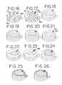
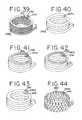
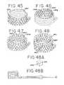
- FIGS. 16-26are perspective views of different embodiments of distraction devices with different cross-sectional profiles
- FIG. 26Ais an illustration of a prior art device in which a “cage” is inserted between adjacent vertebrae
- FIG. 26Bis a top cross-sectional view of an intervertebral disk shown with a disk removal tool inserted into the disk for disk nucleus pulpous removal;
- FIG. 26Cis a side partial cross-sectional view of the intervertebral disk of FIG. 26B shown between superior and inferior vertebrae and with a distraction device being delivered into the intervertebral disk via a cannula;
- FIG. 26Dis a partial cross-sectional anterior view of the intervertebral disk of FIG. 26B shown between superior and inferior vertebrae and with the distraction device completely deployed within the disk;
- FIG. 26Eis an illustration of a prior art device in which a “cage” is used for vertebral body replacement
- FIG. 26Fis an illustration of another prior art device used for vertebral body replacement
- FIG. 26Gis a top cross-sectional view of a vertebra shown with a vertebral bone removal inserted into the vertebra for vertebral body bone removal;
- FIG. 26His a side view of the vertebra of FIG. 26G shown within a section of a vertebral column and having portions broken away to show the delivery of a distraction device into the space created by removal of vertebral body bone;
- FIG. 26Iis a side view of the vertebra of FIG. 26G shown within a section of a vertebral column and having portions broken away to show the distraction device completely deployed within the vertebral body;
- FIG. 26Jis a side view of a section of a vertebral column in which the vertebral body of one of the vertebra along with the adjacent disks have been substantially removed and a distraction device is being deployed into the space created by such removal;
- FIG. 26Kis a side view of the vertebral column section of FIG. 26J shown with the distraction device completely deployed;
- FIG. 27is a partial cross-sectional side view of another embodiment of a distraction device and delivery system employing a pusher for advancing the distraction device over a guide wire;
- FIG. 28is a partial cross-sectional side view of the distraction device delivery system of FIG. 27 , with the pusher advanced distally and the distraction device partially advanced over a coiled section of the guide wire;
- FIG. 29is a partial cross-sectional side view of the distraction device delivery system of FIG. 27 , with the distraction device substantially advanced over the coiled section of the guide wire;
- FIG. 30is a perspective view of a vertebra with the superior endplate removed to show the delivery of a guide wire into the vertebral body;
- FIG. 31is a perspective view of the vertebra shown in FIG. 30 with the guide wire partially deployed within the vertebral body;
- FIG. 32is a perspective view of the vertebra of FIG. 30 shown after the cannula and introducer sheath have been removed and a distraction device and pusher mounted on the guide wire;
- FIG. 33is a perspective view of the vertebra of FIG. 30 shown with the distraction device partially advanced or deployed within the vertebral body;
- FIG. 34is a perspective view of the vertebra of FIG. 30 shown with the distraction device substantially fully deployed within the vertebral body;
- FIG. 35is a side cross-sectional view of the vertebra of FIG. 30 , with the distraction device fully deployed within the vertebral body;
- FIG. 36is a top cross-sectional view of a vertebra having a distraction device deployed within the vertebral body and bone filler being injected into the treatment site within the distraction device;
- FIG. 37is a top cross-sectional view of the vertebra shown in FIG. 36 having bone filler injected and contained within the inner space defined by the distraction device when in the deployed position defining a generally hollow cylindrical coil or helical shaped support structure within the vertebra;
- FIG. 38is a perspective view of the vertebra shown in FIG. 36 having bone filler substantially occupying the area within the distraction device;
- FIGS. 39-48are perspective views of different embodiments of distraction devices, showing a variety of shapes and cross-sectional profiles including profiles that all allow the distraction device to bend or curve;
- FIG. 48Ais one embodiment of a distraction device element
- FIG. 48Bis a partial cross-sectional side view of one embodiment of a distraction device having multiple distraction device elements slidably mounted on a guide wire;
- FIG. 49is a top partial cross-sectional view of a vertebral body with two delivery access opening being used in a trans-pendicular approach for side by side placement of distraction devices or guide wires;
- FIG. 50is a perspective view of one embodiment of the delivery system of the present invention for placing two distraction devices or guide wires in a relative superior and inferior position;
- FIG. 51is a side cross-sectional view of a vertebral body in combination with the system of FIG. 50 at least partially deployed;
- FIG. 52is a perspective view of another embodiment of the delivery system of the present invention having a double distraction device or guide wire configuration in a relative lateral position;
- FIG. 53is a top partial cross-sectional view of a vertebral body and the system of FIG. 52 at least partially deployed;
- FIG. 54is a perspective view of yet another embodiment of the system of the present invention having a quadruple distraction device or guide wire configuration in relative superior and inferior lateral positions;
- FIG. 55is a side view of a wheel driven delivery apparatus in a starting position
- FIG. 56is a side view of the wheel driven delivery apparatus of FIG. 55 during deployment of the distraction device;
- FIG. 57is a perspective view of a spool type delivery system during deployment
- FIG. 58is a side view of a ratchet delivery apparatus
- FIG. 58Ais a side view of a ratchet delivery apparatus in which the distraction device or guide wire exits out of the side of the distal tip of the delivery apparatus;
- FIG. 59is a side view of a vertebral column shown with a disk nucleus removal tool entering one of the intervertebral disk from a posterior approach;
- FIG. 60is a cross-sectional view of the spinal region illustrating in example of an anterior approach which can be used for deployment of a distraction device;
- FIG. 61is a top cross-sectional view of an intervertebral disk shown with a disk removal tool inserted into the disk for disk nucleus pulpous removal;
- FIG. 62is a top cross-sectional view of the intervertebral disk of FIG. 61 shown after the nucleus pulpous of the disk has been removed;
- FIG. 63is a top cross-sectional view of the intervertebral disk of FIG. 61 shown with a cannula inserted into the disk and a guide wire partially deployed within the nucleus space;
- FIG. 63Ais a side partial cross-sectional view of the intervertebral disk of FIG. 61 shown between superior and inferior vertebrae and with the guide wire partially deployed;
- FIG. 64is a top cross-sectional view of the intervertebral disk of FIG. 61 shown with the guide wire deployed within the nucleus disk space and the cannula removed;
- FIG. 65is a top cross-sectional view of the intervertebral disk of FIG. 61 shown with a distraction device placed over the guide wire partially deployed within the nucleus space;
- FIG. 65Ais a side partial cross-sectional view of the intervertebral disk of FIG. 61 shown between superior and inferior vertebrae and with the distraction device mounted on the guide wire and partially deployed within the intervertebral disk;
- FIG. 66is a top cross-sectional view of the intervertebral disk of FIG. 61 shown with a distraction device defining a support structured deployed within the nucleus space;
- FIG. 67is a top cross-sectional view of an intervertebral disk shown with a cannula inserted into the nucleus space and a guide wire partially deployed into the nucleus space;
- FIG. 68is a top cross-sectional view of the intervertebral disk of FIG. 67 shown after the cannula has been removed and a distraction device partially deployed within the nucleus space;
- FIG. 69is a top cross-sectional view of the intervertebral disk of FIG. 67 shown with a second cannula inserted into the nucleus space and a second guide wire deployed into the nucleus space;
- FIG. 70is a top cross-sectional view of the intervertebral disk of FIG. 67 shown with a second distraction device placed over a delivery track and partially deployed within a nucleus space;
- FIG. 71is a top cross-sectional view of the intervertebral disk of FIG. 67 shown with two distraction devices deployed within a nucleus space;
- FIG. 72is a side view of a vertebral column with adjacent vertebrae having non-parallel endplates
- FIG. 72Ais a schematic illustration of a distraction device delivery system inserted into an intervertebral disk using a posterior approach
- FIG. 72Bis a side partial cross-sectional view of the vertebral column of FIG. 72 shown with the distraction device illustrated in FIGS. 73 and 74 partially deployed within an intervertebral disk of the vertebral column;
- FIG. 73is a perspective view of another embodiment of a distraction device of the present invention.
- FIG. 74is a side view of the distraction device of FIG. 73 when coiled to define a support structure
- FIG. 75is a top view of a cannula delivering a guide wire in a spiral configuration
- FIG. 76is a top cross-sectional view of an intervertebral disk with the guide wire deployed into the nucleus space;
- FIG. 77is a top cross-sectional view of the intervertebral disk of FIG. 76 with a distraction device placed over the guide wire and partially deployed within the vertebral body;
- FIG. 78is a top cross-sectional view of the intervertebral disk of FIG. 78 shown with the spiral shape distraction device deployed within the nucleus space;
- FIG. 79is a side view of a section of a vertebral column with portions of a vertebral body broken away to show a guide wire deployed into the vertebral body via a cannula;
- FIG. 80is a side view of the vertebral column section of FIG. 79 with portions of the vertebral body broken away to show a distraction device being deployed into the vertebral body via a guide wire;
- FIG. 81is a side view of the vertebral column section of FIG. 79 with portions of the vertebral body broken away to show the distraction device deployed within the vertebral body;
- FIG. 82is a side view of a section of a vertebral column in which the vertebral body of one of the vertebra along with the adjacent disks have been substantially removed, and a guide wire is being deployed into the space created by such removal;
- FIG. 83is a side view of the vertebral column section of FIG. 82 shown with a distraction device mounted on the guide wire and partially deployed into the space created by the removal of the vertebral body and adjacent disks;
- FIG. 84is a side view of the vertebral column section of FIG. 82 shown with the distraction device fully deployed within the space created by the removal of the vertebral body and disks.
- FIG. 1illustrates a section of a healthy vertebral (spinal) column, generally designated as 100 , without injury.
- the vertebral column 100includes adjacent vertebrae 102 , 102 a and 102 b and intervertebral disks 104 , 104 a , 104 b and 104 c separating adjacent vertebrae.
- FIGS. 3 and 4illustrate in more detail a normal vertebra and its attributes.
- the vertebragenerally designated as 102 , includes a vertebral body 106 that is roughly cylindrically and comprised of inner cancellous bone 108 surrounded by the cortical rim 110 , which is comprised of a thin layer of cortical compact bone.
- the cortical rim 110can be weakened by osteoporosis and may be fractured due to excessive movement and/or loading.
- the body 106 of the vertebrais capped at the top by a superior endplate 112 and at the bottom by an inferior endplate 114 , made of a cartilaginous layer.
- vertebral foramen 116To the posterior (or rear) of the vertebral body 106 is the vertebral foramen 116 , which contains the spinal cord (not shown). On either side of the vertebral foramen 116 are the pedicles 118 , 118 a , which lead to the spinal process 120 . Other elements of the vertebra include the transverse process 122 , the superior articular process 124 and the inferior articular process 126 .
- FIG. 2illustrates a damaged vertebral column, generally designated as 128 , with a vertebral body 130 of a vertebra 132 suffering from a compression fracture 134 .
- the vertebral body 130 suffering from the compression fraction 134becomes typically wedge shaped and reduces the height of both the vertebra 132 and vertebral column 128 on the anterior (or front) side. As a result, this reduction of height can affect the normal curvature of the vertebral column 128 .
- pain caused by a compressed vertebral fracture 134can sometimes be relieved by procedures like vertebroplasty and kyphoplasty, (these procedures have been described in the background), however such procedures have safety concerns and sometimes fails to provide a desired or predictable height restoration.
- the apparatus or device of the present inventionwhich is generally defined as a distraction device, can serve to actively separate tissue layers by engaging them and forcing them apart, or to support the separation of tissue layers separated by the distraction device itself or by other devices or processes or a combination of these.
- the term “distracting device”is intended to have a general meaning and is not limited to devices that only actively separate tissue layers, only support tissue layers or only both actively separate and support tissue layers.
- the distraction devicein general can be used to actively separate layers of tissue and then be removed after such separation, or the distraction device could be used to support layers of tissue that have been previously separated by a different device.
- the distraction devicecan be used to actively separate the layers of tissue and remain in place to support the layers of tissue in order to maintain such separation.
- “distraction device”encompasses any and all of these.
- FIG. 5illustrates one embodiment of a distraction device, generally designated as 136 , in accordance with the present invention.
- the distraction device 136is preferably comprised of an elongated member, such as thread or ribbon, made of a shape memory material, such as a Nitinol (NiTi) or other suitable alloy (Cu—Al—Ni, Ti—Nb—Al, Au—Cd, etc.), a shape memory polymer or other suitable materials.
- the distraction device thread or ribbonhas a rectangular cross-section.
- the distraction devicecan have a variety of shapes and profiles.
- the distraction device 136When deployed between tissue layers, as shown in FIGS. 5 , 14 , 16 - 26 , 29 , 35 , 39 - 48 , 50 - 54 , 65 , 71 , 74 , 72 , 81 and 84 , for example, the distraction device 136 defines a support structure of a predetermined configuration such as a multi-tiered arrangement, scaffolding or platform that serves to actively separate or support (or both) opposed tissue layers.
- the distraction deviceas deployed, has a helical, coil or spring-like configuration. As illustrated, the distraction device defines a helical configuration with a tight pitch forming an essentially hollow cylinder or cage.
- each turn or winding 140is wound on top of the previous winding 140 a to form a plurality of stacked windings or tiers with lithe or no spacing between each winding or tier.
- the distraction device 136forms a very stiff column or support structure 141 along the axis of a center line of the coil or spring as shown in FIG. 6 .
- the support structure 141includes or defines an innerspace or resident volume 145 .
- resident volumerefers generally to a structural characteristic of the support structure.
- the resident volumeis a volume that is generally defined by the distraction device, when it is in the deployed configuration.
- the resident volumeis not necessarily a volume completely enclosed by the distraction device and can be any volume generally defined by the distraction device. This term does not necessarily mean that the resident volume is an open or void volume or cavity and does not preclude a situation in which the resident volume is, at some point in time, filled with another material, such as bone filler, cement, therapeutic drugs or the like.
- the resident volumedoes not preclude the resident volume from containing undisturbed human tissue that is located or remains within the resident volume during or after deployment of the distraction device, as will be explained in more detail below.
- the resident volume of the distraction devicemay be hollow or void of tissue after separation.
- the resident volumewill contain undisturbed bone tissue and no void or cavity is formed by the distraction device.
- Nickel-Titanium alloysexhibit the phenomena of thermal shape memory and superelasticity.
- thermal shape memoryrefers to the material's ability to return from a plastically deformed shape to a pre-determined shape upon increasing the temperature of the material.
- superelasticityrefers to the elastic ability of the material. Materials with superelastic characteristics can be deformed by applying a force to constrain the material in a deformed or constrained shape. Once the force or constraint is removed, the material will substantially return to its predetermined or initial shape.
- Superelastic materialssuch as Nickel-titanium alloys, can be considerably more elastic than stainless steel.
- the pre-determined or initial shapecan be referred to as the free state and the deformed shape can be referred to as the constrained state.
- the initial or pre-determined shape of a shape memory materialis normally set by a heat treatment process, which is well known in the art.
- the material selectedis wound on a mandrel and securely attached so it can be heat treated to set the desire shape, in this case, to be configured like a tight pitch coil or helical shape.
- the heat cycleis typically around 500° C. and for a period of 10 minutes to 60 minutes depending on the strength of the material, spring constant and oxide layer required.
- the mandrelcould range in sizes from about 0.125 to about 2.0 inches, but is preferably around 0.5 inches in diameter.
- the wind directioncould be right hand or left hand, with a tight pitch, having little or no space between adjacent coils or turns.
- other pitchescould be used if required by the application, and if the material is of sufficient strength, the coils can be spaced apart.
- the distraction devicecan be deformed prior to or during delivery to a desired treatment site, and then returned to its original shape within the treatment site.
- the distraction devicehas an inherent tendency or is predisposed to form itself into its deployed shape. Referring to FIGS. 5-8 , for example, the distraction device 136 is first formed into the helical or coil shape seen in FIG. 5 . It may then be unwound or deformed into a substantially linear configuration or pre-deployed configuration (see FIG. 7 ) by insertion into a cannula 142 for delivery.
- the cannula 142constrains the distraction device 136 (shown in phantom within the cannula) in the deformed (straight) shape as the distraction device is passed through the cannula. While constrained within the cannula, the deformed shape or pre-deployed shape of the elongated member is substantially linear in that the shape can be perfectly straight or the shape could include slight bends or zigzags.
- the distraction device 136Upon exiting an opening 144 in a distal end portion 146 of the cannula 142 , the distraction device 136 , by change of configuration, returns to its initial or free state, as illustrated in FIG. 8 .
- a coiled portion of the distraction device 136is outside of the cannula 142 in the free state and the remaining portion of the distraction device is inside the cannula in a constrained state.
- the distraction device 136exits the cannula 142 and reforms into a coil shape it defines or provides a support structure 141 that includes a resident volume 145 .
- the support structure 141may be used in a vertebra to actively separate endplates and restore height, or the support structure may be used to support endplates that have been previously separated by a different device.
- the cannula 142preferably has a lumen 143 and a bore 144 that is complementary to or the same as the cross-section of the distraction device 136 .
- the distraction device 136can be pushed or pulled through the cannula 142 with the aid of a pushrod 150 or other suitable advancement device.
- the proximal end 152 of the cannula 142may have a knob or handle 154 or other structure for ease of use and a proximal end 156 of the pushrod 150 also may have a knob or handle 158 as well.
- FIGS. 9 , 10 and 11depict the action of the distraction device 136 as it reforms into its initial or deployed configuration upon being advanced out of the distal end 146 of the cannula 142 .
- the distraction device 136i.e., the elongated member or ribbon
- the cannula 142where it may be deformed into a constrained state, e.g., a substantially straight or linear state.
- the pushrod 150(not shown) or other suitable advancement mechanism is manipulated to advance the distraction device out of the distal end 146 of the cannula 142 .
- the distraction device 136As the distraction device 136 exits out the distal end portion 146 of the cannula 142 in the direction of the arrow A, the device begins to return to its wound or coil shape because it is no longer being constrained by the cannula. In the illustrated embodiment, the distraction device 136 returns to the initial configuration as it winds in a clockwise direction as indicated by arrow B.
- the distraction device 136continues to advance out of the distal end 146 of the cannula 142 , in the direction of arrow A and continues to wind in the direction of arrow B.
- the height or extent of the coiled shaped support structure 141also increases as represented by arrow C.
- the extent or height of the support structurewill increase in the direction of tissue separation. The process will continue until the desired height or extent of the support structure 141 is obtained and/or the distraction device 136 is fully displaced from the cannula.
- the coil shaped support structure 141is at its full deployed height, which preferably is the distance required for height restoration of a compressed vertebra or a diseased disk when the device is used for such treatments.
- FIGS. 12 and 13which illustrate one potential procedure, an access opening 160 is drilled into the cortical rim 110 of the vertebral body 130 of a vertebra 132 suffering from a compression fracture 134 .
- the cannula 142is inserted through the access hole 160 into the vertebral body 130 .
- the cannula 142may be placed adjacent to the access hole 160 instead of inserted through the access hole.
- the access opening 160will be drilled through the pedicle 118 , which is sometimes referred to as a transpedicular approach.
- the access hole 160could be made in any other portion of the cortical rim 110 as the physician may chose.
- the distraction device 136may be prepositioned within the cannula 142 , which constrains the distraction device in the deformed or pre-deployed configuration. As the pushrod 150 is advanced, the distraction device 136 is advanced out of the distal end portion 146 of the cannula 142 and into the cancellous bone 108 of the vertebral body 130 . Upon exiting the cannula 142 , the distraction device 136 will begin to revert, by change of configuration, to its initial or deployed coil shape to define support structure 141 . Thus, as it is advanced from the cannula, the distraction device 136 winds up into the relatively spongy cancellous bone 108 of the vertebral body 130 as shown in FIG. 13 .
- the distraction devicetraverses or passes through the cancellous bone 108 there is no compression of cancellous bone.
- the distraction devicedoes not create a significant void or cavity within the cancellous bone, but instead winds through the cancellous bone so that undisturbed cancellous bone 108 a is located within the resident volume 145 defined by the support structure 141 .
- the spring-shaped distraction device support structure 141will contact the endplates and start to distract the endplates (or actively separate them) apart from each other as the support structure increases in height.
- the distraction device 136will be advanced out of the cannula 142 until the distraction device attains the desired height or extent as measured in the direction of endplate separation, or the endplates 112 , 114 have been separated by a desired distance.
- the distraction device 136is advanced until the height of the distraction device support structure 141 is such that it returns the endplates 112 , 114 to a normal pre-compression position, or such other spacing as the physician deems appropriate as illustrated in FIG. 14 , therefore alleviating a potential deformity that could eventually result in kyphosis. It is understood that the action accomplished by the distraction device preferably restores all or a substantial portion of the original height of the vertebra, although there may be circumstances where partial height restoration is deemed sufficient.
- the height of the vertebrais estimated prior to the procedure by measuring adjacent vertebrae, and then an appropriate sized distraction device that will achieve the desired height upon completely exiting the cannula is selected.
- the height of the distraction devicecould be monitored during the procedure, and when the desired height is attained, the distraction device (“ribbon”) could be severed at a location near the distal end of the cannula.
- Another optional and beneficial aspect of the distraction device of the present inventionis the ability to control the delivery of flowable material, such as bone filler, for example bone cement, allograph, autograph or some other biocompatible material, or therapeutic drug into the treatment site.
- flowable materialsuch as bone filler
- bone fillerfor example bone cement, allograph, autograph or some other biocompatible material, or therapeutic drug into the treatment site.
- bone filleris polymethyl methacrylate (PMMA), commercially available as Kyphx HV-R from Kyphon, Spineplex from Stryker, Simplex from Stryker Howmedica and Parallax Acrylic Resin with Tracers TA from Arthocare.
- PMMApolymethyl methacrylate
- the distraction devicealso can be used to control the delivery of drugs or other agents or fluids, depending on the application.
- bone filler 162can be introduced into the treatment site to assist in stabilization of the distraction device and to aid in supporting the separation of the endplates 112 , 114 .
- a syringe 164can be used to deliver the bone filler 162 into the treatment site.
- the tip 166 of the syringe 164can be inserted between the windings 140 , 140 a (shown in FIG. 14 ) of the coil shaped distraction device 136 to access the resident volume 145 (which may or may not contain undisturbed cancellous bone, depending on the desired application) defined by the support structure 141 .
- the support structure 141acts like a container or barrier that contains the bone filler 162 within a specified location and prevents or reduces the potential for bone filler contact with more sensitive tissue such as nerve fibers.
- the support structuremay also serve to limit and direct the flow of the bone filler into areas outside the distraction device, as illustrated in FIG. 15A and explained in more detail below.
- the container effectgreatly reduces the complications associated with injection of bone filler because the container-like effect of the distraction device greatly reduces the chances of extravasation.
- the distraction devicecan have a variety of the cross-sectional profiles configurations, as shown in FIGS. 16-26 . However, it will be understood that other designs or profiles could be used based on the appropriate type of treatment required without departing for the present invention.
- the cross-sectional profile of the elongated member or ribbon of the distraction device 136may be of a variety of shapes, depending on the application and desired attributes. In certain applications, the profile may be more significant to functionality than in other applications.
- the cross-sectional shape of the distraction deviceis generally rectangular.
- the winding surface on the mandrelis preferably the short axis for better stability and increased surface contact when inserted into a vertebra.
- the distraction deviceis formed so that the wider side contacts the tissue to be distracted (e.g., endplates of a vertebra) to provide reduced contact pressure.
- the distraction devicecould also be wound on the long axis depending on the application.
- the range of the material profilecould be from about 0.005 ⁇ 0.010 inches (about 0.127 mm ⁇ 0.254 mm) (height ⁇ width) to about 0.10 ⁇ 0.50 inches (about 2.54 mm ⁇ 12.7 mm), but preferably in the range of 0.01 ⁇ 0.02 inches (about 12.7 mm ⁇ 0.5 mm) to 0.05 ⁇ 0.25 inches (about 1.27 mm ⁇ 6.35 mm).
- the distraction device 136 acan include lateral grooves or slots 170 or other lateral passageways at strategic locations. These grooves 170 or other passageways may be formed by drilling, cutting, grinding or compressing the distraction device material. When the distraction device is made of a shape memory material, the grooves or passageways can be formed either before or after winding and heat treating.
- the grooves 170can be uniformly or randomly spaced apart and, depending on the desired treatment, located only on one side of the support structure defined by the distraction device.
- the grooves 170can be used to direct and limit the flow of bone filler injected into and around the treatment site. For example, as illustrated in FIG. 15A , the grooves 170 can be located on the distraction device so that they are on only the anterior side 172 of the support structure.
- the grooves 170control the direction of the bone filler 162 so that the bone filler injected into the center area 145 a defined by the support structure 141 a is directed to flow toward the anterior portion 174 of the vertebral body and away from the posterior portion 176 where the bone filler 162 could penetrate the blood venous return system, which could create embolism complications or cause spinal cord trauma.
- the cross-sectional shape of the distraction device 136 bis that of a generally rectangular tube having a channel 178 extending therethrough.
- This profile configurationmay be similar to the rectangular outer dimensions detailed in the previous embodiment and may have a wall 180 within the range of about 0.002 to 0.25 inches (about 0.05 mm to 6.35 mm), but more preferably in the range of about 0.005 to 0.020 inches (about 0.127 mm to 6.35 mm).
- the distraction devicecould also include apertures or holes 182 which extend through the wall 180 and communicate with the internal bore or channel 178 .
- the apertures 182can be uniformly or randomly spaced apart and may be of the same size or vary in size. Additionally, the apertures 182 could be limited to the inner wall of the distraction device or to the outer wall of the distraction device or could be located on both the inner and outer walls. Further, the apertures 182 could be limited to one side of the distraction device, such as on the anterior side or posterior side.
- Bone fillercan be delivered to the treatment site by inserting the tip of the syringe into the channel 178 and injecting the bone filler into the channel. The bone filler will flow along the channel 178 and escape out of the apertures 182 in the desired directions into the treatment site. The location and arrangement of the apertures will determine the direction of bone filler injected within the treatment site.
- the distraction devicealso may be coated with a polymer based of bone filler material that can be activated upon implantation and diffused into the surrounding tissue. This potential feature is applicable to a distraction device of any cross-sectional shape.
- the cross-sectional shapeis round. This profile may be slightly less stable during certain treatments because, in some cases, the windings could have the tendency to slip over each other. However introduction of bone filler material into the center of the windings may, after curing add substantially to the stability of this distraction device as well as the others shown in FIGS. 16-26 .
- the diameter of the circular cross-sectional distraction device in FIG. 18preferably ranges from about 0.005 to 0.025 inches (about 0.127 mm to 0.635 mm).
- the cross-sectional shapeis square. This profile has similar advantages as the rectangular profile and would be much stiffer at the same width dimension as the rectangular one.
- the cross-sectional shapeis double round. This profile has improved stability over a single round profile while being easy to wind.
- the double round profilecould be extruded as such or welded together or otherwise joined prior to winding and heat treatment.
- the size of each round sectionis preferably in the same range as the round profile.
- the cross-sectional shapeis that of a round tube that includes a channel or bore 184 that forms a lumen through the distraction device.
- This profilemay have similar dimensions as the round profile, and may have a wall 186 with a thickness in the range of about 0.002 to 0.05 inches (about 0.05 mm to 1.27 mm).
- This embodiment of the distraction devicemay also include apertures, generally similar to the apertures 182 described above with respect to FIG. 17 , for flow of bone filler or other material into the treatment site.
- the cross-sectional shapeis oblong.
- This profilecan be obtained by taking a distraction device that has the same dimensions as the round profile and flattening it, preferably prior to heat treatment if the device is made of a shape memory material.
- the flattening processcould use roller technology where the material is pushed between rollers that are separated by a distance less than the diameter of the distraction device. Several passes might be necessary depending on the thickness required.
- One of the advantagesis potentially an increase in stability over a round profile without having any sharp corners or edges that are commonly associated with interfering surfaces.
- the cross-sectional shapeis that of an oblong tube.
- This profileis generally similar to the oblong profile, but includes a center channel or bore 188 defining a lumen through the distraction device. Additionally, this embodiment could also include the apertures generally similar to those described above with respect to FIG. 17 .
- the cross-sectional shapeis a combination of the above shapes.
- This profilecombines two or more of the previously described profiles.
- the devicecould have a square and a round profile, as shown. It is understood that any combination of profiles can be achieved using one or more profiles as might be required by the application.
- the cross-sectional shapeis a custom profile.
- This type of profilemay require special manufacturing process like special extrusion dies or secondary manufacturing after extrusion to create the desired profile.
- the advantage of such profilewould be the locking characteristic of the windings on top of each other to form a very solid column not only in the vertical direction but also resistant to sliding or shifting in the lateral direction as well.
- the cross-sectional shapeis another custom profile having benefits as described above with reference to FIG. 25 .
- the distraction devices of the present inventionmay also be used in intervertebral disk treatments and intervertebral body fusion procedures, as well as, total or partial vertebral body replacements procedures.
- One of the advantages of the present inventionis the ability to use the device in a minimally invasive surgery setting that allows the surgeon to use an endoscopic approach to remove damaged spinal tissue due to disease, such as trauma or tumor and to deploy the device into the space created by such removal.
- FIG. 26Aillustrates a prior art device, sometimes referred to as a “cage,” that is used in intervertebral disk treatments and intervertebral body fusion procedures.
- These cage type devicestypically have a fixed size that does not substantially change before, during or after implantation.
- a relatively large incisionis made in the patient's back and spinal tissue to accommodate the size of the device being inserted.
- the use of a separate toolmay be required to separate or distract the spinal tissue prior to insertion of the device between the tissue.
- a disk nucleus removal tool 190such as rongeurs, curettes, probes or dissectors, is inserted through a small access hole 191 in the annulus fibrous 192 of an intervertebral disk 193 , as illustrated in FIG. 26B .
- the removal tool 190is used to remove a portion of or the entire disk nucleus pulpous 194 by endoscopic techniques and procedures generally known to those skilled in the art.
- a delivery cannula 142is inserted through the access hole 190 and a distraction device 136 is deployed into the space 195 created by the removal of the nucleus pulpous 194 .
- the distraction device 136preferably has a substantially linear pre-deployed configuration for deployment through the cannula 142 and a coiled or deployed configuration upon exiting the cannula in which the distraction device defines a support structure 141 . As the distraction device 136 exits the cannula, the support structure 141 increases in extent heightwise within the space 195 .
- the support structure 141will cause the endplates 196 a and 196 b of adjacent vertebrae 102 a , 102 b , respectively, to distract or separate.
- the distraction device 136will be advanced out of the cannula 142 until the distraction device 136 has completely exited the cannula 142 or the support structure 141 has attained the desired height.
- the distraction device 136is advanced out of the cannula until the height of the support structure 141 is such that it returns the endplates 196 a , 196 b to a normal position, as illustrated in FIG. 26D .
- the desired height of the support structure 141is pre-determined and a distraction device of an appropriate size is chosen for use.
- the height of the support structuremay be monitored under fluoroscopy, and once the support structure has reached the desired height, the distraction device may be severed at a location near the distal end portion of the cannula.
- the distraction deviceUpon deployment, the distraction device restores disk height and stabilizes the vertebral column.
- the resident volume of the support structuremay be substantially empty or may contain some nucleus pulpous tissue.
- bone fillersuch as bone cement, allograph or autograph, or other therapeutic drugs may be inserted into the resident volume defined by the support structure and/or around the support structure to aid in stabilization of the device and/or to promote bone fusion between the adjacent vertebrae.
- FIGS. 26E and 26Fillustrate prior art devices, also sometimes referred to as “cages,” that are used in vertebral body replacement (VBR) procedures.
- VBRvertebral body replacement
- a portion of or the entire vertebral bodyis removed, and the cage is inserted into the space of the removed vertebral body.
- cages of the type illustrated in FIG. 26Ehave a fixed size that does not substantially change before, during or after deployment. Thus, a relatively large incision is made in a patient's back and spinal tissues to implant such a device. Additionally, the procedure may require the use of a separate device to distract the tissue in order to accommodate insertion of the device.
- FIG. 26FThe prior art device illustrated in FIG. 26F is somewhat different than that of the one shown in FIG. 26E in that it has individual sections which are inserted to build the device or cage. Again these sections are relatively large and require a relatively large incision for implantation.
- a vertebral bone removal tool 197is inserted through a small access hole 160 c of a vertebral body 130 c as illustrated in FIG. 26G .
- the vertebral bone removal tool 197can be used to remove a portion of the vertebral body or completely remove the vertebral body using endoscopic techniques and procedures generally known to those skilled in the art. Typically, this procedure is use to remove damaged vertebral bone.
- a delivery cannula 142is inserted through the access hole 160 c and a distraction device 136 is deployed into the vertebral body 130 c through the cannula, using similar procedures and techniques as described above.
- the distraction device 136As the distraction device 136 is deployed, it defines a support structure 141 that separates and supports the endplates 112 c , 114 c of the vertebral body 130 c , as illustrated in FIG. 26I .
- the resident volume of the support structuremay be substantially empty or the resident volume may contain some cancellous bone depending on the amount of cancellous bone initially removed and the deployment location of the support structure.
- the distraction deviceitself does not compress the cancellous tissue to form a cavity or void volume.
- bone filler or therapeutic drugsmay be inserted into the resident volume and/or around the support structure to stabilize the support structure and/or to promote bone fusion.
- the vertebral body removal tool described aboveis used to move substantially all of a vertebral body, and optionally, a disk removal tool is used to substantially remove the adjacent disks.
- a disk removal toolis used to substantially remove the adjacent disks.
- the distal end portion 146 of a cannula 142can be inserted into the space 198 created by the removal of the vertebral body and/or adjacent disks, and a distraction device 136 can deploy into the space, using similar minimally invasive procedures and techniques described above.
- the distraction device 136Upon exiting the cannula 142 , the distraction device 136 forms a support structure 141 that increases in height as the distraction device is deployed.
- the support structure 141As the support structure 141 increases in height, it contacts endplate 112 d of superior vertebra 130 d and endplate 114 d of inferior vertebra 130 e to distract and support the vertebrae in a spaced-a-part relation, as illustrated in FIG. 26K .
- the deployed support structure 141provides support and stabilizes the vertebra column.
- bone filler or therapeutic drugsmay be inserted into the resident volume and around the support structure to stabilize the support structure and/or to promote bone fusion.
- FIG. 27illustrates another embodiment of the distraction device and delivery system of the present invention.
- the distraction device 202is deployed with the aid of a guide wire or delivery track 200 .
- the distraction device 202Prior to deployment, the distraction device 202 preferably has an elongated generally linear shape and includes a center bore or passageway (shown in FIG. 39-FIG . 48 ) for slidably mounting onto the guide wire.
- the distraction device 202should be sufficiently flexible to follow along the contour of the guide wire 200 for example, the distraction device 202 may be required to take on a generally elongated shape for mounting on a guide wire for deployment into the treatment site and a generally coil or spring shape within the treatment site.
- the distraction device 202is preferably made from biocompatible materials that are suitable for long term implantation into human tissue in the treatment of degenerative tissue, trauma or metastatic conditions or where a tissue distraction device is needed.
- the material usedmay also be a biological material such as, Calcium Phosphate, Tricalicum Phosphate, Hydroxyapatite, or any other suitable biological material.
- the biocompatible materialsmay be PEEK (polyetheretherketone), Nylon, NiTi or any other suitable.
- the materialmay be solid or porous for tissue ingrowth, and may elute therapeutic or growth enhancing agents.
- One of the advantages of using biological or biocompatible material to treat vertebral compression fracturesis that these elements have a more natural like substance. However, other materials could be used and still be within the scope of the present invention.
- the guide wire 200includes a proximal end portion 204 and a distal end portion 206 .
- the distal end portionin a deployed state, preferably defines a multi-tiered arrangement, scaffolding or platform, such as the illustrated coil or helical shape with a plurality of stacked windings, as shown in FIG. 27 .
- the shape of distal end portion of the guide wire in a deployed statemay be predetermined.
- At least the coil shaped distal end portion 206 of the guide wire 200is made of a shape memory material, such as a Nitinol or a polymer having shape memory characteristics, so that the guide wire can be deformed into a generally straight configuration prior to or during deployment of the guide wire into the treatment site, and then allowed to reform into its initial coil shape within the treatment site.
- the guide wireitself may act as an initial distraction device, contacting the endplates of the vertebra and forcing them apart.
- the guide wiremay also have a cross-sectional shape (e.g., oval) that tends to reduce contact force with endplates or to keep contact force within an acceptable range.
- the distraction device 202is inserted onto the proximal end portion 204 of the guide wire followed by a pusher 208 .
- the distal end portion 210 of the distraction devicecan be tapered, ramped or otherwise configured (as illustrated in FIGS. 27 and 44 ) to facilitate insertion and passage of the distraction device through the bone and between the tissue to be distracted.
- a small knob 212can be mounted at the proximal end portion 204 of the guide wire 200 to provide a gripping portion.
- the knob 212can be held with one hand as the pusher 208 is advanced distally along the guide wire 200 , indicated by arrow D in FIG. 28 , with the other hand.
- Advancing the pusher 208distally forces the distraction device 202 to move distally, sliding over the guide wire 200 .
- the distraction device 202follows along guide wire 200 into the vertebra and substantially takes the shape of the distal end portion of the guide wire to form a support structure with a multi-tiered arrangement or scaffolding.
- the distraction device 202winds into a coil shape as it passes over the coil-shaped portion 206 of the guide wire.
- the distraction device 202winds upon on itself as many times as the number of windings 214 of the guide wire to form a multi-tiered support structure or scaffolding, such as the coil or helical shaped support structure 216 .
- FIG. 29illustrates a completed scaffolding or support structure 216 that is defined by the coiled distraction device 202 .
- the extent or height H 1 of the support structure 216is determined generally by multiplying the number of turns or windings by the height H 2 (shown in FIG. 27 ) of the elongated distraction device.
- the guide wire 200can now be removed from the deployed distraction device 202 .
- the removal of the guide wire 200can be accomplished by holding the pusher 208 in place while pulling the proximal end 204 of the guide wire 200 in a proximal direction.
- the guide wire 200can remain in place with the distraction device 202 to further strengthen and stabilize the support structure 216 defined of distraction device 202 .
- the proximal end 204 of the guide wire 200could be severed from the remainder of the guide wire by cutting, unscrewing or other means as it is known in the art.
- the present inventionis particularly advantageous and conducive to minimally invasive surgical procedures for treatment of the spine.
- a single access openingis required, which may be made transcutaneously and through the appropriate spinal bone or other tissue.
- Insertion of the distraction devicemay be aided by an introduction cannula or sheath, or the distraction device itself may be directly advanced through an access opening without the need for a cannula or other advancing aid.
- a relatively large support structureis built or formed in situ through a relatively much smaller access opening, providing the benefits of more drastic and invasive surgical approaches with the safety and ease of minimally invasive techniques.
- FIG. 30 through FIG. 35illustrate the deployment of the distraction device 202 into a vertebral body.
- an introducer sheath 218is introduced through the back of a patient while the patient is lying in a prone position. Fluoroscopic guidance using a biplane imaging system for better visualization of the spine may be used to help guide the delivery system to the desired location.
- the introducer sheath 218has a sharp tip to help penetrate the bone structure typically through the pedicle 220 of the vertebral body 222 (in the transpedicular approach).
- a delivery cannula 224may be inserted into the introducer sheath 218 and the guide wire 200 is advanced forward through the cannula.
- the guide wiremay be inserted through the cannula without an introducer sheath.
- the guide wire 200is preferably made of a shape memory material that has an initial or free state in the shape of a coil or spring.
- the cannulaconstrains the guide wire into a generally elongated linear configuration, allowing an easy and minimally invasive deployment of the guide wire into the treatment site.
- the guide wire 200will return to its coil-shaped free state once the constraint is removed, i.e., as the guide wire exits the distal end portion 225 of the cannula 224 and enters the vertebral body 222 .
- the guide wire 200can be advanced through the cannula 224 manually or with the aid of an advancing mechanism, such as a ratcheting mechanism, e.g., the ratchet gun shown in FIG. 58 .
- an energy systemcan be operatively connected to the guide wire to transmit energy that enables the tip of the wire to drill through the tissue or bone to access the desired site or obtain the desire configuration.
- the proximal end portion 204 of the guide wire 200can be coupled to an energy system, such as a transducer assembly 226 with a piezoelectric element that produces ultrasonic vibrations at a specific frequency to help the guide wire penetrate the bony structure of the vertebral body.
- an energy systemcould include an energy source 228 coupled to the transducer 226 capable of propagating ultrasonic energy at frequencies suitable for drilling a pathway into dense material, such as bone.
- the energy system as described hereincan also be used in a substantially similar manner to aid in the delivery of the above described distraction device 136 of FIG. 12 .
- the use of a transducer assemblyis optional and that in some procedures it is advantageous to deploy the guide wire 200 without the aid of a transducer assembly.
- the guide wirecan be deployed in a manner generally similar to that previously described above with respect to the deployment of the distraction device 136 of FIG. 12 .
- the distal end portion 206 of the guide wirebegins to return to its unconstrained shape, i.e., the distal end portion of the guide wire begins to wind into its coil shape.
- the guide wire 200is advanced and deployed into cancellous bone of the vertebral body 222 until the coil shape reaches the desired height or has the desired number of loops or windings 214 .
- the guide wireitself may function to distract or separate the endplates of a damaged vertebra.
- the guide wire 200is advanced until the coiled portion of the guide wire attains a height that spans the gap between the superior endplate and the inferior endplate.
- the guide wire 200may itself contact the endplates of the vertebral body and function to cause distraction of the endplates and enlargement of the vertical height of the vertebral body, restoring or partially restoring the height of the vertebra.
- the coil shaped guide wiremay be deployed within the vertebral body without any distraction or minimal distraction of the endplates.
- the introducer sheath and cannulacan be retracted and removed from the system and the transducer assembly can be disconnected.
- the coiled distal end portion 206 of the guide wire 200is deployed within the vertebral body 222
- the proximal end portion 204 of the guide wireis extending out of the passageway 219 of the vertebral body.
- the proximal end portion 204 of the guide wiredefines an insertion path or track for the distraction device 202 .
- the introducer sheath and/or cannulacan be left in place, and the distraction device can be deployed into the vertebral body through the introducer sheath, the cannula or both.
- One of the advantages of removing the introducer sheath and the cannula from the systemis that such removal allows for a larger passageway into the vertebral body.
- the larger passagewaymakes it possible to employ distraction devices or implants having larger dimensions.
- the dimensions of the distraction devicecan be larger because the size of the distraction device is not constrained or controlled by the size of the introducer sheath or cannula.
- One advantage of employing a larger distraction deviceis that the larger distraction device provides a larger surface area that disperses the loading forces acting on the device and results in less pressure being placed on any given portion of the device or on the surface of the vertebral body contacted by the distraction device.
- the distraction device 202is inserted over the proximal end portion (not shown) of the guide wire 200 , and a pusher member 208 is placed over the guide wire behind or proximal the distraction device. As the pusher member 208 is advanced, it contacts the distraction device 202 and advances it forward or distally over the guide wire 200 .
- a ratchet deviceshown in FIG. 58 or other advancement mechanism may also be employed to assist in advancing the pusher member incrementally.
- the guide wireguides the distraction device through the passageway 219 and into vertebral body 222 .
- the distal end 210 of the distraction devicecan be tapered, ramped or otherwise shaped to aid in passing through tissue.
- the distraction device 202follows along the coiled shaped portion 206 of the guide wire 200 and winds into a coil shaped support structure 216 as shown in FIGS. 34 and 35 .
- the side slots in the distraction deviceallow it to bend more easily and follow the contour of the guide wire.
- the support structureincreases in height.
- the support structure 216increases in height, it distracts and supports the endplates of the vertebra, restoring or partially restoring vertebral height and stabilizing the vertebral body 222 .
- the distraction of the endplatesstabilizes the fracture because the load is no longer applying pressure onto the fractured section or onto the fragmented pieces that can pressure the nerve endings surrounding the vertebral body, and thus back pain is reduced.
- this embodiment of the distraction devicecan be inserted through a small access hole and a much larger three dimensional support structure, such as a multi-tiered arrangement or scaffolding, can be built within a limited or confined space between or within the tissue layers.
- the distraction device 202can be inserted through a small access hole and the support structure 216 can be built one loop at the time by adding one thickness of the distraction device over another one.
- the average vertebral bodyis 18 mm in height. As illustrated in FIG. 2 , after a vertebral body compression fracture, the vertebral body can be about half of the height of a normal vertebral body, which would result in a compressed body of about 9 mm.
- a guide wire in the form a wire with a 1 mm in diameter with a pitch about half of the wire sizewould require about 5 loops to span from endplate to endplate.
- the distraction deviceWhen the distraction device is inserted onto the guide member, it will start winding along the loops and distract or push up and down in the axial direction which may benefit from the mechanical advantage of advancing over a coil. Because the fractured body has less resistance, it will expand the distance between the two endplates until they are preferably at the pre-fractured position, as illustrated in FIG. 35 .
- the guide wire 200can be retracted from the distraction device and removed from the system. This can be accomplished by holding the pusher member 208 in place while retracting the guide wire 200 in a proximal direction.
- the guide wire 200can be retracted proximally by reversing the advancing mechanism, e.g., the ratchet mechanism of the delivery gun, while keeping the pusher member in place.
- the distraction device of the present inventionis preferably but not exclusively used with bone filler material to add stability to the distraction device and support between the distracted tissue, i.e., the endplates of the vertebra.
- Bone fillermay be introduced in a variety of ways. As illustrated in FIG. 36 and FIG. 37 , a small tubular element or needle 238 may be inserted between the windings 236 of the support structure or within a center hole of distraction device 202 , for example central channel 240 of FIG. 39 , so that a bone filler material 242 , preferably bone graft material or bone cement, can be injected into the inner area or resident volume 244 defined by the support structure 216 .
- the resident volume 244may or may not contain cancellous bone.
- the needle 238could be connected to syringe or other type injection device.
- the distraction device 202includes slots 246 that communicate with the central channel.
- the slots 246are arranged so that the slots direct the injected bone filler 242 to resident volume 244 defined by the support structure 216 .
- the support structure 216acts as a barrier that limits and/or directs the movement of the bone filler 242 and substantially prevents the bone filler from spreading to areas outside of the support structure 216 .
- the support structure 216can serve as a containment device that surrounds the bone filler 242 and contains it within resident volume 244 defined by the support structure 216 .
- the support structure/containment device 216prevents undesired leakage or extravasation.
- the bone filler 242is injected until it has completely filled the resident volume 244 defined by the support structure 216 as illustrated in FIG. 38 .
- the distraction devicemay have a variety of configurations without departing from the present disclosure.
- the different configurationsprovide a variety of advantageous features of the distraction device.
- One aspect to be considered in regards to an implanted distraction deviceis the ability of the device to resist different forces, such as compressive and axial forces. It is easily understood that the device can resist compressive loading wherein the force on the distraction device is axial. However, additional lateral or translation forces can also act on the device when the body is moving.
- FIGS. 39-48illustrate examples of possible profiles of the distraction device and the multi-tiered support structures that can be formed by such distraction devices.
- the various profilesaid in shape retention so as to keep the distraction device in the shape of the deployed support structure and substantially accommodate resistance to both compressive and lateral forces, among other advantageous features.
- All of the embodiments in these figurespreferably include a channel generally designated 240 - 240 i for mounting the distraction device onto the guide wire.
- the central channelin some embodiments also can be utilized for directing the flow of bone filler or the delivery of drugs or other fluid materials.
- the cross-sectional profileis generally square and in FIG. 40 , the cross-sectional profile is generally rectangular. Both of these embodiments provide windings 236 a and 236 b having substantially flat surfaces that contact flat surfaces of adjacent windings. The contact between the surfaces of each winding provides a support structure, which is very good at resisting compressive forces. Additionally, as illustrated in FIG. 39 the distraction device can have a porous coating 247 throughout or at least on the sides of the distraction device for better integration into the tissue to be treated.
- the cross-sectional shapeis a custom tongue and groove profile having a corrugated shape with a plurality of peaks 248 and valleys 250 .
- the peaks 248 and valleys 250 of each windingengage these of the next adjacent winding to provide interfering surface that adds stability and resists lateral slippage.
- the cross-sectional shapeis a custom profile with a single tongue and groove configuration.
- the distraction devicehas a groove 254 formed on one surface and a raised rib or tongue 252 formed on the opposite surface so that when wound together the tongue extends into the groove of an adjacent winding and the groove receives the tongue of an adjacent winding. Again the tongue 252 and groove 254 engage each other to provide interfering surfaces that add stability and resists slippage and shifting due to lateral forces.
- the cross-sectional shapeis a custom profile having opposed concave surface 256 and a convex surface 258 .
- the concave and convex surfaces 256 , 258engage the mating convex or concave surface of adjacent windings to add stability and reduce slippage and shifting due to lateral forces.
- FIGS. 44-48illustrate embodiments of the distraction device which include features that assist in directing and limiting the direction bone filler injected into the treatment site.
- materialssuch as bone filler or medications, can be injected into one of the channels 240 e - 240 i .
- the materialwill flow through the channel and into slots located in the distraction device.
- the slotsdirect and/or limit the flow of the material to a specific region within the treatment site.
- the illustrated embodimentsalso include features that aid in the insertion of the distraction device and assist in the turning of the distraction device as it is guided over the guide wire.
- the slots located in the distraction deviceenhances the flexibility of the distraction device, making it easier for the distraction device to follow the contour of the guide wire.
- FIG. 44illustrates a distraction device wherein the distraction device includes upward directed slots 260 .
- the boner fillerflows out of the slots 260 and into areas on both the inside and outside of the distraction device support structure.
- the distraction deviceincludes outwardly facing slots 260 a .
- the bone fillerflows out of the slots 260 a into the area outside of the distraction device support structure.
- the slots 260 adirect the flow of bone filler toward the outside of the distraction device, and the distraction device support structure acts as a barrier, leaving the inner area defined by the distraction device substantially free of bone filler material.
- the distraction deviceincludes inwardly facing slots 260 b .
- the bone fillerflows out of the slots 260 b and into the inner space 244 b defined by the distraction device.
- the slots 260 bdirect and limit the flow of bone filler toward the inside of the distraction device, and the distraction device acts like a container that contains the bone filler within the distraction device, leaving the outside region of the distraction device substantially free of bone filler material.
- the distraction devicehas upwardly and downwardly facing slots 260 c , 260 d , which allows bone filler to flow into regions inside and outside of the distraction device.
- the distraction devicehas inwardly and outwardly facing slots 260 e , 260 f .
- the inwardly and outwardly facing slots 260 e , 260 fdirect the bone filler toward both the inner space defined by the distraction device and the region outside of the distraction device.
- the size and dimension of the distraction device when used for the treatment of vertebral compression fractureis preferably of a size that can be inserted through a cannula no larger that about a 6 gauge size (working diameter about 0.173 inches (about 4.39 mm)) which would allow the distraction device to have a generally square profile of about 0.118 inches ⁇ 0.118 inches (about 3 mm ⁇ 3 mm). Other sizes and dimensions could be used depending on the application.
- the length of the distraction devicecould be pre-determined or could be cut to fit during the treatment.
- the construction of the distraction devicecould be accomplished using several techniques known in the art, including but not limited to molding, machining or extruding. It is also understood that the delivery coil or guide member could have different profiles and different shapes according to the application requirements.
- the distraction devicecould be comprised of a plurality of individual distraction device elements 251 , each including a hole 240 j for mounting onto the guide wire 200 a for insertion into the vertebral body.
- the individual distraction device elements 48 acould have a cube-like configuration or could be longer or shorter in length or width depending on the desired use.
- the distraction deviceis preferably stabilized by leaving the guide wire 200 implanted within the distraction device or with the aid of cement introduced into the inner area defined by the distraction device or at least in contact with the spiral or both.
- the distraction devicealso can be constructed by linking a plurality of individual distraction device elements together to form a chain-like structure.
- a thin section of materialcould be connected to a plurality of cube-like distraction device elements to retain all of the elements together, forming a line or deformable linear structure.
- the individual distraction device elementscan be similarly sized and shaped, or alternatively, each individual element can be a different size and shape.
- the distraction devicecan be formed from a bar or rod shaped in which a multitude of slots that can be machined into the starting bar or rod at regular or random intervals.
- a channelmay be bored through the middle of the distraction device for mounting and sliding onto a guide wire.
- the distraction devices and guide wires of the present inventioncan be deployed by a variety of different methods and with a variety of apparatus. It will be understood that the deployment methods and apparatus disclosed in FIGS. 49-58 are examples of what could be used to deliver distraction devices of the type generally disclosed in FIG. 12 or guide wires of the type generally disclosed in FIG. 27 . For convenience, the aforementioned deployment methods and apparatus will be described in relation to the deployment of distraction devices.
- the distraction devicemay be made more effective for certain procedures by using multiple coil or spring-shaped distraction devices in order to speed up the procedure and also increase the surface area in contact with the tissue or endplates in the case of treating vertebras.
- the surgeoncan used a bi-transpedicular approach for instance as shown in FIG. 49 .
- Two holesare drilled into the vertebral body 262 and two cannulas 264 a , 264 b can be inserted through the holes to deliver each distraction device 266 a , 266 b .
- the surgeonmay, preferably, insert one device after the other for ease of use and safety concerns. However, at the surgeon's option both could be inserted at the same time.
- this inventionis not limited to the sequence of insertion.
- a double coil or distraction device having a superior device 268 and an inferior device 270is also shown in FIGS. 50 and 51 .
- Each devicewinds in the opposite direction, therefore device 268 winds in the upward direction and device 270 winds in the downward direction.
- the devicesare preferably delivered simultaneously but could also be delivered one at the time. Both devices 268 and 270 wind to the right relative to surgeon introducing them; however another device could have the devices that wind to the left as it might be required.
- the delivery cannula 272could also have two channels 274 , 274 a on its distal end to properly guide each device in its proper orientation.
- This embodimentis preferably employed when it is possible to access the center (height wise) of the vertebral body because the distraction device expands in both directions.
- FIG. 52Another configuration of a double coil or device design is shown in FIG. 52 , wherein the distraction device has a first device 275 in an anterior position and a second device 276 in a posterior position.
- the first device 275winds to the right when deployed and the other device 276 winds to the left when deployed.
- both of the devices 275 , 276wind in the downward direction; however, in another embodiment both devices could wind in the upward direction.
- the distal end 277 of the cannula 278has two channels located side by side to properly guide the devices.
- the surface area contactis doubled which reduces the stress to the tissue or endplate as the case might be.
- the deployment timeis similar as to deploying a single coil device. It might be more advantageous to use this embodiment when only one pedicle 279 or one side can be access for a medical or physical reason, as shown in FIG. 53 . This way the surface contact area is significantly increased.
- FIG. 54In order to both reduce delivery time and double the surface contact area, another distraction device configuration is illustrated with four distraction devices in FIG. 54 .
- the two devices 280 and 281are located in a superior position and side-by-side, with device 280 winding to the right and device 281 winding to the left. Both devices also wind in the upward direction.
- the other two devices 282 and 283are located in an inferior position and both are winding downwardly with device 282 winding to the left and device 283 winding to the right.
- This designpotentially requires a larger cannula 284 to accommodate the four different materials for each of the distraction devices.
- FIG. 55shows a schematic representation of an automatic design using a cannula 285 for the delivery of the distraction device within the body to the treatment site.
- the apparatushas a set of motorized rollers 286 to push out the distraction device 287 in its un-deformed configuration from a holding cartridge 288 .
- the controls of such an apparatuswould include stop and start commands and potentially a reverse command so that the distraction device can be retrieved. It could also include indication of delivery speed and force resistance encountered by the advancing distraction device into the intended tissue in question. Additional features could be added to such apparatus as it is well know in the art.
- FIG. 56shows the coil distraction device 287 being delivered and as the rollers 286 spin in the direction represented by arrow E and F, the friction exercises onto the distraction device will make it move into the direction shown by arrow G.
- FIG. 57Another device and method to deliver the distraction device are illustrated in FIG. 57 as a semi-automated type of device with manual control of the delivery action.
- the distraction device 288is mounted on a rotating spool which is connected to a handle 289 , and carried with a housing 290 .
- the distraction deviceextends through a fixed cannula 291 .
- the handle 289By turning the handle 289 in the direction indicated by arrow, the distraction device is fed along the cannula 291 until it exits at the distal end and takes its un-deformed state at the treatment site.
- FIG. 58illustrates a ratchet feed device 292 that preferably has an advancing mode and a retracting mode.
- the distraction device 294advances incrementally through the cannula 295 .
- the trigger 293is activated by repeatedly squeezing and releasing the trigger.
- FIG. 58Aillustrates another embodiment of a ratchet feed device 292 a in which the distraction device or guide track exits out of the side of the distal end 297 a of the cannula 295 a.
- the present inventionrelates to devices and methods to treat a condition that requires skin, tissue, organ, bone or a combination of those to be distracted from one another and supported apart of each other, either on a permanent situation or a temporary situation. It is also more specifically applicable for the treatment of vertebral compression fractures.
- the distraction deviceis also particularly well suited for the treatment of intervertebral disk treatments and spinal fusion.
- FIG. 59illustrates a section of a vertebral (spinal) column 300 having adjacent vertebrae 301 and 301 a and an intervertebral disk 302 located between the vertebrae 301 , 301 a .
- a disk nucleus removal tool 304such as rongeurs, curettes, probes and dissectors, is shown accessing the disk 302 via a posterior approach.
- the removal tool 304can be inserted through a small access hole 310 in the anulus fibrous 312 to remove the disk nucleus pulpous 306 using techniques and procedures generally known to those skilled in the art.
- an open space or disk nucleus space 308is created by the removal of the disk nucleus 306 . Additionally, the small access hole 310 that was created in the disk annulus 312 during the nucleus removal can be used to access the disk nucleus space.
- a delivery cannula 314is inserted through the access hole 310 and a guide wire 316 is deployed into the nucleus space 308 through the cannula 314 , using similar procedures and techniques as described above. Similar to the embodiments described above, the guide wire 316 has an elongated linear configuration for delivery through the cannula and a coiled or deployed configuration upon exiting the cannula. After the guide wire 316 has been deployed, the delivery cannula 314 can be retracted and removed from the delivery system.
- a coiled portion 317 of the guide wire 316is left occupying at least a portion of the nucleus space 308 , as shown in FIG. 64 , and a proximal end 318 of the guide wire extends from the disk 302 to define an insertion path for deployment of a distraction device.
- an implant or distraction device 320is advanced distally over the guide wire 316 .
- the distraction device 320can be advanced over the guide wire 316 with the assistance of a pusher 319 or an advancing mechanism, such as the delivery ratcheting gun 292 of FIG. 58 , or by any other suitable method.
- the guide wireguides the distraction device into the nucleus space 308 .
- the distraction device 320follows along the guide wire 316 and winds into a coil to form a support structure 313 substantially similar to the support structures of the previous embodiments.
- the delivery wire 316can be removed leaving the support structure 313 in place as shown in FIG. 66 .
- the delivery wire 316may be severed and left within the distraction device 320 .
- bone fillersuch as bone cement or cancellous bone graft material, may be inserted around the distraction device to promoted bone fusion. The complete fusion process is expected to require about 6 months to be totally healed. If required, supplemental fixation may be added to the spine to prevent instability during the healing process.
- FIGS. 67-71An alternate deployment method in accordance with the present invention is illustrated in FIGS. 67-71 .
- FIG. 67illustrates an intervertebral disk in which the nucleus has already been removed.
- a guide wire 322 asimilar to the guide wires described above, is deployed through a cannula 314 a into the nucleus space 308 a in a generally similar manner as described above. After the guide wire 322 a has been deployed, if desired, the cannula 314 a can be removed from the system.
- the coiled configuration of this embodiment of the guide wirehas a tighter wind (smaller diameter coil), and thus occupies only a portion of the nucleus space 308 a.
- a distraction device 324 ais placed over the guide wire 322 a and deployed into the nucleus space 308 a , in a similar manner as previously disclosed.
- the distraction device 324 afollows along the coiled guide wire 322 a and winds into a coil to form a support structure 313 a as shown in FIG. 69 . Because the wind of the coiled guide wire is tighter, the cross-sectional width “J” of the support structure 313 a is smaller than in the previously described embodiment, and thus the support structure only occupies a portion of the nucleus space 308 .
- the guide wire 322 dcan be removed. Alternatively, the guide wire 322 a can be severed and left within the distraction device 324 a.
- the distraction device 324 aAfter the distraction device 324 a has formed the support structure 313 a , if there are excess portions of the distraction device, the excess portion may be severed and removed. In other words, the distraction device can be cut to length after deployment.
- One of the advantages of being able to cut the distraction device to lengthis that a single distraction device is capable of being deployed over guide wires of different radii, lengths and coil or deployment configurations.
- a second guide wire 322 bis deployed through a cannula 314 b into the nucleus space 308 a adjacent to support structure 313 a .
- a second distraction device 324 bis then deployed over the guide wire 322 b , as shown in FIG. 70 .
- FIG. 71illustrates an intervertebral disk after the two distractions devices support structures 313 a , 313 b have been deployed within the nucleus space 308 a .
- One advantage of employing two distraction devicesis an increased surface area occupied by the distraction devices, which provides for aided support and distribution of forces.
- FIG. 60illustrates an example of an anterior approach.
- an incisionis made in the belly of the patient and the main organs such as the descending colon 330 , aorta 332 and inferior vena cava 334 are dissected and pushed to the side and then held by retractors 336 to provide an access to the vertebral column 300 .
- One advantage of this approachis the ability to access the disk space from the anterior and complete a fusion when the end plates 338 , 340 of adjacent vertebra are not parallel, as shown in FIG. 72 , but have a wedge like shape making is difficult to insert a distraction device from the posterior approach.
- FIG. 74shows one embodiment of a support structure 341 formed by a distraction device.
- the support structure 341has a top portion 342 and a bottom portion 344 that are generally angled toward each other.
- the support structurehas an anterior portion 346 and a posterior portion 348 .
- the anterior portion 346is taller than the posterior portion 348 , conforming the support structure to the wedge-like shape between the non-parallel vertebral plates 338 , 340 as illustrated in FIG. 72B .
- One advantage of an oblique configurationis that it can be used with a posterior approach as illustrated in FIG. 72A , which is much less invasive than the anterior approach just described.
- the posterior approachallows for a faster recovery period without sacrificing the wedge type implant desired for these particular cases.
- the distraction device having an oblique configurationcan be formed from the distraction device ribbon 349 as illustrated in FIG. 73 .
- the distraction device ribbon 349has a pre-deployed state having peaks 350 and valleys 351 . Each peak 350 is spaced apart by a defined pitch “P.”
- the peaks 350 and valleys 351 of the distraction device 349are spaced apart so that when an appropriate guide wire is employed, the distraction device forms the support structure 341 of FIG. 73 having a longer anterior dimension.
- Such a support structurecan be achieved by deploying distraction device 349 on a corresponding guide wire that has a coiled configuration having a radius that matches the appropriate pitch spacing.
- FIGS. 75 and 76illustrate another embodiment of the present invention wherein the deployed configuration of the guide wire 352 would have a single layer spiral portion 353 .
- the guide wire 352is deployed through a cannula 355 into the open space 308 b created by the removal of the disk nucleus.
- the spiral portion 353 of the guide wireforms within the nucleus space 308 b .
- the distraction device 354is inserted over the guide wire 352 and advanced into the nucleus space 308 using methods and techniques generally similar to those previously described.
- the distraction device 354follows along the guide wire 352 to create a single layered generally spiraled support structure 356 .
- the delivery track 352can be removed leaving behind a well compact distraction device.
- FIG. 78illustrates the distraction device support device 356 deployed in this spiral configuration.
- the distraction devices of the present inventioncan also be used for total or partial vertebral body replacements (VBR).
- VBRtotal or partial vertebral body replacements
- an endoscopic proceduregenerally similar to the procedure described above with respect to FIG. 26G , can be used to remove damaged vertebral body tissue.
- This procedurecan include inserting a vertebral bone removal tool through a small access hole of the vertebral body to remove damaged portions of vertebral bone.
- a delivery cannula 400can be inserted through an access hole 402 , typically the same access hole created for bone removal, in vertebra 403 , and a guide wire 404 is deployed into the vertebral body 406 through the cannula, as illustrated in FIG. 79 .
- the distal end portion 410 of the guide wirebegins to return to its unconstrained coiled shape.
- the guide wire 404is advanced and deployed into the vertebral body until the coil shape reaches a desired height or has the desired number of windings 412 .
- the cannula 400can be retracted and removed from the system.
- the coiled distal end portion 410 of the guide wire 404is deployed within the vertebral body 406 , and the proximal end portion 414 of the guide wire is extending out of the passageway 408 .
- the proximal end portion 414 of the guide wiredefines an insertion path for the distraction device 416 , as illustrated in FIG. 80 .
- the distraction device 416is inserted over the proximal end portion 414 of the guide wire 404 , and a pusher member 418 is placed over the guide wire behind or proximal the distraction device. As the pusher member 418 is advanced, it contacts the distraction device 416 and advances it forward or distally over the guide wire 404 .
- the distraction device 416follows along the coiled shaped portion 410 of the guide wire 404 and winds into a coil shaped support structure 420 . With each formation of an additional coil or winding 422 of the support structure 420 , the support structure increases in height or extent. As the support structure 420 increases in height, it distracts and supports the endplates 424 , 426 of the vertebra, restoring or partially restoring vertebral height and stabilizing the vertebral body 406 .
- the guide wire 404can be retracted from the distraction device and removed from the system. Alternatively, the guide wire 404 could be severed and left within the distraction device 416 .
- bone fillersuch as bone cement, allograph or autograph, or therapeutic drugs may be inserted in or around the device, by similar methods described above, in order stabilize the device and/or to promote bone fusion.
- the vertebral body removal tool described abovecan be used to remove substantially all of the vertebral body of a vertebra 401 , and a disk removal tool can used to substantially remove the adjacent disks.
- a disk removal toolcan be used to substantially remove the adjacent disks.
- the distal end portion 408 a of the cannula 400 acan be inserted into the space 430 created by the removal of the vertebral body and adjacent disk, and a guide wire 404 a can be deployed into said space, using similar procedures and techniques as described above.
- the distal end portion 410 a of the guide wire 404 abegins to return to its unconstrained coiled shape.
- the guide wire 404 ais advanced and deployed into the space 430 created by the vertebral body and disk removal until the coil shape reaches the desired height or has the desired number of loops or windings 412 a.
- the cannula 400 acan be retracted and removed from the system.
- the distraction device 416 ais inserted over the proximal end portion 414 a of the guide wire 404 a , and a pusher member 418 a is placed over the guide wire behind the proximal end portion of distraction device.
- the pusher member 418 aAs the pusher member 418 a is advanced, it contacts the distraction device 416 a and advances it forward or distally over the guide wire 404 a .
- the guide wireguides the distraction device into the space 430 created by the removal of the vertebral body and adjacent disks.
- the distraction device 416 afollows along the coiled shaped portion 410 a of the guide wire 404 a , it winds into a coiled shape support structure 420 a .
- the support structureincreases in height.
- the support structure 420 aincreases in height, it distracts and supports an endplate 432 of a superior vertebra 434 and an endplate 436 of an inferior vertebra 438 , as shown in FIG. 84 .
- bone fillersuch as bone cement, allograph or autograph, or therapeutic drugs may be inserted in or around the support structure to stabilize the support structure and/or to promote bone fusion.
Landscapes
- Health & Medical Sciences (AREA)
- Orthopedic Medicine & Surgery (AREA)
- Engineering & Computer Science (AREA)
- Biomedical Technology (AREA)
- Life Sciences & Earth Sciences (AREA)
- Neurology (AREA)
- General Health & Medical Sciences (AREA)
- Public Health (AREA)
- Heart & Thoracic Surgery (AREA)
- Animal Behavior & Ethology (AREA)
- Veterinary Medicine (AREA)
- Transplantation (AREA)
- Surgery (AREA)
- Cardiology (AREA)
- Oral & Maxillofacial Surgery (AREA)
- Vascular Medicine (AREA)
- Nuclear Medicine, Radiotherapy & Molecular Imaging (AREA)
- Molecular Biology (AREA)
- Medical Informatics (AREA)
- Physical Education & Sports Medicine (AREA)
- Chemical & Material Sciences (AREA)
- Dispersion Chemistry (AREA)
- Prostheses (AREA)
- Surgical Instruments (AREA)
Abstract
Description
Claims (20)
Priority Applications (1)
| Application Number | Priority Date | Filing Date | Title |
|---|---|---|---|
| US14/037,498US8961609B2 (en) | 2005-08-16 | 2013-09-26 | Devices for distracting tissue layers of the human spine |
Applications Claiming Priority (6)
| Application Number | Priority Date | Filing Date | Title |
|---|---|---|---|
| US70869105P | 2005-08-16 | 2005-08-16 | |
| US73843205P | 2005-11-21 | 2005-11-21 | |
| US78418506P | 2006-03-21 | 2006-03-21 | |
| US11/464,807US8057544B2 (en) | 2005-08-16 | 2006-08-15 | Methods of distracting tissue layers of the human spine |
| US13/296,841US8556978B2 (en) | 2005-08-16 | 2011-11-15 | Devices and methods for treating the vertebral body |
| US14/037,498US8961609B2 (en) | 2005-08-16 | 2013-09-26 | Devices for distracting tissue layers of the human spine |
Related Parent Applications (1)
| Application Number | Title | Priority Date | Filing Date |
|---|---|---|---|
| US13/296,841ContinuationUS8556978B2 (en) | 2005-08-16 | 2011-11-15 | Devices and methods for treating the vertebral body |
Publications (2)
| Publication Number | Publication Date |
|---|---|
| US20140025171A1 US20140025171A1 (en) | 2014-01-23 |
| US8961609B2true US8961609B2 (en) | 2015-02-24 |
Family
ID=37546999
Family Applications (22)
| Application Number | Title | Priority Date | Filing Date |
|---|---|---|---|
| US11/464,790Active2026-12-14US7666226B2 (en) | 2005-08-16 | 2006-08-15 | Spinal tissue distraction devices |
| US11/464,782Active2027-03-28US7785368B2 (en) | 2005-08-16 | 2006-08-15 | Spinal tissue distraction devices |
| US11/464,812Active2027-10-05US7670374B2 (en) | 2005-08-16 | 2006-08-15 | Methods of distracting tissue layers of the human spine |
| US11/464,793Active2027-04-01US7666227B2 (en) | 2005-08-16 | 2006-08-15 | Devices for limiting the movement of material introduced between layers of spinal tissue |
| US11/464,807Active2028-09-24US8057544B2 (en) | 2005-08-16 | 2006-08-15 | Methods of distracting tissue layers of the human spine |
| US11/464,815Active2027-09-06US7670375B2 (en) | 2005-08-16 | 2006-08-15 | Methods for limiting the movement of material introduced between layers of spinal tissue |
| US12/389,583Active2027-10-30US9066808B2 (en) | 2005-08-16 | 2009-02-20 | Method of interdigitating flowable material with bone tissue |
| US12/410,961ActiveUS8808376B2 (en) | 2005-08-16 | 2009-03-25 | Intravertebral implants |
| US12/705,904ActiveUS7963993B2 (en) | 2005-08-16 | 2010-02-15 | Methods of distracting tissue layers of the human spine |
| US12/705,909ActiveUS7955391B2 (en) | 2005-08-16 | 2010-02-15 | Methods for limiting the movement of material introduced between layers of spinal tissue |
| US12/705,895ActiveUS7967864B2 (en) | 2005-08-16 | 2010-02-15 | Spinal tissue distraction devices |
| US12/705,901ActiveUS7967865B2 (en) | 2005-08-16 | 2010-02-15 | Devices for limiting the movement of material introduced between layers of spinal tissue |
| US13/161,956Active2027-03-24US8979929B2 (en) | 2005-08-16 | 2011-06-16 | Spinal tissue distraction devices |
| US13/162,021Active2026-09-02US8801787B2 (en) | 2005-08-16 | 2011-06-16 | Methods of distracting tissue layers of the human spine |
| US13/296,841ActiveUS8556978B2 (en) | 2005-08-16 | 2011-11-15 | Devices and methods for treating the vertebral body |
| US13/794,977ActiveUS9044338B2 (en) | 2005-08-16 | 2013-03-12 | Spinal tissue distraction devices |
| US14/037,498ActiveUS8961609B2 (en) | 2005-08-16 | 2013-09-26 | Devices for distracting tissue layers of the human spine |
| US14/549,908ActiveUS9259326B2 (en) | 2005-08-16 | 2014-11-21 | Spinal tissue distraction devices |
| US14/705,640Active2026-08-17US10028840B2 (en) | 2005-08-16 | 2015-05-06 | Spinal tissue distraction devices |
| US14/992,557ActiveUS9788974B2 (en) | 2005-08-16 | 2016-01-11 | Spinal tissue distraction devices |
| US15/710,254AbandonedUS20180008432A1 (en) | 2005-08-16 | 2017-09-20 | Devices for Insertion into a Vertebral Body and Methods of Treating a Vertebral Body |
| US16/016,832AbandonedUS20180303620A1 (en) | 2005-08-16 | 2018-06-25 | Spinal tissue distraction devices |
Family Applications Before (16)
| Application Number | Title | Priority Date | Filing Date |
|---|---|---|---|
| US11/464,790Active2026-12-14US7666226B2 (en) | 2005-08-16 | 2006-08-15 | Spinal tissue distraction devices |
| US11/464,782Active2027-03-28US7785368B2 (en) | 2005-08-16 | 2006-08-15 | Spinal tissue distraction devices |
| US11/464,812Active2027-10-05US7670374B2 (en) | 2005-08-16 | 2006-08-15 | Methods of distracting tissue layers of the human spine |
| US11/464,793Active2027-04-01US7666227B2 (en) | 2005-08-16 | 2006-08-15 | Devices for limiting the movement of material introduced between layers of spinal tissue |
| US11/464,807Active2028-09-24US8057544B2 (en) | 2005-08-16 | 2006-08-15 | Methods of distracting tissue layers of the human spine |
| US11/464,815Active2027-09-06US7670375B2 (en) | 2005-08-16 | 2006-08-15 | Methods for limiting the movement of material introduced between layers of spinal tissue |
| US12/389,583Active2027-10-30US9066808B2 (en) | 2005-08-16 | 2009-02-20 | Method of interdigitating flowable material with bone tissue |
| US12/410,961ActiveUS8808376B2 (en) | 2005-08-16 | 2009-03-25 | Intravertebral implants |
| US12/705,904ActiveUS7963993B2 (en) | 2005-08-16 | 2010-02-15 | Methods of distracting tissue layers of the human spine |
| US12/705,909ActiveUS7955391B2 (en) | 2005-08-16 | 2010-02-15 | Methods for limiting the movement of material introduced between layers of spinal tissue |
| US12/705,895ActiveUS7967864B2 (en) | 2005-08-16 | 2010-02-15 | Spinal tissue distraction devices |
| US12/705,901ActiveUS7967865B2 (en) | 2005-08-16 | 2010-02-15 | Devices for limiting the movement of material introduced between layers of spinal tissue |
| US13/161,956Active2027-03-24US8979929B2 (en) | 2005-08-16 | 2011-06-16 | Spinal tissue distraction devices |
| US13/162,021Active2026-09-02US8801787B2 (en) | 2005-08-16 | 2011-06-16 | Methods of distracting tissue layers of the human spine |
| US13/296,841ActiveUS8556978B2 (en) | 2005-08-16 | 2011-11-15 | Devices and methods for treating the vertebral body |
| US13/794,977ActiveUS9044338B2 (en) | 2005-08-16 | 2013-03-12 | Spinal tissue distraction devices |
Family Applications After (5)
| Application Number | Title | Priority Date | Filing Date |
|---|---|---|---|
| US14/549,908ActiveUS9259326B2 (en) | 2005-08-16 | 2014-11-21 | Spinal tissue distraction devices |
| US14/705,640Active2026-08-17US10028840B2 (en) | 2005-08-16 | 2015-05-06 | Spinal tissue distraction devices |
| US14/992,557ActiveUS9788974B2 (en) | 2005-08-16 | 2016-01-11 | Spinal tissue distraction devices |
| US15/710,254AbandonedUS20180008432A1 (en) | 2005-08-16 | 2017-09-20 | Devices for Insertion into a Vertebral Body and Methods of Treating a Vertebral Body |
| US16/016,832AbandonedUS20180303620A1 (en) | 2005-08-16 | 2018-06-25 | Spinal tissue distraction devices |
Country Status (6)
| Country | Link |
|---|---|
| US (22) | US7666226B2 (en) |
| EP (2) | EP2705809B1 (en) |
| JP (2) | JP4944111B2 (en) |
| AU (1) | AU2006279558B2 (en) |
| CA (1) | CA2617872C (en) |
| WO (1) | WO2007022194A2 (en) |
Cited By (38)
| Publication number | Priority date | Publication date | Assignee | Title |
|---|---|---|---|---|
| US9289240B2 (en) | 2005-12-23 | 2016-03-22 | DePuy Synthes Products, Inc. | Flexible elongated chain implant and method of supporting body tissue with same |
| US9421056B2 (en) | 2007-09-28 | 2016-08-23 | DePuy Synthes Products, Inc. | Balloon with shape control for spinal procedures |
| US9498263B2 (en) | 2005-05-27 | 2016-11-22 | DePuy Synthes Products, Inc. | Prosthetic ligament having a helical bone fastener |
| US9592063B2 (en) | 2010-06-24 | 2017-03-14 | DePuy Synthes Products, Inc. | Universal trial for lateral cages |
| US9788963B2 (en) | 2003-02-14 | 2017-10-17 | DePuy Synthes Products, Inc. | In-situ formed intervertebral fusion device and method |
| US9931224B2 (en) | 2009-11-05 | 2018-04-03 | DePuy Synthes Products, Inc. | Self-pivoting spinal implant and associated instrumentation |
| US10022245B2 (en) | 2012-12-17 | 2018-07-17 | DePuy Synthes Products, Inc. | Polyaxial articulating instrument |
| US10098751B2 (en) | 2004-06-09 | 2018-10-16 | Vexim | Methods and apparatuses for bone restoration |
| US10398425B2 (en) | 2004-02-09 | 2019-09-03 | Medos International Sarl | Systems and methods for spinal surgery |
| US10537435B2 (en) | 2007-05-17 | 2020-01-21 | DePuy Synthes Products, Inc. | Self-distracting cage |
| US10603080B2 (en) | 2013-12-23 | 2020-03-31 | Vexim | Expansible intravertebral implant system with posterior pedicle fixation |
| US10888433B2 (en) | 2016-12-14 | 2021-01-12 | DePuy Synthes Products, Inc. | Intervertebral implant inserter and related methods |
| US10940016B2 (en) | 2017-07-05 | 2021-03-09 | Medos International Sarl | Expandable intervertebral fusion cage |
| US10966840B2 (en) | 2010-06-24 | 2021-04-06 | DePuy Synthes Products, Inc. | Enhanced cage insertion assembly |
| US10966843B2 (en) | 2017-07-18 | 2021-04-06 | DePuy Synthes Products, Inc. | Implant inserters and related methods |
| US10973652B2 (en) | 2007-06-26 | 2021-04-13 | DePuy Synthes Products, Inc. | Highly lordosed fusion cage |
| US11045331B2 (en) | 2017-08-14 | 2021-06-29 | DePuy Synthes Products, Inc. | Intervertebral implant inserters and related methods |
| US11273050B2 (en) | 2006-12-07 | 2022-03-15 | DePuy Synthes Products, Inc. | Intervertebral implant |
| US11344424B2 (en) | 2017-06-14 | 2022-05-31 | Medos International Sarl | Expandable intervertebral implant and related methods |
| US11369490B2 (en) | 2011-03-22 | 2022-06-28 | DePuy Synthes Products, Inc. | Universal trial for lateral cages |
| US11426286B2 (en) | 2020-03-06 | 2022-08-30 | Eit Emerging Implant Technologies Gmbh | Expandable intervertebral implant |
| US11426290B2 (en) | 2015-03-06 | 2022-08-30 | DePuy Synthes Products, Inc. | Expandable intervertebral implant, system, kit and method |
| US11446155B2 (en) | 2017-05-08 | 2022-09-20 | Medos International Sarl | Expandable cage |
| US11446156B2 (en) | 2018-10-25 | 2022-09-20 | Medos International Sarl | Expandable intervertebral implant, inserter instrument, and related methods |
| US11452607B2 (en) | 2010-10-11 | 2022-09-27 | DePuy Synthes Products, Inc. | Expandable interspinous process spacer implant |
| US11497619B2 (en) | 2013-03-07 | 2022-11-15 | DePuy Synthes Products, Inc. | Intervertebral implant |
| US11510788B2 (en) | 2016-06-28 | 2022-11-29 | Eit Emerging Implant Technologies Gmbh | Expandable, angularly adjustable intervertebral cages |
| US11596523B2 (en) | 2016-06-28 | 2023-03-07 | Eit Emerging Implant Technologies Gmbh | Expandable and angularly adjustable articulating intervertebral cages |
| US11602438B2 (en) | 2008-04-05 | 2023-03-14 | DePuy Synthes Products, Inc. | Expandable intervertebral implant |
| US11607321B2 (en) | 2009-12-10 | 2023-03-21 | DePuy Synthes Products, Inc. | Bellows-like expandable interbody fusion cage |
| US11612491B2 (en) | 2009-03-30 | 2023-03-28 | DePuy Synthes Products, Inc. | Zero profile spinal fusion cage |
| US11654033B2 (en) | 2010-06-29 | 2023-05-23 | DePuy Synthes Products, Inc. | Distractible intervertebral implant |
| US11737881B2 (en) | 2008-01-17 | 2023-08-29 | DePuy Synthes Products, Inc. | Expandable intervertebral implant and associated method of manufacturing the same |
| US11752009B2 (en) | 2021-04-06 | 2023-09-12 | Medos International Sarl | Expandable intervertebral fusion cage |
| US11850160B2 (en) | 2021-03-26 | 2023-12-26 | Medos International Sarl | Expandable lordotic intervertebral fusion cage |
| USRE49973E1 (en) | 2013-02-28 | 2024-05-21 | DePuy Synthes Products, Inc. | Expandable intervertebral implant, system, kit and method |
| US12090064B2 (en) | 2022-03-01 | 2024-09-17 | Medos International Sarl | Stabilization members for expandable intervertebral implants, and related systems and methods |
| US12440346B2 (en) | 2023-03-31 | 2025-10-14 | DePuy Synthes Products, Inc. | Expandable intervertebral implant |
Families Citing this family (230)
| Publication number | Priority date | Publication date | Assignee | Title |
|---|---|---|---|---|
| CA2363254C (en) | 1999-03-07 | 2009-05-05 | Discure Ltd. | Method and apparatus for computerized surgery |
| US7717961B2 (en)* | 1999-08-18 | 2010-05-18 | Intrinsic Therapeutics, Inc. | Apparatus delivery in an intervertebral disc |
| EP1624832A4 (en) | 1999-08-18 | 2008-12-24 | Intrinsic Therapeutics Inc | Devices and method for augmenting a vertebral disc nucleus |
| US8323341B2 (en) | 2007-09-07 | 2012-12-04 | Intrinsic Therapeutics, Inc. | Impaction grafting for vertebral fusion |
| US7972337B2 (en) | 2005-12-28 | 2011-07-05 | Intrinsic Therapeutics, Inc. | Devices and methods for bone anchoring |
| CA2425951C (en) | 1999-08-18 | 2008-09-16 | Intrinsic Therapeutics, Inc. | Devices and method for nucleus pulposus augmentation and retention |
| US7204851B2 (en)* | 2000-08-30 | 2007-04-17 | Sdgi Holdings, Inc. | Method and apparatus for delivering an intervertebral disc implant |
| US7267687B2 (en)* | 2001-10-02 | 2007-09-11 | Rex Medical, L.P | Spinal implant and method of use |
| US6793678B2 (en) | 2002-06-27 | 2004-09-21 | Depuy Acromed, Inc. | Prosthetic intervertebral motion disc having dampening |
| CA2735324A1 (en)* | 2002-11-05 | 2004-05-21 | Spineology, Inc. | A semi-biological intervertebral disc replacement system |
| US20040267367A1 (en) | 2003-06-30 | 2004-12-30 | Depuy Acromed, Inc | Intervertebral implant with conformable endplate |
| US20050278023A1 (en)* | 2004-06-10 | 2005-12-15 | Zwirkoski Paul A | Method and apparatus for filling a cavity |
| US8236029B2 (en) | 2004-08-11 | 2012-08-07 | Nlt Spine Ltd. | Devices for introduction into a body via a substantially straight conduit to for a predefined curved configuration, and methods employing such devices |
| US7503920B2 (en) | 2004-08-11 | 2009-03-17 | Tzony Siegal | Spinal surgery system and method |
| US20060036241A1 (en) | 2004-08-11 | 2006-02-16 | Tzony Siegal | Spinal surgery system and method |
| WO2006034436A2 (en) | 2004-09-21 | 2006-03-30 | Stout Medical Group, L.P. | Expandable support device and method of use |
| US9247952B2 (en) | 2004-10-15 | 2016-02-02 | Amendia, Inc. | Devices and methods for tissue access |
| US7887538B2 (en) | 2005-10-15 | 2011-02-15 | Baxano, Inc. | Methods and apparatus for tissue modification |
| US7959577B2 (en) | 2007-09-06 | 2011-06-14 | Baxano, Inc. | Method, system, and apparatus for neural localization |
| US8221397B2 (en) | 2004-10-15 | 2012-07-17 | Baxano, Inc. | Devices and methods for tissue modification |
| US8048080B2 (en) | 2004-10-15 | 2011-11-01 | Baxano, Inc. | Flexible tissue rasp |
| US8062300B2 (en) | 2006-05-04 | 2011-11-22 | Baxano, Inc. | Tissue removal with at least partially flexible devices |
| US8613745B2 (en) | 2004-10-15 | 2013-12-24 | Baxano Surgical, Inc. | Methods, systems and devices for carpal tunnel release |
| US20100331883A1 (en) | 2004-10-15 | 2010-12-30 | Schmitz Gregory P | Access and tissue modification systems and methods |
| US7857813B2 (en) | 2006-08-29 | 2010-12-28 | Baxano, Inc. | Tissue access guidewire system and method |
| US9101386B2 (en) | 2004-10-15 | 2015-08-11 | Amendia, Inc. | Devices and methods for treating tissue |
| US7578819B2 (en) | 2005-05-16 | 2009-08-25 | Baxano, Inc. | Spinal access and neural localization |
| US8430881B2 (en) | 2004-10-15 | 2013-04-30 | Baxano, Inc. | Mechanical tissue modification devices and methods |
| US7938830B2 (en) | 2004-10-15 | 2011-05-10 | Baxano, Inc. | Powered tissue modification devices and methods |
| US20110190772A1 (en) | 2004-10-15 | 2011-08-04 | Vahid Saadat | Powered tissue modification devices and methods |
| US8257356B2 (en) | 2004-10-15 | 2012-09-04 | Baxano, Inc. | Guidewire exchange systems to treat spinal stenosis |
| JP5243034B2 (en) | 2004-10-15 | 2013-07-24 | バクサノ,インク. | Tissue removal device |
| EP1833375B1 (en)* | 2005-01-05 | 2013-07-17 | NLT Spine Ltd. | Straight introduction device that assumes curved configuration |
| US7955339B2 (en)* | 2005-05-24 | 2011-06-07 | Kyphon Sarl | Low-compliance expandable medical device |
| US20070162135A1 (en)* | 2005-06-15 | 2007-07-12 | Jerome Segal | Mechanical apparatus and method for artificial disc replacement |
| US7601172B2 (en)* | 2005-06-15 | 2009-10-13 | Ouroboros Medical, Inc. | Mechanical apparatus and method for artificial disc replacement |
| US7442210B2 (en) | 2005-06-15 | 2008-10-28 | Jerome Segal | Mechanical apparatus and method for artificial disc replacement |
| US7547319B2 (en)* | 2005-06-15 | 2009-06-16 | Ouroboros Medical | Mechanical apparatus and method for artificial disc replacement |
| US8021426B2 (en) | 2005-06-15 | 2011-09-20 | Ouroboros Medical, Inc. | Mechanical apparatus and method for artificial disc replacement |
| US7988735B2 (en)* | 2005-06-15 | 2011-08-02 | Matthew Yurek | Mechanical apparatus and method for delivering materials into the inter-vertebral body space for nucleus replacement |
| EP1903949A2 (en) | 2005-07-14 | 2008-04-02 | Stout Medical Group, L.P. | Expandable support device and method of use |
| WO2008103781A2 (en) | 2007-02-21 | 2008-08-28 | Benvenue Medical, Inc. | Devices for treating the spine |
| AU2006279558B2 (en) | 2005-08-16 | 2012-05-17 | Izi Medical Products, Llc | Spinal tissue distraction devices |
| US8366773B2 (en) | 2005-08-16 | 2013-02-05 | Benvenue Medical, Inc. | Apparatus and method for treating bone |
| US8062298B2 (en) | 2005-10-15 | 2011-11-22 | Baxano, Inc. | Flexible tissue removal devices and methods |
| US8366712B2 (en) | 2005-10-15 | 2013-02-05 | Baxano, Inc. | Multiple pathways for spinal nerve root decompression from a single access point |
| US8092456B2 (en) | 2005-10-15 | 2012-01-10 | Baxano, Inc. | Multiple pathways for spinal nerve root decompression from a single access point |
| WO2007062080A2 (en)* | 2005-11-21 | 2007-05-31 | Philipp Lang | Intervetebral devices and methods |
| US20070213642A1 (en)* | 2006-02-13 | 2007-09-13 | Sdgi Holdings, Inc. | Device and method for measuring parameters of intradiscal space |
| EP2023864B1 (en) | 2006-05-01 | 2019-07-10 | Stout Medical Group, L.P. | Expandable support device |
| US8034110B2 (en) | 2006-07-31 | 2011-10-11 | Depuy Spine, Inc. | Spinal fusion implant |
| CN101616642A (en)* | 2006-10-16 | 2009-12-30 | 先锋外科技术公司 | fusion device |
| CA2668655A1 (en)* | 2006-11-16 | 2008-05-29 | Rex Medical, L.P. | Spinal implant and method of use |
| CN101883604A (en)* | 2006-11-28 | 2010-11-10 | 康隆有限公司 | Tissue prosthesis insertion system and method |
| WO2008076330A1 (en) | 2006-12-15 | 2008-06-26 | Soteira, Inc. | Drills and methods for vertebrostenting |
| US7947078B2 (en)* | 2007-01-09 | 2011-05-24 | Nonlinear Technologies Ltd. | Devices for forming curved or closed-loop structures |
| EP2114257B1 (en)* | 2007-02-09 | 2013-05-22 | Alphatec Spine, Inc. | Curvilinear spinal access device |
| EP2124778B1 (en) | 2007-02-21 | 2019-09-25 | Benvenue Medical, Inc. | Devices for treating the spine |
| WO2008106478A1 (en)* | 2007-02-27 | 2008-09-04 | Lanx, Llc | Compositions and methods for modification of target cells and to their uses thereof |
| GB0707394D0 (en)* | 2007-04-17 | 2007-05-23 | Smith & Nephew | Shape memory spine jack |
| US7799058B2 (en)* | 2007-04-19 | 2010-09-21 | Zimmer Gmbh | Interspinous spacer |
| WO2008151119A2 (en)* | 2007-06-01 | 2008-12-11 | Lanx, Llc | Compositions and methods for use of scar tissue in repair of weight bearing surfaces |
| US20080312704A1 (en)* | 2007-06-12 | 2008-12-18 | Zimmer Spine, Inc. | Instrumentation and associated techniques for minimally invasive spinal construct installation |
| FR2917287B1 (en)* | 2007-06-15 | 2010-09-03 | Ldr Medical | INTERVERTEBRAL PROSTHESIS |
| CN101801277A (en)* | 2007-06-18 | 2010-08-11 | 马根医疗解决方案有限公司 | Temporary implantable medical device |
| CA2688437C (en) | 2007-06-29 | 2015-12-22 | Synthes Usa, Llc | Flexible chain implants and instrumentation |
| US7922767B2 (en)* | 2007-07-07 | 2011-04-12 | Jmea Corporation | Disk fusion implant |
| EP2208481B1 (en) | 2007-07-27 | 2016-12-28 | R Tree Innovations, LLC | Inter-Body Implantation System |
| US20110196492A1 (en)* | 2007-09-07 | 2011-08-11 | Intrinsic Therapeutics, Inc. | Bone anchoring systems |
| US20090299282A1 (en)* | 2007-11-16 | 2009-12-03 | Osseon Therapeutics, Inc. | Steerable vertebroplasty system with a plurality of cavity creation elements |
| US20090131886A1 (en) | 2007-11-16 | 2009-05-21 | Liu Y King | Steerable vertebroplasty system |
| US9510885B2 (en) | 2007-11-16 | 2016-12-06 | Osseon Llc | Steerable and curvable cavity creation system |
| US20090131950A1 (en)* | 2007-11-16 | 2009-05-21 | Liu Y King | Vertebroplasty method with enhanced control |
| US20090131867A1 (en) | 2007-11-16 | 2009-05-21 | Liu Y King | Steerable vertebroplasty system with cavity creation element |
| WO2009073209A1 (en)* | 2007-12-06 | 2009-06-11 | Osseon Therapeutics, Inc. | Vertebroplasty implant with enhanced interfacial shear strength |
| US8192436B2 (en) | 2007-12-07 | 2012-06-05 | Baxano, Inc. | Tissue modification devices |
| CA2781407A1 (en) | 2008-01-14 | 2009-07-23 | Michael P. Brenzel | Apparatus and methods for fracture repair |
| WO2009105606A1 (en)* | 2008-02-21 | 2009-08-27 | Lanx, Llc | Compositions and methods for use of scar tissue in repair of weight bearing surfaces |
| DK2257261T3 (en)* | 2008-02-21 | 2016-01-18 | Poul Torben Nielsen | Dispenser for local anesthetics and other fluids |
| EP2265200B1 (en)* | 2008-03-14 | 2020-05-27 | Mazor Robotics Ltd. | Segmented insert for intervertebral support |
| US20090240334A1 (en)* | 2008-03-19 | 2009-09-24 | Richelsoph Marc E | Vertebral device for restoration of vertebral body height |
| FR2929502B1 (en)* | 2008-04-04 | 2011-04-08 | Clariance | NUCLEIC IMPLANT. |
| DE102008018202A1 (en)* | 2008-04-10 | 2009-10-15 | T & W Implant-Service-Vertriebs- Gmbh | Method for forming pad from wire made of shape memory material on defect bone for augmentation of bones, involves spreading wire arranged on narrow helical winding by meshing wire between adjacent windings and outputting wire from magazine |
| EP2285312A4 (en)* | 2008-05-01 | 2014-03-12 | Columna Pty Ltd | Systems methods and apparatuses for formation and insertion of tissue prostheses |
| US8114156B2 (en)* | 2008-05-30 | 2012-02-14 | Edwin Burton Hatch | Flexibly compliant ceramic prosthetic meniscus for the replacement of damaged cartilage in orthopedic surgical repair or reconstruction of hip, knee, ankle, shoulder, elbow, wrist and other anatomical joints |
| US8628493B2 (en)* | 2008-06-03 | 2014-01-14 | The Feinstein Institute For Medical Research | Flexible spirally-rolled polymer tube for monitoring and treatment of brain injuries |
| WO2009155319A1 (en) | 2008-06-17 | 2009-12-23 | Soteira, Inc. | Devices and methods for fracture reduction |
| US9314253B2 (en) | 2008-07-01 | 2016-04-19 | Amendia, Inc. | Tissue modification devices and methods |
| US8409206B2 (en) | 2008-07-01 | 2013-04-02 | Baxano, Inc. | Tissue modification devices and methods |
| US8398641B2 (en) | 2008-07-01 | 2013-03-19 | Baxano, Inc. | Tissue modification devices and methods |
| AU2009271047B2 (en) | 2008-07-14 | 2014-04-17 | Baxano Surgical, Inc. | Tissue modification devices |
| US8328812B2 (en)* | 2008-07-27 | 2012-12-11 | NLT-Spine Ltd. | Tool and corresponding method for removal of material from within a body |
| CA2731351A1 (en)* | 2008-07-27 | 2010-02-04 | Nonlinear Technologies Ltd. | Tool and corresponding method for removal of material from within a body |
| US9149319B2 (en)* | 2008-09-23 | 2015-10-06 | Lanx, Llc | Methods and compositions for stabilization of a vertebra |
| WO2010056895A1 (en) | 2008-11-12 | 2010-05-20 | Stout Medical Group, L.P. | Fixation device and method |
| US20100211176A1 (en) | 2008-11-12 | 2010-08-19 | Stout Medical Group, L.P. | Fixation device and method |
| US9161773B2 (en)* | 2008-12-23 | 2015-10-20 | Benvenue Medical, Inc. | Tissue removal tools and methods of use |
| US8470043B2 (en)* | 2008-12-23 | 2013-06-25 | Benvenue Medical, Inc. | Tissue removal tools and methods of use |
| US8349015B2 (en) | 2009-02-11 | 2013-01-08 | Howmedica Osteonics Corp. | Intervertebral implant with integrated fixation |
| WO2010093955A1 (en)* | 2009-02-12 | 2010-08-19 | Osteotech,Inc. | Segmented delivery system |
| EP2405823A4 (en) | 2009-03-13 | 2012-07-04 | Baxano Inc | Flexible neural localization devices and methods |
| US8535327B2 (en) | 2009-03-17 | 2013-09-17 | Benvenue Medical, Inc. | Delivery apparatus for use with implantable medical devices |
| WO2010111246A1 (en) | 2009-03-23 | 2010-09-30 | Soteira, Inc. | Devices and methods for vertebrostenting |
| US20100298832A1 (en) | 2009-05-20 | 2010-11-25 | Osseon Therapeutics, Inc. | Steerable curvable vertebroplasty drill |
| DE102009025297A1 (en)* | 2009-06-15 | 2010-12-16 | Heraeus Medical Gmbh | Medical system |
| US8394102B2 (en) | 2009-06-25 | 2013-03-12 | Baxano, Inc. | Surgical tools for treatment of spinal stenosis |
| KR101687435B1 (en) | 2009-07-06 | 2016-12-19 | 신세스 게엠바하 | Expandable fixation assemblies |
| ES2563172T3 (en) | 2009-07-09 | 2016-03-11 | R Tree Innovations, Llc | Flexible intersomatic implant |
| US20110077655A1 (en)* | 2009-09-25 | 2011-03-31 | Fisher Michael A | Vertebral Body Spool Device |
| US20110098759A1 (en)* | 2009-10-28 | 2011-04-28 | Kyphon Sarl | Expandable device for bone manipulation |
| US20110196494A1 (en)* | 2009-12-04 | 2011-08-11 | Osteo Innovations Llc | Percutaneous interbody spine fusion devices, nuclear support device, spine fracture support device, delivery tools, percutaneous off-angle bone stapling/nailing fixation device and methods of use |
| US9168138B2 (en) | 2009-12-09 | 2015-10-27 | DePuy Synthes Products, Inc. | Aspirating implants and method of bony regeneration |
| EP2519195A4 (en)* | 2009-12-30 | 2013-09-18 | Spinal Usa Inc | Spinal implant devices and methods |
| US20110178520A1 (en) | 2010-01-15 | 2011-07-21 | Kyle Taylor | Rotary-rigid orthopaedic rod |
| WO2011091052A1 (en)* | 2010-01-20 | 2011-07-28 | Kyle Taylor | Apparatus and methods for bone access and cavity preparation |
| JP5774028B2 (en) | 2010-02-16 | 2015-09-02 | エヌエルティー スパイン エルティーディー. | Medical device locking mechanism |
| US9220554B2 (en) | 2010-02-18 | 2015-12-29 | Globus Medical, Inc. | Methods and apparatus for treating vertebral fractures |
| WO2011112615A1 (en)* | 2010-03-08 | 2011-09-15 | Krinke Todd A | Apparatus and methods for securing a bone implant |
| EP2547292B1 (en) | 2010-03-16 | 2019-04-24 | Pinnacle Spine Group, LLC | Ntervertebral implants and graft delivery systems |
| WO2011123439A2 (en)* | 2010-03-31 | 2011-10-06 | Kitchen Michael S | Intervertebral spacer and methods of use |
| US8673007B2 (en) | 2010-04-20 | 2014-03-18 | Warsaw Orthopedic, Inc. | Implant with insertion device and method |
| US9125671B2 (en) | 2010-04-29 | 2015-09-08 | Dfine, Inc. | System for use in treatment of vertebral fractures |
| WO2011149557A1 (en)* | 2010-05-27 | 2011-12-01 | Stout Medical Group, L.P. | Support device and method for use |
| BR112013002765A2 (en) | 2010-07-15 | 2017-09-19 | Nlt Spine Ltd | deflectable implant, system and methods for implantation |
| EP3017793A3 (en)* | 2010-07-15 | 2016-08-17 | Spine Wave, Inc. | A plastically deformable inter-osseous device |
| US9144501B1 (en) | 2010-07-16 | 2015-09-29 | Nuvasive, Inc. | Fracture reduction device and methods |
| CN103096843A (en)* | 2010-07-21 | 2013-05-08 | Nlt脊椎有限公司 | Spinal surgery implants and delivery system |
| EP2608747A4 (en) | 2010-08-24 | 2015-02-11 | Flexmedex Llc | Support device and method for use |
| US20120078372A1 (en) | 2010-09-23 | 2012-03-29 | Thomas Gamache | Novel implant inserter having a laterally-extending dovetail engagement feature |
| US8353964B2 (en) | 2010-11-04 | 2013-01-15 | Carpenter Clyde T | Anatomic total disc replacement |
| EP2637587A1 (en) | 2010-11-09 | 2013-09-18 | Benvenue Medical, Inc. | Devices and methods for treatment of a bone fracture |
| US8512408B2 (en) | 2010-12-17 | 2013-08-20 | Warsaw Orthopedic, Inc. | Flexiable spinal implant |
| US8231624B1 (en) | 2010-12-22 | 2012-07-31 | Strippgen Walter E | Dynamic surgical implant |
| US9023085B2 (en) | 2010-12-22 | 2015-05-05 | Walter E. Strippgen | Dynamic surgical implant |
| US9211153B2 (en)* | 2011-01-04 | 2015-12-15 | DePuy Synthes Products, Inc. | Expansion screw bone tamp |
| US9358122B2 (en) | 2011-01-07 | 2016-06-07 | K2M, Inc. | Interbody spacer |
| US9943360B2 (en) | 2011-01-30 | 2018-04-17 | University Health Network | Coil electrode for thermal therapy |
| US9700425B1 (en) | 2011-03-20 | 2017-07-11 | Nuvasive, Inc. | Vertebral body replacement and insertion methods |
| US8814873B2 (en) | 2011-06-24 | 2014-08-26 | Benvenue Medical, Inc. | Devices and methods for treating bone tissue |
| EP2726023A2 (en) | 2011-07-05 | 2014-05-07 | Expanding Orthopedics, Inc. | Bone structural device |
| US20130018467A1 (en)* | 2011-07-15 | 2013-01-17 | Sean Suh | Systems and Methods For Vertebral Body and Disc Height Restoration |
| EP2747682A4 (en) | 2011-08-23 | 2015-01-21 | Flexmedex Llc | Tissue removal device and method |
| US9248028B2 (en) | 2011-09-16 | 2016-02-02 | DePuy Synthes Products, Inc. | Removable, bone-securing cover plate for intervertebral fusion cage |
| EP2758008B1 (en)* | 2011-09-20 | 2019-09-11 | The University of Toledo | Expandable inter-vertebral cage |
| US9380932B1 (en) | 2011-11-02 | 2016-07-05 | Pinnacle Spine Group, Llc | Retractor devices for minimally invasive access to the spine |
| US9060870B2 (en)* | 2012-02-05 | 2015-06-23 | Michael J. Milella, Jr. | In-situ formed spinal implant |
| US9226764B2 (en) | 2012-03-06 | 2016-01-05 | DePuy Synthes Products, Inc. | Conformable soft tissue removal instruments |
| CN104582639A (en) | 2012-05-29 | 2015-04-29 | Nlt-脊椎有限公司 | Laterally deflectable implant |
| GB201209809D0 (en)* | 2012-06-01 | 2012-07-18 | Depuy Ireland Ltd | Surgical instrument |
| EP2877127B1 (en) | 2012-07-26 | 2019-08-21 | Synthes GmbH | Expandable implant |
| US9532881B2 (en) | 2012-08-12 | 2017-01-03 | Brian Albert Hauck | Memory material implant system and methods of use |
| US9320611B2 (en) | 2012-10-20 | 2016-04-26 | Carlos Andres Rodriguez | Surgically implantable joint spacer |
| US10258480B1 (en) | 2012-10-20 | 2019-04-16 | Carlos Andres Rodriguez | Surgically implantable joint spacer |
| US9486330B2 (en) | 2013-03-01 | 2016-11-08 | Bones And Spine Surgery Inc. | Minimally invasive method and surgical tools for trans-PSOAS approach |
| US9028464B2 (en) | 2013-03-08 | 2015-05-12 | Kyphon Saul | Bone fracture reduction system and methods of using the same |
| US9585761B2 (en) | 2013-03-14 | 2017-03-07 | DePuy Synthes Products, Inc. | Angulated rings and bonded foils for use with balloons for fusion and dynamic stabilization |
| US9480574B2 (en) | 2013-03-14 | 2016-11-01 | Benvenue Medical, Inc. | Spinal fusion implants and devices and methods for deploying such implants |
| US9358120B2 (en)* | 2013-03-14 | 2016-06-07 | DePuy Synthes Products, Inc. | Expandable coil spinal implant |
| WO2014159739A1 (en) | 2013-03-14 | 2014-10-02 | Pinnacle Spine Group, Llc | Interbody implants and graft delivery systems |
| US9700435B2 (en) | 2013-03-14 | 2017-07-11 | Warsaw Orthopedic, Inc. | Surgical delivery system and method |
| US9572676B2 (en) | 2013-03-14 | 2017-02-21 | DePuy Synthes Products, Inc. | Adjustable multi-volume balloon for spinal interventions |
| US10085783B2 (en) | 2013-03-14 | 2018-10-02 | Izi Medical Products, Llc | Devices and methods for treating bone tissue |
| US10149770B2 (en) | 2013-07-09 | 2018-12-11 | Seaspine, Inc. | Orthopedic implant with adjustable angle between tissue contact surfaces |
| WO2015054057A1 (en) | 2013-10-07 | 2015-04-16 | Spine Wave, Inc. | Expandable anterior lumbar interbody fusion device |
| EP3057517B1 (en) | 2013-10-15 | 2020-04-08 | Stryker Corporation | Device for creating a void space in a living tissue, the device including a handle with a control knob that can be set regardless of the orientation of the handle |
| US9820865B2 (en) | 2013-10-31 | 2017-11-21 | Nlt Spine Ltd. | Adjustable implant |
| EP3068316B1 (en) | 2013-11-13 | 2019-08-07 | Thixos LLC | Devices and kits for treatment of facet joints |
| US9737411B2 (en) | 2013-12-11 | 2017-08-22 | Nlt Spine Ltd. | Worm-gear actuated orthopedic implants and methods |
| CN105939677A (en) | 2013-12-12 | 2016-09-14 | 康文图斯整形外科公司 | Tissue displacement tools and methods |
| US10492923B2 (en) | 2014-06-25 | 2019-12-03 | Seaspine, Inc. | Expanding implant with hinged arms |
| US10314605B2 (en) | 2014-07-08 | 2019-06-11 | Benvenue Medical, Inc. | Apparatus and methods for disrupting intervertebral disc tissue |
| US9101408B1 (en) | 2014-08-20 | 2015-08-11 | ZynFusion, LLC | Minimally invasive spinal fusion system and method |
| US9730707B2 (en) | 2014-08-20 | 2017-08-15 | Kyphon SÀRL | Surgical instrument with graduated markings correlating to angulation |
| US20160074174A1 (en)* | 2014-09-12 | 2016-03-17 | Nexus Spine, LLC | IBD Expandable Ti |
| US9901457B2 (en) | 2014-10-16 | 2018-02-27 | Jmea Corporation | Coiling implantable prostheses |
| US9592132B2 (en) | 2015-01-09 | 2017-03-14 | Shape Memory Orthopedics | Shape-memory spinal fusion system |
| US20160199170A1 (en)* | 2015-01-13 | 2016-07-14 | Cook Medical Technologies Llc | Ureteral stent with sideports |
| AU2016200179B2 (en) | 2015-01-14 | 2020-09-17 | Stryker European Operations Holdings Llc | Spinal implant with porous and solid surfaces |
| AU2016200195B2 (en) | 2015-01-14 | 2020-07-02 | Vb Spine Us Opco Llc | Spinal implant with fluid delivery capabilities |
| US10022243B2 (en) | 2015-02-06 | 2018-07-17 | Benvenue Medical, Inc. | Graft material injector system and method |
| US9943416B2 (en)* | 2015-03-10 | 2018-04-17 | Simplify Medical Pty Limited | Intervertebral spacer that dynamically promotes bone growth |
| US11207191B2 (en) | 2015-03-10 | 2021-12-28 | Simplify Medical Pty Ltd | Intervertebral spacer that dynamically promotes bone growth |
| US10709570B2 (en) | 2015-04-29 | 2020-07-14 | Institute for Musculoskeletal Science and Education, Ltd. | Implant with a diagonal insertion axis |
| US10492921B2 (en) | 2015-04-29 | 2019-12-03 | Institute for Musculoskeletal Science and Education, Ltd. | Implant with arched bone contacting elements |
| US10449051B2 (en) | 2015-04-29 | 2019-10-22 | Institute for Musculoskeletal Science and Education, Ltd. | Implant with curved bone contacting elements |
| JP6768001B2 (en) | 2015-04-29 | 2020-10-14 | インスティテュート フォー マスキュロスケレタル サイエンス アンド エジュケイション,リミテッド | Coiled implants and systems and how to make them |
| CA2930123A1 (en) | 2015-05-18 | 2016-11-18 | Stryker European Holdings I, Llc | Partially resorbable implants and methods |
| US9913727B2 (en) | 2015-07-02 | 2018-03-13 | Medos International Sarl | Expandable implant |
| CN105496535A (en)* | 2016-01-04 | 2016-04-20 | 张兰发 | Medical miniature back shore device |
| US9877843B2 (en)* | 2016-01-26 | 2018-01-30 | Warsaw Orthopedic, Inc. | Spinal implant system and method |
| US10231846B2 (en) | 2016-08-19 | 2019-03-19 | Stryker European Holdings I, Llc | Bone graft delivery loading assembly |
| US10314632B2 (en) | 2016-10-07 | 2019-06-11 | Medtronic Holding Company Sárl | Surgical system and methods of use |
| US11033394B2 (en) | 2016-10-25 | 2021-06-15 | Institute for Musculoskeletal Science and Education, Ltd. | Implant with multi-layer bone interfacing lattice |
| US10478312B2 (en) | 2016-10-25 | 2019-11-19 | Institute for Musculoskeletal Science and Education, Ltd. | Implant with protected fusion zones |
| JP2019534130A (en) | 2016-10-27 | 2019-11-28 | ディーファイン,インコーポレイティド | Articulated osteotome with cement delivery channel |
| US10537436B2 (en) | 2016-11-01 | 2020-01-21 | DePuy Synthes Products, Inc. | Curved expandable cage |
| CA3041114A1 (en) | 2016-11-28 | 2018-05-31 | Dfine, Inc. | Tumor ablation devices and related methods |
| US10470781B2 (en) | 2016-12-09 | 2019-11-12 | Dfine, Inc. | Medical devices for treating hard tissues and related methods |
| US11957320B2 (en) | 2016-12-16 | 2024-04-16 | Beth Israel Deaconess Medical Center, Inc. | Image guided spinal decompression with contralateral oblique view |
| US10660656B2 (en) | 2017-01-06 | 2020-05-26 | Dfine, Inc. | Osteotome with a distal portion for simultaneous advancement and articulation |
| US10631881B2 (en) | 2017-03-09 | 2020-04-28 | Flower Orthopedics Corporation | Plating depth gauge and countersink instrument |
| US10667924B2 (en) | 2017-03-13 | 2020-06-02 | Institute for Musculoskeletal Science and Education, Ltd. | Corpectomy implant |
| US10213317B2 (en) | 2017-03-13 | 2019-02-26 | Institute for Musculoskeletal Science and Education | Implant with supported helical members |
| US10512549B2 (en) | 2017-03-13 | 2019-12-24 | Institute for Musculoskeletal Science and Education, Ltd. | Implant with structural members arranged around a ring |
| US10357377B2 (en) | 2017-03-13 | 2019-07-23 | Institute for Musculoskeletal Science and Education, Ltd. | Implant with bone contacting elements having helical and undulating planar geometries |
| US10758286B2 (en) | 2017-03-22 | 2020-09-01 | Benvenue Medical, Inc. | Minimal impact access system to disc space |
| JP6656593B2 (en)* | 2017-04-14 | 2020-03-04 | 横河電機株式会社 | Safety instrumented control device and method, and safety instrumented system |
| WO2019010252A2 (en) | 2017-07-04 | 2019-01-10 | Conventus Orthopaedics, Inc. | APPARATUS AND METHODS FOR TREATING BONES |
| US10064735B1 (en) | 2017-07-06 | 2018-09-04 | Robert E Simonson | Method of inserting a surgical implant within a transcorporeal void |
| WO2019051260A1 (en) | 2017-09-08 | 2019-03-14 | Pioneer Surgical Technology, Inc. | Intervertebral implants, instruments, and methods |
| EP3459502B1 (en) | 2017-09-20 | 2024-05-22 | Stryker European Operations Holdings LLC | Spinal implants |
| USD907771S1 (en) | 2017-10-09 | 2021-01-12 | Pioneer Surgical Technology, Inc. | Intervertebral implant |
| US10744001B2 (en) | 2017-11-21 | 2020-08-18 | Institute for Musculoskeletal Science and Education, Ltd. | Implant with improved bone contact |
| US10940015B2 (en) | 2017-11-21 | 2021-03-09 | Institute for Musculoskeletal Science and Education, Ltd. | Implant with improved flow characteristics |
| WO2019148083A1 (en)* | 2018-01-29 | 2019-08-01 | Benvenue Medical, Inc. | Minimally invasive interbody fusion |
| WO2019148344A1 (en)* | 2018-01-31 | 2019-08-08 | 肖志娟 | Expandable coil implant for minimally invasive spine surgery |
| US10695192B2 (en) | 2018-01-31 | 2020-06-30 | Institute for Musculoskeletal Science and Education, Ltd. | Implant with internal support members |
| WO2019178575A1 (en) | 2018-03-16 | 2019-09-19 | Benvenue Medical, Inc. | Articulated instrumentation and methods of using the same |
| CN112674917B (en)* | 2018-06-12 | 2021-08-10 | 深圳市立心科学有限公司 | Intervertebral fusion device for fitting with vertebra |
| JP6467099B1 (en)* | 2018-08-23 | 2019-02-06 | 株式会社カタリメディック | Artificial bone storage container |
| US11129728B1 (en) | 2018-10-03 | 2021-09-28 | Guillermo Molina | Surgically implantable joint spacer |
| US11937864B2 (en) | 2018-11-08 | 2024-03-26 | Dfine, Inc. | Ablation systems with parameter-based modulation and related devices and methods |
| US11344425B2 (en)* | 2019-03-22 | 2022-05-31 | Nimesis Technology | Vertebral spacer |
| US11849986B2 (en) | 2019-04-24 | 2023-12-26 | Stryker Corporation | Systems and methods for off-axis augmentation of a vertebral body |
| US11986229B2 (en) | 2019-09-18 | 2024-05-21 | Merit Medical Systems, Inc. | Osteotome with inflatable portion and multiwire articulation |
| US11684485B1 (en) | 2020-02-04 | 2023-06-27 | Guillermo Molina | Surgically implantable joint spacer |
| US11083593B1 (en)* | 2020-12-31 | 2021-08-10 | Robert E. Simonson | Method and implant for converting a transcorporeal corpectomy procedure to an intervertebral discectomy with fusion procedure |
| US11857431B1 (en) | 2023-02-01 | 2024-01-02 | Robert E. Simonson | Method and apparatus for placement of vertebral body replacement device into a transcorporeal void during a surgical operation on the cervical portion of the spine |
| US11766338B1 (en) | 2023-02-06 | 2023-09-26 | Robert E. Simonson | Method and apparatus for placement of a reduced vertebral body replacement device during a surgical operation on the cervical portion of the spine including into a transcorporeal void |
| US12232971B1 (en) | 2024-08-06 | 2025-02-25 | Robert E. Simonson | Method and apparatus for directional guidance in the performance of a partial vertebrectomy within a cervical spine |
Citations (597)
| Publication number | Priority date | Publication date | Assignee | Title |
|---|---|---|---|---|
| US1965653A (en) | 1932-11-01 | 1934-07-10 | James W Kennedy | Dilator |
| US3091237A (en) | 1960-05-16 | 1963-05-28 | Clawson N Skinner | Facial muscle and tissue conditioning device |
| US3112743A (en) | 1960-09-01 | 1963-12-03 | Orthopaedic Specialties Corp | Method for treatment of bone fractures |
| US3648294A (en) | 1969-02-08 | 1972-03-14 | Esfandiar Shahrestani | Endoprostheses, especially for hip joints |
| US3800788A (en) | 1972-07-12 | 1974-04-02 | N White | Antral catheter for reduction of fractures |
| US3867728A (en) | 1971-12-30 | 1975-02-25 | Cutter Lab | Prosthesis for spinal repair |
| US3875595A (en) | 1974-04-15 | 1975-04-08 | Edward C Froning | Intervertebral disc prosthesis and instruments for locating same |
| US3889665A (en) | 1972-03-08 | 1975-06-17 | Nat Res Dev | Apparatus and method for pressurizing gap-filling cement to a concavely relieved site in a bone |
| US3964480A (en) | 1974-10-03 | 1976-06-22 | Froning Edward C | Apparatus for sterotaxic lateral extradural disc puncture |
| US4262676A (en) | 1979-08-24 | 1981-04-21 | Khosrow Jamshidi | Biopsy needle having integral stylet locking device |
| US4274163A (en) | 1979-07-16 | 1981-06-23 | The Regents Of The University Of California | Prosthetic fixation technique |
| US4312337A (en) | 1980-09-08 | 1982-01-26 | Donohue Brian T | Cannula and drill guide apparatus |
| US4313434A (en) | 1980-10-17 | 1982-02-02 | David Segal | Fracture fixation |
| US4399814A (en) | 1981-04-27 | 1983-08-23 | Massachusetts Institute Of Technology | Method and apparatus for pressure-coated bones |
| US4462394A (en) | 1982-05-03 | 1984-07-31 | Howmedica, Inc. | Intramedullary canal seal for cement pressurization |
| US4466435A (en) | 1981-09-04 | 1984-08-21 | Murray William M | Bone cement nozzle and method |
| US4467479A (en) | 1982-02-05 | 1984-08-28 | Brody Garry S | Method of surgically repairing an injured human joint and a prosthetic device therefor |
| US4488549A (en) | 1981-08-25 | 1984-12-18 | University Of Exeter | Pressurization of cement in bones |
| US4562598A (en) | 1981-04-01 | 1986-01-07 | Mecron Medizinische Produkte Gmbh | Joint prosthesis |
| US4595006A (en) | 1982-08-16 | 1986-06-17 | Burke Dennis W | Apparatus for cemented implantation of prostheses |
| US4625722A (en) | 1985-05-03 | 1986-12-02 | Murray William M | Bone cement system and method |
| US4628945A (en) | 1985-01-25 | 1986-12-16 | Johnson Jr Glenn W | Inflatable ankle brace with porous compressible filler |
| US4630616A (en) | 1984-06-15 | 1986-12-23 | Berkley And Company, Inc. | Bone marrow needle |
| US4665906A (en) | 1983-10-14 | 1987-05-19 | Raychem Corporation | Medical devices incorporating sim alloy elements |
| US4686973A (en) | 1984-10-12 | 1987-08-18 | Dow Corning Corporation | Method of making an intramedullary bone plug and bone plug made thereby |
| US4697584A (en) | 1984-10-12 | 1987-10-06 | Darrel W. Haynes | Device and method for plugging an intramedullary bone canal |
| US4706670A (en) | 1985-11-26 | 1987-11-17 | Meadox Surgimed A/S | Dilatation catheter |
| US4714478A (en) | 1986-01-17 | 1987-12-22 | Fischer William B | Prosthesis, method, and tool for installing same |
| US4743256A (en) | 1985-10-04 | 1988-05-10 | Brantigan John W | Surgical prosthetic implant facilitating vertebral interbody fusion and method |
| US4772287A (en) | 1987-08-20 | 1988-09-20 | Cedar Surgical, Inc. | Prosthetic disc and method of implanting |
| US4834069A (en) | 1987-09-03 | 1989-05-30 | Kabushiki Kaisha Machida Seisakusho | Endoscope with improved inserting portion |
| US4838282A (en) | 1987-02-26 | 1989-06-13 | Manan Manufacturing Co., Inc. | Bone biopsy needle assembly |
| US4863476A (en) | 1986-08-29 | 1989-09-05 | Shepperd John A N | Spinal implant |
| US4878915A (en) | 1987-01-22 | 1989-11-07 | Brantigan John W | Surgical prosthetic implant facilitating vertebral interbody fusion |
| US4888022A (en) | 1985-12-30 | 1989-12-19 | Huebsch Donald L | Endoprosthesis |
| US4888024A (en) | 1985-11-08 | 1989-12-19 | Powlan Roy Y | Prosthetic device and method of fixation within the medullary cavity of bones |
| US4892550A (en) | 1985-12-30 | 1990-01-09 | Huebsch Donald L | Endoprosthesis device and method |
| US4896662A (en) | 1987-11-30 | 1990-01-30 | Pfizer Hospital Products Group, Inc. | Sealing device for introducing cement into a bone canal |
| US4941466A (en) | 1987-04-13 | 1990-07-17 | Romano Jack W | Curved bore drilling method and apparatus |
| US4961740A (en) | 1988-10-17 | 1990-10-09 | Surgical Dynamics, Inc. | V-thread fusion cage and method of fusing a bone joint |
| US4969888A (en) | 1989-02-09 | 1990-11-13 | Arie Scholten | Surgical protocol for fixation of osteoporotic bone using inflatable device |
| US5015247A (en) | 1988-06-13 | 1991-05-14 | Michelson Gary K | Threaded spinal implant |
| US5015255A (en) | 1989-05-10 | 1991-05-14 | Spine-Tech, Inc. | Spinal stabilization method |
| US5051189A (en) | 1989-01-31 | 1991-09-24 | University Of Florida | Method of removing an unwanted impurity from an aqueous material |
| US5053035A (en) | 1990-05-24 | 1991-10-01 | Mclaren Alexander C | Flexible intramedullary fixation rod |
| US5055104A (en) | 1989-11-06 | 1991-10-08 | Surgical Dynamics, Inc. | Surgically implanting threaded fusion cages between adjacent low-back vertebrae by an anterior approach |
| US5059193A (en) | 1989-11-20 | 1991-10-22 | Spine-Tech, Inc. | Expandable spinal implant and surgical method |
| US5071435A (en) | 1990-12-20 | 1991-12-10 | Albert Fuchs | Extendible bone prosthesis |
| US5098435A (en) | 1990-11-21 | 1992-03-24 | Alphatec Manufacturing Inc. | Cannula |
| US5102413A (en) | 1990-11-14 | 1992-04-07 | Poddar Satish B | Inflatable bone fixation device |
| US5122130A (en) | 1988-03-23 | 1992-06-16 | Waldemar Link Gmbh & Co. | Forceps for inserting intervertebral device |
| US5123926A (en) | 1991-02-22 | 1992-06-23 | Madhavan Pisharodi | Artificial spinal prosthesis |
| US5147366A (en) | 1990-03-01 | 1992-09-15 | Pfizer Hospital Products Group, Inc. | Pressurization of bone cement surrounding an endoprosthesis |
| US5163989A (en) | 1990-08-27 | 1992-11-17 | Advanced Cardiovascular Systems, Inc. | Method for forming a balloon mold and the use of such mold |
| US5171280A (en) | 1990-04-20 | 1992-12-15 | Sulzer Brothers Limited | Intervertebral prosthesis |
| US5176683A (en) | 1991-04-22 | 1993-01-05 | Kimsey Timothy P | Prosthesis press and method of using the same |
| US5176692A (en) | 1991-12-09 | 1993-01-05 | Wilk Peter J | Method and surgical instrument for repairing hernia |
| US5183052A (en) | 1990-11-07 | 1993-02-02 | Terwilliger Richard A | Automatic biopsy instrument with cutting cannula |
| EP0529275A2 (en) | 1991-08-27 | 1993-03-03 | MAN Ceramics GmbH | Vertebral prosthesis |
| US5192327A (en) | 1991-03-22 | 1993-03-09 | Brantigan John W | Surgical prosthetic implant for vertebrae |
| US5242448A (en) | 1991-08-01 | 1993-09-07 | Pettine Kenneth A | Bone probe |
| US5242879A (en) | 1990-12-13 | 1993-09-07 | Mitsubishi Gas Chemical Company, Inc. | Active carbon materials, process for the preparation thereof and the use thereof |
| US5257632A (en) | 1992-09-09 | 1993-11-02 | Symbiosis Corporation | Coaxial bone marrow biopsy coring and aspirating needle assembly and method of use thereof |
| US5263953A (en) | 1991-12-31 | 1993-11-23 | Spine-Tech, Inc. | Apparatus and system for fusing bone joints |
| US5303718A (en) | 1990-12-29 | 1994-04-19 | Milan Krajicek | Method and device for the osteosynthesis of bones |
| US5306308A (en) | 1989-10-23 | 1994-04-26 | Ulrich Gross | Intervertebral implant |
| US5322505A (en) | 1990-02-07 | 1994-06-21 | Smith & Nephew Dyonics, Inc. | Surgical instrument |
| US5330429A (en) | 1989-05-09 | 1994-07-19 | Toray Industries, Inc. | Catheter with a balloon reinforced with composite yarn |
| US5331975A (en) | 1990-03-02 | 1994-07-26 | Bonutti Peter M | Fluid operated retractors |
| EP0621020A1 (en) | 1993-04-21 | 1994-10-26 | SULZER Medizinaltechnik AG | Intervertebral prosthesis and method of implanting such a prosthesis |
| US5361752A (en) | 1991-05-29 | 1994-11-08 | Origin Medsystems, Inc. | Retraction apparatus and methods for endoscopic surgery |
| US5383932A (en) | 1993-04-27 | 1995-01-24 | Johnson & Johnson Professional, Inc. | Absorbable medullary plug |
| FR2712486A1 (en) | 1993-11-19 | 1995-05-24 | Breslave Patrice | Intervertebral prosthesis |
| US5423816A (en) | 1993-07-29 | 1995-06-13 | Lin; Chih I. | Intervertebral locking device |
| US5423817A (en) | 1993-07-29 | 1995-06-13 | Lin; Chih-I | Intervertebral fusing device |
| US5423850A (en) | 1993-10-01 | 1995-06-13 | Berger; J. Lee | Balloon compressor for internal fixation of bone fractures |
| US5431658A (en) | 1994-02-14 | 1995-07-11 | Moskovich; Ronald | Facilitator for vertebrae grafts and prostheses |
| US5441538A (en) | 1993-04-12 | 1995-08-15 | Bonutti; Peter M. | Bone implant and method of securing |
| US5454827A (en) | 1994-05-24 | 1995-10-03 | Aust; Gilbert M. | Surgical instrument |
| US5454365A (en) | 1990-11-05 | 1995-10-03 | Bonutti; Peter M. | Mechanically expandable arthroscopic retractors |
| US5456686A (en) | 1989-01-31 | 1995-10-10 | Biomet, Inc. | Implantation and removal of orthopedic prostheses |
| US5462563A (en) | 1991-01-17 | 1995-10-31 | Minnesota Mining And Manufacturing Company | Orthopaedic implant |
| US5468245A (en) | 1994-02-03 | 1995-11-21 | Vargas, Iii; Joseph H. | Biomedical cement bonding enhancer |
| US5480400A (en) | 1993-10-01 | 1996-01-02 | Berger; J. Lee | Method and device for internal fixation of bone fractures |
| US5484437A (en) | 1988-06-13 | 1996-01-16 | Michelson; Gary K. | Apparatus and method of inserting spinal implants |
| US5509923A (en) | 1989-08-16 | 1996-04-23 | Raychem Corporation | Device for dissecting, grasping, or cutting an object |
| US5514143A (en) | 1991-11-27 | 1996-05-07 | Apogee Medical Products, Inc. | Apparatus and method for use during surgery |
| US5514153A (en) | 1990-03-02 | 1996-05-07 | General Surgical Innovations, Inc. | Method of dissecting tissue layers |
| US5522846A (en) | 1993-05-14 | 1996-06-04 | Bonutti; Peter M. | Suture anchor |
| US5522398A (en) | 1994-01-07 | 1996-06-04 | Medsol Corp. | Bone marrow biopsy needle |
| US5522790A (en) | 1991-05-29 | 1996-06-04 | Origin Medsystems, Inc. | Retraction apparatus and methods for endoscopic surgery |
| US5527624A (en) | 1991-11-22 | 1996-06-18 | The Lubrizol Corporation | Process for preparing sintered shapes and compositions used therein |
| US5534023A (en) | 1992-12-29 | 1996-07-09 | Henley; Julian L. | Fluid filled prosthesis excluding gas-filled beads |
| US5538009A (en) | 1994-07-21 | 1996-07-23 | Baxter International, Inc. | Biopsy needle assembly |
| US5540711A (en) | 1992-06-02 | 1996-07-30 | General Surgical Innovations, Inc. | Apparatus and method for developing an anatomic space for laparoscopic procedures with laparoscopic visualization |
| US5545222A (en) | 1991-08-12 | 1996-08-13 | Bonutti; Peter M. | Method using human tissue |
| US5549679A (en) | 1994-05-20 | 1996-08-27 | Kuslich; Stephen D. | Expandable fabric implant for stabilizing the spinal motion segment |
| US5562736A (en) | 1994-10-17 | 1996-10-08 | Raymedica, Inc. | Method for surgical implantation of a prosthetic spinal disc nucleus |
| US5571190A (en) | 1993-08-20 | 1996-11-05 | Heinrich Ulrich | Implant for the replacement of vertebrae and/or stabilization and fixing of the spinal column |
| US5571109A (en) | 1993-08-26 | 1996-11-05 | Man Ceramics Gmbh | System for the immobilization of vertebrae |
| US5575790A (en) | 1995-03-28 | 1996-11-19 | Rensselaer Polytechnic Institute | Shape memory alloy internal linear actuator for use in orthopedic correction |
| EP0743045A2 (en) | 1995-04-28 | 1996-11-20 | Gazzani, Romolo Igino | Devices for osteosynthesis |
| US5593409A (en) | 1988-06-13 | 1997-01-14 | Sofamor Danek Group, Inc. | Interbody spinal fusion implants |
| US5601556A (en) | 1994-03-18 | 1997-02-11 | Pisharodi; Madhavan | Apparatus for spondylolisthesis reduction |
| US5601572A (en) | 1989-08-16 | 1997-02-11 | Raychem Corporation | Device or apparatus for manipulating matter having a elastic ring clip |
| US5645597A (en) | 1995-12-29 | 1997-07-08 | Krapiva; Pavel I. | Disc replacement method and apparatus |
| US5665122A (en) | 1995-01-31 | 1997-09-09 | Kambin; Parviz | Expandable intervertebral cage and surgical method |
| US5669926A (en) | 1993-01-25 | 1997-09-23 | Aust & Taylor Medical Corporation | Surgical instrument |
| US5674295A (en) | 1994-10-17 | 1997-10-07 | Raymedica, Inc. | Prosthetic spinal disc nucleus |
| US5681263A (en) | 1994-02-25 | 1997-10-28 | Vermon | Endoscope for ultrasonic echography |
| US5693100A (en) | 1991-02-22 | 1997-12-02 | Pisharodi; Madhavan | Middle expandable intervertebral disk implant |
| US5695513A (en) | 1996-03-01 | 1997-12-09 | Metagen, Llc | Flexible cutting tool and methods for its use |
| US5700239A (en) | 1990-07-24 | 1997-12-23 | Yoon; Inbae | Multifunctional devices for use in endoscopic surgical procedures and method therefor |
| US5702453A (en) | 1994-12-09 | 1997-12-30 | Sofamor Danek Group | Adjustable vertebral body replacement |
| US5716416A (en) | 1996-09-10 | 1998-02-10 | Lin; Chih-I | Artificial intervertebral disk and method for implanting the same |
| US5749879A (en) | 1989-08-16 | 1998-05-12 | Medtronic, Inc. | Device or apparatus for manipulating matter |
| US5756127A (en) | 1996-10-29 | 1998-05-26 | Wright Medical Technology, Inc. | Implantable bioresorbable string of calcium sulfate beads |
| US5766252A (en) | 1995-01-24 | 1998-06-16 | Osteonics Corp. | Interbody spinal prosthetic implant and method |
| US5772661A (en) | 1988-06-13 | 1998-06-30 | Michelson; Gary Karlin | Methods and instrumentation for the surgical correction of human thoracic and lumbar spinal disease from the antero-lateral aspect of the spine |
| US5782832A (en) | 1996-10-01 | 1998-07-21 | Surgical Dynamics, Inc. | Spinal fusion implant and method of insertion thereof |
| US5788703A (en) | 1995-02-17 | 1998-08-04 | Allo Pro Ag | Apparatus for the placement of a medullary space blocker |
| WO1998034552A1 (en) | 1997-02-06 | 1998-08-13 | Surgical Dynamics | Expandable non-threaded spinal fusion device |
| US5807275A (en) | 1995-07-19 | 1998-09-15 | Medical Biopsy, Inc. | Biopsy needle |
| US5823979A (en) | 1995-01-24 | 1998-10-20 | Mezo; Robert | Device for stabilizing joints of the limbs |
| US5824093A (en) | 1994-10-17 | 1998-10-20 | Raymedica, Inc. | Prosthetic spinal disc nucleus |
| US5827289A (en) | 1994-01-26 | 1998-10-27 | Reiley; Mark A. | Inflatable device for use in surgical protocols relating to treatment of fractured or diseased bones |
| US5836948A (en) | 1997-01-02 | 1998-11-17 | Saint Francis Medical Technologies, Llc | Spine distraction implant and method |
| US5851212A (en) | 1997-06-11 | 1998-12-22 | Endius Incorporated | Surgical instrument |
| US5860977A (en) | 1997-01-02 | 1999-01-19 | Saint Francis Medical Technologies, Llc | Spine distraction implant and method |
| US5865848A (en) | 1997-09-12 | 1999-02-02 | Artifex, Ltd. | Dynamic intervertebral spacer and method of use |
| US5904690A (en) | 1989-08-16 | 1999-05-18 | Medtronic, Inc. | Device or apparatus for manipulating matter |
| DE19710392C1 (en) | 1997-03-13 | 1999-07-01 | Haehnel Michael | Slipped disc implant comprises an extensible, hinged or wound body |
| US5919235A (en) | 1995-11-08 | 1999-07-06 | Sulzer Orthopaedie Ag | Intervertebral prosthesis |
| US5925074A (en) | 1996-12-03 | 1999-07-20 | Atrium Medical Corporation | Vascular endoprosthesis and method |
| US5961554A (en) | 1996-12-31 | 1999-10-05 | Janson; Frank S | Intervertebral spacer |
| US5972015A (en) | 1997-08-15 | 1999-10-26 | Kyphon Inc. | Expandable, asymetric structures for deployment in interior body regions |
| US5976186A (en) | 1994-09-08 | 1999-11-02 | Stryker Technologies Corporation | Hydrogel intervertebral disc nucleus |
| US5980522A (en) | 1994-07-22 | 1999-11-09 | Koros; Tibor | Expandable spinal implants |
| US6015436A (en) | 1996-06-07 | 2000-01-18 | Heinrich Ulrich | Implant for filling a space between vertebrae |
| US6019793A (en) | 1996-10-21 | 2000-02-01 | Synthes | Surgical prosthetic device |
| US6030401A (en) | 1998-10-07 | 2000-02-29 | Nuvasive, Inc. | Vertebral enplate decorticator and osteophyte resector |
| US6033406A (en) | 1992-03-17 | 2000-03-07 | Sdgi Holdings, Inc. | Method for subcutaneous suprafascial pedicular internal fixation |
| US6033412A (en) | 1997-04-03 | 2000-03-07 | Losken; H. Wolfgang | Automated implantable bone distractor for incremental bone adjustment |
| US6039761A (en) | 1997-02-12 | 2000-03-21 | Li Medical Technologies, Inc. | Intervertebral spacer and tool and method for emplacement thereof |
| US6039740A (en) | 1995-02-07 | 2000-03-21 | Olerud; Sven | Method and a device for implant locking |
| US6045552A (en) | 1998-03-18 | 2000-04-04 | St. Francis Medical Technologies, Inc. | Spine fixation plate system |
| US6048360A (en) | 1997-03-18 | 2000-04-11 | Endotex Interventional Systems, Inc. | Methods of making and using coiled sheet graft for single and bifurcated lumens |
| US6048346A (en) | 1997-08-13 | 2000-04-11 | Kyphon Inc. | Systems and methods for injecting flowable materials into bones |
| US6048342A (en) | 1997-01-02 | 2000-04-11 | St. Francis Medical Technologies, Inc. | Spine distraction implant |
| US6066154A (en) | 1994-01-26 | 2000-05-23 | Kyphon Inc. | Inflatable device for use in surgical protocol relating to fixation of bone |
| US6068630A (en) | 1997-01-02 | 2000-05-30 | St. Francis Medical Technologies, Inc. | Spine distraction implant |
| US6083225A (en) | 1996-03-14 | 2000-07-04 | Surgical Dynamics, Inc. | Method and instrumentation for implant insertion |
| US6090143A (en) | 1998-09-21 | 2000-07-18 | Meriwether; Michael W. | Box cage for intervertebral body fusion |
| US6096080A (en) | 1998-05-06 | 2000-08-01 | Cortek, Inc. | Apparatus for spinal fusion using implanted devices |
| WO2000044288A1 (en) | 1999-01-30 | 2000-08-03 | Aesculap Ag & Co. Kg | Surgical instrument for inserting intervertebral implants |
| US6102950A (en) | 1999-01-19 | 2000-08-15 | Vaccaro; Alex | Intervertebral body fusion device |
| US6110210A (en) | 1999-04-08 | 2000-08-29 | Raymedica, Inc. | Prosthetic spinal disc nucleus having selectively coupled bodies |
| US6113640A (en) | 1997-06-11 | 2000-09-05 | Bionx Implants Oy | Reconstructive bioabsorbable joint prosthesis |
| US6119044A (en) | 1997-06-02 | 2000-09-12 | Advanced Bionics Corporation | Cochlear electrode array with positioning stylet |
| US6123705A (en) | 1988-06-13 | 2000-09-26 | Sdgi Holdings, Inc. | Interbody spinal fusion implants |
| US6126660A (en) | 1998-07-29 | 2000-10-03 | Sofamor Danek Holdings, Inc. | Spinal compression and distraction devices and surgical methods |
| US6127597A (en) | 1997-03-07 | 2000-10-03 | Discotech N.V. | Systems for percutaneous bone and spinal stabilization, fixation and repair |
| US6159244A (en) | 1999-07-30 | 2000-12-12 | Suddaby; Loubert | Expandable variable angle intervertebral fusion implant |
| US6159211A (en) | 1998-10-22 | 2000-12-12 | Depuy Acromed, Inc. | Stackable cage system for corpectomy/vertebrectomy |
| US6174337B1 (en) | 1997-01-06 | 2001-01-16 | Pinnacle Research Institute, Inc. | Method of construction of electrochemical cell device using capillary tubing and optional permselective polymers |
| US6179873B1 (en) | 1995-08-11 | 2001-01-30 | Bernhard Zientek | Intervertebral implant, process for widening and instruments for implanting an intervertebral implant |
| US6187048B1 (en) | 1994-05-24 | 2001-02-13 | Surgical Dynamics, Inc. | Intervertebral disc implant |
| WO2001010316A1 (en) | 1999-05-28 | 2001-02-15 | Ferree Bret A | Methods and apparatus for treating disc herniation |
| US6190414B1 (en) | 1996-10-31 | 2001-02-20 | Surgical Dynamics Inc. | Apparatus for fusion of adjacent bone structures |
| US6193757B1 (en) | 1998-10-29 | 2001-02-27 | Sdgi Holdings, Inc. | Expandable intervertebral spacers |
| US6197033B1 (en) | 1998-04-09 | 2001-03-06 | Sdgi Holdings, Inc. | Guide sleeve for offset vertebrae |
| USD439980S1 (en) | 1999-10-19 | 2001-04-03 | Kyphon, Inc. | Hand-held surgical instrument |
| US6221082B1 (en) | 1998-06-09 | 2001-04-24 | Nuvasive, Inc. | Spinal surgery guidance platform |
| US6224603B1 (en) | 1998-06-09 | 2001-05-01 | Nuvasive, Inc. | Transiliac approach to entering a patient's intervertebral space |
| US6238491B1 (en) | 1999-05-05 | 2001-05-29 | Davitech, Inc. | Niobium-titanium-zirconium-molybdenum (nbtizrmo) alloys for dental and other medical device applications |
| US6241734B1 (en) | 1998-08-14 | 2001-06-05 | Kyphon, Inc. | Systems and methods for placing materials into bone |
| US6248110B1 (en) | 1994-01-26 | 2001-06-19 | Kyphon, Inc. | Systems and methods for treating fractured or diseased bone using expandable bodies |
| US6251140B1 (en) | 1998-05-27 | 2001-06-26 | Nuvasive, Inc. | Interlocking spinal inserts |
| US6261289B1 (en) | 1998-10-26 | 2001-07-17 | Mark Levy | Expandable orthopedic device |
| US6264695B1 (en) | 1999-09-30 | 2001-07-24 | Replication Medical, Inc. | Spinal nucleus implant |
| US6267763B1 (en) | 1999-03-31 | 2001-07-31 | Surgical Dynamics, Inc. | Method and apparatus for spinal implant insertion |
| US20010016741A1 (en) | 2000-02-04 | 2001-08-23 | Burkus J. Kenneth | Methods and instrumentation for vertebral interbody fusion |
| US6290724B1 (en) | 1998-05-27 | 2001-09-18 | Nuvasive, Inc. | Methods for separating and stabilizing adjacent vertebrae |
| US6296647B1 (en) | 1998-08-07 | 2001-10-02 | Stryker Trauma Gmbh | Instrument for the positioning of an implant in the human spine |
| USD449691S1 (en) | 1999-10-19 | 2001-10-23 | Kyphon Inc. | Hand-held surgical instrument |
| US6312443B1 (en) | 1998-12-23 | 2001-11-06 | Nuvasive, Inc. | Expandable cannula |
| EP1157676A1 (en) | 2000-05-26 | 2001-11-28 | Sulzer Orthopädie AG | Spinal disc replacement for the core of an intervertebral disc |
| US20020016583A1 (en) | 2000-02-16 | 2002-02-07 | Cragg Andrew H. | Methods of performing procedures in the spine |
| US20020026244A1 (en) | 2000-08-30 | 2002-02-28 | Trieu Hai H. | Intervertebral disc nucleus implants and methods |
| US20020026195A1 (en) | 2000-04-07 | 2002-02-28 | Kyphon Inc. | Insertion devices and method of use |
| WO2002017824A2 (en) | 2000-08-30 | 2002-03-07 | Sdgi Holdings, Inc. | Intervertebral disc nucleus implants and methods |
| US6364828B1 (en) | 2000-01-06 | 2002-04-02 | Hubert K. Yeung | Elongated flexible inspection neck |
| US6368325B1 (en) | 1998-05-27 | 2002-04-09 | Nuvasive, Inc. | Bone blocks and methods for inserting bone blocks into intervertebral spaces |
| US20020045942A1 (en) | 2000-10-16 | 2002-04-18 | Ham Michael J. | Procedure for repairing damaged discs |
| WO2002030338A1 (en) | 2000-10-10 | 2002-04-18 | Vertx, Inc. | Method and appartus for treating a vertebral body |
| US6387130B1 (en) | 1999-04-16 | 2002-05-14 | Nuvasive, Inc. | Segmented linked intervertebral implant systems |
| WO2002043628A1 (en) | 2000-12-01 | 2002-06-06 | Sabitzer Ronald J | Method and device for expanding a body cavity |
| US20020068974A1 (en) | 2000-07-21 | 2002-06-06 | Kuslich Stephen D. | Expandable porous mesh bag device and methods of use for reduction, filling, fixation and supporting of bone |
| US6402750B1 (en) | 2000-04-04 | 2002-06-11 | Spinlabs, Llc | Devices and methods for the treatment of spinal disorders |
| WO2002047563A1 (en) | 2000-12-15 | 2002-06-20 | The Spineology Group, Llc. | Tool to direct bond replacement material |
| US20020082608A1 (en) | 1994-01-26 | 2002-06-27 | Kyphon Inc. | Systems and methods using expandable bodies to push apart cortical bone surfaces |
| US20020082584A1 (en) | 2000-12-22 | 2002-06-27 | Rosenman Daniel C. | Drug delivery catheters that attach to tissue and methods for their use |
| US20020087163A1 (en) | 2001-01-02 | 2002-07-04 | Dixon Robert A. | Vertebral distraction stabilizer |
| US6419705B1 (en) | 1999-06-23 | 2002-07-16 | Sulzer Spine-Tech Inc. | Expandable fusion device and method |
| US6423071B1 (en) | 2000-07-25 | 2002-07-23 | Kevin Jon Lawson | Surgical tool and method for passing pilot-line sutures through spinal vertebrae |
| US20020099385A1 (en) | 2000-10-25 | 2002-07-25 | Kyphon Inc. | Systems and methods for reducing fractured bone using a fracture reduction cannula |
| US6425919B1 (en) | 1999-08-18 | 2002-07-30 | Intrinsic Orthopedics, Inc. | Devices and methods of vertebral disc augmentation |
| US6428541B1 (en) | 1998-04-09 | 2002-08-06 | Sdgi Holdings, Inc. | Method and instrumentation for vertebral interbody fusion |
| US20020107573A1 (en) | 1999-03-07 | 2002-08-08 | Discure Ltd. | Method and apparatus for computerized surgery |
| US20020107519A1 (en) | 2001-02-05 | 2002-08-08 | Dixon Robert A. | Dual spreader flange-tube vertebral stabilizer |
| US6436140B1 (en) | 1998-08-28 | 2002-08-20 | Sofamor S.N.C. | Expandable interbody fusion cage and method for insertion |
| US6440138B1 (en) | 1998-04-06 | 2002-08-27 | Kyphon Inc. | Structures and methods for creating cavities in interior body regions |
| US6451019B1 (en) | 1998-10-20 | 2002-09-17 | St. Francis Medical Technologies, Inc. | Supplemental spine fixation device and method |
| WO2002071921A2 (en) | 2001-03-08 | 2002-09-19 | Spine Wave, Inc. | Tissue distraction device |
| US6468279B1 (en) | 1998-01-27 | 2002-10-22 | Kyphon Inc. | Slip-fit handle for hand-held instruments that access interior body regions |
| US20020156482A1 (en) | 1994-01-26 | 2002-10-24 | Kyphon Inc. | Expandable preformed structures for deployment in interior body regions |
| US6478805B1 (en) | 1999-04-16 | 2002-11-12 | Nuvasive, Inc. | System for removing cut tissue from the inner bore of a surgical instrument |
| US20020169471A1 (en) | 2001-04-16 | 2002-11-14 | Kyphon Inc. | Insertion devices and method of use |
| US20020173851A1 (en) | 1999-12-06 | 2002-11-21 | Mckay William F. | Intervertebral disc treatment devices and methods |
| US20020173796A1 (en) | 2000-02-16 | 2002-11-21 | Cragg Andrew H. | Method and apparatus for spinal augmentation |
| US20020172851A1 (en) | 2001-03-27 | 2002-11-21 | Corey John A. | Methods and apparatuses for managing effluent products in a fuel cell system |
| US20020173841A1 (en) | 2000-07-06 | 2002-11-21 | Paul A. Spence | Annuloplasty devices and related heart valve repair methods |
| US6485518B1 (en) | 1999-12-10 | 2002-11-26 | Nuvasive | Facet screw and bone allograft intervertebral support and fusion system |
| US6488710B2 (en) | 1999-07-02 | 2002-12-03 | Petrus Besselink | Reinforced expandable cage and method of deploying |
| US6491626B1 (en) | 1999-04-16 | 2002-12-10 | Nuvasive | Articulation systems for positioning minimally invasive surgical tools |
| US6491695B1 (en) | 1999-11-05 | 2002-12-10 | Carl Roggenbuck | Apparatus and method for aligning vertebrae |
| US20020191487A1 (en) | 2000-10-25 | 2002-12-19 | Kyphon Inc. | Systems and methods for mixing and transferring flowable materials |
| USD467657S1 (en) | 2001-10-19 | 2002-12-24 | Kyphon Inc. | Hand held surgical instrument |
| US6498421B1 (en) | 2001-06-15 | 2002-12-24 | Amega Lab, L.L.C. | Ultrasonic drilling device with arc-shaped probe |
| US6500205B1 (en) | 2000-04-19 | 2002-12-31 | Gary K. Michelson | Expandable threaded arcuate interbody spinal fusion implant with cylindrical configuration during insertion |
| US6508839B1 (en) | 1999-08-18 | 2003-01-21 | Intrinsic Orthopedics, Inc. | Devices and methods of vertebral disc augmentation |
| US6512958B1 (en) | 2001-04-26 | 2003-01-28 | Medtronic, Inc. | Percutaneous medical probe and flexible guide wire |
| WO2003007854A1 (en) | 2001-07-20 | 2003-01-30 | The Spineology Group, Llc | Device for inserting fill material particles into body cavities |
| USD469871S1 (en) | 2001-10-19 | 2003-02-04 | Kyphon Inc. | Hand held surgical instrument |
| US20030032963A1 (en) | 2001-10-24 | 2003-02-13 | Kyphon Inc. | Devices and methods using an expandable body with internal restraint for compressing cancellous bone |
| US6520991B2 (en) | 1999-05-11 | 2003-02-18 | Donald R. Huene | Expandable implant for inter-vertebral stabilization, and a method of stabilizing vertebrae |
| US20030040796A1 (en) | 1999-10-08 | 2003-02-27 | Ferree Bret A. | Devices used to treat disc herniation and attachment mechanisms therefore |
| US20030045937A1 (en) | 2001-09-06 | 2003-03-06 | Integrated Vascular Systems, Inc. | Apparatus and methods for treating spinal discs |
| US20030050644A1 (en) | 2001-09-11 | 2003-03-13 | Boucher Ryan P. | Systems and methods for accessing and treating diseased or fractured bone employing a guide wire |
| US6533791B1 (en) | 1997-11-13 | 2003-03-18 | Sulzer Orthopedics Ltd. | Instrument system for the operative correction of vertebral displacements |
| US6533797B1 (en) | 1999-11-24 | 2003-03-18 | Nuvasive | Control grip assembly |
| USD472323S1 (en) | 2002-01-15 | 2003-03-25 | Kyphon Inc. | Hand-held mixer for flowable materials |
| WO2003028587A2 (en) | 2001-10-02 | 2003-04-10 | Rex Medical, L.P. | Spinal implant and method of use |
| US20030069593A1 (en) | 2001-08-31 | 2003-04-10 | Tremulis William S. | Method and apparatus for valve repair |
| US20030074075A1 (en) | 2001-08-27 | 2003-04-17 | Thomas James C. | Expandable implant for partial disc replacement and reinforcement of a disc partially removed in a discectomy and for reduction and maintenance of alignment of cancellous bone fractures and methods and apparatuses for same |
| US6554833B2 (en) | 1998-10-26 | 2003-04-29 | Expanding Orthopedics, Inc. | Expandable orthopedic device |
| US6558390B2 (en) | 2000-02-16 | 2003-05-06 | Axiamed, Inc. | Methods and apparatus for performing therapeutic procedures in the spine |
| US6562074B2 (en) | 2001-10-17 | 2003-05-13 | Medicinelodge, Inc. | Adjustable bone fusion implant and method |
| US6575919B1 (en) | 1999-10-19 | 2003-06-10 | Kyphon Inc. | Hand-held instruments that access interior body regions |
| US6576016B1 (en) | 1997-05-01 | 2003-06-10 | Spinal Concepts, Inc. | Adjustable height fusion device |
| US6575979B1 (en) | 2000-02-16 | 2003-06-10 | Axiamed, Inc. | Method and apparatus for providing posterior or anterior trans-sacral access to spinal vertebrae |
| US20030108588A1 (en) | 2001-09-17 | 2003-06-12 | Jianbing Chen | Stent coated with a sustained-release drug delivery and method for use thereof |
| US6579291B1 (en) | 2000-10-10 | 2003-06-17 | Spinalabs, Llc | Devices and methods for the treatment of spinal disorders |
| US6582433B2 (en) | 2001-04-09 | 2003-06-24 | St. Francis Medical Technologies, Inc. | Spine fixation device and method |
| US20030130664A1 (en) | 1998-08-14 | 2003-07-10 | Kyphon Inc. | Systems and methods for treating vertebral bodies |
| WO2003059180A2 (en) | 2001-12-31 | 2003-07-24 | Expandis Ltd. | Minimally invasive modular support implant device and method |
| US6602293B1 (en) | 1996-11-01 | 2003-08-05 | The Johns Hopkins University | Polymeric composite orthopedic implant |
| US6607530B1 (en) | 1999-05-10 | 2003-08-19 | Highgate Orthopedics, Inc. | Systems and methods for spinal fixation |
| US6620196B1 (en) | 2000-08-30 | 2003-09-16 | Sdgi Holdings, Inc. | Intervertebral disc nucleus implants and methods |
| US20030187445A1 (en) | 2000-04-04 | 2003-10-02 | Peter T. Keith | Devices and methods for annular repair of intervertebral discs |
| US20030195630A1 (en) | 2002-04-10 | 2003-10-16 | Ferree Bret A. | Disc augmentation using materials that expand in situ |
| US6641587B2 (en) | 1998-08-14 | 2003-11-04 | Kyphon Inc. | Systems and methods for treating vertebral bodies |
| US20030208136A1 (en) | 2000-11-28 | 2003-11-06 | Promex, Inc. | Flexible tip medical instrument |
| US6645213B2 (en) | 1997-08-13 | 2003-11-11 | Kyphon Inc. | Systems and methods for injecting flowable materials into bones |
| USD482787S1 (en) | 2002-09-04 | 2003-11-25 | Kyphon Inc. | Hand held surgical instrument |
| US20030220695A1 (en) | 2000-09-26 | 2003-11-27 | Sevrain Lionel C. | Inter-vertebral disc prosthesis for lumbar rachis through posterior surgery thereof |
| US20030220648A1 (en) | 2000-04-05 | 2003-11-27 | Kyphon Inc. | Methods and devices for treating fractured and/or diseased bone |
| US6656178B1 (en) | 1999-07-28 | 2003-12-02 | Baat B.V. Engineering | Vertebral-column fusion devices and surgical methods |
| US6656180B2 (en) | 2001-09-05 | 2003-12-02 | Stahurski Consulting Inc. | Apparatus for retaining vertebrae in a desired spatial relationship |
| USD483495S1 (en) | 2000-10-25 | 2003-12-09 | Kyphon Inc. | Hand-held mixer for flowable materials |
| US20030229372A1 (en) | 1994-01-26 | 2003-12-11 | Kyphon Inc. | Inflatable device for use in surgical protocols relating to treatment of fractured or diseased bone |
| US20030233146A1 (en) | 2002-06-18 | 2003-12-18 | Alexander Grinberg | Intervertebral disc |
| US6666890B2 (en) | 2000-04-19 | 2003-12-23 | Gary K. Michelson | Bone hemi-lumbar interbody spinal implant having an asymmetrical leading end and method of installation thereof |
| US6666891B2 (en) | 2000-11-13 | 2003-12-23 | Frank H. Boehm, Jr. | Device and method for lumbar interbody fusion |
| US6676665B2 (en) | 2000-08-11 | 2004-01-13 | Sdgi Holdings, Inc. | Surgical instrumentation and method for treatment of the spine |
| US6676663B2 (en) | 2001-07-19 | 2004-01-13 | Higueras Antonio Perez | Applicator device for controllably injecting a surgical cement into bones |
| US20040010251A1 (en) | 2001-12-10 | 2004-01-15 | Shahar Pitaru | Methods, devices, and preparations for intervertebral disc treatment |
| US6682561B2 (en) | 1998-06-18 | 2004-01-27 | Pioneer Laboratories, Inc. | Spinal fixation system |
| US6685742B1 (en) | 2002-11-12 | 2004-02-03 | Roger P. Jackson | Articulated anterior expandable spinal fusion cage system |
| US20040024463A1 (en) | 2001-08-27 | 2004-02-05 | Thomas James C. | Expandable implant for partial disc replacement and reinforcement of a disc partially removed in a discectomy and for reduction and maintenance of alignment of cancellous bone fractures and methods and apparatuses for same |
| US20040024465A1 (en) | 1999-08-18 | 2004-02-05 | Gregory Lambrecht | Devices and method for augmenting a vertebral disc |
| US6689125B1 (en) | 2000-04-04 | 2004-02-10 | Spinalabs, Llc | Devices and methods for the treatment of spinal disorders |
| US6689168B2 (en) | 2000-10-05 | 2004-02-10 | The Cleveland Clinic Foundation | Method and apparatus for stabilizing adjacent bones |
| US6692563B2 (en) | 2000-07-03 | 2004-02-17 | Kyphon, Inc. | Magnesium-ammonium-phosphates cements, the production of the same and the use thereof |
| US20040034429A1 (en) | 1999-08-18 | 2004-02-19 | Lambrecht Gregg H, | Anchored anulus method |
| US6706070B1 (en) | 1997-05-01 | 2004-03-16 | Spinal Concepts, Inc. | Multi-variable-height fusion device |
| US20040059339A1 (en) | 2002-09-19 | 2004-03-25 | Roehm Thomas E. | Oval dilator and retractor set and method |
| US20040059418A1 (en) | 2002-09-18 | 2004-03-25 | Mckay William F. | Natural tissue devices and methods of implantation |
| US6716247B2 (en) | 2000-02-04 | 2004-04-06 | Gary K. Michelson | Expandable push-in interbody spinal fusion implant |
| US6716957B2 (en) | 1999-03-05 | 2004-04-06 | Stryker Technologies Corporation | Bioabsorbable materials and medical devices made therefrom |
| US6719773B1 (en) | 1998-06-01 | 2004-04-13 | Kyphon Inc. | Expandable structures for deployment in interior body regions |
| US6723128B2 (en) | 2000-10-17 | 2004-04-20 | Chang Jong Uk | Prosthetic device for correcting deformity of spine |
| WO2004034924A2 (en) | 2002-10-14 | 2004-04-29 | Expandis Ltd. | Minimally invasive support implant device and method |
| US20040082953A1 (en) | 2000-07-31 | 2004-04-29 | Dominique Petit | Cage for immobilization of the spine and for osteosynthesis, method of manufacturing a cage, method of implanting a cage, and method of removing a cage |
| US20040087947A1 (en) | 2002-08-28 | 2004-05-06 | Roy Lim | Minimally invasive expanding spacer and method |
| US20040092988A1 (en) | 2002-11-08 | 2004-05-13 | Shaolian Samuel M. | Transpedicular intervertebral disk access methods and devices |
| USD490159S1 (en) | 2002-10-04 | 2004-05-18 | Kyphon Inc. | Hand-held mixer for flowable materials |
| US20040098131A1 (en) | 1996-07-22 | 2004-05-20 | Sdgi Holdings, Inc. | Human spinal disc prosthesis |
| US20040097932A1 (en) | 1998-04-09 | 2004-05-20 | Ray Eddie F. | Methods and instrumentation for vertebral interbody fusion |
| US20040097930A1 (en) | 2002-08-27 | 2004-05-20 | Justis Jeff R. | Systems and methods for intravertebral reduction |
| US6740093B2 (en) | 2000-02-28 | 2004-05-25 | Stephen Hochschuler | Method and apparatus for treating a vertebral body |
| US20040102774A1 (en) | 2002-11-21 | 2004-05-27 | Trieu Hai H. | Systems and techniques for intravertebral spinal stabilization with expandable devices |
| US20040111161A1 (en) | 2002-12-10 | 2004-06-10 | Trieu Hai H. | System and method for blocking and/or retaining a prosthetic spinal implant |
| US20040117019A1 (en) | 2000-08-30 | 2004-06-17 | Trieu Hai H. | Method and apparatus for delivering an intervertebral disc implant |
| USD492032S1 (en) | 2003-02-12 | 2004-06-22 | Kyphon Inc. | Impact handle for hand held surgical instruments |
| US6755841B2 (en) | 2000-05-08 | 2004-06-29 | Depuy Acromed, Inc. | Medical installation tool |
| USD492775S1 (en) | 2003-02-12 | 2004-07-06 | Kyphon Inc. | Impact handle for hand held surgical instruments |
| US6758673B2 (en) | 2001-12-05 | 2004-07-06 | Ofir Fromovich | Periosteal distraction |
| US20040133124A1 (en) | 2003-01-06 | 2004-07-08 | Cook Incorporated. | Flexible biopsy needle |
| US20040133280A1 (en) | 2002-11-21 | 2004-07-08 | Trieu Hai H. | Systems and techniques for interbody spinal stabilization with expandable devices |
| US20040133229A1 (en) | 2000-08-18 | 2004-07-08 | Lambrecht Gregory H. | Minimally invasive system for manipulating intervertebral disc tissue |
| US20040138748A1 (en) | 2000-03-22 | 2004-07-15 | Synthes (Usa) | Plugs for filling bony defects |
| US6764514B1 (en) | 1999-04-26 | 2004-07-20 | Sdgi Holdings, Inc. | Prosthetic apparatus and method |
| USD493533S1 (en) | 2003-02-14 | 2004-07-27 | Nuvasive, Inc. | Intervertebral implant |
| US6773460B2 (en) | 2000-12-05 | 2004-08-10 | Roger P. Jackson | Anterior variable expandable fusion cage |
| US20040158206A1 (en) | 1997-07-11 | 2004-08-12 | A-Med Systems, Inc. | Apparatus and methods for entering cavities of the body |
| US20040167625A1 (en) | 1999-01-27 | 2004-08-26 | Disc-O-Tech Orthopedic Technologies Inc. | Spacer filler |
| USD495417S1 (en) | 2003-02-12 | 2004-08-31 | Kyphon Inc. | Slip-fit handle for hand held surgical instruments |
| US20040176775A1 (en) | 1999-02-04 | 2004-09-09 | Burkus J. Kenneth | Methods and instrumentation for vertebral interbody fusion |
| US6793679B2 (en) | 2000-02-04 | 2004-09-21 | Gary Karlin Michelson | Expandable push-in arcuate interbody spinal fusion implant with tapered configuration during insertion |
| US20040186528A1 (en) | 2003-03-20 | 2004-09-23 | Medtronic, Inc. | Subcutaneous implantable medical devices with anti-microbial agents for chronic release |
| US20040186471A1 (en) | 2002-12-07 | 2004-09-23 | Sdgi Holdings, Inc. | Method and apparatus for intervertebral disc expansion |
| US20040186573A1 (en) | 1999-10-08 | 2004-09-23 | Ferree Bret A. | Annulus fibrosis augmentation methods and apparatus |
| US6796983B1 (en) | 1997-01-02 | 2004-09-28 | St. Francis Medical Technologies, Inc. | Spine distraction implant and method |
| WO2004082526A2 (en) | 2003-03-14 | 2004-09-30 | Schneiderman Gary A | Intervertebral disk nuclear augmentation system |
| US20040210310A1 (en) | 2002-12-10 | 2004-10-21 | Trieu Hai H. | Implant system and method for intervertebral disc augmentation |
| US6808537B2 (en) | 2000-07-07 | 2004-10-26 | Gary Karlin Michelson | Expandable implant with interlocking walls |
| US20040220672A1 (en) | 2003-05-03 | 2004-11-04 | Shadduck John H. | Orthopedic implants, methods of use and methods of fabrication |
| US6814756B1 (en) | 2000-02-04 | 2004-11-09 | Gary K. Michelson | Expandable threaded arcuate interbody spinal fusion implant with lordotic configuration during insertion |
| WO2004098420A2 (en) | 2003-05-06 | 2004-11-18 | Replication Medical, Inc. | Fiber implant system for soft tissue augmentation |
| US20040230191A1 (en) | 2002-11-23 | 2004-11-18 | George Frey | Distraction and retraction system for spinal surgery |
| US20040230309A1 (en) | 2003-02-14 | 2004-11-18 | Depuy Spine, Inc. | In-situ formed intervertebral fusion device and method |
| US6821298B1 (en) | 2000-04-18 | 2004-11-23 | Roger P. Jackson | Anterior expandable spinal fusion cage system |
| US20040243241A1 (en) | 2003-05-30 | 2004-12-02 | Naim Istephanous | Implants based on engineered metal matrix composite materials having enhanced imaging and wear resistance |
| US20040243229A1 (en) | 2002-01-09 | 2004-12-02 | Myocor, Inc. | Devices and methods for heart valve treatment |
| US20040249377A1 (en) | 2001-07-12 | 2004-12-09 | Kaes David R. | Intervertebral implant with movement resistant structure |
| US20040254520A1 (en) | 2001-04-07 | 2004-12-16 | Eric Porteous | Coil implant for glaucoma treatment |
| US20040254644A1 (en) | 2002-10-21 | 2004-12-16 | Taylor Brett Allison | Intervertebral disk prosthesis |
| WO2004108022A1 (en) | 2003-06-02 | 2004-12-16 | Sdgi Holdings, Inc. | Intervertebral disc implants and methods for manufacturing and using same |
| US20040260300A1 (en) | 2003-06-20 | 2004-12-23 | Bogomir Gorensek | Method of delivering an implant through an annular defect in an intervertebral disc |
| US20050004578A1 (en) | 1999-08-18 | 2005-01-06 | Lambrecht Gregory H. | Apparatus delivery in an intervertebral disc |
| US6840944B2 (en) | 2002-05-21 | 2005-01-11 | Loubert Suddaby | Vertebral body end plate cutter |
| US20050010293A1 (en) | 2003-05-22 | 2005-01-13 | Zucherman James F. | Distractible interspinous process implant and method of implantation |
| US20050015152A1 (en) | 2003-07-15 | 2005-01-20 | Spinal Generations | Spinal disc prosthesis system |
| US20050015148A1 (en) | 2003-07-18 | 2005-01-20 | Jansen Lex P. | Biocompatible wires and methods of using same to fill bone void |
| US20050021041A1 (en) | 2001-03-27 | 2005-01-27 | Michelson Gary K. | Instrumentation for use with radially expanding interbody spinal fusion implant |
| US6852126B2 (en) | 2000-07-17 | 2005-02-08 | Nuvasive, Inc. | Stackable interlocking intervertebral support system |
| US20050033440A1 (en) | 1999-08-18 | 2005-02-10 | Lambrecht Gregory H. | Intervertebral disc implant resistant to migration |
| US20050033295A1 (en) | 2003-08-08 | 2005-02-10 | Paul Wisnewski | Implants formed of shape memory polymeric material for spinal fixation |
| US20050038517A1 (en) | 2003-08-13 | 2005-02-17 | Carrison Harold F. | Apparatus and methods of reducing bone compression fractures using wedges |
| US20050043796A1 (en) | 2003-07-01 | 2005-02-24 | Grant Richard L. | Spinal disc nucleus implant |
| US6863668B2 (en) | 2002-08-16 | 2005-03-08 | Edwards Lifesciences Corporation | Articulation mechanism for medical devices |
| US20050054948A1 (en) | 2003-07-29 | 2005-03-10 | Goldenberg Alec S. | Biopsy needles |
| US6866682B1 (en) | 1999-09-02 | 2005-03-15 | Stryker Spine | Distractable corpectomy device |
| US20050060036A1 (en) | 2003-05-21 | 2005-03-17 | Robert Schultz | Spinal column implant |
| US20050065519A1 (en) | 1988-06-13 | 2005-03-24 | Karlin Technology, Inc. | Threaded spinal device for insertion between vertebral bodies |
| US20050065609A1 (en) | 2001-11-19 | 2005-03-24 | Douglas Wardlaw | Intervertebral disc prosthesis |
| US20050070913A1 (en) | 2003-09-29 | 2005-03-31 | Milbocker Michael T. | Devices and methods for spine repair |
| US20050071011A1 (en) | 2001-07-16 | 2005-03-31 | Ralph James D. | Insertion tool for use with trial intervertebral distraction spacers |
| US20050070911A1 (en) | 2003-09-29 | 2005-03-31 | Scimed Life Systems, Inc. | Apparatus and methods for reducing compression bone fractures using high strength ribbed members |
| US20050069571A1 (en) | 2003-09-30 | 2005-03-31 | Michael Slivka | Method for treatment of defects in the intervertebral disc |
| WO2005027734A2 (en) | 2003-09-19 | 2005-03-31 | Synecor, Llc | Method and apparatus for treating diseased or fractured bone |
| US20050080488A1 (en) | 2003-10-08 | 2005-04-14 | Robert Schultz | Intervertebral implant |
| US6881228B2 (en) | 1999-06-04 | 2005-04-19 | Sdgi Holdings, Inc. | Artificial disc implant |
| US20050085912A1 (en) | 2003-10-20 | 2005-04-21 | Uri Arnin | Facet prosthesis |
| US20050090852A1 (en) | 2000-04-07 | 2005-04-28 | Kyphon Inc. | Insertion devices and method of use |
| US20050090899A1 (en) | 2003-10-24 | 2005-04-28 | Dipoto Gene | Methods and apparatuses for treating the spine through an access device |
| US20050090833A1 (en) | 2003-10-24 | 2005-04-28 | Dipoto Gene | Methods and apparatuses for fixation of the spine through an access device |
| US20050107880A1 (en) | 2001-12-05 | 2005-05-19 | Osteotech, Inc. | Spinal intervertebral implant, interconnections for such implant and processes for making |
| US20050113928A1 (en) | 2000-02-16 | 2005-05-26 | Cragg Andrew H. | Dual anchor prosthetic nucleus apparatus |
| US20050113918A1 (en) | 2003-09-02 | 2005-05-26 | Dominique Messerli | Multipiece allograft implant |
| US20050119754A1 (en) | 2002-09-18 | 2005-06-02 | Trieu Hai H. | Compositions and methods for treating intervertebral discs with collagen-based materials |
| US20050119752A1 (en) | 2003-11-19 | 2005-06-02 | Synecor Llc | Artificial intervertebral disc |
| US20050119751A1 (en) | 2003-11-28 | 2005-06-02 | Lawson Kevin J. | Intervertebral bone fusion device |
| US20050119750A1 (en) | 2002-04-04 | 2005-06-02 | Marthys Medizinaltechnik Ag | Intervertebral prosthesis or nucleus replacement prosthesis |
| US20050118228A1 (en) | 2003-03-28 | 2005-06-02 | Trieu Hai H. | Compositions and methods for augmentation or repair of intervertebral discs |
| US20050124992A1 (en) | 2002-04-24 | 2005-06-09 | Ferree Bret A. | Methods and apparatus for placing intradiscal devices |
| US20050125066A1 (en) | 2003-12-08 | 2005-06-09 | Innovative Spinal Technologies | Nucleus replacement securing device and method |
| US20050124999A1 (en) | 2003-10-31 | 2005-06-09 | Teitelbaum George P. | Device and method for radial delivery of a structural element |
| US20050124989A1 (en) | 2002-08-29 | 2005-06-09 | Loubert Suddaby | Mechanical bone tamping device for repair of osteoporotic bone fractures |
| US6905512B2 (en) | 1998-12-14 | 2005-06-14 | Phoenix Biomedical Corporation | System for stabilizing the vertebral column including deployment instruments and variable expansion inserts therefore |
| US20050131269A1 (en) | 1995-06-07 | 2005-06-16 | Talmadge Karen D. | System and method for delivering a therapeutic agent for bone disease |
| US20050131268A1 (en) | 1995-06-07 | 2005-06-16 | Talmadge Karen D. | System and method for delivering a therapeutic agent for bone disease |
| US20050131267A1 (en) | 1995-06-07 | 2005-06-16 | Talmadge Karen D. | System and method for delivering a therapeutic agent for bone disease |
| US20050131536A1 (en) | 2003-12-11 | 2005-06-16 | Lukas Eisermann | Expandable intervertebral implant |
| US20050137602A1 (en) | 2003-10-23 | 2005-06-23 | Assell Robert L. | Method and apparatus for spinal distraction |
| USD506828S1 (en) | 2003-09-23 | 2005-06-28 | Kyphon Inc. | Y-adapter |
| US20050142211A1 (en) | 2002-06-07 | 2005-06-30 | Kyphon Inc. | Strontium-apatite-cement-preparations, cements formed therefrom, and uses thereof |
| US20050143763A1 (en) | 2003-12-29 | 2005-06-30 | Ortiz Mark S. | Device and method for intralumenal anastomosis |
| US20050149197A1 (en) | 1999-10-20 | 2005-07-07 | Anulex Technologies, Inc. | Spinal disc annulus repair device |
| US20050149022A1 (en) | 2000-06-23 | 2005-07-07 | Shaolian Samuel M. | Curable media for implantable medical device |
| US20050154396A1 (en) | 1999-10-20 | 2005-07-14 | Foley Kevin T. | Methods and instrumentation for distraction of a disc space |
| US20050154463A1 (en) | 2000-08-30 | 2005-07-14 | Trieu Hal H. | Spinal nucleus replacement implants and methods |
| US6923814B1 (en) | 2001-10-30 | 2005-08-02 | Nuvasive, Inc. | System and methods for cervical spinal fusion |
| US6923813B2 (en) | 2003-09-03 | 2005-08-02 | Kyphon Inc. | Devices for creating voids in interior body regions and related methods |
| US6923810B1 (en) | 1988-06-13 | 2005-08-02 | Gary Karlin Michelson | Frusto-conical interbody spinal fusion implants |
| US20050171539A1 (en) | 2004-01-30 | 2005-08-04 | Braun John T. | Orthopedic distraction implants and techniques |
| US6929647B2 (en) | 2001-02-21 | 2005-08-16 | Howmedica Osteonics Corp. | Instrumentation and method for implant insertion |
| US20050182412A1 (en) | 2000-08-14 | 2005-08-18 | Wesley Johnson | Transverse cavity device and method |
| US20050182414A1 (en) | 2004-01-08 | 2005-08-18 | Richard Manzi | Apparatus and method for injecting fluent material at a distracted tissue site |
| US20050187564A1 (en) | 1999-12-23 | 2005-08-25 | Swaminathan Jayaraman | Occlusive coil manufacturing and delivery |
| US20050187556A1 (en) | 2004-02-25 | 2005-08-25 | Synecor, Llc | Universal percutaneous spinal access system |
| US20050187559A1 (en) | 2003-03-31 | 2005-08-25 | Raymond Spanky A. | Tissue distraction device |
| US20050197707A1 (en) | 2002-09-18 | 2005-09-08 | Trieu Hai H. | Collagen-based materials and methods for augmenting intervertebral discs |
| US6945973B2 (en) | 2003-05-01 | 2005-09-20 | Nuvasive, Inc. | Slidable bone plate system |
| US20050216087A1 (en) | 2004-01-05 | 2005-09-29 | St. Francis Medical Technologies, Inc. | Disk repair structures for positioning disk repair material |
| US20050216018A1 (en) | 2004-03-29 | 2005-09-29 | Sennett Andrew R | Orthopedic surgery access devices |
| US6952129B2 (en) | 2004-01-12 | 2005-10-04 | Ememory Technology Inc. | Four-phase dual pumping circuit |
| US20050228391A1 (en) | 2004-04-05 | 2005-10-13 | Levy Mark M | Expandable bone device |
| US20050228397A1 (en) | 1998-08-14 | 2005-10-13 | Malandain Hugues F | Cavity filling device |
| US20050234425A1 (en) | 2004-04-16 | 2005-10-20 | Innospine, Inc. | Spinal diagnostic methods and apparatus |
| US20050234452A1 (en) | 2004-04-16 | 2005-10-20 | Malandain Hugues F | Subcutaneous support |
| US20050234456A1 (en) | 2004-04-16 | 2005-10-20 | Malandain Hugues F | Plate system for minimally invasive support of the spine |
| US20050234451A1 (en) | 2004-04-16 | 2005-10-20 | Markworth Aaron D | Pedicle screw assembly |
| US20050240189A1 (en) | 2004-04-22 | 2005-10-27 | Rousseau Robert A | Sternal closure device and method |
| US20050240182A1 (en) | 1997-01-02 | 2005-10-27 | St. Francis Medical Technologies, Inc. | Supplemental spine fixation device and method |
| US20050240269A1 (en) | 1999-08-18 | 2005-10-27 | Lambrecht Gregory H | Resilient intervertebral disc implant |
| US6962606B2 (en) | 2000-02-04 | 2005-11-08 | Gary Karlin Michelson | Expandable push-in interbody spinal fusion implant |
| US20050251260A1 (en) | 2002-08-15 | 2005-11-10 | David Gerber | Controlled artificial intervertebral disc implant |
| US20050251149A1 (en) | 2004-04-27 | 2005-11-10 | Kyphon Inc. | Bone substitute compositions and method of use |
| US6964674B1 (en) | 1999-09-20 | 2005-11-15 | Nuvasive, Inc. | Annulotomy closure device |
| US20050261781A1 (en) | 2004-04-15 | 2005-11-24 | Sennett Andrew R | Cement-directing orthopedic implants |
| US20050261695A1 (en) | 2000-02-16 | 2005-11-24 | Cragg Andrew H | Method and apparatus for spinal distraction and fusion |
| US20050267471A1 (en) | 2004-05-04 | 2005-12-01 | Lutz Biedermann | Flexible space holder |
| USD512506S1 (en) | 2003-09-16 | 2005-12-06 | Kyphon, Inc. | Hand held surgical instrument for creating cavities in interior body regions |
| US20050273173A1 (en) | 2003-08-05 | 2005-12-08 | Gordon Charles R | Expandable articulating intervertebral implant with cam |
| US20050273166A1 (en) | 2004-06-08 | 2005-12-08 | Sweeney Patrick J | Expandable spinal stabilization device |
| US20050278023A1 (en) | 2004-06-10 | 2005-12-15 | Zwirkoski Paul A | Method and apparatus for filling a cavity |
| US20050278027A1 (en) | 2004-06-11 | 2005-12-15 | Hyde Edward R Jr | Annulus fibrosus stent |
| US20050287071A1 (en) | 2002-12-03 | 2005-12-29 | Kyphon Inc. | Formulation for a cement preparation as bone substitute |
| US20060009779A1 (en) | 2004-06-29 | 2006-01-12 | Keith Collins | Devices for injecting a curable biomaterial into a intervertebral space |
| US20060030933A1 (en) | 2004-08-04 | 2006-02-09 | Delegge Rebecca | Thermal transition methods and devices |
| US20060030943A1 (en) | 2004-07-23 | 2006-02-09 | Marc Peterman | Expandable spinal implant having interlocking geometry for structural support |
| US20060030850A1 (en) | 2004-07-23 | 2006-02-09 | Keegan Thomas E | Methods and apparatuses for percutaneous implant delivery |
| US6997929B2 (en) | 2003-05-16 | 2006-02-14 | Spine Wave, Inc. | Tissue distraction device |
| US20060036261A1 (en) | 2004-08-13 | 2006-02-16 | Stryker Spine | Insertion guide for a spinal implant |
| US20060036273A1 (en) | 2004-08-11 | 2006-02-16 | Tzony Siegal | Spinal surgery system and method |
| US20060036259A1 (en) | 2004-08-03 | 2006-02-16 | Carl Allen L | Spine treatment devices and methods |
| US20060036241A1 (en) | 2004-08-11 | 2006-02-16 | Tzony Siegal | Spinal surgery system and method |
| US20060041258A1 (en) | 2004-08-19 | 2006-02-23 | Foster-Miller, Inc. | Support system for intervertebral fusion |
| US7004945B2 (en) | 2001-11-01 | 2006-02-28 | Spinewave, Inc. | Devices and methods for the restoration of a spinal disc |
| US20060045904A1 (en) | 2004-08-20 | 2006-03-02 | Barry Aronson | Joint therapy |
| US20060058807A1 (en) | 2004-08-25 | 2006-03-16 | Michael Landry | Expandable interbody fusion device |
| US20060064171A1 (en) | 2000-08-30 | 2006-03-23 | Trieu Hai H | Methods for forming and retaining intervertebral disc implants |
| US7018453B2 (en) | 2003-12-31 | 2006-03-28 | Sun Chemical Corporation | Low VOC web offset heatset inks |
| US7018089B2 (en) | 2002-09-17 | 2006-03-28 | Kyphon Inc. | Apparatus and methods for mixing two components |
| US7018415B1 (en) | 2002-09-23 | 2006-03-28 | Sdgi Holdings, Inc. | Expandable spinal fusion device and methods of promoting spinal fusion |
| US20060069440A1 (en) | 2004-09-29 | 2006-03-30 | Zucherman James F | Multi-piece artificial spinal disk replacement device with selectably positioning articulating element |
| US20060069439A1 (en) | 2004-09-29 | 2006-03-30 | St. Francis Medical Technologies, Inc. | Artificial vertebral disk replacement implant with translating articulation contact surface and method |
| US7029498B2 (en) | 2000-03-31 | 2006-04-18 | Koenigsee Implantate Und Instrumente Zur Osteosynthese Gmbh | Variable height vertebral implant |
| US20060085009A1 (en) | 2004-08-09 | 2006-04-20 | Csaba Truckai | Implants and methods for treating bone |
| US20060085002A1 (en) | 2004-10-14 | 2006-04-20 | Sdgi Holdings, Inc. | Implant system, method, and instrument for augmentation or reconstruction of intervertebral disc |
| US20060089646A1 (en) | 2004-10-26 | 2006-04-27 | Bonutti Peter M | Devices and methods for stabilizing tissue and implants |
| US20060089719A1 (en) | 2004-10-21 | 2006-04-27 | Trieu Hai H | In situ formation of intervertebral disc implants |
| US20060089654A1 (en) | 2004-10-25 | 2006-04-27 | Lins Robert E | Interspinous distraction devices and associated methods of insertion |
| US20060089718A1 (en) | 2003-05-22 | 2006-04-27 | St. Francis Medical Technologies, Inc. | Interspinous process implant and method of implantation |
| US20060089642A1 (en) | 2004-10-27 | 2006-04-27 | Diaz Robert L | Prefracture spinal implant for osteoporotic unfractured bone |
| US20060089715A1 (en) | 2004-06-07 | 2006-04-27 | Csaba Truckai | Implants and methods for treating bone |
| US20060095045A1 (en) | 2004-11-01 | 2006-05-04 | Sdgi Holdings, Inc. | Methods for explantation of intervertebral disc implants |
| WO2006047645A2 (en) | 2004-10-25 | 2006-05-04 | Heneveld Scott H Sr | Expandable implant for repairing a defective intervertebral nucleus |
| US20060095134A1 (en) | 2004-10-28 | 2006-05-04 | Sdgi Holdings, Inc. | Materials, devices and methods for implantation of transformable implants |
| US20060095138A1 (en) | 2004-06-09 | 2006-05-04 | Csaba Truckai | Composites and methods for treating bone |
| US20060100706A1 (en) | 2004-11-10 | 2006-05-11 | Shadduck John H | Stent systems and methods for spine treatment |
| US7044954B2 (en) | 1994-01-26 | 2006-05-16 | Kyphon Inc. | Method for treating a vertebral body |
| US20060106459A1 (en) | 2004-08-30 | 2006-05-18 | Csaba Truckai | Bone treatment systems and methods |
| US20060106397A1 (en) | 2004-10-25 | 2006-05-18 | Lins Robert E | Interspinous distraction devices and associated methods of insertion |
| WO2006060420A1 (en) | 2004-11-30 | 2006-06-08 | Vertelink Corporation | Transpedicular intervertebral disk access methods and devices |
| US20060122704A1 (en) | 2004-07-27 | 2006-06-08 | Synthes Inc. | Supplementation or replacement of a nucleus pulposus of an intervertebral disc |
| DE202006005868U1 (en) | 2006-04-06 | 2006-06-08 | Aesculap Ag & Co. Kg | Implant replacing intervertebral disk, comprising plates divided into movable segments lifted by expanding elements |
| US20060129244A1 (en) | 2004-10-25 | 2006-06-15 | Alphaspine, Inc. | Expandable intervertebral spacer method and apparatus |
| WO2006066228A2 (en) | 2004-12-16 | 2006-06-22 | Innovative Spinal Technologies | Expandable implants for spinal disc replacement |
| US7066961B2 (en) | 1988-06-28 | 2006-06-27 | Gary Karlin Michelson | Spinal implant |
| US7069087B2 (en) | 2000-02-25 | 2006-06-27 | Oratec Interventions, Inc. | Apparatus and method for accessing and performing a function within an intervertebral disc |
| US7070598B2 (en) | 2002-06-25 | 2006-07-04 | Sdgi Holdings, Inc. | Minimally invasive expanding spacer and method |
| US20060149136A1 (en) | 2004-12-22 | 2006-07-06 | Kyphon Inc. | Elongating balloon device and method for soft tissue expansion |
| US20060149237A1 (en) | 2004-12-30 | 2006-07-06 | Markworth Aaron D | Screw with deployable interlaced dual rods |
| US20060149380A1 (en) | 2004-12-01 | 2006-07-06 | Lotz Jeffrey C | Systems, devices and methods for treatment of intervertebral disorders |
| US20060149252A1 (en) | 2004-12-30 | 2006-07-06 | Markworth Aaron D | Bone anchorage screw with built-in hinged plate |
| WO2006072941A2 (en) | 2005-01-05 | 2006-07-13 | Tzony Siegal | Straight introduction device that assumes curved configuration |
| US7081122B1 (en) | 1999-10-19 | 2006-07-25 | Kyphon Inc. | Hand-held instruments that access interior body regions |
| US7081120B2 (en) | 1999-04-26 | 2006-07-25 | Sdgi Holdings, Inc. | Instrumentation and method for delivering an implant into a vertebral space |
| US20060167553A1 (en) | 1999-10-20 | 2006-07-27 | Anulex Technologies, Inc. | Spinal disc annulus reconstruction method and deformable spinal disc annulus stent |
| US20060173545A1 (en) | 1999-10-20 | 2006-08-03 | Anulex Technologies, Inc. | Spinal disc annulus reconstruction method and deformable spinal disc annulus stent |
| US7087055B2 (en) | 2002-06-25 | 2006-08-08 | Sdgi Holdings, Inc. | Minimally invasive expanding spacer and method |
| US20060178746A1 (en) | 2005-02-10 | 2006-08-10 | Depuy Spine, Inc. | Intervertebral prosthetic disc and method for installing using a guidewire |
| US20060184192A1 (en) | 2005-02-11 | 2006-08-17 | Markworth Aaron D | Systems and methods for providing cavities in interior body regions |
| US20060184247A1 (en) | 2005-02-17 | 2006-08-17 | Edidin Avram A | Percutaneous spinal implants and methods |
| US20060184248A1 (en) | 2005-02-17 | 2006-08-17 | Edidin Avram A | Percutaneous spinal implants and methods |
| US7094257B2 (en) | 2003-02-14 | 2006-08-22 | Zimmer Spine, Inc. | Expandable intervertebral implant cage |
| US20060189999A1 (en) | 2005-02-24 | 2006-08-24 | Paul Zwirkoski | Linked slideable and interlockable rotatable components |
| US20060190083A1 (en)* | 2003-07-25 | 2006-08-24 | Uri Arnin | Elastomeric spinal disc nucleus replacement |
| US20060195102A1 (en) | 2005-02-17 | 2006-08-31 | Malandain Hugues F | Apparatus and method for treatment of spinal conditions |
| US20060195191A1 (en) | 2005-01-08 | 2006-08-31 | Alphaspine Inc. | Modular disc device |
| US20060200164A1 (en) | 1988-06-13 | 2006-09-07 | Sdgi Holdings, Inc. | Method of maintaining distraction of a spinal disc space |
| US20060200241A1 (en) | 2005-03-03 | 2006-09-07 | Accin Corporation | Intervertebral stabilizer, methods of use, and instrumentation therefor |
| US20060206207A1 (en) | 2005-01-20 | 2006-09-14 | Dryer Randall F | Expandable spinal fusion cage and associated instrumentation |
| US20060206116A1 (en) | 2003-05-07 | 2006-09-14 | Yeung Jeffrey E | Injection device for the invertebral disc |
| US7118580B1 (en) | 1999-09-14 | 2006-10-10 | Spine Solutions Inc. | Instrument for inserting intervertebral implants |
| US7118579B2 (en) | 2001-02-04 | 2006-10-10 | Sdgi Holdings, Inc. | Instrumentation for inserting an expandable interbody spinal fusion implant |
| US20060235423A1 (en) | 2005-04-01 | 2006-10-19 | Cantu Alberto R | Apparatus having at least one actuatable planar surface and method using the same for a spinal procedure |
| US20060241770A1 (en) | 2005-04-21 | 2006-10-26 | Rhoda William S | Expandable vertebral prosthesis |
| US20060241663A1 (en) | 2005-04-21 | 2006-10-26 | Zimmer Spine, Inc. | Surgical cutter |
| US20060247771A1 (en) | 2005-04-29 | 2006-11-02 | Peterman Marc M | Expandable spinal implant and associated instrumentation |
| US20060247781A1 (en) | 2005-04-29 | 2006-11-02 | Sdgi Holdings, Inc. | Implant |
| US7135424B2 (en) | 2001-01-25 | 2006-11-14 | Outlast Technologies, Inc. | Coated articles having enhanced reversible thermal properties and exhibiting improved flexibility, softness, air permeability, or water vapor transport properties |
| US20060265077A1 (en) | 2005-02-23 | 2006-11-23 | Zwirkoski Paul A | Spinal repair |
| US20060264945A1 (en) | 2005-05-18 | 2006-11-23 | Edidin Avram A | Selectively-expandable bone scaffold |
| US20060264896A1 (en) | 2005-05-09 | 2006-11-23 | Palmer Erika I | Minimally invasive apparatus and method for treatment of a tumor associated with a bone |
| US20060264939A1 (en) | 2003-05-22 | 2006-11-23 | St. Francis Medical Technologies, Inc. | Interspinous process implant with slide-in distraction piece and method of implantation |
| US20060265067A1 (en) | 2003-05-22 | 2006-11-23 | St. Francis Medical Technologies, Inc. | Interspinous process implant with slide-in distraction piece and method of implantation |
| US20060271049A1 (en) | 2005-04-18 | 2006-11-30 | St. Francis Medical Technologies, Inc. | Interspinous process implant having deployable wings and method of implantation |
| US20060271061A1 (en) | 2001-07-25 | 2006-11-30 | Disc-O-Tech, Ltd. | Deformable tools and implants |
| US20060276899A1 (en) | 2005-06-03 | 2006-12-07 | Zipnick Richard I | Minimally invasive apparatus to manipulate and revitalize spinal column disc |
| US20060276897A1 (en) | 2004-12-13 | 2006-12-07 | St. Francis Medical Technologies, Inc. | Implant for stabilizing a bone graft during spinal fusion |
| US20060287726A1 (en) | 2005-06-15 | 2006-12-21 | Jerome Segal | Mechanical apparatus and method for artificial disc replacement |
| US20060287727A1 (en) | 2005-06-15 | 2006-12-21 | Jerome Segal | Mechanical apparatus and method for artificial disc replacement |
| US7153304B2 (en) | 2000-12-29 | 2006-12-26 | Zimmer Trabecular Metal Technology, Inc. | Instrument system for preparing a disc space between adjacent vertebral bodies to receive a repair device |
| US20060293753A1 (en) | 2002-08-19 | 2006-12-28 | Lanx, Llc | Corrective artificial disc |
| US20060293662A1 (en) | 2005-06-13 | 2006-12-28 | Boyer Michael L Ii | Spinous process spacer |
| US7156874B2 (en) | 2000-12-05 | 2007-01-02 | Stryker Spine | Spinal intervertebral implant adjustable in situ comprising hard pass point |
| US7156875B2 (en) | 2000-04-19 | 2007-01-02 | Warsaw Orthopedic, Inc. | Arcuate artificial hemi-lumbar interbody spinal fusion implant having an asymmetrical leading end |
| US20070010845A1 (en) | 2005-07-08 | 2007-01-11 | Gorman Gong | Directionally controlled expandable device and methods for use |
| US20070010889A1 (en) | 2005-07-06 | 2007-01-11 | Sdgi Holdings, Inc. | Foldable nucleus replacement device |
| US20070010824A1 (en) | 2005-07-11 | 2007-01-11 | Hugues Malandain | Products, systems and methods for delivering material to bone and other internal body parts |
| US20070010846A1 (en) | 2005-07-07 | 2007-01-11 | Leung Andrea Y | Method of manufacturing an expandable member with substantially uniform profile |
| US20070010848A1 (en) | 2005-07-11 | 2007-01-11 | Andrea Leung | Systems and methods for providing cavities in interior body regions |
| US20070010844A1 (en) | 2005-07-08 | 2007-01-11 | Gorman Gong | Radiopaque expandable body and methods |
| US20070010716A1 (en) | 2005-07-11 | 2007-01-11 | Malandain Hugues F | Surgical access device, system, and methods of use |
| US20070006692A1 (en) | 2005-07-11 | 2007-01-11 | Phan Christopher U | Torque limiting device |
| US7166107B2 (en) | 2000-09-11 | 2007-01-23 | D. Greg Anderson | Percutaneous technique and implant for expanding the spinal canal |
| US20070032703A1 (en) | 2005-07-11 | 2007-02-08 | Sankaran Meera L | Radially expansive surgical instruments for tissue retraction and methods for using the same |
| US20070032791A1 (en) | 2005-07-14 | 2007-02-08 | Greenhalgh E S | Expandable support device and method of use |
| US7179293B2 (en) | 1997-12-10 | 2007-02-20 | Warsaw Orthopedic, Inc. | Osteogenic fusion device |
| WO2007022194A2 (en) | 2005-08-16 | 2007-02-22 | Benvenue Medical, Inc. | Spinal tissue distraction devices |
| US20070043361A1 (en) | 2005-02-17 | 2007-02-22 | Malandain Hugues F | Percutaneous spinal implants and methods |
| US20070043363A1 (en) | 2005-02-17 | 2007-02-22 | Malandain Hugues F | Percutaneous spinal implants and methods |
| US20070043362A1 (en) | 2005-02-17 | 2007-02-22 | Malandain Hugues F | Percutaneous spinal implants and methods |
| US20070048382A1 (en) | 2005-08-29 | 2007-03-01 | Jorg Meyer | Bone cement composition and method of making the same |
| US20070050034A1 (en) | 2005-05-24 | 2007-03-01 | Schwardt Jeffrey D | Low-compliance expandable medical device |
| US20070049934A1 (en) | 2005-02-17 | 2007-03-01 | Edidin Avram A | Percutaneous spinal implants and methods |
| US20070049935A1 (en) | 2005-02-17 | 2007-03-01 | Edidin Avram A | Percutaneous spinal implants and methods |
| US20070055237A1 (en) | 2005-02-17 | 2007-03-08 | Edidin Avram A | Percutaneous spinal implants and methods |
| US20070055201A1 (en) | 2005-07-11 | 2007-03-08 | Seto Christine L | Systems and methods for providing cavities in interior body regions |
| US20070055276A1 (en) | 2005-07-11 | 2007-03-08 | Edidin Avram A | Systems and methods for inserting biocompatible filler materials in interior body regions |
| US20070055274A1 (en) | 2005-06-20 | 2007-03-08 | Andreas Appenzeller | Apparatus and methods for treating bone |
| US20070060933A1 (en) | 2005-07-11 | 2007-03-15 | Meera Sankaran | Curette heads |
| US20070060935A1 (en) | 2005-07-11 | 2007-03-15 | Schwardt Jeffrey D | Apparatus and methods of tissue removal within a spine |
| US20070067034A1 (en) | 2005-08-31 | 2007-03-22 | Chirico Paul E | Implantable devices and methods for treating micro-architecture deterioration of bone tissue |
| US20070073292A1 (en) | 2005-02-17 | 2007-03-29 | Kohm Andrew C | Percutaneous spinal implants and methods |
| US20070078463A1 (en) | 2005-07-07 | 2007-04-05 | Malandain Hugues F | Retractable cannula and method for minimally invasive medical procedure |
| US20070093906A1 (en) | 2005-10-26 | 2007-04-26 | Zimmer Spine, Inc. | Nucleus implant and method |
| US20070093899A1 (en) | 2005-09-28 | 2007-04-26 | Christof Dutoit | Apparatus and methods for treating bone |
| US7211112B2 (en) | 2004-02-10 | 2007-05-01 | Atlas Spine | Spinal fusion device |
| US7214227B2 (en) | 2004-03-22 | 2007-05-08 | Innovative Spinal Technologies | Closure member for a medical implant device |
| US7223227B2 (en) | 2002-05-13 | 2007-05-29 | Pflueger D Russell | Spinal disc therapy system |
| US20070135922A1 (en) | 2005-04-25 | 2007-06-14 | Trieu Hai H | Selectively Expandable Composite Structures for Spinal Arthroplasty |
| WO2007067726A2 (en) | 2005-12-08 | 2007-06-14 | Synthes (U.S.A.) | Apparatus and methods for treating bone |
| US20070150059A1 (en) | 2005-12-22 | 2007-06-28 | Depuy Spine, Inc. | Methods and devices for intervertebral augmentation using injectable formulations and enclosures |
| US20070150061A1 (en) | 2005-12-27 | 2007-06-28 | Sdgi Holdings, Inc. | Intervertebral disc augmentation and rehydration with superabsorbent polymers |
| US20070150060A1 (en) | 2005-12-27 | 2007-06-28 | Sdgi Holdings, Inc | Rehydration and restoration of intervertebral discs with polyelectrolytes |
| US20070149978A1 (en) | 2003-03-30 | 2007-06-28 | Yuval Shezifi | Minimally invasive distraction device and method |
| US20070150064A1 (en) | 2005-12-22 | 2007-06-28 | Depuy Spine, Inc. | Methods and devices for intervertebral augmentation |
| US20070150063A1 (en) | 2005-12-22 | 2007-06-28 | Depuy Spine, Inc. | Devices for intervertebral augmentation and methods of controlling their delivery |
| US20070162127A1 (en) | 2005-12-08 | 2007-07-12 | Sdgi Holdings, Inc. | Instruments and techniques for delivering non-rigid implant members in surgical procedures |
| US7244273B2 (en) | 1999-12-17 | 2007-07-17 | Cartificial A/S | Prosthetic device |
| US20070168038A1 (en) | 2006-01-13 | 2007-07-19 | Sdgi Holdings, Inc. | Materials, devices and methods for treating multiple spinal regions including the interbody region |
| US20070167945A1 (en) | 2006-01-18 | 2007-07-19 | Sdgi Holdings, Inc. | Intervertebral prosthetic device for spinal stabilization and method of manufacturing same |
| US20070173939A1 (en) | 2005-12-23 | 2007-07-26 | The Board Of Trustees Of The Leland Stanford Junior University | Systems and methods for fixation of bone with an expandable device |
| US7250060B2 (en) | 2004-01-27 | 2007-07-31 | Sdgi Holdings, Inc. | Hybrid intervertebral disc system |
| US20070179618A1 (en) | 2006-01-31 | 2007-08-02 | Sdgi Holdings, Inc. | Intervertebral prosthetic disc |
| US20070179616A1 (en) | 2006-01-30 | 2007-08-02 | Sdgi Holdings, Inc. | Posterior joint replacement device |
| US20070179615A1 (en) | 2006-01-31 | 2007-08-02 | Sdgi Holdings, Inc. | Intervertebral prosthetic disc |
| US20070185578A1 (en) | 2006-02-03 | 2007-08-09 | Depuy Spine, Inc. | Modular intervertebral disc replacements |
| US20070191953A1 (en) | 2006-01-27 | 2007-08-16 | Sdgi Holdings, Inc. | Intervertebral implants and methods of use |
| US20070208426A1 (en) | 2006-03-03 | 2007-09-06 | Sdgi Holdings, Inc. | Spinal implant with improved surface properties for delivery |
| US20070213717A1 (en) | 2006-02-14 | 2007-09-13 | Sdgi Holdings, Inc. | Biological fusion in the vertebral column |
| US20070219634A1 (en) | 2004-09-21 | 2007-09-20 | Greenhalgh E S | Expandable support device and method of use |
| US20070233074A1 (en) | 2006-03-16 | 2007-10-04 | Sdgi Holdings, Inc. | Expandable device for insertion between anatomical structures and a procedure utilizing same |
| US20070260255A1 (en) | 2006-05-04 | 2007-11-08 | Sdgi Holdings, Inc. | Method for using retractable stylet and cannula combination to form an opening in bone |
| US20070270957A1 (en) | 2006-04-13 | 2007-11-22 | Sdgi Holdings, Inc. | Vertebral implants having predetermined angular correction and methods of use |
| US20070282443A1 (en) | 1997-03-07 | 2007-12-06 | Disc-O-Tech Medical Technologies Ltd. | Expandable element |
| US7316714B2 (en) | 2003-08-05 | 2008-01-08 | Flexuspine, Inc. | Artificial functional spinal unit assemblies |
| US7320689B2 (en) | 2003-07-15 | 2008-01-22 | Cervitech, Inc. | Multi-part cervical endoprosthesis with insertion instrument |
| US20080021557A1 (en) | 2006-07-24 | 2008-01-24 | Warsaw Orthopedic, Inc. | Spinal motion-preserving implants |
| US7322962B2 (en) | 2004-04-23 | 2008-01-29 | Leonard Edward Forrest | Device and method for treatment of intervertebral disc disruption |
| US20080071356A1 (en) | 2005-04-27 | 2008-03-20 | Stout Medical Group, L.P. | Expandable support device and methods of use |
| US7383639B2 (en) | 2005-07-12 | 2008-06-10 | Medtronic Spine Llc | Measurement instrument for percutaneous surgery |
| US20080177306A1 (en) | 2004-10-25 | 2008-07-24 | Lanx, Inc. | Spinal implants and methods |
| US20080195096A1 (en) | 2004-10-15 | 2008-08-14 | The University Of British Columbia | Orthopaedic Helical Coil Fastener and Apparatus and Method for Implantation Thereof |
| US20080195210A1 (en) | 2005-03-01 | 2008-08-14 | Columna Pty Ltd | Intervertebral Disc Restoration |
| US20080281364A1 (en) | 2007-05-08 | 2008-11-13 | Spineworks Medical, Inc. | Systems, devices and methods for stabilizing bone |
| US20080281346A1 (en) | 2005-12-19 | 2008-11-13 | Stout Medical Group, L.P. | Expandable support device |
| US20090018524A1 (en) | 2005-12-19 | 2009-01-15 | Stout Medical Group, L.P. | Expandable delivery device |
| US7485134B2 (en) | 2001-12-07 | 2009-02-03 | Simonson Rush E | Vertebral implants adapted for posterior insertion |
| US20090048678A1 (en) | 2005-05-26 | 2009-02-19 | Jeffrey Alan Saal | Spinal disc annulus augmentation |
| US7828807B2 (en) | 2005-04-29 | 2010-11-09 | Warsaw Orthopedic, Inc. | Implantation of a deformable prosthesic device |
| US8236029B2 (en) | 2004-08-11 | 2012-08-07 | Nlt Spine Ltd. | Devices for introduction into a body via a substantially straight conduit to for a predefined curved configuration, and methods employing such devices |
Family Cites Families (55)
| Publication number | Priority date | Publication date | Assignee | Title |
|---|---|---|---|---|
| US2700788A (en)* | 1954-03-22 | 1955-02-01 | Walter L Hennelly | Laterally resiliently displaceable stop for relatively movable elements |
| US4309777A (en) | 1980-11-13 | 1982-01-12 | Patil Arun A | Artificial intervertebral disc |
| US4838853A (en) | 1987-02-05 | 1989-06-13 | Interventional Technologies Inc. | Apparatus for trimming meniscus |
| GB8718627D0 (en) | 1987-08-06 | 1987-09-09 | Showell A W Sugicraft Ltd | Spinal implants |
| US4898577A (en) | 1988-09-28 | 1990-02-06 | Advanced Cardiovascular Systems, Inc. | Guiding cathether with controllable distal tip |
| US4877915A (en)* | 1989-01-27 | 1989-10-31 | Union Camp Corporation | Process for preparing polyalkyl tetrahydronaphthalenes |
| US5957882A (en) | 1991-01-11 | 1999-09-28 | Advanced Cardiovascular Systems, Inc. | Ultrasound devices for ablating and removing obstructive matter from anatomical passageways and blood vessels |
| US5228441A (en) | 1991-02-15 | 1993-07-20 | Lundquist Ingemar H | Torquable catheter and method |
| US5409453A (en) | 1992-08-12 | 1995-04-25 | Vidamed, Inc. | Steerable medical probe with stylets |
| US5285795A (en) | 1991-09-12 | 1994-02-15 | Surgical Dynamics, Inc. | Percutaneous discectomy system having a bendable discectomy probe and a steerable cannula |
| DE19509116C2 (en) | 1995-03-16 | 2000-01-05 | Deutsch Zentr Luft & Raumfahrt | Flexible structure |
| US5554365A (en)* | 1995-05-05 | 1996-09-10 | Medlogic Global Corporation | Use of cyanoacrylate adhesive compositions to inhibit acute radiation-induced skin damage |
| US6095149A (en) | 1996-08-13 | 2000-08-01 | Oratec Interventions, Inc. | Method for treating intervertebral disc degeneration |
| EP0925033B1 (en) | 1996-07-18 | 2004-02-25 | Implant Innovations, Inc. | Power-driven osteotome tools for compaction of bone tissue |
| US6585770B1 (en) | 1997-06-02 | 2003-07-01 | Sdgi Holdings, Inc. | Devices for supporting bony structures |
| US6086613A (en) | 1997-12-23 | 2000-07-11 | Depuy Acromed, Inc. | Spacer assembly for use in spinal surgeries |
| ES2228165T3 (en) | 1998-12-09 | 2005-04-01 | Cook Incorporated | HOLLOW NEEDLE, CURVED, SUPERELASTIC, FOR MEDICAL USE. |
| ATE515983T1 (en) | 1999-05-07 | 2011-07-15 | Univ Virginia Patent Found | SYSTEM FOR WELDING A SPINAL REGION |
| US6805697B1 (en) | 1999-05-07 | 2004-10-19 | University Of Virginia Patent Foundation | Method and system for fusing a spinal region |
| US7637905B2 (en) | 2003-01-15 | 2009-12-29 | Usgi Medical, Inc. | Endoluminal tool deployment system |
| US6780151B2 (en) | 1999-10-26 | 2004-08-24 | Acmi Corporation | Flexible ureteropyeloscope |
| US6749560B1 (en) | 1999-10-26 | 2004-06-15 | Circon Corporation | Endoscope shaft with slotted tube |
| TW538256B (en)* | 2000-01-14 | 2003-06-21 | Zeiss Stiftung | Microlithographic reduction projection catadioptric objective |
| US7672712B2 (en)* | 2000-03-30 | 2010-03-02 | The Regents Of The University Of Michigan | Internal marker device for identification of biological substances |
| US6579318B2 (en) | 2000-06-12 | 2003-06-17 | Ortho Development Corporation | Intervertebral spacer |
| US6766207B2 (en)* | 2000-08-25 | 2004-07-20 | Fujitsu Limited | Designing method, CAD apparatus and storage medium |
| US6795810B2 (en)* | 2000-12-26 | 2004-09-21 | General Electric Company | Web-enabled method and system for assisting a consumer to reach a purchasing decision regarding a product |
| EP1226760A1 (en)* | 2001-01-24 | 2002-07-31 | Societe Des Produits Nestle S.A. | Creamy product and process for the preparation thereof |
| US20030135204A1 (en) | 2001-02-15 | 2003-07-17 | Endo Via Medical, Inc. | Robotically controlled medical instrument with a flexible section |
| WO2003002587A2 (en)* | 2001-06-29 | 2003-01-09 | Micrologix Biotech Inc. | Phosphoramide containing nucleic acid-based compounds and libraries as antivirals |
| US6758862B2 (en) | 2002-03-21 | 2004-07-06 | Sdgi Holdings, Inc. | Vertebral body and disc space replacement devices |
| JP4333078B2 (en)* | 2002-04-26 | 2009-09-16 | 株式会社ニコン | Projection optical system, exposure apparatus including the projection optical system, exposure method using the projection optical system, and device manufacturing method |
| WO2003101308A1 (en) | 2002-06-04 | 2003-12-11 | Office Of Technology Licensing Stanford University | Device and method for rapid aspiration and collection of body tissue from within an enclosed body space |
| DE10239638A1 (en) | 2002-08-29 | 2004-03-25 | Krones Ag | Machine control system has an operator terminal in which physical condition data are displayed within a window or area of an electrical circuit or switching diagram |
| US7242671B2 (en) | 2002-12-11 | 2007-07-10 | Itt Manufacturing Enterprises, Inc. | System and method for link-state based proxy flooding of messages in a network |
| USD515506S1 (en)* | 2002-12-27 | 2006-02-21 | Fuji Electric Co., Ltd. | Electric connector |
| US20040163300A1 (en)* | 2003-02-26 | 2004-08-26 | Eric Pinkston | Waterfowl decoy device |
| US7276062B2 (en) | 2003-03-12 | 2007-10-02 | Biosence Webster, Inc. | Deflectable catheter with hinge |
| US7085075B2 (en)* | 2003-08-12 | 2006-08-01 | Carl Zeiss Smt Ag | Projection objectives including a plurality of mirrors with lenses ahead of mirror M3 |
| US7840253B2 (en) | 2003-10-17 | 2010-11-23 | Medtronic Navigation, Inc. | Method and apparatus for surgical navigation |
| US7466489B2 (en)* | 2003-12-15 | 2008-12-16 | Susanne Beder | Projection objective having a high aperture and a planar end surface |
| EP1616540B1 (en)* | 2004-07-14 | 2007-11-14 | BrainLAB AG | Positioning system with cannulated implant |
| JP4376151B2 (en)* | 2004-08-09 | 2009-12-02 | 相川鉄工株式会社 | Screen device |
| TWM275548U (en) | 2005-03-03 | 2005-09-11 | Wistron Corp | An external antenna device and an electronic device with the external antenna |
| US8282641B2 (en) | 2006-03-28 | 2012-10-09 | Depuy Spine, Inc. | Methods and instrumentation for disc replacement |
| US8025697B2 (en) | 2006-09-21 | 2011-09-27 | Custom Spine, Inc. | Articulating interbody spacer, vertebral body replacement |
| US8900306B2 (en) | 2006-09-26 | 2014-12-02 | DePuy Synthes Products, LLC | Nucleus anti-expulsion devices and methods |
| WO2008070863A2 (en) | 2006-12-07 | 2008-06-12 | Interventional Spine, Inc. | Intervertebral implant |
| US20080167657A1 (en) | 2006-12-31 | 2008-07-10 | Stout Medical Group, L.P. | Expandable support device and method of use |
| FR2913331B1 (en) | 2007-03-05 | 2010-01-01 | Hassan Razian | INTERSOMATIC CAGE MAY BE INTERCALE BETWEEN TWO CONSECUTIVE VERTEBRAIS AND METHOD FOR FORMING THE SAME |
| US8021429B2 (en) | 2007-03-08 | 2011-09-20 | Zimmer Spine, Inc. | Deployable segmented TLIF device |
| US8137401B2 (en) | 2007-03-30 | 2012-03-20 | Depuy Spine, Inc. | Intervertebral device having expandable endplates |
| EP2208481B1 (en) | 2007-07-27 | 2016-12-28 | R Tree Innovations, LLC | Inter-Body Implantation System |
| US20090240334A1 (en)* | 2008-03-19 | 2009-09-24 | Richelsoph Marc E | Vertebral device for restoration of vertebral body height |
| US9358120B2 (en)* | 2013-03-14 | 2016-06-07 | DePuy Synthes Products, Inc. | Expandable coil spinal implant |
- 2006
- 2006-08-15AUAU2006279558Apatent/AU2006279558B2/ennot_activeCeased
- 2006-08-15USUS11/464,790patent/US7666226B2/enactiveActive
- 2006-08-15USUS11/464,782patent/US7785368B2/enactiveActive
- 2006-08-15EPEP13169809.4Apatent/EP2705809B1/ennot_activeNot-in-force
- 2006-08-15WOPCT/US2006/031861patent/WO2007022194A2/enactiveApplication Filing
- 2006-08-15CACA2617872Apatent/CA2617872C/ennot_activeExpired - Fee Related
- 2006-08-15USUS11/464,812patent/US7670374B2/enactiveActive
- 2006-08-15JPJP2008527067Apatent/JP4944111B2/ennot_activeExpired - Fee Related
- 2006-08-15USUS11/464,793patent/US7666227B2/enactiveActive
- 2006-08-15USUS11/464,807patent/US8057544B2/enactiveActive
- 2006-08-15EPEP06801545.2Apatent/EP1924227B1/ennot_activeNot-in-force
- 2006-08-15USUS11/464,815patent/US7670375B2/enactiveActive
- 2009
- 2009-02-20USUS12/389,583patent/US9066808B2/enactiveActive
- 2009-03-25USUS12/410,961patent/US8808376B2/enactiveActive
- 2010
- 2010-02-15USUS12/705,904patent/US7963993B2/enactiveActive
- 2010-02-15USUS12/705,909patent/US7955391B2/enactiveActive
- 2010-02-15USUS12/705,895patent/US7967864B2/enactiveActive
- 2010-02-15USUS12/705,901patent/US7967865B2/enactiveActive
- 2011
- 2011-06-16USUS13/161,956patent/US8979929B2/enactiveActive
- 2011-06-16USUS13/162,021patent/US8801787B2/enactiveActive
- 2011-09-15JPJP2011201882Apatent/JP5339640B2/ennot_activeExpired - Fee Related
- 2011-11-15USUS13/296,841patent/US8556978B2/enactiveActive
- 2013
- 2013-03-12USUS13/794,977patent/US9044338B2/enactiveActive
- 2013-09-26USUS14/037,498patent/US8961609B2/enactiveActive
- 2014
- 2014-11-21USUS14/549,908patent/US9259326B2/enactiveActive
- 2015
- 2015-05-06USUS14/705,640patent/US10028840B2/enactiveActive
- 2016
- 2016-01-11USUS14/992,557patent/US9788974B2/enactiveActive
- 2017
- 2017-09-20USUS15/710,254patent/US20180008432A1/ennot_activeAbandoned
- 2018
- 2018-06-25USUS16/016,832patent/US20180303620A1/ennot_activeAbandoned
Patent Citations (796)
| Publication number | Priority date | Publication date | Assignee | Title |
|---|---|---|---|---|
| US1965653A (en) | 1932-11-01 | 1934-07-10 | James W Kennedy | Dilator |
| US3091237A (en) | 1960-05-16 | 1963-05-28 | Clawson N Skinner | Facial muscle and tissue conditioning device |
| US3112743A (en) | 1960-09-01 | 1963-12-03 | Orthopaedic Specialties Corp | Method for treatment of bone fractures |
| US3648294A (en) | 1969-02-08 | 1972-03-14 | Esfandiar Shahrestani | Endoprostheses, especially for hip joints |
| US3867728A (en) | 1971-12-30 | 1975-02-25 | Cutter Lab | Prosthesis for spinal repair |
| US3889665A (en) | 1972-03-08 | 1975-06-17 | Nat Res Dev | Apparatus and method for pressurizing gap-filling cement to a concavely relieved site in a bone |
| US3800788A (en) | 1972-07-12 | 1974-04-02 | N White | Antral catheter for reduction of fractures |
| US3875595A (en) | 1974-04-15 | 1975-04-08 | Edward C Froning | Intervertebral disc prosthesis and instruments for locating same |
| US3964480A (en) | 1974-10-03 | 1976-06-22 | Froning Edward C | Apparatus for sterotaxic lateral extradural disc puncture |
| US4274163A (en) | 1979-07-16 | 1981-06-23 | The Regents Of The University Of California | Prosthetic fixation technique |
| US4262676A (en) | 1979-08-24 | 1981-04-21 | Khosrow Jamshidi | Biopsy needle having integral stylet locking device |
| US4312337A (en) | 1980-09-08 | 1982-01-26 | Donohue Brian T | Cannula and drill guide apparatus |
| US4313434A (en) | 1980-10-17 | 1982-02-02 | David Segal | Fracture fixation |
| US4562598A (en) | 1981-04-01 | 1986-01-07 | Mecron Medizinische Produkte Gmbh | Joint prosthesis |
| US4399814A (en) | 1981-04-27 | 1983-08-23 | Massachusetts Institute Of Technology | Method and apparatus for pressure-coated bones |
| US4488549A (en) | 1981-08-25 | 1984-12-18 | University Of Exeter | Pressurization of cement in bones |
| US4466435A (en) | 1981-09-04 | 1984-08-21 | Murray William M | Bone cement nozzle and method |
| US4467479A (en) | 1982-02-05 | 1984-08-28 | Brody Garry S | Method of surgically repairing an injured human joint and a prosthetic device therefor |
| US4462394A (en) | 1982-05-03 | 1984-07-31 | Howmedica, Inc. | Intramedullary canal seal for cement pressurization |
| US4595006A (en) | 1982-08-16 | 1986-06-17 | Burke Dennis W | Apparatus for cemented implantation of prostheses |
| US4665906A (en) | 1983-10-14 | 1987-05-19 | Raychem Corporation | Medical devices incorporating sim alloy elements |
| US4630616A (en) | 1984-06-15 | 1986-12-23 | Berkley And Company, Inc. | Bone marrow needle |
| US4686973A (en) | 1984-10-12 | 1987-08-18 | Dow Corning Corporation | Method of making an intramedullary bone plug and bone plug made thereby |
| US4697584A (en) | 1984-10-12 | 1987-10-06 | Darrel W. Haynes | Device and method for plugging an intramedullary bone canal |
| US4628945A (en) | 1985-01-25 | 1986-12-16 | Johnson Jr Glenn W | Inflatable ankle brace with porous compressible filler |
| US4625722A (en) | 1985-05-03 | 1986-12-02 | Murray William M | Bone cement system and method |
| US4627434A (en) | 1985-05-03 | 1986-12-09 | Murray William M | Bone cement system and method |
| US4743256A (en) | 1985-10-04 | 1988-05-10 | Brantigan John W | Surgical prosthetic implant facilitating vertebral interbody fusion and method |
| US4888024A (en) | 1985-11-08 | 1989-12-19 | Powlan Roy Y | Prosthetic device and method of fixation within the medullary cavity of bones |
| US4706670A (en) | 1985-11-26 | 1987-11-17 | Meadox Surgimed A/S | Dilatation catheter |
| US4888022A (en) | 1985-12-30 | 1989-12-19 | Huebsch Donald L | Endoprosthesis |
| US4892550A (en) | 1985-12-30 | 1990-01-09 | Huebsch Donald L | Endoprosthesis device and method |
| US4714478A (en) | 1986-01-17 | 1987-12-22 | Fischer William B | Prosthesis, method, and tool for installing same |
| US4863476A (en) | 1986-08-29 | 1989-09-05 | Shepperd John A N | Spinal implant |
| US4878915A (en) | 1987-01-22 | 1989-11-07 | Brantigan John W | Surgical prosthetic implant facilitating vertebral interbody fusion |
| US4838282A (en) | 1987-02-26 | 1989-06-13 | Manan Manufacturing Co., Inc. | Bone biopsy needle assembly |
| US4941466A (en) | 1987-04-13 | 1990-07-17 | Romano Jack W | Curved bore drilling method and apparatus |
| US4772287A (en) | 1987-08-20 | 1988-09-20 | Cedar Surgical, Inc. | Prosthetic disc and method of implanting |
| US4834069A (en) | 1987-09-03 | 1989-05-30 | Kabushiki Kaisha Machida Seisakusho | Endoscope with improved inserting portion |
| US4896662A (en) | 1987-11-30 | 1990-01-30 | Pfizer Hospital Products Group, Inc. | Sealing device for introducing cement into a bone canal |
| US5122130A (en) | 1988-03-23 | 1992-06-16 | Waldemar Link Gmbh & Co. | Forceps for inserting intervertebral device |
| US5484437A (en) | 1988-06-13 | 1996-01-16 | Michelson; Gary K. | Apparatus and method of inserting spinal implants |
| US7115128B2 (en) | 1988-06-13 | 2006-10-03 | Sdgi Holdings, Inc. | Method for forming through a guard an implantation space in the human spine |
| US5772661A (en) | 1988-06-13 | 1998-06-30 | Michelson; Gary Karlin | Methods and instrumentation for the surgical correction of human thoracic and lumbar spinal disease from the antero-lateral aspect of the spine |
| US20050065519A1 (en) | 1988-06-13 | 2005-03-24 | Karlin Technology, Inc. | Threaded spinal device for insertion between vertebral bodies |
| US6123705A (en) | 1988-06-13 | 2000-09-26 | Sdgi Holdings, Inc. | Interbody spinal fusion implants |
| US5593409A (en) | 1988-06-13 | 1997-01-14 | Sofamor Danek Group, Inc. | Interbody spinal fusion implants |
| US6923810B1 (en) | 1988-06-13 | 2005-08-02 | Gary Karlin Michelson | Frusto-conical interbody spinal fusion implants |
| US5015247A (en) | 1988-06-13 | 1991-05-14 | Michelson Gary K | Threaded spinal implant |
| US20060200164A1 (en) | 1988-06-13 | 2006-09-07 | Sdgi Holdings, Inc. | Method of maintaining distraction of a spinal disc space |
| US20060200139A1 (en) | 1988-06-13 | 2006-09-07 | Sdgi Holdings, Inc. | Tissue dilator and method for performing a spinal procedure |
| US5741253A (en) | 1988-06-13 | 1998-04-21 | Michelson; Gary Karlin | Method for inserting spinal implants |
| US7066961B2 (en) | 1988-06-28 | 2006-06-27 | Gary Karlin Michelson | Spinal implant |
| US4961740A (en) | 1988-10-17 | 1990-10-09 | Surgical Dynamics, Inc. | V-thread fusion cage and method of fusing a bone joint |
| US4961740B1 (en) | 1988-10-17 | 1997-01-14 | Surgical Dynamics Inc | V-thread fusion cage and method of fusing a bone joint |
| US5456686A (en) | 1989-01-31 | 1995-10-10 | Biomet, Inc. | Implantation and removal of orthopedic prostheses |
| US5051189A (en) | 1989-01-31 | 1991-09-24 | University Of Florida | Method of removing an unwanted impurity from an aqueous material |
| US4969888A (en) | 1989-02-09 | 1990-11-13 | Arie Scholten | Surgical protocol for fixation of osteoporotic bone using inflatable device |
| US5108404A (en) | 1989-02-09 | 1992-04-28 | Arie Scholten | Surgical protocol for fixation of bone using inflatable device |
| US5330429A (en) | 1989-05-09 | 1994-07-19 | Toray Industries, Inc. | Catheter with a balloon reinforced with composite yarn |
| US5015255A (en) | 1989-05-10 | 1991-05-14 | Spine-Tech, Inc. | Spinal stabilization method |
| US5820628A (en) | 1989-08-16 | 1998-10-13 | Medtronic, Inc. | Device or apparatus for manipulating matter |
| US5904690A (en) | 1989-08-16 | 1999-05-18 | Medtronic, Inc. | Device or apparatus for manipulating matter |
| US5749879A (en) | 1989-08-16 | 1998-05-12 | Medtronic, Inc. | Device or apparatus for manipulating matter |
| US5632746A (en) | 1989-08-16 | 1997-05-27 | Medtronic, Inc. | Device or apparatus for manipulating matter |
| US5601572A (en) | 1989-08-16 | 1997-02-11 | Raychem Corporation | Device or apparatus for manipulating matter having a elastic ring clip |
| US5509923A (en) | 1989-08-16 | 1996-04-23 | Raychem Corporation | Device for dissecting, grasping, or cutting an object |
| US5306308A (en) | 1989-10-23 | 1994-04-26 | Ulrich Gross | Intervertebral implant |
| US5055104A (en) | 1989-11-06 | 1991-10-08 | Surgical Dynamics, Inc. | Surgically implanting threaded fusion cages between adjacent low-back vertebrae by an anterior approach |
| US5059193A (en) | 1989-11-20 | 1991-10-22 | Spine-Tech, Inc. | Expandable spinal implant and surgical method |
| US5322505A (en) | 1990-02-07 | 1994-06-21 | Smith & Nephew Dyonics, Inc. | Surgical instrument |
| US5147366A (en) | 1990-03-01 | 1992-09-15 | Pfizer Hospital Products Group, Inc. | Pressurization of bone cement surrounding an endoprosthesis |
| US5514153A (en) | 1990-03-02 | 1996-05-07 | General Surgical Innovations, Inc. | Method of dissecting tissue layers |
| US5331975A (en) | 1990-03-02 | 1994-07-26 | Bonutti Peter M | Fluid operated retractors |
| US5171280A (en) | 1990-04-20 | 1992-12-15 | Sulzer Brothers Limited | Intervertebral prosthesis |
| US5053035A (en) | 1990-05-24 | 1991-10-01 | Mclaren Alexander C | Flexible intramedullary fixation rod |
| US5700239A (en) | 1990-07-24 | 1997-12-23 | Yoon; Inbae | Multifunctional devices for use in endoscopic surgical procedures and method therefor |
| US5163989A (en) | 1990-08-27 | 1992-11-17 | Advanced Cardiovascular Systems, Inc. | Method for forming a balloon mold and the use of such mold |
| US5454365A (en) | 1990-11-05 | 1995-10-03 | Bonutti; Peter M. | Mechanically expandable arthroscopic retractors |
| US5183052A (en) | 1990-11-07 | 1993-02-02 | Terwilliger Richard A | Automatic biopsy instrument with cutting cannula |
| US5102413A (en) | 1990-11-14 | 1992-04-07 | Poddar Satish B | Inflatable bone fixation device |
| US5098435A (en) | 1990-11-21 | 1992-03-24 | Alphatec Manufacturing Inc. | Cannula |
| US5242879A (en) | 1990-12-13 | 1993-09-07 | Mitsubishi Gas Chemical Company, Inc. | Active carbon materials, process for the preparation thereof and the use thereof |
| US5071435A (en) | 1990-12-20 | 1991-12-10 | Albert Fuchs | Extendible bone prosthesis |
| US5303718A (en) | 1990-12-29 | 1994-04-19 | Milan Krajicek | Method and device for the osteosynthesis of bones |
| US5462563A (en) | 1991-01-17 | 1995-10-31 | Minnesota Mining And Manufacturing Company | Orthopaedic implant |
| US5693100A (en) | 1991-02-22 | 1997-12-02 | Pisharodi; Madhavan | Middle expandable intervertebral disk implant |
| US5123926A (en) | 1991-02-22 | 1992-06-23 | Madhavan Pisharodi | Artificial spinal prosthesis |
| US5192327A (en) | 1991-03-22 | 1993-03-09 | Brantigan John W | Surgical prosthetic implant for vertebrae |
| US5176683A (en) | 1991-04-22 | 1993-01-05 | Kimsey Timothy P | Prosthesis press and method of using the same |
| US5361752A (en) | 1991-05-29 | 1994-11-08 | Origin Medsystems, Inc. | Retraction apparatus and methods for endoscopic surgery |
| US5531856A (en) | 1991-05-29 | 1996-07-02 | Origin Medsystems, Inc. | Endoscopic inflatable retraction devices |
| US5522790A (en) | 1991-05-29 | 1996-06-04 | Origin Medsystems, Inc. | Retraction apparatus and methods for endoscopic surgery |
| US5242448A (en) | 1991-08-01 | 1993-09-07 | Pettine Kenneth A | Bone probe |
| US5545222A (en) | 1991-08-12 | 1996-08-13 | Bonutti; Peter M. | Method using human tissue |
| US5306310A (en)* | 1991-08-27 | 1994-04-26 | Man Ceramics Gmbh | Vertebral prosthesis |
| EP0529275A2 (en) | 1991-08-27 | 1993-03-03 | MAN Ceramics GmbH | Vertebral prosthesis |
| US5527624A (en) | 1991-11-22 | 1996-06-18 | The Lubrizol Corporation | Process for preparing sintered shapes and compositions used therein |
| US5514143A (en) | 1991-11-27 | 1996-05-07 | Apogee Medical Products, Inc. | Apparatus and method for use during surgery |
| US5176692A (en) | 1991-12-09 | 1993-01-05 | Wilk Peter J | Method and surgical instrument for repairing hernia |
| US5263953A (en) | 1991-12-31 | 1993-11-23 | Spine-Tech, Inc. | Apparatus and system for fusing bone joints |
| US6033406A (en) | 1992-03-17 | 2000-03-07 | Sdgi Holdings, Inc. | Method for subcutaneous suprafascial pedicular internal fixation |
| US5540711A (en) | 1992-06-02 | 1996-07-30 | General Surgical Innovations, Inc. | Apparatus and method for developing an anatomic space for laparoscopic procedures with laparoscopic visualization |
| US5385151A (en) | 1992-09-09 | 1995-01-31 | Symbiosis Corporation | Coaxial bone marrow biopsy needle assembly |
| US5257632A (en) | 1992-09-09 | 1993-11-02 | Symbiosis Corporation | Coaxial bone marrow biopsy coring and aspirating needle assembly and method of use thereof |
| US5534023A (en) | 1992-12-29 | 1996-07-09 | Henley; Julian L. | Fluid filled prosthesis excluding gas-filled beads |
| US5669926A (en) | 1993-01-25 | 1997-09-23 | Aust & Taylor Medical Corporation | Surgical instrument |
| US5441538A (en) | 1993-04-12 | 1995-08-15 | Bonutti; Peter M. | Bone implant and method of securing |
| US5755797A (en) | 1993-04-21 | 1998-05-26 | Sulzer Medizinaltechnik Ag | Intervertebral prosthesis and a process for implanting such a prosthesis |
| US5702454A (en) | 1993-04-21 | 1997-12-30 | Sulzer Orthopadie Ag | Process for implanting an invertebral prosthesis |
| EP0621020A1 (en) | 1993-04-21 | 1994-10-26 | SULZER Medizinaltechnik AG | Intervertebral prosthesis and method of implanting such a prosthesis |
| US5383932A (en) | 1993-04-27 | 1995-01-24 | Johnson & Johnson Professional, Inc. | Absorbable medullary plug |
| US5522846A (en) | 1993-05-14 | 1996-06-04 | Bonutti; Peter M. | Suture anchor |
| US5527343A (en) | 1993-05-14 | 1996-06-18 | Bonutti; Peter M. | Suture anchor |
| US5423816A (en) | 1993-07-29 | 1995-06-13 | Lin; Chih I. | Intervertebral locking device |
| US5423817A (en) | 1993-07-29 | 1995-06-13 | Lin; Chih-I | Intervertebral fusing device |
| US5571190A (en) | 1993-08-20 | 1996-11-05 | Heinrich Ulrich | Implant for the replacement of vertebrae and/or stabilization and fixing of the spinal column |
| US5571109A (en) | 1993-08-26 | 1996-11-05 | Man Ceramics Gmbh | System for the immobilization of vertebrae |
| US5423850A (en) | 1993-10-01 | 1995-06-13 | Berger; J. Lee | Balloon compressor for internal fixation of bone fractures |
| US5480400A (en) | 1993-10-01 | 1996-01-02 | Berger; J. Lee | Method and device for internal fixation of bone fractures |
| FR2712486A1 (en) | 1993-11-19 | 1995-05-24 | Breslave Patrice | Intervertebral prosthesis |
| US5522398A (en) | 1994-01-07 | 1996-06-04 | Medsol Corp. | Bone marrow biopsy needle |
| US6607544B1 (en) | 1994-01-26 | 2003-08-19 | Kyphon Inc. | Expandable preformed structures for deployment in interior body regions |
| US6423083B2 (en) | 1994-01-26 | 2002-07-23 | Kyphon Inc. | Inflatable device for use in surgical protocol relating to fixation of bone |
| US20040225296A1 (en) | 1994-01-26 | 2004-11-11 | Kyphon Inc. | Devices and methods using an expandable body with internal restraint for compressing cancellous bone |
| US6235043B1 (en) | 1994-01-26 | 2001-05-22 | Kyphon, Inc. | Inflatable device for use in surgical protocol relating to fixation of bone |
| US6248110B1 (en) | 1994-01-26 | 2001-06-19 | Kyphon, Inc. | Systems and methods for treating fractured or diseased bone using expandable bodies |
| US6663647B2 (en) | 1994-01-26 | 2003-12-16 | Kyphon Inc. | Inflatable device for use in surgical protocol relating to fixation of bone |
| US20010011174A1 (en) | 1994-01-26 | 2001-08-02 | Kyphon Inc. | Inflatable device for use in surgical protocol relating to fixation of bone |
| US6981981B2 (en) | 1994-01-26 | 2006-01-03 | Kyphon Inc. | Inflatable device for use in surgical protocol relating to fixation of bone |
| US20010049531A1 (en) | 1994-01-26 | 2001-12-06 | Reiley Mark A. | Systems and methods for treating fractured or diseased bone using expandable bodies |
| US20030229372A1 (en) | 1994-01-26 | 2003-12-11 | Kyphon Inc. | Inflatable device for use in surgical protocols relating to treatment of fractured or diseased bone |
| US6979341B2 (en) | 1994-01-26 | 2005-12-27 | Kyphon Inc. | Expandable preformed structures for deployment in interior body regions |
| US20040267271A9 (en) | 1994-01-26 | 2004-12-30 | Kyphon Inc. | Expandable preformed structures for deployment in interior body regions |
| US7044954B2 (en) | 1994-01-26 | 2006-05-16 | Kyphon Inc. | Method for treating a vertebral body |
| US20020082608A1 (en) | 1994-01-26 | 2002-06-27 | Kyphon Inc. | Systems and methods using expandable bodies to push apart cortical bone surfaces |
| US20020156482A1 (en) | 1994-01-26 | 2002-10-24 | Kyphon Inc. | Expandable preformed structures for deployment in interior body regions |
| US20040153115A1 (en) | 1994-01-26 | 2004-08-05 | Kyphon Inc. | Inflatable device for use in surgical protocol relating to fixation of bone |
| US5827289A (en) | 1994-01-26 | 1998-10-27 | Reiley; Mark A. | Inflatable device for use in surgical protocols relating to treatment of fractured or diseased bones |
| US6066154A (en) | 1994-01-26 | 2000-05-23 | Kyphon Inc. | Inflatable device for use in surgical protocol relating to fixation of bone |
| US20020183778A1 (en) | 1994-01-26 | 2002-12-05 | Kyphon Inc. | Inflatable device for use in surgical protocol relating to fixation of bone |
| US20030191489A1 (en) | 1994-01-26 | 2003-10-09 | Kyphon Inc. | Inflatable device for use in surgical protocol relating to fixation of bone |
| US20070055278A1 (en) | 1994-01-26 | 2007-03-08 | Kyphon Inc. | Method and devices for treating fractured and/or diseased bone using an expandable mesh structure that remains within the bone |
| US20050119662A1 (en) | 1994-01-26 | 2005-06-02 | Kyphon Inc. | Systems and methods for treating fractured or diseased bone using expandable bodies |
| US6899719B2 (en) | 1994-01-26 | 2005-05-31 | Kyphon Inc. | Systems and methods for treating fractured or diseased bone using expandable bodies |
| US20070055266A1 (en) | 1994-01-26 | 2007-03-08 | Kyphon Inc. | Methods and devices for treating fractured and/or diseased bone using an expandable stent structure that remains within the bone |
| US20070055281A1 (en) | 1994-01-26 | 2007-03-08 | Kyphon Inc. | Methods for treating a fractured and/or diseased vertebral body by incremental introduction of bone filling material |
| US20070055300A1 (en) | 1994-01-26 | 2007-03-08 | Kyphon Inc. | Methods and devices for treating fractured and/or diseased bone using an expandable balloon structure that remains within the bone |
| US20070055284A1 (en) | 1994-01-26 | 2007-03-08 | Kyphon Inc. | Methods and devices for treating fractured and/or diseased bone using an expandable structure that remains within the bone |
| US5468245A (en) | 1994-02-03 | 1995-11-21 | Vargas, Iii; Joseph H. | Biomedical cement bonding enhancer |
| US5431658A (en) | 1994-02-14 | 1995-07-11 | Moskovich; Ronald | Facilitator for vertebrae grafts and prostheses |
| US5681263A (en) | 1994-02-25 | 1997-10-28 | Vermon | Endoscope for ultrasonic echography |
| US5601556A (en) | 1994-03-18 | 1997-02-11 | Pisharodi; Madhavan | Apparatus for spondylolisthesis reduction |
| US5549679A (en) | 1994-05-20 | 1996-08-27 | Kuslich; Stephen D. | Expandable fabric implant for stabilizing the spinal motion segment |
| US5571189A (en) | 1994-05-20 | 1996-11-05 | Kuslich; Stephen D. | Expandable fabric implant for stabilizing the spinal motion segment |
| US6187048B1 (en) | 1994-05-24 | 2001-02-13 | Surgical Dynamics, Inc. | Intervertebral disc implant |
| US5454827A (en) | 1994-05-24 | 1995-10-03 | Aust; Gilbert M. | Surgical instrument |
| US5538009A (en) | 1994-07-21 | 1996-07-23 | Baxter International, Inc. | Biopsy needle assembly |
| US6217579B1 (en) | 1994-07-22 | 2001-04-17 | Tibor Koros | Expandable spinal implants |
| US5980522A (en) | 1994-07-22 | 1999-11-09 | Koros; Tibor | Expandable spinal implants |
| US6280475B1 (en) | 1994-09-08 | 2001-08-28 | Stryker Technologies Corporation | Hydrogel intervertebral disc nucleus implantation method |
| US5976186A (en) | 1994-09-08 | 1999-11-02 | Stryker Technologies Corporation | Hydrogel intervertebral disc nucleus |
| US5674295A (en) | 1994-10-17 | 1997-10-07 | Raymedica, Inc. | Prosthetic spinal disc nucleus |
| US5562736A (en) | 1994-10-17 | 1996-10-08 | Raymedica, Inc. | Method for surgical implantation of a prosthetic spinal disc nucleus |
| US5824093A (en) | 1994-10-17 | 1998-10-20 | Raymedica, Inc. | Prosthetic spinal disc nucleus |
| US5702453A (en) | 1994-12-09 | 1997-12-30 | Sofamor Danek Group | Adjustable vertebral body replacement |
| US5766252A (en) | 1995-01-24 | 1998-06-16 | Osteonics Corp. | Interbody spinal prosthetic implant and method |
| US5823979A (en) | 1995-01-24 | 1998-10-20 | Mezo; Robert | Device for stabilizing joints of the limbs |
| US5665122A (en) | 1995-01-31 | 1997-09-09 | Kambin; Parviz | Expandable intervertebral cage and surgical method |
| US6039740A (en) | 1995-02-07 | 2000-03-21 | Olerud; Sven | Method and a device for implant locking |
| US5788703A (en) | 1995-02-17 | 1998-08-04 | Allo Pro Ag | Apparatus for the placement of a medullary space blocker |
| US20020091390A1 (en) | 1995-02-27 | 2002-07-11 | Michelson Gary Karlin | Methods and instrumentation for the surgical correction of human thoracic and lumbar spinal disease from the lateral aspect of the spine |
| US7207991B2 (en) | 1995-02-27 | 2007-04-24 | Warsaw Orthopedic, Inc. | Method for the endoscopic correction of spinal disease |
| US5575790A (en) | 1995-03-28 | 1996-11-19 | Rensselaer Polytechnic Institute | Shape memory alloy internal linear actuator for use in orthopedic correction |
| EP0743045A2 (en) | 1995-04-28 | 1996-11-20 | Gazzani, Romolo Igino | Devices for osteosynthesis |
| US20050131268A1 (en) | 1995-06-07 | 2005-06-16 | Talmadge Karen D. | System and method for delivering a therapeutic agent for bone disease |
| US20050131269A1 (en) | 1995-06-07 | 2005-06-16 | Talmadge Karen D. | System and method for delivering a therapeutic agent for bone disease |
| US20050131267A1 (en) | 1995-06-07 | 2005-06-16 | Talmadge Karen D. | System and method for delivering a therapeutic agent for bone disease |
| US5807275A (en) | 1995-07-19 | 1998-09-15 | Medical Biopsy, Inc. | Biopsy needle |
| US6179873B1 (en) | 1995-08-11 | 2001-01-30 | Bernhard Zientek | Intervertebral implant, process for widening and instruments for implanting an intervertebral implant |
| US20070093689A1 (en) | 1995-09-04 | 2007-04-26 | Active Implants Corporation | Method and apparatus for computerized surgery |
| US6165218A (en) | 1995-11-08 | 2000-12-26 | Sulzer Orthopaedie Ag | Intervertebral prosthesis |
| US6610094B2 (en) | 1995-11-08 | 2003-08-26 | Sulzer Orthopaedie Ag | Intervertebral prosthesis |
| US20030018390A1 (en) | 1995-11-08 | 2003-01-23 | Jean-Louis Husson | Intervertebral prosthesis |
| US6660037B1 (en) | 1995-11-08 | 2003-12-09 | Sulzer Orthopaedie Ag | Intervertebral prosthesis |
| US5919235A (en) | 1995-11-08 | 1999-07-06 | Sulzer Orthopaedie Ag | Intervertebral prosthesis |
| US5645597A (en) | 1995-12-29 | 1997-07-08 | Krapiva; Pavel I. | Disc replacement method and apparatus |
| US5695513A (en) | 1996-03-01 | 1997-12-09 | Metagen, Llc | Flexible cutting tool and methods for its use |
| US6083225A (en) | 1996-03-14 | 2000-07-04 | Surgical Dynamics, Inc. | Method and instrumentation for implant insertion |
| US6015436A (en) | 1996-06-07 | 2000-01-18 | Heinrich Ulrich | Implant for filling a space between vertebrae |
| US20040098131A1 (en) | 1996-07-22 | 2004-05-20 | Sdgi Holdings, Inc. | Human spinal disc prosthesis |
| US5716416A (en) | 1996-09-10 | 1998-02-10 | Lin; Chih-I | Artificial intervertebral disk and method for implanting the same |
| US5782832A (en) | 1996-10-01 | 1998-07-21 | Surgical Dynamics, Inc. | Spinal fusion implant and method of insertion thereof |
| US6019793A (en) | 1996-10-21 | 2000-02-01 | Synthes | Surgical prosthetic device |
| US5756127A (en) | 1996-10-29 | 1998-05-26 | Wright Medical Technology, Inc. | Implantable bioresorbable string of calcium sulfate beads |
| US6190414B1 (en) | 1996-10-31 | 2001-02-20 | Surgical Dynamics Inc. | Apparatus for fusion of adjacent bone structures |
| US6602293B1 (en) | 1996-11-01 | 2003-08-05 | The Johns Hopkins University | Polymeric composite orthopedic implant |
| US6423089B1 (en) | 1996-12-03 | 2002-07-23 | Atrium Medical Corporation | Vascular endoprosthesis and method |
| US5925074A (en) | 1996-12-03 | 1999-07-20 | Atrium Medical Corporation | Vascular endoprosthesis and method |
| US5961554A (en) | 1996-12-31 | 1999-10-05 | Janson; Frank S | Intervertebral spacer |
| US20050228383A1 (en) | 1997-01-02 | 2005-10-13 | St. Francis Medical Technologies, Inc. | Lateral insertion method for spinous process spacer with deployable member |
| US6796983B1 (en) | 1997-01-02 | 2004-09-28 | St. Francis Medical Technologies, Inc. | Spine distraction implant and method |
| US6048342A (en) | 1997-01-02 | 2000-04-11 | St. Francis Medical Technologies, Inc. | Spine distraction implant |
| US20060235521A1 (en) | 1997-01-02 | 2006-10-19 | St. Francis Medical Technologies, Inc. | Spinous process implant with tethers |
| US20050240182A1 (en) | 1997-01-02 | 2005-10-27 | St. Francis Medical Technologies, Inc. | Supplemental spine fixation device and method |
| US5836948A (en) | 1997-01-02 | 1998-11-17 | Saint Francis Medical Technologies, Llc | Spine distraction implant and method |
| US5860977A (en) | 1997-01-02 | 1999-01-19 | Saint Francis Medical Technologies, Llc | Spine distraction implant and method |
| US20070055246A1 (en) | 1997-01-02 | 2007-03-08 | St. Francis Medical Technologies, Inc. | Spine distraction implant and method |
| US6068630A (en) | 1997-01-02 | 2000-05-30 | St. Francis Medical Technologies, Inc. | Spine distraction implant |
| US6500178B2 (en) | 1997-01-02 | 2002-12-31 | St. Francis Medical Technologies, Inc. | Spine distraction implant and method |
| US6235030B1 (en) | 1997-01-02 | 2001-05-22 | St. Francis Medical Technologies, Inc. | Spine distraction implant |
| US6174337B1 (en) | 1997-01-06 | 2001-01-16 | Pinnacle Research Institute, Inc. | Method of construction of electrochemical cell device using capillary tubing and optional permselective polymers |
| US6582431B1 (en) | 1997-02-06 | 2003-06-24 | Howmedica Osteonics Corp. | Expandable non-threaded spinal fusion device |
| WO1998034552A1 (en) | 1997-02-06 | 1998-08-13 | Surgical Dynamics | Expandable non-threaded spinal fusion device |
| US6039761A (en) | 1997-02-12 | 2000-03-21 | Li Medical Technologies, Inc. | Intervertebral spacer and tool and method for emplacement thereof |
| US6127597A (en) | 1997-03-07 | 2000-10-03 | Discotech N.V. | Systems for percutaneous bone and spinal stabilization, fixation and repair |
| US20070282443A1 (en) | 1997-03-07 | 2007-12-06 | Disc-O-Tech Medical Technologies Ltd. | Expandable element |
| DE19710392C1 (en) | 1997-03-13 | 1999-07-01 | Haehnel Michael | Slipped disc implant comprises an extensible, hinged or wound body |
| US6048360A (en) | 1997-03-18 | 2000-04-11 | Endotex Interventional Systems, Inc. | Methods of making and using coiled sheet graft for single and bifurcated lumens |
| US6033412A (en) | 1997-04-03 | 2000-03-07 | Losken; H. Wolfgang | Automated implantable bone distractor for incremental bone adjustment |
| US6576016B1 (en) | 1997-05-01 | 2003-06-10 | Spinal Concepts, Inc. | Adjustable height fusion device |
| US6706070B1 (en) | 1997-05-01 | 2004-03-16 | Spinal Concepts, Inc. | Multi-variable-height fusion device |
| US6119044A (en) | 1997-06-02 | 2000-09-12 | Advanced Bionics Corporation | Cochlear electrode array with positioning stylet |
| US20070055267A1 (en) | 1997-06-09 | 2007-03-08 | Kyphon Inc. | Methods and devices for treating fractured and/or diseased bone using a mesh structure |
| US20030233096A1 (en) | 1997-06-09 | 2003-12-18 | Kyphon Inc. | Methods and devices for treating bone after high velocity and/or trauma fracture |
| US6113640A (en) | 1997-06-11 | 2000-09-05 | Bionx Implants Oy | Reconstructive bioabsorbable joint prosthesis |
| US5851212A (en) | 1997-06-11 | 1998-12-22 | Endius Incorporated | Surgical instrument |
| US20040158206A1 (en) | 1997-07-11 | 2004-08-12 | A-Med Systems, Inc. | Apparatus and methods for entering cavities of the body |
| US6048346A (en) | 1997-08-13 | 2000-04-11 | Kyphon Inc. | Systems and methods for injecting flowable materials into bones |
| US20070198023A1 (en) | 1997-08-13 | 2007-08-23 | Kyphon Inc. | Systems and methods for injecting flowable materials into bones |
| US6719761B1 (en) | 1997-08-13 | 2004-04-13 | Kyphon Inc. | System and methods for injecting flowable materials into bones |
| US6645213B2 (en) | 1997-08-13 | 2003-11-11 | Kyphon Inc. | Systems and methods for injecting flowable materials into bones |
| US20040024409A1 (en) | 1997-08-13 | 2004-02-05 | Kyphon Inc. | Systems and methods for injecting flowable materials into bones |
| US6814736B2 (en) | 1997-08-13 | 2004-11-09 | Kyphon Inc. | Methods for injecting flowable materials into bones |
| US20030195547A1 (en) | 1997-08-15 | 2003-10-16 | Kyphon Inc. | Expandable structures for deployment in interior body regions |
| US5972015A (en) | 1997-08-15 | 1999-10-26 | Kyphon Inc. | Expandable, asymetric structures for deployment in interior body regions |
| US6280456B1 (en) | 1997-08-15 | 2001-08-28 | Kyphon Inc | Methods for treating bone |
| US6623505B2 (en) | 1997-08-15 | 2003-09-23 | Kyphon Inc. | Expandable structures for deployment in interior body regions |
| US5865848A (en) | 1997-09-12 | 1999-02-02 | Artifex, Ltd. | Dynamic intervertebral spacer and method of use |
| US6533791B1 (en) | 1997-11-13 | 2003-03-18 | Sulzer Orthopedics Ltd. | Instrument system for the operative correction of vertebral displacements |
| US7179293B2 (en) | 1997-12-10 | 2007-02-20 | Warsaw Orthopedic, Inc. | Osteogenic fusion device |
| US7063703B2 (en) | 1998-01-27 | 2006-06-20 | Kyphon Inc. | Slip-fit handle for hand-held instruments that access interior body regions |
| US6468279B1 (en) | 1998-01-27 | 2002-10-22 | Kyphon Inc. | Slip-fit handle for hand-held instruments that access interior body regions |
| US6045552A (en) | 1998-03-18 | 2000-04-04 | St. Francis Medical Technologies, Inc. | Spine fixation plate system |
| US20070055277A1 (en) | 1998-04-06 | 2007-03-08 | Kyphon Inc. | Methods and devices for treating fractured and/or diseased bone using an expandable whisk structure |
| US6440138B1 (en) | 1998-04-06 | 2002-08-27 | Kyphon Inc. | Structures and methods for creating cavities in interior body regions |
| US20050043737A1 (en) | 1998-04-06 | 2005-02-24 | Kyphon Inc. | Structures for creating cavities in interior body regions |
| US6863672B2 (en) | 1998-04-06 | 2005-03-08 | Kyphon Inc. | Structures and methods for creating cavities in interior body regions |
| US6428541B1 (en) | 1998-04-09 | 2002-08-06 | Sdgi Holdings, Inc. | Method and instrumentation for vertebral interbody fusion |
| US7189242B2 (en) | 1998-04-09 | 2007-03-13 | Warsaw Orthopedic, Inc. | Method and instrumentation for vertebral interbody fusion |
| US6197033B1 (en) | 1998-04-09 | 2001-03-06 | Sdgi Holdings, Inc. | Guide sleeve for offset vertebrae |
| US20040097932A1 (en) | 1998-04-09 | 2004-05-20 | Ray Eddie F. | Methods and instrumentation for vertebral interbody fusion |
| US6096080A (en) | 1998-05-06 | 2000-08-01 | Cortek, Inc. | Apparatus for spinal fusion using implanted devices |
| US6368325B1 (en) | 1998-05-27 | 2002-04-09 | Nuvasive, Inc. | Bone blocks and methods for inserting bone blocks into intervertebral spaces |
| US6887248B2 (en) | 1998-05-27 | 2005-05-03 | Nuvasive, Inc. | Bone blocks and methods for inserting bone blocks into intervertebral spaces |
| US6290724B1 (en) | 1998-05-27 | 2001-09-18 | Nuvasive, Inc. | Methods for separating and stabilizing adjacent vertebrae |
| US6251140B1 (en) | 1998-05-27 | 2001-06-26 | Nuvasive, Inc. | Interlocking spinal inserts |
| US20040010263A1 (en) | 1998-06-01 | 2004-01-15 | Kyphon Inc. | Expandable preformed structures for deployment in interior body regions |
| US6719773B1 (en) | 1998-06-01 | 2004-04-13 | Kyphon Inc. | Expandable structures for deployment in interior body regions |
| US20040167561A1 (en) | 1998-06-01 | 2004-08-26 | Kyphon Inc. | Expandable structures for deployment in interior body regions |
| US6221082B1 (en) | 1998-06-09 | 2001-04-24 | Nuvasive, Inc. | Spinal surgery guidance platform |
| US6224603B1 (en) | 1998-06-09 | 2001-05-01 | Nuvasive, Inc. | Transiliac approach to entering a patient's intervertebral space |
| US6530930B1 (en) | 1998-06-09 | 2003-03-11 | Nu Vasive, Inc. | Spinal surgery guidance platform |
| US6682561B2 (en) | 1998-06-18 | 2004-01-27 | Pioneer Laboratories, Inc. | Spinal fixation system |
| US6126660A (en) | 1998-07-29 | 2000-10-03 | Sofamor Danek Holdings, Inc. | Spinal compression and distraction devices and surgical methods |
| US6296647B1 (en) | 1998-08-07 | 2001-10-02 | Stryker Trauma Gmbh | Instrument for the positioning of an implant in the human spine |
| US20030130664A1 (en) | 1998-08-14 | 2003-07-10 | Kyphon Inc. | Systems and methods for treating vertebral bodies |
| US6716216B1 (en) | 1998-08-14 | 2004-04-06 | Kyphon Inc. | Systems and methods for treating vertebral bodies |
| US6241734B1 (en) | 1998-08-14 | 2001-06-05 | Kyphon, Inc. | Systems and methods for placing materials into bone |
| US20050228397A1 (en) | 1998-08-14 | 2005-10-13 | Malandain Hugues F | Cavity filling device |
| US20040210231A1 (en) | 1998-08-14 | 2004-10-21 | Kyphon Inc. | Systems and methods for treating vertebral bodies |
| US7252671B2 (en) | 1998-08-14 | 2007-08-07 | Kyphon Inc. | Systems and methods for treating vertebral bodies |
| US7153307B2 (en) | 1998-08-14 | 2006-12-26 | Kyphon Inc. | Systems and methods for placing materials into bone |
| US20040049203A1 (en) | 1998-08-14 | 2004-03-11 | Kyphon Inc. | Systems and methods for treating vertebral bodies |
| US20040010260A1 (en) | 1998-08-14 | 2004-01-15 | Kyphon Inc. | Systems and methods for placing materials into bone |
| US20040167562A1 (en) | 1998-08-14 | 2004-08-26 | Kyphon Inc. | Methods and devices for treating fractured and/or diseased bone |
| US6641587B2 (en) | 1998-08-14 | 2003-11-04 | Kyphon Inc. | Systems and methods for treating vertebral bodies |
| US6726691B2 (en) | 1998-08-14 | 2004-04-27 | Kyphon Inc. | Methods for treating fractured and/or diseased bone |
| US6613054B2 (en) | 1998-08-14 | 2003-09-02 | Kyphon Inc. | Systems and methods for placing materials into bone |
| US6436140B1 (en) | 1998-08-28 | 2002-08-20 | Sofamor S.N.C. | Expandable interbody fusion cage and method for insertion |
| US6090143A (en) | 1998-09-21 | 2000-07-18 | Meriwether; Michael W. | Box cage for intervertebral body fusion |
| US6030401A (en) | 1998-10-07 | 2000-02-29 | Nuvasive, Inc. | Vertebral enplate decorticator and osteophyte resector |
| US6451019B1 (en) | 1998-10-20 | 2002-09-17 | St. Francis Medical Technologies, Inc. | Supplemental spine fixation device and method |
| US6159211A (en) | 1998-10-22 | 2000-12-12 | Depuy Acromed, Inc. | Stackable cage system for corpectomy/vertebrectomy |
| US6554833B2 (en) | 1998-10-26 | 2003-04-29 | Expanding Orthopedics, Inc. | Expandable orthopedic device |
| US6261289B1 (en) | 1998-10-26 | 2001-07-17 | Mark Levy | Expandable orthopedic device |
| US6193757B1 (en) | 1998-10-29 | 2001-02-27 | Sdgi Holdings, Inc. | Expandable intervertebral spacers |
| US6905512B2 (en) | 1998-12-14 | 2005-06-14 | Phoenix Biomedical Corporation | System for stabilizing the vertebral column including deployment instruments and variable expansion inserts therefore |
| US6312443B1 (en) | 1998-12-23 | 2001-11-06 | Nuvasive, Inc. | Expandable cannula |
| US6102950A (en) | 1999-01-19 | 2000-08-15 | Vaccaro; Alex | Intervertebral body fusion device |
| US20050143827A1 (en) | 1999-01-27 | 2005-06-30 | Disco-O-Tech Medical Technologies Ltd. | Expandable intervertebral spacer |
| US20040167625A1 (en) | 1999-01-27 | 2004-08-26 | Disc-O-Tech Orthopedic Technologies Inc. | Spacer filler |
| US6599294B2 (en) | 1999-01-30 | 2003-07-29 | Aesculap Ag & Co. Kg | Surgical instrument for introducing intervertebral implants |
| WO2000044288A1 (en) | 1999-01-30 | 2000-08-03 | Aesculap Ag & Co. Kg | Surgical instrument for inserting intervertebral implants |
| US20040176775A1 (en) | 1999-02-04 | 2004-09-09 | Burkus J. Kenneth | Methods and instrumentation for vertebral interbody fusion |
| US20040024408A1 (en) | 1999-02-04 | 2004-02-05 | Burkus J. Kenneth | Methods and instrumentation for vertebral interbody fusion |
| US6716957B2 (en) | 1999-03-05 | 2004-04-06 | Stryker Technologies Corporation | Bioabsorbable materials and medical devices made therefrom |
| US20020107573A1 (en) | 1999-03-07 | 2002-08-08 | Discure Ltd. | Method and apparatus for computerized surgery |
| US6267763B1 (en) | 1999-03-31 | 2001-07-31 | Surgical Dynamics, Inc. | Method and apparatus for spinal implant insertion |
| US6110210A (en) | 1999-04-08 | 2000-08-29 | Raymedica, Inc. | Prosthetic spinal disc nucleus having selectively coupled bodies |
| US6478805B1 (en) | 1999-04-16 | 2002-11-12 | Nuvasive, Inc. | System for removing cut tissue from the inner bore of a surgical instrument |
| US6387130B1 (en) | 1999-04-16 | 2002-05-14 | Nuvasive, Inc. | Segmented linked intervertebral implant systems |
| US6540747B1 (en) | 1999-04-16 | 2003-04-01 | Nuvasive, Inc. | System for securing joints together |
| US6491626B1 (en) | 1999-04-16 | 2002-12-10 | Nuvasive | Articulation systems for positioning minimally invasive surgical tools |
| US7081120B2 (en) | 1999-04-26 | 2006-07-25 | Sdgi Holdings, Inc. | Instrumentation and method for delivering an implant into a vertebral space |
| US6764514B1 (en) | 1999-04-26 | 2004-07-20 | Sdgi Holdings, Inc. | Prosthetic apparatus and method |
| US6238491B1 (en) | 1999-05-05 | 2001-05-29 | Davitech, Inc. | Niobium-titanium-zirconium-molybdenum (nbtizrmo) alloys for dental and other medical device applications |
| US6607530B1 (en) | 1999-05-10 | 2003-08-19 | Highgate Orthopedics, Inc. | Systems and methods for spinal fixation |
| US20040059333A1 (en) | 1999-05-10 | 2004-03-25 | Allen Carl | Systems, methods, devices and device kits for fixation of bones and spinal vertebrae |
| US6520991B2 (en) | 1999-05-11 | 2003-02-18 | Donald R. Huene | Expandable implant for inter-vertebral stabilization, and a method of stabilizing vertebrae |
| WO2001010316A1 (en) | 1999-05-28 | 2001-02-15 | Ferree Bret A | Methods and apparatus for treating disc herniation |
| US6881228B2 (en) | 1999-06-04 | 2005-04-19 | Sdgi Holdings, Inc. | Artificial disc implant |
| US6830589B2 (en) | 1999-06-23 | 2004-12-14 | Zimmer Spine, Inc. | Expandable fusion device and method |
| US6419705B1 (en) | 1999-06-23 | 2002-07-16 | Sulzer Spine-Tech Inc. | Expandable fusion device and method |
| US6488710B2 (en) | 1999-07-02 | 2002-12-03 | Petrus Besselink | Reinforced expandable cage and method of deploying |
| US6656178B1 (en) | 1999-07-28 | 2003-12-02 | Baat B.V. Engineering | Vertebral-column fusion devices and surgical methods |
| US6159244A (en) | 1999-07-30 | 2000-12-12 | Suddaby; Loubert | Expandable variable angle intervertebral fusion implant |
| US20050240269A1 (en) | 1999-08-18 | 2005-10-27 | Lambrecht Gregory H | Resilient intervertebral disc implant |
| US6508839B1 (en) | 1999-08-18 | 2003-01-21 | Intrinsic Orthopedics, Inc. | Devices and methods of vertebral disc augmentation |
| US6425919B1 (en) | 1999-08-18 | 2002-07-30 | Intrinsic Orthopedics, Inc. | Devices and methods of vertebral disc augmentation |
| US20040097924A1 (en) | 1999-08-18 | 2004-05-20 | Gregory Lambrecht | Devices and method for augmenting a vertebral disc |
| US7124761B2 (en) | 1999-08-18 | 2006-10-24 | Intrinsic Therapeutics, Inc. | Deployment devices and methods for vertebral disc augmentation |
| US6482235B1 (en) | 1999-08-18 | 2002-11-19 | Intrinsic Orthopedics, Inc. | Devices and methods of vertebral disc augmentation |
| US20040260397A1 (en) | 1999-08-18 | 2004-12-23 | Lambrecht Greg H. | Method of defect closure in anulus fibrosus |
| US20050060038A1 (en) | 1999-08-18 | 2005-03-17 | Lambrecht Gregory E. | Flexible implant for intervertebral disc repair |
| US20040024465A1 (en) | 1999-08-18 | 2004-02-05 | Gregory Lambrecht | Devices and method for augmenting a vertebral disc |
| US20050004578A1 (en) | 1999-08-18 | 2005-01-06 | Lambrecht Gregory H. | Apparatus delivery in an intervertebral disc |
| US20040034429A1 (en) | 1999-08-18 | 2004-02-19 | Lambrecht Gregg H, | Anchored anulus method |
| US6883520B2 (en) | 1999-08-18 | 2005-04-26 | Intrinsic Therapeutics, Inc. | Methods and apparatus for dynamically stable spinal implant |
| US7220281B2 (en) | 1999-08-18 | 2007-05-22 | Intrinsic Therapeutics, Inc. | Implant for reinforcing and annulus fibrosis |
| US20050033440A1 (en) | 1999-08-18 | 2005-02-10 | Lambrecht Gregory H. | Intervertebral disc implant resistant to migration |
| US20060282167A1 (en) | 1999-08-18 | 2006-12-14 | Lambrecht Gregory H | Methods of reinforcing an intervertebral disc annulus |
| US20060161162A1 (en) | 1999-08-18 | 2006-07-20 | Lambrecht Gregory H | Method of deploying spinal implants |
| US6866682B1 (en) | 1999-09-02 | 2005-03-15 | Stryker Spine | Distractable corpectomy device |
| US7118580B1 (en) | 1999-09-14 | 2006-10-10 | Spine Solutions Inc. | Instrument for inserting intervertebral implants |
| US6964674B1 (en) | 1999-09-20 | 2005-11-15 | Nuvasive, Inc. | Annulotomy closure device |
| US6264695B1 (en) | 1999-09-30 | 2001-07-24 | Replication Medical, Inc. | Spinal nucleus implant |
| US20040186573A1 (en) | 1999-10-08 | 2004-09-23 | Ferree Bret A. | Annulus fibrosis augmentation methods and apparatus |
| US20030040796A1 (en) | 1999-10-08 | 2003-02-27 | Ferree Bret A. | Devices used to treat disc herniation and attachment mechanisms therefore |
| US20030191414A1 (en) | 1999-10-19 | 2003-10-09 | Kyphon Inc. | Hand-held instruments that access interior body regions |
| USD439980S1 (en) | 1999-10-19 | 2001-04-03 | Kyphon, Inc. | Hand-held surgical instrument |
| US7081122B1 (en) | 1999-10-19 | 2006-07-25 | Kyphon Inc. | Hand-held instruments that access interior body regions |
| US20070197935A1 (en) | 1999-10-19 | 2007-08-23 | Kyphon Inc. | Hand-held instruments that access interior body regions |
| USD449691S1 (en) | 1999-10-19 | 2001-10-23 | Kyphon Inc. | Hand-held surgical instrument |
| US6575919B1 (en) | 1999-10-19 | 2003-06-10 | Kyphon Inc. | Hand-held instruments that access interior body regions |
| US20060190085A1 (en) | 1999-10-20 | 2006-08-24 | Anulex Technologies, Inc. | Spinal disc annulus repair device |
| US20060142864A1 (en) | 1999-10-20 | 2006-06-29 | Anulex Technologies, Inc. | Intervertebral disc annulus stent |
| US20060173545A1 (en) | 1999-10-20 | 2006-08-03 | Anulex Technologies, Inc. | Spinal disc annulus reconstruction method and deformable spinal disc annulus stent |
| US20060167553A1 (en) | 1999-10-20 | 2006-07-27 | Anulex Technologies, Inc. | Spinal disc annulus reconstruction method and deformable spinal disc annulus stent |
| US20050154396A1 (en) | 1999-10-20 | 2005-07-14 | Foley Kevin T. | Methods and instrumentation for distraction of a disc space |
| US20050149197A1 (en) | 1999-10-20 | 2005-07-07 | Anulex Technologies, Inc. | Spinal disc annulus repair device |
| US6783530B1 (en) | 1999-10-22 | 2004-08-31 | Expanding Orthopedics Inc. | Expandable orthopedic device |
| US6491695B1 (en) | 1999-11-05 | 2002-12-10 | Carl Roggenbuck | Apparatus and method for aligning vertebrae |
| US6533797B1 (en) | 1999-11-24 | 2003-03-18 | Nuvasive | Control grip assembly |
| US7318840B2 (en) | 1999-12-06 | 2008-01-15 | Sdgi Holdings, Inc. | Intervertebral disc treatment devices and methods |
| US20060004456A1 (en) | 1999-12-06 | 2006-01-05 | Mckay William F | Intervertebral disc treatment devices and methods |
| US20020173851A1 (en) | 1999-12-06 | 2002-11-21 | Mckay William F. | Intervertebral disc treatment devices and methods |
| US6485518B1 (en) | 1999-12-10 | 2002-11-26 | Nuvasive | Facet screw and bone allograft intervertebral support and fusion system |
| US7244273B2 (en) | 1999-12-17 | 2007-07-17 | Cartificial A/S | Prosthetic device |
| US20050187564A1 (en) | 1999-12-23 | 2005-08-25 | Swaminathan Jayaraman | Occlusive coil manufacturing and delivery |
| US6364828B1 (en) | 2000-01-06 | 2002-04-02 | Hubert K. Yeung | Elongated flexible inspection neck |
| US7008453B1 (en) | 2000-02-04 | 2006-03-07 | Sdgi Holdings, Inc. | Expandable push-in arcuate interbody spinal fusion implant with cylindrical configuration during insertion |
| US6793679B2 (en) | 2000-02-04 | 2004-09-21 | Gary Karlin Michelson | Expandable push-in arcuate interbody spinal fusion implant with tapered configuration during insertion |
| US6962606B2 (en) | 2000-02-04 | 2005-11-08 | Gary Karlin Michelson | Expandable push-in interbody spinal fusion implant |
| US6716247B2 (en) | 2000-02-04 | 2004-04-06 | Gary K. Michelson | Expandable push-in interbody spinal fusion implant |
| US7118598B2 (en) | 2000-02-04 | 2006-10-10 | Sdgi Holdings, Inc. | Expandable push-in arcuate interbody spinal fusion implant with cylindrical configuration during insertion |
| US20010016741A1 (en) | 2000-02-04 | 2001-08-23 | Burkus J. Kenneth | Methods and instrumentation for vertebral interbody fusion |
| US6814756B1 (en) | 2000-02-04 | 2004-11-09 | Gary K. Michelson | Expandable threaded arcuate interbody spinal fusion implant with lordotic configuration during insertion |
| US20050070908A1 (en) | 2000-02-16 | 2005-03-31 | Cragg Andrew H. | Articulating spinal implant |
| US20030195518A1 (en) | 2000-02-16 | 2003-10-16 | Cragg Andrew H. | Methods and apparatus for performing therapeutic procedures in the spine |
| US7014633B2 (en) | 2000-02-16 | 2006-03-21 | Trans1, Inc. | Methods of performing procedures in the spine |
| US20050113928A1 (en) | 2000-02-16 | 2005-05-26 | Cragg Andrew H. | Dual anchor prosthetic nucleus apparatus |
| US20050113919A1 (en) | 2000-02-16 | 2005-05-26 | Cragg Andrew H. | Prosthetic nucleus apparatus |
| US20020173796A1 (en) | 2000-02-16 | 2002-11-21 | Cragg Andrew H. | Method and apparatus for spinal augmentation |
| US20070010717A1 (en) | 2000-02-16 | 2007-01-11 | Cragg Andrew H | Methods of performing procedures in the spine |
| US6575979B1 (en) | 2000-02-16 | 2003-06-10 | Axiamed, Inc. | Method and apparatus for providing posterior or anterior trans-sacral access to spinal vertebrae |
| US20050261695A1 (en) | 2000-02-16 | 2005-11-24 | Cragg Andrew H | Method and apparatus for spinal distraction and fusion |
| US6558390B2 (en) | 2000-02-16 | 2003-05-06 | Axiamed, Inc. | Methods and apparatus for performing therapeutic procedures in the spine |
| US6921403B2 (en) | 2000-02-16 | 2005-07-26 | Trans1 Inc. | Method and apparatus for spinal distraction and fusion |
| US20050149191A1 (en) | 2000-02-16 | 2005-07-07 | Cragg Andrew H. | Spinal mobility preservation apparatus having an expandable membrane |
| US20020016583A1 (en) | 2000-02-16 | 2002-02-07 | Cragg Andrew H. | Methods of performing procedures in the spine |
| US6899716B2 (en) | 2000-02-16 | 2005-05-31 | Trans1, Inc. | Method and apparatus for spinal augmentation |
| US7069087B2 (en) | 2000-02-25 | 2006-06-27 | Oratec Interventions, Inc. | Apparatus and method for accessing and performing a function within an intervertebral disc |
| US6740093B2 (en) | 2000-02-28 | 2004-05-25 | Stephen Hochschuler | Method and apparatus for treating a vertebral body |
| US20040215344A1 (en) | 2000-02-28 | 2004-10-28 | Stephen Hochschuler | Method and apparatus for treating a vertebral body |
| US20040138748A1 (en) | 2000-03-22 | 2004-07-15 | Synthes (Usa) | Plugs for filling bony defects |
| US7029498B2 (en) | 2000-03-31 | 2006-04-18 | Koenigsee Implantate Und Instrumente Zur Osteosynthese Gmbh | Variable height vertebral implant |
| US20030187445A1 (en) | 2000-04-04 | 2003-10-02 | Peter T. Keith | Devices and methods for annular repair of intervertebral discs |
| US6689125B1 (en) | 2000-04-04 | 2004-02-10 | Spinalabs, Llc | Devices and methods for the treatment of spinal disorders |
| US6835205B2 (en) | 2000-04-04 | 2004-12-28 | Spinalabs, Llc | Devices and methods for the treatment of spinal disorders |
| US6805695B2 (en) | 2000-04-04 | 2004-10-19 | Spinalabs, Llc | Devices and methods for annular repair of intervertebral discs |
| US6402750B1 (en) | 2000-04-04 | 2002-06-11 | Spinlabs, Llc | Devices and methods for the treatment of spinal disorders |
| US20030220648A1 (en) | 2000-04-05 | 2003-11-27 | Kyphon Inc. | Methods and devices for treating fractured and/or diseased bone |
| US20020026195A1 (en) | 2000-04-07 | 2002-02-28 | Kyphon Inc. | Insertion devices and method of use |
| US20050090852A1 (en) | 2000-04-07 | 2005-04-28 | Kyphon Inc. | Insertion devices and method of use |
| US6835206B2 (en) | 2000-04-18 | 2004-12-28 | Roger P. Jackson | Anterior expandable spinal fusion cage system |
| US6821298B1 (en) | 2000-04-18 | 2004-11-23 | Roger P. Jackson | Anterior expandable spinal fusion cage system |
| US7156875B2 (en) | 2000-04-19 | 2007-01-02 | Warsaw Orthopedic, Inc. | Arcuate artificial hemi-lumbar interbody spinal fusion implant having an asymmetrical leading end |
| US6500205B1 (en) | 2000-04-19 | 2002-12-31 | Gary K. Michelson | Expandable threaded arcuate interbody spinal fusion implant with cylindrical configuration during insertion |
| US6972035B2 (en) | 2000-04-19 | 2005-12-06 | Michelson Gary K | Expandable threaded arcuate interbody spinal fusion implant with cylindrical configuration during insertion |
| US6666890B2 (en) | 2000-04-19 | 2003-12-23 | Gary K. Michelson | Bone hemi-lumbar interbody spinal implant having an asymmetrical leading end and method of installation thereof |
| US6755841B2 (en) | 2000-05-08 | 2004-06-29 | Depuy Acromed, Inc. | Medical installation tool |
| EP1157676A1 (en) | 2000-05-26 | 2001-11-28 | Sulzer Orthopädie AG | Spinal disc replacement for the core of an intervertebral disc |
| EP1157676B1 (en) | 2000-05-26 | 2005-08-03 | Zimmer GmbH | Spinal disc replacement for the core of an intervertebral disc |
| US20050149022A1 (en) | 2000-06-23 | 2005-07-07 | Shaolian Samuel M. | Curable media for implantable medical device |
| US6692563B2 (en) | 2000-07-03 | 2004-02-17 | Kyphon, Inc. | Magnesium-ammonium-phosphates cements, the production of the same and the use thereof |
| US6908506B2 (en) | 2000-07-03 | 2005-06-21 | Kyphon Inc. | Magnesium ammonium phosphate cement composition |
| US7115163B2 (en) | 2000-07-03 | 2006-10-03 | Kyphon Inc. | Magnesium ammonium phosphate cement composition |
| US20020173841A1 (en) | 2000-07-06 | 2002-11-21 | Paul A. Spence | Annuloplasty devices and related heart valve repair methods |
| US6808537B2 (en) | 2000-07-07 | 2004-10-26 | Gary Karlin Michelson | Expandable implant with interlocking walls |
| US6852126B2 (en) | 2000-07-17 | 2005-02-08 | Nuvasive, Inc. | Stackable interlocking intervertebral support system |
| US20050149194A1 (en) | 2000-07-17 | 2005-07-07 | Nuvasive, Inc. | Stackable interlocking intervertebral support system |
| US20060149379A1 (en) | 2000-07-21 | 2006-07-06 | Spineology, Inc. | Expandable porous mesh bag device and methods of use for reduction, filling, fixation and supporting of bone |
| US20040073308A1 (en) | 2000-07-21 | 2004-04-15 | Spineology, Inc. | Expandable porous mesh bag device and methods of use for reduction, filling, fixation, and supporting of bone |
| US20020068974A1 (en) | 2000-07-21 | 2002-06-06 | Kuslich Stephen D. | Expandable porous mesh bag device and methods of use for reduction, filling, fixation and supporting of bone |
| US7226481B2 (en) | 2000-07-21 | 2007-06-05 | Spineology, Inc. | Expandable porous mesh bag device and methods of use for reduction, filling, fixation, and supporting of bone |
| US6423071B1 (en) | 2000-07-25 | 2002-07-23 | Kevin Jon Lawson | Surgical tool and method for passing pilot-line sutures through spinal vertebrae |
| US20040082953A1 (en) | 2000-07-31 | 2004-04-29 | Dominique Petit | Cage for immobilization of the spine and for osteosynthesis, method of manufacturing a cage, method of implanting a cage, and method of removing a cage |
| US20040153064A1 (en) | 2000-08-11 | 2004-08-05 | Foley Kevin T. | Surgical instrumentation and method for treatment of the spine |
| US6676665B2 (en) | 2000-08-11 | 2004-01-13 | Sdgi Holdings, Inc. | Surgical instrumentation and method for treatment of the spine |
| US20050182413A1 (en) | 2000-08-14 | 2005-08-18 | Wesley Johnson | Transverse cavity device and method |
| US20050182412A1 (en) | 2000-08-14 | 2005-08-18 | Wesley Johnson | Transverse cavity device and method |
| US20040133229A1 (en) | 2000-08-18 | 2004-07-08 | Lambrecht Gregory H. | Minimally invasive system for manipulating intervertebral disc tissue |
| US20060064171A1 (en) | 2000-08-30 | 2006-03-23 | Trieu Hai H | Methods for forming and retaining intervertebral disc implants |
| US20040117019A1 (en) | 2000-08-30 | 2004-06-17 | Trieu Hai H. | Method and apparatus for delivering an intervertebral disc implant |
| US7204851B2 (en) | 2000-08-30 | 2007-04-17 | Sdgi Holdings, Inc. | Method and apparatus for delivering an intervertebral disc implant |
| US6893466B2 (en) | 2000-08-30 | 2005-05-17 | Sdgi Holdings, Inc. | Intervertebral disc nucleus implants and methods |
| US20050131540A1 (en) | 2000-08-30 | 2005-06-16 | Trieu Hai H. | Instruments for delivery of intervertebral disc implants |
| US20050154463A1 (en) | 2000-08-30 | 2005-07-14 | Trieu Hal H. | Spinal nucleus replacement implants and methods |
| US20050278029A1 (en) | 2000-08-30 | 2005-12-15 | Trieu Hai H | Intervertebral disc nucleus implants and methods |
| US20070198025A1 (en) | 2000-08-30 | 2007-08-23 | Trieu Hai H | Method and apparatus for delivering an intervertebral disc implant |
| US20020026244A1 (en) | 2000-08-30 | 2002-02-28 | Trieu Hai H. | Intervertebral disc nucleus implants and methods |
| WO2002017824A2 (en) | 2000-08-30 | 2002-03-07 | Sdgi Holdings, Inc. | Intervertebral disc nucleus implants and methods |
| US20060064172A1 (en) | 2000-08-30 | 2006-03-23 | Trieu Hai H | Composite intervertebral disc implants and methods for forming the same |
| US6620196B1 (en) | 2000-08-30 | 2003-09-16 | Sdgi Holdings, Inc. | Intervertebral disc nucleus implants and methods |
| US20050131541A1 (en) | 2000-08-30 | 2005-06-16 | Trieu Hai H. | Intervertebral disc nucleus implants and methods |
| US7166107B2 (en) | 2000-09-11 | 2007-01-23 | D. Greg Anderson | Percutaneous technique and implant for expanding the spinal canal |
| US20030220695A1 (en) | 2000-09-26 | 2003-11-27 | Sevrain Lionel C. | Inter-vertebral disc prosthesis for lumbar rachis through posterior surgery thereof |
| US6689168B2 (en) | 2000-10-05 | 2004-02-10 | The Cleveland Clinic Foundation | Method and apparatus for stabilizing adjacent bones |
| WO2002030338A1 (en) | 2000-10-10 | 2002-04-18 | Vertx, Inc. | Method and appartus for treating a vertebral body |
| US6579291B1 (en) | 2000-10-10 | 2003-06-17 | Spinalabs, Llc | Devices and methods for the treatment of spinal disorders |
| US20020045942A1 (en) | 2000-10-16 | 2002-04-18 | Ham Michael J. | Procedure for repairing damaged discs |
| US6723128B2 (en) | 2000-10-17 | 2004-04-20 | Chang Jong Uk | Prosthetic device for correcting deformity of spine |
| US20020191487A1 (en) | 2000-10-25 | 2002-12-19 | Kyphon Inc. | Systems and methods for mixing and transferring flowable materials |
| USD483495S1 (en) | 2000-10-25 | 2003-12-09 | Kyphon Inc. | Hand-held mixer for flowable materials |
| US20020099385A1 (en) | 2000-10-25 | 2002-07-25 | Kyphon Inc. | Systems and methods for reducing fractured bone using a fracture reduction cannula |
| US7153306B2 (en) | 2000-10-25 | 2006-12-26 | Kyphon Inc. | Systems and methods for reducing fractured bone using a fracture reduction cannula |
| US6666891B2 (en) | 2000-11-13 | 2003-12-23 | Frank H. Boehm, Jr. | Device and method for lumbar interbody fusion |
| US20030208136A1 (en) | 2000-11-28 | 2003-11-06 | Promex, Inc. | Flexible tip medical instrument |
| WO2002043628A1 (en) | 2000-12-01 | 2002-06-06 | Sabitzer Ronald J | Method and device for expanding a body cavity |
| US7156874B2 (en) | 2000-12-05 | 2007-01-02 | Stryker Spine | Spinal intervertebral implant adjustable in situ comprising hard pass point |
| US6773460B2 (en) | 2000-12-05 | 2004-08-10 | Roger P. Jackson | Anterior variable expandable fusion cage |
| WO2002047563A1 (en) | 2000-12-15 | 2002-06-20 | The Spineology Group, Llc. | Tool to direct bond replacement material |
| US20020082584A1 (en) | 2000-12-22 | 2002-06-27 | Rosenman Daniel C. | Drug delivery catheters that attach to tissue and methods for their use |
| US6511471B2 (en) | 2000-12-22 | 2003-01-28 | Biocardia, Inc. | Drug delivery catheters that attach to tissue and methods for their use |
| US7153304B2 (en) | 2000-12-29 | 2006-12-26 | Zimmer Trabecular Metal Technology, Inc. | Instrument system for preparing a disc space between adjacent vertebral bodies to receive a repair device |
| US20020087163A1 (en) | 2001-01-02 | 2002-07-04 | Dixon Robert A. | Vertebral distraction stabilizer |
| US7135424B2 (en) | 2001-01-25 | 2006-11-14 | Outlast Technologies, Inc. | Coated articles having enhanced reversible thermal properties and exhibiting improved flexibility, softness, air permeability, or water vapor transport properties |
| US7118579B2 (en) | 2001-02-04 | 2006-10-10 | Sdgi Holdings, Inc. | Instrumentation for inserting an expandable interbody spinal fusion implant |
| US20020107519A1 (en) | 2001-02-05 | 2002-08-08 | Dixon Robert A. | Dual spreader flange-tube vertebral stabilizer |
| US6929647B2 (en) | 2001-02-21 | 2005-08-16 | Howmedica Osteonics Corp. | Instrumentation and method for implant insertion |
| US20040220580A1 (en) | 2001-03-08 | 2004-11-04 | Wes Johnson | Tissue distraction device |
| US20050171552A1 (en) | 2001-03-08 | 2005-08-04 | Wes Johnson | Tissue distraction device |
| US20080027454A1 (en) | 2001-03-08 | 2008-01-31 | Spine Wave, Inc. | Tissue Distraction Device |
| US7311713B2 (en) | 2001-03-08 | 2007-12-25 | Spine Wave, Inc. | Method of interbody fusion with stacked elements |
| US20080027437A1 (en) | 2001-03-08 | 2008-01-31 | Spine Wave, Inc. | Tissue Distraction Device |
| US20020183761A1 (en) | 2001-03-08 | 2002-12-05 | Wes Johnson | Tissue distraction device |
| US20070179612A1 (en) | 2001-03-08 | 2007-08-02 | Spine Wave, Inc. | Tissue Distraction Device |
| WO2002071921A2 (en) | 2001-03-08 | 2002-09-19 | Spine Wave, Inc. | Tissue distraction device |
| US6595998B2 (en) | 2001-03-08 | 2003-07-22 | Spinewave, Inc. | Tissue distraction device |
| US7153305B2 (en) | 2001-03-08 | 2006-12-26 | Spine Wave, Inc. | Method for treating tibial plateau compression fractures |
| US20050187558A1 (en) | 2001-03-08 | 2005-08-25 | Johnson Wesley D. | Tissue distraction device |
| US20040019354A1 (en) | 2001-03-08 | 2004-01-29 | Wes Johnson | Tissue distraction device |
| US20060161166A1 (en) | 2001-03-08 | 2006-07-20 | Spine Wave, Inc. | Tissue distraction device |
| US20080027453A1 (en) | 2001-03-08 | 2008-01-31 | Spine Wave, Inc. | Tissue Distraction Device |
| US20040064144A1 (en) | 2001-03-08 | 2004-04-01 | Wes Johnson | Tissue distraction device |
| US20050021041A1 (en) | 2001-03-27 | 2005-01-27 | Michelson Gary K. | Instrumentation for use with radially expanding interbody spinal fusion implant |
| US20020172851A1 (en) | 2001-03-27 | 2002-11-21 | Corey John A. | Methods and apparatuses for managing effluent products in a fuel cell system |
| US7128760B2 (en) | 2001-03-27 | 2006-10-31 | Warsaw Orthopedic, Inc. | Radially expanding interbody spinal fusion implants, instrumentation, and methods of insertion |
| US20040254520A1 (en) | 2001-04-07 | 2004-12-16 | Eric Porteous | Coil implant for glaucoma treatment |
| US6582433B2 (en) | 2001-04-09 | 2003-06-24 | St. Francis Medical Technologies, Inc. | Spine fixation device and method |
| US20020169471A1 (en) | 2001-04-16 | 2002-11-14 | Kyphon Inc. | Insertion devices and method of use |
| US6512958B1 (en) | 2001-04-26 | 2003-01-28 | Medtronic, Inc. | Percutaneous medical probe and flexible guide wire |
| US6498421B1 (en) | 2001-06-15 | 2002-12-24 | Amega Lab, L.L.C. | Ultrasonic drilling device with arc-shaped probe |
| US20040249377A1 (en) | 2001-07-12 | 2004-12-09 | Kaes David R. | Intervertebral implant with movement resistant structure |
| US20050071011A1 (en) | 2001-07-16 | 2005-03-31 | Ralph James D. | Insertion tool for use with trial intervertebral distraction spacers |
| US6676663B2 (en) | 2001-07-19 | 2004-01-13 | Higueras Antonio Perez | Applicator device for controllably injecting a surgical cement into bones |
| WO2003007854A1 (en) | 2001-07-20 | 2003-01-30 | The Spineology Group, Llc | Device for inserting fill material particles into body cavities |
| US20060271061A1 (en) | 2001-07-25 | 2006-11-30 | Disc-O-Tech, Ltd. | Deformable tools and implants |
| US20040024463A1 (en) | 2001-08-27 | 2004-02-05 | Thomas James C. | Expandable implant for partial disc replacement and reinforcement of a disc partially removed in a discectomy and for reduction and maintenance of alignment of cancellous bone fractures and methods and apparatuses for same |
| US20030074075A1 (en) | 2001-08-27 | 2003-04-17 | Thomas James C. | Expandable implant for partial disc replacement and reinforcement of a disc partially removed in a discectomy and for reduction and maintenance of alignment of cancellous bone fractures and methods and apparatuses for same |
| WO2003020169A2 (en) | 2001-08-30 | 2003-03-13 | Sdgi Holdings, Inc. | Intervertebral disc nucleus implants and methods |
| US20030069593A1 (en) | 2001-08-31 | 2003-04-10 | Tremulis William S. | Method and apparatus for valve repair |
| US6656180B2 (en) | 2001-09-05 | 2003-12-02 | Stahurski Consulting Inc. | Apparatus for retaining vertebrae in a desired spatial relationship |
| US20030045937A1 (en) | 2001-09-06 | 2003-03-06 | Integrated Vascular Systems, Inc. | Apparatus and methods for treating spinal discs |
| WO2003022165A1 (en) | 2001-09-11 | 2003-03-20 | Kyphon Inc. | Systems and methods treating bone |
| US20030050644A1 (en) | 2001-09-11 | 2003-03-13 | Boucher Ryan P. | Systems and methods for accessing and treating diseased or fractured bone employing a guide wire |
| US20030108588A1 (en) | 2001-09-17 | 2003-06-12 | Jianbing Chen | Stent coated with a sustained-release drug delivery and method for use thereof |
| US7267687B2 (en) | 2001-10-02 | 2007-09-11 | Rex Medical, L.P | Spinal implant and method of use |
| US20030199979A1 (en) | 2001-10-02 | 2003-10-23 | Rex Medical | Spinal implant and method of use |
| WO2003028587A2 (en) | 2001-10-02 | 2003-04-10 | Rex Medical, L.P. | Spinal implant and method of use |
| US6648917B2 (en) | 2001-10-17 | 2003-11-18 | Medicinelodge, Inc. | Adjustable bone fusion implant and method |
| US6562074B2 (en) | 2001-10-17 | 2003-05-13 | Medicinelodge, Inc. | Adjustable bone fusion implant and method |
| US6852129B2 (en) | 2001-10-17 | 2005-02-08 | Movdice Holding, Inc. | Adjustable bone fusion implant and method |
| US6863673B2 (en) | 2001-10-17 | 2005-03-08 | Movdice Holding, Inc. | Methods for adjustable bone fusion implants |
| USD467657S1 (en) | 2001-10-19 | 2002-12-24 | Kyphon Inc. | Hand held surgical instrument |
| USD469871S1 (en) | 2001-10-19 | 2003-02-04 | Kyphon Inc. | Hand held surgical instrument |
| US20030032963A1 (en) | 2001-10-24 | 2003-02-13 | Kyphon Inc. | Devices and methods using an expandable body with internal restraint for compressing cancellous bone |
| US6923814B1 (en) | 2001-10-30 | 2005-08-02 | Nuvasive, Inc. | System and methods for cervical spinal fusion |
| US7004945B2 (en) | 2001-11-01 | 2006-02-28 | Spinewave, Inc. | Devices and methods for the restoration of a spinal disc |
| US20050065609A1 (en) | 2001-11-19 | 2005-03-24 | Douglas Wardlaw | Intervertebral disc prosthesis |
| US20050107880A1 (en) | 2001-12-05 | 2005-05-19 | Osteotech, Inc. | Spinal intervertebral implant, interconnections for such implant and processes for making |
| US6758673B2 (en) | 2001-12-05 | 2004-07-06 | Ofir Fromovich | Periosteal distraction |
| US7485134B2 (en) | 2001-12-07 | 2009-02-03 | Simonson Rush E | Vertebral implants adapted for posterior insertion |
| US20040010251A1 (en) | 2001-12-10 | 2004-01-15 | Shahar Pitaru | Methods, devices, and preparations for intervertebral disc treatment |
| US20050055097A1 (en) | 2001-12-31 | 2005-03-10 | Expandis Ltd. An Israeli Corporation | Minimally invasive modular support implant device and method |
| US20030171812A1 (en) | 2001-12-31 | 2003-09-11 | Ilan Grunberg | Minimally invasive modular support implant device and method |
| WO2003059180A2 (en) | 2001-12-31 | 2003-07-24 | Expandis Ltd. | Minimally invasive modular support implant device and method |
| US20040243229A1 (en) | 2002-01-09 | 2004-12-02 | Myocor, Inc. | Devices and methods for heart valve treatment |
| US20040092948A1 (en) | 2002-01-11 | 2004-05-13 | Kyphon Inc. | Inflatable device for use in surgical protocol relating to fixation of bone |
| USD472323S1 (en) | 2002-01-15 | 2003-03-25 | Kyphon Inc. | Hand-held mixer for flowable materials |
| US20050119750A1 (en) | 2002-04-04 | 2005-06-02 | Marthys Medizinaltechnik Ag | Intervertebral prosthesis or nucleus replacement prosthesis |
| US20050222684A1 (en) | 2002-04-10 | 2005-10-06 | Ferree Bret A | Disc augmentation using materials that expand in situ |
| US20030195630A1 (en) | 2002-04-10 | 2003-10-16 | Ferree Bret A. | Disc augmentation using materials that expand in situ |
| US20050124992A1 (en) | 2002-04-24 | 2005-06-09 | Ferree Bret A. | Methods and apparatus for placing intradiscal devices |
| US7223227B2 (en) | 2002-05-13 | 2007-05-29 | Pflueger D Russell | Spinal disc therapy system |
| US6840944B2 (en) | 2002-05-21 | 2005-01-11 | Loubert Suddaby | Vertebral body end plate cutter |
| US20050142211A1 (en) | 2002-06-07 | 2005-06-30 | Kyphon Inc. | Strontium-apatite-cement-preparations, cements formed therefrom, and uses thereof |
| US20030233146A1 (en) | 2002-06-18 | 2003-12-18 | Alexander Grinberg | Intervertebral disc |
| US7087055B2 (en) | 2002-06-25 | 2006-08-08 | Sdgi Holdings, Inc. | Minimally invasive expanding spacer and method |
| US7070598B2 (en) | 2002-06-25 | 2006-07-04 | Sdgi Holdings, Inc. | Minimally invasive expanding spacer and method |
| US20050251260A1 (en) | 2002-08-15 | 2005-11-10 | David Gerber | Controlled artificial intervertebral disc implant |
| US6863668B2 (en) | 2002-08-16 | 2005-03-08 | Edwards Lifesciences Corporation | Articulation mechanism for medical devices |
| US20060293753A1 (en) | 2002-08-19 | 2006-12-28 | Lanx, Llc | Corrective artificial disc |
| US20040097930A1 (en) | 2002-08-27 | 2004-05-20 | Justis Jeff R. | Systems and methods for intravertebral reduction |
| US20040087947A1 (en) | 2002-08-28 | 2004-05-06 | Roy Lim | Minimally invasive expanding spacer and method |
| US20050124989A1 (en) | 2002-08-29 | 2005-06-09 | Loubert Suddaby | Mechanical bone tamping device for repair of osteoporotic bone fractures |
| USD482787S1 (en) | 2002-09-04 | 2003-11-25 | Kyphon Inc. | Hand held surgical instrument |
| US7018089B2 (en) | 2002-09-17 | 2006-03-28 | Kyphon Inc. | Apparatus and methods for mixing two components |
| US20040059418A1 (en) | 2002-09-18 | 2004-03-25 | Mckay William F. | Natural tissue devices and methods of implantation |
| US20050119754A1 (en) | 2002-09-18 | 2005-06-02 | Trieu Hai H. | Compositions and methods for treating intervertebral discs with collagen-based materials |
| US20050197707A1 (en) | 2002-09-18 | 2005-09-08 | Trieu Hai H. | Collagen-based materials and methods for augmenting intervertebral discs |
| US7074226B2 (en) | 2002-09-19 | 2006-07-11 | Sdgi Holdings, Inc. | Oval dilator and retractor set and method |
| US20040059339A1 (en) | 2002-09-19 | 2004-03-25 | Roehm Thomas E. | Oval dilator and retractor set and method |
| US7018415B1 (en) | 2002-09-23 | 2006-03-28 | Sdgi Holdings, Inc. | Expandable spinal fusion device and methods of promoting spinal fusion |
| USD490159S1 (en) | 2002-10-04 | 2004-05-18 | Kyphon Inc. | Hand-held mixer for flowable materials |
| WO2004034924A2 (en) | 2002-10-14 | 2004-04-29 | Expandis Ltd. | Minimally invasive support implant device and method |
| WO2004034924A3 (en) | 2002-10-14 | 2004-06-03 | Expandis Ltd | Minimally invasive support implant device and method |
| US20040254644A1 (en) | 2002-10-21 | 2004-12-16 | Taylor Brett Allison | Intervertebral disk prosthesis |
| US20050261684A1 (en) | 2002-11-08 | 2005-11-24 | Shaolian Samuel M | Transpedicular intervertebral disk access methods and devices |
| US7241297B2 (en) | 2002-11-08 | 2007-07-10 | Sdgi Holdings, Inc. | Transpedicular intervertebral disk access methods and devices |
| US20040092988A1 (en) | 2002-11-08 | 2004-05-13 | Shaolian Samuel M. | Transpedicular intervertebral disk access methods and devices |
| US20040106940A1 (en) | 2002-11-08 | 2004-06-03 | Shaolian Samuel M. | Transpedicular intervertebral disk access methods and devices |
| US20040092933A1 (en) | 2002-11-08 | 2004-05-13 | Shaolian Samuel M. | Transpedicular intervertebral disk access methods and devices |
| US6685742B1 (en) | 2002-11-12 | 2004-02-03 | Roger P. Jackson | Articulated anterior expandable spinal fusion cage system |
| US20040133280A1 (en) | 2002-11-21 | 2004-07-08 | Trieu Hai H. | Systems and techniques for interbody spinal stabilization with expandable devices |
| US20040102774A1 (en) | 2002-11-21 | 2004-05-27 | Trieu Hai H. | Systems and techniques for intravertebral spinal stabilization with expandable devices |
| US20040230191A1 (en) | 2002-11-23 | 2004-11-18 | George Frey | Distraction and retraction system for spinal surgery |
| US20050287071A1 (en) | 2002-12-03 | 2005-12-29 | Kyphon Inc. | Formulation for a cement preparation as bone substitute |
| US20040186471A1 (en) | 2002-12-07 | 2004-09-23 | Sdgi Holdings, Inc. | Method and apparatus for intervertebral disc expansion |
| US20040210310A1 (en) | 2002-12-10 | 2004-10-21 | Trieu Hai H. | Implant system and method for intervertebral disc augmentation |
| US20040111161A1 (en) | 2002-12-10 | 2004-06-10 | Trieu Hai H. | System and method for blocking and/or retaining a prosthetic spinal implant |
| US6974479B2 (en) | 2002-12-10 | 2005-12-13 | Sdgi Holdings, Inc. | System and method for blocking and/or retaining a prosthetic spinal implant |
| US20040133124A1 (en) | 2003-01-06 | 2004-07-08 | Cook Incorporated. | Flexible biopsy needle |
| USD495417S1 (en) | 2003-02-12 | 2004-08-31 | Kyphon Inc. | Slip-fit handle for hand held surgical instruments |
| USD492775S1 (en) | 2003-02-12 | 2004-07-06 | Kyphon Inc. | Impact handle for hand held surgical instruments |
| USD492032S1 (en) | 2003-02-12 | 2004-06-22 | Kyphon Inc. | Impact handle for hand held surgical instruments |
| US7094257B2 (en) | 2003-02-14 | 2006-08-22 | Zimmer Spine, Inc. | Expandable intervertebral implant cage |
| USD493533S1 (en) | 2003-02-14 | 2004-07-27 | Nuvasive, Inc. | Intervertebral implant |
| US20040230309A1 (en) | 2003-02-14 | 2004-11-18 | Depuy Spine, Inc. | In-situ formed intervertebral fusion device and method |
| US20040225361A1 (en) | 2003-03-14 | 2004-11-11 | Glenn Bradley J. | Intervertebral disk nuclear augmentation system |
| WO2004082526A2 (en) | 2003-03-14 | 2004-09-30 | Schneiderman Gary A | Intervertebral disk nuclear augmentation system |
| US20040186528A1 (en) | 2003-03-20 | 2004-09-23 | Medtronic, Inc. | Subcutaneous implantable medical devices with anti-microbial agents for chronic release |
| US20050118228A1 (en) | 2003-03-28 | 2005-06-02 | Trieu Hai H. | Compositions and methods for augmentation or repair of intervertebral discs |
| US20070149978A1 (en) | 2003-03-30 | 2007-06-28 | Yuval Shezifi | Minimally invasive distraction device and method |
| US20050187559A1 (en) | 2003-03-31 | 2005-08-25 | Raymond Spanky A. | Tissue distraction device |
| US6945973B2 (en) | 2003-05-01 | 2005-09-20 | Nuvasive, Inc. | Slidable bone plate system |
| US20040220672A1 (en) | 2003-05-03 | 2004-11-04 | Shadduck John H. | Orthopedic implants, methods of use and methods of fabrication |
| WO2004098420A2 (en) | 2003-05-06 | 2004-11-18 | Replication Medical, Inc. | Fiber implant system for soft tissue augmentation |
| US20060206116A1 (en) | 2003-05-07 | 2006-09-14 | Yeung Jeffrey E | Injection device for the invertebral disc |
| US6997929B2 (en) | 2003-05-16 | 2006-02-14 | Spine Wave, Inc. | Tissue distraction device |
| US20050060036A1 (en) | 2003-05-21 | 2005-03-17 | Robert Schultz | Spinal column implant |
| US20060265067A1 (en) | 2003-05-22 | 2006-11-23 | St. Francis Medical Technologies, Inc. | Interspinous process implant with slide-in distraction piece and method of implantation |
| US20050010293A1 (en) | 2003-05-22 | 2005-01-13 | Zucherman James F. | Distractible interspinous process implant and method of implantation |
| US20050010298A1 (en) | 2003-05-22 | 2005-01-13 | St. Francis Medical Technologies, Inc. | Cervical interspinous process distraction implant and method of implantation |
| US20060089718A1 (en) | 2003-05-22 | 2006-04-27 | St. Francis Medical Technologies, Inc. | Interspinous process implant and method of implantation |
| US20060264939A1 (en) | 2003-05-22 | 2006-11-23 | St. Francis Medical Technologies, Inc. | Interspinous process implant with slide-in distraction piece and method of implantation |
| US20040243241A1 (en) | 2003-05-30 | 2004-12-02 | Naim Istephanous | Implants based on engineered metal matrix composite materials having enhanced imaging and wear resistance |
| US7270679B2 (en) | 2003-05-30 | 2007-09-18 | Warsaw Orthopedic, Inc. | Implants based on engineered metal matrix composite materials having enhanced imaging and wear resistance |
| WO2004108022A1 (en) | 2003-06-02 | 2004-12-16 | Sdgi Holdings, Inc. | Intervertebral disc implants and methods for manufacturing and using same |
| US20060136064A1 (en) | 2003-06-02 | 2006-06-22 | Sherman Michael C | Intervertebral disc implants and methods for manufacturing and using the same |
| US20040260300A1 (en) | 2003-06-20 | 2004-12-23 | Bogomir Gorensek | Method of delivering an implant through an annular defect in an intervertebral disc |
| US20050043796A1 (en) | 2003-07-01 | 2005-02-24 | Grant Richard L. | Spinal disc nucleus implant |
| US7320689B2 (en) | 2003-07-15 | 2008-01-22 | Cervitech, Inc. | Multi-part cervical endoprosthesis with insertion instrument |
| US20050015152A1 (en) | 2003-07-15 | 2005-01-20 | Spinal Generations | Spinal disc prosthesis system |
| US20050015148A1 (en) | 2003-07-18 | 2005-01-20 | Jansen Lex P. | Biocompatible wires and methods of using same to fill bone void |
| US20060190083A1 (en)* | 2003-07-25 | 2006-08-24 | Uri Arnin | Elastomeric spinal disc nucleus replacement |
| US20050054948A1 (en) | 2003-07-29 | 2005-03-10 | Goldenberg Alec S. | Biopsy needles |
| US20050273173A1 (en) | 2003-08-05 | 2005-12-08 | Gordon Charles R | Expandable articulating intervertebral implant with cam |
| US7316714B2 (en) | 2003-08-05 | 2008-01-08 | Flexuspine, Inc. | Artificial functional spinal unit assemblies |
| US20050283244A1 (en) | 2003-08-05 | 2005-12-22 | Gordon Charles R | Method of insertion of an expandable intervertebral implant |
| US20050033295A1 (en) | 2003-08-08 | 2005-02-10 | Paul Wisnewski | Implants formed of shape memory polymeric material for spinal fixation |
| US20050038517A1 (en) | 2003-08-13 | 2005-02-17 | Carrison Harold F. | Apparatus and methods of reducing bone compression fractures using wedges |
| US20050113918A1 (en) | 2003-09-02 | 2005-05-26 | Dominique Messerli | Multipiece allograft implant |
| US20050240193A1 (en) | 2003-09-03 | 2005-10-27 | Kyphon Inc. | Devices for creating voids in interior body regions and related methods |
| US6923813B2 (en) | 2003-09-03 | 2005-08-02 | Kyphon Inc. | Devices for creating voids in interior body regions and related methods |
| USD512506S1 (en) | 2003-09-16 | 2005-12-06 | Kyphon, Inc. | Hand held surgical instrument for creating cavities in interior body regions |
| WO2005027734A2 (en) | 2003-09-19 | 2005-03-31 | Synecor, Llc | Method and apparatus for treating diseased or fractured bone |
| US20070043440A1 (en) | 2003-09-19 | 2007-02-22 | William Michael S | Method and apparatus for treating diseased or fractured bone |
| USD506828S1 (en) | 2003-09-23 | 2005-06-28 | Kyphon Inc. | Y-adapter |
| US20050070913A1 (en) | 2003-09-29 | 2005-03-31 | Milbocker Michael T. | Devices and methods for spine repair |
| US20050070911A1 (en) | 2003-09-29 | 2005-03-31 | Scimed Life Systems, Inc. | Apparatus and methods for reducing compression bone fractures using high strength ribbed members |
| WO2005032433A2 (en) | 2003-09-29 | 2005-04-14 | Boston Scientific Limited | Apparatus for reducing compression bone fractures using high strength ribbed members |
| US20050069571A1 (en) | 2003-09-30 | 2005-03-31 | Michael Slivka | Method for treatment of defects in the intervertebral disc |
| US20050080488A1 (en) | 2003-10-08 | 2005-04-14 | Robert Schultz | Intervertebral implant |
| US20050085912A1 (en) | 2003-10-20 | 2005-04-21 | Uri Arnin | Facet prosthesis |
| US20050165406A1 (en) | 2003-10-23 | 2005-07-28 | Assell Robert L. | Kits for enabling axial access and procedures in the spine |
| US20050137602A1 (en) | 2003-10-23 | 2005-06-23 | Assell Robert L. | Method and apparatus for spinal distraction |
| US20050090899A1 (en) | 2003-10-24 | 2005-04-28 | Dipoto Gene | Methods and apparatuses for treating the spine through an access device |
| US20050090833A1 (en) | 2003-10-24 | 2005-04-28 | Dipoto Gene | Methods and apparatuses for fixation of the spine through an access device |
| US20050124999A1 (en) | 2003-10-31 | 2005-06-09 | Teitelbaum George P. | Device and method for radial delivery of a structural element |
| US20050119752A1 (en) | 2003-11-19 | 2005-06-02 | Synecor Llc | Artificial intervertebral disc |
| WO2005051246A2 (en) | 2003-11-20 | 2005-06-09 | Sdgi Holdings, Inc. | Method and apparatus for delivering an intervertebral disc implant |
| US20050119751A1 (en) | 2003-11-28 | 2005-06-02 | Lawson Kevin J. | Intervertebral bone fusion device |
| US20050125066A1 (en) | 2003-12-08 | 2005-06-09 | Innovative Spinal Technologies | Nucleus replacement securing device and method |
| US20050131536A1 (en) | 2003-12-11 | 2005-06-16 | Lukas Eisermann | Expandable intervertebral implant |
| US20050143763A1 (en) | 2003-12-29 | 2005-06-30 | Ortiz Mark S. | Device and method for intralumenal anastomosis |
| US7018453B2 (en) | 2003-12-31 | 2006-03-28 | Sun Chemical Corporation | Low VOC web offset heatset inks |
| US20050216087A1 (en) | 2004-01-05 | 2005-09-29 | St. Francis Medical Technologies, Inc. | Disk repair structures for positioning disk repair material |
| US20050182414A1 (en) | 2004-01-08 | 2005-08-18 | Richard Manzi | Apparatus and method for injecting fluent material at a distracted tissue site |
| US6952129B2 (en) | 2004-01-12 | 2005-10-04 | Ememory Technology Inc. | Four-phase dual pumping circuit |
| US7250060B2 (en) | 2004-01-27 | 2007-07-31 | Sdgi Holdings, Inc. | Hybrid intervertebral disc system |
| US20050171539A1 (en) | 2004-01-30 | 2005-08-04 | Braun John T. | Orthopedic distraction implants and techniques |
| US7211112B2 (en) | 2004-02-10 | 2007-05-01 | Atlas Spine | Spinal fusion device |
| US20050187556A1 (en) | 2004-02-25 | 2005-08-25 | Synecor, Llc | Universal percutaneous spinal access system |
| WO2005081877A2 (en) | 2004-02-25 | 2005-09-09 | Synecor, Llc | Universal percutaneous spinal access system |
| US7214227B2 (en) | 2004-03-22 | 2007-05-08 | Innovative Spinal Technologies | Closure member for a medical implant device |
| US20050216018A1 (en) | 2004-03-29 | 2005-09-29 | Sennett Andrew R | Orthopedic surgery access devices |
| US20050228391A1 (en) | 2004-04-05 | 2005-10-13 | Levy Mark M | Expandable bone device |
| US20050261781A1 (en) | 2004-04-15 | 2005-11-24 | Sennett Andrew R | Cement-directing orthopedic implants |
| US20050234456A1 (en) | 2004-04-16 | 2005-10-20 | Malandain Hugues F | Plate system for minimally invasive support of the spine |
| US20050234451A1 (en) | 2004-04-16 | 2005-10-20 | Markworth Aaron D | Pedicle screw assembly |
| US20050234425A1 (en) | 2004-04-16 | 2005-10-20 | Innospine, Inc. | Spinal diagnostic methods and apparatus |
| US20050234452A1 (en) | 2004-04-16 | 2005-10-20 | Malandain Hugues F | Subcutaneous support |
| US20050240189A1 (en) | 2004-04-22 | 2005-10-27 | Rousseau Robert A | Sternal closure device and method |
| US7322962B2 (en) | 2004-04-23 | 2008-01-29 | Leonard Edward Forrest | Device and method for treatment of intervertebral disc disruption |
| US20050251149A1 (en) | 2004-04-27 | 2005-11-10 | Kyphon Inc. | Bone substitute compositions and method of use |
| US20050267471A1 (en) | 2004-05-04 | 2005-12-01 | Lutz Biedermann | Flexible space holder |
| US20060089715A1 (en) | 2004-06-07 | 2006-04-27 | Csaba Truckai | Implants and methods for treating bone |
| US20050273166A1 (en) | 2004-06-08 | 2005-12-08 | Sweeney Patrick J | Expandable spinal stabilization device |
| US20060095138A1 (en) | 2004-06-09 | 2006-05-04 | Csaba Truckai | Composites and methods for treating bone |
| US20050278023A1 (en) | 2004-06-10 | 2005-12-15 | Zwirkoski Paul A | Method and apparatus for filling a cavity |
| US20050278027A1 (en) | 2004-06-11 | 2005-12-15 | Hyde Edward R Jr | Annulus fibrosus stent |
| US20060009779A1 (en) | 2004-06-29 | 2006-01-12 | Keith Collins | Devices for injecting a curable biomaterial into a intervertebral space |
| US20060030943A1 (en) | 2004-07-23 | 2006-02-09 | Marc Peterman | Expandable spinal implant having interlocking geometry for structural support |
| US20060030850A1 (en) | 2004-07-23 | 2006-02-09 | Keegan Thomas E | Methods and apparatuses for percutaneous implant delivery |
| US20060122704A1 (en) | 2004-07-27 | 2006-06-08 | Synthes Inc. | Supplementation or replacement of a nucleus pulposus of an intervertebral disc |
| US20060036259A1 (en) | 2004-08-03 | 2006-02-16 | Carl Allen L | Spine treatment devices and methods |
| US20060030933A1 (en) | 2004-08-04 | 2006-02-09 | Delegge Rebecca | Thermal transition methods and devices |
| US20060085009A1 (en) | 2004-08-09 | 2006-04-20 | Csaba Truckai | Implants and methods for treating bone |
| US20060036273A1 (en) | 2004-08-11 | 2006-02-16 | Tzony Siegal | Spinal surgery system and method |
| US20060036241A1 (en) | 2004-08-11 | 2006-02-16 | Tzony Siegal | Spinal surgery system and method |
| US8236029B2 (en) | 2004-08-11 | 2012-08-07 | Nlt Spine Ltd. | Devices for introduction into a body via a substantially straight conduit to for a predefined curved configuration, and methods employing such devices |
| US20060036261A1 (en) | 2004-08-13 | 2006-02-16 | Stryker Spine | Insertion guide for a spinal implant |
| US20060041258A1 (en) | 2004-08-19 | 2006-02-23 | Foster-Miller, Inc. | Support system for intervertebral fusion |
| US20060045904A1 (en) | 2004-08-20 | 2006-03-02 | Barry Aronson | Joint therapy |
| US20060058807A1 (en) | 2004-08-25 | 2006-03-16 | Michael Landry | Expandable interbody fusion device |
| US20060058880A1 (en) | 2004-08-25 | 2006-03-16 | Steve Wysocki | Expandable interbody fusion device |
| US20060106459A1 (en) | 2004-08-30 | 2006-05-18 | Csaba Truckai | Bone treatment systems and methods |
| US20070219634A1 (en) | 2004-09-21 | 2007-09-20 | Greenhalgh E S | Expandable support device and method of use |
| US20060069440A1 (en) | 2004-09-29 | 2006-03-30 | Zucherman James F | Multi-piece artificial spinal disk replacement device with selectably positioning articulating element |
| US20060069439A1 (en) | 2004-09-29 | 2006-03-30 | St. Francis Medical Technologies, Inc. | Artificial vertebral disk replacement implant with translating articulation contact surface and method |
| US20060085002A1 (en) | 2004-10-14 | 2006-04-20 | Sdgi Holdings, Inc. | Implant system, method, and instrument for augmentation or reconstruction of intervertebral disc |
| US20080195096A1 (en) | 2004-10-15 | 2008-08-14 | The University Of British Columbia | Orthopaedic Helical Coil Fastener and Apparatus and Method for Implantation Thereof |
| US20060089719A1 (en) | 2004-10-21 | 2006-04-27 | Trieu Hai H | In situ formation of intervertebral disc implants |
| US20060155379A1 (en) | 2004-10-25 | 2006-07-13 | Heneveld Scott H Sr | Expandable implant for repairing a defect in a nucleus of an intervertebral disc |
| US20060129244A1 (en) | 2004-10-25 | 2006-06-15 | Alphaspine, Inc. | Expandable intervertebral spacer method and apparatus |
| WO2006047587A3 (en) | 2004-10-25 | 2007-02-22 | Alphaspine Inc | Expandable intervertebral spacer method and apparatus |
| WO2006047645A2 (en) | 2004-10-25 | 2006-05-04 | Heneveld Scott H Sr | Expandable implant for repairing a defective intervertebral nucleus |
| US20060089654A1 (en) | 2004-10-25 | 2006-04-27 | Lins Robert E | Interspinous distraction devices and associated methods of insertion |
| US20080177306A1 (en) | 2004-10-25 | 2008-07-24 | Lanx, Inc. | Spinal implants and methods |
| US20060106397A1 (en) | 2004-10-25 | 2006-05-18 | Lins Robert E | Interspinous distraction devices and associated methods of insertion |
| US20060089646A1 (en) | 2004-10-26 | 2006-04-27 | Bonutti Peter M | Devices and methods for stabilizing tissue and implants |
| US20060089642A1 (en) | 2004-10-27 | 2006-04-27 | Diaz Robert L | Prefracture spinal implant for osteoporotic unfractured bone |
| US20060095134A1 (en) | 2004-10-28 | 2006-05-04 | Sdgi Holdings, Inc. | Materials, devices and methods for implantation of transformable implants |
| US20060095045A1 (en) | 2004-11-01 | 2006-05-04 | Sdgi Holdings, Inc. | Methods for explantation of intervertebral disc implants |
| US20060095046A1 (en) | 2004-11-01 | 2006-05-04 | Sdgi Holdings, Inc. | Devices and methods for explantation of intervertebral disc implants |
| US20060100706A1 (en) | 2004-11-10 | 2006-05-11 | Shadduck John H | Stent systems and methods for spine treatment |
| WO2006060420A1 (en) | 2004-11-30 | 2006-06-08 | Vertelink Corporation | Transpedicular intervertebral disk access methods and devices |
| US20060149380A1 (en) | 2004-12-01 | 2006-07-06 | Lotz Jeffrey C | Systems, devices and methods for treatment of intervertebral disorders |
| US20060276897A1 (en) | 2004-12-13 | 2006-12-07 | St. Francis Medical Technologies, Inc. | Implant for stabilizing a bone graft during spinal fusion |
| US20060142858A1 (en) | 2004-12-16 | 2006-06-29 | Dennis Colleran | Expandable implants for spinal disc replacement |
| WO2006066228A2 (en) | 2004-12-16 | 2006-06-22 | Innovative Spinal Technologies | Expandable implants for spinal disc replacement |
| US20060149136A1 (en) | 2004-12-22 | 2006-07-06 | Kyphon Inc. | Elongating balloon device and method for soft tissue expansion |
| US20060149252A1 (en) | 2004-12-30 | 2006-07-06 | Markworth Aaron D | Bone anchorage screw with built-in hinged plate |
| US20060149237A1 (en) | 2004-12-30 | 2006-07-06 | Markworth Aaron D | Screw with deployable interlaced dual rods |
| WO2006072941A2 (en) | 2005-01-05 | 2006-07-13 | Tzony Siegal | Straight introduction device that assumes curved configuration |
| US20060195191A1 (en) | 2005-01-08 | 2006-08-31 | Alphaspine Inc. | Modular disc device |
| US20060206207A1 (en) | 2005-01-20 | 2006-09-14 | Dryer Randall F | Expandable spinal fusion cage and associated instrumentation |
| US20060178746A1 (en) | 2005-02-10 | 2006-08-10 | Depuy Spine, Inc. | Intervertebral prosthetic disc and method for installing using a guidewire |
| US20060184192A1 (en) | 2005-02-11 | 2006-08-17 | Markworth Aaron D | Systems and methods for providing cavities in interior body regions |
| US20070049935A1 (en) | 2005-02-17 | 2007-03-01 | Edidin Avram A | Percutaneous spinal implants and methods |
| US20060195102A1 (en) | 2005-02-17 | 2006-08-31 | Malandain Hugues F | Apparatus and method for treatment of spinal conditions |
| US20070055237A1 (en) | 2005-02-17 | 2007-03-08 | Edidin Avram A | Percutaneous spinal implants and methods |
| US20060184247A1 (en) | 2005-02-17 | 2006-08-17 | Edidin Avram A | Percutaneous spinal implants and methods |
| US20070049934A1 (en) | 2005-02-17 | 2007-03-01 | Edidin Avram A | Percutaneous spinal implants and methods |
| US20070043362A1 (en) | 2005-02-17 | 2007-02-22 | Malandain Hugues F | Percutaneous spinal implants and methods |
| US20070043363A1 (en) | 2005-02-17 | 2007-02-22 | Malandain Hugues F | Percutaneous spinal implants and methods |
| US20070043361A1 (en) | 2005-02-17 | 2007-02-22 | Malandain Hugues F | Percutaneous spinal implants and methods |
| US20070073292A1 (en) | 2005-02-17 | 2007-03-29 | Kohm Andrew C | Percutaneous spinal implants and methods |
| US20060184248A1 (en) | 2005-02-17 | 2006-08-17 | Edidin Avram A | Percutaneous spinal implants and methods |
| US20060265077A1 (en) | 2005-02-23 | 2006-11-23 | Zwirkoski Paul A | Spinal repair |
| US20060189999A1 (en) | 2005-02-24 | 2006-08-24 | Paul Zwirkoski | Linked slideable and interlockable rotatable components |
| US20080195210A1 (en) | 2005-03-01 | 2008-08-14 | Columna Pty Ltd | Intervertebral Disc Restoration |
| US20060200241A1 (en) | 2005-03-03 | 2006-09-07 | Accin Corporation | Intervertebral stabilizer, methods of use, and instrumentation therefor |
| US20060200242A1 (en) | 2005-03-03 | 2006-09-07 | Accin Corporation | Intervertebral stabilizer |
| US20060200239A1 (en) | 2005-03-03 | 2006-09-07 | Accin Corporation | Posterior lumbar intervertebral stabilizer |
| US20060200243A1 (en) | 2005-03-03 | 2006-09-07 | Accin Corporation | Cervical intervertebral stabilizer |
| US20060200240A1 (en) | 2005-03-03 | 2006-09-07 | Accin Corporation | Anterior lumbar intervertebral stabilizer |
| US20060235423A1 (en) | 2005-04-01 | 2006-10-19 | Cantu Alberto R | Apparatus having at least one actuatable planar surface and method using the same for a spinal procedure |
| US20060271049A1 (en) | 2005-04-18 | 2006-11-30 | St. Francis Medical Technologies, Inc. | Interspinous process implant having deployable wings and method of implantation |
| US20060241770A1 (en) | 2005-04-21 | 2006-10-26 | Rhoda William S | Expandable vertebral prosthesis |
| US20060241663A1 (en) | 2005-04-21 | 2006-10-26 | Zimmer Spine, Inc. | Surgical cutter |
| US20070135922A1 (en) | 2005-04-25 | 2007-06-14 | Trieu Hai H | Selectively Expandable Composite Structures for Spinal Arthroplasty |
| US20080071356A1 (en) | 2005-04-27 | 2008-03-20 | Stout Medical Group, L.P. | Expandable support device and methods of use |
| US20060247771A1 (en) | 2005-04-29 | 2006-11-02 | Peterman Marc M | Expandable spinal implant and associated instrumentation |
| US7828807B2 (en) | 2005-04-29 | 2010-11-09 | Warsaw Orthopedic, Inc. | Implantation of a deformable prosthesic device |
| US20060247781A1 (en) | 2005-04-29 | 2006-11-02 | Sdgi Holdings, Inc. | Implant |
| US20060247770A1 (en) | 2005-04-29 | 2006-11-02 | Sdgi Holdings, Inc. | Expandable intervertebral implant and associated instrumentation |
| US20060264896A1 (en) | 2005-05-09 | 2006-11-23 | Palmer Erika I | Minimally invasive apparatus and method for treatment of a tumor associated with a bone |
| US8187327B2 (en) | 2005-05-18 | 2012-05-29 | Kyphon Sarl | Selectively-expandable bone scaffold |
| US20060264945A1 (en) | 2005-05-18 | 2006-11-23 | Edidin Avram A | Selectively-expandable bone scaffold |
| US20070050035A1 (en) | 2005-05-24 | 2007-03-01 | Schwardt Jeffrey D | Low-compliance expandable medical device |
| US20070050034A1 (en) | 2005-05-24 | 2007-03-01 | Schwardt Jeffrey D | Low-compliance expandable medical device |
| US20070049849A1 (en) | 2005-05-24 | 2007-03-01 | Schwardt Jeffrey D | Bone probe apparatus and method of use |
| US20090048678A1 (en) | 2005-05-26 | 2009-02-19 | Jeffrey Alan Saal | Spinal disc annulus augmentation |
| US20060276899A1 (en) | 2005-06-03 | 2006-12-07 | Zipnick Richard I | Minimally invasive apparatus to manipulate and revitalize spinal column disc |
| US20060293662A1 (en) | 2005-06-13 | 2006-12-28 | Boyer Michael L Ii | Spinous process spacer |
| US20060287726A1 (en) | 2005-06-15 | 2006-12-21 | Jerome Segal | Mechanical apparatus and method for artificial disc replacement |
| US20060287727A1 (en) | 2005-06-15 | 2006-12-21 | Jerome Segal | Mechanical apparatus and method for artificial disc replacement |
| US20070055274A1 (en) | 2005-06-20 | 2007-03-08 | Andreas Appenzeller | Apparatus and methods for treating bone |
| US20070010889A1 (en) | 2005-07-06 | 2007-01-11 | Sdgi Holdings, Inc. | Foldable nucleus replacement device |
| US20070078463A1 (en) | 2005-07-07 | 2007-04-05 | Malandain Hugues F | Retractable cannula and method for minimally invasive medical procedure |
| US20070010846A1 (en) | 2005-07-07 | 2007-01-11 | Leung Andrea Y | Method of manufacturing an expandable member with substantially uniform profile |
| US20070078436A1 (en) | 2005-07-07 | 2007-04-05 | Leung Andrea Y | Balloon assisted apparatus and method for accessing an intervertebral disc |
| US20070010844A1 (en) | 2005-07-08 | 2007-01-11 | Gorman Gong | Radiopaque expandable body and methods |
| US20070010845A1 (en) | 2005-07-08 | 2007-01-11 | Gorman Gong | Directionally controlled expandable device and methods for use |
| US20070010716A1 (en) | 2005-07-11 | 2007-01-11 | Malandain Hugues F | Surgical access device, system, and methods of use |
| US20070068329A1 (en) | 2005-07-11 | 2007-03-29 | Phan Christopher U | Curette system |
| US20070006692A1 (en) | 2005-07-11 | 2007-01-11 | Phan Christopher U | Torque limiting device |
| US20070032703A1 (en) | 2005-07-11 | 2007-02-08 | Sankaran Meera L | Radially expansive surgical instruments for tissue retraction and methods for using the same |
| US20070055201A1 (en) | 2005-07-11 | 2007-03-08 | Seto Christine L | Systems and methods for providing cavities in interior body regions |
| US20070055276A1 (en) | 2005-07-11 | 2007-03-08 | Edidin Avram A | Systems and methods for inserting biocompatible filler materials in interior body regions |
| US20070010848A1 (en) | 2005-07-11 | 2007-01-11 | Andrea Leung | Systems and methods for providing cavities in interior body regions |
| US20070060933A1 (en) | 2005-07-11 | 2007-03-15 | Meera Sankaran | Curette heads |
| US20070010824A1 (en) | 2005-07-11 | 2007-01-11 | Hugues Malandain | Products, systems and methods for delivering material to bone and other internal body parts |
| US20070060935A1 (en) | 2005-07-11 | 2007-03-15 | Schwardt Jeffrey D | Apparatus and methods of tissue removal within a spine |
| US20080229597A1 (en) | 2005-07-12 | 2008-09-25 | Malandain Hugues F | Measurement instrument for percutaneous surgery |
| US7383639B2 (en) | 2005-07-12 | 2008-06-10 | Medtronic Spine Llc | Measurement instrument for percutaneous surgery |
| US20070032791A1 (en) | 2005-07-14 | 2007-02-08 | Greenhalgh E S | Expandable support device and method of use |
| WO2007022194A2 (en) | 2005-08-16 | 2007-02-22 | Benvenue Medical, Inc. | Spinal tissue distraction devices |
| US20070055273A1 (en) | 2005-08-16 | 2007-03-08 | Laurent Schaller | Methods of Distracting Tissue Layers of the Human Spine |
| US20070055271A1 (en) | 2005-08-16 | 2007-03-08 | Laurent Schaller | Spinal Tissue Distraction Devices |
| US20070055275A1 (en) | 2005-08-16 | 2007-03-08 | Laurent Schaller | Methods for Limiting the Movement of Material Introduced Between Layers of Spinal Tissue |
| US20070055272A1 (en) | 2005-08-16 | 2007-03-08 | Laurent Schaller | Spinal Tissue Distraction Devices |
| US20070123986A1 (en) | 2005-08-16 | 2007-05-31 | Laurent Schaller | Methods of Distracting Tissue Layers of the Human Spine |
| US20070055265A1 (en) | 2005-08-16 | 2007-03-08 | Laurent Schaller | Devices For Limiting the Movement Of Material Introduced Between Layers Of Spinal Tissue |
| US20070048382A1 (en) | 2005-08-29 | 2007-03-01 | Jorg Meyer | Bone cement composition and method of making the same |
| US20070067034A1 (en) | 2005-08-31 | 2007-03-22 | Chirico Paul E | Implantable devices and methods for treating micro-architecture deterioration of bone tissue |
| US20070093899A1 (en) | 2005-09-28 | 2007-04-26 | Christof Dutoit | Apparatus and methods for treating bone |
| US20070093906A1 (en) | 2005-10-26 | 2007-04-26 | Zimmer Spine, Inc. | Nucleus implant and method |
| US20070162127A1 (en) | 2005-12-08 | 2007-07-12 | Sdgi Holdings, Inc. | Instruments and techniques for delivering non-rigid implant members in surgical procedures |
| WO2007067726A2 (en) | 2005-12-08 | 2007-06-14 | Synthes (U.S.A.) | Apparatus and methods for treating bone |
| US20090018524A1 (en) | 2005-12-19 | 2009-01-15 | Stout Medical Group, L.P. | Expandable delivery device |
| US20080281346A1 (en) | 2005-12-19 | 2008-11-13 | Stout Medical Group, L.P. | Expandable support device |
| US20070150063A1 (en) | 2005-12-22 | 2007-06-28 | Depuy Spine, Inc. | Devices for intervertebral augmentation and methods of controlling their delivery |
| US20070150064A1 (en) | 2005-12-22 | 2007-06-28 | Depuy Spine, Inc. | Methods and devices for intervertebral augmentation |
| US20070150059A1 (en) | 2005-12-22 | 2007-06-28 | Depuy Spine, Inc. | Methods and devices for intervertebral augmentation using injectable formulations and enclosures |
| US20070173939A1 (en) | 2005-12-23 | 2007-07-26 | The Board Of Trustees Of The Leland Stanford Junior University | Systems and methods for fixation of bone with an expandable device |
| US20070150060A1 (en) | 2005-12-27 | 2007-06-28 | Sdgi Holdings, Inc | Rehydration and restoration of intervertebral discs with polyelectrolytes |
| US20070150061A1 (en) | 2005-12-27 | 2007-06-28 | Sdgi Holdings, Inc. | Intervertebral disc augmentation and rehydration with superabsorbent polymers |
| US20070168038A1 (en) | 2006-01-13 | 2007-07-19 | Sdgi Holdings, Inc. | Materials, devices and methods for treating multiple spinal regions including the interbody region |
| US20070167945A1 (en) | 2006-01-18 | 2007-07-19 | Sdgi Holdings, Inc. | Intervertebral prosthetic device for spinal stabilization and method of manufacturing same |
| US20070191953A1 (en) | 2006-01-27 | 2007-08-16 | Sdgi Holdings, Inc. | Intervertebral implants and methods of use |
| US20070179616A1 (en) | 2006-01-30 | 2007-08-02 | Sdgi Holdings, Inc. | Posterior joint replacement device |
| US20070179618A1 (en) | 2006-01-31 | 2007-08-02 | Sdgi Holdings, Inc. | Intervertebral prosthetic disc |
| US20070179615A1 (en) | 2006-01-31 | 2007-08-02 | Sdgi Holdings, Inc. | Intervertebral prosthetic disc |
| US20070185578A1 (en) | 2006-02-03 | 2007-08-09 | Depuy Spine, Inc. | Modular intervertebral disc replacements |
| US20070213717A1 (en) | 2006-02-14 | 2007-09-13 | Sdgi Holdings, Inc. | Biological fusion in the vertebral column |
| US20070208426A1 (en) | 2006-03-03 | 2007-09-06 | Sdgi Holdings, Inc. | Spinal implant with improved surface properties for delivery |
| US20070233074A1 (en) | 2006-03-16 | 2007-10-04 | Sdgi Holdings, Inc. | Expandable device for insertion between anatomical structures and a procedure utilizing same |
| DE202006005868U1 (en) | 2006-04-06 | 2006-06-08 | Aesculap Ag & Co. Kg | Implant replacing intervertebral disk, comprising plates divided into movable segments lifted by expanding elements |
| US20070270957A1 (en) | 2006-04-13 | 2007-11-22 | Sdgi Holdings, Inc. | Vertebral implants having predetermined angular correction and methods of use |
| US20070260255A1 (en) | 2006-05-04 | 2007-11-08 | Sdgi Holdings, Inc. | Method for using retractable stylet and cannula combination to form an opening in bone |
| US20080021557A1 (en) | 2006-07-24 | 2008-01-24 | Warsaw Orthopedic, Inc. | Spinal motion-preserving implants |
| US20080281364A1 (en) | 2007-05-08 | 2008-11-13 | Spineworks Medical, Inc. | Systems, devices and methods for stabilizing bone |
Non-Patent Citations (64)
| Title |
|---|
| Ajeya P. Joshi, M.D. And Paul A. Glazer, M.D., "Vertebroplasty: Current Concepts and Outlook", 2003, (9 Pages), From: http://www.spineuniverse.com/displayarticle.php/article2076.html. |
| Annex to PCT Invitation to Pay Additional Fees, Re: International application No. PCT/US2006/031861 dated Jan. 15, 2007. |
| Canadian Office Action dated Jan. 2, 2013, for Application No. 2,617,872, entitled: Spinal Tissue Distraction Devices. |
| Edeland, H.G., "Some Additional Suggestions for an Intervetebral Disc Prosthesis", Journal of BioMedical Engr., vol. 7(1) pp. 57-62, Jan. 1985. |
| European Search Report, dated Feb. 10, 2014, for application No. EP 13169809.4-1654. |
| European Search Report, dated May 7, 2013, for Application No. 08730333.5-1506/2124777 PCT/US2008/054508. |
| Japanese Office Action, mailing date Mar. 7, 2013, for Japanese Patent Application No. 2011-201882 and English Translation. |
| Japanese Office Action, mailing date Mar. 7, 2013, for Japanese Patent Application No. 2011-201882. |
| John A. Carrino, Roxanne Chan and Alexander R. Vaccaro, "Vertebral Augmentation: Vertebroplasty and Kyphoplasty", Seminars in Roentgenology, vol. 39, No. 1 Jan. 2004: pp. 68-84. |
| Notification of Transmittal of International Search Report, International Search Report and Written Opinion for PCT/US08/54508 dated Aug. 27, 2008. |
| Notification of Transmittal of International Search Report, International Search Report and Written Opinion for PCT/US08/54590 dated Aug. 22, 2008. |
| Office Action issued in Australian Patent App. No. 2006279558 dated Aug. 8, 2011. |
| Office Action issued in Canadian Patent Application No. 2,617,872 dated Jul. 13, 2012. |
| Office Action issued in European Patent App. No. 06801545.2 dated May 30, 2011. |
| PCT Invitation to Pay Additional Fees (Form PCT/ISA/206), Re: International application No. PCT/US2006/031861 dated Jan. 15, 2007. |
| PCT Notification concerning transmittal of International Preliminary report on patentability and PCT Written Opinion of the International Searching Authority, PCT Application No. US2006/031861 dated Feb. 28, 2008. |
| PCT/US2006/031861 (pending) to Schaller filed on Aug. 15, 2006, entitled "Spinal Tissue Distraction Devices". |
| Translation of Office Action issued in Japanese Patent App. No. 2008-527067 dated May 13, 2011. |
| U.S. Appl. No. 11/464,782, (pending), to Schaller, filed Aug. 15, 2006, entitled "Spinal Tissue Distraction Devices". |
| U.S. Appl. No. 11/464,790, (pending), to Schaller, filed Aug. 15, 2006, entitled "Spinal Tissue Distraction Devices". |
| U.S. Appl. No. 11/464,793, (pending), to Schaller, filed Aug. 15, 2006, entitled "Devices for Limiting the Movement of Material Introduced Between Layers of Spinal Tissue". |
| U.S. Appl. No. 11/464,812, (pending), to Schaller, filed Aug. 15, 2006, entitled "Methods of Distracting Tissue Layers of the Human Spine". |
| U.S. Appl. No. 11/464,815, (pending), to Schaller, filed Aug. 15, 2006, entitled "Methods for Limiting the Movement of Material Introduced Between Layers of Spinal Tissue". |
| U.S. Appl. No. 60/689,570, filed Jun. 13, 2005; Inventor: Tzony Siegal: Title: Directional Drilling System. |
| USPTO Notice of Allowability of Apr. 13, 2011 for U.S. Appl. No. 12/705,909. |
| USPTO Notice of Allowability of May 9, 2011 for U.S. Appl. No. 12/705,895. |
| USPTO Notice of Allowability of May 9, 2011 for U.S. Appl. No. 12/705,901. |
| USPTO Notice of Allowability of May 9, 2011 for U.S. Appl. No. 12/705,904. |
| USPTO Notice of Allowance and Fee(s) Due of Dec. 17, 2009 for U.S. Appl. No. 11/464,815. |
| USPTO Notice of Allowance and Fee(s) Due of Dec. 23, 2009 for U.S. Appl. No. 11/464,790. |
| USPTO Notice of Allowance and Fee(s) Due of Dec. 23, 2009 for U.S. Appl. No. 11/464,793. |
| USPTO Notice of Allowance and Fee(s) Due of Dec. 23, 2009 for U.S. Appl. No. 11/464,812. |
| USPTO Notice of Allowance and Fee(s) Due of Mar. 10, 2010 for U.S. Appl. No. 11/464,782. |
| USPTO Office Action of Apr. 15, 2009 for U.S. Appl. No. 11/464,790. |
| USPTO Office Action of Apr. 21, 2014 for U.S. Appl. No. 12/389,583. |
| USPTO Office Action of Apr. 6, 2012 for U.S. Appl. No. 12,034,853. |
| USPTO Office Action of Dec. 20, 2013 for U.S. Appl. No. 12/410,961. |
| USPTO Office Action of Feb. 26, 2014 for U.S. Appl. No. 13/161,956. |
| USPTO Office Action of Feb. 27, 2014 for U.S. Appl. No. 13/162,021. |
| USPTO Office Action of Jan. 10, 2014 for U.S. Appl. No. 13/794,977. |
| USPTO Office Action of Jul. 12, 2012 for U.S. Appl. No. 13/162,021. |
| USPTO Office Action of Jun. 21, 2011 for U.S. Appl. No. 12/389,583. |
| USPTO Office Action of Jun. 23, 2008 for U.S. Appl. No. 11/464,782. |
| USPTO Office Action of Jun. 23, 2008 for U.S. Appl. No. 11/464,790. |
| USPTO Office Action of Jun. 23, 2008 for U.S. Appl. No. 11/464,793. |
| USPTO Office Action of Jun. 23, 2008 for U.S. Appl. No. 11/464,812. |
| USPTO Office Action of Jun. 23, 2008 for U.S. Appl. No. 11/464,815. |
| USPTO Office Action of May 11, 2011 for U.S. Appl. No. 12/410,961. |
| USPTO Office Action of May 12, 2009 for U.S. Appl. No. 11/464,812. |
| USPTO Office Action of May 12, 2009 for U.S. Appl. No. 11/464,815. |
| USPTO Office Action of May 21, 2009 for U.S. Appl. No. 11/464,782. |
| USPTO Office Action of May 21, 2012 for U.S. Appl. No. 13/161,956. |
| USPTO Office Action of May 22, 2009 for U.S. Appl. No. 11/464,793. |
| USPTO Office Action of Oct. 29, 2008 for U.S. Appl. No. 11/464,782. |
| USPTO Office Action of Oct. 29, 2008 for U.S. Appl. No. 11/464,793. |
| USPTO Office Action of Oct. 29, 2008 for U.S. Appl. No. 11/464,812. |
| USPTO Office Action of Oct. 29, 2008 for U.S. Appl. No. 11/464,815. |
| USPTO Office Action of Oct. 31, 2008 for U.S. Appl. No. 11/464,790. |
| USPTO Office Action of Sep. 29, 2010 for U.S. Appl. No. 12/410,961. |
| USPTO Office Action of Sep. 29, 2011 for U.S. Appl. No. 12/034,853. |
| USPTO Supplemental Notice of Allowability of Dec. 31, 2009 for U.S. Appl. No. 11/464,790. |
| USPTO Supplemental Notice of Allowability of Dec. 31, 2009 for U.S. Appl. No. 11/464,793. |
| USPTO Supplemental Notice of Allowability of Dec. 31, 2009 for U.S. Appl. No. 11/464,812. |
| USPTO Supplemental Notice of Allowability of Dec. 31, 2009 for U.S. Appl. No. 11/464,815. |
Cited By (106)
| Publication number | Priority date | Publication date | Assignee | Title |
|---|---|---|---|---|
| US10376372B2 (en) | 2003-02-14 | 2019-08-13 | DePuy Synthes Products, Inc. | In-situ formed intervertebral fusion device and method |
| US10786361B2 (en) | 2003-02-14 | 2020-09-29 | DePuy Synthes Products, Inc. | In-situ formed intervertebral fusion device and method |
| US10575959B2 (en) | 2003-02-14 | 2020-03-03 | DePuy Synthes Products, Inc. | In-situ formed intervertebral fusion device and method |
| US11096794B2 (en) | 2003-02-14 | 2021-08-24 | DePuy Synthes Products, Inc. | In-situ formed intervertebral fusion device and method |
| US10492918B2 (en) | 2003-02-14 | 2019-12-03 | DePuy Synthes Products, Inc. | In-situ formed intervertebral fusion device and method |
| US9788963B2 (en) | 2003-02-14 | 2017-10-17 | DePuy Synthes Products, Inc. | In-situ formed intervertebral fusion device and method |
| US11207187B2 (en) | 2003-02-14 | 2021-12-28 | DePuy Synthes Products, Inc. | In-situ formed intervertebral fusion device and method |
| US10583013B2 (en) | 2003-02-14 | 2020-03-10 | DePuy Synthes Products, Inc. | In-situ formed intervertebral fusion device and method |
| US9801729B2 (en) | 2003-02-14 | 2017-10-31 | DePuy Synthes Products, Inc. | In-situ formed intervertebral fusion device and method |
| US9808351B2 (en) | 2003-02-14 | 2017-11-07 | DePuy Synthes Products, Inc. | In-situ formed intervertebral fusion device and method |
| US9814589B2 (en) | 2003-02-14 | 2017-11-14 | DePuy Synthes Products, Inc. | In-situ formed intervertebral fusion device and method |
| US9814590B2 (en) | 2003-02-14 | 2017-11-14 | DePuy Synthes Products, Inc. | In-situ formed intervertebral fusion device and method |
| US10433971B2 (en) | 2003-02-14 | 2019-10-08 | DePuy Synthes Products, Inc. | In-situ formed intervertebral fusion device and method |
| US9925060B2 (en) | 2003-02-14 | 2018-03-27 | DePuy Synthes Products, Inc. | In-situ formed intervertebral fusion device and method |
| US10420651B2 (en) | 2003-02-14 | 2019-09-24 | DePuy Synthes Products, Inc. | In-situ formed intervertebral fusion device and method |
| US10405986B2 (en) | 2003-02-14 | 2019-09-10 | DePuy Synthes Products, Inc. | In-situ formed intervertebral fusion device and method |
| US11432938B2 (en) | 2003-02-14 | 2022-09-06 | DePuy Synthes Products, Inc. | In-situ intervertebral fusion device and method |
| US10639164B2 (en) | 2003-02-14 | 2020-05-05 | DePuy Synthes Products, Inc. | In-situ formed intervertebral fusion device and method |
| US10555817B2 (en) | 2003-02-14 | 2020-02-11 | DePuy Synthes Products, Inc. | In-situ formed intervertebral fusion device and method |
| US10085843B2 (en) | 2003-02-14 | 2018-10-02 | DePuy Synthes Products, Inc. | In-situ formed intervertebral fusion device and method |
| US10398425B2 (en) | 2004-02-09 | 2019-09-03 | Medos International Sarl | Systems and methods for spinal surgery |
| US10098751B2 (en) | 2004-06-09 | 2018-10-16 | Vexim | Methods and apparatuses for bone restoration |
| US10813771B2 (en) | 2004-06-09 | 2020-10-27 | Vexim | Methods and apparatuses for bone restoration |
| US11752004B2 (en) | 2004-06-09 | 2023-09-12 | Stryker European Operations Limited | Systems and implants for bone restoration |
| US10064663B2 (en) | 2005-05-27 | 2018-09-04 | DePuy Synthes Products, Inc. | Intervertebral ligament having a helical bone fastener |
| US9498263B2 (en) | 2005-05-27 | 2016-11-22 | DePuy Synthes Products, Inc. | Prosthetic ligament having a helical bone fastener |
| US11406508B2 (en) | 2005-12-23 | 2022-08-09 | DePuy Synthes Products, Inc. | Flexible elongated chain implant and method of supporting body tissue with same |
| US9956085B2 (en) | 2005-12-23 | 2018-05-01 | DePuy Synthes Products, Inc. | Flexible elongated chain implant and method of supporting body tissue with same |
| US9289240B2 (en) | 2005-12-23 | 2016-03-22 | DePuy Synthes Products, Inc. | Flexible elongated chain implant and method of supporting body tissue with same |
| US11701233B2 (en) | 2005-12-23 | 2023-07-18 | DePuy Synthes Products, Inc. | Flexible elongated chain implant and method of supporting body tissue with same |
| US10881520B2 (en) | 2005-12-23 | 2021-01-05 | DePuy Synthes Products, Inc. | Flexible elongated chain implant and method of supporting body tissue with same |
| US11432942B2 (en) | 2006-12-07 | 2022-09-06 | DePuy Synthes Products, Inc. | Intervertebral implant |
| US11642229B2 (en) | 2006-12-07 | 2023-05-09 | DePuy Synthes Products, Inc. | Intervertebral implant |
| US11497618B2 (en) | 2006-12-07 | 2022-11-15 | DePuy Synthes Products, Inc. | Intervertebral implant |
| US11273050B2 (en) | 2006-12-07 | 2022-03-15 | DePuy Synthes Products, Inc. | Intervertebral implant |
| US11712345B2 (en) | 2006-12-07 | 2023-08-01 | DePuy Synthes Products, Inc. | Intervertebral implant |
| US11660206B2 (en) | 2006-12-07 | 2023-05-30 | DePuy Synthes Products, Inc. | Intervertebral implant |
| US11432939B2 (en) | 2007-05-17 | 2022-09-06 | DePuy Synthes Products, Inc. | Self-distracting cage |
| US10537435B2 (en) | 2007-05-17 | 2020-01-21 | DePuy Synthes Products, Inc. | Self-distracting cage |
| US11622868B2 (en) | 2007-06-26 | 2023-04-11 | DePuy Synthes Products, Inc. | Highly lordosed fusion cage |
| US10973652B2 (en) | 2007-06-26 | 2021-04-13 | DePuy Synthes Products, Inc. | Highly lordosed fusion cage |
| US9421056B2 (en) | 2007-09-28 | 2016-08-23 | DePuy Synthes Products, Inc. | Balloon with shape control for spinal procedures |
| US9936938B2 (en) | 2007-09-28 | 2018-04-10 | DePuy Synthes Products, Inc. | Balloon with shape control for spinal procedures |
| US10786231B2 (en) | 2007-09-28 | 2020-09-29 | DePuy Synthes Products, Inc. | Balloon with shape control for spinal procedures |
| US12426868B2 (en) | 2007-09-28 | 2025-09-30 | DePuy Synthes Products, Inc. | Balloon with shape control for spinal procedures |
| US11737881B2 (en) | 2008-01-17 | 2023-08-29 | DePuy Synthes Products, Inc. | Expandable intervertebral implant and associated method of manufacturing the same |
| US11701234B2 (en) | 2008-04-05 | 2023-07-18 | DePuy Synthes Products, Inc. | Expandable intervertebral implant |
| US11707359B2 (en) | 2008-04-05 | 2023-07-25 | DePuy Synthes Products, Inc. | Expandable intervertebral implant |
| US11712342B2 (en) | 2008-04-05 | 2023-08-01 | DePuy Synthes Products, Inc. | Expandable intervertebral implant |
| US11712341B2 (en) | 2008-04-05 | 2023-08-01 | DePuy Synthes Products, Inc. | Expandable intervertebral implant |
| US12011361B2 (en) | 2008-04-05 | 2024-06-18 | DePuy Synthes Products, Inc. | Expandable intervertebral implant |
| US11617655B2 (en) | 2008-04-05 | 2023-04-04 | DePuy Synthes Products, Inc. | Expandable intervertebral implant |
| US11602438B2 (en) | 2008-04-05 | 2023-03-14 | DePuy Synthes Products, Inc. | Expandable intervertebral implant |
| US12023255B2 (en) | 2008-04-05 | 2024-07-02 | DePuy Synthes Products, Inc. | Expandable inter vertebral implant |
| US12097124B2 (en) | 2009-03-30 | 2024-09-24 | DePuy Synthes Products, Inc. | Zero profile spinal fusion cage |
| US11612491B2 (en) | 2009-03-30 | 2023-03-28 | DePuy Synthes Products, Inc. | Zero profile spinal fusion cage |
| US10792166B2 (en) | 2009-11-05 | 2020-10-06 | DePuy Synthes Products, Inc. | Self-pivoting spinal implant and associated instrumentation |
| US10195049B2 (en) | 2009-11-05 | 2019-02-05 | DePuy Synthes Products, Inc. | Self-pivoting spinal implant and associated instrumentation |
| US9931224B2 (en) | 2009-11-05 | 2018-04-03 | DePuy Synthes Products, Inc. | Self-pivoting spinal implant and associated instrumentation |
| US11712349B2 (en) | 2009-11-05 | 2023-08-01 | DePuy Synthes Products, Inc. | Self-pivoting spinal implant and associated instrumentation |
| US11607321B2 (en) | 2009-12-10 | 2023-03-21 | DePuy Synthes Products, Inc. | Bellows-like expandable interbody fusion cage |
| US9763678B2 (en) | 2010-06-24 | 2017-09-19 | DePuy Synthes Products, Inc. | Multi-segment lateral cage adapted to flex substantially in the coronal plane |
| US9907560B2 (en) | 2010-06-24 | 2018-03-06 | DePuy Synthes Products, Inc. | Flexible vertebral body shavers |
| US9801639B2 (en) | 2010-06-24 | 2017-10-31 | DePuy Synthes Products, Inc. | Lateral spondylolisthesis reduction cage |
| US10449057B2 (en) | 2010-06-24 | 2019-10-22 | DePuy Synthes Products, Inc. | Lateral spondylolisthesis reduction cage |
| US10588754B2 (en) | 2010-06-24 | 2020-03-17 | DePuy Snythes Products, Inc. | Lateral spondylolisthesis reduction cage and instruments and methods for non-parallel disc space preparation |
| US10966840B2 (en) | 2010-06-24 | 2021-04-06 | DePuy Synthes Products, Inc. | Enhanced cage insertion assembly |
| US11872139B2 (en) | 2010-06-24 | 2024-01-16 | DePuy Synthes Products, Inc. | Enhanced cage insertion assembly |
| US9801640B2 (en) | 2010-06-24 | 2017-10-31 | DePuy Synthes Products, Inc. | Lateral spondylolisthesis reduction cage |
| US12318304B2 (en) | 2010-06-24 | 2025-06-03 | DePuy Synthes Products, Inc. | Lateral spondylolisthesis reduction cage |
| US10646350B2 (en) | 2010-06-24 | 2020-05-12 | DePuy Synthes Products, Inc. | Multi-segment lateral cages adapted to flex substantially in the coronal plane |
| US11911287B2 (en) | 2010-06-24 | 2024-02-27 | DePuy Synthes Products, Inc. | Lateral spondylolisthesis reduction cage |
| US9592063B2 (en) | 2010-06-24 | 2017-03-14 | DePuy Synthes Products, Inc. | Universal trial for lateral cages |
| US10405989B2 (en) | 2010-06-24 | 2019-09-10 | DePuy Synthes Products, Inc. | Lateral spondylolisthesis reduction cage |
| US11654033B2 (en) | 2010-06-29 | 2023-05-23 | DePuy Synthes Products, Inc. | Distractible intervertebral implant |
| US11452607B2 (en) | 2010-10-11 | 2022-09-27 | DePuy Synthes Products, Inc. | Expandable interspinous process spacer implant |
| US11369490B2 (en) | 2011-03-22 | 2022-06-28 | DePuy Synthes Products, Inc. | Universal trial for lateral cages |
| US10022245B2 (en) | 2012-12-17 | 2018-07-17 | DePuy Synthes Products, Inc. | Polyaxial articulating instrument |
| USRE49973E1 (en) | 2013-02-28 | 2024-05-21 | DePuy Synthes Products, Inc. | Expandable intervertebral implant, system, kit and method |
| US11850164B2 (en) | 2013-03-07 | 2023-12-26 | DePuy Synthes Products, Inc. | Intervertebral implant |
| US11497619B2 (en) | 2013-03-07 | 2022-11-15 | DePuy Synthes Products, Inc. | Intervertebral implant |
| US10603080B2 (en) | 2013-12-23 | 2020-03-31 | Vexim | Expansible intravertebral implant system with posterior pedicle fixation |
| US11344335B2 (en) | 2013-12-23 | 2022-05-31 | Stryker European Operations Limited | Methods of deploying an intravertebral implant having a pedicle fixation element |
| US11998245B2 (en) | 2013-12-23 | 2024-06-04 | Stryker European Operations Limited | System including an intravertebral implant and a pedicle fixation for treating a vertebral body |
| US11426290B2 (en) | 2015-03-06 | 2022-08-30 | DePuy Synthes Products, Inc. | Expandable intervertebral implant, system, kit and method |
| US11596522B2 (en) | 2016-06-28 | 2023-03-07 | Eit Emerging Implant Technologies Gmbh | Expandable and angularly adjustable intervertebral cages with articulating joint |
| US12390343B2 (en) | 2016-06-28 | 2025-08-19 | Eit Emerging Implant Technologies Gmbh | Expandable, angularly adjustable intervertebral cages |
| US12433757B2 (en) | 2016-06-28 | 2025-10-07 | Eit Emerging Implant Technologies Gmbh | Expandable, angularly adjustable and articulating intervertebral cages |
| US11510788B2 (en) | 2016-06-28 | 2022-11-29 | Eit Emerging Implant Technologies Gmbh | Expandable, angularly adjustable intervertebral cages |
| US11596523B2 (en) | 2016-06-28 | 2023-03-07 | Eit Emerging Implant Technologies Gmbh | Expandable and angularly adjustable articulating intervertebral cages |
| US10888433B2 (en) | 2016-12-14 | 2021-01-12 | DePuy Synthes Products, Inc. | Intervertebral implant inserter and related methods |
| US11446155B2 (en) | 2017-05-08 | 2022-09-20 | Medos International Sarl | Expandable cage |
| US12427031B2 (en) | 2017-05-08 | 2025-09-30 | Medos International Sarl | Expandable cage |
| US11344424B2 (en) | 2017-06-14 | 2022-05-31 | Medos International Sarl | Expandable intervertebral implant and related methods |
| US10940016B2 (en) | 2017-07-05 | 2021-03-09 | Medos International Sarl | Expandable intervertebral fusion cage |
| US10966843B2 (en) | 2017-07-18 | 2021-04-06 | DePuy Synthes Products, Inc. | Implant inserters and related methods |
| US11690734B2 (en) | 2017-08-14 | 2023-07-04 | DePuy Synthes Products, Inc. | Intervertebral implant inserters and related methods |
| US11045331B2 (en) | 2017-08-14 | 2021-06-29 | DePuy Synthes Products, Inc. | Intervertebral implant inserters and related methods |
| US11446156B2 (en) | 2018-10-25 | 2022-09-20 | Medos International Sarl | Expandable intervertebral implant, inserter instrument, and related methods |
| US11426286B2 (en) | 2020-03-06 | 2022-08-30 | Eit Emerging Implant Technologies Gmbh | Expandable intervertebral implant |
| US11806245B2 (en) | 2020-03-06 | 2023-11-07 | Eit Emerging Implant Technologies Gmbh | Expandable intervertebral implant |
| US11850160B2 (en) | 2021-03-26 | 2023-12-26 | Medos International Sarl | Expandable lordotic intervertebral fusion cage |
| US12023258B2 (en) | 2021-04-06 | 2024-07-02 | Medos International Sarl | Expandable intervertebral fusion cage |
| US11752009B2 (en) | 2021-04-06 | 2023-09-12 | Medos International Sarl | Expandable intervertebral fusion cage |
| US12090064B2 (en) | 2022-03-01 | 2024-09-17 | Medos International Sarl | Stabilization members for expandable intervertebral implants, and related systems and methods |
| US12440346B2 (en) | 2023-03-31 | 2025-10-14 | DePuy Synthes Products, Inc. | Expandable intervertebral implant |
Also Published As
Similar Documents
| Publication | Publication Date | Title |
|---|---|---|
| US9788974B2 (en) | Spinal tissue distraction devices |
Legal Events
| Date | Code | Title | Description |
|---|---|---|---|
| STCF | Information on status: patent grant | Free format text:PATENTED CASE | |
| AS | Assignment | Owner name:BENVENUE MEDICAL, INC., CALIFORNIA Free format text:ASSIGNMENT OF ASSIGNORS INTEREST;ASSIGNOR:SCHALLER, LAURENT;REEL/FRAME:036946/0179 Effective date:20070226 | |
| AS | Assignment | Owner name:CRG SERVICING LLC, AS ADMINISTRATIVE AGENT, TEXAS Free format text:SECURITY INTEREST;ASSIGNOR:BENVENUE MEDICAL, INC.;REEL/FRAME:037334/0292 Effective date:20151218 | |
| AS | Assignment | Owner name:BENVENUE MEDICAL, INC., CALIFORNIA Free format text:RELEASE BY SECURED PARTY;ASSIGNOR:CRG SERVICING LLC, AS ADMINISTRATIVE AGENT;REEL/FRAME:045926/0647 Effective date:20180522 | |
| AS | Assignment | Owner name:IZI MEDICAL PRODUCTS, LLC, MARYLAND Free format text:ASSIGNMENT OF ASSIGNORS INTEREST;ASSIGNOR:BENVENUE MEDICAL, INC.;REEL/FRAME:045988/0626 Effective date:20180522 | |
| AS | Assignment | Owner name:WINTRUST BANK, ILLINOIS Free format text:SECURITY INTEREST;ASSIGNORS:SCP IR ACQUISITION, LLC;IZI MEDICAL PRODUCTS, LLC;REEL/FRAME:046349/0851 Effective date:20180522 | |
| MAFP | Maintenance fee payment | Free format text:PAYMENT OF MAINTENANCE FEE, 4TH YR, SMALL ENTITY (ORIGINAL EVENT CODE: M2551); ENTITY STATUS OF PATENT OWNER: SMALL ENTITY Year of fee payment:4 | |
| AS | Assignment | Owner name:WINTRUST BANK, AS AGENT, ILLINOIS Free format text:SECURITY INTEREST;ASSIGNORS:SCP IR ACQUISITION, LLC;IZI MEDICAL PRODUCTS, LLC;REEL/FRAME:047856/0001 Effective date:20181031 | |
| AS | Assignment | Owner name:WINTRUST BANK, N.A, AS AGENT, ILLINOIS Free format text:FOURTH AMENDED AND RESTATED CONFIRMATORY GRANT OF SECURITY INTEREST IN INTELLECTUAL PROPERTY;ASSIGNOR:IZI MEDICAL PRODUCTS, LLC;REEL/FRAME:051459/0750 Effective date:20191216 | |
| MAFP | Maintenance fee payment | Free format text:PAYMENT OF MAINTENANCE FEE, 8TH YR, SMALL ENTITY (ORIGINAL EVENT CODE: M2552); ENTITY STATUS OF PATENT OWNER: SMALL ENTITY Year of fee payment:8 | |
| AS | Assignment | Owner name:SCP INTERVENTIONAL RADIOLOGY, LLC, ILLINOIS Free format text:RELEASE BY SECURED PARTY;ASSIGNOR:WINTRUST BANK, N.A.;REEL/FRAME:061803/0869 Effective date:20220930 Owner name:RADIOMED CORPORATION, TENNESSEE Free format text:RELEASE BY SECURED PARTY;ASSIGNOR:WINTRUST BANK, N.A.;REEL/FRAME:061803/0869 Effective date:20220930 Owner name:SCP IR ACQUISITION, LLC, UNITED KINGDOM Free format text:RELEASE BY SECURED PARTY;ASSIGNOR:WINTRUST BANK, N.A.;REEL/FRAME:061803/0869 Effective date:20220930 Owner name:IZI MEDICAL PRODUCTS, LLC, MARYLAND Free format text:RELEASE BY SECURED PARTY;ASSIGNOR:WINTRUST BANK, N.A.;REEL/FRAME:061803/0869 Effective date:20220930 | |
| FEPP | Fee payment procedure | Free format text:ENTITY STATUS SET TO UNDISCOUNTED (ORIGINAL EVENT CODE: BIG.); ENTITY STATUS OF PATENT OWNER: LARGE ENTITY |