US8961564B2 - Bone tissue clamp - Google Patents
Bone tissue clampDownload PDFInfo
- Publication number
- US8961564B2 US8961564B2US13/709,251US201213709251AUS8961564B2US 8961564 B2US8961564 B2US 8961564B2US 201213709251 AUS201213709251 AUS 201213709251AUS 8961564 B2US8961564 B2US 8961564B2
- Authority
- US
- United States
- Prior art keywords
- cage
- plates
- plate
- fusion
- gripping member
- Prior art date
- Legal status (The legal status is an assumption and is not a legal conclusion. Google has not performed a legal analysis and makes no representation as to the accuracy of the status listed.)
- Active
Links
- 210000000988bone and boneAnatomy0.000titledescription23
- 230000004927fusionEffects0.000claimsabstractdescription90
- 238000000034methodMethods0.000claimsabstractdescription51
- 230000008569processEffects0.000claimsabstractdescription39
- 230000001174ascending effectEffects0.000claimsdescription7
- 230000000295complement effectEffects0.000claims2
- 230000014759maintenance of locationEffects0.000abstract1
- 239000012634fragmentSubstances0.000description7
- 239000000463materialSubstances0.000description3
- 238000013519translationMethods0.000description3
- 238000012986modificationMethods0.000description2
- 230000004048modificationEffects0.000description2
- 229910001200FerrotitaniumInorganic materials0.000description1
- 206010022562Intermittent claudicationDiseases0.000description1
- RTAQQCXQSZGOHL-UHFFFAOYSA-NTitaniumChemical compound[Ti]RTAQQCXQSZGOHL-UHFFFAOYSA-N0.000description1
- 230000008901benefitEffects0.000description1
- -1but not limited toSubstances0.000description1
- 238000010276constructionMethods0.000description1
- 230000008878couplingEffects0.000description1
- 238000010168coupling processMethods0.000description1
- 238000005859coupling reactionMethods0.000description1
- 230000006378damageEffects0.000description1
- 230000006837decompressionEffects0.000description1
- 230000003412degenerative effectEffects0.000description1
- 238000013461designMethods0.000description1
- 238000003780insertionMethods0.000description1
- 230000037431insertionEffects0.000description1
- 208000021156intermittent vascular claudicationDiseases0.000description1
- 206010025005lumbar spinal stenosisDiseases0.000description1
- 210000005036nerveAnatomy0.000description1
- 230000001272neurogenic effectEffects0.000description1
- 210000000278spinal cordAnatomy0.000description1
- 208000005198spinal stenosisDiseases0.000description1
- 229910001220stainless steelInorganic materials0.000description1
- 239000010935stainless steelSubstances0.000description1
- 239000010936titaniumSubstances0.000description1
Images


Classifications
- A—HUMAN NECESSITIES
- A61—MEDICAL OR VETERINARY SCIENCE; HYGIENE
- A61B—DIAGNOSIS; SURGERY; IDENTIFICATION
- A61B17/00—Surgical instruments, devices or methods
- A61B17/56—Surgical instruments or methods for treatment of bones or joints; Devices specially adapted therefor
- A61B17/58—Surgical instruments or methods for treatment of bones or joints; Devices specially adapted therefor for osteosynthesis, e.g. bone plates, screws or setting implements
- A61B17/68—Internal fixation devices, including fasteners and spinal fixators, even if a part thereof projects from the skin
- A61B17/70—Spinal positioners or stabilisers, e.g. stabilisers comprising fluid filler in an implant
- A61B17/7062—Devices acting on, attached to, or simulating the effect of, vertebral processes, vertebral facets or ribs ; Tools for such devices
- A—HUMAN NECESSITIES
- A61—MEDICAL OR VETERINARY SCIENCE; HYGIENE
- A61B—DIAGNOSIS; SURGERY; IDENTIFICATION
- A61B17/00—Surgical instruments, devices or methods
- A61B17/56—Surgical instruments or methods for treatment of bones or joints; Devices specially adapted therefor
- A61B17/58—Surgical instruments or methods for treatment of bones or joints; Devices specially adapted therefor for osteosynthesis, e.g. bone plates, screws or setting implements
- A61B17/68—Internal fixation devices, including fasteners and spinal fixators, even if a part thereof projects from the skin
- A61B17/70—Spinal positioners or stabilisers, e.g. stabilisers comprising fluid filler in an implant
- A61B17/7047—Clamps comprising opposed elements which grasp one vertebra between them
Definitions
- Exemplary embodiments of the present disclosurecomprise a device that can be secured to bone tissue and methods of securing the devices.
- a devicemay be secured to spinous processes of vertebral bodies.
- a devicemay be secured to a calvarial flap or other bone tissue.
- the pedicle screwis a common medical device currently used to attach components to a patient's vertebrae. While providing a stable platform to attach components to vertebrae, the pedicle screw has inherent drawbacks in its use. Such drawbacks include the difficulty in accessing the portion of the vertebrae needed to insert the pedicle screw. In addition, there are risks of serious injuries to the patient when using a pedicle screw to penetrate a vertebra in a region close to the nerves of the spinal cord.
- Exemplary embodiments of the present disclosureprovide novel systems, kits, and methods for securing medical devices to bones for use in treatment of spinal conditions and other medical conditions where securement to bone tissue is needed.
- Identical reference numeralsdo not necessarily indicate an identical structure. Rather, the same reference numeral may be used to indicate a similar feature or a feature with similar functionality. Not every feature of each embodiment is labeled in every figure in which that embodiment appears, in order to keep the figures clear. Similar reference numbers (e.g., those that are identical except for the first numeral) are used to indicate similar features in different embodiments.
- FIG. 1is a first upper perspective view of a fusion member according to a first exemplary embodiment of the present disclosure
- FIG. 2is an upper perspective view of the embodiment of FIG. 6 ;
- FIG. 3is a lower perspective view of the embodiment of FIG. 1 ;
- FIG. 4is an upper view of the embodiment of FIG. 1 in an installed position
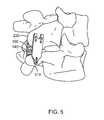
- FIG. 5is an upper perspective view of the embodiment of FIG. 1 in an installed position
- FIG. 6is an upper perspective view of a fusion member according to a second exemplary embodiment of the present disclosure.
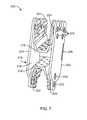
- FIG. 7is an upper perspective view of a fusion member according to a third exemplary embodiment of the present disclosure.
- FIG. 8is a lower perspective view of the embodiment of FIG. 7 ;
- FIG. 9is an upper perspective view of the embodiment of FIG. 7 in an installed position
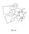
- FIG. 10is an side view of the embodiment of FIG. 7 in an installed position
- FIG. 11is an upper perspective view of a fusion member according to a fourth exemplary embodiment of the present disclosure.
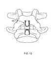
- FIG. 12is an upper view of the embodiment of FIG. 11 in an installed position
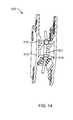
- FIG. 13is an upper perspective view of a fusion member according to a fifth exemplary embodiment of the present disclosure.
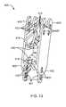
- FIG. 14is an upper perspective view of a fusion member according to a sixth exemplary embodiment of the present disclosure.
- FIG. 15is a lower perspective view of the embodiment of FIG. 14 ;
- FIG. 16is an upper perspective view of a fusion member according to a seventh exemplary embodiment of the present disclosure.
- FIG. 17is a lower perspective view of the embodiment of FIG. 16 .
- a sagittal planedivides a body into right and left portions.
- a mid-sagittal planedivides the body into equal right and left halves.
- a coronal planedivides a body into anterior and posterior portions.
- a transverse planedivides a body into superior and inferior portions.
- Anteriormeans toward the front of the body.
- Posteriormeans toward the back of the body.
- Superiormeans toward the head.
- Inferiormeans toward the feet.
- Medialmeans toward the midline of the body. Lateral means away from the midline of the body.
- Axialmeans toward a central axis of the body.
- Abaxialmeans away from a central axis of the body.
- an exemplary embodiment of a fusion member 100comprises a cage 115 defining an inner volume 110 and paired extensions 120 and 130 extending from cage 115 .
- FIGS. 4 and 5illustrate fusion member 100 installed between a pair of spinous processes 210 and 220 .
- fusion member 100generally forms an “H” shape in a posterior view, with extensions 120 forming ascending legs of the “H” shape and extensions 130 forming descending legs of the “H” shape.
- the term “fusion member”is used to describe a member configured to promote fusion of vertebral processes.
- extensions 120 and 130are configured so that they can be crimped (e.g, plastically deformed) onto spinous processes 210 and 220 .
- Extensions 120 and 130comprise gripping members 121 and 131 , respectively, which assist in clamping fusion member 100 to spinous processes 210 and 220 .
- the cage 115may comprise gripping members 135 located between extensions 120 and 130 .
- Gripping members 121 and 131allow fusion member 100 to be installed from a posterior direction so that extensions 120 and 130 can slide anteriorly along the sides of spinous processes 210 and 220 .
- extensions 120 and 130can be deformed so that gripping members 121 and 131 engage spinous processes 210 and 220 .
- extensions 120can be crimped or deformed so that they are pinched toward each other so that gripping members 121 sink into spinous process 220 .
- extensions 130can be crimped or deformed so that they are pinched toward each other to engage spinous process 210 .
- gripping members 121 , 131 , and 135are configured as sharp angled projections (e.g., teeth).
- gripping members 121 , 131 , and 135may be configured as prongs, tines, tabs, barbs or spikes.
- gripping members 121 and 131are angled so that the projections point towards cage 115 .
- Gripping members 121 and 131are configured to allow translation between the fusion member 100 and a spinous process if the fusion member 100 is moved toward the engaged spinous process. This configuration restricts translation of the fusion member 100 in a direction away from the engaged spinous process.
- gripping members 135are pointed superiorly and inferiorly, and are configured to prevent translation in the posterior direction between the fusion member 100 and spinous processes 210 and 220 .
- Extensions 120 and 130also comprise tabs 122 and 132 , respectively, which assist in maintaining a fixed engagement between fusion member 100 and spinous processes 210 and 220 .
- tabs 122 and 132may be formed by removing material from extensions 120 and 130 in a pattern that forms tabs 122 and 132 .
- tabs 122 and 132are in an undeformed condition wherein tabs 122 and 132 are parallel to extensions 120 and 130 .
- tabs 122 and 132may be deformed (e.g., plastically deformed inward toward the space between extensions 120 and 130 ) so that tabs 122 and 132 further engage spinous processes 210 and 220 .
- Tabs 122 and 132may be deformed with a tool (e.g., forceps or a plier-type device, not shown) that comprise projections configured to engage tabs 122 and 132 and leverage members to provide easier deformation of the tabs.
- Tabs 122 , 132 and gripping members 121 , 131serve to provide a positive engagement of fusion member 100 to spinous processes 210 and 220 .
- fusion member 100can provide fixation of spinous processes 210 and 220 .
- Cage 115is shown in this embodiment to comprise a first end 116 , a second end 118 , a first side 117 and a second side 119 .
- Cage 115also comprise a lower surface 129 , or lower cover, extending between first and second ends 116 , 118 and first and second sides 117 , 119 .
- lower surface 129can assist in retaining bone fragments inserted into inner volume 110 .
- a plurality of bone fragments 145may be disposed within inner volume 110 to assist in fusing spinous processes 210 and 220 together.
- Cage 115comprises a plurality of apertures 125 to promote fusion of the bone fragments 145 and spinous processes 210 and 220 .
- bone fragments 145may be used to assist in inter-spinous process fusion.
- bone fragments 145may be used to assist in fusing various locations of adjacent vertebrae, including for example, inter-laminar fusion, facet fusion, inter-transverse process fusion, and inter-discal fusion.
- Bone fragments 145may be of various sizes and shapes and may comprise bone autograft, allograft, or synthetic bone.
- extensions 120comprise a recessed portion 123 in the area distal from cage 115 .
- Extensions 130comprise projections 133 in the area distal from cage 115 .
- the fusion members 100can be arranged so that projections 133 fit into recessed portions 123 . This can allow for closer spacing of fusion members 100 .
- FIGS. 2 and 6another embodiment of a fusion member 101 is equivalent to fusion member 100 shown and described above in FIGS. 1 and 3 - 5 .
- Fusion member 101does not comprise a lower surface 129 .
- Still other exemplary embodimentsmay comprise a design similar to fusion member 100 with an additional upper surface, or upper cover, opposite of lower surface 129 to form a cage 115 that completely encloses the interior volume 110 .
- the upper surfacemay be movable or installable to provide at least temporary access to the interior volume 110 .
- an exemplary embodimentcomprises a multi-piece fusion member 200 .
- fusion member 200comprises four separate components that can be assembled to form a unit that functions similar to previously-described fusion member 100 .
- Fusion member 200comprises a first clamping member 201 , a second clamping member 202 , a first plate 203 , and a second plate 204 .
- First plate 203comprises a plurality of tabs 223 and second plate 204 comprises a plurality of tabs 233 .
- tabs 223 and 233are configured to extend through slots 224 in first and second clamping members 201 and 202 , respectively, and engage spinous processes 310 and 320 (shown in FIGS. 9 and 10 ).
- First and second plates 203 , 204may also comprise coupling or receiving members (not shown) including without limitation, threaded members, pins, eyelets, etc.
- First clamping member 201comprises a first end 216 and second clamping member comprises a second end 218 .
- First end 216 , second end 218 , and the central portions of first plate 203 and second plate 204combine to form a cage 215 defining an inner volume 210 .
- Second plate 204comprises a lower surface 229 (clearly visible in FIG. 8 ) configured to extend towards first plate 203 .
- Lower surface 229functions similar to previously described lower surface 129 of fusion member 100 and can serve to retain bone fragments 145 (not shown).
- FIGS. 11-12another exemplary embodiment comprises a multi-piece fusion member 300 that is generally equivalent to the embodiment shown and described in FIGS. 7-10 .
- This embodimentdoes not comprise a lower surface similar to lower surface 229 of the embodiment in FIGS. 7-10 .
- fusion member 300is viewed from above in an installed position. Fusion member 300 is generally “H”-shaped when viewed from above.
- FIG. 13another exemplary embodiment comprises a fusion member 400 similar to the one shown and described in FIGS. 1 and 3 - 5 .
- This embodimentalso comprises fastening members 490 configured to extend through first end 416 and second end 418 of cage 415 .
- Fastening members 490may comprise nails, screws, spikes, barbs, etc., and are configured to engage a spinous process inserted between extensions 420 and 430 .
- Fastening members 490can provide fixation of the fusion member 400 to the spinous processes in addition to that provided by gripping members 421 and 431 and tabs 422 and 432 .
- Fastening member 490may be preferentially positioned along a mid-sagittal plane bisecting the spinous process.
- FIGS. 14 and 15another exemplary embodiment comprises a fusion member 500 similar to the one shown and described in FIG. 13 .
- This embodimentcomprises a septum or rib 501 extending between first end 516 and second end 518 of cage 515 .
- Rib 501can serve to provide structural rigidity to fusion member 500 .
- FIGS. 16 and 17another exemplary embodiment comprises a fusion member 600 similar to the one shown and described in FIGS. 14 and 15 .
- This embodimentcomprises a septum or rib 601 extending between first end 616 and second end 618 of cage 615 .
- Rib 601can serve to provide structural rigidity to fusion member 600 .
- Rib 601also comprises a receiving or securing feature 602 .
- securing feature 602comprises a notch, but other exemplary embodiments may comprise different configurations, including for example, a pin, a hook, a spike, a barb, etc.
- Securing feature 602can be configured to secure, for example, a shaped bone block (not shown) configured for insertion into cage 615 .
- Fusion members according to exemplary embodimentsmay be manufactured from suitable medical-grade materials, including, but not limited to, titanium and stainless steel.
- Coupledis defined as connected, although not necessarily directly, and not necessarily mechanically.
- a step of a method or an element of a devicethat “comprises,” “has,” “includes” or “contains” one or more features, possesses those one or more features, but is not limited to possessing only those one or more features.
- a device or structure that is configured in a certain wayis configured in at least that way, but may also be configured in ways that are not listed.
Landscapes
- Health & Medical Sciences (AREA)
- Orthopedic Medicine & Surgery (AREA)
- Life Sciences & Earth Sciences (AREA)
- Neurology (AREA)
- Surgery (AREA)
- Heart & Thoracic Surgery (AREA)
- Engineering & Computer Science (AREA)
- Biomedical Technology (AREA)
- Nuclear Medicine, Radiotherapy & Molecular Imaging (AREA)
- Medical Informatics (AREA)
- Molecular Biology (AREA)
- Animal Behavior & Ethology (AREA)
- General Health & Medical Sciences (AREA)
- Public Health (AREA)
- Veterinary Medicine (AREA)
- Prostheses (AREA)
- Surgical Instruments (AREA)
Abstract
Description
Claims (26)
Priority Applications (2)
| Application Number | Priority Date | Filing Date | Title |
|---|---|---|---|
| US13/709,251US8961564B2 (en) | 2008-12-23 | 2012-12-10 | Bone tissue clamp |
| US14/587,877US20150112388A1 (en) | 2007-12-28 | 2014-12-31 | Bone tissue clamp |
Applications Claiming Priority (4)
| Application Number | Priority Date | Filing Date | Title |
|---|---|---|---|
| US12/342,816US8940019B2 (en) | 2007-12-28 | 2008-12-23 | Bone tissue fixation device and method |
| US21968709P | 2009-06-23 | 2009-06-23 | |
| US12/820,575US8377097B2 (en) | 2009-06-23 | 2010-06-22 | Bone tissue clamp |
| US13/709,251US8961564B2 (en) | 2008-12-23 | 2012-12-10 | Bone tissue clamp |
Related Parent Applications (1)
| Application Number | Title | Priority Date | Filing Date |
|---|---|---|---|
| US12/820,575ContinuationUS8377097B2 (en) | 2007-12-28 | 2010-06-22 | Bone tissue clamp |
Related Child Applications (1)
| Application Number | Title | Priority Date | Filing Date |
|---|---|---|---|
| US14/587,877ContinuationUS20150112388A1 (en) | 2007-12-28 | 2014-12-31 | Bone tissue clamp |
Publications (2)
| Publication Number | Publication Date |
|---|---|
| US20130103089A1 US20130103089A1 (en) | 2013-04-25 |
| US8961564B2true US8961564B2 (en) | 2015-02-24 |
Family
ID=43429762
Family Applications (3)
| Application Number | Title | Priority Date | Filing Date |
|---|---|---|---|
| US12/820,575Active2031-01-13US8377097B2 (en) | 2007-12-28 | 2010-06-22 | Bone tissue clamp |
| US13/709,251ActiveUS8961564B2 (en) | 2007-12-28 | 2012-12-10 | Bone tissue clamp |
| US14/587,877AbandonedUS20150112388A1 (en) | 2007-12-28 | 2014-12-31 | Bone tissue clamp |
Family Applications Before (1)
| Application Number | Title | Priority Date | Filing Date |
|---|---|---|---|
| US12/820,575Active2031-01-13US8377097B2 (en) | 2007-12-28 | 2010-06-22 | Bone tissue clamp |
Family Applications After (1)
| Application Number | Title | Priority Date | Filing Date |
|---|---|---|---|
| US14/587,877AbandonedUS20150112388A1 (en) | 2007-12-28 | 2014-12-31 | Bone tissue clamp |
Country Status (5)
| Country | Link |
|---|---|
| US (3) | US8377097B2 (en) |
| EP (1) | EP2445428A2 (en) |
| JP (1) | JP2012531263A (en) |
| AU (1) | AU2010270915A1 (en) |
| WO (1) | WO2011005508A2 (en) |
Cited By (3)
| Publication number | Priority date | Publication date | Assignee | Title |
|---|---|---|---|---|
| US10034693B2 (en) | 2016-07-07 | 2018-07-31 | Mark S. Stern | Spinous laminar clamp assembly |
| US10398478B2 (en) | 2015-07-31 | 2019-09-03 | Paradigm Spine, Llc | Interspinous stabilization and fusion device |
| US11219531B2 (en) | 2019-04-10 | 2022-01-11 | Wenzel Spine, Inc. | Rotatable intervertebral spacing implant |
Families Citing this family (45)
| Publication number | Priority date | Publication date | Assignee | Title |
|---|---|---|---|---|
| US8241330B2 (en) | 2007-01-11 | 2012-08-14 | Lanx, Inc. | Spinous process implants and associated methods |
| WO2006058221A2 (en) | 2004-11-24 | 2006-06-01 | Abdou Samy M | Devices and methods for inter-vertebral orthopedic device placement |
| US9265532B2 (en) | 2007-01-11 | 2016-02-23 | Lanx, Inc. | Interspinous implants and methods |
| US8382801B2 (en)* | 2007-01-11 | 2013-02-26 | Lanx, Inc. | Spinous process implants, instruments, and methods |
| US9247968B2 (en) | 2007-01-11 | 2016-02-02 | Lanx, Inc. | Spinous process implants and associated methods |
| US7842074B2 (en) | 2007-02-26 | 2010-11-30 | Abdou M Samy | Spinal stabilization systems and methods of use |
| US8940019B2 (en)* | 2007-12-28 | 2015-01-27 | Osteomed Spine, Inc. | Bone tissue fixation device and method |
| EP2323574B1 (en) | 2008-08-13 | 2012-02-15 | Synthes GmbH | Interspinous spacer assembly |
| KR101759354B1 (en) | 2009-06-10 | 2017-07-18 | 히사미쓰 세이야꾸 가부시키가이샤 | Microneedle device |
| EP2445428A2 (en) | 2009-06-23 | 2012-05-02 | Osteomed Spine, Inc. | Bone tissue clamp |
| US8636772B2 (en) | 2009-06-23 | 2014-01-28 | Osteomed Llc | Bone plates, screws, and instruments |
| BR112012003050A2 (en)* | 2009-08-10 | 2019-09-24 | Osteomed Llc | bone plate assembly, bone surface attachment plate, cushion and bone plate |
| US8795335B1 (en) | 2009-11-06 | 2014-08-05 | Samy Abdou | Spinal fixation devices and methods of use |
| US8764806B2 (en) | 2009-12-07 | 2014-07-01 | Samy Abdou | Devices and methods for minimally invasive spinal stabilization and instrumentation |
| US8603142B2 (en)* | 2010-12-05 | 2013-12-10 | James C. Robinson | Spinous process fixation apparatus and method |
| EP3097878A1 (en) | 2011-02-06 | 2016-11-30 | Paradigm Spine, LLC | Translaminar interspinous stabilization system |
| US8425560B2 (en)* | 2011-03-09 | 2013-04-23 | Farzad Massoudi | Spinal implant device with fixation plates and lag screws and method of implanting |
| US20120323276A1 (en)* | 2011-06-17 | 2012-12-20 | Bryan Okamoto | Expandable interspinous device |
| US9149306B2 (en) | 2011-06-21 | 2015-10-06 | Seaspine, Inc. | Spinous process device |
| USD757943S1 (en)* | 2011-07-14 | 2016-05-31 | Nuvasive, Inc. | Spinous process plate |
| US8845728B1 (en) | 2011-09-23 | 2014-09-30 | Samy Abdou | Spinal fixation devices and methods of use |
| US11812923B2 (en) | 2011-10-07 | 2023-11-14 | Alan Villavicencio | Spinal fixation device |
| EP2814410B1 (en)* | 2012-02-17 | 2019-05-01 | The University of Toledo | Hybrid multifunctional posterior interspinous fusion device |
| US20130226240A1 (en) | 2012-02-22 | 2013-08-29 | Samy Abdou | Spinous process fixation devices and methods of use |
| US10448977B1 (en)* | 2012-03-31 | 2019-10-22 | Ali H. MESIWALA | Interspinous device and related methods |
| US10687860B2 (en) | 2012-04-24 | 2020-06-23 | Retrospine Pty Ltd | Segmental correction of lumbar lordosis |
| ITMI20120936A1 (en)* | 2012-05-30 | 2013-12-01 | Promev S R L | INTERLAMINAR-INTERSPINOSUS VERTEBRAL DEVICE |
| US10660674B2 (en)* | 2012-07-17 | 2020-05-26 | Gomboc, LLC | Magnetically levitated spinous process implants and methods thereof |
| US9198767B2 (en) | 2012-08-28 | 2015-12-01 | Samy Abdou | Devices and methods for spinal stabilization and instrumentation |
| WO2015028853A1 (en) | 2013-08-30 | 2015-03-05 | Newsouth Innovations Pty Limited | Spine stabilization device |
| AU2013308332B2 (en)* | 2012-08-31 | 2017-01-19 | Newsouth Innovations Pty Limited | Bone stabilization device and methods of use |
| US8906065B2 (en)* | 2012-10-22 | 2014-12-09 | Spectrum Spine Ip Holdings, Llc | Inter-spinous process device and method |
| US9320617B2 (en) | 2012-10-22 | 2016-04-26 | Cogent Spine, LLC | Devices and methods for spinal stabilization and instrumentation |
| US9999454B2 (en)* | 2013-12-05 | 2018-06-19 | A&E Advanced Closure Systems, Llc | Bone plate system and method |
| AU2015269383B2 (en) | 2014-06-04 | 2017-12-07 | Wenzel Spine, Inc. | Bilaterally expanding intervertebral body fusion device |
| KR101647446B1 (en)* | 2014-10-20 | 2016-08-10 | 주식회사 메드릭스 | Interspinous fusion implant |
| US20160354161A1 (en) | 2015-06-05 | 2016-12-08 | Ortho Kinematics, Inc. | Methods for data processing for intra-operative navigation systems |
| US10857003B1 (en) | 2015-10-14 | 2020-12-08 | Samy Abdou | Devices and methods for vertebral stabilization |
| US10335207B2 (en) | 2015-12-29 | 2019-07-02 | Nuvasive, Inc. | Spinous process plate fixation assembly |
| US11707203B2 (en) | 2016-10-11 | 2023-07-25 | Wenzel Spine, Inc. | Systems for generating image-based measurements during diagnosis |
| US10973648B1 (en) | 2016-10-25 | 2021-04-13 | Samy Abdou | Devices and methods for vertebral bone realignment |
| US10744000B1 (en) | 2016-10-25 | 2020-08-18 | Samy Abdou | Devices and methods for vertebral bone realignment |
| US11678995B2 (en) | 2018-07-20 | 2023-06-20 | Fellowship Of Orthopaedic Researchers, Inc. | Magnetic intervertebral disc replacement devices and methods thereof |
| US11179248B2 (en) | 2018-10-02 | 2021-11-23 | Samy Abdou | Devices and methods for spinal implantation |
| TWI819504B (en)* | 2022-02-25 | 2023-10-21 | 寶億生技股份有限公司 | Interspinous process device and device for stabilizing thereof |
Citations (157)
| Publication number | Priority date | Publication date | Assignee | Title |
|---|---|---|---|---|
| US3242922A (en) | 1963-06-25 | 1966-03-29 | Charles B Thomas | Internal spinal fixation means |
| US3469573A (en) | 1966-05-04 | 1969-09-30 | Michael A Florio | Orthopedic clamp |
| US3648691A (en) | 1970-02-24 | 1972-03-14 | Univ Colorado State Res Found | Method of applying vertebral appliance |
| US4066082A (en) | 1975-04-24 | 1978-01-03 | Ramot University Authority For Applied Research And Industrial Development Ltd. | Force applicator including indicator |
| US4290328A (en) | 1980-02-15 | 1981-09-22 | Vermont American Corp. | Ratchet handle |
| USD281814S (en) | 1983-07-13 | 1985-12-17 | Techmedica, Inc. | Osteotomy staple |
| US4570623A (en) | 1983-06-02 | 1986-02-18 | Pfizer Hospital Products Group Inc. | Arched bridge staple |
| US4592346A (en) | 1985-04-08 | 1986-06-03 | Jurgutis John A | Orthopedic staple |
| US4848328A (en) | 1986-05-20 | 1989-07-18 | Laboureau Jacques P | Agraffe for osteosynthesis |
| US4852558A (en) | 1987-07-29 | 1989-08-01 | Outerbridge Howard K G | Compressible bone staple |
| US4913144A (en) | 1988-08-03 | 1990-04-03 | D.A.O. S.R.L. | Adjustable staple |
| US4994073A (en) | 1989-02-22 | 1991-02-19 | United States Surgical Corp. | Skin fastener |
| US5007909A (en) | 1986-11-05 | 1991-04-16 | Chaim Rogozinski | Apparatus for internally fixing the spine |
| US5011484A (en) | 1987-11-16 | 1991-04-30 | Breard Francis H | Surgical implant for restricting the relative movement of vertebrae |
| US5053038A (en) | 1989-08-17 | 1991-10-01 | Tenstaple, Inc. | Compression bone staple |
| US5074864A (en) | 1988-12-21 | 1991-12-24 | Zimmer, Inc. | Clamp assembly for use in a spinal system |
| US5108422A (en) | 1990-10-22 | 1992-04-28 | United States Surgical Corporation | Skin fastener |
| US5196318A (en) | 1990-06-26 | 1993-03-23 | The Texas A&M University System | Precisely regulated expression of deleterious genes |
| US5201746A (en) | 1991-10-16 | 1993-04-13 | United States Surgical Corporation | Surgical hemostatic clip |
| US5246442A (en) | 1991-12-31 | 1993-09-21 | Danek Medical, Inc. | Spinal hook |
| US5261909A (en) | 1992-02-18 | 1993-11-16 | Danek Medical, Inc. | Variable angle screw for spinal implant system |
| US5290312A (en) | 1991-09-03 | 1994-03-01 | Alphatec | Artificial vertebral body |
| US5395370A (en) | 1991-10-18 | 1995-03-07 | Pina Vertriebs Ag | Vertebral compression clamp for surgical repair to damage to the spine |
| US5454814A (en) | 1992-09-02 | 1995-10-03 | Orthomed Sarl | Surgical clamp and clamp driving device |
| US5496318A (en) | 1993-01-08 | 1996-03-05 | Advanced Spine Fixation Systems, Inc. | Interspinous segmental spine fixation device |
| US5609634A (en) | 1992-07-07 | 1997-03-11 | Voydeville; Gilles | Intervertebral prosthesis making possible rotatory stabilization and flexion/extension stabilization |
| US5611800A (en) | 1994-02-15 | 1997-03-18 | Alphatec Manufacturing, Inc. | Spinal fixation system |
| US5626592A (en) | 1993-04-16 | 1997-05-06 | United States Surgical Corporation | Surgical hemostatic clip |
| US5645599A (en) | 1994-07-26 | 1997-07-08 | Fixano | Interspinal vertebral implant |
| US5713911A (en) | 1996-10-03 | 1998-02-03 | United States Surgical Corporation | Surgical clip |
| US5722976A (en) | 1993-08-27 | 1998-03-03 | Brown; Robin Peter | Apparatus and method for surgically securing bone parts |
| US5836948A (en) | 1997-01-02 | 1998-11-17 | Saint Francis Medical Technologies, Llc | Spine distraction implant and method |
| US5853414A (en) | 1991-05-09 | 1998-12-29 | Groiso; Jorge A. | Elastic clip for osteosynthesis |
| US5893889A (en) | 1997-06-20 | 1999-04-13 | Harrington; Michael | Artificial disc |
| US5941881A (en) | 1998-01-09 | 1999-08-24 | Medidea, Llc | Bone fastening apparatus and related procedures |
| US6007538A (en) | 1997-07-25 | 1999-12-28 | Duke University | Sternal closure device |
| WO2000062693A1 (en) | 1999-04-21 | 2000-10-26 | Eaves Felmont F Iii | Bone fracture fixation clip |
| US6148696A (en) | 1999-06-01 | 2000-11-21 | Chiang; Shu Chi | Ratchet screw driver |
| US20010020188A1 (en) | 1997-10-27 | 2001-09-06 | Tom Sander | Selective uptake of materials by bone implants |
| US6312431B1 (en) | 2000-04-24 | 2001-11-06 | Wilson T. Asfora | Vertebrae linking system |
| US6332883B1 (en) | 1997-01-02 | 2001-12-25 | St. Francis Medical Technologies, Inc. | Spine distraction implant |
| US6336928B1 (en) | 1996-10-18 | 2002-01-08 | Depuy France | Device for securing at least two vertebrae |
| US6352537B1 (en) | 1998-09-17 | 2002-03-05 | Electro-Biology, Inc. | Method and apparatus for spinal fixation |
| US6364883B1 (en) | 2001-02-23 | 2002-04-02 | Albert N. Santilli | Spinous process clamp for spinal fusion and method of operation |
| US6375683B1 (en) | 1997-05-02 | 2002-04-23 | Stryker France S.A. | Implant in particular for replacing a vertebral body in surgery of the spine |
| US6440169B1 (en)* | 1998-02-10 | 2002-08-27 | Dimso | Interspinous stabilizer to be fixed to spinous processes of two vertebrae |
| US6443987B1 (en) | 2000-09-15 | 2002-09-03 | Donald W. Bryan | Spinal vertebral implant |
| US6451019B1 (en) | 1998-10-20 | 2002-09-17 | St. Francis Medical Technologies, Inc. | Supplemental spine fixation device and method |
| US6485518B1 (en) | 1999-12-10 | 2002-11-26 | Nuvasive | Facet screw and bone allograft intervertebral support and fusion system |
| WO2003007829A1 (en) | 2001-07-20 | 2003-01-30 | Spinal Concepts, Inc. | Spinal stabilization system and method |
| US20030045877A1 (en) | 2001-08-29 | 2003-03-06 | Chung-Chun Yeh | Device for fixing spinal column under treatment |
| US6558387B2 (en) | 2001-01-30 | 2003-05-06 | Fastemetix, Llc | Porous interbody fusion device having integrated polyaxial locking interference screws |
| US6565573B1 (en) | 2001-04-16 | 2003-05-20 | Smith & Nephew, Inc. | Orthopedic screw and method of use |
| US6582435B2 (en) | 2001-11-29 | 2003-06-24 | Bioplate, Inc. | Bone alignment and fixation device and installation method, using guide tab |
| US6641585B2 (en) | 2000-09-22 | 2003-11-04 | Showa Ika Kohgyo Co., Ltd. | Bone connecting tool and connecting member thereof |
| US20030216736A1 (en) | 2002-05-17 | 2003-11-20 | Robinson James C. | Device for fixation of spinous processes |
| US20040034430A1 (en) | 2002-06-14 | 2004-02-19 | Falahee Mark H. | Anatomic vertebral cage |
| US6695842B2 (en) | 1997-10-27 | 2004-02-24 | St. Francis Medical Technologies, Inc. | Interspinous process distraction system and method with positionable wing and method |
| US6699247B2 (en) | 1997-01-02 | 2004-03-02 | St. Francis Medical Technologies, Inc. | Spine distraction implant |
| US6712819B2 (en) | 1998-10-20 | 2004-03-30 | St. Francis Medical Technologies, Inc. | Mating insertion instruments for spinal implants and methods of use |
| US20040106995A1 (en)* | 2000-07-12 | 2004-06-03 | Regis Le Couedic | Shock-absorbing intervertebral implant |
| US6761720B1 (en) | 1999-10-15 | 2004-07-13 | Spine Next | Intervertebral implant |
| US6783531B2 (en) | 1999-04-26 | 2004-08-31 | Drew Allen, DPM | Compression bone staple, apparatus and method |
| US6796983B1 (en) | 1997-01-02 | 2004-09-28 | St. Francis Medical Technologies, Inc. | Spine distraction implant and method |
| US20040193272A1 (en) | 2003-03-06 | 2004-09-30 | Rafail Zubok | Instrumentation and methods for use in implanting a cervical disc replacement device |
| JP2004535239A (en) | 2001-07-16 | 2004-11-25 | スパインコア,インコーポレーション | Artificial disc with corrugated washer force restoration element |
| US20050043732A1 (en) | 2003-08-18 | 2005-02-24 | Dalton Brian E. | Cervical compression plate assembly |
| US20050056979A1 (en) | 2001-12-07 | 2005-03-17 | Mathys Medizinaltechnik Ag | Damping element and device for stabilisation of adjacent vertebral bodies |
| US20050137594A1 (en) | 2002-02-04 | 2005-06-23 | Doubler Robert L. | Spinal fixation assembly |
| US6923812B1 (en) | 2001-07-30 | 2005-08-02 | Bioplate, Inc. | Barbed clip for bone alignment and fixation |
| US20050216017A1 (en) | 2004-03-09 | 2005-09-29 | Louie Fielding | Spinal implant and method for restricting spinal flexion |
| US20050234459A1 (en) | 2002-10-10 | 2005-10-20 | U.S. Spinal Technologies, Llc | Bone fixation implant system and method |
| US20050256582A1 (en) | 1999-10-08 | 2005-11-17 | Ferree Bret A | Spinal implants, including devices that reduce pressure on the annulus fibrosis |
| US6969391B1 (en) | 1999-04-21 | 2005-11-29 | Romolo Igino Gazzani | Semi-rigid compressive clamp for use in sternotomy, and forceps for its application |
| US20060004367A1 (en) | 2004-06-17 | 2006-01-05 | Alamin Todd F | Facet joint fusion devices and methods |
| US20060074425A1 (en) | 2002-09-11 | 2006-04-06 | Chester Sutterlin | Systems and methods for removing body tissue |
| US7025787B2 (en) | 2001-11-26 | 2006-04-11 | Sdgi Holdings, Inc. | Implantable joint prosthesis and associated instrumentation |
| US7060068B2 (en) | 2000-10-24 | 2006-06-13 | Sdgi Holdings, Inc. | Vertebrae fastener placement guide |
| US20060142771A1 (en) | 2003-06-11 | 2006-06-29 | Florian Beutter | Bone clamp |
| US20060235518A1 (en) | 2005-03-17 | 2006-10-19 | Jason Blain | Flanged interbody fusion device with fastener insert and retaining ring |
| US20060235391A1 (en) | 2005-03-08 | 2006-10-19 | Sutterlin Chester Iii | Facet joint stabilization |
| US20060241601A1 (en) | 2005-04-08 | 2006-10-26 | Trautwein Frank T | Interspinous vertebral and lumbosacral stabilization devices and methods of use |
| US20060247623A1 (en) | 2005-04-29 | 2006-11-02 | Sdgi Holdings, Inc. | Local delivery of an active agent from an orthopedic implant |
| US20060247634A1 (en) | 2005-05-02 | 2006-11-02 | Warner Kenneth D | Spinous Process Spacer Implant and Technique |
| US20060247640A1 (en) | 2005-04-29 | 2006-11-02 | Sdgi Holdings, Inc. | Spinous process stabilization devices and methods |
| US20060287654A1 (en) | 2006-08-11 | 2006-12-21 | Jeffrey Posnick | Implant securing device and method |
| US20070016189A1 (en) | 2005-06-30 | 2007-01-18 | Depuy Spine Sarl | Orthopedic clamping hook assembly |
| US20070093823A1 (en) | 2005-09-29 | 2007-04-26 | Nuvasive, Inc. | Spinal distraction device and methods of manufacture and use |
| US7229444B2 (en) | 2004-08-25 | 2007-06-12 | Howmedica Osteonics Corp. | Trochanteric cerclage plate |
| WO2007070819A2 (en) | 2005-12-14 | 2007-06-21 | Spinefrontier Lls | Spinous process fixation implant |
| US7250060B2 (en) | 2004-01-27 | 2007-07-31 | Sdgi Holdings, Inc. | Hybrid intervertebral disc system |
| US7255698B2 (en) | 1994-03-28 | 2007-08-14 | Warsaw Orthopedic, Inc. | Apparatus and method for anterior spinal stabilization |
| US20070191844A1 (en) | 2006-01-31 | 2007-08-16 | Sdgi Holdings, Inc. | In-series, dual locking mechanism device |
| WO2007109402A2 (en) | 2006-03-21 | 2007-09-27 | Spinefrontier Lls | Spinous process fixation device |
| US20070250065A1 (en) | 2006-04-21 | 2007-10-25 | David Efron | Method and apparatus for the control of hemorrhage from major vessels |
| EP1477124B1 (en) | 2003-05-12 | 2007-10-31 | C.H. Medical Limited | Fixation of fractured bones |
| US7294128B2 (en) | 2002-04-09 | 2007-11-13 | Nas Medical Technologies, Inc. | Bone fixation apparatus |
| US20070270812A1 (en) | 2006-04-14 | 2007-11-22 | Sdgi Holdings, Inc. | Fixation plate and method of use |
| US20070276384A1 (en) | 2003-11-19 | 2007-11-29 | Frank Spratt | Hook for Fixing a Spinal Support Rod to a Vertebra |
| US20070276500A1 (en) | 2004-09-23 | 2007-11-29 | St. Francis Medical Technologies, Inc. | Interspinous process implant including a binder, binder aligner and method of implantation |
| US20080021472A1 (en) | 2003-02-12 | 2008-01-24 | Kyphon Inc. | System and Method for Immobilizing Adjacent Spinous Processes |
| US20080103512A1 (en) | 2006-10-23 | 2008-05-01 | G&L Consulting, Llc | Clamping system and method for fusing vertebral elements in a spine |
| US20080147190A1 (en) | 2006-12-14 | 2008-06-19 | Warsaw Orthopedic, Inc. | Interspinous Process Devices and Methods |
| US7393361B2 (en) | 2004-02-20 | 2008-07-01 | Spinecore, Inc. | Artificial intervertebral disc having a bored semispherical bearing with a compression locking post and retaining caps |
| US7396360B2 (en) | 2004-09-29 | 2008-07-08 | The Cleveland Clinic Foundation | Minimally invasive method and apparatus for fusing adjacent vertebrae |
| US20080177330A1 (en) | 2006-10-24 | 2008-07-24 | Ralph James D | Self-locking screws for medical implants |
| US20080183211A1 (en)* | 2007-01-11 | 2008-07-31 | Lanx, Llc | Spinous process implants and associated methods |
| US20080183218A1 (en) | 2007-01-31 | 2008-07-31 | Nuvasive, Inc. | System and Methods for Spinous Process Fusion |
| US20080228225A1 (en)* | 2006-11-30 | 2008-09-18 | Paradigm Spine, Llc | Interlaminar-Interspinous Vertebral Stabilization System |
| US20080243186A1 (en) | 2007-02-26 | 2008-10-02 | Abdou M Samy | Spinal stabilization systems and methods of use |
| US20080243185A1 (en) | 2006-09-27 | 2008-10-02 | Felix Brent A | Spinal stabilizing system |
| US20080281359A1 (en) | 2007-01-29 | 2008-11-13 | Abdou M S | Spinal stabilization systems and methods of use |
| US20090018658A1 (en) | 2006-08-09 | 2009-01-15 | Nuvasive, Inc. | Methods and apparatus for treating spinal stenosis |
| US20090062918A1 (en) | 2007-08-30 | 2009-03-05 | Jeffrey Chun Wang | Interspinous implant, tools and methods of implanting |
| WO2009086397A2 (en) | 2007-12-28 | 2009-07-09 | Osteomed Spine, Inc. | Bone tissue fixation device and method |
| US20090216272A1 (en) | 2008-02-22 | 2009-08-27 | Depuy Spine, Inc. | Method and system for trans-lamina spinal fixation |
| US20090216273A1 (en) | 2008-02-19 | 2009-08-27 | U. S. Spinal Technologies, L.L.C. | Curved facet joint fixation assembly and associated implantation tool and method |
| US20090264927A1 (en) | 2008-04-14 | 2009-10-22 | Howard Joeseph Ginsberg | Spinous process stabilization device and method |
| US20090270918A1 (en) | 2005-04-08 | 2009-10-29 | David Attia | Surgical Intervertebral Implant Forming a Swivel Joint |
| US20090326589A1 (en) | 2008-06-26 | 2009-12-31 | Lemoine Jeremy J | Hinged plate for dynamic stabilization |
| US20100036419A1 (en) | 2008-08-08 | 2010-02-11 | Alphatec Spine, Inc. | Spinous process device and method of use |
| US20100087860A1 (en) | 2006-12-12 | 2010-04-08 | Spinefrontier, Inc | Spinous process fixation implant |
| US20100241167A1 (en) | 2007-01-11 | 2010-09-23 | Lanx, Inc. | Spinous process implants and associated methods |
| US20100318127A1 (en) | 2009-06-12 | 2010-12-16 | Kyphon Sarl | Interspinous implant and methods of use |
| US7857857B2 (en)* | 2005-05-02 | 2010-12-28 | The Board Of Trustees Of The Leland Stanford Junior University | Devices, systems and methods for augmenting intervertebral discs |
| US7862592B2 (en) | 2005-12-06 | 2011-01-04 | Nuvasive, Inc. | Methods and apparatus for treating spinal stenosis |
| US20110029020A1 (en) | 2009-06-23 | 2011-02-03 | Osteomed, L.P. | Bone Tissue Clamp |
| US20110054531A1 (en) | 2007-01-11 | 2011-03-03 | Andrew Lamborne | Spinous process implants, instruments, and methods |
| US20110066186A1 (en) | 2009-09-11 | 2011-03-17 | Boyer Ii Michael Lee | Spinous Process Fusion Devices |
| US7935133B2 (en) | 2008-02-08 | 2011-05-03 | Mmsn Limited Partnership | Interlaminar hook |
| US20110144692A1 (en) | 2008-08-13 | 2011-06-16 | Synthes Usa, Llc | Interspinous spacer assembly |
| US20110166600A1 (en) | 2007-01-11 | 2011-07-07 | Lanx, Inc. | Interspinsous implants and methods |
| US20110224731A1 (en) | 2010-03-12 | 2011-09-15 | Southern Spine, Llc | Interspinous Process Spacing Device |
| US8043337B2 (en) | 2006-06-14 | 2011-10-25 | Spartek Medical, Inc. | Implant system and method to treat degenerative disorders of the spine |
| US8048120B1 (en) | 2006-05-31 | 2011-11-01 | Medicine Lodge, Inc. | System and method for segmentally modular spinal plating |
| US8070817B2 (en) | 2006-06-28 | 2011-12-06 | M.O.R.E. Medical Solutions Gmbh | Vertebral implant |
| US20110313458A1 (en) | 2010-06-16 | 2011-12-22 | Butler Michael S | Spinal Clips For Interspinous Decompression |
| US20110319936A1 (en) | 2009-06-23 | 2011-12-29 | Osteomed Llc | Spinous process fusion implants and insertion, compression, and locking instrumentation |
| US20120010662A1 (en) | 2010-07-12 | 2012-01-12 | Depuy Spine, Inc. | Pedicular facet fusion screw with plate |
| US20120016418A1 (en) | 2010-07-15 | 2012-01-19 | Spinefrontier Inc | Interspinous fixation implant |
| US8114132B2 (en) | 2010-01-13 | 2012-02-14 | Kyphon Sarl | Dynamic interspinous process device |
| US20120078304A1 (en) | 2010-09-28 | 2012-03-29 | Harm-Iven Jensen | Bilaterales lamina-implantat |
| US20120078305A1 (en) | 2009-12-31 | 2012-03-29 | Industrial Technology Research Institute | Flexible spine fixing structure |
| US20120083846A1 (en) | 2010-10-01 | 2012-04-05 | K2M, Inc. | Dynamic plate with inserts |
| US20120083844A1 (en) | 2008-10-23 | 2012-04-05 | Linares Medical Devices, Llc | Inter-vertebral support kit including main insert jack and dual secondary auxiliary support jacks located between succeeding transverse processes |
| US20120089184A1 (en) | 2010-10-08 | 2012-04-12 | Chung-Chun Yeh | Device for tightly gripping on the spinous process of the spine |
| US20120095512A1 (en) | 2010-10-18 | 2012-04-19 | Raj Nihalani | Cross connectors |
| US20120101528A1 (en) | 2010-07-26 | 2012-04-26 | Souza John J | Spinous process implant and method of fixation |
| US20120109203A1 (en) | 2010-11-01 | 2012-05-03 | Warsaw Orthopedic, Inc. | Spinous process implant with extended post |
| US20120109198A1 (en) | 2010-11-01 | 2012-05-03 | Warsaw Orthopedic, Inc. | Spinous process implant with a post and an enlarged boss |
| US20120109205A1 (en) | 2006-10-24 | 2012-05-03 | Kyphon Sarl | Systems and Methods for In Situ Assembly of an Interspinous Process Distraction Implant |
| US20120123475A1 (en) | 2010-11-12 | 2012-05-17 | Medisourceplus Co., Ltd. | Cervical plating system |
| US20120136390A1 (en) | 2010-11-29 | 2012-05-31 | Butler Michael S | Spinal Implants For Lumbar Vertebra To Sacrum Fixation |
| US20120143252A1 (en) | 2010-12-05 | 2012-06-07 | Robinson James C | Spinous process fixation apparatus and method |
| US20120150228A1 (en) | 2010-12-13 | 2012-06-14 | Jason Zappacosta | Spinous Process Fusion Devices and Methods Thereof |
| US20120158063A1 (en) | 2004-10-20 | 2012-06-21 | Vertiflex, Inc. | Interspinous spacer |
| US20120158061A1 (en) | 2010-12-17 | 2012-06-21 | David Koch | Methods and systems for minimally invasive posterior arch expansion |
- 2010
- 2010-06-22EPEP10797565Apatent/EP2445428A2/ennot_activeWithdrawn
- 2010-06-22AUAU2010270915Apatent/AU2010270915A1/ennot_activeAbandoned
- 2010-06-22USUS12/820,575patent/US8377097B2/enactiveActive
- 2010-06-22JPJP2012517647Apatent/JP2012531263A/enactivePending
- 2010-06-22WOPCT/US2010/039463patent/WO2011005508A2/enactiveApplication Filing
- 2012
- 2012-12-10USUS13/709,251patent/US8961564B2/enactiveActive
- 2014
- 2014-12-31USUS14/587,877patent/US20150112388A1/ennot_activeAbandoned
Patent Citations (178)
| Publication number | Priority date | Publication date | Assignee | Title |
|---|---|---|---|---|
| US3242922A (en) | 1963-06-25 | 1966-03-29 | Charles B Thomas | Internal spinal fixation means |
| US3469573A (en) | 1966-05-04 | 1969-09-30 | Michael A Florio | Orthopedic clamp |
| US3648691A (en) | 1970-02-24 | 1972-03-14 | Univ Colorado State Res Found | Method of applying vertebral appliance |
| US4066082A (en) | 1975-04-24 | 1978-01-03 | Ramot University Authority For Applied Research And Industrial Development Ltd. | Force applicator including indicator |
| US4290328A (en) | 1980-02-15 | 1981-09-22 | Vermont American Corp. | Ratchet handle |
| US4570623A (en) | 1983-06-02 | 1986-02-18 | Pfizer Hospital Products Group Inc. | Arched bridge staple |
| USD281814S (en) | 1983-07-13 | 1985-12-17 | Techmedica, Inc. | Osteotomy staple |
| US4592346A (en) | 1985-04-08 | 1986-06-03 | Jurgutis John A | Orthopedic staple |
| US4848328A (en) | 1986-05-20 | 1989-07-18 | Laboureau Jacques P | Agraffe for osteosynthesis |
| US5007909A (en) | 1986-11-05 | 1991-04-16 | Chaim Rogozinski | Apparatus for internally fixing the spine |
| US4852558A (en) | 1987-07-29 | 1989-08-01 | Outerbridge Howard K G | Compressible bone staple |
| US5011484A (en) | 1987-11-16 | 1991-04-30 | Breard Francis H | Surgical implant for restricting the relative movement of vertebrae |
| US4913144A (en) | 1988-08-03 | 1990-04-03 | D.A.O. S.R.L. | Adjustable staple |
| US5074864A (en) | 1988-12-21 | 1991-12-24 | Zimmer, Inc. | Clamp assembly for use in a spinal system |
| US4994073A (en) | 1989-02-22 | 1991-02-19 | United States Surgical Corp. | Skin fastener |
| US5053038A (en) | 1989-08-17 | 1991-10-01 | Tenstaple, Inc. | Compression bone staple |
| US5196318A (en) | 1990-06-26 | 1993-03-23 | The Texas A&M University System | Precisely regulated expression of deleterious genes |
| US5108422A (en) | 1990-10-22 | 1992-04-28 | United States Surgical Corporation | Skin fastener |
| US5853414A (en) | 1991-05-09 | 1998-12-29 | Groiso; Jorge A. | Elastic clip for osteosynthesis |
| US5290312A (en) | 1991-09-03 | 1994-03-01 | Alphatec | Artificial vertebral body |
| US5201746A (en) | 1991-10-16 | 1993-04-13 | United States Surgical Corporation | Surgical hemostatic clip |
| US5395370A (en) | 1991-10-18 | 1995-03-07 | Pina Vertriebs Ag | Vertebral compression clamp for surgical repair to damage to the spine |
| US5246442A (en) | 1991-12-31 | 1993-09-21 | Danek Medical, Inc. | Spinal hook |
| US5261909A (en) | 1992-02-18 | 1993-11-16 | Danek Medical, Inc. | Variable angle screw for spinal implant system |
| US5609634A (en) | 1992-07-07 | 1997-03-11 | Voydeville; Gilles | Intervertebral prosthesis making possible rotatory stabilization and flexion/extension stabilization |
| US5454814A (en) | 1992-09-02 | 1995-10-03 | Orthomed Sarl | Surgical clamp and clamp driving device |
| US5496318A (en) | 1993-01-08 | 1996-03-05 | Advanced Spine Fixation Systems, Inc. | Interspinous segmental spine fixation device |
| US5626592A (en) | 1993-04-16 | 1997-05-06 | United States Surgical Corporation | Surgical hemostatic clip |
| US5722976A (en) | 1993-08-27 | 1998-03-03 | Brown; Robin Peter | Apparatus and method for surgically securing bone parts |
| US5611800A (en) | 1994-02-15 | 1997-03-18 | Alphatec Manufacturing, Inc. | Spinal fixation system |
| US7255698B2 (en) | 1994-03-28 | 2007-08-14 | Warsaw Orthopedic, Inc. | Apparatus and method for anterior spinal stabilization |
| US5645599A (en) | 1994-07-26 | 1997-07-08 | Fixano | Interspinal vertebral implant |
| US5713911A (en) | 1996-10-03 | 1998-02-03 | United States Surgical Corporation | Surgical clip |
| US6336928B1 (en) | 1996-10-18 | 2002-01-08 | Depuy France | Device for securing at least two vertebrae |
| US5836948A (en) | 1997-01-02 | 1998-11-17 | Saint Francis Medical Technologies, Llc | Spine distraction implant and method |
| US6796983B1 (en) | 1997-01-02 | 2004-09-28 | St. Francis Medical Technologies, Inc. | Spine distraction implant and method |
| US6699247B2 (en) | 1997-01-02 | 2004-03-02 | St. Francis Medical Technologies, Inc. | Spine distraction implant |
| US6238397B1 (en) | 1997-01-02 | 2001-05-29 | St. Francis Technologies, Inc. | Spine distraction implant and method |
| US6332883B1 (en) | 1997-01-02 | 2001-12-25 | St. Francis Medical Technologies, Inc. | Spine distraction implant |
| US6379355B1 (en) | 1997-01-02 | 2002-04-30 | St. Francis Medical Technologies, Inc. | Spine distraction implant and method |
| US6375683B1 (en) | 1997-05-02 | 2002-04-23 | Stryker France S.A. | Implant in particular for replacing a vertebral body in surgery of the spine |
| US5893889A (en) | 1997-06-20 | 1999-04-13 | Harrington; Michael | Artificial disc |
| US6007538A (en) | 1997-07-25 | 1999-12-28 | Duke University | Sternal closure device |
| US20010020188A1 (en) | 1997-10-27 | 2001-09-06 | Tom Sander | Selective uptake of materials by bone implants |
| US6695842B2 (en) | 1997-10-27 | 2004-02-24 | St. Francis Medical Technologies, Inc. | Interspinous process distraction system and method with positionable wing and method |
| US5941881A (en) | 1998-01-09 | 1999-08-24 | Medidea, Llc | Bone fastening apparatus and related procedures |
| US6440169B1 (en)* | 1998-02-10 | 2002-08-27 | Dimso | Interspinous stabilizer to be fixed to spinous processes of two vertebrae |
| US6352537B1 (en) | 1998-09-17 | 2002-03-05 | Electro-Biology, Inc. | Method and apparatus for spinal fixation |
| US6451019B1 (en) | 1998-10-20 | 2002-09-17 | St. Francis Medical Technologies, Inc. | Supplemental spine fixation device and method |
| US6712819B2 (en) | 1998-10-20 | 2004-03-30 | St. Francis Medical Technologies, Inc. | Mating insertion instruments for spinal implants and methods of use |
| US6969391B1 (en) | 1999-04-21 | 2005-11-29 | Romolo Igino Gazzani | Semi-rigid compressive clamp for use in sternotomy, and forceps for its application |
| WO2000062693A1 (en) | 1999-04-21 | 2000-10-26 | Eaves Felmont F Iii | Bone fracture fixation clip |
| US6783531B2 (en) | 1999-04-26 | 2004-08-31 | Drew Allen, DPM | Compression bone staple, apparatus and method |
| US6148696A (en) | 1999-06-01 | 2000-11-21 | Chiang; Shu Chi | Ratchet screw driver |
| US20050256582A1 (en) | 1999-10-08 | 2005-11-17 | Ferree Bret A | Spinal implants, including devices that reduce pressure on the annulus fibrosis |
| US6761720B1 (en) | 1999-10-15 | 2004-07-13 | Spine Next | Intervertebral implant |
| US6485518B1 (en) | 1999-12-10 | 2002-11-26 | Nuvasive | Facet screw and bone allograft intervertebral support and fusion system |
| US6312431B1 (en) | 2000-04-24 | 2001-11-06 | Wilson T. Asfora | Vertebrae linking system |
| US7666228B2 (en) | 2000-07-12 | 2010-02-23 | Zimmer Spine | Shock-absorbing intervertebral implant |
| US20040106995A1 (en)* | 2000-07-12 | 2004-06-03 | Regis Le Couedic | Shock-absorbing intervertebral implant |
| US6443987B1 (en) | 2000-09-15 | 2002-09-03 | Donald W. Bryan | Spinal vertebral implant |
| US6641585B2 (en) | 2000-09-22 | 2003-11-04 | Showa Ika Kohgyo Co., Ltd. | Bone connecting tool and connecting member thereof |
| US7060068B2 (en) | 2000-10-24 | 2006-06-13 | Sdgi Holdings, Inc. | Vertebrae fastener placement guide |
| US6558387B2 (en) | 2001-01-30 | 2003-05-06 | Fastemetix, Llc | Porous interbody fusion device having integrated polyaxial locking interference screws |
| US6364883B1 (en) | 2001-02-23 | 2002-04-02 | Albert N. Santilli | Spinous process clamp for spinal fusion and method of operation |
| US6565573B1 (en) | 2001-04-16 | 2003-05-20 | Smith & Nephew, Inc. | Orthopedic screw and method of use |
| JP2004535239A (en) | 2001-07-16 | 2004-11-25 | スパインコア,インコーポレーション | Artificial disc with corrugated washer force restoration element |
| US20030040746A1 (en) | 2001-07-20 | 2003-02-27 | Mitchell Margaret E. | Spinal stabilization system and method |
| WO2003007829A1 (en) | 2001-07-20 | 2003-01-30 | Spinal Concepts, Inc. | Spinal stabilization system and method |
| US20080140125A1 (en) | 2001-07-20 | 2008-06-12 | Mitchell Margaret E | Spinal stabilization system and method |
| US6923812B1 (en) | 2001-07-30 | 2005-08-02 | Bioplate, Inc. | Barbed clip for bone alignment and fixation |
| US20030045877A1 (en) | 2001-08-29 | 2003-03-06 | Chung-Chun Yeh | Device for fixing spinal column under treatment |
| US7025787B2 (en) | 2001-11-26 | 2006-04-11 | Sdgi Holdings, Inc. | Implantable joint prosthesis and associated instrumentation |
| US6582435B2 (en) | 2001-11-29 | 2003-06-24 | Bioplate, Inc. | Bone alignment and fixation device and installation method, using guide tab |
| US20050056979A1 (en) | 2001-12-07 | 2005-03-17 | Mathys Medizinaltechnik Ag | Damping element and device for stabilisation of adjacent vertebral bodies |
| US7377921B2 (en) | 2001-12-07 | 2008-05-27 | Synthes (U.S.A.) | Damping element and device for stabilization of adjacent vertebral bodies |
| US20050137594A1 (en) | 2002-02-04 | 2005-06-23 | Doubler Robert L. | Spinal fixation assembly |
| US7294128B2 (en) | 2002-04-09 | 2007-11-13 | Nas Medical Technologies, Inc. | Bone fixation apparatus |
| US7048736B2 (en) | 2002-05-17 | 2006-05-23 | Sdgi Holdings, Inc. | Device for fixation of spinous processes |
| US20030216736A1 (en) | 2002-05-17 | 2003-11-20 | Robinson James C. | Device for fixation of spinous processes |
| US20040034430A1 (en) | 2002-06-14 | 2004-02-19 | Falahee Mark H. | Anatomic vertebral cage |
| US20060074425A1 (en) | 2002-09-11 | 2006-04-06 | Chester Sutterlin | Systems and methods for removing body tissue |
| US20050234459A1 (en) | 2002-10-10 | 2005-10-20 | U.S. Spinal Technologies, Llc | Bone fixation implant system and method |
| US7588592B2 (en) | 2003-02-12 | 2009-09-15 | Kyphon Sarl | System and method for immobilizing adjacent spinous processes |
| US20080021472A1 (en) | 2003-02-12 | 2008-01-24 | Kyphon Inc. | System and Method for Immobilizing Adjacent Spinous Processes |
| US20080021471A1 (en) | 2003-02-12 | 2008-01-24 | Kyphon Inc. | System and Method for Immobilizing Adjacent Spinous Processes |
| US7335203B2 (en) | 2003-02-12 | 2008-02-26 | Kyphon Inc. | System and method for immobilizing adjacent spinous processes |
| US20040193272A1 (en) | 2003-03-06 | 2004-09-30 | Rafail Zubok | Instrumentation and methods for use in implanting a cervical disc replacement device |
| EP1477124B1 (en) | 2003-05-12 | 2007-10-31 | C.H. Medical Limited | Fixation of fractured bones |
| US20060142771A1 (en) | 2003-06-11 | 2006-06-29 | Florian Beutter | Bone clamp |
| US20050043732A1 (en) | 2003-08-18 | 2005-02-24 | Dalton Brian E. | Cervical compression plate assembly |
| US20070276384A1 (en) | 2003-11-19 | 2007-11-29 | Frank Spratt | Hook for Fixing a Spinal Support Rod to a Vertebra |
| US7250060B2 (en) | 2004-01-27 | 2007-07-31 | Sdgi Holdings, Inc. | Hybrid intervertebral disc system |
| US7393361B2 (en) | 2004-02-20 | 2008-07-01 | Spinecore, Inc. | Artificial intervertebral disc having a bored semispherical bearing with a compression locking post and retaining caps |
| US20050216017A1 (en) | 2004-03-09 | 2005-09-29 | Louie Fielding | Spinal implant and method for restricting spinal flexion |
| US20060004367A1 (en) | 2004-06-17 | 2006-01-05 | Alamin Todd F | Facet joint fusion devices and methods |
| US7229444B2 (en) | 2004-08-25 | 2007-06-12 | Howmedica Osteonics Corp. | Trochanteric cerclage plate |
| US20070276500A1 (en) | 2004-09-23 | 2007-11-29 | St. Francis Medical Technologies, Inc. | Interspinous process implant including a binder, binder aligner and method of implantation |
| US7396360B2 (en) | 2004-09-29 | 2008-07-08 | The Cleveland Clinic Foundation | Minimally invasive method and apparatus for fusing adjacent vertebrae |
| US20120158063A1 (en) | 2004-10-20 | 2012-06-21 | Vertiflex, Inc. | Interspinous spacer |
| US20060235391A1 (en) | 2005-03-08 | 2006-10-19 | Sutterlin Chester Iii | Facet joint stabilization |
| US20060235518A1 (en) | 2005-03-17 | 2006-10-19 | Jason Blain | Flanged interbody fusion device with fastener insert and retaining ring |
| US20090270918A1 (en) | 2005-04-08 | 2009-10-29 | David Attia | Surgical Intervertebral Implant Forming a Swivel Joint |
| US20060241601A1 (en) | 2005-04-08 | 2006-10-26 | Trautwein Frank T | Interspinous vertebral and lumbosacral stabilization devices and methods of use |
| US7727233B2 (en) | 2005-04-29 | 2010-06-01 | Warsaw Orthopedic, Inc. | Spinous process stabilization devices and methods |
| US20060247640A1 (en) | 2005-04-29 | 2006-11-02 | Sdgi Holdings, Inc. | Spinous process stabilization devices and methods |
| US20060247623A1 (en) | 2005-04-29 | 2006-11-02 | Sdgi Holdings, Inc. | Local delivery of an active agent from an orthopedic implant |
| US20060247634A1 (en) | 2005-05-02 | 2006-11-02 | Warner Kenneth D | Spinous Process Spacer Implant and Technique |
| US7857857B2 (en)* | 2005-05-02 | 2010-12-28 | The Board Of Trustees Of The Leland Stanford Junior University | Devices, systems and methods for augmenting intervertebral discs |
| US20070016189A1 (en) | 2005-06-30 | 2007-01-18 | Depuy Spine Sarl | Orthopedic clamping hook assembly |
| US20070093823A1 (en) | 2005-09-29 | 2007-04-26 | Nuvasive, Inc. | Spinal distraction device and methods of manufacture and use |
| US7862592B2 (en) | 2005-12-06 | 2011-01-04 | Nuvasive, Inc. | Methods and apparatus for treating spinal stenosis |
| US20070233082A1 (en) | 2005-12-14 | 2007-10-04 | Spinefrontier Lls | Spinous process fixation implant |
| US20070179500A1 (en) | 2005-12-14 | 2007-08-02 | Spinefrontier Lls | Spinous process fixation implant |
| WO2007070819A2 (en) | 2005-12-14 | 2007-06-21 | Spinefrontier Lls | Spinous process fixation implant |
| US20070162001A1 (en) | 2005-12-14 | 2007-07-12 | Spinefrontier Lls | Spinous process fixation implant |
| US20070191844A1 (en) | 2006-01-31 | 2007-08-16 | Sdgi Holdings, Inc. | In-series, dual locking mechanism device |
| WO2007109402A2 (en) | 2006-03-21 | 2007-09-27 | Spinefrontier Lls | Spinous process fixation device |
| US7871426B2 (en) | 2006-03-21 | 2011-01-18 | Spinefrontier, LLS | Spinous process fixation device |
| US20070270840A1 (en) | 2006-03-21 | 2007-11-22 | Spinefrontier Lls | Spinous process fixation device |
| US20070270812A1 (en) | 2006-04-14 | 2007-11-22 | Sdgi Holdings, Inc. | Fixation plate and method of use |
| US20070250065A1 (en) | 2006-04-21 | 2007-10-25 | David Efron | Method and apparatus for the control of hemorrhage from major vessels |
| US8048120B1 (en) | 2006-05-31 | 2011-11-01 | Medicine Lodge, Inc. | System and method for segmentally modular spinal plating |
| US8043337B2 (en) | 2006-06-14 | 2011-10-25 | Spartek Medical, Inc. | Implant system and method to treat degenerative disorders of the spine |
| US8070817B2 (en) | 2006-06-28 | 2011-12-06 | M.O.R.E. Medical Solutions Gmbh | Vertebral implant |
| US20090018658A1 (en) | 2006-08-09 | 2009-01-15 | Nuvasive, Inc. | Methods and apparatus for treating spinal stenosis |
| US20060287654A1 (en) | 2006-08-11 | 2006-12-21 | Jeffrey Posnick | Implant securing device and method |
| US20080243185A1 (en) | 2006-09-27 | 2008-10-02 | Felix Brent A | Spinal stabilizing system |
| US20080103512A1 (en) | 2006-10-23 | 2008-05-01 | G&L Consulting, Llc | Clamping system and method for fusing vertebral elements in a spine |
| US20120109205A1 (en) | 2006-10-24 | 2012-05-03 | Kyphon Sarl | Systems and Methods for In Situ Assembly of an Interspinous Process Distraction Implant |
| US20080177330A1 (en) | 2006-10-24 | 2008-07-24 | Ralph James D | Self-locking screws for medical implants |
| US20080228225A1 (en)* | 2006-11-30 | 2008-09-18 | Paradigm Spine, Llc | Interlaminar-Interspinous Vertebral Stabilization System |
| US20100087860A1 (en) | 2006-12-12 | 2010-04-08 | Spinefrontier, Inc | Spinous process fixation implant |
| US20080147190A1 (en) | 2006-12-14 | 2008-06-19 | Warsaw Orthopedic, Inc. | Interspinous Process Devices and Methods |
| US7955392B2 (en) | 2006-12-14 | 2011-06-07 | Warsaw Orthopedic, Inc. | Interspinous process devices and methods |
| US20110054531A1 (en) | 2007-01-11 | 2011-03-03 | Andrew Lamborne | Spinous process implants, instruments, and methods |
| US20080183211A1 (en)* | 2007-01-11 | 2008-07-31 | Lanx, Llc | Spinous process implants and associated methods |
| US20100241167A1 (en) | 2007-01-11 | 2010-09-23 | Lanx, Inc. | Spinous process implants and associated methods |
| US20110166600A1 (en) | 2007-01-11 | 2011-07-07 | Lanx, Inc. | Interspinsous implants and methods |
| US20080281359A1 (en) | 2007-01-29 | 2008-11-13 | Abdou M S | Spinal stabilization systems and methods of use |
| US20080183218A1 (en) | 2007-01-31 | 2008-07-31 | Nuvasive, Inc. | System and Methods for Spinous Process Fusion |
| US20080243186A1 (en) | 2007-02-26 | 2008-10-02 | Abdou M Samy | Spinal stabilization systems and methods of use |
| US20090062918A1 (en) | 2007-08-30 | 2009-03-05 | Jeffrey Chun Wang | Interspinous implant, tools and methods of implanting |
| WO2009086397A2 (en) | 2007-12-28 | 2009-07-09 | Osteomed Spine, Inc. | Bone tissue fixation device and method |
| US7935133B2 (en) | 2008-02-08 | 2011-05-03 | Mmsn Limited Partnership | Interlaminar hook |
| US20090216273A1 (en) | 2008-02-19 | 2009-08-27 | U. S. Spinal Technologies, L.L.C. | Curved facet joint fixation assembly and associated implantation tool and method |
| US20090216272A1 (en) | 2008-02-22 | 2009-08-27 | Depuy Spine, Inc. | Method and system for trans-lamina spinal fixation |
| US20090264927A1 (en) | 2008-04-14 | 2009-10-22 | Howard Joeseph Ginsberg | Spinous process stabilization device and method |
| US8128659B2 (en) | 2008-04-14 | 2012-03-06 | Howard Joeseph Ginsberg | Spinous process stabilization device and method |
| US20090326589A1 (en) | 2008-06-26 | 2009-12-31 | Lemoine Jeremy J | Hinged plate for dynamic stabilization |
| US20100036419A1 (en) | 2008-08-08 | 2010-02-11 | Alphatec Spine, Inc. | Spinous process device and method of use |
| US20110144692A1 (en) | 2008-08-13 | 2011-06-16 | Synthes Usa, Llc | Interspinous spacer assembly |
| US20120083844A1 (en) | 2008-10-23 | 2012-04-05 | Linares Medical Devices, Llc | Inter-vertebral support kit including main insert jack and dual secondary auxiliary support jacks located between succeeding transverse processes |
| US20100318127A1 (en) | 2009-06-12 | 2010-12-16 | Kyphon Sarl | Interspinous implant and methods of use |
| US8157842B2 (en) | 2009-06-12 | 2012-04-17 | Kyphon Sarl | Interspinous implant and methods of use |
| US20110029020A1 (en) | 2009-06-23 | 2011-02-03 | Osteomed, L.P. | Bone Tissue Clamp |
| US20110319936A1 (en) | 2009-06-23 | 2011-12-29 | Osteomed Llc | Spinous process fusion implants and insertion, compression, and locking instrumentation |
| US20110066186A1 (en) | 2009-09-11 | 2011-03-17 | Boyer Ii Michael Lee | Spinous Process Fusion Devices |
| US20120078305A1 (en) | 2009-12-31 | 2012-03-29 | Industrial Technology Research Institute | Flexible spine fixing structure |
| US8114132B2 (en) | 2010-01-13 | 2012-02-14 | Kyphon Sarl | Dynamic interspinous process device |
| US20110224731A1 (en) | 2010-03-12 | 2011-09-15 | Southern Spine, Llc | Interspinous Process Spacing Device |
| US20120310292A1 (en) | 2010-03-12 | 2012-12-06 | Southern Spine, Llc | Implantation Tools for Interspinous Process Spacing Device |
| US20110224740A1 (en) | 2010-03-12 | 2011-09-15 | Southern Spine, Llc | Implantation Tools for Interspinous Process Spacing Device |
| US20110313458A1 (en) | 2010-06-16 | 2011-12-22 | Butler Michael S | Spinal Clips For Interspinous Decompression |
| US20120010662A1 (en) | 2010-07-12 | 2012-01-12 | Depuy Spine, Inc. | Pedicular facet fusion screw with plate |
| US20120016418A1 (en) | 2010-07-15 | 2012-01-19 | Spinefrontier Inc | Interspinous fixation implant |
| US20120101528A1 (en) | 2010-07-26 | 2012-04-26 | Souza John J | Spinous process implant and method of fixation |
| US20120078304A1 (en) | 2010-09-28 | 2012-03-29 | Harm-Iven Jensen | Bilaterales lamina-implantat |
| US20120083846A1 (en) | 2010-10-01 | 2012-04-05 | K2M, Inc. | Dynamic plate with inserts |
| US20120089184A1 (en) | 2010-10-08 | 2012-04-12 | Chung-Chun Yeh | Device for tightly gripping on the spinous process of the spine |
| US20120095512A1 (en) | 2010-10-18 | 2012-04-19 | Raj Nihalani | Cross connectors |
| US20120109198A1 (en) | 2010-11-01 | 2012-05-03 | Warsaw Orthopedic, Inc. | Spinous process implant with a post and an enlarged boss |
| US20120109203A1 (en) | 2010-11-01 | 2012-05-03 | Warsaw Orthopedic, Inc. | Spinous process implant with extended post |
| US20120123475A1 (en) | 2010-11-12 | 2012-05-17 | Medisourceplus Co., Ltd. | Cervical plating system |
| US20120136390A1 (en) | 2010-11-29 | 2012-05-31 | Butler Michael S | Spinal Implants For Lumbar Vertebra To Sacrum Fixation |
| US20120143252A1 (en) | 2010-12-05 | 2012-06-07 | Robinson James C | Spinous process fixation apparatus and method |
| US20120150228A1 (en) | 2010-12-13 | 2012-06-14 | Jason Zappacosta | Spinous Process Fusion Devices and Methods Thereof |
| US20120158061A1 (en) | 2010-12-17 | 2012-06-21 | David Koch | Methods and systems for minimally invasive posterior arch expansion |
Non-Patent Citations (12)
| Title |
|---|
| "Globus Medical; SP-Fix Spinous Process Fixation Plate: Surgical Technique, pp. 1-32 Jan. 2011". |
| Bostman et al., "Posterior Spinal Fusion Using Internal Fixation with the Daab Plate," Acta. Orthop. Scand., vol. 55, pp. 310-314, 1984. |
| International Search Report and Written Opinion issued in International Application No. PCT/US08/88204, mailed Feb. 12, 2009. |
| International Search Report and Written Opinion issued in international Application No. PCT/US2008/088196, mailed Apr. 23, 2009. |
| Lanx, "Aspen Spinous Process System Product Brochure," www.lanx.com, Dec. 16, 2008. |
| Lanx, "Aspen Spinous Process System," http://www.spineansi.com/080607-Aspen-Lab-Presentation.ppt, last accessed Jun. 10, 1999. |
| Lanx, "Aspen Spinous Process System," http://www.spineansi.com/080607—Aspen—Lab—Presentation.ppt, last accessed Jun. 10, 1999. |
| Oregon Health & Science University, "OHSU Surgeons Find New Way to Fix Painful Broken Ribs," http://www.ohsu.edu/ohsuedu/newspub/releases/062706ribs.cfm, Jun. 27, 2006. |
| Saint John's Health Center, "Saint John's Spine Surgeion Uses ILIF Procedure to Treat Lumbar Spinal Stenosis," www.medicalnewstoday.com/articles/155013.php. |
| Sénégas, "Minimally Invasive Dynamic Stabilisation of the Lumbar Motion Segment with an Interspinous Implant," Minimally Invasive Spine Surgery, pp. 459-465, 2006. |
| S�n�gas, "Minimally Invasive Dynamic Stabilisation of the Lumbar Motion Segment with an Interspinous Implant," Minimally Invasive Spine Surgery, pp. 459-465, 2006. |
| U.S. Appl. No. 60/724,632 entitled "Inter-spinous Orthopedic Device Placement and Method of Use," filed Oct. 7, 2005. |
Cited By (4)
| Publication number | Priority date | Publication date | Assignee | Title |
|---|---|---|---|---|
| US10398478B2 (en) | 2015-07-31 | 2019-09-03 | Paradigm Spine, Llc | Interspinous stabilization and fusion device |
| US11141201B2 (en) | 2015-07-31 | 2021-10-12 | Paradigm Spine, Llc | Interspinous stabilization and fusion device |
| US10034693B2 (en) | 2016-07-07 | 2018-07-31 | Mark S. Stern | Spinous laminar clamp assembly |
| US11219531B2 (en) | 2019-04-10 | 2022-01-11 | Wenzel Spine, Inc. | Rotatable intervertebral spacing implant |
Also Published As
| Publication number | Publication date |
|---|---|
| EP2445428A2 (en) | 2012-05-02 |
| US20130103089A1 (en) | 2013-04-25 |
| WO2011005508A2 (en) | 2011-01-13 |
| US20110029020A1 (en) | 2011-02-03 |
| AU2010270915A1 (en) | 2011-12-15 |
| WO2011005508A3 (en) | 2011-03-24 |
| US20150112388A1 (en) | 2015-04-23 |
| JP2012531263A (en) | 2012-12-10 |
| US8377097B2 (en) | 2013-02-19 |
Similar Documents
| Publication | Publication Date | Title |
|---|---|---|
| US8961564B2 (en) | Bone tissue clamp | |
| US12053211B2 (en) | Posterior cervical fixation system | |
| US20240268868A1 (en) | Lateral mass fixation implant | |
| US8940019B2 (en) | Bone tissue fixation device and method | |
| US9675385B2 (en) | Spinous process staple with interdigitating-interlocking hemi-spacers for adjacent spinous process separation and distraction | |
| AU2003285028B2 (en) | Multi-axial, cross-link connector system for spinal implants | |
| AU2003240820B2 (en) | Laminoplasty devices and methods | |
| US8096996B2 (en) | Rod reducer | |
| US8372118B2 (en) | Spinous process fixation implant | |
| US8617218B2 (en) | Bone anchor extenders | |
| US20160270827A1 (en) | Interspinous implant | |
| US20110046743A1 (en) | Minimally Invasive Interbody Device | |
| EP1698294A1 (en) | Allograft-holding spinal implants | |
| US20240341815A1 (en) | Minimally invasive surgery add on screw system | |
| US10136926B2 (en) | Expandable spinal fixation system | |
| WO2013130907A1 (en) | Spinous process fusion devices | |
| US20240206918A1 (en) | Minimally invasive surgery add on screw system | |
| US11944357B2 (en) | Minimally invasive surgery add on screw system |
Legal Events
| Date | Code | Title | Description |
|---|---|---|---|
| AS | Assignment | Owner name:OSTEOMED LLC, TEXAS Free format text:ASSIGNMENT OF ASSIGNORS INTEREST;ASSIGNOR:GORDON, CHARLES;REEL/FRAME:030050/0960 Effective date:20130314 Owner name:OSTEOMED LLC, TEXAS Free format text:ASSIGNMENT OF ASSIGNORS INTEREST;ASSIGNOR:YAP, MARC C.;REEL/FRAME:030050/0857 Effective date:20130123 | |
| STCF | Information on status: patent grant | Free format text:PATENTED CASE | |
| CC | Certificate of correction | ||
| AS | Assignment | Owner name:WENZEL SPINE, INC., TEXAS Free format text:ASSIGNMENT OF ASSIGNORS INTEREST;ASSIGNOR:OSTEOMED LLC;REEL/FRAME:043515/0645 Effective date:20161230 Owner name:WENZEL SPINE, INC., TEXAS Free format text:ASSIGNMENT OF ASSIGNORS INTEREST;ASSIGNOR:OSTEOMED LLC;REEL/FRAME:043526/0412 Effective date:20161230 | |
| FEPP | Fee payment procedure | Free format text:ENTITY STATUS SET TO SMALL (ORIGINAL EVENT CODE: SMAL) | |
| AS | Assignment | Owner name:COMERICA BANK, MICHIGAN Free format text:SECURITY INTEREST;ASSIGNOR:WENZEL SPINE, INC.;REEL/FRAME:046551/0727 Effective date:20110812 | |
| MAFP | Maintenance fee payment | Free format text:PAYMENT OF MAINTENANCE FEE, 4TH YR, SMALL ENTITY (ORIGINAL EVENT CODE: M2551) Year of fee payment:4 | |
| MAFP | Maintenance fee payment | Free format text:PAYMENT OF MAINTENANCE FEE, 8TH YR, SMALL ENTITY (ORIGINAL EVENT CODE: M2552); ENTITY STATUS OF PATENT OWNER: SMALL ENTITY Year of fee payment:8 |