US8961518B2 - Apparatus and methods for bone access and cavity preparation - Google Patents
Apparatus and methods for bone access and cavity preparationDownload PDFInfo
- Publication number
- US8961518B2 US8961518B2US13/009,657US201113009657AUS8961518B2US 8961518 B2US8961518 B2US 8961518B2US 201113009657 AUS201113009657 AUS 201113009657AUS 8961518 B2US8961518 B2US 8961518B2
- Authority
- US
- United States
- Prior art keywords
- axis
- rotator
- bone
- broaching
- loop
- Prior art date
- Legal status (The legal status is an assumption and is not a legal conclusion. Google has not performed a legal analysis and makes no representation as to the accuracy of the status listed.)
- Active, expires
Links
- 210000000988bone and boneAnatomy0.000titleclaimsabstractdescription399
- 238000000034methodMethods0.000titleabstractdescription93
- 238000002360preparation methodMethods0.000titleabstractdescription7
- 239000000463materialSubstances0.000claimsdescription68
- 210000003484anatomyAnatomy0.000claimsdescription7
- 208000010392Bone FracturesDiseases0.000abstractdescription17
- 238000002560therapeutic procedureMethods0.000abstractdescription7
- 238000013519translationMethods0.000abstractdescription3
- 238000011282treatmentMethods0.000abstractdescription3
- 230000000717retained effectEffects0.000abstractdescription2
- 238000005520cutting processMethods0.000description53
- 239000000523sampleSubstances0.000description33
- 230000002787reinforcementEffects0.000description26
- 230000001054cortical effectEffects0.000description24
- 229920000642polymerPolymers0.000description17
- 239000002184metalSubstances0.000description16
- 238000006073displacement reactionMethods0.000description14
- 210000001519tissueAnatomy0.000description12
- 229910045601alloyInorganic materials0.000description11
- 239000000956alloySubstances0.000description11
- 239000007943implantSubstances0.000description11
- 230000006835compressionEffects0.000description9
- 238000007906compressionMethods0.000description9
- 239000012634fragmentSubstances0.000description8
- 210000004872soft tissueAnatomy0.000description6
- 230000001154acute effectEffects0.000description5
- 239000000945fillerSubstances0.000description5
- 229910001000nickel titaniumInorganic materials0.000description5
- HLXZNVUGXRDIFK-UHFFFAOYSA-Nnickel titaniumChemical compound[Ti].[Ti].[Ti].[Ti].[Ti].[Ti].[Ti].[Ti].[Ti].[Ti].[Ti].[Ni].[Ni].[Ni].[Ni].[Ni].[Ni].[Ni].[Ni].[Ni].[Ni].[Ni].[Ni].[Ni].[Ni]HLXZNVUGXRDIFK-UHFFFAOYSA-N0.000description5
- 239000010935stainless steelSubstances0.000description5
- 229910001220stainless steelInorganic materials0.000description5
- 238000012546transferMethods0.000description5
- 238000005452bendingMethods0.000description4
- 230000008859changeEffects0.000description4
- 239000002131composite materialSubstances0.000description4
- 238000002788crimpingMethods0.000description4
- 238000009826distributionMethods0.000description4
- 239000002245particleSubstances0.000description4
- 230000000737periodic effectEffects0.000description4
- 230000001225therapeutic effectEffects0.000description4
- 238000003466weldingMethods0.000description4
- 239000000919ceramicSubstances0.000description3
- 238000002594fluoroscopyMethods0.000description3
- 238000003780insertionMethods0.000description3
- 230000037431insertionEffects0.000description3
- 230000035515penetrationEffects0.000description3
- 230000001012protectorEffects0.000description3
- 238000013459approachMethods0.000description2
- 230000008602contractionEffects0.000description2
- 230000007423decreaseEffects0.000description2
- 238000003384imaging methodMethods0.000description2
- 230000001788irregularEffects0.000description2
- 238000003698laser cuttingMethods0.000description2
- 230000007246mechanismEffects0.000description2
- 230000007935neutral effectEffects0.000description2
- 230000008439repair processEffects0.000description2
- 239000007787solidSubstances0.000description2
- QNRATNLHPGXHMA-XZHTYLCXSA-N(r)-(6-ethoxyquinolin-4-yl)-[(2s,4s,5r)-5-ethyl-1-azabicyclo[2.2.2]octan-2-yl]methanol;hydrochlorideChemical compoundCl.C([C@H]([C@H](C1)CC)C2)CN1[C@@H]2[C@H](O)C1=CC=NC2=CC=C(OCC)C=C21QNRATNLHPGXHMA-XZHTYLCXSA-N0.000description1
- BCNLHVSJLAIGTI-UHFFFAOYSA-NC1C2(C3)C=C3CCC12Chemical compoundC1C2(C3)C=C3CCC12BCNLHVSJLAIGTI-UHFFFAOYSA-N0.000description1
- 230000006978adaptationEffects0.000description1
- 238000004873anchoringMethods0.000description1
- 230000015572biosynthetic processEffects0.000description1
- 230000037182bone densityEffects0.000description1
- 239000004568cementSubstances0.000description1
- 238000004891communicationMethods0.000description1
- 230000000295complement effectEffects0.000description1
- 238000010276constructionMethods0.000description1
- 230000003247decreasing effectEffects0.000description1
- 210000003275diaphysisAnatomy0.000description1
- 230000000694effectsEffects0.000description1
- 238000005516engineering processMethods0.000description1
- 210000002745epiphysisAnatomy0.000description1
- 230000006870functionEffects0.000description1
- 230000035876healingEffects0.000description1
- 238000010438heat treatmentMethods0.000description1
- 238000011065in-situ storageMethods0.000description1
- 238000004519manufacturing processMethods0.000description1
- 238000013507mappingMethods0.000description1
- 238000012986modificationMethods0.000description1
- 230000004048modificationEffects0.000description1
- 230000000149penetrating effectEffects0.000description1
- 230000009467reductionEffects0.000description1
- 229910001285shape-memory alloyInorganic materials0.000description1
- 238000010008shearingMethods0.000description1
- 239000000126substanceSubstances0.000description1
- 238000001356surgical procedureMethods0.000description1
- 230000036346tooth eruptionEffects0.000description1
- 230000005641tunnelingEffects0.000description1
- 230000000007visual effectEffects0.000description1
Images


Classifications
- A—HUMAN NECESSITIES
- A61—MEDICAL OR VETERINARY SCIENCE; HYGIENE
- A61B—DIAGNOSIS; SURGERY; IDENTIFICATION
- A61B17/00—Surgical instruments, devices or methods
- A61B17/16—Instruments for performing osteoclasis; Drills or chisels for bones; Trepans
- A61B17/1613—Component parts
- A61B17/1615—Drill bits, i.e. rotating tools extending from a handpiece to contact the worked material
- A61B17/1617—Drill bits, i.e. rotating tools extending from a handpiece to contact the worked material with mobile or detachable parts
- A—HUMAN NECESSITIES
- A61—MEDICAL OR VETERINARY SCIENCE; HYGIENE
- A61B—DIAGNOSIS; SURGERY; IDENTIFICATION
- A61B17/00—Surgical instruments, devices or methods
- A61B17/16—Instruments for performing osteoclasis; Drills or chisels for bones; Trepans
- A61B17/1604—Chisels; Rongeurs; Punches; Stamps
- A—HUMAN NECESSITIES
- A61—MEDICAL OR VETERINARY SCIENCE; HYGIENE
- A61B—DIAGNOSIS; SURGERY; IDENTIFICATION
- A61B17/00—Surgical instruments, devices or methods
- A61B17/16—Instruments for performing osteoclasis; Drills or chisels for bones; Trepans
- A61B17/1637—Hollow drills or saws producing a curved cut, e.g. cylindrical
- A—HUMAN NECESSITIES
- A61—MEDICAL OR VETERINARY SCIENCE; HYGIENE
- A61B—DIAGNOSIS; SURGERY; IDENTIFICATION
- A61B17/00—Surgical instruments, devices or methods
- A61B17/16—Instruments for performing osteoclasis; Drills or chisels for bones; Trepans
- A61B17/164—Instruments for performing osteoclasis; Drills or chisels for bones; Trepans intramedullary
- A—HUMAN NECESSITIES
- A61—MEDICAL OR VETERINARY SCIENCE; HYGIENE
- A61B—DIAGNOSIS; SURGERY; IDENTIFICATION
- A61B17/00—Surgical instruments, devices or methods
- A61B17/16—Instruments for performing osteoclasis; Drills or chisels for bones; Trepans
- A61B17/1662—Instruments for performing osteoclasis; Drills or chisels for bones; Trepans for particular parts of the body
- A61B17/1671—Instruments for performing osteoclasis; Drills or chisels for bones; Trepans for particular parts of the body for the spine
- A—HUMAN NECESSITIES
- A61—MEDICAL OR VETERINARY SCIENCE; HYGIENE
- A61B—DIAGNOSIS; SURGERY; IDENTIFICATION
- A61B17/00—Surgical instruments, devices or methods
- A61B17/16—Instruments for performing osteoclasis; Drills or chisels for bones; Trepans
- A61B17/1662—Instruments for performing osteoclasis; Drills or chisels for bones; Trepans for particular parts of the body
- A—HUMAN NECESSITIES
- A61—MEDICAL OR VETERINARY SCIENCE; HYGIENE
- A61B—DIAGNOSIS; SURGERY; IDENTIFICATION
- A61B17/00—Surgical instruments, devices or methods
- A61B17/16—Instruments for performing osteoclasis; Drills or chisels for bones; Trepans
- A61B17/17—Guides or aligning means for drills, mills, pins or wires
- A61B17/1703—Guides or aligning means for drills, mills, pins or wires using imaging means, e.g. by X-rays
- A—HUMAN NECESSITIES
- A61—MEDICAL OR VETERINARY SCIENCE; HYGIENE
- A61B—DIAGNOSIS; SURGERY; IDENTIFICATION
- A61B17/00—Surgical instruments, devices or methods
- A61B17/16—Instruments for performing osteoclasis; Drills or chisels for bones; Trepans
- A61B17/17—Guides or aligning means for drills, mills, pins or wires
- A61B17/1725—Guides or aligning means for drills, mills, pins or wires for applying transverse screws or pins through intramedullary nails or pins
- A—HUMAN NECESSITIES
- A61—MEDICAL OR VETERINARY SCIENCE; HYGIENE
- A61B—DIAGNOSIS; SURGERY; IDENTIFICATION
- A61B17/00—Surgical instruments, devices or methods
- A61B17/16—Instruments for performing osteoclasis; Drills or chisels for bones; Trepans
- A61B17/17—Guides or aligning means for drills, mills, pins or wires
- A61B17/1739—Guides or aligning means for drills, mills, pins or wires specially adapted for particular parts of the body
- A61B17/1782—Guides or aligning means for drills, mills, pins or wires specially adapted for particular parts of the body for the hand or wrist
- A61B2017/1782—
Definitions
- aspects of the disclosurerelate to providing apparatus and methods for repairing bone fractures.
- the disclosurerelates to apparatus and methods for repairing bone fractures utilizing a device that is inserted into a bone.
- Bone fracture fixationmay involve using a structure to counteract or partially counteract forces on a fractured bone or associated bone fragments.
- fracture fixationmay provide longitudinal (along the long axis of the bone), transverse (across the long axis of the bone), and rotational (about the long axis of the bone) stability. Fracture fixation may also preserve normal biologic and healing function.
- Bone fracture fixationoften involves addressing loading conditions, fracture patterns, alignment, compression force, and other factors, which may differ for different types of fractures. For example, midshaft fractures may have ample bone material on either side of the fracture in which anchors may be driven. End-bone fractures, especially on the articular surface may have thin cortical bone, soft cancellous bone, and relatively fewer possible anchoring locations.
- Typical bone fracture fixation approachesmay involve one or both of: (1) a device that is within the skin (internal fixation); and (2) a device that extends out of the skin (external fixation).
- Internal fixation approachestypically involve one or both of: (a) a plate that is screwed to the outside of the bone; and (b) an implant that is inserted inside the bone.
- Platesare often characterized by relatively invasive surgery, support of fractured bone segments from one side outside of bone, and screws that anchor into the plate and the bone.
- Implantsmay include intramedullary rods or nails, such as those used in mid shaft treatments.
- the typical intramedullary rod or nailis fixed in diameter and is introduced into the medullary canal through an incision.
- Flexible intramedullary rod-like solutionsutilize structures that can be inserted into the medullary cavity through an access site and then be made rigid.
- the flexible structuresmay be reinforced with polymers or cements.
- Multi-segment fractures, of either the midshaft or end-bonemay require alignment and stability in a manner that generates adequate fixation in multiple directions. Implants may be used to treat midshaft fractures and end-bone fractures.
- Implant-based therapiesmay involve removing bone tissue from the interior of the bone to prepare the interior for the implant. Preparation for the implant may involve providing a space in the bone interior for reception of the implant.
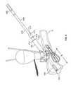
- FIG. 1shows illustrative apparatus in accordance with principles of the invention.
- FIG. 2shows illustrative anatomy in connection with which the invention may be practiced.
- FIG. 3shows a view, taken along lines 3 - 3 (shown in FIG. 1 ) of a portion of the apparatus shown in FIG. 1 .
- FIG. 4shows a view, taken along lines 4 - 4 (shown in FIG. 1 ) of a portion of the apparatus shown in FIG. 1 .
- FIG. 5shows a view, taken along lines 5 - 5 (shown in FIG. 1 ) of a portion of the apparatus shown in FIG. 1 .
- FIG. 6shows a portion of the apparatus shown in FIG. 1 along with other apparatus in accordance with principles of the invention.
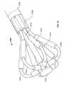
- FIG. 7shows a portion of the apparatus shown in FIG. 1 in a state that is different from the state shown in FIG. 1 .
- FIG. 8shows a portion of the apparatus shown in FIG. 1 .
- FIG. 9shows a portion of the apparatus shown in FIG. 1 along with other apparatus in accordance with principles of the invention.
- FIG. 10shows a portion of the apparatus shown in FIG. 1 .
- FIG. 11shows other illustrative apparatus in accordance with principles of the invention.
- FIG. 12shows a partial cross-sectional view, taken along lines 12 - 12 (shown in FIG. 11 ), of the apparatus shown in FIG. 11 .
- FIG. 13shows a partial cross-sectional view, taken along lines 13 - 13 (shown in FIG. 11 ) of the apparatus shown in FIG. 11 .
- FIG. 14shows other illustrative apparatus in accordance with principles of the invention.
- FIG. 15shows a portion of the apparatus shown in FIG. 14 .
- FIG. 16shows a portion (labeled “ 16 ”) of the apparatus shown in FIG. 11 .
- FIG. 17shows a view, taken along lines 17 - 17 (shown in FIG. 16 ) of a portion of the apparatus shown in FIG. 16 .
- FIG. 18shows a view, taken along lines 18 - 18 (shown in FIG. 17 ) of the apparatus shown in FIG. 17 .
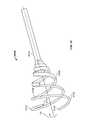
- FIG. 19shows other illustrative apparatus in accordance with principles of the invention.
- FIG. 20shows a partial cross-sectional view, taken along lines 20 - 20 (shown in FIG. 7 ) of the apparatus shown in FIG. 7 .
- FIG. 21shows a partial cross-sectional view, taken along lines 21 - 21 (shown in FIG. 8 ) of the apparatus shown in FIG. 8 .
- FIG. 22shows a partial cross-sectional view, taken along lines 22 - 22 (shown in FIG. 21 ) of the apparatus shown in FIG. 21 .
- FIG. 22Ashows the apparatus shown in FIG. 22 along with illustrative anatomy in connection with which the invention may be practiced.
- FIG. 23shows a view, taken along lines 23 - 23 (shown in FIG. 20 ), of the apparatus shown in FIG. 20 .
- FIG. 24shows a partial cross-sectional view, taken along lines 24 - 24 (shown in FIG. 8 ) of the apparatus shown in FIG. 8 .
- FIG. 25shows a portion of the apparatus shown in FIG. 9 , along with other apparatus.
- FIG. 26shows a partial cross-sectional view, taken along lines 26 - 26 (shown in FIG. 25 ), of apparatus shown in FIG. 25 .
- FIG. 27shows information that may be used to manufacture apparatus in accordance with the principles of the invention.
- FIG. 28shows a partial cross-sectional view, taken along lines 28 - 28 (shown in FIG. 25 ), of apparatus shown in FIG. 25 .
- FIG. 29shows a partial cross-sectional view, taken along lines 29 - 29 (shown in FIG. 25 ), of apparatus shown in FIG. 25 .
- FIG. 30shows apparatus shown in FIG. 25 in a state that is different from the state shown in FIG. 25 .
- FIG. 31shows still other apparatus in accordance with the principles of the invention.
- FIG. 32shows yet other apparatus in accordance with the principles of the invention.
- FIG. 33shows yet other apparatus in accordance with the principles of the invention.
- FIG. 34shows yet other apparatus in accordance with the principles of the invention.
- FIG. 35shows yet other apparatus in accordance with the principles of the invention.
- FIG. 36shows yet other apparatus in accordance with the principles of the invention.
- FIG. 37shows a portion of the apparatus shown in FIG. 36 .
- FIG. 38shows a partial cross-sectional view, taken along lines 38 - 38 (shown in FIG. 37 ), of the apparatus shown in FIG. 37 .
- FIG. 39shows a partial cross-sectional view, taken along lines 39 - 39 (shown in FIG. 37 ), of the apparatus shown in FIG. 37 .
- FIG. 40shows a partial cross-sectional view, taken along lines 40 - 40 (shown in FIG. 37 ), of the apparatus shown in FIG. 37 .
- FIG. 41shows yet other apparatus in accordance with the principles of the invention.
- FIG. 42shows yet other apparatus in accordance with the principles of the invention.
- the therapymay include therapy for a bone fracture.
- the apparatus and methodsmay involve orienting a surgical instrument for proper deployment in the interior of the bone.
- the surgical instrumentmay provide access from outside the bone to the interior of the bone.
- the surgical instrumentmay prepare the interior to receive a therapeutic device.
- the surgical instrumentmay include a therapeutic device.
- the apparatusmay be a surgical instrument guide.
- the surgical instrumentmay be a device for repairing the bone.
- the surgical instrumentmay be a prosthetic device.
- the surgical instrumentmay include one or more of the features of devices that are shown and described in U.S. Patent Application Publication No. 2009/0182336A1, which is hereby incorporated by reference herein in its entirety.
- the surgical instrumentmay be for accessing an interior region of the bone.
- the surgical instrumentmay be a bone saw.
- the surgical instrumentmay be a drill.
- the surgical instrumentmay be for preparing the interior region of the bone to receive a therapeutic device.
- the surgical instrumentmay be a broach.
- the surgical instrumentmay have a portion that is configured to be positioned in a targeted region inside the bone.
- the bonemay have a surface.
- the surfacemay have a normal axis.
- the normal axismay be substantially perpendicular to the surface.
- the surfacemay have an anterior-posterior axis.
- the anterior-posterior axismay extend in a direction that is substantially normal to the anterior and posterior sides of the bone.
- the surfacemay have a proximal-distal axis.
- the proximal-distal axismay extend in a direction that is substantially along the bone.
- the bone surfacemay have curvature.
- the curvaturemay define a curvature axis.
- the curvaturemay be circumferential around the bone.
- the curvature axismay be parallel or near parallel with the proximal-distal axis.
- the surgical instrument guidemay include a bottom index.
- the bottom indexmay provide for aligning the device at a position along the surface normal axis. The position may be flush with the surface.
- the bottom indexmay be a bottom surface of the device.
- the bottom indexmay be one or more features that project from the bottom surface of the device.
- the surgical instrument guidemay include first and second lateral extensions.
- the first lateral extensionmay be configured to respond to an anterior contour of the bone.
- the anterior contourmay be a contour on the anterior side of the bone.
- the second lateral extensionmay be configured to respond to a posterior contour of the bone.
- the posterior contourmay be a contour on the posterior side of the bone.
- the first and second lateral extensionsmay provide for aligning the device along the anterior-posterior axis.
- the surgical instrument guidemay include a distal index.
- the distal indexmay be configured to provide visual alignment along the proximal-distal axis.
- the surgical instrument guidemay include a first bone contactor.
- the first bone contactormay be configured to engage the surface.
- the apparatusmay include a second bone contactor.
- the second bone contactormay be configured to engage the surface. When the first and second bone contactors engage the surface, the first and second contactors resist rotation about the surface normal axis.
- the first and second bone contactorsmay be configured to penetrate the surface.
- the surgical instrument guidemay include first and second lateral cleats.
- the first lateral cleatmay be configured to engage an anterior portion of the bone.
- the second lateral cleatmay be configured to engage a posterior portion of the bone.
- the first and second lateral cleatsmay resist rotation about the proximal-distal axis of the bone.
- the surgical instrument guidemay include an instrument guide member.
- the surgical instrument guidemay include an aligning member.
- the aligning membermay be configured to align the guide member with the bone.
- the surgical instrument guidemay include a base member. The base member may support the aligning member.
- the surgical instrument guidemay include a lateral cleat.
- the lateral cleatmay be configured to resist movement of the base member in a direction along the circumference of the elongated bone.
- the lateral cleatmay include a stem that is directly fixed to the base.
- the surgical instrument guidemay include a bone contactor.
- the bone contactormay be configured to resist rotation of the base about an axis that is substantially normal to the surface.
- the bone contactormay be a first bone contactor and the surgical instrument guide may include a second bone contactor.
- the first and second bone contactorsmay extend from a surface of the base.
- the first and second bone contactorsmay be configured to contact the bone surface along the curvature axis of the bone surface.
- the surgical instrument guidemay include a handle support and a grip.
- the gripmay be rotatable relative to the handle support when a torque greater than a threshold torque is applied to the grip.
- the surgical instrument guidemay include an alignment template.
- the alignment templatemay be configured to register the instrument guide member to a target region inside the bone.
- the instrument templatemay include a dimension that corresponds to a dimension of a surgical instrument that is configured for deployment in the bone interior through the instrument guide member.
- the templatemay include a fluoroscopically detectable material.
- the templatemay be fixed to the base.
- the templatemay map to a lateral view plane in the cavity.
- the templatemay map to an anterior-posterior view plane in the cavity.
- the surgical instrument guidemay include a first template that maps to the lateral view plane and a second template that maps to the anterior-posterior view plane.
- the surgical instrument guidemay include a channel.
- the channelmay be configured to direct an elongated fixation member into the bone.
- the elongated fixation membermay be a wire.
- the wiremay be a k-wire.
- the elongated fixation membermay be a rod.
- the rodmay be a threaded rod.
- the surgical instrument guidemay include a first channel and a second channel.
- the first and second channelsmay be configured to direct first and second elongated fixation members into the bone.
- the first and second channelsmay be oblique to each other.
- the methodsmay include a method for performing a procedure in a bone interior.
- the methodmay include positioning an instrument template outside the bone interior at a position that corresponds to a target region inside the bone.
- the methodmay include generating an electronic image showing the instrument template and the target region.
- the methodmay include delivering an instrument to the target region.
- the deliveringmay include arranging a guide member to direct the instrument to the target region.
- the guide membermay have a fixed orientation relative to the instrument template.
- the positioningmay include positioning a coring saw outline.
- the positioningmay include positioning a broach outline.
- the positioningmay include positioning a prosthesis outline.
- the positioningmay include positioning a bone implant outline.
- the generatingmay include receiving an image using fluoroscopy.
- the instrument templatemay be a first instrument template and the method may include positioning a second instrument template outside the bone interior at a position that corresponds to the target region; and generating an electronic image showing the second instrument template and the target region.
- the positioning of a second instrument templatemay include arranging the second instrument template in a plane that is oblique to a plane that includes the first instrument template.
- the positioning of the second instrument templatecomprises arranging the second instrument template in a plane that is substantially orthogonal to a plane that includes the first instrument template.
- the deliveringmay include delivering a coring saw.
- the deliveringmay include delivering a bone interior broach.
- the deliveringmay include delivering a prosthesis.
- the methodsmay include a method for guiding an instrument into a bone interior.
- the methodmay include positioning an instrument guide adjacent a bone.
- the instrument guidemay include a first fixation element and a second fixation element.
- the methodmay include passing a first fixation member through the bone such that the first fixation member is in contact with the first fixation element.
- the methodmay include passing a second fixation member through the bone such that the second fixation member is in contact with the second fixation element.
- the passing of a second fixation membermay include orienting the second fixation member substantially obliquely with respect to the first fixation member.
- the passing of the second fixation membermay include encompassing human tissue in a region defined by the first fixation member, the second fixation member and the instrument guide such that the instrument guide is retained adjacent the bone by the human tissue.
- the apparatusmay be a surgical instrument guide.
- the bonemay have a longitudinal axis.
- the surgical instrument guidemay include an instrument guide member and a base member.
- the base membermay support the guide member.
- the instrument guide membermay be configured to pivot with respect to the base member from a first position to a second position.
- the first positionmay define a first angle relative to the bone longitudinal axis.
- the second positionmay define a second relative to the bone longitudinal axis.
- the surgical instrument guidemay include an alignment template.
- the alignment templatemay register the instrument guide member to a first target region inside the bone when the guide member is in the first position.
- the alignment templatemay register the instrument guide member to a second target region inside the bone when the guide member is in the second position.
- the templatemay have a dimension that corresponds to a dimension of a surgical instrument that is configured for deployment in the bone interior through the instrument guide member.
- the templatemay include a fluoroscopically detectable material.
- the templatemay be fixed to the guide member.
- the templatemay map to a lateral plane in the bone interior.
- the templatemay map to an anterior plane in the cavity.
- the templatemay map to a posterior plane in the cavity.
- the templatemay be a first template and the surgical instrument guide may include a second template.
- the second templatemay be fixed to the guide member.
- the second templatemay map to a lateral plane in the cavity.
- the surgical instrument guidemay include a guide member stop.
- the guide member stopmay be configured to fix the position of the guide member with respect to the base member.
- the stopmay induce a frictional force between a first surface on the guide member and a second surface on the base member.
- the stopmay include a projection that interferes with relative movement between the guide member and the base.
- the methodsmay include a method for introducing an instrument into an interior of a bone.
- the methodmay include introducing the instrument into a guide member that is pivotably mounted on a base.
- the basemay be positioned adjacent a bone.
- the methodmay include pivoting the guide member relative to the base to change an angle between the guide member and the base.
- the methodmay include advancing the instrument through the guide member.
- the pivotingmay include adjusting the angle to align an instrument template with a target region inside the interior of the bone.
- the adjustingmay include viewing an electronic image that shows the instrument template and the target region.
- the methodmay include fixing the angle between the guide member and the base.
- the bonemay include first bone material.
- the first bone materialmay include cancellous bone.
- the bonemay include second bone material.
- the second bone materialmay include cortical bone.
- the second bone materialmay have a density that is higher than a density of the first bone material.
- the apparatusmay include rotator.
- the apparatusmay include a broaching member.
- the broaching membermay be moved in the bone interior to displace, disaggregate, disintegrate, dislocate, excavate, abrade, cut or otherwise broach bone material.
- the broaching membermay be rotated in the bone interior.
- the rotationmay be continuous.
- the rotationmay be pulsed.
- the rotationmay be unidirectional.
- the rotationmay alternate between a first rotational direction and a second rotational direction.
- the broaching membermay be fixed to the rotator.
- the broaching membermay be configured to be moved relative to the rotator to displace bone material that is radially away from the rotator.
- the broaching membermay be configured to substantially deflect around second bone material.
- the broaching membermay be configured to form in the bone a space having a first contour that corresponds to a shape of the broaching member.
- the broaching membermay be configured to form in the bone a space having a second contour that corresponds to anatomy that includes the second bone material.
- the broaching membermay be a first broaching member and the apparatus may include a second broaching member.
- the second broaching membermay be disposed opposite the first broaching member.
- the broaching membermay include a cutting edge.
- the broaching membermay include a flexible wire segment.
- the wire segmentmay include braided wire.
- the apparatusmay include a reinforcement that supports the broaching member.
- the reinforcementmay support a cutting edge.
- the broaching membermay have a proximal end that is fixed to the rotator and a distal end that is fixed to the rotator.
- the broaching membermay have a proximal end that is fixed to the rotator and a distal end that is free.
- the broaching membermay include an edge of an open cell in a mesh.
- the broaching membermay include a segment that has any suitable form.
- the segmentmay be straight, circular, rhombic, square, triangular, oval, ellipsoid, spiral, loop-shaped, hoop-shaped, teardrop-shaped, egg-beater-shaped, football-shaped, or any other suitable shape.
- the segmentmay be a closed loop.
- the loopmay be asymmetric.
- the segmentmay have one or more of a variety of transverse cross sections, such as square, rectangular, octagonal, contours with sharp edges, stranded cable, or other suitable configurations to facilitate bone displacement.
- the segmentmay have a leading edge.
- the leading edgemay be beveled at a suitable angle, including an angle from about 5° to about 75°. The angle may cause leading edge 2202 to be generally sharp or knife-like.
- the segmentmay be rigid.
- the segmentmay be resilient.
- the broaching membermay have one or more ends that are attached to apparatus such as a drive shaft or a suitable support, such as a hub.
- the broaching membermay have a free end.
- Broaching members with free distal endsmay have any suitable shape at the tine distal ends, such as pointed, forked, rounded, blunt or truncated.
- the broaching membermay have an end that is attached to apparatus by crimping, welding, set-screw, snap fit or any other suitable fastening.
- the broaching membermay have one or more ends that are of unitary construction with the apparatus.
- the broaching membermay include a tine.
- the tinemay be resilient or stiff.
- the tinemay have an end that is attached to a drive shaft.
- the tinemay have a free end.
- the broaching membermay include a blade.
- the broaching membermay include numerous interconnected cells.
- the cellsmay be arranged in a network.
- the cellsmay be linked such that when the structure is stressed (e.g., compressed) at a point the stress is distributed to nearby cells.
- the cellsmay be constructed from laser-cut tube stock that is expanded into a suitable shape.
- the broaching membermay be one of a number of broaching members in a broaching head.
- the broaching headmay have one broaching member, 2-6 broaching members, 7-20 broaching members, more than 20 broaching members, 100 broaching members or any suitable number of broaching members.
- Broaching membermay rotate in a bone cavity that has an irregular shape, for example, nonround, oblong, or angular.
- the cavitymay be smaller than a diameter of broaching member.
- Broaching membermay include any suitable structural form such as wire, ribbon, cable, stranded wire, braided wire, braided ribbon, or any other suitable structural form.
- Broaching membermay include any suitable material, such as polymer, metal, composite, stainless steel, Nitinol (shapeset, superelastic or other Nitinol), other alloy or any other suitable material.
- suitable materialsuch as polymer, metal, composite, stainless steel, Nitinol (shapeset, superelastic or other Nitinol), other alloy or any other suitable material.
- the broaching membermay be supported by one or more reinforcements.
- the reinforcementmay be sized and positioned to support a segment of the broaching member in a desired contour.
- the reinforcementmay provide bone-broaching abrasiveness, momentum or both.
- the reinforcementmay be a tube.
- the reinforcementmay be a brace.
- the bracemay be fixed to the broaching member, for example, by crimping, welding or press-fit.
- the bracemay include broaching edges for displacing bone material.
- the broaching edgesmay have any suitable form, such as serrated, saw-tooth, knife-edge, rectilinear edge or any other suitable form.
- the reinforcementmay be formed from polymer, metal, alloy or any other suitable material.
- the reinforcementmay be formed from a pattern that is cut into a metal tube.
- the apparatusmay include a distal hub.
- the broaching membermay have a distal end that is fixed to the distal hub.
- the distal hubmay be configured to move between a first position and a second position. The first and second positions may be located along a longitudinal axis of the rotator.
- the distal hubmay be constructed of metal, stainless steel, laser-cut tube, polymer, ceramic or any other suitable material.
- the distal hubmay include flutes.
- the distal hubmay include broaching edges.
- the methodsmay include a method for broaching an interior region of a bone.
- the interior regionmay include a bottom surface.
- the bottom surfacemay be an surface of a portion of the bone that is opposite an access hole in the bone.
- the methodmay include expanding a bone broaching member in the interior region.
- the methodmay include disaggregating relatively low-density material inside the bone using the member.
- the methodmay include deflecting the broaching member away from relatively high-density material inside the bone.
- the methodmay include rotating the bone broaching member using a flexible drive shaft.
- the methodmay include changing the elevation of the bone broaching member relative to the bottom surface.
- the disaggregatingmay include cutting the relatively low-density material.
- the disaggregatingmay include displacing the relatively low-density material.
- the methodmay include registering an exterior instrument guide to the bone broaching member; visually mapping the exterior instrument guide to the interior region; and deploying the bone broaching member to the interior region based on the exterior instrument guide.
- the exterior instrument guidemay be exterior to the bone.
- Apparatus and methods for treating a bone interiorare provided.
- the apparatusmay include a flexible sheath.
- the flexible sheathmay include stress-relief features that allow bending under tension and compression.
- the stress-relief featuresmay include slots or slot patterns.
- the stress-relief featuresmay be provided using laser-cutting.
- the stress-relief featuresmay include sintered particles.
- the particlesmay include metal, polymer, composite or any other suitable material.
- the flexible sheathmay have a first configuration and a second configuration.
- the second configurationmay have a smaller radius of curvature than the first configuration.
- the apparatusmay include a rotatable shaft.
- the rotatable shaftmay extend through the sheath.
- the apparatusmay include an elongated steering member.
- the elongated steering membermay be configured to deflect the flexible sheath from the first configuration to the second configuration.
- the elongated steering membermay be configured to be elastically deformed when the elongated steering member deflects the flexible sheath from the first configuration to the second configuration.
- the elongated steering membermay include a first portion.
- the first portionmay translate along a longitudinal direction of the sheath.
- the elongated steering membermay include a second portion.
- the second portionmay be configured to extend radially outward through a passage in the sheath when the elongated steering member deflects the flexible sheath from the first configuration to the second configuration.
- the rotatable shaftmay have a distal end and the apparatus may include an expandable head that extends from the distal end.
- the expandable headmay include a compressed configuration for translating within the sheath.
- the expandable headmay include an expanded configuration when the expandable head is deployed outside the sheath.
- the expandable headmay be configured to displace cancellous bone and not cortical bone.
- Apparatus and methods for preparation of the interior of a boneare provided.
- the apparatusmay include an elongated member.
- the elongated membermay have a longitudinal axis.
- the elongated membermay be curved about the longitudinal axis.
- the elongated membermay be configured to rotate about the longitudinal axis inside the bone.
- the elongated membermay include a substantially spiral segment.
- the spiral segmentmay include a proximal end and a distal end.
- the proximal endmay be disposed at a first radius from the longitudinal axis.
- the distal endmay be disposed at a second radius from the longitudinal axis.
- the second radiusmay be at least as great as the first radius.
- the second radiusmay be greater than the first radius.
- the elongated membermay be a first elongated member and the apparatus may include a second elongated member.
- the second elongated membermay be curved about the longitudinal axis.
- the second elongated membermay be configured to rotate about the longitudinal axis.
- the second elongated membermay include a substantially spiral second segment.
- the proximal endmay be a first proximal end and the distal end may be a first distal end.
- the spiral second segmentmay include a second proximal end and a second distal end.
- the second proximal endmay be disposed at a third radius from the longitudinal axis.
- the second distal endmay be disposed at a fourth radius from the longitudinal axis.
- the fourth radiusmay be at least as great as the third radius.
- the fourth radiusmay be greater than the third radius.
- the third radiusmay be substantially the same as the first radius; and the fourth radius may be substantially the same as the second radius.
- the apparatusmay include a circumferential offset.
- the circumferential offsetmay be in a circumferential direction about the longitudinal axis.
- the circumferential offsetmay be between the second proximal end and the first proximal end.
- the circumferential offsetmay be between the second distal end and the first distal end.
- the apparatusmay include a support.
- the supportmay include a proximal support end.
- the proximal support endmay be fixed to a shaft.
- the apparatusmay include a support segment.
- the support segmentmay be fixed to at least one of the first and second spiral segments.
- the support segmentmay conform to a contour of the spiral segment.
- the methodsmay include a method for preparing a bone interior.
- the methodmay include providing access to a bone intramedullary space.
- the methodmay include introducing into the intramedullary space an elongated member.
- the elongated membermay have a substantially spiral segment.
- the spiral segmentmay have a longitudinal axis.
- the methodmay include rotating the substantially spiral segment about the longitudinal axis to displace cancellous bone matter.
- the elongated membermay be a first elongated member
- the substantially spiral segmentmay be a first substantially spiral segment
- the methodmay include introducing into the intramedullary space a second elongated member.
- the second elongated membermay have a substantially spiral second segment.
- the substantially spiral second segmentmay share the longitudinal axis with the first substantially spiral segment.
- the methodmay include rotating the substantially spiral second segment about the longitudinal axis.
- the first spiral segmentmay have a first periodic rotation cycle.
- the second spiral segmentmay have a second periodic rotation cycle.
- the second periodic rotation cyclemay lag behind the first periodic rotation cycle by a phase lag.
- the phase lagmay be about Pi radians.
- the bonemay have a longitudinal bone axis.
- the apparatusmay include a bone coring saw.
- the bone coring sawmay include a tooth.
- the toothmay include a first cutting member and a second cutting member.
- the first cutting membermay be configured to cut bone when the coring saw rotates in a first direction.
- the second cutting membermay be configured to cut bone when the coring saw rotates in a second direction.
- the second directionmay be rotationally opposite from the first direction.
- the bone coring sawmay include a cylindrical tube.
- the cylindrical tubemay define a tube longitudinal direction and a tube radial direction.
- the bone coring sawmay include a saw tooth.
- the saw toothmay extend longitudinally from an end of the cylindrical tube.
- the saw toothmay include a cutting surface that is oblique to the tube radial direction.
- the methodsmay include a method for sawing a hole in the bone.
- the methodmay include forming a substantially cylindrical passage into the intramedullary space of a bone.
- the substantially cylindrical passagemay extend along a direction that is at an acute angle to the longitudinal bone axis.
- the methodmay include removing from the bone a substantially cylindrical plug that is substantially coaxial with the passage.
- the formingmay include tunneling through the bone using a K-wire.
- the removingmay include sawing a hole using a rotary coring saw.
- the methodmay include rotating the rotary coring saw about a portion of the K-wire.
- the methodmay include sustaining a coaxial relationship between the K-wire and the rotary coring saw.
- the sustainingmay include rotating the rotary coring saw about a bushing.
- the K-wire, the bushing and the rotary coring sawmay be substantially coaxial.
- the methodmay include translating the K-wire relative to the rotary coring saw to remove from the coring saw the cylindrical plug.
- the methodmay include a method for providing access to an intramedullary space of a bone.
- the methodmay include supporting a cylindrical body of a rotary saw at an acute angle to a surface of the bone; and engaging teeth of the rotary saw with the surface.
- Apparatus and methods for accessing the inside of a boneare provided.
- the apparatusmay include a rotatable saw that includes a cannula.
- the apparatusmay include a bushing that is disposed in the cannula.
- the apparatusmay include a wire that is disposed substantially coaxially with the rotatable saw in the bushing.
- the wiremay include a distal end that is configured to penetrate the bone.
- the wiremay include a proximal end that is configured to receive torque.
- the wiremay be configured to drill a pilot hole in the bone.
- the pilot holemay have an axis that forms an acute angle with a surface of the bone at the opening of the pilot hole.
- the sawmay include teeth.
- the teethmay be arranged adjacent a distal end of the cannula.
- the bushingmay be configured to align the rotatable saw coaxially with the axis when the teeth contact the bone.
- the apparatusmay include a biased member proximal the bushing.
- the biased membermay be configured to urge a distal end of the bushing toward the bone when the teeth have penetrated into the bone.
- the bushingmay be fitted into the cannula with a tolerance that provides friction between the bushing and the rotatable saw.
- the frictionmay resist proximally-directed force from a bone core in the cannula while the teeth are cutting into the bone.
- the rotatable sawmay include a cylindrical body having a wall thickness that is traversed by a vent.
- the ventmay be configured to exhaust bone matter.
- the wiremay include a distal diameter and a proximal diameter.
- the proximal diametermay be greater than the distal diameter.
- the wiremay include a shoulder where the distal diameter adjoins the proximal diameter. The shoulder may be configured to be translated proximally relative to the rotatable saw to eject a bone core from the cannula.
- the apparatusmay include an assembly for accessing the inside of a bone.
- the assemblymay include an arrangement of teeth.
- the teethmay be supported at the end of a rotatable frame.
- the framemay define one or more passageways.
- the passagewaysmay extend from a cannula inside the frame to a region that is outside the frame.
- the assemblymay include a bushing.
- the bushingmay be disposed in the cannula.
- the assemblymay include a wire.
- the wiremay be disposed substantially coaxially with the rotatable saw in the bushing.
- the wiremay be configured to drill a pilot hole in the bone.
- the pilot holemay have an axis that forms an acute angle with a surface of the bone at the opening of the pilot hole.
- the busingmay be configured to align the rotatable saw coaxially with the axis when the teeth contact the bone.
- the apparatusmay have a longitudinal apparatus axis.
- the apparatusmay include one or more broaching members.
- the broaching membersmay be blades.
- a first blademay be linked to a second blade by a linkage.
- the linkagemay be configured to be rotated about the longitudinal axis.
- the linkagemaybe configured to be radially displaced from the longitudinal apparatus axis.
- At least one of the first and second bladesmay be rigid.
- At least one of the first and second bladesmay include stainless steel.
- At least one of the first and second bladesmay include Nitinol.
- the linkagemay include a pin.
- the linkagemay be a first linkage.
- the apparatusmay include an actuator.
- the actuatormay be linked to the first blade by a second linkage.
- the actuatormay be linked to the second blade by a third linkage.
- the actuatormay include a main body.
- the main bodymay include members that are configured to be displaced relative to each other. One of the members may be fixed relative to the main body.
- At least one of the second and third linkagesmay include a pin.
- the third linkageis distal the second linkage.
- the actuatormay be configured to radially displace the first linkage by changing a distance between the second linkage and the third linkage.
- the actuatormay include a first elongated actuator member.
- the first elongated actuator membermay be linked to the second linkage.
- the actuatormay include a second elongated actuator member.
- the second elongated actuator membermay be linked to the third linkage.
- the second elongated actuator membermay be configured to radially displace the first linkage by changing a longitudinal offset between the first and second elongated members.
- the apparatusmay be configured to traverse a path in the bone interior.
- the apparatusmay include a fourth linkage that constrains the longitudinal offset based on position of the apparatus along the path.
- the fourth linkagemay be a manual linkage.
- the longitudinal offsetmay include a range of values.
- the range of valuesmay include a first value.
- the first valuemay correspond to a first linkage first radial displacement.
- the range of valuesmay include a second value.
- the second valuemay correspond to a first linkage second radial displacement.
- the second radial displacementmay be greater than the first radial displacement.
- the rangemay include a third value.
- the third valuemay correspond to a first linkage third radial displacement.
- the first linkage third radial displacementmay be less than the second radial displacement.
- the apparatusmay include a cutting surface.
- the cutting surfacemay be disposed on one of the first and second blades. At the first and third radial displacements, the cutting surface may be disengaged from the bone.
- the cutting surfacemay be engaged with the bone.
- the first blademay have a first bound portion.
- the first bound portionmay be between the first and second linkages.
- the first blademay have a first free portion. The first free portion may extend beyond the first linkage in a direction away from the second linkage.
- the second blademay have a second bound portion.
- the second bound portionmay be between the first and third linkages.
- the second blademay have a second free portion. The second free portion may extend beyond the first linkage in a direction away from the third linkage.
- the first bound portionmay be longer than the second bound portion.
- the second bound portionmay be longer than the first bound portion.
- the first free portionmay be longer than the second free portion.
- the second free portionmay be longer than the first free portion.
- the apparatusmay include a cutting surface.
- the cutting surfacemay be disposed on at least one of the first and second blades.
- the fourth linkagemay be programmed to position the cutting surfaces at different radial displacements along the path. Each of the radial displacements may correspond to a longitudinal position on the path.
- the fourth linkagemay control the longitudinal offset based on an electronic signal.
- the electronic signalmay be based on a set of digital instructions.
- the digital instructionsmay be based on a digitized image of the bone interior.
- the apparatusmay include a third blade.
- the apparatusmay include a fourth blade.
- the third blademay be linked to the fourth blade by a fourth linkage.
- the fourth linkagemay be configured to be rotated about the longitudinal axis.
- the fourth linkagemay be configured to be radially displaced from the longitudinal axis.
- the actuatormay be configured to radially displace the fourth linkage by changing the longitudinal offset between the first and second elongate members.
- the methodsmay include a method for preparing the bone interior.
- the methodmay include rotating a cutting surface inside a bone about a rotational axis.
- the methodmay include moving a control member from a first control position to a second control position.
- the cutting surfacemay be configured to occupy a first radial position that corresponds to the first control position.
- the cutting surfacemay be configured to occupy a second radial position that corresponds to the second control position.
- the cutting surfacemay be configured to occupy a third radial position that corresponds to an intermediate control position.
- the intermediate control positionmay be between the first and second control positions.
- the third radial positionmay be at a greater radial distance from the rotational axis than are both the first and second radial positions.
- the first and second radial positionsmay be at substantially the same distance from the rotational axis.
- the cutting surfacewhen the cutting surface is at one or both of the first and second radial positions, the cutting surface may be disengaged from the bone. When the cutting surface is at the third radial position, the cutting surface may be engaged with the bone.
- Apparatus and methods for positioning a bone fragmentare provided.
- the apparatusmay include a probe support.
- the probe supportmay have a proximal end and a distal end.
- the apparatusmay include a handle.
- the handlemay be attached to the proximal end.
- the apparatusmay include a probe.
- the probemay be attached to the distal end.
- the probe supportmay be configured to traverse an angled access hole in a metaphyseal bone surface.
- the probe supportmay be configured to provide mechanical communication between the handle and the probe when the handle is outside a bone interior and the probe is inside the bone interior.
- the probemay have a conical tip.
- the probemay have a rounded tip.
- the probe supportmay include a proximal segment and a distal segment.
- the proximal segmentmay extend from the handle.
- the distal segmentmay support the probe.
- the proximal and distal segmentsmay define an obtuse angle.
- the proximal segmentmay have a first flexibility.
- the distal segmentmay have a second flexibility. The second flexibility may be greater than the first flexibility.
- the apparatusmay include an intermediate segment.
- the intermediate segmentmay be between the proximal and distal segments.
- the intermediate segmentmay include a curve.
- the proximal segmentmay have a first flexibility.
- the intermediate segmentmay have a second flexibility.
- the distal segmentmay have a third flexibility. The second flexibility may be greater than the third flexibility.
- the methodsmay include a method for treating a bone.
- the bonemay have a longitudinal bone axis.
- the methodmay include providing a hole in the bone.
- the holemay be at an angle to the longitudinal bone axis.
- the holemay provide access to a bone interior region.
- the methodmay include advancing a probe through the hole and into the interior region.
- the methodmay include displacing cancellous bone using the probe.
- the displacingmay include identifying a spatial distribution of low-density matter in the interior region.
- the methodmay include displaying an image of the interior region and the probe when the probe is inside the interior region.
- the methodsmay include another method for treating the bone.
- the methodmay include providing a hole in the bone.
- the holemay be at an angle to the longitudinal bone axis.
- the holemay provide access to a bone interior region.
- the methodmay include advancing a probe through the hole and into the interior region.
- the methodmay include displacing bone matter using the probe.
- the displacingmay include identifying a spatial distribution of cancellous bone in the interior region.
- the methodmay include displaying an image of the interior region and the probe when the probe is inside the interior region.
- the displacingmay include positioning a first cortical bone fragment relative to a second cortical bone fragment.
- the methodmay include displaying an image of the interior region and the probe when the probe is inside the interior region.
- FIGS.show illustrative features of apparatus and methods in accordance with the principles of the invention.
- the featuresare illustrated in the context of selected embodiments. It will be understood that features shown in connection with one of the embodiments may be practiced in accordance with the principles of the invention along with features shown in connection with another of the embodiments.
- Apparatus and methods described hereinare illustrative. Apparatus and methods of the invention may involve some or all of the features of the illustrative apparatus and/or some or all of the steps of the illustrative methods. The steps of the methods may be performed in an order other than the order shown or described herein. Some embodiments may omit steps shown or described in connection with the illustrative methods. Some embodiments may include steps that are not shown or described in connection with the illustrative methods.
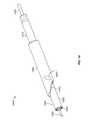
- FIG. 1shows illustrative instrument guide 100 positioned at site H′ on bone B.
- Broach head 124may be delivered through guide 100 to target region R t of intramedullary space IS.
- Target region R tis illustrated as being within cancellous bone B CA , but could be in either, or both, of cancellous bone B CA and cortical bone B CO .
- Side template 130 and top template 132are registered to guide tube 120 .
- Arm 131may support template 130 .
- a practitionermay position templates 130 and 132 such that templates 130 and 132 “project” onto target region R t so that guide 100 will guide broach head 124 to target region R t .
- Template 130may include lobe outline 134 and shaft outline 136 for projecting, respectively, a “swept-out” area of broach head 124 and a location of shaft-like structure 125 .
- Template 132may include lobe outline 138 and shaft outline 140 for projecting, respectively, a target “swept-out” area of broach head 124 and a target location of shaft-like structure 125 .
- Templates 130 and 132may be configured to project a shape of any suitable instrument that may be deployed, such as a drill, a coring saw, a prosthetic device or any other suitable instrument.
- Fluoroscopic imagingmay be used to position templates 130 and 132 relative to target region R t .
- Broach head 124may rotate in intramedullary space IS to clear intramedullary bone matter so that a prosthetic device may be implanted. Broach head 124 may be driven and supported by broach control 126 and broach sheath 127 .
- Guide 100may include base 102 .
- Alignment members 104 and 106(shown in FIG. 10 ) may extend from base 102 to align guide centerline CL G of guide 100 with bone centerline CL BS of the top surface of bone B.
- One or both of alignment members 104 and 106may be resilient.
- One or both of alignment members 104 and 106may be stiff.
- Alignment members 104 and 106may be relatively free to slide along surfaces of bone B.
- Guide 100may include contacts 108 and 110 (shown in FIG. 10 ) that may engage bone B along centerline CL BS .
- Contacts 108 and 110may extend from a bottom surface (shown in FIG. 10 ) of guide 100 .
- Contacts 108 and 110may prevent guide centerline CL G from rotating out of alignment with bone centerline CL BS .
- Contacts 108 and 110may assure alignment of guide 100 with the surface of bone B, because two points of contact may be stable on an uneven surface even in circumstances in which 3, 4 or more contacts are not stable.
- Guide 100may include lateral cleats 112 and 114 (shown in FIG. 10 ). Lateral cleats 112 and 114 may engage the surface of bone B to prevent guide 100 from rotating in direction ⁇ about guide centerline CL G . Lateral cleats 112 and 114 may be resilient to allow some sliding over bone B.
- alignment members 104 and 106may be the first components of guide 100 to engage bone B. Alignment members 104 and 106 may bring guide centerline CL G into alignment with bone centerline CL BS before contacts 108 and 110 and cleats 112 and 114 engage bone B. Then, in some embodiments, cleats 112 and 114 may engage bone B to inhibit rotation in direction ⁇ . Then, in some embodiments, contacts 108 and 110 may engage bone B along bone centerline CL BS . Contacts 108 and 110 may have sharp points to provide further resistance to de-alignment of guide centerline CL G from bone centerline CL BS . In some embodiments, there may be no more than two contacts (e.g., 108 and 110 ) to ensure that the contacts are in line with bone centerline CL BS .
- Guide 100may include stem 116 and grip 118 .
- a practitionermay manually grip grip 118 .
- a torque-limiter(not shown) may be provided to limit the torque that the practitioner can apply via grip 118 to contacts 108 and 110 .
- Guide tube 120may receive and guide any suitable instrument.
- Guide tube 120may be oriented at angle ⁇ with respect to handle 116 .
- angle ⁇may be fixed.
- angle ⁇may be adjustable.
- templates 130 and 132may be fixed relative to guide tube 120 .
- guide tube 120may be oriented so that the axis L GT of guide tube 120 intersects bone B at substantially the same point as does axis L H of stem 116 . Grip 118 will thus be positioned directly over the center of hole site H′.
- Guide 100may include channels 142 and 144 (shown in FIG. 5 ). Rods 146 and 148 may be inserted through channels 142 and 144 , respectively, through cortical bone B CO . Rods 146 and 148 may stabilize guide 100 on bone B. Rods 146 and 148 may be K-wires. Rods 146 and 148 may be inserted using a wire drill.
- FIG. 2illustrates anatomical features of fractured bone B.
- Reference frame 200shows that the view of bone B is substantially in anterior/posterior plane 200 .
- Lateral plane 204includes volar half-plane VOL and dorsal half-plane DOR.
- Bone Bis illustrated as a radius that is fractured at fractures F h and F a Bone B includes bone portions P b , P h and P a in distal end D. Bone segment P b is the largest portion of bone B. Bone segment P h is a head portion of bone B. Bone segments P h and P a include articular surface AS. Bone portions P b , P h and P a are separated or partially separated along fractures F a and F h . Fracture F a transects articular surface AS. Fracture F h transects head of bone B.
- Bone Bshown in a cross section that includes approximate longitudinal axis L B , includes cortical bone B CO and cancellous bone B CA .
- Deployment of an implant into distal end D of bone Bmay require an access hole at site H′.
- Deployment of the implantmay require displacement of cancellous bone B CA .
- Illustrative contours C 1 , C 2 and C 3 in cancellous bone B CAare different contours within which cancellous bone B CA may be displaced.
- Contour C 4which is a projection of contour C 3 onto articular surface AS, shows that contour C 4 , for example, may be asymmetric.
- contour C 4may have major axis A 1 and minor axis A 2 (shown in half). The other contours may also be asymmetric.
- Apparatus and methods provided hereinmay provide an access hole H at site H′.
- An apparatus inserted at site H′ through access hole Hmay travel a distance x H through intermedullary space IS to reach a head portion of bone B.
- An apparatus inserted at site I′ through access hole Imay travel a distance x I through intermedullary space IS to reach a head portion of bone B.
- An apparatus inserted at H′may require a “bend” to travel through intermedullary space IS to reach a head portion of bone B.
- An apparatus inserted at I′may not require a “bend” to reach a head portion of bone B.
- Apparatus and methods provided hereinmay displace cancellous bone B CA within a contour such as C 1 , C 2 or C 3 .
- FIG. 3shows guide 100 , from the side, positioned at site H′ at which an access hole is to be provided.
- Template 130is positioned to register with target area R t a broach (with outline 134 ) and a drill (with outline 136 ).
- Template 132extends normal to the plane of FIG. 3 . Fluoroscopy may be used to select the target area based on contours of cancellous bone B CA and cortical bone B CO (shown in FIG. 2 ) in bone B.
- a rodsuch as a K-wire may be inserted through hole 302 and bone B to fix a position of guide 100 relative to bone B.
- FIG. 4shows guide 100 , from the top, positioned at site H′ (not shown).
- Template 132is positioned to register with target area R t the broach (with outline 138 ) and the drill (with outline 140 ).
- Template 132extends from the base of grip 118 .
- Arm 404supports template 130 , which extends normal to the plane of FIG. 3 . Fluoroscopy may be used to select the target area based on contours of cancellous bone B CA (shown in FIG. 2 ) and cortical bone B CO (shown in FIG. 2 ) in bone B. A rod such as a K-wire may be inserted through hole 402 and bone B to fix a position of guide 100 relative to bone B.
- Cannula 406is present in guide tube 120 for delivering instruments to intramedullary space IS (shown in FIG. 2 ) of bone B.
- FIG. 5shows guide 100 , from above and posterior, positioned at site H′.
- H′is approximately centered along axis L GT of guide tube 120 .
- Distal ends of rods 146 and 148penetrate bone B to maintain a position of guide 100 .
- Rods 146 and 148may be at oblique to each other.
- Rods 146 and 148may be skewed relative to each other.
- FIG. 6shows illustrative drill 600 inserted in guide tube 120 and penetrating bone B.
- Drill 600may penetrate cortical bone B CO (shown in FIG. 2 ) and cancellous bone B CA (shown in FIG. 2 ).
- Drill 600may include teeth 602 , flutes 604 , shaft 606 , torque adapter 608 and any other suitable features.
- Torque adapter 608may be an A-O type torque adapter or any other suitable torque adapter.
- Stop 610may be present to limit penetration depth dp of drill 600 .
- Stop 610may be any suitable feature that limits forward axial motion of members 600 .
- Stop 610may include annular distal surface 612 , which may abut rim 614 of guide tube 120 when d P is reached.
- Fastener 616which may be a set screw, may be used to fix the position of stop 610 along shaft 606 to fix the magnitude of d P .
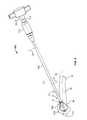
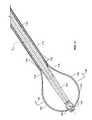
- FIG. 7shows illustrative intramedullary broach 700 .
- Broach 700may include broach head 702 .
- Broach head 702may include illustrative broaching member 704 .
- Broaching member 704may be sufficiently rigid to displace cancellous bone B CA . Broaching member 704 may be sufficiently flexible to be deformed by cortical bone B CO . In some embodiments, broaching member 704 may be expandable. Broach head 702 may be supported by and rotated by shaft assembly 714 . Broach control 706 may include drive handle 708 for rotating and translating broach head 702 . Broach control 706 may include expansion control hub 710 . Expansion control hub 710 may be displaceable along control shaft to expand or contract broaching member 704 . Broach head 702 may include distal end 780 . Expansion control hub 710 is shown in the “contract” position.
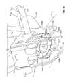
- FIG. 8shows broach 700 deployed in bone B through hole H. Broach 700 may be deployed while broaching member 704 is contracted.
- Broach head 702may be advanced, through intramedullary space IS, into metaphyseal region M of bone B. Broach head 702 may be disposed in any portion of intramedullary space IS, such as in the end-bone.
- Access hole Hmay be sufficiently small that it reduces the occurrence of cause stress risers at site H′.
- Expansion control hub 710is shown in the “expand” position and broaching member 704 is shown expanded in bone B. Broaching member 704 may be expanded during or after deployment.
- a standard orthopaedic drill instrumentmay be used to open access hole H in cortical bone BCO (shown in FIG. 2 ) at site H′ on bone B.
- the drill instrumentmay be guided by apparatus such as guide 100 (shown in FIG. 1 ).
- Axis hole Hmay be drilled along broach axis LC.
- Broach axis LCmay form an angle ⁇ with bone axis LB.
- Broach 700may be positioned such that broach axis Lc substantially coincides with guide tube axis LGT (shown in FIG. 1 ).
- Angle ⁇may be an acute angle.
- Angle ⁇may be complementary with angle ⁇ (shown in FIG. 1 ).
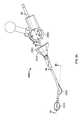
- FIG. 9shows illustrative instrument guide 900 at site H′ on bone B.
- Instrument guide 900may have one or more features in common with instrument guide 100 (shown in FIG. 1 ).
- Instrument guide 900may include instrument templates 930 and 932 for positioning instrument guide 900 such that an instrument can be positioned at target region St 1 .
- Illustrative steerable broach 950may be deployed at target region St 1 in intramedullary space IS by insertion through guide 900 at site H′.
- Broach 950may include broach head 925 .
- Broach head 925may have one or more features or properties in common with broach head 125 (shown in FIG. 1 ).
- Broach head 925may be supported by broach sheath 927 .
- Broach head 925may be rotated by drive shaft 940 which may extend inside broach sheath 927 and receive torque from torque adapter 908 .
- Torque adapter 908may provide rotation from any suitable rotation source drive shaft 940 .
- Broach sheath 927may be flexible. Broach sheath 927 may be flexible in region 928 such that application of off-axis tension by elevator ribbon 952 may position broach head 925 at a distance y or ⁇ y relative to bone axis L B . Illustrative elevator control body 960 may apply axial compression to elevator ribbon 952 to cause broach sheath 927 to bend.
- Broach sheath 927may be configured to flex in more than one plane. Broach sheath 927 may be configured to flex substantially in one plane only.
- Target region S t1could be in either, or both, of cancellous bone B CA and cortical bone B CO (shown in FIG. 2 ).
- Side template 930 and top template 932are registered to guide tube 920 .
- a practitionermay position templates 930 and 932 such that templates 930 and 932 “project” onto target region S t1 so that guide 900 will guide broach head 925 to target region S t1 .
- Side template 930may be rotatable at arm 942 to change angle ⁇ between side template 930 axis L T and guide 900 centerline CL GT .
- ⁇may be selected to correspond to a degree of elevation in direction y or ⁇ y of broach head 925 .
- ⁇may be selected to correspond to a degree of actuation of control 962 of control body 960 .
- ⁇may be selected such that side template 930 “projects” onto target region St 2 .
- Fluoroscopic imagingmay be used to position templates 930 and 932 relative to target region St 1 .
- a practitionercan select the position of H′ (distance x H shown in FIG. 2 ), the angle of hole H (shown in FIG. 2 ) relative to bone axis LB, the degree and distribution of flexing in region 928 , the penetration of broach sheath 927 , the size of broach head 925 , the swept-out profile of broaching member 924 , and any other suitable parameters, to determine the size, shape, orientation and location of a cavity to be swept out by broaching member 924 .
- one or more of the aforementioned parametersmay be selected to position broach head 925 in target region St 2 .
- FIG. 10shows guide base 102 from below on the distal side.
- Stem 116extends from the top of base 102 .
- Guide tube 120extends from the distal portion of base 102 .
- Arm 131extends from the side of base 102 .
- Site H′ of hole H(shown in FIG. 2 ) is shown projected onto opening 1002 of guide tube 120 and centered about axes LH and LGT.
- Illustrative contacts 108 and 110extend down from base 102 to engage bone B (shown in FIG. 2 ) and resist rotation about vertical axes L H and L TR and translation along guide centerline CL G .
- Contacts 108 and 110may be sufficiently sharp to penetrate or partially penetrate bone B.
- Cleats 112 and 114may engage the surface of bone B and resist rotation about guide centerline CL G .
- Base 102may support any suitable number of contacts in any suitable pattern or location.
- Base 102may support an arrangement of contacts that extends in a direction that is substantially oblique or transverse to guide centerline CL G .
- base 102may include a flange (not shown) that saddles bone B.
- the flangemay include any suitable number of contacts in any suitable pattern, including an arrangement of contacts that extends in a direction that is substantially oblique or transverse to guide centerline CLG.
- Alignment members 104 and 106may extend from base 102 to align guide centerline CLG of guide 100 with bone centerline CLBS of the top surface of bone B (shown in FIG. 2 ). Each of alignment members 104 and 106 include continuous alignment edges 1004 and 1006 . Edge 1004 is supported by substantially vertical struts 1007 and 1008 . Edge 1006 is supported by substantially vertical struts 1010 and 1012 . Edges 1004 and 1006 are substantially parallel to centerline CLG.
- alignment membersmay be or may include tines that correspond to struts 1007 , 1008 , 1010 and 1012 .
- One or more of the tinesmay extend straight down from base 102 .
- One or more of the tinesmay extend down and in the proximal direction relative to base 102 .
- One or more of the tinesmay extend down and in the distal direction relative to base 102 .
- edges 1004 and 1006may be absent.
- the tinesmay flex independently of each other.
- One or more of the tinesmay be biased away from guide centerline CLG.
- One or more of the tinesmay be biased toward guide centerline CLG.
- One or more of the tinesmay be curved or arcuate.
- Some embodimentsmay include a bushing (not shown) in guide tube 120 .
- the bushingmay provide stability for a K-wire in procedures in which the K-wire is used as a drill to provide preliminary access to the inside of a bone.
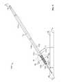
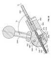
- FIG. 11shows illustrative saw 1100 .
- Saw 1100may be used to cut an access hole at site H′ or site I′ (shown in FIG. 2 ) or any other suitable hole.
- Saw 1100may be guided by guide 100 (shown in FIG. 1 ), guide 900 (shown in FIG. 9 ), guide 1900 (shown in FIG. 19 ) or any other suitable guide.
- Saw 1100may include wire 1102 .
- Wire 1102may be a K-wire or any other suitable wire.
- Saw 1100may include centering sleeve 1104 . Centering sleeve 1104 may be made of polymer, alloy or any other suitable material.
- Saw 1100may include cutting member 1106 . Cutting member 1106 may include teeth 1108 , vents 1110 and cylindrical member 1112 . Vents 1110 may provide chip clearance, side-cutting, reduced heating or other properties, among others.
- Saw 1100may include torque adapter 1114 . Torque adapter 1114 may transmit rotation from a rotation source to one or both of K-wire 1102 and cutting member 1106 .
- Wire 1102may form an angled pilot hole in bone B.
- the holemay be formed at angle ⁇ between saw axis L s and bone axis L B .
- saw 1100may be advanced distally until teeth 1108 engage bone B and being to cut. Teeth 1108 will engage bone B first at point p, in the crotch between wire 1102 and bone B. Teeth 1108 may therefore be subjected to a contact force from bone B that is oblique to a plane defined by teeth 1108 .
- Centering sleeve 1104may support teeth 1108 against the oblique force and maintain teeth 1108 at a substantially constant radius from axis L s during the formation of an access hole.
- a spring 1116may urge centering sleeve 1104 distally to keep centering sleeve 1104 at or near bone B as teeth 1108 penetrate into bone B.
- FIG. 12shows that centering sleeve 1104 may be coaxially arranged within cutting member 1106 .
- Wire 1102may be coaxially arranged within centering sleeve 1104 .
- Collar 1202 of centering sleeve 1104may be provided at a distal end of centering sleeve 1104 to provide a close tolerance between wire 1102 and centering sleeve 1104 .
- FIG. 13shows spring 1116 compressed between proximal face 1302 of centering sleeve 1104 and distal face 1304 of torque adapter 1114 .
- wire 1102may be used to drill a pilot hole in bone B without apparatus such as centering sleeve 1104 and cutting member 1106 .
- a bushing(not shown) may be provided in a guide tube such as guide tube 120 (shown in FIG. 1 ).
- Wire 1102may be placed through the bushing and driven by a torque adapter such as 1114 .
- the bushingmay have a bore that is sized to stabilize a K-wire driven in rotation by a surgical drill.
- the bushing(not shown) may be removed from the guide tube to allow a coring saw to advance through the guide tube.
- FIG. 14shows illustrative apparatus 1400 for cutting in bone B a hole that is substantially coaxial with wire 1402 .
- FIG. 14shows a relevant portion of coring saw guide 1450 .
- Coring saw guide 1450may include contacts 1452 for engaging a surface of bone B (shown in FIG. 2 ).
- Coring saw guide 1450may include handle-mounting recesses such as 1454 .
- a centering sleeve(not shown) may be disposed coaxially between wire 1402 and cutting member 1406 .
- a cutting member such as 1406may be engaged by a collar (not shown) that is configured for delivery of torque.
- a proximal end of wire 1402may be engaged in a hand drill fitting and rotatingly driven into the bone as it is advanced distally through saw guide 1450 .
- FIG. 15shows wire 1402 .
- Distal end 1502 of wire 1402may have a first diameter.
- Proximal end 1504 of wire 1402may have a second diameter that is greater than the first diameter.
- Step 1506 between the first diameter and the second diametermay be used as a stop to limit the extent to which wire 1402 may be driven into bone B.
- Proximal end 1504 of a wire such as 1402may extend along and through a cannula in an A-O type adapter while the adapter drives a cutting member such as 1408 distally into a bone.
- step 1506may be used to distally eject a bone plug from the interior of distal end 1405 of cutting member 1406 after a hole is cut and cutting member 1406 is withdrawn from the bone.
- a soft-tissue protectormay be provided to keep soft tissue proximate the access hole from becoming engaged by rotating apparatus.
- the protectormay include a cannula for guiding the rotating apparatus into the hole.
- the protectormay include a flange that “funnels” the apparatus into the cannula and blocks the soft tissue from approaching the apparatus.
- FIG. 16shows a portion of illustrative cutting member 1106 from region 16 of FIG. 11 .
- a circumferential tooth 1602may extend into one or more of vents 1110 to engage bone on the inside of the cutter.
- Tooth 1602may provide friction between cutting member 1106 and the bone plug and may facilitate removal of the bone plug upon with drawal of cutting member 1106 from the access hole. The distal end of the bone plug may not be severed from bone B native tissue by cutting member 1106 . Tooth 1602 may provide one or both of torsional and axial force to sever the plug from bone B. Vents 1110 may include vent edges 1604 . Vent edges 1604 may cut a wall of the access hole.
- Tooth 1602may provide friction between cutting member 1106 and centering sleeve 1104 .
- the frictionmay resist proximal motion of centering sleeve 1104 .
- FIG. 17shows illustrative teeth 1108 of cutter member 1106 (shown in FIG. 11 ).
- Illustrative tooth 1702may include cutting edge 1704 , face 1706 and back 1708 .
- Face 1706 and back 1708may partially define adjacent gullets 1710 and 1712 , which intervene between tooth 1702 and neighboring teeth 1714 and 1716 , respectively.
- Tooth 1702may have thickness t.
- Tooth 1702may be circumferentially set apart from neighboring tooth 1716 by pitch P t .
- Cutting edge 1704may be angled relative to saw radial direction R s by bevel angle ⁇ (shown on a different tooth).
- Face 1706may have longitudinal rake angle ⁇ .
- rake anglese.g., positive
- Smaller rake anglese.g., negative
- heat capacitymay increase heat capacity and increase heat generated in shearing but increase cutting forces.
- Gullet 1710may have gullet depth D g .
- tooth 1702may include facet 1718 (shown in broken line). When facet 1718 is present, tooth face 1706 may be shortened by distance h. Facet 1718 may have a normal (not shown) that is oriented at any suitable angle relative to axis L s and radius R s .
- FIG. 18shows teeth 1108 (shown in FIG. 11 ) as viewed along lines 18 - 18 (shown in FIG. 17 ).
- Cutting edge 1704forms angle ⁇ with saw outer wall 1802 .
- Cutting edge 1704is shown with ⁇ 90°, but any suitable ⁇ may be used.
- a tooth formed by cutting along chord Ch 1may create a cutting edge having ⁇ >90°.
- a tooth formed by cutting along chord Chemay create a cutting edge having ⁇ 90°.
- a cutting membermay have bi-directionally cutting teeth. Each tooth such tooth may have a right and a left cutting edge. When the coring saw rotates clockwise, a right edge cuts. When the coring saw rotates counterclockwise, a left edge cuts.
- FIG. 19shows illustrative instrument guide 1900 .
- Illustrative instrument guide 1900may have one or more features in common with one or more of guide 100 (shown in FIG. 1 ) and guide 900 (shown in FIG. 9 ).
- Guide 1900may be used to guide an instrument into bone B at a site such as H′ or I′ (shown in FIG. 2 ).
- Guide 1900may include base 1902 .
- Base 1902may be placed against bone B (shown in FIG. 2 ) at site H′.
- Base 1902may include contacts (not shown), alignment members (not shown), cleats (not shown) or any other suitable features.
- Grip 1918may extend from base 1902 .
- Base 1902may include pivot 1904 .
- Pivot 1904may pivotably support guide tube 1920 .
- Guide tube 1920 centerline CL GT′may be positioned at any suitable angle ⁇ ′ relative to axis L H ′ so that saw 1950 may be advanced through bone B (not shown) at angle ⁇ ′.
- the intersection of axis L H′ and CL GT′may substantially coincide with site H′ or site I′ for different values of ⁇ ′.
- a practitionermay change angle ⁇ ′ before or during penetration of saw 1950 into bone B. For example, a practitioner may initiate a pilot hole at ⁇ ′ ⁇ 0° and then change ⁇ ′ to obtain the desired angle for the access hole.
- Saw 1950may include teeth 1952 , flutes 1954 , cannula 1956 or any other suitable features, including the features described and shown herein in connection with other saws.
- FIG. 20shows a view of a distal portion of broach 700 taken along lines 20 - 20 (shown in FIG. 7 ).
- Pin 703may be located near the distal end of bracket 720 .
- Pin 703may fix the position of the distal end of broaching member 704 .
- Pin 703may support cylindrical form 705 .
- Cylindrical form 705may be coaxially mounted on pin 703 .
- Cylindrical form 705may support a spiral segment of broaching member 704 .
- One or more distal portions of broaching member 704may be welded or otherwise suitably fixed to cylindrical form 705 .
- Cylindrical form 705may constrain or partially constrain the orientation of distal portions of broaching member 704 . Cylindrical form 705 may be fixed relative to bracket 720 . Cylindrical form 705 may be rotatable relative to bracket 720 .
- Broach head 702may include end cap 701 .
- Broaching member 704may remove tissue that is generally proximal end cap 701 .
- member 704may expand in such a manner as to extend distally of end cap 701 .
- the broaching membermay remove tissue that is distal of end cap 701 .
- End cap 701may be positioned at the distal end of bracket 720 . End cap 701 may be configured to have a smooth, atraumatic surface. Bracket 720 may be attached to drive shaft 730 .
- Shaft assembly 714may include drive shaft 730 .
- Drive shaft 730may support bracket 720 at union 732 .
- Drive shaft 730may be secured to bracket 720 by pin 734 .
- Drive shaft 730may provide rotation to broach head 702 .
- Proximal ends 736 and 738 of broaching member 704may be fixed to slide 740 , which may be a tube.
- Proximal end 738may be threaded through or keyed into windows 742 and 744 in slide 740 .
- Proximal end 736may be threaded through or keyed into slots 746 and 748 in slide 740 .
- Slide 740may slide relative to drive shaft 730 to expand and contract broaching member 704 .
- Slide 740is shown in the “contract” state, in which broaching member 704 is drawn close to bracket 720 .
- Slide cover 750may slide with slide 740 .
- One or both of slide 740 and slide cover 750may be translated along axis L c by control hub 710 (shown in FIG. 7 ) or any other suitable position controller.
- Slide cover 750may remain stationary relative to drive shaft 730 when slide 740 slides relative to drive shaft 730 .
- distal end 752 of slide cover 750may limit the radial position of broaching member 704 at a fixed distance along drive shaft 730 and thus affect the deformation of broaching member 704 in the expanded state.
- Broaching member 704may undergo one or both of elastic and plastic deformation.
- FIG. 21shows a view of a distal portion of broach 700 taken along lines 20 - 20 (shown in FIG. 7 ) when broaching member 704 is in an expanded state.
- Broaching member 704is shown as mainly circular. However, any desired shape may be able to be imparted in the expanded state such as but not limited to: square, triangular, oval, ellipsoid, teardrop, football, or any other suitable shape.
- Different shapesmay be obtained using several methods, such as utilizing a pre-set shape in a shape memory alloy, modifying the geometry of the member cross-section (along the member length) such that it preferentially bends in a desired manner, constraining broaching member 704 (e.g., in force, shear or moment) in a way that forces the expansion to take desired shape, having the final shape be that of the expanded geometry and the reduced or collapsed geometry be that of a higher strain configuration, and/or any other suitable method of forming a desired shape.
- broaching member 704may modify the geometry of broaching member 704 from a generally straight configuration to a generally eggbeater shape.
- the deformationmay relatively increase the distance between (a) sections 760 and 762 and (b) bracket 720 . As this distance is increased, the swept-out volume of broaching member 704 , as broaching member 704 rotates generally about an axis such as Lc (shown in FIG. 8 ), is increased.
- a broachmay include a broaching member that includes one or more stiff tines (not shown) that is joined to a drive shaft.
- the drive shaftmay have a longitudinal axis.
- the tinemay be joined to the drive shaft radially close to the axis at a proximal end of the tine.
- the tinemay have a distal end that is spaced radially apart from the axis.
- the distal end of the tinemay be distal of the distal end of the drive shaft.
- FIG. 22shows broaching member 704 in partial cross section from view lines 22 - 22 (shown in FIG. 21 ).
- Broaching member 704may have leading edges 2202 and 2204 that may be rotated in direction ⁇ c by drive shaft 730 (shown in FIG. 21 ).
- Broaching member 704may sweep out a space in bone B (shown in FIG. 2 ) based on radius R c , which corresponds to sections 760 and 762 (shown in FIG. 21 ).
- Leading edge 2202may be beveled at angle ⁇ c1 .
- Angle ⁇ c1may be any suitable angle, including an angle from about 5° to about 75°. Angle ⁇ c1 may cause leading edge 2202 to be generally sharp or knife-like. This may aid in the broaching member's ability to remove tissue.
- Leading edge 2204may be beveled at angle ⁇ c2 .
- Angle ⁇ c2may be any suitable angle, including an angle from about 5° to about 75°. Angle ⁇ c2 may cause leading edge 2204 to be generally sharp or knife-like. This may aid in the broaching member's ability to remove tissue.
- leading edges 2202 and 2204may generally be the first portion of sections 760 and 762 to come in contact with tissues such as relatively less dense cancellous bone B CA (shown in FIG. 2 ).
- Sections 760 and 762may be configured to be sufficiently flexible such that if either of sections 760 and 762 contacts relatively more dense materials, such as diaphysis, metaphysis and epiphysis bone, sections 760 and 762 may deflect generally radially in direction ⁇ o about axis L c and/or in the linear direction towards axis L c at any location along the length of sections 760 and 762 or any other portion of broaching member 704 . Deflection or deformation of sections 760 and 762 may have the affect of not disturbing the more dense tissues.
- Leading edges 2202 and 2204may be offset from axis L c by offsets ⁇ 1 and ⁇ 2 respectively. Appropriate magnitudes of offsets ⁇ 1 and ⁇ 2 may be selected.
- offsets ⁇ 1 and ⁇ 2may be constrained by the collapsed diameter (overall diameter of broach head 702 in a plane transverse to axis L c when broaching member 704 is collapsed, e.g., for deployment) of the configuration and the desired expanded engagement (radius R c ) of broaching member 704 with the tissue. Offsets ⁇ 1 and ⁇ 2 may aid in the broaching member's efficiency at displacing tissue.
- FIG. 22Ashows broach head 704 in intramedullary space IS of bone B and illustrates how flexible broaching members can broach bone of a relatively lower density and be deflected by bone of a relatively higher density.
- Sections 760 and 762have displaced or removed some of cancellous bone B CA from bone B by rotating in direction ⁇ c about axis L c .
- Sections 760 and 762may be sufficiently stiff to remove cancellous bone to radius R c from axis Lc in the “top” portion of bone B. Because of the placement of axis L c relative to the bottom portion of bone B, sections 760 and 762 contact cortical bone BCO at the bottom of bone B.
- Sections 760 and 762may be sufficiently flexible to be deflected by cortical bone BCO. Section 760 is shown deflected in direction ⁇ c by bone BCO. Sections 760 and 762 thus remove bone only to radius R c ′ in the “bottom” portion of bone B.
- the cavity created by broach 700may thus be bounded in part by cancellous bone BCA and in part by cortical bone BCO.
- the shape of the cavity portion that is bounded by cancellous bone BCAmay be governed substantially by the geometry and mechanical properties of broach 700 .
- the shape of the cavity portion that is bounded by cortical bone BCOmay be governed substantially by the native anatomy of bone B.
- FIG. 23shows a view of broach 700 along lines 23 - 23 (shown in FIG. 20 ).
- Broach 700is in the contracted state.
- Slide cover 750has been removed.
- Slots 746 , 748 and 2302 in slide 740may be configured to coincide with features on proximal end 736 (shown in FIG. 21 ) of broaching member 704 .
- slots 746 , 748 and 2302may restrict movement of proximal end 736 in either direction generally along axis L c .
- Slots 746 , 748 and 2302may have any suitable geometry that allows for the engagement and axial translation of proximal end 736 .
- Slots 746 , 748 and 2302may be of sufficient depth that, when proximal end 736 is engaged in slots 746 , 748 and 2302 , slide cover 750 (shown in FIG. 20 ) has adequate radial clearance with respect to proximal end 736 and slide 740 to slide over slide 740 and slots 746 , 748 and 2302 .
- An inner surface of slide cover 750may prevent movement of proximal end 736 from moving in a direction generally away from axis L c .
- Slide 740may include slots (not shown) that correspond to proximal end 738 (shown in FIG. 20 ) and have one or more features in common with, slots 746 , 748 and 2302 .
- Broach head 720may include broaching member wrap section 2304 .
- Pin 703may be integrated into wrap section 2304 .
- Wrap section 2304may be separate from pin 703 .
- Wrap section 2304may be configured to allow wrapping of broaching member 704 generally around wrap section 2304 .
- Broaching member 704may be looped in wrap section 2304 .
- Broaching member 704may be wrapped (as shown in FIG. 23 ) at least one full turn in wrap section 2304 . Wrapping about wrap section 2304 may bias segments 760 and 762 (shown in FIG. 21 ) away from axis L c .
- FIG. 24shows a cross section, viewed along lines 24 - 24 (shown in FIG. 8 ) of a portion of broach control 706 (shown in FIG. 7 ).
- Expansion control hub 710is shown with base 2402 at position p e . This may correspond to the expanded state of broaching member 704 , as shown in FIG. 8 .
- Base 2402may be moved distally to position p c . This may correspond to the contracted state of broaching member 704 , as shown in FIG. 7 .
- Expansion control hub 710may operate in connection with body 2408 .
- Body 2408may include control shaft 712 and distal stop 2410 .
- Control shaft 712may include threads 2418 .
- Expansion control hub 710may include outer member 2412 and inner member 2414 . Outer member 2412 and inner member 2414 may be fixed to each other. Slide pin 2404 may be captured between outer member 2412 and inner member 2414 . Inner member 2414 may include threads 2416 for engagement with threads 2418 on control shaft 712 . Slide pin 2404 may travel in slots 2405 and 2407 in body 2408 .
- Expansion control hub 710may be moved along axis L c by applying force to expansion control hub 710 .
- expansion control hub 710may be advanced axial generally along axis L c by applying rotational force generally about axis L c to expansion control hub 710 such that threads 2416 move advance or retreat through threads 2418 .
- Axial movement of expansion control hub 710 relative to body 2408may be transferred to slide 740 and slide cover 750 while drive shaft 730 remains axially fixed to body 2408 by pin 2406 .
- Slide 740may include cut-outs 2430 and 2432 .
- Slide cover 750may include cut-outs 2434 and 2436 . Cut-outs 2430 , 2432 , 2434 and 2436 may provide clearance of pin 2406 when slide 740 and slide cover 750 travel axially.
- proximal ends 736 and 738(shown in FIG. 20 ) of broaching member 704 thus move axially.
- Distal end 780 (shown in FIG. 7 ) of broaching member 704may be axially fixed to drive shaft 730 , which may be fixed to body 2408 .
- drive shaft 730which may be fixed to body 2408 .
- distal end 780decreases and broaching member 704 expands.
- expansion control hub 710moves proximally, the distance between (a) proximal ends 736 and 738 ; and (b) distal end 780 increases and broaching member 704 contracts.
- Distal stop 2410 and proximal stop 2420may limit axial movement of expansion control hub 710 .
- proximal stop 2420is shown as being part of handle 708 , proximal stop 2420 may be separate from handle 708 .
- Handle 708may transfer rotational motion generally about axis L c to control shaft 712 .
- Control shaft 712may transfer the rotation to slide pin 2404 and drive shaft pin 2406 .
- Slide pin 2404may transfer the rotation to slide 740 and slide cover 750 .
- Drive shaft pin 2406may transfer the rotation to drive shaft 730 , which may drive broaching member 704 (shown in FIG. 21 ).
- Distal stop 2410is shown as being integral with body 2408 , but distal stop may be a separate element that is attached to control shaft 712 or a different part of body 2408 .
- Pin 2406may extend into recess feature 2422 .
- Recess feature 2422may be a through-hole. Pin 2406 may extend through the through hole to a location external to body 2408 .
- Pin 2404may extend into recess feature 2424 .
- Recess feature 2424may be a through-hole. Pin 2404 may extend through the through-hole to a location external to body outer member 2412 .
- Recess featuremay extend circumferentially about axis L c . If recess feature 2424 extends circumferentially about axis L c , expansion control hub 710 may rotate about axis L c substantially without restricting, or being restricted by, pin 2404 .
- Body 2408may include circumferential recess 2426 .
- Recess 2426may be sized to engage O-ring 2428 .
- Recess 2426may prevent axial movement between body 2408 and O-ring 2428 generally along axis L c .
- O-ring 2428may be sized to provide an interference fit with outer member 2412 .
- the interference fitmay produce friction between O-ring 2428 and expansion control hub 710 .
- the frictionmay allow expansion control hub 710 to be lightly locked at any rotational position relative to body 2408 , generally about axis L c .
- FIG. 25shows illustrative cavity preparation apparatus 2500 .
- Apparatus 2500may include broach 2550 .
- Broach 2550may have one or more features in common with broach 950 (shown in FIG. 9 ).
- Broach 2550may include one or more of broach head 2525 , elevator ribbon 2552 and control body 2560 .
- Apparatus 2500may include guide 2502 .
- Guide 2502may guide broach 2550 or any other suitable apparatus through an access hole such as H or I (shown in FIG. 2 ).
- Guide 2502may retain soft tissue at a distance from the access hole to prevent engagement of the soft tissue by an instrument that is present in guide 2502 .
- FIGS. 26-29show features of different portions of apparatus 2500 .
- FIG. 26shows in partial cross section illustrative broach head 2525 and illustrative elevator ribbon 2552 .
- Broach head 2525may be driven about axis L E by rotating drive shaft 2540 .
- Broach head 2525may include broaching member 2524 , which may have one or more features in common with broaching member 704 (shown in FIG. 7 ).
- Broach head 2525may include distal hub 2526 and proximal hub 2528 .
- One or both of distal hub 2526 and proximal hub 2528may transfer rotation to broaching member 2524 .
- One or both of distal hub 2526 and proximal hub 2528may support broaching member 2524 .
- Drive shaft 2540may extend within broach sheath 2527 .
- Drive shaft 2540may be supported in rotation by bushing 2530 at the end of broach sheath 2527 .
- Illustrative elevator ribbon 2552may be anchored to broach sheath 2527 at fixation 2532 .
- elevator ribbon 2552may buckle along its length.
- elevator ribbon 2552may buckle at or near section 2534 .
- Section 2536may be used to support broach sheath 2527 at an elevation relative to cancellous bone B CA or cortical bone B CO in bone B (shown in FIG. 2 ).
- Portions of elevator ribbon 2552may extend inside broach sheath 2527 and pass through slots 2542 and 2544 to section 2534 . In some embodiments, there may be contact between drive shaft 2540 and elevator ribbon 2552 . In some embodiments, there may be no contact between drive shaft 2540 and elevator ribbon 2552 .
- Elevator ribbon 2552when compressed, may apply tension to adjacent portion 2538 of broach sheath 2527 and compression to opposite portion 2540 of broach sheath 2527 .
- One or both of the tension of adjacent portion 2538 and the compression of opposite portion 2540may cause broach sheath 2527 to curve generally about an axis such as L F .
- One or both of adjacent portion 2538 and opposite portion 2540may include stress-relief features that allow bending under tension and compression.
- the stress-relief featuresmay include slots or slot patterns.
- the stress-relief featuresmay be provided using laser-cutting.
- the stress-reliefmay provide an equilibrium curvature such that broach sheath 2527 is curved at rest.
- the stress-relief featuresmay include sintered particles.
- the particlesmay include metal, polymer, composite or any other suitable material.
- FIG. 27shows illustrative laser-cut pattern 2700 for a broach sheath such as 927 (shown in FIG. 9 ) or 2527 (shown in FIG. 26 ).
- Pattern 2700which is shown flat for illustration, may be cut in a cylindrical tube to relieve compression on one side of the tube and relieve tension on the other side of the tube.
- compression relief pattern 2740may be provided along opposite portion 2540 of broach sheath 2527 .
- Tension relief pattern 2738may be provided along adjacent portion 2538 of broach sheath 2527 .
- Tension and compression reliefmay be increased by lengthening lengths L p1 and L p2 , respectively. Bending stiffness may be reduced by increasing pattern widths w 1 and w 2 . Increasing kerf and decreasing inter-cut spacing may also decrease bending stiffness.
- the tubemay have an outer diameter of 0.108 in.
- the tubemay have an outer diameter of 0.125 in. Any suitable outer diameter may be used.
- FIG. 28shows illustrative elevator control body 2860 .
- Elevator control body 2860may support the proximal end of broach sheath 2527 .
- Drive shaft 2540may extend through control body 2860 to torque adapter 2808 .
- Torque adapter 2808may be cannulated.
- Torque adapter 2808may be a cannulated A-O type adapter.
- Torque adapter 2808may have a “D”-shaped extension for engagement by a D-shaped chuck.
- Torque adapter 2808may be torqued by any suitable source of rotational energy.
- Control body 2860may include housing 2862 and actuator 2866 .
- Handle 2864may be used to rotate actuator 2866 through angle ⁇ hd E about axis L TE relative to housing 2862 .
- shaft 2868may drive shuttle 2870 in slot 2872 .
- the distal end of elevator ribbon 2552may be fixed to the shuttle, for example, by screw 2874 .
- elevator ribbon 2552is expanded (as shown in FIG. 26 ).
- elevator ribbon 2552is contracted toward axis L E .
- Actuator 2866may include face member 2890 .
- Face member 2890may be fixed relative to housing 2862 .
- Face member 2890may include recess 2892 .
- Recess 2892may “catch” a projection such as 2894 to act as a detent.
- Projection 2894may be one of several projections that provide detent positions. For example, three detent positions may be provided: forward, neutral and back. In the forward position, elevator ribbon 2552 is extended. In the back position, elevator ribbon 2552 is compressed. In the neutral position, elevator ribbon 2552 is in a partially compressed state.
- Housing 2862may be configured to house a torque limiter (not shown).
- the torque limitermay couple torque adapter 2808 to drive shaft 2540 and may be used to limit the torque that is applied to broach head 2525 (shown in FIG. 25 ). If broach head 2525 were to jam in bone B (shown in FIG. 2 ), the torque limiter may cap or reduce the torque on broaching head 2525 to prevent damage to broaching head 2525 , other elements of apparatus 2500 , other involved apparatus or bone B.
- FIG. 29shows illustrative guide 2502 .
- Guide 2502may include cannula 2904 and funnel 2906 .
- Funnel 2906may facilitate insertion of a broach head such as 2525 (shown in FIG. 25 ) into a hole such as H (shown in FIG. 2 ).
- Guide 2502may be “preloaded” on broach sheath 2527 .
- a practitionermay insert a broach head into hole H (shown in FIG. 2 ) and then position guide 2520 in hole H.
- Funnel 2906may protect soft tissue outside bone B.
- Cannula 2904may guide the broach head through hole H when broach head is withdrawn from hole H (for example, at the conclusion of a cavity preparation procedure).
- Outer wall 2908 of cannula 2904may be of an appropriate diameter to substantially fill hole H.
- Funnel 2906may include ledge 2910 .
- Ledge 2910may limit the extent to which cannula 2904 may extend into intramedullary space IS.
- Cannula 2904may support detent 2912 .
- Detent 2912may be present to catch on the inside of cortical bone B CO wall W to retain cannula 2904 in position in hole H.
- Detent 2912may be have a tapered profile so that it can engage walls W of different thickness.
- detent 2912may be passive. In passive embodiments, detent 2912 may be resilient, biased or rigid.
- detent 2912may be active. In active embodiments, detent 2912 may be actuated. For example, detent 2912 may be actuated by a manual control that causes detent 2912 to extend away from tube cannula 2904 a desired distance or a preset distance.
- Cannula 2904may include more than one detent.
- Mouth 2914 of funnel 2906may have any suitable shape transverse to axis L E .
- the shapemay be rectangular, triangular, elliptical, tear-drop, splayed, circular and any other suitable shape.
- Funnel 2906may include a skiving-curved section (not shown).
- the skiving-curved sectionmay be at the distal end of funnel 2906 .
- Guides for rotatable broachesmay include a body that has a cannula.
- the bodymay support a broach sheath in alignment with the cannula.
- a drive shaftmay pass through the cannula and extend distally through the broach sheath.
- a rotation sourcemay be connected to the drive shaft proximal the body.
- the bodymay be hand-held.
- the bodymay have no adaptations to mate with a hole such as H (shown in FIG. 2 ).
- FIG. 30shows apparatus 2500 (shown in FIG. 25 ) with control 2864 at a larger angle ⁇ E and elevator ribbon 2552 in the contracted state close to broach sheath 2527 .
- Stress-relief featuressuch as those shown in flat model 2700 (shown in FIG. 27 ) are shown in portions 2538 and 2540 of broach sheath 2527 .
- FIG. 31shows illustrative broaching member 3102 .
- Broaching member 3102may be mounted by fixture 3104 to hub 3106 at the distal end of a broach shaft 3108 .
- Broach shaft 3108may have one or more features in common with broach shaft 2527 (shown in FIG. 26 ) or any other broach shaft discussed or shown herein.
- broach shaft 3108may include stress-relief features 3110 and 3112 .
- Hub 3106may have one or more features in common with hub 2528 (shown in FIG. 26 ).
- Broaching member 3102may be a self expanding structure. Broaching member 3102 may be constructed from laser-cut tube stock that is expanded into a suitable shape, such as that shown. Broaching member 3102 may include broaching members such as 3114 . Broaching member 3102 may include numerous interconnected cells such as cell 3116 . The cells may be defined by one or more broaching members. Some cells may be defined by structures other than broaching members. The cells may be arranged in a network. The cells may be linked such that when the structure is stressed (e.g., compressed) at a point the stress is distributed to nearby cells. Broaching member 3102 may thus rotate in a bone cavity that has an irregular shape, for example, nonround, oblong, or angular. The cavity may be smaller than a diameter of broaching member 3102 , such as expanded diameter D E .
- Broaching member 3102may include broaching members that included braided wire (not shown). Broaching member 3102 may include broaching members that included braided ribbon (not shown).
- each cell armmay be a broaching member.
- a large numberi.e., when the circumferential density of broaching members is high
- a relatively lower torqueis required to drive the broaching head.
- FIG. 32shows illustrative broach 3200 inserted in bone B.
- Broach 3200may include broaching head 3202 .
- Flexible rotating drive shaft 3204may drive broaching head 3202 in rotation in directions ⁇ ′ or ⁇ ′.
- Drive shaft 3204may be driven by a rotation source such as handle 3206 .
- the rotation sourcemay include a surgical hand drill, a dremel motor or any other suitable rotational power source.
- Drive shaft 3204may be sheathed in a flexible cannula (apart from broach sheath 3210 , which is described below).
- Control body 3208may be used to insert broaching head 3202 through a hole at site H′. During insertion, broaching head 3202 may be withdrawn into flexible broach sheath 3210 . Proximal end 3212 of flexible broach sheath 3210 may be fixed to distal end 3214 of control body 3208 . Actuator 3216 may engage drive shaft 3204 and may slide relative to control body 3208 . Actuator 3216 may thus translate drive shaft 3204 along axis L M within guide sheath 3210 .
- broaching head 3202may be compressible and expandable. Broaching head 3202 may be compressed within guide sheath 3210 . Broaching head 3202 may be expanded outside of guide sheath 3210 . In some embodiments, broaching head 3202 may self-expand in bone B after being pushed out of guide sheath 3210 by drive shaft 3204 . In some embodiments, broaching head 3202 may be outside guide sheath 3210 when broaching head 3202 is delivered into bone B.
- Broaching head 3202may include one or more broaching members 3218 that have sufficient rigidity to displace cancellous bone, but sufficient resilience to deform when brought into contact with cortical bone and thus leave the cortical bone substantially in place.
- Broaching members 3218may be formed from loops.
- the loopsmay be fixed to distal hub 3220 .
- the loopsmay be fixed to proximal hub 3222 .
- One or both of distal hub 3220 and proximal hub 3222maybe axially fixed to drive shaft 3204 .
- One or both of distal hub 3220 and proximal hub 3222maybe rotationally fixed to drive shaft 3204 .
- Broaching head 3202may include any suitable number of loops.
- Broaching members 3218may have one or more features in common with broaching member 704 (shown in FIG. 7 ) or any other broaching member described or shown herein.
- FIG. 33shows illustrative broaching head 3300 .
- Broaching head 3300may include broaching members 3302 .
- Each of broaching members 3302may have one or more features in common with broaching member 704 (shown in FIG. 7 ) or any other broaching member shown or described herein.
- Broaching head 3300may have any suitable number of broaching members 3302 .
- broaching head 3300may have one broaching member, 2-6 broaching members, 7-20 broaching members, more than 20 broaching members or any suitable number of broaching members.
- Broaching head 3300may be contracted toward drive shaft 3310 and withdrawn into an outer sheath (not shown). The outer sheath may be inserted in a hole such as H (shown in FIG. 2 ). Broaching head 3300 may then be deployed by retracting the sheath. Broaching members 3302 may be sufficiently resilient to be contracted and may expand away from drive shaft 3310 when the sheath is retracted.
- Broaching members 3302may be supported by distal hub 3304 .
- Distal hub 3304may be absent and broaching members 3302 may have free distal ends.
- Broaching members with free distal endsmay be supported at their proximal ends near the central axis of broaching head 3300 .
- the broaching membersmay be angled radially away from the central axis of broaching head 3300 .
- Broaching members with free distal endsmay have suitable shape at the distal ends, such as pointed, forked, rounded, blunt or truncated.
- Broaching members 3302may be supported by proximal hub 3306 .
- Proximal hub 3306may be supported by broach sheath 3308 .
- Broach sheath 3308may have one or more features in common with broach sheath 127 (shown in FIG. 1 ).
- Drive shaft 3310may drive broaching head 3300 in rotation.
- Drive shaft 3310may extend distally to distal hub 3304 .
- Drive shaft 3310may extend through broach sheath 3308 to a proximal rotation source (not shown).
- distal hub 3304 and proximal hub 3306maybe axially fixed to drive shaft 3310 .
- One or both of distal hub 3304 and proximal hub 3306maybe rotationally fixed to drive shaft 3310 .
- One or more of broaching members 3302may include a hoop segment such as 3312 .
- Segment 3312may support one or more reinforcements such as 3314 .
- Segment 3312may be rigid. Segment 3312 may be resilient. Segment 3312 may have any suitable pre-set curvature or be substantially linear. Segment 3312 may be a closed loop. The loop may be asymmetric.
- Segment 3312may include a length of wire, ribbon, cable, stranded wire, or any other suitable form or structure. Segment 3312 may include polymer, metal, alloy or any other suitable material. Segment 3312 may be constructed of a mesh cut from metal tube.
- Reinforcement 3314may be a tube. Reinforcement 3314 may be formed from polymer, metal, alloy or any other suitable material. One or more reinforcements such as 3314 may be sized and positioned to support segment 3312 in a desired contour. One or more reinforcements such as 3314 may provide bone-broaching abrasiveness, momentum or both.
- FIG. 34shows illustrative broaching head 3400 .
- Broaching head 3400may include broaching members 3402 .
- Each of broaching members 3402may have one or more features in common with broaching member 704 (shown in FIG. 7 ) or any other broaching member shown or described herein.
- Broaching head 3400may have any suitable number of broaching members 3402 .
- broaching head 3400may have one broaching member, 2-6 broaching members, 7-20 broaching members, more than 20 broaching members or any suitable number of broaching members.
- Broaching members 3402may be supported by distal hub 3404 . Broaching members 3402 may be supported by proximal hub 3406 . Proximal hub 3406 may be supported by drive shaft 3410 . Drive shaft 3410 may have one or more features in common with drive shaft 730 (shown in FIG. 20 ) or any other drive shaft that is shown or described herein.
- Drive shaft 3410may drive broaching head 3400 in rotation.
- Drive shaft 3410may extend distally to distal hub 3404 .
- Drive shaft 3410may extend to a proximal rotation source (not shown).
- distal hub 3404 and proximal hub 3406maybe axially fixed to drive shaft 3410 .
- One or both of distal hub 3404 and proximal hub 3406maybe rotationally fixed to drive shaft 3410 .
- broaching members 3402may include a hoop segment such as 3412 .
- Reinforcement 3414may support one or more segments such as 3412 .
- Segment 3412may be rigid. Segment 3412 may be resilient. Segment 3412 may include a length of wire, ribbon, cable, stranded wire or any other suitable form or structure. Segment 3412 may include polymer, metal, alloy or any other suitable material.
- Reinforcement 3414may be a brace. Reinforcement 3414 may be formed from polymer, metal, alloy or any other suitable material. One or more reinforcements such as 3414 may be sized and positioned to support segment 3412 in a desired contour. One or more reinforcements such as 3414 may provide bone-broaching abrasiveness, momentum or both.
- the bracemay reduce material fatigue in segment 3412 .
- the bracemay help segment 3412 retain its shape under forces of rotation and broaching resistance.
- the bracemay include loops such as 3418 and 3416 .
- the loopsmay pass around the circumference of segment 3412 .
- loops 3418 and 3416may encompass only a portion of the circumference.
- the bracemay be fixed to segment 3412 , for example, by crimping, welding or press-fit.
- the bracemay support broaching edges for displacing bone material in bone B (shown in FIG. 2 ).
- the broaching edgesmay have any suitable form, such as serrated, saw-tooth, knife-edge, rectilinear edge or any other suitable form.
- the bracemay be formed from a pattern that is cut into a metal tube.
- FIG. 35shows illustrative broaching head 3500 .
- Broaching head 3500may include broaching member 3502 .
- Broaching member 3502may have one or more features in common with broaching member 704 (shown in FIG. 7 ) or any other broaching member shown or described herein.
- Broaching head 3500may have any suitable number of broaching members such as broaching member 3502 .
- broaching head 3400may have one broaching member, 2-6 broaching members, 7-20 broaching members, more than 20 broaching members or any suitable number of broaching members.
- the broaching membersmay have different sizes or other features.
- Broaching member 3502is illustrated as a single solid hoop.
- Broaching member 3502may include one or more members that are stranded or braided.
- Broaching member 3502may include wire, strip stock, sheet stock, strand, ribbon, polymer, composite, ceramic, sintered material or any other suitable material.
- Broaching member 3502may have one or more of a variety of cross sections, such as square, rectangular, octagonal, contours with sharp edges, stranded cable, or other suitable configurations to facilitate bone displacement.
- Broaching member 3502may include stainless steel, Nitinol (shapeset, superelastic or other Nitinol) or any other suitable substance.
- Broaching member 3502may be a substantially continuous structure. Broaching member 3502 may pass through channel 3512 in distal hub 3504 . Broaching member 3502 may be fastened to distal hub 3504 in channel 3512 .
- Broaching member 3502may be supported by distal hub 3504 .
- Broaching member 3502may be supported by proximal hub 3506 .
- Proximal hub 3506may be supported by broach sheath 3508 .
- Broach sheath 3508may have one or more features in common with broach sheath 127 (shown in FIG. 1 ) or any other broach sheath that is shown or described herein.
- Drive shaft 3510may drive broaching head 3500 in rotation.
- Drive shaft 3510may extend distally to distal hub 3504 .
- Drive shaft 3510may extend to a proximal rotation source (not shown).
- distal hub 3504 and proximal hub 3506maybe axially fixed to drive shaft 3510 .
- One or both of distal hub 3504 and proximal hub 3506maybe rotationally fixed to drive shaft 3510 .
- Distal hub 3504may be constructed of metal, stainless steel, laser-cut tube, polymer, ceramic or any other suitable material.
- the distal end of drive shaft 3510may extend into a channel (not shown) in distal hub 3504 .
- Distal hub 3504may be free to move axially with respect to drive shaft 3510 .
- the channel in distal hub 3504may be keyed for receiving a complementarily keyed distal end of drive shaft 3510 .
- Drive shaft 3510may thus drive broaching member 3502 distal portions 3518 and 3520 .
- broaching member 3502may elongate axially, along axis L G and push distal hub 3504 distally relative to drive shaft 3510 . Such motion may contract broaching member 3502 .
- broaching member 3502may expand axially along axis L G and draw distal hub 3504 proximally relative to drive shaft 3510 . Contraction may occur, for example, when distal hub 3504 encounters resistant material.
- Distal hub 3504may be fixed to drive shaft 3510 .
- Broaching member 3502may be driven rotationally by application of torque to proximal ends 3514 and 3516 of broaching member 3502 .
- Broaching member 3502may be driven rotationally by application of torque to distal portions 3518 and 3520 of broaching member 3502 .
- Proximal ends 3514 and 3516 of broaching member 3502may be affixed to drive shaft 3510 by proximal hub 3506 .
- Proximal hub 3506may engage proximal ends 3514 and 3516 by crimping, welding, set-screw, snap fit or any other suitable fastening.
- Proximal hub 3506may include or rotate with respect to a bearing (not shown).
- the bearingmay be seated in the distal end of broach sheath 3508 .
- broach sheath 3508 and the bearingdo not rotate.
- the orientation at which proximal ends 3514 and 3516 of broaching member 3502 are fixed to proximal hub 3506may provide or retain a shape of broaching member 3502 .
- Distal hub 3504may extend a distance E in the distal direction away from distal portions 3518 and 3520 of broaching member 3502 . Distal hub 3504 may thus contact bone material inside bone B (shown in FIG. 2 ) before distal portions 3518 and 3520 contact the material. If the material is dense, such as cortical bone, the material may resist distal advancement of distal hub 3504 . Broaching member 3502 may thus be prevented from broaching or interacting with the material.
- Distal hub 3504may include flutes 3522 and 3524 . Broaching edges 3526 , 3528 , 3530 , 3532 , 3534 and 3536 may displace material inside bone B. Flutes 3522 and 3524 may intersect with each other at the distal end of distal hub 3504 .
- Distal hub 3504may have a blunt distal end without flutes. This may prevent broaching member 3502 from interacting with material that resists distal advancement of distal hub 3504 .
- the distal end of distal hub 3504may be any suitable shape.
- Distal hub 3504may be absent from broaching head 3500 .
- FIG. 36shows illustrative broach 3600 .
- Broach 3600may include broaching head 3602 , control shaft assembly 3604 and actuator 3606 .
- Broaching head 3602may include linked blades 3608 , 3610 , 3612 and 3613 .
- Linked blades 3608 and 3610may have broaching edges 3630 and 3632 , respectively.
- the broaching edgesmay broach bone inside bone B (shown in FIG. 2 ) when broach head 3602 is rotated about axis L I .
- the bladesmay positioned radially by a locking mechanism.
- the bladesmay be positioned radially by a resilient mechanism such that the blades may interact with bone tissue with sufficient pressure to displace bone tissue of certain densities, but insufficient pressure to substantially displace bones of a higher density.
- Linked blades 3608 , 3610 , 3612 and 3613may be linked by one or more linkages such as linkages 3614 , 3616 , 3618 and 3620 .
- Linkage 3618(and corresponding linkage 3619 , not shown) may be supported by elongated members such as fixed struts 3622 and 3624 .
- Fixed struts 3622 and 3624may be fixed with respect to axis L I . Fixed struts 3622 and 3624 may be joined by distal tip 3634 .
- Linkage 3614may be supported by one or more elongated members, such as pull struts (not shown) that extend axially within control shaft assembly 3604 .
- the pull strutsmay cause radial extension and contraction of the blades by changing the axial distance between (a) linkage 3614 and (b) linkages 3618 and 3619 (not shown).
- Control shaft assembly 3604may include fixed struts 3622 and 3624 , the one or more pull struts (not shown), housing members 3626 and 3628 , one or more filler members (not shown) and other suitable members (not shown).
- Actuator 3606may include elements for creating an offset between elongated members such as the fixed struts and the puller struts. Actuator 3606 may include elements for rotating broaching head 3602 about axis L I .
- FIG. 37shows broaching head 3602 and a portion of control shaft assembly 3604 with housing members 3626 and 3628 removed. Pullers 3702 and 3704 may be present in control shaft assembly 3604 to move linkage 3614 axially relative to linkages 3618 and 3619 .
- FIG. 38shows illustrative portion 3800 of linkage 3614 .
- Portion 3800may be a pin channel that spans pull struts 3702 and 3704 and blades 3608 and 3610 .
- a pin(not shown) may traverse the pin channel to axially align holes 3802 , 3804 , 3808 and 3810 , of strut pull 3702 , strut 3704 , blade 3608 and blade 3610 , respectively.
- FIG. 39shows pin channel 3902 of linkage 3618 and pin channel 3904 of linkage 3619 .
- Pin channel 3902traverses blade 3612 , housing member 3622 and pin fastener 3906 .
- Pin channel 3904traverses blade 3613 , housing member 3624 and pin fastener 3908 .
- a pinmay be present in channel 3902 to axially fix linkage 3618 to housing member 3622 .
- a pinmay be present in channel 3904 to axially fix linkage 3619 to housing member 3624 .
- Linkages 3619 and 3618may be offset from axis L I by offsets ⁇ 3 and ⁇ 4 .
- broach head 3602When broach head 3602 is rotated in bone B (shown in FIG. 2 ) in direction ⁇ I or ⁇ I , with blades 3608 and 3610 positioned as shown, broaching edges 3630 and 3632 (shown in FIG. 36 ) will sweep out a space of radius R IMAX , which is the maximum radius for broach head 3602 . If linkage 3614 (shown in FIG. 36 ) were moved from the axial position shown, broaching edges 3630 and 3632 would sweep out a space of R I .
- FIG. 40shows the radial extent of tip 4002 of blade 3610 for different axial positions of linkage 3614 .
- Filler memberssuch as filler 4004 may be placed in spaces between pull struts.
- the filler membersmay be placed proximate blades that are actuated by the pull struts.
- the filler membersmay provide lateral stability to the pull struts.
- FIG. 41shows illustrative broaching head 4100 .
- Broaching head 4100may include broaching members 4102 .
- Each of broaching members 4102may have one or more features in common with broaching member 704 (shown in FIG. 7 ) or any other broaching member shown or described herein.
- Broaching head 4100may have any suitable number of broaching members 4102 .
- broaching head 4100may have one broaching member, 2-6 broaching members, 7-20 broaching members, more than 20 broaching members or any suitable number of broaching members.
- Broaching head 4100may be contracted toward drive shaft 4110 and withdrawn into a broach sheath (not shown). The broach sheath may be inserted in a hole such as H (shown in FIG. 2 ). Broaching head 4100 may then be deployed by retracting the broach sheath. Broaching members 4102 may be sufficiently resilient to be contracted and may expand away from drive shaft 4110 when the broach sheath is retracted.
- Broaching members 4102may include free distal ends such as distal end 4104 . Broaching members with free distal ends may be supported at their proximal ends near the central axis of broaching head 4100 .
- Distal end 4104may have any suitable shape, such as pointed, forked, rounded, blunt or truncated.
- Broaching members 4102may be supported proximally by one or more of drive shaft 4110 , a proximal hub (not shown), and a broach sheath.
- the broach sheathmay have one or more features in common with broach sheath 127 (shown in FIG. 1 ).
- Drive shaft 4110may drive broaching head 4100 in rotation.
- the rotationmay be in direction ⁇ s .
- the rotationmay be in direction ⁇ s .
- Drive shaft 4110may extend through the broach sheath (not shown) to a proximal rotation source (not shown).
- Broaching members 4102may be rotated at high angular speed to break up cancellous bone, such as bone B CA (shown in FIG. 2 ).
- One or both of stiffness of broaching members 4102 and angular speedmay be chosen to select a bone density threshold above which broaching members 4102 will have reduced or substantially no effect and below which broaching members 4102 will break up the cancellous bone.
- One or more of broaching members 4102may include a spiral segment such as 4106 . Segment 4106 may be supported by one or more reinforcements such as 4108 .
- Segment 4106may be rigid. Segment 4106 may be resilient. Segment 4106 may have any suitable pre-set curvature. Segment 4106 may include a substantially linear portion (not shown).
- Segment 4106may include a length of wire, ribbon, cable, stranded wire, or any other suitable form or structure. Segment 4106 may include polymer, metal, alloy or any other suitable material. Segment 4106 may be constructed of a mesh cut from metal tube.
- Reinforcement 4108may be a tube.
- a reinforcement 4108may be formed from polymer, metal, alloy or any other suitable material.
- One or more reinforcements such as 4108may be sized and positioned to support segment 4106 in a desired contour.
- One or more reinforcements such as 4108may provide bone-broaching abrasiveness, momentum or both.
- Reinforcement 4108may be a brace.
- Spiral segment 4112may “spiral” in the same direction as spiral segment 4106 .
- Spiral segment 4112may “spiral” in the opposite direction from spiral segment 4106 such that distal tips 4104 and 4114 “face” in opposite circumferential directions.
- Broaching members 4102may be absent from broaching head 4100 .
- Reinforcements such as 4108may be present in broaching head 4100 to perform as broaching members.
- FIG. 42shows illustrative intramedullary tool 4200 .
- Tool 4200may include handle 4202 , elongated support 4204 and probe 4206 .
- a practitionermay use handle 4202 to insert probe 4206 into intramedullary space IS of bone B (shown in FIG. 2 ).
- Probe 4206may be used to determine the spatial distribution of cancellous bone B CA (shown in FIG. 2 ) in intramedullary space IS.
- Probe 4206may be used to apply force to a bone fragment such as fragments P h and P a (shown in FIG. 2 ) to position the bone fragment for provisional reduction of a fracture such as F h and F a (shown in FIG. 2 ).
- Probe 4206may be viewed in situ via fluoroscopic imagery or any other suitable type of imagery during operation of tool 4200 .
- Probe 4206may include distal face 4208 .
- Distal face 4208may be rounded, conical, faceted or any other suitable shape.
- Probe 4206may include a wire loop.
- Probe 4206may include polymer, alloy or any other suitable material.
- Elongated support 4204may include one or more straight portions such as portion 4208 .
- Elongated support 4204may include one or more curved portions such as portion 4210 .
- Elongated support 4204may be shaped such that probe 4206 may be inserted into an angled access hole such as H or I (shown in FIG. 2 ) and advanced substantially along bone axis LB toward distal end D of bone B (shown in FIG. 2 ).
- Elongated support 4204may include one or more rigid sections. Elongated support 4204 may include one or more flexible sections. A flexible section may help probe 4206 negotiate a turn from the angled access hole into the intramedullary space. A flexible section may help probe 4206 deflect away from high density bone, such as high density cancellous bone or cortical bone, during advancement substantially along bone axis L B (shown in FIG. 2 ).
- Elongated support 4204may have one or more solid sections. Elongated support 4204 may have one or more cannulated sections.
- Elongated support 4204may include polymer, alloy or any other suitable material.
Landscapes
- Health & Medical Sciences (AREA)
- Surgery (AREA)
- Life Sciences & Earth Sciences (AREA)
- Biomedical Technology (AREA)
- Medical Informatics (AREA)
- Orthopedic Medicine & Surgery (AREA)
- Oral & Maxillofacial Surgery (AREA)
- Engineering & Computer Science (AREA)
- Dentistry (AREA)
- Heart & Thoracic Surgery (AREA)
- Nuclear Medicine, Radiotherapy & Molecular Imaging (AREA)
- Molecular Biology (AREA)
- Animal Behavior & Ethology (AREA)
- General Health & Medical Sciences (AREA)
- Public Health (AREA)
- Veterinary Medicine (AREA)
- Surgical Instruments (AREA)
Abstract
Description
Claims (105)
Priority Applications (4)
| Application Number | Priority Date | Filing Date | Title |
|---|---|---|---|
| US13/009,657US8961518B2 (en) | 2010-01-20 | 2011-01-19 | Apparatus and methods for bone access and cavity preparation |
| US14/594,482US20150141996A1 (en) | 2010-01-20 | 2015-01-12 | Apparatus and methods for bone access and cavity preparation |
| US14/929,757US9848889B2 (en) | 2010-01-20 | 2015-11-02 | Apparatus and methods for bone access and cavity preparation |
| US16/413,900US20190269417A1 (en) | 2010-01-20 | 2019-05-16 | Apparatus and methods for bone access and cavity preparation |
Applications Claiming Priority (3)
| Application Number | Priority Date | Filing Date | Title |
|---|---|---|---|
| US29672210P | 2010-01-20 | 2010-01-20 | |
| US38950710P | 2010-10-04 | 2010-10-04 | |
| US13/009,657US8961518B2 (en) | 2010-01-20 | 2011-01-19 | Apparatus and methods for bone access and cavity preparation |
Related Child Applications (1)
| Application Number | Title | Priority Date | Filing Date |
|---|---|---|---|
| US14/594,482ContinuationUS20150141996A1 (en) | 2010-01-20 | 2015-01-12 | Apparatus and methods for bone access and cavity preparation |
Publications (2)
| Publication Number | Publication Date |
|---|---|
| US20110190832A1 US20110190832A1 (en) | 2011-08-04 |
| US8961518B2true US8961518B2 (en) | 2015-02-24 |
Family
ID=44307190
Family Applications (4)
| Application Number | Title | Priority Date | Filing Date |
|---|---|---|---|
| US13/009,657Active2032-10-21US8961518B2 (en) | 2010-01-20 | 2011-01-19 | Apparatus and methods for bone access and cavity preparation |
| US14/594,482AbandonedUS20150141996A1 (en) | 2010-01-20 | 2015-01-12 | Apparatus and methods for bone access and cavity preparation |
| US14/929,757ActiveUS9848889B2 (en) | 2010-01-20 | 2015-11-02 | Apparatus and methods for bone access and cavity preparation |
| US16/413,900AbandonedUS20190269417A1 (en) | 2010-01-20 | 2019-05-16 | Apparatus and methods for bone access and cavity preparation |
Family Applications After (3)
| Application Number | Title | Priority Date | Filing Date |
|---|---|---|---|
| US14/594,482AbandonedUS20150141996A1 (en) | 2010-01-20 | 2015-01-12 | Apparatus and methods for bone access and cavity preparation |
| US14/929,757ActiveUS9848889B2 (en) | 2010-01-20 | 2015-11-02 | Apparatus and methods for bone access and cavity preparation |
| US16/413,900AbandonedUS20190269417A1 (en) | 2010-01-20 | 2019-05-16 | Apparatus and methods for bone access and cavity preparation |
Country Status (9)
| Country | Link |
|---|---|
| US (4) | US8961518B2 (en) |
| EP (1) | EP2523616B1 (en) |
| JP (4) | JP5926688B2 (en) |
| CN (2) | CN105534561B (en) |
| AU (3) | AU2011207550B2 (en) |
| CA (1) | CA2823873A1 (en) |
| ES (1) | ES2733729T3 (en) |
| IL (1) | IL221014A0 (en) |
| WO (1) | WO2011091052A1 (en) |
Cited By (35)
| Publication number | Priority date | Publication date | Assignee | Title |
|---|---|---|---|---|
| US20130018377A1 (en)* | 2011-07-14 | 2013-01-17 | Alphatec Spine, Inc. | Instrument for removal of material from within a body |
| US20140350567A1 (en)* | 2008-06-23 | 2014-11-27 | Gregory P. Schmitz | Selective tissue removal tool for use in medical applications and methods for making and using |
| US20150164562A1 (en)* | 2012-06-01 | 2015-06-18 | Depuy (Ireland) | Surgical instruments |
| US9277945B2 (en) | 2012-02-07 | 2016-03-08 | Mnr Device Corporation | Method and apparatus for treating a bone fracture |
| US9364339B2 (en)* | 2012-04-30 | 2016-06-14 | Peter L. Mayer | Unilaterally placed expansile spinal prosthesis |
| US9393126B2 (en)* | 2012-04-20 | 2016-07-19 | Peter L. Mayer | Bilaterally placed disc prosthesis for spinal implant and method of bilateral placement |
| US9517093B2 (en) | 2008-01-14 | 2016-12-13 | Conventus Orthopaedics, Inc. | Apparatus and methods for fracture repair |
| US9848889B2 (en) | 2010-01-20 | 2017-12-26 | Conventus Orthopaedics, Inc. | Apparatus and methods for bone access and cavity preparation |
| US9993277B2 (en) | 2010-03-08 | 2018-06-12 | Conventus Orthopaedics, Inc. | Apparatus and methods for securing a bone implant |
| US10022132B2 (en) | 2013-12-12 | 2018-07-17 | Conventus Orthopaedics, Inc. | Tissue displacement tools and methods |
| US20180317900A1 (en)* | 2017-05-04 | 2018-11-08 | University Of Rochester | Atrial Retraction Device For Minimally Invasive Mitral Valve Procedures |
| US10251691B2 (en) | 2016-09-22 | 2019-04-09 | Globus Medical, Inc. | Systems and methods for intramedullary nail implantation |
| US10492803B2 (en) | 2016-09-22 | 2019-12-03 | Globus Medical, Inc. | Systems and methods for intramedullary nail implantation |
| US20190374233A1 (en)* | 2018-06-06 | 2019-12-12 | Acumed Llc | Orthopedic reamer with expandable cutting head |
| US10751096B2 (en) | 2016-09-22 | 2020-08-25 | Bala Sundararajan | Systems and methods for intramedullary nail implantation |
| US10918426B2 (en) | 2017-07-04 | 2021-02-16 | Conventus Orthopaedics, Inc. | Apparatus and methods for treatment of a bone |
| US10939934B2 (en) | 2008-06-23 | 2021-03-09 | Microfabrica Inc. | Miniature shredding tools for use in medical applications, methods for making, and procedures for using |
| US11045242B2 (en) | 2016-09-22 | 2021-06-29 | Globus Medical, Inc. | Systems and methods for intramedullary nail implantation |
| US20210212832A1 (en)* | 2015-04-14 | 2021-07-15 | Cartiva, Inc. | Tooling for creating tapered opening in tissue and related methods |
| US11083503B2 (en) | 2016-09-22 | 2021-08-10 | Globus Medical, Inc. | Systems and methods for intramedullary nail implantation |
| US11439493B2 (en) | 2008-09-15 | 2022-09-13 | Merit Medical Systems, Inc. | Convertible nephroureteral catheter |
| US11633219B2 (en) | 2019-06-26 | 2023-04-25 | Globus Medical, Inc. | Fenestrated pedicle nail |
| US11660100B2 (en)* | 2018-01-26 | 2023-05-30 | Dsm Ip Assets B.V. | Radially expanding debridement tools |
| US11857441B2 (en) | 2018-09-04 | 2024-01-02 | 4C Medical Technologies, Inc. | Stent loading device |
| US11931275B2 (en) | 2014-08-12 | 2024-03-19 | Merit Medical Systems, Inc. | Systems and methods for coupling and decoupling a catheter |
| US11931253B2 (en) | 2020-01-31 | 2024-03-19 | 4C Medical Technologies, Inc. | Prosthetic heart valve delivery system: ball-slide attachment |
| US11944537B2 (en) | 2017-01-24 | 2024-04-02 | 4C Medical Technologies, Inc. | Systems, methods and devices for two-step delivery and implantation of prosthetic heart valve |
| US11957577B2 (en) | 2017-01-19 | 2024-04-16 | 4C Medical Technologies, Inc. | Systems, methods and devices for delivery systems, methods and devices for implanting prosthetic heart valves |
| US11992403B2 (en) | 2020-03-06 | 2024-05-28 | 4C Medical Technologies, Inc. | Devices, systems and methods for improving recapture of prosthetic heart valve device with stent frame having valve support with inwardly stent cells |
| US12029647B2 (en) | 2017-03-07 | 2024-07-09 | 4C Medical Technologies, Inc. | Systems, methods and devices for prosthetic heart valve with single valve leaflet |
| US12036113B2 (en) | 2017-06-14 | 2024-07-16 | 4C Medical Technologies, Inc. | Delivery of heart chamber prosthetic valve implant |
| US12053375B2 (en) | 2020-03-05 | 2024-08-06 | 4C Medical Technologies, Inc. | Prosthetic mitral valve with improved atrial and/or annular apposition and paravalvular leakage mitigation |
| US12133797B2 (en) | 2020-01-31 | 2024-11-05 | 4C Medical Technologies, Inc. | Prosthetic heart valve delivery system: paddle attachment feature |
| US12226327B2 (en) | 2020-04-15 | 2025-02-18 | Merit Medical Systems, Inc. | Systems and methods for coupling and decoupling a catheter |
| US12232991B2 (en) | 2019-04-15 | 2025-02-25 | 4C Medical Technologies, Inc. | Loading systems for collapsible prosthetic heart valve devices and methods thereof |
Families Citing this family (56)
| Publication number | Priority date | Publication date | Assignee | Title |
|---|---|---|---|---|
| JP2623701B2 (en) | 1988-06-10 | 1997-06-25 | 株式会社豊田自動織機製作所 | Weft insertion device in jet loom |
| US9060820B2 (en) | 2005-05-18 | 2015-06-23 | Sonoma Orthopedic Products, Inc. | Segmented intramedullary fracture fixation devices and methods |
| US8961516B2 (en) | 2005-05-18 | 2015-02-24 | Sonoma Orthopedic Products, Inc. | Straight intramedullary fracture fixation devices and methods |
| US8568413B2 (en)* | 2008-12-18 | 2013-10-29 | Sonoma Orthopedic Products, Inc. | Bone fixation device, tools and methods |
| WO2008064346A2 (en) | 2006-11-22 | 2008-05-29 | Sonoma Orthopedic Products, Inc. | Fracture fixation device, tools and methods |
| JP2012504027A (en) | 2008-09-26 | 2012-02-16 | ソノマ・オーソペディック・プロダクツ・インコーポレーテッド | Bone fixation device, tool and method |
| AU2010341491B2 (en) | 2009-12-22 | 2015-05-14 | Smith & Nephew, Inc. | Apparatuses and methods for negative pressure wound therapy |
| US20110178520A1 (en) | 2010-01-15 | 2011-07-21 | Kyle Taylor | Rotary-rigid orthopaedic rod |
| USRE48117E1 (en) | 2010-05-07 | 2020-07-28 | Smith & Nephew, Inc. | Apparatuses and methods for negative pressure wound therapy |
| RU2016111981A (en) | 2010-12-22 | 2018-11-27 | Смит Энд Нефью, Инк. | DEVICE AND METHOD FOR TREATING RAS WITH NEGATIVE PRESSURE |
| USD714433S1 (en) | 2010-12-22 | 2014-09-30 | Smith & Nephew, Inc. | Suction adapter |
| US10363140B2 (en) | 2012-03-09 | 2019-07-30 | Si-Bone Inc. | Systems, device, and methods for joint fusion |
| EP3818947B1 (en) | 2012-05-04 | 2023-08-30 | SI-Bone, Inc. | Fenestrated implant |
| US9554820B2 (en) | 2012-06-01 | 2017-01-31 | Covidien Lp | Ultrasonic surgical instrument |
| US10357259B2 (en) | 2012-12-05 | 2019-07-23 | Smith & Nephew, Inc. | Surgical instrument |
| WO2014089198A1 (en)* | 2012-12-05 | 2014-06-12 | Smith & Nephew, Inc. | Surgical instrument |
| AU2014228369A1 (en) | 2013-03-12 | 2015-09-03 | Smith & Nephew, Inc. | Retro guidewire reamer |
| WO2014145902A1 (en) | 2013-03-15 | 2014-09-18 | Si-Bone Inc. | Implants for spinal fixation or fusion |
| CN108670349B (en) | 2013-04-24 | 2021-06-04 | Tag医疗器材农业合作有限公司 | Device and method for bone material removal |
| US11147688B2 (en) | 2013-10-15 | 2021-10-19 | Si-Bone Inc. | Implant placement |
| US9770278B2 (en) | 2014-01-17 | 2017-09-26 | Arthrex, Inc. | Dual tip guide wire |
| US9243881B2 (en) | 2014-05-29 | 2016-01-26 | Smith & Nephew, Inc. | Retrograde reamer depth tub gage |
| US10166033B2 (en) | 2014-09-18 | 2019-01-01 | Si-Bone Inc. | Implants for bone fixation or fusion |
| JP6542362B2 (en) | 2014-09-18 | 2019-07-10 | エスアイ−ボーン・インコーポレイテッドSi−Bone, Inc. | Matrix implant |
| US9814499B2 (en) | 2014-09-30 | 2017-11-14 | Arthrex, Inc. | Intramedullary fracture fixation devices and methods |
| WO2016053834A1 (en) | 2014-10-01 | 2016-04-07 | Smith & Nephew, Inc. | Bone marrow lesion drill |
| BR112017008135B1 (en) | 2014-10-19 | 2022-11-16 | T.A.G. Medical Devices - Agriculture Cooperative Ltd | SET INCLUDING A GUIDANCE SYSTEM AND BONE MATERIAL REMOVAL DEVICE AND METHOD FOR DRILLING A BONE TUNNEL INTO A BONE |
| CN106031635A (en)* | 2015-03-19 | 2016-10-19 | 上海市第六人民医院 | A Cantilever Laser Optical Path Calibration Device |
| JP7007190B2 (en) | 2015-04-09 | 2022-01-24 | ティー.エー.ジー. メディカル デヴァイシス-アグリカルチャー コーポラティヴ リミテッド | Bone material remover and how to use it |
| WO2017015371A1 (en)* | 2015-07-21 | 2017-01-26 | Smith & Nephew, Inc. | Orthopedic instrumentation |
| US10820934B2 (en) | 2015-10-08 | 2020-11-03 | Stabiliz Orthopaedics, LLC | Surgical guidewire centering device |
| EP3799806A1 (en) | 2016-02-11 | 2021-04-07 | T.A.G. Medical Devices - Agriculture Cooperative Ltd. | Bone material removal device |
| EP3448274B1 (en) | 2016-04-24 | 2024-05-15 | T.A.G. Medical Products Corporation Ltd. | Guiding device |
| IT201600116509A1 (en)* | 2016-11-17 | 2018-05-17 | Medacta Int Sa | GUIDE FOR INTRAMIDOLLAR REAMER |
| JPWO2018174169A1 (en)* | 2017-03-23 | 2020-01-30 | 国立大学法人京都大学 | Bone treatment guide, bone treatment guide set, and method of using the bone treatment guide |
| US11116519B2 (en) | 2017-09-26 | 2021-09-14 | Si-Bone Inc. | Systems and methods for decorticating the sacroiliac joint |
| US10980587B2 (en)* | 2018-01-25 | 2021-04-20 | Medtronic Holding Company Sàrl | Adaptor for use with a driver, a drill, and a cannula for drilling into bone |
| ES3011907T3 (en) | 2018-03-28 | 2025-04-08 | Si Bone Inc | Threaded implants for use across bone segments |
| GB201811449D0 (en) | 2018-07-12 | 2018-08-29 | Smith & Nephew | Apparatuses and methods for negative pressure wound therapy |
| IL280574B2 (en) | 2018-08-01 | 2025-08-01 | Tag Medical Devices Agriculture Coop Ltd | Adjustable drilling device and method for using the same |
| CN112955083A (en)* | 2018-09-16 | 2021-06-11 | Ignite骨科有限责任公司 | Bone reamer and method of use thereof |
| EP4613244A2 (en) | 2019-02-14 | 2025-09-10 | SI-Bone Inc. | Implants for spinal fixation and or fusion |
| US11382549B2 (en) | 2019-03-22 | 2022-07-12 | Globus Medical, Inc. | System for neuronavigation registration and robotic trajectory guidance, and related methods and devices |
| US20200297357A1 (en) | 2019-03-22 | 2020-09-24 | Globus Medical, Inc. | System for neuronavigation registration and robotic trajectory guidance, robotic surgery, and related methods and devices |
| US11419616B2 (en) | 2019-03-22 | 2022-08-23 | Globus Medical, Inc. | System for neuronavigation registration and robotic trajectory guidance, robotic surgery, and related methods and devices |
| US11571265B2 (en) | 2019-03-22 | 2023-02-07 | Globus Medical Inc. | System for neuronavigation registration and robotic trajectory guidance, robotic surgery, and related methods and devices |
| US11317978B2 (en) | 2019-03-22 | 2022-05-03 | Globus Medical, Inc. | System for neuronavigation registration and robotic trajectory guidance, robotic surgery, and related methods and devices |
| US11806084B2 (en) | 2019-03-22 | 2023-11-07 | Globus Medical, Inc. | System for neuronavigation registration and robotic trajectory guidance, and related methods and devices |
| JP7646654B2 (en) | 2019-11-21 | 2025-03-17 | エスアイ-ボーン・インコーポレイテッド | Rod coupling assembly for bone stabilization construct - Patent application |
| CN112932668A (en)* | 2019-11-26 | 2021-06-11 | 格罗伯斯医疗有限公司 | Surgical robotic system for performing surgery on anatomical features of a patient |
| AU2020392121B2 (en) | 2019-11-27 | 2025-05-22 | Si-Bone, Inc. | Bone stabilizing implants and methods of placement across SI joints |
| EP4072452A4 (en) | 2019-12-09 | 2023-12-20 | SI-Bone, Inc. | Sacro-iliac joint stabilizing implants and methods of implantation |
| GB202000574D0 (en) | 2020-01-15 | 2020-02-26 | Smith & Nephew | Fluidic connectors for negative pressure wound therapy |
| EP4259015A4 (en) | 2020-12-09 | 2024-09-11 | SI-Bone, Inc. | SACROILIAC JOINT STABILIZATION IMPLANTS AND METHODS OF IMPLANTATION |
| JP7510481B2 (en)* | 2022-11-28 | 2024-07-03 | 財團法人金屬工業研究發展中心 | Surgical instruments |
| WO2025038769A1 (en) | 2023-08-15 | 2025-02-20 | Si-Bone Inc. | Pelvic stabilization implants, methods of use and manufacture |
Citations (831)
| Publication number | Priority date | Publication date | Assignee | Title |
|---|---|---|---|---|
| US1344327A (en) | 1916-12-20 | 1920-06-22 | Said William W Wilson | Underreamer |
| US1362513A (en) | 1920-04-19 | 1920-12-14 | Charles P Skinner | Underreamer |
| US1493240A (en) | 1923-02-15 | 1924-05-06 | Frank J Bohn | Surgical bone cutter and extractor |
| US1685380A (en) | 1926-09-09 | 1928-09-25 | Pilley Packing & Flue Brush Mf | Scraping tool |
| US2137710A (en) | 1937-12-13 | 1938-11-22 | Alfred W Anderson | Forceps |
| US2485531A (en) | 1948-01-13 | 1949-10-18 | Dzus William | Surgical toggle bolt |
| US2493598A (en) | 1948-08-06 | 1950-01-03 | Louis M Rozek | Self-retaining abdominal retractor |
| US2537070A (en) | 1948-12-27 | 1951-01-09 | Puy Mfg Company Inc De | Surgical appliance and method for fixation of bone fragments |
| US2580821A (en) | 1950-10-21 | 1952-01-01 | Nicola Toufick | Spring impactor bone plate |
| US2730101A (en) | 1954-02-23 | 1956-01-10 | Roy D Hoffman | Teat bistoury with expansible cutter knives |
| US2780223A (en) | 1955-05-17 | 1957-02-05 | Paul B Haggland | Fracture plate |
| US2898963A (en) | 1953-09-17 | 1959-08-11 | Weatherhead Co | Nut locking mechanism with threaded pawl manipulating sleeve |
| US3143916A (en) | 1962-04-03 | 1964-08-11 | A A Rice Inc | Collapsible self-anchoring device |
| US3143915A (en) | 1961-10-27 | 1964-08-11 | Anton Tendler | Anchor bolts |
| US3181533A (en) | 1962-01-15 | 1965-05-04 | William C Heath | Surgical snare |
| US3495586A (en) | 1965-07-28 | 1970-02-17 | Eberhard Regenbogen | Rectoscope with spreading means |
| US3517128A (en) | 1968-02-08 | 1970-06-23 | James R Hines | Surgical expanding arm dilator |
| US3593342A (en) | 1969-01-27 | 1971-07-20 | Cutter Lab | Prosthetic joint |
| US3623164A (en) | 1969-10-06 | 1971-11-30 | Gulf Oil Corp | Prosthetic device |
| US3640280A (en) | 1969-11-26 | 1972-02-08 | Daniel R Slanker | Power-driven reciprocating bone surgery instrument |
| US3702611A (en) | 1971-06-23 | 1972-11-14 | Meyer Fishbein | Surgical expansive reamer for hip socket |
| US3710789A (en) | 1970-12-04 | 1973-01-16 | Univ Minnesota | Method of repairing bone fractures with expanded metal |
| US3744488A (en) | 1971-06-08 | 1973-07-10 | J Cox | Bone splint |
| US3745590A (en) | 1971-06-25 | 1973-07-17 | Cutter Lab | Articulating prosthesis with ligamentous attachment |
| US3759257A (en) | 1971-03-13 | 1973-09-18 | Fischer Artur | Connector for fractured tubular bones |
| US3760802A (en) | 1971-02-26 | 1973-09-25 | Fischer Artur | Supporting device for fractured tubular bones |
| US3779239A (en) | 1971-03-13 | 1973-12-18 | Fischer Artur | Connector for fractured bones |
| US3805775A (en) | 1970-09-18 | 1974-04-23 | Fischer Artur | Expanding bone connector |
| US3828790A (en) | 1973-02-28 | 1974-08-13 | American Cystoscope Makers Inc | Surgical snare |
| US3835859A (en) | 1973-02-22 | 1974-09-17 | R Roberts | Surgical instrument |
| US3886600A (en) | 1971-07-15 | 1975-06-03 | Cutter Lab | Joint prosthesis |
| US3909853A (en) | 1973-05-22 | 1975-10-07 | Nat Res Dev | Endoprosthetic wrist joint |
| US3917249A (en) | 1971-06-14 | 1975-11-04 | Avondale Shipyards Inc | Workpiece orientation column |
| US3946445A (en) | 1974-05-03 | 1976-03-30 | National Research Development Corporation | Endoprosthetic bone joint |
| US3970075A (en) | 1974-09-30 | 1976-07-20 | Sindelar Frank J | Surgical retractor anchor apparatus |
| US3986504A (en) | 1974-10-25 | 1976-10-19 | Rafael Pares Avila | Internal fixation device for securing two fractured bone joints together |
| US3992726A (en) | 1974-08-07 | 1976-11-23 | National Research Development Corporation | Endoprosthetic bone joint devices |
| US4036107A (en) | 1973-08-20 | 1977-07-19 | Avondale Shipyards, Inc. | Workpiece orientation column and process |
| US4091806A (en) | 1976-01-13 | 1978-05-30 | Jacob Aginsky | Intramedullary compression nail for the treatment of bone fractures |
| US4124026A (en) | 1976-05-14 | 1978-11-07 | Deutsche Gardner-Denver Gmbh | Procedure and apparatus for screwing implants into bones |
| US4156296A (en) | 1977-04-08 | 1979-05-29 | Bio-Dynamics, Inc. | Great (large) toe prosthesis and method of implanting |
| US4180871A (en) | 1977-11-02 | 1980-01-01 | Hamas Robert S | Pre-centered total wrist prosthesis |
| US4190044A (en) | 1978-08-16 | 1980-02-26 | Wood Eugene W | Telescoping intermedullary pin |
| US4193139A (en) | 1978-03-08 | 1980-03-18 | Codman & Shurtleff, Inc. | Prosthetic finger joint |
| US4194250A (en) | 1978-03-08 | 1980-03-25 | Codman & Shurtleff, Inc. | Load-stabilizing prosthetic joint and connecting component thereof |
| US4203444A (en) | 1977-11-07 | 1980-05-20 | Dyonics, Inc. | Surgical instrument suitable for closed surgery such as of the knee |
| US4204531A (en) | 1977-12-28 | 1980-05-27 | Yacov Aginsky | Intramedullary nail with expanding mechanism |
| US4213208A (en) | 1977-12-05 | 1980-07-22 | Sheldon Marne | Metatarso-phalangeal joint implant |
| US4227518A (en) | 1978-02-12 | 1980-10-14 | Jacob Aginsky | Intramedullary retraction nail for fixation of comminuted fractured bones |
| US4229840A (en) | 1978-08-01 | 1980-10-28 | Pfizer Inc. | Total trispherical wrist prosthesis |
| US4231121A (en) | 1979-07-05 | 1980-11-04 | Wright Dow Corning | Metacarpal-phalangeal prosthesis |
| US4262665A (en) | 1979-06-27 | 1981-04-21 | Roalstad W L | Intramedullary compression device |
| US4273128A (en) | 1980-01-14 | 1981-06-16 | Lary Banning G | Coronary cutting and dilating instrument |
| US4274398A (en) | 1979-05-14 | 1981-06-23 | Scott Jr Frank B | Surgical retractor utilizing elastic tubes frictionally held in spaced notches |
| US4275717A (en) | 1979-07-27 | 1981-06-30 | Zimmer Usa, Inc. | Intramedullary fixation device for fractured tubular bones |
| US4293962A (en) | 1980-02-14 | 1981-10-13 | Zimmer Usa, Inc. | Bone plug inserting system |
| US4313434A (en) | 1980-10-17 | 1982-02-02 | David Segal | Fracture fixation |
| US4349922A (en) | 1979-02-22 | 1982-09-21 | Agee John M | Joint prosthesis with improved articulation means |
| US4352212A (en) | 1979-03-05 | 1982-10-05 | Howmedica, Inc. | Joint prosthesis |
| DE3146065A1 (en) | 1981-11-20 | 1983-05-26 | Ortopedia Gmbh, 2300 Kiel | Intramedullary force carrier |
| US4430991A (en) | 1981-11-05 | 1984-02-14 | Humboldt Products Corp. | Surgical retractor stay device and tube connector |
| DE3234875A1 (en) | 1982-09-21 | 1984-03-22 | S & T Marketing AG, 8212 Neuhausen am Rheinfall | Device for preparing an operating area in surgery, especially in microsurgery |
| US4453539A (en) | 1982-03-01 | 1984-06-12 | The University Of Toledo | Expandable intramedullary nail for the fixation of bone fractures |
| US4473070A (en) | 1983-01-05 | 1984-09-25 | Regents Of The University Of Michigan | Intramedullary reamer |
| US4485816A (en) | 1981-06-25 | 1984-12-04 | Alchemia | Shape-memory surgical staple apparatus and method for use in surgical suturing |
| US4502554A (en) | 1982-06-02 | 1985-03-05 | Jones Richard H | Expansible tool for reaming frustoconical undercuts in cylindrical holes |
| US4519100A (en) | 1982-09-30 | 1985-05-28 | Orthopedic Equipment Co. Inc. | Distal locking intramedullary nail |
| US4522200A (en) | 1983-06-10 | 1985-06-11 | Ace Orthopedic Company | Adjustable intramedullar rod |
| EP0145166A2 (en) | 1983-10-14 | 1985-06-19 | RAYCHEM CORPORATION (a Delaware corporation) | Medical device comprising a shape memory alloy |
| US4548199A (en) | 1981-11-13 | 1985-10-22 | Agee John M | Fracture splint |
| US4572186A (en) | 1983-12-07 | 1986-02-25 | Cordis Corporation | Vessel dilation |
| US4573448A (en) | 1983-10-05 | 1986-03-04 | Pilling Co. | Method for decompressing herniated intervertebral discs |
| US4585000A (en) | 1983-09-28 | 1986-04-29 | Cordis Corporation | Expandable device for treating intravascular stenosis |
| US4590930A (en) | 1983-06-22 | 1986-05-27 | Lloyd A. Kurth | Fixation device and process for an intramedullary nail |
| US4601290A (en) | 1983-10-11 | 1986-07-22 | Cabot Medical Corporation | Surgical instrument for cutting body tissue from a body area having a restricted space |
| US4611594A (en) | 1984-04-11 | 1986-09-16 | Northwestern University | Medical instrument for containment and removal of calculi |
| GB2173565A (en) | 1985-04-03 | 1986-10-15 | Hatif Himoud | Expansion screw for surgical use |
| US4619122A (en) | 1984-12-24 | 1986-10-28 | Simpson Harold N | Threadably engaged locking mechanism |
| US4627434A (en) | 1985-05-03 | 1986-12-09 | Murray William M | Bone cement system and method |
| US4634445A (en) | 1981-01-30 | 1987-01-06 | Oec Europe Limited | Joint prosthesis |
| US4643177A (en) | 1984-06-13 | 1987-02-17 | University Of Florida | Dynamic traction wrist cast brace |
| US4644951A (en) | 1985-09-16 | 1987-02-24 | Concept, Inc. | Vacuum sleeve for a surgical appliance |
| US4646738A (en) | 1985-12-05 | 1987-03-03 | Concept, Inc. | Rotary surgical tool |
| US4655203A (en) | 1983-09-20 | 1987-04-07 | Materials Consultants Oy | Bone fracture surgical device |
| US4660557A (en) | 1984-06-18 | 1987-04-28 | Collis Jr John S | Surgical instrument |
| US4662371A (en) | 1983-01-26 | 1987-05-05 | Whipple Terry L | Surgical instrument |
| US4665906A (en) | 1983-10-14 | 1987-05-19 | Raychem Corporation | Medical devices incorporating sim alloy elements |
| US4669237A (en) | 1981-04-15 | 1987-06-02 | Constantine Denny G | Batproofing apparatus and method |
| US4674488A (en) | 1985-03-04 | 1987-06-23 | American Hospital Supply Corporation | Method of treating bone fractures to reduce formation of fibrous adhesions |
| US4705027A (en) | 1984-05-14 | 1987-11-10 | Synthes Ltd. (U.S.A.) | Intramedullary nail |
| EP0253526A1 (en) | 1986-06-27 | 1988-01-20 | DiPietropolo, Al | Flexible medullary reamer |
| US4721103A (en) | 1985-01-31 | 1988-01-26 | Yosef Freedland | Orthopedic device |
| US4730608A (en) | 1986-03-05 | 1988-03-15 | Schlein Allen P | External bone-anchoring fixator |
| US4731087A (en) | 1987-01-06 | 1988-03-15 | New York Society For The Relief Of The Ruptured And Crippled | Metatarsal-phalangeal prosthesis |
| EP0263292A1 (en) | 1986-10-02 | 1988-04-13 | GebràDer Sulzer Aktiengesellschaft | Instrument for milling a curvature inside the femur |
| US4782833A (en) | 1987-02-19 | 1988-11-08 | Thomas A. Einhorn | Bone boring instrument |
| US4790302A (en) | 1986-06-17 | 1988-12-13 | Colwill John C | Method and apparatus for fixing bone fractures |
| US4809793A (en) | 1987-10-19 | 1989-03-07 | Hailey Charles D | Enhanced diameter clean-out tool and method |
| US4820305A (en) | 1986-11-03 | 1989-04-11 | Harms Juergen | Place holder, in particular for a vertebra body |
| WO1989004150A1 (en) | 1987-11-03 | 1989-05-18 | Synthes Ag | Implant for osteosynthesis |
| WO1989007056A1 (en) | 1988-01-29 | 1989-08-10 | Biomet, Inc. | Variable wall thickness interlocking intramedullary nail and method for making same |
| US4886062A (en) | 1987-10-19 | 1989-12-12 | Medtronic, Inc. | Intravascular radially expandable stent and method of implant |
| EP0355035A2 (en) | 1987-11-03 | 1990-02-21 | SYNTHES AG, Chur | Bone plate with conical holes |
| US4914818A (en) | 1988-08-23 | 1990-04-10 | The United States Of America As Represented By The United States Department Of Energy | Coaxial cable cutter |
| WO1990003764A1 (en) | 1988-10-08 | 1990-04-19 | Chas F Thackray Limited | A surgical instrument |
| US4921478A (en) | 1988-02-23 | 1990-05-01 | C. R. Bard, Inc. | Cerebral balloon angioplasty system |
| US4941466A (en) | 1987-04-13 | 1990-07-17 | Romano Jack W | Curved bore drilling method and apparatus |
| US4946459A (en) | 1989-12-04 | 1990-08-07 | Georgia Tech Research Corporation | Intramedullary device |
| EP0381462A2 (en) | 1989-02-02 | 1990-08-08 | Howmedica Inc. | Apparatus for treating a fracture |
| US4954126A (en) | 1982-04-30 | 1990-09-04 | Shepherd Patents S.A. | Prosthesis comprising an expansible or contractile tubular body |
| US4955916A (en) | 1989-05-01 | 1990-09-11 | Techmedica, Inc. | Thumb joint prosthesis |
| WO1990011726A1 (en) | 1989-03-31 | 1990-10-18 | Vsesojuzny Nauchno-Issledovatelsky I Ispytatelny Institut Meditsinskoi Tekhniki | Device for restoring a lost fraction of tubular bone |
| EP0396519A1 (en) | 1989-04-25 | 1990-11-07 | Per-Ingvar Branemark | Anchor element for holding a joint component of a finger or other artificial joints |
| CA2007210A1 (en) | 1989-05-10 | 1990-11-10 | Stephen D. Kuslich | Intervertebral reamer |
| US4969888A (en) | 1989-02-09 | 1990-11-13 | Arie Scholten | Surgical protocol for fixation of osteoporotic bone using inflatable device |
| US4973257A (en) | 1990-02-13 | 1990-11-27 | The Chamberlain Group, Inc. | Battery terminal |
| EP0401650A1 (en) | 1989-06-07 | 1990-12-12 | Guglielmo Vicenzi | Intramedullary pin with self-locking end for metadiaphyseal fractures of long bones |
| US4978349A (en) | 1989-08-03 | 1990-12-18 | Synthes (U.S.A.) | Fixation plate |
| EP0409769A1 (en) | 1989-07-18 | 1991-01-23 | GebràDer Sulzer Aktiengesellschaft | Reinforcement for a bed of bone cement |
| DE3922044A1 (en) | 1989-07-05 | 1991-02-07 | Richter Turtur Matthias Dr | Treatment of fractured vertebra - by instrument which avoids any force on intact adjacent to vertebrae |
| WO1991002493A1 (en) | 1989-08-16 | 1991-03-07 | Raychem Corporation | A device for grasping or cutting an object |
| US4998539A (en) | 1987-12-18 | 1991-03-12 | Delsanti Gerard L | Method of using removable endo-arterial devices to repair detachments in the arterial walls |
| US5002546A (en) | 1987-04-13 | 1991-03-26 | Romano Jack W | Curved bore drilling apparatus |
| EP0420542A1 (en) | 1989-09-28 | 1991-04-03 | Howmedica Inc. | Cast bone ingrowth surface |
| FR2653006A1 (en) | 1989-10-12 | 1991-04-19 | Dorange Arnaud | Centromedullary nail with a multiplicity of internal fixators |
| US5015255A (en) | 1989-05-10 | 1991-05-14 | Spine-Tech, Inc. | Spinal stabilization method |
| WO1991006260A1 (en) | 1989-10-31 | 1991-05-16 | Constantin Protogirou | Prosthesis of the hip- or knee-joint anchored with a prestressing element |
| WO1991006265A1 (en) | 1989-10-31 | 1991-05-16 | Thibodaux Peggy L | Brace for fixation of bone fractures |
| US5030201A (en) | 1989-11-24 | 1991-07-09 | Aubrey Palestrant | Expandable atherectomy catheter device |
| EP0440371A1 (en) | 1990-02-02 | 1991-08-07 | Howmedica Inc. | Surgical reamer |
| EP0442137A1 (en) | 1990-02-14 | 1991-08-21 | Angiomed GmbH & Co. Medizintechnik KG | Atherectomy device |
| WO1991011962A1 (en) | 1990-02-09 | 1991-08-22 | Romano Jack W | Curved bore drilling apparatus |
| US5059193A (en) | 1989-11-20 | 1991-10-22 | Spine-Tech, Inc. | Expandable spinal implant and surgical method |
| US5067957A (en) | 1983-10-14 | 1991-11-26 | Raychem Corporation | Method of inserting medical devices incorporating SIM alloy elements |
| US5071407A (en) | 1990-04-12 | 1991-12-10 | Schneider (U.S.A.) Inc. | Radially expandable fixation member |
| WO1991019461A1 (en) | 1990-06-18 | 1991-12-26 | Constantin Protogirou | System for osteosynthesis with axially guided prestressing elements |
| US5084050A (en) | 1984-12-14 | 1992-01-28 | Klaus Draenert | Implant for bone reinforcement and for anchoring bone screws, implants and implant parts |
| EP0475077A2 (en) | 1990-09-10 | 1992-03-18 | Synthes AG, Chur | Bone regeneration membrane |
| US5100423A (en) | 1990-08-21 | 1992-03-31 | Medical Engineering & Development Institute, Inc. | Ablation catheter |
| US5102413A (en) | 1990-11-14 | 1992-04-07 | Poddar Satish B | Inflatable bone fixation device |
| US5112333A (en) | 1990-02-07 | 1992-05-12 | Fixel Irving E | Intramedullary nail |
| US5113846A (en) | 1990-07-03 | 1992-05-19 | Richard Wolf Gmbh | Organ manipulator |
| US5116335A (en) | 1989-09-18 | 1992-05-26 | Hannon Gerard T | Intramedullary hybrid nail and instrumentation for installation and removal |
| EP0491211A1 (en) | 1990-12-19 | 1992-06-24 | Synthes AG, Chur | Bone screw |
| US5139497A (en) | 1991-11-25 | 1992-08-18 | Timesh, Inc. | Orbital repair implant |
| US5151103A (en) | 1987-11-03 | 1992-09-29 | Synthes (U.S.A.) | Point contact bone compression plate |
| EP0508710A1 (en) | 1991-04-10 | 1992-10-14 | Linvatec Corporation | Surgical reamer |
| US5171284A (en) | 1989-04-25 | 1992-12-15 | Medevelop Ab | Method of inserting an anchoring element within a finger bone |
| US5174374A (en) | 1991-10-17 | 1992-12-29 | Hailey Charles D | Clean-out tool cutting blade |
| EP0525352A1 (en) | 1991-07-22 | 1993-02-03 | Synthes AG, Chur | Resorbable fixation device with controlled stiffness for treating bodily material in vivo and introducer therefor |
| US5190546A (en) | 1983-10-14 | 1993-03-02 | Raychem Corporation | Medical devices incorporating SIM alloy elements |
| US5190545A (en) | 1991-08-27 | 1993-03-02 | Pfizer Hospital Products Group, Inc. | Cerclage wire positioning insert |
| US5197971A (en) | 1990-03-02 | 1993-03-30 | Bonutti Peter M | Arthroscopic retractor and method of using the same |
| US5197966A (en) | 1992-05-22 | 1993-03-30 | Sommerkamp T Greg | Radiodorsal buttress blade plate implant for repairing distal radius fractures |
| US5197967A (en) | 1991-04-02 | 1993-03-30 | Synthes (U.S.A.) | Trephine instrument and method for cutting annular holes |
| US5201741A (en) | 1990-07-24 | 1993-04-13 | Andrew Surgical, Inc. | Surgical snare with shape memory effect wire |
| US5203773A (en) | 1991-10-18 | 1993-04-20 | United States Surgical Corporation | Tissue gripping apparatus for use with a cannula or trocar assembly |
| US5221261A (en) | 1990-04-12 | 1993-06-22 | Schneider (Usa) Inc. | Radially expandable fixation member |
| US5242017A (en) | 1991-12-27 | 1993-09-07 | Hailey Charles D | Cutter blades for rotary tubing tools |
| US5242461A (en) | 1991-07-22 | 1993-09-07 | Dow Corning Wright | Variable diameter rotating recanalization catheter and surgical method |
| US5250048A (en) | 1991-01-28 | 1993-10-05 | Ferdinand Gundolf | Stabilizing element for osteosynthesis of bone fragments, especially for the fixation of bone fractures |
| US5263955A (en) | 1989-07-04 | 1993-11-23 | Rainer Baumgart | Medullary nail |
| US5269785A (en) | 1990-06-28 | 1993-12-14 | Bonutti Peter M | Apparatus and method for tissue removal |
| US5275602A (en) | 1989-12-04 | 1994-01-04 | Gunze Limited | Bone-joining articles |
| US5275608A (en) | 1991-10-16 | 1994-01-04 | Implemed, Inc. | Generic endoscopic instrument |
| GB2268068A (en) | 1992-07-01 | 1994-01-05 | John Bruce Clayfield Davies | Securing devices for tubular members/ bone portions |
| US5281226A (en) | 1989-03-31 | 1994-01-25 | Davydov Anatoly B | Missing portion of a tubular bone |
| US5286249A (en) | 1989-10-31 | 1994-02-15 | Thibodaux Peggy L | Brace for fixation of bone fractures |
| US5307790A (en) | 1992-09-11 | 1994-05-03 | Surigcal Innovations I, L.P. | Bracelet retractor assembly |
| US5314486A (en) | 1991-06-25 | 1994-05-24 | Microaire Surgical Instruments, Inc. | Non-constrained total joint system |
| US5326205A (en) | 1992-05-27 | 1994-07-05 | Anspach Jr William E | Expandable rivet assembly |
| US5334184A (en) | 1992-06-30 | 1994-08-02 | Bimman Lev A | Apparatus for intramedullary fixation broken bones |
| EP0611560A1 (en) | 1993-02-16 | 1994-08-24 | LANDANGER- LANDOS, Société Anonyme | Prosthetic element for small joints |
| US5358405A (en) | 1991-06-05 | 1994-10-25 | Daigen Sangyo Inc. | Tooth fixing member and method of fixing teeth with the member |
| WO1994024938A1 (en) | 1993-04-23 | 1994-11-10 | Teijin Limited | Osteometry and osteometric apparatus |
| WO1994027507A1 (en) | 1993-05-27 | 1994-12-08 | Howmedica Inc. | Flexible medullary reaming system |
| WO1994028824A2 (en) | 1988-06-13 | 1994-12-22 | Karlin Technology, Inc. | Apparatus and method of inserting spinal implants |
| US5376100A (en) | 1991-12-23 | 1994-12-27 | Lefebvre; Jean-Marie | Rotary atherectomy or thrombectomy device with centrifugal transversal expansion |
| US5376097A (en) | 1991-04-05 | 1994-12-27 | Phillips; Edward H. | Surgical fastener system |
| US5380328A (en) | 1993-08-09 | 1995-01-10 | Timesh, Inc. | Composite perforated implant structures |
| US5397320A (en) | 1994-03-03 | 1995-03-14 | Essig; Mitchell N. | Dissecting surgical device and associated method |
| US5415660A (en) | 1994-01-07 | 1995-05-16 | Regents Of The University Of Minnesota | Implantable limb lengthening nail driven by a shape memory alloy |
| WO1995014433A1 (en) | 1993-11-24 | 1995-06-01 | Orthopaedic Innovations, Inc. | Cannulated instrumentation for total joint arthroplasty and method of use |
| US5423823A (en) | 1993-02-18 | 1995-06-13 | Arthrex Inc. | Coring reamer |
| US5431671A (en) | 1993-05-28 | 1995-07-11 | Nallakrishnan; Ravi | Surgical knife with retractable and angularly adjustable blade |
| US5437665A (en) | 1993-10-12 | 1995-08-01 | Munro; Malcolm G. | Electrosurgical loop electrode instrument for laparoscopic surgery |
| US5437674A (en) | 1992-08-25 | 1995-08-01 | Alexandre Worcel | Osteosynthesis device |
| WO1995020362A1 (en) | 1994-01-26 | 1995-08-03 | Reiley Mark A | Improved inflatable device for use in surgical protocol relating to fixation of bone |
| US5439464A (en) | 1993-03-09 | 1995-08-08 | Shapiro Partners Limited | Method and instruments for performing arthroscopic spinal surgery |
| US5454365A (en) | 1990-11-05 | 1995-10-03 | Bonutti; Peter M. | Mechanically expandable arthroscopic retractors |
| US5458648A (en) | 1994-02-24 | 1995-10-17 | Kinetikos Medical, Inc. | Great toe joint implant and method of implantation |
| US5458599A (en) | 1994-04-21 | 1995-10-17 | Adobbati; Ricardo N. | System for the use in the fixation of a fractured bone |
| US5467763A (en) | 1992-01-21 | 1995-11-21 | Mcmahon; Michael J. | Surgical instruments |
| WO1995031159A1 (en) | 1994-05-16 | 1995-11-23 | Ullmark Goesta | A device for use in transplantation of bone tissue material in a cavity in bone |
| US5474557A (en) | 1993-09-21 | 1995-12-12 | Mai; Christian | Multibranch osteosynthesis clip with dynamic compression and self-retention |
| USD365634S (en) | 1993-09-23 | 1995-12-26 | Timesh, Inc. | Metallic surgical grid material |
| US5480447A (en) | 1992-12-15 | 1996-01-02 | International Polymer Engineering, Inc. | Joint implant |
| WO1996002202A1 (en) | 1994-07-15 | 1996-02-01 | Smith & Nephew Richards Inc. | Multi-section intramedullary nail |
| WO1996002203A1 (en) | 1994-07-15 | 1996-02-01 | Smith & Nephew Richards Inc. | Modular intramedullary nail |
| WO1996006041A1 (en) | 1994-08-23 | 1996-02-29 | Norian Corporation | Storage stable calcium phosphate cements |
| WO1996005783A1 (en) | 1994-08-22 | 1996-02-29 | Li Medical Technologies, Inc. | Anchor and method for securement into a bore |
| US5496330A (en) | 1993-02-19 | 1996-03-05 | Boston Scientific Corporation | Surgical extractor with closely angularly spaced individual filaments |
| WO1996007161A1 (en) | 1994-08-29 | 1996-03-07 | Eskofot A/S | A method of estimation |
| US5499981A (en) | 1993-03-16 | 1996-03-19 | Ep Technologies, Inc. | Flexible interlaced multiple electrode assemblies |
| US5501695A (en) | 1992-05-27 | 1996-03-26 | The Anspach Effort, Inc. | Fastener for attaching objects to bones |
| US5505734A (en) | 1993-10-06 | 1996-04-09 | Gruppo Industriale Bioimpianti S.R.L. | Lockable intramedullary nail for the humerus |
| US5509919A (en) | 1993-09-24 | 1996-04-23 | Young; Merry A. | Apparatus for guiding a reaming instrument |
| US5512037A (en) | 1994-05-12 | 1996-04-30 | United States Surgical Corporation | Percutaneous surgical retractor |
| WO1996016607A1 (en) | 1994-11-30 | 1996-06-06 | Lob Guenter | Securing element for osteosynthesis |
| WO1996017557A1 (en) | 1994-12-05 | 1996-06-13 | Smith & Nephew Richards, Inc. | External fixator for distal radius fractures |
| US5527316A (en) | 1994-02-23 | 1996-06-18 | Stone; Kevin T. | Surgical reamer |
| WO1996018354A2 (en) | 1994-12-16 | 1996-06-20 | Roland Streckbein | Instrument for preparing cavities in bones |
| US5531792A (en) | 1994-06-14 | 1996-07-02 | Huene; Donald R. | Bone plug fixation assembly, expansible plug assembly therefor, and method of fixation |
| US5536267A (en) | 1993-11-08 | 1996-07-16 | Zomed International | Multiple electrode ablation apparatus |
| US5540693A (en) | 1992-02-12 | 1996-07-30 | Sierra Surgical, Inc. | Surgical instrument for cutting hard tissue and method of use |
| US5545162A (en) | 1995-02-15 | 1996-08-13 | Huebner; Randall J. | External fixator for repairing fractures of distal radius and wrist |
| WO1996025118A1 (en) | 1995-02-14 | 1996-08-22 | Collux Ab | L-plate |
| US5554163A (en) | 1995-04-27 | 1996-09-10 | Shturman Cardiology Systems, Inc. | Atherectomy device |
| GB2274993B (en) | 1993-02-13 | 1996-09-11 | Christopher John Chadwick | Surgical apparatus |
| US5556408A (en) | 1995-04-27 | 1996-09-17 | Interventional Technologies Inc. | Expandable and compressible atherectomy cutter |
| US5571189A (en) | 1994-05-20 | 1996-11-05 | Kuslich; Stephen D. | Expandable fabric implant for stabilizing the spinal motion segment |
| US5571098A (en) | 1994-11-01 | 1996-11-05 | The General Hospital Corporation | Laser surgical devices |
| US5578035A (en) | 1995-05-16 | 1996-11-26 | Lin; Chih-I | Expandable bone marrow cavity fixation device |
| EP0745352A2 (en) | 1995-05-31 | 1996-12-04 | Zsolt Szabo | Intramedullary rasp |
| US5582577A (en) | 1995-02-13 | 1996-12-10 | Vance Products Incorporated | Surgical retractor including central elastic member |
| US5582618A (en) | 1993-01-12 | 1996-12-10 | R.J. Surgical Instruments, Inc. | Surgical cutting instrument |
| WO1996040476A1 (en) | 1995-06-07 | 1996-12-19 | Surgijet Corporation | Fluid jet cutting system |
| US5586985A (en) | 1994-10-26 | 1996-12-24 | Regents Of The University Of Minnesota | Method and apparatus for fixation of distal radius fractures |
| US5586983A (en) | 1990-05-22 | 1996-12-24 | Sanders; Albert E. | Bone clamp of shape memory material |
| US5586990A (en) | 1995-05-08 | 1996-12-24 | Symbiosis Corporation | Endosurgical instrument with a radially movable end effector |
| US5591169A (en) | 1994-06-14 | 1997-01-07 | Benoist; Louis | Device and method for positioning and holding bone fragments in place |
| US5591170A (en) | 1994-10-14 | 1997-01-07 | Genesis Orthopedics | Intramedullary bone cutting saw |
| WO1997003611A1 (en) | 1995-07-18 | 1997-02-06 | Edwards, Garland, U. | Flexible shaft |
| US5620414A (en) | 1992-06-30 | 1997-04-15 | Campbell, Jr.; Robert M. | Apparatus and method for effecting surgical incision through use of a fluid jet |
| US5624447A (en) | 1995-03-20 | 1997-04-29 | Othy, Inc. | Surgical tool guide and entry hole positioner |
| US5624440A (en) | 1996-01-11 | 1997-04-29 | Huebner; Randall J. | Compact small bone fixator |
| WO1997018775A1 (en) | 1995-11-22 | 1997-05-29 | Eska Implants Gmbh & Co. | Implant as bone prosthesis |
| US5658283A (en) | 1995-02-15 | 1997-08-19 | Huebner; Randall J. | External fixator for repairing fractures |
| US5658280A (en) | 1995-05-22 | 1997-08-19 | Issa; Muta M. | Resectoscope electrode assembly with simultaneous cutting and coagulation |
| US5660188A (en) | 1991-05-09 | 1997-08-26 | Groiso; Jorge A. | Procedure for applying an elastic clip |
| US5662649A (en) | 1995-02-15 | 1997-09-02 | Huebner; Randall J. | External fixator for repairing fractures of distal radius and wrist |
| US5667509A (en) | 1995-03-02 | 1997-09-16 | Westin; Craig D. | Retractable shield apparatus and method for a bone drill |
| US5676545A (en) | 1994-08-15 | 1997-10-14 | Jones; Shedrick D. | Method and apparatus for implantation |
| US5681310A (en) | 1994-07-20 | 1997-10-28 | Yuan; Hansen A. | Vertebral auxiliary fixation device having holding capability |
| WO1997042602A1 (en) | 1996-05-06 | 1997-11-13 | Torsana A/S | A method of estimating skeletal status |
| EP0807419A2 (en) | 1996-05-15 | 1997-11-19 | ORTHOFIX S.r.l. | Compact external fixator |
| WO1997042912A1 (en) | 1996-05-10 | 1997-11-20 | Tellman, Lars | Graft constraint device |
| US5693011A (en) | 1995-04-27 | 1997-12-02 | Surgical Dynamics, Inc. | Surgical suction cutting instrument |
| WO1997047251A1 (en) | 1996-06-14 | 1997-12-18 | Depuy Ace Medical Company | Upper extremity bone plate |
| US5707374A (en) | 1995-06-09 | 1998-01-13 | Merck Patent Gesellschaft Mit Beschrankter Haftung | Apparatus for preparing the medullary cavity |
| WO1998001077A1 (en) | 1996-07-10 | 1998-01-15 | Protogirou G Constantine | Intramedullary, flexible fracture fixation device, using bi-axial prestressing |
| US5709697A (en) | 1995-11-22 | 1998-01-20 | United States Surgical Corporation | Apparatus and method for removing tissue |
| EP0819413A2 (en) | 1996-07-16 | 1998-01-21 | Cordis Corporation | Stent delivery system |
| WO1998005261A2 (en) | 1996-08-02 | 1998-02-12 | Stryker Corporation | Multi-purpose surgical tool system |
| WO1998007392A1 (en) | 1996-08-16 | 1998-02-26 | Lob Guenter | Endoprosthesis |
| US5725541A (en) | 1996-01-22 | 1998-03-10 | The Anspach Effort, Inc. | Soft tissue fastener device |
| US5728047A (en) | 1995-08-24 | 1998-03-17 | Smc Surg-Med Devices, Inc. | Surgical instrument positioning system |
| US5728098A (en) | 1996-11-07 | 1998-03-17 | Sdgi Holdings, Inc. | Multi-angle bone screw assembly using shape-memory technology |
| US5730704A (en) | 1992-02-24 | 1998-03-24 | Avitall; Boaz | Loop electrode array mapping and ablation catheter for cardiac chambers |
| US5741266A (en) | 1996-09-19 | 1998-04-21 | Biomet, Inc. | Pin placement guide and method of making a bone entry hole for implantation of an intramedullary nail |
| US5741282A (en) | 1996-01-22 | 1998-04-21 | The Anspach Effort, Inc. | Soft tissue fastener device |
| US5758713A (en) | 1993-11-05 | 1998-06-02 | Dimafond - Distribution Et Ingenierie De Materiel Pour La Fonderie | Device for decoring cores of castings |
| WO1998024380A1 (en) | 1996-12-02 | 1998-06-11 | Synthes Ag Chur | Flat intramedullary nail |
| WO1998026725A1 (en) | 1996-12-18 | 1998-06-25 | Eska Implants Gmbh & Co. | Prophylactic implant for protecting bone segments affected by osteoporosis against fractures |
| US5792106A (en) | 1993-12-02 | 1998-08-11 | Scimed Life Systems, Inc. | In situ stent forming catheter |
| WO1998038918A1 (en) | 1997-03-07 | 1998-09-11 | Mordechay Beyar | Systems for percutaneous bone and spinal stabilization, fixation and repair |
| US5810721A (en) | 1996-03-04 | 1998-09-22 | Heartport, Inc. | Soft tissue retractor and method for providing surgical access |
| US5814044A (en) | 1995-02-10 | 1998-09-29 | Enable Medical Corporation | Apparatus and method for morselating and removing tissue from a patient |
| US5817098A (en) | 1995-05-17 | 1998-10-06 | Astra Aktiebolag | Drill guide instrument |
| US5824095A (en) | 1996-04-26 | 1998-10-20 | E. I. Du Pont De Nemours And Company | Anatomically neutral joint |
| WO1998046169A1 (en) | 1997-04-15 | 1998-10-22 | Limber Ltd. | Bone-growth promoting implant |
| US5827312A (en) | 1995-06-09 | 1998-10-27 | Instratek Incorporated | Marked cannula |
| WO1998056301A1 (en) | 1997-06-09 | 1998-12-17 | Kyphon Inc. | Systems for treating fractured or diseased bone using expandable bodies |
| USD403069S (en) | 1997-06-02 | 1998-12-22 | Sdgi Holdings, Inc. | Orthopedic bone support |
| US5853054A (en) | 1994-10-31 | 1998-12-29 | Smith International, Inc. | 2-Stage underreamer |
| US5876399A (en) | 1997-05-28 | 1999-03-02 | Irvine Biomedical, Inc. | Catheter system and methods thereof |
| US5879352A (en) | 1994-10-14 | 1999-03-09 | Synthes (U.S.A.) | Osteosynthetic longitudinal alignment and/or fixation device |
| US5885282A (en) | 1997-05-09 | 1999-03-23 | The Regents Of The University Of California | Apparatus for treatment of fracture and malunion of the distal radius |
| US5885258A (en) | 1996-02-23 | 1999-03-23 | Memory Medical Systems, Inc. | Medical instrument with slotted memory metal tube |
| US5891147A (en) | 1996-06-25 | 1999-04-06 | Sdgi Holdings, Inc. | Minimally invasive spinal surgical methods & instruments |
| US5893850A (en) | 1996-11-12 | 1999-04-13 | Cachia; Victor V. | Bone fixation device |
| US5897556A (en) | 1997-06-02 | 1999-04-27 | Sdgi Holdings, Inc. | Device for supporting weak bony structures |
| WO1999022661A1 (en) | 1997-11-04 | 1999-05-14 | Smith & Nephew, Inc. | External fixator for distal radius fractures |
| WO1999022662A1 (en) | 1996-09-05 | 1999-05-14 | Karl Laminger | Helical wire |
| US5919195A (en) | 1998-01-20 | 1999-07-06 | Johnson & Johnson Professional, Inc. | Oblong acetabular component instrumentation |
| US5925039A (en) | 1996-06-12 | 1999-07-20 | Iti Medical Technologies, Inc. | Electrosurgical instrument with conductive ceramic or cermet and method of making same |
| US5928239A (en) | 1998-03-16 | 1999-07-27 | University Of Washington | Percutaneous surgical cavitation device and method |
| WO1999037219A1 (en) | 1998-01-26 | 1999-07-29 | Orthodyne, Inc. | Tissue anchoring system and method |
| US5935127A (en) | 1997-12-17 | 1999-08-10 | Biomet, Inc. | Apparatus and method for treatment of a fracture in a long bone |
| US5938699A (en) | 1997-04-18 | 1999-08-17 | Campbell; G. Stewart | Distal radial ulnar joint reconstruction system |
| US5941878A (en) | 1995-02-14 | 1999-08-24 | Medoff; Robert J. | Implantable, surgical buttressing device |
| US5951467A (en) | 1999-03-23 | 1999-09-14 | Applied Medical Technology, Inc. | Reconfigurable and self-retaining surgical retractor |
| US5964698A (en) | 1999-01-20 | 1999-10-12 | Lone Star Medical Products, Inc. | Sliding hook assembly for use with a surgical retractor stay apparatus and methods for use |
| WO1999051149A1 (en) | 1998-04-06 | 1999-10-14 | Kyphon Inc. | Structures and methods for creating cavities in interior body regions |
| WO1999053843A1 (en) | 1998-04-21 | 1999-10-28 | Tornier S.A. | Reversible fixing device for setting an implant in the bone |
| US5976134A (en) | 1995-06-01 | 1999-11-02 | Huebner; Randall J. | External fixator for repairing fractures |
| WO1999055248A1 (en) | 1998-04-30 | 1999-11-04 | Orthodyne, Inc. | Adjustable length orthopedic fixation device |
| US5980525A (en) | 1997-10-27 | 1999-11-09 | Bristol-Myers Squibb Company | Bone reamer with impeller |
| US5984937A (en) | 1997-03-31 | 1999-11-16 | Origin Medsystems, Inc. | Orbital dissection cannula and method |
| US5984932A (en) | 1996-11-27 | 1999-11-16 | Yoon; Inbae | Suturing instrument with one or more spreadable needle holders mounted for arcuate movement |
| US5997538A (en) | 1998-03-23 | 1999-12-07 | New York Society For The Ruptured And Crippled Maintaining The Hospital For Special Surgery | Rotationally ratcheting bone screw |
| WO1999062416A1 (en) | 1998-06-01 | 1999-12-09 | Kyphon Inc. | Expandable preformed structures for deployment in interior body regions |
| US6001099A (en) | 1998-06-08 | 1999-12-14 | Huebner; Randall J. | Bone plate with varying rigidity |
| US6015406A (en) | 1996-01-09 | 2000-01-18 | Gyrus Medical Limited | Electrosurgical instrument |
| US6019947A (en) | 1998-06-22 | 2000-02-01 | Cavitech, Inc. | Method and apparatus for sterilization of a continuous liquid flow |
| WO2000006037A1 (en) | 1998-07-25 | 2000-02-10 | Helke Lob | Fixing element for bone fragments |
| WO2000009024A1 (en) | 1998-08-14 | 2000-02-24 | Kyphon Inc. | Systems and methods for placing materials into bone |
| US6033412A (en) | 1997-04-03 | 2000-03-07 | Losken; H. Wolfgang | Automated implantable bone distractor for incremental bone adjustment |
| WO2000012036A1 (en) | 1998-09-01 | 2000-03-09 | Durham Alfred A | Method and devices for use in bone fixation procedures |
| US6048309A (en) | 1996-03-04 | 2000-04-11 | Heartport, Inc. | Soft tissue retractor and delivery device therefor |
| WO2000021455A1 (en) | 1998-10-09 | 2000-04-20 | Carmichael Robert P | Bone implant |
| WO2000025681A1 (en) | 1998-11-02 | 2000-05-11 | Grampian Healthcare National Health Service Trust | Fracture treatment |
| WO2000028906A1 (en) | 1998-11-17 | 2000-05-25 | Synthes Ag Chur | Intramedullary nail for the operative treatment of fractures of the lower arm |
| US6068642A (en) | 1996-03-01 | 2000-05-30 | Orthopaedic Innovations, Inc. | Flexible cutting tool and methods for its use |
| WO2000030551A1 (en) | 1998-11-20 | 2000-06-02 | Intuitive Surgical, Inc. | Stabilizer for robotic beating-heart surgery |
| WO2000030569A1 (en) | 1998-11-26 | 2000-06-02 | Eska Implants Gmbh & Co. | Reinforcement endoprosthesis |
| WO2000038586A1 (en) | 1998-12-23 | 2000-07-06 | Nenad Sesic | Axial intramedullary screw for the osteosynthesis of long bones |
| US6093162A (en) | 1998-11-16 | 2000-07-25 | Fairleigh; Angela | Dynamic splint for post-operative treatment of flexible implant arthroplasty of the fingers |
| WO2000042954A2 (en) | 1999-01-22 | 2000-07-27 | Osteotech, Inc. | Intervertebral implant |
| WO2000044946A1 (en) | 1998-03-06 | 2000-08-03 | Disc-O-Tech Medical Technologies, Ltd. | Metal processing method |
| WO2000045722A1 (en) | 1997-02-13 | 2000-08-10 | Chan Kwan Ho | Improved bone cement plug for deployment in a bone canal |
| WO2000045714A1 (en) | 1999-02-03 | 2000-08-10 | Synthes Ag Chur | Surgical reamer and method of using same |
| WO2000045715A1 (en) | 1999-02-01 | 2000-08-10 | Eska Implants Gmbh & Co. | Hollow rasp for preparing a tubular bone |
| WO2000045712A1 (en) | 1999-02-02 | 2000-08-10 | Synthes Ag Chur | Device for removing bone grafts |
| WO2000047119A1 (en) | 1999-02-15 | 2000-08-17 | Ishibashi, Toru | Bone fracture therapeutic implement |
| WO2000048534A1 (en) | 1999-02-16 | 2000-08-24 | Eska Implants Gmbh & Co. | Hollow endoprosthesis |
| US6120504A (en) | 1998-12-10 | 2000-09-19 | Biomet Inc. | Intramedullary nail having dual distal bore formation |
| US6120472A (en) | 1998-11-06 | 2000-09-19 | Singer, Jr.; Richard F. | Forearm splint system for treatment and prevention of carpal tunnel syndrome and other cumulative trauma disorders |
| US6123704A (en) | 1999-06-22 | 2000-09-26 | Hajianpour; Mohammed A. | Support fixture for setting a fractured distal radius |
| US6126662A (en) | 1998-10-09 | 2000-10-03 | Carmichael; Robert P. | Bone implant |
| JP2000287983A (en) | 1999-04-07 | 2000-10-17 | Mizuho Co Ltd | Thigh bone extramedullary clamp guide device for artificial patella replacing technique |
| US6143012A (en) | 1997-05-06 | 2000-11-07 | Orthofix S.R.L. | Intramedullary awl assembly for preparation for a femoral-style nailing |
| US6149689A (en) | 1995-11-22 | 2000-11-21 | Eska Implants Gmbh & Co. | Implant as bone replacement |
| US6149651A (en) | 1997-06-02 | 2000-11-21 | Sdgi Holdings, Inc. | Device for supporting weak bony structures |
| WO2000071038A1 (en) | 1999-05-21 | 2000-11-30 | The Board Of Trustees Of The Leland Stanford Junior University | Microfluidic devices and methods for producing pulsed microfluidic jets in a liquid environment |
| US6156069A (en) | 1999-02-04 | 2000-12-05 | Amstutz; Harlan C. | Precision hip joint replacement method |
| US6162223A (en) | 1999-04-09 | 2000-12-19 | Smith & Nephew, Inc. | Dynamic wrist fixation apparatus for early joint motion in distal radius fractures |
| US6162224A (en) | 1995-02-15 | 2000-12-19 | Acumed, Inc. | External fixator for repairing fractures of distal radius and wrist |
| WO2000076414A1 (en) | 1999-06-10 | 2000-12-21 | Orthodyne, Inc. | Femoral intramedullary rod system |
| US6171309B1 (en) | 1995-02-15 | 2001-01-09 | Acumed, Inc. | External fixator for repairing fractures of distal radius and wrist |
| US6174312B1 (en) | 1996-09-05 | 2001-01-16 | Karl Laminger | Helical wire |
| WO2001008571A1 (en) | 1999-08-01 | 2001-02-08 | Disc-O-Tech Medical Technologies Ltd. | Method and apparatus for spinal procedures |
| US6197027B1 (en) | 1999-09-08 | 2001-03-06 | Mohammed Ali Hajianpour | Device for external fixation of a fractured radius |
| US6200330B1 (en) | 1998-11-23 | 2001-03-13 | Theodore V. Benderev | Systems for securing sutures, grafts and soft tissue to bone and periosteum |
| US6221102B1 (en) | 1983-12-09 | 2001-04-24 | Endovascular Technologies, Inc. | Intraluminal grafting system |
| WO2001028443A1 (en) | 1999-10-22 | 2001-04-26 | Mark Levy | Expandable orthopedic device |
| US6224604B1 (en) | 1999-07-30 | 2001-05-01 | Loubert Suddaby | Expandable orthopedic drill for vertebral interbody fusion techniques |
| EP1099412A2 (en) | 1999-11-13 | 2001-05-16 | Dieter Von Zeppelin | High-speed motor for surgical treatment of bones |
| WO2001034045A1 (en) | 1999-11-11 | 2001-05-17 | Synthes Ag Chur | Radially expandable intramedullary nail |
| US6248110B1 (en) | 1994-01-26 | 2001-06-19 | Kyphon, Inc. | Systems and methods for treating fractured or diseased bone using expandable bodies |
| WO2001049193A1 (en) | 2000-01-03 | 2001-07-12 | Orthoscope Ltd. | Intramedullary support strut |
| WO2001054598A1 (en) | 1998-03-06 | 2001-08-02 | Disc-O-Tech Medical Technologies, Ltd. | Expanding bone implants |
| WO2001060268A1 (en) | 2000-02-15 | 2001-08-23 | Spineology Group, Llc | Expandable reamer |
| US6280474B1 (en) | 1997-01-09 | 2001-08-28 | Neucoll, Inc. | Devices for tissue repair and methods for preparation and use thereof |
| US20010018588A1 (en) | 1997-08-04 | 2001-08-30 | Hans E. Harder | Reaming tool for reaming bone canals |
| EP1132051A2 (en) | 2000-03-07 | 2001-09-12 | Bristol-Myers Squibb Company | Polymer filled hip fracture fixation device |
| US6296639B1 (en) | 1999-02-12 | 2001-10-02 | Novacept | Apparatuses and methods for interstitial tissue removal |
| US6302915B1 (en) | 2000-08-30 | 2001-10-16 | The Mayo Foundation For Medical Education & Research | Ulnar implant system |
| WO2001076514A2 (en) | 2000-04-05 | 2001-10-18 | Kyphon Inc. | Methods and devices for treating fractured and/or diseased bone |
| WO2001078015A2 (en) | 2000-04-07 | 2001-10-18 | Carnegie Mellon University | Computer-aided bone distraction |
| WO2001076493A1 (en) | 2000-04-10 | 2001-10-18 | Synthes Ag Chur | Osteosynthetic anchoring element |
| WO2001080751A1 (en) | 2000-04-26 | 2001-11-01 | Anchor Medical Technologies, Inc. | Bone fixation system |
| US6312467B1 (en) | 1995-07-18 | 2001-11-06 | Iowa State University Research Foundation, Inc. | Method of restructuring bone |
| WO2001085042A1 (en) | 2000-05-05 | 2001-11-15 | Orthofix S.R.L. | A bone screw, particularly for use with external fixators in fracture stabilization |
| US6322591B1 (en) | 1996-05-06 | 2001-11-27 | Aap Implantate Ag | Intramedullary osteosynthesis nail for healing fractures or bone elongation |
| US6331166B1 (en) | 1998-03-03 | 2001-12-18 | Senorx, Inc. | Breast biopsy system and method |
| US6332885B1 (en) | 1998-05-07 | 2001-12-25 | Pasquale Martella | Synthesis device for orthopaedia and traumatology |
| US20020013600A1 (en) | 1997-08-15 | 2002-01-31 | Kyphon Inc. | Expandable, asymmetric structures for deployment in interior body regions |
| US20020015517A1 (en) | 2000-03-29 | 2002-02-07 | Hwang Scott N. | Subvoxel processing: a method for reducing partial volume blurring |
| WO2002013716A1 (en) | 2000-08-16 | 2002-02-21 | Medartis Ag | Dental splint |
| WO2002013700A2 (en) | 2000-08-11 | 2002-02-21 | Sdgi Holdings, Inc. | Surgical instrumentation and method for treatment of the spine |
| WO2002017794A1 (en) | 2000-09-01 | 2002-03-07 | Synthes (U.S.A.) | Tools and methods for creating cavities in bone |
| US20020032444A1 (en) | 1999-12-09 | 2002-03-14 | Mische Hans A. | Methods and devices for treatment of bone fractures |
| WO2002024088A2 (en) | 2000-09-22 | 2002-03-28 | Piper Medical, Inc. | Intramedullary interlocking fixation device for the distal radius |
| US6364909B1 (en) | 1995-07-18 | 2002-04-02 | Iowa State University Research Foundation, Inc. | Method of restructuring bone |
| US6365555B1 (en) | 1999-10-25 | 2002-04-02 | Worcester Polytechnic Institute | Method of preparing metal containing compounds using hydrodynamic cavitation |
| US6375666B1 (en) | 1999-12-09 | 2002-04-23 | Hans Alois Mische | Methods and devices for treatment of neurological disorders |
| WO2002034107A2 (en) | 2000-10-26 | 2002-05-02 | Safedrip Ltd. | Self locking intramedullary nail |
| WO2002034148A2 (en) | 2000-10-25 | 2002-05-02 | Kyphon Inc. | Systems and methods for reducing fractured bone using a fracture reduction cannula |
| EP1203569A1 (en) | 2000-11-03 | 2002-05-08 | Finsbury (Development) Limited | Metacarpo-phalangeal joint prosthesis |
| US20020055742A1 (en) | 2000-11-08 | 2002-05-09 | The Cleveland Clinic Foundation | Apparatus for attaching fractured sections of bone |
| WO2002037935A2 (en) | 2000-10-23 | 2002-05-16 | Krause Norman M | Computer-aided orthopedic surgery |
| US20020065530A1 (en) | 1999-12-09 | 2002-05-30 | Mische Hans Alois | Methods and devices for treatment of neurological disorders |
| US20020068974A1 (en) | 2000-07-21 | 2002-06-06 | Kuslich Stephen D. | Expandable porous mesh bag device and methods of use for reduction, filling, fixation and supporting of bone |
| WO2002045606A1 (en) | 2000-12-08 | 2002-06-13 | Synthes Ag Chur | Device for fixing bones, particularly vertebral bodies, in relation to one another |
| WO2002049517A1 (en) | 2000-12-21 | 2002-06-27 | Precimed S.A. | Surgical reamer |
| WO2002058575A1 (en) | 2001-01-27 | 2002-08-01 | John Bruce Clayfield Davies | Improvements in or relating to expandable bone nails |
| US20020111629A1 (en) | 1999-05-27 | 2002-08-15 | Jonathan Phillips | Pediatric intramedullary nail and method |
| US20020111690A1 (en) | 2001-01-16 | 2002-08-15 | Hyde Edward R. | Joint prosthesis and method of implantation |
| US20020120270A1 (en) | 2001-02-28 | 2002-08-29 | Hai Trieu | Flexible systems for spinal stabilization and fixation |
| US20020120269A1 (en) | 2001-02-28 | 2002-08-29 | Lange Eric C. | Flexible spine stabilization systems |
| US20020123750A1 (en) | 2001-02-28 | 2002-09-05 | Lukas Eisermann | Woven orthopedic implants |
| US6447515B1 (en) | 2000-06-21 | 2002-09-10 | Russell Meldrum | Bioresorbable implant for fracture fixation |
| US6447518B1 (en) | 1995-07-18 | 2002-09-10 | William R. Krause | Flexible shaft components |
| US20020133172A1 (en) | 1997-12-19 | 2002-09-19 | Greg Lambrecht | Guide-pin placement device and method of use |
| US20020133156A1 (en) | 1999-06-10 | 2002-09-19 | Cole J. Dean | Femoral intramedullary rod system |
| US20020133175A1 (en) | 2001-02-27 | 2002-09-19 | Carson Christopher P. | Surgical navigation systems and processes for unicompartmental knee arthroplasty |
| US20020143335A1 (en) | 2001-03-30 | 2002-10-03 | Von Hoffmann Gerard | Distal bone anchors for bone fixation with secondary compression |
| US20020143329A1 (en) | 2001-03-30 | 2002-10-03 | Serhan Hassan A. | Intervertebral connection system |
| WO2002078555A1 (en) | 2001-03-30 | 2002-10-10 | Triage Medical, Inc. | Distal bone anchors for bone fixation with secondary compression |
| US6468207B1 (en) | 2000-02-04 | 2002-10-22 | Lone Star Medical Products, Inc. | Deep tissue surgical retractor apparatus and method of retracting tissue |
| US6475789B1 (en) | 1996-10-01 | 2002-11-05 | University Technology Corporation | Human telomerase catalytic subunit: diagnostic and therapeutic methods |
| US20020165461A1 (en) | 2001-05-02 | 2002-11-07 | Hayzelden Robert C. | Steerable catheter with shaft support system for resisting axial compressive loads |
| WO2002089683A1 (en) | 2001-05-03 | 2002-11-14 | Synthes Ag Chur | Osteosynthetic device |
| US20020173813A1 (en) | 2001-04-05 | 2002-11-21 | Peterson Francis C. | Circumferential resecting reamer tool |
| US20020171208A1 (en) | 2001-01-19 | 2002-11-21 | Andre Lechot | Torque-transmitting coupling |
| US6488685B1 (en) | 1995-06-26 | 2002-12-03 | Easton L. Manderson | Extramedullary rod fixateur for bones |
| US20020183758A1 (en) | 2001-06-01 | 2002-12-05 | Middleton Lance M. | Tissue cavitation device and method |
| US20020191823A1 (en) | 2001-04-12 | 2002-12-19 | The Trustees Of The University Of Pennsylvania | Digital topological analysis of trabecular bone MR images and prediction of osteoporosis fractures |
| EP1277442A2 (en) | 1990-10-09 | 2003-01-22 | Medtronic, Inc. | Device or apparatus for manipulating matter |
| CA2452508A1 (en) | 1998-10-26 | 2003-01-30 | Expanding Orthopedics Inc. | Expandable orthopedic device |
| WO2003013336A2 (en) | 2001-08-03 | 2003-02-20 | Stemsource Llc | Devices and method for extraction of bone marrow |
| US20030040805A1 (en) | 2001-08-27 | 2003-02-27 | Yoshitaka Minamikawa | Artificial joint |
| US6533788B1 (en) | 2001-11-01 | 2003-03-18 | Hand Innovations, Inc. | Locking device for intramedullary pin fixation |
| US20030055425A1 (en) | 2001-09-19 | 2003-03-20 | Hajianpour Mohammed A. | Device for external fixation of a fractured radius with simultaneous claimping of multiple pins and with a fixture for applying extension to distal bone fragments |
| EP1300122A2 (en) | 2001-10-05 | 2003-04-09 | Depuy Orthopaedics, Inc. | Prosthetic joint component having multiple arcuate bending portions |
| US20030069582A1 (en) | 2001-03-30 | 2003-04-10 | Culbert Brad S. | Method and apparatus for bone fixation with secondary compression |
| WO2003030760A1 (en) | 2001-10-12 | 2003-04-17 | Regents Of The University Of Minnesota | Intramedullary rod for wrist fixation |
| US6554833B2 (en) | 1998-10-26 | 2003-04-29 | Expanding Orthopedics, Inc. | Expandable orthopedic device |
| US20030083660A1 (en) | 2000-02-01 | 2003-05-01 | Hand Innovations, Inc. | Bone fracture fixation systems with both multidirectional and unidirectional stabilization pegs |
| US20030083662A1 (en) | 2001-11-01 | 2003-05-01 | Middleton Lance M. | Orthopaedic implant fixation using an in-situ formed anchor |
| US20030097132A1 (en) | 2001-11-19 | 2003-05-22 | Marty Padget | Proximal anchors for bone fixation system |
| US20030097133A1 (en) | 2001-11-21 | 2003-05-22 | Green James M. | Attachable/detachable reaming head for surgical reamer |
| US20030105461A1 (en) | 2001-11-30 | 2003-06-05 | Putnam Matthew D. | Wrist surgery devices and techniques |
| US6575878B1 (en) | 1998-11-19 | 2003-06-10 | Unisen, Inc. | Automatic safety shut-off switch for exercise equipment |
| WO2003047440A2 (en) | 2001-12-04 | 2003-06-12 | The University Of Dundee | Fixing device and applicator therefor |
| US6582467B1 (en) | 2000-10-31 | 2003-06-24 | Vertelink Corporation | Expandable fusion cage |
| US20030120273A1 (en) | 2001-12-21 | 2003-06-26 | Cole J. Dean | Surgical distractor frame |
| US6585770B1 (en) | 1997-06-02 | 2003-07-01 | Sdgi Holdings, Inc. | Devices for supporting bony structures |
| US20030153918A1 (en) | 2002-02-14 | 2003-08-14 | Putnam Matthew D. | Volar fixation plate |
| WO2003068090A1 (en) | 2002-02-11 | 2003-08-21 | Smith & Nephew, Inc. | Image-guided fracture reduction |
| US6610839B1 (en) | 1997-08-14 | 2003-08-26 | Geron Corporation | Promoter for telomerase reverse transcriptase |
| US6613052B1 (en) | 2000-12-21 | 2003-09-02 | J. Gregory Kinnett | Multi-functional orthopedic surgical instrument and method of using same |
| US6617110B1 (en) | 1996-10-01 | 2003-09-09 | Geron Corporation | Cells immortalized with telomerase reverse transcriptase for use in drug screening |
| EP1348384A2 (en) | 2002-03-29 | 2003-10-01 | Depuy Orthopaedics, Inc. | Medical instrument for milling bone along a curve |
| US6632224B2 (en) | 1996-11-12 | 2003-10-14 | Triage Medical, Inc. | Bone fixation system |
| US6645210B2 (en) | 1995-06-26 | 2003-11-11 | Easton L. Manderson | Rod implant for osteosynthesis of long bones |
| US6648890B2 (en) | 1996-11-12 | 2003-11-18 | Triage Medical, Inc. | Bone fixation system with radially extendable anchor |
| US20030216738A1 (en) | 2002-05-15 | 2003-11-20 | Azar Carlos A. | Fracture fixation system |
| US20030220646A1 (en) | 2002-05-23 | 2003-11-27 | Thelen Sarah L. | Method and apparatus for reducing femoral fractures |
| US20030220644A1 (en) | 2002-05-23 | 2003-11-27 | Thelen Sarah L. | Method and apparatus for reducing femoral fractures |
| US20030220641A1 (en) | 2000-03-07 | 2003-11-27 | Thelen Sarah L. | Method and apparatus for reducing femoral fractures |
| US20030220698A1 (en) | 2000-04-26 | 2003-11-27 | Dana Mears | Method and apparatus for performing a minimally invasive total hip arthroplasty |
| US6656219B1 (en) | 1987-10-19 | 2003-12-02 | Dominik M. Wiktor | Intravascular stent |
| US6656187B1 (en) | 2002-09-03 | 2003-12-02 | Depuy Products, Inc. | Adjustable orthopaedic instrument |
| US20030225407A1 (en) | 2002-02-28 | 2003-12-04 | Estrada Hector Mark | Apparatus for dynamic external fixation of distal radius and wrist fractures |
| US6682565B1 (en) | 1999-09-14 | 2004-01-27 | Flinders University | Joint prosthesis |
| WO2004008949A2 (en) | 2002-07-19 | 2004-01-29 | Triage Medical, Inc. | Method and apparatus for spinal fixation |
| EP1391186A1 (en) | 2002-08-21 | 2004-02-25 | BIEDERMANN MOTECH GmbH | Method for manufacturing a tubular spacer, and spacer |
| US20040039384A1 (en) | 2002-08-21 | 2004-02-26 | Boehm Frank H. | Device and method for pertcutaneous placement of lumbar pedicle screws and connecting rods |
| US20040044413A1 (en) | 2001-10-30 | 2004-03-04 | Schulter Carl W. | Biocompatible form and method of fabrication |
| WO2004017817A2 (en) | 2002-08-23 | 2004-03-04 | Mcafee Paul C | Metal-backed uhmpe rod sleeve system preserving spinal motion |
| US20040049192A1 (en) | 2002-09-10 | 2004-03-11 | Hirotaka Shimizu | Osteosynthetic apparatus |
| US6709433B1 (en) | 2001-12-20 | 2004-03-23 | Biomet, Inc. | Bridging/non-bridging external bone fixator |
| US6719761B1 (en) | 1997-08-13 | 2004-04-13 | Kyphon Inc. | System and methods for injecting flowable materials into bones |
| WO2004030549A1 (en) | 2002-10-01 | 2004-04-15 | Synthes Ag Chur | Device for fixing bones |
| US20040092946A1 (en) | 2001-02-20 | 2004-05-13 | Bagga Charanpreet S. | System and kit for delivery of restorative materials |
| US20040102788A1 (en) | 2002-11-19 | 2004-05-27 | Huebner Randall J. | Guide system for bone-repair devices |
| US20040102777A1 (en) | 2002-11-19 | 2004-05-27 | Huebner Randall J. | Deformable bone plates |
| US20040102778A1 (en) | 2002-11-19 | 2004-05-27 | Huebner Randall J. | Adjustable bone plates |
| US20040106925A1 (en) | 2002-11-25 | 2004-06-03 | Culbert Brad S. | Soft tissue anchor and method of using same |
| EP1442718A1 (en) | 2003-02-03 | 2004-08-04 | Biomet, Inc. | Apparatus for intramedullary delivery of a material |
| EP1442729A1 (en) | 2003-01-31 | 2004-08-04 | Howmedica Osteonics Corp. | Adjustable reamer with tip tracker linkage |
| US20040153114A1 (en) | 1994-01-26 | 2004-08-05 | Kyphon Inc. | Inflatable device for use in surgical protocol relating to fixation of bone |
| WO2004064603A2 (en) | 2003-01-16 | 2004-08-05 | Triage Medical Inc. | Locking plate for bone anchors |
| US20040167528A1 (en) | 2003-02-21 | 2004-08-26 | Schantz Eric J. | Collapsible acetabular reamer |
| US20040181221A1 (en) | 2003-03-12 | 2004-09-16 | Huebner Randall J. | External fixator |
| WO2004078220A2 (en) | 2003-02-28 | 2004-09-16 | Triage Medical Inc. | Tool for bone fixation device |
| WO2004078221A2 (en) | 2003-02-28 | 2004-09-16 | Triage Medical Inc. | Deployment tool for distal bone anchors with secondary compression |
| US20040193165A1 (en) | 2003-03-27 | 2004-09-30 | Hand Innovations, Inc. | Anatomical distal radius fracture fixation plate and methods of using the same |
| US20040193164A1 (en) | 2003-03-27 | 2004-09-30 | Orbay Jorge L. | Anatomical distal radius fracture fixation plate and methods of using the same |
| US20040193251A1 (en) | 1994-08-12 | 2004-09-30 | Meadox Medicals, Inc. | Nested stent |
| US20040193267A1 (en) | 2003-03-31 | 2004-09-30 | Jones Michael C. | Intercalary implant |
| US20040193163A1 (en) | 2003-03-27 | 2004-09-30 | Orbay Jorge L. | Bone fracture fixation system with subchondral and articular surface support |
| WO2004086934A2 (en) | 2003-03-30 | 2004-10-14 | Expandis Ltd. | Minimally invasive distraction device and method |
| US20040208717A1 (en) | 2003-04-17 | 2004-10-21 | Secant Medical, Llc | Tool with deployable cutting blade |
| US20040214311A1 (en) | 2003-04-24 | 2004-10-28 | Levy Mark M. | Ingestible gastrointestinal device |
| WO2004092431A1 (en) | 2003-04-18 | 2004-10-28 | The University Of Hong Kong | Shape memory material and method of making the same |
| US20040220678A1 (en) | 2003-04-29 | 2004-11-04 | Chow Shew Ping | Prosthetic device and method for total joint replacement in small joint arthroplasty |
| WO2004093633A2 (en) | 2003-04-24 | 2004-11-04 | Levy Mark M | Ingestible gastrointestinal device |
| US20040230193A1 (en) | 2003-04-18 | 2004-11-18 | Cheung Kenneth M.C. | Fixation device |
| WO2004098453A2 (en) | 2003-05-06 | 2004-11-18 | Triage Medical, Inc. | Proximal anchors for bone fixation system |
| US20040236328A1 (en) | 2003-05-23 | 2004-11-25 | Paul David C. | Spine stabilization system |
| US20040236339A1 (en) | 2002-02-22 | 2004-11-25 | Pepper John R. | Long bone reaming apparatus and method |
| WO2004103209A2 (en) | 2003-05-19 | 2004-12-02 | Secant Medical Llc | Tissue distention device and related methods for therapeutic intervention |
| US20040249375A1 (en) | 2003-06-03 | 2004-12-09 | The John M. Agee Trust | External fixator for colles' fracture |
| US20040260297A1 (en) | 2001-03-22 | 2004-12-23 | Martin Padget | Tool for bone fixation device |
| WO2004110292A2 (en) | 2003-06-12 | 2004-12-23 | Disc-O-Tech Medical Technologies, Ltd. | Plate device |
| WO2004110300A2 (en) | 2001-07-25 | 2004-12-23 | Disc Orthopaedic Technologies Inc. | Deformable tools and implants |
| WO2004112661A1 (en) | 2003-06-20 | 2004-12-29 | Myers Thomas H | Method and apparatus for strengthening the biomechanical properties of implants |
| EP1079752B1 (en) | 1998-05-07 | 2005-01-05 | Pasquale Martella | Synthesis device for orthopaedia and traumatology |
| WO2005000159A2 (en) | 2003-06-25 | 2005-01-06 | Baylor College Of Medicine | Tissue integration design for seamless implant fixation |
| EP1495729A1 (en) | 2003-07-08 | 2005-01-12 | Kwan-Ku Lin | Flexible, expandable and air-permeable implant for medical application |
| US20050015129A1 (en) | 1999-12-09 | 2005-01-20 | Mische Hans A. | Methods and devices for the treatment of neurological and physiological disorders |
| WO2005020830A1 (en) | 2003-08-29 | 2005-03-10 | Synthes Gmbh | Intramedullary nail |
| WO2005023085A2 (en) | 2003-09-03 | 2005-03-17 | Kyphon Inc. | Devices for creating voids in interior body regions and related methods |
| US20050065523A1 (en) | 2003-03-27 | 2005-03-24 | Orbay Jorge L. | Distal radius fracture fixation plate having K-wire hole structured to fix a K-wire in one dimension relative to the plate |
| US20050065524A1 (en) | 2003-03-27 | 2005-03-24 | Orbay Jorge L. | Anatomical distal radius fracture fixation plate with fixed-angle K-wire holes defining a three-dimensional surface |
| US20050065522A1 (en) | 2003-03-27 | 2005-03-24 | Orbay Jorge L. | Low profile distal radius fracture fixation plate |
| US20050070902A1 (en) | 2003-09-30 | 2005-03-31 | Medoff Robert J. | Intramedullary implant for fracture fixation |
| WO2005032326A2 (en) | 2003-10-07 | 2005-04-14 | Disc-O-Tech Medical Technologies, Ltd. | Soft tissue to bone fixation |
| WO2005032340A2 (en) | 2003-09-29 | 2005-04-14 | Secant Medical, Llc | Integral support stent graft assembly |
| US20050085818A1 (en) | 2003-10-17 | 2005-04-21 | Huebner Randall J. | Systems for distal radius fixation |
| US20050085921A1 (en) | 2003-07-22 | 2005-04-21 | Amitava Gupta | Prosthetic wrist implant |
| US20050085824A1 (en) | 2003-10-15 | 2005-04-21 | Hand Innovations, Inc. | JIG assembly for implantation of a fracture fixation device |
| US20050085813A1 (en) | 2003-10-21 | 2005-04-21 | Innovative Spinal Technologies | System and method for stabilizing of internal structures |
| WO2005039651A2 (en) | 2003-10-23 | 2005-05-06 | Trans1 Inc. | Tools and tool kits for performing minimally invasive procedures on the spine |
| CN2699849Y (en) | 2004-06-02 | 2005-05-18 | 孙建行 | Strutting piece for treating ischemic necrosis of femoral head |
| WO2005044122A1 (en) | 2003-11-05 | 2005-05-19 | Königsee Implantate und Instrumente zur Osteosynthese GmbH | Plate used to stabilise distal radius fractures |
| US20050113892A1 (en) | 2003-11-26 | 2005-05-26 | Sproul Michael E. | Surgical tool with an electroactive polymer for use in a body |
| US20050113836A1 (en) | 2003-11-25 | 2005-05-26 | Lozier Antony J. | Expandable reamer |
| US20050124972A1 (en) | 1999-12-10 | 2005-06-09 | Hans Mische | Dual syringe and methods |
| US20050125066A1 (en) | 2003-12-08 | 2005-06-09 | Innovative Spinal Technologies | Nucleus replacement securing device and method |
| WO2005051971A1 (en) | 2003-11-24 | 2005-06-09 | Canji, Inc. | Reduction of dermal scarring |
| US20050131407A1 (en) | 2003-12-16 | 2005-06-16 | Sicvol Christopher W. | Flexible spinal fixation elements |
| US20050143734A1 (en) | 1996-11-12 | 2005-06-30 | Cachia Victor V. | Bone fixation system with radially extendable anchor |
| US20050154331A1 (en) | 2003-12-30 | 2005-07-14 | Christie Michael J. | Minimally invasive bone miller apparatus |
| US20050159749A1 (en) | 2004-01-16 | 2005-07-21 | Expanding Orthopedics, Inc. | Bone fracture treatment devices and methods of their use |
| US20050182399A1 (en) | 2004-02-13 | 2005-08-18 | Benjamin Levine | Bone fixation device |
| US6932086B1 (en) | 2002-12-30 | 2005-08-23 | Mohammed Ali Hajianpour | Support fixture for setting a fractured distal radius |
| US20050197537A1 (en) | 1998-12-01 | 2005-09-08 | Frank Bonadio | Wound retractor device |
| US6942666B2 (en) | 2002-03-29 | 2005-09-13 | Ethicon, Inc. | Expandable cable anchor |
| US20050209557A1 (en) | 1999-06-15 | 2005-09-22 | Cryocath Technologies Inc. | Defined deflection structure |
| US20050216007A1 (en) | 2004-03-29 | 2005-09-29 | Christian Woll | Orthopedic intramedullary fixation system |
| US20050216000A1 (en) | 2004-03-22 | 2005-09-29 | Innovative Spinal Technologies | Closure member for a medical implant device |
| EP1582159A1 (en) | 2004-03-31 | 2005-10-05 | Orthofix International B.V. | Intramedullary nail provided with expansion means for fixation to the bone |
| EP1582163A1 (en) | 2004-03-31 | 2005-10-05 | Orthofix International B.V. | Intramedullary nail comprising an helical element of shape-memory material |
| EP1582164A1 (en) | 2004-03-31 | 2005-10-05 | Orthofix International B.V. | Intramedullary nail comprising a stem whereon longitudinal portions are provided driving elements of shape-memory material |
| EP1582160A1 (en) | 2004-03-31 | 2005-10-05 | Orthofix International B.V. | Intramedullary nail comprising elements of shape-memory material |
| EP1582161A1 (en) | 2004-03-31 | 2005-10-05 | Orthofix International B.V. | Intramedullary nail provided with expansion fixing means operated by one or more driving elements |
| EP1582162A1 (en) | 2004-03-31 | 2005-10-05 | Orthofix International B.V. | Intramedullary nail provided with expansion fixing means comprising at least one element of shape-retention material |
| US6953313B2 (en) | 2003-06-26 | 2005-10-11 | Gordon Tylosky | Self-locking linear adjustment mechanism |
| WO2005094706A1 (en) | 2004-03-31 | 2005-10-13 | Orthofix S.R.L. | Intramedullary nail comprising elements of shape-memory material |
| WO2005094705A2 (en) | 2004-03-31 | 2005-10-13 | Orthofix S.R.L | Shape memory alloy comprising intramedullary nail provided with expansion fixing means |
| US20050228391A1 (en) | 2004-04-05 | 2005-10-13 | Levy Mark M | Expandable bone device |
| US20050234472A1 (en) | 2004-04-19 | 2005-10-20 | Huebner Randall J | Placement of fasteners into bone |
| US20050240190A1 (en) | 2004-04-21 | 2005-10-27 | Gall Kenneth A | Osteosynthetic implants and methods of use and manufacture |
| US20050245928A1 (en) | 2004-05-03 | 2005-11-03 | Innovative Spinal Technologies | System and method for displacement of bony structures |
| US20050261779A1 (en) | 2003-11-17 | 2005-11-24 | Meyer Rudolf X | Expansible rod-type prosthesis and external magnetic apparatus |
| WO2005112804A1 (en) | 2004-05-21 | 2005-12-01 | Myers Surgical Solutions, Llc | Fracture fixation and site stabilization system |
| US20050267483A1 (en) | 2004-05-28 | 2005-12-01 | Middleton Lance M | Instruments and methods for reducing and stabilizing bone fractures |
| US20050273138A1 (en) | 2003-12-19 | 2005-12-08 | Guided Delivery Systems, Inc. | Devices and methods for anchoring tissue |
| US20050277936A1 (en) | 2004-06-11 | 2005-12-15 | Mark Siravo | Intramedullary rod with spiraling flutes |
| US20050277978A1 (en) | 2004-06-09 | 2005-12-15 | Secant Medical, Llc | Three-dimensional coils for treatment of vascular aneurysms |
| US20050283159A1 (en) | 2004-06-17 | 2005-12-22 | Bouali Amara | Intramedullary osteosynthesis implant |
| US20050283154A1 (en) | 2000-02-01 | 2005-12-22 | Orbay Jorge L | Intramedullary fixation device for metaphyseal long bone fractures |
| US20050288676A1 (en) | 2004-06-29 | 2005-12-29 | Barry Schnieders | Minimally invasive bone broach |
| WO2005122931A1 (en) | 2004-06-22 | 2005-12-29 | Synthes Gmbh | Intramedullary nail |
| US20060004362A1 (en) | 2004-07-02 | 2006-01-05 | Patterson Chad J | Distal radius bone plating system with locking and non-locking screws |
| US20060009771A1 (en) | 2000-02-01 | 2006-01-12 | Orbay Jorge L | Bone stabilization system including plate having fixed-angle holes together with unidirectional locking screws and surgeon-directed locking screws |
| US20060015123A1 (en) | 2004-07-15 | 2006-01-19 | Wright Medical Technology, Inc. | Guide assembly for intramedullary fixation and method of using the same |
| WO2006011152A2 (en) | 2004-06-17 | 2006-02-02 | Disc-O-Tech Medical Technologies, Ltd. | Methods for treating bone and other tissue |
| US20060036244A1 (en) | 2003-10-21 | 2006-02-16 | Innovative Spinal Technologies | Implant assembly and method for use in an internal structure stabilization system |
| US20060036240A1 (en) | 2004-08-09 | 2006-02-16 | Innovative Spinal Technologies | System and method for dynamic skeletal stabilization |
| WO2006020530A2 (en) | 2004-08-09 | 2006-02-23 | Innovative Spinal Technologies | System and method for dynamic skeletal stabilization |
| US20060047787A1 (en) | 2004-09-01 | 2006-03-02 | Microsoft Corporation | Hot swap and plug-and-play for RFID devices |
| WO2006023793A2 (en) | 2004-08-20 | 2006-03-02 | Triage Medical, Inc. | Method and apparatus for delivering an agent |
| WO2006026323A2 (en) | 2004-08-25 | 2006-03-09 | Modmed Therapeutics, Inc. | Tissue cavitation device |
| US20060052788A1 (en) | 2003-02-04 | 2006-03-09 | Thelen Sarah L | Expandable fixation devices for minimally invasive surgery |
| EP1634548A2 (en) | 2004-09-08 | 2006-03-15 | Arthrex, Inc. | Modular system for replacement of radial head |
| US20060064164A1 (en) | 2000-03-07 | 2006-03-23 | Thelen Sarah L | Method and apparatus for reducing femoral fractures |
| US20060064005A1 (en) | 2004-09-23 | 2006-03-23 | Innovative Spinal Technologies | System and method for externally controlled surgical navigation |
| US20060064106A1 (en) | 2004-09-23 | 2006-03-23 | Fernandez Alberto A | Coplanar X-ray guided aiming arm for locking of intramedullary nails |
| US7018332B1 (en) | 2001-07-30 | 2006-03-28 | Si-1, Inc. | Circumferential retractor apparatus |
| EP1639953A1 (en) | 2004-09-27 | 2006-03-29 | Orthofix International B.V. | Intramedullary nail for the treatment of proximal femur fractures |
| US20060079894A1 (en) | 2003-10-21 | 2006-04-13 | Innovative Spinal Technologies | Connector transfer tool for internal structure stabilization systems |
| WO2006042334A2 (en) | 2004-10-12 | 2006-04-20 | Stout Medical Group, L.P. | Expandable support device and method of use |
| US20060085009A1 (en) | 2004-08-09 | 2006-04-20 | Csaba Truckai | Implants and methods for treating bone |
| WO2006041460A1 (en) | 2004-10-04 | 2006-04-20 | Saint Louis University | Intramedullary nail device and method for repairing long bone |
| US20060089648A1 (en) | 2004-10-27 | 2006-04-27 | Masini Michael A | Versatile bone plate systems particularly suited to minimally invasive surgical procedures |
| WO2006034396A3 (en) | 2004-09-21 | 2006-05-11 | Stout Medical Group Lp | Balloon and methods of making and using |
| US20060100631A1 (en) | 2003-08-18 | 2006-05-11 | Symmetry Medical, Inc. | Hybrid flexible drive shaft |
| US20060100706A1 (en) | 2004-11-10 | 2006-05-11 | Shadduck John H | Stent systems and methods for spine treatment |
| US20060106390A1 (en) | 2004-11-18 | 2006-05-18 | Jensen David G | Composite bone fasteners |
| US20060106394A1 (en) | 2004-11-16 | 2006-05-18 | Innovative Spinal Technologies, Inc. | Off-axis anchor guidance system |
| WO2006051547A2 (en) | 2004-11-15 | 2006-05-18 | Disc-O-Tech Medical Technologies, Ltd. | Assembled prosthesis such as a disc |
| US20060116773A1 (en) | 2004-12-01 | 2006-06-01 | Cooney William P Iii | Sigmoid notch implant |
| US20060122610A1 (en) | 2004-12-08 | 2006-06-08 | Culbert Brad S | Method and apparatus for spinal stabilization |
| EP1669035A1 (en) | 2004-12-10 | 2006-06-14 | Stryker Trauma GmbH | Device for cleaning out bone cavities |
| US7063701B2 (en) | 1999-05-05 | 2006-06-20 | Sdgi Holdings, Inc. | Screws of cortical bone having a trailing end configured to cooperatively engage an implant |
| WO2006066228A2 (en) | 2004-12-16 | 2006-06-22 | Innovative Spinal Technologies | Expandable implants for spinal disc replacement |
| WO2006068682A1 (en) | 2004-09-24 | 2006-06-29 | Stout Medical Group, L.P. | Expandable support device and method of use |
| US20060149281A1 (en) | 1994-01-26 | 2006-07-06 | Kyphon Inc. | Method for treating a bone |
| US20060178737A1 (en) | 2005-01-12 | 2006-08-10 | Furcht Leo T | Coated medical apparatus |
| US20060189994A1 (en) | 2002-09-13 | 2006-08-24 | Symmetry Medical, Inc. | Orthopaedic reamer driver for minimally invasive surgery |
| US20060187748A1 (en) | 2005-02-23 | 2006-08-24 | Five Star Technologies, Inc. | Methods and devices for mixing fluids |
| WO2006089929A1 (en) | 2005-02-24 | 2006-08-31 | Lob Guenter | Fixing element |
| WO2006090379A2 (en) | 2005-02-22 | 2006-08-31 | Disc-O-Tech Medical Technologies, Ltd. | Methods, materials and apparatus for treating bone and other tissue |
| US20060200061A1 (en) | 2005-03-03 | 2006-09-07 | Warkentine Blaine L | Stabilization and traction apparatus and method for non-operative treatment of distal radius and upper extremity fractures |
| EP1700572A1 (en) | 2005-03-11 | 2006-09-13 | Orthofix International B.V. | Device for the osteosynthesis of proximal humerus fractures |
| US20060217730A1 (en) | 2005-03-24 | 2006-09-28 | Zafer Termanini | Expandable spring loaded acetabuler reamer |
| US20060229602A1 (en) | 2005-03-18 | 2006-10-12 | Olsen Ron A | Adjustable splint for osteosynthesis |
| WO2006108067A2 (en) | 2005-04-05 | 2006-10-12 | Triage Medical, Inc. | Tissue dilation systems and related methods |
| US7122033B2 (en) | 2000-12-07 | 2006-10-17 | The United States Of America As Represented By The Department Of Health And Human Services | Endoluminal radiofrequency cauterization system |
| WO2006034436A3 (en) | 2004-09-21 | 2006-10-19 | Stout Medical Group Lp | Expandable support device and method of use |
| EP1714618A2 (en) | 2005-04-07 | 2006-10-25 | Zimmer Technology, Inc. | Expandable reamer |
| US20060241776A1 (en) | 2005-04-21 | 2006-10-26 | Biomet Manufacturing Corp. | Method and apparatus for use of porous implants |
| WO2006113800A2 (en) | 2005-04-20 | 2006-10-26 | Stout Medical Group, Llc | Self-sealing surgical access port |
| US20060241630A1 (en) | 2004-02-11 | 2006-10-26 | Brunnett William C | High speed surgical cutting instrument |
| WO2006116761A2 (en) | 2005-04-27 | 2006-11-02 | Stout Medical Group, L.P. | Expandable support device and methods of use |
| WO2006116760A2 (en) | 2005-04-27 | 2006-11-02 | Stout Medical Group, L.P. | Expandable support device and method of use |
| US20060264945A1 (en) | 2005-05-18 | 2006-11-23 | Edidin Avram A | Selectively-expandable bone scaffold |
| US20060264950A1 (en) | 2005-05-18 | 2006-11-23 | Nelson Charles L | Minimally Invasive Actuable Bone Fixation Devices |
| US20060264944A1 (en) | 2000-06-06 | 2006-11-23 | Cole J D | Bone Fixation System and Method of Use |
| WO2006127904A1 (en) | 2005-05-24 | 2006-11-30 | Gary Botimer | Expandable surgical reaming tool |
| US20060276797A1 (en) | 2005-05-24 | 2006-12-07 | Gary Botimer | Expandable reaming device |
| WO2007002933A2 (en) | 2005-06-28 | 2007-01-04 | Stout Medical Group, Inc. | Micro-thin film structures for cardiovascular indications |
| DE202006017194U1 (en) | 2006-11-10 | 2007-01-04 | Aesculap Ag & Co. Kg | Intramedullary nail for positioning bone fragments, has body part attached to shaft, where part is form stable, net or grid-like molded body with through holes, through which bone screws are screwed and fixed in body in different directions |
| WO2007009123A2 (en) | 2005-07-14 | 2007-01-18 | Stout Medical Group, L.P. | Implant systems and methods for use |
| US20070016300A1 (en) | 2000-12-15 | 2007-01-18 | Kuslich Stephen D | Annulus-reinforcing band |
| WO2007009107A2 (en) | 2005-07-14 | 2007-01-18 | Stout Medical Group, P.L. | Expandable support device and method of use |
| WO2007008177A1 (en) | 2005-07-12 | 2007-01-18 | Nanyang Technological University | Intramedullary fixation device for fractures |
| WO2007011994A2 (en) | 2005-07-15 | 2007-01-25 | Stout Medical Group, L.P. | Device and method for fibrous tissue repair |
| WO2007012046A2 (en) | 2005-07-19 | 2007-01-25 | Stout Medical Group, L.P. | Anatomical measurement tool |
| US20070027230A1 (en) | 2004-03-21 | 2007-02-01 | Disc-O-Tech Medical Technologies Ltd. | Methods, materials, and apparatus for treating bone and other tissue |
| US7172595B1 (en) | 2000-10-03 | 2007-02-06 | Medicinelodge, Inc. | Bone fixation systems and related methods |
| US20070032567A1 (en) | 2003-06-17 | 2007-02-08 | Disc-O-Tech Medical | Bone Cement And Methods Of Use Thereof |
| US20070043373A1 (en) | 2004-05-19 | 2007-02-22 | Sintea Biotech S.P.A. | Devices and method for widening bone cavities |
| WO2007025236A2 (en) | 2005-08-26 | 2007-03-01 | Innovative Spinal Technologies | Alignment instrument for dynamic spinal stabilization systems |
| US20070055379A1 (en) | 2005-08-03 | 2007-03-08 | Stone Corbett W | Annular access devices |
| US20070066480A1 (en) | 1999-10-25 | 2007-03-22 | Moser William R | Method of preparing compounds using cavitation and compounds formed therefrom |
| US7195589B1 (en) | 2002-02-15 | 2007-03-27 | Si-1, Inc. | Pressure relief pad for use with a circumferential retractor |
| US7195633B2 (en) | 2004-01-08 | 2007-03-27 | Robert J. Medoff | Fracture fixation system |
| US20070073342A1 (en) | 2005-09-27 | 2007-03-29 | Innovative Spinal Technologies | Annular access device using t-anchors |
| WO2007040949A2 (en) | 2005-09-29 | 2007-04-12 | Depuy Spine, Inc | Methods and devices for stenting or tamping a fractured vertebral body |
| WO2007041665A2 (en) | 2005-10-04 | 2007-04-12 | Stout Medical Group, L.P. | Expandable support device and method of use |
| US20070100285A1 (en) | 2005-10-27 | 2007-05-03 | Boston Scientific Scimed, Inc. | Elongate medical device with continuous reinforcement member |
| US20070112427A1 (en) | 2005-11-16 | 2007-05-17 | Aoi Medical, Inc. | Intervertebral Spacer |
| WO2007053960A1 (en) | 2005-11-08 | 2007-05-18 | Synthes Gmbh | Intramedullary, longitudinal implant |
| WO2007058943A2 (en) | 2005-11-10 | 2007-05-24 | Zimmer, Inc. | Minamally invasive orthopaedic delivery devices and tools |
| WO2007059243A1 (en) | 2005-11-15 | 2007-05-24 | Aoi Medical, Inc. | Arterial closure button |
| WO2007059259A1 (en) | 2005-11-15 | 2007-05-24 | Aoi Medical, Inc. | Inflatable device for restoring anatomy of fractured bone |
| US20070123876A1 (en) | 2005-10-31 | 2007-05-31 | Czartoski Timothy J | Multiple purpose nail, nail assembly and associated method |
| WO2007065137A2 (en) | 2005-11-30 | 2007-06-07 | Stout Medical Group, L.P. | Balloon and methods of making and using |
| US20070129746A1 (en) | 1999-12-09 | 2007-06-07 | Mische Hans A | Methods and devices for the treatment of neurological and physiological disorders |
| WO2007069251A2 (en) | 2005-12-13 | 2007-06-21 | Expanding Orthopedics Inc. | Polyaxial fastener assembly |
| WO2007073488A2 (en) | 2005-12-19 | 2007-06-28 | Stout Medical Group, L.P | Expendable support device and method of use |
| WO2007076377A2 (en) | 2005-12-19 | 2007-07-05 | Stout Medical Group, L.P. | Expandable support device |
| WO2007076374A2 (en) | 2005-12-19 | 2007-07-05 | Stout Medical Group, L.P. | Expandable support device and method of using the same |
| WO2007076308A2 (en) | 2005-12-15 | 2007-07-05 | Stout Medical Group, L.P. | Expandable support device and method of use |
| WO2007076376A2 (en) | 2005-12-19 | 2007-07-05 | Stout Medical Group, L.P. | Expandable delivery device |
| WO2007078692A2 (en) | 2005-12-23 | 2007-07-12 | The Board Of Trustees Of The Leland Stanford Junior University | Systems and methods for fixation of bone with an expandable device |
| WO2007079237A2 (en) | 2005-12-28 | 2007-07-12 | Stout Medical Group, L.P. | Expandable support device and method of use |
| EP1808143A1 (en) | 2006-01-13 | 2007-07-18 | Robert J. Medoff | Intramedullary implant for fracture fixation |
| WO2007082151A2 (en) | 2006-01-10 | 2007-07-19 | Dvo Extremity Solutions, Llc | Fracture fixation plate with cover sheath |
| US20070173745A1 (en) | 2004-11-16 | 2007-07-26 | Jennifer Diederich | Rod length measuring instrument |
| WO2007084239A2 (en) | 2005-12-19 | 2007-07-26 | Stout Medical Group, L.P. | Expandable support devices and methods |
| WO2007092841A2 (en) | 2006-02-06 | 2007-08-16 | Conformis, Inc. | Patient selectable joint arthroplasty devices and surgical tools |
| WO2007092813A2 (en) | 2006-02-09 | 2007-08-16 | Synthes (U.S.A.) | Method and apparatus for bone fracture fixation |
| US20070198043A1 (en) | 2006-02-22 | 2007-08-23 | Cox Daniel L | Bone marrow aspiration device |
| US7264622B2 (en) | 1993-06-10 | 2007-09-04 | Warsaw Orthopedic, Inc. | System for radial bone displacement |
| US20070225726A1 (en) | 2006-03-23 | 2007-09-27 | Justin Dye | Instruments for delivering spinal implants |
| US20070225810A1 (en) | 2006-03-23 | 2007-09-27 | Dennis Colleran | Flexible cage spinal implant |
| US20070225568A1 (en) | 2006-03-22 | 2007-09-27 | Dennis Colleran | Surgical retractor device and method of use |
| US20070233091A1 (en) | 2006-02-23 | 2007-10-04 | Naifeh Bill R | Multi-level spherical linkage implant system |
| DE102006016213A1 (en) | 2006-04-03 | 2007-10-11 | Aesculap Ag & Co. Kg | Connecting system for attaching drill sleeve to drill guide when drilling bone in surgery comprises block on guide with transverse bores, tubular connector on sleeve fitting into bore and being clamped into place by rotating it |
| WO2007114982A1 (en) | 2006-03-31 | 2007-10-11 | Nanyang Technological University | A tissue retractor, tissue retractor kit and method of use thereof |
| WO2007115108A1 (en) | 2006-03-29 | 2007-10-11 | Innovative Spinal Technologies, Inc. | Dynamic motion spinal stabilization system |
| WO2007117571A2 (en) | 2006-04-06 | 2007-10-18 | Lotus Medical, Llc | Active compression to facilitate healing of bones |
| WO2007120539A2 (en) | 2006-04-11 | 2007-10-25 | Eli Hurowitz | Orthopedic device |
| US20070255287A1 (en) | 2006-04-26 | 2007-11-01 | Illuminoss Medical, Inc. | Apparatus and methods for reinforcing bone |
| WO2007124130A2 (en) | 2006-04-21 | 2007-11-01 | Interventional Spine, Inc. | Method and apparatus for spinal fixation |
| WO2007127260A2 (en) | 2006-04-26 | 2007-11-08 | Illuminoss Medical, Inc. | Apparatus and methods for delivery of reinforcing materials to bone |
| WO2007131002A2 (en) | 2006-05-01 | 2007-11-15 | Stout Medical Group, L.P. | Expandable support device and method of use |
| WO2007134134A2 (en) | 2006-05-09 | 2007-11-22 | Lifecell Corporation | Reinforced biological tissue |
| US20070276392A1 (en) | 2007-01-09 | 2007-11-29 | Disc-O-Tech Medical Technologies Ltd | Soft Tissue to Bone Fixation |
| US20070282443A1 (en) | 1997-03-07 | 2007-12-06 | Disc-O-Tech Medical Technologies Ltd. | Expandable element |
| US20070283849A1 (en) | 2006-06-08 | 2007-12-13 | Avram Allan Edidin | Self-foaming cement for void filling and/or delivery systems |
| WO2008006117A2 (en) | 2006-07-07 | 2008-01-10 | Bioassets Development Corporation | Methods for preventing, postponing or improving the outcome of spinal device and fusion procedures |
| US20080009868A1 (en) | 2006-07-07 | 2008-01-10 | Bruce Gotfried | Device and method for treating compression fractures |
| WO2008004229A2 (en) | 2006-07-06 | 2008-01-10 | Depuy Spine, Inc. | Mixing apparatus |
| US20080009874A1 (en) | 2006-06-14 | 2008-01-10 | Biomet Manufacturing Corp. | Method and apparatus for reaming an acetabulum |
| US20080012317A1 (en) | 2006-02-07 | 2008-01-17 | Orren Johnson | Method of locking tubular components in end to end relation |
| US20080015601A1 (en) | 2006-06-14 | 2008-01-17 | Michael Castro | Reduction device and method of use |
| USD560128S1 (en) | 2006-06-13 | 2008-01-22 | Innovative Spinal Technologies | Rod length indicator |
| US20080021474A1 (en) | 2006-02-07 | 2008-01-24 | Bonutti Peter M | Methods and devices for intracorporeal bonding of implants with thermal energy |
| US7329228B2 (en) | 1998-03-03 | 2008-02-12 | Senorx, Inc. | Methods and apparatus for securing medical instruments to desired locations in a patient's body |
| US20080039854A1 (en) | 2006-04-26 | 2008-02-14 | Illuminoss Medical, Inc. | Apparatus and methods for delivery of reinforcing materials to bone |
| WO2008019397A2 (en) | 2006-08-11 | 2008-02-14 | Archus Orthopedics, Inc. | Angled washer polyaxial connection for dynamic spine prosthesis |
| US20080041629A1 (en) | 2003-09-15 | 2008-02-21 | Baker Hughes Incorporated | Steerable bit system assembly and methods |
| US20080058804A1 (en) | 2003-04-28 | 2008-03-06 | Andre Lechot | Precision Assembleable Surgical Tool Handle with Limited-Play Interconnect Mechanism |
| US20080065073A1 (en) | 2006-09-08 | 2008-03-13 | Michael Perriello | Offset dynamic motion spinal stabilization system |
| US20080065074A1 (en) | 2006-09-13 | 2008-03-13 | The University Of Hong Kong | Shape memory locking device for orthopedic implants |
| US20080065072A1 (en) | 2006-09-08 | 2008-03-13 | James Spitler | Kit for Implant Retrieval and Method of Use |
| US20080065140A1 (en) | 1990-03-02 | 2008-03-13 | Bonutti Peter M | Active cannulas |
| WO2008035849A1 (en) | 2006-09-23 | 2008-03-27 | Nam Soo Song | Expandable jacking curette for bone fusion surgery |
| US20080077172A1 (en) | 2004-04-16 | 2008-03-27 | Kyphon, Inc. | Spinal diagnostic methods and apparatus |
| EP1905367A1 (en) | 2006-09-28 | 2008-04-02 | Orthofix S.r.l. | Intramedullary osteosynthesis device |
| US20080086133A1 (en) | 2003-05-16 | 2008-04-10 | Spineology | Expandable porous mesh bag device and methods of use for reduction, filling, fixation and supporting of bone |
| US20080097332A1 (en) | 2006-10-18 | 2008-04-24 | Stout Medical Group L.P. | Surgical access port |
| US20080114364A1 (en) | 2006-11-15 | 2008-05-15 | Aoi Medical, Inc. | Tissue cavitation device and method |
| EP1923019A1 (en) | 2006-11-20 | 2008-05-21 | Stout Medical Group LP | Device and method for preventing the undesired passage of emboli from a venous blood pool to an arterial blood pool |
| WO2008060277A2 (en) | 2006-11-15 | 2008-05-22 | Aoi Medical, Inc. | Tissue cavitation device and method |
| WO2008058960A2 (en) | 2006-11-15 | 2008-05-22 | Resoimplant Gmbh | Fixing element for a bone fragment |
| WO2008059027A2 (en) | 2006-11-15 | 2008-05-22 | Resoimplant Gmbh | Fixing element for a bone fragment |
| WO2008064350A2 (en) | 2006-11-22 | 2008-05-29 | Sonoma Orthopedic Products Inc. | Surgical tools for use in deploying bone repair devices |
| CA2670263A1 (en) | 2006-11-22 | 2008-05-29 | Sonoma Orthopedic Products, Inc. | Fracture fixation device, tools and methods |
| US20080125784A1 (en) | 2006-11-10 | 2008-05-29 | Illuminoss Medical, Inc. | Systems and methods for internal bone fixation |
| WO2008064347A2 (en) | 2006-11-22 | 2008-05-29 | Sonoma Orthopedic Products, Inc. | Curved orthopedic tool |
| US20080125805A1 (en) | 1999-12-09 | 2008-05-29 | Mische Hans A | Method and devices for the treatment of nasal sinus disorders |
| US20080140130A1 (en) | 2004-01-26 | 2008-06-12 | Chan Jason S | Highly-versatile variable-angle bone plate system |
| WO2008076357A1 (en) | 2006-12-15 | 2008-06-26 | Soteira, Inc. | Delivery apparatus and methods for vertebrostenting |
| US20080149115A1 (en) | 2006-11-22 | 2008-06-26 | Sonoma Orthopedic Products, Inc. | Surgical station for orthopedic reconstruction surgery |
| WO2008076330A1 (en) | 2006-12-15 | 2008-06-26 | Soteira, Inc. | Drills and methods for vertebrostenting |
| US20080161825A1 (en) | 2006-11-20 | 2008-07-03 | Stout Medical Group, L.P. | Anatomical measurement tool |
| US20080167657A1 (en) | 2006-12-31 | 2008-07-10 | Stout Medical Group, L.P. | Expandable support device and method of use |
| US20080177261A1 (en) | 2007-01-13 | 2008-07-24 | Mcminn Derek James Wallace | Instrumentation for knee surgery |
| US20080183171A1 (en) | 2007-01-26 | 2008-07-31 | Ebi, L.P. | Lockable intermedullary fixation device |
| US20080194868A1 (en) | 2003-03-04 | 2008-08-14 | Kozyuk Oleg V | Hydrodynamic cavitation crystallization device and process |
| US20080195105A1 (en) | 2007-02-09 | 2008-08-14 | Sidebotham Christopher G | Low cost modular tapered hollow reamer for medical applications |
| US20080195104A1 (en) | 2007-02-09 | 2008-08-14 | Sidebotham Christopher G | Modular tapered hollow reamer for medical applications |
| US20080200915A1 (en) | 2005-07-31 | 2008-08-21 | Disc-O-Tech Medical Technologies, Ltd. | Marked tools |
| US20080208202A1 (en) | 2007-01-25 | 2008-08-28 | Jeffrey Williams | Adaptable tool removal device and method |
| WO2008109566A1 (en) | 2007-03-02 | 2008-09-12 | Spinealign Medical, Inc. | Fracture fixation system and method |
| WO2008112308A1 (en) | 2007-03-12 | 2008-09-18 | Stout Medical Group, L.P. | Expandable attachment device and method |
| EP1972308A1 (en) | 2007-03-21 | 2008-09-24 | ESKA Implants GmbH & Co. KG | Ball socket or cap implant for an artificial hip joint. |
| WO2008116170A2 (en) | 2007-03-22 | 2008-09-25 | Novalign Orthopaedics, Inc. | Fracture fixation device with support rods and sheath |
| WO2008116175A2 (en) | 2007-03-22 | 2008-09-25 | Novalign Orthopaedics, Inc. | Segmented intramedullary structure |
| WO2007011353A3 (en) | 2005-07-19 | 2008-09-25 | Stout Medical Group Lp | Embolic filtering method and apparatus |
| WO2008118945A1 (en) | 2007-03-26 | 2008-10-02 | Spineology, Inc. | Articulating shaper |
| WO2008121608A2 (en) | 2007-03-29 | 2008-10-09 | Kyphon Sarl | Apparatuses and methods for bone screw augmentation |
| US20080249436A1 (en) | 2007-04-05 | 2008-10-09 | Darr Allan J | Dynaflex |
| US20080269748A1 (en) | 2007-04-24 | 2008-10-30 | Osteolign | Deformable Implant Systems and Methods |
| US20080269742A1 (en) | 2007-04-25 | 2008-10-30 | Levy Mark M | Connector assembly for bone anchoring element |
| EP1987785A2 (en) | 2007-05-02 | 2008-11-05 | Depuy Products, Inc. | Expandable reamer |
| WO2008134758A1 (en) | 2007-04-30 | 2008-11-06 | Innovative Spinal Technologies | Implant insertion and alignment system |
| US20080275448A1 (en) | 2007-05-02 | 2008-11-06 | Sackett Samuel G | Expandable proximal reamer |
| WO2008139456A2 (en) | 2007-05-10 | 2008-11-20 | Disc-O-Tech Medical Technologies, Ltd | Expandable intramedullary nail for small bone fixation |
| US20080294167A1 (en) | 2007-05-21 | 2008-11-27 | Brian Schumacher | Articulating cavitation device |
| US20080294169A1 (en) | 2007-05-25 | 2008-11-27 | Howmedica Osteonics Corp. | Bone-reaming system |
| US7465318B2 (en) | 2004-04-15 | 2008-12-16 | Soteira, Inc. | Cement-directing orthopedic implants |
| WO2009006622A2 (en) | 2007-07-03 | 2009-01-08 | Innovative Spinal Technologies, Inc. | Facet fusion implant |
| EP2014261A1 (en) | 2007-07-09 | 2009-01-14 | ESKA Implants GmbH & Co. KG | Set for creating an offset resurfacing hip joint implant. |
| US20090018656A1 (en) | 2007-07-09 | 2009-01-15 | Exploramed Nc4, Inc. | Surgical implantation method and devices for an extra-articular mechanical energy absorbing apparatus |
| WO2009007331A2 (en) | 2007-07-06 | 2009-01-15 | Resoimplant Gmbh | Bioresorbable implant |
| US20090018542A1 (en) | 2007-07-11 | 2009-01-15 | Sonoma Orthopedic Products,Inc. | Fracture fixation devices, systems and methods incorporating a membrane |
| WO2009010412A1 (en) | 2007-07-17 | 2009-01-22 | Resoimplant Gmbh | Fastening element |
| WO2009012347A1 (en) | 2007-07-17 | 2009-01-22 | Expanding Orthopedics Inc. | Expandable bone device |
| US7488329B2 (en) | 2000-03-07 | 2009-02-10 | Zimmer Technology, Inc. | Method and apparatus for reducing femoral fractures |
| US20090048672A1 (en) | 2007-06-19 | 2009-02-19 | Juventas, Inc. | Bone support devices and methods |
| US20090048629A1 (en) | 2007-08-14 | 2009-02-19 | Illuminoss Medical, Inc. | Apparatus and methods for attaching soft tissue to bone |
| US20090048620A1 (en) | 2007-08-14 | 2009-02-19 | Illuminoss Medical, Inc. | Apparatus and methods for carpal tunnel release |
| US20090054900A1 (en) | 2006-11-10 | 2009-02-26 | Illuminoss Medical, Inc. | Systems and Methods for Internal Bone Fixation |
| WO2009027325A1 (en) | 2007-08-30 | 2009-03-05 | Eska Implants Ag | Set for producing an offset resurfacing condyle cap implant for an artificial hip joint |
| USD589147S1 (en) | 2006-02-02 | 2009-03-24 | Innovative Spinal Technologies | Bone anchor head |
| WO2009039430A1 (en) | 2007-09-19 | 2009-03-26 | Stout Medical Group, L.P. | Implantable support device and method of use |
| US20090088752A1 (en) | 2007-09-28 | 2009-04-02 | Depuy Products, Inc. | Composite intramedullary nail |
| US7520879B2 (en) | 2006-02-07 | 2009-04-21 | Warsaw Orthopedic, Inc. | Surgical instruments and techniques for percutaneous placement of spinal stabilization elements |
| US20090104586A1 (en) | 2005-06-01 | 2009-04-23 | Osseous Technologies Of America | Collagen Antral Membrane Expander |
| WO2006026397A3 (en) | 2004-08-26 | 2009-04-23 | Stout Medical Group Lp | Sutures and methods of making the same |
| US20090112196A1 (en) | 2007-10-31 | 2009-04-30 | Illuminoss Medical, Inc. | Light Source |
| WO2009059227A1 (en) | 2007-11-02 | 2009-05-07 | Stout Medical Group, L.P. | Expandable attachment device and method |
| US20090125028A1 (en) | 2007-11-14 | 2009-05-14 | Jacques Teisen | Hybrid bone fixation element and methods of using the same |
| US20090143827A1 (en) | 2007-12-04 | 2009-06-04 | Levy Mark M | Double collet connector assembly for bone anchoring element |
| US20090143781A1 (en) | 1999-12-09 | 2009-06-04 | Mische Hans A | Methods and devices for treatment of bone fractures |
| US20090149890A1 (en) | 2007-12-05 | 2009-06-11 | Martin Daniel L | Flexible bone screw |
| US20090177206A1 (en) | 2008-01-08 | 2009-07-09 | Zimmer Spine, Inc. | Instruments, implants, and methods for fixation of vertebral compression fractures |
| US20090177239A1 (en) | 2007-08-06 | 2009-07-09 | Michael Castro | Cervical plate instrument kit |
| WO2009088376A1 (en) | 2008-01-09 | 2009-07-16 | Nanyang Technological University | Tissue retractor and method of use thereof |
| WO2009094478A1 (en) | 2008-01-22 | 2009-07-30 | Stout Medical Group, L.P. | Expandable orthopedic device and method |
| US7578824B2 (en) | 2003-12-30 | 2009-08-25 | Zimmer, Inc. | Methods and apparatus for forming a tunnel through a proximal end of a tibia |
| WO2008112912A3 (en) | 2007-03-13 | 2009-09-03 | Smith & Nephew, Inc. | Internal fixation devices |
| WO2009132333A2 (en) | 2008-04-25 | 2009-10-29 | Kyphon Sarl | Medical device with one-way rotary drive mechanism |
| US20090281628A1 (en) | 2008-04-08 | 2009-11-12 | Jean-Francois Oglaza | Apparatus for restoration of the spine and methods of use thereof |
| US7621950B1 (en) | 1999-01-27 | 2009-11-24 | Kyphon Sarl | Expandable intervertebral spacer |
| WO2009143374A2 (en) | 2008-05-23 | 2009-11-26 | Novalign Orthopaedics, Inc. | Modular segmented intramedullary system, apparatus and associated methods |
| US20090292323A1 (en) | 2008-05-20 | 2009-11-26 | Chirico Paul E | Systems, devices and methods for posterior lumbar interbody fusion |
| WO2009143496A1 (en) | 2008-05-22 | 2009-11-26 | Trinity Orthopedics, Llc | Devices and methods for spinal reduction, displacement and resection |
| WO2008112875A3 (en) | 2007-03-13 | 2009-12-03 | Smith & Nephew, Inc. | Internal fixation devices |
| WO2009146457A1 (en) | 2008-05-30 | 2009-12-03 | Expanding Orthopedics, Inc. | Bone fracture treatment devices and methods of their use |
| WO2009152270A1 (en) | 2008-06-10 | 2009-12-17 | Sonoma Orthopedic Products, Inc. | Fracture fixation device, tools and methods |
| WO2009152272A1 (en) | 2008-06-10 | 2009-12-17 | Sonoma Orthopedic Products, Inc. | Fracture fixation device, tools and methods |
| WO2009152273A1 (en) | 2008-06-10 | 2009-12-17 | Sonoma Orthopedic Products, Inc. | Fracture fixation device, tools and methods |
| US20090318981A1 (en) | 2008-06-23 | 2009-12-24 | National Cancer Center | Pin assembly for operation |
| US7666226B2 (en) | 2005-08-16 | 2010-02-23 | Benvenue Medical, Inc. | Spinal tissue distraction devices |
| WO2010037038A2 (en) | 2008-09-26 | 2010-04-01 | Sonoma Orthopedic Products, Inc. | Bone fixation device, tools and methods |
| WO2010035156A2 (en) | 2008-09-26 | 2010-04-01 | Koninklijke Philips Electronics N.V. | Methods and devices for communications between two devices |
| US20100094292A1 (en) | 2008-10-14 | 2010-04-15 | Zimmer, Inc. | Modular intramedullary nail |
| WO2010056895A1 (en) | 2008-11-12 | 2010-05-20 | Stout Medical Group, L.P. | Fixation device and method |
| US7722626B2 (en) | 1989-08-16 | 2010-05-25 | Medtronic, Inc. | Method of manipulating matter in a mammalian body |
| US7727264B2 (en) | 2000-02-01 | 2010-06-01 | Depuy Products, Inc. | Intramedullary fixation device for metaphyseal long bone fractures |
| WO2010062379A1 (en) | 2008-11-25 | 2010-06-03 | Sonoma Orthopedic Products, Inc. | Bone fracture fixation screws, systems and methods of use |
| US7731720B2 (en) | 1997-08-13 | 2010-06-08 | Kyphon SÀRL | Systems and methods for injecting flowable materials into bones |
| US20100145397A1 (en) | 2008-12-05 | 2010-06-10 | Tom Overes | Anchor-in-anchor system for use in bone fixation |
| US20100161061A1 (en) | 2008-12-18 | 2010-06-24 | Jessee Hunt | Truss implant |
| US7749232B2 (en) | 2005-05-24 | 2010-07-06 | Anthony Salerni | Electromagnetically guided spinal rod system and related methods |
| US7758500B2 (en) | 1996-03-04 | 2010-07-20 | Edwards Lifesciences Llc | Soft tissue retractor and method for providing surgical access |
| WO2010091242A1 (en) | 2009-02-05 | 2010-08-12 | Novalign Orthopaedics, Inc. | Proximal femur fixation apparatus, systems and methods with angled elongate elements |
| US7806929B2 (en) | 2004-08-27 | 2010-10-05 | Brown David C | Intracapsular pseudophakic device |
| US7811291B2 (en) | 2007-11-16 | 2010-10-12 | Osseon Therapeutics, Inc. | Closed vertebroplasty bone cement injection system |
| US7837612B2 (en) | 2005-04-08 | 2010-11-23 | Ethicon Endo-Surgery, Inc. | Tissue suspension device |
| US7879103B2 (en) | 2005-04-15 | 2011-02-01 | Musculoskeletal Transplant Foundation | Vertebral disc repair |
| US7905909B2 (en) | 2005-09-19 | 2011-03-15 | Depuy Products, Inc. | Bone stabilization system including multi-directional threaded fixation element |
| US20110077650A1 (en) | 2008-02-08 | 2011-03-31 | Smith & Nephew Orthopaedics Gmbh | Medical device and method |
| US20110087227A1 (en) | 2008-12-18 | 2011-04-14 | Mazur Kal U | Bone fixation device, tools and methods |
| US7931689B2 (en) | 2000-02-28 | 2011-04-26 | Spineology Inc. | Method and apparatus for treating a vertebral body |
| US20110137313A1 (en) | 2008-08-12 | 2011-06-09 | Tantum Ag | Short pin for taking care of epiphysis fractures |
| US7959683B2 (en) | 2006-07-25 | 2011-06-14 | Musculoskeletal Transplant Foundation | Packed demineralized cancellous tissue forms for disc nucleus augmentation, restoration, or replacement and methods of implantation |
| US7959634B2 (en) | 2004-03-29 | 2011-06-14 | Soteira Inc. | Orthopedic surgery access devices |
| US20110178520A1 (en) | 2010-01-15 | 2011-07-21 | Kyle Taylor | Rotary-rigid orthopaedic rod |
| US7988735B2 (en) | 2005-06-15 | 2011-08-02 | Matthew Yurek | Mechanical apparatus and method for delivering materials into the inter-vertebral body space for nucleus replacement |
| US20110218585A1 (en) | 2010-03-08 | 2011-09-08 | Krinke Todd A | Apparatus and methods for bone repair |
| US20110218626A1 (en) | 2010-03-08 | 2011-09-08 | Krinke Todd A | Apparatus and methods for securing a bone implant |
| US8021365B2 (en) | 2005-07-11 | 2011-09-20 | Kyphon Sarl | Surgical device having interchangeable components and methods of use |
| US8043334B2 (en) | 2007-04-13 | 2011-10-25 | Depuy Spine, Inc. | Articulating facet fusion screw |
| US20110306975A1 (en) | 2009-08-31 | 2011-12-15 | Ozics Oy | Arrangement for internal bone support |
| US8105236B2 (en) | 2005-07-11 | 2012-01-31 | Kyphon Sarl | Surgical access device, system, and methods of use |
| US8109933B2 (en) | 2007-04-03 | 2012-02-07 | Dfine, Inc. | Bone treatment systems and methods |
| US8114084B2 (en) | 2007-03-07 | 2012-02-14 | Vertech, Inc. | Expandable blade device for stabilizing compression fractures |
| US20120065638A1 (en) | 2009-05-21 | 2012-03-15 | Sonoma Orthopedic Products, Inc. | Snap and twist segmented intramedullary system, apparatus and associated methods |
| US8152737B2 (en) | 1998-03-03 | 2012-04-10 | Senorx, Inc. | Tissue specimen encapsulation device and method thereof |
| US20120152872A1 (en) | 2010-12-17 | 2012-06-21 | Zenith Products Corporation | Tension rod mechanism with opposing threads |
| US20120179161A1 (en)* | 2009-07-24 | 2012-07-12 | Smith & Nephew, Inc. | Surgical instruments for cutting cavities in intramedullary canals |
| US8226719B2 (en) | 2007-11-14 | 2012-07-24 | Cook Medical Technologies Llc | Method and bone cement substitute kit for stabilizing a collapsed vertebra of a patient |
| US8241335B2 (en) | 2004-11-10 | 2012-08-14 | Dfine, Inc. | Bone treatment systems and methods for introducing an abrading structure to abrade bone |
| US20120232533A1 (en) | 2009-12-04 | 2012-09-13 | Sonoma Orthopedic Products, Inc. | Device and method for tensioning an elongate member |
| US20120253410A1 (en) | 2011-03-07 | 2012-10-04 | Kyle Taylor | Apparatus and methods for bone repair preparation |
| US8287538B2 (en) | 2008-01-14 | 2012-10-16 | Conventus Orthopaedics, Inc. | Apparatus and methods for fracture repair |
| US8317791B2 (en) | 2005-07-11 | 2012-11-27 | Kyphon Sarl | Torque limiting device and methods |
| US20130012942A1 (en) | 2005-05-18 | 2013-01-10 | Sonoma Orthopedic Products, Inc. | Segmented intramedullary fracture fixation devices and methods |
| US8366773B2 (en) | 2005-08-16 | 2013-02-05 | Benvenue Medical, Inc. | Apparatus and method for treating bone |
| US8409211B2 (en) | 2006-04-07 | 2013-04-02 | Societe De Commercialisation Des Produits De La Recherche Appliquee Socpra Sciences Et Genie S.E.C. | Integrated cement delivery system for bone augmentation procedures and methods |
| US20130116693A1 (en) | 2005-05-18 | 2013-05-09 | Sonoma Orthopedic Products, Inc. | Straight intramedullary fracture fixation devices and methods |
| US8485798B2 (en) | 2005-11-17 | 2013-07-16 | Schlumberger Technology Corporation | Pump apparatus, systems and methods |
| US8491591B2 (en) | 2001-11-03 | 2013-07-23 | DePuy Synthes Products, LLC | Device for straightening and stabilizing the vertebral column |
| US8496657B2 (en) | 2006-02-07 | 2013-07-30 | P Tech, Llc. | Methods for utilizing vibratory energy to weld, stake and/or remove implants |
| US8496394B2 (en) | 2007-09-18 | 2013-07-30 | Nord-Lock Ag | Connecting arrangement and connecting method, in particular by way of non-positive connection on all sides |
| US8500357B2 (en) | 2008-02-16 | 2013-08-06 | Fast Industriprodukter Hb | Telescopic lock |
| US8505879B2 (en) | 2010-01-16 | 2013-08-13 | Zhejiang Topsun Logistic Control Co., Ltd. | Rigid tie down |
| US8506199B2 (en) | 2009-03-13 | 2013-08-13 | Zf Friedrichshafen Ag | Tie rod |
| US8579537B2 (en) | 2006-07-05 | 2013-11-12 | Husqvarna Consumer Outdoor Products N.A., Inc. | Coupling arrangement |
Family Cites Families (68)
| Publication number | Priority date | Publication date | Assignee | Title |
|---|---|---|---|---|
| DE923085C (en) | 1939-12-17 | 1955-02-03 | Ernst Dr Med H C Pohl | Inner rail for tubular bones |
| US3146892A (en) | 1962-07-06 | 1964-09-01 | Harris & Sheldon Display Ltd | Support stand |
| US3602218A (en) | 1969-04-16 | 1971-08-31 | Zimmer Mfg Co | Sterile disposable finger pin |
| US4438762A (en) | 1981-12-30 | 1984-03-27 | Richard F. Kyle | Orthopedic hip fixation device |
| US4530114A (en) | 1982-07-16 | 1985-07-23 | Slobodan Tepic | Total hip joint prostheses |
| US4608965A (en)* | 1985-03-27 | 1986-09-02 | Anspach Jr William E | Endoscope retainer and tissue retracting device |
| US4772261A (en) | 1987-01-29 | 1988-09-20 | Board Of Regents, The University Of Texas System | Intramedullary catheter |
| JP2644285B2 (en) | 1988-06-10 | 1997-08-25 | 古河電気工業株式会社 | Surface treatment method of Ni-Ti-based shape memory alloy implant for bioimplantation |
| US5059206A (en) | 1989-04-12 | 1991-10-22 | Winters Thomas F | Method and apparatus for repairing a tear in a knee meniscus |
| US5129906A (en) | 1989-09-08 | 1992-07-14 | Linvatec Corporation | Bioabsorbable tack for joining bodily tissue and in vivo method and apparatus for deploying same |
| AT393617B (en) | 1989-10-25 | 1991-11-25 | Ender Hans Georg | INSTRUMENTARIUM FOR REPOSITION AND FIXATION OF PER- AND SUBTROCHANTER FRACTURES |
| US5057103A (en) | 1990-05-01 | 1991-10-15 | Davis Emsley A | Compressive intramedullary nail |
| CH686222A5 (en) | 1991-05-30 | 1996-02-15 | Synthes Ag | The trochanter stabilization. |
| FR2686788A1 (en) | 1992-02-05 | 1993-08-06 | Hardy Jean Marie | Set of osteosynthesis implants, especially for the end of the femur, and its fitting device |
| DE4217236C2 (en) | 1992-05-20 | 1996-10-31 | Stuckenbrock Medizintechnik Gm | Plate screw implant |
| US5628747A (en)* | 1993-01-22 | 1997-05-13 | Wright Medical Technology, Inc. | Device for removing cancellous bone |
| CN2326199Y (en) | 1996-08-13 | 1999-06-30 | 魏兆文 | Carrier-type biomechanical internal fixer for thigh-bone cervical-bone fracture |
| DE29711559U1 (en) | 1997-07-02 | 1997-08-21 | Howmedica GmbH, 24232 Schönkirchen | Elongated element for the transmission of forces |
| FR2781360B1 (en) | 1998-07-23 | 2000-09-08 | Raymond Massaad | FIXING DEVICE IN ORTHOPEDIC AND TRAUMATOLOGICAL SURGERY USING A NAIL-BLADE BLADE |
| US6030406A (en)* | 1998-10-05 | 2000-02-29 | Origin Medsystems, Inc. | Method and apparatus for tissue dissection |
| US6740090B1 (en)* | 2000-02-16 | 2004-05-25 | Trans1 Inc. | Methods and apparatus for forming shaped axial bores through spinal vertebrae |
| US7717958B2 (en) | 2000-02-16 | 2010-05-18 | Trans1, Inc. | Prosthetic nucleus apparatus |
| US6551321B1 (en) | 2000-06-23 | 2003-04-22 | Centerpulse Orthopedics Inc. | Flexible intramedullary nail |
| EP1437989A2 (en) | 2001-08-27 | 2004-07-21 | James C. Thomas, Jr. | Expandable implant for partial disc replacement and reinforcement of a disc partially removed in a discectomy and for reduction and maintenance of alignment of cancellous bone fractures and methods and apparatuses for same. |
| US7833255B2 (en) | 2001-12-27 | 2010-11-16 | Osteotech, Inc. | Bone fasteners and method for stabilizing vertebral bone facets using the bone fasteners |
| ATE303765T1 (en) | 2002-04-18 | 2005-09-15 | Zimmer Gmbh | BONE FIXATION SYSTEM |
| US7901407B2 (en)* | 2002-08-02 | 2011-03-08 | Boston Scientific Scimed, Inc. | Media delivery device for bone structures |
| ATE335438T1 (en) | 2002-09-03 | 2006-09-15 | Dietmar Prof Dr Pennig | NAIL AND SCREW FOR SURGICAL FIXATION SYSTEM |
| WO2004039271A2 (en) | 2002-10-29 | 2004-05-13 | Tantum Ag | Fracture pin |
| CN1530079A (en) | 2003-03-13 | 2004-09-22 | 钱本文 | Hollow devided intramedullary nail |
| US7527632B2 (en) | 2003-03-31 | 2009-05-05 | Cordis Corporation | Modified delivery device for coated medical devices |
| US6974862B2 (en) | 2003-06-20 | 2005-12-13 | Kensey Nash Corporation | High density fibrous polymers suitable for implant |
| FR2861576A1 (en) | 2003-10-31 | 2005-05-06 | Jean Michel Cognet | Osteosynthesis system for fractured upper end of ulna comprises lengthwise pin with holes for fixing screws at both ends |
| US20050148512A1 (en) | 2003-11-10 | 2005-07-07 | Angiotech International Ag | Medical implants and fibrosis-inducing agents |
| WO2005082115A2 (en) | 2004-02-26 | 2005-09-09 | Acumed Llc | Bone plates with locking apertures |
| US20050216008A1 (en) | 2004-03-24 | 2005-09-29 | Zwirnmann Ralph F | Bone fixation implants |
| JP2008503275A (en)* | 2004-06-16 | 2008-02-07 | ウォーソー・オーソペディック・インコーポレーテッド | Surgical instruments and methods for treatment of spinal structures |
| US9220595B2 (en) | 2004-06-23 | 2015-12-29 | Orthovita, Inc. | Shapeable bone graft substitute and instruments for delivery thereof |
| US7559932B2 (en)* | 2004-12-06 | 2009-07-14 | Dfine, Inc. | Bone treatment systems and methods |
| WO2006066053A1 (en) | 2004-12-15 | 2006-06-22 | Stryker Spine | Spinal rods having segments of different elastic properties and methods of using them |
| US20060184192A1 (en) | 2005-02-11 | 2006-08-17 | Markworth Aaron D | Systems and methods for providing cavities in interior body regions |
| US7337781B2 (en) | 2005-04-15 | 2008-03-04 | Restore Medical, Inc. | Implant for tongue |
| EP1874201A4 (en) | 2005-04-22 | 2015-11-11 | Amei Technologies Inc | Drive systems and devices incorporating drive systems |
| EP3266414B1 (en) | 2005-05-12 | 2024-07-17 | Covidien LP | Implant delivery system with interlocked rx port orientation |
| ES2251888B1 (en) | 2005-11-08 | 2007-04-01 | Carlos Enrique Morales Berenguer | DELTA DEVICE FOR THE TREATMENT OF TROCANTERIC AND SUBTOCANTERIC FRACTURES OF FEMUR. |
| US20070173838A1 (en) | 2006-01-12 | 2007-07-26 | Kung-Chia Li | Femoral head and neck strengthening device |
| US7635089B2 (en)* | 2006-07-03 | 2009-12-22 | Identity Stronghold, Llc | Device for shielding reading of a contactless smartcard |
| US20080009877A1 (en)* | 2006-07-07 | 2008-01-10 | Meera Sankaran | Medical device with expansion mechanism |
| US20080288003A1 (en) | 2006-11-06 | 2008-11-20 | Mckinley Laurence M | Reversibly expandable fixation device |
| CN101687067A (en)* | 2007-02-22 | 2010-03-31 | 脊柱诊察公司 | Expandable rotating device and method for tissue aspiration |
| WO2008109870A1 (en) | 2007-03-07 | 2008-09-12 | Spinealign Medical, Inc. | Transdiscal interbody fusion device and method |
| US8480675B2 (en) | 2007-03-07 | 2013-07-09 | Vertech, Inc. | Betts osteotome |
| JP5248606B2 (en) | 2007-06-26 | 2013-07-31 | セント ジュード メディカル インコーポレイテッド | Device for implanting a collapsible / expandable prosthetic heart valve |
| WO2009067568A1 (en)* | 2007-11-19 | 2009-05-28 | Magellan Spine Technologies, Inc. | Spinal implants and methods |
| US8277506B2 (en) | 2008-06-24 | 2012-10-02 | Carefusion 2200, Inc. | Method and structure for stabilizing a vertebral body |
| WO2010059860A1 (en) | 2008-11-19 | 2010-05-27 | Endoorthopaedics, Inc. | Intramedullary repair system for bone fractures |
| JP5580838B2 (en) | 2009-02-26 | 2014-08-27 | デピュー インターナショナル リミテッド | Support structure implant for bone cavity |
| JP5607080B2 (en) | 2009-02-26 | 2014-10-15 | デピュー インターナショナル リミテッド | Bone cavity support structure assembly |
| CN102421383B (en) | 2009-02-26 | 2014-06-04 | 德普伊国际有限公司 | Support structure implant for a bone cavity |
| GB0903247D0 (en) | 2009-02-26 | 2009-04-08 | Depuy Int Ltd | Support structure implant for a bone cavity |
| US20110030697A1 (en)* | 2009-08-07 | 2011-02-10 | Robert Beau Thompson | Manufacture, testing, assembly, packaging, sale and method of use of condom with integrated applicator |
| US9421109B2 (en) | 2010-01-13 | 2016-08-23 | Jcbd, Llc | Systems and methods of fusing a sacroiliac joint |
| WO2011091052A1 (en) | 2010-01-20 | 2011-07-28 | Kyle Taylor | Apparatus and methods for bone access and cavity preparation |
| US9320535B2 (en) | 2010-11-15 | 2016-04-26 | Spine View, Inc. | Tissue removal system with retention mechanism |
| US8951251B2 (en)* | 2011-11-08 | 2015-02-10 | Boston Scientific Scimed, Inc. | Ostial renal nerve ablation |
| US20130165935A1 (en) | 2011-12-27 | 2013-06-27 | Jerry R. Griffiths | Expandable retrograde drill |
| WO2014146018A1 (en) | 2013-03-15 | 2014-09-18 | Jcbd, Llc | Systems and methods for fusing a sacroiliac joint and anchoring an orthopedic appliance |
| CN105939677A (en) | 2013-12-12 | 2016-09-14 | 康文图斯整形外科公司 | Tissue displacement tools and methods |
- 2011
- 2011-01-19WOPCT/US2011/021735patent/WO2011091052A1/enactiveApplication Filing
- 2011-01-19CNCN201510993429.XApatent/CN105534561B/ennot_activeExpired - Fee Related
- 2011-01-19JPJP2012550091Apatent/JP5926688B2/ennot_activeExpired - Fee Related
- 2011-01-19USUS13/009,657patent/US8961518B2/enactiveActive
- 2011-01-19AUAU2011207550Apatent/AU2011207550B2/ennot_activeCeased
- 2011-01-19EPEP11735124.7Apatent/EP2523616B1/enactiveActive
- 2011-01-19CACA2823873Apatent/CA2823873A1/ennot_activeAbandoned
- 2011-01-19CNCN201180013862.2Apatent/CN102821707B/ennot_activeExpired - Fee Related
- 2011-01-19ESES11735124Tpatent/ES2733729T3/enactiveActive
- 2012
- 2012-07-18ILIL221014Apatent/IL221014A0/enunknown
- 2015
- 2015-01-12USUS14/594,482patent/US20150141996A1/ennot_activeAbandoned
- 2015-03-19JPJP2015055986Apatent/JP6063979B2/ennot_activeExpired - Fee Related
- 2015-11-02USUS14/929,757patent/US9848889B2/enactiveActive
- 2016
- 2016-06-08AUAU2016203827Apatent/AU2016203827B2/ennot_activeCeased
- 2016-12-19JPJP2016245210Apatent/JP6426686B2/ennot_activeExpired - Fee Related
- 2018
- 2018-04-24AUAU2018202843Apatent/AU2018202843A1/ennot_activeAbandoned
- 2018-10-25JPJP2018200891Apatent/JP2019018051A/ennot_activeWithdrawn
- 2019
- 2019-05-16USUS16/413,900patent/US20190269417A1/ennot_activeAbandoned
Patent Citations (1339)
| Publication number | Priority date | Publication date | Assignee | Title |
|---|---|---|---|---|
| US1344327A (en) | 1916-12-20 | 1920-06-22 | Said William W Wilson | Underreamer |
| US1362513A (en) | 1920-04-19 | 1920-12-14 | Charles P Skinner | Underreamer |
| US1493240A (en) | 1923-02-15 | 1924-05-06 | Frank J Bohn | Surgical bone cutter and extractor |
| US1685380A (en) | 1926-09-09 | 1928-09-25 | Pilley Packing & Flue Brush Mf | Scraping tool |
| US2137710A (en) | 1937-12-13 | 1938-11-22 | Alfred W Anderson | Forceps |
| US2485531A (en) | 1948-01-13 | 1949-10-18 | Dzus William | Surgical toggle bolt |
| US2493598A (en) | 1948-08-06 | 1950-01-03 | Louis M Rozek | Self-retaining abdominal retractor |
| US2537070A (en) | 1948-12-27 | 1951-01-09 | Puy Mfg Company Inc De | Surgical appliance and method for fixation of bone fragments |
| US2580821A (en) | 1950-10-21 | 1952-01-01 | Nicola Toufick | Spring impactor bone plate |
| US2898963A (en) | 1953-09-17 | 1959-08-11 | Weatherhead Co | Nut locking mechanism with threaded pawl manipulating sleeve |
| US2730101A (en) | 1954-02-23 | 1956-01-10 | Roy D Hoffman | Teat bistoury with expansible cutter knives |
| US2780223A (en) | 1955-05-17 | 1957-02-05 | Paul B Haggland | Fracture plate |
| US3143915A (en) | 1961-10-27 | 1964-08-11 | Anton Tendler | Anchor bolts |
| US3181533A (en) | 1962-01-15 | 1965-05-04 | William C Heath | Surgical snare |
| US3143916A (en) | 1962-04-03 | 1964-08-11 | A A Rice Inc | Collapsible self-anchoring device |
| US3495586A (en) | 1965-07-28 | 1970-02-17 | Eberhard Regenbogen | Rectoscope with spreading means |
| US3517128A (en) | 1968-02-08 | 1970-06-23 | James R Hines | Surgical expanding arm dilator |
| US3593342A (en) | 1969-01-27 | 1971-07-20 | Cutter Lab | Prosthetic joint |
| US3623164A (en) | 1969-10-06 | 1971-11-30 | Gulf Oil Corp | Prosthetic device |
| US3640280A (en) | 1969-11-26 | 1972-02-08 | Daniel R Slanker | Power-driven reciprocating bone surgery instrument |
| US3805775A (en) | 1970-09-18 | 1974-04-23 | Fischer Artur | Expanding bone connector |
| US3710789A (en) | 1970-12-04 | 1973-01-16 | Univ Minnesota | Method of repairing bone fractures with expanded metal |
| US3760802A (en) | 1971-02-26 | 1973-09-25 | Fischer Artur | Supporting device for fractured tubular bones |
| US3759257A (en) | 1971-03-13 | 1973-09-18 | Fischer Artur | Connector for fractured tubular bones |
| US3779239A (en) | 1971-03-13 | 1973-12-18 | Fischer Artur | Connector for fractured bones |
| US3744488A (en) | 1971-06-08 | 1973-07-10 | J Cox | Bone splint |
| US3917249A (en) | 1971-06-14 | 1975-11-04 | Avondale Shipyards Inc | Workpiece orientation column |
| US3702611A (en) | 1971-06-23 | 1972-11-14 | Meyer Fishbein | Surgical expansive reamer for hip socket |
| US3745590A (en) | 1971-06-25 | 1973-07-17 | Cutter Lab | Articulating prosthesis with ligamentous attachment |
| US3886600A (en) | 1971-07-15 | 1975-06-03 | Cutter Lab | Joint prosthesis |
| US3835859A (en) | 1973-02-22 | 1974-09-17 | R Roberts | Surgical instrument |
| US3828790A (en) | 1973-02-28 | 1974-08-13 | American Cystoscope Makers Inc | Surgical snare |
| US3909853A (en) | 1973-05-22 | 1975-10-07 | Nat Res Dev | Endoprosthetic wrist joint |
| US4036107A (en) | 1973-08-20 | 1977-07-19 | Avondale Shipyards, Inc. | Workpiece orientation column and process |
| US3946445A (en) | 1974-05-03 | 1976-03-30 | National Research Development Corporation | Endoprosthetic bone joint |
| US3992726A (en) | 1974-08-07 | 1976-11-23 | National Research Development Corporation | Endoprosthetic bone joint devices |
| US3970075A (en) | 1974-09-30 | 1976-07-20 | Sindelar Frank J | Surgical retractor anchor apparatus |
| US3986504A (en) | 1974-10-25 | 1976-10-19 | Rafael Pares Avila | Internal fixation device for securing two fractured bone joints together |
| US4091806A (en) | 1976-01-13 | 1978-05-30 | Jacob Aginsky | Intramedullary compression nail for the treatment of bone fractures |
| US4124026A (en) | 1976-05-14 | 1978-11-07 | Deutsche Gardner-Denver Gmbh | Procedure and apparatus for screwing implants into bones |
| US4156296A (en) | 1977-04-08 | 1979-05-29 | Bio-Dynamics, Inc. | Great (large) toe prosthesis and method of implanting |
| US4180871A (en) | 1977-11-02 | 1980-01-01 | Hamas Robert S | Pre-centered total wrist prosthesis |
| US4203444A (en) | 1977-11-07 | 1980-05-20 | Dyonics, Inc. | Surgical instrument suitable for closed surgery such as of the knee |
| US4203444B1 (en) | 1977-11-07 | 1987-07-21 | ||
| US4213208A (en) | 1977-12-05 | 1980-07-22 | Sheldon Marne | Metatarso-phalangeal joint implant |
| US4204531A (en) | 1977-12-28 | 1980-05-27 | Yacov Aginsky | Intramedullary nail with expanding mechanism |
| US4227518A (en) | 1978-02-12 | 1980-10-14 | Jacob Aginsky | Intramedullary retraction nail for fixation of comminuted fractured bones |
| US4193139A (en) | 1978-03-08 | 1980-03-18 | Codman & Shurtleff, Inc. | Prosthetic finger joint |
| US4194250A (en) | 1978-03-08 | 1980-03-25 | Codman & Shurtleff, Inc. | Load-stabilizing prosthetic joint and connecting component thereof |
| US4229840A (en) | 1978-08-01 | 1980-10-28 | Pfizer Inc. | Total trispherical wrist prosthesis |
| US4190044A (en) | 1978-08-16 | 1980-02-26 | Wood Eugene W | Telescoping intermedullary pin |
| US4349922A (en) | 1979-02-22 | 1982-09-21 | Agee John M | Joint prosthesis with improved articulation means |
| US4352212A (en) | 1979-03-05 | 1982-10-05 | Howmedica, Inc. | Joint prosthesis |
| US4274398A (en) | 1979-05-14 | 1981-06-23 | Scott Jr Frank B | Surgical retractor utilizing elastic tubes frictionally held in spaced notches |
| US4262665A (en) | 1979-06-27 | 1981-04-21 | Roalstad W L | Intramedullary compression device |
| US4231121A (en) | 1979-07-05 | 1980-11-04 | Wright Dow Corning | Metacarpal-phalangeal prosthesis |
| US4275717A (en) | 1979-07-27 | 1981-06-30 | Zimmer Usa, Inc. | Intramedullary fixation device for fractured tubular bones |
| US4273128A (en) | 1980-01-14 | 1981-06-16 | Lary Banning G | Coronary cutting and dilating instrument |
| US4293962A (en) | 1980-02-14 | 1981-10-13 | Zimmer Usa, Inc. | Bone plug inserting system |
| US4313434A (en) | 1980-10-17 | 1982-02-02 | David Segal | Fracture fixation |
| US4634445A (en) | 1981-01-30 | 1987-01-06 | Oec Europe Limited | Joint prosthesis |
| US4669237A (en) | 1981-04-15 | 1987-06-02 | Constantine Denny G | Batproofing apparatus and method |
| US4485816A (en) | 1981-06-25 | 1984-12-04 | Alchemia | Shape-memory surgical staple apparatus and method for use in surgical suturing |
| US4430991A (en) | 1981-11-05 | 1984-02-14 | Humboldt Products Corp. | Surgical retractor stay device and tube connector |
| US4548199A (en) | 1981-11-13 | 1985-10-22 | Agee John M | Fracture splint |
| DE3146065A1 (en) | 1981-11-20 | 1983-05-26 | Ortopedia Gmbh, 2300 Kiel | Intramedullary force carrier |
| US4453539A (en) | 1982-03-01 | 1984-06-12 | The University Of Toledo | Expandable intramedullary nail for the fixation of bone fractures |
| US4954126A (en) | 1982-04-30 | 1990-09-04 | Shepherd Patents S.A. | Prosthesis comprising an expansible or contractile tubular body |
| US4954126B1 (en) | 1982-04-30 | 1996-05-28 | Ams Med Invent S A | Prosthesis comprising an expansible or contractile tubular body |
| US4502554A (en) | 1982-06-02 | 1985-03-05 | Jones Richard H | Expansible tool for reaming frustoconical undercuts in cylindrical holes |
| DE3234875A1 (en) | 1982-09-21 | 1984-03-22 | S & T Marketing AG, 8212 Neuhausen am Rheinfall | Device for preparing an operating area in surgery, especially in microsurgery |
| US4519100A (en) | 1982-09-30 | 1985-05-28 | Orthopedic Equipment Co. Inc. | Distal locking intramedullary nail |
| US4473070A (en) | 1983-01-05 | 1984-09-25 | Regents Of The University Of Michigan | Intramedullary reamer |
| US4662371A (en) | 1983-01-26 | 1987-05-05 | Whipple Terry L | Surgical instrument |
| US4522200A (en) | 1983-06-10 | 1985-06-11 | Ace Orthopedic Company | Adjustable intramedullar rod |
| US4590930A (en) | 1983-06-22 | 1986-05-27 | Lloyd A. Kurth | Fixation device and process for an intramedullary nail |
| US4655203A (en) | 1983-09-20 | 1987-04-07 | Materials Consultants Oy | Bone fracture surgical device |
| US4585000A (en) | 1983-09-28 | 1986-04-29 | Cordis Corporation | Expandable device for treating intravascular stenosis |
| US4573448A (en) | 1983-10-05 | 1986-03-04 | Pilling Co. | Method for decompressing herniated intervertebral discs |
| US4601290A (en) | 1983-10-11 | 1986-07-22 | Cabot Medical Corporation | Surgical instrument for cutting body tissue from a body area having a restricted space |
| EP0145166A3 (en) | 1983-10-14 | 1986-08-06 | Raychem Corporation | Shape memory alloys |
| US5190546A (en) | 1983-10-14 | 1993-03-02 | Raychem Corporation | Medical devices incorporating SIM alloy elements |
| US5067957A (en) | 1983-10-14 | 1991-11-26 | Raychem Corporation | Method of inserting medical devices incorporating SIM alloy elements |
| EP0145166A2 (en) | 1983-10-14 | 1985-06-19 | RAYCHEM CORPORATION (a Delaware corporation) | Medical device comprising a shape memory alloy |
| US6306141B1 (en) | 1983-10-14 | 2001-10-23 | Medtronic, Inc. | Medical devices incorporating SIM alloy elements |
| US5597378A (en) | 1983-10-14 | 1997-01-28 | Raychem Corporation | Medical devices incorporating SIM alloy elements |
| US4665906A (en) | 1983-10-14 | 1987-05-19 | Raychem Corporation | Medical devices incorporating sim alloy elements |
| US4572186A (en) | 1983-12-07 | 1986-02-25 | Cordis Corporation | Vessel dilation |
| US6221102B1 (en) | 1983-12-09 | 2001-04-24 | Endovascular Technologies, Inc. | Intraluminal grafting system |
| US4611594A (en) | 1984-04-11 | 1986-09-16 | Northwestern University | Medical instrument for containment and removal of calculi |
| US4705027A (en) | 1984-05-14 | 1987-11-10 | Synthes Ltd. (U.S.A.) | Intramedullary nail |
| US4643177A (en) | 1984-06-13 | 1987-02-17 | University Of Florida | Dynamic traction wrist cast brace |
| US4660557A (en) | 1984-06-18 | 1987-04-28 | Collis Jr John S | Surgical instrument |
| US5084050A (en) | 1984-12-14 | 1992-01-28 | Klaus Draenert | Implant for bone reinforcement and for anchoring bone screws, implants and implant parts |
| US4619122A (en) | 1984-12-24 | 1986-10-28 | Simpson Harold N | Threadably engaged locking mechanism |
| US4721103A (en) | 1985-01-31 | 1988-01-26 | Yosef Freedland | Orthopedic device |
| US4674488A (en) | 1985-03-04 | 1987-06-23 | American Hospital Supply Corporation | Method of treating bone fractures to reduce formation of fibrous adhesions |
| GB2173565A (en) | 1985-04-03 | 1986-10-15 | Hatif Himoud | Expansion screw for surgical use |
| US4627434A (en) | 1985-05-03 | 1986-12-09 | Murray William M | Bone cement system and method |
| US4644951A (en) | 1985-09-16 | 1987-02-24 | Concept, Inc. | Vacuum sleeve for a surgical appliance |
| US4646738A (en) | 1985-12-05 | 1987-03-03 | Concept, Inc. | Rotary surgical tool |
| US4730608A (en) | 1986-03-05 | 1988-03-15 | Schlein Allen P | External bone-anchoring fixator |
| US4790302A (en) | 1986-06-17 | 1988-12-13 | Colwill John C | Method and apparatus for fixing bone fractures |
| EP0253526A1 (en) | 1986-06-27 | 1988-01-20 | DiPietropolo, Al | Flexible medullary reamer |
| US4751922A (en) | 1986-06-27 | 1988-06-21 | Dipietropolo Al | Flexible medullary reamer |
| US4777942A (en) | 1986-10-02 | 1988-10-18 | Sulzer Brothers Limited | Bone milling instrument |
| EP0263292A1 (en) | 1986-10-02 | 1988-04-13 | GebràDer Sulzer Aktiengesellschaft | Instrument for milling a curvature inside the femur |
| US4820305A (en) | 1986-11-03 | 1989-04-11 | Harms Juergen | Place holder, in particular for a vertebra body |
| US4731087A (en) | 1987-01-06 | 1988-03-15 | New York Society For The Relief Of The Ruptured And Crippled | Metatarsal-phalangeal prosthesis |
| EP0275871A1 (en) | 1987-01-06 | 1988-07-27 | New York Society for the Relief of the Ruptured and Crippled | Metatarsal-phalangeal prosthesis |
| US4782833A (en) | 1987-02-19 | 1988-11-08 | Thomas A. Einhorn | Bone boring instrument |
| US5002546A (en) | 1987-04-13 | 1991-03-26 | Romano Jack W | Curved bore drilling apparatus |
| US4941466A (en) | 1987-04-13 | 1990-07-17 | Romano Jack W | Curved bore drilling method and apparatus |
| US6923828B1 (en) | 1987-10-19 | 2005-08-02 | Medtronic, Inc. | Intravascular stent |
| US4809793A (en) | 1987-10-19 | 1989-03-07 | Hailey Charles D | Enhanced diameter clean-out tool and method |
| US6656219B1 (en) | 1987-10-19 | 2003-12-02 | Dominik M. Wiktor | Intravascular stent |
| US4886062A (en) | 1987-10-19 | 1989-12-12 | Medtronic, Inc. | Intravascular radially expandable stent and method of implant |
| US5053036A (en) | 1987-11-03 | 1991-10-01 | Synthes (U.S.A.) | Point contact bone compression plate |
| WO1989004150A1 (en) | 1987-11-03 | 1989-05-18 | Synthes Ag | Implant for osteosynthesis |
| EP0355035A2 (en) | 1987-11-03 | 1990-02-21 | SYNTHES AG, Chur | Bone plate with conical holes |
| US5151103A (en) | 1987-11-03 | 1992-09-29 | Synthes (U.S.A.) | Point contact bone compression plate |
| US4998539A (en) | 1987-12-18 | 1991-03-12 | Delsanti Gerard L | Method of using removable endo-arterial devices to repair detachments in the arterial walls |
| WO1989007056A1 (en) | 1988-01-29 | 1989-08-10 | Biomet, Inc. | Variable wall thickness interlocking intramedullary nail and method for making same |
| US4875474A (en) | 1988-01-29 | 1989-10-24 | Biomet, Inc. | Variable wall thickness interlocking intramedullary nail |
| US4921478A (en) | 1988-02-23 | 1990-05-01 | C. R. Bard, Inc. | Cerebral balloon angioplasty system |
| WO1994028824A2 (en) | 1988-06-13 | 1994-12-22 | Karlin Technology, Inc. | Apparatus and method of inserting spinal implants |
| US4914818A (en) | 1988-08-23 | 1990-04-10 | The United States Of America As Represented By The United States Department Of Energy | Coaxial cable cutter |
| US5169402A (en) | 1988-10-08 | 1992-12-08 | Chas. F. Thackray Ltd. | Surgical instrument |
| WO1990003764A1 (en) | 1988-10-08 | 1990-04-19 | Chas F Thackray Limited | A surgical instrument |
| EP0381462A2 (en) | 1989-02-02 | 1990-08-08 | Howmedica Inc. | Apparatus for treating a fracture |
| US5066296A (en) | 1989-02-02 | 1991-11-19 | Pfizer Hopsital Products Group, Inc. | Apparatus for treating a fracture |
| US5108404A (en) | 1989-02-09 | 1992-04-28 | Arie Scholten | Surgical protocol for fixation of bone using inflatable device |
| US4969888A (en) | 1989-02-09 | 1990-11-13 | Arie Scholten | Surgical protocol for fixation of osteoporotic bone using inflatable device |
| US5281226A (en) | 1989-03-31 | 1994-01-25 | Davydov Anatoly B | Missing portion of a tubular bone |
| WO1990011726A1 (en) | 1989-03-31 | 1990-10-18 | Vsesojuzny Nauchno-Issledovatelsky I Ispytatelny Institut Meditsinskoi Tekhniki | Device for restoring a lost fraction of tubular bone |
| EP0396519A1 (en) | 1989-04-25 | 1990-11-07 | Per-Ingvar Branemark | Anchor element for holding a joint component of a finger or other artificial joints |
| US5171284A (en) | 1989-04-25 | 1992-12-15 | Medevelop Ab | Method of inserting an anchoring element within a finger bone |
| US4955916A (en) | 1989-05-01 | 1990-09-11 | Techmedica, Inc. | Thumb joint prosthesis |
| US5015255A (en) | 1989-05-10 | 1991-05-14 | Spine-Tech, Inc. | Spinal stabilization method |
| CA2007210A1 (en) | 1989-05-10 | 1990-11-10 | Stephen D. Kuslich | Intervertebral reamer |
| US5062845A (en) | 1989-05-10 | 1991-11-05 | Spine-Tech, Inc. | Method of making an intervertebral reamer |
| US5445639A (en) | 1989-05-10 | 1995-08-29 | Spine-Tech, Inc. | Intervertebral reamer construction |
| US5281225A (en) | 1989-06-07 | 1994-01-25 | Guglielmo Vicenzi | Intramedullary pin with self-locking end for metadiaphyseal fractures of long bones |
| EP0401650A1 (en) | 1989-06-07 | 1990-12-12 | Guglielmo Vicenzi | Intramedullary pin with self-locking end for metadiaphyseal fractures of long bones |
| US5263955A (en) | 1989-07-04 | 1993-11-23 | Rainer Baumgart | Medullary nail |
| DE3922044A1 (en) | 1989-07-05 | 1991-02-07 | Richter Turtur Matthias Dr | Treatment of fractured vertebra - by instrument which avoids any force on intact adjacent to vertebrae |
| EP0409769A1 (en) | 1989-07-18 | 1991-01-23 | GebràDer Sulzer Aktiengesellschaft | Reinforcement for a bed of bone cement |
| US5035714A (en) | 1989-07-18 | 1991-07-30 | Sulzer Brothers Limited | Reinforcement for a bone cement bed |
| US4978349A (en) | 1989-08-03 | 1990-12-18 | Synthes (U.S.A.) | Fixation plate |
| WO1991002493A1 (en) | 1989-08-16 | 1991-03-07 | Raychem Corporation | A device for grasping or cutting an object |
| US7722626B2 (en) | 1989-08-16 | 2010-05-25 | Medtronic, Inc. | Method of manipulating matter in a mammalian body |
| US5116335A (en) | 1989-09-18 | 1992-05-26 | Hannon Gerard T | Intramedullary hybrid nail and instrumentation for installation and removal |
| US5108435A (en) | 1989-09-28 | 1992-04-28 | Pfizer Hospital Products Group, Inc. | Cast bone ingrowth surface |
| EP0420542A1 (en) | 1989-09-28 | 1991-04-03 | Howmedica Inc. | Cast bone ingrowth surface |
| FR2653006A1 (en) | 1989-10-12 | 1991-04-19 | Dorange Arnaud | Centromedullary nail with a multiplicity of internal fixators |
| US5286249A (en) | 1989-10-31 | 1994-02-15 | Thibodaux Peggy L | Brace for fixation of bone fractures |
| WO1991006265A1 (en) | 1989-10-31 | 1991-05-16 | Thibodaux Peggy L | Brace for fixation of bone fractures |
| WO1991006260A1 (en) | 1989-10-31 | 1991-05-16 | Constantin Protogirou | Prosthesis of the hip- or knee-joint anchored with a prestressing element |
| US5059193A (en) | 1989-11-20 | 1991-10-22 | Spine-Tech, Inc. | Expandable spinal implant and surgical method |
| US5030201A (en) | 1989-11-24 | 1991-07-09 | Aubrey Palestrant | Expandable atherectomy catheter device |
| US5275602A (en) | 1989-12-04 | 1994-01-04 | Gunze Limited | Bone-joining articles |
| US4946459A (en) | 1989-12-04 | 1990-08-07 | Georgia Tech Research Corporation | Intramedullary device |
| US5122134A (en) | 1990-02-02 | 1992-06-16 | Pfizer Hospital Products Group, Inc. | Surgical reamer |
| EP0440371A1 (en) | 1990-02-02 | 1991-08-07 | Howmedica Inc. | Surgical reamer |
| US5112333A (en) | 1990-02-07 | 1992-05-12 | Fixel Irving E | Intramedullary nail |
| WO1991011962A1 (en) | 1990-02-09 | 1991-08-22 | Romano Jack W | Curved bore drilling apparatus |
| US4973257A (en) | 1990-02-13 | 1990-11-27 | The Chamberlain Group, Inc. | Battery terminal |
| EP0442137A1 (en) | 1990-02-14 | 1991-08-21 | Angiomed GmbH & Co. Medizintechnik KG | Atherectomy device |
| US20080065140A1 (en) | 1990-03-02 | 2008-03-13 | Bonutti Peter M | Active cannulas |
| US5888196A (en) | 1990-03-02 | 1999-03-30 | General Surgical Innovations, Inc. | Mechanically expandable arthroscopic retractors |
| US5197971A (en) | 1990-03-02 | 1993-03-30 | Bonutti Peter M | Arthroscopic retractor and method of using the same |
| US20080103519A1 (en) | 1990-03-02 | 2008-05-01 | Bonutti Peter M | Active cannulas |
| US5378239A (en) | 1990-04-12 | 1995-01-03 | Schneider (Usa) Inc. | Radially expandable fixation member constructed of recovery metal |
| US5221261A (en) | 1990-04-12 | 1993-06-22 | Schneider (Usa) Inc. | Radially expandable fixation member |
| US5496277A (en) | 1990-04-12 | 1996-03-05 | Schneider (Usa) Inc. | Radially expandable body implantable device |
| US5071407A (en) | 1990-04-12 | 1991-12-10 | Schneider (U.S.A.) Inc. | Radially expandable fixation member |
| US5586983A (en) | 1990-05-22 | 1996-12-24 | Sanders; Albert E. | Bone clamp of shape memory material |
| EP0487669A1 (en) | 1990-06-18 | 1992-06-03 | PROTOGIROU, Constantin | Device for osteosynthesis with axially guided prestressing elements |
| WO1991019461A1 (en) | 1990-06-18 | 1991-12-26 | Constantin Protogirou | System for osteosynthesis with axially guided prestressing elements |
| US5269785A (en) | 1990-06-28 | 1993-12-14 | Bonutti Peter M | Apparatus and method for tissue removal |
| US5113846A (en) | 1990-07-03 | 1992-05-19 | Richard Wolf Gmbh | Organ manipulator |
| US5201741A (en) | 1990-07-24 | 1993-04-13 | Andrew Surgical, Inc. | Surgical snare with shape memory effect wire |
| US5100423A (en) | 1990-08-21 | 1992-03-31 | Medical Engineering & Development Institute, Inc. | Ablation catheter |
| US5676699A (en) | 1990-09-10 | 1997-10-14 | Laboratorium fur experimentalle Chirurgie, Forschungsinstitut | Bone regeneration membrane |
| EP0475077A2 (en) | 1990-09-10 | 1992-03-18 | Synthes AG, Chur | Bone regeneration membrane |
| EP1484077A3 (en) | 1990-10-09 | 2005-01-05 | Medtronic, Inc. | Device or apparatus for manipulating matter |
| EP1277442A2 (en) | 1990-10-09 | 2003-01-22 | Medtronic, Inc. | Device or apparatus for manipulating matter |
| EP1484077A2 (en) | 1990-10-09 | 2004-12-08 | Medtronic, Inc. | Device or apparatus for manipulating matter |
| EP1277442B1 (en) | 1990-10-09 | 2008-07-30 | Medtronic, Inc. | Apparatus for manipulating matter |
| EP1484077B1 (en) | 1990-10-09 | 2009-06-17 | Medtronic, Inc. | Surgical device for manipulating tissue |
| EP1277442A3 (en) | 1990-10-09 | 2004-03-10 | Medtronic, Inc. | Device or apparatus for manipulating matter |
| US5454365A (en) | 1990-11-05 | 1995-10-03 | Bonutti; Peter M. | Mechanically expandable arthroscopic retractors |
| US5685826A (en) | 1990-11-05 | 1997-11-11 | General Surgical Innovations, Inc. | Mechanically expandable arthroscopic retractors and method of using the same |
| US5102413A (en) | 1990-11-14 | 1992-04-07 | Poddar Satish B | Inflatable bone fixation device |
| US5180382A (en) | 1990-12-19 | 1993-01-19 | Synthes (U.S.A.) | Bone screw |
| EP0491211A1 (en) | 1990-12-19 | 1992-06-24 | Synthes AG, Chur | Bone screw |
| US5250048A (en) | 1991-01-28 | 1993-10-05 | Ferdinand Gundolf | Stabilizing element for osteosynthesis of bone fragments, especially for the fixation of bone fractures |
| US5197967A (en) | 1991-04-02 | 1993-03-30 | Synthes (U.S.A.) | Trephine instrument and method for cutting annular holes |
| US5376097A (en) | 1991-04-05 | 1994-12-27 | Phillips; Edward H. | Surgical fastener system |
| US5190548A (en) | 1991-04-10 | 1993-03-02 | Linvatec Corporation | Surgical reamer |
| EP0508710A1 (en) | 1991-04-10 | 1992-10-14 | Linvatec Corporation | Surgical reamer |
| US5660188A (en) | 1991-05-09 | 1997-08-26 | Groiso; Jorge A. | Procedure for applying an elastic clip |
| US5358405A (en) | 1991-06-05 | 1994-10-25 | Daigen Sangyo Inc. | Tooth fixing member and method of fixing teeth with the member |
| US5314486A (en) | 1991-06-25 | 1994-05-24 | Microaire Surgical Instruments, Inc. | Non-constrained total joint system |
| EP0546162B1 (en) | 1991-06-25 | 1997-09-03 | Microaire Surgical Instruments, Inc. | Prosthesis for metatarso-phalangeal joint |
| US5242461A (en) | 1991-07-22 | 1993-09-07 | Dow Corning Wright | Variable diameter rotating recanalization catheter and surgical method |
| EP0525352A1 (en) | 1991-07-22 | 1993-02-03 | Synthes AG, Chur | Resorbable fixation device with controlled stiffness for treating bodily material in vivo and introducer therefor |
| US5236431A (en) | 1991-07-22 | 1993-08-17 | Synthes | Resorbable fixation device with controlled stiffness for treating bodily material in vivo and introducer therefor |
| US5190545A (en) | 1991-08-27 | 1993-03-02 | Pfizer Hospital Products Group, Inc. | Cerclage wire positioning insert |
| US5275608A (en) | 1991-10-16 | 1994-01-04 | Implemed, Inc. | Generic endoscopic instrument |
| US5174374A (en) | 1991-10-17 | 1992-12-29 | Hailey Charles D | Clean-out tool cutting blade |
| US5203773A (en) | 1991-10-18 | 1993-04-20 | United States Surgical Corporation | Tissue gripping apparatus for use with a cannula or trocar assembly |
| US5139497A (en) | 1991-11-25 | 1992-08-18 | Timesh, Inc. | Orbital repair implant |
| US5376100A (en) | 1991-12-23 | 1994-12-27 | Lefebvre; Jean-Marie | Rotary atherectomy or thrombectomy device with centrifugal transversal expansion |
| US5242017A (en) | 1991-12-27 | 1993-09-07 | Hailey Charles D | Cutter blades for rotary tubing tools |
| US5467763A (en) | 1992-01-21 | 1995-11-21 | Mcmahon; Michael J. | Surgical instruments |
| US5540693A (en) | 1992-02-12 | 1996-07-30 | Sierra Surgical, Inc. | Surgical instrument for cutting hard tissue and method of use |
| US5730704A (en) | 1992-02-24 | 1998-03-24 | Avitall; Boaz | Loop electrode array mapping and ablation catheter for cardiac chambers |
| US5197966A (en) | 1992-05-22 | 1993-03-30 | Sommerkamp T Greg | Radiodorsal buttress blade plate implant for repairing distal radius fractures |
| US5326205A (en) | 1992-05-27 | 1994-07-05 | Anspach Jr William E | Expandable rivet assembly |
| US5501695A (en) | 1992-05-27 | 1996-03-26 | The Anspach Effort, Inc. | Fastener for attaching objects to bones |
| US5620414A (en) | 1992-06-30 | 1997-04-15 | Campbell, Jr.; Robert M. | Apparatus and method for effecting surgical incision through use of a fluid jet |
| US5334184A (en) | 1992-06-30 | 1994-08-02 | Bimman Lev A | Apparatus for intramedullary fixation broken bones |
| GB2268068A (en) | 1992-07-01 | 1994-01-05 | John Bruce Clayfield Davies | Securing devices for tubular members/ bone portions |
| US5437674A (en) | 1992-08-25 | 1995-08-01 | Alexandre Worcel | Osteosynthesis device |
| US5307790A (en) | 1992-09-11 | 1994-05-03 | Surigcal Innovations I, L.P. | Bracelet retractor assembly |
| EP0674495B1 (en) | 1992-12-15 | 2001-11-14 | International Polymer Engineering, Inc. | Joint implant |
| US5480447A (en) | 1992-12-15 | 1996-01-02 | International Polymer Engineering, Inc. | Joint implant |
| US5582618A (en) | 1993-01-12 | 1996-12-10 | R.J. Surgical Instruments, Inc. | Surgical cutting instrument |
| GB2274993B (en) | 1993-02-13 | 1996-09-11 | Christopher John Chadwick | Surgical apparatus |
| EP0611560A1 (en) | 1993-02-16 | 1994-08-24 | LANDANGER- LANDOS, Société Anonyme | Prosthetic element for small joints |
| US5423823A (en) | 1993-02-18 | 1995-06-13 | Arthrex Inc. | Coring reamer |
| US5496330A (en) | 1993-02-19 | 1996-03-05 | Boston Scientific Corporation | Surgical extractor with closely angularly spaced individual filaments |
| US5439464A (en) | 1993-03-09 | 1995-08-08 | Shapiro Partners Limited | Method and instruments for performing arthroscopic spinal surgery |
| US5499981A (en) | 1993-03-16 | 1996-03-19 | Ep Technologies, Inc. | Flexible interlaced multiple electrode assemblies |
| WO1994024938A1 (en) | 1993-04-23 | 1994-11-10 | Teijin Limited | Osteometry and osteometric apparatus |
| US5602935A (en) | 1993-04-23 | 1997-02-11 | Teijin Limited | Bone morphometric method using radiation patterns along measuring lines related to a bone axis and apparatus for carrying out the same |
| WO1994027507A1 (en) | 1993-05-27 | 1994-12-08 | Howmedica Inc. | Flexible medullary reaming system |
| US5908423A (en) | 1993-05-27 | 1999-06-01 | Howmedica, Inc. | Flexible medullary reaming system |
| US5431671A (en) | 1993-05-28 | 1995-07-11 | Nallakrishnan; Ravi | Surgical knife with retractable and angularly adjustable blade |
| US7264622B2 (en) | 1993-06-10 | 2007-09-04 | Warsaw Orthopedic, Inc. | System for radial bone displacement |
| US5380328A (en) | 1993-08-09 | 1995-01-10 | Timesh, Inc. | Composite perforated implant structures |
| US5474557A (en) | 1993-09-21 | 1995-12-12 | Mai; Christian | Multibranch osteosynthesis clip with dynamic compression and self-retention |
| USD365634S (en) | 1993-09-23 | 1995-12-26 | Timesh, Inc. | Metallic surgical grid material |
| US5509919A (en) | 1993-09-24 | 1996-04-23 | Young; Merry A. | Apparatus for guiding a reaming instrument |
| US5505734A (en) | 1993-10-06 | 1996-04-09 | Gruppo Industriale Bioimpianti S.R.L. | Lockable intramedullary nail for the humerus |
| US5437665A (en) | 1993-10-12 | 1995-08-01 | Munro; Malcolm G. | Electrosurgical loop electrode instrument for laparoscopic surgery |
| US5758713A (en) | 1993-11-05 | 1998-06-02 | Dimafond - Distribution Et Ingenierie De Materiel Pour La Fonderie | Device for decoring cores of castings |
| US5536267A (en) | 1993-11-08 | 1996-07-16 | Zomed International | Multiple electrode ablation apparatus |
| WO1995014433A1 (en) | 1993-11-24 | 1995-06-01 | Orthopaedic Innovations, Inc. | Cannulated instrumentation for total joint arthroplasty and method of use |
| US5792106A (en) | 1993-12-02 | 1998-08-11 | Scimed Life Systems, Inc. | In situ stent forming catheter |
| US5415660A (en) | 1994-01-07 | 1995-05-16 | Regents Of The University Of Minnesota | Implantable limb lengthening nail driven by a shape memory alloy |
| US6248110B1 (en) | 1994-01-26 | 2001-06-19 | Kyphon, Inc. | Systems and methods for treating fractured or diseased bone using expandable bodies |
| WO1995020362A1 (en) | 1994-01-26 | 1995-08-03 | Reiley Mark A | Improved inflatable device for use in surgical protocol relating to fixation of bone |
| US20060149281A1 (en) | 1994-01-26 | 2006-07-06 | Kyphon Inc. | Method for treating a bone |
| US20040153115A1 (en) | 1994-01-26 | 2004-08-05 | Kyphon Inc. | Inflatable device for use in surgical protocol relating to fixation of bone |
| US7967827B2 (en) | 1994-01-26 | 2011-06-28 | Kyphon Sarl | Methods and devices for treating fractured and/or diseased bone using an expandable structure that remains within the bone |
| US20040153114A1 (en) | 1994-01-26 | 2004-08-05 | Kyphon Inc. | Inflatable device for use in surgical protocol relating to fixation of bone |
| US5827289A (en) | 1994-01-26 | 1998-10-27 | Reiley; Mark A. | Inflatable device for use in surgical protocols relating to treatment of fractured or diseased bones |
| US7682364B2 (en) | 1994-01-26 | 2010-03-23 | Kyphon Sarl | Method for treating a bone |
| US20090076517A1 (en) | 1994-01-26 | 2009-03-19 | Kyphon Inc. | Systems and methods for treating bone using expandable bodies |
| US5527316A (en) | 1994-02-23 | 1996-06-18 | Stone; Kevin T. | Surgical reamer |
| US5458648A (en) | 1994-02-24 | 1995-10-17 | Kinetikos Medical, Inc. | Great toe joint implant and method of implantation |
| US5397320A (en) | 1994-03-03 | 1995-03-14 | Essig; Mitchell N. | Dissecting surgical device and associated method |
| US5458599A (en) | 1994-04-21 | 1995-10-17 | Adobbati; Ricardo N. | System for the use in the fixation of a fractured bone |
| US5512037A (en) | 1994-05-12 | 1996-04-30 | United States Surgical Corporation | Percutaneous surgical retractor |
| WO1995031159A1 (en) | 1994-05-16 | 1995-11-23 | Ullmark Goesta | A device for use in transplantation of bone tissue material in a cavity in bone |
| US5879355A (en) | 1994-05-16 | 1999-03-09 | Ullmark; Goesta | Device for use in transplantation of bone tissue material in a cavity in bone |
| US5571189A (en) | 1994-05-20 | 1996-11-05 | Kuslich; Stephen D. | Expandable fabric implant for stabilizing the spinal motion segment |
| US5531792A (en) | 1994-06-14 | 1996-07-02 | Huene; Donald R. | Bone plug fixation assembly, expansible plug assembly therefor, and method of fixation |
| US5779703A (en) | 1994-06-14 | 1998-07-14 | Benoist; Louis Armand | Device and method for positioning and holding bone fragments in place |
| US5591169A (en) | 1994-06-14 | 1997-01-07 | Benoist; Louis | Device and method for positioning and holding bone fragments in place |
| US5626580A (en) | 1994-07-15 | 1997-05-06 | Brosnahan; Robert | Multi-section intramedullary nail |
| WO1996002202A1 (en) | 1994-07-15 | 1996-02-01 | Smith & Nephew Richards Inc. | Multi-section intramedullary nail |
| WO1996002203A1 (en) | 1994-07-15 | 1996-02-01 | Smith & Nephew Richards Inc. | Modular intramedullary nail |
| US5620445A (en) | 1994-07-15 | 1997-04-15 | Brosnahan; Robert | Modular intramedullary nail |
| US5681310A (en) | 1994-07-20 | 1997-10-28 | Yuan; Hansen A. | Vertebral auxiliary fixation device having holding capability |
| US20040193251A1 (en) | 1994-08-12 | 2004-09-30 | Meadox Medicals, Inc. | Nested stent |
| US5676545A (en) | 1994-08-15 | 1997-10-14 | Jones; Shedrick D. | Method and apparatus for implantation |
| WO1996005783A1 (en) | 1994-08-22 | 1996-02-29 | Li Medical Technologies, Inc. | Anchor and method for securement into a bore |
| US5645589A (en) | 1994-08-22 | 1997-07-08 | Li Medical Technologies, Inc. | Anchor and method for securement into a bore |
| US6129762A (en) | 1994-08-22 | 2000-10-10 | Li Medical Technologies, Inc. | Anchor and method for securement into a bore |
| US5697981A (en) | 1994-08-23 | 1997-12-16 | Norian Corporation | Method for repairing bone |
| WO1996006041A1 (en) | 1994-08-23 | 1996-02-29 | Norian Corporation | Storage stable calcium phosphate cements |
| US5915036A (en) | 1994-08-29 | 1999-06-22 | Eskofot A/S | Method of estimation |
| WO1996007161A1 (en) | 1994-08-29 | 1996-03-07 | Eskofot A/S | A method of estimation |
| US5591170A (en) | 1994-10-14 | 1997-01-07 | Genesis Orthopedics | Intramedullary bone cutting saw |
| US5879352A (en) | 1994-10-14 | 1999-03-09 | Synthes (U.S.A.) | Osteosynthetic longitudinal alignment and/or fixation device |
| US5586985A (en) | 1994-10-26 | 1996-12-24 | Regents Of The University Of Minnesota | Method and apparatus for fixation of distal radius fractures |
| US5853054A (en) | 1994-10-31 | 1998-12-29 | Smith International, Inc. | 2-Stage underreamer |
| US5571098A (en) | 1994-11-01 | 1996-11-05 | The General Hospital Corporation | Laser surgical devices |
| US6056750A (en) | 1994-11-30 | 2000-05-02 | Lob; Guenter | Fixing element for osteosynthesis |
| WO1996016607A1 (en) | 1994-11-30 | 1996-06-06 | Lob Guenter | Securing element for osteosynthesis |
| US5683389A (en) | 1994-12-05 | 1997-11-04 | Smith & Nephew, Inc. | External fixator for distal radius fractures |
| US6491694B1 (en) | 1994-12-05 | 2002-12-10 | Smith & Nephew, Inc. | External fixator for distal radius fractures |
| US6793655B2 (en) | 1994-12-05 | 2004-09-21 | Smith & Nephew, Inc. | External fixator for distal radius fractures |
| WO1996017557A1 (en) | 1994-12-05 | 1996-06-13 | Smith & Nephew Richards, Inc. | External fixator for distal radius fractures |
| WO1996018354A3 (en) | 1994-12-16 | 1996-08-22 | Roland Streckbein | Instrument for preparing cavities in bones |
| WO1996018354A2 (en) | 1994-12-16 | 1996-06-20 | Roland Streckbein | Instrument for preparing cavities in bones |
| US5957884A (en) | 1995-02-10 | 1999-09-28 | Enable Medical Corporation | System for morselating and removing tissue from a patient |
| US5814044A (en) | 1995-02-10 | 1998-09-29 | Enable Medical Corporation | Apparatus and method for morselating and removing tissue from a patient |
| US5582577A (en) | 1995-02-13 | 1996-12-10 | Vance Products Incorporated | Surgical retractor including central elastic member |
| WO1996025118A1 (en) | 1995-02-14 | 1996-08-22 | Collux Ab | L-plate |
| US5941878A (en) | 1995-02-14 | 1999-08-24 | Medoff; Robert J. | Implantable, surgical buttressing device |
| US5718704A (en) | 1995-02-14 | 1998-02-17 | Medoff; Robert J. | L-shape surgical buttress plate |
| US5662649A (en) | 1995-02-15 | 1997-09-02 | Huebner; Randall J. | External fixator for repairing fractures of distal radius and wrist |
| US5545162A (en) | 1995-02-15 | 1996-08-13 | Huebner; Randall J. | External fixator for repairing fractures of distal radius and wrist |
| US5658283A (en) | 1995-02-15 | 1997-08-19 | Huebner; Randall J. | External fixator for repairing fractures |
| US6171309B1 (en) | 1995-02-15 | 2001-01-09 | Acumed, Inc. | External fixator for repairing fractures of distal radius and wrist |
| US6162224A (en) | 1995-02-15 | 2000-12-19 | Acumed, Inc. | External fixator for repairing fractures of distal radius and wrist |
| US5667509A (en) | 1995-03-02 | 1997-09-16 | Westin; Craig D. | Retractable shield apparatus and method for a bone drill |
| US5624447A (en) | 1995-03-20 | 1997-04-29 | Othy, Inc. | Surgical tool guide and entry hole positioner |
| US5554163A (en) | 1995-04-27 | 1996-09-10 | Shturman Cardiology Systems, Inc. | Atherectomy device |
| US5693011A (en) | 1995-04-27 | 1997-12-02 | Surgical Dynamics, Inc. | Surgical suction cutting instrument |
| US5556408A (en) | 1995-04-27 | 1996-09-17 | Interventional Technologies Inc. | Expandable and compressible atherectomy cutter |
| US5586990A (en) | 1995-05-08 | 1996-12-24 | Symbiosis Corporation | Endosurgical instrument with a radially movable end effector |
| US5578035A (en) | 1995-05-16 | 1996-11-26 | Lin; Chih-I | Expandable bone marrow cavity fixation device |
| US5817098A (en) | 1995-05-17 | 1998-10-06 | Astra Aktiebolag | Drill guide instrument |
| US5658280A (en) | 1995-05-22 | 1997-08-19 | Issa; Muta M. | Resectoscope electrode assembly with simultaneous cutting and coagulation |
| EP0745352A2 (en) | 1995-05-31 | 1996-12-04 | Zsolt Szabo | Intramedullary rasp |
| US5976134A (en) | 1995-06-01 | 1999-11-02 | Huebner; Randall J. | External fixator for repairing fractures |
| US6216573B1 (en) | 1995-06-07 | 2001-04-17 | Hydrocision, Inc. | Fluid jet cutting system |
| WO1996040476A1 (en) | 1995-06-07 | 1996-12-19 | Surgijet Corporation | Fluid jet cutting system |
| US5707374A (en) | 1995-06-09 | 1998-01-13 | Merck Patent Gesellschaft Mit Beschrankter Haftung | Apparatus for preparing the medullary cavity |
| US5827312A (en) | 1995-06-09 | 1998-10-27 | Instratek Incorporated | Marked cannula |
| US6712073B2 (en) | 1995-06-26 | 2004-03-30 | Easton L. Manderson | Extramedullary rod implant for long bones |
| US6645210B2 (en) | 1995-06-26 | 2003-11-11 | Easton L. Manderson | Rod implant for osteosynthesis of long bones |
| US6488685B1 (en) | 1995-06-26 | 2002-12-03 | Easton L. Manderson | Extramedullary rod fixateur for bones |
| US6447518B1 (en) | 1995-07-18 | 2002-09-10 | William R. Krause | Flexible shaft components |
| WO1997003611A1 (en) | 1995-07-18 | 1997-02-06 | Edwards, Garland, U. | Flexible shaft |
| US6053922A (en) | 1995-07-18 | 2000-04-25 | Krause; William R. | Flexible shaft |
| US6719793B2 (en) | 1995-07-18 | 2004-04-13 | Iowa State University Research Foundation, Inc. | Method of restructuring bone |
| US6312467B1 (en) | 1995-07-18 | 2001-11-06 | Iowa State University Research Foundation, Inc. | Method of restructuring bone |
| US6364909B1 (en) | 1995-07-18 | 2002-04-02 | Iowa State University Research Foundation, Inc. | Method of restructuring bone |
| US20020147451A1 (en) | 1995-07-18 | 2002-10-10 | Mcgee Thomas D. | Method of restructuring bone |
| US5728047A (en) | 1995-08-24 | 1998-03-17 | Smc Surg-Med Devices, Inc. | Surgical instrument positioning system |
| US5709697A (en) | 1995-11-22 | 1998-01-20 | United States Surgical Corporation | Apparatus and method for removing tissue |
| WO1997018775A1 (en) | 1995-11-22 | 1997-05-29 | Eska Implants Gmbh & Co. | Implant as bone prosthesis |
| US6149689A (en) | 1995-11-22 | 2000-11-21 | Eska Implants Gmbh & Co. | Implant as bone replacement |
| US6015406A (en) | 1996-01-09 | 2000-01-18 | Gyrus Medical Limited | Electrosurgical instrument |
| US5624440A (en) | 1996-01-11 | 1997-04-29 | Huebner; Randall J. | Compact small bone fixator |
| US5725541A (en) | 1996-01-22 | 1998-03-10 | The Anspach Effort, Inc. | Soft tissue fastener device |
| US5741282A (en) | 1996-01-22 | 1998-04-21 | The Anspach Effort, Inc. | Soft tissue fastener device |
| US5885258A (en) | 1996-02-23 | 1999-03-23 | Memory Medical Systems, Inc. | Medical instrument with slotted memory metal tube |
| US6068642A (en) | 1996-03-01 | 2000-05-30 | Orthopaedic Innovations, Inc. | Flexible cutting tool and methods for its use |
| US7758500B2 (en) | 1996-03-04 | 2010-07-20 | Edwards Lifesciences Llc | Soft tissue retractor and method for providing surgical access |
| US5810721A (en) | 1996-03-04 | 1998-09-22 | Heartport, Inc. | Soft tissue retractor and method for providing surgical access |
| US6142935A (en) | 1996-03-04 | 2000-11-07 | Heartport, Inc. | Illuminating soft tissue retractor |
| US6048309A (en) | 1996-03-04 | 2000-04-11 | Heartport, Inc. | Soft tissue retractor and delivery device therefor |
| US5824095A (en) | 1996-04-26 | 1998-10-20 | E. I. Du Pont De Nemours And Company | Anatomically neutral joint |
| EP0900065B1 (en) | 1996-04-26 | 2002-06-26 | Depuy Orthopaedics, Inc. | Anatomically neutral joint |
| US6322591B1 (en) | 1996-05-06 | 2001-11-27 | Aap Implantate Ag | Intramedullary osteosynthesis nail for healing fractures or bone elongation |
| US6411729B1 (en) | 1996-05-06 | 2002-06-25 | Torsana Osteoporosis Diagnostics A/S | Method of estimating skeletal status |
| WO1997042602A1 (en) | 1996-05-06 | 1997-11-13 | Torsana A/S | A method of estimating skeletal status |
| US6113603A (en) | 1996-05-10 | 2000-09-05 | Medoff; Robert J. | Graft constraint device |
| WO1997042912A1 (en) | 1996-05-10 | 1997-11-20 | Tellman, Lars | Graft constraint device |
| EP0807419A2 (en) | 1996-05-15 | 1997-11-19 | ORTHOFIX S.r.l. | Compact external fixator |
| US5951556A (en) | 1996-05-15 | 1999-09-14 | Orthofix S.R.L. | Compact external fixation device |
| US5925039A (en) | 1996-06-12 | 1999-07-20 | Iti Medical Technologies, Inc. | Electrosurgical instrument with conductive ceramic or cermet and method of making same |
| WO1997047251A1 (en) | 1996-06-14 | 1997-12-18 | Depuy Ace Medical Company | Upper extremity bone plate |
| US6096040A (en) | 1996-06-14 | 2000-08-01 | Depuy Ace Medical Company | Upper extremity bone plates |
| US5891147A (en) | 1996-06-25 | 1999-04-06 | Sdgi Holdings, Inc. | Minimally invasive spinal surgical methods & instruments |
| WO1998001077A1 (en) | 1996-07-10 | 1998-01-15 | Protogirou G Constantine | Intramedullary, flexible fracture fixation device, using bi-axial prestressing |
| US6224600B1 (en) | 1996-07-10 | 2001-05-01 | G. Constantine Protogirou | Intramedullary, flexible fracture fixation device, using bi-axial prestressing |
| EP0819413A2 (en) | 1996-07-16 | 1998-01-21 | Cordis Corporation | Stent delivery system |
| US6045564A (en) | 1996-08-02 | 2000-04-04 | Stryker Corporation | Multi-purpose surgical tool system |
| WO1998005261A2 (en) | 1996-08-02 | 1998-02-12 | Stryker Corporation | Multi-purpose surgical tool system |
| US6454810B1 (en) | 1996-08-16 | 2002-09-24 | Guenter Lob | Endoprosthesis |
| WO1998007392A1 (en) | 1996-08-16 | 1998-02-26 | Lob Guenter | Endoprosthesis |
| WO1999022662A1 (en) | 1996-09-05 | 1999-05-14 | Karl Laminger | Helical wire |
| US6174312B1 (en) | 1996-09-05 | 2001-01-16 | Karl Laminger | Helical wire |
| US5741266A (en) | 1996-09-19 | 1998-04-21 | Biomet, Inc. | Pin placement guide and method of making a bone entry hole for implantation of an intramedullary nail |
| US6617110B1 (en) | 1996-10-01 | 2003-09-09 | Geron Corporation | Cells immortalized with telomerase reverse transcriptase for use in drug screening |
| US6475789B1 (en) | 1996-10-01 | 2002-11-05 | University Technology Corporation | Human telomerase catalytic subunit: diagnostic and therapeutic methods |
| WO1998019616A1 (en) | 1996-11-07 | 1998-05-14 | Sdgi Holdings, Inc. | Multi-angle bone screw assembly using shape-memory technology |
| US5728098A (en) | 1996-11-07 | 1998-03-17 | Sdgi Holdings, Inc. | Multi-angle bone screw assembly using shape-memory technology |
| US6348053B1 (en) | 1996-11-12 | 2002-02-19 | Triage Medical, Inc. | Bone fixation device |
| US6632224B2 (en) | 1996-11-12 | 2003-10-14 | Triage Medical, Inc. | Bone fixation system |
| US5893850A (en) | 1996-11-12 | 1999-04-13 | Cachia; Victor V. | Bone fixation device |
| US6648890B2 (en) | 1996-11-12 | 2003-11-18 | Triage Medical, Inc. | Bone fixation system with radially extendable anchor |
| US7008428B2 (en) | 1996-11-12 | 2006-03-07 | Triage Medical, Inc. | Bone fixation system |
| US20050143734A1 (en) | 1996-11-12 | 2005-06-30 | Cachia Victor V. | Bone fixation system with radially extendable anchor |
| US5984932A (en) | 1996-11-27 | 1999-11-16 | Yoon; Inbae | Suturing instrument with one or more spreadable needle holders mounted for arcuate movement |
| WO1998024380A1 (en) | 1996-12-02 | 1998-06-11 | Synthes Ag Chur | Flat intramedullary nail |
| US6231576B1 (en) | 1996-12-02 | 2001-05-15 | Synthes (U.S.A.) | Flat intramedullary nail |
| EP0941037B1 (en) | 1996-12-18 | 2001-10-10 | ESKA Implants GmbH & Co. | Prophylactic implant for protecting bone segments affected by osteoporosis against fractures |
| WO1998026725A1 (en) | 1996-12-18 | 1998-06-25 | Eska Implants Gmbh & Co. | Prophylactic implant for protecting bone segments affected by osteoporosis against fractures |
| US6319255B1 (en) | 1996-12-18 | 2001-11-20 | Eska Implants Gmbh & Co. | Prophylactic implant against fracture of osteoporosis-affected bone segments |
| US6280474B1 (en) | 1997-01-09 | 2001-08-28 | Neucoll, Inc. | Devices for tissue repair and methods for preparation and use thereof |
| WO2000045722A1 (en) | 1997-02-13 | 2000-08-10 | Chan Kwan Ho | Improved bone cement plug for deployment in a bone canal |
| US6299642B1 (en) | 1997-02-13 | 2001-10-09 | Kwan-Ho Chan | Bone cement plug for deployment in a bone canal |
| US6127597A (en) | 1997-03-07 | 2000-10-03 | Discotech N.V. | Systems for percutaneous bone and spinal stabilization, fixation and repair |
| EP1011464B1 (en) | 1997-03-07 | 2008-01-23 | Disc-O-Tech Medical Technologies, Ltd. | Systems for percutaneous bone and spinal stabilization, fixation and repair |
| US20070282443A1 (en) | 1997-03-07 | 2007-12-06 | Disc-O-Tech Medical Technologies Ltd. | Expandable element |
| EP1905392A1 (en) | 1997-03-07 | 2008-04-02 | Disc-O-Tech Medical Technologies, Ltd. | System for percutaneous bone and spinal stabilization, fixation and repair |
| WO1998038918A1 (en) | 1997-03-07 | 1998-09-11 | Mordechay Beyar | Systems for percutaneous bone and spinal stabilization, fixation and repair |
| US5984937A (en) | 1997-03-31 | 1999-11-16 | Origin Medsystems, Inc. | Orbital dissection cannula and method |
| US6033412A (en) | 1997-04-03 | 2000-03-07 | Losken; H. Wolfgang | Automated implantable bone distractor for incremental bone adjustment |
| US7255712B1 (en) | 1997-04-15 | 2007-08-14 | Active Implants Corporation | Bone growth promoting implant |
| WO1998046169A1 (en) | 1997-04-15 | 1998-10-22 | Limber Ltd. | Bone-growth promoting implant |
| US5938699A (en) | 1997-04-18 | 1999-08-17 | Campbell; G. Stewart | Distal radial ulnar joint reconstruction system |
| US6143012A (en) | 1997-05-06 | 2000-11-07 | Orthofix S.R.L. | Intramedullary awl assembly for preparation for a femoral-style nailing |
| US5885282A (en) | 1997-05-09 | 1999-03-23 | The Regents Of The University Of California | Apparatus for treatment of fracture and malunion of the distal radius |
| US5876399A (en) | 1997-05-28 | 1999-03-02 | Irvine Biomedical, Inc. | Catheter system and methods thereof |
| US6149651A (en) | 1997-06-02 | 2000-11-21 | Sdgi Holdings, Inc. | Device for supporting weak bony structures |
| US5897556A (en) | 1997-06-02 | 1999-04-27 | Sdgi Holdings, Inc. | Device for supporting weak bony structures |
| USD403069S (en) | 1997-06-02 | 1998-12-22 | Sdgi Holdings, Inc. | Orthopedic bone support |
| US6585770B1 (en) | 1997-06-02 | 2003-07-01 | Sdgi Holdings, Inc. | Devices for supporting bony structures |
| US7959638B2 (en) | 1997-06-09 | 2011-06-14 | Kyphon Sarl | Methods and devices for treating bone after high velocity and/or trauma fracture |
| US20080319444A9 (en) | 1997-06-09 | 2008-12-25 | Kyphon Inc. | Methods and devices for treating bone after high velocity and/or trauma fracture |
| WO1998056301A1 (en) | 1997-06-09 | 1998-12-17 | Kyphon Inc. | Systems for treating fractured or diseased bone using expandable bodies |
| US20010018588A1 (en) | 1997-08-04 | 2001-08-30 | Hans E. Harder | Reaming tool for reaming bone canals |
| US6416517B2 (en) | 1997-08-04 | 2002-07-09 | Stryker Trauma Gmbh | Reaming tool for reaming bone canals |
| US7731720B2 (en) | 1997-08-13 | 2010-06-08 | Kyphon SÀRL | Systems and methods for injecting flowable materials into bones |
| US6719761B1 (en) | 1997-08-13 | 2004-04-13 | Kyphon Inc. | System and methods for injecting flowable materials into bones |
| US7972340B2 (en) | 1997-08-13 | 2011-07-05 | Kyphon Sarl | Systems and methods for injecting flowable materials into bones |
| US6610839B1 (en) | 1997-08-14 | 2003-08-26 | Geron Corporation | Promoter for telomerase reverse transcriptase |
| US20020013600A1 (en) | 1997-08-15 | 2002-01-31 | Kyphon Inc. | Expandable, asymmetric structures for deployment in interior body regions |
| US5980525A (en) | 1997-10-27 | 1999-11-09 | Bristol-Myers Squibb Company | Bone reamer with impeller |
| WO1999022661A1 (en) | 1997-11-04 | 1999-05-14 | Smith & Nephew, Inc. | External fixator for distal radius fractures |
| US5935127A (en) | 1997-12-17 | 1999-08-10 | Biomet, Inc. | Apparatus and method for treatment of a fracture in a long bone |
| US20020133172A1 (en) | 1997-12-19 | 2002-09-19 | Greg Lambrecht | Guide-pin placement device and method of use |
| EP0931513A2 (en) | 1998-01-20 | 1999-07-28 | Johnson & Johnson Professional, Inc. | Reaming system for oblong acetabular component |
| US5919195A (en) | 1998-01-20 | 1999-07-06 | Johnson & Johnson Professional, Inc. | Oblong acetabular component instrumentation |
| WO1999037219A1 (en) | 1998-01-26 | 1999-07-29 | Orthodyne, Inc. | Tissue anchoring system and method |
| US20050033366A1 (en) | 1998-01-26 | 2005-02-10 | Orthodyne, Inc. | Tissue anchoring system and method |
| US6068648A (en) | 1998-01-26 | 2000-05-30 | Orthodyne, Inc. | Tissue anchoring system and method |
| US6544267B1 (en) | 1998-01-26 | 2003-04-08 | Orthodyne, Inc. | Tissue anchoring system and method |
| US6761722B2 (en) | 1998-01-26 | 2004-07-13 | Orthodyne, Inc. | Tissue anchoring system and method |
| US7329228B2 (en) | 1998-03-03 | 2008-02-12 | Senorx, Inc. | Methods and apparatus for securing medical instruments to desired locations in a patient's body |
| EP2025292A1 (en) | 1998-03-03 | 2009-02-18 | Senorx, Inc. | Breast biopsy system |
| US6331166B1 (en) | 1998-03-03 | 2001-12-18 | Senorx, Inc. | Breast biopsy system and method |
| US8152737B2 (en) | 1998-03-03 | 2012-04-10 | Senorx, Inc. | Tissue specimen encapsulation device and method thereof |
| US7322938B2 (en) | 1998-03-03 | 2008-01-29 | Senorx, Inc. | Breast biopsy system and methods |
| WO2000044946A1 (en) | 1998-03-06 | 2000-08-03 | Disc-O-Tech Medical Technologies, Ltd. | Metal processing method |
| WO2001054598A1 (en) | 1998-03-06 | 2001-08-02 | Disc-O-Tech Medical Technologies, Ltd. | Expanding bone implants |
| WO1999047055A1 (en) | 1998-03-16 | 1999-09-23 | University Of Washington | Percutaneous surgical cavitation device and method |
| US5928239A (en) | 1998-03-16 | 1999-07-27 | University Of Washington | Percutaneous surgical cavitation device and method |
| US5997538A (en) | 1998-03-23 | 1999-12-07 | New York Society For The Ruptured And Crippled Maintaining The Hospital For Special Surgery | Rotationally ratcheting bone screw |
| WO1999051149A1 (en) | 1998-04-06 | 1999-10-14 | Kyphon Inc. | Structures and methods for creating cavities in interior body regions |
| US6440138B1 (en) | 1998-04-06 | 2002-08-27 | Kyphon Inc. | Structures and methods for creating cavities in interior body regions |
| US7909827B2 (en) | 1998-04-06 | 2011-03-22 | Kyphon Sarl | Systems and methods for creating cavities in interior body regions |
| EP1073371B1 (en) | 1998-04-06 | 2006-08-02 | Kyphon Inc. | Structures for creating cavities in interior body regions |
| EP1073371B2 (en) | 1998-04-06 | 2009-07-15 | Kyphon SÀRL | Structures for creating cavities in interior body regions |
| US6540770B1 (en) | 1998-04-21 | 2003-04-01 | Tornier Sa | Reversible fixation device for securing an implant in bone |
| WO1999053843A1 (en) | 1998-04-21 | 1999-10-28 | Tornier S.A. | Reversible fixing device for setting an implant in the bone |
| US6019762A (en) | 1998-04-30 | 2000-02-01 | Orthodyne, Inc. | Adjustable length orthopedic fixation device |
| WO1999055248A1 (en) | 1998-04-30 | 1999-11-04 | Orthodyne, Inc. | Adjustable length orthopedic fixation device |
| US6238417B1 (en) | 1998-04-30 | 2001-05-29 | J. Dean Cole | Method for fixing at least two bone segments |
| EP1079752B1 (en) | 1998-05-07 | 2005-01-05 | Pasquale Martella | Synthesis device for orthopaedia and traumatology |
| US6332885B1 (en) | 1998-05-07 | 2001-12-25 | Pasquale Martella | Synthesis device for orthopaedia and traumatology |
| WO1999062416A1 (en) | 1998-06-01 | 1999-12-09 | Kyphon Inc. | Expandable preformed structures for deployment in interior body regions |
| US6001099A (en) | 1998-06-08 | 1999-12-14 | Huebner; Randall J. | Bone plate with varying rigidity |
| US6019947A (en) | 1998-06-22 | 2000-02-01 | Cavitech, Inc. | Method and apparatus for sterilization of a continuous liquid flow |
| EP1098600B1 (en) | 1998-07-25 | 2004-03-03 | Helke Lob | Fixing element for bone fragments |
| US6767350B1 (en) | 1998-07-25 | 2004-07-27 | Helke Lob | Fixing element for bone fragments |
| WO2000006037A1 (en) | 1998-07-25 | 2000-02-10 | Helke Lob | Fixing element for bone fragments |
| EP1459689B1 (en) | 1998-08-14 | 2009-04-22 | Kyphon SARL | System for introducing a material into a bone |
| WO2000009024A1 (en) | 1998-08-14 | 2000-02-24 | Kyphon Inc. | Systems and methods for placing materials into bone |
| US6613054B2 (en) | 1998-08-14 | 2003-09-02 | Kyphon Inc. | Systems and methods for placing materials into bone |
| US7153307B2 (en) | 1998-08-14 | 2006-12-26 | Kyphon Inc. | Systems and methods for placing materials into bone |
| US7708742B2 (en) | 1998-08-14 | 2010-05-04 | Kyphon Sarl | Methods for placing materials into bone |
| US6241734B1 (en) | 1998-08-14 | 2001-06-05 | Kyphon, Inc. | Systems and methods for placing materials into bone |
| EP1459689B3 (en) | 1998-08-14 | 2009-11-18 | Kyphon SÀRL | System for introducing a material into a bone |
| WO2000012036A1 (en) | 1998-09-01 | 2000-03-09 | Durham Alfred A | Method and devices for use in bone fixation procedures |
| US6074392A (en) | 1998-09-01 | 2000-06-13 | Durham; Alfred A. | Method and devices for use in bone fixation procedures |
| WO2000021455A1 (en) | 1998-10-09 | 2000-04-20 | Carmichael Robert P | Bone implant |
| US6126662A (en) | 1998-10-09 | 2000-10-03 | Carmichael; Robert P. | Bone implant |
| CN1533260A (en) | 1998-10-26 | 2004-09-29 | ��չ������ƹ�˾ | Expandable orthopedic device |
| WO2003007830A1 (en) | 1998-10-26 | 2003-01-30 | Expanding Orthopedics Inc. | Expandable orthopedic device |
| US7601152B2 (en) | 1998-10-26 | 2009-10-13 | Expanding Orthopedics, Inc. | Expandable orthopedic device |
| US7670339B2 (en) | 1998-10-26 | 2010-03-02 | Expanding Orthopedics, Inc. | Expandable orthopedic device |
| US20030130660A1 (en) | 1998-10-26 | 2003-07-10 | Expanding Orthopedics, Inc. | Expandable orthopedic device |
| CA2452508A1 (en) | 1998-10-26 | 2003-01-30 | Expanding Orthopedics Inc. | Expandable orthopedic device |
| US6261289B1 (en) | 1998-10-26 | 2001-07-17 | Mark Levy | Expandable orthopedic device |
| US7052498B2 (en) | 1998-10-26 | 2006-05-30 | Expanding Orthopedics, Inc. | Expandable orthopedic device |
| US6554833B2 (en) | 1998-10-26 | 2003-04-29 | Expanding Orthopedics, Inc. | Expandable orthopedic device |
| RU2004104359A (en) | 1998-10-26 | 2005-02-20 | Икспэндинг Ортопедикс Инк. (Us) | EXTENDABLE ORTHOPEDIC DEVICE |
| US6692496B1 (en) | 1998-11-02 | 2004-02-17 | Grampian University Hospitals Nhs Trust | Fracture treatment |
| WO2000025681A1 (en) | 1998-11-02 | 2000-05-11 | Grampian Healthcare National Health Service Trust | Fracture treatment |
| US6120472A (en) | 1998-11-06 | 2000-09-19 | Singer, Jr.; Richard F. | Forearm splint system for treatment and prevention of carpal tunnel syndrome and other cumulative trauma disorders |
| US6093162A (en) | 1998-11-16 | 2000-07-25 | Fairleigh; Angela | Dynamic splint for post-operative treatment of flexible implant arthroplasty of the fingers |
| WO2000028906A1 (en) | 1998-11-17 | 2000-05-25 | Synthes Ag Chur | Intramedullary nail for the operative treatment of fractures of the lower arm |
| US20010053912A1 (en) | 1998-11-17 | 2001-12-20 | Robert Frigg | Medullary nail for the surgical treatment of forearm fractures |
| US6575878B1 (en) | 1998-11-19 | 2003-06-10 | Unisen, Inc. | Automatic safety shut-off switch for exercise equipment |
| WO2000030551A1 (en) | 1998-11-20 | 2000-06-02 | Intuitive Surgical, Inc. | Stabilizer for robotic beating-heart surgery |
| US6200330B1 (en) | 1998-11-23 | 2001-03-13 | Theodore V. Benderev | Systems for securing sutures, grafts and soft tissue to bone and periosteum |
| US6712858B1 (en) | 1998-11-26 | 2004-03-30 | Eska Implants Gmbh & Co. | Reinforcement endoprosthesis |
| WO2000030569A1 (en) | 1998-11-26 | 2000-06-02 | Eska Implants Gmbh & Co. | Reinforcement endoprosthesis |
| US20050197537A1 (en) | 1998-12-01 | 2005-09-08 | Frank Bonadio | Wound retractor device |
| US6120504A (en) | 1998-12-10 | 2000-09-19 | Biomet Inc. | Intramedullary nail having dual distal bore formation |
| WO2000038586A1 (en) | 1998-12-23 | 2000-07-06 | Nenad Sesic | Axial intramedullary screw for the osteosynthesis of long bones |
| US6517541B1 (en) | 1998-12-23 | 2003-02-11 | Nenad Sesic | Axial intramedullary screw for the osteosynthesis of long bones |
| US5964698A (en) | 1999-01-20 | 1999-10-12 | Lone Star Medical Products, Inc. | Sliding hook assembly for use with a surgical retractor stay apparatus and methods for use |
| WO2000042954A2 (en) | 1999-01-22 | 2000-07-27 | Osteotech, Inc. | Intervertebral implant |
| US20020029081A1 (en) | 1999-01-22 | 2002-03-07 | Scarborough Nelson L. | Method for forming an intervertebral implant |
| US7621950B1 (en) | 1999-01-27 | 2009-11-24 | Kyphon Sarl | Expandable intervertebral spacer |
| US20040167625A1 (en) | 1999-01-27 | 2004-08-26 | Disc-O-Tech Orthopedic Technologies Inc. | Spacer filler |
| WO2000044321A2 (en) | 1999-01-27 | 2000-08-03 | Disc-O-Tech Medical Technologies, Ltd. | Expandable element delivery system |
| EP1148850B1 (en) | 1999-01-27 | 2005-04-20 | Disc-O-Tech Medical Technologies, Ltd. | Expandable intervertebral spacer |
| US7097648B1 (en) | 1999-01-27 | 2006-08-29 | Disc-O-Tech Medical Technologies Ltd. | Expandable element delivery system |
| WO2000044319A1 (en) | 1999-01-27 | 2000-08-03 | Disc-O-Tech Medical Technologies, Ltd. | Expandable intervertebral spacer |
| WO2000045715A1 (en) | 1999-02-01 | 2000-08-10 | Eska Implants Gmbh & Co. | Hollow rasp for preparing a tubular bone |
| US6660041B1 (en) | 1999-02-01 | 2003-12-09 | Eska Implants Gmbh & Co. | Hollow rasp for preparing a tubular bone |
| US6783532B2 (en) | 1999-02-02 | 2004-08-31 | Synthes (Usa) | Device for removing bone tissue |
| WO2000045712A1 (en) | 1999-02-02 | 2000-08-10 | Synthes Ag Chur | Device for removing bone grafts |
| EP1148825B1 (en) | 1999-02-03 | 2005-03-16 | SYNTHES AG Chur | Surgical reamer |
| US6332886B1 (en) | 1999-02-03 | 2001-12-25 | Synthes (Usa) | Surgical reamer and method of using same |
| WO2000045714A1 (en) | 1999-02-03 | 2000-08-10 | Synthes Ag Chur | Surgical reamer and method of using same |
| US6156069A (en) | 1999-02-04 | 2000-12-05 | Amstutz; Harlan C. | Precision hip joint replacement method |
| US6296639B1 (en) | 1999-02-12 | 2001-10-02 | Novacept | Apparatuses and methods for interstitial tissue removal |
| EP1155661A1 (en) | 1999-02-15 | 2001-11-21 | Ishibashi, Toru | Bone fracture therapeutic implement |
| WO2000047119A1 (en) | 1999-02-15 | 2000-08-17 | Ishibashi, Toru | Bone fracture therapeutic implement |
| US6641616B1 (en) | 1999-02-16 | 2003-11-04 | Eska Implants Gmbh & Co. | Hollow endoprosthesis |
| WO2000048534A1 (en) | 1999-02-16 | 2000-08-24 | Eska Implants Gmbh & Co. | Hollow endoprosthesis |
| US5951467A (en) | 1999-03-23 | 1999-09-14 | Applied Medical Technology, Inc. | Reconfigurable and self-retaining surgical retractor |
| US6258096B1 (en) | 1999-04-07 | 2001-07-10 | Mizuho Ika Kogyo Kabushiki Kaisha | Extramedullary femoral clamp guide system for total knee arthroplasty |
| JP2000287983A (en) | 1999-04-07 | 2000-10-17 | Mizuho Co Ltd | Thigh bone extramedullary clamp guide device for artificial patella replacing technique |
| US6162223A (en) | 1999-04-09 | 2000-12-19 | Smith & Nephew, Inc. | Dynamic wrist fixation apparatus for early joint motion in distal radius fractures |
| US7063701B2 (en) | 1999-05-05 | 2006-06-20 | Sdgi Holdings, Inc. | Screws of cortical bone having a trailing end configured to cooperatively engage an implant |
| US6913605B2 (en) | 1999-05-21 | 2005-07-05 | The Board Of Trustees Of The Leland Stanford Junior University | Microfluidic devices and methods for producing pulsed microfluidic jets in a liquid environment |
| WO2000071038A1 (en) | 1999-05-21 | 2000-11-30 | The Board Of Trustees Of The Leland Stanford Junior University | Microfluidic devices and methods for producing pulsed microfluidic jets in a liquid environment |
| US20020111629A1 (en) | 1999-05-27 | 2002-08-15 | Jonathan Phillips | Pediatric intramedullary nail and method |
| US7008425B2 (en) | 1999-05-27 | 2006-03-07 | Jonathan Phillips | Pediatric intramedullary nail and method |
| US7018380B2 (en) | 1999-06-10 | 2006-03-28 | Cole J Dean | Femoral intramedullary rod system |
| US20020133156A1 (en) | 1999-06-10 | 2002-09-19 | Cole J. Dean | Femoral intramedullary rod system |
| WO2000076414A1 (en) | 1999-06-10 | 2000-12-21 | Orthodyne, Inc. | Femoral intramedullary rod system |
| US6402753B1 (en) | 1999-06-10 | 2002-06-11 | Orthodyne, Inc. | Femoral intramedullary rod system |
| US20060122600A1 (en) | 1999-06-10 | 2006-06-08 | Orthodyne, Inc. | Femoral intramedullary rod system |
| US7041104B1 (en) | 1999-06-10 | 2006-05-09 | Orthodyne, Inc. | Femoral intramedullary rod system |
| US6221074B1 (en) | 1999-06-10 | 2001-04-24 | Orthodyne, Inc. | Femoral intramedullary rod system |
| US20050209557A1 (en) | 1999-06-15 | 2005-09-22 | Cryocath Technologies Inc. | Defined deflection structure |
| US6123704A (en) | 1999-06-22 | 2000-09-26 | Hajianpour; Mohammed A. | Support fixture for setting a fractured distal radius |
| US6224604B1 (en) | 1999-07-30 | 2001-05-01 | Loubert Suddaby | Expandable orthopedic drill for vertebral interbody fusion techniques |
| WO2001008571A1 (en) | 1999-08-01 | 2001-02-08 | Disc-O-Tech Medical Technologies Ltd. | Method and apparatus for spinal procedures |
| US7189240B1 (en) | 1999-08-01 | 2007-03-13 | Disc-O-Tech Medical Technologies Ltd. | Method and apparatus for spinal procedures |
| US6197027B1 (en) | 1999-09-08 | 2001-03-06 | Mohammed Ali Hajianpour | Device for external fixation of a fractured radius |
| US6682565B1 (en) | 1999-09-14 | 2004-01-27 | Flinders University | Joint prosthesis |
| US6783530B1 (en) | 1999-10-22 | 2004-08-31 | Expanding Orthopedics Inc. | Expandable orthopedic device |
| WO2001028443A1 (en) | 1999-10-22 | 2001-04-26 | Mark Levy | Expandable orthopedic device |
| EP1522268A1 (en) | 1999-10-22 | 2005-04-13 | Mark Levy | Expandable orthopedic device |
| US6365555B1 (en) | 1999-10-25 | 2002-04-02 | Worcester Polytechnic Institute | Method of preparing metal containing compounds using hydrodynamic cavitation |
| US20070066480A1 (en) | 1999-10-25 | 2007-03-22 | Moser William R | Method of preparing compounds using cavitation and compounds formed therefrom |
| EP1227765B1 (en) | 1999-11-11 | 2005-05-04 | SYNTHES AG Chur | Radially expandable intramedullary nail |
| WO2001034045A1 (en) | 1999-11-11 | 2001-05-17 | Synthes Ag Chur | Radially expandable intramedullary nail |
| EP1099412A2 (en) | 1999-11-13 | 2001-05-16 | Dieter Von Zeppelin | High-speed motor for surgical treatment of bones |
| US6423070B1 (en) | 1999-11-13 | 2002-07-23 | Dieter Von Zeppelin | High speed motor for the surgical treatment of bones |
| US6375666B1 (en) | 1999-12-09 | 2002-04-23 | Hans Alois Mische | Methods and devices for treatment of neurological disorders |
| US7300449B2 (en) | 1999-12-09 | 2007-11-27 | Mische Hans A | Methods and devices for the treatment of neurological and physiological disorders |
| US20050015129A1 (en) | 1999-12-09 | 2005-01-20 | Mische Hans A. | Methods and devices for the treatment of neurological and physiological disorders |
| US20020065530A1 (en) | 1999-12-09 | 2002-05-30 | Mische Hans Alois | Methods and devices for treatment of neurological disorders |
| US20080077174A1 (en) | 1999-12-09 | 2008-03-27 | Hans Mische | Methods and devices for treating obesity, incontinence, and neurological and physiological disorders |
| US20020032444A1 (en) | 1999-12-09 | 2002-03-14 | Mische Hans A. | Methods and devices for treatment of bone fractures |
| US20080125805A1 (en) | 1999-12-09 | 2008-05-29 | Mische Hans A | Method and devices for the treatment of nasal sinus disorders |
| US20090143781A1 (en) | 1999-12-09 | 2009-06-04 | Mische Hans A | Methods and devices for treatment of bone fractures |
| US8007498B2 (en) | 1999-12-09 | 2011-08-30 | Mische Hans A | Methods and devices for treatment of bone fractures |
| US20070129746A1 (en) | 1999-12-09 | 2007-06-07 | Mische Hans A | Methods and devices for the treatment of neurological and physiological disorders |
| US20050124972A1 (en) | 1999-12-10 | 2005-06-09 | Hans Mische | Dual syringe and methods |
| WO2001049193A1 (en) | 2000-01-03 | 2001-07-12 | Orthoscope Ltd. | Intramedullary support strut |
| US20030109932A1 (en) | 2000-01-03 | 2003-06-12 | Ory Keynan | Intramedullary support strut |
| US6755862B2 (en) | 2000-01-03 | 2004-06-29 | Orthoscope Ltd. | Intramedullary support strut |
| US20030083660A1 (en) | 2000-02-01 | 2003-05-01 | Hand Innovations, Inc. | Bone fracture fixation systems with both multidirectional and unidirectional stabilization pegs |
| US20060009771A1 (en) | 2000-02-01 | 2006-01-12 | Orbay Jorge L | Bone stabilization system including plate having fixed-angle holes together with unidirectional locking screws and surgeon-directed locking screws |
| US7727264B2 (en) | 2000-02-01 | 2010-06-01 | Depuy Products, Inc. | Intramedullary fixation device for metaphyseal long bone fractures |
| US6893444B2 (en) | 2000-02-01 | 2005-05-17 | Hand Innovations, Llc | Bone fracture fixation systems with both multidirectional and unidirectional stabilization pegs |
| US7695502B2 (en) | 2000-02-01 | 2010-04-13 | Depuy Products, Inc. | Bone stabilization system including plate having fixed-angle holes together with unidirectional locking screws and surgeon-directed locking screws |
| US7563263B2 (en) | 2000-02-01 | 2009-07-21 | Depuy Products, Inc. | Intramedullary fixation device for metaphyseal long bone fractures |
| US20050283154A1 (en) | 2000-02-01 | 2005-12-22 | Orbay Jorge L | Intramedullary fixation device for metaphyseal long bone fractures |
| US6468207B1 (en) | 2000-02-04 | 2002-10-22 | Lone Star Medical Products, Inc. | Deep tissue surgical retractor apparatus and method of retracting tissue |
| USRE42757E1 (en) | 2000-02-15 | 2011-09-27 | Spineology, Inc. | Expandable reamer |
| WO2001060268A1 (en) | 2000-02-15 | 2001-08-23 | Spineology Group, Llc | Expandable reamer |
| US6383188B2 (en) | 2000-02-15 | 2002-05-07 | The Spineology Group Llc | Expandable reamer |
| US20010034526A1 (en) | 2000-02-15 | 2001-10-25 | Kuslich Stephen D. | Expandable reamer |
| US7931689B2 (en) | 2000-02-28 | 2011-04-26 | Spineology Inc. | Method and apparatus for treating a vertebral body |
| US6447514B1 (en) | 2000-03-07 | 2002-09-10 | Zimmer | Polymer filled hip fracture fixation device |
| US20070123995A1 (en) | 2000-03-07 | 2007-05-31 | Zimmer Technology, Inc. | Method and apparatus for reducing femoral fractures |
| US7485119B2 (en) | 2000-03-07 | 2009-02-03 | Zimmer Technology, Inc. | Method and apparatus for reducing femoral fractures |
| US7258692B2 (en) | 2000-03-07 | 2007-08-21 | Zimmer, Inc. | Method and apparatus for reducing femoral fractures |
| US20060064164A1 (en) | 2000-03-07 | 2006-03-23 | Thelen Sarah L | Method and apparatus for reducing femoral fractures |
| EP1702572A2 (en) | 2000-03-07 | 2006-09-20 | Zimmer Technology, Inc. | Orthopaedic reamer |
| EP1132051A2 (en) | 2000-03-07 | 2001-09-12 | Bristol-Myers Squibb Company | Polymer filled hip fracture fixation device |
| US20070225721A1 (en) | 2000-03-07 | 2007-09-27 | Zimmer Technology, Inc. | Method and apparatus for reducing femoral fractures |
| US20030220641A1 (en) | 2000-03-07 | 2003-11-27 | Thelen Sarah L. | Method and apparatus for reducing femoral fractures |
| US7488329B2 (en) | 2000-03-07 | 2009-02-10 | Zimmer Technology, Inc. | Method and apparatus for reducing femoral fractures |
| US20020015517A1 (en) | 2000-03-29 | 2002-02-07 | Hwang Scott N. | Subvoxel processing: a method for reducing partial volume blurring |
| US6775401B2 (en) | 2000-03-29 | 2004-08-10 | The Trustees Of The University Of Pennsylvania | Subvoxel processing: a method for reducing partial volume blurring |
| WO2001076514A2 (en) | 2000-04-05 | 2001-10-18 | Kyphon Inc. | Methods and devices for treating fractured and/or diseased bone |
| US6701174B1 (en) | 2000-04-07 | 2004-03-02 | Carnegie Mellon University | Computer-aided bone distraction |
| WO2001078015A2 (en) | 2000-04-07 | 2001-10-18 | Carnegie Mellon University | Computer-aided bone distraction |
| US6780185B2 (en) | 2000-04-10 | 2004-08-24 | Synthes (U.S.A.) | Osteosynthetic anchoring member |
| WO2001076493A1 (en) | 2000-04-10 | 2001-10-18 | Synthes Ag Chur | Osteosynthetic anchoring element |
| WO2001080751A1 (en) | 2000-04-26 | 2001-11-01 | Anchor Medical Technologies, Inc. | Bone fixation system |
| US20030220698A1 (en) | 2000-04-26 | 2003-11-27 | Dana Mears | Method and apparatus for performing a minimally invasive total hip arthroplasty |
| US6991656B2 (en) | 2000-04-26 | 2006-01-31 | Dana Mears | Method and apparatus for performing a minimally invasive total hip arthroplasty |
| US20050177172A1 (en) | 2000-04-26 | 2005-08-11 | Acker Dean M. | Method and apparatus for performing a minimally invasive total hip arthroplasty |
| WO2001085042A1 (en) | 2000-05-05 | 2001-11-15 | Orthofix S.R.L. | A bone screw, particularly for use with external fixators in fracture stabilization |
| US20030093076A1 (en) | 2000-05-05 | 2003-05-15 | Daniele Venturini | Bone screw, particularly for use with external fixators in fracture stabilization |
| US6749611B2 (en) | 2000-05-05 | 2004-06-15 | Orthofix S.R.L. | Bone screw, particularly for use with external fixators in fracture stabilization |
| US20060264944A1 (en) | 2000-06-06 | 2006-11-23 | Cole J D | Bone Fixation System and Method of Use |
| US6447515B1 (en) | 2000-06-21 | 2002-09-10 | Russell Meldrum | Bioresorbable implant for fracture fixation |
| US20020068974A1 (en) | 2000-07-21 | 2002-06-06 | Kuslich Stephen D. | Expandable porous mesh bag device and methods of use for reduction, filling, fixation and supporting of bone |
| US20060149379A1 (en) | 2000-07-21 | 2006-07-06 | Spineology, Inc. | Expandable porous mesh bag device and methods of use for reduction, filling, fixation and supporting of bone |
| US6676665B2 (en) | 2000-08-11 | 2004-01-13 | Sdgi Holdings, Inc. | Surgical instrumentation and method for treatment of the spine |
| WO2002013700A2 (en) | 2000-08-11 | 2002-02-21 | Sdgi Holdings, Inc. | Surgical instrumentation and method for treatment of the spine |
| US7048542B2 (en) | 2000-08-16 | 2006-05-23 | Medartis Ag | Dental splint |
| WO2002013716A1 (en) | 2000-08-16 | 2002-02-21 | Medartis Ag | Dental splint |
| US6302915B1 (en) | 2000-08-30 | 2001-10-16 | The Mayo Foundation For Medical Education & Research | Ulnar implant system |
| WO2002017794A1 (en) | 2000-09-01 | 2002-03-07 | Synthes (U.S.A.) | Tools and methods for creating cavities in bone |
| US7476226B2 (en) | 2000-09-01 | 2009-01-13 | Synthes (U.S.A.) | Tools and methods for creating cavities in bone |
| WO2002017794A9 (en) | 2000-09-01 | 2003-09-04 | Synthes Usa | Tools and methods for creating cavities in bone |
| US20040087956A1 (en) | 2000-09-01 | 2004-05-06 | Synthes (U.S.A) | Tools and methods for creating cavities in bone |
| WO2002017794A8 (en) | 2000-09-01 | 2003-03-20 | Synthes Usa | Tools and methods for creating cavities in bone |
| US6679886B2 (en) | 2000-09-01 | 2004-01-20 | Synthes (Usa) | Tools and methods for creating cavities in bone |
| US7160302B2 (en) | 2000-09-22 | 2007-01-09 | Piper Medical, Inc. | Intramedullary interlocking fixation device for the distal radius |
| US20060200143A1 (en) | 2000-09-22 | 2006-09-07 | Piper Medical, Inc. | Kits with intramedullary interlocking fixation devices for the distal radius |
| US20090157080A1 (en) | 2000-09-22 | 2009-06-18 | Piper Medical, Inc. | Intramedullary interlocking fixation devices for the distal radius |
| WO2002024088A2 (en) | 2000-09-22 | 2002-03-28 | Piper Medical, Inc. | Intramedullary interlocking fixation device for the distal radius |
| US6527775B1 (en) | 2000-09-22 | 2003-03-04 | Piper Medical, Inc. | Intramedullary interlocking fixation device for the distal radius |
| US7713271B2 (en) | 2000-09-22 | 2010-05-11 | Piper Medical, Inc. | Intramedullary interlocking fixation devices for the distal radius |
| US7172595B1 (en) | 2000-10-03 | 2007-02-06 | Medicinelodge, Inc. | Bone fixation systems and related methods |
| US6711432B1 (en) | 2000-10-23 | 2004-03-23 | Carnegie Mellon University | Computer-aided orthopedic surgery |
| WO2002037935A2 (en) | 2000-10-23 | 2002-05-16 | Krause Norman M | Computer-aided orthopedic surgery |
| WO2002034148A2 (en) | 2000-10-25 | 2002-05-02 | Kyphon Inc. | Systems and methods for reducing fractured bone using a fracture reduction cannula |
| US6575973B1 (en) | 2000-10-26 | 2003-06-10 | Safedrip Ltd. | Self locking intramedullary nail |
| WO2002034107A2 (en) | 2000-10-26 | 2002-05-02 | Safedrip Ltd. | Self locking intramedullary nail |
| US6582467B1 (en) | 2000-10-31 | 2003-06-24 | Vertelink Corporation | Expandable fusion cage |
| EP1203569A1 (en) | 2000-11-03 | 2002-05-08 | Finsbury (Development) Limited | Metacarpo-phalangeal joint prosthesis |
| US20020055785A1 (en) | 2000-11-03 | 2002-05-09 | Finsbury (Development) Limited | Prosthesis |
| US20020055742A1 (en) | 2000-11-08 | 2002-05-09 | The Cleveland Clinic Foundation | Apparatus for attaching fractured sections of bone |
| US7122033B2 (en) | 2000-12-07 | 2006-10-17 | The United States Of America As Represented By The Department Of Health And Human Services | Endoluminal radiofrequency cauterization system |
| US20060271053A1 (en) | 2000-12-08 | 2006-11-30 | Synthes (Usa) | Fixation device for bones |
| WO2002045606A1 (en) | 2000-12-08 | 2002-06-13 | Synthes Ag Chur | Device for fixing bones, particularly vertebral bodies, in relation to one another |
| US7220282B2 (en) | 2000-12-15 | 2007-05-22 | Spineology, Inc. | Annulus-reinforcing band |
| US20070016300A1 (en) | 2000-12-15 | 2007-01-18 | Kuslich Stephen D | Annulus-reinforcing band |
| WO2002049517A1 (en) | 2000-12-21 | 2002-06-27 | Precimed S.A. | Surgical reamer |
| US7011662B2 (en) | 2000-12-21 | 2006-03-14 | Precimed Sa | Surgical reamer |
| US6613052B1 (en) | 2000-12-21 | 2003-09-02 | J. Gregory Kinnett | Multi-functional orthopedic surgical instrument and method of using same |
| US20020111690A1 (en) | 2001-01-16 | 2002-08-15 | Hyde Edward R. | Joint prosthesis and method of implantation |
| US6984248B2 (en) | 2001-01-16 | 2006-01-10 | Hyde Jr Edward R | Transosseous core approach and instrumentation for joint replacement and repair |
| US20020138149A1 (en) | 2001-01-16 | 2002-09-26 | Hyde Edward R. | Transosseous core approach and instrumentation for joint replacement and repair |
| US20020133153A1 (en) | 2001-01-16 | 2002-09-19 | Hyde Edward R. | Transosseous core approach and instrumentation for joint replacement and repair |
| US20020171208A1 (en) | 2001-01-19 | 2002-11-21 | Andre Lechot | Torque-transmitting coupling |
| US6689138B2 (en) | 2001-01-19 | 2004-02-10 | Precimed S.A. | Torque-transmitting coupling |
| WO2002058575A1 (en) | 2001-01-27 | 2002-08-01 | John Bruce Clayfield Davies | Improvements in or relating to expandable bone nails |
| US20040092946A1 (en) | 2001-02-20 | 2004-05-13 | Bagga Charanpreet S. | System and kit for delivery of restorative materials |
| US6923817B2 (en) | 2001-02-27 | 2005-08-02 | Smith & Nephew, Inc. | Total knee arthroplasty systems and processes |
| US20020133175A1 (en) | 2001-02-27 | 2002-09-19 | Carson Christopher P. | Surgical navigation systems and processes for unicompartmental knee arthroplasty |
| US20020147455A1 (en) | 2001-02-27 | 2002-10-10 | Carson Christopher P. | Total knee arthroplasty systems and processes |
| US6827723B2 (en) | 2001-02-27 | 2004-12-07 | Smith & Nephew, Inc. | Surgical navigation systems and processes for unicompartmental knee arthroplasty |
| US7341601B2 (en) | 2001-02-28 | 2008-03-11 | Warsaw Orthopedic, Inc. | Woven orthopedic implants |
| US6852128B2 (en) | 2001-02-28 | 2005-02-08 | Sdgi Holdings, Inc. | Flexible spine stabilization systems |
| US6827743B2 (en) | 2001-02-28 | 2004-12-07 | Sdgi Holdings, Inc. | Woven orthopedic implants |
| WO2002067824A2 (en) | 2001-02-28 | 2002-09-06 | Sdgi Holdings, Inc. | Woven orthopedic implants |
| US20050119749A1 (en) | 2001-02-28 | 2005-06-02 | Lange Eric C. | Flexible spine stabilization systems |
| US20020123750A1 (en) | 2001-02-28 | 2002-09-05 | Lukas Eisermann | Woven orthopedic implants |
| US20050043733A1 (en) | 2001-02-28 | 2005-02-24 | Lukas Eisermann | Woven orthopedic implants |
| US20040078082A1 (en) | 2001-02-28 | 2004-04-22 | Lange Eric C. | Flexible spine stabilization systems |
| US6652585B2 (en) | 2001-02-28 | 2003-11-25 | Sdgi Holdings, Inc. | Flexible spine stabilization system |
| US7041138B2 (en) | 2001-02-28 | 2006-05-09 | Sdgi Holdings, Inc. | Flexible spine stabilization systems |
| US20060200140A1 (en) | 2001-02-28 | 2006-09-07 | Lange Eric C | Flexible spine stabilization systems |
| US20020120269A1 (en) | 2001-02-28 | 2002-08-29 | Lange Eric C. | Flexible spine stabilization systems |
| US7229441B2 (en) | 2001-02-28 | 2007-06-12 | Warsaw Orthopedic, Inc. | Flexible systems for spinal stabilization and fixation |
| US7326249B2 (en) | 2001-02-28 | 2008-02-05 | Warsaw Orthopedic, Inc. | Flexible spine stabilization systems |
| US20020120270A1 (en) | 2001-02-28 | 2002-08-29 | Hai Trieu | Flexible systems for spinal stabilization and fixation |
| US20040260297A1 (en) | 2001-03-22 | 2004-12-23 | Martin Padget | Tool for bone fixation device |
| US20030069582A1 (en) | 2001-03-30 | 2003-04-10 | Culbert Brad S. | Method and apparatus for bone fixation with secondary compression |
| US6890333B2 (en) | 2001-03-30 | 2005-05-10 | Triage Medical, Inc. | Method and apparatus for bone fixation with secondary compression |
| US6511481B2 (en) | 2001-03-30 | 2003-01-28 | Triage Medical, Inc. | Method and apparatus for fixation of proximal femoral fractures |
| US20020143333A1 (en) | 2001-03-30 | 2002-10-03 | Von Hoffmann Gerard | Method and apparatus for fixation of proximal femoral fractures |
| WO2002078555A1 (en) | 2001-03-30 | 2002-10-10 | Triage Medical, Inc. | Distal bone anchors for bone fixation with secondary compression |
| US20050251142A1 (en) | 2001-03-30 | 2005-11-10 | Hoffmann Gerard V | Distal bone anchors for bone fixation with secondary compression |
| US20020143334A1 (en) | 2001-03-30 | 2002-10-03 | Hoffmann Gerard Von | Method and apparatus for bone fixation with secondary compression |
| US20020143329A1 (en) | 2001-03-30 | 2002-10-03 | Serhan Hassan A. | Intervertebral connection system |
| US20020143335A1 (en) | 2001-03-30 | 2002-10-03 | Von Hoffmann Gerard | Distal bone anchors for bone fixation with secondary compression |
| US6908465B2 (en) | 2001-03-30 | 2005-06-21 | Triage Medical, Inc. | Distal bone anchors for bone fixation with secondary compression |
| US6887243B2 (en) | 2001-03-30 | 2005-05-03 | Triage Medical, Inc. | Method and apparatus for bone fixation with secondary compression |
| US7344539B2 (en) | 2001-03-30 | 2008-03-18 | Depuy Acromed, Inc. | Intervertebral connection system |
| EP1372496A1 (en) | 2001-04-05 | 2004-01-02 | Spineology, Inc. | Circumferential resecting reamer tool |
| US6575978B2 (en) | 2001-04-05 | 2003-06-10 | Spineology, Inc. | Circumferential resecting reamer tool |
| US20020173813A1 (en) | 2001-04-05 | 2002-11-21 | Peterson Francis C. | Circumferential resecting reamer tool |
| WO2002096306A1 (en) | 2001-04-05 | 2002-12-05 | Spineology, Inc. | Circumferential resecting reamer tool |
| US20060058621A1 (en) | 2001-04-12 | 2006-03-16 | The Trustees Of The University Of Pennsylvania | Digital topological analysis of trabecular bone MR images and prediction of osteoporosis fractures |
| US20020191823A1 (en) | 2001-04-12 | 2002-12-19 | The Trustees Of The University Of Pennsylvania | Digital topological analysis of trabecular bone MR images and prediction of osteoporosis fractures |
| US6975894B2 (en) | 2001-04-12 | 2005-12-13 | Trustees Of The University Of Pennsylvania | Digital topological analysis of trabecular bone MR images and prediction of osteoporosis fractures |
| US20020165461A1 (en) | 2001-05-02 | 2002-11-07 | Hayzelden Robert C. | Steerable catheter with shaft support system for resisting axial compressive loads |
| WO2002089683A1 (en) | 2001-05-03 | 2002-11-14 | Synthes Ag Chur | Osteosynthetic device |
| US20100241123A1 (en) | 2001-06-01 | 2010-09-23 | Lance Middleton | Tissue Cavitation Device and Method |
| US20020183758A1 (en) | 2001-06-01 | 2002-12-05 | Middleton Lance M. | Tissue cavitation device and method |
| US6746451B2 (en) | 2001-06-01 | 2004-06-08 | Lance M. Middleton | Tissue cavitation device and method |
| US20040267269A1 (en) | 2001-06-01 | 2004-12-30 | Middleton Lance M. | Tissue cavitation device and method |
| US20060271061A1 (en) | 2001-07-25 | 2006-11-30 | Disc-O-Tech, Ltd. | Deformable tools and implants |
| WO2004110300A2 (en) | 2001-07-25 | 2004-12-23 | Disc Orthopaedic Technologies Inc. | Deformable tools and implants |
| US7022069B1 (en) | 2001-07-30 | 2006-04-04 | Si-1, Inc. | Circumferential retractor apparatus with locking slots |
| US7018332B1 (en) | 2001-07-30 | 2006-03-28 | Si-1, Inc. | Circumferential retractor apparatus |
| WO2003013336A2 (en) | 2001-08-03 | 2003-02-20 | Stemsource Llc | Devices and method for extraction of bone marrow |
| US20030055373A1 (en) | 2001-08-03 | 2003-03-20 | Stemsource Llc | Devices and methods for extraction of bone marrow |
| US6849051B2 (en) | 2001-08-03 | 2005-02-01 | Stemsource Llc | Devices and methods for extraction of bone marrow |
| US20080108996A1 (en) | 2001-08-23 | 2008-05-08 | Interventional Spine, Inc. | Deployment tool for distal bone anchors with secondary compression |
| US20040260289A1 (en) | 2001-08-23 | 2004-12-23 | Martin Padget | Deployment tool for distal bone anchors with secondary compression |
| US6811568B2 (en) | 2001-08-27 | 2004-11-02 | Aidall International Ltd. | Artificial joint |
| US20030040805A1 (en) | 2001-08-27 | 2003-02-27 | Yoshitaka Minamikawa | Artificial joint |
| US6585736B2 (en) | 2001-09-19 | 2003-07-01 | Mohammed A. Hajianpour | Device for external fixation of a fractured radius with simultaneous clamping of multiple pins and with a fixture for applying extension to distal bone fragments |
| US20030055425A1 (en) | 2001-09-19 | 2003-03-20 | Hajianpour Mohammed A. | Device for external fixation of a fractured radius with simultaneous claimping of multiple pins and with a fixture for applying extension to distal bone fragments |
| EP1300122A2 (en) | 2001-10-05 | 2003-04-09 | Depuy Orthopaedics, Inc. | Prosthetic joint component having multiple arcuate bending portions |
| US20030069645A1 (en) | 2001-10-05 | 2003-04-10 | Ball Robert J. | Prosthetic joint component having multiple arcuate bending portions |
| WO2003030760A1 (en) | 2001-10-12 | 2003-04-17 | Regents Of The University Of Minnesota | Intramedullary rod for wrist fixation |
| US6793659B2 (en) | 2001-10-12 | 2004-09-21 | Regents Of The University Of Minnesota | Intramedullary rod for wrist fixation |
| US6911046B2 (en) | 2001-10-30 | 2005-06-28 | Cagenix, Inc. | Biocompatible form and method of fabrication |
| US20040044413A1 (en) | 2001-10-30 | 2004-03-04 | Schulter Carl W. | Biocompatible form and method of fabrication |
| US6533788B1 (en) | 2001-11-01 | 2003-03-18 | Hand Innovations, Inc. | Locking device for intramedullary pin fixation |
| US20030083662A1 (en) | 2001-11-01 | 2003-05-01 | Middleton Lance M. | Orthopaedic implant fixation using an in-situ formed anchor |
| US7488320B2 (en) | 2001-11-01 | 2009-02-10 | Renova Orthopedics, Llc | Orthopaedic implant fixation using an in-situ formed anchor |
| US8491591B2 (en) | 2001-11-03 | 2013-07-23 | DePuy Synthes Products, LLC | Device for straightening and stabilizing the vertebral column |
| EP1920721A2 (en) | 2001-11-19 | 2008-05-14 | Triage Medical, Inc. | Anchors for bone fixation system |
| WO2003043488A2 (en) | 2001-11-19 | 2003-05-30 | Triage Medical, Inc. | Proximal anchors for bone fixation system |
| US20030097132A1 (en) | 2001-11-19 | 2003-05-22 | Marty Padget | Proximal anchors for bone fixation system |
| US20040138665A1 (en) | 2001-11-19 | 2004-07-15 | Marty Padget | Proximal anchors for bone fixation system |
| US6942668B2 (en) | 2001-11-19 | 2005-09-13 | Triage Medical, Inc. | Proximal anchors for bone fixation system |
| US20060195103A1 (en) | 2001-11-19 | 2006-08-31 | Marty Padget | Proximal anchors for bone fixation system |
| US6685706B2 (en) | 2001-11-19 | 2004-02-03 | Triage Medical, Inc. | Proximal anchors for bone fixation system |
| US20030097133A1 (en) | 2001-11-21 | 2003-05-22 | Green James M. | Attachable/detachable reaming head for surgical reamer |
| US6783533B2 (en) | 2001-11-21 | 2004-08-31 | Sythes Ag Chur | Attachable/detachable reaming head for surgical reamer |
| WO2003045257A2 (en) | 2001-11-21 | 2003-06-05 | Synthes (U.S.A.) | Attachable/detachable reamer head for surgical reamer |
| US20030105461A1 (en) | 2001-11-30 | 2003-06-05 | Putnam Matthew D. | Wrist surgery devices and techniques |
| US6755831B2 (en) | 2001-11-30 | 2004-06-29 | Regents Of The University Of Minnesota | Wrist surgery devices and techniques |
| US20050065526A1 (en) | 2001-12-04 | 2005-03-24 | Tim Drew | Fixing device and applicator therefor |
| WO2003047440A2 (en) | 2001-12-04 | 2003-06-12 | The University Of Dundee | Fixing device and applicator therefor |
| US6709433B1 (en) | 2001-12-20 | 2004-03-23 | Biomet, Inc. | Bridging/non-bridging external bone fixator |
| US7311711B2 (en) | 2001-12-21 | 2007-12-25 | Cole J Dean | Surgical distractor frame |
| US20030120273A1 (en) | 2001-12-21 | 2003-06-26 | Cole J. Dean | Surgical distractor frame |
| WO2003068090A1 (en) | 2002-02-11 | 2003-08-21 | Smith & Nephew, Inc. | Image-guided fracture reduction |
| US7237556B2 (en) | 2002-02-11 | 2007-07-03 | Smith & Nephew, Inc. | Image-guided fracture reduction |
| US20030153918A1 (en) | 2002-02-14 | 2003-08-14 | Putnam Matthew D. | Volar fixation plate |
| US7195589B1 (en) | 2002-02-15 | 2007-03-27 | Si-1, Inc. | Pressure relief pad for use with a circumferential retractor |
| WO2005094693A1 (en) | 2002-02-22 | 2005-10-13 | Pepper John R | Long bone reaming apparatus and method |
| US20040236339A1 (en) | 2002-02-22 | 2004-11-25 | Pepper John R. | Long bone reaming apparatus and method |
| US20030225407A1 (en) | 2002-02-28 | 2003-12-04 | Estrada Hector Mark | Apparatus for dynamic external fixation of distal radius and wrist fractures |
| US6949101B2 (en) | 2002-03-29 | 2005-09-27 | Depuy Orthopaedics, Inc. | Medical instrument for milling a curved path in bone and procedure |
| US20030187449A1 (en) | 2002-03-29 | 2003-10-02 | Mccleary Larry G. | Medical instrument for milling a curved path in bone and procedure |
| EP1348384A2 (en) | 2002-03-29 | 2003-10-01 | Depuy Orthopaedics, Inc. | Medical instrument for milling bone along a curve |
| US6942666B2 (en) | 2002-03-29 | 2005-09-13 | Ethicon, Inc. | Expandable cable anchor |
| US6660009B1 (en) | 2002-05-15 | 2003-12-09 | Carlos A. Azar | Fracture fixation system |
| US20030216738A1 (en) | 2002-05-15 | 2003-11-20 | Azar Carlos A. | Fracture fixation system |
| US20030220644A1 (en) | 2002-05-23 | 2003-11-27 | Thelen Sarah L. | Method and apparatus for reducing femoral fractures |
| US20030220646A1 (en) | 2002-05-23 | 2003-11-27 | Thelen Sarah L. | Method and apparatus for reducing femoral fractures |
| US20070118132A1 (en) | 2002-07-19 | 2007-05-24 | Triage Medical, Inc. | Method and apparatus for spinal fixation |
| WO2004008949A2 (en) | 2002-07-19 | 2004-01-29 | Triage Medical, Inc. | Method and apparatus for spinal fixation |
| US20040039384A1 (en) | 2002-08-21 | 2004-02-26 | Boehm Frank H. | Device and method for pertcutaneous placement of lumbar pedicle screws and connecting rods |
| US7306603B2 (en) | 2002-08-21 | 2007-12-11 | Innovative Spinal Technologies | Device and method for percutaneous placement of lumbar pedicle screws and connecting rods |
| US7131995B2 (en) | 2002-08-21 | 2006-11-07 | Biedermann Motech Gmbh | Method for the manufacture of a tubular spacer and spacer |
| US20070016198A1 (en) | 2002-08-21 | 2007-01-18 | Boehm Frank H Jr | Systems, methods and devices for placement of bone anchors and connectors |
| US20070016188A1 (en) | 2002-08-21 | 2007-01-18 | Boehm Frank H Jr | Methods and systems for performing spinal surgery |
| EP1391186A1 (en) | 2002-08-21 | 2004-02-25 | BIEDERMANN MOTECH GmbH | Method for manufacturing a tubular spacer, and spacer |
| US20070016199A1 (en) | 2002-08-21 | 2007-01-18 | Boehm Frank H Jr | Systems, methods and tools for spinal surgery |
| WO2004017817A2 (en) | 2002-08-23 | 2004-03-04 | Mcafee Paul C | Metal-backed uhmpe rod sleeve system preserving spinal motion |
| US20040143264A1 (en) | 2002-08-23 | 2004-07-22 | Mcafee Paul C. | Metal-backed UHMWPE rod sleeve system preserving spinal motion |
| US6656187B1 (en) | 2002-09-03 | 2003-12-02 | Depuy Products, Inc. | Adjustable orthopaedic instrument |
| EP1396231A1 (en) | 2002-09-03 | 2004-03-10 | Depuy Products, Inc. | Tool for preparation of a bone cavity for arthroplasty |
| US20040049192A1 (en) | 2002-09-10 | 2004-03-11 | Hirotaka Shimizu | Osteosynthetic apparatus |
| US7611515B2 (en) | 2002-09-13 | 2009-11-03 | Symmetry Medical, Inc. | Orthopaedic reamer driver for minimally invasive surgery |
| US20060189994A1 (en) | 2002-09-13 | 2006-08-24 | Symmetry Medical, Inc. | Orthopaedic reamer driver for minimally invasive surgery |
| WO2004030549A1 (en) | 2002-10-01 | 2004-04-15 | Synthes Ag Chur | Device for fixing bones |
| EP1915959A2 (en) | 2002-10-08 | 2008-04-30 | Zimmer Technology, Inc. | Apparatus for reducing femoral fractures |
| EP1410765A2 (en) | 2002-10-08 | 2004-04-21 | Zimmer Technology, Inc. | Method and apparatus for reducing femoral fractures |
| US7090676B2 (en) | 2002-11-19 | 2006-08-15 | Acumed Llc | Adjustable bone plates |
| US20040102788A1 (en) | 2002-11-19 | 2004-05-27 | Huebner Randall J. | Guide system for bone-repair devices |
| US7153309B2 (en) | 2002-11-19 | 2006-12-26 | Acumed Llc | Guide system for bone-repair devices |
| US20040102777A1 (en) | 2002-11-19 | 2004-05-27 | Huebner Randall J. | Deformable bone plates |
| US20040102778A1 (en) | 2002-11-19 | 2004-05-27 | Huebner Randall J. | Adjustable bone plates |
| US7189237B2 (en) | 2002-11-19 | 2007-03-13 | Acumed Llc | Deformable bone plates |
| US20070276405A1 (en) | 2002-11-19 | 2007-11-29 | Huebner Randall J | Adjustable bone plates |
| US7704251B2 (en) | 2002-11-19 | 2010-04-27 | Acumed Llc | Adjustable bone plates |
| US20070179505A1 (en) | 2002-11-25 | 2007-08-02 | Triage Medical, Inc. | Soft tissue anchor and method of using same |
| US7175625B2 (en) | 2002-11-25 | 2007-02-13 | Triage Medical | Soft tissue anchor and method of using same |
| US20040106925A1 (en) | 2002-11-25 | 2004-06-03 | Culbert Brad S. | Soft tissue anchor and method of using same |
| US6932086B1 (en) | 2002-12-30 | 2005-08-23 | Mohammed Ali Hajianpour | Support fixture for setting a fractured distal radius |
| WO2004064603A2 (en) | 2003-01-16 | 2004-08-05 | Triage Medical Inc. | Locking plate for bone anchors |
| US7070601B2 (en) | 2003-01-16 | 2006-07-04 | Triage Medical, Inc. | Locking plate for bone anchors |
| US20040153080A1 (en) | 2003-01-31 | 2004-08-05 | Howmedica Osteonics Corp. | Adjustable reamer with tip tracker linkage |
| US7008430B2 (en) | 2003-01-31 | 2006-03-07 | Howmedica Osteonics Corp. | Adjustable reamer with tip tracker linkage |
| EP1442729A1 (en) | 2003-01-31 | 2004-08-04 | Howmedica Osteonics Corp. | Adjustable reamer with tip tracker linkage |
| EP1442718A1 (en) | 2003-02-03 | 2004-08-04 | Biomet, Inc. | Apparatus for intramedullary delivery of a material |
| US7141054B2 (en) | 2003-02-03 | 2006-11-28 | Biomet, Inc. | Method and apparatus for intramedullary delivery of a material |
| EP1459686A2 (en) | 2003-02-04 | 2004-09-22 | Zimmer Technology, Inc. | Apparatus for performing a minimally invasive total hip arthroplasty |
| EP1454592A3 (en) | 2003-02-04 | 2006-08-09 | Zimmer Technology, Inc. | Method and apparatus for reducing femoral fractures |
| US20060052788A1 (en) | 2003-02-04 | 2006-03-09 | Thelen Sarah L | Expandable fixation devices for minimally invasive surgery |
| EP1454592A2 (en) | 2003-02-04 | 2004-09-08 | Zimmer Technology, Inc. | Method and apparatus for reducing femoral fractures |
| US20040167528A1 (en) | 2003-02-21 | 2004-08-26 | Schantz Eric J. | Collapsible acetabular reamer |
| US7097646B2 (en) | 2003-02-21 | 2006-08-29 | Zimmer Inc. | Collapsible acetabular reamer |
| WO2004078220A2 (en) | 2003-02-28 | 2004-09-16 | Triage Medical Inc. | Tool for bone fixation device |
| WO2004078221A2 (en) | 2003-02-28 | 2004-09-16 | Triage Medical Inc. | Deployment tool for distal bone anchors with secondary compression |
| US20080194868A1 (en) | 2003-03-04 | 2008-08-14 | Kozyuk Oleg V | Hydrodynamic cavitation crystallization device and process |
| US20040181221A1 (en) | 2003-03-12 | 2004-09-16 | Huebner Randall J. | External fixator |
| US7147640B2 (en) | 2003-03-12 | 2006-12-12 | Acumed Llc | External fixator |
| US20050065524A1 (en) | 2003-03-27 | 2005-03-24 | Orbay Jorge L. | Anatomical distal radius fracture fixation plate with fixed-angle K-wire holes defining a three-dimensional surface |
| US20040193163A1 (en) | 2003-03-27 | 2004-09-30 | Orbay Jorge L. | Bone fracture fixation system with subchondral and articular surface support |
| US20040193164A1 (en) | 2003-03-27 | 2004-09-30 | Orbay Jorge L. | Anatomical distal radius fracture fixation plate and methods of using the same |
| US6866665B2 (en) | 2003-03-27 | 2005-03-15 | Hand Innovations, Llc | Bone fracture fixation system with subchondral and articular surface support |
| US7294130B2 (en) | 2003-03-27 | 2007-11-13 | Depuy Products, Inc. | Distal radius fracture fixation plate having K-wire hole structured to fix a K-wire in one dimension relative to the plate |
| US7282053B2 (en) | 2003-03-27 | 2007-10-16 | Depuy Products, Inc. | Method of using fracture fixation plate for performing osteotomy |
| US20040193165A1 (en) | 2003-03-27 | 2004-09-30 | Hand Innovations, Inc. | Anatomical distal radius fracture fixation plate and methods of using the same |
| US20050065523A1 (en) | 2003-03-27 | 2005-03-24 | Orbay Jorge L. | Distal radius fracture fixation plate having K-wire hole structured to fix a K-wire in one dimension relative to the plate |
| US20050065522A1 (en) | 2003-03-27 | 2005-03-24 | Orbay Jorge L. | Low profile distal radius fracture fixation plate |
| WO2004086934A2 (en) | 2003-03-30 | 2004-10-14 | Expandis Ltd. | Minimally invasive distraction device and method |
| US20040193267A1 (en) | 2003-03-31 | 2004-09-30 | Jones Michael C. | Intercalary implant |
| US7141067B2 (en) | 2003-03-31 | 2006-11-28 | Depuy Products, Inc. | Intercalary implant |
| US7179024B2 (en) | 2003-04-17 | 2007-02-20 | Stout Medical Group, L.P. | Tool with deployable cutting blade |
| US20040208717A1 (en) | 2003-04-17 | 2004-10-21 | Secant Medical, Llc | Tool with deployable cutting blade |
| US7695471B2 (en) | 2003-04-18 | 2010-04-13 | The University Of Hong Kong | Fixation device |
| WO2004092431A1 (en) | 2003-04-18 | 2004-10-28 | The University Of Hong Kong | Shape memory material and method of making the same |
| US20040230193A1 (en) | 2003-04-18 | 2004-11-18 | Cheung Kenneth M.C. | Fixation device |
| US7306683B2 (en) | 2003-04-18 | 2007-12-11 | Versitech Limited | Shape memory material and method of making the same |
| US20080053575A1 (en) | 2003-04-18 | 2008-03-06 | Versitech Limited | Shape memory material and method of making the same |
| US20040214311A1 (en) | 2003-04-24 | 2004-10-28 | Levy Mark M. | Ingestible gastrointestinal device |
| WO2004093633A2 (en) | 2003-04-24 | 2004-11-04 | Levy Mark M | Ingestible gastrointestinal device |
| US20080058804A1 (en) | 2003-04-28 | 2008-03-06 | Andre Lechot | Precision Assembleable Surgical Tool Handle with Limited-Play Interconnect Mechanism |
| US20040220678A1 (en) | 2003-04-29 | 2004-11-04 | Chow Shew Ping | Prosthetic device and method for total joint replacement in small joint arthroplasty |
| US7025789B2 (en) | 2003-04-29 | 2006-04-11 | The University Of Hong Kong | Prosthetic device and method for total joint replacement in small joint arthroplasty |
| WO2004098453A2 (en) | 2003-05-06 | 2004-11-18 | Triage Medical, Inc. | Proximal anchors for bone fixation system |
| US6951561B2 (en) | 2003-05-06 | 2005-10-04 | Triage Medical, Inc. | Spinal stabilization device |
| US20080086133A1 (en) | 2003-05-16 | 2008-04-10 | Spineology | Expandable porous mesh bag device and methods of use for reduction, filling, fixation and supporting of bone |
| WO2004103209A2 (en) | 2003-05-19 | 2004-12-02 | Secant Medical Llc | Tissue distention device and related methods for therapeutic intervention |
| US7122043B2 (en) | 2003-05-19 | 2006-10-17 | Stout Medical Group, L.P. | Tissue distention device and related methods for therapeutic intervention |
| US6986771B2 (en) | 2003-05-23 | 2006-01-17 | Globus Medical, Inc. | Spine stabilization system |
| US6989011B2 (en) | 2003-05-23 | 2006-01-24 | Globus Medical, Inc. | Spine stabilization system |
| US20040236327A1 (en) | 2003-05-23 | 2004-11-25 | Paul David C. | Spine stabilization system |
| US20040236328A1 (en) | 2003-05-23 | 2004-11-25 | Paul David C. | Spine stabilization system |
| US20040249375A1 (en) | 2003-06-03 | 2004-12-09 | The John M. Agee Trust | External fixator for colles' fracture |
| WO2004110292A2 (en) | 2003-06-12 | 2004-12-23 | Disc-O-Tech Medical Technologies, Ltd. | Plate device |
| US20070032567A1 (en) | 2003-06-17 | 2007-02-08 | Disc-O-Tech Medical | Bone Cement And Methods Of Use Thereof |
| US20060079905A1 (en) | 2003-06-17 | 2006-04-13 | Disc-O-Tech Medical Technologies Ltd. | Methods, materials and apparatus for treating bone and other tissue |
| WO2004112661A1 (en) | 2003-06-20 | 2004-12-29 | Myers Thomas H | Method and apparatus for strengthening the biomechanical properties of implants |
| US20050010231A1 (en) | 2003-06-20 | 2005-01-13 | Myers Thomas H. | Method and apparatus for strengthening the biomechanical properties of implants |
| US20050015154A1 (en) | 2003-06-25 | 2005-01-20 | Baylor College Of Medicine Office Of Technology Administration | Tissue integration design for seamless implant fixation |
| WO2005000159A2 (en) | 2003-06-25 | 2005-01-06 | Baylor College Of Medicine | Tissue integration design for seamless implant fixation |
| US6953313B2 (en) | 2003-06-26 | 2005-10-11 | Gordon Tylosky | Self-locking linear adjustment mechanism |
| EP1495729A1 (en) | 2003-07-08 | 2005-01-12 | Kwan-Ku Lin | Flexible, expandable and air-permeable implant for medical application |
| US20050085921A1 (en) | 2003-07-22 | 2005-04-21 | Amitava Gupta | Prosthetic wrist implant |
| US20060004462A1 (en) | 2003-07-22 | 2006-01-05 | Amitava Gupta | Prosthetic wrist implant |
| US20060100631A1 (en) | 2003-08-18 | 2006-05-11 | Symmetry Medical, Inc. | Hybrid flexible drive shaft |
| WO2005020830A1 (en) | 2003-08-29 | 2005-03-10 | Synthes Gmbh | Intramedullary nail |
| WO2005020833A3 (en) | 2003-09-02 | 2005-07-28 | Vita Special Purpose Corp | System and kit for delivery of restorative materials |
| WO2005020833A2 (en) | 2003-09-02 | 2005-03-10 | Vita Special Purpose Corporation | System and kit for delivery of restorative materials |
| WO2005023085A2 (en) | 2003-09-03 | 2005-03-17 | Kyphon Inc. | Devices for creating voids in interior body regions and related methods |
| US20050240193A1 (en) | 2003-09-03 | 2005-10-27 | Kyphon Inc. | Devices for creating voids in interior body regions and related methods |
| US6923813B2 (en) | 2003-09-03 | 2005-08-02 | Kyphon Inc. | Devices for creating voids in interior body regions and related methods |
| US20080041629A1 (en) | 2003-09-15 | 2008-02-21 | Baker Hughes Incorporated | Steerable bit system assembly and methods |
| WO2005032340A2 (en) | 2003-09-29 | 2005-04-14 | Secant Medical, Llc | Integral support stent graft assembly |
| US7122052B2 (en) | 2003-09-29 | 2006-10-17 | Stout Medical Group Lp | Integral support stent graft assembly |
| US20050070902A1 (en) | 2003-09-30 | 2005-03-31 | Medoff Robert J. | Intramedullary implant for fracture fixation |
| US7267678B2 (en) | 2003-09-30 | 2007-09-11 | Robert J. Medoff | Intramedullary implant for fracture fixation |
| WO2005032326A2 (en) | 2003-10-07 | 2005-04-14 | Disc-O-Tech Medical Technologies, Ltd. | Soft tissue to bone fixation |
| US6926720B2 (en) | 2003-10-15 | 2005-08-09 | Hand Innovations, Llc | Jig assembly for implantation of a fracture fixation device |
| US20050085824A1 (en) | 2003-10-15 | 2005-04-21 | Hand Innovations, Inc. | JIG assembly for implantation of a fracture fixation device |
| US20050085818A1 (en) | 2003-10-17 | 2005-04-21 | Huebner Randall J. | Systems for distal radius fixation |
| US20060079894A1 (en) | 2003-10-21 | 2006-04-13 | Innovative Spinal Technologies | Connector transfer tool for internal structure stabilization systems |
| US7588575B2 (en) | 2003-10-21 | 2009-09-15 | Innovative Spinal Technologies | Extension for use with stabilization systems for internal structures |
| US20060036244A1 (en) | 2003-10-21 | 2006-02-16 | Innovative Spinal Technologies | Implant assembly and method for use in an internal structure stabilization system |
| US20050085813A1 (en) | 2003-10-21 | 2005-04-21 | Innovative Spinal Technologies | System and method for stabilizing of internal structures |
| WO2005041799A1 (en) | 2003-10-21 | 2005-05-12 | Innovative Spinal Technologies | System and method for stabilization of internal structures |
| US20060173454A1 (en) | 2003-10-21 | 2006-08-03 | Innovative Spinal Technologies | Internal structure stabilization system for spanning three or more structures |
| US7588588B2 (en) | 2003-10-21 | 2009-09-15 | Innovative Spinal Technologies | System and method for stabilizing of internal structures |
| WO2005039651A2 (en) | 2003-10-23 | 2005-05-06 | Trans1 Inc. | Tools and tool kits for performing minimally invasive procedures on the spine |
| US7500977B2 (en) | 2003-10-23 | 2009-03-10 | Trans1 Inc. | Method and apparatus for manipulating material in the spine |
| US20070123886A1 (en) | 2003-11-05 | 2007-05-31 | Koenigsee Implantate U. Inst. Zur Osteosynth. Gmbh | Plate used to stabilise distal radius fractures |
| WO2005044122A1 (en) | 2003-11-05 | 2005-05-19 | Königsee Implantate und Instrumente zur Osteosynthese GmbH | Plate used to stabilise distal radius fractures |
| US20050261779A1 (en) | 2003-11-17 | 2005-11-24 | Meyer Rudolf X | Expansible rod-type prosthesis and external magnetic apparatus |
| WO2005051971A1 (en) | 2003-11-24 | 2005-06-09 | Canji, Inc. | Reduction of dermal scarring |
| EP1535579A2 (en) | 2003-11-25 | 2005-06-01 | Zimmer Technology, Inc. | Expandable reamer |
| US20050113836A1 (en) | 2003-11-25 | 2005-05-26 | Lozier Antony J. | Expandable reamer |
| US20050113892A1 (en) | 2003-11-26 | 2005-05-26 | Sproul Michael E. | Surgical tool with an electroactive polymer for use in a body |
| US20080200951A1 (en) | 2003-12-08 | 2008-08-21 | Mcafee Paul | Nucleus replacement securing device and method |
| US20050125066A1 (en) | 2003-12-08 | 2005-06-09 | Innovative Spinal Technologies | Nucleus replacement securing device and method |
| WO2005055874A2 (en) | 2003-12-08 | 2005-06-23 | Innovative Spinal Technologies | Nucleus replacement securing device and method |
| US20060271198A1 (en) | 2003-12-08 | 2006-11-30 | Innovative Spinal Technologies | Nucleus replacement securing device and method |
| US7354453B2 (en) | 2003-12-08 | 2008-04-08 | Innovative Spinal Technologies | Nucleus replacement securing device and method |
| US20050131407A1 (en) | 2003-12-16 | 2005-06-16 | Sicvol Christopher W. | Flexible spinal fixation elements |
| US20050273138A1 (en) | 2003-12-19 | 2005-12-08 | Guided Delivery Systems, Inc. | Devices and methods for anchoring tissue |
| US7578824B2 (en) | 2003-12-30 | 2009-08-25 | Zimmer, Inc. | Methods and apparatus for forming a tunnel through a proximal end of a tibia |
| EP1563795A1 (en) | 2003-12-30 | 2005-08-17 | Depuy Products, Inc. | Minimally invasive bone miller apparatus |
| US20050154331A1 (en) | 2003-12-30 | 2005-07-14 | Christie Michael J. | Minimally invasive bone miller apparatus |
| US7195633B2 (en) | 2004-01-08 | 2007-03-27 | Robert J. Medoff | Fracture fixation system |
| US20050159749A1 (en) | 2004-01-16 | 2005-07-21 | Expanding Orthopedics, Inc. | Bone fracture treatment devices and methods of their use |
| US7828802B2 (en) | 2004-01-16 | 2010-11-09 | Expanding Orthopedics, Inc. | Bone fracture treatment devices and methods of their use |
| CN1909848A (en) | 2004-01-16 | 2007-02-07 | 扩展整形外科公司 | Fracture Treatment Device |
| WO2005070314A1 (en) | 2004-01-16 | 2005-08-04 | Expanding Orthopedics, Inc. | Bone fracture treatment devices |
| US20080140130A1 (en) | 2004-01-26 | 2008-06-12 | Chan Jason S | Highly-versatile variable-angle bone plate system |
| US20060241630A1 (en) | 2004-02-11 | 2006-10-26 | Brunnett William C | High speed surgical cutting instrument |
| US20050182399A1 (en) | 2004-02-13 | 2005-08-18 | Benjamin Levine | Bone fixation device |
| US20070027230A1 (en) | 2004-03-21 | 2007-02-01 | Disc-O-Tech Medical Technologies Ltd. | Methods, materials, and apparatus for treating bone and other tissue |
| US7214227B2 (en) | 2004-03-22 | 2007-05-08 | Innovative Spinal Technologies | Closure member for a medical implant device |
| WO2005092223A2 (en) | 2004-03-22 | 2005-10-06 | Innovative Spinal Technologies | Closure member for a medical implant device |
| US20050216000A1 (en) | 2004-03-22 | 2005-09-29 | Innovative Spinal Technologies | Closure member for a medical implant device |
| WO2005102196A1 (en) | 2004-03-29 | 2005-11-03 | Woll Bioorthopedics Llc | Orthopedic intramedullary fixation system |
| US7959634B2 (en) | 2004-03-29 | 2011-06-14 | Soteira Inc. | Orthopedic surgery access devices |
| US7632277B2 (en) | 2004-03-29 | 2009-12-15 | Woll Bioorthopedics Llc | Orthopedic intramedullary fixation system |
| US20050216007A1 (en) | 2004-03-29 | 2005-09-29 | Christian Woll | Orthopedic intramedullary fixation system |
| EP1582160A1 (en) | 2004-03-31 | 2005-10-05 | Orthofix International B.V. | Intramedullary nail comprising elements of shape-memory material |
| EP1815813A2 (en) | 2004-03-31 | 2007-08-08 | ORTHOFIX S.r.l. | Intramedullary nail comprising elements of shape-memory material |
| US20080262495A1 (en) | 2004-03-31 | 2008-10-23 | Orthofix S.R.L | Intramedullary Nail Comprising Elements of Shape-Memory Material |
| EP1820462A1 (en) | 2004-03-31 | 2007-08-22 | ORTHOFIX S.r.l. | Intramedullary nail comprising elements of shape-memory material |
| WO2005094705A2 (en) | 2004-03-31 | 2005-10-13 | Orthofix S.R.L | Shape memory alloy comprising intramedullary nail provided with expansion fixing means |
| EP1582164A1 (en) | 2004-03-31 | 2005-10-05 | Orthofix International B.V. | Intramedullary nail comprising a stem whereon longitudinal portions are provided driving elements of shape-memory material |
| EP1582163A1 (en) | 2004-03-31 | 2005-10-05 | Orthofix International B.V. | Intramedullary nail comprising an helical element of shape-memory material |
| EP1582161A1 (en) | 2004-03-31 | 2005-10-05 | Orthofix International B.V. | Intramedullary nail provided with expansion fixing means operated by one or more driving elements |
| EP1582159A1 (en) | 2004-03-31 | 2005-10-05 | Orthofix International B.V. | Intramedullary nail provided with expansion means for fixation to the bone |
| WO2005094706A1 (en) | 2004-03-31 | 2005-10-13 | Orthofix S.R.L. | Intramedullary nail comprising elements of shape-memory material |
| EP1582162A1 (en) | 2004-03-31 | 2005-10-05 | Orthofix International B.V. | Intramedullary nail provided with expansion fixing means comprising at least one element of shape-retention material |
| WO2005096975A2 (en) | 2004-04-05 | 2005-10-20 | Expanding Orthopedics Inc. | Expandable bone device |
| US7507241B2 (en) | 2004-04-05 | 2009-03-24 | Expanding Orthopedics Inc. | Expandable bone device |
| US20050228391A1 (en) | 2004-04-05 | 2005-10-13 | Levy Mark M | Expandable bone device |
| US20090163918A1 (en) | 2004-04-05 | 2009-06-25 | Mark M Levy | Expandable bone device |
| US7465318B2 (en) | 2004-04-15 | 2008-12-16 | Soteira, Inc. | Cement-directing orthopedic implants |
| US20080077172A1 (en) | 2004-04-16 | 2008-03-27 | Kyphon, Inc. | Spinal diagnostic methods and apparatus |
| US20080077117A1 (en) | 2004-04-16 | 2008-03-27 | Kyphon, Inc. | Spinal diagnostic methods and apparatus |
| US20050234472A1 (en) | 2004-04-19 | 2005-10-20 | Huebner Randall J | Placement of fasteners into bone |
| US20050240190A1 (en) | 2004-04-21 | 2005-10-27 | Gall Kenneth A | Osteosynthetic implants and methods of use and manufacture |
| US8118952B2 (en) | 2004-04-21 | 2012-02-21 | Medshape Solutions, Inc. | Osteosynthetic implants and methods of use and manufacture |
| WO2005107415A2 (en) | 2004-05-03 | 2005-11-17 | Innovative Spinal Technologies | System and method for displacement of bony structures |
| US20050245928A1 (en) | 2004-05-03 | 2005-11-03 | Innovative Spinal Technologies | System and method for displacement of bony structures |
| US20070043373A1 (en) | 2004-05-19 | 2007-02-22 | Sintea Biotech S.P.A. | Devices and method for widening bone cavities |
| US7722612B2 (en) | 2004-05-19 | 2010-05-25 | Sintea Biotech S.P.A. | Devices, kit and method for kyphoplasty |
| EP1787593A1 (en) | 2004-05-19 | 2007-05-23 | Sintea Biotech S.p.A. | Device for creating bone cavities |
| WO2005112804A1 (en) | 2004-05-21 | 2005-12-01 | Myers Surgical Solutions, Llc | Fracture fixation and site stabilization system |
| WO2005112804A9 (en) | 2004-05-21 | 2006-03-23 | Myers Surgical Solutions Llc | Fracture fixation and site stabilization system |
| CA2609175A1 (en) | 2004-05-21 | 2005-12-01 | Myers Surgical Solutions, Llc | Fracture fixation and site stabilization system |
| US20080255560A1 (en) | 2004-05-21 | 2008-10-16 | Myers Surgical Solutions, Llc | Fracture Fixation and Site Stabilization System |
| JP2008500140A (en) | 2004-05-21 | 2008-01-10 | メイヤーズ サージカル ソリューションズ, エルエルシー | Fracture fixation and site stabilization system |
| US20050267483A1 (en) | 2004-05-28 | 2005-12-01 | Middleton Lance M | Instruments and methods for reducing and stabilizing bone fractures |
| CN2699849Y (en) | 2004-06-02 | 2005-05-18 | 孙建行 | Strutting piece for treating ischemic necrosis of femoral head |
| US20050277978A1 (en) | 2004-06-09 | 2005-12-15 | Secant Medical, Llc | Three-dimensional coils for treatment of vascular aneurysms |
| WO2005123171A2 (en) | 2004-06-09 | 2005-12-29 | Stout Medical Group Lp | Three-dimensional coils for treatment of vascular aneurysms |
| WO2005122932A2 (en) | 2004-06-11 | 2005-12-29 | Synthes (U.S.A) | Intramedullary rod with spiraling flutes |
| US20050277936A1 (en) | 2004-06-11 | 2005-12-15 | Mark Siravo | Intramedullary rod with spiraling flutes |
| WO2006011152A2 (en) | 2004-06-17 | 2006-02-02 | Disc-O-Tech Medical Technologies, Ltd. | Methods for treating bone and other tissue |
| US20050283159A1 (en) | 2004-06-17 | 2005-12-22 | Bouali Amara | Intramedullary osteosynthesis implant |
| WO2005122931A1 (en) | 2004-06-22 | 2005-12-29 | Synthes Gmbh | Intramedullary nail |
| US20050288676A1 (en) | 2004-06-29 | 2005-12-29 | Barry Schnieders | Minimally invasive bone broach |
| US7137987B2 (en) | 2004-07-02 | 2006-11-21 | Wright Medical Technology, Inc. | Distal radius bone plating system with locking and non-locking screws |
| US20060004362A1 (en) | 2004-07-02 | 2006-01-05 | Patterson Chad J | Distal radius bone plating system with locking and non-locking screws |
| US7588577B2 (en) | 2004-07-15 | 2009-09-15 | Wright Medical Technology, Inc. | Guide assembly for intramedullary fixation and method of using the same |
| US20060015123A1 (en) | 2004-07-15 | 2006-01-19 | Wright Medical Technology, Inc. | Guide assembly for intramedullary fixation and method of using the same |
| US20060085009A1 (en) | 2004-08-09 | 2006-04-20 | Csaba Truckai | Implants and methods for treating bone |
| US20060036240A1 (en) | 2004-08-09 | 2006-02-16 | Innovative Spinal Technologies | System and method for dynamic skeletal stabilization |
| WO2006020530A2 (en) | 2004-08-09 | 2006-02-23 | Innovative Spinal Technologies | System and method for dynamic skeletal stabilization |
| US20060247637A1 (en) | 2004-08-09 | 2006-11-02 | Dennis Colleran | System and method for dynamic skeletal stabilization |
| US20060089647A1 (en) | 2004-08-20 | 2006-04-27 | Culbert Brad S | Method and apparatus for delivering an agent |
| WO2006023793A2 (en) | 2004-08-20 | 2006-03-02 | Triage Medical, Inc. | Method and apparatus for delivering an agent |
| WO2006026323A9 (en) | 2004-08-25 | 2006-04-06 | Aem Therapeutics | Tissue cavitation device |
| WO2006026323A2 (en) | 2004-08-25 | 2006-03-09 | Modmed Therapeutics, Inc. | Tissue cavitation device |
| WO2006026323A3 (en) | 2004-08-25 | 2009-04-09 | Modmed Therapeutics Inc | Tissue cavitation device |
| US20060058826A1 (en) | 2004-08-25 | 2006-03-16 | Evans Avery J | Tissue cavitation device |
| WO2006026397A3 (en) | 2004-08-26 | 2009-04-23 | Stout Medical Group Lp | Sutures and methods of making the same |
| US7806929B2 (en) | 2004-08-27 | 2010-10-05 | Brown David C | Intracapsular pseudophakic device |
| US20060047787A1 (en) | 2004-09-01 | 2006-03-02 | Microsoft Corporation | Hot swap and plug-and-play for RFID devices |
| EP1634548A2 (en) | 2004-09-08 | 2006-03-15 | Arthrex, Inc. | Modular system for replacement of radial head |
| US20060064173A1 (en) | 2004-09-08 | 2006-03-23 | Arthrex, Inc. | Modular system for replacement of radial head |
| US20070244485A1 (en) | 2004-09-21 | 2007-10-18 | Greenhalgh E S | Expandable support device and method of use |
| US20070219634A1 (en) | 2004-09-21 | 2007-09-20 | Greenhalgh E S | Expandable support device and method of use |
| WO2006034436A3 (en) | 2004-09-21 | 2006-10-19 | Stout Medical Group Lp | Expandable support device and method of use |
| WO2006034396A3 (en) | 2004-09-21 | 2006-05-11 | Stout Medical Group Lp | Balloon and methods of making and using |
| US20060064106A1 (en) | 2004-09-23 | 2006-03-23 | Fernandez Alberto A | Coplanar X-ray guided aiming arm for locking of intramedullary nails |
| US7481815B2 (en) | 2004-09-23 | 2009-01-27 | Synthes (U.S.A.) | Coplanar X-ray guided aiming arm for locking of intramedullary nails |
| US20060064005A1 (en) | 2004-09-23 | 2006-03-23 | Innovative Spinal Technologies | System and method for externally controlled surgical navigation |
| WO2006068682A1 (en) | 2004-09-24 | 2006-06-29 | Stout Medical Group, L.P. | Expandable support device and method of use |
| US20060069392A1 (en) | 2004-09-27 | 2006-03-30 | Orthofix International B.V. | Endomedullary nail for the treatment of proximal femur fractures |
| EP1639953A1 (en) | 2004-09-27 | 2006-03-29 | Orthofix International B.V. | Intramedullary nail for the treatment of proximal femur fractures |
| US20100241120A1 (en) | 2004-10-04 | 2010-09-23 | Saint Louis University | Intramedullary nail device and method for repairing long bone |
| WO2006041460A1 (en) | 2004-10-04 | 2006-04-20 | Saint Louis University | Intramedullary nail device and method for repairing long bone |
| WO2006042189A2 (en) | 2004-10-08 | 2006-04-20 | Innovative Spinal Technologies | Connector transfer tool for internal structure stabilization systems |
| WO2006042188A2 (en) | 2004-10-08 | 2006-04-20 | Innovative Spinal Technologies | A spinal implant stabilization system |
| WO2006042334A2 (en) | 2004-10-12 | 2006-04-20 | Stout Medical Group, L.P. | Expandable support device and method of use |
| US20060089648A1 (en) | 2004-10-27 | 2006-04-27 | Masini Michael A | Versatile bone plate systems particularly suited to minimally invasive surgical procedures |
| US20060100706A1 (en) | 2004-11-10 | 2006-05-11 | Shadduck John H | Stent systems and methods for spine treatment |
| US8241335B2 (en) | 2004-11-10 | 2012-08-14 | Dfine, Inc. | Bone treatment systems and methods for introducing an abrading structure to abrade bone |
| WO2006051547A2 (en) | 2004-11-15 | 2006-05-18 | Disc-O-Tech Medical Technologies, Ltd. | Assembled prosthesis such as a disc |
| US20080133017A1 (en) | 2004-11-15 | 2008-06-05 | Disc-O- Tech Medical Technology | Assembled Prosthesis Such as a Disc |
| US7569061B2 (en) | 2004-11-16 | 2009-08-04 | Innovative Spinal Technologies, Inc. | Off-axis anchor guidance system |
| US20070173745A1 (en) | 2004-11-16 | 2007-07-26 | Jennifer Diederich | Rod length measuring instrument |
| US20060106394A1 (en) | 2004-11-16 | 2006-05-18 | Innovative Spinal Technologies, Inc. | Off-axis anchor guidance system |
| WO2006055448A1 (en) | 2004-11-16 | 2006-05-26 | Innovative Spinal Technologies | Off-axis anchor guidance system |
| US20060106390A1 (en) | 2004-11-18 | 2006-05-18 | Jensen David G | Composite bone fasteners |
| US7235079B2 (en) | 2004-11-18 | 2007-06-26 | Acumed Llc | Composite bone fasteners |
| US20060116773A1 (en) | 2004-12-01 | 2006-06-01 | Cooney William P Iii | Sigmoid notch implant |
| US7160331B2 (en) | 2004-12-01 | 2007-01-09 | Mayo Foundation For Medical Research And Education | Sigmoid notch implant |
| US20070142919A1 (en) | 2004-12-01 | 2007-06-21 | Cooney William P Iii | Sigmoid notch implant |
| WO2006063083A1 (en) | 2004-12-08 | 2006-06-15 | Triage Medical, Inc. | Method and apparatus for spinal stabilization |
| US20060122610A1 (en) | 2004-12-08 | 2006-06-08 | Culbert Brad S | Method and apparatus for spinal stabilization |
| US20060155289A1 (en) | 2004-12-10 | 2006-07-13 | Stryker Trauma Gmbh | Apparatus for reaming bone cavities |
| EP1669035A1 (en) | 2004-12-10 | 2006-06-14 | Stryker Trauma GmbH | Device for cleaning out bone cavities |
| WO2006066228A2 (en) | 2004-12-16 | 2006-06-22 | Innovative Spinal Technologies | Expandable implants for spinal disc replacement |
| US20060142858A1 (en) | 2004-12-16 | 2006-06-29 | Dennis Colleran | Expandable implants for spinal disc replacement |
| US20060178737A1 (en) | 2005-01-12 | 2006-08-10 | Furcht Leo T | Coated medical apparatus |
| WO2006090379A2 (en) | 2005-02-22 | 2006-08-31 | Disc-O-Tech Medical Technologies, Ltd. | Methods, materials and apparatus for treating bone and other tissue |
| US7422360B2 (en) | 2005-02-23 | 2008-09-09 | Cavitech Holdings, Llc | Fluid impingement mixing device |
| US20060187748A1 (en) | 2005-02-23 | 2006-08-24 | Five Star Technologies, Inc. | Methods and devices for mixing fluids |
| WO2006089929A1 (en) | 2005-02-24 | 2006-08-31 | Lob Guenter | Fixing element |
| US20090012522A1 (en) | 2005-02-24 | 2009-01-08 | Gunter Lob | Fixing Element |
| US20060200061A1 (en) | 2005-03-03 | 2006-09-07 | Warkentine Blaine L | Stabilization and traction apparatus and method for non-operative treatment of distal radius and upper extremity fractures |
| EP1700572A1 (en) | 2005-03-11 | 2006-09-13 | Orthofix International B.V. | Device for the osteosynthesis of proximal humerus fractures |
| US20060229602A1 (en) | 2005-03-18 | 2006-10-12 | Olsen Ron A | Adjustable splint for osteosynthesis |
| US20060217730A1 (en) | 2005-03-24 | 2006-09-28 | Zafer Termanini | Expandable spring loaded acetabuler reamer |
| WO2006108067A2 (en) | 2005-04-05 | 2006-10-12 | Triage Medical, Inc. | Tissue dilation systems and related methods |
| US20060241629A1 (en) | 2005-04-07 | 2006-10-26 | Zimmer Technology, Inc. | Expandable reamer |
| EP1714618A2 (en) | 2005-04-07 | 2006-10-25 | Zimmer Technology, Inc. | Expandable reamer |
| US7837612B2 (en) | 2005-04-08 | 2010-11-23 | Ethicon Endo-Surgery, Inc. | Tissue suspension device |
| US7879103B2 (en) | 2005-04-15 | 2011-02-01 | Musculoskeletal Transplant Foundation | Vertebral disc repair |
| US20060241671A1 (en) | 2005-04-20 | 2006-10-26 | Stout Medical Group, Llc | Self-sealing surgical access port |
| WO2006113800A2 (en) | 2005-04-20 | 2006-10-26 | Stout Medical Group, Llc | Self-sealing surgical access port |
| US20060241776A1 (en) | 2005-04-21 | 2006-10-26 | Biomet Manufacturing Corp. | Method and apparatus for use of porous implants |
| WO2006116760A2 (en) | 2005-04-27 | 2006-11-02 | Stout Medical Group, L.P. | Expandable support device and method of use |
| US20080071356A1 (en) | 2005-04-27 | 2008-03-20 | Stout Medical Group, L.P. | Expandable support device and methods of use |
| WO2006116761A2 (en) | 2005-04-27 | 2006-11-02 | Stout Medical Group, L.P. | Expandable support device and methods of use |
| US20060264952A1 (en) | 2005-05-18 | 2006-11-23 | Nelson Charles L | Methods of Using Minimally Invasive Actuable Bone Fixation Devices |
| CA2608693A1 (en) | 2005-05-18 | 2006-11-23 | Sonoma Orthopedic Products, Inc. | Minimally invasive actuable bone fixation devices, systems and methods of use |
| JP2008540037A (en) | 2005-05-18 | 2008-11-20 | ソノマ・オーソペディック・プロダクツ・インコーポレイテッド | Bone fixation device, system and method of use that can be operated minimally invasively |
| US20100094347A1 (en) | 2005-05-18 | 2010-04-15 | Nelson Charles L | Fracture fixation device, tools and methods |
| US20130116693A1 (en) | 2005-05-18 | 2013-05-09 | Sonoma Orthopedic Products, Inc. | Straight intramedullary fracture fixation devices and methods |
| US20070233105A1 (en) | 2005-05-18 | 2007-10-04 | Nelson Charles L | Minimally invasive actuable bone fixation devices |
| US20130012942A1 (en) | 2005-05-18 | 2013-01-10 | Sonoma Orthopedic Products, Inc. | Segmented intramedullary fracture fixation devices and methods |
| CN101208053A (en) | 2005-05-18 | 2008-06-25 | 索诺玛整形外科产品公司 | Minimally invasive actuable bone fixation devices, system and method of using the same |
| US8287541B2 (en) | 2005-05-18 | 2012-10-16 | Sonoma Orthopedic Products, Inc. | Fracture fixation device, tools and methods |
| US8287539B2 (en) | 2005-05-18 | 2012-10-16 | Sonoma Orthopedic Products, Inc. | Fracture fixation device, tools and methods |
| US7942875B2 (en) | 2005-05-18 | 2011-05-17 | Sonoma Orthopedic Products, Inc. | Methods of using minimally invasive actuable bone fixation devices |
| US20100023010A1 (en) | 2005-05-18 | 2010-01-28 | Nelson Charles L | Fracture fixation device, tools and methods |
| US20060264945A1 (en) | 2005-05-18 | 2006-11-23 | Edidin Avram A | Selectively-expandable bone scaffold |
| WO2006124937A2 (en) | 2005-05-18 | 2006-11-23 | Kyphon Inc. | Selectively-expandable bone scaffold |
| US20060264950A1 (en) | 2005-05-18 | 2006-11-23 | Nelson Charles L | Minimally Invasive Actuable Bone Fixation Devices |
| WO2006124937A3 (en) | 2005-05-18 | 2007-05-31 | Kyphon Inc | Selectively-expandable bone scaffold |
| WO2006124764A1 (en) | 2005-05-18 | 2006-11-23 | Sonoma Orthopedic Products, Inc. | Minimally invasive actuable bone fixation devices, systems and methods of use |
| US20060264951A1 (en) | 2005-05-18 | 2006-11-23 | Nelson Charles L | Minimally Invasive Actuable Bone Fixation Devices Having a Retractable Interdigitation Process |
| US7846162B2 (en) | 2005-05-18 | 2010-12-07 | Sonoma Orthopedic Products, Inc. | Minimally invasive actuable bone fixation devices |
| US20140074093A9 (en) | 2005-05-18 | 2014-03-13 | Sonoma Orthopedic Products, Inc. | Straight intramedullary fracture fixation devices and methods |
| US7914533B2 (en) | 2005-05-18 | 2011-03-29 | Sonoma Orthopedic Products, Inc. | Minimally invasive actuable bone fixation devices |
| US20060276797A1 (en) | 2005-05-24 | 2006-12-07 | Gary Botimer | Expandable reaming device |
| WO2006127904A1 (en) | 2005-05-24 | 2006-11-30 | Gary Botimer | Expandable surgical reaming tool |
| US7749232B2 (en) | 2005-05-24 | 2010-07-06 | Anthony Salerni | Electromagnetically guided spinal rod system and related methods |
| US20070016211A1 (en) | 2005-05-24 | 2007-01-18 | Gary Botimer | Expandable surgical reaming tool |
| US20090104586A1 (en) | 2005-06-01 | 2009-04-23 | Osseous Technologies Of America | Collagen Antral Membrane Expander |
| US7988735B2 (en) | 2005-06-15 | 2011-08-02 | Matthew Yurek | Mechanical apparatus and method for delivering materials into the inter-vertebral body space for nucleus replacement |
| WO2007002933A2 (en) | 2005-06-28 | 2007-01-04 | Stout Medical Group, Inc. | Micro-thin film structures for cardiovascular indications |
| US20070016283A1 (en) | 2005-06-28 | 2007-01-18 | Stout Medical Group, Inc. | Micro-thin film structures for cardiovascular indications |
| US8021365B2 (en) | 2005-07-11 | 2011-09-20 | Kyphon Sarl | Surgical device having interchangeable components and methods of use |
| US8021366B2 (en) | 2005-07-11 | 2011-09-20 | Kyphon Sarl | Axial load limiting system and methods |
| US8105236B2 (en) | 2005-07-11 | 2012-01-31 | Kyphon Sarl | Surgical access device, system, and methods of use |
| US8317791B2 (en) | 2005-07-11 | 2012-11-27 | Kyphon Sarl | Torque limiting device and methods |
| WO2007008177A1 (en) | 2005-07-12 | 2007-01-18 | Nanyang Technological University | Intramedullary fixation device for fractures |
| US20080294163A1 (en) | 2005-07-12 | 2008-11-27 | Siaw Meng Chou | Intramedullary Fixation Device for Fractures |
| WO2007009107A2 (en) | 2005-07-14 | 2007-01-18 | Stout Medical Group, P.L. | Expandable support device and method of use |
| WO2007009123A2 (en) | 2005-07-14 | 2007-01-18 | Stout Medical Group, L.P. | Implant systems and methods for use |
| WO2007011994A2 (en) | 2005-07-15 | 2007-01-25 | Stout Medical Group, L.P. | Device and method for fibrous tissue repair |
| WO2007012046A2 (en) | 2005-07-19 | 2007-01-25 | Stout Medical Group, L.P. | Anatomical measurement tool |
| WO2007011353A3 (en) | 2005-07-19 | 2008-09-25 | Stout Medical Group Lp | Embolic filtering method and apparatus |
| US20080200915A1 (en) | 2005-07-31 | 2008-08-21 | Disc-O-Tech Medical Technologies, Ltd. | Marked tools |
| US20070055379A1 (en) | 2005-08-03 | 2007-03-08 | Stone Corbett W | Annular access devices |
| US7666226B2 (en) | 2005-08-16 | 2010-02-23 | Benvenue Medical, Inc. | Spinal tissue distraction devices |
| US7785368B2 (en) | 2005-08-16 | 2010-08-31 | Benvenue Medical, Inc. | Spinal tissue distraction devices |
| US8366773B2 (en) | 2005-08-16 | 2013-02-05 | Benvenue Medical, Inc. | Apparatus and method for treating bone |
| US7670375B2 (en) | 2005-08-16 | 2010-03-02 | Benvenue Medical, Inc. | Methods for limiting the movement of material introduced between layers of spinal tissue |
| US7967865B2 (en) | 2005-08-16 | 2011-06-28 | Benvenue Medical, Inc. | Devices for limiting the movement of material introduced between layers of spinal tissue |
| US8057544B2 (en) | 2005-08-16 | 2011-11-15 | Benvenue Medical, Inc. | Methods of distracting tissue layers of the human spine |
| US7670374B2 (en) | 2005-08-16 | 2010-03-02 | Benvenue Medical, Inc. | Methods of distracting tissue layers of the human spine |
| WO2007025236A2 (en) | 2005-08-26 | 2007-03-01 | Innovative Spinal Technologies | Alignment instrument for dynamic spinal stabilization systems |
| US20070049936A1 (en) | 2005-08-26 | 2007-03-01 | Dennis Colleran | Alignment instrument for dynamic spinal stabilization systems |
| US7905909B2 (en) | 2005-09-19 | 2011-03-15 | Depuy Products, Inc. | Bone stabilization system including multi-directional threaded fixation element |
| US20070073342A1 (en) | 2005-09-27 | 2007-03-29 | Innovative Spinal Technologies | Annular access device using t-anchors |
| US20080228192A1 (en) | 2005-09-28 | 2008-09-18 | Disc-O-Tech Medical Technologies, Ltd. | Cannula |
| WO2007036815A2 (en) | 2005-09-28 | 2007-04-05 | Depuy Spine, Inc. | Cannula for injecting material into bone |
| WO2007040949A2 (en) | 2005-09-29 | 2007-04-12 | Depuy Spine, Inc | Methods and devices for stenting or tamping a fractured vertebral body |
| US20090024204A1 (en) | 2005-10-04 | 2009-01-22 | Stout Medical Group, L.P. | Expandable support device and method of use |
| WO2007041665A2 (en) | 2005-10-04 | 2007-04-12 | Stout Medical Group, L.P. | Expandable support device and method of use |
| US20070100285A1 (en) | 2005-10-27 | 2007-05-03 | Boston Scientific Scimed, Inc. | Elongate medical device with continuous reinforcement member |
| US20070123876A1 (en) | 2005-10-31 | 2007-05-31 | Czartoski Timothy J | Multiple purpose nail, nail assembly and associated method |
| WO2007053960A1 (en) | 2005-11-08 | 2007-05-18 | Synthes Gmbh | Intramedullary, longitudinal implant |
| US20080287950A1 (en) | 2005-11-08 | 2008-11-20 | Robert Frigg | Intramedullary, Longitudinal Implant |
| WO2007058943A2 (en) | 2005-11-10 | 2007-05-24 | Zimmer, Inc. | Minamally invasive orthopaedic delivery devices and tools |
| WO2007059259A1 (en) | 2005-11-15 | 2007-05-24 | Aoi Medical, Inc. | Inflatable device for restoring anatomy of fractured bone |
| US20070123877A1 (en) | 2005-11-15 | 2007-05-31 | Aoi Medical, Inc. | Inflatable Device for Restoring Anatomy of Fractured Bone |
| WO2007059243A1 (en) | 2005-11-15 | 2007-05-24 | Aoi Medical, Inc. | Arterial closure button |
| US20070123936A1 (en) | 2005-11-15 | 2007-05-31 | Aoi Medical, Inc. | Arterial Closure Button |
| WO2007059246A1 (en) | 2005-11-16 | 2007-05-24 | Aoi Medical, Inc. | Intervertebral spacer |
| US20070112427A1 (en) | 2005-11-16 | 2007-05-17 | Aoi Medical, Inc. | Intervertebral Spacer |
| US8485798B2 (en) | 2005-11-17 | 2013-07-16 | Schlumberger Technology Corporation | Pump apparatus, systems and methods |
| US20080212405A1 (en) | 2005-11-22 | 2008-09-04 | Disc-O-Tech Medical Technologies, Ltd. | Mixing Apparatus |
| WO2007065137A2 (en) | 2005-11-30 | 2007-06-07 | Stout Medical Group, L.P. | Balloon and methods of making and using |
| WO2007069251A2 (en) | 2005-12-13 | 2007-06-21 | Expanding Orthopedics Inc. | Polyaxial fastener assembly |
| US20080294205A1 (en) | 2005-12-15 | 2008-11-27 | Stout Medical Group, L.P. | Expandable support device and method of use |
| WO2007076308A2 (en) | 2005-12-15 | 2007-07-05 | Stout Medical Group, L.P. | Expandable support device and method of use |
| WO2007076374A2 (en) | 2005-12-19 | 2007-07-05 | Stout Medical Group, L.P. | Expandable support device and method of using the same |
| WO2007073488A2 (en) | 2005-12-19 | 2007-06-28 | Stout Medical Group, L.P | Expendable support device and method of use |
| WO2007084239A2 (en) | 2005-12-19 | 2007-07-26 | Stout Medical Group, L.P. | Expandable support devices and methods |
| WO2007076377A2 (en) | 2005-12-19 | 2007-07-05 | Stout Medical Group, L.P. | Expandable support device |
| WO2007076376A2 (en) | 2005-12-19 | 2007-07-05 | Stout Medical Group, L.P. | Expandable delivery device |
| US20070173939A1 (en) | 2005-12-23 | 2007-07-26 | The Board Of Trustees Of The Leland Stanford Junior University | Systems and methods for fixation of bone with an expandable device |
| WO2007078692A2 (en) | 2005-12-23 | 2007-07-12 | The Board Of Trustees Of The Leland Stanford Junior University | Systems and methods for fixation of bone with an expandable device |
| WO2007078692A3 (en) | 2005-12-23 | 2008-12-18 | Univ Leland Stanford Junior | Systems and methods for fixation of bone with an expandable device |
| WO2007079237A2 (en) | 2005-12-28 | 2007-07-12 | Stout Medical Group, L.P. | Expandable support device and method of use |
| WO2007079237A3 (en) | 2005-12-28 | 2007-12-06 | Stout Medical Group Lp | Expandable support device and method of use |
| US20070173839A1 (en) | 2006-01-10 | 2007-07-26 | Running Donald E | Fracture fixation plate with cover sheath |
| WO2007082151A2 (en) | 2006-01-10 | 2007-07-19 | Dvo Extremity Solutions, Llc | Fracture fixation plate with cover sheath |
| US20070173835A1 (en) | 2006-01-13 | 2007-07-26 | Medoff Robert J | Intramedullary implant for fracture fixation and method of using the same |
| EP1808143A1 (en) | 2006-01-13 | 2007-07-18 | Robert J. Medoff | Intramedullary implant for fracture fixation |
| US20080208261A1 (en) | 2006-01-13 | 2008-08-28 | Medoff Robert J | Method of using an intramedullary implant for fracture fixation |
| USD589147S1 (en) | 2006-02-02 | 2009-03-24 | Innovative Spinal Technologies | Bone anchor head |
| WO2007092841A2 (en) | 2006-02-06 | 2007-08-16 | Conformis, Inc. | Patient selectable joint arthroplasty devices and surgical tools |
| WO2007092841A3 (en) | 2006-02-06 | 2007-11-08 | Conformis Inc | Patient selectable joint arthroplasty devices and surgical tools |
| US7520879B2 (en) | 2006-02-07 | 2009-04-21 | Warsaw Orthopedic, Inc. | Surgical instruments and techniques for percutaneous placement of spinal stabilization elements |
| US8496657B2 (en) | 2006-02-07 | 2013-07-30 | P Tech, Llc. | Methods for utilizing vibratory energy to weld, stake and/or remove implants |
| US20080012317A1 (en) | 2006-02-07 | 2008-01-17 | Orren Johnson | Method of locking tubular components in end to end relation |
| US20080021474A1 (en) | 2006-02-07 | 2008-01-24 | Bonutti Peter M | Methods and devices for intracorporeal bonding of implants with thermal energy |
| US7717472B2 (en) | 2006-02-07 | 2010-05-18 | Orren Johnson | Method of locking tubular components in end to end relation |
| CA2537171C (en) | 2006-02-07 | 2010-12-07 | Orren Johnson | Method of locking tubular components in end to end relation |
| US20070213727A1 (en) | 2006-02-09 | 2007-09-13 | Apex Abc, Llc | Method and apparatus for bone fracture fixation |
| WO2007092813A2 (en) | 2006-02-09 | 2007-08-16 | Synthes (U.S.A.) | Method and apparatus for bone fracture fixation |
| WO2007092813A3 (en) | 2006-02-09 | 2008-09-18 | Synthes Usa | Method and apparatus for bone fracture fixation |
| US20070198043A1 (en) | 2006-02-22 | 2007-08-23 | Cox Daniel L | Bone marrow aspiration device |
| US20070233091A1 (en) | 2006-02-23 | 2007-10-04 | Naifeh Bill R | Multi-level spherical linkage implant system |
| US20070225568A1 (en) | 2006-03-22 | 2007-09-27 | Dennis Colleran | Surgical retractor device and method of use |
| US20070225726A1 (en) | 2006-03-23 | 2007-09-27 | Justin Dye | Instruments for delivering spinal implants |
| US20070225810A1 (en) | 2006-03-23 | 2007-09-27 | Dennis Colleran | Flexible cage spinal implant |
| WO2007115108A1 (en) | 2006-03-29 | 2007-10-11 | Innovative Spinal Technologies, Inc. | Dynamic motion spinal stabilization system |
| WO2007114982A1 (en) | 2006-03-31 | 2007-10-11 | Nanyang Technological University | A tissue retractor, tissue retractor kit and method of use thereof |
| DE102006016213A1 (en) | 2006-04-03 | 2007-10-11 | Aesculap Ag & Co. Kg | Connecting system for attaching drill sleeve to drill guide when drilling bone in surgery comprises block on guide with transverse bores, tubular connector on sleeve fitting into bore and being clamped into place by rotating it |
| WO2007117571A2 (en) | 2006-04-06 | 2007-10-18 | Lotus Medical, Llc | Active compression to facilitate healing of bones |
| US20070270855A1 (en) | 2006-04-06 | 2007-11-22 | Lotus Medical, Llc | Active compression to facilitate healing of bones |
| US8409211B2 (en) | 2006-04-07 | 2013-04-02 | Societe De Commercialisation Des Produits De La Recherche Appliquee Socpra Sciences Et Genie S.E.C. | Integrated cement delivery system for bone augmentation procedures and methods |
| WO2007120539A2 (en) | 2006-04-11 | 2007-10-25 | Eli Hurowitz | Orthopedic device |
| US20070288097A1 (en) | 2006-04-11 | 2007-12-13 | Eli Hurowitz | Orthopedic device |
| WO2007124130A2 (en) | 2006-04-21 | 2007-11-01 | Interventional Spine, Inc. | Method and apparatus for spinal fixation |
| US20070255287A1 (en) | 2006-04-26 | 2007-11-01 | Illuminoss Medical, Inc. | Apparatus and methods for reinforcing bone |
| WO2007127260A2 (en) | 2006-04-26 | 2007-11-08 | Illuminoss Medical, Inc. | Apparatus and methods for delivery of reinforcing materials to bone |
| WO2007127255A2 (en) | 2006-04-26 | 2007-11-08 | Illuminoss Medical, Inc. | Apparatus and methods for reinforcing bone |
| US20080039854A1 (en) | 2006-04-26 | 2008-02-14 | Illuminoss Medical, Inc. | Apparatus and methods for delivery of reinforcing materials to bone |
| WO2007131002A2 (en) | 2006-05-01 | 2007-11-15 | Stout Medical Group, L.P. | Expandable support device and method of use |
| US20090149956A1 (en) | 2006-05-01 | 2009-06-11 | Stout Medical Group, L.P. | Expandable support device and method of use |
| WO2007134134A2 (en) | 2006-05-09 | 2007-11-22 | Lifecell Corporation | Reinforced biological tissue |
| US20120239038A1 (en) | 2006-05-17 | 2012-09-20 | Sonoma Orthopedic Products, Inc | Bone fixation device, tools and methods |
| WO2007145824A2 (en) | 2006-06-08 | 2007-12-21 | Kyphon Sarl | Self-foaming cement for void filling and/or delivery systems |
| US20070283849A1 (en) | 2006-06-08 | 2007-12-13 | Avram Allan Edidin | Self-foaming cement for void filling and/or delivery systems |
| USD560128S1 (en) | 2006-06-13 | 2008-01-22 | Innovative Spinal Technologies | Rod length indicator |
| US20080009874A1 (en) | 2006-06-14 | 2008-01-10 | Biomet Manufacturing Corp. | Method and apparatus for reaming an acetabulum |
| US20080015601A1 (en) | 2006-06-14 | 2008-01-17 | Michael Castro | Reduction device and method of use |
| US8579537B2 (en) | 2006-07-05 | 2013-11-12 | Husqvarna Consumer Outdoor Products N.A., Inc. | Coupling arrangement |
| WO2008004229A2 (en) | 2006-07-06 | 2008-01-10 | Depuy Spine, Inc. | Mixing apparatus |
| US20080019970A1 (en) | 2006-07-07 | 2008-01-24 | Gorman James R | Methods for preventing, postponing or improving the outcome of spinal device and fusion procedures |
| WO2008006117A2 (en) | 2006-07-07 | 2008-01-10 | Bioassets Development Corporation | Methods for preventing, postponing or improving the outcome of spinal device and fusion procedures |
| US20080009868A1 (en) | 2006-07-07 | 2008-01-10 | Bruce Gotfried | Device and method for treating compression fractures |
| US7959683B2 (en) | 2006-07-25 | 2011-06-14 | Musculoskeletal Transplant Foundation | Packed demineralized cancellous tissue forms for disc nucleus augmentation, restoration, or replacement and methods of implantation |
| WO2008016910A2 (en) | 2006-08-01 | 2008-02-07 | Orthodyne, Inc. | Bone fixation system and method of use |
| WO2008019397A2 (en) | 2006-08-11 | 2008-02-14 | Archus Orthopedics, Inc. | Angled washer polyaxial connection for dynamic spine prosthesis |
| US20080103501A1 (en) | 2006-08-11 | 2008-05-01 | Ralph Christopher R | Angled Washer Polyaxial Connection for Dynamic Spine Prosthesis |
| US20080065073A1 (en) | 2006-09-08 | 2008-03-13 | Michael Perriello | Offset dynamic motion spinal stabilization system |
| US20080065072A1 (en) | 2006-09-08 | 2008-03-13 | James Spitler | Kit for Implant Retrieval and Method of Use |
| US20080065074A1 (en) | 2006-09-13 | 2008-03-13 | The University Of Hong Kong | Shape memory locking device for orthopedic implants |
| WO2008043254A1 (en) | 2006-09-13 | 2008-04-17 | The University Of Hong Kong | Shape memory locking device for orthopedic implants |
| WO2008035849A1 (en) | 2006-09-23 | 2008-03-27 | Nam Soo Song | Expandable jacking curette for bone fusion surgery |
| WO2008037454A1 (en) | 2006-09-28 | 2008-04-03 | Orthofix S.R.L. | Intramedullary osteosynthesis device |
| EP1905367A1 (en) | 2006-09-28 | 2008-04-02 | Orthofix S.r.l. | Intramedullary osteosynthesis device |
| US20080097332A1 (en) | 2006-10-18 | 2008-04-24 | Stout Medical Group L.P. | Surgical access port |
| US20080125784A1 (en) | 2006-11-10 | 2008-05-29 | Illuminoss Medical, Inc. | Systems and methods for internal bone fixation |
| US20090054900A1 (en) | 2006-11-10 | 2009-02-26 | Illuminoss Medical, Inc. | Systems and Methods for Internal Bone Fixation |
| DE202006017194U1 (en) | 2006-11-10 | 2007-01-04 | Aesculap Ag & Co. Kg | Intramedullary nail for positioning bone fragments, has body part attached to shaft, where part is form stable, net or grid-like molded body with through holes, through which bone screws are screwed and fixed in body in different directions |
| WO2008063265A1 (en) | 2006-11-10 | 2008-05-29 | Illuminoss Medical, Inc. | Systems and methods for internal bone fixation |
| US20100114181A1 (en) | 2006-11-15 | 2010-05-06 | Lob Guenter | Fixing element for a bone fragment |
| WO2008060277A3 (en) | 2006-11-15 | 2009-09-03 | Aoi Medical, Inc. | Tissue cavitation device and method |
| US20100131019A1 (en) | 2006-11-15 | 2010-05-27 | Lob Guenter | Fixing element for a bone fragment |
| WO2008058960A2 (en) | 2006-11-15 | 2008-05-22 | Resoimplant Gmbh | Fixing element for a bone fragment |
| WO2008059027A2 (en) | 2006-11-15 | 2008-05-22 | Resoimplant Gmbh | Fixing element for a bone fragment |
| WO2008060277A2 (en) | 2006-11-15 | 2008-05-22 | Aoi Medical, Inc. | Tissue cavitation device and method |
| US20080114364A1 (en) | 2006-11-15 | 2008-05-15 | Aoi Medical, Inc. | Tissue cavitation device and method |
| US20080119886A1 (en) | 2006-11-20 | 2008-05-22 | Stout Medical Group. L.P. | Mechanical tissue device and method |
| EP1923019A1 (en) | 2006-11-20 | 2008-05-21 | Stout Medical Group LP | Device and method for preventing the undesired passage of emboli from a venous blood pool to an arterial blood pool |
| US20080161825A1 (en) | 2006-11-20 | 2008-07-03 | Stout Medical Group, L.P. | Anatomical measurement tool |
| US7909825B2 (en) | 2006-11-22 | 2011-03-22 | Sonoma Orthepedic Products, Inc. | Fracture fixation device, tools and methods |
| CA2670438A1 (en) | 2006-11-22 | 2008-05-29 | Sonoma Orthopedic Products, Inc. | Curved orthopedic tool |
| US20080140078A1 (en) | 2006-11-22 | 2008-06-12 | Sonoma Orthopedic Products, Inc. | Surgical tools for use in deploying bone repair devices |
| US20130231665A1 (en) | 2006-11-22 | 2013-09-05 | Sonoma Orthopedic Products, Inc. | Fracture fixation device, tools and methods |
| JP2010510041A (en) | 2006-11-22 | 2010-04-02 | ソノマ・オーソペディック・プロダクツ・インコーポレイテッド | Curved orthopedic tools |
| WO2008064346A2 (en) | 2006-11-22 | 2008-05-29 | Sonoma Orthopedic Products, Inc. | Fracture fixation device, tools and methods |
| US20110144645A1 (en) | 2006-11-22 | 2011-06-16 | Sonoma Orthopedic Products, Inc. | Fracture Fixation Device, Tools and Methods |
| US20080149115A1 (en) | 2006-11-22 | 2008-06-26 | Sonoma Orthopedic Products, Inc. | Surgical station for orthopedic reconstruction surgery |
| CA2669737A1 (en) | 2006-11-22 | 2008-05-29 | Sonoma Orthopedic Products, Inc. | Surgical tools for use in deploying bone repair devices |
| JP2010510042A (en) | 2006-11-22 | 2010-04-02 | ソノマ・オーソペディック・プロダクツ・インコーポレイテッド | Tools for use in the placement of bone repair devices |
| CA2670263A1 (en) | 2006-11-22 | 2008-05-29 | Sonoma Orthopedic Products, Inc. | Fracture fixation device, tools and methods |
| US20080132896A1 (en) | 2006-11-22 | 2008-06-05 | Sonoma Orthopedic Products, Inc. | Curved orthopedic tool |
| US20080161805A1 (en) | 2006-11-22 | 2008-07-03 | Sonoma Orthopedic Products, Inc. | Fracture fixation device, tools and methods |
| US8439917B2 (en) | 2006-11-22 | 2013-05-14 | Sonoma Orthopedic Products, Inc. | Fracture fixation device, tools and methods |
| WO2008064350A2 (en) | 2006-11-22 | 2008-05-29 | Sonoma Orthopedic Products Inc. | Surgical tools for use in deploying bone repair devices |
| JP2010510040A (en) | 2006-11-22 | 2010-04-02 | ソノマ・オーソペディック・プロダクツ・インコーポレイテッド | Fracture fixation device, tool and method |
| WO2008064347A2 (en) | 2006-11-22 | 2008-05-29 | Sonoma Orthopedic Products, Inc. | Curved orthopedic tool |
| US20080208320A1 (en) | 2006-12-15 | 2008-08-28 | Francisca Tan-Malecki | Delivery Apparatus and Methods for Vertebrostenting |
| WO2008076357A1 (en) | 2006-12-15 | 2008-06-26 | Soteira, Inc. | Delivery apparatus and methods for vertebrostenting |
| WO2008076330A1 (en) | 2006-12-15 | 2008-06-26 | Soteira, Inc. | Drills and methods for vertebrostenting |
| US7909873B2 (en) | 2006-12-15 | 2011-03-22 | Soteira, Inc. | Delivery apparatus and methods for vertebrostenting |
| US20080167657A1 (en) | 2006-12-31 | 2008-07-10 | Stout Medical Group, L.P. | Expandable support device and method of use |
| US20070276392A1 (en) | 2007-01-09 | 2007-11-29 | Disc-O-Tech Medical Technologies Ltd | Soft Tissue to Bone Fixation |
| US20080177261A1 (en) | 2007-01-13 | 2008-07-24 | Mcminn Derek James Wallace | Instrumentation for knee surgery |
| US20080208202A1 (en) | 2007-01-25 | 2008-08-28 | Jeffrey Williams | Adaptable tool removal device and method |
| US20080183171A1 (en) | 2007-01-26 | 2008-07-31 | Ebi, L.P. | Lockable intermedullary fixation device |
| WO2008094407A1 (en) | 2007-01-26 | 2008-08-07 | Ebi, Llc. | Lockable intramedullary fixation device |
| US20080195105A1 (en) | 2007-02-09 | 2008-08-14 | Sidebotham Christopher G | Low cost modular tapered hollow reamer for medical applications |
| US20080195104A1 (en) | 2007-02-09 | 2008-08-14 | Sidebotham Christopher G | Modular tapered hollow reamer for medical applications |
| WO2008109566A1 (en) | 2007-03-02 | 2008-09-12 | Spinealign Medical, Inc. | Fracture fixation system and method |
| US20090005782A1 (en) | 2007-03-02 | 2009-01-01 | Chirico Paul E | Fracture Fixation System and Method |
| US8114084B2 (en) | 2007-03-07 | 2012-02-14 | Vertech, Inc. | Expandable blade device for stabilizing compression fractures |
| US8157804B2 (en) | 2007-03-07 | 2012-04-17 | Vertech, Inc. | Expandable blade device for stabilizing long bone fractures |
| WO2008112308A1 (en) | 2007-03-12 | 2008-09-18 | Stout Medical Group, L.P. | Expandable attachment device and method |
| WO2008112875A3 (en) | 2007-03-13 | 2009-12-03 | Smith & Nephew, Inc. | Internal fixation devices |
| WO2008112912A3 (en) | 2007-03-13 | 2009-09-03 | Smith & Nephew, Inc. | Internal fixation devices |
| US20090112330A1 (en) | 2007-03-21 | 2009-04-30 | Eska Implants Gmbh & Co. Kg | Ball joint or cap implant for an artificial hip joint |
| EP1972308A1 (en) | 2007-03-21 | 2008-09-24 | ESKA Implants GmbH & Co. KG | Ball socket or cap implant for an artificial hip joint. |
| US20090228007A1 (en) | 2007-03-22 | 2009-09-10 | Osteolign, Inc. | Segmented intramedullary system and methods |
| US8128627B2 (en) | 2007-03-22 | 2012-03-06 | Sonoma Orthopedic Products, Inc. | Segmented intramedullary system and apparatus |
| US20080287951A1 (en) | 2007-03-22 | 2008-11-20 | Stoneburner James D | Segmented intramedullary structure |
| WO2008116170A2 (en) | 2007-03-22 | 2008-09-25 | Novalign Orthopaedics, Inc. | Fracture fixation device with support rods and sheath |
| WO2008116175A2 (en) | 2007-03-22 | 2008-09-25 | Novalign Orthopaedics, Inc. | Segmented intramedullary structure |
| CA2678911A1 (en) | 2007-03-22 | 2008-09-25 | Novalign Orthopaedics, Inc. | Segmented intramedullary structure |
| CN101636119A (en) | 2007-03-22 | 2010-01-27 | 诺瓦利恩整形公司 | Segmented intramedullary structure |
| JP2010522046A (en) | 2007-03-22 | 2010-07-01 | ノヴァリン・オルソペディクス・インコーポレーテッド | Segmented intramedullary structure |
| US8496658B2 (en) | 2007-03-22 | 2013-07-30 | Sonoma Orthopedic Products, Inc. | Segmented intramedullary structure |
| US20090216232A1 (en) | 2007-03-22 | 2009-08-27 | Osteolign, Inc. | Modular segmented intramedullary system, apparatus and methods |
| US20090228008A1 (en) | 2007-03-22 | 2009-09-10 | Osteolign, Inc. | Segmented intramedullary system and apparatus |
| US20130006245A1 (en) | 2007-03-22 | 2013-01-03 | Sonoma Orthopedic Products, Inc. | Segmented intramedullary structure |
| US20100087821A1 (en) | 2007-03-22 | 2010-04-08 | Novalign Orthopaedics, Inc. | Fracture fixation device with support rods and sheath |
| US8430879B2 (en) | 2007-03-22 | 2013-04-30 | Sonoma Orthopedic Products, Inc. | Segmented intramedullary structure |
| WO2008118945A1 (en) | 2007-03-26 | 2008-10-02 | Spineology, Inc. | Articulating shaper |
| WO2008121608A2 (en) | 2007-03-29 | 2008-10-09 | Kyphon Sarl | Apparatuses and methods for bone screw augmentation |
| WO2008121608A3 (en) | 2007-03-29 | 2009-01-29 | Kyphon Sarl | Apparatuses and methods for bone screw augmentation |
| US8109933B2 (en) | 2007-04-03 | 2012-02-07 | Dfine, Inc. | Bone treatment systems and methods |
| US20080249436A1 (en) | 2007-04-05 | 2008-10-09 | Darr Allan J | Dynaflex |
| US8043334B2 (en) | 2007-04-13 | 2011-10-25 | Depuy Spine, Inc. | Articulating facet fusion screw |
| US20080269750A1 (en) | 2007-04-24 | 2008-10-30 | Osteolign | Implantable Composite Apparatus and Method |
| WO2008134287A2 (en) | 2007-04-24 | 2008-11-06 | Novalign Orthopaedics, Inc. | Deformable implant systems and methods |
| US20080269746A1 (en) | 2007-04-24 | 2008-10-30 | Osteolign, Inc. | Conformable intramedullary implant with nestable components |
| US20080269745A1 (en) | 2007-04-24 | 2008-10-30 | Osteolign, Inc. | Thermo-chemically activated intramedullary bone stent |
| JP2010524642A (en) | 2007-04-24 | 2010-07-22 | ノヴァリン・オルソペディクス・インコーポレーテッド | Deformable implant system and method |
| CA2685046A1 (en) | 2007-04-24 | 2008-11-06 | Novalign Orthopaedics, Inc. | Deformable implant systems and methods |
| US20080269776A1 (en) | 2007-04-24 | 2008-10-30 | Osteolign | System and Method for Guidance and Implantation of Implantable Devices |
| US20080269749A1 (en) | 2007-04-24 | 2008-10-30 | Osteolign | Thermo-Chemically Activated Implantable Apparatus and Method |
| WO2008134287A3 (en) | 2007-04-24 | 2009-01-22 | Osteolign | Deformable implant systems and methods |
| US20080269748A1 (en) | 2007-04-24 | 2008-10-30 | Osteolign | Deformable Implant Systems and Methods |
| US20080269747A1 (en) | 2007-04-24 | 2008-10-30 | Osteolign, Inc. | System and method for delivery, conformation and removal of intramedullary bone fixation devices |
| US20080269742A1 (en) | 2007-04-25 | 2008-10-30 | Levy Mark M | Connector assembly for bone anchoring element |
| WO2008132728A1 (en) | 2007-04-25 | 2008-11-06 | Expanding Orthopedics Inc. | Connector assembly for bone anchoring element |
| WO2008134758A1 (en) | 2007-04-30 | 2008-11-06 | Innovative Spinal Technologies | Implant insertion and alignment system |
| US20080275448A1 (en) | 2007-05-02 | 2008-11-06 | Sackett Samuel G | Expandable proximal reamer |
| US20080275449A1 (en) | 2007-05-02 | 2008-11-06 | Sackett Samuel G | Expandable proximal reamer |
| EP1987785A2 (en) | 2007-05-02 | 2008-11-05 | Depuy Products, Inc. | Expandable reamer |
| WO2008139456A2 (en) | 2007-05-10 | 2008-11-20 | Disc-O-Tech Medical Technologies, Ltd | Expandable intramedullary nail for small bone fixation |
| WO2008139456A3 (en) | 2007-05-10 | 2010-02-25 | Disc-O-Tech Medical Technologies, Ltd | Expandable intramedullary nail for small bone fixation |
| WO2008144709A3 (en) | 2007-05-21 | 2009-07-23 | Aoi Medical Inc | Articulating cavitation device |
| US20080294167A1 (en) | 2007-05-21 | 2008-11-27 | Brian Schumacher | Articulating cavitation device |
| WO2008144709A2 (en) | 2007-05-21 | 2008-11-27 | Aoi Medical Inc. | Articulating cavitation device |
| US8353911B2 (en) | 2007-05-21 | 2013-01-15 | Aoi Medical, Inc. | Extendable cutting member |
| US20080294166A1 (en) | 2007-05-21 | 2008-11-27 | Mark Goldin | Extendable cutting member |
| US20080294169A1 (en) | 2007-05-25 | 2008-11-27 | Howmedica Osteonics Corp. | Bone-reaming system |
| US20090048672A1 (en) | 2007-06-19 | 2009-02-19 | Juventas, Inc. | Bone support devices and methods |
| WO2009006622A2 (en) | 2007-07-03 | 2009-01-08 | Innovative Spinal Technologies, Inc. | Facet fusion implant |
| WO2009007331A2 (en) | 2007-07-06 | 2009-01-15 | Resoimplant Gmbh | Bioresorbable implant |
| US20090018666A1 (en) | 2007-07-09 | 2009-01-15 | Eska Implants Gmbh & Co. Kg | Set For Creating An Offset-Resurfacing Hip-Joint Implant |
| US7632310B2 (en) | 2007-07-09 | 2009-12-15 | Moximed, Inc. | Surgical implantation method and devices for an extra-articular mechanical energy absorbing apparatus |
| EP2014261A1 (en) | 2007-07-09 | 2009-01-14 | ESKA Implants GmbH & Co. KG | Set for creating an offset resurfacing hip joint implant. |
| US20090018656A1 (en) | 2007-07-09 | 2009-01-15 | Exploramed Nc4, Inc. | Surgical implantation method and devices for an extra-articular mechanical energy absorbing apparatus |
| US20090018542A1 (en) | 2007-07-11 | 2009-01-15 | Sonoma Orthopedic Products,Inc. | Fracture fixation devices, systems and methods incorporating a membrane |
| WO2009009772A1 (en) | 2007-07-11 | 2009-01-15 | Sonoma Orthopedic Products, Inc. | Fracture fixation devices and methods incorporating a membrane |
| US20100241176A1 (en) | 2007-07-17 | 2010-09-23 | Helke Lob | Fastening element |
| WO2009010412A1 (en) | 2007-07-17 | 2009-01-22 | Resoimplant Gmbh | Fastening element |
| WO2009012347A1 (en) | 2007-07-17 | 2009-01-22 | Expanding Orthopedics Inc. | Expandable bone device |
| US20090177239A1 (en) | 2007-08-06 | 2009-07-09 | Michael Castro | Cervical plate instrument kit |
| US20090048620A1 (en) | 2007-08-14 | 2009-02-19 | Illuminoss Medical, Inc. | Apparatus and methods for carpal tunnel release |
| US20090048629A1 (en) | 2007-08-14 | 2009-02-19 | Illuminoss Medical, Inc. | Apparatus and methods for attaching soft tissue to bone |
| WO2009026070A1 (en) | 2007-08-14 | 2009-02-26 | Illuminoss Medical, Inc. | Apparatus and methods for attaching soft tissue to bone |
| WO2009027325A1 (en) | 2007-08-30 | 2009-03-05 | Eska Implants Ag | Set for producing an offset resurfacing condyle cap implant for an artificial hip joint |
| US8496394B2 (en) | 2007-09-18 | 2013-07-30 | Nord-Lock Ag | Connecting arrangement and connecting method, in particular by way of non-positive connection on all sides |
| WO2009039430A1 (en) | 2007-09-19 | 2009-03-26 | Stout Medical Group, L.P. | Implantable support device and method of use |
| US20090088752A1 (en) | 2007-09-28 | 2009-04-02 | Depuy Products, Inc. | Composite intramedullary nail |
| WO2009045751A1 (en) | 2007-09-28 | 2009-04-09 | Depuy Products, Inc | Composite intramedullary nail |
| US20090112196A1 (en) | 2007-10-31 | 2009-04-30 | Illuminoss Medical, Inc. | Light Source |
| US20090131992A1 (en) | 2007-11-02 | 2009-05-21 | Stout Medical Group, L.P. | Expandable attachment device and method |
| WO2009059227A1 (en) | 2007-11-02 | 2009-05-07 | Stout Medical Group, L.P. | Expandable attachment device and method |
| US20090125028A1 (en) | 2007-11-14 | 2009-05-14 | Jacques Teisen | Hybrid bone fixation element and methods of using the same |
| US8226719B2 (en) | 2007-11-14 | 2012-07-24 | Cook Medical Technologies Llc | Method and bone cement substitute kit for stabilizing a collapsed vertebra of a patient |
| US7842041B2 (en) | 2007-11-16 | 2010-11-30 | Osseon Therapeutics, Inc. | Steerable vertebroplasty system |
| US7811291B2 (en) | 2007-11-16 | 2010-10-12 | Osseon Therapeutics, Inc. | Closed vertebroplasty bone cement injection system |
| WO2009072125A1 (en) | 2007-12-04 | 2009-06-11 | Expanding Orthopedics Inc. | Double collet connector assembly for bone anchoring element |
| US20090143827A1 (en) | 2007-12-04 | 2009-06-04 | Levy Mark M | Double collet connector assembly for bone anchoring element |
| US20090149890A1 (en) | 2007-12-05 | 2009-06-11 | Martin Daniel L | Flexible bone screw |
| WO2009076086A1 (en) | 2007-12-05 | 2009-06-18 | Martin Daniel L | Flexible bone screw |
| US20090177206A1 (en) | 2008-01-08 | 2009-07-09 | Zimmer Spine, Inc. | Instruments, implants, and methods for fixation of vertebral compression fractures |
| US20100286481A1 (en) | 2008-01-09 | 2010-11-11 | Sharp Bradley J | Tissue retractor and method of use thereof |
| WO2009088376A1 (en) | 2008-01-09 | 2009-07-16 | Nanyang Technological University | Tissue retractor and method of use thereof |
| US20130267953A1 (en) | 2008-01-14 | 2013-10-10 | Conventus Orthopaedics, Inc, | Apparatus and methods for fracture repair |
| US8287538B2 (en) | 2008-01-14 | 2012-10-16 | Conventus Orthopaedics, Inc. | Apparatus and methods for fracture repair |
| WO2009094478A1 (en) | 2008-01-22 | 2009-07-30 | Stout Medical Group, L.P. | Expandable orthopedic device and method |
| US20100286692A1 (en) | 2008-01-22 | 2010-11-11 | Stout Medical Group, L.P. | Expandable orthopedic device and method |
| US20110077650A1 (en) | 2008-02-08 | 2011-03-31 | Smith & Nephew Orthopaedics Gmbh | Medical device and method |
| US8500357B2 (en) | 2008-02-16 | 2013-08-06 | Fast Industriprodukter Hb | Telescopic lock |
| US20090281628A1 (en) | 2008-04-08 | 2009-11-12 | Jean-Francois Oglaza | Apparatus for restoration of the spine and methods of use thereof |
| WO2009132333A2 (en) | 2008-04-25 | 2009-10-29 | Kyphon Sarl | Medical device with one-way rotary drive mechanism |
| WO2009132333A3 (en) | 2008-04-25 | 2010-01-07 | Kyphon Sarl | Medical device with one-way rotary drive mechanism |
| US20090292323A1 (en) | 2008-05-20 | 2009-11-26 | Chirico Paul E | Systems, devices and methods for posterior lumbar interbody fusion |
| WO2009143496A1 (en) | 2008-05-22 | 2009-11-26 | Trinity Orthopedics, Llc | Devices and methods for spinal reduction, displacement and resection |
| WO2009143374A2 (en) | 2008-05-23 | 2009-11-26 | Novalign Orthopaedics, Inc. | Modular segmented intramedullary system, apparatus and associated methods |
| WO2009146457A1 (en) | 2008-05-30 | 2009-12-03 | Expanding Orthopedics, Inc. | Bone fracture treatment devices and methods of their use |
| WO2009152273A1 (en) | 2008-06-10 | 2009-12-17 | Sonoma Orthopedic Products, Inc. | Fracture fixation device, tools and methods |
| US20110282346A1 (en) | 2008-06-10 | 2011-11-17 | Sonoma Orthopedic Products, Inc. | Fracture Fixation Device, Tools and Methods |
| JP2011523889A (en) | 2008-06-10 | 2011-08-25 | ソノマ・オーソペディック・プロダクツ・インコーポレーテッド | Device, tool and method for fixing fractures |
| WO2009152272A1 (en) | 2008-06-10 | 2009-12-17 | Sonoma Orthopedic Products, Inc. | Fracture fixation device, tools and methods |
| WO2009152270A1 (en) | 2008-06-10 | 2009-12-17 | Sonoma Orthopedic Products, Inc. | Fracture fixation device, tools and methods |
| CA2727453A1 (en) | 2008-06-10 | 2009-12-17 | Sonoma Orthopedic Products, Inc. | Fracture fixation device, tools and methods |
| US20090318981A1 (en) | 2008-06-23 | 2009-12-24 | National Cancer Center | Pin assembly for operation |
| US20110137313A1 (en) | 2008-08-12 | 2011-06-09 | Tantum Ag | Short pin for taking care of epiphysis fractures |
| WO2010037038A2 (en) | 2008-09-26 | 2010-04-01 | Sonoma Orthopedic Products, Inc. | Bone fixation device, tools and methods |
| CA2738478A1 (en) | 2008-09-26 | 2010-04-01 | Sonoma Orthopedic Products, Inc. | Bone fixation device, tools and methods |
| WO2010035156A2 (en) | 2008-09-26 | 2010-04-01 | Koninklijke Philips Electronics N.V. | Methods and devices for communications between two devices |
| JP2012504027A (en) | 2008-09-26 | 2012-02-16 | ソノマ・オーソペディック・プロダクツ・インコーポレーテッド | Bone fixation device, tool and method |
| US20100094292A1 (en) | 2008-10-14 | 2010-04-15 | Zimmer, Inc. | Modular intramedullary nail |
| WO2010056895A1 (en) | 2008-11-12 | 2010-05-20 | Stout Medical Group, L.P. | Fixation device and method |
| US20100222884A1 (en) | 2008-11-12 | 2010-09-02 | Stout Medical Group, L.P. | Fixation device and method |
| WO2010062379A1 (en) | 2008-11-25 | 2010-06-03 | Sonoma Orthopedic Products, Inc. | Bone fracture fixation screws, systems and methods of use |
| US20100145397A1 (en) | 2008-12-05 | 2010-06-10 | Tom Overes | Anchor-in-anchor system for use in bone fixation |
| WO2010065855A1 (en) | 2008-12-05 | 2010-06-10 | Synthes Usa, Llc | Anchor-in-anchor system for use in bone fixation |
| US20140031823A1 (en) | 2008-12-18 | 2014-01-30 | Sonoma Orthopedic Products, Inc. | Bone fixation device, tools and methods |
| US8568413B2 (en) | 2008-12-18 | 2013-10-29 | Sonoma Orthopedic Products, Inc. | Bone fixation device, tools and methods |
| US20110087227A1 (en) | 2008-12-18 | 2011-04-14 | Mazur Kal U | Bone fixation device, tools and methods |
| US20100161061A1 (en) | 2008-12-18 | 2010-06-24 | Jessee Hunt | Truss implant |
| US20110295255A1 (en) | 2009-02-05 | 2011-12-01 | Sonoma Orthopedic Products, Inc. | Proximal femur fixation apparatus, systems and methods with angled elongate elements |
| WO2010091242A1 (en) | 2009-02-05 | 2010-08-12 | Novalign Orthopaedics, Inc. | Proximal femur fixation apparatus, systems and methods with angled elongate elements |
| US8506199B2 (en) | 2009-03-13 | 2013-08-13 | Zf Friedrichshafen Ag | Tie rod |
| US20120065638A1 (en) | 2009-05-21 | 2012-03-15 | Sonoma Orthopedic Products, Inc. | Snap and twist segmented intramedullary system, apparatus and associated methods |
| US20120179161A1 (en)* | 2009-07-24 | 2012-07-12 | Smith & Nephew, Inc. | Surgical instruments for cutting cavities in intramedullary canals |
| US20110306975A1 (en) | 2009-08-31 | 2011-12-15 | Ozics Oy | Arrangement for internal bone support |
| US20120232533A1 (en) | 2009-12-04 | 2012-09-13 | Sonoma Orthopedic Products, Inc. | Device and method for tensioning an elongate member |
| US20110178520A1 (en) | 2010-01-15 | 2011-07-21 | Kyle Taylor | Rotary-rigid orthopaedic rod |
| US8505879B2 (en) | 2010-01-16 | 2013-08-13 | Zhejiang Topsun Logistic Control Co., Ltd. | Rigid tie down |
| US20110218585A1 (en) | 2010-03-08 | 2011-09-08 | Krinke Todd A | Apparatus and methods for bone repair |
| US20110218626A1 (en) | 2010-03-08 | 2011-09-08 | Krinke Todd A | Apparatus and methods for securing a bone implant |
| US20120152872A1 (en) | 2010-12-17 | 2012-06-21 | Zenith Products Corporation | Tension rod mechanism with opposing threads |
| US20120253410A1 (en) | 2011-03-07 | 2012-10-04 | Kyle Taylor | Apparatus and methods for bone repair preparation |
Non-Patent Citations (42)
| Title |
|---|
| "Medtronic-Abdominal Stent Graft System, Instructions for Use," Medtronic, Inc., Minneapolis-Minnesota, 2008. |
| "OptiMesh 1500E-Percutaneous Interbody Fusion Surgical Technique," Spineology Inc., Feb. 2010, Saint Paul, Minnesota. |
| Advanced Core Decompression System-Surgical Technique, Wright, 2010, Arlington, Tennessee. |
| App No. PCT/US/2009/30971 International Search Report, Mar. 6, 2009. |
| App No. PCT/US/2009/30971 Written Opinion of the International Searching Authority, Mar. 6, 2009. |
| App No. PCT/US/2011/021735 International Search Report, May 25, 2011. |
| App No. PCT/US/2011/021735 Written Opinion of the International Searching Authority, May 25, 2011. |
| App No. PCT/US/2011/027597 International Search Report, Jul. 6, 2011. |
| App No. PCT/US/2011/027597 Written Opinion of the International Searching Authority, Jul. 6, 2011. |
| App No. PCT/US/2011/027602 International Search Report, Jul. 5, 2011. |
| App No. PCT/US/2011/027602 Written Opinion of the International Searching Authority, Jul. 5, 2011. |
| App No. PCT/US/2011/21074 International Search Report, May 23, 2011. |
| App No. PCT/US/2011/21074 Written Opinion of the International Searching Authority, May 23, 2011. |
| App No. PCT/US/2012/028145 International Search Report, Sep. 13, 2012. |
| App No. PCT/US/2012/028145 Written Opinion of the International Searching Authority, Sep. 13, 2012. |
| Arora, Rohit, et al., "A Representative Case of Osteoporotic Distal Radius Fracture," The Journal of Orthopedic Trauma, vol. 22, No. 8, Supplement, Philadelphia, Pennsylvania, Sep. 2008. |
| Barnes, C. Lowry, et al., "Advanced Core Decompression System," Wright, 2008, Arlington, Tennessee. |
| Bogoch, Earl R., et al., "The Osteoporosis Needs of Patients with Wrist Fractures," The Journal of Orthopedic Trauma, vol. 22, No. 8, Supplement, Philadelphia, Pennsylvania, Sep. 2008. |
| Corti, G., et al., "Acute Vertebral Body Compression Fracture treated with OptiMesh-Indications, Applications and First Clinical Results," Eurospine, 2005, Uster-Zürich Switzerland. |
| Downing, Martin R., et al., "Assessment of Inducible Fracture Micromotion in Distal Radial Fractures Using Radiostereometry," The Journal of Orthopedic Trauma, vol. 22, No. 8, Supplement, Philadelphia, Pennsylvania, Sep. 2008. |
| Figl, Markus, et al., "Volar Fixed-Angle Plate Osteosynthesis of Unstable Distal Radius Fractures: 12 Months Results," Springer, New York, New York, Feb. 19, 2009. |
| Firoozabadi, Reza, et al., "Qualitative and Quantitative Assessment of Bone Fragility and Fracture Healing Using Conventional Radiography and Advanced Imaging Technologies-Focus on Wrist Fracture," The Journal of Orthopedic Trauma, vol. 22, No. 8, Supplement, Philadelphia, Pennsylvania, Sep. 2008. |
| Goldhan, Jorg, et al., "What Counts: Outcome Assessment After Distal Radius Fractures in Aged Patients," The Journal of Orthopedic Trauma, vol. 22, No. 8, Supplement, Philadelphia, Pennsylvania, Sep. 2008. |
| Higgins, Thomas F., et al., "A Biomechanical Analysis of Fixation of Intra-Articular Distal Radial Fractures with Calcium-Phosphate Bone Cement," The Journal of Bone and Joint Surgery, 84:1579-1586, Needham, Massachusetts, Sep. 2002. |
| Hoang-Kim, Amy, et al., "Wrist Fractures in Osteoporotic Patients," The Journal of Orthopedic Trauma, vol. 22, No. 8, Supplement, Philadelphia, Pennsylvania, Sep. 2008. |
| Ilyas, Asif M., "Intramedullary Fixation of Distal Radius Fractures," Elsevier, Inc. on behalf of the American Society for Surgery of the Hand, New York, New York, Feb. 2009. |
| Japanese Patent Office, First Office Action, Japanese Patent Application No. JP2012-550091, Sep. 19, 2014. |
| Jupiter, Jesse B., et al., "Operative Management of Distal Radial Fractures with 2.4-Millimeter Locking Plates. A Multicenter Prospective Case Series," The Journal of Bone and Joint Surgery, 91: 55-65, doi:10.2106-JBJS.G.01498, Needham, Massachusetts, Jan. 1, 2009. |
| Keast-Butler, Oliver, et al., "Biology Versus Mechanics in the Treatment of Distal Radial Fractures," The Journal of Orthopedic Trauma, 22: S91-S95, Philadelphia, Pennsylvania, Sep. 2008. |
| Kettler, Mark, et al., "Do We Need to Include Osteoporosis in Today's Classification of Distal Radius Fractures?" The Journal of Orthopedic Trauma, vol. 22, No. 8, Supplement, Philadelphia, Pennsylvania, Sep. 2008. |
| Mudgal, Chaitanya S., et al., "Plate Fixation of Osteoporotic Fractures of the Distal Radius," The Journal of Orthopedic Trauma, 22: S106-S115, 2008, Philadelphia, Pennsylvania, Sep. 2008. |
| Parkinson, Ian H., et al., "Whole Bone Geometry and Bone Quality in Distal Forearm Fracture," The Journal of Orthopedic Trauma, vol. 22, No. 8, Supplement, Philadelphia, Pennsylvania, Sep. 2008. |
| Photograph, OrthopaedicLIST, 2010, Wilmington, North Carolina. |
| Putnam, Matthew D., et al., "Distal Radial Metaphyseal Forces in an Extrinsic Grip Model: Implications for Post fracture Rehabilitation," American Society for Surgery of the Hand, 25A: 469-475, May 2000. |
| Rozenthal, Tamara D., et al., "Functional Outcome and Complications After Volar Plating for Dorsally Displaced, Unstable Fractures of the Distal Radius," The Journal of Hand Surgery, 31A: 359-365, Mar. 2006. |
| State Intellectual Property Office of China, First Office Action, Chinese Patent Application No. 201180013862.2, Aug. 8, 2014. |
| State Intellectual Property Office of China, First Search Report, Chinese Patent Application No. 201180013862.2, Aug. 8, 2014. |
| Stoeckel et al., "Self-Expanding Nitinol Stents-Material and Design Considerations," Nitinol Devices & Components, Fremont, California, 2003. |
| Suhm, Norbert, et al., "Injectable Bone Cement Augmentation for the Treatment of Distal Radius Fractures: A Review," The Journal of Orthopedic Trauma, vol. 22, No. 8, Supplement, Philadelphia, Pennsylvania, Sep. 2008. |
| US 7,063,700, 06/2006, Michelson (withdrawn). |
| US 7,201,752, 04/2007, Huebner et al. (withdrawn). |
| Van Lenthe, G. Harry, et al., "Quantification of Bone Structural Parameters and Mechanical Competence at the Distal Radius," The Journal of Orthopedic Trauma, vol. 22, No. 8, Supplement, Philadelphia, Pennsylvania, Sep. 2008. |
Cited By (53)
| Publication number | Priority date | Publication date | Assignee | Title |
|---|---|---|---|---|
| US10603087B2 (en) | 2008-01-14 | 2020-03-31 | Conventus Orthopaedics, Inc. | Apparatus and methods for fracture repair |
| US11399878B2 (en) | 2008-01-14 | 2022-08-02 | Conventus Orthopaedics, Inc. | Apparatus and methods for fracture repair |
| US9517093B2 (en) | 2008-01-14 | 2016-12-13 | Conventus Orthopaedics, Inc. | Apparatus and methods for fracture repair |
| US20140350567A1 (en)* | 2008-06-23 | 2014-11-27 | Gregory P. Schmitz | Selective tissue removal tool for use in medical applications and methods for making and using |
| US10939934B2 (en) | 2008-06-23 | 2021-03-09 | Microfabrica Inc. | Miniature shredding tools for use in medical applications, methods for making, and procedures for using |
| US10064644B2 (en)* | 2008-06-23 | 2018-09-04 | Microfabrica Inc. | Selective tissue removal tool for use in medical applications and methods for making and using |
| US11439493B2 (en) | 2008-09-15 | 2022-09-13 | Merit Medical Systems, Inc. | Convertible nephroureteral catheter |
| US9848889B2 (en) | 2010-01-20 | 2017-12-26 | Conventus Orthopaedics, Inc. | Apparatus and methods for bone access and cavity preparation |
| US9993277B2 (en) | 2010-03-08 | 2018-06-12 | Conventus Orthopaedics, Inc. | Apparatus and methods for securing a bone implant |
| US20130018377A1 (en)* | 2011-07-14 | 2013-01-17 | Alphatec Spine, Inc. | Instrument for removal of material from within a body |
| US9204896B2 (en)* | 2011-07-14 | 2015-12-08 | Alphatec Spine, Inc. | Instrument for removal of material from within a body |
| US10117686B2 (en) | 2012-02-07 | 2018-11-06 | The Vertical Group, Inc. | Method and apparatus for treating a bone fracture |
| US9277945B2 (en) | 2012-02-07 | 2016-03-08 | Mnr Device Corporation | Method and apparatus for treating a bone fracture |
| US9393126B2 (en)* | 2012-04-20 | 2016-07-19 | Peter L. Mayer | Bilaterally placed disc prosthesis for spinal implant and method of bilateral placement |
| US9364339B2 (en)* | 2012-04-30 | 2016-06-14 | Peter L. Mayer | Unilaterally placed expansile spinal prosthesis |
| US9987056B2 (en)* | 2012-06-01 | 2018-06-05 | Depuy Ireland Unlimited Company | Surgical instruments |
| US10980579B2 (en) | 2012-06-01 | 2021-04-20 | Depuy Ireland Unlimited Company | Implant inserter assembly |
| US20150164562A1 (en)* | 2012-06-01 | 2015-06-18 | Depuy (Ireland) | Surgical instruments |
| US10076342B2 (en) | 2013-12-12 | 2018-09-18 | Conventus Orthopaedics, Inc. | Tissue displacement tools and methods |
| US10022132B2 (en) | 2013-12-12 | 2018-07-17 | Conventus Orthopaedics, Inc. | Tissue displacement tools and methods |
| US11931275B2 (en) | 2014-08-12 | 2024-03-19 | Merit Medical Systems, Inc. | Systems and methods for coupling and decoupling a catheter |
| US20210212832A1 (en)* | 2015-04-14 | 2021-07-15 | Cartiva, Inc. | Tooling for creating tapered opening in tissue and related methods |
| US11701231B2 (en)* | 2015-04-14 | 2023-07-18 | Cartiva, Inc. | Tooling for creating tapered opening in tissue and related methods |
| US11090098B2 (en) | 2016-09-22 | 2021-08-17 | Globus Medical, Inc. | Systems and methods for intramedullary nail implantation |
| US12285178B2 (en) | 2016-09-22 | 2025-04-29 | Globus Medical, Inc. | Systems and methods for intramedullary nail implantation |
| US10492803B2 (en) | 2016-09-22 | 2019-12-03 | Globus Medical, Inc. | Systems and methods for intramedullary nail implantation |
| US11045242B2 (en) | 2016-09-22 | 2021-06-29 | Globus Medical, Inc. | Systems and methods for intramedullary nail implantation |
| US10307197B2 (en) | 2016-09-22 | 2019-06-04 | Globus Medical, Inc. | Systems and methods for intramedullary nail implantation |
| US11083503B2 (en) | 2016-09-22 | 2021-08-10 | Globus Medical, Inc. | Systems and methods for intramedullary nail implantation |
| US10751096B2 (en) | 2016-09-22 | 2020-08-25 | Bala Sundararajan | Systems and methods for intramedullary nail implantation |
| US11730524B2 (en) | 2016-09-22 | 2023-08-22 | Globus Medical, Inc. | Systems and methods for intramedullary nail implantation |
| US10299847B2 (en) | 2016-09-22 | 2019-05-28 | Globus Medical, Inc. | Systems and methods for intramedullary nail implantation |
| US10251691B2 (en) | 2016-09-22 | 2019-04-09 | Globus Medical, Inc. | Systems and methods for intramedullary nail implantation |
| US11490905B2 (en) | 2016-09-22 | 2022-11-08 | Globus Medical, Inc. | Systems and methods for intramedullary nail implantation |
| US12178489B2 (en) | 2016-09-22 | 2024-12-31 | Globus Medical, Inc. | Systems and methods for intramedullary nail implantation |
| US11957577B2 (en) | 2017-01-19 | 2024-04-16 | 4C Medical Technologies, Inc. | Systems, methods and devices for delivery systems, methods and devices for implanting prosthetic heart valves |
| US11944537B2 (en) | 2017-01-24 | 2024-04-02 | 4C Medical Technologies, Inc. | Systems, methods and devices for two-step delivery and implantation of prosthetic heart valve |
| US12029647B2 (en) | 2017-03-07 | 2024-07-09 | 4C Medical Technologies, Inc. | Systems, methods and devices for prosthetic heart valve with single valve leaflet |
| US20180317900A1 (en)* | 2017-05-04 | 2018-11-08 | University Of Rochester | Atrial Retraction Device For Minimally Invasive Mitral Valve Procedures |
| US12036113B2 (en) | 2017-06-14 | 2024-07-16 | 4C Medical Technologies, Inc. | Delivery of heart chamber prosthetic valve implant |
| US10918426B2 (en) | 2017-07-04 | 2021-02-16 | Conventus Orthopaedics, Inc. | Apparatus and methods for treatment of a bone |
| US11660100B2 (en)* | 2018-01-26 | 2023-05-30 | Dsm Ip Assets B.V. | Radially expanding debridement tools |
| US20190374233A1 (en)* | 2018-06-06 | 2019-12-12 | Acumed Llc | Orthopedic reamer with expandable cutting head |
| US12048440B2 (en) | 2018-06-06 | 2024-07-30 | Acumed Llc | Orthopedic reamer with expandable cutting head |
| US11219466B2 (en)* | 2018-06-06 | 2022-01-11 | Acumed Llc | Orthopedic reamer with expandable cutting head |
| US11857441B2 (en) | 2018-09-04 | 2024-01-02 | 4C Medical Technologies, Inc. | Stent loading device |
| US12232991B2 (en) | 2019-04-15 | 2025-02-25 | 4C Medical Technologies, Inc. | Loading systems for collapsible prosthetic heart valve devices and methods thereof |
| US11633219B2 (en) | 2019-06-26 | 2023-04-25 | Globus Medical, Inc. | Fenestrated pedicle nail |
| US11931253B2 (en) | 2020-01-31 | 2024-03-19 | 4C Medical Technologies, Inc. | Prosthetic heart valve delivery system: ball-slide attachment |
| US12133797B2 (en) | 2020-01-31 | 2024-11-05 | 4C Medical Technologies, Inc. | Prosthetic heart valve delivery system: paddle attachment feature |
| US12053375B2 (en) | 2020-03-05 | 2024-08-06 | 4C Medical Technologies, Inc. | Prosthetic mitral valve with improved atrial and/or annular apposition and paravalvular leakage mitigation |
| US11992403B2 (en) | 2020-03-06 | 2024-05-28 | 4C Medical Technologies, Inc. | Devices, systems and methods for improving recapture of prosthetic heart valve device with stent frame having valve support with inwardly stent cells |
| US12226327B2 (en) | 2020-04-15 | 2025-02-18 | Merit Medical Systems, Inc. | Systems and methods for coupling and decoupling a catheter |
Also Published As
| Publication number | Publication date |
|---|---|
| AU2016203827B2 (en) | 2018-02-01 |
| CN105534561A (en) | 2016-05-04 |
| US20190269417A1 (en) | 2019-09-05 |
| AU2016203827A1 (en) | 2016-06-30 |
| AU2011207550B2 (en) | 2016-03-10 |
| ES2733729T3 (en) | 2019-12-02 |
| WO2011091052A1 (en) | 2011-07-28 |
| EP2523616A4 (en) | 2015-09-30 |
| EP2523616A1 (en) | 2012-11-21 |
| CN102821707B (en) | 2016-02-03 |
| IL221014A0 (en) | 2012-09-24 |
| JP6426686B2 (en) | 2018-11-21 |
| AU2018202843A1 (en) | 2018-05-10 |
| CA2823873A1 (en) | 2011-07-28 |
| JP6063979B2 (en) | 2017-01-18 |
| AU2011207550A1 (en) | 2012-09-13 |
| JP2017094109A (en) | 2017-06-01 |
| US9848889B2 (en) | 2017-12-26 |
| JP2013517101A (en) | 2013-05-16 |
| JP2015134204A (en) | 2015-07-27 |
| JP2019018051A (en) | 2019-02-07 |
| JP5926688B2 (en) | 2016-05-25 |
| CN102821707A (en) | 2012-12-12 |
| US20160066926A1 (en) | 2016-03-10 |
| HK1221391A1 (en) | 2017-06-02 |
| CN105534561B (en) | 2018-04-03 |
| US20150141996A1 (en) | 2015-05-21 |
| EP2523616B1 (en) | 2019-04-17 |
| HK1178771A1 (en) | 2013-09-19 |
| US20110190832A1 (en) | 2011-08-04 |
Similar Documents
| Publication | Publication Date | Title |
|---|---|---|
| US20190269417A1 (en) | Apparatus and methods for bone access and cavity preparation | |
| US5624447A (en) | Surgical tool guide and entry hole positioner | |
| JP4932715B2 (en) | Intramedullary rod with spiral flutes | |
| US9615928B2 (en) | Medical device for reconstruction of a humerus for the operative treatment of a proximal humerus fracture | |
| US20130066383A1 (en) | Arthrodesis implant and buttressing apparatus and method | |
| US20130325007A1 (en) | Segmented intramedullary implant | |
| US20090062796A1 (en) | Modular, blade-rod, intramedullary fixation device | |
| JP2010510042A (en) | Tools for use in the placement of bone repair devices | |
| JP2019502523A (en) | Fracture repair device and method | |
| JP2009530035A (en) | Assembly consisting of shaping plate and screw | |
| WO2012109475A2 (en) | Method and apparatus for attaching an elongated object to bone | |
| US20150202413A1 (en) | Dual tip guide wire | |
| US12004785B2 (en) | Retrograde femoral intramedullary nail, and related systems and methods | |
| CN114206242B (en) | Guide sleeve for fine axial adjustability of a fixing member and related system | |
| HK1178771B (en) | Apparatus and methods for bone access and cavity preparation | |
| HK1221391B (en) | Apparatus and methods for bone access and cavity preparation | |
| Sissener | Principles of intramedullary pinning techniques in small animal practice | |
| WO2013179002A1 (en) | A trial instrument for use in orthopaedic surgery |
Legal Events
| Date | Code | Title | Description |
|---|---|---|---|
| AS | Assignment | Owner name:CONVENTUS ORTHOPAEDICS, MINNESOTA Free format text:ASSIGNMENT OF ASSIGNORS INTEREST;ASSIGNORS:TAYLOR, KYLE;HERTEL, STEFAN J.;PETERSON, ALEX A.;AND OTHERS;SIGNING DATES FROM 20110324 TO 20110405;REEL/FRAME:026133/0611 | |
| AS | Assignment | Owner name:CONVENTUS ORTHOPAEDICS, INC., MINNESOTA Free format text:CORRECTIVE ASSIGNMENT TO CORRECT THE ASSIGNEE NAME PREVIOUSLY RECORDED AT REEL: 026133 FRAME: 0611. ASSIGNOR(S) HEREBY CONFIRMS THE ASSIGNMENT;ASSIGNORS:TAYLOR, KYLE;HERTEL, STEFAN J.;PETERSON, ALEX A.;AND OTHERS;SIGNING DATES FROM 20110324 TO 20110405;REEL/FRAME:033032/0022 | |
| STCF | Information on status: patent grant | Free format text:PATENTED CASE | |
| CC | Certificate of correction | ||
| AS | Assignment | Owner name:WESTERN ALLIANCE BANK, CALIFORNIA Free format text:SECURITY INTEREST;ASSIGNOR:CONVENTUS ORTHOPAEDICS, INC.;REEL/FRAME:042210/0864 Effective date:20170421 | |
| MAFP | Maintenance fee payment | Free format text:PAYMENT OF MAINTENANCE FEE, 4TH YR, SMALL ENTITY (ORIGINAL EVENT CODE: M2551) Year of fee payment:4 | |
| MAFP | Maintenance fee payment | Free format text:PAYMENT OF MAINTENANCE FEE, 8TH YR, SMALL ENTITY (ORIGINAL EVENT CODE: M2552); ENTITY STATUS OF PATENT OWNER: SMALL ENTITY Year of fee payment:8 |