US8961406B2 - Surgical access devices and methods providing seal movement in predefined movement regions - Google Patents
Surgical access devices and methods providing seal movement in predefined movement regionsDownload PDFInfo
- Publication number
- US8961406B2 US8961406B2US12/399,656US39965609AUS8961406B2US 8961406 B2US8961406 B2US 8961406B2US 39965609 AUS39965609 AUS 39965609AUS 8961406 B2US8961406 B2US 8961406B2
- Authority
- US
- United States
- Prior art keywords
- housing
- sealing
- surgical
- sealing elements
- retractor
- Prior art date
- Legal status (The legal status is an assumption and is not a legal conclusion. Google has not performed a legal analysis and makes no representation as to the accuracy of the status listed.)
- Active, expires
Links
Images


Classifications
- A—HUMAN NECESSITIES
- A61—MEDICAL OR VETERINARY SCIENCE; HYGIENE
- A61B—DIAGNOSIS; SURGERY; IDENTIFICATION
- A61B17/00—Surgical instruments, devices or methods
- A61B17/34—Trocars; Puncturing needles
- A61B17/3417—Details of tips or shafts, e.g. grooves, expandable, bendable; Multiple coaxial sliding cannulas, e.g. for dilating
- A61B17/3421—Cannulas
- A61B17/3423—Access ports, e.g. toroid shape introducers for instruments or hands
- A—HUMAN NECESSITIES
- A61—MEDICAL OR VETERINARY SCIENCE; HYGIENE
- A61B—DIAGNOSIS; SURGERY; IDENTIFICATION
- A61B17/00—Surgical instruments, devices or methods
- A61B17/02—Surgical instruments, devices or methods for holding wounds open, e.g. retractors; Tractors
- A61B17/0293—Surgical instruments, devices or methods for holding wounds open, e.g. retractors; Tractors with ring member to support retractor elements
- A—HUMAN NECESSITIES
- A61—MEDICAL OR VETERINARY SCIENCE; HYGIENE
- A61B—DIAGNOSIS; SURGERY; IDENTIFICATION
- A61B17/00—Surgical instruments, devices or methods
- A61B17/02—Surgical instruments, devices or methods for holding wounds open, e.g. retractors; Tractors
- A61B17/0218—Surgical instruments, devices or methods for holding wounds open, e.g. retractors; Tractors for minimally invasive surgery
- A—HUMAN NECESSITIES
- A61—MEDICAL OR VETERINARY SCIENCE; HYGIENE
- A61B—DIAGNOSIS; SURGERY; IDENTIFICATION
- A61B17/00—Surgical instruments, devices or methods
- A61B17/34—Trocars; Puncturing needles
- A61B17/3462—Trocars; Puncturing needles with means for changing the diameter or the orientation of the entrance port of the cannula, e.g. for use with different-sized instruments, reduction ports, adapter seals
- A—HUMAN NECESSITIES
- A61—MEDICAL OR VETERINARY SCIENCE; HYGIENE
- A61B—DIAGNOSIS; SURGERY; IDENTIFICATION
- A61B17/00—Surgical instruments, devices or methods
- A61B17/34—Trocars; Puncturing needles
- A61B17/3474—Insufflating needles, e.g. Veress needles
- A—HUMAN NECESSITIES
- A61—MEDICAL OR VETERINARY SCIENCE; HYGIENE
- A61M—DEVICES FOR INTRODUCING MEDIA INTO, OR ONTO, THE BODY; DEVICES FOR TRANSDUCING BODY MEDIA OR FOR TAKING MEDIA FROM THE BODY; DEVICES FOR PRODUCING OR ENDING SLEEP OR STUPOR
- A61M13/00—Insufflators for therapeutic or disinfectant purposes, i.e. devices for blowing a gas, powder or vapour into the body
- A61M13/003—Blowing gases other than for carrying powders, e.g. for inflating, dilating or rinsing
- A—HUMAN NECESSITIES
- A61—MEDICAL OR VETERINARY SCIENCE; HYGIENE
- A61B—DIAGNOSIS; SURGERY; IDENTIFICATION
- A61B17/00—Surgical instruments, devices or methods
- A61B17/02—Surgical instruments, devices or methods for holding wounds open, e.g. retractors; Tractors
- A61B17/0218—Surgical instruments, devices or methods for holding wounds open, e.g. retractors; Tractors for minimally invasive surgery
- A61B2017/0225—Surgical instruments, devices or methods for holding wounds open, e.g. retractors; Tractors for minimally invasive surgery flexible, e.g. fabrics, meshes, or membranes
- A—HUMAN NECESSITIES
- A61—MEDICAL OR VETERINARY SCIENCE; HYGIENE
- A61B—DIAGNOSIS; SURGERY; IDENTIFICATION
- A61B17/00—Surgical instruments, devices or methods
- A61B17/34—Trocars; Puncturing needles
- A61B17/3417—Details of tips or shafts, e.g. grooves, expandable, bendable; Multiple coaxial sliding cannulas, e.g. for dilating
- A61B2017/3419—Sealing means between cannula and body
- A—HUMAN NECESSITIES
- A61—MEDICAL OR VETERINARY SCIENCE; HYGIENE
- A61B—DIAGNOSIS; SURGERY; IDENTIFICATION
- A61B17/00—Surgical instruments, devices or methods
- A61B17/34—Trocars; Puncturing needles
- A61B17/3417—Details of tips or shafts, e.g. grooves, expandable, bendable; Multiple coaxial sliding cannulas, e.g. for dilating
- A61B17/3421—Cannulas
- A61B2017/3445—Cannulas used as instrument channel for multiple instruments
- A61B2017/3447—Linked multiple cannulas
- A—HUMAN NECESSITIES
- A61—MEDICAL OR VETERINARY SCIENCE; HYGIENE
- A61B—DIAGNOSIS; SURGERY; IDENTIFICATION
- A61B17/00—Surgical instruments, devices or methods
- A61B17/34—Trocars; Puncturing needles
- A61B17/3462—Trocars; Puncturing needles with means for changing the diameter or the orientation of the entrance port of the cannula, e.g. for use with different-sized instruments, reduction ports, adapter seals
- A61B2017/3466—Trocars; Puncturing needles with means for changing the diameter or the orientation of the entrance port of the cannula, e.g. for use with different-sized instruments, reduction ports, adapter seals for simultaneous sealing of multiple instruments
Definitions
- the present inventionrelates to surgical access devices for providing surgical access into a body cavity.
- Laparoscopic proceduresgenerally involve insufflation of the abdominal cavity with CO 2 gas to a pressure of around 15 mm Hg.
- the abdominal wallis pierced and a 5-10 mm diameter straight tubular cannula or trocar sleeve is then inserted into the abdominal cavity.
- a laparoscopic telescope connected to an operating room monitoris used to visualize the operative field, and is placed through a the trocar sleeve.
- Laparoscopic instruments(graspers, dissectors, scissors, retractors, etc.) are placed through two or more additional trocar sleeves for the manipulations by the surgeon and surgical assistant(s).
- mini-laparoscopyhas been introduced utilizing 2-3 mm diameter straight trocar sleeves and laparoscopic instruments.
- mini-laparoscopyallows further reduction of abdominal wall trauma and improved cosmesis.
- Instruments used for mini-laparoscopic proceduresare, however, generally more expensive and fragile. Because of their performance limitations, due to their smaller diameter (weak suction-irrigation system, poor durability, decreased video quality), mini-laparoscopic instruments can generally be used only on selected patients with favorable anatomy (thin cavity wall, few adhesions, minimal inflammation, etc.). These patients represent a small percentage of patients requiring laparoscopic procedures. In addition, smaller 2-3 mm incisions may still cause undesirable cosmetic outcomes and wound complications (bleeding, infection, pain, keloid formation, etc.).
- An umbilicusis well-hidden and the thinnest and least vascularized area of the abdominal wall.
- the umbilicusis generally a preferred choice of abdominal cavity entry in laparoscopic procedures.
- An umbilical incisioncan be easily enlarged (in order to eviscerate a larger specimen) without significantly compromising cosmesis and without increasing the chances of wound complications.
- a surgical access devicecan include a housing having a central axis and a working channel extending therethrough.
- a seal membercan be disposed in the housing and can be configured to seal the working channel.
- a plurality of sealing elementscan be disposed in the seal member and configured to receive and form a seal around an instrument inserted therethrough and into the working channel.
- the plurality of sealing elementscan include at least one movable sealing element that is movable independent of the other sealing elements within a predetermined path.
- the seal membercan be rotatable about the central axis of the housing to enable collective movement of the plurality of sealing elements.
- the surgical access devicecan also include a plurality of movable sealing elements wherein each of the plurality of movable sealing elements is movable independent of the other sealing elements within a predetermined path, such as an elongate track, that is unique to each movable sealing element.
- the movable sealing elementscan be slidable within the elongate track and can be movable in any direction within the elongate track.
- the elongate trackcan extend in a complete circle within the seal member and the sealing element can be movable around the circle within the track.
- the seal membercan have various configurations, for example, the seal member can include a deformable membrane and at least a portion of each sealing element can be integrally formed with the deformable membrane. Each sealing element can be angularly movable relative to a planar surface of the housing such that a central axis of the sealing element is non-parallel with the central axis of the housing. At least one of the sealing elements can have an opening with a diameter different than a diameter of an opening in the other sealing elements.
- a retractorcan extend from the housing and can have an opening formed therethough for receiving surgical instruments. The housing can optionally be rotatable relative to the retractor.
- the surgical access devicecan also include a safety shield extending through the retractor and configured to protect the retractor from sharp surgical instruments inserted therethrough.
- a surgical access devicecan include a housing having a central axis and a working channel extending therethrough, a seal member disposed within the housing and configured to seal the working channel, and a plurality of sealing elements disposed in the seal member.
- the plurality of sealing elementscan be collectively rotatable about the central axis of the housing, and at least one sealing element can be independently movable within a predefined elongate pathway with respect to others of the plurality of sealing elements.
- the sealing elementcan be movable in all directions within its predefined elongate pathway.
- the plurality of sealing elementscan include a plurality of movable sealing elements and each movable sealing element can be configured for lateral and/or angular movement with respect to the central axis of the housing. At least one of the sealing elements can be configured to rotate 360 degrees about a central axis of the housing. In addition, each sealing element can be angularly movable relative to a planar surface of the housing such that a central axis of the sealing element is non-parallel with the central axis of the housing.
- the seal membercan have various configurations and can include a flexible membrane that is configured to deform while maintaining a seal in response to movement of a surgical instrument inserted through one of the plurality of sealing elements.
- a selective locking mechanismcan be included that can be configured to selectively lock a position of at least one of the sealing elements within the seal member against movement in at least one direction.
- the selective locking mechanismcan also be configured to be unlocked to allow the position of at least one sealing element within the seal member to be changed to a new position and can be configured to relock the sealing element against movement in at least one direction in the new position.
- a surgical access devicecan include a flexible retractor having an opening extending therethrough and that is configured to be positioned within a surgical incision, a housing coupled to a portion of the retractor that can be rotatable relative to the retractor, and a base member disposed within the housing that includes a plurality of sealing elements formed therein.
- the sealing elementscan be configured to allow positioning of surgical instruments therethrough in a sealing arrangement.
- a majority of the sealing elementscan be movable sealing elements that are movable independent of the other of the plurality of sealing elements within a predefined movement region within the base member.
- the base membercan include an upper bearing plate and a lower bearing plate. Each bearing plate can have predefined movement regions formed therein to guide movement of the movable sealing elements.
- the base membercan further include a deformable seal member disposed between the upper and lower bearing plates that is effective to seal a working channel extending through the housing and the retractor.
- the plurality of sealing elementscan optionally each include a flexible sealing membrane integrally formed with the deformable seal member and configured to form a seal around a surgical instrument inserted therethrough.
- the plurality of sealing elementscan each include an upper seal support and a lower seal support that are configured to mate together such that the flexible sealing membrane of the sealing element is coupled between the upper and lower seal supports.
- the upper seal supportcan be movable within the predefined movement region formed in the upper bearing plate and the lower seal support can be movable within the predefined movement region formed in the lower bearing plate.
- the surgical access devicecan also include an insufflation port extending from a side wall of the housing and configured to provide insufflation into a body through a working channel extending through the housing and the retractor.
- methods for accessing a surgical site within a bodycan include inserting a flexible retractor of a surgical access device into an opening in a body in proximity to an interior surgical site, inserting a surgical instrument into a sealing element disposed within a sealing member of a housing of the surgical access device such that the surgical instrument extends through a working channel of the surgical access device and into the interior surgical site, and moving the surgical instrument laterally and/or angularly to cause corresponding lateral and/or angular movement of the sealing element within a predefined pathway formed in the housing to better access the interior surgical site.
- moving the surgical instrument laterally and/or angularly to cause corresponding lateral and/or angular movement of the sealing element within a predefined pathwaycan include stretching and pushing the sealing member.
- moving the surgical instrument laterallycan cause corresponding lateral movement of the sealing element within a predefined pathway and can include moving the sealing element from a center portion of the predefined pathway to one end of the predefined pathway.
- Certain exemplary methodscan also include inserting a second surgical instrument into a second sealing element disposed within the sealing member of the housing of the surgical access device such that the second surgical instrument extends through the working channel of the surgical access device and into the interior surgical site.
- the methodcan further include moving the second surgical instrument laterally and/or angularly to cause corresponding lateral and/or angular movement of the second sealing element within a second predefined pathway independently of the surgical instrument within the predefined pathway.
- FIG. 1is a perspective view of one embodiment of a surgical access device having sealing elements disposed in predefined paths;
- FIG. 2is top view of the surgical access device of FIG. 1 ;
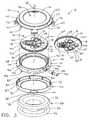
- FIG. 3is an exploded view of the surgical access device of FIG. 1 ;
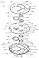
- FIG. 4is an exploded view of a base member included in the surgical access device of FIG. 1 ;
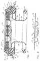
- FIG. 5is a cross-sectional view of the surgical access device of FIG. 1 ;
- FIG. 6is a cross-sectional view of a sealing member of the surgical access device of FIG. 1 ;
- FIG. 7is another cross-sectional view of the surgical access device of FIG. 1 ;
- FIG. 8is another cross-section view of the sealing membrane of the surgical access device of FIG. 1
- FIG. 9is a perspective view of the surgical access device of FIG. 1 with a surgical instrument disposed through a sealing element and positioned at an angle with respect to a central longitudinal axis of the surgical access device;
- FIG. 10is a cross-section view of the surgical access device of FIG. 1 showing a surgical instrument disposed through a sealing element and positioned at an angle with respect to the central longitudinal axis of the surgical access device;
- FIG. 11is a perspective view of the surgical access device of FIG. 1 disposed in tissue and having three surgical instruments disposed through three sealing elements;
- FIG. 12is a perspective view of the surgical access device of FIG. 1 disposed in tissue and having three surgical instruments disposed through three sealing elements at various angles;
- FIG. 13is a cross-sectional view of the surgical access device of FIG. 1 showing surgical instruments disposed through the sealing elements;
- FIG. 14is a perspective view illustrating a first range of motion of the surgical access device of FIG. 1 ;
- FIG. 15is a perspective view illustrating a second range of motion of the surgical access device of FIG. 1 ;
- FIG. 16is a perspective view illustrating a third range of motion of the surgical access device of FIG. 1 ;
- FIG. 17is a perspective view illustrating all three ranges of motion of FIGS. 17-19 ;
- FIG. 18is a perspective view of the surgical access device of FIG. 1 disposed in tissue with a surgical instrument disposed within a sealing element;
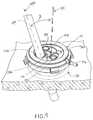
- FIG. 19is a perspective view of a housing support and a retractor of the surgical access device of FIG. 1 disposed in tissue with a top portion of the housing detached therefrom;
- FIG. 20is a cross-sectional view of tissue being removed through the retractor and the housing support of the surgical access device of FIG. 1 ;
- FIG. 21is a cross-sectional view of the surgical access device of FIG. 1 including one embodiment of a safety shield;
- FIG. 22is a perspective view of the safety shield of FIG. 21 ;
- FIG. 23is an exploded view of the safety shield of FIG. 21 ;
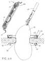
- FIG. 24is a cross-sectional side view of a second embodiment of a safety shield
- FIG. 25is a cross-sectional top view of the safety shield of FIG. 24 ;
- FIG. 26is a cross-sectional side view of a third embodiment of a safety shield
- FIG. 27is a cross-sectional top view of the safety shield of FIG. 26 ;
- FIG. 28is a perspective view of the safety shield of FIG. 26 ;
- FIG. 29Ais a cross-sectional view of another embodiment of a base member of a surgical access device having rotatable sealing elements
- FIG. 29Bis an exploded view of the base member of FIG. 29A illustrating rotatable rims for rotating the sealing elements;
- FIG. 30is one embodiment of locking mechanism for preventing rotation of the rotatable rims of FIG. 29B ;
- FIG. 31Ais a perspective view of one embodiment of a base member with multiple rotatable rings
- FIG. 31Bis a top view of the base member of FIG. 31A showing movable flexible arms
- FIG. 31Cis a cross-sectional view of the base member of FIG. 31A ;
- FIG. 31Dis a top view of the base member of FIG. 31A ;
- FIG. 31Eis a perspective view of an adjustment mechanism of the base member of FIG. 31A .
- FIG. 32Ais a cross-sectional view of a base member of a surgical access device having a flush sealing element
- FIG. 32Bis a cross-sectional view of a base member of a surgical access device having a recessed sealing element
- FIG. 33Ais a perspective view of a base member having a flexible bellows sealing member
- FIG. 33Bis a top view of the base member of FIG. 33A ;
- FIG. 34Ais an exploded view of three rotatable base members having sealing elements therein;
- FIG. 34Bis a cross-sectional view of the base members of FIG. 34A positioned in a housing;
- FIG. 35Ais a cross-sectional view of an exemplary base member having multiple layers of sealing elements
- FIG. 35Bis a perspective view of the base member of FIG. 35A ;
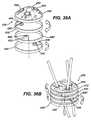
- FIG. 36Ais an exploded view of a base member having a flexible sealing membrane and a plurality of rotatable rims;
- FIG. 36Bis a perspective view of the base member of FIG. 36A ;
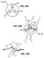
- FIG. 37Ais a cross-sectional view of a gimbal seal
- FIG. 37Bis a perspective of the gimbal seal of FIG. 37A having an instrument positioned therein;
- FIG. 37Cis a perspective of the gimbal seal of FIG. 37A ;
- FIG. 37Dis another perspective view of the gimbal seal of FIG. 37A .
- FIG. 38Ais a top view of one embodiment of a base member having tracks formed therein;
- FIG. 38Bis a perspective view of the base member of FIG. 38A ;
- FIG. 38Cis a cross-sectional view of a sealing element in the base member of FIG. 38A ;
- FIG. 39Ais a top view of another embodiment of a base member having rotatable rims.
- FIG. 39Bis a cross-sectional view of the base member of FIG. 39A .
- the present inventiongenerally provides improved surgical access devices that allow multiple surgical instruments to be inserted into sealing elements of a single surgical access device.
- the improved surgical access devicesallow surgical instruments inserted through the sealing elements to be moved laterally, rotationally, angularly, and vertically for ease of manipulation within a patient's body while maintaining insufflation.
- a housinghaving a base member with a plurality of sealing elements coupled thereto for receiving and forming a seal around surgical instruments inserted therein.
- the base membercan provide one or more predetermined paths, predefined movement regions, and/or predefined elongate pathways that can guide lateral, independent movement of the sealing elements therein, thereby allowing for lateral movement of surgical instruments inserted within the sealing elements.
- the housingcan define a central longitudinal axis, and the plurality of sealing elements can each have a central axis that can be angularly adjustable relative to the central longitudinal axis of the housing within the predetermined paths of the base member, thereby allowing a surgeon more control over the insertion of multiple surgical instruments.
- the plurality of sealing elementscan be collectively rotated about the central axis of the housing to enable greater surgeon maneuverability within the device.
- the various surgical access devicescan further include a wound protector, cannula, ring retractor, or other member for forming a pathway through tissue (hereinafter generally referred to as a retractor).
- the retractorcan extend from the housing and it can be configured to be positioned within an opening in a patient's body.
- the sealing elementscan each define working channels extending through the housing that are generally aligned with the retractor.
- Any and all of the surgical access devices described hereincan also include various other features, such as one or more ventilation ports to allow evacuation of smoke during procedures that utilize cautery and/or one or more insufflation ports through which the surgeon can insufflate the abdomen to cause pneumoperitenium, as described for example in U.S. Patent Application No.
- the insufflation portcan be any size and can accept a leur lock or a needle, as will be appreciated by those skilled in the art.
- the surgical access devices disclosed hereincan be utilized to provide access to a patient's body cavity.
- the retractorcan be positionable within an opening in a patient's body such that a distal portion of the retractor extends into a patient's body cavity and a proximal portion is coupled to a housing positioned adjacent to the patient's skin on an exterior of the patient's body.
- a lumen in the retractorcan form a pathway through the opening in a patient's body so that surgical instruments can be inserted from outside the body, through the sealing elements, to an interior body cavity.
- the elasticity of the skin of the patientcan assist in the retention of the retractor in the body opening or incision made in the body.
- the retractorcan be placed in any opening within a patient's body, whether a natural orifice or an opening made by an incision.
- the retractorcan be substantially flexible so that it can easily be maneuvered into and within tissue as needed.
- the retractorcan be rigid or semi-rigid.
- the retractorcan be formed of any suitable material known in the art, for example silicone, urethane, thermoplastic elastomer, and rubber.
- most surgical access devicestypically include at least one seal disposed therein to prevent air and/or gas from escaping when surgical instruments are inserted therethrough.
- Some of the embodiments disclosed hereincan be used with only one type of seal, for example an instrument seal, that prevents air and/or gas from escaping when a surgical instrument is inserted therethrough, but otherwise does not form a seal when no instrument is disposed therethrough.
- inventionscan include various sealing elements that are known in the art, and can include at least one instrument seal, at least one channel seal or zero-closure seal that seals the working channel created by the sealing port when no instrument is disposed therethrough, and/or a combination instrument seal and channel seal that is effective to both form a seal around an instrument disposed therethrough and to form a seal in the working channel when no instrument is disposed therethrough.
- various seals known in the artcan be used including, for example, duckbill seals, cone seals, flapper valves, gel seals, diaphragm seals, lip seals, gimbal seals, deep cone seals, iris seals, slit seals, etc.
- any combination of sealscan be included in any of the embodiments described herein, whether or not a particular seal combination is specifically discussed in the corresponding description of a particular embodiment.
- exemplary surgical access devicesprovide for greater maneuverability of surgical instruments within a patient while maintaining insufflation.
- this greater maneuverabilitycan be provided by having predefined movement regions, predefined elongate pathways, tracks, and/or predetermined paths formed within the housing that allow sealing elements, and surgical instruments disposed within the sealing elements, to be independently moved within and/or along the predetermined paths to allow for a greater range of motion.
- the sealing elementscan be angled relative to the predetermined paths to allow for angular manipulation of the surgical instruments as well as lateral movement along the predefined paths.
- each sealing elementcan include a flexible sealing membrane that can be integrally formed with a flexible sealing member.
- the flexible sealing membercan provide a gas tight seal within the housing and across the working channel and can stretch, twist, bunch, and otherwise deform to allow the sealing elements to move laterally, angularly, and vertically within their predetermined paths and relative to other sealing elements.
- the entire sealing membercan be rotated 360 degrees to thereby rotate the sealing elements to allow a change in position of surgical instruments inserted through the sealing elements.
- the surgical access device 10can generally include a housing 12 with a retractor 28 extending distally therefrom.
- the housing 12 and the retractor 28can define a working channel extending therethrough and a central longitudinal axis 30 .
- the housing 12can generally include one or more sealing elements 18 and/or sealing members 48 and the retractor 28 can be configured to be positioned within an opening in a patient's body to provide access to an interior surgical site.
- the tissue surrounding an opening in which the retractor 28 is placedcan exert a pressure on the retractor 28 to hold the retractor 28 in place within a body such that the housing 12 is positioned against tissue on the exterior of the body. In this way, an access pathway to an interior surgical site is created through which surgical instruments can be inserted to perform a surgical procedure.
- the retractor 28can extend from the housing, and in one embodiment, the retractor 28 is a substantially flexible member having a proximal flange 32 and a distal flange 34 with an inner elongate portion 36 extending therebetween.
- the proximal flange 32can be positioned within a distal portion of the housing 12 .
- a proximal o-ring 38can be included within the proximal flange 32 to add structural support to the proximal flange 32 and to aid in allowing rotation of the housing 12 relative to the retractor 28 , as will be described in more detail below.
- a distal o-ring 40can optionally be included within the distal flange 34 of the retractor 28 to provide structural support to the retractor 28 within a patient's body.
- the proximal and distal o-rings 38 , 40can be flexible or substantially rigid as needed for use in a particular application.
- the device 10can include a housing cover 14 and a housing support 42 that can be mated together to generally form the structure of the housing 12 .
- the housing 12can further include a base member 16 and a base member support 44 secured between the housing cover 14 and the housing support 42 .
- the housing cover 14can be formed of a crown 20 and cover flange 22 with one or more latches 24 extending from the cover flange 22 to aid in securing the housing cover 14 to the housing support 42 .
- the crown 20 of the housing cover 14can generally serve as a top most portion of the housing 12 and is in the shape or form of a ring defining an opening 46 in the housing cover 14 that allows access to the sealing elements 18 .
- the crown 20can have a diameter that is, for example, smaller than a diameter of the cover flange 22 . In other embodiments, the crown 20 can have a diameter that is the same as, or larger than, a diameter of the cover flange 22 depending on the requirements of a particular surgical access device.
- the crown 20 and the cover flange 22are integrally formed as a single component and the cover flange 22 extends distally at an angle from the crown 20 in an expanding diameter.
- the crown 20 and the cover flange 22can be adhered and/or fastened together with any mating mechanism known in the art, such as adhesive, screws, threads, etc.
- the cover flange 22can have a ring-like shape with a diameter that can generally define an outer diameter or outer circumference of the housing 12 .
- a distal surface 50 of the cover flange 22can be substantially level or flat to enable flush mating with an outer rim 52 of the base member support 44 .
- a notch 26can be formed in the cover flange 22 to receive an insufflation access port 54 formed in the base member support 44 that can receive an insufflation port 56 .
- One or more apertures or openings 58shown in FIGS. 5 and 6 , can be formed into the cover flange 22 around a circumference thereof to enable further mating between the housing cover 14 and the base member support 54 , as will be described in more detail below.
- the openings 58 in the cover flange 22can extend upward or proximally from the distal surface 50 of the cover flange 22 to a lower or distal surface 60 of the crown 20 .
- any number of mating or coupling mechanismscan be formed in and/or around the housing cover 14 to allow mating with other components of the housing 12 .
- one or more latches 24can extend from the cover flange 22 of the housing cover 14 to allow the housing cover 14 to mate or couple with the housing support 42 .
- the latches 24can include a recessed groove 62 having an inner lip 64 that can support and seat an outer rim 66 formed by a recessed portion 68 of the housing support 42 .
- the recessed groove 62 within the latch 24can also receive a recessed lip 70 of the base member support 44 seated on top of the outer rim 66 , thereby securing all components of the housing 12 together.
- An outer lip 72 of the latch 24allows for the latch 24 to be manually moved outward and upward, as indicated by the directional arrow A in FIG.
- any number of mating and/or coupling mechanismscan be used to mate the housing cover 14 with the rest of the housing 12 , including but not limited to, adhesives, threads, screws, bayonet latches, etc.
- the housing support 42is illustrated as a generally ring-shaped member having a seating flange 74 with a circumferential sidewall 76 extending proximally from an outer circumference of the seating flange 74 .
- the seating flange 74can be configured to seat the proximal flange 32 of the retractor 28 such that a top surface 78 of the proximal flange 32 is positioned slightly below a top surface 80 of the circumferential sidewall 76 .
- the proximal flange 32can generally be seated within the housing support 42 without the aid of any securement mechanism in order to allow the housing 12 to be moved relative to the retractor 28 .
- the proximal flange 32 of the retractor 28can have a diameter smaller than a diameter of the circumferential sidewall 76 , and in some embodiments, can have a diameter significantly smaller than a diameter of the circumferential sidewall 76 to allow for both lateral, sliding movement and rotational, sliding movement of the housing 12 relative to the retractor 28 . In other embodiments, the diameter of the proximal flange 32 can be only slightly smaller than a diameter of the circumferential sidewall 76 to prevent such lateral, sliding movement while still allowing for rotational, sliding movement.
- the housing support 42can optionally include one or more frictional protrusions 82 extending inward from an inner surface 84 of the circumferential sidewall 76 to provide a surface against which the proximal flange 32 can move as the housing 12 is being moved or rotated relative to the retractor 28 .
- the inner elongate portion 36 of the retractor 28can extend proximally through the opening formed in the housing support 42 , thereby defining the working channel through which instruments can be inserted.
- the housing support 42can have many configurations, in the illustrated embodiment, the top surface 80 of the circumferential sidewall 76 has a diameter equal to a diameter of the base member support 44 and can thus sit flush against a bottom or distal surface 86 of the base member support 44 .
- the sidewall 76can also have other diameters smaller or larger than the base member support 44 as needed in a particular application.
- the housing support 42can have one or more recessed portions 68 formed in the circumferential sidewall 76 for mating with one or more latches 24 of the housing cover 14 .
- the proximal outer rim 66 of the recessed portion 68can be seated by the inner lip 64 of the recessed grooves 62 of the latches 24 extending from the housing cover 14 .
- the base member 16 and the base member support 44can be secured between the housing cover 14 and the housing support 42 .
- the base member 16can generally be seated or disposed within the base member support 44 , and the base member support 44 can provide the connection or coupling to the housing cover 14 and the housing support 42 .
- the base member support 44has a planar flange portion in the shape of a ring with a circular sidewall 88 extending proximally from the planar flange portion such that the flange portion is divided into two sections.
- a first section or inner rim 90forms a seating area with the sidewall 88 for receiving and seating the base member 16 .
- the second section or outer rim 52provides mating elements for mating the base member support 42 to the housing cover 14 .
- an inner surface 94 of the sidewall 88can include threads formed therearound and/or another engagement mechanism for mating with corresponding threads or engagement mechanisms formed on an outer circumference 92 of the base member 16 , thereby securing the base member while still allowing rotation thereof.
- the base member 16fits securely within the base member support 44 through a loose press fit and/or interference fit connection between the outer circumference 92 of the base member 16 and the inner surface 94 of the sidewall 88 .
- the loose press fit or interference fitcan be such that the base member 16 is freely rotatable in both directions relative to the base member support 42 and the rest of the housing 12 . Rotation of the base member 16 relative to the base member support 42 and the housing 12 allows rotation of all of the sealing elements 18 disposed within the base member 16 as a unit, as will be described further below.
- the outer rim 52 of the base member support 42can include one or more mating protrusions 96 extending therefrom for mating with one or more corresponding openings 58 in the housing cover 14 .
- a press fit, interference fit, and/or adhesivecan be used to join the protrusions 96 with the openings 58 in the housing cover 14 .
- a proximal or top surface of the outer rim 52can be positioned adjacent to the distal surface 50 of the cover flange 22 .
- the outer rim 52can have an outer circumference that is substantially flush with the outer circumference of the cover flange 22 .
- the distal or bottom surface 86 of the outer rim 52can be positioned adjacent to the top surface 80 of the circumferential wall 76 of the housing support 42 , and its outer circumference can also be substantially flush with the outer circumference of the housing support 42 .
- One or more recessed slots 70can be formed around an outer circumference of the outer rim 52 to correspond with the recessed portions 68 formed in the housing support 42 for receiving the housing cover latch 24 .
- the recessed portion 68can be securely grasped on top of the outer rim 66 of the housing support 42 within the groove 62 of the latch 24 .
- the insufflation access port 54can be formed in the base member support 44 and can consist of an opening 100 extending from the outer circumference of the outer rim 52 and through the sidewall 88 into the working channel.
- the opening 100can receive the insufflation port 56 for introducing insufflation gases through the working channel and into a body.
- the opening 100can extend into the working channel at a position below or distal to the base member 16 and the sealing elements 18 disposed in the base member 16 . In this way, insufflation gases can be introduced and retained in the working channel and body by the sealing elements 18 when surgical instruments are inserted therethrough.
- the insufflation port 56extends perpendicularly to the central longitudinal axis 30 of the housing 12 , but as will be appreciated by those skilled in the art, insufflation access ports 54 can be positioned at any suitable place within the housing 12 . In addition, the insufflation ports 56 can extend from the housing 12 at any angle relative to its central longitudinal axis 30 , including parallel thereto.
- the base member 16can include an upper bearing plate 102 , a lower bearing plate 104 , and the sealing member 48 disposed between the two bearing plates 102 , 104 .
- the sealing elements 18can extend through the sealing member 48 and the bearing plates 102 , 104 , as will be described in more detail below.
- the upper and lower bearing plates 102 , 104can each include one or more predefined movement regions, predefined elongate pathways, predetermined paths, and/or tracks formed therein that are provided to guide movement of the sealing elements 18 .
- the bearing plates 102 , 104are generally each substantially flat, circular elements that, in some embodiments, can be substantially rigid.
- bearing plates 102 , 104can be substantially flexible as needed in a particular application.
- Each bearing plate 102 , 104can be formed of any suitable material known in the art, including but not limited to, polycarbinate and/or high density polyethelene.
- three generally elongate tracks 106 , 108 , 110are provided in the upper and lower bearing plates 102 , 104 for receiving three movable sealing elements 18 a , 18 b , 18 c therein.
- a fourth, generally circular opening 112is provided to receive a more constrained, non-movable sealing element 18 d therein.
- any number of trackscan be disposed in the bearing plates 102 , 104 as needed.
- the tracks 106 , 108 , 110can have any size, shape, length, and curvature known in the art, in the illustrated embodiment, the tracks 106 , 108 , 110 are generally elongate and have a width substantially corresponding to a diameter of the sealing element 18 disposed therein and a length corresponding to between about one and a half to two times the diameter of the sealing element 18 disposed therein. In other embodiments, the tracks 106 , 108 , 110 can have a width and/or a length corresponding to anywhere between about two to five times a diameter of the sealing element 18 disposed therein.
- the number of tracks within a bearing platecan range between one and any number (two, three, four, five, six, etc.) that can reasonably fit within a diameter of the bearing plates 102 , 104 .
- a single track formed within the base member 16can have a substantially large size relative to the size of the bearing plates 102 , 104
- multiple tracks formed within the base member 16can have a smaller size relative to the size of the bearing plates 102 , 104 .
- Multiple trackscan also have substantially different sizes from one another.
- the tracks 106 , 108 , 110can generally be positioned and spaced within the upper and lower bearing plates 102 , 104 in any way as needed in a particular application.
- a first track 106is a substantially straight track and extends from a position adjacent to an outer diameter of the upper and lower bearing plates 102 , 104 into a center portion of the plates 102 , 104 .
- Second and third tracks 108 , 110can be positioned on opposite sides of the first track 106 and can also extend from a position adjacent to an outer diameter of the upper and lower bearing plates 102 , 104 .
- the second and third tracks 108 , 110curve slightly inward around a portion of the first track 106 that extends into the center of the bearing plates 102 , 104 .
- the fourth opening 112is disposed at a position substantially opposite to a position of the first track 106 .
- the tracks 106 , 108 , 110can be situated around a diameter of the bearing plates 102 , 104 or, as shown in FIGS. 38A-38C , tracks 106 ′, 108 ′, 110 ′ can all extend from an outer diameter into a center of the bearing plates 102 ′, 104 ′.
- the bearing plates 102 ′, 104 ′can have a sealing element 18 ′ formed therein with a flexible sealing member 48 ′ therearound.
- all of the tracks 106 , 108 , 110can be straight and in other embodiments, all of the tracks 106 , 108 , 110 can have a curvature.
- shape and positioning of the tracks 106 , 108 , 110 within the bearing plates 102 , 104should not be limited to the several that are noted herein.
- the upper bearing plate tracks 106 a , 108 a , 110 acan have smooth interior sidewalls 116 to enable smooth movement of the movable sealing elements 18 a , 18 b , 18 c within the upper bearing plate tracks 106 a , 108 a , 110 a .
- the lower bearing plate tracks 106 b , 108 b , 110 bcan have interior sidewalls with a smooth proximal portion 114 corresponding in size to the sidewalls 116 of the upper bearing plate tracks 106 a , 108 a , 110 a to enable smooth movement of the sealing elements 18 a , 18 b , 18 c within the tracks 106 b , 108 b , 110 b .
- a lower or distal portion 118 of the sidewallscan extend or protrude slightly into the tracks 106 b , 108 b , 110 b to form a lip extending therearound that has a size slightly smaller than a size of the proximal portion 114 and a size of the sidewalls 116 of the upper bearing plate tracks 106 a , 108 a , 110 a .
- the sealing elements 18 a , 18 b , 18 ccan move and/or slide along the lip formed in the lower bearing plates tracks 106 b , 108 b , 110 b and vertical and/or longitudinal movement of the sealing elements 18 a , 18 b , 18 c below the lower bearing plate tracks 106 b , 108 b , 110 b is restrained or prohibited while vertical and/or longitudinal movement of the sealing elements 18 a , 18 b , 18 c above the upper bearing plate tracks 106 a , 108 a , 110 a is not restrained or prohibited.
- the sidewalls 116 , 114 , 118 of the upper and lower bearing plate tracks 106 a , 106 b , 108 a , 108 b , 110 a , 110 bare completely smooth, with no lip, such that vertical and/or longitudinal movement below and above the tracks is allowed.
- engagement elementssuch as grooves or recesses, can extend around the sidewalls 116 , 114 , 118 in the upper and/or lower bearing plate tracks 106 a , 106 b , 108 a , 108 b , 110 a , 110 b that are configured to mate with corresponding engagement elements formed around the sealing elements 18 a , 18 b , 18 c to provide constrained vertical and/or longitudinal movement of the sealing elements 18 a , 18 b , 18 c while allowing lateral, guided movement within the tracks 106 , 108 , 110 .
- one or more tracks 106 , 108 , 110can provide constrained movement of a sealing element 18 a , 18 b , 18 c disposed therein while one or more tracks 106 , 108 , 110 can provide a full range of movement and/or motion of a sealing element 18 a , 18 b , 18 c disposed therein.
- the upper and lower bearing plates 102 , 104can be joined or coupled together by any method known in the art, including but not limited to, adhesive, screws, press fit, interference fit, etc.
- one or more cylindrical protrusions 120 and one or more elongate protrusions 122are formed around an outer rim 124 of the lower bearing plate 104 such that they extend proximally therefrom.
- the cylindrical protrusions 120are configured to extend through securement openings 126 formed around an outer diameter of the sealing member 48 and into corresponding openings 128 formed around an outer diameter of the upper bearing plate 102 such that a press fit or interference fit is achieved between the cylindrical protrusions 120 and the openings 128 in the upper bearing plate 102 .
- the elongate protrusions 122are configured to secure the lower bearing plate 104 to the sealing member 48 and thus extend into corresponding elongate slots 130 formed around the outer diameter of the sealing member 48 . In this way, the base member 16 is secured together with the sealing member 48 coupled between the upper and lower bearing plates 102 , 104 .
- the sealing member 48can have many configurations and in the illustrated embodiment, the sealing member 48 generally seals the working channel of the surgical access device 10 by providing an air and gas tight seal between the upper bearing plate 102 and the lower bearing plate 104 .
- the sealing member 48can be composed of a flexible, stretchable, and/or deformable material that is able to flex, stretch, bunch and/or otherwise deform to allow the sealing elements 18 a , 18 b , 18 c disposed therethrough to be moved within their respective tracks 106 , 108 , 110 within the bearing plates 102 , 104 .
- the sealing member 48is a relatively thin, deformable membrane that has a diameter corresponding to a diameter of the upper and lower bearing plates 102 , 104 such that it can be positioned and form a seal between the upper and lower bearing plates 102 , 104 .
- the sealing member 48can be formed of any suitable material known in the art, including but not limited to, silicone, urethane, sanaprene, isoprene, and/or krayton.
- the sealing member 48can include one or more openings 132 formed therethrough that define openings for one or more sealing elements 18 .
- each sealing element 18can be a movable sealing element, for example, movable sealing elements 18 a , 18 b , 18 c , or a non-movable sealing element, for example, non-movable sealing element 18 d .
- Movable sealing elements 18 a , 18 b , 18 care generally configured to be independently movable within their respective bearing plate tracks 106 , 108 , 110 relative to the housing, each other, and to non-movable sealing elements.
- the non-movable sealing element 18 dis generally configured to be secured within a circular opening, for example, opening 112 , in the bearing plates 102 , 104 that does not provide room for the sealing element 18 d to move.
- the movable sealing elements 18 a , 18 b , 18 ccompose a majority of the total number of sealing elements 18 disposed within the base member 16 .
- one or more sealing elements 18can have an opening with a different diameter than an opening of the other sealing elements 18 .
- one or more movable sealing elements 18 a , 18 b , 18 ccan have an opening with a diameter that is the same as, larger than, or smaller than openings in other movable sealing elements 18 a , 18 b , 18 c and in other non-movable sealing element 18 d .
- One or more non-movable sealing elements 18 dcan have an opening with a diameter that is the same as, larger than, or smaller than openings in other non-movable sealing elements (not shown) and in other movable sealing elements 18 a , 18 b , 18 c.
- the sealing elements 18can have many configurations and constructions, but in the illustrated embodiment, the sealing elements 18 each include a sealing membrane 134 , formed integrally with the sealing member 48 , that is configured to form a seal around a surgical instrument positioned therethrough.
- the sealing membrane 134can generally have a cone-like shape with flexible conical walls 136 and an opening 138 , shown most clearly in FIGS. 5 and 6 , at the apex of the cone that is smaller than a diameter of a surgical instrument such that the opening 138 can deform to form a seal around an instrument inserted therethrough.
- Each sealing membrane 134can be the same as every other sealing membrane 134 or one or more sealing membranes 134 can be different than another. As shown in FIGS.
- the sealing membrane 134 of sealing element 18 acan have a fluted form in which the conical walls 136 are folded in v-shaped, accordion style folds. This construction assists in preventing eversion of the sealing membrane 134 when an instrument is withdrawn from the sealing element 18 a .
- the fluted formbunches beneath the sealing member 48 and thus provides a bracing that prevents the sealing element 18 a from everting.
- the conical walls 136 of the sealing elements 18 b , 18 cdo not have fluted forms and instead have a steep angle ⁇ relative to a lateral plane of the sealing member 48 , as shown in FIG. 8 , that resists eversion when a surgical instrument is withdrawn from the sealing element 18 b , 18 c .
- any of the sealing elements 18can have one or more of the various available constructions for their respective sealing membrane 134 .
- the sealing elements 18can also be formed as separate elements apart from the sealing member 48 and do not have to be formed integrally therewith.
- the sealing elements 18can be constructed in various ways, but in the illustrated embodiment, the sealing elements 18 can include upper and lower seal supports 140 , 142 , shown most clearly in FIG. 4 .
- the upper and lower seal supports 140 , 142can be substantially rigid rings that are configured to engage upper and lower surfaces of a perimeter of the opening 132 of the sealing member 48 therebetween.
- the seal supports 140 , 142serve to further define the openings formed through the sealing member 48 , provide support thereto for the insertion and withdrawal of surgical instruments, and for the movable sealing elements 18 a , 18 b , 18 c , can provide a structure that can move, slide, and/or otherwise travel along and within the tracks 106 , 108 , 110 in the upper and lower bearing plates 102 , 104 .
- the upper and lower seal supports 140 , 142can be joined or coupled together by any method known in the art including, but not limited to, adhesives, screws, threads, etc.
- the lower seal support 142includes several cylindrical protrusions 144 and several elongate protrusions 146 formed around its circumference and extending in a proximal direction from its proximal surface 148 .
- the cylindrical protrusions 144can extend through corresponding openings 149 formed around a circumference of the sealing element openings 132 in the sealing member 48 and into corresponding openings 152 within the upper seal supports 140 .
- the elongate protrusions 146can extend through corresponding elongate slots 150 formed adjacent to the circumference of the sealing element openings 132 formed in the sealing member 48 . In this way, a circumference surrounding each sealing membrane 134 is clamped, coupled, or otherwise secured between the upper and lower seal supports 140 , 142 .
- the sealing elements 18are able to form an air and gas tight seal around a surgical instrument inserted therethrough while the sealing member 48 seals the rest of the working channel between the upper bearing plate 102 and the interior of a body.
- the sealing member 48is flexible and thus will stretch, bunch, twist and otherwise deform in response to movement of the various sealing elements 18 a , 18 b , 18 c within the upper and lower bearing plate tracks 106 , 108 , 110 . More particularly, because the upper and lower seal supports 140 , 142 grasp the sealing member 48 around the sealing membranes 134 , the sealing elements 18 a , 18 b , 18 c are able to pull and push the sealing member 48 in response to movement of surgical instruments disposed therein.
- the sealing elements 18 a , 18 b , 18 care each independently movable laterally within and along the length and/or width of their respective bearing plate tracks 106 , 108 , 110 .
- Each of the sealing elements 18 a , 18 b , 18 ccan independently and selectively be moved laterally from an initial resting position, such as a relatively center position in the tracks 106 , 108 , 110 to either of opposed ends of the tracks 106 , 108 , 110 , and anywhere in between, whether along a straight line of a track 106 or along a curved path that follows the curve of tracks 108 , 110 .
- the tracks 106 , 108 , 110 containing each sealing element 18 a , 18 b , 18 cdefine the predetermined path of movement allowed.
- a surgical instrument 900is inserted through the sealing element 18 a , which is moved from its natural, center position within the track 106 to one end of the track 106 near the outer circumference of the device 10 .
- FIGS. 9 , 11 , and 12a surgical instrument 900 is inserted through the sealing element 18 a , which is moved from its natural, center position within the track 106 to one end of the track 106 near the outer circumference of the device 10 .
- a surgical instrument 902is positioned within sealing element 18 b , which is also moved from its natural, center position in the track 108 to one end of the track 108 .
- a surgical instrument 904is positioned within the sealing element 18 c and is positioned in a center portion of the track 110 in FIG. 11 and is moved to one end of the track 110 in FIG. 12 . Accordingly, some variations of the possible lateral movement of the sealing elements 18 a , 18 b , 18 c within their respective tracks 106 , 108 , 110 can be seen. Of course, many other variations and combinations of lateral movement are also possible.
- Each sealing element 18 a , 18 b , 18 ccan also be moved angularly within each track 106 , 108 , 110 such that a longitudinal axis of the sealing element 18 a , 18 b , 18 c is movable and adjustable relative to the central longitudinal axis 30 of the housing 12 .
- the sealing elements 18 a , 18 b , 18 ccan be pivoted out of a lateral plane of the tracks 106 , 108 , 110 within the base member 16 .
- the sealing member 48can stretch and bunch around each sealing element 18 a , 18 b , 18 c to enable each sealing element 18 a , 18 b , 18 c to be pivoted to an angle with respect to the lateral plane while maintaining a seal around an instrument inserted therethrough.
- the sealing elements 18 a , 18 b , 18 care angularly adjustable at any position along a lateral, long-axis of the elongate tracks 106 , 108 , 110 . For example, in FIGS.
- a central longitudinal axis 930 of the sealing element 18 ain which the surgical instrument 900 is disposed, is positioned at an angle ⁇ with respect to the central longitudinal axis 30 of the housing 12 .
- the sealing element 18 bin which the surgical instrument 902 is disposed, is moved from a position in which its central longitudinal axis 932 is parallel with the central longitudinal axis 30 of the housing 12 ( FIG. 11 ) to a position in which its central longitudinal axis 932 is at an angle ⁇ with respect to the central longitudinal axis 30 of the housing 12 ( FIG. 12 ).
- a central longitudinal axis 934 of the sealing element 18 cremains parallel with the central longitudinal axis 30 of the housing 12 in both configurations.
- All of the sealing elements 18 a , 18 b , 18 care completely and independently angularly adjustable within their respective tracks 106 , 108 , 110 at any lateral position within the tracks 106 , 108 , 110 .
- the sealing elements 18 a , 18 b , 18 ccan be angularly adjustable at any position along both a long-axis and a short-axis of the elongate tracks 106 , 108 , 110 , and/or angularly adjustable at any position around 360 degrees laterally within the tracks 106 , 108 , 110 .
- the sealing elements 18 a , 18 b , 18 ccan also be moved vertically relative to the base member 16 and parallel relative to the central longitudinal axis 30 of the housing 12 .
- the lips formed in the lower bearing plate tracks 106 b , 108 b , 110 bcan prevent vertical movement below the bearing plate tracks 106 b , 108 b , 110 b , while vertical movement above the upper bearing plate tracks 106 a , 108 a , 110 a is allowed.
- a surgical instrument disposed within a sealing element 18 a , 18 b , 18 ccan be pulled proximally from the sealing element 18 a , 18 b , 18 c , whether for complete withdrawal or for adjustment purposes, and the movement can lift the sealing elements 18 a , 18 b , 18 c above the plane of the base member 16 .
- vertical movementis allowed in both directions above and below the bearing plate tracks 106 , 108 , 110 .
- a particular sealing element 18 a , 18 b , 18 ccan be independently moved laterally within a track 106 , 108 , 110 while its central longitudinal axis is at an angle relative to the central longitudinal axis 30 of the housing 12 .
- a particular sealing element 18 a , 18 b , 18 ccan be independently moved vertically while its central longitudinal axis is at an angle relative to the central longitudinal axis 30 of the housing 12 .
- Such vertical movementis thus no longer strictly parallel to the central longitudinal axis 30 of the housing 12 , but is instead movement that is at an angle relative to the central longitudinal axis 30 of the housing 12 .
- each movable sealing element 18 a , 18 b , 18 cis accomplished due to the flexibility of the sealing member 48 being configured to stretch, twist, bunch, and otherwise deform in response to the movement.
- all such movementis performed while the working channel is sealed due to the seal formed by the sealing elements 18 a , 18 b , 18 c around a surgical instrument inserted therethrough and due to the flexibility of sealing member 48 that able to maintain a seal during deformation.
- the base member 16can also be rotated within and relative to the base member support 44 , and thus relative to the housing 12 . Accordingly, the base member 16 provides multiple ways in which the sealing elements 18 can be moved to provide better access for surgical instruments inserted therein. By rotating the base member 16 , the sealing elements 18 can all be rotated as a collective unit around the central longitudinal axis 30 of the housing 12 . In addition, each sealing element 18 a , 18 b , 18 c can be moved laterally, angularly, and vertically within the base member 16 , as described above, to enable better access and maneuverability.
- FIGS. 14-17illustrate one embodiment of the range of motion that the surgical access device 10 can provide during surgical procedures.
- FIGS. 14-16illustrate a series of possible ranges of motion for various positions of the sealing elements 18 .
- FIG. 17combines the three series shown in FIGS. 14-16 to give a complete picture of one embodiment of the range of motion possible with the surgical access device 10 .
- an assumptionis made that a first surgical instrument 940 , disposed through the sealing element 18 c , remains perpendicular to a lateral axis or a lateral surface of the housing 12 as a second surgical instrument 942 , disposed through the sealing element 18 b , is moved through various angles relative to the lateral axis or the lateral surface of the housing 12 .
- a target diameter 944is illustrated and represents the target space over which one or both of the first and second surgical instruments 940 , 942 can move during a surgical procedure.
- the first surgical instrument 940is positioned through the sealing element 18 c , which is positioned at a left-hand end of the track 110 .
- the second surgical instrument 942is positioned through the sealing element 18 b , which is positioned at a left-hand end of the track 108 .
- the two sealing elements 18 c , 18 bare positioned at the same, left-hand end of the tracks 110 , 108 . In this position, there is a triangular shaped space 946 a behind the surgical instrument 940 that cannot be accessed by any angular movement of the second instrument 942 .
- a key-hole shape 948 ais also shown and generally illustrates the area over which the instrument 942 cannot reach while in this lateral position within the track 108 due to, for example, handle and shaft interference between the two instruments 940 , 942 .
- the entire target diameter 944 , minus the triangle 946 a and the key-hole shape 948 acan be reached by the second surgical instrument 942 during a surgical procedure while the sealing elements 18 c , 18 b are in the far, left-hand end position within their tracks 110 , 108 .
- the target diameter 944is again illustrated.
- the first surgical instrument 940is positioned through the sealing element 18 c , which is positioned at a center portion of the track 110 .
- the second surgical instrument 942is positioned through the sealing element 18 b , which is positioned at a center portion of the track 108 . In this position, there is a triangular shaped space 946 b behind the first surgical instrument 940 that cannot be accessed by any angular movement of the second surgical instrument 942 . As the second surgical instrument 942 is moved through its entire angular range, it will pass over the first surgical instrument 940 , as illustrated by the arrow B.
- a key-hole shape 948 bis also shown and generally illustrates the area over which the second surgical instrument 942 cannot reach while in this center, lateral position within the track 108 due to, for example, handle and shaft interference between the two instruments 940 , 942 .
- the entire target diameter 944 , minus the triangle 946 b and the key-hole shape 948 bcan be reached by the surgical instrument 942 while the sealing elements 18 c , 18 b are in center positions within their respective tracks 110 , 108 .
- the target diameter 944is again illustrated.
- the first surgical instrument 940is positioned through the sealing element 18 c , which is positioned at a right-hand end of the track 110 .
- the second surgical instrument 942is positioned through the sealing element 18 b , which is positioned at a right-hand end of the track 108 .
- the two sealing elements 18 c , 18 bare positioned at the same, right-hand end of the tracks 110 , 108 . In this position, there is a triangular shaped space 946 c behind the first surgical instrument 940 that cannot be accessed by any angular movement of the second surgical instrument 942 .
- a key-hole shape 948 cis also shown and generally illustrates the area over which the second surgical instrument 942 cannot reach while in this lateral position within the track 108 due to, for example, handle and shaft interference between the two instruments 940 , 942 .
- the entire target diameter 944 , minus the triangle 946 c and the key-hole shape 948 ccan be reached by the second surgical instrument 942 during a surgical procedure while the sealing elements 18 c , 18 b are in the far, right-hand end position within their tracks 110 , 108 .
- FIG. 17represents the combination of FIGS. 14-16 to illustrate one embodiment of the full range of motion available during a surgical procedure to the second surgical instrument 942 disposed through the surgical access device 10 .
- the target diameter 944is again shown.
- An area 946enclosed by dotted lines, represents the combination of triangles 946 a , 946 b , 946 c and is essentially an area where a small portion of the target diameter 944 becomes unavailable to the second surgical instrument 942 at each lateral position within the track 108 due to, for example, interference between the two shafts.
- An area 948is a combination of the key-holes 948 a , 948 b , 948 c and is the only area within the target diameter 944 that can be unavailable to the second surgical instrument 942 during a surgical procedure. Accordingly, almost the entire target diameter 944 is accessible to the second surgical instrument 942 , while another surgical instrument 940 is disposed through the surgical access device 10 , just by moving the second surgical instrument 942 along the track 108 and through the various possible angular orientations. Of course, the inaccessible area 948 is accessible by another surgical instrument disposed through the sealing element 18 c and/or 18 a .
- the base member 16is rotatable relative to the rest of the housing 12 , and thus with a slight rotation of the base member 16 , the second surgical instrument 942 can access the area 948 . Additionally, the entire housing 12 is rotatable relative to the retractor 28 , providing a similar type of access to the second surgical instrument 942 . As will be appreciated, this series of range of motion illustrations is only one example of many possible ranges of motion that the surgical access device 10 can provide.
- the retractor 28 of the exemplary access device 10can be positioned within any opening in a patient's body, including natural openings and surgically formed openings.
- the retractoris positioned through an opening within tissue 19 .
- the retractor 28is held in place by the tissue 19 within the opening such that the housing 12 is positioned against an outer surface of the patient's body.
- the housing 12can be rotated in either direction by any amount relative to the retractor 28 to enable proper positioning of the sealing elements 18 .
- various surgical instrumentsfor example surgical instrument 27 , can be inserted through the movable and immovable sealing elements 18 disposed within the housing 12 and into the working channel of the surgical access device.
- one sealing element 18 ahas a diameter than is larger than the other sealing elements 18 b , 18 c , 18 d .
- the sealing element 18 acan receive the surgical instrument 27 having a larger diameter, such as an endoscopic camera and/or light.
- the immovable sealing element 18 dhas a diameter smaller than the other sealing elements 18 a , 18 b , 18 c and can receive an instrument with a smaller diameter, for example, a surgical retractor.
- the other two movable sealing elements 18 b , 18 ccan receive any number of other surgical instruments as may be needed in a particular application.
- the sealing elements 18can have various diameter and that any surgical instrument having a suitable diameter can be inserted in any one of the various sealing elements.
- insufflation of the interior surgical sitecan be achieved by flowing an insufflation gas through the insufflation port 56 and into the sealed working channel.
- the surgical instruments within the sealing elements 18 a , 18 b , 18 ccan then be moved laterally, angularly, and vertically, as described above, to achieve optimal positioning of the surgical instruments within the interior surgical site.
- the base member 16can be rotated relative to the base member support 44 and the housing 12 to rotate all of the sealing elements 18 , and the instruments disposed in the sealing elements 18 , as a collective unit.
- the housing 12can also be rotated as needed to achieve better positioning for, for example, the insufflation port 56 .
- the surgical instruments disposed in the sealing elements 18can be repeatedly and independently moved and manipulated within their respective tracks 106 , 108 , 110 to facilitate ease of use.
- insufflation pressurecan be released through the insufflation port 56 , and the surgical instruments can be withdrawn from the sealing elements.
- a top portion 11 of the housing 12including the housing cover 14 , the base member 16 , and the base member support 44 , can be unlatched and removed from the housing support 42 , as shown most clearly in FIG. 20 .
- the retractor 28remains within the opening in the tissue 19 and the housing support 42 remains adjacent to the tissue 19 on an exterior thereof.
- Tissue 43 that was cut or dissected during the surgical procedurecan be withdrawn through the working channel of the retractor 28 as needed using a surgical instrument 49 .
- the retractor 28can then be removed from the opening in the tissue 19 upon completion of the procedure.
- the top portion 11 of the housing 12can also be latched back to the housing support 42 as needed if further surgical procedures are required.
- the surgical access device 10can also include a shield 719 configured to extend through the retractor 28 to thereby provide a protective lining as surgical instruments are inserted through the device 10 .
- the shield 719can have a length corresponding to a length of the retractor 28 , but can also have a length less than or considerably longer than the length of the retractor depending on a specific application.
- the shield 719can be mated to the retractor 28 using any attachment mechanism, e.g., adhesive, screws, press fit, etc., as will be appreciated by a person skilled in the art.
- the shield 719can be configured to engage a proximal flange 32 of the retractor 28 that is seated in the housing support 42 and the distal surface 86 of the base member support 44 .
- the proximal o-ring 38 within the flange 32can help provide structure to the proximal flange 32 and therefore help provide a more stable engagement surface for the shield 719 .
- Lips 720 a , 720 bcan be formed around an outer circumference of a proximal rim 718 of the shield 719 and can fit within and engage a recess 722 formed in the distal surface 86 of the base member support 44 to provide further securement of the shield 719 between the proximal flange 32 and the base member support 44 .
- the shield 719can have any size, shape, and configuration.
- the shield 719includes a circumferentially expandable, cylindrically-shaped member having an outer layer 719 a and an inner layer 719 b configured to be disposed within in the outer layer 719 a .
- the outer and inner layers 719 a , 719 bcan each respectively include a circumferential proximal rim 721 a , 721 b having a plurality of flanges 723 a , 723 b extending radially outward therefrom.
- the outer and inner layers 719 a , 719 bcan include any number of flanges 723 a , 723 b , and the flanges 723 a , 723 b can be spaced equidistantly or any other distance apart from one another around their respective proximal rims 721 a , 721 b .
- the outer and inner flanges 723 a , 723 bcan each be configured to at least partially overlap to form a continuous proximal flange of the shield 719 that is configured to engage the proximal flange 32 of the retractor 28 .
- a portion of the outer and inner flanges 723 a , 723 bcan be configured to engage one another to form a “broken” proximal flange of the shield 719 .
- none of the outer and inner flanges 723 a , 723 bcan overlap one another when the inner layer 719 b is disposed in the outer layer 719 a.
- the outer and inner layers 719 a , 719 b of the shield 719can also include a plurality of respective distal elongate fingers 725 a , 725 b distally extending from the proximal rim 721 a , 721 b and configured to at least partially overlap and engage one another when the inner layer 719 b is disposed in the outer layer 719 a to form a continuous distal surface configured to engage at least a portion of an inner wall of the inner elongate portion 36 of the retractor 28 .
- the distal fingers 725 a , 725 bcan thus be configured to protect the inner elongate portion 36 of the retractor 28 from damage but be configured to be selectively movable when in contact with a surgical instrument such that the surgical instrument can optionally push between the distal fingers 725 a , 725 b to help provide the surgical instrument with free angular range of motion through the device 10 .
- the distal fingers 725 a , 725 bcan also be configured to be selectively movable when the retractor 28 bends when in position in tissue, if the retractor 28 is flexible.
- a shieldcan include a plurality of layers as discussed above, or a shield can be a singular member, which can make the shield easier to dispose in a retractor.
- FIGS. 24 and 25illustrate one embodiment of a singular shield 719 ′.
- the alternate shield 719 ′can include a circumferential proximal rim 721 ′ with or without radially extending flanges and with a lip 720 ′ for mating with the device 10 , as described above.
- the alternate shield 719 ′can include a pleated distal portion 723 ′ that simulates distal fingers.
- the pleated distal portion 723 ′can have a variety of sizes, shapes, and configurations. As shown, the pleated distal portion 723 ′ can include a plurality of box pleats 723 a ′ folded in the shield 719 ′ circumferentially around the distal portion 723 ′. In this way, the pleated distal portion 723 ′ can be configured to be selectively movable when the retractor 719 ′ bends, if the retractor 719 ′ is flexible, and/or when a surgical instrument presses against an inner wall of the pleated distal portion 723 ′. In another embodiment of a singular retractor shield 719 ′′, shown in FIGS.
- the shield 719 ′′can include a pleated distal portion 723 ′′ distally extending from a proximal rim 721 ′′ having a lip 720 ′′ and having a plurality of knife pleats 723 a ′′ formed circumferentially therearound.
- any type of shieldcan be used as needed in a particular application and can be interchanged before, during, and/or after a procedure as needed.
- a base member 200 of a housing for a surgical access devicehaving three sealing elements 202 attached or coupled to independently slidably rotatable rims 204 a , 204 b , 204 c .
- the three slidably rotatable rims 204 a , 204 b , 204 care provided concentrically adjacent to one another near an outer circumference of the base member 200 .
- the rotatable rims 204 a , 204 b , 204 ccan each have an elongate sealing element arm 205 extending radially therefrom.
- the rotatable rims 204 a , 204 b , 204 ccan be independently rotatable, thus allowing the sealing element arms 205 extending therefrom to be rotatable relative to the other sealing element arms 205 coupled to the other rims 204 a , 204 b , 204 c .
- a particular sealing element arm 205can be rotated by a surgical instrument disposed therein, which causes the rim 204 a , 204 b , 204 c to rotate relative to the other rims 204 a , 204 b , 204 c . In this way, independent rotation of the sealing elements 202 relative to each other and relative to the base member 200 can be achieved.
- a flexible sealing membercan form at least a center portion of the base member 200 , and sealing membranes of each sealing element 202 can be integrally formed with the sealing member.
- the sealing membranescan be, for example, flexible, conically shaped elements that are configured to receive and form a seal around an instrument inserted therethrough.
- the sealing membercan stretch, twist, bunch, and otherwise deform to allow movement of the sealing elements 202 around the base member 200 while maintaining a seal across a working channel of the access device.
- the sealing elements 202can also be moved angularly with respect to a central longitudinal axis of the base member 200 , as shown in FIG.
- the flexible sealing membercan form just a center portion of the base member 200 . In other embodiments, the flexible sealing member can form an entire layer of the base member 200 .
- FIG. 29BAn exemplary mechanism for accomplishing rotation of three independent rims is shown most clearly in FIG. 29B .
- three tracks or grooves 214can be formed around an outer circumference of the base member 200 and can each receive a slidably rotatable rim 204 a , 204 b , 204 c .
- Each rotatable rim 204 a , 204 b , 204 ccan move or slide within its groove 214 to accomplish rotation.
- Each sealing element 202can be attached to one of the rotatable rims 204 a , 204 b , 204 c and can thereby be rotated around the circumference of the base member 200 .
- each rim 204 a , 204 b , 204 ccan simply be positioned adjacent to one another such that the rims 204 a , 204 b , 204 c are slidably rotatable relative to each other around the circumference of the base member 200 .
- a person skilled in the artwill appreciate the various methods of accomplishing rotation of the rims 204 a , 204 b , 204 c.
- each rotatable rim 204 and each groove 214can be divided into two portions.
- the end of each portion of the rotatable rim 204can have an opening 218 formed therein for receiving a selectively movable latch 220 that joins the two sections together.
- a bottom portion 222 of the latch 220is raised to allow the rotatable rim 204 to be moved within its corresponding groove 214 and around the circumference of the base member 200 .
- the bottom portion 222 of the latch 220is lower than the groove 214 and cannot be moved within the groove 214 , thereby preventing movement of the rotatable rim 204 .
- FIGS. 31A-31EAnother exemplary embodiment of a base member 300 for a surgical access device is illustrated in FIGS. 31A-31E .
- the base member 300is similar to that described above in FIGS. 29A-29B , but includes an additional feature enabling adjustment of a radial length of an elongate member 304 of a sealing element 302 extending into a center of the base member 300 .
- One or more slots 312can be formed in each rotatable rim 310 to receive the elongate member 304 of the sealing element 302 .
- An adjustment mechanism in the form of a flexible lever 314can be inserted through the slots 312 in the rotatable rims 310 to thereby secure a radial length of the elongate member 304 .
- the flexible lever 314can engage sides of the slot 312 to prevent radial adjustment of the elongate member 304 .
- a width of the flexible lever 314can be decreased so that the radial length of the elongate member 304 can be adjusted.
- the elongate member 304 of the sealing element 302can be made longer by sliding the elongate member 304 inward within the slot 312 to thereby move the sealing element 302 further into a center portion of the base member 300 .
- the elongate member 304 of the sealing element 302can be shortened by sliding the elongate member 304 outward within the slot 312 to thereby pull the sealing element 302 toward the outer circumference of the base member 300 and away from the center portion.
- the sealing elements 302can each be disposed through and/or formed integrally with a flexible sealing member, similar to those described above, which allows for the radius of each sealing element 302 to be adjusted. As the sealing elements 302 are each moved inward and/or outward relative to the outer circumference of the base member 300 , the sealing member can bunches, stretches, twists, and otherwise deforms as needed to allow movement of the sealing element 302 while maintaining an air and gas tight seal across the working channel of the housing. In addition to radial length adjustments, the sealing elements 302 can also be independently rotated via the rotatable rims 310 , as described above, and as also facilitated by the flexible sealing member. As with other embodiments, the sealing elements 302 can each be independently moved laterally, angularly, and vertically as needed due to the flexibility of the sealing member 320 .
- a flexible retractor 330is positioned within tissue 332 .
- a housing 334is positioned within the retractor 330 and seats a rotatable base member 336 having a sealing element 338 formed therein.
- the rotatable base member 336can be generally flush with a top surface of the housing 334 as shown, for example, in FIG. 32A .
- the base member 336can extend distally at an angle with respect to the top surface of the housing 334 such that the sealing element 338 is in a recessed positioned relative to the top surface of the housing, as shown, for example, in FIG. 32B .
- the base member 336can also have a semi-flexible or completely flexible sealing membrane to enable the sealing element 338 to be moved between a flush position and a recessed position.
- the base member 400can include one or more rotatable pathways, for example two pathways 402 , 404 , extending around the base member 400 at different radii.
- One or more sealing elementsfor example, sealing elements 406 a and 406 b , can be disposed within each rotatable pathway 402 , 404 and can be rotated 360 degrees around the base member 400 within their respective pathways 402 , 404 .
- Each pathway 402 , 404contains a flexible membrane, for example a flexible bellows, that can compress and expand in response to movement of the sealing elements 406 a , 406 b .
- sealing elements 406 aare moved along pathway 402 , the flexible bellows or other flexible membrane can bunch and compress to allow independent movement of each sealing element 406 a or 406 b independent of the other.
- a sealing element 406 ccan be positioned in a center portion of the base member 400 .
- FIGS. 34A and 34BAnother exemplary embodiment of a surgical access device 500 is illustrated in FIGS. 34A and 34B .
- the surgical access deviceincludes three base members 502 , 504 , 506 disposed within a housing 510 .
- the three base members 502 , 504 , 506are generally positioned vertically within the housing 510 , one on top of another, and separated by a distance.
- a sealing element 512for example a gimbal type seal, is disposed therein and positioned, for example, on one side of each base member 502 , 504 , 506 .
- a flexible sealing member 514 with various openings formed therein and having a substantially crescent or moon-like shapecan be positioned on a side of the base members 502 , 504 , 506 opposite to the sealing element 512 .
- the sealing member 514can be a slit seal having two thin, overlapping silicone or urethane pieces that allow a seal to be maintained between each of the three base members 502 , 504 , 506 when an instrument is passed therethrough.
- Each base member 502 , 504 , 506can be disposed within the housing 510 in such a way that the sealing elements 512 and the sealing members 514 are slightly offset from one another.
- each base member 502 , 504 , 506can be rotatable relative to the housing 510 to enable adjustment of their position relative to one another.
- the sealing elements 512 and sealing members 514are offset so that a surgical instrument can be inserted through all three base members 502 , 504 , 506 and have a range of motion within its respective base member 502 , 504 , 506 relative to the other base members 502 , 504 , 506 .
- a first surgical instrument 516can be inserted into the sealing element 512 in the top or proximal most base member 506 .
- the first surgical instrument 516extends through the sealing element 512 and through the openings in the flexible sealing members 514 of the bottom two base members 502 , 504 .
- the first surgical instrument 516is sealed within the sealing element 512 in the top base member 506 and can be moved laterally within the sealing members 514 of the bottom two base members 502 , 504 to enable greater maneuverability.
- a second surgical instrument 518can be inserted through the sealing member 514 of the top base member 506 , into the sealing element 512 of the middle base member 504 , and through the sealing member 514 of the bottom base member 502 .
- the second surgical instrument 518can move laterally within the sealing members 514 of the top and bottom base members 506 , 502 and is sealed within the sealing element 512 of the middle base member 504 .
- a third surgical instrument 520can be inserted through the sealing members 514 of the top and middle base members 506 , 504 and into the sealing element 512 of the bottom base member 502 .
- the third surgical instrument 520can be laterally movable relative to the top and middle base members 506 , 504 and is sealed within the sealing element 512 formed in the bottom base member 502 . In this way, each surgical instrument 516 , 518 , 520 has a greater range of maneuverability within the surgical access device 500 .
- FIGS. 35A and 35BAnother embodiment is shown in FIGS. 35A and 35B .
- a base member 350is provided having a plurality of rotatable rings 352 that can be positioned on top of a base member support 354 .
- Each ring 352 ′, 352 ′′, 352 ′′′can include a movable arm 356 having a sealing element 358 disposed therein.
- the arm 356can be radially adjustable to move the sealing element 358 between an outer circumference of the base member 350 and a center portion of the base member 350 by any mechanism known in the art.
- a simple press fit or interference fitcan exist between the arm 356 and the rings 352 ′, 352 ′′, 352 ′′′ such that the arm can be held in place using friction and can be manually moved relative to the rings 352 ′, 352 ′′, 352 ′′′ as needed.
- the sealing elements 358can be movable angularly relative to the movable arm 356 to allow angular movement of a surgical instrument disposed therethrough.
- a flexible seal member 360 ′, 360 ′′, 360 ′′′can form the a center portion of each ring 352 ′, 352 ′′, 352 ′′′ and can bunch, stretch, and deform to allow the sealing elements 358 to move with the surgical instruments.
- a base member 430having a plurality of rotatable rings.
- a top rotatable ring 432can contain a flexible sealing member 434 , similar to the flexible membranes described herein.
- the sealing member 434can include one or more sealing elements 442 disposed therethrough that can be integrally formed with the flexible sealing member 434 .
- One or more other rotatable rings 436for example, three rings 436 ′, 436 ′′, 436 ′′′ each can have sealing arms 438 extending therefrom and can be stacked one on top of the other beneath the sealing member 434 .
- Each ring 436can be individually rotatable relative to the other rings 436 ′, 436 ′′, 436 ′′′ and relative to the sealing member 434 .
- Each of the sealing arms 438can include a sealing element 440 positioned at one end thereof and configured to form a seal around an instrument inserted therethrough.
- an instrumentcan be inserted through the sealing element 442 in the sealing member 434 , and into one of the sealing elements 440 in one of the rings 436 .
- the instrumentcan be used to rotate each ring 436 as needed in a procedure, and the sealing member can flex, stretch, and bunch to allow the instrument to move while still maintaining a seal around the instrument.
- FIGS. 39A-39BAnother exemplary embodiment of a surgical access device 800 is shown in FIGS. 39A-39B .
- the surgical access device 800can have a housing 814 with one or more, for example three, triangular-shaped base members 802 , 804 , 806 stacked one on top of another.
- Each base member 802 , 804 , 806can have at least one sealing element 808 and one or more, for example two, slit seals 810 disposed therein. Similar to the embodiment illustrated in FIGS.
- surgical instrumentscan be inserted through the sealing element 808 in one base member 802 , 804 , 806 and can extend through the slit seals 810 in the other two base members to allow movement of the instrument within the sealing element 808 relative to the other base members while a seal is maintained.
- tracks 812extending around the circumference of each base member 802 , 804 , 806 allows the base members 802 , 804 , 806 to be rotatable relative to each other and relative to the housing 814 .
- any type of seal known in the artcan be used to form a seal around a surgical instrument and/or to seal a channel of the sealing element such that a seal is formed when no instrument is inserted therethrough.
- Conical sealssuch as those shown in FIGS. 5 and 6 , can be used to form a seal around an instrument and are simply composed of conically shaped flexible membrane have an opening at an apex of the cone.
- a gimbal sealsuch as that shown in FIGS. 37A-37D , can be used.
- a gimbal sealcan include a frame 450 that connects a sealing element 452 to a base member 454 .
- the sealing element 452can include a gimbal 456 and a sealing membrane 458 extending from the gimbal 456 .
- the gimbal 456can rotate and move in all directions within the frame 450 to allow a full range of movement for a surgical instrument inserted through the sealing element 452 .
- the sealing membrane 458can form a seal around an instrument inserted therethough and generally does not form a seal when no instrument is inserted therethrough.
- sealing elementscan take the form of a multi-layer conical instrument seal.
- the multi-layer conical sealcan generally include a series of overlapping seal segments that are assembled in a woven arrangement to provide a complete seal body.
- a protective membercan be positioned adjacent to the multi-layer conical seal to protect the seal from sharp instruments being inserted therethrough.
- the multi-layer conical seal and/or the protectorcan be formed of elastomeric materials and/or from a molded thermoplastic polyurethane elastomer, such as PellethaneTM.
- Exemplary instrument seal configurationsare described in more detail in U.S. Publication No. 2004/0230161 entitled “Trocar Seal Assembly,” filed on Mar. 31, 2004, and U.S. application Ser. No. 10/687,502 entitled “Conical Trocar Seal,” filed on Oct. 15, 2003, which are hereby incorporated by reference in their entireties.
- the zero-closure sealcan be, for example, in the form of a duckbill seal that is configured to form a seal in a working channel when no instrument is disposed therethrough to thus prevent the leakage of insufflation gases delivered through the surgical access device to the body cavity.
- the duckbill sealcan generally have opposed flaps that extend at an angle toward one another in a distal direction and that come together at a distal end to form a seal face.
- the opposed flapscan be movable relative to one another to allow the seal face to move between a closed position, in which no instrument is disposed therethrough and the seal face seals the working channel of the surgical access device, and an open position in which an instrument is disposed therethrough.
- the sealcan include various other features, as described in more detail in U.S. application Ser. No. 11/771,263, entitled “Duckbill Seal with Fluid Drainage Feature,” filed on Jun. 29, 2007, which is hereby incorporated by reference in its entirety.
- the seal face of the duckbill sealcan be in any nonlinear shape or configuration known in the art, for example in an S-shaped configuration, as described in more detail in U.S. Pat. No. 5,330,437, entitled “Self Sealing Flexible Elastomeric Valve and Trocar Assembly for Incorporating Same,” filed Nov. 12, 1993, which is hereby incorporated by reference in its entirety.
- the general structure of the sealsdo not generally form part of the present invention.
- a person skilled in the artwill certainly appreciate that any and all sealing elements and sealing configurations known in the art can be used within the surgical access device embodiments disclosed herein without departing from the spirit of the invention disclosed.
- an exemplary surgical access device kitcould include multiple housings and base members with one or more retractors.
- Each base member and housing combinationcan have different pathway and/or track configurations enabling various combinations of sealing element movement as needed in particular application.
- Various release mechanisms known in the artcan be used to releasably attach the various base members and housings to a retractor.
- a safety shieldcan optionally be included to reduce the risk of tearing or puncture by a surgical instrument.
- the shieldcan be of a material that is relatively smooth to allow ease of passage of instruments, but resistant to tearing and puncture.
- the shieldcan formed of silicone, urethane, thermoplastic elastomer, rubber, polyolefins, polyesters, nylons, fluoropolymers, and any other suitable materials known in the art.
- the shieldcan generally provide a liner for a retractor or tissue and can be detachable from a surgical access device so it can be used as needed in a particular procedure.
- a component of the devicesuch as a base member, housing, retractor, etc.
- a component of the devicecan have one or more lights formed thereon or around a circumference thereof to enable better visualization when inserted within a patient.
- any wavelength of lightcan be used for various applications, whether visible or invisible.
- Any number of portscan also be included on and/or through the surgical access devices to enable the use of various surgical techniques and devices as needed in a particular procedure.
- openings and portscan allow for the introduction of pressurized gases, vacuum systems, energy sources such as radiofrequency and ultrasound, irrigation, imaging, etc.
- any of these techniques and devicescan be removably attachable to the surgical access device and can be exchanged and manipulated as needed.
- any of the embodiments described hereincan be used in performing a sleeve gastrectomy and/or a gastroplasty, as described in U.S. application Ser. No. 12/242,765 entitled “Surgical Access Device” filed on Sep. 30, 2008; U.S. application Ser. No. 12/242,711 entitled “Surgical Access Device with Protective Element” filed on Sep. 30, 2008; U.S. application Ser. No. 12/242,721 entitled “Multiple Port Surgical Access Device” filed on Sep. 30, 2008; U.S. application Ser. No. 12/242,726 entitled “Variable Surgical Access Device” filed on Sep.
- the devices disclosed hereincan be designed to be disposed of after a single use, or they can be designed to be used multiple times. In either case, however, the device can be reconditioned for reuse after at least one use. Reconditioning can include any combination of the steps of disassembly of the device, followed by cleaning or replacement of particular pieces, and subsequent reassembly. In particular, the device can be disassembled, and any number of the particular pieces or parts of the device can be selectively replaced or removed in any combination, e.g., a sealing element, sealing member, base member, a housing, a retractor, etc.
- the devicecan be reassembled for subsequent use either at a reconditioning facility, or by a surgical team immediately prior to a surgical procedure.
- reconditioning of a devicecan utilize a variety of techniques for disassembly, cleaning/replacement, and reassembly. Use of such techniques, and the resulting reconditioned device, are all within the scope of the present application.
- the invention described hereinwill be processed before surgery.
- a new or used instrumentis obtained and if necessary cleaned.
- the instrumentcan then be sterilized.
- the instrumentis placed in a closed and sealed container, such as a plastic or TYVEK bag.
- the container and instrumentare then placed in a field of radiation that can penetrate the container, such as gamma radiation, x-rays, or high-energy electrons.
- the radiationkills bacteria on the instrument and in the container.
- the sterilized instrumentcan then be stored in the sterile container.
- the sealed containerkeeps the instrument sterile until it is opened in the medical facility.
- deviceis sterilized. This can be done by any number of ways known to those skilled in the art including beta or gamma radiation, ethylene oxide, steam, and a liquid bath (e.g., cold soak).
- a liquid bathe.g., cold soak
- individual components of the devices described hereincan be sterilized separately.
- a surgical access device of the inventioncan be deconstructed into its individual component pieces, such as the housing cover, the housing support, the base member support, and/or the various components of the base member, and each can be sterilized using any of the above described techniques.
Landscapes
- Health & Medical Sciences (AREA)
- Life Sciences & Earth Sciences (AREA)
- Surgery (AREA)
- Public Health (AREA)
- Animal Behavior & Ethology (AREA)
- Engineering & Computer Science (AREA)
- Biomedical Technology (AREA)
- Heart & Thoracic Surgery (AREA)
- Veterinary Medicine (AREA)
- General Health & Medical Sciences (AREA)
- Nuclear Medicine, Radiotherapy & Molecular Imaging (AREA)
- Molecular Biology (AREA)
- Medical Informatics (AREA)
- Pathology (AREA)
- Anesthesiology (AREA)
- Hematology (AREA)
- Surgical Instruments (AREA)
Abstract
Description
Claims (16)
Priority Applications (16)
| Application Number | Priority Date | Filing Date | Title |
|---|---|---|---|
| US12/399,656US8961406B2 (en) | 2009-03-06 | 2009-03-06 | Surgical access devices and methods providing seal movement in predefined movement regions |
| AU2010200632AAU2010200632A1 (en) | 2009-03-06 | 2010-02-19 | Surgical access devices and methods providing seal movement in predefined movement regions |
| US12/712,276US9005116B2 (en) | 2006-04-05 | 2010-02-25 | Access device |
| CN201010129400ACN101822555A (en) | 2009-03-06 | 2010-03-05 | The surgical access devices and the method that in predetermined moving area, provide sealing to move |
| JP2010048830AJP2010207579A (en) | 2009-03-06 | 2010-03-05 | Surgical access devices and methods providing seal movement in predefined movement regions |
| EP20100250402EP2226026B1 (en) | 2009-03-06 | 2010-03-05 | Surgical access devices providing seal movement in predefined movement regions |
| CA2695831ACA2695831A1 (en) | 2009-03-06 | 2010-03-05 | Surgical access devices and methods providing seal movement in predefined movement regions |
| KR1020100019928AKR20100100707A (en) | 2009-03-06 | 2010-03-05 | Surgical access devices and methods providing seal movement in predefined movement regions |
| US14/594,535US9538997B2 (en) | 2009-03-06 | 2015-01-12 | Surgical access devices and methods providing seal movement in predefined movement regions |
| US14/683,306US20150209025A1 (en) | 2006-04-05 | 2015-04-10 | Access Device |
| US15/207,133US20160317184A1 (en) | 2006-04-05 | 2016-07-11 | Access Device |
| US15/369,220US10182805B2 (en) | 2009-03-06 | 2016-12-05 | Surgical access devices and methods providing seal movement in predefined movement regions |
| US15/469,040US20170215919A1 (en) | 2006-04-05 | 2017-03-24 | Access Device |
| US16/213,587US10813632B2 (en) | 2009-03-06 | 2018-12-07 | Surgical access devices and methods providing seal movement in predefined movement regions |
| US17/065,924US11849934B2 (en) | 2009-03-06 | 2020-10-08 | Surgical access devices and methods providing seal movement in predefined movement regions |
| US18/511,267US20240081802A1 (en) | 2009-03-06 | 2023-11-16 | Surgical access devices and methods providing seal movement in predefined movement regions |
Applications Claiming Priority (1)
| Application Number | Priority Date | Filing Date | Title |
|---|---|---|---|
| US12/399,656US8961406B2 (en) | 2009-03-06 | 2009-03-06 | Surgical access devices and methods providing seal movement in predefined movement regions |
Related Child Applications (1)
| Application Number | Title | Priority Date | Filing Date |
|---|---|---|---|
| US14/594,535ContinuationUS9538997B2 (en) | 2009-03-06 | 2015-01-12 | Surgical access devices and methods providing seal movement in predefined movement regions |
Publications (2)
| Publication Number | Publication Date |
|---|---|
| US20100228094A1 US20100228094A1 (en) | 2010-09-09 |
| US8961406B2true US8961406B2 (en) | 2015-02-24 |
Family
ID=42289635
Family Applications (6)
| Application Number | Title | Priority Date | Filing Date |
|---|---|---|---|
| US12/399,656Active2032-06-25US8961406B2 (en) | 2006-04-05 | 2009-03-06 | Surgical access devices and methods providing seal movement in predefined movement regions |
| US14/594,535ActiveUS9538997B2 (en) | 2009-03-06 | 2015-01-12 | Surgical access devices and methods providing seal movement in predefined movement regions |
| US15/369,220ActiveUS10182805B2 (en) | 2009-03-06 | 2016-12-05 | Surgical access devices and methods providing seal movement in predefined movement regions |
| US16/213,587Active2029-04-01US10813632B2 (en) | 2009-03-06 | 2018-12-07 | Surgical access devices and methods providing seal movement in predefined movement regions |
| US17/065,924Active2030-01-20US11849934B2 (en) | 2009-03-06 | 2020-10-08 | Surgical access devices and methods providing seal movement in predefined movement regions |
| US18/511,267PendingUS20240081802A1 (en) | 2009-03-06 | 2023-11-16 | Surgical access devices and methods providing seal movement in predefined movement regions |
Family Applications After (5)
| Application Number | Title | Priority Date | Filing Date |
|---|---|---|---|
| US14/594,535ActiveUS9538997B2 (en) | 2009-03-06 | 2015-01-12 | Surgical access devices and methods providing seal movement in predefined movement regions |
| US15/369,220ActiveUS10182805B2 (en) | 2009-03-06 | 2016-12-05 | Surgical access devices and methods providing seal movement in predefined movement regions |
| US16/213,587Active2029-04-01US10813632B2 (en) | 2009-03-06 | 2018-12-07 | Surgical access devices and methods providing seal movement in predefined movement regions |
| US17/065,924Active2030-01-20US11849934B2 (en) | 2009-03-06 | 2020-10-08 | Surgical access devices and methods providing seal movement in predefined movement regions |
| US18/511,267PendingUS20240081802A1 (en) | 2009-03-06 | 2023-11-16 | Surgical access devices and methods providing seal movement in predefined movement regions |
Country Status (7)
| Country | Link |
|---|---|
| US (6) | US8961406B2 (en) |
| EP (1) | EP2226026B1 (en) |
| JP (1) | JP2010207579A (en) |
| KR (1) | KR20100100707A (en) |
| CN (1) | CN101822555A (en) |
| AU (1) | AU2010200632A1 (en) |
| CA (1) | CA2695831A1 (en) |
Cited By (26)
| Publication number | Priority date | Publication date | Assignee | Title |
|---|---|---|---|---|
| US20130103057A1 (en)* | 2010-04-13 | 2013-04-25 | Neosurgical Limited | Laparoscopic surgical system |
| US20140024899A1 (en)* | 2012-07-19 | 2014-01-23 | Covidien Lp | Method and structure for selectively locking portions of a seal assembly |
| USD752746S1 (en)* | 2013-11-07 | 2016-03-29 | Karl Storz Gmbh & Co. Kg | Trocar |
| USD757266S1 (en)* | 2013-11-07 | 2016-05-24 | Karl Storz Gmbh & Co. Kg | Trocar |
| US9538997B2 (en) | 2009-03-06 | 2017-01-10 | Ethicon Endo-Surgery, Inc. | Surgical access devices and methods providing seal movement in predefined movement regions |
| US9700296B2 (en) | 1998-12-01 | 2017-07-11 | Atropos Limited | Wound retractor device |
| US9737335B2 (en) | 2002-08-08 | 2017-08-22 | Atropos Limited | Device |
| US9855031B2 (en) | 2010-04-13 | 2018-01-02 | Neosurgical Limited | Suture delivery system |
| US10022149B2 (en) | 2012-09-28 | 2018-07-17 | Covidien Lp | Optical trocar visualization system and apparatus |
| US10321934B2 (en) | 2007-06-05 | 2019-06-18 | Atropos Limited | Instrument access device |
| US10537360B2 (en) | 2007-06-05 | 2020-01-21 | Atropos Limited | Instrument access device |
| US10682129B2 (en)* | 2017-03-23 | 2020-06-16 | Mobius Imaging, Llc | Robotic end effector with adjustable inner diameter |
| US11357542B2 (en) | 2019-06-21 | 2022-06-14 | Covidien Lp | Valve assembly and retainer for surgical access assembly |
| US11446058B2 (en) | 2020-03-27 | 2022-09-20 | Covidien Lp | Fixture device for folding a seal member |
| US11541218B2 (en) | 2020-03-20 | 2023-01-03 | Covidien Lp | Seal assembly for a surgical access assembly and method of manufacturing the same |
| US11627987B2 (en)* | 2020-05-20 | 2023-04-18 | Covidien Lp | Low impact cutting guard |
| US11642153B2 (en) | 2020-03-19 | 2023-05-09 | Covidien Lp | Instrument seal for surgical access assembly |
| US11717321B2 (en) | 2020-04-24 | 2023-08-08 | Covidien Lp | Access assembly with retention mechanism |
| US11812991B2 (en) | 2019-10-18 | 2023-11-14 | Covidien Lp | Seal assemblies for surgical access assemblies |
| US11957421B2 (en) | 2021-09-29 | 2024-04-16 | Cilag Gmbh International | Methods and systems for controlling cooperative surgical instruments |
| US12121305B2 (en) | 2021-09-29 | 2024-10-22 | Cilag Gmbh International | Methods and systems for controlling cooperative surgical instruments with variable surgical site access trajectories |
| US12137986B2 (en) | 2021-09-29 | 2024-11-12 | Cilag Gmbh International | Methods for controlling cooperative surgical instruments |
| US12137872B2 (en) | 2021-09-29 | 2024-11-12 | Cilag Gmbh International | Surgical devices, systems, and methods using multi-source imaging |
| US12239387B2 (en) | 2021-09-29 | 2025-03-04 | Cilag Gmbh International | Surgical methods using fiducial identification and tracking |
| US12295667B2 (en) | 2021-09-29 | 2025-05-13 | Cilag Gmbh International | Surgical devices, systems, and methods using multi-source imaging |
| US12364545B2 (en) | 2021-09-29 | 2025-07-22 | Cilag Gmbh International | Surgical devices, systems, and methods using fiducial identification and tracking |
Families Citing this family (126)
| Publication number | Priority date | Publication date | Assignee | Title |
|---|---|---|---|---|
| JP5190169B2 (en) | 2000-10-19 | 2013-04-24 | アプライド メディカル リソーシーズ コーポレイション | Surgical access instruments and methods |
| EP2422829B1 (en) | 2001-08-14 | 2013-03-06 | Applied Medical Resources Corporation | Surgical access sealing apparatus |
| US6958037B2 (en) | 2001-10-20 | 2005-10-25 | Applied Medical Resources Corporation | Wound retraction apparatus and method |
| EP2343032B1 (en) | 2002-06-05 | 2012-05-09 | Applied Medical Resources Corporation | Wound retractor |
| US20050020884A1 (en) | 2003-02-25 | 2005-01-27 | Hart Charles C. | Surgical access system |
| CA2533204A1 (en) | 2003-08-06 | 2005-02-17 | Applied Medical Resources Corporation | Surgical device with tack-free gel and method of manufacture |
| US7163510B2 (en) | 2003-09-17 | 2007-01-16 | Applied Medical Resources Corporation | Surgical instrument access device |
| AU2006304141B2 (en) | 2005-10-14 | 2012-07-05 | Applied Medical Resources Corporation | Gel cap for wound retractor |
| US8821391B2 (en) | 2009-03-06 | 2014-09-02 | Ethicon Endo-Surgery, Inc. | Methods and devices for providing access into a body cavity |
| US8251900B2 (en) | 2009-03-06 | 2012-08-28 | Ethicon Endo-Surgery, Inc. | Surgical access devices and methods providing seal movement in predefined paths |
| US8430811B2 (en)* | 2008-09-30 | 2013-04-30 | Ethicon Endo-Surgery, Inc. | Multiple port surgical access device |
| US8357085B2 (en) | 2009-03-31 | 2013-01-22 | Ethicon Endo-Surgery, Inc. | Devices and methods for providing access into a body cavity |
| US8485970B2 (en) | 2008-09-30 | 2013-07-16 | Ethicon Endo-Surgery, Inc. | Surgical access device |
| US8926506B2 (en) | 2009-03-06 | 2015-01-06 | Ethicon Endo-Surgery, Inc. | Methods and devices for providing access into a body cavity |
| US8425410B2 (en)* | 2008-09-30 | 2013-04-23 | Ethicon Endo-Surgery, Inc. | Surgical access device with protective element |
| EP2146644A4 (en) | 2007-05-11 | 2012-07-18 | Applied Med Resources | Surgical retractor |
| WO2008141291A1 (en) | 2007-05-11 | 2008-11-20 | Applied Medical Resources Corporation | Surgical retractor with gel pad |
| US20090093752A1 (en) | 2007-10-05 | 2009-04-09 | Tyco Healthcare Group Lp | Seal anchor for use in surgical procedures |
| CA2711116C (en) | 2008-01-22 | 2017-08-29 | Applied Medical Resources Corporation | Surgical instrument access device |
| US8328761B2 (en) | 2008-09-30 | 2012-12-11 | Ethicon Endo-Surgery, Inc. | Variable surgical access device |
| USD738500S1 (en) | 2008-10-02 | 2015-09-08 | Covidien Lp | Seal anchor for use in surgical procedures |
| CA2739910C (en) | 2008-10-13 | 2017-06-06 | Applied Medical Resources Corporation | Single port access system |
| US9737334B2 (en) | 2009-03-06 | 2017-08-22 | Ethicon Llc | Methods and devices for accessing a body cavity |
| US20100249520A1 (en) | 2009-03-31 | 2010-09-30 | Shelton Iv Frederick E | Method Of Surgical Access |
| US8419635B2 (en) | 2009-04-08 | 2013-04-16 | Ethicon Endo-Surgery, Inc. | Surgical access device having removable and replaceable components |
| US8257251B2 (en) | 2009-04-08 | 2012-09-04 | Ethicon Endo-Surgery, Inc. | Methods and devices for providing access into a body cavity |
| US8137267B2 (en) | 2009-04-08 | 2012-03-20 | Ethicon Endo-Surgery, Inc. | Retractor with flexible sleeve |
| US8475490B2 (en) | 2009-06-05 | 2013-07-02 | Ethicon Endo-Surgery, Inc. | Methods and devices for providing access through tissue to a surgical site |
| US8361109B2 (en) | 2009-06-05 | 2013-01-29 | Ethicon Endo-Surgery, Inc. | Multi-planar obturator with foldable retractor |
| US9078695B2 (en) | 2009-06-05 | 2015-07-14 | Ethicon Endo-Surgery, Inc. | Methods and devices for accessing a body cavity using a surgical access device with modular seal components |
| US8033995B2 (en) | 2009-06-05 | 2011-10-11 | Ethicon Endo-Surgery, Inc. | Inflatable retractor with insufflation and method |
| US8465422B2 (en) | 2009-06-05 | 2013-06-18 | Ethicon Endo-Surgery, Inc. | Retractor with integrated wound closure |
| US8795163B2 (en) | 2009-06-05 | 2014-08-05 | Ethicon Endo-Surgery, Inc. | Interlocking seal components |
| US8241209B2 (en) | 2009-06-05 | 2012-08-14 | Ethicon Endo-Surgery, Inc. | Active seal components |
| EP2269516B1 (en)* | 2009-06-29 | 2013-01-02 | National Cancer Center | Surgical apparatus for transanal endoscopic microsurgery |
| US8454502B2 (en)* | 2009-08-06 | 2013-06-04 | Covidien Lp | Surgical device having a port with an undercut |
| US8932212B2 (en) | 2009-10-01 | 2015-01-13 | Covidien Lp | Seal anchor with non-parallel lumens |
| US9339264B2 (en) | 2010-10-01 | 2016-05-17 | Cook Medical Technologies Llc | Port access visualization platform |
| US8684918B2 (en)* | 2009-10-02 | 2014-04-01 | Covidien Lp | Single port device including selectively closeable openings |
| WO2011041668A1 (en)* | 2009-10-02 | 2011-04-07 | Wilson-Cook Medical, Inc. | Endoscopic fascia tunneling |
| WO2011041669A1 (en)* | 2009-10-02 | 2011-04-07 | Wilson-Cook Medical, Inc. | Apparatus for single port access |
| US9474540B2 (en) | 2009-10-08 | 2016-10-25 | Ethicon-Endo-Surgery, Inc. | Laparoscopic device with compound angulation |
| US8562592B2 (en) | 2010-05-07 | 2013-10-22 | Ethicon Endo-Surgery, Inc. | Compound angle laparoscopic methods and devices |
| US9226760B2 (en) | 2010-05-07 | 2016-01-05 | Ethicon Endo-Surgery, Inc. | Laparoscopic devices with flexible actuation mechanisms |
| US8814788B2 (en)* | 2010-05-13 | 2014-08-26 | Livac Pty Ltd | Suction retractor |
| US8460337B2 (en) | 2010-06-09 | 2013-06-11 | Ethicon Endo-Surgery, Inc. | Selectable handle biasing |
| KR101022754B1 (en)* | 2010-08-24 | 2011-03-17 | 류성엽 | Multichannel trocar with ound retractor |
| DE102010040985A1 (en)* | 2010-09-17 | 2012-03-22 | Siemens Aktiengesellschaft | Trocar for performing minimal-invasive surgery (MIS), used in urology field, has central portion provided along longitudinal axis that is supported by bearing portion |
| JP6396657B2 (en)* | 2010-10-01 | 2018-09-26 | アプライド メディカル リソーシーズ コーポレイション | Natural orifice surgery system |
| US9289115B2 (en) | 2010-10-01 | 2016-03-22 | Applied Medical Resources Corporation | Natural orifice surgery system |
| US9119664B2 (en) | 2010-12-20 | 2015-09-01 | Covidien Lp | Integral foam port |
| US8586865B2 (en)* | 2011-03-23 | 2013-11-19 | Covidien Lp | Wire guides and anchors for endoscopy |
| US8920312B2 (en)* | 2011-03-29 | 2014-12-30 | Covidien Lp | Triangulation mechanism for access ports |
| RU2471432C1 (en)* | 2011-04-28 | 2013-01-10 | Государственное бюджетное образовательное учреждение дополнительного профессионального образования "Российская медицинская академия последипломного образования" Министерства здравоохранения Российской Федерации (ГБОУ ДПО РМАПО Минздрава России) | Method of operative access in laparoscopic apendectomy in children |
| US8758236B2 (en) | 2011-05-10 | 2014-06-24 | Applied Medical Resources Corporation | Wound retractor |
| CN102204832A (en)* | 2011-05-18 | 2011-10-05 | 东南大学 | Flexible multichannel integrator |
| US9247997B2 (en)* | 2011-09-30 | 2016-02-02 | Ethicon Endo-Surgery, Inc. | Patient-referenced surgical support frame |
| KR101967947B1 (en) | 2012-01-25 | 2019-04-10 | 스미또모 베이크라이트 가부시키가이샤 | Medical treatment device |
| CN102920508A (en)* | 2012-03-12 | 2013-02-13 | 苏州敏行医学信息技术有限公司 | Deformable single-hole surgical robot device |
| US10299778B2 (en) | 2012-05-15 | 2019-05-28 | Covidien Lp | Surgical access device including gimbal mount cooperating with bellows |
| JP6005992B2 (en)* | 2012-05-18 | 2016-10-12 | オリンパス株式会社 | Trokka |
| USD907205S1 (en)* | 2012-09-07 | 2021-01-05 | Exsurco Medical, Inc. | Power operated rotary excision tool |
| JP5504316B2 (en)* | 2012-09-21 | 2014-05-28 | 日機装株式会社 | Body wall contact water tank and body cavity fluid perfusion system |
| WO2014144233A1 (en) | 2013-03-15 | 2014-09-18 | Intuitive Surgical Operations, Inc. | Rotating assistant port |
| JP2016512725A (en) | 2013-03-15 | 2016-05-09 | アプライド メディカル リソーシーズ コーポレイション | Mechanical gel surgical access instrument |
| ES2806266T3 (en) | 2013-03-15 | 2021-02-17 | Applied Med Resources | Trocar Surgical Seal Gasket |
| EP3123969B1 (en)* | 2014-03-27 | 2018-08-01 | Fujifilm Corporation | Outertube and endoscopic surgical device |
| WO2015146484A1 (en)* | 2014-03-27 | 2015-10-01 | 秀司 北城 | Body cavity access tool |
| US10064649B2 (en) | 2014-07-07 | 2018-09-04 | Covidien Lp | Pleated seal for surgical hand or instrument access |
| EP3169510B1 (en) | 2014-07-18 | 2018-10-03 | Applied Medical Resources Corporation | Method for manufacturing gels having permanent tack free coatings |
| KR20240172766A (en) | 2014-08-15 | 2024-12-10 | 어플라이드 메디컬 리소시스 코포레이션 | Natural orifice surgery system |
| US9707011B2 (en) | 2014-11-12 | 2017-07-18 | Covidien Lp | Attachments for use with a surgical access device |
| WO2016085930A2 (en) | 2014-11-25 | 2016-06-02 | Applied Medical Resources Corporation | Circumferential wound retraction with support and guidance structures |
| US11202653B2 (en) | 2015-08-28 | 2021-12-21 | Atropos Limited | Access port device |
| US10368908B2 (en) | 2015-09-15 | 2019-08-06 | Applied Medical Resources Corporation | Surgical robotic access system |
| WO2017062850A2 (en) | 2015-10-07 | 2017-04-13 | Applied Medical Resources Corporation | Wound retractor with multi-segment outer ring |
| JP6666118B2 (en)* | 2015-10-30 | 2020-03-13 | 株式会社トップ | Retractor valve cap |
| US10299785B2 (en)* | 2016-04-01 | 2019-05-28 | Ethicon Llc | Surgical access devices with integrated wound closure features |
| WO2018013734A1 (en)* | 2016-07-13 | 2018-01-18 | Intuitive Surgical Operations, Inc. | Surgical instrument guide with insufflation channels |
| CN106236210B (en)* | 2016-08-31 | 2020-01-07 | 南方医科大学南方医院 | A multi-channel single-hole endoscopic trocar |
| AU2017324450B2 (en) | 2016-09-12 | 2022-09-29 | Applied Medical Resources Corporation | Surgical robotic access system for irregularly shaped robotic actuators and associated robotic surgical instruments |
| US10456571B2 (en)* | 2017-01-09 | 2019-10-29 | Stillwater Trust | Sealable, penetrable interface and methods of making and using same |
| US11235133B2 (en)* | 2017-01-24 | 2022-02-01 | Intuitive Surgical Operations, Inc. | Surgical instrument ports configured for use with wound retractors, and related devices and methods |
| USD832436S1 (en)* | 2017-02-16 | 2018-10-30 | Ergosurg Gmbh | Electromagnetic localizer |
| US11160682B2 (en) | 2017-06-19 | 2021-11-02 | Covidien Lp | Method and apparatus for accessing matter disposed within an internal body vessel |
| US10568619B2 (en)* | 2017-06-29 | 2020-02-25 | Ethicon Llc | Surgical port with wound closure channels |
| US10828065B2 (en) | 2017-08-28 | 2020-11-10 | Covidien Lp | Surgical access system |
| US10675056B2 (en) | 2017-09-07 | 2020-06-09 | Covidien Lp | Access apparatus with integrated fluid connector and control valve |
| CN107693057A (en)* | 2017-09-21 | 2018-02-16 | 杭州康基医疗器械股份有限公司 | Endoscope-assistant surgery single-hole multi-channel road enters system |
| CN107837100A (en)* | 2017-09-21 | 2018-03-27 | 杭州康基医疗器械股份有限公司 | Endoscope-assistant surgery single-hole multi-channel road enters device |
| US10413324B2 (en)* | 2017-10-23 | 2019-09-17 | Conmed Corporation | Devices for performing minimally invasive surgery having foam support housing |
| EP3717055B1 (en)* | 2017-12-01 | 2025-09-03 | Merit Medical Systems, Inc. | Hemostasis valve system |
| EP3731921A4 (en) | 2017-12-27 | 2021-09-29 | Saphena Medical, Inc. | GAS SEAL PILLOWS |
| EP3560547A1 (en)* | 2018-04-29 | 2019-10-30 | PFM Medical AG | Implantable access device for accessing the vascular system of a human or animal body, particularly subcutaneously implantable access port |
| CN108852436B (en)* | 2018-05-10 | 2023-10-13 | 苏州法兰克曼医疗器械有限公司 | Channel device for transanal minimally invasive surgery |
| CN108523946B (en)* | 2018-05-10 | 2023-10-13 | 苏州法兰克曼医疗器械有限公司 | Angle-adjustable channel device for minimally invasive surgery |
| US10987135B2 (en)* | 2018-07-13 | 2021-04-27 | Ethicon Llc | Seal cartridge design for trocar assemblies |
| CN108888359A (en)* | 2018-08-20 | 2018-11-27 | 苏州法兰克曼医疗器械有限公司 | A kind of operation path device of adjustable-angle |
| US11389193B2 (en) | 2018-10-02 | 2022-07-19 | Covidien Lp | Surgical access device with fascial closure system |
| US11457949B2 (en) | 2018-10-12 | 2022-10-04 | Covidien Lp | Surgical access device and seal guard for use therewith |
| US10905464B2 (en) | 2018-12-28 | 2021-02-02 | Titan Medical, Inc. | Apparatus for providing access for a medical procedure |
| US11166748B2 (en) | 2019-02-11 | 2021-11-09 | Covidien Lp | Seal assemblies for surgical access assemblies |
| US10792071B2 (en) | 2019-02-11 | 2020-10-06 | Covidien Lp | Seals for surgical access assemblies |
| US11000313B2 (en) | 2019-04-25 | 2021-05-11 | Covidien Lp | Seals for surgical access devices |
| US11413068B2 (en) | 2019-05-09 | 2022-08-16 | Covidien Lp | Seal assemblies for surgical access assemblies |
| US11259840B2 (en) | 2019-06-21 | 2022-03-01 | Covidien Lp | Valve assemblies for surgical access assemblies |
| US11259841B2 (en) | 2019-06-21 | 2022-03-01 | Covidien Lp | Seal assemblies for surgical access assemblies |
| US11413065B2 (en) | 2019-06-28 | 2022-08-16 | Covidien Lp | Seal assemblies for surgical access assemblies |
| US11399865B2 (en) | 2019-08-02 | 2022-08-02 | Covidien Lp | Seal assemblies for surgical access assemblies |
| US11432843B2 (en) | 2019-09-09 | 2022-09-06 | Covidien Lp | Centering mechanisms for a surgical access assembly |
| US11523842B2 (en)* | 2019-09-09 | 2022-12-13 | Covidien Lp | Reusable surgical port with disposable seal assembly |
| CN111110327B (en)* | 2020-01-07 | 2025-01-28 | 深圳市精锋医疗科技股份有限公司 | Sealing device and puncture device |
| US11464540B2 (en) | 2020-01-17 | 2022-10-11 | Covidien Lp | Surgical access device with fixation mechanism |
| US12324606B2 (en) | 2020-01-28 | 2025-06-10 | Covidien Lp | Seal assemblies for surgical access assemblies |
| KR102352882B1 (en)* | 2020-02-05 | 2022-01-18 | 주식회사 오렌지메딕스 | Single port for minimal invasive surgery |
| US11957862B2 (en) | 2020-02-25 | 2024-04-16 | Titan Medical Inc. | Apparatus for providing instrument access through a surgical access device |
| US11583314B2 (en)* | 2020-03-03 | 2023-02-21 | Covidien Lp | Surgical access device and method for using the same |
| US11576701B2 (en) | 2020-03-05 | 2023-02-14 | Covidien Lp | Surgical access assembly having a pump |
| US11607210B2 (en) | 2020-03-12 | 2023-03-21 | Intuitive Surgical Operations, Inc. | Auto-locking wound retractor |
| US11684354B2 (en)* | 2020-03-12 | 2023-06-27 | Intuitive Surgical Operations, Inc. | Wound retractor clamp |
| US11622790B2 (en) | 2020-05-21 | 2023-04-11 | Covidien Lp | Obturators for surgical access assemblies and methods of assembly thereof |
| US11751908B2 (en) | 2020-06-19 | 2023-09-12 | Covidien Lp | Seal assembly for surgical access assemblies |
| JP2024536169A (en)* | 2021-09-29 | 2024-10-04 | シラグ・ゲーエムベーハー・インターナショナル | Surgical sealing device for natural body orifices |
| WO2023052931A1 (en)* | 2021-09-29 | 2023-04-06 | Cilag Gmbh International | Surgical sealing systems for instrument stabilization |
| US11937799B2 (en) | 2021-09-29 | 2024-03-26 | Cilag Gmbh International | Surgical sealing systems for instrument stabilization |
| CN114027952B (en)* | 2021-12-14 | 2024-07-30 | 丰县人民医院 | Double-channel puncture outfit for laparoscopic surgery |
Citations (166)
| Publication number | Priority date | Publication date | Assignee | Title |
|---|---|---|---|---|
| US1001549A (en) | 1904-10-18 | 1911-08-22 | Eduard Mertens | Process of lighting in photography. |
| US1002187A (en) | 1910-11-12 | 1911-08-29 | Edward Burke Stafford | Fender. |
| US2129391A (en) | 1936-04-09 | 1938-09-06 | Wappler Frederick Charles | Endoscopic instrument |
| US3402710A (en) | 1966-06-27 | 1968-09-24 | Hydra Power Corp | Self-closing valve device for implantation in the human body |
| US3654965A (en) | 1967-06-23 | 1972-04-11 | Pneumatiques Caoutchouc Mfg | Closure members for pipe sections |
| US4112932A (en) | 1977-02-24 | 1978-09-12 | Chiulli Robert D | Laparoscopic cannula |
| US4306545A (en) | 1980-07-11 | 1981-12-22 | Canadian Patents & Development Limited | Re-entrant cannula device |
| US4402683A (en) | 1981-12-28 | 1983-09-06 | Kopman Ercument A | Cannula introducer |
| US4417888A (en) | 1982-03-15 | 1983-11-29 | Renal Systems, Inc. | Percutaneous implant |
| US5183471A (en) | 1992-01-24 | 1993-02-02 | Wilk Peter J | Laparoscopic cannula |
| US5183464A (en) | 1991-05-17 | 1993-02-02 | Interventional Thermodynamics, Inc. | Radially expandable dilator |
| US5197955A (en) | 1991-10-18 | 1993-03-30 | Ethicon, Inc. | Universal seal for trocar assembly |
| US5207213A (en) | 1991-02-01 | 1993-05-04 | Circon Corporation | Laparoscope having means for removing image impeding material from a distal lens |
| US5209741A (en) | 1991-07-08 | 1993-05-11 | Endomedix Corporation | Surgical access device having variable post-insertion cross-sectional geometry |
| US5209737A (en) | 1991-07-18 | 1993-05-11 | Applied Medical Resources, Inc. | Lever actuated septum seal |
| EP0568383A1 (en) | 1992-05-01 | 1993-11-03 | Ethicon, Inc. | Sealing mechnism for surgical trocar |
| US5269772A (en) | 1992-01-24 | 1993-12-14 | Wilk Peter J | Laparoscopic cannula assembly and associated method |
| US5285945A (en) | 1991-08-23 | 1994-02-15 | Ethicon, Inc. | Surgical anastomosis stapling instrument |
| US5320611A (en) | 1993-02-04 | 1994-06-14 | Peter M. Bonutti | Expandable cannula having longitudinal wire and method of use |
| US5330437A (en) | 1993-11-12 | 1994-07-19 | Ethicon Endo-Surgery | Self sealing flexible elastomeric valve and trocar assembly for incorporating same |
| US5366748A (en) | 1992-09-14 | 1994-11-22 | The Procter & Gamble Company | Method of production of extruded cereal grain-based food products having improved qualities |
| US5366478A (en) | 1993-07-27 | 1994-11-22 | Ethicon, Inc. | Endoscopic surgical sealing device |
| US5385560A (en) | 1992-10-13 | 1995-01-31 | Ethicon Endo-Surgery | Reducer for cannulae |
| US5385553A (en) | 1991-07-18 | 1995-01-31 | Applied Medical Resources Corporation | Trocar with floating septum seal |
| US5391154A (en) | 1993-08-30 | 1995-02-21 | United States Surgical Corporation | Trocar seal system |
| US5395367A (en) | 1992-07-29 | 1995-03-07 | Wilk; Peter J. | Laparoscopic instrument with bendable shaft and removable actuator |
| EP0646358A1 (en) | 1993-10-05 | 1995-04-05 | Pacesetter AB | Instrument for laparoscopy |
| US5431676A (en) | 1993-03-05 | 1995-07-11 | Innerdyne Medical, Inc. | Trocar system having expandable port |
| US5443484A (en) | 1992-06-16 | 1995-08-22 | Loma Linda University Medical Center | Trocar and method for endoscopic surgery |
| US5443452A (en) | 1992-07-02 | 1995-08-22 | Applied Medical Resources | Seal assembly for access device |
| US5480410A (en) | 1994-03-14 | 1996-01-02 | Advanced Surgical, Inc. | Extracorporeal pneumoperitoneum access bubble |
| US5492304A (en) | 1993-06-16 | 1996-02-20 | United States Surgical Corporation | Seal assembly for accommodating introduction of surgical instruments |
| US5496280A (en) | 1992-07-02 | 1996-03-05 | Applied Medical Resources Corporation | Trocar valve assembly |
| US5545179A (en) | 1995-07-21 | 1996-08-13 | Ethicon Endo-Surgery, Inc. | Endoscopic access assembly |
| US5569254A (en) | 1995-04-12 | 1996-10-29 | Midas Rex Pneumatic Tools, Inc. | Surgical resection tool having an irrigation, lighting, suction and vision attachment |
| US5569205A (en) | 1994-07-14 | 1996-10-29 | Hart; Charles C. | Multiport trocar |
| US5584850A (en) | 1995-05-25 | 1996-12-17 | Applied Medical Resources Corporation | Trocar having an anti-inversion seal |
| FR2710270B1 (en) | 1993-09-24 | 1997-05-09 | Jean Claude Sgro | Device for the introduction of instruments into a trocar for surgical stopping. |
| US5634911A (en) | 1995-05-19 | 1997-06-03 | General Surgical Innovations, Inc. | Screw-type skin seal with inflatable membrane |
| US5634937A (en) | 1995-05-19 | 1997-06-03 | General Surgical Innovations, Inc. | Skin seal with inflatable membrane |
| US5643301A (en) | 1995-06-07 | 1997-07-01 | General Surgical Innovations, Inc. | Cannula assembly with squeeze operated valve |
| US5653705A (en) | 1994-10-07 | 1997-08-05 | General Surgical Innovations, Inc. | Laparoscopic access port for surgical instruments or the hand |
| US5672168A (en) | 1994-10-07 | 1997-09-30 | De La Torre; Roger A. | Laparoscopic access port for surgical instruments or the hand |
| US5676657A (en) | 1990-07-26 | 1997-10-14 | Yoon; Inbae | Endoscopic portal having multiluminal trumpet valve |
| US5695448A (en) | 1994-08-29 | 1997-12-09 | Olympus Optical Co., Ltd. | Endoscopic sheath |
| US5752970A (en) | 1995-02-03 | 1998-05-19 | Yoon; Inbae | Cannula with distal end valve |
| US5814058A (en) | 1993-03-05 | 1998-09-29 | Innerdyne, Inc. | Method and apparatus employing conformable sleeve for providing percutaneous access |
| US5827319A (en) | 1996-05-20 | 1998-10-27 | Innerdyne, Inc. | Radially expandable access system having disposable and reusable components |
| US5865807A (en) | 1995-09-01 | 1999-02-02 | Blake, Iii; Joseph W. | Seal for trocar |
| US5891013A (en) | 1996-02-07 | 1999-04-06 | Pinotage, Llc | System for single-puncture endoscopic surgery |
| US5906577A (en) | 1997-04-30 | 1999-05-25 | University Of Massachusetts | Device, surgical access port, and method of retracting an incision into an opening and providing a channel through the incision |
| US5990382A (en) | 1990-08-29 | 1999-11-23 | Biomedical Enterprises, Inc. | Method and implant for surgical manipulation of bone |
| US5997515A (en) | 1995-05-19 | 1999-12-07 | General Surgical Innovations, Inc. | Screw-type skin seal with inflatable membrane |
| US6004303A (en) | 1997-12-10 | 1999-12-21 | Phillips Plastics Corporation | Choker catheter |
| US6066090A (en) | 1997-06-19 | 2000-05-23 | Yoon; Inbae | Branched endoscope system |
| US6077288A (en) | 1998-04-07 | 2000-06-20 | Hakko Electric Machine Works Co., Ltd. | Valved trocar jacket tube |
| US6086603A (en) | 1998-12-14 | 2000-07-11 | Syntheon, Llc | Luminal port device having internal and external sealing mechanisms |
| US6120513A (en) | 1998-01-09 | 2000-09-19 | Bailey; Robert W. | Laparoscopic surgery instrumentation and method of its use |
| US6123689A (en) | 1996-06-11 | 2000-09-26 | Applied Medical Resources Corporation | Reusable cannula with disposable seal |
| US6162196A (en) | 1994-07-14 | 2000-12-19 | Applied Medical Resources Corporation | Multiport access device |
| US6245052B1 (en) | 1998-07-08 | 2001-06-12 | Innerdyne, Inc. | Methods, systems, and kits for implanting articles |
| US6258069B1 (en) | 1997-02-14 | 2001-07-10 | Cardiothoracic Systems, Inc. | Surgical instrument for cardiac valve repair on the beating heart |
| US6277064B1 (en) | 1997-12-30 | 2001-08-21 | Inbae Yoon | Surgical instrument with rotatably mounted offset endoscope |
| US6328730B1 (en) | 1999-03-26 | 2001-12-11 | William W. Harkrider, Jr. | Endoluminal multi-luminal surgical sheath and method |
| US6352503B1 (en) | 1998-07-17 | 2002-03-05 | Olympus Optical Co., Ltd. | Endoscopic surgery apparatus |
| WO2002017800A2 (en) | 2000-08-30 | 2002-03-07 | Genzyme Corporation | Dual lumen access port |
| US6440061B1 (en) | 2000-03-24 | 2002-08-27 | Donald E. Wenner | Laparoscopic instrument system for real-time biliary exploration and stone removal |
| US6447489B1 (en) | 2000-01-18 | 2002-09-10 | Ethicon Endo-Surgey, Inc. | Laparoscopic access tool with gas seal |
| US6454783B1 (en) | 1998-09-15 | 2002-09-24 | Gregory Piskun | Laparoscopic instruments and trocar systems for trans-umbilical laproscopic surgery |
| US6458077B1 (en) | 1999-07-29 | 2002-10-01 | Richard Wolf Gmbh | Medical instrument, in particular a rectoscope |
| US20020156432A1 (en) | 1997-05-02 | 2002-10-24 | Racenet David C. | Trocar seal system |
| US20030028179A1 (en) | 1998-09-15 | 2003-02-06 | Gregory Piskun | Laparoscopic instruments and trocar systems and related surgical method |
| US6551282B1 (en) | 1998-02-23 | 2003-04-22 | Tyco Healthcare Group Lp | Universal seal for use with endoscopic cannula |
| US6589167B1 (en) | 1997-10-08 | 2003-07-08 | Hakko Electric Machine Works Co., Ltd. | Valve and valved trocar jacket tube |
| US20030139756A1 (en) | 2002-01-24 | 2003-07-24 | Applied Medical Resources Corporation | Surgical access device with floating gel seal |
| US6605063B2 (en) | 1998-09-21 | 2003-08-12 | Gerald G. Bousquet | Transcutaneous access device |
| US6613038B2 (en) | 1993-02-04 | 2003-09-02 | Bonutti 2003 Trust-A | Method of using expandable cannula |
| US6669674B1 (en) | 1997-09-26 | 2003-12-30 | Cardeon Corporation | Introducer and perfusion cannula |
| US20040015185A1 (en) | 2000-10-19 | 2004-01-22 | Ewers Richard C. | Surgical access apparatus and method |
| US6706033B1 (en) | 1999-08-02 | 2004-03-16 | Edwards Lifesciences Corporation | Modular access port for device delivery |
| US6706050B1 (en) | 1996-05-10 | 2004-03-16 | Emmanuil Giannadakis | System of laparoscopic-endoscopic surgery |
| US20040106942A1 (en) | 2002-12-02 | 2004-06-03 | Applied Medical Resources Corporation | Universal access seal |
| US20040138528A1 (en) | 2000-10-12 | 2004-07-15 | Jorn Richter | Surgical instrument |
| US20040199181A1 (en) | 2003-04-02 | 2004-10-07 | Knodel Bryan D. | Surgical device for anastomosis |
| US6807965B1 (en) | 1998-06-03 | 2004-10-26 | Scott Laboratories, Inc. | Apparatus and method for providing a conscious patient relief from pain and anxiety associated with medical or surgical procedures |
| US20040215063A1 (en) | 1993-09-06 | 2004-10-28 | Atropos Ltd. | Apparatus for use in surgery and a valve |
| US20040230160A1 (en) | 2000-06-22 | 2004-11-18 | Erblan Surgical Inc. | Safety trocar including sealing member |
| US20040230161A1 (en) | 2003-03-21 | 2004-11-18 | Zeiner Mark S. | Trocar seal assembly |
| US20040254426A1 (en) | 2003-04-25 | 2004-12-16 | Thomas Wenchell | Surgical hand access apparatus |
| US20050020884A1 (en) | 2003-02-25 | 2005-01-27 | Hart Charles C. | Surgical access system |
| US20050033342A1 (en) | 2001-11-13 | 2005-02-10 | Hart Charles C | Multi-seal trocar system |
| US20050070946A1 (en) | 2003-09-30 | 2005-03-31 | Franer Paul T. | Reinforced seal assembly |
| US20050085842A1 (en) | 2003-04-24 | 2005-04-21 | Eversull Christian S. | Expandable guide sheath and apparatus with distal protection and methods for use |
| EP1350476B1 (en) | 2002-04-02 | 2005-04-27 | Pajunk OHG Besitzverwaltung | Trocar sleeve |
| US6905057B2 (en) | 2003-09-29 | 2005-06-14 | Ethicon Endo-Surgery, Inc. | Surgical stapling instrument incorporating a firing mechanism having a linked rack transmission |
| US6908430B2 (en) | 1999-07-30 | 2005-06-21 | Applied Medical Resources Corporation | Hand access port device |
| US20050137609A1 (en) | 2003-12-17 | 2005-06-23 | Gerald Guiraudon | Universal cardiac introducer |
| US20050148823A1 (en) | 2003-10-15 | 2005-07-07 | Trevor Vaugh | Surgical sealing device |
| US20050155611A1 (en) | 2003-11-05 | 2005-07-21 | Trevor Vaugh | Surgical sealing device |
| US20050192483A1 (en) | 1998-12-01 | 2005-09-01 | Frank Bonadio | Device |
| US6939296B2 (en) | 2001-10-17 | 2005-09-06 | Applied Medical Resources Corp. | Laparoscopic illumination apparatus and method |
| US6945932B1 (en) | 1999-03-18 | 2005-09-20 | Gaya Limited | Surgical access device |
| US20050209608A1 (en) | 2004-03-22 | 2005-09-22 | O'heeron Peter T | Trocar seal |
| WO2005087112A1 (en) | 2004-03-12 | 2005-09-22 | The New Industry Research Organization | Finger assisted access device for laparoscopic operation |
| US20050222582A1 (en) | 2004-04-05 | 2005-10-06 | Thomas Wenchell | Surgical hand access apparatus |
| US20050267419A1 (en) | 2004-04-05 | 2005-12-01 | Smith Robert C | Surgical hand access apparatus |
| US6972026B1 (en) | 1999-03-18 | 2005-12-06 | Gaya Limited | Surgical access device |
| US20050273132A1 (en) | 2003-08-26 | 2005-12-08 | Shluzas Alan E | Access systems and methods for minimally invasive surgery |
| US20050277946A1 (en) | 2004-06-15 | 2005-12-15 | Secant Medical, Llc | Access port for laparoscopic surgery |
| US20060019592A1 (en) | 2004-07-22 | 2006-01-26 | Minel Kupferberg | High velocity and high dilution exhaust system |
| US20060020241A1 (en) | 2004-07-21 | 2006-01-26 | Pnaval Systems, Inc. | Laparoscopic instrument and cannula assembly and related surgical method |
| US20060020281A1 (en) | 2000-10-13 | 2006-01-26 | Smith Robert C | Valve assembly including diameter reduction structure for trocar |
| US20060019723A1 (en) | 2004-06-29 | 2006-01-26 | Pieter Vorenkamp | Automatic control of power save operation in a portable communication device utilizing historical usage information |
| US20060024500A1 (en) | 2003-01-23 | 2006-02-02 | Gon Seo | Network silica for enhancing tensile strength of rubber compound |
| EP1629787A2 (en) | 2004-08-25 | 2006-03-01 | Tyco Healthcare Group Lp | Gel seal for a surgical trocar apparatus |
| US20060071432A1 (en) | 2004-09-29 | 2006-04-06 | Staudner Rupert A | Seal for trocar |
| WO2006035446A2 (en) | 2004-09-30 | 2006-04-06 | Duocure, Inc. | Device and method for treating weight disorders |
| US7052454B2 (en) | 2001-10-20 | 2006-05-30 | Applied Medical Resources Corporation | Sealed surgical access device |
| US7083626B2 (en) | 2002-10-04 | 2006-08-01 | Applied Medical Resources Corporation | Surgical access device with pendent valve |
| US20060212062A1 (en) | 2005-03-16 | 2006-09-21 | David Farascioni | Radially expandable access system including trocar seal |
| US20060224129A1 (en) | 1998-12-07 | 2006-10-05 | Beasley Jim C | Septum including at least one identifiable feature, access ports including same, and related methods |
| US7118528B1 (en) | 2004-03-16 | 2006-10-10 | Gregory Piskun | Hemorrhoids treatment method and associated instrument assembly including anoscope and cofunctioning tissue occlusion device |
| US20060229501A1 (en) | 2005-03-31 | 2006-10-12 | David Jensen | Surgical hand access apparatus |
| WO2006110733A2 (en) | 2005-04-08 | 2006-10-19 | Ethicon Endo-Surgery, Inc. | Surgical instrument system |
| US20060241671A1 (en) | 2005-04-20 | 2006-10-26 | Stout Medical Group, Llc | Self-sealing surgical access port |
| US20060241651A1 (en) | 2005-04-22 | 2006-10-26 | Wilk Patent, Llc | Surgical port device and associated method |
| EP1716813A1 (en) | 2005-04-25 | 2006-11-02 | Tyco Healthcare Group Lp | Surgical portal with seal system |
| US20060264706A1 (en) | 2004-03-16 | 2006-11-23 | Gregory Piskun | Endoluminal treatment method and associated surgical assembly including tissue occlusion device |
| JP2006320750A (en) | 2006-08-07 | 2006-11-30 | Applied Medical Resources Corp | Closed surgical access apparatus |
| EP1731105A1 (en) | 2005-06-09 | 2006-12-13 | University of Dundee | Device for establishing free transcutaneous access to an endoscopic surgical area |
| US7163510B2 (en) | 2003-09-17 | 2007-01-16 | Applied Medical Resources Corporation | Surgical instrument access device |
| US20070049966A1 (en) | 2005-03-22 | 2007-03-01 | Frank Bonadio | Surgical instrument |
| US20070060939A1 (en) | 2005-09-02 | 2007-03-15 | Zimmer Spine, Inc. | Expandable and retractable cannula |
| US20070088202A1 (en) | 2005-10-14 | 2007-04-19 | Applied Medical Resources Corporation | Circular surgical retractor |
| US20070088277A1 (en) | 2005-10-14 | 2007-04-19 | Applied Medical Resources Corporation | Surgical access port |
| US7214185B1 (en) | 1999-03-18 | 2007-05-08 | Maclachlan & Donaldson | Surgical access device |
| US20070118021A1 (en) | 2005-11-22 | 2007-05-24 | Pokorney James L | Anatomical cavity implant transport device and method |
| US20070185453A1 (en) | 2003-03-21 | 2007-08-09 | Michael Cropper S | Conical trocar seal |
| US20070208312A1 (en) | 2006-03-03 | 2007-09-06 | Axcess Instruments, Inc. | Apparatus and method for minimally invasive surgery |
| WO2007119232A2 (en) | 2006-04-19 | 2007-10-25 | Atropos Limited | An instrument access device |
| US20070255218A1 (en) | 2006-04-18 | 2007-11-01 | Franer Paul T | Pleated Trocar Seal |
| US20070260121A1 (en) | 2006-05-08 | 2007-11-08 | Ethicon Endo-Surgery, Inc. | Endoscopic Translumenal Surgical Systems |
| US20070260273A1 (en) | 2006-05-08 | 2007-11-08 | Ethicon Endo-Surgery, Inc. | Endoscopic Translumenal Surgical Systems |
| US20080051739A1 (en) | 2006-08-25 | 2008-02-28 | Mcfarlane Richard H | Caged floating seal assembly |
| US7338473B2 (en) | 2003-04-08 | 2008-03-04 | Surgiquest, Incorporated | Pneumoseal trocar arrangement |
| US20080065021A1 (en) | 2006-09-07 | 2008-03-13 | Gyrus Medical Limited | Surgical instrument |
| US20080119821A1 (en) | 2006-11-17 | 2008-05-22 | Warsaw Orthopedic, Inc. | Multiport Cannula |
| WO2008093313A1 (en) | 2007-02-01 | 2008-08-07 | Atropos Limited | An instrument insertion device |
| US7413559B2 (en) | 2003-04-08 | 2008-08-19 | Surgiquest, Incorporated | Gas flow trocar arrangement |
| WO2008121294A1 (en) | 2007-03-30 | 2008-10-09 | Pnavel Systems, Inc. | Laparoscopic port assembly |
| WO2008149332A1 (en) | 2007-06-05 | 2008-12-11 | Atropos Limited | An instrument access device |
| US20090005799A1 (en) | 2007-06-29 | 2009-01-01 | Ethicon Endo-Surgery, Inc. | Duckbill seal with fluid drainage feature |
| WO2009035663A2 (en) | 2007-09-12 | 2009-03-19 | Synecor, Llc | Multi-instrument access devices and systems |
| US20090187079A1 (en) | 2008-01-22 | 2009-07-23 | Applied Medical Resources Corporation | Surgical instrument access device |
| US20090221966A1 (en)* | 2008-03-03 | 2009-09-03 | Tyco Helathcare Group Lp | Single port device with multi-lumen cap |
| EP2119404A1 (en) | 2008-05-14 | 2009-11-18 | Tyco Healthcare Group LP | Access assembly |
| US20100081863A1 (en) | 2008-09-30 | 2010-04-01 | Ethicon Endo-Surgery, Inc. | Methods and devices for performing gastrectomies and gastroplasties |
| US20100081882A1 (en) | 2008-09-30 | 2010-04-01 | Ethicon Endo-Surgery, Inc. | Multiple Port Surgical Access Device |
| US20100081883A1 (en) | 2008-09-30 | 2010-04-01 | Ethicon Endo-Surgery, Inc. | Methods and devices for performing gastroplasties using a multiple port access device |
| US20100081880A1 (en) | 2008-09-30 | 2010-04-01 | Ethicon Endo-Surgery, Inc. | Surgical Access Device |
| US20100081881A1 (en) | 2008-09-30 | 2010-04-01 | Ethicon Endo-Surgery, Inc. | Surgical Access Device with Protective Element |
| US20100081995A1 (en) | 2008-09-30 | 2010-04-01 | Ethicon Endo-Surgery, Inc. | Variable Surgical Access Device |
| US20100113882A1 (en) | 2008-10-30 | 2010-05-06 | Widenhouse Christopher W | Surgical access port with multilayered tortuous path seal |
| US20100113886A1 (en) | 2004-07-21 | 2010-05-06 | Gregory Piskun | Surgical port assembly |
| US20100228092A1 (en) | 2009-03-06 | 2010-09-09 | Ethicon Endo-Surgery, Inc. | Surgical access devices and methods providing seal movement in predefined paths |
| US20110190590A1 (en) | 2008-06-25 | 2011-08-04 | Tyco Healthcare Group Lp | Multi-lumen access port |
Family Cites Families (60)
| Publication number | Priority date | Publication date | Assignee | Title |
|---|---|---|---|---|
| US5375588A (en)* | 1992-08-17 | 1994-12-27 | Yoon; Inbae | Method and apparatus for use in endoscopic procedures |
| US5658272A (en)* | 1992-09-15 | 1997-08-19 | Hasson; Harrith M. | Surgical instrument support and method of using the same |
| DE19726141A1 (en)* | 1997-06-19 | 1999-01-28 | Daum Gmbh | Device for inserting medical instrument into neuronal part of head |
| US6382211B1 (en)* | 1997-07-21 | 2002-05-07 | Medical Creative Technologies, Inc. | Surgical retractor liner appliance |
| US5951466A (en)* | 1998-04-13 | 1999-09-14 | Viamedics, Llc | Self-seating surgical access device and method of gaining surgical access to a body cavity |
| US6592573B2 (en)* | 2000-10-11 | 2003-07-15 | Popcab, Llc | Through-port heart stabilization system |
| US7896889B2 (en)* | 2003-02-20 | 2011-03-01 | Medtronic, Inc. | Trajectory guide with angled or patterned lumens or height adjustment |
| US7850600B1 (en)* | 2003-09-23 | 2010-12-14 | Tyco Healthcare Group Lp | Laparoscopic instrument and trocar system and related surgical method |
| US8206294B2 (en) | 2008-09-30 | 2012-06-26 | Ethicon Endo-Surgery, Inc. | Surgical access device with flexible seal channel |
| US8357085B2 (en)* | 2009-03-31 | 2013-01-22 | Ethicon Endo-Surgery, Inc. | Devices and methods for providing access into a body cavity |
| US8821391B2 (en)* | 2009-03-06 | 2014-09-02 | Ethicon Endo-Surgery, Inc. | Methods and devices for providing access into a body cavity |
| US20100228096A1 (en)* | 2009-03-06 | 2010-09-09 | Ethicon Endo-Surgery, Inc. | Methods and devices for providing access into a body cavity |
| US8926506B2 (en)* | 2009-03-06 | 2015-01-06 | Ethicon Endo-Surgery, Inc. | Methods and devices for providing access into a body cavity |
| US8961406B2 (en) | 2009-03-06 | 2015-02-24 | Ethicon Endo-Surgery, Inc. | Surgical access devices and methods providing seal movement in predefined movement regions |
| US9687271B2 (en)* | 2007-02-23 | 2017-06-27 | Axcess Instruments, Inc. | Uniport having a one-piece body anchor and an elongated surgical instrument passageway for use in single site surgical procedures |
| CA2632369A1 (en)* | 2007-05-31 | 2008-11-30 | Tyco Healthcare Group Lp | Access apparatus with shallow zero closure valve |
| US8657740B2 (en)* | 2007-06-05 | 2014-02-25 | Atropos Limited | Instrument access device |
| US20090093683A1 (en)* | 2007-10-05 | 2009-04-09 | Tyco Healthcare Group Lp | Surgical portal kit for use in single incision surgery |
| US20090093752A1 (en)* | 2007-10-05 | 2009-04-09 | Tyco Healthcare Group Lp | Seal anchor for use in surgical procedures |
| US7914491B2 (en)* | 2008-07-17 | 2011-03-29 | Tyco Healthcare Group Lp | Constricting mechanism for use with a surgical access assembly |
| CN102105503B (en) | 2008-07-23 | 2014-03-19 | 巴斯夫欧洲公司 | Use of 2-isopropyl-2-alkyl-1, 3-propanediol for producing polymers |
| US20100228090A1 (en)* | 2009-03-06 | 2010-09-09 | Ethicon Endo-Surgery, Inc. | Methods and devices for providing access into a body cavity |
| DE102009018639A1 (en)* | 2009-04-17 | 2010-10-21 | Karl Storz Gmbh & Co. Kg | Seal for closing an access instrument into a body |
| US8574153B2 (en)* | 2009-03-20 | 2013-11-05 | Covidien Lp | Flexible port seal |
| US20100249518A1 (en)* | 2009-03-24 | 2010-09-30 | Battles Christopher A | Three piece elastic disk |
| GB2469083A (en)* | 2009-04-01 | 2010-10-06 | Surgical Innovations Ltd | Laparoscopic surgical apparatus with ball joint ports |
| US20100274093A1 (en)* | 2009-04-22 | 2010-10-28 | Ethicon Endo-Surgery, Inc. | Methods and devices for identifying sealing port size |
| US8968189B2 (en)* | 2009-05-07 | 2015-03-03 | Covidien Lp | Flexible access assembly with multiple ports |
| US20100298646A1 (en)* | 2009-05-19 | 2010-11-25 | Tyco Healthcare Group Lp | Flexible access assembly with reinforced lumen |
| US8361109B2 (en)* | 2009-06-05 | 2013-01-29 | Ethicon Endo-Surgery, Inc. | Multi-planar obturator with foldable retractor |
| US9078695B2 (en)* | 2009-06-05 | 2015-07-14 | Ethicon Endo-Surgery, Inc. | Methods and devices for accessing a body cavity using a surgical access device with modular seal components |
| US8033995B2 (en)* | 2009-06-05 | 2011-10-11 | Ethicon Endo-Surgery, Inc. | Inflatable retractor with insufflation and method |
| US8795163B2 (en)* | 2009-06-05 | 2014-08-05 | Ethicon Endo-Surgery, Inc. | Interlocking seal components |
| US8475490B2 (en)* | 2009-06-05 | 2013-07-02 | Ethicon Endo-Surgery, Inc. | Methods and devices for providing access through tissue to a surgical site |
| US8241209B2 (en)* | 2009-06-05 | 2012-08-14 | Ethicon Endo-Surgery, Inc. | Active seal components |
| US20110015491A1 (en)* | 2009-07-16 | 2011-01-20 | Sundaram Ravikumar | Surgical access device with moveable device port |
| US8721536B2 (en)* | 2009-07-28 | 2014-05-13 | Trinity Orthopedics, Llc | Arcuate surgical guidance system and methods |
| US8454502B2 (en)* | 2009-08-06 | 2013-06-04 | Covidien Lp | Surgical device having a port with an undercut |
| US8398667B2 (en)* | 2009-08-06 | 2013-03-19 | Covidien Lp | Surgical device having indicia for cutting to size |
| US8845528B2 (en)* | 2009-08-06 | 2014-09-30 | Covidien Lp | Surgical device having non-circular cross-section |
| US8968190B2 (en)* | 2009-08-25 | 2015-03-03 | Covidien Lp | Single incision surgical portal apparatus including inner member |
| WO2011033495A1 (en)* | 2009-09-17 | 2011-03-24 | Atropos Limited | An instrument access device |
| US8721539B2 (en)* | 2010-01-20 | 2014-05-13 | EON Surgical Ltd. | Rapid laparoscopy exchange system and method of use thereof |
| US9017252B2 (en)* | 2010-04-12 | 2015-04-28 | Covidien Lp | Access assembly with flexible cannulas |
| US9011324B2 (en)* | 2010-11-24 | 2015-04-21 | Covidien Lp | Access assembly including one or more foldable caps |
| US8602983B2 (en)* | 2010-12-20 | 2013-12-10 | Covidien Lp | Access assembly having undercut structure |
| US9119664B2 (en)* | 2010-12-20 | 2015-09-01 | Covidien Lp | Integral foam port |
| US9179933B2 (en)* | 2011-03-29 | 2015-11-10 | Covidien Lp | Gear driven triangulation |
| US9247997B2 (en)* | 2011-09-30 | 2016-02-02 | Ethicon Endo-Surgery, Inc. | Patient-referenced surgical support frame |
| US20130085341A1 (en) | 2011-09-30 | 2013-04-04 | Rudolph H. Nobis | Methods and devices for manipulating tissue in vivo |
| KR101967947B1 (en)* | 2012-01-25 | 2019-04-10 | 스미또모 베이크라이트 가부시키가이샤 | Medical treatment device |
| JP6005992B2 (en)* | 2012-05-18 | 2016-10-12 | オリンパス株式会社 | Trokka |
| USD720068S1 (en)* | 2012-11-07 | 2014-12-23 | Karl Storz Gmbh & Co. Kg | Sealing element |
| US9707011B2 (en)* | 2014-11-12 | 2017-07-18 | Covidien Lp | Attachments for use with a surgical access device |
| US11202653B2 (en)* | 2015-08-28 | 2021-12-21 | Atropos Limited | Access port device |
| US10076358B2 (en)* | 2015-09-01 | 2018-09-18 | Surgiquest, Inc. | Multi-port access device for minimally invasive surgical procedures |
| US10405884B2 (en)* | 2017-10-23 | 2019-09-10 | Conmed Corporation | Devices for performing minimally invasive surgery having rotating multiport access |
| US10413324B2 (en)* | 2017-10-23 | 2019-09-17 | Conmed Corporation | Devices for performing minimally invasive surgery having foam support housing |
| US10463396B2 (en)* | 2017-10-23 | 2019-11-05 | Conmed Corporation | Devices for performing minimally invasive surgery having bellows support housing |
| GB2570328B (en)* | 2018-01-22 | 2022-07-27 | Gyrus Medical Ltd | Surgical devices |
- 2009
- 2009-03-06USUS12/399,656patent/US8961406B2/enactiveActive
- 2010
- 2010-02-19AUAU2010200632Apatent/AU2010200632A1/ennot_activeAbandoned
- 2010-03-05EPEP20100250402patent/EP2226026B1/ennot_activeNot-in-force
- 2010-03-05KRKR1020100019928Apatent/KR20100100707A/ennot_activeWithdrawn
- 2010-03-05CACA2695831Apatent/CA2695831A1/ennot_activeAbandoned
- 2010-03-05CNCN201010129400Apatent/CN101822555A/enactivePending
- 2010-03-05JPJP2010048830Apatent/JP2010207579A/enactivePending
- 2015
- 2015-01-12USUS14/594,535patent/US9538997B2/enactiveActive
- 2016
- 2016-12-05USUS15/369,220patent/US10182805B2/enactiveActive
- 2018
- 2018-12-07USUS16/213,587patent/US10813632B2/enactiveActive
- 2020
- 2020-10-08USUS17/065,924patent/US11849934B2/enactiveActive
- 2023
- 2023-11-16USUS18/511,267patent/US20240081802A1/enactivePending
Patent Citations (200)
| Publication number | Priority date | Publication date | Assignee | Title |
|---|---|---|---|---|
| US1001549A (en) | 1904-10-18 | 1911-08-22 | Eduard Mertens | Process of lighting in photography. |
| US1002187A (en) | 1910-11-12 | 1911-08-29 | Edward Burke Stafford | Fender. |
| US2129391A (en) | 1936-04-09 | 1938-09-06 | Wappler Frederick Charles | Endoscopic instrument |
| US3402710A (en) | 1966-06-27 | 1968-09-24 | Hydra Power Corp | Self-closing valve device for implantation in the human body |
| US3654965A (en) | 1967-06-23 | 1972-04-11 | Pneumatiques Caoutchouc Mfg | Closure members for pipe sections |
| US4112932A (en) | 1977-02-24 | 1978-09-12 | Chiulli Robert D | Laparoscopic cannula |
| US4306545A (en) | 1980-07-11 | 1981-12-22 | Canadian Patents & Development Limited | Re-entrant cannula device |
| US4402683A (en) | 1981-12-28 | 1983-09-06 | Kopman Ercument A | Cannula introducer |
| US4417888A (en) | 1982-03-15 | 1983-11-29 | Renal Systems, Inc. | Percutaneous implant |
| US5308336A (en) | 1982-09-28 | 1994-05-03 | Applied Medical Resources | Seal protection mechanism |
| US5676657A (en) | 1990-07-26 | 1997-10-14 | Yoon; Inbae | Endoscopic portal having multiluminal trumpet valve |
| US5990382A (en) | 1990-08-29 | 1999-11-23 | Biomedical Enterprises, Inc. | Method and implant for surgical manipulation of bone |
| US5207213A (en) | 1991-02-01 | 1993-05-04 | Circon Corporation | Laparoscope having means for removing image impeding material from a distal lens |
| US5183464A (en) | 1991-05-17 | 1993-02-02 | Interventional Thermodynamics, Inc. | Radially expandable dilator |
| US5209741A (en) | 1991-07-08 | 1993-05-11 | Endomedix Corporation | Surgical access device having variable post-insertion cross-sectional geometry |
| US5209737A (en) | 1991-07-18 | 1993-05-11 | Applied Medical Resources, Inc. | Lever actuated septum seal |
| US5385553A (en) | 1991-07-18 | 1995-01-31 | Applied Medical Resources Corporation | Trocar with floating septum seal |
| US5285945A (en) | 1991-08-23 | 1994-02-15 | Ethicon, Inc. | Surgical anastomosis stapling instrument |
| US5197955A (en) | 1991-10-18 | 1993-03-30 | Ethicon, Inc. | Universal seal for trocar assembly |
| US5183471A (en) | 1992-01-24 | 1993-02-02 | Wilk Peter J | Laparoscopic cannula |
| US5269772A (en) | 1992-01-24 | 1993-12-14 | Wilk Peter J | Laparoscopic cannula assembly and associated method |
| EP0568383A1 (en) | 1992-05-01 | 1993-11-03 | Ethicon, Inc. | Sealing mechnism for surgical trocar |
| US5443484A (en) | 1992-06-16 | 1995-08-22 | Loma Linda University Medical Center | Trocar and method for endoscopic surgery |
| US5496280A (en) | 1992-07-02 | 1996-03-05 | Applied Medical Resources Corporation | Trocar valve assembly |
| US5443452A (en) | 1992-07-02 | 1995-08-22 | Applied Medical Resources | Seal assembly for access device |
| US5395367A (en) | 1992-07-29 | 1995-03-07 | Wilk; Peter J. | Laparoscopic instrument with bendable shaft and removable actuator |
| US5366748A (en) | 1992-09-14 | 1994-11-22 | The Procter & Gamble Company | Method of production of extruded cereal grain-based food products having improved qualities |
| US5385560A (en) | 1992-10-13 | 1995-01-31 | Ethicon Endo-Surgery | Reducer for cannulae |
| US5320611A (en) | 1993-02-04 | 1994-06-14 | Peter M. Bonutti | Expandable cannula having longitudinal wire and method of use |
| US6613038B2 (en) | 1993-02-04 | 2003-09-02 | Bonutti 2003 Trust-A | Method of using expandable cannula |
| US5814058A (en) | 1993-03-05 | 1998-09-29 | Innerdyne, Inc. | Method and apparatus employing conformable sleeve for providing percutaneous access |
| US5431676A (en) | 1993-03-05 | 1995-07-11 | Innerdyne Medical, Inc. | Trocar system having expandable port |
| US5492304A (en) | 1993-06-16 | 1996-02-20 | United States Surgical Corporation | Seal assembly for accommodating introduction of surgical instruments |
| US5366478A (en) | 1993-07-27 | 1994-11-22 | Ethicon, Inc. | Endoscopic surgical sealing device |
| US5391154A (en) | 1993-08-30 | 1995-02-21 | United States Surgical Corporation | Trocar seal system |
| US20040215063A1 (en) | 1993-09-06 | 2004-10-28 | Atropos Ltd. | Apparatus for use in surgery and a valve |
| FR2710270B1 (en) | 1993-09-24 | 1997-05-09 | Jean Claude Sgro | Device for the introduction of instruments into a trocar for surgical stopping. |
| EP0646358A1 (en) | 1993-10-05 | 1995-04-05 | Pacesetter AB | Instrument for laparoscopy |
| US5330437A (en) | 1993-11-12 | 1994-07-19 | Ethicon Endo-Surgery | Self sealing flexible elastomeric valve and trocar assembly for incorporating same |
| US5480410A (en) | 1994-03-14 | 1996-01-02 | Advanced Surgical, Inc. | Extracorporeal pneumoperitoneum access bubble |
| US5569205A (en) | 1994-07-14 | 1996-10-29 | Hart; Charles C. | Multiport trocar |
| US6217555B1 (en) | 1994-07-14 | 2001-04-17 | Charles C. Hart | Multiport trocar |
| US6162196A (en) | 1994-07-14 | 2000-12-19 | Applied Medical Resources Corporation | Multiport access device |
| US5695448A (en) | 1994-08-29 | 1997-12-09 | Olympus Optical Co., Ltd. | Endoscopic sheath |
| US5957913A (en) | 1994-10-07 | 1999-09-28 | General Surgical Innovations, Inc. | Laparoscopic access port for surgical instruments or the hand |
| US5672168A (en) | 1994-10-07 | 1997-09-30 | De La Torre; Roger A. | Laparoscopic access port for surgical instruments or the hand |
| US5653705A (en) | 1994-10-07 | 1997-08-05 | General Surgical Innovations, Inc. | Laparoscopic access port for surgical instruments or the hand |
| US6024736A (en) | 1994-10-07 | 2000-02-15 | General Surgical Innovations, Inc. | Laparascopic access port for surgical instruments or the hand |
| US6319246B1 (en) | 1994-10-07 | 2001-11-20 | General Surgical Innovations, Inc. | Laparoscopic access port for surgical instruments or the hand |
| US5752970A (en) | 1995-02-03 | 1998-05-19 | Yoon; Inbae | Cannula with distal end valve |
| US5569254A (en) | 1995-04-12 | 1996-10-29 | Midas Rex Pneumatic Tools, Inc. | Surgical resection tool having an irrigation, lighting, suction and vision attachment |
| US5634937A (en) | 1995-05-19 | 1997-06-03 | General Surgical Innovations, Inc. | Skin seal with inflatable membrane |
| US5997515A (en) | 1995-05-19 | 1999-12-07 | General Surgical Innovations, Inc. | Screw-type skin seal with inflatable membrane |
| US5634911A (en) | 1995-05-19 | 1997-06-03 | General Surgical Innovations, Inc. | Screw-type skin seal with inflatable membrane |
| US5584850A (en) | 1995-05-25 | 1996-12-17 | Applied Medical Resources Corporation | Trocar having an anti-inversion seal |
| US5643301A (en) | 1995-06-07 | 1997-07-01 | General Surgical Innovations, Inc. | Cannula assembly with squeeze operated valve |
| US7014628B2 (en) | 1995-07-07 | 2006-03-21 | Bousquet Gerald G | Transcutaneous access device |
| US5545179A (en) | 1995-07-21 | 1996-08-13 | Ethicon Endo-Surgery, Inc. | Endoscopic access assembly |
| US5865807A (en) | 1995-09-01 | 1999-02-02 | Blake, Iii; Joseph W. | Seal for trocar |
| US6315770B1 (en) | 1995-09-27 | 2001-11-13 | General Surgical Innovations, Inc. | Laparoscopic access port for surgical instruments or the hand |
| US5891013A (en) | 1996-02-07 | 1999-04-06 | Pinotage, Llc | System for single-puncture endoscopic surgery |
| US6348034B1 (en) | 1996-02-07 | 2002-02-19 | Pinotage, Llc | System for single-puncture endoscopic surgery |
| US6706050B1 (en) | 1996-05-10 | 2004-03-16 | Emmanuil Giannadakis | System of laparoscopic-endoscopic surgery |
| US5827319A (en) | 1996-05-20 | 1998-10-27 | Innerdyne, Inc. | Radially expandable access system having disposable and reusable components |
| US6123689A (en) | 1996-06-11 | 2000-09-26 | Applied Medical Resources Corporation | Reusable cannula with disposable seal |
| US6258069B1 (en) | 1997-02-14 | 2001-07-10 | Cardiothoracic Systems, Inc. | Surgical instrument for cardiac valve repair on the beating heart |
| US5906577A (en) | 1997-04-30 | 1999-05-25 | University Of Massachusetts | Device, surgical access port, and method of retracting an incision into an opening and providing a channel through the incision |
| US20020156432A1 (en) | 1997-05-02 | 2002-10-24 | Racenet David C. | Trocar seal system |
| US6702787B2 (en) | 1997-05-02 | 2004-03-09 | Tyco Healthcare Group Lp | Trocar seal system |
| US6066090A (en) | 1997-06-19 | 2000-05-23 | Yoon; Inbae | Branched endoscope system |
| US6669674B1 (en) | 1997-09-26 | 2003-12-30 | Cardeon Corporation | Introducer and perfusion cannula |
| US6589167B1 (en) | 1997-10-08 | 2003-07-08 | Hakko Electric Machine Works Co., Ltd. | Valve and valved trocar jacket tube |
| US6004303A (en) | 1997-12-10 | 1999-12-21 | Phillips Plastics Corporation | Choker catheter |
| US6277064B1 (en) | 1997-12-30 | 2001-08-21 | Inbae Yoon | Surgical instrument with rotatably mounted offset endoscope |
| US6120513A (en) | 1998-01-09 | 2000-09-19 | Bailey; Robert W. | Laparoscopic surgery instrumentation and method of its use |
| US6551282B1 (en) | 1998-02-23 | 2003-04-22 | Tyco Healthcare Group Lp | Universal seal for use with endoscopic cannula |
| US6077288A (en) | 1998-04-07 | 2000-06-20 | Hakko Electric Machine Works Co., Ltd. | Valved trocar jacket tube |
| EP0950376B1 (en) | 1998-04-07 | 2006-05-03 | Hakko Co., Ltd. | Valved surgical access port |
| US7247154B2 (en) | 1998-06-03 | 2007-07-24 | Scott Laboratories, Inc | Method for drug delivery in association with medical or surgical procedures |
| US7201734B2 (en) | 1998-06-03 | 2007-04-10 | Scott Laboratories, Inc. | Apparatus for drug delivery in association with medical or surgical procedures |
| US6807965B1 (en) | 1998-06-03 | 2004-10-26 | Scott Laboratories, Inc. | Apparatus and method for providing a conscious patient relief from pain and anxiety associated with medical or surgical procedures |
| US6245052B1 (en) | 1998-07-08 | 2001-06-12 | Innerdyne, Inc. | Methods, systems, and kits for implanting articles |
| US6352503B1 (en) | 1998-07-17 | 2002-03-05 | Olympus Optical Co., Ltd. | Endoscopic surgery apparatus |
| US6454783B1 (en) | 1998-09-15 | 2002-09-24 | Gregory Piskun | Laparoscopic instruments and trocar systems for trans-umbilical laproscopic surgery |
| US7344547B2 (en) | 1998-09-15 | 2008-03-18 | Phavel Systems, Inc. | Laparoscopic instruments and trocar systems and related surgical method |
| US20080027476A1 (en) | 1998-09-15 | 2008-01-31 | Pnaval Systems, Inc. | Laparoscopic instruments and trocar systems and related surgical method |
| US20030028179A1 (en) | 1998-09-15 | 2003-02-06 | Gregory Piskun | Laparoscopic instruments and trocar systems and related surgical method |
| US6605063B2 (en) | 1998-09-21 | 2003-08-12 | Gerald G. Bousquet | Transcutaneous access device |
| US20050192483A1 (en) | 1998-12-01 | 2005-09-01 | Frank Bonadio | Device |
| US20060224129A1 (en) | 1998-12-07 | 2006-10-05 | Beasley Jim C | Septum including at least one identifiable feature, access ports including same, and related methods |
| US6086603A (en) | 1998-12-14 | 2000-07-11 | Syntheon, Llc | Luminal port device having internal and external sealing mechanisms |
| US6945932B1 (en) | 1999-03-18 | 2005-09-20 | Gaya Limited | Surgical access device |
| US7214185B1 (en) | 1999-03-18 | 2007-05-08 | Maclachlan & Donaldson | Surgical access device |
| US6972026B1 (en) | 1999-03-18 | 2005-12-06 | Gaya Limited | Surgical access device |
| US6328730B1 (en) | 1999-03-26 | 2001-12-11 | William W. Harkrider, Jr. | Endoluminal multi-luminal surgical sheath and method |
| US6458077B1 (en) | 1999-07-29 | 2002-10-01 | Richard Wolf Gmbh | Medical instrument, in particular a rectoscope |
| US6908430B2 (en) | 1999-07-30 | 2005-06-21 | Applied Medical Resources Corporation | Hand access port device |
| US6706033B1 (en) | 1999-08-02 | 2004-03-16 | Edwards Lifesciences Corporation | Modular access port for device delivery |
| US6447489B1 (en) | 2000-01-18 | 2002-09-10 | Ethicon Endo-Surgey, Inc. | Laparoscopic access tool with gas seal |
| US6440061B1 (en) | 2000-03-24 | 2002-08-27 | Donald E. Wenner | Laparoscopic instrument system for real-time biliary exploration and stone removal |
| US20040230160A1 (en) | 2000-06-22 | 2004-11-18 | Erblan Surgical Inc. | Safety trocar including sealing member |
| US6551270B1 (en) | 2000-08-30 | 2003-04-22 | Snowden Pencer, Inc. | Dual lumen access port |
| WO2002017800A2 (en) | 2000-08-30 | 2002-03-07 | Genzyme Corporation | Dual lumen access port |
| US20040138528A1 (en) | 2000-10-12 | 2004-07-15 | Jorn Richter | Surgical instrument |
| US20060020281A1 (en) | 2000-10-13 | 2006-01-26 | Smith Robert C | Valve assembly including diameter reduction structure for trocar |
| US20040015185A1 (en) | 2000-10-19 | 2004-01-22 | Ewers Richard C. | Surgical access apparatus and method |
| US6939296B2 (en) | 2001-10-17 | 2005-09-06 | Applied Medical Resources Corp. | Laparoscopic illumination apparatus and method |
| US7052454B2 (en) | 2001-10-20 | 2006-05-30 | Applied Medical Resources Corporation | Sealed surgical access device |
| US20050033342A1 (en) | 2001-11-13 | 2005-02-10 | Hart Charles C | Multi-seal trocar system |
| US20030139756A1 (en) | 2002-01-24 | 2003-07-24 | Applied Medical Resources Corporation | Surgical access device with floating gel seal |
| EP1350476B1 (en) | 2002-04-02 | 2005-04-27 | Pajunk OHG Besitzverwaltung | Trocar sleeve |
| US7083626B2 (en) | 2002-10-04 | 2006-08-01 | Applied Medical Resources Corporation | Surgical access device with pendent valve |
| US20060224164A1 (en) | 2002-10-04 | 2006-10-05 | Applied Medical Resources Corporation | Surgical access device with pendent valve |
| US20040106942A1 (en) | 2002-12-02 | 2004-06-03 | Applied Medical Resources Corporation | Universal access seal |
| US20060024500A1 (en) | 2003-01-23 | 2006-02-02 | Gon Seo | Network silica for enhancing tensile strength of rubber compound |
| US20050020884A1 (en) | 2003-02-25 | 2005-01-27 | Hart Charles C. | Surgical access system |
| US20040230161A1 (en) | 2003-03-21 | 2004-11-18 | Zeiner Mark S. | Trocar seal assembly |
| US20070185453A1 (en) | 2003-03-21 | 2007-08-09 | Michael Cropper S | Conical trocar seal |
| US20040199181A1 (en) | 2003-04-02 | 2004-10-07 | Knodel Bryan D. | Surgical device for anastomosis |
| US7413559B2 (en) | 2003-04-08 | 2008-08-19 | Surgiquest, Incorporated | Gas flow trocar arrangement |
| US7338473B2 (en) | 2003-04-08 | 2008-03-04 | Surgiquest, Incorporated | Pneumoseal trocar arrangement |
| US20050085842A1 (en) | 2003-04-24 | 2005-04-21 | Eversull Christian S. | Expandable guide sheath and apparatus with distal protection and methods for use |
| US20040254426A1 (en) | 2003-04-25 | 2004-12-16 | Thomas Wenchell | Surgical hand access apparatus |
| US7153261B2 (en)* | 2003-04-25 | 2006-12-26 | Tyco Healthcare Group Lp | Surgical hand access apparatus |
| US20050273132A1 (en) | 2003-08-26 | 2005-12-08 | Shluzas Alan E | Access systems and methods for minimally invasive surgery |
| US20070151566A1 (en) | 2003-09-17 | 2007-07-05 | Applied Medical Resources Corporation | Surgical instrument access device |
| US7163510B2 (en) | 2003-09-17 | 2007-01-16 | Applied Medical Resources Corporation | Surgical instrument access device |
| US6905057B2 (en) | 2003-09-29 | 2005-06-14 | Ethicon Endo-Surgery, Inc. | Surgical stapling instrument incorporating a firing mechanism having a linked rack transmission |
| US20050070946A1 (en) | 2003-09-30 | 2005-03-31 | Franer Paul T. | Reinforced seal assembly |
| US20050148823A1 (en) | 2003-10-15 | 2005-07-07 | Trevor Vaugh | Surgical sealing device |
| US20050155611A1 (en) | 2003-11-05 | 2005-07-21 | Trevor Vaugh | Surgical sealing device |
| US20050137609A1 (en) | 2003-12-17 | 2005-06-23 | Gerald Guiraudon | Universal cardiac introducer |
| WO2005087112A1 (en) | 2004-03-12 | 2005-09-22 | The New Industry Research Organization | Finger assisted access device for laparoscopic operation |
| US20060264706A1 (en) | 2004-03-16 | 2006-11-23 | Gregory Piskun | Endoluminal treatment method and associated surgical assembly including tissue occlusion device |
| US7118528B1 (en) | 2004-03-16 | 2006-10-10 | Gregory Piskun | Hemorrhoids treatment method and associated instrument assembly including anoscope and cofunctioning tissue occlusion device |
| WO2005094432A2 (en) | 2004-03-22 | 2005-10-13 | Neosurg Technologies, Inc. | Trocar seal |
| US20050209608A1 (en) | 2004-03-22 | 2005-09-22 | O'heeron Peter T | Trocar seal |
| US20050222582A1 (en) | 2004-04-05 | 2005-10-06 | Thomas Wenchell | Surgical hand access apparatus |
| US20050267419A1 (en) | 2004-04-05 | 2005-12-01 | Smith Robert C | Surgical hand access apparatus |
| US7393322B2 (en) | 2004-04-05 | 2008-07-01 | Tyco Healthcare Group Lp | Surgical hand access apparatus |
| US20050277946A1 (en) | 2004-06-15 | 2005-12-15 | Secant Medical, Llc | Access port for laparoscopic surgery |
| US20060019723A1 (en) | 2004-06-29 | 2006-01-26 | Pieter Vorenkamp | Automatic control of power save operation in a portable communication device utilizing historical usage information |
| US20100113886A1 (en) | 2004-07-21 | 2010-05-06 | Gregory Piskun | Surgical port assembly |
| WO2006019723A2 (en) | 2004-07-21 | 2006-02-23 | Pnaval Systems Inc. | Laparoscopic instrument and cannula assembly and related surgical method |
| WO2006019592A2 (en) | 2004-07-21 | 2006-02-23 | Pnaval Systems, Inc. | Laparoscopic instrument and cannula assemblz and related surgical method |
| US20060020241A1 (en) | 2004-07-21 | 2006-01-26 | Pnaval Systems, Inc. | Laparoscopic instrument and cannula assembly and related surgical method |
| US20060019592A1 (en) | 2004-07-22 | 2006-01-26 | Minel Kupferberg | High velocity and high dilution exhaust system |
| EP1629787A2 (en) | 2004-08-25 | 2006-03-01 | Tyco Healthcare Group Lp | Gel seal for a surgical trocar apparatus |
| US20060071432A1 (en) | 2004-09-29 | 2006-04-06 | Staudner Rupert A | Seal for trocar |
| WO2006035446A2 (en) | 2004-09-30 | 2006-04-06 | Duocure, Inc. | Device and method for treating weight disorders |
| US20060212062A1 (en) | 2005-03-16 | 2006-09-21 | David Farascioni | Radially expandable access system including trocar seal |
| US20070049966A1 (en) | 2005-03-22 | 2007-03-01 | Frank Bonadio | Surgical instrument |
| US20060229501A1 (en) | 2005-03-31 | 2006-10-12 | David Jensen | Surgical hand access apparatus |
| US20060247500A1 (en) | 2005-04-08 | 2006-11-02 | Voegele James W | Surgical access device |
| US20060247673A1 (en) | 2005-04-08 | 2006-11-02 | Voegele James W | Multi-port laparoscopic access device |
| WO2006110733A2 (en) | 2005-04-08 | 2006-10-19 | Ethicon Endo-Surgery, Inc. | Surgical instrument system |
| US20060241671A1 (en) | 2005-04-20 | 2006-10-26 | Stout Medical Group, Llc | Self-sealing surgical access port |
| US20060241651A1 (en) | 2005-04-22 | 2006-10-26 | Wilk Patent, Llc | Surgical port device and associated method |
| EP1716813A1 (en) | 2005-04-25 | 2006-11-02 | Tyco Healthcare Group Lp | Surgical portal with seal system |
| EP1731105A1 (en) | 2005-06-09 | 2006-12-13 | University of Dundee | Device for establishing free transcutaneous access to an endoscopic surgical area |
| US20070060939A1 (en) | 2005-09-02 | 2007-03-15 | Zimmer Spine, Inc. | Expandable and retractable cannula |
| US20070088277A1 (en) | 2005-10-14 | 2007-04-19 | Applied Medical Resources Corporation | Surgical access port |
| US20070085232A1 (en) | 2005-10-14 | 2007-04-19 | Applied Medical Resources Corporation | Method of making a hand access laparoscopic device |
| US20070088202A1 (en) | 2005-10-14 | 2007-04-19 | Applied Medical Resources Corporation | Circular surgical retractor |
| US20070118021A1 (en) | 2005-11-22 | 2007-05-24 | Pokorney James L | Anatomical cavity implant transport device and method |
| US20070208312A1 (en) | 2006-03-03 | 2007-09-06 | Axcess Instruments, Inc. | Apparatus and method for minimally invasive surgery |
| US20070255218A1 (en) | 2006-04-18 | 2007-11-01 | Franer Paul T | Pleated Trocar Seal |
| US20070255219A1 (en) | 2006-04-19 | 2007-11-01 | Trevor Vaugh | Instrument access device |
| WO2007119232A2 (en) | 2006-04-19 | 2007-10-25 | Atropos Limited | An instrument access device |
| US20070260273A1 (en) | 2006-05-08 | 2007-11-08 | Ethicon Endo-Surgery, Inc. | Endoscopic Translumenal Surgical Systems |
| US20070260121A1 (en) | 2006-05-08 | 2007-11-08 | Ethicon Endo-Surgery, Inc. | Endoscopic Translumenal Surgical Systems |
| JP2006320750A (en) | 2006-08-07 | 2006-11-30 | Applied Medical Resources Corp | Closed surgical access apparatus |
| US20080051739A1 (en) | 2006-08-25 | 2008-02-28 | Mcfarlane Richard H | Caged floating seal assembly |
| WO2008024502A2 (en) | 2006-08-25 | 2008-02-28 | Teleflex Medical Incorporated | Caged floating seal assembly |
| US20080065021A1 (en) | 2006-09-07 | 2008-03-13 | Gyrus Medical Limited | Surgical instrument |
| US20080119821A1 (en) | 2006-11-17 | 2008-05-22 | Warsaw Orthopedic, Inc. | Multiport Cannula |
| WO2008093313A1 (en) | 2007-02-01 | 2008-08-07 | Atropos Limited | An instrument insertion device |
| US20080255519A1 (en)* | 2007-03-30 | 2008-10-16 | Pnavel Systems, Inc. | Laparoscopic port assembly |
| WO2008121294A1 (en) | 2007-03-30 | 2008-10-09 | Pnavel Systems, Inc. | Laparoscopic port assembly |
| WO2008149332A1 (en) | 2007-06-05 | 2008-12-11 | Atropos Limited | An instrument access device |
| US20090036745A1 (en) | 2007-06-05 | 2009-02-05 | Frank Bonadio | Instrument access device |
| US20090005799A1 (en) | 2007-06-29 | 2009-01-01 | Ethicon Endo-Surgery, Inc. | Duckbill seal with fluid drainage feature |
| WO2009035663A2 (en) | 2007-09-12 | 2009-03-19 | Synecor, Llc | Multi-instrument access devices and systems |
| US20090227843A1 (en) | 2007-09-12 | 2009-09-10 | Smith Jeffrey A | Multi-instrument access devices and systems |
| US20090187079A1 (en) | 2008-01-22 | 2009-07-23 | Applied Medical Resources Corporation | Surgical instrument access device |
| EP2098182A2 (en) | 2008-03-03 | 2009-09-09 | Tyco Healthcare Group LP | Single port device with multi-lumen cap |
| US20090221966A1 (en)* | 2008-03-03 | 2009-09-03 | Tyco Helathcare Group Lp | Single port device with multi-lumen cap |
| EP2119404A1 (en) | 2008-05-14 | 2009-11-18 | Tyco Healthcare Group LP | Access assembly |
| US20090287163A1 (en)* | 2008-05-14 | 2009-11-19 | Tyco Healthcare Group Lp | Access assembly |
| US20110190590A1 (en) | 2008-06-25 | 2011-08-04 | Tyco Healthcare Group Lp | Multi-lumen access port |
| US20100081883A1 (en) | 2008-09-30 | 2010-04-01 | Ethicon Endo-Surgery, Inc. | Methods and devices for performing gastroplasties using a multiple port access device |
| US20100081882A1 (en) | 2008-09-30 | 2010-04-01 | Ethicon Endo-Surgery, Inc. | Multiple Port Surgical Access Device |
| US20100081880A1 (en) | 2008-09-30 | 2010-04-01 | Ethicon Endo-Surgery, Inc. | Surgical Access Device |
| US20100081881A1 (en) | 2008-09-30 | 2010-04-01 | Ethicon Endo-Surgery, Inc. | Surgical Access Device with Protective Element |
| US20100081995A1 (en) | 2008-09-30 | 2010-04-01 | Ethicon Endo-Surgery, Inc. | Variable Surgical Access Device |
| US20100081864A1 (en) | 2008-09-30 | 2010-04-01 | Ethicon Endo-Surgery, Inc. | Methods and devices for performing gastrectomies and gastroplasties |
| US20100081863A1 (en) | 2008-09-30 | 2010-04-01 | Ethicon Endo-Surgery, Inc. | Methods and devices for performing gastrectomies and gastroplasties |
| EP2168512B1 (en) | 2008-09-30 | 2014-11-12 | Ethicon Endo-Surgery, Inc. | Surgical access device with protective element |
| US20100113882A1 (en) | 2008-10-30 | 2010-05-06 | Widenhouse Christopher W | Surgical access port with multilayered tortuous path seal |
| US20100228092A1 (en) | 2009-03-06 | 2010-09-09 | Ethicon Endo-Surgery, Inc. | Surgical access devices and methods providing seal movement in predefined paths |
Non-Patent Citations (34)
| Title |
|---|
| Ahmad G, Duffy JM, Phillips K, Watson A., " Laparoscopic Entry Techniques" Cochrane Database Syst Rev., (2):CD006583, Apr. 16, 2008. |
| Bucher P, Pugin F, Morel P., "Single Port Access Laparoscopic Right Hemicolectomy" Int J Colorectal Dis., Jul. 8, 2008. |
| Canes D, Desai MM, Aron M, Haber GP, Goel RK, Stein RJ, Kaouk JH, Gill IS., "Transumbilical Single-Port Surgery: Evolution and Current Status" Eur Urol., Jul. 14, 2008. |
| European Search Report for Application No. 09252291, dated Jan. 19, 2010. |
| European Search Report for Application No. 09252291, dated Jan. 19, 2010. (5 pages). |
| European Search Report for Application No. 09252296, dated Feb. 4, 2010. |
| European Search Report for Application No. 09252296, dated Feb. 4, 2010. (7 pages). |
| European Search Report for EP 09 25 2312 dated Feb. 25, 2010. ( 5 pages). |
| European Search Report, from related EP Appl. No. 10250402.4, dated Jul. 27, 2010. |
| European Search Report, from related EP Appl. No. 10250406.5, dated Jun. 9, 2010. |
| Gill IS, Canes D, Aron M, Haber GP, Goldfarb DA, Flechner S, Desai MR, Kaouk JH, Desai MM., "Single Port Transumbilical (E-Notes) Donor Nephrectomy" Journal Urol., 180(2):637-41; Aug. 2008. |
| Goel RK, Kaouk JH., "Single Port Access Renal Cryoablation (SPARC): A New Approach" Eur Urol. Jun. 2008;53(6):1204-9. Epub Mar. 18, 2008. |
| Johnston D , Dachtler J , Sue-Ling HM, King RF, Martin I. G, Roderick F.G. "The Magenstrasse and Mill Operation for Morbid Obesity" Obesity Surgery, Apr. 2003. |
| K. Sumiyama, C. Gostout, E.Rajan, T.Bakken, M.Knipschield, S.Chung, P.Cotton, R.Hawes, A.Kalloo, A.Kalloo, S.Kantsevoy and P.Pasricha "Transgastric Cholecystectomy: Transgastric Accessibility to the Gallbladder Improved with the SEMF Method and a Novel Multibending Therapeutic Endoscope" Gastrointestinal Endoscopy , vol. 65, Issue 7, Jun. 2007. |
| Kaouk JH, Haber GP, Goel RK, Desai MM, Aron M, Rackley RR, Moore C, Gill IS., "Single-port Laparoscopic Surgery in Urology: Iniitial Experience", Urology., 71(1):3-6., Jan. 2008. |
| Kaouk JH, Palmer JS., "Single-port Laparoscopic Surgery: Initial Experience in Children for Varicocelectomy" BJU Int.;102(1):97-9. Epub Mar. 5, 2008. |
| Ponsky LE, Cherullo EE, Sawyer M, Hartke D., "Single Access Site Laparoscopic Radical Nephrectomy: Initial Clinical Experience" J Endourol., 22(4):663-6, Apr. 2008. |
| Ponsky TA, Lukish JR., "Single Site Laparoscopic Gastrostomy with a 4-mm Bronchoscopic Optical Grasper" J Pediatric Surgery, 43(2):412-4, Feb. 2008. |
| Product Brochure "Access the Future of Laparoscopic Surgery" Advanced Surgical Concepts Limited, Inc. |
| Rane , Rao P, Rao P. Single-port-access Nephrectomy and Other Laparoscopic Urologic Procedures Using a Novel Laparoscopic Port (R-port), Urology. (2):260-3; discussion, Epub May 12, 2008. |
| U.S. Appl. No. 12/242,333, filed Sep. 30, 2008, Hess, et al. |
| U.S. Appl. No. 12/242,353, filed Sep. 30, 2008, Hess, et al. |
| U.S. Appl. No. 12/242,381, filed Sep. 30, 2008, Murray, et al. |
| U.S. Appl. No. 12/242,383, filed Sep. 30, 2008, Widenhouse, et al. |
| U.S. Appl. No. 12/242,711, filed Sep. 30, 2008, Murray, et al. |
| U.S. Appl. No. 12/242,721, filed Sep. 30, 2008, Hess, et al. |
| U.S. Appl. No. 12/242,726, filed Sep. 30, 2008, Widenhouse, et al. |
| U.S. Appl. No. 12/242,765, filed Sep. 30, 2008, Widenhouse, et al. |
| U.S. Appl. No. 12/399,547 for "Surgical Access Aevices and Methods Providing Seal Movement in Predefined Movement Regions" dated Mar. 6, 2009. |
| Vassallo C, et al. "The Super-Magenstrasse and Mill Operation with Pyloroplasty: Preliminary Results", Obesity Surgery, Aug. 17, 2007. |
| Web Page www.websurg.com/notes/videos.php , Screenshots videos "Notes Hybrid Sleeve Gastrectomy Performed During Course" Vix, MD; Solano, MD; Asakuma, MD, Feb. 2008. |
| Web Page www.websurg.com/notes/videos.php , Screenshots videos "Transvaginal Hybrid Notes Sleeve Gastrectomy Porcine Model" Vix, MD; Solano, MD; Asakuma, MD, Dec. 2007. |
| Web Page www.websurg.com/notes/videos.php <http://www.websurg.com/notes/videos.php>, Screenshots videos "Notes Hybrid Sleeve Gastrectomy Performed During Course" Vix, MD; Solano, MD; Asakuma, MD, Feb. 2008. |
| Web Page www.websurg.com/notes/videos.php <http://www.websurg.com/notes/videos.php>, Screenshots videos "Transvaginal Hybrid Notes Sleeve Gastrectomy Porcine Model" Vix, MD; Solano, MD; Asakuma, MD, Dec. 2007. |
Cited By (54)
| Publication number | Priority date | Publication date | Assignee | Title |
|---|---|---|---|---|
| US9700296B2 (en) | 1998-12-01 | 2017-07-11 | Atropos Limited | Wound retractor device |
| US10278688B2 (en) | 1998-12-01 | 2019-05-07 | Atropos Limited | Wound retractor device |
| US9737335B2 (en) | 2002-08-08 | 2017-08-22 | Atropos Limited | Device |
| US10405883B2 (en) | 2002-08-08 | 2019-09-10 | Atropos Limited | Surgical device |
| US10321934B2 (en) | 2007-06-05 | 2019-06-18 | Atropos Limited | Instrument access device |
| US10537360B2 (en) | 2007-06-05 | 2020-01-21 | Atropos Limited | Instrument access device |
| US10182805B2 (en) | 2009-03-06 | 2019-01-22 | Ethicon Llc | Surgical access devices and methods providing seal movement in predefined movement regions |
| US11849934B2 (en)* | 2009-03-06 | 2023-12-26 | Cilag Gmbh International | Surgical access devices and methods providing seal movement in predefined movement regions |
| US9538997B2 (en) | 2009-03-06 | 2017-01-10 | Ethicon Endo-Surgery, Inc. | Surgical access devices and methods providing seal movement in predefined movement regions |
| US20210022724A1 (en)* | 2009-03-06 | 2021-01-28 | Ethicon Llc | Surgical access devices and methods providing seal movement in predefined movement regions |
| US10813632B2 (en) | 2009-03-06 | 2020-10-27 | Ethicon, Llc | Surgical access devices and methods providing seal movement in predefined movement regions |
| US11103231B2 (en) | 2010-04-13 | 2021-08-31 | Sharp Fluidics, Llc | Suture delivery system |
| US9855031B2 (en) | 2010-04-13 | 2018-01-02 | Neosurgical Limited | Suture delivery system |
| US20130103057A1 (en)* | 2010-04-13 | 2013-04-25 | Neosurgical Limited | Laparoscopic surgical system |
| US9775601B2 (en)* | 2010-04-13 | 2017-10-03 | Neosurgical Limited | Laparoscopic surgical system |
| US9247956B2 (en)* | 2012-07-19 | 2016-02-02 | Covidien Lp | Method and structure for selectively locking portions of a seal assembly |
| US9895164B2 (en) | 2012-07-19 | 2018-02-20 | Covidien Lp | Method and structure for selectively locking portions of a seal assembly |
| US20140024899A1 (en)* | 2012-07-19 | 2014-01-23 | Covidien Lp | Method and structure for selectively locking portions of a seal assembly |
| US10772661B2 (en) | 2012-07-19 | 2020-09-15 | Covidien Lp | Method and structure for selectively locking portions of a seal assembly |
| US10111685B2 (en) | 2012-07-19 | 2018-10-30 | Covidien Lp | Method and structure for selectively locking portions of a seal assembly |
| US10588662B2 (en) | 2012-09-28 | 2020-03-17 | Covidien Lp | Optical trocar visualization system and apparatus |
| US10022149B2 (en) | 2012-09-28 | 2018-07-17 | Covidien Lp | Optical trocar visualization system and apparatus |
| US11529169B2 (en) | 2012-09-28 | 2022-12-20 | Covidien Lp | Optical trocar visualization system and apparatus |
| USD752746S1 (en)* | 2013-11-07 | 2016-03-29 | Karl Storz Gmbh & Co. Kg | Trocar |
| USD757266S1 (en)* | 2013-11-07 | 2016-05-24 | Karl Storz Gmbh & Co. Kg | Trocar |
| US20200268369A1 (en)* | 2017-03-23 | 2020-08-27 | Mobius Imaging Llc | Robotic End Effector With Adjustable Inner Diameter |
| US10682129B2 (en)* | 2017-03-23 | 2020-06-16 | Mobius Imaging, Llc | Robotic end effector with adjustable inner diameter |
| US11612439B2 (en)* | 2017-03-23 | 2023-03-28 | Mobius Imaging Llc | Robotic end effector with adjustable inner diameter |
| US11357542B2 (en) | 2019-06-21 | 2022-06-14 | Covidien Lp | Valve assembly and retainer for surgical access assembly |
| US12127762B2 (en) | 2019-06-21 | 2024-10-29 | Covidien, LP | Valve assembly and retainer for surgical access assembly |
| US11812991B2 (en) | 2019-10-18 | 2023-11-14 | Covidien Lp | Seal assemblies for surgical access assemblies |
| US11642153B2 (en) | 2020-03-19 | 2023-05-09 | Covidien Lp | Instrument seal for surgical access assembly |
| US12127763B2 (en) | 2020-03-19 | 2024-10-29 | Covidien Lp | Instrument seal for surgical access assembly |
| US11541218B2 (en) | 2020-03-20 | 2023-01-03 | Covidien Lp | Seal assembly for a surgical access assembly and method of manufacturing the same |
| US11446058B2 (en) | 2020-03-27 | 2022-09-20 | Covidien Lp | Fixture device for folding a seal member |
| US12064141B2 (en) | 2020-03-27 | 2024-08-20 | Covidien Lp | Fixture device for folding a seal member |
| US11717321B2 (en) | 2020-04-24 | 2023-08-08 | Covidien Lp | Access assembly with retention mechanism |
| US11627987B2 (en)* | 2020-05-20 | 2023-04-18 | Covidien Lp | Low impact cutting guard |
| US11957421B2 (en) | 2021-09-29 | 2024-04-16 | Cilag Gmbh International | Methods and systems for controlling cooperative surgical instruments |
| US12161425B2 (en) | 2021-09-29 | 2024-12-10 | Cilag Gmbh International | Methods and systems for controlling cooperative surgical instruments with variable surgical site access trajectories |
| US12102392B2 (en) | 2021-09-29 | 2024-10-01 | Cilag Gmbh International | Methods and systems for controlling cooperative surgical instruments |
| US12082885B2 (en) | 2021-09-29 | 2024-09-10 | Cilag Gmbh International | Methods and systems for controlling cooperative surgical instruments |
| US12137986B2 (en) | 2021-09-29 | 2024-11-12 | Cilag Gmbh International | Methods for controlling cooperative surgical instruments |
| US12137872B2 (en) | 2021-09-29 | 2024-11-12 | Cilag Gmbh International | Surgical devices, systems, and methods using multi-source imaging |
| US12144561B2 (en) | 2021-09-29 | 2024-11-19 | Cilag Gmbh International | Methods and systems for controlling cooperative surgical instruments with variable surgical site access trajectories |
| US12121305B2 (en) | 2021-09-29 | 2024-10-22 | Cilag Gmbh International | Methods and systems for controlling cooperative surgical instruments with variable surgical site access trajectories |
| US12171399B2 (en) | 2021-09-29 | 2024-12-24 | Cilag Gmbh International | Surgical devices, systems, and methods using multi-source imaging |
| US12239387B2 (en) | 2021-09-29 | 2025-03-04 | Cilag Gmbh International | Surgical methods using fiducial identification and tracking |
| US12290320B2 (en) | 2021-09-29 | 2025-05-06 | Cilag Gmbh International | Methods and systems for controlling cooperative surgical instruments |
| US12290319B2 (en) | 2021-09-29 | 2025-05-06 | Cilag Gmbh International | Methods for controlling cooperative surgical instruments |
| US12295667B2 (en) | 2021-09-29 | 2025-05-13 | Cilag Gmbh International | Surgical devices, systems, and methods using multi-source imaging |
| US12343089B2 (en) | 2021-09-29 | 2025-07-01 | Cilag GmbH Intenational | Methods and systems for controlling cooperative surgical instruments |
| US12364545B2 (en) | 2021-09-29 | 2025-07-22 | Cilag Gmbh International | Surgical devices, systems, and methods using fiducial identification and tracking |
| US12376910B2 (en) | 2021-09-29 | 2025-08-05 | Cilag Gmbh International | Methods for controlling cooperative surgical instruments |
Also Published As
| Publication number | Publication date |
|---|---|
| EP2226026B1 (en) | 2015-04-29 |
| EP2226026A1 (en) | 2010-09-08 |
| US20100228094A1 (en) | 2010-09-09 |
| US20150173735A1 (en) | 2015-06-25 |
| CA2695831A1 (en) | 2010-09-06 |
| US20210022724A1 (en) | 2021-01-28 |
| US9538997B2 (en) | 2017-01-10 |
| US10813632B2 (en) | 2020-10-27 |
| AU2010200632A1 (en) | 2010-09-23 |
| US11849934B2 (en) | 2023-12-26 |
| JP2010207579A (en) | 2010-09-24 |
| US20170079637A1 (en) | 2017-03-23 |
| US10182805B2 (en) | 2019-01-22 |
| CN101822555A (en) | 2010-09-08 |
| US20190159769A1 (en) | 2019-05-30 |
| KR20100100707A (en) | 2010-09-15 |
| US20240081802A1 (en) | 2024-03-14 |
Similar Documents
| Publication | Publication Date | Title |
|---|---|---|
| US11849934B2 (en) | Surgical access devices and methods providing seal movement in predefined movement regions | |
| US8251900B2 (en) | Surgical access devices and methods providing seal movement in predefined paths | |
| US11266394B2 (en) | Methods and devices for providing access into a body cavity | |
| US11801071B2 (en) | Surgical access device | |
| US8821391B2 (en) | Methods and devices for providing access into a body cavity | |
| CA2680915C (en) | Surgical access device with protective element | |
| CA2680944C (en) | Multiple port surgical access device | |
| EP2168509B1 (en) | Variable surgical access device | |
| US20100228090A1 (en) | Methods and devices for providing access into a body cavity | |
| US20100228096A1 (en) | Methods and devices for providing access into a body cavity |
Legal Events
| Date | Code | Title | Description |
|---|---|---|---|
| AS | Assignment | Owner name:ETHICON ENDO-SURGERY, INC., OHIO Free format text:ASSIGNMENT OF ASSIGNORS INTEREST;ASSIGNORS:ORTIZ, MARK S.;MARTIN, DAVID T.;MILLER, MATTHEW C.;AND OTHERS;SIGNING DATES FROM 20090514 TO 20090518;REEL/FRAME:022713/0715 | |
| FEPP | Fee payment procedure | Free format text:PAYOR NUMBER ASSIGNED (ORIGINAL EVENT CODE: ASPN); ENTITY STATUS OF PATENT OWNER: LARGE ENTITY Free format text:PAYER NUMBER DE-ASSIGNED (ORIGINAL EVENT CODE: RMPN); ENTITY STATUS OF PATENT OWNER: LARGE ENTITY | |
| STCF | Information on status: patent grant | Free format text:PATENTED CASE | |
| AS | Assignment | Owner name:ETHICON ENDO-SURGERY, LLC, PUERTO RICO Free format text:ASSIGNMENT OF ASSIGNORS INTEREST;ASSIGNOR:ETHICON ENDO-SURGERY INC.;REEL/FRAME:037219/0081 Effective date:20151106 | |
| AS | Assignment | Owner name:ETHICON LLC, PUERTO RICO Free format text:CHANGE OF NAME;ASSIGNOR:ETHICON ENDO-SURGERY, LLC;REEL/FRAME:041825/0651 Effective date:20161230 | |
| MAFP | Maintenance fee payment | Free format text:PAYMENT OF MAINTENANCE FEE, 4TH YEAR, LARGE ENTITY (ORIGINAL EVENT CODE: M1551) Year of fee payment:4 | |
| AS | Assignment | Owner name:CILAG GMBH INTERNATIONAL, SWITZERLAND Free format text:ASSIGNMENT OF ASSIGNORS INTEREST;ASSIGNOR:ETHICON LLC;REEL/FRAME:056601/0339 Effective date:20210405 | |
| MAFP | Maintenance fee payment | Free format text:PAYMENT OF MAINTENANCE FEE, 8TH YEAR, LARGE ENTITY (ORIGINAL EVENT CODE: M1552); ENTITY STATUS OF PATENT OWNER: LARGE ENTITY Year of fee payment:8 |