US8961244B2 - Terminal fitting and bulb socket - Google Patents
Terminal fitting and bulb socketDownload PDFInfo
- Publication number
- US8961244B2 US8961244B2US13/757,938US201313757938AUS8961244B2US 8961244 B2US8961244 B2US 8961244B2US 201313757938 AUS201313757938 AUS 201313757938AUS 8961244 B2US8961244 B2US 8961244B2
- Authority
- US
- United States
- Prior art keywords
- contact
- bulb
- terminal fitting
- contact point
- socket
- Prior art date
- Legal status (The legal status is an assumption and is not a legal conclusion. Google has not performed a legal analysis and makes no representation as to the accuracy of the status listed.)
- Active, expires
Links
- 238000005452bendingMethods0.000abstractdescription5
- 238000012856packingMethods0.000abstractdescription3
- 238000010586diagramMethods0.000description4
- 238000003780insertionMethods0.000description3
- 230000037431insertionEffects0.000description3
- 230000002093peripheral effectEffects0.000description3
- 230000003247decreasing effectEffects0.000description2
- 238000006073displacement reactionMethods0.000description2
- 230000002411adverseEffects0.000description1
- 230000015556catabolic processEffects0.000description1
- 238000006731degradation reactionMethods0.000description1
- 230000000593degrading effectEffects0.000description1
- 238000012986modificationMethods0.000description1
- 230000004048modificationEffects0.000description1
Images


Classifications
- H—ELECTRICITY
- H01—ELECTRIC ELEMENTS
- H01R—ELECTRICALLY-CONDUCTIVE CONNECTIONS; STRUCTURAL ASSOCIATIONS OF A PLURALITY OF MUTUALLY-INSULATED ELECTRICAL CONNECTING ELEMENTS; COUPLING DEVICES; CURRENT COLLECTORS
- H01R13/00—Details of coupling devices of the kinds covered by groups H01R12/70 or H01R24/00 - H01R33/00
- H01R13/02—Contact members
- H01R13/10—Sockets for co-operation with pins or blades
- H01R13/11—Resilient sockets
- H—ELECTRICITY
- H01—ELECTRIC ELEMENTS
- H01R—ELECTRICALLY-CONDUCTIVE CONNECTIONS; STRUCTURAL ASSOCIATIONS OF A PLURALITY OF MUTUALLY-INSULATED ELECTRICAL CONNECTING ELEMENTS; COUPLING DEVICES; CURRENT COLLECTORS
- H01R13/00—Details of coupling devices of the kinds covered by groups H01R12/70 or H01R24/00 - H01R33/00
- H01R13/02—Contact members
- H01R13/22—Contacts for co-operating by abutting
- H01R13/24—Contacts for co-operating by abutting resilient; resiliently-mounted
- H01R13/2407—Contacts for co-operating by abutting resilient; resiliently-mounted characterized by the resilient means
- H01R13/2428—Contacts for co-operating by abutting resilient; resiliently-mounted characterized by the resilient means using meander springs
- H—ELECTRICITY
- H01—ELECTRIC ELEMENTS
- H01R—ELECTRICALLY-CONDUCTIVE CONNECTIONS; STRUCTURAL ASSOCIATIONS OF A PLURALITY OF MUTUALLY-INSULATED ELECTRICAL CONNECTING ELEMENTS; COUPLING DEVICES; CURRENT COLLECTORS
- H01R33/00—Coupling devices specially adapted for supporting apparatus and having one part acting as a holder providing support and electrical connection via a counterpart which is structurally associated with the apparatus, e.g. lamp holders; Separate parts thereof
- H01R33/05—Two-pole devices
- H01R33/46—Two-pole devices for bayonet type base
Definitions
- the present inventionrelates to a terminal fitting which is attached to a bulb socket and makes elastic contact with a contact point of a bulb mounted in the bulb socket.
- Patent Reference 1This kind of terminal fitting is disclosed in the following Patent Reference 1.
- a spring partextends in a meandering shape from a base part fixed to a socket body and the spring part makes elastic contact with a contact point of a bulb.
- the terminal fitting described abovehad a fear of degrading spring performance of the spring part with use since a bent part of the spring part flexes in the case of making elastic contact with the contact point of the bulb. Also, there was a fear of adversely affecting continuity performance by displacing a position of contact between the spring part and the contact point of the bulb resulting from deformation of the bent part.
- the inventionhas been implemented in view of such problems, and an object of the invention is to provide a terminal fitting and a bulb socket capable of solving the problems described above.
- a terminal fittingwhich is attached to a bulb socket and makes elastic contact with a contact point of a bulb mounted in the bulb socket, including a spring part for making elastic contact with the contact point, wherein the spring part is formed in a meandering shape including at least four bent parts and extending from a contact part making contact with the contact point.
- Each of the bent partsmay be bent at an equal angle.
- the contact partmay include a folded part formed by folding a side of the bent part beyond a portion making contact with the contact point so that the contact part makes perpendicular contact with the contact point.
- FIG. 1is an exploded perspective view showing a bulb socket of one embodiment of the invention.
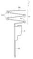
- FIG. 2is a side view showing a terminal fitting of FIG. 1 .
- FIG. 3is a partially enlarged view of the terminal fitting of FIG. 2 .
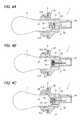
- FIGS. 4A to 4Care diagrams showing operation in the case of mounting a bulb in the bulb socket.
- FIG. 5is a diagram showing a spring part making elastic contact with a terminal of the bulb in FIG. 4 .
- FIGS. 6A to 6Care diagrams showing operation in the case of mounting a bulb in a conventional bulb socket.
- FIG. 7is a diagram showing a spring part making elastic contact with a terminal of the bulb in FIG. 6 .
- a bulb socket 1 shown in FIG. 1includes a socket body 3 in which a bulb 2 is mounted, an earth terminal 4 , a pair of terminal fittings 5 for making elastic contact with a contact point 21 of the bulb 2 , and packing 6 with which a gap between the socket body 3 and an attachment part of the socket body 3 is sealed.
- An outer peripheral surface of a mounting part of the bulb 2 to the socket body 3is provided with a protrusion 22 .
- One end of the socket body 3is provided with a mounting port 31 of the bulb 2 and the other end of the socket body 3 is provided with a connection 34 (see FIGS. 4A to 4C ) of a connector, respectively.
- the earth terminal 4 and the terminal fittings 5are attached to the inside of the mounting port 31 .
- the inside of the mounting port 31is provided with a guide groove 311 for guiding the protrusion 22 of the bulb 2 , and a lock groove 312 (see FIGS. 4A to 4C ) communicating with the guide groove 311 .
- the mounting port 31communicates with the connection 34 through an insertion hole 33 (see FIGS. 4A to 4C ).
- the packing 6is mounted on an outer peripheral surface of the socket body 3 , and is interposed between the attachment part of the socket body 3 and a flange part 32 formed on the outer peripheral surface of the socket body 3 .
- Each of the terminal fittings 5includes a body 51 , a leg part 52 linearly extending from one end of the body 51 , and a spring part 53 extending from the other end of the body 51 in a meandering shape as shown in FIG. 2 .
- the spring part 53includes four bent parts 531 . As enlarged and shown in FIG. 3 , bending angles A to D of the bent parts 531 are equal.
- the distal end of the spring part 53has a contact part 532 for making contact with the contact point 21 of the bulb 2 .
- the contact part 532is provided with a folded part 533 formed by folding the side of the bent part 531 beyond a portion making contact with the contact point 21 so that the contact part 532 makes perpendicular contact with the contact point 21 .
- the body 51is fitted into the insertion hole 33 of the socket body 3 and the leg part 52 is inserted into the insertion hole 33 and the distal side of the leg part 52 is projected inside the connection 34 as shown in FIGS. 4A to 4C .
- the spring part 53 of the terminal fitting 5is arranged inside the mounting port 31 and the contact part 532 is turned to the opening end side of the mounting port 31 .
- the bulb 2is straight moved inside the mounting port 31 with the protrusion 22 guided into the guide groove 311 of the socket body 3 as shown in FIG. 4A .
- the contact point 21 of the bulb 2abuts on the contact part 532 , each of the spring parts 53 of the terminal fittings 5 is pressed to the side of the body 51 by the contact point 21 , and contracts with the amount of bending of the bent parts 531 increased as shown in FIG. 4B .
- the spring part 53 formed in the meandering shapeincludes the four bent parts 531 , so that as compared with a conventional case shown in FIGS. 6A to 6C and 7 , the amount of deformation of each of the bent parts 531 is decreased to reduce settling and spring performance of the spring part 53 can be prevented from being degraded with use.
- each of the bent parts 531is bent at an equal angle, so that the amount of deformation of each of the bent parts 531 is prevented from varying to reduce settling effectively and degradation in the spring performance can be prevented more effectively.
- the contact part 532is folded and the contact part 532 makes perpendicular contact with the contact point 21 , so that displacement of a position of contact between the spring part 53 and the contact point 21 of the bulb 2 is reduced and continuity performance can be improved.
- the spring part 53includes the four bent parts 531
- the number of bent parts 531is freely selected as long as the number is four or more.
- the case where the bending angle of each of the bent parts 531 of the spring part 53 is equalhas been described, but the bending angle may differ every the bent part 531 .
- the case where the contact part 532 includes the folded part 533has been described, but the folded part 533 may not necessarily be included.
- the spring part formed in the meandering shapeincludes the at least four bent parts, so that the amount of deformation of each of the bent parts is decreased to reduce settling and spring performance of the spring part can be prevented from being degraded with use. Also, the side of the bent part beyond the portion making contact between the contact point and the contact part is folded and the contact part makes perpendicular contact with the contact point, so that displacement of a position of contact between the spring part and the contact point is reduced and continuity performance can be improved.
Landscapes
- Connecting Device With Holders (AREA)
Abstract
Description
The present invention relates to a terminal fitting which is attached to a bulb socket and makes elastic contact with a contact point of a bulb mounted in the bulb socket.
This kind of terminal fitting is disclosed in the followingPatent Reference 1. In the terminal fitting ofPatent Reference 1, a spring part extends in a meandering shape from a base part fixed to a socket body and the spring part makes elastic contact with a contact point of a bulb.
[Patent Reference 1] JP-A-10-92538
The terminal fitting described above had a fear of degrading spring performance of the spring part with use since a bent part of the spring part flexes in the case of making elastic contact with the contact point of the bulb. Also, there was a fear of adversely affecting continuity performance by displacing a position of contact between the spring part and the contact point of the bulb resulting from deformation of the bent part.
The invention has been implemented in view of such problems, and an object of the invention is to provide a terminal fitting and a bulb socket capable of solving the problems described above.
According to one aspect of the present invention, there is provided a terminal fitting which is attached to a bulb socket and makes elastic contact with a contact point of a bulb mounted in the bulb socket, including a spring part for making elastic contact with the contact point, wherein the spring part is formed in a meandering shape including at least four bent parts and extending from a contact part making contact with the contact point.
Each of the bent parts may be bent at an equal angle.
The contact part may include a folded part formed by folding a side of the bent part beyond a portion making contact with the contact point so that the contact part makes perpendicular contact with the contact point.
One embodiment of the invention will hereinafter be described with reference to the drawings.
Abulb socket 1 shown inFIG. 1 includes asocket body 3 in which abulb 2 is mounted, an earth terminal4, a pair ofterminal fittings 5 for making elastic contact with acontact point 21 of thebulb 2, and packing6 with which a gap between thesocket body 3 and an attachment part of thesocket body 3 is sealed. An outer peripheral surface of a mounting part of thebulb 2 to thesocket body 3 is provided with aprotrusion 22.
One end of thesocket body 3 is provided with amounting port 31 of thebulb 2 and the other end of thesocket body 3 is provided with a connection34 (seeFIGS. 4A to 4C ) of a connector, respectively. The earth terminal4 and theterminal fittings 5 are attached to the inside of themounting port 31. The inside of themounting port 31 is provided with aguide groove 311 for guiding theprotrusion 22 of thebulb 2, and a lock groove312 (seeFIGS. 4A to 4C ) communicating with theguide groove 311. Themounting port 31 communicates with theconnection 34 through an insertion hole33 (seeFIGS. 4A to 4C ).
Thepacking 6 is mounted on an outer peripheral surface of thesocket body 3, and is interposed between the attachment part of thesocket body 3 and aflange part 32 formed on the outer peripheral surface of thesocket body 3.
Each of theterminal fittings 5 includes abody 51, aleg part 52 linearly extending from one end of thebody 51, and aspring part 53 extending from the other end of thebody 51 in a meandering shape as shown inFIG. 2 . Thespring part 53 includes fourbent parts 531. As enlarged and shown inFIG. 3 , bending angles A to D of thebent parts 531 are equal.
The distal end of thespring part 53 has acontact part 532 for making contact with thecontact point 21 of thebulb 2. Thecontact part 532 is provided with a foldedpart 533 formed by folding the side of thebent part 531 beyond a portion making contact with thecontact point 21 so that thecontact part 532 makes perpendicular contact with thecontact point 21.
In theterminal fitting 5, thebody 51 is fitted into theinsertion hole 33 of thesocket body 3 and theleg part 52 is inserted into theinsertion hole 33 and the distal side of theleg part 52 is projected inside theconnection 34 as shown inFIGS. 4A to 4C . Thespring part 53 of theterminal fitting 5 is arranged inside themounting port 31 and thecontact part 532 is turned to the opening end side of themounting port 31.
Next, operation of thebulb socket 1 in the case of mounting thebulb 2 inside themounting port 31 of thesocket body 3 will be described.
Thebulb 2 is straight moved inside themounting port 31 with theprotrusion 22 guided into theguide groove 311 of thesocket body 3 as shown inFIG. 4A . When thecontact point 21 of thebulb 2 abuts on thecontact part 532, each of thespring parts 53 of theterminal fittings 5 is pressed to the side of thebody 51 by thecontact point 21, and contracts with the amount of bending of thebent parts 531 increased as shown inFIG. 4B .
Thereafter, as shown inFIG. 4C , when thebulb 2 is rotated and theprotrusion 22 enters the inside of thelock groove 312 from theguide groove 311 and a force by which thebulb 2 is pushed into themounting port 31 is released, thebulb 2 is moved to the opening side of themounting port 31 by a resilient force of thespring part 53 and theprotrusion 22 abuts on an inner wall of thelock groove 312 and thebulb 2 is positioned inside thelock groove 312. Each of theterminal fittings 5 brings thecontact part 532 of thespring part 53 into elastic contact with thecontact point 21 of thebulb 2, and makes electrical connection between thebulb 2 and the connector connected to theconnection 34 as shown inFIG. 5 .
According to the embodiment, thespring part 53 formed in the meandering shape includes the fourbent parts 531, so that as compared with a conventional case shown inFIGS. 6A to 6C and7, the amount of deformation of each of thebent parts 531 is decreased to reduce settling and spring performance of thespring part 53 can be prevented from being degraded with use.
Also, each of thebent parts 531 is bent at an equal angle, so that the amount of deformation of each of thebent parts 531 is prevented from varying to reduce settling effectively and degradation in the spring performance can be prevented more effectively.
Also, thecontact part 532 is folded and thecontact part 532 makes perpendicular contact with thecontact point 21, so that displacement of a position of contact between thespring part 53 and thecontact point 21 of thebulb 2 is reduced and continuity performance can be improved.
In addition, in the embodiment described above, the case where thespring part 53 includes the fourbent parts 531 has been described, but the number ofbent parts 531 is freely selected as long as the number is four or more. Also, in the embodiment described above, the case where the bending angle of each of thebent parts 531 of thespring part 53 is equal has been described, but the bending angle may differ every thebent part 531. Also, in the embodiment described above, the case where thecontact part 532 includes the foldedpart 533 has been described, but the foldedpart 533 may not necessarily be included.
It is apparent that various modifications can be made in the invention within a scope not deviating from the gist of the invention.
The present application is based on Japanese patent application No. 2012-026869 filed on Feb. 10, 2012, and the contents of the patent application are incorporated herein by reference.
According to the invention, the spring part formed in the meandering shape includes the at least four bent parts, so that the amount of deformation of each of the bent parts is decreased to reduce settling and spring performance of the spring part can be prevented from being degraded with use. Also, the side of the bent part beyond the portion making contact between the contact point and the contact part is folded and the contact part makes perpendicular contact with the contact point, so that displacement of a position of contact between the spring part and the contact point is reduced and continuity performance can be improved.
Claims (4)
1. A terminal fitting which is attached to a bulb socket and makes elastic contact with a contact point of a bulb mounted in the bulb socket, including a spring part for making elastic contact with the contact point,
wherein the spring part is formed in a meandering shape including at least four bent parts and extending from a contact part making contact with the contact point, and wherein
the contact part includes a leg having an obtuse angle portion between a contact segment of the leg that contacts the contact point and a bent part closest to the contact segment, such that the contact segment makes perpendicular contact with the contact point.
2. The terminal fitting as claimed inclaim 1 , wherein each of the bent parts is bent at an equal angle.
3. The terminal fitting as claimed inclaim 1 , wherein the obtuse angle portion is formed by folding a side of the leg.
4. A bulb socket including a terminal fitting as claimed inclaim 1 .
Applications Claiming Priority (2)
| Application Number | Priority Date | Filing Date | Title |
|---|---|---|---|
| JP2012026869AJP2013164948A (en) | 2012-02-10 | 2012-02-10 | Terminal fitting and bulb socket |
| JP2012-026869 | 2012-02-10 |
Publications (2)
| Publication Number | Publication Date |
|---|---|
| US20130210253A1 US20130210253A1 (en) | 2013-08-15 |
| US8961244B2true US8961244B2 (en) | 2015-02-24 |
Family
ID=48945932
Family Applications (1)
| Application Number | Title | Priority Date | Filing Date |
|---|---|---|---|
| US13/757,938Active2033-04-27US8961244B2 (en) | 2012-02-10 | 2013-02-04 | Terminal fitting and bulb socket |
Country Status (2)
| Country | Link |
|---|---|
| US (1) | US8961244B2 (en) |
| JP (1) | JP2013164948A (en) |
Families Citing this family (1)
| Publication number | Priority date | Publication date | Assignee | Title |
|---|---|---|---|---|
| EP4184723A1 (en)* | 2021-11-17 | 2023-05-24 | KNORR-BREMSE Systeme für Nutzfahrzeuge GmbH | Electric terminal, terminal assembly, connector assembly and method for manufacturing the terminal assembly |
Citations (15)
| Publication number | Priority date | Publication date | Assignee | Title |
|---|---|---|---|---|
| US4773877A (en)* | 1986-08-19 | 1988-09-27 | Feinmetall Gmbh | Contactor for an electronic tester |
| JPH1092538A (en) | 1996-09-17 | 1998-04-10 | Sumitomo Wiring Syst Ltd | Terminal fitting for bulb socket |
| US5967856A (en)* | 1995-12-20 | 1999-10-19 | Berg Technology, Inc. | Connector with spring contact member and shorting means |
| US6358097B1 (en)* | 1999-07-23 | 2002-03-19 | Fci Americas Technology, Inc. | Contact element, process for making the same and connector comprising the same |
| US6402567B1 (en)* | 2001-05-25 | 2002-06-11 | Hon Hai Precision Ind. Co., Ltd. | Electrical connector having improved spring contact member |
| US6524140B2 (en)* | 2000-06-21 | 2003-02-25 | Japan Aviation Electronics Industry, Ltd. | Connector excellent in reliability of contact |
| US6626708B2 (en)* | 2001-03-30 | 2003-09-30 | Tyco Electronics Corporation | Single piece spring contact |
| US20050064766A1 (en)* | 2003-09-23 | 2005-03-24 | Hougbo Zhang | Electrical connector with improved contacts |
| US20050070170A1 (en)* | 2003-09-30 | 2005-03-31 | Hongbo Zhang | Connector contact having wiping function |
| US20070093145A1 (en)* | 2005-10-26 | 2007-04-26 | Shih-Fu Wei | Elastic contact |
| US7226293B2 (en)* | 2004-12-21 | 2007-06-05 | Samsung Electro-Mechanics Co. Ltd. | Built-in type antenna assembly of wireless communication terminal |
| US7322834B2 (en)* | 2005-04-28 | 2008-01-29 | Hon Hai Precision Ind. Co., Ltd. | Electrical connector with improved contacts |
| US7445518B2 (en)* | 2006-05-05 | 2008-11-04 | Schneider Nee Hild Anja | Pressure contact |
| US7585192B1 (en)* | 2009-02-24 | 2009-09-08 | Cheng Uei Precision Industry Co., Ltd. | Electrical connector |
| US8734193B2 (en)* | 2011-03-07 | 2014-05-27 | Fujitsu Component Limited | Connector |
- 2012
- 2012-02-10JPJP2012026869Apatent/JP2013164948A/ennot_activeAbandoned
- 2013
- 2013-02-04USUS13/757,938patent/US8961244B2/enactiveActive
Patent Citations (15)
| Publication number | Priority date | Publication date | Assignee | Title |
|---|---|---|---|---|
| US4773877A (en)* | 1986-08-19 | 1988-09-27 | Feinmetall Gmbh | Contactor for an electronic tester |
| US5967856A (en)* | 1995-12-20 | 1999-10-19 | Berg Technology, Inc. | Connector with spring contact member and shorting means |
| JPH1092538A (en) | 1996-09-17 | 1998-04-10 | Sumitomo Wiring Syst Ltd | Terminal fitting for bulb socket |
| US6358097B1 (en)* | 1999-07-23 | 2002-03-19 | Fci Americas Technology, Inc. | Contact element, process for making the same and connector comprising the same |
| US6524140B2 (en)* | 2000-06-21 | 2003-02-25 | Japan Aviation Electronics Industry, Ltd. | Connector excellent in reliability of contact |
| US6626708B2 (en)* | 2001-03-30 | 2003-09-30 | Tyco Electronics Corporation | Single piece spring contact |
| US6402567B1 (en)* | 2001-05-25 | 2002-06-11 | Hon Hai Precision Ind. Co., Ltd. | Electrical connector having improved spring contact member |
| US20050064766A1 (en)* | 2003-09-23 | 2005-03-24 | Hougbo Zhang | Electrical connector with improved contacts |
| US20050070170A1 (en)* | 2003-09-30 | 2005-03-31 | Hongbo Zhang | Connector contact having wiping function |
| US7226293B2 (en)* | 2004-12-21 | 2007-06-05 | Samsung Electro-Mechanics Co. Ltd. | Built-in type antenna assembly of wireless communication terminal |
| US7322834B2 (en)* | 2005-04-28 | 2008-01-29 | Hon Hai Precision Ind. Co., Ltd. | Electrical connector with improved contacts |
| US20070093145A1 (en)* | 2005-10-26 | 2007-04-26 | Shih-Fu Wei | Elastic contact |
| US7445518B2 (en)* | 2006-05-05 | 2008-11-04 | Schneider Nee Hild Anja | Pressure contact |
| US7585192B1 (en)* | 2009-02-24 | 2009-09-08 | Cheng Uei Precision Industry Co., Ltd. | Electrical connector |
| US8734193B2 (en)* | 2011-03-07 | 2014-05-27 | Fujitsu Component Limited | Connector |
Also Published As
| Publication number | Publication date |
|---|---|
| JP2013164948A (en) | 2013-08-22 |
| US20130210253A1 (en) | 2013-08-15 |
Similar Documents
| Publication | Publication Date | Title |
|---|---|---|
| EP2922152B1 (en) | Connector | |
| US8616924B2 (en) | Female terminal for connector | |
| JP6633824B2 (en) | connector | |
| US9490567B2 (en) | Connector | |
| US20160079686A1 (en) | Terminal | |
| KR20170052531A (en) | Coaxial connector with floating mechanism | |
| CN105612672A (en) | Coaxial connector with floating mechanism | |
| US20130040506A1 (en) | Electrical contact for plug-in connections | |
| TW200908476A (en) | Connector and structure of connector terminal | |
| CN109768419B (en) | Connector with a locking member | |
| US20140169871A1 (en) | Connector | |
| TW200742180A (en) | Electric connector for circuit board | |
| US10283902B2 (en) | Waterproof structure for connector | |
| US9614315B2 (en) | Electrical connector and connector terminal | |
| US20150017823A1 (en) | Connector | |
| KR20160072037A (en) | Connector terminal | |
| US8961244B2 (en) | Terminal fitting and bulb socket | |
| US20220006236A1 (en) | Electrical connector having position holder | |
| KR101497367B1 (en) | Connector assembly | |
| KR101732622B1 (en) | Connector terminal | |
| KR200449502Y1 (en) | Waterproof seal | |
| CN102255199B (en) | Rectangular connector socket with false-imbedding prevention structure for plug | |
| US20160372854A1 (en) | Plug connector assembly for establishing an electrical plug connection | |
| JP5002485B2 (en) | connector | |
| JP2011233336A (en) | Connector |
Legal Events
| Date | Code | Title | Description |
|---|---|---|---|
| AS | Assignment | Owner name:YAZAKI CORPORATION, JAPAN Free format text:ASSIGNMENT OF ASSIGNORS INTEREST;ASSIGNOR:NAGASAWA, MASANORI;REEL/FRAME:029745/0462 Effective date:20130115 | |
| STCF | Information on status: patent grant | Free format text:PATENTED CASE | |
| MAFP | Maintenance fee payment | Free format text:PAYMENT OF MAINTENANCE FEE, 4TH YEAR, LARGE ENTITY (ORIGINAL EVENT CODE: M1551) Year of fee payment:4 | |
| MAFP | Maintenance fee payment | Free format text:PAYMENT OF MAINTENANCE FEE, 8TH YEAR, LARGE ENTITY (ORIGINAL EVENT CODE: M1552); ENTITY STATUS OF PATENT OWNER: LARGE ENTITY Year of fee payment:8 | |
| AS | Assignment | Owner name:YAZAKI CORPORATION, JAPAN Free format text:CHANGE OF ADDRESS;ASSIGNOR:YAZAKI CORPORATION;REEL/FRAME:063845/0802 Effective date:20230331 |