US8960898B1 - Contact lens that restricts incoming light to the eye - Google Patents
Contact lens that restricts incoming light to the eyeDownload PDFInfo
- Publication number
- US8960898B1 US8960898B1US13/625,841US201213625841AUS8960898B1US 8960898 B1US8960898 B1US 8960898B1US 201213625841 AUS201213625841 AUS 201213625841AUS 8960898 B1US8960898 B1US 8960898B1
- Authority
- US
- United States
- Prior art keywords
- light
- contact lens
- pupil
- sensors
- restricting
- Prior art date
- Legal status (The legal status is an assumption and is not a legal conclusion. Google has not performed a legal analysis and makes no representation as to the accuracy of the status listed.)
- Expired - Fee Related, expires
Links
Images


Classifications
- G—PHYSICS
- G02—OPTICS
- G02C—SPECTACLES; SUNGLASSES OR GOGGLES INSOFAR AS THEY HAVE THE SAME FEATURES AS SPECTACLES; CONTACT LENSES
- G02C7/00—Optical parts
- G02C7/02—Lenses; Lens systems ; Methods of designing lenses
- G02C7/04—Contact lenses for the eyes
- G—PHYSICS
- G02—OPTICS
- G02C—SPECTACLES; SUNGLASSES OR GOGGLES INSOFAR AS THEY HAVE THE SAME FEATURES AS SPECTACLES; CONTACT LENSES
- G02C7/00—Optical parts
- G02C7/02—Lenses; Lens systems ; Methods of designing lenses
- G02C7/04—Contact lenses for the eyes
- G02C7/049—Contact lenses having special fitting or structural features achieved by special materials or material structures
- G—PHYSICS
- G02—OPTICS
- G02C—SPECTACLES; SUNGLASSES OR GOGGLES INSOFAR AS THEY HAVE THE SAME FEATURES AS SPECTACLES; CONTACT LENSES
- G02C7/00—Optical parts
- G02C7/10—Filters, e.g. for facilitating adaptation of the eyes to the dark; Sunglasses
- G02C7/101—Filters, e.g. for facilitating adaptation of the eyes to the dark; Sunglasses having an electro-optical light valve
Definitions
- This disclosuregenerally relates to systems and/or methods to restrict light entering an opening of an eye pupil by detecting pupil dilation, detecting incoming light intensity or direction, and adjusting light restricting properties of one or more light restricting regions of the contact lens based in part upon detected pupil dilation parameters and incoming light intensity or direction.
- the human eyecan restrict amount of light entering an eye by adjusting size of an opening of a pupil. For example, in dim ambient light conditions the pupil will dilate the opening and in brighter ambient light conditions the pupil will contract the opening. However, the pupil has maximum and minimum limits to which it can adjust size of the opening. To compensate for very bright ambient light conditions, a person will generally attempt to squint their eyelids to further restrict the amount of light entering the opening of the pupil.
- FIG. 1Aillustrates a diagram of an exemplary non-limiting system for restricting some portion of light entering an eye using a contact lens in accordance with an implementation of this disclosure.
- FIG. 1Billustrates a diagram of the exemplary non-limiting system of FIG. 1A worn on both eyes of a human user in accordance with an implementation of this disclosure.
- FIG. 2Aillustrates a diagram of an exemplary non-limiting light restricting contact lens in accordance with an implementation of this disclosure.
- FIG. 2Billustrates a diagram of an exemplary non-limiting light restricting contact lens with two sensors respectively aligned at top and bottom of light restricting contact lens in accordance with an implementation of this disclosure.
- FIG. 2Cillustrates a diagram of an exemplary non-limiting light restricting contact lens with two sensors respectively aligned at a bottom and one side of light restricting contact lens in accordance with an implementation of this disclosure.
- FIG. 2Dillustrates a diagram of an exemplary non-limiting light restricting contact lens with three sensors respectively aligned at top, bottom, and one side of light restricting contact lens in accordance with an implementation of this disclosure.
- FIG. 2Eillustrates a diagram of an exemplary non-limiting light restricting contact lens with three sensors aligned in an equilateral triangular shape near a periphery of light restricting contact lens in accordance with an implementation of this disclosure.
- FIG. 2Fillustrates a diagram of an exemplary non-limiting light restricting contact lens with five sensors aligned in a pentagon shape near a periphery of light restricting contact lens in accordance with an implementation of this disclosure.
- FIG. 2Gillustrates a diagram of an exemplary non-limiting light restricting contact lens 110 with four light sensors 230 aligned at top, bottom, and both side near a periphery of at top, bottom, and one side of light restricting contact lens in accordance with an implementation of this disclosure.
- FIG. 3Aillustrates a diagram of an exemplary non-limiting light restricting contact lens with light restricting material configured in seven concentrically smaller ring light restricting material areas in accordance with an implementation of this disclosure.
- FIG. 3Billustrates a diagram of an exemplary non-limiting light restricting contact lens with light restricting material configured in seven concentrically smaller ring light restricting material areas as depicted in FIG. 3A further divided into eight pie shaped areas in accordance with an implementation of this disclosure.
- FIG. 3Cillustrates a diagram of an exemplary non-limiting light restricting contact lens with light restricting material configured in an array of square light restricting material areas, with a non-light restricting area in accordance with an implementation of this disclosure.
- FIG. 3Dillustrates a diagram of an exemplary non-limiting light restricting contact lens with light restricting material configured in an array of square light restricting material areas similar to FIG. 3C , however, also covering the central area depicted as non-light restricting area in FIG. 3C in accordance with an implementation of this disclosure.
- FIG. 3Eillustrates a diagram of an exemplary non-limiting light restricting contact lens with light restricting material configured in an overall donut shape partitioned into an array of various shaped light restricting material areas in accordance with an implementation of this disclosure.
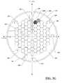
- FIG. 3Fillustrates a diagram of an exemplary non-limiting light restricting contact lens with light restricting material configured in an array of hexagon light restricting material areas in accordance with an implementation of this disclosure.
- FIG. 3Gillustrates a diagram of an exemplary non-limiting light restricting contact lens with light restricting material configured similar to FIG. 3F with respective light restricting material areas that are individually configurable in accordance with an implementation of this disclosure.
- FIG. 3Hillustrates a diagram of an exemplary non-limiting light restricting contact lens with light restricting material configured as a mechanical aperture in accordance with an implementation of this disclosure.
- FIG. 4illustrates a diagram of an exemplary non-limiting control circuit in accordance with an implementation of this disclosure.
- FIG. 5Aillustrates a diagram of an exemplary non-limiting light restricting contact lens with a pupil sensor configured for detecting relative pupil opening sizes in accordance with an implementation of this disclosure.
- FIG. 5Billustrates a diagram of an exemplary non-limiting light restricting contact lens with a pupil sensor configured for detecting a full diameter of a pupil opening size in accordance with an implementation of this disclosure.
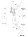
- FIG. 5Cillustrates a diagram of an exemplary non-limiting light restricting contact lens with a pupil sensor configured for detecting a first pupil opening size in accordance with an implementation of this disclosure.
- FIG. 5Dillustrates a diagram of an exemplary non-limiting light restricting contact lens with a pupil sensor configured for detecting a second pupil opening size in accordance with an implementation of this disclosure.
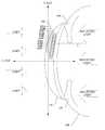
- FIG. 6Aillustrates a diagram of close-up view a non-limiting exemplary light restricting contact lens on eye with a light source in a first position and light restricting material adjusted according to the position of the light source in accordance with an implementation of this disclosure.
- FIG. 6Billustrates a diagram of close-up view a non-limiting exemplary light restricting contact lens on eye with light source in a second position and light restricting material adjusted according to the position of the light source in accordance with an implementation of this disclosure.
- FIG. 6Cillustrates a diagram of close-up view a non-limiting exemplary light restricting contact lens on eye with light source in the first position as in FIG. 6A and light restricting material adjusted to varying degrees of light restriction according to the position of the light source in accordance with an implementation of this disclosure.
- FIG. 6Dillustrates a diagram of close-up view a non-limiting exemplary light restricting contact lens on eye with multiple light sources in differing positions and light restricting material adjusted according to the positions of the light sources in accordance with an implementation of this disclosure.
- FIG. 7illustrates a diagram of an exemplary non-limiting system for restricting some portion of light entering an eye using a pair of eyeglasses in accordance with an implementation of this disclosure.
- FIG. 8illustrates an exemplary non-limiting flow diagram for learning maximum size or minimum size of an opening of a pupil in accordance with an implementation of this disclosure.
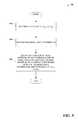
- FIG. 9illustrates an exemplary non-limiting flow diagram for restricting some portion of light through one or more areas of a contact lens in accordance with an implementation of this disclosure.
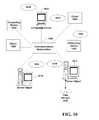
- FIG. 10is a block diagram representing an exemplary non-limiting networked environment in which the various embodiments can be implemented.
- FIG. 11is a block diagram representing an exemplary non-limiting computing system or operating environment in which the various embodiments can be implemented.
- a mechanismfor restricting light from entering an eye via light restricting components disposed on or within a contact lens (hereinafter referred to as “light restricting contact lens”).
- the light restricting contact lenscan restrict light to an opening significantly smaller than achievable by a pupil of an eye.
- light restricting contact lenscan restrict light through areas of light restricting contact lens corresponding to respective directions of one or more sources of incoming light, without restricting light through other areas of light restricting contact lens.
- a light restricting contact lenscan dynamically change opacity of one or more of its regions to restrict some portion of light entering the eye.
- light restricting contact lenscan receive commands from a remote device or user to restrict some portion of light entering the eye.
- light restricting contact lenscan monitor intensity and/or direction of light ambient to the wearer of the light restricting contact lens and dynamically restrict some portion of light entering the eye. Additionally, light restricting contact lens can monitor pupil dilation to determine maximum and/or minimum limits of the opening of the pupil and, for example, activate restriction of light entering the eye based upon detected light conditions and detected pupil dilation. It is to be appreciated that light restricting contact lens can be employed in connection with a human user or a non-human user (e.g., dogs or other species with eyes). Additionally, components on or within a contact lens can be of a suitable shape, size, opacity, and/or positioned so as not to obstruct vision through an opening of a pupil when worn.
- FIG. 1Adepicts a system 100 for restricting some portion of light entering an eye.
- System 100includes a light restricting contact lens 110 that restricts some portion of light entering the eye.
- light restricting contact lens 110can communicate with a remote device 120 in connection with operations associated with the remote device 120 or light restricting contact lens 110 (e.g., adjusting light restricting properties of one or more areas of light restricting contact lens 110 , requesting instructions or information, sending commands or information, or any other suitable function).
- Light restricting contact lens 110 and remote device 120can also receive input from users, for example to control restriction of some portion of light entering the eye, see e.g., FIG. 11 and corresponding disclosure.
- Light restricting contact lens 110 and remote device 120respectively include a memory that stores computer executable components and a processing circuit or processor that executes computer executable components stored in the memory (see e.g., FIG. 11 ).
- Light restricting contact lens 110 and remote device 120can communicate via a wireless network. It is to be appreciated that while only one remote device 120 is depicted, light restricting contact lens 110 can communicate with any suitable number of remote devices 120 concurrently, serially, an ad hoc manner, or in accordance with any suitable protocol. Additionally, remote device 120 can communicate with any suitable number of light restricting contact lenses 110 concurrently, serially, an ad hoc manner, or in accordance with any suitable protocol.
- Remote device 120can include a wearable device or a non-wearable device.
- Wearable devicecan include, for example, heads-up display glasses, a monocle, eyeglasses, sunglasses, a headset, a visor, a cap, a helmet, a mask, a headband, clothing, or any other suitable device that can be worn by a human or non-human user and can communicate with light restricting contact lens 110 remotely.
- Non-wearable devicecan include, for example, a mobile device, a mobile phone, a camera, a camcorder, a video camera, personal data assistant, laptop computer, tablet computer, desktop computer, server system, cable set top box, satellite set top box, cable modem, television set, monitor, media extender device, blu-ray device, DVD (digital versatile disc or digital video disc) device, compact disc device, video game system, portable video game console, audio/video receiver, radio device, portable music player, navigation system, car stereo, or any suitable device that can communicate with light restricting contact lens 110 remotely.
- a mobile devicea mobile phone, a camera, a camcorder, a video camera, personal data assistant, laptop computer, tablet computer, desktop computer, server system, cable set top box, satellite set top box, cable modem, television set, monitor, media extender device, blu-ray device, DVD (digital versatile disc or digital video disc) device, compact disc device, video game system, portable video game console, audio/video receiver, radio device, portable music player, navigation system
- remote device 120 and light restricting contact lens 110can include a display and/or user interface (e.g., a web browser or application), that can generate, receive and/or present graphical indicia (e.g., displays, text, video . . . ) generated locally or remotely.
- a display and/or user interfacee.g., a web browser or application
- graphical indiciae.g., displays, text, video . . .
- system 100is depicted on a human user.
- Light restricting contact lenses 110are shown worn on both eyes 130 , covering irises 140 and pupils 145 while eyelids 150 are open.
- Remote device 120is shown with one or more transceivers (not shown) arranged to communicate wirelessly with light restricting contact lenses 110 .
- respective transceivers of remote device 120can have transmission power and/or signal reception sensitivity suitable for transmitting a signal to and receiving a signal from an associated light restricting contact lens 110 on an eye without interfering with another light restricting contact lens 110 on another eye.
- FIG. 1Billustrates a light restricting contact lenses 110 arrangement in both eyes, it is to be appreciated that an arrangement with a light restricting contact lens 110 on one eye can be employed (e.g., on a person with a damaged pupil in one eye).
- light restricting contact lens 110is depicted that includes, disposed on or within its substrate, a control circuit 220 , one or more light sensors 230 (in this non-limiting example, eight light sensors 230 equally space near the periphery of light restricting contact lens 110 ), and a pupil sensor 235 .
- Control circuit 220 , light sensors 230 , and pupil sensor 235are coupled wirelessly or via wire by coupling 242 .
- pupil sensor 235 or all or some light sensors 230can have independent coupling to control circuit 220 .
- Different aspects of interaction between control circuit 220 and light sensors 230 or pupil sensor 235can be respectively coupled via wire or wirelessly. In one example, all interactions are coupled via wire.
- Light sensor 230can be any suitable sensor for detecting intensity, wavelength, and/or direction of light. In an embodiment, light sensor 230 can be a photodiode or photo detector. It is to be appreciated that pupil sensor 235 and respective light sensors 230 can respectively be uniquely identifiable to control circuit 220 , for example, via an identifier signal or identifying information conveyed from pupil sensor 235 or respective light sensors 230 to control circuit 220 .
- Light sensors 230can be arranged on or within light restricting contact lens 110 to face outward away from eye 130 when light restricting contact lens 110 is worn.
- light restricting contact lens 110can be weighted to self-align into a particular position when worn, similar to a toric contact lens.
- light sensors 230may require specific positioning based upon arrangement of light restricting materials 240 (e.g. a custom lens designed to compensate for a partially damaged pupil).
- light restricting contact lens 110is not weighted.
- light sensors 230can be employed in an arrangement, such as eight light sensors 230 equally spaced around a periphery of light restricting contact lens 110 to operate in most any orientation of the light restricting contact lens 110 .
- FIG. 2Bshows a light restricting contact lens 110 with two light sensors 230 respectively aligned at top and bottom of light restricting contact lens 110 .
- FIG. 2Cillustrates a light restricting contact lens 110 with two light sensors 230 respectively aligned at a bottom and one side of light restricting contact lens 110 .
- FIG. 2Ddepicts a light restricting contact lens 110 with three light sensors 230 respectively aligned at top, bottom, and one side of light restricting contact lens 110 .
- respective left and right light restricting contact lenses 110can have side light sensors 230 arranged at opposite sides to detect light entering from a periphery.
- FIG. 2Eillustrates a light restricting contact lens 110 with three light sensors 230 aligned in an equilateral triangular shape near a periphery of light restricting contact lens 110 .
- FIG. 2Fdepicts a light restricting contact lens 110 with five light sensors 230 aligned in a pentagon shape near a periphery of light restricting contact lens 110 .
- FIG. 2Gillustrates a light restricting contact lens 110 with four light sensors 230 aligned at top, bottom, and both sides near a periphery of light restricting contact lens 110 .
- Employing a plurality of uniquely identifiable light sensors 230allows for detecting direction of one or more sources of incoming light to light restricting contact lens 110 .
- Any suitable number of light sensors 230can be respectively placed in any suitable locations of light restricting contact lens 110 . It is to be appreciated that increasing number of light sensors 230 , for example distributed about a periphery of the light restricting contact lens 110 , can increase precision or granularity of determining (or inferring) direction of one or more sources of incoming light to light restricting contact lens 110 .
- light restricting contact lens 110includes, disposed on or within its substrate, a light restricting material 240 coupled to control circuit 220 .
- light restricting material 240covers an area of a center of light restricting contact lens 110 .
- Light restricting material 240can be any suitable material that is electronically configurable to restrict some portion of light. It is to be appreciated that, restricting some portion of light can include restricting all visible or non-visible wavelengths of light or a subset of the wavelengths.
- light restricting material 240is an electrochromic material which can be configured to restrict some portion of light based upon an electronic signal.
- light restricting material 240includes a mechanical aperture of which a size or shape of an opening of the aperture can be configured based upon an electronic signal.
- Light restricting material 240can be partitioned into different areas which respectively include different types of light restricting materials 240 .
- some light restricting material 240 areascan include electrochromic material while other light restricting material 240 areas include a mechanical aperture.
- FIGS. 3A-Fvarious exemplary configurations of light restricting material 240 on or within a light restricting contact lens 110 are shown.
- Control circuit 220 , light sensors 230 , pupil sensor 235 , and coupling 240exist but are not shown in FIGS. 3A-F to minimize obfuscation of the illustrated configurations of light restricting material 240 .
- FIG. 3Ashows a light restricting contact lens 110 with light restricting material 240 configured in seven concentrically smaller ring light restricting material 240 areas with a non-light restricting area 245 in the center.
- Non-light restricting area 245 in the center of light restricting contact lens 110does not contain light restricting material 240 to avoid obstructing light entering pupil 145 from this area.
- non-light restricting area 245is of a size smaller than a minimum opening of pupil 145 .
- FIG. 3Bdepicts light restricting contact lens 110 with light restricting material 240 configured in seven concentrically smaller ring light restricting material 240 areas as shown in FIG. 3A and further divided into eight pie shaped areas.
- FIG. 3Cshows light restricting contact lens 110 with light restricting material 240 configured in an array of square light restricting material 240 areas, also with a non-light restricting area 245 .
- FIG. 3Dillustrates light restricting contact lens 110 with light restricting material 240 configured in an array of square light restricting material 240 areas similar to FIG. 3C , however, also covering central non-light restricting area 245 .
- FIG. 3Bdepicts light restricting contact lens 110 with light restricting material 240 configured in seven concentrically smaller ring light restricting material 240 areas as shown in FIG. 3A and further divided into eight pie shaped areas.
- FIG. 3Cshows light restricting contact lens 110 with light restrict
- FIG. 3Edepicts light restricting contact lens 110 with light restricting material 240 configured in an overall donut shape partitioned into an array of various shaped light restricting material 240 areas, also with a non-light restricting area 245 .
- FIG. 3Fillustrates light restricting contact lens 110 with light restricting material 240 configured in an array of hexagon light restricting material 240 areas, also with non-light restricting area 245 .
- light restricting contact lens 110is illustrated with light restricting material 240 configured similar to FIG. 3F .
- Respective light restricting material 240 areascan be individually configurable, identifiable, or addressable by control circuit 220 .
- light restricting material area 240 Acan be configured to have light restricting properties associated with a first level of light restriction while light restricting material area 240 B can be configured to have light restricting properties associated with a second level of light restriction.
- any suitable number and/or shapes of light restricting material 240 areascan be respectively placed in any suitable locations of light restricting contact lens 110 .
- light restricting material 240 areascan provide greater precision or granularity of patterns of light restriction on light restricting contact lens 110 , e.g., to provide varying levels of light restriction on different areas of light restricting contact lens 110 based upon intensity wavelength, and/or direction of incoming light.
- light restricting material 240can be centered about a geometric center of light restricting contact lens 110 .
- light restricting contact lens 110is depicted with light restricting material 240 configured as a mechanical aperture.
- mechanical apertureis centered about a geometric center of light restricting contact lens 110 .
- Mechanical aperturehas an opening with size M that can be adjusted between a maximum M MAX size and a minimum size M MIN .
- M MAXcan be greater that a maximum size of an opening of pupil 145 so as not to obstruct pupil 145 when light restricting contact lens 110 is not actively restricting some portion of light from entering eye 130 .
- M MINcan be smaller than a minimum size of an opening of pupil 145 so as to provide greater restriction of light entering eye 130 than can be achieved by pupil 145 .
- Light restricting contact lens 110can adjust M based upon intensity, wavelength, and/or direction of incoming light to light restricting contact lens 110 . For example, when an intensity of incoming light decreases, light restricting contact lens 110 can increase M, or when intensity of incoming light increases, light restricting contact lens 110 can decrease M.
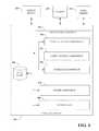
- control circuit 220includes processing component 255 that restricts some portions of light from passing through light restricting contact lens 110 , and communicates with remote device 120 , light sensor 230 , and pupil sensor 235 .
- Control circuit 220can include power component 275 that manages, receives, generates, stores, and/or distributes electrical power to other components of light restricting contact lens 110 .
- Control circuit 220can also include one or more transceivers 280 for transmitting or receiving signals to or from remote device 120 , light sensor 230 , or pupil sensor 235 .
- Light sensor 230 or pupil sensor 235can interface directly with processing component 255 without need to employ transceiver 280 , for example through a wired coupling.
- control circuit 220can include a data store 250 that can store data from processing component 255 , power component 275 , transceiver 280 , remote device 120 , light sensor 230 , or pupil sensor 235 .
- Data store 250can reside on any suitable type of storage device, non-limiting examples of which are illustrated with reference to FIGS. 10 and 11 , and corresponding disclosure.
- processing component 255includes pupil detection component 260 that detects current state and/or limits of an opening of pupil 145 .
- Pupil detection component 260can monitor continuously, or at random or predetermining intervals pupil sensor 235 to determine (or infer) an amount of opening of pupil 145 .
- pupil sensor 235can be arranged on light restricting contact lens 110 in a suitable location to determine (or infer) current size P, maximum size P MAX , or minimum size P MIN of an opening of pupil 145 .
- pupil sensorcan include a plurality of sensors 232 facing eye 130 when light restricting contact lens 110 is worn.
- sensors 232can be arranged in a linear array from near an outside edge of light restricting material 240 to near a geometric center of light restricting contact lens 110 .
- Sensors 232can be similar to light sensors 230 and can detect light reflected from an inside of eye 130 (e.g., photodiode).
- sensors 232can be in known locations (e.g., in a coordinate system) relative to each other and/or to a position (e.g. geometric center) on light restricting contact lens 110 .
- pupil sensor 235covers approximately a radius of light restricting area 240 .
- pupil sensor 235can detect relative positions of an edge of an opening of pupil 145 as the pupil 145 dilates or constricts.
- respective sensors 232can be uniquely identifiable to control circuit 220 , for example, via an identifier signal or identifying information conveyed from respective sensors 232 to control circuit 220 . Any suitable number of sensors 232 in any suitable configuration for detecting an opening of a pupil 145 can be employed.
- FIG. 5Billustrates an arrangement of pupil sensor 235 that has sensors 232 covering approximately a diameter of light restricting area 240 .
- pupil sensor 235can detect a diameter of the opening of pupil 145 as it dilates and constricts.
- FIG. 5Cdepicts a side view of light restricting contact lens 110 on eye 130 .
- Control circuit 220 , light sensors 230 , pupil sensor 235 , light restricting material 240 , and coupling 240exist but are not shown in FIGS. 5C-D to avoid cluttering depiction of configurations of pupil sensor 235 .
- z-axiscan be aligned with a geometric center of light restricting contact lens 110 .
- z-axiscan be aligned with a central axis of an outward looking gaze of eye 130 .
- z-axiscan be aligned at a geometric center of pupil 145 and orthogonal to a two-dimensional plane corresponding to an image captured by eye 130 .
- Pupil sensor 235includes sensors 232 A-J.
- Pupil detection component 260can employ information from pupil sensor 235 to determine (or infer) current size P, maximum size P MAX , or minimum size P MIN of an opening of pupil 145 .
- FIG. 5Cdepicts pupil 145 having an opening with size P 1 . As such, light reflected from within eye 130 is blocked from reaching sensors 232 A-D by pupil 145 , but reaches sensors 232 E-J.
- Pupil sensor 235can provide indications (hereafter referred to as “pupil information”) to pupil detection component 260 of state of respective sensors 232 A-J with respect to light (e.g. intensity or wavelengths) detected by respective sensors 232 A-J. Given known locations of sensors 232 A-J, pupil detection component 260 can determine (or infer) P 1 .
- FIG. 5Ddepicts a side view of light restricting contact lens 110 on eye 130 as shown in FIG. 5C , but with the opening of pupil 145 dilated an amount P 2 less than P 1 in FIG. 5C .
- P 2the opening of pupil 145 dilated an amount P 2 less than P 1 in FIG. 5C .
- processing component 255includes light control component 265 that configures amount of light restriction by light restricting material 240 .
- light control component 265can selectively provide electronic signals to respective areas of light restricting material 240 to adjust respective restriction of some portion of light.
- light control component 265can receive indications from respective light sensors 230 regarding light (e.g. intensity or wavelengths) detected by respective light sensors 230 .
- FIG. 6Aillustrates a close-up view of a non-limiting exemplary light restricting contact lens 110 on eye 130 with light source 610 .
- Light source 610transmits light to eye 130 which is received at varying degrees by light sensors 230 A-H.
- light sensor 230 Hreceives light most directly while light sensors 230 G and 230 A respectively receive light to a lesser degree than light sensor 230 H.
- Light sensors 230 B-Freceive light to a lesser degree than light sensors 230 G and A.
- light sensors 230 A-Hcan provide indications (hereafter referred to as “incoming light information”), such as intensity, wavelengths, or direction, of light received at respective light sensors 230 A-H to light control component 265 .
- incoming light informationsuch as intensity, wavelengths, or direction
- Light control componentcan determine (or infer) from the incoming light information respectively received from light sensors 230 A-H where light source 610 is located relative to light restricting contact lens 110 as depicted in FIG. 6A .
- Light control component 265can configure light restricting material 240 areas to restrict some portion of the light from light source 610 .
- light restricting material 240 areas near light sensor 230 Hcan have some portion of light restricted as depicted in FIG. 6A by the darkened colored hexagons while other light restricting material 240 areas away from light sensor 230 H are not light restricted as illustrated by white hexagons.
- light control component 265can also control light restricting material 240 based upon pupil information. For example, light control component 265 can initiate restricting portions of light through light restricting material 240 after pupil dilation has reached P MIN , thereby acting as an extension of the pupil. In another embodiment, light control component 265 can activate restricting portions of light through light restricting material 240 at any size P, however selectively restricting light restricting material 240 areas that are within diameter of a current P in order to minimize excessive power usage by the light restricting material 240 areas outside of the diameter of the current P.
- FIG. 6Bdepicts a close-up view of a non-limiting exemplary light restricting contact lens 110 on eye 130 with light source 610 in a different position than the illustration of FIG. 6A .
- Light control component 265can employ incoming light information from sensors 232 A-H to determine (or infer) that light source 610 is located relative to light restricting contact lens 110 as depicted in FIG. 6B . Additionally, light control component 265 can configure light restricting material 240 areas to restrict some portion of the light from light source 610 as depicted by the darkened hexagons near light sensors 230 B-C based upon indications from light sensors 230 A-H.
- FIG. 6Cillustrates a close-up view of a non-limiting exemplary light restricting contact lens 110 on eye 130 with light source 610 similar to the depiction in FIG. 6A .
- light control component 265can configure light restricting material 240 areas to restrict some portion of the light from light source 610 to varying degrees as depicted by the varying shades of gray of hexagons near light sensor 230 H based upon incoming light information (e.g. light intensity) from light sensors 230 A-H.
- light restricting material 240 areas in a more direct line of reception of light from light source 610can be configured to restrict more light than light restricting material 240 areas in a less direct line of reception of light from light source 610 .
- FIG. 6Dshows a close-up view of a non-limiting exemplary light restricting contact lens 110 on eye 130 , however with two light sources 610 A-B.
- light control component 265can employ incoming light information from sensors 232 A-H to determine (or infer) that light sources 610 A-B are located relative to light restricting contact lens 110 as depicted in FIG. 6D .
- Light control component 265can configure light restricting material 240 areas to restrict some portion of the light from light source 610 to varying degree as depicted by the varying shades of gray of hexagons near light sensors 230 D, E, and H. It is to be appreciated that any number of light sources 610 and their respective directions can be determined (or inferred).
- light control component 265can adjust light restricting material 240 areas, to restrict some portion of light to any suitable degree or pattern.
- control circuit 220receives commands from remote device 120 instructing light control component 265 to configure light restricting material 240 .
- a wearer of light restricting contact lens 110can issue a command via a mobile phone to activate light control component 265 .
- light restricting contact lens 110does not have light sensors 230 while a remote device 120 (e.g, hat) worn by the wearer of light restricting contact lens 110 can have light sensors 230 to monitor intensity, wavelengths, and/or direction of light.
- Remote device 120can provide information related to monitoring of light sensors 230 to light control component 265 in order to facilitate configuring light restricting material 240 .
- light restricting contact lens 110can have a GPS sensor to determine GPS coordinates of light restricting contact lens 110 .
- a remote device 120e.g., a camera
- a light sourcee.g. flash
- interface component 270can communicate information, such as information related to or derived from light sensors 230 , pupil sensor 235 , or light restricting contact lens 110 , to remote device 120 using one or more transceivers 280 . Furthermore, interface component 270 can receive data or commands from remote device 120 using the one or more transceivers 280 .
- Power component 275can include any suitable power source that can manage, receive, generate, store, and/or distribute necessary electrical power for the operation of various components of light restricting contact lens 110 .
- power component 275can include but is not limited to a battery, a capacitor, a solar power source, radio frequency power source, electrochemical power source, temperature power source, or mechanically derived power source (e.g., MEMs system).
- power component 275receives or generates power from one or more sensors suitable for capturing energy wirelessly or mechanically (e.g., a photodiode, a pressure sensor, a conductivity sensor, a temperature sensor, an electric field sensor, an antenna, or a micromechanical switch).
- Transceiver 280can transmit and receive information to and from, or within light restricting contact lens 110 .
- transceiver 280can include an RF antenna.
- FIG. 7depicts a non-limiting example of a pair of light restricting eyeglasses 115 for restricting some portion of light entering one or both eyes 130 of a wearer of eyeglasses 115 .
- components of eyeglasses 115can operate similar to like components of light restricting contact lens 110 .
- pupil sensor 236can provide information regarding size of an opening P similar to pupil sensor 235 .
- photodiodesmay not be practical for pupil sensor 236 .
- pupil sensor 236can employ one or more cameras facing eye 130 to monitor an opening of pupil 145 .
- userscan opt-in or opt-out of providing personal information, demographic information, location information, proprietary information, sensitive information, or the like in connection with data gathering aspects.
- one or more implementations described hereincan provide for anonymizing collected, received, or transmitted data.
- FIGS. 8 and 9illustrates various methodologies in accordance with certain disclosed aspects. While, for purposes of simplicity of explanation, the methodologies are shown and described as a series of acts, it is to be understood and appreciated that the disclosed aspects are not limited by the order of acts, as some acts may occur in different orders and/or concurrently with other acts from that shown and described herein. For example, those skilled in the art will understand and appreciate that a methodology can alternatively be represented as a series of interrelated states or events, such as in a state diagram. Moreover, not all illustrated acts may be required to implement a methodology in accordance with certain disclosed aspects. Additionally, it is to be further appreciated that the methodologies disclosed hereinafter and throughout this disclosure are capable of being stored on an article of manufacture to facilitate transporting and transferring such methodologies to computers.
- an exemplary method 800 for learning maximum size P MAX , or minimum size P MIN of an opening of pupil 145is depicted.
- pupil informationis received from a pupil sensor 235 (e.g. by a pupil detection component 260 , processing component 255 , or control circuit 220 ).
- pupil informationis tracked over a period of time (e.g. by a pupil detection component 260 , processing component 255 , or control circuit 220 ).
- maximum size P MAX , or minimum size P MIN of an opening of pupil 145is determined (or inferred) based upon the tracked pupil information (e.g. by a pupil detection component 260 , processing component 255 , or control circuit 220 ).
- an exemplary method 900 for restricting some portion of light through one or more areas of a contact lensis depicted.
- an optional act of receiving current size P, maximum size P MAX , or minimum size P MIN of an opening of pupil 145is performed (e.g. by a light control component 265 , processing component 255 , or control circuit 220 ).
- incoming light information from one more light sensors 230is received (e.g. by a light control component 265 , processing component 255 , interface component 270 , or control circuit 220 ).
- light restricting properties of one or more light restricting material 240 areas of a contact lens 110are adjusted based upon the incoming light information and optionally current size P, maximum size P MAX , or minimum size P MIN of an opening of pupil 145 (e.g. by a light control component 265 , processing component 255 , or control circuit 220 ).
- the various embodiments described hereincan be implemented in connection with any computer or other client or server device, which can be deployed as part of a computer network or in a distributed computing environment, and can be connected to any kind of data store where media may be found.
- the various embodiments described hereincan be implemented in any computer system or environment having any number of memory or storage units, and any number of applications and processes occurring across any number of storage units. This includes, but is not limited to, an environment with server computers and client computers deployed in a network environment or a distributed computing environment, having remote or local storage.
- Distributed computingprovides sharing of computer resources and services by communicative exchange among computing devices and systems. These resources and services include the exchange of information, cache storage and disk storage for objects, such as files. These resources and services can also include the sharing of processing power across multiple processing units for load balancing, expansion of resources, specialization of processing, and the like. Distributed computing takes advantage of network connectivity, allowing clients to leverage their collective power to benefit the entire enterprise. In this regard, a variety of devices may have applications, objects or resources that may participate in the various embodiments of this disclosure.
- FIG. 10provides a schematic diagram of an exemplary networked or distributed computing environment.
- the distributed computing environmentcomprises computing objects 1010 , 1012 , etc. and computing objects or devices 1020 , 1022 , 1024 , 1026 , 1028 , etc., which may include programs, methods, data stores, programmable logic, etc., as represented by applications 1030 , 1032 , 1034 , 1036 , 1038 .
- computing objects 1010 , 1012 , etc. and computing objects or devices 1020 , 1022 , 1024 , 1026 , 1028 , etc.may comprise different devices, such as personal digital assistants (PDAs), audio/video devices, mobile phones, MP3 players, personal computers, laptops, tablets, etc.
- PDAspersonal digital assistants
- Each computing object 1010 , 1012 , etc. and computing objects or devices 1020 , 1022 , 1024 , 1026 , 1028 , etc.can communicate with one or more other computing objects 1010 , 1012 , etc. and computing objects or devices 1020 , 1022 , 1024 , 1026 , 1028 , etc. by way of the communications network 1040 , either directly or indirectly.
- network 1040may comprise other computing objects and computing devices that provide services to the system of FIG. 10 , and/or may represent multiple interconnected networks, which are not shown.
- computing objects or devices 1020 , 1022 , 1024 , 1026 , 1028 , etc.can also contain an application, such as applications 1030 , 1032 , 1034 , 1036 , 1038 , that might make use of an API, or other object, software, firmware and/or hardware, suitable for communication with or implementation of various embodiments of this disclosure.
- an applicationsuch as applications 1030 , 1032 , 1034 , 1036 , 1038 , that might make use of an API, or other object, software, firmware and/or hardware, suitable for communication with or implementation of various embodiments of this disclosure.
- computing systemscan be connected together by wired or wireless systems, by local networks or widely distributed networks.
- networksare coupled to the Internet, which provides an infrastructure for widely distributed computing and encompasses many different networks, though any suitable network infrastructure can be used for exemplary communications made incident to the systems as described in various embodiments herein.
- clientis a member of a class or group that uses the services of another class or group.
- a clientcan be a computer process, e.g., roughly a set of instructions or tasks, that requests a service provided by another program or process.
- a client processmay utilize the requested service without having to “know” all working details about the other program or the service itself.
- a clientcan be a computer that accesses shared network resources provided by another computer, e.g., a server.
- a servere.g., a server
- computing objects or devices 1020 , 1022 , 1024 , 1026 , 1028 , etc.can be thought of as clients and computing objects 1010 , 1012 , etc. can be thought of as servers where computing objects 1010 , 1012 , etc.
- any computercan be considered a client, a server, or both, depending on the circumstances. Any of these computing devices may be processing data, or requesting transaction services or tasks that may implicate the techniques for systems as described herein for one or more embodiments.
- a serveris typically a remote computer system accessible over a remote or local network, such as the Internet or wireless network infrastructures.
- the client processmay be active in a first computer system, and the server process may be active in a second computer system, communicating with one another over a communications medium, thus providing distributed functionality and allowing multiple clients to take advantage of the information-gathering capabilities of the server.
- Any software objects utilized pursuant to the techniques described hereincan be provided standalone, or distributed across multiple computing devices or objects.
- the computing objects 1010 , 1012 , etc.can be Web servers, file servers, media servers, etc. with which the client computing objects or devices 1020 , 1022 , 1024 , 1026 , 1028 , etc. communicate via any of a number of known protocols, such as the hypertext transfer protocol (HTTP).
- HTTPhypertext transfer protocol
- Objects 1010 , 1012 , etc.may also serve as client computing objects or devices 1020 , 1022 , 1024 , 1026 , 1028 , etc., as may be characteristic of a distributed computing environment.
- the techniques described hereincan be applied to any suitable device. It is to be understood, therefore, that handheld, portable and other computing devices and computing objects of all kinds are contemplated for use in connection with the various embodiments. Accordingly, the computer described below in FIG. 11 is but one example of a computing device that can be employed with implementing one or more of the systems or methods shown and described in connection with FIGS. 1-8 . Additionally, a suitable server can include one or more aspects of the below computer, such as a media server or other media management server components.
- embodimentscan partly be implemented via an operating system, for use by a developer of services for a device or object, and/or included within application software that operates to perform one or more functional aspects of the various embodiments described herein.
- Softwaremay be described in the general context of computer executable instructions, such as program modules, being executed by one or more computers, such as client workstations, servers or other devices.
- computerssuch as client workstations, servers or other devices.
- client workstationssuch as client workstations, servers or other devices.
- FIG. 11thus illustrates an example of a suitable computing system environment 1100 in which one or aspects of the embodiments described herein can be implemented, although as made clear above, the computing system environment 1100 is only one example of a suitable computing environment and is not intended to suggest any limitation as to scope of use or functionality. Neither is the computing environment 1100 be interpreted as having any dependency or requirement relating to any one or combination of components illustrated in the exemplary operating environment 1100 .
- FIG. 11an exemplary computing device for implementing one or more embodiments in the form of a computer 1110 is depicted.
- Components of computer 1110may include, but are not limited to, a processing unit 1120 , a system memory 1130 , and a system bus 1122 that couples various system components including the system memory to the processing unit 1120 .
- Computer 1110typically includes a variety of computer readable media and can be any available media that can be accessed by computer 1110 .
- the system memory 1130may include computer storage media in the form of volatile and/or nonvolatile memory such as read only memory (ROM) and/or random access memory (RAM).
- ROMread only memory
- RAMrandom access memory
- system memory 1130may also include an operating system, application programs, other program modules, and program data.
- a usercan enter commands and information into the computer 1110 through input devices 1140 , non-limiting examples of which can include a keyboard, keypad, a pointing device, a mouse, stylus, touchpad, touchscreen, trackball, motion detector, camera, microphone, joystick, game pad, scanner, or any other device that allows the user to interact with computer 1110 .
- input devices 1140non-limiting examples of which can include a keyboard, keypad, a pointing device, a mouse, stylus, touchpad, touchscreen, trackball, motion detector, camera, microphone, joystick, game pad, scanner, or any other device that allows the user to interact with computer 1110 .
- a monitor or other type of display deviceis also connected to the system bus 1122 via an interface, such as output interface 1150 .
- computerscan also include other peripheral output devices such as speakers and a printer, which may be connected through output interface 1150 .
- the computer 1110may operate in a networked or distributed environment using logical connections to one or more other remote computers, such as remote computer 1160 .
- the remote computer 1160may be a personal computer, a server, a router, a network PC, a peer device or other common network node, or any other remote media consumption or transmission device, and may include any or all of the elements described above relative to the computer 1110 .
- the logical connections depicted in FIG. 11include a network 1162 , such local area network (LAN) or a wide area network (WAN), but may also include other networks/buses e.g., cellular networks.
- an appropriate APIe.g., an appropriate API, tool kit, driver code, operating system, control, standalone or downloadable software object, etc. which enables applications and services to take advantage of the techniques described herein.
- embodiments hereinare contemplated from the standpoint of an API (or other software object), as well as from a software or hardware object that implements one or more aspects described herein.
- various embodiments described hereincan have aspects that are wholly in hardware, partly in hardware and partly in software, as well as in software.
- exemplaryis used herein to mean serving as an example, instance, or illustration.
- aspects disclosed hereinare not limited by such examples.
- any aspect or design described herein as “exemplary”is not necessarily to be construed as preferred or advantageous over other aspects or designs, nor is it meant to preclude equivalent exemplary structures and techniques known to those of ordinary skill in the art.
- the terms “includes,” “has,” “contains,” and other similar wordsare used in either the detailed description or the claims, for the avoidance of doubt, such terms are intended to be inclusive in a manner similar to the term “comprising” as an open transition word without precluding any additional or other elements.
- Computer-readable storage mediacan be any available storage media that can be accessed by the computer, is typically of a non-transitory nature, and can include both volatile and nonvolatile media, removable and non-removable media.
- Computer-readable storage mediacan be implemented in connection with any method or technology for storage of information such as computer-readable instructions, program modules, structured data, or unstructured data.
- Computer-readable storage mediacan include, but are not limited to, RAM, ROM, EEPROM, flash memory or other memory technology, CD-ROM, digital versatile disk (DVD) or other optical disk storage, magnetic cassettes, magnetic tape, magnetic disk storage or other magnetic storage devices, or other tangible and/or non-transitory media which can be used to store desired information.
- Computer-readable storage mediacan be accessed by one or more local or remote computing devices, e.g., via access requests, queries or other data retrieval protocols, for a variety of operations with respect to the information stored by the medium.
- communications mediatypically embody computer-readable instructions, data structures, program modules or other structured or unstructured data in a data signal such as a modulated data signal, e.g., a carrier wave or other transport mechanism, and includes any information delivery or transport media.
- modulated data signalor signals refers to a signal that has one or more of its characteristics set or changed in such a manner as to encode information in one or more signals.
- communication mediainclude wired media, such as a wired network or direct-wired connection, and wireless media such as acoustic, RF, infrared and other wireless media.
- a componentmay be, but is not limited to being, a process running on a processor, a processor, an object, an executable, a thread of execution, a program, and/or a computer.
- a componentmay be, but is not limited to being, a process running on a processor, a processor, an object, an executable, a thread of execution, a program, and/or a computer.
- an application running on computer and the computercan be a component.
- One or more componentsmay reside within a process and/or thread of execution and a component may be localized on one computer and/or distributed between two or more computers.
- a “device”can come in the form of specially designed hardware; generalized hardware made specialized by the execution of software thereon that enables the hardware to perform specific function (e.g., coding and/or decoding); software stored on a computer readable medium; or a combination thereof.
- components described hereincan examine the entirety or a subset of the data to which it is granted access and can provide for reasoning about or infer states of the system, environment, etc. from a set of observations as captured via events and/or data.
- Inferencecan be employed to identify a specific context or action, or can generate a probability distribution over states, for example.
- the inferencecan be probabilistic—that is, the computation of a probability distribution over states of interest based on a consideration of data and events.
- Inferencecan also refer to techniques employed for composing higher-level events from a set of events and/or data.
- Such inferencecan result in the construction of new events or actions from a set of observed events and/or stored event data, whether or not the events are correlated in close temporal proximity, and whether the events and data come from one or several event and data sources.
- Various classification (explicitly and/or implicitly trained) schemes and/or systemse.g., support vector machines, neural networks, expert systems, Bayesian belief networks, fuzzy logic, data fusion engines, etc. can be employed in connection with performing automatic and/or inferred action in connection with the claimed subject matter.
- Such classificationcan employ a probabilistic and/or statistical-based analysis (e.g., factoring into the analysis utilities and costs) to prognose or infer an action that a user desires to be automatically performed.
- a support vector machine (SVM)is an example of a classifier that can be employed. The SVM operates by finding a hyper-surface in the space of possible inputs, where the hyper-surface attempts to split the triggering criteria from the non-triggering events. Intuitively, this makes the classification correct for testing data that is near, but not identical to training data.
- directed and undirected model classification approachesinclude, e.g., na ⁇ ve Bayes, Bayesian networks, decision trees, neural networks, fuzzy logic models, and probabilistic classification models providing different patterns of independence can be employed. Classification as used herein also is inclusive of statistical regression that is utilized to develop models of priority.
Landscapes
- Health & Medical Sciences (AREA)
- Ophthalmology & Optometry (AREA)
- Physics & Mathematics (AREA)
- General Health & Medical Sciences (AREA)
- General Physics & Mathematics (AREA)
- Optics & Photonics (AREA)
- Eye Examination Apparatus (AREA)
Abstract
Description
Claims (26)
Priority Applications (1)
| Application Number | Priority Date | Filing Date | Title |
|---|---|---|---|
| US13/625,841US8960898B1 (en) | 2012-09-24 | 2012-09-24 | Contact lens that restricts incoming light to the eye |
Applications Claiming Priority (1)
| Application Number | Priority Date | Filing Date | Title |
|---|---|---|---|
| US13/625,841US8960898B1 (en) | 2012-09-24 | 2012-09-24 | Contact lens that restricts incoming light to the eye |
Publications (1)
| Publication Number | Publication Date |
|---|---|
| US8960898B1true US8960898B1 (en) | 2015-02-24 |
Family
ID=52472886
Family Applications (1)
| Application Number | Title | Priority Date | Filing Date |
|---|---|---|---|
| US13/625,841Expired - Fee RelatedUS8960898B1 (en) | 2012-09-24 | 2012-09-24 | Contact lens that restricts incoming light to the eye |
Country Status (1)
| Country | Link |
|---|---|
| US (1) | US8960898B1 (en) |
Cited By (43)
| Publication number | Priority date | Publication date | Assignee | Title |
|---|---|---|---|---|
| US20140088881A1 (en)* | 2012-09-25 | 2014-03-27 | Google Inc. | Information Processing Method |
| US20140163351A1 (en)* | 2012-12-12 | 2014-06-12 | National Taiwan University | System and method for monitoring change of intraocular pressure and contact lens for sensing change of intraocular pressure |
| US20140240655A1 (en)* | 2013-02-28 | 2014-08-28 | Johnson & Johnson Vision Care, Inc. | Electronic ophthalmic lens with lid position sensor |
| US20150342723A1 (en)* | 2013-01-09 | 2015-12-03 | Sloan Kettering Institute For Cancer Research | Ocular Prosthesis with Display Device |
| US20150362756A1 (en)* | 2014-06-13 | 2015-12-17 | Google Inc. | Apparatus, system and method for gaze tracking based on photodetection by an eye-mountable device |
| US20160299354A1 (en)* | 2014-12-08 | 2016-10-13 | RaayonNova LLC | Smart Contact Lens |
| US9696564B1 (en) | 2012-08-21 | 2017-07-04 | Verily Life Sciences Llc | Contact lens with metal portion and polymer layer having indentations |
| WO2017114759A1 (en)* | 2015-12-30 | 2017-07-06 | Essilor International (Compagnie Generale D'optique) | Method for controlling an ophthalmic system on the basis of a measurement and information obtained by an external electronic device |
| JP2017131302A (en)* | 2016-01-26 | 2017-08-03 | レノボ・シンガポール・プライベート・リミテッド | Iris pattern protection device, method for preventing voyeurism, and method for authentication of iris |
| US9812096B2 (en) | 2008-01-23 | 2017-11-07 | Spy Eye, Llc | Eye mounted displays and systems using eye mounted displays |
| US20170364732A1 (en)* | 2014-12-05 | 2017-12-21 | Texas State University | Eye tracking via patterned contact lenses |
| US9993335B2 (en) | 2014-01-08 | 2018-06-12 | Spy Eye, Llc | Variable resolution eye mounted displays |
| JP2018527067A (en)* | 2015-08-07 | 2018-09-20 | コーニンクレッカ フィリップス エヌ ヴェKoninklijke Philips N.V. | Apparatus and system for monitoring subject's eyes |
| US20190079316A1 (en)* | 2015-07-10 | 2019-03-14 | Essilor International | Connected optical element |
| US10353463B2 (en) | 2016-03-16 | 2019-07-16 | RaayonNova LLC | Smart contact lens with eye driven control system and method |
| US10505394B2 (en) | 2018-04-21 | 2019-12-10 | Tectus Corporation | Power generation necklaces that mitigate energy absorption in the human body |
| US10529107B1 (en) | 2018-09-11 | 2020-01-07 | Tectus Corporation | Projector alignment in a contact lens |
| US10642068B2 (en) | 2016-07-15 | 2020-05-05 | Tectus Corporation | Process for customizing an active contact lens |
| US10644543B1 (en) | 2018-12-20 | 2020-05-05 | Tectus Corporation | Eye-mounted display system including a head wearable object |
| US10649233B2 (en) | 2016-11-28 | 2020-05-12 | Tectus Corporation | Unobtrusive eye mounted display |
| US10673414B2 (en) | 2018-02-05 | 2020-06-02 | Tectus Corporation | Adaptive tuning of a contact lens |
| US10740465B2 (en) | 2014-12-05 | 2020-08-11 | Texas State University—San Marcos | Detection of print-based spoofing attacks |
| US10790700B2 (en) | 2018-05-18 | 2020-09-29 | Tectus Corporation | Power generation necklaces with field shaping systems |
| US10838232B2 (en) | 2018-11-26 | 2020-11-17 | Tectus Corporation | Eye-mounted displays including embedded solenoids |
| US10838239B2 (en) | 2018-04-30 | 2020-11-17 | Tectus Corporation | Multi-coil field generation in an electronic contact lens system |
| US10845621B1 (en) | 2019-08-02 | 2020-11-24 | Tectus Corporation | Headgear providing inductive coupling to a contact lens, with controller |
| US10895762B2 (en) | 2018-04-30 | 2021-01-19 | Tectus Corporation | Multi-coil field generation in an electronic contact lens system |
| US10901505B1 (en) | 2019-10-24 | 2021-01-26 | Tectus Corporation | Eye-based activation and tool selection systems and methods |
| US10932902B2 (en) | 2018-08-03 | 2021-03-02 | Johnson & Johnson Vision Care, Inc. | Dynamically tunable apodized multiple-focus opthalmic devices and methods |
| US10966605B2 (en) | 2014-04-25 | 2021-04-06 | Texas State University—San Marcos | Health assessment via eye movement biometrics |
| US20210255486A1 (en)* | 2018-05-09 | 2021-08-19 | Johnson & Johnson Vision Care, Inc. | Electronic ophthalmic lens for measuring distance using ultrasound time-of-flight |
| US11099405B2 (en) | 2016-09-17 | 2021-08-24 | Raayon Nova LLC | Master slave smart contact lens system |
| US11137622B2 (en) | 2018-07-15 | 2021-10-05 | Tectus Corporation | Eye-mounted displays including embedded conductive coils |
| US11194179B2 (en) | 2016-07-15 | 2021-12-07 | Tectus Corporation | Wiring on curved surfaces |
| WO2022060589A1 (en)* | 2020-09-21 | 2022-03-24 | Sterling Labs Llc | Synchronization of image capture and visual light transmission |
| US11480813B2 (en)* | 2020-06-08 | 2022-10-25 | Acucela Inc. | Projection of defocused images on the peripheral retina to treat refractive error |
| US11592899B1 (en) | 2021-10-28 | 2023-02-28 | Tectus Corporation | Button activation within an eye-controlled user interface |
| US11619994B1 (en) | 2022-01-14 | 2023-04-04 | Tectus Corporation | Control of an electronic contact lens using pitch-based eye gestures |
| US11662807B2 (en) | 2020-01-06 | 2023-05-30 | Tectus Corporation | Eye-tracking user interface for virtual tool control |
| US11874961B2 (en) | 2022-05-09 | 2024-01-16 | Tectus Corporation | Managing display of an icon in an eye tracking augmented reality device |
| US11907417B2 (en) | 2019-07-25 | 2024-02-20 | Tectus Corporation | Glance and reveal within a virtual environment |
| US12135471B2 (en) | 2021-09-10 | 2024-11-05 | Tectus Corporation | Control of an electronic contact lens using eye gestures |
| US12174465B2 (en) | 2018-08-03 | 2024-12-24 | Johnson & Johnson Vision Care, Inc. | Dynamically tunable apodized multiple-focus opthalmic devices and methods |
Citations (168)
| Publication number | Priority date | Publication date | Assignee | Title |
|---|---|---|---|---|
| US3958560A (en) | 1974-11-25 | 1976-05-25 | Wayne Front March | Non-invasive automatic glucose sensor system |
| US4014321A (en) | 1974-11-25 | 1977-03-29 | March Wayne F | Non-invasive glucose sensor system |
| US4055378A (en) | 1971-12-31 | 1977-10-25 | Agfa-Gevaert Aktiengesellschaft | Silicone contact lens with hydrophilic surface treatment |
| US4122942A (en) | 1974-01-31 | 1978-10-31 | Wolfson Leonard G | Hydrophilic contact lens case |
| US4136250A (en) | 1977-07-20 | 1979-01-23 | Ciba-Geigy Corporation | Polysiloxane hydrogels |
| US4143949A (en) | 1976-10-28 | 1979-03-13 | Bausch & Lomb Incorporated | Process for putting a hydrophilic coating on a hydrophobic contact lens |
| US4153641A (en) | 1977-07-25 | 1979-05-08 | Bausch & Lomb Incorporated | Polysiloxane composition and contact lens |
| US4214014A (en) | 1977-12-16 | 1980-07-22 | Titmus Eurocon Kontaklinsen GmbH & Co. KG | Method for surface treatment of contact lenses |
| US4309085A (en) | 1979-07-12 | 1982-01-05 | Morrison Robert J | Method for measuring eye features with a contact lens |
| US4312575A (en) | 1979-09-18 | 1982-01-26 | Peyman Gholam A | Soft corneal contact lens with tightly cross-linked polymer coating and method of making same |
| US4401371A (en) | 1979-09-24 | 1983-08-30 | Neefe Charles W | Hydrogel oxygen generator with improved fluid flow |
| US4463149A (en) | 1982-03-29 | 1984-07-31 | Polymer Technology Corporation | Silicone-containing contact lens material and contact lenses made thereof |
| US4555372A (en) | 1981-03-23 | 1985-11-26 | Bausch & Lomb Incorporated | Rotational molding of contact lenses |
| US4604479A (en) | 1981-12-04 | 1986-08-05 | Polymer Technology Corporation | Silicone-containing contact lens material and contact lenses made thereof |
| US4632844A (en) | 1984-02-04 | 1986-12-30 | Japan Synthetic Rubber Co., Ltd. | Optical product having a thin film on the surface |
| US4686267A (en) | 1985-10-11 | 1987-08-11 | Polymer Technology Corporation | Fluorine containing polymeric compositions useful in contact lenses |
| US4740533A (en) | 1987-07-28 | 1988-04-26 | Ciba-Geigy Corporation | Wettable, flexible, oxygen permeable, substantially non-swellable contact lens containing block copolymer polysiloxane-polyoxyalkylene backbone units, and use thereof |
| US4826936A (en) | 1981-12-04 | 1989-05-02 | Polymer Technology Corp. | Silicone-containing contact lens material and contact lenses made thereof |
| US4996275A (en) | 1985-10-11 | 1991-02-26 | Polymer Technology Corporation | Fluorine containing polymeric compositions useful in contact lenses |
| US4997770A (en) | 1987-05-26 | 1991-03-05 | Alcoholism And Drug Addiction Res. Foundation | Method and means for detecting blood alcohol in humans by testing vapor above the eye |
| US5032658A (en) | 1989-10-17 | 1991-07-16 | Polymer Technology Corporation | Polymeric compositions useful in oxygen permeable contact lenses |
| US5034461A (en) | 1989-06-07 | 1991-07-23 | Bausch & Lomb Incorporated | Novel prepolymers useful in biomedical devices |
| US5070215A (en) | 1989-05-02 | 1991-12-03 | Bausch & Lomb Incorporated | Novel vinyl carbonate and vinyl carbamate contact lens material monomers |
| US5135297A (en) | 1990-11-27 | 1992-08-04 | Bausch & Lomb Incorporated | Surface coating of polymer objects |
| US5177165A (en) | 1990-11-27 | 1993-01-05 | Bausch & Lomb Incorporated | Surface-active macromonomers |
| US5177168A (en) | 1989-10-17 | 1993-01-05 | Polymer Technology Corp. | Polymeric compositions useful in oxygen permeable contact lenses |
| US5219965A (en) | 1990-11-27 | 1993-06-15 | Bausch & Lomb Incorporated | Surface modification of polymer objects |
| US5260000A (en) | 1992-08-03 | 1993-11-09 | Bausch & Lomb Incorporated | Process for making silicone containing hydrogel lenses |
| US5271875A (en) | 1991-09-12 | 1993-12-21 | Bausch & Lomb Incorporated | Method for molding lenses |
| EP0369942B1 (en) | 1988-11-16 | 1993-12-29 | Ciba-Geigy Ag | Colored contact lens and method of making the same |
| US5310779A (en) | 1991-11-05 | 1994-05-10 | Bausch & Lomb Incorporated | UV curable crosslinking agents useful in copolymerization |
| US5321108A (en) | 1993-02-12 | 1994-06-14 | Bausch & Lomb Incorporated | Fluorosilicone hydrogels |
| US5326584A (en) | 1989-04-24 | 1994-07-05 | Drexel University | Biocompatible, surface modified materials and method of making the same |
| US5336797A (en) | 1992-12-30 | 1994-08-09 | Bausch & Lomb Incorporated | Siloxane macromonomers |
| US5346976A (en) | 1993-03-29 | 1994-09-13 | Polymer Technology Corporation | Itaconate copolymeric compositions for contact lenses |
| US5358995A (en) | 1992-05-15 | 1994-10-25 | Bausch & Lomb Incorporated | Surface wettable silicone hydrogels |
| WO1995004609A1 (en) | 1993-08-09 | 1995-02-16 | Ciba-Geigy Ag | Hydrophilic films by plasma polymerisation |
| US5472436A (en) | 1994-07-26 | 1995-12-05 | Fremstad; Daria A. | Ocular appliance for delivering medication |
| US5585871A (en) | 1995-05-26 | 1996-12-17 | Linden; Harry | Multi-function display apparatus |
| US5616757A (en) | 1993-04-08 | 1997-04-01 | Bausch & Lomb Incorporated | Organosilicon-containing materials useful for biomedical devices |
| US5682210A (en) | 1995-12-08 | 1997-10-28 | Weirich; John | Eye contact lens video display system |
| US5708094A (en) | 1996-12-17 | 1998-01-13 | Bausch & Lomb Incorporated | Polybutadiene-based compositions for contact lenses |
| US5710302A (en) | 1995-12-07 | 1998-01-20 | Bausch & Lomb Incorporated | Monomeric units useful for reducing the modules of silicone hydrogels |
| US5714557A (en) | 1995-12-07 | 1998-02-03 | Bausch & Lomb Incorporated | Monomeric units useful for reducing the modulus of low water polymeric silicone compositions |
| US5726733A (en) | 1993-12-21 | 1998-03-10 | Bausch & Lomb Incorporated | Method for increasing hydrophilicity of contact lenses |
| US5760100A (en) | 1994-09-06 | 1998-06-02 | Ciba Vision Corporation | Extended wear ophthalmic lens |
| US5981669A (en) | 1997-12-29 | 1999-11-09 | Bausch & Lomb Incorporated | Silicone-containing prepolymers and low water materials |
| US6087941A (en) | 1998-09-01 | 2000-07-11 | Ferraz; Mark | Warning device for alerting a person falling asleep |
| US6131580A (en) | 1998-04-17 | 2000-10-17 | The University Of Washington | Template imprinted materials by RFGD plasma deposition |
| EP0686372B1 (en) | 1989-04-26 | 2001-01-17 | GLYNN, Christopher James | Device for monitoring body functions |
| US6193369B1 (en) | 1998-05-05 | 2001-02-27 | Bausch & Lomb Incorporated | Plasma surface treatment of silicone hydrogel contact lenses |
| WO2001016641A1 (en) | 1999-08-31 | 2001-03-08 | Johnson & Johnson Vision Care, Inc. | Rotationally stabilized contact lenses |
| US6200626B1 (en) | 1999-05-20 | 2001-03-13 | Bausch & Lomb Incorporated | Surface-treatment of silicone medical devices comprising an intermediate carbon coating and graft polymerization |
| US6213604B1 (en) | 1999-05-20 | 2001-04-10 | Bausch & Lomb Incorporated | Plasma surface treatment of silicone hydrogel contact lenses with a flexible carbon coating |
| WO2001034312A1 (en) | 1999-11-05 | 2001-05-17 | Bausch & Lomb Incorporated | Surface treatment of non-plasma treated silicone hydrogel contact lenses |
| US6312393B1 (en) | 1996-09-04 | 2001-11-06 | Marcio Marc A. M. Abreu | Contact device for placement in direct apposition to the conjunctive of the eye |
| US6348507B1 (en) | 1998-05-05 | 2002-02-19 | Bausch & Lomb Incorporated | Surface treatment of silicone hydrogel contact lenses |
| US6366794B1 (en) | 1998-11-20 | 2002-04-02 | The University Of Connecticut | Generic integrated implantable potentiostat telemetry unit for electrochemical sensors |
| US6428839B1 (en) | 2000-06-02 | 2002-08-06 | Bausch & Lomb Incorporated | Surface treatment of medical device |
| US6431705B1 (en) | 1999-11-10 | 2002-08-13 | Infoeye | Eyewear heart rate monitor |
| US6440571B1 (en) | 1999-05-20 | 2002-08-27 | Bausch & Lomb Incorporated | Surface treatment of silicone medical devices with reactive hydrophilic polymers |
| US6450642B1 (en) | 1999-01-12 | 2002-09-17 | California Institute Of Technology | Lenses capable of post-fabrication power modification |
| US20020193674A1 (en) | 2000-08-21 | 2002-12-19 | The Cleveland Clinic Foundation | Measurement system including a sensor mounted in a contact lens |
| US6532298B1 (en) | 1998-11-25 | 2003-03-11 | Iridian Technologies, Inc. | Portable authentication device and method using iris patterns |
| US6550915B1 (en) | 1998-12-21 | 2003-04-22 | Bausch & Lomb Incorporated | Surface treatment of fluorinated contact lens materials |
| US6570386B2 (en) | 2001-07-30 | 2003-05-27 | Hewlett-Packard Development Company, L.P. | System and method for providing power to electrical devices |
| US6579235B1 (en) | 1999-11-01 | 2003-06-17 | The Johns Hopkins University | Method for monitoring intraocular pressure using a passive intraocular pressure sensor and patient worn monitoring recorder |
| US6599559B1 (en) | 2000-04-03 | 2003-07-29 | Bausch & Lomb Incorporated | Renewable surface treatment of silicone medical devices with reactive hydrophilic polymers |
| US6614408B1 (en) | 1998-03-25 | 2003-09-02 | W. Stephen G. Mann | Eye-tap for electronic newsgathering, documentary video, photojournalism, and personal safety |
| US20030179094A1 (en) | 2002-03-08 | 2003-09-25 | Abreu Marcio Marc | Signal-to-product coupling |
| US6630243B2 (en) | 1999-05-20 | 2003-10-07 | Bausch & Lomb Incorporated | Surface treatment of silicone hydrogel contact lenses comprising hydrophilic polymer chains attached to an intermediate carbon coating |
| US6638563B2 (en) | 2000-09-19 | 2003-10-28 | Bausch & Lomb Incorporated | Method for applying renewable polymeric lens coating |
| WO2003065876A3 (en) | 2002-02-05 | 2003-10-30 | Vittorio Porciatti | Glaucoma screening system and method |
| US20040027536A1 (en) | 1999-07-02 | 2004-02-12 | Blum Ronald D. | Electro-active contact lens system |
| US6726322B2 (en) | 2000-09-28 | 2004-04-27 | Novartis Ag | Fenestrated lens for increased tear flow and method of making the same |
| US6735328B1 (en) | 2000-03-07 | 2004-05-11 | Agilent Technologies, Inc. | Personal viewing device with system for providing identification information to a connected system |
| US20040116794A1 (en) | 2002-10-16 | 2004-06-17 | Wolfgang Fink | Optically powered and optically data-transmitting wireless intraocular pressure sensor device |
| WO2004060431A1 (en) | 2002-12-17 | 2004-07-22 | Bausch & Lomb Incorporated | Surface treatment of medical device |
| WO2004064629A1 (en) | 2003-01-21 | 2004-08-05 | Ehrfeld Miktotechnik Ag | Sensor system for detecting analytes in tear fluid |
| US6779888B2 (en) | 2000-07-28 | 2004-08-24 | Ocular Sciences, Inc. | Contact lenses with microchannels |
| US6804560B2 (en) | 1999-05-07 | 2004-10-12 | Eberhard-Karls-Universitat Tubingen Universitatsklinikum | Retina implant |
| US20050045589A1 (en) | 2003-08-25 | 2005-03-03 | Sanjay Rastogi | Plasma treatment of contact lens and IOL |
| US6885818B2 (en) | 2001-07-30 | 2005-04-26 | Hewlett-Packard Development Company, L.P. | System and method for controlling electronic devices |
| US6939299B1 (en) | 1999-12-13 | 2005-09-06 | Kurt Petersen | Implantable continuous intraocular pressure sensor |
| US20050221276A1 (en) | 2002-10-11 | 2005-10-06 | Case Western Reserve University | Sensor system |
| US6980842B2 (en) | 1999-08-26 | 2005-12-27 | Novartis | Ocular analyte sensor |
| EP1061874B1 (en) | 1998-03-13 | 2006-06-07 | The Johns Hopkins University | Visual prosthesis |
| US20070016074A1 (en) | 1996-09-04 | 2007-01-18 | Abreu Marcio M | Contact lens for collecting tears and detecting analytes for determining health status, ovulation detection, and diabetes screening |
| US20070030443A1 (en) | 2003-08-07 | 2007-02-08 | Chapoy Lawrence L | Opthalmic sensor |
| WO2006015315A3 (en) | 2004-07-30 | 2007-04-19 | Univ Rochester Medical Ct | Intraocular video system |
| US20070121065A1 (en) | 2005-03-24 | 2007-05-31 | Cox David D | Device and method for tracking eye gaze direction |
| US20070188710A1 (en) | 2006-02-16 | 2007-08-16 | Hetling John R | Mapping retinal function using corneal electrode array |
| US7398119B2 (en) | 1998-07-13 | 2008-07-08 | Childrens Hospital Los Angeles | Assessing blood brain barrier dynamics or identifying or measuring selected substances, including ethanol or toxins, in a subject by analyzing Raman spectrum signals |
| US20080208335A1 (en) | 2007-01-22 | 2008-08-28 | Blum Ronald D | Flexible electro-active lens |
| US7423801B2 (en) | 2003-10-03 | 2008-09-09 | Invisia Ltd | Lens with SLM |
| US20080218696A1 (en) | 2005-07-01 | 2008-09-11 | Jose Mir | Non-Invasive Monitoring System |
| US7429465B2 (en) | 2002-09-13 | 2008-09-30 | Novartis Ag | Process for analyzing tear fluid |
| US7443016B2 (en) | 2005-06-07 | 2008-10-28 | Silicon Precision Industries Co., Ltd. | Semiconductor device for use as multimedia memory card, has encapsulant with chamfer such that portion of substrate and chamfer are exposed from encapsulant and remaining portion of surface of substrate is covered by encapsulant |
| US7441892B2 (en) | 2006-04-28 | 2008-10-28 | Wei-Pin Hsu | Contact lenses |
| US7450981B2 (en) | 2004-11-11 | 2008-11-11 | Samsung Electronics Co., Ltd. | Apparatus and method for measuring blood component using light trans-reflectance |
| US20090033863A1 (en)* | 2007-02-23 | 2009-02-05 | Blum Ronald D | Ophthalmic dynamic aperture |
| US20090057164A1 (en) | 2007-08-31 | 2009-03-05 | Kasey Jon Minick | Contact lens packaging solutions |
| US20090076367A1 (en) | 2006-05-17 | 2009-03-19 | Mayo Foundation For Medical Education And Research | Monitoring Intraocular Pressure |
| US20090118604A1 (en) | 2007-11-02 | 2009-05-07 | Edwards Lifesciences Corporation | Analyte monitoring system having back-up power source for use in either transport of the system or primary power loss |
| WO2009094643A2 (en) | 2008-01-26 | 2009-07-30 | Deering Michael F | Systems using eye mounted displays |
| US20090189830A1 (en) | 2008-01-23 | 2009-07-30 | Deering Michael F | Eye Mounted Displays |
| US20090196460A1 (en) | 2008-01-17 | 2009-08-06 | Thomas Jakobs | Eye tracking system and method |
| EP1617757B1 (en) | 2003-03-12 | 2009-08-26 | Novartis AG | Devices for collecting analytes of interest in tears |
| US7639845B2 (en) | 2004-08-06 | 2009-12-29 | Canon Kabushiki Kaisha | Detection apparatus for detecting an amount of an object of analysis in a fluid present in an eye or on an eye surface |
| US20100001926A1 (en) | 2007-03-07 | 2010-01-07 | Washington, University Of | Contact lens with integrated light-emitting component |
| US20100016704A1 (en) | 2008-07-16 | 2010-01-21 | Naber John F | Method and system for monitoring a condition of an eye |
| US20100013114A1 (en) | 2006-03-10 | 2010-01-21 | Roderick William Jonathan Bowers | Method of forming |
| US7654671B2 (en) | 2005-01-27 | 2010-02-02 | Christopher Glynn | Device for monitoring body functions |
| US20100028559A1 (en) | 2007-03-12 | 2010-02-04 | The State Of Oregon Acting By And Through State Board Of Higher Education On Behalf Of Portland | Method for functionalizing materials and devices comprising such materials |
| US20100053549A1 (en)* | 2008-09-04 | 2010-03-04 | Jerome Legerton | Method and apparatus for constructing a contact lens with optics |
| US20100072643A1 (en) | 2008-09-22 | 2010-03-25 | Pugh Randall B | Binder of energized components in an ophthalmic lens |
| US7699465B2 (en) | 2006-04-12 | 2010-04-20 | Rikke Dootjes | Contact lens |
| US20100110372A1 (en) | 2008-10-31 | 2010-05-06 | Pugh Randall B | Ophthalmic device with embedded microcontroller |
| US20100109175A1 (en) | 2008-10-31 | 2010-05-06 | Pugh Randall B | Processor controlled ophthalmic device |
| US20100113901A1 (en) | 2008-10-24 | 2010-05-06 | Jin Zhang | Contact lens integrated with a biosensor for the detection of glucose and other components in tears |
| US7728949B2 (en) | 2007-01-22 | 2010-06-01 | Pixeloptics, Inc. | Electro-active lens |
| US20100133510A1 (en) | 2008-11-29 | 2010-06-03 | Electronics And Telecommunications Research Institute | Bio-sensor chip |
| US7751896B2 (en) | 2003-06-23 | 2010-07-06 | Retina Implant Ag | Active retina implant with a multiplicity of pixel elements |
| US7799243B2 (en) | 2004-03-31 | 2010-09-21 | University Of Connecticut | Shape memory main-chain smectic-C elastomers |
| WO2010105728A2 (en) | 2009-03-20 | 2010-09-23 | Retina Implant Ag | Active retinal implant |
| US20100249548A1 (en) | 2007-01-17 | 2010-09-30 | Eyesense Ag | Ocular sensor for the detection of an analyte in eye water |
| US20110015512A1 (en) | 2008-03-06 | 2011-01-20 | The Regents Of The University Of California | Measuring outflow resistance/facility of an eye |
| WO2011011344A1 (en) | 2009-07-24 | 2011-01-27 | Bausch & Lomb Incorporated | Contact lens |
| US7878650B2 (en) | 2006-06-29 | 2011-02-01 | Fritsch Michael H | Contact lens materials, designs, substances, and methods |
| US7885698B2 (en) | 2006-02-28 | 2011-02-08 | Abbott Diabetes Care Inc. | Method and system for providing continuous calibration of implantable analyte sensors |
| US20110055317A1 (en) | 2009-08-27 | 2011-03-03 | Musigy Usa, Inc. | System and Method for Pervasive Computing |
| US7907931B2 (en) | 2003-05-26 | 2011-03-15 | Securecom Technologies Limited | Portable communications device |
| WO2011034592A1 (en) | 2009-09-18 | 2011-03-24 | University Of Akron | Optical device and method for non-invasive real-time testing of blood sugar levels |
| WO2011035228A1 (en) | 2009-09-18 | 2011-03-24 | Orthomems, Inc. | Implantable mems intraocular pressure sensor devices and methods for glaucoma monitoring |
| WO2011035262A1 (en) | 2009-09-18 | 2011-03-24 | Orthomems, Inc. | Implantable ophthalmic mems sensor devices and methods for eye surgery |
| US20110084834A1 (en) | 2009-10-13 | 2011-04-14 | Anton Sabeta | Method and System for Contact Lens Care and Compliance |
| US7926940B2 (en) | 2007-02-23 | 2011-04-19 | Pixeloptics, Inc. | Advanced electro-active optic device |
| US7931832B2 (en) | 2008-03-31 | 2011-04-26 | Johnson & Johnson Vision Care, Inc. | Ophthalmic lens media insert |
| US20110157541A1 (en) | 2009-03-11 | 2011-06-30 | Peyman Gholam A | Transition lenses with virtual pupil |
| WO2011083105A1 (en) | 2010-01-05 | 2011-07-14 | Sensimed Sa | Intraocular pressure monitoring device |
| US20110184271A1 (en) | 2008-06-06 | 2011-07-28 | Jaume Veciana | Sensor contact lens, system for the non-invasive monitoring of intraocular pressure and method for measuring same |
| WO2010133317A9 (en) | 2009-05-17 | 2011-10-06 | Helmut Binder | Lens with variable refraction power for the human eye |
| US20110274680A1 (en) | 2009-10-02 | 2011-11-10 | Mazed Mohammad A | Chemical composition and its delivery for lowering the risks of alzheimer's, cardiov ascular and type-2 diabetes diseases |
| US20110286064A1 (en) | 2000-01-07 | 2011-11-24 | Barry Burles | Ophthalmic device comprising a holographic sensor |
| US20110298794A1 (en) | 2010-06-08 | 2011-12-08 | Barney Freedman | Circular polarized contact lenses and methods thereof |
| US8080187B2 (en) | 2008-02-20 | 2011-12-20 | Johnson & Johnson Vision Care, Inc. | Energized biomedical device |
| WO2011163080A1 (en) | 2010-06-20 | 2011-12-29 | Elenza, Inc. | Ophthalmic devices and methods with application specific integrated circuits |
| US8096654B2 (en) | 2007-03-07 | 2012-01-17 | University Of Washington Through Its Center For Commercialization | Active contact lens |
| US20120026458A1 (en) | 2010-07-30 | 2012-02-02 | Yongxing Qiu | Silicone hydrogel lenses with water-rich surfaces |
| US20120041552A1 (en) | 2003-01-09 | 2012-02-16 | Chuck Roy S | Implantable Devices and Methods for Measuring Intraocular, Subconjunctival or Subdermal Pressure and/or Analyte Concentration |
| US20120038881A1 (en) | 2007-11-07 | 2012-02-16 | University Of Washington | Free-standing two-sided device fabrication |
| US20120041287A1 (en) | 2008-12-04 | 2012-02-16 | Searete Llc, A Limited Liability Corporation Of The State Of Delaware | Systems, devices, and methods including implantable devices with anti-microbial properties |
| US8118752B2 (en) | 2006-02-16 | 2012-02-21 | The Board Of Trustees Of The University Of Illinois | Apparatus and methods for mapping retinal function |
| WO2012035429A2 (en) | 2010-09-13 | 2012-03-22 | The University Of British Columbia | Remotely controlled drug delivery systems |
| WO2012037455A1 (en) | 2010-09-16 | 2012-03-22 | Orthomems, Inc. | Expandable implantable pressure sensor for intraocular surgery |
| US20120069254A1 (en) | 2011-09-29 | 2012-03-22 | Ehren Ray Burton | Color changing contact lenses |
| US20120078071A1 (en) | 2010-09-29 | 2012-03-29 | Dexcom, Inc. | Advanced continuous analyte monitoring system |
| US20120075168A1 (en) | 2010-09-14 | 2012-03-29 | Osterhout Group, Inc. | Eyepiece with uniformly illuminated reflective display |
| US20120075574A1 (en) | 2008-10-28 | 2012-03-29 | Pugh Randall B | Apparatus and method for activation of components of an energized ophthalmic lens |
| US20120088258A1 (en) | 2009-03-26 | 2012-04-12 | Arizona Board Of Regents, A Body Corporate Of The State Of Arizona | Integrated device for surface-contact sampling, extraction and electrochemical measurements |
| WO2012051167A1 (en) | 2010-10-11 | 2012-04-19 | William Egan | Fluid filled adjustable contact lenses |
| EP1947501B1 (en) | 2002-08-09 | 2012-04-25 | E-Vision, LLC | Electro-active contact lens system |
| WO2012052765A2 (en) | 2010-10-20 | 2012-04-26 | University Of Dundee | Device for monitoring intraocular pressure |
| US20120109296A1 (en) | 2010-10-27 | 2012-05-03 | National Tsing-Hua University | Flexible artificial retina devices |
| WO2012051223A3 (en) | 2010-10-11 | 2012-07-12 | The Regents Of The University Of California | Telescopic contact lens |
| US8224415B2 (en) | 2009-01-29 | 2012-07-17 | Abbott Diabetes Care Inc. | Method and device for providing offset model based calibration for analyte sensor |
| US20120245444A1 (en) | 2007-11-07 | 2012-09-27 | University Of Washington | Wireless powered contact lens with glucose sensor |
| US20120259188A1 (en) | 2011-04-08 | 2012-10-11 | Nxp B.V. | Flexible Eye Insert and Glucose Measuring System |
- 2012
- 2012-09-24USUS13/625,841patent/US8960898B1/ennot_activeExpired - Fee Related
Patent Citations (194)
| Publication number | Priority date | Publication date | Assignee | Title |
|---|---|---|---|---|
| US4055378A (en) | 1971-12-31 | 1977-10-25 | Agfa-Gevaert Aktiengesellschaft | Silicone contact lens with hydrophilic surface treatment |
| US4122942A (en) | 1974-01-31 | 1978-10-31 | Wolfson Leonard G | Hydrophilic contact lens case |
| US3958560A (en) | 1974-11-25 | 1976-05-25 | Wayne Front March | Non-invasive automatic glucose sensor system |
| US4014321A (en) | 1974-11-25 | 1977-03-29 | March Wayne F | Non-invasive glucose sensor system |
| US4143949A (en) | 1976-10-28 | 1979-03-13 | Bausch & Lomb Incorporated | Process for putting a hydrophilic coating on a hydrophobic contact lens |
| US4136250A (en) | 1977-07-20 | 1979-01-23 | Ciba-Geigy Corporation | Polysiloxane hydrogels |
| US4153641A (en) | 1977-07-25 | 1979-05-08 | Bausch & Lomb Incorporated | Polysiloxane composition and contact lens |
| US4214014A (en) | 1977-12-16 | 1980-07-22 | Titmus Eurocon Kontaklinsen GmbH & Co. KG | Method for surface treatment of contact lenses |
| US4309085A (en) | 1979-07-12 | 1982-01-05 | Morrison Robert J | Method for measuring eye features with a contact lens |
| US4312575A (en) | 1979-09-18 | 1982-01-26 | Peyman Gholam A | Soft corneal contact lens with tightly cross-linked polymer coating and method of making same |
| US4401371A (en) | 1979-09-24 | 1983-08-30 | Neefe Charles W | Hydrogel oxygen generator with improved fluid flow |
| US4555372A (en) | 1981-03-23 | 1985-11-26 | Bausch & Lomb Incorporated | Rotational molding of contact lenses |
| US4604479A (en) | 1981-12-04 | 1986-08-05 | Polymer Technology Corporation | Silicone-containing contact lens material and contact lenses made thereof |
| US4826936A (en) | 1981-12-04 | 1989-05-02 | Polymer Technology Corp. | Silicone-containing contact lens material and contact lenses made thereof |
| US4463149A (en) | 1982-03-29 | 1984-07-31 | Polymer Technology Corporation | Silicone-containing contact lens material and contact lenses made thereof |
| US4632844A (en) | 1984-02-04 | 1986-12-30 | Japan Synthetic Rubber Co., Ltd. | Optical product having a thin film on the surface |
| US4686267A (en) | 1985-10-11 | 1987-08-11 | Polymer Technology Corporation | Fluorine containing polymeric compositions useful in contact lenses |
| US4996275A (en) | 1985-10-11 | 1991-02-26 | Polymer Technology Corporation | Fluorine containing polymeric compositions useful in contact lenses |
| US4997770A (en) | 1987-05-26 | 1991-03-05 | Alcoholism And Drug Addiction Res. Foundation | Method and means for detecting blood alcohol in humans by testing vapor above the eye |
| US4740533A (en) | 1987-07-28 | 1988-04-26 | Ciba-Geigy Corporation | Wettable, flexible, oxygen permeable, substantially non-swellable contact lens containing block copolymer polysiloxane-polyoxyalkylene backbone units, and use thereof |
| EP0369942B1 (en) | 1988-11-16 | 1993-12-29 | Ciba-Geigy Ag | Colored contact lens and method of making the same |
| US5326584A (en) | 1989-04-24 | 1994-07-05 | Drexel University | Biocompatible, surface modified materials and method of making the same |
| EP0686372B1 (en) | 1989-04-26 | 2001-01-17 | GLYNN, Christopher James | Device for monitoring body functions |
| US5070215A (en) | 1989-05-02 | 1991-12-03 | Bausch & Lomb Incorporated | Novel vinyl carbonate and vinyl carbamate contact lens material monomers |
| US5610252A (en) | 1989-05-02 | 1997-03-11 | Bausch & Lomb Incorporated | Vinyl carbonate and vinyl carbamate contact lens material monomers |
| US5034461A (en) | 1989-06-07 | 1991-07-23 | Bausch & Lomb Incorporated | Novel prepolymers useful in biomedical devices |
| US5032658A (en) | 1989-10-17 | 1991-07-16 | Polymer Technology Corporation | Polymeric compositions useful in oxygen permeable contact lenses |
| US5177168A (en) | 1989-10-17 | 1993-01-05 | Polymer Technology Corp. | Polymeric compositions useful in oxygen permeable contact lenses |
| US5219965A (en) | 1990-11-27 | 1993-06-15 | Bausch & Lomb Incorporated | Surface modification of polymer objects |
| US5364918A (en) | 1990-11-27 | 1994-11-15 | Bausch & Lomb Incorporated | Surface modification of polymer objects |
| US5135297A (en) | 1990-11-27 | 1992-08-04 | Bausch & Lomb Incorporated | Surface coating of polymer objects |
| US5177165A (en) | 1990-11-27 | 1993-01-05 | Bausch & Lomb Incorporated | Surface-active macromonomers |
| US5271875A (en) | 1991-09-12 | 1993-12-21 | Bausch & Lomb Incorporated | Method for molding lenses |
| US5310779A (en) | 1991-11-05 | 1994-05-10 | Bausch & Lomb Incorporated | UV curable crosslinking agents useful in copolymerization |
| US5512205A (en) | 1991-11-05 | 1996-04-30 | Bausch & Lomb Incorporated | UV curable crosslinking agents useful in copolymerization |
| US5449729A (en) | 1991-11-05 | 1995-09-12 | Bausch & Lomb Incorporated | UV curable crosslinking agents useful in copolymerization |
| US5358995A (en) | 1992-05-15 | 1994-10-25 | Bausch & Lomb Incorporated | Surface wettable silicone hydrogels |
| US5260000A (en) | 1992-08-03 | 1993-11-09 | Bausch & Lomb Incorporated | Process for making silicone containing hydrogel lenses |
| US5336797A (en) | 1992-12-30 | 1994-08-09 | Bausch & Lomb Incorporated | Siloxane macromonomers |
| US5321108A (en) | 1993-02-12 | 1994-06-14 | Bausch & Lomb Incorporated | Fluorosilicone hydrogels |
| US5387662A (en) | 1993-02-12 | 1995-02-07 | Bausch & Lomb Incorporated | Fluorosilicone hydrogels |
| US5346976A (en) | 1993-03-29 | 1994-09-13 | Polymer Technology Corporation | Itaconate copolymeric compositions for contact lenses |
| US5616757A (en) | 1993-04-08 | 1997-04-01 | Bausch & Lomb Incorporated | Organosilicon-containing materials useful for biomedical devices |
| WO1995004609A1 (en) | 1993-08-09 | 1995-02-16 | Ciba-Geigy Ag | Hydrophilic films by plasma polymerisation |
| US5726733A (en) | 1993-12-21 | 1998-03-10 | Bausch & Lomb Incorporated | Method for increasing hydrophilicity of contact lenses |
| US5472436A (en) | 1994-07-26 | 1995-12-05 | Fremstad; Daria A. | Ocular appliance for delivering medication |
| US5760100B1 (en) | 1994-09-06 | 2000-11-14 | Ciba Vision Corp | Extended wear ophthalmic lens |
| US5760100A (en) | 1994-09-06 | 1998-06-02 | Ciba Vision Corporation | Extended wear ophthalmic lens |
| US5585871A (en) | 1995-05-26 | 1996-12-17 | Linden; Harry | Multi-function display apparatus |
| US5710302A (en) | 1995-12-07 | 1998-01-20 | Bausch & Lomb Incorporated | Monomeric units useful for reducing the modules of silicone hydrogels |
| US5714557A (en) | 1995-12-07 | 1998-02-03 | Bausch & Lomb Incorporated | Monomeric units useful for reducing the modulus of low water polymeric silicone compositions |
| US5908906A (en) | 1995-12-07 | 1999-06-01 | Bausch & Lomb Incorporated | Monomeric units useful for reducing the modulus of silicone hydrogels |
| US5682210A (en) | 1995-12-08 | 1997-10-28 | Weirich; John | Eye contact lens video display system |
| US20110040161A1 (en) | 1996-09-04 | 2011-02-17 | Marcio Marc Abreu | Device for generating a detectable signal based upon concentration of at least one substance |
| US20070016074A1 (en) | 1996-09-04 | 2007-01-18 | Abreu Marcio M | Contact lens for collecting tears and detecting analytes for determining health status, ovulation detection, and diabetes screening |
| US7809417B2 (en) | 1996-09-04 | 2010-10-05 | Marcio Marc Abreu | Contact lens for collecting tears and detecting analytes for determining health status, ovulation detection, and diabetes screening |
| US20110028807A1 (en) | 1996-09-04 | 2011-02-03 | Marcio Marc Abreu | Contact lens for collecting tears and detecting at least one analyte |
| US6312393B1 (en) | 1996-09-04 | 2001-11-06 | Marcio Marc A. M. Abreu | Contact device for placement in direct apposition to the conjunctive of the eye |
| US6423001B1 (en) | 1996-09-04 | 2002-07-23 | Marcio Marc Abreu | Method and apparatus for signal transmission and detection using a contact device |
| US5708094A (en) | 1996-12-17 | 1998-01-13 | Bausch & Lomb Incorporated | Polybutadiene-based compositions for contact lenses |
| US5981669A (en) | 1997-12-29 | 1999-11-09 | Bausch & Lomb Incorporated | Silicone-containing prepolymers and low water materials |
| EP1061874B1 (en) | 1998-03-13 | 2006-06-07 | The Johns Hopkins University | Visual prosthesis |
| US6614408B1 (en) | 1998-03-25 | 2003-09-02 | W. Stephen G. Mann | Eye-tap for electronic newsgathering, documentary video, photojournalism, and personal safety |
| US6131580A (en) | 1998-04-17 | 2000-10-17 | The University Of Washington | Template imprinted materials by RFGD plasma deposition |
| US6193369B1 (en) | 1998-05-05 | 2001-02-27 | Bausch & Lomb Incorporated | Plasma surface treatment of silicone hydrogel contact lenses |
| US6348507B1 (en) | 1998-05-05 | 2002-02-19 | Bausch & Lomb Incorporated | Surface treatment of silicone hydrogel contact lenses |
| US7398119B2 (en) | 1998-07-13 | 2008-07-08 | Childrens Hospital Los Angeles | Assessing blood brain barrier dynamics or identifying or measuring selected substances, including ethanol or toxins, in a subject by analyzing Raman spectrum signals |
| US6087941A (en) | 1998-09-01 | 2000-07-11 | Ferraz; Mark | Warning device for alerting a person falling asleep |
| US6366794B1 (en) | 1998-11-20 | 2002-04-02 | The University Of Connecticut | Generic integrated implantable potentiostat telemetry unit for electrochemical sensors |
| US6532298B1 (en) | 1998-11-25 | 2003-03-11 | Iridian Technologies, Inc. | Portable authentication device and method using iris patterns |
| US6550915B1 (en) | 1998-12-21 | 2003-04-22 | Bausch & Lomb Incorporated | Surface treatment of fluorinated contact lens materials |
| US6450642B1 (en) | 1999-01-12 | 2002-09-17 | California Institute Of Technology | Lenses capable of post-fabrication power modification |
| US6804560B2 (en) | 1999-05-07 | 2004-10-12 | Eberhard-Karls-Universitat Tubingen Universitatsklinikum | Retina implant |
| US6630243B2 (en) | 1999-05-20 | 2003-10-07 | Bausch & Lomb Incorporated | Surface treatment of silicone hydrogel contact lenses comprising hydrophilic polymer chains attached to an intermediate carbon coating |
| US6213604B1 (en) | 1999-05-20 | 2001-04-10 | Bausch & Lomb Incorporated | Plasma surface treatment of silicone hydrogel contact lenses with a flexible carbon coating |
| US6440571B1 (en) | 1999-05-20 | 2002-08-27 | Bausch & Lomb Incorporated | Surface treatment of silicone medical devices with reactive hydrophilic polymers |
| US6200626B1 (en) | 1999-05-20 | 2001-03-13 | Bausch & Lomb Incorporated | Surface-treatment of silicone medical devices comprising an intermediate carbon coating and graft polymerization |
| US20040027536A1 (en) | 1999-07-02 | 2004-02-12 | Blum Ronald D. | Electro-active contact lens system |
| US7018040B2 (en) | 1999-07-02 | 2006-03-28 | E-Vision, Llc | Stabilized electro-active contact lens |
| US6851805B2 (en) | 1999-07-02 | 2005-02-08 | E-Vision, Llc | Stabilized electro-active contact lens |
| US6980842B2 (en) | 1999-08-26 | 2005-12-27 | Novartis | Ocular analyte sensor |
| WO2001016641A1 (en) | 1999-08-31 | 2001-03-08 | Johnson & Johnson Vision Care, Inc. | Rotationally stabilized contact lenses |
| US6579235B1 (en) | 1999-11-01 | 2003-06-17 | The Johns Hopkins University | Method for monitoring intraocular pressure using a passive intraocular pressure sensor and patient worn monitoring recorder |
| WO2001034312A1 (en) | 1999-11-05 | 2001-05-17 | Bausch & Lomb Incorporated | Surface treatment of non-plasma treated silicone hydrogel contact lenses |
| US6431705B1 (en) | 1999-11-10 | 2002-08-13 | Infoeye | Eyewear heart rate monitor |
| US6939299B1 (en) | 1999-12-13 | 2005-09-06 | Kurt Petersen | Implantable continuous intraocular pressure sensor |
| US20110286064A1 (en) | 2000-01-07 | 2011-11-24 | Barry Burles | Ophthalmic device comprising a holographic sensor |
| US6735328B1 (en) | 2000-03-07 | 2004-05-11 | Agilent Technologies, Inc. | Personal viewing device with system for providing identification information to a connected system |
| US6599559B1 (en) | 2000-04-03 | 2003-07-29 | Bausch & Lomb Incorporated | Renewable surface treatment of silicone medical devices with reactive hydrophilic polymers |
| US6428839B1 (en) | 2000-06-02 | 2002-08-06 | Bausch & Lomb Incorporated | Surface treatment of medical device |
| US6779888B2 (en) | 2000-07-28 | 2004-08-24 | Ocular Sciences, Inc. | Contact lenses with microchannels |
| US7169106B2 (en) | 2000-08-21 | 2007-01-30 | The Cleveland Clinic Foundation | Intraocular pressure measurement system including a sensor mounted in a contact lens |
| US20020193674A1 (en) | 2000-08-21 | 2002-12-19 | The Cleveland Clinic Foundation | Measurement system including a sensor mounted in a contact lens |
| US6638563B2 (en) | 2000-09-19 | 2003-10-28 | Bausch & Lomb Incorporated | Method for applying renewable polymeric lens coating |
| US6726322B2 (en) | 2000-09-28 | 2004-04-27 | Novartis Ag | Fenestrated lens for increased tear flow and method of making the same |
| EP1818008B1 (en) | 2001-02-23 | 2011-11-02 | Marcio Marc Aurelio Martins Abreu | Noninvasive measurements of chemical substances |
| US20090036761A1 (en) | 2001-02-23 | 2009-02-05 | Marcio Marc Abreu | Noninvasive measurement of chemical substances |
| US6885818B2 (en) | 2001-07-30 | 2005-04-26 | Hewlett-Packard Development Company, L.P. | System and method for controlling electronic devices |
| US6570386B2 (en) | 2001-07-30 | 2003-05-27 | Hewlett-Packard Development Company, L.P. | System and method for providing power to electrical devices |
| WO2003065876A3 (en) | 2002-02-05 | 2003-10-30 | Vittorio Porciatti | Glaucoma screening system and method |
| US20030179094A1 (en) | 2002-03-08 | 2003-09-25 | Abreu Marcio Marc | Signal-to-product coupling |
| EP1947501B1 (en) | 2002-08-09 | 2012-04-25 | E-Vision, LLC | Electro-active contact lens system |
| US7429465B2 (en) | 2002-09-13 | 2008-09-30 | Novartis Ag | Process for analyzing tear fluid |
| US20050221276A1 (en) | 2002-10-11 | 2005-10-06 | Case Western Reserve University | Sensor system |
| US7964390B2 (en) | 2002-10-11 | 2011-06-21 | Case Western Reserve University | Sensor system |
| US20120201755A1 (en) | 2002-10-11 | 2012-08-09 | George Rozakis | Sensor system |
| US20040116794A1 (en) | 2002-10-16 | 2004-06-17 | Wolfgang Fink | Optically powered and optically data-transmitting wireless intraocular pressure sensor device |
| US7131945B2 (en) | 2002-10-16 | 2006-11-07 | California Institute Of Technology | Optically powered and optically data-transmitting wireless intraocular pressure sensor device |
| WO2004060431A1 (en) | 2002-12-17 | 2004-07-22 | Bausch & Lomb Incorporated | Surface treatment of medical device |
| US20120041552A1 (en) | 2003-01-09 | 2012-02-16 | Chuck Roy S | Implantable Devices and Methods for Measuring Intraocular, Subconjunctival or Subdermal Pressure and/or Analyte Concentration |
| WO2004064629A1 (en) | 2003-01-21 | 2004-08-05 | Ehrfeld Miktotechnik Ag | Sensor system for detecting analytes in tear fluid |
| EP1617757B1 (en) | 2003-03-12 | 2009-08-26 | Novartis AG | Devices for collecting analytes of interest in tears |
| US7907931B2 (en) | 2003-05-26 | 2011-03-15 | Securecom Technologies Limited | Portable communications device |
| US7751896B2 (en) | 2003-06-23 | 2010-07-06 | Retina Implant Ag | Active retina implant with a multiplicity of pixel elements |
| US20070030443A1 (en) | 2003-08-07 | 2007-02-08 | Chapoy Lawrence L | Opthalmic sensor |
| US20050045589A1 (en) | 2003-08-25 | 2005-03-03 | Sanjay Rastogi | Plasma treatment of contact lens and IOL |
| US7423801B2 (en) | 2003-10-03 | 2008-09-09 | Invisia Ltd | Lens with SLM |
| US7799243B2 (en) | 2004-03-31 | 2010-09-21 | University Of Connecticut | Shape memory main-chain smectic-C elastomers |
| WO2006015315A3 (en) | 2004-07-30 | 2007-04-19 | Univ Rochester Medical Ct | Intraocular video system |
| US7639845B2 (en) | 2004-08-06 | 2009-12-29 | Canon Kabushiki Kaisha | Detection apparatus for detecting an amount of an object of analysis in a fluid present in an eye or on an eye surface |
| US7450981B2 (en) | 2004-11-11 | 2008-11-11 | Samsung Electronics Co., Ltd. | Apparatus and method for measuring blood component using light trans-reflectance |
| US7654671B2 (en) | 2005-01-27 | 2010-02-02 | Christopher Glynn | Device for monitoring body functions |
| US20070121065A1 (en) | 2005-03-24 | 2007-05-31 | Cox David D | Device and method for tracking eye gaze direction |
| US7443016B2 (en) | 2005-06-07 | 2008-10-28 | Silicon Precision Industries Co., Ltd. | Semiconductor device for use as multimedia memory card, has encapsulant with chamfer such that portion of substrate and chamfer are exposed from encapsulant and remaining portion of surface of substrate is covered by encapsulant |
| US20080218696A1 (en) | 2005-07-01 | 2008-09-11 | Jose Mir | Non-Invasive Monitoring System |
| US20070188710A1 (en) | 2006-02-16 | 2007-08-16 | Hetling John R | Mapping retinal function using corneal electrode array |
| US8118752B2 (en) | 2006-02-16 | 2012-02-21 | The Board Of Trustees Of The University Of Illinois | Apparatus and methods for mapping retinal function |
| US7885698B2 (en) | 2006-02-28 | 2011-02-08 | Abbott Diabetes Care Inc. | Method and system for providing continuous calibration of implantable analyte sensors |
| US20100013114A1 (en) | 2006-03-10 | 2010-01-21 | Roderick William Jonathan Bowers | Method of forming |
| US7699465B2 (en) | 2006-04-12 | 2010-04-20 | Rikke Dootjes | Contact lens |
| US7441892B2 (en) | 2006-04-28 | 2008-10-28 | Wei-Pin Hsu | Contact lenses |
| US20090076367A1 (en) | 2006-05-17 | 2009-03-19 | Mayo Foundation For Medical Education And Research | Monitoring Intraocular Pressure |
| US7878650B2 (en) | 2006-06-29 | 2011-02-01 | Fritsch Michael H | Contact lens materials, designs, substances, and methods |
| US20110116035A1 (en) | 2006-06-29 | 2011-05-19 | Fritsch Michael H | Contact lens materials, designs, substances, and methods |
| US20100249548A1 (en) | 2007-01-17 | 2010-09-30 | Eyesense Ag | Ocular sensor for the detection of an analyte in eye water |
| US7728949B2 (en) | 2007-01-22 | 2010-06-01 | Pixeloptics, Inc. | Electro-active lens |
| US20080208335A1 (en) | 2007-01-22 | 2008-08-28 | Blum Ronald D | Flexible electro-active lens |
| US20090033863A1 (en)* | 2007-02-23 | 2009-02-05 | Blum Ronald D | Ophthalmic dynamic aperture |
| US7926940B2 (en) | 2007-02-23 | 2011-04-19 | Pixeloptics, Inc. | Advanced electro-active optic device |
| US8096654B2 (en) | 2007-03-07 | 2012-01-17 | University Of Washington Through Its Center For Commercialization | Active contact lens |
| US20100001926A1 (en) | 2007-03-07 | 2010-01-07 | Washington, University Of | Contact lens with integrated light-emitting component |
| US20100028559A1 (en) | 2007-03-12 | 2010-02-04 | The State Of Oregon Acting By And Through State Board Of Higher Education On Behalf Of Portland | Method for functionalizing materials and devices comprising such materials |
| US20090057164A1 (en) | 2007-08-31 | 2009-03-05 | Kasey Jon Minick | Contact lens packaging solutions |
| US20090118604A1 (en) | 2007-11-02 | 2009-05-07 | Edwards Lifesciences Corporation | Analyte monitoring system having back-up power source for use in either transport of the system or primary power loss |
| US20120038881A1 (en) | 2007-11-07 | 2012-02-16 | University Of Washington | Free-standing two-sided device fabrication |
| US20120245444A1 (en) | 2007-11-07 | 2012-09-27 | University Of Washington | Wireless powered contact lens with glucose sensor |
| US20090196460A1 (en) | 2008-01-17 | 2009-08-06 | Thomas Jakobs | Eye tracking system and method |
| US20090189830A1 (en) | 2008-01-23 | 2009-07-30 | Deering Michael F | Eye Mounted Displays |
| WO2009094643A2 (en) | 2008-01-26 | 2009-07-30 | Deering Michael F | Systems using eye mounted displays |
| US8080187B2 (en) | 2008-02-20 | 2011-12-20 | Johnson & Johnson Vision Care, Inc. | Energized biomedical device |
| US20110015512A1 (en) | 2008-03-06 | 2011-01-20 | The Regents Of The University Of California | Measuring outflow resistance/facility of an eye |
| US20110157544A1 (en) | 2008-03-31 | 2011-06-30 | Pugh Randall B | Ophthalmic lens media insert |
| US7931832B2 (en) | 2008-03-31 | 2011-04-26 | Johnson & Johnson Vision Care, Inc. | Ophthalmic lens media insert |
| US20110184271A1 (en) | 2008-06-06 | 2011-07-28 | Jaume Veciana | Sensor contact lens, system for the non-invasive monitoring of intraocular pressure and method for measuring same |
| US20100016704A1 (en) | 2008-07-16 | 2010-01-21 | Naber John F | Method and system for monitoring a condition of an eye |
| US8142016B2 (en) | 2008-09-04 | 2012-03-27 | Innovega, Inc. | Method and apparatus for constructing a contact lens with optics |
| US20100053549A1 (en)* | 2008-09-04 | 2010-03-04 | Jerome Legerton | Method and apparatus for constructing a contact lens with optics |
| US20100072643A1 (en) | 2008-09-22 | 2010-03-25 | Pugh Randall B | Binder of energized components in an ophthalmic lens |
| US20100113901A1 (en) | 2008-10-24 | 2010-05-06 | Jin Zhang | Contact lens integrated with a biosensor for the detection of glucose and other components in tears |
| US20120075574A1 (en) | 2008-10-28 | 2012-03-29 | Pugh Randall B | Apparatus and method for activation of components of an energized ophthalmic lens |
| US20100109175A1 (en) | 2008-10-31 | 2010-05-06 | Pugh Randall B | Processor controlled ophthalmic device |
| US20100110372A1 (en) | 2008-10-31 | 2010-05-06 | Pugh Randall B | Ophthalmic device with embedded microcontroller |
| US20100133510A1 (en) | 2008-11-29 | 2010-06-03 | Electronics And Telecommunications Research Institute | Bio-sensor chip |
| US20120041287A1 (en) | 2008-12-04 | 2012-02-16 | Searete Llc, A Limited Liability Corporation Of The State Of Delaware | Systems, devices, and methods including implantable devices with anti-microbial properties |
| US8224415B2 (en) | 2009-01-29 | 2012-07-17 | Abbott Diabetes Care Inc. | Method and device for providing offset model based calibration for analyte sensor |
| US20110157541A1 (en) | 2009-03-11 | 2011-06-30 | Peyman Gholam A | Transition lenses with virtual pupil |
| WO2010105728A2 (en) | 2009-03-20 | 2010-09-23 | Retina Implant Ag | Active retinal implant |
| US20120088258A1 (en) | 2009-03-26 | 2012-04-12 | Arizona Board Of Regents, A Body Corporate Of The State Of Arizona | Integrated device for surface-contact sampling, extraction and electrochemical measurements |
| US20120092612A1 (en) | 2009-05-17 | 2012-04-19 | Helmut Binder | Lens with variable refraction power for the human eye |
| WO2010133317A9 (en) | 2009-05-17 | 2011-10-06 | Helmut Binder | Lens with variable refraction power for the human eye |
| WO2011011344A1 (en) | 2009-07-24 | 2011-01-27 | Bausch & Lomb Incorporated | Contact lens |
| EP2457122A1 (en) | 2009-07-24 | 2012-05-30 | Bausch & Lomb Incorporated | Contact lens |
| US20110063568A1 (en) | 2009-07-24 | 2011-03-17 | Richard Fanqing Meng | Contact lens |
| US20110055317A1 (en) | 2009-08-27 | 2011-03-03 | Musigy Usa, Inc. | System and Method for Pervasive Computing |
| WO2011034592A1 (en) | 2009-09-18 | 2011-03-24 | University Of Akron | Optical device and method for non-invasive real-time testing of blood sugar levels |
| US20120177576A1 (en) | 2009-09-18 | 2012-07-12 | Jun Jack Hu | Optical device and method for non-invasive real-time testing of blood sugar levels |
| WO2011035262A1 (en) | 2009-09-18 | 2011-03-24 | Orthomems, Inc. | Implantable ophthalmic mems sensor devices and methods for eye surgery |
| WO2011035228A1 (en) | 2009-09-18 | 2011-03-24 | Orthomems, Inc. | Implantable mems intraocular pressure sensor devices and methods for glaucoma monitoring |
| US20110274680A1 (en) | 2009-10-02 | 2011-11-10 | Mazed Mohammad A | Chemical composition and its delivery for lowering the risks of alzheimer's, cardiov ascular and type-2 diabetes diseases |
| US20110084834A1 (en) | 2009-10-13 | 2011-04-14 | Anton Sabeta | Method and System for Contact Lens Care and Compliance |
| WO2011083105A1 (en) | 2010-01-05 | 2011-07-14 | Sensimed Sa | Intraocular pressure monitoring device |
| US20110298794A1 (en) | 2010-06-08 | 2011-12-08 | Barney Freedman | Circular polarized contact lenses and methods thereof |
| WO2011163080A1 (en) | 2010-06-20 | 2011-12-29 | Elenza, Inc. | Ophthalmic devices and methods with application specific integrated circuits |
| US20120026458A1 (en) | 2010-07-30 | 2012-02-02 | Yongxing Qiu | Silicone hydrogel lenses with water-rich surfaces |
| WO2012035429A2 (en) | 2010-09-13 | 2012-03-22 | The University Of British Columbia | Remotely controlled drug delivery systems |
| US20120075168A1 (en) | 2010-09-14 | 2012-03-29 | Osterhout Group, Inc. | Eyepiece with uniformly illuminated reflective display |
| WO2012037455A1 (en) | 2010-09-16 | 2012-03-22 | Orthomems, Inc. | Expandable implantable pressure sensor for intraocular surgery |
| US20120078071A1 (en) | 2010-09-29 | 2012-03-29 | Dexcom, Inc. | Advanced continuous analyte monitoring system |
| WO2012051223A3 (en) | 2010-10-11 | 2012-07-12 | The Regents Of The University Of California | Telescopic contact lens |
| WO2012051167A1 (en) | 2010-10-11 | 2012-04-19 | William Egan | Fluid filled adjustable contact lenses |
| WO2012052765A2 (en) | 2010-10-20 | 2012-04-26 | University Of Dundee | Device for monitoring intraocular pressure |
| US20120109296A1 (en) | 2010-10-27 | 2012-05-03 | National Tsing-Hua University | Flexible artificial retina devices |
| US20120259188A1 (en) | 2011-04-08 | 2012-10-11 | Nxp B.V. | Flexible Eye Insert and Glucose Measuring System |
| US20120069254A1 (en) | 2011-09-29 | 2012-03-22 | Ehren Ray Burton | Color changing contact lenses |
Non-Patent Citations (66)
| Title |
|---|
| "Alcohol Detection Technologies: Present and Future," American Beverage Institute, 9 pages. |
| "Contact Lenses: Look Into My Eyes," The Economist, Jun. 2, 2011, http://www.economist.com/node/18750624/print, Last accessed Mar. 13, 2012, 8 pages. |
| "Integrated circuit," Wikipedia, 9 pages, http://en.wikipedia.org/wiki/lntegrated-circuit, Last accessed Sep. 10, 2012. |
| "Linear regression," Wikipedia, 15 pages, http://en.wikipedia.org/wiki/Linear-regression, Last accessed Sep. 10, 2012. |
| "Nonlinear regression," Wikipedia, 4 pages, http://en.wikipedia.org/wiki/Nonlinear-regression, Last accessed Sep. 10, 2012. |
| "Photolithography," Wikipedia, 8 pages, http://en.wikipedia.org/wiki/Photolithography, Last accessed Sep. 10, 2012. |
| "Polyvinylidene fluoride," Wikipedia, http://en.wikipedia.org/wiki/Polyvinylidene-fluoride, Last accessed Mar. 30, 2012, 4 pages. |
| "Regression analysis," Wikipedia, 11 pages, http://en.wikipedia.org/wiki/Regression-analysis, Last accessed Sep. 6, 2012. |
| "Statistics," Wikipedia, 10 pages, http://en.wikipedia.org/wiki/Statistics, Last accessed Sep. 6, 2012. |
| "Understanding pH measurement," Sensorland, 8 pages, http://www.sensorland.com/HowPage037.html, Last accessed Sep. 6, 2012. |
| Adler, "What types of statistical analysis do scientists use most often?" O'Reilly Community, Jan. 15, 2010, 2 pages, http://broadcast.oreilly.com/2010/01/what-types-of-statistical-anal.html, Last accessed Sep. 4, 2012. |
| Badugu et al., "A Glucose Sensing Contact Lens: A Non-Invasive Technique for Continuous Physiological Glucose Monitoring," Journal of Fluorescence, Sep. 2003, pp. 371-374, vol. 13, No. 5. |
| Baxter, "Capacitive Sensors," 2000, 17 pages. |
| Bionic contact lens 'to project emails before eyes,' http://www.kurzweilai.net/forums/topic/bionic-contact-lens-to-project-emails-before-eyes, Last accessed Mar. 14, 2012, 2 pages. |
| Brahim, et al., "Polypyrrole-hydrogel composites for the construction of clinically important biosensors," 2002, Biosensors & Bioelectronics, vol. 17, pp. 53-59. |
| Bull, "Different Types of Statistical Analysis," Article Click, Feb. 4, 2008, 4 pages, http://www.articleclick.com/Article/Different-Types-of-Statistical-Analysis/968252, Last accessed Sep. 4, 2012. |
| Carlson et al., "A 20 mV Input Boost Converter With Efficient Digital Control for Thermoelectric Energy Harvesting," IEEE Journal of Solid-State Circuits, Apr. 2010, pp. 741-750, vol. 45, No. 4. |
| Chen, et al., "Microfabricated Implantable Parylene-Based Wireless Passive Intraocular Pressure Sensors," Journal of Microelectromechanical Systems, Dec. 2008, vol. 17, No. 6, pp. 1342-1351. |
| Chu et al., "Biomedical soft contact-lens sensor for in situ ocular biomonitoring of tear contents," Biomed Microdevices, 2011, pp. 603-611, vol. 13. |
| Chu et al., "Soft contact lens biosensor for in situ monitoring of tear glucose as non-invasive blood sugar assessment," Talanta, 2011, pp. 960-965, vol. 83. |
| Chu, "Contact Lenses that Respond to Light," Technology Review, Nov. 10, 2009, http://www.technologyreview.com/printer-friendly-article.aspx?id=23922, Last accessed Apr. 12, 2012, 2 pages. |
| Chu, et al., "Soft Contact-lens Sensor for Monitoring Tear Sugar as Novel Wearable Device of Body Sensor Network," http://www.ksi.edu/seke/dms11/DMS/2-Kohji-Mitsubayashi.pdf, Last accessed Jul. 27, 2012, 4 pages. |
| Haders, "New Controlled Release Technologies Broaden Opportunities for Ophthalmic Therapies," Drug Delivery Technology, Jul./Aug. 2009, vol. 8, No. 7, pp. 48-53. |
| Harding, et al., "Alcohol Toxicology for Prosecutors: Targeting Hardcore Impaired Drivers," American Prosecutors Research Institute, Jul. 2003, 40 pages. |
| Ho et al., "Contact Lens With Integrated Inorganic Semiconductor Devices," MEMS 2008. IEEE 21st International Conference on. IEEE, 2008., pp. 403-406. |
| Holloway, "Microsoft developing electronic contact lens to monitor blood sugar," Gizmag, Jan. 5, 2012, http:// www.gizmag.com/microsoft-electronic-diabetic-contact-lens/20987/, Last accessed Mar. 13, 2012, 5 pages. |
| Huang, et al., "Wrinkling of Ultrathin Polymer Films," Mater. Res. Soc. Symp. Proc., 2006, vol. 924, 6 pages, Materials Research Society. |
| Hurst, "How contact lenses could help save your life," Mail Online, Apr. 19, 2010, http://www.dailymail.co.uk/health/article-1267345/How-contact-lenses-help-save-life.html, Last accessed Jul. 27, 2012. |
| Kim, et al., "Oral Alcohol Administration Disturbs Tear Film and Ocular Surface," American Academy of Ophthalmology, 2012, 7 pages. |
| Lähdesmäki et al., "Possibilities for Continuous Glucose Monitoring by a Functional Contact Lens," IEEE Instrumentation & Measurement Magazine, Jun. 2010, pp. 14-17. |
| Liao, et al., "A 3-muW CMOS Glucose Sensor for Wireless Contact-Lens Tear Glucose Monitoring," IEEE Journal of Solid-State Circuits, Jan. 2012, vol. 47, No. 1, pp. 335-344. |
| Liao, et al., "A 3muW Wirelessly Powered CMOS Glucose Sensor for an Active Contact Lens," 2011 IEEE International Solid-State Circuits Conference, Session 2, Feb. 21, 2011, 3 pages. |
| Liao, et al., "A 3-μW CMOS Glucose Sensor for Wireless Contact-Lens Tear Glucose Monitoring," IEEE Journal of Solid-State Circuits, Jan. 2012, vol. 47, No. 1, pp. 335-344. |
| Liao, et al., "A 3μW Wirelessly Powered CMOS Glucose Sensor for an Active Contact Lens," 2011 IEEE International Solid-State Circuits Conference, Session 2, Feb. 21, 2011, 3 pages. |
| Lingley et al., "A contact lens with integrated micro solar cells," Microsyst Technol, 2012, pp. 453-458, vol. 18. |
| Lingley, et al., "A Single-Pixel Wireless Contact Lens Display," Journal of Micromechanics and Microengineering, 2011, 9 pages. |
| Lingley, et al., "Multipurpose integrated active contact lenses," SPIE, 2009, 2 pages. |
| Liu, et al., "Miniature Amperometric Self-Powered Continuous Glucose Sensor with Linear Response," Analytical Chemistry, 7 pages. |
| Lon{hacek over (c)}ar, et al., "Design and Fabrication of Silicon Photonic Crystal Optical Waveguides," Journal of Lightwave Technology, Oct. 2000, vol. 18, No. 10, pp. 1402-1411. |
| Murdan, "Electro-responsive drug delivery from hydrogels," Journal of Controlled Release, 2003, vol. 92, pp. 1-17. |
| Pandey, et al., "A Fully Integrated RF-Powered Contact Lens With a Single Element Display," IEEE Transactions on Biomedical Circuits and Systems, Dec. 2010, vol. 4, No. 6, pages. |
| Parviz, Babak A., "Augmented Reality in a Contact Lens," IEEE Spectrum, Sep. 2009, http://spectrum.ieee.org/biomedical/bionics/augmented-reality-in-a-contact-lens/0, Last accessed Mar. 14, 2012, 6 pages. |
| Parviz, Babak A., "For Your Eyes Only," IEEE Spectrum, Sep. 2009, pp. 36-41. |
| Quick, "Color-changing electrochromic lens technology has fashion and military applications," Gizmag, Jul. 12, 2011, http://www.gizmag.com/electrochromic-lens-technology/19191/, Last accessed Apr. 12, 2012, 4 pages. |
| Saeedi et al., "Self-Assembled Inorganic Micro-Display on Plastic," Micro Electro Mechanical Systems, 2007. MEMS. IEEE 20th International Conference on. IEEE, 2007., pp. 755-758. |
| Saeedi, E. et al., "Self-assembled crystalline semiconductor optoelectronics on glass and plastic," J. Micromech. Microeng., 2008, pp. 1-7, vol. 18. |
| Selner, et al., "Novel Contact Lens Electrode Array for Multi-electrode Electroretinography (meERG)," IEEE, 2011, 2 pages. |
| Sensimed Triggerfish, Sensimed Brochure, 2010, 10 pages. |
| Shih, Yi-Chun et al., "An Inductorless DC-DC Converter for Energy Harvesting With a 1.2-muW Bandgap-Referenced Output Controller," IEEE Transactions on Circuits and Systems-II: Express Briefs, Dec. 2011, pp. 832-836, vol. 58, No. 12. |
| Shih, Yi-Chun et al., "An Inductorless DC-DC Converter for Energy Harvesting With a 1.2-μW Bandgap-Referenced Output Controller," IEEE Transactions on Circuits and Systems-II: Express Briefs, Dec. 2011, pp. 832-836, vol. 58, No. 12. |
| Shum et al., "Functional modular contact lens," Proc. of SPIE, 2009, pp. 73970K-1 to 73970K-8, vol. 7397. |
| Singh, et al., "Novel Approaches in Formulation and Drug Delivery using Contact Lenses," Journal of Basic and Clinical Pharmacy, May 2011, vol. 2, Issue 2, pp. 87-101. |
| Stauth et al., "Self-assembled single-crystal silicon circuits on plastic," PNAS, Sep. 19, 2006, pp. 13922-13927, vol. 103, No. 38. |
| Thomas, et al., "Functional Contact Lenses for Remote Health Monitoring in Developing Countries," IEEE Global Humanitarian Technology Conference, 2011, pp. 212-217, IEEE Computer Society. |
| Tweedie, et al., "Contact creep compliance of viscoelastic materials via nanoindentation," J. Mater. Res., Jun. 2006, vol. 21, No. 2, pp. 1576-1589, Materials Research Society. |
| Unpublished U.S. Appl. No. 13/209,706, Titled "Optical Display System and Method with Gaze Tracking," filed Aug. 15, 2011, 30 pages. |
| Unpublished U.S. Appl. No. 13/240,994, Titled "See-Through Display With Infrared Eye-Tracker," filed Sep. 22, 2011, 38 pages. |
| Wall, K., "Active contact lens that lets you see like the Terminator patented," Feb. 10, 2012, http://www.patexia.com/feed/active-contact-lens-that-lets-you-see-like-the-terminator-patented-2407, Last accessed Mar. 28, 2012, 5 pages. |
| Yao et al., "A contact lens with embedded sensor for monitoring tear glucose level," Biosensors and Bioelectronics, 2011, pp. 3290-3296, vol. 26. |
| Yao, H. et al., "A contact lens with integrated telecommunication circuit and sensors for wireless and continuous tear glucose monitoring," J. Micromech. Microeng., 2012, pp. 1-10, vol. 22. |
| Yao, H. et al., "A Dual Microscal Glucose Sensor on a Contact Lens, Tested in Conditions Mimicking the Eye," Micro Electro Mechanical Systems (MEMS), 2011 IEEE 24th International Conference on. IEEE, 2011, pp. 25-28. |
| Yao, H. et al., "A Soft Hydrogel Contact Lens with an Encapsulated Sensor for Tear Glucose Monitoring," Micro Electro Mechanical Systems (MEMS), 2012 IEEE 25th International Conference on. IEEE, 2012, pp. 769-772. |
| Yeager et al., "A 9 muA, Addressable Gen2 Sensor Tag for Biosignal Acquistion," IEEE Journal of Solid-State Circuits, Oct. 2010, pp. 2198-2209, vol. 45, No. 10. |
| Yeager et al., "A 9 μA, Addressable Gen2 Sensor Tag for Biosignal Acquistion," IEEE Journal of Solid-State Circuits, Oct. 2010, pp. 2198-2209, vol. 45, No. 10. |
| Zarbin, et al., "Nanotechnology in ophthalmology," Can J Ophthalmol, 2010, vol. 45, No. 5, pp. 457-476. |
| Zhang et al., "Design for Ultra-Low Power Biopotential Amplifiers for Biosignal Acquistion Applications," IEEE Transactions on Biomedical Circuits and Systems, 2012, pp. 344-355, vol. 6, No. 4. |
Cited By (68)
| Publication number | Priority date | Publication date | Assignee | Title |
|---|---|---|---|---|
| US11393435B2 (en) | 2008-01-23 | 2022-07-19 | Tectus Corporation | Eye mounted displays and eye tracking systems |
| US9899005B2 (en) | 2008-01-23 | 2018-02-20 | Spy Eye, Llc | Eye mounted displays and systems, with data transmission |
| US9858900B2 (en) | 2008-01-23 | 2018-01-02 | Spy Eye, Llc | Eye mounted displays and systems, with scaler |
| US10467992B2 (en) | 2008-01-23 | 2019-11-05 | Tectus Corporation | Eye mounted intraocular displays and systems |
| US10089966B2 (en) | 2008-01-23 | 2018-10-02 | Spy Eye, Llc | Eye mounted displays and systems |
| US9837052B2 (en) | 2008-01-23 | 2017-12-05 | Spy Eye, Llc | Eye mounted displays and systems, with variable resolution |
| US9824668B2 (en) | 2008-01-23 | 2017-11-21 | Spy Eye, Llc | Eye mounted displays and systems, with headpiece |
| US9899006B2 (en) | 2008-01-23 | 2018-02-20 | Spy Eye, Llc | Eye mounted displays and systems, with scaler using pseudo cone pixels |
| US9812096B2 (en) | 2008-01-23 | 2017-11-07 | Spy Eye, Llc | Eye mounted displays and systems using eye mounted displays |
| US9858901B2 (en) | 2008-01-23 | 2018-01-02 | Spy Eye, Llc | Eye mounted displays and systems, with eye tracker and head tracker |
| US9696564B1 (en) | 2012-08-21 | 2017-07-04 | Verily Life Sciences Llc | Contact lens with metal portion and polymer layer having indentations |
| US9965583B2 (en)* | 2012-09-25 | 2018-05-08 | Verily Life Sciences, LLC | Information processing method |
| US20140088881A1 (en)* | 2012-09-25 | 2014-03-27 | Google Inc. | Information Processing Method |
| US20140163351A1 (en)* | 2012-12-12 | 2014-06-12 | National Taiwan University | System and method for monitoring change of intraocular pressure and contact lens for sensing change of intraocular pressure |
| US9254085B2 (en)* | 2012-12-12 | 2016-02-09 | National Taiwan University | System and method for monitoring change of intraocular pressure and contact lens for sensing change of intraocular pressure |
| US12336902B2 (en) | 2013-01-09 | 2025-06-24 | Sloan Kettering Institute For Cancer Research | Ocular prosthesis with display device |
| US10820986B2 (en)* | 2013-01-09 | 2020-11-03 | Sloan Kettering Institute For Cancer Research | Ocular prosthesis with display device |
| US20150342723A1 (en)* | 2013-01-09 | 2015-12-03 | Sloan Kettering Institute For Cancer Research | Ocular Prosthesis with Display Device |
| US9778492B2 (en)* | 2013-02-28 | 2017-10-03 | Johnson & Johnson Vision Care, Inc. | Electronic ophthalmic lens with lid position sensor |
| US20140240655A1 (en)* | 2013-02-28 | 2014-08-28 | Johnson & Johnson Vision Care, Inc. | Electronic ophthalmic lens with lid position sensor |
| US9993335B2 (en) | 2014-01-08 | 2018-06-12 | Spy Eye, Llc | Variable resolution eye mounted displays |
| US11284993B2 (en) | 2014-01-08 | 2022-03-29 | Tectus Corporation | Variable resolution eye mounted displays |
| US10966605B2 (en) | 2014-04-25 | 2021-04-06 | Texas State University—San Marcos | Health assessment via eye movement biometrics |
| US9933634B2 (en)* | 2014-06-13 | 2018-04-03 | Verily Life Sciences Llc | Apparatus, system and method for gaze tracking based on photodetection by an eye-mountable device |
| US20150362756A1 (en)* | 2014-06-13 | 2015-12-17 | Google Inc. | Apparatus, system and method for gaze tracking based on photodetection by an eye-mountable device |
| US10416477B2 (en) | 2014-06-13 | 2019-09-17 | Verily Life Sciences Llc | Ophthalmic system having adjustable accommodation based on photodetection |
| US10740465B2 (en) | 2014-12-05 | 2020-08-11 | Texas State University—San Marcos | Detection of print-based spoofing attacks |
| US20170364732A1 (en)* | 2014-12-05 | 2017-12-21 | Texas State University | Eye tracking via patterned contact lenses |
| US20160299354A1 (en)* | 2014-12-08 | 2016-10-13 | RaayonNova LLC | Smart Contact Lens |
| US10845620B2 (en)* | 2014-12-08 | 2020-11-24 | Aleksandr Shtukater | Smart contact lens |
| US20190079316A1 (en)* | 2015-07-10 | 2019-03-14 | Essilor International | Connected optical element |
| JP2018527067A (en)* | 2015-08-07 | 2018-09-20 | コーニンクレッカ フィリップス エヌ ヴェKoninklijke Philips N.V. | Apparatus and system for monitoring subject's eyes |
| US10782542B2 (en) | 2015-12-30 | 2020-09-22 | Essilor International | Method for controlling an ophthalmic system on the basis of a measurement and information obtained by an external electronic device |
| WO2017114759A1 (en)* | 2015-12-30 | 2017-07-06 | Essilor International (Compagnie Generale D'optique) | Method for controlling an ophthalmic system on the basis of a measurement and information obtained by an external electronic device |
| JP2017131302A (en)* | 2016-01-26 | 2017-08-03 | レノボ・シンガポール・プライベート・リミテッド | Iris pattern protection device, method for preventing voyeurism, and method for authentication of iris |
| US10353463B2 (en) | 2016-03-16 | 2019-07-16 | RaayonNova LLC | Smart contact lens with eye driven control system and method |
| US10642068B2 (en) | 2016-07-15 | 2020-05-05 | Tectus Corporation | Process for customizing an active contact lens |
| US11194179B2 (en) | 2016-07-15 | 2021-12-07 | Tectus Corporation | Wiring on curved surfaces |
| US11099405B2 (en) | 2016-09-17 | 2021-08-24 | Raayon Nova LLC | Master slave smart contact lens system |
| US11624938B2 (en) | 2016-11-28 | 2023-04-11 | Tectus Corporation | Unobtrusive eye mounted display |
| US10649233B2 (en) | 2016-11-28 | 2020-05-12 | Tectus Corporation | Unobtrusive eye mounted display |
| US11029535B2 (en) | 2016-11-28 | 2021-06-08 | Tectus Corporation | Unobtrusive eye mounted display |
| US10673414B2 (en) | 2018-02-05 | 2020-06-02 | Tectus Corporation | Adaptive tuning of a contact lens |
| US10505394B2 (en) | 2018-04-21 | 2019-12-10 | Tectus Corporation | Power generation necklaces that mitigate energy absorption in the human body |
| US10838239B2 (en) | 2018-04-30 | 2020-11-17 | Tectus Corporation | Multi-coil field generation in an electronic contact lens system |
| US10895762B2 (en) | 2018-04-30 | 2021-01-19 | Tectus Corporation | Multi-coil field generation in an electronic contact lens system |
| US20210255486A1 (en)* | 2018-05-09 | 2021-08-19 | Johnson & Johnson Vision Care, Inc. | Electronic ophthalmic lens for measuring distance using ultrasound time-of-flight |
| US11982881B2 (en)* | 2018-05-09 | 2024-05-14 | Johnson & Johnson Vision Care, Inc. | Electronic ophthalmic lens for measuring distance using ultrasound time-of-flight |
| US10790700B2 (en) | 2018-05-18 | 2020-09-29 | Tectus Corporation | Power generation necklaces with field shaping systems |
| US11137622B2 (en) | 2018-07-15 | 2021-10-05 | Tectus Corporation | Eye-mounted displays including embedded conductive coils |
| US12174465B2 (en) | 2018-08-03 | 2024-12-24 | Johnson & Johnson Vision Care, Inc. | Dynamically tunable apodized multiple-focus opthalmic devices and methods |
| US10932902B2 (en) | 2018-08-03 | 2021-03-02 | Johnson & Johnson Vision Care, Inc. | Dynamically tunable apodized multiple-focus opthalmic devices and methods |
| US10529107B1 (en) | 2018-09-11 | 2020-01-07 | Tectus Corporation | Projector alignment in a contact lens |
| US10838232B2 (en) | 2018-11-26 | 2020-11-17 | Tectus Corporation | Eye-mounted displays including embedded solenoids |
| US10644543B1 (en) | 2018-12-20 | 2020-05-05 | Tectus Corporation | Eye-mounted display system including a head wearable object |
| US11907417B2 (en) | 2019-07-25 | 2024-02-20 | Tectus Corporation | Glance and reveal within a virtual environment |
| US10845621B1 (en) | 2019-08-02 | 2020-11-24 | Tectus Corporation | Headgear providing inductive coupling to a contact lens, with controller |
| US10944290B2 (en) | 2019-08-02 | 2021-03-09 | Tectus Corporation | Headgear providing inductive coupling to a contact lens |
| US10901505B1 (en) | 2019-10-24 | 2021-01-26 | Tectus Corporation | Eye-based activation and tool selection systems and methods |
| US11662807B2 (en) | 2020-01-06 | 2023-05-30 | Tectus Corporation | Eye-tracking user interface for virtual tool control |
| US11480813B2 (en)* | 2020-06-08 | 2022-10-25 | Acucela Inc. | Projection of defocused images on the peripheral retina to treat refractive error |
| CN116601542A (en)* | 2020-09-21 | 2023-08-15 | 苹果公司 | Synchronization of image capture and visible light transmission |
| US20230370728A1 (en)* | 2020-09-21 | 2023-11-16 | Apple Inc. | Synchronization of image capture and visual light transmission |
| WO2022060589A1 (en)* | 2020-09-21 | 2022-03-24 | Sterling Labs Llc | Synchronization of image capture and visual light transmission |
| US12135471B2 (en) | 2021-09-10 | 2024-11-05 | Tectus Corporation | Control of an electronic contact lens using eye gestures |
| US11592899B1 (en) | 2021-10-28 | 2023-02-28 | Tectus Corporation | Button activation within an eye-controlled user interface |
| US11619994B1 (en) | 2022-01-14 | 2023-04-04 | Tectus Corporation | Control of an electronic contact lens using pitch-based eye gestures |
| US11874961B2 (en) | 2022-05-09 | 2024-01-16 | Tectus Corporation | Managing display of an icon in an eye tracking augmented reality device |
Similar Documents
| Publication | Publication Date | Title |
|---|---|---|
| US8960898B1 (en) | Contact lens that restricts incoming light to the eye | |
| US10932695B2 (en) | Sensing system | |
| US20140098226A1 (en) | Image capture component on active contact lens | |
| US8820934B1 (en) | Passive surface acoustic wave communication | |
| US10342424B2 (en) | Input detection system | |
| US8384617B2 (en) | Nose bridge sensor | |
| US10698483B1 (en) | Eye-tracking systems, head-mounted displays including the same, and related methods | |
| US10238286B2 (en) | Method and device for radiating light used to capture iris | |
| EP3154481B1 (en) | Method, device and system for accessing an eye-mountable device with a user interface | |
| US11559201B1 (en) | Systems and methods for eye tracking using modulated radiation | |
| US10729363B1 (en) | Cancellation of a baseline current signal via current subtraction within a linear relaxation oscillator-based current-to-frequency converter circuit | |
| US20240220008A1 (en) | Head mounted display apparatus including eye-tracking sensor and operating method thereof | |
| US20250306934A1 (en) | Accelerator context switching | |
| US20250225742A1 (en) | Method for providing information based on gaze point and electronic device therefor | |
| CN119204165A (en) | Federated Learning for Smart Head-Mounted Devices | |
| HK1194837A (en) | Nose bridge sensor |
Legal Events
| Date | Code | Title | Description |
|---|---|---|---|
| AS | Assignment | Owner name:GOOGLE INC., CALIFORNIA Free format text:ASSIGNMENT OF ASSIGNORS INTEREST;ASSIGNORS:ETZKORN, JAMES;OTIS, BRIAN;REEL/FRAME:029015/0664 Effective date:20120924 | |
| STCF | Information on status: patent grant | Free format text:PATENTED CASE | |
| AS | Assignment | Owner name:GOOGLE LIFE SCIENCES LLC, CALIFORNIA Free format text:ASSIGNMENT OF ASSIGNORS INTEREST;ASSIGNOR:GOOGLE INC.;REEL/FRAME:037288/0768 Effective date:20150805 | |
| AS | Assignment | Owner name:VERILY LIFE SCIENCES LLC, CALIFORNIA Free format text:CHANGE OF NAME;ASSIGNOR:GOOGLE LIFE SCIENCES LLC;REEL/FRAME:037317/0139 Effective date:20151207 | |
| MAFP | Maintenance fee payment | Free format text:PAYMENT OF MAINTENANCE FEE, 4TH YEAR, LARGE ENTITY (ORIGINAL EVENT CODE: M1551); ENTITY STATUS OF PATENT OWNER: LARGE ENTITY Year of fee payment:4 | |
| FEPP | Fee payment procedure | Free format text:MAINTENANCE FEE REMINDER MAILED (ORIGINAL EVENT CODE: REM.); ENTITY STATUS OF PATENT OWNER: LARGE ENTITY | |
| LAPS | Lapse for failure to pay maintenance fees | Free format text:PATENT EXPIRED FOR FAILURE TO PAY MAINTENANCE FEES (ORIGINAL EVENT CODE: EXP.); ENTITY STATUS OF PATENT OWNER: LARGE ENTITY | |
| STCH | Information on status: patent discontinuation | Free format text:PATENT EXPIRED DUE TO NONPAYMENT OF MAINTENANCE FEES UNDER 37 CFR 1.362 | |
| FP | Lapsed due to failure to pay maintenance fee | Effective date:20230224 |