US8960727B2 - Method and system for visually indicating a secure connection - Google Patents
Method and system for visually indicating a secure connectionDownload PDFInfo
- Publication number
- US8960727B2 US8960727B2US12/984,007US98400711AUS8960727B2US 8960727 B2US8960727 B2US 8960727B2US 98400711 AUS98400711 AUS 98400711AUS 8960727 B2US8960727 B2US 8960727B2
- Authority
- US
- United States
- Prior art keywords
- connector
- receptacle
- arrangement
- visual indicator
- retaining
- Prior art date
- Legal status (The legal status is an assumption and is not a legal conclusion. Google has not performed a legal analysis and makes no representation as to the accuracy of the status listed.)
- Expired - Fee Related, expires
Links
Images


Classifications
- F—MECHANICAL ENGINEERING; LIGHTING; HEATING; WEAPONS; BLASTING
- F16—ENGINEERING ELEMENTS AND UNITS; GENERAL MEASURES FOR PRODUCING AND MAINTAINING EFFECTIVE FUNCTIONING OF MACHINES OR INSTALLATIONS; THERMAL INSULATION IN GENERAL
- F16L—PIPES; JOINTS OR FITTINGS FOR PIPES; SUPPORTS FOR PIPES, CABLES OR PROTECTIVE TUBING; MEANS FOR THERMAL INSULATION IN GENERAL
- F16L37/00—Couplings of the quick-acting type
- F16L37/08—Couplings of the quick-acting type in which the connection between abutting or axially overlapping ends is maintained by locking members
- F—MECHANICAL ENGINEERING; LIGHTING; HEATING; WEAPONS; BLASTING
- F16—ENGINEERING ELEMENTS AND UNITS; GENERAL MEASURES FOR PRODUCING AND MAINTAINING EFFECTIVE FUNCTIONING OF MACHINES OR INSTALLATIONS; THERMAL INSULATION IN GENERAL
- F16L—PIPES; JOINTS OR FITTINGS FOR PIPES; SUPPORTS FOR PIPES, CABLES OR PROTECTIVE TUBING; MEANS FOR THERMAL INSULATION IN GENERAL
- F16L37/00—Couplings of the quick-acting type
- F16L37/24—Couplings of the quick-acting type in which the connection is made by inserting one member axially into the other and rotating it to a limited extent, e.g. with bayonet-action
- F16L37/244—Couplings of the quick-acting type in which the connection is made by inserting one member axially into the other and rotating it to a limited extent, e.g. with bayonet-action the coupling being co-axial with the pipe
- F16L37/248—Bayonet-type couplings
- A—HUMAN NECESSITIES
- A61—MEDICAL OR VETERINARY SCIENCE; HYGIENE
- A61M—DEVICES FOR INTRODUCING MEDIA INTO, OR ONTO, THE BODY; DEVICES FOR TRANSDUCING BODY MEDIA OR FOR TAKING MEDIA FROM THE BODY; DEVICES FOR PRODUCING OR ENDING SLEEP OR STUPOR
- A61M16/00—Devices for influencing the respiratory system of patients by gas treatment, e.g. ventilators; Tracheal tubes
- A61M16/08—Bellows; Connecting tubes ; Water traps; Patient circuits
- A61M16/0816—Joints or connectors
- A—HUMAN NECESSITIES
- A61—MEDICAL OR VETERINARY SCIENCE; HYGIENE
- A61M—DEVICES FOR INTRODUCING MEDIA INTO, OR ONTO, THE BODY; DEVICES FOR TRANSDUCING BODY MEDIA OR FOR TAKING MEDIA FROM THE BODY; DEVICES FOR PRODUCING OR ENDING SLEEP OR STUPOR
- A61M39/00—Tubes, tube connectors, tube couplings, valves, access sites or the like, specially adapted for medical use
- A61M39/10—Tube connectors; Tube couplings
- A61M39/1011—Locking means for securing connection; Additional tamper safeties
- A—HUMAN NECESSITIES
- A61—MEDICAL OR VETERINARY SCIENCE; HYGIENE
- A61M—DEVICES FOR INTRODUCING MEDIA INTO, OR ONTO, THE BODY; DEVICES FOR TRANSDUCING BODY MEDIA OR FOR TAKING MEDIA FROM THE BODY; DEVICES FOR PRODUCING OR ENDING SLEEP OR STUPOR
- A61M16/00—Devices for influencing the respiratory system of patients by gas treatment, e.g. ventilators; Tracheal tubes
- A61M16/01—Devices for influencing the respiratory system of patients by gas treatment, e.g. ventilators; Tracheal tubes specially adapted for anaesthetising
- A—HUMAN NECESSITIES
- A61—MEDICAL OR VETERINARY SCIENCE; HYGIENE
- A61M—DEVICES FOR INTRODUCING MEDIA INTO, OR ONTO, THE BODY; DEVICES FOR TRANSDUCING BODY MEDIA OR FOR TAKING MEDIA FROM THE BODY; DEVICES FOR PRODUCING OR ENDING SLEEP OR STUPOR
- A61M39/00—Tubes, tube connectors, tube couplings, valves, access sites or the like, specially adapted for medical use
- A61M39/10—Tube connectors; Tube couplings
- A61M2039/1033—Swivel nut connectors, e.g. threaded connectors, bayonet-connectors
- A—HUMAN NECESSITIES
- A61—MEDICAL OR VETERINARY SCIENCE; HYGIENE
- A61M—DEVICES FOR INTRODUCING MEDIA INTO, OR ONTO, THE BODY; DEVICES FOR TRANSDUCING BODY MEDIA OR FOR TAKING MEDIA FROM THE BODY; DEVICES FOR PRODUCING OR ENDING SLEEP OR STUPOR
- A61M39/00—Tubes, tube connectors, tube couplings, valves, access sites or the like, specially adapted for medical use
- A61M39/10—Tube connectors; Tube couplings
- A61M2039/1044—Verifying the connection, e.g. audible feedback, tactile feedback, visual feedback, using external light sources
- A—HUMAN NECESSITIES
- A61—MEDICAL OR VETERINARY SCIENCE; HYGIENE
- A61M—DEVICES FOR INTRODUCING MEDIA INTO, OR ONTO, THE BODY; DEVICES FOR TRANSDUCING BODY MEDIA OR FOR TAKING MEDIA FROM THE BODY; DEVICES FOR PRODUCING OR ENDING SLEEP OR STUPOR
- A61M2205/00—General characteristics of the apparatus
- A61M2205/58—Means for facilitating use, e.g. by people with impaired vision
- A61M2205/583—Means for facilitating use, e.g. by people with impaired vision by visual feedback
- A61M2205/584—Means for facilitating use, e.g. by people with impaired vision by visual feedback having a color code
- F—MECHANICAL ENGINEERING; LIGHTING; HEATING; WEAPONS; BLASTING
- F16—ENGINEERING ELEMENTS AND UNITS; GENERAL MEASURES FOR PRODUCING AND MAINTAINING EFFECTIVE FUNCTIONING OF MACHINES OR INSTALLATIONS; THERMAL INSULATION IN GENERAL
- F16L—PIPES; JOINTS OR FITTINGS FOR PIPES; SUPPORTS FOR PIPES, CABLES OR PROTECTIVE TUBING; MEANS FOR THERMAL INSULATION IN GENERAL
- F16L2201/00—Special arrangements for pipe couplings
- F16L2201/10—Indicators for correct coupling
Definitions
- the present disclosuregenerally relates to a connector arrangement for attaching a gas conduit to a gas supply device. More specifically, the present disclosure relates to a connector arrangement that visually indicates a secure connection between the gas conduit and the gas supply device, such as an anesthesia machine.
- connection arrangementsare available for joining a gas conduit to a gas supply device.
- These types of connector arrangementstypically include some type of attachment arrangement that secures a connector on the gas conduit to a receptacle of the gas supply device to prevent inadvertent disconnection of the two components.
- a secure connection between a patient circuit and an anesthesia machineis critical to insure that the proper amount of anesthetic agent is being delivered to the patient and not being dispersed into the environment surrounding the patient. Therefore, a need exists to insure a secure connection between the gas conduit and the anesthesia machine to facilitate the proper connection of the two components.
- the present disclosurerelates to a connector arrangement that allows a gas conduit to be joined to a gas supply device.
- the connector arrangement of the present disclosurevisually indicates when a secure connection is made between the gas conduit and the gas supply device. Further, the connector arrangement also visually indicates when no connection is present between the gas conduit and the gas supply device.
- the connector arrangementgenerally includes a connector that is attached to the gas conduit.
- the connectorincludes a locking arrangement that allows the connector to be securely connected to a receptacle formed on the gas supply device.
- the receptacle formed on the gas supply deviceincludes a receiving arrangement that interacts with the locking arrangement on the connector to positively retain the connector within the receptacle. The interaction between the locking arrangement on the connector and the receiving arrangement on the receptacle prevent inadvertent separation of the gas conduit and the gas supply device.
- the connector arrangementfurther includes a visual indicator that is associated with the receptacle.
- the visual indicatorprovides a visual indication of when the connector is securely received within the receptacle. Additionally, the visual indicator can provide a visual indication of when the connector is not received within the receptacle. The visual indicator allows a user to visually determine whether a proper connection has been made between the gas conduit and the gas supply device.
- the visual indicatoris an indicator light that is illuminated when the connector is securely received in the receptacle.
- the indicator lightis connected to an activation switch formed in the receptacle. When the connector is received within the receptacle, the activation switch is closed to provide power to the illumination light.
- the illumination lightis an LED.
- the visual indicatoris a visual indicator shroud that is position within the receptacle.
- the visual indicator shroudincludes both a first portion and a second portion that have different colors.
- the first portionis colored red and the second portion is colored green.
- a first portion of the indicator shroudWhen the connector is not properly received within the receptacle, a first portion of the indicator shroud is visible. The red color of the first portion indicates to a user that a proper connection has not been made.
- a second, green portion of the indicator shroudis visible to the user.
- the second, green color visible to the userindicates that the connector is positively retained within the receptacle.
- the connector arrangementincludes some type of visual indicator that provides the user with a visual indication of when the connector is securely received in the receptacle.
- the visual indicationallows a user to quickly and easily determine whether a proper connection has been made between the gas conduit and the gas supply device.
- the connectionis formed between and anesthesia machine and a patient breathing circuit.
- other implementations of the connector arrangementare contemplated as being within the scope of the disclosure.
- FIG. 1is a perspective view of the connection between two gas conduits of a patient breathing circuit and an anesthesia machine;
- FIG. 2is a view similar to FIG. 1 with the pair of connectors separated from the corresponding receptacles;
- FIG. 3is a perspective view of the connector and receptacle prior to receipt of the connector in the receptacle;
- FIG. 4is a perspective view illustrating the initial receipt of the connector within the receptacle
- FIG. 5is a perspective view illustrating the rotation of the connector relative to the receptacle and into the locked position
- FIG. 6is an exploded perspective view of the components of the receptacle
- FIG. 7is a perspective view of a second embodiment of the connector arrangement with the connector on the gas conduit separated from the receptacle;
- FIG. 8is a section view taken along line 8 - 8 of FIG. 7 ;
- FIG. 9is a perspective view of the engagement between the connector and receptacle.
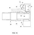
- FIG. 10is a section view taken along line 10 - 10 of FIG. 9 ;
- FIG. 11is a front perspective view of a third embodiment of the connector arrangement
- FIG. 12is a front perspective view illustrating the insertion of the connector into the receptacle of the third embodiment.
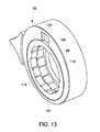
- FIG. 13is a front perspective view of the receptacle in the locking condition.
- FIG. 1illustrates the connection between a pair of gas conduits 10 and a gas supply device, such as an anesthesia machine 12 .
- a gas supply devicesuch as an anesthesia machine 12 .
- the anesthesia machine 12is shown in the embodiment of FIG. 1 as the gas supply device, it should be understood that the connector arrangement of the present disclosure could be utilized between gas conduits and various other types of gas supply devices other than an anesthesia machine 12 .
- each of the gas conduits 10includes a connector 14 securely attached to one end of the gas conduit 10 .
- Each of the gas conduits 10is connected to a receptacle 16 formed on the anesthesia machine 12 .
- the interaction between the connector 14 on the gas conduit 10 and the receptacle 16allows gas to be delivered between the anesthesia machine 12 and the respective gas conduit 10 .
- the gas conduits 10form part of a patient circuit that delivers an anesthetic agent to a patient and receives exhalation gases from the patient during a normal breathing cycle.
- the connector 14 of each of the gas conduits 10can be separated from the corresponding receptacle 16 such that the gas conduits 10 can be disconnected and replaced as desired.
- the receptacle 16includes a stationary outer shroud 18 that surrounds a supply port 20 that extends from a face surface 22 of the anesthesia machine 12 .
- the supply port 20engages the gas conduit 10 to either supply or receive gas from the conduits 10 when the connector 14 is received within the receptacle 16 .
- the connector 14 formed on the gas conduit 10includes a series of raised gripping ridges 24 formed on a cylindrical outer wall 26 .
- the cylindrical outer wall 26is securely attached to the gas conduit 10 to provide a point of attachment between the gas conduit 10 and the anesthesia machine.
- the distal end 28 of the connector 14includes a locking arrangement 30 .
- the locking arrangement 30includes a series of spaced retaining tabs 32 .
- four separate retaining tabs 32are equally positioned along the outer circumference of the outer wall 26 near the distal end 28 .
- the receptacle 16 formed on the anesthesia machineincludes the outer shroud 18 .
- the outer shroud 18includes a front face surface 34 that includes a series of spaced receiving slots 36 each separated from each other by a series of retaining projections 38 .
- the size of the receiving slots 36generally correspond to the size of the retaining tabs 32 formed on the connector 14 .
- the receptacle 16 of the first embodimentis shown in an exploded view.
- the receptacle 16includes a receiving arrangement ( 31 ) including the outer shroud 18 , a visual indicator shroud 40 , a bias ring 42 and a bias spring 44 .
- the bias spring 44exerts a bias force on the bias ring 42 , which in turn exerts a bias force on the visual indicating shroud 40 .
- the visual indicating shroud 40includes a series of receiving slots 46 that are each aligned with one of the receiving slot 36 formed in the outer shroud 18 .
- the receiving slots 46are each sized to receive one of the retaining tabs 32 formed on the connector 14 .
- the receiving slots 46are each recessed from an outer rim 48 .
- the outer rim 48includes a series of first portions 50 and second portions 52 that are alternately spaced around the generally circular outer rim 48 .
- the first portion 50is of a first color, red
- the second portion 52is of a second color, green.
- red and greenare described as being the colors for the first and second portions 50 , 52 , it should be understood that other colors could be utilized while operating within the scope of the present disclosure.
- the first portion 50 of the visual indicating shroud 40is visible through each of the receiving slots 36 . Since the first portion 50 is red, the user is presented with a visual indication that the connector 14 is not properly inserted into the receptacle 16 .
- the retaining tabs 32are received within the receiving slots 46 of the visual indicating shroud.
- an outer portion of the first portion 50 of the visual indicating shroudis still visible to the user.
- the userviews the red color of the first portion 50 when the connector 14 is first inserted into the receptacle 16 .
- the connector 14is depressed against the bias force created by the bias spring until the retaining tabs 32 are recessed enough to extend past the front wall 54 of the outer shroud 18 .
- the movement of the connector 14 in the direction shown by arrow 56causes the visual indicating shroud 40 and the bias ring 42 to compress the bias spring 44 , which allows the visual indicating shroud 40 to move inwardly.
- the connector 14is rotated in the clockwise direction, as indicated by arrow 58 .
- the second portion 52 of the visual indicating shroud 40is visible through the receiving slots 36 .
- the second portion 52has a second color, green, which is visible and indicates to the user that the connector has been positively retained within the receptacle. In this manner, the user can quickly determine that the connector has been properly attached to the receptacle and that a fluid tight communication is achieved between the gas conduit 10 and the anesthesia machine.
- the front face surface 34 of the outer shroud 18includes a printed arrow and locking icons to illustrate to the user which direction the connector 14 needs to be rotated to lock and unlock the connector from within the receptacle 16 .
- the visual indicating shroud 40 shown in FIG. 6is formed having two different colors to visually indicate to the user when the connector has been properly received within the receptacle.
- the first portion 50 and the second portion 52are colored red and green, which are commonly used colors to indicate a proper connection and an improper connection. However, other colors could be utilized while operating within the scope of the present disclosure.
- the illustrated embodimentrequires rotation of the connector 14 in the clockwise direction to enter the locked condition
- the orientation of the connector and receptaclecould be reversed such that counter-clockwise rotation would create the locked condition.
- the connector and receptaclecould be configured such that rotation of the connector in either direction could create the locked condition.
- the first and second colored portionswould be located appropriately on the visual indicating shroud 40 to indicate that the connector has been positively retained within the receptacle.
- FIG. 7illustrates a second embodiment of the connector arrangement of the present disclosure.
- the gas conduit 10includes a connector 58 having an alternate configuration.
- the anesthesia machineincludes an alternate receptacle 60 in accordance with the second embodiment.
- the receptacle 60surrounds the supply port 20 and acts as a receptacle for the connector 58 to positively retain the connector 58 while creating the fluid communication between the gas conduit 10 and the supply port 20 .
- the connector 58includes a locking arrangement formed by a latch 62 that extends from the outer wall 26 of the connector 58 .
- the latch 62is received within an access opening 64 formed in the outer shroud 66 of the receptacle 60 .
- the outer shroud 66further includes a pair of visual indicators 68 that provide a visual indication of the proper connection of the connector 58 to the receptacle 60 .
- the visual indicators 68include a pair of light emitting diodes (LEDs) 70 that are each contained within an outer shroud 72 . Although LEDs 70 are shown, it should be understood that the visual indicator could be another type of illumination light while operating within the scope of the present disclosure.
- the pair of LEDs 70are each connected to an activation switch 74 contained within the outer shroud 66 .
- the activation switch 74is connected to a supply of power and includes a movable switch arm 76 .
- the switch arm 76When the switch arm 76 is moved from the resting position shown in FIG. 8 to the depressed position of FIG. 10 , the switch arm 76 closes a pair of contacts within the activation switch 74 , which results in power being applied to the LED, thereby resulting in illumination of the LED 70 .
- the switch arm 76is in the position shown in FIG. 8 , the switch contacts are open and no power is applied to the LED 70 and the LED 70 is not illuminated.
- the outer end 84 of the latch 62is depressed, which causes the locking end 80 to move upward away from the shoulder 82 , as illustrated in FIG. 10 . Once the locking end 80 has been elevated, the connector 58 can simply be removed from the receptacle 60 .
- the visual indicators 68provide a visual indication to the user when a positive connection is made between the connector 58 and the receptacle 60 .
- a pair of LEDs 70are shown in the embodiment illustrated, it should be understood that a single LED or other types of light emitting devices could be utilized while operating within the scope of the present disclosure.
- the pair of gas conduits 10each include a unique connector 90 that is received within a receptacle 92 formed as part of the anesthesia machine 12 .
- the leftmost connectoris shown in its positively retained condition while the rightmost connector 90 is separated from the receptacle 92 .
- the receptacle 92includes an outer shroud 94 that surrounds a retaining ring 96 and a visual indicator shroud 98 .
- the outer shroud 94includes a viewing window 100 that allows a user to view a portion of the visual indicator shroud 98 .
- the visual indicator shroud 98includes both a first portion and a second portion that have different colors, such as red and green as described in the first embodiment previously discussed.
- a first portion 102 of the visual indicator shroudis visible through the viewing window 100 .
- a first portion 102is visible through the viewing window 100 .
- the first portion 102is preferably colored red to indicate no connection while the second portion 104 is colored green to indicate a proper connection.
- a release handle 106is connected to the visual indicating shroud 98 and is sized to receive the thumb of a user.
- the release handle 106allows the user to release the connector 90 from within the receptacle 92 , as will be described in detail below.
- the connector 90includes an engagement end 108 having a series of retaining tabs 110 positioned near the distal end 112 .
- the spacing between the retaining tabs 110corresponds to the spacing between a series of locking tabs 114 formed on the retaining ring 96 .
- the series of retaining tabs 110are aligned with the open spaces between the locking tabs 114 of the retaining ring 96 .
- the connector 90is moved inwardly relative to the stationary outer shroud 94 until the retaining tabs 110 are received within the open receiving slots 116 formed in the visual indicator shroud 98 .
- the receiving slots 116are spaced between a series of engagement tabs 118 that project radially outward and are flush with the locking tabs 114 .
- the retaining ring 96 and the visual indicating shroud 98interact with each other along a serrated contact surface 120 .
- the serrated contact surface 120allows the two rings to rotate in only one direction relative to each other.
- the entire connector 90is rotated in the clockwise direction, which causes the retaining ring 96 and the visual indicator shroud 98 to rotate into the condition shown in FIG. 13 .
- the connectoris not shown in FIG. 13 , each of the retaining tabs 110 are positioned within the receiving slot 116 and thus positioned behind the locking tabs 114 in this rotated condition.
- the connectoris securely held within the receptacle 92 and the second portion 104 of the visual indicator shroud 98 is visible through the viewing window 100 .
- the second portionis preferably colored green such that the second portion 104 indicates a proper connection between the connector and the receptacle.
Landscapes
- Health & Medical Sciences (AREA)
- Engineering & Computer Science (AREA)
- Heart & Thoracic Surgery (AREA)
- Anesthesiology (AREA)
- Life Sciences & Earth Sciences (AREA)
- Pulmonology (AREA)
- Hematology (AREA)
- Biomedical Technology (AREA)
- Animal Behavior & Ethology (AREA)
- General Health & Medical Sciences (AREA)
- Public Health (AREA)
- Veterinary Medicine (AREA)
- General Engineering & Computer Science (AREA)
- Emergency Medicine (AREA)
- Mechanical Engineering (AREA)
- Details Of Connecting Devices For Male And Female Coupling (AREA)
- Infusion, Injection, And Reservoir Apparatuses (AREA)
- Quick-Acting Or Multi-Walled Pipe Joints (AREA)
Abstract
Description
Claims (13)
Priority Applications (5)
| Application Number | Priority Date | Filing Date | Title |
|---|---|---|---|
| US12/984,007US8960727B2 (en) | 2011-01-04 | 2011-01-04 | Method and system for visually indicating a secure connection |
| DE102011057162ADE102011057162A1 (en) | 2011-01-04 | 2011-12-29 | Method and system for visually displaying a secure connection |
| CN201610166934.1ACN105715891B (en) | 2011-01-04 | 2012-01-04 | For intuitively indicating the method and system being reliably connected |
| CN201210012845.3ACN102588696B (en) | 2011-01-04 | 2012-01-04 | Connector assembly and method for indicating a reliable connection |
| US14/629,418US20150167877A1 (en) | 2011-01-04 | 2015-02-23 | Visual indicator for a secure fluid connection |
Applications Claiming Priority (1)
| Application Number | Priority Date | Filing Date | Title |
|---|---|---|---|
| US12/984,007US8960727B2 (en) | 2011-01-04 | 2011-01-04 | Method and system for visually indicating a secure connection |
Related Child Applications (1)
| Application Number | Title | Priority Date | Filing Date |
|---|---|---|---|
| US14/629,418DivisionUS20150167877A1 (en) | 2011-01-04 | 2015-02-23 | Visual indicator for a secure fluid connection |
Publications (2)
| Publication Number | Publication Date |
|---|---|
| US20120169044A1 US20120169044A1 (en) | 2012-07-05 |
| US8960727B2true US8960727B2 (en) | 2015-02-24 |
Family
ID=46380085
Family Applications (2)
| Application Number | Title | Priority Date | Filing Date |
|---|---|---|---|
| US12/984,007Expired - Fee RelatedUS8960727B2 (en) | 2011-01-04 | 2011-01-04 | Method and system for visually indicating a secure connection |
| US14/629,418AbandonedUS20150167877A1 (en) | 2011-01-04 | 2015-02-23 | Visual indicator for a secure fluid connection |
Family Applications After (1)
| Application Number | Title | Priority Date | Filing Date |
|---|---|---|---|
| US14/629,418AbandonedUS20150167877A1 (en) | 2011-01-04 | 2015-02-23 | Visual indicator for a secure fluid connection |
Country Status (3)
| Country | Link |
|---|---|
| US (2) | US8960727B2 (en) |
| CN (2) | CN105715891B (en) |
| DE (1) | DE102011057162A1 (en) |
Cited By (15)
| Publication number | Priority date | Publication date | Assignee | Title |
|---|---|---|---|---|
| US20190255278A1 (en)* | 2013-09-13 | 2019-08-22 | Fisher & Paykel Healthcare Limited | Connections for humidification system |
| US20210402127A1 (en)* | 2015-09-04 | 2021-12-30 | Fisher & Paykel Healthcare Limited | Connectors for conduits |
| US11426553B2 (en)* | 2018-04-16 | 2022-08-30 | Aeronics, Inc. | Portable gas delivery system |
| US11628267B2 (en) | 2010-08-04 | 2023-04-18 | Medline Industries, Lp | Universal medical gas delivery system |
| US11712536B2 (en) | 2014-06-03 | 2023-08-01 | Fisher & Paykel Healthcare Limited | Flow mixers for respiratory therapy systems |
| US11878093B2 (en) | 2012-04-27 | 2024-01-23 | Fisher & Paykel Healthcare Limited | Usability features for respiratory humidification system |
| USD1026221S1 (en) | 2020-03-03 | 2024-05-07 | Fisher & Paykel Healthcare Limited | Connector for a respiratory system conduit |
| USD1027165S1 (en) | 2016-06-10 | 2024-05-14 | Fisher & Paykel Healthcare Limited | Connector for a breathing circuit |
| USD1037433S1 (en) | 2019-09-10 | 2024-07-30 | Fisher & Paykel Healthcare Limited | Connector for a breathing conduit |
| USD1039134S1 (en) | 2021-06-11 | 2024-08-13 | Fisher & Paykel Healthcare Limited | Tube assembly and connector |
| USD1054555S1 (en) | 2020-12-09 | 2024-12-17 | Fisher & Paykel Healthcare Limited | Conduit connector |
| US12201776B2 (en) | 2015-03-31 | 2025-01-21 | Fisher & Paykel Healthcare Limited | Apparatus for use in a respiratory support system |
| USD1073919S1 (en) | 2021-05-17 | 2025-05-06 | Fisher & Paykel Healthcare Limited | Respiratory system conduit with connector |
| US12350436B2 (en) | 2012-03-15 | 2025-07-08 | Fisher & Paykel Healthcare Limited | Respiratory gas humidification system |
| US12397127B2 (en) | 2014-02-07 | 2025-08-26 | Fisher & Paykel Healthcare Limited | Respiratory humidification system |
Families Citing this family (19)
| Publication number | Priority date | Publication date | Assignee | Title |
|---|---|---|---|---|
| ES2935418T3 (en) | 2011-08-10 | 2023-03-06 | Fisher & Paykel Healthcare Ltd | Conduit connector for a patient breathing device |
| USD747471S1 (en) | 2012-08-10 | 2016-01-12 | Fisher & Paykel Healthcare Limited | Connector |
| WO2014205513A1 (en)* | 2013-06-25 | 2014-12-31 | Resmed Limited | Outlet connection assembly and method of making the same |
| US9849314B2 (en)* | 2013-11-29 | 2017-12-26 | Msa Technology, Llc | Breathing apparatus with illuminated connection |
| WO2015134749A2 (en)* | 2014-03-06 | 2015-09-11 | Stryker Corporation | Medical/surgical waste collection unit with a light assembly separate from the primary display, the light assembly presenting informatin about the operation of the system by selectively outputting light |
| US9149623B1 (en)* | 2014-03-18 | 2015-10-06 | Oridion Medical 1987 Ltd. | Adapters |
| US9592353B2 (en)* | 2015-04-30 | 2017-03-14 | Sanjay K Roy | Adaptor/tubing with alarm(s) |
| WO2016191619A1 (en)* | 2015-05-27 | 2016-12-01 | Johnson Controls Technology Company | Actuator conduit adaptor |
| ES2992747T3 (en)* | 2015-08-21 | 2024-12-17 | Surgiquest Inc | Coupling devices for tube sets used with surgical gas delivery systems |
| JP6784398B2 (en)* | 2017-02-28 | 2020-11-11 | アコマ医科工業株式会社 | Anesthesia tank and anesthetic misinjection prevention system |
| US10857397B2 (en)* | 2017-07-26 | 2020-12-08 | Honeywell International Inc. | Bayonet hose connector assembly mechanism in powered air purifying air respirator housing |
| GB2573165B (en)* | 2018-04-27 | 2020-11-18 | John Guest International Ltd | A connector |
| PL3826698T3 (en)* | 2018-07-25 | 2024-07-08 | Acist Medical Systems, Inc. | Improved injection system and day set assembly therefor |
| USD1006981S1 (en) | 2019-09-06 | 2023-12-05 | Fisher & Paykel Healthcare Limited | Breathing conduit |
| DE102020203433A1 (en)* | 2020-03-18 | 2021-09-23 | Conti Tech Techno-Chemie Gmbh | Fluid line coupling |
| DE102020114117A1 (en)* | 2020-05-26 | 2021-12-02 | Bayerische Motoren Werke Aktiengesellschaft | Line coupling assembly |
| US12392431B2 (en) | 2020-10-05 | 2025-08-19 | Oetiker Ny, Inc. | Fluid connector including a connection verification contact |
| CN116006806A (en)* | 2022-11-30 | 2023-04-25 | 乐普(北京)医疗器械股份有限公司 | A gas path joint structure of ablation equipment |
| US20250073441A1 (en)* | 2023-08-28 | 2025-03-06 | Alcon Inc. | Connector assembly for fluid ports |
Citations (11)
| Publication number | Priority date | Publication date | Assignee | Title |
|---|---|---|---|---|
| US423323A (en)* | 1890-03-11 | johnson | ||
| US1130726A (en)* | 1913-09-29 | 1915-03-09 | Cleveland Pneumatic Tool Co | Coupling. |
| US1847379A (en)* | 1928-03-13 | 1932-03-01 | Alemite Corp | Connecter for nipples |
| US2076918A (en)* | 1936-03-20 | 1937-04-13 | George A Robison | Hose coupling |
| US3687137A (en)* | 1969-11-13 | 1972-08-29 | Donald W Johnson | Small animal anesthesia machine |
| US5741084A (en)* | 1995-03-27 | 1998-04-21 | Del Rio; Eddy H. | Wear compensating axial connection |
| US6585016B1 (en) | 2002-03-15 | 2003-07-01 | Datex-Ohmeda, Inc. | Keyed anesthetic vaporizer filling system |
| US7168467B2 (en) | 2004-12-21 | 2007-01-30 | Dräger Medical AG & Co. KGaA | Filling system for an anesthetic evaporator |
| US7287561B2 (en) | 2004-12-21 | 2007-10-30 | Dräger Medical AG & Co. KGaA | Filling system for an anesthetic evaporator |
| US7389801B2 (en) | 2005-08-11 | 2008-06-24 | Drägerwerk Medical AG & Co. KG | Filling system for an anesthetic evaporator |
| US7490607B2 (en) | 2005-04-11 | 2009-02-17 | The General Electric Company | Anesthetic agent cassette for an anesthesia machine |
Family Cites Families (5)
| Publication number | Priority date | Publication date | Assignee | Title |
|---|---|---|---|---|
| YU33502A (en)* | 1999-11-10 | 2003-07-07 | Walter Tosto Serbatoi S.P.A. | Cartridge connecting system for combustible gas distributors |
| US7850660B2 (en)* | 2003-12-19 | 2010-12-14 | Ethicon Endo-Surgery, Inc. | Implantable medical device with simultaneous attachment mechanism and method |
| US20100229866A1 (en)* | 2006-10-09 | 2010-09-16 | Austrlian Centre for Advanced Medical Tecnology Pty Ltd | Gas mask assembly with swivel connector |
| CA2717754C (en)* | 2008-03-04 | 2017-06-06 | Infusion Innovations, Inc. | Devices, assemblies, and methods for controlling fluid flow |
| US7798995B2 (en)* | 2008-10-10 | 2010-09-21 | Laborie Medical Technologies, Inc. | Adjustable tip needle apparatus |
- 2011
- 2011-01-04USUS12/984,007patent/US8960727B2/ennot_activeExpired - Fee Related
- 2011-12-29DEDE102011057162Apatent/DE102011057162A1/ennot_activeWithdrawn
- 2012
- 2012-01-04CNCN201610166934.1Apatent/CN105715891B/ennot_activeExpired - Fee Related
- 2012-01-04CNCN201210012845.3Apatent/CN102588696B/ennot_activeExpired - Fee Related
- 2015
- 2015-02-23USUS14/629,418patent/US20150167877A1/ennot_activeAbandoned
Patent Citations (12)
| Publication number | Priority date | Publication date | Assignee | Title |
|---|---|---|---|---|
| US423323A (en)* | 1890-03-11 | johnson | ||
| US1130726A (en)* | 1913-09-29 | 1915-03-09 | Cleveland Pneumatic Tool Co | Coupling. |
| US1847379A (en)* | 1928-03-13 | 1932-03-01 | Alemite Corp | Connecter for nipples |
| US2076918A (en)* | 1936-03-20 | 1937-04-13 | George A Robison | Hose coupling |
| US3687137A (en)* | 1969-11-13 | 1972-08-29 | Donald W Johnson | Small animal anesthesia machine |
| US5741084A (en)* | 1995-03-27 | 1998-04-21 | Del Rio; Eddy H. | Wear compensating axial connection |
| US6585016B1 (en) | 2002-03-15 | 2003-07-01 | Datex-Ohmeda, Inc. | Keyed anesthetic vaporizer filling system |
| US6929041B2 (en) | 2002-03-15 | 2005-08-16 | Datex-Ohmeda, Inc. | Keyed anesthetic vaporizer filling system |
| US7168467B2 (en) | 2004-12-21 | 2007-01-30 | Dräger Medical AG & Co. KGaA | Filling system for an anesthetic evaporator |
| US7287561B2 (en) | 2004-12-21 | 2007-10-30 | Dräger Medical AG & Co. KGaA | Filling system for an anesthetic evaporator |
| US7490607B2 (en) | 2005-04-11 | 2009-02-17 | The General Electric Company | Anesthetic agent cassette for an anesthesia machine |
| US7389801B2 (en) | 2005-08-11 | 2008-06-24 | Drägerwerk Medical AG & Co. KG | Filling system for an anesthetic evaporator |
Cited By (19)
| Publication number | Priority date | Publication date | Assignee | Title |
|---|---|---|---|---|
| US11628267B2 (en) | 2010-08-04 | 2023-04-18 | Medline Industries, Lp | Universal medical gas delivery system |
| US12350436B2 (en) | 2012-03-15 | 2025-07-08 | Fisher & Paykel Healthcare Limited | Respiratory gas humidification system |
| US11878093B2 (en) | 2012-04-27 | 2024-01-23 | Fisher & Paykel Healthcare Limited | Usability features for respiratory humidification system |
| US20190255278A1 (en)* | 2013-09-13 | 2019-08-22 | Fisher & Paykel Healthcare Limited | Connections for humidification system |
| US11801360B2 (en)* | 2013-09-13 | 2023-10-31 | Fisher & Paykel Healthcare Limited | Connections for humidification system |
| US12397127B2 (en) | 2014-02-07 | 2025-08-26 | Fisher & Paykel Healthcare Limited | Respiratory humidification system |
| US11712536B2 (en) | 2014-06-03 | 2023-08-01 | Fisher & Paykel Healthcare Limited | Flow mixers for respiratory therapy systems |
| US12201776B2 (en) | 2015-03-31 | 2025-01-21 | Fisher & Paykel Healthcare Limited | Apparatus for use in a respiratory support system |
| US12115317B2 (en)* | 2015-09-04 | 2024-10-15 | Fisher &Paykel Healthcare Limited | Connectors for conduits |
| US20210402127A1 (en)* | 2015-09-04 | 2021-12-30 | Fisher & Paykel Healthcare Limited | Connectors for conduits |
| USD1028213S1 (en) | 2016-06-10 | 2024-05-21 | Fisher & Paykel Healthcare Limited | Connector for a breathing circuit |
| USD1027165S1 (en) | 2016-06-10 | 2024-05-14 | Fisher & Paykel Healthcare Limited | Connector for a breathing circuit |
| US11426553B2 (en)* | 2018-04-16 | 2022-08-30 | Aeronics, Inc. | Portable gas delivery system |
| USD1037433S1 (en) | 2019-09-10 | 2024-07-30 | Fisher & Paykel Healthcare Limited | Connector for a breathing conduit |
| USD1074989S1 (en) | 2019-09-10 | 2025-05-13 | Fisher & Paykel Healthcare Limited | Connector for a breathing conduit |
| USD1026221S1 (en) | 2020-03-03 | 2024-05-07 | Fisher & Paykel Healthcare Limited | Connector for a respiratory system conduit |
| USD1054555S1 (en) | 2020-12-09 | 2024-12-17 | Fisher & Paykel Healthcare Limited | Conduit connector |
| USD1073919S1 (en) | 2021-05-17 | 2025-05-06 | Fisher & Paykel Healthcare Limited | Respiratory system conduit with connector |
| USD1039134S1 (en) | 2021-06-11 | 2024-08-13 | Fisher & Paykel Healthcare Limited | Tube assembly and connector |
Also Published As
| Publication number | Publication date |
|---|---|
| US20150167877A1 (en) | 2015-06-18 |
| CN102588696B (en) | 2016-03-30 |
| DE102011057162A1 (en) | 2012-07-05 |
| CN105715891B (en) | 2018-01-12 |
| US20120169044A1 (en) | 2012-07-05 |
| CN102588696A (en) | 2012-07-18 |
| CN105715891A (en) | 2016-06-29 |
Similar Documents
| Publication | Publication Date | Title |
|---|---|---|
| US8960727B2 (en) | Method and system for visually indicating a secure connection | |
| CA3040682C (en) | Electrical connector with plug latching assembly | |
| CN105849452B (en) | Connector, release tool and device comprising connector and release tool | |
| US4116476A (en) | Quick disconnect coupler assembly | |
| US20220296842A1 (en) | Adapter | |
| US9819127B2 (en) | Internally switched female receptacle or connector with plug-latching safety interlock | |
| ES2763208T3 (en) | Optical and / or Electrical Locking Connectors and Cable Assemblies | |
| US20170227153A1 (en) | Lock mechanism of tubular body | |
| US20130137287A1 (en) | Electrical plug connection, in particular circular plug connector | |
| EP2283544A1 (en) | Medical connector | |
| US11067211B2 (en) | Aircraft fluid line coupling assembly for releasably interconnecting fluid conveying members | |
| US5562121A (en) | Gas delivery system with universal outlet | |
| CN105792882A (en) | Connector with sealing element and adapted connecting parts | |
| WO2005028940A1 (en) | Pipe joint and socket for pipe joint | |
| EP3319184B1 (en) | Apparatus for connecting two electrical connectors together, tool for use with the first or second electrical connectors and method of connecting two electrical connectors together. | |
| US20200001954A1 (en) | Inflation Device with Means for Preventing the Removal of the Gas Container | |
| JP2017213065A (en) | Plug-in fitting | |
| CN105210242A (en) | Latching connector assembly | |
| JP6865060B2 (en) | Manual tools, ground contact mounting sets, and methods for mounting terminals on ground stud contacts, especially for vehicle bodies. | |
| KR100699229B1 (en) | Locking device of circuit breaker for apartment house | |
| JP2019199924A (en) | Pipe joint and joint member thereof | |
| US9178305B2 (en) | Arrangement for establishing and breaking a connection between a plug and a mating plug by pivoting lever arranged on the plug | |
| JP2012048822A (en) | Electric apparatus | |
| JP2010165650A (en) | Mounting device for ceiling direct-mounted luminaire | |
| JPH0737410A (en) | Luminaire installing device |
Legal Events
| Date | Code | Title | Description |
|---|---|---|---|
| AS | Assignment | Owner name:GENERAL ELECTRIC COMPANY, NEW YORK Free format text:ASSIGNMENT OF ASSIGNORS INTEREST;ASSIGNOR:KENDRICK, PAUL A.;REEL/FRAME:025627/0024 Effective date:20101230 | |
| AS | Assignment | Owner name:CAREFUSION CORPORATION, CALIFORNIA Free format text:ASSIGNMENT OF ASSIGNORS INTEREST;ASSIGNOR:GENERAL ELECTRIC COMPANY;REEL/FRAME:032198/0468 Effective date:20131223 | |
| STCF | Information on status: patent grant | Free format text:PATENTED CASE | |
| AS | Assignment | Owner name:CITIZENS BANK, N.A, AS COLLATERAL AGENT, MASSACHUSETTS Free format text:SECURITY AGREEMENT;ASSIGNORS:VYAIRE MEDICAL CAPITAL LLC;VYAIRE MEDICAL CONSUMABLES LLC;VITAL SIGNS, INC.;AND OTHERS;REEL/FRAME:040357/0952 Effective date:20161013 Owner name:CITIZENS BANK, N.A, AS COLLATERAL AGENT, MASSACHUS Free format text:SECURITY AGREEMENT;ASSIGNORS:VYAIRE MEDICAL CAPITAL LLC;VYAIRE MEDICAL CONSUMABLES LLC;VITAL SIGNS, INC.;AND OTHERS;REEL/FRAME:040357/0952 Effective date:20161013 | |
| AS | Assignment | Owner name:KINGSTON RESPIRATORY CONSUMABLES LLC, NEW JERSEY Free format text:ASSIGNMENT OF ASSIGNORS INTEREST;ASSIGNOR:KINGSTON RESPIRATORY 102 LLC;REEL/FRAME:040648/0047 Effective date:20160929 Owner name:VYAIRE MEDICAL CONSUMABLES LLC, CALIFORNIA Free format text:CHANGE OF NAME;ASSIGNOR:KINGSTON RESPIRATORY CONSUMABLES LLC;REEL/FRAME:040648/0028 Effective date:20161007 Owner name:KINGSTON RESPIRATORY 102 LLC, NEW JERSEY Free format text:ASSIGNMENT OF ASSIGNORS INTEREST;ASSIGNOR:CAREFUSION 2200, INC.;REEL/FRAME:040372/0928 Effective date:20160928 Owner name:CAREFUSION 2200, INC., CALIFORNIA Free format text:ASSIGNMENT OF ASSIGNORS INTEREST;ASSIGNOR:CAREFUSION CORPORATION;REEL/FRAME:040372/0822 Effective date:20160928 | |
| AS | Assignment | Owner name:CAREFUSION 202, INC., ILLINOIS Free format text:RELEASE BY SECURED PARTY;ASSIGNOR:CITIZENS BANK, N.A.;REEL/FRAME:045779/0035 Effective date:20180416 Owner name:VITAL SIGNS, INC., ILLINOIS Free format text:RELEASE BY SECURED PARTY;ASSIGNOR:CITIZENS BANK, N.A.;REEL/FRAME:045779/0035 Effective date:20180416 Owner name:VYAIRE MEDICAL CAPITAL LLC, ILLINOIS Free format text:RELEASE BY SECURED PARTY;ASSIGNOR:CITIZENS BANK, N.A.;REEL/FRAME:045779/0035 Effective date:20180416 Owner name:VYAIRE MEDICAL CONSUMABLES LLC, ILLINOIS Free format text:RELEASE BY SECURED PARTY;ASSIGNOR:CITIZENS BANK, N.A.;REEL/FRAME:045779/0035 Effective date:20180416 | |
| AS | Assignment | Owner name:WILMINGTON TRUST, NATIONAL ASSOCIATION, AS COLLATERAL AGENT, DELAWARE Free format text:SECOND LIEN SECURITY AGREEMENT;ASSIGNOR:VYAIRE MEDICAL CONSUMABLES LLC;REEL/FRAME:045969/0830 Effective date:20180416 Owner name:BANK OF AMERICA, N.A., AS COLLATERAL AGENT, NORTH CAROLINA Free format text:FIRST LIEN SECURITY AGREEMENT;ASSIGNOR:VYAIRE MEDICAL CONSUMABLES LLC;REEL/FRAME:045968/0940 Effective date:20180416 Owner name:BANK OF AMERICA, N.A., AS COLLATERAL AGENT, NORTH Free format text:FIRST LIEN SECURITY AGREEMENT;ASSIGNOR:VYAIRE MEDICAL CONSUMABLES LLC;REEL/FRAME:045968/0940 Effective date:20180416 Owner name:WILMINGTON TRUST, NATIONAL ASSOCIATION, AS COLLATE Free format text:SECOND LIEN SECURITY AGREEMENT;ASSIGNOR:VYAIRE MEDICAL CONSUMABLES LLC;REEL/FRAME:045969/0830 Effective date:20180416 | |
| MAFP | Maintenance fee payment | Free format text:PAYMENT OF MAINTENANCE FEE, 4TH YEAR, LARGE ENTITY (ORIGINAL EVENT CODE: M1551) Year of fee payment:4 | |
| AS | Assignment | Owner name:WILMINGTON TRUST, NATIONAL ASSOCIATION, MINNESOTA Free format text:SECURITY INTEREST;ASSIGNOR:VYAIRE MEDICAL CONSUMABLES LLC;REEL/FRAME:049147/0928 Effective date:20190503 | |
| FEPP | Fee payment procedure | Free format text:MAINTENANCE FEE REMINDER MAILED (ORIGINAL EVENT CODE: REM.); ENTITY STATUS OF PATENT OWNER: LARGE ENTITY | |
| LAPS | Lapse for failure to pay maintenance fees | Free format text:PATENT EXPIRED FOR FAILURE TO PAY MAINTENANCE FEES (ORIGINAL EVENT CODE: EXP.); ENTITY STATUS OF PATENT OWNER: LARGE ENTITY | |
| STCH | Information on status: patent discontinuation | Free format text:PATENT EXPIRED DUE TO NONPAYMENT OF MAINTENANCE FEES UNDER 37 CFR 1.362 | |
| FP | Lapsed due to failure to pay maintenance fee | Effective date:20230224 |