US8959911B2 - Engine assembly including fluid control to boost mechanism - Google Patents
Engine assembly including fluid control to boost mechanismDownload PDFInfo
- Publication number
- US8959911B2 US8959911B2US13/267,092US201113267092AUS8959911B2US 8959911 B2US8959911 B2US 8959911B2US 201113267092 AUS201113267092 AUS 201113267092AUS 8959911 B2US8959911 B2US 8959911B2
- Authority
- US
- United States
- Prior art keywords
- accumulator
- engine
- flow path
- communication
- boost mechanism
- Prior art date
- Legal status (The legal status is an assumption and is not a legal conclusion. Google has not performed a legal analysis and makes no representation as to the accuracy of the status listed.)
- Expired - Fee Related, expires
Links
Images


Classifications
- F—MECHANICAL ENGINEERING; LIGHTING; HEATING; WEAPONS; BLASTING
- F01—MACHINES OR ENGINES IN GENERAL; ENGINE PLANTS IN GENERAL; STEAM ENGINES
- F01M—LUBRICATING OF MACHINES OR ENGINES IN GENERAL; LUBRICATING INTERNAL COMBUSTION ENGINES; CRANKCASE VENTILATING
- F01M5/00—Heating, cooling, or controlling temperature of lubricant; Lubrication means facilitating engine starting
- F01M5/02—Conditioning lubricant for aiding engine starting, e.g. heating
- F01M5/025—Conditioning lubricant for aiding engine starting, e.g. heating by prelubricating, e.g. using an accumulator
- F—MECHANICAL ENGINEERING; LIGHTING; HEATING; WEAPONS; BLASTING
- F02—COMBUSTION ENGINES; HOT-GAS OR COMBUSTION-PRODUCT ENGINE PLANTS
- F02B—INTERNAL-COMBUSTION PISTON ENGINES; COMBUSTION ENGINES IN GENERAL
- F02B39/00—Component parts, details, or accessories relating to, driven charging or scavenging pumps, not provided for in groups F02B33/00 - F02B37/00
- F02B39/14—Lubrication of pumps; Safety measures therefor
- F—MECHANICAL ENGINEERING; LIGHTING; HEATING; WEAPONS; BLASTING
- F02—COMBUSTION ENGINES; HOT-GAS OR COMBUSTION-PRODUCT ENGINE PLANTS
- F02D—CONTROLLING COMBUSTION ENGINES
- F02D41/00—Electrical control of supply of combustible mixture or its constituents
- F02D41/02—Circuit arrangements for generating control signals
- F02D41/04—Introducing corrections for particular operating conditions
- F02D41/042—Introducing corrections for particular operating conditions for stopping the engine
- F—MECHANICAL ENGINEERING; LIGHTING; HEATING; WEAPONS; BLASTING
- F02—COMBUSTION ENGINES; HOT-GAS OR COMBUSTION-PRODUCT ENGINE PLANTS
- F02N—STARTING OF COMBUSTION ENGINES; STARTING AIDS FOR SUCH ENGINES, NOT OTHERWISE PROVIDED FOR
- F02N11/00—Starting of engines by means of electric motors
- F02N11/08—Circuits specially adapted for starting of engines
- F02N11/0814—Circuits specially adapted for starting of engines comprising means for controlling automatic idle-start-stop
Definitions
- the present disclosurerelates to engine boost mechanisms, and more specifically to control of fluid supplied to an engine boost mechanism.
- An enginemay include a turbocharger to provide a compressed air flow to the engine. Oil may be provided to a bearing region of the turbocharger for lubrication and cooling during engine operation.
- a powertrain assemblymay include an internal combustion engine, a boost mechanism and a fluid supply mechanism.
- the boost mechanismmay be in communication with an air source and the internal combustion engine.
- the fluid supply mechanismmay include a first accumulator in communication with a pressurized fluid supply from the internal combustion engine and the boost mechanism.
- the accumulatormay receive pressurized fluid from the internal combustion engine during engine operation and may provide the pressurized fluid to the boost mechanism during an engine off condition.
- FIG. 1is a schematic illustration of a vehicle assembly according to the present disclosure.
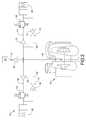
- FIG. 2is a schematic illustration of the boost mechanism and fluid supply from the engine assembly of FIG. 1 .
- Example embodimentsare provided so that this disclosure will be thorough, and will fully convey the scope to those who are skilled in the art. Numerous specific details are set forth such as examples of specific components, devices, and methods, to provide a thorough understanding of embodiments of the present disclosure. It will be apparent to those skilled in the art that specific details need not be employed, that example embodiments may be embodied in many different forms and that neither should be construed to limit the scope of the disclosure. In some example embodiments, well-known processes, well-known device structures, and well-known technologies are not described in detail.
- first, second, third, etc.may be used herein to describe various elements, components, regions, layers and/or sections, these elements, components, regions, layers and/or sections should not be limited by these terms. These terms may be only used to distinguish one element, component, region, layer or section from another region, layer or section. Terms such as “first,” “second,” and other numerical terms when used herein do not imply a sequence or order unless clearly indicated by the context. Thus, a first element, component, region, layer or section discussed below could be termed a second element, component, region, layer or section without departing from the teachings of the example embodiments.
- a hybrid vehicle 10is schematically illustrated in FIG. 1 and may include an engine assembly 12 , a hybrid power assembly 14 , a transmission 16 and a drive axle 18 driven by the transmission 16 .
- the engine assembly 12may include an internal combustion engine 20 defining cylinders 22 housing pistons 24 engaged with a crankshaft 26 and an intake system 28 . While the internal combustion engine 20 is illustrated as a four cylinder engine configuration, it is understood that the present teachings apply to any number of piston-cylinder arrangements and a variety of reciprocating engine configurations including, but not limited to, V-engines, inline engines, and horizontally opposed engines, as well as both overhead cam and cam-in-block configurations.
- the intake system 28may supply air (A) to the cylinders 22 and may include an intake manifold 32 in communication with the cylinders 22 and a boost mechanism 34 in communication with the air source (A) and the intake manifold 32 to provide a compressed air flow to the cylinders 22 via the intake manifold 32 .
- a throttle control valve 36may be located between the boost mechanism 34 and the intake manifold 32 to control air flow to the intake manifold 32 . While described in combination with a gasoline engine, it is understood that the present disclosure applies equally to diesel engines as well.
- the engine assembly 12may drive the transmission 16 via a coupling device 38 engaged with the crankshaft 26 and the transmission 16 .
- the coupling device 38may include a friction clutch or a torque converter.
- the hybrid power assembly 14may include a motor 40 in communication with a rechargeable battery 42 .
- the motor 40is coupled to the crankshaft 26 via a belt 44 .
- combustion within the cylinders 22may power rotation of the crankshaft 26 to propel the vehicle 10 .
- the crankshaft 26may additionally power rotation of the motor 40 to charge the battery 42 during the first mode.
- the internal combustion engine 20may be non-operational (i.e., no combustion within the cylinders 22 ) and the motor 40 may be powered by the battery 42 and may drive rotation of the crankshaft 26 . It is understood that the present disclosure is not limited to hybrid arrangements where the crankshaft 26 is driven by a motor of a hybrid system and applies equally to any hybrid propulsion system.
- the vehicle 10may also be operated in a stop-start mode where the internal combustion engine 20 is temporarily shut off during vehicle stop conditions while the vehicle is still operating (e.g., temporary traffic stops).
- the engine assembly 12may include a fluid supply mechanism 46 associated with the boost mechanism 34 .
- the boost mechanism 34is illustrated as a turbocharger driven by exhaust gas (E) and the fluid supply mechanism 46 provides lubrication and/or cooling during transitions of the internal combustion engine 20 between on and off conditions.
- Eexhaust gas
- the present disclosureis not limited to boost mechanisms including a turbocharger and applies equally to a variety of alternate arrangements including, but not limited to, superchargers.
- the fluid supply mechanism 46may be in communication with a pressurized fluid supply (O) from the engine assembly 12 .
- the pressurized fluid supply (O)is provided by an engine lubrication system 48 and includes engine oil.
- the fluid supply mechanism 46may include a first accumulator 50 , a first control valve 52 , a first flow path 54 , a second flow path 56 , a first check valve 58 , a second check valve 60 , a first orifice 62 , a second accumulator 64 , a second control valve 66 , a third flow path 68 , a fourth flow path 70 , a third check valve 72 , a fourth check valve 74 , a second orifice 76 and a fifth check valve 78 .
- the engine lubrication system 48may provide oil to the boost mechanism 34 during operation of the internal combustion engine 20 . More specifically, the engine lubrication system 48 may be in communication with a bearing region 80 of the boost mechanism 34 . The oil may lubricate and cool the bearing region 80 .
- the first flow path 54may provide pressurized oil to the first accumulator 50 and the second flow path 56 may provide oil from the first accumulator 50 to the boost mechanism 34 .
- the second flow path 56may be in a parallel flow arrangement to the first flow path 54 .
- the first and second flow paths 54 , 56may form parallel flow paths between the pressurized fluid supply (O) and the first accumulator 50 .
- the first check valve 58may allow fluid flow to the first accumulator 50 and inhibit fluid flow from the first accumulator 50 to the boost mechanism 34 through the first flow path 54 .
- the first orifice 62may be located in the first flow path 54 and may meter flow to the first accumulator 50 .
- the first control valve 52may be located in the second flow path 56 and may control fluid communication between the first accumulator 50 and the boost mechanism 34 through the second flow path 56 .
- the first control valve 52may be a solenoid actuated valve selectively displaceable between open and closed positions.
- the second check valve 60may be located in the second flow path 56 and may prevent backflow to the first accumulator 50 .
- the third flow path 68may provide pressurized oil to the second accumulator 64 and the fourth flow path 70 may provide oil from the second accumulator 64 to the boost mechanism 34 .
- the fourth flow path 70may be in a parallel flow arrangement to the third flow path 68 .
- the third and fourth flow paths 68 , 70may form parallel flow paths between the pressurized fluid supply (O) and the second accumulator 64 .
- the third check valve 72may allow fluid flow to the second accumulator 64 and inhibit fluid flow from the second accumulator 64 to the boost mechanism 34 through the third flow path 68 .
- the second orifice 76may be located in the third flow path 68 and may meter flow to the second accumulator 64 .
- the second control valve 66may be located in the fourth flow path 70 and may control fluid communication between the second accumulator 64 and the boost mechanism 34 through the fourth flow path 70 .
- the second control valve 66may be a solenoid actuated valve selectively displaceable between open and closed positions.
- the fourth check valve 74may be located in the fourth flow path 70 and may prevent backflow to the second accumulator 64 .
- the fifth check valve 78may be located between the pressurized fluid supply (O) and the fluid supply mechanism 46 and may prevent backflow to the pressurized fluid supply (O) from the fluid supply mechanism 46 .
- the first and second control valves 52 , 66may each be closed. Pressurized oil may be provided to the first accumulator 50 via the first flow path 54 and to the second accumulator 64 via the third flow path 68 . The oil may be stored within the first and second accumulators 50 , 64 until a predetermined vehicle operating condition. The first and second accumulators 50 , 64 may provide oil to the bearing region 80 of the boost mechanism 34 during transitions to and from the stop-start mode.
- the second control valve 66may be displaced to the open position to provide cooling at the bearing region 80 of the boost mechanism 34 .
- the first control valve 52may remain in the closed position when the internal combustion engine 20 shut down.
- the second control valve 66may be in the closed position and the first control valve 52 may be displaced to the open position to provide lubrication to the bearing region 80 of the boost mechanism 34 at re-start of the internal combustion engine 20 .
Landscapes
- Engineering & Computer Science (AREA)
- Mechanical Engineering (AREA)
- General Engineering & Computer Science (AREA)
- Chemical & Material Sciences (AREA)
- Combustion & Propulsion (AREA)
- Lubrication Of Internal Combustion Engines (AREA)
- Hybrid Electric Vehicles (AREA)
- Supercharger (AREA)
Abstract
Description
Claims (10)
Priority Applications (3)
| Application Number | Priority Date | Filing Date | Title |
|---|---|---|---|
| US13/267,092US8959911B2 (en) | 2011-10-06 | 2011-10-06 | Engine assembly including fluid control to boost mechanism |
| CN201210366571.8ACN103032155B (en) | 2011-10-06 | 2012-09-28 | Engine assembly including fluid control to boost mechanism |
| DE102012218042.7ADE102012218042B4 (en) | 2011-10-06 | 2012-10-02 | Motor assembly with fluid control for boost pressure mechanism |
Applications Claiming Priority (1)
| Application Number | Priority Date | Filing Date | Title |
|---|---|---|---|
| US13/267,092US8959911B2 (en) | 2011-10-06 | 2011-10-06 | Engine assembly including fluid control to boost mechanism |
Publications (2)
| Publication Number | Publication Date |
|---|---|
| US20130086903A1 US20130086903A1 (en) | 2013-04-11 |
| US8959911B2true US8959911B2 (en) | 2015-02-24 |
Family
ID=47909072
Family Applications (1)
| Application Number | Title | Priority Date | Filing Date |
|---|---|---|---|
| US13/267,092Expired - Fee RelatedUS8959911B2 (en) | 2011-10-06 | 2011-10-06 | Engine assembly including fluid control to boost mechanism |
Country Status (3)
| Country | Link |
|---|---|
| US (1) | US8959911B2 (en) |
| CN (1) | CN103032155B (en) |
| DE (1) | DE102012218042B4 (en) |
Families Citing this family (2)
| Publication number | Priority date | Publication date | Assignee | Title |
|---|---|---|---|---|
| CN106996328B (en)* | 2016-01-22 | 2019-12-06 | 北京福田康明斯发动机有限公司 | Lubricating device for turbocharger and engine |
| GB2572188A (en)* | 2018-03-22 | 2019-09-25 | Ford Global Tech Llc | A pressurised oil reservoir device |
Citations (46)
| Publication number | Priority date | Publication date | Assignee | Title |
|---|---|---|---|---|
| US3057436A (en)* | 1960-09-01 | 1962-10-09 | Caterpillar Tractor Co | System for lubrication of engine turbochargers |
| US3761146A (en)* | 1970-11-07 | 1973-09-25 | Toyoda Machine Works Ltd | Fluid bearing |
| US3827236A (en)* | 1972-12-18 | 1974-08-06 | D Rust | Cooling systems for turbocharger mechanisms |
| US3927530A (en)* | 1974-05-28 | 1975-12-23 | Anton Braun | Supercharged internal combustion engine |
| US4058981A (en)* | 1976-06-04 | 1977-11-22 | Caterpillar Tractor Co. | Lubricating system and method for turbocharged engines |
| US4083188A (en)* | 1977-02-10 | 1978-04-11 | The Garrett Corporation | Engine turbocharger system |
| US4107927A (en)* | 1976-11-29 | 1978-08-22 | Caterpillar Tractor Co. | Ebullient cooled turbocharger bearing housing |
| US4142608A (en)* | 1975-07-10 | 1979-03-06 | Wallace Murray Corporation | Turbocharger lubrication and exhaust system |
| US4322949A (en)* | 1979-07-16 | 1982-04-06 | The Garrett Corporation | Hydraulic assist turbocharger system |
| US4331112A (en)* | 1978-10-04 | 1982-05-25 | Klockner-Humboldt-Deutz Aktiengesellschaft | Lubricating arrangement, especially for internal combustion engines |
| US4422295A (en)* | 1980-10-31 | 1983-12-27 | Yamaha Motor Co., Ltd. | Lubricating system for turbo-chargers |
| GB2133481A (en)* | 1983-01-05 | 1984-07-25 | Gen Motors Overseas | Turbocharged diesel engine |
| JPS59145331A (en)* | 1983-02-04 | 1984-08-20 | Mazda Motor Corp | Safety device for engine fitted with turbosupercharger |
| US4513704A (en)* | 1983-12-02 | 1985-04-30 | Evans John W | Pressurized lubrication assembly for machinery having a flow restrictor device |
| US4513705A (en)* | 1983-12-02 | 1985-04-30 | Evans John W | Pressurized lubrication assembly for the center bearing of a turbocharger |
| JPS61123719A (en)* | 1984-11-19 | 1986-06-11 | Mazda Motor Corp | Lubricating device for turbosupercharger |
| US4690572A (en)* | 1985-11-01 | 1987-09-01 | Nissan Motor Co., Ltd. | Static pressure gas bearing apparatus for turbocharger |
| US4717318A (en)* | 1984-12-14 | 1988-01-05 | The Garrett Corporation | Turbocharger heat transfer control method and apparatus |
| US4722663A (en)* | 1986-02-04 | 1988-02-02 | Rotoflow Corporation | Seal-off mechanism for rotating turbine shaft |
| US4752193A (en)* | 1983-09-01 | 1988-06-21 | Bbc Brown Boveri Ltd. | Exhaust-gas turbocharger for the two-stage supercharging of an internal-combustion engine with a device to prevent losses of lubricant |
| US4784586A (en)* | 1986-10-16 | 1988-11-15 | Allied-Signal Inc. | Turbocharger having controlled heat transfer for bearing protection |
| JPS6480720A (en)* | 1987-09-24 | 1989-03-27 | Hino Motors Ltd | Lubrication device for exhaust turbo supercharger |
| US4884406A (en)* | 1987-08-17 | 1989-12-05 | Isuzu Motors Limited | Turbocharger |
| US4926641A (en)* | 1989-01-11 | 1990-05-22 | Keller Robert A | Turbocharger lubrication system |
| US4928637A (en)* | 1988-08-30 | 1990-05-29 | Fuji Jukogyo Kabushiki Kaisha | System for cooling an internal combustion engine including a turbocharger |
| US4958600A (en)* | 1989-02-17 | 1990-09-25 | General Motors Corporation | Liquid cooling system for a supercharged internal combustion engine |
| US5000143A (en)* | 1990-03-15 | 1991-03-19 | Lubrication Research, Inc. | Engine lubrication system with shared oil filter |
| US5014820A (en)* | 1989-01-10 | 1991-05-14 | Evans John W | Engine prelubricator and pressurized lubricant reservoir |
| US5102305A (en)* | 1988-12-13 | 1992-04-07 | Allied-Signal Inc. | Turbomachine having a unitary ceramic rotating assembly |
| US5308169A (en)* | 1992-11-20 | 1994-05-03 | Cummins Engine Company, Inc. | Bearing system for turbocharger |
| US5499693A (en)* | 1994-04-02 | 1996-03-19 | Abb Management Ag | Method and apparatus for lubricating the bearings of a turbocharger |
| JPH08158876A (en)* | 1994-12-08 | 1996-06-18 | Toyota Motor Corp | Lubricator for supercharger |
| US5870894A (en)* | 1996-07-16 | 1999-02-16 | Turbodyne Systems, Inc. | Motor-assisted supercharging devices for internal combustion engines |
| US5884601A (en)* | 1998-02-02 | 1999-03-23 | Siemens Canada Limited | Electric motor driven primary oil pump for an internal combustion engine |
| US5967762A (en)* | 1996-03-18 | 1999-10-19 | Turbonetics, Inc. | Turbocharger for high performance internal combustion engines |
| US6092371A (en)* | 1998-02-25 | 2000-07-25 | Caterpillar Inc. | Turbocharging apparatus including integral exhaust backpressure control means |
| US6745568B1 (en)* | 2003-03-27 | 2004-06-08 | Richard K. Squires | Turbo system and method of installing |
| JP2005009434A (en)* | 2003-06-20 | 2005-01-13 | Fuji Heavy Ind Ltd | Oil leakage prevention device for turbocharger |
| US6874998B2 (en)* | 2003-04-04 | 2005-04-05 | Borgwagner Inc. | Turbocharger with reduced coking |
| CN2888093Y (en) | 2006-01-25 | 2007-04-11 | 罗中柱 | Worm wheel supercharger protection system |
| US20100061855A1 (en)* | 2005-01-06 | 2010-03-11 | Mahindra & Mahindra Ltd | System for providing continuous lubrication to engine turbocharger shaft and bearing arrangement |
| US20100114454A1 (en)* | 2007-04-10 | 2010-05-06 | Pierre Bernard French | Turbocharged internal combustion engine |
| US20110011077A1 (en)* | 2008-03-21 | 2011-01-20 | Daisuke Kozuka | Hydraulic servo-drive device and variable turbo-supercharger using the same |
| US8015810B2 (en)* | 2007-05-14 | 2011-09-13 | GM Global Technology Operations LLC | Control of turbocharger lubrication for hybrid electric vehicle |
| US8393152B2 (en)* | 2006-09-06 | 2013-03-12 | Toyota Jidosha Kabushiki Kaisha | Electric supercharger |
| US8474259B2 (en)* | 2009-10-28 | 2013-07-02 | Dr. Ing. H.C. F. Porsche Aktiengesellschaft | Internal combustion engine |
Family Cites Families (7)
| Publication number | Priority date | Publication date | Assignee | Title |
|---|---|---|---|---|
| US4390082A (en)* | 1980-12-18 | 1983-06-28 | Rotoflow Corporation | Reserve lubricant supply system |
| CN2764942Y (en)* | 2004-12-20 | 2006-03-15 | 粱文利 | Fuel feeding device used for turbocharger |
| CN101623570B (en)* | 2009-07-30 | 2012-03-28 | 奇瑞汽车股份有限公司 | Pressure stabilizing filter |
| CN101776008A (en)* | 2009-12-25 | 2010-07-14 | 郭乐禧 | Turbo-charging automatic protection device |
| CN201705398U (en)* | 2010-05-27 | 2011-01-12 | 江苏安泰动力机械有限公司 | Lubricating device of slide bearing turbine pressure booster |
| JP5796073B2 (en)* | 2010-08-11 | 2015-10-21 | ボーグワーナー インコーポレーテッド | Exhaust gas turbocharger |
| CN201963392U (en)* | 2011-01-07 | 2011-09-07 | 山东交通学院 | Temperature-controlled emergency stop cooling protection device for turbocharger |
- 2011
- 2011-10-06USUS13/267,092patent/US8959911B2/ennot_activeExpired - Fee Related
- 2012
- 2012-09-28CNCN201210366571.8Apatent/CN103032155B/ennot_activeExpired - Fee Related
- 2012-10-02DEDE102012218042.7Apatent/DE102012218042B4/ennot_activeExpired - Fee Related
Patent Citations (49)
| Publication number | Priority date | Publication date | Assignee | Title |
|---|---|---|---|---|
| US3057436A (en)* | 1960-09-01 | 1962-10-09 | Caterpillar Tractor Co | System for lubrication of engine turbochargers |
| US3761146A (en)* | 1970-11-07 | 1973-09-25 | Toyoda Machine Works Ltd | Fluid bearing |
| US3827236A (en)* | 1972-12-18 | 1974-08-06 | D Rust | Cooling systems for turbocharger mechanisms |
| US3927530A (en)* | 1974-05-28 | 1975-12-23 | Anton Braun | Supercharged internal combustion engine |
| US4142608A (en)* | 1975-07-10 | 1979-03-06 | Wallace Murray Corporation | Turbocharger lubrication and exhaust system |
| US4058981A (en)* | 1976-06-04 | 1977-11-22 | Caterpillar Tractor Co. | Lubricating system and method for turbocharged engines |
| US4126997A (en)* | 1976-06-04 | 1978-11-28 | Caterpillar Tractor Co. | Method for lubricating turbocharged engines |
| US4107927A (en)* | 1976-11-29 | 1978-08-22 | Caterpillar Tractor Co. | Ebullient cooled turbocharger bearing housing |
| US4083188A (en)* | 1977-02-10 | 1978-04-11 | The Garrett Corporation | Engine turbocharger system |
| US4331112A (en)* | 1978-10-04 | 1982-05-25 | Klockner-Humboldt-Deutz Aktiengesellschaft | Lubricating arrangement, especially for internal combustion engines |
| US4322949A (en)* | 1979-07-16 | 1982-04-06 | The Garrett Corporation | Hydraulic assist turbocharger system |
| US4422295A (en)* | 1980-10-31 | 1983-12-27 | Yamaha Motor Co., Ltd. | Lubricating system for turbo-chargers |
| GB2133481A (en)* | 1983-01-05 | 1984-07-25 | Gen Motors Overseas | Turbocharged diesel engine |
| JPS59145331A (en)* | 1983-02-04 | 1984-08-20 | Mazda Motor Corp | Safety device for engine fitted with turbosupercharger |
| US4752193A (en)* | 1983-09-01 | 1988-06-21 | Bbc Brown Boveri Ltd. | Exhaust-gas turbocharger for the two-stage supercharging of an internal-combustion engine with a device to prevent losses of lubricant |
| US4513704A (en)* | 1983-12-02 | 1985-04-30 | Evans John W | Pressurized lubrication assembly for machinery having a flow restrictor device |
| US4513705A (en)* | 1983-12-02 | 1985-04-30 | Evans John W | Pressurized lubrication assembly for the center bearing of a turbocharger |
| JPS61123719A (en)* | 1984-11-19 | 1986-06-11 | Mazda Motor Corp | Lubricating device for turbosupercharger |
| US4717318A (en)* | 1984-12-14 | 1988-01-05 | The Garrett Corporation | Turbocharger heat transfer control method and apparatus |
| US4690572A (en)* | 1985-11-01 | 1987-09-01 | Nissan Motor Co., Ltd. | Static pressure gas bearing apparatus for turbocharger |
| US4722663A (en)* | 1986-02-04 | 1988-02-02 | Rotoflow Corporation | Seal-off mechanism for rotating turbine shaft |
| US4784586A (en)* | 1986-10-16 | 1988-11-15 | Allied-Signal Inc. | Turbocharger having controlled heat transfer for bearing protection |
| US4884406A (en)* | 1987-08-17 | 1989-12-05 | Isuzu Motors Limited | Turbocharger |
| JPS6480720A (en)* | 1987-09-24 | 1989-03-27 | Hino Motors Ltd | Lubrication device for exhaust turbo supercharger |
| US4928637A (en)* | 1988-08-30 | 1990-05-29 | Fuji Jukogyo Kabushiki Kaisha | System for cooling an internal combustion engine including a turbocharger |
| US5102305A (en)* | 1988-12-13 | 1992-04-07 | Allied-Signal Inc. | Turbomachine having a unitary ceramic rotating assembly |
| US5014820A (en)* | 1989-01-10 | 1991-05-14 | Evans John W | Engine prelubricator and pressurized lubricant reservoir |
| US4926641A (en)* | 1989-01-11 | 1990-05-22 | Keller Robert A | Turbocharger lubrication system |
| US4958600A (en)* | 1989-02-17 | 1990-09-25 | General Motors Corporation | Liquid cooling system for a supercharged internal combustion engine |
| US5000143A (en)* | 1990-03-15 | 1991-03-19 | Lubrication Research, Inc. | Engine lubrication system with shared oil filter |
| US5308169A (en)* | 1992-11-20 | 1994-05-03 | Cummins Engine Company, Inc. | Bearing system for turbocharger |
| US5499693A (en)* | 1994-04-02 | 1996-03-19 | Abb Management Ag | Method and apparatus for lubricating the bearings of a turbocharger |
| JPH08158876A (en)* | 1994-12-08 | 1996-06-18 | Toyota Motor Corp | Lubricator for supercharger |
| US5967762A (en)* | 1996-03-18 | 1999-10-19 | Turbonetics, Inc. | Turbocharger for high performance internal combustion engines |
| US5870894A (en)* | 1996-07-16 | 1999-02-16 | Turbodyne Systems, Inc. | Motor-assisted supercharging devices for internal combustion engines |
| US5884601A (en)* | 1998-02-02 | 1999-03-23 | Siemens Canada Limited | Electric motor driven primary oil pump for an internal combustion engine |
| US6092371A (en)* | 1998-02-25 | 2000-07-25 | Caterpillar Inc. | Turbocharging apparatus including integral exhaust backpressure control means |
| US6745568B1 (en)* | 2003-03-27 | 2004-06-08 | Richard K. Squires | Turbo system and method of installing |
| US6874998B2 (en)* | 2003-04-04 | 2005-04-05 | Borgwagner Inc. | Turbocharger with reduced coking |
| JP2005009434A (en)* | 2003-06-20 | 2005-01-13 | Fuji Heavy Ind Ltd | Oil leakage prevention device for turbocharger |
| US20100061855A1 (en)* | 2005-01-06 | 2010-03-11 | Mahindra & Mahindra Ltd | System for providing continuous lubrication to engine turbocharger shaft and bearing arrangement |
| US8226351B2 (en)* | 2005-01-06 | 2012-07-24 | Mahindra & Mahindra Ltd. | System for providing continuous lubrication to engine turbocharger shaft and bearing arrangement |
| US20130047608A1 (en)* | 2005-01-06 | 2013-02-28 | Mahindra & Mahindra Ltd. | System for providing continuous lubrication to engine |
| CN2888093Y (en) | 2006-01-25 | 2007-04-11 | 罗中柱 | Worm wheel supercharger protection system |
| US8393152B2 (en)* | 2006-09-06 | 2013-03-12 | Toyota Jidosha Kabushiki Kaisha | Electric supercharger |
| US20100114454A1 (en)* | 2007-04-10 | 2010-05-06 | Pierre Bernard French | Turbocharged internal combustion engine |
| US8015810B2 (en)* | 2007-05-14 | 2011-09-13 | GM Global Technology Operations LLC | Control of turbocharger lubrication for hybrid electric vehicle |
| US20110011077A1 (en)* | 2008-03-21 | 2011-01-20 | Daisuke Kozuka | Hydraulic servo-drive device and variable turbo-supercharger using the same |
| US8474259B2 (en)* | 2009-10-28 | 2013-07-02 | Dr. Ing. H.C. F. Porsche Aktiengesellschaft | Internal combustion engine |
Also Published As
| Publication number | Publication date |
|---|---|
| CN103032155B (en) | 2015-05-20 |
| US20130086903A1 (en) | 2013-04-11 |
| DE102012218042B4 (en) | 2022-07-07 |
| DE102012218042A1 (en) | 2013-04-11 |
| CN103032155A (en) | 2013-04-10 |
Similar Documents
| Publication | Publication Date | Title |
|---|---|---|
| US9751411B2 (en) | Variable speed hybrid electric supercharger assembly and method of control of vehicle having same | |
| US10605158B2 (en) | Engine braking an opposed piston that includes a mechanically driven supercharger | |
| US20060174624A1 (en) | Hydrogen fuelled hybrid powertrain and vehicle | |
| CN104879207B (en) | Twin turbo-charger system for the internal combustion engine with cylinder deactivation feature | |
| US8627659B2 (en) | Engine assembly including exhaust port separation for turbine feed | |
| WO2008045036A3 (en) | Improved reciprocating devices | |
| US9051871B1 (en) | Variable twin-scroll turbine for turbocharged internal combustion engine featuring cylinder deactivation | |
| CN103717855B (en) | Internal combustion engines for motor vehicles | |
| US8783015B2 (en) | Shared EGR system and method for a dual-module engine | |
| CN104863661A (en) | Valve for controlling piston cooling jets in an internal combustion engine | |
| RU2599220C2 (en) | Turbocharged internal combustion engine and method for operation thereof | |
| CN103628979A (en) | Four-cylinder in-line engine with partial shutdown and method for operating such a four-cylinder in-line engine | |
| US9512789B2 (en) | Supercharging engine | |
| US8959911B2 (en) | Engine assembly including fluid control to boost mechanism | |
| JP2014015898A (en) | Internal combustion engine and method for controlling internal combustion engine | |
| CN107687367B (en) | Variable speed supercharger for highly dilute internal combustion engines | |
| WO2017110189A1 (en) | Engine control device | |
| CN117536704A (en) | Lubrication system of engine and control method thereof | |
| CN110778395A (en) | Method and system for variable compression ratio engine | |
| WO2013118308A1 (en) | Turbocharger excess power recovery device for internal combustion engine | |
| JP6750220B2 (en) | Engine controller | |
| US8646423B2 (en) | Hybrid powertrain assembly including engine with variable valve lift | |
| JP6750221B2 (en) | Engine controller | |
| WO2011073620A2 (en) | System for reducing compressor oil consumption | |
| GB2502806A (en) | Intercooler arrangement for a vehicle engine having a turbocharger and a supercharger |
Legal Events
| Date | Code | Title | Description |
|---|---|---|---|
| AS | Assignment | Owner name:GM GLOBAL TECHNOLOGY OPERATIONS LLC, MICHIGAN Free format text:ASSIGNMENT OF ASSIGNORS INTEREST;ASSIGNORS:DENESZCZUK, WILLIAM C.;LAPRES-BILBREY, MARY T.;SIMON, MICHAEL;AND OTHERS;SIGNING DATES FROM 20110831 TO 20110916;REEL/FRAME:027024/0389 | |
| AS | Assignment | Owner name:WILMINGTON TRUST COMPANY, DELAWARE Free format text:SECURITY AGREEMENT;ASSIGNOR:GM GLOBAL TECHNOLOGY OPERATIONS LLC;REEL/FRAME:028458/0184 Effective date:20101027 | |
| AS | Assignment | Owner name:GM GLOBAL TECHNOLOGY OPERATIONS LLC, MICHIGAN Free format text:RELEASE BY SECURED PARTY;ASSIGNOR:WILMINGTON TRUST COMPANY;REEL/FRAME:034186/0776 Effective date:20141017 | |
| FEPP | Fee payment procedure | Free format text:PAYOR NUMBER ASSIGNED (ORIGINAL EVENT CODE: ASPN); ENTITY STATUS OF PATENT OWNER: LARGE ENTITY | |
| STCF | Information on status: patent grant | Free format text:PATENTED CASE | |
| MAFP | Maintenance fee payment | Free format text:PAYMENT OF MAINTENANCE FEE, 4TH YEAR, LARGE ENTITY (ORIGINAL EVENT CODE: M1551) Year of fee payment:4 | |
| FEPP | Fee payment procedure | Free format text:MAINTENANCE FEE REMINDER MAILED (ORIGINAL EVENT CODE: REM.); ENTITY STATUS OF PATENT OWNER: LARGE ENTITY | |
| LAPS | Lapse for failure to pay maintenance fees | Free format text:PATENT EXPIRED FOR FAILURE TO PAY MAINTENANCE FEES (ORIGINAL EVENT CODE: EXP.); ENTITY STATUS OF PATENT OWNER: LARGE ENTITY | |
| STCH | Information on status: patent discontinuation | Free format text:PATENT EXPIRED DUE TO NONPAYMENT OF MAINTENANCE FEES UNDER 37 CFR 1.362 | |
| FP | Lapsed due to failure to pay maintenance fee | Effective date:20230224 |