US8959681B2 - Ground sensor control of foot section retraction - Google Patents
Ground sensor control of foot section retractionDownload PDFInfo
- Publication number
- US8959681B2 US8959681B2US12/973,069US97306910AUS8959681B2US 8959681 B2US8959681 B2US 8959681B2US 97306910 AUS97306910 AUS 97306910AUS 8959681 B2US8959681 B2US 8959681B2
- Authority
- US
- United States
- Prior art keywords
- upper frame
- patient support
- sensor
- deck section
- support apparatus
- Prior art date
- Legal status (The legal status is an assumption and is not a legal conclusion. Google has not performed a legal analysis and makes no representation as to the accuracy of the status listed.)
- Active, expires
Links
- 238000013459approachMethods0.000claimsdescription3
- 238000000034methodMethods0.000abstractdescription6
- 210000000689upper legAnatomy0.000description29
- 238000004519manufacturing processMethods0.000description5
- 230000004913activationEffects0.000description2
- 238000001514detection methodMethods0.000description2
- 238000010586diagramMethods0.000description2
- 230000005355Hall effectEffects0.000description1
- 230000003213activating effectEffects0.000description1
- 238000012986modificationMethods0.000description1
- 230000004048modificationEffects0.000description1
- 238000012544monitoring processMethods0.000description1
- 230000003287optical effectEffects0.000description1
- 238000013519translationMethods0.000description1
Images


Classifications
- A—HUMAN NECESSITIES
- A61—MEDICAL OR VETERINARY SCIENCE; HYGIENE
- A61G—TRANSPORT, PERSONAL CONVEYANCES, OR ACCOMMODATION SPECIALLY ADAPTED FOR PATIENTS OR DISABLED PERSONS; OPERATING TABLES OR CHAIRS; CHAIRS FOR DENTISTRY; FUNERAL DEVICES
- A61G7/00—Beds specially adapted for nursing; Devices for lifting patients or disabled persons
- A61G7/10—Devices for lifting patients or disabled persons, e.g. special adaptations of hoists thereto
- A61G7/16—Devices for lifting patients or disabled persons, e.g. special adaptations of hoists thereto converting a lying surface into a chair
- A—HUMAN NECESSITIES
- A61—MEDICAL OR VETERINARY SCIENCE; HYGIENE
- A61G—TRANSPORT, PERSONAL CONVEYANCES, OR ACCOMMODATION SPECIALLY ADAPTED FOR PATIENTS OR DISABLED PERSONS; OPERATING TABLES OR CHAIRS; CHAIRS FOR DENTISTRY; FUNERAL DEVICES
- A61G7/00—Beds specially adapted for nursing; Devices for lifting patients or disabled persons
- A61G7/002—Beds specially adapted for nursing; Devices for lifting patients or disabled persons having adjustable mattress frame
- A61G7/012—Beds specially adapted for nursing; Devices for lifting patients or disabled persons having adjustable mattress frame raising or lowering of the whole mattress frame
- A—HUMAN NECESSITIES
- A61—MEDICAL OR VETERINARY SCIENCE; HYGIENE
- A61G—TRANSPORT, PERSONAL CONVEYANCES, OR ACCOMMODATION SPECIALLY ADAPTED FOR PATIENTS OR DISABLED PERSONS; OPERATING TABLES OR CHAIRS; CHAIRS FOR DENTISTRY; FUNERAL DEVICES
- A61G7/00—Beds specially adapted for nursing; Devices for lifting patients or disabled persons
- A61G7/002—Beds specially adapted for nursing; Devices for lifting patients or disabled persons having adjustable mattress frame
- A61G7/015—Beds specially adapted for nursing; Devices for lifting patients or disabled persons having adjustable mattress frame divided into different adjustable sections, e.g. for Gatch position
- A—HUMAN NECESSITIES
- A61—MEDICAL OR VETERINARY SCIENCE; HYGIENE
- A61G—TRANSPORT, PERSONAL CONVEYANCES, OR ACCOMMODATION SPECIALLY ADAPTED FOR PATIENTS OR DISABLED PERSONS; OPERATING TABLES OR CHAIRS; CHAIRS FOR DENTISTRY; FUNERAL DEVICES
- A61G7/00—Beds specially adapted for nursing; Devices for lifting patients or disabled persons
- A61G7/002—Beds specially adapted for nursing; Devices for lifting patients or disabled persons having adjustable mattress frame
- A61G7/018—Control or drive mechanisms
- A—HUMAN NECESSITIES
- A61—MEDICAL OR VETERINARY SCIENCE; HYGIENE
- A61G—TRANSPORT, PERSONAL CONVEYANCES, OR ACCOMMODATION SPECIALLY ADAPTED FOR PATIENTS OR DISABLED PERSONS; OPERATING TABLES OR CHAIRS; CHAIRS FOR DENTISTRY; FUNERAL DEVICES
- A61G2203/00—General characteristics of devices
- A61G2203/30—General characteristics of devices characterised by sensor means
- A61G2203/36—General characteristics of devices characterised by sensor means for motion
- A—HUMAN NECESSITIES
- A61—MEDICAL OR VETERINARY SCIENCE; HYGIENE
- A61G—TRANSPORT, PERSONAL CONVEYANCES, OR ACCOMMODATION SPECIALLY ADAPTED FOR PATIENTS OR DISABLED PERSONS; OPERATING TABLES OR CHAIRS; CHAIRS FOR DENTISTRY; FUNERAL DEVICES
- A61G2203/00—General characteristics of devices
- A61G2203/30—General characteristics of devices characterised by sensor means
- A61G2203/40—General characteristics of devices characterised by sensor means for distance
- A—HUMAN NECESSITIES
- A61—MEDICAL OR VETERINARY SCIENCE; HYGIENE
- A61G—TRANSPORT, PERSONAL CONVEYANCES, OR ACCOMMODATION SPECIALLY ADAPTED FOR PATIENTS OR DISABLED PERSONS; OPERATING TABLES OR CHAIRS; CHAIRS FOR DENTISTRY; FUNERAL DEVICES
- A61G2203/00—General characteristics of devices
- A61G2203/70—General characteristics of devices with special adaptations, e.g. for safety or comfort
- A61G2203/72—General characteristics of devices with special adaptations, e.g. for safety or comfort for collision prevention
- A61G2203/726—General characteristics of devices with special adaptations, e.g. for safety or comfort for collision prevention for automatic deactivation, e.g. deactivation of actuators or motors
Definitions
- the present disclosureis related to a patient support apparatus having frame and deck members that move relative to one another. More specifically, the present disclosure is related to a patient support apparatus having sensors which detect when frame and deck members encounter obstructions and a control system that modifies movement of the patient support apparatus based on the information from the sensors.
- Patient support apparatusessuch as hospital beds, for example, may include frames that move relative to one another, and deck sections that move relative to a frame.
- the patient support apparatusmay include a lower frame, also known as a base frame, and an upper frame which moves relative to the lower frame.
- the upper framemay be supported on various structures which cause the upper frame to move relative to the lower frame.
- the upper frameis supported on two hydraulic cylinders and is movable relative to the lower frame when the hydraulic cylinders are extended and retracted.
- the upper frameis supported on one or more lift arms that are driven by hydraulic cylinders or motorized actuators. Movement of the lift arms causes the upper frame to move relative to the lower frame. If one of the drives or hydraulic cylinders is driven at a different rate as compared to the other of the drive or hydraulic cylinders, the upper frame may move to a tilt position as compared to the lower frame.
- Patient support deck sectionsare supported on an upper frame and pivotable relative to the upper frame to raise or lower portions of a patient's body.
- a head deck sectionmay rise relative to the upper frame to incline the patient's torso.
- a thigh deck section that supports a portion of the patient's seat and thighsmay also pivot relative to the upper frame.
- a foot deck sectionmay be pivotable relative to a thigh deck section to change the angle between the thigh deck section and the foot deck section. It is also known to have a foot deck section that is extendable and retractable to change the length of the foot deck section.
- the bedis capable of being moved to a position in which a patient may exit, or egress, from the foot end of the bed when the bed has been moved to a chair configuration.
- This positionis generally known as a “chair egress position.”
- the upper framemay be tilted relative to the lower frame
- the foot deck sectionmay be pivoted relative to the thigh deck section
- the head deck sectionsmay be pivoted relative to the upper frame.
- the positions of the various frames and deck sectionsare monitored by position sensors that provide feedback to a controller to confirm that the frame members and the deck sections are in positions that will not result in contact between frame members and deck section members or between the frame members and deck section members and the floor.
- potentiometersare connected between two members that move relative to one another.
- the potentiometersare used to determine the relative movement between the members.
- a potentiometermay be positioned between a left arm and a lower frame member to determine the amount of movement of the left arm relative to the lower frame.
- a potentiometeris used to measure the length of a hydraulic cylinder or motorized actuator. The amount of movement of the lift arm relative to lower frame, or the length of the cylinder or motorized actuator, are used to determine a relative position of two members of the patient support apparatus.
- accelerometersto determine the attitude of a frame number or deck section member with the controller utilizing the attitude of the various deck section members and frame members to determine the orientation of the various members relative to one another.
- a patient support apparatusincludes a lower frame, an upper frame, a first sensor positioned on one of the upper frame and the lower frame, and a control system.
- the upper frameis movable relative to the lower frame.
- the first sensorhas a sensing field and transmits a signal when the first sensor detects a body in the sensing field.
- the control systemincludes a controller coordinating movement of the upper frame relative to the lower frame. The controller receives a signal from the first sensor and responds to the first sensor to control movement of the upper frame.
- the first sensormay be positioned such that the other of the upper frame and lower frame that the first sensor is not positioned on is the body detected by the first sensor when movement the upper frame relative to the lower frame causes the other of the upper frame and lower frame that the first sensor is not positioned on is in the sensing field.
- the controllermay modify the movement of the upper frame relative to the lower frame if movement of the upper frame is being requested and the first sensor detects a body in the sensing field.
- the patient support apparatusmay further comprise a lift system coupled to the control system.
- the lift systemmay move the upper frame relative to the lower frame.
- the control systemmay control the movement of the lift system.
- the lift systemmay be operable to tilt the upper frame relative to the lower frame.
- the first sensormay be positioned on the upper frame to detect the floor when the upper frame approaches the floor.
- the control systemmay be operable to stop operation of portions of the patient support apparatus when the first sensor detects a body in the sensing field. In some embodiments, the control system may be operable to change the speed of operation of portions of the patient support apparatus when the first sensor detects a body in the sensing field.
- the first sensorforms a magnetic field. In other embodiments, the first sensor forms a light field.
- the patient support apparatusfurther comprises a patient support deck section supported on the upper frame and a second sensor positioned on the patient support deck, the patient support deck section movable relative to the upper frame.
- the controllermodifies the movement of the upper frame relative to the lower frame if movement of the upper frame is being requested and the first sensor detects a body in the sensing field.
- the controllermodifies the movement of the patient support deck section relative to the upper frame if movement of the patient support deck section is being requested and the second sensor detects a body in the sensing field.
- a patient support apparatuscomprises a base frame, an upper frame movable relative to the base frame, and a plurality of deck sections supported on the upper frame.
- the deck sectionsare movable relative to the upper frame. At least one deck section that is both pivotable relative to the upper frame and variable in size.
- the patient support apparatusalso includes a first sensor positioned on one of the frames and a second sensor positioned on the at least one deck section that is both pivotable relative to the upper frame and variable in size.
- the patient support apparatusalso includes a control system including a controller coordinating movement of the upper frame relative to the lower frame and coordinating movement of the deck sections relative to the upper frame.
- the controllerreceives a signal from the first sensor and responds to the first sensor to control movement of the upper frame if the first sensor detects that the upper frame is proximate the base frame.
- the controllerfurther receives a signal from the second sensor and responds to the second sensor to control movement of the at least one deck section that is both pivotable relative to the upper frame and variable in size if the second sensor detects that the at least one deck section that is both pivotable relative to the upper frame and variable in size is proximate an obstruction.
- the second sensormay detect that the at least one deck section that is both pivotable relative to the upper frame and variable in size is proximate the floor.
- the patient support apparatusmay further include a first drive to pivot the at least one deck section that is both pivotable relative to the upper frame and variable in size relative to the upper frame.
- the patient support apparatusmay still further include a second drive to extend and retract said at least one deck section that is both pivotable relative to the upper frame and variable in size. Movement of one of the first and second drives may be interrupted if the second sensor detects an obstruction, while the movement of the other of the first and second drives is continued.
- At least one deck section that is both pivotable relative to the upper frame and variable in sizeis a foot deck section.
- the foot deck sectionmay continue to retract in size if the second sensor detects an obstruction while the pivoting of the foot deck section is interrupted until the second sensor no longer detects an obstruction.
- the obstruction detectedmay be the floor supporting the patient support apparatus.
- the patient support apparatusmay further comprise at least two drives that move the upper frame relative to the base frame with the controller controlling operation of the at least two drives.
- operation of one of the at least two drives that move the upper frame relative to the base frameis interrupted while the foot deck section continues to retract in size if the second sensor detects an obstruction.
- the one of the at least two drives that move the upper frame relative to the base frameresumes operation when the second sensor no longer detects an obstruction.
- a method of controlling movement of portions of a patient support apparatusincludes receiving an input signal indicative of a desired position of a member of the patient support apparatus. The method also includes activating a driver to move the member toward the desired position and monitoring a proximity sensor detecting the proximity of the member to an obstruction. The method also includes altering the operation of the driver if the member is determined to be proximate an obstruction.
- the memberis variable in size and the patient support apparatus includes a first driver operable to change the size of the member and a second driver to move the member and the method includes the step of changing the size of the member during movement to the desired position.
- the methodmay further include varying the speed of the first driver during movement to the desired position.
- the step of varying the speedmay include the step of stopping the first driver during movement to the desired position.
- the step of varying the speed of the first drivermay include varying the speed of the first driver if the proximity sensor detects that the first member is proximate an obstruction.
- the step of varying the speed of the first drivermay include varying the speed of the first driver if the proximity sensor detects that the member is proximate the floor.
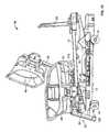
- FIG. 1is a perspective view of a patient support apparatus including a lower frame, an upper frame movable relative the lower frame, and a number of deck sections movable relative to the upper frame;
- FIG. 2is a block diagram of the control system of the patient support apparatus of FIG. 1 ;
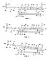
- FIG. 3is a diagrammatic view of the kinematic relationships of the frame members and deck section members of the patient support apparatus of FIG. 1 , with the deck section members positioned such that the patient support apparatus is in a horizontal bed position and the upper frame is in a fully raised position relative to the lower frame;
- FIG. 4is a diagrammatic view similar to FIG. 3 with the upper frame in a fully lowered position relative to the lower frame;
- FIG. 5is a diagrammatic view of the patient support apparatus in a forward tilt position with the head end of the upper frame lower than the foot end of the upper frame;
- FIG. 6is a diagrammatic view of the patient support apparatus in a reverse tilt position with the foot end of the upper frame lower than the head end of the upper frame;
- FIG. 8is a diagrammatic view similar to FIG. 7 with the upper frame the lowered relative to the lower frame such that the foot end of the foot deck section is in close proximity to the floor;
- FIGS. 9-12are diagrammatic views illustrating the progression of the movement of the upper frame and deck section members of the patient support apparatus from the position shown in FIG. 8 to a chair egress position.
- a patient support apparatus 10illustratively embodied as a hospital bed, is movable between a horizontal bed position as shown in FIG. 1 and a chair egress position as shown in FIG. 12 .
- the hospital bed 10includes a lower frame 12 supported on a number of casters 14 above the floor 16 .
- the hospital bed 10also includes an upper frame 18 movable vertically relative to the lower frame 12 .
- the upper frame 18is supported on a pair of lift arms 20 that are pivotally coupled to the upper frame 18 near the portion of the upper frame nearest a foot end 22 of the hospital bed 10 .
- the upper frame 18is also supported on a pair of lift arms 24 that are pivotally connected to the upper frame 18 near the portion of the upper frame 18 nearest a head end 26 of the hospital bed 10 . It should be understood that the reference to the foot end 22 and head end 26 of the hospital bed 10 is provided for orientation only and does not refer to any specific location or portion of the hospital bed 10 .
- the hospital bed 10includes a head deck section 34 which is pivotable relative to the upper frame 18 and a seat deck section 36 which is fixed to the upper frame 18 .
- a thigh deck section 38is pivotably coupled to the upper frame 18 such that the end 40 of the thigh deck section 38 nearest the foot end 22 of the hospital bed 10 lifts relative to the upper frame 18 .
- a foot deck section 32is pivotally coupled to the thigh deck section 38 near the end 40 of the thigh deck section 38 .
- the foot deck section 32includes a base 42 and an extension 44 that moves relative to the base 42 to increase the length of the foot deck section 32 .
- the hospital bed 10also includes a head panel 28 supported on the upper frame 18 and a footboard 30 supported on the extension 44 of the foot deck section 32 .
- a head side rail 46is shown in FIG. 1 is positioned on the patient left side of the head deck section 34 so that the head side rail 46 moves with the head deck section 34 .
- a main side rail 48is supported from the upper frame 18 and movable between a raised position as shown in FIG. 1 and a lowered position (not shown).
- the head side rail 46is also movable between the raised position shown in FIG. 1 and a lowered position (not shown).
- the hospital bed 10also includes a main side rail and a head side rail position on the patient right side of the hospital bed 10 and similar to the head side rail 46 and main side rail 48 .
- the control system 50further includes a sensor system 56 that includes a number of sensors 84 , 86 , 88 , 90 , or 100 that are positioned to detect the proximity of one of the frame members or deck section members to other frame members or deck section members.
- the sensors 84 , 86 , 88 , 90 , or 100 of the sensor system 56may also detect the proximity of one of the frame members to an external structure such as the floor, for example.
- the sensors 84 , 86 , 88 , 90 , or 100are field sensors which output an electromagnetic signal and monitor for reflection of the emitted signal to determine if the signal is being reflected by an obstruction.
- the user interface 58includes a user input device 94 that may be activated by a user to indicate a desire of the user to move the hospital bed 10 to the chair egress position.
- the user input device 94may be activated regardless of the position of the upper frame 18 and deck sections 34 , 36 , 38 , and 32 .
- the signal from the user input device 94is received by the controller 52 and considered by a processor 96 of the controller 52 .
- the processor 96is coupled to the memory device 98 that includes instructions that cause the processor 96 to operate the drives 60 , 62 , 68 , 74 , 78 , and 82 to move the foot deck section 32 to the lowered position, the head deck section 34 to the raised position, the thigh deck section 38 to a slightly inclined position, and the upper frame 18 to a reverse tilt position.
- the processor 96will monitor a footboard sensor 100 to determine if the footboard 30 is present on the foot deck section 32 . The footboard 30 must be removed from the foot deck section 32 before the hospital bed 10 will move to the full chair egress position.
- the upper frame head lift drive 62would be activated to raise the head and 26 of the upper frame 18 .
- the upper frame 18may come into close proximity to the pivot 64 . If the presence of the upper frame 18 is detected by the sensor 88 , then the controller 52 will cause the upper frame foot lift drive 60 to raise the foot and 22 of the upper frame 18 slightly to prevent contact between the upper frame 18 and the pivot 64 .
- the upper frame 18will achieve a reverse tilt position such as that shown in FIG. 6 .
- the thigh deck section 38will raise relative to the upper frame 18 is shown in FIG. 7 .
- the foot deck section 32will lower relative to the thigh deck section 38 as shown in FIG. 7 . Additional movement of the foot deck section 32 relative to the thigh deck section 38 will result in a configuration of the hospital bed 10 similar to that shown in FIG. 8 .
- the intermittent operation of the foot deck section raise drive 78will continue until the foot deck section 32 comes in proximity with the upper frame 18 as detected by the sensor 84 . If the foot deck section 32 is fully pivoted relative to the thigh deck section 38 and in proximity to the upper frame 18 , the upper frame foot lift drive 60 is raised until the sensor 86 no longer detects proximity to the floor 16 . Once the foot deck section 32 is fully retracted with the extension 44 retracted relative to the base 42 , additional actuation of the user input device 94 will cause the upper frame foot lift to be activated to lower the foot and 22 of the upper frame until the floor 16 is detected by the sensor 86 . Utilizing this approach, the height 102 of the thigh deck section 38 relative to the floor 16 is minimized without reliance on the potentiometers of the drives 60 , 62 , 68 , 74 , 78 , and 82 .
- the sensor 90 positioned on the pivot 92will detect the proximity of the upper frame 18 as the head and 26 of the upper frame 18 is lowered.
- the controller 52will then continue to operate the upper frame head lift drive 62 to raise the foot and 22 of the upper frame 18 until the appropriate tilt angle is reached.
- the tilt anglemay be determined by comparing the potentiometer readings of the upper frame foot lift drive 60 and upper frame head lift drive 62 .
- the use of the sensor 90causes the controller 52 to move the upper frame 18 to a position in which the head and 26 of the upper frame 18 is as low as possible without having to compensate for variations in the potentiometers in the drives 60 and 62 or manufacturing variations in the frame members of the hospital bed 10 .
- the controller 52is also operable to utilize the signal from the foot section end sensor 86 when the hospital bed 10 is moved out of the chair egress position to the horizontal bed position. For example, if a user selects the user input device 104 to move the hospital bed 10 from the chair egress position shown in FIGS. 11 and 12 to bed position of FIG. 1 , the foot deck section raise drive 78 will pivot the foot deck section 32 relative to the thigh deck section 38 . While the foot deck section 32 is pivoted, the foot section extension drive 82 will begin to extend the extension 44 of the foot deck section 32 relative to the base 42 of the foot deck section 32 .
- the foot section extension drive 82will be interrupted until the sensor 86 no longer detects the floor 16 due to pivoting of the foot deck section 38 .
- the remainder of the frame and deck memberswill be driven by the respective drives 60 , 62 , 68 , 74 , 78 , and 82 with drives being interrupted as necessary if any of the sensors 84 , 86 , 88 , 90 , or 100 detect the proximity of one of the frame or deck members to an obstruction.
- detection of an obstructionwill cause the controller 52 to vary the speed of one or more of the drives 60 , 62 , 68 , 74 , 78 , and 82 until the obstruction is no longer detected.
- the user interface 58will include user input devices for controlling movement of any of the drives 60 , 62 , 68 , 74 , 78 , and 82 to extend while other user input devices will control movement of any of the drives 60 , 62 , 68 , 74 , 78 , and 82 to retract.
- the sensors 84 , 86 , 88 , 90 , or 100may be any of several types of sensing devices that detect the presence of a body.
- the sensorscould be Hall effect sensors, contact switches, force sensing devices, photo diode array devices, ultrasonic devices, optical sensors detecting shapes, or other proximity or contact switch devices known in the art.
- the sensors 84 , 86 , 88 , 90 , or 100may actually contact an obstruction to sense the proximity of a frame or deck member to the obstruction.
- the controller 52monitors the potentiometers in the drives 60 , 62 , 68 , 74 , 78 , and 82 , the sensors 84 , 86 , 88 , 90 , or 100 , and the user input devices 94 and 104 .
- the processor 96 of the controller 52utilizes instructions stored in memory device 98 to determine when to drive the drives 60 , 62 , 68 , 74 , 78 , and 82 and in what direction to drive the drives 60 , 62 , 68 , 74 , 78 , and 82 to achieve a position desired by a user.
- the controller 52utilizes the data from potentiometers in the drives 60 , 62 , 68 , 74 , 78 , and 82 , the sensors 84 , 86 , 88 , 90 , or 100 , and the user input devices 94 and 104 and drives the drives 60 , 62 , 68 , 74 , 78 , and 82 to the desired position as quickly as possible.
- the controller 52modifies operation of one or more of the drives 60 , 62 , 68 , 74 , 78 , and 82 to prevent contact with the obstruction.
- the operation of the drives 60 , 62 , 68 , 74 , 78 , and 82is optimized to achieve the desired position as quickly as possible by allowing the members to move as near as the obstruction as safely possible without having the member contact the obstruction.
Landscapes
- Health & Medical Sciences (AREA)
- Nursing (AREA)
- Life Sciences & Earth Sciences (AREA)
- Animal Behavior & Ethology (AREA)
- General Health & Medical Sciences (AREA)
- Public Health (AREA)
- Veterinary Medicine (AREA)
- Accommodation For Nursing Or Treatment Tables (AREA)
- Invalid Beds And Related Equipment (AREA)
Abstract
Description
Claims (22)
Priority Applications (2)
| Application Number | Priority Date | Filing Date | Title |
|---|---|---|---|
| US12/973,069US8959681B2 (en) | 2010-12-20 | 2010-12-20 | Ground sensor control of foot section retraction |
| EP20110193865EP2465478B1 (en) | 2010-12-20 | 2011-12-15 | Ground sensor control of patient support apparatus |
Applications Claiming Priority (1)
| Application Number | Priority Date | Filing Date | Title |
|---|---|---|---|
| US12/973,069US8959681B2 (en) | 2010-12-20 | 2010-12-20 | Ground sensor control of foot section retraction |
Publications (2)
| Publication Number | Publication Date |
|---|---|
| US20120151678A1 US20120151678A1 (en) | 2012-06-21 |
| US8959681B2true US8959681B2 (en) | 2015-02-24 |
Family
ID=45218576
Family Applications (1)
| Application Number | Title | Priority Date | Filing Date |
|---|---|---|---|
| US12/973,069Active2032-12-24US8959681B2 (en) | 2010-12-20 | 2010-12-20 | Ground sensor control of foot section retraction |
Country Status (2)
| Country | Link |
|---|---|
| US (1) | US8959681B2 (en) |
| EP (1) | EP2465478B1 (en) |
Cited By (25)
| Publication number | Priority date | Publication date | Assignee | Title |
|---|---|---|---|---|
| US20130340165A1 (en)* | 2011-03-09 | 2013-12-26 | Koninklijke Philips N.V. | Imaging system subject support |
| US20160067127A1 (en)* | 2013-04-23 | 2016-03-10 | Paramount Bed Co., Ltd. | Bed apparatus |
| US20170042750A1 (en)* | 2011-11-22 | 2017-02-16 | Paramount Bed Co., Ltd. | Bed device |
| US20180064592A1 (en)* | 2016-09-02 | 2018-03-08 | Styrker Corporation | Patient support systems with a chair configuration and a stowable foot section |
| US10130536B2 (en) | 2013-09-06 | 2018-11-20 | Stryker Corporation | Patient support usable with bariatric patients |
| US10188569B2 (en) | 2013-09-06 | 2019-01-29 | Stryker Corporation | Patient support usable with bariatric patients |
| US10463556B2 (en) | 2017-07-13 | 2019-11-05 | Stryker Corporation | Patient mobility system with integrated ambulation device |
| US10813806B2 (en) | 2016-05-24 | 2020-10-27 | Stryker Corporation | Medical support apparatus with stand assistance |
| US10835430B2 (en) | 2016-09-02 | 2020-11-17 | Stryker Corporation | Patient mobility system with integrated ambulation device |
| US10857047B2 (en) | 2016-12-27 | 2020-12-08 | Stryker Corporation | Variable speed patient transfer apparatus |
| US10869792B2 (en) | 2016-09-02 | 2020-12-22 | Stryker Corporation | Patient support apparatus |
| US10959533B2 (en)* | 2017-09-01 | 2021-03-30 | Ascion, Llc | Adjustable bed with dual-tilt adjustable foundation |
| US11020295B2 (en) | 2015-12-22 | 2021-06-01 | Stryker Corporation | Patient support systems and methods for assisting caregivers with patient care |
| US11020297B2 (en) | 2015-12-22 | 2021-06-01 | Stryker Corporation | Powered side rail for a patient support apparatus |
| US11052005B2 (en) | 2017-09-19 | 2021-07-06 | Stryker Corporation | Patient support apparatus with handles for patient ambulation |
| US11090209B2 (en)* | 2017-06-20 | 2021-08-17 | Stryker Corporation | Patient support apparatus with control system and method to avoid obstacles during reconfiguration |
| US11116680B2 (en) | 2017-09-19 | 2021-09-14 | Stryker Corporation | Patient support apparatus for controlling patient ingress and egress |
| US11160705B2 (en) | 2017-10-20 | 2021-11-02 | Stryker Corporation | Adjustable patient support apparatus for assisted egress and ingress |
| US11197790B2 (en) | 2018-11-02 | 2021-12-14 | Stryker Corporation | Techniques for detecting a force acting on a base of a patient transport apparatus |
| US11213443B2 (en) | 2017-12-29 | 2022-01-04 | Stryker Corporation | Indication system to identify open space beneath patient support apparatus |
| US11355236B2 (en) | 2018-09-12 | 2022-06-07 | Stryker Corporation | Patient support apparatus communication systems |
| US11406548B2 (en) | 2018-09-27 | 2022-08-09 | Hill-Rom Services, Inc. | Obstacle detection IR beam filter |
| US11679045B2 (en) | 2019-12-30 | 2023-06-20 | Stryker Corporation | Patient transport apparatus user interface |
| US11938068B2 (en) | 2019-12-30 | 2024-03-26 | Stryker Corporation | Patient transport apparatus drive systems |
| US11963916B2 (en) | 2019-12-30 | 2024-04-23 | Stryker Corporation | Track assembly for patient transport apparatus |
Families Citing this family (43)
| Publication number | Priority date | Publication date | Assignee | Title |
|---|---|---|---|---|
| BR0016875A (en)* | 1999-12-29 | 2003-06-17 | Hill Rom Services Inc | Patient support, patient-configured mattress, patient support method, method of maintaining a patient's heel pressure relief, pressure system for use with a patient support mattress, and patient support frame |
| US8973187B2 (en)* | 2010-07-30 | 2015-03-10 | Hill-Rom Services, Inc. | Bed frame assembly with a lift system having a translatable carriage |
| US20140310876A1 (en)* | 2011-12-16 | 2014-10-23 | Chg Hospital Beds Inc. | Patient support overload or obstruction detection |
| US10197259B2 (en) | 2012-01-09 | 2019-02-05 | L&P Property Management Company | Standalone capacitance sensor for furniture |
| US9337831B2 (en) | 2012-01-09 | 2016-05-10 | L&P Property Management Company | Capacitive wire sensing for furniture |
| US10555615B2 (en) | 2012-01-09 | 2020-02-11 | L&P Property Management Company | Calibration of detection features for automated furniture |
| US10197609B2 (en) | 2012-01-09 | 2019-02-05 | L&P Property Management Company | Capacitive sensing for automated furniture |
| US10334960B2 (en) | 2012-01-09 | 2019-07-02 | L&P Property Management Company | Drop-in occupancy detection component for furniture |
| US10048662B2 (en) | 2012-01-09 | 2018-08-14 | L&P Property Management Company | Characterization and calibration for automated furniture |
| US9228885B2 (en)* | 2012-06-21 | 2016-01-05 | Hill-Rom Services, Inc. | Patient support systems and methods of use |
| US9306322B2 (en)* | 2012-08-23 | 2016-04-05 | Stryker Corporation | Patient support apparatus connectors |
| US9966997B2 (en)* | 2012-09-17 | 2018-05-08 | Stryker Corporation | Communication systems for patient support apparatuses |
| USD707480S1 (en)* | 2012-11-05 | 2014-06-24 | Hill-Rom Services, Inc. | Bed frame |
| USD707483S1 (en)* | 2012-11-05 | 2014-06-24 | Hill-Rom Services, Inc. | Side rail |
| US9180063B2 (en) | 2012-12-04 | 2015-11-10 | Scott & White Healthcare (Swh) | Systems and methods for assisted ambulation |
| CN105263410B (en)* | 2013-04-01 | 2019-10-08 | L & P 产权管理公司 | Occupancy for furniture detects |
| WO2014174965A1 (en)* | 2013-04-25 | 2014-10-30 | パラマウントベッド株式会社 | Bed apparatus and bed apparatus control method |
| US9930969B2 (en) | 2013-05-13 | 2018-04-03 | Paramount Bed Co., Ltd. | Bed apparatus |
| USD710507S1 (en)* | 2013-09-23 | 2014-08-05 | Hill-Rom Services Pte. Ltd. | Patient bed |
| USD710510S1 (en)* | 2013-09-23 | 2014-08-05 | Hill-Rom Services Pte. Ltd. | Foot rail for a patient bed |
| USD706427S1 (en)* | 2013-09-23 | 2014-06-03 | Hill-Rom Services Pte. Ltd. | Endboard for a patient bed |
| USD710509S1 (en)* | 2013-09-23 | 2014-08-05 | Hill-Rom Services Pte. Ltd. | Head rail for a patient bed |
| USD768422S1 (en) | 2014-08-12 | 2016-10-11 | Hill-Rom Services, Inc. | Foot end siderail |
| USD769042S1 (en) | 2014-08-12 | 2016-10-18 | Hill-Rom Services, Inc. | Head end siderail |
| USD770824S1 (en)* | 2014-08-12 | 2016-11-08 | Hill-Rom Services, Inc. | Barrier for a hospital bed |
| CA2902102C (en)* | 2014-08-27 | 2023-02-14 | Umano Medical Inc. | Systems for patient support surface orientation and displacement |
| USD770829S1 (en) | 2015-01-29 | 2016-11-08 | Hill-Rom Services, Inc. | Head rail for patient bed |
| USD770827S1 (en) | 2015-01-29 | 2016-11-08 | Hill-Rom Services, Inc. | Headboard for patient bed |
| USD770828S1 (en) | 2015-01-29 | 2016-11-08 | Hill-Rom Services, Inc. | Footboard for patient bed |
| USD771259S1 (en) | 2015-01-29 | 2016-11-08 | Hill-Rom Services, Inc. | Foot rail for patient bed |
| AU2016201802B2 (en)* | 2015-03-26 | 2021-03-25 | King Furniture Australia Pty Ltd | Safety interlock |
| US10905609B2 (en) | 2015-11-20 | 2021-02-02 | Stryker Corporation | Patient support systems and methods for assisting caregivers with patient care |
| WO2017109894A1 (en)* | 2015-12-24 | 2017-06-29 | 富士通株式会社 | Bed |
| USD812401S1 (en) | 2016-05-28 | 2018-03-13 | Hill-Rom Services, Inc. | Headboard |
| USD804884S1 (en) | 2016-05-28 | 2017-12-12 | Hill-Rom Services, Inc. | Footboard |
| USD804882S1 (en) | 2016-05-28 | 2017-12-12 | Hill-Rom Services, Inc. | Headrail |
| USD804885S1 (en) | 2016-05-28 | 2017-12-12 | Hill-Rom Services, Inc. | Headboard |
| USD804883S1 (en) | 2016-05-28 | 2017-12-12 | Hill-Rom Services, Inc. | Footrail |
| WO2018111594A1 (en) | 2016-12-12 | 2018-06-21 | Byron Wade Wurdeman | Hospital chair beds with extendable/retractable foot sections |
| CN107496100A (en)* | 2017-09-18 | 2017-12-22 | 国家康复辅具研究中心秦皇岛研究院 | Sickbed patients Special nursing bed |
| DE202019005494U1 (en)* | 2018-08-20 | 2020-10-15 | Stollenwerk und Cie. Fabrik für Sanitätsausrüstungen Gesellschaft mit beschränkter Haftung | Patient transport device |
| EP3692966A1 (en)* | 2019-02-07 | 2020-08-12 | Rotobed ApS | Bed system and related method |
| CN109875793A (en)* | 2019-02-22 | 2019-06-14 | 佛山市顺德区亿卡尔医疗设备有限公司 | It has assisted bed system and has assisted bed process |
Citations (34)
| Publication number | Priority date | Publication date | Assignee | Title |
|---|---|---|---|---|
| US4094024A (en) | 1976-08-30 | 1978-06-13 | Interroyal Corporation | System for controlling relative movement of portions of a bed |
| US4159496A (en) | 1977-09-22 | 1979-06-26 | Randam Electronics, Inc. | Safety device for hospital beds employing electric current |
| US4227269A (en) | 1978-09-01 | 1980-10-14 | Burke, Inc. | Adjustable bed |
| US4403214A (en) | 1980-10-27 | 1983-09-06 | William Wolar | Protective device for attachments affixed to electrically operated beds |
| US4425673A (en) | 1980-12-01 | 1984-01-17 | B-W Health Products, Inc. | Lifting system for adjustable hospital bed |
| US4534077A (en) | 1983-10-03 | 1985-08-13 | Simmons Universal Corporation | Hospital bed having safety mechanism |
| US4628556A (en) | 1984-05-10 | 1986-12-16 | Daniel J. Blackman | Tilt-prevention mechanism for adjustable bed |
| US4882566A (en) | 1988-08-03 | 1989-11-21 | Hill-Rom Company, Inc. | Safety control system for a hospital bed |
| US5468216A (en)* | 1994-10-12 | 1995-11-21 | Physicians Consulting Incorporated | Kinetic rehabilitation device employing controlled passive motion |
| US5611096A (en) | 1994-05-09 | 1997-03-18 | Kinetic Concepts, Inc. | Positional feedback system for medical mattress systems |
| EP1275328A1 (en)* | 2001-07-10 | 2003-01-15 | Hollandia The Sleep Engineering Center - Investments (1992) Ltd | Control mechanism for an adjustable position furniture |
| US6601251B2 (en) | 2000-05-30 | 2003-08-05 | Gerald S. Paul | Height adjustable medical bed including intermediate upper and lower stop positions |
| US6841953B2 (en) | 2000-07-05 | 2005-01-11 | Linak A/S | Control for two or more dc motors, in particular actuators for adjustment of furniture |
| US6904631B2 (en) | 1996-11-18 | 2005-06-14 | Kci Licensing, Inc. | Bariatric treatment system and related methods |
| US6907630B2 (en) | 2003-10-10 | 2005-06-21 | Midmark Corporation | Load compensation system for power chair |
| US6915538B2 (en) | 2003-10-10 | 2005-07-12 | Midmark Corporation | Smooth start system for power chair |
| US6944896B2 (en) | 2003-10-10 | 2005-09-20 | Midmark Corporation | Line voltage compensation system for power chair |
| US7003828B2 (en) | 2004-06-25 | 2006-02-28 | Carroll Hospital, Inc. | Leveling system for a height adjustment patient bed |
| US7076818B2 (en) | 1995-08-04 | 2006-07-18 | Hill-Rom Services, Inc. | Hospital bed having a siderail position detector |
| US20060244466A1 (en) | 2005-04-27 | 2006-11-02 | Call Evan W | Proximity sensor |
| US7208896B2 (en) | 2004-10-18 | 2007-04-24 | Innovative Design Solutions | Electric jack load balancing method and device |
| US20080083065A1 (en)* | 2003-02-06 | 2008-04-10 | Basil Bautovich | Bed monitoring system |
| US7383107B2 (en) | 2002-07-02 | 2008-06-03 | The United States Of America As Represented By The Department Of Veterans Affairs | Computer-controlled power wheelchair navigation system |
| US7386900B2 (en) | 2004-07-29 | 2008-06-17 | Stryker Corporation | Patient support deck lifting/lowering assembly |
| US20080189856A1 (en) | 2005-04-01 | 2008-08-14 | Toms Martin P | Height-Adustable Bedframes |
| DE102007018694A1 (en) | 2007-04-18 | 2008-11-27 | Dr. Ing. H.C. F. Porsche Aktiengesellschaft | Bed, particularly hospital or care bed, has couch surface, which is height adjustable in relation to base and light field extends parallel to contour of couch surface, particularly for contour of lower side of couch surface |
| US7472237B1 (en) | 2002-10-28 | 2008-12-30 | Netapp, Inc. | Apparatus to offload and accelerate pico code processing running in a storage processor |
| US7472437B2 (en)* | 2002-04-19 | 2009-01-06 | Hill-Rom Services, Inc. | Hospital bed obstacle detection device and method |
| US20090064414A1 (en) | 2006-04-27 | 2009-03-12 | Linak A/S | Bed, Preferably Hospital or Care Bed |
| US7520006B2 (en) | 2002-09-06 | 2009-04-21 | Hill-Rom Services, Inc. | Hospital bed including moveable foot portion |
| US20100030926A1 (en) | 2008-04-10 | 2010-02-04 | Richard Roussy | Signaling device for detecting the presence of an object |
| US7834768B2 (en) | 1999-03-05 | 2010-11-16 | Hill-Rom Services, Inc. | Obstruction detection apparatus for a bed |
| US7932690B2 (en) | 2008-02-11 | 2011-04-26 | Robert Dion Jones | Wall saver |
| US20120137439A1 (en)* | 2010-12-01 | 2012-06-07 | Heimbrock Richard H | Thin footboard for chair egress |
- 2010
- 2010-12-20USUS12/973,069patent/US8959681B2/enactiveActive
- 2011
- 2011-12-15EPEP20110193865patent/EP2465478B1/enactiveActive
Patent Citations (39)
| Publication number | Priority date | Publication date | Assignee | Title |
|---|---|---|---|---|
| US4094024A (en) | 1976-08-30 | 1978-06-13 | Interroyal Corporation | System for controlling relative movement of portions of a bed |
| US4159496A (en) | 1977-09-22 | 1979-06-26 | Randam Electronics, Inc. | Safety device for hospital beds employing electric current |
| US4227269A (en) | 1978-09-01 | 1980-10-14 | Burke, Inc. | Adjustable bed |
| US4403214A (en) | 1980-10-27 | 1983-09-06 | William Wolar | Protective device for attachments affixed to electrically operated beds |
| US4425673A (en) | 1980-12-01 | 1984-01-17 | B-W Health Products, Inc. | Lifting system for adjustable hospital bed |
| US4534077A (en) | 1983-10-03 | 1985-08-13 | Simmons Universal Corporation | Hospital bed having safety mechanism |
| US4628556A (en) | 1984-05-10 | 1986-12-16 | Daniel J. Blackman | Tilt-prevention mechanism for adjustable bed |
| US4882566A (en) | 1988-08-03 | 1989-11-21 | Hill-Rom Company, Inc. | Safety control system for a hospital bed |
| US6353950B1 (en) | 1994-05-09 | 2002-03-12 | Kinetic Concepts, Inc. | Positional feedback system for medical mattress systems |
| US5611096A (en) | 1994-05-09 | 1997-03-18 | Kinetic Concepts, Inc. | Positional feedback system for medical mattress systems |
| US5468216A (en)* | 1994-10-12 | 1995-11-21 | Physicians Consulting Incorporated | Kinetic rehabilitation device employing controlled passive motion |
| US7076818B2 (en) | 1995-08-04 | 2006-07-18 | Hill-Rom Services, Inc. | Hospital bed having a siderail position detector |
| US6904631B2 (en) | 1996-11-18 | 2005-06-14 | Kci Licensing, Inc. | Bariatric treatment system and related methods |
| US7978084B2 (en)* | 1999-03-05 | 2011-07-12 | Hill-Rom Services, Inc. | Body position monitoring system |
| US7834768B2 (en) | 1999-03-05 | 2010-11-16 | Hill-Rom Services, Inc. | Obstruction detection apparatus for a bed |
| US6601251B2 (en) | 2000-05-30 | 2003-08-05 | Gerald S. Paul | Height adjustable medical bed including intermediate upper and lower stop positions |
| US6841953B2 (en) | 2000-07-05 | 2005-01-11 | Linak A/S | Control for two or more dc motors, in particular actuators for adjustment of furniture |
| EP1275328A1 (en)* | 2001-07-10 | 2003-01-15 | Hollandia The Sleep Engineering Center - Investments (1992) Ltd | Control mechanism for an adjustable position furniture |
| US20090109025A1 (en) | 2002-04-19 | 2009-04-30 | Carl William Riley | Hospital bed obstacle detection device and method |
| US7472437B2 (en)* | 2002-04-19 | 2009-01-06 | Hill-Rom Services, Inc. | Hospital bed obstacle detection device and method |
| US7383107B2 (en) | 2002-07-02 | 2008-06-03 | The United States Of America As Represented By The Department Of Veterans Affairs | Computer-controlled power wheelchair navigation system |
| US7703158B2 (en) | 2002-09-06 | 2010-04-27 | Hill-Rom Services, Inc. | Patient support apparatus having a diagnostic system |
| US7520006B2 (en) | 2002-09-06 | 2009-04-21 | Hill-Rom Services, Inc. | Hospital bed including moveable foot portion |
| US7472237B1 (en) | 2002-10-28 | 2008-12-30 | Netapp, Inc. | Apparatus to offload and accelerate pico code processing running in a storage processor |
| US20080083065A1 (en)* | 2003-02-06 | 2008-04-10 | Basil Bautovich | Bed monitoring system |
| US6907630B2 (en) | 2003-10-10 | 2005-06-21 | Midmark Corporation | Load compensation system for power chair |
| US6915538B2 (en) | 2003-10-10 | 2005-07-12 | Midmark Corporation | Smooth start system for power chair |
| US6944896B2 (en) | 2003-10-10 | 2005-09-20 | Midmark Corporation | Line voltage compensation system for power chair |
| US7003828B2 (en) | 2004-06-25 | 2006-02-28 | Carroll Hospital, Inc. | Leveling system for a height adjustment patient bed |
| US7386900B2 (en) | 2004-07-29 | 2008-06-17 | Stryker Corporation | Patient support deck lifting/lowering assembly |
| US7208896B2 (en) | 2004-10-18 | 2007-04-24 | Innovative Design Solutions | Electric jack load balancing method and device |
| US7676866B2 (en) | 2005-04-01 | 2010-03-16 | Pegasus Limited | Height-adjustable bedframes |
| US20080189856A1 (en) | 2005-04-01 | 2008-08-14 | Toms Martin P | Height-Adustable Bedframes |
| US20060244466A1 (en) | 2005-04-27 | 2006-11-02 | Call Evan W | Proximity sensor |
| US20090064414A1 (en) | 2006-04-27 | 2009-03-12 | Linak A/S | Bed, Preferably Hospital or Care Bed |
| DE102007018694A1 (en) | 2007-04-18 | 2008-11-27 | Dr. Ing. H.C. F. Porsche Aktiengesellschaft | Bed, particularly hospital or care bed, has couch surface, which is height adjustable in relation to base and light field extends parallel to contour of couch surface, particularly for contour of lower side of couch surface |
| US7932690B2 (en) | 2008-02-11 | 2011-04-26 | Robert Dion Jones | Wall saver |
| US20100030926A1 (en) | 2008-04-10 | 2010-02-04 | Richard Roussy | Signaling device for detecting the presence of an object |
| US20120137439A1 (en)* | 2010-12-01 | 2012-06-07 | Heimbrock Richard H | Thin footboard for chair egress |
Non-Patent Citations (1)
| Title |
|---|
| European Search Report for EP 11 19 3865, dated Apr. 13, 2012. |
Cited By (54)
| Publication number | Priority date | Publication date | Assignee | Title |
|---|---|---|---|---|
| US20130340165A1 (en)* | 2011-03-09 | 2013-12-26 | Koninklijke Philips N.V. | Imaging system subject support |
| US10285655B2 (en)* | 2011-03-09 | 2019-05-14 | Koninklijke Philips N.V. | Imaging system subject support |
| US20190021923A1 (en)* | 2011-11-22 | 2019-01-24 | Paramount Bed Co., Ltd. | Bed device |
| US12053422B2 (en) | 2011-11-22 | 2024-08-06 | Paramount Bed Co., Ltd. | Bed device |
| US10111791B2 (en)* | 2011-11-22 | 2018-10-30 | Paramount Bed Co., Ltd. | Bed device |
| US11786426B2 (en) | 2011-11-22 | 2023-10-17 | Paramount Bed Co., Ltd. | Bed device |
| US20170042750A1 (en)* | 2011-11-22 | 2017-02-16 | Paramount Bed Co., Ltd. | Bed device |
| US11426315B2 (en) | 2011-11-22 | 2022-08-30 | Paramount Bed Co., Ltd. | Bed device |
| US10463552B2 (en)* | 2011-11-22 | 2019-11-05 | Paramount Bed Co., Ltd. | Bed device |
| US20200016016A1 (en)* | 2011-11-22 | 2020-01-16 | Paramount Bed Co., Ltd. | Bed device |
| US10893992B2 (en)* | 2011-11-22 | 2021-01-19 | Paramount Bed Co., Ltd. | Bed device |
| US10695244B2 (en)* | 2013-04-23 | 2020-06-30 | Paramount Bed Co., Ltd. | Bed apparatus |
| US20160067127A1 (en)* | 2013-04-23 | 2016-03-10 | Paramount Bed Co., Ltd. | Bed apparatus |
| US10716722B2 (en) | 2013-09-06 | 2020-07-21 | Stryker Corporation | Patient support usable with bariatric patients |
| US10188569B2 (en) | 2013-09-06 | 2019-01-29 | Stryker Corporation | Patient support usable with bariatric patients |
| US11285061B2 (en) | 2013-09-06 | 2022-03-29 | Stryker Corporation | Patient support usable with bariatric patients |
| US10130536B2 (en) | 2013-09-06 | 2018-11-20 | Stryker Corporation | Patient support usable with bariatric patients |
| US10842694B2 (en) | 2013-09-06 | 2020-11-24 | Stryker Corporation | Patient support usable with bariatric patients |
| US11865056B2 (en) | 2013-09-06 | 2024-01-09 | Stryker Corporation | Patient support usable with bariatric patients |
| US11980580B2 (en) | 2013-09-06 | 2024-05-14 | Stryker Corporation | Patient support usable with bariatric patients |
| US11419776B2 (en) | 2013-09-06 | 2022-08-23 | Stryker Corporation | Patient support usable with bariatric patients |
| US11020295B2 (en) | 2015-12-22 | 2021-06-01 | Stryker Corporation | Patient support systems and methods for assisting caregivers with patient care |
| US11020297B2 (en) | 2015-12-22 | 2021-06-01 | Stryker Corporation | Powered side rail for a patient support apparatus |
| US11998499B2 (en) | 2015-12-22 | 2024-06-04 | Stryker Corporation | Powered side rail for a patient support apparatus |
| US10813806B2 (en) | 2016-05-24 | 2020-10-27 | Stryker Corporation | Medical support apparatus with stand assistance |
| US20220192905A1 (en)* | 2016-09-02 | 2022-06-23 | Strker Corporation | Patient support systems with a chair configuration and a stowable foot section |
| US12377004B2 (en)* | 2016-09-02 | 2025-08-05 | Stryker Corporation | Patient support systems with a chair configuration and a stowable foot section |
| US10869792B2 (en) | 2016-09-02 | 2020-12-22 | Stryker Corporation | Patient support apparatus |
| US11304864B2 (en)* | 2016-09-02 | 2022-04-19 | Stryker Corporation | Patient support systems with a chair configuration and a stowable foot section |
| US10835430B2 (en) | 2016-09-02 | 2020-11-17 | Stryker Corporation | Patient mobility system with integrated ambulation device |
| US20180064592A1 (en)* | 2016-09-02 | 2018-03-08 | Styrker Corporation | Patient support systems with a chair configuration and a stowable foot section |
| US12109156B2 (en) | 2016-12-27 | 2024-10-08 | Stryker Corporation | Variable speed patient transfer apparatus |
| US11369531B2 (en) | 2016-12-27 | 2022-06-28 | Stryker Corporation | Variable speed patient transfer apparatus |
| US10857047B2 (en) | 2016-12-27 | 2020-12-08 | Stryker Corporation | Variable speed patient transfer apparatus |
| US11090209B2 (en)* | 2017-06-20 | 2021-08-17 | Stryker Corporation | Patient support apparatus with control system and method to avoid obstacles during reconfiguration |
| US10568793B2 (en) | 2017-07-13 | 2020-02-25 | Stryker Corporation | Patient mobility system with integrated ambulation device |
| US10463556B2 (en) | 2017-07-13 | 2019-11-05 | Stryker Corporation | Patient mobility system with integrated ambulation device |
| US10959533B2 (en)* | 2017-09-01 | 2021-03-30 | Ascion, Llc | Adjustable bed with dual-tilt adjustable foundation |
| US11116680B2 (en) | 2017-09-19 | 2021-09-14 | Stryker Corporation | Patient support apparatus for controlling patient ingress and egress |
| US11723821B2 (en) | 2017-09-19 | 2023-08-15 | Stryker Corporation | Patient support apparatus for controlling patient ingress and egress |
| US11052005B2 (en) | 2017-09-19 | 2021-07-06 | Stryker Corporation | Patient support apparatus with handles for patient ambulation |
| US11806290B2 (en) | 2017-10-20 | 2023-11-07 | Stryker Corporation | Adjustable patient support apparatus for assisted egress and ingress |
| US11160705B2 (en) | 2017-10-20 | 2021-11-02 | Stryker Corporation | Adjustable patient support apparatus for assisted egress and ingress |
| US11213443B2 (en) | 2017-12-29 | 2022-01-04 | Stryker Corporation | Indication system to identify open space beneath patient support apparatus |
| US11355236B2 (en) | 2018-09-12 | 2022-06-07 | Stryker Corporation | Patient support apparatus communication systems |
| US11406548B2 (en) | 2018-09-27 | 2022-08-09 | Hill-Rom Services, Inc. | Obstacle detection IR beam filter |
| US12042435B2 (en) | 2018-11-02 | 2024-07-23 | Stryker Corporation | Techniques for detecting a force acting on a base of a patient transport apparatus |
| US11197790B2 (en) | 2018-11-02 | 2021-12-14 | Stryker Corporation | Techniques for detecting a force acting on a base of a patient transport apparatus |
| US11672711B2 (en) | 2018-11-02 | 2023-06-13 | Stryker Corporation | Techniques for detecting a force acting on a base of a patient transport apparatus |
| US11963916B2 (en) | 2019-12-30 | 2024-04-23 | Stryker Corporation | Track assembly for patient transport apparatus |
| US11679045B2 (en) | 2019-12-30 | 2023-06-20 | Stryker Corporation | Patient transport apparatus user interface |
| US11938068B2 (en) | 2019-12-30 | 2024-03-26 | Stryker Corporation | Patient transport apparatus drive systems |
| US12115111B2 (en) | 2019-12-30 | 2024-10-15 | Stryker Corporation | Patient transport apparatus user interface |
| US12329696B2 (en) | 2019-12-30 | 2025-06-17 | Stryker Corporation | Track assembly for patient transport apparatus |
Also Published As
| Publication number | Publication date |
|---|---|
| EP2465478A1 (en) | 2012-06-20 |
| US20120151678A1 (en) | 2012-06-21 |
| EP2465478B1 (en) | 2014-01-22 |
Similar Documents
| Publication | Publication Date | Title |
|---|---|---|
| US8959681B2 (en) | Ground sensor control of foot section retraction | |
| US11638668B2 (en) | Obstruction detection system and method | |
| US11090209B2 (en) | Patient support apparatus with control system and method to avoid obstacles during reconfiguration | |
| US12409087B2 (en) | User controls for patient support apparatus having low height | |
| US12208045B2 (en) | Techniques for determining a pose of a patient transport apparatus | |
| US8341779B2 (en) | Retractable foot caster supports | |
| US11806292B2 (en) | Techniques for controlling actuators of a patient support apparatus | |
| US11801180B2 (en) | Patient transport apparatus with movable head section | |
| US12042435B2 (en) | Techniques for detecting a force acting on a base of a patient transport apparatus | |
| US11141333B2 (en) | Patient transport apparatus with handle assembly for controlling drive system | |
| US20240277536A1 (en) | Patient Transport Apparatus with Articulable Powered Litter | |
| WO2025088924A1 (en) | Handrail and bed |
Legal Events
| Date | Code | Title | Description |
|---|---|---|---|
| AS | Assignment | Owner name:HILL-ROM SERVICES, INC., DELAWARE Free format text:ASSIGNMENT OF ASSIGNORS INTEREST;ASSIGNOR:RICHARDS, SANDY M.;REEL/FRAME:025584/0502 Effective date:20110104 | |
| AS | Assignment | Owner name:HILL-ROM SERVICES, INC., INDIANA Free format text:ASSIGNMENT OF ASSIGNORS INTEREST;ASSIGNOR:RICHARDS, SANDY M.;REEL/FRAME:025751/0192 Effective date:20110128 | |
| STCF | Information on status: patent grant | Free format text:PATENTED CASE | |
| AS | Assignment | Owner name:JPMORGAN CHASE BANK, N.A., AS COLLATERAL AGENT, ILLINOIS Free format text:SECURITY INTEREST;ASSIGNORS:ALLEN MEDICAL SYSTEMS, INC.;HILL-ROM SERVICES, INC.;ASPEN SURGICAL PRODUCTS, INC.;AND OTHERS;REEL/FRAME:036582/0123 Effective date:20150908 Owner name:JPMORGAN CHASE BANK, N.A., AS COLLATERAL AGENT, IL Free format text:SECURITY INTEREST;ASSIGNORS:ALLEN MEDICAL SYSTEMS, INC.;HILL-ROM SERVICES, INC.;ASPEN SURGICAL PRODUCTS, INC.;AND OTHERS;REEL/FRAME:036582/0123 Effective date:20150908 | |
| AS | Assignment | Owner name:JPMORGAN CHASE BANK, N.A., AS COLLATERAL AGENT, ILLINOIS Free format text:SECURITY AGREEMENT;ASSIGNORS:HILL-ROM SERVICES, INC.;ASPEN SURGICAL PRODUCTS, INC.;ALLEN MEDICAL SYSTEMS, INC.;AND OTHERS;REEL/FRAME:040145/0445 Effective date:20160921 Owner name:JPMORGAN CHASE BANK, N.A., AS COLLATERAL AGENT, IL Free format text:SECURITY AGREEMENT;ASSIGNORS:HILL-ROM SERVICES, INC.;ASPEN SURGICAL PRODUCTS, INC.;ALLEN MEDICAL SYSTEMS, INC.;AND OTHERS;REEL/FRAME:040145/0445 Effective date:20160921 | |
| MAFP | Maintenance fee payment | Free format text:PAYMENT OF MAINTENANCE FEE, 4TH YEAR, LARGE ENTITY (ORIGINAL EVENT CODE: M1551) Year of fee payment:4 | |
| AS | Assignment | Owner name:ANODYNE MEDICAL DEVICE, INC., FLORIDA Free format text:RELEASE BY SECURED PARTY;ASSIGNOR:JPMORGAN CHASE BANK, N.A.;REEL/FRAME:050254/0513 Effective date:20190830 Owner name:HILL-ROM COMPANY, INC., ILLINOIS Free format text:RELEASE BY SECURED PARTY;ASSIGNOR:JPMORGAN CHASE BANK, N.A.;REEL/FRAME:050254/0513 Effective date:20190830 Owner name:WELCH ALLYN, INC., NEW YORK Free format text:RELEASE BY SECURED PARTY;ASSIGNOR:JPMORGAN CHASE BANK, N.A.;REEL/FRAME:050254/0513 Effective date:20190830 Owner name:HILL-ROM, INC., ILLINOIS Free format text:RELEASE BY SECURED PARTY;ASSIGNOR:JPMORGAN CHASE BANK, N.A.;REEL/FRAME:050254/0513 Effective date:20190830 Owner name:HILL-ROM SERVICES, INC., ILLINOIS Free format text:RELEASE BY SECURED PARTY;ASSIGNOR:JPMORGAN CHASE BANK, N.A.;REEL/FRAME:050254/0513 Effective date:20190830 Owner name:ALLEN MEDICAL SYSTEMS, INC., ILLINOIS Free format text:RELEASE BY SECURED PARTY;ASSIGNOR:JPMORGAN CHASE BANK, N.A.;REEL/FRAME:050254/0513 Effective date:20190830 Owner name:MORTARA INSTRUMENT, INC., WISCONSIN Free format text:RELEASE BY SECURED PARTY;ASSIGNOR:JPMORGAN CHASE BANK, N.A.;REEL/FRAME:050254/0513 Effective date:20190830 Owner name:MORTARA INSTRUMENT SERVICES, INC., WISCONSIN Free format text:RELEASE BY SECURED PARTY;ASSIGNOR:JPMORGAN CHASE BANK, N.A.;REEL/FRAME:050254/0513 Effective date:20190830 Owner name:VOALTE, INC., FLORIDA Free format text:RELEASE BY SECURED PARTY;ASSIGNOR:JPMORGAN CHASE BANK, N.A.;REEL/FRAME:050254/0513 Effective date:20190830 | |
| AS | Assignment | Owner name:JPMORGAN CHASE BANK, N.A., ILLINOIS Free format text:SECURITY AGREEMENT;ASSIGNORS:HILL-ROM HOLDINGS, INC.;HILL-ROM, INC.;HILL-ROM SERVICES, INC.;AND OTHERS;REEL/FRAME:050260/0644 Effective date:20190830 | |
| AS | Assignment | Owner name:HILL-ROM HOLDINGS, INC., ILLINOIS Free format text:RELEASE OF SECURITY INTEREST AT REEL/FRAME 050260/0644;ASSIGNOR:JPMORGAN CHASE BANK, N.A.;REEL/FRAME:058517/0001 Effective date:20211213 Owner name:BARDY DIAGNOSTICS, INC., ILLINOIS Free format text:RELEASE OF SECURITY INTEREST AT REEL/FRAME 050260/0644;ASSIGNOR:JPMORGAN CHASE BANK, N.A.;REEL/FRAME:058517/0001 Effective date:20211213 Owner name:VOALTE, INC., FLORIDA Free format text:RELEASE OF SECURITY INTEREST AT REEL/FRAME 050260/0644;ASSIGNOR:JPMORGAN CHASE BANK, N.A.;REEL/FRAME:058517/0001 Effective date:20211213 Owner name:HILL-ROM, INC., ILLINOIS Free format text:RELEASE OF SECURITY INTEREST AT REEL/FRAME 050260/0644;ASSIGNOR:JPMORGAN CHASE BANK, N.A.;REEL/FRAME:058517/0001 Effective date:20211213 Owner name:WELCH ALLYN, INC., NEW YORK Free format text:RELEASE OF SECURITY INTEREST AT REEL/FRAME 050260/0644;ASSIGNOR:JPMORGAN CHASE BANK, N.A.;REEL/FRAME:058517/0001 Effective date:20211213 Owner name:ALLEN MEDICAL SYSTEMS, INC., ILLINOIS Free format text:RELEASE OF SECURITY INTEREST AT REEL/FRAME 050260/0644;ASSIGNOR:JPMORGAN CHASE BANK, N.A.;REEL/FRAME:058517/0001 Effective date:20211213 Owner name:HILL-ROM SERVICES, INC., ILLINOIS Free format text:RELEASE OF SECURITY INTEREST AT REEL/FRAME 050260/0644;ASSIGNOR:JPMORGAN CHASE BANK, N.A.;REEL/FRAME:058517/0001 Effective date:20211213 Owner name:BREATHE TECHNOLOGIES, INC., CALIFORNIA Free format text:RELEASE OF SECURITY INTEREST AT REEL/FRAME 050260/0644;ASSIGNOR:JPMORGAN CHASE BANK, N.A.;REEL/FRAME:058517/0001 Effective date:20211213 | |
| MAFP | Maintenance fee payment | Free format text:PAYMENT OF MAINTENANCE FEE, 8TH YEAR, LARGE ENTITY (ORIGINAL EVENT CODE: M1552); ENTITY STATUS OF PATENT OWNER: LARGE ENTITY Year of fee payment:8 |