US8958869B2 - Electromyography system - Google Patents
Electromyography systemDownload PDFInfo
- Publication number
- US8958869B2 US8958869B2US13/726,110US201213726110AUS8958869B2US 8958869 B2US8958869 B2US 8958869B2US 201213726110 AUS201213726110 AUS 201213726110AUS 8958869 B2US8958869 B2US 8958869B2
- Authority
- US
- United States
- Prior art keywords
- neuro
- response
- nerve
- onset
- muscular
- Prior art date
- Legal status (The legal status is an assumption and is not a legal conclusion. Google has not performed a legal analysis and makes no representation as to the accuracy of the status listed.)
- Expired - Fee Related
Links
Images


Classifications
- A61B5/04001—
- A—HUMAN NECESSITIES
- A61—MEDICAL OR VETERINARY SCIENCE; HYGIENE
- A61B—DIAGNOSIS; SURGERY; IDENTIFICATION
- A61B17/00—Surgical instruments, devices or methods
- A61B17/00234—Surgical instruments, devices or methods for minimally invasive surgery
- A61B5/0488—
- A—HUMAN NECESSITIES
- A61—MEDICAL OR VETERINARY SCIENCE; HYGIENE
- A61B—DIAGNOSIS; SURGERY; IDENTIFICATION
- A61B5/00—Measuring for diagnostic purposes; Identification of persons
- A61B5/24—Detecting, measuring or recording bioelectric or biomagnetic signals of the body or parts thereof
- A—HUMAN NECESSITIES
- A61—MEDICAL OR VETERINARY SCIENCE; HYGIENE
- A61B—DIAGNOSIS; SURGERY; IDENTIFICATION
- A61B5/00—Measuring for diagnostic purposes; Identification of persons
- A61B5/24—Detecting, measuring or recording bioelectric or biomagnetic signals of the body or parts thereof
- A61B5/316—Modalities, i.e. specific diagnostic methods
- A61B5/389—Electromyography [EMG]
- A61B5/395—Details of stimulation, e.g. nerve stimulation to elicit EMG response
- A—HUMAN NECESSITIES
- A61—MEDICAL OR VETERINARY SCIENCE; HYGIENE
- A61B—DIAGNOSIS; SURGERY; IDENTIFICATION
- A61B5/00—Measuring for diagnostic purposes; Identification of persons
- A61B5/48—Other medical applications
- A61B5/4836—Diagnosis combined with treatment in closed-loop systems or methods
- A—HUMAN NECESSITIES
- A61—MEDICAL OR VETERINARY SCIENCE; HYGIENE
- A61B—DIAGNOSIS; SURGERY; IDENTIFICATION
- A61B5/00—Measuring for diagnostic purposes; Identification of persons
- A61B5/48—Other medical applications
- A61B5/4887—Locating particular structures in or on the body
- A61B5/4893—Nerves
- A—HUMAN NECESSITIES
- A61—MEDICAL OR VETERINARY SCIENCE; HYGIENE
- A61B—DIAGNOSIS; SURGERY; IDENTIFICATION
- A61B17/00—Surgical instruments, devices or methods
- A61B2017/00017—Electrical control of surgical instruments
- A61B2017/00022—Sensing or detecting at the treatment site
- A—HUMAN NECESSITIES
- A61—MEDICAL OR VETERINARY SCIENCE; HYGIENE
- A61B—DIAGNOSIS; SURGERY; IDENTIFICATION
- A61B17/00—Surgical instruments, devices or methods
- A61B2017/00017—Electrical control of surgical instruments
- A61B2017/00022—Sensing or detecting at the treatment site
- A61B2017/00039—Electric or electromagnetic phenomena other than conductivity, e.g. capacity, inductivity, Hall effect
- A61B5/0492—
- A—HUMAN NECESSITIES
- A61—MEDICAL OR VETERINARY SCIENCE; HYGIENE
- A61B—DIAGNOSIS; SURGERY; IDENTIFICATION
- A61B5/00—Measuring for diagnostic purposes; Identification of persons
- A61B5/24—Detecting, measuring or recording bioelectric or biomagnetic signals of the body or parts thereof
- A61B5/25—Bioelectric electrodes therefor
- A61B5/279—Bioelectric electrodes therefor specially adapted for particular uses
- A61B5/296—Bioelectric electrodes therefor specially adapted for particular uses for electromyography [EMG]
- A—HUMAN NECESSITIES
- A61—MEDICAL OR VETERINARY SCIENCE; HYGIENE
- A61N—ELECTROTHERAPY; MAGNETOTHERAPY; RADIATION THERAPY; ULTRASOUND THERAPY
- A61N1/00—Electrotherapy; Circuits therefor
- A61N1/02—Details
- A61N1/08—Arrangements or circuits for monitoring, protecting, controlling or indicating
Definitions
- the present inventionrelates to electromyography (EMG) and to systems for detecting the presence of nerves during surgical procedures.
- EMGelectromyography
- a variety of antiquated, existing electrical systemsare adapted to sense whether a surgical tool is positioned adjacent to a patient's nerve. Such systems have proven to be particularly advantageous in positioning a hypodermic needle adjacent to a nerve such that the needle can be used to deliver anesthetic to the region of the body adjacent the nerve. Such systems rely on electrifying the needle itself such that as a nerve is approached, the electrical potential of the needle will depolarize the nerve causing the muscle fibers coupled to the nerve to contract and relax, resulting in a visible muscular reaction, seen as a “twitch”.
- the present inventionprovides methods and apparatus for informing an operator that a surgical tool or probe is approaching a nerve.
- the surgical tool or probemay be introduced into the patient in a minimally invasive cannulated approach.
- the surgical tool or probecomprises the minimally invasive cannula itself.
- the present inventionprovides a system for detecting the presence of a nerve near a surgical tool or probe, based upon the current intensity level of a stimulus pulse applied to the surgical tool or probe.
- a measurable neuro-muscular (EMG) responseis detected from a stimulus pulse having a current intensity level at or below a pre-determined onset level, the nerve is considered to be near the tool or probe and thus, detected.
- the onset level(i.e.: the stimulus current level at which a neuro-muscular response is detected for a particular nerve) may be based on EMG responses measured for a probe at a predetermined location relative to the nerve. Specifically, onset levels may first be measured for each of a plurality of spinal nerves, (yielding an initial “baseline” set of neuro-muscular response onset threshold levels), which are then used in the first (nerve detection) aspect of the invention. Therefore, in accordance with this optional second aspect of the invention, a system for determining relative neuro-muscular onset values (i.e.: EMG response thresholds), for a plurality of spinal nerves is also provided. Accordingly, the pre-determined onset level may be compared to the current level required to generate a measurable EMG response for a tool or probe being advanced toward one or more nerves of interest.
- EMG response thresholdsi.e.: EMG response thresholds
- the neuro-muscular onset values that are used to accomplish the first (nerve detection) aspect of the inventionare not measured for each of the patient's plurality of spinal nerves. Rather, pre-determined levels of current intensity (below which neuro-muscular responses are detected in accordance with the first aspect of the invention) can instead be directly pre-set into the system. Such levels preferably correspond to specific expected or desired onset threshold values, which may have been determined beforehand by experimentation on other patients.
- onset valuescan optionally be used to calibrate the present nerve-detection system (which in turn operates to detect whether an minimally invasive surgical tool or probe is positioned adjacent to a spinal nerve).
- the present inventionis not limited to systems that first determine relative neuro-muscular onset values, and then use these neuro-muscular onset values to detect the presence of a nerve. Rather, the present invention includes an optional system to first determine relative neuro-muscular onset values and a system to detect the presence of a nerve (using the neuro-muscular onset values which have been previously determined). As such, the present invention encompasses systems that also use fixed neuro-muscular onset values (which may simply be input into the system hardware/software by the operator prior to use) when performing electromyographic monitoring of spinal nerves to detect the presence of a spinal nerve adjacent a tool or probe.
- the preferred method of sensing for the presence of a nervemay be continuously repeated as the probe/surgical tool is physically advanced further into the patient such that the operator is warned quickly when the probe/surgical tool is closely approaching the nerve.
- the present nerve-detection systemcomprises an electrode or electrodes positioned on the distal end of the surgical tool or probe, with an electromyographic system used to detect whether a spinal nerve is positioned adjacent to the surgical tool or probe.
- an electromyographic systemused to detect whether a spinal nerve is positioned adjacent to the surgical tool or probe.
- the stimulus pulseitself may be emitted from a single probe, but in an optional aspect, the stimulus pulse may be emitted from separate left and right probes with the signals being multiplexed.
- pre-determined levelsmay be pre-input by the operator (or be pre-set into the system's hardware or software) and may thus optionally correspond to known or expected values. (For example, values as measured by experimentation on other patients).
- the neuro-muscular response onset values used in nerve detectionmay instead be measured for the particular patient's various nerves, as follows.
- an EMG stimulus pulseis first used to depolarize a portion of the patient's cauda equina.
- This stimulus pulsemay be carried out with a pulse passing between an epidural stimulating electrode and a corresponding skin surface return electrode, or alternatively, between a pair of electrodes disposed adjacent to the patient's spine, or alternatively, or alternatively, by a non-invasive magnetic stimulation means. It is to be understood that any suitable means for stimulating (and depolarizing a portion of) the patient's cauda equina can be used in this regard.
- neuro-muscular responses to the stimulus pulseare then detected at various myotome locations corresponding to a plurality of spinal nerves, with the current intensity level of the stimulus pulse at which each neuro-muscular response is first detected being the neuro-muscular response “onset values” for each of the plurality of spinal nerves.
- onsetis not limited to a condition in which all of the muscle fibers in a bundle of muscle fibers associated with a particular nerve exhibit a neuro-muscular response. Rather, an “onset” condition may comprise any pre-defined majority of the muscle fibers associated with a particular nerve exhibit a neuro-muscular response.
- the relative neuro-muscular response onset valuescan be repeatedly re-determined (at automatic intervals or at intervals determined by the operator) so as to account for any changes to the response onset values caused by the surgical procedure itself. Accordingly, a further advantage of the present invention is that it permits automatic re-assessment of the nerve status, with the relative neuro-muscular response onset values for each of the plurality of spinal nerves being re-determined before, during and after the surgical procedure, or repeatedly determined again and again during the surgical procedure.
- This optional aspectis advantageous during spinal surgery as the surgery itself may change the relative neuro-muscular response onset values for each of the plurality of nerves, such as would be caused by reducing the pressure on an exiting spinal nerve positioned between two adjacent vertebrae. This periodic re-determination of the onset values can be carried out concurrently with the nerve sensing function.
- an advantageous feature of the present inventionis that it can simultaneously indicate to an operator both: (1) nerve detection (i.e.: whether the surgical tool/probe is near a nerve); and (2) nerve status changes (i.e.: the change in each nerve's neuro-muscular response onset values over time).
- nerve detectioni.e.: whether the surgical tool/probe is near a nerve
- nerve status changesi.e.: the change in each nerve's neuro-muscular response onset values over time.
- the surgeonis thus able to better interpret the accuracy of nerve detection warnings by simultaneously viewing changes in the various onset levels. For example, should the surgeon note that a particular onset value (i.e.: the current level of a stimulus pulse required to elicit an EMG response for a particular nerve) is increasing, this would tend to show that this nerve pathway is becoming less sensitive. Accordingly, a “low” warning may be interpreted to more accurately correspond to a “medium” likelihood of nerve contact; or a “medium” warning may be interpreted to more accurately correspond
- such re-assessment of the nerve statuscan be used to automatically re-calibrate the present nerve detection system. This can be accomplished by continually updating the onset values that are then used in the nerve detection function.
- the neuro-muscular response onset values for each of the plurality of spinal nervesare measured at each of the spaced-apart myotome locations, and are visually indicated to an operator (for example, by way of an LED scale).
- the measuring of each of the various neuro-muscular response onset valuesis repeatedly carried out with the present and previously measured onset value levels being simultaneously visually indicated to an operator such as by way of the LED scale.
- different LED lightscan be used to indicate whether the value of each of the various neuro-muscular response onset values is remaining constant over time, increasing or decreasing.
- An advantage of this optional feature of the inventionis that a surgeon operating the device can be quickly alerted to the fact that a neuro-muscular response onset value of one or more of the spinal nerves has changed. Should the onset value decrease for a particular nerve, this may indicate that the nerve was previously compressed or impaired, but become uncompressed or no longer impaired.
- a blue LEDcan be emitted at a baseline value (i.e.: when the neuro-muscular response onset value remains the same as previously measured); and a yellow light can be emitted when the neuro-muscular response onset value has increased from that previously measured; and a green light being emitted when the neuro-muscular response onset value has decreased from that previously measured.
- different colors of lightsmay be simultaneously displayed to indicate currently measured onset values for each of the plurality of spinal nerve myotome locations, as compared to previously measured onset values.
- the present measured onset value levels for each of the plurality of spinal nerve myotome locationscan appear as yellow LED lights on the LED scale, with the immediately previously measured onset value levels simultaneously appearing as green LED lights on the LED scale. This also allows the operator to compare presently measured (i.e. just updated) neuro-muscular response onset values to the previously measured neuro-muscular response onset values.
- the present systemalso audibly alerts the operator to the presence of a nerve.
- the volume or frequency of the alarmmay change as the probe/tool moves closer to the nerve.
- the neuro-muscular onset valuesare detected by monitoring a plurality of distally spaced-apart myotome locations which anatomically correspond to each of the spinal nerves. Most preferably, these myotome locations are selected to correspond to the associated spinal nerves that are near the surgical site.
- these myotome locationspreferably correspond with distally spaced-apart on the patient's legs (when the operating site is in the lower vertebral range), but may also include myotome locations on the patient's arms (when the operating site is in the upper vertebral range). It is to be understood, however, that the present system therefore encompasses monitoring of any relevant myotome locations that are innervated by nerves in the area of surgery. Therefore, the present invention can be adapted for use in cervical, thoracic or lumbar spine applications.
- the emission of the stimulus pulseis preferably of a varying current intensity.
- the stimulus pulseis incrementally increased step-by-step in a “staircase” fashion over time, at least until a neuro-muscular response signal is detected.
- the stimulus pulseitself may be delivered either between a midline epidural electrode and a return electrode, or between two electrodes disposed adjacent the patient's spine, or from an electrode disposed directly on the probe/tool, or by other means.
- An important advantage of the present system of increasing the level of stimulus pulse to a level at which a response is first detectedis that it avoids overstimulating a nerve (which may cause a patient to “twitch”), or cause other potential nerve damage.
- the “steps” of the staircase of increasing current intensity of the stimulus pulseare carried out in rapid succession, most preferably within the refractory period of the spinal nerves.
- a second probeis added to the present system, functioning as a “confirmation electrode”.
- an electrode or electroded surface on the second probeis also used to detect the presence of a nerve, (using the same system as was used for the first probe to detect a nerve).
- Such a second “confirmation electrode” probeis especially useful when the first probe is an electrified cannula itself, and the second “confirmation electrode” probe is a separate probe that can be advanced through the electrified cannula.
- the operating (electrified) cannulais advanced into the patient, this operating cannula itself functions as a nerve detection probe. As such, the operating cannula can be advanced to the operating site without causing any nerve damage.
- this cannulaAfter this cannula has been positioned at the surgical site, it may then be used as the operating cannula through which various surgical tools are then advanced. At this stage, its nerve-sensing feature may be optionally disabled, should this feature interfere with other surgical tools or procedures. Thereafter, (and at periodic intervals, if desired) the second “confirmation electrode” probe can be re-advanced through the operating cannula to confirm that a nerve has not slipped into the operating space during the surgical procedure. In the intervals of time during which this second “confirmation electrode” probe is removed from the operating cannula, access is permitted for other surgical tools and procedures.
- the second “confirmation electrode” probe of the present inventionpreferably comprises a probe having an electrode on its distal end. This confirmation electrode may either be mono-polar or bi-polar.
- the second “confirmation electrode” probemay also be used as a “screw test” probe.
- the electrode on the secondary “confirmation” probemay be placed in contact with a pedicle screw, thereby electrifying the pedicle screw. Should the present invention detect a nerve adjacent such an electrified pedicle screw, this would indicate that pedicle wall is cracked (since the electrical stimulus pulse has passed out through the crack in the pedicle wall and stimulated a nerve adjacent the pedicle).
- An advantage of the present systemis that it may provide both nerve “detection” (i.e.: sensing for the presence of nerves as the probe/tool is being advanced) and nerve “surveillance” (i.e.: sensing for the presence of nerves when the probe/tool had been positioned).
- a further important advantage of the present inventionis that it simultaneously monitors neuro-muscular responses in a plurality of different nerves. This is especially advantageous when operating in the region of the spinal cord due to the high concentration of different nerves in this region of the body. Moreover, by simultaneously monitoring a plurality of different nerves, the present system can be used to indicate when relative nerve response onset values have changed among the various nerves. This information can be especially important when the surgical procedure being performed can alter the relative nerve response onset value of one or more nerves with respect to one another.
- a further advantage of the present systemis that a weaker current intensity can be applied at the nerve detecting electrodes (on the probe) than at the stimulus (i.e.: nerve status) electrodes.
- FIG. 1is an illustration of various components of the present invention in operation.
- FIG. 2shows a current intensity staircase for an electromyographic stimulation (nerve status) electrode.
- FIG. 3shows a current intensity staircase for an electromyographic stimulation pulse for a nerve detection electrode disposed on a probe.
- FIG. 4corresponds to FIG. 1 , but also shows exemplary “high”, “medium” and “low” warning levels corresponding to exemplary neuro-muscular response onset levels.
- FIG. 5shows a patient's spinal nerves, and corresponding myotome monitoring locations.
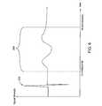
- FIG. 6is an illustration of the waveform characteristics of a stimulus pulse and a corresponding neuro-muscular (EMG) response as detected at a myotome location.
- EMGneuro-muscular
- FIG. 7is a schematic diagram of a nerve detection system.
- FIG. 8Ais an illustration of the front panel of one design of the present nerve status and detection system.
- FIG. 8Bis an illustration of the front panel of another design of the present nerve status and detection system.
- the present inventionsets forth systems for detecting when a nerve is near or adjacent to an electrified surgical tool, probe, cannula, or other surgical instrument.
- the present inventionalso involves optional systems for simultaneously determining the “status” (e.g.: sensitivity) of a plurality of nerves.
- the present systeminvolves applying a signal with a current level to a probe near a nerve and determining whether an electromyographic “EMG” (i.e.: neuro-muscular) response for a muscle coupled to the nerve is present.
- EMGelectromyographic
- the present systemapplies a signal with a known current level (mA) to a “probe” (which could be midline probe, a cannula, a needle, etc.)
- a “probe”which could be midline probe, a cannula, a needle, etc.
- an EMGmay be detected in a muscle coupled to the nerve.
- an EMG responseis determined to have been detected when the peak-to-peak response of the EMG signal is greater than some level (mVolts).
- an EMG responseis determined to have been detected when the stimulus current level generates an EMG having a peak-to-peak value greater than a pre-determined level (for example, 60 mV or 80 mV in spinal nerve applications.)
- a pre-determined levelfor example, 60 mV or 80 mV in spinal nerve applications.
- Such stimulus current level at which an EMG response is detectedis termed the “onset” current level for the nerve.
- the present inventionalso sets forth systems for determining these onset current values (i.e.: determining the stimulus current level at which an EMG response is detected with a maximum peak-to-peak value greater than a predetermined level).
- onset valuesmay be determined for a plurality of nerves either in absolute terms, or in relation to one another.
- the first aspect of the present inventioninvolves nerve detection.
- nerve status informationmay be used to aid nerve detection.
- the nerve status aspectdetermines the minimum current level of a signal applied to a probe near a nerve needed to generate onset EMG response for a muscle coupled to a nerve of interest.
- the present inventionmay use this determined minimum current level when determining whether a probe is near the same nerve.
- the present inventionmay involve determining an initial set of “baseline” neuro-muscular response onset values for a plurality of different spinal nerve pathways.
- This optional second (nerve status) aspect of the present inventionis preferably carried out prior to the first (nerve detection) aspect of the invention, with the initial set of “baseline” neuro-muscular onset values then optionally being used in the nerve detection function, as will be explained below.
- the optional second aspect of the inventionis carried out prior to carrying out the first aspect of the invention, it will be described first.
- the minimum current level of a signal applied to a probe needed to generate an onset neuro-muscular responseis first determined for each of a plurality of nerves, as follows.
- a patient's vertebrae L1, L2, L3, L4, L5, and S1are shown.
- a portion of the patient's cauda equinais stimulated (i.e. depolarized). This depolarization of a portion of the patient's cauda equina may be achieved by conducting a stimulus pulse having a known current level between an epidural stimulating electrode 11 and a patient return electrode 13 .
- Electrodes 11 and 13are referred to herein as “status” electrodes, as they assist in determining the initial status of the various nerve pathways).
- the epidural electrodeis placed in the epidural space of the spine.
- the depolarization of a portion of the patient's cauda equinamay be achieved by conducting a stimulus pulse having a known current level between a pair of status (baseline) electrodes 12 and 14 , which may be positioned adjacent the (thoracic/lumbar) T/L junction (above vertebra L1), as shown.
- Status electrodes 12 and 14may be positioned in-line at the T/L junction, (as shown in FIG. 1 ).
- Status electrodes 12 and 14could also be positioned on opposite lateral sides of the T/L junction.
- neuro-musculari.e., EMG
- responses to the stimulus pulse by muscles coupled to nerves near the stimulating electrodeare detected by electrodes positioned at each of a plurality of myotome locations MR1, MR2, and MR3 on the patient's right leg, and myotome locations ML1, ML2, and ML3 on the patient's left leg.
- the sensing of neuro-muscular responses at these locationsmay be performed with needle electrodes, or electrodes placed on the surface of the patient's skin, as desired.
- An EMG response at each location MR1 to MR6is detected when the maximum peak-to-peak height of the EMG response to the stimulus pulse is greater than a predetermined mV value (called “onset”).
- the current level required to elicit an onset EMG responseis called the “onset” current level.
- the current level of the stimulus pulse or signal applied to the electrode 11 or electrodes 12 , 14may be incremented from a low level until an onset EMG response is detected for one or more of the myotome locations MR1 to ML3.
- myotome sensingmay be carried out at more than the three distal locations illustrated on each of the patient's legs in FIG. 1 .
- a greater number of spinal nerves corresponding to each of these myotome locationscan be individually monitored, thereby enhancing the present system's nerve detection ability over a larger section of the patient's spinal column.
- the present inventioncan be easily adapted to cervical or thoracic spinal applications (in addition to the illustrated lumbar application of FIG. 1 ).
- an appropriate portion of the spinal columnis depolarized and myotome-sensing locations are selected according to the physiology of the associated nerves for portion of the spinal column of interest.
- preferred myotome-sensing locationsmay therefore include locations on the patient's arms, anal sphincter, bladder, and other areas, depending upon the vertebrae level where the spinal surgery is to be performed.
- the current level of the stimulus signal conducted between status electrodes 11 and 13 (or 12 and 14 )is incrementally increased in a staircase fashion as shown in the current staircase of FIG. 2 from a low value until an onset EMG response is detected at one or more myotome locations.
- onset EMG response peak-to-peak valueis between 60 mV and 80 mV.
- the current levelis shown as increasing from 4 mA to 32 mA, in eight 4 mA increments where the current level is incremented until an onset EMG response is detected.
- the present inventionis not limited to these values and other current ranges (and other numbers “steps” in the staircase) may also be used, as is desired.
- an onset neuro-muscular (i.e., EMG) responses to the stimulus pulsemay not be detected at each myotome ML1 to MR3 location.
- an onset neuro-muscular (i.e., EMG) responsemay eventually be detected at each of the various myotome locations ML1 through MR3 for each of the six associated spinal nerves.
- EMGonset neuro-muscular
- the current level required to generate an onset EMG responsemay be greater than the similar, non-compressed nerve at a similar distance from the stimulating electrode. Accordingly, the onset neuro-muscular response for each of the various myotome ML1 to MR3 locations may be elicited at different stimulus current levels due at least in part to the various individual spinal nerves being compressed, impaired, etc., and also due simply to differences in the individual nerve pathway sensitivities.
- a stimulus signal having an initial current levelis conducted between electrodes 11 and 13 (or between electrodes 12 and 14 ).
- the current level of the stimulus pulseis increased step-by-step according to the intensity staircase shown in FIG. 2 until an onset EMG response is detected at one or more selected myotomes.
- a response to the increasing current level stimulus pulseis detected at each of the various myotome locations ML1 through MR3. Because each of the spinal nerve paths corresponding to the various myotome locations ML1 through MR3 may have different sensitivities (as noted), different onset EMG responses may be detected at the different onset current levels for different myotome locations.
- Table 1illustrates the current level required to elicit an onset EMG response for myotome location.
- myotome location ML1detected an onset EMG response to the stimulus pulse for a current level of 4 mA.
- myotome MR2detected an onset neuro-muscular/EMG response to the stimulus pulse for a current level of 24 mA, etc.
- the above detected stimulus current levelsmay then be optionally scaled to correspond to stimulus staircase levels 1 through 8, with the maximum signal strength of 32 mA corresponding to “8”, as follows, and as illustrated for each of Myotome locations ML1 to MR3, as shown in Table 2 based on the levels shown in Table 1.
- a method for determining the relative neuro-muscular response for each of the plurality of spinal nervesis provided.
- the relative sensitivities of the various spinal nerve pathways with respect to one anothercan initially be determined.
- This informationmay represent the relative health or status of the nerves coupled to each myotome location where the stimulating electrode is approximately the same distance from each of the corresponding nerves.
- the nerve corresponding to myotome location MR2required 24 mA to elicit an onset EMG response in the corresponding muscle. Accordingly, this nerve may be compressed or otherwise physiologically inhibited.
- These respective stimulus pulse current levels at which an onset neuro-muscular response is detected for each of myotome locations ML1 through MR3 are detectedmay then be electronically stored (as an initial “baseline” set of onset EMG response current levels). In a preferred aspect, these stored levels may then be used to perform nerve detection for a probe at a location other than the midline as will be explained.
- onset neuro-muscular or EMG-responsehas been detected for each of the myotome locations, it is not necessary to apply further increased current level signals. As such, it may not be necessary for the current level of the signal to reach the top of the current level staircase (as shown in FIG. 2 ) (provided a response has been detected at each of the myotome locations).
- the present systemBy either reaching the end of the increasing current amplitude staircase, (or by simply proceeding as far up the staircase as is necessary to detect a response at each myotome location), the present system obtains and stores an initial “baseline” set of current level onset values for each myotome location. These onset values may be stored either as absolute (i.e.: mA) or scaled (i.e.: 1 to 8) values. As noted these values represent the baseline or initial nerve status for each nerve corresponding to one of the myotome locations. This baseline onset current level may be displayed as a fixed value on a bar graft of LEDs such as shown in FIG. 8A or 8 B.
- the nerve status of the nerves corresponding to the myotomesmay be determined again by applying a varying current level signal to the midline electrodes. If a procedure is being performed on the patient, the onset current level for one or more of the corresponding nerves may change.
- the increased onset current levelmay also be displayed on the bar graft for the respective myotome (FIG. 8 A/ 8 B).
- the baseline onset current levelis shown as a particular color LED in the bar graph for each myotome location and the increased onset current level value is shown as a different color LED on the bar graph.
- the decreased onset current levelmay also be displayed on the bar graft for the respective myotome.
- the decreased onset current level valueis shown as a third color LED on the bar graph.
- a blue LEDis depicted for the baseline onset current level
- an orange LEDis depicted for an increased (over the baseline) onset current level
- a green LEDis depicted for a decreased onset current level.
- the baseline LEDmay be set to flash to indicate this condition. Accordingly, a clinician may periodically request nerve status (midline stimulation) readings to determine what impact, positive, negative, or neutral, a procedure has had on a patient. The clinician can make this assessment by viewing the bar graphs on the display shown in FIG. 8 for each of the myotome locations.
- the above determined initial set baseline neuro-muscular response onset current levels for each nerve pathwaymay then be used in the first (i.e.: nerve sensing) aspect of the present invention, in which a system is provided for detecting the presence of a spinal nerve adjacent to the distal end of a single probe 20 , or either of probes 20 or 22 .
- nerve sensingi.e.: nerve sensing
- the forgoing nerve status systemwhich may experimentally determine neuro-muscular response onset values
- nerve detection(performed as the surgical tool or probe is advancing toward the operative site), or nerve surveillance (performed in an ongoing fashion when the surgical tool or probe is stationary has already reached the operative site) may be carried out, as follows.
- probes 20 and 22can be any manner of surgical tool, including (electrified) cannulae through which other surgical tools are introduced into the patient.
- probes 20 and 22can be any manner of surgical tool, including (electrified) cannulae through which other surgical tools are introduced into the patient.
- only one probee.g.: probe 20
- two probese.g.: 20 and 22
- more than two probesmay also be used.
- probe 20is an electrified cannula and probe 22 is a “confirmation electrode” which can be inserted through cannula/probe 20 , as will be explained.
- Probes 20 and 22may have electrified distal ends, with electrodes 21 and 23 positioned thereon, respectively.
- electrode 21may be positioned on an electrified distal end of the cannula, or alternatively, the entire surface of the electrified cannula may function as the electrode).
- Nerve detectionis accomplished as follows.
- a stimulus pulseis passed between electrode 21 (disposed on the distal end of a probe 20 ) and patient return electrode 30 .
- a stimulus pulseis passed between electrode 23 (disposed on the distal end of a probe 22 ) and patient return electrode 30 .
- electrodes 21 or 23operate as cathodes and patient return electrode 30 is an anode.
- probes 20 and 22are monopolar.
- the stimulus pulse emitted by each of electrodes 21 and 23is multiplexed, so as to distinguish between their signals.
- electrodes 21 and 23could be replaced by any combination of multiple electrodes, operating either in monopolar or bipolar mode.
- probe 20could instead be bi-polar with patient return electrode 30 no longer being required.
- each of myotome locations ML1 through MR3are monitored to determine if they exhibit an EMG response.
- the intensity of the stimulus pulse passing between electrodes 21 and 30 or between 22 and 30is preferably varied over time.
- the current intensity level of the stimulus pulseis incrementally increased step-by-step in a “staircase” fashion.
- the currentmay be increased in ten 0.5 mA steps from 0.5 mA to 5.0 mA.
- This stimulus pulseis preferably increased one step at a time until a neuro-muscular (i.e., EMG) response to the stimulus pulse is detected in each of myotome locations ML1 through MR3.
- the present inventionFor myotome locations that exhibit an EMG response as a result of the stimulus pulse, the present invention then records the lowest amplitude of current required to elicit such a response. Subsequently, this stimulus level is interpreted so as to produce an appropriate warning indication to the user that the surgical tool/probe is in close proximity to the nerve.
- the staircase of stimulus pulsesmay comprise only three levels, (rather than the 8 levels which are illustrated in FIG. 3 ). If an EMG response is recorded at a particular myotome location for only the highest level of stimulation (i.e.: the third step on a 3-step staircase), then the system could indicate a “low” alarm condition (since it took a relatively high level of stimulation to produce an EMG response, it is therefore unlikely that the tool/probe distal tip(s) are in close proximity to a nerve). If an EMG response is instead first recorded when the middle level of stimulation (i.e.: the second step on the 3-step staircase) is reached, then the system could indicate a “medium” alarm condition.
- the middle level of stimulationi.e.: the second step on the 3-step staircase
- an important advantage of increasing the stimulus current intensity in a “staircase” function, increasing from lower to higher levels of current intensityis that a “high” alarm condition would be reached prior to a “low” alarm condition being reached, providing an early warning to the surgeon.
- the present inventionneed not continue through to the end (third step) of the staircase function.
- the current level of the applied signal to the probe ( 20 or 22 )elicits an EMG response greater than the pre-determined onset EMG response, the current level is not increased.
- the initial “baseline” neuro-muscular EMG response onset value data setwhich characterizes the relative EMG onset values of the various nerve roots of interest, (as described above), is used to guide the interpretation of EMG response data and any subsequent proximity warning indication, as follows.
- the stimulation staircase transmitted between electrodes 11 and 13resulted in measures neuro-muscular (i.e.: EMG) response onset values of 4, 16, 20, 16, 24 and 12 mA at myotome locations ML1, ML2, ML3, MR1, MR2 and MR3, respectively.
- EMGneuro-muscular response onset values of 4, 16, 20, 16, 24 and 12 mA at myotome locations ML1, ML2, ML3, MR1, MR2 and MR3, respectively.
- twice the intensity of currentwas required to produce a neuro-muscular response at MR2 as was required to produce a neuro-muscular response at MR3 (since “24” mA is twice as big as “12” mA).
- the nerve pathway to MR3is more “sensitive” than to MR2 (since MR3 is able to exhibit a neuro-muscular response at 1 ⁇ 2 of the current intensity required to exhibit a neuro-muscular response at MR2). Consequently, during nerve detection, when electrode 21 or 23 (positioned on the distal end of tool/probe 20 or 22 ) is positioned adjacent the nerve root affiliated with MR3, twice the current stimulation intensity was required to produce an EMG response. In contrast, when electrode 21 or 23 (on the distal end of tool/probe 20 or 22 ) was positioned adjacent to the nerve root affiliated with MR2, the same level of stimulation that produced a response at MR3 would not produce a response at MR2.
- the sensitivities of the various spinal nerve pathwaysare incorporated into the nerve detection function of the invention by incorporating the various neuro-muscular response onset values, as follows.
- the previously determined neuro-muscular response onset levelwas 4 mA, as shown in Table 1. Should a neuro-muscular response to the stimulus pulse be detected at a current intensity level at or below 4 mA, this would signal the operator that the respective probe electrode 21 (or 23 ) emitting the stimulus pulse is in close proximity to the spinal nerve.
- the neuro-muscular response onset value for myotome location ML2was determined to be 16 mA, as shown in Table 1. Accordingly, should a neuro-muscular response be detected at a current intensity level of less than or equal to 16 mA, this would indicate that respective probe electrode 21 (or 23 ) emitting the stimulus pulse is in close proximity to the spinal nerve.
- “high”, “medium” and “low” warning levelsmay preferably be mapped onto each stimulation staircase level for each myotome location.
- the neuro-muscular onset level for ML1was 4 mA, corresponding to the first level of the 8-level status electrode current staircase of FIG. 2 .
- the first (4 mA) step on the staircaseis assigned a “high” warning level.
- Level two (8 mA)is assigned a “medium” warning level and level three (12 mA) is assigned a “low” warning level.
- an EMG responseis recorded at ML1 at the first stimulation level, (4 mA), a “high” proximity warning is given.
- a responseis detected at the second level (8 mA)
- a “medium” proximity warningis given.
- a responseis detected at the third level (12 mA)
- a “low” proximity warningis given. If responses are detected only above the third level, or if no responses are detected, than no warning indication is given.
- the “high”, “medium” and “low” warning levelsare assigned starting at the fourth step on the status electrode current staircase, with the fourth step being “high”, the fifth level being “medium” and the sixth level being “low”, respectively, as shown.
- the first, second, third, or fourth surveillance levelsi.e.: 4, 18, 12 or 16 mA
- a “high” warning indicationwill be given.
- a response initially detected at the fifth leveli.e.: 20 mA
- a “medium” warning indicationis given.
- each of myotome locations ML1 through MR3are monitored at conditions indicating “high”, “medium” and “low” likelihood of a nerve being disposed adjacent the surgical tool/probe.
- levels “9” and “10”are useful as follows. Should scaled level 8 be the minimum onset level at which a neuro-muscular response is detected, levels “9” and “10” can be used to indicate “medium” and “low” warning levels, respectively.
- the various neuro-muscular response current onset levels used in detection of spinal nervesmay either have been either determined in accordance with the second aspect of the present invention, or may simply correspond to a set of known or expected values input by the user, or pre-set into the system's hardware/software.
- an advantage of the present systemis that different neuro-muscular response onset value levels may be used when simultaneously sensing for different nerves.
- An advantage of thisis that the present invention is able to compensate for different sensitivities among the various spinal nerves.
- This feature of the present inventionis very advantageous in that electrodes 21 and 23 are positioned much closer to the spinal nerves. As such, electrodes 21 and 23 do not depolarize a large portion of the cauda equina, as do electrodes 12 and 14 .
- the placement of electrode 11 in the epidural spaceensures that the electrode is at a relatively known distance from the spinal nerves.
- a neuro-muscular response(greater than the onset EMG response) is detected for all six myotome sensing locations ML1 through MR3 before all of the steps on the staircase is completed, the remaining steps need not be executed.
- the top three stimulation levelsneed to be monitored during the neuro-muscular response detection sequence.
- the top three monitored levelswill correspond to “high”, “medium”, and “low” probabilities of the surgical tool/probe being disposed adjacent the a nerve.
- the maximum stimulation leveli.e.: top step on the staircase
- they are assigned the maximum scale valuei.e.: a “low” warning indication.
- each of the spinal nerves monitored at myotome locations ML1 through MR3will correspond to nerves exiting from successive vertebrae along the spine.
- a main spinal nerve 50will continuously branch out downwardly along the spinal column with spinal nerve 51 exiting between vertebrae L2 and L3 while nerve 52 passes downwardly.
- Spinal nerve 53exits between vertebrae L3 and L4 while spinal nerve 54 passes downwardly to L4.
- spinal nerve 55will exit between vertebrae L4 and L5 while spinal nerve 56 passes downwardly.
- neuro-muscular (i.e., EMG) response measurements taken at myotome location MR1will correspond to EMG signals in spinal nerve 51
- response measurements taken at myotome location MR2correspond to EMG signals in spinal nerve 53
- response measurements taken at myotome location MR3correspond to EMG signals in spinal nerve 55 .
- the detection of a neuro-muscular (EMG) responsemay be accomplished as follows.
- An “EMG sampling window” 200may be defined at a fixed internal of time after the stimulus pulse 202 is emitted. The boundaries of window 200 may be determined by the earliest and latest times that an EMG response may occur relative to stimulus pulse 202 . In the case of stimulation near the lumbar spine, these times are, for example, about 10 milliseconds and 50 milliseconds, respectively.
- the EMG signalmay optionally be amplified and filtered in accordance with guidelines known to those skilled in the art.
- the signalmay then be rectified and passed through a threshold detector to produce a train of pulses representing the number of “humps” of certain amplitudes contained in the EMG waveform.
- a re-settable counting circuitmay then count the number of humps and a comparator may determine whether the number of pulses is within an acceptable range.
- the number of acceptable pulses for EMG responses elicited by stimulation in the lumbar spine regionmay range from about two to about five.
- true EMG waveformsare typically biphasic (having at least one positive curved pulse response and one negative curved pulse response) resulting in at least two pulses.
- This pulse-counting schemehelps to discriminate between true EMG waveforms and noise, since noise signals are typically either sporadic and monophasic (and therefore produce only one pulse) or repetitive (producing a high number of pulses during the EMG sampling window).
- a separate noise-sampling windowmay be established to remove noise present in the EMG responses to increase the ability of the system to discriminate between true EMG responses and false responses caused by noise.
- the boundaries of noise sampling windoware chosen such that there is no significant change of a true EMG signal occurring during the window. For example, it may be deemed acceptable that one curved pulse of an EMG response may be comprised primarily of noise, but if more than one curved pulse of an EMG response is primarily comprised of noise, an alarm would be triggered indicating that excess noise is present on that particular channel.
- both the optional second aspect of determining the neuro-muscular response onset values for each of the plurality of spinal nerves and the first aspect of sensing to detect if a nerve is positioned adjacent to a surgical tool/probeare repeated over time.
- the sensing of whether a nerve is positioned adjacent to a surgical tool/probeis continuously repeated in very short intervals of time, such that the operator can be warned in real time as the surgical tool/probe is advanced toward the nerve.
- the present system of determining the neuro-muscular response onset values for each of the plurality of spinal nervesis also preferably repeated, and may be repeated automatically, or under operator control.
- the above two aspects of the present inventionwill not be carried out simultaneously. Rather, when the neuro-muscular response onset values are being determined (using electrodes 11 and 13 or 12 and 14 ), the operation of probe electrodes 21 and 23 will be suspended. Conversely, when sensing to determine whether a nerve is positioned adjacent either of probes 20 or 22 , the operation of stimulation electrodes 11 and 13 or 12 and 14 will be suspended.
- a standard reference electrode 32may be used for grounding the recording electrodes at the myotomes.
- FIG. 6depicts a particular exemplary embodiment of the present invention. Other embodiments are also possible, and are encompassed by the present invention.
- Pulse generator 100creates pulse trains of an appropriate frequency and duration when instructed to do so by controller 118 .
- the pulse frequencymay be between 1 pulse-per-second and 10 pulses-per-second, and the pulse duration may be between 20 ⁇ sec and 300 ⁇ sec.
- Pulse generator 100may be implemented using an integrated circuit (IC), such as an ICL75556 (Intensity) or generated by a software module.
- Amplitude modulator 102produces a pulse of appropriate amplitude as instructed by controller 118 , and may comprise a digital-to-analog converter such as a DAC08 (National Semiconductor).
- DAC08National Semiconductor
- the output of amplitude modulator 102drives output stage 103 , which puts out a pulse of the desired amplitude.
- Output stage 103may comprise a transformer coupled, constant-current output circuit.
- the output of output stage 103is directed through output multiplexer 106 by controller 118 to the appropriate electrodes, either to status (baseline) electrodes 11 and 13 , or to a combination of screw test probe 109 , probe electrode 21 , 23 and patient return electrode 13 .
- Impedance monitor 104senses the voltage and current characteristics of the output pulses and controller 118 elicits an error indication on error display 127 if the impedance falls above or below certain pre-set limits.
- Input keys 116may be present on a front panel of a control unit of the present invention, as depicted in FIG. 8 , to allow the user to shift between modes of operation.
- EMG inputs 128 to 138comprise the six pairs of electrodes used to detect EMG activity at six different myotome locations. It will be appreciated that the number of channels may vary depending upon the number of nerve roots and affiliated myotomes that need to be monitored.
- a reference electrode 140may also be attached to the patient at a location roughly central to the groupings of EMG electrodes 128 to 138 to serve as a ground reference for the EMG input signals. Electrodes 128 to 140 may either be of the needle-type or of the gelled foam type, or of any type appropriate for detecting low-level physiological signals.
- EMG input stage 142may contain input protection circuit comprising, for example, gas discharge elements (to suppress high voltage transients) and/or clamping diodes.
- Such clamping diodesare preferably of the low-leakage types, such as SST-pads (Siliconix).
- the signalis then passed through amplifier/filter 144 , which may amplify the signal differentially using an instrumentation amplifier such as an AD620 (Analog Devices).
- the overall gainmay be on the order of about 10,000:1 to about 1,000,000:1, and the low and high filter bands may be in the range of about 1-100 Hz and 500 to 5,000 Hz, respectively.
- Such filteringmay be accomplished digitally, in software, or with discrete components using techniques well known to those skilled in the art.
- the amplified and filtered signalthen passes through rectifier 141 , which may be either a software rectifier or a hardware rectifier.
- the output of rectifier 146goes to threshold detector 147 which may be implemented either in electronic hardware or in software.
- the output of threshold detector 147then goes to counter 148 which may also be implemented by either software or hardware.
- Controller 118may be a microcomputer or microcontroller, or it may be a programmable gate array, or other hardware logic device.
- Display elements 120 to 127may be of any appropriate type, either individually implemented (such as with multicolor LEDs) or as an integrated display (such as an LCD).
Landscapes
- Health & Medical Sciences (AREA)
- Life Sciences & Earth Sciences (AREA)
- Surgery (AREA)
- Veterinary Medicine (AREA)
- General Health & Medical Sciences (AREA)
- Biomedical Technology (AREA)
- Heart & Thoracic Surgery (AREA)
- Engineering & Computer Science (AREA)
- Public Health (AREA)
- Animal Behavior & Ethology (AREA)
- Medical Informatics (AREA)
- Molecular Biology (AREA)
- Physics & Mathematics (AREA)
- Biophysics (AREA)
- Pathology (AREA)
- Neurology (AREA)
- Nuclear Medicine, Radiotherapy & Molecular Imaging (AREA)
- Radiology & Medical Imaging (AREA)
- Measurement And Recording Of Electrical Phenomena And Electrical Characteristics Of The Living Body (AREA)
Abstract
Description
| TABLE 1 |
| Stimulus Current Level at Which Onset EMG Response is Detected: |
| ML1 - 4 mA | MR1 - 16 mA | ||
| ML2 - 16 mA | MR2 - 24 mA | ||
| ML3 - 20 mA | MR3 - 12 mA | ||
| TABLE 2 |
| Scaled Neuro-muscular Response Onset Values: |
| ML1 - 1 | MR1 - 4 | ||
| ML2 - 4 | MR2 - 6 | ||
| ML3 - 5 | MR3 - 3 | ||
Claims (13)
Priority Applications (3)
| Application Number | Priority Date | Filing Date | Title |
|---|---|---|---|
| US13/726,110US8958869B2 (en) | 1999-11-24 | 2012-12-22 | Electromyography system |
| US14/622,585US9743853B2 (en) | 1999-11-24 | 2015-02-13 | Electromyography system |
| US15/690,180US20190046058A1 (en) | 1999-11-24 | 2017-08-29 | Electromyography System |
Applications Claiming Priority (6)
| Application Number | Priority Date | Filing Date | Title |
|---|---|---|---|
| US16741699P | 1999-11-24 | 1999-11-24 | |
| US09/722,070US7470236B1 (en) | 1999-11-24 | 2000-11-24 | Electromyography system |
| US10/830,189US7963927B2 (en) | 1999-11-24 | 2004-04-21 | Electromyography system |
| US11/982,238US7991463B2 (en) | 1999-11-24 | 2007-10-31 | Electromyography system |
| US13/196,784US8337410B2 (en) | 1999-11-24 | 2011-08-02 | Electromyography system |
| US13/726,110US8958869B2 (en) | 1999-11-24 | 2012-12-22 | Electromyography system |
Related Parent Applications (1)
| Application Number | Title | Priority Date | Filing Date |
|---|---|---|---|
| US13/196,784ContinuationUS8337410B2 (en) | 1999-11-24 | 2011-08-02 | Electromyography system |
Related Child Applications (1)
| Application Number | Title | Priority Date | Filing Date |
|---|---|---|---|
| US14/622,585ContinuationUS9743853B2 (en) | 1999-11-24 | 2015-02-13 | Electromyography system |
Publications (2)
| Publication Number | Publication Date |
|---|---|
| US20130178758A1 US20130178758A1 (en) | 2013-07-11 |
| US8958869B2true US8958869B2 (en) | 2015-02-17 |
Family
ID=22607298
Family Applications (12)
| Application Number | Title | Priority Date | Filing Date |
|---|---|---|---|
| US09/722,070Expired - LifetimeUS7470236B1 (en) | 1999-11-24 | 2000-11-24 | Electromyography system |
| US10/830,189Expired - Fee RelatedUS7963927B2 (en) | 1999-11-24 | 2004-04-21 | Electromyography system |
| US11/894,987Expired - LifetimeUS8562539B2 (en) | 1999-11-24 | 2007-08-21 | Electromyography system |
| US11/982,238Expired - Fee RelatedUS7991463B2 (en) | 1999-11-24 | 2007-10-31 | Electromyography system |
| US11/981,891AbandonedUS20080065178A1 (en) | 1999-11-24 | 2007-10-31 | Electromyography system |
| US11/981,893AbandonedUS20080071191A1 (en) | 1999-11-24 | 2007-10-31 | Electromyography system |
| US11/981,889Expired - LifetimeUS8641638B2 (en) | 1999-11-24 | 2007-10-31 | Electromyography system |
| US13/196,784Expired - Fee RelatedUS8337410B2 (en) | 1999-11-24 | 2011-08-02 | Electromyography system |
| US13/196,836AbandonedUS20120029382A1 (en) | 1999-11-24 | 2011-08-02 | Electromyography System |
| US13/726,110Expired - Fee RelatedUS8958869B2 (en) | 1999-11-24 | 2012-12-22 | Electromyography system |
| US14/622,585Expired - Fee RelatedUS9743853B2 (en) | 1999-11-24 | 2015-02-13 | Electromyography system |
| US15/690,180AbandonedUS20190046058A1 (en) | 1999-11-24 | 2017-08-29 | Electromyography System |
Family Applications Before (9)
| Application Number | Title | Priority Date | Filing Date |
|---|---|---|---|
| US09/722,070Expired - LifetimeUS7470236B1 (en) | 1999-11-24 | 2000-11-24 | Electromyography system |
| US10/830,189Expired - Fee RelatedUS7963927B2 (en) | 1999-11-24 | 2004-04-21 | Electromyography system |
| US11/894,987Expired - LifetimeUS8562539B2 (en) | 1999-11-24 | 2007-08-21 | Electromyography system |
| US11/982,238Expired - Fee RelatedUS7991463B2 (en) | 1999-11-24 | 2007-10-31 | Electromyography system |
| US11/981,891AbandonedUS20080065178A1 (en) | 1999-11-24 | 2007-10-31 | Electromyography system |
| US11/981,893AbandonedUS20080071191A1 (en) | 1999-11-24 | 2007-10-31 | Electromyography system |
| US11/981,889Expired - LifetimeUS8641638B2 (en) | 1999-11-24 | 2007-10-31 | Electromyography system |
| US13/196,784Expired - Fee RelatedUS8337410B2 (en) | 1999-11-24 | 2011-08-02 | Electromyography system |
| US13/196,836AbandonedUS20120029382A1 (en) | 1999-11-24 | 2011-08-02 | Electromyography System |
Family Applications After (2)
| Application Number | Title | Priority Date | Filing Date |
|---|---|---|---|
| US14/622,585Expired - Fee RelatedUS9743853B2 (en) | 1999-11-24 | 2015-02-13 | Electromyography system |
| US15/690,180AbandonedUS20190046058A1 (en) | 1999-11-24 | 2017-08-29 | Electromyography System |
Country Status (6)
| Country | Link |
|---|---|
| US (12) | US7470236B1 (en) |
| EP (1) | EP1237472A4 (en) |
| JP (1) | JP4854900B2 (en) |
| KR (1) | KR20020077346A (en) |
| AU (1) | AU779567B2 (en) |
| WO (1) | WO2001037728A1 (en) |
Cited By (44)
| Publication number | Priority date | Publication date | Assignee | Title |
|---|---|---|---|---|
| US20140148725A1 (en)* | 2012-11-27 | 2014-05-29 | Cadwell Laboratories, Inc. | Neuromonitoring systems and methods |
| US9750490B2 (en) | 2002-06-26 | 2017-09-05 | Nuvasive, Inc. | Surgical access system and related methods |
| US9788822B2 (en) | 2003-09-25 | 2017-10-17 | Nuvasive, Inc. | Surgical access system and related methods |
| US9795371B2 (en) | 2003-01-16 | 2017-10-24 | Nuvasive, Inc. | Surgical access system and related methods |
| US9820729B2 (en) | 2002-10-08 | 2017-11-21 | Nuvasive, Inc. | Surgical access system and related methods |
| US9931077B2 (en) | 2001-07-11 | 2018-04-03 | Nuvasive, Inc. | System and methods for determining nerve proximity, direction and pathology during surgery |
| US9949651B2 (en) | 2011-11-01 | 2018-04-24 | DePuy Synthes Products, Inc. | Intraoperative neurophysiological monitoring system |
| US9949840B1 (en) | 2011-04-01 | 2018-04-24 | William D. Smith | Systems and methods for performing spine surgery |
| US10278686B2 (en) | 2010-09-20 | 2019-05-07 | DePuy Synthes Products, Inc. | Spinal access retractor |
| US10321833B2 (en) | 2016-10-05 | 2019-06-18 | Innovative Surgical Solutions. | Neural locating method |
| US10376208B2 (en) | 2013-09-20 | 2019-08-13 | Innovative Surgical Solutions, Llc | Nerve mapping system |
| US10376209B2 (en) | 2013-09-20 | 2019-08-13 | Innovative Surgical Solutions, Llc | Neural locating method |
| US10433793B1 (en) | 2015-03-27 | 2019-10-08 | Cadwell Laboratories, Inc. | Methods and systems for simultaneous review of brain activity and physical manifestations of users |
| US10449002B2 (en) | 2013-09-20 | 2019-10-22 | Innovative Surgical Solutions, Llc | Method of mapping a nerve |
| US10478096B2 (en) | 2013-08-13 | 2019-11-19 | Innovative Surgical Solutions. | Neural event detection |
| US10478097B2 (en) | 2013-08-13 | 2019-11-19 | Innovative Surgical Solutions | Neural event detection |
| US10507120B2 (en) | 2001-09-25 | 2019-12-17 | Nuvasive, Inc. | Systems and methods for performing surgical procedures and assessments |
| US10653308B2 (en) | 2003-10-17 | 2020-05-19 | Nuvasive, Inc. | Surgical access system and related methods |
| US10687797B2 (en) | 2008-12-18 | 2020-06-23 | Howmedica Osteonics Corp. | Lateral access system for the lumbar spine |
| US10869616B2 (en) | 2018-06-01 | 2020-12-22 | DePuy Synthes Products, Inc. | Neural event detection |
| US10870002B2 (en) | 2018-10-12 | 2020-12-22 | DePuy Synthes Products, Inc. | Neuromuscular sensing device with multi-sensor array |
| US10912483B2 (en) | 2018-03-05 | 2021-02-09 | Edge Surgical, Inc. | Handheld devices for use in medical procedures |
| US11026627B2 (en) | 2013-03-15 | 2021-06-08 | Cadwell Laboratories, Inc. | Surgical instruments for determining a location of a nerve during a procedure |
| US11128076B2 (en) | 2019-01-21 | 2021-09-21 | Cadwell Laboratories, Inc. | Connector receptacle |
| US11168966B2 (en) | 2016-11-03 | 2021-11-09 | Edge Surgical, Inc. | Surgical depth instrument having neuromonitoring capabilities |
| US11166709B2 (en) | 2016-08-23 | 2021-11-09 | Stryker European Operations Holdings Llc | Instrumentation and methods for the implantation of spinal implants |
| US11177610B2 (en) | 2017-01-23 | 2021-11-16 | Cadwell Laboratories, ino. | Neuromonitoring connection system |
| US11185684B2 (en) | 2018-09-18 | 2021-11-30 | Cadwell Laboratories, Inc. | Minimally invasive two-dimensional grid electrode |
| US11191532B2 (en) | 2018-03-30 | 2021-12-07 | Stryker European Operations Holdings Llc | Lateral access retractor and core insertion |
| US11253182B2 (en) | 2018-05-04 | 2022-02-22 | Cadwell Laboratories, Inc. | Apparatus and method for polyphasic multi-output constant-current and constant-voltage neurophysiological stimulation |
| US11317841B2 (en) | 2018-11-14 | 2022-05-03 | Cadwell Laboratories, Inc. | Method and system for electrode verification |
| US11399777B2 (en) | 2019-09-27 | 2022-08-02 | DePuy Synthes Products, Inc. | Intraoperative neural monitoring system and method |
| US11443649B2 (en) | 2018-06-29 | 2022-09-13 | Cadwell Laboratories, Inc. | Neurophysiological monitoring training simulator |
| US11471087B2 (en) | 2018-11-09 | 2022-10-18 | Cadwell Laboratories, Inc. | Integrity verification system for testing high channel count neuromonitoring recording equipment |
| US11517245B2 (en) | 2018-10-30 | 2022-12-06 | Cadwell Laboratories, Inc. | Method and system for data synchronization |
| US11517239B2 (en) | 2018-04-05 | 2022-12-06 | Cadwell Laboratories, Inc. | Systems and methods for processing and displaying electromyographic signals |
| US11529107B2 (en) | 2018-11-27 | 2022-12-20 | Cadwell Laboratories, Inc. | Methods for automatic generation of EEG montages |
| US11564719B2 (en) | 2017-06-14 | 2023-01-31 | Edge Surgical, Inc. | Devices for minimally invasive procedures |
| US11564674B2 (en) | 2019-11-27 | 2023-01-31 | K2M, Inc. | Lateral access system and method of use |
| US11596337B2 (en) | 2018-04-24 | 2023-03-07 | Cadwell Laboratories, Inc | Methods and systems for operating an intraoperative neurophysiological monitoring system in conjunction with electrocautery procedures |
| US11950972B2 (en) | 2016-12-12 | 2024-04-09 | Cadwell Laboratories, Inc. | Controller, adapter and connector systems for high density electrode management |
| US11992339B2 (en) | 2018-05-04 | 2024-05-28 | Cadwell Laboratories, Inc. | Systems and methods for dynamic neurophysiological stimulation |
| US11992227B2 (en) | 2018-03-05 | 2024-05-28 | Edge Surgical, Inc. | Handheld devices for use in medical procedures |
| US12343069B2 (en) | 2017-02-01 | 2025-07-01 | Avent, Inc. | EMG guidance for probe placement, nearby tissue preservation, and lesion confirmation |
Families Citing this family (319)
| Publication number | Priority date | Publication date | Assignee | Title |
|---|---|---|---|---|
| EP1146816B1 (en) | 1998-12-23 | 2005-10-12 | Nuvasive Inc. | Nerve surveillance cannulae systems |
| CA2363254C (en) | 1999-03-07 | 2009-05-05 | Discure Ltd. | Method and apparatus for computerized surgery |
| WO2001037728A1 (en) | 1999-11-24 | 2001-05-31 | Nuvasive, Inc. | Electromyography system |
| US6466817B1 (en)* | 1999-11-24 | 2002-10-15 | Nuvasive, Inc. | Nerve proximity and status detection system and method |
| US6389312B1 (en)* | 2000-07-21 | 2002-05-14 | General Electric Company | Method and system having simplified neuromuscular transmission scoring |
| AU2015246103B2 (en)* | 2001-07-11 | 2017-06-29 | Nuvasive, Inc. | System and methods for determining nerve proximity, direction, and pathology during surgery |
| JP2005503872A (en)* | 2001-09-28 | 2005-02-10 | メーガン メディカル、インク. | Method and apparatus for controlling transcutaneous vaginal electrical signals |
| US7664544B2 (en)* | 2002-10-30 | 2010-02-16 | Nuvasive, Inc. | System and methods for performing percutaneous pedicle integrity assessments |
| JP4340153B2 (en)* | 2001-10-30 | 2009-10-07 | ヌバシブ, インコーポレイテッド | System and method for performing percutaneous stem integrity assessment |
| US6850788B2 (en) | 2002-03-25 | 2005-02-01 | Masimo Corporation | Physiological measurement communications adapter |
| US8147421B2 (en) | 2003-01-15 | 2012-04-03 | Nuvasive, Inc. | System and methods for determining nerve direction to a surgical instrument |
| AU2003214884A1 (en)* | 2003-01-15 | 2004-08-13 | Nuvasive, Inc. | Systems and methods for determining direction to a nerve |
| US7819801B2 (en) | 2003-02-27 | 2010-10-26 | Nuvasive, Inc. | Surgical access system and related methods |
| US20040225228A1 (en) | 2003-05-08 | 2004-11-11 | Ferree Bret A. | Neurophysiological apparatus and procedures |
| EP1675508B1 (en) | 2003-08-05 | 2016-04-20 | NuVasive, Inc. | System for performing dynamic pedicle integrity assessments |
| DE202004021953U1 (en) | 2003-09-12 | 2013-06-19 | Vessix Vascular, Inc. | Selectable eccentric remodeling and / or ablation of atherosclerotic material |
| US8313430B1 (en) | 2006-01-11 | 2012-11-20 | Nuvasive, Inc. | Surgical access system and related methods |
| EP2301471A1 (en) | 2004-04-01 | 2011-03-30 | The General Hospital Corporation | Method and apparatus for dermatological treatment and tissue reshaping |
| US9713730B2 (en) | 2004-09-10 | 2017-07-25 | Boston Scientific Scimed, Inc. | Apparatus and method for treatment of in-stent restenosis |
| US8396548B2 (en) | 2008-11-14 | 2013-03-12 | Vessix Vascular, Inc. | Selective drug delivery in a lumen |
| EP1804660A4 (en)* | 2004-10-07 | 2009-11-11 | Nuvasive Inc | System and methods for assessing the neuromuscular pathway prior to nerve testing |
| WO2006042241A2 (en) | 2004-10-08 | 2006-04-20 | Nuvasive, Inc. | Surgical access system and related methods |
| US7959577B2 (en) | 2007-09-06 | 2011-06-14 | Baxano, Inc. | Method, system, and apparatus for neural localization |
| US7963915B2 (en) | 2004-10-15 | 2011-06-21 | Baxano, Inc. | Devices and methods for tissue access |
| JP5243034B2 (en) | 2004-10-15 | 2013-07-24 | バクサノ,インク. | Tissue removal device |
| US7578819B2 (en) | 2005-05-16 | 2009-08-25 | Baxano, Inc. | Spinal access and neural localization |
| US8430881B2 (en) | 2004-10-15 | 2013-04-30 | Baxano, Inc. | Mechanical tissue modification devices and methods |
| US20100004654A1 (en)* | 2008-07-01 | 2010-01-07 | Schmitz Gregory P | Access and tissue modification systems and methods |
| US20110190772A1 (en) | 2004-10-15 | 2011-08-04 | Vahid Saadat | Powered tissue modification devices and methods |
| US8257356B2 (en) | 2004-10-15 | 2012-09-04 | Baxano, Inc. | Guidewire exchange systems to treat spinal stenosis |
| US8062300B2 (en) | 2006-05-04 | 2011-11-22 | Baxano, Inc. | Tissue removal with at least partially flexible devices |
| US7857813B2 (en) | 2006-08-29 | 2010-12-28 | Baxano, Inc. | Tissue access guidewire system and method |
| US7938830B2 (en) | 2004-10-15 | 2011-05-10 | Baxano, Inc. | Powered tissue modification devices and methods |
| US8048080B2 (en) | 2004-10-15 | 2011-11-01 | Baxano, Inc. | Flexible tissue rasp |
| US7738969B2 (en) | 2004-10-15 | 2010-06-15 | Baxano, Inc. | Devices and methods for selective surgical removal of tissue |
| US9101386B2 (en) | 2004-10-15 | 2015-08-11 | Amendia, Inc. | Devices and methods for treating tissue |
| US7887538B2 (en) | 2005-10-15 | 2011-02-15 | Baxano, Inc. | Methods and apparatus for tissue modification |
| US20100331883A1 (en) | 2004-10-15 | 2010-12-30 | Schmitz Gregory P | Access and tissue modification systems and methods |
| US9247952B2 (en) | 2004-10-15 | 2016-02-02 | Amendia, Inc. | Devices and methods for tissue access |
| US8613745B2 (en) | 2004-10-15 | 2013-12-24 | Baxano Surgical, Inc. | Methods, systems and devices for carpal tunnel release |
| US8221397B2 (en) | 2004-10-15 | 2012-07-17 | Baxano, Inc. | Devices and methods for tissue modification |
| US20100010367A1 (en)* | 2004-12-30 | 2010-01-14 | Foley Kevin T | System and methods for monitoring during anterior surgery |
| US7643884B2 (en)* | 2005-01-31 | 2010-01-05 | Warsaw Orthopedic, Inc. | Electrically insulated surgical needle assembly |
| US20090177112A1 (en) | 2005-02-02 | 2009-07-09 | James Gharib | System and Methods for Performing Neurophysiologic Assessments During Spine Surgery |
| WO2006084194A2 (en) | 2005-02-02 | 2006-08-10 | Nuvasive, Inc. | System and methods for monitoring during anterior surgery |
| US20060200219A1 (en)* | 2005-03-01 | 2006-09-07 | Ndi Medical, Llc | Systems and methods for differentiating and/or identifying tissue regions innervated by targeted nerves for diagnostic and/or therapeutic purposes |
| US10154792B2 (en) | 2005-03-01 | 2018-12-18 | Checkpoint Surgical, Inc. | Stimulation device adapter |
| US7896815B2 (en)* | 2005-03-01 | 2011-03-01 | Checkpoint Surgical, Llc | Systems and methods for intra-operative stimulation |
| US20110060238A1 (en)* | 2005-03-01 | 2011-03-10 | Checkpoint Surgical, Llc | Systems and methods for intra-operative physiological functional stimulation |
| US20110060242A1 (en)* | 2005-03-01 | 2011-03-10 | Checkpoint Surgical, Llc | Systems and methods for intra-operative stimulation within a surgical field |
| US20110060243A1 (en)* | 2005-03-01 | 2011-03-10 | Checkpoint Surgical, Llc | Systems and methods for intra-operative regional neural stimulation |
| US7878981B2 (en)* | 2005-03-01 | 2011-02-01 | Checkpoint Surgical, Llc | Systems and methods for intra-operative stimulation |
| US20110054346A1 (en)* | 2005-03-01 | 2011-03-03 | Checkpoint Surgical, Llc | Systems and methods for Intra-operative semi-quantitative threshold neural response testing related applications |
| US7942826B1 (en) | 2005-06-06 | 2011-05-17 | Nuvasive, Inc. | Insulated pedicle access system and related methods |
| US8740783B2 (en)* | 2005-07-20 | 2014-06-03 | Nuvasive, Inc. | System and methods for performing neurophysiologic assessments with pressure monitoring |
| US8328851B2 (en) | 2005-07-28 | 2012-12-11 | Nuvasive, Inc. | Total disc replacement system and related methods |
| US8571666B2 (en)* | 2005-08-02 | 2013-10-29 | William F. Urmey | Nerve stimulation system with programmed pulse charge attenuation |
| US7640059B2 (en)* | 2005-09-08 | 2009-12-29 | Medtronic, Inc. | External presentation of electrical stimulation parameters |
| US7551960B2 (en)* | 2005-09-08 | 2009-06-23 | Medtronic, Inc. | External presentation of electrical stimulation parameters |
| WO2007035925A2 (en)* | 2005-09-22 | 2007-03-29 | Nuvasive, Inc. | System and methods for performing pedicle integrity assessments of the thoracic spine |
| WO2007038290A2 (en) | 2005-09-22 | 2007-04-05 | Nuvasive, Inc. | Multi-channel stimulation threshold detection algorithm for use in neurophysiology monitoring |
| US8568317B1 (en) | 2005-09-27 | 2013-10-29 | Nuvasive, Inc. | System and methods for nerve monitoring |
| US8062298B2 (en) | 2005-10-15 | 2011-11-22 | Baxano, Inc. | Flexible tissue removal devices and methods |
| US8366712B2 (en) | 2005-10-15 | 2013-02-05 | Baxano, Inc. | Multiple pathways for spinal nerve root decompression from a single access point |
| US20080051812A1 (en)* | 2006-08-01 | 2008-02-28 | Baxano, Inc. | Multi-Wire Tissue Cutter |
| US8092456B2 (en) | 2005-10-15 | 2012-01-10 | Baxano, Inc. | Multiple pathways for spinal nerve root decompression from a single access point |
| US20090292328A1 (en)* | 2005-11-30 | 2009-11-26 | Corlius Fourie Birkill | Medical Device |
| US8480576B2 (en) | 2005-12-07 | 2013-07-09 | Faheem A. Sandhu | Access system for minimally invasive spinal surgery |
| US7906239B2 (en)* | 2006-03-06 | 2011-03-15 | Sony Corporation | Cathode active material, method for producing the same, and nonaqueous electrolyte secondary battery |
| US8019435B2 (en) | 2006-05-02 | 2011-09-13 | Boston Scientific Scimed, Inc. | Control of arterial smooth muscle tone |
| US8840549B2 (en) | 2006-09-22 | 2014-09-23 | Masimo Corporation | Modular patient monitor |
| US9161696B2 (en) | 2006-09-22 | 2015-10-20 | Masimo Corporation | Modular patient monitor |
| JP5559539B2 (en) | 2006-10-18 | 2014-07-23 | べシックス・バスキュラー・インコーポレイテッド | System that induces desirable temperature effects on body tissue |
| EP2076198A4 (en) | 2006-10-18 | 2009-12-09 | Minnow Medical Inc | Inducing desirable temperature effects on body tissue |
| EP2455036B1 (en) | 2006-10-18 | 2015-07-15 | Vessix Vascular, Inc. | Tuned RF energy and electrical tissue characterization for selective treatment of target tissues |
| US20080103572A1 (en) | 2006-10-31 | 2008-05-01 | Medtronic, Inc. | Implantable medical lead with threaded fixation |
| US7987001B2 (en) | 2007-01-25 | 2011-07-26 | Warsaw Orthopedic, Inc. | Surgical navigational and neuromonitoring instrument |
| US8374673B2 (en) | 2007-01-25 | 2013-02-12 | Warsaw Orthopedic, Inc. | Integrated surgical navigational and neuromonitoring system having automated surgical assistance and control |
| WO2008124079A1 (en) | 2007-04-03 | 2008-10-16 | Nuvasive, Inc. | Neurophysiologic monitoring system |
| US8075601B2 (en) | 2007-04-30 | 2011-12-13 | Warsaw Orthopedic, Inc. | Deformity correction using neural integrity monitoring |
| US10758283B2 (en) | 2016-08-11 | 2020-09-01 | Mighty Oak Medical, Inc. | Fixation devices having fenestrations and methods for using the same |
| WO2009032778A2 (en)* | 2007-08-29 | 2009-03-12 | Verathon Inc. | System and methods for nerve response mapping |
| US8942797B2 (en)* | 2007-10-18 | 2015-01-27 | Innovative Surgical Solutions, Llc | Neural monitoring system |
| US8343079B2 (en) | 2007-10-18 | 2013-01-01 | Innovative Surgical Solutions, Llc | Neural monitoring sensor |
| US8343065B2 (en) | 2007-10-18 | 2013-01-01 | Innovative Surgical Solutions, Llc | Neural event detection |
| US20090105788A1 (en)* | 2007-10-18 | 2009-04-23 | Innovative Surgical Solutions, Llc | Minimally invasive nerve monitoring device and method |
| US9084550B1 (en)* | 2007-10-18 | 2015-07-21 | Innovative Surgical Solutions, Llc | Minimally invasive nerve monitoring device and method |
| US8348983B2 (en)* | 2007-11-13 | 2013-01-08 | Warsaw Orthopedic, Inc. | Surgical bone screw construction |
| US8192436B2 (en) | 2007-12-07 | 2012-06-05 | Baxano, Inc. | Tissue modification devices |
| GB2456558A (en)* | 2008-01-21 | 2009-07-22 | Salisbury Nhs Foundation Trust | Controlling equipment with electromyogram (EMG) signals |
| US11557073B2 (en) | 2008-06-02 | 2023-01-17 | Precision Biometrics, Inc. | System for generating medical diagnostic images |
| AU2009256441B2 (en)* | 2008-06-02 | 2013-06-13 | Precision Biometrics, Inc. | Systems and methods for performing surface electromyography and range-of-motion tests |
| US8409206B2 (en) | 2008-07-01 | 2013-04-02 | Baxano, Inc. | Tissue modification devices and methods |
| US9314253B2 (en) | 2008-07-01 | 2016-04-19 | Amendia, Inc. | Tissue modification devices and methods |
| US8398641B2 (en) | 2008-07-01 | 2013-03-19 | Baxano, Inc. | Tissue modification devices and methods |
| AU2009271047B2 (en) | 2008-07-14 | 2014-04-17 | Baxano Surgical, Inc. | Tissue modification devices |
| US8512715B2 (en)* | 2008-08-14 | 2013-08-20 | The Cleveland Clinic Foundation | Apparatus and method for treating a neuromuscular defect |
| JP5602739B2 (en) | 2008-09-02 | 2014-10-08 | ジンテス ゲゼルシャフト ミット ベシュレンクテル ハフツング | Intervertebral implant having blades for connection to adjacent vertebral bodies |
| EP2331201B1 (en) | 2008-10-01 | 2020-04-29 | Inspire Medical Systems, Inc. | System for treating sleep apnea transvenously |
| US8876851B1 (en) | 2008-10-15 | 2014-11-04 | Nuvasive, Inc. | Systems and methods for performing spinal fusion surgery |
| EP3231365B1 (en)* | 2008-10-15 | 2025-01-22 | Nuvasive, Inc. | Neurophysiologic monitoring system |
| EP2355737B1 (en) | 2008-11-17 | 2021-08-11 | Boston Scientific Scimed, Inc. | Selective accumulation of energy without knowledge of tissue topography |
| JP5575789B2 (en) | 2008-11-19 | 2014-08-20 | インスパイア・メディカル・システムズ・インコーポレイテッド | How to treat sleep-disordered breathing |
| US9084551B2 (en) | 2008-12-08 | 2015-07-21 | Medtronic Xomed, Inc. | Method and system for monitoring a nerve |
| AU2009329873A1 (en) | 2008-12-26 | 2011-11-03 | Scott Spann | Minimally-invasive retroperitoneal lateral approach for spinal surgery |
| EP2405823A4 (en) | 2009-03-13 | 2012-07-04 | Baxano Inc | Flexible neural localization devices and methods |
| JP2012521864A (en) | 2009-03-31 | 2012-09-20 | インスパイア・メディカル・システムズ・インコーポレイテッド | Percutaneous access method in a system for treating sleep-related abnormal breathing |
| US9351845B1 (en) | 2009-04-16 | 2016-05-31 | Nuvasive, Inc. | Method and apparatus for performing spine surgery |
| US8287597B1 (en) | 2009-04-16 | 2012-10-16 | Nuvasive, Inc. | Method and apparatus for performing spine surgery |
| EP2429388A2 (en)* | 2009-05-11 | 2012-03-21 | Timothy Taylor Davis | Neurologic monitoring system and method |
| US8394102B2 (en) | 2009-06-25 | 2013-03-12 | Baxano, Inc. | Surgical tools for treatment of spinal stenosis |
| US9681813B2 (en) | 2009-07-29 | 2017-06-20 | Dinnos Technology | Neurophysiological stimulation system and methods with wireless communication |
| US9750508B1 (en) | 2009-11-11 | 2017-09-05 | Nuvasive, Inc. | Insulated pedicle access system and related methods |
| WO2011059498A1 (en) | 2009-11-11 | 2011-05-19 | Nuvasive, Inc. | Surgical access system and related methods |
| US9153112B1 (en) | 2009-12-21 | 2015-10-06 | Masimo Corporation | Modular patient monitor |
| US8864761B2 (en)* | 2010-03-10 | 2014-10-21 | Covidien Lp | System and method for determining proximity relative to a critical structure |
| US9888864B2 (en) | 2010-03-12 | 2018-02-13 | Inspire Medical Systems, Inc. | Method and system for identifying a location for nerve stimulation |
| US20110230785A1 (en)* | 2010-03-16 | 2011-09-22 | ProNerve, LLC | Somatosensory Evoked Potential (SSEP) Automated Alert System |
| EP2547292B1 (en) | 2010-03-16 | 2019-04-24 | Pinnacle Spine Group, LLC | Ntervertebral implants and graft delivery systems |
| WO2011126580A2 (en) | 2010-04-09 | 2011-10-13 | Minnow Medical, Inc. | Power generating and control apparatus for the treatment of tissue |
| US9192790B2 (en) | 2010-04-14 | 2015-11-24 | Boston Scientific Scimed, Inc. | Focused ultrasonic renal denervation |
| US10631912B2 (en) | 2010-04-30 | 2020-04-28 | Medtronic Xomed, Inc. | Interface module for use with nerve monitoring and electrosurgery |
| US9743884B2 (en)* | 2010-04-30 | 2017-08-29 | J3G Spine, Llc | Devices and methods for nerve mapping |
| US8473067B2 (en) | 2010-06-11 | 2013-06-25 | Boston Scientific Scimed, Inc. | Renal denervation and stimulation employing wireless vascular energy transfer arrangement |
| US8870889B2 (en)* | 2010-06-29 | 2014-10-28 | George Frey | Patient matching surgical guide and method for using the same |
| KR101859932B1 (en) | 2010-06-29 | 2018-05-21 | 조지 프레이 | Patient matching surgical guide and method for using the same |
| US9642633B2 (en) | 2010-06-29 | 2017-05-09 | Mighty Oak Medical, Inc. | Patient-matched apparatus and methods for performing surgical procedures |
| US11806197B2 (en) | 2010-06-29 | 2023-11-07 | Mighty Oak Medical, Inc. | Patient-matched apparatus for use in spine related surgical procedures and methods for using the same |
| WO2017066518A1 (en) | 2010-06-29 | 2017-04-20 | Mighty Oak Medical, Inc. | Patient-matched apparatus and methods for performing surgical procedures |
| US11376073B2 (en) | 2010-06-29 | 2022-07-05 | Mighty Oak Medical Inc. | Patient-matched apparatus and methods for performing surgical procedures |
| US11039889B2 (en) | 2010-06-29 | 2021-06-22 | Mighty Oak Medical, Inc. | Patient-matched apparatus and methods for performing surgical procedures |
| US12357413B2 (en) | 2010-06-29 | 2025-07-15 | Mighty Oak Medical, Inc. | Patient-matched apparatus for use in spine related surgical procedures and methods for using the same |
| US9155589B2 (en) | 2010-07-30 | 2015-10-13 | Boston Scientific Scimed, Inc. | Sequential activation RF electrode set for renal nerve ablation |
| US9084609B2 (en) | 2010-07-30 | 2015-07-21 | Boston Scientific Scime, Inc. | Spiral balloon catheter for renal nerve ablation |
| US9358365B2 (en) | 2010-07-30 | 2016-06-07 | Boston Scientific Scimed, Inc. | Precision electrode movement control for renal nerve ablation |
| US9408661B2 (en) | 2010-07-30 | 2016-08-09 | Patrick A. Haverkost | RF electrodes on multiple flexible wires for renal nerve ablation |
| US9463062B2 (en) | 2010-07-30 | 2016-10-11 | Boston Scientific Scimed, Inc. | Cooled conductive balloon RF catheter for renal nerve ablation |
| CA2714857A1 (en)* | 2010-09-15 | 2012-03-15 | Evan B. Friedman | Electromyographic (emg) device for the diagnosis and treatment of muscle injuries |
| US9392953B1 (en) | 2010-09-17 | 2016-07-19 | Nuvasive, Inc. | Neurophysiologic monitoring |
| US8974451B2 (en) | 2010-10-25 | 2015-03-10 | Boston Scientific Scimed, Inc. | Renal nerve ablation using conductive fluid jet and RF energy |
| US9220558B2 (en) | 2010-10-27 | 2015-12-29 | Boston Scientific Scimed, Inc. | RF renal denervation catheter with multiple independent electrodes |
| US9155503B2 (en) | 2010-10-27 | 2015-10-13 | Cadwell Labs | Apparatus, system, and method for mapping the location of a nerve |
| US9028485B2 (en) | 2010-11-15 | 2015-05-12 | Boston Scientific Scimed, Inc. | Self-expanding cooling electrode for renal nerve ablation |
| US9089350B2 (en) | 2010-11-16 | 2015-07-28 | Boston Scientific Scimed, Inc. | Renal denervation catheter with RF electrode and integral contrast dye injection arrangement |
| US9668811B2 (en) | 2010-11-16 | 2017-06-06 | Boston Scientific Scimed, Inc. | Minimally invasive access for renal nerve ablation |
| US9326751B2 (en) | 2010-11-17 | 2016-05-03 | Boston Scientific Scimed, Inc. | Catheter guidance of external energy for renal denervation |
| US9060761B2 (en) | 2010-11-18 | 2015-06-23 | Boston Scientific Scime, Inc. | Catheter-focused magnetic field induced renal nerve ablation |
| US9023034B2 (en) | 2010-11-22 | 2015-05-05 | Boston Scientific Scimed, Inc. | Renal ablation electrode with force-activatable conduction apparatus |
| US9192435B2 (en) | 2010-11-22 | 2015-11-24 | Boston Scientific Scimed, Inc. | Renal denervation catheter with cooled RF electrode |
| EP2651506B1 (en)* | 2010-12-13 | 2015-09-30 | Neural Pathways, LLC | Handheld emg stimulator device with adjustable shaft length |
| US20120157993A1 (en) | 2010-12-15 | 2012-06-21 | Jenson Mark L | Bipolar Off-Wall Electrode Device for Renal Nerve Ablation |
| US9220561B2 (en) | 2011-01-19 | 2015-12-29 | Boston Scientific Scimed, Inc. | Guide-compatible large-electrode catheter for renal nerve ablation with reduced arterial injury |
| US9179843B2 (en) | 2011-04-21 | 2015-11-10 | Hassan Ghaderi MOGHADDAM | Method and system for optically evaluating proximity to the inferior alveolar nerve in situ |
| USD738498S1 (en) | 2013-12-16 | 2015-09-08 | George Frey | Sacroiliac surgical guide |
| USD775335S1 (en) | 2011-06-29 | 2016-12-27 | Mighty Oak Medical, Inc. | Multi-level surgical guide |
| USD745672S1 (en) | 2012-09-18 | 2015-12-15 | George Frey | Thoracic surgical guide |
| USD705929S1 (en) | 2011-06-29 | 2014-05-27 | George A. Frey | Surgical guide |
| CN103813745B (en) | 2011-07-20 | 2016-06-29 | 波士顿科学西美德公司 | In order to visualize, be directed at and to melt transcutaneous device and the method for nerve |
| EP2734264B1 (en) | 2011-07-22 | 2018-11-21 | Boston Scientific Scimed, Inc. | Nerve modulation system with a nerve modulation element positionable in a helical guide |
| US20150039045A1 (en) | 2011-08-11 | 2015-02-05 | Inspire Medical Systems, Inc. | Method and system for applying stimulation in treating sleep disordered breathing |
| CN103987326B (en) | 2011-08-19 | 2016-06-08 | 诺威适有限公司 | Surgical retractor system and method of use |
| US9132021B2 (en) | 2011-10-07 | 2015-09-15 | Pioneer Surgical Technology, Inc. | Intervertebral implant |
| WO2013055826A1 (en) | 2011-10-10 | 2013-04-18 | Boston Scientific Scimed, Inc. | Medical devices including ablation electrodes |
| EP2765940B1 (en) | 2011-10-11 | 2015-08-26 | Boston Scientific Scimed, Inc. | Off-wall electrode device for nerve modulation |
| US9420955B2 (en) | 2011-10-11 | 2016-08-23 | Boston Scientific Scimed, Inc. | Intravascular temperature monitoring system and method |
| US9364284B2 (en) | 2011-10-12 | 2016-06-14 | Boston Scientific Scimed, Inc. | Method of making an off-wall spacer cage |
| WO2013056160A2 (en) | 2011-10-13 | 2013-04-18 | Masimo Corporation | Medical monitoring hub |
| US9943269B2 (en) | 2011-10-13 | 2018-04-17 | Masimo Corporation | System for displaying medical monitoring data |
| US9162046B2 (en) | 2011-10-18 | 2015-10-20 | Boston Scientific Scimed, Inc. | Deflectable medical devices |
| EP2768568B1 (en) | 2011-10-18 | 2020-05-06 | Boston Scientific Scimed, Inc. | Integrated crossing balloon catheter |
| US9198765B1 (en) | 2011-10-31 | 2015-12-01 | Nuvasive, Inc. | Expandable spinal fusion implants and related methods |
| US9380932B1 (en) | 2011-11-02 | 2016-07-05 | Pinnacle Spine Group, Llc | Retractor devices for minimally invasive access to the spine |
| US8951251B2 (en) | 2011-11-08 | 2015-02-10 | Boston Scientific Scimed, Inc. | Ostial renal nerve ablation |
| US8983593B2 (en) | 2011-11-10 | 2015-03-17 | Innovative Surgical Solutions, Llc | Method of assessing neural function |
| US9301711B2 (en) | 2011-11-10 | 2016-04-05 | Innovative Surgical Solutions, Llc | System and method for assessing neural health |
| WO2013074813A1 (en) | 2011-11-15 | 2013-05-23 | Boston Scientific Scimed, Inc. | Device and methods for renal nerve modulation monitoring |
| US9119632B2 (en) | 2011-11-21 | 2015-09-01 | Boston Scientific Scimed, Inc. | Deflectable renal nerve ablation catheter |
| US9265969B2 (en) | 2011-12-21 | 2016-02-23 | Cardiac Pacemakers, Inc. | Methods for modulating cell function |
| US9028472B2 (en) | 2011-12-23 | 2015-05-12 | Vessix Vascular, Inc. | Methods and apparatuses for remodeling tissue of or adjacent to a body passage |
| EP2797534A1 (en) | 2011-12-28 | 2014-11-05 | Boston Scientific Scimed, Inc. | Device and methods for nerve modulation using a novel ablation catheter with polymeric ablative elements |
| US9050106B2 (en) | 2011-12-29 | 2015-06-09 | Boston Scientific Scimed, Inc. | Off-wall electrode device and methods for nerve modulation |
| US9066701B1 (en) | 2012-02-06 | 2015-06-30 | Nuvasive, Inc. | Systems and methods for performing neurophysiologic monitoring during spine surgery |
| US9655505B1 (en) | 2012-02-06 | 2017-05-23 | Nuvasive, Inc. | Systems and methods for performing neurophysiologic monitoring during spine surgery |
| US10307111B2 (en) | 2012-02-09 | 2019-06-04 | Masimo Corporation | Patient position detection system |
| US10149616B2 (en) | 2012-02-09 | 2018-12-11 | Masimo Corporation | Wireless patient monitoring device |
| US9060815B1 (en) | 2012-03-08 | 2015-06-23 | Nuvasive, Inc. | Systems and methods for performing spine surgery |
| US9888859B1 (en) | 2013-03-14 | 2018-02-13 | Nuvasive, Inc. | Directional dilator for intraoperative monitoring |
| US8855822B2 (en) | 2012-03-23 | 2014-10-07 | Innovative Surgical Solutions, Llc | Robotic surgical system with mechanomyography feedback |
| US9439598B2 (en) | 2012-04-12 | 2016-09-13 | NeuroMedic, Inc. | Mapping and ablation of nerves within arteries and tissues |
| US10660703B2 (en) | 2012-05-08 | 2020-05-26 | Boston Scientific Scimed, Inc. | Renal nerve modulation devices |
| US9901395B2 (en) | 2012-05-21 | 2018-02-27 | II Erich W. Wolf | Probe for directional surgical coagulation with integrated nerve detection and method of use |
| US9039630B2 (en) | 2012-08-22 | 2015-05-26 | Innovative Surgical Solutions, Llc | Method of detecting a sacral nerve |
| US10321946B2 (en) | 2012-08-24 | 2019-06-18 | Boston Scientific Scimed, Inc. | Renal nerve modulation devices with weeping RF ablation balloons |
| CA2882974C (en) | 2012-08-31 | 2018-10-23 | Alfred E. Mann Foundation For Scientific Research | Feedback controlled coil driver for inductive power transfer |
| CN104780859B (en) | 2012-09-17 | 2017-07-25 | 波士顿科学西美德公司 | Self-positioning electrode systems and methods for renal neuromodulation |
| USD745671S1 (en) | 2012-09-18 | 2015-12-15 | George Frey | Transitional surgical guide |
| USD745673S1 (en) | 2012-09-18 | 2015-12-15 | George Frey | Lumbar surgical guide |
| US9749232B2 (en) | 2012-09-20 | 2017-08-29 | Masimo Corporation | Intelligent medical network edge router |
| US10549127B2 (en) | 2012-09-21 | 2020-02-04 | Boston Scientific Scimed, Inc. | Self-cooling ultrasound ablation catheter |
| US10398464B2 (en) | 2012-09-21 | 2019-09-03 | Boston Scientific Scimed, Inc. | System for nerve modulation and innocuous thermal gradient nerve block |
| US8892259B2 (en) | 2012-09-26 | 2014-11-18 | Innovative Surgical Solutions, LLC. | Robotic surgical system with mechanomyography feedback |
| CN104869930B (en) | 2012-10-10 | 2020-12-25 | 波士顿科学国际有限公司 | Renal neuromodulation apparatus and methods |
| US20140121555A1 (en)* | 2012-11-01 | 2014-05-01 | Justin Scott | Neuromonitoring systems and methods |
| US11259737B2 (en)* | 2012-11-06 | 2022-03-01 | Nuvasive, Inc. | Systems and methods for performing neurophysiologic monitoring during spine surgery |
| US11877860B2 (en) | 2012-11-06 | 2024-01-23 | Nuvasive, Inc. | Systems and methods for performing neurophysiologic monitoring during spine surgery |
| US9757067B1 (en) | 2012-11-09 | 2017-09-12 | Nuvasive, Inc. | Systems and methods for performing neurophysiologic monitoring during spine surgery |
| US9775763B2 (en)* | 2012-12-19 | 2017-10-03 | Intel Corporation | Adaptive exoskeleton, control system and methods using the same |
| US9757072B1 (en) | 2013-02-11 | 2017-09-12 | Nuvasive, Inc. | Waveform marker placement algorithm for use in neurophysiologic monitoring |
| US9814402B2 (en) | 2013-02-15 | 2017-11-14 | Acacia Designs Bv | Electrode systems for use with medical monitoring systems |
| WO2014163987A1 (en) | 2013-03-11 | 2014-10-09 | Boston Scientific Scimed, Inc. | Medical devices for modulating nerves |
| WO2014143571A1 (en) | 2013-03-11 | 2014-09-18 | Boston Scientific Scimed, Inc. | Medical devices for modulating nerves |
| US9808311B2 (en) | 2013-03-13 | 2017-11-07 | Boston Scientific Scimed, Inc. | Deflectable medical devices |
| WO2014159739A1 (en) | 2013-03-14 | 2014-10-02 | Pinnacle Spine Group, Llc | Interbody implants and graft delivery systems |
| EP2967734B1 (en) | 2013-03-15 | 2019-05-15 | Boston Scientific Scimed, Inc. | Methods and apparatuses for remodeling tissue of or adjacent to a body passage |
| US10265122B2 (en) | 2013-03-15 | 2019-04-23 | Boston Scientific Scimed, Inc. | Nerve ablation devices and related methods of use |
| CA2903843C (en) | 2013-03-15 | 2019-03-05 | Alfred E. Mann Foundation For Scientific Research | Current sensing multiple output current stimulators with fast turn on time |
| US9044614B2 (en) | 2013-03-15 | 2015-06-02 | Alfred E. Mann Foundation For Scientific Research | High voltage monitoring successive approximation analog to digital converter |
| CN105228546B (en) | 2013-03-15 | 2017-11-14 | 波士顿科学国际有限公司 | Medical devices and methods for treating hypertension utilizing impedance compensation |
| JP6702856B2 (en) | 2013-05-03 | 2020-06-03 | アルフレッド イー. マン ファウンデーション フォー サイエンティフィック リサーチ | Reliable wire welding for embedded devices |
| AU2014262147B2 (en) | 2013-05-03 | 2018-11-08 | Alfred E. Mann Foundation For Scientific Research | Implant recharger handshaking system and method |
| EP2991726B1 (en) | 2013-05-03 | 2018-07-25 | Alfred E. Mann Foundation for Scientific Research | Multi-branch stimulation electrode for subcutaneous field stimulation |
| JP6259513B2 (en) | 2013-06-07 | 2018-01-10 | フライ, ジョージFREY, George | Patient-compatible instruments and methods for performing surgical procedures |
| CN105473092B (en) | 2013-06-21 | 2019-05-17 | 波士顿科学国际有限公司 | The medical instrument for renal nerve ablation with rotatable shaft |
| CN105473091B (en) | 2013-06-21 | 2020-01-21 | 波士顿科学国际有限公司 | Renal denervation balloon catheter with co-movable electrode supports |
| US9707036B2 (en) | 2013-06-25 | 2017-07-18 | Boston Scientific Scimed, Inc. | Devices and methods for nerve modulation using localized indifferent electrodes |
| CN105358084B (en) | 2013-07-01 | 2018-11-09 | 波士顿科学国际有限公司 | Medical instrument for renal nerve ablation |
| US10413357B2 (en) | 2013-07-11 | 2019-09-17 | Boston Scientific Scimed, Inc. | Medical device with stretchable electrode assemblies |
| CN105377169B (en) | 2013-07-11 | 2019-04-19 | 波士顿科学国际有限公司 | Devices and methods for neuromodulation |
| US9925001B2 (en) | 2013-07-19 | 2018-03-27 | Boston Scientific Scimed, Inc. | Spiral bipolar electrode renal denervation balloon |
| US10695124B2 (en) | 2013-07-22 | 2020-06-30 | Boston Scientific Scimed, Inc. | Renal nerve ablation catheter having twist balloon |
| US10342609B2 (en) | 2013-07-22 | 2019-07-09 | Boston Scientific Scimed, Inc. | Medical devices for renal nerve ablation |
| US9780596B2 (en) | 2013-07-29 | 2017-10-03 | Alfred E. Mann Foundation For Scientific Research | Microprocessor controlled class E driver |
| AU2014296322B2 (en) | 2013-07-29 | 2020-01-16 | Alfred E. Mann Foundation For Scientific Research | High efficiency magnetic link for implantable devices |
| CN105473093B (en) | 2013-08-22 | 2019-02-05 | 波士顿科学国际有限公司 | Flexible circuit with improved adhesion to renal neuromodulation balloon |
| US9895194B2 (en) | 2013-09-04 | 2018-02-20 | Boston Scientific Scimed, Inc. | Radio frequency (RF) balloon catheter having flushing and cooling capability |
| EP3043733A1 (en) | 2013-09-13 | 2016-07-20 | Boston Scientific Scimed, Inc. | Ablation balloon with vapor deposited cover layer |
| US9622684B2 (en)* | 2013-09-20 | 2017-04-18 | Innovative Surgical Solutions, Llc | Neural locating system |
| US10832818B2 (en) | 2013-10-11 | 2020-11-10 | Masimo Corporation | Alarm notification system |
| EP3057488B1 (en) | 2013-10-14 | 2018-05-16 | Boston Scientific Scimed, Inc. | High resolution cardiac mapping electrode array catheter |
| US11246654B2 (en) | 2013-10-14 | 2022-02-15 | Boston Scientific Scimed, Inc. | Flexible renal nerve ablation devices and related methods of use and manufacture |
| US9770606B2 (en) | 2013-10-15 | 2017-09-26 | Boston Scientific Scimed, Inc. | Ultrasound ablation catheter with cooling infusion and centering basket |
| US9962223B2 (en) | 2013-10-15 | 2018-05-08 | Boston Scientific Scimed, Inc. | Medical device balloon |
| EP3057521B1 (en) | 2013-10-18 | 2020-03-25 | Boston Scientific Scimed, Inc. | Balloon catheters with flexible conducting wires |
| US10022090B2 (en) | 2013-10-18 | 2018-07-17 | Atlantic Health System, Inc. | Nerve protecting dissection device |
| US11166672B2 (en) | 2013-10-18 | 2021-11-09 | Atlantic Health System, Inc. | Nerve protecting dissection device |
| CN105658163B (en) | 2013-10-25 | 2020-08-18 | 波士顿科学国际有限公司 | Embedded thermocouple in denervation flexible circuit |
| US10492717B2 (en)* | 2013-11-04 | 2019-12-03 | The Research Foundation Of State University Of New York | Methods, systems, and devices for determining and visually indicating demyelinated pathways |
| US11083387B2 (en) | 2013-11-07 | 2021-08-10 | Safeop Surgical, Inc. | Systems and methods for detecting nerve function |
| EP3091922B1 (en) | 2014-01-06 | 2018-10-17 | Boston Scientific Scimed, Inc. | Tear resistant flex circuit assembly |
| CN106572881B (en) | 2014-02-04 | 2019-07-26 | 波士顿科学国际有限公司 | Alternative placement of thermal sensors on bipolar electrodes |
| US11000679B2 (en) | 2014-02-04 | 2021-05-11 | Boston Scientific Scimed, Inc. | Balloon protection and rewrapping devices and related methods of use |
| US9968373B1 (en) | 2014-02-21 | 2018-05-15 | Surgentec, Llc | Handles for needle assemblies |
| JP2015223435A (en)* | 2014-05-29 | 2015-12-14 | 渉 成田 | Tool and system for spinal cord and nerve operation |
| CA2958210C (en) | 2014-08-15 | 2023-09-26 | Axonics Modulation Technologies, Inc. | Integrated electromyographic clinician programmer for use with an implantable neurostimulator |
| US10682521B2 (en) | 2014-08-15 | 2020-06-16 | Axonics Modulation Technologies, Inc. | Attachment devices and associated methods of use with a nerve stimulation charging device |
| ES2782556T3 (en) | 2014-08-15 | 2020-09-15 | Axonics Modulation Tech Inc | System for neurostimulation electrode configurations based on neuronal location |
| AU2015301401B2 (en) | 2014-08-15 | 2020-01-16 | Axonics Modulation Technologies, Inc. | Electromyographic lead positioning and stimulation titration in a nerve stimulation system for treatment of overactive bladder |
| CA3208375A1 (en) | 2014-08-15 | 2016-02-18 | Axonics, Inc. | External pulse generator device and associated methods for trial nerve stimulation |
| AU2015301398B2 (en) | 2014-08-15 | 2020-05-21 | Axonics Modulation Technologies, Inc. | Implantable lead affixation structure for nerve stimulation to alleviate bladder dysfunction and other indications |
| KR20170045286A (en)* | 2014-08-26 | 2017-04-26 | 아벤트, 인크. | Method and system for identification of source of chronic pain and treatment |
| US10420480B1 (en) | 2014-09-16 | 2019-09-24 | Nuvasive, Inc. | Systems and methods for performing neurophysiologic monitoring |
| JP6751718B2 (en) | 2015-01-09 | 2020-09-09 | アクソニクス モジュレーション テクノロジーズ インコーポレイテッド | Mounting devices and related methods for use with neurostimulation charging devices |
| CA2973192C (en) | 2015-01-09 | 2023-04-04 | Axonics Modulation Technologies, Inc. | Improved antenna and methods of use for an implantable nerve stimulator |
| CN107427675B (en) | 2015-01-09 | 2021-10-26 | 艾克索尼克斯股份有限公司 | Patient remote control and associated method for use with a neurostimulation system |
| WO2016149344A1 (en) | 2015-03-19 | 2016-09-22 | Inspire Medical Systems, Inc. | Stimulation for treating sleep disordered breathing |
| US11197640B2 (en) | 2015-05-04 | 2021-12-14 | Safeop Surgical, Inc. | System, method, and computer algorithm for measuring, displaying, and accurately detecting changes in electrophysiological evoked potentials |
| US9681889B1 (en) | 2015-06-09 | 2017-06-20 | Surgentec, Llc | Depth controlled needle assembly |
| AU2016291554B2 (en) | 2015-07-10 | 2021-01-07 | Axonics Modulation Technologies, Inc. | Implantable nerve stimulator having internal electronics without ASIC and methods of use |
| KR102612874B1 (en) | 2015-08-31 | 2023-12-12 | 마시모 코오퍼레이션 | Wireless patient monitoring systems and methods |
| US10195423B2 (en) | 2016-01-19 | 2019-02-05 | Axonics Modulation Technologies, Inc. | Multichannel clip device and methods of use |
| US9517338B1 (en) | 2016-01-19 | 2016-12-13 | Axonics Modulation Technologies, Inc. | Multichannel clip device and methods of use |
| JP6876363B2 (en) | 2016-01-29 | 2021-05-26 | アクソニクス モジュレーション テクノロジーズ インコーポレイテッド | Methods and systems for frequency adjustment that optimize the charging of implantable neurostimulators |
| WO2017139784A1 (en) | 2016-02-12 | 2017-08-17 | Axonics Modulation Technologies, Inc. | External pulse generator device and associated methods for trial nerve stimulation |
| US10617302B2 (en) | 2016-07-07 | 2020-04-14 | Masimo Corporation | Wearable pulse oximeter and respiration monitor |
| US12016573B2 (en) | 2016-08-11 | 2024-06-25 | Mighty Oak Medical, Inc. | Drill apparatus and surgical fixation devices and methods for using the same |
| US10743890B2 (en) | 2016-08-11 | 2020-08-18 | Mighty Oak Medical, Inc. | Drill apparatus and surgical fixation devices and methods for using the same |
| KR102700682B1 (en) | 2016-09-19 | 2024-08-30 | 삼성전자주식회사 | Method of identifying characteristics of a muscle, method for walking assist using the same, and devices operating the same |
| US11986321B2 (en) | 2016-09-22 | 2024-05-21 | Safeop Surgical, Inc. | System and method for detecting and removing periodic non-physiological artifact from evoked potentials |
| AU2017339255B2 (en)* | 2016-10-05 | 2022-04-14 | Innovative Surgical Solutions, Llc | Neural locating and mapping |
| JP7197473B2 (en) | 2016-10-13 | 2022-12-27 | マシモ・コーポレイション | System and method for patient fall detection |
| WO2018111812A1 (en)* | 2016-12-12 | 2018-06-21 | University Of Louisville Research Foundation, Inc. | Methods for detecting and mapping spinal cord epidurally-evoked potentials |
| TWI624248B (en)* | 2017-01-17 | 2018-05-21 | Univ Chang Gung | Nerve injury zone detection board, nerve assessment system and nerve assessment law |
| US11963775B2 (en) | 2017-03-22 | 2024-04-23 | Safeop Surgical, Inc. | Medical systems and methods for detecting changes in electrophysiological evoked potentials |
| US10716553B2 (en) | 2017-04-19 | 2020-07-21 | Pantheon Spinal, Llc | Spine surgery retractor system and related methods |
| CN110402161A (en)* | 2017-04-21 | 2019-11-01 | 美敦力公司 | Lead placement for nerve stimulation |
| JP7179029B2 (en) | 2017-06-16 | 2022-11-28 | アルファテック スパイン, インコーポレイテッド | System for detecting nerve-muscle response thresholds using variable frequency stimulation |
| WO2019051260A1 (en) | 2017-09-08 | 2019-03-14 | Pioneer Surgical Technology, Inc. | Intervertebral implants, instruments, and methods |
| USD907771S1 (en) | 2017-10-09 | 2021-01-12 | Pioneer Surgical Technology, Inc. | Intervertebral implant |
| WO2019077625A1 (en) | 2017-10-20 | 2019-04-25 | Indian Institute Of Technology, Guwahati | A point-of-care system for detection of the physical stress at different parts of body |
| USD857893S1 (en) | 2017-10-26 | 2019-08-27 | Mighty Oak Medical, Inc. | Cortical surgical guide |
| WO2019165108A1 (en) | 2018-02-22 | 2019-08-29 | Axonics Modulation Technologies, Inc. | Neurostimulation leads for trial nerve stimulation and methods of use |
| WO2019204368A1 (en) | 2018-04-19 | 2019-10-24 | Masimo Corporation | Mobile patient alarm display |
| USD895111S1 (en) | 2018-06-04 | 2020-09-01 | Mighty Oak Medical, Inc. | Sacro-iliac guide |
| USD948717S1 (en) | 2018-06-04 | 2022-04-12 | Mighty Oak Medical, Inc. | Sacro-iliac guide |
| US20200113485A1 (en)* | 2018-10-12 | 2020-04-16 | DePuy Synthes Products, Inc. | Wireless neuromuscular sensing device |
| US11272839B2 (en) | 2018-10-12 | 2022-03-15 | Ma Simo Corporation | System for transmission of sensor data using dual communication protocol |
| US11642537B2 (en) | 2019-03-11 | 2023-05-09 | Axonics, Inc. | Charging device with off-center coil |
| JP7487222B2 (en) | 2019-03-26 | 2024-05-20 | マイティ オーク メディカル、インコーポレイテッド | Patient-adapted device for use in augmented reality assisted surgery and method for using same - Patents.com |
| US11439829B2 (en) | 2019-05-24 | 2022-09-13 | Axonics, Inc. | Clinician programmer methods and systems for maintaining target operating temperatures |
| WO2020242900A1 (en) | 2019-05-24 | 2020-12-03 | Axonics Modulation Technologies, Inc. | Trainer device for a neurostimulator programmer and associated methods of use with a neurostimulation system |
| US11711596B2 (en) | 2020-01-23 | 2023-07-25 | Covidien Lp | System and methods for determining proximity relative to an anatomical structure |
| US12094061B2 (en)* | 2020-03-16 | 2024-09-17 | Covidien Lp | System and methods for updating an anatomical 3D model |
| US12390114B2 (en) | 2020-03-20 | 2025-08-19 | Masimo Corporation | Wearable device for monitoring health status |
| USD956223S1 (en) | 2020-05-12 | 2022-06-28 | Innovasis, Inc. | Surgical retractor |
| US11432810B2 (en) | 2020-05-12 | 2022-09-06 | Innovasis, Inc. | Systems and methods for surgical retraction |
| USD956224S1 (en) | 2020-05-12 | 2022-06-28 | Innovasis, Inc. | Surgical retractor |
| USD956225S1 (en) | 2020-05-12 | 2022-06-28 | Innovasis, Inc. | Surgical retractor |
| EP4154552A1 (en)* | 2020-05-19 | 2023-03-29 | Wisear | Gesture detection system for personal head wearable device |
| US12295641B2 (en) | 2020-07-01 | 2025-05-13 | Covidien Lp | Electrosurgical forceps with swivel action nerve probe |
| USD980091S1 (en) | 2020-07-27 | 2023-03-07 | Masimo Corporation | Wearable temperature measurement device |
| USD974193S1 (en) | 2020-07-27 | 2023-01-03 | Masimo Corporation | Wearable temperature measurement device |
| US12420103B1 (en) | 2020-08-20 | 2025-09-23 | Axonics, Inc. | Neurostimulation leads with reduced current leakage |
| USD1072837S1 (en) | 2020-10-27 | 2025-04-29 | Masimo Corporation | Display screen or portion thereof with graphical user interface |
| US11832897B2 (en)* | 2021-07-30 | 2023-12-05 | Remex Medical Corp. | Method and system for surgical navigation |
| USD992114S1 (en) | 2021-08-12 | 2023-07-11 | Mighty Oak Medical, Inc. | Surgical guide |
| USD1000975S1 (en) | 2021-09-22 | 2023-10-10 | Masimo Corporation | Wearable temperature measurement device |
| CN114748080B (en)* | 2022-06-17 | 2022-08-19 | 安徽星辰智跃科技有限责任公司 | Method and system for detecting and quantifying sensory-motor function |
| USD1048908S1 (en) | 2022-10-04 | 2024-10-29 | Masimo Corporation | Wearable sensor |
| EP4565123A1 (en)* | 2023-04-18 | 2025-06-11 | Retropsoas Technologies, Llc | Bipolar nerve stimulation/monitoring cuff |
Citations (43)
| Publication number | Priority date | Publication date | Assignee | Title |
|---|---|---|---|---|
| US2736002A (en) | 1956-02-21 | oriel | ||
| US3785368A (en) | 1971-08-23 | 1974-01-15 | Carthy T Mc | Abnormal nerve pressure locus detector and method |
| US4545374A (en) | 1982-09-03 | 1985-10-08 | Jacobson Robert E | Method and instruments for performing a percutaneous lumbar diskectomy |
| US4592369A (en) | 1982-07-12 | 1986-06-03 | National Research Development Corp. | Method and apparatus for use in temporal analysis of waveforms |
| US4759377A (en) | 1986-11-26 | 1988-07-26 | Regents Of The University Of Minnesota | Apparatus and method for mechanical stimulation of nerves |
| US4962766A (en) | 1989-07-19 | 1990-10-16 | Herzon Garrett D | Nerve locator and stimulator |
| US4964411A (en) | 1989-07-13 | 1990-10-23 | Empi, Inc. | Evoked EMG signal processing |
| US5196015A (en) | 1992-04-30 | 1993-03-23 | Neubardt Seth L | Procedure for spinal pedicle screw insertion |
| US5284153A (en) | 1992-04-14 | 1994-02-08 | Brigham And Women's Hospital | Method for locating a nerve and for protecting nerves from injury during surgery |
| EP0607688A1 (en) | 1992-12-21 | 1994-07-27 | Seth Lowell Dr. Neubardt | Procedure and system for spinal pedicle screw insertion |
| US5375067A (en) | 1992-12-11 | 1994-12-20 | Nicolet Instrument Corporation | Method and apparatus for adjustment of acquisition parameters in a data acquisition system such as a digital oscilloscope |
| US5474558A (en) | 1992-04-30 | 1995-12-12 | Neubardt; Seth L. | Procedure and system for spinal pedicle screw insertion |
| US5480440A (en) | 1991-08-15 | 1996-01-02 | Smith & Nephew Richards, Inc. | Open surgical technique for vertebral fixation with subcutaneous fixators positioned between the skin and the lumbar fascia of a patient |
| US5549656A (en) | 1993-08-16 | 1996-08-27 | Med Serve Group, Inc. | Combination neuromuscular stimulator and electromyograph system |
| US5775331A (en) | 1995-06-07 | 1998-07-07 | Uromed Corporation | Apparatus and method for locating a nerve |
| US5779642A (en) | 1996-01-16 | 1998-07-14 | Nightengale; Christopher | Interrogation device and method |
| US5806522A (en) | 1995-08-15 | 1998-09-15 | Katims; Jefferson Jacob | Digital automated current perception threshold (CPT) determination device and method |
| DE29908259U1 (en) | 1999-05-07 | 1999-07-15 | Aesculap AG & Co. KG, 78532 Tuttlingen | Rotating surgical tool |
| US5928158A (en) | 1997-03-25 | 1999-07-27 | Aristides; Arellano | Medical instrument with nerve sensor |
| US5935131A (en) | 1990-06-28 | 1999-08-10 | Bonutti; Peter M. | Apparatus and method for tissue removal |
| US6027456A (en) | 1998-07-10 | 2000-02-22 | Advanced Neuromodulation Systems, Inc. | Apparatus and method for positioning spinal cord stimulation leads |
| US6038477A (en) | 1998-12-23 | 2000-03-14 | Axon Engineering, Inc. | Multiple channel nerve stimulator with channel isolation |
| US6104957A (en) | 1998-08-21 | 2000-08-15 | Alo; Kenneth M. | Epidural nerve root stimulation with lead placement method |
| US6104960A (en) | 1998-07-13 | 2000-08-15 | Medtronic, Inc. | System and method for providing medical electrical stimulation to a portion of the nervous system |
| US6119068A (en) | 1996-12-27 | 2000-09-12 | Kannonji; Michihiro | Rear-end collision alarming device and method linked to speed control device of a vehicle |
| US6128576A (en) | 1998-07-13 | 2000-10-03 | Mitsubishi Denki Kabushiki Kaisha | Obstruction detecting apparatus |
| US6138681A (en) | 1997-10-13 | 2000-10-31 | Light Sciences Limited Partnership | Alignment of external medical device relative to implanted medical device |
| FR2795624A1 (en) | 1999-07-01 | 2001-01-05 | Vanacker Gerard | METHOD FOR DRILLING THE VERTEBRAL PEDICLE, IN PARTICULAR FOR THE PLACEMENT OF A PEDICULAR SCREW, AN INSTRUMENT FOR THE IMPLEMENTATION OF SUCH A METHOD |
| US6181961B1 (en) | 1997-12-16 | 2001-01-30 | Richard L. Prass | Method and apparatus for an automatic setup of a multi-channel nerve integrity monitoring system |
| US6266558B1 (en) | 1998-12-01 | 2001-07-24 | Neurometrix, Inc. | Apparatus and method for nerve conduction measurements with automatic setting of stimulus intensity |
| US6306100B1 (en) | 1997-12-16 | 2001-10-23 | Richard L. Prass | Intraoperative neurophysiological monitoring system |
| US6334068B1 (en) | 1999-09-14 | 2001-12-25 | Medtronic Xomed, Inc. | Intraoperative neuroelectrophysiological monitor |
| US6466817B1 (en) | 1999-11-24 | 2002-10-15 | Nuvasive, Inc. | Nerve proximity and status detection system and method |
| US6579244B2 (en) | 2001-10-24 | 2003-06-17 | Cutting Edge Surgical, Inc. | Intraosteal ultrasound during surgical implantation |
| US6719692B2 (en) | 1999-05-07 | 2004-04-13 | Aesculap Ag & Co. Kg | Rotating surgical tool |
| US20040225228A1 (en) | 2003-05-08 | 2004-11-11 | Ferree Bret A. | Neurophysiological apparatus and procedures |
| US6819956B2 (en) | 1998-08-05 | 2004-11-16 | Dilorenzo Daniel J. | Optimal method and apparatus for neural modulation for the treatment of neurological disease, particularly movement disorders |
| US20050033380A1 (en) | 2003-08-04 | 2005-02-10 | Philip Tanner | Method and device for stimulating the brain |
| US6855105B2 (en) | 2001-07-11 | 2005-02-15 | Jackson, Iii Avery M. | Endoscopic pedicle probe |
| US6929606B2 (en) | 2001-01-29 | 2005-08-16 | Depuy Spine, Inc. | Retractor and method for spinal pedicle screw placement |
| US20050192575A1 (en) | 2004-02-20 | 2005-09-01 | Pacheco Hector O. | Method of improving pedicle screw placement in spinal surgery |
| US7089059B1 (en) | 2000-11-03 | 2006-08-08 | Pless Benjamin D | Predicting susceptibility to neurological dysfunction based on measured neural electrophysiology |
| US20080064976A1 (en) | 1999-11-24 | 2008-03-13 | Nuvasive, Inc. | Electromyography system |
Family Cites Families (269)
| Publication number | Priority date | Publication date | Assignee | Title |
|---|---|---|---|---|
| US208227A (en) | 1878-09-24 | Improvement in vaginal speculums | ||
| US577942A (en)* | 1897-03-02 | Sheet-pile | ||
| US972983A (en) | 1909-05-17 | 1910-10-18 | Lester R Lantz | Dilator. |
| US1003232A (en) | 1910-10-15 | 1911-09-12 | Ferdinando Cerbo | Urethroscope. |
| US1044348A (en) | 1912-06-29 | 1912-11-12 | Ferdinando Cerbo | Urethroscope. |
| US1328624A (en) | 1917-08-13 | 1920-01-20 | Frank B Graham | Dilator |
| US1548184A (en) | 1923-04-11 | 1925-08-04 | Will J Cameron | Holder and control for pulp testers |
| US1919120A (en) | 1932-02-10 | 1933-07-18 | Bernard A O'connor | Surgical instrument |
| US2594086A (en) | 1950-04-29 | 1952-04-22 | David P Smith | Table supported abdominal retractor |
| US2704064A (en) | 1952-09-10 | 1955-03-15 | Meditron Company | Neurosurgical stimulator |
| US2808826A (en) | 1956-01-19 | 1957-10-08 | Teca Corp | Electro-diagnostic apparatus and a circuit therefor |
| US3364929A (en) | 1964-12-21 | 1968-01-23 | Burroughs Wellcome Co | Method for administering muscle relaxant drug |
| US3682162A (en) | 1968-12-13 | 1972-08-08 | Wellcome Found | Combined electrode and hypodermic syringe needle |
| US3664329A (en) | 1970-03-09 | 1972-05-23 | Concept | Nerve locator/stimulator |
| CH531879A (en) | 1971-04-13 | 1972-12-31 | Micro Mega Sa | Dental handpiece for connection to a micromotor |
| US3830226A (en) | 1973-06-15 | 1974-08-20 | Concept | Variable output nerve locator |
| US3957036A (en) | 1975-02-03 | 1976-05-18 | Baylor College Of Medicine | Method and apparatus for recording activity in intact nerves |
| USD245789S (en) | 1975-11-05 | 1977-09-13 | Shea John J | Bone drill |
| GB1534162A (en) | 1976-07-21 | 1978-11-29 | Lloyd J | Cyosurgical probe |
| US4099519A (en) | 1977-01-14 | 1978-07-11 | Warren Fred E | Diagnostic device |
| US4164214A (en) | 1977-07-25 | 1979-08-14 | The Regents Of The University Of California | Method and apparatus for measuring the sensitivity of teeth |
| US4224949A (en) | 1977-11-17 | 1980-09-30 | Cornell Research Foundation, Inc. | Method and electrical resistance probe for detection of estrus in bovine |
| GB2010905B (en)* | 1977-12-23 | 1982-05-26 | Matsushita Electric Industrial Co Ltd | Lead alloy for lead-acid batteries and process for producing the alloy |
| US4226288A (en) | 1978-05-05 | 1980-10-07 | California Institute Of Technology | Side hole drilling in boreholes |
| US4226228A (en) | 1978-11-02 | 1980-10-07 | Shin Hee J | Multiple joint retractor with light |
| US4235242A (en) | 1979-04-02 | 1980-11-25 | Med General, Inc. | Electronic circuit permitting simultaneous use of stimulating and monitoring equipment |
| US4285347A (en) | 1979-07-25 | 1981-08-25 | Cordis Corporation | Stabilized directional neural electrode lead |
| US4291705A (en) | 1979-09-10 | 1981-09-29 | The Regents Of The University Of California | Neuromuscular block monitor |
| DE3025785C2 (en) | 1980-07-08 | 1984-08-16 | Storz, Karl, 7200 Tuttlingen | Dilator, method for its use and device for carrying out the method |
| US4424812A (en)* | 1980-10-09 | 1984-01-10 | Cordis Corporation | Implantable externally programmable microprocessor-controlled tissue stimulator |
| USRE34390E (en) | 1980-12-31 | 1993-09-28 | Nicolet Instrument Corporation | Apparatus and method for topographic display of multichannel EEG data |
| US4461300A (en) | 1982-01-18 | 1984-07-24 | Sutter Biomedical, Inc. | Bone and tissue healing device including a special electrode assembly and method |
| DE3229466A1 (en) | 1982-08-06 | 1984-02-09 | Sterimed Gesellschaft für medizinischen Bedarf mbH, 6600 Saarbrücken | POINTING AND CATHETERIZING DEVICE FOR HUMAN OR ANIMAL BODIES |
| DE3240592A1 (en) | 1982-11-03 | 1984-05-03 | Werner Dipl.-Ing. 8000 München Kraus | IMPLANTABLE DEVICE FOR STIMULATING BONE GROWTH |
| US4512351A (en) | 1982-11-19 | 1985-04-23 | Cordis Corporation | Percutaneous lead introducing system and method |
| US4519403A (en) | 1983-04-29 | 1985-05-28 | Medtronic, Inc. | Balloon lead and inflator |
| US4561445A (en) | 1983-05-25 | 1985-12-31 | Joseph J. Berke | Elongated needle electrode and method of making same |
| FI73878C (en) | 1983-06-10 | 1987-12-10 | Instrumentarium Oy | FOERFARANDE FOER VIDAREUTVECKLING AV NERVMUSKELANSLUTNINGS MAETNING. |
| US4515168A (en) | 1983-07-22 | 1985-05-07 | Chester Martin H | Clamp-on nerve stimulator and locator |
| US4917274A (en) | 1983-09-27 | 1990-04-17 | Maurice Asa | Miniscule droplet dispenser tip |
| US4573448A (en) | 1983-10-05 | 1986-03-04 | Pilling Co. | Method for decompressing herniated intervertebral discs |
| US4562832A (en) | 1984-01-21 | 1986-01-07 | Wilder Joseph R | Medical instrument and light pipe illumination assembly |
| DE3509787C2 (en) | 1984-04-04 | 1987-03-19 | Aesculap-Werke Ag Vormals Jetter & Scheerer, 7200 Tuttlingen | Surgical instrument for spreading wound edges |
| US4595013A (en) | 1984-08-17 | 1986-06-17 | Neurologics, Inc. | Electrode harness |
| US4633889A (en) | 1984-12-12 | 1987-01-06 | Andrew Talalla | Stimulation of cauda-equina spinal nerves |
| DE3508937A1 (en)* | 1985-03-13 | 1986-09-18 | Deutsche Forschungs- und Versuchsanstalt für Luft- und Raumfahrt e.V., 5000 Köln | SIMULATOR FOR AERODYNAMIC EXAMINATIONS OF MODELS IN THE WIND TUNNEL |
| US4658835A (en) | 1985-07-25 | 1987-04-21 | Cordis Corporation | Neural stimulating lead with fixation canopy formation |
| EP0233258A1 (en) | 1985-08-16 | 1987-08-26 | BROWN, David | Electromyographic repetitive strain injury monitor |
| USD295445S (en) | 1985-09-19 | 1988-04-26 | Freeman Jerre M | Combined punctum plug dilator and inserter for treating dry eye or other ophthalmic ailments |
| USD300561S (en) | 1985-12-04 | 1989-04-04 | Maurice Asa | Fluid dispenser tip |
| US4892105A (en) | 1986-03-28 | 1990-01-09 | The Cleveland Clinic Foundation | Electrical stimulus probe |
| RU1804426C (en)* | 1986-05-02 | 1993-03-23 | Фераг Аг | Apparatus for winding printed production, fed by cascades, into portable rolls and binding obtained rolls |
| US4784150A (en) | 1986-11-04 | 1988-11-15 | Research Corporation | Surgical retractor and blood flow monitor |
| US4753223A (en) | 1986-11-07 | 1988-06-28 | Bremer Paul W | System for controlling shape and direction of a catheter, cannula, electrode, endoscope or similar article |
| US4744371A (en) | 1987-04-27 | 1988-05-17 | Cordis Leads, Inc. | Multi-conductor lead assembly for temporary use |
| CH673623A5 (en)* | 1987-06-19 | 1990-03-30 | Grapha Holding Ag | |
| CH672589A5 (en) | 1987-07-09 | 1989-12-15 | Sulzer Ag | |
| US4913134A (en) | 1987-07-24 | 1990-04-03 | Biotechnology, Inc. | Spinal fixation system |
| US4926865A (en) | 1987-10-01 | 1990-05-22 | Oman Paul S | Microcomputer-based nerve and muscle stimulator |
| US5487739A (en) | 1987-11-17 | 1996-01-30 | Brown University Research Foundation | Implantable therapy systems and methods |
| DE8803153U1 (en) | 1988-03-09 | 1988-06-23 | B. Braun Melsungen Ag, 3508 Melsungen | Catheter device for plexus anesthesia |
| US4862891A (en) | 1988-03-14 | 1989-09-05 | Canyon Medical Products | Device for sequential percutaneous dilation |
| US7491205B1 (en) | 1988-06-13 | 2009-02-17 | Warsaw Orthopedic, Inc. | Instrumentation for the surgical correction of human thoracic and lumbar spinal disease from the lateral aspect of the spine |
| US5015247A (en) | 1988-06-13 | 1991-05-14 | Michelson Gary K | Threaded spinal implant |
| US5484437A (en) | 1988-06-13 | 1996-01-16 | Michelson; Gary K. | Apparatus and method of inserting spinal implants |
| US6770074B2 (en) | 1988-06-13 | 2004-08-03 | Gary Karlin Michelson | Apparatus for use in inserting spinal implants |
| EP0703757B1 (en) | 1988-06-13 | 2003-08-27 | Karlin Technology, Inc. | Apparatus for inserting spinal implants |
| US5772661A (en) | 1988-06-13 | 1998-06-30 | Michelson; Gary Karlin | Methods and instrumentation for the surgical correction of human thoracic and lumbar spinal disease from the antero-lateral aspect of the spine |
| US5609635A (en) | 1988-06-28 | 1997-03-11 | Michelson; Gary K. | Lordotic interbody spinal fusion implants |
| US5127403A (en) | 1988-07-05 | 1992-07-07 | Cardiac Control Systems, Inc. | Pacemaker catheter utilizing bipolar electrodes spaced in accordance to the length of a heart depolarization signal |
| US5052373A (en) | 1988-07-29 | 1991-10-01 | Michelson Gary K | Spinal retractor |
| US4950257A (en) | 1988-09-15 | 1990-08-21 | Mallinckrodt, Inc. | Catheter introducer with flexible tip |
| US5058602A (en) | 1988-09-30 | 1991-10-22 | Brody Stanley R | Paraspinal electromyography scanning |
| US5045054A (en) | 1990-02-06 | 1991-09-03 | Advanced Osseous Technologies Inc. | Apparatus for implantation and extraction of osteal prostheses |
| US5295994A (en) | 1991-11-15 | 1994-03-22 | Bonutti Peter M | Active cannulas |
| US5454365A (en) | 1990-11-05 | 1995-10-03 | Bonutti; Peter M. | Mechanically expandable arthroscopic retractors |
| US5514153A (en) | 1990-03-02 | 1996-05-07 | General Surgical Innovations, Inc. | Method of dissecting tissue layers |
| US5331975A (en) | 1990-03-02 | 1994-07-26 | Bonutti Peter M | Fluid operated retractors |
| USD340521S (en) | 1990-04-09 | 1993-10-19 | Colgate-Palmolive Company | Periodontal instrument |
| US5081990A (en) | 1990-05-11 | 1992-01-21 | New York University | Catheter for spinal epidural injection of drugs and measurement of evoked potentials |
| US5095905A (en) | 1990-06-07 | 1992-03-17 | Medtronic, Inc. | Implantable neural electrode |
| US5092344A (en) | 1990-11-19 | 1992-03-03 | Lee Tzium Shou | Remote indicator for stimulator |
| SE467561B (en) | 1990-12-04 | 1992-08-10 | Dorsograf Ab | DEVICE FOR SEATING TRANSPORT TIME OF NERV SIGNALS |
| US5192327A (en) | 1991-03-22 | 1993-03-09 | Brantigan John W | Surgical prosthetic implant for vertebrae |
| US5215100A (en) | 1991-04-29 | 1993-06-01 | Occupational Preventive Diagnostic, Inc. | Nerve condition monitoring system and electrode supporting structure |
| US5571149A (en) | 1991-05-21 | 1996-11-05 | E.P., Inc. | Non-intrusive analgesic neuroaugmentive and iontophoretic delivery apparatus and management system |
| US7744617B2 (en) | 1991-05-29 | 2010-06-29 | Covidien Ag | Method and inflatable chamber apparatus for separating layers of tissue |
| EP0591253A4 (en) | 1991-06-06 | 1995-07-05 | Meditech Int Pty Ltd | Speculum. |
| US5269797A (en) | 1991-09-12 | 1993-12-14 | Meditron Devices, Inc. | Cervical discectomy instruments |
| US5161533A (en) | 1991-09-19 | 1992-11-10 | Xomed-Treace Inc. | Break-apart needle electrode system for monitoring facial EMG |
| US5195541A (en) | 1991-10-18 | 1993-03-23 | Obenchain Theodore G | Method of performing laparoscopic lumbar discectomy |
| US5313962A (en) | 1991-10-18 | 1994-05-24 | Obenchain Theodore G | Method of performing laparoscopic lumbar discectomy |
| US5762629A (en) | 1991-10-30 | 1998-06-09 | Smith & Nephew, Inc. | Oval cannula assembly and method of use |
| US5395317A (en) | 1991-10-30 | 1995-03-07 | Smith & Nephew Dyonics, Inc. | Unilateral biportal percutaneous surgical procedure |
| US5255691A (en) | 1991-11-13 | 1993-10-26 | Medtronic, Inc. | Percutaneous epidural lead introducing system and method |
| US6500173B2 (en) | 1992-01-07 | 2002-12-31 | Ronald A. Underwood | Methods for electrosurgical spine surgery |
| US5171279A (en) | 1992-03-17 | 1992-12-15 | Danek Medical | Method for subcutaneous suprafascial pedicular internal fixation |
| ES2041221B1 (en) | 1992-04-24 | 1994-05-16 | Alacreu Jose Vicente Barbera | PROCEDURE FOR THE PROSTHETIC VERTEBRAL SUBSTITUTION IN THE SURGERY OF MALIGNANT TUMORS AND PROTESIS FOR THE PRACTICE OF SUCH PROCEDURE. |
| US5312417A (en) | 1992-07-29 | 1994-05-17 | Wilk Peter J | Laparoscopic cannula assembly and associated method |
| US5299563A (en) | 1992-07-31 | 1994-04-05 | Seton Joseph Z | Method of using a surgical retractor |
| US5342384A (en) | 1992-08-13 | 1994-08-30 | Brigham & Women's Hospital | Surgical dilator |
| US5772597A (en) | 1992-09-14 | 1998-06-30 | Sextant Medical Corporation | Surgical tool end effector |
| US5248153A (en)* | 1992-09-18 | 1993-09-28 | Jones Gary C | Lost object game apparatus and method |
| EP0719113A1 (en) | 1992-11-13 | 1996-07-03 | American Cardiac Ablation Co., Inc. | Fluid cooled electrosurgical probe |
| US5450845A (en) | 1993-01-11 | 1995-09-19 | Axelgaard; Jens | Medical electrode system |
| US5814073A (en) | 1996-12-13 | 1998-09-29 | Bonutti; Peter M. | Method and apparatus for positioning a suture anchor |
| JPH08502438A (en) | 1993-02-22 | 1996-03-19 | ヴァリーラブ・インコーポレーテッド | Laparoscopic distraction tension retractor device and method |
| US6522905B2 (en) | 1993-03-11 | 2003-02-18 | Jawahar M. Desai | Apparatus and method for cardiac ablation |
| US5375594A (en) | 1993-03-29 | 1994-12-27 | Cueva; Roberto A. | Removable medical electrode system |
| US5327902A (en) | 1993-05-14 | 1994-07-12 | Lemmen Roger D | Apparatus for use in nerve conduction studies |
| US5333618A (en) | 1993-06-30 | 1994-08-02 | Gregory Lekhtman | Portable self-contained instrument for the measurement of nerve resistance of a patient |
| US5383676A (en)* | 1993-09-02 | 1995-01-24 | Valentino; Thomas J. | Centering apparatus for front wheel of three wheeled vehicle |
| US5566678B1 (en) | 1993-09-10 | 1999-11-30 | Cadwell Ind Inc | Digital eeg noise synthesizer |
| JPH0793186A (en) | 1993-09-28 | 1995-04-07 | Hitachi Software Eng Co Ltd | Reusing method for existing test program |
| US5433739A (en)* | 1993-11-02 | 1995-07-18 | Sluijter; Menno E. | Method and apparatus for heating an intervertebral disc for relief of back pain |
| US5560372A (en) | 1994-02-02 | 1996-10-01 | Cory; Philip C. | Non-invasive, peripheral nerve mapping device and method of use |
| CA2144211C (en) | 1994-03-16 | 2005-05-24 | David T. Green | Surgical instruments useful for endoscopic spinal procedures |
| CA2551185C (en) | 1994-03-28 | 2007-10-30 | Sdgi Holdings, Inc. | Apparatus and method for anterior spinal stabilization |
| US5616130A (en) | 1994-06-20 | 1997-04-01 | Nima Enterprises, Inc. | Needleless injection site |
| US5482038A (en) | 1994-06-28 | 1996-01-09 | Cadwell Industries, Inc. | Needle electrode assembly |
| US5593429A (en) | 1994-06-28 | 1997-01-14 | Cadwell Industries, Inc. | Needle electrode with depth of penetration limiter |
| US5540235A (en) | 1994-06-30 | 1996-07-30 | Wilson; John R. | Adaptor for neurophysiological monitoring with a personal computer |
| US5681265A (en) | 1994-09-02 | 1997-10-28 | Yufu Seiki Co., Ltd. | Cylindrical anal retractor |
| US6038469A (en) | 1994-10-07 | 2000-03-14 | Ortivus Ab | Myocardial ischemia and infarction analysis and monitoring method and apparatus |
| US5579781A (en) | 1994-10-13 | 1996-12-03 | Cooke; Thomas H. | Wireless transmitter for needle electrodes as used in electromyography |
| US5630813A (en) | 1994-12-08 | 1997-05-20 | Kieturakis; Maciej J. | Electro-cauterizing dissector and method for facilitating breast implant procedure |
| US5569290A (en) | 1995-01-30 | 1996-10-29 | Paul C. McAfee | Method of and apparatus for laparoscopic or endoscopic spinal surgery using an unsealed anteriorly inserted transparent trochar |
| US5860973A (en) | 1995-02-27 | 1999-01-19 | Michelson; Gary Karlin | Translateral spinal implant |
| US5671752A (en) | 1995-03-31 | 1997-09-30 | Universite De Montreal/The Royal Insitution For The Advancement Of Learning (Mcgill University) | Diaphragm electromyography analysis method and system |
| AU5448496A (en)* | 1995-04-10 | 1996-10-30 | St. Luke's-Roosevelt Hospital | Peripheral nerve stimulation device for unassisted nerve blo ckade |
| US5711307A (en) | 1995-04-13 | 1998-01-27 | Liberty Mutual Insurance Company | Method and apparatus for detecting myoelectric activity from the surface of the skin |
| DE29510204U1 (en) | 1995-06-23 | 1995-08-31 | Aesculap Ag, 78532 Tuttlingen | Surgical retractor |
| US5797854A (en) | 1995-08-01 | 1998-08-25 | Hedgecock; James L. | Method and apparatus for testing and measuring current perception threshold and motor nerve junction performance |
| DE19530869A1 (en) | 1995-08-22 | 1997-02-27 | Sterimed Gmbh | Puncturing and / or catheterizing device for probing nerves |
| US5688223A (en) | 1995-11-08 | 1997-11-18 | Minnesota Scientific, Inc. | Retractor support with adjustable retractor blades |
| US5707359A (en) | 1995-11-14 | 1998-01-13 | Bufalini; Bruno | Expanding trocar assembly |
| US6425901B1 (en) | 1995-12-07 | 2002-07-30 | Loma Linda University Medical Center | Vascular wound closure system |
| CA2198036C (en) | 1996-02-20 | 2000-12-05 | Charles S. Taylor | Access platform for internal mammary dissection |
| EP0929259B1 (en) | 1996-03-20 | 2006-12-06 | General Surgical Innovations, Inc. | Apparatus for combined dissection and retraction |
| US6679833B2 (en) | 1996-03-22 | 2004-01-20 | Sdgi Holdings, Inc. | Devices and methods for percutaneous surgery |
| US7198598B2 (en) | 1996-03-22 | 2007-04-03 | Warsaw Orthopedic, Inc. | Devices and methods for percutaneous surgery |
| US5792044A (en) | 1996-03-22 | 1998-08-11 | Danek Medical, Inc. | Devices and methods for percutaneous surgery |
| DE19780707C2 (en) | 1996-03-22 | 2002-09-12 | Sdgi Holdings Inc | Percutaneous surgery device |
| US5782774A (en) | 1996-04-17 | 1998-07-21 | Imagyn Medical Technologies California, Inc. | Apparatus and method of bioelectrical impedance analysis of blood flow |
| US5667508A (en) | 1996-05-01 | 1997-09-16 | Fastenetix, Llc | Unitary locking cap for use with a pedicle screw |
| DE69735146T2 (en) | 1996-05-09 | 2006-09-28 | Olympus Corporation | Surgical tool for holding a cavity |
| DE19618945C2 (en) | 1996-05-10 | 2003-02-27 | Phonak Ag Staefa | Fixable positioning system for a firm, play-free connection to the human skull |
| US5741261A (en) | 1996-06-25 | 1998-04-21 | Sdgi Holdings, Inc. | Minimally invasive spinal surgical methods and instruments |
| US6620155B2 (en) | 1996-07-16 | 2003-09-16 | Arthrocare Corp. | System and methods for electrosurgical tissue contraction within the spine |
| US5853373A (en) | 1996-08-05 | 1998-12-29 | Becton, Dickinson And Company | Bi-level charge pulse apparatus to facilitate nerve location during peripheral nerve block procedures |
| US5759159A (en) | 1996-09-25 | 1998-06-02 | Ormco Corporation | Method and apparatus for apical detection with complex impedance measurement |
| TW375522B (en) | 1996-10-24 | 1999-12-01 | Danek Medical Inc | Devices for percutaneous surgery under direct visualization and through an elongated cannula |
| US5862314A (en) | 1996-11-01 | 1999-01-19 | Micron Electronics, Inc. | System and method for remapping defective memory locations |
| AU734856B2 (en) | 1996-11-27 | 2001-06-21 | Cook Medical Technologies Llc | Radio frequency dilator sheath |
| US6135965A (en) | 1996-12-02 | 2000-10-24 | Board Of Regents, The University Of Texas System | Spectroscopic detection of cervical pre-cancer using radial basis function networks |
| US6447484B1 (en) | 1997-01-09 | 2002-09-10 | Medtronic, Inc. | Flexible disc obturator for a cannula assembly |
| AU6171798A (en) | 1997-02-13 | 1998-09-08 | Boston Scientific Ireland Limited, Barbados Head Office | Method and apparatus for minimally invasive pelvic surgery |
| US6004312A (en) | 1997-04-15 | 1999-12-21 | Paraspinal Diagnostic Corporation | Computerized EMG diagnostic system |
| US6050992A (en) | 1997-05-19 | 2000-04-18 | Radiotherapeutics Corporation | Apparatus and method for treating tissue with multiple electrodes |
| NZ513472A (en)* | 1997-06-09 | 2002-12-20 | Kyphon Inc | Apparatus for treating fractured or diseased bone using plastically expandable bodies |
| US6080105A (en) | 1997-06-26 | 2000-06-27 | Spears; Robert A. | Illuminated dental and surgical retractor and kit including plurality of blades and blades recharging base |
| US6132387A (en) | 1997-07-01 | 2000-10-17 | Neurometrix, Inc. | Neuromuscular electrode |
| US5851191A (en) | 1997-07-01 | 1998-12-22 | Neurometrix, Inc. | Apparatus and methods for assessment of neuromuscular function |
| US6146335A (en) | 1997-07-01 | 2000-11-14 | Neurometrix, Inc. | Apparatus for methods for the assessment of neuromuscular function of the lower extremity |
| US6132386A (en) | 1997-07-01 | 2000-10-17 | Neurometrix, Inc. | Methods for the assessment of neuromuscular function by F-wave latency |
| US5872314A (en) | 1997-07-25 | 1999-02-16 | Clinton; Robert P. | Method and apparatus for measuring characteristics of meat |
| US5944658A (en) | 1997-09-23 | 1999-08-31 | Koros; Tibor B. | Lumbar spinal fusion retractor and distractor system |
| JP3429685B2 (en) | 1997-10-06 | 2003-07-22 | オリンパス光学工業株式会社 | Endoscope guide tube |
| US5938688A (en) | 1997-10-22 | 1999-08-17 | Cornell Research Foundation, Inc. | Deep brain stimulation method |
| FR2770124B1 (en) | 1997-10-23 | 1999-12-10 | Materiel Orthopedique En Abreg | SURGICAL INSTRUMENTATION FOR SHRINKAGE AND SPREADING OF SOFT TISSUES AND VESSELS FOR AN ANTERIOR APPROACH OF THE RACHIS |
| US6348058B1 (en) | 1997-12-12 | 2002-02-19 | Surgical Navigation Technologies, Inc. | Image guided spinal surgery guide, system, and method for use thereof |
| US6206826B1 (en) | 1997-12-18 | 2001-03-27 | Sdgi Holdings, Inc. | Devices and methods for percutaneous surgery |
| US6810281B2 (en) | 2000-12-21 | 2004-10-26 | Endovia Medical, Inc. | Medical mapping system |
| US5931777A (en) | 1998-03-11 | 1999-08-03 | Sava; Gerard A. | Tissue retractor and method for use |
| US6241729B1 (en) | 1998-04-09 | 2001-06-05 | Sdgi Holdings, Inc. | Method and instrumentation for posterior interbody fusion |
| DE69920896T2 (en) | 1998-04-23 | 2005-11-17 | Boston Scientific Ltd., St. Michael | MEDICAL DEVICE WHICH ENABLES ACCESS TO THE BODY |
| US5928139A (en) | 1998-04-24 | 1999-07-27 | Koros; Tibor B. | Retractor with adjustable length blades and light pipe guides |
| US6024696A (en) | 1998-04-24 | 2000-02-15 | Hoftman; Moshe | Side wall support speculum |
| US6161047A (en) | 1998-04-30 | 2000-12-12 | Medtronic Inc. | Apparatus and method for expanding a stimulation lead body in situ |
| US6337994B1 (en) | 1998-04-30 | 2002-01-08 | Johns Hopkins University | Surgical needle probe for electrical impedance measurements |
| US6010520A (en) | 1998-05-01 | 2000-01-04 | Pattison; C. Phillip | Double tapered esophageal dilator |
| US6004262A (en) | 1998-05-04 | 1999-12-21 | Ad-Tech Medical Instrument Corp. | Visually-positioned electrical monitoring apparatus |
| US6139493A (en) | 1998-07-08 | 2000-10-31 | Koros; Tibor B. | Retractor with adjustable length blades and light pipe guides |
| US6126660A (en) | 1998-07-29 | 2000-10-03 | Sofamor Danek Holdings, Inc. | Spinal compression and distraction devices and surgical methods |
| US6292701B1 (en) | 1998-08-12 | 2001-09-18 | Medtronic Xomed, Inc. | Bipolar electrical stimulus probe with planar electrodes |
| US5885210A (en) | 1998-09-21 | 1999-03-23 | Cox; Victor M. | Surgical retractor |
| US6174311B1 (en) | 1998-10-28 | 2001-01-16 | Sdgi Holdings, Inc. | Interbody fusion grafts and instrumentation |
| FR2785518B3 (en) | 1998-11-10 | 2002-02-22 | Euros Sa | SPREADING DEVICE FOR PREVIOUSLY ACCESSING A PART OF THE RACHIS |
| DE29820525U1 (en) | 1998-11-17 | 2000-04-06 | B. Braun Melsungen Ag, 34212 Melsungen | Catheter set for plexus anesthesia |
| US6451015B1 (en) | 1998-11-18 | 2002-09-17 | Sherwood Services Ag | Method and system for menu-driven two-dimensional display lesion generator |
| ES2228165T3 (en) | 1998-12-09 | 2005-04-01 | Cook Incorporated | HOLLOW NEEDLE, CURVED, SUPERELASTIC, FOR MEDICAL USE. |
| US6564078B1 (en) | 1998-12-23 | 2003-05-13 | Nuvasive, Inc. | Nerve surveillance cannula systems |
| EP1146816B1 (en) | 1998-12-23 | 2005-10-12 | Nuvasive Inc. | Nerve surveillance cannulae systems |
| US6024697A (en) | 1999-01-11 | 2000-02-15 | Pisarik; Paul | Multi-bladed speculum for dilating a body cavity |
| US6500116B1 (en) | 1999-01-24 | 2002-12-31 | Genzyme Corporation | Surgical retractor having improved blades |
| DE19903762C1 (en) | 1999-01-30 | 2000-11-16 | Aesculap Ag & Co Kg | Surgical instrument for inserting intervertebral implants |
| CA2363254C (en) | 1999-03-07 | 2009-05-05 | Discure Ltd. | Method and apparatus for computerized surgery |
| US6159179A (en) | 1999-03-12 | 2000-12-12 | Simonson; Robert E. | Cannula and sizing and insertion method |
| US6395007B1 (en) | 1999-03-16 | 2002-05-28 | American Osteomedix, Inc. | Apparatus and method for fixation of osteoporotic bone |
| US6214035B1 (en) | 1999-03-23 | 2001-04-10 | Jackson Streeter | Method for improving cardiac microcirculation |
| US6074343A (en) | 1999-04-16 | 2000-06-13 | Nathanson; Michael | Surgical tissue retractor |
| US6224549B1 (en) | 1999-04-20 | 2001-05-01 | Nicolet Biomedical, Inc. | Medical signal monitoring and display |
| US6055456A (en) | 1999-04-29 | 2000-04-25 | Medtronic, Inc. | Single and multi-polar implantable lead for sacral nerve electrical stimulation |
| US6259945B1 (en) | 1999-04-30 | 2001-07-10 | Uromed Corporation | Method and device for locating a nerve |
| US6901928B2 (en) | 1999-05-04 | 2005-06-07 | Paul G. Loubser | Superglottic and peri-laryngeal apparatus for supraglottic airway insertion |
| US6196969B1 (en) | 1999-05-21 | 2001-03-06 | Lab Engineering & Manufacturing, Inc. | Tissue retractor adapted for the attachment of an auxiliary element |
| IES990659A2 (en) | 1999-07-30 | 2001-02-21 | Gaya Ltd | A surgical device |
| FR2796846A1 (en) | 1999-07-30 | 2001-02-02 | Mohamed Zouheir Naja | Thoraco-abdominal or pelvic anaesthesia apparatus comprises needle and electrode linked to electrical power source, extension, guide tube and catheter |
| US7047082B1 (en) | 1999-09-16 | 2006-05-16 | Micronet Medical, Inc. | Neurostimulating lead |
| US6500180B1 (en) | 1999-10-20 | 2002-12-31 | Sdgi Holdings, Inc. | Methods and instrumentation for distraction of a disc space |
| US6468207B1 (en) | 2000-02-04 | 2002-10-22 | Lone Star Medical Products, Inc. | Deep tissue surgical retractor apparatus and method of retracting tissue |
| US6575979B1 (en) | 2000-02-16 | 2003-06-10 | Axiamed, Inc. | Method and apparatus for providing posterior or anterior trans-sacral access to spinal vertebrae |
| US6312392B1 (en) | 2000-04-06 | 2001-11-06 | Garrett D. Herzon | Bipolar handheld nerve locator and evaluator |
| US6416465B2 (en) | 2000-04-14 | 2002-07-09 | Salvador A. Brau | Surgical retractor and related surgical approach to access the anterior lumbar region |
| US6851430B2 (en) | 2000-05-01 | 2005-02-08 | Paul M. Tsou | Method and apparatus for endoscopic spinal surgery |
| EP1289415A4 (en) | 2000-05-18 | 2008-12-03 | Nuvasive Inc | Tissue discrimination and applications in medical procedures |
| WO2001093748A2 (en) | 2000-06-08 | 2001-12-13 | Nuvasive, Inc. | Relative nerve movement and status detection system and method |
| US6308712B1 (en) | 2000-06-23 | 2001-10-30 | Fredrick C. Shaw | Immobilizing apparatus having a sterile insert |
| AU2001285071A1 (en) | 2000-08-17 | 2002-02-25 | John David | Trajectory guide with instrument immobilizer |
| US6871099B1 (en) | 2000-08-18 | 2005-03-22 | Advanced Bionics Corporation | Fully implantable microstimulator for spinal cord stimulation as a therapy for chronic pain |
| US6560490B2 (en) | 2000-09-26 | 2003-05-06 | Case Western Reserve University | Waveforms for selective stimulation of central nervous system neurons |
| US6487446B1 (en) | 2000-09-26 | 2002-11-26 | Medtronic, Inc. | Method and system for spinal cord stimulation prior to and during a medical procedure |
| DE10048790A1 (en) | 2000-10-02 | 2002-04-25 | Aesculap Ag & Co Kg | Device for creating percutaneous access |
| US6847849B2 (en) | 2000-11-15 | 2005-01-25 | Medtronic, Inc. | Minimally invasive apparatus for implanting a sacral stimulation lead |
| US6599240B2 (en) | 2000-12-20 | 2003-07-29 | Genzyme Corporation | Segmented arm assembly for use with a surgical retractor and instruments and methods related thereto |
| US6520955B2 (en) | 2000-12-28 | 2003-02-18 | Michael Reynard | Phacophotolysis method and apparatus |
| US6620157B1 (en) | 2000-12-28 | 2003-09-16 | Senorx, Inc. | High frequency power source |
| NO312274B1 (en) | 2001-01-11 | 2002-04-22 | Medinnova Sf | Device for locating fossa ovalis |
| WO2002060330A1 (en) | 2001-01-29 | 2002-08-08 | Stephen Ritland | Retractor and method for spinal pedicle screw placement |
| JP4181410B2 (en) | 2001-03-09 | 2008-11-12 | ボストン サイエンティフィック リミテッド | System and method for implanting an implant |
| US6839594B2 (en) | 2001-04-26 | 2005-01-04 | Biocontrol Medical Ltd | Actuation and control of limbs through motor nerve stimulation |
| US6512958B1 (en) | 2001-04-26 | 2003-01-28 | Medtronic, Inc. | Percutaneous medical probe and flexible guide wire |
| US6524320B2 (en) | 2001-05-15 | 2003-02-25 | Endius Incorporated | Cannula for receiving surgical instruments |
| US20030105503A1 (en) | 2001-06-08 | 2003-06-05 | Nuvasive, Inc. | Relative nerve movement and status detection system and method |
| EP1417000B1 (en) | 2001-07-11 | 2018-07-11 | Nuvasive, Inc. | System for determining nerve proximity during surgery |
| US6926728B2 (en) | 2001-07-18 | 2005-08-09 | St. Francis Medical Technologies, Inc. | Curved dilator and method |
| JP2005503857A (en) | 2001-09-25 | 2005-02-10 | ヌバシブ, インコーポレイテッド | Systems and methods for performing surgical procedures and surgical diagnosis |
| CA2458595C (en) | 2001-10-11 | 2007-12-04 | Peter M. Wilson | Bronchial flow control devices and methods of use |
| US6829508B2 (en) | 2001-10-19 | 2004-12-07 | Alfred E. Mann Foundation For Scientific Research | Electrically sensing and stimulating system for placement of a nerve stimulator or sensor |
| US6916330B2 (en) | 2001-10-30 | 2005-07-12 | Depuy Spine, Inc. | Non cannulated dilators |
| US7664544B2 (en) | 2002-10-30 | 2010-02-16 | Nuvasive, Inc. | System and methods for performing percutaneous pedicle integrity assessments |
| JP4340153B2 (en) | 2001-10-30 | 2009-10-07 | ヌバシブ, インコーポレイテッド | System and method for performing percutaneous stem integrity assessment |
| US7008431B2 (en) | 2001-10-30 | 2006-03-07 | Depuy Spine, Inc. | Configured and sized cannula |
| US20030149341A1 (en) | 2002-02-06 | 2003-08-07 | Clifton Guy L. | Retractor and/or distractor for anterior cervical fusion |
| US7717959B2 (en) | 2002-03-30 | 2010-05-18 | Lytton William | Intervertebral device and method of use |
| US7261688B2 (en) | 2002-04-05 | 2007-08-28 | Warsaw Orthopedic, Inc. | Devices and methods for percutaneous tissue retraction and surgery |
| US8147421B2 (en) | 2003-01-15 | 2012-04-03 | Nuvasive, Inc. | System and methods for determining nerve direction to a surgical instrument |
| US6652524B1 (en) | 2002-05-30 | 2003-11-25 | Millennium Medical Technologies, Inc. | Fixator with outrigger |
| US7582058B1 (en) | 2002-06-26 | 2009-09-01 | Nuvasive, Inc. | Surgical access system and related methods |
| US7473222B2 (en) | 2002-06-26 | 2009-01-06 | Warsaw Orthopedic, Inc. | Instruments and methods for minimally invasive tissue retraction and surgery |
| US6945933B2 (en) | 2002-06-26 | 2005-09-20 | Sdgi Holdings, Inc. | Instruments and methods for minimally invasive tissue retraction and surgery |
| KR101008813B1 (en) | 2002-08-02 | 2011-01-14 | 워쏘우 오르쏘페딕 인코포레이티드 | Surgery room lighting systems and technologies |
| US8137284B2 (en) | 2002-10-08 | 2012-03-20 | Nuvasive, Inc. | Surgical access system and related methods |
| US6869398B2 (en) | 2003-01-06 | 2005-03-22 | Theodore G. Obenchain | Four-blade surgical speculum |
| US7691057B2 (en) | 2003-01-16 | 2010-04-06 | Nuvasive, Inc. | Surgical access system and related methods |
| US7819801B2 (en) | 2003-02-27 | 2010-10-26 | Nuvasive, Inc. | Surgical access system and related methods |
| EP1675508B1 (en) | 2003-08-05 | 2016-04-20 | NuVasive, Inc. | System for performing dynamic pedicle integrity assessments |
| US7481766B2 (en) | 2003-08-14 | 2009-01-27 | Synthes (U.S.A.) | Multiple-blade retractor |
| US7226451B2 (en) | 2003-08-26 | 2007-06-05 | Shluzas Alan E | Minimally invasive access device and method |
| US7905840B2 (en) | 2003-10-17 | 2011-03-15 | Nuvasive, Inc. | Surgical access system and related methods |
| JP4463819B2 (en) | 2003-09-25 | 2010-05-19 | ヌヴァシヴ インコーポレイテッド | Surgical access system |
| US7337005B2 (en) | 2004-09-08 | 2008-02-26 | Spinal Modulations, Inc. | Methods for stimulating a nerve root ganglion |
| WO2006042241A2 (en) | 2004-10-08 | 2006-04-20 | Nuvasive, Inc. | Surgical access system and related methods |
| WO2006066217A2 (en) | 2004-12-16 | 2006-06-22 | Alcoa Inc. | Weight redistribution in freight trucks |
| US7643884B2 (en) | 2005-01-31 | 2010-01-05 | Warsaw Orthopedic, Inc. | Electrically insulated surgical needle assembly |
| US8740783B2 (en) | 2005-07-20 | 2014-06-03 | Nuvasive, Inc. | System and methods for performing neurophysiologic assessments with pressure monitoring |
| US8911364B2 (en) | 2005-09-08 | 2014-12-16 | DePuy Synthes Products, LLC | Spine retractor and distractor device |
| JP4596282B2 (en) | 2008-04-24 | 2010-12-08 | Smc株式会社 | Automatic reduction ratio switching device |
| EP2547292B1 (en) | 2010-03-16 | 2019-04-24 | Pinnacle Spine Group, LLC | Ntervertebral implants and graft delivery systems |
- 2000
- 2000-11-24WOPCT/US2000/032329patent/WO2001037728A1/enactiveIP Right Grant
- 2000-11-24EPEP00986240Apatent/EP1237472A4/ennot_activeCeased
- 2000-11-24USUS09/722,070patent/US7470236B1/ennot_activeExpired - Lifetime
- 2000-11-24AUAU22517/01Apatent/AU779567B2/ennot_activeExpired
- 2000-11-24KRKR1020027006649Apatent/KR20020077346A/ennot_activeWithdrawn
- 2000-11-24JPJP2001539347Apatent/JP4854900B2/ennot_activeExpired - Lifetime
- 2004
- 2004-04-21USUS10/830,189patent/US7963927B2/ennot_activeExpired - Fee Related
- 2007
- 2007-08-21USUS11/894,987patent/US8562539B2/ennot_activeExpired - Lifetime
- 2007-10-31USUS11/982,238patent/US7991463B2/ennot_activeExpired - Fee Related
- 2007-10-31USUS11/981,891patent/US20080065178A1/ennot_activeAbandoned
- 2007-10-31USUS11/981,893patent/US20080071191A1/ennot_activeAbandoned
- 2007-10-31USUS11/981,889patent/US8641638B2/ennot_activeExpired - Lifetime
- 2011
- 2011-08-02USUS13/196,784patent/US8337410B2/ennot_activeExpired - Fee Related
- 2011-08-02USUS13/196,836patent/US20120029382A1/ennot_activeAbandoned
- 2012
- 2012-12-22USUS13/726,110patent/US8958869B2/ennot_activeExpired - Fee Related
- 2015
- 2015-02-13USUS14/622,585patent/US9743853B2/ennot_activeExpired - Fee Related
- 2017
- 2017-08-29USUS15/690,180patent/US20190046058A1/ennot_activeAbandoned
Patent Citations (50)
| Publication number | Priority date | Publication date | Assignee | Title |
|---|---|---|---|---|
| US2736002A (en) | 1956-02-21 | oriel | ||
| US3785368A (en) | 1971-08-23 | 1974-01-15 | Carthy T Mc | Abnormal nerve pressure locus detector and method |
| US4592369A (en) | 1982-07-12 | 1986-06-03 | National Research Development Corp. | Method and apparatus for use in temporal analysis of waveforms |
| US4545374A (en) | 1982-09-03 | 1985-10-08 | Jacobson Robert E | Method and instruments for performing a percutaneous lumbar diskectomy |
| US4759377A (en) | 1986-11-26 | 1988-07-26 | Regents Of The University Of Minnesota | Apparatus and method for mechanical stimulation of nerves |
| US4964411A (en) | 1989-07-13 | 1990-10-23 | Empi, Inc. | Evoked EMG signal processing |
| US4962766A (en) | 1989-07-19 | 1990-10-16 | Herzon Garrett D | Nerve locator and stimulator |
| US5935131A (en) | 1990-06-28 | 1999-08-10 | Bonutti; Peter M. | Apparatus and method for tissue removal |
| US5480440A (en) | 1991-08-15 | 1996-01-02 | Smith & Nephew Richards, Inc. | Open surgical technique for vertebral fixation with subcutaneous fixators positioned between the skin and the lumbar fascia of a patient |
| US5284153A (en) | 1992-04-14 | 1994-02-08 | Brigham And Women's Hospital | Method for locating a nerve and for protecting nerves from injury during surgery |
| US5284154A (en) | 1992-04-14 | 1994-02-08 | Brigham And Women's Hospital | Apparatus for locating a nerve and for protecting nerves from injury during surgery |
| US5474558A (en) | 1992-04-30 | 1995-12-12 | Neubardt; Seth L. | Procedure and system for spinal pedicle screw insertion |
| US5196015A (en) | 1992-04-30 | 1993-03-23 | Neubardt Seth L | Procedure for spinal pedicle screw insertion |
| US5375067A (en) | 1992-12-11 | 1994-12-20 | Nicolet Instrument Corporation | Method and apparatus for adjustment of acquisition parameters in a data acquisition system such as a digital oscilloscope |
| EP0607688A1 (en) | 1992-12-21 | 1994-07-27 | Seth Lowell Dr. Neubardt | Procedure and system for spinal pedicle screw insertion |
| US5549656A (en) | 1993-08-16 | 1996-08-27 | Med Serve Group, Inc. | Combination neuromuscular stimulator and electromyograph system |
| US5775331A (en) | 1995-06-07 | 1998-07-07 | Uromed Corporation | Apparatus and method for locating a nerve |
| US5806522A (en) | 1995-08-15 | 1998-09-15 | Katims; Jefferson Jacob | Digital automated current perception threshold (CPT) determination device and method |
| US5779642A (en) | 1996-01-16 | 1998-07-14 | Nightengale; Christopher | Interrogation device and method |
| US6119068A (en) | 1996-12-27 | 2000-09-12 | Kannonji; Michihiro | Rear-end collision alarming device and method linked to speed control device of a vehicle |
| US5928158A (en) | 1997-03-25 | 1999-07-27 | Aristides; Arellano | Medical instrument with nerve sensor |
| US6138681A (en) | 1997-10-13 | 2000-10-31 | Light Sciences Limited Partnership | Alignment of external medical device relative to implanted medical device |
| US6306100B1 (en) | 1997-12-16 | 2001-10-23 | Richard L. Prass | Intraoperative neurophysiological monitoring system |
| US6181961B1 (en) | 1997-12-16 | 2001-01-30 | Richard L. Prass | Method and apparatus for an automatic setup of a multi-channel nerve integrity monitoring system |
| US6027456A (en) | 1998-07-10 | 2000-02-22 | Advanced Neuromodulation Systems, Inc. | Apparatus and method for positioning spinal cord stimulation leads |
| US6104960A (en) | 1998-07-13 | 2000-08-15 | Medtronic, Inc. | System and method for providing medical electrical stimulation to a portion of the nervous system |
| US6128576A (en) | 1998-07-13 | 2000-10-03 | Mitsubishi Denki Kabushiki Kaisha | Obstruction detecting apparatus |
| US6819956B2 (en) | 1998-08-05 | 2004-11-16 | Dilorenzo Daniel J. | Optimal method and apparatus for neural modulation for the treatment of neurological disease, particularly movement disorders |
| US6104957A (en) | 1998-08-21 | 2000-08-15 | Alo; Kenneth M. | Epidural nerve root stimulation with lead placement method |
| US6266558B1 (en) | 1998-12-01 | 2001-07-24 | Neurometrix, Inc. | Apparatus and method for nerve conduction measurements with automatic setting of stimulus intensity |
| US6038477A (en) | 1998-12-23 | 2000-03-14 | Axon Engineering, Inc. | Multiple channel nerve stimulator with channel isolation |
| US6719692B2 (en) | 1999-05-07 | 2004-04-13 | Aesculap Ag & Co. Kg | Rotating surgical tool |
| DE29908259U1 (en) | 1999-05-07 | 1999-07-15 | Aesculap AG & Co. KG, 78532 Tuttlingen | Rotating surgical tool |
| FR2795624A1 (en) | 1999-07-01 | 2001-01-05 | Vanacker Gerard | METHOD FOR DRILLING THE VERTEBRAL PEDICLE, IN PARTICULAR FOR THE PLACEMENT OF A PEDICULAR SCREW, AN INSTRUMENT FOR THE IMPLEMENTATION OF SUCH A METHOD |
| US6796985B2 (en) | 1999-07-01 | 2004-09-28 | Spinevision S.A. | Method for drilling bone, in particular for setting a pedicle screw, equipment, instrument and control device for implementing said method |
| US6334068B1 (en) | 1999-09-14 | 2001-12-25 | Medtronic Xomed, Inc. | Intraoperative neuroelectrophysiological monitor |
| US8337410B2 (en)* | 1999-11-24 | 2012-12-25 | Nu Vasive, Inc. | Electromyography system |
| US6466817B1 (en) | 1999-11-24 | 2002-10-15 | Nuvasive, Inc. | Nerve proximity and status detection system and method |
| US7991463B2 (en)* | 1999-11-24 | 2011-08-02 | Nuvasive, Inc. | Electromyography system |
| US7963927B2 (en)* | 1999-11-24 | 2011-06-21 | Nuvasive, Inc. | Electromyography system |
| US20080064977A1 (en) | 1999-11-24 | 2008-03-13 | Nuvasive, Inc. | Electromyography system |
| US20080064976A1 (en) | 1999-11-24 | 2008-03-13 | Nuvasive, Inc. | Electromyography system |
| US7089059B1 (en) | 2000-11-03 | 2006-08-08 | Pless Benjamin D | Predicting susceptibility to neurological dysfunction based on measured neural electrophysiology |
| US6929606B2 (en) | 2001-01-29 | 2005-08-16 | Depuy Spine, Inc. | Retractor and method for spinal pedicle screw placement |
| US6855105B2 (en) | 2001-07-11 | 2005-02-15 | Jackson, Iii Avery M. | Endoscopic pedicle probe |
| US6579244B2 (en) | 2001-10-24 | 2003-06-17 | Cutting Edge Surgical, Inc. | Intraosteal ultrasound during surgical implantation |
| US6849047B2 (en) | 2001-10-24 | 2005-02-01 | Cutting Edge Surgical, Inc. | Intraosteal ultrasound during surgical implantation |
| US20040225228A1 (en) | 2003-05-08 | 2004-11-11 | Ferree Bret A. | Neurophysiological apparatus and procedures |
| US20050033380A1 (en) | 2003-08-04 | 2005-02-10 | Philip Tanner | Method and device for stimulating the brain |
| US20050192575A1 (en) | 2004-02-20 | 2005-09-01 | Pacheco Hector O. | Method of improving pedicle screw placement in spinal surgery |
Non-Patent Citations (27)
| Title |
|---|
| "Electromyography System," International Search Report from International Application No. PCT/US00/32329, Apr. 27, 2001, 9 pages. |
| "Neurovision SE Nerve Locator/Monitor", RLN Systems Inc. Operators Manual, 1999, 22 pages. |
| "System and Methods for Determining Nerve Proximity Direction and Pathology During Surgery," International Search Report from International Application No. PCT/US02/22247, Mar. 27, 2003, 4 pages. |
| "Systems and Methods for Performing Dynamic Pedicle Integrity Assessments", International Search Report, International Application No. PCT/US04/025550, Jun. 3, 2005, 3 pages. |
| "Systems and Methods for Performing Percutaneous Pedicle Integrity Assessments," International Search Report from International Application No. PCT/US02/35047, Aug. 11, 2003, 5 pages. |
| "Systems and Methods for Performing Surgery Procedures and Assessments," International Search Report from International Application No. PCT/US02/30617, Jun. 5, 2003, 4 pages. |
| "The Brackmann II EMG Monitoring System," Medical Electronics Co. Operator's Manual Version 1.1, 1995, 50 pages. |
| "The Nicolet Viking IV," Nicolet Biomedical Products, 1999, 6 pages. |
| American Society of Electroneurodiagnostic Technologists Position Statement on Unattended Intraoperative Neurophysiologic Monitoring, p. 1 (2007), available at http://www.aset.org/files/public/Postion-Statement-on-Unattended-Monitoring. pdf. |
| Anderson, D.G. et al., "Pedicle screws with high electrical resistance: a potential source of error with stimulus-evoked EMG", Spine. 27(14): Department of Orthopaedic Surgery, university of Virginia Jul. 15, 2002, 1577-1581. |
| Bose et al., "Neurophysiologic Monitoring of Spinal Nerve Root function During Instrument Posterior Lumbar Spine Surgery", Spine, 27(13) 2002, 1444-1450. |
| Brackmann II EMG System, Medical Electronics, 1999, 4 pages. |
| Calancie et al., "Stimulus-Evoked EMG Monitoring During Transpedicular Lumbosacral Spine Instrumentation" Spine, 1994, 19(24): 2780-2786. |
| Clements et al., "Evoked and Spontaneous Electromyography to Evaluate Lumbosacral Pedicle Screw Placement," Spine, 1996, 21(5): 600-604. |
| Danesh-Clough et al. ,"The Use of Evoked EMG in Detecting Misplaced Thoracolumbar Pedicle Screws," Spine, Orthopaedic Department Dunedin Hospital, Jun. 15, 2001, 26(12): 1313-1316. |
| Darden et al., "A Comparison of Impedance and Electromyogram Measurements in Detecting the Presence of Pedicle Wall Breakthrough," Spine, Charlotte Spine Center North Carolina, Jan. 15, 1998, 23(2): 256-262. |
| Ebraheim et al., "Anatomic Relations Between the Lumbar Pedicle and the Adjacent Neural Structures," Spine, Department of Orthopaedic Surgery Medical College of Ohio, Oct. 15, 1997, 22(20): 2338-2341. |
| Glassman et al., "A Prospective Analysis of Intraoperative Electromyographic Monitoring of Pedicle Screw Placement With Computed Tomographic Scan Confirmation," Spine, 1995, 20(12): 1375-1379. |
| Holland et al., "Higher Electrical Stimulus Intensities are Required to Activate Chronically Compressed Nerve Roots: Implications for Intraoperative Electromyographic Pedicle Screw Testing," Spine, Department of Neurology, Johns Hopkins University School of Medicine, Jan. 15, 1998, 23(2): 224-227. |
| Holland, "Intraoperative Electromyography During Thoracolumbar Spinal Surgery," Spine, 1998, 23(17): 1915-1922. |
| Journee, H.L. et al., "System for Intra-Operative Monitoring of the Cortical Integrity of the Pedicle During Screw Placement in Low-Back Surgery: Design and Clinical Results," Sensory and neuromuscular diagnostic instrumentation and data analysis, 18th Annual International Conference on Engineering in Medicine and Biology Society,1(31), Oct. 1996, 144-145. |
| Lenke et al., "Triggered Electromyographic Threshold for Accuracy of Pedicle Screw Placement," Spine, 1995, 20(4): 1585-1591. |
| Maguire et al., "Evaluation of Intrapedicular Screw Position Using Intraoperative Evoked Electromyography," Spine, 1995, 20(9): 1068-1074. |
| Minahan et al., "The Effect of Neuromuscular Blockade on Pedicle Screw Stimulation Thresholds" Spine, Department of Neurology, Johns Hopkins University School of Medicine, Oct. 1, 2000, 25(19): 2526-2530. |
| Toleikis et al., "The Usefulness of Electrical Stimulation for Assessing Pedicle Screw Replacements," Journal of Spinal Disorder, 2000, 13(4): 283-289. |
| Welch et al., "Evaluation with evoked and spontaneous electromyography during lumbar instrumentation: a prospective study," J. Neurosurg. 87, 1997, pp. 397-402. |
| Zouridakis et al., A Concise Guide to Intraoperative Monitoring, Chapter 1 (CRC Press 2001). |
Cited By (76)
| Publication number | Priority date | Publication date | Assignee | Title |
|---|---|---|---|---|
| US9931077B2 (en) | 2001-07-11 | 2018-04-03 | Nuvasive, Inc. | System and methods for determining nerve proximity, direction and pathology during surgery |
| US10507120B2 (en) | 2001-09-25 | 2019-12-17 | Nuvasive, Inc. | Systems and methods for performing surgical procedures and assessments |
| US9750490B2 (en) | 2002-06-26 | 2017-09-05 | Nuvasive, Inc. | Surgical access system and related methods |
| US10251633B2 (en) | 2002-06-26 | 2019-04-09 | Nuvasive, Inc. | Surgical access system and related methods |
| US9826968B2 (en) | 2002-06-26 | 2017-11-28 | Nuvasive, Inc. | Surgical access system and related methods |
| US9833227B2 (en) | 2002-06-26 | 2017-12-05 | Nuvasive, Inc. | Surgical access system and related methods |
| US9848861B2 (en) | 2002-06-26 | 2017-12-26 | Nuvasive, Inc. | Surgical access system and related methods |
| US10695044B2 (en) | 2002-10-08 | 2020-06-30 | Nuvasive, Inc. | Surgical access system and related methods |
| US9820729B2 (en) | 2002-10-08 | 2017-11-21 | Nuvasive, Inc. | Surgical access system and related methods |
| US10357238B2 (en) | 2003-01-16 | 2019-07-23 | Nuvasive, Inc. | Surgical access system and related methods |
| US9795371B2 (en) | 2003-01-16 | 2017-10-24 | Nuvasive, Inc. | Surgical access system and related methods |
| US11219440B2 (en) | 2003-01-16 | 2022-01-11 | Nuvasive, Inc. | Surgical access system and related methods |
| US10357233B2 (en) | 2003-09-25 | 2019-07-23 | Nuvasive, Inc. | Surgical access system and related methods |
| US9974531B2 (en) | 2003-09-25 | 2018-05-22 | Nuvasive, Inc. | Surgical access system and related methods |
| US9788822B2 (en) | 2003-09-25 | 2017-10-17 | Nuvasive, Inc. | Surgical access system and related methods |
| US11064934B2 (en) | 2003-09-25 | 2021-07-20 | Nuvasive, Inc. | Surgical access system and related methods |
| US10653308B2 (en) | 2003-10-17 | 2020-05-19 | Nuvasive, Inc. | Surgical access system and related methods |
| US11925342B2 (en) | 2008-12-18 | 2024-03-12 | Howmedica Osteonics Corp. | Lateral access system for the lumbar spine |
| US10687797B2 (en) | 2008-12-18 | 2020-06-23 | Howmedica Osteonics Corp. | Lateral access system for the lumbar spine |
| US10278686B2 (en) | 2010-09-20 | 2019-05-07 | DePuy Synthes Products, Inc. | Spinal access retractor |
| US12023016B2 (en) | 2010-09-20 | 2024-07-02 | DePuy Synthes Products, Inc. | Spine access retractor |
| US11103227B2 (en) | 2010-09-20 | 2021-08-31 | DePuy Synthes Products, Inc. | Spinal access retractor |
| US9949840B1 (en) | 2011-04-01 | 2018-04-24 | William D. Smith | Systems and methods for performing spine surgery |
| US10980438B2 (en) | 2011-11-01 | 2021-04-20 | DePuy Synthes Products, LLC | Intraoperative neurophysiological monitoring system |
| US9949651B2 (en) | 2011-11-01 | 2018-04-24 | DePuy Synthes Products, Inc. | Intraoperative neurophysiological monitoring system |
| US20140148725A1 (en)* | 2012-11-27 | 2014-05-29 | Cadwell Laboratories, Inc. | Neuromonitoring systems and methods |
| US10039461B2 (en) | 2012-11-27 | 2018-08-07 | Cadwell Laboratories, Inc. | Neuromonitoring systems and methods |
| US9295401B2 (en)* | 2012-11-27 | 2016-03-29 | Cadwell Laboratories, Inc. | Neuromonitoring systems and methods |
| US10945621B2 (en) | 2012-11-27 | 2021-03-16 | Cadwell Laboratories, Inc. | Neuromonitoring systems and methods |
| US12178606B2 (en) | 2013-03-15 | 2024-12-31 | Cadwell Laboratories, Inc. | Neuromonitoring systems and methods |
| US11026627B2 (en) | 2013-03-15 | 2021-06-08 | Cadwell Laboratories, Inc. | Surgical instruments for determining a location of a nerve during a procedure |
| US10478097B2 (en) | 2013-08-13 | 2019-11-19 | Innovative Surgical Solutions | Neural event detection |
| US10478096B2 (en) | 2013-08-13 | 2019-11-19 | Innovative Surgical Solutions. | Neural event detection |
| US10376209B2 (en) | 2013-09-20 | 2019-08-13 | Innovative Surgical Solutions, Llc | Neural locating method |
| US10449002B2 (en) | 2013-09-20 | 2019-10-22 | Innovative Surgical Solutions, Llc | Method of mapping a nerve |
| US10376208B2 (en) | 2013-09-20 | 2019-08-13 | Innovative Surgical Solutions, Llc | Nerve mapping system |
| US10433793B1 (en) | 2015-03-27 | 2019-10-08 | Cadwell Laboratories, Inc. | Methods and systems for simultaneous review of brain activity and physical manifestations of users |
| US12133643B2 (en) | 2016-08-23 | 2024-11-05 | Stryker European Operations Holdings Llc | Instrumentation and methods for the implantation of spinal implants |
| US11166709B2 (en) | 2016-08-23 | 2021-11-09 | Stryker European Operations Holdings Llc | Instrumentation and methods for the implantation of spinal implants |
| US12109042B2 (en) | 2016-10-05 | 2024-10-08 | Innovative Surgical Solutions, Llc | Neural locating system and method |
| US10321833B2 (en) | 2016-10-05 | 2019-06-18 | Innovative Surgical Solutions. | Neural locating method |
| US11311222B2 (en) | 2016-10-05 | 2022-04-26 | Innovative Surgical Solutions | Neural locating system |
| US11168967B2 (en) | 2016-11-03 | 2021-11-09 | Edge Surgical, Inc. | Surgical depth instrument having neuromonitoring capabilities |
| US11168966B2 (en) | 2016-11-03 | 2021-11-09 | Edge Surgical, Inc. | Surgical depth instrument having neuromonitoring capabilities |
| US11950972B2 (en) | 2016-12-12 | 2024-04-09 | Cadwell Laboratories, Inc. | Controller, adapter and connector systems for high density electrode management |
| US12364574B2 (en) | 2016-12-12 | 2025-07-22 | Cadwell Laboratories, Inc. | System and method for high density electrode management |
| US11177610B2 (en) | 2017-01-23 | 2021-11-16 | Cadwell Laboratories, ino. | Neuromonitoring connection system |
| US11949188B2 (en) | 2017-01-23 | 2024-04-02 | Cadwell Laboratories, Inc. | Methods for concurrently forming multiple electrical connections in a neuro-monitoring system |
| US12343069B2 (en) | 2017-02-01 | 2025-07-01 | Avent, Inc. | EMG guidance for probe placement, nearby tissue preservation, and lesion confirmation |
| US11564719B2 (en) | 2017-06-14 | 2023-01-31 | Edge Surgical, Inc. | Devices for minimally invasive procedures |
| US11992227B2 (en) | 2018-03-05 | 2024-05-28 | Edge Surgical, Inc. | Handheld devices for use in medical procedures |
| US10912483B2 (en) | 2018-03-05 | 2021-02-09 | Edge Surgical, Inc. | Handheld devices for use in medical procedures |
| US11191532B2 (en) | 2018-03-30 | 2021-12-07 | Stryker European Operations Holdings Llc | Lateral access retractor and core insertion |
| US11911016B2 (en) | 2018-03-30 | 2024-02-27 | Stryker European Operations Holdings Llc | Lateral access retractor and core insertion |
| US11517239B2 (en) | 2018-04-05 | 2022-12-06 | Cadwell Laboratories, Inc. | Systems and methods for processing and displaying electromyographic signals |
| US11596337B2 (en) | 2018-04-24 | 2023-03-07 | Cadwell Laboratories, Inc | Methods and systems for operating an intraoperative neurophysiological monitoring system in conjunction with electrocautery procedures |
| US11998338B2 (en) | 2018-05-04 | 2024-06-04 | Cadwell Laboratories, Inc. | Systems and methods for dynamically switching output port cathode and anode designations |
| US11253182B2 (en) | 2018-05-04 | 2022-02-22 | Cadwell Laboratories, Inc. | Apparatus and method for polyphasic multi-output constant-current and constant-voltage neurophysiological stimulation |
| US11992339B2 (en) | 2018-05-04 | 2024-05-28 | Cadwell Laboratories, Inc. | Systems and methods for dynamic neurophysiological stimulation |
| US10869616B2 (en) | 2018-06-01 | 2020-12-22 | DePuy Synthes Products, Inc. | Neural event detection |
| US11978360B2 (en) | 2018-06-29 | 2024-05-07 | Cadwell Laboratories, Inc. | Systems and methods for neurophysiological simulation |
| US11443649B2 (en) | 2018-06-29 | 2022-09-13 | Cadwell Laboratories, Inc. | Neurophysiological monitoring training simulator |
| US11938313B2 (en) | 2018-09-18 | 2024-03-26 | Cadwell Laboratories, Inc. | Methods and systems for deploying an electrode array at a target location and verifying the location thereof |
| US11185684B2 (en) | 2018-09-18 | 2021-11-30 | Cadwell Laboratories, Inc. | Minimally invasive two-dimensional grid electrode |
| US10870002B2 (en) | 2018-10-12 | 2020-12-22 | DePuy Synthes Products, Inc. | Neuromuscular sensing device with multi-sensor array |
| US12090320B2 (en) | 2018-10-12 | 2024-09-17 | DePuy Synthes Products, Inc. | Neuromuscular sensing device with multi-sensor array |
| US11517245B2 (en) | 2018-10-30 | 2022-12-06 | Cadwell Laboratories, Inc. | Method and system for data synchronization |
| US11471087B2 (en) | 2018-11-09 | 2022-10-18 | Cadwell Laboratories, Inc. | Integrity verification system for testing high channel count neuromonitoring recording equipment |
| US11896378B2 (en) | 2018-11-09 | 2024-02-13 | Cadwell Laboratories, Inc. | Integrity verification system for testing high channel count neuromonitoring recording equipment |
| US11317841B2 (en) | 2018-11-14 | 2022-05-03 | Cadwell Laboratories, Inc. | Method and system for electrode verification |
| US11529107B2 (en) | 2018-11-27 | 2022-12-20 | Cadwell Laboratories, Inc. | Methods for automatic generation of EEG montages |
| US11128076B2 (en) | 2019-01-21 | 2021-09-21 | Cadwell Laboratories, Inc. | Connector receptacle |
| US11777243B2 (en) | 2019-01-21 | 2023-10-03 | Cadwell Laboratories, Inc. | Connector receptacle with improved mating retention and release |
| US12303301B2 (en) | 2019-09-27 | 2025-05-20 | DePuy Synthes Products, Inc. | Intraoperative neural monitoring system and method |
| US11399777B2 (en) | 2019-09-27 | 2022-08-02 | DePuy Synthes Products, Inc. | Intraoperative neural monitoring system and method |
| US11564674B2 (en) | 2019-11-27 | 2023-01-31 | K2M, Inc. | Lateral access system and method of use |
Also Published As
| Publication number | Publication date |
|---|---|
| EP1237472A1 (en) | 2002-09-11 |
| WO2001037728A9 (en) | 2002-08-01 |
| US20080071191A1 (en) | 2008-03-20 |
| AU2251701A (en) | 2001-06-04 |
| AU779567B2 (en) | 2005-01-27 |
| JP4854900B2 (en) | 2012-01-18 |
| US20130178758A1 (en) | 2013-07-11 |
| US20110288433A1 (en) | 2011-11-24 |
| US7470236B1 (en) | 2008-12-30 |
| US9743853B2 (en) | 2017-08-29 |
| EP1237472A4 (en) | 2008-04-30 |
| US7991463B2 (en) | 2011-08-02 |
| US8641638B2 (en) | 2014-02-04 |
| US20040199084A1 (en) | 2004-10-07 |
| KR20020077346A (en) | 2002-10-11 |
| US20190046058A1 (en) | 2019-02-14 |
| US20080065178A1 (en) | 2008-03-13 |
| US20120029382A1 (en) | 2012-02-02 |
| US20080064977A1 (en) | 2008-03-13 |
| US8562539B2 (en) | 2013-10-22 |
| US20150157227A1 (en) | 2015-06-11 |
| WO2001037728A1 (en) | 2001-05-31 |
| US8337410B2 (en) | 2012-12-25 |
| US7963927B2 (en) | 2011-06-21 |
| US20070293782A1 (en) | 2007-12-20 |
| JP2003514607A (en) | 2003-04-22 |
| US20080064976A1 (en) | 2008-03-13 |
Similar Documents
| Publication | Publication Date | Title |
|---|---|---|
| US9743853B2 (en) | Electromyography system | |
| US11793447B2 (en) | System and methods for performing neurophysiologic assessments during spine surgery | |
| US10507120B2 (en) | Systems and methods for performing surgical procedures and assessments |
Legal Events
| Date | Code | Title | Description |
|---|---|---|---|
| AS | Assignment | Owner name:NUVASIVE, INC., CALIFORNIA Free format text:ASSIGNMENT OF ASSIGNORS INTEREST;ASSIGNORS:KELLEHER, BRIAN S.;MARINO, JAMES F.;STONE, CORBETT W.;AND OTHERS;SIGNING DATES FROM 20010423 TO 20010514;REEL/FRAME:032188/0571 | |
| STCF | Information on status: patent grant | Free format text:PATENTED CASE | |
| AS | Assignment | Owner name:BANK OF AMERICA, N.A., AS ADMINISTRATIVE AGENT, CALIFORNIA Free format text:NOTICE OF GRANT OF SECURITY INTEREST IN PATENTS;ASSIGNORS:NUVASIVE, INC.;IMPULSE MONITORING, INC.;REEL/FRAME:040634/0404 Effective date:20160208 Owner name:BANK OF AMERICA, N.A., AS ADMINISTRATIVE AGENT, CA Free format text:NOTICE OF GRANT OF SECURITY INTEREST IN PATENTS;ASSIGNORS:NUVASIVE, INC.;IMPULSE MONITORING, INC.;REEL/FRAME:040634/0404 Effective date:20160208 | |
| AS | Assignment | Owner name:BANK OF AMERICA, N.A., AS ADMINISTRATIVE AGENT, TE Free format text:NOTICE OF GRANT OF SECURITY INTEREST IN PATENTS;ASSIGNORS:NUVASIVE, INC.;BIOTRONIC NATIONAL, LLC;NUVASIVE CLINICAL SERVICES MONITORING, INC.;AND OTHERS;REEL/FRAME:042490/0236 Effective date:20170425 Owner name:BANK OF AMERICA, N.A., AS ADMINISTRATIVE AGENT, TEXAS Free format text:NOTICE OF GRANT OF SECURITY INTEREST IN PATENTS;ASSIGNORS:NUVASIVE, INC.;BIOTRONIC NATIONAL, LLC;NUVASIVE CLINICAL SERVICES MONITORING, INC.;AND OTHERS;REEL/FRAME:042490/0236 Effective date:20170425 | |
| MAFP | Maintenance fee payment | Free format text:PAYMENT OF MAINTENANCE FEE, 4TH YEAR, LARGE ENTITY (ORIGINAL EVENT CODE: M1551) Year of fee payment:4 | |
| AS | Assignment | Owner name:BANK OF AMERICA, N.A., AS ADMINISTRATIVE AGENT, NORTH CAROLINA Free format text:SECURITY INTEREST;ASSIGNORS:NUVASIVE, INC.;NUVASIVE CLINICAL SERVICES MONITORING, INC.;NUVASIVE CLINICAL SERVICES, INC.;AND OTHERS;REEL/FRAME:052918/0595 Effective date:20200224 | |
| FEPP | Fee payment procedure | Free format text:MAINTENANCE FEE REMINDER MAILED (ORIGINAL EVENT CODE: REM.); ENTITY STATUS OF PATENT OWNER: LARGE ENTITY | |
| LAPS | Lapse for failure to pay maintenance fees | Free format text:PATENT EXPIRED FOR FAILURE TO PAY MAINTENANCE FEES (ORIGINAL EVENT CODE: EXP.); ENTITY STATUS OF PATENT OWNER: LARGE ENTITY | |
| STCH | Information on status: patent discontinuation | Free format text:PATENT EXPIRED DUE TO NONPAYMENT OF MAINTENANCE FEES UNDER 37 CFR 1.362 | |
| FP | Lapsed due to failure to pay maintenance fee | Effective date:20230217 |