US8958673B2 - Molded fiber optic cable furcation assemblies, and related fiber optic components, assemblies, and methods - Google Patents
Molded fiber optic cable furcation assemblies, and related fiber optic components, assemblies, and methodsDownload PDFInfo
- Publication number
- US8958673B2 US8958673B2US13/161,976US201113161976AUS8958673B2US 8958673 B2US8958673 B2US 8958673B2US 201113161976 AUS201113161976 AUS 201113161976AUS 8958673 B2US8958673 B2US 8958673B2
- Authority
- US
- United States
- Prior art keywords
- fiber optic
- cable
- optic cable
- furcation
- furcation plug
- Prior art date
- Legal status (The legal status is an assumption and is not a legal conclusion. Google has not performed a legal analysis and makes no representation as to the accuracy of the status listed.)
- Active, expires
Links
- 239000000835fiberSubstances0.000titleclaimsabstractdescription170
- 238000000034methodMethods0.000titleclaimsabstractdescription45
- 238000000429assemblyMethods0.000titleabstractdescription12
- 230000000712assemblyEffects0.000titleabstractdescription12
- 239000013307optical fiberSubstances0.000claimsabstractdescription87
- 230000008569processEffects0.000claimsabstractdescription20
- 230000007704transitionEffects0.000claimsdescription71
- 238000000465mouldingMethods0.000claimsdescription46
- 239000000463materialSubstances0.000claimsdescription10
- 239000012778molding materialSubstances0.000claimsdescription9
- 239000011241protective layerSubstances0.000claimsdescription2
- 239000004593EpoxySubstances0.000abstractdescription16
- 230000008901benefitEffects0.000description8
- 238000009434installationMethods0.000description7
- 238000004891communicationMethods0.000description6
- 238000004519manufacturing processMethods0.000description6
- 238000010586diagramMethods0.000description5
- 238000009826distributionMethods0.000description5
- 230000003287optical effectEffects0.000description4
- 239000004760aramidSubstances0.000description3
- 229920003235aromatic polyamidePolymers0.000description3
- 238000005452bendingMethods0.000description3
- 238000010276constructionMethods0.000description3
- 238000012986modificationMethods0.000description3
- 230000004048modificationEffects0.000description3
- 230000000295complement effectEffects0.000description2
- 230000007547defectEffects0.000description2
- 238000002360preparation methodMethods0.000description2
- RYGMFSIKBFXOCR-UHFFFAOYSA-NCopperChemical compound[Cu]RYGMFSIKBFXOCR-UHFFFAOYSA-N0.000description1
- 229920000271Kevlar®Polymers0.000description1
- 239000004677NylonSubstances0.000description1
- 229920000561TwaronPolymers0.000description1
- 230000002411adverseEffects0.000description1
- 230000005540biological transmissionEffects0.000description1
- 239000003795chemical substances by applicationSubstances0.000description1
- 229910052802copperInorganic materials0.000description1
- 239000010949copperSubstances0.000description1
- 238000005520cutting processMethods0.000description1
- 239000000428dustSubstances0.000description1
- 238000005516engineering processMethods0.000description1
- 230000007613environmental effectEffects0.000description1
- 239000002184metalSubstances0.000description1
- 229910052751metalInorganic materials0.000description1
- 229920001778nylonPolymers0.000description1
- 230000008520organizationEffects0.000description1
- 239000004033plasticSubstances0.000description1
- 229920003023plasticPolymers0.000description1
- 229920002647polyamidePolymers0.000description1
- 229920000642polymerPolymers0.000description1
- 229920002635polyurethanePolymers0.000description1
- 239000004814polyurethaneSubstances0.000description1
- 238000007789sealingMethods0.000description1
- 229920001169thermoplasticPolymers0.000description1
- 229920006346thermoplastic polyester elastomerPolymers0.000description1
- 239000004416thermosoftening plasticSubstances0.000description1
Images


Classifications
- G—PHYSICS
- G02—OPTICS
- G02B—OPTICAL ELEMENTS, SYSTEMS OR APPARATUS
- G02B6/00—Light guides; Structural details of arrangements comprising light guides and other optical elements, e.g. couplings
- G02B6/44—Mechanical structures for providing tensile strength and external protection for fibres, e.g. optical transmission cables
- G02B6/4439—Auxiliary devices
- G02B6/4471—Terminating devices ; Cable clamps
- G—PHYSICS
- G02—OPTICS
- G02B—OPTICAL ELEMENTS, SYSTEMS OR APPARATUS
- G02B6/00—Light guides; Structural details of arrangements comprising light guides and other optical elements, e.g. couplings
- G02B6/24—Coupling light guides
- G02B6/36—Mechanical coupling means
- G02B6/38—Mechanical coupling means having fibre to fibre mating means
- G02B6/3807—Dismountable connectors, i.e. comprising plugs
- G02B6/3887—Anchoring optical cables to connector housings, e.g. strain relief features
- G02B6/3889—Anchoring optical cables to connector housings, e.g. strain relief features using encapsulation for protection, e.g. adhesive, molding or casting resin
- G—PHYSICS
- G02—OPTICS
- G02B—OPTICAL ELEMENTS, SYSTEMS OR APPARATUS
- G02B6/00—Light guides; Structural details of arrangements comprising light guides and other optical elements, e.g. couplings
- G02B6/44—Mechanical structures for providing tensile strength and external protection for fibres, e.g. optical transmission cables
- G02B6/4439—Auxiliary devices
- G02B6/4471—Terminating devices ; Cable clamps
- G02B6/4477—Terminating devices ; Cable clamps with means for strain-relieving to interior strengths element
- G—PHYSICS
- G02—OPTICS
- G02B—OPTICAL ELEMENTS, SYSTEMS OR APPARATUS
- G02B6/00—Light guides; Structural details of arrangements comprising light guides and other optical elements, e.g. couplings
- G02B6/44—Mechanical structures for providing tensile strength and external protection for fibres, e.g. optical transmission cables
- G02B6/4439—Auxiliary devices
- G02B6/4471—Terminating devices ; Cable clamps
- G02B6/44785—Cable clamps
Definitions
- the technology of the disclosurerelates to fiber optic cable furcation assemblies for fiber optic cables, which may be used in establishing interconnection points in fiber optic communications networks.
- optical fiber useincludes extremely wide bandwidth and low noise operation. Because of these advantages, optical fiber is increasingly being used for a variety of applications, including but not limited to broadband voice, video, and data transmission. Consequently, optical fiber networks are displacing copper communication networks. However, the installation of optical networks can be more challenging to install and as a result “plug and play” components and systems are generally preferred by the craft. Plug and play systems typically use installation-ready components such as preconnectorized fiber optic cables and the like so that the installation in the field is quick and easy.
- preconnectorized fiber optic cablemay refers to a communications cable including at least one optical fiber that is terminated to a fiber optic connector, plug, receptacle or the like or otherwise assembled by the manufacturer prior to installing the fiber optic cable at a service location.
- preconnectorized distribution cablespermit the optical fibers to be interconnected with optical fibers of other preconnectorized fiber optic cables and/or to connection terminals without removing or opening the jacket of the distribution cable, and thereby exposing the optical fibers to adverse environmental conditions, such as moisture, dirt, or dust.
- a terminated end of the fiber optic cableoften times must be pulled to a desired location during installation, such as to a connection terminal (e.g., a fiber distribution hub (FDH)) or to another distribution cable, through relatively small diameter conduits or passageways. Transferring a tensile load to optical fibers disposed in a fiber optic cable during the pulling (i.e., installation) of a fiber optic cable could damage the optical fibers.
- a terminated end of the fiber optic cablecan be provided within a furcation assembly for transferring pulling load away from optical fibers disposed in the fiber optic cable.
- the furcation plugalso typically has a transition from a larger count fiber unit to several smaller-count fiber units for fiber management and connection purposes.
- the furcation plugis designed to transfer pulling load away from the optical fibers, such as to the cable jacket and/or a strength member(s) of the fiber optic cable that can withstand the pulling load.
- the furcation assemblymay also include a furcation plug that may be configured to be disposed in a pulling clamp during installation.
- Conventional furcation assembliesare located near an end portion of a fiber optic cable with a portion of the cable jacket removed to expose optical fibers and/or strength members therein and then disposed through an opening in the furcation plug or furcation body. Thereafter, an epoxy is injected into the conventional furcation plug or furcation body for securing the cable jacket and/or strength members disposed inside the end portion of the fiber optic cable at the furcation plug.
- the optical fibersextend through the furcation plug and can be connectorized as known in the art to make a plug and play assembly.
- Embodiments disclosed in the detailed descriptioninclude molded fiber optic cable furcation assemblies, and related fiber optic components, assemblies, and methods.
- an end portion of a fiber optic cable with a portion of a cable jacket removed to expose optical fibers and/or a strength member(s) thereincan be disposed in a mold to create a molded furcation plug about the end portion of the fiber optic cable.
- the molded furcation plugmay be overmolded about the end portion of the fiber optic cable.
- the molded furcation plugcan be used to pull a fiber optic cable without damaging the optical fiber(s) disposed within the fiber optic cable.
- the molded furcation plugis advantageous since it may be manufactured with fewer parts, without epoxy, and/or without a labor intensive process that may be difficult to automate.
- a method of preparing a fiber optic cable furcation assemblyincludes providing a fiber optic cable. This method also includes removing a portion of a cable jacket from an end portion of a fiber optic cable to form a transition interface exposing end portions of one or more optical fibers and one or more strength members from the cable jacket, thereby forming a transition area.
- the transition areamay comprise the transition interface, a portion of the cable jacket located a first distance from the transition interface, and a portion of the end portions of one or more optical fibers and strength members located a second distance from the transition interface.
- This methodalso includes molding, within a first mold, a furcation plug upon the transition area of the fiber optic cable.
- a fiber optic cable assemblymay comprise a fiber optic cable including one or more optical fibers and one or more strength members disposed in a cable jacket.
- This assemblyalso includes end portions of the one or more optical fibers and end portions of the one or more strength members that may both be exposed from an end portion of the cable jacket at a transition interface to form a transition area in an end portion of the fiber optic cable. Further, this assembly also includes a furcation plug that may be molded upon the transition area of the end portion of the fiber optic cable.
- a fiber optic pulling assemblymay include one or more optical fibers and one or more strength members disposed within a cable jacket. Also, end portions of the one or more optical fibers and end portions of the one or more strength members may both be exposed from an end portion of the cable jacket at a transition interface to form a transition area in an end portion of the fiber optic cable.
- the fiber optic pulling assemblyalso may comprise a furcation assembly including a furcation plug molded upon the transition area of the end portion of the fiber optic cable having one or more pulling surfaces.
- the fiber optic pulling assemblymay also include a pulling clamp disposed around the furcation plug and in communication with one or more pulling surfaces of the furcation plug.
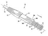
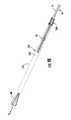
- FIG. 1Ais a schematic diagram of an exemplary molded fiber optic cable furcation assembly disposed on an end portion of a fiber optic cable, the fiber optic cable furcation assembly comprised of an integral furcation plug and strain relief device molded upon the end portion of the fiber optic cable;
- FIG. 1Bis a schematic diagram of the furcation assembly of FIG. 1A depicting optical fibers and strength members disposed within the furcation plug;
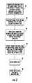
- FIG. 2is a flowchart diagram illustrating an explanatory process that may form a molded fiber optic cable furcation assembly using an overmolding process with a single mold cavity to produce both the furcation plug and strain relief device as depicted in FIG. 1A ;
- FIG. 3Aillustrates an end portion of the fiber optic cable in FIG. 1A prior to overmolding and cut to a desired length with a portion of a cable jacket removed at a transition interface to expose end portions of optical fibers (“optical fiber end portions”) and end portions of strength members (“strength member end portions”) disposed inside the cable jacket to form a transition area in the fiber optic cable;
- FIG. 3Billustrates the exposed strength member end portions in FIG. 3A twisted
- FIG. 3Cillustrates the strength member end portion and the optical fiber end portions of the fiber optic cable in FIG. 3A , prior to overmolding a transition area of the fiber optic cable in a mold;
- FIG. 4illustrates the transition area of the fiber optic cable in FIG. 3C disposed in a molding machine configured to accept the cable and create the molded furcation plug upon a transition area;
- FIG. 5is a flowchart diagram illustrating an exemplary process that may be employed to manufacture a molded fiber optic cable furcation assembly using an overmolding process with a multi-cavity mold to produce the furcation plug in a first mold cavity and the strain relief device in a second mold cavity;
- FIG. 6illustrates a multi-cavity mold adapted to create the molded furcation plug upon the transition area of the fiber optic cable in the first cavity and the strain relief device upon the molded furcation plug in the second cavity using an overmolding process;
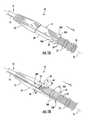
- FIG. 7Aillustrates another exemplary embodiment of an assembled, molded fiber optic cable furcation assembly without an integral strain relief device
- FIG. 7Billustrates a partial cross-sectional view of a cross-section of the molded fiber optic cable furcation assembly of FIG. 7A ;
- FIG. 7Cillustrates an axial end view of the molded fiber optic cable furcation assembly of FIG. 7A ;
- FIG. 7Dillustrates a partial cross-section of the molded fiber optic cable furcation assembly of FIG. 7A with a separate strain relief device disposed adjacent to a side of a molded furcation plug;
- FIG. 7Eillustrates a partial cross-section of the molded fiber optic cable furcation assembly of FIG. 7A with a second strain relief device disposed about the optical fibers extending from the furcation plug;
- FIG. 8Aillustrates an exemplary molded fiber optic cable furcation assembly that may be disposed on a fiber optic cable and formed in the multi-cavity mold
- FIG. 8Billustrates a view of a molded fiber optic cable furcation assembly being disposed within a pulling device
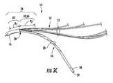
- FIG. 9Aillustrates a pulling bag for receiving the pulling device of FIG. 8B and the molded fiber optic cable furcation assembly of FIG. 8B therein for pulling the fiber optic cable during installation;
- FIG. 9Billustrates the molded fiber optic cable furcation assembly with the pulling device of FIG. 8B securing the molded fiber optic cable furcation assembly of FIG. 8B disposed therein for pulling the fiber optic cable;
- FIG. 10Aillustrates another exemplary molded fiber optic cable furcation assembly that additionally includes a strength member pulling loop
- FIG. 10Billustrates a partial cross-sectional view of the molded fiber optic cable furcation assembly in FIG. 10A ;
- FIG. 11Aillustrates another exemplary molded fiber optic cable furcation assembly including a molded furcation plug having a round or elliptical cross-section
- FIG. 11Billustrates another exemplary molded fiber optic cable furcation assembly including a molded furcation plug having a triangular cross-section.
- Embodiments disclosed in the detailed descriptioninclude molded fiber optic cable furcation assemblies, and related fiber optic components, assemblies, and methods.
- an end portion of a fiber optic cable with a portion of a cable jacket removed to expose optical fibers and/or a strength member(s) thereincan be disposed in a mold to create a molded furcation plug about the end portion of the fiber optic cable.
- the molded furcation plugmay be overmolded about the end portion of the fiber optic cable.
- the molded furcation plugcan be used to pull a fiber optic cable without damaging the optical fiber(s) disposed within the fiber optic cable along with providing a furcation for the optical fibers.
- the molded furcation plugmay be manufactured with fewer parts, without epoxy, and/or without a labor intensive process that may be difficult to automate.
- FIG. 1Aillustrates a schematic diagram of one embodiment of a fiber optic cable furcation assembly 10 (referred to herein as “furcation assembly 10 ”).
- the furcation assembly 10 in this embodimentis comprised of a molded furcation plug 12 and optional strain relief device 13 disposed upon a fiber optic cable 14 .
- FIG. 1Billustrates the furcation assembly 10 in FIG. 1A , but with the molded furcation plug 12 and strain relief device 13 shown in hidden lines so that the fiber optic cable 14 and preparations disposed inside the molded furcation plug 12 can been seen.
- the fiber optic cable 14is comprised of a cable jacket 16 with a plurality of optical fibers 18 and one or more cable strength members 20 disposed therein.
- the cable strength members 20may be provided as one or more tensile yarns.
- the cable strength members 20may be manufactured from aramid, such as Kevlar®.
- Other examples of materials that may be employed for the cable strength members 20include, but are not limited to para-aramid fibers such as the Twaron® brand manufactured by Teijin Aramid, or thermoplastic polyester elastomer materials such as the Heraflex® brand manufactured by Radici Partecipazioni S.p.A.
- the optical fibers 18are disposed in one or more optical fiber sub-units 22 disposed longitudinally within the cable jacket 16 . More specifically, the optical fibers 18 are disposed in sub-unit jackets 23 of the optical fiber sub-units 22 . Any suitable number of optical fiber sub-units 22 may be provided. Likewise, any suitable number of optical fibers 18 may be disposed within each of the optical fiber sub-units 22 . In this embodiment, the optical fibers are disposed within the sub-unit jacket within the furcation plug. However, the optical fibers 18 can have any suitable construction or covering as they pass through the furcation plug such as buffered fibers, bare fibers, or suitable other construction.
- a portion of the cable jacket 16can be cut or otherwise removed to expose the optical fiber sub-units 22 from the cable jacket 16 to provide furcated legs for establishing fiber optic connections with the optical fibers 18 .
- the sub-unitspass through the furcation plug and provide furcated legs of optical fibers as the sub-units transition out of the furcation plug.
- the ends of the optical fibers 18can be connectorized with fiber optic connectors (e.g., without limitation, LC, FC, ST, SC, MTP style connectors), if desired, to allow fiber optic connections.
- the molded furcation plug 12is molded on or about a transition area 24 in an end portion 26 of the fiber optic cable 14 , as illustrated in FIG. 1B .
- the transition area 24 in the end portion 26 of the fiber optic cable 14 in this embodimentis comprised of an end portion of the cable jacket 16 adjacent a transition interface 28 , and a portion of the optical fiber sub-units 22 and cable strength member 20 adjacent to and on the opposite side of the transition interface 24 from the cable jacket 16 .
- the optional strain relief device 13is also illustrated in FIGS. 1A and 1B as being disposed on or about the cable jacket 16 adjacent to the molded furcation plug 12 .
- the strain relief device 13is integrally molded with the molded furcation plug 12 from a single mold cavity.
- the strain relief device 13is designed to prevent or resist excess bending of the cable jacket 16 adjacent to the molded furcation plug 12 beyond the bend rating of the fiber optic cable 14 . This may prevent or avoid damage to the optical fibers 18 and/or avoid unacceptable optical attenuation in the optical fibers 18 .
- the strain relief device 13may be provided as a separate component from the molded furcation body 30 , and may be formed or provided prior to being disposed on the fiber optic cable 14 .
- the molded furcation plug 12 in FIGS. 1A and 1Bmay provide several benefits.
- the molded furcation plug 12may secure the cable jacket 16 and the cable strength member(s) 20 disposed in the fiber optic cable 14 in a manner that may direct a pulling load P 1 to the cable jacket 16 and/or the cable strength members 20 and away from the optical fibers 18 to avoid damaging the optical fibers 18 .
- the molded furcation plug 12may provide a structure that may be secured in a fiber optic cable environment, such as a chassis, to secure the fiber optic cable 14 and thereby allow the optical fiber sub-unit 22 to be connected to the other fiber optic connectors, adapters, and/or equipment.
- the furcation plugmay have structure or geometry to aid in mounting and/or securing the plug within a clip or directly to a mounting structure.
- the furcation plugmay be manufactured with fewer parts, without epoxy, and/or without a labor intensive process that may be difficult to automate.
- the molded furcation plug 12may be molded to provide a molded furcation body 30 that includes a shoulder 32 disposed on first and second ends 34 A, 34 B of the molded furcation body 30 .
- the shoulder 32provides a surface for pulling the molded furcation body 30 to in turn pull the fiber optic cable 14 .
- the shoulder 32may be molded in a geometry that is complementary to a geometry of a pulling device for imposing a pulling load on the molded furcation plug 12 for pulling the fiber optic cable 14 .
- the shoulder 32may have pulling surfaces 36 A, 36 B disposed generally orthogonal to a longitudinal axis A 1 of the molded furcation plug 12 to transfer the pulling load P 1 to the molded furcation body 30 and in turn to the cable jacket 16 and/or the cable strength member(s) 20 .
- FIG. 2provides a flowchart representation of an explanatory process for molding the molded furcation plug 12 and the strain relief device 13 as integrated using a single mold, as shown in FIGS. 1A and 1B .
- the process in FIG. 2will be described in conjunction with FIGS. 3A-4
- an end portion 50 of the cable jacket 16is removed to prepare the fiber optic cable 14 for molding (block 40 in FIG. 2 ).
- the transition interface 28is provided between the remaining end of the cable jacket 16 and the optical fiber sub-units 22 and cable strength members 20 . For example, a technician may perform this removal.
- the end portion 50 of the cable jacket 16may be removed by stripping away the end portion 50 of the cable jacket 16 with a stripping or cutting apparatus.
- end portions 52 of the optical fiber sub-units 22 and end portions 54 of the cable strength members 20are exposed.
- the step of removing a portion of the cable jacketleaves a protective layer on the end portions of one or more optical fibers for the step of molding, thereby providing organization in the furcation and protection for the furcated optical fibers; however, different constructions about the optical fibers are possible according to the concepts disclosed herein.
- the optical fiber sub-units 22are exposed to provide furcation legs that will extend from the molded furcation plug 12 , as illustrated in FIGS. 1A and 1B .
- the cable strength members 20are also exposed so that the molded furcation plug 12 can be secured to the cable strength members 20 to direct pulling force applied to the molded furcation plug 12 to the cable strength members 20 .
- the optical fibers 18 disposed within the optical fiber sub-units 22are not exposed in this embodiment prior to molding the molded furcation plug 12 , but could be removed prior to molding if desired.
- preparations for molding the molded furcation plug 12 and the strain relief device 13can be made.
- an optional twisting of the cable strength members 20may be performed, as illustrated in FIG. 3B , to dispose twists 56 in the cable strength member 20 to provide additional tensile strength in the cable strength member 20 (block 42 in FIG. 2 ).
- tape 58 or other securing meansmay be disposed around an end 59 of the cable strength member 20 , as illustrated in FIG. 3C .
- the fiber optic cable 14is now prepared for molding the molded furcation plug 12 about the transition interface 28 to provide the furcation assembly 10 .
- the transition interface 28between the remaining cable jacket 16 and the exposed optical fiber sub-units 22 and cable strength members 20 is provided.
- the transition interface 28defines a portion of the transition area 24 that is the area that the molded furcation plug 12 will be molded about the fiber optic cable 14 .
- the transition area 24comprises an end portion 60 of the cable jacket 16 adjacent to the transition interface 28 of distance D 1 and end portions 62 , 64 of the exposed optical fiber sub-units 22 and cable strength members 20 , respectively, of distance D 2 also adjacent to the transition interface 28 .
- the end portions 62 , 64 of the exposed optical fiber sub-units 22 and cable strength members 20are disposed on an opposite side of the transition interface 28 from the end portion 60 of the cable jacket 16 .
- the end portion 50 of the cable jacket 16may be removed (block 40 in FIG. 2 ) in any amount desired to provide the desired distances D 1 , D 2 to be compatible with a mold for molding the molded furcation plug 12 and/or the strain relief device 13 about the fiber optic cable 14 .
- the distances D 1 , D 2may be set to provide the desired amount of the end portion 60 of the cable jacket 16 and the end portions 62 , 64 of the optical sub-units 22 and the cable strength member 20 to be secured within the molded furcation plug 12 to transfer pulling forces to the cable jacket 16 and the cable strength member 20 , as desired.
- the distances D 1 , D 2may be 0.75 inches and 1.25 inches, respectively, as non-limiting examples.
- the end portion 54 of the cable strength members 20is trimmed back after being exposed from the cable jacket 16 to be exposed within the transition area 26 (block 44 in FIG. 2 ) so that the cable strength member 20 does not extend outside of the molded furcation body 30 with the optical fiber sub-units 22 .
- the molded furcation plug 12may be formed.
- the transition area 24 of the fiber optic cable 14 comprised of the end portions 52 , 54 of the optical fiber sub-units 22 and the cable strength members 20can now be disposed in a mold cavity to produce the molded furcation plug 12 and/or the strain relief device 13 (block 46 in FIG. 2 ).
- FIG. 4illustrates a depiction of the transition area 24 of the fiber optic cable 14 disposed within a mold 66 to form the molded furcation plug 12 and the integrated strain relief device 13 about the transition area 24 to be formed upon the fiber optic cable 14 .
- the mold 66may be a platen mold, but other suitable molds are possible. As illustrated in FIG. 4 , the mold 66 is designed such that the transition area 24 is disposed inside the mold 66 with the fiber optic cable 14 extending from a first end 68 of the mold 66 through an orifice formed from half channel 79 B and half channel 81 B and the end portions 52 of the optical fiber sub-units 22 extending from a second end 70 of the mold 66 through an orifice formed from half channel 79 A and half channel 81 A.
- the mold 66is comprised of a first cover 72 and a second cover 74 .
- Cavities 76 , 78are disposed inside the first cover 72 and the second cover 74 , respectively.
- the cavities 76 , 78form a closed geometry that provides the shape of the molded furcation body 12 and the strain relief device 13 after the molding process.
- the cavities 76 , 78 in this embodimentare comprised of first sub-cavities 80 , 82 to form the molded furcation plug 12 and second sub-cavities 84 , 86 to form the strain relief device 13 .
- the first cover 72 and the second cover 74 of the mold 66are brought together and secured to each other to close the mold 66 with the transition area 24 of the fiber optic cable 14 disposed therein (block 47 , FIG. 2 ).
- the mold 66 with the transition area 24 secured thereinmay then be disposed in a molding machine 88 where the cavities 76 , 78 are filled with a mold material of specified temperature and pressed through a channel 55 for a controlled time to produce the molded furcation plug 12 (block 48 , FIG. 2 ). Because of the molding process, no epoxy may be required to be disposed inside the molded furcation plug 12 to secure the transition area 24 inside the molded furcation plug 12 .
- molding materialsinclude, but are not limited to polymers, including thermoplastics, including polyurethane, or polyamid materials such as those manufactured by Henkel Corporation under the Macromelt® brand, for example.
- the molding timemay be from forty-five (45) to sixty (60) seconds, from eighty (80) to one hundred seventy (170) degrees Fahrenheit, and from fifty (50) to one hundred fifty (150) pounds per square inch (psi) pressure.
- an overmolding processremoves the need to use epoxy and heat shrinks, or other securing devices, to attach a furcation plug to a fiber optic cable.
- epoxydoes not substantially contribute to the attachment of a furcation plug to a fiber optic cable.
- One advantage of not using epoxy to secure a furcation plug to a fiber optic cableis that epoxy creates voids that may allow the optical fibers to bend and thus degrade signal quality due to optical attenuation.
- the overmolding process in FIG. 2may also be automated in a manufacturing facility resulting in time savings over conventional manufacturing process that require epoxy.
- the integrated strain relief device 13 depicted in FIGS. 1A and 1B and molded in the mold 66may be molded from the same molding material as the molded furcation plug 12 .
- the strain relief device 13extends from the first end 34 A of the molded furcation plug 12 opposite from the second end 34 B where the optical fiber sub-units 22 extend from outside of the molded furcation body 30 .
- the fiber optic cable 14may experience bending forces during installation and movement that may cause strain in the fiber optic cable 14 .
- the strain relief device 13may relieve the strain on the fiber optic cable 14 by providing a level of flexibility to resist the bending forces and thereby relieve the strain.
- the level of flexibility of the strain relief device 13is controlled by tapered cross-section areas 90 , 92 disposed in the second sub-cavities 84 , 86 , as illustrated in FIG. 4 .
- a cross-section area A 2 on a first end 94 of the second sub-cavity 86is smaller than a cross-section area A 3 on a second end 96 of the second sub-cavity 86 .
- the level of flexibilitymay be measured by the spring force constant of the various cross-section areas 90 , 92 , which may be controlled by the amount of material allowed in the second sub-cavities 84 , 86 and thus are able to provide larger restoring forces to relieve cable strain when the fiber optic cable 14 is bent.
- Other embodiments of the strain relief devices molded on the cable jacket 14may also have variances in cross-section area to control bend resistance.
- FIG. 5depicts an alternative exemplary process for preparing a molded furcation plug and strain relief device on the fiber optic cable 14 in FIGS. 1A and 1B .
- a multi-cavity mold 110is employed.
- blocks 100 - 104may be performed just as performed in blocks 40 - 44 in FIG. 2 to prepare the transition area 24 of the fiber optic cable 14 for molding.
- the transition area 24 of the fiber optic cable 14may be placed into a first cavity 112 of a bottom cover 114 of the multi-cavity mold 110 shown in FIG. 6 .
- the multi-cavity mold 110also includes a top cover 116 that also contains a cavity (not visible) that aligns with the first cavity 112 when the top cover 116 is secured to the bottom cover 114 to form a cavity having the shape of the molded furcation body 30 .
- the top cover 116 of the multi-cavity mold 110is secured or closed onto the bottom cover 114 and the first cavity 112 is filled with a first molding material of specified temperature and pressure for a controlled time to produce a molded furcation plug (block 106 in FIG. 5 ). After a desired specified time has elapsed, the multi-cavity mold 110 is opened and the transition area 24 of the fiber optic cable 14 is removed with the molded furcation plug 12 molded thereto without a strain relief device.
- FIGS. 7A and 7BAn explanatory example of a furcation assembly that includes a molded furcation plug that can be molded using the process in FIG. 5 is illustrated in FIGS. 7A and 7B .
- the molded furcation plugis the molded furcation plug 12 in the furcation assembly 10 in FIGS. 1A and 1B , but molded using the alternative molding process in FIG. 5 and the multi-cavity mold 110 in FIG. 6 .
- FIG. 7Aillustrates a perspective view of the molded furcation plug 12 without the strain relief device 13 provided.
- FIG. 7Bdepicts a side view of the molded furcation plug 12 in FIG. 7A .
- the first end 34 A of the molded furcation body 30may be created in the first cavity 112 of the multi-cavity mold 110 .
- the first end 34 Amay include a cylindrical shoulder feature 121 in the molded furcation body 30 to allow for a strain relief device to be pushed onto the cylindrical shoulder feature 121 to provide a friction fit and a communication between a shoulder surface 123 and the end portion of the strain relief device.
- an alternative strain relief device 122is disposed about the cable jacket 16 prior to molding of the molded furcation plug 12 in the first cavity 112 of the multi-cavity mold 110 .
- the strain relief device 122is not molded to the fiber optic cable 14 . Instead, after the molded furcation plug 12 is molded, a first end 124 of the strain relief device 122 may be pushed towards the first end 34 A of the molded furcation body 30 .
- the strain relief device 122contains an orifice (not shown) that receives the cylindrical shoulder feature 121 of the molded furcation body 30 to interface and abut the first end 124 of the strain relief device 122 to the shoulder surface 123 of the molded furcation plug 30 .
- FIG. 7AAnother optional embodiment of the fiber optic furcation assembly 10 in FIG. 7A includes providing a second strain relief device 125 attached to the second end 34 B of the molded furcation body 30 .
- the second strain relief device 125may be provided as a tube 127 , and more particularly a spiral wound tube.
- the tube 127may be disposed over the end portions 52 of the optical fiber sub-units 22 prior to molding the molded furcation plug 12 .
- a portion 129 of the tube 127is disposed inside the mold used to mold the molded furcation plug 12 .
- the molded bond 120secures the tube 127 during the molding process to attach the tube 127 to the molded furcation plug 12 to provide strain relief for the optical fiber sub-units 22 .
- the tube 127may be made from the same material as the strain relief devices disclosed herein, or any other materials desired that provide some flexibility to allow the optical fiber sub-units 22 to be bent.
- the multi-cavity mold 110 in FIG. 6may be used to also mold a strain relief device upon the fiber optic cable 14 in lieu of the strain relief device being provided as a separate component and disposed on the fiber optic cable 14 before the molded furcation plug 12 is molded.
- This stepis represented by block 108 in FIG. 5 .
- the strain relief device 13 in FIGS. 1A and 1Bcan also be molded about the cable jacket 16 after the molding of the molded furcation plug 12 in the first cavity 112 of the multi-cavity mold 110 .
- the molded furcation plug 12is placed inside a second cavity 118 ( FIG.
- the multi-cavity mold 110to mold the strain relief device 13 about the fiber optic cable 14 adjacent to the molded furcation plug 12 .
- the same molding material used to mold the molded furcation plug 12may be used to mold the strain relief device 13 .
- a different, second molding materialmay be used to fill the second cavity 118 at a specified temperature and pressure for a controlled time to produce a strain relief device molded upon the molded furcation plug 12 and the cable jacket 16 .
- the furcation assembly 10is removed from the multi-cavity mold 110 to complete the furcation assembly 10 shown in FIG. 8A , which is also illustrated in FIGS. 1A and 1B and previously described.
- the molded furcation plug 12may be disposed in a pulling clamp 130 depicted in FIG. 8B .
- the pulling clamp 130 with the molded furcation plug 12 disposed thereinmay be inserted into a pulling bag 132 illustrated in FIGS. 9A and 9B to pull the fiber optic cable 14 to provide a fiber optic pulling assembly 134 illustrated in FIG. 9B .
- the pulling clamp 130is comprised of a top clamp member 136 and a bottom clamp member 138 .
- a cavity 139is provided therein that is designed to tightly receive the molded furcation plug 12 .
- the cavity 139contains a sub-cavity that is designed to apply a pulling force applied to the pulling clamp 130 to the pulling surfaces 36 B in the molded furcation body 30 .
- a complementary cavity(not shown) is provided in the top clamp member 136 .
- the pulling bag 132may include a bag loop 140 for transferring a pulling force P 2 to a body 142 of the pulling bag 132 , which may in turn transfer the pulling force P 2 to the pulling clamp 130 via an internal tapered surface 144 of the pulling bag 132 .
- the bag loop 140is located at a first end 146 of the body 142 of the pulling bag 132 .
- the internal tapered surface 144is located on a second end 148 of the body 142 .
- the pulling clamp 130 with the furcation assembly 10 disposed thereincan be disposed within an interior cavity 150 of the body 142 to secure the fiber optic cable 14 for pulling.
- the pulling bag 132may be made of nylon, canvas, or any strong flexible material.
- FIGS. 10A and 10Billustrate the molded furcation plug 12 with the alternate strain relief device 122 in FIG. 7D , but include an addition of a strength member pulling loop 150 .
- the strength member pulling loop 150provides an alternative or additional member that can be pulled to pull the fiber optic cable 14 having the furcation assembly 10 to transfer pulling force to the cable strength member 20 .
- a pulling forcemay be directly applied to the strength member pulling loop 150 .
- the process to create the strength member pulling loop 150may be as previously provided, for example, in blocks 40 - 44 in FIG. 2 .
- the cable strength member 20is trimmed, the cable strength member 20 is left longer than in previous embodiments described above. This is so that an excess portion 152 of the cable strength member 20 exits from the second end 34 B of the molded furcation body 30 .
- the strength member pulling loop 150may be created by positioning a first end 154 of the excess portion 152 of the cable strength member 20 back within the mold, as illustrated in molded form in FIGS. 10A and 10B .
- the molding material disposed in the mold to form the molded furcation plug 12surrounds and secures the first end 154 of the excess portion 152 of the cable strength members 20 inside the molded furcation plug 12 to form the strength member pulling loop 150 .
- a heat shrink tube 156as illustrated in FIGS. 10A and 10B , may be disposed around the cable strength member 20 prior to forming the strength member pulling loop 150 , if desired.
- FIG. 11Adepicts a molded furcation plug 160 that may have a furcation body 162 having a round or an elliptical-shaped cross-section.
- FIG. 11Bdepicts a molded furcation plug 164 that may have a furcation body 166 having a triangular-shaped cross-section.
- the embodiments hereincan be applied to any type of cable and fiber optic cable that includes one or more strength members.
- the cablemay include any other medium, including buffered and unbuffered optical fibers as an example. Any sizes of the features disclosed herein may be provided without limitation.
Landscapes
- Physics & Mathematics (AREA)
- General Physics & Mathematics (AREA)
- Optics & Photonics (AREA)
- Mechanical Coupling Of Light Guides (AREA)
Abstract
Description
Claims (22)
Priority Applications (1)
| Application Number | Priority Date | Filing Date | Title |
|---|---|---|---|
| US13/161,976US8958673B2 (en) | 2011-05-27 | 2011-06-16 | Molded fiber optic cable furcation assemblies, and related fiber optic components, assemblies, and methods |
Applications Claiming Priority (2)
| Application Number | Priority Date | Filing Date | Title |
|---|---|---|---|
| US201161490771P | 2011-05-27 | 2011-05-27 | |
| US13/161,976US8958673B2 (en) | 2011-05-27 | 2011-06-16 | Molded fiber optic cable furcation assemblies, and related fiber optic components, assemblies, and methods |
Publications (2)
| Publication Number | Publication Date |
|---|---|
| US20120301090A1 US20120301090A1 (en) | 2012-11-29 |
| US8958673B2true US8958673B2 (en) | 2015-02-17 |
Family
ID=47219275
Family Applications (1)
| Application Number | Title | Priority Date | Filing Date |
|---|---|---|---|
| US13/161,976Active2032-05-06US8958673B2 (en) | 2011-05-27 | 2011-06-16 | Molded fiber optic cable furcation assemblies, and related fiber optic components, assemblies, and methods |
Country Status (4)
| Country | Link |
|---|---|
| US (1) | US8958673B2 (en) |
| EP (2) | EP2715418B1 (en) |
| CN (1) | CN103582832B (en) |
| WO (1) | WO2012166433A1 (en) |
Cited By (12)
| Publication number | Priority date | Publication date | Assignee | Title |
|---|---|---|---|---|
| US20160124174A1 (en)* | 2013-06-10 | 2016-05-05 | Afl Telecommunications Llc | Optical fiber furcation assembly and method |
| US10175430B2 (en) | 2016-05-05 | 2019-01-08 | Belden Canada Inc. | Overmoulded furcation assembly with strain relief |
| US10247889B1 (en)* | 2018-05-15 | 2019-04-02 | Te Connectivity Corporation | Overmolded breakout |
| US10353164B2 (en) | 2017-06-27 | 2019-07-16 | Afl Telecommunications Llc | Fiber optic transition assemblies |
| US10379311B1 (en) | 2018-04-04 | 2019-08-13 | Northrop Grumman Systems Corporation | Over-molded multi-optical fiber ribbon cable and method of making same |
| US20210396945A1 (en)* | 2020-06-17 | 2021-12-23 | Commscope Technologies Llc | Breakout assembly for fiber optic cable |
| US11243367B2 (en) | 2018-08-03 | 2022-02-08 | Afl Telecommunications Llc | Multiple cable size fiber optic transition assemblies |
| US11347014B2 (en) | 2018-09-07 | 2022-05-31 | Corning Incorporated | Optical fiber fan-out assembly with ribbonized interface for mass fusion splicing, and fabrication method |
| US11561344B2 (en) | 2017-03-21 | 2023-01-24 | Corning Research & Development Corporation | Fiber optic cable assembly with thermoplastically overcoated fusion splice, and related method and apparatus |
| US11774677B2 (en) | 2019-07-31 | 2023-10-03 | Corning Research & Development Corporation | Fiber optic cable assembly with overlapping bundled strength members, and fabrication method and apparatus |
| US11867947B2 (en) | 2021-04-30 | 2024-01-09 | Corning Research & Development Corporation | Cable assembly having routable splice protectors |
| US11886009B2 (en) | 2020-10-01 | 2024-01-30 | Corning Research & Development Corporation | Coating fusion spliced optical fibers and subsequent processing methods thereof |
Families Citing this family (28)
| Publication number | Priority date | Publication date | Assignee | Title |
|---|---|---|---|---|
| US7198409B2 (en) | 2003-06-30 | 2007-04-03 | Adc Telecommunications, Inc. | Fiber optic connector holder and method |
| US7218827B2 (en) | 2004-06-18 | 2007-05-15 | Adc Telecommunications, Inc. | Multi-position fiber optic connector holder and method |
| US8885999B2 (en)* | 2010-03-19 | 2014-11-11 | Corning Cable Systems Llc | Optical USB cable with controlled fiber positioning |
| KR20140027352A (en) | 2011-06-10 | 2014-03-06 | 코닝 케이블 시스템스 엘엘씨 | Fiber optic cables allowing fiber translation to reduce bend attenuation |
| US8953916B2 (en) | 2011-06-22 | 2015-02-10 | Corning Cable Systems Llc | Multi-fiber, fiber optic cable assemblies providing constrained optical fibers within an optical fiber sub-unit, and related fiber optic components, cables, and methods |
| US8630523B2 (en)* | 2011-07-13 | 2014-01-14 | Corning Cable Systems Llc | Methods of preparing strength member pulling members in fiber optic cable furcations and related components, assemblies, and fiber optic cables |
| US8676012B2 (en)* | 2012-01-20 | 2014-03-18 | Corning Cable Systems Llc | Fiber optic cable for very-short-distance networks |
| US8678668B2 (en)* | 2012-01-30 | 2014-03-25 | Corning Cable Systems Llc | Overmolded ferrule boot and methods for making the same |
| US8961032B2 (en)* | 2012-02-09 | 2015-02-24 | Corning Cable Systems Llc | Cable leg and connector management system |
| US9170389B2 (en) | 2012-08-28 | 2015-10-27 | Corning Cable Systems Llc | Hybrid fiber optic cable systems |
| US9140872B2 (en)* | 2013-09-17 | 2015-09-22 | Panduit Corp. | Hydra cable assembly and components thereof |
| JP5719052B1 (en)* | 2014-03-06 | 2015-05-13 | 株式会社フジクラ | Optical cable |
| US20150362690A1 (en)* | 2014-06-12 | 2015-12-17 | Commscope Technologies Llc | Environmental sealing arrangement for furcated optical fibers |
| US10156692B2 (en)* | 2014-06-17 | 2018-12-18 | Afl Telecommunications Llc | Optical fiber furcation transition assembly with integrated retention feature |
| US10054753B2 (en) | 2014-10-27 | 2018-08-21 | Commscope Technologies Llc | Fiber optic cable with flexible conduit |
| ES2738423T3 (en)* | 2015-06-30 | 2020-01-22 | Corning Optical Communications LLC | Fiber optic cable assembly |
| AU2015207954C1 (en) | 2015-07-31 | 2022-05-05 | Adc Communications (Australia) Pty Limited | Cable breakout assembly |
| EP3403125B1 (en) | 2016-03-18 | 2021-07-14 | Commscope Technologies LLC | Fiber-optic cable fanout conduit arrangement and method for organizing optical fibers |
| US10890730B2 (en) | 2016-08-31 | 2021-01-12 | Commscope Technologies Llc | Fiber optic cable clamp and clamp assembly |
| US10914909B2 (en) | 2016-10-13 | 2021-02-09 | Commscope Technologies Llc | Fiber optic breakout transition assembly incorporating epoxy plug and cable strain relief |
| US10067310B2 (en) | 2016-11-03 | 2018-09-04 | Corning Optical Communications LLC | Fiber optic drop cable assembly |
| CN110622051A (en) | 2017-05-08 | 2019-12-27 | 康普技术有限责任公司 | Optical fiber branch transition assembly |
| JP6927760B2 (en)* | 2017-06-23 | 2021-09-01 | 三菱電線工業株式会社 | Optical fiber core wire protection structure |
| JP7063107B2 (en)* | 2018-05-18 | 2022-05-09 | 住友電気工業株式会社 | Optical connector cable and metal parts |
| CN116075759A (en)* | 2020-07-07 | 2023-05-05 | 康普技术有限责任公司 | Optical fiber splice transition and method of assembly |
| US11495923B2 (en)* | 2021-04-09 | 2022-11-08 | Steve Kuhl | Cable cap with power indicator |
| EP4174545A1 (en)* | 2021-11-02 | 2023-05-03 | Corning Research & Development Corporation | Attachment bodies and optical cable assemblies for mating with compact multiports |
| EP4490563A2 (en)* | 2022-03-07 | 2025-01-15 | Corning Research & Development Corporation | Overmold for optical fiber distribution cable and related method and system |
Citations (40)
| Publication number | Priority date | Publication date | Assignee | Title |
|---|---|---|---|---|
| DE3820950A1 (en) | 1988-06-16 | 1989-12-21 | Siemens Ag | Method for fastening cable reinforcement |
| US5231688A (en) | 1991-10-07 | 1993-07-27 | Siecor Corporation | Furcation kit |
| US5473718A (en) | 1994-09-20 | 1995-12-05 | The United States Of America As Represented By The Secretary Of The Navy | Fiber optic loose tube buffer to fan-out tube adapter system |
| US5838861A (en) | 1997-03-06 | 1998-11-17 | Newport News Shipbuilding And Dry Dock Company | Transition assembly for optical fiber |
| US5892871A (en) | 1995-12-13 | 1999-04-06 | Dahan; Michael | Fiber optic cable termination |
| US5903693A (en) | 1997-09-30 | 1999-05-11 | The United States Of America As Represented By The Secretary Of The Navy | Fiber optic cable furcation unit |
| US5966489A (en) | 1997-06-30 | 1999-10-12 | Siecor Corporation | Fiber optic ribbon interconnect cable |
| US6278831B1 (en) | 1999-01-08 | 2001-08-21 | Priority Electronics Inc. | Fiber optic cable assembly |
| US6389214B1 (en) | 2001-05-17 | 2002-05-14 | 3M Innovative Properties Company | Furcation apparatus for optical fibers |
| US6438299B1 (en) | 1997-09-30 | 2002-08-20 | The United States Of America As Represented By The Secretary Of The Navy | Assembly and method for furcating optical fibers |
| US20030210875A1 (en) | 2002-05-07 | 2003-11-13 | Wagner Karl M. | High performance, flexible optical fiber furcation |
| US6738555B1 (en) | 2001-03-28 | 2004-05-18 | Corning Cable Systems Llc | Furcation kit |
| US20040126069A1 (en) | 2002-12-30 | 2004-07-01 | Jong Michael De | Flexible, multi-fiber fiber optic jumper |
| US20050002621A1 (en) | 2003-07-02 | 2005-01-06 | Zimmel Steven C. | Fiberoptic furcation device with crimp |
| US20050111811A1 (en) | 2003-11-26 | 2005-05-26 | Cooke Terry L. | Pulling grip for installing pre-connectorized fiber optic cable |
| US20050111810A1 (en) | 2003-11-26 | 2005-05-26 | Giraud William J. | Connector housing for a communication network |
| US20050276551A1 (en) | 2004-06-15 | 2005-12-15 | Troy Brown | Fiber optic furcation tube and method |
| US20060120672A1 (en) | 2004-12-03 | 2006-06-08 | Cody Joseph T | Tether assembly having individual connector ports |
| US20070047897A1 (en) | 2005-08-31 | 2007-03-01 | Cooke Terry L | Fiber optic universal bracket apparatus and methods |
| US7270485B1 (en) | 2006-06-23 | 2007-09-18 | Carlyle, Inc. | Device for furcating fiber optic cables |
| US20080013888A1 (en) | 2006-06-30 | 2008-01-17 | Barnes Brandon A | Optical fiber transition device |
| US20080138026A1 (en) | 2006-12-08 | 2008-06-12 | Yow Charles A | Furcation tubing and fanout furcation kit |
| US20090003782A1 (en) | 2007-06-27 | 2009-01-01 | Verizon Services Corp. | Fiber optic drop ribbon, system, and associated method |
| US20100054678A1 (en) | 2008-09-04 | 2010-03-04 | Dimarco Brian Anthony | Fiber optic furcation method |
| US20100054676A1 (en) | 2008-08-29 | 2010-03-04 | Cooke Terry L | Fiber Optic Furcation Assembly Having Feature(s) for Cable Management |
| US20100054686A1 (en) | 2008-08-29 | 2010-03-04 | Cooke Terry L | Structures for Managing and Mounting Cable Assemblies |
| US20100054684A1 (en) | 2008-08-29 | 2010-03-04 | Cooke Terry L | Rear-Slidable Extension in a Fiber Optic Equipment Tray |
| US20100080524A1 (en) | 2008-09-30 | 2010-04-01 | Tomasz Ciechomski | System for the Distribution of Optical Fibers |
| US20100086267A1 (en) | 2008-08-29 | 2010-04-08 | Cooke Terry L | Fiber Optic Cable Assemblies Employing a Furcation Body Having Anti-Rotation Feature |
| US20100092135A1 (en) | 2008-09-12 | 2010-04-15 | Draka Comteq B.V. | Optical Fiber Cable Assembly |
| US20100098386A1 (en) | 2008-10-17 | 2010-04-22 | Kleeberger Terry M | Devices and associated methods for furcating fiber optic cables |
| US7703990B1 (en) | 2009-04-23 | 2010-04-27 | Corning Cable Systems Llc | Furcation bodies and fiber optic assemblies using the same |
| US20100183270A1 (en) | 2008-08-29 | 2010-07-22 | Davis Gerald J | Clip for Securing a Fiber Optic Cable Assembly and Associated Assemblies |
| US20100202740A1 (en) | 2008-08-29 | 2010-08-12 | Barlowe Edward K | Fiber optic cable assemblies with furcation bodies having features for manufacturing and methods of making the same |
| US20100209059A1 (en) | 2009-02-16 | 2010-08-19 | Conrad Craig M | Micromodule Cables and Breakout Cables Therefor |
| US20100215330A1 (en) | 2009-02-24 | 2010-08-26 | Bartlomiej Sokolowski | Holding Device for a Cable or an Assembly for Use With a Cable |
| US20100220964A1 (en) | 2008-09-30 | 2010-09-02 | De Jong Michael | Fiber Optic Drop Cable Furcation Assemblies and Methods |
| US20100322578A1 (en) | 2009-06-19 | 2010-12-23 | Cooke Terry L | Mounting of Fiber Optic Cable Assemblies Within Fiber Optic Shelf Assemblies |
| US20110091169A1 (en) | 2008-06-10 | 2011-04-21 | Tyco Electronics Nederland Bv | Fiber optic furcation assembly |
| US20110243514A1 (en)* | 2010-03-30 | 2011-10-06 | Nave Samuel D | Multiple channel optical fiber furcation tube and cable assembly using same |
Family Cites Families (1)
| Publication number | Priority date | Publication date | Assignee | Title |
|---|---|---|---|---|
| WO1994024598A1 (en)* | 1993-04-16 | 1994-10-27 | Raychem Corporation | Bonding assembly for fiber optic cable and associated method |
- 2011
- 2011-06-16USUS13/161,976patent/US8958673B2/enactiveActive
- 2012
- 2012-05-22EPEP12792605.3Apatent/EP2715418B1/enactiveActive
- 2012-05-22EPEP18201393.8Apatent/EP3460551A1/ennot_activeWithdrawn
- 2012-05-22WOPCT/US2012/038956patent/WO2012166433A1/enactiveApplication Filing
- 2012-05-22CNCN201280025870.3Apatent/CN103582832B/enactiveActive
Patent Citations (60)
| Publication number | Priority date | Publication date | Assignee | Title |
|---|---|---|---|---|
| DE3820950A1 (en) | 1988-06-16 | 1989-12-21 | Siemens Ag | Method for fastening cable reinforcement |
| US5231688A (en) | 1991-10-07 | 1993-07-27 | Siecor Corporation | Furcation kit |
| US5473718A (en) | 1994-09-20 | 1995-12-05 | The United States Of America As Represented By The Secretary Of The Navy | Fiber optic loose tube buffer to fan-out tube adapter system |
| US5892871A (en) | 1995-12-13 | 1999-04-06 | Dahan; Michael | Fiber optic cable termination |
| US5838861A (en) | 1997-03-06 | 1998-11-17 | Newport News Shipbuilding And Dry Dock Company | Transition assembly for optical fiber |
| US5966489A (en) | 1997-06-30 | 1999-10-12 | Siecor Corporation | Fiber optic ribbon interconnect cable |
| US5970195A (en) | 1997-09-30 | 1999-10-19 | The United States Of America As Represented By The Secretary Of The Navy | Fiber optic cable furcation unit |
| US6438299B1 (en) | 1997-09-30 | 2002-08-20 | The United States Of America As Represented By The Secretary Of The Navy | Assembly and method for furcating optical fibers |
| US5903693A (en) | 1997-09-30 | 1999-05-11 | The United States Of America As Represented By The Secretary Of The Navy | Fiber optic cable furcation unit |
| US6278831B1 (en) | 1999-01-08 | 2001-08-21 | Priority Electronics Inc. | Fiber optic cable assembly |
| US6738555B1 (en) | 2001-03-28 | 2004-05-18 | Corning Cable Systems Llc | Furcation kit |
| US6389214B1 (en) | 2001-05-17 | 2002-05-14 | 3M Innovative Properties Company | Furcation apparatus for optical fibers |
| US6771861B2 (en) | 2002-05-07 | 2004-08-03 | Corning Cable Systems Llc | High performance, flexible optical fiber furcation |
| US20030210875A1 (en) | 2002-05-07 | 2003-11-13 | Wagner Karl M. | High performance, flexible optical fiber furcation |
| US6764221B1 (en) | 2002-12-30 | 2004-07-20 | Corning Calde Systems Llc | Flexible, multi-fiber fiber optic jumper |
| US20040126069A1 (en) | 2002-12-30 | 2004-07-01 | Jong Michael De | Flexible, multi-fiber fiber optic jumper |
| US20050002621A1 (en) | 2003-07-02 | 2005-01-06 | Zimmel Steven C. | Fiberoptic furcation device with crimp |
| US20050031276A1 (en) | 2003-07-02 | 2005-02-10 | Adc Telecommunications, Inc. | Fiberoptic furcation device with crimp |
| US6909828B2 (en) | 2003-07-02 | 2005-06-21 | Adc Telecommunications, Inc. | Fiberoptic furcation device with crimp |
| US7035510B2 (en) | 2003-07-02 | 2006-04-25 | Adc Telecommunications, Inc. | Fiberoptic furcation device with crimp |
| US20050111811A1 (en) | 2003-11-26 | 2005-05-26 | Cooke Terry L. | Pulling grip for installing pre-connectorized fiber optic cable |
| US20050111810A1 (en) | 2003-11-26 | 2005-05-26 | Giraud William J. | Connector housing for a communication network |
| US7200316B2 (en) | 2003-11-26 | 2007-04-03 | Corning Cable Systems Llc | Connector housing for a communication network |
| US6993237B2 (en) | 2003-11-26 | 2006-01-31 | Corning Cable Systems Llc | Pulling grip for installing pre-connectorized fiber optic cable |
| US20050276551A1 (en) | 2004-06-15 | 2005-12-15 | Troy Brown | Fiber optic furcation tube and method |
| US7280725B2 (en) | 2004-06-15 | 2007-10-09 | Adc Telecommunications, Inc. | Fiber optic furcation tube and method |
| US20060120672A1 (en) | 2004-12-03 | 2006-06-08 | Cody Joseph T | Tether assembly having individual connector ports |
| US7277614B2 (en) | 2004-12-03 | 2007-10-02 | Corning Cable Systems Llc | Tether assembly having individual connector ports |
| US7330629B2 (en) | 2005-08-31 | 2008-02-12 | Corning Cable Systems Llc | Fiber optic universal bracket apparatus and methods |
| US20070047897A1 (en) | 2005-08-31 | 2007-03-01 | Cooke Terry L | Fiber optic universal bracket apparatus and methods |
| US7270485B1 (en) | 2006-06-23 | 2007-09-18 | Carlyle, Inc. | Device for furcating fiber optic cables |
| US20080138020A1 (en) | 2006-06-23 | 2008-06-12 | Paul Robinson | Device for furcating fiber optic cables |
| US7494284B2 (en) | 2006-06-23 | 2009-02-24 | Carlyle Inc. | Device for furcating fiber optic cables |
| US20090190889A1 (en) | 2006-06-23 | 2009-07-30 | Paul Robinson | Device for furcating fiber optic cables |
| US20080013888A1 (en) | 2006-06-30 | 2008-01-17 | Barnes Brandon A | Optical fiber transition device |
| US7512308B2 (en) | 2006-06-30 | 2009-03-31 | Corning Incorporated | Optical fiber transition device |
| US20080138026A1 (en) | 2006-12-08 | 2008-06-12 | Yow Charles A | Furcation tubing and fanout furcation kit |
| US7461981B2 (en) | 2006-12-08 | 2008-12-09 | Corning Cable Systems Llc | Furcation tubing and fanout furcation kit |
| US20090003782A1 (en) | 2007-06-27 | 2009-01-01 | Verizon Services Corp. | Fiber optic drop ribbon, system, and associated method |
| US7492997B2 (en) | 2007-06-27 | 2009-02-17 | Verizon Services Corp. | Fiber optic drop ribbon, system, and associated method |
| US20110091169A1 (en) | 2008-06-10 | 2011-04-21 | Tyco Electronics Nederland Bv | Fiber optic furcation assembly |
| US20100054684A1 (en) | 2008-08-29 | 2010-03-04 | Cooke Terry L | Rear-Slidable Extension in a Fiber Optic Equipment Tray |
| US20100202740A1 (en) | 2008-08-29 | 2010-08-12 | Barlowe Edward K | Fiber optic cable assemblies with furcation bodies having features for manufacturing and methods of making the same |
| US20100054676A1 (en) | 2008-08-29 | 2010-03-04 | Cooke Terry L | Fiber Optic Furcation Assembly Having Feature(s) for Cable Management |
| US20100086267A1 (en) | 2008-08-29 | 2010-04-08 | Cooke Terry L | Fiber Optic Cable Assemblies Employing a Furcation Body Having Anti-Rotation Feature |
| US20100054686A1 (en) | 2008-08-29 | 2010-03-04 | Cooke Terry L | Structures for Managing and Mounting Cable Assemblies |
| US7903925B2 (en) | 2008-08-29 | 2011-03-08 | Corning Cable Systems Llc | Fiber optic furcation assembly having feature(s) for cable management |
| US20100183270A1 (en) | 2008-08-29 | 2010-07-22 | Davis Gerald J | Clip for Securing a Fiber Optic Cable Assembly and Associated Assemblies |
| US7955004B2 (en) | 2008-09-04 | 2011-06-07 | Fibersource, Inc. | Fiber optic furcation method |
| US20100054678A1 (en) | 2008-09-04 | 2010-03-04 | Dimarco Brian Anthony | Fiber optic furcation method |
| US20100092135A1 (en) | 2008-09-12 | 2010-04-15 | Draka Comteq B.V. | Optical Fiber Cable Assembly |
| US20100220964A1 (en) | 2008-09-30 | 2010-09-02 | De Jong Michael | Fiber Optic Drop Cable Furcation Assemblies and Methods |
| US20100080524A1 (en) | 2008-09-30 | 2010-04-01 | Tomasz Ciechomski | System for the Distribution of Optical Fibers |
| US20100098386A1 (en) | 2008-10-17 | 2010-04-22 | Kleeberger Terry M | Devices and associated methods for furcating fiber optic cables |
| US20100209059A1 (en) | 2009-02-16 | 2010-08-19 | Conrad Craig M | Micromodule Cables and Breakout Cables Therefor |
| US20100215330A1 (en) | 2009-02-24 | 2010-08-26 | Bartlomiej Sokolowski | Holding Device for a Cable or an Assembly for Use With a Cable |
| US7703990B1 (en) | 2009-04-23 | 2010-04-27 | Corning Cable Systems Llc | Furcation bodies and fiber optic assemblies using the same |
| US20100322578A1 (en) | 2009-06-19 | 2010-12-23 | Cooke Terry L | Mounting of Fiber Optic Cable Assemblies Within Fiber Optic Shelf Assemblies |
| US7945136B2 (en) | 2009-06-19 | 2011-05-17 | Corning Cable Systems Llc | Mounting of fiber optic cable assemblies within fiber optic shelf assemblies |
| US20110243514A1 (en)* | 2010-03-30 | 2011-10-06 | Nave Samuel D | Multiple channel optical fiber furcation tube and cable assembly using same |
Non-Patent Citations (2)
| Title |
|---|
| European Patent Office Search Report, Application No. 12792605.3-1504/2715418, Oct. 1, 2014, 8 pages. |
| Patent Cooperation Treaty International Search Report, Application No. PCT/US2012/038956, Aug. 17, 2012, 2 pages. |
Cited By (14)
| Publication number | Priority date | Publication date | Assignee | Title |
|---|---|---|---|---|
| US9529173B2 (en)* | 2013-06-10 | 2016-12-27 | Afl Telecommunications Llc | Optical fiber furcation assembly and method |
| US20160124174A1 (en)* | 2013-06-10 | 2016-05-05 | Afl Telecommunications Llc | Optical fiber furcation assembly and method |
| US10175430B2 (en) | 2016-05-05 | 2019-01-08 | Belden Canada Inc. | Overmoulded furcation assembly with strain relief |
| US11561344B2 (en) | 2017-03-21 | 2023-01-24 | Corning Research & Development Corporation | Fiber optic cable assembly with thermoplastically overcoated fusion splice, and related method and apparatus |
| US10353164B2 (en) | 2017-06-27 | 2019-07-16 | Afl Telecommunications Llc | Fiber optic transition assemblies |
| US10379311B1 (en) | 2018-04-04 | 2019-08-13 | Northrop Grumman Systems Corporation | Over-molded multi-optical fiber ribbon cable and method of making same |
| US10247889B1 (en)* | 2018-05-15 | 2019-04-02 | Te Connectivity Corporation | Overmolded breakout |
| US11243367B2 (en) | 2018-08-03 | 2022-02-08 | Afl Telecommunications Llc | Multiple cable size fiber optic transition assemblies |
| US11347014B2 (en) | 2018-09-07 | 2022-05-31 | Corning Incorporated | Optical fiber fan-out assembly with ribbonized interface for mass fusion splicing, and fabrication method |
| US11774677B2 (en) | 2019-07-31 | 2023-10-03 | Corning Research & Development Corporation | Fiber optic cable assembly with overlapping bundled strength members, and fabrication method and apparatus |
| US20210396945A1 (en)* | 2020-06-17 | 2021-12-23 | Commscope Technologies Llc | Breakout assembly for fiber optic cable |
| US11609401B2 (en)* | 2020-06-17 | 2023-03-21 | Commscope Technologies Llc | Breakout assembly for fiber optic cable |
| US11886009B2 (en) | 2020-10-01 | 2024-01-30 | Corning Research & Development Corporation | Coating fusion spliced optical fibers and subsequent processing methods thereof |
| US11867947B2 (en) | 2021-04-30 | 2024-01-09 | Corning Research & Development Corporation | Cable assembly having routable splice protectors |
Also Published As
| Publication number | Publication date |
|---|---|
| EP2715418A1 (en) | 2014-04-09 |
| EP2715418B1 (en) | 2019-02-27 |
| CN103582832A (en) | 2014-02-12 |
| EP2715418A4 (en) | 2014-10-29 |
| US20120301090A1 (en) | 2012-11-29 |
| WO2012166433A1 (en) | 2012-12-06 |
| CN103582832B (en) | 2017-03-15 |
| EP3460551A1 (en) | 2019-03-27 |
Similar Documents
| Publication | Publication Date | Title |
|---|---|---|
| US8958673B2 (en) | Molded fiber optic cable furcation assemblies, and related fiber optic components, assemblies, and methods | |
| CN101529299B (en) | Improved hauling shroud for hauling a fibre optic cable along a conduit | |
| US20220026658A1 (en) | Fiber optic cable assembly with furcation and method of making same | |
| US8885998B2 (en) | Splice enclosure arrangement for fiber optic cables | |
| US20130016948A1 (en) | Methods of preparing strength member pulling members in fiber optic cable furcations and related components, assemblies, and fiber optic cables | |
| US7658549B2 (en) | Pre-connectorized fiber optic distribution cable having overmolded access location | |
| US8917968B2 (en) | Furcation plugs having segregated channels to guide epoxy into passageways for optical fiber furcation, and related assemblies and methods | |
| US8155490B2 (en) | Fiber optic cable furcation assemblies and methods | |
| US9063286B2 (en) | Flex tactical cable splice | |
| US20060056782A1 (en) | Flexible optical closure and other flexible optical assemblies | |
| EP2244115A1 (en) | Furcation bodies and fiber optic assemblies using the same | |
| US9915792B2 (en) | Fiber optic cable demarcations inhibiting movement of optical fibers relative to strength members, and related assemblies and methods | |
| JP2008501151A (en) | Pre-connector-processed optical fiber distribution cable with multi-fiber connectors | |
| US7837396B2 (en) | Attachment of a connector to a fiber optic cable | |
| US20140140662A1 (en) | Fiber optic cable assemblies having a connector with a stable fiber length therein | |
| CN108152893B (en) | Fanout connector for optical fiber cable |
Legal Events
| Date | Code | Title | Description |
|---|---|---|---|
| AS | Assignment | Owner name:CORNING CABLE SYSTEMS LLC, NORTH CAROLINA Free format text:ASSIGNMENT OF ASSIGNORS INTEREST;ASSIGNORS:CLINE, TIMOTHY S.;COOKE, TERRY L.;KLAVUHN, TORY A.;AND OTHERS;SIGNING DATES FROM 20110601 TO 20110602;REEL/FRAME:026476/0910 | |
| STCF | Information on status: patent grant | Free format text:PATENTED CASE | |
| AS | Assignment | Owner name:CORNING OPTICAL COMMUNICATIONS LLC, NORTH CAROLINA Free format text:CHANGE OF NAME;ASSIGNOR:CORNING CABLE SYSTEMS LLC;REEL/FRAME:040126/0818 Effective date:20140114 | |
| AS | Assignment | Owner name:CCS TECHNOLOGY, INC., DELAWARE Free format text:ASSIGNMENT OF ASSIGNORS INTEREST;ASSIGNOR:CORNING OPTICAL COMMUNICATIONS LLC;REEL/FRAME:040663/0047 Effective date:20160419 | |
| AS | Assignment | Owner name:CORNING OPTICAL COMMUNICATIONS LLC, NORTH CAROLINA Free format text:MERGER;ASSIGNORS:CCS TECHNOLOGY, INC.;CORNING OPTICAL COMMUNICATIONS BRANDS, INC.;REEL/FRAME:043601/0427 Effective date:20170630 | |
| MAFP | Maintenance fee payment | Free format text:PAYMENT OF MAINTENANCE FEE, 4TH YEAR, LARGE ENTITY (ORIGINAL EVENT CODE: M1551) Year of fee payment:4 | |
| MAFP | Maintenance fee payment | Free format text:PAYMENT OF MAINTENANCE FEE, 8TH YEAR, LARGE ENTITY (ORIGINAL EVENT CODE: M1552); ENTITY STATUS OF PATENT OWNER: LARGE ENTITY Year of fee payment:8 |