US8958340B2 - System and methods for open fabric management - Google Patents
System and methods for open fabric managementDownload PDFInfo
- Publication number
- US8958340B2 US8958340B2US13/524,917US201213524917AUS8958340B2US 8958340 B2US8958340 B2US 8958340B2US 201213524917 AUS201213524917 AUS 201213524917AUS 8958340 B2US8958340 B2US 8958340B2
- Authority
- US
- United States
- Prior art keywords
- switches
- network
- switch
- ofm
- virtual
- Prior art date
- Legal status (The legal status is an assumption and is not a legal conclusion. Google has not performed a legal analysis and makes no representation as to the accuracy of the status listed.)
- Active, expires
Links
Images


Classifications
- H—ELECTRICITY
- H04—ELECTRIC COMMUNICATION TECHNIQUE
- H04L—TRANSMISSION OF DIGITAL INFORMATION, e.g. TELEGRAPHIC COMMUNICATION
- H04L41/00—Arrangements for maintenance, administration or management of data switching networks, e.g. of packet switching networks
- H04L41/04—Network management architectures or arrangements
- H04L41/046—Network management architectures or arrangements comprising network management agents or mobile agents therefor
- H—ELECTRICITY
- H04—ELECTRIC COMMUNICATION TECHNIQUE
- H04L—TRANSMISSION OF DIGITAL INFORMATION, e.g. TELEGRAPHIC COMMUNICATION
- H04L49/00—Packet switching elements
- H04L49/70—Virtual switches
- H—ELECTRICITY
- H04—ELECTRIC COMMUNICATION TECHNIQUE
- H04L—TRANSMISSION OF DIGITAL INFORMATION, e.g. TELEGRAPHIC COMMUNICATION
- H04L41/00—Arrangements for maintenance, administration or management of data switching networks, e.g. of packet switching networks
- H04L41/08—Configuration management of networks or network elements
- H04L41/0803—Configuration setting
- H04L41/0806—Configuration setting for initial configuration or provisioning, e.g. plug-and-play
- H—ELECTRICITY
- H04—ELECTRIC COMMUNICATION TECHNIQUE
- H04L—TRANSMISSION OF DIGITAL INFORMATION, e.g. TELEGRAPHIC COMMUNICATION
- H04L41/00—Arrangements for maintenance, administration or management of data switching networks, e.g. of packet switching networks
- H04L41/08—Configuration management of networks or network elements
- H04L41/0893—Assignment of logical groups to network elements
- H—ELECTRICITY
- H04—ELECTRIC COMMUNICATION TECHNIQUE
- H04L—TRANSMISSION OF DIGITAL INFORMATION, e.g. TELEGRAPHIC COMMUNICATION
- H04L41/00—Arrangements for maintenance, administration or management of data switching networks, e.g. of packet switching networks
- H04L41/08—Configuration management of networks or network elements
- H04L41/0894—Policy-based network configuration management
- H—ELECTRICITY
- H04—ELECTRIC COMMUNICATION TECHNIQUE
- H04L—TRANSMISSION OF DIGITAL INFORMATION, e.g. TELEGRAPHIC COMMUNICATION
- H04L41/00—Arrangements for maintenance, administration or management of data switching networks, e.g. of packet switching networks
- H04L41/08—Configuration management of networks or network elements
- H04L41/0895—Configuration of virtualised networks or elements, e.g. virtualised network function or OpenFlow elements
Definitions
- Embodiments described hereinrelate to the field of managing information handling systems. More particularly, embodiments described herein are related to the field of switch fabric architectures for use in information handling systems.
- An information handling systemgenerally processes, compiles, stores, and/or communicates information or data for business, personal, or other purposes thereby allowing users to take advantage of the value of the information.
- information handling systemsmay also vary regarding what information is handled, how the information is handled, how much information is processed, stored, or communicated, and how quickly and efficiently the information may be processed, stored, or communicated.
- the variations in information handling systemsallow for information handling systems to be general or configured for a specific user or specific use similar to financial transaction processing, airline reservations, enterprise data storage, or global communications.
- information handling systemsmay include a variety of hardware and software components that may be configured to process, store, and communicate information and may include one or more computer systems, data storage systems, and networking systems.
- State of the art information handling systems and networksinclude switch fabrics having a physical portion with a plurality of switching devices including physical ports and connections.
- state of the art systemsmay have a virtual portion with a plurality of virtual elements including virtual switches.
- Virtual switchesinclude software control logic to switch data packages between virtual servers on the same physical server or between virtual servers on the physical server and entities outside of the physical server, according to a pre-established set of rules.
- These virtual elements or switchesare typically controlled by a virtual machine manager (VMM), which is separate from the physical portion in the network.
- VMMvirtual machine manager
- What is neededis a method and devices for managing an information handling system that includes a switch fabric having a physical component and a virtual component.
- a system for operating a plurality of information handling systems forming a networkincludes a plurality of switches selected from the plurality of information handling systems, each switch device having ports to couple the information handling systems to one another, the plurality of switches including at least one physical switch and at least one virtual switch; a management unit configured to provide commands to the switches and to collect status information for each of the switches; and an agent unit coupled to each of the switches, the agent configured to receive the commands from the management unit, provide the commands to the switch associated thereto, monitor status of the switch associated thereto, and provide the status information to the management unit.
- a method for operating a network using a management unitmay include provisioning a plurality of switches using a set of user-defined policies, the plurality of switches including at least a physical switch and a virtual switch; configuring the plurality of switches with an IP address and an operating system; discovering the connections of each of the switches in the plurality of switch devices; controlling each of the switches in the plurality of switches by executing dynamic policies on demand; and monitoring the status of each of the switches in the plurality of switch devices.
- a computer program productmay include a non-transitory computer readable medium having computer readable and executable code for instructing a processor in a management unit for a plurality of information handling systems forming a network to perform a method, the method including: provisioning a plurality of switches using a set of user-defined policies; configuring the plurality of switches with an IP address and an operating system; discovering the connections of each of the switches in the plurality of switch devices; controlling each of the switches in the plurality of switch devices by executing dynamic policies on demand; and monitoring the status of each of the switches in the plurality of switch devices; wherein the plurality of switches comprises at least one physical switch and at least one virtual switch.
- a network managing devicemay be configured to be coupled to a service provider, and to be coupled to a storage component and a computational component to provide a service to a plurality of users through a network, the network managing device including a central unit in a console for user interface, the central unit configured to couple with a plurality of agent units, each agent unit associated with each of a plurality of switches including at least one physical switch and at least one virtual switch; a configuration channel coupling the central unit with each of the agent units to provide a plurality of configuration parameters to each agent unit and the switch associated therewith; a control channel coupling the central unit with each of the agent units to provide control to each agent unit and the switch associated therewith; a monitor channel coupling the central unit with each of the agent units to enable monitoring of each agent unit and the switch associated therewith; and a console for providing a user interface.
- FIG. 1shows a partial view of a data center in an information handling system according to embodiments disclosed herein.
- FIG. 2shows a network fabric including devices and relationships for use in an information handling system according to embodiments disclosed herein.
- FIG. 3shows a switch including its logical components and relationships with other devices and for use in an information handling system according to embodiments disclosed herein.
- FIG. 4shows the path of a packet request from a network client through a network fabric, according to embodiments disclosed herein.
- FIG. 5shows an information handling system configured to be coupled to a switch fabric in a network including virtual local area networks (VLANs), according to embodiments disclosed herein.
- VLANsvirtual local area networks
- FIG. 6shows an open fabric management (OFM) unit in a switch fabric including VLANs, according to embodiments disclosed herein.
- OFDMopen fabric management
- FIG. 7shows an OFM unit configured to control a switch device in a physical distributed system, according to embodiments disclosed herein.
- FIG. 8Ashows a method for using an OFM unit, according to embodiments disclosed herein.
- FIG. 8Bshows a flow chart in a method for starting up a switch using an OFM unit in a network fabric, according to embodiments disclosed herein.
- FIG. 9Ashows an OFM unit configured to setup a private VLAN (pVLAN) in a network fabric, according to embodiments disclosed herein.
- pVLANprivate VLAN
- FIG. 9Bshows a flow chart in a method for setting up a private VLAN (pVLAN) in a network fabric using an OFM unit according to embodiments disclosed herein.
- pVLANprivate VLAN
- FIG. 10Ashows an OFM unit configured to migrate a virtual machine in a network fabric, according to embodiments disclosed herein.
- FIG. 10Bshows a flow chart in a method to migrate a virtual machine in a network fabric, according to embodiments disclosed herein.
- an information handling systemmay include any instrumentality or aggregate of instrumentalities operable to compute, classify, process, transmit, receive, retrieve, originate, switch, store, display, manifest, detect, record, reproduce, handle, or utilize any form of information, intelligence, or data for business, scientific, control, or other purposes.
- an information handling systemmay be a personal computer, a network storage device, or any other suitable device and may vary in size, shape, performance, functionality, and price.
- the information handling systemmay include random access memory (RAM), one or more processing resources similar to a central processing unit (CPU) or hardware or software control logic, ROM, and/or other types of nonvolatile memory.
- Additional components of the information handling systemmay include one or more disk drives, one or more network ports for communicating with external devices similar to well similar to various input and output (IO) devices, similar to a keyboard, a mouse, and a video display.
- the information handling systemmay also include one or more buses operable to transmit communications between the various hardware components.
- a data center in an information handling system configured according to some embodiments disclosed hereinmay be associated with a service provided by a server linked to a network fabric.
- a network fabricincludes a plurality of information handling devices forming a portion of a network layer.
- a network fabricmay include information handling systems similar to switching devices forming part of a layer-2 (L2) in a network.
- Switching devices in a network fabricmay be grouped into a switch fabric.
- a switch fabricincludes a physical distributed system (pDS) and a virtual distributed system (vDS).
- pDSincludes a plurality of physical switches
- vDSincludes a plurality of virtual switches.
- a switch devicemay include a processing circuit and a memory circuit. Thus, a switch device may operate by executing commands stored in the memory circuit using the processing circuit.
- a physical switchincludes switching hardware similar to routers and connectors. The connectors in a physical switch are coupled to the network and to other information handling systems in the data center, by cables carrying electrical signals or optical signals.
- a virtual switchis a set of software instructions operating on information handling systems such as a physical server.
- a virtual switchaccording to some embodiments switches data packets between VMs and physical servers in a computing resource.
- FIG. 1shows a data center 10 in an information handling system according to embodiments disclosed herein.
- services 15are provided.
- resources 20are provided.
- Resources 20may include software 35 and an infrastructure 30 .
- the infrastructureincludes information handling systems such as network 50 , storage 40 and computing 60 .
- Network resources 50may include switching fabric 150 , which may include both physical switches 110 and virtual switches 120 .
- Infrastructure 30may also include storage resources 40 and computing 60 .
- Network 50enables communication of each of the information handling systems forming the infrastructure 30 of service 15 , with each other. Each of the information handling systems in network 50 may be utilized and controlled by software 35 .
- Computers and servers 60may include servers 180 .
- Servers 180may include web servers (WS) or application servers (AS), including a virtual machine (VM) 195 , and a virtual machine manager (VMM) 102 .
- server 180may include a plurality of VMs 195 , controlled by VMM 102 .
- Each servermay be coupled to a plurality of individual users.
- Service 15sets requirements to available resources 20 .
- the requirementsare established based upon software resources 35 , infrastructure resources 30 , and the network traffic handled by data center 10 at a certain point in time.
- Service requirementsgenerate a set of configuration requirements for network fabric 100 .
- Network fabric 100includes a plurality of information handling devices forming network 50 .
- network fabric 100may include information handling systems similar to switching devices forming part of a layer-2 (L2) in a network including network 50 .
- Network fabric 100is managed by open fabric management (OFM) unit 101 .
- Switch fabric 150includes a physical distributed system (pDS) 110 and a virtual distributed system (vDS) 120 .
- pDS 110includes a plurality of physical switches
- vDSincludes a plurality of virtual switches.
- a switch device according to embodiments disclosed hereinmay include a processing circuit and a memory circuit. Thus, a switch device may operate by executing commands stored in the memory circuit using the processing circuit.
- a physical switchincludes a switching hardware similar to routers and connectors. The connectors in a physical switch are coupled to other information handling systems in data center 10 by cables carrying electrical signals or optical signals, forming network 50 .
- a virtual switchis a set of software instructions operating on physical switches to route data packets between VMs in computing center
- physical switches in pDS 110may be coupled to one another in tiers, or levels of connectivity.
- a higher tier in pDS 110may include physical switches having fewer links operating at a faster rate, similar to 40 Gbps (gigabits per second).
- a lower tier in pDS 110may include physical switches having more links operating at a lower rate, similar to 10 Gbps, or 1 Gbps.
- a lower tier in pDS 110may include a top-of-rack (ToR) physical switch (p-switch) coupled to a server 180 in a computing center 60 .
- the v-switchmay then couple VMs defined within each of the servers 180 in the rack.
- v-switchesmay be defined that couple VMs residing in servers 180 located in different racks.
- Nodes, or switches, in switch fabric 150have attributes that define their performance.
- attributes of switches in switch fabric 150may include accessibility 151 , bandwidth 152 , latency 153 , and security 154 .
- the configuration requirements for network fabric 100 according to the service requirements established by service 15include attributes 151 , 152 , 153 , and 154 that need to be coordinated on both pDS ( 110 ) and vDS ( 120 ).
- Security 154is an attribute that determines whether a data packet is accessible to an information handling system in the network, or not.
- OFM 101handles the connectivity of each of the nodes in switch fabric 150 according to attributes 151 , 152 , 153 , and 154 for each node.
- OFM 101may establish, monitor and control virtual switches within network fabric 100 using VMM 102 .
- OFM 101is coupled to VMM 102 to receive status information of the setup of VM 195 , and to determine connectivity and other attributes of v-switches in vDS 120 .
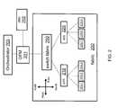
- FIG. 2shows a network fabric 200 including devices and relationships for use in an information handling system according to embodiments disclosed herein.
- Switch fabric 250includes a physical distributed system (pDS) 210 and a virtual distributed system (vDS) 220 .
- Physical distributed system (pDS) 210includes a plurality of p-switches 215 - 1 , 215 - 2 , and 215 - 3 .
- Virtual distributed system (vDS) 220includes a plurality of v-switches 225 - 1 , 225 - 2 , and 225 - 3 .
- OFM 201manages and controls each of switches 215 - 1 , 215 - 2 , and 215 - 3 in pDS 210 , and each of switches 225 - 1 , 225 - 2 , and 225 - 3 in vDS 220 .
- pDS 210may have p-switches 215 separated in tiers, according to the level of connectivity of the switches.
- An upper tier in pDSmay include p-switches having fewer links operating at a faster bit rate, relative to p-switches in a lower tier.
- p-switches within a single tier in pDS 210are likely to share the same or similar configuration parameters.
- an uplinkmay enable data communication between p-switch 215 - 1 and an information handling system at an upper tier of the network.
- a down linkmay couple p-switch 215 - 1 with an information handling system in a lower tier of the network relative to p-switch 215 - 1 .
- Peer linkscouple p-switch 215 - 1 with other p-switches within the same network tier.
- Up links and down linksare configured to handle data at specified data rates according to the network layer they are coupled to.
- Upper tier information handling systemsmay operate at a faster data rate compared to lower tier information handling systems.
- Lower tier information handling systemsmay operate at lower data rates, similar to 10 Gbps, 1 Gbps, or even lower.
- some embodimentsmay use a North-South and East/West definition for up-down, and peer links, respectively. This is illustrated in FIG. 2 .
- OFM 201may be handled by an orchestrator 203 , at a higher level.
- Orchestrator 203may determine how to allocate the storage resources ( 40 ), the networking resources in network fabric 100 , and the computing resources ( 60 ), available for service 15 in data center 10 .
- OFM 201 and orchestrator 203may be included in a console coupled to network fabric 200 .
- the consolemay be operated by authorized personnel.
- orchestrator 203configures switch fabric 250 in network fabric 200 through OFM 201 so that a certain QoS is maintained throughout a data center such as data center 10 (cf. FIG. 1 ).
- the QoSmay be established by the requirements from service 15 .
- OFM 201may determine the status of network fabric 200 by monitoring the attributes at each node accordingly. OFM 201 may thus reconfigure switch fabric 250 according to the status of network fabric 200 in order to maintain a desired QoS.
- FIG. 3shows a network fabric 300 including devices and connections for use in an information handling system according to embodiments disclosed herein.
- Network fabric 300is managed by an OFM unit 301 , similar to OFM 101 described in detail in relation to FIG. 1 , above.
- Network fabric 300includes switch fabric 350 .
- Network fabric 300also includes a management unit 355 , a port 360 , a set of grouped ports (LAG) 356 , a virtual local area network (VLAN) 357 .
- LAGgrouped ports
- VLANvirtual local area network
- Network fabric 300includes a plurality of information handling systems that may be distributed across multiple connectivity layers in a network. Switches included in switch fabric 350 provide connectivity between information handling systems in the multiple layers of the network in network fabric 300 .
- each of management unit 355 , LAG 356 , and VLAN 357 as illustrated in FIG. 3may represent one of a plurality of similar elements in the network.
- network fabric 300may include a plurality of VLANs such as VLAN 357 .
- switches in switch fabric 350route data packets between switch ports ( 370 ).
- Port 360may be configured as a L2 switch port 370 or a L3 router interface 375 .
- switch port 370may belong to a layer-2 in network fabric 200 .
- router interface 375may belong to a layer-3 in network fabric 200 .
- devices, components, and elements illustrated in FIG. 3may belong to different connectivity layers in network fabric 350 .
- port 360is coupled to a network interface card (NIC) 382 coupled to a server 380 .
- Server 380may be similar to server 180 described above in relation to FIG. 1 .
- Port 360may be part of a p-switch (physical port) or may be part of a v-switch (virtual port).
- a NIC 382can be a physical NIC (pNIC) or a virtual NIC (vNIC) 385 .
- Server 380may be a physical host (p-host) 390 in the network, and may also be a virtual machine (VM) 395 .
- VM 395 in server 380is controlled by VMM 302 , which is also coupled to OFM 301 .
- OFM 301may include object definitions that enable the operation and management of network fabric 300 .
- OFM 301may define a device group.
- a device groupis a container including a group of information handling systems onto which a configuration, or a policy, or an action can be commonly applied.
- OFM 301can reduce the number of management steps used to control a network fabric.
- switch fabric 350includes multiple tiers
- p-switches within a single tiermay be included in a device group defined by OFM 301 .
- embodiments of network fabric 300may include multiple device groups defined by OFM 301 . Each device group has configuration properties and policies shared by all the devices in the group.
- LAG 356 described aboveis a device group, where the grouped devices are a plurality of ports selected from a single p-switch or from a group of p-switches in a pDS.
- OFM 301applies an action to a device group, all the devices in the group are affected by the action.
- Such an actionmay be a ‘start’ or ‘shutdown’ command, or the acquisition of poll traffic statistics through each device in the group.
- OFM 301may also define a service profile.
- a service profileincludes a set of policies to accomplish a service under a Service Level Agreement (SLA).
- the policiesinclude requirements for the resources on physical servers, VMs, storages, networks, including network security requirements.
- OFM 301includes a set of service profiles, each established for a service provided by a service provider through network fabric 300 .
- Policies in a service profilemay include a server policy specifying a resource requirement from physical servers.
- the service profilemay include a VM policy specifying a resource requirement for VMs.
- a VM policymay include requirements for a guest operating system (OS).
- a service profile according to embodiments disclosed hereinmay also include a storage policy specifying requirements for storage devices or systems.
- a service profilemay also include a general security policy specifying general security requirements for the service.
- a service profile according to embodiments disclosed hereinmay further include a set of network profiles ensuring network security support for the service.
- a network profile according to some embodimentsincludes a set of network security policies shared by a group of NICs 382 , including vNICs 385 . Design and execution of network profiles using OFM 301 ensures the fulfillment of the SLA for the service.
- a network profileincludes attributes similar to a network policy.
- a network policymay include an access policy using a VLAN to limit the broadcast domain in a given network fabric.
- an access policymay include a common access using a cVLAN and a restricted access using a pVLAN.
- a network policymay also include a Quality of Service (QoS) policy to determine bandwidth policing, limiting requirements, and latency requirements.
- QoSQuality of Service
- a network profile consistent with the present disclosuremay include a network security policy.
- a network security policymay be similar to specified in a network protocol similar to 802.1x.
- a network profile consistent with the present disclosuremay also include an interface type, namely physical or virtual interface.
- a network profilemay include a direction attribute for the ports in the network. For example, a north (N) direction is usually assigned to uplinks, a south (S) direction is usually assigned to downlinks, and an east/west (EW) direction is assigned for peer links.
- Nnorth
- Ssouth
- EWeast/west
- FIG. 4shows an example path 403 of a packet request from a network client through a network fabric 400 , according to some embodiments.
- a network clientmay be any information handling system located at some external node outside of the fabric 400 .
- a packet request from a network cliententers fabric 400 through input port 404 - 1 .
- Fabric 400is configured by OFM 401 to direct path 403 through a plurality of ports 460 , such that the packet request is routed through the proper information handling systems.
- the information handling systemsinclude a web load balancer (WLB) 430 - 1 and application server load balancer (ALB) 430 - 2 , a plurality of web servers (WS) 480 W, a plurality of application servers (AS) 480 A, and a plurality of storage servers (SS) 440 - 1 and 440 - 2 (collectively referred to as storage servers 440 ).
- the information handling systemsare coupled to ports 460 in fabric 400 using NICs, similar to NIC 382 or VNICs similar to VNIC 385 (cf. FIG. 3 ).
- WLB 430 - 1receives the packet request from port 460 - 1 and determines which WB 480 W should receive the packet requests. Similar to illustrated in FIG. 4 , WS 480 W- 2 may receive the packet request through port 460 - 5 . To send the packet request to the next layer, WB 480 W- 2 sends the request to fabric 400 through port 460 - 6 . Fabric 400 transmits the request to ALB 430 - 2 . ALB 430 - 2 makes a determination of which similar to 480 A receives the packet request. Thus, for example, ALB 430 - 2 may send the packet request to similar to 480 A- 1 .
- Application server 480 A- 1determines that the information requested is stored in SS 440 - 1 . Thus, 480 A- 1 directs path 403 to fabric 400 through port 460 - 12 and from there to SS 440 - 1 , through port 460 - 15 .
- Fabric 400 managed by OFM 401is then able to “flatten” a 3-tier network topology into a single tier. According to embodiments consistent with the present disclosure, OFM 401 manages fabric 400 to handle path 403 similar to traversing a single switch.
- FIG. 5shows information handling system 500 configured to be coupled to a switch fabric in a network including VLAN A 541 and VLAN B 542 , according to embodiments disclosed herein.
- Information handling system 500is coupled to VLAN A 541 through port 565 and to VLAN B 542 through port 566 .
- Information handling system 500includes a VNIC 585 - 1 configured to interface with VLAN 541 via port 565 on a v-switch.
- Information handling system 500includes a VNIC 585 - 2 configured to interface with VLAN B 542 via port 566 on a v-switch.
- VNICs 585 - 1 and 585 - 2may be similar to described in detail above in relation to VNIC 385 (cf. FIG. 3 ).
- An OFM similar to disclosed hereinmay need to configure ports 565 and 566 with the attributes and requisites of VLAN A 541 and VLAN B 542 , respectively.
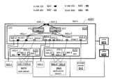
- FIG. 6shows a switch fabric including virtual local area networks (VLANs) 641 , 642 , 643 , and 644 , according to embodiments disclosed herein.
- fabric 600includes a pDS 610 and a vDS 620 , managed by OFM unit 601 .
- the vDSis also controlled by VMM 602 , which is coupled to OFM unit 601 .
- Up-link ports 604 - 1 and 604 - 2couple fabric 600 to the outside of the fabric.
- Physical distributed switch (pDS) 610may include a two-tier set of p-switches.
- a top tiermay include p-switches 611 and 612
- a bottom tiermay include p-switches 615 - 1 and 615 - 2 .
- Ports 661 d - 1 , in p-switch 615 - 1may be configured for VLAN 641 .
- Ports 662 d - 1 , and 662 u - 1may be configured by OFM 601 for VLAN 642 in p-switch 615 - 1 .
- Ports 662 d - 2 , and 662 u - 2may be configured by OFM 601 for VLAN 642 in p-switch 615 - 2 . Also, OFM 601 may configure ports 662 d in p-switch 611 and p-switch 612 for VLAN 642 . OFM 601 configures ports 663 d - 2 in p-switch 615 - 2 for VLAN 643 . OFM 601 configures ports 664 d - 2 in p-switch 615 - 2 for VLAN 644 . In some embodiments, OFM 601 may configure a link in a p-switch to accept the attributes and profiles of more than one VLAN, such as VLAN 643 and of VLAN 644 .
- Virtual distributed switch (vDS) 620includes virtual switches 625 - 1 , 625 - 2 , 625 - 3 , and 625 - 4 .
- Virtual switches 625 - 1 through 625 - 4are managed by OFM 601 through VMM 602 .
- Virtual switches 625 - 1 through 625 - 4enable fabric 600 to incorporate a set of virtual machines 695 - 1 through 695 - 4 into the network.
- Virtual machines 695 - 1 through 695 - 4are created within physical servers 680 W and 680 A.
- Virtual machines 695 - 1 and 695 - 2are formed within physical server 680 W.
- Virtual machines 695 - 3 and 695 - 4are formed within physical server 680 A.
- Virtual switches 625 - 1 through 625 - 4have down ports 665 and 666 configured by OFM 601 through VMM 602 to set up the desired coupling for VLANs 641 , 642 , 643 , and 644 amongst VMs 695 - 1 through 695 - 4 .
- virtual machines 695 - 1 and 695 - 2have a link to VLAN 641 and a link to VLAN 642 , established by v-switch 625 - 1 and 625 - 2 .
- Ports 665 - 1 and 665 - 2 in v-switch 625 - 1are configured to couple VLAN 641 with VM 695 - 1 and VM 695 - 2 .
- Ports 666 - 1 and 666 - 2 in v-switch 625 - 2are configured to couple VLAN 642 with VM 695 - 1 and VM 695 - 2 .
- virtual machines 695 - 3 and 695 - 4have a link to VLAN 643 and a link to VLAN 644 , established by v-switch 625 - 3 and v-switch 625 - 4 .
- Ports 665 - 3 and 665 - 4 in v-switch 625 - 3are configured to couple VLAN 643 with VM 695 - 3 and VM 695 - 4 .
- Ports 666 - 3 and 666 - 4 in v-switch 625 - 4are configured to couple VLAN 644 with VM 695 - 3 and VM 695 - 4 .
- OFM 601enables VLANs 641 , 642 , 643 , and 644 to be configured on both vDS 620 and pDS 610 according to the network requirements. Furthermore, the function of configuring the entire network fabric 600 is centralized in OFM 601 , which has access to the v-switches through VMM 602 and the p-switches in the network. OFM 601 may reconfigure the links in any of the p-switches or the v-switches in network fabric 600 .
- FIG. 6illustrates also load balancers 630 - 1 and 630 - 2 coupled to pDS 610 .
- the north and south links to load balancer 630 - 1 or 630 - 2may be coupled to different VLANs.
- the north link to 630 - 1may not be configured for a specific VLAN.
- the south link to 630 - 1may be configured for VLAN 641 .
- the north link of load balancer 630 - 2may be configured for VLAN 642
- the south link of load balancer 630 - 2may be configured for VLAN 643 .
- Storage server 640may be coupled to VLAN 644 through link 664 d - 2 , in p-switch 615 - 2 .
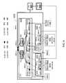
- FIG. 7shows an OFM 701 configured to control a p-switch 715 , according to embodiments disclosed herein.
- P-switch 715includes hardware (HW) 732 and software (SW) 735 .
- Software 735includes an operating system (OS) which may be loaded onto switch 715 by OFM 701 .
- Hardware 732may include routers, port connectors, a memory circuit to store data and software 735 , and a processor circuit to implement the commands in software 735 .
- an Open Fabric Agent (OFA) unit 703controls p-switch 715 .
- OFA 703includes administrator agent (AA) 714 , Control Agent (CA) 716 , and Monitor Agent (MA) 718 .
- AAadministrator agent
- CAControl Agent
- MAMonitor Agent
- P-switch 715also includes a Configuration Manager (CM) 720 which is coupled to AA 714 and CA 716 on each of a plurality of OFAs 703 that may exist in a pDS.
- CMConfiguration Manager
- OFM 701is coupled to each of a plurality of OFAs in a network fabric through a configuration channel 780 , a control channel 782 , and a monitor channel 785 .
- the function and operation of channels 780 , 782 , and 785 in relation to OFM 701 , OFA 703 , and p-switch 715will be described in detail in relation to methods 800 and 850 illustrated in FIGS. 8A and 8B , below.
- FIG. 8Ashows a method 800 for using an OFM unit, according to embodiments disclosed herein.
- Method 800may be performed by an OFM unit in relation to a network fabric similar to OFM 101 , and network fabric 100 in data center 10 , described in detail above in FIG. 1 .
- method 800may be performed by an OFM similar to OFM 101 , 201 , 301 , 401 , 601 , and 701 , operating on network fabrics 100 , 200 , 300 , 400 , and 600 , similar to described in detail above in relation to FIGS. 1-4 , and 6 , respectively.
- information about the networkis stored in the OFM to perform method 800 .
- Information about the networkincludes the number of tiers in a pDS and the IP address and profile of external ports in the network fabric, similar to ports 404 - 1 and 404 - 2 (cf. FIG. 4 ), and ports 604 - 1 and 604 - 2 (cf. FIG. 6 ). Information about the network may also include uplink port addresses and profiles and peer-link addresses and profiles. Also, in method 800 switches and servers in the network fabric are coupled to the OFM unit. In some embodiments, switches and servers in the network fabric may be coupled to a Dynamic Host Configuration Protocol (DHCP) server and an operating system imaging server. In embodiments consistent with the present disclosure, performing 810 enables automatic IP address assignment for each switch in a switch fabric.
- DHCPDynamic Host Configuration Protocol
- method 800 performed with an OFMenables the automatic download and installation of operating systems and configuration files in newly installed switches.
- a startup file for a switchmay include information about the system, the services and application attributes of the services provided by the switch, and the name of the switch in the network.
- an OFMenables the automatic download and installation of service programs and applications similar to OF agent 703 , for each p-switch 715 in a network fabric (cf. FIG. 7 ).
- step 810the OFM unit performs provisioning.
- the OFMsearches for and obtains the resources needed by a data center according to the services provided by a service provider.
- the resources provisioned in step 810 by the OFMmay include physical equipment or hardware similar to switches, routers, servers, storage devices and network security devices.
- the resources provisioned in 810 by the OFMmay include software similar to an operating system for the switches, application software, and storage management software.
- step 810includes creating a master provisioning table including every switch in the pDS.
- the master provisioning tableincludes information similar to the switch IP address, the operating system installed on the switch, its configuration, the switch name, and a switch media access control (MAC) address.
- MACswitch media access control
- the OFMperforms configuring of the network fabric.
- OFM 701may use channel 780 to communicate with AA 714 (cf. FIG. 7 ), in step 820 .
- the OFM in 820creates containers with groups of switches having the same or very similar configuration.
- physical switches in the same tier of a pDSmay be included in a single container by the OFM, in step 820 .
- a configuration applied by the OFM in step 820 to each switch in a switch fabricmay include attributes similar to type of switch (physical/virtual, or tier level), port bandwidth, uplinks, downlinks, peer-links, and management ports.
- Another attribute of a switch configurationmay be bandwidth usage and latency thresholds for the switch. Accordingly, for a multi-tier pDS each tier may be contained or grouped separately, having a different monitoring policy for each tier.
- Monitoring policiesmay include a service profile and a network profile, similar to discussed in detail above in reference to FIG. 2 .
- a service profileincludes specifications of requirements for a service similar to provided by service 15 (cf. FIG. 1 ). This may be defined outside of the OFM and include server policy, VM policy, storage policy, and general security policy.
- a network profileis the specification of network requirements for a service. These requirements include network access policy, network QoS policy, and network security policy.
- the OFMmay perform step 820 at a device level. For example, in an OFM console a user may configure each individual device (e.g. each switch in a switch fabric). A specific device configuration may take precedence even when the device is part of a group of devices. In some embodiments a conflict may arise in configuration step 820 when an OFM tries to push a policy to a group of devices, and the policy conflicts with the configuration of one of the devices in the group. In such circumstance, an OFM performing step 820 may instruct an administrator agent to proceed according to a pre-established conflict resolution rule. The administrator agent may be similar to AA 714 described in detail above in reference to FIG. 7 .
- the OFMdiscovers the topology of the fabric, including a determination of the configuration of devices in the fabric.
- the devices in the fabricmay include p-switches, web servers, application servers, v-switches, and VMs included in web servers and application servers.
- Step 830may be performed by collecting information from discovery processes conducted by single administrator agents on each p-switch in the fabric. For example, AA 714 in FIG. 7 may perform a discovery process within the neighborhood of p-switch 715 .
- the neighborhood of p-switch 715may include all the information handling systems directly coupled to p-switch 715 , including up-link connections; peer-link connections; down-link connections; and management link connections.
- discovery in 830may also include finding nearest neighbors in a virtual network, similar to VLANs 641 , 642 , 643 , and 644 .
- an OFMdiscovers a p-host in step 830 .
- a p-host in a network fabricmay be similar to p-host 380 in fabric 300 (cf. FIG. 3 ). Discovery of a p-host is based on the server's IP address or the subnet that the p-host may belong to.
- an OFMmay perform step 830 by providing a ‘hint’ to each p-switch in the fabric, including the ports and devices coupled to the ports in each switch. The ‘hint’ may be based on the information discovered previously and stored in an OFM database, or a user-defined template provided to the OFM. For example, a user may enter information for the template through an OFM console.
- the ‘hint’may be a set of data including port information and IP information for each information handling system directly coupled to a p-switch.
- the OFMprovides the ‘hint’ to an administrator agent on the p-switch, similar to AA 714 in p-switch 715 (cf. FIG. 7 ).
- the port information in the ‘hint’may include all ports, or a set of port numbers.
- the IP information in the ‘hint’may be a specific IP address, or a set of IP addresses or a subnet coupled to the p-switch.
- the administrator agentuses ‘ping’ commands in step 830 for discovering the ports associated with a given IP address.
- the administrator agentreports the result similar to a list, including: (p-switch, ⁇ port, ⁇ physical server IP ⁇ ), to the OFM.
- the value ‘p-switch’ abovemay be the name of the p-switch, the ‘port’ value may be a port number, and the ‘physical server IP’ may be a network address of a physical server coupled to the port indicated in the port number.
- an OFMdiscovers virtual networks on a p-server, in step 830 .
- a p-servermay be virtualized to have virtual switches.
- p-server 380may include VM 395
- port 360may be a virtual port coupling p-server 380 to VLAN 357 and to v-switches 325 (cf. FIG. 3 ).
- An administrator agent for the p-switchdiscovers v-switches and related network components and attributes similar to NICs, vNICs, VMs and Port Groups.
- a p-servermay be similar to p-server 380 coupled to NIC 382 , and include VM 395 (cf. FIG. 3 ).
- a p-server similar to p-server 380may be coupled through port 360 to a LAG 356 (cf. FIG. 3 ).
- virtual network information of a p-servermay be previously discovered or entered via a user-defined template into the OFM.
- the OFMretrieves the virtual network information from the corresponding VMM, similar to VMM 395 (cf. FIG. 3 ), and passes the virtual network information to the administrator agent.
- the administrator agentintercepts initial traffic from the p-server and validates on which port of the p-switch the virtual network is coupled.
- the administrator agentreports the discovery result to the OFM.
- an OFMdiscovers an edge virtual bridging (EVB) module on a p-server, in step 830 .
- a p-switchmay include an EVB module in the operating system (OS) running the p-switch.
- the EVB in the operating system of the p-switchqueries whether there is an EVB device on a p-server coupled to the p-switch.
- the EVB modulethen provides the information to the administrator agent associated with the p-switch.
- the OFMprovides a ‘hint’ to the administrator agent whether there may be EVB support on a set of p-servers coupled to the p-switch through a set of ports.
- the administrator agentinvokes an EVB module on the ports ‘hinted’ by the OFM.
- the EVB module in the OS running the p-switchuses EVB protocols to discover and communicate with an EVB device on the p-server.
- the administrator agent associated with the p-switchretrieves the EVB configuration on the port.
- the administrator agentmay activate channels in the p-switch, according to the EVB configuration.
- Each channel in the p-switchrepresents a v-switch to which a set of VSIs (Virtual Switch Interfaces) is coupled.
- a policy ID(VSI type ID) is exchanged between the p-switch and the p-server for consistent policy management.
- an OFMdiscovers p-switch-to-p-switch connections in step 830 .
- the p-switchFor a p-switch to discover other p-switches coupled to it, the p-switch needs to turn ‘on’ a link layer discovery protocol (LLDP) on all its ports.
- LLDPis a vendor-neutral link layer protocol used by network devices for advertising their identity, capabilities, and neighbors.
- the OFMmay provide the administrator agent a ‘hint’ in terms of which ports in the p-switch associated with the administrator agent may be coupled to other p-switches. Thus, the administrator agent turns ‘on’ the LLDP on the ports ‘hinted’ by the OFM.
- the administrator agent on the p-switchfinds out in step 830 which ports are coupled to other p-switches in a switch fabric using a simple network management protocol (SNMP) database.
- SNMPsimple network management protocol
- An SNMP databaseis an internet standard developed to manage nodes on an IP network, similar to a network fabric consistent with embodiments disclosed herein.
- the administrator agentmay then report the findings from the SNMP database to OFM, in step 830 .
- an OFMcomputes the fabric topology in step 830 . Based on the discoveries from the p-switches in the fabric performed in step 830 , a fabric topology can be computed by the OFM. Computing a fabric topology in step 830 may include determining the latencies for data packets routed through the network.
- the latency of a data packetmay include the time it takes a data packet to travel through a link from a first information handling device to a second information handling device in the network.
- the first and second information handling devicesmay be nearest neighbors in the network.
- a latency valuemay include the time it takes a data packet to traverse from input external port 404 - 1 to port 460 - 1 in fabric 400 .
- a latency valuemay also include the time it takes a data packet to traverse from port 460 - 1 to port 460 - 2 , travelling to and from LB 430 - 1 .
- a latency valuemay include the time it takes a data packet to traverse from port 460 - 2 to port 460 - 5 .
- a usermay, in step 830 , specify ports in the network fabric having uplinks outside of the fabric, in 830 .
- a usercan enter this information from an OFM console.
- Ports having uplinks outside of the fabricmay be similar to ports 404 - 1 and 404 - 2 (cf. FIG. 4 ), or ports 604 - 1 and 604 - 2 (cf. FIG. 5 ), described in detail above.
- the computed topologyis properly oriented in a north-south configuration, in the sense that uplinks are coupled towards the north direction and downlinks are coupled towards the south direction, similar to illustrated in FIG. 3 .
- An OFM consistent with embodiments disclosed hereinperforms step 830 in method 800 when a modification is performed in the network fabric.
- the fabric topologyis recalculated when adding or removing a p-switch in the switch fabric, or changing the connections in some of the switch ports.
- a modification in the network fabricmay include a modification in the physical portion of the fabric (pDS) and also a modification in the virtual portion of the fabric (vDS). Changes in the network fabric that may prompt the OFM to perform a discovery and topology recalculation similar to step 830 above.
- controlling functions in step 840include executing policies.
- the OFMcontrols when and how often a policy is executed based on the priority of the policy.
- the OFMinstructs a control agent to perform the action.
- controlling functions in 840include migrating policies from one device to another. For example, in the case of VM migration the OFM may transfer network policies and device policies to the appropriate p-switches through a control agent.
- controlling functions in step 840include ‘Start’ and ‘Shutdown’ of one or a group of devices. Further embodiments may include in step 840 ‘Start’ and ‘Shutdown’ of an administrator agent or a monitor agent associated with a p-switch.
- OFM 701may instruct a control agent similar to CA 716 to shut down AA 714 or MA 718 , in OF agent 703 associated with p-switch 715 (cf. FIG. 7 ).
- Control in step 840may include controlling virtual networks in the network fabric.
- the OFMmay control virtual networks in the network fabric using EVB modules installed in the OS of p-switches of the network.
- an OFMmay use a VMM, similar to OFM 201 using VMM 202 (cf. FIG. 2 ).
- Some embodimentsmay include in 840 the step of integrating an open flow controller in the OFM.
- an open flow controlleris integrated in the OFM to define open flow rules (traffic pattern and actions) on an OFM console.
- the OFMthen passes the open flow rules to an Open Flow module installed in the operating system of the p-switches associated with the open flow.
- step 845the OFM performs monitoring.
- OFM 701may use channel 785 to communicate with MA 718 (cf. FIG. 7 ).
- Monitoring in step 845may include monitoring the health of a device by transmitting a ‘Hello’ message between the monitor agent and the OFM.
- the ‘Hello’ messagemay include other health information similar to active/inactive ports in the device.
- the health of a devicemay be defined by a status profile retrieved by the OFM in step 845 .
- Monitoring in step 845may include monitoring traffic types and statistics. Traffic type and statistics may be obtained by the OFM using an SFlow Agent on each p-switch, to collect traffic samples and statistics.
- Monitoring in step 845may also include monitoring configuration changes on both physical and virtual networks in the network fabric.
- an OFMmay use the administrator agent associated with a p-switch to register events in virtual networks Based on the monitoring policies, the administrator agent may notify the OFM about the changes in the virtual network.
- the OFMmay use polling and event notification in step 845 to keep a history of events reported from all the devices in the network fabric.
- Some embodimentsuse OFM 101 , 201 , 301 , 401 , 601 , and 701 , described in detail above.
- FIG. 8Bshows a method 850 for starting up a p-switch in a network fabric, according to embodiments disclosed herein.
- Method 850may be performed by an information handling system similar to a p-switch, a DHCP server, an operating system (OS) image server, and an OFM unit. Some steps in method 850 may be performed by any of the above mentioned information handling systems, at least partially.
- the p-switchmay be for example p-switch 715 and some steps in method 850 may be performed by software 735 in p-switch 715 .
- the p-switchboots and requests an IP address in 860 .
- the IP address in step 860may be requested by the p-switch to the DCHP server.
- step 865the DCHP server responds to the request in step 855 by sending an IP address to the switch. Also, in step 865 the DCHP may include an IP address for the OS image server in the response. In step 870 , the p-switch requests an operating system image from the OS imaging server.
- the p-switchmay also include a request for a configuration file from the OS imaging server.
- the OS imaging serversends the requested operating system image and the requested configuration file to the p-switch.
- the p-switchstarts the received operating system.
- OFM 701may start AA 714 in OFA 703 , associated with p-switch 715 .
- OFM 701registers the IP provided to the p-switch in step 865 similar to a valid network IP for the p-switch.
- the OFMsends a network policy to the p-switch.
- a network policy in step 892may establish which VM can be coupled to which VM in a network.
- a p-switch in method 800may configure ports in order to satisfy the network policies provided in step 892 .
- the OFMalso provides a switch name to the registered p-switch.
- the p-switchapplies the network policy received from the OFM in step 895 .
- FIG. 9Ashows an OFM unit 901 configured to setup a private VLAN (pVLAN) 941 in a network fabric 900 , according to embodiments disclosed herein.
- Up-link ports 904 - 1 and 904 - 2couple fabric 900 to the outside of the fabric.
- Fabric 900includes switch fabric 950 .
- Switch fabric 950includes pDS 910 and vDS 920 .
- pDS 910includes p-switch 911 in a higher tier, and p-switch 915 in a lower tier.
- Virtual distributed switch vDS 920includes v-switches 925 - 1 through 925 - 6 .
- Switch 911includes down link port 962 d configured according to VLAN 942 .
- Downlink port 962 d in switch 911is coupled to uplink port 962 u in switch 915 .
- uplink port 962 uis configured according to VLAN 942 .
- Switch 915has ports 960 - 1 through 960 - 8 coupled to downlinks that couple switch 915 with vDS 920 and with a layer of information handling systems.
- the layer of information handling systemsincludes LB 930 , and virtual machines 995 - 1 through 995 - 6 .
- Virtual machines 995 - 1 through 995 - 6are distributed within physical servers 980 W- 1 , 980 W- 2 , and 980 W- 3 .
- physical server 980 W- 1includes virtual machines 995 - 1 and 995 - 2 ;
- physical server 980 W- 2includes virtual machines 995 - 3 and 995 - 4 ;
- physical server 980 W- 3includes virtual machines 995 - 5 and 995 - 6 .
- Ports 960 - 1 through 960 - 8are configured by OFM 901 to be compatible with either pVLAN 941 or VLAN 942 .
- Port 960 - 1connects with the north NIC in LB 930 , and it may be configured by OFM 901 to handle all data packets traversing through switch 915 , including those associated with pVLAN 941 and VLAN 942 .
- Port 960 - 2connects with the south NIC in LB 930 , and may be configured by OFM 901 to handle data packets associated with pVLAN 941 .
- port 960 - 2may include common handling privileges for LB 930 to all data packets associated with pVLAN 941 .
- port 960 - 2is common to all data packets in pVLAN 941 .
- Ports 960 - 3 , 960 - 5 , and 960 - 7may be configured by OFM 901 for handling pVLAN 941 .
- port 960 - 3may handle data packets directed to or coming from virtual machine 995 - 1 , but may not have access to data packets directed to or coming from virtual machine 995 - 3 .
- virtual machines 995 - 1 and 995 - 3may belong in the same virtual local area network, the fact that this area network is a pVLAN implies certain restrictions for accessing packets in the local area network.
- the restrictions in a pVLANmay be configured by OFM 901 .
- the OFMmay also configure an access control list (ACL) determined by a service agreement with clients having access to each of web servers 980 W- 1 , 980 W- 2 , and 980 W- 3 .
- ACLaccess control list
- OFM 901may configure the ports in v-switch 925 - 1 , 925 - 3 , and 925 - 5 using links 905 - 1 through 905 - 6 (collectively referred to as links 905 ).
- v-switch 925 - 1may have port 965 - 1 configured with link 905 - 1 to establish a link with virtual machine 995 - 1 , and port 965 - 2 configured with link 905 - 2 to establish a link with virtual machine 995 - 2 .
- v-switch 925 - 3may have port 965 - 3 configured with link 905 - 3 to establish a link with virtual machine 995 - 3 , and port 965 - 4 configured with link 905 - 4 to associate with virtual machine 995 - 4 .
- v-switch 925 - 5may have port 965 - 5 configured with link 905 - 5 to associate with virtual machine 995 - 5 , and port 965 - 6 configured with link 905 - 6 to associate with virtual machine 995 - 6 .
- v-switch 925 - 2may have port 966 - 1 configured with link 906 - 1 to establish a link with virtual machine 995 - 1 , and port 966 - 2 configured with link 906 - 2 to establish a link with virtual machine 995 - 2 .
- v-switch 925 - 4may have port 966 - 3 configured with link 906 - 3 to establish a link with virtual machine 995 - 3 , and port 966 - 4 configured with link 906 - 4 to associate with virtual machine 995 - 4 .
- v-switch 925 - 6may have port 966 - 5 configured with link 906 - 5 to associate with virtual machine 995 - 5 , and port 966 - 6 configured with link 906 - 6 to associate with virtual machine 995 - 6 .
- the configuration of virtual ports in v-switches 925 - 1 through 925 - 6may be performed by OFM 901 through VMM 902 .
- FIG. 9Bshows a flow chart in a method 930 for setting up a private VLAN in a network fabric using an OFM unit according to embodiments disclosed herein.
- Method 930is performed by an OFM unit similar to OFM units disclosed herein.
- Method 930may be performed by an OFM unit in conjunction with a VMM similar to disclosed herein.
- Method 930may be performed by authorized personnel in a console having access to an OFM unit consistent with the present disclosure.
- the OFMretrieves a service profile for a load balancer (LB) and a web server (WS) from either a user or a high-level management system such as an orchestrator.
- LBmay be similar to LB 930 and WS may be similar to any of WS 980 W- 1 , 980 W- 2 , and 980 W- 3 (cf. FIG. 9A ).
- the OFMcreates a network profile for the LB based on the service profile. For example, the OFM may create an internal network profile and assign a port in a p-switch to the internal profile.
- the p-switchmay be part of a pDS similar to pDS 910 , and the port may be similar to port 960 - 2 in p-switch 915 (cf. FIG. 9A ).
- a c-VLANmay be associated with port 960 - 2 having the internal network profile of the LB.
- the OFM unitallocates a port in a vDS for each interface in each of a virtual machine (VM) residing within the web servers.
- the vDS in step 933may be linked down (‘south’) from the pDS, similar to vDS 920 and pDS 910 (cf. FIG. 9A ).
- each port in a v-switch within the vDSmay be linked to an external interface or ‘north’ link for each of the VMs.
- the OFMcreates an external network profile for the WS and adds the links created in step 933 into the network profile.
- the OFMmay assign a pVLAN to a network profile based on the access policy required.
- the OFMassigns physical ports in the pDS to the newly created pVLAN. For example, ports 960 - 3 , 960 - 5 , and 960 - 7 in FIG. 9A may be assigned to the newly created pVLAN.
- VM 995 - 1 , VM 995 - 3 , and VM 995 - 5are part of pVLAN 941 , connecting in the north direction with LB 930 .
- LB 930has access to all the packets from VM 995 - 1 , VM 995 - 3 , and VM 995 - 5 .
- VM 995 - 1may not have access to the packets to and from VM 995 - 3 , and VM 995 - 5 .
- the south interface of LB 930is coupled through port 960 - 2 in p-switch 915 with all the six VMs 925 - 1 , 925 - 2 , 925 - 3 , 925 - 4 , 925 - 5 , and 925 - 6 through links 905 - 1 , 905 - 2 , 905 - 3 , 905 - 4 , 905 - 5 , and 905 - 6 , respectively, in pVLAN 941 . Since links 905 are configured according to a pVLAN, each of links 905 couples each of VMs 925 with LB 930 , but not with each other.
- FIG. 10Ashows an OFM unit 1001 configured to migrate a virtual machine 995 - 2 in network fabric 1000 according to embodiments disclosed herein.
- Uplink ports 904 - 1 and 904 - 2couple fabric 1000 to the outside of the fabric.
- Fabric 1000 in FIG. 10Aincludes switch fabric 1000 , pDS 1010 , and vDS 1020 .
- pDS 1010may be similar to pDS 910 described in detail above with reference to FIG. 9A .
- pDS 1010may include p-switch 911 at a higher tier level and p-switch 915 at a lower tier level.
- Switch 911 in pDS 1010may include downlink port 962 d .
- OFM 1001may re-configure downlink port 962 d to be compatible with pVLAN 941 and also with VLAN 942 . This may arise when, similar to a result of a virtual machine migration similar to illustrated in FIG. 10A , a new p-switch 1015 is incorporated to pVLAN 941 , opening a new route for packets in pVLAN 941 through a higher tier in pDS 1010 .
- switch 915may include an uplink port 962 u compatible with both pVLAN 941 and VLAN 942 .
- Switch 1015may include uplink port 1062 u compatible with both pVLAN 941 and VLAN 942 .
- pDS 1010may further include p-switch 1015 at a lower tier level.
- p-switch 915 and p-switch 1015may be at the same tier level.
- p-switch 1015may include up-links with ports coupled to down-link ports in p-switch 911 .
- vDS 1020may be similar to vDS 920 described in detail above with reference to FIG. 9A .
- vDS 1020may include v-switches 925 - 1 through 925 - 6 .
- Virtual DS 1020may also include v-switches 1025 - 1 and 1025 - 2 coupled to p-switch 1015 in the north direction and to virtual machine 995 - 2 in the south direction.
- Virtual machine 995 - 2is migrated from web server 980 W- 1 to web server 1080 W.
- OFM 1001migrates the network profile for a virtual machine when the virtual machine migrates from one physical server to another.
- the configuration and attributes of virtual switches 925 - 1 , 925 - 3 , 925 - 4 , 925 - 5 , and 925 - 6remains intact.
- For the migration of virtual machine 995 - 2 from server 980 W- 1 to server 1080 W OFM unit 1001transfers the network profile for the virtual machine from v-switch 925 - 1 to v-switch 1025 - 1 and from v-switch 925 - 1 to v-switch 1025 - 2 . In some embodiments, this may be performed by using VMM 1002 to perform the appropriate configuration software in v-switches 1025 - 1 and 1025 - 2 .
- OFM 1001may incorporate a p-switch 1015 in pDS 1010 . To do so, OFM 1001 configures the ports in p-switch 1015 accordingly. For example, uplink port 1062 u connecting p-switch 1015 in the north direction with p-switch 911 may be configured similar to a dual port to handle pVLAN 941 and VLAN 942 . Also, downlink port 1060 - 1 connecting p-switch 1015 in the south direction with v-switch 1025 - 1 may be configured to handle pVLAN 941 . And downlink port 1060 - 2 connecting p-switch 1015 in the south direction with v-switch 1025 - 2 may be configured to handle VLAN 942 .
- OFM 1001may configure uplink port 962 u coupling p-switch 915 with p-switch 911 in the north direction, to handle pVLAN 941 and VLAN 942 . Further, VMM 1002 may configure port 1065 - 2 in v-switch 1025 - 1 with link 905 - 2 to associate with virtual machine 995 - 2 . VMM 1002 may also configure port 1066 - 2 in v-switch 1025 - 2 with link 906 - 2 to associate with virtual machine 995 - 2 .
- FIG. 10Bshows a flow chart in a method 1030 to migrate a virtual machine in a network fabric, according to embodiments disclosed herein.
- Method 1030is performed by an OFM similar to OFMs 101 , 201 , 301 , 401 , 601 , 701 , 901 , and 1001 , disclosed herein.
- Method 1030may be performed by an OFM in conjunction with a VMM, similar to disclosed herein.
- Method 1030may be performed by authorized personnel in a console having access to an OFM consistent with the present disclosure.
- the OFMcreates a link between a VNIC and a vDS by associating a VNIC with a port on a vDS.
- the OFMmay allocate two VNICS, a first VNIC for a north interface with a WS, and a second VNIC for a south interface with the WS.
- the OFMassociates each of the newly allocated VNICs to a port on a v-switch through links 905 - 1 through 905 - 6 (collectively referred to as links 905 ), and links 906 - 1 through 906 - 6 (collectively referred to as links 906 ).
- the first VNICmay use link 905 - 2
- the second VNICmay use link 906 - 2 (cf. FIG. 10A ).
- the newly allocated VNICsmirror the configuration of VM 995 - 2 , which is to be migrated to a new web server.
- a VNIC in a north linkmay be configured with a link associated with a pVLAN.
- a VNIC in a south linkmay be configured with a link associated with a c-VLAN.
- the OFMadds a first port in a pDS layer associated with the pVLAN and a second port in the pDS layer associated with the c-VLAN.
- the pDS in step 1033may be on a layer up-linked from the vDS in step 1031 , similar to in pDS 1010 and vDS 1020 in FIG. 10 .
- the first portmay be similar to port 1060 - 1 configured according to pVLAN 941 and the second port may be similar to port 1060 - 2 configured for VLAN 942 (cf. FIG. 10A ).
- the OFMremoves the link from the old web server.
- link 905 - 2 in the north interface of 980 W- 1 and link 906 - 2 in the south interface of 980 W- 1are removed (cf. FIG. 10A ).
- VM 995 - 2is migrated to WS 1080 W.
Landscapes
- Engineering & Computer Science (AREA)
- Computer Networks & Wireless Communication (AREA)
- Signal Processing (AREA)
- Data Exchanges In Wide-Area Networks (AREA)
Abstract
Description
Claims (7)
Priority Applications (1)
| Application Number | Priority Date | Filing Date | Title |
|---|---|---|---|
| US13/524,917US8958340B2 (en) | 2012-06-15 | 2012-06-15 | System and methods for open fabric management |
Applications Claiming Priority (1)
| Application Number | Priority Date | Filing Date | Title |
|---|---|---|---|
| US13/524,917US8958340B2 (en) | 2012-06-15 | 2012-06-15 | System and methods for open fabric management |
Publications (2)
| Publication Number | Publication Date |
|---|---|
| US20130336134A1 US20130336134A1 (en) | 2013-12-19 |
| US8958340B2true US8958340B2 (en) | 2015-02-17 |
Family
ID=49755803
Family Applications (1)
| Application Number | Title | Priority Date | Filing Date |
|---|---|---|---|
| US13/524,917Active2033-01-12US8958340B2 (en) | 2012-06-15 | 2012-06-15 | System and methods for open fabric management |
Country Status (1)
| Country | Link |
|---|---|
| US (1) | US8958340B2 (en) |
Cited By (4)
| Publication number | Priority date | Publication date | Assignee | Title |
|---|---|---|---|---|
| US20130290694A1 (en)* | 2012-04-30 | 2013-10-31 | Cisco Technology, Inc. | System and method for secure provisioning of virtualized images in a network environment |
| US20140047125A1 (en)* | 2012-08-07 | 2014-02-13 | Fujitsu Limited | Apparatus and method for controlling virtual switches |
| US20150333956A1 (en)* | 2014-08-18 | 2015-11-19 | Advanced Micro Devices, Inc. | Configuration of a cluster server using cellular automata |
| US20170288985A1 (en)* | 2014-01-28 | 2017-10-05 | Dell Products L.P. | Device management system |
Families Citing this family (21)
| Publication number | Priority date | Publication date | Assignee | Title |
|---|---|---|---|---|
| US8891375B2 (en)* | 2012-08-02 | 2014-11-18 | Cisco Technology, Inc. | System and method for virtual Ethernet interface binding |
| US9455901B2 (en) | 2013-10-04 | 2016-09-27 | Nicira, Inc. | Managing software and hardware forwarding elements to define virtual networks |
| WO2016033193A1 (en)* | 2014-08-26 | 2016-03-03 | Matthew Hayden Harper | Distributed input/output architecture for network functions virtualization |
| US9806950B2 (en)* | 2015-02-26 | 2017-10-31 | Cisco Technology, Inc. | System and method for automatically detecting and configuring server uplink network interface |
| US10210120B2 (en)* | 2015-03-26 | 2019-02-19 | Intel Corporation | Method, apparatus and system to implement secondary bus functionality via a reconfigurable virtual switch |
| US10747564B2 (en)* | 2015-04-02 | 2020-08-18 | Vmware, Inc. | Spanned distributed virtual switch |
| US9942058B2 (en)* | 2015-04-17 | 2018-04-10 | Nicira, Inc. | Managing tunnel endpoints for facilitating creation of logical networks |
| CA2931906C (en) | 2015-06-03 | 2023-09-05 | Evertz Microsystems Ltd. | Systems and methods for determining a destination location in a network system |
| US10554484B2 (en) | 2015-06-26 | 2020-02-04 | Nicira, Inc. | Control plane integration with hardware switches |
| US9967182B2 (en) | 2015-07-31 | 2018-05-08 | Nicira, Inc. | Enabling hardware switches to perform logical routing functionalities |
| US10313186B2 (en) | 2015-08-31 | 2019-06-04 | Nicira, Inc. | Scalable controller for hardware VTEPS |
| US10263828B2 (en) | 2015-09-30 | 2019-04-16 | Nicira, Inc. | Preventing concurrent distribution of network data to a hardware switch by multiple controllers |
| US9948577B2 (en) | 2015-09-30 | 2018-04-17 | Nicira, Inc. | IP aliases in logical networks with hardware switches |
| US9979593B2 (en) | 2015-09-30 | 2018-05-22 | Nicira, Inc. | Logical L3 processing for L2 hardware switches |
| US10250553B2 (en) | 2015-11-03 | 2019-04-02 | Nicira, Inc. | ARP offloading for managed hardware forwarding elements |
| US9998375B2 (en)* | 2015-12-15 | 2018-06-12 | Nicira, Inc. | Transactional controls for supplying control plane data to managed hardware forwarding elements |
| US10200343B2 (en) | 2016-06-29 | 2019-02-05 | Nicira, Inc. | Implementing logical network security on a hardware switch |
| CN111464593B (en)* | 2020-03-11 | 2022-11-08 | 云知声智能科技股份有限公司 | System and method for external connection mode of soft telephone exchange platform and application service cluster |
| US11223569B2 (en) | 2020-04-02 | 2022-01-11 | PrimeWan Limited | Device, method, and system that virtualize a network |
| US11245645B2 (en)* | 2020-04-02 | 2022-02-08 | PrimeWan Limited | Virtual network device |
| CN117596175B (en)* | 2024-01-17 | 2024-04-16 | 苏州元脑智能科技有限公司 | Hierarchical monitoring method, device, equipment, system and storage medium for switch |
Citations (23)
| Publication number | Priority date | Publication date | Assignee | Title |
|---|---|---|---|---|
| US7397794B1 (en) | 2002-11-21 | 2008-07-08 | Juniper Networks, Inc. | Systems and methods for implementing virtual switch planes in a physical switch fabric |
| US20080222633A1 (en)* | 2007-03-08 | 2008-09-11 | Nec Corporation | Virtual machine configuration system and method thereof |
| US7620794B2 (en) | 2006-09-06 | 2009-11-17 | Hitachi, Ltd. | Storage system with storage apparatuses including virtual switches |
| US7751416B2 (en) | 2003-09-18 | 2010-07-06 | Cisco Technology, Inc. | Virtual network device |
| US20100290473A1 (en)* | 2009-05-15 | 2010-11-18 | Cisco Technology, Inc. | Port grouping for association with virtual interfaces |
| US20110085560A1 (en) | 2009-10-12 | 2011-04-14 | Dell Products L.P. | System and Method for Implementing a Virtual Switch |
| US20110238820A1 (en)* | 2010-03-23 | 2011-09-29 | Fujitsu Limited | Computer, communication device, and communication control system |
| US20120016970A1 (en)* | 2010-07-16 | 2012-01-19 | Hemal Shah | Method and System for Network Configuration and/or Provisioning Based on Open Virtualization Format (OVF) Metadata |
| US20120072909A1 (en)* | 2010-09-22 | 2012-03-22 | Juniper Networks Inc. | Automated orchestration between physical and virtual computing systems |
| US20120275328A1 (en)* | 2009-09-24 | 2012-11-01 | Atsushi Iwata | System and method for identifying communication between virtual servers |
| US20120291028A1 (en)* | 2011-05-13 | 2012-11-15 | International Business Machines Corporation | Securing a virtualized computing environment using a physical network switch |
| US20120331142A1 (en)* | 2011-06-24 | 2012-12-27 | Cisco Technology, Inc. | Private virtual local area network isolation |
| US20130010799A1 (en)* | 2011-05-13 | 2013-01-10 | International Business Machines Corporation | Efficient Software-Based Private VLAN Solution for Distributed Virtual Switches |
| US20130034021A1 (en)* | 2011-08-05 | 2013-02-07 | International Business Machines Corporation | Automated network configuration in a dynamic virtual environment |
| US8416796B2 (en)* | 2011-05-06 | 2013-04-09 | Big Switch Networks, Inc. | Systems and methods for managing virtual switches |
| US20130132952A1 (en)* | 2011-11-18 | 2013-05-23 | Broadcom Corporation | Network Port Profile Deployment in a Pre-Provisioned or Dynamically Provisioned Network Infrastructure |
| US8589919B2 (en)* | 2009-04-28 | 2013-11-19 | Cisco Technology, Inc. | Traffic forwarding for virtual machines |
| US20130308647A1 (en)* | 2012-05-15 | 2013-11-21 | Cisco Technology, Inc. | Virtual Local Area Network State Processing in a Layer 2 Ethernet Switch |
| US8599854B2 (en)* | 2010-04-16 | 2013-12-03 | Cisco Technology, Inc. | Method of identifying destination in a virtual environment |
| US8612559B2 (en)* | 2008-12-10 | 2013-12-17 | Cisco Technology, Inc. | Central controller for coordinating multicast message transmissions in distributed virtual network switch environment |
| US20140025816A1 (en)* | 2012-07-18 | 2014-01-23 | Hitachi, Ltd. | Method and apparatus of cloud computing subsystem |
| US8639783B1 (en)* | 2009-08-28 | 2014-01-28 | Cisco Technology, Inc. | Policy based configuration of interfaces in a virtual machine environment |
| US8793687B2 (en)* | 2011-05-13 | 2014-07-29 | International Business Machines Corporation | Operating virtual switches in a virtualized computing environment |
- 2012
- 2012-06-15USUS13/524,917patent/US8958340B2/enactiveActive
Patent Citations (24)
| Publication number | Priority date | Publication date | Assignee | Title |
|---|---|---|---|---|
| US7397794B1 (en) | 2002-11-21 | 2008-07-08 | Juniper Networks, Inc. | Systems and methods for implementing virtual switch planes in a physical switch fabric |
| US7751416B2 (en) | 2003-09-18 | 2010-07-06 | Cisco Technology, Inc. | Virtual network device |
| US7620794B2 (en) | 2006-09-06 | 2009-11-17 | Hitachi, Ltd. | Storage system with storage apparatuses including virtual switches |
| US20080222633A1 (en)* | 2007-03-08 | 2008-09-11 | Nec Corporation | Virtual machine configuration system and method thereof |
| US8612559B2 (en)* | 2008-12-10 | 2013-12-17 | Cisco Technology, Inc. | Central controller for coordinating multicast message transmissions in distributed virtual network switch environment |
| US8589919B2 (en)* | 2009-04-28 | 2013-11-19 | Cisco Technology, Inc. | Traffic forwarding for virtual machines |
| US20100290473A1 (en)* | 2009-05-15 | 2010-11-18 | Cisco Technology, Inc. | Port grouping for association with virtual interfaces |
| US8639783B1 (en)* | 2009-08-28 | 2014-01-28 | Cisco Technology, Inc. | Policy based configuration of interfaces in a virtual machine environment |
| US20120275328A1 (en)* | 2009-09-24 | 2012-11-01 | Atsushi Iwata | System and method for identifying communication between virtual servers |
| US20110085560A1 (en) | 2009-10-12 | 2011-04-14 | Dell Products L.P. | System and Method for Implementing a Virtual Switch |
| US20110238820A1 (en)* | 2010-03-23 | 2011-09-29 | Fujitsu Limited | Computer, communication device, and communication control system |
| US8599854B2 (en)* | 2010-04-16 | 2013-12-03 | Cisco Technology, Inc. | Method of identifying destination in a virtual environment |
| US20120016970A1 (en)* | 2010-07-16 | 2012-01-19 | Hemal Shah | Method and System for Network Configuration and/or Provisioning Based on Open Virtualization Format (OVF) Metadata |
| US20130124702A1 (en)* | 2010-07-16 | 2013-05-16 | Broadcom Corporation | Method and System For Network Configuration And/Or Provisioning Based On Metadata |
| US20120072909A1 (en)* | 2010-09-22 | 2012-03-22 | Juniper Networks Inc. | Automated orchestration between physical and virtual computing systems |
| US8416796B2 (en)* | 2011-05-06 | 2013-04-09 | Big Switch Networks, Inc. | Systems and methods for managing virtual switches |
| US20130010799A1 (en)* | 2011-05-13 | 2013-01-10 | International Business Machines Corporation | Efficient Software-Based Private VLAN Solution for Distributed Virtual Switches |
| US20120291028A1 (en)* | 2011-05-13 | 2012-11-15 | International Business Machines Corporation | Securing a virtualized computing environment using a physical network switch |
| US8793687B2 (en)* | 2011-05-13 | 2014-07-29 | International Business Machines Corporation | Operating virtual switches in a virtualized computing environment |
| US20120331142A1 (en)* | 2011-06-24 | 2012-12-27 | Cisco Technology, Inc. | Private virtual local area network isolation |
| US20130034021A1 (en)* | 2011-08-05 | 2013-02-07 | International Business Machines Corporation | Automated network configuration in a dynamic virtual environment |
| US20130132952A1 (en)* | 2011-11-18 | 2013-05-23 | Broadcom Corporation | Network Port Profile Deployment in a Pre-Provisioned or Dynamically Provisioned Network Infrastructure |
| US20130308647A1 (en)* | 2012-05-15 | 2013-11-21 | Cisco Technology, Inc. | Virtual Local Area Network State Processing in a Layer 2 Ethernet Switch |
| US20140025816A1 (en)* | 2012-07-18 | 2014-01-23 | Hitachi, Ltd. | Method and apparatus of cloud computing subsystem |
Cited By (8)
| Publication number | Priority date | Publication date | Assignee | Title |
|---|---|---|---|---|
| US20130290694A1 (en)* | 2012-04-30 | 2013-10-31 | Cisco Technology, Inc. | System and method for secure provisioning of virtualized images in a network environment |
| US9385918B2 (en)* | 2012-04-30 | 2016-07-05 | Cisco Technology, Inc. | System and method for secure provisioning of virtualized images in a network environment |
| US20140047125A1 (en)* | 2012-08-07 | 2014-02-13 | Fujitsu Limited | Apparatus and method for controlling virtual switches |
| US9231849B2 (en)* | 2012-08-07 | 2016-01-05 | Fujitsu Limited | Apparatus and method for controlling virtual switches |
| US20170288985A1 (en)* | 2014-01-28 | 2017-10-05 | Dell Products L.P. | Device management system |
| US10659320B2 (en)* | 2014-01-28 | 2020-05-19 | Dell Products L.P. | Device management system |
| US20150333956A1 (en)* | 2014-08-18 | 2015-11-19 | Advanced Micro Devices, Inc. | Configuration of a cluster server using cellular automata |
| US10158530B2 (en)* | 2014-08-18 | 2018-12-18 | Advanced Micro Devices, Inc. | Configuration of a cluster server using cellular automata |
Also Published As
| Publication number | Publication date |
|---|---|
| US20130336134A1 (en) | 2013-12-19 |
Similar Documents
| Publication | Publication Date | Title |
|---|---|---|
| US8958340B2 (en) | System and methods for open fabric management | |
| US11689497B2 (en) | Auto deploying network for virtual private cloud with heterogenous workloads | |
| US12261718B2 (en) | Method and apparatus for providing a point-to-point connection over a network | |
| KR101714279B1 (en) | System and method providing policy based data center network automation | |
| US11316738B2 (en) | Vendor agnostic profile-based modeling of service access endpoints in a multitenant environment | |
| US10698714B2 (en) | Application/context-based management of virtual networks using customizable workflows | |
| EP3146676B1 (en) | Touchless orchestration for layer 3 data center interconnect in communications networks | |
| EP3046288B1 (en) | Virtual network function network elements management method, device and system | |
| US8977726B2 (en) | Logical networks | |
| JP5986692B2 (en) | Network function virtualization for network devices | |
| US9294351B2 (en) | Dynamic policy based interface configuration for virtualized environments | |
| US20150350102A1 (en) | Method and System for Integrated Management of Converged Heterogeneous Resources in Software-Defined Infrastructure | |
| US20180013798A1 (en) | Automatic link security | |
| Alshaer | An overview of network virtualization and cloud network as a service | |
| US20130185436A1 (en) | Optimizing Allocation Of On-Demand Resources Using Performance Zones | |
| EP3493483A1 (en) | Virtual broadband access method, controller, and system | |
| CN111464454B (en) | Load sharing method and system for virtual BRAS (broadband remote Access Server) equipment in data center | |
| US12294532B2 (en) | Stretched EPG and micro-segmentation in multisite fabrics | |
| US12052185B2 (en) | Software-defined network recommendation | |
| CN119011537A (en) | High availability egress access with consistent source internet protocol address of workload | |
| CN112655185B (en) | Apparatus, method and storage medium for service allocation in a software defined network | |
| US20240134673A1 (en) | Sub-transport node profile configurations for a cluster of hosts |
Legal Events
| Date | Code | Title | Description |
|---|---|---|---|
| AS | Assignment | Owner name:DELL PRODUCTS L.P., TEXAS Free format text:ASSIGNMENT OF ASSIGNORS INTEREST;ASSIGNORS:BAO, WANQUN;SUBRAMANIAN, KRISHNAMURTHY;REEL/FRAME:028387/0240 Effective date:20120615 | |
| AS | Assignment | Owner name:BANK OF AMERICA, N.A., AS ADMINISTRATIVE AGENT, TEXAS Free format text:PATENT SECURITY AGREEMENT (ABL);ASSIGNORS:DELL INC.;APPASSURE SOFTWARE, INC.;ASAP SOFTWARE EXPRESS, INC.;AND OTHERS;REEL/FRAME:031898/0001 Effective date:20131029 Owner name:BANK OF AMERICA, N.A., AS COLLATERAL AGENT, NORTH CAROLINA Free format text:PATENT SECURITY AGREEMENT (TERM LOAN);ASSIGNORS:DELL INC.;APPASSURE SOFTWARE, INC.;ASAP SOFTWARE EXPRESS, INC.;AND OTHERS;REEL/FRAME:031899/0261 Effective date:20131029 Owner name:BANK OF NEW YORK MELLON TRUST COMPANY, N.A., AS FIRST LIEN COLLATERAL AGENT, TEXAS Free format text:PATENT SECURITY AGREEMENT (NOTES);ASSIGNORS:APPASSURE SOFTWARE, INC.;ASAP SOFTWARE EXPRESS, INC.;BOOMI, INC.;AND OTHERS;REEL/FRAME:031897/0348 Effective date:20131029 Owner name:BANK OF NEW YORK MELLON TRUST COMPANY, N.A., AS FI Free format text:PATENT SECURITY AGREEMENT (NOTES);ASSIGNORS:APPASSURE SOFTWARE, INC.;ASAP SOFTWARE EXPRESS, INC.;BOOMI, INC.;AND OTHERS;REEL/FRAME:031897/0348 Effective date:20131029 Owner name:BANK OF AMERICA, N.A., AS COLLATERAL AGENT, NORTH Free format text:PATENT SECURITY AGREEMENT (TERM LOAN);ASSIGNORS:DELL INC.;APPASSURE SOFTWARE, INC.;ASAP SOFTWARE EXPRESS, INC.;AND OTHERS;REEL/FRAME:031899/0261 Effective date:20131029 Owner name:BANK OF AMERICA, N.A., AS ADMINISTRATIVE AGENT, TE Free format text:PATENT SECURITY AGREEMENT (ABL);ASSIGNORS:DELL INC.;APPASSURE SOFTWARE, INC.;ASAP SOFTWARE EXPRESS, INC.;AND OTHERS;REEL/FRAME:031898/0001 Effective date:20131029 | |
| FEPP | Fee payment procedure | Free format text:PAYOR NUMBER ASSIGNED (ORIGINAL EVENT CODE: ASPN); ENTITY STATUS OF PATENT OWNER: LARGE ENTITY | |
| STCF | Information on status: patent grant | Free format text:PATENTED CASE | |
| AS | Assignment | Owner name:APPASSURE SOFTWARE, INC., VIRGINIA Free format text:RELEASE BY SECURED PARTY;ASSIGNOR:BANK OF AMERICA, N.A., AS ADMINISTRATIVE AGENT;REEL/FRAME:040065/0216 Effective date:20160907 Owner name:WYSE TECHNOLOGY L.L.C., CALIFORNIA Free format text:RELEASE BY SECURED PARTY;ASSIGNOR:BANK OF AMERICA, N.A., AS ADMINISTRATIVE AGENT;REEL/FRAME:040065/0216 Effective date:20160907 Owner name:DELL SOFTWARE INC., CALIFORNIA Free format text:RELEASE BY SECURED PARTY;ASSIGNOR:BANK OF AMERICA, N.A., AS ADMINISTRATIVE AGENT;REEL/FRAME:040065/0216 Effective date:20160907 Owner name:DELL PRODUCTS L.P., TEXAS Free format text:RELEASE BY SECURED PARTY;ASSIGNOR:BANK OF AMERICA, N.A., AS ADMINISTRATIVE AGENT;REEL/FRAME:040065/0216 Effective date:20160907 Owner name:DELL INC., TEXAS Free format text:RELEASE BY SECURED PARTY;ASSIGNOR:BANK OF AMERICA, N.A., AS ADMINISTRATIVE AGENT;REEL/FRAME:040065/0216 Effective date:20160907 Owner name:ASAP SOFTWARE EXPRESS, INC., ILLINOIS Free format text:RELEASE BY SECURED PARTY;ASSIGNOR:BANK OF AMERICA, N.A., AS ADMINISTRATIVE AGENT;REEL/FRAME:040065/0216 Effective date:20160907 Owner name:CREDANT TECHNOLOGIES, INC., TEXAS Free format text:RELEASE BY SECURED PARTY;ASSIGNOR:BANK OF AMERICA, N.A., AS ADMINISTRATIVE AGENT;REEL/FRAME:040065/0216 Effective date:20160907 Owner name:PEROT SYSTEMS CORPORATION, TEXAS Free format text:RELEASE BY SECURED PARTY;ASSIGNOR:BANK OF AMERICA, N.A., AS ADMINISTRATIVE AGENT;REEL/FRAME:040065/0216 Effective date:20160907 Owner name:DELL USA L.P., TEXAS Free format text:RELEASE BY SECURED PARTY;ASSIGNOR:BANK OF AMERICA, N.A., AS ADMINISTRATIVE AGENT;REEL/FRAME:040065/0216 Effective date:20160907 Owner name:FORCE10 NETWORKS, INC., CALIFORNIA Free format text:RELEASE BY SECURED PARTY;ASSIGNOR:BANK OF AMERICA, N.A., AS ADMINISTRATIVE AGENT;REEL/FRAME:040065/0216 Effective date:20160907 Owner name:COMPELLANT TECHNOLOGIES, INC., MINNESOTA Free format text:RELEASE BY SECURED PARTY;ASSIGNOR:BANK OF AMERICA, N.A., AS ADMINISTRATIVE AGENT;REEL/FRAME:040065/0216 Effective date:20160907 Owner name:SECUREWORKS, INC., GEORGIA Free format text:RELEASE BY SECURED PARTY;ASSIGNOR:BANK OF AMERICA, N.A., AS ADMINISTRATIVE AGENT;REEL/FRAME:040065/0216 Effective date:20160907 Owner name:DELL MARKETING L.P., TEXAS Free format text:RELEASE BY SECURED PARTY;ASSIGNOR:BANK OF AMERICA, N.A., AS ADMINISTRATIVE AGENT;REEL/FRAME:040065/0216 Effective date:20160907 | |
| AS | Assignment | Owner name:COMPELLENT TECHNOLOGIES, INC., MINNESOTA Free format text:RELEASE BY SECURED PARTY;ASSIGNOR:BANK OF AMERICA, N.A., AS COLLATERAL AGENT;REEL/FRAME:040040/0001 Effective date:20160907 Owner name:ASAP SOFTWARE EXPRESS, INC., ILLINOIS Free format text:RELEASE BY SECURED PARTY;ASSIGNOR:BANK OF AMERICA, N.A., AS COLLATERAL AGENT;REEL/FRAME:040040/0001 Effective date:20160907 Owner name:SECUREWORKS, INC., GEORGIA Free format text:RELEASE BY SECURED PARTY;ASSIGNOR:BANK OF AMERICA, N.A., AS COLLATERAL AGENT;REEL/FRAME:040040/0001 Effective date:20160907 Owner name:CREDANT TECHNOLOGIES, INC., TEXAS Free format text:RELEASE BY SECURED PARTY;ASSIGNOR:BANK OF AMERICA, N.A., AS COLLATERAL AGENT;REEL/FRAME:040040/0001 Effective date:20160907 Owner name:DELL SOFTWARE INC., CALIFORNIA Free format text:RELEASE BY SECURED PARTY;ASSIGNOR:BANK OF AMERICA, N.A., AS COLLATERAL AGENT;REEL/FRAME:040040/0001 Effective date:20160907 Owner name:WYSE TECHNOLOGY L.L.C., CALIFORNIA Free format text:RELEASE BY SECURED PARTY;ASSIGNOR:BANK OF AMERICA, N.A., AS COLLATERAL AGENT;REEL/FRAME:040040/0001 Effective date:20160907 Owner name:DELL PRODUCTS L.P., TEXAS Free format text:RELEASE BY SECURED PARTY;ASSIGNOR:BANK OF AMERICA, N.A., AS COLLATERAL AGENT;REEL/FRAME:040040/0001 Effective date:20160907 Owner name:DELL MARKETING L.P., TEXAS Free format text:RELEASE BY SECURED PARTY;ASSIGNOR:BANK OF AMERICA, N.A., AS COLLATERAL AGENT;REEL/FRAME:040040/0001 Effective date:20160907 Owner name:DELL INC., TEXAS Free format text:RELEASE BY SECURED PARTY;ASSIGNOR:BANK OF AMERICA, N.A., AS COLLATERAL AGENT;REEL/FRAME:040040/0001 Effective date:20160907 Owner name:APPASSURE SOFTWARE, INC., VIRGINIA Free format text:RELEASE BY SECURED PARTY;ASSIGNOR:BANK OF AMERICA, N.A., AS COLLATERAL AGENT;REEL/FRAME:040040/0001 Effective date:20160907 Owner name:PEROT SYSTEMS CORPORATION, TEXAS Free format text:RELEASE BY SECURED PARTY;ASSIGNOR:BANK OF AMERICA, N.A., AS COLLATERAL AGENT;REEL/FRAME:040040/0001 Effective date:20160907 Owner name:FORCE10 NETWORKS, INC., CALIFORNIA Free format text:RELEASE BY SECURED PARTY;ASSIGNOR:BANK OF AMERICA, N.A., AS COLLATERAL AGENT;REEL/FRAME:040040/0001 Effective date:20160907 Owner name:DELL USA L.P., TEXAS Free format text:RELEASE BY SECURED PARTY;ASSIGNOR:BANK OF AMERICA, N.A., AS COLLATERAL AGENT;REEL/FRAME:040040/0001 Effective date:20160907 Owner name:DELL INC., TEXAS Free format text:RELEASE BY SECURED PARTY;ASSIGNOR:BANK OF NEW YORK MELLON TRUST COMPANY, N.A., AS COLLATERAL AGENT;REEL/FRAME:040065/0618 Effective date:20160907 Owner name:WYSE TECHNOLOGY L.L.C., CALIFORNIA Free format text:RELEASE BY SECURED PARTY;ASSIGNOR:BANK OF NEW YORK MELLON TRUST COMPANY, N.A., AS COLLATERAL AGENT;REEL/FRAME:040065/0618 Effective date:20160907 Owner name:DELL MARKETING L.P., TEXAS Free format text:RELEASE BY SECURED PARTY;ASSIGNOR:BANK OF NEW YORK MELLON TRUST COMPANY, N.A., AS COLLATERAL AGENT;REEL/FRAME:040065/0618 Effective date:20160907 Owner name:DELL SOFTWARE INC., CALIFORNIA Free format text:RELEASE BY SECURED PARTY;ASSIGNOR:BANK OF NEW YORK MELLON TRUST COMPANY, N.A., AS COLLATERAL AGENT;REEL/FRAME:040065/0618 Effective date:20160907 Owner name:COMPELLENT TECHNOLOGIES, INC., MINNESOTA Free format text:RELEASE BY SECURED PARTY;ASSIGNOR:BANK OF NEW YORK MELLON TRUST COMPANY, N.A., AS COLLATERAL AGENT;REEL/FRAME:040065/0618 Effective date:20160907 Owner name:FORCE10 NETWORKS, INC., CALIFORNIA Free format text:RELEASE BY SECURED PARTY;ASSIGNOR:BANK OF NEW YORK MELLON TRUST COMPANY, N.A., AS COLLATERAL AGENT;REEL/FRAME:040065/0618 Effective date:20160907 Owner name:SECUREWORKS, INC., GEORGIA Free format text:RELEASE BY SECURED PARTY;ASSIGNOR:BANK OF NEW YORK MELLON TRUST COMPANY, N.A., AS COLLATERAL AGENT;REEL/FRAME:040065/0618 Effective date:20160907 Owner name:ASAP SOFTWARE EXPRESS, INC., ILLINOIS Free format text:RELEASE BY SECURED PARTY;ASSIGNOR:BANK OF NEW YORK MELLON TRUST COMPANY, N.A., AS COLLATERAL AGENT;REEL/FRAME:040065/0618 Effective date:20160907 Owner name:PEROT SYSTEMS CORPORATION, TEXAS Free format text:RELEASE BY SECURED PARTY;ASSIGNOR:BANK OF NEW YORK MELLON TRUST COMPANY, N.A., AS COLLATERAL AGENT;REEL/FRAME:040065/0618 Effective date:20160907 Owner name:DELL PRODUCTS L.P., TEXAS Free format text:RELEASE BY SECURED PARTY;ASSIGNOR:BANK OF NEW YORK MELLON TRUST COMPANY, N.A., AS COLLATERAL AGENT;REEL/FRAME:040065/0618 Effective date:20160907 Owner name:DELL USA L.P., TEXAS Free format text:RELEASE BY SECURED PARTY;ASSIGNOR:BANK OF NEW YORK MELLON TRUST COMPANY, N.A., AS COLLATERAL AGENT;REEL/FRAME:040065/0618 Effective date:20160907 Owner name:APPASSURE SOFTWARE, INC., VIRGINIA Free format text:RELEASE BY SECURED PARTY;ASSIGNOR:BANK OF NEW YORK MELLON TRUST COMPANY, N.A., AS COLLATERAL AGENT;REEL/FRAME:040065/0618 Effective date:20160907 Owner name:CREDANT TECHNOLOGIES, INC., TEXAS Free format text:RELEASE BY SECURED PARTY;ASSIGNOR:BANK OF NEW YORK MELLON TRUST COMPANY, N.A., AS COLLATERAL AGENT;REEL/FRAME:040065/0618 Effective date:20160907 | |
| AS | Assignment | Owner name:THE BANK OF NEW YORK MELLON TRUST COMPANY, N.A., AS NOTES COLLATERAL AGENT, TEXAS Free format text:SECURITY AGREEMENT;ASSIGNORS:ASAP SOFTWARE EXPRESS, INC.;AVENTAIL LLC;CREDANT TECHNOLOGIES, INC.;AND OTHERS;REEL/FRAME:040136/0001 Effective date:20160907 Owner name:CREDIT SUISSE AG, CAYMAN ISLANDS BRANCH, AS COLLATERAL AGENT, NORTH CAROLINA Free format text:SECURITY AGREEMENT;ASSIGNORS:ASAP SOFTWARE EXPRESS, INC.;AVENTAIL LLC;CREDANT TECHNOLOGIES, INC.;AND OTHERS;REEL/FRAME:040134/0001 Effective date:20160907 Owner name:CREDIT SUISSE AG, CAYMAN ISLANDS BRANCH, AS COLLAT Free format text:SECURITY AGREEMENT;ASSIGNORS:ASAP SOFTWARE EXPRESS, INC.;AVENTAIL LLC;CREDANT TECHNOLOGIES, INC.;AND OTHERS;REEL/FRAME:040134/0001 Effective date:20160907 Owner name:THE BANK OF NEW YORK MELLON TRUST COMPANY, N.A., A Free format text:SECURITY AGREEMENT;ASSIGNORS:ASAP SOFTWARE EXPRESS, INC.;AVENTAIL LLC;CREDANT TECHNOLOGIES, INC.;AND OTHERS;REEL/FRAME:040136/0001 Effective date:20160907 | |
| MAFP | Maintenance fee payment | Free format text:PAYMENT OF MAINTENANCE FEE, 4TH YEAR, LARGE ENTITY (ORIGINAL EVENT CODE: M1551) Year of fee payment:4 | |
| AS | Assignment | Owner name:THE BANK OF NEW YORK MELLON TRUST COMPANY, N.A., T Free format text:SECURITY AGREEMENT;ASSIGNORS:CREDANT TECHNOLOGIES, INC.;DELL INTERNATIONAL L.L.C.;DELL MARKETING L.P.;AND OTHERS;REEL/FRAME:049452/0223 Effective date:20190320 Owner name:THE BANK OF NEW YORK MELLON TRUST COMPANY, N.A., TEXAS Free format text:SECURITY AGREEMENT;ASSIGNORS:CREDANT TECHNOLOGIES, INC.;DELL INTERNATIONAL L.L.C.;DELL MARKETING L.P.;AND OTHERS;REEL/FRAME:049452/0223 Effective date:20190320 | |
| AS | Assignment | Owner name:THE BANK OF NEW YORK MELLON TRUST COMPANY, N.A., TEXAS Free format text:SECURITY AGREEMENT;ASSIGNORS:CREDANT TECHNOLOGIES INC.;DELL INTERNATIONAL L.L.C.;DELL MARKETING L.P.;AND OTHERS;REEL/FRAME:053546/0001 Effective date:20200409 | |
| AS | Assignment | Owner name:WYSE TECHNOLOGY L.L.C., CALIFORNIA Free format text:RELEASE BY SECURED PARTY;ASSIGNOR:CREDIT SUISSE AG, CAYMAN ISLANDS BRANCH;REEL/FRAME:058216/0001 Effective date:20211101 Owner name:SCALEIO LLC, MASSACHUSETTS Free format text:RELEASE BY SECURED PARTY;ASSIGNOR:CREDIT SUISSE AG, CAYMAN ISLANDS BRANCH;REEL/FRAME:058216/0001 Effective date:20211101 Owner name:MOZY, INC., WASHINGTON Free format text:RELEASE BY SECURED PARTY;ASSIGNOR:CREDIT SUISSE AG, CAYMAN ISLANDS BRANCH;REEL/FRAME:058216/0001 Effective date:20211101 Owner name:MAGINATICS LLC, CALIFORNIA Free format text:RELEASE BY SECURED PARTY;ASSIGNOR:CREDIT SUISSE AG, CAYMAN ISLANDS BRANCH;REEL/FRAME:058216/0001 Effective date:20211101 Owner name:FORCE10 NETWORKS, INC., CALIFORNIA Free format text:RELEASE BY SECURED PARTY;ASSIGNOR:CREDIT SUISSE AG, CAYMAN ISLANDS BRANCH;REEL/FRAME:058216/0001 Effective date:20211101 Owner name:EMC IP HOLDING COMPANY LLC, TEXAS Free format text:RELEASE BY SECURED PARTY;ASSIGNOR:CREDIT SUISSE AG, CAYMAN ISLANDS BRANCH;REEL/FRAME:058216/0001 Effective date:20211101 Owner name:EMC CORPORATION, MASSACHUSETTS Free format text:RELEASE BY SECURED PARTY;ASSIGNOR:CREDIT SUISSE AG, CAYMAN ISLANDS BRANCH;REEL/FRAME:058216/0001 Effective date:20211101 Owner name:DELL SYSTEMS CORPORATION, TEXAS Free format text:RELEASE BY SECURED PARTY;ASSIGNOR:CREDIT SUISSE AG, CAYMAN ISLANDS BRANCH;REEL/FRAME:058216/0001 Effective date:20211101 Owner name:DELL SOFTWARE INC., CALIFORNIA Free format text:RELEASE BY SECURED PARTY;ASSIGNOR:CREDIT SUISSE AG, CAYMAN ISLANDS BRANCH;REEL/FRAME:058216/0001 Effective date:20211101 Owner name:DELL PRODUCTS L.P., TEXAS Free format text:RELEASE BY SECURED PARTY;ASSIGNOR:CREDIT SUISSE AG, CAYMAN ISLANDS BRANCH;REEL/FRAME:058216/0001 Effective date:20211101 Owner name:DELL MARKETING L.P., TEXAS Free format text:RELEASE BY SECURED PARTY;ASSIGNOR:CREDIT SUISSE AG, CAYMAN ISLANDS BRANCH;REEL/FRAME:058216/0001 Effective date:20211101 Owner name:DELL INTERNATIONAL, L.L.C., TEXAS Free format text:RELEASE BY SECURED PARTY;ASSIGNOR:CREDIT SUISSE AG, CAYMAN ISLANDS BRANCH;REEL/FRAME:058216/0001 Effective date:20211101 Owner name:DELL USA L.P., TEXAS Free format text:RELEASE BY SECURED PARTY;ASSIGNOR:CREDIT SUISSE AG, CAYMAN ISLANDS BRANCH;REEL/FRAME:058216/0001 Effective date:20211101 Owner name:CREDANT TECHNOLOGIES, INC., TEXAS Free format text:RELEASE BY SECURED PARTY;ASSIGNOR:CREDIT SUISSE AG, CAYMAN ISLANDS BRANCH;REEL/FRAME:058216/0001 Effective date:20211101 Owner name:AVENTAIL LLC, CALIFORNIA Free format text:RELEASE BY SECURED PARTY;ASSIGNOR:CREDIT SUISSE AG, CAYMAN ISLANDS BRANCH;REEL/FRAME:058216/0001 Effective date:20211101 Owner name:ASAP SOFTWARE EXPRESS, INC., ILLINOIS Free format text:RELEASE BY SECURED PARTY;ASSIGNOR:CREDIT SUISSE AG, CAYMAN ISLANDS BRANCH;REEL/FRAME:058216/0001 Effective date:20211101 | |
| AS | Assignment | Owner name:SCALEIO LLC, MASSACHUSETTS Free format text:RELEASE OF SECURITY INTEREST IN PATENTS PREVIOUSLY RECORDED AT REEL/FRAME (040136/0001);ASSIGNOR:THE BANK OF NEW YORK MELLON TRUST COMPANY, N.A., AS NOTES COLLATERAL AGENT;REEL/FRAME:061324/0001 Effective date:20220329 Owner name:EMC IP HOLDING COMPANY LLC (ON BEHALF OF ITSELF AND AS SUCCESSOR-IN-INTEREST TO MOZY, INC.), TEXAS Free format text:RELEASE OF SECURITY INTEREST IN PATENTS PREVIOUSLY RECORDED AT REEL/FRAME (040136/0001);ASSIGNOR:THE BANK OF NEW YORK MELLON TRUST COMPANY, N.A., AS NOTES COLLATERAL AGENT;REEL/FRAME:061324/0001 Effective date:20220329 Owner name:EMC CORPORATION (ON BEHALF OF ITSELF AND AS SUCCESSOR-IN-INTEREST TO MAGINATICS LLC), MASSACHUSETTS Free format text:RELEASE OF SECURITY INTEREST IN PATENTS PREVIOUSLY RECORDED AT REEL/FRAME (040136/0001);ASSIGNOR:THE BANK OF NEW YORK MELLON TRUST COMPANY, N.A., AS NOTES COLLATERAL AGENT;REEL/FRAME:061324/0001 Effective date:20220329 Owner name:DELL MARKETING CORPORATION (SUCCESSOR-IN-INTEREST TO FORCE10 NETWORKS, INC. AND WYSE TECHNOLOGY L.L.C.), TEXAS Free format text:RELEASE OF SECURITY INTEREST IN PATENTS PREVIOUSLY RECORDED AT REEL/FRAME (040136/0001);ASSIGNOR:THE BANK OF NEW YORK MELLON TRUST COMPANY, N.A., AS NOTES COLLATERAL AGENT;REEL/FRAME:061324/0001 Effective date:20220329 Owner name:DELL PRODUCTS L.P., TEXAS Free format text:RELEASE OF SECURITY INTEREST IN PATENTS PREVIOUSLY RECORDED AT REEL/FRAME (040136/0001);ASSIGNOR:THE BANK OF NEW YORK MELLON TRUST COMPANY, N.A., AS NOTES COLLATERAL AGENT;REEL/FRAME:061324/0001 Effective date:20220329 Owner name:DELL INTERNATIONAL L.L.C., TEXAS Free format text:RELEASE OF SECURITY INTEREST IN PATENTS PREVIOUSLY RECORDED AT REEL/FRAME (040136/0001);ASSIGNOR:THE BANK OF NEW YORK MELLON TRUST COMPANY, N.A., AS NOTES COLLATERAL AGENT;REEL/FRAME:061324/0001 Effective date:20220329 Owner name:DELL USA L.P., TEXAS Free format text:RELEASE OF SECURITY INTEREST IN PATENTS PREVIOUSLY RECORDED AT REEL/FRAME (040136/0001);ASSIGNOR:THE BANK OF NEW YORK MELLON TRUST COMPANY, N.A., AS NOTES COLLATERAL AGENT;REEL/FRAME:061324/0001 Effective date:20220329 Owner name:DELL MARKETING L.P. (ON BEHALF OF ITSELF AND AS SUCCESSOR-IN-INTEREST TO CREDANT TECHNOLOGIES, INC.), TEXAS Free format text:RELEASE OF SECURITY INTEREST IN PATENTS PREVIOUSLY RECORDED AT REEL/FRAME (040136/0001);ASSIGNOR:THE BANK OF NEW YORK MELLON TRUST COMPANY, N.A., AS NOTES COLLATERAL AGENT;REEL/FRAME:061324/0001 Effective date:20220329 Owner name:DELL MARKETING CORPORATION (SUCCESSOR-IN-INTEREST TO ASAP SOFTWARE EXPRESS, INC.), TEXAS Free format text:RELEASE OF SECURITY INTEREST IN PATENTS PREVIOUSLY RECORDED AT REEL/FRAME (040136/0001);ASSIGNOR:THE BANK OF NEW YORK MELLON TRUST COMPANY, N.A., AS NOTES COLLATERAL AGENT;REEL/FRAME:061324/0001 Effective date:20220329 | |
| AS | Assignment | Owner name:SCALEIO LLC, MASSACHUSETTS Free format text:RELEASE OF SECURITY INTEREST IN PATENTS PREVIOUSLY RECORDED AT REEL/FRAME (045455/0001);ASSIGNOR:THE BANK OF NEW YORK MELLON TRUST COMPANY, N.A., AS NOTES COLLATERAL AGENT;REEL/FRAME:061753/0001 Effective date:20220329 Owner name:EMC IP HOLDING COMPANY LLC (ON BEHALF OF ITSELF AND AS SUCCESSOR-IN-INTEREST TO MOZY, INC.), TEXAS Free format text:RELEASE OF SECURITY INTEREST IN PATENTS PREVIOUSLY RECORDED AT REEL/FRAME (045455/0001);ASSIGNOR:THE BANK OF NEW YORK MELLON TRUST COMPANY, N.A., AS NOTES COLLATERAL AGENT;REEL/FRAME:061753/0001 Effective date:20220329 Owner name:EMC CORPORATION (ON BEHALF OF ITSELF AND AS SUCCESSOR-IN-INTEREST TO MAGINATICS LLC), MASSACHUSETTS Free format text:RELEASE OF SECURITY INTEREST IN PATENTS PREVIOUSLY RECORDED AT REEL/FRAME (045455/0001);ASSIGNOR:THE BANK OF NEW YORK MELLON TRUST COMPANY, N.A., AS NOTES COLLATERAL AGENT;REEL/FRAME:061753/0001 Effective date:20220329 Owner name:DELL MARKETING CORPORATION (SUCCESSOR-IN-INTEREST TO FORCE10 NETWORKS, INC. AND WYSE TECHNOLOGY L.L.C.), TEXAS Free format text:RELEASE OF SECURITY INTEREST IN PATENTS PREVIOUSLY RECORDED AT REEL/FRAME (045455/0001);ASSIGNOR:THE BANK OF NEW YORK MELLON TRUST COMPANY, N.A., AS NOTES COLLATERAL AGENT;REEL/FRAME:061753/0001 Effective date:20220329 Owner name:DELL PRODUCTS L.P., TEXAS Free format text:RELEASE OF SECURITY INTEREST IN PATENTS PREVIOUSLY RECORDED AT REEL/FRAME (045455/0001);ASSIGNOR:THE BANK OF NEW YORK MELLON TRUST COMPANY, N.A., AS NOTES COLLATERAL AGENT;REEL/FRAME:061753/0001 Effective date:20220329 Owner name:DELL INTERNATIONAL L.L.C., TEXAS Free format text:RELEASE OF SECURITY INTEREST IN PATENTS PREVIOUSLY RECORDED AT REEL/FRAME (045455/0001);ASSIGNOR:THE BANK OF NEW YORK MELLON TRUST COMPANY, N.A., AS NOTES COLLATERAL AGENT;REEL/FRAME:061753/0001 Effective date:20220329 Owner name:DELL USA L.P., TEXAS Free format text:RELEASE OF SECURITY INTEREST IN PATENTS PREVIOUSLY RECORDED AT REEL/FRAME (045455/0001);ASSIGNOR:THE BANK OF NEW YORK MELLON TRUST COMPANY, N.A., AS NOTES COLLATERAL AGENT;REEL/FRAME:061753/0001 Effective date:20220329 Owner name:DELL MARKETING L.P. (ON BEHALF OF ITSELF AND AS SUCCESSOR-IN-INTEREST TO CREDANT TECHNOLOGIES, INC.), TEXAS Free format text:RELEASE OF SECURITY INTEREST IN PATENTS PREVIOUSLY RECORDED AT REEL/FRAME (045455/0001);ASSIGNOR:THE BANK OF NEW YORK MELLON TRUST COMPANY, N.A., AS NOTES COLLATERAL AGENT;REEL/FRAME:061753/0001 Effective date:20220329 Owner name:DELL MARKETING CORPORATION (SUCCESSOR-IN-INTEREST TO ASAP SOFTWARE EXPRESS, INC.), TEXAS Free format text:RELEASE OF SECURITY INTEREST IN PATENTS PREVIOUSLY RECORDED AT REEL/FRAME (045455/0001);ASSIGNOR:THE BANK OF NEW YORK MELLON TRUST COMPANY, N.A., AS NOTES COLLATERAL AGENT;REEL/FRAME:061753/0001 Effective date:20220329 | |
| AS | Assignment | Owner name:DELL MARKETING L.P. (ON BEHALF OF ITSELF AND AS SUCCESSOR-IN-INTEREST TO CREDANT TECHNOLOGIES, INC.), TEXAS Free format text:RELEASE OF SECURITY INTEREST IN PATENTS PREVIOUSLY RECORDED AT REEL/FRAME (053546/0001);ASSIGNOR:THE BANK OF NEW YORK MELLON TRUST COMPANY, N.A., AS NOTES COLLATERAL AGENT;REEL/FRAME:071642/0001 Effective date:20220329 Owner name:DELL INTERNATIONAL L.L.C., TEXAS Free format text:RELEASE OF SECURITY INTEREST IN PATENTS PREVIOUSLY RECORDED AT REEL/FRAME (053546/0001);ASSIGNOR:THE BANK OF NEW YORK MELLON TRUST COMPANY, N.A., AS NOTES COLLATERAL AGENT;REEL/FRAME:071642/0001 Effective date:20220329 Owner name:DELL PRODUCTS L.P., TEXAS Free format text:RELEASE OF SECURITY INTEREST IN PATENTS PREVIOUSLY RECORDED AT REEL/FRAME (053546/0001);ASSIGNOR:THE BANK OF NEW YORK MELLON TRUST COMPANY, N.A., AS NOTES COLLATERAL AGENT;REEL/FRAME:071642/0001 Effective date:20220329 Owner name:DELL USA L.P., TEXAS Free format text:RELEASE OF SECURITY INTEREST IN PATENTS PREVIOUSLY RECORDED AT REEL/FRAME (053546/0001);ASSIGNOR:THE BANK OF NEW YORK MELLON TRUST COMPANY, N.A., AS NOTES COLLATERAL AGENT;REEL/FRAME:071642/0001 Effective date:20220329 Owner name:EMC CORPORATION, MASSACHUSETTS Free format text:RELEASE OF SECURITY INTEREST IN PATENTS PREVIOUSLY RECORDED AT REEL/FRAME (053546/0001);ASSIGNOR:THE BANK OF NEW YORK MELLON TRUST COMPANY, N.A., AS NOTES COLLATERAL AGENT;REEL/FRAME:071642/0001 Effective date:20220329 Owner name:DELL MARKETING CORPORATION (SUCCESSOR-IN-INTEREST TO FORCE10 NETWORKS, INC. AND WYSE TECHNOLOGY L.L.C.), TEXAS Free format text:RELEASE OF SECURITY INTEREST IN PATENTS PREVIOUSLY RECORDED AT REEL/FRAME (053546/0001);ASSIGNOR:THE BANK OF NEW YORK MELLON TRUST COMPANY, N.A., AS NOTES COLLATERAL AGENT;REEL/FRAME:071642/0001 Effective date:20220329 Owner name:EMC IP HOLDING COMPANY LLC, TEXAS Free format text:RELEASE OF SECURITY INTEREST IN PATENTS PREVIOUSLY RECORDED AT REEL/FRAME (053546/0001);ASSIGNOR:THE BANK OF NEW YORK MELLON TRUST COMPANY, N.A., AS NOTES COLLATERAL AGENT;REEL/FRAME:071642/0001 Effective date:20220329 | |
| MAFP | Maintenance fee payment | Free format text:PAYMENT OF MAINTENANCE FEE, 8TH YEAR, LARGE ENTITY (ORIGINAL EVENT CODE: M1552); ENTITY STATUS OF PATENT OWNER: LARGE ENTITY Year of fee payment:8 |