US8957777B2 - Body area network pairing improvements for clinical workflows - Google Patents
Body area network pairing improvements for clinical workflowsDownload PDFInfo
- Publication number
- US8957777B2 US8957777B2US12/827,817US82781710AUS8957777B2US 8957777 B2US8957777 B2US 8957777B2US 82781710 AUS82781710 AUS 82781710AUS 8957777 B2US8957777 B2US 8957777B2
- Authority
- US
- United States
- Prior art keywords
- electronic computing
- computing device
- magnet
- patient
- sensor
- Prior art date
- Legal status (The legal status is an assumption and is not a legal conclusion. Google has not performed a legal analysis and makes no representation as to the accuracy of the status listed.)
- Expired - Fee Related, expires
Links
Images


Classifications
- A—HUMAN NECESSITIES
- A61—MEDICAL OR VETERINARY SCIENCE; HYGIENE
- A61B—DIAGNOSIS; SURGERY; IDENTIFICATION
- A61B5/00—Measuring for diagnostic purposes; Identification of persons
- A61B5/0002—Remote monitoring of patients using telemetry, e.g. transmission of vital signals via a communication network
- A61B5/0015—Remote monitoring of patients using telemetry, e.g. transmission of vital signals via a communication network characterised by features of the telemetry system
- A61B5/0024—Remote monitoring of patients using telemetry, e.g. transmission of vital signals via a communication network characterised by features of the telemetry system for multiple sensor units attached to the patient, e.g. using a body or personal area network
- A—HUMAN NECESSITIES
- A61—MEDICAL OR VETERINARY SCIENCE; HYGIENE
- A61B—DIAGNOSIS; SURGERY; IDENTIFICATION
- A61B5/00—Measuring for diagnostic purposes; Identification of persons
- A61B5/0002—Remote monitoring of patients using telemetry, e.g. transmission of vital signals via a communication network
- A61B5/0015—Remote monitoring of patients using telemetry, e.g. transmission of vital signals via a communication network characterised by features of the telemetry system
- A61B5/002—Monitoring the patient using a local or closed circuit, e.g. in a room or building
- A—HUMAN NECESSITIES
- A61—MEDICAL OR VETERINARY SCIENCE; HYGIENE
- A61B—DIAGNOSIS; SURGERY; IDENTIFICATION
- A61B5/00—Measuring for diagnostic purposes; Identification of persons
- A61B5/72—Signal processing specially adapted for physiological signals or for diagnostic purposes
- A61B5/7271—Specific aspects of physiological measurement analysis
- A61B5/7285—Specific aspects of physiological measurement analysis for synchronizing or triggering a physiological measurement or image acquisition with a physiological event or waveform, e.g. an ECG signal
- A—HUMAN NECESSITIES
- A61—MEDICAL OR VETERINARY SCIENCE; HYGIENE
- A61B—DIAGNOSIS; SURGERY; IDENTIFICATION
- A61B5/00—Measuring for diagnostic purposes; Identification of persons
- A61B5/74—Details of notification to user or communication with user or patient; User input means
- A61B5/742—Details of notification to user or communication with user or patient; User input means using visual displays
- A61B5/7425—Displaying combinations of multiple images regardless of image source, e.g. displaying a reference anatomical image with a live image
- H—ELECTRICITY
- H04—ELECTRIC COMMUNICATION TECHNIQUE
- H04W—WIRELESS COMMUNICATION NETWORKS
- H04W4/00—Services specially adapted for wireless communication networks; Facilities therefor
- H04W4/02—Services making use of location information
- H04W4/023—Services making use of location information using mutual or relative location information between multiple location based services [LBS] targets or of distance thresholds
- H—ELECTRICITY
- H04—ELECTRIC COMMUNICATION TECHNIQUE
- H04W—WIRELESS COMMUNICATION NETWORKS
- H04W48/00—Access restriction; Network selection; Access point selection
- H04W48/08—Access restriction or access information delivery, e.g. discovery data delivery
- H04W48/14—Access restriction or access information delivery, e.g. discovery data delivery using user query or user detection
- H—ELECTRICITY
- H04—ELECTRIC COMMUNICATION TECHNIQUE
- H04W—WIRELESS COMMUNICATION NETWORKS
- H04W76/00—Connection management
- H04W76/10—Connection setup
- H—ELECTRICITY
- H04—ELECTRIC COMMUNICATION TECHNIQUE
- H04W—WIRELESS COMMUNICATION NETWORKS
- H04W84/00—Network topologies
- H04W84/18—Self-organising networks, e.g. ad-hoc networks or sensor networks
- A—HUMAN NECESSITIES
- A61—MEDICAL OR VETERINARY SCIENCE; HYGIENE
- A61B—DIAGNOSIS; SURGERY; IDENTIFICATION
- A61B2560/00—Constructional details of operational features of apparatus; Accessories for medical measuring apparatus
- A61B2560/02—Operational features
- A61B2560/0204—Operational features of power management
- A61B2560/0214—Operational features of power management of power generation or supply
- A—HUMAN NECESSITIES
- A61—MEDICAL OR VETERINARY SCIENCE; HYGIENE
- A61B—DIAGNOSIS; SURGERY; IDENTIFICATION
- A61B2560/00—Constructional details of operational features of apparatus; Accessories for medical measuring apparatus
- A61B2560/04—Constructional details of apparatus
- A61B2560/0475—Special features of memory means, e.g. removable memory cards
- A—HUMAN NECESSITIES
- A61—MEDICAL OR VETERINARY SCIENCE; HYGIENE
- A61B—DIAGNOSIS; SURGERY; IDENTIFICATION
- A61B2562/00—Details of sensors; Constructional details of sensor housings or probes; Accessories for sensors
- A61B2562/02—Details of sensors specially adapted for in-vivo measurements
- A61B2562/0223—Magnetic field sensors
- A—HUMAN NECESSITIES
- A61—MEDICAL OR VETERINARY SCIENCE; HYGIENE
- A61B—DIAGNOSIS; SURGERY; IDENTIFICATION
- A61B2562/00—Details of sensors; Constructional details of sensor housings or probes; Accessories for sensors
- A61B2562/02—Details of sensors specially adapted for in-vivo measurements
- A61B2562/0257—Proximity sensors
- A—HUMAN NECESSITIES
- A61—MEDICAL OR VETERINARY SCIENCE; HYGIENE
- A61B—DIAGNOSIS; SURGERY; IDENTIFICATION
- A61B2562/00—Details of sensors; Constructional details of sensor housings or probes; Accessories for sensors
- A61B2562/16—Details of sensor housings or probes; Details of structural supports for sensors
- A61B2562/166—Details of sensor housings or probes; Details of structural supports for sensors the sensor is mounted on a specially adapted printed circuit board
Definitions
- Personal area networks in a medical settingpermit sensor data from a patient to be efficiently transmitted to a display device.
- These networkstypically use Bluetooth technology both in sensors attached to the patient and in the display device.
- Each Bluetooth sensoris typically paired to the display device to enable the transmission of sensor data to the display device.
- Bluetooth sensorsIn order for a Bluetooth sensor to be paired to a display device, power must be applied to both the Bluetooth sensor, including the sensor radio, and the display device including, the display device radio. Each radio must be in a connectable mode. Further, if the radios in the sensor and display device are not aware of each other, the radios must also be in a discoverable state.
- Bluetooth sensorsoperate on battery power. It is desirable that a mechanism for applying power to a Bluetooth sensor be easy to use, minimize drainage of the battery, connect to the desired display device and ensure that the patient be correctly identified.
- aspects of the disclosureare directed to establishing a connection between a first electronic computing device and a second electronic computing device.
- the second electronic computing deviceis moved so that the second electronic computing device is proximal to the first electronic computing device.
- the first electronic computing devicedetects the proximity of the first electronic computing device relative to the second electronic computing device.
- a radio on the first electronic computing deviceis set to a connectable and discoverable state.
- a wireless connectionis established between the first electronic computing device and the second electronic computing device. Data is transmitted between the first electronic computing device and the second electronic computing device.
- a medical sensor devicein another aspect, includes a system memory, a processing unit, a physiological sensor, a radio device, a housing, a printed circuit board, a proximity detector and a power source.
- the physiological sensoris attached to a patient in a medical facility.
- the physiological sensormonitors one or more types of physiological data from the patient.
- the radio deviceestablishes a wireless connection to a patient monitoring device.
- the physiological data from the patientis transmitted from the medical sensor device to the patient monitoring device via the wireless connection.
- the power sourceis configured to switchably provide power to the medical sensor device.
- the actuation of the proximity detectorcauses the radio device to be placed in a connectable state.
- a patient monitoring devicein another aspect, includes a system memory, a processing unit, a display unit, a radio device, a network interface to a server computer, a housing, a printed circuit board and a proximity detector.
- the display unitdisplays medical data from one or more patients in a medical facility.
- the radio deviceis capable of establishing a wireless connection to a physiological sensor device for a patient in the medical facility.
- the radio devicereceives physiological data from the patient via the wireless connection.
- the physiological data from the patientis transmitted to the server computer via the network interface.
- the radio deviceestablishes the wireless connection to the physiological sensor device after the proximity detector actuates at a predetermined threshold.
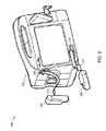
- FIG. 1shows an example personal area network for a medical application.
- FIG. 2shows example modules of a physiological sensor and of the patient monitor of FIG. 1 .
- FIG. 3shows an example patient monitor that includes a proximity detector.
- FIG. 4shows example components of the proximity detector of FIG. 3 .
- FIGS. 5 and 6show a flowchart for a method of establishing a connection between a sensor device and a gateway device in the personal area network of FIG. 2 .
- a proximity detectoris used to enable devices to execute functions such as turning on power at a sensor device, turning on power to a radio in the sensor device, and enabling the radio device to making a radio connection between devices.
- the proximity detectorturns the power on at the sensor device when the sensor device is in close proximity to a gateway device.
- the gateway deviceis typically a monitoring and display device that also provides access to a local or wide area network for transmitting sensor data to a server computer.
- the gateway devicealso includes a proximity detector.
- the gateway deviceincludes a source of AC power so that the gateway device is generally powered on. However, in other examples, the gateway device may be battery operated and may not be powered on until the gateway device comes into proximity with a sensor device.
- the proximity detector on the sensor deviceprovides a magnetic mechanism to activate power at the sensor device.
- Each proximity detectorincludes both a magnet and a magnetic detector.
- the magnetic detector on the gateway devicedetects the magnet on the sensor device and the magnetic detector on the sensor device detects the magnet on the gateway device.
- the detection of the magnet by the sensor deviceactivates power on the sensor device and the detection of the magnet on the gateway device provides an indication to the gateway device that power is activated on the sensor device.
- the detection of the magnet on the gateway deviceactivates power on the gateway device.
- the proximity detectionmay power the radio, enable the radio and put the radio in a connectable state. If the radio in either the sensor device or the gateway device is already powered, then the proximity detection may put the radio in a connectable state.
- proximity detectorsmay be used. If each device has a coil, magnetic coupling allows the coil in one device to detect if the coil in the other device has a current. One could pulse current in the first coil and detect the current pulse in the second coil. Detection of the current pulse in the coil of the first device by the coil of the second device would indicate proximity.
- a related solution with a magnet and a coil in the first device and a magnetic detector and a coil on the second devicecould have the second device detect proximity of the first device through actuation of the magnetic switch. The proximity detection causes the second device to enable its radio and also to pulse a current through its coil. This current pulse is detected in the first device, causing it to enable its radio.
- placing a load on the receiving coilallows the transmitting coil to detect proximity of the receiving coil as reflected impedance of the receiving coil's load affects the current and voltage in the transmitting coil.
- Proximity detectionmay be accomplished through time stamps of related signals, such as acceleration when two devices are tapped together.
- a time stamp on the signalscan be used as a filter to ensure that the two devices were tapped at close to the same time.
- a devicemay require a specific sequence such as three taps before enabling the radio.
- Optical signals (IR, UV, or Visible) from one devicemay be received by the second and these could be both detected by the second device and be reflected back to the first device. By encoding the optical signal, one may confidently assume the signal is authentic.
- a resistive detectioncould be used to detect if one device touches another as could one-wire serial where making electrical contact causes one device to transmit data to the other, such as a Bluetooth address and other out of band communication.
- Capacitive touch switchesmay be placed on a printed circuit board or embedded in the plastic cases creating a hidden switch that is activated when a hand is brought nearby.
- Ultrasonic transceivers, Ultra-Wideband (UWB) and RFIDmay be used for both proximity detection and communication of out of band data. For example, UWB can be used to determine if the range between two radios is less than 25 cm and only then allow the radios to connect.
- the systems and methods of the present disclosuremay also use contextual data to determine when to change the radio state to connectable or connectable and discoverable.
- a sensormay assume that it is in range of a gateway whenever the sensor is powered, whenever a new measurement is requested or when other contextual events occur and automatically put its radio in a discoverable and connectable state.
- Other contextual eventsinclude one or more of: losing connection to a previous gateway, detecting a new gateway, detecting a decrease in received power from the current gateway, detecting an increase in received power from a new gateway and receiving new patient information.
- a personal area networkis a computer network used for communication between computer devices close to an individual person.
- a personal area networkmay also be referred to as a body area network when the personal area network is a collection of physiological sensors and monitors.
- pairingrefers to Bluetooth pairing and also to equivalent transmission of credentials and information, such as an address, required to establish a radio connection.
- credentialsmay include authentication credentials, such as public keys and nonces that may be used to authenticate devices for secure, authenticated data transfer.
- a personal area networkmay include physiological sensor devices attached to a patient that are used to monitor health parameters of the patient.
- physiological sensor devices used in a medical settingare blood pressure monitoring devices, thermometers, ECG sensors, EEG sensors, cardiac output sensors, ETCO 2 sensors, and oxygen saturation sensors (SPO 2 ).
- Other types of sensor devicescan be used.
- the sensor devicestypically transmit sensor data over a network to a patient monitoring device, such as a wall-mounted display unit or a central station, such as the ACUITY® Central Monitoring System from Welch Allyn Inc. of Skaneateles Falls, N.Y.
- a personal area networkmay also include a Personal Digital Assistant (PDA), perhaps used by a clinician to interact with the patients' personal area networks such as the Clinician Notifier product from Welch Allyn Inc. of Skaneateles Falls, N.Y.
- PDAPersonal Digital Assistant
- the PDAcould join a patient network either using a menu-based system as is common for Bluetooth connections today or it could have a proximity detector that causes the PDA to joint the personal area network.
- Bluetoothis a wireless technology that can be used in personal area networks to transmit and receive data over short distances (generally less than 30 feet, although data can be transmitted up 100 meters depending on device class).
- Bluetoothuses a layered protocol architecture consisting of four core layers and associated protocols. The physical layer is the lowest layer in each Bluetooth device and is instantiated as a radio frequency (“RF”) layer that includes a transceiver with transmit and receive capability.
- RFradio frequency
- Bluetoothuses the microwave radio spectrum in the 2.402 GHz to 2.4835 GHz range.
- Bluetooth devicesare peer devices, each including a Bluetooth radio and the four core protocol layers. However, when two or more Bluetooth devices are connected in a personal area network, one device can become a master device and the remaining devices then become slave devices.
- a master Bluetooth devicecan communicate with up to seven slave devices. However, a slave can switch roles and become a master at any given time.
- a Bluetooth devicemay be a slave in one personal area network and a master in a second personal area network. Later version of the Bluetooth specification, such as Bluetooth LE, provide for a larger set of peer devices.
- Bluetoothis a wireless technology, the integrity and privacy of the transmitted data are a concern.
- Bluetoothpermits two devices to be paired with each other where the devices transmit on an encrypted link so that they can securely communicate with each other. Once two devices are paired, they can connect and communicate with each other without additional user intervention.
- the pairing processis typically initiated the first time a device receives a connection request from a device to which it is not already paired.
- Bluetooth addresses of each deviceare shared and during the pairing process, a shared secret key, known as a link key, is generated by the two devices. This link key is used to generate an encryption key, which is used to encrypt data for the current session.
- the link keyis stored along with the Bluetooth address of the peer device, then the devices are bonded so that the pairing information can be used in the future, even if the device(s) has been power cycled or if the devices have been out of range of each other. If either device deletes the link key, pairing must occur again before communication can occur.
- the link keyis used in a process to cryptographically authenticate the identity of the device, and be sure that it is the same device with which it previously paired.
- sensor datais transmitted using a wireless data exchange protocol, such as Bluetooth, to a central point, called a hub.
- a wireless data exchange protocolsuch as Bluetooth
- this central pointhas a connection to a larger network, such as an 802.3 or 802.11 LAN.
- a hub with a connection to a different type of networkis called a bridge.
- each sensor devicemay be joined to the network.
- joining a network when none of the network information is knownrequires discovery to learn the Bluetooth address of the other device, connection to initiate communication, and pairing to generate a shared secret key for authentication and encryption.
- any networkincluding 802.15.4, Bluetooth LE, ZigBee, UWB, a low-power 802.11 network, Wi-FiTM Direct, or a proprietary network could be used.
- Other physical mediasuch as IR as disclosed in the IEEE 802.11-1999 standard and ultrasonic may be used in lieu of RF.
- some technologiesallow for ranging and ranging allows proximity detection. These include at least UWB, IR, and Ultrasound.
- a hub to which multiple sensors are paired that includes a display to show the physiological state of the patientis a patient monitoring device.
- This type of hubtypically has a local area network uplink, making the patient monitoring device a bridge.
- Any RF enabled device with a processor and displayincluding a PDA, cellular phone, PC, or laptop can operate as a hub and also as a patient monitor.
- the appropriate pairing of a sensor device with a patient monitoring deviceensures that the sensor data is properly transmitted to the correct monitoring device. This is particularly important in a medical setting that may include a plurality of patients, sensors, monitoring devices and personal area networks to ensure that a particular patient's physiological data is tagged with his patient identifier.
- the patient identifiermay be encrypted independent of any encryption that occurs automatically on the communication link to further ensure protection of electronic personal health information.
- the procedure for pairing a sensor device to a monitoring devicetypically requires a user to manually enter data to authenticate that the proper devices are connecting in order to complete the pairing.
- the two devices that pairrequire that the same PIN is presented to both devices.
- the PIN for the headsetmay be hard coded into the headset and the user enters the PIN into the device to be paired, e.g., a cellular telephone. Since no data are transacted prior to PIN entry and the PIN is not transmitted, this process verifies that the user intends the two devices to establish a connection.
- This solutionworks reasonably well if the device is only to be paired once.
- the PIN solutionalso has security and usability issues, particularly as implemented.
- the PIN for most headsetsis an easy to remember number such as 0000 or 9999, so an intruder can guess the PIN and masquerade as the intended device.
- a brute force attackrequires only 10,000 different sequences (Although Bluetooth 2.0 uses a 16-byte PIN, this is usually generated by augmenting a 4-digit PIN with part of the Bluetooth address of the device, which is known). If the use case requires pairings to be made, removed, and re-built as occurs in clinical applications, the time to enter the PIN and navigate menus may be cumbersome.
- the systems and methods described in the present disclosurepermit sensor devices to be attached to a patient and paired to a monitoring device in an efficient and automated manner, thereby minimizing the need for a user to manually enter information.
- SSPSecure Simple Pairing
- OOBOut-Of-Band
- MIMMman-in-the-middle
- Radiosare neither connectable nor discoverable, except for a few seconds while the pairing information is exchanged, it is extremely unlikely an eavesdropper could detect the Personal Area Network (PAN) and generate a MITM attack before the pairing completes.
- PANPersonal Area Network
- application level softwarecan cause the radio to delete pairing information and destroy the RF connection. Such deletion and destruction can occur before any data are accepted across the RF link.
- Application level softwarecan determine correct device pairings through several methods including comparing the Bluetooth address to a known list of acceptable addresses, through an application level challenge-response or other authentication solution.
- FIG. 1shows example physiological sensors that can be used on a patient 100 in a personal area network for a medical application.
- the four physiological sensorsinclude an example thermometer 104 , ECG sensor 106 , blood pressure sensor 108 and SPO 2 sensor 110 .
- the SPO 2 sensoris also known as an oxygen saturation sensor.
- the sensors 104 , 106 , 108 , and 110can be paired to patient monitor 208 and communicate with a medical application over a personal area network, as described below.
- FIG. 2shows an example personal area network 200 for a medical application.
- the example personal area network 200includes the example SPO 2 sensor 110 and an example patient monitor 208 .
- the example personal area network 200may also include one or more of the example physiological sensors 104 , 106 and 108 (shown in FIG. 1 ).
- Each of the example physiological sensors 104 , 106 , 108 , 110has Bluetooth capability.
- the example SPO 2 sensor 110as well as the example sensors 104 , 106 and 108 , also includes a proximity detector 202 , sensor electronics 204 and a Bluetooth radio 206 .
- the example patient monitor 208includes a proximity detector 210 and may include one or more embedded sensors 212 that have a physical attachment to patient monitor 208 .
- the patient monitoralso includes a display 214 that indicates the state of various sensors and network connections.
- the patient monitor 208includes a Bluetooth radio 216 and a LAN/WAN connection 218 , providing a gateway 217 .
- the LAN/WAN connection 218permits data to be transmitted between the example personal area network 200 and one or more server computers 220 that are accessible via the LAN/WAN connection.
- Other network connectionsincluding mesh, UWB, MAN and the like may allow connection to the one or more server computers 220 .
- the example patient monitor 208is may be continually powered on.
- the patient monitor 208may be a wall-mounted unit or may be permanently mounted to a stand or other apparatus in hospital room.
- the patient monitor 208typically is connected to AC power and is typically continually powered on.
- the patient monitor 208may be a portable unit that is operated via battery power.
- the patient monitor 208is typically powered on manually via a power-on button.
- a portable patient monitormay also be power on automatically via the proximity detector 210 .
- Bluetooth devicesIn order for Bluetooth pairing to occur, Bluetooth devices must be both discoverable and connectable.
- a proximity detector in a Bluetooth devicefor example physiological sensor 110 , the Bluetooth device may be kept in a low power state to save power until the Bluetooth device is moved into close proximity with a second Bluetooth device, for example patient monitor 208 .
- the physiological sensor 110is off.
- the physiological sensor 110can be in a low power state including any of the following: the physiological sensor 110 being completely off, the microprocessor of physiological sensor 110 operating in a low power mode, the radio in physiological sensor 110 being in a low power mode, the radio in physiological sensor 110 being on, but not in a connectable state, or the radio in physiological sensor 110 being off. Regardless of the state of the physiological sensor 110 and its radio, detection of another proximal device causes the physiological sensor 110 and its radio to move to a state where the radio can connect to another device.
- the radios on both the physiological sensor 110 and the patient monitor 208are placed in connectable and discoverable mode, and Bluetooth pairing occurs between the physiological sensor 110 and the patient monitor 208 .
- the Bluetooth pairingestablishes a wireless connection between the physiological sensor 110 and the patient monitor 208 . Note that if sensor 110 and patient monitor 208 have previously paired and bonded, the radios do not need to discover each other. Similarly, if the sensor 110 and patient monitor 208 have been provisioned with the pairing information, perhaps at manufacturing, the radios do not need to discover each other.
- the physiological sensor 110is placed on the patient 100 and physiological data is sent from the physiological sensor 110 to the patient monitor 208 via the wireless connection.
- pairingmay occur after the sensor is placed on the patient 102 and pairing may occur after the patient monitor 208 is placed on the patient 102 .
- Providing an auxiliary, low power discoverypermits the medical device to be selective in the devices with which it might connect. For example, upon detection of an auxiliary discovery signal, the radio may change state to “discoverable” or “discoverable and connectable” for a limited time so that only the opportunity to connect to the wrong device is decreased compared to a device that is always in the “discoverable” or “discoverable and connectable” state. If both sides of the connection have this feature, then the opportunity to connect to the wrong device is further diminished. When one device is AC powered, the radio may be kept in connectable and discoverable mode all the time and rely on the physiological sensor 110 to correctly initiate pairing.
- the AC powered devicemay exit discoverable mode, but stay in connectable mode. This allows another sensor, perhaps that has lost contact with its primary gateway, to send physiological data via an alternate gateway. Even if this other sensor does not have a patient ID, a unique identifier such as the sensor serial number can be associated to the patient. With this unique identifier, sensor data transmitted via an alternate gateway can be associated with the correct patient ID at the server computer 220 . Another case for keeping radios in connectable mode allows re-connections to occur.
- eachwill likely keep its radio in connectable mode, but not discoverable mode. This allows the two devices to re-connect if the RF link is broken, but does not allow any other devices to discover the PAN. To keep the network more secure but still allow devices to reconnect, the devices may also exit both discoverable and connectable states after connecting to sensors and upon loss of RF connection move to the connectable state.
- the status of those devicesmay be annotated to a server for use by the biomedical engineers and clinicians.
- status and configuration informationare transferred between sensor device and gateway device, for example between physiological sensor 110 and patient monitor 208 , to verify that both the sensor device and the gateway device are operational and compatible with each other.
- application software of patient monitor 208may query physiological sensor 110 to verify that physiological sensor 110 has passed a diagnostics self test, to verify the strength of a battery on physiological sensor 110 , to determine if any component of physiological sensor 110 is in need of repair or due for periodic maintenance, or to determine the status of the RF connection.
- This status informationmay be transmitted along with other parameters from the monitor such as its own RF connection strength to the IT network, battery status, and location. These data may be used to trend performance, debug connection issues, or to determine if maintenance is required.
- the sensorprovides model and version information. The model and version of the sensor device are compared with the model and version of the gateway device to determine whether the sensor device and gateway device are compatible.
- the sensor device and the gateway deviceare said to have a logical connection with each other that is analogous to the connection that occurs when a cable is plugged into the monitor.
- This logical connectionmay occur at an RF level or at an application level.
- the logical connectionmay occur at the RF level after the devices are paired or the logical connection may occur at the application level when the compatibility check between devices is completed.
- plugging the cable into the deviceis analogous to the RF connection and the device recognizing the cable and the sensors at the end of that cable are analogous to a connection at the application level.
- a clinicianis required to verify the sensor device for a specific patient. Requiring the clinician to confirm the sensor device for a specific patient provides an additional level of security to ensure that the sensor device is placed on the correct person. In addition, the clinician must confirm the sensor for a specific patient within a short time period after the sensor device and the gateway device are placed in connectable and discoverable modes. Through confirming the device the clinician indicates to the system that the data from the new sensor belongs to the same patient as is indicated on the patient monitor. If the clinician does not confirm the sensor for a specific patient within the short time period, the wireless connection between the sensor device and the gateway device is broken and the logical connection between the sensor device and the gateway device is destroyed.
- the reset of the logical connectionmight include removal of the pairing information.
- the time periodmust last long enough for both radios to enter the connectable state and connect or to enter the connectable and discoverable state, be discovered, and connect.
- a short time periodmay be range from a hundred milliseconds to several seconds.
- the radioexits the connectable state or the connectable and discoverable state immediately upon initiation of a radio connection. Leaving the logical connection in place could allow the sensor to maintain a connection to the incorrect monitor.
- the systemmay be configured to allow the unconfirmed connection to remain; but without indicating the patient ID.
- a pseudo-IDmay be used to identify the data until such time as a patient ID is assigned to the sensor.
- the datamight be saved in a database keyed by the sensor serial number instead of the patient ID. If the sensor is later correctly connected to the proper patient monitor, the data that has been thus far collected and stored is annotated with the patient ID associated with the proper patient monitor.
- connection modeFor the connection between the sensor device and the gateway.
- the connection modedescribes the extent to which alarms and equipment alerts are generated in the connection.
- An alarmrefers to an error condition for a patient while an equipment alert refers to an error condition for the medical equipment.
- Application software at the gateway devicepermits the clinician to assign one of three connection modes—loose pairing, tight pairing and locked.
- Each connection modeis defined to match a specific workflow and provides a class of alarm response. For example, loose pairing provides one class of alarm response, tight pairing provides a second class of alarm response and locked provides a third class of alarm response.
- Other application-level connection modes and combinations thereofmay be used to match different workflows.
- Loose pairingis typically used for a spot monitoring workflow in which a sensor device is periodically brought into a patient's room to check a physiological parameter that is not being monitored by the patient monitor in the patient's room. This is sometimes referred to as spot checking.
- spot checkingIn a workflow that uses loose pairing, there are no equipment alerts if the connection between the sensor device and the gateway device is broken. There may also be no alarms as the workflow includes a clinician at the patient location.
- Tight pairingis typically used for a workflow in which there is continuous monitoring of patient physiological data.
- an equipment alertis generated whenever certain error conditions occur. For example, an equipment alert is generated when the wireless connection between the sensor device and the gateway device is broken. This is analogous to an equipment alert if an ECG cable is removed from the monitor or the ECG electrode falls off the patient.
- Another error condition that causes an alarm to be generatedis when the gateway device determines that one or more physiological parameters received from the sensor device is above or below a predetermined threshold.
- error conditions that cause an equipment alert condition to be generatedinclude: need for maintenance (including scheduled periodic maintenance), sensor device loss of power, unacceptable RF performance such as high packet loss or poor signal level, RF interference, inappropriately sized blood pressure cuff detected, ECG lead failure, SPO 2 sensor with no signal detected, a sensor that is not confirmed for a particular patient, and other equipment alerts familiar to those skilled in the art.
- the wireless connection between the sensor device and the gateway devicemay be broken and pairing information for the connection may be deleted at the sensor device and at the gateway device.
- pairing informationFor example, if a physiological sensor falls of the patient, when the physiological sensor is re-attached, the clinician may be required again connect the Bluetooth radios.
- the deletion of pairing information when the connection is brokenprevents physiological data from the sensor device from being associated with an erroneous patient identification number.
- the application level softwaremay allow the Bluetooth connection to persist, but stop annotation of the data with the patient ID until the patient ID is confirmed. A system may also stop the data flow from the sensor until the patient ID is confirmed.
- the systemmay have a record of the data and use an algorithm such as pattern recognition to verify the sensor is still attached to the same patient or the system may correlate the physiological signal from the unconfirmed sensor with physiological data from a confirmed sensor to determine if they are still on the same patient. If the data correlates, the system may begin annotating data from the previously unconfirmed sensor.
- an algorithmsuch as pattern recognition to verify the sensor is still attached to the same patient or the system may correlate the physiological signal from the unconfirmed sensor with physiological data from a confirmed sensor to determine if they are still on the same patient. If the data correlates, the system may begin annotating data from the previously unconfirmed sensor.
- Locked pairingis used when it is determined that a sensor device is only to be connected to a specific gateway device, for example to the patient monitor 208 or to a select set of gateway devices.
- a sensor deviceis used with locked pairing, an equipment theft alert is generated when an attempt is made to connect the sensor device to a gateway device that is not included in the select set of gateway devices.
- the intent of a locked connectionis to minimize the potential for the sensor device from being moved, borrowed or stolen from the gateway device to which the sensor device is connected.
- a reset capabilityis designed into the product. This may be through a hidden service screen, a reset button, through a specific set of key strokes or similar method that obscures the ability to remove the locked pairing configuration.
- FIG. 3show an example patient monitor 300 .
- the example patient monitor 300is a portable device and includes two example proximity detectors 308 and 310 .
- the proximity detectors 308 and 310are mounted internally in the patient monitor 300 with one surface of each of proximity detectors 308 and 310 being adjacent to an external surface of the patient monitor 300 .
- FIG. 3Also shown in FIG. 3 are two example physiological sensor devices 304 , 306 , each including a proximity detector, for example proximity detector 202 .
- Arrow 312shows the direction in which physiological sensor device 304 is moved to become in close proximity with proximity detector 308 .
- Arrow 314shows the direction in which physiological sensor device 306 moves to become in close proximity with proximity detector 310 .
- more or fewer proximity detectorsmay be used and the proximity detectors may be located on different areas of the patient monitor 300 .
- FIG. 4shows an example physical view for the proximity detection mechanism for physiological sensor 110 and proximity detector 202 .
- Physiological sensor 110is housed in a plastic housing 402 and includes a printed circuit board (PCB) 404 that includes sensor electronics 204 and Bluetooth radio 206 (not shown), a magnet 408 and a magnetic detector 406 .
- the magnet 408 and magnetic detector 406comprise proximity detector 202 .
- Patient monitor 208is housed in a plastic housing 410 and includes a printed circuit board 412 , a magnet 416 and a magnetic detector 414 .
- the magnet 416 and magnetic detector 414comprise proximity detector 210 .
- Patient monitor 208includes the Bluetooth radio 216 (not shown).
- the magnetic detectors 406 , 414are typically a magnetic switch such as a reed switch, a reed relay, a Hall Effect sensor, a Hall Effect switch or a giant magnetoresistance (GMR) detector. These magnetic switches permit proximity detection using very low power.
- a magnetic switchsuch as a reed switch, a reed relay, a Hall Effect sensor, a Hall Effect switch or a giant magnetoresistance (GMR) detector. These magnetic switches permit proximity detection using very low power.
- GMRgiant magnetoresistance
- the reed switchis a normally open switch, thereby drawing little or no power in the open state.
- the reed switchcloses when a magnetic field of a predetermined threshold is detected by the reed switch.
- a typical threshold for a sensitive reed switchmay vary between 5 Ampere-Turns and 15 Ampere-Turns. However, this assumes a uniform magnetic field along the axis of the axially leaded part.
- a Hall effect sensorgenerates a voltage in response to a magnetic field.
- the generated voltageincreases as the magnetic field increases.
- the Hall effect sensormay be combined with circuitry such as a comparator that permits the Hall effect sensor to act as a switch. When the magnetic field reaches a predetermined threshold, a magnetic switch closes, signifying an “on” state.
- a sensitive Hall effect sensormay operate at field strengths of around 10 to 25 Gauss, depending on temperature and frequency of the magnetic field.
- a GMR switchincludes giant magnetoresistance material and makes use of the concept of magnetoresistance. With magnetoresistance the electrical resistance of the GMR material changes its value when a magnetic field is applied to it. When the magnetic field reaches a predetermined threshold, the resistance of the GMR material is changed to a point such that sufficient current flows through a bridge in the GMR switch to close the GMR switch, signifying an “on” state.
- Some GMR switchesfor example GMR switches in the AFL200 series from NVE Corporation, require only a few microamperes of supply current.
- a sensitive GMR switchmay operate at a field strength of 7-13 Gauss.
- Whether the magnetic switch is normally open or normally closedis not relevant to the detection of an applied magnetic field; rather only the state change is important.
- the magnet 408must be strong enough to activate magnetic detector 414 when physiological sensor 110 is brought in the proximity of the magnetic detector 414 .
- the magnet 408must be positioned so that the magnet 408 does not falsely trigger magnetic detector 406 or any other magnetic detectors in other medical devices that may be implanted on a patient.
- implantable cardio defibrillatorsmay have embedded magnetic detectors that are typically activated at a field strength of greater than 10 Gauss.
- magnet 408 and magnet 416may need to provide a magnetic field or more than 10 Gauss.
- Each magnet 408 , 416is located on the outside of their respective plastic housing 402 , 410 .
- Each magnet 408 , 416is recessed in the plastic housing 402 and positioned so that one side of each magnet 408 , 416 is flush with a side of the plastic housing 402 .
- the reason magnets 408 and 416 are located on the outside on their respective plastic housing 402 , 410is to permit the use of a weaker magnet than would be needed if the magnets 408 and 416 were located within their plastic housing. The reason for this is the exponential decrease in magnetic flux density with distance. Suppose a magnet were placed on the inside of the plastic and had sufficient magnetization to create a field of 10 Gauss at 4 mm outside the plastic.
- magnets 408 and 416Comparing to a magnet recessed as indicated by magnets 408 and 416 that has sufficient magnetization to create a field of 10 Gauss at 4 mm from the outside of the plastic, the latter magnet would be weaker and its field strength at more than 4 mm from the outside of the plastic will be less than the field strength of the stronger magnet placed inside of the plastic.
- Using a weaker magnetminimizes the risk of false triggers for medical devices that contain embedded magnetic detectors. Placing magnets 408 and 416 on the outside of their respective plastic housings places magnet 408 closer to magnetic detector 414 than would be the case if magnet 408 were located inside of plastic housing 402 and places magnet 416 closer to magnetic detector 406 than would be the case if magnet 416 were located inside of plastic housing 410 . Typically, the spacing gap between magnets 416 and magnetic detector 406 and between magnet 408 and magnetic detector 414 is reduced by 2 millimeters by placing magnets 408 and 416 on the outside of their respective plastic housings.
- Physical detentsmay be included in the plastic housing to help the user properly locate the sensor 110 relative to monitor 208 to trigger the proximity detection. Labels may be used over the magnets 408 and 416 and over the magnetic detectors 406 and 408 to help guide the user to place the physiological sensor 110 in proper alignment with the magnetic detector in monitor 208 .
- FIGS. 5 and 6show a flowchart 500 for a method for establishing a connection between a sensor device, for example physiological sensor 110 and a gateway device, for example patient monitor 208 .
- a radio on the sensor deviceis in a non-connectable state. Typically, both the radio and the sensor device are powered off. An internal retry count is set to zero.
- the proximity detector on the sensor deviceis typically not activated until the sensor device is proximal to the gateway device.
- the determination of whether the proximity detector is activatedcomprises whether a magnet, for example magnet 416 on the gateway device activates a magnetic detector, for example magnetic detector 406 on the sensor device.
- the sensor devicemay need to be moved within centimeters of the gateway device or in some examples the sensor device may need to physically touch the gateway device in order for the magnetic detector to be activated.
- the Bluetooth radio on the sensor deviceis set to a connectable state, in low-power. This includes powering on the radio if it was not powered. The use of low-power radio transmission during connection improves security during the connection process, but is not required.
- a second radio devicefor example a Bluetooth radio
- proximity detectionoccurs near simultaneously at sensor device and the gateway device and each places its respective radio in a connectable state.
- This connectable statemay include also being discoverable.
- the Bluetooth radio on the gateway devicemay turn on at a slightly different time than the Bluetooth radio on the sensor device. It is also possible that one magnetic detector was triggered and the other was not.
- a retry countis incremented.
- a determinationis made as to whether a retry limit has been reached. When it is determined at operation 512 , that a retry limit has not been reached, control returns to operation 508 and another determination is made as to whether a second Bluetooth radio has been detected. When it is determined at operation 512 , that a retry limit has been reached, control returns to operation 502 and the sensor device is put back in a non-connectable state.
- a determinationmay be made at operation 512 as to whether a timeout limit has been reached.
- Bluetooth pairingis performed between the sensor device and the gateway device.
- the radio devicesare set to a standard power level and the sensor device is paired to the gateway device.
- standard poweris 4 dBm for a Class II Bluetooth radio and 20 dBm for a Class I Bluetooth radio.
- status and configuration informationare transferred between the sensor device and the gateway device.
- the status and configurationincludes such items as the strength of a battery on the sensor device and the model and version numbers of the sensor device and the gateway device.
- the status and configuration informationare transferred in an attempt to determine whether the sensor device is operationally compatible with the gateway device.
- a status message that the sensor device and gateway device are not compatibleis displayed to the user.
- This status messagemight be displayed on the gateway device, the sensor device, a syslog server, through e-mail or other electronic communication.
- the logical connection between the sensor device and the gateway deviceis broken and the connection sequence ends. Breaking the logical connection might be at the application layer or at the RF layer and might include removing stored pairing information.
- the incompatibility messagemay be sent to a server.
- a message that the sensor device and the gateway device are compatibleis displayed on the user interface of the gateway device and the clinician is prompted to confirm the patient for the sensor device.
- the confirmation of the patient to the sensor deviceprovides an additional level of security to ensure that the sensor device is being assigned to the correct patient.
- connection modeis selected.
- the connection modecan be one of loose pairing, tight pairing or locked. Additional connection modes may be created to support additional clinical work flows.
- a physiological sensor and monitor that incorporate Bluetooth technologyare computing devices and typically include at least one processing unit, system memory and a power source.
- the system memorymay be physical memory, such as volatile memory (such as RAM), non-volatile memory (such as ROM, flash memory, etc.) or some combination of the two.
- System memorytypically includes an embedded operating system suitable for controlling the operation of the sensor device.
- the system memorymay also include one or more software applications, for example Bluetooth, and may include program data.
Landscapes
- Health & Medical Sciences (AREA)
- Life Sciences & Earth Sciences (AREA)
- Engineering & Computer Science (AREA)
- Computer Networks & Wireless Communication (AREA)
- Signal Processing (AREA)
- Heart & Thoracic Surgery (AREA)
- Molecular Biology (AREA)
- Physics & Mathematics (AREA)
- Veterinary Medicine (AREA)
- Biophysics (AREA)
- Pathology (AREA)
- Biomedical Technology (AREA)
- Public Health (AREA)
- Medical Informatics (AREA)
- General Health & Medical Sciences (AREA)
- Surgery (AREA)
- Animal Behavior & Ethology (AREA)
- Nuclear Medicine, Radiotherapy & Molecular Imaging (AREA)
- Radiology & Medical Imaging (AREA)
- Psychiatry (AREA)
- Computer Vision & Pattern Recognition (AREA)
- Physiology (AREA)
- Computer Security & Cryptography (AREA)
- Artificial Intelligence (AREA)
- Measuring And Recording Apparatus For Diagnosis (AREA)
Abstract
Description
Claims (19)
Priority Applications (5)
| Application Number | Priority Date | Filing Date | Title |
|---|---|---|---|
| US12/827,817US8957777B2 (en) | 2010-06-30 | 2010-06-30 | Body area network pairing improvements for clinical workflows |
| US13/225,989US8907782B2 (en) | 2010-06-30 | 2011-09-06 | Medical devices with proximity detection |
| US14/531,142US9402545B2 (en) | 2010-06-30 | 2014-11-03 | Medical devices with proximity detection |
| US14/593,353US9386924B2 (en) | 2010-06-30 | 2015-01-09 | Body area network pairing improvements for clinical workflows |
| US15/180,732US10136817B2 (en) | 2010-06-30 | 2016-06-13 | Body area network pairing improvements for clinical workflows |
Applications Claiming Priority (1)
| Application Number | Priority Date | Filing Date | Title |
|---|---|---|---|
| US12/827,817US8957777B2 (en) | 2010-06-30 | 2010-06-30 | Body area network pairing improvements for clinical workflows |
Related Child Applications (2)
| Application Number | Title | Priority Date | Filing Date |
|---|---|---|---|
| US13/225,989Continuation-In-PartUS8907782B2 (en) | 2010-06-30 | 2011-09-06 | Medical devices with proximity detection |
| US14/593,353ContinuationUS9386924B2 (en) | 2010-06-30 | 2015-01-09 | Body area network pairing improvements for clinical workflows |
Publications (2)
| Publication Number | Publication Date |
|---|---|
| US20120001751A1 US20120001751A1 (en) | 2012-01-05 |
| US8957777B2true US8957777B2 (en) | 2015-02-17 |
Family
ID=45399277
Family Applications (3)
| Application Number | Title | Priority Date | Filing Date |
|---|---|---|---|
| US12/827,817Expired - Fee RelatedUS8957777B2 (en) | 2010-06-30 | 2010-06-30 | Body area network pairing improvements for clinical workflows |
| US14/593,353ActiveUS9386924B2 (en) | 2010-06-30 | 2015-01-09 | Body area network pairing improvements for clinical workflows |
| US15/180,732Expired - Fee RelatedUS10136817B2 (en) | 2010-06-30 | 2016-06-13 | Body area network pairing improvements for clinical workflows |
Family Applications After (2)
| Application Number | Title | Priority Date | Filing Date |
|---|---|---|---|
| US14/593,353ActiveUS9386924B2 (en) | 2010-06-30 | 2015-01-09 | Body area network pairing improvements for clinical workflows |
| US15/180,732Expired - Fee RelatedUS10136817B2 (en) | 2010-06-30 | 2016-06-13 | Body area network pairing improvements for clinical workflows |
Country Status (1)
| Country | Link |
|---|---|
| US (3) | US8957777B2 (en) |
Cited By (11)
| Publication number | Priority date | Publication date | Assignee | Title |
|---|---|---|---|---|
| US20150190053A1 (en)* | 2010-06-30 | 2015-07-09 | Welch Allyn, Inc. | Body Area Network Pairing Improvements for Clinical Workflows |
| US20160057565A1 (en)* | 2014-08-25 | 2016-02-25 | Steven K. Gold | Proximity-Based Sensing, Communicating, and Processing of User Physiologic Information |
| US20160058285A1 (en)* | 2014-08-29 | 2016-03-03 | Nihon Kohden Corporation | Medical device system and medical device |
| WO2016103047A1 (en)* | 2014-12-24 | 2016-06-30 | 4Iiii Innovations Inc. | A wireless sensor pod uses trigger events for pairing and testing |
| US9402545B2 (en) | 2010-06-30 | 2016-08-02 | Welch Allyn, Inc. | Medical devices with proximity detection |
| US20170323073A1 (en)* | 2014-11-20 | 2017-11-09 | T&W Engineering A/S | Method and system for establishing network connection to a wearable eeg monitoring module |
| US20190174284A1 (en)* | 2014-08-25 | 2019-06-06 | Phyzio, Inc. | Physiologic Sensors for Sensing, Measuring, Transmitting, and Processing Signals |
| US10945679B2 (en) | 2017-01-31 | 2021-03-16 | Welch Allyn, Inc. | Modular monitoring smart bed |
| US12123654B2 (en) | 2010-05-04 | 2024-10-22 | Fractal Heatsink Technologies LLC | System and method for maintaining efficiency of a fractal heat sink |
| US12251201B2 (en) | 2019-08-16 | 2025-03-18 | Poltorak Technologies Llc | Device and method for medical diagnostics |
| US12262973B1 (en)* | 2024-03-29 | 2025-04-01 | Perin Health Devices Llc | Systems and methods of a medical device and environmental connectivity hub |
Families Citing this family (42)
| Publication number | Priority date | Publication date | Assignee | Title |
|---|---|---|---|---|
| US9000914B2 (en) | 2010-03-15 | 2015-04-07 | Welch Allyn, Inc. | Personal area network pairing |
| US20130211265A1 (en)* | 2010-10-18 | 2013-08-15 | 3M Innovative Properties Company | Multifunctional medical device for telemedicine applications |
| US20120158428A1 (en)* | 2010-12-16 | 2012-06-21 | General Electric Company | Dynamic patient data monitoring system and method |
| US8923918B2 (en)* | 2010-12-18 | 2014-12-30 | Kallows Engineering India Pvt. Ltd. | Biosensor interface apparatus for a mobile communication device |
| US20120306652A1 (en)* | 2011-06-02 | 2012-12-06 | Nokia Siemens Networks Oy | Ecg alerts |
| US20120306653A1 (en)* | 2011-06-02 | 2012-12-06 | Nokia Siemens Networks Oy | Medical sensor |
| DE102011107795A1 (en) | 2011-07-15 | 2013-01-17 | Fresenius Medical Care Deutschland Gmbh | Method and device for remote monitoring and control of medical fluid management devices |
| US9186071B2 (en)* | 2012-01-27 | 2015-11-17 | Qualcomm Incorporated | Unlocking a body area network |
| US10307111B2 (en) | 2012-02-09 | 2019-06-04 | Masimo Corporation | Patient position detection system |
| TW201335737A (en)* | 2012-02-29 | 2013-09-01 | Quanta Comp Inc | Reset device and electronic system having the same |
| US9008658B2 (en)* | 2012-06-06 | 2015-04-14 | Welch Allyn, Inc. | Using near-field communication both for out-of-band pairing and physiological data transfer |
| US20150372770A1 (en)* | 2013-02-06 | 2015-12-24 | Koninklijke Philips N.V. | Body coupled communiication system |
| US20140340217A1 (en)* | 2013-05-15 | 2014-11-20 | Collar ID, LLC | Apparatus and methods for sensing a parameter with a restraint device |
| US9861290B1 (en) | 2013-06-05 | 2018-01-09 | Rittenhouse Engineering, LLC | Wireless medical sensor system |
| US10348598B2 (en)* | 2013-08-20 | 2019-07-09 | Sony Corporation | Information processing to control polling for short range wireless communication |
| WO2016166383A1 (en)* | 2015-04-13 | 2016-10-20 | Tsb Real Time Location Systems, S.L. | Identifier device |
| US10910102B2 (en)* | 2015-05-22 | 2021-02-02 | Hill-Rom Services, Inc. | In-bed patient identity verification and data collection |
| KR102612874B1 (en)* | 2015-08-31 | 2023-12-12 | 마시모 코오퍼레이션 | Wireless patient monitoring systems and methods |
| CN108012575B (en)* | 2015-09-03 | 2021-11-23 | 皇家飞利浦有限公司 | Device for wireless transmission of data and power |
| WO2017036895A1 (en)* | 2015-09-03 | 2017-03-09 | Koninklijke Philips N.V. | Connector and device for wireless transmission of data and/or power |
| JP6466624B2 (en) | 2015-09-03 | 2019-02-06 | コーニンクレッカ フィリップス エヌ ヴェKoninklijke Philips N.V. | Cable unit for connecting devices and enabling wireless exchange of data and / or power between devices |
| CN105228089B (en)* | 2015-09-30 | 2019-11-05 | 成都信汇聚源科技有限公司 | A kind of wearable device multisensor adaptation and real-time data acquisition method |
| US10638260B2 (en)* | 2015-10-05 | 2020-04-28 | Unwire Payments & Mobility Aps | System and method for initiating communication with a short range transceiver |
| JP7197473B2 (en) | 2016-10-13 | 2022-12-27 | マシモ・コーポレイション | System and method for patient fall detection |
| US9943229B1 (en)* | 2016-12-08 | 2018-04-17 | General Electric Copany | Systems and methods for monitoring patient health |
| AU2018201125B2 (en) | 2017-02-17 | 2020-01-30 | Seal Shield, Llc | Uv sterilization system and device and related methods |
| US10577550B2 (en)* | 2017-09-26 | 2020-03-03 | Catherine J. Chagnot | Continuously operable mechanical or electrical power source fueled by gas or solid fuel including gas from improved biomass downdraft gasifier |
| WO2019107888A1 (en) | 2017-11-29 | 2019-06-06 | 삼성전자 주식회사 | Method for rf communication connection using electronic device and user touch input |
| US10403113B1 (en)* | 2018-04-06 | 2019-09-03 | Witricity Corpoation | Methods for warning of electromagnetic fields produced by wireless electric vehicle charging systems |
| US11281869B2 (en)* | 2018-12-21 | 2022-03-22 | General Electric Company | Methods and devices for device detection using magnetic signatures |
| US20210199793A1 (en)* | 2019-12-27 | 2021-07-01 | Continental Automotive Systems, Inc. | Method for bluetooth low energy rf ranging sequence |
| US12390114B2 (en) | 2020-03-20 | 2025-08-19 | Masimo Corporation | Wearable device for monitoring health status |
| US12426783B2 (en)* | 2020-05-22 | 2025-09-30 | Lifelens Technologies, Inc. | Gateway device facilitating collection and management of data from a body area network to a study coordinating system |
| USD974193S1 (en) | 2020-07-27 | 2023-01-03 | Masimo Corporation | Wearable temperature measurement device |
| USD980091S1 (en) | 2020-07-27 | 2023-03-07 | Masimo Corporation | Wearable temperature measurement device |
| US12082276B1 (en)* | 2020-08-26 | 2024-09-03 | Apple Inc. | Automatic pairing of personal devices with peripheral devices |
| USD1072837S1 (en) | 2020-10-27 | 2025-04-29 | Masimo Corporation | Display screen or portion thereof with graphical user interface |
| USD1000975S1 (en) | 2021-09-22 | 2023-10-10 | Masimo Corporation | Wearable temperature measurement device |
| WO2023044889A1 (en)* | 2021-09-27 | 2023-03-30 | Medtrum Technologies Inc. | Analyte detection system |
| KR20230073386A (en)* | 2021-11-18 | 2023-05-26 | 현대자동차주식회사 | Vehicle |
| USD1048908S1 (en) | 2022-10-04 | 2024-10-29 | Masimo Corporation | Wearable sensor |
| WO2024155764A1 (en)* | 2023-01-19 | 2024-07-25 | Lifelens Technologies, Inc. | Pairing of devices associated with a body area network |
Citations (99)
| Publication number | Priority date | Publication date | Assignee | Title |
|---|---|---|---|---|
| JPS61149820A (en)* | 1984-12-24 | 1986-07-08 | Matsushita Electric Works Ltd | Proximity sensor |
| US4893073A (en)* | 1989-01-30 | 1990-01-09 | General Motors Corporation | Electric circuit board current sensor |
| US4922197A (en)* | 1988-08-01 | 1990-05-01 | Eaton Corporation | High resolution proximity detector employing magnetoresistive sensor disposed within a pressure resistant enclosure |
| US4994738A (en)* | 1985-06-19 | 1991-02-19 | Gerno Soyck | Proximity switch for detecting a magnetic inductive field |
| JPH0484948A (en)* | 1990-07-30 | 1992-03-18 | Matsushita Electric Ind Co Ltd | Punctual ultrasonic probe |
| EP0589466A1 (en)* | 1992-09-24 | 1994-03-30 | Jack B. Meister | Impact sensor for vehicle safety restraint system |
| US5326945A (en)* | 1991-12-02 | 1994-07-05 | Tokin Corporation | Shock sensor |
| US5559433A (en)* | 1993-02-04 | 1996-09-24 | Mitsubishi Denki Kabushiki Kaisha | Magnetic sensor device including apparatus for aligning a magnetoresistance element and a circuit board and a method of manufacturing the magnetoresistive device |
| US5928227A (en)* | 1997-03-10 | 1999-07-27 | The University Of Iowa Research | Remote controlled coagulator system and methods |
| US20020008625A1 (en)* | 2000-02-29 | 2002-01-24 | Adams Jonathan D. | Remote accountability system and method |
| US6356584B1 (en)* | 1996-09-19 | 2002-03-12 | Siemens Aktiengesellschaft | Method for the clocked serial data transmission of data blocks of identical block length |
| US20020082480A1 (en) | 2000-08-29 | 2002-06-27 | Riff Kenneth M. | Medical device systems implemented network scheme for remote patient management |
| US20030033032A1 (en) | 2001-07-02 | 2003-02-13 | Lind Michael A. | Application specific intelligent microsensors |
| US20030105499A1 (en) | 1998-02-27 | 2003-06-05 | Cardiac Pacemakers, Inc. | Rate adaptive cardiac rhythm management device using transthoracic impedance |
| US20030142651A1 (en)* | 2002-01-25 | 2003-07-31 | Docomo Communications Laboratories Usa, Inc. | Quality of service aware handoff trigger |
| US20030149459A1 (en)* | 2002-02-07 | 2003-08-07 | Von Arx Jeffrey A. | Methods and apparatuses for implantable medical device telemetry power management |
| US20030206116A1 (en) | 2000-05-19 | 2003-11-06 | Weiner Herbert S. | Patient monitoring system |
| US20040015058A1 (en) | 1993-09-04 | 2004-01-22 | Motorola, Inc. | Wireless medical diagnosis and monitoring equipment |
| US20040073127A1 (en) | 2001-07-17 | 2004-04-15 | Gmp Companies, Inc. | Wireless ECG system |
| US20040102683A1 (en) | 2002-04-16 | 2004-05-27 | Khanuja Sukhwant Singh | Method and apparatus for remotely monitoring the condition of a patient |
| US20040202339A1 (en) | 2003-04-09 | 2004-10-14 | O'brien, William D. | Intrabody communication with ultrasound |
| US20040225199A1 (en) | 2003-05-08 | 2004-11-11 | Evanyk Shane Walter | Advanced physiological monitoring systems and methods |
| US20040249257A1 (en)* | 2003-06-04 | 2004-12-09 | Tupin Joe Paul | Article of manufacture for extracting physiological data using ultra-wideband radar and improved signal processing techniques |
| US20050068173A1 (en)* | 2003-03-28 | 2005-03-31 | Anthony Capobianco | User programmable portable proximity detector |
| US20050097191A1 (en) | 2001-09-05 | 2005-05-05 | Olympus Corporation | Control system for controlling medical equipment |
| US6934874B2 (en)* | 2000-02-11 | 2005-08-23 | Daimlerchrysler Ag | Method and apparatus for ensuring integrity of transmitted data in a distributed control system |
| US20050261556A1 (en) | 2002-10-11 | 2005-11-24 | Koninkijke Philips Electronics N.V. | Power saving uplink for biosensors |
| WO2006047400A2 (en) | 2004-10-25 | 2006-05-04 | Eastern Virginia Medical School | System, method and medium for simulating normal and abnormal medical conditions |
| US20060115066A1 (en)* | 2004-11-22 | 2006-06-01 | Levien Royce A | Transfer back |
| US20060135065A1 (en)* | 2004-12-17 | 2006-06-22 | Samsung Electronics Co., Ltd. | Bluetooth device and method for providing service determined according to bluetooth pin |
| US20060179079A1 (en) | 2005-02-09 | 2006-08-10 | Mikko Kolehmainen | System, method and apparatus for data transfer between computing hosts |
| US20060212085A1 (en) | 2004-05-13 | 2006-09-21 | Fischell David R | Emergency room triage system |
| US20060219776A1 (en) | 2003-11-17 | 2006-10-05 | Dpd Patent Trust | Rfid reader with multiple interfaces |
| US20070003061A1 (en)* | 2005-05-23 | 2007-01-04 | Jung Edward K | Device pairing via device to device contact |
| US20070010748A1 (en)* | 2005-07-06 | 2007-01-11 | Rauch Steven D | Ambulatory monitors |
| US20070032832A1 (en) | 2005-08-03 | 2007-02-08 | Kamilo Feher | Medical diagnostic and communication system |
| US7197357B2 (en) | 2001-07-17 | 2007-03-27 | Life Sync Corporation | Wireless ECG system |
| US20070070035A1 (en)* | 2005-09-29 | 2007-03-29 | Ray Asbury | Method for pairing 1-way devices without buttons |
| US20070135866A1 (en) | 2005-12-14 | 2007-06-14 | Welch Allyn Inc. | Medical device wireless adapter |
| US20070162089A1 (en)* | 2006-01-09 | 2007-07-12 | Transoma Medical, Inc. | Cross-band communications in an implantable device |
| US20070264988A1 (en)* | 2006-03-31 | 2007-11-15 | Polycom, Inc. | System, method, and apparatus for extending wireless personal area networks using conferencing connection |
| US20080005288A1 (en)* | 2006-06-29 | 2008-01-03 | Shoji Kodama | Storage system and data replication method |
| US20080013601A1 (en)* | 2004-05-10 | 2008-01-17 | Patric Lind | Method and Device for Bluetooth Pairing |
| US20080046039A1 (en) | 2006-08-18 | 2008-02-21 | Corndorf Eric D | Secure Telemetric Link |
| US20080140160A1 (en) | 2006-12-06 | 2008-06-12 | Medtronic, Inc. | Intelligent discovery of medical devices by a programming system |
| US20080151695A1 (en) | 2006-12-22 | 2008-06-26 | Kimel Janna C | Mobile medication |
| US20080177150A1 (en) | 2007-01-18 | 2008-07-24 | Mutsuya Ii | Molecular Sensors for Bio-Metric Measurements and Bio-Assays |
| US20080183910A1 (en) | 2006-12-28 | 2008-07-31 | Natoli Joseph D | Personal medical device (PMD) docking station |
| US20080183245A1 (en)* | 2007-01-31 | 2008-07-31 | Van Oort Geeske | Telemetry of external physiological sensor data and implantable medical device data to a central processing system |
| US20080191866A1 (en) | 2005-03-22 | 2008-08-14 | Koninklijke Philips Electronics N. V. | Addressing Scheme for Smart Wireless Medical Sensor Networks |
| US20080227393A1 (en)* | 2007-03-14 | 2008-09-18 | John Tang | Method and system for pairing of wireless devices using physical presence |
| US20080228045A1 (en) | 2007-02-23 | 2008-09-18 | Tia Gao | Multiprotocol Wireless Medical Monitors and Systems |
| US20080234557A1 (en)* | 2007-03-22 | 2008-09-25 | Siemens Aktiengesellschaft | Mobile radio transmission unit |
| US20080281170A1 (en)* | 2005-11-08 | 2008-11-13 | Koninklijke Philips Electronics N.V. | Method for Detecting Critical Trends in Multi-Parameter Patient Monitoring and Clinical Data Using Clustering |
| US20080281169A1 (en) | 2005-10-07 | 2008-11-13 | Koninklijke Philips Electronics N. V. | Ear-Thermometer With Ear Identification |
| US20080287748A1 (en) | 2007-02-05 | 2008-11-20 | Demetrios Sapounas | System and method for physiological data readings, transmission and presentation |
| US20090018453A1 (en) | 2007-06-12 | 2009-01-15 | Triage Wireless, Inc. | Vital sign monitor for measuring blood pressure using optical, electrical and pressure waveforms |
| US20090023391A1 (en) | 2006-02-24 | 2009-01-22 | Koninklijke Philips Electronics N. V. | Wireless body sensor network |
| US20090030285A1 (en) | 2007-07-25 | 2009-01-29 | Andersen Bjorn K | Monitoring of use status and automatic power management in medical devices |
| KR20090011863A (en) | 2007-07-27 | 2009-02-02 | 고려대학교 산학협력단 | User Management System and Method Using Unique Identifier of Sink Node in Human Body Sensor Network |
| US20090069642A1 (en) | 2007-09-11 | 2009-03-12 | Aid Networks, Llc | Wearable Wireless Electronic Patient Data Communications and Physiological Monitoring Device |
| US20090076348A1 (en)* | 2007-09-14 | 2009-03-19 | Corventis, Inc. | Injectable Device for Physiological Monitoring |
| US20090076343A1 (en)* | 2007-09-14 | 2009-03-19 | Corventis, Inc. | Energy Management for Adherent Patient Monitor |
| US20090076350A1 (en)* | 2007-09-14 | 2009-03-19 | Corventis, Inc. | Data Collection in a Multi-Sensor Patient Monitor |
| US20090088605A1 (en) | 2007-09-27 | 2009-04-02 | John Anderson Fergus Ross | System and method for interference mitigation in a wireless sensor network |
| US20090096573A1 (en) | 2007-10-10 | 2009-04-16 | Apple Inc. | Activation of Cryptographically Paired Device |
| US20090112630A1 (en) | 2007-10-26 | 2009-04-30 | Collins Jr Williams F | System and method for collection and communication of data from multiple patient care devices |
| US20090118595A1 (en) | 2004-06-15 | 2009-05-07 | Koninklijke Philips Electronics N.V. | Sensor for acquiring physiological signals of a patient |
| US20090140923A1 (en)* | 2007-12-04 | 2009-06-04 | Nortel Networks Limited | Systems and methods for facilitating a first response mission at an incident scene using precision location |
| KR20090059324A (en) | 2007-12-06 | 2009-06-11 | 삼성전기주식회사 | Patient monitoring system and method |
| US20090215398A1 (en)* | 2008-02-25 | 2009-08-27 | Adler Mitchell D | Methods and Systems for Establishing Communications Between Devices |
| US20090227282A1 (en) | 2008-03-10 | 2009-09-10 | Sony Corporation | Communication device and communication method |
| US20090231125A1 (en) | 2004-12-13 | 2009-09-17 | Koninklijke Philips Electronics N.V. | Mobile monitoring |
| US20090239587A1 (en)* | 2008-03-19 | 2009-09-24 | Universal Electronics Inc. | System and method for appliance control via a personal communication or entertainment device |
| US20090275296A1 (en)* | 2008-05-01 | 2009-11-05 | Huang Chung-Er | Communication module with dual systems and method for defining operating mode thereof |
| US20100010338A1 (en)* | 2008-07-08 | 2010-01-14 | Peter Van Dam | Implantable Medical Device Orientation Detection Utilizing an External Magnet and a 3D Accelerometer Sensor |
| EP2146431A2 (en)* | 2008-07-15 | 2010-01-20 | Optosys SA | Inductive proximity sensor for embedded mounting and method of designing the same |
| US20100029205A1 (en)* | 2008-07-31 | 2010-02-04 | HONG FU JIN PRECISION INDUSTRY (ShenZhen) CO, LTD. | Wireless device, pairing method, and unpairing method |
| US20100045425A1 (en) | 2008-08-21 | 2010-02-25 | Chivallier M Laurent | data transmission of sensors |
| US20100082990A1 (en)* | 2008-09-29 | 2010-04-01 | Microsoft Corporation | Establishment of a relationship between wireless devices |
| US20100082983A1 (en) | 2008-09-30 | 2010-04-01 | Shah Rahul C | Secure device association |
| US20100125188A1 (en)* | 2008-11-18 | 2010-05-20 | Nonin Medical, Inc. | Motion correlated pulse oximetry |
| US20100145165A1 (en)* | 2006-12-30 | 2010-06-10 | Safer Sleep Limited | Notification System |
| US20100297946A1 (en)* | 2009-05-22 | 2010-11-25 | Alameh Rachid M | Method and system for conducting communication between mobile devices |
| US7860456B2 (en)* | 2006-02-08 | 2010-12-28 | Samsung Electronics Co., Ltd | Method and apparatus for secured communication between bluetooth® devices |
| US20110018854A1 (en)* | 2008-02-15 | 2011-01-27 | Duncan Barclay | Electronic document reading device |
| US20110105861A1 (en)* | 2009-09-01 | 2011-05-05 | Adidas Ag World Of Sports | Physiological Monitoring Garment |
| US20110152632A1 (en) | 2008-08-06 | 2011-06-23 | E-Vitae Pte. Ltd. | Universal Body Sensor Network |
| US20110160786A1 (en)* | 2009-12-29 | 2011-06-30 | Stubbs Scott R | Implantable device failsafe mode for mri |
| US7973657B2 (en)* | 2008-02-20 | 2011-07-05 | Mourad Ben Ayed | Systems for monitoring proximity to prevent loss or to assist recovery |
| US7978062B2 (en)* | 2007-08-31 | 2011-07-12 | Cardiac Pacemakers, Inc. | Medical data transport over wireless life critical network |
| US20110183698A1 (en)* | 2010-01-22 | 2011-07-28 | General Electric Company | Methods and systems for reuse of radio resources in medical telemetry networks |
| US20110202371A1 (en) | 2008-09-12 | 2011-08-18 | Capsule Technologie | Device, system and method for providing contextualized medical data |
| US20110210820A1 (en) | 2010-02-26 | 2011-09-01 | Gm Global Technology Operations, Inc. | Multiple near field communication tags in a pairing domain |
| US20110213216A1 (en) | 2010-02-28 | 2011-09-01 | Nellcor Puritan Bennett Llc | Adaptive wireless body networks |
| US20110221590A1 (en) | 2010-03-15 | 2011-09-15 | Welch Allyn, Inc. | Personal Area Network Pairing |
| US20110288379A1 (en)* | 2007-08-02 | 2011-11-24 | Wuxi Microsens Co., Ltd. | Body sign dynamically monitoring system |
| US20120003933A1 (en) | 2010-06-30 | 2012-01-05 | Welch Allyn, Inc. | Medical devices with proximity detection |
| US20140128674A1 (en)* | 2011-07-11 | 2014-05-08 | Olympus Winter & Ibe Gmbh | Contact-free magnetic coupling for an endoscope, and endoscope |
Family Cites Families (31)
| Publication number | Priority date | Publication date | Assignee | Title |
|---|---|---|---|---|
| CN1252877A (en) | 1997-03-13 | 2000-05-10 | 第一咨询公司 | Disease management system |
| US6868288B2 (en)* | 2000-08-26 | 2005-03-15 | Medtronic, Inc. | Implanted medical device telemetry using integrated thin film bulk acoustic resonator filtering |
| US7646872B2 (en) | 2004-04-02 | 2010-01-12 | Research In Motion Limited | Systems and methods to securely generate shared keys |
| US8532304B2 (en) | 2005-04-04 | 2013-09-10 | Nokia Corporation | Administration of wireless local area networks |
| US20080194922A1 (en) | 2005-09-07 | 2008-08-14 | Holden James F | Potentiation for medical therapies |
| EP1949724A4 (en) | 2005-11-16 | 2011-07-06 | Nokia Corp | SYSTEM AND METHOD FOR ESTABLISHING INDEPENDENT SUPPORT CONNECTIONS AND SECURITY |
| WO2008076464A2 (en) | 2006-06-21 | 2008-06-26 | Surgisense Corporation | Wireless medical telemetry system and methods using radio-frequency energized biosensors |
| WO2008033970A2 (en) | 2006-09-14 | 2008-03-20 | Sloan Kettering Institute For Cancer Research | Automated association of patient care devices |
| US10311533B2 (en) | 2006-12-27 | 2019-06-04 | Cardiac Pacemakers, Inc. | Method and system to enable physician labels on a remote server and use labels to verify and improve algorithm results |
| AU2007343390A1 (en)* | 2007-01-10 | 2008-07-17 | Tomtom International B.V. | Navigation device and method for displaying navigation information |
| US8556811B2 (en) | 2007-02-02 | 2013-10-15 | Johns Hopkins University | Method and system for determining a cerebrovascular autoregulation state of a patient |
| US20080262376A1 (en) | 2007-04-17 | 2008-10-23 | Proactive Health Devices, Inc. | Wireless sensor system for monitoring skin condition using the body as communication conduit |
| US7647196B2 (en) | 2007-08-08 | 2010-01-12 | Dp Technologies, Inc. | Human activity monitoring device with distance calculation |
| US8162841B2 (en) | 2007-08-31 | 2012-04-24 | Pacesetter, Inc. | Standalone systemic arterial blood pressure monitoring device |
| US8535223B2 (en) | 2008-02-28 | 2013-09-17 | Koninklijke Philips N.V. | Wireless patient monitoring using streaming of medical data with body-coupled communication |
| JP4613969B2 (en) | 2008-03-03 | 2011-01-19 | ソニー株式会社 | Communication apparatus and communication method |
| EP2328463B1 (en) | 2008-08-20 | 2012-05-09 | Koninklijke Philips Electronics N.V. | Monitoring vital parameters of a patient using a body sensor network |
| CN102132281B (en) | 2008-08-28 | 2016-02-03 | 皇家飞利浦电子股份有限公司 | Sensor for wearing for patient provides the method and system of patient's identification beacon |
| US20100160742A1 (en) | 2008-12-18 | 2010-06-24 | General Electric Company | Telemetry system and method |
| EP2908540B1 (en)* | 2009-04-01 | 2016-09-21 | Oticon A/s | A method of pairing wireless devices |
| US8655441B2 (en) | 2009-04-16 | 2014-02-18 | Massachusetts Institute Of Technology | Methods and apparatus for monitoring patients and delivering therapeutic stimuli |
| US8188851B2 (en)* | 2009-05-04 | 2012-05-29 | Sony Mobile Communications Ab | Wake-up system and method for an electronic apparatus |
| US20100331645A1 (en)* | 2009-06-25 | 2010-12-30 | Roche Diagnostics Operations, Inc. | Methods and systems for wireless communication between a blood glucose meter and a portable communication device |
| US8321017B2 (en) | 2009-07-08 | 2012-11-27 | Pacesetter, Inc. | Electromechanical delay (EMD) monitoring devices, systems and methods |
| US20110015496A1 (en) | 2009-07-14 | 2011-01-20 | Sherman Lawrence M | Portable medical device |
| US20110208015A1 (en) | 2009-07-20 | 2011-08-25 | Masimo Corporation | Wireless patient monitoring system |
| US20110028091A1 (en)* | 2009-08-03 | 2011-02-03 | Motorola, Inc. | Method and system for near-field wireless device pairing |
| US8957777B2 (en)* | 2010-06-30 | 2015-02-17 | Welch Allyn, Inc. | Body area network pairing improvements for clinical workflows |
| US20120158428A1 (en) | 2010-12-16 | 2012-06-21 | General Electric Company | Dynamic patient data monitoring system and method |
| WO2012112407A1 (en) | 2011-02-14 | 2012-08-23 | Chung Wayne | Wireless physiological sensor system and method |
| US9008658B2 (en)* | 2012-06-06 | 2015-04-14 | Welch Allyn, Inc. | Using near-field communication both for out-of-band pairing and physiological data transfer |
- 2010
- 2010-06-30USUS12/827,817patent/US8957777B2/ennot_activeExpired - Fee Related
- 2015
- 2015-01-09USUS14/593,353patent/US9386924B2/enactiveActive
- 2016
- 2016-06-13USUS15/180,732patent/US10136817B2/ennot_activeExpired - Fee Related
Patent Citations (111)
| Publication number | Priority date | Publication date | Assignee | Title |
|---|---|---|---|---|
| JPS61149820A (en)* | 1984-12-24 | 1986-07-08 | Matsushita Electric Works Ltd | Proximity sensor |
| US4994738A (en)* | 1985-06-19 | 1991-02-19 | Gerno Soyck | Proximity switch for detecting a magnetic inductive field |
| US4922197A (en)* | 1988-08-01 | 1990-05-01 | Eaton Corporation | High resolution proximity detector employing magnetoresistive sensor disposed within a pressure resistant enclosure |
| US4893073A (en)* | 1989-01-30 | 1990-01-09 | General Motors Corporation | Electric circuit board current sensor |
| JPH0484948A (en)* | 1990-07-30 | 1992-03-18 | Matsushita Electric Ind Co Ltd | Punctual ultrasonic probe |
| US5326945A (en)* | 1991-12-02 | 1994-07-05 | Tokin Corporation | Shock sensor |
| EP0589466A1 (en)* | 1992-09-24 | 1994-03-30 | Jack B. Meister | Impact sensor for vehicle safety restraint system |
| US5559433A (en)* | 1993-02-04 | 1996-09-24 | Mitsubishi Denki Kabushiki Kaisha | Magnetic sensor device including apparatus for aligning a magnetoresistance element and a circuit board and a method of manufacturing the magnetoresistive device |
| US20040015058A1 (en) | 1993-09-04 | 2004-01-22 | Motorola, Inc. | Wireless medical diagnosis and monitoring equipment |
| US6356584B1 (en)* | 1996-09-19 | 2002-03-12 | Siemens Aktiengesellschaft | Method for the clocked serial data transmission of data blocks of identical block length |
| US5928227A (en)* | 1997-03-10 | 1999-07-27 | The University Of Iowa Research | Remote controlled coagulator system and methods |
| US20030105499A1 (en) | 1998-02-27 | 2003-06-05 | Cardiac Pacemakers, Inc. | Rate adaptive cardiac rhythm management device using transthoracic impedance |
| US6934874B2 (en)* | 2000-02-11 | 2005-08-23 | Daimlerchrysler Ag | Method and apparatus for ensuring integrity of transmitted data in a distributed control system |
| US20020008625A1 (en)* | 2000-02-29 | 2002-01-24 | Adams Jonathan D. | Remote accountability system and method |
| US20030206116A1 (en) | 2000-05-19 | 2003-11-06 | Weiner Herbert S. | Patient monitoring system |
| US20020082480A1 (en) | 2000-08-29 | 2002-06-27 | Riff Kenneth M. | Medical device systems implemented network scheme for remote patient management |
| US20030033032A1 (en) | 2001-07-02 | 2003-02-13 | Lind Michael A. | Application specific intelligent microsensors |
| US20040073127A1 (en) | 2001-07-17 | 2004-04-15 | Gmp Companies, Inc. | Wireless ECG system |
| US7197357B2 (en) | 2001-07-17 | 2007-03-27 | Life Sync Corporation | Wireless ECG system |
| US20050097191A1 (en) | 2001-09-05 | 2005-05-05 | Olympus Corporation | Control system for controlling medical equipment |
| US20030142651A1 (en)* | 2002-01-25 | 2003-07-31 | Docomo Communications Laboratories Usa, Inc. | Quality of service aware handoff trigger |
| US7099283B2 (en)* | 2002-01-25 | 2006-08-29 | Ntt Docomo, Inc. | Quality of service aware handoff trigger |
| US20030149459A1 (en)* | 2002-02-07 | 2003-08-07 | Von Arx Jeffrey A. | Methods and apparatuses for implantable medical device telemetry power management |
| US6985773B2 (en)* | 2002-02-07 | 2006-01-10 | Cardiac Pacemakers, Inc. | Methods and apparatuses for implantable medical device telemetry power management |
| US20060025834A1 (en)* | 2002-02-07 | 2006-02-02 | Cardiac Pacemakers, Inc. | Methods and apparatuses for implantable medical device telemetry power management |
| US20040102683A1 (en) | 2002-04-16 | 2004-05-27 | Khanuja Sukhwant Singh | Method and apparatus for remotely monitoring the condition of a patient |
| US20050261556A1 (en) | 2002-10-11 | 2005-11-24 | Koninkijke Philips Electronics N.V. | Power saving uplink for biosensors |
| US20050068173A1 (en)* | 2003-03-28 | 2005-03-31 | Anthony Capobianco | User programmable portable proximity detector |
| US7042364B2 (en)* | 2003-03-28 | 2006-05-09 | Sony Corporation | User programmable portable proximity detector |
| US20040202339A1 (en) | 2003-04-09 | 2004-10-14 | O'brien, William D. | Intrabody communication with ultrasound |
| US20040225199A1 (en) | 2003-05-08 | 2004-11-11 | Evanyk Shane Walter | Advanced physiological monitoring systems and methods |
| US20040249257A1 (en)* | 2003-06-04 | 2004-12-09 | Tupin Joe Paul | Article of manufacture for extracting physiological data using ultra-wideband radar and improved signal processing techniques |
| US20040249258A1 (en)* | 2003-06-04 | 2004-12-09 | Tupin Joe Paul | System and method for extracting physiological data using ultra-wideband radar and improved signal processing techniques |
| US20100234720A1 (en)* | 2003-06-04 | 2010-09-16 | Tupin Jr Joe Paul | System and method for extracting physiological data using ultra-wideband radar and improved signal processing techniques |
| US20060219776A1 (en) | 2003-11-17 | 2006-10-05 | Dpd Patent Trust | Rfid reader with multiple interfaces |
| US20080013601A1 (en)* | 2004-05-10 | 2008-01-17 | Patric Lind | Method and Device for Bluetooth Pairing |
| US20060212085A1 (en) | 2004-05-13 | 2006-09-21 | Fischell David R | Emergency room triage system |
| US20090118595A1 (en) | 2004-06-15 | 2009-05-07 | Koninklijke Philips Electronics N.V. | Sensor for acquiring physiological signals of a patient |
| WO2006047400A2 (en) | 2004-10-25 | 2006-05-04 | Eastern Virginia Medical School | System, method and medium for simulating normal and abnormal medical conditions |
| US20090305212A1 (en) | 2004-10-25 | 2009-12-10 | Eastern Virginia Medical School | System, method and medium for simulating normal and abnormal medical conditions |
| US20060115066A1 (en)* | 2004-11-22 | 2006-06-01 | Levien Royce A | Transfer back |
| US7424288B2 (en)* | 2004-11-22 | 2008-09-09 | Searete Llc | Call transfer to proximate devices |
| US20090231125A1 (en) | 2004-12-13 | 2009-09-17 | Koninklijke Philips Electronics N.V. | Mobile monitoring |
| US20060135065A1 (en)* | 2004-12-17 | 2006-06-22 | Samsung Electronics Co., Ltd. | Bluetooth device and method for providing service determined according to bluetooth pin |
| US7689169B2 (en)* | 2004-12-17 | 2010-03-30 | Samsung Electronics Co., Ltd. | Bluetooth device and method for providing service determined according to Bluetooth PIN |
| US20060179079A1 (en) | 2005-02-09 | 2006-08-10 | Mikko Kolehmainen | System, method and apparatus for data transfer between computing hosts |
| US20080191866A1 (en) | 2005-03-22 | 2008-08-14 | Koninklijke Philips Electronics N. V. | Addressing Scheme for Smart Wireless Medical Sensor Networks |
| US20070003061A1 (en)* | 2005-05-23 | 2007-01-04 | Jung Edward K | Device pairing via device to device contact |
| US20070010748A1 (en)* | 2005-07-06 | 2007-01-11 | Rauch Steven D | Ambulatory monitors |
| US20070032832A1 (en) | 2005-08-03 | 2007-02-08 | Kamilo Feher | Medical diagnostic and communication system |
| US20070070035A1 (en)* | 2005-09-29 | 2007-03-29 | Ray Asbury | Method for pairing 1-way devices without buttons |
| US20080281169A1 (en) | 2005-10-07 | 2008-11-13 | Koninklijke Philips Electronics N. V. | Ear-Thermometer With Ear Identification |
| US20080281170A1 (en)* | 2005-11-08 | 2008-11-13 | Koninklijke Philips Electronics N.V. | Method for Detecting Critical Trends in Multi-Parameter Patient Monitoring and Clinical Data Using Clustering |
| US20070135866A1 (en) | 2005-12-14 | 2007-06-14 | Welch Allyn Inc. | Medical device wireless adapter |
| US20070162089A1 (en)* | 2006-01-09 | 2007-07-12 | Transoma Medical, Inc. | Cross-band communications in an implantable device |
| US7860456B2 (en)* | 2006-02-08 | 2010-12-28 | Samsung Electronics Co., Ltd | Method and apparatus for secured communication between bluetooth® devices |
| US20090023391A1 (en) | 2006-02-24 | 2009-01-22 | Koninklijke Philips Electronics N. V. | Wireless body sensor network |
| US20070264988A1 (en)* | 2006-03-31 | 2007-11-15 | Polycom, Inc. | System, method, and apparatus for extending wireless personal area networks using conferencing connection |
| US20080005288A1 (en)* | 2006-06-29 | 2008-01-03 | Shoji Kodama | Storage system and data replication method |
| US20080046039A1 (en) | 2006-08-18 | 2008-02-21 | Corndorf Eric D | Secure Telemetric Link |
| US20080140160A1 (en) | 2006-12-06 | 2008-06-12 | Medtronic, Inc. | Intelligent discovery of medical devices by a programming system |
| US20080151695A1 (en) | 2006-12-22 | 2008-06-26 | Kimel Janna C | Mobile medication |
| US20080183910A1 (en) | 2006-12-28 | 2008-07-31 | Natoli Joseph D | Personal medical device (PMD) docking station |
| US20100145165A1 (en)* | 2006-12-30 | 2010-06-10 | Safer Sleep Limited | Notification System |
| US20080177150A1 (en) | 2007-01-18 | 2008-07-24 | Mutsuya Ii | Molecular Sensors for Bio-Metric Measurements and Bio-Assays |
| US20080183245A1 (en)* | 2007-01-31 | 2008-07-31 | Van Oort Geeske | Telemetry of external physiological sensor data and implantable medical device data to a central processing system |
| US20080287748A1 (en) | 2007-02-05 | 2008-11-20 | Demetrios Sapounas | System and method for physiological data readings, transmission and presentation |
| US20080228045A1 (en) | 2007-02-23 | 2008-09-18 | Tia Gao | Multiprotocol Wireless Medical Monitors and Systems |
| US20080227393A1 (en)* | 2007-03-14 | 2008-09-18 | John Tang | Method and system for pairing of wireless devices using physical presence |
| US20080234557A1 (en)* | 2007-03-22 | 2008-09-25 | Siemens Aktiengesellschaft | Mobile radio transmission unit |
| US20090018453A1 (en) | 2007-06-12 | 2009-01-15 | Triage Wireless, Inc. | Vital sign monitor for measuring blood pressure using optical, electrical and pressure waveforms |
| US20090030285A1 (en) | 2007-07-25 | 2009-01-29 | Andersen Bjorn K | Monitoring of use status and automatic power management in medical devices |
| KR20090011863A (en) | 2007-07-27 | 2009-02-02 | 고려대학교 산학협력단 | User Management System and Method Using Unique Identifier of Sink Node in Human Body Sensor Network |
| US20110288379A1 (en)* | 2007-08-02 | 2011-11-24 | Wuxi Microsens Co., Ltd. | Body sign dynamically monitoring system |
| US7978062B2 (en)* | 2007-08-31 | 2011-07-12 | Cardiac Pacemakers, Inc. | Medical data transport over wireless life critical network |
| US20090069642A1 (en) | 2007-09-11 | 2009-03-12 | Aid Networks, Llc | Wearable Wireless Electronic Patient Data Communications and Physiological Monitoring Device |
| US20090076350A1 (en)* | 2007-09-14 | 2009-03-19 | Corventis, Inc. | Data Collection in a Multi-Sensor Patient Monitor |
| US20090076343A1 (en)* | 2007-09-14 | 2009-03-19 | Corventis, Inc. | Energy Management for Adherent Patient Monitor |
| US20090076348A1 (en)* | 2007-09-14 | 2009-03-19 | Corventis, Inc. | Injectable Device for Physiological Monitoring |
| US20090088605A1 (en) | 2007-09-27 | 2009-04-02 | John Anderson Fergus Ross | System and method for interference mitigation in a wireless sensor network |
| US20090096573A1 (en) | 2007-10-10 | 2009-04-16 | Apple Inc. | Activation of Cryptographically Paired Device |
| US20090112630A1 (en) | 2007-10-26 | 2009-04-30 | Collins Jr Williams F | System and method for collection and communication of data from multiple patient care devices |
| US20090140923A1 (en)* | 2007-12-04 | 2009-06-04 | Nortel Networks Limited | Systems and methods for facilitating a first response mission at an incident scene using precision location |
| KR20090059324A (en) | 2007-12-06 | 2009-06-11 | 삼성전기주식회사 | Patient monitoring system and method |
| US20110018854A1 (en)* | 2008-02-15 | 2011-01-27 | Duncan Barclay | Electronic document reading device |
| US7973657B2 (en)* | 2008-02-20 | 2011-07-05 | Mourad Ben Ayed | Systems for monitoring proximity to prevent loss or to assist recovery |
| US20090215398A1 (en)* | 2008-02-25 | 2009-08-27 | Adler Mitchell D | Methods and Systems for Establishing Communications Between Devices |
| US20090227282A1 (en) | 2008-03-10 | 2009-09-10 | Sony Corporation | Communication device and communication method |
| US20090239587A1 (en)* | 2008-03-19 | 2009-09-24 | Universal Electronics Inc. | System and method for appliance control via a personal communication or entertainment device |
| US20090275296A1 (en)* | 2008-05-01 | 2009-11-05 | Huang Chung-Er | Communication module with dual systems and method for defining operating mode thereof |
| US20100010338A1 (en)* | 2008-07-08 | 2010-01-14 | Peter Van Dam | Implantable Medical Device Orientation Detection Utilizing an External Magnet and a 3D Accelerometer Sensor |
| US8179124B2 (en)* | 2008-07-15 | 2012-05-15 | Optosys Sa | Inductive proximity sensor for embedded mounting and method of design |
| JP2010027611A (en)* | 2008-07-15 | 2010-02-04 | Optosys Ag | Fit-in inductive proximity sensor and its design method |
| EP2146431A2 (en)* | 2008-07-15 | 2010-01-20 | Optosys SA | Inductive proximity sensor for embedded mounting and method of designing the same |
| US20100029205A1 (en)* | 2008-07-31 | 2010-02-04 | HONG FU JIN PRECISION INDUSTRY (ShenZhen) CO, LTD. | Wireless device, pairing method, and unpairing method |
| US20110152632A1 (en) | 2008-08-06 | 2011-06-23 | E-Vitae Pte. Ltd. | Universal Body Sensor Network |
| US20100045425A1 (en) | 2008-08-21 | 2010-02-25 | Chivallier M Laurent | data transmission of sensors |
| US20110202371A1 (en) | 2008-09-12 | 2011-08-18 | Capsule Technologie | Device, system and method for providing contextualized medical data |
| US20100082990A1 (en)* | 2008-09-29 | 2010-04-01 | Microsoft Corporation | Establishment of a relationship between wireless devices |
| US20100082983A1 (en) | 2008-09-30 | 2010-04-01 | Shah Rahul C | Secure device association |
| US20100125188A1 (en)* | 2008-11-18 | 2010-05-20 | Nonin Medical, Inc. | Motion correlated pulse oximetry |
| US20100297946A1 (en)* | 2009-05-22 | 2010-11-25 | Alameh Rachid M | Method and system for conducting communication between mobile devices |
| US20110105861A1 (en)* | 2009-09-01 | 2011-05-05 | Adidas Ag World Of Sports | Physiological Monitoring Garment |
| US20110160786A1 (en)* | 2009-12-29 | 2011-06-30 | Stubbs Scott R | Implantable device failsafe mode for mri |
| US20110183698A1 (en)* | 2010-01-22 | 2011-07-28 | General Electric Company | Methods and systems for reuse of radio resources in medical telemetry networks |
| US20110210820A1 (en) | 2010-02-26 | 2011-09-01 | Gm Global Technology Operations, Inc. | Multiple near field communication tags in a pairing domain |
| US20110213216A1 (en) | 2010-02-28 | 2011-09-01 | Nellcor Puritan Bennett Llc | Adaptive wireless body networks |
| US20110221590A1 (en) | 2010-03-15 | 2011-09-15 | Welch Allyn, Inc. | Personal Area Network Pairing |
| WO2011115717A1 (en) | 2010-03-15 | 2011-09-22 | Welch Allyn, Inc. | Personal area network pairing |
| US20120003933A1 (en) | 2010-06-30 | 2012-01-05 | Welch Allyn, Inc. | Medical devices with proximity detection |
| US20140128674A1 (en)* | 2011-07-11 | 2014-05-08 | Olympus Winter & Ibe Gmbh | Contact-free magnetic coupling for an endoscope, and endoscope |
Non-Patent Citations (13)
| Title |
|---|
| Agrafioti et al.: On Supporting Anonymity in a Ban Biometric Framework; Digital Signal Processing, Aug. 18, 2009; © 2009 IEEE; 6 pgs. |
| Antoniou et al.; "iTouch: RFID Middleware for Boosting Connectivity & Intuitive User Interaction in Smart Spaces", May 9, 2006, 34 pages. |
| Cho et al.; Opportunistic Medical Monitoring Using Bluetooth P2P Networks, Jun. 2008, 6 pages. |
| Chowdhury et al.: Context-aware Data Association and Authenticity in Pervasive Healthcare; Dec. 1, 2009; © 2009 IEEE Computer Society; pp. 227-230. |
| Falck et al.: Plug 'n Play Simplicity for Wireless Medical Body Sensors; Mobile Netw Appl, vol. 12 Issue 2-3, Jul. 25, 2007; © Springer Science + Business Media, LLC; pp. 143-153. |
| International Search Report & Written Opinion in PCT/US2012/051830 mailed Feb. 1, 2013, 10 pages. |
| International Search Report and Written Opinion in PCT/US2011/024853, mailed Aug. 2, 2011, 10 pages. |
| International Search Report and Written Opinion in PCT/US2012/051830 mailed Feb. 1, 2013, 10 pages. |
| Kostelnik et al.; BlueMedica-Wireless Medical Data Access Appliance, 2008, 7 pages. |
| Kostelnik et al.; BlueMedica—Wireless Medical Data Access Appliance, 2008, 7 pages. |
| Olla: Mobile Health Technology of the Future: Creation of an M-Health Taxonomy Based on Proximity; Int. J. Healthcare Technology and Management, vol. 8, Nos. 3-4; © 2007 Inderscience Enterprises Ltd.; pp. 370-387. |
| U.S. Appl. No. 12/723,726, filed Mar. 15, 2010. |
| U.S. Appl. No. 13/225,989, filed Sep. 6, 2011. |
Cited By (20)
| Publication number | Priority date | Publication date | Assignee | Title |
|---|---|---|---|---|
| US12123654B2 (en) | 2010-05-04 | 2024-10-22 | Fractal Heatsink Technologies LLC | System and method for maintaining efficiency of a fractal heat sink |
| US9386924B2 (en)* | 2010-06-30 | 2016-07-12 | Welch Allyn, Inc. | Body area network pairing improvements for clinical workflows |
| US20150190053A1 (en)* | 2010-06-30 | 2015-07-09 | Welch Allyn, Inc. | Body Area Network Pairing Improvements for Clinical Workflows |
| US10136817B2 (en) | 2010-06-30 | 2018-11-27 | Welch Allyn, Inc. | Body area network pairing improvements for clinical workflows |
| US9402545B2 (en) | 2010-06-30 | 2016-08-02 | Welch Allyn, Inc. | Medical devices with proximity detection |
| US20190174284A1 (en)* | 2014-08-25 | 2019-06-06 | Phyzio, Inc. | Physiologic Sensors for Sensing, Measuring, Transmitting, and Processing Signals |
| US11706601B2 (en) | 2014-08-25 | 2023-07-18 | Phyzio, Inc | Physiologic sensors for sensing, measuring, transmitting, and processing signals |
| US20160057565A1 (en)* | 2014-08-25 | 2016-02-25 | Steven K. Gold | Proximity-Based Sensing, Communicating, and Processing of User Physiologic Information |
| US12035217B2 (en) | 2014-08-25 | 2024-07-09 | Phyzio, Inc. | Physiologic sensors for sensing, measuring, transmitting, and processing signals |
| US9386401B2 (en)* | 2014-08-25 | 2016-07-05 | Steven K. Gold | Proximity-based sensing, communicating, and processing of user physiologic information |
| US11277728B2 (en)* | 2014-08-25 | 2022-03-15 | Phyzio, Inc. | Physiologic sensors for sensing, measuring, transmitting, and processing signals |
| US10798547B2 (en)* | 2014-08-25 | 2020-10-06 | Phyzio, Inc. | Physiologic sensors for sensing, measuring, transmitting, and processing signals |
| US10568509B2 (en)* | 2014-08-29 | 2020-02-25 | Nihon Kohden Corporation | Medical device system and medical device |
| US20160058285A1 (en)* | 2014-08-29 | 2016-03-03 | Nihon Kohden Corporation | Medical device system and medical device |
| US20170323073A1 (en)* | 2014-11-20 | 2017-11-09 | T&W Engineering A/S | Method and system for establishing network connection to a wearable eeg monitoring module |
| WO2016103047A1 (en)* | 2014-12-24 | 2016-06-30 | 4Iiii Innovations Inc. | A wireless sensor pod uses trigger events for pairing and testing |
| US10039143B2 (en) | 2014-12-24 | 2018-07-31 | 4Iiii Innovations Inc. | Wireless sensor pod uses trigger events for pairing and testing |
| US10945679B2 (en) | 2017-01-31 | 2021-03-16 | Welch Allyn, Inc. | Modular monitoring smart bed |
| US12251201B2 (en) | 2019-08-16 | 2025-03-18 | Poltorak Technologies Llc | Device and method for medical diagnostics |
| US12262973B1 (en)* | 2024-03-29 | 2025-04-01 | Perin Health Devices Llc | Systems and methods of a medical device and environmental connectivity hub |
Also Published As
| Publication number | Publication date |
|---|---|
| US20120001751A1 (en) | 2012-01-05 |
| US20150190053A1 (en) | 2015-07-09 |
| US9386924B2 (en) | 2016-07-12 |
| US20160296116A1 (en) | 2016-10-13 |
| US10136817B2 (en) | 2018-11-27 |
Similar Documents
| Publication | Publication Date | Title |
|---|---|---|
| US10136817B2 (en) | Body area network pairing improvements for clinical workflows | |
| US9402545B2 (en) | Medical devices with proximity detection | |
| US9973883B2 (en) | Personal area network pairing | |
| EP2441312B1 (en) | Identification and connectivity gateway wristband for hospital and medical applications | |
| US9996669B2 (en) | Intelligent discovery of medical devices by a programming system | |
| JP6118028B2 (en) | Wireless monitoring system and method with dual mode alarm | |
| US9101306B2 (en) | Medical system having plug and play function | |
| US10460836B2 (en) | Medical device system and method for establishing wireless communication | |
| CN107079049B (en) | Method for establishing a wireless operative communication between a fluid treatment medical device and a medical accessory and extracorporeal blood treatment device | |
| JP2010524050A (en) | Wireless data communication protocol and wireless data communication technology for wireless medical device network | |
| JP2016122426A (en) | Information processing apparatus and control method of information processing apparatus | |
| CN102054334A (en) | Wireless urine wet state detection system and method | |
| JP7324199B2 (en) | Protect headless devices from malicious (re)configuration | |
| CN110268645A (en) | Sensing data quality is existed on body as being used to check and promotes to release the trigger matched | |
| CN114785461A (en) | Data transmission method and system for continuous monitoring system | |
| US20100128636A1 (en) | Sensor network with rapid, intuitive configuration | |
| US20100190444A1 (en) | Rapid wireless pairing method | |
| WO2012006999A2 (en) | Hub exchange in medical device network |
Legal Events
| Date | Code | Title | Description |
|---|---|---|---|
| AS | Assignment | Owner name:WELCH ALLYN, INC., NEW YORK Free format text:ASSIGNMENT OF ASSIGNORS INTEREST;ASSIGNORS:BAKER, STEVEN D.;LATHROP, BRAXTON L.;REEL/FRAME:024621/0839 Effective date:20100630 | |
| STCF | Information on status: patent grant | Free format text:PATENTED CASE | |
| AS | Assignment | Owner name:JPMORGAN CHASE BANK, N.A., AS COLLATERAL AGENT, ILLINOIS Free format text:SECURITY INTEREST;ASSIGNORS:ALLEN MEDICAL SYSTEMS, INC.;HILL-ROM SERVICES, INC.;ASPEN SURGICAL PRODUCTS, INC.;AND OTHERS;REEL/FRAME:036582/0123 Effective date:20150908 Owner name:JPMORGAN CHASE BANK, N.A., AS COLLATERAL AGENT, IL Free format text:SECURITY INTEREST;ASSIGNORS:ALLEN MEDICAL SYSTEMS, INC.;HILL-ROM SERVICES, INC.;ASPEN SURGICAL PRODUCTS, INC.;AND OTHERS;REEL/FRAME:036582/0123 Effective date:20150908 | |
| AS | Assignment | Owner name:JPMORGAN CHASE BANK, N.A., AS COLLATERAL AGENT, ILLINOIS Free format text:SECURITY AGREEMENT;ASSIGNORS:HILL-ROM SERVICES, INC.;ASPEN SURGICAL PRODUCTS, INC.;ALLEN MEDICAL SYSTEMS, INC.;AND OTHERS;REEL/FRAME:040145/0445 Effective date:20160921 Owner name:JPMORGAN CHASE BANK, N.A., AS COLLATERAL AGENT, IL Free format text:SECURITY AGREEMENT;ASSIGNORS:HILL-ROM SERVICES, INC.;ASPEN SURGICAL PRODUCTS, INC.;ALLEN MEDICAL SYSTEMS, INC.;AND OTHERS;REEL/FRAME:040145/0445 Effective date:20160921 | |
| MAFP | Maintenance fee payment | Free format text:PAYMENT OF MAINTENANCE FEE, 4TH YEAR, LARGE ENTITY (ORIGINAL EVENT CODE: M1551) Year of fee payment:4 | |
| AS | Assignment | Owner name:VOALTE, INC., FLORIDA Free format text:RELEASE BY SECURED PARTY;ASSIGNOR:JPMORGAN CHASE BANK, N.A.;REEL/FRAME:050254/0513 Effective date:20190830 Owner name:ANODYNE MEDICAL DEVICE, INC., FLORIDA Free format text:RELEASE BY SECURED PARTY;ASSIGNOR:JPMORGAN CHASE BANK, N.A.;REEL/FRAME:050254/0513 Effective date:20190830 Owner name:MORTARA INSTRUMENT SERVICES, INC., WISCONSIN Free format text:RELEASE BY SECURED PARTY;ASSIGNOR:JPMORGAN CHASE BANK, N.A.;REEL/FRAME:050254/0513 Effective date:20190830 Owner name:HILL-ROM COMPANY, INC., ILLINOIS Free format text:RELEASE BY SECURED PARTY;ASSIGNOR:JPMORGAN CHASE BANK, N.A.;REEL/FRAME:050254/0513 Effective date:20190830 Owner name:WELCH ALLYN, INC., NEW YORK Free format text:RELEASE BY SECURED PARTY;ASSIGNOR:JPMORGAN CHASE BANK, N.A.;REEL/FRAME:050254/0513 Effective date:20190830 Owner name:MORTARA INSTRUMENT, INC., WISCONSIN Free format text:RELEASE BY SECURED PARTY;ASSIGNOR:JPMORGAN CHASE BANK, N.A.;REEL/FRAME:050254/0513 Effective date:20190830 Owner name:HILL-ROM SERVICES, INC., ILLINOIS Free format text:RELEASE BY SECURED PARTY;ASSIGNOR:JPMORGAN CHASE BANK, N.A.;REEL/FRAME:050254/0513 Effective date:20190830 Owner name:ALLEN MEDICAL SYSTEMS, INC., ILLINOIS Free format text:RELEASE BY SECURED PARTY;ASSIGNOR:JPMORGAN CHASE BANK, N.A.;REEL/FRAME:050254/0513 Effective date:20190830 Owner name:HILL-ROM, INC., ILLINOIS Free format text:RELEASE BY SECURED PARTY;ASSIGNOR:JPMORGAN CHASE BANK, N.A.;REEL/FRAME:050254/0513 Effective date:20190830 | |
| AS | Assignment | Owner name:JPMORGAN CHASE BANK, N.A., ILLINOIS Free format text:SECURITY AGREEMENT;ASSIGNORS:HILL-ROM HOLDINGS, INC.;HILL-ROM, INC.;HILL-ROM SERVICES, INC.;AND OTHERS;REEL/FRAME:050260/0644 Effective date:20190830 | |
| AS | Assignment | Owner name:HILL-ROM HOLDINGS, INC., ILLINOIS Free format text:RELEASE OF SECURITY INTEREST AT REEL/FRAME 050260/0644;ASSIGNOR:JPMORGAN CHASE BANK, N.A.;REEL/FRAME:058517/0001 Effective date:20211213 Owner name:BARDY DIAGNOSTICS, INC., ILLINOIS Free format text:RELEASE OF SECURITY INTEREST AT REEL/FRAME 050260/0644;ASSIGNOR:JPMORGAN CHASE BANK, N.A.;REEL/FRAME:058517/0001 Effective date:20211213 Owner name:VOALTE, INC., FLORIDA Free format text:RELEASE OF SECURITY INTEREST AT REEL/FRAME 050260/0644;ASSIGNOR:JPMORGAN CHASE BANK, N.A.;REEL/FRAME:058517/0001 Effective date:20211213 Owner name:HILL-ROM, INC., ILLINOIS Free format text:RELEASE OF SECURITY INTEREST AT REEL/FRAME 050260/0644;ASSIGNOR:JPMORGAN CHASE BANK, N.A.;REEL/FRAME:058517/0001 Effective date:20211213 Owner name:WELCH ALLYN, INC., NEW YORK Free format text:RELEASE OF SECURITY INTEREST AT REEL/FRAME 050260/0644;ASSIGNOR:JPMORGAN CHASE BANK, N.A.;REEL/FRAME:058517/0001 Effective date:20211213 Owner name:ALLEN MEDICAL SYSTEMS, INC., ILLINOIS Free format text:RELEASE OF SECURITY INTEREST AT REEL/FRAME 050260/0644;ASSIGNOR:JPMORGAN CHASE BANK, N.A.;REEL/FRAME:058517/0001 Effective date:20211213 Owner name:HILL-ROM SERVICES, INC., ILLINOIS Free format text:RELEASE OF SECURITY INTEREST AT REEL/FRAME 050260/0644;ASSIGNOR:JPMORGAN CHASE BANK, N.A.;REEL/FRAME:058517/0001 Effective date:20211213 Owner name:BREATHE TECHNOLOGIES, INC., CALIFORNIA Free format text:RELEASE OF SECURITY INTEREST AT REEL/FRAME 050260/0644;ASSIGNOR:JPMORGAN CHASE BANK, N.A.;REEL/FRAME:058517/0001 Effective date:20211213 | |
| FEPP | Fee payment procedure | Free format text:MAINTENANCE FEE REMINDER MAILED (ORIGINAL EVENT CODE: REM.); ENTITY STATUS OF PATENT OWNER: LARGE ENTITY | |
| LAPS | Lapse for failure to pay maintenance fees | Free format text:PATENT EXPIRED FOR FAILURE TO PAY MAINTENANCE FEES (ORIGINAL EVENT CODE: EXP.); ENTITY STATUS OF PATENT OWNER: LARGE ENTITY | |
| STCH | Information on status: patent discontinuation | Free format text:PATENT EXPIRED DUE TO NONPAYMENT OF MAINTENANCE FEES UNDER 37 CFR 1.362 | |
| FP | Lapsed due to failure to pay maintenance fee | Effective date:20230217 |