US8957396B2 - Charged particle cancer therapy beam path control method and apparatus - Google Patents
Charged particle cancer therapy beam path control method and apparatusDownload PDFInfo
- Publication number
- US8957396B2 US8957396B2US12/994,132US99413209AUS8957396B2US 8957396 B2US8957396 B2US 8957396B2US 99413209 AUS99413209 AUS 99413209AUS 8957396 B2US8957396 B2US 8957396B2
- Authority
- US
- United States
- Prior art keywords
- patient
- proton
- synchrotron
- tumor
- protons
- Prior art date
- Legal status (The legal status is an assumption and is not a legal conclusion. Google has not performed a legal analysis and makes no representation as to the accuracy of the status listed.)
- Expired - Fee Related, expires
Links
Images


Classifications
- G—PHYSICS
- G21—NUCLEAR PHYSICS; NUCLEAR ENGINEERING
- G21K—TECHNIQUES FOR HANDLING PARTICLES OR IONISING RADIATION NOT OTHERWISE PROVIDED FOR; IRRADIATION DEVICES; GAMMA RAY OR X-RAY MICROSCOPES
- G21K1/00—Arrangements for handling particles or ionising radiation, e.g. focusing or moderating
- G21K1/08—Deviation, concentration or focusing of the beam by electric or magnetic means
- G21K1/087—Deviation, concentration or focusing of the beam by electric or magnetic means by electrical means
- G—PHYSICS
- G21—NUCLEAR PHYSICS; NUCLEAR ENGINEERING
- G21K—TECHNIQUES FOR HANDLING PARTICLES OR IONISING RADIATION NOT OTHERWISE PROVIDED FOR; IRRADIATION DEVICES; GAMMA RAY OR X-RAY MICROSCOPES
- G21K1/00—Arrangements for handling particles or ionising radiation, e.g. focusing or moderating
- G21K1/08—Deviation, concentration or focusing of the beam by electric or magnetic means
- G21K1/093—Deviation, concentration or focusing of the beam by electric or magnetic means by magnetic means
- G—PHYSICS
- G21—NUCLEAR PHYSICS; NUCLEAR ENGINEERING
- G21K—TECHNIQUES FOR HANDLING PARTICLES OR IONISING RADIATION NOT OTHERWISE PROVIDED FOR; IRRADIATION DEVICES; GAMMA RAY OR X-RAY MICROSCOPES
- G21K1/00—Arrangements for handling particles or ionising radiation, e.g. focusing or moderating
- G21K1/14—Arrangements for handling particles or ionising radiation, e.g. focusing or moderating using charge exchange devices, e.g. for neutralising or changing the sign of the electrical charges of beams
- H—ELECTRICITY
- H05—ELECTRIC TECHNIQUES NOT OTHERWISE PROVIDED FOR
- H05H—PLASMA TECHNIQUE; PRODUCTION OF ACCELERATED ELECTRICALLY-CHARGED PARTICLES OR OF NEUTRONS; PRODUCTION OR ACCELERATION OF NEUTRAL MOLECULAR OR ATOMIC BEAMS
- H05H13/00—Magnetic resonance accelerators; Cyclotrons
- H05H13/04—Synchrotrons
- H—ELECTRICITY
- H05—ELECTRIC TECHNIQUES NOT OTHERWISE PROVIDED FOR
- H05H—PLASMA TECHNIQUE; PRODUCTION OF ACCELERATED ELECTRICALLY-CHARGED PARTICLES OR OF NEUTRONS; PRODUCTION OR ACCELERATION OF NEUTRAL MOLECULAR OR ATOMIC BEAMS
- H05H7/00—Details of devices of the types covered by groups H05H9/00, H05H11/00, H05H13/00
- H05H7/04—Magnet systems, e.g. undulators, wigglers; Energisation thereof
- H—ELECTRICITY
- H05—ELECTRIC TECHNIQUES NOT OTHERWISE PROVIDED FOR
- H05H—PLASMA TECHNIQUE; PRODUCTION OF ACCELERATED ELECTRICALLY-CHARGED PARTICLES OR OF NEUTRONS; PRODUCTION OR ACCELERATION OF NEUTRAL MOLECULAR OR ATOMIC BEAMS
- H05H7/00—Details of devices of the types covered by groups H05H9/00, H05H11/00, H05H13/00
- H05H7/08—Arrangements for injecting particles into orbits
- H—ELECTRICITY
- H05—ELECTRIC TECHNIQUES NOT OTHERWISE PROVIDED FOR
- H05H—PLASMA TECHNIQUE; PRODUCTION OF ACCELERATED ELECTRICALLY-CHARGED PARTICLES OR OF NEUTRONS; PRODUCTION OR ACCELERATION OF NEUTRAL MOLECULAR OR ATOMIC BEAMS
- H05H7/00—Details of devices of the types covered by groups H05H9/00, H05H11/00, H05H13/00
- H05H7/10—Arrangements for ejecting particles from orbits
- A—HUMAN NECESSITIES
- A61—MEDICAL OR VETERINARY SCIENCE; HYGIENE
- A61N—ELECTROTHERAPY; MAGNETOTHERAPY; RADIATION THERAPY; ULTRASOUND THERAPY
- A61N5/00—Radiation therapy
- A61N5/10—X-ray therapy; Gamma-ray therapy; Particle-irradiation therapy
- A61N2005/1085—X-ray therapy; Gamma-ray therapy; Particle-irradiation therapy characterised by the type of particles applied to the patient
- A61N2005/1087—Ions; Protons
Definitions
- This inventionrelates generally to treatment of solid cancers. More particularly, the invention relates to a charged particle cancer therapy method and apparatus.
- a tumoris an abnormal mass of tissue. Tumors are either benign or malignant. A benign tumor grows locally, but does not spread to other parts of the body. Benign tumors cause problems because of their spread, as they press and displace normal tissues. Benign tumors are dangerous in confined places such as the skull. A malignant tumor is capable of invading other regions of the body. Metastasis is cancer spreading by invading normal tissue and spreading to distant tissues.
- Proton therapy systemstypically include: a beam generator, an accelerator, and a beam transport system to move the resulting accelerated protons to a plurality of treatment rooms where the protons are delivered to a tumor in a patient's body.
- Proton therapyworks by aiming energetic ionizing particles, such as protons accelerated with a particle accelerator, onto a target tumor. These particles damage the DNA of cells, ultimately causing their death. Cancerous cells, because of their high rate of division and their reduced ability to repair damaged DNA, are particularly vulnerable to attack on their DNA.
- energetic ionizing particlessuch as protons accelerated with a particle accelerator
- Patents related to the current inventionare summarized here.
- a synchrotronhaving combined function magnets and a radio frequency (RF) cavity accelerator.
- the combined function magnetsfunction to first bend the particle beam along an orbital path and second focus the particle beam.
- the RF cavity acceleratoris a ferrite loaded cavity adapted for high speed frequency swings for rapid cycling particle acceleration.
- the ion beam systemuses a gantry that has a vertical deflection system and a horizontal deflection system positioned before a last bending magnet that result in a parallel scanning mode resulting from an edge focusing effect.
- the deviceconsists of an electromagnet undulation system, whose driving system for electromagnets is made in the form of a radio-frequency (RF) oscillator operating in the frequency range from about 100 KHz to 10 GHz.
- RFradio-frequency
- T. Nakanishi, et. al. “Method of Operating the Particle Beam Radiation Therapy System”, U.S. Pat. No. 7,122,978 (Oct. 17, 2006)describe a charged particle beam accelerator having an RF-KO unit for increasing amplitude of betatron oscillation of a charged particle beam within a stable region of resonance and an extraction quadrupole electromagnet unit for varying a stable region of resonance.
- the RF-KO unitis operated within a frequency range in which the circulating beam does not go beyond a boundary of stable region of resonance and the extraction quadrupole electromagnet is operated with timing required for beam extraction.
- the high frequency sourcegenerates a sum signal of a plurality of alternating current (AC) signals of which the instantaneous frequencies change with respect to time, and of which the average values of the instantaneous frequencies with respect to time are different.
- the systemapplies the sum signal via electrodes to the beam.
- four-pole divergence electromagnetsare arranged: (1) downstream with respect to a first deflector; (2) upstream with respect to a deflecting electromagnet; (3) downstream with respect to the deflecting electromagnet; and (4) and upstream with respect to a second deflector.
- Particle Beam Irradiation System and Method of Adjusting Irradiation ApparatusU.S. Pat. No. 6,777,700 (Aug. 17, 2004) all describe a scattering device, a range adjustment device, and a peak spreading device.
- the scattering device and range adjustment deviceare combined together and are moved along a beam axis.
- the spreading deviceis independently moved along the axis to adjust the degree of ion beam scattering.
- the combined deviceincreases the degree of uniformity of radiation dose distribution to diseased tissue.
- A. Sliski, et. al. “Programmable Particle Scatterer for Radiation Therapy Beam Formation”, U.S. Pat. No. 7,208,748 (Apr. 24, 2007)describe a programmable pathlength of a fluid disposed into a particle beam to modulate scattering angle and beam range in a predetermined manner.
- the charged particle beam scatterer/range modulatorcomprises a fluid reservoir having opposing walls in a particle beam path and a drive to adjust the distance between the walls of the fluid reservoir under control of a programmable controller to create a predetermined spread out Bragg peak at a predetermined depth in a tissue.
- the beam scattering and modulationis continuously and dynamically adjusted during treatment of a tumor to deposit a dose in a targeted predetermined three dimensional volume.
- Particle Therapy Systemcapable of measuring energy of a charged particle beam during irradiation of cancerous tissue.
- the systemincludes a beam passage between a pair of collimators, an energy detector, and a signal processing unit.
- the ionization chamberincludes a chamber housing, a beam inlet window, a beam outlet window and a chamber volume filled with counting gas.
- the gantryis rotatable about an axis of rotation where the irradiation field forming device is eccentrically arranged, such that an axis of irradiation passes through a different position than the axis of rotation.
- Y. Nagamine, et. al. “Patient Positioning Device and Patient Positioning Method”, U.S. Pat. No. 7,212,609 (May 1, 2007) and Y. Nagamine, et. al. “Patient Positioning Device and Patient Positioning Method”, U.S. Pat. No. 7,212,608 (May 1, 2007)describe a patient positioning system that compares a comparison area of a reference X-ray image and a current X-ray image of a current patient location using pattern matching.
- 6,792,078(Sep. 14, 2004) all describe a system of leaf plates used to shorten positioning time of a patient for irradiation therapy. Motor driving force is transmitted to a plurality of leaf plates at the same time through a pinion gear.
- the systemalso uses upper and lower air cylinders and upper and lower guides to position a patient.
- the inventioncomprises a charged particle beam path integrated charged particle cancer therapy method and apparatus.
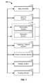
- FIG. 1illustrates component connections of a particle beam therapy system
- FIG. 2illustrates a charged particle therapy system
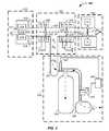
- FIG. 3illustrates an ion beam generation system
- FIG. 4illustrates straight and turning sections of a synchrotron
- FIG. 5illustrates bending magnets of a synchrotron
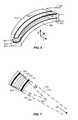
- FIG. 6provides a perspective view of a bending magnet
- FIG. 7illustrates a cross-sectional view of a bending magnet
- FIG. 8illustrates a cross-sectional view of a bending magnet
- FIG. 9illustrates a magnetic turning section of a synchrotron
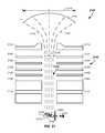
- FIGS. 10A and Billustrate an RF accelerator and an RF accelerator subsystem, respectively
- FIG. 11illustrates a magnetic field control system
- FIG. 12illustrates a charged particle extraction and intensity control system
- FIG. 13illustrates a proton beam position verification system
- FIG. 14illustrates a patient positioning system from: (A) a front view and (B) a top view;
- FIG. 15provides X-ray and proton beam dose distributions
- FIGS. 16 A-Eillustrate controlled depth of focus irradiation
- FIGS. 17 A-Eillustrate multi-field irradiation
- FIG. 18illustrates dose efficiency enhancement via use of multi-field irradiation
- FIG. 19provides two methods of multi-field irradiation implementation
- FIG. 20illustrates multi-dimensional scanning of a charged particle beam spot scanning system operating on: (A) a 2-D slice or (B) a 3-D volume of a tumor;
- FIG. 21illustrates an electron gun source used in generating X-rays coupled with a particle beam therapy system
- FIG. 22illustrates an X-ray source proximate a particle beam path
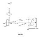
- FIG. 23illustrates an expanded X-ray beam path
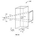
- FIG. 24provides an X-ray tomography system
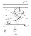
- FIG. 25illustrates a semi-vertical patient positioning system
- FIG. 26provides a method of coordinating X-ray collection with patient breathing.
- the inventioncomprises a charged particle beam path integrated charged particle beam radiation method and apparatus for irradiation of tumors of a patient.
- the systemcomprises a charged particle beam path, through which charged particles flow.
- the charged particle beam pathcouples an injector, synchrotron accelerator, beam transport system, targeting system, and/or patient interface method and apparatus.
- the method and apparatuscomprises a charged particle beam path coupling an injector, synchrotron accelerator, beam transport system, targeting system, and/or patient interface method and apparatus used to irradiate a tumor of a patient.
- the injectorcomprises: a negative ion beam source, a two phase ion source vacuum system, an ion beam focusing lens, and/or a tandem accelerator.
- the synchrotroncomprises turning magnets, edge focusing magnets, magnetic field concentration magnets, winding and correction coils, flat magnetic field incident surfaces, and/or extraction elements.
- the beam transport system, targeting system, and patient interfacecombine to allow multi-axis/multi-field irradiation, where multi-axis control comprises control of horizontal and vertical beam position, beam energy, and beam intensity and multi-field control comprises control of patient rotation and distribution of delivered energy in and about the tumor in a time controlled, targeted, accurate, precise, dosage controlled, and efficient manner.
- multi-axis controlcomprises control of horizontal and vertical beam position, beam energy, and beam intensity
- multi-field controlcomprises control of patient rotation and distribution of delivered energy in and about the tumor in a time controlled, targeted, accurate, precise, dosage controlled, and efficient manner.
- the charged particle beam pathbegins at the injector and ends in the tumor or above the rotatable platform holding the patients.
- the charged particle beam pathpasses over the rotatable platform holding the patient.
- the charged particle beam pathcircumferentially surrounds the negative ion beam in the injector, the circulating charged particles in the synchrotron, spans the charged particle beam path in the extraction step, or is proximate the charged particle beam path in the transport system from the synchrotron to the tumor.
- the charged particle beamcomprises the walls of the gap through which the protons travel.
- the charged particle beam pathpasses proximate to the X-ray generation source. Permutations and combinations of the charged particle beam path include beam path surrounding any of the apparatus components described herein.
- novel design features of a charged particle beam cancer therapy systemare optionally used.
- a negative ion beam sourcewith novel features in the negative ion source, ion source vacuum system, ion beam focusing lens, and tandem accelerator is described.
- synchrotron turning magnets, edge focusing magnets, magnetic field concentration magnets, winding and correction coils, flat magnetic field incident surfaces, and extraction elementsare described that minimize the overall size of the synchrotron, provide a tightly controlled proton beam, directly reduce the size of required magnetic fields, directly reduce required operating power, and allow continual acceleration of protons in a synchrotron even during a process of extracting protons from the synchrotron.
- the ion beam source system and synchrotronare preferably computer integrated with a patient imaging system and a patient interface including respiration monitoring sensors and patient positioning elements. Further, intensity control of a charged particle beam acceleration, extraction, and/or targeting method and apparatus used in conjunction with charged particle beam radiation therapy of cancerous tumors is described. More particularly, intensity, energy, and timing control of a charged particle stream of a synchrotron is described.
- the synchrotron control elementsallow tight control of the charged particle beam, which compliments the tight control of patient positioning to yield efficient treatment of a solid tumor with reduced tissue damage to surrounding healthy tissue.
- the systemreduces the overall size of the synchrotron, provides a tightly controlled proton beam, directly reduces the size of required magnetic fields, directly reduces required operating power, and allows continual acceleration of protons in a synchrotron even during a process of extracting protons from the synchrotron.
- All of these systemsare preferably used in conjunction with an X-ray system capable of collecting X-rays of a patient in (1) a positioning system for proton treatment and (2) at a specified moment of the patient's respiration cycle. Combined, the systems provide for efficient, accurate, and precise noninvasive tumor treatment with minimal damage to surrounding healthy tissue.
- a charged particle beam therapy systemsuch as a proton beam, hydrogen ion beam, or carbon ion beam
- the charged particle beam therapy systemis described using a proton beam.
- the aspects taught and described in terms of a proton beamare not intended to be limiting to that of a proton beam and are illustrative of a charged particle beam system. Any charged particle beam system is equally applicable to the techniques described herein.
- the charged particle beampreferably comprises a number of subsystems including any of: a main controller 110 ; an injection system 120 ; a synchrotron 130 that typically includes: (1) an accelerator system 132 and (2) an extraction system 134 ; a scanning/targeting/delivery system 140 ; a patient interface module 150 ; a display system 160 ; and/or an imaging system 170 .
- one or more of the subsystemsare stored on a client.
- the clientis a computing platform configured to act as a client device, e.g. a personal computer, a digital media player, a personal digital assistant, etc.
- the clientcomprises a processor that is coupled to a number of external or internal inputting devices, e.g. a mouse, a keyboard, a display device, etc.
- the processoris also coupled to an output device, e.g. a computer monitor to display information.
- the main controller 110is the processor.
- the main controller 110is a set of instructions stored in memory that is carried out by the processor.
- the clientincludes a computer-readable storage medium, i.e. memory.
- the memoryincludes, but is not limited to, an electronic, optical, magnetic, or another storage or transmission device capable of coupling to a processor, e.g. such as a processor in communication with a touch-sensitive input device, with computer-readable instructions.
- a processore.g. such as a processor in communication with a touch-sensitive input device, with computer-readable instructions.
- suitable mediainclude, for example, flash drive, CD-ROM, read only memory (ROM), random access memory (RAM), application-specific integrated circuit (ASIC), DVD, magnetic disk, memory chip, etc.
- the processorexecutes a set of computer-executable program code instructions stored in the memory.
- the instructionsmay comprise code from any computer-programming language, including, for example, C, C++, C#, Visual Basic, Java, and JavaScript.
- the main controller 110controls one or more of the subsystems to accurately and precisely deliver protons to a tumor of a patient. For example, the main controller 110 obtains an image, such as a portion of a body and/or of a tumor, from the imaging system 170 . The main controller 110 also obtains position and/or timing information from the patient interface module 150 . The main controller 110 then optionally controls the injection system 120 to inject a proton into a synchrotron 130 .
- the synchrotrontypically contains at least an accelerator system 132 and an extraction system 134 .
- the main controllerpreferably controls the proton beam within the accelerator system, such as by controlling speed, trajectory, and timing of the proton beam.
- the main controllerthen controls extraction of a proton beam from the accelerator through the extraction system 134 .
- the controllercontrols timing, energy, and/or intensity of the extracted beam.
- the controller 110also preferably controls targeting of the proton beam through the scanning/targeting/delivery system 140 to the patient interface module 150 .
- One or more components of the patient interface module 150are preferably controlled by the main controller 110 .
- display elements of the display system 160are preferably controlled via the main controller 110 . Displays, such as display screens, are typically provided to one or more operators and/or to one or more patients.
- the main controller 110times the delivery of the proton beam from all systems, such that protons are delivered in an optimal therapeutic manner to the patient.
- the main controller 110refers to a single system controlling the charged particle beam system 100 , to a single controller controlling a plurality of subsystems controlling the charged particle beam system 100 , or to a plurality of individual controllers controlling one or more sub-systems of the charged particle beam system 100 .
- synchrotronis used to refer to a system maintaining the charged particle beam in a circulating path; however, cyclotrons are alternatively used, albeit with their inherent limitations of energy, intensity, and extraction control.
- the charged particle beamis referred to herein as circulating along a circulating path about a central point of the synchrotron.
- the circulating pathis alternatively referred to as an orbiting path; however, the orbiting path does not refer a perfect circle or ellipse, rather it refers to cycling of the protons around a central point or region.
- an injector system 210 or ion source or charged particle beam sourcegenerates protons.
- the protonsare delivered into a vacuum tube that runs into, through, and out of the synchrotron.
- the generated protonsare delivered along an initial path 262 .
- Focusing magnets 230such as quadrupole magnets or injection quadrupole magnets, are used to focus the proton beam path.
- a quadrupole magnetis a focusing magnet.
- An injector bending magnet 232bends the proton beam toward the plane of the synchrotron 130 .
- the focused protons having an initial energyare introduced into an injector magnet 240 , which is preferably an injection Lamberson magnet.
- the initial beam path 262is along an axis off of, such as above, a circulating plane of the synchrotron 130 .
- the injector bending magnet 232 and injector magnet 240combine to move the protons into the synchrotron 130 .
- Main bending magnets 250 or dipole magnets or circulating magnetsare used to turn the protons along a circulating beam path 264 .
- a dipole magnetis a bending magnet.
- the main bending magnets 250bend the initial beam path 262 into a circulating beam path 264 .
- the main bending magnets 250 or circulating magnetsare represented as four sets of four magnets to maintain the circulating beam path 264 into a stable circulating beam path.
- any number of magnets or sets of magnetsare optionally used to move the protons around a single orbit in the circulation process.
- the protonspass through an accelerator 270 .
- the acceleratoraccelerates the protons in the circulating beam path 264 .
- the fields applied by the magnetsare increased.
- the speed of the protons achieved by the accelerator 270are synchronized with magnetic fields of the main bending magnets 250 or circulating magnets to maintain stable circulation of the protons about a central point or region 280 of the synchrotron.
- the accelerator 270 /main bending magnet 250 combinationis used to accelerate and/or decelerate the circulating protons while maintaining the protons in the circulating path or orbit.
- An extraction element of the inflector/deflector system 290is used in combination with a Lamberson extraction magnet 292 to remove protons from their circulating beam path 264 within the synchrotron 130 .
- a deflector componentis a Lamberson magnet.
- the deflectormoves the protons from the circulating plane to an axis off of the circulating plane, such as above the circulating plane.
- Extracted protonsare preferably directed and/or focused using an extraction bending magnet 237 and extraction focusing magnets 235 , such as quadrupole magnets along a transport path 268 into the scanning/targeting/delivery system 140 .
- Two components of a scanning system 140 or targeting systemtypically include a first axis control 142 , such as a vertical control, and a second axis control 144 , such as a horizontal control.
- the first axis control 142allows for about 100 mm of vertical scanning of the proton beam 268 and the second axis control 144 allows for about 700 mm of horizontal scanning of the proton beam 268 .
- a nozzle system 146is used for imaging the proton beam and/or as a vacuum barrier between the low pressure beam path of the synchrotron and the atmosphere. Protons are delivered with control to the patient interface module 150 and to a tumor of a patient. All of the above listed elements are optional and may be used in various permutations and combinations.
- An ion beam generation systemgenerates a negative ion beam, such as a hydrogen anion or H ⁇ beam; preferably focuses the negative ion beam; converts the negative ion beam to a positive ion beam, such as a proton or H + beam; and injects the positive ion beam into the synchrotron 130 . Portions of the ion beam path are preferably under partial vacuum.
- the ion beam generation system 300has four major elements: a negative ion source 310 , a first partial vacuum system 330 , an optional ion beam focusing system 350 , and a tandem accelerator 390 .
- the negative ion source 310preferably includes an inlet port 312 for injection of hydrogen gas into a high temperature plasma chamber 314 .
- the plasma chamberincludes a magnetic material 316 , which provides a magnetic field barrier 317 between the high temperature plasma chamber 314 and a low temperature plasma region on the opposite side of the magnetic field barrier.
- An extraction pulseis applied to a negative ion extraction electrode 318 to pull the negative ion beam into a negative ion beam path 319 , which proceeds through the first partial vacuum system 330 , through the ion beam focusing system 350 , and into the tandem accelerator 390 .
- the first partial vacuum system 330is an enclosed system running from the hydrogen gas inlet port 312 to the tandem accelerator 390 input foil 395 .
- the input foil 395is sealed directly or indirectly to the edges of the vacuum tube 320 providing for a higher pressure, such as about 10 ⁇ 5 torr, to be maintained on the first partial vacuum system 330 side of the foil 395 and a lower pressure, such as about 10 ⁇ 7 torr, to be maintained on the synchrotron side of the foil 390 .
- the first partial vacuum system 330preferably includes: a first pump 332 , such as a continuously operating pump and/or a turbo molecular pump; a large holding volume 334 ; and a semi-continuously operating pump 336 .
- a pump controller 340receives a signal from a pressure sensor 342 monitoring pressure in the large holding volume 334 .
- the pump controller 340instructs an actuator 345 to open a valve 346 between the large holding volume and the semi-continuously operating pump 336 and instructs the semi-continuously operating pump to turn on and pump to atmosphere residual gases out of the vacuum line 320 about the charged particle stream.
- the lifetime of the semi-continuously operating pumpis extended by only operating semi-continuously and as needed.
- the semi-continuously operating pump 336operates for a few minutes every few hours, such as 5 minutes every 4 hours, thereby extending a pump with a lifetime of about 2,000 hours to about 96,000 hours.
- the synchrotron vacuum pumpssuch as turbo molecular pumps can operate over a longer lifetime as the synchrotron vacuum pumps have fewer gas molecules to deal with.
- the inlet gasis primarily hydrogen gas but may contain impurities, such as nitrogen and carbon dioxide.
- the ion beam focusing system 350includes two or more electrodes where one electrode of each electrode pair partially obstructs the ion beam path with conductive paths 372 , such as a conductive mesh.
- conductive paths 372such as a conductive mesh.
- three ion beam focusing system sectionsare illustrated, a two electrode ion focusing section 360 , a first three electrode ion focusing section 370 , and a second three electrode ion focusing section 380 .
- electric field linesrunning between the conductive mesh of a first electrode and a second electrode, provide inward forces focusing the negative ion beam. Multiple such electrode pairs provide multiple negative ion beam focusing regions.
- the two electrode ion focusing section 360 , first three electrode ion focusing section 370 , and second three electrode ion focusing section 380are placed after the negative ion source and before the tandem accelerator and/or cover a space of about 0.5, 1, or 2 meters along the ion beam path. Ion beam focusing systems are further described, infra.
- the tandem accelerator 390preferably includes a foil 395 , such as a carbon foil.
- the negative ions in the negative ion beam path 319are converted to positive ions, such as protons, and the initial ion beam path 262 results.
- the foil 395is preferably sealed directly or indirectly to the edges of the vacuum tube 320 providing for a higher pressure, such as about 10 ⁇ 5 torr, to be maintained on the side of the foil 395 having the negative ion beam path 319 and a lower pressure, such as about 10 ⁇ 7 torr, to be maintained on the side of the foil 390 having the proton ion beam path 262 .
- Having the foil 395 physically separating the vacuum chamber 320 into two pressure regionsallows for a system having fewer and/or smaller pumps to maintain the lower pressure system in the synchrotron 130 as the inlet hydrogen and its residuals are extracted in a separate contained and isolated space by the first partial vacuum system 330 .
- the main controller 110controls one or more of the subsystems to accurately and precisely deliver protons to a tumor of a patient. For example, the main controller sends a message to the patient indicating when or how to breath.
- the main controller 110obtains a sensor reading from the patient interface module, such as a temperature breath sensor or a force reading indicative of where in a breath cycle the subject is.
- the main controllercollects an image, such as a portion of a body and/or of a tumor, from the imaging system 170 .
- the main controller 110also obtains position and/or timing information from the patient interface module 150 .
- the main controller 110then optionally controls the injection system 120 to inject hydrogen gas into a negative ion beam source 310 and controls timing of extraction of the negative ion from the negative ion beam source 310 .
- the main controllercontrols ion beam focusing the ion beam focusing lens system 350 ; acceleration of the proton beam with the tandem accelerator 390 ; and/or injection of the proton into the synchrotron 130 .
- the synchrotrontypically contains at least an accelerator system 132 and an extraction system 134 .
- the synchrotronpreferably contains one or more of: turning magnets, edge focusing magnets, magnetic field concentration magnets, winding and correction coils, and flat magnetic field incident surfaces, some of which contain elements under control by the main controller 110 .
- the main controllerpreferably controls the proton beam within the accelerator system, such as by controlling speed, trajectory, and/or timing of the proton beam.
- the main controllerthen controls extraction of a proton beam from the accelerator through the extraction system 134 .
- the controllercontrols timing, energy, and/or intensity of the extracted beam.
- the controller 110also preferably controls targeting of the proton beam through the targeting/delivery system 140 to the patient interface module 150 .
- One or more components of the patient interface module 150are preferably controlled by the main controller 110 , such as vertical position of the patient, rotational position of the patient, and patient chair positioning/stabilization/control elements.
- display elements of the display system 160are preferably controlled via the main controller 110 . Displays, such as display screens, are typically provided to one or more operators and/or to one or more patients.
- the main controller 110times the delivery of the proton beam from all systems, such that protons are delivered in an optimal therapeutic manner to the patient.
- a synchrotron 130preferably comprises a combination of straight sections 410 and ion beam turning sections 420 .
- the circulating path of the protonsis not circular in a synchrotron, but is rather a polygon with rounded corners.
- the synchrotron 130which as also referred to as an accelerator system, has four straight elements and four turning sections.
- straight sections 410include the: inflector 240 , accelerator 270 , extraction system 290 , and deflector 292 .
- ion beam turning sections 420which are also referred to as magnet sections or turning sections. Turning sections are further described, infra.
- the synchrotron 130comprises four straight sections 410 and four bending or turning sections 420 where each of the four turning sections use one or more magnets to turn the proton beam about ninety degrees.
- the ability to closely space the turning sections and efficiently turn the proton beamresults in shorter straight sections. Shorter straight sections allows for a synchrotron design without the use of focusing quadrupoles in the circulating beam path of the synchrotron.
- the illustrated synchrotronhas about a five meter diameter versus eight meter and larger cross-sectional diameters for systems using a quadrupole focusing magnet in the circulating proton beam path.
- Each of the turning sectionspreferably comprises multiple magnets, such as about 2, 4, 6, 8, 10, or 12 magnets.
- four turning magnets 510 , 520 , 530 , 540 in the first turning section 420are used to illustrate key principles, which are the same regardless of the number of magnets in a turning section 420 .
- a turning magnet 510is a particular type of main bending or circulating magnet 250 .
- the Lorentz forceis the force on a point charge due to electromagnetic fields.
- Equation 1F is the force in newtons; B is the magnetic field in Teslas; and v is the instantaneous velocity of the particles in meters per second.
- the turning sectionincludes a gap 610 through which protons circulate.
- the gap 610is preferably a flat gap, allowing for a magnetic field across the gap 610 that is more uniform, even, and intense.
- a magnetic fieldenters the gap 610 through a magnetic field incident surface and exits the gap 610 through a magnetic field exiting surface.
- the gap 610runs in a vacuum tube between two magnet halves.
- the gap 610is controlled by at least two parameters: (1) the gap 610 is kept as large as possible to minimize loss of protons and (2) the gap 610 is kept as small as possible to minimize magnet sizes and the associated size and power requirements of the magnet power supplies.
- the flat nature of the gap 610allows for a compressed and more uniform magnetic field across the gap 610 .
- One example of a gap dimensionis to accommodate a vertical proton beam size of about 2 cm with a horizontal beam size of about 5 to 6 cm.
- a larger gap sizerequires a larger power supply. For instance, if the gap 610 size doubles in vertical size, then the power supply requirements increase by about a factor of 4.
- the flatness of the gap 610is also important. For example, the flat nature of the gap 610 allows for an increase in energy of the extracted protons from about 250 to about 330 MeV. More particularly, if the gap 610 has an extremely flat surface, then the limits of a magnetic field of an iron magnet are reachable.
- An exemplary precision of the flat surface of the gap 610is a polish of less than about 5 microns and preferably with a polish of about 1 to 3 microns. Unevenness in the surface results in imperfections in the applied magnetic field. The polished flat surface spreads unevenness of the applied magnetic field.
- the charged particle beammoves through the gap 610 with an instantaneous velocity, v.
- a first magnetic coil 620 and a second magnetic coil 630run above and below the gap 610 , respectively.
- Current running through the coils 620 , 630results in a magnetic field, B, running through the single magnet turning section 510 .
- the magnetic field, Bruns upward, which results in a force, F, pushing the charged particle beam inward toward a central point of the synchrotron, which turns the charged particle beam in an arc.
- the coils 620 , 630typically have return elements 640 , 650 or turns at the end of one magnet, such as at the end of the first magnet turning section 510 .
- the turns 640 , 650take space. The space reduces the percentage of the path about one orbit of the synchrotron that is covered by the turning magnets. This leads to portions of the circulating path where the protons are not turned and/or focused and allows for portions of the circulating path where the proton path defocuses. Thus, the space results in a larger synchrotron. Therefore, the space between magnet turning sections 660 is preferably minimized.
- the second turning magnetis used to illustrate that the coils 620 , 630 optionally run along a plurality of magnets, such as 2, 3, 4, 5, 6, or more magnets. Coils 620 , 630 running across multiple turning section magnets allows for two turning section magnets to be spatially positioned closer to each other due to the removal of the steric constraint of the turns, which reduces and/or minimizes the space 660 between two turning section magnets.
- the magnet assemblyhas a first magnet 810 and a second magnet 820 .
- a magnetic field induced by coils, described infraruns between the first magnet 810 to the second magnet 820 across the gap 610 .
- Return magnetic fieldsrun through a first yoke 812 and second yoke 822 .
- the combined cross-section area of the return yokesroughly approximates the cross-sectional area of the first magnet 810 or second magnet 820 .
- the charged particlesrun through the vacuum tube in the gap 610 . As illustrated, protons run into FIG.
- the magnetic fieldis created using windings.
- a first coilmakes up a first winding coil 850 and a second coil of wire makes up a second winding coil 860 .
- Isolating or concentrating gaps 830 , 840such as air gaps, isolate the iron based yokes from the gap 610 .
- the gap 610is approximately flat to yield a uniform magnetic field across the gap 610 , as described supra.
- the ends of a single bending or turning magnetare preferably beveled.
- Nearly perpendicular or right angle edges of a turning magnet 510are represented by dashed lines 774 , 784 .
- the dashed lines 774 , 784intersect at a point 790 beyond the center of the synchrotron 280 .
- the edge of the turning magnetis beveled at angles alpha, ⁇ , and beta, ⁇ , which are angles formed by a first line 772 , 782 going from an edge of the turning magnet 510 and the center 280 and a second line 774 , 784 going from the same edge of the turning magnet and the intersecting point 790 .
- angle alphais used to describe the effect and the description of angle alpha applies to angle beta, but angle alpha is optionally different from angle beta.
- the angle alphaprovides an edge focusing effect. Beveling the edge of the turning magnet 510 at angle alpha focuses the proton beam.
- Multiple turning magnetsprovide multiple magnet edges that each have edge focusing effects in the synchrotron 130 . If only one turning magnet is used, then the beam is only focused once for angle alpha or twice for angle alpha and angle beta. However, by using smaller turning magnets, more turning magnets fit into the turning sections 420 of the synchrotron 130 . For example, if four magnets are used in a turning section 420 of the synchrotron, then for a single turning section there are eight possible edge focusing effect surfaces, two edges per magnet. The eight focusing surfaces yield a smaller cross-sectional beam size. This allows the use of a smaller gap 610 .
- edge focusing effects in the turning magnetsresults in not only a smaller gap 610 , but also the use of smaller magnets and smaller power supplies.
- a synchrotron 130 having four turning sections 420 where each turning sections has four turning magnets and each turning magnet has two focusing edgesa total of thirty-two focusing edges exist for each orbit of the protons in the circulating path of the synchrotron 130 .
- 2, 6, or 8 magnetsare used in a given turning section, or if 2, 3, 5, or 6 turning sections are used, then the number of edge focusing surfaces expands or contracts according to equation 2.
- T ⁇ ⁇ F ⁇ ⁇ EN ⁇ ⁇ T ⁇ ⁇ S * M N ⁇ ⁇ T ⁇ ⁇ S * F ⁇ ⁇ E M eq . ⁇ 2
- TFEis the number of total focusing edges
- NTSis the number of turning sections
- Mis the number of magnets
- FEis the number of focusing edges.
- the inventorshave determined that multiple smaller magnets have benefits over fewer larger magnets. For example, the use of 16 small magnets yields 32 focusing edges whereas the use of 4 larger magnets yields only 8 focusing edges.
- the use of a synchrotron having more focusing edgesresults in a circulating path of the synchrotron built without the use of focusing quadrupoles magnets. All prior art synchrotrons use quadrupoles in the circulating path of the synchrotron. Further, the use of quadrupoles in the circulating path necessitates additional straight sections in the circulating path of the synchrotron. Thus, the use of quadrupoles in the circulating path of a synchrotron results in synchrotrons having larger diameters, circulating beam pathlengths, and/or larger circumferences.
- the synchrotronhas any combination of:
- the incident magnetic field surface 870 of the first magnet 810is further described.
- FIG. 8is not to scale and is illustrative in nature. Local imperfections or unevenness in quality of the finish of the incident surface 870 results in inhomogeneities or imperfections in the magnetic field applied to the gap 610 .
- the incident surface 870is flat, such as to within about a zero to three micron finish polish, or less preferably to about a ten micron finish polish.
- the first magnet 810preferably contains an initial cross sectional distance 890 of the iron based core.
- the contours of the magnetic fieldare shaped by the magnets 810 , 820 and the yokes 812 , 822 .
- the iron based coretapers to a second cross sectional distance 892 .
- the magnetic field in the magnetpreferentially stays in the iron based core as opposed to the gaps 830 , 840 .
- the magnetic fieldconcentrates.
- the change in shape of the magnet from the longer distance 890 to the smaller distance 892acts as an amplifier.
- the concentration of the magnetic fieldis illustrated by representing an initial density of magnetic field vectors 894 in the initial cross section 890 to a concentrated density of magnetic field vectors 896 in the final cross section 892 .
- the concentration of the magnetic field due to the geometry of the turning magnetsresults in fewer winding coils 850 , 860 being required and also a smaller power supply to the coils being required.
- the initial cross-section distance 890is about fifteen centimeters and the final cross-section distance 892 is about ten centimeters.
- the concentration of the magnetic fieldis about 15/10 or 1.5 times at the incident surface 870 of the gap 610 , though the relationship is not linear.
- the taper 842has a slope, such as about 20, 40, or 60 degrees.
- the concentration of the magnetic fieldsuch as by 1.5 times, leads to a corresponding decrease in power consumption requirements to the magnets.
- the first magnet 810preferably contains an initial cross sectional distance 890 of the iron based core.
- the contours of the magnetic fieldare shaped by the magnets 810 , 820 and the yokes 812 , 822 .
- the coretapers to a second cross sectional distance 892 with a smaller angle theta, ⁇ .
- the magnetic field in the magnetpreferentially stays in the iron based core as opposed to the gaps 830 , 840 .
- the magnetic fieldconcentrates.
- the smaller angle, thetaresults in a greater amplification of the magnetic field in going from the longer distance 890 to the smaller distance 892 .
- the concentration of the magnetic fieldis illustrated by representing an initial density of magnetic field vectors 894 in the initial cross section 890 to a concentrated density of magnetic field vectors 896 in the final cross section 892 .
- the concentration of the magnetic field due to the geometry of the turning magnetsresults in fewer winding coils 850 , 860 being required and also a smaller power supply to the winding coils 850 , 860 being required.
- optional correction coils 852 , 862are illustrated that are used to correct the strength of one or more turning magnets.
- the correction coils 852 , 862supplement the winding coils 850 , 860 .
- the correction coils 852 , 862have correction coil power supplies that are separate from winding coil power supplies used with the winding coils 850 , 860 .
- the correction coil power suppliestypically operate at a fraction of the power required compared to the winding coil power supplies, such as about 1, 2, 3, 5, 7, or 10 percent of the power and more preferably about 1 or 2 percent of the power used with the winding coils 850 , 860 .
- correction coils 852 , 862allow for more accurate and/or precise control of the correction coils.
- Correction coilsare used to adjust for imperfection in the turning magnets 510 , 520 , 530 , 540 .
- separate correction coilsare used for each turning magnet allowing individual tuning of the magnetic field for each turning magnet, which eases quality requirements in the manufacture of each turning magnet.
- FIG. 9an example of winding coils and correction coils about a plurality of turning magnets 510 , 520 , 530 , 540 in an ion beam turning section 420 is illustrated.
- One or more high precision magnetic field sensorsare placed into the synchrotron and are used to measure the magnetic field at or near the proton beam path.
- the magnetic sensors 950are optionally placed between turning magnets and/or within a turning magnet, such as at or near the gap 610 or at or near the magnet core or yoke.
- the sensorsare part of a feedback system to the correction coils.
- the systempreferably stabilizes the magnetic field in the synchrotron elements rather that stabilizing the current applied to the magnets. Stabilization of the magnetic field allows the synchrotron to come to a new energy level quickly. This allows the system to be controlled to an operator or algorithm selected energy level with each pulse of the synchrotron and/or with each breath of the patient.
- the winding and/or correction coilscorrect 1, 2, 3, or 4 turning magnets, and preferably correct a magnetic field generated by two turning magnets.
- a winding or correction coil covering multiple magnetsreduces space between magnets as fewer winding or correction coil ends are required, which occupy space.
- the accelerator system 270such as a radio-frequency (RF) accelerator system, is further described.
- the acceleratorincludes a series of coils 1010 - 1019 , such as iron or ferrite coils, each circumferentially enclosing the vacuum system 320 through which the proton beam 264 passes in the synchrotron 130 .
- the first coil 1010is further described.
- a loop of standard wire 1030completes at least one turn about the first coil 1010 .
- the loopattaches to a microcircuit 1020 .
- an RF synthesizer 1040which is preferably connected to the main controller 110 , provides a low voltage RF signal that is synchronized to the period of circulation of protons in the proton beam path 264 .
- the RF synthesizer 1040 , microcircuit 1020 , loop 1030 , and coil 1010combine to provide an accelerating voltage to the protons in the proton beam path 264 .
- the RF synthesizer 1040sends a signal to the microcircuit 1020 , which amplifies the low voltage RF signal and yields an acceleration voltage, such as about 10 volts.
- the actual acceleration voltage for a single microcircuit/loop/coil combinationis about 5, 10, 15, or 20 volts, but is preferably about 10 volts.
- the RF-amplifier microcircuit and accelerating coilare integrated.
- the integrated RF-amplifier microcircuit and accelerating coil presented in FIG. 10Bis repeated, as illustrated as the set of coils 1011 - 1019 surrounding the vacuum tube 320 .
- the RF-synthesizer 1040under main controller 130 direction, sends an RF-signal to the microcircuits 1020 - 1029 connected to coils 1010 - 1019 , respectively.
- Each of the microcircuit/loop/coil combinationsgenerates a proton accelerating voltage, such as about 10 volts each.
- a set of five coil combinationsgenerates about 50 volts for proton acceleration.
- Preferably about 5 to 20 microcircuit/loop/coil combinationsare used and more preferably about 9 or 10 microcircuit/loop/coil combinations are used in the accelerator system 270 .
- the RF synthesizer 1040sends an RF-signal, with a period equal to a period of circulation of a proton about the synchrotron 130 , to a set of ten microcircuit/loop/coil combinations, which results in about 100 volts for acceleration of the protons in the proton beam path 264 .
- the 100 voltsis generated at a range of frequencies, such as at about 1 MHz for a low energy proton beam to about 15 MHz for a high energy proton beam.
- the RF-signalis optionally set at an integer multiple of a period of circulation of the proton about the synchrotron circulating path.
- Each of the microcircuit/loop/coil combinationsare optionally independently controlled in terms of acceleration voltage and frequency.
- the prior artdoes not use microcircuits integrated with the accelerating coils but rather uses a set of long cables to provide power to a corresponding set of coils.
- the long cableshave an impedance/resistance, which is problematic for high frequency RF control.
- the prior art systemis not operable at high frequencies, such as above about 10 MHz.
- the integrated RF-amplifier microcircuit/accelerating coil systemis operable at above about 10 MHz and even 15 MHz where the impedance and/or resistance of the long cables in the prior art systems results in poor control or failure in proton acceleration.
- the long cable systemcosts about $50,000 and the integrated microcircuit system costs about $1000, which is 50 times less expensive.
- the microcircuit/loop/coil combinations in conjunction with the RF-amplifier systemresults in a compact low power consumption design allowing production and use of a proton cancer therapy system is a small space, as described supra, and in a cost effective manner.
- a respiratory sensor 1110senses the breathing cycle of the subject.
- the respiratory sensorsends the information to an algorithm in a magnetic field controller 1120 , typically via the patient interface module 150 and/or via the main controller 110 or a subcomponent thereof.
- the algorithmpredicts and/or measures when the subject is at a particular point in the breathing cycle, such as at the bottom of a breath.
- Magnetic field sensors 1130are used as input to the magnetic field controller, which controls a magnet power supply 1140 for a given magnetic field 1150 , such as within a first turning magnet 510 of a synchrotron 130 .
- the control feedback loopis thus used to dial the synchrotron to a selected energy level and deliver protons with the desired energy at a selected point in time, such as at the bottom of the breath. More particularly, the main controller injects protons into the synchrotron and accelerates the protons in a manner that combined with extraction delivers the protons to the tumor at a selected point in the breathing cycle. Intensity of the proton beam is also selectable and controllable by the main controller at this stage.
- the feedback control to the correction coilsallows rapid selection of energy levels of the synchrotron that are tied to the patient's breathing cycle. This system is in stark contrast to a system where the current is stabilized and the synchrotron deliver pulses with a period, such as 10 or 20 cycles per second with a fixed period.
- the feedback or the magnetic field design coupled with the correction coilsallows for the extraction cycle to match the varying respiratory rate of the patient.
- a winding coil 930that covers two turning magnets 510 , 520 is provided.
- a first winding coil 940covers one magnets or a second winding coil 920 covers a plurality of magnets 510 , 520 .
- this systemreduces space between turning section allowing more magnetic field to be applied per radian of turn.
- a first correction coil 910is illustrated that is used to correct the magnetic field for the first turning magnet 510 .
- a second correction coil 920is illustrated that is used to correct the magnetic field for a winding coil 930 about two turning magnets. Individual correction coils for each turning magnet are preferred and individual correction coils yield the most precise and/or accurate magnetic field in each turning section.
- the individual correction coil 910is used to compensate for imperfections in the individual magnet of a given turning section.
- corresponding magnetic fieldsare individually adjustable in a series of feedback loops, via a magnetic field monitoring system, as an independent coil is used for each turning section.
- a multiple magnet correction coilis used to correct the magnetic field for a plurality of turning section magnets.
- gap surfaceis described in terms of the first turning magnet 510 , the discussion applies to each of the turning magnets in the synchrotron. Similarly, while the gap 610 surface is described in terms of the magnetic field incident surface 670 , the discussion additionally optionally applies to the magnetic field exiting surface 680 .
- the magnetic field incident surface 870 of the first magnet 810is preferably about flat, such as to within about a zero to three micron finish polish or less preferably to about a ten micron finish polish.
- the very flat surfacesuch as about 0, 1, 2, 4, 6, 8, 10, 15, or 20 micron finish, allows for a smaller gap size, a smaller applied magnetic field, smaller power supplies, and tighter control of the proton beam cross-sectional area.
- the magnetic field exiting surface 880is also preferably flat.
- FIG. 12an exemplary proton extraction process from the synchrotron 130 is illustrated.
- FIG. 12removes elements represented in FIG. 2 , such as the turning magnets, which allows for greater clarity of presentation of the proton beam path as a function of time.
- protonsare extracted from the synchrotron 130 by slowing the protons.
- the protonswere initially accelerated in a circulating path 264 , which is maintained with a plurality of main bending magnets 250 .
- the circulating pathis referred to herein as an original central beamline 264 .
- the protonsrepeatedly cycle around a central point in the synchrotron 280 .
- the proton pathtraverses through a radio frequency (RF) cavity system 1210 .
- RFradio frequency
- the first blade 1212 and second blade 1214are referred to herein as a first pair of blades.
- an RF voltageis applied across the first pair of blades, where the first blade 1212 of the first pair of blades is on one side of the circulating proton beam path 264 and the second blade 1214 of the first pair of blades is on an opposite side of the circulating proton beam path 264 .
- the applied RF fieldapplies energy to the circulating charged-particle beam.
- the applied RF fieldalters the orbiting or circulating beam path slightly of the protons from the original central beamline 264 to an altered circulating beam path 265 .
- the RF fieldfurther moves the protons off of the original proton beamline 264 .
- the altered beamlineis slightly elliptical.
- the applied RF fieldis timed to apply outward or inward movement to a given band of protons circulating in the synchrotron accelerator.
- Each orbit of the protonsis slightly more off axis compared to the original circulating beam path 264 .
- Successive passes of the protons through the RF cavity systemare forced further and further from the original central beamline 264 by altering the direction and/or intensity of the RF field with each successive pass of the proton beam through the RF field.
- the RF voltageis frequency modulated at a frequency about equal to the period of one proton cycling around the synchrotron for one revolution or at a frequency than is an integral multiplier of the period of one proton cycling about the synchrotron.
- the applied RF frequency modulated voltageexcites a betatron oscillation.
- the oscillationis a sine wave motion of the protons.
- the process of timing the RF field to a given proton beam within the RF cavity systemis repeated thousands of times with each successive pass of the protons being moved approximately one micrometer further off of the original central beamline 264 . For clarity, the approximately 1000 changing beam paths with each successive path of a given band of protons through the RF field are illustrated as the altered beam path 265 .
- the altered circulating beam path 265touches a material 1230 , such as a foil an extraction foil, an extraction material or a sheet of foil.
- the foilis preferably a lightweight material, such as beryllium, a lithium hydride, a carbon sheet, or a material of low nuclear charge.
- a material of low nuclear chargeis a material composed of atoms consisting essentially of atoms having six or fewer protons.
- the foilis preferably about 10 to 150 microns thick, is more preferably 30 to 100 microns thick, and is still more preferably 40-60 microns thick. In one example, the foil is beryllium with a thickness of about 50 microns.
- the reduced radius of curvature 266 pathis also referred to herein as a path having a smaller diameter of trajectory or a path having protons with reduced energy.
- the reduced radius of curvature 266is typically about two millimeters less than a radius of curvature of the last pass of the protons along the altered proton beam path 265 .
- the thickness of the material 1230is optionally adjusted to created a change in the radius of curvature, such as about 1 ⁇ 2, 1, 2, 3, or 4 mm less than the last pass of the protons 265 or original radius of curvature 264 .
- Protons moving with the smaller radius of curvaturetravel between a second pair of blades.
- the second pair of bladesis physically distinct and/or are separated from the first pair of blades.
- one of the first pair of bladesis also a member of the second pair of blades.
- the second pair of bladesis the second blade 1214 and a third blade 1216 in the RF cavity system 1210 .
- a high voltage DC signalsuch as about 1 to 5 kV, is then applied across the second pair of blades, which directs the protons out of the synchrotron through an extraction magnet 292 , such as a Lamberson extraction magnet, into a transport path 268 .
- an extraction magnet 292such as a Lamberson extraction magnet
- Control of acceleration of the charged particle beam path in the synchrotron with the accelerator and/or applied fields of the turning magnets in combination with the above described extraction systemallows for control of the intensity of the extracted proton beam, where intensity is a proton flux per unit time or the number of protons extracted as a function of time. For example, when a current is measured beyond a threshold, the RF field modulation in the RF cavity system is terminated or reinitiated to establish a subsequent cycle of proton beam extraction. This process is repeated to yield many cycles of proton beam extraction from the synchrotron accelerator.
- the extraction systemdoes not depend on any change in magnetic field properties, it allows the synchrotron to continue to operate in acceleration or deceleration mode during the extraction process. Stated differently, the extraction process does not interfere with synchrotron acceleration.
- traditional extraction systemsintroduce a new magnetic field, such as via a hexapole, during the extraction process. More particularly, traditional synchrotrons have a magnet, such as a hexapole magnet, that is off during an acceleration stage. During the extraction phase, the hexapole magnetic field is introduced to the circulating path of the synchrotron. The introduction of the magnetic field necessitates two distinct modes, an acceleration mode and an extraction mode, which are mutually exclusive in time.
- Control of applied fieldsuch as a radio-frequency (RF) field, frequency and magnitude in the RF cavity system 1210 allows for intensity control of the extracted proton beam, where intensity is extracted proton flux per unit time or the number of protons extracted as a function of time.
- RFradio-frequency
- the resulting currentis converted to a voltage and is used as part of a ion beam intensity monitoring system or as part of an ion beam feedback loop for controlling beam intensity.
- the voltageis optionally measured and sent to the main controller 110 or to a controller subsystem. More particularly, when protons in the charged particle beam path pass through the material 1230 , some of the protons lose a small fraction of their energy, such as about one-tenth of a percent, which results in a secondary electron. That is, protons in the charged particle beam push some electrons when passing through material 1230 giving the electrons enough energy to cause secondary emission.
- the resulting electron flowresults in a current or signal that is proportional to the number of protons going through the target material 1230 .
- the resulting currentis preferably converted to voltage and amplified.
- the resulting signalis referred to as a measured intensity signal.
- the amplified signal or measured intensity signal resulting from the protons passing through the material 1230is preferably used in controlling the intensity of the extracted protons.
- the measured intensity signalis compared to a goal signal, which is predetermined in an irradiation of the tumor plan 1260 .
- the tumor plan 1260contains the goal or targeted energy and intensity of the delivered proton beam as a function of x-position, y-position, time, and/or rotational position of the patient.
- the difference between the measured intensity signal and the planned for goal signalis calculated. The difference is used as a control to the RF generator.
- the measured flow of current resulting from the protons passing through the material 1230is used as a control in the RF generator to increase or decrease the number of protons undergoing betatron oscillation and striking the material 1230 .
- the voltage determined off of the material 1230is used as a measure of the orbital path and is used as a feedback control to control the RF cavity system.
- the measured intensity signalis not used in the feedback control and is just used as a monitor of the intensity of the extracted protons.
- the photons striking the material 1230is a step in the extraction of the protons from the synchrotron 130 .
- the measured intensity signalis used to change the number of protons per unit time being extracted, which is referred to as intensity of the proton beam.
- the intensity of the proton beamis thus under algorithm control. Further, the intensity of the proton beam is controlled separately from the velocity of the protons in the synchrotron 130 . Hence, intensity of the protons extracted and the energy of the protons extracted are independently variable.
- protonsinitially move at an equilibrium trajectory in the synchrotron 130 .
- An RF fieldis used to excite the protons into a betatron oscillation.
- the frequency of the protons orbitis about 10 MHz.
- the first protonshit an outer edge of the target material 130 .
- the specific frequencyis dependent upon the period of the orbit.
- the protonspush electrons through the foil to produce a current.
- the currentis converted to voltage and amplified to yield a measured intensity signal.
- the measured intensity signalis used as a feedback input to control the applied RF magnitude, RF frequency, or RF field.
- the measured intensity signalis compared to a target signal and a measure of the difference between the measured intensity signal and target signal is used to adjust the applied RF field in the RF cavity system 1210 in the extraction system to control the intensity of the protons in the extraction step.
- the signal resulting from the protons striking and/or passing through the material 130is used as an input in RF field modulation.
- An increase in the magnitude of the RF modulationresults in protons hitting the foil or material 130 sooner.
- By increasing the RFmore protons are pushed into the foil, which results in an increased intensity, or more protons per unit time, of protons extracted from the synchrotron 130 .
- a detector 1250 external to the synchrotron 130is used to determine the flux of protons extracted from the synchrotron and a signal from the external detector is used to alter the RF field or RF modulation in the RF cavity system 1210 .
- the external detectorgenerates an external signal, which is used in a manner similar to the measured intensity signal, described in the preceding paragraphs.
- the measured intensity signalis compared to a desired signal from the irradiation plan 1260 in a feedback intensity controller 1240 , which adjusts the RF field between the first plate 1212 and the second plate 1214 in the extraction process, described supra.
- the RE field modulation in the RF cavity systemis terminated or reinitiated to establish a subsequent cycle of proton beam extraction. This process is repeated to yield many cycles of proton beam extraction from the synchrotron accelerator.
- intensity modulation of the extracted proton beamis controlled by the main controller 110 .
- the main controller 110optionally and/or additionally controls timing of extraction of the charged particle beam and energy of the extracted proton beam.
- the benefits of the systeminclude a multi-dimensional scanning system.
- the systemallows independence in: (1) energy of the protons extracted and (2) intensity of the protons extracted. That is, energy of the protons extracted is controlled by an energy control system and an intensity control system controls the intensity of the extracted protons.
- the energy control system and intensity control systemare optionally independently controlled.
- the main controller 110controls the energy control system and the main controller simultaneously controls the intensity control system to yield an extracted proton beam with controlled energy and controlled intensity where the controlled energy and controlled intensity are independently variable.
- the irradiation spot hitting the tumoris under independent control of:
- the patientis optionally independently rotated relative to a translational axis of the proton beam at the same time.
- the systemis capable of pulse-to-pulse energy variability. Additionally, the system is capable of dynamic energy modulation during a pulse, enabling true three-dimensional proton beam scanning with energy and/or intensity modulation.
- a nozzle 1310provides an outlet for the second reduced pressure vacuum system initiating at the foil 395 of the tandem accelerator 390 and running through the synchrotron 130 to a nozzle foil 1320 covering the end of the nozzle 1310 .
- the nozzleexpands in cross-sectional area along the z-axis of the proton beam path 268 to allow the proton beam 268 to be scanned along the x- and y-axes by the vertical control element 142 and horizontal control element 144 , respectively.
- the nozzle foil 1320is preferably mechanically supported by the outer edges of an exit port of the nozzle 1310 .
- a nozzle foil or output foil 1320is a sheet of about 0.1 inch thick aluminum foil.
- the nozzle foilseparates atmosphere pressures on the patient side of the nozzle foil 1320 from the low pressure region, such as about 10 ⁇ 5 to 10 ⁇ 7 torr region, on the synchrotron 130 side of the nozzle foil 1320 .
- the low pressure regionis maintained to reduce scattering of the proton beam 264 , 268 .
- the proton beam verification system 1300is a system that allows for monitoring of the actual proton beam position 268 , 269 in real-time without destruction of the proton beam.
- the proton beam verification system 1300preferably includes a proton beam position verification layer 1330 , which is also referred to herein as a coating, luminescent, fluorescent, phosphorescent, radiance, or viewing layer.
- the verification layer or coating layer 1330is preferably a coating or thin layer substantially in contact with an inside surface of the nozzle foil or output foil 1320 , where the inside surface is on the synchrotron side of the nozzle foil 1320 .
- the verification layer or coating layer 1330is substantially in contact with an outer surface of the nozzle foil 1320 , where the outer surface is on the patient treatment side of the nozzle foil 1320 .
- the nozzle foil 1320provides a substrate surface for coating by the coating layer, but optionally a separate coating layer support element, on which the coating 1330 is mounted, is placed anywhere in the proton beam path 268 .
- the coating layerpreferably contains protons emitting centers or molecular structures that emit photons when struck by charged particles, such as protons.
- the coating 1330yields a measurable spectroscopic response, spatially viewable by the detector 1340 , as a result of transmission by the proton beam 268 .
- the coating 1330is preferably a phosphor, but is optionally any material that is viewable or imaged by a detector where the material changes spectroscopically as a result of the proton beam path 268 hitting or transmitting through the coating 1330 .
- the coating 1330emits photons when struck by charged particles in the charged particle beam path.
- a detector or camera 1340views the coating layer 1330 and determines the current position of the proton beam 268 by the spectroscopic differences resulting from protons passing through the coating layer.
- the camera 1340views the coating surface 1330 as the proton beam 268 is being scanned by the horizontal 144 and vertical 142 beam position control elements during treatment of the tumor 1420 .
- the camera 1340views the current position of the proton beam 268 as measured by spectroscopic response.
- the coating layer 1330is preferably a phosphor or luminescent material that glows or emits photons for a short period of time, such as less than 5 seconds for a 50% intensity, as a result of excitation by the proton beam 268 .
- a plurality of cameras or detectors 1340are used, where each detector views all or a portion of the coating layer 1330 .
- two detectors 1340are used where a first detector views a first half of the coating layer and the second detector views a second half of the coating layer.
- the detector 1340is mounted into the nozzle 1310 to view the proton beam position after passing through the first axis and second axis controllers 142 , 144 .
- the coating layer 1330is positioned in the proton beam path 268 in a position prior to the protons striking the patient 1430 .
- the main controller 130connected to the camera or detector 1340 output, compares the actual proton beam position 268 with the planned proton beam position and/or a calibration reference to determine if the actual proton beam position 268 is within tolerance.
- the proton beam verification system 1300preferably is used in at least two phases, a calibration phase and a proton beam treatment phase.
- the calibration phaseis used to correlate, as a function of x-, y-position of the glowing response the actual x-, y-position of the proton beam at the patient interface.
- the proton beam positionis monitored and compared to the calibration and/or treatment plan to verify accurate proton delivery to the tumor 1420 and/or as a proton beam shutoff safety indicator.
- the patientis preferably positioned on or within a patient positioning system 1410 of the patient interface module 150 .
- the patient positioning system 1410is used to translate the patient and/or rotate the patient into a zone where the proton beam can scan the tumor using a scanning system 140 or proton targeting system, described infra.
- the patient positioning system 1410performs large movements of the patient to place the tumor near the center of a proton beam path 268 and the proton scanning or targeting system 140 performs fine movements of the momentary beam position 269 in targeting the tumor 1420 .
- the scannable positions 1440are about the tumor 1420 of the patient 1430 .
- the scannable positionsare scanned along the x- and y-axes; however, scanning is optionally simultaneously performed along the z-axis as described infra.
- Thisillustratively shows that the y-axis movement of the patient occurs on a scale of the body, such as adjustment of about 1, 2, 3, or 4 feet, while the scannable region of the proton beam 268 covers a portion of the body, such as a region of about 1, 2, 4, 6, 8, 10, or 12 inches.
- the patient positioning system and its rotation and/or translation of the patientcombines with the proton targeting system to yield precise and/or accurate delivery of the protons to the tumor.
- the patient positioning system 1410optionally includes a bottom unit 1412 and a top unit 1414 , such as discs or a platform.
- the patient positioning unit 1410is preferably y-axis adjustable 1416 to allow vertical shifting of the patient relative to the proton therapy beam 268 .
- the vertical motion of the patient positioning unit 1410is about 10, 20, 30, or 50 centimeters per minute.
- the patient positioning unit 1410is also preferably rotatable 1417 about a rotation axis, such as about the y-axis running through the center of the bottom unit 1412 or about a y-axis running through the tumor 1420 , to allow rotational control and positioning of the patient relative to the proton beam path 268 .
- the rotational motion of the patient positioning unit 1410is about 360 degrees per minute.
- the patient positioning unitrotates about 45, 90, or 180 degrees.
- the patient positioning unit 1410rotates at a rate of about 45, 90, 180, 360, 720, or 1080 degrees per minute.
- the rotation of the positioning unit 1417is illustrated about the rotation axis at two distinct times, t 1 and t 2 .
- Protonsare optionally delivered to the tumor 1420 at n times where each of the n times represent different directions of the incident proton beam 269 hitting the patient 1430 due to rotation of the patient 1417 about the rotation axis.
- any of the semi-vertical, sitting, or laying patient positioning embodiments described, infraare optionally vertically translatable along the y-axis or rotatable about the rotation or y-axis.
- the top and bottom units 1412 , 1414move together, such that they rotate at the same rates and translate in position at the same rates.
- the top and bottom units 1412 , 1414are independently adjustable along the y-axis to allow a difference in distance between the top and bottom units 1412 , 1414 .
- Motors, power supplies, and mechanical assemblies for moving the top and bottom units 1412 , 1414are preferably located out of the proton beam path 269 , such as below the bottom unit 1412 and/or above the top unit 1414 . This is preferable as the patient positioning unit 1410 is preferably rotatable about 360 degrees and the motors, power supplies, and mechanical assemblies interfere with the protons if positioned in the proton beam path 269
- X-raysdeposit their highest dose near the surface of the targeted tissue and then exponentially decreases as function of tissue depth.
- the deposition of X-ray energy near the surfaceis non-ideal for tumors located deep within the body, which is usually the case, as excessive damage is done to the soft tissue layers surrounding the tumor 1420 .
- the advantage of protonsis that they deposit most of their energy near the end of the flight trajectory as the energy loss per unit path of the absorber transversed by a proton increases with decreasing particle velocity, giving rise to a sharp maximum in ionization near the end of the range, referred to herein as the Bragg peak.
- the flight trajectory of the protonsis variable by increasing or decreasing their initial kinetic energy or initial velocity, then the peak corresponding to maximum energy is movable within the tissue.
- z-axis control of the proton depth of penetrationis allowed by the acceleration/extraction process, described supra.
- a radiation oncologistcan optimize dosage to the tumor 1420 while minimizing dosage to surrounding normal tissues.
- the Bragg peak energy profileshows that protons deliver their energy across the entire length of the body penetrated by the proton up to a maximum penetration depth.
- energyis being delivered, in the distal portion of the Bragg peak energy profile, to healthy tissue, bone, and other body constituents before the proton beam hits the tumor. It follows that the shorter the pathlength in the body prior to the tumor, the higher the efficiency of proton delivery efficiency, where proton delivery efficiency is a measure of how much energy is delivered to the tumor relative to healthy portions of the patient.
- proton delivery efficiencyexamples include: (1) a ratio of proton energy delivered to the tumor over proton energy delivered to non-tumor tissue; (2) pathlength of protons in the tumor versus pathlength in the non-tumor tissue; and (3) damage to a tumor compared to damage to healthy body parts. Any of these measures are optionally weighted by damage to sensitive tissue, such as a nervous system element, heart, brain, or other organ.
- a tumor near the heartwould at times be treated with protons running through the head-to-heart path, leg-to-heart path, or hip-to-heart path, which are all inefficient compared to a patient in a sitting or semi-vertical position where the protons are all delivered through a shorter chest-to-heart; side-of-body-to-heart, or back-to-heart path.
- a shorter pathlength through the body to a tumoris provided to a tumor located in the torso or head, which results in a higher or better proton delivery efficiency.
- x-axis scanning of the proton beamis illustrated while z-axis energy of the proton beam undergoes controlled variation 1600 to allow irradiation of slices of the tumor 1420 .
- the simultaneous y-axis scanning that is performedis not illustrated.
- irradiationis commencing with the momentary proton beam position 269 at the start of a first slice.
- the momentary proton beam positionis at the end of the first slice.
- the proton beam energyis preferably continuously controlled and changed according to the tissue density in front of the tumor 1420 .
- FIGS. 16C , 16 D, and 16 Eshow the momentary proton beam position in the middle of the second slice, two-thirds of the way through a third slice, and after finalizing irradiation from a given direction, respectively.
- controlled, accurate, and precise delivery of proton irradiation energy to the tumor 1420 , to a designated tumor subsection, or to a tumor layeris achieved.
- Efficiency of deposition of proton energy to tumoras defined as the ratio of the proton irradiation energy delivered to the tumor relative to the proton irradiation energy delivered to the healthy tissue is further described infra.
- Multi-field irradiationis proton beam irradiation from a plurality of entry points into the body.
- the patient 1430is rotated and the radiation source point is held constant.
- proton therapyis applied from a multitude of angles resulting in the distal radiation being circumferentially spread about the tumor yielding enhanced proton irradiation efficiency.
- the bodyis rotated into greater than 3, 5, 10, 15, 20, 25, 30, or 35 positions and proton irradiation occurs with each rotation position.
- Rotation of the patient for proton therapy or for X-ray imagingis preferably about 45, 90, 135, 180, 270, or 360 degrees.
- Rotation of the patientis preferably performed using the patient positioning system 1410 and/or the bottom unit 1412 or disc, described supra.
- Rotation of the patient 1430 while keeping the delivery proton beam 268 in a relatively fixed orientationallows irradiation of the tumor 1420 from multiple directions without use of a new collimator for each direction. Further, as no new setup is required for each rotation position of the patient 1430 , the system allows the tumor 1420 to be treated from multiple directions without reseating or positioning the patient, thereby minimizing tumor 1420 regeneration time and increasing patient 1430 cancer therapy throughput.
- the patientis optionally centered on the bottom unit 1412 or the tumor 1420 is optionally centered on the bottom unit 1412 . If the patient is centered on the bottom unit 1412 , then the first axis control element 142 and second axis control element 144 are programmed to compensate for the off central axis of rotation position variation of the tumor 1420 .
- FIGS. 17 A-Ean example of multi-field irradiation 1700 is presented.
- five patient rotation positionsare illustrated; however, the five rotation positions are discrete rotation positions of about thirty-six rotation positions, where the body is rotated about ten degrees with each position.
- FIG. 17Aa range of irradiation beam positions 269 is illustrated from a first body rotation position, illustrated as the patient 1430 facing the proton irradiation beam where a first healthy volume 1711 is irradiated by the ingress or distal portion of the Bragg peak energy irradiation profile.
- FIG. 17Bthe patient 1430 is rotated about forty degrees and the irradiation is repeated.
- the tumor 1420again receives the bulk of the irradiation energy and a second healthy tissue volume 1712 receives the smaller ingress or distal portion of the Bragg peak energy.
- the patient 1430is rotated a total of about 90, 130, and 180 degrees, respectively.
- the tumor 1420receives the bulk of the irradiation energy and the third 1713 , fourth 1714 , and fifth 1715 healthy tissue volumes receive the smaller ingress or distal portion of the Bragg peak energy, respectively.
- the rotation of the patient during proton therapyresults in the distal energy of the delivered proton energy to be distributed about the tumor 1420 , such as to regions one to five, while along a given axis, at least about 75, 80, 85, 90, or 95 percent of the energy is delivered to the tumor 1420 .
- all or part of the tumoris irradiated.
- a distal section or distal slice of the tumor 1420is irradiated with each rotation position, where the distal section is a section furthest from the entry point of the proton beam into the patient 1430 .
- the distal sectionis the dorsal side of the tumor when the patient 1430 is facing the proton beam and the distal section is the ventral side of the tumor when the patient 1430 is facing away from the proton beam.
- FIG. 18a second example of multi-field irradiation 1800 is presented where the proton source is stationary and the patient 1430 is rotated.
- the proton beam path 269is illustrated as entering the patient 1430 from varying sides at times t 1 , t 2 , t 3 , . . . , t n , t n+1 .
- t 1the distal end of the Bragg peak profile hits a first area 1810 , A 1 .
- the patientis rotated and the proton beam path is illustrated at a second time, t 2 , where the distal end of the Bragg peak hits a second area 1820 , A 2 .
- the distal end of the Bragg peak profilehits a third area 1830 , A 3 .
- This rotation and irradiation processis repeated n times, where n is a positive number greater than four and preferably greater than about 10, 20, 30, 100, or 300.
- nis a positive number greater than four and preferably greater than about 10, 20, 30, 100, or 300.
- the distal end of the Bragg peak profilestrikes an n th area 1840 .
- t nif the patient 1430 is rotated further, the proton beam would hit a sensitive body constituent 1450 , such as the spinal cord or eyes. Irradiation is preferably suspended until the sensitive body constituent is rotated out of the proton beam path.
- the particle therapy system with a synchrotron ring diameter of less than six metersincludes ability to:
- two multi-field irradiation methods 1900are described.
- the main controller 110rotationally positions 1910 the patient 1430 and subsequently irradiates 1920 the tumor 1420 . The process is repeated until a multi-field irradiation plan is complete.
- the main controller 110simultaneously rotates and irradiates 1930 the tumor 1420 within the patient 1430 until the multi-field irradiation plan is complete. More particularly, the proton beam irradiation occurs while the patient 1430 is being rotated.
- the 3-dimensional scanning system of the proton spot focal pointis preferably combined with a rotation/raster method.
- the methodincludes layer wise tumor irradiation from many directions.
- the proton beam energyis continuously changed according to the tissue's density in front of the tumor to result in the beam stopping point, defined by the Bragg peak, to always be inside the tumor and inside the irradiated slice.
- the novel methodallows for irradiation from many directions, referred to herein as multi-field irradiation, to achieve the maximal effective dose at the tumor level while simultaneously significantly reducing possible side-effects on the surrounding healthy tissues in comparison with existing methods.
- the multi-field irradiation systemdistributes dose-distribution at tissue depths not yet reaching the tumor.
- FIG. 20a beam delivery and tissue volume scanning system is illustrated.
- the worldwide radiotherapy communityuses a method of dose field forming using a pencil beam scanning system.
- FIG. 20illustrates a spot scanning system or tissue volume scanning system.
- the scanning systemis an active system, where the beam is focused into a spot focal point of about one-half, one, two, or three millimeters in diameter.
- the focal pointis translated along two axes while simultaneously altering the applied energy of the proton beam, which effectively changes the third dimension of the focal point.
- the systemis applicable in combination with the above described rotation of the body, which preferably occurs in-between individual moments or cycles of proton delivery to the tumor.
- the rotation of the body by the above described systemoccurs continuously and simultaneously with proton delivery to the tumor.
- the spotis translated horizontally, is moved down a vertical y-axis, and is then back along the horizontal axis.
- currentis used to control a vertical scanning system having at least one magnet.
- the applied currentalters the magnetic field of the vertical scanning system to control the vertical deflection of the proton beam.
- a horizontal scanning magnet systemcontrols the horizontal deflection of the proton beam.
- the degree of transport along each axesis controlled to conform to the tumor cross-section at the given depth. The depth is controlled by changing the energy of the proton beam.
- the proton beam energyis decreased, so as to define a new penetration depth, and the scanning process is repeated along the horizontal and vertical axes covering a new cross-sectional area of the tumor.
- the three axes of controlallow scanning or movement of the proton beam focal point over the entire volume of the cancerous tumor.
- the time at each spot and the direction into the body for each spotis controlled to yield the desired radiation does at each sub-volume of the cancerous volume while distributing energy hitting outside of the tumor.
- the focused beam spot volume dimensionis preferably tightly controlled to a diameter of about 0.5, 1, or 2 millimeters, but is alternatively several centimeters in diameter.
- Preferred design controlsallow scanning in two directions with: (1) a vertical amplitude of about 100 mm amplitude and frequency up to about 200 Hz; and (2) a horizontal amplitude of about 700 mm amplitude and frequency up to about 1 Hz.
- the proton beamis illustrated along a z-axis controlled by the beam energy, the horizontal movement is along an x-axis, and the vertical direction is along a y-axis.
- the distance the protons move along the z-axis into the tissue, in this example,is controlled by the kinetic energy of the proton.
- This coordinate systemis arbitrary and exemplary.
- the actual control of the proton beamis controlled in 3-dimensional space using two scanning magnet systems and by controlling the kinetic energy of the proton beam.
- the use of the extraction system, described supra,allows for different scanning patterns. Particularly, the system allows simultaneous adjustment of the x-, y-, and z-axes in the irradiation of the solid tumor.
- the systemallows for moving along the z-axes while simultaneously adjusting the x- and or y-axes.
- the tumoris optionally irradiated in three simultaneous dimensions.
- the tumoris irradiated around an outer edge of the tumor in three dimensions.
- the tumoris irradiated around an outer edge of an internal section of the tumor. This process is repeated until the entire tumor is irradiated.
- the outer edge irradiationis preferably coupled with simultaneous rotation of the subject, such as about a vertical y-axis.
- This systemallows for maximum efficiency of deposition of protons to the tumor, as defined as the ratio of the proton irradiation energy delivered to the tumor relative to the proton irradiation energy delivered to the healthy tissue.
- the systemallows for multi-axes control of the charged particle beam system in a small space with low power supply.
- the systemuses multiple magnets where each magnet has at least one edge focusing effect in each turning section of the synchrotron and/or multiple magnets having concentrating magnetic field geometry, as described supra.
- the multiple edge focusing effects in the circulating beam path of the synchrotron combined with the concentration geometry of the magnets and described extraction systemyields a synchrotron having:
- the resultis a 3-dimensional scanning system, x-, y-, and z-axes control, where the z-axes control resides in the synchrotron and where the z-axes energy is variably controlled during the extraction process inside the synchrotron.
- FIG. 27Ban example of a proton scanning or targeting system 140 used to direct the protons to the tumor with 4-dimensional scanning control is provided, where the 4-dimensional scanning control is along the x-, y-, and z-axes along with intensity control, as described supra.
- a fifth axisis time.
- charged particles traveling along the transport path 268are directed through a first axis control element 142 , such as a vertical control, and a second axis control element 144 , such as a horizontal control and into a tumor 1420 .
- the extraction systemalso allows for simultaneous variation in the z-axis.
- the intensity or dose of the extracted beamis optionally simultaneously and independently controlled and varied.
- FIG. 27Ainstead of irradiating a slice of the tumor, as in FIG. 27A , all four dimensions defining the targeting spot of the proton delivery in the tumor are simultaneously variable.
- the simultaneous variation of the proton delivery spotis illustrated in FIG. 27B by the spot delivery path 269 .
- the protonsare initially directed around an outer edge of the tumor and are then directed around an inner radius of the tumor.
- a multi-field illumination processis used where a not yet irradiated portion of the tumor is preferably irradiated at the further distance of the tumor from the proton entry point into the body. This yields the greatest percentage of the proton delivery, as defined by the Bragg peak, into the tumor and minimizes damage to peripheral healthy tissue.
- an X-ray systemis used to illustrate an imaging system.
- An X-rayis preferably collected either (1) just before or (2) concurrently with treating a subject with proton therapy for a couple of reasons.
- movement of the bodydescribed supra, changes the local position of the tumor in the body relative to other body constituents. If the subject has an X-ray taken and is then bodily moved to a proton treatment room, accurate alignment of the proton beam to the tumor is problematic. Alignment of the proton beam to the tumor using one or more X-rays is best performed at the time of proton delivery or in the seconds or minutes immediately prior to proton delivery and after the patient is placed into a therapeutic body position, which is typically a fixed position or partially immobilized position. Second, the X-ray taken after positioning the patient is used for verification of proton beam alignment to a targeted position, such as a tumor and/or internal organ position.
- An X-rayis preferably taken just before treating the subject to aid in patient positioning.
- an X-ray of a large body areais not needed.
- an X-ray of only a local areais collected.
- the X-rayhas an X-ray path.
- the proton beamhas a proton beam path.
- Overlaying the X-ray path with the proton beam pathis one method of aligning the proton beam to the tumor.
- this methodinvolves putting the X-ray equipment into the proton beam path, taking the X-ray, and then moving the X-ray equipment out of the beam path. This process takes time. The elapsed time while the X-ray equipment moves has a couple of detrimental effects.
- the bodymoves.
- the resulting movementdecreases precision and/or accuracy of subsequent proton beam alignment to the tumor.
- the time required to move the X-ray equipmentis time that the proton beam therapy system is not in use, which decreases the total efficiency of the proton beam therapy system.
- components in the particle beam therapy systemrequire minimal or no maintenance over the lifetime of the particle beam therapy system.
- electronsare used to create X-rays.
- the electronsare generated at a cathode where the lifetime of the cathode is temperature dependent.
- Analogous to a light bulb, where the filament is kept in equilibriumthe cathode temperature is held in equilibrium at temperatures at about 200, 500, or 1000 degrees Celsius. Reduction of the cathode temperature results in increased lifetime of the cathode.
- the cathode used in generating the electronsis preferably held at as low of a temperature as possible. However, if the temperature of the cathode is reduced, then electron emissions also decrease.
- a large cathodeis used and the generated electrons are concentrated.
- the processis analogous to compressing electrons in an electron gun; however, here the compression techniques are adapted to apply to enhancing an X-ray tube lifetime.
- Electrons 2120are generated at a cathode 2110 , focused with a control electrode 2112 , and accelerated with a series of accelerating electrodes 2140 .
- the accelerated electrons 2150impact an X-ray generation source 2148 resulting in generated X-rays that are then directed along an X-ray path 2270 to the subject 1430 .
- the concentrating of the electrons from a first diameter 2115 to a second diameter 2116allows the cathode to operate at a reduced temperature and still yield the necessary amplified level of electrons at the X-ray generation source 2148 .
- the X-ray generation sourceis the anode coupled with the cathode 2110 and/or the X-ray generation source is substantially composed of tungsten.
- An anode 2114 /cathode 2110 pairis used to generated electrons.
- the electrons 2120are generated at the cathode 2110 having a first diameter 2115 , which is denoted d 1 .
- the control electrodes 2112attract the generated electrons 2120 . For example, if the cathode is held at about ⁇ 150 kV and the control electrode is held at about ⁇ 149 kV, then the generated electrons 2120 are attracted toward the control electrodes 2112 and focused.
- a series of accelerating electrodes 2140are then used to accelerate the electrons into a substantially parallel path 2150 with a smaller diameter 2116 , which is denoted d 2 .
- a first, second, third, and fourth accelerating electrodes 2142 , 2144 , 2146 , 2148are held at about ⁇ 120, ⁇ 90, ⁇ 60, and ⁇ 30 kV, respectively. If a thinner body part is to be analyzed, then the cathode 2110 is held at a smaller level, such as about ⁇ 90 kV and the control electrode, first, second, third, and fourth electrode are each adjusted to lower levels.
- the voltage difference from the cathode to fourth electrodeis less for a smaller negative voltage at the cathode and vise-versa.
- the accelerated electrons 2150are optionally passed through a magnetic lens 2160 for adjustment of beam size, such as a cylindrical magnetic lens.
- the electronsare also optionally focused using quadrupole magnets 2170 , which focus in one direction and defocus in another direction.
- the accelerated electrons 2150which are now adjusted in beam size and focused strike an X-ray generation source 2148 , such as tungsten, resulting in generated X-rays that pass through a blocker 2262 and proceed along an X-ray path 2170 to the subject.
- the X-ray generation source 2148is optionally cooled with a cooling element 2149 , such as water touching or thermally connected to a backside of the X-ray generation source 2148 .
- a cooling element 2149such as water touching or thermally connected to a backside of the X-ray generation source 2148 .
- the X-ray generation device 2100produces electrons having initial vectors.
- One or more of the control electrode 2112 , accelerating electrodes 2140 , magnetic lens 2160 , and quadrupole magnets 2170combine to alter the initial electron vectors into parallel vectors with a decreased cross-sectional area having a substantially parallel path, referred to as the accelerated electrons 2150 .
- the processallows the X-ray generation device 2100 to operate at a lower temperature. Particularly, instead of using a cathode that is the size of the electron beam needed, a larger electrode is used and the resulting electrons 2120 are focused and/or concentrated into the required electron beam needed.
- the concentration of the current densityresults in a larger lifetime of the X-ray generation device.
- a specific exampleis provided for clarity. If the cathode has a fifteen mm radius or d 1 is about 30 mm, then the area ( ⁇ r 2 ) is about 225 mm 2 times pi. If the concentration of the electrons achieves a radius of five mm or d 2 is about 10 mm, then the area ( ⁇ r 2 ) is about 25 mm 2 times pi. The ratio of the two areas is about nine (225 ⁇ /25 ⁇ ). Thus, there is about nine times less density of current at the larger cathode compared to the traditional cathode having an area of the desired electron beam.
- the lifetime of the larger cathodeapproximates nine times the lifetime of the traditional cathode, though the actual current through the larger cathode and traditional cathode is about the same.
- the area of the cathode 2110is about 2, 4, 6, 8, 10, 15, 20, or 25 times that of the cross-sectional area of the substantially parallel electron beam 2150 .
- the quadrupole magnets 2170result in an oblong cross-sectional shape of the electron beam 2150 .
- a projection of the oblong cross-sectional shape of the electron beam 2150 onto the X-ray generation source 2148results in an X-ray beam that has a small spot in cross-sectional view, which is preferably substantially circular in cross-sectional shape, that is then passed through the patient 2130 .
- the small spotis used to yield an X-ray having enhanced resolution at the patient.
- an X-rayis generated close to, but not in, the proton beam path.
- a proton beam therapy system and an X-ray system combination 2200is illustrated in FIG. 22 .
- the proton beam therapy systemhas a proton beam 268 in a transport system after the Lamberson extraction magnet 292 of the synchrotron 130 .
- the proton beamis directed by the scanning/targeting/delivery system 140 to a tumor 1420 of a patient 1430 .
- the X-ray system 2205includes an electron beam source 2105 generating an electron beam 2150 .
- the electron beamis directed to an X-ray generation source 2148 , such as a piece of tungsten.
- the tungsten X-ray sourceis located about 1, 2, 3, 5, 10, 15, 20, or 40 millimeters from the proton beam path 268 .
- the electron beam 2150hits the tungsten, X-rays are generated in all directions. X-rays are blocked with a port 2262 and are selected for an X-ray beam path 2270 .
- the X-ray beam path 2270 and proton beam path 268run substantially in parallel as they progress to the tumor 1420 .
- the distance between the X-ray beam path 2270 and proton beam path 269preferably diminishes to near zero and/or the X-ray beam path 2270 and proton beam path 269 overlap by the time they reach the tumor 1420 .
- Simple geometryshows this to be the case given the long distance, of at least a meter, between the tungsten and the tumor 1420 .
- the distanceis illustrated as a gap 2280 in FIG. 22 .
- the X-raysare detected at an X-ray detector 2290 , which is used to form an image of the tumor 1420 and/or position of the patient 1430 .
- the systemgenerates an X-ray beam that lies in substantially the same path as the proton therapy beam.
- the X-ray beamis generated by striking a tungsten or equivalent material with an electron beam.
- the X-ray generation sourceis located proximate to the proton beam path.
- Geometry of the incident electrons, geometry of the X-ray generation material, and geometry of the X-ray beam blocker 262yield an X-ray beam that runs either in substantially in parallel with the proton beam or results in an X-ray beam path that starts proximate the proton beam path an expands to cover and transmit through a tumor cross-sectional area to strike an X-ray detector array or film allowing imaging of the tumor from a direction and alignment of the proton therapy beam.
- the X-ray imageis then used to control the charged particle beam path to accurately and precisely target the tumor, and/or is used in system verification and validation.
- Having an X-ray generation source 2148 that is proximate the proton beam path 268allows for an X-ray of the patient 1430 to be collected close in time to use of the proton beam for tumor 1420 therapy as the X-ray generation source 2148 need not be mechanically moved prior to proton therapy. For instance, proton irradiation of the tumor 1420 occurs within about 1, 5, 10, 20, 30, or 60 seconds of when the X-ray is collected.
- the electron beam 350is shown as an expanded electron beam path 2152 , 2154 .
- the X-ray beam path 2270is shown as an expanded X-ray beam path 2272 , 2274 .
- a 3-dimensional (3-D) X-ray tomography system 2400is presented.
- the X-ray source and detectorrotationally translate about a stationary subject.
- the X-ray source and detectorare stationary and the patient 1430 rotates.
- the stationary X-ray sourceallows a system where the X-ray source 2148 is proximate the proton therapy beam path 268 , as described supra.
- the rotation of the patient 1430allows the proton dosage and/or X-ray to be distributed around the body, rather than being concentrated on one static entrance side of the body.
- the 3-D X-ray tomography systemallows for simultaneous updates of the tumor position relative to body constituents in real-time during proton therapy treatment of the tumor 1420 in the patient 1430 .
- the X-ray tomography systemis further described, infra.
- a first step of the X-ray tomography system 2400the patient 1430 is positioned relative to the X-ray beam path 2270 and proton beam path 268 using a patient semi-immobilization/placement system, described infra.
- a series of reference 2-D X-ray imagesare collected, on a detector array 2290 or film, of the patient 1430 and tumor 1420 as the subject is rotated about a y-axis 1417 .
- a series of about 50, 100, 200, or 400 X-ray images of the patientare collected as the patient is rotated.
- an X-ray imageis collected with each n degrees of rotation of the patient 1430 , where n is about 1 ⁇ 2, 1, 2, 3, or 5 degrees of rotation. Preferably, about 200 images are collected during one full rotation of the patient through 360 degrees.
- an algorithmproduces a reference 3-D picture of the tumor 1420 relative to the patient's constituent body parts.
- a tumor 1420 irradiation planis made using the 3-D picture of the tumor 1420 and the patient's constituent body parts. Creation of the proton irradiation plan is optionally performed after the patient has moved from the X-ray imaging area.
- the patient 1430is repositioned relative to the X-ray beam path 2270 and proton beam path 268 using the patient semi-immobilization/placement system.
- a few comparative X-ray images of the patient 1430 and tumor 1420are collected at a limited number of positions using the X-ray tomography system 2400 setup. For example, a single X-ray image is collected with the patient positioned straight on, at angles of plus/minus forty-five degrees, and/or at angles of plus/minus ninety degrees relative to the proton beam path 268 .
- the actual orientation of the patient 1430 relative to the proton beam path 268is optionally any orientation.
- the actual number of comparative X-ray imagesis also optionally any number of images, though the preferable number of comparative X-ray images is about 2 to 5 comparative images.
- the comparative X-ray imagesare compared to the reference X-ray images and differences are detected.
- a medical expert or an algorithmdetermines if the difference between the reference images and the comparative images is significant. Based upon the differences, the medical expert or algorithm determines if: proton treatment should commence, be halted, or adapted in real-time. For example, if significant differences in the X-ray images are observed, then the treatment is preferably halted and the process of collecting a reference 3-D picture of the patient's tumor is reinitiated.
- the proton irradiation plancommences.
- the algorithm or medical expertcan adapt the proton irradiation plan in real-time to adjust for differences in tumor location resulting from changes in position of the tumor 1420 in the patient 1430 or from differences in the patient 1430 placement.
- the adaptive proton therapyincreases patient throughput and enhances precision and accuracy of proton irradiation of the tumor 1420 relative to the healthy tissue of the patient 1430 .
- Accurate and precise delivery of a proton beam to a tumor of a patientrequires: (1) positioning control of the proton beam and (2) positioning control of the patient.
- the proton beamis controlled using algorithms and magnetic fields to a diameter of about 0.5, 1, or 2 millimeters. This section addresses partial immobilization, restraint, and/or alignment of the patient to insure the tightly controlled proton beam efficiently hits a target tumor and not surrounding healthy tissue as a result of patient movement.
- an x-, y-, and z-axes coordinate system and rotation axisis used to describe the orientation of the patient relative to the proton beam.
- the z-axisrepresent travel of the proton beam, such as the depth of the proton beam into the patient.
- the x-axisrefers to moving left or right across the patient and the y-axis refers to movement up or down the patient.
- a first rotation axisis rotation of the patient about the y-axis and is referred to herein as a rotation axis, bottom unit 1412 rotation axis, or y-axis of rotation.
- the proton beam path 269optionally runs in any direction.
- the proton beam path running through a treatment roomis described as running horizontally through the treatment room.
- a semi-vertical partial immobilization system 2500is described, which is also illustrative of a sitting partial immobilization system or a laying positioning system.
- the semi-vertical patient positioning system 2500is preferably used in conjunction with proton therapy of tumors in the torso.
- the patient positioning and/or immobilization systemcontrols and/or restricts movement of the patient during proton beam therapy.
- the patientis positioned in a semi-vertical position in a proton beam therapy system. As illustrated, the patient is reclining at an angle alpha, ⁇ , about 45 degrees off of the y-axis as defined by an axis running from head to foot of the patient.
- the patientis optionally completely standing in a vertical position of zero degrees off the of y-axis or is in a semi-vertical position alpha that is reclined about 5, 10, 15, 20, 25, 30, 35, 40, 45, 50, 55, 60, or 65 degrees off of the y-axis toward the z-axis.
- Patient positioning constraints 2515are used to maintain the patient in a treatment position, including one or more of: a seat support 2520 , a back support 2530 , a head support 2540 , an arm support 2550 , a knee support 2560 , and a foot support 2570 .
- the constraintsare optionally and independently rigid or semi-rigid. Examples of a semi-rigid material include a high or low density foam or a visco-elastic foam.
- the foot supportis preferably rigid and the back support is preferably semi-rigid, such as a high density foam material.
- One or more of the positioning constraints 2515are movable and/or under computer control for rapid positioning and/or immobilization of the patient.
- the seat support 2520is adjustable along a seat adjustment axis 2522 , which is preferably the y-axis;
- the back support 2530is adjustable along a back support axis 2532 , which is preferably dominated by z-axis movement with a y-axis element;
- the head support 2540is adjustable along a head support axis 2542 , which is preferably dominated by z-axis movement with a y-axis element;
- the arm support 2550is adjustable along an arm support axis 2552 , which is preferably dominated by z-axis movement with a y-axis element;
- the knee support 2560is adjustable along a knee support axis 2562 , which is preferably dominated by y-axis movement with a z-axis element;
- the foot support 2570is adjustable along a foot support axis 2572 , which is preferably dominated by y-axis movement with a z-axis element.
- An optional camera 2580is used with the patient immobilization system.
- the cameraviews the patient/subject creating an video image.
- the imageis provided to one or more operators of the charged particle beam system and allows the operators a safety mechanism for determining if the subject has moved or desires to terminate the proton therapy treatment procedure. Based on the video image, the operators may suspend or terminate the proton therapy procedure. For example, if the operator observes via the video image that the subject is moving, then the operator has the option to terminate or suspend the proton therapy procedure.
- An optional video display 2590is provided to the patient.
- the video displayoptionally presents to the patient any of: operator instructions, system instructions, status of treatment, or entertainment.
- Motors for positioning the constraints 2515 , the camera 2580 , and video display 2590are preferably mounted above or below the proton path.
- Respiration controlis optionally performed by using the video display.
- internal and external structures of the bodymove in both absolute terms and in relative terms.
- the outside of the chest cavity and internal organsboth have absolute moves with a breath.
- the relative position of an internal organ relative to another body componentsuch as an outer region of the body, a bone, support structure, or another organ, moves with each breath.
- the proton beamis preferably delivered at point a in time where the position of the internal structure or tumor is well defined, such as at the bottom of each breath.
- the video displayis used to help coordinate the proton beam delivery with the patient's breathing cycle.
- the video displayoptionally displays to the patient a command, such as a hold breath statement, a breath statement, a countdown indicating when a breadth will next need to be held, or a countdown until breathing may resume.
- the semi-vertical patient positioning system 2500 and sitting patient positioning systemare preferentially used to treatment of tumors in the head or torso due to efficiency.
- the semi-vertical patient positioning system 2500 , sitting patient positioning system, and laying patient positioning systemare all usable for treatment of tumors in the patient's limbs.
- Positioning constraints 2515include all elements used to position the patient, such as those described in the semi-vertical positioning system 2500 , sitting positioning system, and laying positioning system. Preferably, positioning constraints or support system elements are aligned in positions that do not impede or overlap the proton beam path 269 . However, in some instances the positioning constraints are in the proton beam path 269 during at least part of the time of treatment of the patient. For instance, a positioning constraint element may reside in the proton beam path 269 during part of a time period where the patient is rotated about the y-axis during treatment.
- an upward adjustment of proton beam energyis preferably applied that increases the proton beam energy to offset the positioning constraint element impedance of the proton beam.
- the proton beam energyis increased by a separate measure of the positioning constraint element impedance determined during a reference scan of the positioning constraint system element or set of reference scans of the positioning constraint element as a function of rotation about the y-axis.
- the positioning constraints 2515 or support system elementsare herein described relative to the semi-vertical positioning system 2500 ; however, the positioning elements and descriptive x-, y-, and z-axes are adjustable to fit any coordinate system, to the sitting positioning system, or the laying positioning system.
- the head support systempreferably has several head support elements including any of: a back of head support, a right of head alignment element, and a left of head alignment element.
- the back of head support elementis preferably curved to fit the head and is optionally adjustable along a head support axis, such as along the z-axis.
- the head supportslike the other patient positioning constraints, is preferably made of a semi-rigid material, such as a low or high density foam, and has an optional covering, such as a plastic or leather.
- the right of head alignment element and left of head alignment elements or head alignment elementsare primarily used to semi-constrain movement of the head.
- the head alignment elementsare preferably padded and flat, but optionally have a radius of curvature to fit the side of the head.
- the right and left head alignment elementsare preferably respectively movable along translation axes to make contact with the sides of the head. Restricted movement of the head during proton therapy is important when targeting and treating tumors in the head or neck.
- the head alignment elements and the back of head support elementcombine to restrict tilt, rotation or yaw, roll and/or position of the head in the x-, y-, z-axes coordinate system.
- One or more of the patient positioning unit components and/or one of more of the patient positioning constraintsare preferably under computer control, where the computer control positioning devices, such as via a series of motors and drives, to reproducibly position the patient.
- the patientis initially positioned and constrained by the patient positioning constraints.
- the position of each of the patient positioning constraintsis recorded and saved by the main controller 110 , by a sub-controller or the main controller 110 , or by a separate computer controller.
- medical devicesare used to locate the tumor 1420 in the patient 1430 while the patient is in the orientation of final treatment.
- the imaging system 170includes one or more of: MRI's, X-rays, CT's, proton beam tomography, and the like.
- Timeoptionally passes at this point where images from the imaging system 170 are analyzed and a proton therapy treatment plan is devised.
- the patientmay exit the constraint system during this time period, which may be minutes, hours, or days.
- the computercan return the patient positioning constraints to the recorded positions. This system allows for rapid repositioning of the patient to the position used during imaging and development of the treatment plan, which minimizes setup time of patient positioning and maximizes time that the charged particle beam system 100 is used for cancer treatment.
- the patient 1430is aligned in the proton beam path 269 in a precise and accurate manner.
- placement systemsare described. The patient placement systems are described using the laying positioning system, but are equally applicable to the semi-vertical and sitting positioning systems.
- the patientis positioned in a known location relative to the platform.
- one or more of the positioning constraintsposition the patient in a precise and/or accurate location on the platform.
- a placement constraint element connected or replaceably connected to the platformis used to position the patient on the platform.
- the placement constraint element(s)is used to position any position of the patient, such as a hand, limb, head, or torso element.
- a lock and key systemis optionally used, where a lock fits a key.
- the lock and key elementscombine to locate the patient relative to the proton beam path 269 in terms of any of the x-, y-, and z-position, tilt, yaw, and roll.
- the lockis a first registration element and the key is a second registration element fitting into, adjacent to, or with the first registration element to fix the patient location and/or a support element location relative to the proton beam path 269 .
- Examples of a registration elementinclude any of a mechanical element, such as a mechanical stop, and an electrical connection indicating relative position or contact.
- the imaging systemIn a third placement system, the imaging system, described supra, is used to determine where the patient is relative to the proton beam path 269 or relative to an imaging marker placed in an support element or structure holding the patient, such as in the platform.
- the imaging systemsuch as an X-ray imaging system
- the first placement system or positioning constraintsminimize patient movement once the imaging system determines location of the subject.
- the imaging systemsuch as an X-ray imaging system
- the first placement system and/or second positioning systemprovide a crude position of the patient relative to the proton beam path 269 and the imaging system subsequently determines a fine position of the patient relative to the proton beam path 269 .
- X-ray imagesare collected in synchronization with patient respiration or breathing.
- the synchronizationenhances X-ray image clarity by removing position ambiguity due to the relative movement of body constituents during a patient breathing cycle.
- an X-ray systemis orientated to provide X-ray images of a patient in the same orientation as viewed by a proton therapy beam, is synchronized with patient breathing, is operable on a patient positioned for proton therapy, and does not interfere with a proton beam treatment path.
- the synchronized systemis used in conjunction with a negative ion beam source, synchrotron, and/or targeting method apparatus to provide an X-ray timed with patient breathing and performed immediately prior to and/or concurrently with particle beam therapy irradiation to ensure targeted and controlled delivery of energy relative to a patient position resulting in efficient, precise, and/or accurate noninvasive, in-vivo treatment of a solid cancerous tumor with minimization of damage to surrounding healthy tissue in a patient using the proton beam position verification system.
- a negative ion beam source, synchrotron, and/or targeting method apparatusto provide an X-ray timed with patient breathing and performed immediately prior to and/or concurrently with particle beam therapy irradiation to ensure targeted and controlled delivery of energy relative to a patient position resulting in efficient, precise, and/or accurate noninvasive, in-vivo treatment of a solid cancerous tumor with minimization of damage to surrounding healthy tissue in a patient using the proton beam position verification system.
- An X-ray delivery control algorithmis used to synchronize delivery of the X-rays to the patient 1430 within a given period of each breath, such as at the top or bottom of a breath when the subject is holding their breath.
- the patientis preferably both accurately positioned and precisely aligned relative to the X-ray beam path 2270 .
- the X-ray delivery control algorithmis preferably integrated with the breathing control module.
- the X-ray delivery control algorithmknows when the subject is breathing, where in the breath cycle the subject is, and/or when the subject is holding their breath. In this manner, the X-ray delivery control algorithm delivers X-rays at a selected period of the breathing cycle.
- Accuracy and precision of patient alignmentallow for (1) more accurate and precise location of the tumor 1420 relative to other body constituents and (2) more accurate and precise combination of X-rays in generation of a 3-dimensional X-ray image of the patient 1430 and tumor 1420 .
- an example of generating an X-ray image 2600 of the patient 1430 and tumor 1420 using the X-ray generation device 2100 or 3-dimensional X-ray generation device 2100 as a known function of time of the patient's breathing cycleis provided.
- the main controller 110instructs, monitors, and/or is informed of patient positioning 2610 .
- an automated patient positioning systemunder main controller 110 control, is used to align the patient 1430 relative to the X-ray beam path 2270 .
- the main controller 110is told via sensors or human input that the patient 1430 is aligned.
- patient breathingis then monitored 2620 , as described infra.
- respiration monitoringan X-ray is collected 2640 at a known point in the patient respiration cycle.
- the patient's respiration cycleis first controlled in a third step of controlling patient breathing 2630 and then as a fourth step an X-ray is collected 2640 at a controlled point in the patient breathing cycle.
- the cycle of patient positioning 2610 , patient breath monitoring 2620 , patient breath control 2630 , and collecting an X-ray 2640is repeated with different patient positions.
- the patient 1430is rotated about an axis 1417 and X-rays are collected as a function of the rotation.
- a 3-dimensional X-ray image 2650is generated of the patient 1430 , tumor 1420 , and body constituents about the tumor using the collected X-ray images, such as with the 3-dimensional X-ray generation device 2100 , described supra.
- the patient breath monitoring and control stepsare further described, infra.
- the patient's breathing patternis monitored 2620 .
- a subject or patient 1430is breathing many portions of the body move with each breath.
- the lungsmove as do relative positions of organs within the body, such as the stomach, kidneys, liver, chest muscles, skin, heart, and lungs.
- most or all parts of the torsomove with each breath.
- Motionis to be considered in delivery of a proton dose to the body as the protons are preferentially delivered to the tumor and not to surrounding tissue. Motion thus results in an ambiguity in where the tumor resides relative to the beam path.
- protonsare preferentially delivered at the same point in each of a series of breathing cycles.
- a rhythmic pattern of breathing of a subjectis determined 2620 .
- the cycleis observed or measured.
- an X-ray beam operator or proton beam operatorcan observe when a subject is breathing or is between breaths and can time the delivery of the protons to a given period of each breath.
- the subjectis told to inhale, exhale, and/or hold their breath and the protons are delivered during the commanded time period.
- one or more sensorsare used to determine the breathing cycle of the individual.
- a breath monitoring systemTwo examples are provided: (1) a thermal monitoring system and (2) a force monitoring system.
- a first example of the thermal breath monitoring systemis provided.
- a sensoris placed by the nose and/or mouth of the patient.
- the thermal breath monitoring systemis preferably placed by the patient's nose exhalation path.
- the thermal breath monitoring systemis preferably used when treating a tumor not located in the head or neck, such as a when treating a tumor in the torso or limbs.
- a first thermal resistor 2595is used to monitor the patient's breathing cycle and/or location in the patient's breathing cycle.
- the first thermal resistor 2595is placed by the patient's nose, such that the patient exhaling through their nose onto the first thermal resistor 2595 warms the first thermal resistor 2595 indicating an exhale.
- a second thermal resistoroperates as an environmental temperature sensor.
- the second thermal resistoris preferably placed out of the exhalation path of the patient but in the same local room environment as the first thermal resistor 2595 .
- Generated signalsuch as current from the thermal resistors 2595 , is preferably converted to voltage and communicated with the main controller 110 or a sub-controller of the main controller.
- the second thermal resistoris used to adjust for the environmental temperature fluctuation that is part of a signal of the first thermal resistor 2595 , such as by calculating a difference between values of the thermal resistors 2595 to yield a more accurate reading of the patient's breathing cycle.
- a second example of the force/pressure breath monitoring systemis provided.
- a sensoris placed by the torso.
- the force breath monitoring systemis preferably used when treating a tumor located in the head, neck, or limbs.
- a belt or strap 2555is placed around an area of the patient's torso that expands and contracts with each breath cycle of the patient.
- the belt 2555is preferably tight about the patient's chest and is flexible.
- a force meter 2557is attached to the belt and senses the patients breathing pattern. The forces applied to the force meter 2557 correlate with periods of the breathing cycle.
- the signals from the force meter 2557are preferably communicated with the main controller 110 or a sub-controller of the main controller.
- a signalis optionally delivered to the subject to more precisely control the breathing frequency 2630 .
- a display screen 2590is placed in front of the subject directing the subject when to hold their breath and when to breath.
- a respiration control moduleuses input from one or more of the breathing sensors. For example, the input is used to determine when the next breath exhale is to complete.
- the control moduledisplays a hold breath signal to the subject, such as on a monitor, via an oral signal, digitized and automatically generated voice command, or via a visual control signal.
- a display monitor 2590is positioned in front of the subject and the display monitor displays breathing commands to the subject.
- the subjectis directed to hold their breath for a short period of time, such as about 1 ⁇ 2, 1, 2, 3, 5, or 10 seconds.
- the period of time the breath is heldis preferably synchronized to the delivery time of the proton beam to the tumor, which is about 1 ⁇ 2, 1, 2, or 3 seconds. While delivery of the protons at the bottom of the breath is preferred, protons are optionally delivered at any point in the breathing cycle, such as upon full inhalation.
- the respiration control moduleDelivery at the top of the breath or when the patient is directed to inhale deeply and hold their breath by the respiration control module is optionally performed as at the top of the breath the chest cavity is largest and for some tumors the distance between the tumor and surrounding tissue is maximized or the surrounding tissue is rarefied as a result of the increased volume. Hence, protons hitting surrounding tissue is minimized.
- the display screentells the subject when they are about to be asked to hold their breath, such as with a 3, 2, 1, second countdown so that the subject is aware of the task they are about to be asked to perform.
- a proton delivery control algorithmis used to synchronize delivery of the protons to the tumor within a given period of each breath, such as at the top or bottom of a breath when the subject is holding their breath.
- the proton delivery control algorithmis preferably integrated with the respiration control module.
- the proton delivery control algorithmknows when the subject is breathing, where in the breath cycle the subject is, and/or when the subject is holding their breath.
- the proton delivery control algorithmcontrols when protons are injected and/or inflected into the synchrotron, when an RF signal is applied to induce an oscillation, as described supra, and when a DC voltage is applied to extract protons from the synchrotron, as described supra.
- the proton delivery control algorithminitiates proton inflection and subsequent RF induced oscillation before the subject is directed to hold their breath or before the identified period of the breathing cycle selected for a proton delivery time.
- the proton delivery control algorithmcan deliver protons at a selected period of the breathing cycle by simultaneously or nearly simultaneously delivering the high DC voltage to the second pair of plates, described supra, which results in extraction of the protons from the synchrotron and subsequent delivery to the subject at the selected time point. Since the period of acceleration of protons in the synchrotron is constant or known for a desired energy level of the proton beam, the proton delivery control algorithm is used to set an AC RF signal that matches the breathing cycle or directed breathing cycle of the subject.
Landscapes
- Physics & Mathematics (AREA)
- Engineering & Computer Science (AREA)
- Spectroscopy & Molecular Physics (AREA)
- Plasma & Fusion (AREA)
- General Engineering & Computer Science (AREA)
- High Energy & Nuclear Physics (AREA)
- Optics & Photonics (AREA)
- Radiation-Therapy Devices (AREA)
Abstract
Description
- U.S. provisional patent application No. 61/055,395 filed May 22, 2008;
- U.S. provisional patent application No. 61/137,574 filed Aug. 1, 2008;
- U.S. provisional patent application No. 61/192,245 filed Sep. 17, 2008;
- U.S. provisional patent application No. 61/055,409 filed May 22, 2008;
- U.S. provisional patent application No. 61/203,308 filed Dec. 22, 2008;
- U.S. provisional patent application No. 61/188,407 filed Aug. 11, 2008;
- U.S. provisional patent application No. 61/209,529 filed Mar. 9, 2009;
- U.S. provisional patent application No. 61/188,406 filed Aug. 11, 2008;
- U.S. provisional patent application No. 61/189,815 filed Aug. 25, 2008;
- U.S. provisional patent application No. 61/208,182 filed Feb. 23, 2009;
- U.S. provisional patent application No. 61/201,731 filed Dec. 15, 2008;
- U.S. provisional patent application No. 61/208,971 filed Mar. 3, 2009;
- U.S. provisional patent application No. 61/205,362 filed Jan. 21, 2009;
- U.S. provisional patent application No. 61/134,717 filed Jul. 14, 2008;
- U.S. provisional patent application No. 61/134,707 filed Jul. 14, 2008;
- U.S. provisional patent application No. 61/201,732 filed Dec. 15, 2008;
- U.S. provisional patent application No. 61/198,509 filed Nov. 7, 2008;
- U.S. provisional patent application No. 61/134,718 filed Jul. 14, 2008;
- U.S. provisional patent application No. 61/190,613 filed Sep. 2, 2008;
- U.S. provisional patent application No. 61/191,043 filed Sep. 8, 2008;
- U.S. provisional patent application No. 61/192,237 filed Sep. 17, 2008,
- U.S. provisional patent application No. 61/201,728 filed Dec. 15, 2008;
- U.S. provisional patent application No. 61/190,546 filed Sep. 2, 2008; U.S. provisional patent application No. 61/189,017 filed Aug. 15, 2008;
- U.S. provisional patent application No. 61/198,248 filed Nov. 5, 2008;
- U.S. provisional patent application No. 61/198,508 filed Nov. 7, 2008;
- U.S. provisional patent application No. 61/197,971 filed Nov. 3, 2008;
- U.S. provisional patent application No. 61/199,405 filed Nov. 17, 2008;
- U.S. provisional patent application No. 61/199,403 filed Nov. 17, 2008;
- U.S. provisional patent application No. 61/199,404 filed Nov. 17, 2008; and
claims priority to PCT patent application no. PCT/RU2009/00105, “Multi-Field Charged Particle Cancer Therapy Method and Apparatus”, filed Mar. 4, 2009; - all of which are incorporated herein in their entirety by this reference thereto.
F=q(v×B) eq. 1
where TFE is the number of total focusing edges, NTS is the number of turning sections, M is the number of magnets, and FE is the number of focusing edges. Naturally, not all magnets are necessarily beveled and some magnets are optionally beveled on only one edge.
- at least 4 and preferably 6, 8, 10, or more edge focusing edges per 90 degrees of turn of the charged particle beam in a synchrotron having four turning sections;
- at least about 16 and preferably about 24, 32, or more edge focusing edges per orbit of the charged particle beam in the synchrotron;
- only 4 turning sections where each of the turning sections includes at least 4 and preferably 8 edge focusing edges;
- an equal number of straight sections and turning sections;
- exactly 4 turning sections;
- at least 4 edge focusing edges per turning section;
- no quadrupoles in the circulating path of the synchrotron;
- a rounded corner rectangular polygon configuration;
- a circumference of less than 60 meters;
- a circumference of less than 60 meters and 32 edge focusing surfaces; and/or
- any of about 8, 16, 24, or 32 non-quadrupole magnets per circulating path of the synchrotron, where the non-quadrupole magnets include edge focusing edges.
- time;
- energy;
- intensity;
- x-axis position, where the x-axis represents horizontal movement of the proton beam relative to the patient, and
- y-axis position, where the y-axis represents vertical movement of the proton beam relative to the patient.
- rotate the patient through about 360 degrees;
- extract radiation in about 0.1 to 10 seconds;
- scan vertically about 100 millimeters;
- scan horizontally about 700 millimeters;
- vary beam energy from about 30 to 330 MeV/second during irradiation;
- focus the proton beam from about 2 to 20 millimeters at the tumor; and/or
- complete multi-field irradiation of a tumor in less than about 1, 2, 4, or 6 minutes as measured from the time of initiating proton delivery to the
patient 1430.
- a small circumference system, such as less than about 50 meters;
- a vertical proton beam size gap of about 2 cm;
- corresponding reduced power supply requirements associated with the reduced gap size;
- an extraction system not requiring a newly introduced magnetic field;
- acceleration or deceleration of the protons during extraction; and
- control of z-axis energy during extraction.
Claims (4)
Priority Applications (1)
| Application Number | Priority Date | Filing Date | Title |
|---|---|---|---|
| US12/994,132US8957396B2 (en) | 2008-05-22 | 2009-05-21 | Charged particle cancer therapy beam path control method and apparatus |
Applications Claiming Priority (35)
| Application Number | Priority Date | Filing Date | Title |
|---|---|---|---|
| US5539508P | 2008-05-22 | 2008-05-22 | |
| US5540908P | 2008-05-22 | 2008-05-22 | |
| US13471708P | 2008-07-14 | 2008-07-14 | |
| US13470708P | 2008-07-14 | 2008-07-14 | |
| US13471808P | 2008-07-14 | 2008-07-14 | |
| US13757408P | 2008-08-01 | 2008-08-01 | |
| US18840608P | 2008-08-11 | 2008-08-11 | |
| US18840708P | 2008-08-11 | 2008-08-11 | |
| US18901708P | 2008-08-15 | 2008-08-15 | |
| US18981508P | 2008-08-25 | 2008-08-25 | |
| US19054608P | 2008-09-02 | 2008-09-02 | |
| US19061308P | 2008-09-02 | 2008-09-02 | |
| US19104308P | 2008-09-08 | 2008-09-08 | |
| US19223708P | 2008-09-17 | 2008-09-17 | |
| US19224508P | 2008-09-17 | 2008-09-17 | |
| US19797108P | 2008-11-03 | 2008-11-03 | |
| US19824808P | 2008-11-05 | 2008-11-05 | |
| US19850808P | 2008-11-07 | 2008-11-07 | |
| US19850908P | 2008-11-07 | 2008-11-07 | |
| US19940408P | 2008-11-17 | 2008-11-17 | |
| US19940508P | 2008-11-17 | 2008-11-17 | |
| US19940308P | 2008-11-17 | 2008-11-17 | |
| US20172808P | 2008-12-15 | 2008-12-15 | |
| US20173108P | 2008-12-15 | 2008-12-15 | |
| US20173208P | 2008-12-15 | 2008-12-15 | |
| US20330808P | 2008-12-22 | 2008-12-22 | |
| US20536209P | 2009-01-21 | 2009-01-21 | |
| US20818209P | 2009-02-23 | 2009-02-23 | |
| US20897109P | 2009-03-03 | 2009-03-03 | |
| PCT/RU2009/000105WO2010101489A1 (en) | 2009-03-04 | 2009-03-04 | Multi-field charged particle cancer therapy method and apparatus |
| RUPCT/RU2009/000105 | 2009-03-04 | ||
| WOPCT/RU2009/000105 | 2009-03-04 | ||
| US20952909P | 2009-03-09 | 2009-03-09 | |
| PCT/RU2009/000246WO2009142544A2 (en) | 2008-05-22 | 2009-05-21 | Charged particle cancer therapy beam path control method and apparatus |
| US12/994,132US8957396B2 (en) | 2008-05-22 | 2009-05-21 | Charged particle cancer therapy beam path control method and apparatus |
Publications (2)
| Publication Number | Publication Date |
|---|---|
| US20110182410A1 US20110182410A1 (en) | 2011-07-28 |
| US8957396B2true US8957396B2 (en) | 2015-02-17 |
Family
ID=42333374
Family Applications (1)
| Application Number | Title | Priority Date | Filing Date |
|---|---|---|---|
| US12/994,132Expired - Fee RelatedUS8957396B2 (en) | 2008-05-22 | 2009-05-21 | Charged particle cancer therapy beam path control method and apparatus |
Country Status (6)
| Country | Link |
|---|---|
| US (1) | US8957396B2 (en) |
| EP (1) | EP2283708B1 (en) |
| CN (1) | CN102172106B (en) |
| CA (1) | CA2725493C (en) |
| MX (1) | MX2010012714A (en) |
| WO (1) | WO2009142544A2 (en) |
Cited By (15)
| Publication number | Priority date | Publication date | Assignee | Title |
|---|---|---|---|---|
| US9661736B2 (en) | 2014-02-20 | 2017-05-23 | Mevion Medical Systems, Inc. | Scanning system for a particle therapy system |
| US9962560B2 (en) | 2013-12-20 | 2018-05-08 | Mevion Medical Systems, Inc. | Collimator and energy degrader |
| US10258810B2 (en) | 2013-09-27 | 2019-04-16 | Mevion Medical Systems, Inc. | Particle beam scanning |
| US10646728B2 (en) | 2015-11-10 | 2020-05-12 | Mevion Medical Systems, Inc. | Adaptive aperture |
| US10653892B2 (en) | 2017-06-30 | 2020-05-19 | Mevion Medical Systems, Inc. | Configurable collimator controlled using linear motors |
| US10675487B2 (en) | 2013-12-20 | 2020-06-09 | Mevion Medical Systems, Inc. | Energy degrader enabling high-speed energy switching |
| US10925147B2 (en) | 2016-07-08 | 2021-02-16 | Mevion Medical Systems, Inc. | Treatment planning |
| US20210046330A1 (en)* | 2018-03-12 | 2021-02-18 | Ph Kleven As | Particle beam guiding system and related radiotherapy system |
| US11027143B2 (en) | 2020-02-06 | 2021-06-08 | Vivek K. Sharma | System and methods for treating cancer cells with alternating polarity magnetic fields |
| US11103730B2 (en) | 2017-02-23 | 2021-08-31 | Mevion Medical Systems, Inc. | Automated treatment in particle therapy |
| US11246209B2 (en)* | 2019-09-17 | 2022-02-08 | Sumitomo Heavy Industries, Ltd. | Radiation treatment apparatus |
| US11291861B2 (en) | 2019-03-08 | 2022-04-05 | Mevion Medical Systems, Inc. | Delivery of radiation by column and generating a treatment plan therefor |
| US11344739B2 (en) | 2019-02-07 | 2022-05-31 | Asha Medical, Inc. | System and methods for treating cancer cells with alternating polarity magnetic fields |
| US11344740B2 (en) | 2019-02-07 | 2022-05-31 | Asha Medical, Inc. | System and methods for treating cancer cells with alternating polarity magnetic fields |
| US20220390628A1 (en)* | 2021-06-08 | 2022-12-08 | Academia Sinica | Particle induced radiography system |
Families Citing this family (37)
| Publication number | Priority date | Publication date | Assignee | Title |
|---|---|---|---|---|
| EP1790203B1 (en) | 2004-07-21 | 2015-12-30 | Mevion Medical Systems, Inc. | A programmable radio frequency waveform generator for a synchrocyclotron |
| JP5448831B2 (en) | 2006-11-21 | 2014-03-19 | ローマ リンダ ユニヴァーシティ メディカル センター | Apparatus and method for securing a patient for breast radiation therapy |
| US8896239B2 (en) | 2008-05-22 | 2014-11-25 | Vladimir Yegorovich Balakin | Charged particle beam injection method and apparatus used in conjunction with a charged particle cancer therapy system |
| WO2009142548A2 (en) | 2008-05-22 | 2009-11-26 | Vladimir Yegorovich Balakin | X-ray method and apparatus used in conjunction with a charged particle cancer therapy system |
| WO2009142546A2 (en) | 2008-05-22 | 2009-11-26 | Vladimir Yegorovich Balakin | Multi-field charged particle cancer therapy method and apparatus |
| WO2009142549A2 (en) | 2008-05-22 | 2009-11-26 | Vladimir Yegorovich Balakin | Multi-axis charged particle cancer therapy method and apparatus |
| EP2283711B1 (en) | 2008-05-22 | 2018-07-11 | Vladimir Yegorovich Balakin | Charged particle beam acceleration apparatus as part of a charged particle cancer therapy system |
| US8688197B2 (en)* | 2008-05-22 | 2014-04-01 | Vladimir Yegorovich Balakin | Charged particle cancer therapy patient positioning method and apparatus |
| JP2011523169A (en) | 2008-05-22 | 2011-08-04 | エゴロヴィチ バラキン、ウラジミール | Charged particle beam extraction method and apparatus for use with a charged particle cancer treatment system |
| KR100946270B1 (en)* | 2008-08-12 | 2010-03-09 | 주식회사 메가젠임플란트 | Soft tissue cutting dental tools |
| BRPI0924903B8 (en) | 2009-03-04 | 2021-06-22 | Zakrytoe Aktsionernoe Obshchestvo Protom | apparatus for generating a negative ion beam for use in charged particle radiation therapy and method for generating a negative ion beam for use with charged particle radiation therapy |
| US8232536B2 (en)* | 2010-05-27 | 2012-07-31 | Mitsubishi Electric Corporation | Particle beam irradiation system and method for controlling the particle beam irradiation system |
| EP2684034A4 (en) | 2011-03-07 | 2014-09-03 | Univ Loma Linda Med | SYSTEMS, DEVICES AND METHODS RELATING TO CALIBRATION OF COMPUTER-COMPUTED PROTONE TRANSMISSION TOMOGRAPHY SCANNER |
| JP5638457B2 (en)* | 2011-05-09 | 2014-12-10 | 住友重機械工業株式会社 | Synchrocyclotron and charged particle beam irradiation apparatus including the same |
| US20140014849A1 (en)* | 2012-07-11 | 2014-01-16 | Procure Treatment Centers, Inc. | Permanent Magnet Beam Transport System for Proton Radiation Therapy |
| TW201424467A (en)* | 2012-09-28 | 2014-06-16 | Mevion Medical Systems Inc | Controlling intensity of a particle beam |
| TW201422278A (en) | 2012-09-28 | 2014-06-16 | Mevion Medical Systems Inc | Control system for a particle accelerator |
| EP2886158B1 (en) | 2013-12-17 | 2016-11-30 | Varian Medical Systems Particle Therapy GmbH | Irradiation device |
| WO2016029083A1 (en)* | 2014-08-22 | 2016-02-25 | Varian Medical Systems, Inc. | Particle therapy systems, devices, and methods for beam transportation |
| AU2017203110B2 (en)* | 2016-05-27 | 2018-03-08 | ProTom International Holding Corp. | Cancer treatment - proton tomography apparatus and method of use thereof |
| CN106540505A (en)* | 2017-02-03 | 2017-03-29 | 盐城工学院 | Electron irradiation pipe and VOC emission-control equipments |
| US10039935B1 (en)* | 2017-10-11 | 2018-08-07 | HIL Applied Medical, Ltd. | Systems and methods for providing an ion beam |
| JP6901381B2 (en)* | 2017-11-20 | 2021-07-14 | 株式会社日立製作所 | Accelerator and particle beam therapy system |
| WO2019127443A1 (en)* | 2017-12-29 | 2019-07-04 | Shenzhen United Imaging Healthcare Co., Ltd. | System and method for synchronous motion optimization of device with moving components |
| JP7244814B2 (en)* | 2018-04-09 | 2023-03-23 | 東芝エネルギーシステムズ株式会社 | Accelerator control method, accelerator control device, and particle beam therapy system |
| IT201800006452A1 (en)* | 2018-06-19 | 2019-12-19 | Beam transport line with 2 or 4 quadrant fast-varying power supplies to perform a "Fast Adaptative Spot Scanning Therapy" (FASST) with proton beams | |
| CN109641134B (en)* | 2018-11-15 | 2021-05-18 | 新瑞阳光粒子医疗装备(无锡)有限公司 | Method and device for controlling injected particle number of accelerator, accelerator and storage medium |
| EP3797830A1 (en)* | 2019-09-26 | 2021-03-31 | Centre Hospitalier Universitaire Vaudois (CHUV) | Device for ultra-high dose rate radiation treatment |
| CA3179718A1 (en)* | 2020-04-08 | 2021-10-14 | Best Theratronics, Ltd. | 70 mev to 150 mev cyclotron dedicated for medical treatment including a robotic chair/table |
| US11883687B2 (en)* | 2020-09-08 | 2024-01-30 | Shanghai United Imaging Healthcare Co., Ltd. | X-ray imaging system for radiation therapy |
| US11951333B2 (en) | 2020-09-08 | 2024-04-09 | Shanghai United Imaging Healthcare Co., Ltd. | X-ray imaging system for radiation therapy |
| US12186591B2 (en) | 2020-09-08 | 2025-01-07 | Shanghai United Imaging Healthcare Co., Ltd. | X-ray imaging system for radiation therapy |
| US12213818B2 (en) | 2020-09-08 | 2025-02-04 | Shanghai United Imaging Healthcare Co., Ltd. | X-ray imaging system for radiation therapy |
| CN113209501B (en)* | 2021-06-08 | 2023-06-20 | 兰州科近泰基新技术有限责任公司 | A miniaturized ion beam therapy device |
| CN115172122B (en)* | 2022-07-29 | 2025-08-12 | 西安交通大学 | Load configuration for quasi-single axis framing and multi-axis simultaneous X-ray flash photography |
| CN115414569B (en)* | 2022-09-30 | 2023-07-18 | 长三角一体化示范区(上海)菏芯医疗技术有限公司 | Non-wearable depression treatment equipment |
| CN116347743B (en)* | 2023-02-06 | 2023-11-10 | 散裂中子源科学中心 | Diffuser for extracting extremely weak particle beams |
Citations (268)
| Publication number | Priority date | Publication date | Assignee | Title |
|---|---|---|---|---|
| US2306875A (en) | 1940-02-06 | 1942-12-29 | Int Standard Electric Corp | Electron discharge apparatus |
| US2533688A (en) | 1950-01-31 | 1950-12-12 | Quam Nichols Company | Focusing device |
| US2790902A (en) | 1954-03-03 | 1957-04-30 | Byron T Wright | Ion accelerator beam extractor |
| US2822490A (en) | 1955-01-14 | 1958-02-04 | Allis Chalmers Mfg Co | Combination electron x-ray beam tube for a betatron |
| US3128405A (en) | 1962-07-31 | 1964-04-07 | Glen R Lambertson | Extractor for high energy charged particles |
| US3328708A (en) | 1965-03-04 | 1967-06-27 | Bob H Smith | Method and apparatus for accelerating ions of any mass |
| US3412337A (en) | 1966-08-24 | 1968-11-19 | Atomic Energy Commission Usa | Beam spill control for a synchrotron |
| US3461410A (en) | 1967-08-21 | 1969-08-12 | Atomic Energy Commission | 2-n pole electromagnet for focusing charged particles |
| US3655968A (en) | 1970-06-29 | 1972-04-11 | Kermath Mfg Corp | X-ray examination chair |
| GB1270619A (en) | 1970-01-20 | 1972-04-12 | Cyclotron Corp | Method of and apparatus for accelerating particles |
| US3806749A (en) | 1973-01-12 | 1974-04-23 | Atomic Energy Commission | Method and means of effecting charge exchange in particle beams |
| US3860828A (en)* | 1972-05-10 | 1975-01-14 | Atlant Anatolievich Vasiliev | Pulsed neutron source |
| US3867705A (en) | 1974-03-29 | 1975-02-18 | Atomic Energy Commission | Cyclotron internal ion source with dc extraction |
| US3882339A (en) | 1974-06-17 | 1975-05-06 | Gen Electric | Gridded X-ray tube gun |
| US3906280A (en) | 1972-06-22 | 1975-09-16 | Max Planck Gesellschaft | Electron beam producing system for very high acceleration voltages and beam powers |
| US3986026A (en)* | 1975-11-14 | 1976-10-12 | The United States Of America As Represented By The United States Energy Research And Development Administration | Apparatus for proton radiography |
| US4344011A (en) | 1978-11-17 | 1982-08-10 | Hitachi, Ltd. | X-ray tubes |
| US4607380A (en) | 1984-06-25 | 1986-08-19 | General Electric Company | High intensity microfocus X-ray source for industrial computerized tomography and digital fluoroscopy |
| US4612660A (en) | 1985-05-17 | 1986-09-16 | The United States Of America As Represented By The Secretary Of The Navy | Time resolved extended X-ray absorption fine structure spectrometer |
| US4622687A (en) | 1981-04-02 | 1986-11-11 | Arthur H. Iversen | Liquid cooled anode x-ray tubes |
| JPS6287171U (en) | 1985-11-21 | 1987-06-03 | ||
| US4705955A (en) | 1985-04-02 | 1987-11-10 | Curt Mileikowsky | Radiation therapy for cancer patients |
| US4726046A (en) | 1985-11-05 | 1988-02-16 | Varian Associates, Inc. | X-ray and electron radiotherapy clinical treatment machine |
| US4730353A (en) | 1984-05-31 | 1988-03-08 | Kabushiki Kaisha Toshiba | X-ray tube apparatus |
| US4868844A (en) | 1986-09-10 | 1989-09-19 | Varian Associates, Inc. | Mutileaf collimator for radiotherapy machines |
| US4870287A (en) | 1988-03-03 | 1989-09-26 | Loma Linda University Medical Center | Multi-station proton beam therapy system |
| US4992746A (en)* | 1988-04-26 | 1991-02-12 | Acctek Associates | Apparatus for acceleration and application of negative ions and electrons |
| USH909H (en) | 1990-03-19 | 1991-04-02 | The United States Of America As Represented By The United States Department Of Energy | Method of correcting eddy current magnetic fields in particle accelerator vacuum chambers |
| US5017789A (en) | 1989-03-31 | 1991-05-21 | Loma Linda University Medical Center | Raster scan control system for a charged-particle beam |
| US5039867A (en) | 1987-08-24 | 1991-08-13 | Mitsubishi Denki Kabushiki Kaisha | Therapeutic apparatus |
| US5073913A (en)* | 1988-04-26 | 1991-12-17 | Acctek Associates, Inc. | Apparatus for acceleration and application of negative ions and electrons |
| US5117829A (en) | 1989-03-31 | 1992-06-02 | Loma Linda University Medical Center | Patient alignment system and procedure for radiation treatment |
| US5168241A (en) | 1989-03-20 | 1992-12-01 | Hitachi, Ltd. | Acceleration device for charged particles |
| US5177448A (en) | 1987-03-18 | 1993-01-05 | Hitachi, Ltd. | Synchrotron radiation source with beam stabilizers |
| US5260581A (en) | 1992-03-04 | 1993-11-09 | Loma Linda University Medical Center | Method of treatment room selection verification in a radiation beam therapy system |
| US5285166A (en) | 1991-10-16 | 1994-02-08 | Hitachi, Ltd. | Method of extracting charged particles from accelerator, and accelerator capable of carrying out the method, by shifting particle orbit |
| US5349198A (en) | 1992-07-15 | 1994-09-20 | Mitsubishi Denki Kabushiki Kaisha | Beam supply device |
| US5363008A (en) | 1991-10-08 | 1994-11-08 | Hitachi, Ltd. | Circular accelerator and method and apparatus for extracting charged-particle beam in circular accelerator |
| US5388580A (en) | 1992-08-19 | 1995-02-14 | The United States Of America As Represented By The Department Of Health And Human Services | Head holder for magnetic resonance imaging/spectroscopy system |
| US5402462A (en) | 1992-01-31 | 1995-03-28 | Kabushiki Kaisha Toshiba | X-ray CT scanner |
| US5423328A (en) | 1993-01-20 | 1995-06-13 | Gavish; Benjamin | Stress detecting device and method for monitoring breathing |
| US5440133A (en) | 1993-07-02 | 1995-08-08 | Loma Linda University Medical Center | Charged particle beam scattering system |
| US5483129A (en) | 1992-07-28 | 1996-01-09 | Mitsubishi Denki Kabushiki Kaisha | Synchrotron radiation light-source apparatus and method of manufacturing same |
| US5511549A (en) | 1995-02-13 | 1996-04-30 | Loma Linda Medical Center | Normalizing and calibrating therapeutic radiation delivery systems |
| US5538494A (en) | 1994-03-17 | 1996-07-23 | Hitachi, Ltd. | Radioactive beam irradiation method and apparatus taking movement of the irradiation area into consideration |
| US5568109A (en) | 1993-12-28 | 1996-10-22 | Sumitomo Heavy Industries, Ltd. | Normal conducting bending electromagnet |
| US5576549A (en) | 1994-07-20 | 1996-11-19 | Siemens Aktiengesellschaft | Electron generating assembly for an x-ray tube having a cathode and having an electrode system for accelerating the electrons emanating from the cathode |
| US5585642A (en) | 1995-02-15 | 1996-12-17 | Loma Linda University Medical Center | Beamline control and security system for a radiation treatment facility |
| US5600213A (en) | 1990-07-20 | 1997-02-04 | Hitachi, Ltd. | Circular accelerator, method of injection of charged particles thereof, and apparatus for injection of charged particles thereof |
| US5626682A (en) | 1994-03-17 | 1997-05-06 | Hitachi, Ltd. | Process and apparatus for treating inner surface treatment of chamber and vacuum chamber |
| US5633907A (en) | 1996-03-21 | 1997-05-27 | General Electric Company | X-ray tube electron beam formation and focusing |
| US5659223A (en)* | 1995-07-14 | 1997-08-19 | Science Research Laboratory, Inc. | System for extracting a high power beam comprising air dynamic and foil windows |
| US5661366A (en) | 1994-11-04 | 1997-08-26 | Hitachi, Ltd. | Ion beam accelerating device having separately excited magnetic cores |
| US5668371A (en) | 1995-06-06 | 1997-09-16 | Wisconsin Alumni Research Foundation | Method and apparatus for proton therapy |
| US5698954A (en) | 1993-09-20 | 1997-12-16 | Hitachi, Ltd. | Automatically operated accelerator using obtained operating patterns |
| US5760395A (en) | 1996-04-18 | 1998-06-02 | Universities Research Assoc., Inc. | Method and apparatus for laser-controlled proton beam radiology |
| US5818058A (en) | 1996-01-18 | 1998-10-06 | Mitsubishi Denki Kabushiki Kaisha | Particle beam irradiation apparatus |
| US5825845A (en) | 1996-10-28 | 1998-10-20 | Loma Linda University Medical Center | Proton beam digital imaging system |
| US5854531A (en) | 1997-05-30 | 1998-12-29 | Science Applications International Corporation | Storage ring system and method for high-yield nuclear production |
| US5866912A (en) | 1995-04-18 | 1999-02-02 | Loma Linda University Medical Center | System and method for multiple particle therapy |
| JPH1157042A (en) | 1997-08-21 | 1999-03-02 | Mitsubishi Electric Corp | Radiation irradiation device |
| US5907595A (en) | 1997-08-18 | 1999-05-25 | General Electric Company | Emitter-cup cathode for high-emission x-ray tube |
| US5917293A (en) | 1995-12-14 | 1999-06-29 | Hitachi, Ltd. | Radio-frequency accelerating system and ring type accelerator provided with the same |
| US5949080A (en) | 1996-07-18 | 1999-09-07 | Hitachi Medical Corporation | Irradiation apparatus for effectively performing intermittent irradiation in synchronism with respiration |
| US5969367A (en) | 1996-08-30 | 1999-10-19 | Hitachi, Ltd | Charged particle beam apparatus and method for operating the same |
| WO1999053998A1 (en) | 1998-04-21 | 1999-10-28 | Boris Vladimirovich Astrakhan | Armchair for attaching a patient in order to carry out a rotary radiation therapy using a horizontal therapeutic beam of protons and method for attaching a patient in said armchair |
| US5986274A (en) | 1997-02-07 | 1999-11-16 | Hitachi, Ltd. | Charged particle irradiation apparatus and an operating method thereof |
| US5993373A (en) | 1997-08-08 | 1999-11-30 | Sumitomo Heavy Industries, Ltd. | Rotating radiation chamber for radiation therapy |
| US6008499A (en) | 1996-12-03 | 1999-12-28 | Hitachi, Ltd. | Synchrotron type accelerator and medical treatment system employing the same |
| JP2000021597A (en) | 1998-06-30 | 2000-01-21 | Nissin Electric Co Ltd | Hydrogen anion beam implantation method and implantation device |
| US6034377A (en) | 1997-11-12 | 2000-03-07 | Mitsubishi Denki Kabushiki Kaisha | Charged particle beam irradiation apparatus and method of irradiation with charged particle beam |
| US6057655A (en) | 1995-10-06 | 2000-05-02 | Ion Beam Applications, S.A. | Method for sweeping charged particles out of an isochronous cyclotron, and device therefor |
| RU2149045C1 (en) | 1998-04-21 | 2000-05-20 | Астрахан Борис Владимирович | Method and device for irradiating patients with heavy charged particles like protons |
| US6087672A (en) | 1997-03-07 | 2000-07-11 | Hitachi, Ltd. | Charged particle beam irradiation system and irradiation method thereof |
| US6148058A (en) | 1998-10-23 | 2000-11-14 | Analogic Corporation | System and method for real time measurement of detector offset in rotating-patient CT scanner |
| US6207952B1 (en) | 1997-08-11 | 2001-03-27 | Sumitomo Heavy Industries, Ltd. | Water phantom type dose distribution determining apparatus |
| US6218675B1 (en) | 1997-08-28 | 2001-04-17 | Hitachi, Ltd. | Charged particle beam irradiation apparatus |
| US6236043B1 (en) | 1997-05-09 | 2001-05-22 | Hitachi, Ltd. | Electromagnet and magnetic field generating apparatus |
| US6265837B1 (en) | 1998-03-10 | 2001-07-24 | Hitachi, Ltd. | Charged-particle beam irradiation method and system |
| US6282263B1 (en) | 1996-09-27 | 2001-08-28 | Bede Scientific Instruments Limited | X-ray generator |
| US6292538B1 (en) | 1999-02-01 | 2001-09-18 | Siemens Aktiengesellschaft | X-ray tube with flying focus |
| US6322249B1 (en) | 1999-07-26 | 2001-11-27 | Siemens Medical Solutions Usa, Inc. | System and method for automatic calibration of a multileaf collimator |
| US6333966B1 (en) | 1998-08-18 | 2001-12-25 | Neil Charles Schoen | Laser accelerator femtosecond X-ray source |
| US6335535B1 (en)* | 1998-06-26 | 2002-01-01 | Nissin Electric Co., Ltd | Method for implanting negative hydrogen ion and implanting apparatus |
| US6339635B1 (en) | 1998-03-10 | 2002-01-15 | Siemens Aktiengesellschaft | X-ray tube |
| US6356617B1 (en) | 1997-12-22 | 2002-03-12 | Deutsches Elektronon-Synchrotron Desy | Device for digital subtraction angiography |
| US6421416B1 (en) | 2000-02-11 | 2002-07-16 | Photoelectron Corporation | Apparatus for local radiation therapy |
| US6433494B1 (en) | 1999-04-22 | 2002-08-13 | Victor V. Kulish | Inductional undulative EH-accelerator |
| US6433336B1 (en) | 1998-12-21 | 2002-08-13 | Ion Beam Applications S.A. | Device for varying the energy of a particle beam extracted from an accelerator |
| US6437513B1 (en) | 1999-02-19 | 2002-08-20 | Gesellschaft Fuer Schwerionenforschung Mbh | Ionization chamber for ion beams and method for monitoring the intensity of an ion beam |
| US6444990B1 (en) | 1998-11-05 | 2002-09-03 | Advanced Molecular Imaging Systems, Inc. | Multiple target, multiple energy radioisotope production |
| US6462348B1 (en) | 1999-11-08 | 2002-10-08 | The University Of Alberta, Simon Fraser University | Plural foils shaping intensity profile of ion beams |
| US6462490B1 (en) | 1999-07-29 | 2002-10-08 | Hitachi, Ltd. | Method and apparatus for controlling circular accelerator |
| US6470068B2 (en) | 2001-01-19 | 2002-10-22 | Cheng Chin-An | X-ray computer tomography scanning system |
| US6472834B2 (en) | 2000-07-27 | 2002-10-29 | Hitachi, Ltd. | Accelerator and medical system and operating method of the same |
| US6476403B1 (en) | 1999-04-01 | 2002-11-05 | Gesellschaft Fuer Schwerionenforschung Mbh | Gantry with an ion-optical system |
| US20020183667A1 (en) | 1996-10-07 | 2002-12-05 | Matsushita Electric Works, Ltd. | Relaxation apparatus |
| US20030048080A1 (en) | 2001-09-11 | 2003-03-13 | Hitachi, Ltd. | Accelerator system and medical accelerator facility |
| US6545436B1 (en) | 1999-11-24 | 2003-04-08 | Adelphi Technology, Inc. | Magnetic containment system for the production of radiation from high energy electrons using solid targets |
| US6560354B1 (en) | 1999-02-16 | 2003-05-06 | University Of Rochester | Apparatus and method for registration of images to physical space using a weighted combination of points and surfaces |
| US20030104207A1 (en) | 2001-11-30 | 2003-06-05 | High Energy Accelerator Research Organization. | Stripping foil, method for fabricating a stripping foil and apparatus for fabricating a stripping foil |
| US6580084B1 (en) | 1999-09-14 | 2003-06-17 | Hitachi, Ltd. | Accelerator system |
| US6597005B1 (en) | 1999-02-19 | 2003-07-22 | Gesellschaft Fuer Schwerionenforschung Mbh | Method for monitoring an emergency switch-off of an ion-beam therapy system |
| US6600164B1 (en) | 1999-02-19 | 2003-07-29 | Gesellschaft Fuer Schwerionenforschung Mbh | Method of operating an ion beam therapy system with monitoring of beam position |
| US20030163015A1 (en) | 2002-02-28 | 2003-08-28 | Masaki Yanagisawa | Medical charged particle irradiation apparatus |
| US6614038B1 (en) | 1999-02-19 | 2003-09-02 | Gesellschaft Fuer Schwerionenforschung Mbh | Method for monitoring the irradiation control unit of an ion-beam therapy system |
| US20030164459A1 (en) | 2000-05-26 | 2003-09-04 | Dieter Schardt | Device for positioning a tumour patient with a tumour in the head or neck region in a heavy-ion theraphy chamber |
| US6617598B1 (en) | 2002-02-28 | 2003-09-09 | Hitachi, Ltd. | Charged particle beam irradiation apparatus |
| US6626842B2 (en) | 2000-08-09 | 2003-09-30 | Colin Corporation | Heart-sound analyzing apparatus |
| US20030188757A1 (en) | 2002-04-03 | 2003-10-09 | Koninklijke Philips Electronics N.V. | CT integrated respiratory monitor |
| US6635882B1 (en) | 1999-02-04 | 2003-10-21 | Gesellschaft Fuer Schwerionenforschung Mbh | Gantry system and method for operating same |
| US6639234B1 (en) | 1999-02-19 | 2003-10-28 | Gesellschaft Fuer Schwerionenforschung Mbh | Method for checking beam steering in an ion beam therapy system |
| US6661876B2 (en) | 2001-07-30 | 2003-12-09 | Moxtek, Inc. | Mobile miniature X-ray source |
| US6670618B1 (en) | 1999-02-19 | 2003-12-30 | Gesellschaft Fuer Schwerionenforschung Mbh | Method of checking an isocentre and a patient-positioning device of an ion beam therapy system |
| US20040002641A1 (en) | 2002-06-24 | 2004-01-01 | Bo Sjogren | Patient representation in medical machines |
| US6683426B1 (en) | 1999-07-13 | 2004-01-27 | Ion Beam Applications S.A. | Isochronous cyclotron and method of extraction of charged particles from such cyclotron |
| US6683318B1 (en) | 1998-09-11 | 2004-01-27 | Gesellschaft Fuer Schwerionenforschung Mbh | Ion beam therapy system and a method for operating the system |
| US20040022361A1 (en) | 2002-07-30 | 2004-02-05 | Sergio Lemaitre | Cathode for high emission x-ray tube |
| US6710362B2 (en) | 2000-06-30 | 2004-03-23 | Gesellschaft Fuer Schwerionenforschung Mbh | Device for irradiating a tumor tissue |
| US20040062354A1 (en) | 2001-01-30 | 2004-04-01 | Hitachi, Ltd. | Multi-leaf collimator and medical system including accelerator |
| US6717162B1 (en) | 1998-12-24 | 2004-04-06 | Ion Beam Applications S.A. | Method for treating a target volume with a particle beam and device implementing same |
| US6730921B2 (en) | 2000-03-07 | 2004-05-04 | Gesellschaft Fuer Schwerionenforschung Mbh | Ion beam system for irradiating tumor tissues |
| US6736831B1 (en) | 1999-02-19 | 2004-05-18 | Gesellschaft Fuer Schwerionenforschung Mbh | Method for operating an ion beam therapy system by monitoring the distribution of the radiation dose |
| US6745072B1 (en)* | 1999-02-19 | 2004-06-01 | Gesellschaft Fuer Schwerionenforschung Mbh | Method for checking beam generation and beam acceleration means of an ion beam therapy system |
| US6774383B2 (en) | 2002-03-26 | 2004-08-10 | Hitachi, Ltd. | Particle therapy system |
| US20040155206A1 (en) | 2001-06-08 | 2004-08-12 | Bruno Marchand | Device and method for regulating intensity of beam extracted from a particle accelerator |
| US6777700B2 (en) | 2002-06-12 | 2004-08-17 | Hitachi, Ltd. | Particle beam irradiation system and method of adjusting irradiation apparatus |
| US20040162457A1 (en) | 2001-08-30 | 2004-08-19 | Carl Maggiore | Antiproton production and delivery for imaging and termination of undersirable cells |
| US6787771B2 (en) | 2000-04-27 | 2004-09-07 | Loma Linda University | Nanodosimeter based on single ion detection |
| US20040184583A1 (en) | 2003-03-05 | 2004-09-23 | Yoshihiko Nagamine | Patient positioning device and patient positioning method |
| US6799068B1 (en) | 1999-02-19 | 2004-09-28 | Gesellschaft Fuer Schwerionenforschung Mbh | Method for verifying the calculated radiation dose of an ion beam therapy system |
| US6803591B2 (en) | 2002-09-30 | 2004-10-12 | Hitachi, Ltd. | Medical particle irradiation apparatus |
| US6809325B2 (en) | 2001-02-05 | 2004-10-26 | Gesellschaft Fuer Schwerionenforschung Mbh | Apparatus for generating and selecting ions used in a heavy ion cancer therapy facility |
| US20040218725A1 (en) | 2001-12-04 | 2004-11-04 | X-Ray Optical Systems, Inc. | Method and device for cooling and electrically insulating a high-voltage, heat-generating component such as an x-ray tube for analyzing fluid streams |
| US6822244B2 (en) | 2003-01-02 | 2004-11-23 | Loma Linda University Medical Center | Configuration management and retrieval system for proton beam therapy system |
| JP2004357724A (en) | 2003-05-30 | 2004-12-24 | Toshiba Corp | X-ray CT apparatus, X-ray generator, and data collection method for X-ray CT apparatus |
| US6838676B1 (en) | 2003-07-21 | 2005-01-04 | Hbar Technologies, Llc | Particle beam processing system |
| US6859741B2 (en) | 2000-11-21 | 2005-02-22 | Gesellschaft Fuer Schwerionenforschung Mbh | Device and method for adapting the size of an ion beam spot in the domain of tumor irradiation |
| US6881970B2 (en) | 1999-09-27 | 2005-04-19 | Hitachi, Ltd. | Charged particle beam irradiation equipment and control method thereof |
| US6891177B1 (en) | 1999-02-19 | 2005-05-10 | Gesellschaft Fuer Schwerionenforschung Mbh | Ion beam scanner system and operating method |
| US6897451B2 (en) | 2002-09-05 | 2005-05-24 | Man Technologie Ag | Isokinetic gantry arrangement for the isocentric guidance of a particle beam and a method for constructing same |
| US20050161618A1 (en) | 2002-09-18 | 2005-07-28 | Paul Scherrer Institut | Arrangement for performing proton therapy |
| US6937696B1 (en) | 1998-10-23 | 2005-08-30 | Varian Medical Systems Technologies, Inc. | Method and system for predictive physiological gating |
| US20050211905A1 (en) | 2004-03-19 | 2005-09-29 | Iain Stark | System for medical imaging and a patient support system for medical diagnosis |
| US20050226378A1 (en) | 2004-04-06 | 2005-10-13 | Duke University | Devices and methods for targeting interior cancers with ionizing radiation |
| US20050238134A1 (en) | 2002-05-31 | 2005-10-27 | Caterina Brusasco | Apparatus for irradiating a target volume |
| US20050269497A1 (en) | 2002-07-22 | 2005-12-08 | Ion Beam Applications S.A. | Cyclotron equipped with novel particle beam deflecting means |
| US6984835B2 (en) | 2003-04-23 | 2006-01-10 | Mitsubishi Denki Kabushiki Kaisha | Irradiation apparatus and irradiation method |
| US7006594B2 (en) | 2002-02-25 | 2006-02-28 | Ge Medical Systems Global Technology Company, Llc | Method and apparatus for reconstruction calibration of detector position and source motion based on a multi-pin phantom |
| US20060050848A1 (en) | 2004-08-06 | 2006-03-09 | Stefan Vilsmeier | Volumetric imaging on a radiotherapy apparatus |
| US7012267B2 (en) | 2003-03-07 | 2006-03-14 | Hitachi, Ltd. | Particle beam therapy system |
| US7045781B2 (en) | 2003-01-17 | 2006-05-16 | Ict, Integrated Circuit Testing Gesellschaft Fur Halbleiterpruftechnik Mbh | Charged particle beam apparatus and method for operating the same |
| US20060106301A1 (en) | 2002-05-03 | 2006-05-18 | Ion Beam Applications S.A. | Device for irradiation therapy with charged particles |
| US7049613B2 (en) | 2003-12-10 | 2006-05-23 | Hitachi, Ltd. | Particle beam irradiation system and method of adjusting irradiation field forming apparatus |
| US7054801B2 (en) | 2001-01-23 | 2006-05-30 | Mitsubishi Denki Kabushiki Kaisha | Radiation treatment plan making system and method |
| US7053389B2 (en) | 2003-09-10 | 2006-05-30 | Hitachi, Ltd. | Charged particle therapy system, range modulation wheel device, and method of installing range modulation wheel device |
| US7058158B2 (en) | 2004-09-07 | 2006-06-06 | Canon Kabushiki Kaisha | X-ray apparatus capable of operating in a plurality of imaging modes |
| EP1683545A2 (en)* | 2005-01-24 | 2006-07-26 | Hitachi, Ltd. | Ion beam therapy system and couch positioning method |
| US20060171508A1 (en) | 2005-01-31 | 2006-08-03 | Koji Noda | C-arm holding apparatus and X-ray diagnostic apparatus |
| US7091478B2 (en) | 2002-02-12 | 2006-08-15 | Gesellschaft Fuer Schwerionenforschung Mbh | Method and device for controlling a beam extraction raster scan irradiation device for heavy ions or protons |
| US7102144B2 (en) | 2003-05-13 | 2006-09-05 | Hitachi, Ltd. | Particle beam irradiation apparatus, treatment planning unit, and particle beam irradiation method |
| WO2006094533A1 (en) | 2005-03-09 | 2006-09-14 | Paul Scherrer Institute | System for taking wide-field beam-eye-view (bev) x-ray-images simultaneously to the proton therapy delivery |
| US7109505B1 (en) | 2000-02-11 | 2006-09-19 | Carl Zeiss Ag | Shaped biocompatible radiation shield and method for making same |
| US20060255285A1 (en) | 2002-11-25 | 2006-11-16 | Ion Beam Applications S.A. | Cyclotron |
| US7141810B2 (en) | 2004-09-28 | 2006-11-28 | Hitachi, Ltd. | Particle beam irradiation system |
| US7154108B2 (en) | 2003-10-24 | 2006-12-26 | Hitachi, Ltd. | Particle therapy system |
| US20070018121A1 (en) | 2003-05-13 | 2007-01-25 | Ion Beam Applications Sa Of | Method and system for automatic beam allocation in a multi-room particle beam treatment facility |
| US7173265B2 (en) | 2003-08-12 | 2007-02-06 | Loma Linda University Medical Center | Modular patient support system |
| US20070055124A1 (en) | 2005-09-01 | 2007-03-08 | Viswanathan Raju R | Method and system for optimizing left-heart lead placement |
| US7199382B2 (en) | 2003-08-12 | 2007-04-03 | Loma Linda University Medical Center | Patient alignment system with external measurement and object coordination for radiation therapy system |
| US7208748B2 (en) | 2004-07-21 | 2007-04-24 | Still River Systems, Inc. | Programmable particle scatterer for radiation therapy beam formation |
| US20070093723A1 (en) | 2005-10-04 | 2007-04-26 | Paul Keall | Method and apparatus for respiratory audio-visual biofeedback for imaging and radiotherapy |
| US20070121788A1 (en) | 2003-12-02 | 2007-05-31 | Mildner Mark J | Modular x-ray tube and method of production thereof |
| US20070131876A1 (en) | 2003-12-02 | 2007-06-14 | Radinova Ab | Multiple room radiation treatment system |
| US20070170994A1 (en) | 2006-01-24 | 2007-07-26 | Peggs Stephen G | Rapid cycling medical synchrotron and beam delivery system |
| US7252745B2 (en) | 2000-04-10 | 2007-08-07 | G & H Technologies, Llc | Filtered cathodic arc deposition method and apparatus |
| US20070181815A1 (en) | 2004-06-30 | 2007-08-09 | Ebstein Steven M | High resolution proton beam monitor |
| US7259529B2 (en) | 2003-02-17 | 2007-08-21 | Mitsubishi Denki Kabushiki Kaisha | Charged particle accelerator |
| US7274025B2 (en) | 2002-01-25 | 2007-09-25 | Gesellschaft Fuer Schwerionenforschung Mbh | Detector for detecting particle beams and method for the production thereof |
| US7301162B2 (en) | 2004-11-16 | 2007-11-27 | Hitachi, Ltd. | Particle beam irradiation system |
| US7310404B2 (en) | 2004-03-24 | 2007-12-18 | Canon Kabushiki Kaisha | Radiation CT radiographing device, radiation CT radiographing system, and radiation CT radiographing method using the same |
| US7315606B2 (en) | 2004-04-21 | 2008-01-01 | Canon Kabushiki Kaisha | X-ray imaging apparatus and its control method |
| WO2007014026A3 (en) | 2005-07-22 | 2008-01-17 | Tomotherapy Inc | System and method of detecting a breathing phase of a patient receiving radiation therapy |
| US20080023644A1 (en) | 2004-04-27 | 2008-01-31 | Paul Scherrer Institut | System for the Delivery of Proton Therapy |
| US20080043916A1 (en) | 2006-08-16 | 2008-02-21 | General Electric Company | Method for reducing x-ray tube power de-rating during dynamic focal spot deflection |
| US20080049896A1 (en) | 2006-08-25 | 2008-02-28 | Kuduvalli Gopinath R | Determining a target-to-surface distance and using it for real time absorbed dose calculation and compensation |
| US7349522B2 (en) | 2005-06-22 | 2008-03-25 | Board Of Trustees Of The University Of Arkansas | Dynamic radiation therapy simulation system |
| US7351988B2 (en) | 2004-05-19 | 2008-04-01 | Gesellschaft Fuer Schwerionenforschung Mbh | Beam allocation apparatus and beam allocation method for medical particle accelerators |
| US7356112B2 (en) | 2003-01-21 | 2008-04-08 | Elekta Ab (Pub) | Computed tomography scanning |
| WO2008044194A2 (en) | 2006-10-13 | 2008-04-17 | Philips Intellectual Property & Standards Gmbh | Electron optical apparatus, x-ray emitting device and method of producing an electron beam |
| US20080093567A1 (en) | 2005-11-18 | 2008-04-24 | Kenneth Gall | Charged particle radiation therapy |
| US7372053B2 (en) | 2005-02-25 | 2008-05-13 | Hitachi, Ltd. | Rotating gantry of particle beam therapy system |
| US7381979B2 (en) | 2005-06-30 | 2008-06-03 | Hitachi, Ltd. | Rotating irradiation apparatus |
| US7385203B2 (en) | 2005-06-07 | 2008-06-10 | Hitachi, Ltd. | Charged particle beam extraction system and method |
| US20080139955A1 (en) | 2006-12-07 | 2008-06-12 | Drager Medical Ag & Co. Kg | Device and method for determining a respiration rate |
| US7394082B2 (en) | 2006-05-01 | 2008-07-01 | Hitachi, Ltd. | Ion beam delivery equipment and an ion beam delivery method |
| US7397901B1 (en) | 2007-02-28 | 2008-07-08 | Varian Medical Systems Technologies, Inc. | Multi-leaf collimator with leaves formed of different materials |
| US7397054B2 (en) | 2004-07-28 | 2008-07-08 | Hitachi, Ltd. | Particle beam therapy system and control system for particle beam therapy |
| US7402822B2 (en) | 2006-06-05 | 2008-07-22 | Varian Medical Systems Technologies, Inc. | Particle beam nozzle transport system |
| US7402963B2 (en) | 2004-07-21 | 2008-07-22 | Still River Systems, Inc. | Programmable radio frequency waveform generator for a synchrocyclotron |
| US7439528B2 (en) | 2003-11-07 | 2008-10-21 | Hitachi, Ltd. | Particle therapy system and method |
| US7449701B2 (en) | 2003-04-14 | 2008-11-11 | Hitachi, Ltd. | Particle beam irradiation equipment and particle beam irradiation method |
| US7456415B2 (en) | 2005-03-31 | 2008-11-25 | Hitachi, Ltd. | Charged particle beam extraction system and method |
| US7465944B2 (en) | 2003-07-07 | 2008-12-16 | Hitachi, Ltd. | Charged particle therapy apparatus and charged particle therapy system |
| US7476883B2 (en) | 2006-05-26 | 2009-01-13 | Advanced Biomarker Technologies, Llc | Biomarker generator system |
| US20090086905A1 (en) | 2007-09-28 | 2009-04-02 | Searete Llc, A Limited Liability Corporation Of The State Of Delaware | X-ray fluorescence visualizer, imager, or information provider |
| US20090096179A1 (en) | 2007-10-11 | 2009-04-16 | Still River Systems Inc. | Applying a particle beam to a patient |
| US20090122961A1 (en) | 2004-08-20 | 2009-05-14 | Satoshi Ohsawa | X-ray generating method, and X-ray generating apparatus |
| US20090140672A1 (en) | 2007-11-30 | 2009-06-04 | Kenneth Gall | Interrupted Particle Source |
| US20090168960A1 (en) | 2005-12-12 | 2009-07-02 | Yves Jongen | Device and method for positioning a target volume in a radiation therapy apparatus |
| US20090190719A1 (en) | 2004-10-08 | 2009-07-30 | Koninklijke Philips Electronics, N.V. | X-ray source apparatus, computer tomography apparatus, and method of operating an x-ray source apparatus |
| US20090189095A1 (en) | 2007-02-27 | 2009-07-30 | Ryan Thomas Flynn | Ion radiation therapy system with variable beam resolution |
| US7576342B2 (en) | 2005-01-24 | 2009-08-18 | Hitachi, Ltd. | Ion beam delivery equipment and ion beam delivery method |
| US7586112B2 (en) | 2003-12-26 | 2009-09-08 | Hitachi, Ltd. | Particle therapy system |
| US20090236545A1 (en) | 2008-03-20 | 2009-09-24 | Accel Instruments Gmbh | Non-continuous particle beam irradiation method and apparatus |
| US20090283704A1 (en) | 2006-03-29 | 2009-11-19 | Hitachi, Ltd. | Particle beam irradiation system |
| US20090289194A1 (en) | 2008-05-20 | 2009-11-26 | Hitachi, Ltd. | Particle beam therapy system |
| US20090304153A1 (en) | 2004-12-10 | 2009-12-10 | Ion Beam Applications Sa | Patient positioning imaging device and method |
| US7634057B2 (en) | 2007-09-18 | 2009-12-15 | Moshe Ein-Gal | Radiotherapy system with turntable |
| US20090309046A1 (en) | 2008-05-22 | 2009-12-17 | Dr. Vladimir Balakin | Multi-field charged particle cancer therapy method and apparatus coordinated with patient respiration |
| US20100001212A1 (en) | 2008-07-02 | 2010-01-07 | Hitachi, Ltd. | Charged particle beam irradiation system and charged particle beam extraction method |
| US20100008468A1 (en) | 2008-05-22 | 2010-01-14 | Vladimir Balakin | Charged particle cancer therapy x-ray method and apparatus |
| US20100008469A1 (en) | 2008-05-22 | 2010-01-14 | Vladimir Balakin | Elongated lifetime x-ray method and apparatus used in conjunction with a charged particle cancer therapy system |
| US20100027745A1 (en) | 2008-05-22 | 2010-02-04 | Vladimir Balakin | Charged particle cancer therapy and patient positioning method and apparatus |
| US20100033115A1 (en) | 2008-08-11 | 2010-02-11 | Cleland Marshall R | High-current dc proton accelerator |
| US7668585B2 (en) | 2003-01-09 | 2010-02-23 | Koninklijke Philips Electronics N.V. | Respiration monitor for computed tomography |
| US20100060209A1 (en) | 2008-05-22 | 2010-03-11 | Vladimir Balakin | Rf accelerator method and apparatus used in conjunction with a charged particle cancer therapy system |
| US20100059688A1 (en) | 2006-07-06 | 2010-03-11 | Ion Beam Applications S.A. | Method And Software For Irradiating A Target Volume With A Particle Beam And Device Implementing Same |
| US7692168B2 (en) | 2006-07-07 | 2010-04-06 | Hitachi, Ltd. | Device and method for outputting charged particle beam |
| US7701677B2 (en) | 2006-09-07 | 2010-04-20 | Massachusetts Institute Of Technology | Inductive quench for magnet protection |
| US7709818B2 (en) | 2004-09-30 | 2010-05-04 | Hitachi, Ltd. | Particle beam irradiation apparatus and particle beam irradiation method |
| US20100128846A1 (en) | 2008-05-22 | 2010-05-27 | Vladimir Balakin | Synchronized x-ray / breathing method and apparatus used in conjunction with a charged particle cancer therapy system |
| US7729469B2 (en) | 2007-05-14 | 2010-06-01 | Canon Kabushiki Kaisha | X-ray imaging apparatus |
| US7741623B2 (en) | 2005-09-01 | 2010-06-22 | Siemens Aktiengesellschaft | Patient positioning device |
| US7755305B2 (en) | 2008-05-14 | 2010-07-13 | Hitachi, Ltd. | Charged particle beam extraction system and method |
| US20100176309A1 (en) | 2007-02-27 | 2010-07-15 | Mackie Thomas R | Ion radiation therapy system with rocking gantry motion |
| US7772577B2 (en) | 2007-08-17 | 2010-08-10 | Hitachi, Ltd. | Particle beam therapy system |
| US7796730B2 (en) | 2007-05-24 | 2010-09-14 | P-Cure, Ltd. | Irradiation treatment apparatus and method |
| US7801277B2 (en) | 2008-03-26 | 2010-09-21 | General Electric Company | Field emitter based electron source with minimized beam emittance growth |
| US7817778B2 (en) | 2008-08-29 | 2010-10-19 | Varian Medical Systems International Ag | Interactive treatment plan optimization for radiation therapy |
| US20100272241A1 (en) | 2009-04-22 | 2010-10-28 | Ion Beam Applications | Charged particle beam therapy system having an x-ray imaging device |
| US7826593B2 (en) | 2006-12-19 | 2010-11-02 | C-Rad Innovation Ab | Collimator |
| US7825388B2 (en) | 2006-02-24 | 2010-11-02 | Hitachi, Ltd. | Charged particle beam irradiation system and charged particle beam extraction method |
| US7834336B2 (en) | 2008-05-28 | 2010-11-16 | Varian Medical Systems, Inc. | Treatment of patient tumors by charged particle therapy |
| US7838855B2 (en) | 2007-06-22 | 2010-11-23 | Hitachi, Ltd. | Charged particle irradiation system |
| US7848488B2 (en) | 2007-09-10 | 2010-12-07 | Varian Medical Systems, Inc. | Radiation systems having tiltable gantry |
| US7875868B2 (en) | 2007-12-21 | 2011-01-25 | Hitachi, Ltd. | Charged particle beam irradiation system |
| US7894574B1 (en) | 2009-09-22 | 2011-02-22 | Varian Medical Systems International Ag | Apparatus and method pertaining to dynamic use of a radiation therapy collimator |
| US7906769B2 (en) | 2004-06-16 | 2011-03-15 | Gesellschaft Fuer Schwerionenforschung Mbh | Particle accelerator for radiotherapy by means of ion beams |
| US20110073778A1 (en) | 2009-09-30 | 2011-03-31 | Hitachi, Ltd. | Charged particle irradiation system and method for controlling the same |
| US20110089329A1 (en) | 2008-03-29 | 2011-04-21 | Yves Jongen | Device And Method For Measuring Characteristics Of An Ion Beam |
| US7940891B2 (en) | 2008-10-22 | 2011-05-10 | Varian Medical Systems, Inc. | Methods and systems for treating breast cancer using external beam radiation |
| US20110118530A1 (en) | 2008-05-22 | 2011-05-19 | Vladimir Yegorovich Balakin | Charged particle beam injection method and apparatus used in conjunction with a charged particle cancer therapy system |
| US20110118531A1 (en) | 2008-05-22 | 2011-05-19 | Vladimir Yegorovich Balakin | Multi-axis charged particle cancer therapy method and apparatus |
| US20110127443A1 (en) | 2009-11-12 | 2011-06-02 | Sean Comer | Integrated beam modifying assembly for use with a proton beam therapy machine |
| US7961844B2 (en) | 2006-08-31 | 2011-06-14 | Hitachi, Ltd. | Rotating irradiation therapy apparatus |
| US20110150180A1 (en) | 2008-05-22 | 2011-06-23 | Vladimir Yegorovich Balakin | X-ray method and apparatus used in conjunction with a charged particle cancer therapy system |
| US7977656B2 (en) | 2005-09-07 | 2011-07-12 | Hitachi, Ltd. | Charged particle beam irradiation system and method of extracting charged particle beam |
| US20110168903A1 (en) | 2008-07-09 | 2011-07-14 | Nicholas Roberts Kyele | Beam Sensing |
| US7987053B2 (en) | 2008-05-30 | 2011-07-26 | Varian Medical Systems International Ag | Monitor units calculation method for proton fields |
| US20110180720A1 (en) | 2008-05-22 | 2011-07-28 | Vladimir Yegorovich Balakin | Charged particle beam acceleration method and apparatus as part of a charged particle cancer therapy system |
| US20110186720A1 (en) | 2008-07-03 | 2011-08-04 | Yves Jongen | Device And Method For Particle Therapy Verification |
| US7995813B2 (en) | 2007-04-12 | 2011-08-09 | Varian Medical Systems, Inc. | Reducing variation in radiation treatment therapy planning |
| US8009804B2 (en) | 2009-10-20 | 2011-08-30 | Varian Medical Systems International Ag | Dose calculation method for multiple fields |
| US8093564B2 (en) | 2008-05-22 | 2012-01-10 | Vladimir Balakin | Ion beam focusing lens method and apparatus used in conjunction with a charged particle cancer therapy system |
| US8129694B2 (en) | 2008-05-22 | 2012-03-06 | Vladimir Balakin | Negative ion beam source vacuum method and apparatus used in conjunction with a charged particle cancer therapy system |
| US8129701B2 (en) | 2007-02-27 | 2012-03-06 | Al-Sadah Jihad H | Areal modulator for intensity modulated radiation therapy |
| US8144832B2 (en) | 2008-05-22 | 2012-03-27 | Vladimir Balakin | X-ray tomography method and apparatus used in conjunction with a charged particle cancer therapy system |
Family Cites Families (3)
| Publication number | Priority date | Publication date | Assignee | Title |
|---|---|---|---|---|
| US4017789A (en)* | 1973-04-02 | 1977-04-12 | Litton Business Systems, Inc. | Current overload protection circuit |
| CN1169191C (en)* | 1998-06-12 | 2004-09-29 | 日新电机株式会社 | Method for implanting negative hydrogen ion and implanting apparatus |
| DE19939811A1 (en)* | 1999-08-21 | 2001-02-22 | Bosch Gmbh Robert | Minimising frequency offset in receiver of base station of telecommunications system by calculating reference frequency from converter reference frequencies such that frequency offset is zero |
- 2009
- 2009-05-21CACA2725493Apatent/CA2725493C/enactiveActive
- 2009-05-21WOPCT/RU2009/000246patent/WO2009142544A2/enactiveApplication Filing
- 2009-05-21CNCN200980122624.8Apatent/CN102172106B/ennot_activeExpired - Fee Related
- 2009-05-21EPEP09750853.5Apatent/EP2283708B1/ennot_activeNot-in-force
- 2009-05-21USUS12/994,132patent/US8957396B2/ennot_activeExpired - Fee Related
- 2009-05-21MXMX2010012714Apatent/MX2010012714A/enactiveIP Right Grant
Patent Citations (351)
| Publication number | Priority date | Publication date | Assignee | Title |
|---|---|---|---|---|
| US2306875A (en) | 1940-02-06 | 1942-12-29 | Int Standard Electric Corp | Electron discharge apparatus |
| US2533688A (en) | 1950-01-31 | 1950-12-12 | Quam Nichols Company | Focusing device |
| US2790902A (en) | 1954-03-03 | 1957-04-30 | Byron T Wright | Ion accelerator beam extractor |
| US2822490A (en) | 1955-01-14 | 1958-02-04 | Allis Chalmers Mfg Co | Combination electron x-ray beam tube for a betatron |
| US3128405A (en) | 1962-07-31 | 1964-04-07 | Glen R Lambertson | Extractor for high energy charged particles |
| US3328708A (en) | 1965-03-04 | 1967-06-27 | Bob H Smith | Method and apparatus for accelerating ions of any mass |
| US3412337A (en) | 1966-08-24 | 1968-11-19 | Atomic Energy Commission Usa | Beam spill control for a synchrotron |
| US3461410A (en) | 1967-08-21 | 1969-08-12 | Atomic Energy Commission | 2-n pole electromagnet for focusing charged particles |
| GB1270619A (en) | 1970-01-20 | 1972-04-12 | Cyclotron Corp | Method of and apparatus for accelerating particles |
| US3655968A (en) | 1970-06-29 | 1972-04-11 | Kermath Mfg Corp | X-ray examination chair |
| US3860828A (en)* | 1972-05-10 | 1975-01-14 | Atlant Anatolievich Vasiliev | Pulsed neutron source |
| US3906280A (en) | 1972-06-22 | 1975-09-16 | Max Planck Gesellschaft | Electron beam producing system for very high acceleration voltages and beam powers |
| US3806749A (en) | 1973-01-12 | 1974-04-23 | Atomic Energy Commission | Method and means of effecting charge exchange in particle beams |
| US3867705A (en) | 1974-03-29 | 1975-02-18 | Atomic Energy Commission | Cyclotron internal ion source with dc extraction |
| US3882339A (en) | 1974-06-17 | 1975-05-06 | Gen Electric | Gridded X-ray tube gun |
| US3986026A (en)* | 1975-11-14 | 1976-10-12 | The United States Of America As Represented By The United States Energy Research And Development Administration | Apparatus for proton radiography |
| US4344011A (en) | 1978-11-17 | 1982-08-10 | Hitachi, Ltd. | X-ray tubes |
| US4622687A (en) | 1981-04-02 | 1986-11-11 | Arthur H. Iversen | Liquid cooled anode x-ray tubes |
| US4730353A (en) | 1984-05-31 | 1988-03-08 | Kabushiki Kaisha Toshiba | X-ray tube apparatus |
| US4607380A (en) | 1984-06-25 | 1986-08-19 | General Electric Company | High intensity microfocus X-ray source for industrial computerized tomography and digital fluoroscopy |
| US4705955A (en) | 1985-04-02 | 1987-11-10 | Curt Mileikowsky | Radiation therapy for cancer patients |
| US4612660A (en) | 1985-05-17 | 1986-09-16 | The United States Of America As Represented By The Secretary Of The Navy | Time resolved extended X-ray absorption fine structure spectrometer |
| US4726046A (en) | 1985-11-05 | 1988-02-16 | Varian Associates, Inc. | X-ray and electron radiotherapy clinical treatment machine |
| JPS6287171U (en) | 1985-11-21 | 1987-06-03 | ||
| US4868844A (en) | 1986-09-10 | 1989-09-19 | Varian Associates, Inc. | Mutileaf collimator for radiotherapy machines |
| US5177448A (en) | 1987-03-18 | 1993-01-05 | Hitachi, Ltd. | Synchrotron radiation source with beam stabilizers |
| US5039867A (en) | 1987-08-24 | 1991-08-13 | Mitsubishi Denki Kabushiki Kaisha | Therapeutic apparatus |
| US4870287A (en) | 1988-03-03 | 1989-09-26 | Loma Linda University Medical Center | Multi-station proton beam therapy system |
| US4992746A (en)* | 1988-04-26 | 1991-02-12 | Acctek Associates | Apparatus for acceleration and application of negative ions and electrons |
| US5073913A (en)* | 1988-04-26 | 1991-12-17 | Acctek Associates, Inc. | Apparatus for acceleration and application of negative ions and electrons |
| US5168241A (en) | 1989-03-20 | 1992-12-01 | Hitachi, Ltd. | Acceleration device for charged particles |
| US5017789A (en) | 1989-03-31 | 1991-05-21 | Loma Linda University Medical Center | Raster scan control system for a charged-particle beam |
| US5117829A (en) | 1989-03-31 | 1992-06-02 | Loma Linda University Medical Center | Patient alignment system and procedure for radiation treatment |
| USH909H (en) | 1990-03-19 | 1991-04-02 | The United States Of America As Represented By The United States Department Of Energy | Method of correcting eddy current magnetic fields in particle accelerator vacuum chambers |
| US5789875A (en) | 1990-07-20 | 1998-08-04 | Hitachi, Ltd. | Circular accelerator, method of injection of charged particle thereof, and apparatus for injection of charged particle thereof |
| US5600213A (en) | 1990-07-20 | 1997-02-04 | Hitachi, Ltd. | Circular accelerator, method of injection of charged particles thereof, and apparatus for injection of charged particles thereof |
| US5363008A (en) | 1991-10-08 | 1994-11-08 | Hitachi, Ltd. | Circular accelerator and method and apparatus for extracting charged-particle beam in circular accelerator |
| US5285166A (en) | 1991-10-16 | 1994-02-08 | Hitachi, Ltd. | Method of extracting charged particles from accelerator, and accelerator capable of carrying out the method, by shifting particle orbit |
| US5402462A (en) | 1992-01-31 | 1995-03-28 | Kabushiki Kaisha Toshiba | X-ray CT scanner |
| US5260581A (en) | 1992-03-04 | 1993-11-09 | Loma Linda University Medical Center | Method of treatment room selection verification in a radiation beam therapy system |
| US5349198A (en) | 1992-07-15 | 1994-09-20 | Mitsubishi Denki Kabushiki Kaisha | Beam supply device |
| US5483129A (en) | 1992-07-28 | 1996-01-09 | Mitsubishi Denki Kabushiki Kaisha | Synchrotron radiation light-source apparatus and method of manufacturing same |
| US5388580A (en) | 1992-08-19 | 1995-02-14 | The United States Of America As Represented By The Department Of Health And Human Services | Head holder for magnetic resonance imaging/spectroscopy system |
| US5423328A (en) | 1993-01-20 | 1995-06-13 | Gavish; Benjamin | Stress detecting device and method for monitoring breathing |
| US5440133A (en) | 1993-07-02 | 1995-08-08 | Loma Linda University Medical Center | Charged particle beam scattering system |
| US5698954A (en) | 1993-09-20 | 1997-12-16 | Hitachi, Ltd. | Automatically operated accelerator using obtained operating patterns |
| US5568109A (en) | 1993-12-28 | 1996-10-22 | Sumitomo Heavy Industries, Ltd. | Normal conducting bending electromagnet |
| US5626682A (en) | 1994-03-17 | 1997-05-06 | Hitachi, Ltd. | Process and apparatus for treating inner surface treatment of chamber and vacuum chamber |
| US5820320A (en) | 1994-03-17 | 1998-10-13 | Hitachi, Ltd. | Apparatus for treating the inner surface of vacuum chamber |
| US5538494A (en) | 1994-03-17 | 1996-07-23 | Hitachi, Ltd. | Radioactive beam irradiation method and apparatus taking movement of the irradiation area into consideration |
| US5576549A (en) | 1994-07-20 | 1996-11-19 | Siemens Aktiengesellschaft | Electron generating assembly for an x-ray tube having a cathode and having an electrode system for accelerating the electrons emanating from the cathode |
| US5661366A (en) | 1994-11-04 | 1997-08-26 | Hitachi, Ltd. | Ion beam accelerating device having separately excited magnetic cores |
| US5511549A (en) | 1995-02-13 | 1996-04-30 | Loma Linda Medical Center | Normalizing and calibrating therapeutic radiation delivery systems |
| US5585642A (en) | 1995-02-15 | 1996-12-17 | Loma Linda University Medical Center | Beamline control and security system for a radiation treatment facility |
| US5895926A (en) | 1995-02-15 | 1999-04-20 | Loma Linda University Medical Center | Beamline control and security system for a radiation treatment facility |
| US5866912A (en) | 1995-04-18 | 1999-02-02 | Loma Linda University Medical Center | System and method for multiple particle therapy |
| US5668371A (en) | 1995-06-06 | 1997-09-16 | Wisconsin Alumni Research Foundation | Method and apparatus for proton therapy |
| US5659223A (en)* | 1995-07-14 | 1997-08-19 | Science Research Laboratory, Inc. | System for extracting a high power beam comprising air dynamic and foil windows |
| US6057655A (en) | 1995-10-06 | 2000-05-02 | Ion Beam Applications, S.A. | Method for sweeping charged particles out of an isochronous cyclotron, and device therefor |
| US5917293A (en) | 1995-12-14 | 1999-06-29 | Hitachi, Ltd. | Radio-frequency accelerating system and ring type accelerator provided with the same |
| US5818058A (en) | 1996-01-18 | 1998-10-06 | Mitsubishi Denki Kabushiki Kaisha | Particle beam irradiation apparatus |
| US5633907A (en) | 1996-03-21 | 1997-05-27 | General Electric Company | X-ray tube electron beam formation and focusing |
| US5760395A (en) | 1996-04-18 | 1998-06-02 | Universities Research Assoc., Inc. | Method and apparatus for laser-controlled proton beam radiology |
| US5949080A (en) | 1996-07-18 | 1999-09-07 | Hitachi Medical Corporation | Irradiation apparatus for effectively performing intermittent irradiation in synchronism with respiration |
| US6316776B1 (en) | 1996-08-30 | 2001-11-13 | Hitachi, Ltd. | Charged particle beam apparatus and method for operating the same |
| US5969367A (en) | 1996-08-30 | 1999-10-19 | Hitachi, Ltd | Charged particle beam apparatus and method for operating the same |
| US6282263B1 (en) | 1996-09-27 | 2001-08-28 | Bede Scientific Instruments Limited | X-ray generator |
| US20020183667A1 (en) | 1996-10-07 | 2002-12-05 | Matsushita Electric Works, Ltd. | Relaxation apparatus |
| US5825845A (en) | 1996-10-28 | 1998-10-20 | Loma Linda University Medical Center | Proton beam digital imaging system |
| US6008499A (en) | 1996-12-03 | 1999-12-28 | Hitachi, Ltd. | Synchrotron type accelerator and medical treatment system employing the same |
| US6087670A (en) | 1996-12-03 | 2000-07-11 | Hitachi, Ltd. | Synchrotron type accelerator and medical treatment system employing the same |
| US5986274A (en) | 1997-02-07 | 1999-11-16 | Hitachi, Ltd. | Charged particle irradiation apparatus and an operating method thereof |
| US6087672A (en) | 1997-03-07 | 2000-07-11 | Hitachi, Ltd. | Charged particle beam irradiation system and irradiation method thereof |
| US6365894B2 (en) | 1997-05-09 | 2002-04-02 | Hitachi, Ltd. | Electromagnet and magnetic field generating apparatus |
| US6236043B1 (en) | 1997-05-09 | 2001-05-22 | Hitachi, Ltd. | Electromagnet and magnetic field generating apparatus |
| US5854531A (en) | 1997-05-30 | 1998-12-29 | Science Applications International Corporation | Storage ring system and method for high-yield nuclear production |
| US5993373A (en) | 1997-08-08 | 1999-11-30 | Sumitomo Heavy Industries, Ltd. | Rotating radiation chamber for radiation therapy |
| US6207952B1 (en) | 1997-08-11 | 2001-03-27 | Sumitomo Heavy Industries, Ltd. | Water phantom type dose distribution determining apparatus |
| US5907595A (en) | 1997-08-18 | 1999-05-25 | General Electric Company | Emitter-cup cathode for high-emission x-ray tube |
| JPH1157042A (en) | 1997-08-21 | 1999-03-02 | Mitsubishi Electric Corp | Radiation irradiation device |
| US6218675B1 (en) | 1997-08-28 | 2001-04-17 | Hitachi, Ltd. | Charged particle beam irradiation apparatus |
| US6034377A (en) | 1997-11-12 | 2000-03-07 | Mitsubishi Denki Kabushiki Kaisha | Charged particle beam irradiation apparatus and method of irradiation with charged particle beam |
| US6356617B1 (en) | 1997-12-22 | 2002-03-12 | Deutsches Elektronon-Synchrotron Desy | Device for digital subtraction angiography |
| US6265837B1 (en) | 1998-03-10 | 2001-07-24 | Hitachi, Ltd. | Charged-particle beam irradiation method and system |
| US6433349B2 (en) | 1998-03-10 | 2002-08-13 | Hitachi, Ltd. | Charged-particle beam irradiation method and system |
| US6339635B1 (en) | 1998-03-10 | 2002-01-15 | Siemens Aktiengesellschaft | X-ray tube |
| RU2149662C1 (en) | 1998-04-21 | 2000-05-27 | Астрахан Борис Владимирович | Method and device for fixing patient to be subjected to rotation radiation therapy with horizontal therapeutic proton beam |
| WO1999053998A1 (en) | 1998-04-21 | 1999-10-28 | Boris Vladimirovich Astrakhan | Armchair for attaching a patient in order to carry out a rotary radiation therapy using a horizontal therapeutic beam of protons and method for attaching a patient in said armchair |
| RU2149045C1 (en) | 1998-04-21 | 2000-05-20 | Астрахан Борис Владимирович | Method and device for irradiating patients with heavy charged particles like protons |
| US6335535B1 (en)* | 1998-06-26 | 2002-01-01 | Nissin Electric Co., Ltd | Method for implanting negative hydrogen ion and implanting apparatus |
| JP2000021597A (en) | 1998-06-30 | 2000-01-21 | Nissin Electric Co Ltd | Hydrogen anion beam implantation method and implantation device |
| US6333966B1 (en) | 1998-08-18 | 2001-12-25 | Neil Charles Schoen | Laser accelerator femtosecond X-ray source |
| US6683318B1 (en) | 1998-09-11 | 2004-01-27 | Gesellschaft Fuer Schwerionenforschung Mbh | Ion beam therapy system and a method for operating the system |
| US6148058A (en) | 1998-10-23 | 2000-11-14 | Analogic Corporation | System and method for real time measurement of detector offset in rotating-patient CT scanner |
| US6937696B1 (en) | 1998-10-23 | 2005-08-30 | Varian Medical Systems Technologies, Inc. | Method and system for predictive physiological gating |
| US6444990B1 (en) | 1998-11-05 | 2002-09-03 | Advanced Molecular Imaging Systems, Inc. | Multiple target, multiple energy radioisotope production |
| US6433336B1 (en) | 1998-12-21 | 2002-08-13 | Ion Beam Applications S.A. | Device for varying the energy of a particle beam extracted from an accelerator |
| US6717162B1 (en) | 1998-12-24 | 2004-04-06 | Ion Beam Applications S.A. | Method for treating a target volume with a particle beam and device implementing same |
| US6292538B1 (en) | 1999-02-01 | 2001-09-18 | Siemens Aktiengesellschaft | X-ray tube with flying focus |
| US6635882B1 (en) | 1999-02-04 | 2003-10-21 | Gesellschaft Fuer Schwerionenforschung Mbh | Gantry system and method for operating same |
| US6560354B1 (en) | 1999-02-16 | 2003-05-06 | University Of Rochester | Apparatus and method for registration of images to physical space using a weighted combination of points and surfaces |
| US6639234B1 (en) | 1999-02-19 | 2003-10-28 | Gesellschaft Fuer Schwerionenforschung Mbh | Method for checking beam steering in an ion beam therapy system |
| US6891177B1 (en) | 1999-02-19 | 2005-05-10 | Gesellschaft Fuer Schwerionenforschung Mbh | Ion beam scanner system and operating method |
| US6736831B1 (en) | 1999-02-19 | 2004-05-18 | Gesellschaft Fuer Schwerionenforschung Mbh | Method for operating an ion beam therapy system by monitoring the distribution of the radiation dose |
| US6745072B1 (en)* | 1999-02-19 | 2004-06-01 | Gesellschaft Fuer Schwerionenforschung Mbh | Method for checking beam generation and beam acceleration means of an ion beam therapy system |
| US6437513B1 (en) | 1999-02-19 | 2002-08-20 | Gesellschaft Fuer Schwerionenforschung Mbh | Ionization chamber for ion beams and method for monitoring the intensity of an ion beam |
| US6600164B1 (en) | 1999-02-19 | 2003-07-29 | Gesellschaft Fuer Schwerionenforschung Mbh | Method of operating an ion beam therapy system with monitoring of beam position |
| US6670618B1 (en) | 1999-02-19 | 2003-12-30 | Gesellschaft Fuer Schwerionenforschung Mbh | Method of checking an isocentre and a patient-positioning device of an ion beam therapy system |
| US6614038B1 (en) | 1999-02-19 | 2003-09-02 | Gesellschaft Fuer Schwerionenforschung Mbh | Method for monitoring the irradiation control unit of an ion-beam therapy system |
| US6799068B1 (en) | 1999-02-19 | 2004-09-28 | Gesellschaft Fuer Schwerionenforschung Mbh | Method for verifying the calculated radiation dose of an ion beam therapy system |
| US6597005B1 (en) | 1999-02-19 | 2003-07-22 | Gesellschaft Fuer Schwerionenforschung Mbh | Method for monitoring an emergency switch-off of an ion-beam therapy system |
| US6476403B1 (en) | 1999-04-01 | 2002-11-05 | Gesellschaft Fuer Schwerionenforschung Mbh | Gantry with an ion-optical system |
| US6433494B1 (en) | 1999-04-22 | 2002-08-13 | Victor V. Kulish | Inductional undulative EH-accelerator |
| US6683426B1 (en) | 1999-07-13 | 2004-01-27 | Ion Beam Applications S.A. | Isochronous cyclotron and method of extraction of charged particles from such cyclotron |
| US6322249B1 (en) | 1999-07-26 | 2001-11-27 | Siemens Medical Solutions Usa, Inc. | System and method for automatic calibration of a multileaf collimator |
| US6462490B1 (en) | 1999-07-29 | 2002-10-08 | Hitachi, Ltd. | Method and apparatus for controlling circular accelerator |
| US6580084B1 (en) | 1999-09-14 | 2003-06-17 | Hitachi, Ltd. | Accelerator system |
| US6903351B1 (en) | 1999-09-27 | 2005-06-07 | Hitachi, Ltd. | Charged particle beam irradiation equipment having scanning electromagnet power supplies |
| US6900446B2 (en) | 1999-09-27 | 2005-05-31 | Hitachi, Ltd. | Charged particle beam irradiation equipment and control method thereof |
| US6881970B2 (en) | 1999-09-27 | 2005-04-19 | Hitachi, Ltd. | Charged particle beam irradiation equipment and control method thereof |
| US6462348B1 (en) | 1999-11-08 | 2002-10-08 | The University Of Alberta, Simon Fraser University | Plural foils shaping intensity profile of ion beams |
| US6545436B1 (en) | 1999-11-24 | 2003-04-08 | Adelphi Technology, Inc. | Magnetic containment system for the production of radiation from high energy electrons using solid targets |
| US6421416B1 (en) | 2000-02-11 | 2002-07-16 | Photoelectron Corporation | Apparatus for local radiation therapy |
| US7109505B1 (en) | 2000-02-11 | 2006-09-19 | Carl Zeiss Ag | Shaped biocompatible radiation shield and method for making same |
| US6730921B2 (en) | 2000-03-07 | 2004-05-04 | Gesellschaft Fuer Schwerionenforschung Mbh | Ion beam system for irradiating tumor tissues |
| US7252745B2 (en) | 2000-04-10 | 2007-08-07 | G & H Technologies, Llc | Filtered cathodic arc deposition method and apparatus |
| US6787771B2 (en) | 2000-04-27 | 2004-09-07 | Loma Linda University | Nanodosimeter based on single ion detection |
| US7081619B2 (en) | 2000-04-27 | 2006-07-25 | Loma Linda University | Nanodosimeter based on single ion detection |
| US20030164459A1 (en) | 2000-05-26 | 2003-09-04 | Dieter Schardt | Device for positioning a tumour patient with a tumour in the head or neck region in a heavy-ion theraphy chamber |
| US6710362B2 (en) | 2000-06-30 | 2004-03-23 | Gesellschaft Fuer Schwerionenforschung Mbh | Device for irradiating a tumor tissue |
| US6472834B2 (en) | 2000-07-27 | 2002-10-29 | Hitachi, Ltd. | Accelerator and medical system and operating method of the same |
| US6626842B2 (en) | 2000-08-09 | 2003-09-30 | Colin Corporation | Heart-sound analyzing apparatus |
| US6859741B2 (en) | 2000-11-21 | 2005-02-22 | Gesellschaft Fuer Schwerionenforschung Mbh | Device and method for adapting the size of an ion beam spot in the domain of tumor irradiation |
| US6470068B2 (en) | 2001-01-19 | 2002-10-22 | Cheng Chin-An | X-ray computer tomography scanning system |
| US7054801B2 (en) | 2001-01-23 | 2006-05-30 | Mitsubishi Denki Kabushiki Kaisha | Radiation treatment plan making system and method |
| US6819743B2 (en) | 2001-01-30 | 2004-11-16 | Hitachi, Ltd. | Multi-leaf collimator and medical system including accelerator |
| US6823045B2 (en) | 2001-01-30 | 2004-11-23 | Hitachi, Ltd. | Multi-leaf collimator and medical system including accelerator |
| US6931100B2 (en) | 2001-01-30 | 2005-08-16 | Hitachi, Ltd. | Multi-leaf collimator and medical system including accelerator |
| US6792078B2 (en) | 2001-01-30 | 2004-09-14 | Hitachi, Ltd. | Multi-leaf collimator and medical system including accelerator |
| US20040062354A1 (en) | 2001-01-30 | 2004-04-01 | Hitachi, Ltd. | Multi-leaf collimator and medical system including accelerator |
| US20050134204A1 (en)* | 2001-02-05 | 2005-06-23 | Alexander Bechthold | Apparatus for pre-acceleration of ion beams used in a heavy ion beam application system |
| US6809325B2 (en) | 2001-02-05 | 2004-10-26 | Gesellschaft Fuer Schwerionenforschung Mbh | Apparatus for generating and selecting ions used in a heavy ion cancer therapy facility |
| US20040155206A1 (en) | 2001-06-08 | 2004-08-12 | Bruno Marchand | Device and method for regulating intensity of beam extracted from a particle accelerator |
| US6873123B2 (en) | 2001-06-08 | 2005-03-29 | Ion Beam Applications S.A. | Device and method for regulating intensity of beam extracted from a particle accelerator |
| US6661876B2 (en) | 2001-07-30 | 2003-12-09 | Moxtek, Inc. | Mobile miniature X-ray source |
| US20070225603A1 (en) | 2001-08-30 | 2007-09-27 | Jackson Gerald P | Antiproton production and delivery for imaging and termination of undersirable cells |
| US20040162457A1 (en) | 2001-08-30 | 2004-08-19 | Carl Maggiore | Antiproton production and delivery for imaging and termination of undersirable cells |
| US6800866B2 (en) | 2001-09-11 | 2004-10-05 | Hitachi, Ltd. | Accelerator system and medical accelerator facility |
| US20030048080A1 (en) | 2001-09-11 | 2003-03-13 | Hitachi, Ltd. | Accelerator system and medical accelerator facility |
| US20030104207A1 (en) | 2001-11-30 | 2003-06-05 | High Energy Accelerator Research Organization. | Stripping foil, method for fabricating a stripping foil and apparatus for fabricating a stripping foil |
| US7223463B2 (en)* | 2001-11-30 | 2007-05-29 | High Energy Accelerator Research Organization | Stripping foil |
| US20040218725A1 (en) | 2001-12-04 | 2004-11-04 | X-Ray Optical Systems, Inc. | Method and device for cooling and electrically insulating a high-voltage, heat-generating component such as an x-ray tube for analyzing fluid streams |
| US7274025B2 (en) | 2002-01-25 | 2007-09-25 | Gesellschaft Fuer Schwerionenforschung Mbh | Detector for detecting particle beams and method for the production thereof |
| US7091478B2 (en) | 2002-02-12 | 2006-08-15 | Gesellschaft Fuer Schwerionenforschung Mbh | Method and device for controlling a beam extraction raster scan irradiation device for heavy ions or protons |
| US7006594B2 (en) | 2002-02-25 | 2006-02-28 | Ge Medical Systems Global Technology Company, Llc | Method and apparatus for reconstruction calibration of detector position and source motion based on a multi-pin phantom |
| US20030163015A1 (en) | 2002-02-28 | 2003-08-28 | Masaki Yanagisawa | Medical charged particle irradiation apparatus |
| US6617598B1 (en) | 2002-02-28 | 2003-09-09 | Hitachi, Ltd. | Charged particle beam irradiation apparatus |
| US6992312B2 (en) | 2002-02-28 | 2006-01-31 | Hitachi, Ltd. | Medical charged particle irradiation apparatus |
| US6979832B2 (en) | 2002-02-28 | 2005-12-27 | Hitachi, Ltd. | Medical charged particle irradiation apparatus |
| US6953943B2 (en) | 2002-02-28 | 2005-10-11 | Hitachi, Ltd. | Medical charged particle irradiation apparatus |
| US6936832B2 (en) | 2002-03-26 | 2005-08-30 | Hitachi, Ltd. | Particle therapy system |
| US7060997B2 (en) | 2002-03-26 | 2006-06-13 | Hitachi, Ltd. | Particle therapy system |
| US6774383B2 (en) | 2002-03-26 | 2004-08-10 | Hitachi, Ltd. | Particle therapy system |
| US20030188757A1 (en) | 2002-04-03 | 2003-10-09 | Koninklijke Philips Electronics N.V. | CT integrated respiratory monitor |
| US20060106301A1 (en) | 2002-05-03 | 2006-05-18 | Ion Beam Applications S.A. | Device for irradiation therapy with charged particles |
| US7345291B2 (en) | 2002-05-03 | 2008-03-18 | Ion Beam Applications S.A. | Device for irradiation therapy with charged particles |
| US20050238134A1 (en) | 2002-05-31 | 2005-10-27 | Caterina Brusasco | Apparatus for irradiating a target volume |
| US7307264B2 (en) | 2002-05-31 | 2007-12-11 | Ion Beam Applications S.A. | Apparatus for irradiating a target volume |
| US6777700B2 (en) | 2002-06-12 | 2004-08-17 | Hitachi, Ltd. | Particle beam irradiation system and method of adjusting irradiation apparatus |
| US7071479B2 (en) | 2002-06-12 | 2006-07-04 | Hitachi, Ltd. | Particle beam irradiation system and method of adjusting irradiation apparatus |
| US7026636B2 (en) | 2002-06-12 | 2006-04-11 | Hitachi, Ltd. | Particle beam irradiation system and method of adjusting irradiation apparatus |
| US7297967B2 (en) | 2002-06-12 | 2007-11-20 | Hitachi, Ltd. | Particle beam irradiation system and method of adjusting irradiation apparatus |
| US20040002641A1 (en) | 2002-06-24 | 2004-01-01 | Bo Sjogren | Patient representation in medical machines |
| US7456591B2 (en) | 2002-07-22 | 2008-11-25 | Ion Beam Applications S.A. | Cyclotron equipped with novel particle beam deflecting means |
| US20050269497A1 (en) | 2002-07-22 | 2005-12-08 | Ion Beam Applications S.A. | Cyclotron equipped with novel particle beam deflecting means |
| US6785359B2 (en) | 2002-07-30 | 2004-08-31 | Ge Medical Systems Global Technology Company, Llc | Cathode for high emission x-ray tube |
| US20040022361A1 (en) | 2002-07-30 | 2004-02-05 | Sergio Lemaitre | Cathode for high emission x-ray tube |
| US6897451B2 (en) | 2002-09-05 | 2005-05-24 | Man Technologie Ag | Isokinetic gantry arrangement for the isocentric guidance of a particle beam and a method for constructing same |
| US20050161618A1 (en) | 2002-09-18 | 2005-07-28 | Paul Scherrer Institut | Arrangement for performing proton therapy |
| US7030396B2 (en) | 2002-09-30 | 2006-04-18 | Hitachi, Ltd. | Medical particle irradiation apparatus |
| US6903356B2 (en) | 2002-09-30 | 2005-06-07 | Hitachi, Ltd. | Medical particle irradiation apparatus |
| US6803591B2 (en) | 2002-09-30 | 2004-10-12 | Hitachi, Ltd. | Medical particle irradiation apparatus |
| US20060255285A1 (en) | 2002-11-25 | 2006-11-16 | Ion Beam Applications S.A. | Cyclotron |
| US7446490B2 (en) | 2002-11-25 | 2008-11-04 | Ion Beam Appliances S.A. | Cyclotron |
| US6822244B2 (en) | 2003-01-02 | 2004-11-23 | Loma Linda University Medical Center | Configuration management and retrieval system for proton beam therapy system |
| US7368740B2 (en) | 2003-01-02 | 2008-05-06 | Loma Linda University Medical Center | Configuration management and retrieval system for proton beam therapy system |
| US7084410B2 (en) | 2003-01-02 | 2006-08-01 | Loma Linda University Medical Center | Configuration management and retrieval system for proton beam therapy system |
| US7668585B2 (en) | 2003-01-09 | 2010-02-23 | Koninklijke Philips Electronics N.V. | Respiration monitor for computed tomography |
| US7274018B2 (en) | 2003-01-17 | 2007-09-25 | Ict, Integrated Circuit Testing Gesellschaft Fur Halbleiterpruftechnik Mbh | Charged particle beam apparatus and method for operating the same |
| US7045781B2 (en) | 2003-01-17 | 2006-05-16 | Ict, Integrated Circuit Testing Gesellschaft Fur Halbleiterpruftechnik Mbh | Charged particle beam apparatus and method for operating the same |
| US7356112B2 (en) | 2003-01-21 | 2008-04-08 | Elekta Ab (Pub) | Computed tomography scanning |
| US7259529B2 (en) | 2003-02-17 | 2007-08-21 | Mitsubishi Denki Kabushiki Kaisha | Charged particle accelerator |
| US7212608B2 (en) | 2003-03-05 | 2007-05-01 | Hitachi, Ltd. | Patient positioning device and patient positioning method |
| US20040184583A1 (en) | 2003-03-05 | 2004-09-23 | Yoshihiko Nagamine | Patient positioning device and patient positioning method |
| US7212609B2 (en) | 2003-03-05 | 2007-05-01 | Hitachi, Ltd. | Patient positioning device and patient positioning method |
| US7012267B2 (en) | 2003-03-07 | 2006-03-14 | Hitachi, Ltd. | Particle beam therapy system |
| US7319231B2 (en) | 2003-03-07 | 2008-01-15 | Hitachi, Ltd. | Particle beam therapy system |
| US7262424B2 (en) | 2003-03-07 | 2007-08-28 | Hitachi, Ltd. | Particle beam therapy system |
| US7345292B2 (en) | 2003-03-07 | 2008-03-18 | Hitachi, Ltd. | Particle beam therapy system |
| US7173264B2 (en) | 2003-03-07 | 2007-02-06 | Hitachi, Ltd. | Particle beam therapy system |
| US7449701B2 (en) | 2003-04-14 | 2008-11-11 | Hitachi, Ltd. | Particle beam irradiation equipment and particle beam irradiation method |
| US6984835B2 (en) | 2003-04-23 | 2006-01-10 | Mitsubishi Denki Kabushiki Kaisha | Irradiation apparatus and irradiation method |
| US7425717B2 (en) | 2003-05-13 | 2008-09-16 | Hitachi, Ltd. | Particle beam irradiation apparatus, treatment planning unit, and particle beam irradiation method |
| US7227161B2 (en) | 2003-05-13 | 2007-06-05 | Hitachi, Ltd. | Particle beam irradiation apparatus, treatment planning unit, and particle beam irradiation method |
| US20070018121A1 (en) | 2003-05-13 | 2007-01-25 | Ion Beam Applications Sa Of | Method and system for automatic beam allocation in a multi-room particle beam treatment facility |
| US7122811B2 (en) | 2003-05-13 | 2006-10-17 | Hitachi, Ltd. | Particle beam irradiation apparatus, treatment planning unit, and particle beam irradiation method |
| US7560717B2 (en) | 2003-05-13 | 2009-07-14 | Hitachi, Ltd. | Particle beam irradiation apparatus, treatment planning unit, and particle beam irradiation method |
| US7102144B2 (en) | 2003-05-13 | 2006-09-05 | Hitachi, Ltd. | Particle beam irradiation apparatus, treatment planning unit, and particle beam irradiation method |
| JP2004357724A (en) | 2003-05-30 | 2004-12-24 | Toshiba Corp | X-ray CT apparatus, X-ray generator, and data collection method for X-ray CT apparatus |
| US7465944B2 (en) | 2003-07-07 | 2008-12-16 | Hitachi, Ltd. | Charged particle therapy apparatus and charged particle therapy system |
| US6838676B1 (en) | 2003-07-21 | 2005-01-04 | Hbar Technologies, Llc | Particle beam processing system |
| US20050017193A1 (en) | 2003-07-21 | 2005-01-27 | Jackson Gerald P. | Particle beam processing system |
| US7280633B2 (en) | 2003-08-12 | 2007-10-09 | Loma Linda University Medical Center | Path planning and collision avoidance for movement of instruments in a radiation therapy environment |
| US7199382B2 (en) | 2003-08-12 | 2007-04-03 | Loma Linda University Medical Center | Patient alignment system with external measurement and object coordination for radiation therapy system |
| US7173265B2 (en) | 2003-08-12 | 2007-02-06 | Loma Linda University Medical Center | Modular patient support system |
| RU2006103781A (en) | 2003-08-12 | 2007-09-20 | Лома Линда Юниверсити Медикал Сентер (Us) | PATIENT POSITIONING SYSTEM FOR RADIATION THERAPY SYSTEMS |
| US7053389B2 (en) | 2003-09-10 | 2006-05-30 | Hitachi, Ltd. | Charged particle therapy system, range modulation wheel device, and method of installing range modulation wheel device |
| US7355189B2 (en) | 2003-09-10 | 2008-04-08 | Hitachi, Ltd. | Charged particle therapy system, range modulation wheel device, and method of installing range modulation wheel device |
| US7247869B2 (en) | 2003-10-24 | 2007-07-24 | Hitachi, Ltd. | Particle therapy system |
| US7154108B2 (en) | 2003-10-24 | 2006-12-26 | Hitachi, Ltd. | Particle therapy system |
| US7439528B2 (en) | 2003-11-07 | 2008-10-21 | Hitachi, Ltd. | Particle therapy system and method |
| US7531818B2 (en) | 2003-12-02 | 2009-05-12 | Radinova Ab | Multiple room radiation treatment system |
| US20070131876A1 (en) | 2003-12-02 | 2007-06-14 | Radinova Ab | Multiple room radiation treatment system |
| US20070121788A1 (en) | 2003-12-02 | 2007-05-31 | Mildner Mark J | Modular x-ray tube and method of production thereof |
| US7049613B2 (en) | 2003-12-10 | 2006-05-23 | Hitachi, Ltd. | Particle beam irradiation system and method of adjusting irradiation field forming apparatus |
| US7154107B2 (en) | 2003-12-10 | 2006-12-26 | Hitachi, Ltd. | Particle beam irradiation system and method of adjusting irradiation field forming apparatus |
| US7586112B2 (en) | 2003-12-26 | 2009-09-08 | Hitachi, Ltd. | Particle therapy system |
| US20050211905A1 (en) | 2004-03-19 | 2005-09-29 | Iain Stark | System for medical imaging and a patient support system for medical diagnosis |
| US7310404B2 (en) | 2004-03-24 | 2007-12-18 | Canon Kabushiki Kaisha | Radiation CT radiographing device, radiation CT radiographing system, and radiation CT radiographing method using the same |
| US20050226378A1 (en) | 2004-04-06 | 2005-10-13 | Duke University | Devices and methods for targeting interior cancers with ionizing radiation |
| US7315606B2 (en) | 2004-04-21 | 2008-01-01 | Canon Kabushiki Kaisha | X-ray imaging apparatus and its control method |
| US20080023644A1 (en) | 2004-04-27 | 2008-01-31 | Paul Scherrer Institut | System for the Delivery of Proton Therapy |
| US7351988B2 (en) | 2004-05-19 | 2008-04-01 | Gesellschaft Fuer Schwerionenforschung Mbh | Beam allocation apparatus and beam allocation method for medical particle accelerators |
| US7906769B2 (en) | 2004-06-16 | 2011-03-15 | Gesellschaft Fuer Schwerionenforschung Mbh | Particle accelerator for radiotherapy by means of ion beams |
| US20070181815A1 (en) | 2004-06-30 | 2007-08-09 | Ebstein Steven M | High resolution proton beam monitor |
| US20100045213A1 (en) | 2004-07-21 | 2010-02-25 | Still River Systems, Inc. | Programmable Radio Frequency Waveform Generator for a Synchrocyclotron |
| US7626347B2 (en) | 2004-07-21 | 2009-12-01 | Still River Systems, Inc. | Programmable radio frequency waveform generator for a synchrocyclotron |
| US7718982B2 (en) | 2004-07-21 | 2010-05-18 | Still River Systems, Inc. | Programmable particle scatterer for radiation therapy beam formation |
| US7208748B2 (en) | 2004-07-21 | 2007-04-24 | Still River Systems, Inc. | Programmable particle scatterer for radiation therapy beam formation |
| US20100308235A1 (en) | 2004-07-21 | 2010-12-09 | Still River Systems, Inc. | Programmable Particle Scatterer for Radiation Therapy Beam Formation |
| US7402963B2 (en) | 2004-07-21 | 2008-07-22 | Still River Systems, Inc. | Programmable radio frequency waveform generator for a synchrocyclotron |
| US7397054B2 (en) | 2004-07-28 | 2008-07-08 | Hitachi, Ltd. | Particle beam therapy system and control system for particle beam therapy |
| US20060050848A1 (en) | 2004-08-06 | 2006-03-09 | Stefan Vilsmeier | Volumetric imaging on a radiotherapy apparatus |
| US20090122961A1 (en) | 2004-08-20 | 2009-05-14 | Satoshi Ohsawa | X-ray generating method, and X-ray generating apparatus |
| US7058158B2 (en) | 2004-09-07 | 2006-06-06 | Canon Kabushiki Kaisha | X-ray apparatus capable of operating in a plurality of imaging modes |
| US7141810B2 (en) | 2004-09-28 | 2006-11-28 | Hitachi, Ltd. | Particle beam irradiation system |
| US7709818B2 (en) | 2004-09-30 | 2010-05-04 | Hitachi, Ltd. | Particle beam irradiation apparatus and particle beam irradiation method |
| US20090190719A1 (en) | 2004-10-08 | 2009-07-30 | Koninklijke Philips Electronics, N.V. | X-ray source apparatus, computer tomography apparatus, and method of operating an x-ray source apparatus |
| US7301162B2 (en) | 2004-11-16 | 2007-11-27 | Hitachi, Ltd. | Particle beam irradiation system |
| US20090304153A1 (en) | 2004-12-10 | 2009-12-10 | Ion Beam Applications Sa | Patient positioning imaging device and method |
| US7589334B2 (en) | 2005-01-24 | 2009-09-15 | Hitachi, Ltd. | Ion beam delivery equipment and an ion beam delivery method |
| US7576342B2 (en) | 2005-01-24 | 2009-08-18 | Hitachi, Ltd. | Ion beam delivery equipment and ion beam delivery method |
| US7193227B2 (en) | 2005-01-24 | 2007-03-20 | Hitachi, Ltd. | Ion beam therapy system and its couch positioning method |
| EP1683545A3 (en)* | 2005-01-24 | 2008-12-24 | Hitachi, Ltd. | Ion beam therapy system and couch positioning method |
| US20060163495A1 (en) | 2005-01-24 | 2006-07-27 | Kazuo Hiramoto | Ion beam therapy system and its couch positioning method |
| EP1683545A2 (en)* | 2005-01-24 | 2006-07-26 | Hitachi, Ltd. | Ion beam therapy system and couch positioning method |
| US20060171508A1 (en) | 2005-01-31 | 2006-08-03 | Koji Noda | C-arm holding apparatus and X-ray diagnostic apparatus |
| US7372053B2 (en) | 2005-02-25 | 2008-05-13 | Hitachi, Ltd. | Rotating gantry of particle beam therapy system |
| US20080191142A1 (en) | 2005-03-09 | 2008-08-14 | Paul Scherrer Institute | System for Taking Wide-Field Beam-Eye-View (Bev) X-Ray-Images Simultaneously to the Proton Therapy Delivery |
| US7659521B2 (en) | 2005-03-09 | 2010-02-09 | Paul Scherrer Institute | System for taking wide-field beam-eye-view (BEV) x-ray-images simultaneously to the proton therapy delivery |
| WO2006094533A1 (en) | 2005-03-09 | 2006-09-14 | Paul Scherrer Institute | System for taking wide-field beam-eye-view (bev) x-ray-images simultaneously to the proton therapy delivery |
| US7456415B2 (en) | 2005-03-31 | 2008-11-25 | Hitachi, Ltd. | Charged particle beam extraction system and method |
| US7385203B2 (en) | 2005-06-07 | 2008-06-10 | Hitachi, Ltd. | Charged particle beam extraction system and method |
| US7349522B2 (en) | 2005-06-22 | 2008-03-25 | Board Of Trustees Of The University Of Arkansas | Dynamic radiation therapy simulation system |
| US7381979B2 (en) | 2005-06-30 | 2008-06-03 | Hitachi, Ltd. | Rotating irradiation apparatus |
| WO2007014026A3 (en) | 2005-07-22 | 2008-01-17 | Tomotherapy Inc | System and method of detecting a breathing phase of a patient receiving radiation therapy |
| US20070055124A1 (en) | 2005-09-01 | 2007-03-08 | Viswanathan Raju R | Method and system for optimizing left-heart lead placement |
| US7741623B2 (en) | 2005-09-01 | 2010-06-22 | Siemens Aktiengesellschaft | Patient positioning device |
| US7977656B2 (en) | 2005-09-07 | 2011-07-12 | Hitachi, Ltd. | Charged particle beam irradiation system and method of extracting charged particle beam |
| US20070093723A1 (en) | 2005-10-04 | 2007-04-26 | Paul Keall | Method and apparatus for respiratory audio-visual biofeedback for imaging and radiotherapy |
| US20100230617A1 (en) | 2005-11-18 | 2010-09-16 | Still River Systems Incorporated, a Delaware Corporation | Charged particle radiation therapy |
| US7728311B2 (en) | 2005-11-18 | 2010-06-01 | Still River Systems Incorporated | Charged particle radiation therapy |
| US20080093567A1 (en) | 2005-11-18 | 2008-04-24 | Kenneth Gall | Charged particle radiation therapy |
| US20090200483A1 (en) | 2005-11-18 | 2009-08-13 | Still River Systems Incorporated | Inner Gantry |
| US20110137159A1 (en) | 2005-12-12 | 2011-06-09 | Ion Beam Applications S.A. | Device And Method For Positioning A Target Volume In A Radiation Therapy Apparatus |
| US7860216B2 (en) | 2005-12-12 | 2010-12-28 | Ion Beam Applications S.A. | Device and method for positioning a target volume in radiation therapy apparatus |
| US20090168960A1 (en) | 2005-12-12 | 2009-07-02 | Yves Jongen | Device and method for positioning a target volume in a radiation therapy apparatus |
| US7432516B2 (en)* | 2006-01-24 | 2008-10-07 | Brookhaven Science Associates, Llc | Rapid cycling medical synchrotron and beam delivery system |
| US20070170994A1 (en) | 2006-01-24 | 2007-07-26 | Peggs Stephen G | Rapid cycling medical synchrotron and beam delivery system |
| US7825388B2 (en) | 2006-02-24 | 2010-11-02 | Hitachi, Ltd. | Charged particle beam irradiation system and charged particle beam extraction method |
| US20090283704A1 (en) | 2006-03-29 | 2009-11-19 | Hitachi, Ltd. | Particle beam irradiation system |
| US7807982B2 (en) | 2006-03-29 | 2010-10-05 | Hitachi, Ltd. | Particle beam irradiation system |
| US7982198B2 (en) | 2006-03-29 | 2011-07-19 | Hitachi, Ltd. | Particle beam irradiation system |
| US7394082B2 (en) | 2006-05-01 | 2008-07-01 | Hitachi, Ltd. | Ion beam delivery equipment and an ion beam delivery method |
| US7476883B2 (en) | 2006-05-26 | 2009-01-13 | Advanced Biomarker Technologies, Llc | Biomarker generator system |
| US7402822B2 (en) | 2006-06-05 | 2008-07-22 | Varian Medical Systems Technologies, Inc. | Particle beam nozzle transport system |
| US7402823B2 (en) | 2006-06-05 | 2008-07-22 | Varian Medical Systems Technologies, Inc. | Particle beam system including exchangeable particle beam nozzle |
| US7402824B2 (en) | 2006-06-05 | 2008-07-22 | Varian Medical Systems Technologies, Inc. | Particle beam nozzle |
| US20100059688A1 (en) | 2006-07-06 | 2010-03-11 | Ion Beam Applications S.A. | Method And Software For Irradiating A Target Volume With A Particle Beam And Device Implementing Same |
| US7692168B2 (en) | 2006-07-07 | 2010-04-06 | Hitachi, Ltd. | Device and method for outputting charged particle beam |
| US20080043916A1 (en) | 2006-08-16 | 2008-02-21 | General Electric Company | Method for reducing x-ray tube power de-rating during dynamic focal spot deflection |
| US20080049896A1 (en) | 2006-08-25 | 2008-02-28 | Kuduvalli Gopinath R | Determining a target-to-surface distance and using it for real time absorbed dose calculation and compensation |
| US7961844B2 (en) | 2006-08-31 | 2011-06-14 | Hitachi, Ltd. | Rotating irradiation therapy apparatus |
| US7701677B2 (en) | 2006-09-07 | 2010-04-20 | Massachusetts Institute Of Technology | Inductive quench for magnet protection |
| WO2008044194A2 (en) | 2006-10-13 | 2008-04-17 | Philips Intellectual Property & Standards Gmbh | Electron optical apparatus, x-ray emitting device and method of producing an electron beam |
| US20100020937A1 (en) | 2006-10-13 | 2010-01-28 | Koninklijke Philips Electronics N.V. | Electron optical apparatus, x-ray emitting device and method of producing an electron beam |
| US20080139955A1 (en) | 2006-12-07 | 2008-06-12 | Drager Medical Ag & Co. Kg | Device and method for determining a respiration rate |
| US7826593B2 (en) | 2006-12-19 | 2010-11-02 | C-Rad Innovation Ab | Collimator |
| US8129701B2 (en) | 2007-02-27 | 2012-03-06 | Al-Sadah Jihad H | Areal modulator for intensity modulated radiation therapy |
| US20090189095A1 (en) | 2007-02-27 | 2009-07-30 | Ryan Thomas Flynn | Ion radiation therapy system with variable beam resolution |
| US20100176309A1 (en) | 2007-02-27 | 2010-07-15 | Mackie Thomas R | Ion radiation therapy system with rocking gantry motion |
| US7397901B1 (en) | 2007-02-28 | 2008-07-08 | Varian Medical Systems Technologies, Inc. | Multi-leaf collimator with leaves formed of different materials |
| US7555103B2 (en) | 2007-02-28 | 2009-06-30 | Varian Medical Systems, Inc. | Multi-leaf collimator with leaves formed of different materials |
| US7995813B2 (en) | 2007-04-12 | 2011-08-09 | Varian Medical Systems, Inc. | Reducing variation in radiation treatment therapy planning |
| US7729469B2 (en) | 2007-05-14 | 2010-06-01 | Canon Kabushiki Kaisha | X-ray imaging apparatus |
| US7796730B2 (en) | 2007-05-24 | 2010-09-14 | P-Cure, Ltd. | Irradiation treatment apparatus and method |
| US7838855B2 (en) | 2007-06-22 | 2010-11-23 | Hitachi, Ltd. | Charged particle irradiation system |
| US7772577B2 (en) | 2007-08-17 | 2010-08-10 | Hitachi, Ltd. | Particle beam therapy system |
| US7848488B2 (en) | 2007-09-10 | 2010-12-07 | Varian Medical Systems, Inc. | Radiation systems having tiltable gantry |
| US7634057B2 (en) | 2007-09-18 | 2009-12-15 | Moshe Ein-Gal | Radiotherapy system with turntable |
| US20090086905A1 (en) | 2007-09-28 | 2009-04-02 | Searete Llc, A Limited Liability Corporation Of The State Of Delaware | X-ray fluorescence visualizer, imager, or information provider |
| US20090096179A1 (en) | 2007-10-11 | 2009-04-16 | Still River Systems Inc. | Applying a particle beam to a patient |
| US8003964B2 (en) | 2007-10-11 | 2011-08-23 | Still River Systems Incorporated | Applying a particle beam to a patient |
| US20090140672A1 (en) | 2007-11-30 | 2009-06-04 | Kenneth Gall | Interrupted Particle Source |
| US7875868B2 (en) | 2007-12-21 | 2011-01-25 | Hitachi, Ltd. | Charged particle beam irradiation system |
| US20090236545A1 (en) | 2008-03-20 | 2009-09-24 | Accel Instruments Gmbh | Non-continuous particle beam irradiation method and apparatus |
| US7919765B2 (en) | 2008-03-20 | 2011-04-05 | Varian Medical Systems Particle Therapy Gmbh | Non-continuous particle beam irradiation method and apparatus |
| US7801277B2 (en) | 2008-03-26 | 2010-09-21 | General Electric Company | Field emitter based electron source with minimized beam emittance growth |
| US20110089329A1 (en) | 2008-03-29 | 2011-04-21 | Yves Jongen | Device And Method For Measuring Characteristics Of An Ion Beam |
| US7755305B2 (en) | 2008-05-14 | 2010-07-13 | Hitachi, Ltd. | Charged particle beam extraction system and method |
| US20090289194A1 (en) | 2008-05-20 | 2009-11-26 | Hitachi, Ltd. | Particle beam therapy system |
| US20110118530A1 (en) | 2008-05-22 | 2011-05-19 | Vladimir Yegorovich Balakin | Charged particle beam injection method and apparatus used in conjunction with a charged particle cancer therapy system |
| US7953205B2 (en) | 2008-05-22 | 2011-05-31 | Vladimir Balakin | Synchronized X-ray / breathing method and apparatus used in conjunction with a charged particle cancer therapy system |
| US20100027745A1 (en) | 2008-05-22 | 2010-02-04 | Vladimir Balakin | Charged particle cancer therapy and patient positioning method and apparatus |
| US8129694B2 (en) | 2008-05-22 | 2012-03-06 | Vladimir Balakin | Negative ion beam source vacuum method and apparatus used in conjunction with a charged particle cancer therapy system |
| US8144832B2 (en) | 2008-05-22 | 2012-03-27 | Vladimir Balakin | X-ray tomography method and apparatus used in conjunction with a charged particle cancer therapy system |
| US20120143051A1 (en) | 2008-05-22 | 2012-06-07 | Vladimir Balakin | Multi-field charged particle cancer therapy method and apparatus coordinated with patient respiration |
| US8093564B2 (en) | 2008-05-22 | 2012-01-10 | Vladimir Balakin | Ion beam focusing lens method and apparatus used in conjunction with a charged particle cancer therapy system |
| US20100008468A1 (en) | 2008-05-22 | 2010-01-14 | Vladimir Balakin | Charged particle cancer therapy x-ray method and apparatus |
| US20110118531A1 (en) | 2008-05-22 | 2011-05-19 | Vladimir Yegorovich Balakin | Multi-axis charged particle cancer therapy method and apparatus |
| US8129699B2 (en) | 2008-05-22 | 2012-03-06 | Vladimir Balakin | Multi-field charged particle cancer therapy method and apparatus coordinated with patient respiration |
| US8045679B2 (en) | 2008-05-22 | 2011-10-25 | Vladimir Balakin | Charged particle cancer therapy X-ray method and apparatus |
| US20100128846A1 (en) | 2008-05-22 | 2010-05-27 | Vladimir Balakin | Synchronized x-ray / breathing method and apparatus used in conjunction with a charged particle cancer therapy system |
| US20090309046A1 (en) | 2008-05-22 | 2009-12-17 | Dr. Vladimir Balakin | Multi-field charged particle cancer therapy method and apparatus coordinated with patient respiration |
| US20110150180A1 (en) | 2008-05-22 | 2011-06-23 | Vladimir Yegorovich Balakin | X-ray method and apparatus used in conjunction with a charged particle cancer therapy system |
| US20110180720A1 (en) | 2008-05-22 | 2011-07-28 | Vladimir Yegorovich Balakin | Charged particle beam acceleration method and apparatus as part of a charged particle cancer therapy system |
| US20100008469A1 (en) | 2008-05-22 | 2010-01-14 | Vladimir Balakin | Elongated lifetime x-ray method and apparatus used in conjunction with a charged particle cancer therapy system |
| US20100060209A1 (en) | 2008-05-22 | 2010-03-11 | Vladimir Balakin | Rf accelerator method and apparatus used in conjunction with a charged particle cancer therapy system |
| US7834336B2 (en) | 2008-05-28 | 2010-11-16 | Varian Medical Systems, Inc. | Treatment of patient tumors by charged particle therapy |
| US7987053B2 (en) | 2008-05-30 | 2011-07-26 | Varian Medical Systems International Ag | Monitor units calculation method for proton fields |
| US20100001212A1 (en) | 2008-07-02 | 2010-01-07 | Hitachi, Ltd. | Charged particle beam irradiation system and charged particle beam extraction method |
| US20110186720A1 (en) | 2008-07-03 | 2011-08-04 | Yves Jongen | Device And Method For Particle Therapy Verification |
| US20110168903A1 (en) | 2008-07-09 | 2011-07-14 | Nicholas Roberts Kyele | Beam Sensing |
| US20100033115A1 (en) | 2008-08-11 | 2010-02-11 | Cleland Marshall R | High-current dc proton accelerator |
| US7817778B2 (en) | 2008-08-29 | 2010-10-19 | Varian Medical Systems International Ag | Interactive treatment plan optimization for radiation therapy |
| US7940891B2 (en) | 2008-10-22 | 2011-05-10 | Varian Medical Systems, Inc. | Methods and systems for treating breast cancer using external beam radiation |
| US20100272241A1 (en) | 2009-04-22 | 2010-10-28 | Ion Beam Applications | Charged particle beam therapy system having an x-ray imaging device |
| US7894574B1 (en) | 2009-09-22 | 2011-02-22 | Varian Medical Systems International Ag | Apparatus and method pertaining to dynamic use of a radiation therapy collimator |
| US20110073778A1 (en) | 2009-09-30 | 2011-03-31 | Hitachi, Ltd. | Charged particle irradiation system and method for controlling the same |
| US8009804B2 (en) | 2009-10-20 | 2011-08-30 | Varian Medical Systems International Ag | Dose calculation method for multiple fields |
| US20110127443A1 (en) | 2009-11-12 | 2011-06-02 | Sean Comer | Integrated beam modifying assembly for use with a proton beam therapy machine |
Non-Patent Citations (26)
| Title |
|---|
| "Proton-Ion Medical Machine Study (PIMMS) Part II", European Organization for Nuclear Research CERN-PS Division, Jul. 27, 2000, pp. 1-352. |
| Adams, et al., "Electrostatic cylinder lenses II: Three element einzel lenses", Journal of Physics E: Sci. Intr., vol. 5, No. 2, Feb. 1972, pp. 150-155. |
| Amaldi, U. et al., "A Hospital-Based Hadrontherapy Complex", Proceedings of EPAC '94, London, England, Jun. 1994, pp. 49-51. |
| Arimoto, et al., "A Study of the PRISM-FFAG Magnet", Proc. of Cyclotron 2004 Conference, Tokyo, Japan, Oct. 2004, 243-245, plus 30 page presentation. |
| Arimoto, et al., "A Study of the PRISM-FFAG Magnet", Proc. of Cyclotron 2004 Conference, Tokyo, Japan, Oct. 2004, pp. 243-245. |
| Biophysics Group, et al., "Design, construction and First Experiments of a Magnetic Scanning System for Therapy. Radiobilogical Experiments on the Radiobiological Action of Carbon, Oxygen and Neon", GSI Report, Gesellschaft Fuer Schwerionenforschung MbH, vol. GSI-91-18, Jun. 1991, pp. 1-31. |
| Blackmore, et al., "Operation of the TRIUMF Proton Therapy Facility", Proc. of the 1997 Particle Accelerator Conference, vol. 3, Piscataway, NJ, USA, May 1997, 3831-3833. |
| Bryant, P. , "Proton-Ion Medical Machine Study (PIMMS) Part II", Proton-Ion Medical Machine Study: PIMMS, European Organisation for Nuclear Research Cern-PS Division, Geneva, Switzerland, Jul. 2000, pp. 23, 228, 289-290. |
| Craddock, M.K. , "New Concepts in FFAG Design for Secondary Beam Facilities and other Applications", Proc. of 2005 Particle Accelerator Conference, Knoxville, TN, USA, May 2005, pp. 261-265. |
| Dzhelepov, et al., "Use of USSR proton accelerators for medical purposes", IEEE Transactions on Nuclear Science USA, vol. ns-20, No. 3, Jun. 1973, pp. 268-270. |
| Endo, et al., "Medical Synchrotron for Proton Therapy", Proc. of EPAC 88, Rome, Italy, Jun. 1988, pp. 1459-1461. |
| Franzke, et al., "Commissioning of the heavy ion storage ring ESR", Proc. of EPAC 90, Nice, France, Jun. 1990, pp. 46-48. |
| Johnstone, et al., "Tune-Stabilized Linear-Field FFAG for Carbon Therapy", Proc. of EPAC 2006, Edinburgh, Scotland, UK, Jun. 2006, Total of 3 Pages. |
| Kalnins, J.G., "The use of electric mutipole lenses for bending and focusing polar molecules with application to the design of a rotational-state separator", Proc. of PAC 2003, Portland, OR, USA, May 2003, pp. 2951-2953. |
| Kim, et al., "50MEV Proton Beam Test Facility for Low Flux Beam Utilization Studies of PEFP", Proceedings of APAC 2004, Gyeongju, Korea, Oct. 2005, pp. 441-443. |
| Lapostolle, P. , "Introduction a la theorie des accelerateurs lineaires", CERN Yellow Books, CERN87-09, Geneva, Switzerland, Jul. 1987, pp. 4-5. |
| Li, Yulin, "A Thin Beryllium Injection Window for CESR-C", Proc. PAC '03, Portland, Oregon, USA, May 2001, pp. 2264-2266. |
| Noda, et al., "Performance of a respiration-gated beam control system for patient treatment", Proc. EPAC 96, Barcelona, Spain, Jun. 1996, pp. 2656-2658. |
| Noda, et al., "Slow beam extraction by a transverse RF field with AM and FM", Nuclear Instruments & Methods in Physics Research, Section-A: Accelerators, Spectrometers, Detectors and Associated Equipment, vol. A 374, Amsterdam, NL, May 1996, pp. 269-277. |
| Peters, J. , "Negative ion sources for high energy accelerators (invited)", Review of Scientific Instruments, AIP, vol. 71, No. 2, Melville, NY, US, Feb. 2000, pp. 1069-1074. |
| Pohlit, W., "Optimization of Cancer Treatment with Accelerator Produced Radiations", Proc. EPAC '98, Stockholm, Sweden, Jun. 1998, pp. 192-194. |
| Saito, et al., "RF Accelerating System for a Compact Ion Synchrotron", Proc. of 2001 PAC, Chicago, USA, Jun. 2001, pp. 966-968. |
| Suda, et al., "Medical application of the positron emitter beam at HIMAC", Proc. of EPAC 2000, Vienna, Austria, Jun. 2000, pp. 2554-2556. |
| Tanigaki, et al., "Construction of FFAG Accelerators in KURRI for ADS Study", Proc. of 2005, Knoxville, TN, USA, May 2005, pp. 350-352. |
| Trbojevic, et al., "Design of a Non-Scaling FFAG Accelerator for Proton Therapy", Proc. of 2004 Cyclotron Conf., Tokyo, Japan, Oct. 2004, Total of 3 pages. |
| Winkler, et al., "Charge Exchange Extraction at the Experimental Storage Ring ESR at GSI", Proc. of EPAC 98, Stockholm Sweden, Jun. 1998, pp. 559-561. |
Cited By (31)
| Publication number | Priority date | Publication date | Assignee | Title |
|---|---|---|---|---|
| US10258810B2 (en) | 2013-09-27 | 2019-04-16 | Mevion Medical Systems, Inc. | Particle beam scanning |
| US10456591B2 (en) | 2013-09-27 | 2019-10-29 | Mevion Medical Systems, Inc. | Particle beam scanning |
| US10675487B2 (en) | 2013-12-20 | 2020-06-09 | Mevion Medical Systems, Inc. | Energy degrader enabling high-speed energy switching |
| US9962560B2 (en) | 2013-12-20 | 2018-05-08 | Mevion Medical Systems, Inc. | Collimator and energy degrader |
| US10434331B2 (en) | 2014-02-20 | 2019-10-08 | Mevion Medical Systems, Inc. | Scanning system |
| US11717700B2 (en) | 2014-02-20 | 2023-08-08 | Mevion Medical Systems, Inc. | Scanning system |
| US9661736B2 (en) | 2014-02-20 | 2017-05-23 | Mevion Medical Systems, Inc. | Scanning system for a particle therapy system |
| US10786689B2 (en) | 2015-11-10 | 2020-09-29 | Mevion Medical Systems, Inc. | Adaptive aperture |
| US11213697B2 (en) | 2015-11-10 | 2022-01-04 | Mevion Medical Systems, Inc. | Adaptive aperture |
| US11786754B2 (en) | 2015-11-10 | 2023-10-17 | Mevion Medical Systems, Inc. | Adaptive aperture |
| US10646728B2 (en) | 2015-11-10 | 2020-05-12 | Mevion Medical Systems, Inc. | Adaptive aperture |
| US10925147B2 (en) | 2016-07-08 | 2021-02-16 | Mevion Medical Systems, Inc. | Treatment planning |
| US12150235B2 (en) | 2016-07-08 | 2024-11-19 | Mevion Medical Systems, Inc. | Treatment planning |
| US11103730B2 (en) | 2017-02-23 | 2021-08-31 | Mevion Medical Systems, Inc. | Automated treatment in particle therapy |
| US10653892B2 (en) | 2017-06-30 | 2020-05-19 | Mevion Medical Systems, Inc. | Configurable collimator controlled using linear motors |
| US20210046330A1 (en)* | 2018-03-12 | 2021-02-18 | Ph Kleven As | Particle beam guiding system and related radiotherapy system |
| US11583692B2 (en) | 2019-02-07 | 2023-02-21 | Asha Medical, Inc. | System and methods for treating cancer cells with alternating polarity magnetic fields |
| US11944837B2 (en) | 2019-02-07 | 2024-04-02 | Asha Medical, Inc. | System and methods for treating cancer cells with alternating polarity magnetic fields |
| US11344740B2 (en) | 2019-02-07 | 2022-05-31 | Asha Medical, Inc. | System and methods for treating cancer cells with alternating polarity magnetic fields |
| US12415086B2 (en) | 2019-02-07 | 2025-09-16 | Asha Medical, Inc. | System and methods for treating cancer cells with alternating polarity magnetic fields |
| US11577089B2 (en) | 2019-02-07 | 2023-02-14 | Asha Medical, Inc. | System and methods for treating cancer cells with alternating polarity magnetic fields |
| US11344739B2 (en) | 2019-02-07 | 2022-05-31 | Asha Medical, Inc. | System and methods for treating cancer cells with alternating polarity magnetic fields |
| US11931593B2 (en) | 2019-02-07 | 2024-03-19 | Asha Medical, Inc. | System and methods for treating cancer cells with alternating polarity magnetic fields |
| US11717703B2 (en) | 2019-03-08 | 2023-08-08 | Mevion Medical Systems, Inc. | Delivery of radiation by column and generating a treatment plan therefor |
| US11291861B2 (en) | 2019-03-08 | 2022-04-05 | Mevion Medical Systems, Inc. | Delivery of radiation by column and generating a treatment plan therefor |
| US11311746B2 (en) | 2019-03-08 | 2022-04-26 | Mevion Medical Systems, Inc. | Collimator and energy degrader for a particle therapy system |
| US12161885B2 (en) | 2019-03-08 | 2024-12-10 | Mevion Medical Systems, Inc. | Delivery of radiation by column and generating a treatment plan therefor |
| US12168147B2 (en) | 2019-03-08 | 2024-12-17 | Mevion Medical Systems, Inc. | Collimator and energy degrader for a particle therapy system |
| US11246209B2 (en)* | 2019-09-17 | 2022-02-08 | Sumitomo Heavy Industries, Ltd. | Radiation treatment apparatus |
| US11027143B2 (en) | 2020-02-06 | 2021-06-08 | Vivek K. Sharma | System and methods for treating cancer cells with alternating polarity magnetic fields |
| US20220390628A1 (en)* | 2021-06-08 | 2022-12-08 | Academia Sinica | Particle induced radiography system |
Also Published As
| Publication number | Publication date |
|---|---|
| US20110182410A1 (en) | 2011-07-28 |
| MX2010012714A (en) | 2011-06-01 |
| EP2283708A2 (en) | 2011-02-16 |
| EP2283708B1 (en) | 2018-07-11 |
| CN102172106B (en) | 2015-09-02 |
| CA2725493A1 (en) | 2009-11-26 |
| WO2009142544A3 (en) | 2010-04-22 |
| CN102172106A (en) | 2011-08-31 |
| WO2009142544A2 (en) | 2009-11-26 |
| CA2725493C (en) | 2015-08-18 |
Similar Documents
| Publication | Publication Date | Title |
|---|---|---|
| US8957396B2 (en) | Charged particle cancer therapy beam path control method and apparatus | |
| US8710462B2 (en) | Charged particle cancer therapy beam path control method and apparatus | |
| US8487278B2 (en) | X-ray method and apparatus used in conjunction with a charged particle cancer therapy system | |
| US9649510B2 (en) | Multi-axis charged particle cancer therapy method and apparatus | |
| US8901509B2 (en) | Multi-axis charged particle cancer therapy method and apparatus | |
| US8766217B2 (en) | Multi-field charged particle cancer therapy method and apparatus | |
| US8436327B2 (en) | Multi-field charged particle cancer therapy method and apparatus | |
| US8614429B2 (en) | Multi-axis/multi-field charged particle cancer therapy method and apparatus | |
| US8373143B2 (en) | Patient immobilization and repositioning method and apparatus used in conjunction with charged particle cancer therapy | |
| US8688197B2 (en) | Charged particle cancer therapy patient positioning method and apparatus | |
| US8598543B2 (en) | Multi-axis/multi-field charged particle cancer therapy method and apparatus | |
| US8963112B1 (en) | Charged particle cancer therapy patient positioning method and apparatus | |
| HK1154166A (en) | Charged particle cancer therapy beam path control apparatus | |
| HK1154166B (en) | Charged particle cancer therapy beam path control apparatus | |
| HK1154162B (en) | X-ray apparatus used in conjunction with a charged particle cancer therapy system | |
| HK1154162A (en) | X-ray apparatus used in conjunction with a charged particle cancer therapy system | |
| HK1154163B (en) | Multi-axis charged particle cancer therapy apparatus | |
| HK1154163A (en) | Multi-axis charged particle cancer therapy apparatus |
Legal Events
| Date | Code | Title | Description |
|---|---|---|---|
| AS | Assignment | Owner name:WILMINGTON TRUST, NATIONAL ASSOCIATION (AS AGENT), Free format text:SECURITY AGREEMENT;ASSIGNORS:PROTOM INTERNATIONAL INC.;PROTOM INTERNATIONAL LLC;BALAKIN, VLADIMIR;REEL/FRAME:028487/0065 Effective date:20120626 | |
| AS | Assignment | Owner name:PROTOM INTERNATIONAL, INC, TEXAS Free format text:RELEASE OF SECURITY INTEREST;ASSIGNOR:WILMINGTON TRUST, NATIONAL ASSOCIATION;REEL/FRAME:033227/0562 Effective date:20140620 Owner name:BALAKIN, VLADIMIR, RUSSIAN FEDERATION Free format text:RELEASE OF SECURITY INTEREST;ASSIGNOR:WILMINGTON TRUST, NATIONAL ASSOCIATION;REEL/FRAME:033227/0562 Effective date:20140620 Owner name:PROTOM INTERNATIONAL, LLC, TEXAS Free format text:RELEASE OF SECURITY INTEREST;ASSIGNOR:WILMINGTON TRUST, NATIONAL ASSOCIATION;REEL/FRAME:033227/0562 Effective date:20140620 | |
| AS | Assignment | Owner name:MICHAELSON CAPITAL SPECIAL FINANCE FUND LP, NEW YO Free format text:SECURITY INTEREST;ASSIGNORS:PROTOM INTERNATIONAL, INC;PROTOM INTERNATIONAL, LLC;REEL/FRAME:033246/0351 Effective date:20140620 | |
| STCF | Information on status: patent grant | Free format text:PATENTED CASE | |
| MAFP | Maintenance fee payment | Free format text:PAYMENT OF MAINTENANCE FEE, 4TH YR, SMALL ENTITY (ORIGINAL EVENT CODE: M2551) Year of fee payment:4 | |
| FEPP | Fee payment procedure | Free format text:MAINTENANCE FEE REMINDER MAILED (ORIGINAL EVENT CODE: REM.); ENTITY STATUS OF PATENT OWNER: SMALL ENTITY | |
| LAPS | Lapse for failure to pay maintenance fees | Free format text:PATENT EXPIRED FOR FAILURE TO PAY MAINTENANCE FEES (ORIGINAL EVENT CODE: EXP.); ENTITY STATUS OF PATENT OWNER: SMALL ENTITY | |
| STCH | Information on status: patent discontinuation | Free format text:PATENT EXPIRED DUE TO NONPAYMENT OF MAINTENANCE FEES UNDER 37 CFR 1.362 | |
| FP | Lapsed due to failure to pay maintenance fee | Effective date:20230217 |