US8956397B2 - Endovascular flow direction indicator - Google Patents
Endovascular flow direction indicatorDownload PDFInfo
- Publication number
- US8956397B2 US8956397B2US13/519,971US201013519971AUS8956397B2US 8956397 B2US8956397 B2US 8956397B2US 201013519971 AUS201013519971 AUS 201013519971AUS 8956397 B2US8956397 B2US 8956397B2
- Authority
- US
- United States
- Prior art keywords
- fin
- delivery shaft
- pivot joints
- shaft
- delivery
- Prior art date
- Legal status (The legal status is an assumption and is not a legal conclusion. Google has not performed a legal analysis and makes no representation as to the accuracy of the status listed.)
- Expired - Fee Related, expires
Links
Images


Classifications
- A—HUMAN NECESSITIES
- A61—MEDICAL OR VETERINARY SCIENCE; HYGIENE
- A61F—FILTERS IMPLANTABLE INTO BLOOD VESSELS; PROSTHESES; DEVICES PROVIDING PATENCY TO, OR PREVENTING COLLAPSING OF, TUBULAR STRUCTURES OF THE BODY, e.g. STENTS; ORTHOPAEDIC, NURSING OR CONTRACEPTIVE DEVICES; FOMENTATION; TREATMENT OR PROTECTION OF EYES OR EARS; BANDAGES, DRESSINGS OR ABSORBENT PADS; FIRST-AID KITS
- A61F2/00—Filters implantable into blood vessels; Prostheses, i.e. artificial substitutes or replacements for parts of the body; Appliances for connecting them with the body; Devices providing patency to, or preventing collapsing of, tubular structures of the body, e.g. stents
- A61F2/95—Instruments specially adapted for placement or removal of stents or stent-grafts
- A—HUMAN NECESSITIES
- A61—MEDICAL OR VETERINARY SCIENCE; HYGIENE
- A61B—DIAGNOSIS; SURGERY; IDENTIFICATION
- A61B17/00—Surgical instruments, devices or methods
- A61B17/12—Surgical instruments, devices or methods for ligaturing or otherwise compressing tubular parts of the body, e.g. blood vessels or umbilical cord
- A61B17/12022—Occluding by internal devices, e.g. balloons or releasable wires
- A61B17/12099—Occluding by internal devices, e.g. balloons or releasable wires characterised by the location of the occluder
- A61B17/12109—Occluding by internal devices, e.g. balloons or releasable wires characterised by the location of the occluder in a blood vessel
- A61B17/12113—Occluding by internal devices, e.g. balloons or releasable wires characterised by the location of the occluder in a blood vessel within an aneurysm
- A61B17/12118—Occluding by internal devices, e.g. balloons or releasable wires characterised by the location of the occluder in a blood vessel within an aneurysm for positioning in conjunction with a stent
- A—HUMAN NECESSITIES
- A61—MEDICAL OR VETERINARY SCIENCE; HYGIENE
- A61B—DIAGNOSIS; SURGERY; IDENTIFICATION
- A61B17/00—Surgical instruments, devices or methods
- A61B17/12—Surgical instruments, devices or methods for ligaturing or otherwise compressing tubular parts of the body, e.g. blood vessels or umbilical cord
- A61B17/12022—Occluding by internal devices, e.g. balloons or releasable wires
- A61B17/12131—Occluding by internal devices, e.g. balloons or releasable wires characterised by the type of occluding device
- A61B17/1214—Coils or wires
- A61B17/1215—Coils or wires comprising additional materials, e.g. thrombogenic, having filaments, having fibers, being coated
- A—HUMAN NECESSITIES
- A61—MEDICAL OR VETERINARY SCIENCE; HYGIENE
- A61F—FILTERS IMPLANTABLE INTO BLOOD VESSELS; PROSTHESES; DEVICES PROVIDING PATENCY TO, OR PREVENTING COLLAPSING OF, TUBULAR STRUCTURES OF THE BODY, e.g. STENTS; ORTHOPAEDIC, NURSING OR CONTRACEPTIVE DEVICES; FOMENTATION; TREATMENT OR PROTECTION OF EYES OR EARS; BANDAGES, DRESSINGS OR ABSORBENT PADS; FIRST-AID KITS
- A61F2/00—Filters implantable into blood vessels; Prostheses, i.e. artificial substitutes or replacements for parts of the body; Appliances for connecting them with the body; Devices providing patency to, or preventing collapsing of, tubular structures of the body, e.g. stents
- A61F2/01—Filters implantable into blood vessels
- A61F2/011—Instruments for their placement or removal
- A—HUMAN NECESSITIES
- A61—MEDICAL OR VETERINARY SCIENCE; HYGIENE
- A61B—DIAGNOSIS; SURGERY; IDENTIFICATION
- A61B17/00—Surgical instruments, devices or methods
- A61B17/12—Surgical instruments, devices or methods for ligaturing or otherwise compressing tubular parts of the body, e.g. blood vessels or umbilical cord
- A61B17/12022—Occluding by internal devices, e.g. balloons or releasable wires
- A61B2017/1205—Introduction devices
- A—HUMAN NECESSITIES
- A61—MEDICAL OR VETERINARY SCIENCE; HYGIENE
- A61B—DIAGNOSIS; SURGERY; IDENTIFICATION
- A61B90/00—Instruments, implements or accessories specially adapted for surgery or diagnosis and not covered by any of the groups A61B1/00 - A61B50/00, e.g. for luxation treatment or for protecting wound edges
- A61B90/08—Accessories or related features not otherwise provided for
- A61B2090/0807—Indication means
- A—HUMAN NECESSITIES
- A61—MEDICAL OR VETERINARY SCIENCE; HYGIENE
- A61B—DIAGNOSIS; SURGERY; IDENTIFICATION
- A61B90/00—Instruments, implements or accessories specially adapted for surgery or diagnosis and not covered by any of the groups A61B1/00 - A61B50/00, e.g. for luxation treatment or for protecting wound edges
- A61B90/36—Image-producing devices or illumination devices not otherwise provided for
- A61B90/37—Surgical systems with images on a monitor during operation
- A61B2090/376—Surgical systems with images on a monitor during operation using X-rays, e.g. fluoroscopy
- A—HUMAN NECESSITIES
- A61—MEDICAL OR VETERINARY SCIENCE; HYGIENE
- A61B—DIAGNOSIS; SURGERY; IDENTIFICATION
- A61B90/00—Instruments, implements or accessories specially adapted for surgery or diagnosis and not covered by any of the groups A61B1/00 - A61B50/00, e.g. for luxation treatment or for protecting wound edges
- A61B90/39—Markers, e.g. radio-opaque or breast lesions markers
- A61B2090/3966—Radiopaque markers visible in an X-ray image
- A61F2002/011—
Definitions
- This present applicationrelates generally to surgical tools and methods, and specifically to endovascular surgical tools and techniques for implanting prostheses to maintain patency of body passages such as blood vessels, such as for treating aneurysms.
- Endovascular prosthesesare sometimes used to treat aortic aneurysms.
- Such treatmentincludes implanting a stent or stent-graft within the diseased vessel to bypass the anomaly.
- An aneurysmis a sac formed by the dilation of the wall of the artery. Aneurysms may be congenital, but are usually caused by disease or, occasionally, by trauma.
- Aortic aneurysms which commonly form between the renal arteries and the iliac arteriesare referred to as abdominal aortic aneurysms (“AAAs”).
- AAAAsabdominal aortic aneurysms
- Other aneurysmsoccur in the aorta, such as thoracic aortic aneurysms (“TAAs”) and aortic uni-iliac (“AUI”) aneurysms.
- the endovascular tooluseful for aligning an imaging system, in order to facilitate properly aligning an implantable medical device, such as a vascular stent.
- the endovascular toolcomprises a longitudinal delivery shaft and a fin coupled to the delivery shaft.
- the finis configured to assume a compressed state for endoluminal delivery, and an expanded state for endoluminal deployment, in which state the fin is configured to pivot around an axis of rotation.
- the finis configured such that, when the fin is placed in a blood flow path, at least a portion of the fin pivots in a direction that is indicative of a direction of blood flow in a vicinity of the fin.
- the finis endoluminally deployed in one or more blood vessels of a subject, such as in the left and right common iliac arteries in a vicinity of a bifurcation with the descending abdominal aorta.
- the endovascular toolis endoluminally introduced into the one or more blood vessels while the fin is in its compressed state, typically in an outer shaft.
- the outer shaftis withdrawn proximally, thereby delivering the fin from the outer shaft, and transitioning the fin to its expanded state.
- the finIn its expanded state, the fin is configured to pivot around the axis of rotation, as described above.
- a blood flow pathsuch as blood flow downstream from the descending abdominal aorta into the iliac arteries
- at least a portion of the finpivots in a direction that is indicative of the direction of blood flow in the vicinity of the fin.
- the toolis positioned such that the axis of rotation is generally perpendicular to the direction of blood flow in the vicinity of the axis of rotation.
- a radiographic image (such as a fluoroscopy image) of the finis generated using an imaging system.
- the imageis used to align an image plane of the imaging system generally parallel to a plane defined by the fin that is indicative of the direction of blood flow in the vicinity of the fin. This plane is defined by (a) the axis of rotation of the fin and (b) a vector oriented in the direction that the fin extends from the axis of rotation.
- a spatial attitude of a component of the imaging systemis changed (sometimes repeatedly), responsively to the radiographic image, until the image plane is generally parallel to the plane indicative of the direction of the blood flow in the vicinity of the fin.
- the finwill appear with a modified aspect ratio in the image to the extent that the image plane is not parallel with the plane indicative of the direction of blood flow in the vicinity of the fin.
- the spatial attitude of the component of the imaging systemis adjusted until the fin appears to have its actual aspect ratio, indicating that the image plane and plane indicative of the direction of blood flow in the vicinity of the fin are parallel.
- the spatial attitude of the component of the imaging systemis adjusted until an apparent shape of the fin (either of the entire fin, or of a portion thereof, such as one or more radiographic markers thereof), as shown in the radiographic image, is no longer distorted (e.g., no longer has a modified aspect ratio) compared to an actual shape of the fin, (e.g., appears to have its actual aspect ratio).
- the assessing and changing of the spatial attitudeare repeated until a desired relationship has been obtained between the apparent dimensions and the actual dimensions of the fin.
- the delivery shaft and the finare withdrawn from the patient.
- the finis first transitioned back to its compressed state, by retracting the fin into the outer shaft, by either advancing the outer shaft distally, and/or withdrawing the delivery shaft proximally.
- a medical devicesuch as a stent (which, optionally, comprises a stent-graft), is introduced into vasculature of the subject, typically the one or more blood vessels from which the fin was withdrawn, or one or more other blood vessels in a vicinity of the one or more blood vessels from which the fin was withdrawn.
- the medical deviceis oriented using one or more images generated by the imaging system. Because the imaging system is properly aligned, as described above, the medical device can be properly aligned using images generated by the imaging system.
- the medical devicee.g., the stent
- the stentis rotationally oriented using the one or more images generated by the imaging system.
- the stentmay be shaped so as to define a lateral opening, and the lateral opening may be rotationally oriented using the imaging system, such as to face in a direction that is parallel to the image plane. If the imaging plane of the imaging system were not properly aligned as described above, the lateral opening would not be properly rotated to face the descending abdominal aorta, but instead would face another direction parallel to the misaligned imaging plane.
- the imaging planeis sometimes misaligned with the plane indicative of the direction of blood flow by up to about 20 degrees, which results in the lateral opening being misaligned with the bifurcation with the descending abdominal aorta by up to about 20 degrees.
- the fincomprises a structural member and at least one substantially flow-resistant membrane member, which is securely mounted to at least a portion of the structural member.
- the finis at least partially radiopaque, in order to facilitate radiographic imaging of the fin.
- the finextends laterally from a portion of the delivery shaft, and a longitudinal axis of the portion coincides with the axis of rotation of the fin.
- the finis shaped so as to define one or more pivot joints, which rotatably couple the fin to the portion of the delivery shaft.
- the pivot jointsare configured to facilitate at least 180 degrees of rotation of the fin around the delivery shaft, at least when the fin is in its expanded state.
- the pivot joints and the delivery shaftare configured to facilitate low-friction rotation of the fin around the delivery shaft, at least when the fin is in its expanded state.
- the finhas a substantially planar shape when in its expanded state.
- the substantially planar shapemay be a parallelogram, a rectangle, a square, a semicircle, a trapezoid, a shape defined by a curved segment having ends connected by a straight line, or a shape defined by an arc having ends connected by a straight line.
- the endovascular toolis used to treat an aneurysm, such as an aortic aneurism, or an aneurism of another blood vessel.
- an aneurysmsuch as an aortic aneurism, or an aneurism of another blood vessel.
- the aneurismmay be of the sub-renal aorta.
- apparatusincluding an endovascular tool, which includes:
- a finwhich is coupled to the delivery shaft, and which is configured to assume (a) a compressed state for endoluminal delivery, and (b) an expanded state for endoluminal deployment, in which state the fin is configured to pivot around an axis of rotation.
- the finis configured such that, when the fin is placed in a blood flow path, at least a portion of the fin pivots in a direction that is indicative of a direction of blood flow in a vicinity of the fin.
- the finis pivotable to rotate at least 180 degrees around the axis of rotation, at least when the fin is in its expanded state.
- the delivery shafthas a length of at least 10 cm.
- the finat least when in its expanded state, extends laterally from a portion of the delivery shaft, and a longitudinal axis of the portion coincides with the axis of rotation.
- the longitudinal axis of the portion of the delivery shaftsubstantially lies within a plane generally defined by the fin when in its expanded state.
- the finincludes a structural member and a substantially flow-resistant membrane member, which is securely mounted to at least a portion of the structural member, and the longitudinal axis of the portion of the delivery shaft substantially lies within a plane generally defined by the membrane member when the fin is in its expanded state.
- the finis shaped so as to define one or more pivot joints, which rotatably couple the fin to the portion of the delivery shaft.
- each of the one or more pivot jointsis shaped so as to surround at least 210 degrees of the delivery shaft.
- the pivot jointsare configured to facilitate at least 180 degrees of rotation of the fin around the delivery shaft, at least when the fin is in its expanded state.
- the pivot joints and the delivery shaftare configured to facilitate low-friction rotation of the fin around the delivery shaft, at least when the fin is in its expanded state.
- the pivot joints and the delivery shaftare configured to provide a coefficient of static friction between the pivot joints and the delivery shaft of no more than 0.5.
- the pivot joints and the delivery shaftare configured such that the pivot joints rotate with respect to the delivery shaft even when the fin is positioned in a blood flow of a healthy peripheral artery having a diameter of at least 3 mm in a subject having a systolic to diastolic blood pressure gradient of at least 30 mmHg.
- at least one of the pivot jointse.g., exactly one of the pivot joints, or two or more of the pivot joints
- the finincludes a structural member and at least one substantially flow-resistant membrane member, which is securely mounted to at least a portion of the structural member, and the structural member is shaped so as to define the one or more pivot joints.
- the finincludes a structural member and at least one substantially flow-resistant membrane member, which is securely mounted to at least a portion of the structural member, and the membrane member is shaped so as to define the one or more pivot joints.
- the portion of the delivery shafthas first and second ends from which respective first and second portions of the fin extend in a same radial direction from the longitudinal axis.
- the endovascular toolfurther includes a support structure, which is coupled to the delivery shaft, and the fin is coupled to the support structure, so as to be indirectly coupled to the delivery shaft.
- the endovascular toolincludes exactly one fin.
- the finis at least partially radiopaque.
- the finincludes a structural member, and a plurality of radiopaque markers, which are fixed to the structural member, and which have a greater radiopacity per unit weight than that of the structural member.
- the finincludes a structural member and at least one substantially flow-resistant membrane member, which is securely mounted to at least a portion of the structural member.
- the structural memberincludes a super-elastic material, such as a super-elastic metal alloy, e.g., Nitinol.
- the flow-resistant membrane memberincludes an implantable-grade polymer, such as polytetrafluoroethylene (PTFE), e.g., expanded polytetrafluoroethylene (ePTFE).
- PTFEpolytetrafluoroethylene
- ePTFEexpanded polytetrafluoroethylene
- the polymerincludes a polyester.
- the at least one membrane memberhas a surface area of between 9 and 50 mm2 when the fin is in its expanded state.
- a length of the delivery shaftis at least 10 times a greatest dimension of the fin measured in a direction parallel with the axis of rotation when the fin is in its expanded state.
- the finhas a substantially planar shape when in its expanded state.
- the substantially planar shapemay be selected from the group of shapes consisting of: a parallelogram, a rectangle, a square, a semicircle, a trapezoid, a shape defined by a curved segment having ends connected by a straight line, and a shape defined by an arc having ends connected by a straight line.
- the finhas an airfoil shape when in its expanded state.
- the finis generally cylindrical when in its expanded state.
- the finhas a greatest length in a direction perpendicular to the axis of rotation, which greatest length is at least 200% greater when the fin is in its expanded state than when the fin is in its compressed state.
- the finhas a greatest length in a direction perpendicular to the axis of rotation when the fin is in its expanded state, which greatest length is between 3 and 15 mm.
- the finhas a greatest length in a direction perpendicular to the axis of rotation when the fin is in its compressed state, which greatest length is between 1.5 and 4 mm.
- the finis configured to assume the compressed state when constrained, and to assume the expanded state when relaxed.
- an axial length of the fin along the axis of rotationis at least 50% greater when the fin is in its compressed state than when the fin is in its expanded state.
- an axial length of the fin along the axis of rotationis between 6 and 20 mm when the fin is in its expanded state.
- an axial length of the fin along the axis of rotationis between 10 and 40 mm when the fin is in its compressed state.
- the apparatusmay further include a generally tubular outer shaft, in which the delivery shaft is at least partially positioned, and in which the fin is initially positioned in its compressed state at least partially alongside the delivery shaft.
- the outer shaft, the delivery shaft, and the finare configured such that longitudinal translation of the outer shaft with respect to the delivery shaft (a) in a first axial direction effects a transition of the fin from its compressed state to its expanded state, and (b) in a second axial direction opposite the first axial direction effects a transition of the fin from its expanded state to its compressed state.
- the outer shaft, the delivery shaft, and the finare configured such that rotation of the outer shaft with respect to the delivery shaft (a) in a first rotational direction effects a transition of the fin from its compressed state to its expanded state, and (b) in a second rotation direction opposite the first rotation direction effects a transition of the fin from its expanded state to its compressed state.
- the apparatusmay further include an endovascular guidewire, and the delivery shaft is shaped so as to define a longitudinal bore therethrough, which is configured to allow deployment of the delivery shaft over the guidewire.
- an endovascular toolincluding a longitudinal delivery shaft and a fin coupled to the delivery shaft;
- the methodfurther includes, after transitioning, generating a radiographic image of the fin using an imaging system.
- the methodfurther includes changing a spatial attitude of a component of the imaging system, responsively to the radiographic image, such that an image plane of the imaging system is generally parallel to a plane defined by the fin that is indicative of a direction of blood flow in a vicinity of the fin.
- the methodfurther includes changing a spatial attitude of a component of the imaging system until an apparent shape of the fin, as shown in the radiographic image, no longer has a modified aspect ratio compared to its actual aspect ratio.
- the methodfurther includes, after generating the image, assessing one or more apparent dimensions of the fin as shown in the image. For some applications, assessing includes assessing two or more apparent dimensions of the fin, and assessing at least one ratio between two of the two or more apparent dimensions. For some applications, the method further includes, after generating the image, assessing a reference dimension of a portion of the delivery shaft, and comparing the one or more apparent dimensions of the fin with the reference dimension. For some applications, assessing includes measuring the one or more apparent dimensions. For some applications, the method further includes, further including, after assessing, comparing the one or more apparent dimensions with one or more respective actual dimensions of the fin in its expanded state.
- assessingincludes assessing two or more apparent dimensions of the fin, and comparing includes comparing a ratio of two of the apparent dimensions with a ratio of two of the actual dimensions.
- the methodfurther includes changing a spatial attitude of a component of the imaging system responsively to the assessing.
- changingincludes changing the spatial attitude of the component such that an image plane of the imaging system is generally parallel to a plane defined by the fin that is indicative of a direction of blood flow in a vicinity of the fin.
- assessing and changing the spatial attitudeinclude repeatedly assessing and changing the spatial attitude until a desired relationship has been obtained between the apparent dimensions and the actual dimensions of the fin.
- the imaging systemis a fluoroscopy system
- the component of the imaging systemis a C-arm
- changing the spatial attitudeincludes changing the spatial attitude of the C-arm.
- the methodfurther includes, after changing the spatial attitude:
- orientinginclude rotationally orienting the medical device.
- the medical deviceis a stent, and introducing and orienting includes introducing and orienting the stent.
- the stentis shaped so as to define a lateral opening, and orienting the stent includes orienting the lateral opening.
- orienting the lateral openingincludes orienting the lateral opening to face in a direction that is parallel to the image plane.
- the stentincludes two or more radiopaque features distributed around the lateral opening, and orienting the lateral opening includes orienting the lateral opening such that at least a portion of the radiopaque features are aligned with one another in the one or more images.
- the delivery shaftis shaped so as to define a longitudinal bore therethrough
- endoluminally introducing the endovascular toolincludes endoluminally introducing a guidewire into the one or more blood vessels, and advancing the delivery shaft over the guidewire such that the guidewire passes through the bore,
- withdrawing the endovascular toolincludes leaving the guidewire in the one or more blood vessels, and
- introducing the medical deviceincludes introducing the medical device over the guidewire.
- endoluminally introducingincludes positioning the fin in a vicinity of a bifurcation between at least two blood vessels.
- endoluminally introducingincludes positioning the delivery shaft in the one or more blood vessels such that the fin is aligned with the bifurcation.
- positioning the delivery shaftincludes positioning two portions of the delivery shaft in left and right common iliac arteries, respectively.
- the methodfurther includes identifying that the patient suffers from an aneurysm, and endoluminally introducing includes endoluminally introducing the endovascular tool responsively to the identifying.
- transitioningincludes transitioning the fin to its expanded state in which the fin extends laterally from a portion of the delivery shaft, and a longitudinal axis of the portion coincides with the axis of rotation.
- providing the endovascular toolincludes providing the endovascular tool in which the fin is shaped so as to define one or more pivot joints, which rotatably couple the fin to the portion of the delivery shaft.
- providing the endovascular toolincludes providing the endovascular tool further including a support structure, which is coupled to the delivery shaft, and the fin is coupled to the support structure, so as to be indirectly coupled to the delivery shaft.
- providing the endovascular toolincludes providing the endovascular tool including exactly one fin.
- providing the endovascular toolincludes providing the endovascular tool in which the fin is at least partially radiopaque.
- providing the endovascular toolincludes providing the endovascular tool in which the fin includes a structural member and at least one substantially flow-resistant membrane member, which is securely mounted to at least a portion of the structural member.
- transitioningincludes transitioning the fin to its expanded in which state the fin has a substantially planar shape.
- the substantially planar shapemay be selected from the group of shapes consisting of: a parallelogram, a rectangle, a square, a semicircle, a trapezoid, a shape defined by a curved segment having ends connected by a straight line, and a shape defined by an arc having ends connected by a straight line.
- providing the endovascular toolincludes providing the endovascular tool further including a generally tubular outer shaft, and endoluminally introducing includes endoluminally introducing the outer shaft in which the delivery shaft is at least partially positioned, and in which the fin is initially positioned in its compressed state at least partially alongside the delivery shaft.
- transitioning the fin to its expanded stateincludes longitudinally translating the outer shaft with respect to the delivery shaft in a first axial direction, and further including subsequently longitudinally translating the outer shaft with respect to the delivery shaft in a second axial direction opposite the first axial direction to effect a transition of the fin from its expanded state to its compressed state.
- transitioning the fin to its expanded stateincludes rotating the outer shaft with respect to the delivery shaft in a first axial direction, and further including subsequently rotating the outer shaft with respect to the delivery shaft in a second axial direction opposite the first axial direction to effect a transition of the fin from its expanded state to its compressed state.
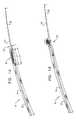
- FIGS. 1A-Care schematic illustrations of an endovascular tool in compressed, partially-expanded, and expanded states, respectively, in accordance with an application of the present invention
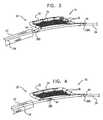
- FIGS. 2A-Bare schematic illustrations of another configuration of the endovascular tool of FIGS. 1A-C in compressed and expanded states, respectively, in accordance with an application of the present invention
- FIG. 3is a schematic illustration of yet another configuration of the endovascular tool of FIGS. 1A-C in an expanded state, in accordance with an application of the present invention
- FIG. 4is a schematic illustration of still another configuration of the endovascular tool of FIGS. 1A-C in an expanded state, in accordance with an application of the present invention
- FIG. 5is a schematic illustration of another configuration of the endovascular tool of FIGS. 1A-C in an expanded state, in accordance with an application of the present invention
- FIG. 6is a schematic illustration of yet another configuration of the endovascular tool of FIGS. 1A-C in an expanded state, in accordance with an application of the present invention
- FIG. 7is a schematic illustration of another configuration of the endovascular tool of FIGS. 1A-C in an expanded state, in accordance with an application of the present invention.
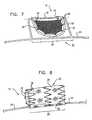
- FIG. 8is a schematic illustration of yet another configuration of the endovascular tool of FIGS. 1A-C in an expanded state, in accordance with an application of the present invention
- FIGS. 9A-Care schematic illustrations of respective configurations of the endovascular tool of FIGS. 1A-C in an expanded state, in accordance with respective applications of the present invention.
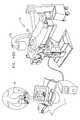
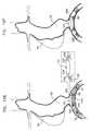
- FIGS. 10A-Fare schematic illustrations of an exemplary transluminal procedure performed using the endovascular tool of FIGS. 1A-C , in accordance with an application of the present invention.
- FIGS. 1A-Care schematic illustrations of an endovascular tool 10 in compressed, partially-expanded, and expanded states, respectively, in accordance with an application of the present invention.
- Endovascular tool 10typically comprises a longitudinal delivery shaft 24 and a fin 20 coupled to the delivery shaft.
- the finis configured to assume (a) a compressed state for endoluminal delivery (and, optionally, retrieval), as shown in FIG. 1A , and (b) an expanded state for endoluminal deployment, in which state the fin is configured to pivot around an axis of rotation 18 , such as shown in FIG. 1C .
- Fin 20typically assumes its compressed state when positioned a generally tubular outer shaft 22 at least partially alongside delivery shaft 24 , initially before deployment of the fin, as described hereinbelow with reference to FIG. 10B , and, optionally, again subsequently to performing a calibration procedure using tool 10 .
- FIG. 1Bshows the fin in an intermediate, partially-expanded state, in which the fin is partially deployed from outer shaft 22 .
- tool 10comprises exactly one fin 20 ; alternatively, tool 10 comprises two or more fins (configuration not shown).
- fin 20is relaxed in its expanded state.
- the finis configured to be self-expanding.
- the finmay be heat-set to assume its expanded state.
- fin 20is configured to assume the compressed state when constrained (such as when within outer shaft 22 ), and to assume the expanded state when relaxed.
- fin 20is configured such that, when the fin is placed in a blood flow path, at least a portion of the fin pivots in a direction that is indicative of the direction of blood flow in a vicinity of the fin.
- fin 20is pivotable to rotate at least 180 degrees around axis of rotation 18 , as schematically indicated by an arrow 26 in FIG. 1C , at least when the fin is in its expanded state.
- fin 20comprises a structural member 32 and at least one substantially flow-resistant membrane member 34 , which is securely mounted to at least a portion of the structural member, either directly or indirectly, such as by a plurality of coupling elements 36 , e.g., sutures or threads.
- structural member 32comprises a super-elastic material, such as a super-elastic metal alloy, e.g., Nitinol.
- Membrane member 34typically comprises a thin pliable sheet of material, which may, for example, comprise an implantable-grade polymer, such as polytetrafluoroethylene (PTFE), e.g., expanded polytetrafluoroethylene (ePTFE), a polyester, or a textile material (e.g., polyethylene terephthalate (PET)).
- PTFEpolytetrafluoroethylene
- ePTFEexpanded polytetrafluoroethylene
- PETpolyethylene terephthalate
- membrane member 34has a surface area of at least 9 mm2, no more than 50 mm2, and/or between 9 and 50 mm2.
- fin 20extends laterally from a portion 28 of delivery shaft 24 , and a longitudinal axis of portion 28 coincides with axis of rotation 18 .
- the longitudinal axis of portion 28typically substantially lies within a plane 29 generally defined by fin 20 and/or membrane member 34 when the fin is in its expanded state, as shown in the side-view blow-up in FIG. 1C .
- portion 28has first and second ends from which respective first and second portions of fin 20 extend in a same radial direction from longitudinal axis 18 , for example, the direction indicated by a vector V in FIG. 1C .
- axis of rotation 18does not coincide with a longitudinal axis of delivery shaft 24 .
- fin 20(typically, structural member 32 and/or membrane member 34 ) is shaped so as to define one or more pivot joints 38 , which rotatably couple the fin to portion 28 of delivery shaft 24 .
- the pivot jointsmay include exactly two pivot joints 38 A and 38 B, such as shown in FIGS. 1A-C (and FIGS. 3-6 , described hereinbelow).
- exactly one pivot jointmay be provided, such as shown in FIG. 8 , or more than two pivot joints may be provided, such as shown in FIGS. 2A-B , described hereinbelow.
- each of pivot joints 38is shaped so as to surround at least 210 degrees of delivery shaft 24 , such as at least 270 degrees, or 360 degrees (i.e., entirely surround the shaft), in order to be coupled to the delivery shaft.
- pivot joints 38are configured to facilitate at least 180 degrees of rotation of the fin around the delivery shaft, as indicated by arrow 26 in FIG. 1C , at least when the fin is in its expanded state.
- pivot joints 38 and delivery shaft 24are configured to facilitate low-friction rotation of fin 20 around the delivery shaft, at least when the fin, is in its expanded state.
- the pivot joints and the delivery shaftmay be configured to provide a coefficient of static friction between the pivots and the delivery shaft of no more than 0.5, such as no more than 0.2.
- the pivot joints and the delivery shaftmay be configured such that the pivot joints rotate with respect to the delivery shaft even when fin 20 is positioned in a blood flow of a healthy peripheral artery having a diameter of at least 3 mm in a subject having a systolic to diastolic blood pressure gradient of at least 30 mmHg.
- At least one (e.g., exactly one, or two or more) of pivot joints 38is axially fixed to delivery shaft 24 so as to prevent axial motion of the at least one of the pivots with respect to the delivery shaft. Such fixation may aid in deployment of fin 20 from outer shaft 22 , such as described hereinbelow with reference to FIG. 10C .
- fin 20has a substantially planar shape when in its expanded state.
- the substantially planar shapemay be a parallelogram, a rectangle (such as shown in FIGS. 2B , 3 , and 4 ), a square, a semicircle, a trapezoid, a shape defined by a curved segment having ends connected by a straight line (such as shown FIGS. 1C and 6 ), or a shape defined by an arc having ends connected by a straight line.
- fin 20has an airfoil shape (e.g., a symmetrical airfoil) when in its expanded state (configuration not shown).
- fin 20is generally cylindrical when in its expanded state, such as described hereinbelow with reference to FIG. 8 .
- a length of delivery shaft 24is at least 10 times, such as at least 20 times a greatest dimension D 1 of fin 20 measured in a direction parallel with axis of rotation 18 , when the fin is in its expanded state, as shown in FIG. 1C .
- greatest dimension D 1is at least 3 mm, no more than 30 mm, and/or between 3 and 30 mm.
- a greatest dimension D 2 of fin 20 measured in a direction parallel with axis of rotation 18 , when the fin is in its compressed stateis at least 5 mm, no more than 50 mm, and/or between 5 and 50 mm, as shown in FIG. 1A .
- delivery shaft 24has a length of at least 10 cm, such as at least 50 cm.
- fin 20has a greatest length L 1 in a direction perpendicular to axis of rotation 24 when the fin is in its expanded state, which greatest length is at least 3 mm, no more than 15 mm, and/or between 3 and 15 mm, as shown in FIG. 1C .
- fin 20has a greatest length L 2 in a direction perpendicular to axis of rotation 24 when the fin is in its compressed state, which greatest length is at least 1.5 mm, no more than 4 mm, and/or between 1.5 and 4 mm, as shown in FIG. 1A .
- greatest length L 1 (when the fin is in its expanded state)is at least 200% greater than greatest length L 2 (when the fin is in its compressed state).
- an axial length L 3 of fin 20 along axis of rotation 18is at least 6 mm, no more than 20 mm, and/or between 6 and 20 mm when the fin is in its expanded state, as shown in FIG. 1C .
- greatest dimension D 1may be greater than axial length L 3 , when the greatest dimension does not coincide with axis of rotation 18 .
- an axial length L 4 of fin 20 along axis of rotation 18is at least 10 mm, no more than 40 mm, and/or between 10 and 40 mm when the fin is in its compressed state, as shown in FIG. 1A .
- axial length L 4 (when the fin is in its compressed state)is at least 50% greater than axial length L 3 (when the fin is in its expanded state).
- outer shaft 22 , delivery shaft 24 , and fin 20are configured such that longitudinal translation of the outer shaft with respect to the delivery shaft (a) in a first axial direction (e.g., translation of the outer shaft to the left in FIGS. 1A-C ) effects a transition of the fin from its compressed state (such shown in FIG. 1A ) to its expanded state (such as shown in FIG. 1C ), and (b) in a second axial direction opposite the first axial direction effects a transition of the fin from its expanded state to its compressed state.
- the finis configured to be capable of being compressed by the outer shaft when withdrawn into the outer shaft.
- outer shaft 22 , delivery shaft 24 , and fin 20are configured such that rotation of the outer shaft with respect to the delivery shaft (a) in a first rotational direction effects a transition of the fin from its compressed state to its expanded state, and (b) in a second rotation direction opposite the first rotation direction effects a transition of the fin from its expanded state to its compressed state.
- outer shaft 22 and delivery shaft 24may be shaped so as to define a threading therebetween.
- an endovascular guidewire 30is provided.
- Delivery shaft 24is shaped so as to define a longitudinal bore therethrough, which is configured to allow deployment of the delivery shaft over the guidewire.
- FIGS. 2A-Bare schematic illustrations of another configuration of endovascular tool 10 in compressed and expanded states, respectively, in accordance with an application of the present invention. Except as described below, this configuration of tool 10 is generally similar to the configuration described hereinabove with reference to FIGS. 1A-C .
- fin 20(typically, structural member 32 and/or membrane member 34 ) is shaped so as to define three pivot joints 38 , which rotatably couple the fin to portion 28 of delivery shaft 24 .
- First and second ones of these pivot joints ( 38 A and 38 B)extend to respective axial ends of portion 28 of delivery shaft 24 , and a third one of the pivot joints ( 38 C) is positioned between first and second pivot joints 38 A and 38 B.
- structural member 32is shaped so as to define all three pivot joints 38 A, 38 B, and 38 C.
- pivot joint 38 Cis not directly coupled to the remainder of structural member 32 .
- membrane member 34is coupled to the portion of structural member 32 that defines pivot joint 38 C (such as by coupling elements 36 ), as well as to the portion of structural member 32 that defines pivot joints 38 A and 38 B.
- fin 20is shown in FIG. 2B as having the shape of a rectangle when in its expanded state, the fin may alternatively have another shapes, such as the shapes described hereinabove with reference to FIGS. 1A-C , and/or shown in any of the other figures.
- One or more of the features of the configuration of fin 20 described with referenced to and/or shown in FIGS. 2A-Bmay be implemented in combination with the features of fin 20 described with reference to and/or shown in FIGS. 1A-C , 3 , 4 , 5 , 6 , 7 , 8 , and/or 9 A-C.
- FIG. 3is a schematic illustration of yet another configuration of endovascular tool 10 in an expanded state, in accordance with an application of the present invention.
- This configuration of tool 10is generally similar to the configuration described hereinabove with reference to FIGS. 2A-B , except that fin 20 comprises only first and second pivot joints 38 A and 38 B, and not third pivot joint 38 C.
- One or more of the features of the configuration of fin 20 described with referenced to and/or shown in FIG. 3may be implemented in combination with the features of fin 20 described with reference to and/or shown in FIGS. 1A-C , 2 A-B, 4 , 5 , 6 , 7 , 8 , and/or 9 A-C.
- FIG. 4is a schematic illustration of still another configuration of endovascular tool 10 in an expanded state, in accordance with an application of the present invention. Except as described hereinbelow with reference to FIGS. 1A-C and 2 - 7 , this configuration of tool 10 is generally similar to the configuration described hereinabove with reference to FIG. 3 .
- One or more of the features of the configuration of fin 20 described with referenced to and/or shown in FIG. 4may be implemented in combination with the features of fin 20 described with reference to and/or shown in FIGS. 1A-C , 2 A-B, 3 , 5 , 6 , 7 , 8 , and/or 9 A-C.
- FIG. 5is a schematic illustration of another configuration of endovascular tool 10 in an expanded state, in accordance with an application of the present invention. Except as described below, this configuration of tool 10 is generally similar to the configuration described hereinabove with reference to FIG. 4 .
- structural member 32is shaped so as to define one or more loops 42 . These loops may serve to reduce kinking in at least one corner of the structural member, when the fin is folded into outer shaft 22 .
- One or more of the features of the configuration of fin 20 described with referenced to and/or shown in FIG. 5may be implemented in combination with the features of fin 20 described with reference to and/or shown in FIGS. 1A-C , 2 A-B, 3 , 4 , 6 , 7 , 8 , and/or 9 A-C.
- FIG. 6is a schematic illustration of yet another configuration of endovascular tool 10 in an expanded state, in accordance with an application of the present invention. Except as described below, this configuration of tool 10 is generally similar to the configuration described hereinabove with reference to FIGS. 1A-C . In this configuration pivot joints 38 A and 38 B come nearly in contact with each other along delivery shaft 24 when the fin is in its expanded state, such as within 2 mm of each other.
- One or more of the features of the configuration of fin 20 described with referenced to and/or shown in FIG. 6may be implemented in combination with the features of fin 20 described with reference to and/or shown in FIGS. 1A-C , 2 A-B, 3 , 4 , 5 , 7 , 8 , and/or 9 A-C.
- FIG. 7is a schematic illustration of another configuration of endovascular tool 10 in an expanded state, in accordance with an application of the present invention. Except as described below, this configuration of tool 10 is generally similar to the configuration described hereinabove with reference to FIGS. 1A-C .
- endovascular tool 10further comprises a support structure 50 , which is coupled to delivery shaft 24 .
- support structure 50is rotationally fixed with respect to the delivery shaft and/or axially-fixed to the delivery shaft to prevent axial motion of the support structure with respect to the shaft.
- the support structureis only axially fixed to the shaft, only rotationally fixed to the shaft, or neither axially fixed nor rotationally fixed to the shaft.
- Fin 20is coupled to support structure 50 , so as to be indirectly coupled to delivery shaft 24 .
- Fin 20is configured to pivot around axis of rotation 18 , which, in this configuration, does not coincide with the longitudinal axis of portion 28 of delivery shaft 24 .
- axis of rotation 18coincides with an axis of a portion of support structure 50 , such as shown in FIG. 7 .
- axis of rotation 18is generally parallel with the longitudinal axis of portion 28 of delivery shaft 24 , such as shown in FIG. 7 .
- the axis of rotationis not generally parallel with the longitudinal axis of portion 28 (configuration not shown).
- One or more of the features of the configuration of fin 20 described with referenced to and/or shown in FIG. 7may be implemented in combination with the features of fin 20 described with reference to and/or shown in FIGS. 1A-C , 2 A-B, 3 , 4 , 5 , 8 , and/or 9 A-C.
- respective portions of structural member 32 that define pivot joints 38 A and 38 Bhave respective ends 44 .
- ends 44face in axially-opposite directions along axis of rotation 18 .
- ends 44face axially toward each other along axis of rotation 18 , while for others of these applications, such as shown in FIGS.
- ends 44face axially away from each other along axis of rotation 18 (this configuration may facilitate retraction of the fin into outer shaft 22 ).
- ends 44face in the same axial direction along axis of rotation 18 .
- FIG. 8is a schematic illustration of yet another configuration of endovascular tool 10 in an expanded state, in accordance with an application of the present invention.
- fin 20is generally cylindrical when in its expanded state.
- a central axis of the fin 20is generally parallel to axis of rotation 18 , as shown in FIG. 8 , while for other applications, the central axis of the fin is generally perpendicular to the axis of rotation (configuration not shown).
- FIGS. 9A-Care schematic illustrations of respective configurations of endovascular tool 10 in an expanded state, in accordance with respective applications of the present invention.
- fin 20is at least partially radiopaque, in order to facilitate radiographic imaging of the fin, such as described hereinbelow with reference to FIG. 10D .
- fin 20comprises a plurality of radiopaque markers 40 , which are fixed to structural member 40 , and have a greater radiopacity per unit weight than that of the structural member.
- at least some of radiopaque markers 40comprise small circular or semispherical elements, such as shown in FIG. 9A .
- at least some of radiopaque markers 40comprise short tube segment, as shown in FIGS.
- FIGS. 9A-Cillustrate radiopaque markers 40 applied to the configuration of fin 20 described hereinabove with reference to FIGS. 1A-C
- the radiopaque markersmay be similarly applied to the other configurations of fin 20 described herein, such as with reference to FIGS. 2A-B , 3 , 4 , 5 , 6 , 7 , and/or 8 .
- FIGS. 10A-Fare schematic illustrations of an exemplary transluminal procedure performed using endovascular tool 10 , in accordance with an application of the present invention. Although this procedure is illustrated using the configuration of tool 10 described hereinabove with reference to FIGS. 1A-C , the procedure may also be used to deploy the other configurations of tool 10 described herein, mutatis mutandis.
- the exemplary proceduresbegins by endoluminally introducing guidewire 30 into one or more blood vessels of a subject.
- fin 20may be positioned in a vicinity of a bifurcation between at least two blood vessels, optionally aligned with the bifurcation, as shown in FIG. 10A .
- the guidewireis shown introduced into left and right common iliac arteries 100 A and 100 B.
- endovascular tool 10is endoluminally introduced into the one or more blood vessels while fin 20 is in its compressed state.
- delivery shaft 24is passed over guidewire 30 such that the guidewire passes through a bore defined by the delivery shaft, and outer shaft 22 is also passed over the guidewire.
- Fin 20is initially positioned in its compressed state within outer shaft 22 , typically near a distal end of the outer shaft.
- delivery shaft 24is shown by way of illustration in FIG. 10B as extending slightly distally out of the distal end of outer shaft 22 , delivery shaft 24 does not necessarily extend out of outer shaft 22 at this stage of deployment.
- Delivery shaft 24 and outer shaft 22are longitudinally translated with respect to each other, thereby delivering fin 20 from the outer shaft, and transitioning fin 20 to its expanded state, as shown in FIG. 10C .
- this relative longitudinal translationis effected by holding delivery shaft 24 in place as outer shaft 22 is withdrawn proximally.
- this relative longitudinal translationis effected by holding outer shaft 22 in place as delivery shaft 24 is advanced distally (technique not shown).
- at least one (e.g., exactly one, or two or more) of pivot joints 38is axially fixed to delivery shaft 24 so as to prevent axial motion of the at least one of the pivots with respect to the delivery shaft.
- fixationmay aid in deployment of the fin from outer shaft 22 , by preventing fin 20 from moving with respect to outer shaft 22 as the delivery shaft and outer shaft are longitudinally translated with respect to each other.
- the finIn its expanded state, the fin is configured to pivot around the axis of rotation, as described hereinabove with reference to FIGS. 1A-C .
- a blood flow pathin this exemplary case, blood flow downstream from a descending abdominal aorta 102 into iliac arteries 100 A and 100 B
- at least a portion of the finpivots in a direction that is indicative of the direction of blood flow in the vicinity of the fin, as indicated by a vector V in FIG. 10C , perhaps best seen in Section A-A thereof.
- Tool 10is positioned such that axis of rotation 18 (and, in the illustrated configuration, portion 28 of delivery shaft 24 ) is generally perpendicular to the direction of blood flow, in the vicinity of the axis of rotation.
- a radiographic image(such as a fluoroscopy image) of fin 20 is generated using an imaging system 120 (such as a fluoroscopy imaging system).
- the imageis used to align an image plane of imaging system 120 generally parallel to a plane 122 defined by the fin that is indicative of the direction of blood flow in the vicinity of the fin.
- Plane 122is defined by (a) axis of rotation 18 (and, in the illustrated configuration, portion 28 of delivery shaft 24 ), and (b) vector V oriented in the direction that fin 20 extends from axis of rotation 18 .
- image planeas used herein, including in the claims, is a plane that is perpendicular to the optical axis at any axial image point of the imaging system.
- a spatial attitudei.e., an orientation or angular position
- a component of the imaging systemsuch as a C-arm 124
- the radiographic imageis changed (sometimes repeatedly), responsively to the radiographic image, until the image plane is generally parallel to plane 122 .
- fin 20in order to align the image plane, after generating the image, one or more apparent dimensions of fin 20 as shown in the image are assessed, and the spatial attitude of the component of the imaging system is changed responsively to the assessing.
- fin 20(optionally, as represented by radiopaque markers 40 ) will appear distorted in the image to the extent that the image plane is not parallel with plane 122 .
- the spatial attitude of the component of the imaging systemis adjusted until fin 20 no longer appears distorted, indicating that the image plane and plane 122 are parallel.
- the spatial attitude of the component of the imaging systemis adjusted until an apparent shape of the fin (either of the entire fin, or of a portion thereof, such as one or more radiographic markers thereof), as shown in the radiographic image, is no longer distorted compared to an actual shape of the fin, i.e., no longer has a modified aspect ratio compared to its actual aspect ratio.
- the assessing and changing of the spatial attitudeare repeated until a desired relationship has been obtained between the apparent dimensions and the actual dimensions of the fin.
- two or more apparent dimensions of the finmay be assessed, and at least one ratio between two of the two or more apparent dimensions may be assessed.
- a reference dimension of a portion of the delivery shaftmay be assessed, and the one or more apparent dimensions of the fin are compared with the reference dimension.
- the dimensions of the finmay include one or more of the following: one or more distances between respective sets of two features of the fin (e.g., radiopaque markers 40 ), a greatest width of the fin in a direction parallel with axis of rotation 24 , and/or a greatest length of the fin in a direction perpendicular to axis of rotation 24 .
- assessingcomprises measuring the one or more apparent dimensions.
- the one or more apparent dimensionsare compared with one or more respective actual dimensions of the fin in its expanded state.
- two or more apparent dimensions of the finare assessed, and a ratio of two of the apparent dimensions are compared with a ratio of two of the actual dimensions.
- delivery shaft 24 and fin 20are withdrawn from the patient.
- fin 20is first retracted into outer shaft 22 , by either advancing outer shaft 22 distally, or withdrawing delivery shaft 24 proximally, until the fin reassumes its contracted state.
- a medical devicesuch as a stent 106 (which, optionally, comprises a stent-graft), is introduced into vasculature of the subject, typically the one or more blood vessels from which the fin was withdrawn, or one or more other blood vessels in a vicinity of the one or more blood vessels from which the fin was withdrawn.
- the medical deviceis oriented using one or more images generated by the imaging system. Because the imaging system is properly aligned, as described above, the medical device can be properly aligned, for example, specifically in the rotational dimension, using images generated by the imaging system.
- the medical devicee.g., stent 106
- the stentis rotationally oriented using the one or more images generated by the imaging system.
- the stentmay be shaped so as to define a lateral opening 123
- the lateral openingmay be rotationally oriented using the imaging system, such as to face in a direction that is parallel to the image plane.
- lateral opening 123is oriented to face the opening between descending abdominal aorta 102 and left and right common iliac arteries 100 A and 100 B. If the imaging plane of imaging system 120 were not properly aligned as described above, the lateral opening would not be properly rotated to face the descending abdominal aorta, but instead would face another direction parallel to the misaligned imaging plane.
- stent 106includes two or more radiopaque features 124 distributed around lateral opening 123 .
- lateral opening 123is oriented such that at least a portion of radiopaque features 124 are aligned with one another in the one or more images.
- stent 106may be properly rotationally aligned when radiopaque feature 124 A appears to coincide with radiopaque feature 124 B in the two-dimensional radiographic image (because radiopaque feature 124 A is directly above radiopaque feature 124 B when viewed in the properly-aligned image plane), and radiopaque feature 124 D appears to coincide with radiopaque feature 124 C.
- the medical devicee.g., stent 106
- the medical deviceis delivered in a radially-compressed state within a delivery shaft 130 , as shown in FIG. 10E .
- the medical deviceis typically aligned while still compressed in the delivery shaft, which is generally readily rotated in the vasculature.
- guidewire 30is left in the one or more blood vessels, and the medical device is introduced over the guidewire.
- the medical devicee.g., stent 106
- the medical deviceis delivered from the delivery shaft, and transitions to a radially-expanded state. If necessary for precise alignment, the medical device typically can be further slightly rotated even after expansion thereof.
- stent 106may be configured using techniques described in US Patent Application Publication 2010/0063575, which is incorporated herein by reference, such as regarding stent graft component 60 thereof.
- the techniques described hereinare used for rotationally aligning stent graft component 60 of the '575 publication, optionally in combination with other apparatus and/or methods described in the '575 publication.
- additional stentse.g., stent-grafts
- stent-graftsare deployed in combination with stent 106 , either before or after deploying stent 106 , such as using techniques described in one or more of the patent applications incorporated hereinbelow by reference.
- a kitfor some applications of the present invention, comprises endovascular tool 10 and at least one medical device, such as a stent (e.g., a stent-graft).
- a stente.g., a stent-graft
- the kitfurther comprises delivery shaft 130 and/or guidewire 30 .
- endovascular tool 10is used to treat an aneurysm 104 , such as an aortic aneurism, or an aneurism of another blood vessel.
- an aneurysm 104such as an aortic aneurism, or an aneurism of another blood vessel.
- the aneurismmay be of the sub-renal aorta, as shown in FIGS. 10A-F .
- a methodcomprises identifying that a patient suffers from an aneurysm, such as an aortic aneurism (e.g., a sub-renal aortic aneurism), and, responsively to the identifying, endoluminally introducing endovascular tool 10 responsively to the identifying, and, optionally, a medical device, such as a stent, e.g., a stent-graft.
- an aneurysmsuch as an aortic aneurism (e.g., a sub-renal aortic aneurism)
- endoluminallyintroducing endovascular tool 10 responsively to the identifying, and, optionally, a medical device, such as a stent, e.g., a stent-graft.
- endovascular tool 10has sometimes been described hereinabove as being deployed in the common iliac arteries in a vicinity of a bifurcation with the descending abdominal aorta
- the endovascular toolmay, for some applications, also be deployed in other body lumens, such as at other branching body lumens.
- the toolmay be deployed in the aortic arch in a vicinity of one of the branches of the aortic arch, and also when placing a fenestrated stent between the common carotid artery and either the internal or external carotid artery, and an additional stent between the fenestration of the aforementioned stent and the other carotid artery.
Landscapes
- Health & Medical Sciences (AREA)
- Life Sciences & Earth Sciences (AREA)
- Surgery (AREA)
- Biomedical Technology (AREA)
- Engineering & Computer Science (AREA)
- Veterinary Medicine (AREA)
- Animal Behavior & Ethology (AREA)
- Vascular Medicine (AREA)
- Public Health (AREA)
- Heart & Thoracic Surgery (AREA)
- General Health & Medical Sciences (AREA)
- Molecular Biology (AREA)
- Nuclear Medicine, Radiotherapy & Molecular Imaging (AREA)
- Medical Informatics (AREA)
- Reproductive Health (AREA)
- Neurosurgery (AREA)
- Cardiology (AREA)
- Oral & Maxillofacial Surgery (AREA)
- Transplantation (AREA)
- Prostheses (AREA)
- Media Introduction/Drainage Providing Device (AREA)
Abstract
Description
- PCT Application PCT/IL2008/000287, filed Mar. 5, 2008, which published as PCT Publication WO 2008/107885 to Shalev et al., and U.S. application Ser. No. 12/529,936 in the national stage thereof, which published as US Patent Application Publication 2010/0063575
- U.S. application Ser. No. 12/529,936, which published as US Patent Application Publication 2010/0063575 to Shalev et al.
- U.S. Provisional Application 60/892,885, filed Mar. 5, 2007
- U.S. Provisional Application 60/991,726, filed Dec. 2, 2007
- U.S. Provisional Application 61/219,758, filed Jun. 23, 2009
- U.S. Provisional Application 61/221,074, filed Jun. 28, 2009
- PCT Application PCT/IB2010/052861, filed Jun. 23, 2010, which published as PCT Publication WO 2010/150208
- PCT Application PCT/IL2010/000564, filed Jul. 14, 2010, which published as PCT Publication WO 2011/007354
- PCT Application PCT/IL2010/000917, filed Nov. 4, 2010, which published as PCT Publication WO 2011/055364
- PCT Application PCT/IL2010/000999, filed Nov. 30, 2010, entitled, “Multi-component stent-graft system for implantation in a blood vessel with multiple branches,” which published as PCT Publication WO 2011/064782
- PCT Application PCT/IL2010/00101, filed Dec. 2, 2010, entitled, “Endovascular fenestrated stent-grafting,” which published as PCT Publication WO 2011/067764
- PCT Application PCT/IL2010/001037, filed Dec. 8, 2010, entitled, “Endovascular stent-graft system with fenestrated and crossing stent-grafts,”which published as PCT Publication WO 2011/070576
Claims (43)
Priority Applications (1)
| Application Number | Priority Date | Filing Date | Title |
|---|---|---|---|
| US13/519,971US8956397B2 (en) | 2009-12-31 | 2010-12-27 | Endovascular flow direction indicator |
Applications Claiming Priority (3)
| Application Number | Priority Date | Filing Date | Title |
|---|---|---|---|
| US29142709P | 2009-12-31 | 2009-12-31 | |
| US13/519,971US8956397B2 (en) | 2009-12-31 | 2010-12-27 | Endovascular flow direction indicator |
| PCT/IL2010/001087WO2011080738A1 (en) | 2009-12-31 | 2010-12-27 | Endovascular flow direction indicator |
Publications (2)
| Publication Number | Publication Date |
|---|---|
| US20120316634A1 US20120316634A1 (en) | 2012-12-13 |
| US8956397B2true US8956397B2 (en) | 2015-02-17 |
Family
ID=44226220
Family Applications (1)
| Application Number | Title | Priority Date | Filing Date |
|---|---|---|---|
| US13/519,971Expired - Fee RelatedUS8956397B2 (en) | 2009-12-31 | 2010-12-27 | Endovascular flow direction indicator |
Country Status (4)
| Country | Link |
|---|---|
| US (1) | US8956397B2 (en) |
| EP (1) | EP2519166A4 (en) |
| CA (1) | CA2785953C (en) |
| WO (1) | WO2011080738A1 (en) |
Families Citing this family (26)
| Publication number | Priority date | Publication date | Assignee | Title |
|---|---|---|---|---|
| ES2624595T3 (en) | 2007-03-05 | 2017-07-17 | Endospan Ltd | Bifurcated, supportive, expandable endoluminal grafts with multiple components and methods for use |
| CN101965162B (en) | 2007-12-15 | 2014-12-10 | 恩多斯潘有限公司 | Extra-vascular wrapping for treating aneurysmatic aorta in conjunction with endovascular stent-graft and methods thereof |
| CA3009244C (en) | 2009-06-23 | 2020-04-28 | Endospan Ltd. | Vascular prostheses for treating aneurysms |
| WO2011004374A1 (en) | 2009-07-09 | 2011-01-13 | Endospan Ltd. | Apparatus for closure of a lumen and methods of using the same |
| CN102740807B (en) | 2009-11-30 | 2015-11-25 | 恩多斯潘有限公司 | Multi-component stent-graft system for implantation into vessels with multiple branches |
| EP2509535B1 (en) | 2009-12-08 | 2016-12-07 | Endospan Ltd | Endovascular stent-graft system with fenestrated and crossing stent-grafts |
| WO2011080738A1 (en) | 2009-12-31 | 2011-07-07 | Endospan Ltd. | Endovascular flow direction indicator |
| US9468517B2 (en) | 2010-02-08 | 2016-10-18 | Endospan Ltd. | Thermal energy application for prevention and management of endoleaks in stent-grafts |
| CA2826022A1 (en) | 2011-02-03 | 2012-08-09 | Endospan Ltd. | Implantable medical devices constructed of shape memory material |
| WO2012111006A1 (en) | 2011-02-17 | 2012-08-23 | Endospan Ltd. | Vascular bands and delivery systems therefor |
| WO2012117395A1 (en) | 2011-03-02 | 2012-09-07 | Endospan Ltd. | Reduced-strain extra- vascular ring for treating aortic aneurysm |
| US8574287B2 (en) | 2011-06-14 | 2013-11-05 | Endospan Ltd. | Stents incorporating a plurality of strain-distribution locations |
| US8951298B2 (en) | 2011-06-21 | 2015-02-10 | Endospan Ltd. | Endovascular system with circumferentially-overlapping stent-grafts |
| US9254209B2 (en) | 2011-07-07 | 2016-02-09 | Endospan Ltd. | Stent fixation with reduced plastic deformation |
| US9839510B2 (en) | 2011-08-28 | 2017-12-12 | Endospan Ltd. | Stent-grafts with post-deployment variable radial displacement |
| US9427339B2 (en) | 2011-10-30 | 2016-08-30 | Endospan Ltd. | Triple-collar stent-graft |
| US9597204B2 (en) | 2011-12-04 | 2017-03-21 | Endospan Ltd. | Branched stent-graft system |
| WO2013171730A1 (en) | 2012-05-15 | 2013-11-21 | Endospan Ltd. | Stent-graft with fixation elements that are radially confined for delivery |
| WO2014020609A1 (en) | 2012-08-01 | 2014-02-06 | Endospan Ltd. | Stent-grafts configured for post-implantation expansion |
| US9993360B2 (en) | 2013-01-08 | 2018-06-12 | Endospan Ltd. | Minimization of stent-graft migration during implantation |
| US9668892B2 (en) | 2013-03-11 | 2017-06-06 | Endospan Ltd. | Multi-component stent-graft system for aortic dissections |
| WO2015075708A1 (en) | 2013-11-19 | 2015-05-28 | Endospan Ltd. | Stent system with radial-expansion locking |
| KR20150144568A (en)* | 2014-06-17 | 2015-12-28 | (주) 타우피엔유메디칼 | Tissue protective tube for tricuspid regurgitation |
| CN106029005B (en) | 2014-12-18 | 2018-01-19 | 恩都思潘有限公司 | The Endovascular stent-graft of horizontal conduit with tired resistance |
| EP3247310A4 (en)* | 2015-01-20 | 2018-07-18 | Keystone Heart Ltd. | Intravascular devices and delivery systems and uses thereof |
| US10595895B2 (en) | 2016-07-19 | 2020-03-24 | Cardiovascular Systems, Inc. | Rotational medical device with airfoil |
Citations (229)
| Publication number | Priority date | Publication date | Assignee | Title |
|---|---|---|---|---|
| US4180613A (en)* | 1977-09-01 | 1979-12-25 | E. I. Du Pont De Nemours And Company | Craze-resistant polysiloxane resin coatings and coating compositions containing a discontinuous phase |
| US4355426A (en) | 1975-05-09 | 1982-10-26 | Macgregor David C | Porous flexible vascular graft |
| US4505767A (en) | 1983-10-14 | 1985-03-19 | Raychem Corporation | Nickel/titanium/vanadium shape memory alloy |
| US4562596A (en) | 1984-04-25 | 1986-01-07 | Elliot Kornberg | Aortic graft, device and method for performing an intraluminal abdominal aortic aneurysm repair |
| US4577631A (en) | 1984-11-16 | 1986-03-25 | Kreamer Jeffry W | Aneurysm repair apparatus and method |
| US4617932A (en) | 1984-04-25 | 1986-10-21 | Elliot Kornberg | Device and method for performing an intraluminal abdominal aortic aneurysm repair |
| US4665906A (en) | 1983-10-14 | 1987-05-19 | Raychem Corporation | Medical devices incorporating sim alloy elements |
| US4739762A (en) | 1985-11-07 | 1988-04-26 | Expandable Grafts Partnership | Expandable intraluminal graft, and method and apparatus for implanting an expandable intraluminal graft |
| US4787899A (en) | 1983-12-09 | 1988-11-29 | Lazarus Harrison M | Intraluminal graft device, system and method |
| US4878906A (en) | 1986-03-25 | 1989-11-07 | Servetus Partnership | Endoprosthesis for repairing a damaged vessel |
| US4886062A (en) | 1987-10-19 | 1989-12-12 | Medtronic, Inc. | Intravascular radially expandable stent and method of implant |
| US4938740A (en) | 1988-05-25 | 1990-07-03 | Trustees Of The University Of Pennsylvania | Reducing stress at vascular graft anastomoses |
| US4969458A (en) | 1987-07-06 | 1990-11-13 | Medtronic, Inc. | Intracoronary stent and method of simultaneous angioplasty and stent implant |
| US5042707A (en) | 1990-10-16 | 1991-08-27 | Taheri Syde A | Intravascular stapler, and method of operating same |
| US5064435A (en) | 1990-06-28 | 1991-11-12 | Schneider (Usa) Inc. | Self-expanding prosthesis having stable axial length |
| US5122136A (en) | 1990-03-13 | 1992-06-16 | The Regents Of The University Of California | Endovascular electrolytically detachable guidewire tip for the electroformation of thrombus in arteries, veins, aneurysms, vascular malformations and arteriovenous fistulas |
| US5133732A (en) | 1987-10-19 | 1992-07-28 | Medtronic, Inc. | Intravascular stent |
| US5192286A (en)* | 1991-07-26 | 1993-03-09 | Regents Of The University Of California | Method and device for retrieving materials from body lumens |
| US5486183A (en) | 1990-10-09 | 1996-01-23 | Raychem Corporation | Device or apparatus for manipulating matter |
| US5507769A (en) | 1994-10-18 | 1996-04-16 | Stentco, Inc. | Method and apparatus for forming an endoluminal bifurcated graft |
| US5509923A (en) | 1989-08-16 | 1996-04-23 | Raychem Corporation | Device for dissecting, grasping, or cutting an object |
| US5522880A (en) | 1990-06-11 | 1996-06-04 | Barone; Hector D. | Method for repairing an abdominal aortic aneurysm |
| US5527322A (en) | 1993-11-08 | 1996-06-18 | Perclose, Inc. | Device and method for suturing of internal puncture sites |
| US5554181A (en) | 1994-05-04 | 1996-09-10 | Regents Of The University Of Minnesota | Stent |
| US5562724A (en) | 1993-12-15 | 1996-10-08 | William Cook Europe A/S | Endovascular graft prosthesis and an implantation method for such a prosthesis |
| US5613974A (en) | 1992-12-10 | 1997-03-25 | Perclose, Inc. | Apparatus and method for vascular closure |
| US5632763A (en) | 1995-01-19 | 1997-05-27 | Cordis Corporation | Bifurcated stent and method for implanting same |
| US5632746A (en) | 1989-08-16 | 1997-05-27 | Medtronic, Inc. | Device or apparatus for manipulating matter |
| US5632772A (en) | 1993-10-21 | 1997-05-27 | Corvita Corporation | Expandable supportive branched endoluminal grafts |
| US5639278A (en) | 1993-10-21 | 1997-06-17 | Corvita Corporation | Expandable supportive bifurcated endoluminal grafts |
| US5643340A (en) | 1994-10-27 | 1997-07-01 | Nunokawa; Mioko | Synthetic vascular prosthesis |
| US5653743A (en) | 1994-09-09 | 1997-08-05 | Martin; Eric C. | Hypogastric artery bifurcation graft and method of implantation |
| US5676697A (en) | 1996-07-29 | 1997-10-14 | Cardiovascular Dynamics, Inc. | Two-piece, bifurcated intraluminal graft for repair of aneurysm |
| US5676696A (en) | 1995-02-24 | 1997-10-14 | Intervascular, Inc. | Modular bifurcated intraluminal grafts and methods for delivering and assembling same |
| US5728134A (en) | 1996-09-17 | 1998-03-17 | Barak; Shlomo | Method and apparatus for hemostasis |
| US5749879A (en) | 1989-08-16 | 1998-05-12 | Medtronic, Inc. | Device or apparatus for manipulating matter |
| US5755777A (en) | 1991-10-25 | 1998-05-26 | Cook Incorporated | Expandable transluminal graft prosthesis for repair of aneurysm |
| US5755770A (en) | 1995-01-31 | 1998-05-26 | Boston Scientific Corporatiion | Endovascular aortic graft |
| US5755771A (en) | 1994-11-03 | 1998-05-26 | Divysio Solutions Ulc | Expandable stent and method of delivery of same |
| US5769882A (en) | 1995-09-08 | 1998-06-23 | Medtronic, Inc. | Methods and apparatus for conformably sealing prostheses within body lumens |
| US5782903A (en) | 1987-10-19 | 1998-07-21 | Medtronic, Inc. | Intravascular stent and method |
| US5782906A (en) | 1994-08-25 | 1998-07-21 | Ethicon, Inc. | Combination arterial stent |
| US5824040A (en) | 1995-12-01 | 1998-10-20 | Medtronic, Inc. | Endoluminal prostheses and therapies for highly variable body lumens |
| US5876432A (en) | 1994-04-01 | 1999-03-02 | Gore Enterprise Holdings, Inc. | Self-expandable helical intravascular stent and stent-graft |
| US5906641A (en) | 1997-05-27 | 1999-05-25 | Schneider (Usa) Inc | Bifurcated stent graft |
| US5921994A (en) | 1995-06-15 | 1999-07-13 | Perclose, Inc. | Low profile intraluminal suturing device and method |
| US6015431A (en) | 1996-12-23 | 2000-01-18 | Prograft Medical, Inc. | Endolumenal stent-graft with leak-resistant seal |
| US6033435A (en) | 1997-11-03 | 2000-03-07 | Divysio Solutions Ulc | Bifurcated stent and method for the manufacture and delivery of same |
| US6059824A (en) | 1998-12-23 | 2000-05-09 | Taheri; Syde A. | Mated main and collateral stent and method for treatment of arterial disease |
| US6099497A (en) | 1998-03-05 | 2000-08-08 | Scimed Life Systems, Inc. | Dilatation and stent delivery system for bifurcation lesions |
| US6117145A (en) | 1994-06-01 | 2000-09-12 | Perclose, Inc. | Method and device for providing hemostasis at vascular penetration sites |
| US6200339B1 (en) | 1999-02-23 | 2001-03-13 | Datascope Investment Corp. | Endovascular split-tube bifurcated graft prosthesis and an implantation method for such a prosthesis |
| US6270524B1 (en) | 1996-11-12 | 2001-08-07 | Medtronic, Inc. | Flexible, radially expansible luminal prostheses |
| US20010014823A1 (en) | 1998-03-16 | 2001-08-16 | Teramed, Inc. | Bifurcated prosthetic graft |
| US6290720B1 (en) | 1998-11-16 | 2001-09-18 | Endotex Interventional Systems, Inc. | Stretchable anti-buckling coiled-sheet stent |
| US20010044652A1 (en) | 1999-10-14 | 2001-11-22 | Moore Brian Edward | Stents with multi-layered struts |
| US6325823B1 (en) | 1999-10-29 | 2001-12-04 | Revasc Corporation | Endovascular prosthesis accommodating torsional and longitudinal displacements and methods of use |
| US20010053930A1 (en) | 1999-12-03 | 2001-12-20 | Teramed, Inc. | Endovascular graft system |
| US20020099441A1 (en) | 1999-12-29 | 2002-07-25 | Edwards Lifesciences, Llc | Towel graft means for enhancing tissue ingrowth in vascular grafts |
| US6428565B1 (en) | 1997-09-11 | 2002-08-06 | Medtronic Ave, Inc. | System and method for edoluminal grafting of bifurcated or branched vessels |
| US20020123791A1 (en) | 2000-12-28 | 2002-09-05 | Harrison William J. | Stent design with increased vessel coverage |
| JP2002253682A (en) | 2001-02-27 | 2002-09-10 | Inprest Co Ltd | Stent and stent member |
| US20020156495A1 (en) | 1995-09-15 | 2002-10-24 | Rodney Brenneman | Apparatus and method for percutaneous sealing of blood vessel punctures |
| US6471722B1 (en) | 1995-05-19 | 2002-10-29 | Kanji Inoue | Appliance to be implanted and a device for handling the appliance to be implanted |
| US20020183783A1 (en)* | 2001-06-04 | 2002-12-05 | Shadduck John H. | Guidewire for capturing emboli in endovascular interventions |
| US20020198585A1 (en) | 1999-10-05 | 2002-12-26 | Willem Wisselink | System and method for edoluminal grafting of bifurcated or branched vessels |
| US6506211B1 (en) | 2000-11-13 | 2003-01-14 | Scimed Life Systems, Inc. | Stent designs |
| US6544279B1 (en)* | 2000-08-09 | 2003-04-08 | Incept, Llc | Vascular device for emboli, thrombus and foreign body removal and methods of use |
| US20030093145A1 (en) | 2001-10-26 | 2003-05-15 | Cook Incorporated | Endoluminal graft |
| US20030130720A1 (en) | 2002-01-08 | 2003-07-10 | Depalma Donald F. | Modular aneurysm repair system |
| US20030153968A1 (en) | 2002-02-14 | 2003-08-14 | Geis John S. | Vessel support, delivery system for vessel support and method for preventive treatment of aorta diseases |
| US20030153944A1 (en)* | 2001-10-19 | 2003-08-14 | Scimed Life Systems, Inc. | Embolus extractor |
| US6613078B1 (en) | 2000-08-02 | 2003-09-02 | Hector Daniel Barone | Multi-component endoluminal graft assembly, use thereof and method of implanting |
| US20030171771A1 (en)* | 2002-03-08 | 2003-09-11 | Anderson Kent D. | Vascular protection devices and methods of use |
| US6635083B1 (en) | 2001-06-25 | 2003-10-21 | Advanced Cardiovascular Systems, Inc. | Stent with non-linear links and method of use |
| US20030199967A1 (en) | 2002-03-25 | 2003-10-23 | Cook Incorporated | Bifurcated/branch vessel prosthesis |
| US20030212449A1 (en) | 2001-12-28 | 2003-11-13 | Cox Daniel L. | Hybrid stent |
| US6652567B1 (en) | 1999-11-18 | 2003-11-25 | David H. Deaton | Fenestrated endovascular graft |
| US20030233117A1 (en)* | 2002-06-14 | 2003-12-18 | Adams Daniel O. | Rapid exchange catheters usable with embolic protection devices |
| US20030236567A1 (en) | 2002-06-25 | 2003-12-25 | Scimed Life Systems, Inc. | Implantable prosthesis with displaceabe skirt |
| US6673080B2 (en)* | 2001-01-08 | 2004-01-06 | Scimed Life Systems, Inc. | Retrieval basket with releasable tip |
| US20040015227A1 (en) | 1996-11-04 | 2004-01-22 | Gil Vardi | Extendible stent apparatus |
| US6692520B1 (en) | 1998-12-15 | 2004-02-17 | C. R. Bard, Inc. | Systems and methods for imbedded intramuscular implants |
| US6695833B1 (en) | 2000-09-27 | 2004-02-24 | Nellix, Inc. | Vascular stent-graft apparatus and forming method |
| WO2004017868A1 (en) | 2002-08-23 | 2004-03-04 | William A. Cook Australia Pty. Ltd. | Asymmetric stent graft attachment |
| CA2497704A1 (en) | 2002-09-03 | 2004-03-18 | Boston Scientific Limited | Elephant trunk thoracic endograft and delivery system |
| US6743195B2 (en) | 2001-03-14 | 2004-06-01 | Cardiodex | Balloon method and apparatus for vascular closure following arterial catheterization |
| US20040106978A1 (en) | 2002-06-28 | 2004-06-03 | Cook Incorporated | Thoracic aortic aneurysm stent graft |
| US20040106972A1 (en) | 2000-11-20 | 2004-06-03 | Deaton David H. | Fenestrated endovascular graft |
| US20040133266A1 (en) | 1997-05-27 | 2004-07-08 | Clerc Claude O. | Stent and stent-graft for treating branched vessels |
| US6776794B1 (en) | 2001-11-28 | 2004-08-17 | Advanced Cardiovascular Systems, Inc. | Stent pattern with mirror image |
| US20040171978A1 (en) | 2002-12-16 | 2004-09-02 | Shalaby Shalaby W. | Composite vascular constructs with selectively controlled properties |
| US20040181149A1 (en) | 2001-02-07 | 2004-09-16 | Ulrich Langlotz | Device and method for intraoperative navigation |
| US20040215327A1 (en) | 2003-04-25 | 2004-10-28 | Medtronic Ave, Inc. | Universal modular stent graft assembly to accommodate flow to collateral branches |
| US6814749B2 (en) | 1999-12-30 | 2004-11-09 | Advanced Cardiovascular Systems, Inc. | Stent designs for use in peripheral vessels |
| US6814752B1 (en) | 2000-03-03 | 2004-11-09 | Endovascular Technologies, Inc. | Modular grafting system and method |
| US6824560B2 (en) | 2001-06-13 | 2004-11-30 | Advanced Cardiovascular Systems, Inc. | Double-butted superelastic nitinol tubing |
| US20050010246A1 (en)* | 2000-06-30 | 2005-01-13 | Streeter Richard B. | Intravascular filter with debris entrapment mechanism |
| US6846321B2 (en) | 2000-06-21 | 2005-01-25 | Cardiodex, Ltd. | Mechanical method and apparatus for enhancing hemostatis following arterial catheterization |
| US20050033406A1 (en) | 2003-07-15 | 2005-02-10 | Barnhart William H. | Branch vessel stent and graft |
| WO2005002466A3 (en) | 2003-07-08 | 2005-03-03 | Ventor Technologies Ltd | Implantable prosthetic devices particularly for transarterial delivery in the treatment of aortic stenosis, and methods of implanting such devices |
| US20050049678A1 (en) | 2001-09-04 | 2005-03-03 | Graeme Cocks | Stent |
| US20050065545A1 (en) | 2003-09-23 | 2005-03-24 | Scimed Life Systems, Inc. | External activation of vaso-occlusive implants |
| US20050102018A1 (en) | 2003-11-06 | 2005-05-12 | Carpenter Judith T. | Endovascular prosthesis, system and method |
| US20050102021A1 (en) | 2003-10-10 | 2005-05-12 | Cook Incorporated | Stretchable prosthesis fenestration |
| WO2005041781A1 (en) | 2003-10-30 | 2005-05-12 | Sunshine Heart Company Pty Ltd | Methods and devices for tensioning a wrap around a blood vessel |
| US6907285B2 (en) | 2001-01-16 | 2005-06-14 | Kenergy, Inc. | Implantable defibrillartor with wireless vascular stent electrodes |
| US20050131517A1 (en) | 2003-10-10 | 2005-06-16 | William A. Cook Australia Pty. Ltd. | Stent graft fenestration |
| US6908477B2 (en) | 2000-10-13 | 2005-06-21 | Rex Medical, L.P. | Methods of implanting covered stents with side branch |
| US20050149166A1 (en) | 2003-11-08 | 2005-07-07 | Schaeffer Darin G. | Branch vessel prosthesis with anchoring device and method |
| WO2005041783A8 (en) | 2003-10-30 | 2005-07-21 | Sunshine Heart Co Pty Ltd | A wrap |
| WO2005037138A3 (en) | 2003-10-14 | 2005-08-04 | James C Peacock Iii | Aneurysm treatment system and method |
| US6929660B1 (en) | 2000-12-22 | 2005-08-16 | Advanced Cardiovascular Systems, Inc. | Intravascular stent |
| US6942691B1 (en) | 2000-04-27 | 2005-09-13 | Timothy A. M. Chuter | Modular bifurcated graft for endovascular aneurysm repair |
| US20050203606A1 (en) | 2004-03-09 | 2005-09-15 | Vancamp Daniel H. | Stent system for preventing restenosis |
| US20050222669A1 (en) | 2004-03-31 | 2005-10-06 | Purdy James D | Fenestrated intraluminal stent system |
| US6986774B2 (en) | 1989-08-16 | 2006-01-17 | Medtronic, Inc. | Method of manipulating matter in a mammalian body |
| WO2006007389A1 (en) | 2004-06-16 | 2006-01-19 | Cook Incorprated | Thoracic deployment device and stent graft |
| US20060015170A1 (en) | 2004-07-16 | 2006-01-19 | Jones Ryan A | Contrast coated stent and method of fabrication |
| WO2006028925A1 (en) | 2004-09-02 | 2006-03-16 | Med Institute, Inc. | Modular prosthesis and method for branch vessels |
| US20060069426A1 (en) | 2004-09-27 | 2006-03-30 | Weinberger Judah Z | Methods and devices for extravascular intervention |
| US20060100684A1 (en) | 2003-02-26 | 2006-05-11 | Elliott Christopher J | Endoluminal device having enhanced affixation characteristics |
| US20060149360A1 (en) | 2003-07-08 | 2006-07-06 | Ventor Technologies Ltd. | Fluid flow prosthetic device |
| US20060155366A1 (en) | 2005-01-10 | 2006-07-13 | Laduca Robert | Apparatus and method for deploying an implantable device within the body |
| US20060155358A1 (en) | 2005-01-10 | 2006-07-13 | Laduca Robert | Methods for placing a stent in a branched vessel |
| US20060167476A1 (en) | 2000-11-06 | 2006-07-27 | Perclose, Inc | Systems, devices and methods for suturing patient tissue |
| US20060193892A1 (en) | 2001-10-26 | 2006-08-31 | Icon Medical Corp. | Polymer biodegradable medical device |
| US7105020B2 (en) | 2003-01-14 | 2006-09-12 | The Cleveland Clinic Foundation | Branched vessel endoluminal device |
| US7112217B1 (en) | 1998-03-16 | 2006-09-26 | Cordis Corporation | Biluminal endovascular graft system |
| US7115127B2 (en) | 2003-02-04 | 2006-10-03 | Cardiodex, Ltd. | Methods and apparatus for hemostasis following arterial catheterization |
| US20060229709A1 (en) | 2005-03-30 | 2006-10-12 | Morris Liam G | Vascular graft |
| US20070021822A1 (en) | 2005-07-25 | 2007-01-25 | Cook Incorporated | Fenestrated endoluminal stent system |
| US20070043425A1 (en) | 2005-08-18 | 2007-02-22 | William A. Cook Australia Pty Ltd. | Assembly of stent grafts |
| US20070055350A1 (en) | 2005-09-02 | 2007-03-08 | Medtronic Vascular, Inc. | Modular branch vessel stent-graft assembly |
| US20070055358A1 (en) | 2005-08-22 | 2007-03-08 | Krolik Jeffrey A | Axially compressible flared stents and apparatus and methods for delivering them |
| US20070060989A1 (en) | 2005-09-07 | 2007-03-15 | Deem Mark E | Apparatus and method for disrupting subcutaneous structures |
| US20070073373A1 (en) | 2005-09-28 | 2007-03-29 | Craig Bonsignore | Intraluminal medical device with nested interlocking segments |
| US20070088425A1 (en) | 2005-10-13 | 2007-04-19 | Cook Incorporated | Endoluminal prosthesis |
| US20070112344A1 (en) | 1997-10-14 | 2007-05-17 | Cardiometrix, Inc. | Endoluminal implant with therapeutic and diagnostic capability |
| US7223266B2 (en) | 2003-02-04 | 2007-05-29 | Cardiodex Ltd. | Methods and apparatus for hemostasis following arterial catheterization |
| US20070150051A1 (en) | 2005-01-10 | 2007-06-28 | Duke Fiduciary, Llc | Vascular implants and methods of fabricating the same |
| US20070156167A1 (en) | 2000-04-14 | 2007-07-05 | Connors Kevin G | Pressure attenuation device |
| WO2007084547A1 (en) | 2006-01-18 | 2007-07-26 | William A. Cook Australia Pty. Ltd. | Endoluminal delivery device |
| US20070208410A1 (en) | 2005-09-02 | 2007-09-06 | Medtronic Vascular, Inc. | Methods and Apparatus for Treatment of Aneurysms Adjacent to Branch Arteries |
| US20070213805A1 (en) | 2006-03-09 | 2007-09-13 | Cook Incorporated | Expandable stent grafts and methods of use thereof |
| US20070219610A1 (en) | 2006-03-20 | 2007-09-20 | Israel Henry M | Stent with flap |
| US20070233229A1 (en) | 2005-09-01 | 2007-10-04 | Medtronic Vascular, Inc. | Methods and Apparatus for Treatment of Thoracic Aortic Aneurysms |
| US7279003B2 (en) | 2003-04-24 | 2007-10-09 | Medtronic Vascular, Inc. | Stent graft tapered spring |
| US20070237973A1 (en) | 2006-02-21 | 2007-10-11 | Purdy James D | Graft material, stent graft and method |
| US20070244542A1 (en) | 2006-04-18 | 2007-10-18 | Medtronic Vascular, Inc. | Stent Graft Having a Flexible, Articulable, and Axially Compressible Branch Graft |
| US20070244547A1 (en) | 2006-04-18 | 2007-10-18 | Medtronic Vascular, Inc., A Delaware Corporation | Device and Method for Controlling the Positioning of a Stent Graft Fenestration |
| US20070244543A1 (en) | 2006-04-18 | 2007-10-18 | Medtronic Vascular, Inc. A Delaware Corporation | Stent With Movable Crown |
| US20070255388A1 (en) | 2004-03-31 | 2007-11-01 | Merlin Md Pte Ltd | Endovascular device with membrane |
| EP1325716B1 (en) | 2002-01-08 | 2007-11-14 | Cordis Corporation | Thoracic aneurysm repair prosthesis and system |
| US7306623B2 (en) | 2005-01-13 | 2007-12-11 | Medtronic Vascular, Inc. | Branch vessel graft design and deployment method |
| WO2007144782A2 (en) | 2006-04-28 | 2007-12-21 | Younes Boudjemline | Vascular stents, methods of use and methods of manufacture |
| US20080002871A1 (en) | 2006-05-23 | 2008-01-03 | Konstanze Gunzert-Marx | Procedure for detecting a deviation in a x-ray system from a target position |
| US20080015673A1 (en) | 2006-07-10 | 2008-01-17 | Chuter Timothy A | Conformable end sealing stent |
| US7341598B2 (en) | 1999-01-13 | 2008-03-11 | Boston Scientific Scimed, Inc. | Stent with protruding branch portion for bifurcated vessels |
| WO2008035337A2 (en) | 2006-09-19 | 2008-03-27 | Ventor Technologies, Ltd. | Fixation member for valve |
| WO2008047092A1 (en) | 2006-10-16 | 2008-04-24 | Anson Medical Ltd | System and method for positioning a stent graft |
| WO2008047354A2 (en) | 2006-10-16 | 2008-04-24 | Ventor Technologies Ltd. | Transapical delivery system with ventriculo-arterial overflow bypass |
| US20080109066A1 (en) | 2000-12-11 | 2008-05-08 | Quinn Stephen F | Bifurcated side-access intravascular stent graft |
| US20080114445A1 (en) | 2006-10-24 | 2008-05-15 | Cook Incorporated | Thoracic arch stent graft and method of delivery |
| WO2008042266A3 (en) | 2006-09-28 | 2008-05-22 | Cook Inc | Thoracic aortic aneurysm repair apparatus and method |
| WO2008008291A3 (en) | 2006-07-13 | 2008-06-12 | Icon Medical Corp | Stent |
| US20080147173A1 (en) | 2006-12-18 | 2008-06-19 | Medtronic Vascular, Inc. | Prosthesis Deployment Apparatus and Methods |
| US20080167704A1 (en) | 2007-01-05 | 2008-07-10 | Medtronic Vascular, Inc. | Branch Vessel Graft Method and Delivery System |
| US7407509B2 (en) | 2003-01-14 | 2008-08-05 | The Cleveland Clinic Foundation | Branched vessel endoluminal device with fenestration |
| WO2008107885A2 (en) | 2007-03-05 | 2008-09-12 | Alon Shalev | Multi-component expandable supportive bifurcated endoluminal grafts and methods for using same |
| US20080269789A1 (en) | 2007-04-27 | 2008-10-30 | Uri Eli | Implantable device with miniature rotating portion for the treatment of atherosclerosis, especially vulnerable plaques |
| US20080275540A1 (en) | 2005-11-09 | 2008-11-06 | Ning Wen | Artificial Heart Valve Stent and Weaving Method Thereof |
| WO2008140796A1 (en) | 2007-05-11 | 2008-11-20 | William A. Cook Australia Pty. Ltd. | Stent grafts for the thoracic aorta |
| US20080288044A1 (en) | 2005-10-31 | 2008-11-20 | Osborne Thomas A | Composite Stent Graft |
| US20080319528A1 (en) | 2007-06-25 | 2008-12-25 | Abbott Laboratories | Modular endoprosthesis with flexible interconnectors between modules |
| US7473272B2 (en) | 2005-08-17 | 2009-01-06 | Medtronic Vascular, Inc. | Recapturable stent with minimum crossing profile |
| US20090012602A1 (en) | 2003-10-10 | 2009-01-08 | Cardiaq Valve Technologies, Inc. | System and method for endoluminal grafting of bifurcated and branched vessels |
| US20090030502A1 (en) | 2007-07-26 | 2009-01-29 | Jichao Sun | Socket For Fenestrated Tubular Prosthesis |
| US20090048663A1 (en) | 2007-08-08 | 2009-02-19 | Greenberg Roy K | Branched stent graft system |
| US20090082847A1 (en) | 2007-09-26 | 2009-03-26 | Boston Scientific Corporation | System and method of securing stent barbs |
| US20090099648A1 (en) | 2006-11-09 | 2009-04-16 | Chun Ho Yu | Modular stent graft and delivery system |
| US20090099649A1 (en) | 2007-10-04 | 2009-04-16 | Chobotov Michael V | Modular vascular graft for low profile percutaneous delivery |
| US20090105809A1 (en) | 2007-10-19 | 2009-04-23 | Lee Michael J | Implantable and lumen-supporting stents and related methods of manufacture and use |
| US20090112233A1 (en) | 2007-10-30 | 2009-04-30 | Medtronic Vascular, Inc. | Prosthesis Fixation Apparatus and Methods |
| US20090125096A1 (en) | 2007-11-12 | 2009-05-14 | Medtronic Vascular, Inc. | Stent Graft With Pins |
| US7537609B2 (en) | 1998-01-14 | 2009-05-26 | Boston Scientific Scimed, Inc. | Extendible stent apparatus |
| US7540881B2 (en) | 2005-12-22 | 2009-06-02 | Boston Scientific Scimed, Inc. | Bifurcation stent pattern |
| US7544160B2 (en) | 2005-02-10 | 2009-06-09 | Yossi Gross | Extracardiac blood flow amplification device |
| US20090149877A1 (en) | 2007-12-06 | 2009-06-11 | Cardiovascular Systems, Inc. | Rotational atherectomy device with pre-curved drive shaft |
| WO2009078010A2 (en) | 2007-12-15 | 2009-06-25 | Aneuwrap Ltd | Extra-vascular wrapping for treating aneurysmatic aorta in conjunction with endovascular stent-graft and methods thereof |
| WO2008053469A3 (en) | 2006-10-29 | 2009-09-03 | Alon Shalev | An extra-vascular wrapping for treating aneurysmatic aorta and methods thereof |
| US20090240316A1 (en) | 2008-03-20 | 2009-09-24 | Medtronic Vascular, Inc. | Bloused Stent-Graft and Fenestration Method |
| US20090248134A1 (en) | 2007-12-26 | 2009-10-01 | Med Institute, Inc. | Stent with polished eyelet |
| US20090254170A1 (en) | 2003-04-03 | 2009-10-08 | William A. Cook Australia Pty. Ltd. | Branch stent graft deployment and method |
| US20090259290A1 (en) | 2008-04-14 | 2009-10-15 | Medtronic Vascular, Inc. | Fenestration Segment Stent-Graft and Fenestration Method |
| US20090287145A1 (en) | 2008-05-15 | 2009-11-19 | Altura Interventional, Inc. | Devices and methods for treatment of abdominal aortic aneurysms |
| US7637939B2 (en) | 2005-06-30 | 2009-12-29 | Boston Scientific Scimed, Inc. | Hybrid stent |
| US7662161B2 (en) | 1999-09-13 | 2010-02-16 | Rex Medical, L.P | Vascular hole closure device |
| US7662168B2 (en) | 1999-09-13 | 2010-02-16 | Rex Medical, L.P. | Vascular closure |
| WO2010024879A1 (en) | 2008-08-26 | 2010-03-04 | William A. Cook Australia Pty. Ltd. | Thoracic aorta stent graft with access region |
| WO2010024869A1 (en) | 2008-08-26 | 2010-03-04 | William A. Cook Australia Pty. Ltd. | Thoracic introducer |
| WO2009116041A3 (en) | 2008-03-18 | 2010-03-11 | Ventor Technologies Ltd. | Valve suturing and implantation procedures |
| WO2009116042A3 (en) | 2008-03-18 | 2010-03-11 | Ventor Technologies Ltd. | Medical suturing device and method of use thereof |
| WO2009118733A3 (en) | 2008-03-25 | 2010-03-11 | K.M.B.Y. Ltd. | Drill-aiming method and apparatus |
| WO2010031060A1 (en) | 2008-09-15 | 2010-03-18 | Medtronic Ventor Technologies Ltd. | Prosthetic heart valve having identifiers for aiding in radiographic positioning |
| WO2010045238A2 (en) | 2008-10-13 | 2010-04-22 | Medtronic Ventor Technologies Ltd. | Prosthetic valve having tapered tip when compressed for delivery |
| WO2010062355A1 (en) | 2008-10-31 | 2010-06-03 | William Cook Europe Aps | Introducer for deploying a stent graft in a curved lumen and stent graft therefor |
| US7731732B2 (en) | 2007-08-31 | 2010-06-08 | Ken Christopher G M | Closure medical device |
| US20100161026A1 (en) | 2007-12-26 | 2010-06-24 | David Brocker | Low profile non-symmetrical stent |
| WO2010088776A1 (en) | 2009-02-09 | 2010-08-12 | Evysio Medical Devices Ulc | Stent |
| US7815673B2 (en) | 2008-04-01 | 2010-10-19 | Medtronic Vascular, Inc. | Double-walled stent system |
| WO2010128162A1 (en) | 2009-05-08 | 2010-11-11 | National University Of Ireland, Galway | A flexible intraluminal stent |
| WO2010150208A2 (en) | 2009-06-23 | 2010-12-29 | Endospan Ltd. | Vascular prostheses for treating aneurysms |
| WO2011004374A1 (en) | 2009-07-09 | 2011-01-13 | Endospan Ltd. | Apparatus for closure of a lumen and methods of using the same |
| WO2011007354A1 (en) | 2009-07-14 | 2011-01-20 | Endospan Ltd. | Sideport engagement and sealing mechanism for endoluminal stent-grafts |
| US20110093002A1 (en) | 2009-10-20 | 2011-04-21 | Wilson-Cook Medical Inc. | Stent-within-stent arrangements |
| WO2011055364A1 (en) | 2009-11-04 | 2011-05-12 | Endospan Ltd. | Treatment of a main body lumen in the vicinity of a branching body lumen |
| WO2011064782A2 (en) | 2009-11-30 | 2011-06-03 | Endospan Ltd. | Multi-component stent-graft system for implantation in a blood vessel with multiple branches |
| WO2011067764A1 (en) | 2009-12-02 | 2011-06-09 | Endospan Ltd. | Endovascular fenestrated stent-grafting |
| US7959662B2 (en) | 2000-11-17 | 2011-06-14 | Raimund Erbel | Endovascular prosthesis |
| WO2011070576A1 (en) | 2009-12-08 | 2011-06-16 | Endospan Ltd. | Endovascular stent-graft system with fenestrated and crossing stent-grafts |
| WO2011080738A1 (en) | 2009-12-31 | 2011-07-07 | Endospan Ltd. | Endovascular flow direction indicator |
| WO2011095979A1 (en) | 2010-02-08 | 2011-08-11 | Endospan Ltd. | Thermal energy application for prevention and management of endoleaks in stent-grafts |
| US20110208289A1 (en) | 2010-02-25 | 2011-08-25 | Endospan Ltd. | Flexible Stent-Grafts |
| US20110208298A1 (en) | 2010-02-24 | 2011-08-25 | Medtronic Ventor Technologies Ltd | Mitral Prosthesis and Methods for Implantation |
| US20110208296A1 (en) | 2010-02-24 | 2011-08-25 | Medtronic Ventor Technologies Ltd. | Catheter Assembly with Valve Crimping Accessories |
| US20110218607A1 (en) | 2003-09-03 | 2011-09-08 | Samuel Arbefeuille | Methods of Self-Aligning Stent Grafts |
| US20110264184A1 (en) | 2010-04-26 | 2011-10-27 | Paul Heltai | Sleeve and tubing device for restricting and constricting aneurysms and a system and method for using such a device |
| US20110288622A1 (en) | 2010-05-18 | 2011-11-24 | Abbott Cardiovascular Systems, Inc. | Expandable endoprostheses, systems, and methods for treating a bifurcated lumen |
- 2010
- 2010-12-27WOPCT/IL2010/001087patent/WO2011080738A1/enactiveApplication Filing
- 2010-12-27EPEP10840702.4Apatent/EP2519166A4/ennot_activeWithdrawn
- 2010-12-27CACA2785953Apatent/CA2785953C/enactiveActive
- 2010-12-27USUS13/519,971patent/US8956397B2/ennot_activeExpired - Fee Related
Patent Citations (265)
| Publication number | Priority date | Publication date | Assignee | Title |
|---|---|---|---|---|
| US4355426A (en) | 1975-05-09 | 1982-10-26 | Macgregor David C | Porous flexible vascular graft |
| US4180613A (en)* | 1977-09-01 | 1979-12-25 | E. I. Du Pont De Nemours And Company | Craze-resistant polysiloxane resin coatings and coating compositions containing a discontinuous phase |
| US4505767A (en) | 1983-10-14 | 1985-03-19 | Raychem Corporation | Nickel/titanium/vanadium shape memory alloy |
| US4665906A (en) | 1983-10-14 | 1987-05-19 | Raychem Corporation | Medical devices incorporating sim alloy elements |
| US4787899A (en) | 1983-12-09 | 1988-11-29 | Lazarus Harrison M | Intraluminal graft device, system and method |
| US4562596A (en) | 1984-04-25 | 1986-01-07 | Elliot Kornberg | Aortic graft, device and method for performing an intraluminal abdominal aortic aneurysm repair |
| US4617932A (en) | 1984-04-25 | 1986-10-21 | Elliot Kornberg | Device and method for performing an intraluminal abdominal aortic aneurysm repair |
| US4577631A (en) | 1984-11-16 | 1986-03-25 | Kreamer Jeffry W | Aneurysm repair apparatus and method |
| US4739762A (en) | 1985-11-07 | 1988-04-26 | Expandable Grafts Partnership | Expandable intraluminal graft, and method and apparatus for implanting an expandable intraluminal graft |
| US4739762B1 (en) | 1985-11-07 | 1998-10-27 | Expandable Grafts Partnership | Expandable intraluminal graft and method and apparatus for implanting an expandable intraluminal graft |
| US4878906A (en) | 1986-03-25 | 1989-11-07 | Servetus Partnership | Endoprosthesis for repairing a damaged vessel |
| US4969458A (en) | 1987-07-06 | 1990-11-13 | Medtronic, Inc. | Intracoronary stent and method of simultaneous angioplasty and stent implant |
| US4886062A (en) | 1987-10-19 | 1989-12-12 | Medtronic, Inc. | Intravascular radially expandable stent and method of implant |
| US5133732A (en) | 1987-10-19 | 1992-07-28 | Medtronic, Inc. | Intravascular stent |
| US5782903A (en) | 1987-10-19 | 1998-07-21 | Medtronic, Inc. | Intravascular stent and method |
| US4938740A (en) | 1988-05-25 | 1990-07-03 | Trustees Of The University Of Pennsylvania | Reducing stress at vascular graft anastomoses |
| US20060052799A1 (en) | 1989-08-16 | 2006-03-09 | Medtronic Vascular, Inc. | Method of manipulating matter in a mammalian body |
| US5749879A (en) | 1989-08-16 | 1998-05-12 | Medtronic, Inc. | Device or apparatus for manipulating matter |
| US5632746A (en) | 1989-08-16 | 1997-05-27 | Medtronic, Inc. | Device or apparatus for manipulating matter |
| US7722626B2 (en) | 1989-08-16 | 2010-05-25 | Medtronic, Inc. | Method of manipulating matter in a mammalian body |
| US5509923A (en) | 1989-08-16 | 1996-04-23 | Raychem Corporation | Device for dissecting, grasping, or cutting an object |
| US6986774B2 (en) | 1989-08-16 | 2006-01-17 | Medtronic, Inc. | Method of manipulating matter in a mammalian body |
| US5122136A (en) | 1990-03-13 | 1992-06-16 | The Regents Of The University Of California | Endovascular electrolytically detachable guidewire tip for the electroformation of thrombus in arteries, veins, aneurysms, vascular malformations and arteriovenous fistulas |
| US5522880A (en) | 1990-06-11 | 1996-06-04 | Barone; Hector D. | Method for repairing an abdominal aortic aneurysm |
| US5064435A (en) | 1990-06-28 | 1991-11-12 | Schneider (Usa) Inc. | Self-expanding prosthesis having stable axial length |
| US5486183A (en) | 1990-10-09 | 1996-01-23 | Raychem Corporation | Device or apparatus for manipulating matter |
| US5042707A (en) | 1990-10-16 | 1991-08-27 | Taheri Syde A | Intravascular stapler, and method of operating same |
| US5192286A (en)* | 1991-07-26 | 1993-03-09 | Regents Of The University Of California | Method and device for retrieving materials from body lumens |
| US5755777A (en) | 1991-10-25 | 1998-05-26 | Cook Incorporated | Expandable transluminal graft prosthesis for repair of aneurysm |
| US5860991A (en) | 1992-12-10 | 1999-01-19 | Perclose, Inc. | Method for the percutaneous suturing of a vascular puncture site |
| US5613974A (en) | 1992-12-10 | 1997-03-25 | Perclose, Inc. | Apparatus and method for vascular closure |
| US5632772A (en) | 1993-10-21 | 1997-05-27 | Corvita Corporation | Expandable supportive branched endoluminal grafts |
| US5639278A (en) | 1993-10-21 | 1997-06-17 | Corvita Corporation | Expandable supportive bifurcated endoluminal grafts |
| US20090138067A1 (en) | 1993-10-21 | 2009-05-28 | Leonard Pinchuk | Expandable supportive branched endoluminal grafts |
| US6206893B1 (en) | 1993-11-08 | 2001-03-27 | Perclose, Inc. | Device and method for suturing of internal puncture sites |
| US5527322A (en) | 1993-11-08 | 1996-06-18 | Perclose, Inc. | Device and method for suturing of internal puncture sites |
| US5562724A (en) | 1993-12-15 | 1996-10-08 | William Cook Europe A/S | Endovascular graft prosthesis and an implantation method for such a prosthesis |
| US5876432A (en) | 1994-04-01 | 1999-03-02 | Gore Enterprise Holdings, Inc. | Self-expandable helical intravascular stent and stent-graft |
| US5554181A (en) | 1994-05-04 | 1996-09-10 | Regents Of The University Of Minnesota | Stent |
| US6117145A (en) | 1994-06-01 | 2000-09-12 | Perclose, Inc. | Method and device for providing hemostasis at vascular penetration sites |
| US5782906A (en) | 1994-08-25 | 1998-07-21 | Ethicon, Inc. | Combination arterial stent |
| US5653743A (en) | 1994-09-09 | 1997-08-05 | Martin; Eric C. | Hypogastric artery bifurcation graft and method of implantation |
| US5507769A (en) | 1994-10-18 | 1996-04-16 | Stentco, Inc. | Method and apparatus for forming an endoluminal bifurcated graft |
| US5643340A (en) | 1994-10-27 | 1997-07-01 | Nunokawa; Mioko | Synthetic vascular prosthesis |
| US5755771A (en) | 1994-11-03 | 1998-05-26 | Divysio Solutions Ulc | Expandable stent and method of delivery of same |
| US5632763A (en) | 1995-01-19 | 1997-05-27 | Cordis Corporation | Bifurcated stent and method for implanting same |
| US5755770A (en) | 1995-01-31 | 1998-05-26 | Boston Scientific Corporatiion | Endovascular aortic graft |
| US6964679B1 (en) | 1995-02-24 | 2005-11-15 | Endovascular Technologies, Inc. | Bifurcated graft with a superior extension |
| US5676696A (en) | 1995-02-24 | 1997-10-14 | Intervascular, Inc. | Modular bifurcated intraluminal grafts and methods for delivering and assembling same |
| US6471722B1 (en) | 1995-05-19 | 2002-10-29 | Kanji Inoue | Appliance to be implanted and a device for handling the appliance to be implanted |
| US5921994A (en) | 1995-06-15 | 1999-07-13 | Perclose, Inc. | Low profile intraluminal suturing device and method |
| US5769882A (en) | 1995-09-08 | 1998-06-23 | Medtronic, Inc. | Methods and apparatus for conformably sealing prostheses within body lumens |
| US6656214B1 (en) | 1995-09-08 | 2003-12-02 | Medtronic Ave, Inc. | Methods and apparatus for conformably sealing prostheses within body lumens |
| US20020156495A1 (en) | 1995-09-15 | 2002-10-24 | Rodney Brenneman | Apparatus and method for percutaneous sealing of blood vessel punctures |
| US5824040A (en) | 1995-12-01 | 1998-10-20 | Medtronic, Inc. | Endoluminal prostheses and therapies for highly variable body lumens |
| US6283991B1 (en) | 1995-12-01 | 2001-09-04 | Medtronics Inc. | Endoluminal prostheses and therapies for highly variable body lumens |
| US5676697A (en) | 1996-07-29 | 1997-10-14 | Cardiovascular Dynamics, Inc. | Two-piece, bifurcated intraluminal graft for repair of aneurysm |
| US5728134A (en) | 1996-09-17 | 1998-03-17 | Barak; Shlomo | Method and apparatus for hemostasis |
| US20040015227A1 (en) | 1996-11-04 | 2004-01-22 | Gil Vardi | Extendible stent apparatus |
| US20060241740A1 (en) | 1996-11-04 | 2006-10-26 | Advanced Stent Technologies, Inc. | Extendible stent apparatus |
| US6270524B1 (en) | 1996-11-12 | 2001-08-07 | Medtronic, Inc. | Flexible, radially expansible luminal prostheses |
| US6015431A (en) | 1996-12-23 | 2000-01-18 | Prograft Medical, Inc. | Endolumenal stent-graft with leak-resistant seal |
| US20040133266A1 (en) | 1997-05-27 | 2004-07-08 | Clerc Claude O. | Stent and stent-graft for treating branched vessels |
| US5906641A (en) | 1997-05-27 | 1999-05-25 | Schneider (Usa) Inc | Bifurcated stent graft |
| US6428565B1 (en) | 1997-09-11 | 2002-08-06 | Medtronic Ave, Inc. | System and method for edoluminal grafting of bifurcated or branched vessels |
| US20070112344A1 (en) | 1997-10-14 | 2007-05-17 | Cardiometrix, Inc. | Endoluminal implant with therapeutic and diagnostic capability |
| US6033435A (en) | 1997-11-03 | 2000-03-07 | Divysio Solutions Ulc | Bifurcated stent and method for the manufacture and delivery of same |
| US7537609B2 (en) | 1998-01-14 | 2009-05-26 | Boston Scientific Scimed, Inc. | Extendible stent apparatus |
| US6099497A (en) | 1998-03-05 | 2000-08-08 | Scimed Life Systems, Inc. | Dilatation and stent delivery system for bifurcation lesions |
| US7112217B1 (en) | 1998-03-16 | 2006-09-26 | Cordis Corporation | Biluminal endovascular graft system |
| US20010014823A1 (en) | 1998-03-16 | 2001-08-16 | Teramed, Inc. | Bifurcated prosthetic graft |
| US6290720B1 (en) | 1998-11-16 | 2001-09-18 | Endotex Interventional Systems, Inc. | Stretchable anti-buckling coiled-sheet stent |
| US6692520B1 (en) | 1998-12-15 | 2004-02-17 | C. R. Bard, Inc. | Systems and methods for imbedded intramuscular implants |
| US6059824A (en) | 1998-12-23 | 2000-05-09 | Taheri; Syde A. | Mated main and collateral stent and method for treatment of arterial disease |
| US7341598B2 (en) | 1999-01-13 | 2008-03-11 | Boston Scientific Scimed, Inc. | Stent with protruding branch portion for bifurcated vessels |
| US6200339B1 (en) | 1999-02-23 | 2001-03-13 | Datascope Investment Corp. | Endovascular split-tube bifurcated graft prosthesis and an implantation method for such a prosthesis |
| US7662161B2 (en) | 1999-09-13 | 2010-02-16 | Rex Medical, L.P | Vascular hole closure device |
| US7662168B2 (en) | 1999-09-13 | 2010-02-16 | Rex Medical, L.P. | Vascular closure |
| US20020198585A1 (en) | 1999-10-05 | 2002-12-26 | Willem Wisselink | System and method for edoluminal grafting of bifurcated or branched vessels |
| US20010044652A1 (en) | 1999-10-14 | 2001-11-22 | Moore Brian Edward | Stents with multi-layered struts |
| US6325823B1 (en) | 1999-10-29 | 2001-12-04 | Revasc Corporation | Endovascular prosthesis accommodating torsional and longitudinal displacements and methods of use |
| US6652567B1 (en) | 1999-11-18 | 2003-11-25 | David H. Deaton | Fenestrated endovascular graft |
| US20010053930A1 (en) | 1999-12-03 | 2001-12-20 | Teramed, Inc. | Endovascular graft system |
| US20020099441A1 (en) | 1999-12-29 | 2002-07-25 | Edwards Lifesciences, Llc | Towel graft means for enhancing tissue ingrowth in vascular grafts |
| US6814749B2 (en) | 1999-12-30 | 2004-11-09 | Advanced Cardiovascular Systems, Inc. | Stent designs for use in peripheral vessels |
| US6814752B1 (en) | 2000-03-03 | 2004-11-09 | Endovascular Technologies, Inc. | Modular grafting system and method |
| US20070156167A1 (en) | 2000-04-14 | 2007-07-05 | Connors Kevin G | Pressure attenuation device |
| US6942691B1 (en) | 2000-04-27 | 2005-09-13 | Timothy A. M. Chuter | Modular bifurcated graft for endovascular aneurysm repair |
| US6846321B2 (en) | 2000-06-21 | 2005-01-25 | Cardiodex, Ltd. | Mechanical method and apparatus for enhancing hemostatis following arterial catheterization |
| US20050010246A1 (en)* | 2000-06-30 | 2005-01-13 | Streeter Richard B. | Intravascular filter with debris entrapment mechanism |
| EP1177780B1 (en) | 2000-08-02 | 2008-03-26 | Hector Daniel Barone | Multi-component endoluminal graft assembly |
| US6613078B1 (en) | 2000-08-02 | 2003-09-02 | Hector Daniel Barone | Multi-component endoluminal graft assembly, use thereof and method of implanting |
| US6544279B1 (en)* | 2000-08-09 | 2003-04-08 | Incept, Llc | Vascular device for emboli, thrombus and foreign body removal and methods of use |
| US6695833B1 (en) | 2000-09-27 | 2004-02-24 | Nellix, Inc. | Vascular stent-graft apparatus and forming method |
| US6908477B2 (en) | 2000-10-13 | 2005-06-21 | Rex Medical, L.P. | Methods of implanting covered stents with side branch |
| US20060167476A1 (en) | 2000-11-06 | 2006-07-27 | Perclose, Inc | Systems, devices and methods for suturing patient tissue |
| US6506211B1 (en) | 2000-11-13 | 2003-01-14 | Scimed Life Systems, Inc. | Stent designs |
| US7959662B2 (en) | 2000-11-17 | 2011-06-14 | Raimund Erbel | Endovascular prosthesis |
| US20040106972A1 (en) | 2000-11-20 | 2004-06-03 | Deaton David H. | Fenestrated endovascular graft |
| US20080109066A1 (en) | 2000-12-11 | 2008-05-08 | Quinn Stephen F | Bifurcated side-access intravascular stent graft |
| US6929660B1 (en) | 2000-12-22 | 2005-08-16 | Advanced Cardiovascular Systems, Inc. | Intravascular stent |
| US20020123791A1 (en) | 2000-12-28 | 2002-09-05 | Harrison William J. | Stent design with increased vessel coverage |
| US6673080B2 (en)* | 2001-01-08 | 2004-01-06 | Scimed Life Systems, Inc. | Retrieval basket with releasable tip |
| US6907285B2 (en) | 2001-01-16 | 2005-06-14 | Kenergy, Inc. | Implantable defibrillartor with wireless vascular stent electrodes |
| US20040181149A1 (en) | 2001-02-07 | 2004-09-16 | Ulrich Langlotz | Device and method for intraoperative navigation |
| JP2002253682A (en) | 2001-02-27 | 2002-09-10 | Inprest Co Ltd | Stent and stent member |
| US7008441B2 (en) | 2001-03-14 | 2006-03-07 | Cardiodex | Balloon method and apparatus for vascular closure following arterial catheterization |
| US6743195B2 (en) | 2001-03-14 | 2004-06-01 | Cardiodex | Balloon method and apparatus for vascular closure following arterial catheterization |
| US20020183783A1 (en)* | 2001-06-04 | 2002-12-05 | Shadduck John H. | Guidewire for capturing emboli in endovascular interventions |
| US6824560B2 (en) | 2001-06-13 | 2004-11-30 | Advanced Cardiovascular Systems, Inc. | Double-butted superelastic nitinol tubing |
| US6635083B1 (en) | 2001-06-25 | 2003-10-21 | Advanced Cardiovascular Systems, Inc. | Stent with non-linear links and method of use |
| US20050049678A1 (en) | 2001-09-04 | 2005-03-03 | Graeme Cocks | Stent |
| US20030153944A1 (en)* | 2001-10-19 | 2003-08-14 | Scimed Life Systems, Inc. | Embolus extractor |
| US20030093145A1 (en) | 2001-10-26 | 2003-05-15 | Cook Incorporated | Endoluminal graft |
| US20060193892A1 (en) | 2001-10-26 | 2006-08-31 | Icon Medical Corp. | Polymer biodegradable medical device |
| US6776794B1 (en) | 2001-11-28 | 2004-08-17 | Advanced Cardiovascular Systems, Inc. | Stent pattern with mirror image |
| US20030212449A1 (en) | 2001-12-28 | 2003-11-13 | Cox Daniel L. | Hybrid stent |
| US20030130720A1 (en) | 2002-01-08 | 2003-07-10 | Depalma Donald F. | Modular aneurysm repair system |
| EP1325716B1 (en) | 2002-01-08 | 2007-11-14 | Cordis Corporation | Thoracic aneurysm repair prosthesis and system |
| US20030153968A1 (en) | 2002-02-14 | 2003-08-14 | Geis John S. | Vessel support, delivery system for vessel support and method for preventive treatment of aorta diseases |
| US20030171771A1 (en)* | 2002-03-08 | 2003-09-11 | Anderson Kent D. | Vascular protection devices and methods of use |
| US20030199967A1 (en) | 2002-03-25 | 2003-10-23 | Cook Incorporated | Bifurcated/branch vessel prosthesis |
| US20030233117A1 (en)* | 2002-06-14 | 2003-12-18 | Adams Daniel O. | Rapid exchange catheters usable with embolic protection devices |
| US20030236567A1 (en) | 2002-06-25 | 2003-12-25 | Scimed Life Systems, Inc. | Implantable prosthesis with displaceabe skirt |
| US7044962B2 (en) | 2002-06-25 | 2006-05-16 | Scimed Life Systems, Inc. | Implantable prosthesis with displaceable skirt |
| US20040106978A1 (en) | 2002-06-28 | 2004-06-03 | Cook Incorporated | Thoracic aortic aneurysm stent graft |
| WO2004017868A1 (en) | 2002-08-23 | 2004-03-04 | William A. Cook Australia Pty. Ltd. | Asymmetric stent graft attachment |
| CA2497704A1 (en) | 2002-09-03 | 2004-03-18 | Boston Scientific Limited | Elephant trunk thoracic endograft and delivery system |
| US20040171978A1 (en) | 2002-12-16 | 2004-09-02 | Shalaby Shalaby W. | Composite vascular constructs with selectively controlled properties |
| US7407509B2 (en) | 2003-01-14 | 2008-08-05 | The Cleveland Clinic Foundation | Branched vessel endoluminal device with fenestration |
| US7105020B2 (en) | 2003-01-14 | 2006-09-12 | The Cleveland Clinic Foundation | Branched vessel endoluminal device |
| US7115127B2 (en) | 2003-02-04 | 2006-10-03 | Cardiodex, Ltd. | Methods and apparatus for hemostasis following arterial catheterization |
| US7223266B2 (en) | 2003-02-04 | 2007-05-29 | Cardiodex Ltd. | Methods and apparatus for hemostasis following arterial catheterization |
| US20060100684A1 (en) | 2003-02-26 | 2006-05-11 | Elliott Christopher J | Endoluminal device having enhanced affixation characteristics |
| US20090254170A1 (en) | 2003-04-03 | 2009-10-08 | William A. Cook Australia Pty. Ltd. | Branch stent graft deployment and method |
| US7279003B2 (en) | 2003-04-24 | 2007-10-09 | Medtronic Vascular, Inc. | Stent graft tapered spring |
| US20040215327A1 (en) | 2003-04-25 | 2004-10-28 | Medtronic Ave, Inc. | Universal modular stent graft assembly to accommodate flow to collateral branches |
| US20090012597A1 (en) | 2003-04-25 | 2009-01-08 | Medtronic Vascular, Inc. | Universal Modular Stent Graft Assembly to Accommodate Flow to Collateral Branches |
| US7201772B2 (en) | 2003-07-08 | 2007-04-10 | Ventor Technologies, Ltd. | Fluid flow prosthetic device |
| US7442204B2 (en) | 2003-07-08 | 2008-10-28 | Ventor Technologies, Ltd. | Fluid flow prosthetic device |
| US20060149360A1 (en) | 2003-07-08 | 2006-07-06 | Ventor Technologies Ltd. | Fluid flow prosthetic device |
| WO2005002466A3 (en) | 2003-07-08 | 2005-03-03 | Ventor Technologies Ltd | Implantable prosthetic devices particularly for transarterial delivery in the treatment of aortic stenosis, and methods of implanting such devices |
| US7429269B2 (en) | 2003-07-08 | 2008-09-30 | Ventor Technologies Ltd. | Aortic prosthetic devices |
| US20070185565A1 (en) | 2003-07-08 | 2007-08-09 | Ventor Technologies Ltd. | Fluid flow prosthetic device |
| US20050033406A1 (en) | 2003-07-15 | 2005-02-10 | Barnhart William H. | Branch vessel stent and graft |
| US20110218607A1 (en) | 2003-09-03 | 2011-09-08 | Samuel Arbefeuille | Methods of Self-Aligning Stent Grafts |
| US20050065545A1 (en) | 2003-09-23 | 2005-03-24 | Scimed Life Systems, Inc. | External activation of vaso-occlusive implants |
| US20090012602A1 (en) | 2003-10-10 | 2009-01-08 | Cardiaq Valve Technologies, Inc. | System and method for endoluminal grafting of bifurcated and branched vessels |
| US20050102021A1 (en) | 2003-10-10 | 2005-05-12 | Cook Incorporated | Stretchable prosthesis fenestration |
| US20050131517A1 (en) | 2003-10-10 | 2005-06-16 | William A. Cook Australia Pty. Ltd. | Stent graft fenestration |
| US20060281966A1 (en) | 2003-10-14 | 2006-12-14 | Peacock James C Iii | Aneurysm treatment system and method |
| WO2005037138A3 (en) | 2003-10-14 | 2005-08-04 | James C Peacock Iii | Aneurysm treatment system and method |
| WO2005041781A1 (en) | 2003-10-30 | 2005-05-12 | Sunshine Heart Company Pty Ltd | Methods and devices for tensioning a wrap around a blood vessel |
| US20070167898A1 (en) | 2003-10-30 | 2007-07-19 | Sunshine Heart Company Pty Ltd. | Methods and devices for tensioning a wrap around a blood vessel |
| WO2005041783A8 (en) | 2003-10-30 | 2005-07-21 | Sunshine Heart Co Pty Ltd | A wrap |
| US20070135677A1 (en) | 2003-10-30 | 2007-06-14 | Sunshine Heart Company Pty Ltd | Wrap |
| US20050102018A1 (en) | 2003-11-06 | 2005-05-12 | Carpenter Judith T. | Endovascular prosthesis, system and method |
| US7144421B2 (en) | 2003-11-06 | 2006-12-05 | Carpenter Judith T | Endovascular prosthesis, system and method |
| US20050149166A1 (en) | 2003-11-08 | 2005-07-07 | Schaeffer Darin G. | Branch vessel prosthesis with anchoring device and method |
| US20050222668A1 (en) | 2003-11-08 | 2005-10-06 | Schaeffer Darin G | Flareable branch vessel prosthesis and method |
| US20050171598A1 (en) | 2003-11-08 | 2005-08-04 | Schaeffer Darin G. | Aorta and branch vessel stent grafts and method |
| US20050203606A1 (en) | 2004-03-09 | 2005-09-15 | Vancamp Daniel H. | Stent system for preventing restenosis |
| US20070255388A1 (en) | 2004-03-31 | 2007-11-01 | Merlin Md Pte Ltd | Endovascular device with membrane |
| US20050222669A1 (en) | 2004-03-31 | 2005-10-06 | Purdy James D | Fenestrated intraluminal stent system |
| WO2006007389A1 (en) | 2004-06-16 | 2006-01-19 | Cook Incorprated | Thoracic deployment device and stent graft |
| US20060015170A1 (en) | 2004-07-16 | 2006-01-19 | Jones Ryan A | Contrast coated stent and method of fabrication |
| WO2006028925A1 (en) | 2004-09-02 | 2006-03-16 | Med Institute, Inc. | Modular prosthesis and method for branch vessels |
| US20060069426A1 (en) | 2004-09-27 | 2006-03-30 | Weinberger Judah Z | Methods and devices for extravascular intervention |
| WO2006070372A2 (en) | 2004-12-30 | 2006-07-06 | Ventor Technologies, Ltd. | Fluid flow prosthetic device |
| US20060155366A1 (en) | 2005-01-10 | 2006-07-13 | Laduca Robert | Apparatus and method for deploying an implantable device within the body |
| US20080275542A1 (en) | 2005-01-10 | 2008-11-06 | Duke Fiduciary, Llc | Implantable devices for the treatment of intersecting lumens |
| US20060155358A1 (en) | 2005-01-10 | 2006-07-13 | Laduca Robert | Methods for placing a stent in a branched vessel |
| US20070150051A1 (en) | 2005-01-10 | 2007-06-28 | Duke Fiduciary, Llc | Vascular implants and methods of fabricating the same |
| US7306623B2 (en) | 2005-01-13 | 2007-12-11 | Medtronic Vascular, Inc. | Branch vessel graft design and deployment method |
| US20080058918A1 (en) | 2005-01-13 | 2008-03-06 | Medtronic Vascular, Inc. | Branch Vessel Graft Design and Deployment Method |
| US7544160B2 (en) | 2005-02-10 | 2009-06-09 | Yossi Gross | Extracardiac blood flow amplification device |
| US20060229709A1 (en) | 2005-03-30 | 2006-10-12 | Morris Liam G | Vascular graft |
| US7637939B2 (en) | 2005-06-30 | 2009-12-29 | Boston Scientific Scimed, Inc. | Hybrid stent |
| US20070021822A1 (en) | 2005-07-25 | 2007-01-25 | Cook Incorporated | Fenestrated endoluminal stent system |
| US7473272B2 (en) | 2005-08-17 | 2009-01-06 | Medtronic Vascular, Inc. | Recapturable stent with minimum crossing profile |
| US20070043425A1 (en) | 2005-08-18 | 2007-02-22 | William A. Cook Australia Pty Ltd. | Assembly of stent grafts |
| WO2007022495A1 (en) | 2005-08-18 | 2007-02-22 | William A. Cook Australia Pty. Ltd. | Design and assembly of fenestrated stent grafts |
| US20070142896A1 (en) | 2005-08-18 | 2007-06-21 | William A. Cook Australia Pty Ltd. | Design and assembly of fenestrated stent grafts |
| US20070055358A1 (en) | 2005-08-22 | 2007-03-08 | Krolik Jeffrey A | Axially compressible flared stents and apparatus and methods for delivering them |
| US20070233229A1 (en) | 2005-09-01 | 2007-10-04 | Medtronic Vascular, Inc. | Methods and Apparatus for Treatment of Thoracic Aortic Aneurysms |
| US20070055350A1 (en) | 2005-09-02 | 2007-03-08 | Medtronic Vascular, Inc. | Modular branch vessel stent-graft assembly |
| US20070208410A1 (en) | 2005-09-02 | 2007-09-06 | Medtronic Vascular, Inc. | Methods and Apparatus for Treatment of Aneurysms Adjacent to Branch Arteries |
| US20070060989A1 (en) | 2005-09-07 | 2007-03-15 | Deem Mark E | Apparatus and method for disrupting subcutaneous structures |
| US20070073373A1 (en) | 2005-09-28 | 2007-03-29 | Craig Bonsignore | Intraluminal medical device with nested interlocking segments |
| US20070088425A1 (en) | 2005-10-13 | 2007-04-19 | Cook Incorporated | Endoluminal prosthesis |
| US20080288044A1 (en) | 2005-10-31 | 2008-11-20 | Osborne Thomas A | Composite Stent Graft |
| US20080275540A1 (en) | 2005-11-09 | 2008-11-06 | Ning Wen | Artificial Heart Valve Stent and Weaving Method Thereof |
| US7540881B2 (en) | 2005-12-22 | 2009-06-02 | Boston Scientific Scimed, Inc. | Bifurcation stent pattern |
| WO2007084547A1 (en) | 2006-01-18 | 2007-07-26 | William A. Cook Australia Pty. Ltd. | Endoluminal delivery device |
| US20070237973A1 (en) | 2006-02-21 | 2007-10-11 | Purdy James D | Graft material, stent graft and method |
| US20070213805A1 (en) | 2006-03-09 | 2007-09-13 | Cook Incorporated | Expandable stent grafts and methods of use thereof |
| US20070219610A1 (en) | 2006-03-20 | 2007-09-20 | Israel Henry M | Stent with flap |
| US20070244547A1 (en) | 2006-04-18 | 2007-10-18 | Medtronic Vascular, Inc., A Delaware Corporation | Device and Method for Controlling the Positioning of a Stent Graft Fenestration |
| US20070244542A1 (en) | 2006-04-18 | 2007-10-18 | Medtronic Vascular, Inc. | Stent Graft Having a Flexible, Articulable, and Axially Compressible Branch Graft |
| US7678141B2 (en) | 2006-04-18 | 2010-03-16 | Medtronic Vascular, Inc. | Stent graft having a flexible, articulable, and axially compressible branch graft |
| US20070244543A1 (en) | 2006-04-18 | 2007-10-18 | Medtronic Vascular, Inc. A Delaware Corporation | Stent With Movable Crown |
| WO2007144782A2 (en) | 2006-04-28 | 2007-12-21 | Younes Boudjemline | Vascular stents, methods of use and methods of manufacture |
| US20080002871A1 (en) | 2006-05-23 | 2008-01-03 | Konstanze Gunzert-Marx | Procedure for detecting a deviation in a x-ray system from a target position |
| US20080015673A1 (en) | 2006-07-10 | 2008-01-17 | Chuter Timothy A | Conformable end sealing stent |
| WO2008008291A3 (en) | 2006-07-13 | 2008-06-12 | Icon Medical Corp | Stent |
| WO2008035337A2 (en) | 2006-09-19 | 2008-03-27 | Ventor Technologies, Ltd. | Fixation member for valve |
| WO2008042266A3 (en) | 2006-09-28 | 2008-05-22 | Cook Inc | Thoracic aortic aneurysm repair apparatus and method |
| WO2008047092A1 (en) | 2006-10-16 | 2008-04-24 | Anson Medical Ltd | System and method for positioning a stent graft |
| WO2008047354A2 (en) | 2006-10-16 | 2008-04-24 | Ventor Technologies Ltd. | Transapical delivery system with ventriculo-arterial overflow bypass |
| US20080114445A1 (en) | 2006-10-24 | 2008-05-15 | Cook Incorporated | Thoracic arch stent graft and method of delivery |
| WO2008053469A3 (en) | 2006-10-29 | 2009-09-03 | Alon Shalev | An extra-vascular wrapping for treating aneurysmatic aorta and methods thereof |
| US20100070019A1 (en) | 2006-10-29 | 2010-03-18 | Aneuwrap Ltd. | extra-vascular wrapping for treating aneurysmatic aorta and methods thereof |
| US20090099648A1 (en) | 2006-11-09 | 2009-04-16 | Chun Ho Yu | Modular stent graft and delivery system |
| US20080147173A1 (en) | 2006-12-18 | 2008-06-19 | Medtronic Vascular, Inc. | Prosthesis Deployment Apparatus and Methods |
| US20080167704A1 (en) | 2007-01-05 | 2008-07-10 | Medtronic Vascular, Inc. | Branch Vessel Graft Method and Delivery System |
| US20100063575A1 (en) | 2007-03-05 | 2010-03-11 | Alon Shalev | Multi-component expandable supportive bifurcated endoluminal grafts and methods for using same |
| WO2008107885A2 (en) | 2007-03-05 | 2008-09-12 | Alon Shalev | Multi-component expandable supportive bifurcated endoluminal grafts and methods for using same |
| US20080269789A1 (en) | 2007-04-27 | 2008-10-30 | Uri Eli | Implantable device with miniature rotating portion for the treatment of atherosclerosis, especially vulnerable plaques |
| WO2008140796A1 (en) | 2007-05-11 | 2008-11-20 | William A. Cook Australia Pty. Ltd. | Stent grafts for the thoracic aorta |
| US20080319528A1 (en) | 2007-06-25 | 2008-12-25 | Abbott Laboratories | Modular endoprosthesis with flexible interconnectors between modules |
| US20090030502A1 (en) | 2007-07-26 | 2009-01-29 | Jichao Sun | Socket For Fenestrated Tubular Prosthesis |
| US20090048663A1 (en) | 2007-08-08 | 2009-02-19 | Greenberg Roy K | Branched stent graft system |
| US7731732B2 (en) | 2007-08-31 | 2010-06-08 | Ken Christopher G M | Closure medical device |
| US20090082847A1 (en) | 2007-09-26 | 2009-03-26 | Boston Scientific Corporation | System and method of securing stent barbs |
| US20090099649A1 (en) | 2007-10-04 | 2009-04-16 | Chobotov Michael V | Modular vascular graft for low profile percutaneous delivery |
| US20090105809A1 (en) | 2007-10-19 | 2009-04-23 | Lee Michael J | Implantable and lumen-supporting stents and related methods of manufacture and use |
| US20090112233A1 (en) | 2007-10-30 | 2009-04-30 | Medtronic Vascular, Inc. | Prosthesis Fixation Apparatus and Methods |
| US20090125096A1 (en) | 2007-11-12 | 2009-05-14 | Medtronic Vascular, Inc. | Stent Graft With Pins |
| US20090149877A1 (en) | 2007-12-06 | 2009-06-11 | Cardiovascular Systems, Inc. | Rotational atherectomy device with pre-curved drive shaft |
| WO2009078010A2 (en) | 2007-12-15 | 2009-06-25 | Aneuwrap Ltd | Extra-vascular wrapping for treating aneurysmatic aorta in conjunction with endovascular stent-graft and methods thereof |
| US20090248134A1 (en) | 2007-12-26 | 2009-10-01 | Med Institute, Inc. | Stent with polished eyelet |
| US20100161026A1 (en) | 2007-12-26 | 2010-06-24 | David Brocker | Low profile non-symmetrical stent |
| WO2009116041A3 (en) | 2008-03-18 | 2010-03-11 | Ventor Technologies Ltd. | Valve suturing and implantation procedures |
| WO2009116042A3 (en) | 2008-03-18 | 2010-03-11 | Ventor Technologies Ltd. | Medical suturing device and method of use thereof |
| US20090240316A1 (en) | 2008-03-20 | 2009-09-24 | Medtronic Vascular, Inc. | Bloused Stent-Graft and Fenestration Method |
| WO2009118733A3 (en) | 2008-03-25 | 2010-03-11 | K.M.B.Y. Ltd. | Drill-aiming method and apparatus |
| US7815673B2 (en) | 2008-04-01 | 2010-10-19 | Medtronic Vascular, Inc. | Double-walled stent system |
| US20090259290A1 (en) | 2008-04-14 | 2009-10-15 | Medtronic Vascular, Inc. | Fenestration Segment Stent-Graft and Fenestration Method |
| US20090287145A1 (en) | 2008-05-15 | 2009-11-19 | Altura Interventional, Inc. | Devices and methods for treatment of abdominal aortic aneurysms |
| WO2010024869A1 (en) | 2008-08-26 | 2010-03-04 | William A. Cook Australia Pty. Ltd. | Thoracic introducer |
| WO2010024879A1 (en) | 2008-08-26 | 2010-03-04 | William A. Cook Australia Pty. Ltd. | Thoracic aorta stent graft with access region |
| WO2010031060A1 (en) | 2008-09-15 | 2010-03-18 | Medtronic Ventor Technologies Ltd. | Prosthetic heart valve having identifiers for aiding in radiographic positioning |
| WO2010045238A2 (en) | 2008-10-13 | 2010-04-22 | Medtronic Ventor Technologies Ltd. | Prosthetic valve having tapered tip when compressed for delivery |
| WO2010062355A1 (en) | 2008-10-31 | 2010-06-03 | William Cook Europe Aps | Introducer for deploying a stent graft in a curved lumen and stent graft therefor |
| WO2010088776A1 (en) | 2009-02-09 | 2010-08-12 | Evysio Medical Devices Ulc | Stent |
| WO2010128162A1 (en) | 2009-05-08 | 2010-11-11 | National University Of Ireland, Galway | A flexible intraluminal stent |
| WO2010150208A2 (en) | 2009-06-23 | 2010-12-29 | Endospan Ltd. | Vascular prostheses for treating aneurysms |
| WO2011004374A1 (en) | 2009-07-09 | 2011-01-13 | Endospan Ltd. | Apparatus for closure of a lumen and methods of using the same |
| WO2011007354A1 (en) | 2009-07-14 | 2011-01-20 | Endospan Ltd. | Sideport engagement and sealing mechanism for endoluminal stent-grafts |
| US20110093002A1 (en) | 2009-10-20 | 2011-04-21 | Wilson-Cook Medical Inc. | Stent-within-stent arrangements |
| WO2011055364A1 (en) | 2009-11-04 | 2011-05-12 | Endospan Ltd. | Treatment of a main body lumen in the vicinity of a branching body lumen |
| WO2011064782A2 (en) | 2009-11-30 | 2011-06-03 | Endospan Ltd. | Multi-component stent-graft system for implantation in a blood vessel with multiple branches |
| WO2011067764A1 (en) | 2009-12-02 | 2011-06-09 | Endospan Ltd. | Endovascular fenestrated stent-grafting |
| WO2011070576A1 (en) | 2009-12-08 | 2011-06-16 | Endospan Ltd. | Endovascular stent-graft system with fenestrated and crossing stent-grafts |
| WO2011080738A1 (en) | 2009-12-31 | 2011-07-07 | Endospan Ltd. | Endovascular flow direction indicator |
| WO2011095979A1 (en) | 2010-02-08 | 2011-08-11 | Endospan Ltd. | Thermal energy application for prevention and management of endoleaks in stent-grafts |
| WO2011106532A1 (en) | 2010-02-24 | 2011-09-01 | Medtronic Ventor Technologies Ltd | Catheter assembly with valve crimping accessories |
| US20110208296A1 (en) | 2010-02-24 | 2011-08-25 | Medtronic Ventor Technologies Ltd. | Catheter Assembly with Valve Crimping Accessories |
| US20110208297A1 (en) | 2010-02-24 | 2011-08-25 | Medtronic Ventor Technologies Ltd. | Mitral Prosthesis and Methods for Implantation |
| WO2011106533A1 (en) | 2010-02-24 | 2011-09-01 | Medtronic Ventor Technologies Ltd | Mitral prosthesis |
| WO2011106544A1 (en) | 2010-02-24 | 2011-09-01 | Medtronic Ventor Technologies Ltd | Mitral prosthesis |
| US20110208298A1 (en) | 2010-02-24 | 2011-08-25 | Medtronic Ventor Technologies Ltd | Mitral Prosthesis and Methods for Implantation |
| US20110208289A1 (en) | 2010-02-25 | 2011-08-25 | Endospan Ltd. | Flexible Stent-Grafts |
| US20110264184A1 (en) | 2010-04-26 | 2011-10-27 | Paul Heltai | Sleeve and tubing device for restricting and constricting aneurysms and a system and method for using such a device |
| US20110288622A1 (en) | 2010-05-18 | 2011-11-24 | Abbott Cardiovascular Systems, Inc. | Expandable endoprostheses, systems, and methods for treating a bifurcated lumen |
Non-Patent Citations (29)
| Title |
|---|
| "E-vita® open plus" product brochure (JOTEC GmbH, Hechingen, Germany), 2010. |
| A Written Opinion dated Dec. 23, 2011, which issued during the prosecution of Applicant's PCT/IB2010/052861. |
| A Written Opinion dated Jan. 14, 2012, which issued during the prosecution of Applicant's PCT/IL2010/000564. |
| A Written Opinion dated Jan. 9, 2012, which issued during the prosecution of Applicant's PCT/IL2010/000549. |
| A Written Opinion dated Jul. 31, 2009, which issued during the prosecution of Applicant's PCT/IL2007/001312. |
| A Written Opinion dated Jun. 15, 2010, which issued during the prosecution of Applicant's PCT/IL2008/001621. |
| A Written Opinion dated Nov. 12, 2009, which issued during the prosecution of Applicant's PCT/IL08/000287. |
| An English translation of an Office Action dated Aug. 25, 2011, which issued during the prosecution of Chinese Patent Application No. 200880014919.9. |
| An International Search Report dated Apr. 28, 2011, which issued during the prosecution of Applicant's PCT/IB2010/052861. |
| An International Search Report dated Aug. 11, 2011, which issued during the prosecution of Applicant's PCT/IL2011/000135. |
| An International Search Report dated Dec. 3, 2010, which issued during the prosecution of Applicant's PCT/IL2010/000564. |
| An International Search Report dated Feb. 18, 2010, which issued during the prosecution of Applicant's PCT/IL08/000287. |
| An International Search Report dated Jul. 7, 2011, which issued during the prosecution of Applicant's PCT/IL2010/001087. |
| An International Search Report dated Jun. 16, 2011, which issued during the prosecution of Applicant's PCT/IL2010/001037. |
| An International Search Report dated Jun. 9, 2011, which issued during the prosecution of Applicant's PCT/IL2010/001018. |
| An International Search Report dated Mar. 10, 2011, which issued during the prosecution of Applicant's PCT/IL2010/000917. |
| An International Search Report dated Mar. 11, 2010, which issued during the prosecution of Applicant's PCT/IL2008/001621. |
| An International Search Report dated Nov. 5, 2010, which issued during the prosecution of Applicant's PCT/IL2010/000549. |
| An International Search Report dated Oct. 6, 2011, which issued during the prosecution of Applicant's PCT/IL2010/000999. |
| An International Search Report dated Sep. 3, 2009, which issued during the prosecution of Applicant's PCT/IL2007/001312. |
| An International Search Report together with Written Opinion both dated Jun. 14, 2013, which issued during the prosecution of Applicant's PCT/IL2012/050506. |
| An International Search Report together with Written Opinion both dated May 23, 2011, which issued during the prosecution of Applicant's PCT/IL10/01087. |
| An Office Action dated Apr. 27, 2011, which issued during the prosecution of U.S. Appl. No. 12/447,684. |
| An Office Action dated Nov. 12, 2010, which issued during the prosecution of U.S. Appl. No. 12/447,684. |
| Fonseca A et al., "Intravascular ultrasound assessment of the novel AngioSculpt scoring balloon catheter for the treatment of complex coronary lesions," J Invasive Cardiol 20(1):21-7 (Jan. 2008). |
| Khlif H et al., "Contribution to the Improvement of Textile Vascular Prostheses Crimping," Trends in Applied Sciences Research 6(9):1019-1027 (2011). |
| Office Action issued on Oct. 27, 2014 in Canadian Patent Application No. 2,785,953. |
| Rossella Fattori et al.: "Degenerative aneurysm of the descending aorta. Endovascular treatment", Multimedia Manual of Cardiothoracic Surgery / doi:10.1510/mmcts.2007.002824 (2007). |
| Van Prehn J et al.: "Oversizing of aortic stent grafts for abdominal aneurysm repair: a systematic review of the benefits and risks", Eur J. Vasc Endovasc Surg., Jul. 2009;38(1):42-53. Epub May 9, 2009. |
Also Published As
| Publication number | Publication date |
|---|---|
| EP2519166A1 (en) | 2012-11-07 |
| CA2785953C (en) | 2016-02-16 |
| CA2785953A1 (en) | 2011-07-07 |
| WO2011080738A1 (en) | 2011-07-07 |
| EP2519166A4 (en) | 2017-06-14 |
| US20120316634A1 (en) | 2012-12-13 |
Similar Documents
| Publication | Publication Date | Title |
|---|---|---|
| US8956397B2 (en) | Endovascular flow direction indicator | |
| US12427010B2 (en) | Vascular prosthesis with crimped adapter and methods of use | |
| US20210196491A1 (en) | Apparatus and method of placement of a graft or graft system | |
| CN109561958B (en) | Vascular medical devices and systems | |
| US9314360B2 (en) | Bi-directional stent delivery system | |
| JP4291971B2 (en) | Modified guidewire access modulator endoluminal prosthesis with connections | |
| US9597204B2 (en) | Branched stent-graft system | |
| US20190247178A1 (en) | Vascular Prosthesis with Moveable Fenestration and Method of Use | |
| JP5156936B2 (en) | A fenestration stent graft and its sizing method | |
| JP6714361B2 (en) | Visceral-sided twin-tube main body stent graft and method of use | |
| US20130204343A1 (en) | Endovascular system with circumferentially-overlapping stent-grafts | |
| JP2019524274A (en) | Systems, instruments, and methods for coupling an artificial implant to a fenestrated body | |
| CN103932820B (en) | Endoluminal prosthesis with modular branches and method of deployment thereof | |
| WO2018156847A1 (en) | Delivery system and method to radially constrict a stent graft | |
| AU2010248822A1 (en) | Low-profile modular abdominal aortic aneurysm graft | |
| US10821009B2 (en) | Vascular medical device, system and method | |
| HK40006966A (en) | A vascular medical device and system | |
| HK40006966B (en) | A vascular medical device and system |
Legal Events
| Date | Code | Title | Description |
|---|---|---|---|
| AS | Assignment | Owner name:ENDOSPAN LTD., ISRAEL Free format text:ASSIGNMENT OF ASSIGNORS INTEREST;ASSIGNORS:SHALEV, ALON;RAZ, SAGI;REEL/FRAME:028864/0017 Effective date:20120801 | |
| STCF | Information on status: patent grant | Free format text:PATENTED CASE | |
| MAFP | Maintenance fee payment | Free format text:PAYMENT OF MAINTENANCE FEE, 4TH YR, SMALL ENTITY (ORIGINAL EVENT CODE: M2551) Year of fee payment:4 | |
| AS | Assignment | Owner name:JAPAN LIFELINE, CO., LTD., JAPAN Free format text:ASSIGNMENT OF ASSIGNORS INTEREST;ASSIGNOR:ENDOSPAN LTD.;REEL/FRAME:050811/0390 Effective date:20191010 | |
| FEPP | Fee payment procedure | Free format text:MAINTENANCE FEE REMINDER MAILED (ORIGINAL EVENT CODE: REM.); ENTITY STATUS OF PATENT OWNER: SMALL ENTITY | |
| LAPS | Lapse for failure to pay maintenance fees | Free format text:PATENT EXPIRED FOR FAILURE TO PAY MAINTENANCE FEES (ORIGINAL EVENT CODE: EXP.); ENTITY STATUS OF PATENT OWNER: SMALL ENTITY | |
| STCH | Information on status: patent discontinuation | Free format text:PATENT EXPIRED DUE TO NONPAYMENT OF MAINTENANCE FEES UNDER 37 CFR 1.362 | |
| FP | Lapsed due to failure to pay maintenance fee | Effective date:20230217 |