US8956362B2 - Spinal stabilization systems and methods - Google Patents
Spinal stabilization systems and methodsDownload PDFInfo
- Publication number
- US8956362B2 US8956362B2US13/944,205US201313944205AUS8956362B2US 8956362 B2US8956362 B2US 8956362B2US 201313944205 AUS201313944205 AUS 201313944205AUS 8956362 B2US8956362 B2US 8956362B2
- Authority
- US
- United States
- Prior art keywords
- collar
- bone fastener
- bone
- sleeve
- distal end
- Prior art date
- Legal status (The legal status is an assumption and is not a legal conclusion. Google has not performed a legal analysis and makes no representation as to the accuracy of the status listed.)
- Expired - Lifetime
Links
- 230000006641stabilisationEffects0.000titleabstractdescription150
- 238000011105stabilizationMethods0.000titleabstractdescription150
- 238000000034methodMethods0.000titledescription75
- 210000000988bone and boneAnatomy0.000claimsabstractdescription543
- 238000001356surgical procedureMethods0.000claimsdescription14
- 230000007246mechanismEffects0.000claimsdescription7
- 238000004140cleaningMethods0.000claims1
- 238000003780insertionMethods0.000abstractdescription68
- 230000037431insertionEffects0.000abstractdescription68
- 230000000712assemblyEffects0.000abstractdescription67
- 238000000429assemblyMethods0.000abstractdescription67
- 238000002324minimally invasive surgeryMethods0.000abstractdescription25
- 230000015572biosynthetic processEffects0.000abstractdescription3
- 210000001519tissueAnatomy0.000description106
- 230000008685targetingEffects0.000description70
- 230000008878couplingEffects0.000description28
- 238000010168coupling processMethods0.000description28
- 238000005859coupling reactionMethods0.000description28
- 210000004872soft tissueAnatomy0.000description19
- 230000036961partial effectEffects0.000description15
- 230000000295complement effectEffects0.000description12
- 239000012190activatorSubstances0.000description11
- 238000000926separation methodMethods0.000description11
- 238000013519translationMethods0.000description11
- 239000007943implantSubstances0.000description10
- 208000014674injuryDiseases0.000description10
- 239000000463materialSubstances0.000description9
- 238000010079rubber tappingMethods0.000description9
- 210000003195fasciaAnatomy0.000description8
- 230000008733traumaEffects0.000description8
- 210000003484anatomyAnatomy0.000description7
- 230000001054cortical effectEffects0.000description7
- 239000007787solidSubstances0.000description7
- 230000006378damageEffects0.000description6
- 238000005259measurementMethods0.000description6
- 238000012978minimally invasive surgical procedureMethods0.000description6
- 210000003205muscleAnatomy0.000description6
- 230000008569processEffects0.000description6
- 238000013459approachMethods0.000description5
- 238000005520cutting processMethods0.000description5
- 238000011068loading methodMethods0.000description5
- 230000009467reductionEffects0.000description5
- 238000005452bendingMethods0.000description4
- 230000008901benefitEffects0.000description4
- 238000000576coating methodMethods0.000description4
- 230000006835compressionEffects0.000description4
- 238000007906compressionMethods0.000description4
- 238000003384imaging methodMethods0.000description4
- 238000009434installationMethods0.000description4
- 238000011084recoveryMethods0.000description4
- 230000002829reductive effectEffects0.000description4
- 238000010008shearingMethods0.000description4
- 208000002193PainDiseases0.000description3
- 238000012790confirmationMethods0.000description3
- 230000010339dilationEffects0.000description3
- 210000004705lumbosacral regionAnatomy0.000description3
- 230000013011matingEffects0.000description3
- 238000012986modificationMethods0.000description3
- 230000004048modificationEffects0.000description3
- 210000005036nerveAnatomy0.000description3
- 230000007935neutral effectEffects0.000description3
- 238000002360preparation methodMethods0.000description3
- 230000000087stabilizing effectEffects0.000description3
- 241000333074Eucalyptus occidentalisSpecies0.000description2
- 208000004550Postoperative PainDiseases0.000description2
- 229910001069Ti alloyInorganic materials0.000description2
- RTAQQCXQSZGOHL-UHFFFAOYSA-NTitaniumChemical compound[Ti]RTAQQCXQSZGOHL-UHFFFAOYSA-N0.000description2
- 208000027418Wounds and injuryDiseases0.000description2
- 230000004075alterationEffects0.000description2
- 230000002146bilateral effectEffects0.000description2
- -1but not limited toSubstances0.000description2
- 239000000919ceramicSubstances0.000description2
- 230000007850degenerationEffects0.000description2
- 230000001788irregularEffects0.000description2
- 230000000670limiting effectEffects0.000description2
- 229910052751metalInorganic materials0.000description2
- 239000002184metalSubstances0.000description2
- 229920000642polymerPolymers0.000description2
- 230000002441reversible effectEffects0.000description2
- 230000007480spreadingEffects0.000description2
- 238000003892spreadingMethods0.000description2
- 239000010935stainless steelSubstances0.000description2
- 229910001220stainless steelInorganic materials0.000description2
- 239000010936titaniumSubstances0.000description2
- 229910052719titaniumInorganic materials0.000description2
- 238000012546transferMethods0.000description2
- 210000002517zygapophyseal jointAnatomy0.000description2
- UCTWMZQNUQWSLP-VIFPVBQESA-N(R)-adrenalineChemical compoundCNC[C@H](O)C1=CC=C(O)C(O)=C1UCTWMZQNUQWSLP-VIFPVBQESA-N0.000description1
- 229930182837(R)-adrenalineNatural products0.000description1
- 208000010392Bone FracturesDiseases0.000description1
- 206010017076FractureDiseases0.000description1
- 206010061246Intervertebral disc degenerationDiseases0.000description1
- 206010023509KyphosisDiseases0.000description1
- NNJVILVZKWQKPM-UHFFFAOYSA-NLidocaineChemical compoundCCN(CC)CC(=O)NC1=C(C)C=CC=C1CNNJVILVZKWQKPM-UHFFFAOYSA-N0.000description1
- 208000007623LordosisDiseases0.000description1
- 206010028980NeoplasmDiseases0.000description1
- 208000028389Nerve injuryDiseases0.000description1
- 208000002607PseudarthrosisDiseases0.000description1
- 206010058907Spinal deformityDiseases0.000description1
- 208000007103SpondylolisthesisDiseases0.000description1
- 206010041899Stab woundDiseases0.000description1
- 230000005856abnormalityEffects0.000description1
- 230000009471actionEffects0.000description1
- 230000002411adverseEffects0.000description1
- 230000032683agingEffects0.000description1
- 230000003466anti-cipated effectEffects0.000description1
- 239000011324beadSubstances0.000description1
- 238000001574biopsyMethods0.000description1
- 210000001185bone marrowAnatomy0.000description1
- 239000011248coating agentSubstances0.000description1
- 239000003086colorantSubstances0.000description1
- 239000002131composite materialSubstances0.000description1
- 238000002591computed tomographyMethods0.000description1
- 208000018180degenerative disc diseaseDiseases0.000description1
- 238000013461designMethods0.000description1
- 230000001687destabilizationEffects0.000description1
- 201000010099diseaseDiseases0.000description1
- 208000037265diseases, disorders, signs and symptomsDiseases0.000description1
- 238000002224dissectionMethods0.000description1
- 229960005139epinephrineDrugs0.000description1
- 238000005530etchingMethods0.000description1
- 239000000835fiberSubstances0.000description1
- 238000002594fluoroscopyMethods0.000description1
- 230000004927fusionEffects0.000description1
- 238000001727in vivoMethods0.000description1
- 238000007373indentationMethods0.000description1
- 230000002401inhibitory effectEffects0.000description1
- 238000012966insertion methodMethods0.000description1
- 238000007689inspectionMethods0.000description1
- 208000021600intervertebral disc degenerative diseaseDiseases0.000description1
- 229960004194lidocaineDrugs0.000description1
- 230000001045lordotic effectEffects0.000description1
- 238000003754machiningMethods0.000description1
- 230000014759maintenance of locationEffects0.000description1
- 238000012544monitoring processMethods0.000description1
- 230000008764nerve damageEffects0.000description1
- 230000037361pathwayEffects0.000description1
- 239000004033plasticSubstances0.000description1
- 238000003825pressingMethods0.000description1
- 238000007639printingMethods0.000description1
- 238000002271resectionMethods0.000description1
- 230000004044responseEffects0.000description1
- 230000000284resting effectEffects0.000description1
- 239000005060rubberSubstances0.000description1
- 238000004513sizingMethods0.000description1
- 208000005198spinal stenosisDiseases0.000description1
- 238000004381surface treatmentMethods0.000description1
- 210000000115thoracic cavityAnatomy0.000description1
- 210000003813thumbAnatomy0.000description1
- 238000012800visualizationMethods0.000description1
Images


Classifications
- A—HUMAN NECESSITIES
- A61—MEDICAL OR VETERINARY SCIENCE; HYGIENE
- A61B—DIAGNOSIS; SURGERY; IDENTIFICATION
- A61B17/00—Surgical instruments, devices or methods
- A61B17/56—Surgical instruments or methods for treatment of bones or joints; Devices specially adapted therefor
- A61B17/58—Surgical instruments or methods for treatment of bones or joints; Devices specially adapted therefor for osteosynthesis, e.g. bone plates, screws or setting implements
- A61B17/68—Internal fixation devices, including fasteners and spinal fixators, even if a part thereof projects from the skin
- A61B17/70—Spinal positioners or stabilisers, e.g. stabilisers comprising fluid filler in an implant
- A61B17/7001—Screws or hooks combined with longitudinal elements which do not contact vertebrae
- A61B17/7035—Screws or hooks, wherein a rod-clamping part and a bone-anchoring part can pivot relative to each other
- A61B17/7037—Screws or hooks, wherein a rod-clamping part and a bone-anchoring part can pivot relative to each other wherein pivoting is blocked when the rod is clamped
- A—HUMAN NECESSITIES
- A61—MEDICAL OR VETERINARY SCIENCE; HYGIENE
- A61B—DIAGNOSIS; SURGERY; IDENTIFICATION
- A61B17/00—Surgical instruments, devices or methods
- A61B17/00234—Surgical instruments, devices or methods for minimally invasive surgery
- A—HUMAN NECESSITIES
- A61—MEDICAL OR VETERINARY SCIENCE; HYGIENE
- A61B—DIAGNOSIS; SURGERY; IDENTIFICATION
- A61B17/00—Surgical instruments, devices or methods
- A61B17/16—Instruments for performing osteoclasis; Drills or chisels for bones; Trepans
- A61B17/1604—Chisels; Rongeurs; Punches; Stamps
- A—HUMAN NECESSITIES
- A61—MEDICAL OR VETERINARY SCIENCE; HYGIENE
- A61B—DIAGNOSIS; SURGERY; IDENTIFICATION
- A61B17/00—Surgical instruments, devices or methods
- A61B17/16—Instruments for performing osteoclasis; Drills or chisels for bones; Trepans
- A61B17/1662—Instruments for performing osteoclasis; Drills or chisels for bones; Trepans for particular parts of the body
- A61B17/1671—Instruments for performing osteoclasis; Drills or chisels for bones; Trepans for particular parts of the body for the spine
- A—HUMAN NECESSITIES
- A61—MEDICAL OR VETERINARY SCIENCE; HYGIENE
- A61B—DIAGNOSIS; SURGERY; IDENTIFICATION
- A61B17/00—Surgical instruments, devices or methods
- A61B17/16—Instruments for performing osteoclasis; Drills or chisels for bones; Trepans
- A61B17/17—Guides or aligning means for drills, mills, pins or wires
- A61B17/1703—Guides or aligning means for drills, mills, pins or wires using imaging means, e.g. by X-rays
- A—HUMAN NECESSITIES
- A61—MEDICAL OR VETERINARY SCIENCE; HYGIENE
- A61B—DIAGNOSIS; SURGERY; IDENTIFICATION
- A61B17/00—Surgical instruments, devices or methods
- A61B17/16—Instruments for performing osteoclasis; Drills or chisels for bones; Trepans
- A61B17/17—Guides or aligning means for drills, mills, pins or wires
- A61B17/1739—Guides or aligning means for drills, mills, pins or wires specially adapted for particular parts of the body
- A61B17/1757—Guides or aligning means for drills, mills, pins or wires specially adapted for particular parts of the body for the spine
- A—HUMAN NECESSITIES
- A61—MEDICAL OR VETERINARY SCIENCE; HYGIENE
- A61B—DIAGNOSIS; SURGERY; IDENTIFICATION
- A61B17/00—Surgical instruments, devices or methods
- A61B17/56—Surgical instruments or methods for treatment of bones or joints; Devices specially adapted therefor
- A61B17/58—Surgical instruments or methods for treatment of bones or joints; Devices specially adapted therefor for osteosynthesis, e.g. bone plates, screws or setting implements
- A61B17/68—Internal fixation devices, including fasteners and spinal fixators, even if a part thereof projects from the skin
- A61B17/70—Spinal positioners or stabilisers, e.g. stabilisers comprising fluid filler in an implant
- A61B17/7001—Screws or hooks combined with longitudinal elements which do not contact vertebrae
- A61B17/7002—Longitudinal elements, e.g. rods
- A61B17/701—Longitudinal elements with a non-circular, e.g. rectangular, cross-section
- A—HUMAN NECESSITIES
- A61—MEDICAL OR VETERINARY SCIENCE; HYGIENE
- A61B—DIAGNOSIS; SURGERY; IDENTIFICATION
- A61B17/00—Surgical instruments, devices or methods
- A61B17/56—Surgical instruments or methods for treatment of bones or joints; Devices specially adapted therefor
- A61B17/58—Surgical instruments or methods for treatment of bones or joints; Devices specially adapted therefor for osteosynthesis, e.g. bone plates, screws or setting implements
- A61B17/68—Internal fixation devices, including fasteners and spinal fixators, even if a part thereof projects from the skin
- A61B17/70—Spinal positioners or stabilisers, e.g. stabilisers comprising fluid filler in an implant
- A61B17/7001—Screws or hooks combined with longitudinal elements which do not contact vertebrae
- A61B17/7002—Longitudinal elements, e.g. rods
- A61B17/7011—Longitudinal element being non-straight, e.g. curved, angled or branched
- A—HUMAN NECESSITIES
- A61—MEDICAL OR VETERINARY SCIENCE; HYGIENE
- A61B—DIAGNOSIS; SURGERY; IDENTIFICATION
- A61B17/00—Surgical instruments, devices or methods
- A61B17/56—Surgical instruments or methods for treatment of bones or joints; Devices specially adapted therefor
- A61B17/58—Surgical instruments or methods for treatment of bones or joints; Devices specially adapted therefor for osteosynthesis, e.g. bone plates, screws or setting implements
- A61B17/68—Internal fixation devices, including fasteners and spinal fixators, even if a part thereof projects from the skin
- A61B17/70—Spinal positioners or stabilisers, e.g. stabilisers comprising fluid filler in an implant
- A61B17/7001—Screws or hooks combined with longitudinal elements which do not contact vertebrae
- A61B17/7032—Screws or hooks with U-shaped head or back through which longitudinal rods pass
- A—HUMAN NECESSITIES
- A61—MEDICAL OR VETERINARY SCIENCE; HYGIENE
- A61B—DIAGNOSIS; SURGERY; IDENTIFICATION
- A61B17/00—Surgical instruments, devices or methods
- A61B17/56—Surgical instruments or methods for treatment of bones or joints; Devices specially adapted therefor
- A61B17/58—Surgical instruments or methods for treatment of bones or joints; Devices specially adapted therefor for osteosynthesis, e.g. bone plates, screws or setting implements
- A61B17/68—Internal fixation devices, including fasteners and spinal fixators, even if a part thereof projects from the skin
- A61B17/70—Spinal positioners or stabilisers, e.g. stabilisers comprising fluid filler in an implant
- A61B17/7001—Screws or hooks combined with longitudinal elements which do not contact vertebrae
- A61B17/7035—Screws or hooks, wherein a rod-clamping part and a bone-anchoring part can pivot relative to each other
- A—HUMAN NECESSITIES
- A61—MEDICAL OR VETERINARY SCIENCE; HYGIENE
- A61B—DIAGNOSIS; SURGERY; IDENTIFICATION
- A61B17/00—Surgical instruments, devices or methods
- A61B17/56—Surgical instruments or methods for treatment of bones or joints; Devices specially adapted therefor
- A61B17/58—Surgical instruments or methods for treatment of bones or joints; Devices specially adapted therefor for osteosynthesis, e.g. bone plates, screws or setting implements
- A61B17/68—Internal fixation devices, including fasteners and spinal fixators, even if a part thereof projects from the skin
- A61B17/70—Spinal positioners or stabilisers, e.g. stabilisers comprising fluid filler in an implant
- A61B17/7074—Tools specially adapted for spinal fixation operations other than for bone removal or filler handling
- A61B17/7076—Tools specially adapted for spinal fixation operations other than for bone removal or filler handling for driving, positioning or assembling spinal clamps or bone anchors specially adapted for spinal fixation
- A61B17/7077—Tools specially adapted for spinal fixation operations other than for bone removal or filler handling for driving, positioning or assembling spinal clamps or bone anchors specially adapted for spinal fixation for moving bone anchors attached to vertebrae, thereby displacing the vertebrae
- A61B17/708—Tools specially adapted for spinal fixation operations other than for bone removal or filler handling for driving, positioning or assembling spinal clamps or bone anchors specially adapted for spinal fixation for moving bone anchors attached to vertebrae, thereby displacing the vertebrae with tubular extensions coaxially mounted on the bone anchors
- A—HUMAN NECESSITIES
- A61—MEDICAL OR VETERINARY SCIENCE; HYGIENE
- A61B—DIAGNOSIS; SURGERY; IDENTIFICATION
- A61B17/00—Surgical instruments, devices or methods
- A61B17/56—Surgical instruments or methods for treatment of bones or joints; Devices specially adapted therefor
- A61B17/58—Surgical instruments or methods for treatment of bones or joints; Devices specially adapted therefor for osteosynthesis, e.g. bone plates, screws or setting implements
- A61B17/68—Internal fixation devices, including fasteners and spinal fixators, even if a part thereof projects from the skin
- A61B17/70—Spinal positioners or stabilisers, e.g. stabilisers comprising fluid filler in an implant
- A61B17/7074—Tools specially adapted for spinal fixation operations other than for bone removal or filler handling
- A61B17/7076—Tools specially adapted for spinal fixation operations other than for bone removal or filler handling for driving, positioning or assembling spinal clamps or bone anchors specially adapted for spinal fixation
- A61B17/7082—Tools specially adapted for spinal fixation operations other than for bone removal or filler handling for driving, positioning or assembling spinal clamps or bone anchors specially adapted for spinal fixation for driving, i.e. rotating, screws or screw parts specially adapted for spinal fixation, e.g. for driving polyaxial or tulip-headed screws
- A—HUMAN NECESSITIES
- A61—MEDICAL OR VETERINARY SCIENCE; HYGIENE
- A61B—DIAGNOSIS; SURGERY; IDENTIFICATION
- A61B17/00—Surgical instruments, devices or methods
- A61B17/56—Surgical instruments or methods for treatment of bones or joints; Devices specially adapted therefor
- A61B17/58—Surgical instruments or methods for treatment of bones or joints; Devices specially adapted therefor for osteosynthesis, e.g. bone plates, screws or setting implements
- A61B17/68—Internal fixation devices, including fasteners and spinal fixators, even if a part thereof projects from the skin
- A61B17/70—Spinal positioners or stabilisers, e.g. stabilisers comprising fluid filler in an implant
- A61B17/7074—Tools specially adapted for spinal fixation operations other than for bone removal or filler handling
- A61B17/7083—Tools for guidance or insertion of tethers, rod-to-anchor connectors, rod-to-rod connectors, or longitudinal elements
- A61B17/7085—Tools for guidance or insertion of tethers, rod-to-anchor connectors, rod-to-rod connectors, or longitudinal elements for insertion of a longitudinal element down one or more hollow screw or hook extensions, i.e. at least a part of the element within an extension has a component of movement parallel to the extension's axis
- A—HUMAN NECESSITIES
- A61—MEDICAL OR VETERINARY SCIENCE; HYGIENE
- A61B—DIAGNOSIS; SURGERY; IDENTIFICATION
- A61B17/00—Surgical instruments, devices or methods
- A61B17/56—Surgical instruments or methods for treatment of bones or joints; Devices specially adapted therefor
- A61B17/58—Surgical instruments or methods for treatment of bones or joints; Devices specially adapted therefor for osteosynthesis, e.g. bone plates, screws or setting implements
- A61B17/68—Internal fixation devices, including fasteners and spinal fixators, even if a part thereof projects from the skin
- A61B17/70—Spinal positioners or stabilisers, e.g. stabilisers comprising fluid filler in an implant
- A61B17/7074—Tools specially adapted for spinal fixation operations other than for bone removal or filler handling
- A61B17/7091—Tools specially adapted for spinal fixation operations other than for bone removal or filler handling for applying, tightening or removing longitudinal element-to-bone anchor locking elements, e.g. caps, set screws, nuts or wedges
- A—HUMAN NECESSITIES
- A61—MEDICAL OR VETERINARY SCIENCE; HYGIENE
- A61B—DIAGNOSIS; SURGERY; IDENTIFICATION
- A61B17/00—Surgical instruments, devices or methods
- A61B17/56—Surgical instruments or methods for treatment of bones or joints; Devices specially adapted therefor
- A61B17/58—Surgical instruments or methods for treatment of bones or joints; Devices specially adapted therefor for osteosynthesis, e.g. bone plates, screws or setting implements
- A61B17/68—Internal fixation devices, including fasteners and spinal fixators, even if a part thereof projects from the skin
- A61B17/84—Fasteners therefor or fasteners being internal fixation devices
- A61B17/86—Pins or screws or threaded wires; nuts therefor
- A61B17/8605—Heads, i.e. proximal ends projecting from bone
- A61B17/861—Heads, i.e. proximal ends projecting from bone specially shaped for gripping driver
- A—HUMAN NECESSITIES
- A61—MEDICAL OR VETERINARY SCIENCE; HYGIENE
- A61B—DIAGNOSIS; SURGERY; IDENTIFICATION
- A61B17/00—Surgical instruments, devices or methods
- A61B17/56—Surgical instruments or methods for treatment of bones or joints; Devices specially adapted therefor
- A61B17/58—Surgical instruments or methods for treatment of bones or joints; Devices specially adapted therefor for osteosynthesis, e.g. bone plates, screws or setting implements
- A61B17/88—Osteosynthesis instruments; Methods or means for implanting or extracting internal or external fixation devices
- A61B17/8863—Apparatus for shaping or cutting osteosynthesis equipment by medical personnel
- A—HUMAN NECESSITIES
- A61—MEDICAL OR VETERINARY SCIENCE; HYGIENE
- A61B—DIAGNOSIS; SURGERY; IDENTIFICATION
- A61B17/00—Surgical instruments, devices or methods
- A61B17/56—Surgical instruments or methods for treatment of bones or joints; Devices specially adapted therefor
- A61B17/58—Surgical instruments or methods for treatment of bones or joints; Devices specially adapted therefor for osteosynthesis, e.g. bone plates, screws or setting implements
- A61B17/88—Osteosynthesis instruments; Methods or means for implanting or extracting internal or external fixation devices
- A61B17/8897—Guide wires or guide pins
- A—HUMAN NECESSITIES
- A61—MEDICAL OR VETERINARY SCIENCE; HYGIENE
- A61B—DIAGNOSIS; SURGERY; IDENTIFICATION
- A61B17/00—Surgical instruments, devices or methods
- A61B17/16—Instruments for performing osteoclasis; Drills or chisels for bones; Trepans
- A61B17/1655—Instruments for performing osteoclasis; Drills or chisels for bones; Trepans for tapping
- A—HUMAN NECESSITIES
- A61—MEDICAL OR VETERINARY SCIENCE; HYGIENE
- A61B—DIAGNOSIS; SURGERY; IDENTIFICATION
- A61B17/00—Surgical instruments, devices or methods
- A61B17/56—Surgical instruments or methods for treatment of bones or joints; Devices specially adapted therefor
- A61B17/58—Surgical instruments or methods for treatment of bones or joints; Devices specially adapted therefor for osteosynthesis, e.g. bone plates, screws or setting implements
- A61B17/88—Osteosynthesis instruments; Methods or means for implanting or extracting internal or external fixation devices
- A61B17/8866—Osteosynthesis instruments; Methods or means for implanting or extracting internal or external fixation devices for gripping or pushing bones, e.g. approximators
- A—HUMAN NECESSITIES
- A61—MEDICAL OR VETERINARY SCIENCE; HYGIENE
- A61B—DIAGNOSIS; SURGERY; IDENTIFICATION
- A61B17/00—Surgical instruments, devices or methods
- A61B17/56—Surgical instruments or methods for treatment of bones or joints; Devices specially adapted therefor
- A61B17/58—Surgical instruments or methods for treatment of bones or joints; Devices specially adapted therefor for osteosynthesis, e.g. bone plates, screws or setting implements
- A61B17/88—Osteosynthesis instruments; Methods or means for implanting or extracting internal or external fixation devices
- A61B17/8875—Screwdrivers, spanners or wrenches
- A—HUMAN NECESSITIES
- A61—MEDICAL OR VETERINARY SCIENCE; HYGIENE
- A61B—DIAGNOSIS; SURGERY; IDENTIFICATION
- A61B17/00—Surgical instruments, devices or methods
- A61B17/02—Surgical instruments, devices or methods for holding wounds open, e.g. retractors; Tractors
- A61B17/025—Joint distractors
- A61B2017/0256—Joint distractors for the spine
- A61B2019/307—
- A61B2019/461—
- A61B2019/462—
- A—HUMAN NECESSITIES
- A61—MEDICAL OR VETERINARY SCIENCE; HYGIENE
- A61B—DIAGNOSIS; SURGERY; IDENTIFICATION
- A61B90/00—Instruments, implements or accessories specially adapted for surgery or diagnosis and not covered by any of the groups A61B1/00 - A61B50/00, e.g. for luxation treatment or for protecting wound edges
- A61B90/03—Automatic limiting or abutting means, e.g. for safety
- A61B2090/031—Automatic limiting or abutting means, e.g. for safety torque limiting
- A—HUMAN NECESSITIES
- A61—MEDICAL OR VETERINARY SCIENCE; HYGIENE
- A61B—DIAGNOSIS; SURGERY; IDENTIFICATION
- A61B90/00—Instruments, implements or accessories specially adapted for surgery or diagnosis and not covered by any of the groups A61B1/00 - A61B50/00, e.g. for luxation treatment or for protecting wound edges
- A61B90/03—Automatic limiting or abutting means, e.g. for safety
- A61B2090/037—Automatic limiting or abutting means, e.g. for safety with a frangible part, e.g. by reduced diameter
- A—HUMAN NECESSITIES
- A61—MEDICAL OR VETERINARY SCIENCE; HYGIENE
- A61B—DIAGNOSIS; SURGERY; IDENTIFICATION
- A61B90/00—Instruments, implements or accessories specially adapted for surgery or diagnosis and not covered by any of the groups A61B1/00 - A61B50/00, e.g. for luxation treatment or for protecting wound edges
- A61B90/06—Measuring instruments not otherwise provided for
- A61B2090/061—Measuring instruments not otherwise provided for for measuring dimensions, e.g. length
- A—HUMAN NECESSITIES
- A61—MEDICAL OR VETERINARY SCIENCE; HYGIENE
- A61B—DIAGNOSIS; SURGERY; IDENTIFICATION
- A61B90/00—Instruments, implements or accessories specially adapted for surgery or diagnosis and not covered by any of the groups A61B1/00 - A61B50/00, e.g. for luxation treatment or for protecting wound edges
- A61B90/06—Measuring instruments not otherwise provided for
- A61B2090/062—Measuring instruments not otherwise provided for penetration depth
- Y—GENERAL TAGGING OF NEW TECHNOLOGICAL DEVELOPMENTS; GENERAL TAGGING OF CROSS-SECTIONAL TECHNOLOGIES SPANNING OVER SEVERAL SECTIONS OF THE IPC; TECHNICAL SUBJECTS COVERED BY FORMER USPC CROSS-REFERENCE ART COLLECTIONS [XRACs] AND DIGESTS
- Y10—TECHNICAL SUBJECTS COVERED BY FORMER USPC
- Y10S—TECHNICAL SUBJECTS COVERED BY FORMER USPC CROSS-REFERENCE ART COLLECTIONS [XRACs] AND DIGESTS
- Y10S606/00—Surgery
- Y10S606/914—Toolkit for installing or removing spinal positioner or stabilizer
Definitions
- the present inventiongenerally relates to spinal stabilization systems that include at least one polyaxial fastener.
- Embodiments of the inventionrelate to spinal stabilization systems that may be inserted into a patient during a minimally invasive surgical procedure.
- Embodiments of the inventionrelate to tools used during a minimally invasive surgical procedure.
- Embodiments of the inventionrelate to methods of forming implant system components, methods of forming stabilization systems and components, and methods for performing minimally invasive spinal stabilization procedures.
- Bonemay be subject to degeneration caused by trauma, disease, and/or aging. Degeneration may destabilize bone and affect surrounding structures. For example, destabilization of a spine may result in alteration of a natural spacing between adjacent vertebrae. Alteration of a natural spacing between adjacent vertebrae may subject nerves that pass between vertebral bodies to pressure. Pressure applied to the nerves may cause pain and/or nerve damage. Maintaining the natural spacing between vertebrae may reduce pressure applied to nerves that pass between vertebral bodies. A spinal stabilization procedure may be used to maintain the natural spacing between vertebrae and promote spinal stability.
- Spinal stabilizationmay involve accessing a portion of the spine through soft tissue.
- Conventional stabilization systemsmay require a large incision and/or multiple incisions in the soft tissue to provide access to a portion of the spine to be stabilized.
- Conventional proceduresmay result in trauma to the soft tissue, for example, due to muscle stripping.
- Spinal stabilization systems for a lumbar region of the spinemay be inserted during a spinal stabilization procedure using a posterior spinal approach
- Conventional systems and methods for posterolateral spinal fusionmay involve dissecting and retracting soft tissue proximate the surgical site. Dissection and retraction of soft tissue may cause trauma to the soft tissue, and extend recovery time. Minimally invasive procedures and systems may reduce recovery time as well as trauma to the soft tissue surrounding a stabilization site.
- JustisU.S. Pat. No. 6,530,929 to Justis et al. (hereinafter “Justis”), which is incorporated by reference as if fully disclosed herein, describes minimally invasive techniques and instruments for stabilizing a bony structure in an animal subject.
- Justisprovides a method for using an instrument to connect at least two bone anchors with a connecting element. The instrument is secured to the anchors and manipulated to place the connecting element in a position more proximate the anchors.
- a spinal stabilization systemmay be installed in a patient to stabilize a portion of a spine.
- a spinal stabilization systemmay be installed using a minimally invasive procedure.
- An instrumentation kitmay provide instruments and spinal stabilization system components necessary for forming a spinal stabilization system in a patient.
- a spinal stabilization systemmay be used to achieve rigid pedicle fixation while minimizing the amount of damage to surrounding tissue.
- a spinal stabilization systemmay be used to provide stability to two or more vertebrae.
- a spinal stabilization systemmay include an elongated member, two or more bone fastener assemblies, and/or a closure member.
- the bone fastener assemblymay include, but is not limited to, a bone fastener and a collar.
- a first portion of the bone fastenermay couple to a portion of the spine during use.
- a first portion of a collarmay couple to a second portion of the bone fastener.
- a second portion of the collarmay couple to an elongated member during use.
- an orientation of the bone fastenermay be independent of the orientation of the collar for a bone fastener assembly.
- the collar coupled to the bone fastenermay be positioned so that the elongated member can be positioned in the collar and in at least one other collar that is coupled to another vertebral body by a bone fastener.
- a bone fastener assemblymay include a bone fastener, a ring, and a collar.
- the ringmay be positioned in the collar. Removal of the ring from the collar may be inhibited.
- a bone fastenermay be positioned in the ring through a lower opening in the ring and in the collar.
- Splines of the bone fastenermay be aligned with seats in the ring. The splines may be forced into the seats to couple the ring to the bone fastener. Separation of the ring from the bone fastener may be inhibited after the bone fastener is forced into the seats.
- the ringmay angulate within the collar (i.e., the bone fastener may move relative to the collar within a defined range of motion).
- a collarmay include, but is not limited to, arms and a body. Arms and body of a collar may form a slot to receive an elongated member. When the elongated member is positioned in the collar, a portion of the elongated member may be coupled to a head of a bone fastener of the bone fastener assembly.
- Inner surfaces of the arms of a bone fastener assembly collarmay include a modified thread.
- the modified threadmay engage a complementary modified thread of a closure member.
- a closure membermay secure an elongated member to a bone fastener assembly.
- a range of motion of a collar relative to a bone fastenermay be skewed from a conical range of motion relative to a longitudinal center axis of the collar. The skew may be used to accommodate lordotic alignment and/or pedicle angle shift in adjacent vertebrae.
- the instrumentsmay include, but are not limited to, positioning needles, guide wires, sleeves, bone fastener driver, mallets, tissue wedges, tissue retractors, tissue dilators, bone awls, taps, and an elongated member length estimator.
- An instrumentation kitmay include, but is not limited to, two or more detachable members (e.g., sleeves), a tissue wedge, an elongated member positioner, a counter torque wrench, an estimating tool, a seater, closure member driver, and/or combinations thereof.
- Detachable membersmay be used during installation of one vertebral level stabilization systems at each of the two vertebrae to be stabilized.
- a detachable membermay be coupled to a collar of a bone fastener assembly.
- a detachable membermay include channels to allow movable members to advance and/or retract relative to the detachable member.
- movable membersmay be positioned through other portions of a detachable member. Movable members may couple to a bone fastener assembly collar. The movable members may inhibit translational and/or rotational movement of the collar relative to the detachable member.
- An estimating toolmay be used prior to insertion of an elongated member into bone fastener assemblies to estimate a desired length of the elongated member.
- the estimating toolmay include arms.
- the armsmay be positioned down detachable members to rest on top of collars or bone fasteners of bone fastener assemblies that are coupled to vertebral bodies.
- the arms of the estimating toolmay be expanded to contact inner surfaces of the detachable members. When the ends of the arms contact the inner surfaces of the detachable members at the bone fastener assemblies, the estimating tool may be withdrawn from the detachable members.
- the armsmay compress during removal, but will spring back to the measured distance between the detachable members adjacent the collar.
- the distance between the armsmay be measured using a scale to provide an estimate of the appropriate elongated member length. Some additional length may be added to the estimated value to account for contouring of the elongated member and/or to allow the elongated member to extend beyond an end of at least two collars
- a tissue wedgemay be used to form a plane between a first vertebra and a second vertebra during a minimally invasive procedure.
- the planemay accept an elongated member.
- a tissue wedgemay include a handle portion and a blunted blade.
- the blademay be a double-wedged blade.
- One edge of the blademay include a hooked portion.
- the hooked portionmay include a cutting edge for severing fascia. The hooked portion may cut fascia positioned in the hooked portion when the tissue wedge is drawn upwards.
- an elongated member positionermay be used to guide an elongated member through detachable members and position the elongated member in collars proximate pedicles of vertebrae.
- an elongated member positionermay include a body and a plunger.
- the bodymay include a passageway, a handle portion, and an engaging portion.
- the plungermay contact the elongated member in the engaging portion.
- pressure supplied to an elongated member with an elongated member positionermay not be sufficient to seat the elongated member in collars of bone fastener assemblies.
- a seatermay be used to place the elongated member in the collars.
- the seatermay include a handle portion.
- a grooved portion of the seatermay be used to push the elongated member downwards into the collars.
- a closure member drivermay position a closure member in a collar coupled to a bone fastener.
- the closure member drivermay include a handle, an elongated portion, and a coupling portion.
- a detachable membermay be held with a counter torque wrench to inhibit injury to the patient as the tool portion of a secured closure member is sheared off.
- a counter torque wrenchmay include a handle portion and a sleeve portion. A distal end of the sleeve portion may engage an elongated member.
- a method for inserting a stabilization system in a spinemay involve determining one or more vertebrae of the spine to be targeted for stabilization, making an incision in the skin, inserting a spinal stabilization system, and closing the incision in the skin.
- images of a patientmay be taken to assist in determining target locations for insertion of bone fastener assemblies in vertebrae to be stabilized.
- a marking or markingsmay be made on the patient to indicate the target locations.
- An incisionmay be made in the patient's skin between the target locations. In some embodiments, the incision may be enlarged after insertion of a first bone fastener assembly.
- the targeting needlemay be inserted into a first pedicle. Imaging may be used to monitor orientation and depth of the targeting needle during insertion.
- a guide wiremay be inserted through a hollow shaft of the targeting needle into the first pedicle.
- the targeting needlemay be removed from the patient.
- a first bone fastener assembly coupled to a first detachable membermay be inserted into the first pedicle.
- a planemay be created in soft tissue between the first bone fastener assembly and a second pedicle.
- the planemay be formed without severing muscle tissue. If needed, fascia may be cut to facilitate formation of the plane.
- the targeting needlemay be inserted in the first detachable member.
- a distal end of the targeting needlemay be wanded through the plane and placed at an entry point of the second pedicle.
- the targeting needlemay be inserted into the second pedicle in a desired orientation and to a desired depth.
- a guide wiremay be inserted through a hollow shaft of the targeting needle into the second pedicle.
- the targeting needlemay be removed, and a second bone fastener assembly coupled to a second detachable member may be inserted into the second pedicle.
- An elongated membermay be guided down the detachable members.
- the elongated membermay be seated in the collars.
- a position of the elongated member in the collarsmay be confirmed using fluoroscopic imaging.
- a first closure member coupled to a drivermay be advanced down the first detachable members.
- the first closure membermay be coupled to the first collar.
- a counter torque wrenchmay be coupled to the detachable member.
- a head of the first closure membermay be sheared. When the head is sheared, enough force is applied to the elongated member by the closure member to inhibit movement of the elongated member relative to the bone fastener assembly.
- the drivermay be removed from the first closure member after coupling the first closure member to the first collar.
- the sheared off headmay be removed from the driver.
- the drivermay be coupled to a second closure member.
- a second closure member coupled to the driver and a counter torque wrenchmay be used while the head of the closure member is sheared off to form the spinal stabilization system.
- the detachable membersmay be removed from the collars. The incision in the skin may be closed.
- FIG. 1depicts a perspective view of an embodiment of a spinal stabilization system.
- FIG. 2depicts a perspective view of an embodiment of a bone fastener assembly.
- FIG. 3depicts a perspective view of an embodiment of a bone fastener.
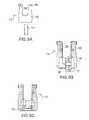
- FIGS. 4A and 4Bdepict perspective views of embodiments of bone fastener assembly rings.
- FIG. 5depicts a perspective view of an embodiment of a bone fastener assembly collar.
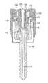
- FIG. 6depicts a cross-sectional view of an embodiment of a bone fastener assembly.
- FIG. 7depicts a perspective view of an embodiment of a bone fastener assembly.
- FIGS. 8A-8Cdepict schematic views of a method of positioning a ring in a collar of a bone fastener assembly.
- FIGS. 9A-9Cdepict schematic views of a method of positioning a ring in a collar of a bone fastener assembly.
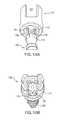
- FIGS. 10A and 10Bdepict schematic views of positioning a bone fastener in a ring and collar to form a bone fastener assembly.
- FIG. 11depicts a front view of an embodiment of a bone fastener assembly with a collar that allows for angulation of a bone fastener relative to the collar in a conical range of motion that is symmetrical relative to an axis that passes through a central axis of the collar and a central axis of a bone fastener.
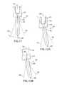
- FIG. 12Adepicts a front view of an embodiment of a bone fastener assembly with a collar that allows for angulation of a bone fastener relative to the collar in a conical range of motion that is not symmetrical relative to an axis that passes through a central axis of the collar and a central axis of a bone fastener.
- the collarallows additional lateral bias relative to a non-biased collar.
- FIG. 12Bdepicts a side view of an embodiment of a bone fastener assembly with a collar that allows for angulation of a bone fastener relative to the collar in a conical range of motion that is not symmetrical relative to an axis that passes through a central axis of the collar and a central axis of a bone fastener.
- the collarallows additional caudal or cephalid bias relative to a non-biased collar.
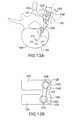
- FIG. 13Adepicts a schematic side view representation of embodiments of bone fastener assemblies positioned in vertebrae.
- FIG. 13Bdepicts a schematic top view representation of an embodiment of a single-level spinal stabilization system.
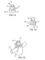
- FIG. 14depicts a perspective view of an embodiment of a closure member.
- FIG. 15depicts a cross-sectional representation of the closure member taken substantially along plane 15 - 15 indicated in FIG. 14 .
- FIG. 16depicts a perspective view of an embodiment of a portion of a spinal stabilization system.
- FIG. 17Adepicts a cross-sectional representation of an embodiment of a spinal stabilization system.
- FIG. 17Bdepicts a detailed view of a portion of FIG. 17A .
- FIG. 18Adepicts a cross-sectional representation of an embodiment of a spinal stabilization system.
- FIG. 18Bdepicts a detailed view of a portion of FIG. 18A .
- FIG. 19depicts a perspective view of an embodiment of a targeting needle.
- FIG. 20depicts a perspective view of an outer housing of a targeting needle.
- FIG. 21depicts a perspective view of an embodiment of a member of a targeting needle.
- FIG. 22depicts a perspective view of an embodiment of a guide wire.
- FIG. 23depicts a perspective view of an embodiment of a guide wire.
- FIG. 24depicts a perspective view of an embodiment of a bone awl.
- FIG. 25depicts a perspective view of an embodiment of a bone tap.
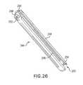
- FIG. 26depicts a perspective view of an embodiment of a multi-channel sleeve.
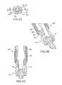
- FIG. 27depicts a top view of an embodiment of a multi-channel sleeve with a bone fastener assembly coupled to the sleeve.
- FIG. 28depicts a cross-sectional representation of a portion of the sleeve with the bone fastener assembly taken substantially along line 28 - 28 of FIG. 27 .
- FIG. 29depicts a cross-sectional representation of a portion of the sleeve with the bone fastener assembly taken substantially along line 29 - 29 of FIG. 27 .
- FIG. 30depicts a perspective view of an embodiment of a single-channel sleeve.
- FIG. 31depicts a perspective view of an embodiment of a sleeve during connection of the sleeve to a collar of a bone fastener assembly.
- FIG. 31Adepicts a detailed view of a portion of FIG. 31 .
- FIG. 32depicts a partial cross-sectional representation of an embodiment of a sleeve coupled to a collar of a bone fastener assembly.
- FIG. 33depicts a partial cross-sectional representation of an embodiment of a sleeve coupled to a collar of a bone fastener assembly.
- FIG. 34depicts a partial cross-sectional representation of an embodiment of a sleeve coupled to a collar of a bone fastener assembly.
- FIG. 35depicts a partial cross-sectional representation of an embodiment of a sleeve coupled to a collar of a bone fastener assembly.
- FIG. 36depicts top view representation of an embodiment of a collar.
- FIG. 37depicts a partial cross-sectional representation of an embodiment of a sleeve coupled to an embodiment of a collar of a bone fastener assembly, such as the collar depicted in FIG. 36 .
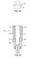
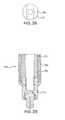
- FIG. 38depicts a top view representation of an embodiment of a collar.
- FIG. 39depicts a partial cross-sectional representation of an embodiment of a sleeve coupled to an embodiment of a collar of a bone fastener assembly, such as the collar depicted in FIG. 38 .
- FIG. 40depicts a partial cross-sectional view of an embodiment of a sleeve with an inner sleeve.
- FIG. 41depicts a partial cross-sectional representation of an embodiment of a sleeve coupled to a collar of a bone fastener assembly.
- FIG. 42depicts a partial cross-sectional representation of an embodiment of a sleeve coupled to a collar of a bone fastener assembly.
- FIG. 43depicts a partial cross-sectional representation of an embodiment of a sleeve coupled to a collar of a bone fastener assembly.
- FIG. 44depicts a cross-sectional representation of an embodiment of a hinged sleeve coupled to a collar of a bone fastener assembly.
- FIG. 45depicts a cross-sectional representation of an embodiment of a hinged sleeve coupled to a collar of a bone fastener assembly.
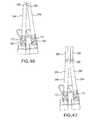
- FIG. 46depicts a schematic representation of sleeve embodiments coupled to collars of a spinal stabilization system.
- FIG. 47depicts a schematic representation of sleeve embodiments with connections that allow relative movement of portions of a sleeve.
- FIG. 48depicts a perspective view of an embodiment of sleeves coupled to bone fastener assemblies.
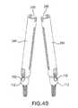
- FIG. 49depicts a perspective view of an embodiment of sleeves that are coupled to bone fastener assemblies.
- FIG. 50depicts a schematic view of sleeve embodiments that are coupled to an embodiment of a frame.
- FIG. 51depicts a perspective view of an embodiment of a driver coupled to a bone fastener and a sleeve.
- FIG. 52depicts a partial cross-sectional view of an embodiment of a bone fastener and collar coupled to a driver positioned in a dilator.
- FIG. 53depicts a perspective view of an embodiment of a tissue wedge.
- FIG. 54depicts a perspective view of an embodiment of an estimating tool.
- FIG. 55depicts a perspective view of an embodiment of an estimating tool.
- FIG. 56depicts a perspective view of an embodiment of an estimating tool.
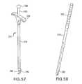
- FIG. 57depicts a perspective view of a tool designed to position an elongated member proximate vertebrae.
- FIG. 58depicts a perspective view of a seater for placing an elongated member proximate vertebrae.
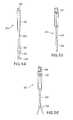
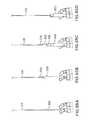
- FIGS. 59A and 59Bdepict perspective views of a tool designed to position a closure member in a collar coupled to a bone fastener.
- FIGS. 60A and 60Bdepict perspective views of a tool designed to position a closure member in a collar coupled to a bone fastener.
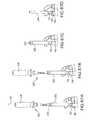
- FIG. 61depicts an embodiment of a counter torque wrench coupled to a sleeve.
- FIG. 62depicts an embodiment of a counter torque wrench.
- FIG. 63depicts a schematic view of the counter torque wrench shown in FIG. 62 coupled to an elongated member.
- FIGS. 64A-64Edepict schematic views of guide wire placement during a minimally invasive spinal stabilization procedure.
- FIGS. 65A-65Ddepict schematic views of tissue dilation during a minimally invasive spinal stabilization procedure.
- FIGS. 66A-66Fdepict schematic views of vertebra preparation for receiving a bone fastener assembly during a minimally invasive spinal stabilization procedure.
- FIGS. 67A-67Ddepict schematic views of insertion of a sleeve and bone fastener assembly during a minimally invasive spinal stabilization procedure.
- FIGS. 68A-68Ddepict schematic views of tissue plane creation during a minimally invasive spinal stabilization procedure.
- FIG. 69depicts an embodiment of a tissue wedge.
- FIGS. 70A-70Ddepict schematic views of placement of a sleeve and a bone fastener assembly in second vertebra during a minimally invasive spinal stabilization procedure.
- FIG. 71depicts a tissue plane between adjacent vertebrae with anchored sleeves crossing at the surface of the skin.
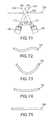
- FIG. 72depicts an embodiment of an elongated member.
- FIG. 73depicts an embodiment of an elongated member.
- FIG. 74depicts an embodiment of an elongated member.
- FIG. 75depicts an embodiment of an elongated member.
- FIGS. 76A-76Ddepict schematic views of elongated member placement during a minimally invasive spinal stabilization.
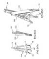
- FIG. 77depicts a perspective view of a distal portion of a two-pronged driver.
- FIGS. 78A-78Ddepict schematic views of a sleeve removal during a minimally invasive spinal stabilization procedure.
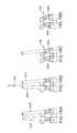
- FIGS. 79A-79Edepict schematic views of elongated member placement in sleeves for a multi-level spinal stabilization system.
- FIGS. 80A-80Cdepict schematic views of bone fastener assemblies coupled to sleeves.
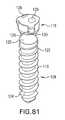
- FIG. 81depicts a perspective view of a bone fastener used in an invasive procedure.
- a spinal stabilization systemmay be installed in a patient to stabilize a portion of a spine.
- Spinal stabilizationmay be used, but is not limited to use, in patients having degenerative disc disease, spinal stenosis, spondylolisthesis, pseudoarthrosis, and/or spinal deformities; in patients having fracture or other vertebral trauma; and in patients after tumor resection.
- a spinal stabilization systemmay be installed using a minimally invasive procedure.
- An instrumentation setmay include instruments and spinal stabilization system components for forming a spinal stabilization system in a patient.
- a minimally invasive proceduremay be used to limit an amount of trauma to soft tissue surrounding vertebrae that are to be stabilized.
- the natural flexibility of skin and soft tissuemay be used to limit the length and/or depth of an incision or incisions needed during the stabilization procedure.
- Minimally invasive proceduresmay provide limited direct visibility in vivo. Forming a spinal stabilization system using a minimally invasive procedure may include using tools to position system components in the body.
- a minimally invasive proceduremay be performed after installation of one or more spinal implants in a patient.
- the spinal implant or spinal implantsmay be inserted using an anterior procedure and/or a lateral procedure.
- the patientmay be turned and a minimally invasive procedure may be used to install a posterior spinal stabilization system.
- a minimally invasive procedure for stabilizing the spinemay be performed without prior insertion of one or more spinal implants in some patients.
- a minimally invasive proceduremay be used to install a spinal stabilization system after one or more spinal implants are inserted using a posterior spinal approach.
- a spinal stabilization systemmay be used to achieve rigid pedicle fixation while minimizing the amount of damage to surrounding tissue.
- a spinal stabilization systemmay be used to provide stability to two adjacent vertebrae (i.e., one vertebral level).
- a spinal stabilization systemmay include two bone fastener assemblies. One bone fastener assembly may be positioned in each of the vertebrae to be stabilized. An elongated member may be coupled and secured to the bone fastener assemblies. As used herein, “coupled” components may directly contact each other or may be separated by one or more intervening members.
- a single spinal stabilization systemmay be installed in a patient.
- Such a systemmay be referred to as a unilateral, single-level stabilization system or a single-level, two-point stabilization system.
- two spinal stabilization systemsmay be installed in a patient on opposite sides of a spine.
- Such a systemmay be referred to as a bilateral, single-level stabilization system or a single-level, four-point stabilization system.
- a spinal stabilization systemmay provide stability to three or more vertebrae (i.e., two or more vertebral levels).
- the spinal stabilization systemmay include three bone fastener assemblies.
- One bone fastener assemblymay be positioned in each of the vertebrae to be stabilized.
- An elongated membermay be coupled and secured to the three bone fastener assemblies.
- a single two-level spinal stabilization systemmay be installed in a patient.
- Such a systemmay be referred to as a unilateral, two-level stabilization system or a two-level, three-point stabilization system.
- two three-point spinal stabilization systemsmay be installed in a patient on opposite sides of a spine.
- Such a systemmay be referred to as a bilateral, two-level stabilization system or a two-level, six-point stabilization system.
- combination systemsmay be installed.
- a two-point stabilization systemmay be installed on one side of a spine, and a three-point stabilization system may be installed on the opposite side-of the spine.
- the composite systemmay be referred to a five-point stabilization system.
- Minimally invasive proceduresmay reduce trauma to soft tissue surrounding vertebrae that are to be stabilized. Only a small opening may need to be made in a patient.
- the surgical proceduremay be performed through a 2 cm to 4 cm incision formed in the skin of the patient.
- the incisionmay be above and substantially between the vertebrae to be stabilized.
- the incisionmay be above and between the vertebrae to be stabilized.
- the incisionmay be above and substantially halfway between the vertebrae to be stabilized.
- Dilators, a targeting needle, and/or a tissue wedgemay be used to provide access to the vertebrae to be stabilized without the need to form an incision with a scalpel through muscle and other tissue between the vertebrae to be stabilized.
- a minimally invasive proceduremay reduce an amount of post-operative pain felt by a patient as compared to invasive spinal stabilization procedures.
- a minimally invasive proceduremay reduce recovery time for the patient as compared to invasive spinal procedures.
- Components of spinal stabilization systemsmay be made of materials including, but not limited to, titanium, titanium alloys, stainless steel, ceramics, and/or polymers. Some components of a spinal stabilization system may be autoclaved and/or chemically sterilized. Components that may not be autoclaved and/or chemically sterilized may be made of sterile materials. Components made of sterile materials may be placed in working relation to other sterile components during assembly of a spinal stabilization system.
- Spinal stabilization systemsmay be used to correct problems in lumbar, thoracic, and/or cervical portions of a spine.
- Various embodiments of a spinal stabilization systemmay be used from the C1 vertebra to the sacrum.
- a spinal stabilization systemmay be implanted posterior to the spine to maintain distraction between adjacent vertebral bodies in a lumbar portion of the spine.
- FIG. 1depicts an embodiment of spinal stabilization system 100 that may be implanted using a minimally invasive surgical procedure.
- Spinal stabilization system 100may include bone fastener assemblies 102 , elongated member 104 , and/or closure members 106 .
- Other spinal stabilization system embodimentsmay include, but are not limited to, plates, dumbbell-shaped members, and/or transverse connectors.
- FIG. 1depicts a spinal stabilization system for one vertebral level.
- the spinal stabilization system of FIG. 1may be used as a multi-level spinal stabilization system if one or more vertebrae are located between the vertebrae in which bone fastener assemblies 102 are placed.
- multi-level spinal stabilization systemsmay include additional bone fastener assemblies to couple to one or more other vertebrae.
- FIG. 2depicts a perspective view of bone fastener assembly 102 .
- FIG. 3 , FIGS. 4A and 4B , and FIG. 5depict embodiments of bone fastener assembly components.
- Components of bone fastener assembly 102may include, but are not limited to, bone fastener 108 (shown in FIG. 3 ), ring 110 (shown in FIGS. 4A and 4B ), and collar 112 (shown in FIG. 5 ).
- Bone fastener 108may couple bone fastener assembly 102 to a vertebra.
- Ring 110may be positioned between a head of bone fastener 108 and collar 112 .
- FIG. 6depicts a cross-sectional representation of bone fastener 108 , ring 110 , and collar 112 of bone fastener assembly 102 .
- Bone fastener 108 of bone fastener assembly 102may include passage 114 .
- Bone fastener 108may be cannulated (i.e., passage 114 may run through the full length of the bone fastener).
- a guide wiremay be placed through passage 114 so that bone fastener 108 may be inserted into a vertebra at a desired location and in a desired angular orientation relative to the vertebra with limited or no visibility of the vertebra
- a bone fastener assemblymay be a fixed angle fastener.
- FIG. 7depicts an embodiment of a fixed angle bone fastener.
- Collar and bone fastenermay be formed as a unitary piece of metal.
- a fixed angle fastenermay be positioned as the first bone fastener assembly inserted into a vertebra.
- a bone fastenermay be, but is not limited to, a bone screw, a ring shank fastener, a barb, a nail, a brad, or a trocar.
- Bone fasteners and/or bone fastener assembliesmay be provided in various lengths in an instrumentation set to accommodate variability in vertebral bodies.
- an instrumentation set for stabilizing vertebrae in a lumbar region of the spinemay include bone fastener assemblies with lengths ranging from about 30 mm to about 75 mm in 5 mm increments.
- a bone fastener assemblymay be stamped with indicia (i.e., printing on a side of the collar).
- a bone fastener assembly or a bone fastenermay be color-coded to indicate a length of the bone fastener.
- a bone fastener with a 30 mm thread lengthmay have a magenta color
- a bone fastener with a 35 mm thread lengthmay have an orange color
- a bone fastener with a 55 mm thread lengthmay have a blue color.
- Other colorsmay be used as desired.
- Each bone fastener provided in an instrumentation setmay have substantially the same thread profile and thread pitch.
- the threadmay have about a 4 mm major diameter and about a 2.5 mm minor diameter with a cancellous thread profile.
- the minor diameter of the threadmay be in a range from about 1.5 mm to about 4 mm or larger.
- the major diameter of the threadmay be in a range from about 3.5 mm to about 6.5 mm or larger.
- Bone fasteners with other thread dimensions and/or thread profilesmay also be used.
- a thread profile of the bone fastenersmay allow bone purchase to be maximized when the bone fastener is positioned in vertebral bone.
- FIG. 3depicts an embodiment of bone fastener 108 .
- Bone fastener 108may include shank 116 , head 118 , and neck 120 .
- Shank 116may include threading 122 .
- threading 122may include self-tapping start 124 .
- Self-tapping start 124may facilitate insertion of bone fastener 108 into vertebral bone.
- Head 118 of bone fastener 108may include various configurations to engage a driver that inserts the bone fastener into a vertebra.
- the drivermay also be used to remove an installed bone fastener from a vertebra.
- head 118may include one or more tool portions 126 .
- Tool portions 126may be recesses and/or protrusions designed to engage a portion of the driver.
- bone fastener 108may be cannulated for use in a minimally invasive procedure.
- Head 118 of bone fastener 108may include one or more splines 128 , as depicted in FIG. 3 .
- head 118may include three splines.
- Splines 128may be equally spaced circumferentially around head 118 of bone fastener 108 .
- splines 128may be spaced at unequal distances circumferentially around head 118 .
- Splines 128may include various surface configurations and/or texturing to enhance coupling of bone fastener 108 with a ring of a bone fastener assembly.
- sides of the splinesmay be tapered so that the splines form a dovetail connection with a ring.
- spline widthmay be tapered so that a good interference connection is established when the bone screw is coupled to a ring.
- Splines 128may include one or more projections 130 to facilitate coupling bone fastener 108 with an inner surface of a ring.
- projections 130may be positioned on a lower portion of splines 128 .
- the splinesmay include recessed surfaces that accept projections extending from surfaces of the ring.
- Neck 120 of bone fastener 108may have a smaller diameter than adjacent portions of head 118 and shank 116 .
- the diameter of neck 120may fix the maximum angle that the collar of the bone fastener assembly can be rotated relative to bone fastener 108 .
- neck 120may be sized to allow up to about 40.degree. or more of angulation of the collar relative to the bone fastener.
- the neckmay be sized to allow up to about 30.degree. of angulation of the collar relative to the bone fastener.
- the neckmay be sized to allow up to about 20.degree. of angulation of the collar relative to the bone fastener
- FIGS. 4A and 4Bdepict perspective views of embodiments of ring 110 .
- Outer surface 132 of ring 110may have a contour that substantially complements a contour of an inner surface of a collar in which the ring resides.
- a contour of the outer surface of the ringmay be a spherical portion.
- Outer surface 132 of ring 110may have a smooth finish.
- outer surface 132may be surface treated or include coatings and/or coverings. Surface treatments, coatings, and/or coverings may be used to adjust frictional and/or wear properties of the outer surface of the ring.
- a portion of the outer surface of the ringmay be shaped and/or textured to limit a range of motion of the collar relative to a bone fastener of a bone fastener assembly.
- An inner surface of ring 110may include one or more grooves 134 and/or one or more seats 136 .
- Seats 136may be circumferentially offset from grooves 134 .
- Grooves 134may be sized to allow passage of splines of a bone fastener (e.g., splines 128 shown in FIG. 3 ) through the ring.
- a bone fastenere.g., splines 128 shown in FIG. 3
- projectionse.g., projections 130 in FIG. 3
- Passage of the projections over ridges 138may securely couple the bone fastener to the ring and inhibit separation of the ring from the bone fastener.
- a number of grooves 134 and a number of seats 136may equal a number of splines 128 on a head of a bone fastener.
- Seats 136 and grooves 134may be equally spaced circumferentially around the inner surface of ring 110 .
- seats 136may be circumferentially offset about 60.degree. from grooves 134 .
- a ringmay be a complete ring without a split or slots.
- a ringmay include a split or slots to facilitate insertion of the ring into a collar.
- FIG. 4Bdepicts a ring with a split.
- a ring with a split and/or slotsmay be compressed to ease insertion into a collar. Once positioned in the collar, the ring may expand to its original uncompressed dimensions, thus inhibiting removal from the collar.
- the term “collar”includes any element that wholly or partially encloses or receives one or more other elements.
- a collarmay enclose or receive elements including, but not limited to, a bone fastener, a closure member, a ring, and/or an elongated member.
- a collarmay couple two or more other elements together (e.g., an elongated member and a bone fastener).
- a collarmay have any of various physical forms.
- a collarmay have a “U” shape, however it is to be understood that a collar may also have other shapes.
- a collarmay be open or closed.
- a collar having a slot and an open topsuch as collar 112 shown in FIG. 2 and in FIG. 5 , may be referred to as an “open collar.”
- a bone fastener assembly that includes an open collarmay be referred to as an “open fastener.”
- an elongated membermay be top loaded into the open fastener.
- a closure membermay be coupled to the collar to secure the elongated member to the open fastener.
- a collar that does not include a slot and an open topmay be referred to as a “closed collar,”
- a spinal implant that includes a closed collarmay be referred to as a “closed implant.”
- a closed collarmay include an aperture, bore, or other feature in side surfaces for accommodating other components of a stabilization system (e.g., an elongated member).
- a setscrewmay be used to securely couple an elongated member to a closed implant.
- Collar 112may include body 140 and arms 142 . Arms 142 may extend from body 140 . Body 140 of collar 112 may be greater in width than a width across arms 142 of collar 112 (i.e., body 140 may have a maximum effective outer diameter greater than a maximum effective outer diameter of arms 142 ). A reduced width across arms 142 may allow a detachable member to be coupled to the arms without substantially increasing a maximum effective outer diameter along a length of collar 112 . Thus, a reduced width across arms 142 may reduce bulk at a surgical site.
- a height of body 140may range from about 3 millimeters (mm) to about 7 mm. In an embodiment, a height of body 140 is about 5 mm.
- Body 140may include opening 144 in a lower surface of the body. To inhibit passage of a ring from collar 112 , opening 144 may be smaller than an outer diameter of the ring.
- Inner surface 146may be machined to complement a portion of an outer surface of a ring that is to be positioned in collar 112 . Machining of inner surface 146 may enhance retention of a ring in collar 112 .
- Inner surface 146 of body 140may be complementary in shape to a portion of outer surface 132 of ring 110 (see FIG. 4 ) so that the ring is able to swivel in the collar.
- Inner surfaces and/or outer surfaces of collar 112may be surface treated or include coatings and/or coverings to modify frictional properties or other properties of the collar.
- Inner surfaces of arms 142may include modified thread 148 .
- Modified threads 148may engage complementary modified threads of a closure member to secure an elongated member to a bone fastener assembly.
- Modified threads 148may have a constant pitch or a variable pitch.
- a height and a width of arms 142may vary. Arms 142 may range in height from about 8 mm to about 15 mm. In an embodiment, a height of arms 142 is about 11 mm. A width (i.e., effective diameter) of arms 142 may range from about 5 mm to 14 mm. Arms 142 and body 140 may form slot 150 . Slot 150 may be sized to receive an elongated member. Slot 150 may include, but is not limited to, an elongated opening of constant width, an elongated opening of variable width, a rectangular opening, a trapezoidal opening, a circular opening, a square opening, an ovoid opening, an egg-shaped opening, a tapered opening, and combinations and/or portions thereof.
- a first portion of slot 150may have different dimensions than a second portion of slot 150 .
- a portion of slot 150 in first arm 142may have different dimensions than a portion of slot 150 in second arm 142 .
- arms 142 of collar 112may include one or more openings and/or indentions 152 .
- Indentions 152may vary in size and shape (e.g., circular, triangular, rectangular). Indentions 152 may be position markets and/or force application regions for instruments that perform reduction, compression, or distraction of adjacent vertebrae. In some embodiments, openings and/or indentions may be positioned in the body of the collar.
- Arms 142may include ridges or flanges 154 .
- Flange 154may allow collar 112 to be coupled to a detachable member so that translational motion of the collar relative to the detachable member is inhibited.
- Flanges 154may also include notches 156 .
- a movable member of a detachable membermay extend into notch 156 . When the movable member is positioned in notch 156 , a channel in the detachable member may align with a slot in collar 112 . With the movable member positioned in notch 156 , rotational movement of collar 112 relative to the detachable member may be inhibited.
- FIGS. 8A-8Cshow views of collar 112 and ring 110 during top loading insertion of the ring into the collar.
- Ring 110may be positioned as shown in FIG. 8A and inserted past arms 142 into body 140 .
- FIG. 8Bdepicts a cross-sectional view of ring 110 and collar 112 after insertion of the ring into the collar through slot 150 .
- the ringmay be rotated so that a bone fastener may be positioned through the ring.
- FIG. 8Cdepicts a cross-sectional view of ring 110 and collar 112 after rotation of the ring in the collar.
- FIGS. 9A-9Cshow views of collar 112 and ring 110 during bottom loading insertion of the ring into the collar.
- Ring 110may be positioned as shown in FIG. 9A and inserted into body 140 through an opening in the bottom of collar 112 .
- ring 110may be inserted into body 140 through a groove or a slot in the bottom of collar 112 .
- collar 112 designed for bottom insertion of ring 110may have narrower slot 150 than a collar designed for top insertion of a ring.
- Collar 112 with narrower slot 150may allow an elongated member with a reduced diameter to be used in a spinal stabilization system.
- Collar 112 with narrower slot 150may be used to reduce bulk at a surgical site.
- FIG. 9Bdepicts a cross-sectional view of ring 110 and collar 112 after insertion of the ring into the collar through the opening in the bottom of the collar.
- the ringmay be rotated so that a bone fastener may be positioned through the ring.
- Tolerance between an outer surface of ring 110 and an inner surface of body 140 shown in FIGS. 8A-8C and 9 A- 9 Cmay require force to be applied to the ring to drive the ring into the body.
- the ringOnce ring 110 is positioned in body 140 , the ring may expand slightly. In certain embodiments, significant force may be required to remove ring 110 from body 140 (i.e., the ring may be substantially unreleasable from the body). The required force may inhibit unintentional removal of ring 110 from body 140 .
- FIG. 9Cdepicts a cross-sectional view of ring 110 and collar 112 after rotation of the ring in the collar.
- FIG. 10Adepicts bone fastener 108 before insertion of the bone fastener into ring 110 positioned in collar 112 .
- Splines 128may be aligned with grooves 134 to allow passage of head 118 through ring 110 and into collar 112 .
- FIG. 10Bdepicts bone fastener 108 , ring 110 , and collar 112 after the bone fastener has been rotated and head 118 has been coupled to seats in the ring to form bone fastener assembly 102 .
- Inserting bone fastener 108 through opening 144 in collar 112may allow use of bone fasteners that have shanks and/or heads with larger diameters than can pass through slot 150 .
- Bone fasteners with large diameter shanksmay form a bone fastener assembly (threaded or otherwise) that securely fastens to vertebral bone during use.
- a bone fastenermay be rotatably positioned in a collar such that the bone fastener is able to move radially and/or rotationally relative to the collar (or the collar relative to the bone fastener) within a defined range of motion.
- the range of motionmay be provided within a plane, such as by a hinged connection, or within a three-dimensional region, such as by a ball and socket connection. Motion of the bone fastener relative to the collar (or the collar relative to the bone fastener) may be referred to as “angulation” and/or “polyaxial movement”.
- FIG. 11depicts bone fastener assembly 102 with central axis 158 of collar 112 aligned with central axis 160 of bone fastener 108 .
- Bone fastener 108may be angulated in a symmetrical conical range of motion characterized by angle .alpha. about the aligned axes. Bone fastener 108 may be constrained from motion outside of limit axis 162 by contact between neck 120 of bone fastener 108 and collar 112 . Alignment of axis 160 of bone fastener 108 with central axis 158 of collar 112 may be considered a neutral position relative to the range of motion. The alignment is a neutral position because bone fastener 108 may be angulated an equal amount in any direction from central axis 158 . When a driver is inserted into bone fastener 108 , axis 160 of bone fastener 108 may be substantially aligned with axis 158 of collar 112 to facilitate insertion of the bone fastener into a vertebral body.
- a range of motion of a collarmay be skewed from a full conical range of motion relative to aligned central axes of the collar and a bone fastener coupled to the collar.
- a distal end of a collarmay be shaped to skew, or bias, the range of motion from the range of motion depicted in FIG. 11 .
- FIGS. 12A and 12Bdepict bone fastener assemblies 102 with biased collars 112 .
- Body 140 of biased collar 112may be shaped to restrict relative movement of bone fastener 108 (and/or the collar) to a skewed conical range of motion defined by limit axes 162 . As depicted by limit axes 162 in FIG.
- a first arm 142 of collar 112may approach bone fastener 108 more closely than a second arm of the collar.
- a first opening of the slot between arms 142 of collar 112may approach bone fastener 108 more closely than a second opening of the slot.
- biased collarsmay be designed to selectively restrict relative movement of collars and/or bone fasteners
- a biased collarmay be attached to a detachable member such that a surgeon performing a minimally invasive procedure may selectively align the portion of the collar with the greater range of motion as needed.
- the collar depicted in FIG. 12Bmay be coupled to a single-level (e.g., C-shaped) sleeve so that the side of the collar (i.e., the side of the slot) with a larger range of motion is positioned next to a channel opening of the sleeve.
- central axis 158 of collar 112may align with central axis 160 of bone fastener 108 to facilitate insertion of the bone fastener into bone.
- the bias of the collarmay be so large that a flexible drive member is needed to drive the bone fastener into bone.
- one or more biased collarsmay be used in a spinal stabilization system.
- the spinal stabilization systemsmay be single-level systems or multi-level systems. Biased collars may be used to accommodate the increasing angle of the pedicle corridor for each lumbar vertebra. The angle may increase by about 5 degrees for each successive lumbar vertebra.
- a bone fastener of bone fastener assembly 102 Amay engage pedicle 164 A at pedicle angle .phi.A relative to sagittal plane 168 .
- Pedicle angle .phi.Amay range between about 13.degree. and about 17.degree.
- Collar 112 A of bone fastener assembly 102 Amay be unbiased.
- Pedicle angle .phi.Bmay range between about 18.degree. and about 22.degree.
- Collar 112 Bmay have a bias angle .beta. of about 5.degree.
- Bone fastener assembly 102 Bmay engage pedicle 164 B at pedicle angle .phi.B.
- slots 150 A and 150 B in bone fastener assemblies 102 A and 102 B, respectively,may be generally aligned when both bone fasteners are in neutral positions.
- Angulation of either or both collars of the bone fastener assembliesmay allow fine adjustment of engagement angles of the bone fasteners.
- collar angulationmay allow adjustment in the orientation of bone fasteners in a sagittal plane (i.e., to conform to lordosis of a spine) while still allowing the collars to be easily coupled with elongated member 104 .
- Elongated member 104may be disposed in slots 150 A and 150 B and secured by closure members.
- a flexible driver or a polyaxial drivermay be used to drive the heads of the bone fasteners from a position that is off-axis from the bone fasteners to reduce the size of an opening of the body needed to implant the spinal stabilization system.
- a closure membermay be coupled to a collar of a bone fastener assembly to fix an elongated member positioned in the collar to the bone fastener assembly.
- a closure membermay be cannulated.
- a closure membermay have a solid central core.
- a closure member with a solid central coremay allow more contact area between the closure member and a driver used to couple the closure member to the collar.
- a closure member with a solid central coremay provide a more secure connection to an elongated member than a cannulated closure member by providing contact against the elongated member at a central portion of the closure member as well as near an edge of the closure member.
- FIG. 1depicts closure members 106 coupled to bone fastener assemblies 102 .
- FIG. 14depicts closure member 106 prior to insertion of the closure member into a collar of a bone fastener assembly.
- Closure member 106may include tool portion 170 and male modified thread 172 .
- Tool portion 170may couple to a tool that allows closure member 106 to be positioned in a collar.
- Tool portion 170may include various configurations (e.g., threads, hexalobular connections, hexes) for engaging a tool (ergo, a driver).
- Male modified thread 172may have a shape that complements the shape of a female modified thread in arms of a collar (e.g., modified thread 148 depicted in FIG. 5 ).
- FIG. 15depicts a cross-sectional representation of closure member 106 taken substantially along plane 15 - 15 of FIG. 14 .
- Closure member 106may include removal openings 174 .
- a drive toolmay be inserted into removal openings 174 to allow removal of closure member 106 after tool portion 170 has been sheared off.
- Removal openings 174may include any of a variety of features including, but not limited to, sockets, holes, slots, and/or combinations thereof. In an embodiment, removal openings 174 are holes that pass through bottom surface 176 of closure member 106 .
- a bottom surface of a closure membermay include structure and/or texturing that promotes contact between the closure member and an elongated member. A portion of the structure and/or texturing may enter and/or deform an elongated member when the closure member is coupled to the elongated member. Having a portion of the closure member enter and/or deform the elongated member may couple the elongated member to the closure member and a bone fastener assembly so that movement of the elongated member relative to the bone fastener assembly is inhibited.
- bottom surface 176 of closure member 106may include point 178 and rim 180 . In some embodiments, rim 180 may come to a sharp point.
- a height of rim 180may be less than a height of point 178 . In other embodiments, a height of rim 180 may be the same or larger than a height of point 178 . In some embodiments, rim 180 may not extend completely around the closure member. For example, eight or more portions of rim 180 may be equally spaced circumferentially around closure member 106 . In certain embodiments, a solid central core including point 178 and rim 180 may enhance the ability of closure member 106 to secure an elongated member in a collar.
- FIG. 16depicts a portion of a spinal stabilization system with closure member 106 coupled to collar 112 before tool portion 170 is sheared off.
- Closure member 106may couple to collar 112 by a variety of systems including, but not limited to, standard threads, modified threads, reverse angle threads, buttress threads, or helical flanges.
- a buttress thread on a closure membermay include a rearward-facing surface that is substantially perpendicular to the axis of the closure member.
- Closure member 106may be advanced into an opening in a collar to engage a portion of elongated member 104 . In some embodiments, closure member 106 may inhibit movement of elongated member 104 relative to collar 112 .
- FIG. 17Adepicts a cross-sectional view of closure member 106 coupled to bone fastener assembly 102 .
- Closure member 106may include male modified thread 172 .
- Male modified thread 172may include male distal surface 182 and male proximal surface 184 , as shown in FIG. 17B .
- Collar 112may include female modified thread 148 on an inside surface of arms 142 .
- Female modified thread 148may include female proximal surface 186 and female distal surface 188 .
- Male proximal surface 184may couple to female distal surface 188 during use.
- Male proximal surface 184 and female distal surface 188may be load-bearing surfaces.
- a loadmay result from an upward load on closure member 106 , such as a load resulting when elongated member 104 positioned in a slot of collar 112 is secured to bone fastener assembly 102 by closure member 106 .
- Raised portions 190 and recessed portions 192may be included on male distal surface 182 and female proximal surface 186 .
- Cooperating surfaces 194 of modified threads 172 and 148may contact or be proximate to one another during use. As used herein, “proximate” means near to or closer to one portion of a component than another portion of a component. Engagement of cooperating surfaces 194 of modified threads 172 and 148 during use may inhibit radial expansion of collar 112 . Engagement of cooperating surfaces 194 may inhibit spreading of arms 142 away from each other (i.e., inhibit separation of the arms). In some embodiments, cooperating surfaces 194 may be substantially parallel to a central axis of closure member 106 . In other embodiments, cooperating surfaces 194 may be angled relative to a central axis of closure member 106 .
- a proximal surface of a male modified threadmay include raised and recessed portions.
- FIG. 18Adepicts a cross-sectional view of bone fastener assembly 102 coupled to closure member 106 with raised and recessed portions on a proximal surface of male modified thread 172 .
- FIG. 18Bdepicts a cross-sectional view of raised portions 190 at male proximal surface 184 of male modified thread 172 and female distal surface 188 of female modified thread 148 .
- Male proximal surface 184may include an overall positive slope S such that point A near the top of male modified thread 172 is distal from point B at the base of the male modified thread.
- male proximal surface 184may include an overall negative slope or a slope of about zero.
- a bone fastener assembly and a closure membermay be coupled with a running fit.
- a running fiti.e., a fit in which parts are free to rotate
- Predictable loading characteristicsmay facilitate use of a closure member with a break-off portion designed to shear off at a predetermined torque.
- a running fitmay also facilitate removal and replacement of closure members.
- a closure membermay include an interference fit (e.g., crest-to-root radial interference).
- a position (i.e., axial position and angular orientation) of a modified thread of a collarmay be controlled, or “timed,” relative to selected surfaces of the collar.
- a modified thread formmay be controlled relative to a top surface of a collar and an angular orientation of the slots of the collar.
- positions of engaging structural elements of other coupling systemse.g., thread forms may be controlled.
- Controlling a position of a modified thread formmay affect a thickness of a top modified thread portion of a collar.
- top modified thread portion 196is the first modified thread portion to engage a closure member.
- a position of a modified thread formmay be selected such that the thickness of the leading edge of a top modified thread portion is substantially equal to the full thickness of the rest of the modified thread.
- Controlling a position of a modified thread form of a collarmay increase a combined strength of engaged modified thread portions for a collar of a given size (e.g., wall height, modified thread dimensions, and thread pitch). Controlling a position of the modified thread form may reduce a probability of failure of modified thread portions, and thus reduce a probability of coupling failure between a collar and a closure member. Controlling the position of a modified thread form in a collar of a bone fastener assembly may increase a combined strength of engaged collar and closure member modified thread portions such that failure of the modified thread portions does not occur prior to the intended shearing off of a tool portion of the closure member.
- a tool portion of a closure membermay be designed to shear off at about 90 in-lbs of torque, while the combined modified thread portions may be designed to withstand a torque on the closure member of at least 120 in-lbs.
- a thickness of a modified thread portion of a given size and profileis reduced below a minimum thickness, the modified thread portion may not significantly contribute to the holding strength of the modified thread of a collar.
- a position of a modified thread form of a collarmay be controlled such that a thickness of a top modified thread portion is sufficient for the portion to increase a holding strength of the collar.
- a top modified thread portionmay have a leading edge thickness of about 0.2 mm.
- a position of a modified thread form of a collarmay be selected to ensure that a closure member engages a selected minimum number of modified thread portions on each arm of the collar.
- at least two modified thread portions having a full thickness over width w of a collar armmay be engaged by a closure member at each arm.
- a closure membermay engage parts of three or more modified thread portions on each arm, with the total width of the portions equal to at least two full-width portions. Allowances may be made for tolerances in the components (e.g., diameter of the elongated member) and/or anticipated misalignment between the components, such as misalignment between an elongated member and a slot.
- a substantially equal number of modified thread portions in each armmay engage the closure member when an elongated member is coupled to a bone fastener assembly.
- Various instrumentsmay be used in a minimally invasive procedure to form a spinal stabilization system in a patient.
- the instrumentsmay include, but are not limited to, positioning needles, guide wires, dilators, bone awls, bone taps, sleeves, drivers, tissue wedges, elongated member length estimating tools, mallets, tissue retractors, and tissue dilators.
- the instrumentsmay be provided in an instrumentation set.
- the instrumentation setmay also include components of the spinal stabilization system.
- the components of the spinal stabilization systemmay include, but are not limited to, bone fastener assemblies of various sizes and/or lengths, elongated members, and closure members.
- Instruments used to install a spinal stabilization systemmay be made of materials including, but not limited to, stainless steel, titanium, titanium alloys, ceramics, and/or polymers. Some instruments may be autoclaved and/or chemically sterilized Some instruments may include components that cannot be autoclaved or chemically sterilized. Components of instruments that cannot be autoclaved or chemically sterilized may be made of sterile materials. The sterile materials may be placed in working relation to other parts of the instrument that have been sterilized.
- a targeting needlemay be used to locate an entry point in a vertebral body for a bone fastener of a bone fastener assembly.
- the targeting needlemay be a Jamshidi® bone marrow biopsy needle.
- FIG. 19depicts an embodiment of targeting needle 198 .
- Targeting needle 198may include outer housing 200 and member 202 .
- FIG. 20depicts an embodiment of outer housing 200 .
- Outer housing 200may include hollow shaft 204 and handle 206 .
- Scale markings 208may be printed, etched, or otherwise placed on hollow shaft 204 . Scale markings 208 may be used to approximate a length of a bone fastener needed for a vertebra.
- Handle 206may provide a grip that allows a user to manipulate the targeting needle.
- Handle 206may include threaded portion 210 . Threaded portion 210 may couple to threading on a portion of a targeting needle member to secure the member to outer housing 200 .
- FIG. 21depicts an embodiment of member 202 of a targeting needle.
- Member 202may include point 212 and cap 214 .
- Point 212may be placed through a hollow shaft of an outer housing of the targeting needle.
- Cap 214may include threading 216 .
- Member 202may be rotated relative to the outer housing to couple threading 216 with threading in a handle of the outer housing.
- the membermay be coupled to the outer housing by another type of connection system (e.g., by placement of a key in a keyway). With member 202 positioned in an outer housing, point 212 may extend from a distal end of a hollow shaft of the outer housing.
- Cap 214may be used as an impact surface for driving the targeting needle in bone.
- FIG. 22 and FIG. 23depict embodiments of guide wire 218 .
- Guide wire 218may be an 18-gauge K-wire.
- Guide wire 218may pass down a shaft of a targeting needle outer housing.
- a guide wiremay be from about 15 cm to about 65 cm in length.
- guide wires provided in an instrumentation setare about 46 cm in length.
- the length of guide wire 218may allow a surgeon and/or assistants to hold at least one portion of the guide wire at all times when the guide wire is inserted into vertebral bone, even during insertion, use, and removal of instruments along a length of the guide wire.
- a guide wire that can be held continuously during a surgical proceduremay inhibit removal or advancement of the guide wire from a desired position during a minimally invasive surgical procedure.
- a distal end of guide wire 218may include point 220 .
- Point 220may facilitate insertion of the distal end of guide wire 218 into vertebral bone.
- a distal end of guide wire 218may not be pointed. A position of an unpointed guide wire in bone may be easier to maintain during a spinal stabilization procedure.
- Dilatorsmay be used during a minimally invasive surgical procedure to push aside tissue and create space to access vertebral bone.
- four tissue dilators of increasing diametermay be used to establish sufficient working space to accommodate instruments and spinal stabilization system components.
- only three dilatorsmay be needed to form sufficient working space.
- Dilators in an instrumentation setmay increase in diameter incrementally by a selected amount. For example, outside diameters of dilators in an instrumentation set may increase sequentially by increments of about 0.5 mm.
- FIG. 24depicts an embodiment of bone awl 222 .
- Bone awl 222may include handle 224 , passage 226 , and tip 228 .
- Handle 224may provide a secure grip that allows a surgeon to breach cortical bone of a pedicle with tip 228 .
- a guide wire that is inserted in vertebral bone in a desired orientationmay be inserted through passage 226 that extends through bone awl 222 .
- Bone awl 222may be moved down the guide wire so that tip 228 contacts the pedicle.
- Bone awl 222may have a length that allows a guide wire positioned in vertebral bone to always be held in at least one location when the guide wire is placed through passage 226 in the needle.
- handle 224may be removable from a shaft of bone awl 222 so that the guide wire may always be held during use of the bone awl.
- a guide wiremay be removed, the bone awl may be used to breach cortical bone, and the guide wire may be reinserted.
- a small dilatormay be placed over the portion of the guide wire extending from the bone awl so that a first end of the dilator contacts the bone awl.
- a mallet or other impact devicemay be used against a second end of the dilator so that the bone awl breaches cortical bone of the vertebra. The dilator may be removed from the bone awl and contact with the guide wire may be reestablished.
- a bone tapmay be used to form a threaded passage of a desired depth through a pedicle and into a vertebral body.
- FIG. 25depicts an embodiment of tap 230 .
- Tap 230may include passage 232 , shaft 234 , removable handle 236 , flutes 238 , and indicia 240 .
- Passage 232may extend through a length of shaft 234 and removable handle 236 .
- a guide wire positioned in vertebral bonemay be inserted into a distal end of passage 232 so that tap 230 can be moved down the guide wire toward the bone.
- a proximal portion of shaft 234may include at least one flat portion that fits in a mating portion of removable handle 236 .
- Proximal end of shaft 234may also include a detent depression. The flat portion may allow for rotation of shaft 234 when removable handle 236 is rotated.
- An embodiment of removable handle 236may include spring-loaded release 242 . When spring-loaded release 242 is compressed (i.e., drawn upwards), a detent in removable handle 236 may be movable. When spring-loaded release 242 is not compressed, movement of the detent may be inhibited.
- the detent of the removable handlemay be positioned in the detent depression of shaft 234 to couple the shaft to the removable handle.
- a tap portion of tap 230may have a known length. As shown in FIG. 25 , a tap portion of tap 230 may have a length t. In some embodiments, t may be about 20 mm, about 40 mm, about 60 mm, or greater. For example, t may be about 45 mm.
- X-ray monitoring of a depth of a tap portion of known lengthmay allow a medical practitioner to assess a depth of a hole tapped in a bone.
- the holemay be tapped to accommodate a bone fastener of a desired length. In certain embodiments, a bone fastener may be chosen to accommodate a hole tapped to a desired depth.
- a guide wire positioned in vertebral bonemay be held near a top of a dilator inserted over the guide wire at a surgical site.
- a proximal end of the guide wiremay be positioned through a distal end of a passage in shaft 234 of tap 230 without a removable handle coupled to the shaft.
- a proximal portion of the guide wiremay be held when the proximal portion of the guide wire extends beyond the top of shaft 234 .
- a portion of the guide wiremay always be held during use of tap 230 .
- Shaft 234may be moved down the guide wire until the shaft contacts the vertebral bone.
- the guide wiremay be held near the top of shaft 234 and the guide wire may be positioned through passage 232 of removable handle 236 . When the guide wire extends out of passage 232 through removable handle 236 , the guide wire may be held above the removable handle.
- the handlemay be coupled to the shaft using spring-loaded release 242 .
- a first reading of indicia 240 relative to a proximal end of a dilatormay be taken when a first flute of flutes 238 is located at a pedicle.
- Tap 230may be rotated so that flutes 238 form a threaded opening through the pedicle and into a vertebral body.
- Flutes 238may have a diameter that is about 0.1 mm to about 0.7 mm less than a maximum thread flight of a bone fastener to be positioned in the threaded opening formed by the flutes.
- tapmay form a thread that is about 0.5 mm less than a maximum thread flight of a bone fastener to be positioned in the threaded opening formed by the flutes.
- a position of tap 230may be monitored using a fluoroscope.
- a second reading of indicia 240 relative to the dilatormay be taken.
- a length of a bone fastener to be inserted into the vertebral bodymay be estimated by taking the difference between the indicia readings.
- tap 230may be removed by rotating the tap until flutes 238 are disengaged from vertebral bone.
- Removable handle 236may be separated from shaft 234 , and the removable handle may be removed with the guide wire always held in at least one location. After removable handle 236 is removed from the guide wire, shaft 234 may be removed with the guide wire always held in at least one location.
- a detachable membermay be used as a guide to install bone fasteners of a bone fastener assembly in vertebral bone.
- a detachable membermay be coupled to a collar of a bone fastener assembly.
- a distal end of a detachable membermay be tapered or angled to reduce bulk at a surgical site. Instruments may be inserted into the detachable member to manipulate the bone fastener assembly. Movement of the detachable member may alter an orientation of a collar relative to a bone fastener of the bone fastener assembly.
- a detachable membermay be used as a retractor during a spinal stabilization procedure.
- a detachable member for a single-level vertebral stabilization systemmay include one or more channels in a wall of the detachable member to allow access to an adjacent vertebra.
- only single-channel detachable membersi.e., detachable members with a single channel in a wall of the detachable member
- one or more multi-channel detachable membersi.e., detachable members with two or more channels in a wall of the detachable member
- Channelsmay provide flexibility to or enhance flexibility of a multi-channel detachable member.
- a proximal portion of a multi-channel detachable membermay have a solid circumference.
- a region of solid circumference in a multi-channel detachable membermay enhance stability of the multi-channel detachable member.
- a multi-channel detachable membermay be longer than a single-channel detachable member.
- a detachable member used at a middle vertebra in a multi-level stabilization proceduremay be a multi-channel detachable member. Channels in a multi-channel detachable member may allow access to adjacent vertebrae from a middle vertebra.
- a detachable member used at an end vertebra of a multi-level stabilization systemmay be a single-channel detachable member or a multi-channel detachable member.
- a system for coupling a bone fastener assembly to a multi-channel detachable membermay include a limiter that inhibits spreading of arms of the detachable member to inhibit release of the bone fastener assembly from the detachable member.
- a channel in a wall of a detachable membermay allow access to a vertebra that is to be stabilized with a spinal stabilization system being formed.
- a single-channel detachable membermay be coupled to a bone fastener assembly to be inserted into vertebral bone of a first vertebra.
- the single-channel detachable membermay allow access to a second vertebra from the first vertebra.
- a multi-channel detachable membermay be coupled to a bone fastener assembly to be inserted into vertebral bone of a first vertebra.
- the multi-channel detachable membermay allow access from the first vertebra to adjacent vertebrae.
- Instrumentsmay access a bone fastener assembly through a passage in a detachable member.
- a channel in a wall of a detachable membermay extend a full length of the detachable member.
- a channel in a wall of a detachable membermay extend only a portion of the length of the detachable member.
- a channel in a wall of a detachable membermay extend 25%, 50%, 75%, 80%, 90%, 95% or more of the length of the detachable member.
- a channelmay extend to a distal end of a detachable member such that an elongated member inserted in the channel may pass from the detachable member into a slot of a collar of a bone fastener assembly coupled to the detachable member.
- a channel in a detachable membermay be any of a variety of shapes.
- a channelmay have a width that exceeds a width (e.g., a diameter) of an elongated member that is to be inserted in the channel.
- a channelmay be a linear opening parallel to a longitudinal axis of the detachable member.
- a channelmay have a non-linear shape including, but not limited to, a helical pattern, an arc, an “L” shape, or an “S” shape.
- a non-linear channelmay allow an elongated member to travel along a predetermined path.
- adjacent detachable membersmay include channels with matching profiles, allowing ends of an elongated member to follow similar paths down the detachable member channels.
- Movable membersmay extend through portions of a detachable member proximate a channel in the detachable member. Movable members may engage notches in a collar to establish a radial orientation of the detachable member on the collar and/or to inhibit rotation of the collar relative to the detachable member.
- a distal end of a movable membermay be flat, curved, or angled. In some embodiments, a distal end of a movable member may be threaded. In other embodiments, a distal end of a movable member may be a projection that engages an opening in a collar.
- an upper surface of a collar and/or a surface of a distal end of a movable membermay be textured to inhibit rotation of the collar relative to the detachable member.
- a proximal end of a movable membermay include a tool engaging portion.
- a tool engaging portionmay include, but is not limited to, a hex section, a hexalobular section, a tapered section, a bead, a knot, a keyed opening, a coating, a threading, and/or a roughened surface for engaging a drive that rotates or otherwise displaces the movable member.
- a cross section transverse to a longitudinal axis of a detachable membermay have shapes including, but not limited to, circular, ovoid, square, pentagonal, hexagonal, and combinations thereof.
- a detachable membermay be hollow.
- a thickness of a hollow detachable membermay be uniform.
- a thickness of a hollow detachable membermay vary along the length of the detachable member.
- a detachable member with a passage extending longitudinally from a first end of the detachable member to a second end of the detachable membermay be referred to as a “sleeve”.
- FIG. 26depicts an embodiment of sleeve 244 .
- Sleeve 244may be a multi-channel sleeve.
- Sleeve 244may include wall 246 , channels 248 , passage 250 , movable members 252 , and flange 254 .
- Channels 248may extend from a distal end of sleeve 244 through a portion of wall 246 .
- Channels 248may allow instruments to be positioned and used to form a plane through soft tissue to one or more adjacent vertebrae.
- An elongated membermay be inserted in the tissue plane and positioned in collars of bone fastener assemblies anchored in vertebrae and coupled to sleeves.
- Passage 250may allow instruments to be positioned and used to manipulate a bone fastener assembly that is coupled to a distal end of sleeve 244 .
- Movable members 252may be part of a system that couples a bone fastener assembly to sleeve 244 .
- movable members 252may include tool engaging portion 256 .
- a drivermay be positioned in tool portion 256 .
- the drivere.g., a hex wrench
- a distal end of sleeve 244may include flange 254 that mates with a complementary flange on a collar of a bone fastener assembly.
- a distal end of sleeve 244may be tapered to reduce bulk (e.g., reduce spin diameter) at a surgical site.
- FIG. 27depicts a top view of an embodiment of sleeve 244 coupled to a bone fastener assembly.
- Tool portion 126 of bone fastener 108is a hexalobular connection.
- FIG. 28depicts a cross-sectional representation of a portion of sleeve 244 with bone fastener assembly 102 taken substantially along line 28 - 28 of FIG. 27 .
- Flange 254 of sleeve 244may mate with flange 154 of collar 112 to inhibit translation of the sleeve relative to the collar.
- Sleeve 244may also include stop 258 . Stop 258 may engage a portion of collar 112 to inhibit separation of walls 246 . During use, stop 258 may inhibit undesired separation of bone fastener assembly 102 from sleeve 244 .
- FIG. 29depicts a cross-sectional representation of a portion of sleeve 244 with bone fastener assembly 102 and elongated member 104 taken substantially along line 29 - 29 of FIG. 27 .
- Distal ends of movable members 252may extend into notches (e.g., notches 156 depicted in FIG. 5 ) in collar 112 .
- Portions of walls 246 of sleeve 244may include threading.
- Portions of movable members 252may include threading complementary to threaded portions of walls 246 . Threading of movable members 252 may engage threading in walls 246 such that rotation of the movable members advances or retracts the movable members relative to the walls.
- collar 112may be designed such that elongated member 104 lies below a distal end of sleeve 244 . Coupling sleeve 244 to collar 112 above elongated member 104 may reduce bulk at a surgical site. With elongated member 104 coupled to collar 112 below a distal end of sleeve 244 , the sleeve may be removed without interference from the elongated member of a spinal stabilization system.
- FIG. 30depicts an embodiment of sleeve 244 .
- Sleeve 244may be a single-channel sleeve for use in single-level or multi-level spinal stabilization procedures.
- Sleeve 244may be used at the outermost vertebrae to be stabilized during installation of a multi-level vertebral stabilization system.
- Sleeve 244may be coupled to a collar of a bone fastener assembly with movable members 252 and/or flange 254 .
- Instrumentsmay be inserted through passage 250 of sleeve 244 to access an anchored bone fastener assembly coupled to the sleeve.
- An instrumentmay be moved through channel 248 toward an adjacent vertebra to form a tissue plane in soft tissue between sleeve 244 and the adjacent vertebra.
- a sleevemay be coupled to a bone fastener assembly in various ways to inhibit movement of the sleeve relative to a collar of the bone fastener assembly.
- a system used to couple the sleeve to the bone fastener assemblymay inhibit rotation and translation of the sleeve relative to the collar.
- FIG. 31depicts a perspective view of a sleeve embodiment during connection of the sleeve to collar 112 of a bone fastener assembly.
- Sleeve 244may include movable members 252 .
- Movable members 252may include threaded distal end portions.
- FIG. 31Adepicts a detailed view of a portion of sleeve 244 and collar 112 .
- Collar 112may include openings 260 . Openings 260 may be threaded. Openings 260 of collar 112 may be aligned with movable members 252 .
- a drive end of driver 262may be positioned in tool engaging portion 256 of movable member 252 .
- Driver 262may be rotated to couple a threaded end of movable member 252 with threads in opening 260 .
- the drivermay be positioned in a tool opening of second movable member 252 .
- the drivermay be used to couple a threaded end of second movable member 252 with threads in second opening 260 .
- Threaded connections between movable members 252 and collar 112may inhibit movement of the collar relative to sleeve 244 .
- a detachable membermay be coupled to a collar of a bone fastener assembly in various ways. When a detachable member is coupled to a collar, rotation and translation of the detachable member relative to the collar may be inhibited.
- a system used to couple a detachable member and collarshould be simple, inexpensive to implement, and should not significantly weaken the mechanical strength of the collar and/or the detachable member.
- Detachable membersmay be coupled to collars using various coupling systems including, but not limited to, flanges, threaded connections, interlocking connections (e.g., ratcheting connection systems), and/or interference fits.
- a detachable membermay include an opposing pair of deflectable arms. Each deflectable arm may include a tooth. The deflectable arms may be forced outwards during coupling of a collar to the detachable member. When the collar is coupled to the detachable member, the deflectable arms may be positioned in channels in the collar, with the teeth positioned in indentions in the collar. The presence of the deflectable arms in the channels of the collar may inhibit rotation and translation of the detachable member relative to the collar. Separation of the detachable member from the collar may be achieved by insertion of an expander in the detachable member. The expander may be used to force the deflectable arms outwards and expel the teeth from the indentions.
- FIGS. 32-45depict embodiments of sleeves coupled to bone fastener assemblies.
- an elongated member seated in the collar of the bone fastener assemblywould lie below a distal end of sleeve 244 .
- Having the elongated member below the distal end of sleeve 244reduces bulk at the surgical site. With sleeve 244 positioned above the elongated member, interference of the secured elongated member with the sleeve is avoided during removal of the sleeve.
- FIG. 32depicts a cross-sectional representation of sleeve 244 including sleeve flange 254 .
- Sleeve 244may be rotated onto collar 112 until slot 150 aligns with channel 248 .
- Sleeve flange 254may engage flange 154 of collar 112 to inhibit translation of sleeve 244 relative to collar 112 of bone fastener assembly 102 .
- the detachable member and the collarmay include members that work together to inhibit radial expansion of walls of the detachable member.
- FIG. 33depicts an embodiment of sleeve 244 coupled to an embodiment of bone fastener assembly 102 .
- Sleeve 244may include sleeve flange 254 and stop 258 .
- Sleeve flange 254may engage flange 154 of collar 112 to inhibit translation of sleeve 244 relative to the collar.
- Stop 258may contact ledge 264 of collar 112 . Contact of stop 258 against ledge 264 may inhibit release of collar 112 from sleeve 244 caused by radial expansion of walls of the sleeve.
- a stop in a sleeve and a ledge in a collarmay be needed in a multi-channel sleeve embodiment.
- a stop in a sleeve and/or a ledge in a collarmay not be needed in a single-channel sleeve embodiment or in a collar for a single-level stabilization.
- a detachable membermay include a protrusion that mates with a complementary groove in a collar.
- a detachable membermay include a groove that mates with a complementary protrusion of a collar.
- FIG. 34depicts a cross-sectional view of sleeve 244 with ridge 266 .
- Ridge 266may couple with groove 268 in collar 112 .
- Ridge 266 and groove 268may form a dovetail joint.
- the dovetail jointmay inhibit radial expansion of sleeve walls 246 .
- ridge 266 and groove 268may not form a dovetail joint.
- a detachable member and/or a collarmay include a locking system to inhibit rotation of the detachable member relative to the collar.
- the locking systemmay be, but is not limited to, threading, interference fits, frictional engagement, or a press-fit connection.
- a locking systemmay inhibit translation and/or rotation of a detachable member relative to a collar.
- FIG. 36depicts a top view representation of an embodiment of collar 112 of a bone fastener assembly.
- Collar 112includes openings 260 .
- openings 260may be threaded.
- openings 260may not include threading.
- the body of collar 112 adjacent to openings 260may include extra material to provide strength to the collar.
- FIG. 37depicts a partial cross-sectional representation of an embodiment of sleeve 244 coupled to an embodiment of collar 112 , such as the collar depicted in FIG. 36 .
- Distal end portions of movable members 252may extend into openings 260 .
- Sleeve 244may include flange 254 .
- Flange 254may engage flange 154 of collar 112 to inhibit translation of sleeve 244 relative to the collar.
- portion 270 of movable member 252may include threading. Threading of portion 270 may engage threading in wall 246 of sleeve 244 . Engagement of threading of portion 270 with threading in wall 246 may allow distal end portion of movable member 252 to advance towards, or retract from, a distal end of sleeve 244 when the movable member is rotated.
- FIG. 38depicts a top view representation of an embodiment of collar 112 of a bone fastener assembly.
- Collar 112may include notches 156
- FIG. 39depicts a partial cross-sectional representation of an embodiment of sleeve 244 coupled to an embodiment of collar 112 , such as the collar depicted in FIG. 38 .
- Distal end portions of movable members 252 of sleeve 244may be extended and positioned in notches 156 of collar 112 .
- An interference fit between the distal end portions of movable members 252 and the body of collar 112 that defines the notchesmay inhibit rotation of sleeve 244 relative to the collar.
- Portion 270 of movable member 252may include threading. Threading of portion 270 may engage threading in wall 246 of sleeve 244 . Engagement of threading of portion 270 with threading in wall 246 may allow a distal end portion of movable member 252 to advance towards, or retract from, a distal end of sleeve 244 when the movable member is rotated.
- an inner sleevemay be positioned in a sleeve to inhibit translation and/or rotation of the sleeve relative to a collar of a bone fastener assembly.
- FIG. 40depicts a cross-sectional view of sleeve 244 with inner sleeve 272 .
- a distal end of inner sleeve 272may contact an upper end of collar 112 .
- a proximal portion of inner sleeve 272may engage a proximal portion of sleeve 244 .
- the engagementmay allow inner sleeve 272 to apply a force against collar 112 that presses flange 154 against flange 254 of sleeve 244 to inhibit translation of the sleeve relative to the collar.
- the engagementmay be, but is not limited to, a threaded connection, an interference fit, a frictional fit, or a keyway type of connection.
- a distal end of an inner sleevemay be roughened or textured to frictionally engage a proximal surface of the collar. The frictional engagement may inhibit rotation of the sleeve relative to the collar.
- inner sleeve 272may include passage 274 .
- a pinmay pass through passage 274 into an opening in collar 112 . When a pin is positioned through passage 274 into the opening, rotation of sleeve 244 relative to collar 112 may be inhibited.
- threadingmay be used to couple a detachable member to a collar.
- FIG. 41 and FIG. 42depict partial cross-sectional representations of sleeves 244 that couple to collars 112 by threaded connections.
- Sleeves 244may include female threading that is complementary to male threading of collar 112 .
- threading of the sleeve and threading of the collarmay be modified threads.
- FIG. 43depicts a partial cross-sectional representation of sleeve 244 that couples to collar 112 by a threaded connection.
- Sleeve 244may include male threading, and collar 112 may include complementary female threading.
- portion 276 of collar 112 that includes threading which mates with threading of sleeve 244may be a break-off section. Collar 112 may be held in a fixed position. Torque may be applied to sleeve 244 to shear off portion 276 .
- a detachable membermay include a pair of hinged arms configured to couple to a collar.
- FIG. 44 and FIG. 45depict embodiments of sleeves that include hinged portions.
- Sleeve 244may include arms 278 . Arms 278 may be pivotally coupled together by hinge 280 . Hinge 280 may be located near a proximal end of sleeve 244 .
- sleeve 244may include a locking element or a biasing element (e.g., a spring) near or at hinge 280 .
- a locking element or biasing elementmay cause a clamping force to be exerted on collar 112 to maintain the collar in the sleeve and/or to inhibit rotation of collar 112 in sleeve 244 .
- flange 254 of sleeve 244may contact a bottom portion of collar 112 .
- flange 254 of sleeve 244may contact flange 154 of collar 112 .
- proximal portions of detachable membersmay be chamfered to allow ends of the detachable members to more closely approach each other than detachable members with a uniform cross section.
- FIG. 46depicts sleeves 244 coupled to collars 112 engaged in adjacent pedicles 164 .
- Sleeves 244may include chamfered surfaces 282 .
- Chamfered surfaces 282may reduce space between proximal ends of sleeves 244 .
- only one of the sleevesmay be chamfered.
- the use of a sleeve with a chamfered surfacemay allow for a smaller incision than required when using non-chamfered sleeves.
- detachable membersmay be used to reduce space between proximal ends of detachable members.
- Other types of detachable membersmay include, but are not limited to, detachable members of different lengths, detachable members of different diameters, and detachable members with flexible end portions.
- Detachable membersmay be of various lengths. Detachable members of different lengths may be used in the same surgical procedure. A detachable member length used in a spinal stabilization procedure may be determined by a patient's anatomy. Detachable members may be just short enough to allow manipulation by a medical practitioner above an incision in a patient. In some embodiments, detachable members may be about 3.5 to about 11.5 cm long. For example, a single-channel detachable member may be about 10 cm long. In some embodiments, detachable members may be about 11.5 cm to about 14 cm long. For example, a single-channel or a multi-channel detachable member may be about 12.5 cm long.
- a multi-channel detachable membermay be longer than a single-channel detachable member.
- a multi-channel detachable membermay be at least about 15 cm long.
- a multi-channel detachable membermay be about 16 cm long.
- Detachable members that are too longmay require a longer incision and/or a larger tissue plane for insertion of a spinal stabilization system. Insertion of an elongated member may be more difficult with detachable members that are longer than necessary. Detachable members with excess length may be bulky and hard to manipulate during a surgical procedure.
- a detachable membermay be flexible over its entire length or include a flexible portion near a proximal end of the detachable member.
- a flexible portionmay allow positioning of a proximal portion of a detachable member in a desired location.
- a flexible portionmay be produced from any of various materials including, but not limited to, a surgical grade plastic, rubber, or metal.
- a flexible portionmay be formed of various elements, including, but not limited to, a tube, a channel, or a plurality of linked segments.
- FIG. 47depicts an embodiment of sleeve 244 with a connection that allows movement of first portion 284 relative to second portion 286 .
- First portion 284may be coupled to collar 112 of a bone fastener assembly.
- Second portion 286may connect to first portion 284 at linkage 288 .
- Linkage 288may include, but is not limited to, a locking element, a pivot point, a hinge, or a pin.
- the linkagemay be a ball and socket type of connection that allows rotational motion of second portion 286 relative to first portion 284 .
- a detachable member without a second portion that is able to move relative to a first portionmay be used at one vertebra, and a detachable member with a second portion that is able to move relative to a first portion may be used at one or more vertebrae that are to be stabilized.
- detachable members coupled to collars of the bone fastener assembliesmay be moved in desired positions.
- a detachable member in a patientmay be oriented towards an adjacent vertebra that is to be stabilized to reduce the required incision size.
- channels of the detachable membersmay be aligned so that an elongated member may be positioned in collars of the bone fastener assemblies.
- FIG. 48depicts an orientation of three sleeves.
- Sleeves 244 , 244 ′may couple to collars 112 , 112 ′.
- Bone fasteners 108 , 108 ′may be inserted into vertebrae.
- Single-channel sleeves 244may be coupled to collars 112 before insertion of bone fasteners 108 into two outer pedicles to be stabilized.
- Multi-channel sleeve 244 ′may be coupled to collar 112 ′ before insertion of bone fastener 108 ′ into a central pedicle of the three adjacent pedicles.
- Single-channel sleeves 244may be angled towards multi-channel sleeve 244 ′.
- multi-channel detachable membersmay be coupled to all three pedicles. In other embodiments, differently shaped detachable members (e.g., circular, oval) may be used in one or more of the pedicles. Channels of the detachable members may be aligned so that an elongated member may be moved down the detachable members and into collars of the bone fastener assemblies
- channels of detachable membersmay face a direction other than toward each other.
- FIG. 49depicts sleeves 244 coupled to collars 112 oriented at an angle so that channels 248 of sleeves 244 face in different directions.
- An elongated membermay be curved in an appropriate shape to engage slots 150 in collars 112 when channels 248 of sleeves 244 are angled.
- channels in the detachable membermay not be longitudinal channels down the length of the detachable member. In embodiments of detachable members with non-longitudinal channels, the channels of two adjacent detachable members may not face towards each other when the openings of collars coupled to the detachable members are aligned.
- a framemay couple to two or more detachable members.
- FIG. 50depicts a perspective view of sleeves 244 coupled to frame 290 .
- a “frame”includes any of a variety of structural elements including, but not limited, rods, bars, cages, or machined blocks.
- frame 290may provide a rigid coupling between sleeves 244 .
- frame 290may allow for angular or translational movement between sleeves.
- frame 290may include slidable elements that allow sleeves to be translated toward each other or away from each other to facilitate compression or distraction of vertebrae.
- frame 290may enable sleeves 244 to pivot toward each other or away from each other.
- frame 290may allow for movement of sleeves 244 to facilitate spinal reduction.
- a drivermay be coupled to a bone fastener of the bone fastener assembly.
- the drivermay be used to insert the bone fastener into vertebral bone.
- FIG. 51depicts an embodiment of driver 292 positioned in sleeve 244 .
- Sleeve 244is coupled to bone fastener assembly 102 .
- Driver 292may be coupled to collar 112 and to bone fastener 108 of bone fastener assembly 102 .
- Coupling driver 292 to collar 112 and to bone fastener 108may ensure proper alignment of the driver relative to the bone fastener.
- Coupling driver 292 to collar 112 and to bone fastener 108may also inhibit movement of the collar relative to the bone fastener during insertion of the bone fastener.
- Driver 292may include outer shaft 294 , inner shaft 296 , and removable handle 236 .
- Outer shaft 294may include threading 298 and textured portion 300 .
- a portion of outer shaft 294may be positioned in a passage through sleeve 244 (passage 250 shown in FIG. 30 ).
- Threading 298may couple to a modified thread of collar 112 .
- Textured portion 300may facilitate rotation of outer shaft 294 so that threading 298 engages the modified thread of collar 112 .
- driver 292may be securely coupled to bone fastener assembly 102 , which is securely fastened to sleeve 244 .
- a distal end of inner shaft 296may be coupled to bone fastener 108 during use.
- Inner shaft 296may be coupled at a proximal end to removable handle 236 during use.
- Inner shaft 296may be rotatable relative to outer shaft 294 so that bone fastener 108 can be inserted into vertebral bone.
- a proximal portion of inner shaft 296may include at least one flat portion that fits in a mating portion of removable handle 236 .
- Removable handle 236may be the same removable handle that is used with a bone tap that forms a threaded opening in vertebral bone for a bone fastener Removable handle 236 may be removed from driver 292 during insertion of a guide wire through the driver so that the guide wire may be held in at least one place at all times.
- a removable handle for the drivermay be unnecessary given the length of the guide wire and/or the length of the driver (e.g., a long guide wire and/or a short driver).
- FIG. 52depicts a cross-sectional representation of a portion of an embodiment of a driver that is coupled to bone fastener 108 and collar 112 of a bone fastener assembly.
- Collar 112is coupled to sleeve 244 .
- Sleeve 244is positioned in dilator 302 .
- clearance between outer shaft 294 and sleeve 244may be relatively small.
- the clearance between outer shaft 294 and sleeve 244may range from about 0.1 mm to about 0.75 mm.
- the clearance between outer shaft 294 and sleeve 244may be about 0.25 mm (i.e., an inner diameter of the sleeve may be about 0.5 mm greater than an outer diameter of the outer shaft).
- clearance between sleeve 244 and dilator 302may be relatively small. The small clearances may inhibit undesired movement of the instruments relative to each other and/or reduce bulkiness at the surgical site.
- Thread 298 of outer shaft 294 of the drivermay couple to modified thread 148 of collar 112 .
- Head 304 of inner shaft 296 of the drivermay couple to tool portion 126 of bone fastener 108 .
- Head 304may have a complementary shape to tool portion 126 of bone fastener 108 .
- a guide wiremay be inserted into a distal end of passage 114 of bone fastener 108 and through passage 306 of the driver. When the guide wire is inserted into passage 114 and passage 306 , a removable handle may not be coupled to inner shaft 296 .
- a planemay be created in tissue from a first vertebra to a second vertebra.
- An elongated membermay be positioned in the plane during the surgical procedure.
- a tissue planemay be formed using a targeting needle.
- the targeting needlemay be positioned at the first vertebra.
- the distal end of the needlemay be moved toward the second vertebra to form the plane while maintaining a position of the needle at a surface of the skin.
- the needlemay be moved back and forth a number of times to clearly establish the plane. Care may need to be taken to avoid bending the targeting needle during establishment of the plane.
- a tissue wedgemay be used to form a plane in tissue between a first vertebra and a second vertebra.
- FIG. 53depicts an embodiment of tissue wedge 308 .
- Tissue wedge 308may include handle 310 and blade 312 .
- Handle 310may allow blade 312 to be easily positioned at a desired location.
- Blade 312may be a double-wedged blade. Blade 312 may have a diamond-like shape. Edges of blade 312 may be blunt to avoid severing tissue during use of tissue wedge 308 . Distal end 314 of blade 312 may be rounded. A shape of distal end 314 may inhibit damage to tissue and may facilitate movement of blade 312 towards a target location during formation of a plane in tissue between vertebrae.
- tissue wedge 308may include hook 316 .
- Cutting edge 318 in hook 316may be used to sever portions of tissue (e.g., fascia) through which blade 312 cannot form a plane. Cutting edge 318 may be oriented in blade 312 so that severing of tissue results when tissue wedge 308 is pulled away from the spine.
- An estimating toolmay be used to estimate a distance between bone fastener assemblies anchored in vertebrae.
- the bone fastener assembliesmay be part of a single-level or multi-level spinal stabilization system.
- the distance estimated by an estimating toolmay be used to determine a desired length of an elongated member to be positioned in collars of the anchored bone fastener assemblies.
- FIG. 54depicts an embodiment of estimating tool 320 with handle 322 and shaft 324 .
- Arms 326may be pivotably coupled to coupling portion 325 of shaft 324 .
- Distal ends of arms 326may be rounded. In some embodiments, distal ends of arms 326 may include members 330 .
- Members 330may be rounded (e.g., spherical) or elongated (e.g., tubular). Members 330 may also have other shapes to meet specific needs or requirements. In embodiments, a shape and/or a size of members 330 may be designed to fit snugly into detachable members coupled to a spinal stabilization system.
- Activator 328may be located at a proximal end of handle 322 .
- a biasing elemente.g., a spring, springs, and/or elastic member
- members 330may achieve a maximum separation distance.
- Estimating tool 320may be designed such that a maximum separation distance of members 330 exceeds an expected distance between anchored bone fastener assemblies.
- Fully extended arms 326may be manually compressed and inserted into passages of sleeves coupled to anchored bone fastener assemblies.
- arms 326may be inserted in detachable members coupled to the outermost bone fastener assemblies while one or more detachable members coupled to one or more inner vertebrae are held out of the way. With activator 328 unengaged, the biasing element in coupling portion 325 may force members 330 against inner walls of the detachable members.
- Estimating tool 320may be advanced toward the anchored bone fastener assemblies. In some embodiments, estimating tool 320 may be advanced toward the anchored bone fastener assemblies until members 330 contact collars and/or bone fasteners of the bone fastener assemblies. With members 330 contacting collars and/or bone fasteners, activator 328 of estimating tool 320 may be engaged. Engaging activator 328 of estimating tool 320 may limit the biasing element such that the distance between outer surfaces of members 330 does not exceed the distance between the anchored bone fastener assemblies. With activator 328 engaged and the distance between outer surfaces of members 330 fixed to indicate the distance between the anchored bone fastener assemblies, estimating tool 320 may be moved upwards to remove the estimating tool from the patient. When estimating tool 320 is moved upwards, arms 326 may compress to facilitate removal of the estimating tool from the detachable members.
- the biasing elementmay restore the distance between outer surfaces of members 330 to indicate the separation between anchored bone fastener assemblies.
- the distance between members 330e.g., the distance between outer surfaces of the members
- the distance between members 330may be used to estimate a length of an elongated member needed to couple the anchored bone fastener assemblies.
- the distance between members 330may be read using a scale provided in the instrumentation kit.
- the scalemay be indicia or etching on a surface of the instrumentation kit.
- a length of an elongated membermay be chosen to be greater than a distance between members 330 to allow for bending of the elongated member and/or to allow the elongated member to extend beyond the collars of the anchored bone fastener assemblies. For example, 15 mm may be added to the distance between members 330 . In some embodiments, a length of an elongated member may be chosen such that the elongated member extends 2 mm or more beyond the collars. In certain embodiments, a length of an elongated member may be chosen such that ends of the elongated member do not extend from the collars.
- arms 326 of engaging tool 320may be substantially parallel to each other and/or touching each other with activator 328 unengaged.
- Engaging activator 328may cause separation of arms 326 at an angle, such that a distance between distal ends of the arms is greater than a distance between proximal portions of the arms.
- Estimating tool 320may be inserted (ergo, with arms 326 together) in detachable members coupled to bone fastener assemblies anchored in vertebral bone.
- Activator 328may be engaged and activated until arms 326 extend through channels of the detachable members and contact inner surfaces of the detachable members. Arms 326 may contact bone fasteners in the bone fastener assemblies.
- estimating tool 320may be withdrawn from the detachable members. During withdrawal of estimating tool 320 from the detachable members, arms 326 may be compressed toward each other as the estimating tool is moved up the detachable members and out of the body. After withdrawal of estimating tool 320 from the detachable members, arms 326 may extend back to the separation achieved when the arms were touching the bone fasteners. The distance between extended arms 326 may be used to estimate a length of an elongated member needed to couple the anchored bone fastener assemblies.
- an estimating toolmay include a gage.
- FIG. 56depicts an embodiment of estimating tool 320 with gage 332 .
- gage 332may have or may be set to a zero reading.
- gage 332may provide an estimate of the distance between the sleeves. The distance between the sleeves may be used to estimate a length of an elongated member needed to couple the anchored bone fastener assemblies.
- a length of an elongated membermay be chosen to be greater than the distance measured by a gage to allow the elongated member to extend beyond slots of collars of anchored bone fastener assemblies.
- an elongated member positionermay be used to guide an elongated member through detachable members and to position the elongated member in collars proximate pedicles of vertebrae.
- FIG. 57depicts an embodiment of elongated member positioner 334 .
- Elongated member positioner 334may include outer shaft 336 , handle 338 , inner shaft 340 , and grasping member 342 .
- grasping member 342may be a hook.
- a first end (i.e., proximal end) of outer shaft 336may be connected to handle 338 .
- a second end (i.e., distal end) of outer shaft 336may be coupled to grasping member 342 .
- Inner shaft 340may pass through handle 338 and outer shaft 336 .
- a second end (i.e., distal end 344 ) of inner shaft 340may contact an elongated member positioned in grasping member 342 .
- a first end proximal end 346 ) of inner shaft 340may extend from handle 338 .
- Proximal end 346 of inner shaft 340may be a knob or a thumb plate.
- An amount of force applied to an elongated member positioned between grasping member 342 and distal end 344 of inner shaft 340may be controlled by the amount of pressure applied to proximal end 346 of inner shaft 340 .
- Pressuremay be applied to proximal end 346 of inner shaft 340 manually or mechanically.
- Mechanical means of applying pressure to proximal end 346 of inner shaft 340include, but are not limited to, forceps handles and an adjustable rotor.
- Distal end 344 of inner shaft 340may be positioned proximate grasping member 342 .
- An elongated membermay be positioned between grasping member 342 and distal end 344 of inner shaft 340 of positioning tool 334 before or after initial insertion of the elongated member into a sleeve.
- the elongated membermay be held between grasping member 342 and distal end 344 of inner shaft 340 with pressure applied to proximal end 346 of the inner shaft.
- Distal end 344 of inner shaft 340may be contoured (e.g., curved) to allow some motion (e.g., rocking motion) of the elongated member while the elongated member is coaxed into position with positioning tool 334 .
- positioning tool 334may remain coupled to an elongated member until the elongated member is secured in collars of anchored bone fastener assemblies with closure members.
- pressure supplied to an elongated member with an elongated member positionermay not be sufficient to seat the elongated member in a collar.
- a seatermay be used in conjunction with an elongated member positioner to maneuver an elongated member into one or more collars.
- an elongated member positionermay be removed from the elongated member before using the seater.
- the elongated member positionermay remain attached to the elongated member until closure members are secured to bone fastener assemblies to form a spinal stabilization system.
- Seater 348may include handle 350 and groove or grooves 352 .
- a portion of an elongated member to be positioned in collarsmay fit in grooves 352 .
- an elongated member positionermay be used to align an elongated member proximate slots in one or more collars coupled to pedicles of vertebrae.
- Groove 352 of seater 348may be positioned at a desired position along a length of the elongated member.
- a usermay apply downward force with handle 350 to seat the elongated member in a collar as the elongated member positioner is used to guide the elongated member into position.
- FIGS. 59A and 59Bdepict perspective views of driver 354 .
- Driver 354may be used to position a closure member in a collar of a bone fastener assembly.
- driver 354may include handle 356 , elongated portion 358 , and coupling portion 360 .
- Coupling portion 360may be used to engage closure member 106 .
- Coupling portion 360may engage tool portion 170 of closure member 106 , shown in FIG. 59B .
- driver 354may include an inner shaft. The inner shaft may couple the closure member to driver 354 .
- the inner shaftmay couple to the tool portion of the closure member so that the tool portion is securely held after the tool portion is sheared from the closure member.
- an end of inner shaftmay be press fit into the tool portion.
- the inner shaftmay include a threaded end portion that engages a mating thread in the tool portion. Rotation of the inner shaft may allow closure member 106 to be locked in coupling portion 360 of driver 354 . Knob 362 may be used to rotate the inner shaft.
- FIG. 60Adepicts driver 354 with coupled closure member 106 positioned for insertion in sleeve 244 .
- closure member 106may be positioned proximate collar 112 .
- the drivermay be rotated to advance closure member 106 in collar 112 and secure elongated member 104 to the collar.
- driver 354may be disengaged from the closure member and removed from sleeve 244 .
- driver 354may be used to shear off the tool portion of secured closure member 106 .
- the coupling portion of the drivermay capture the sheared tool portion of the closure member.
- driver 354may include a mechanism to dislodge a closure member and/or a tool portion of a closure member from the distal end of the driver.
- a detachable membermay be held with a counter torque wrench as the tool portion of a closure member is sheared off. In an embodiment, about 90 in-lbs of torque may be required to shear off the tool portion of a closure member.
- a counter torque wrenchmay inhibit transfer of force to the patient when a closure member is being secured to a collar.
- FIG. 61depicts an embodiment of counter torque wrench 364 used to inhibit application of torque to a patient's spine during shearing of a tool portion of a secured closure member.
- Sleeve 244may fit in opening 366 of counter torque wrench 364 .
- Counter torque wrench 364may be positioned near a proximal end of sleeve 244 during use.
- Opening 366 in torque wrench 364may be of any shape to accommodate a cross-sectional shape of sleeve 244 and inhibit rotation of the sleeve during use.
- FIG. 62depicts an embodiment of counter torque wrench 368 designed to accommodate sleeves.
- Counter torque wrench 368may include hollow shaft 370 and handle 372 . Groove 374 may be located at a distal end of hollow shaft 370 .
- FIG. 63depicts counter torque wrench 368 fitted over multi-channel sleeve 244 A.
- hollow shaft 370may be inserted through an opening in the body over sleeve 244 and advanced toward the spine until elongated member 104 is seated in groove 374 .
- Counter torque wrench 368may engage the spinal stabilization system. Force may be applied to counter torque wrench 368 in a direction opposite to rotational force applied to a driver used to shear off a tool portion of a secured closure member.
- counter torque wrench 368may be used with various types of detachable members, including single-channel sleeves and multi-channel sleeves.
- Minimally invasive proceduresmay involve locating a surgical site and a position for a single skin incision to access the surgical site.
- the incisionmay be located above and between (e.g., centrally between) vertebrae to be stabilized.
- An opening under the skinmay be enlarged to exceed the size of the skin incision. Movement and/or stretching of the incision, bending of an elongated member, and angulation of collars of bone fastener assemblies may allow the length of the incision and/or the area of a tissue plane to be minimized.
- minimally invasive insertion of a spinal stabilization systemmay not be visualized.
- insertion of a spinal stabilization systemmay be a top-loading, mini-opening, muscle-splitting, screw fixation technique.
- Insertion of a spinal stabilization systemmay include gradually increasing the diameter of an opening formed in a pedicle and/or vertebral body to accept a bone fastener assembly.
- a targeting needlemay have outer diameter of about D.
- a bone awl inserted after the targeting needlemay have an outer diameter incrementally larger than the outer diameter of the targeting needle.
- an incrementally larger diametermay be large enough to allow a snug but adjustable fit.
- the bone awlmay have outer diameter of about (D+x).
- a tap portion of a bone tap inserted after the bone awlmay have a minor diameter of about (D+2x).
- a bone fastenermay have a minor diameter of about (D+3x).
- xmay be between about 0.1 mm and about 1.0 mm.
- xmay be about 0.5 mm. Incremental sizing of the targeting needle, bone awl, tap, and bone fastener may promote a proper fit of the bone fastener in the vertebra to be stabilized.
- the patientmay be placed in a prone position on a radiolucent table with clearance available for a C-arm of a fluoroscope.
- a radiolucent tablewith clearance available for a C-arm of a fluoroscope.
- a Jackson table with a radiolucent Wilson frame attachmentmay be used.
- Bolsters, frames, and padsmay be inspected for radiolucency prior to the operation. Placing the patient in a knee-chest position (e.g., using an Andrews table) should be avoided. Care should be taken to avoid placing the patient's spine in kyphosis during positioning of the patient.
- the C-arm of the fluoroscopeshould be able to freely rotate between the anteroposterior, lateral, and oblique positions for optimal visualization of pedicle anatomy during the procedure.
- the armshould be rotated through a full range of motion prior to beginning the procedure to ensure that there is no obstruction or radio-opaque object in the way.
- the fluoroscopemay be positioned so that Ferguson views and “bullseye” views are obtainable. Once the patient is positioned and the ability to obtain fluoroscopic images of the target levels for instrumentation has been confirmed, the patient may be prepared and draped sterilely.
- the vertebral pedicleis an obliquely oriented cylindrical corridor.
- the angulationvaries by approximately 5 degrees per level (e.g., L1: 5 degrees; L5: 25 degrees).
- a pre-operative fine-cut computed tomography imagemay be examined to determine any unique anatomy of the patient. Acquiring the pedicle in the most lateral and superior quadrant of the pedicle may be desirable to avoid the overriding facet during a minimally invasive procedure.
- a lateral entry pointmay allow for better screw convergence as well as less interference with the superior adjacent level facet joint.
- a targeting needlemay be passed in a medial and inferior trajectory, thus following the natural pathway of the pedicle. Frequent fluoroscopic inspection in both an anteroposterior and lateral plane may ensure proper passage of the needle as the needle is inserted into vertebral bone.
- the planning sequence for a single-level stabilizationmay include the following four steps.
- First, an anteroposterior imagemay be obtained with the spinous processes centered at the target vertebral bodies.
- Vertical lines passing through midpoints of pedicles that are to receive bone fastenersmay be marked on the patient. The lines do not represent skin entry points.
- the linesare markers of pedicle entry points used to estimate angles at which targeting needles to be inserted to contact the pedicles.
- sets of vertical linesmay be drawn corresponding to the lateral edges of the pedicles instead of lines corresponding to the midpoints of the pedicles.
- horizontal linesmay be marked approximately through the centers of the pedicles (mid-pedicle lines) on the patient.
- the linesmay be drawn on the superior side of the center axes (superior to the mid-pedicle).
- an oblique or “bullseye” view(idea, down a longitudinal axis of a pedicle) may be obtained on each side of the patient for each pedicle that is to be stabilized.
- Vertical oblique view linesmay be marked on the skin at the midpoints of each of the pedicles that are to receive a bone fastener.
- the oblique view linesmay be drawn in a different color than the vertical lines drawn during the first step.
- vertical linesmay be drawn corresponding to the lateral edges of the pedicles instead of lines corresponding to the midpoints of the pedicles.
- the oblique view linesmay be about 2 cm to about 3 cm away from the lateral pedicle border lines marked in the first step. For larger patients, the oblique view line may be greater than about 3 cm away from the midline marked in the first step. For smaller patients, the oblique view line may be closer than about 2 cm away from the midline marked in the first step.
- the intersection of the oblique view lines with the horizontal lines drawn in the second stepmay represent skin entry points for a targeting needle as the targeting needle passes through soft tissue at an angle towards the bony pedicle entry point.
- a side fluoroscopic image, the horizontal lines, and the vertical linesmay help the surgeon triangulate between the skin entry points and bony entry points.
- an incisionmay be made in the skin between mid-pedicle lines along the vertical oblique view lines.
- the skin incisionmay be from about 2 cm to about 4 cm long. In some embodiments, the incision may be from about 2.5 cm to about 3 cm long. Limiting the length of the incision may enhance patient satisfaction with the procedure.
- the incisionsmay be pre-anesthetized with, for example, 1% lidocaine with 1:200,000 epinephrine.
- a long spinal needlemay be used to dock on the bone entry point and inject the planned muscle path in a retrograde fashion as well. Once the incision has been made, tissue surrounding the incision may be pulled and/or stretched to allow access to a target location in a vertebra.
- the pedicle entry pointsmay be fluoroscopically rechecked to ensure that the previously marked lines correspond to the intersection of the midline of the transverse process and the lateral joint and pars interarticularis.
- the intersection of the facet and the transverse processprovides a starting point that may help avoid the canal and follow the natural inclination of lumbar pedicles.
- patient anatomymay determine the most advantageous insertion angles of the bone fasteners.
- a scalpelmay be used to make a stab wound at the junction of an oblique view line and a mid-pedicle line.
- the scalpelmay be a #11 scalpel.
- a targeting needlemay be passed through the incision in an oblique lateral to medial trajectory towards the bony entry point defined by a lateral pedicle border line.
- the C-arm of the fluoroscopemay be placed in an anteroposterior position for this maneuver.
- anteroposterior fluoroscopic imagesmay be used to place the tip of the needle at the upper outer quadrant of the pedicle.
- the needlemay be walked medially along the transverse process to the pedicle entry point.
- the needle tipmay be docked by lightly tapping the tip into the bone with a mallet or other impact device to drive the tip into the bone.
- the needle tipmay be docked by applying downward pressure to the targeting needle to force the tip into the bone.
- the fluoroscopemay then be moved to a lateral position.
- the surgeonmay correct the sagittal trajectory of the needle by moving the needle in an anterior or posterior direction to match the vector of the pedicle corridor.
- a mallet or other impact devicemay be used to gently advance the targeting needle into the pedicle halfway to the pedicle-vertebral body junction.
- forcemay be applied to the targeting needle to drive the targeting needle into the pedicle halfway to the pedicle-vertebral body junction.
- An anteroposterior imagemay then be obtained to confirm that the needle is approximately halfway across the pedicle in the anteroposterior view.
- the trajectorymay be too medial. Further advancement of the needle may risk passing the needle through the spinal canal.
- the needlemay be repositioned. A new starting point or new trajectory may be obtained. If the anteroposterior image demonstrates that the needle is significantly lateral in the pedicle, then the needle may have passed along the lateral portion of the pedicle. A needle that has passed along the lateral portion of the pedicle may be withdrawn and repositioned.
- the targeting needlemay be advanced using a mallet.
- the needlemay be pushed in without a mallet.
- the targeting needlemay be advanced to the junction of the pedicle and vertebral body under lateral fluoroscopic guidance.
- FIG. 64Adepicts targeting needle 198 advanced to the junction of pedicle 164 .
- confirmation of position and trajectoryshould be repeated under anteroposterior fluoroscopy.
- Targeting needle 198may be further advanced to a desired depth within vertebral body 166 using a mallet or applied force.
- FIG. 64Bdepicts targeting needle 198 advanced to the desired depth.
- a scale on targeting needle 198may be used to approximate a length of a bone fastener to be used.
- a first depth of targeting needle 198may be measured relative to body surface 376 when pedicle 164 is first encountered.
- a second depth of targeting needle 198may be measured relative to body surface 376 after the targeting needle has been advanced to the desired depth in vertebral body 166 .
- An approximate length of the pedicle screw to be usedmay be determined by taking a difference between the depth measurements.
- FIG. 64Bdepicts outer housing 200 with the member removed.
- a guide wiremay be placed through a passage in targeting needle 198 into vertebral body 166 .
- FIG. 64Ddepicts targeting needle 198 with guide wire 218 positioned through the passage in the targeting needle. Lateral fluoroscopic images may be obtained to indicate the position of guide wire 218 .
- guide wire 218may be pushed into vertebral body 166 .
- guide wire 218may be advanced about 1 cm beyond an end of outer housing 200 to secure the guide wire in vertebral body 166 .
- a small diameter tissue dilatormay be placed over the guide wire and positioned on an upper surface of the targeting needle.
- the tissue dilatormay provide stability to the guide wire. Added stability from the dilator may allow the guide wire to be successfully tapped into the vertebral body with a small mallet. Care should be taken to avoid kinking guide wire 218 .
- outer housing 200may be removed from the patient.
- FIG. 64Edepicts guide wire 218 after removal of the targeting needle.
- the guide wiremay be used as a guide to position one or more successively sized dilators around a target location in a pedicle.
- a dilatormay be a conduit with a regular shape (e.g., cylindrical) or an irregular shape (e.g., C-shaped).
- a dilatormay form an opening through soft tissue to the pedicle For patients with a thick fascia, it may be advantageous to make a nick in the fascia with a scalpel blade to facilitate passage of the dilators.
- the dilatorsmay be passed sequentially over the guide wire. The dilators may be rotated during insertion to facilitate dilation of surrounding tissue.
- the dilatorsmay be inserted until the leading edges contact the pedicle.
- a distal end of a dilatormay be tapered to facilitate positioning of the dilator proximate the pedicle.
- An instrumentation set for a spinal stabilization systemmay include two, three, four, or more successively sized dilators.
- FIG. 65Adepicts first dilator 302 A positioned around guide wire 218 .
- First dilator 302 Amay have an inner diameter just slightly larger than an outer diameter of guide wire 218 .
- an inner diameter just slightly larger than an outer diametermay mean that the inner diameter is between about 0.03 mm and about 1.0 mm greater than the outer diameter.
- an inner diameter of first dilator 302 Amay be about 0.5 mm greater than the outer diameter of guide wire 218 .
- FIG. 65Bdepicts second dilator 302 B positioned around first dilator 302 A.
- Second dilator 302 Bmay have an inner diameter just slightly larger than an outer diameter of first dilator 302 A.
- 65Cdepicts third dilator 302 C and fourth dilator 302 D and positioned around second dilator 302 B.
- Third dilator 302 Cmay have an inner diameter just slightly larger than an outer diameter of second dilator 302 B.
- Fourth dilator 302 Dmay have an inner diameter slightly larger than an outer diameter of third dilator 302 C.
- dilators 302 A, 302 B, 302 Cmay be removed, starting with dilator 302 A. Lengths of dilators in a successively sized set may decrease with increasing diameter to facilitate removal of the smaller dilators.
- FIG. 65Ddepicts fourth dilator 302 D positioned around guide wire 218 following removal of dilators 302 A, 302 B, 302 C.
- FIGS. 66A-66Fdepict portions of a procedure for preparation of pedicle 164 and vertebral body 166 for receiving a bone fastener assembly.
- FIG. 66Adepicts bone awl 222 positioned over guide wire 218 in dilator 302 such that a tip of the bone awl is on or near a surface of pedicle 164 .
- Bone awl 222may be driven downwards into pedicle 164 to breach cortical bone of the pedicle
- FIG. 66Bdepicts a position of bone awl 222 after pedicle 164 has been breached. After pedicle 164 is breached, bone awl 222 may be removed from dilator 302 .
- FIG. 66Cdepicts guide wire 218 and dilator 302 after removal of bone awl 222 .
- an initial passagemay be formed in the pedicle and the vertebral body using a drill or a drill and tap combination.
- FIG. 66Ddepicts tap 230 positioned in dilator 302 .
- tap 230may be inserted over guide wire 218 into dilator 302 .
- dilator 302may be third dilator 302 C.
- Tap 230may be sized to fit snugly inside third dilator 302 C.
- dilator 302may be fourth dilator 302 D.
- fourth dilator 302 Dmay be inserted over third dilator 302 C after bone has been tapped through the third dilator.
- Tapping through third dilator 302 C rather than fourth dilator 302 Dmay introduce less bulk at the target site of a pedicle during the tapping procedure.
- an outer diameter of a sleeve coupled to a bone fastener assembly to be inserted in the pediclemay be substantially the same as an outer diameter of third dilator 302 C.
- Tap 230may include removable handle 236 and indicia 240 .
- Indicia 240may be a scale. When tap 230 is positioned such that a first thread flight contacts pedicle 164 , a first measurement of the position of the tap relative to a top of dilator 302 using indicia 240 may be noted. Tap 230 may be rotated to form a threaded passage through pedicle 164 and into vertebral body 166 to a desired depth. In some embodiments, a length of the threaded portion of tap 230 may be used to determine a depth of a threaded passage formed in a bone.
- a scaled imagee.g., X-ray image
- tap 230may form threads of major diameter about 0.5 mm smaller than a major diameter of threads of a bone fastener to be inserted into the threaded passage.
- FIG. 66Edepicts a position of tap 230 after a threaded passage of a desired length has been formed in pedicle 164 and vertebral body 166 . Care should be exercised to ensure that guide wire 218 is not bent or kinked during the tapping process. The position of tap 230 relative to the end of guide wire 218 may be monitored to ensure that guide wire 218 is not dislodged or removed from the vertebra. In some embodiments, a position of tap 230 may be monitored using fluoroscopic imaging.
- a second measurement of the position of tap 230 relative to a top of dilator 302 using indicia 240may be noted.
- a length of a threaded membermay be determined by taking a difference between the first and second measurements.
- an estimate of lengthmay be derived based upon fluoroscopic images and a known length of the tap that is visibly recognizable in the fluoroscopic images.
- Tap 230may be removed from vertebral body 166 and pedicle 164 by rotating the tap out of the vertebral body and the pedicle.
- Handle 236may be removed from a blade portion of tap 230 .
- the blade portion of tap 230may be removed from guide wire 218 with control of the guide wire initially maintained from above the tap and then from below the tap. Care may be taken when tap 230 is removed to maintain guide wire 218 in position and to avoid damage of the guide wire.
- FIG. 66Fdepicts dilator 302 and guide wire 218 after removal of the tap.
- a bone fastener assembly with a bone fastener of an appropriate lengthmay be selected for insertion in a patient.
- the size of the bone fastenermay be verified with measurement indicia in an instrumentation set.
- measurement indiciamay be etched or printed on a portion of an instrumentation set.
- the chosen bone fastener embodimentmay be placed over the outline of a bone fastener embodiment printed on a tray of the instrumentation set.
- the chosen bone fastener assemblymay be attached to a detachable member.
- a bone fastener assemblymay be rotated on a flange of a detachable member.
- Movable members of the detachable membermay be extended into indentations in a collar of the bone fastener assembly.
- a drivermay be used to extend the movable members to couple with the collar.
- a drive portion of a fastener drivermay be coupled to a tool portion of the bone fastener.
- a shaft of the fastener drivermay be positioned in the passage of the detachable member.
- a removable handlemay be attached to the shaft of the fastener driver.
- the detachable member, collar, and bone fastenermay be substantially co-axial when the fastener driver is positioned in the detachable member.
- the removable handlemay be attached to the shaft of the fastener driver after the bone fastener, collar, detachable member, and fastener driver combination is positioned down a guide wire through a dilator and against a pedicle.
- FIGS. 67A-67Ddepict portions of a procedure for inserting a bone fastener assembly into a patient.
- Driver 292coupled to the bone fastener
- sleeve 244coupled to the collar of the bone fastener assembly
- Guide wire 218represents the trajectory that a bone fastener or bone fastener assembly may follow toward pedicle 164 during insertion of a spinal stabilization system.
- tissue surrounding the incisionmay be pulled and/or stretched to allow a desired angular orientation of the bone fastener assembly relative to pedicle 164 .
- FIG. 67Adepicts driver 292 and sleeve 244 positioned in dilator 302 . After insertion of the bone fastener assembly, sleeve 244 , and driver 292 in dilator 302 , the driver may be rotated to thread the bone fastener into pedicle 164 and vertebral body 166 . The bone fastener may be advanced into the pedicle under fluoroscopic guidance to inhibit breaching of the pedicle walls. When the tip of the bone fastener advances beyond the posterior margin of vertebral body 166 , guide wire 218 may be removed to inhibit inadvertent bending of the guide wire or unwanted advancement of the guide wire.
- the bone fastenermay be advanced to bring the collar down snug to the facet joint.
- the bone fastenermay then be backed off about a quarter of a turn. Backing the fastener off about a quarter of a turn may allow for full motion of the collar relative to the bone fastener.
- FIG. 67Bdepicts driver 292 after the bone fastener has been advanced to the desired depth. After the bone fastener has been advanced to the desired depth, driver 292 may be removed from the head of the bone fastener and from dilator 302 .
- FIG. 67Cdepicts dilator 302 and sleeve 244 after removal of the driver. After removal of the driver, dilator 302 may be removed from the patient.
- FIG. 67Ddepicts collar 112 of bone fastener assembly and sleeve 244 after removal of the dilator.
- the polyaxial nature of the collarmay allow angulation of the sleeve relative to the bone fastener.
- Tissue surrounding the incisionmay be released such that the sleeve is angled toward a central location between vertebrae to be stabilized.
- the sleevemay be moved to facilitate positioning of instruments and/or to facilitate access to the adjacent vertebra that is to be stabilized.
- the sleevemay be tilted towards the adjacent pedicle so that additional length of an opening in the patient is not needed.
- the channel in the sleevemay be turned toward the adjacent pedicle that is to be stabilized with the spinal stabilization system being formed.
- a plane of dilated tissuemay be created between a first pedicle and a second pedicle to be stabilized with a spinal stabilization system.
- a bone fastener assembly and a sleevemay be coupled to the first pedicle.
- the second pediclemay be adjacent to the first pedicle.
- a tissue wedgemay be placed in the sleeve coupled to the first pedicle such that the distal end of the tissue wedge contacts the head of the bone fastener.
- the proximal end of the sleeve coupled to the first pediclemay be held such that tissue around the incision is not pulled or stretched.
- the tissue wedgemay be wanded through the channel in the sleeve and the slot in the collar toward the target location at the second pedicle, thereby creating a plane in muscle and other tissue between the head of the installed bone fastener and the target location of a second bone fastener.
- a tissue wedgemay be pivoted about an inside proximal edge of the sleeve such that the distal end of the tissue wedge bluntly splits the muscle and fascia along fibers and create a tissue plane between the two pedicles.
- the wanding actionmay be repeated more than once (e.g., two or three times) to create a good working plane and displace unwanted tissue from the plane.
- the wandingmay create a tissue plane.
- the tissue planemay be substantially trapezoidal
- a tissue planemay be created before a bone fastener assembly is inserted into a vertebra.
- FIGS. 68A-Ddepict some stages during use of a tissue wedge to form a tissue plane between a sleeve in a first pedicle and a target location at a second pedicle.
- FIG. 68Adepicts tissue wedge 308 aligned above pedicle 164 A in sleeve 244 . With a portion of tissue wedge 308 held proximate to the proximal end of sleeve 244 or resting on the proximal end of the sleeve, blade 312 of tissue wedge 308 may be moved through soft tissue from pedicle 164 A toward pedicle 164 B.
- FIG. 68Bdepicts distal end of tissue wedge 308 positioned at pedicle 164 B.
- FIG. 68Cdepicts tissue wedge 308 after handle 310 has been angled away from sleeve 244 .
- An initial planemay be created by wanding tissue wedge from pedicle 164 A to pedicle 164 B.
- Tissue wedge 308may be similarly wanded back to pedicle 164 A to further establish the plane.
- FIG. 68Ddepicts tissue wedge 308 realigned in sleeve 244 after the plane has been established with a back-and-forth motion.
- handle 310may be maintained proximate sleeve 244 to minimize the area of the tissue plane.
- a tissue planemay be made in a variety of shapes including, but not limited to, substantially trapezoidal, substantially rhomboidal, and substantially triangular.
- a tissue plane with a substantially geometric shapemay have the basic geometric shape with, for example, slightly curved edges and/or slightly rounded corners or apices.
- a sleeve lengthmay be chosen to reduce a size of a tissue plane that needs to be formed between pedicles.
- creating a trapezoidal tissue planemay reduce the invasiveness of a procedure Limiting the area of the plane may promote a faster recovery time and/or may reduce an amount of post-operative pain experienced by the patient.
- a tissue wedgemay be coupled to a portion of a sleeve to facilitate creation of a tissue plane.
- FIG. 69depicts tissue wedge 308 with blade 312 pivotally coupled to a proximal extension of sleeve 244 .
- Tissue wedge 308may be initially positioned in sleeve 244 with a distal end of blade 312 proximate pedicle 164 A.
- Handle 310may be pivoted toward pedicle 164 A to allow wanding of blade 312 towards adjacent pedicle 164 B. If needed, cutting edge 318 may be used to sever fascia that inhibits passage of blade 312 .
- Sleeve 244may be pivoted in conjunction with rotation of collar 112 .
- sleeve 244may be extendable (e.g., telescopic) such that a pivot point may be advanced in the direction of pedicle 164 B during wanding.
- the extendable portion of the sleevemay be selectively lockable using a variety of locking mechanisms including, but not limited to, a setscrew, a clip, a detent, or a pin.
- two pediclesmay be targeted and bone fastener assemblies anchored in both pedicles before creation of a tissue plane.
- a tissue wedgemay be inserted at either of the pedicles.
- the sleevesmay be coupled to each other at proximal ends of the sleeves.
- the tissue wedgemay be coupled to a sleeve and the sleeve may be used as an anchor during wanding. Insertion of an elongated member into collars of bone fastener assemblies, however, may require cutting of some tissue between the two sleeves.
- tissue wedgemay be worked downward from an incision to create a tissue plane.
- a scalpelmay be used to cut from the surface of the body to vertebral bone. Extensive use of a scalpel, however, may remove benefits of a minimally invasive procedure.
- a targeting needlemay be passed through the tissue to create a tissue plane for insertion of an elongated member.
- targeting needle 198may be placed in sleeve 244 A coupled to pedicle 164 A.
- Sleeve 244 Amay be rotated such that channel 248 is directed toward pedicle 164 B.
- a handle portion of targeting needle 198may be positioned over pedicle 164 B, as depicted in FIG. 70B .
- the shaft of targeting needle 198may be wanded from sleeve 244 A (e.g., from a center of sleeve 244 A) in pedicle 164 A to a target location in pedicle 164 B to separate the soft tissue in a plane between the pedicles.
- FIG. 70Cdepicts a distal end of targeting needle 198 positioned proximate pedicle 164 B. Targeting needle 198 may be moved back and forth to establish the plane. After targeting needle 198 contacts pedicle 164 B and the plane is established, a bone fastener assembly may be inserted in pedicle 164 B using a procedure similar to the procedure used to place a bone fastener assembly in an adjacent pedicle.
- FIG. 70Ddepicts sleeves 244 A and 244 B located proximate pedicles 164 A and 164 B, respectively.
- a targeting needlemay be passed down a first sleeve coupled to a first vertebra and then wanded along the formed plane over to a target location at a second pedicle.
- the target location at the second pediclemay be fluoroscopically confirmed.
- a bone fastener assembly coupled to a sleevemay be secured in the second pedicle using a procedure similar to the procedure used to insert a bone fastener assembly in a first pedicle.
- FIG. 71depicts substantially trapezoidal tissue plane 378 between sleeves 24 coupled to adjacent vertebral bodies 166 .
- Sleeves 244touch at incision 375 and cross above body surface 376 , such that a length of the incision and/or an area of tissue plane 378 may be advantageously small.
- Substantially trapezoidal tissue plane 378may have a dimension at body surface 376 equal to a length of the incision. Sides of substantially trapezoidal tissue plane 378 may be define by surfaces of sleeves 244 . Opposite the body surface 376 , substantially trapezoidal tissue plane 378 may extend between collars 112 .
- the edge of substantially trapezoidal tissue plane 378 closest vertebral bodies 166may be substantially straight. In some embodiments, the edge of substantially trapezoidal tissue plane 378 closest vertebral bodies 166 may be curved to match a contour of bone between the vertebral bodies.
- sleeves coupled to the bone fastener assembliesmay be oriented to facilitate insertion of an elongated member in the sleeves.
- sleevesmay serve as tissue retractors during a spinal stabilization procedure.
- Angular motion of a collarmay be limited by a range of motion allowed between the collar and the bone fastener that the collar is anchored to.
- Angular motion of a collarmay be limited by patient anatomy.
- Angular motion or orientation of one collari.e., sleeve
- channel openings in the sleevesmay face each other.
- channel openings in the sleevesmay be angled relative to each other in various arrangements.
- a distance between the sleevesmay be estimated using an estimating tool. The distance between the sleeves may be used to select a length of an elongated member needed to couple the collars.
- flexible arms of estimating tool 320 depicted in FIG. 54may be positioned in sleeves. With the activator disengaged, the estimating tool may be advanced toward the pedicles until the arms or members rest on the collars or bone fasteners of the bone fastener assemblies. The activator may be engaged. When the arms are withdrawn from the sleeves, a biasing element may allow the arms to extend to the length indicative of the distance between bone fastener assemblies. An elongated member length may be selected by measuring a distance between the members of the estimating tool. The measured distance may be increased by an amount to allow the elongated member to extend beyond the collars after curvature and/or insertion.
- a desired length of an elongated membermay be a length that allows the elongated member to extend from each collar by about 2 mm or about 3 mm. In certain embodiments, ends of an elongated member may be flush with the outer surface of one or more collars.
- an elongated member of desired lengthmay be chosen by estimating a distance between the sleeves without the use of an estimating tool.
- the sleevesmay be positioned as desired (e.g., substantially parallel to each other).
- a distance between the most distant outer edges of the sleevesmay be estimated.
- the estimated distancemay be increased by an amount to allow the elongated member to extend beyond the collars after insertion. In some embodiments, from about 1 mm to about 20 mm may be added to the estimated distance.
- a desired length of elongated membermay be a length that allows the elongated member to extend from each collar by about 2 mm.
- An elongated membermay be cut to length and contoured as desired.
- a medical practitionermay use experience and judgment to determine curvature of an elongated member for a patient.
- a desired curvature for the elongated membermay be determined using fluoroscopic imaging.
- a curvature of the elongated membermay be chosen such that, when the elongated member is secured to the collars of the bone fastener assemblies, sleeves coupled to the bone fastener assemblies cross at a surface of the skin. Crossing of the sleeves at a surface of the skin allows the medical practitioner to minimize trauma to a patient by minimizing incision length and tissue plane area.
- the elongated membermay be bent or shaped with a tool (e.g., a rod bender) to allow insertion of the elongated member through channels of sleeves with various spatial locations and/or various angular orientations.
- Elongated membersmay have shapes including, but not limited to, straight, bent, curved, s-shaped, and z-shaped.
- FIG. 72depicts an embodiment of S-shaped elongated member 104 .
- FIG. 73depicts an embodiment of angled elongated member 104 .
- FIG. 74depicts an embodiment of bent elongated member 104 .
- FIG. 75depicts an embodiment of straight elongated member 104 .
- elongated members 104may have a substantially circular longitudinal cross section.
- elongated members 104may have other cross-sectional shapes including, but not limited to, regular shapes (oval, rectangular, rhomboidal, square) and irregular shapes.
- An instrumentation kit for a spinal stabilization systemmay include straight rods and/or pre-shaped rods. Straight rods and/or pre-shaped rods may be contoured to accommodate patient anatomy if needed during the surgical procedure.
- Channels of the sleeves and slots of the collarsmay be oriented by rotating the sleeves to accommodate insertion and seating of the elongated member.
- a channel opening in a sleevemay be non-linear (e.g., bent, curved, or angled) to allow portions of the spine to be selectively stabilized.
- Sleeve orientation and/or designmay be chosen to allow compression, distraction, and/or reduction of vertebrae. In some embodiments, there may be no constraints governing relative location and/or orientation of the sleeves. Sleeves may be forced apart or angled toward each other or away from each other to accommodate insertion of the elongated member.
- the tissue wedge or targeting needlemay be used to wand between the bone fasteners to ensure a clean plane between the bone fasteners.
- An end of the elongated membermay be inserted at an angle or substantially longitudinally in a passage and/or channel of a sleeve coupled to a bone fastener assembly. Inserting the elongated member at an angle or substantially longitudinally allows the length of the incision and/or the area of the tissue plane to remain advantageously small.
- sleeves coupled to anchored bone fastener assembliesmay remain essentially unconstrained relative to each other during insertion of the elongated member.
- angular orientation of the collarsmay determine a trajectory of the elongated member down the sleeves and into collars of the bone fastener assemblies. Inserting the elongated member down two or more sleeves and through an open path (i.e., the tissue plane) may allow a medical practitioner to avoid surgical difficulties associated with anatomical abnormalities and/or misalignment of system components (e.g., in multi-level stabilization procedures).
- a positioning toolmay be used to guide the elongated member down the sleeves into slots in the collars.
- a distal portion of the positioning toolmay be contoured. The contour may allow for some rotation of the elongated member. With slight pressure, the elongated member may be rotated subcutaneously into a substantially horizontal position and seated in the collars. The positioning tool may be held firmly while still allowing a rocking movement between the elongated member and the distal end of the positioning tool. Movement of the elongated member may allow the elongated member to be maneuvered down the sleeves and into the collars.
- FIG. 76Adepicts insertion of a first end of elongated member 104 in an opening of channel 248 A of sleeve 244 A.
- elongated member 104may be positioned between grasping member 342 and distal end 344 of the inner shaft of positioning tool 334 , as shown in FIG. 76B .
- the elongated membermay be held between grasping member 342 and distal end 344 of the inner shaft of positioning tool 334 with pressure applied to a proximal end of the inner shaft.
- a second end of the elongated membermay be inserted in channel 248 B of sleeve 244 B.
- Channels in sleeves 244 A and 244 Bmay include grooves opposite channel openings to engage ends of elongated member 104 and/or to guide the elongated member along the lengths of the sleeves
- Positioning tool 334may be used to guide the elongated member along the length of the sleeves through the plane in the soft tissue.
- Positioning tool 334may be used to angle the elongated member through slot 150 A such that an end of the elongated member protrudes through collar 112 A away from collar 112 B. With one end of elongated member 104 extending through slot 150 A in collar 112 A, positioning tool 334 may be used to guide the other end of the elongated member the remaining distance down second sleeve 244 B.
- Positioning tool 334may then be used to seat the second end of elongated member 104 in collar 112 B and translate the elongated member to a desired location relative to the collars.
- the distal end of the positioning tool inner shaftmay be contoured (e.g., curved and/or grooved) to allow some motion (e.g., rocking) of elongated member 104 while the elongated member is coaxed into position and/or rotated subcutaneously with the positioning tool.
- Pressuremay be applied to inner shaft 340 to seat elongated member 104 in the slots of the collars.
- FIG. 76Cdepicts elongated member 104 seated in collars 112 A, 112 B.
- a seatermay be used to seat the elongated member in the collars.
- FIG. 76Ddepicts seater 348 positioned in sleeve 244 B.
- seater 348may be used to push elongated member 104 into slots in collar 112 A and/or 112 B while the positioning tool is used to maneuver the elongated member into place.
- fluoroscopic confirmationmay ensure that the elongated member is inserted fully into each collar.
- the elongated memberPrior to securing the elongated member to bone fastener assemblies with closure members, the elongated member may be gripped firmly with the positioning tool and persuaded cephalad or caudad as needed. With the elongated member seated in the collars, orientation of the sleeves may be constrained relative to each other.
- FIG. 60Adepicts closure member 106 coupled to driver 354 .
- Driver 354is positioned for insertion into sleeve 244 .
- a counter torque wrenchmay be coupled to the sleeve or to the elongated member.
- closure member 106may be positioned proximate collar 112 . With driver 354 positioned in sleeve 244 , as shown in FIG.
- the drivermay be rotated to advance the closure member in collar 112 .
- the drivermay initially be rotated in a direction that would result in removal of the closure member from the collar.
- the usermay reverse the direction of rotation of the driver to secure the closure member to the driver.
- the closure membermay secure the elongated member to the collar.
- Sleeve 244 Amay serve as a coaxial guide to inhibit cross-threading during insertion of closure members 106 .
- Driver 354may be disengaged from the closure member and removed from sleeve 244 . In some embodiments, driver 354 may be used to shear off a tool portion of a secured closure member. In certain embodiments, a coupling portion of driver 354 may capture a sheared tool portion from a closure member.
- Torque required to shear off the tool portion of a closure membermay be a source of pain and/or injury to a patient.
- sleeve 244may be held with a counter torque wrench as the tool portion of a secured closure member is sheared off. In an embodiment, about 90 in-lbs of torque may be required to shear off the tool portion of a closure member.
- a counter torque wrenchmay inhibit or reduce transfer of torque to the patient's spine.
- FIG. 61depicts an embodiment of counter torque wrench 364 used above the skin to inhibit application of torque to a patient's spine during shearing of a tool portion of a secured closure member.
- Sleeve 244may fit in opening 366 of counter torque wrench 364 .
- Counter torque wrench 364may be positioned near a proximal end of sleeve 244 during use.
- a collar of a bone fastener assemblymay be designed such that a proximal portion of the collar may be sheared off with force exerted above the incision of a patient.
- closure member 106may be designed (e.g., with a solid central core) such that the torque required to shear off the tool portion does not adversely affect the body of the closure member or the coupling between the closure member and the collar. Opening 366 in torque wrench 364 may be of any shape to accommodate a cross-sectional shape of sleeve 244 .
- counter torque wrench 368 shown in FIG. 63may be used to inhibit application of torque to a patient's spine.
- Counter torque wrench sleeve 370may be inserted through the opening in the body over sleeve 244 .
- Counter torque wrench sleeve 370may be advanced toward the spine until elongated member 104 is seated in groove 374 of the counter torque wrench sleeve.
- Forcemay be applied to counter torque wrench 368 in a direction opposite to rotational force applied to a driver used to shear off a tool portion of a secured closure member.
- Coupling failure between a collar and a closure member of a bone fastener assemblymay be a concern during surgery. If failure occurs while locking down an elongated member to a bone fastener assembly in a single- or multi-level system, the failure may require removal of one or more locked closure members and the elongated member to extract a failed bone fastener assembly. Coupling failure may occur during application of other loads, such as loads used to achieve reduction with a spinal stabilization system.
- FIG. 77depicts a distal portion of driver 380 that may be used to remove closure member 106 depicted in FIGS. 14 and 15 .
- a distal end of driver 380may include two prongs designed to fit in removal openings 174 of closure member 106 .
- Driver 380may be inserted in a sleeve to engage a closure member.
- a handle of driver 380may allow a medical practitioner to apply force in a rotational direction necessary to remove the closure member.
- a counter torque wrenchmay be used to inhibit application of torque to the patient's spine during removal of a closure member. The closure member may be removed and replaced as necessary.
- FIG. 78Adepicts an assembled spinal stabilization system following removal of driver 354 .
- Key 262shown in FIG. 78B , may be used to rotate movable members in sleeves 244 A, 244 B. Rotation of movable members in sleeves 244 A, 244 B may release the movable members from the collars. Thus, sleeves 244 A, 244 B may be uncoupled from the collars above the incision.
- FIG. 78Cdepicts assembled spinal stabilization system 100 following removal of sleeve 244 A.
- FIG. 78Ddepicts assembled spinal stabilization system 100 coupled to adjacent pedicles following removal of sleeve 244 B.
- a spinal stabilization systemmay be used to stabilize two or more vertebral levels (i.e., at least three adjacent vertebrae).
- an incisionmay be made in the skin between the outermost vertebrae to be stabilized.
- a first bone fastener assemblymay be coupled to a first sleeve.
- the first bone fastenermay be threaded into a first pedicle at a target location such that the first sleeve extends above the body surface.
- the first sleevemay rotate about the head of the first bone fastener.
- a tissue planemay be created between a channel opening in the first sleeve and a target location at a second pedicle.
- the second pediclemay be adjacent to the first pedicle.
- a second bone fastener assemblymay be coupled to a second sleeve and threaded into the second pedicle through the incision.
- Another tissue planemay be created between the first sleeve or the second sleeve and a target location in a third pedicle.
- the third pediclemay be adjacent to the first pedicle and/or the second pedicle.
- a third bone fastener assemblymay be coupled to a third sleeve and threaded into the third pedicle through the incision.
- an incisionmay be made above a target location in a middle pedicle.
- a first bone fastenermay be anchored to the middle pedicle.
- second and third bone fastenersmay be coupled to outer pedicles as desired by pulling and/or stretching tissue surrounding the incision to allow access to the outer pedicles.
- FIGS. 79A-79Edepict insertion and seating of an elongated member in a two-level spinal stabilization system. Use of a rod positioner and/or seater is implied but not shown in FIGS. 79A-79E .
- FIG. 79Adepicts insertion of a first portion of elongated member 104 through channel 248 ′ of multi-channel sleeve 244 and into channel 248 of sleeve 244 B.
- a second portion of the elongated membermay be inserted in channel 248 of sleeve 244 A.
- elongated member 104may be moved down channels 248 , 248 ′ using a positioning tool. As elongated member 104 is advanced toward collars 112 , 112 ′, the elongated member may pass through an opening in the skin and into the tissue plane.
- FIG. 798depicts elongated member 104 in channels 248 , 248 ′.
- Channels 248 in sleeves 244 A, 244 Bmay include grooves to engage ends of elongated member 104 and/or to guide the elongated member down the lengths of the sleeves.
- channel openingsmay be curved or angled to accommodate various elongated member configurations.
- FIG. 79Cdepicts elongated member 104 engaged in channels 248 , 248 ′.
- a first end of the elongated membermay emerge through slot 150 in collar 112 coupled to sleeve 244 B.
- FIG. 79Ddepicts elongated member 104 after the elongated member has emerged through slot 150 in collar 112 coupled to sleeve 244 B.
- a seatermay be used to position elongated member 104 in collars 112 , 112 ′.
- FIG. 79Edepicts elongated member 104 seated in collars 112 , 112 ′.
- FIGS. 80A-80Cdepict perspective views of various orientations sleeves 244 may assume relative to bone fasteners 108 , 108 ′.
- an orientation of a sleeve coupled to an anchored bone fastener assemblyis not constrained by an orientation of one or more other collars coupled to adjacent bone fastener assemblies.
- FIGS. 80A-80Calso depict various orientations that bone fasteners 108 , 108 ′ may assume relative to each other. Bone fasteners 108 , 108 ′ may be offset from each other (i.e., non-planar) and/or be inserted in pedicles at opposing angles. The range of possible orientations of bone fasteners in pedicles may allow a spinal stabilization system to securely conform to a patient's spine.
- closure membersmay be used to secure the elongated member to the collars.
- One or more counter torque wrenchesmay be used during shearing of the tool portions of the closure members.
- counter torque wrench 364depicted in FIG. 61
- Counter torque wrench 368depicted in FIG. 62
- an external framemay be used to impose a desired constraint on one or more sleeves.
- an external framemay hold one or more sleeves in a particular location and/or orientation such that a desired relative positioning of vertebrae may be achieved.
- An external framemay be used to impose a distance and/or angle between sleeves to achieve distraction or compression of vertebrae. Reduction of vertebrae may be achieved when an external frame is used to adjust a relative height of the sleeves.
- a spinal stabilization systemmay be inserted using an invasive procedure. Since insertion of a spinal stabilization system in an invasive procedure may be visualized, cannulated components (e.g., bone fasteners) and/or instruments (e.g., detachable members) may not be needed for the invasive (i.e., open) procedure. Thus, a bone fastener used in an invasive procedure may differ from a bone fastener used in a minimally invasive procedure.
- FIG. 81depicts a perspective view of an embodiment of bone fastener 108 that may be used in an invasive procedure.
- Bone fastener 108may include shank 116 , head 118 , and neck 120 .
- Shank 116may include threading 122 .
- threading 122may include self-tapping start 124 .
- Self-tapping start 124may facilitate insertion of bone fastener 108 into vertebral bone.
- Head 118 of bone fastener 108may include various configurations to engage a driver that inserts the bone fastener into a vertebra. In certain embodiments, the driver may also be used to remove an installed bone fastener from a vertebra.
- head 118may include one or more tool portions 126 .
- Tool portions 126may be recesses and/or protrusions designed to engage a portion of the driver.
- Driver 380 depicted in FIG. 77may be used to engage bone fastener 108 with tool portions 126 as depicted in FIG. 81 .
- Head 118 of bone fastener 108may include one or more splines.
- bone fastener 108may be used with a collar, a ring, and/or a closure member described for use with a cannulated bone fastener.
- bone fasteners with closed collarsmay be used in an invasive spinal stabilization procedure.
- fixed bone fastenerse.g., open fixed bone fasteners
- tools used in an invasive proceduremay be similar to tools used in a minimally invasive procedure.
- methods of installing a spinal stabilization system in an invasive proceduremay be similar to methods of installing a spinal stabilization system in a minimally invasive procedure.
Landscapes
- Health & Medical Sciences (AREA)
- Orthopedic Medicine & Surgery (AREA)
- Surgery (AREA)
- Life Sciences & Earth Sciences (AREA)
- Neurology (AREA)
- Nuclear Medicine, Radiotherapy & Molecular Imaging (AREA)
- Molecular Biology (AREA)
- Public Health (AREA)
- Heart & Thoracic Surgery (AREA)
- Medical Informatics (AREA)
- Engineering & Computer Science (AREA)
- Animal Behavior & Ethology (AREA)
- General Health & Medical Sciences (AREA)
- Biomedical Technology (AREA)
- Veterinary Medicine (AREA)
- Dentistry (AREA)
- Oral & Maxillofacial Surgery (AREA)
- Pathology (AREA)
- Radiology & Medical Imaging (AREA)
- Surgical Instruments (AREA)
- Prostheses (AREA)
Abstract
Description
Claims (12)
Priority Applications (4)
| Application Number | Priority Date | Filing Date | Title |
|---|---|---|---|
| US13/944,205US8956362B2 (en) | 2002-10-30 | 2013-07-17 | Spinal stabilization systems and methods |
| US14/603,677US9603631B2 (en) | 2002-10-30 | 2015-01-23 | Spinal stabilization systems and methods |
| US14/794,410US10130394B2 (en) | 2002-10-30 | 2015-07-08 | Spinal stabilization systems and methods |
| US15/196,289US10052137B2 (en) | 2002-10-30 | 2016-06-29 | Spinal stabilization systems and methods |
Applications Claiming Priority (7)
| Application Number | Priority Date | Filing Date | Title |
|---|---|---|---|
| US42245502P | 2002-10-30 | 2002-10-30 | |
| US46609103P | 2003-04-28 | 2003-04-28 | |
| US47125403P | 2003-05-16 | 2003-05-16 | |
| US10/697,793US7250052B2 (en) | 2002-10-30 | 2003-10-30 | Spinal stabilization systems and methods |
| US11/764,642US8075592B2 (en) | 2002-10-30 | 2007-06-18 | Spinal stabilization systems and methods |
| US13/289,503US8496685B2 (en) | 2002-10-30 | 2011-11-04 | Spinal stabilization systems and methods |
| US13/944,205US8956362B2 (en) | 2002-10-30 | 2013-07-17 | Spinal stabilization systems and methods |
Related Parent Applications (1)
| Application Number | Title | Priority Date | Filing Date |
|---|---|---|---|
| US13/289,503ContinuationUS8496685B2 (en) | 2002-10-30 | 2011-11-04 | Spinal stabilization systems and methods |
Related Child Applications (1)
| Application Number | Title | Priority Date | Filing Date |
|---|---|---|---|
| US14/603,677ContinuationUS9603631B2 (en) | 2002-10-30 | 2015-01-23 | Spinal stabilization systems and methods |
Publications (2)
| Publication Number | Publication Date |
|---|---|
| US20130296950A1 US20130296950A1 (en) | 2013-11-07 |
| US8956362B2true US8956362B2 (en) | 2015-02-17 |
Family
ID=32314868
Family Applications (13)
| Application Number | Title | Priority Date | Filing Date |
|---|---|---|---|
| US10/697,793Expired - LifetimeUS7250052B2 (en) | 2002-10-30 | 2003-10-30 | Spinal stabilization systems and methods |
| US10/698,010Expired - LifetimeUS7491218B2 (en) | 2002-10-30 | 2003-10-30 | Spinal stabilization systems and methods using minimally invasive surgical procedures |
| US10/698,049AbandonedUS20040172022A1 (en) | 2002-10-30 | 2003-10-30 | Bone fastener assembly for a spinal stabilization system |
| US11/284,282Active2026-03-30US7691132B2 (en) | 2002-10-30 | 2005-11-21 | Spinal stabilization systems and methods |
| US11/337,863Expired - LifetimeUS8034084B2 (en) | 2002-10-30 | 2006-01-23 | Spinal stabilization systems and methods |
| US11/752,167Expired - LifetimeUS7563264B2 (en) | 2002-10-30 | 2007-05-22 | Spinal stabilization systems and methods |
| US11/764,642Active2027-02-23US8075592B2 (en) | 2002-10-30 | 2007-06-18 | Spinal stabilization systems and methods |
| US11/844,891Active2025-12-30US7914558B2 (en) | 2002-10-30 | 2007-08-24 | Spinal stabilization systems and methods using minimally invasive surgical procedures |
| US13/289,503Expired - Fee RelatedUS8496685B2 (en) | 2002-10-30 | 2011-11-04 | Spinal stabilization systems and methods |
| US13/944,205Expired - LifetimeUS8956362B2 (en) | 2002-10-30 | 2013-07-17 | Spinal stabilization systems and methods |
| US14/603,677Expired - Fee RelatedUS9603631B2 (en) | 2002-10-30 | 2015-01-23 | Spinal stabilization systems and methods |
| US14/794,410Expired - LifetimeUS10130394B2 (en) | 2002-10-30 | 2015-07-08 | Spinal stabilization systems and methods |
| US15/196,289Expired - LifetimeUS10052137B2 (en) | 2002-10-30 | 2016-06-29 | Spinal stabilization systems and methods |
Family Applications Before (9)
| Application Number | Title | Priority Date | Filing Date |
|---|---|---|---|
| US10/697,793Expired - LifetimeUS7250052B2 (en) | 2002-10-30 | 2003-10-30 | Spinal stabilization systems and methods |
| US10/698,010Expired - LifetimeUS7491218B2 (en) | 2002-10-30 | 2003-10-30 | Spinal stabilization systems and methods using minimally invasive surgical procedures |
| US10/698,049AbandonedUS20040172022A1 (en) | 2002-10-30 | 2003-10-30 | Bone fastener assembly for a spinal stabilization system |
| US11/284,282Active2026-03-30US7691132B2 (en) | 2002-10-30 | 2005-11-21 | Spinal stabilization systems and methods |
| US11/337,863Expired - LifetimeUS8034084B2 (en) | 2002-10-30 | 2006-01-23 | Spinal stabilization systems and methods |
| US11/752,167Expired - LifetimeUS7563264B2 (en) | 2002-10-30 | 2007-05-22 | Spinal stabilization systems and methods |
| US11/764,642Active2027-02-23US8075592B2 (en) | 2002-10-30 | 2007-06-18 | Spinal stabilization systems and methods |
| US11/844,891Active2025-12-30US7914558B2 (en) | 2002-10-30 | 2007-08-24 | Spinal stabilization systems and methods using minimally invasive surgical procedures |
| US13/289,503Expired - Fee RelatedUS8496685B2 (en) | 2002-10-30 | 2011-11-04 | Spinal stabilization systems and methods |
Family Applications After (3)
| Application Number | Title | Priority Date | Filing Date |
|---|---|---|---|
| US14/603,677Expired - Fee RelatedUS9603631B2 (en) | 2002-10-30 | 2015-01-23 | Spinal stabilization systems and methods |
| US14/794,410Expired - LifetimeUS10130394B2 (en) | 2002-10-30 | 2015-07-08 | Spinal stabilization systems and methods |
| US15/196,289Expired - LifetimeUS10052137B2 (en) | 2002-10-30 | 2016-06-29 | Spinal stabilization systems and methods |
Country Status (7)
| Country | Link |
|---|---|
| US (13) | US7250052B2 (en) |
| EP (4) | EP2366350B1 (en) |
| JP (1) | JP4633622B2 (en) |
| AU (2) | AU2003287273C1 (en) |
| CA (1) | CA2502571C (en) |
| ES (2) | ES2629431T3 (en) |
| WO (1) | WO2004041100A1 (en) |
Cited By (17)
| Publication number | Priority date | Publication date | Assignee | Title |
|---|---|---|---|---|
| US20120330364A1 (en)* | 2007-02-27 | 2012-12-27 | The Center For Orthopedic Research And Education, Inc. | Modular pedicle screw system |
| US20130289623A1 (en)* | 2006-11-16 | 2013-10-31 | Spine Wave, Inc. | Multi-axial spinal fixation system |
| US9439692B1 (en) | 2015-10-09 | 2016-09-13 | Spine Wave, Inc. | Minimally invasive spinal fixation system and method therefor |
| US9539012B2 (en) | 2002-10-30 | 2017-01-10 | Zimmer Spine, Inc. | Spinal stabilization systems with quick-connect sleeve assemblies for use in surgical procedures |
| US9603631B2 (en) | 2002-10-30 | 2017-03-28 | Zimmer Spine, Inc. | Spinal stabilization systems and methods |
| US9907582B1 (en) | 2011-04-25 | 2018-03-06 | Nuvasive, Inc. | Minimally invasive spinal fixation system and related methods |
| US10363073B2 (en) | 2016-07-13 | 2019-07-30 | Medos International Sàrl | Bone anchor assemblies and related instrumentation |
| US10463402B2 (en) | 2016-07-13 | 2019-11-05 | Medos International Sàrl | Bone anchor assemblies and related instrumentation |
| US10568667B2 (en) | 2016-07-13 | 2020-02-25 | Medos International Sàrl | Bone anchor assemblies and related instrumentation |
| US10610265B1 (en) | 2017-07-31 | 2020-04-07 | K2M, Inc. | Polyaxial bone screw with increased angulation |
| US10779866B2 (en) | 2016-12-29 | 2020-09-22 | K2M, Inc. | Rod reducer assembly |
| US10874438B2 (en) | 2016-07-13 | 2020-12-29 | Medos International Sarl | Bone anchor assemblies and related instrumentation |
| US10966762B2 (en) | 2017-12-15 | 2021-04-06 | Medos International Sarl | Unilateral implant holders and related methods |
| US11291482B2 (en) | 2019-03-21 | 2022-04-05 | Medos International Sarl | Rod reducers and related methods |
| US11291481B2 (en) | 2019-03-21 | 2022-04-05 | Medos International Sarl | Rod reducers and related methods |
| USD1004774S1 (en) | 2019-03-21 | 2023-11-14 | Medos International Sarl | Kerrison rod reducer |
| US12318121B2 (en) | 2020-11-09 | 2025-06-03 | Medos International Sàrl | Biplanar forceps reducers and methods of use |
Families Citing this family (730)
| Publication number | Priority date | Publication date | Assignee | Title |
|---|---|---|---|---|
| US20080039859A1 (en) | 1997-01-02 | 2008-02-14 | Zucherman James F | Spine distraction implant and method |
| US6159179A (en) | 1999-03-12 | 2000-12-12 | Simonson; Robert E. | Cannula and sizing and insertion method |
| US20060241602A1 (en)* | 2000-06-06 | 2006-10-26 | Jackson Roger P | Hooked transverse connector for spinal implant system |
| FR2812185B1 (en) | 2000-07-25 | 2003-02-28 | Spine Next Sa | SEMI-RIGID CONNECTION PIECE FOR RACHIS STABILIZATION |
| FR2812186B1 (en)* | 2000-07-25 | 2003-02-28 | Spine Next Sa | FLEXIBLE CONNECTION PIECE FOR SPINAL STABILIZATION |
| US20060025771A1 (en)* | 2000-08-23 | 2006-02-02 | Jackson Roger P | Helical reverse angle guide and advancement structure with break-off extensions |
| US7833250B2 (en)* | 2004-11-10 | 2010-11-16 | Jackson Roger P | Polyaxial bone screw with helically wound capture connection |
| US20060083603A1 (en)* | 2000-08-23 | 2006-04-20 | Jackson Roger P | Reverse angled threadform with anti-splay clearance |
| US6726689B2 (en) | 2002-09-06 | 2004-04-27 | Roger P. Jackson | Helical interlocking mating guide and advancement structure |
| US8377100B2 (en) | 2000-12-08 | 2013-02-19 | Roger P. Jackson | Closure for open-headed medical implant |
| US8425575B2 (en)* | 2010-09-27 | 2013-04-23 | Acumed Llc | Bone plate supported by a leg member and used as a lever |
| US10729469B2 (en) | 2006-01-09 | 2020-08-04 | Roger P. Jackson | Flexible spinal stabilization assembly with spacer having off-axis core member |
| US7862587B2 (en) | 2004-02-27 | 2011-01-04 | Jackson Roger P | Dynamic stabilization assemblies, tool set and method |
| US8292926B2 (en) | 2005-09-30 | 2012-10-23 | Jackson Roger P | Dynamic stabilization connecting member with elastic core and outer sleeve |
| US8353932B2 (en) | 2005-09-30 | 2013-01-15 | Jackson Roger P | Polyaxial bone anchor assembly with one-piece closure, pressure insert and plastic elongate member |
| US10258382B2 (en) | 2007-01-18 | 2019-04-16 | Roger P. Jackson | Rod-cord dynamic connection assemblies with slidable bone anchor attachment members along the cord |
| US20160242816A9 (en) | 2001-05-09 | 2016-08-25 | Roger P. Jackson | Dynamic spinal stabilization assembly with elastic bumpers and locking limited travel closure mechanisms |
| US7008431B2 (en) | 2001-10-30 | 2006-03-07 | Depuy Spine, Inc. | Configured and sized cannula |
| US7824410B2 (en)* | 2001-10-30 | 2010-11-02 | Depuy Spine, Inc. | Instruments and methods for minimally invasive spine surgery |
| CA2471843C (en)* | 2001-12-24 | 2011-04-12 | Synthes (U.S.A.) | Device for osteosynthesis |
| WO2003057051A1 (en)* | 2002-01-09 | 2003-07-17 | Synthes Ag Chur | Device for drilling or for inserting implants |
| US11224464B2 (en) | 2002-05-09 | 2022-01-18 | Roger P. Jackson | Threaded closure with inwardly-facing tool engaging concave radiused structures and axial through-aperture |
| EP1534157A2 (en)* | 2002-07-10 | 2005-06-01 | Joseph Aferzon | Spinal support coupling device |
| US9259144B2 (en) | 2002-07-11 | 2016-02-16 | Nuvasive, Inc. | Surgical access system and related methods |
| US7306603B2 (en) | 2002-08-21 | 2007-12-11 | Innovative Spinal Technologies | Device and method for percutaneous placement of lumbar pedicle screws and connecting rods |
| WO2006052796A2 (en) | 2004-11-10 | 2006-05-18 | Jackson Roger P | Helical guide and advancement flange with break-off extensions |
| US8257402B2 (en) | 2002-09-06 | 2012-09-04 | Jackson Roger P | Closure for rod receiving orthopedic implant having left handed thread removal |
| US8282673B2 (en) | 2002-09-06 | 2012-10-09 | Jackson Roger P | Anti-splay medical implant closure with multi-surface removal aperture |
| US8876868B2 (en) | 2002-09-06 | 2014-11-04 | Roger P. Jackson | Helical guide and advancement flange with radially loaded lip |
| US20060095035A1 (en) | 2004-11-03 | 2006-05-04 | Jones Robert J | Instruments and methods for reduction of vertebral bodies |
| US8162989B2 (en)* | 2002-11-04 | 2012-04-24 | Altus Partners, Llc | Orthopedic rod system |
| US20040111088A1 (en)* | 2002-12-06 | 2004-06-10 | Picetti George D. | Multi-rod bone attachment member |
| US7887539B2 (en) | 2003-01-24 | 2011-02-15 | Depuy Spine, Inc. | Spinal rod approximators |
| TWI315010B (en)* | 2003-03-31 | 2009-09-21 | Sharp Corporatio | Liquid crystal display device and method of manufacturing the same |
| US8540753B2 (en) | 2003-04-09 | 2013-09-24 | Roger P. Jackson | Polyaxial bone screw with uploaded threaded shank and method of assembly and use |
| US6716214B1 (en) | 2003-06-18 | 2004-04-06 | Roger P. Jackson | Polyaxial bone screw with spline capture connection |
| US7621918B2 (en)* | 2004-11-23 | 2009-11-24 | Jackson Roger P | Spinal fixation tool set and method |
| US7377923B2 (en) | 2003-05-22 | 2008-05-27 | Alphatec Spine, Inc. | Variable angle spinal screw assembly |
| US7776067B2 (en) | 2005-05-27 | 2010-08-17 | Jackson Roger P | Polyaxial bone screw with shank articulation pressure insert and method |
| US7766915B2 (en) | 2004-02-27 | 2010-08-03 | Jackson Roger P | Dynamic fixation assemblies with inner core and outer coil-like member |
| US8398682B2 (en) | 2003-06-18 | 2013-03-19 | Roger P. Jackson | Polyaxial bone screw assembly |
| US8257398B2 (en) | 2003-06-18 | 2012-09-04 | Jackson Roger P | Polyaxial bone screw with cam capture |
| US7967850B2 (en) | 2003-06-18 | 2011-06-28 | Jackson Roger P | Polyaxial bone anchor with helical capture connection, insert and dual locking assembly |
| US8137386B2 (en) | 2003-08-28 | 2012-03-20 | Jackson Roger P | Polyaxial bone screw apparatus |
| US8092500B2 (en) | 2007-05-01 | 2012-01-10 | Jackson Roger P | Dynamic stabilization connecting member with floating core, compression spacer and over-mold |
| US8926670B2 (en) | 2003-06-18 | 2015-01-06 | Roger P. Jackson | Polyaxial bone screw assembly |
| US20110040338A1 (en)* | 2003-08-28 | 2011-02-17 | Jackson Roger P | Polyaxial bone anchor having an open retainer with conical, cylindrical or curvate capture |
| US8377102B2 (en) | 2003-06-18 | 2013-02-19 | Roger P. Jackson | Polyaxial bone anchor with spline capture connection and lower pressure insert |
| US8366753B2 (en) | 2003-06-18 | 2013-02-05 | Jackson Roger P | Polyaxial bone screw assembly with fixed retaining structure |
| US7799082B2 (en) | 2003-08-05 | 2010-09-21 | Flexuspine, Inc. | Artificial functional spinal unit system and method for use |
| US7753958B2 (en) | 2003-08-05 | 2010-07-13 | Gordon Charles R | Expandable intervertebral implant |
| US7909869B2 (en) | 2003-08-05 | 2011-03-22 | Flexuspine, Inc. | Artificial spinal unit assemblies |
| AU2004266737B2 (en)* | 2003-08-20 | 2010-05-13 | Warsaw Orthopedic, Inc. | Multi-axial orthopedic device and system, e.g. for spinal surgery |
| US7955355B2 (en) | 2003-09-24 | 2011-06-07 | Stryker Spine | Methods and devices for improving percutaneous access in minimally invasive surgeries |
| US8002798B2 (en) | 2003-09-24 | 2011-08-23 | Stryker Spine | System and method for spinal implant placement |
| US8979900B2 (en) | 2003-09-24 | 2015-03-17 | DePuy Synthes Products, LLC | Spinal stabilization device |
| US7137985B2 (en)* | 2003-09-24 | 2006-11-21 | N Spine, Inc. | Marking and guidance method and system for flexible fixation of a spine |
| US7455685B2 (en)* | 2003-09-29 | 2008-11-25 | Warsaw Orthopedic, Inc. | Instruments and methods for securing a connecting element along a bony segment |
| US7588588B2 (en) | 2003-10-21 | 2009-09-15 | Innovative Spinal Technologies | System and method for stabilizing of internal structures |
| US7588575B2 (en) | 2003-10-21 | 2009-09-15 | Innovative Spinal Technologies | Extension for use with stabilization systems for internal structures |
| US7967826B2 (en)* | 2003-10-21 | 2011-06-28 | Theken Spine, Llc | Connector transfer tool for internal structure stabilization systems |
| US9055934B2 (en)* | 2004-08-26 | 2015-06-16 | Zimmer Spine, Inc. | Methods and apparatus for access to and/or treatment of the spine |
| US7179261B2 (en)* | 2003-12-16 | 2007-02-20 | Depuy Spine, Inc. | Percutaneous access devices and bone anchor assemblies |
| US7527638B2 (en) | 2003-12-16 | 2009-05-05 | Depuy Spine, Inc. | Methods and devices for minimally invasive spinal fixation element placement |
| US11419642B2 (en) | 2003-12-16 | 2022-08-23 | Medos International Sarl | Percutaneous access devices and bone anchor assemblies |
| US7666188B2 (en)* | 2003-12-16 | 2010-02-23 | Depuy Spine, Inc. | Methods and devices for spinal fixation element placement |
| KR20070029650A (en)* | 2003-12-16 | 2007-03-14 | 디퍼이 스파인 인코포레이티드 | Methods and instruments for minimally invasive spinal cord fixation element placement |
| US8038611B2 (en)* | 2003-12-18 | 2011-10-18 | Depuy Spine, Inc. | Surgical methods and surgical kits |
| US7678137B2 (en) | 2004-01-13 | 2010-03-16 | Life Spine, Inc. | Pedicle screw constructs for spine fixation systems |
| US7476240B2 (en) | 2004-02-06 | 2009-01-13 | Depuy Spine, Inc. | Devices and methods for inserting a spinal fixation element |
| US7993373B2 (en)* | 2005-02-22 | 2011-08-09 | Hoy Robert W | Polyaxial orthopedic fastening apparatus |
| US7160300B2 (en) | 2004-02-27 | 2007-01-09 | Jackson Roger P | Orthopedic implant rod reduction tool set and method |
| US11241261B2 (en)* | 2005-09-30 | 2022-02-08 | Roger P Jackson | Apparatus and method for soft spinal stabilization using a tensionable cord and releasable end structure |
| JP2007525274A (en) | 2004-02-27 | 2007-09-06 | ロジャー・ピー・ジャクソン | Orthopedic implant rod reduction instrument set and method |
| US8152810B2 (en) | 2004-11-23 | 2012-04-10 | Jackson Roger P | Spinal fixation tool set and method |
| US7547318B2 (en) | 2004-03-19 | 2009-06-16 | Depuy Spine, Inc. | Spinal fixation element and methods |
| US7214227B2 (en) | 2004-03-22 | 2007-05-08 | Innovative Spinal Technologies | Closure member for a medical implant device |
| JP4980881B2 (en)* | 2004-03-26 | 2012-07-18 | ジンテーズ ゲゼルシャフト ミト ベシュレンクテル ハフツング | Bone screw with joint |
| US7503924B2 (en) | 2004-04-08 | 2009-03-17 | Globus Medical, Inc. | Polyaxial screw |
| US8475495B2 (en) | 2004-04-08 | 2013-07-02 | Globus Medical | Polyaxial screw |
| US7578834B2 (en)* | 2004-05-03 | 2009-08-25 | Abdou M S | Devices and methods for the preservation of spinal prosthesis function |
| US7776051B2 (en)* | 2004-05-03 | 2010-08-17 | Theken Spine, Llc | System and method for displacement of bony structures |
| US7494489B2 (en)* | 2004-05-07 | 2009-02-24 | Jeffrey S. Roh | Systems and methods that facilitate minimally invasive spine surgery |
| FR2870718B1 (en)* | 2004-05-25 | 2006-09-22 | Spine Next Sa | TREATMENT ASSEMBLY FOR THE DEGENERATION OF AN INTERVERTEBRAL DISC |
| DE112004002874A5 (en)* | 2004-06-02 | 2007-05-24 | Synthes Ag Chur | shell |
| US7559943B2 (en)* | 2004-06-09 | 2009-07-14 | Zimmer Spine, Inc. | Spinal fixation device with internal drive structure |
| US20050277934A1 (en)* | 2004-06-10 | 2005-12-15 | Vardiman Arnold B | Rod delivery device and method |
| US20060004398A1 (en)* | 2004-07-02 | 2006-01-05 | Binder Lawrence J Jr | Sequential dilator system |
| US7651496B2 (en)* | 2004-07-23 | 2010-01-26 | Zimmer Spine, Inc. | Methods and apparatuses for percutaneous implant delivery |
| US8114158B2 (en) | 2004-08-03 | 2012-02-14 | Kspine, Inc. | Facet device and method |
| US8460310B2 (en) | 2004-08-04 | 2013-06-11 | Leslie Stern | Surgical base unit and retractor support mechanism |
| US7637914B2 (en)* | 2004-08-04 | 2009-12-29 | Leslie Stern | Surgical base unit and retractor support mechanism |
| US7766945B2 (en)* | 2004-08-10 | 2010-08-03 | Lanx, Inc. | Screw and rod fixation system |
| DE202004020396U1 (en) | 2004-08-12 | 2005-07-07 | Columbus Trading-Partners Pos und Brendel GbR (vertretungsberechtigte Gesellschafter Karin Brendel, 95503 Hummeltal und Bohumila Pos, 95445 Bayreuth) | Child seat for motor vehicles |
| US7465306B2 (en)* | 2004-08-13 | 2008-12-16 | Warsaw Orthopedic, Inc. | System and method for positioning a connecting member adjacent the spinal column in minimally invasive procedures |
| US7641690B2 (en)* | 2004-08-23 | 2010-01-05 | Abdou M Samy | Bone fixation and fusion device |
| US20060058788A1 (en)* | 2004-08-27 | 2006-03-16 | Hammer Michael A | Multi-axial connection system |
| US8951290B2 (en) | 2004-08-27 | 2015-02-10 | Blackstone Medical, Inc. | Multi-axial connection system |
| EP1814472B1 (en)* | 2004-09-08 | 2018-10-24 | NuVasive, Inc. | Systems for performing spinal fixation |
| US7651502B2 (en) | 2004-09-24 | 2010-01-26 | Jackson Roger P | Spinal fixation tool set and method for rod reduction and fastener insertion |
| US7666189B2 (en)* | 2004-09-29 | 2010-02-23 | Synthes Usa, Llc | Less invasive surgical system and methods |
| WO2006041963A2 (en) | 2004-10-05 | 2006-04-20 | Abdou M S | Devices and methods for inter-vertebral orthopedic device placement |
| US8162985B2 (en) | 2004-10-20 | 2012-04-24 | The Board Of Trustees Of The Leland Stanford Junior University | Systems and methods for posterior dynamic stabilization of the spine |
| US8025680B2 (en)* | 2004-10-20 | 2011-09-27 | Exactech, Inc. | Systems and methods for posterior dynamic stabilization of the spine |
| US7935134B2 (en) | 2004-10-20 | 2011-05-03 | Exactech, Inc. | Systems and methods for stabilization of bone structures |
| US8267969B2 (en) | 2004-10-20 | 2012-09-18 | Exactech, Inc. | Screw systems and methods for use in stabilization of bone structures |
| US20070239159A1 (en)* | 2005-07-22 | 2007-10-11 | Vertiflex, Inc. | Systems and methods for stabilization of bone structures |
| US8226690B2 (en) | 2005-07-22 | 2012-07-24 | The Board Of Trustees Of The Leland Stanford Junior University | Systems and methods for stabilization of bone structures |
| US7604655B2 (en)* | 2004-10-25 | 2009-10-20 | X-Spine Systems, Inc. | Bone fixation system and method for using the same |
| WO2006047711A2 (en) | 2004-10-25 | 2006-05-04 | Alphaspine, Inc. | Pedicle screw systems and methods |
| US9055981B2 (en)* | 2004-10-25 | 2015-06-16 | Lanx, Inc. | Spinal implants and methods |
| US8241330B2 (en)* | 2007-01-11 | 2012-08-14 | Lanx, Inc. | Spinous process implants and associated methods |
| US7513905B2 (en)* | 2004-11-03 | 2009-04-07 | Jackson Roger P | Polyaxial bone screw |
| US8075591B2 (en)* | 2004-11-09 | 2011-12-13 | Depuy Spine, Inc. | Minimally invasive spinal fixation guide systems and methods |
| US7572279B2 (en)* | 2004-11-10 | 2009-08-11 | Jackson Roger P | Polyaxial bone screw with discontinuous helically wound capture connection |
| US8926672B2 (en) | 2004-11-10 | 2015-01-06 | Roger P. Jackson | Splay control closure for open bone anchor |
| US7569061B2 (en)* | 2004-11-16 | 2009-08-04 | Innovative Spinal Technologies, Inc. | Off-axis anchor guidance system |
| US9216041B2 (en) | 2009-06-15 | 2015-12-22 | Roger P. Jackson | Spinal connecting members with tensioned cords and rigid sleeves for engaging compression inserts |
| US8444681B2 (en) | 2009-06-15 | 2013-05-21 | Roger P. Jackson | Polyaxial bone anchor with pop-on shank, friction fit retainer and winged insert |
| US9980753B2 (en) | 2009-06-15 | 2018-05-29 | Roger P Jackson | pivotal anchor with snap-in-place insert having rotation blocking extensions |
| US9168069B2 (en) | 2009-06-15 | 2015-10-27 | Roger P. Jackson | Polyaxial bone anchor with pop-on shank and winged insert with lower skirt for engaging a friction fit retainer |
| US7875065B2 (en) | 2004-11-23 | 2011-01-25 | Jackson Roger P | Polyaxial bone screw with multi-part shank retainer and pressure insert |
| US8308782B2 (en) | 2004-11-23 | 2012-11-13 | Jackson Roger P | Bone anchors with longitudinal connecting member engaging inserts and closures for fixation and optional angulation |
| ATE536821T1 (en)* | 2004-11-23 | 2011-12-15 | Roger P Jackson | POLYAXIAL BONE SCREW WITH MULTIPLE SHAFT FIXATION |
| WO2006057837A1 (en)* | 2004-11-23 | 2006-06-01 | Jackson Roger P | Spinal fixation tool attachment structure |
| WO2006058221A2 (en) | 2004-11-24 | 2006-06-01 | Abdou Samy M | Devices and methods for inter-vertebral orthopedic device placement |
| US7811288B2 (en)* | 2004-12-02 | 2010-10-12 | Zimmer Spine, Inc. | Instruments and methods for adjusting separation distance of vertebral bodies with a minimally invasive spinal stabilization procedure |
| US7648523B2 (en)* | 2004-12-08 | 2010-01-19 | Interventional Spine, Inc. | Method and apparatus for spinal stabilization |
| US20060149264A1 (en)* | 2004-12-20 | 2006-07-06 | Castaneda Javier E | Screw locking systems for bone plates |
| US7625376B2 (en)* | 2005-01-26 | 2009-12-01 | Warsaw Orthopedic, Inc. | Reducing instrument for spinal surgery |
| US7445627B2 (en)* | 2005-01-31 | 2008-11-04 | Alpinespine, Llc | Polyaxial pedicle screw assembly |
| US8096995B2 (en) | 2005-02-17 | 2012-01-17 | Kyphon Sarl | Percutaneous spinal implants and methods |
| US7927354B2 (en) | 2005-02-17 | 2011-04-19 | Kyphon Sarl | Percutaneous spinal implants and methods |
| US20070276373A1 (en)* | 2005-02-17 | 2007-11-29 | Malandain Hugues F | Percutaneous Spinal Implants and Methods |
| US8029567B2 (en) | 2005-02-17 | 2011-10-04 | Kyphon Sarl | Percutaneous spinal implants and methods |
| US8096994B2 (en) | 2005-02-17 | 2012-01-17 | Kyphon Sarl | Percutaneous spinal implants and methods |
| US7993342B2 (en)* | 2005-02-17 | 2011-08-09 | Kyphon Sarl | Percutaneous spinal implants and methods |
| US8034080B2 (en) | 2005-02-17 | 2011-10-11 | Kyphon Sarl | Percutaneous spinal implants and methods |
| US8403962B2 (en) | 2005-02-22 | 2013-03-26 | Roger P. Jackson | Polyaxial bone screw assembly |
| US7901437B2 (en) | 2007-01-26 | 2011-03-08 | Jackson Roger P | Dynamic stabilization member with molded connection |
| US10076361B2 (en) | 2005-02-22 | 2018-09-18 | Roger P. Jackson | Polyaxial bone screw with spherical capture, compression and alignment and retention structures |
| US12102357B2 (en) | 2005-02-22 | 2024-10-01 | Roger P. Jackson | Pivotal bone anchor assembly with cannulated shank having a planar top surface and method of assembly |
| WO2008024937A2 (en) | 2006-08-23 | 2008-02-28 | Pioneer Surgical Technology, Inc. | Minimally invasive surgical system |
| EP1858422A4 (en)* | 2005-02-23 | 2011-12-28 | Pioneer Surgical Technology Inc | Minimally invasive surgical system |
| US7951175B2 (en) | 2005-03-04 | 2011-05-31 | Depuy Spine, Inc. | Instruments and methods for manipulating a vertebra |
| US7951172B2 (en) | 2005-03-04 | 2011-05-31 | Depuy Spine Sarl | Constrained motion bone screw assembly |
| US7623902B2 (en)* | 2005-03-07 | 2009-11-24 | Leucadia 6, Llc | System and methods for improved access to vertebral bodies for kyphoplasty, vertebroplasty, vertebral body biopsy or screw placement |
| US7914536B2 (en)* | 2005-03-11 | 2011-03-29 | Aesculap Ag | Bone repair device and method |
| US7621942B2 (en)* | 2005-03-21 | 2009-11-24 | Zimmer Spine, Inc. | Variable geometry occipital fixation plate |
| US20060241600A1 (en)* | 2005-03-23 | 2006-10-26 | Ensign Michael D | Percutaneous pedicle screw assembly |
| US7727260B2 (en)* | 2005-03-24 | 2010-06-01 | Accelerated Innovation, Llc | Method and apparatus for bone stabilization |
| JP4976371B2 (en)* | 2005-03-25 | 2012-07-18 | ブラックストーン メディカル,インコーポレイティド | Multi-axis connection system |
| ES2318917B1 (en)* | 2005-03-30 | 2010-02-04 | Sdgi Holdings Inc. | SYSTEM FOR THE THREE-DIMENSIONAL CORRECTION OF THE CURVATURE OF THE VERTEBRAL COLUMN IN PROBLEMS OF SCHOLIOSIS BY COPLANAR ALIGNMENT OF THE PEDICULAR SCREWS. |
| FR2884135B1 (en)* | 2005-04-07 | 2007-06-22 | Abbott Spine Sa | INTERVERTEBRAL IMPLANT FOR LOMBO-SACRED JOINT |
| TWI375545B (en)* | 2005-04-25 | 2012-11-01 | Synthes Gmbh | Bone anchor with locking cap and method of spinal fixation |
| US7582093B2 (en)* | 2005-04-26 | 2009-09-01 | Amei Technologies, Inc. | Screw extraction and insertion device |
| US9314273B2 (en)* | 2005-04-27 | 2016-04-19 | Globus Medical, Inc. | Percutaneous vertebral stabilization system |
| US7491208B2 (en) | 2005-04-28 | 2009-02-17 | Warsaw Orthopedic, Inc. | Instrument and method for guiding surgical implants and instruments during surgery |
| US7618424B2 (en)* | 2005-04-29 | 2009-11-17 | Warsaw Orthopedic, Inc. | Orthopedic instrument |
| US8177817B2 (en)* | 2005-05-18 | 2012-05-15 | Stryker Spine | System and method for orthopedic implant configuration |
| US20060264252A1 (en)* | 2005-05-23 | 2006-11-23 | White Gehrig H | System and method for providing a host console for use with an electronic card game |
| US7749232B2 (en)* | 2005-05-24 | 2010-07-06 | Anthony Salerni | Electromagnetically guided spinal rod system and related methods |
| US7749233B2 (en) | 2005-06-08 | 2010-07-06 | Innovative Spine, Llc | Sleeve assembly for spinal stabilization system and methods of use |
| US8267872B2 (en)* | 2005-07-07 | 2012-09-18 | St. Jude Medical, Cardiology Division, Inc. | Steerable guide wire with torsionally stable tip |
| US20070185415A1 (en)* | 2005-07-07 | 2007-08-09 | Ressemann Thomas V | Steerable guide wire with torsionally stable tip |
| US8100916B2 (en)* | 2005-07-21 | 2012-01-24 | Depuy Spine, Inc. | Instrument for inserting, adjusting and removing a surgical implant |
| US8523865B2 (en) | 2005-07-22 | 2013-09-03 | Exactech, Inc. | Tissue splitter |
| US7766946B2 (en) | 2005-07-27 | 2010-08-03 | Frank Emile Bailly | Device for securing spinal rods |
| US7717943B2 (en) | 2005-07-29 | 2010-05-18 | X-Spine Systems, Inc. | Capless multiaxial screw and spinal fixation assembly and method |
| JP5084195B2 (en)* | 2005-08-03 | 2012-11-28 | ビーダーマン・モテーク・ゲゼルシャフト・ミット・ベシュレンクタ・ハフツング | Bone anchoring device |
| US8147506B2 (en)* | 2005-08-05 | 2012-04-03 | Ethicon Endo-Surgery, Inc. | Method and clamp for gastric reduction surgery |
| US8388661B2 (en)* | 2005-08-18 | 2013-03-05 | Synthes Usa, Llc | Rod connector for attaching a bone anchor to a support rod and implantation instrument therefor |
| US7909830B2 (en)* | 2005-08-25 | 2011-03-22 | Synthes Usa, Llc | Methods of spinal fixation and instrumentation |
| US7695475B2 (en)* | 2005-08-26 | 2010-04-13 | Warsaw Orthopedic, Inc. | Instruments for minimally invasive stabilization of bony structures |
| US8062294B2 (en)* | 2005-09-15 | 2011-11-22 | Spineform Llc | Implant with integral fastener retention |
| US20070083210A1 (en)* | 2005-09-16 | 2007-04-12 | Zimmer Spine, Inc. | Apparatus and method for minimally invasive spine surgery |
| US7955358B2 (en) | 2005-09-19 | 2011-06-07 | Albert Todd J | Bone screw apparatus, system and method |
| US9072554B2 (en)* | 2005-09-21 | 2015-07-07 | Children's Hospital Medical Center | Orthopedic implant |
| US20070083200A1 (en)* | 2005-09-23 | 2007-04-12 | Gittings Darin C | Spinal stabilization systems and methods |
| US8226689B2 (en)* | 2005-09-23 | 2012-07-24 | Zimmer Spine, Inc. | Apparatus and methods for spinal implant with variable link mechanism |
| US7846093B2 (en) | 2005-09-26 | 2010-12-07 | K2M, Inc. | Minimally invasive retractor and methods of use |
| US20080140076A1 (en)* | 2005-09-30 | 2008-06-12 | Jackson Roger P | Dynamic stabilization connecting member with slitted segment and surrounding external elastomer |
| US8105368B2 (en) | 2005-09-30 | 2012-01-31 | Jackson Roger P | Dynamic stabilization connecting member with slitted core and outer sleeve |
| WO2007041702A2 (en)* | 2005-10-04 | 2007-04-12 | Alphaspine, Inc. | Pedicle screw system with provisional locking aspects |
| US8870920B2 (en)* | 2005-10-07 | 2014-10-28 | M. Samy Abdou | Devices and methods for inter-vertebral orthopedic device placement |
| US8075599B2 (en) | 2005-10-18 | 2011-12-13 | Warsaw Orthopedic, Inc. | Adjustable bone anchor assembly |
| US8002806B2 (en)* | 2005-10-20 | 2011-08-23 | Warsaw Orthopedic, Inc. | Bottom loading multi-axial screw assembly |
| GB0521582D0 (en) | 2005-10-22 | 2005-11-30 | Depuy Int Ltd | An implant for supporting a spinal column |
| GB0521585D0 (en)* | 2005-10-22 | 2005-11-30 | Depuy Int Ltd | A spinal support rod |
| US8097025B2 (en) | 2005-10-25 | 2012-01-17 | X-Spine Systems, Inc. | Pedicle screw system configured to receive a straight or curved rod |
| CN101365392B (en)* | 2005-11-17 | 2011-02-02 | K·R·秦 | Systems and methods for implanting a spinal stabilization device |
| US8100946B2 (en) | 2005-11-21 | 2012-01-24 | Synthes Usa, Llc | Polyaxial bone anchors with increased angulation |
| US20070135817A1 (en)* | 2005-12-08 | 2007-06-14 | Ensign Michael D | Percutaneous screw assembly |
| US20070142855A1 (en)* | 2005-12-16 | 2007-06-21 | Scott Koysh | Surgical port system with marker ring |
| US7704271B2 (en) | 2005-12-19 | 2010-04-27 | Abdou M Samy | Devices and methods for inter-vertebral orthopedic device placement |
| KR200410476Y1 (en)* | 2005-12-21 | 2006-03-07 | (주)베리안 | Pedicle screw |
| US7918792B2 (en)* | 2006-01-04 | 2011-04-05 | Depuy Spine, Inc. | Surgical retractor for use with minimally invasive spinal stabilization systems and methods of minimally invasive surgery |
| US7981031B2 (en) | 2006-01-04 | 2011-07-19 | Depuy Spine, Inc. | Surgical access devices and methods of minimally invasive surgery |
| US7758501B2 (en) | 2006-01-04 | 2010-07-20 | Depuy Spine, Inc. | Surgical reactors and methods of minimally invasive surgery |
| US7955257B2 (en) | 2006-01-05 | 2011-06-07 | Depuy Spine, Inc. | Non-rigid surgical retractor |
| GB0600662D0 (en)* | 2006-01-13 | 2006-02-22 | Depuy Int Ltd | Spinal support rod kit |
| US7927360B2 (en)* | 2006-01-26 | 2011-04-19 | Warsaw Orthopedic, Inc. | Spinal anchor assemblies having extended receivers |
| US8348952B2 (en) | 2006-01-26 | 2013-01-08 | Depuy International Ltd. | System and method for cooling a spinal correction device comprising a shape memory material for corrective spinal surgery |
| USD589147S1 (en)* | 2006-02-02 | 2009-03-24 | Innovative Spinal Technologies | Bone anchor head |
| EP1981422B1 (en) | 2006-02-06 | 2018-10-24 | Stryker European Holdings I, LLC | Rod contouring apparatus for percutaneous pedicle screw extension |
| US7520879B2 (en)* | 2006-02-07 | 2009-04-21 | Warsaw Orthopedic, Inc. | Surgical instruments and techniques for percutaneous placement of spinal stabilization elements |
| US7794464B2 (en)* | 2006-02-09 | 2010-09-14 | Warsaw Orthopedic, Inc. | Spinal derotation instruments and methods |
| US7655008B2 (en)* | 2006-02-09 | 2010-02-02 | Warsaw Orthopedic, Inc. | Methods and instruments for spinal derotation |
| US8740947B2 (en)* | 2006-02-15 | 2014-06-03 | Warsaw, Orthopedic, Inc. | Multiple lead bone fixation apparatus |
| US7850717B2 (en) | 2006-03-01 | 2010-12-14 | Warsaw Orthopedic, Inc. | Bone anchors having two or more portions exhibiting different performance characteristics and method of forming the same |
| US8118869B2 (en) | 2006-03-08 | 2012-02-21 | Flexuspine, Inc. | Dynamic interbody device |
| WO2007114834A1 (en)* | 2006-04-05 | 2007-10-11 | Dong Myung Jeon | Multi-axial, double locking bone screw assembly |
| WO2007121271A2 (en)* | 2006-04-11 | 2007-10-25 | Synthes (U.S.A) | Minimally invasive fixation system |
| US20070270813A1 (en)* | 2006-04-12 | 2007-11-22 | Laszlo Garamszegi | Pedicle screw assembly |
| DE102006018248A1 (en)* | 2006-04-13 | 2007-10-18 | Karl Storz Gmbh & Co. Kg | Medical instrument for spreading vertebral bodies apart |
| EP2007295A4 (en)* | 2006-04-14 | 2012-05-16 | Blackstone Medical Inc | Percutaneous facet fusion system and method |
| US7922749B2 (en)* | 2006-04-14 | 2011-04-12 | Warsaw Orthopedic, Inc. | Reducing device |
| US7588593B2 (en)* | 2006-04-18 | 2009-09-15 | International Spinal Innovations, Llc | Pedicle screw with vertical adjustment |
| US8216240B2 (en)* | 2006-04-24 | 2012-07-10 | Warsaw Orthopedic | Cam based reduction instrument |
| US8361129B2 (en)* | 2006-04-28 | 2013-01-29 | Depuy Spine, Inc. | Large diameter bone anchor assembly |
| US20070255284A1 (en)* | 2006-04-28 | 2007-11-01 | Sdgi Holdings, Inc. | Orthopedic implant apparatus |
| US7731735B2 (en)* | 2006-04-28 | 2010-06-08 | Warsaw Orthopedic, Inc. | Open axle surgical implant |
| US8696560B2 (en) | 2006-05-02 | 2014-04-15 | K2M, Inc. | Minimally open retraction device |
| US20070270835A1 (en)* | 2006-05-05 | 2007-11-22 | Sdgi Holdings, Inc. | Bone attachment devices with a threaded interconnection including a solid lubricious material |
| CN2910138Y (en)* | 2006-05-18 | 2007-06-13 | 雷伟 | Universal expanding screw for pedicle of vertebral arch |
| US7914559B2 (en)* | 2006-05-30 | 2011-03-29 | Warsaw Orthopedic, Inc. | Locking device and method employing a posted member to control positioning of a stabilization member of a bone stabilization system |
| US20070281305A1 (en)* | 2006-06-05 | 2007-12-06 | Sean Wuxiong Cao | Detection of lymph node metastasis from gastric carcinoma |
| US20070299441A1 (en)* | 2006-06-09 | 2007-12-27 | Zachary M. Hoffman | Adjustable Occipital Plate |
| US20080058808A1 (en)* | 2006-06-14 | 2008-03-06 | Spartek Medical, Inc. | Implant system and method to treat degenerative disorders of the spine |
| US20080015601A1 (en)* | 2006-06-14 | 2008-01-17 | Michael Castro | Reduction device and method of use |
| JP5210305B2 (en)* | 2006-06-16 | 2013-06-12 | アルファテック スパイン, インコーポレイテッド | Spinal screw assembly system, system for implanting spinal screw assembly |
| US20080009863A1 (en)* | 2006-06-23 | 2008-01-10 | Zimmer Spine, Inc. | Pedicle screw distractor and associated method of use |
| US8303630B2 (en) | 2006-07-27 | 2012-11-06 | Samy Abdou | Devices and methods for the minimally invasive treatment of spinal stenosis |
| US20080065072A1 (en)* | 2006-09-08 | 2008-03-13 | James Spitler | Kit for Implant Retrieval and Method of Use |
| US8425601B2 (en)* | 2006-09-11 | 2013-04-23 | Warsaw Orthopedic, Inc. | Spinal stabilization devices and methods of use |
| US8414616B2 (en)* | 2006-09-12 | 2013-04-09 | Pioneer Surgical Technology, Inc. | Mounting devices for fixation devices and insertion instruments used therewith |
| US8157809B2 (en)* | 2006-09-25 | 2012-04-17 | Stryker Spine | Percutaneous compression and distraction system |
| WO2008039790A1 (en)* | 2006-09-25 | 2008-04-03 | Zimmer Spine, Inc. | Apparatus for connecting a longitudinal member to a bone portion |
| EP2073734A1 (en)* | 2006-09-25 | 2009-07-01 | Stryker Spine | Force limiting persuader-reducer |
| US7686809B2 (en) | 2006-09-25 | 2010-03-30 | Stryker Spine | Rod inserter and rod with reduced diameter end |
| DE602007008112D1 (en)* | 2006-09-25 | 2010-09-09 | Stryker Spine | ALIGNMENT CONNECTION FOR BAR CONTOURING |
| US7918857B2 (en)* | 2006-09-26 | 2011-04-05 | Depuy Spine, Inc. | Minimally invasive bone anchor extensions |
| US8162952B2 (en) | 2006-09-26 | 2012-04-24 | Ebi, Llc | Percutaneous instrument assembly |
| US8038699B2 (en) | 2006-09-26 | 2011-10-18 | Ebi, Llc | Percutaneous instrument assembly |
| US7901433B2 (en) | 2006-10-04 | 2011-03-08 | Zimmer Spine, Inc. | Occipito-cervical stabilization system and method |
| US8361130B2 (en) | 2006-10-06 | 2013-01-29 | Depuy Spine, Inc. | Bone screw fixation |
| US20090082775A1 (en)* | 2006-10-25 | 2009-03-26 | Moti Altarac | Spondylolisthesis reduction system and method |
| US8096996B2 (en) | 2007-03-20 | 2012-01-17 | Exactech, Inc. | Rod reducer |
| US8052720B2 (en)* | 2006-11-09 | 2011-11-08 | Zimmer Spine, Inc. | Minimally invasive pedicle screw access system and associated method |
| US8262662B2 (en)* | 2006-11-20 | 2012-09-11 | Depuy Spine, Inc. | Break-off screw extensions |
| US9101401B2 (en)* | 2006-11-20 | 2015-08-11 | Aesculap Implant Systems, Llc | Bone repair device and method |
| US8147527B2 (en)* | 2006-11-28 | 2012-04-03 | Zimmer Spine, Inc. | Adjustable occipital plate |
| US7993375B2 (en)* | 2006-12-05 | 2011-08-09 | Spine Wave, Inc. | Dynamic stabilization devices and methods |
| US7931673B2 (en)* | 2006-12-06 | 2011-04-26 | Zimmer Spine, Inc. | Minimally invasive vertebral anchor access system and associated method |
| US9867640B2 (en) | 2006-12-07 | 2018-01-16 | Nexus Spine, LLC | Press-on pedicle screw assembly |
| US20080140132A1 (en)* | 2006-12-07 | 2008-06-12 | Mi4Spine, Llc | Pedicle screw and rod system for minimally invasive spinal fusion surgery |
| CA2670988C (en)* | 2006-12-08 | 2014-03-25 | Roger P. Jackson | Tool system for dynamic spinal implants |
| AU2011211374B2 (en)* | 2006-12-08 | 2012-09-20 | Roger P. Jackson | Tool system for dynamic spinal implants |
| US7955392B2 (en)* | 2006-12-14 | 2011-06-07 | Warsaw Orthopedic, Inc. | Interspinous process devices and methods |
| US20080147078A1 (en)* | 2006-12-14 | 2008-06-19 | Francis Thomas J | Method and Device for Determining Appropriate Spinal Rod Length |
| US20080147128A1 (en)* | 2006-12-15 | 2008-06-19 | Zimmer Technology, Inc. | Cannulated bone screw and cannulated driver for the implantation thereof |
| US8734452B2 (en)* | 2006-12-15 | 2014-05-27 | Spinefrontier, Inc | Guidance system,tools and devices for spinal fixation |
| US9039768B2 (en) | 2006-12-22 | 2015-05-26 | Medos International Sarl | Composite vertebral spacers and instrument |
| US8636737B2 (en)* | 2006-12-27 | 2014-01-28 | Zimmer Spine, Inc. | Modular occipital plate |
| US8246662B2 (en)* | 2006-12-27 | 2012-08-21 | Zimmer Spine, Inc. | Modular occipital plate |
| US8636783B2 (en)* | 2006-12-29 | 2014-01-28 | Zimmer Spine, Inc. | Spinal stabilization systems and methods |
| WO2008082836A1 (en)* | 2006-12-29 | 2008-07-10 | Abbott Spine Inc. | Spinal stabilization systems and methods |
| US20140207191A1 (en)* | 2007-01-05 | 2014-07-24 | Ezriel Kornel | System and Method for Performing Spinal Stabilization |
| US9265532B2 (en) | 2007-01-11 | 2016-02-23 | Lanx, Inc. | Interspinous implants and methods |
| US9247968B2 (en) | 2007-01-11 | 2016-02-02 | Lanx, Inc. | Spinous process implants and associated methods |
| AU2008206396A1 (en) | 2007-01-12 | 2008-07-24 | Lanx, Inc. | Bone fastener assembly |
| US8475498B2 (en) | 2007-01-18 | 2013-07-02 | Roger P. Jackson | Dynamic stabilization connecting member with cord connection |
| US8366745B2 (en) | 2007-05-01 | 2013-02-05 | Jackson Roger P | Dynamic stabilization assembly having pre-compressed spacers with differential displacements |
| US8231635B2 (en) | 2007-01-18 | 2012-07-31 | Stryker Spine | Polyaxial screwdriver for a pedicle screw system |
| US11224463B2 (en) | 2007-01-18 | 2022-01-18 | Roger P. Jackson | Dynamic stabilization connecting member with pre-tensioned flexible core member |
| US7959677B2 (en) | 2007-01-19 | 2011-06-14 | Flexuspine, Inc. | Artificial functional spinal unit system and method for use |
| US10792074B2 (en) | 2007-01-22 | 2020-10-06 | Roger P. Jackson | Pivotal bone anchor assemly with twist-in-place friction fit insert |
| US8403965B2 (en)* | 2007-01-29 | 2013-03-26 | Polaris Biotechnology, Inc. | Vertebra attachment method and system |
| US8182511B2 (en) | 2007-01-29 | 2012-05-22 | Polaris Biotechnology, Inc. | Craniospinal fusion method and apparatus |
| US8556939B2 (en)* | 2008-01-08 | 2013-10-15 | Fraser Cummins Henderson | Mathematical relationship of strain, neurological dysfunction and abnormal behavior resulting from neurological dysfunction of the brainstem |
| US20090036894A1 (en)* | 2007-01-29 | 2009-02-05 | Polaris Biotechnology, Inc. | Method of treating a neurological condition through correction and stabilization of the clivo-axial angle |
| US9827023B2 (en) | 2007-01-29 | 2017-11-28 | Life Spine, Inc. | Craniospinal fusion method and apparatus |
| US8083743B2 (en) | 2007-01-29 | 2011-12-27 | Polaris Biotechnology, Inc. | Craniospinal fusion method and apparatus |
| US9314346B2 (en)* | 2007-02-12 | 2016-04-19 | Brigham Young University | Spinal implant |
| US8012177B2 (en) | 2007-02-12 | 2011-09-06 | Jackson Roger P | Dynamic stabilization assembly with frusto-conical connection |
| US8308801B2 (en)* | 2007-02-12 | 2012-11-13 | Brigham Young University | Spinal implant |
| US8403940B2 (en)* | 2007-02-19 | 2013-03-26 | Lanx, Inc. | Tool to dissect or compress and measure a vertebral body segment |
| US8252026B2 (en) | 2007-02-21 | 2012-08-28 | Zimmer Spine, Inc. | Spinal implant for facet joint |
| US7648521B2 (en)* | 2007-03-15 | 2010-01-19 | Zimmer Spine, Inc. | System and method for minimally invasive spinal surgery |
| US20080249574A1 (en) | 2007-03-20 | 2008-10-09 | Mccombs Mary | Bone Screw System |
| US8052727B2 (en) | 2007-03-23 | 2011-11-08 | Zimmer Gmbh | System and method for insertion of flexible spinal stabilization element |
| WO2008118295A2 (en)* | 2007-03-26 | 2008-10-02 | Laszlo Garamszegi | Bottom-loading pedicle screw assembly |
| US20080255615A1 (en)* | 2007-03-27 | 2008-10-16 | Warsaw Orthopedic, Inc. | Treatments for Correcting Spinal Deformities |
| WO2008121343A1 (en)* | 2007-03-30 | 2008-10-09 | Vertiflex, Inc. | Multi-level minimally invasive spinal stabilization system |
| US7981115B2 (en) | 2007-04-11 | 2011-07-19 | Warsaw Orthopedic, Inc. | Instruments and methods for sizing a connecting element for positioning along a bony segment |
| WO2008131084A2 (en) | 2007-04-17 | 2008-10-30 | K2M, Inc. | Minimally open interbody access retraction device and surgical method |
| US7922725B2 (en) | 2007-04-19 | 2011-04-12 | Zimmer Spine, Inc. | Method and associated instrumentation for installation of spinal dynamic stabilization system |
| US20080269805A1 (en) | 2007-04-25 | 2008-10-30 | Warsaw Orthopedic, Inc. | Methods for correcting spinal deformities |
| US10383660B2 (en) | 2007-05-01 | 2019-08-20 | Roger P. Jackson | Soft stabilization assemblies with pretensioned cords |
| US8979904B2 (en) | 2007-05-01 | 2015-03-17 | Roger P Jackson | Connecting member with tensioned cord, low profile rigid sleeve and spacer with torsion control |
| US8016832B2 (en)* | 2007-05-02 | 2011-09-13 | Zimmer Spine, Inc. | Installation systems for spinal stabilization system and related methods |
| US8197517B1 (en) | 2007-05-08 | 2012-06-12 | Theken Spine, Llc | Frictional polyaxial screw assembly |
| US7942911B2 (en) | 2007-05-16 | 2011-05-17 | Ortho Innovations, Llc | Polyaxial bone screw |
| US8197518B2 (en) | 2007-05-16 | 2012-06-12 | Ortho Innovations, Llc | Thread-thru polyaxial pedicle screw system |
| US7951173B2 (en) | 2007-05-16 | 2011-05-31 | Ortho Innovations, Llc | Pedicle screw implant system |
| US7947065B2 (en) | 2008-11-14 | 2011-05-24 | Ortho Innovations, Llc | Locking polyaxial ball and socket fastener |
| US7942910B2 (en) | 2007-05-16 | 2011-05-17 | Ortho Innovations, Llc | Polyaxial bone screw |
| US7942909B2 (en) | 2009-08-13 | 2011-05-17 | Ortho Innovations, Llc | Thread-thru polyaxial pedicle screw system |
| CA2690038C (en) | 2007-05-31 | 2012-11-27 | Roger P. Jackson | Dynamic stabilization connecting member with pre-tensioned solid core |
| NL1033910C1 (en)* | 2007-05-31 | 2008-12-02 | Baat Holding B V | Medical device for positioning bone parts, in particular spine, relative to each other, as well as a tool for fitting such a medical device component by component. |
| US8114134B2 (en) | 2007-06-05 | 2012-02-14 | Spartek Medical, Inc. | Spinal prosthesis having a three bar linkage for motion preservation and dynamic stabilization of the spine |
| US8109970B2 (en) | 2007-06-05 | 2012-02-07 | Spartek Medical, Inc. | Deflection rod system with a deflection contouring shield for a spine implant and method |
| US8052722B2 (en) | 2007-06-05 | 2011-11-08 | Spartek Medical, Inc. | Dual deflection rod system for a dynamic stabilization and motion preservation spinal implantation system and method |
| US8092501B2 (en)* | 2007-06-05 | 2012-01-10 | Spartek Medical, Inc. | Dynamic spinal rod and method for dynamic stabilization of the spine |
| US8083772B2 (en) | 2007-06-05 | 2011-12-27 | Spartek Medical, Inc. | Dynamic spinal rod assembly and method for dynamic stabilization of the spine |
| US8021396B2 (en) | 2007-06-05 | 2011-09-20 | Spartek Medical, Inc. | Configurable dynamic spinal rod and method for dynamic stabilization of the spine |
| US8048128B2 (en) | 2007-06-05 | 2011-11-01 | Spartek Medical, Inc. | Revision system and method for a dynamic stabilization and motion preservation spinal implantation system and method |
| US8048115B2 (en)* | 2007-06-05 | 2011-11-01 | Spartek Medical, Inc. | Surgical tool and method for implantation of a dynamic bone anchor |
| US8048123B2 (en) | 2007-06-05 | 2011-11-01 | Spartek Medical, Inc. | Spine implant with a deflection rod system and connecting linkages and method |
| US8460300B2 (en)* | 2007-06-12 | 2013-06-11 | Zimmer Spine, Inc. | Instrumentation and associated techniques for minimally invasive vertebral rod installation |
| US20080312704A1 (en)* | 2007-06-12 | 2008-12-18 | Zimmer Spine, Inc. | Instrumentation and associated techniques for minimally invasive spinal construct installation |
| US7947046B2 (en)* | 2007-06-21 | 2011-05-24 | Warsaw Orthopedic, Inc. | Anchor extenders for minimally invasive surgical procedures |
| US20090005815A1 (en)* | 2007-06-28 | 2009-01-01 | Scott Ely | Dynamic stabilization system |
| US20090005787A1 (en)* | 2007-06-28 | 2009-01-01 | Angela Crall | Device and system for implanting polyaxial bone fasteners |
| US8043343B2 (en)* | 2007-06-28 | 2011-10-25 | Zimmer Spine, Inc. | Stabilization system and method |
| US20090012572A1 (en)* | 2007-07-02 | 2009-01-08 | Ming-Chau Chang | Cannular Bolt |
| US8623019B2 (en) | 2007-07-03 | 2014-01-07 | Pioneer Surgical Technology, Inc. | Bone plate system |
| US8361126B2 (en) | 2007-07-03 | 2013-01-29 | Pioneer Surgical Technology, Inc. | Bone plate system |
| US9439681B2 (en) | 2007-07-20 | 2016-09-13 | DePuy Synthes Products, Inc. | Polyaxial bone fixation element |
| PL2170192T3 (en)* | 2007-07-20 | 2011-07-29 | Synthes Gmbh | Polyaxial bone fixation element |
| US8048129B2 (en)* | 2007-08-15 | 2011-11-01 | Zimmer Spine, Inc. | MIS crosslink apparatus and methods for spinal implant |
| US20090069852A1 (en)* | 2007-09-06 | 2009-03-12 | Warsaw Orthopedic, Inc. | Multi-Axial Bone Anchor Assembly |
| US20090082811A1 (en)* | 2007-09-26 | 2009-03-26 | Depuy Spine, Inc. | Devices and methods for positioning a spinal fixation element |
| US20090088803A1 (en)* | 2007-10-01 | 2009-04-02 | Warsaw Orthopedic, Inc. | Flexible members for correcting spinal deformities |
| US8414588B2 (en) | 2007-10-04 | 2013-04-09 | Depuy Spine, Inc. | Methods and devices for minimally invasive spinal connection element delivery |
| US20090093819A1 (en)* | 2007-10-05 | 2009-04-09 | Abhijeet Joshi | Anisotropic spinal stabilization rod |
| BRPI0818608A2 (en) | 2007-10-05 | 2015-04-22 | Synthes Gmbh | Sequential directional dilatation system for dilating from a nerve of a patient's anatomy, and method for forming an access opening through a psoas muscle to a patient's spine using a dilatation system |
| EP2923664B1 (en)* | 2007-10-17 | 2019-01-02 | ARO Medical ApS | Systems and apparatuses for torsional stabilisation |
| US8523912B2 (en) | 2007-10-22 | 2013-09-03 | Flexuspine, Inc. | Posterior stabilization systems with shared, dual dampener systems |
| US8157844B2 (en) | 2007-10-22 | 2012-04-17 | Flexuspine, Inc. | Dampener system for a posterior stabilization system with a variable length elongated member |
| US8182514B2 (en) | 2007-10-22 | 2012-05-22 | Flexuspine, Inc. | Dampener system for a posterior stabilization system with a fixed length elongated member |
| US8187330B2 (en) | 2007-10-22 | 2012-05-29 | Flexuspine, Inc. | Dampener system for a posterior stabilization system with a variable length elongated member |
| US8162994B2 (en) | 2007-10-22 | 2012-04-24 | Flexuspine, Inc. | Posterior stabilization system with isolated, dual dampener systems |
| US8267965B2 (en) | 2007-10-22 | 2012-09-18 | Flexuspine, Inc. | Spinal stabilization systems with dynamic interbody devices |
| WO2009055026A1 (en)* | 2007-10-23 | 2009-04-30 | Alphatec Spine, Inc. | Systems and methods for spinal fixation |
| WO2009055541A1 (en)* | 2007-10-23 | 2009-04-30 | K2M, Inc. | Implant insertion tool |
| AU2014202155B2 (en)* | 2007-10-23 | 2015-11-05 | K2M, Inc. | Polyaxial Screw Assembly |
| WO2009055400A1 (en)* | 2007-10-23 | 2009-04-30 | K2M, Inc. | Polyaxial screw assembly |
| US8911477B2 (en) | 2007-10-23 | 2014-12-16 | Roger P. Jackson | Dynamic stabilization member with end plate support and cable core extension |
| EP2211742A4 (en) | 2007-10-24 | 2012-12-19 | Nuvasive Inc | Surgical fixation system and related methods |
| GB0720762D0 (en)* | 2007-10-24 | 2007-12-05 | Depuy Spine Sorl | Assembly for orthopaedic surgery |
| FR2923153B1 (en)* | 2007-11-05 | 2009-12-11 | Medicrea International | INSTRUMENT FOR THE INSTALLATION OF A BONE SCREW, IN PARTICULAR A "POLYAXIAL" SCREW OF A VERTEBRAL OSTEOSYNTHESIS EQUIPMENT |
| US7947064B2 (en)* | 2007-11-28 | 2011-05-24 | Zimmer Spine, Inc. | Stabilization system and method |
| US20090171392A1 (en)* | 2007-12-04 | 2009-07-02 | Javier Garcia-Bengochea | Guide wire mounting collar for spinal fixation using minimally invasive surgical techniques |
| US8540720B2 (en) | 2007-12-06 | 2013-09-24 | Javier Garcia-Bengochea | System, instrumentation and method for spinal fixation using minimally invasive surgical techniques |
| US8894687B2 (en) | 2011-04-25 | 2014-11-25 | Nexus Spine, L.L.C. | Coupling system for surgical construct |
| US8998958B2 (en)* | 2007-12-20 | 2015-04-07 | Aesculap Implant Systems, Llc | Locking device introducer instrument |
| KR100936212B1 (en) | 2007-12-28 | 2010-01-11 | 유앤아이 주식회사 | Rod mounting device of spinal fixation system |
| WO2009089395A2 (en)* | 2008-01-08 | 2009-07-16 | Polaris Biotechnology, Inc. | Osteointegration apparatus |
| US8282675B2 (en) | 2008-01-25 | 2012-10-09 | Depuy Spine, Inc. | Anti-backout mechanism |
| US9277940B2 (en)* | 2008-02-05 | 2016-03-08 | Zimmer Spine, Inc. | System and method for insertion of flexible spinal stabilization element |
| US8439922B1 (en) | 2008-02-06 | 2013-05-14 | NiVasive, Inc. | Systems and methods for holding and implanting bone anchors |
| US8057517B2 (en) | 2008-02-26 | 2011-11-15 | Spartek Medical, Inc. | Load-sharing component having a deflectable post and centering spring and method for dynamic stabilization of the spine |
| US8333792B2 (en)* | 2008-02-26 | 2012-12-18 | Spartek Medical, Inc. | Load-sharing bone anchor having a deflectable post and method for dynamic stabilization of the spine |
| US8083775B2 (en) | 2008-02-26 | 2011-12-27 | Spartek Medical, Inc. | Load-sharing bone anchor having a natural center of rotation and method for dynamic stabilization of the spine |
| US8211155B2 (en)* | 2008-02-26 | 2012-07-03 | Spartek Medical, Inc. | Load-sharing bone anchor having a durable compliant member and method for dynamic stabilization of the spine |
| US8337536B2 (en) | 2008-02-26 | 2012-12-25 | Spartek Medical, Inc. | Load-sharing bone anchor having a deflectable post with a compliant ring and method for stabilization of the spine |
| US8007518B2 (en) | 2008-02-26 | 2011-08-30 | Spartek Medical, Inc. | Load-sharing component having a deflectable post and method for dynamic stabilization of the spine |
| US20100036437A1 (en)* | 2008-02-26 | 2010-02-11 | Spartek Medical, Inc. | Load-sharing bone anchor having a deflectable post with a compliant ring and method for stabilization of the spine |
| US8097024B2 (en) | 2008-02-26 | 2012-01-17 | Spartek Medical, Inc. | Load-sharing bone anchor having a deflectable post and method for stabilization of the spine |
| US8048125B2 (en) | 2008-02-26 | 2011-11-01 | Spartek Medical, Inc. | Versatile offset polyaxial connector and method for dynamic stabilization of the spine |
| US8267979B2 (en) | 2008-02-26 | 2012-09-18 | Spartek Medical, Inc. | Load-sharing bone anchor having a deflectable post and axial spring and method for dynamic stabilization of the spine |
| US8747407B2 (en)* | 2008-02-28 | 2014-06-10 | K2M, Inc. | Minimally invasive retractor and methods of use |
| US8246538B2 (en)* | 2008-02-28 | 2012-08-21 | K2M, Inc. | Minimally invasive retractor with separable blades and methods of use |
| US20090221879A1 (en)* | 2008-02-28 | 2009-09-03 | K2M, Inc. | Minimally Invasive Retractor Having Separable Blades |
| US20090222044A1 (en)* | 2008-02-28 | 2009-09-03 | K2M, Inc. | Minimally Invasive Retractor Screw and Methods of Use |
| US8097026B2 (en)* | 2008-02-28 | 2012-01-17 | K2M, Inc. | Minimally invasive retraction device having removable blades |
| US8932210B2 (en)* | 2008-02-28 | 2015-01-13 | K2M, Inc. | Minimally invasive retraction device having detachable blades |
| US9060813B1 (en) | 2008-02-29 | 2015-06-23 | Nuvasive, Inc. | Surgical fixation system and related methods |
| US8709015B2 (en)* | 2008-03-10 | 2014-04-29 | DePuy Synthes Products, LLC | Bilateral vertebral body derotation system |
| US8608746B2 (en) | 2008-03-10 | 2013-12-17 | DePuy Synthes Products, LLC | Derotation instrument with reduction functionality |
| US8764754B2 (en)* | 2008-03-21 | 2014-07-01 | Life Spine, Inc. | Systems and methods for spinal rod insertion and reduction |
| US9095386B2 (en)* | 2008-03-21 | 2015-08-04 | Life Spine, Inc. | Spinal rod guide for a vertebral screw spinal rod connector assembly |
| US20090248092A1 (en) | 2008-03-26 | 2009-10-01 | Jonathan Bellas | Posterior Intervertebral Disc Inserter and Expansion Techniques |
| WO2009124196A2 (en)* | 2008-04-03 | 2009-10-08 | Life Spine, Inc. | Top loading polyaxial spine screw assembly with one step lockup |
| US8226656B2 (en)* | 2008-04-16 | 2012-07-24 | Warsaw Orthopedic, Inc. | Minimally invasive systems and methods for insertion of a connecting member adjacent the spinal column |
| US9017333B2 (en)* | 2008-04-17 | 2015-04-28 | Warsaw Orthopedic, Inc. | Surgical tool |
| EP2265202B1 (en)* | 2008-04-22 | 2012-08-29 | Synthes GmbH | Bone fixation element with reduction tabs |
| US8257407B2 (en)* | 2008-04-23 | 2012-09-04 | Aryan Henry E | Bone plate system and method |
| US8142436B2 (en) | 2008-06-06 | 2012-03-27 | X-Spine Systems, Inc. | Retraction tube for use with bone screw |
| US8900248B2 (en)* | 2008-06-13 | 2014-12-02 | The University Of Toledo | Insertion assembly for minimally invasive spinal surgery |
| US10973556B2 (en) | 2008-06-17 | 2021-04-13 | DePuy Synthes Products, Inc. | Adjustable implant assembly |
| US8105362B2 (en)* | 2008-06-30 | 2012-01-31 | Duarte Luis E | Percutaneous spinal rod insertion system and related methods |
| US20100016906A1 (en)* | 2008-07-21 | 2010-01-21 | Abdou M Samy | Device and method to access the anterior column of the spine |
| GB0813659D0 (en) | 2008-07-25 | 2008-09-03 | Smith & Nephew | Fracture putty |
| US9066763B2 (en)* | 2008-07-31 | 2015-06-30 | Zimmer Spine, Inc. | Surgical instrument with integrated reduction and distraction mechanisms |
| US8287546B2 (en) | 2008-07-31 | 2012-10-16 | Zimmer Spine, Inc. | Surgical instrument with integrated compression and distraction mechanisms |
| AU2010260521C1 (en)* | 2008-08-01 | 2013-08-01 | Roger P. Jackson | Longitudinal connecting member with sleeved tensioned cords |
| US20100030337A1 (en)* | 2008-08-04 | 2010-02-04 | Nasser Ani | Spine Surgery Technique And System |
| US20100036434A1 (en)* | 2008-08-05 | 2010-02-11 | Abbott Spine Inc. | Rescue reduction bone anchor |
| WO2010024787A1 (en)* | 2008-08-26 | 2010-03-04 | Hays Saglik Urunleri Ic Ve Dis Ticaret Limited Sirketi | Long body polyaxial posterior cervical screw |
| US8137384B2 (en)* | 2008-09-02 | 2012-03-20 | Bhdl Holdings, Llc | Modular pedicle screw system |
| US9339320B2 (en) | 2008-09-02 | 2016-05-17 | Bhdl Holdings, Llc | Modular pedicle screw system with tap and screw driver device |
| EP2355725B1 (en) | 2008-09-05 | 2017-03-08 | Synthes GmbH | Bone fixation assembly |
| EP2484300B1 (en)* | 2008-09-05 | 2015-05-20 | Biedermann Technologies GmbH & Co. KG | Stabilization device for bones, in particular for the spinal column |
| US9408649B2 (en)* | 2008-09-11 | 2016-08-09 | Innovasis, Inc. | Radiolucent screw with radiopaque marker |
| JP5815407B2 (en) | 2008-09-12 | 2015-11-17 | ジンテス ゲゼルシャフト ミット ベシュレンクテル ハフツング | Spinal stabilization and guided fixation system |
| FR2924596B1 (en)* | 2008-09-12 | 2011-03-04 | Tettra Trading Ltd | FIXING DEVICE FOR LIGAMENTOPLASTY. |
| KR20110081208A (en) | 2008-09-29 | 2011-07-13 | 신세스 게엠바하 | Multi-Axis Bottom-Loading Screw and Rod Assemblies |
| US8211012B2 (en)* | 2008-09-30 | 2012-07-03 | Aesculap Implant Systems, Llc | Tissue retractor system |
| CA2739431C (en)* | 2008-10-01 | 2016-12-06 | Sherwin Hua | System and method for wire-guided pedicle screw stabilization of spinal vertebrae |
| WO2011123580A1 (en) | 2010-03-30 | 2011-10-06 | Sherwin Hua | Systems and methods for pedicle screw stabilization of spinal vertebrae |
| US20100087873A1 (en)* | 2008-10-06 | 2010-04-08 | Warsaw Orthopedics, Inc. | Surgical Connectors for Attaching an Elongated Member to a Bone |
| US8439923B2 (en)* | 2008-10-17 | 2013-05-14 | Omni Surgical LLC | Poly-axial pedicle screw assembly |
| US8388659B1 (en) | 2008-10-17 | 2013-03-05 | Theken Spine, Llc | Spondylolisthesis screw and instrument for implantation |
| ES2477417T3 (en) | 2008-10-23 | 2014-07-16 | Alphatec Spine, Inc. | Fixation systems for the spine |
| CA2742399A1 (en) | 2008-11-03 | 2010-06-03 | Dustin M. Harvey | Uni-planar bone fixation assembly |
| US8114131B2 (en) | 2008-11-05 | 2012-02-14 | Kyphon Sarl | Extension limiting devices and methods of use for the spine |
| US8808292B2 (en)* | 2008-11-11 | 2014-08-19 | Zimmer Gmbh | Orthopedic screw |
| US8828058B2 (en) | 2008-11-11 | 2014-09-09 | Kspine, Inc. | Growth directed vertebral fixation system with distractible connector(s) and apical control |
| US8075603B2 (en) | 2008-11-14 | 2011-12-13 | Ortho Innovations, Llc | Locking polyaxial ball and socket fastener |
| US8603145B2 (en)* | 2008-12-16 | 2013-12-10 | Zimmer Spine, Inc. | Coaxially lockable poly-axial bone fastener assemblies |
| WO2010078029A1 (en) | 2008-12-17 | 2010-07-08 | Synthes Usa, Llc | Posterior spine dynamic stabilizer |
| CN102256558A (en)* | 2008-12-17 | 2011-11-23 | 斯恩蒂斯有限公司 | Rod reducer apparatus for spinal corrective surgery |
| US20100160968A1 (en)* | 2008-12-19 | 2010-06-24 | Abbott Spine Inc. | Systems and methods for pedicle screw-based spine stabilization using flexible bands |
| US8246665B2 (en)* | 2008-12-22 | 2012-08-21 | Life Spine, Inc. | Posterior cervical cross connector assemblies |
| US8636778B2 (en)* | 2009-02-11 | 2014-01-28 | Pioneer Surgical Technology, Inc. | Wide angulation coupling members for bone fixation system |
| CA2743721A1 (en)* | 2009-02-19 | 2010-08-26 | Anton E. Bowden | Compliant dynamic spinal implant |
| WO2010096829A2 (en) | 2009-02-23 | 2010-08-26 | Crocker Spinal, L.L.C. | Press-on link for surgical screws |
| US8998961B1 (en) | 2009-02-26 | 2015-04-07 | Lanx, Inc. | Spinal rod connector and methods |
| US8357182B2 (en) | 2009-03-26 | 2013-01-22 | Kspine, Inc. | Alignment system with longitudinal support features |
| US9750545B2 (en) | 2009-03-27 | 2017-09-05 | Globus Medical, Inc. | Devices and methods for inserting a vertebral fixation member |
| US8900238B2 (en)* | 2009-03-27 | 2014-12-02 | Globus Medical, Inc. | Devices and methods for inserting a vertebral fixation member |
| US9526620B2 (en) | 2009-03-30 | 2016-12-27 | DePuy Synthes Products, Inc. | Zero profile spinal fusion cage |
| US20100256688A1 (en)* | 2009-04-03 | 2010-10-07 | Stryker Trauma Gmbh | Sonic screw |
| KR20120013312A (en) | 2009-04-15 | 2012-02-14 | 신세스 게엠바하 | Orthodontic Connectors for Spinal Structures |
| US8206394B2 (en) | 2009-05-13 | 2012-06-26 | Depuy Spine, Inc. | Torque limited instrument for manipulating a spinal rod relative to a bone anchor |
| CN102497828B (en) | 2009-05-20 | 2015-09-09 | 斯恩蒂斯有限公司 | What patient installed retracts part |
| CN103826560A (en) | 2009-06-15 | 2014-05-28 | 罗杰.P.杰克逊 | Polyaxial Bone Anchor with Socket Stem and Winged Inserts with Friction Fit Compression Collars |
| US11229457B2 (en) | 2009-06-15 | 2022-01-25 | Roger P. Jackson | Pivotal bone anchor assembly with insert tool deployment |
| US9668771B2 (en) | 2009-06-15 | 2017-06-06 | Roger P Jackson | Soft stabilization assemblies with off-set connector |
| US8998959B2 (en) | 2009-06-15 | 2015-04-07 | Roger P Jackson | Polyaxial bone anchors with pop-on shank, fully constrained friction fit retainer and lock and release insert |
| US11464549B2 (en) | 2009-06-15 | 2022-10-11 | Roger P. Jackson | Pivotal bone anchor assembly with horizontal tool engagement grooves and insert with upright arms having flared outer portions |
| CA2764841A1 (en) | 2009-06-17 | 2010-12-23 | Synthes Usa, Llc | Revision connector for spinal constructs |
| US8876869B1 (en)* | 2009-06-19 | 2014-11-04 | Nuvasive, Inc. | Polyaxial bone screw assembly |
| US8246657B1 (en) | 2009-06-29 | 2012-08-21 | Nuvasive, Inc. | Spinal cross connector |
| KR100928843B1 (en)* | 2009-07-08 | 2009-11-30 | (주)에이티이엔지 | Hybrid drying system and control method of hybrid drying system |
| US8152720B2 (en)* | 2009-08-05 | 2012-04-10 | Thomas Stuart Loftus | Retracto component system and method of using same |
| US9707019B2 (en) | 2009-08-11 | 2017-07-18 | Zimmer Spine, Inc. | System and method for performing vertebral reduction using a sleeve |
| WO2011028306A1 (en)* | 2009-09-06 | 2011-03-10 | Cowan Jr John A | Locking spinal fusion device |
| US9433439B2 (en)* | 2009-09-10 | 2016-09-06 | Innovasis, Inc. | Radiolucent stabilizing rod with radiopaque marker |
| US9168071B2 (en) | 2009-09-15 | 2015-10-27 | K2M, Inc. | Growth modulation system |
| US20110082338A1 (en)* | 2009-10-01 | 2011-04-07 | Tyco Healthcare Group Lp | Port fixation with varying thread pitch |
| EP2485654B1 (en) | 2009-10-05 | 2021-05-05 | Jackson P. Roger | Polyaxial bone anchor with non-pivotable retainer and pop-on shank, some with friction fit |
| US9655658B2 (en) | 2009-10-14 | 2017-05-23 | Ebi, Llc | Deformable device for minimally invasive fixation |
| US8361123B2 (en) | 2009-10-16 | 2013-01-29 | Depuy Spine, Inc. | Bone anchor assemblies and methods of manufacturing and use thereof |
| US20110093014A1 (en)* | 2009-10-19 | 2011-04-21 | Zimmer Spine, Inc. | Rod with Removable End and Inserter Therefor |
| US20110098751A1 (en)* | 2009-10-26 | 2011-04-28 | Nasser Ani | Apparatus for compressing or decompressing a spinal disc and method of use thereof |
| US8277453B2 (en)* | 2009-10-30 | 2012-10-02 | Warsaw Orthopedic, Inc. | Instruments and systems for vertebral column manipulation |
| US9157497B1 (en) | 2009-10-30 | 2015-10-13 | Brigham Young University | Lamina emergent torsional joint and related methods |
| WO2011057079A1 (en)* | 2009-11-05 | 2011-05-12 | K2M, Inc. | Semi-constrained bone screw |
| US8795335B1 (en) | 2009-11-06 | 2014-08-05 | Samy Abdou | Spinal fixation devices and methods of use |
| US9044272B2 (en) | 2009-11-09 | 2015-06-02 | Ebi, Llc | Multiplanar bone anchor system |
| DE112010004338B4 (en) | 2009-11-10 | 2019-06-27 | Nuvasive, Inc. | DEVICE FOR IMPLEMENTING SPINE SURGERY |
| US8986349B1 (en) | 2009-11-11 | 2015-03-24 | Nuvasive, Inc. | Systems and methods for correcting spinal deformities |
| US20110118783A1 (en)* | 2009-11-16 | 2011-05-19 | Spartek Medical, Inc. | Load-sharing bone anchor having a flexible post and method for dynamic stabilization of the spine |
| US9763720B2 (en)* | 2009-11-17 | 2017-09-19 | Wright Medical Technology, Inc. | Method and device for insertion of orthopedic fixation pin with blind hole |
| WO2011063410A1 (en)* | 2009-11-23 | 2011-05-26 | Felix Quevedo | Cam lock pedicle screw |
| CN102695465A (en) | 2009-12-02 | 2012-09-26 | 斯帕泰克医疗股份有限公司 | Low profile spinal prosthesis incorporating a bone anchor having a deflectable post and a compound spinal rod |
| US8764806B2 (en) | 2009-12-07 | 2014-07-01 | Samy Abdou | Devices and methods for minimally invasive spinal stabilization and instrumentation |
| USD622843S1 (en)* | 2009-12-08 | 2010-08-31 | Horton Kenneth L | Spinous process inserter |
| USD629896S1 (en)* | 2009-12-10 | 2010-12-28 | Horton Kenneth L | Spinous process tapered dilator |
| US9393129B2 (en) | 2009-12-10 | 2016-07-19 | DePuy Synthes Products, Inc. | Bellows-like expandable interbody fusion cage |
| WO2011077511A1 (en)* | 2009-12-22 | 2011-06-30 | 株式会社ロバート・リード商会 | Spine fixing device, embedding device, embedding member fixing device, and spine fixing system |
| US8795283B2 (en)* | 2009-12-28 | 2014-08-05 | Safe Orthopaedics Sas | Instrument kit for performing spinal stabilization |
| FR2954689B1 (en)* | 2009-12-28 | 2012-12-21 | Sterispine | DEVICE AND METHOD FOR SPINAL SURGERY. |
| AU2012203959B2 (en)* | 2009-12-28 | 2015-02-19 | Safe Orthopaedics | Device and method for spinal surgery |
| US8262697B2 (en)* | 2010-01-14 | 2012-09-11 | X-Spine Systems, Inc. | Modular interspinous fixation system and method |
| WO2011088284A1 (en)* | 2010-01-14 | 2011-07-21 | Synthes Usa, Llc | System and methods for minimally invasive spine surgery |
| US8636655B1 (en) | 2010-01-19 | 2014-01-28 | Ronald Childs | Tissue retraction system and related methods |
| US8540719B2 (en) | 2010-02-09 | 2013-09-24 | Aesculap Implant Systems, Llc | Percutaneous rod insertion system and method |
| US8147526B2 (en) | 2010-02-26 | 2012-04-03 | Kyphon Sarl | Interspinous process spacer diagnostic parallel balloon catheter and methods of use |
| US8323286B2 (en) | 2010-03-02 | 2012-12-04 | Warsaw Orthopedic, Inc. | Systems and methods for minimally invasive surgical procedures |
| US20110218574A1 (en)* | 2010-03-03 | 2011-09-08 | Warsaw Orthopedic, Inc. | Dynamic vertebral construct |
| US8801712B2 (en)* | 2010-03-08 | 2014-08-12 | Innovasis, Inc. | Radiolucent bone plate with radiopaque marker |
| WO2011119690A1 (en) | 2010-03-26 | 2011-09-29 | Echostar Technologies L.L.C. | Multiple input television receiver |
| US20110245880A1 (en)* | 2010-04-01 | 2011-10-06 | The Board Of Trustees Of Michigan State University | Spinal fixator and method of use thereof |
| CN102843984A (en)* | 2010-04-23 | 2012-12-26 | 斯恩蒂斯有限公司 | Spine surgery instrument set and method |
| US8535318B2 (en) | 2010-04-23 | 2013-09-17 | DePuy Synthes Products, LLC | Minimally invasive instrument set, devices and related methods |
| US12383311B2 (en) | 2010-05-14 | 2025-08-12 | Roger P. Jackson | Pivotal bone anchor assembly and method for use thereof |
| US9198696B1 (en) | 2010-05-27 | 2015-12-01 | Nuvasive, Inc. | Cross-connector and related methods |
| US20140243912A1 (en)* | 2010-05-28 | 2014-08-28 | Jean-Pierre Mobasser | Awl-tipped pedicle screw and method of implanting same |
| US20110307015A1 (en) | 2010-06-10 | 2011-12-15 | Spartek Medical, Inc. | Adaptive spinal rod and methods for stabilization of the spine |
| US8206395B2 (en) | 2010-06-18 | 2012-06-26 | Spine Wave, Inc. | Surgical instrument and method for the distraction or compression of bones |
| US8394108B2 (en) | 2010-06-18 | 2013-03-12 | Spine Wave, Inc. | Screw driver for a multiaxial bone screw |
| US8777954B2 (en) | 2010-06-18 | 2014-07-15 | Spine Wave, Inc. | Pedicle screw extension for use in percutaneous spinal fixation |
| US8512383B2 (en) | 2010-06-18 | 2013-08-20 | Spine Wave, Inc. | Method of percutaneously fixing a connecting rod to a spine |
| US8454664B2 (en) | 2010-06-18 | 2013-06-04 | Spine Wave, Inc. | Method for fixing a connecting rod to a thoracic spine |
| CN102293680B (en)* | 2010-06-24 | 2014-04-16 | 华沙整形外科股份有限公司 | Coplanar straightening system |
| US10603083B1 (en) | 2010-07-09 | 2020-03-31 | Theken Spine, Llc | Apparatus and method for limiting a range of angular positions of a screw |
| US9084634B1 (en) | 2010-07-09 | 2015-07-21 | Theken Spine, Llc | Uniplanar screw |
| US8603094B2 (en) | 2010-07-26 | 2013-12-10 | Spinal Usa, Inc. | Minimally invasive surgical tower access devices and related methods |
| WO2012030712A1 (en) | 2010-08-30 | 2012-03-08 | Zimmer Spine, Inc. | Polyaxial pedicle screw |
| FR2964031B1 (en)* | 2010-09-01 | 2013-07-12 | Medicrea International | VERTEBRAL OSTEOSYNTHESIS ASSEMBLY FORMED BY VERTEBRAL OSTEOSYNTHESIS EQUIPMENT AND BY INSTALLATION INSTRUMENTS THEREOF |
| WO2012031000A1 (en) | 2010-09-03 | 2012-03-08 | International Spinal Innovations, Llc | Polyaxial vertebral anchor assembly with vertical adjustment and split lock |
| AU2011299558A1 (en) | 2010-09-08 | 2013-05-02 | Roger P. Jackson | Dynamic stabilization members with elastic and inelastic sections |
| US8623022B2 (en) | 2010-09-20 | 2014-01-07 | Zimmer Spine, Inc. | Surgical instrument support system and method |
| US20120078372A1 (en) | 2010-09-23 | 2012-03-29 | Thomas Gamache | Novel implant inserter having a laterally-extending dovetail engagement feature |
| US20120078373A1 (en) | 2010-09-23 | 2012-03-29 | Thomas Gamache | Stand alone intervertebral fusion device |
| US11529241B2 (en) | 2010-09-23 | 2022-12-20 | DePuy Synthes Products, Inc. | Fusion cage with in-line single piece fixation |
| AU2011324058A1 (en) | 2010-11-02 | 2013-06-20 | Roger P. Jackson | Polyaxial bone anchor with pop-on shank and pivotable retainer |
| DE102010060555A1 (en)* | 2010-11-15 | 2012-05-16 | Ulrich Gmbh & Co. Kg | pedicle screw |
| EP2457527B1 (en) | 2010-11-24 | 2014-04-16 | Biedermann Technologies GmbH & Co. KG | Polyaxial bone anchoring device with enlarged pivot angle |
| US9358122B2 (en) | 2011-01-07 | 2016-06-07 | K2M, Inc. | Interbody spacer |
| US8956284B2 (en) | 2011-01-20 | 2015-02-17 | K2M, Inc. | Minimally invasive retractor and posted screw |
| US20140018867A1 (en)* | 2011-02-04 | 2014-01-16 | Stefan Freudiger | Precaution against jamming on open bone screws |
| US9198698B1 (en)* | 2011-02-10 | 2015-12-01 | Nuvasive, Inc. | Minimally invasive spinal fixation system and related methods |
| US9198692B1 (en) | 2011-02-10 | 2015-12-01 | Nuvasive, Inc. | Spinal fixation anchor |
| CA2826941C (en)* | 2011-02-14 | 2019-09-10 | Glenn R. Buttermann | Orthopaedic device |
| US9247964B1 (en) | 2011-03-01 | 2016-02-02 | Nuasive, Inc. | Spinal Cross-connector |
| US9387013B1 (en) | 2011-03-01 | 2016-07-12 | Nuvasive, Inc. | Posterior cervical fixation system |
| JP5865479B2 (en) | 2011-03-24 | 2016-02-17 | ロジャー・ピー・ジャクソン | Multiaxial bone anchor with compound joint and pop-mounted shank |
| US8388687B2 (en) | 2011-03-25 | 2013-03-05 | Flexuspine, Inc. | Interbody device insertion systems and methods |
| US9017409B2 (en) | 2011-04-22 | 2015-04-28 | K2M, Inc. | Spinal interbody spacer with semi-constrained screws |
| US8828059B2 (en) | 2011-04-25 | 2014-09-09 | Warsaw Orthopedic, Inc. | Elongated connecting elements for minimally invasive surgical procedures |
| US9307972B2 (en) | 2011-05-10 | 2016-04-12 | Nuvasive, Inc. | Method and apparatus for performing spinal fusion surgery |
| US8617218B2 (en) | 2011-05-13 | 2013-12-31 | Warsaw Orthoepdic, Inc. | Bone anchor extenders |
| US9131962B2 (en) | 2011-05-24 | 2015-09-15 | Globus Medical, Inc. | Bone screw assembly |
| CN103717159B (en)* | 2011-05-27 | 2016-08-17 | 新特斯有限责任公司 | Minimally Invasive Spinal Fixation System Including Vertebral Alignment Features |
| JP6158176B2 (en) | 2011-06-03 | 2017-07-05 | ケイツーエム インコーポレイテッドK2M,Inc. | Spine correction system |
| WO2012177412A2 (en) | 2011-06-07 | 2012-12-27 | Brigham Young University | Serpentine spinal stability device and associated methods |
| US8784424B2 (en)* | 2011-06-16 | 2014-07-22 | Industrial Technology Research Institute | Minimally invasive spinal stabilization system |
| US8870879B2 (en) | 2011-06-16 | 2014-10-28 | Industrial Technology Research Institute | Minimally invasive spinal stabilization method |
| US8425606B2 (en) | 2011-06-21 | 2013-04-23 | John A. Cowan | Method and implant device for grafting adjacent vertebral bodies |
| KR101067664B1 (en)* | 2011-06-22 | 2011-09-27 | 메디소스플러스(주) | Spinal Fixation Minimally Invasive Procedure |
| US9198694B2 (en) | 2011-07-15 | 2015-12-01 | Globus Medical, Inc. | Orthopedic fixation devices and methods of installation thereof |
| US8888827B2 (en) | 2011-07-15 | 2014-11-18 | Globus Medical, Inc. | Orthopedic fixation devices and methods of installation thereof |
| US9993269B2 (en) | 2011-07-15 | 2018-06-12 | Globus Medical, Inc. | Orthopedic fixation devices and methods of installation thereof |
| US9358047B2 (en) | 2011-07-15 | 2016-06-07 | Globus Medical, Inc. | Orthopedic fixation devices and methods of installation thereof |
| US9186187B2 (en) | 2011-07-15 | 2015-11-17 | Globus Medical, Inc. | Orthopedic fixation devices and methods of installation thereof |
| ES2639473T3 (en) | 2011-07-29 | 2017-10-26 | Aesculap Ag | Surgical instrumentation for spinal surgery |
| EP2559391B1 (en) | 2011-08-18 | 2014-06-18 | Biedermann Technologies GmbH & Co. KG | Polyaxial bone anchoring system |
| EP2559389B1 (en)* | 2011-08-18 | 2013-04-03 | Biedermann Technologies GmbH & Co. KG | Polyaxial bone anchoring device |
| ES2504067T3 (en) | 2011-08-18 | 2014-10-08 | Biedermann Technologies Gmbh & Co. Kg | Polyaxial bone anchoring device with extended turning angle |
| DE102011053295A1 (en) | 2011-09-06 | 2013-03-07 | Aesculap Ag | Polyaxial pedicle screw with provisional fixation |
| US8845728B1 (en) | 2011-09-23 | 2014-09-30 | Samy Abdou | Spinal fixation devices and methods of use |
| EP2747670A4 (en) | 2011-10-05 | 2015-06-24 | Mark A Dodson | Modular retractor and related method |
| US11812923B2 (en) | 2011-10-07 | 2023-11-14 | Alan Villavicencio | Spinal fixation device |
| US20130096618A1 (en)* | 2011-10-14 | 2013-04-18 | Thibault Chandanson | Bone anchor assemblies |
| US9414862B2 (en) | 2011-10-24 | 2016-08-16 | Warsaw Orthopedic, Inc. | Bone fastener for a spinal surgical system |
| US9333012B2 (en)* | 2011-10-25 | 2016-05-10 | Warsaw Orthopedic, Inc. | Spinal implant system and method |
| US9265541B2 (en)* | 2011-10-28 | 2016-02-23 | Stryker Trauma Gmbh | Intramedullary nail locking hole arrangement |
| US9028522B1 (en) | 2011-11-15 | 2015-05-12 | Seaspine, Inc. | Tissue dilator and retractor system and method of use |
| US9468469B2 (en) | 2011-11-16 | 2016-10-18 | K2M, Inc. | Transverse coupler adjuster spinal correction systems and methods |
| US9451987B2 (en) | 2011-11-16 | 2016-09-27 | K2M, Inc. | System and method for spinal correction |
| US8920472B2 (en) | 2011-11-16 | 2014-12-30 | Kspine, Inc. | Spinal correction and secondary stabilization |
| WO2014172632A2 (en) | 2011-11-16 | 2014-10-23 | Kspine, Inc. | Spinal correction and secondary stabilization |
| US9468468B2 (en) | 2011-11-16 | 2016-10-18 | K2M, Inc. | Transverse connector for spinal stabilization system |
| US9526627B2 (en) | 2011-11-17 | 2016-12-27 | Exactech, Inc. | Expandable interbody device system and method |
| US8740950B2 (en) | 2011-12-08 | 2014-06-03 | Spine Wave, Inc. | Methods for percutaneously attaching a cross connector to contralateral spinal constructs |
| US8956361B2 (en) | 2011-12-19 | 2015-02-17 | Amendia, Inc. | Extended tab bone screw system |
| US9198769B2 (en) | 2011-12-23 | 2015-12-01 | Pioneer Surgical Technology, Inc. | Bone anchor assembly, bone plate system, and method |
| US8911479B2 (en) | 2012-01-10 | 2014-12-16 | Roger P. Jackson | Multi-start closures for open implants |
| US9125703B2 (en) | 2012-01-16 | 2015-09-08 | K2M, Inc. | Rod reducer, compressor, distractor system |
| US8430916B1 (en) | 2012-02-07 | 2013-04-30 | Spartek Medical, Inc. | Spinal rod connectors, methods of use, and spinal prosthesis incorporating spinal rod connectors |
| KR101199458B1 (en)* | 2012-02-17 | 2012-11-09 | 고려대학교 산학협력단 | Apparatus for fixation of spine |
| US8936626B1 (en) | 2012-02-17 | 2015-01-20 | Nuvasive, Inc. | Bi-cortical screw fixation |
| US20130226240A1 (en) | 2012-02-22 | 2013-08-29 | Samy Abdou | Spinous process fixation devices and methods of use |
| US9271836B2 (en) | 2012-03-06 | 2016-03-01 | DePuy Synthes Products, Inc. | Nubbed plate |
| US9220539B2 (en) | 2012-03-19 | 2015-12-29 | Warsaw Orthopedic, Inc. | Spinal implant system and method |
| US9078709B2 (en) | 2012-03-19 | 2015-07-14 | Warsaw Orthopedic, Inc. | Spinal implant system and method |
| WO2013143563A1 (en)* | 2012-03-30 | 2013-10-03 | Stryker Trauma Ag | Torque-limiting assembly for a surgical powertool |
| FR2988582B1 (en) | 2012-04-02 | 2014-03-14 | Safe Orthopaedics | INSTRUMENTATION KIT |
| US8439924B1 (en) | 2012-04-02 | 2013-05-14 | Warsaw Orthopedic, Inc. | Spinal implant system and method |
| FR2988993B1 (en)* | 2012-04-05 | 2014-03-21 | Safe Orthopaedics | INSTRUMENT AND SURGICAL SYSTEM FOR FIXING VERTEBRATES |
| US10687860B2 (en) | 2012-04-24 | 2020-06-23 | Retrospine Pty Ltd | Segmental correction of lumbar lordosis |
| FR2990840B1 (en) | 2012-05-28 | 2017-01-20 | Safe Orthopaedics | INSTRUMENTATION SYSTEM FOR REALIZING A SURGICAL INTERVENTION ON VERTEBRATES COMPRISING MEANS OF TEMPORARY BLOCKING |
| US10179014B1 (en)* | 2012-06-01 | 2019-01-15 | Nuvasive, Inc. | Systems and methods for promoting sacroiliac joint fusion |
| WO2013187928A1 (en) | 2012-06-14 | 2013-12-19 | Spine Wave, Inc. | Pedicle screw extension for use in percutaneous spinal fixation |
| FR2993449B1 (en)* | 2012-07-19 | 2014-07-11 | Safe Orthopaedics | DEVICE FOR GUIDING A SURGICAL INSTRUMENT IN POSITION ON A BONE ANCHORING ELEMENT COMPRISING MEANS FOR REALIGNING A BINDING ROD WITH THE ANCHORING ELEMENT |
| EP2689734B1 (en)* | 2012-07-27 | 2016-09-14 | Biedermann Technologies GmbH & Co. KG | Polyaxial bone anchoring device with enlarged pivot angle |
| US10098665B2 (en) | 2012-08-01 | 2018-10-16 | DePuy Synthes Products, Inc. | Spine derotation system |
| US9011450B2 (en) | 2012-08-08 | 2015-04-21 | DePuy Synthes Products, LLC | Surgical instrument |
| US9572598B2 (en) | 2012-08-09 | 2017-02-21 | Spine Craft, LLC | Uniplanar surgical screw assembly |
| US9179957B2 (en) | 2012-08-09 | 2015-11-10 | Spinecraft, LLC | Systems, assemblies and methods for spinal derotation |
| US9510866B2 (en)* | 2012-08-15 | 2016-12-06 | Blackstone Medical, Inc. | Pivoting spinal fixation devices |
| US9451998B2 (en) | 2012-08-17 | 2016-09-27 | Warsaw Orthopedic, Inc. | Spinal implant system and method |
| US9066758B2 (en) | 2012-08-17 | 2015-06-30 | Warsaw Orthopedic, Inc. | Spinal implant system and method |
| US8945139B2 (en)* | 2012-08-20 | 2015-02-03 | Stryker Trauma Gmbh | Bone screw and washer insertion tool |
| US9198767B2 (en) | 2012-08-28 | 2015-12-01 | Samy Abdou | Devices and methods for spinal stabilization and instrumentation |
| ES2696676T3 (en) | 2012-09-04 | 2019-01-17 | Trigueros Ignacio Sanpera | System for a three-dimensional global correction of the curvatures of the column |
| CA2927433C (en)* | 2012-10-15 | 2020-03-10 | Dynamic Spine, Llc | Orthopaedic device with orthopaedic plate and rotatable tissue protector |
| US9320617B2 (en) | 2012-10-22 | 2016-04-26 | Cogent Spine, LLC | Devices and methods for spinal stabilization and instrumentation |
| US10182921B2 (en) | 2012-11-09 | 2019-01-22 | DePuy Synthes Products, Inc. | Interbody device with opening to allow packing graft and other biologics |
| US8911478B2 (en) | 2012-11-21 | 2014-12-16 | Roger P. Jackson | Splay control closure for open bone anchor |
| DE102013100574A1 (en)* | 2013-01-21 | 2014-07-24 | Aesculap Ag | Implant system and fastener for an implant system |
| US10058354B2 (en) | 2013-01-28 | 2018-08-28 | Roger P. Jackson | Pivotal bone anchor assembly with frictional shank head seating surfaces |
| US8852239B2 (en) | 2013-02-15 | 2014-10-07 | Roger P Jackson | Sagittal angle screw with integral shank and receiver |
| US9492288B2 (en) | 2013-02-20 | 2016-11-15 | Flexuspine, Inc. | Expandable fusion device for positioning between adjacent vertebral bodies |
| US9259247B2 (en) | 2013-03-14 | 2016-02-16 | Medos International Sarl | Locking compression members for use with bone anchor assemblies and methods |
| US9554835B2 (en) | 2013-03-14 | 2017-01-31 | Warsaw Orthopedic, Inc. | Surgical implant system and method |
| US10327910B2 (en) | 2013-03-14 | 2019-06-25 | X-Spine Systems, Inc. | Spinal implant and assembly |
| US9241742B2 (en) | 2013-03-14 | 2016-01-26 | DePuy Synthes Products, Inc. | Methods and devices for polyaxial screw alignment |
| US9387018B2 (en) | 2013-03-14 | 2016-07-12 | Warsaw Orthopedic, Inc. | Surgical implant system and method |
| CA2846149C (en) | 2013-03-14 | 2018-03-20 | Stryker Spine | Systems and methods for percutaneous spinal fusion |
| US9827020B2 (en) | 2013-03-14 | 2017-11-28 | Stryker European Holdings I, Llc | Percutaneous spinal cross link system and method |
| US10206723B2 (en) | 2013-03-14 | 2019-02-19 | Stryker European Holdings I, Llc | Rod inserter and insertion tube |
| US20140276895A1 (en)* | 2013-03-15 | 2014-09-18 | Roger P. Jackson | Tower tool for minimally invasive surgery |
| US9173687B2 (en)* | 2013-03-15 | 2015-11-03 | DePuy Synthes Products, Inc. | Fulcrum cap for spinal constructs |
| EP2967653B1 (en)* | 2013-03-15 | 2019-05-29 | Shriners Hospitals for Children | Techniques for spinal surgery |
| US9453526B2 (en) | 2013-04-30 | 2016-09-27 | Degen Medical, Inc. | Bottom-loading anchor assembly |
| CN114983546A (en) | 2013-05-13 | 2022-09-02 | 尼奥医疗公司 | Orthopedic implant kit |
| US9295500B2 (en) | 2013-06-12 | 2016-03-29 | Spine Wave, Inc. | Screw driver with release for a multiaxial bone screw |
| US10786283B2 (en) | 2013-08-01 | 2020-09-29 | Musc Foundation For Research Development | Skeletal bone fixation mechanism |
| US9402659B2 (en) | 2013-08-06 | 2016-08-02 | Warsaw Orthopedic, Inc. | Spinal implant system |
| US9468471B2 (en) | 2013-09-17 | 2016-10-18 | K2M, Inc. | Transverse coupler adjuster spinal correction systems and methods |
| US9402661B2 (en) | 2013-09-23 | 2016-08-02 | Stryker European Holdings I, LCC | Lumbar-sacral screw insertion and manipulation |
| US9526529B2 (en)* | 2013-09-25 | 2016-12-27 | Blackstone Medical, Inc. | Bone screw systems with pressure caps having biasing members |
| EP3054871B1 (en) | 2013-10-07 | 2022-05-18 | K2M, Inc. | Rod reducer |
| US9848922B2 (en)* | 2013-10-09 | 2017-12-26 | Nuvasive, Inc. | Systems and methods for performing spine surgery |
| US9480501B2 (en) | 2013-10-21 | 2016-11-01 | Blackstone Medical, Inc. | Modular pedicle screw |
| US9566092B2 (en) | 2013-10-29 | 2017-02-14 | Roger P. Jackson | Cervical bone anchor with collet retainer and outer locking sleeve |
| US9980758B2 (en) | 2013-11-27 | 2018-05-29 | Blackstone Medical, Inc. | Minimally invasive counter-torque wrench system |
| US9408716B1 (en) | 2013-12-06 | 2016-08-09 | Stryker European Holdings I, Llc | Percutaneous posterior spinal fusion implant construction and method |
| US9744050B1 (en) | 2013-12-06 | 2017-08-29 | Stryker European Holdings I, Llc | Compression and distraction system for percutaneous posterior spinal fusion |
| US10159579B1 (en) | 2013-12-06 | 2018-12-25 | Stryker European Holdings I, Llc | Tubular instruments for percutaneous posterior spinal fusion systems and methods |
| EP2881053B1 (en) | 2013-12-09 | 2018-01-31 | Biedermann Technologies GmbH & Co. KG | Extension device for a bone anchor, in particular for minimally invasive surgery |
| US9717533B2 (en) | 2013-12-12 | 2017-08-01 | Roger P. Jackson | Bone anchor closure pivot-splay control flange form guide and advancement structure |
| CA2874390C (en) | 2013-12-13 | 2018-03-06 | Stryker European Holdings I, Llc | Tissue retraction and vertebral displacement devices, systems, and methods for posterior spinal fusion |
| US9271768B2 (en)* | 2013-12-20 | 2016-03-01 | Globus Medical, Inc. | Orthopedic fixation devices and instruments for installation thereof |
| USD722698S1 (en) | 2013-12-20 | 2015-02-17 | Musc Foundation For Research Development | Skeletal bone fixation rod |
| US9498255B2 (en)* | 2013-12-31 | 2016-11-22 | Blackstone Medical, Inc. | Translational pedicle screw systems |
| US9451993B2 (en) | 2014-01-09 | 2016-09-27 | Roger P. Jackson | Bi-radial pop-on cervical bone anchor |
| ES2611014T3 (en)* | 2014-01-13 | 2017-05-04 | Biedermann Technologies Gmbh & Co. Kg | Coupling assembly for coupling a rod to a bone anchoring element, and polyaxial bone anchoring device |
| US9707015B2 (en) | 2014-01-14 | 2017-07-18 | Life Spine, Inc. | Implant for immobilizing cervical vertebrae |
| WO2015145343A1 (en)* | 2014-03-26 | 2015-10-01 | Medacta International Sa | Device for implanting a surgical screw |
| US9526553B2 (en) | 2014-04-04 | 2016-12-27 | K2M, Inc. | Screw insertion instrument |
| US10398565B2 (en) | 2014-04-24 | 2019-09-03 | Choice Spine, Llc | Limited profile intervertebral implant with incorporated fastening and locking mechanism |
| US9517144B2 (en) | 2014-04-24 | 2016-12-13 | Exactech, Inc. | Limited profile intervertebral implant with incorporated fastening mechanism |
| US20150313647A1 (en) | 2014-04-30 | 2015-11-05 | Ignacio Sanpera Trigueros | System for correction of the spine curvatures |
| US10383673B1 (en)* | 2014-06-03 | 2019-08-20 | Skeletal Dynamics, L.L.C. | Devices and methods for orthopedic surgery requiring fasteners of multiple lenghts |
| US9597119B2 (en) | 2014-06-04 | 2017-03-21 | Roger P. Jackson | Polyaxial bone anchor with polymer sleeve |
| US10064658B2 (en) | 2014-06-04 | 2018-09-04 | Roger P. Jackson | Polyaxial bone anchor with insert guides |
| US9642651B2 (en) | 2014-06-12 | 2017-05-09 | Brigham Young University | Inverted serpentine spinal stability device and associated methods |
| US10709509B2 (en) | 2014-06-17 | 2020-07-14 | Nuvasive, Inc. | Systems and methods for planning, performing, and assessing spinal correction during surgery |
| EP2957246B1 (en)* | 2014-06-17 | 2017-04-19 | Biedermann Technologies GmbH & Co. KG | Extension device for a bone anchor, in particular for minimally invasive surgery |
| US10258228B2 (en)* | 2014-08-08 | 2019-04-16 | K2M, Inc. | Retraction devices, systems, and methods for minimally invasive spinal surgery |
| WO2016025408A2 (en) | 2014-08-11 | 2016-02-18 | Spinal Elements, Inc | Articulating rod inserter |
| US9795370B2 (en) | 2014-08-13 | 2017-10-24 | Nuvasive, Inc. | Minimally disruptive retractor and associated methods for spinal surgery |
| EP3193755B1 (en)* | 2014-09-19 | 2022-02-09 | In Queue Innovations, LLC | Fusion systems of assembly and use |
| US10543021B2 (en) | 2014-10-21 | 2020-01-28 | Roger P. Jackson | Pivotal bone anchor assembly having an open ring positioner for a retainer |
| DE102014117175A1 (en)* | 2014-11-24 | 2016-05-25 | Aesculap Ag | Pedicle screw system and spine stabilization system |
| CA3008161C (en) | 2014-12-09 | 2023-09-26 | John A. Heflin | Spine alignment system |
| DE102014225327A1 (en) | 2014-12-09 | 2016-06-09 | Silony Medical International AG | osteosynthesis |
| EP3047811B1 (en) | 2015-01-15 | 2022-05-18 | K2M, Inc. | Rod reducer |
| WO2016137983A1 (en) | 2015-02-24 | 2016-09-01 | X-Spine Systems, Inc. | Modular interspinous fixation system with threaded component |
| US10492834B2 (en)* | 2015-03-11 | 2019-12-03 | Warsaw Orthopedic, Inc. | Surgical instrument system and method |
| US10219844B2 (en)* | 2015-03-25 | 2019-03-05 | Robert Reid, Inc. | Spine fixation device and spine fixation system |
| EP3288473B1 (en) | 2015-04-30 | 2022-12-28 | K2M, Inc. | Rod reducer |
| CN107847249A (en) | 2015-05-11 | 2018-03-27 | 普罗维登斯医疗技术公司 | Bone screws and implant delivery apparatus |
| US10149710B2 (en) | 2015-05-11 | 2018-12-11 | Providence Medical Technology, Inc. | Bone screw and implant delivery device |
| EP3092965B1 (en) | 2015-05-15 | 2020-11-18 | Biedermann Technologies GmbH & Co. KG | Instrument for use with a bone anchoring device in spinal surgery and system including the instrument and a bone anchoring device |
| US9974577B1 (en) | 2015-05-21 | 2018-05-22 | Nuvasive, Inc. | Methods and instruments for performing leveraged reduction during single position spine surgery |
| US10117678B2 (en) | 2015-05-28 | 2018-11-06 | K2M, Inc. | Surgical system for bone screw insertion and rod reduction |
| EP3100692A1 (en)* | 2015-06-04 | 2016-12-07 | Zimmer Spine | Spinal dynamic stabilization system |
| DE102015008036A1 (en)* | 2015-06-09 | 2016-12-15 | Signus Medizintechnik Gmbh | Pedicle screw with tulip |
| US10499894B2 (en) | 2015-08-12 | 2019-12-10 | K2M, Inc. | Orthopedic surgical system including surgical access systems, distraction systems, and methods of using same |
| US10149674B2 (en) | 2015-08-12 | 2018-12-11 | K2M, Inc. | Orthopedic surgical system including surgical access systems, distraction systems, and methods of using same |
| US10568646B2 (en)* | 2015-09-11 | 2020-02-25 | AOD Holdings, LLC | Surgical metal debris reduction system |
| EP3352683B1 (en)* | 2015-09-24 | 2024-02-07 | Swiss Medical Instruments AG | Distractor device |
| US10857003B1 (en) | 2015-10-14 | 2020-12-08 | Samy Abdou | Devices and methods for vertebral stabilization |
| DE102015223479B4 (en)* | 2015-11-26 | 2017-07-27 | Silony Medical International AG | Handling instrument for a bone screw |
| US10194960B1 (en) | 2015-12-03 | 2019-02-05 | Nuvasive, Inc. | Spinal compression instrument and related methods |
| US10034691B1 (en) | 2015-12-03 | 2018-07-31 | Nuvasive, Inc. | Bone anchor |
| FR3046534B1 (en)* | 2016-01-13 | 2021-12-10 | Neuro France Implants | IMPLANT DEVICE |
| US9962191B2 (en) | 2016-01-19 | 2018-05-08 | K2M, Inc. | Spinal implant and methods of use thereof |
| US10925592B2 (en)* | 2016-01-19 | 2021-02-23 | K2M, Inc. | Tissue dilation system and methods of use |
| US10456172B2 (en) | 2016-02-12 | 2019-10-29 | Nuvasive, Inc. | Magnetically actuateable rod insertion for minimally invasive surgery |
| CN108697445B (en)* | 2016-02-26 | 2022-04-19 | 美多斯国际有限公司 | Polyaxial bone fixation element |
| US10085778B2 (en) | 2016-03-04 | 2018-10-02 | Spinal Elements, Inc. | Rod reducer instrument for spinal surgery |
| US10524843B2 (en) | 2016-05-06 | 2020-01-07 | K2M, Inc. | Rotation shaft for a rod reducer |
| US20170348029A1 (en)* | 2016-06-01 | 2017-12-07 | Spinecraft, LLC | RCDF Instrument, Apparatus and Procedures |
| EP4278998B1 (en) | 2016-07-29 | 2025-05-21 | Zimmer Biomet Spine, Inc. | Bone anchor housing limiter |
| WO2018039252A1 (en) | 2016-08-22 | 2018-03-01 | Zimmer Biomet Spine, Inc. | Articulating derotators for deformity spinal systems |
| US11179144B2 (en)* | 2016-08-29 | 2021-11-23 | Life Spine, Inc. | Minimally invasive surgical system, apparatus and method |
| CN106308876B (en)* | 2016-08-31 | 2019-03-08 | 关中华 | Minimally invasive mill bone tool |
| US20190262044A1 (en) | 2016-09-16 | 2019-08-29 | Noah Roth | Bone anchor, instruments, and methods for use |
| US10398481B2 (en) | 2016-10-03 | 2019-09-03 | Nuvasive, Inc. | Spinal fixation system |
| US10744000B1 (en) | 2016-10-25 | 2020-08-18 | Samy Abdou | Devices and methods for vertebral bone realignment |
| US10973648B1 (en) | 2016-10-25 | 2021-04-13 | Samy Abdou | Devices and methods for vertebral bone realignment |
| EP3531946A4 (en)* | 2016-10-27 | 2020-10-21 | Leucadia 6, LLC | INTRAOPERATIVE FLUOROSCOPIC REGISTRATION OF VERTEBRAL BODIES |
| US10485590B2 (en) | 2017-01-18 | 2019-11-26 | K2M, Inc. | Rod reducing device |
| US10973558B2 (en) | 2017-06-12 | 2021-04-13 | K2M, Inc. | Screw insertion instrument and methods of use |
| US10940016B2 (en) | 2017-07-05 | 2021-03-09 | Medos International Sarl | Expandable intervertebral fusion cage |
| US10448978B2 (en)* | 2017-07-27 | 2019-10-22 | Warsaw Orthopedic, Inc. | Spinal implant system and method |
| TWI649064B (en)* | 2017-09-07 | 2019-02-01 | 台灣微創醫療器材股份有限公司 | Device for surgery of stabilizing bone segments and extending assembly thereof |
| US10507043B1 (en) | 2017-10-11 | 2019-12-17 | Seaspine Orthopedics Corporation | Collet for a polyaxial screw assembly |
| US11234742B2 (en)* | 2017-11-16 | 2022-02-01 | Globus Medical, Inc. | Anterior cervical plate assembly |
| EP3773261A4 (en) | 2018-04-04 | 2022-05-11 | Wright Medical Technology, Inc. | SYSTEM AND PROCEDURE FOR MINIMALLY INVASIVE MOVEMENT OSTEOTOMY |
| US11051861B2 (en) | 2018-06-13 | 2021-07-06 | Nuvasive, Inc. | Rod reduction assemblies and related methods |
| US11648000B2 (en)* | 2018-07-30 | 2023-05-16 | Braunvest Llc | Vertebral probes and related surgical methods |
| US12232781B2 (en)* | 2018-07-30 | 2025-02-25 | BraunVest, LLC | Cortical/cancellous bone probes and related surgical methods |
| US11311314B2 (en)* | 2018-07-31 | 2022-04-26 | GetSet Surgical SA | Spinal surgery systems and methods |
| US11179248B2 (en) | 2018-10-02 | 2021-11-23 | Samy Abdou | Devices and methods for spinal implantation |
| US10799300B2 (en) | 2018-10-18 | 2020-10-13 | Warsaw Orthopedic, Inc. | Spinal implant system and method |
| JP7495085B2 (en) | 2018-11-08 | 2024-06-04 | ネオ・メディカル・ソシエテ・アノニム | Orthopedic Rod Bender |
| WO2020176695A2 (en)* | 2019-02-27 | 2020-09-03 | Lenkbar Llc | Spinal fixation assembly |
| EP3705069B1 (en) | 2019-03-05 | 2023-02-22 | K2M, Inc. | Automatic ratcheting screwdriver |
| CN113795211B (en) | 2019-03-26 | 2024-11-29 | 尼奥医疗公司 | System for tightening an orthopedic set screw at two different torque levels |
| US11160580B2 (en) | 2019-04-24 | 2021-11-02 | Spine23 Inc. | Systems and methods for pedicle screw stabilization of spinal vertebrae |
| US11224466B2 (en) | 2019-05-13 | 2022-01-18 | Devin Datta | Devices and methods for treating spinal stress fractures |
| ES2988747T3 (en) | 2019-07-02 | 2024-11-21 | Neo Medical Sa | System to prevent lateral tension on bone structures resulting from off-axis forces caused by the screwdriver and screw extender |
| WO2021046235A1 (en)* | 2019-09-04 | 2021-03-11 | Warsaw Orthopedic, Inc. | Surgical instrument and method |
| US11344354B2 (en) | 2019-09-09 | 2022-05-31 | Warsaw Orthopedic, Inc. | Surgical instrument and method |
| US11564812B2 (en)* | 2019-09-09 | 2023-01-31 | Warsaw Orthopedic, Inc. | Surgical instrument and method |
| EP4065016A1 (en) | 2019-11-27 | 2022-10-05 | Spine23 Inc. | Systems, devices and methods for treating a lateral curvature of a spine |
| KR102145362B1 (en)* | 2019-11-29 | 2020-08-27 | 신 앤서니 | A Percutaneous screw fixing rod inserting Device for screw head alignment in minimally invasive surgery |
| EP3878386B1 (en) | 2020-03-12 | 2023-08-30 | Biedermann Technologies GmbH & Co. KG | Coupling device for use with a bone anchoring element and bone anchoring device with such a coupling device |
| US11877779B2 (en) | 2020-03-26 | 2024-01-23 | Xtant Medical Holdings, Inc. | Bone plate system |
| US11957393B2 (en)* | 2020-05-12 | 2024-04-16 | Globus Medical, Inc. | Locking variable length compression screw |
| US12262927B2 (en) | 2020-12-10 | 2025-04-01 | K2M, Inc. | Screw insertion instrument and methods of use |
| WO2022184797A1 (en) | 2021-03-05 | 2022-09-09 | Medos International Sarl | Selectively locking polyaxial screw |
| US12364515B2 (en) | 2021-03-05 | 2025-07-22 | Medos International Sàrl | Multi-feature polyaxial screw |
| US12324610B2 (en) | 2021-04-28 | 2025-06-10 | Spinal Elements, Inc. | Lever reducer |
| WO2022241140A1 (en) | 2021-05-12 | 2022-11-17 | Spine23 Inc. | Systems and methods for pedicle screw stabilization of spinal vertebrae |
| US11439437B1 (en) | 2021-06-09 | 2022-09-13 | Medos International Sarl | Bottom loading bone anchor assemblies with drag retaining ring and related methods |
| US11751915B2 (en) | 2021-07-09 | 2023-09-12 | Roger P. Jackson | Modular spinal fixation system with bottom-loaded universal shank heads |
| US11331125B1 (en) | 2021-10-07 | 2022-05-17 | Ortho Inventions, Llc | Low profile rod-to-rod coupler |
| US12408965B2 (en)* | 2021-12-01 | 2025-09-09 | Crossroads Extremity Systems, Llc | Bone sliver removal system |
| DE102023107972B4 (en)* | 2023-03-29 | 2025-03-27 | Silony Medical International AG | Bone anchor, especially bone screw |
Citations (93)
| Publication number | Priority date | Publication date | Assignee | Title |
|---|---|---|---|---|
| US3875595A (en) | 1974-04-15 | 1975-04-08 | Edward C Froning | Intervertebral disc prosthesis and instruments for locating same |
| US3989284A (en) | 1975-04-23 | 1976-11-02 | Hydril Company | Tubular connection |
| US4545374A (en) | 1982-09-03 | 1985-10-08 | Jacobson Robert E | Method and instruments for performing a percutaneous lumbar diskectomy |
| EP0190678B1 (en) | 1985-02-02 | 1988-11-23 | Hitachi, Ltd. | Method of operating electric power assisted steering systems and electric power assisted steering system |
| US4896661A (en) | 1988-02-05 | 1990-01-30 | Pfizer, Inc. | Multi purpose orthopedic ratcheting forceps |
| US4946458A (en) | 1986-04-25 | 1990-08-07 | Harms Juergen | Pedicle screw |
| US5015247A (en) | 1988-06-13 | 1991-05-14 | Michelson Gary K | Threaded spinal implant |
| US5171279A (en) | 1992-03-17 | 1992-12-15 | Danek Medical | Method for subcutaneous suprafascial pedicular internal fixation |
| US5176680A (en) | 1990-02-08 | 1993-01-05 | Vignaud Jean Louis | Device for the adjustable fixing of spinal osteosynthesis rods |
| US5196013A (en) | 1989-11-03 | 1993-03-23 | Harms Juergen | Pedicel screw and correcting and supporting apparatus comprising such screw |
| US5217497A (en) | 1990-07-04 | 1993-06-08 | Mehdian Seyed M H | Apparatus for use in the treatment of spinal disorders |
| US5354292A (en) | 1993-03-02 | 1994-10-11 | Braeuer Harry L | Surgical mesh introduce with bone screw applicator for the repair of an inguinal hernia |
| US5443467A (en) | 1993-03-10 | 1995-08-22 | Biedermann Motech Gmbh | Bone screw |
| US5488681A (en) | 1994-09-09 | 1996-01-30 | Deacon Research | Method for controllable optical power splitting |
| US5520690A (en) | 1995-04-13 | 1996-05-28 | Errico; Joseph P. | Anterior spinal polyaxial locking screw plate assembly |
| FR2729291A1 (en) | 1995-01-12 | 1996-07-19 | Euros Sa | RACHIDIAN IMPLANT |
| US5569246A (en) | 1993-12-28 | 1996-10-29 | Asahi Kogaku Kogyo Kabushiki Kaisha | Fixing instrument for spinal fusion members |
| US5713900A (en) | 1996-05-31 | 1998-02-03 | Acromed Corporation | Apparatus for retaining bone portions in a desired spatial relationship |
| US5720751A (en) | 1996-11-27 | 1998-02-24 | Jackson; Roger P. | Tools for use in seating spinal rods in open ended implants |
| US5741261A (en) | 1996-06-25 | 1998-04-21 | Sdgi Holdings, Inc. | Minimally invasive spinal surgical methods and instruments |
| US5782833A (en) | 1996-12-20 | 1998-07-21 | Haider; Thomas T. | Pedicle screw system for osteosynthesis |
| US5792044A (en) | 1996-03-22 | 1998-08-11 | Danek Medical, Inc. | Devices and methods for percutaneous surgery |
| US5817094A (en) | 1995-04-13 | 1998-10-06 | Fastenetix, Llc | Polyaxial locking screw and coupling element |
| US5906632A (en) | 1997-10-03 | 1999-05-25 | Innovasive Devices, Inc. | Intratunnel attachment device and system for a flexible load-bearing structure and method of use |
| DE29810798U1 (en) | 1998-06-17 | 1999-10-28 | SCHÄFER micomed GmbH, 73035 Göppingen | Osteosynthesis device |
| US5976146A (en) | 1997-07-11 | 1999-11-02 | Olympus Optical Co., Ltd. | Surgical operation system and method of securing working space for surgical operation in body |
| US5984923A (en) | 1996-05-09 | 1999-11-16 | Science Et Medecine (Sem) | Anti-shifting system for spinal arthrodesis bar |
| US6063090A (en) | 1996-12-12 | 2000-05-16 | Synthes (U.S.A.) | Device for connecting a longitudinal support to a pedicle screw |
| US6074391A (en) | 1997-06-16 | 2000-06-13 | Howmedica Gmbh | Receiving part for a retaining component of a vertebral column implant |
| US6083225A (en) | 1996-03-14 | 2000-07-04 | Surgical Dynamics, Inc. | Method and instrumentation for implant insertion |
| US6090113A (en) | 1996-12-27 | 2000-07-18 | Stryker France S.A. | Adjustable osteosynthesis system of the rachis |
| US6099528A (en) | 1997-05-29 | 2000-08-08 | Sofamor S.N.C. | Vertebral rod for spinal osteosynthesis instrumentation and osteosynthesis instrumentation, including said rod |
| US6110175A (en) | 1999-01-20 | 2000-08-29 | Synthes (Usa) | Surgical chisel and method of using same |
| US6139549A (en) | 1996-04-09 | 2000-10-31 | Waldemar Link (Gmbh & Co.) | Spinal fixing device |
| US6139493A (en) | 1998-07-08 | 2000-10-31 | Koros; Tibor B. | Retractor with adjustable length blades and light pipe guides |
| FR2796545A1 (en) | 1999-07-22 | 2001-01-26 | Dimso Sa | Polyaxial connector for spinal support frame has head, coupling and connector with deformable seating |
| US6183478B1 (en) | 1999-02-04 | 2001-02-06 | Depuy Orthopaedics, Inc. | Temporary fixation device |
| US6183472B1 (en)* | 1998-04-09 | 2001-02-06 | Howmedica Gmbh | Pedicle screw and an assembly aid therefor |
| US6200322B1 (en) | 1999-08-13 | 2001-03-13 | Sdgi Holdings, Inc. | Minimal exposure posterior spinal interbody instrumentation and technique |
| US20010001119A1 (en) | 1999-09-27 | 2001-05-10 | Alan Lombardo | Surgical screw system and related methods |
| US6235028B1 (en) | 2000-02-14 | 2001-05-22 | Sdgi Holdings, Inc. | Surgical guide rod |
| US6251112B1 (en) | 2000-04-18 | 2001-06-26 | Roger P. Jackson | Thin profile closure cap for open ended medical implant |
| US6258090B1 (en) | 2000-04-28 | 2001-07-10 | Roger P. Jackson | Closure for open ended medical implant and removal tool |
| US6302888B1 (en) | 1999-03-19 | 2001-10-16 | Interpore Cross International | Locking dovetail and self-limiting set screw assembly for a spinal stabilization member |
| US6331179B1 (en) | 2000-01-06 | 2001-12-18 | Spinal Concepts, Inc. | System and method for stabilizing the human spine with a bone plate |
| US6360750B1 (en) | 1999-04-29 | 2002-03-26 | Medtronic, Inc. | Minimally invasive surgical techniques for implanting devices that deliver stimulant to the nervous system |
| US6368321B1 (en) | 2000-12-04 | 2002-04-09 | Roger P. Jackson | Lockable swivel head bone screw |
| US6440133B1 (en)* | 2001-07-03 | 2002-08-27 | Sdgi Holdings, Inc. | Rod reducer instruments and methods |
| US6443953B1 (en) | 2000-02-08 | 2002-09-03 | Cross Medical Products, Inc. | Self-aligning cap nut for use with a spinal rod anchor |
| US6458132B2 (en) | 2000-03-15 | 2002-10-01 | Gil-Woon Choi | Spine supporting system |
| US20020161368A1 (en) | 1999-10-20 | 2002-10-31 | Foley Kevin T. | Instruments and methods for stabilization of bony structures |
| US6488681B2 (en) | 2001-01-05 | 2002-12-03 | Stryker Spine S.A. | Pedicle screw assembly |
| US6530926B1 (en) | 2000-08-01 | 2003-03-11 | Endius Incorporated | Method of securing vertebrae |
| US6540749B2 (en) | 2001-02-17 | 2003-04-01 | Bernd Schäfer | Bone screw |
| US6554834B1 (en) | 1999-10-07 | 2003-04-29 | Stryker Spine | Slotted head pedicle screw assembly |
| US6565573B1 (en) | 2001-04-16 | 2003-05-20 | Smith & Nephew, Inc. | Orthopedic screw and method of use |
| US6592587B1 (en) | 1999-08-26 | 2003-07-15 | Australian Surgical Design And Manufacture Pty Limited | Surgical screw and guidewire |
| US6599290B2 (en) | 2001-04-17 | 2003-07-29 | Ebi, L.P. | Anterior cervical plating system and associated method |
| DE10027988C2 (en) | 2000-06-06 | 2003-08-21 | Arkadiusz Kosmala | Device for stereotaxically guided percutaneous implantation of the longitudinal connection of the pedicle screws |
| US20030208206A1 (en) | 2002-05-01 | 2003-11-06 | Norm Gitis | Multiportal device and method for percutaneous surgery |
| US20030208203A1 (en) | 2002-05-06 | 2003-11-06 | Roy Lim | Minimally invasive instruments and methods for inserting implants |
| US6648888B1 (en)* | 2002-09-06 | 2003-11-18 | Endius Incorporated | Surgical instrument for moving a vertebra |
| US6660004B2 (en) | 1999-09-01 | 2003-12-09 | Sdgi Holdings, Inc. | Multi-axial bone screw assembly |
| US20040039384A1 (en) | 2002-08-21 | 2004-02-26 | Boehm Frank H. | Device and method for pertcutaneous placement of lumbar pedicle screws and connecting rods |
| US6716214B1 (en) | 2003-06-18 | 2004-04-06 | Roger P. Jackson | Polyaxial bone screw with spline capture connection |
| WO2004041100A1 (en) | 2002-10-30 | 2004-05-21 | Spinal Concepts, Inc. | Spinal stabilization system insertion and methods |
| US20040147928A1 (en) | 2002-10-30 | 2004-07-29 | Landry Michael E. | Spinal stabilization system using flexible members |
| US20040167525A1 (en) | 2002-09-06 | 2004-08-26 | Jackson Roger P. | Anti-splay medical implant closure with multi-stepped removal counterbore |
| US6821277B2 (en) | 2000-06-23 | 2004-11-23 | University Of Southern California Patent And Copyright Administration | Percutaneous vertebral fusion system |
| US20040249378A1 (en) | 2001-10-04 | 2004-12-09 | Saint Martin Pierre Henri | Spinal osteosynthesis assembly comprising the head of an anchoring member and a tool for fixing said head |
| US20040260284A1 (en) | 2003-06-23 | 2004-12-23 | Matthew Parker | Anti-splay pedicle screw |
| US20050085813A1 (en) | 2003-10-21 | 2005-04-21 | Innovative Spinal Technologies | System and method for stabilizing of internal structures |
| US20050131408A1 (en) | 2003-12-16 | 2005-06-16 | Sicvol Christopher W. | Percutaneous access devices and bone anchor assemblies |
| US20050154389A1 (en) | 2003-12-16 | 2005-07-14 | Depuy Spine, Inc. | Methods and devices for minimally invasive spinal fixation element placement |
| US20050192589A1 (en) | 2004-02-06 | 2005-09-01 | Douglas Raymond | Devices and methods for inserting a spinal fixation element |
| US6939355B1 (en) | 1998-01-27 | 2005-09-06 | Boston Scientific Scimed, Inc. | Bone anchors for bone anchor implantation device |
| US20050245928A1 (en) | 2004-05-03 | 2005-11-03 | Innovative Spinal Technologies | System and method for displacement of bony structures |
| US20060036244A1 (en) | 2003-10-21 | 2006-02-16 | Innovative Spinal Technologies | Implant assembly and method for use in an internal structure stabilization system |
| US20060079894A1 (en) | 2003-10-21 | 2006-04-13 | Innovative Spinal Technologies | Connector transfer tool for internal structure stabilization systems |
| US20060095035A1 (en) | 2004-11-03 | 2006-05-04 | Jones Robert J | Instruments and methods for reduction of vertebral bodies |
| US20060106394A1 (en) | 2004-11-16 | 2006-05-18 | Innovative Spinal Technologies, Inc. | Off-axis anchor guidance system |
| US7056321B2 (en) | 2000-08-01 | 2006-06-06 | Endius, Incorporated | Method of securing vertebrae |
| US20060247630A1 (en) | 2005-04-27 | 2006-11-02 | Andrew Iott | Percutaneous vertebral stabilization system |
| US20070049931A1 (en) | 2005-08-26 | 2007-03-01 | Sdgi Holdings, Inc. | Instruments for minimally invasive stabilization of bony structures |
| US20070233097A1 (en) | 2003-12-16 | 2007-10-04 | Depuy Spine, Inc. | Methods and devices for spinal fixation element placement |
| US20080051787A1 (en) | 2006-08-22 | 2008-02-28 | Neuropro Technologies, Inc. | Percutaneous system for dynamic spinal stabilization |
| US20080077155A1 (en) | 2006-09-25 | 2008-03-27 | Jennifer Diederich | System and method for displacement of bony structures |
| US20080077138A1 (en) | 2006-09-26 | 2008-03-27 | Cohen Dan S | Percutaneous instrument assembly |
| US20080125788A1 (en) | 2006-09-26 | 2008-05-29 | Cohen Dan S | Percutaneous instrument assembly |
| EP1190678B1 (en) | 2000-09-22 | 2008-06-11 | DePuy Spine, Inc. | Lock cap anchor assembly for orthopaedic fixation |
| US7497869B2 (en) | 2006-01-27 | 2009-03-03 | Warsaw Orthopedic, Inc. | Methods and devices for a minimally invasive placement of a rod within a patient |
| US20090088764A1 (en) | 2007-09-28 | 2009-04-02 | Depuy Spine, Inc. | Dual pivot instrument for reduction of a fixation element and method of use |
| US20090143828A1 (en) | 2007-10-04 | 2009-06-04 | Shawn Stad | Methods and Devices For Minimally Invasive Spinal Connection Element Delivery |
Family Cites Families (60)
| Publication number | Priority date | Publication date | Assignee | Title |
|---|---|---|---|---|
| US581709A (en)* | 1897-05-04 | Marie gair | ||
| US4434791A (en)* | 1982-03-15 | 1984-03-06 | Humboldt Products Corp. | Surgical retractor array system |
| US4934352A (en)* | 1982-10-22 | 1990-06-19 | Sullivan Jr Eugene M | Surgical retractor handle construction |
| GB8718949D0 (en)* | 1987-08-11 | 1987-09-16 | Rothmans Benson & Hedges | Tobacco blend formation |
| FR2677242A1 (en)* | 1991-06-05 | 1992-12-11 | Jeanson Jean Francois | Push-bar device for spinal support |
| PT100685A (en)* | 1991-07-15 | 1994-05-31 | Danek Group Inc | SPINAL FIXING SYSTEM |
| DE4238339C2 (en)* | 1992-11-13 | 1994-10-06 | Peter Brehm | Pedicle screw and holding hook for fixing a stiffening rod and instruments for adjusting and attaching the stiffening rod to the pedicle screw or holding hook |
| EP0650344B1 (en)* | 1993-05-11 | 1998-02-18 | Synthes AG, Chur | Osteo-synthetic securing component and manipulation aid therefor |
| FR2722391A1 (en) | 1994-07-12 | 1996-01-19 | Landanger Landos | Orthopaedic file for medullary canal of long bone |
| US6033405A (en)* | 1994-09-15 | 2000-03-07 | Surgical Dynamics, Inc. | Apparatus and method for implant insertion |
| FR2729239B1 (en) | 1995-01-10 | 1997-04-04 | Sgs Thomson Microelectronics | THEFT PROTECTION SYSTEM |
| DE19501377B4 (en) | 1995-01-18 | 2004-01-08 | Deutsch-Französisches Forschungsinstitut Saint-Louis, Saint-Louis | Process for the preparation of trans-1,4,5,8-tetranitro-1,4,5,8-tetraazadecalin (TNAD) |
| US5964760A (en)* | 1996-10-18 | 1999-10-12 | Spinal Innovations | Spinal implant fixation assembly |
| US5910141A (en)* | 1997-02-12 | 1999-06-08 | Sdgi Holdings, Inc. | Rod introduction apparatus |
| JP3929538B2 (en)* | 1997-03-11 | 2007-06-13 | 瑞穂医科工業株式会社 | Spine correction device having a vertebral body fixing device |
| DE19726754C2 (en)* | 1997-06-24 | 1999-07-22 | Aesculap Ag & Co Kg | Implant for the fixation of bone parts and tool for this implant |
| US6080105A (en)* | 1997-06-26 | 2000-06-27 | Spears; Robert A. | Illuminated dental and surgical retractor and kit including plurality of blades and blades recharging base |
| US5993385A (en)* | 1997-08-18 | 1999-11-30 | Johnston; Terry | Self-aligning side-loading surgical retractor |
| US6042540A (en)* | 1997-08-18 | 2000-03-28 | Pacific Surgical Innovations, Inc. | Side-loading surgical retractor |
| US6226548B1 (en)* | 1997-09-24 | 2001-05-01 | Surgical Navigation Technologies, Inc. | Percutaneous registration apparatus and method for use in computer-assisted surgical navigation |
| KR19990070390A (en)* | 1998-02-19 | 1999-09-15 | 윤종용 | Fan casing of window air conditioner |
| US6010503A (en) | 1998-04-03 | 2000-01-04 | Spinal Innovations, Llc | Locking mechanism |
| US5882298A (en)* | 1998-08-05 | 1999-03-16 | Minnesota Scientific, Inc. | Retractor assembly with connecting pin and method for removably assembling |
| FR2792391B1 (en) | 1999-04-19 | 2001-06-15 | Air Liquide | FLUID PACKAGING CONTAINER EQUIPPED WITH A POSITIVE PRESSURE VALVE, ITS USE AND PACKAGING PROCESS |
| US6241659B1 (en)* | 1999-10-06 | 2001-06-05 | Codman & Shurtleff, Inc. | Surgical retractor assembly with controlled rotation |
| US6554831B1 (en)* | 2000-09-01 | 2003-04-29 | Hopital Sainte-Justine | Mobile dynamic system for treating spinal disorder |
| FR2822053B1 (en)* | 2001-03-15 | 2003-06-20 | Stryker Spine Sa | ANCHORING MEMBER WITH SAFETY RING FOR SPINAL OSTEOSYNTHESIS SYSTEM |
| US7862587B2 (en) | 2004-02-27 | 2011-01-04 | Jackson Roger P | Dynamic stabilization assemblies, tool set and method |
| US6887198B2 (en)* | 2001-10-05 | 2005-05-03 | Burns P. Phillips | Gooseneck surgical retractor positioner and method of its use |
| US6740089B2 (en) | 2002-01-10 | 2004-05-25 | Thomas T. Haider | Orthopedic hook system |
| US7188628B2 (en)* | 2002-02-27 | 2007-03-13 | Shubert Lawrence G | Fingernail trimmer having rotationally oscillating abrasive surface |
| US6660006B2 (en)* | 2002-04-17 | 2003-12-09 | Stryker Spine | Rod persuader |
| US6740086B2 (en) | 2002-04-18 | 2004-05-25 | Spinal Innovations, Llc | Screw and rod fixation assembly and device |
| US7842073B2 (en) | 2002-04-18 | 2010-11-30 | Aesculap Ii, Inc. | Screw and rod fixation assembly and device |
| WO2006052796A2 (en) | 2004-11-10 | 2006-05-18 | Jackson Roger P | Helical guide and advancement flange with break-off extensions |
| US9539012B2 (en) | 2002-10-30 | 2017-01-10 | Zimmer Spine, Inc. | Spinal stabilization systems with quick-connect sleeve assemblies for use in surgical procedures |
| US20040162560A1 (en)* | 2003-02-19 | 2004-08-19 | Raynor Donald E. | Implant device including threaded locking mechanism |
| US7226453B2 (en) | 2004-03-31 | 2007-06-05 | Depuy Spine, Inc. | Instrument for inserting, adjusting and removing pedicle screws and other orthopedic implants |
| US7304784B2 (en)* | 2004-09-27 | 2007-12-04 | Idc, Llc | Reflective display device having viewable display on both sides |
| US7811288B2 (en) | 2004-12-02 | 2010-10-12 | Zimmer Spine, Inc. | Instruments and methods for adjusting separation distance of vertebral bodies with a minimally invasive spinal stabilization procedure |
| US7749233B2 (en) | 2005-06-08 | 2010-07-06 | Innovative Spine, Llc | Sleeve assembly for spinal stabilization system and methods of use |
| US7947047B2 (en) | 2005-06-20 | 2011-05-24 | Ams Research Corporation | Medical screwdrivers and methods |
| US7572264B2 (en) | 2005-06-28 | 2009-08-11 | Warsaw Orthopedic, Inc. | Driver instrument for use in a surgical application |
| US7909830B2 (en) | 2005-08-25 | 2011-03-22 | Synthes Usa, Llc | Methods of spinal fixation and instrumentation |
| US8226689B2 (en) | 2005-09-23 | 2012-07-24 | Zimmer Spine, Inc. | Apparatus and methods for spinal implant with variable link mechanism |
| EP1926443B1 (en) | 2005-09-23 | 2013-04-03 | Synthes GmbH | Bone support apparatus |
| WO2007114864A2 (en) | 2005-12-07 | 2007-10-11 | Blackstone Medical, Inc. | Device and method for holding and inserting one or more components of a pedicle screw assembly |
| US7927360B2 (en) | 2006-01-26 | 2011-04-19 | Warsaw Orthopedic, Inc. | Spinal anchor assemblies having extended receivers |
| US8262662B2 (en) | 2006-11-20 | 2012-09-11 | Depuy Spine, Inc. | Break-off screw extensions |
| US8932210B2 (en) | 2008-02-28 | 2015-01-13 | K2M, Inc. | Minimally invasive retraction device having detachable blades |
| US8764754B2 (en) | 2008-03-21 | 2014-07-01 | Life Spine, Inc. | Systems and methods for spinal rod insertion and reduction |
| EP2293741B1 (en) | 2008-06-05 | 2015-05-13 | SeaSpine, Inc. | Minimally invasive implant system for immobilizing adjacent vertebral bodies |
| US8439923B2 (en) | 2008-10-17 | 2013-05-14 | Omni Surgical LLC | Poly-axial pedicle screw assembly |
| US8388659B1 (en) | 2008-10-17 | 2013-03-05 | Theken Spine, Llc | Spondylolisthesis screw and instrument for implantation |
| US8236032B2 (en) | 2009-10-20 | 2012-08-07 | Depuy Spine, Inc. | Spinal implant with a flexible extension element |
| US9011449B1 (en) | 2011-04-05 | 2015-04-21 | Scott Cochran | Screw and rod fixation system |
| US9125694B2 (en) | 2013-05-06 | 2015-09-08 | Life Spine, Inc. | Systems and methods for spinal rod insertion and reduction |
| US9408716B1 (en) | 2013-12-06 | 2016-08-09 | Stryker European Holdings I, Llc | Percutaneous posterior spinal fusion implant construction and method |
| WO2015116624A1 (en) | 2014-01-29 | 2015-08-06 | Spinal Usa, Inc. | Minimally invasive devices, systems and methods for treating the spine |
| US9924981B2 (en) | 2014-11-20 | 2018-03-27 | FloSpine LLC | Minimally-invasive surgery pedicle screw and rod assembly, inserter tool, and insertion method for use in spinal stabilization procedures |
- 2003
- 2003-10-30AUAU2003287273Apatent/AU2003287273C1/ennot_activeCeased
- 2003-10-30ESES11003217.4Tpatent/ES2629431T3/ennot_activeExpired - Lifetime
- 2003-10-30EPEP11003218.2Apatent/EP2366350B1/ennot_activeExpired - Lifetime
- 2003-10-30JPJP2005502213Apatent/JP4633622B2/ennot_activeExpired - Fee Related
- 2003-10-30USUS10/697,793patent/US7250052B2/ennot_activeExpired - Lifetime
- 2003-10-30CACA2502571Apatent/CA2502571C/ennot_activeExpired - Fee Related
- 2003-10-30EPEP11003217.4Apatent/EP2366349B1/ennot_activeExpired - Lifetime
- 2003-10-30USUS10/698,010patent/US7491218B2/ennot_activeExpired - Lifetime
- 2003-10-30WOPCT/US2003/034469patent/WO2004041100A1/enactiveApplication Filing
- 2003-10-30EPEP17164852.0Apatent/EP3222231A1/ennot_activeWithdrawn
- 2003-10-30ESES11003218.2Tpatent/ES2629625T3/ennot_activeExpired - Lifetime
- 2003-10-30EPEP03781506Apatent/EP1558157B1/ennot_activeExpired - Lifetime
- 2003-10-30USUS10/698,049patent/US20040172022A1/ennot_activeAbandoned
- 2005
- 2005-11-21USUS11/284,282patent/US7691132B2/enactiveActive
- 2006
- 2006-01-23USUS11/337,863patent/US8034084B2/ennot_activeExpired - Lifetime
- 2007
- 2007-05-22USUS11/752,167patent/US7563264B2/ennot_activeExpired - Lifetime
- 2007-06-18USUS11/764,642patent/US8075592B2/enactiveActive
- 2007-08-24USUS11/844,891patent/US7914558B2/enactiveActive
- 2009
- 2009-04-15AUAU2009201461Apatent/AU2009201461B2/ennot_activeCeased
- 2011
- 2011-11-04USUS13/289,503patent/US8496685B2/ennot_activeExpired - Fee Related
- 2013
- 2013-07-17USUS13/944,205patent/US8956362B2/ennot_activeExpired - Lifetime
- 2015
- 2015-01-23USUS14/603,677patent/US9603631B2/ennot_activeExpired - Fee Related
- 2015-07-08USUS14/794,410patent/US10130394B2/ennot_activeExpired - Lifetime
- 2016
- 2016-06-29USUS15/196,289patent/US10052137B2/ennot_activeExpired - Lifetime
Patent Citations (114)
| Publication number | Priority date | Publication date | Assignee | Title |
|---|---|---|---|---|
| US3875595A (en) | 1974-04-15 | 1975-04-08 | Edward C Froning | Intervertebral disc prosthesis and instruments for locating same |
| US3989284A (en) | 1975-04-23 | 1976-11-02 | Hydril Company | Tubular connection |
| US4545374A (en) | 1982-09-03 | 1985-10-08 | Jacobson Robert E | Method and instruments for performing a percutaneous lumbar diskectomy |
| EP0190678B1 (en) | 1985-02-02 | 1988-11-23 | Hitachi, Ltd. | Method of operating electric power assisted steering systems and electric power assisted steering system |
| US4946458A (en) | 1986-04-25 | 1990-08-07 | Harms Juergen | Pedicle screw |
| US4896661A (en) | 1988-02-05 | 1990-01-30 | Pfizer, Inc. | Multi purpose orthopedic ratcheting forceps |
| US5015247A (en) | 1988-06-13 | 1991-05-14 | Michelson Gary K | Threaded spinal implant |
| US5196013A (en) | 1989-11-03 | 1993-03-23 | Harms Juergen | Pedicel screw and correcting and supporting apparatus comprising such screw |
| US5176680A (en) | 1990-02-08 | 1993-01-05 | Vignaud Jean Louis | Device for the adjustable fixing of spinal osteosynthesis rods |
| US5217497A (en) | 1990-07-04 | 1993-06-08 | Mehdian Seyed M H | Apparatus for use in the treatment of spinal disorders |
| US5569248A (en) | 1992-03-17 | 1996-10-29 | Danek Medical, Inc. | Apparatus for subcutaneous suprafascial pedicular internal fixation |
| US5171279A (en) | 1992-03-17 | 1992-12-15 | Danek Medical | Method for subcutaneous suprafascial pedicular internal fixation |
| US5354292A (en) | 1993-03-02 | 1994-10-11 | Braeuer Harry L | Surgical mesh introduce with bone screw applicator for the repair of an inguinal hernia |
| US5443467A (en) | 1993-03-10 | 1995-08-22 | Biedermann Motech Gmbh | Bone screw |
| US5569246A (en) | 1993-12-28 | 1996-10-29 | Asahi Kogaku Kogyo Kabushiki Kaisha | Fixing instrument for spinal fusion members |
| US5488681A (en) | 1994-09-09 | 1996-01-30 | Deacon Research | Method for controllable optical power splitting |
| FR2729291A1 (en) | 1995-01-12 | 1996-07-19 | Euros Sa | RACHIDIAN IMPLANT |
| US5520690A (en) | 1995-04-13 | 1996-05-28 | Errico; Joseph P. | Anterior spinal polyaxial locking screw plate assembly |
| US5647873A (en) | 1995-04-13 | 1997-07-15 | Fastenetix, L.L.C. | Bicentric polyaxial locking screw and coupling element |
| US5817094A (en) | 1995-04-13 | 1998-10-06 | Fastenetix, Llc | Polyaxial locking screw and coupling element |
| US6083225A (en) | 1996-03-14 | 2000-07-04 | Surgical Dynamics, Inc. | Method and instrumentation for implant insertion |
| US5792044A (en) | 1996-03-22 | 1998-08-11 | Danek Medical, Inc. | Devices and methods for percutaneous surgery |
| US6520907B1 (en) | 1996-03-22 | 2003-02-18 | Sdgi Holdings, Inc. | Methods for accessing the spinal column |
| US6139549A (en) | 1996-04-09 | 2000-10-31 | Waldemar Link (Gmbh & Co.) | Spinal fixing device |
| US5984923A (en) | 1996-05-09 | 1999-11-16 | Science Et Medecine (Sem) | Anti-shifting system for spinal arthrodesis bar |
| US5713900A (en) | 1996-05-31 | 1998-02-03 | Acromed Corporation | Apparatus for retaining bone portions in a desired spatial relationship |
| US5741261A (en) | 1996-06-25 | 1998-04-21 | Sdgi Holdings, Inc. | Minimally invasive spinal surgical methods and instruments |
| US5720751A (en) | 1996-11-27 | 1998-02-24 | Jackson; Roger P. | Tools for use in seating spinal rods in open ended implants |
| US6063090A (en) | 1996-12-12 | 2000-05-16 | Synthes (U.S.A.) | Device for connecting a longitudinal support to a pedicle screw |
| US5782833A (en) | 1996-12-20 | 1998-07-21 | Haider; Thomas T. | Pedicle screw system for osteosynthesis |
| US6090113A (en) | 1996-12-27 | 2000-07-18 | Stryker France S.A. | Adjustable osteosynthesis system of the rachis |
| US6099528A (en) | 1997-05-29 | 2000-08-08 | Sofamor S.N.C. | Vertebral rod for spinal osteosynthesis instrumentation and osteosynthesis instrumentation, including said rod |
| US6074391A (en) | 1997-06-16 | 2000-06-13 | Howmedica Gmbh | Receiving part for a retaining component of a vertebral column implant |
| US5976146A (en) | 1997-07-11 | 1999-11-02 | Olympus Optical Co., Ltd. | Surgical operation system and method of securing working space for surgical operation in body |
| US5906632A (en) | 1997-10-03 | 1999-05-25 | Innovasive Devices, Inc. | Intratunnel attachment device and system for a flexible load-bearing structure and method of use |
| US6939355B1 (en) | 1998-01-27 | 2005-09-06 | Boston Scientific Scimed, Inc. | Bone anchors for bone anchor implantation device |
| US6183472B1 (en)* | 1998-04-09 | 2001-02-06 | Howmedica Gmbh | Pedicle screw and an assembly aid therefor |
| DE29810798U1 (en) | 1998-06-17 | 1999-10-28 | SCHÄFER micomed GmbH, 73035 Göppingen | Osteosynthesis device |
| US6139493A (en) | 1998-07-08 | 2000-10-31 | Koros; Tibor B. | Retractor with adjustable length blades and light pipe guides |
| US6110175A (en) | 1999-01-20 | 2000-08-29 | Synthes (Usa) | Surgical chisel and method of using same |
| US6183478B1 (en) | 1999-02-04 | 2001-02-06 | Depuy Orthopaedics, Inc. | Temporary fixation device |
| US6302888B1 (en) | 1999-03-19 | 2001-10-16 | Interpore Cross International | Locking dovetail and self-limiting set screw assembly for a spinal stabilization member |
| US6360750B1 (en) | 1999-04-29 | 2002-03-26 | Medtronic, Inc. | Minimally invasive surgical techniques for implanting devices that deliver stimulant to the nervous system |
| FR2796545A1 (en) | 1999-07-22 | 2001-01-26 | Dimso Sa | Polyaxial connector for spinal support frame has head, coupling and connector with deformable seating |
| US6200322B1 (en) | 1999-08-13 | 2001-03-13 | Sdgi Holdings, Inc. | Minimal exposure posterior spinal interbody instrumentation and technique |
| US6592587B1 (en) | 1999-08-26 | 2003-07-15 | Australian Surgical Design And Manufacture Pty Limited | Surgical screw and guidewire |
| US6660004B2 (en) | 1999-09-01 | 2003-12-09 | Sdgi Holdings, Inc. | Multi-axial bone screw assembly |
| US20010001119A1 (en) | 1999-09-27 | 2001-05-10 | Alan Lombardo | Surgical screw system and related methods |
| US6554834B1 (en) | 1999-10-07 | 2003-04-29 | Stryker Spine | Slotted head pedicle screw assembly |
| US6530929B1 (en)* | 1999-10-20 | 2003-03-11 | Sdgi Holdings, Inc. | Instruments for stabilization of bony structures |
| US7188626B2 (en) | 1999-10-20 | 2007-03-13 | Warsaw Orthopedic, Inc. | Instruments and methods for stabilization of bony structures |
| US20020161368A1 (en) | 1999-10-20 | 2002-10-31 | Foley Kevin T. | Instruments and methods for stabilization of bony structures |
| US6331179B1 (en) | 2000-01-06 | 2001-12-18 | Spinal Concepts, Inc. | System and method for stabilizing the human spine with a bone plate |
| US6443953B1 (en) | 2000-02-08 | 2002-09-03 | Cross Medical Products, Inc. | Self-aligning cap nut for use with a spinal rod anchor |
| US6235028B1 (en) | 2000-02-14 | 2001-05-22 | Sdgi Holdings, Inc. | Surgical guide rod |
| US6458132B2 (en) | 2000-03-15 | 2002-10-01 | Gil-Woon Choi | Spine supporting system |
| US6251112B1 (en) | 2000-04-18 | 2001-06-26 | Roger P. Jackson | Thin profile closure cap for open ended medical implant |
| US6258090B1 (en) | 2000-04-28 | 2001-07-10 | Roger P. Jackson | Closure for open ended medical implant and removal tool |
| DE10027988C2 (en) | 2000-06-06 | 2003-08-21 | Arkadiusz Kosmala | Device for stereotaxically guided percutaneous implantation of the longitudinal connection of the pedicle screws |
| US6821277B2 (en) | 2000-06-23 | 2004-11-23 | University Of Southern California Patent And Copyright Administration | Percutaneous vertebral fusion system |
| US6530926B1 (en) | 2000-08-01 | 2003-03-11 | Endius Incorporated | Method of securing vertebrae |
| US7056321B2 (en) | 2000-08-01 | 2006-06-06 | Endius, Incorporated | Method of securing vertebrae |
| EP1190678B1 (en) | 2000-09-22 | 2008-06-11 | DePuy Spine, Inc. | Lock cap anchor assembly for orthopaedic fixation |
| US6368321B1 (en) | 2000-12-04 | 2002-04-09 | Roger P. Jackson | Lockable swivel head bone screw |
| US6488681B2 (en) | 2001-01-05 | 2002-12-03 | Stryker Spine S.A. | Pedicle screw assembly |
| US6540749B2 (en) | 2001-02-17 | 2003-04-01 | Bernd Schäfer | Bone screw |
| US6565573B1 (en) | 2001-04-16 | 2003-05-20 | Smith & Nephew, Inc. | Orthopedic screw and method of use |
| US20030187447A1 (en) | 2001-04-16 | 2003-10-02 | Joseph Ferrante | Orthopedic screw and method of use |
| US6599290B2 (en) | 2001-04-17 | 2003-07-29 | Ebi, L.P. | Anterior cervical plating system and associated method |
| US6440133B1 (en)* | 2001-07-03 | 2002-08-27 | Sdgi Holdings, Inc. | Rod reducer instruments and methods |
| US20040249378A1 (en) | 2001-10-04 | 2004-12-09 | Saint Martin Pierre Henri | Spinal osteosynthesis assembly comprising the head of an anchoring member and a tool for fixing said head |
| US20030208206A1 (en) | 2002-05-01 | 2003-11-06 | Norm Gitis | Multiportal device and method for percutaneous surgery |
| US20030208203A1 (en) | 2002-05-06 | 2003-11-06 | Roy Lim | Minimally invasive instruments and methods for inserting implants |
| US7306603B2 (en) | 2002-08-21 | 2007-12-11 | Innovative Spinal Technologies | Device and method for percutaneous placement of lumbar pedicle screws and connecting rods |
| US20040039384A1 (en) | 2002-08-21 | 2004-02-26 | Boehm Frank H. | Device and method for pertcutaneous placement of lumbar pedicle screws and connecting rods |
| US20070016198A1 (en) | 2002-08-21 | 2007-01-18 | Boehm Frank H Jr | Systems, methods and devices for placement of bone anchors and connectors |
| US20070016199A1 (en) | 2002-08-21 | 2007-01-18 | Boehm Frank H Jr | Systems, methods and tools for spinal surgery |
| US20070016188A1 (en) | 2002-08-21 | 2007-01-18 | Boehm Frank H Jr | Methods and systems for performing spinal surgery |
| US20040167525A1 (en) | 2002-09-06 | 2004-08-26 | Jackson Roger P. | Anti-splay medical implant closure with multi-stepped removal counterbore |
| US6648888B1 (en)* | 2002-09-06 | 2003-11-18 | Endius Incorporated | Surgical instrument for moving a vertebra |
| US20070219554A1 (en) | 2002-10-30 | 2007-09-20 | Landry Michael E | Spinal stabilization systems and methods |
| US20060142761A1 (en) | 2002-10-30 | 2006-06-29 | Landry Michael E | Spinal stabilization systems and methods |
| US7491218B2 (en) | 2002-10-30 | 2009-02-17 | Abbott Spine, Inc. | Spinal stabilization systems and methods using minimally invasive surgical procedures |
| US20040147928A1 (en) | 2002-10-30 | 2004-07-29 | Landry Michael E. | Spinal stabilization system using flexible members |
| US20040143265A1 (en) | 2002-10-30 | 2004-07-22 | Landry Michael E. | Spinal stabilization systems and methods using minimally invasive surgical procedures |
| US20060084993A1 (en) | 2002-10-30 | 2006-04-20 | Landry Michael E | Spinal stabilization systems and methods |
| US7563264B2 (en) | 2002-10-30 | 2009-07-21 | Zimmer Spine Austin, Inc. | Spinal stabilization systems and methods |
| WO2004041100A1 (en) | 2002-10-30 | 2004-05-21 | Spinal Concepts, Inc. | Spinal stabilization system insertion and methods |
| US6716214B1 (en) | 2003-06-18 | 2004-04-06 | Roger P. Jackson | Polyaxial bone screw with spline capture connection |
| US20040260284A1 (en) | 2003-06-23 | 2004-12-23 | Matthew Parker | Anti-splay pedicle screw |
| US20060106380A1 (en) | 2003-10-21 | 2006-05-18 | Innovative Spinal Technologies | Extension for use with stabilization systems for internal structures |
| US20060079894A1 (en) | 2003-10-21 | 2006-04-13 | Innovative Spinal Technologies | Connector transfer tool for internal structure stabilization systems |
| US20060173454A1 (en) | 2003-10-21 | 2006-08-03 | Innovative Spinal Technologies | Internal structure stabilization system for spanning three or more structures |
| US20060036244A1 (en) | 2003-10-21 | 2006-02-16 | Innovative Spinal Technologies | Implant assembly and method for use in an internal structure stabilization system |
| US20050085813A1 (en) | 2003-10-21 | 2005-04-21 | Innovative Spinal Technologies | System and method for stabilizing of internal structures |
| US20050131408A1 (en) | 2003-12-16 | 2005-06-16 | Sicvol Christopher W. | Percutaneous access devices and bone anchor assemblies |
| US7179261B2 (en) | 2003-12-16 | 2007-02-20 | Depuy Spine, Inc. | Percutaneous access devices and bone anchor assemblies |
| US20050154389A1 (en) | 2003-12-16 | 2005-07-14 | Depuy Spine, Inc. | Methods and devices for minimally invasive spinal fixation element placement |
| US20070233097A1 (en) | 2003-12-16 | 2007-10-04 | Depuy Spine, Inc. | Methods and devices for spinal fixation element placement |
| US7527638B2 (en) | 2003-12-16 | 2009-05-05 | Depuy Spine, Inc. | Methods and devices for minimally invasive spinal fixation element placement |
| US20050192589A1 (en) | 2004-02-06 | 2005-09-01 | Douglas Raymond | Devices and methods for inserting a spinal fixation element |
| US7476240B2 (en) | 2004-02-06 | 2009-01-13 | Depuy Spine, Inc. | Devices and methods for inserting a spinal fixation element |
| US20050245928A1 (en) | 2004-05-03 | 2005-11-03 | Innovative Spinal Technologies | System and method for displacement of bony structures |
| US20060095035A1 (en) | 2004-11-03 | 2006-05-04 | Jones Robert J | Instruments and methods for reduction of vertebral bodies |
| US20060106394A1 (en) | 2004-11-16 | 2006-05-18 | Innovative Spinal Technologies, Inc. | Off-axis anchor guidance system |
| US20060247630A1 (en) | 2005-04-27 | 2006-11-02 | Andrew Iott | Percutaneous vertebral stabilization system |
| US20070049931A1 (en) | 2005-08-26 | 2007-03-01 | Sdgi Holdings, Inc. | Instruments for minimally invasive stabilization of bony structures |
| US7497869B2 (en) | 2006-01-27 | 2009-03-03 | Warsaw Orthopedic, Inc. | Methods and devices for a minimally invasive placement of a rod within a patient |
| US20080051787A1 (en) | 2006-08-22 | 2008-02-28 | Neuropro Technologies, Inc. | Percutaneous system for dynamic spinal stabilization |
| US20080077155A1 (en) | 2006-09-25 | 2008-03-27 | Jennifer Diederich | System and method for displacement of bony structures |
| US20080125788A1 (en) | 2006-09-26 | 2008-05-29 | Cohen Dan S | Percutaneous instrument assembly |
| US20080077138A1 (en) | 2006-09-26 | 2008-03-27 | Cohen Dan S | Percutaneous instrument assembly |
| US20090088764A1 (en) | 2007-09-28 | 2009-04-02 | Depuy Spine, Inc. | Dual pivot instrument for reduction of a fixation element and method of use |
| US20090143828A1 (en) | 2007-10-04 | 2009-06-04 | Shawn Stad | Methods and Devices For Minimally Invasive Spinal Connection Element Delivery |
Non-Patent Citations (5)
| Title |
|---|
| Atavi Atraumatic Spine Fusion System, "endoscopic Posterolateral Fusion," Endius Inc. (2001). |
| Medtronic Sofamar DA, CD Horizon Rod Insertion System, as described by: Kevin T. Foley, M.D., Department of Neurosurgery University of Tennessee, Memphis, Tennessee, Medtronic Sofamar Danek (2002). |
| PCT International Search Report PCT/US03/34469-Int'l Filing Date Oct. 30, 2003. |
| PCT International Search Report PCT/US03/34469—Int'l Filing Date Oct. 30, 2003. |
| Versalok Low Back Fixation System, Setting a New Standard for Low Back Fixation, Wright Medical Technology, Inc. (1996). |
Cited By (35)
| Publication number | Priority date | Publication date | Assignee | Title |
|---|---|---|---|---|
| US10130394B2 (en) | 2002-10-30 | 2018-11-20 | Zimmer Spine, Inc. | Spinal stabilization systems and methods |
| US9539012B2 (en) | 2002-10-30 | 2017-01-10 | Zimmer Spine, Inc. | Spinal stabilization systems with quick-connect sleeve assemblies for use in surgical procedures |
| US9603631B2 (en) | 2002-10-30 | 2017-03-28 | Zimmer Spine, Inc. | Spinal stabilization systems and methods |
| US10052137B2 (en) | 2002-10-30 | 2018-08-21 | Zimmer Spine, Inc. | Spinal stabilization systems and methods |
| US9861395B2 (en) | 2006-11-16 | 2018-01-09 | Spine Wave, Inc. | Multi-axial spinal fixation system |
| US20130289623A1 (en)* | 2006-11-16 | 2013-10-31 | Spine Wave, Inc. | Multi-axial spinal fixation system |
| US9226777B2 (en)* | 2006-11-16 | 2016-01-05 | Spine Wave, Inc. | Multi-axial spinal fixation system |
| US10448975B2 (en) | 2006-11-16 | 2019-10-22 | Spine Wave, Inc. | Multi-axial spinal fixation system |
| US9247966B2 (en)* | 2007-02-27 | 2016-02-02 | The Center For Orthopedic Research And Education, Inc. | Modular pedicle screw system |
| US9827014B2 (en) | 2007-02-27 | 2017-11-28 | The Center For Orthopedic Research And Education, Inc. | Modular pedicle screw system |
| US20120330364A1 (en)* | 2007-02-27 | 2012-12-27 | The Center For Orthopedic Research And Education, Inc. | Modular pedicle screw system |
| US11737794B2 (en) | 2007-07-18 | 2023-08-29 | Zimmer Spine, Inc. | Spinal stabilization systems with quick-connect sleeve assemblies for use in surgical procedures |
| US10945772B2 (en) | 2007-07-18 | 2021-03-16 | Zimmer Spine, Inc. | Spinal stabilization systems with quick-connect sleeve assemblies for use in surgical procedures |
| US11596453B2 (en) | 2011-04-25 | 2023-03-07 | Nuvasive, Inc. | Minimally invasive spinal fixation system |
| US9907582B1 (en) | 2011-04-25 | 2018-03-06 | Nuvasive, Inc. | Minimally invasive spinal fixation system and related methods |
| US12357350B2 (en) | 2011-04-25 | 2025-07-15 | Nuvasive, Inc. | Minimally invasive spinal fixation system and related methods |
| US10716600B1 (en) | 2011-04-25 | 2020-07-21 | Nuvasive, Inc. | Minimally invasive spinal fixation system |
| US9439692B1 (en) | 2015-10-09 | 2016-09-13 | Spine Wave, Inc. | Minimally invasive spinal fixation system and method therefor |
| US10363073B2 (en) | 2016-07-13 | 2019-07-30 | Medos International Sàrl | Bone anchor assemblies and related instrumentation |
| US10874438B2 (en) | 2016-07-13 | 2020-12-29 | Medos International Sarl | Bone anchor assemblies and related instrumentation |
| US10568667B2 (en) | 2016-07-13 | 2020-02-25 | Medos International Sàrl | Bone anchor assemblies and related instrumentation |
| US11839411B2 (en) | 2016-07-13 | 2023-12-12 | Medos International Sarl | Bone anchor assemblies and related instrumentation |
| US10463402B2 (en) | 2016-07-13 | 2019-11-05 | Medos International Sàrl | Bone anchor assemblies and related instrumentation |
| US10779866B2 (en) | 2016-12-29 | 2020-09-22 | K2M, Inc. | Rod reducer assembly |
| US12178479B2 (en) | 2016-12-29 | 2024-12-31 | K2M, Inc. | Rod reducer assembly |
| US10610265B1 (en) | 2017-07-31 | 2020-04-07 | K2M, Inc. | Polyaxial bone screw with increased angulation |
| US11229459B2 (en) | 2017-07-31 | 2022-01-25 | K2M, Inc. | Polyaxial bone screw with increased angulation |
| US12262923B2 (en) | 2017-07-31 | 2025-04-01 | K2M, Inc. | Polyaxial bone screw with increased angulation |
| US11832855B2 (en) | 2017-12-15 | 2023-12-05 | Medos International Sårl | Unilateral implant holders and related methods |
| US12336742B2 (en) | 2017-12-15 | 2025-06-24 | Medos International Sárl | Unilateral implant holders and related methods |
| US10966762B2 (en) | 2017-12-15 | 2021-04-06 | Medos International Sarl | Unilateral implant holders and related methods |
| US11291481B2 (en) | 2019-03-21 | 2022-04-05 | Medos International Sarl | Rod reducers and related methods |
| USD1004774S1 (en) | 2019-03-21 | 2023-11-14 | Medos International Sarl | Kerrison rod reducer |
| US11291482B2 (en) | 2019-03-21 | 2022-04-05 | Medos International Sarl | Rod reducers and related methods |
| US12318121B2 (en) | 2020-11-09 | 2025-06-03 | Medos International Sàrl | Biplanar forceps reducers and methods of use |
Also Published As
Similar Documents
| Publication | Publication Date | Title |
|---|---|---|
| US10052137B2 (en) | Spinal stabilization systems and methods | |
| US10945772B2 (en) | Spinal stabilization systems with quick-connect sleeve assemblies for use in surgical procedures | |
| US8870919B2 (en) | Stabilization system and method | |
| US8608780B2 (en) | MIS crosslink apparatus and methods for spinal implant |
Legal Events
| Date | Code | Title | Description |
|---|---|---|---|
| STCF | Information on status: patent grant | Free format text:PATENTED CASE | |
| AS | Assignment | Owner name:ROS ACQUISITION OFFSHORE, LP, CAYMAN ISLANDS Free format text:SECURITY INTEREST;ASSIGNORS:BACTERIN INTERNATIONAL, INC.;X-SPINE SYSTEMS, INC.;REEL/FRAME:036252/0338 Effective date:20150731 | |
| FEPP | Fee payment procedure | Free format text:PAYOR NUMBER ASSIGNED (ORIGINAL EVENT CODE: ASPN); ENTITY STATUS OF PATENT OWNER: LARGE ENTITY | |
| MAFP | Maintenance fee payment | Free format text:PAYMENT OF MAINTENANCE FEE, 4TH YEAR, LARGE ENTITY (ORIGINAL EVENT CODE: M1551) Year of fee payment:4 | |
| AS | Assignment | Owner name:WELLS FARGO BANK, NATIONAL ASSOCIATION, CALIFORNIA Free format text:SECURITY INTEREST;ASSIGNORS:SEASPINE HOLDINGS CORPORATION;SEASPINE ORTHOPEDICS CORPORATION;SEASPINE, INC.;AND OTHERS;REEL/FRAME:057941/0609 Effective date:20211026 | |
| AS | Assignment | Owner name:ZIMMER BIOMET SPINE, INC., INDIANA Free format text:MERGER;ASSIGNOR:ZIMMER SPINE, INC.;REEL/FRAME:059232/0356 Effective date:20160930 | |
| AS | Assignment | Owner name:JPMORGAN CHASE BANK, N.A., AS ADMINISTRATIVE AGENT, NEW YORK Free format text:SECURITY INTEREST;ASSIGNORS:BIOMET 3I, LLC;EBI, LLC;ZIMMER BIOMET SPINE, INC.;AND OTHERS;REEL/FRAME:059293/0213 Effective date:20220228 | |
| MAFP | Maintenance fee payment | Free format text:PAYMENT OF MAINTENANCE FEE, 8TH YEAR, LARGE ENTITY (ORIGINAL EVENT CODE: M1552); ENTITY STATUS OF PATENT OWNER: LARGE ENTITY Year of fee payment:8 | |
| AS | Assignment | Owner name:ZIMMER SPINE, INC., MINNESOTA Free format text:MERGER;ASSIGNOR:ZIMMER SPINE AUSTIN, INC.;REEL/FRAME:066876/0894 Effective date:20090828 Owner name:ZIMMER SPINE AUSTIN, INC., TEXAS Free format text:CHANGE OF NAME;ASSIGNOR:ABBOTT SPINE INC.;REEL/FRAME:066876/0812 Effective date:20081215 Owner name:ABBOTT SPINE, INC., TEXAS Free format text:CHANGE OF NAME;ASSIGNOR:SPINAL CONCEPTS, INC.;REEL/FRAME:066876/0713 Effective date:20030630 Owner name:SPINAL CONCEPTS, INC., TEXAS Free format text:ASSIGNMENT OF ASSIGNORS INTEREST;ASSIGNORS:LANDRY, MICHAEL E.;KHOO, LARRY T.;WAGNER, ERIK J.;AND OTHERS;SIGNING DATES FROM 20040218 TO 20040326;REEL/FRAME:066876/0507 | |
| AS | Assignment | Owner name:ZIMMER SPINE, INC., MINNESOTA Free format text:MERGER AND CHANGE OF NAME;ASSIGNORS:ZIMMER SPINE AUSTIN, INC.;ZIMMER SPINE, INC.;REEL/FRAME:066889/0447 Effective date:20090828 Owner name:ZIMMER SPINE AUSTIN, INC., TEXAS Free format text:CHANGE OF NAME;ASSIGNOR:ABBOTT SPINE INC.;REEL/FRAME:066889/0307 Effective date:20081215 Owner name:SPINAL CONCEPTS, INC., TEXAS Free format text:ASSIGNMENT OF ASSIGNORS INTEREST;ASSIGNORS:LANDRY, MICHAEL E.;KHOO, LARRY T.;WAGNER, ERIK J.;AND OTHERS;SIGNING DATES FROM 20040218 TO 20040326;REEL/FRAME:066889/0055 Owner name:ABBOTT SPINE, INC., TEXAS Free format text:MERGER;ASSIGNOR:SPINAL CONCEPTS, INC.;REEL/FRAME:066889/0221 Effective date:20030630 | |
| AS | Assignment | Owner name:ZIMMER BIOMET SPINE, LLC (F/K/A ZIMMER BIOMET SPINE, INC.), COLORADO Free format text:RELEASE BY SECURED PARTY;ASSIGNOR:JPMORGAN CHASE BANK, N.A.;REEL/FRAME:066973/0833 Effective date:20240401 Owner name:EBI, LLC, NEW JERSEY Free format text:RELEASE BY SECURED PARTY;ASSIGNOR:JPMORGAN CHASE BANK, N.A.;REEL/FRAME:066973/0833 Effective date:20240401 |