US8956348B2 - Methods and systems for endometrial ablation - Google Patents
Methods and systems for endometrial ablationDownload PDFInfo
- Publication number
- US8956348B2 US8956348B2US13/187,332US201113187332AUS8956348B2US 8956348 B2US8956348 B2US 8956348B2US 201113187332 AUS201113187332 AUS 201113187332AUS 8956348 B2US8956348 B2US 8956348B2
- Authority
- US
- United States
- Prior art keywords
- energy
- uterine cavity
- expanded
- hall effect
- expandable
- Prior art date
- Legal status (The legal status is an assumption and is not a legal conclusion. Google has not performed a legal analysis and makes no representation as to the accuracy of the status listed.)
- Active, expires
Links
- 238000002679ablationMethods0.000titleclaimsabstractdescription49
- 238000000034methodMethods0.000titleclaimsabstractdescription44
- 230000002357endometrial effectEffects0.000titleclaimsabstractdescription39
- 230000005355Hall effectEffects0.000claimsabstractdescription30
- 210000004291uterusAnatomy0.000claimsabstractdescription10
- 230000008859changeEffects0.000claimsdescription9
- 230000002093peripheral effectEffects0.000claimsdescription5
- 239000012530fluidSubstances0.000claimsdescription4
- 230000004044responseEffects0.000claimsdescription4
- 238000004891communicationMethods0.000claimsdescription3
- 229910052761rare earth metalInorganic materials0.000claimsdescription2
- 150000002910rare earth metalsChemical group0.000claimsdescription2
- 238000007674radiofrequency ablationMethods0.000abstractdescription4
- 239000007789gasSubstances0.000description82
- 210000001519tissueAnatomy0.000description49
- 230000007935neutral effectEffects0.000description22
- 230000007246mechanismEffects0.000description21
- 210000002381plasmaAnatomy0.000description18
- 238000011282treatmentMethods0.000description18
- 230000008878couplingEffects0.000description11
- 238000010168coupling processMethods0.000description11
- 238000005859coupling reactionMethods0.000description11
- XKRFYHLGVUSROY-UHFFFAOYSA-NArgonChemical compound[Ar]XKRFYHLGVUSROY-UHFFFAOYSA-N0.000description8
- 239000000463materialSubstances0.000description8
- 238000010586diagramMethods0.000description6
- 230000001419dependent effectEffects0.000description5
- 210000004696endometriumAnatomy0.000description5
- 230000006870functionEffects0.000description5
- 229910052786argonInorganic materials0.000description4
- 230000004323axial lengthEffects0.000description4
- 210000003679cervix uteriAnatomy0.000description4
- 229910052751metalInorganic materials0.000description4
- 239000002184metalSubstances0.000description4
- 229920001296polysiloxanePolymers0.000description4
- 230000008901benefitEffects0.000description3
- 239000004020conductorSubstances0.000description3
- 239000003989dielectric materialSubstances0.000description3
- 230000005684electric fieldEffects0.000description3
- 238000010438heat treatmentMethods0.000description3
- 239000007788liquidSubstances0.000description3
- 238000012986modificationMethods0.000description3
- 230000004048modificationEffects0.000description3
- 239000000523sampleSubstances0.000description3
- 238000007789sealingMethods0.000description3
- 230000007727signaling mechanismEffects0.000description3
- 229910001220stainless steelInorganic materials0.000description3
- 239000010935stainless steelSubstances0.000description3
- 230000000007visual effectEffects0.000description3
- 208000027418Wounds and injuryDiseases0.000description2
- 238000010276constructionMethods0.000description2
- 230000006378damageEffects0.000description2
- 230000000694effectsEffects0.000description2
- 208000014674injuryDiseases0.000description2
- 150000002500ionsChemical class0.000description2
- 238000012544monitoring processMethods0.000description2
- 210000000754myometriumAnatomy0.000description2
- 210000000056organAnatomy0.000description2
- 229920001721polyimidePolymers0.000description2
- 208000007101Muscle CrampDiseases0.000description1
- 239000004642PolyimideSubstances0.000description1
- 208000005392SpasmDiseases0.000description1
- 241000321728Tritogonia verrucosaSpecies0.000description1
- 206010046798Uterine leiomyomaDiseases0.000description1
- 238000011298ablation treatmentMethods0.000description1
- 230000003213activating effectEffects0.000description1
- 230000015556catabolic processEffects0.000description1
- 239000000919ceramicSubstances0.000description1
- 239000003086colorantSubstances0.000description1
- 239000002131composite materialSubstances0.000description1
- 230000007812deficiencyEffects0.000description1
- 238000002716delivery methodMethods0.000description1
- 238000002224dissectionMethods0.000description1
- 239000008151electrolyte solutionSubstances0.000description1
- 239000004744fabricSubstances0.000description1
- 239000010408filmSubstances0.000description1
- 229920005570flexible polymerPolymers0.000description1
- 238000007667floatingMethods0.000description1
- PCHJSUWPFVWCPO-UHFFFAOYSA-NgoldChemical compound[Au]PCHJSUWPFVWCPO-UHFFFAOYSA-N0.000description1
- 239000010931goldSubstances0.000description1
- 229910052737goldInorganic materials0.000description1
- 230000000977initiatory effectEffects0.000description1
- 238000003780insertionMethods0.000description1
- 230000037431insertionEffects0.000description1
- 239000012212insulatorSubstances0.000description1
- 201000010260leiomyomaDiseases0.000description1
- 238000005259measurementMethods0.000description1
- 208000007106menorrhagiaDiseases0.000description1
- 239000000203mixtureSubstances0.000description1
- 239000002991molded plasticSubstances0.000description1
- 229910001000nickel titaniumInorganic materials0.000description1
- 229910052756noble gasInorganic materials0.000description1
- 150000002835noble gasesChemical class0.000description1
- 239000004033plasticSubstances0.000description1
- 229920003223poly(pyromellitimide-1,4-diphenyl ether)Polymers0.000description1
- 229920000642polymerPolymers0.000description1
- 230000008569processEffects0.000description1
- 238000005070samplingMethods0.000description1
- 239000004065semiconductorSubstances0.000description1
- 230000011664signalingEffects0.000description1
- 239000007787solidSubstances0.000description1
- 239000010409thin filmSubstances0.000description1
- 210000001215vaginaAnatomy0.000description1
Images


Classifications
- A—HUMAN NECESSITIES
- A61—MEDICAL OR VETERINARY SCIENCE; HYGIENE
- A61B—DIAGNOSIS; SURGERY; IDENTIFICATION
- A61B18/00—Surgical instruments, devices or methods for transferring non-mechanical forms of energy to or from the body
- A61B18/04—Surgical instruments, devices or methods for transferring non-mechanical forms of energy to or from the body by heating
- A61B18/12—Surgical instruments, devices or methods for transferring non-mechanical forms of energy to or from the body by heating by passing a current through the tissue to be heated, e.g. high-frequency current
- A61B18/14—Probes or electrodes therefor
- A61B18/1485—Probes or electrodes therefor having a short rigid shaft for accessing the inner body through natural openings
- A—HUMAN NECESSITIES
- A61—MEDICAL OR VETERINARY SCIENCE; HYGIENE
- A61B—DIAGNOSIS; SURGERY; IDENTIFICATION
- A61B18/00—Surgical instruments, devices or methods for transferring non-mechanical forms of energy to or from the body
- A61B18/04—Surgical instruments, devices or methods for transferring non-mechanical forms of energy to or from the body by heating
- A61B18/042—Surgical instruments, devices or methods for transferring non-mechanical forms of energy to or from the body by heating using additional gas becoming plasma
- A—HUMAN NECESSITIES
- A61—MEDICAL OR VETERINARY SCIENCE; HYGIENE
- A61B—DIAGNOSIS; SURGERY; IDENTIFICATION
- A61B18/00—Surgical instruments, devices or methods for transferring non-mechanical forms of energy to or from the body
- A61B18/18—Surgical instruments, devices or methods for transferring non-mechanical forms of energy to or from the body by applying electromagnetic radiation, e.g. microwaves
- A61B18/1815—Surgical instruments, devices or methods for transferring non-mechanical forms of energy to or from the body by applying electromagnetic radiation, e.g. microwaves using microwaves
- A—HUMAN NECESSITIES
- A61—MEDICAL OR VETERINARY SCIENCE; HYGIENE
- A61B—DIAGNOSIS; SURGERY; IDENTIFICATION
- A61B18/00—Surgical instruments, devices or methods for transferring non-mechanical forms of energy to or from the body
- A61B2018/00053—Mechanical features of the instrument of device
- A61B2018/00214—Expandable means emitting energy, e.g. by elements carried thereon
- A61B2018/0022—Balloons
- A—HUMAN NECESSITIES
- A61—MEDICAL OR VETERINARY SCIENCE; HYGIENE
- A61B—DIAGNOSIS; SURGERY; IDENTIFICATION
- A61B18/00—Surgical instruments, devices or methods for transferring non-mechanical forms of energy to or from the body
- A61B2018/00315—Surgical instruments, devices or methods for transferring non-mechanical forms of energy to or from the body for treatment of particular body parts
- A61B2018/00559—Female reproductive organs
- A—HUMAN NECESSITIES
- A61—MEDICAL OR VETERINARY SCIENCE; HYGIENE
- A61B—DIAGNOSIS; SURGERY; IDENTIFICATION
- A61B18/00—Surgical instruments, devices or methods for transferring non-mechanical forms of energy to or from the body
- A61B2018/00571—Surgical instruments, devices or methods for transferring non-mechanical forms of energy to or from the body for achieving a particular surgical effect
- A61B2018/00577—Ablation
Definitions
- the present inventionrelates to electrosurgical methods and devices for global endometrial ablation in a treatment of menorrhagia. More particularly, the present invention relates to applying radiofrequency current to endometrial tissue by means of capacitively coupling the current through an expandable, thin-wall dielectric member enclosing an ionized gas.
- a variety of deviceshave been developed or proposed for endometrial ablation. Of relevance to the present invention, a variety of radiofrequency ablation devices have been proposed including solid electrodes, balloon electrodes, metalized fabric electrodes, and the like. While often effective, many of the prior electrode designs have suffered from one or more deficiencies, such as relatively slow treatment times, incomplete treatments, non-uniform ablation depths, and risk of injury to adjacent organs.
- U.S. Pat. Nos. 5,769,880; 6,296,639; 6,663,626; and 6,813,520describe intrauterine ablation devices formed from a permeable mesh defining electrodes for the application of radiofrequency energy to ablate uterine tissue.
- U.S. Pat. No. 4,979,948describes a balloon filled with an electrolyte solution for applying radiofrequency current to a mucosal layer via capacitive coupling.
- U.S. 2008/097425having common inventorship with the present application, describes delivering a pressurized flow of a liquid medium which carries a radiofrequency current to tissue, where the liquid is ignited into a plasma as it passes through flow orifices.
- U.S. Pat. No. 6,041,260describes radiofrequency electrodes distributed over the exterior surface of a balloon which is inflated in a body cavity to be treated.
- U.S. Pat. No. 7,371,231 and U.S. 2009/054892describe a conductive balloon having an exterior surface which acts as an electrode for performing endometrial ablation.
- U.S. Pat. No. 5,191,883describes bipolar heating of a medium within a balloon for thermal ablation.
- U.S. Pat. No. 6,736,811 and U.S. Pat. No. 5,925,038show an inflatable conductive electrode.
- the present inventionprovides methods, systems and devices for evaluating the integrity of a uterine cavity.
- the uterine cavitymay be perforated or otherwise damaged by the transcervical introduction of probes and instruments into the uterine cavity. If the uterine wall is perforated, it would be preferable to defer any ablation treatment until the uterine wall is healed.
- a method of the inventioncomprises introducing transcervically a probe into a patient's uterine cavity, providing a flow of a fluid (e.g., CO 2 ) through the probe into the uterine cavity and monitoring the rate of the flow to characterize the uterine cavity as perforated or non-perforated based on a change in the flow rate.
- a fluide.g., CO 2
- the flow ratedrops to zero or close to zero, this indicates that the uterine cavity is intact and not perforated. If the flow rate does not drop to zero or close to zero, this indicates that a fluid flow is leaking through a perforation in the uterine cavity into the uterine cavity or escaping around an occlusion balloon that occludes the cervical canal.
- Embodiments hereinprovide a system for treating uterine tissue, including a thin conformable wall at least partially surrounding an interior chamber and having a shape for positioning in a uterine cavity, the wall capable of non-expanded and expanded shapes; and an indicator mechanism operatively coupled to the wall and configured to indicate non-expanded and expanded shapes of the wall.
- the interior chamberis fluid-tight
- the wallis at least partly a dielectric
- the wallcomprises an energy delivery surface for delivering ablative energy to uterine tissue.
- the wallmay, for example, deliver RF current for ablating tissue.
- An indicator mechanismmay be provided to indicate threshold expansion of the wall for delivering RF current to the tissue.
- the indicator mechanismmay be coupled to a controller, with threshold expansion of the wall enabling an RF source to deliver RF current to the tissue.
- the indicator mechanismmay be coupled to a controller and an absence of threshold expansion of the wall causes the controller to disable the RF source to prevent the delivery of RF current to the wall.
- the non-expanded shapeis configured for constraining in a bore in a sleeve.
- the expanded shapemay have a triangular configuration for contacting endometrial tissue about the uterine cavity, or a plurality of partially expanded shapes for contacting endometrial tissue in varied shapes of uterine cavities, or a plurality of partially expanded shapes for contacting endometrial tissue in varied dimension uterine cavities, as examples.
- Embodimentsinclude a frame having at least one spring element in the interior chamber biasing the wall toward the expanded shape.
- the indicator mechanismmay be coupled to the frame and indicate expansion of the wall by movement of the frame.
- the indicator mechanismcomprises an indicator member that indicates the axial relationship between first and second axially-extending frame elements.
- the indicator mechanismmay provide at least one of visual, aural or tactile indication.
- Embodimentsmay additionally include an energy delivery controller, with the wall having an energy delivery surface coupled to the energy delivery controller and for delivering ablative energy to uterine tissue, and wherein the indicator mechanism comprises an electrical sensor operatively coupled to the energy delivery controller such that the controller operates the energy delivery surface responsive to a signal from the indicator mechanism.
- the wallmay include an energy delivery surface coupled to the energy delivery controller and for delivering ablative energy to uterine tissue, and wherein the indicator mechanism generates an electrical signal responsive to which the energy delivery surface is activated.
- an electrosurgical system for treating uterine tissuecomprising an expandable dielectric member for positioning in a uterine cavity; and an indicator mechanism configured to indicate shapes of the dielectric member between non-expanded and expanded.
- a system for treating uterine tissuecomprising an expandable RF energy delivery surface for positioning in a uterine cavity; an RF source and controller configured to deliver current across the surface when the energy delivery surface is expanded in a uterine cavity; and a sensor mechanism for sensing the degree of expansion of the surface.
- a method of treating uterine tissuecomprising expanding a RF energy delivery surface comprising a dielectric within a uterine cavity; and sensing the degree of expansion of the surface.
- Still more embodimentsprovide a method of endometrial ablation, comprising positioning an expandable dielectric structure in a uterine cavity, the dielectric structure coupled to an electrosurgical energy source; moving the dielectric structure from a non-expanded shape to an expanded shape; acquiring a signal from an indicator mechanism indicating whether the dielectric structure has expanded to a threshold expanded shape; and activating the electrosurgical energy source if the dielectric structure has a threshold expanded shape.
- FIG. 1is a perspective view of an ablation system corresponding to the invention, including a hand-held electrosurgical device for endometrial ablation, RF power source, gas source and controller.
- FIG. 2is a view of the hand-held electrosurgical device of FIG. 1 with a deployed, expanded thin-wall dielectric structure.
- FIG. 3is a block diagram of components of one electrosurgical system corresponding to the invention.
- FIG. 4s a block diagram of the gas flow components of the electrosurgical system of FIG. 1 .
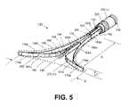
- FIG. 5is an enlarged perspective view of the expanded thin-wall dielectric structure, showing an expandable-collapsible frame with the thin dielectric wall in phantom view.
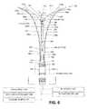
- FIG. 6is a partial sectional view of the expanded thin-wall dielectric structure of FIG. 5 showing (i) translatable members of the expandable-collapsible frame a that move the structure between collapsed and (ii) gas inflow and outflow lumens.
- FIG. 7is a sectional view of an introducer sleeve showing various lumens of the introducer sleeve taken along line 7 - 7 of FIG. 6 .
- FIG. 8Ais an enlarged schematic view of an aspect of a method of the invention illustrating the step introducing an introducer sleeve into a patient's uterus.
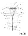
- FIG. 8Bis a schematic view of a subsequent step of retracting the introducer sleeve to expose a collapsed thin-wall dielectric structure and internal frame in the uterine cavity.
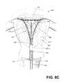
- FIG. 8Cis a schematic view of subsequent steps of the method, including, (i) actuating the internal frame to move the a collapsed thin-wall dielectric structure to an expanded configuration, (ii) inflating a cervical-sealing balloon carried on the introducer sleeve, and (iii) actuating gas flows and applying RF energy to contemporaneously ionize the gas in the interior chamber and cause capacitive coupling of current through the thin-wall dielectric structure to cause ohmic heating in the engaged tissue indicated by current flow paths.
- FIG. 8Dis a schematic view of a subsequent steps of the method, including: (i) advancing the introducer sleeve over the thin-wall dielectric structure to collapse it into an interior bore shown in phantom view, and (ii) withdrawing the introducer sleeve and dielectric structure from the uterine cavity.
- FIG. 9is a cut-away perspective view of an alternative expanded thin-wall dielectric structure similar to that of FIGS. 5 and 6 show an alternative electrode configuration.
- FIG. 10is an enlarged cut-away view of a portion of the expanded thin-wall dielectric structure of FIG. 9 showing the electrode configuration.
- FIG. 11is a diagram of a radiofrequency energy delivery apparatus and method corresponding to the invention.
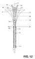
- FIG. 12is a schematic view of the working end of the ablation device of FIGS. 1-2 depicting three outlines of the expandable working end in a range of slightly-expanded to fully-expanded positions.
- FIG. 13Ais a schematic representation of an indicator mechanism in the handle of the ablation device of FIGS. 1-2 for indicating a first degree of expansion of the dielectric structure in a range shown in FIG. 12 .
- FIG. 13Bis a schematic representation of the indicator mechanism of FIG. 13A indicating a second the degree of expansion of the dielectric structure.
- FIG. 14is a cut-away view of a working end that carries a Hall effect sensor and magnetic field means, the sensor configured to provide a signal indicating an expansion parameter of the working end.
- FIG. 15is a schematic view of another working end that utilizes a Hall effect sensor for generating a signal indicating an expansion parameter of the working end.
- FIG. 16is a view of another working end that utilizes a plurality of Hall effect sensors for generating a signal indicating an expansion parameter of the working end and an asymmetric shape of a uterine cavity.
- an electrosurgical ablation systemcomprising an elongated introducer member for accessing a patient's uterine cavity with a working end that deploys an expandable thin-wall dielectric structure containing an electrically non-conductive gas as a dielectric.
- an interior chamber of the thin-wall dielectric structurecontains a circulating neutral gas such as argon.
- An RF power sourceprovides current that is coupled to the neutral gas flow by a first polarity electrode disposed within the interior chamber and a second polarity electrode at an exterior of the working end.
- the gas flowwhich is converted to a conductive plasma by an electrode arrangement, functions as a switching mechanism that permits current flow to engaged endometrial tissue only when the voltage across the combination of the gas, the thin-wall dielectric structure and the engaged tissue reaches a threshold that causes capacitive coupling across the thin-wall dielectric material.
- capacitively coupling current to tissuein this manner, the system provides a substantially uniform tissue effect within all tissue in contact with the expanded dielectric structure. Further, the invention allows the neutral gas to be created contemporaneously with the capacitive coupling of current to tissue.
- a plasmaconsists of a state of matter in which electrons in a neutral gas are stripped or “ionized” from their molecules or atoms. Such plasmas can be formed by application of an electric field or by high temperatures. In a neutral gas, electrical conductivity is non-existent or very low. Neutral gases act as a dielectric or insulator until the electric field reaches a breakdown value, freeing the electrons from the atoms in an avalanche process thus forming a plasma. Such a plasma provides mobile electrons and positive ions, and acts as a conductor which supports electric currents and can form spark or arc. Due to their lower mass, the electrons in a plasma accelerate more quickly in response to an electric field than the heavier positive ions, and hence carry the bulk of the current.
- FIG. 1depicts one embodiment of an electrosurgical ablation system 100 configured for endometrial ablation.
- the system 100includes a hand-held apparatus 105 with a proximal handle 106 shaped for grasping with a human hand that is coupled to an elongated introducer sleeve 110 having axis 111 that extends to a distal end 112 .
- the introducer sleeve 110can be fabricated of a thin-wall plastic, composite, ceramic or metal in a round or oval cross-section having a diameter or major axis ranging from about 4 mm to 8 mm in at least a distal portion of the sleeve that accesses the uterine cavity.
- the handle 106is fabricated of an electrically insulative material such as a molded plastic with a pistol-grip having first and second portions, 114 a and 114 b , that can be squeezed toward one another to translate an elongated translatable sleeve 115 which is housed in a bore 120 in the elongated introducer sleeve 110 .
- a working end 122can be deployed from a first retracted position ( FIG. 1 ) in the distal portion of bore 120 in introducer sleeve 110 to an extended position as shown in FIG. 2 .
- FIG. 2it can be seen that the first and second handle portions, 114 a and 114 b , are in a second actuated position with the working end 122 deployed from the bore 120 in introducer sleeve 110 .
- FIGS. 2 and 3shows that ablation system 100 includes an RF energy source 130 A and RF controller 130 B in a control unit 135 .
- the RF energy source 130 Ais connected to the hand-held device 105 by a flexible conduit 136 with a plug-in connector 137 configured with a gas inflow channel, a gas outflow channel, and first and second electrical leads for connecting to receiving connector 138 in the control unit 135 .
- the control unit 135further comprises a neutral gas inflow source 140 A, gas flow controller 140 B and optional vacuum or negative pressure source 145 to provide controlled gas inflows and gas outflows to and from the working end 122 .
- the control unit 135further includes a balloon inflation source 148 for inflating an expandable sealing balloon 225 carried on introducer sleeve 110 as described further below.
- the working end 122includes a flexible, thin-wall member or structure 150 of a dielectric material that when expanded has a triangular shape configured for contacting the patient's endometrial lining that is targeted for ablation.
- the dielectric structure 150comprises a thin-wall material such as silicone with a fluid-tight interior chamber 152 .
- an expandable-collapsible frame assembly 155is disposed in the interior chamber.
- the dielectric structuremay be expanded by a neutral gas without a frame, but using a frame offers a number of advantages.
- the uterine cavityis flattened with the opposing walls in contact with one another. Expanding a balloon-type member may cause undesirable pain or spasms. For this reason, a flat structure that is expanded by a frame is better suited for deployment in the uterine cavity.
- the neutral gasis converted to a conductive plasma at a very low pressure controlled by gas inflows and gas outflows—so that any pressurization of a balloon-type member with the neutral gas may exceed a desired pressure range and would require complex controls of gas inflows and gas outflows.
- the frameprovides an electrode for contact with the neutral gas in the interior chamber 152 of the dielectric structure 150 , and the frame 155 extends into all regions of the interior chamber to insure electrode exposure to all regions of the neutral gas and plasma.
- the frame 155can be constructed of any flexible material with at least portions of the frame functioning as spring elements to move the thin-wall structure 150 from a collapsed configuration ( FIG. 1 ) to an expanded, deployed configuration ( FIG.
- the frame 155comprises stainless steel elements 158 a , 158 b and 160 a and 160 b that function akin to leaf springs.
- the framecan be a stainless steel such as 316 SS, 17A SS, 420 SS, 440 SS or the frame can be a NiTi material.
- the framepreferably extends along a single plane, yet remains thin transverse to the plane, so that the frame may expand into the uterine cavity.
- the frame elementscan have a thickness ranging from about 0.005′′ to 0.025′′. As can be seen in FIGS.
- the proximal ends 162 a and 162 b of spring elements 158 a , 158 bare fixed (e.g., by welds 164 ) to the distal end 165 of sleeve member 115 .
- the proximal ends 166 a and 166 b of spring elements 160 a , 160 bare welded to distal portion 168 of a secondary translatable sleeve 170 that can be extended from bore 175 in translatable sleeve 115 .
- the secondary translatable sleeve 170is dimensioned for a loose fit in bore 175 to allow gas flows within bore 175 .
- FIGS. 5 and 6further illustrate the distal ends 176 a and 176 b of spring elements 158 a , 158 b are welded to distal ends 178 a and 178 b of spring elements 160 a and 160 b to thus provide a frame 155 that can be moved from a linear shape (see FIG. 1 ) to an expanded triangular shape ( FIGS. 5 and 6 ).
- the bore 175 in sleeve 115 and bore 180 in secondary translatable sleeve 170function as gas outflow and gas inflow lumens, respectively.
- the gas inflow lumencan comprise any single lumen or plurality of lumens in either sleeve 115 or sleeve 170 or another sleeve, or other parts of the frame 155 or the at least one gas flow lumen can be formed into a wall of dielectric structure 150 .
- FIGS. 5 , 6 and 7it can be seen that gas inflows are provided through bore 180 in sleeve 170 , and gas outflows are provided in bore 175 of sleeve 115 .
- FIGS. 5 and 6further show that a rounded bumper element 185 is provided at the distal end of sleeve 170 to insure that no sharp edges of the distal end of sleeve 170 can contact the inside of the thin dielectric wall 150 .
- the bumper element 185is silicone, but it could also comprise a rounded metal element.
- FIGS. 5 and 6also show that a plurality of gas inflow ports 188 can be provided along a length of in sleeve 170 in chamber 152 , as well as a port 190 in the distal end of sleeve 170 and bumper element 185 .
- the sectional view of FIG. 7also shows the gas flow passageways within the interior of introducer sleeve 110 .
- first and second handle portions, 114 a and 114 bactuation of first and second handle portions, 114 a and 114 b , (i) initially causes movement of the assembly of sleeves 115 and 170 relative to bore 120 of introducer sleeve 110 , and (ii) secondarily causes extension of sleeve 170 from bore 175 in sleeve 115 to expand the frame 155 into the triangular shape of FIG. 5 .
- the dimensions of the triangular shapeare suited for a patient uterine cavity, and for example can have an axial length A ranging from 4 to 10 cm and a maximum width B at the distal end ranging from about 2 to 5 cm.
- the thickness C of the thin-wall structure 150can be from 1 to 4 mm as determined by the dimensions of spring elements 158 a , 158 b , 160 a and 160 b of frame assembly 155 .
- the frame assembly 155can comprise round wire elements, flat spring elements, of any suitable metal or polymer that can provide opening forces to move thin-wall structure 150 from a collapsed configuration to an expanded configuration within the patient uterus.
- some elements of the frame 155can be spring elements and some elements can be flexible without inherent spring characteristics.
- the working end embodiment of FIGS. 2 , 5 and 6has a thin-wall structure 150 that is formed of a dielectric material such as silicone that permits capacitive coupling of current to engaged tissue while the frame assembly 155 provides structural support to position the thin-wall structure 150 against tissue. Further, gas inflows into the interior chamber 152 of the thin-wall structure can assist in supporting the dielectric wall so as to contact endometrial tissue.
- the dielectric thin-wall structure 150can be free from fixation to the frame assembly 155 , or can be bonded to an outward-facing portion or portions of frame elements 158 a and 158 b .
- the proximal end 182 of thin-wall structure 150is bonded to the exterior of the distal end of sleeve 115 to thus provide a sealed, fluid-tight interior chamber 152 ( FIG. 5 ).
- the gas inflow source 140 Acomprises one or more compressed gas cartridges that communicate with flexible conduit 136 through plug-in connector 137 and receiving connector 138 in the control unit 135 ( FIGS. 1-2 ).
- the gas inflows from source 140 Aflow through bore 180 in sleeve 170 to open terminations 188 and 190 therein to flow into interior chamber 152 .
- a vacuum source 145is connected through conduit 136 and connector 137 to allow circulation of gas flow through the interior chamber 152 of the thin-wall dielectric structure 150 .
- gas outflowscommunicate with vacuum source 145 through open end 200 of bore 175 in sleeve 115 . Referring to FIG.
- frame elements 158 a and 158 bare configured with a plurality of apertures 202 to allow for gas flows through all interior portions of the frame elements, and thus gas inflows from open terminations 188 , 190 in bore 180 are free to circulated through interior chamber 152 to return to an outflow path through open end 200 of bore 175 of sleeve 115 .
- the gas inflow source 140 Ais connected to a gas flow or circulation controller 140 B which controls a pressure regulator 205 and also controls vacuum source 145 which is adapted for assisting in circulation of the gas.
- the frame elementscan be configured with apertures, notched edges or any other configurations that allow for effective circulation of a gas through interior chamber 152 of the thin-wall structure 150 between the inflow and outflow passageways.
- FIGS. 5 and 6illustrate opposing polarity electrodes of the system 100 that are configured to convert a flow of neutral gas in chamber 152 into a plasma 208 ( FIG. 6 ) and to allow capacitive coupling of current through a wall 210 of the thin-wall dielectric structure 150 to endometrial tissue in contact with the wall 210 .
- the electrosurgical methods of capacitively coupling RF current across a plasma 208 and dielectric wall 210are described in U.S. patent application Ser. No. 12/541,043; filed Aug. 13, 2009 and U.S. application Ser. No. 12/541,050, referenced above.
- the first polarity electrode 215is within interior chamber 152 to contact the neutral gas flow and comprises the frame assembly 155 that is fabricated of an electrically conductive stainless steel. In another embodiment, the first polarity electrode can be any element disposed within the interior chamber 152 , or extendable into interior chamber 152 .
- the first polarity electrode 215is electrically coupled to sleeves 115 and 170 which extends through the introducer sleeve 110 to handle 106 and conduit 136 and is connected to a first pole of the RF source energy source 130 A and controller 130 B.
- a second polarity electrode 220is external of the internal chamber 152 and in one embodiment the electrode is spaced apart from wall 210 of the thin-wall dielectric structure 150 .
- the second polarity electrode 220comprises a surface element of an expandable balloon member 225 carried by introducer sleeve 110 .
- the second polarity electrode 220is coupled by a lead (not shown) that extends through the introducer sleeve 110 and conduit 136 to a second pole of the RF source 130 A.
- second polarity electrode 220can be positioned on sleeve 110 or can be attached to surface portions of the expandable thin-wall dielectric structure 150 , as will be described below, to provide suitable contact with body tissue to allow the electrosurgical ablation of the method of the invention.
- the second polarity electrode 220can comprise a thin conductive metallic film, thin metal wires, a conductive flexible polymer or a polymeric positive temperature coefficient material.
- the expandable member 225comprises a thin-wall compliant balloon having a length of about 1 cm to 6 cm that can be expanded to seal the cervical canal.
- the balloon 225can be inflated with a gas or liquid by any inflation source 148 , and can comprise a syringe mechanism controlled manually or by control unit 135 .
- the balloon inflation source 148is in fluid communication with an inflation lumen 228 in introducer sleeve 110 that extends to an inflation chamber of balloon 225 (see FIG. 7 ).
- control unit 135can include a display 230 and touch screen or other controls 232 for setting and controlling operational parameters such as treatment time intervals, treatment algorithms, gas flows, power levels and the like. Suitable gases for use in the system include argon, other noble gases and mixtures thereof.
- a footswitch 235is coupled to the control unit 135 for actuating the system.
- FIGS. 3 and 4schematically depict the system 100 , subsystems and components that are configured for an endometrial ablation system.
- RF energy source 130 A and circuitryis controlled by a controller 130 B.
- the systemcan include feedback control systems that include signals relating to operating parameters of the plasma in interior chamber 152 of the dielectric structure 150 .
- feedback signalscan be provided from at least one temperature sensor 240 in the interior chamber 152 of the dielectric structure 150 , from a pressure sensor within, or in communication, with interior chamber 152 , and/or from a gas flow rate sensor in an inflow or outflow channel of the system.
- FIG. 4is a schematic block diagram of the flow control components relating to the flow of gas media through the system 100 and hand-held device 105 .
- a pressurized gas source 140 Ais linked to a downstream pressure regulator 205 , an inflow proportional valve 246 , flow meter 248 and normally closed solenoid valve 250 .
- the valve 250is actuated by the system operator which then allows a flow of a neutral gas from gas source 140 A to circulate through flexible conduit 136 and the device 105 .
- the gas outflow side of the systemincludes a normally open solenoid valve 260 , outflow proportional valve 262 and flow meter 264 that communicate with vacuum pump or source 145 .
- the gascan be exhausted into the environment or into a containment system.
- a temperature sensor 270(e.g., thermocouple) is shown in FIG. 4 that is configured for monitoring the temperature of outflow gases.
- FIG. 4further depicts an optional subsystem 275 which comprises a vacuum source 280 and solenoid valve 285 coupled to the controller 140 B for suctioning steam from a uterine cavity 302 at an exterior of the dielectric structure 150 during a treatment interval.
- the flow passageway from the uterine cavity 302can be through bore 120 in sleeve 110 (see FIGS. 2 , 6 and 7 ) or another lumen in a wall of sleeve 110 can be provided.
- FIGS. 8A-8Dschematically illustrate a method of the invention wherein (i) the thin-wall dielectric structure 150 is deployed within a patient uterus and (ii) RF current is applied to a contained neutral gas volume in the interior chamber 152 to contemporaneously create a plasma 208 in the chamber and capacitively couple current through the thin dielectric wall 210 to apply ablative energy to the endometrial lining to accomplish global endometrial ablation.
- FIG. 8Aillustrates a patient uterus 300 with uterine cavity 302 surrounded by endometrium 306 and myometrium 310 .
- the external cervical os 312is the opening of the cervix 314 into the vagina 316 .
- the internal os or opening 320is a region of the cervical canal that opens to the uterine cavity 302 .
- FIG. 8Adepicts a first step of a method of the invention wherein the physician has introduced a distal portion of sleeve 110 into the uterine cavity 302 . The physician gently can advance the sleeve 110 until its distal tip contacts the fundus 324 of the uterus. Prior to insertion of the device, the physician can optionally introduce a sounding instrument into the uterine cavity to determine uterine dimensions, for example from the internal os 320 to fundus 324 .
- FIG. 8Billustrates a subsequent step of a method of the invention wherein the physician begins to actuate the first and second handle portions, 114 a and 114 b , and the introducer sleeve 110 retracts in the proximal direction to expose the collapsed frame 155 and thin-wall structure 150 within the uterine cavity 302 .
- the sleeve 110can be retracted to expose a selected axial length of thin-wall dielectric structure 150 , which can be determined by markings 330 on sleeve 115 (see FIG. 1 ) which indicate the axial travel of sleeve 115 relative to sleeve 170 and thus directly related to the length of deployed thin-wall structure 150 .
- FIG. 2depicts the handle portions 114 a and 114 b fully approximated thus deploying the thin-wall structure to its maximum length.
- the spring frame elements 158 a , 158 b , 160 a and 160 bmove the dielectric structure 150 from a non-expanded position to an expanded position in the uterine cavity as depicted by the profiles in dashed lines.
- the spring force of the frame 155will expand the dielectric structure 150 until limited by the dimensions of the uterine cavity.
- FIG. 8Cillustrates several subsequent steps of a method of the invention.
- FIG. 8Cfirst depicts the physician continuing to actuate the first and second handle portions, 114 a and 114 b , which further actuates the frame 155 (see FIGS. 5-6 ) to expand the frame 155 and thin-wall structure 150 to a deployed triangular shape to contact the patient's endometrial lining 306 .
- the physiciancan slightly rotate and move the expanding dielectric structure 150 back and forth as the structure is opened to insure it is opened to the desired extent.
- the physiciancan actuate handle portions, 114 a and 114 b , a selected degree which causes a select length of travel of sleeve 170 relative to sleeve 115 which in turn opens the frame 155 to a selected degree.
- the selected actuation of sleeve 170 relative to sleeve 115also controls the length of dielectric structure deployed from sleeve 110 into the uterine cavity.
- the thin-wall structure 150can be deployed in the uterine cavity with a selected length, and the spring force of the elements of frame 155 will open the structure 150 to a selected triangular shape to contact or engage the endometrium 306 .
- the expandable thin-wall structure 150is urged toward and maintained in an open position by the spring force of elements of the frame 155 .
- the handle 106includes a locking mechanism with finger-actuated sliders 332 on either side of the handle that engage a grip-lock element against a notch in housing 333 coupled to introducer sleeve 110 ( FIG. 2 ) to lock sleeves 115 and 170 relative to introducer sleeve 110 to maintain the thin-wall dielectric structure 150 in the selected open position.
- FIG. 8Cfurther illustrates the physician expanding the expandable balloon structure 225 from inflation source 148 to thus provide an elongated sealing member to seal the cervix 314 outward from the internal os 320 .
- the system 100is ready for the application of RF energy to ablate endometrial tissue 306 .
- FIG. 8Cnext depicts the actuation of the system 100 , for example, by actuating footswitch 235 , which commences a flow of neutral gas from source 140 A into the interior chamber 152 of the thin-wall dielectric structure 150 .
- the system's actuationdelivers RF energy to the electrode arrangement which includes first polarity electrode 215 (+) of frame 155 and the second polarity electrode 220 ( ⁇ ) which is carried on the surface of expandable balloon member 225 .
- the delivery of RF energy deliverywill instantly convert the neutral gas in interior chamber 152 into conductive plasma 208 which in turn results in capacitive coupling of current through the dielectric wall 210 of the thin-wall structure 150 resulting in ohmic heating of the engaged tissue.
- FIG. 8Cschematically illustrates the multiplicity of RF current paths 350 between the plasma 208 and the second polarity electrode 220 through the dielectric wall 210 .
- ablation depths of three mm to six mm or morecan be accomplished very rapidly, for example in 60 seconds to 120 seconds dependent upon the selected voltage and other operating parameters.
- the voltage at which the neutral gas inflow, such as argon, becomes conductiveis dependent upon a number of factors controlled by the controllers 130 B and 140 B, including the pressure of the neutral gas, the volume of interior chamber 152 , the flow rate of the gas through the chamber 152 , the distance between electrode 210 and interior surfaces of the dielectric wall 210 , the dielectric constant of the dielectric wall 210 and the selected voltage applied by the RF source 130 , all of which can be optimized by experimentation.
- the gas flow ratecan be in the range of 5 ml/sec to 50 ml/sec.
- the dielectric wall 210can comprise a silicone material having a thickness ranging from a 0.005′′ to 0.015 and having a relative permittivity in the range of 3 to 4.
- the gascan be argon supplied in a pressurized cartridge which is commercially available.
- Pressure in the interior chamber 152 of dielectric structure 150can be maintained between 14 psia and 15 psia with zero or negative differential pressure between gas inflow source 140 A and negative pressure or vacuum source 145 .
- the controlleris configured to maintain the pressure in interior chamber in a range that varies by less than 10% or less than 5% from a target pressure.
- the RF power source 130 Acan have a frequency of 450 to 550 KHz, and electrical power can be provided within the range of 600 Vrms to about 1200 Vrms and about 0.2 Amps to 0.4 Amps and an effective power of 40 W to 100 W.
- the control unit 135can be programmed to delivery RF energy for a preselected time interval, for example, between 60 seconds and 120 seconds.
- One aspect of a treatment method corresponding to the inventionconsists of ablating endometrial tissue with RF energy to elevate endometrial tissue to a temperature greater than 45 degrees Celsius for a time interval sufficient to ablate tissue to a depth of at least 1 mm.
- Another aspect of the method of endometrial ablation ofconsists of applying radiofrequency energy to elevate endometrial tissue to a temperature greater than 45 degrees Celsius without damaging the myometrium.
- FIG. 8Dillustrates a final step of the method wherein the physician deflates the expandable balloon member 225 and then extends sleeve 110 distally by actuating the handles 114 a and 114 b to collapse frame 155 and then retracting the assembly from the uterine cavity 302 .
- the deployed working end 122 as shown in FIG. 8Ccan be withdrawn in the proximal direction from the uterine cavity wherein the frame 155 and thin-wall structure 150 will collapse as it is pulled through the cervix.
- FIG. 8Dshows the completed ablation with the ablated endometrial tissue indicated at 360 .
- the systemcan include an electrode arrangement in the handle 106 or within the gas inflow channel to pre-ionize the neutral gas flow before it reaches the interior chamber 152 .
- the gas inflow channelcan be configured with axially or radially spaced apart opposing polarity electrodes configured to ionize the gas inflow.
- Such electrodeswould be connected in separate circuitry to an RF source.
- the first and second electrodes 215 (+) and 220 ( ⁇ ) described abovewould operate as described above to provide the current that is capacitively coupled to tissue through the walls of the dielectric structure 150 . In all other respects, the system and method would function as described above.
- FIGS. 9 and 10an alternate working end 122 with thin-wall dielectric structure 150 is shown.
- the thin-wall dielectric structure 150is similar to that of FIGS. 5 and 6 except that the second polarity electrode 220 ′ that is exterior of the internal chamber 152 is disposed on a surface portion 370 of the thin-wall dielectric structure 150 .
- the second polarity electrode 220 ′comprises a thin-film conductive material, such as gold, that is bonded to the exterior of thin-wall material 210 along two lateral sides 354 of dielectric structure 150 .
- the second polarity electrodecan comprise one or more conductive elements disposed on the exterior of wall material 210 , and can extend axially, or transversely to axis 111 and can be singular or multiple elements.
- the second polarity electrode 220 ′can be fixed on another lubricious layer 360 , such as a polyimide film, for example KAPTON®.
- the polyimide tapeextends about the lateral sides 354 of the dielectric structure 150 and provides protection to the wall 210 when it is advanced from or withdrawn into bore 120 in sleeve 110 .
- the RF delivery method using the embodiment of FIGS. 9 and 10is the same as described above, with RF current being capacitively coupled from the plasma 208 through the wall 210 and endometrial tissue to the second polarity electrode 220 ′ to cause the ablation.
- FIG. 9further shows an optional temperature sensor 390 , such as a thermocouple, carried at an exterior of the dielectric structure 150 .
- the control unit 135can acquire temperature feedback signals from at least one temperature sensor 390 to modulate or terminate RF energy delivery, or to modulate gas flows within the system.
- the control unit 135can acquire temperature feedback signals from temperature sensor 240 in interior chamber 152 ( FIG. 6 to modulate or terminate RF energy delivery or to modulate gas flows within the system.
- FIG. 11is a graphic representation of an algorithm utilized by the RF source 130 A and RF controller 130 B of the system to controllably apply RF energy in an endometrial ablation procedure.
- the systemis configured to allow the dielectric structure 150 to open to different expanded dimensions depending on the size and shape of the uterine cavity 302 .
- the axial length of dielectric structure 150also can be adjusted to have a predetermined axial length extended outward from the introducer sleeve 110 to match a measured length of a uterine cavity. In any case, the actual surface area of the expanded dielectric structure 150 within different uterine cavities will differ—and it would be optimal to vary total applied energy to correspond to the differing size uterine cavities.
- FIG. 11represents a method of the invention that automatically determines relevant parameters of the tissue and the size of uterine cavity 302 to allow for selection of an energy delivery mode that is well suited to control the total applied energy in an ablation procedure.
- RF energyis applied at constant power for a first time increment, and the following electrical parameters (e.g., voltage, current, power, impedance) are measured during the application of energy during that first time increment.
- the initial impedancemay be also be utilized by the controller as a shutoff criteria for the second treatment interval after a selected increase in impedance.
- a first step following the positioning of the dielectric structure in the uterine cavity 302is to apply radiofrequency energy in a first mode of predetermined constant power, or constant RF energy (“FIRST MODE—POWER”).
- This first poweris sufficient to capacitively couple current across the dielectric to contacted tissue, wherein empirical studies have shown the power can be in the range of 50 W-300 W, and in one embodiment is 80 W.
- This first power modeis applied for a predetermined interval which can be less than 15 seconds, 10 seconds, or 5 seconds, as examples, and is depicted in FIG. 11 as being 2 seconds.
- the voltage valueis determined a voltage sensor in controller 130 A and is recorded at the “one-second” time point after the initiation of RF energy delivery.
- the controllerincludes a power sensor, voltage sensor and current sensor as is known in the art.
- This voltage value, or another electrical parametermay be determined and recorded at any point during the interval, and more than one recording may be made, with averages taken for the multiple recordings, or the multiple recordings may be used in another way to consistently take a measurement of an electrical value or values.
- the controller algorithmswitches to a second mode (“SECOND MODE—VOLTAGE”) of applying radiofrequency energy at a selected constant voltage, with the selected constant voltage related to the recorded voltage (or other electrical parameter) at the “one-second” time point.
- the selected constant voltageis equal to the recorded voltage, but other algorithms can select a constant voltage that is greater or lesser than the recorded voltage but determined by a factor or algorithm applied to the recorded voltage.
- the algorithmthen applies RF energy over a treatment interval to ablate endometrial tissue. During this period, the RF energy is varied as the measured voltage is kept constant.
- the treatment intervalcan have an automatic time-out after a predetermined interval of less that 360 seconds, 240 seconds, 180 seconds, 120 seconds or 90 seconds, as examples.
- a voltage levelis recorded (e.g., in the example, at one second) that directly relates to a combination of (i) the surface area of the dielectric structure, and the degree to which wall portions of the dielectric structure have been elastically stretched; (ii) the flow rate of neutral gas through the dielectric structure and (iii) the impedance of the contacted tissue.
- the length of the second, treatment intervalcan be the same for all different dimension uterine cavities and will result in substantially the same ablation depth, since the constant voltage maintained during the second interval will result in power that drifts off to lower levels toward the end of the treatment interval as tissue impedance increases.
- the controller 130 Aalso can use an impedance level or a selected increase in impedance to terminate the treatment interval.
- the algorithm aboveprovides a recorded voltage at set time point in the first mode of RF energy application, but another embodiment can utilize a recorded voltage parameter that can be an average voltage over a measuring interval or the like. Also, the constant voltage in the second mode of RF energy application can include any ramp-up or ramp-down in voltage based on the recorded voltage parameter.
- an electrosurgical method for endometrial ablationcomprises positioning a RF ablation device in contact with endometrial tissue, applying radiofrequency energy in a first mode based on a predetermined constant power over a first interval, and applying radiofrequency energy in a second mode over a second interval to ablate endometrial tissue, the energy level of the second mode being based on treatment voltage parameters obtained or measured during the first interval. Power during the first interval is constant, and during the second period is varied to maintain voltage at a constant level.
- Another step in applying RF energy in the first modeincludes the step of recording a voltage parameter in the first interval, wherein the voltage parameter is at least one of voltage at a point in time, average voltage over a time interval, and a change or rate of change of voltage.
- the second modeincludes setting the treatment voltage parameters in relation to the voltage parameter recorded in the first interval.
- an electrosurgical system for endometrial ablationcomprises a radiofrequency ablation device coupled to an radiofrequency power supply, and control means connected to the radiofrequency power supply for switching the application of radiofrequency energy between a constant power mode and a constant voltage mode.
- the control meansincludes an algorithm that (i) applies radiofrequency energy in the first mode (ii) records the voltage within a predetermined interval of the first mode, and (iii) applies radiofrequency energy in the second mode with constant voltage related to the recorded voltage.
- the inventioncomprises a radiofrequency power supply, a means for coupling the radiofrequency power supply to an ablation device configured for positioning in a uterine cavity, the ablation device comprising a dielectric for contacting endometrial tissue, a system for recording an electrical parameter of the ablation device and contacted tissue, and a feedback system for varying the application of radiofrequency energy to tissue between a constant power mode and a constant voltage mode based on a recorded electrical parameter.
- FIGS. 12 , 13 A and 13 Bdepict components of the ablation device of FIGS. 1-2 that provide the physician with an indication of the degree to which the dielectric structure 150 has opened in the patient's uterine cavity 302 . It can be understood from FIGS. 5 , 6 and 8 C that the spring frame 155 that moves the dielectric structure 150 from a contracted, linear shape ( FIG. 8B ) to an expanded, triangular shape ( FIG.
- inner sleeve 170 and intermediate sleeve 115are shown for convenience without their respective welded connections to spring frame elements 158 a , 158 b , 160 a and 160 b .
- the frame elements 158 a , 158 b , 160 a and 160 b and their springing functioncan be seen in FIGS. 5 and 6 .
- the introducer sheath 110is shown as being moved proximally relative to the dielectric structure 150 which corresponds to a position of the dielectric structure 150 shown in FIG. 8B .
- FIG. 12the introducer sheath 110 is shown as being moved proximally relative to the dielectric structure 150 which corresponds to a position of the dielectric structure 150 shown in FIG. 8B .
- the distal end 400 of sleeve 170has an axial position X and can be approximately the same axial position as the distal end 402 of the introducer sleeve 110 . It can be understood that when the dielectric structure 150 and interior spring frame 155 are deployed in a uterine cavity, the spring force of frame 155 will tend to open the dielectric structure 150 from a position in FIG. 8B toward the position of FIG. 8C .
- an initial position of the distal end 405 of sleeve 170has an axial position indicated at A which corresponds to plan shape A′ of the dielectric structure 150 .
- the spring force of frame 155will move the distal end 405 of sleeve 170 toward an axial position B which corresponds to expanded dielectric plan shape B′ or toward an axial position C and corresponding expanded dielectric plan shape C′.
- Dielectric plan C′represents a fully expanded dielectric structure 150 .
- the physicianmay gently and very slightly rotate, tilt and translate the expanding dielectric structure 150 in the uterine cavity 302 .
- the different dimensions of uterine cavitieswill impinge on the degree of expansion of the dielectric structure 150 —and the size and surface area of the dielectric structure, as an example, will be within the dimension range between plan shapes A′ and plan shape C′ of FIG. 12 .
- the dielectric structure 150is preferred to have a minimum surface area directly related to its expanded shape to thus cooperate with an RF energy delivery algorithm.
- the systemprovides a “degree of frame-open” signaling mechanism for signaling the physician that the frame 155 and dielectric structure 150 has expanded to a minimum predetermined configuration.
- the signaling mechanismis based on the relative axial location of inner sleeve 170 and sleeve 115 as can be understood from FIGS. 12 and 13 A- 13 B.
- FIGS. 1 and 2it can be seen that a sliding element 450 is exposed in a top portion of handle component 114 B to slide axially in a slot 452 .
- the proximal end 454 of sleeve 115is fixed in handle component 114 b .
- inner sleeve 170is slidable and free-floating in the bore 175 of sleeve 115 and can be moved axially to and fro depending to the opening spring force of frame 155 —which force can be constrained by the frame being withdrawn into the bore 120 of introducer sleeve 110 or by uterine walls impinging on the dielectric structure 150 and frame 155 when deployed in a uterine cavity.
- the sliding elementhas at least two axially-extending indicators 460 A and 460 B that can be different colors that slide axially relative to status-indicating arrow element 465 in a fixed location in the handle 114 b .
- indicator 460 Acan be red for “stop” and indicator 460 B can be “green”, for indicating whether to stop proceeding with the procedure, or to go ahead with the ablation procedure.
- FIG. 13Ait can be seen that inner sleeve 170 and its distal end 405 are only axially extended at point A which corresponds to dielectric expansion profile A′.
- the limited expansion of dielectric structure at profile A′is indicated at the slider 450 wherein the arrow 465 points to the red ‘stop” indicator 460 A which indicates to the physician to stop and not proceed with the ablation procedure due to limited expansion of dielectric structure 150 .
- FIG. 13Bdepicts an extension of inner sleeve 170 and its distal end 405 to axially extended at point B which corresponds to dielectric expansion profile B′.
- This intermediate expansion of dielectric structure 150 at profile B′is indicated to the physician by observing slider 450 wherein arrow 465 points to the green indicator 460 B which indicates “go”—that is, the physician can proceed with the ablation procedure since the dielectric structure 150 and frame 155 have expanded to a predetermined degree that cooperates with an RF energy delivery algorithm.
- sleeve 170can move axially toward extended position C with corresponding dielectric structure profile C′ and indicator arrow 465 will again point to the “go” portion 460 B of sliding element which is green.
- the handle component 114 bcan include a electrical contact sensor 470 that detects the axial movement of sliding element 450 and sleeve 170 relative to sleeve 115 to thereby provide an electronic signal indicating the degree of expansion of the frame 155 and dielectric structure 150 .
- the electronic signalcommunicates with RF controller 130 B to disable the system if the relative axial positions of sleeves 170 and 115 do not indicate a predetermined degree of expansion of the frame 155 and dielectric structure.
- the systemcan further include an override mechanism, whereby the physician can manipulate the instrument slightly back and forth and rotationally to evaluate whether the frame 155 opens incrementally more.
- the electrical sensor 470can detect a plurality of degrees of expansion of the frame 155 and dielectric structure 150 , for example as depicted by an electrical contact be activated at positions AA, BB, CC, and DD of the slider 450 in FIGS. 13A-13B , wherein each degree of expansion of frame 155 signals the controller to select a different RF delivery algorithm.
- the various different RF delivery algorithmscan alter at least one of: (i) the duration of a treatment interval, for example from between 60 seconds and 240 seconds, (ii) the relation between a recorded voltage and a treatment voltage as described in the text accompanying FIG.
- the treatment voltagecan equal the recorded voltage, or vary as a factor about 0.8, 0.9, 1.0, 1.1 or 1.2 times the recorded voltage; (iv) can vary a ramp-up or ramp-down in voltage, or can a time interval of the first and second modes of RF energy delivery described above.
- the number of degrees of expansion of frame 155 and dielectric structurecan range from 1 to 10 or more.
- FIGS. 1 , 2 , 13 A and 13 Bdepict indicator subsystems that include visual and electrical signals, but it should be appreciated that the indicator subsystem can provide any single or combination signals that can be visual, aural or tactile with respect to the operator and/or electrically communicate with microprocessors, programmable logic devices or controllers of the ablation system.
- FIG. 14depicts another embodiment 500 of a system that provides a signal relating to the degree to which the frame 155 within dielectric structure 150 has opened, or more generally the signaling mechanism can provide a controller or the physician a signal indicative of a dimensional parameter of patient's uterine cavity, such as width, volume, length and the like.
- the working end embodiment 500includes a frame 155 that as been actuated as described previously to expand within the dielectric structure 150 working end.
- the embodiment of FIG. 14has an introducer sleeve 510 with axis 111 that carries an inner sleeve 512 that is extendable to articulate laterally-outward frame elements 516 a , 516 b and inner frame elements 522 a , 522 b .
- the system for providing the signal related to frame openingcomprises a Hall effect sensor 540 and magnetic means 545 which are moved from a first lesser spaced apart position (cf. FIG. 8B , FIG. 12 ) to a greater spaced apart position indicated in FIG. 14 .
- Hall effect sensorsare typically used for proximity sensing and position/rotation sensing in relation to rotating shafts.
- a Hall effect sensorrelates to the phenomenon known as the Hall Effect, which refers to the potential difference (Hall voltage) on opposite sides of a thin Hall element of conducting or semiconducting material through which an electric current is flowing, with a magnetic field applied angularly to the Hall element.
- a Hall effect sensorvaries its output in response to a change in magnetic field.
- FIG. 14shows a Hall effect sensor 540 attached to a distal portion of frame element 522 a and the magnetic means 545 coupled to a distal portion of frame element 522 b .
- the Hall sensoris operatively coupled to electrical source 550 and computer controller 555 by electrical leads 558 , which can typically be three leads or more.
- electrical leads 558can typically be three leads or more.
- the voltage output and signal provided by the sensor 540 to the controller 555will vary from both the change in spacing between the sensor 540 and magnetic means and the change in axis 560 of magnetic field 562 relative to the sensor 540 .
- the change in output signal from the Hall sensorwill allow for comparison against a look-up table in the controller memory to determine a frame-open dimension or uterine dimension.
- FIG. 15depicts another similar working end embodiment 500 ′ which again includes a frame (not shown) that as been actuated as in FIG. 14 .
- the schematic drawing in FIG. 15shows a Hall effect sensor 540 carried by extendable sleeve 512 along that axis 511 together with first and second magnets 545 and 545 ′.
- the magnetscan be electromagnets and the controller 555 can switch in short time interval ranging from milliseconds to seconds between sampling signals from the Hall sensor 540 to each magnet.
- the systemcan be adapted to detect asymmetric uterine cavities since, in effect, each side of the working end on either side of axis 111 has an independent sensing mechanism.
- FIG. 16depicts another similar working end embodiment 500 ′′ wherein first and second Hall effect sensors 540 and 540 ′ are carried on, or within, outwardly-expanding portions of the working end.
- a magnet 545is carried by an extendible sleeve 512 along the axis 511 . All such sensors and magnets can be carried by frame 155 , or inside, outside or within the thin-wall dielectric structure.
- a system of the inventioncomprises an energy-delivery structure moveable between non-expanded and expanded shapes wherein the expanded shape is configured for positioning in a uterine cavity, a Hall effect sensor carried in a first peripheral portion of the structure in an expanded shape and a magnet carried by a second portion of the structure.
- the magnetcan be carried in a peripheral portion that opposes the Hall sensor.
- the magnetcan be carried in a central portion of the structure when in an expanded shape.
- the systemcan comprise an expandable-collapsible energy-delivery structure that carries a plurality of Hall effect sensors.
- Hall sensorscan be carried in opposing peripheral portions of the working end.
- system of the inventioncan use permanent magnets (such as rare earth magnets) or electromagnets to cooperate with the Hall effect sensor.
- permanent magnetssuch as rare earth magnets
- electromagnetsto cooperate with the Hall effect sensor.
- the ablation systemcomprises a thin wall expandable structure having an interior chamber and a Hall effect sensor and magnetic means carried in first and second locations in or about the structure wherein the sensor provides a signal of movement of the magnet away from the sensor upon expansion of the expandable structure to thereby indicate an expansion parameter of the structure.
- the structurecan be expandable by means of a frame as described above or by an inflation medium.
- the scope of the inventionextends to expandable working end for endometrial ablation that utilize any energy delivery means, such as RF means described above, bi-polar or mono-polar electrode means, microwave means etc. In all these cases, it may be useful or necessary to determine the dimensional parameters of the working to insure that it opened properly or to determine uterine cavity dimensions to thereby determine energy delivery parameters.
- energy delivery meanssuch as RF means described above, bi-polar or mono-polar electrode means, microwave means etc.
- a method of the invention for characterizing a uterine cavitycomprises transcervically introducing a working end into a patient uterus and expanding an expandable-collapsible structure carrying at least one Hall effect sensor and magnet, wherein the Hall effect sensor varies its output in response to a change the magnetic field to provide a signal indicative of a dimensional parameter of the uterine cavity.
- the sensing systemcan be adapted to generate a signal indicating a frame-open parameter, or volume, width or length of the uterine cavity.
- the system and methodcan further include acquiring the signal from the Hall effect sensor to select a parameter of ablative energy delivery from the working end for endometrial ablation.
Landscapes
- Health & Medical Sciences (AREA)
- Surgery (AREA)
- Engineering & Computer Science (AREA)
- Life Sciences & Earth Sciences (AREA)
- Biomedical Technology (AREA)
- Otolaryngology (AREA)
- Nuclear Medicine, Radiotherapy & Molecular Imaging (AREA)
- Plasma & Fusion (AREA)
- Physics & Mathematics (AREA)
- Heart & Thoracic Surgery (AREA)
- Medical Informatics (AREA)
- Molecular Biology (AREA)
- Animal Behavior & Ethology (AREA)
- General Health & Medical Sciences (AREA)
- Public Health (AREA)
- Veterinary Medicine (AREA)
- Surgical Instruments (AREA)
Abstract
Description
Claims (33)
Priority Applications (1)
| Application Number | Priority Date | Filing Date | Title |
|---|---|---|---|
| US13/187,332US8956348B2 (en) | 2010-07-21 | 2011-07-20 | Methods and systems for endometrial ablation |
Applications Claiming Priority (2)
| Application Number | Priority Date | Filing Date | Title |
|---|---|---|---|
| US36626810P | 2010-07-21 | 2010-07-21 | |
| US13/187,332US8956348B2 (en) | 2010-07-21 | 2011-07-20 | Methods and systems for endometrial ablation |
Publications (2)
| Publication Number | Publication Date |
|---|---|
| US20120022520A1 US20120022520A1 (en) | 2012-01-26 |
| US8956348B2true US8956348B2 (en) | 2015-02-17 |
Family
ID=45494207
Family Applications (1)
| Application Number | Title | Priority Date | Filing Date |
|---|---|---|---|
| US13/187,332Active2033-12-17US8956348B2 (en) | 2010-07-21 | 2011-07-20 | Methods and systems for endometrial ablation |
Country Status (1)
| Country | Link |
|---|---|
| US (1) | US8956348B2 (en) |
Cited By (7)
| Publication number | Priority date | Publication date | Assignee | Title |
|---|---|---|---|---|
| US11160597B2 (en) | 2010-11-09 | 2021-11-02 | Aegea Medical Inc. | Positioning method and apparatus for delivering vapor to the uterus |
| US11207118B2 (en) | 2007-07-06 | 2021-12-28 | Tsunami Medtech, Llc | Medical system and method of use |
| US11213338B2 (en) | 2007-08-23 | 2022-01-04 | Aegea Medical Inc. | Uterine therapy device and method |
| US11219479B2 (en) | 2014-05-22 | 2022-01-11 | Aegea Medical Inc. | Integrity testing method and apparatus for delivering vapor to the uterus |
| US11331037B2 (en) | 2016-02-19 | 2022-05-17 | Aegea Medical Inc. | Methods and apparatus for determining the integrity of a bodily cavity |
| US11497089B2 (en) | 2017-06-20 | 2022-11-08 | Aegea Medical Inc. | Induction coil assembly for uterine ablation and method |
| US11849991B2 (en) | 2011-10-07 | 2023-12-26 | Aegea Medical Inc. | Integrity testing method and apparatus for delivering vapor to the uterus |
Families Citing this family (7)
| Publication number | Priority date | Publication date | Assignee | Title |
|---|---|---|---|---|
| US8715278B2 (en)* | 2009-11-11 | 2014-05-06 | Minerva Surgical, Inc. | System for endometrial ablation utilizing radio frequency |
| US8939971B2 (en)* | 2011-03-11 | 2015-01-27 | Minerva Surgical, Inc. | System and method for endometrial ablation |
| US20130281920A1 (en)* | 2012-04-20 | 2013-10-24 | Elwha LLC, a limited liability company of the State of Delaware | Endometrial Ablation |
| US10610294B2 (en) | 2012-04-22 | 2020-04-07 | Newuro, B.V. | Devices and methods for transurethral bladder partitioning |
| US9883906B2 (en) | 2012-04-22 | 2018-02-06 | Newuro, B.V. | Bladder tissue modification for overactive bladder disorders |
| WO2019022724A1 (en)* | 2017-07-25 | 2019-01-31 | Park Sam Boong | Systems and methods for automatically controlled endometrial ablation |
| US11903633B2 (en)* | 2020-12-30 | 2024-02-20 | Avent, Inc. | Radiofrequency probe, system, and method for adaptive multivariate control of an ablation procedure |
Citations (175)
| Publication number | Priority date | Publication date | Assignee | Title |
|---|---|---|---|---|
| US4611604A (en) | 1983-01-11 | 1986-09-16 | Siemens Aktiengesellschaft | Bipolar electrode for medical applications |
| US4949718A (en) | 1988-09-09 | 1990-08-21 | Gynelab Products | Intrauterine cauterizing apparatus |
| US4979948A (en) | 1989-04-13 | 1990-12-25 | Purdue Research Foundation | Method and apparatus for thermally destroying a layer of an organ |
| US5045056A (en) | 1989-09-15 | 1991-09-03 | Behl Robert S | Method and device for thermal ablation of hollow body organs |
| US5078717A (en) | 1989-04-13 | 1992-01-07 | Everest Medical Corporation | Ablation catheter with selectively deployable electrodes |
| US5084044A (en) | 1989-07-14 | 1992-01-28 | Ciron Corporation | Apparatus for endometrial ablation and method of using same |
| US5191883A (en) | 1988-10-28 | 1993-03-09 | Prutech Research And Development Partnership Ii | Device for heating tissue in a patient's body |
| US5242390A (en) | 1991-05-03 | 1993-09-07 | Goldrath Milton H | Endometrium coagulating surgical method for thermal destruction of the endometrium |
| US5248312A (en) | 1992-06-01 | 1993-09-28 | Sensor Electronics, Inc. | Liquid metal-filled balloon |
| US5277201A (en) | 1992-05-01 | 1994-01-11 | Vesta Medical, Inc. | Endometrial ablation apparatus and method |
| US5344435A (en) | 1988-07-28 | 1994-09-06 | Bsd Medical Corporation | Urethral inserted applicator prostate hyperthermia |
| US5374261A (en) | 1990-07-24 | 1994-12-20 | Yoon; Inbae | Multifunctional devices for use in endoscopic surgical procedures and methods-therefor |
| US5401272A (en) | 1992-09-25 | 1995-03-28 | Envision Surgical Systems, Inc. | Multimodality probe with extendable bipolar electrodes |
| US5441498A (en) | 1994-02-16 | 1995-08-15 | Envision Surgical Systems, Inc. | Method of using a multimodality probe with extendable bipolar electrodes |
| US5443470A (en) | 1992-05-01 | 1995-08-22 | Vesta Medical, Inc. | Method and apparatus for endometrial ablation |
| US5501681A (en) | 1993-11-12 | 1996-03-26 | Neuwirth; Robert S. | Intrauterine cryoablation cauterizing apparatus and method |
| US5505730A (en) | 1994-06-24 | 1996-04-09 | Stuart D. Edwards | Thin layer ablation apparatus |
| US5549546A (en) | 1994-01-28 | 1996-08-27 | Richard Wolf Gmbh | Insufflation device |
| US5562720A (en) | 1992-05-01 | 1996-10-08 | Vesta Medical, Inc. | Bipolar/monopolar endometrial ablation device and method |
| US5562703A (en) | 1994-06-14 | 1996-10-08 | Desai; Ashvin H. | Endoscopic surgical instrument |
| US5575788A (en) | 1994-06-24 | 1996-11-19 | Stuart D. Edwards | Thin layer ablation apparatus |
| US5584872A (en) | 1992-11-13 | 1996-12-17 | Scimed Life Systems, Inc. | Electrophysiology energy treatment devices and methods of use |
| US5599347A (en)* | 1991-02-13 | 1997-02-04 | Applied Medical Resources Corporation | Surgical trocar with cutoff circuit |
| US5653692A (en) | 1995-09-07 | 1997-08-05 | Innerdyne Medical, Inc. | Method and system for direct heating of fluid solution in a hollow body organ |
| US5681308A (en) | 1994-06-24 | 1997-10-28 | Stuart D. Edwards | Ablation apparatus for cardiac chambers |
| US5697882A (en) | 1992-01-07 | 1997-12-16 | Arthrocare Corporation | System and method for electrosurgical cutting and ablation |
| US5697281A (en) | 1991-10-09 | 1997-12-16 | Arthrocare Corporation | System and method for electrosurgical cutting and ablation |
| US5769880A (en) | 1996-04-12 | 1998-06-23 | Novacept | Moisture transport system for contact electrocoagulation |
| US5800493A (en) | 1995-04-26 | 1998-09-01 | Gynecare, Inc. | Intrauterine ablation system |
| US5843020A (en) | 1997-04-16 | 1998-12-01 | Irvine Biomedical, Inc. | Ablation device and methods |
| US5846239A (en) | 1996-04-12 | 1998-12-08 | Ep Technologies, Inc. | Tissue heating and ablation systems and methods using segmented porous electrode structures |
| US5860974A (en) | 1993-07-01 | 1999-01-19 | Boston Scientific Corporation | Heart ablation catheter with expandable electrode and method of coupling energy to an electrode on a catheter shaft |
| US5876340A (en) | 1997-04-17 | 1999-03-02 | Irvine Biomedical, Inc. | Ablation apparatus with ultrasonic imaging capabilities |
| US5891136A (en) | 1996-01-19 | 1999-04-06 | Ep Technologies, Inc. | Expandable-collapsible mesh electrode structures |
| US5891134A (en) | 1996-09-24 | 1999-04-06 | Goble; Colin | System and method for applying thermal energy to tissue |
| US5891094A (en) | 1995-09-07 | 1999-04-06 | Innerdyne, Inc. | System for direct heating of fluid solution in a hollow body organ and methods |
| US5902251A (en) | 1996-05-06 | 1999-05-11 | Vanhooydonk; Neil C. | Transcervical intrauterine applicator for intrauterine hyperthermia |
| US5904651A (en) | 1996-10-28 | 1999-05-18 | Ep Technologies, Inc. | Systems and methods for visualizing tissue during diagnostic or therapeutic procedures |
| US5925038A (en) | 1996-01-19 | 1999-07-20 | Ep Technologies, Inc. | Expandable-collapsible electrode structures for capacitive coupling to tissue |
| US5954714A (en) | 1996-11-20 | 1999-09-21 | Gynecare, Inc. | Heated balloon having rotary fluid impeller |
| US5976129A (en) | 1991-10-18 | 1999-11-02 | Desai; Ashvin H. | Endoscopic surgical instrument |
| US5997534A (en) | 1998-06-08 | 1999-12-07 | Tu; Hosheng | Medical ablation device and methods thereof |
| US6024743A (en) | 1994-06-24 | 2000-02-15 | Edwards; Stuart D. | Method and apparatus for selective treatment of the uterus |
| US6026331A (en) | 1993-07-27 | 2000-02-15 | Microsulis Limited | Treatment apparatus |
| US6057689A (en) | 1997-08-04 | 2000-05-02 | Gynecare, Inc. | Apparatus and method for leak detection in a fluid-filled balloon useful to treat body tissue |
| US6086581A (en) | 1992-09-29 | 2000-07-11 | Ep Technologies, Inc. | Large surface cardiac ablation catheter that assumes a low profile during introduction into the heart |
| US6113597A (en) | 1992-01-07 | 2000-09-05 | Arthrocare Corporation | Electrosurgical systems and methods for urological and gynecological procedures |
| US6139570A (en) | 1997-05-19 | 2000-10-31 | Gynelab Products, Inc. | Disposable bladder for intrauterine use |
| US6146378A (en) | 1999-03-19 | 2000-11-14 | Endocare, Inc. | Placement guide for ablation devices |
| US6149620A (en) | 1995-11-22 | 2000-11-21 | Arthrocare Corporation | System and methods for electrosurgical tissue treatment in the presence of electrically conductive fluid |
| US6228078B1 (en) | 1995-11-22 | 2001-05-08 | Arthrocare Corporation | Methods for electrosurgical dermatological treatment |
| US6254599B1 (en) | 1997-05-09 | 2001-07-03 | Atrionix, Inc. | Circumferential ablation device assembly |
| US6283962B1 (en) | 1998-06-08 | 2001-09-04 | Quantum Therapeutics Corp. | Device for valvular annulus treatment and methods thereof |
| US6296639B1 (en) | 1999-02-12 | 2001-10-02 | Novacept | Apparatuses and methods for interstitial tissue removal |
| US6302904B1 (en) | 1998-12-17 | 2001-10-16 | Wallsten Medical S.A. | Device and method for medical treatment |
| US6315776B1 (en) | 1994-06-24 | 2001-11-13 | Vidacare, Inc. | Thin layer ablation apparatus |
| US20020022870A1 (en) | 1996-04-12 | 2002-02-21 | Csaba Truckai | Moisture transport system for contact electrocoagulation |
| US6366818B1 (en) | 1999-02-04 | 2002-04-02 | Prostalund Operations Ab | Method and device for combined heat treatment of body tissue |
| US6387088B1 (en) | 1999-06-30 | 2002-05-14 | John H. Shattuck | Photoionization enabled electrochemical material removal techniques for use in biomedical fields |
| US6395012B1 (en) | 2000-05-04 | 2002-05-28 | Inbae Yoon | Apparatus and method for delivering and deploying an expandable body member in a uterine cavity |
| US20020068934A1 (en) | 1999-06-23 | 2002-06-06 | Edwards Stuart D. | Thin layer ablation apparatus |
| US20020082635A1 (en) | 2000-12-27 | 2002-06-27 | Kammerer Gene W. | Conformal surgical balloon |
| US6443947B1 (en) | 2000-03-01 | 2002-09-03 | Alexei Marko | Device for thermal ablation of a cavity |
| US6508815B1 (en) | 1998-05-08 | 2003-01-21 | Novacept | Radio-frequency generator for powering an ablation device |
| US6551310B1 (en) | 1999-11-16 | 2003-04-22 | Robert A. Ganz | System and method of treating abnormal tissue in the human esophagus |
| US6589237B2 (en) | 1993-05-10 | 2003-07-08 | Arthrocare Corp. | Electrosurgical apparatus and methods for treating tissue |
| US6602248B1 (en) | 1995-06-07 | 2003-08-05 | Arthro Care Corp. | Methods for repairing damaged intervertebral discs |
| US20030153905A1 (en) | 2002-01-25 | 2003-08-14 | Edwards Stuart Denzil | Selective ablation system |
| US6607545B2 (en) | 2000-12-27 | 2003-08-19 | Ethicon, Inc. | Conformal surgical balloon with varying wall expansibility |
| US20030171743A1 (en) | 1995-11-22 | 2003-09-11 | Arthrocare Corporation | Systems and method for electrosurgically promoting blood flow to tissue |
| US6635055B1 (en) | 1998-05-06 | 2003-10-21 | Microsulis Plc | Microwave applicator for endometrial ablation |
| US6635054B2 (en) | 2000-07-13 | 2003-10-21 | Transurgical, Inc. | Thermal treatment methods and apparatus with focused energy application |
| US20030208200A1 (en) | 2002-05-03 | 2003-11-06 | Palanker Daniel V. | Method and apparatus for plasma-mediated thermo-electrical ablation |
| US20040002702A1 (en) | 2002-06-28 | 2004-01-01 | Ethicon, Inc. | RF device for treating the uterus |
| US6673071B2 (en) | 2000-02-24 | 2004-01-06 | Vandusseldorp Gregg A. | Partial ablation procedure and device therefor |
| US6699241B2 (en) | 2000-08-11 | 2004-03-02 | Northeastern University | Wide-aperture catheter-based microwave cardiac ablation antenna |
| US6726684B1 (en) | 1996-07-16 | 2004-04-27 | Arthrocare Corporation | Methods for electrosurgical spine surgery |
| US20040087936A1 (en) | 2000-11-16 | 2004-05-06 | Barrx, Inc. | System and method for treating abnormal tissue in an organ having a layered tissue structure |
| US6758847B2 (en) | 1997-07-08 | 2004-07-06 | Atrionix, Inc. | Circumferential ablation device assembly and methods of use and manufacture providing an ablative circumferential band along an expandable member |
| US6802839B2 (en) | 2000-09-06 | 2004-10-12 | Radiotherapeutics Corporation | Apparatus and method for shielding tissue during tumor ablation |
| US20040215180A1 (en) | 2003-04-25 | 2004-10-28 | Medtronic, Inc. | Ablation of stomach lining to treat obesity |
| US20040215182A1 (en) | 2000-08-09 | 2004-10-28 | Lee Bruce B | Gynecological ablation procedure and system using an ablation needle |
| US20040215296A1 (en) | 1999-11-16 | 2004-10-28 | Barrx, Inc. | System and method for treating abnormal epithelium in an esophagus |
| US6814730B2 (en) | 2001-10-09 | 2004-11-09 | Hong Li | Balloon catheters for non-continuous lesions |
| US20040230190A1 (en) | 1998-08-11 | 2004-11-18 | Arthrocare Corporation | Electrosurgical apparatus and methods for tissue treatment and removal |
| US6837887B2 (en) | 1995-06-07 | 2005-01-04 | Arthrocare Corporation | Articulated electrosurgical probe and methods |
| US6896674B1 (en) | 1993-05-10 | 2005-05-24 | Arthrocare Corporation | Electrosurgical apparatus having digestion electrode and methods related thereto |
| US20050143728A1 (en) | 1999-11-10 | 2005-06-30 | Sampson Russel M. | System and method for detecting perforations in a body cavity |
| US20050165389A1 (en) | 2002-07-09 | 2005-07-28 | Paul Swain | Microwave hollow organ probe |
| US6923805B1 (en) | 1992-11-13 | 2005-08-02 | Scimed Life Systems, Inc. | Electrophysiology energy treatment devices and methods of use |
| US6929642B2 (en) | 2002-06-28 | 2005-08-16 | Ethicon, Inc. | RF device for treating the uterus |
| US20050182397A1 (en) | 2004-02-04 | 2005-08-18 | Thomas Ryan | Device and method for ablation of body cavities |
| US20050192652A1 (en) | 2004-02-26 | 2005-09-01 | Iulian Cioanta | Thermal treatment systems with enhanced tissue penetration depth using adjustable treatment pressures and related methods |
| US6949096B2 (en) | 1998-01-21 | 2005-09-27 | Arthrocare Corporation | Electrosurgical ablation and aspiration apparatus having flow directing feature and methods related thereto |
| US6951569B2 (en) | 2000-12-27 | 2005-10-04 | Ethicon, Inc. | Surgical balloon having varying wall thickness |
| US20050240211A1 (en) | 2004-04-21 | 2005-10-27 | Stefan Sporri | Apparatus and method for selectably treating a fallopian tube |
| US20050240176A1 (en) | 2002-10-25 | 2005-10-27 | Regents Of The University Of Michigan | Ablation catheters |
| US6960203B2 (en) | 2002-06-26 | 2005-11-01 | Ethicon, Inc. | Thermal ablation with deployable cage |
| US20060009756A1 (en) | 2004-05-14 | 2006-01-12 | Francischelli David E | Method and devices for treating atrial fibrillation by mass ablation |
| US20060052771A1 (en) | 2004-02-03 | 2006-03-09 | Sartor Joe D | Gas-enhanced surgical instrument with pressure safety feature |
| US7025765B2 (en)* | 2000-03-31 | 2006-04-11 | Rita Medical Systems, Inc. | Tissue biopsy and treatment apparatus and method |
| US20060089637A1 (en) | 2004-10-14 | 2006-04-27 | Werneth Randell L | Ablation catheter |
| US7087052B2 (en) | 2001-01-16 | 2006-08-08 | Cytyc Surgical Products | Apparatus and method for treating venous reflux |
| US20060189976A1 (en) | 2005-01-18 | 2006-08-24 | Alma Lasers International | System and method for treating biological tissue with a plasma gas discharge |
| US20060224154A1 (en) | 2001-12-07 | 2006-10-05 | Shadduck John H | Medical instrument and method of use |
| US7118590B1 (en) | 1999-02-25 | 2006-10-10 | Microsulis Limited | Radiation applicator |
| US20060259025A1 (en) | 2005-05-16 | 2006-11-16 | Arthrocare Corporation | Conductive fluid bridge electrosurgical apparatus |
| US20070021743A1 (en) | 2005-07-22 | 2007-01-25 | Boston Scientific Scimed, Inc. | Compressible/expandable hydrophilic ablation electrode |
| US7179255B2 (en) | 1995-06-07 | 2007-02-20 | Arthrocare Corporation | Methods for targeted electrosurgery on contained herniated discs |
| US7186234B2 (en) | 1995-11-22 | 2007-03-06 | Arthrocare Corporation | Electrosurgical apparatus and methods for treatment and removal of tissue |
| US20070083192A1 (en) | 2005-10-07 | 2007-04-12 | Eric Welch | Apparatus and method for ablation of targeted tissue |
| US20070156138A1 (en)* | 2004-02-25 | 2007-07-05 | Erbe Elektromedizin Gmbh | Apparatus for the interstitial coagulation of tissue |
| US20070161981A1 (en) | 2006-01-06 | 2007-07-12 | Arthrocare Corporation | Electrosurgical method and systems for treating glaucoma |
| US20070213704A1 (en) | 1999-05-24 | 2007-09-13 | Arqos Surgical Inc. | Electrical discharge devices and techniques for medical procedures |
| US7276063B2 (en) | 1998-08-11 | 2007-10-02 | Arthrocare Corporation | Instrument for electrosurgical tissue treatment |
| US7297143B2 (en) | 2003-02-05 | 2007-11-20 | Arthrocare Corporation | Temperature indicating electrosurgical apparatus and methods |
| US20070282323A1 (en) | 2006-05-30 | 2007-12-06 | Arthrocare Corporation | Hard tissue ablation system |
| US20070287996A1 (en) | 2006-06-09 | 2007-12-13 | Boston Scientific Scimed, Inc. | Co-access foam/electrode introducer |
| US20070288075A1 (en) | 2006-05-24 | 2007-12-13 | Rush University Medical Center | High temperature thermal therapy of breast cancer |
| US7331957B2 (en) | 1993-05-10 | 2008-02-19 | Arthrocare Corporation | Electrosurgical apparatus and methods for laparoscopy |
| US20080058797A1 (en) | 2006-08-31 | 2008-03-06 | Rioux Robert F | Uterine foam insert for ablation |
| US20080097425A1 (en) | 2005-03-24 | 2008-04-24 | Csaba Truckai | Electrosurgical ablation apparatus and method |
| US7371231B2 (en) | 2004-02-02 | 2008-05-13 | Boston Scientific Scimed, Inc. | System and method for performing ablation using a balloon |
| US7371235B2 (en) | 2002-05-03 | 2008-05-13 | Boston Scientific Scimed, Inc. | Ablation systems including insulated energy transmitting elements |
| US20080125770A1 (en) | 2006-11-24 | 2008-05-29 | Expandoheat, Llc. | Ablation apparatus |
| US7381208B2 (en) | 2003-12-22 | 2008-06-03 | Ams Research Corporation | Cryosurgical devices for endometrial ablation |
| US7387628B1 (en) | 2000-09-15 | 2008-06-17 | Boston Scientific Scimed, Inc. | Methods and systems for focused bipolar tissue ablation |
| US20080154238A1 (en) | 2006-12-01 | 2008-06-26 | Mcguckin James F | Endometrial ablation device |
| US20080167664A1 (en) | 2006-12-12 | 2008-07-10 | Cytyc Corporation | Method and apparatus for verifying occlusion of fallopian tubes |
| US20080208189A1 (en) | 2007-02-21 | 2008-08-28 | Van Wyk Robert A | Instruments and Methods for Thermal Tissue Treatment |
| US20080221567A1 (en) | 1997-09-30 | 2008-09-11 | Boston Scientific Scimed, Inc. | Electrosurgical tissue removal with a selectively insulated electrode |
| US20080249518A1 (en) | 2004-04-19 | 2008-10-09 | Prorhythm, Inc. | Ablation Devices with Sensor Structures |
| US7452358B2 (en) | 1996-01-05 | 2008-11-18 | Thermage, Inc. | RF electrode assembly for handpiece |
| US20090052488A1 (en) | 2007-08-23 | 2009-02-26 | Hamamatsu Photonics K.K. | Quantum cascade laser element |
| US20090076494A1 (en) | 2007-09-14 | 2009-03-19 | Lazure Technologies, Llc | Transurethral systems and methods for ablation treatment of prostate tissue |
| US7512445B2 (en) | 1996-04-12 | 2009-03-31 | Cytyc Corporation | Moisture transport system for contact electrocoagulation |
| US20090105703A1 (en) | 2000-12-09 | 2009-04-23 | Shadduck John H | Method for treating tissue |
| US20090131927A1 (en) | 2007-11-20 | 2009-05-21 | Nathan Kastelein | Method and apparatus for remote detection of rf ablation |
| US20090149846A1 (en) | 2003-10-07 | 2009-06-11 | Tsunami Medtech, Llc | Medical system and method of use |
| US20090163908A1 (en) | 2007-12-19 | 2009-06-25 | Maclean Stewart | Vacuum Pre-Check for a Tissue Ablation Device |
| US7556628B2 (en) | 1996-10-11 | 2009-07-07 | BÂRRX Medical, Inc. | Method for tissue ablation |
| US7572251B1 (en) | 1995-06-07 | 2009-08-11 | Arthrocare Corporation | Systems and methods for electrosurgical tissue treatment |
| US20090209956A1 (en) | 2008-02-14 | 2009-08-20 | Marion Duane W | Ablation performance indicator for electrosurgical devices |
| US7625368B2 (en) | 2005-10-17 | 2009-12-01 | Galil Medical Ltd. | Endometrial ablation device and method |
| US20090306654A1 (en) | 2006-03-31 | 2009-12-10 | Giberto Garbagnati | Device and method for the controlled thermal ablation of tumors by means of high-frequency electromagnetic energy |
| US20100004595A1 (en) | 2008-07-01 | 2010-01-07 | Ethicon, Inc. | Balloon catheter systems for treating uterine disorders having fluid line de-gassing assemblies and methods therefor |
| US20100042095A1 (en) | 2008-08-13 | 2010-02-18 | Robert Bigley | Systems and methods for screen electrode securement |
| US20100042097A1 (en) | 2008-08-18 | 2010-02-18 | Encision, Inc. | Enhanced control systems including flexible shielding and support systems for electrosurgical applications |
| US20100049190A1 (en) | 2008-08-25 | 2010-02-25 | Ethicon Endo-Surgery, Inc. | Electrical ablation devices |
| US7674259B2 (en) | 2000-12-09 | 2010-03-09 | Tsunami Medtech | Medical instruments and techniques for thermally-mediated therapies |
| US7678106B2 (en) | 2000-08-09 | 2010-03-16 | Halt Medical, Inc. | Gynecological ablation procedure and system |
| US20100100091A1 (en) | 2008-10-21 | 2010-04-22 | Hermes Innovations Llc | Tissue ablation systems |
| US20100106152A1 (en) | 2008-10-21 | 2010-04-29 | Hermes Innovations Llc | Endometrial ablation method |
| US7708733B2 (en) | 2003-10-20 | 2010-05-04 | Arthrocare Corporation | Electrosurgical method and apparatus for removing tissue within a bone body |
| US20100114089A1 (en) | 2008-10-21 | 2010-05-06 | Hermes Innovations Llc | Endometrial ablation devices and systems |
| US20100121319A1 (en) | 2008-11-10 | 2010-05-13 | Microcube, Llc | Methods and devices for applying energy to bodily tissues |
| US20100125269A1 (en) | 2008-10-21 | 2010-05-20 | Microcube, Limited Liability Corporation | Microwave treatment devices and methods |
| US20100137857A1 (en) | 2008-10-21 | 2010-06-03 | Microcube, Limited Liability Corporation | Methods and devices for applying energy to bodily tissues |
| US20100137855A1 (en) | 2007-04-30 | 2010-06-03 | Berjano Zanon Enrique | Applicator device for ablation by radiofrequency of biological tissues |
| US7736362B2 (en) | 2003-09-15 | 2010-06-15 | Boston Scientific Scimed, Inc. | Catheter balloons |
| US20100152725A1 (en) | 2008-12-12 | 2010-06-17 | Angiodynamics, Inc. | Method and system for tissue treatment utilizing irreversible electroporation and thermal track coagulation |
| US7749159B2 (en) | 1998-10-05 | 2010-07-06 | Boston Scientific Scimed, Inc. | Large area thermal ablation |
| US20100185191A1 (en) | 2009-01-20 | 2010-07-22 | Meridian Medical Systems, Llc | Method and apparatus for aligning an ablation catheter and a temperature probe during an ablation procedure |
| US20100198214A1 (en) | 2009-01-30 | 2010-08-05 | Cytyc Corporation | Cervical opening sealing devices |
| US20100204688A1 (en) | 2008-09-09 | 2010-08-12 | Michael Hoey | Medical system and method of use |
| US20100228245A1 (en) | 2004-12-20 | 2010-09-09 | Sampson Russel M | Method and System for Transcervical Tubal Occlusion |
| US20100228239A1 (en) | 2009-03-09 | 2010-09-09 | Cytyc Corporation | Ablation device with suction capability |
| US7846160B2 (en) | 2006-12-21 | 2010-12-07 | Cytyc Corporation | Method and apparatus for sterilization |
| US20110004205A1 (en) | 2008-10-21 | 2011-01-06 | Chu Chun Yiu | Methods and devices for delivering microwave energy |
| US7879034B2 (en) | 2006-03-02 | 2011-02-01 | Arthrocare Corporation | Internally located return electrode electrosurgical apparatus, system and method |
| US20110060391A1 (en) | 2009-06-09 | 2011-03-10 | Regear Life Sciences, Inc. | Shielded Diathermy Applicator with Automatic Tuning and Low Incidental Radiation |
| US7918795B2 (en) | 2005-02-02 | 2011-04-05 | Gynesonics, Inc. | Method and device for uterine fibroid treatment |
| WO2011053599A1 (en) | 2009-10-26 | 2011-05-05 | Hermes Innovations Llc | Endometrial ablation devices and system |
| US20110112524A1 (en) | 2009-11-10 | 2011-05-12 | Cardea MedSystems, Inc. | Hollow body cavity ablation apparatus |
| US8328798B2 (en)* | 1999-10-02 | 2012-12-11 | Quantumcor, Inc | Method for treating and repairing mitral valve annulus |
- 2011
- 2011-07-20USUS13/187,332patent/US8956348B2/enactiveActive
Patent Citations (221)
| Publication number | Priority date | Publication date | Assignee | Title |
|---|---|---|---|---|
| US4611604A (en) | 1983-01-11 | 1986-09-16 | Siemens Aktiengesellschaft | Bipolar electrode for medical applications |
| US5344435A (en) | 1988-07-28 | 1994-09-06 | Bsd Medical Corporation | Urethral inserted applicator prostate hyperthermia |
| US4949718B1 (en) | 1988-09-09 | 1998-11-10 | Gynelab Products | Intrauterine cauterizing apparatus |
| US4949718A (en) | 1988-09-09 | 1990-08-21 | Gynelab Products | Intrauterine cauterizing apparatus |
| US5191883A (en) | 1988-10-28 | 1993-03-09 | Prutech Research And Development Partnership Ii | Device for heating tissue in a patient's body |
| US5078717A (en) | 1989-04-13 | 1992-01-07 | Everest Medical Corporation | Ablation catheter with selectively deployable electrodes |
| US4979948A (en) | 1989-04-13 | 1990-12-25 | Purdue Research Foundation | Method and apparatus for thermally destroying a layer of an organ |
| US5084044A (en) | 1989-07-14 | 1992-01-28 | Ciron Corporation | Apparatus for endometrial ablation and method of using same |
| US5045056A (en) | 1989-09-15 | 1991-09-03 | Behl Robert S | Method and device for thermal ablation of hollow body organs |
| US5374261A (en) | 1990-07-24 | 1994-12-20 | Yoon; Inbae | Multifunctional devices for use in endoscopic surgical procedures and methods-therefor |
| US5599347A (en)* | 1991-02-13 | 1997-02-04 | Applied Medical Resources Corporation | Surgical trocar with cutoff circuit |
| US5242390A (en) | 1991-05-03 | 1993-09-07 | Goldrath Milton H | Endometrium coagulating surgical method for thermal destruction of the endometrium |
| US5697281A (en) | 1991-10-09 | 1997-12-16 | Arthrocare Corporation | System and method for electrosurgical cutting and ablation |
| US5976129A (en) | 1991-10-18 | 1999-11-02 | Desai; Ashvin H. | Endoscopic surgical instrument |
| US7824405B2 (en) | 1992-01-07 | 2010-11-02 | Arthrocare Corporation | Electrosurgical apparatus and methods for laparoscopy |
| US6113597A (en) | 1992-01-07 | 2000-09-05 | Arthrocare Corporation | Electrosurgical systems and methods for urological and gynecological procedures |
| US5697882A (en) | 1992-01-07 | 1997-12-16 | Arthrocare Corporation | System and method for electrosurgical cutting and ablation |
| US5277201A (en) | 1992-05-01 | 1994-01-11 | Vesta Medical, Inc. | Endometrial ablation apparatus and method |
| US6041260A (en) | 1992-05-01 | 2000-03-21 | Vesta Medical, Inc. | Method and apparatus for endometrial ablation |
| US5562720A (en) | 1992-05-01 | 1996-10-08 | Vesta Medical, Inc. | Bipolar/monopolar endometrial ablation device and method |
| US5713942A (en) | 1992-05-01 | 1998-02-03 | Vesta Medical, Inc. | Body cavity ablation apparatus and model |
| US5443470A (en) | 1992-05-01 | 1995-08-22 | Vesta Medical, Inc. | Method and apparatus for endometrial ablation |
| US5248312A (en) | 1992-06-01 | 1993-09-28 | Sensor Electronics, Inc. | Liquid metal-filled balloon |
| US5401272A (en) | 1992-09-25 | 1995-03-28 | Envision Surgical Systems, Inc. | Multimodality probe with extendable bipolar electrodes |
| US6086581A (en) | 1992-09-29 | 2000-07-11 | Ep Technologies, Inc. | Large surface cardiac ablation catheter that assumes a low profile during introduction into the heart |
| US6923805B1 (en) | 1992-11-13 | 2005-08-02 | Scimed Life Systems, Inc. | Electrophysiology energy treatment devices and methods of use |
| US5584872A (en) | 1992-11-13 | 1996-12-17 | Scimed Life Systems, Inc. | Electrophysiology energy treatment devices and methods of use |
| US6589237B2 (en) | 1993-05-10 | 2003-07-08 | Arthrocare Corp. | Electrosurgical apparatus and methods for treating tissue |
| US6746447B2 (en) | 1993-05-10 | 2004-06-08 | Arthrocare Corporation | Methods for ablating tissue |
| US6416508B1 (en) | 1993-05-10 | 2002-07-09 | Arthrocare Corporation | Methods for electrosurgical tissue treatment in conductive fluid |
| US7331957B2 (en) | 1993-05-10 | 2008-02-19 | Arthrocare Corporation | Electrosurgical apparatus and methods for laparoscopy |
| US6896674B1 (en) | 1993-05-10 | 2005-05-24 | Arthrocare Corporation | Electrosurgical apparatus having digestion electrode and methods related thereto |
| US5860974A (en) | 1993-07-01 | 1999-01-19 | Boston Scientific Corporation | Heart ablation catheter with expandable electrode and method of coupling energy to an electrode on a catheter shaft |
| US6026331A (en) | 1993-07-27 | 2000-02-15 | Microsulis Limited | Treatment apparatus |
| US5501681A (en) | 1993-11-12 | 1996-03-26 | Neuwirth; Robert S. | Intrauterine cryoablation cauterizing apparatus and method |
| US5549546A (en) | 1994-01-28 | 1996-08-27 | Richard Wolf Gmbh | Insufflation device |
| US5441498A (en) | 1994-02-16 | 1995-08-15 | Envision Surgical Systems, Inc. | Method of using a multimodality probe with extendable bipolar electrodes |
| US5562703A (en) | 1994-06-14 | 1996-10-08 | Desai; Ashvin H. | Endoscopic surgical instrument |
| US5827273A (en) | 1994-06-24 | 1998-10-27 | Stuart D. Edwards | Thin layer ablation apparatus |
| US5769846A (en) | 1994-06-24 | 1998-06-23 | Stuart D. Edwards | Ablation apparatus for cardiac chambers |
| US5505730A (en) | 1994-06-24 | 1996-04-09 | Stuart D. Edwards | Thin layer ablation apparatus |
| US6315776B1 (en) | 1994-06-24 | 2001-11-13 | Vidacare, Inc. | Thin layer ablation apparatus |
| US5558672A (en) | 1994-06-24 | 1996-09-24 | Vidacare, Inc. | Thin layer ablation apparatus |
| US5575788A (en) | 1994-06-24 | 1996-11-19 | Stuart D. Edwards | Thin layer ablation apparatus |
| US5681308A (en) | 1994-06-24 | 1997-10-28 | Stuart D. Edwards | Ablation apparatus for cardiac chambers |
| US5964755A (en) | 1994-06-24 | 1999-10-12 | Vioacare International, Inc. | Thin layer ablation apparatus |
| US6024743A (en) | 1994-06-24 | 2000-02-15 | Edwards; Stuart D. | Method and apparatus for selective treatment of the uterus |
| US5800493A (en) | 1995-04-26 | 1998-09-01 | Gynecare, Inc. | Intrauterine ablation system |
| US7572251B1 (en) | 1995-06-07 | 2009-08-11 | Arthrocare Corporation | Systems and methods for electrosurgical tissue treatment |
| US6602248B1 (en) | 1995-06-07 | 2003-08-05 | Arthro Care Corp. | Methods for repairing damaged intervertebral discs |
| US7179255B2 (en) | 1995-06-07 | 2007-02-20 | Arthrocare Corporation | Methods for targeted electrosurgery on contained herniated discs |
| US6832996B2 (en) | 1995-06-07 | 2004-12-21 | Arthrocare Corporation | Electrosurgical systems and methods for treating tissue |
| US6837887B2 (en) | 1995-06-07 | 2005-01-04 | Arthrocare Corporation | Articulated electrosurgical probe and methods |
| USRE40156E1 (en) | 1995-06-07 | 2008-03-18 | Arthrocare Corporation | Methods for repairing damaged intervertebral discs |
| US5653692A (en) | 1995-09-07 | 1997-08-05 | Innerdyne Medical, Inc. | Method and system for direct heating of fluid solution in a hollow body organ |
| US5891094A (en) | 1995-09-07 | 1999-04-06 | Innerdyne, Inc. | System for direct heating of fluid solution in a hollow body organ and methods |
| US20060189971A1 (en) | 1995-11-22 | 2006-08-24 | Arthrocare Corporation | Systems and methods for electrosurgical treatment of fasciitis |
| US6149620A (en) | 1995-11-22 | 2000-11-21 | Arthrocare Corporation | System and methods for electrosurgical tissue treatment in the presence of electrically conductive fluid |
| US6228078B1 (en) | 1995-11-22 | 2001-05-08 | Arthrocare Corporation | Methods for electrosurgical dermatological treatment |
| US20030171743A1 (en) | 1995-11-22 | 2003-09-11 | Arthrocare Corporation | Systems and method for electrosurgically promoting blood flow to tissue |
| US7186234B2 (en) | 1995-11-22 | 2007-03-06 | Arthrocare Corporation | Electrosurgical apparatus and methods for treatment and removal of tissue |
| US7452358B2 (en) | 1996-01-05 | 2008-11-18 | Thermage, Inc. | RF electrode assembly for handpiece |
| US5891136A (en) | 1996-01-19 | 1999-04-06 | Ep Technologies, Inc. | Expandable-collapsible mesh electrode structures |
| US6736811B2 (en) | 1996-01-19 | 2004-05-18 | Ep Technologies, Inc. | Expandable-collapsible electrode structures made of electrically conductive material |
| US5925038A (en) | 1996-01-19 | 1999-07-20 | Ep Technologies, Inc. | Expandable-collapsible electrode structures for capacitive coupling to tissue |
| US20020022870A1 (en) | 1996-04-12 | 2002-02-21 | Csaba Truckai | Moisture transport system for contact electrocoagulation |
| US20100036372A1 (en) | 1996-04-12 | 2010-02-11 | Csaba Truckai | Moisture transport system for contact electrocoagulation |
| US7604633B2 (en) | 1996-04-12 | 2009-10-20 | Cytyc Corporation | Moisture transport system for contact electrocoagulation |
| US5769880A (en) | 1996-04-12 | 1998-06-23 | Novacept | Moisture transport system for contact electrocoagulation |
| US6813520B2 (en) | 1996-04-12 | 2004-11-02 | Novacept | Method for ablating and/or coagulating tissue using moisture transport |
| US7512445B2 (en) | 1996-04-12 | 2009-03-31 | Cytyc Corporation | Moisture transport system for contact electrocoagulation |
| US5846239A (en) | 1996-04-12 | 1998-12-08 | Ep Technologies, Inc. | Tissue heating and ablation systems and methods using segmented porous electrode structures |
| US5902251A (en) | 1996-05-06 | 1999-05-11 | Vanhooydonk; Neil C. | Transcervical intrauterine applicator for intrauterine hyperthermia |
| US6726684B1 (en) | 1996-07-16 | 2004-04-27 | Arthrocare Corporation | Methods for electrosurgical spine surgery |
| US5891134A (en) | 1996-09-24 | 1999-04-06 | Goble; Colin | System and method for applying thermal energy to tissue |
| EP1236440A1 (en) | 1996-09-24 | 2002-09-04 | Ethicon, Inc. | System and method for applying thermal energy to tissue |
| US7556628B2 (en) | 1996-10-11 | 2009-07-07 | BÂRRX Medical, Inc. | Method for tissue ablation |
| US5904651A (en) | 1996-10-28 | 1999-05-18 | Ep Technologies, Inc. | Systems and methods for visualizing tissue during diagnostic or therapeutic procedures |
| US5954714A (en) | 1996-11-20 | 1999-09-21 | Gynecare, Inc. | Heated balloon having rotary fluid impeller |
| US5843020A (en) | 1997-04-16 | 1998-12-01 | Irvine Biomedical, Inc. | Ablation device and methods |
| US5876340A (en) | 1997-04-17 | 1999-03-02 | Irvine Biomedical, Inc. | Ablation apparatus with ultrasonic imaging capabilities |
| US20050251131A1 (en) | 1997-05-09 | 2005-11-10 | Lesh Michael D | Circumferential ablation device assembly |
| US6416511B1 (en) | 1997-05-09 | 2002-07-09 | The Regents Of The University Of California | Circumferential ablation device assembly |
| US6254599B1 (en) | 1997-05-09 | 2001-07-03 | Atrionix, Inc. | Circumferential ablation device assembly |
| US6872205B2 (en) | 1997-05-09 | 2005-03-29 | The Regents Of The University Of California | Circumferential ablation device assembly |
| US6139570A (en) | 1997-05-19 | 2000-10-31 | Gynelab Products, Inc. | Disposable bladder for intrauterine use |
| US6758847B2 (en) | 1997-07-08 | 2004-07-06 | Atrionix, Inc. | Circumferential ablation device assembly and methods of use and manufacture providing an ablative circumferential band along an expandable member |
| US6954977B2 (en) | 1997-07-08 | 2005-10-18 | Maguire Mark A | Circumferential ablation device assembly and methods of use and manufacture providing an ablative circumferential band along an expandable member |
| US6057689A (en) | 1997-08-04 | 2000-05-02 | Gynecare, Inc. | Apparatus and method for leak detection in a fluid-filled balloon useful to treat body tissue |
| US20080221567A1 (en) | 1997-09-30 | 2008-09-11 | Boston Scientific Scimed, Inc. | Electrosurgical tissue removal with a selectively insulated electrode |
| US6949096B2 (en) | 1998-01-21 | 2005-09-27 | Arthrocare Corporation | Electrosurgical ablation and aspiration apparatus having flow directing feature and methods related thereto |
| US6635055B1 (en) | 1998-05-06 | 2003-10-21 | Microsulis Plc | Microwave applicator for endometrial ablation |
| US7717909B2 (en) | 1998-05-08 | 2010-05-18 | Cytyc Surgical Products | Radio-frequency generator for powering an ablation device |
| US7407502B2 (en) | 1998-05-08 | 2008-08-05 | Cytyc Corporation | Radio-frequency generator for powering an ablation device |
| US20100217256A1 (en) | 1998-05-08 | 2010-08-26 | Bruno Strul | Radio-Frequency Generator for Powering an Ablation Device |
| US6508815B1 (en) | 1998-05-08 | 2003-01-21 | Novacept | Radio-frequency generator for powering an ablation device |
| US7074217B2 (en) | 1998-05-08 | 2006-07-11 | Cytyc Surgical Products | Radio-frequency generator for powering an ablation device |
| US6283962B1 (en) | 1998-06-08 | 2001-09-04 | Quantum Therapeutics Corp. | Device for valvular annulus treatment and methods thereof |
| US5997534A (en) | 1998-06-08 | 1999-12-07 | Tu; Hosheng | Medical ablation device and methods thereof |
| US7192430B2 (en) | 1998-07-13 | 2007-03-20 | Cytyc Corporation | Apparatuses and methods for interstitial tissue removal |
| US20070293853A1 (en) | 1998-07-13 | 2007-12-20 | Cytyc Corporation | Apparatuses and Methods for Interstitial Tissue Removal |
| US6663626B2 (en) | 1998-07-13 | 2003-12-16 | Novacept | Apparatuses and methods for interstitial tissue removal |
| US20040230190A1 (en) | 1998-08-11 | 2004-11-18 | Arthrocare Corporation | Electrosurgical apparatus and methods for tissue treatment and removal |
| US7276063B2 (en) | 1998-08-11 | 2007-10-02 | Arthrocare Corporation | Instrument for electrosurgical tissue treatment |
| US7749159B2 (en) | 1998-10-05 | 2010-07-06 | Boston Scientific Scimed, Inc. | Large area thermal ablation |
| US6302904B1 (en) | 1998-12-17 | 2001-10-16 | Wallsten Medical S.A. | Device and method for medical treatment |
| US6366818B1 (en) | 1999-02-04 | 2002-04-02 | Prostalund Operations Ab | Method and device for combined heat treatment of body tissue |
| US6296639B1 (en) | 1999-02-12 | 2001-10-02 | Novacept | Apparatuses and methods for interstitial tissue removal |
| US7118590B1 (en) | 1999-02-25 | 2006-10-10 | Microsulis Limited | Radiation applicator |
| US6146378A (en) | 1999-03-19 | 2000-11-14 | Endocare, Inc. | Placement guide for ablation devices |
| US20070213704A1 (en) | 1999-05-24 | 2007-09-13 | Arqos Surgical Inc. | Electrical discharge devices and techniques for medical procedures |
| US20020068934A1 (en) | 1999-06-23 | 2002-06-06 | Edwards Stuart D. | Thin layer ablation apparatus |
| US6387088B1 (en) | 1999-06-30 | 2002-05-14 | John H. Shattuck | Photoionization enabled electrochemical material removal techniques for use in biomedical fields |
| US8328798B2 (en)* | 1999-10-02 | 2012-12-11 | Quantumcor, Inc | Method for treating and repairing mitral valve annulus |
| US20050143728A1 (en) | 1999-11-10 | 2005-06-30 | Sampson Russel M. | System and method for detecting perforations in a body cavity |
| US20090048593A1 (en) | 1999-11-16 | 2009-02-19 | Ganz Robert A | System and method of treating abnormal tissue in the human esophagus |
| US6551310B1 (en) | 1999-11-16 | 2003-04-22 | Robert A. Ganz | System and method of treating abnormal tissue in the human esophagus |
| US20040215296A1 (en) | 1999-11-16 | 2004-10-28 | Barrx, Inc. | System and method for treating abnormal epithelium in an esophagus |
| US7530979B2 (en) | 1999-11-16 | 2009-05-12 | BÂRRX Medical, Inc. | Method of treating abnormal tissue in the human esophagus |
| US6673071B2 (en) | 2000-02-24 | 2004-01-06 | Vandusseldorp Gregg A. | Partial ablation procedure and device therefor |
| US6443947B1 (en) | 2000-03-01 | 2002-09-03 | Alexei Marko | Device for thermal ablation of a cavity |
| US7419500B2 (en) | 2000-03-01 | 2008-09-02 | Idoman Limited | Device for thermal ablation of a cavity |
| US7025765B2 (en)* | 2000-03-31 | 2006-04-11 | Rita Medical Systems, Inc. | Tissue biopsy and treatment apparatus and method |
| US6395012B1 (en) | 2000-05-04 | 2002-05-28 | Inbae Yoon | Apparatus and method for delivering and deploying an expandable body member in a uterine cavity |
| US7462178B2 (en) | 2000-05-12 | 2008-12-09 | Arthrocare Corporation | Systems and methods for electrosurgical spine surgery |
| US7270658B2 (en) | 2000-05-12 | 2007-09-18 | Arthrocare Corporation | Systems and methods for electrosurgery |
| US6635054B2 (en) | 2000-07-13 | 2003-10-21 | Transurgical, Inc. | Thermal treatment methods and apparatus with focused energy application |
| US7326201B2 (en) | 2000-07-13 | 2008-02-05 | Prorhythm, Inc. | Thermal treatment methods and apparatus with focused energy application |
| US7083614B2 (en) | 2000-07-13 | 2006-08-01 | Prorhythm, Inc. | Thermal treatment methods and apparatus with focused energy application |
| US7678106B2 (en) | 2000-08-09 | 2010-03-16 | Halt Medical, Inc. | Gynecological ablation procedure and system |
| US6840935B2 (en) | 2000-08-09 | 2005-01-11 | Bekl Corporation | Gynecological ablation procedure and system using an ablation needle |
| US20040215182A1 (en) | 2000-08-09 | 2004-10-28 | Lee Bruce B | Gynecological ablation procedure and system using an ablation needle |
| US6699241B2 (en) | 2000-08-11 | 2004-03-02 | Northeastern University | Wide-aperture catheter-based microwave cardiac ablation antenna |
| US6802839B2 (en) | 2000-09-06 | 2004-10-12 | Radiotherapeutics Corporation | Apparatus and method for shielding tissue during tumor ablation |
| US7387628B1 (en) | 2000-09-15 | 2008-06-17 | Boston Scientific Scimed, Inc. | Methods and systems for focused bipolar tissue ablation |
| US20040087936A1 (en) | 2000-11-16 | 2004-05-06 | Barrx, Inc. | System and method for treating abnormal tissue in an organ having a layered tissue structure |
| US7549987B2 (en) | 2000-12-09 | 2009-06-23 | Tsunami Medtech, Llc | Thermotherapy device |
| US20090105703A1 (en) | 2000-12-09 | 2009-04-23 | Shadduck John H | Method for treating tissue |
| US7674259B2 (en) | 2000-12-09 | 2010-03-09 | Tsunami Medtech | Medical instruments and techniques for thermally-mediated therapies |
| US20020082635A1 (en) | 2000-12-27 | 2002-06-27 | Kammerer Gene W. | Conformal surgical balloon |
| US6951569B2 (en) | 2000-12-27 | 2005-10-04 | Ethicon, Inc. | Surgical balloon having varying wall thickness |
| US6607545B2 (en) | 2000-12-27 | 2003-08-19 | Ethicon, Inc. | Conformal surgical balloon with varying wall expansibility |
| US7087052B2 (en) | 2001-01-16 | 2006-08-08 | Cytyc Surgical Products | Apparatus and method for treating venous reflux |
| US7294126B2 (en) | 2001-01-16 | 2007-11-13 | Cytyc Corporation | Apparatus and method for treating venous reflux |
| US6814730B2 (en) | 2001-10-09 | 2004-11-09 | Hong Li | Balloon catheters for non-continuous lesions |
| US20060224154A1 (en) | 2001-12-07 | 2006-10-05 | Shadduck John H | Medical instrument and method of use |
| US20030153905A1 (en) | 2002-01-25 | 2003-08-14 | Edwards Stuart Denzil | Selective ablation system |
| US7238185B2 (en) | 2002-05-03 | 2007-07-03 | The Board Of Trustees Of The Leland Stanford Junior University | Method and apparatus for plasma-mediated thermo-electrical ablation |
| US7371235B2 (en) | 2002-05-03 | 2008-05-13 | Boston Scientific Scimed, Inc. | Ablation systems including insulated energy transmitting elements |
| US20030208200A1 (en) | 2002-05-03 | 2003-11-06 | Palanker Daniel V. | Method and apparatus for plasma-mediated thermo-electrical ablation |
| US6780178B2 (en) | 2002-05-03 | 2004-08-24 | The Board Of Trustees Of The Leland Stanford Junior University | Method and apparatus for plasma-mediated thermo-electrical ablation |
| US6960203B2 (en) | 2002-06-26 | 2005-11-01 | Ethicon, Inc. | Thermal ablation with deployable cage |
| US20040002702A1 (en) | 2002-06-28 | 2004-01-01 | Ethicon, Inc. | RF device for treating the uterus |
| US6929642B2 (en) | 2002-06-28 | 2005-08-16 | Ethicon, Inc. | RF device for treating the uterus |
| US20050165389A1 (en) | 2002-07-09 | 2005-07-28 | Paul Swain | Microwave hollow organ probe |
| US20050240176A1 (en) | 2002-10-25 | 2005-10-27 | Regents Of The University Of Michigan | Ablation catheters |
| US7297143B2 (en) | 2003-02-05 | 2007-11-20 | Arthrocare Corporation | Temperature indicating electrosurgical apparatus and methods |
| US20040215180A1 (en) | 2003-04-25 | 2004-10-28 | Medtronic, Inc. | Ablation of stomach lining to treat obesity |
| US7736362B2 (en) | 2003-09-15 | 2010-06-15 | Boston Scientific Scimed, Inc. | Catheter balloons |
| US20090149846A1 (en) | 2003-10-07 | 2009-06-11 | Tsunami Medtech, Llc | Medical system and method of use |
| US7708733B2 (en) | 2003-10-20 | 2010-05-04 | Arthrocare Corporation | Electrosurgical method and apparatus for removing tissue within a bone body |
| US7381208B2 (en) | 2003-12-22 | 2008-06-03 | Ams Research Corporation | Cryosurgical devices for endometrial ablation |
| US7500973B2 (en) | 2003-12-22 | 2009-03-10 | Ams Research Corporation | Cryosurgical devices and methods for endometrial ablation |
| US7371231B2 (en) | 2004-02-02 | 2008-05-13 | Boston Scientific Scimed, Inc. | System and method for performing ablation using a balloon |
| US20090054892A1 (en) | 2004-02-02 | 2009-02-26 | Rioux Robert F | System and method for performing ablation using an expandable member |
| US20060052771A1 (en) | 2004-02-03 | 2006-03-09 | Sartor Joe D | Gas-enhanced surgical instrument with pressure safety feature |
| US20050182397A1 (en) | 2004-02-04 | 2005-08-18 | Thomas Ryan | Device and method for ablation of body cavities |
| US20070156138A1 (en)* | 2004-02-25 | 2007-07-05 | Erbe Elektromedizin Gmbh | Apparatus for the interstitial coagulation of tissue |
| US20050192652A1 (en) | 2004-02-26 | 2005-09-01 | Iulian Cioanta | Thermal treatment systems with enhanced tissue penetration depth using adjustable treatment pressures and related methods |
| US20080249518A1 (en) | 2004-04-19 | 2008-10-09 | Prorhythm, Inc. | Ablation Devices with Sensor Structures |
| US20050240211A1 (en) | 2004-04-21 | 2005-10-27 | Stefan Sporri | Apparatus and method for selectably treating a fallopian tube |
| US20060009756A1 (en) | 2004-05-14 | 2006-01-12 | Francischelli David E | Method and devices for treating atrial fibrillation by mass ablation |
| US20060089637A1 (en) | 2004-10-14 | 2006-04-27 | Werneth Randell L | Ablation catheter |
| US20100228245A1 (en) | 2004-12-20 | 2010-09-09 | Sampson Russel M | Method and System for Transcervical Tubal Occlusion |
| US20060189976A1 (en) | 2005-01-18 | 2006-08-24 | Alma Lasers International | System and method for treating biological tissue with a plasma gas discharge |
| US7918795B2 (en) | 2005-02-02 | 2011-04-05 | Gynesonics, Inc. | Method and device for uterine fibroid treatment |
| US20080097425A1 (en) | 2005-03-24 | 2008-04-24 | Csaba Truckai | Electrosurgical ablation apparatus and method |
| US20060259025A1 (en) | 2005-05-16 | 2006-11-16 | Arthrocare Corporation | Conductive fluid bridge electrosurgical apparatus |
| US20070021743A1 (en) | 2005-07-22 | 2007-01-25 | Boston Scientific Scimed, Inc. | Compressible/expandable hydrophilic ablation electrode |
| US20070083192A1 (en) | 2005-10-07 | 2007-04-12 | Eric Welch | Apparatus and method for ablation of targeted tissue |
| US7625368B2 (en) | 2005-10-17 | 2009-12-01 | Galil Medical Ltd. | Endometrial ablation device and method |
| US20070161981A1 (en) | 2006-01-06 | 2007-07-12 | Arthrocare Corporation | Electrosurgical method and systems for treating glaucoma |
| US7879034B2 (en) | 2006-03-02 | 2011-02-01 | Arthrocare Corporation | Internally located return electrode electrosurgical apparatus, system and method |
| US20090306654A1 (en) | 2006-03-31 | 2009-12-10 | Giberto Garbagnati | Device and method for the controlled thermal ablation of tumors by means of high-frequency electromagnetic energy |
| US20070288075A1 (en) | 2006-05-24 | 2007-12-13 | Rush University Medical Center | High temperature thermal therapy of breast cancer |
| US20070282323A1 (en) | 2006-05-30 | 2007-12-06 | Arthrocare Corporation | Hard tissue ablation system |
| US20070287996A1 (en) | 2006-06-09 | 2007-12-13 | Boston Scientific Scimed, Inc. | Co-access foam/electrode introducer |
| US20080058797A1 (en) | 2006-08-31 | 2008-03-06 | Rioux Robert F | Uterine foam insert for ablation |
| US20100286680A1 (en) | 2006-11-24 | 2010-11-11 | Gennady Kleyman | Ablation apparatus |
| US20080125765A1 (en) | 2006-11-24 | 2008-05-29 | Berenshteyn A | Microwave apparatus for ablation |
| US20080125770A1 (en) | 2006-11-24 | 2008-05-29 | Expandoheat, Llc. | Ablation apparatus |
| US20080154238A1 (en) | 2006-12-01 | 2008-06-26 | Mcguckin James F | Endometrial ablation device |
| US20080167664A1 (en) | 2006-12-12 | 2008-07-10 | Cytyc Corporation | Method and apparatus for verifying occlusion of fallopian tubes |
| US7846160B2 (en) | 2006-12-21 | 2010-12-07 | Cytyc Corporation | Method and apparatus for sterilization |
| US20080208189A1 (en) | 2007-02-21 | 2008-08-28 | Van Wyk Robert A | Instruments and Methods for Thermal Tissue Treatment |
| US20100137855A1 (en) | 2007-04-30 | 2010-06-03 | Berjano Zanon Enrique | Applicator device for ablation by radiofrequency of biological tissues |
| US20090052488A1 (en) | 2007-08-23 | 2009-02-26 | Hamamatsu Photonics K.K. | Quantum cascade laser element |
| US20090076494A1 (en) | 2007-09-14 | 2009-03-19 | Lazure Technologies, Llc | Transurethral systems and methods for ablation treatment of prostate tissue |
| US20090131927A1 (en) | 2007-11-20 | 2009-05-21 | Nathan Kastelein | Method and apparatus for remote detection of rf ablation |
| US20090163908A1 (en) | 2007-12-19 | 2009-06-25 | Maclean Stewart | Vacuum Pre-Check for a Tissue Ablation Device |
| US20090209956A1 (en) | 2008-02-14 | 2009-08-20 | Marion Duane W | Ablation performance indicator for electrosurgical devices |
| US20100004595A1 (en) | 2008-07-01 | 2010-01-07 | Ethicon, Inc. | Balloon catheter systems for treating uterine disorders having fluid line de-gassing assemblies and methods therefor |
| US20100042095A1 (en) | 2008-08-13 | 2010-02-18 | Robert Bigley | Systems and methods for screen electrode securement |
| US20100042097A1 (en) | 2008-08-18 | 2010-02-18 | Encision, Inc. | Enhanced control systems including flexible shielding and support systems for electrosurgical applications |
| US20100049190A1 (en) | 2008-08-25 | 2010-02-25 | Ethicon Endo-Surgery, Inc. | Electrical ablation devices |
| US20100204688A1 (en) | 2008-09-09 | 2010-08-12 | Michael Hoey | Medical system and method of use |
| US20100137857A1 (en) | 2008-10-21 | 2010-06-03 | Microcube, Limited Liability Corporation | Methods and devices for applying energy to bodily tissues |
| US20100100091A1 (en) | 2008-10-21 | 2010-04-22 | Hermes Innovations Llc | Tissue ablation systems |
| US20100100094A1 (en) | 2008-10-21 | 2010-04-22 | Hermes Innovations Llc | Tissue ablation methods |
| US20100125269A1 (en) | 2008-10-21 | 2010-05-20 | Microcube, Limited Liability Corporation | Microwave treatment devices and methods |
| US20110004205A1 (en) | 2008-10-21 | 2011-01-06 | Chu Chun Yiu | Methods and devices for delivering microwave energy |
| US20100114089A1 (en) | 2008-10-21 | 2010-05-06 | Hermes Innovations Llc | Endometrial ablation devices and systems |
| US20100106152A1 (en) | 2008-10-21 | 2010-04-29 | Hermes Innovations Llc | Endometrial ablation method |
| US20100121319A1 (en) | 2008-11-10 | 2010-05-13 | Microcube, Llc | Methods and devices for applying energy to bodily tissues |
| US20100152725A1 (en) | 2008-12-12 | 2010-06-17 | Angiodynamics, Inc. | Method and system for tissue treatment utilizing irreversible electroporation and thermal track coagulation |
| US20100185191A1 (en) | 2009-01-20 | 2010-07-22 | Meridian Medical Systems, Llc | Method and apparatus for aligning an ablation catheter and a temperature probe during an ablation procedure |
| US20100198214A1 (en) | 2009-01-30 | 2010-08-05 | Cytyc Corporation | Cervical opening sealing devices |
| US20100228239A1 (en) | 2009-03-09 | 2010-09-09 | Cytyc Corporation | Ablation device with suction capability |
| US20110060391A1 (en) | 2009-06-09 | 2011-03-10 | Regear Life Sciences, Inc. | Shielded Diathermy Applicator with Automatic Tuning and Low Incidental Radiation |
| WO2011053599A1 (en) | 2009-10-26 | 2011-05-05 | Hermes Innovations Llc | Endometrial ablation devices and system |
| US20110112524A1 (en) | 2009-11-10 | 2011-05-12 | Cardea MedSystems, Inc. | Hollow body cavity ablation apparatus |
Non-Patent Citations (1)
| Title |
|---|
| Third party observations dated Sep. 6, 2013 for EP Application No. 10830743.0. |
Cited By (11)
| Publication number | Priority date | Publication date | Assignee | Title |
|---|---|---|---|---|
| US11207118B2 (en) | 2007-07-06 | 2021-12-28 | Tsunami Medtech, Llc | Medical system and method of use |
| US11213338B2 (en) | 2007-08-23 | 2022-01-04 | Aegea Medical Inc. | Uterine therapy device and method |
| US11160597B2 (en) | 2010-11-09 | 2021-11-02 | Aegea Medical Inc. | Positioning method and apparatus for delivering vapor to the uterus |
| US12279802B2 (en) | 2010-11-09 | 2025-04-22 | Coopersurgical, Inc. | Positioning method and apparatus for delivering vapor to the uterus |
| US11849991B2 (en) | 2011-10-07 | 2023-12-26 | Aegea Medical Inc. | Integrity testing method and apparatus for delivering vapor to the uterus |
| US11219479B2 (en) | 2014-05-22 | 2022-01-11 | Aegea Medical Inc. | Integrity testing method and apparatus for delivering vapor to the uterus |
| US11331037B2 (en) | 2016-02-19 | 2022-05-17 | Aegea Medical Inc. | Methods and apparatus for determining the integrity of a bodily cavity |
| US12011283B2 (en) | 2016-02-19 | 2024-06-18 | Aegea Medical Inc. | Methods and apparatus for determining the integrity of a bodily cavity |
| US11497089B2 (en) | 2017-06-20 | 2022-11-08 | Aegea Medical Inc. | Induction coil assembly for uterine ablation and method |
| US11576236B2 (en) | 2017-06-20 | 2023-02-07 | Aegea Medical Inc. | Induction coil assembly for uterine ablation and method |
| US11950348B2 (en) | 2017-06-20 | 2024-04-02 | Aegea Medical Inc. | Induction coil assembly for uterine ablation and method |
Also Published As
| Publication number | Publication date |
|---|---|
| US20120022520A1 (en) | 2012-01-26 |
Similar Documents
| Publication | Publication Date | Title |
|---|---|---|
| US12369972B2 (en) | Methods and systems for endometrial ablation utilizing radio frequency | |
| US8956348B2 (en) | Methods and systems for endometrial ablation | |
| US8529562B2 (en) | Systems and methods for endometrial ablation | |
| US8394037B2 (en) | Systems and devices for evaluating the integrity of a uterine cavity | |
| US10722298B2 (en) | Systems and methods for endometrial ablation | |
| US10052150B2 (en) | Device for endometrial ablation having an expandable seal for a cervical canal | |
| US8715278B2 (en) | System for endometrial ablation utilizing radio frequency | |
| US20210106379A1 (en) | Systems and methods for endometrial albation | |
| US20110208178A1 (en) | Systems and methods for cervical seal | |
| US20120265197A1 (en) | Systems and methods for endometrial ablation | |
| US20120116378A1 (en) | Endometrial ablation with a device that conforms to symmetric or asymmetric uterine cavities | |
| US20120101498A1 (en) | Systems and methods for endometrial ablation | |
| US20250318868A1 (en) | Methods and systems for endometrial ablation utilizing radio frequency | |
| US20230310065A1 (en) | Systems and methods for endometrial ablation |
Legal Events
| Date | Code | Title | Description |
|---|---|---|---|
| AS | Assignment | Owner name:MINERVA SURGICAL, INC., CALIFORNIA Free format text:ASSIGNMENT OF ASSIGNORS INTEREST;ASSIGNOR:BEK, ROBIN;REEL/FRAME:027208/0649 Effective date:20110819 | |
| STCF | Information on status: patent grant | Free format text:PATENTED CASE | |
| MAFP | Maintenance fee payment | Free format text:PAYMENT OF MAINTENANCE FEE, 4TH YR, SMALL ENTITY (ORIGINAL EVENT CODE: M2551); ENTITY STATUS OF PATENT OWNER: SMALL ENTITY Year of fee payment:4 | |
| AS | Assignment | Owner name:ARES CAPITAL CORPORATION, NEW YORK Free format text:SECURITY INTEREST;ASSIGNOR:MINERVA SURGICAL, INC.;REEL/FRAME:051395/0275 Effective date:20191230 | |
| AS | Assignment | Owner name:CANADIAN IMPERIAL BANK OF COMMERCE, CANADA Free format text:SECURITY INTEREST;ASSIGNOR:MINERVA SURGICAL, INC.;REEL/FRAME:057758/0137 Effective date:20211008 | |
| AS | Assignment | Owner name:MINERVA SURGICAL, INC., CALIFORNIA Free format text:RELEASE BY SECURED PARTY;ASSIGNOR:ARES CAPITAL CORPORATION, AS ADMINISTRATIVE AGENT;REEL/FRAME:057770/0451 Effective date:20211012 | |
| MAFP | Maintenance fee payment | Free format text:PAYMENT OF MAINTENANCE FEE, 8TH YR, SMALL ENTITY (ORIGINAL EVENT CODE: M2552); ENTITY STATUS OF PATENT OWNER: SMALL ENTITY Year of fee payment:8 |