US8956327B2 - Access device - Google Patents
Access deviceDownload PDFInfo
- Publication number
- US8956327B2 US8956327B2US13/577,653US201113577653AUS8956327B2US 8956327 B2US8956327 B2US 8956327B2US 201113577653 AUS201113577653 AUS 201113577653AUS 8956327 B2US8956327 B2US 8956327B2
- Authority
- US
- United States
- Prior art keywords
- dilator
- needle
- hub
- access device
- sheath
- Prior art date
- Legal status (The legal status is an assumption and is not a legal conclusion. Google has not performed a legal analysis and makes no representation as to the accuracy of the status listed.)
- Active, expires
Links
- JAPMJSVZDUYFKL-UHFFFAOYSA-NC1C2C1CCC2Chemical compoundC1C2C1CCC2JAPMJSVZDUYFKL-UHFFFAOYSA-N0.000description1
Images


Classifications
- A—HUMAN NECESSITIES
- A61—MEDICAL OR VETERINARY SCIENCE; HYGIENE
- A61B—DIAGNOSIS; SURGERY; IDENTIFICATION
- A61B17/00—Surgical instruments, devices or methods
- A61B17/34—Trocars; Puncturing needles
- A61B17/3415—Trocars; Puncturing needles for introducing tubes or catheters, e.g. gastrostomy tubes, drain catheters
- A—HUMAN NECESSITIES
- A61—MEDICAL OR VETERINARY SCIENCE; HYGIENE
- A61M—DEVICES FOR INTRODUCING MEDIA INTO, OR ONTO, THE BODY; DEVICES FOR TRANSDUCING BODY MEDIA OR FOR TAKING MEDIA FROM THE BODY; DEVICES FOR PRODUCING OR ENDING SLEEP OR STUPOR
- A61M25/00—Catheters; Hollow probes
- A61M25/01—Introducing, guiding, advancing, emplacing or holding catheters
- A61M25/06—Body-piercing guide needles or the like
- A61M25/0662—Guide tubes
- A—HUMAN NECESSITIES
- A61—MEDICAL OR VETERINARY SCIENCE; HYGIENE
- A61M—DEVICES FOR INTRODUCING MEDIA INTO, OR ONTO, THE BODY; DEVICES FOR TRANSDUCING BODY MEDIA OR FOR TAKING MEDIA FROM THE BODY; DEVICES FOR PRODUCING OR ENDING SLEEP OR STUPOR
- A61M29/00—Dilators with or without means for introducing media, e.g. remedies
- A—HUMAN NECESSITIES
- A61—MEDICAL OR VETERINARY SCIENCE; HYGIENE
- A61B—DIAGNOSIS; SURGERY; IDENTIFICATION
- A61B17/00—Surgical instruments, devices or methods
- A61B17/34—Trocars; Puncturing needles
- A61B17/3417—Details of tips or shafts, e.g. grooves, expandable, bendable; Multiple coaxial sliding cannulas, e.g. for dilating
- A61B17/3421—Cannulas
- A61B17/3423—Access ports, e.g. toroid shape introducers for instruments or hands
- A—HUMAN NECESSITIES
- A61—MEDICAL OR VETERINARY SCIENCE; HYGIENE
- A61M—DEVICES FOR INTRODUCING MEDIA INTO, OR ONTO, THE BODY; DEVICES FOR TRANSDUCING BODY MEDIA OR FOR TAKING MEDIA FROM THE BODY; DEVICES FOR PRODUCING OR ENDING SLEEP OR STUPOR
- A61M29/00—Dilators with or without means for introducing media, e.g. remedies
- A61M29/02—Dilators made of swellable material
- A—HUMAN NECESSITIES
- A61—MEDICAL OR VETERINARY SCIENCE; HYGIENE
- A61M—DEVICES FOR INTRODUCING MEDIA INTO, OR ONTO, THE BODY; DEVICES FOR TRANSDUCING BODY MEDIA OR FOR TAKING MEDIA FROM THE BODY; DEVICES FOR PRODUCING OR ENDING SLEEP OR STUPOR
- A61M39/00—Tubes, tube connectors, tube couplings, valves, access sites or the like, specially adapted for medical use
- A61M39/02—Access sites
- A61M39/06—Haemostasis valves, i.e. gaskets sealing around a needle, catheter or the like, closing on removal thereof
- A61M39/0606—Haemostasis valves, i.e. gaskets sealing around a needle, catheter or the like, closing on removal thereof without means for adjusting the seal opening or pressure
- A—HUMAN NECESSITIES
- A61—MEDICAL OR VETERINARY SCIENCE; HYGIENE
- A61B—DIAGNOSIS; SURGERY; IDENTIFICATION
- A61B17/00—Surgical instruments, devices or methods
- A61B17/34—Trocars; Puncturing needles
- A61B2017/347—Locking means, e.g. for locking instrument in cannula
- A—HUMAN NECESSITIES
- A61—MEDICAL OR VETERINARY SCIENCE; HYGIENE
- A61M—DEVICES FOR INTRODUCING MEDIA INTO, OR ONTO, THE BODY; DEVICES FOR TRANSDUCING BODY MEDIA OR FOR TAKING MEDIA FROM THE BODY; DEVICES FOR PRODUCING OR ENDING SLEEP OR STUPOR
- A61M39/00—Tubes, tube connectors, tube couplings, valves, access sites or the like, specially adapted for medical use
- A61M39/02—Access sites
- A61M39/06—Haemostasis valves, i.e. gaskets sealing around a needle, catheter or the like, closing on removal thereof
- A61M2039/062—Haemostasis valves, i.e. gaskets sealing around a needle, catheter or the like, closing on removal thereof used with a catheter
- A—HUMAN NECESSITIES
- A61—MEDICAL OR VETERINARY SCIENCE; HYGIENE
- A61M—DEVICES FOR INTRODUCING MEDIA INTO, OR ONTO, THE BODY; DEVICES FOR TRANSDUCING BODY MEDIA OR FOR TAKING MEDIA FROM THE BODY; DEVICES FOR PRODUCING OR ENDING SLEEP OR STUPOR
- A61M25/00—Catheters; Hollow probes
- A61M25/01—Introducing, guiding, advancing, emplacing or holding catheters
- A61M25/06—Body-piercing guide needles or the like
- A61M25/0693—Flashback chambers
Definitions
- This inventionis generally directed to access devices for introducing and/or delivering a medical article (such as, for example, a catheter, cannula, sheath, etc.) into a body space, such as, for example, an artery, vein, vessel, body cavity, or drainage site.
- a medical articlesuch as, for example, a catheter, cannula, sheath, etc.
- a body spacesuch as, for example, an artery, vein, vessel, body cavity, or drainage site.
- a preferred non-surgical method for inserting a catheter or vascular sheath into a blood vesselinvolves the use of the Seldinger or a modified Seldinger technique, which includes an access needle that is inserted into a patient's blood vessel.
- a guidewireis inserted through the needle and into the vessel.
- the needleis removed, and a dilator and sheath in combination or separately are then inserted over the guidewire.
- the dilator and sheath, together or separately,are then inserted a short distance through the tissue into the vessel, after which the dilator and guidewire are removed and discarded.
- a catheter or other medical articlemay then be inserted through the sheath into the vessel to a desired location, or the sheath may simply be left in the vessel.
- the tubular sectioncan be disposed on the dilator and define a space between the medical article and the dilator in communication with the needle side fenestration through the dilator side fenestration. At a least portion of the medical article can be configured to allow visual determination of the presence of a body fluid within the space.
- an access device for placing a medical article within a body spacecan include a needle, a dilator, and a medical article.
- the needlecan include an elongated needle body with a distal end and a hub from which the needle body extends.
- the dilatorcan be slideably disposed on the needle body and include a dilator hub and an elongated dilator shaft that extends from the dilator hub to a distal end.
- the dilator shaftcan include at least one side fenestration in communication with the needle side fenestration, and the dilator distal end can taper at approximately 30 degrees.
- the medical articleincludes a tubular section and a hub.
- the tubular sectioncan be disposed on the dilator and define a space between the medical article and the dilator in communication with the needle side fenestration through the dilator side fenestration. At a least portion of the medical article can be configured to allow visual determination of the presence of a body fluid within the space.
- an access device for placing a medical article within a body spacecan include a needle, a dilator, a sealing piece, and a medical article.
- the needlecan include an elongated needle body with a distal end and a hub from which the needle body extends.
- the dilatorcan be slideably disposed on the needle body and include a dilator hub and an elongated dilator shaft that extends from the dilator hub to a distal end.
- the dilator shaftcan include at least one side fenestration in communication with the needle side fenestration.
- a method of accessing a body cavityis provided.
- a needle with a hollow bore, a side fenestration, and a needle hubcan be inserted into a body cavity.
- a dilator with a side fenestration and a dilator hubcan be axially disposed on the needle and a medical article can be axially disposed on the dilator.
- a body fluidcan be drawn from the body cavity through the needle bore to the needle side fenestration. Further, the body fluid can be drawn through the needle side fenestration and through the dilator side fenestration into a space between the dilator and the medical article. Movement of the body fluid proximally between the needle and the dilator hub can be inhibited.
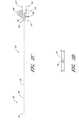
- FIG. 1Bis a plan view of the embodiment depicted in FIG. 1A .
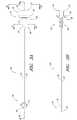
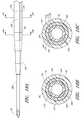
- FIG. 2Ais a plan view of the needle from FIG. 1A and shows a fenestration near a distal end.
- FIG. 2Fis an enlarged side view of the needle hub of the needle of FIG. 2A .
- FIG. 2Gis an enlarged proximal end view of the needle hub of the needle of FIG. 2A .
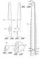
- FIG. 3Ais a plan view of the dilator from FIG. 1A and shows a fenestration near a distal end.
- FIG. 3Aalso shows longitudinally arranged grooves in the luer surface for venting air from between the dilator and sheath.
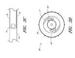
- FIG. 3Bis a cross-sectional view taken along the lines 3 B- 3 B in FIG. 3A .
- FIG. 3Cis an enlarged plan view of a portion of the dilator from FIG. 3A and shows the fenestration and longitudinal channel.
- FIG. 3Dis an enlarged end view of the dilator hub from FIG. 3A .
- FIG. 4Ais a plan view of the sheath from FIG. 1A and shows a sheath hub connected to a proximal end of a sheath.
- FIG. 4Dis an enlarged perspective view of a proximal portion of the sheath from FIG. 4A .
- FIG. 5Ais a perspective view of the guidewire section from FIG. 1A and shows a guidewire hub connected to a proximal end of a guidewire.
- FIG. 6Cis a side view of the track in FIG. 6B .
- FIG. 6Dan enlarged view of the locking mechanism from FIG. 6B .
- FIG. 7Bis a side view of the access device and locking mechanism from FIG. 7A .
- FIG. 7Cis a cross-sectional view through the access device of FIG. 7A and shows the guidewire hub disposed between an element and stop of the track.
- FIG. 7Dis an enlarged end view of the access device from FIG. 7B and shows two arms extending from the track and around at least a portion of the guidewire hub.
- FIG. 8Ais a plan view of the embodiment depicted in FIG. 1A illustrating the insertion of the distal end of the access device into a patient.
- FIG. 8Cis an enlarged view of a portion of the embodiment depicted in FIG. 8B and illustrates the needle opening or fenestration aligned with the dilator opening or fenestration in hidden lines.
- FIG. 8Dis an enlarged cross-sectional view of a portion of the embodiment depicted in FIG. 8C and shows the needle opening or fenestration aligned with the dilator opening or fenestration so as to allow fluid to flow from inside the needle to a channel formed between the sheath and dilator.
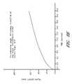
- FIG. 8Eis a graph showing the rate fluid is drawn up a channel with a gap height width of 0.002 inches.
- FIG. 8Gis a graph showing the rate fluid is drawn up a channel with a gap height width of 0.0005 inches.
- FIG. 8Iis an enlarged view of the embodiment depicted in FIG. 8A focusing on the area where the needle hub is locked to the dilator hub when the needle hub is in the first position.
- FIG. 8Jis a cross-sectional view of the embodiment depicted in FIG. 8I .
- FIG. 9Ais a side view of the embodiment depicted in FIG. 1A illustrating the guidewire advanced from the needle tip in a distal direction.
- FIG. 9Bis an enlarged view of the embodiment depicted in FIG. 9A focusing on the area where the guidewire hub is locked to the needle hub when the needle hub is in the first position.
- FIG. 9Cis a cross-sectional view of the embodiment depicted in FIG. 9B .
- FIG. 10Ais a side view of the embodiment depicted in FIG. 1A illustrating the dilator and sheath being advanced distally relative to the needle body from the position illustrated in FIG. 9A .
- FIG. 10Bis an enlarged rear view of the embodiment depicted in FIG. 10A focusing on the area where the needle hub is locked to the track when the needle hub is in the second position.
- FIG. 11Ais a side view of the embodiment depicted in FIG. 1A illustrating the removal of the guidewire, needle body, and dilator from the sheath.
- FIG. 11Bis an enlarged view of the portion of the embodiment illustrated in FIG. 11A showing the needle tip covered by the dilator during removal of the guidewire, needle body, and dilator from the sheath.
- FIG. 12Ais an enlarged plan view that illustrates another embodiment of the aligned openings or fenestrations in the needle and dilator.
- FIG. 13Ais an enlarged plan view that illustrates another embodiment of the aligned openings or fenestrations in the needle and dilator.
- FIG. 13Bis an enlarged cross-sectional view along lines 13 B- 13 B in FIG. 13A and shows the needle opening or fenestration aligned with the dilator opening or fenestration so as to allow fluid to flow from inside the needle to a channel formed between the sheath and dilator
- FIG. 14Ais an enlarged plan view that illustrates another embodiment of the channel formed between the dilator and the sheath.
- FIG. 15Ais an enlarged plan view that illustrates another embodiment of the channel formed between the dilator and the sheath.
- FIG. 15Bis a cross-sectional view along lines 15 B- 15 B in FIG. 15A and shows the thickness of the channel extending into both the dilator and the sheath.
- FIG. 16Ais an enlarged plan view that illustrates another embodiment of the channel formed between the dilator and the sheath.
- FIG. 16Bis a cross-sectional view along lines 16 B- 16 B in FIG. 15A and shows a plurality of equally spaced channels in the form of splines extending into the dilator.
- FIG. 17is an enlarged cross-sectional view through another embodiment of the access device and shows the channel formed between a sheath and a dilator that have dissimilar shapes.
- FIG. 18Ais an enlarged plan view of a portion of another embodiment of the access device and illustrates another embodiment of a channel this time formed between the needle and the dilator.
- FIG. 18Bis an enlarged cross-sectional view through the embodiment of FIG. 18A taken at 18 B- 18 B.
- FIG. 18Cis an enlarged cross-sectional view through the embodiment of FIG. 18A taken at 18 C- 18 C.
- FIG. 18Dis an enlarged perspective view of a needle hub configured to form part of the needle depicted in FIG. 18A .
- FIG. 18Eis a plan view of the dilator of FIG. 18A .
- FIG. 19Bis an enlarged cross-section view of the access device of FIG. 19A , wherein an insert is not fully inserted.
- FIG. 19Cis an enlarged view of an insert of the access device of FIG. 19A .
- FIG. 20Bis a cross-sectional view of the distal portion of the dilator of FIG. 20A , with a fenestration in phantom.
- FIG. 20Cis an enlarged view of a section of the dilator of FIG. 20B taken at 20 C- 20 C.
- FIG. 20Dis an enlarged view of a section of the dilator of FIG. 20B taken at 20 D- 20 D.
- FIG. 20Eis a side view of the dilator of FIG. 20A , with interior features in phantom.
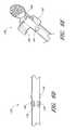
- FIG. 21Ais a side view of another embodiment of a needle.
- FIG. 21Bis an enlarged view of a distal end of the needle of FIG. 21A .
- FIG. 22Bis a plan view of the track of FIG. 22A .
- FIG. 22Cis a side view of the track of FIG. 22A
- FIG. 22Dis an enlarged view of a section of the track of FIG. 22A taken at 22 D- 22 D.
- FIG. 23Ais a perspective view of another embodiment of a guidewire hub.
- FIG. 23Bis a bottom view of the guidewire hub of FIG. 23A .
- FIG. 24Ais a proximal end view of another embodiment of a sheath.
- FIG. 24Bis a plan view of the sheath of FIG. 24A .
- FIG. 1Aillustrates an access device 20 that is configured to be inserted into a blood vessel (e.g., a vein or an artery) in accordance with a preferred embodiment of the present invention. While the access device is described below in this context (i.e., for vascular access), the access device also can be used to access and place a medical article (e.g., catheter or sheath) into other locations within a patient's body (e.g., a drainage site) and for other purposes (e.g., for draining an abscess).
- a medical articlee.g., catheter or sheath
- the present embodiment of the access deviceis disclosed in the context of placing an exemplary single-piece, tubular medical article into a body space within a patient. Once placed, the tubular article can then be used to receive other medical articles (e.g., catheters, guidewires, etc.) to provide access into the body space and/or be used to provide a passage way for introducing fluids into the body space or removing (e.g., draining) fluids from the body space.
- the tubular medical articleis a sheath or catheter that is configured primarily to provide a fluid passage into a vein.
- the principles of the present inventionare not limited to the placement of single piece sheaths or catheters, or to the subsequent insertion of a medical article via the sheath or catheter.
- the access device disclosed hereinalso can be successfully utilized in connection with placing one or more other types of medical articles, including other types of sheaths, fluid drainage and delivery tubes, and single or multi-lumen catheters directly in the patient or indirectly via another medical article.
- the access device disclosed hereincan also be configured to directly or indirectly place central venous catheters, peripherally inserted central catheters, hemodialysis catheters, surgical drainage tubes, tear-away sheaths, multi-piece sheaths, scopes, as well as electrical conduit for wires or cables connected to external or implanted electronic devices or sensors.
- the medical articles listed abovemay be directly placed in the patient via the dilator, needle, and guidewire of the access device or subsequently placed within the patient via a medical article that was placed within the patient via the dilator, needle, and guidewire of the access device.
- the embodiments disclosed hereinare not limited to co-axial insertion of a single medical article.
- two cathetersmay be inserted in the patient via an inserted sheath or a second catheter may be inserted in the patient via an inserted first catheter.
- the medical article inserted via the dilator, needle, and guidewirecan form a lumen that is in addition to the lumen(s) of the subsequently inserted medical article.
- the illustration and description of the access device in connection with a sheathis merely exemplary of one possible application of the access device.
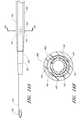
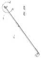
- FIGS. 1A and 1Billustrated a preferred embodiment of an access device 20 .
- the access device 20comprises a needle 22 , a dilator 24 , and a sheath 26 .
- the access devicealso includes a guidewire section 28 and a track 30 .
- the dilator 24is preferably coaxially mounted on the needle 22
- the sheath 26is coaxially mounted on the dilator 24 .
- the telescoping nature of the access device's componentscan also be accomplished by arranging the components with their axes arranged substantially parallel rather than coaxially (e.g., a monorail-type design).
- each of these componentsincludes a luminal fitting at a terminal end or transition (i.e., a hub) and elongated structure that extends from the fitting.
- the needle 22includes a needle body 32 that extends distally from the needle hub 34
- the dilator 24includes a dilator shaft 36 that extends distally from a dilator hub 38
- the sheath 26includes a sheath body 40 that extends distally from a sheath hub 42
- the guidewire section 28comprises a guidewire 44 and preferably a guidewire hub or cap 46 .
- the guidewire hub 46is disposed on the proximal end of the guidewire 44 ; however, in other applications, the hub 46 can be disposed at a location between the ends of the guidewire 44 .
- FIGS. 2A-2Gillustrate the needle body 32 and needle hub 34 of the needle 22 , which are configured in accordance with a preferred embodiment of the access device, in isolation from the other components of the access device 20 .
- the needle hub 34is disposed on a proximal end of the needle body 32 .
- the needle body 32terminates at a distal end near a distal portion 50 of the needle 22
- the needle hub 34lies at a proximal portion 52 of the needle 22 .
- the needle body 32preferably has an elongated tubular shape having a circular, constant-diameter inner bore and a circular, constant-diameter exterior surface. In other embodiments, however, the needle body 32 can have other bore and exterior shapes (such as, for example, but without limitation, an oval cross-sectional shape).
- the interior or exterior of the needlecan also include grooves or channels. The grooves or channels may guide fluids within the needle bore either around or to certain structures of the needle 22 or within the needle 22 (e.g., around the guidewire). In some embodiments, the grooves or channels may assist in maintaining a desired orientation of the needle 22 with respect to the dilator.
- the size of the needlepreferably is 18 gauge or smaller, and more preferably between 18-28 gauge, and most preferably between 18-26 gauge for micro-puncture applications (peripheral IVs).
- the length and gauge of the needle body 32should be significantly shorter and smaller, for example preferably between 3-4 cm and between 26-28 gauge.
- the needle body 32includes at least one fenestration or opening 56 near a distal end of the needle body 32 .
- the fenestration 56extends through the wall of the needle body 32 and can have a variety of shapes and orientations on the needle body 32 , as described in detail below.
- the needle body 32can have a bevel tip 54 disposed on the distal portion 50 .
- a fin 58is preferably disposed at a circumferential location around the needle hub 34 that is aligned with the circumferential locations of the bevel on the needle tip and the opening or fenestration 56 in the needle. That is, the fin 58 is indexed with the bevel and fenestration.
- the physician or healthcare providercan determine the orientation of the beveled needle tip (and the fenestration 56 ) by noting the orientation of the exposed fin 58 even though the bevel is inside the vessel and the fenestration is covered by the sheath and/or dilator.
- an orientation of the fin 58 away from the patientcoincides with a bevel up orientation of the needle tip within the vessel.
- the fenestration 56is also on the same side as the fin 58 , as seen in FIG. 2C .
- FIG. 2Dis an enlarged view of the side opening or fenestration 56 in the needle body 32 .
- the one or more fenestration 56provides a path through the side of the needle body 32 .
- the fenestration 56 illustrated in FIG. 2Dhas an oblong shape.
- the shape of the side opening 56is not limited to the illustrated embodiment and may be round, oblong, square, or another shape.
- the needle hub 34preferably includes locking structures at the proximal portion and distal portion of the needle hub 34 .
- These locking structuresmay be a luer-thread-type or another type of connections.
- the locking structure on the proximal portion 52 of the needle hub 34allows the physician or healthcare provider to secure another medical article to the proximal end of the needle hub 34 .
- the needle hub 34 in the illustrated embodimentincludes an annular flange or lip 63 .
- the lip 63is threaded to allow the needle hub 34 to attach to other medical articles with a corresponding luer-nut locking feature.
- a physician or healthcare providermay attach a syringe or monitoring equipment to the locking structure on the proximal end to perform other procedures as desired.
- the needle hub 34can also include a septum at its proximal end and/or a side port if these features are desirably for a particular application.
- the locking structure on the distal portion of the needle hub 34allows the physician or healthcare provider, for example, to lock the needle hub 34 to the dilator hub 38 when the needle hub 34 is in the first position 121 .
- the locking structureincludes a latch element 66 on the needle hub 34 .
- the latch element 66releasably locks the needle hub 34 to the dilator hub 38 .
- the locking structureallows the healthcare provider to advance the needle into a patient while grasping the needle hub 34 , the dilator hub 38 or both.
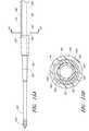
- FIG. 3Ais a plan view of the dilator 24 of the embodiment depicted in FIG. 1A .
- FIG. 3Bis a cross-sectional view of the dilator 24 of the embodiment depicted in FIG. 3A , taken along line 3 B- 3 B.
- the illustrated dilator 24comprises a dilator shaft 36 , a dilator hub 38 , a distal region 70 , and a proximal region 72 .
- the dilator shaft 36includes a side openings or fenestrations 74 ; however, in other embodiments, the dilator shaft 36 can include fewer or greater numbers of fenestrations 74 .
- the dilator shaft 36may not include a fenestration 74 where a blood flash chamber(s) is disposed within the dilator (as will be described in more detail below).
- the dilator hub 38may comprise one or more vents.
- the vents in the dilator hub 38are formed by grooves 75 .
- the dilator shaft 36may comprise one or more longitudinal channels formed in the outer surface of the dilator shaft 36 .
- the channelis an open channel.
- the side walls of the open channelare formed by ridges 76 .
- the ridges 76define generally smooth, arcuate exterior surfaces that interface with the sheath 26 ; however, in other embodiments, the ridges can have other shapes (e.g., can define more pronounced apexes).
- FIG. 3Cis an enlarged plan view of a portion of the embodiment illustrated in FIG. 3A .
- the illustrated dilator shaft 36comprises one or more side openings 74 and one or more channels formed between ridges 76 .
- the side opening or fenestration 74provides a fluid path through the side of the dilator shaft 36 .
- the shape of the side opening 74is not limited to the illustrated embodiment and may be round, oblong, square, or have another shape.
- the opening or fenestration 74 illustrated in FIG. 3Chas an oblong shape.
- the opening 74 in the dilator shaft 36has an oblong shape with its major axis being non-parallel relative to the major axis of the oblong opening 56 in the needle 22 .
- the needle opening 56may extend in a longitudinal direction and the dilator opening 74 may extend in a circumferential direction or vice versa.
- the long axis of the dilator opening 74is disposed generally perpendicular to the long axis of the needle opening 56 .
- these openings 56 , 76can have other shapes, sizes and orientations that preferably obtain a significant degree of overlap to account for manufacturing tolerances and rotational misalignments.
- the channel formed between the ridges 76extends in a proximal direction from a point distal to the opening 74 .
- the ridges 76 in the illustrated embodimentare disposed along the dilator shaft 36 and on opposite sides of the dilator shaft 36 so as to balance the dilator shaft 36 within the sheath.
- the ridges 76form two channels there between. Balancing the dilator within the sheath allows the dilator to apply equal pressure to the inside circumference of the sheath.
- the dilator hub 38may include locking structures at the proximal region 72 and the distal region of the dilator 24 .
- Each locking structuremay be a luer type or other type of connection.
- the dilator hub 38comprises a first luer connection 78 , a second luer connection 80 , a lip 77 , and a base 79 .
- the first luer connection 78engages to the needle hub 34 on the needle 22 illustrated in FIG. 2E .
- the second luer connection 80is disposed distal to the first luer connection 78 .
- the second luer connection 80(e.g., a male luer slip connector) can be configured to engage to the sheath hub 42 (e.g., a female luer slip connector) on the sheath 26 illustrated in FIG. 1A . Additionally, the male-female lure slip connectors on these components can be reversed.
- FIG. 3Dis an enlarged proximal end view of the dilator 24 of FIG. 3A .
- the dilator hub 38comprises an opening 82 that releasably engages the latch element 66 on the needle hub 34 illustrated in FIG. 2E-2F to secure the dilator hub 38 to the needle hub 34 when the needle hub 34 is in the first position 121 .
- the male-female lure slip connectors on the dilator hub and the needle hub 34can also be reversed in other embodiments.
- the color of the dilator 24may be selected to enhance the contrast between the blood or other fluid and the dilator 24 .
- bloodis observed flowing between the dilator 24 and the sheath to confirm proper placement of the needle in a blood vessel.
- the sheathis preferably manufactured from a clear or transparent material with the dilator 24 having a color that contrasts with the color of the fluid.
- the dilator 24may have a white color to enhance its contrast with red blood. Other colors of dilator 24 could be employed depending on the color of the fluid and the degree of contrast desired.
- the dilator 24may be manufactured of a clear or transparent material similar to the sheath to allow the physician to observe the blood flash through both the sheath and dilator 24 .
- FIG. 3Eis an enlarged perspective view of another embodiment of a dilator hub 38 A.
- the dilator hub 38 Ais similar to the dilator hub 38 illustrated in FIG. 3A except that the dilator hub 38 A further includes a spin nut or collar 84 .
- the proximal end of the spin nut 84rotates about an annular groove 73 in the dilator hub 38 (see FIG. 3A ). Once disposed within the annular groove 73 , the spin nut 84 is inhibited from moving in the distal direction but is free to rotate about the dilator hub 38 A.
- the spin nut 84can have an interengaging element that locks to a corresponding interengaging element on the sheath 26 .
- the spin nut 84includes an internal thread which engages with an external thread on the sheath hub 42 on the sheath 26 illustrated in FIG. 1A .
- the dilator 24 or sheath 26may separately, or together, form one or more passages to allow air or gas to escape or vent from between the dilator 24 and sheath 26 and/or between the needle and the dilator.
- the one or more passagesmay further be sized to inhibit the flow of a liquid, such as blood, while allowing air to pass therethrough.
- the one or more passagesmay be in the wall of the sheath 26 , the sheath hub, the dilator hub 38 , an exposed section of the dilator shaft, and/or formed between adjacent surfaces of the dilator 24 and sheath 26 .
- FIG. 3Ashows longitudinally arranged grooves 75 that are formed between adjacent surfaces of the dilator 24 and sheath 26 .
- Such venting passagescan also be labyrinth.
- the adjacent surfacesform a luer slip connection between the sheath 26 and dilator 24 .
- FIG. 3Fis a cross-sectional view taken along lines 3 F- 3 F in FIG. 3A and shows the grooves 75 equally spaced, though not required to be equally spaced, about the circumference of the luer slip surface.
- the grooves 75are sized to allow air to escape from between the dilator and the medical article, such as a sheath, when the blood flash occurs.
- the one or more passagesneed not be in the form of a surface groove 75 and instead may be in the form of an opening or passageway.
- the one or more passagesallow air to pass through the luer connection between the sheath and dilator hubs.
- a distal end of the passage 75is located on the distal side of the luer connection with the proximal end of the passage 75 being located on the proximal side of the luer connection.
- the one or more passagesmay be sized to filter blood or other liquid or may include a filter or other structure that inhibits the passage of a liquid while allowing the passage of air.
- the sheathitself may include one or more passages in the form of small openings, pores or porous material.
- the one or more small openings, pores or porous material in the sheathcan form a porous vent that allows air to pass yet retain blood.
- an extrusion processis used to create a long tubular body having one or more longitudinal grooves or channels on its outer diameter (OD) or within the substance of the dilator.
- the long tubular bodyexceeds the required length of a single dilator and preferably has a length that is many times greater than the length of a single dilator.
- a manufacturing dieis employed in the extrusion process having geometry that reflects the desired geometry for the inside and outside diameters of the dilator and the thickness and circumferential span of the longitudinal grooves or channels or interior channels. In the illustrated embodiment of FIGS.
- the long tubular bodyincludes two longitudinal OD channels on opposite sides of the body to enhance the balance of the dilator within the sheath.
- a single channelcan provide a visible indicator for the blood flash.
- the two channelspreferably extend along the length of the extruded tubular body.
- the illustrated embodimentincludes one or more channel disposed between the dilator and the sheath, one or more channels can in addition or in the alternative be formed between the needle and the dilator, within the dilator, and/or within the sheath.
- the dilator 24thus is made partially or completely from clear, translucent, transparent, or semi-opaque material to visualize the fluid flash within the channel.
- the extruded tubular bodyis cut to the appropriate length for a single dilator.
- the two OD groovesextend for the entire length of the cut dilator.
- thermal energyis applied to the tip to reform the tip to match the die/mandrel.
- the thermal energymay be applied by any known technique, including using radiant heating from an infrared or RF heat source.
- the dilator in the tip regionis reformed so that the grooves are essentially removed. With the grooves removed, the dilator is able to form the close fit or seal with the sheath near the tip.
- the groovesare maintained along the remainder of the dilator on the proximal side of the location where the tip of the sheath 26 sits on the dilator. After removal from the die/mandrel, the tip end of the dilator may be cleaned and cut as necessary to remove any manufacturing remnants.
- the one or more fenestrations in the dilatoris cut through the dilator near the tip region and in or near the groove.
- Each fenestrationmay be cut by any known means, including a drill or laser. Further, the cutting device may be moved with respect to the dilator or vice versa to achieve an oblong or other shape for the fenestration.
- the end of the dilator opposite from the tip endcan be flared to facilitate over molding the dilator hub onto the dilator.
- FIG. 4Ais a plan view of the sheath 26 of the embodiment depicted in FIG. 1A .
- FIG. 4Bis a cross-sectional view of the sheath 26 of the embodiment depicted in FIG. 4A , taken along line 4 B- 4 B.
- FIG. 4Cis an enlarged proximal end view of the sheath 26 of FIG. 4A .
- FIG. 4Dis an enlarged perspective view of the sheath hub 42 of the sheath 26 of FIG. 4A .
- the sheath 26may comprise a sheath body 40 , a sheath hub 42 , a distal portion 90 , and a proximal region 92 .
- the sheath body 40may be made partially or completely from clear, translucent, transparent, or semi-opaque material.
- the sheath body 40can also include one or more radio opaque markers, such as, for example, barium sulfate stripes.
- the sheathincludes two such radio opaque stripes disposed on diametrically opposite sides of the body 40 .
- the sheath body 40may be a single piece sheath through which a catheter or other medical article (e.g., a guidewire) is inserted into the vessel.
- the sheath body 40forms a conduit for insertion of the catheter or other medical article (e.g., a guidewire).
- the sheath or a portion of the sheathcan form a lumen that is in addition to the lumen(s) of the catheter.
- an equivalent to a triple lumen cathetercan be formed by inserting a dual lumen catheter through the sheath body 40 with the sheath body 40 itself forming a third lumen.
- a peel-away sheathcan include perforations, serrations, skives, or other structures, or include other materials (e.g., PTFE with bismuth) to allow the physician or healthcare provider to remove easily a portion or the entire sheath body 40 .
- the sheath hub 42may include a luer slip connection and a lock member 94 .
- the locking member 94may comprise a locking or attaching structure that mates or engages with a corresponding structure.
- the lock member 94can be a luer connection 94 which can be configured to engage with the second luer connection 80 of the dilator hub 38 .
- the sheath hub 42preferably is designed so that the locking mechanism or second luer connection 80 of the dilator hub 38 can enter the sheath hub 42 substantially unobstructed.
- the physician or healthcare providercan push, pull, or twist the sheath hub 42 and possibly disengage or engage the locking member 94 with a corresponding connector on another medical article.
- the locking member 94can be, for example, a luer connection, a protruding bump, dent, etc., that creates a mechanical fit so that the dilator hub 38 and the sheath hub 42 are releasably interlocked.
- the locking member 94 of the sheath hub 42comprises a luer connection.
- the sheath hub 42preferably engages with the corresponding second luer connection 80 on the dilator hub 38 .
- the locked positioncan be disengaged or engaged by pulling, squeezing, pushing or twisting the dilator hub 38 relative to the sheath hub 42 .
- the sheath hub 42can comprise a lip 95 .
- the lip 95can be threaded to allow the sheath hub 42 to attach to other medical articles with a corresponding locking feature.
- the sheath hub 42preferably comprises one or more surface features to allow the physician or healthcare provider to easily grasp or manipulate the sheath 26 and/or access device 20 .
- the sheath hub 42includes a squared grip 96 and ridges 98 .
- the distal end portion of the guidewirecan have a reduced diameter in comparison to other sections of the guidewire.
- the size of such reduced diameter sectioncan be selected to permit fluid to pass to the fenestration 56 in the needle body even when the guidewire has been advanced beyond the distal tip of the needle.
- FIG. 6Ais a perspective view of the track 30 of the embodiment depicted in FIG. 1A .
- FIG. 6Bis a plan view of the track 30 illustrated in FIG. 6A .
- FIG. 6Cis a side view of the track 30 illustrated in FIG. 6A . As shown in FIGS.
- FIG. 6Dis an enlarged view of a portion of the embodiment depicted in FIG. 6B .
- the locking mechanism 128is formed by varying the width of the track in the region of the second position 123 .
- the illustrated embodimentincludes a track section 134 of increasing width in the distal direction, a track section 136 of reduced width distal to the track section 134 of increasing width, and two finger elements 138 .
- the two finger elements 138project from the distal end of the track section 136 toward the proximal end of the track 30 and flare away from the longitudinal axis of the track 30 .
- FIG. 6Eis an enlarged view of a portion of the embodiment depicted in FIG. 6B .
- the locking mechanism 130is formed by a clip, clasp or other structure that engages with a portion of the guidewire hub or with a portion of the track 30 when the guidewire hub is in the third position. Some or all of the engagement structure may be part of the track 30 , be part of the guidewire hub, or be split between the track 30 and guidewire hub. In the illustrated embodiment, the locking mechanism 130 extends from the track 30 and engages with the guidewire hub.
- the locking mechanism 130comprises a rectangular element 140 protruding from the track 30 , two track arms 142 projecting from the track 30 distal to the rectangular element 140 , and a stop 144 protruding from the track 30 distal to the track arms 142 .
- the locking mechanism between the needle hub and the dilatorresides on the proximal side of the dilator hub.
- the locking mechanismcan be disposed at other locations as well.
- the locking mechanismincludes two pivotal levers which are joined by a locking hinge
- the locking mechanismcan be disposed radially relative to the needle hub.
- one leveris pivotally coupled to the dilator and the other lever is pivotally coupled to the needle.
- an elongated structurecan extend parallel to the needle body from the needle hub within the dilator.
- additional structure of the locking mechanisme.g., a detent
- the locking mechanism operating between the needle and the dilatorcan be disposed at a variety of locations relative to the dilator hub.
- the guidewire hub 46can releasably lock between the rectangular element 140 and the stop 144 .
- the track arms 142can further secure the guidewire hub 46 to the track 30 .
- This locking mechanismcan arrest unintended rotational and axial movement of the guidewire 44 at least in the distal direction when the guidewire hub 46 is in the third position 125 .
- the healthcare providermay disengage the guidewire hub 46 from the track 30 to allow distal movement of the guidewire through the access device 20 .
- the needle hub 34is locked to the dilator hub 38 when the needle hub 34 is in the first position 121 .
- the openings or fenestrations in the needle and dilatorare in register or in alignment with each other.
- the needle 22 and the dilator 24are inhibited from at least unintentional rotational and axial movement relative to each other.
- the fenestrations or openingsmaintain their general alignment.
- FIG. 8Ais a plan view of the embodiment depicted in FIG. 1A that illustrates an operational step of one method of using the access device 20 .
- FIG. 8Adepicts the needle body 32 of the access device 20 inserted into a vessel 148 , such as a vein. While the described method refers to vascular access, the access device 20 also can be used to access and place a catheter or sheath into other locations within a patient's body (e.g., for draining an abscess) and for other purposes.
- FIG. 8Bis an enlarged plan view of the portion of the embodiment illustrated in FIG. 8A which is circled by line 8 B- 8 B.
- FIG. 8Cis an enlarged plan view of the portion of the embodiment illustrated in FIG. 8B which is circled by line 8 C- 8 C.
- FIG. 8Dis an enlarged cross-sectional view of the embodiment depicted in FIG. 8C along line 8 D- 8 D.
- FIGS. 8A-Dillustrate the alignment between only one set of corresponding side openings. Other sets of side openings can also be aligned or be misaligned depending upon the relative orientations of the needle body 32 and the dilator shaft 36 .
- the dilator shaft 36is coaxially positioned to minimize an annular space 150 between the needle body 32 and the dilator shaft 36 .
- the inner surface 152 of the dilator shaft 36need not, though it can, lie directly against the outer-surface 154 of the needle body 32 .
- the annular space 150 between the outer-surface 154 of the needle body 32 and the inner surface 152 of the dilator shaft 36is minimized to inhibit the flow of blood or its constituents (or other bodily fluids) into the annular space 150 between the dilator shaft 36 and needle body 32 .
- this featureminimizes the blood's exposure to multiple external surfaces and reduces the risk of contamination, infection, and clotting.
- the dilator shaft 36is coaxially mounted to the needle body 32 such that at least part of one side opening 56 disposed on the needle body 32 is rotationally aligned with at least part of one side opening 74 on the dilator shaft 36 .
- the needle body 32 and dilator shaft 36maintain rotational alignment so that blood flows through the needle side opening 56 and dilator side opening 74 .
- the sheath body 40is preferably made partially or completely from clear, semi-opaque, translucent, or transparent material so that when blood flows into the needle body 32 , (1) through the needle side opening 56 , (2) through the dilator side opening 74 , and (3) into a channel 156 , the physician or healthcare provider can see the blood.
- the channel 156is formed between the dilator shaft 36 and the sheath body 40 and defined by one or more ridges 76 on the dilator shaft 36 .
- the channel 156is formed within a wall of the dilator shaft 36 with the dilator shaft 36 preferably comprising a transparent material. Blood will indicate to the physician or healthcare provider that the bevel tip 54 of the needle body 32 has punctured a vessel 148 .
- the needle body 32 and dilator shaft 36may (both) have multiple side openings where some or all of these side openings can be rotationally aligned.
- the channel 156can have an axial length that is almost coextensive with the length of the sheath 26 .
- the channel 156can be significantly smaller than the elongated channel 156 just described.
- the channel 156can be disposed within a distal, mid and/or proximal portion(s) of the sheath 26 .
- the channel 156alternatively can have a linear, curved or spiral shape along an axial length of the sheath 26 or can be formed by a plurality of such shapes.
- the channel 156may have various thicknesses and span angles. The thickness of the channel 156 can range from almost close to zero to 0.010 inches.
- the channel 156has a thickness of about 0.0005 to about 0.003 inches. More preferably, the channel 156 can have a thickness of about 0.001 inches to about 0.002 inches.
- the channel 156can have a span angle ⁇ about the axis of the dilator 24 of about 30 degrees to about 210 degrees or more, but preferably less than 360 degrees. More preferably, the channel 156 can have a span angle ⁇ of about 60 to 150. In the illustrated embodiment, the channel 156 spans 120 degrees.
- 8Gillustrates the rate fluid is drawn up a channel 156 with a gap height width of 0.0005 inches. As shown in FIGS. 8E-G , fluid is drawn up the fastest in a channel with a gap height width of 0.0005 inches, followed by a channel with a gap height width of 0.001 inches, followed by a channel with a gap height width of 0.002 inches.
- the shape of the channel 156 described above and the resulting capillary actionwas optimized for use with whole blood as opposed to other fluids having a different viscosity than whole blood (e.g. leukocytes, pus, urine, plasma).
- the shape of the channel 156is not limited to the disclosed shape and may be optimized for draining other liquids, such as pus.
- the shape of the channel 156 described abovewas optimized for peripherally located vessels where the pressure in the vessel enhances the capillary action and resulting blood flash as well as for vessels located in the regions where the pressure may be low. For example, in the thorax region of the body, the expected pressure in the veins may be lower than in a peripherally located vein when the patient breathes.
- a different size of the channel for use of the access device 20 in other regions of the bodymay be employed taking into account the expected pressure within the vessel or body cavity.
- an outer-surface 160 of the dilator shaft 36 and/or an inner surface 158 of the sheath body 40can be coated with a substance to promote or enhance the capillary action within the channel 156 .
- a hydrophilic substancecan be used to coat outer-surface 160 of the dilator shaft 36 and/or the inner surface 158 of the sheath body 40 to enhance capillary action.
- a surfactantcan be used to coat the outer-surface 160 of the dilator shaft 36 and the inner surface 158 of the sheath body 40 .
- a surfactantthat can be used is Lutrol 68TM, commercially available from BASFTM; other surfactants can also be used.
- Other surfaces that can be coatedinclude the inner surface of the needle body 32 , the outer surface 154 of the needle body 32 , the inner surface 152 of the dilator shaft 36 , and the guidewire 44 .
- These surfaces, including the outer-surface 160 of the dilator shaft 36 and the inner surface 158 of the sheath body 40can be coated with a surfactant individually, or in combination.
- a surfactantcan accelerate and facilitate the progression of blood through the needle, dilator, or sheath. Accordingly, smaller needles, dilators, and sheaths can be used while still allowing blood to travel through said pieces with sufficient speed to indicate to an operator that the needle has entered the vessel or drainage site. Notably, in most embodiments a body fluid will pass through the needle, and thus in most embodiments it can be desirable to apply a surfactant to the interior surface of the needle.
- one or more of these componentscan be made of a hydrophilic material.
- a hydrophilic substanceadditionally can be applied to the outer surface of the sheath 26 to act as a lubricant to ease insertion of the sheath 26 into a patient.
- Other lubricants or lubricous coatingscan be used on the exterior of the sheath 26 or at least the outer surface of the sheath can be formed of a lubricous material.
- the sheath 26can be coated or formed with agents (e.g., heparin), which elute from the sheath, to facilitate the clinical application of the access device 20 .
- the outer surface of the sheath 26can include a coating of silicone, such as Dow Corning 360 Medical Fluid, 12,5000 CSTTM, commercially available from Dow Corning.
- the sheathcan be coated with a surfactant in some embodiments.
- FIG. 8His a cross sectional view of the embodiment depicted in FIG. 8C along line 8 H- 8 H.
- the sheath body 40is coaxially positioned to minimize the annular space 157 between the sheath body 40 and the dilator shaft 36 while still allowing relative movement of the sheath body 40 and the dilator shaft 36 .
- the inner surface 158 of the sheath body 40need not, though it can, lie directly against the outer-surface 160 of the dilator shaft 36 .
- the annular interface 157 between the outer-surface 160 of the dilator shaft 36 and the inner surface 158 of the sheath body 40may be reduced in this region to inhibit the distal flow of blood or its constituents (or other bodily fluids) from the opening 74 in the dilator shaft 36 .
- FIG. 8Iis an enlarged plan view of the portion of the embodiment illustrated in FIG. 8A which is circled by line 8 I- 8 I.
- FIG. 8Jis a cross-sectional view of the embodiment depicted in FIG. 8I .
- FIGS. 8I and 8Jillustrate the needle hub 34 locked to the dilator hub 38 when the needle hub is in the first position 121 .
- the dilator shaft 36may be coaxially mounted to the needle body 32 by slipping a hollow section 84 of the dilator shaft 36 over the needle body 32 and releasably securing the dilator hub 38 to the needle hub 34 .
- the proximal end 86 of the dilator hub 38is configured to mechanically fit and interlock with the needle hub 34 .
- the dilator shaft 36may be releasably mounted to the needle body 32 so that the dilator shaft 36 can be mounted and released, or vice versa, from a coaxial position relative to the needle body 32 .
- This locking mechanismcan inhibit at least some unintentional rotational and axial movement between the needle 22 and the dilator 24 when the needle hub 34 is in the first position.
- the needle hub 34may have a luer connection 64 that locks to the luer connection 78 of the dilator hub 38 .
- the needle hub 34may also have latch element 66 that locks to the opening 82 in the dilator hub 38 .
- FIGS. 8I and 8Jillustrate the dilator hub 38 engaged with the sheath hub 42 when the access device 20 is inserted into a vessel 148 .
- the proximal end 86 of the sheath hub 42is configured to mechanically fit and releasably engaged with the dilator hub 38 .
- the luer connection 80 in the dilator hub 38can engage with the lock member 94 of the sheath hub. The resulting friction fit can inhibit at least some unintentional rotational and axial movement between the dilator 24 and the sheath 26 when the access device 20 is inserted into a vessel 148 .
- FIG. 9Ais a side view of the embodiment depicted in FIG. 1A that illustrates a further operational step of the access device 20 .
- FIG. 9Adepicts the guidewire 44 of the access device 20 advanced in a distal direction into a vessel 148 . This can be achieved by advancing guidewire hub 46 from the third position 125 in a distal direction. The guidewire hub 46 is then locked to the needle hub 34 when the needle hub 34 is in the first position 121 .
- FIG. 9Bis an enlarged side view of the portion of the embodiment illustrated in FIG. 9A which is circled by line 9 B- 9 B.
- FIG. 9Cis a cross-sectional view of the embodiment depicted in FIG. 9B .
- FIG. 9Cillustrates the locking mechanism between the guidewire hub 46 and the needle hub 34 .
- the guidewire hub 46is configured to mechanically fit and releasably or irreversibly interlock with the needle hub 34 .
- the guidewire hub 46includes a nub 162 on the inner surface of the guidewire hub 46 .
- the nub 162 of the guidewire hubcan lock onto the needle hub 34 by advancing the guidewire hub 46 in a distal direction until the nub 162 is secured within the threaded groove on the lip of the needle hub 46 .
- the guidewire hub 46can lock to the needle hub 34 via corresponding threaded elements.
- FIG. 10Ais a side view of the embodiment depicted in FIG. 1A that illustrates another operational step of the access device 20 .
- FIG. 10Adepicts the dilator shaft 36 and the sheath body 40 advanced in a distal direction into a vessel 148 . This can be achieved by releasing the dilator hub 38 from the needle hub 34 and advancing the dilator 24 and sheath 26 in a distal direction relative to the needle hub 34 along the guidewire and needle.
- FIG. 10Afurther illustrates the proximal movement of the needle 22 and guidewire section 28 relative to the dilator 24 and the sheath 26 .
- the needle hub 34will lock to the track 30 when the needle hub 36 reaches the second position 123 .
- FIG. 10Bis an enlarged rear view of the portion of the embodiment illustrated in FIG. 10A which is circled by line 10 B- 10 B.
- the needle hub 34locks onto the track 30 via the locking mechanism 128 in the second position 123 .
- the needle hub tangs 68slide in a proximal direction over the track fingers 138 and the tangs 68 can lock into place between the track fingers 138 and the track section of increasing width 134 . This arrests and, more preferably, substantially irreversibly prevent axial movement of the needle body 32 at least in the distal direction when the needle hub 34 is in the second position 123 .
- the locking mechanism 128irreversibly prevents the needle hub 34 from moving in either the proximal or distal directions once engaged. Furthermore, the distal tip 54 of the needle 22 is drawn into the dilator 24 to sheath the distal tip 54 when the needle hub 34 is in the second position 123 . Thus, this locking mechanism 128 inhibits the bevel tip 54 disposed on the distal portion 50 of the needle body 32 from being advanced beyond the distal end of the dilator shaft 36 once the dilator shaft 36 has been advanced over the needle body 32 during use. The dilator shaft 36 thus sheaths the sharp bevel tip 54 of the needle body 32 to inhibit accidental needle sticks from occurring.
- FIG. 11Ais a side view of the embodiment depicted in FIG. 1A that illustrates the final operational step of the access device 20 .
- FIG. 11Aillustrates the removal of the guidewire 44 and the dilator shaft 36 from the vessel leaving the sheath body 40 properly inserted within the vessel 148 .
- FIG. 11Bis an enlarged plan view of the portion of the embodiment illustrated in FIG. 11A which is circled by line 11 B- 11 B. As clearly shown in FIG. 11B , the distal end of the dilator shaft 36 and the guidewire 44 extend beyond the sharp bevel tip 54 of the needle body 32 to inhibit accidental needle sticks from occurring.
- openings 56 , 74 in the needle body 32 and dilator shaft 36 with different aspect ratioswill increase the likelihood that the openings 56 , 74 in the needle body 32 and dilator shaft 36 will be aligned so that blood flows substantially unobstructed through the needle side opening 56 and dilator side opening 74 .
- FIG. 12Ais a plan view of another embodiment of the openings 56 , 74 in the needle body 32 and dilator shaft 36 illustrated in FIGS. 8B and 8C .
- FIG. 12Bis an enlarged cross-sectional view of the embodiment depicted in FIG. 12A along line 12 B- 12 B.
- FIGS. 12A and 12Bdepict a needle body 32 A with an oblong opening 56 A and a dilator shaft 36 A with a circular opening 74 A.
- the needlecan have a circular opening and the dilator can have an oblong opening. These embodiments can increase the likelihood that the openings 56 A, 74 A will be at least substantially aligned so that blood flows through the needle side opening 56 A and dilator side opening 74 A.
- FIG. 13Ais a plan view of another embodiment of the openings 56 , 74 in the needle body 32 and dilator shaft 36 illustrated in FIGS. 8B and 8C .
- FIG. 13Bis an enlarged cross-sectional view of the embodiment depicted in FIG. 13A along line 13 B- 13 B.
- FIGS. 13A and 13Bdepict a needle body 32 B with a circular opening 56 B and a dilator shaft 36 B with a circular opening 74 B that is larger than the circular opening 56 B in the needle body 32 B.
- the opening in the dilatorcan be smaller than the opening in the needle.
- the dilator shaft 36may have one or more channels 156 formed between ridges 76 to form a conduit or flow path between the sheath body 40 and the dilator shaft 36 to enable the physician or health care provider to view the blood after the bevel tip 54 of the needle body 32 has properly punctured a vessel or the channels may be formed without ridges but by extruding axial indentations of various possible configurations or by forming fully enclosed channels within the dilator shaft or body.
- FIG. 14Ais a plan view of another embodiment of the ridges 76 depicted in FIG. 8C .
- FIG. 14Bis an enlarged cross-sectional view of another embodiment of the ridges 76 depicted in FIG. 8D .
- FIGS. 14A and 14Bdepict two ridges 76 C on the inner surface 158 C of the sheath body 40 C that form at least one channel 156 C between the sheath body 40 C and the dilator shaft 36 C.
- FIG. 15Ais a plan view of another embodiment of the ridges 76 depicted in FIG. 8C .
- FIG. 15Bis an enlarged cross-sectional view of another embodiment of the ridges 76 depicted in FIG. 8D .
- FIGS. 15A and 15Bdepict two ridges 76 D on the inner surface 158 D of the sheath body 40 D and two ridges 76 E on the outer surface 160 D of the dilator shaft 36 D that combine to form a channel 156 D between the sheath body 40 D and the dilator shaft 36 D.
- the two ridges 76 D on the inner surface 158 D of the sheath body 40 Dcan each be about 0.0005 inches thick and the two ridges 76 E on the outer surface 160 D of the dilator shaft 36 D can each be about 0.0005 inches thick.
- FIG. 16Ais a plan view of another embodiment of the ridges 76 depicted in FIG. 8C .
- FIG. 16Bis an enlarged cross-sectional view of another embodiment of the ridges 76 depicted in FIG. 8D .
- FIGS. 16A and 16Bdepict many ridges on the outer surface 160 E of the dilator shaft 36 E. Between adjacent ridges are splines 76 F. The splines 76 F form a plurality of channels 156 E between the sheath body 40 E and the dilator shaft 36 E. One or more of the channels 156 E can have the same span angle ⁇ or different span angles ⁇ . In the illustrated embodiment the channels 156 E have span angles of 120 degrees and 23 degrees. In another embodiment, a single ridge 76 can spiral around the exterior of the dilator along its length.
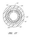
- FIG. 17is an enlarged cross-sectional view through another embodiment of the access device and shows the channel 156 F formed between a medical article or sheath body 40 F and a dilator shaft 36 F that have dissimilar shapes.
- the outer surface of the dilator shaft 36 Fhas an oval shape while the inner surface of the sheath body 40 F has a round shape.
- the oval dilator shaft 36 F and the adjacent round sheath body 40 Fform one or more channels or gaps 156 F between the sheath body 40 F and the dilator shaft 36 F.
- the shapes of the sheath body 40 F and dilator shaft 36 Fare not limited to round and oval and may include any other combination of dissimilar shapes in adjacent regions of the sheath body 40 F and dilator shaft 36 F.
- the outer surface of the dilator shaft 36 Fis oblong and the inner surface of the sheath body or medical article 40 F is round.
- the outer surface of the dilator shaft 36 Fis round and the inner surface of the medical article 40 F is square.
- the gap or channel 156 Fcan follow a longitudinal axis, a spiral path along the longitudinal axis, a linear path along the longitudinal axis or other path along the access device. In some modes, the linear path is parallel to the longitudinal axis.
- the gap or channel 156 F thicknesscan vary along at least a portion of a length of the gap or channel 156 F.
- the access devicein another mode, includes a blood flash-back space defined between the shaft of the needle and the shaft of the dilator.
- the flash-back spacepreferably vents to the atmosphere and more preferably vents independent of the sheath.
- a vent passageis formed through the dilator, through the needle, or between the dilator and the needle.
- FIGS. 18A-18Eillustrate an embodiment of this mode of the access device, wherein a vent channel is formed between the needle and the dilator.
- the needle body 32 Gincludes one or more fenestrations 56 (e.g., like any of the fenestrations depicted in FIGS. 12A-16A ), and one or more optional ridges 176 (e.g., two ridges 176 are shown in the illustrated embodiment).
- the ridges 176define the sides of at least one channel 256 extending along a length of the needle body 32 G.
- additional channels 256can be formed with additional ridges.
- channels 256can be formed with a protruding ridge, or without a protruding ridge such as with a depression(s) or with a concentric gap.
- a channel 256can be formed with protruding or non-protruding ridges on the inner surface of the dilator shaft 36 G (instead of or in addition to features on the needle body 32 G).
- the channel 256is depicted as straight, it can also form other patterns such as a helix or another shape wrapping about the access device. Further, where multiple channels are present they can form intersecting helices, parallel helices, or other patterns.
- a distance between the needle body 32 G and a dilator shaft 36 Gcan generally define a space, or a generally annular space, similar to the space created by the channels 256 .
- the needle hub 34 Gcan include one or more venting grooves 175 .
- the venting grooves 175are on the luer connection 64 , but in other embodiments they can be located on the needle body 32 G, on the dilator shaft 36 G, pass through the needle hub 34 G, pass through a dilator hub 38 G, or take some other path.
- the venting grooves 175can provide communication between the channels 256 (or similar spaces) and the ambient atmosphere.
- the luer connection 64can be configured to cooperate with the dilator hub 38 G to form a substantially liquid tight seal, such that a substance can only escape through the venting grooves 175 .
- the venting grooves 175can form a passage sufficiently small in cross-sectional area to allow the escape of gases (e.g., air) to the ambient atmosphere while hindering the escape to the ambient atmosphere of body liquids (e.g., red blood cells) with high molecular sizes, viscosities, or surface tensions. Further, in some embodiments multiple such passages can be provided, allowing adequate air ventilation despite small cross-sectional passages.
- gasese.g., air
- body liquidse.g., red blood cells
- multiple such passagescan be provided, allowing adequate air ventilation despite small cross-sectional passages.
- venting structureis depicted as grooves 175 in the illustrated embodiment, other structures can perform similar functions.
- a single reduced space location between the needle body 32 G and the dilator body 34 Gcan permit the escape of air while inhibiting the flow of blood proximally beyond the reduced space location.
- a labyrinth passagecan be disposed between the ambient atmosphere and the flash-back space (the space between the needle and dilator).
- one or more of the venting grooves 175can be filled at least in part by a porous material that permits gases to flow through the material but inhibits the passage of a body fluid (e.g., blood).
- a porous materialthat permits gases to flow through the material but inhibits the passage of a body fluid (e.g., blood).
- a body fluide.g., blood
- Such materialcan be integrally formed into the needle hub 34 G or dilator hub 38 G such that the material and the hubs are unitary. The material can then comprise any portion of the length of the venting grooves 175 .
- the materialcan be placed into the venting grooves 175 or a receptacle in communication with the groove(s).
- the groovecan include a receiving portion such as a groove notch 185 configured to receive the porous material.
- vent passages in other embodimentscan be entirely formed by such porous material.
- Suitable porous materialsinclude, but are not limited to a porous polymer such as HDPE, UHMWPE, PP, PTFE, PVDF, EVA, PE, Nylon, and PU, of pore size approximately 2.5 microns.
- a combination of pore volume and pore sizecan be chosen to allow passage of gases (such as air) but inhibit the passage of body fluids (such as blood).
- the venting passagescan be tubes defined solely by either the needle hub 34 G or the dilator hub 38 G.
- the channel 256can lead to an opening in the needle hub 34 G.
- This openingcan include any of the characteristics discussed above to control the passage of gases and fluids. The opening can thus allow the escape of gases (e.g. air) through the needle hub 34 G to the ambient atmosphere while inhibiting the passage of body fluids (e.g. blood).
- a similar venting passagecan be a tube defined solely by the dilator hub 38 G. It will be clear from the disclosure herein that a variety of passages (e.g. venting grooves 175 , tubes, porous material, etc.) can be used to allow the escape of gases (e.g. air) to the ambient atmosphere while inhibiting the escape of body fluids (e.g. blood).
- the venting passagescan be within the dilator shaft 36 G and the sheath body 40 .
- a venting hole or a patch of venting materialcan be provided in each of the dilator shaft 36 G and the sheath body 40 .
- these venting structurescan overlap, allowing gases to pass directly from one to the other.
- these venting structurescan be positioned some distance away from each other, in which case a channel or groove similar to those in FIG. 18D can be provided between the dilator shaft 36 G and the sheath body 40 to bring the venting structures into communication.
- These venting structurescan be provided proximal from the fenestration 56 in the needle body 32 G.
- the dilator shaft 36 G in this embodimentcan have no fenestration and can be generally continuous.
- the dilator shaft 36 Gcan thus radially close the channel 256 (or similar space).
- the same functionalitycan be accomplished with ridges in the dilator shaft 36 G cooperating with an otherwise generally continuous needle 32 G including a fenestration 56 .
- the dilator shaft 36 Gcan be formed of a translucent material in the entirety, or alternatively be translucent in at least the region adjacent the channel 256 .
- the sheath body 40can be similarly formed of a translucent material. In other embodiments, the material can be transparent instead of only translucent. In further embodiments, the material can be only partially translucent both spatially and temporally.
- the material of the dilator shaft 36 G and/or the sheath body 40can be translucent near the channel 256 , allowing visual confirmation of e.g. blood flash-back.
- the visual characteristics of the materialcan change upon entry of a body fluid (e.g. due to temperature change or molecular interaction). The material can thus become translucent upon entry of a body fluid, or in other embodiments change color or provide some other visual indication.
- the surfactantcan ease the passage of a body fluid through spaces within the access device, accelerating flashback.
- a similar channelcan be provided between a dilator shaft and a sheath body, and the surfactant can be supplied on the inner surface of the sheath and the outer surface of the dilator.
- channelscan be provided both between the dilator and needle and the dilator and sheath, with the channels being in communication via a fenestration in the dilator, as described herein.
- the outer surface of the sheathcan be coated with a surfactant, lubricious material, or the like.
- the channel 156can be formed by having one complete ridge on the inner surface of the sheath and one complete ridge on the outer surface of the dilator.
- the inner surface of the sheathcan have two ridges that run 50% of the length of the channel 156 and the outer surface of the dilator can have two ridges that run the remaining 50% of the channel 156 .
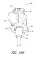
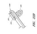
- the ventingcan be provided at least partially through an insert 451 between a dilator hub 438 and needle hub 434 , as best shown in FIGS. 19A , 19 B.
- an additional piecesuch as the insert 451 can facilitate the provision of certain desirable dimensions, materials, and other design features that might not be otherwise possible or economical.
- a middle portion of the dilator shaft 436it may be desirable for a middle portion of the dilator shaft 436 to have an inner diameter substantially larger than the outer diameter of the needle body 432 near a needle fenestration (such as those described in relation to other embodiments).
- This difference in diameterscan create a space that allows a body fluid to flow between the two (such as in the channel 256 ) from the fenestration.
- the embodiment depicted in FIGS. 19A-19Cprovides venting with the assistance of an insert 451 .
- the insert 451can be disposed within a proximal opening 460 of the dilator hub 438 .
- the proximal opening 460can be configured to also receive a distally protruding portion 461 of the needle hub 434 , as described in similar embodiments above (e.g., the portions forming a luer fitting between the needle and dilator hubs).
- the insert 451can be press-fit into the dilator hub 434 , while in other embodiments it can be loosely slid onto the needle body 432 (prior to combination with the dilator 424 ).
- the insert 451defines a through-hole 452 that can slidingly receive the needle 422 (or another needle described herein), e.g. along the needle body 432 .
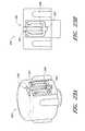
- the insert 451can be substantially circular, or donut-shaped, allowing flexibility in its rotational position within the dilator hub 438 .
- the insert 451can be rotationally fixed within the dilator hub 438 , i.e., with a non-circular insert and a corresponding non-circular receiving portion in the dilator hub 438 .
- the insert 451can have particular dimensions to facilitate the release of gases while hindering the release of body fluids.
- the diameter of the insert's through-hole 452can be only slightly greater than the outer diameter of the needle body 432 , creating a space that allows the release of gases but hinders the release of a body fluid.
- the gasescan then enter a space between the needle hub 434 and the insert 451 within the receiving portion of the dilator hub 438 . From this space, the gases can then proceed to the ambient atmosphere in a passage 462 defined between the needle hub 434 and the dilator hub 438 .
- the needle hub 434 and the dilator hub 438can connect via a luer connection that may prevent the passage of gases
- additional mechanismscan also attach the two hubs.
- the needle hub 434can include a hook portion 470 that can releasably hook to a ledge portion 471 of the dilator.
- the latch element 66 and the opening 82can also attach the two hubs.
- components that might otherwise form a luer connection between the two hubscan also be sufficiently separated to allow the escape of gases without compromising a connection between the hubs.
- the outer edge of the insert 451can be shaped to substantially match the receiving portion of the receiving portion of the dilator hub 438 to form a seal between the two that at least hinders the escape of a body fluid therethrough.
- a taper within the dilator hub 438(also used for a luer connection with a needle, as discussed above) can facilitate a seal between the insert 451 and the dilator hub.
- the seal between the outer edge of the insert 451 and the receiving portion 460 of the dilator hub 438can also be impermeable to gases, forcing their passage through the through-hole 452 , as described above.
- the insert 451can also include a proximally projecting portion depicted as a ridge 455 along its proximal face, which can be of particular relevance as shown in FIG. 19B . If the insert 451 is ajar, it may not completely enter the dilator hub 438 , as depicted in FIG. 19B . The insert 451 can then come into contact with the needle hub 434 . Such contact between the needle hub 434 and the insert 451 could then potentially form a seal, preventing the escape of gases through the insert's through-hole 452 . Thus, in some embodiments, the insert can also include a ridge 455 with grooves 456 .
- the needle hub 434can contact the ridge 455 before contacting the rest of the proximal end of the insert 451 , preserving a space therebetween.
- the ridge 455can include one or more grooves 456 , providing an opening in the ridge 455 for gases to pass through, to the passage 462 between the hubs 434 , 438 .
- more than one groovecan be provided to advantageously allow gases to pass through in multiple directions.
- the proximally projecting portion on the insert 451can take other forms.
- the insert 451can have one or more distinct projections to maintain separation from the needle hub 434 .
- the insert 451can include one or more grooves that allow the escape of gases despite contact with the needle hub 434 .
- similar structurescan be provided on the needle hub instead of or in addition to the structures on the insert.
- FIGS. 20A-20Edepict another embodiment of a dilator 24 H that includes additional elements to enhance the fluid flash-back feature of the access device 20 .
- One additional elementinvolves at least one wiper or seal that interacts with a needle (e.g., the needle 22 described in connection with the embodiment illustrated in FIGS. 1-7 above) about which the dilator 24 H is coaxially disposed to inhibit fluid uptake thorough a space occurring between the needle exterior (e.g., needle exterior surface 154 of FIG. 8D ) and the dilator interior (e.g., dilator interior surface 152 of FIG. 8D ).
- the seal featurecan be incorporated into any of the previously described embodiments of the access device 20 , along with or separate from the other elements depicted in FIGS.
- the seal featurecan have a smaller inner diameter and be on a dilator body associated with the dilator hub 438 depicted in FIGS. 19A-19C .
- the dilatorcan include multiple seals located along the length of the dilator. Such seals can be located in series to the proximal side of the dilator fenestration and/or the needle fenestration. Additional seals can be located on the distal side of such fenestration as well in some embodiments; however, in the illustrated embodiment, the seal is depicted to the proximal side of both the dilator and needle fenestrations.
- the dilator 24 Hincludes a sealing portion 250 that lies slightly proximal of a fenestration 74 H on the dilator 24 H.
- the sealing portion 250is depicted as an inward protrusion that creates a narrowed region in the interior of the dilator 24 H.
- the dilator 24 Hcan form a seal with a needle (not shown) to separate the space between the dilator 24 H and the needle into proximal and distal sections each lying to one side of the seal.
- a fluidis intended to advance from the needle bore to a space between the dilator 24 H and a sheath (e.g., the sheath 26 described in connection with the embodiment illustrated in FIGS. 1-7 above)
- fluid leakage into the proximal space between the dilator 24 H and the needleis reduced, as the body fluid is inhibited from passing proximally beyond the sealing portion 250 .
- the sealing portion 250can serve as a wiper, removing fluid (e.g., blood) from the surface of the distal portion of a needle as it is retracted into the dilator 24 H.
- the sealing portion 250can take a variety of cross-sectional shapes, including triangular (an example of which is illustrated in FIG. 20C ), rounded or rectangular. In the illustrated embodiment depicted in FIG. 20C , the sealing portion 250 has a generally triangular cross-sectional shape formed in part by a tapering surface 252 that slopes inward preferably in a proximal direction. The tapering surface 252 intersects with a ledge 251 of the sealing portion 250 .
- the ledge 251lies generally perpendicular to a longitudinal axis of the dilator 24 H; however, in other embodiments, the ledge 251 can lie at various angles relative to the longitudinal axis so that an angle formed between the tapering surface 252 and the ledge 251 can be acute, right or obtuse.
- the tapering surface 252 on the sealing portion 250can assist movement of the needle through the dilator 24 H in a proximal direction.
- the ledge 251allows the sealing portion 250 to deflect proximally as a needle is passing through.
- the dimension of the inward projection of the sealing portion 250preferably is not significantly less than, and is more preferably greater than half of the difference in diameters between the exterior of the needle and the interior of the dilator at the point of the fenestrations.
- the dilator 24 Hcan include an expanded portion 260 , formed with a taper 262 proximal of the sealing portion 250 .
- the expanded portion 260can reduce contact and friction between the dilator 24 H and a needle (or other article for that matter) passing through the dilator 24 H.
- a needle or other article passing through the dilator 24 Hcan include a stop portion extending axially outward to engage the taper and inhibit further advancement of the article.
- the expanded portion 260 and its coinciding tapercan define a limit on axial movement between the dilator 24 H and a corresponding needle or other article.
- the sealing portion 250can be formed on the dilator in any of a wide variety of ways readily known to those skilled in the art.
- the sealing portion 250can be formed during a dilator tipping process after the dilator has been extruded.
- An internal mandrelcan be cut with an annular groove that has the inverse image of the sealing portion 250 .
- the mandrelis then placed within dilator. As the material of the dilator's distal end is heated during the tipping process and then pressed into the desired exterior shape, the material will also be forced into the annular groove on the mandrel to form the sealing portion 250 . After sufficient cooling, the dilator can be withdrawn.
- a sealing portioncan take a different form.
- a needlecan have an expanded exterior portion, forming an enlarged external diameter on the proximal side of its fenestration, similar to the enlarged internal diameter of the expanded portion 260 of the embodiment depicted in FIGS. 20A-20C .
- the needlecan have a smaller external diameter at a distal portion and a larger external diameter at a distal portion.
- the enlarged diameter portioncan engage or abut against the internal surface of the dilator (e.g., against taper 262 ) to form a sealing portion similar to that described above.
- the contact between the needle and dilator, forming a sealing portioncan be formed between matching tapers such as the taper 262 on the dilator 24 H and a similar external taper on the needle.
- the contact between the needle and the dilatorcan be on other surfaces, such as surfaces generally parallel with the longitudinal axis of the needle and dilator.
- the dilator 24 Hcan have an inner diameter d 1 in a portion distal from the fenestration 74 H.
- a needlesuch as the needle 22 J, or other needles such as the needle 22
- d 1can be less than d 2 ; this can provide a number of advantages.
- the interference fit of the dilator 24 H on the needlecan put the dilator 24 H under a radial or hoop load. This loading can increase the strength of the dilator 24 H in an axial direction.
- the inner diameter d 1 of the dilator 24 Hcan be smaller than the outer diameter d 2 of a needle on which it mounts by approximately 15% or less.
- the outer diameter d 2 of the needlecan be approximately 15% larger than the inner diameter d 1 of the dilator 24 H.
- the inner diameter d 1 of the dilator 24 His smaller than the outer diameter d 2 by approximately 10% or less.
- the inner diameter d 1is smaller than the outer diameter d 2 by approximately 2% to 4% of the outer diameter d 2 .
- the inner diameter d 1 of the dilator 24 Hcan be approximately 97% of the outer diameter d 2 of a needle on which it mounts.
- the dilator tipcan be beveled to provide a smoother dilation and to ensure further that the dilator tip does not deform upon entrance into the patient's body.
- the tipcan have a taper or bevel at an angle ⁇ on each side (it is noted that the indicated angle ⁇ 's opposite angle is equal to ⁇ , and thus they are treated as the same herein).
- the beveled tipcan reduce axial forces on the dilator 24 H upon passage through tissue (e.g., skin).
- the angle ⁇can be approximately 30 degrees. In other embodiments, the angle ⁇ can be between approximately 40 and 20 degrees.
- the dilator tipcan taper at a shallower angle, as depicted in FIG. 20D .
- the dilatorcan then taper at approximately 3 degrees, or alternatively at an angle less than approximately 3 degrees.
- the dilator 24 Hcan include a ridge or protrusion 264 through which the fenestration 74 H passes.
- the ridge 264can separate a sheath overlapping the dilator, facilitating any flow through the fenestrations 74 H into a space between the dilator 24 H and said sheath.
- the ridge 264can be generally thinner than the fenestration 74 H.
- the ridge 264can contact and separate the sheath while also leaving space for a fluid to flow around the ridge.
- the ridge 264can be generally oriented in an axial, proximal-distal direction. However, in other embodiments the ridge 264 can be oriented in a circumferential direction or otherwise.
- FIGS. 21A and 21Bdepict a further embodiment of a needle 22 J that can be used in a manner similar to that of other needles described herein such as the needle 22 .
- the needle 22 Jcan comprise an echogenic portion 270 at the distal tip.
- the echogenic portioncan comprise a material that scatters waves used in imaging, thus facilitating visualization of the needle under ultrasound.
- Other imaging techniquescan also be used, such as using a needle having a radio-opaque portion facilitating visualization under X-rays or fluoroscopy.
- the echogenicitycan be increased by sandblasting the portion 270 to roughen the surface.
- the tipcan be sharpened after sandblasting, allowing the tip of the needle to be echogenic.
- Echogenicitycan also be increased by modifying the internal material of the needle itself, such as by adding granular impurities. However, in some instances modification of the internal material may unacceptably compromise the structural integrity of the needle.
- the echogenicity or similar imaging compatibilitycan allow an operator to easily view the needle tip inside the body using a scanning technique such as ultrasound.
- a needle with an echogenic portion 270can further lack fenestrations 56 , 74 , grooves 75 , and/or surfactant. Further, in some embodiments with an echogenic portion 270 , the access device can lack a flashback space or flash chamber.
- the needle 22 Jcan have both an echogenic portion 270 and a fenestration 56 (in addition to other optional features described above).
- the needle 22 Jcan include a contrast portion 280 .
- the contrast portion 280can have optical properties that improve the visibility of a fluid surrounding the contrast portion. For example, as described above, in some embodiments a body fluid can flow into a flashback space through the fenestration 56 . The contrast portion 280 can then be positioned generally adjacent the flashback space and the contrast portion can have optical properties that contrast with the body fluid. Thus, the body fluid's entry into the flashback space can be more immediately apparent.
- the contrast portion 280can have a color that contrasts with the color of blood, such as white, green, blue, etc.
- other optical propertiescan be varied such as by choosing between a reflective or matte finish.
- the contrast portion 280can have be striped, checkered, dotted, or have some other pattern wherein the optical properties vary.
- the contrast portion 280can have black and white stripes oriented axially and/or circumferentially along the needle. Where a pattern with different optical properties is utilized, the contrast portion 280 can be more generic to different fluids that may be distinguishable from one region of the contrast portion 280 but not another region.
- the contrast portion 280can be painted to have a particular color, finish, pattern, etc.
- portions of the needlecan be polished or roughened to effect the reflective properties of the contrast portion 280 .
- the contrast portion 280can be formed from a different material, or have a different material applied to its surface, to yield different optical properties.
- the contrast portion 280can be made echogenic, as in the echogenic portion 270 described above.
- the contrast portion 280can be positioned just proximal from the fenestration 56 and extend a distance less than the entire distance of the needle 22 J. This position can generally correspond to the beginning of a flashback space that may also be just proximal of the fenestration 56 . However, in other embodiments the position of either or both the flashback space and the contrast portion 280 can vary. For example, in some embodiments the contrast portion 280 can span across the fenestration 56 , or can be offset some distance therefrom. In further embodiments, the contrast portion 280 can extend to the needle hub or can span the entire needle body. As depicted, the contrast portion 280 can span circumferentially about the entire needle. However, in some embodiments the contrast portion 280 can be positioned only along an angularly reduced portion of the needle body, such as an angular portion having an angular span corresponding to the angular span of the fenestration 56 .
- the dilatorcan have corresponding portions that are clear, translucent, transparent, or semi-opaque, such that the contrast portion 280 can be viewable from outside the access device. Then, as a fluid such as a body fluid enters the flashback space an observer can see both the contrast portion 280 and the body fluid as it enters the flashback space to occlude the contrast portion 280 . The contrast in optical properties between the fluid and the contrast portion 280 can then facilitate the visual detection of the fluid's entry.
- the flashbackcan be enhanced or accelerated by sealing off or restricting air flow from the space between the needle body and the dilator body.
- fluid leakagee.g., air egress
- a sealing piecesuch as a washer between the needle and dilator hubs. The washer reduces any fluid flow that might occur between a dilator and needle at their abutting hubs.
- a trapped air columncan form between the dilator and needle that inhibits the flow of a body fluid (e.g., blood) into the space between the needle and dilator.
- the body fluid flowcan thus be diverted, e.g., into a dilator fenestration 74 H and into a space between a dilator and sheath.
- the washercan be an elastic material, such as silicone.
- the washercan mount on the needle and have a planar or an o-ring-like shape.
- a flashback spacecan be provided between a needle and a dilator.
- a channelcan be formed between the needle and the dilator that can receive blood or other fluids through the needle fenestration 56 .
- An example of such a flashback spaceis described in FIGS. 18B-18D and the accompanying text in Application No. PCT/US2009/037204, filed 13 Mar. 2009, and incorporated herein by reference in its entirety.
- a preassembled access devicecan optionally be provided with a needle 22 J that does not include any fenestrations and that can (but need not) be echogenic (depicted in FIGS. 21A , 21 B), along with a guidewire, dilator, sheath, and associated hubs.
- the preassembled access devicecan be inserted inside packaging, in the preassembled state.
- An operatorcan insert the access device into a patient and stop the advancement of the needle once the needle enters a targeted body space, as viewed from outside the body by ultrasound, X-ray, or some other imaging technique.
- the preloaded guidewirecan then pass through the needle into the body space.
- the dilatorcan be advanced over the needle into the body space.
- the needlecan be withdrawn the patient and further actions can be taken to insert the sheath over the dilator, as described above in relation to other embodiments.
- an access devicecan also include a modified track 30 K and guidewire hub 46 K, as depicted in FIGS. 22A-23B .
- the track 30 K and guidewire hub 46 Kcan be substantially similar to the tracks and hubs discussed above, can be operated in a similar manner, and can be used similarly with other elements such as the needles, dilators, and sheaths described herein.
- the track 30 Kcan generally define a third position 125 K with some similarity to the third position 125 described above.
- the third position 125 Kcan include a releasable coupling mechanism 130 K that can engage with the guidewire hubs with corresponding parts, such as the guidewire hub 46 K.
- the coupling mechanism 130 Kcan include a coupling section 290 formed from a T-shaped projection extending from the track 30 K.
- the T-shaped projectioncan additionally include two latch recesses, on each side of its base, generally toward a distal end of the coupling section 290 .
- a corresponding guidewire hub 46 Kcan have corresponding structure with the coupling section 290 to releasably connect thereto.
- the guidewire hub 46 Kcan include a receiving section 296 that can be in the form of a recess.
- the recesscan have a T-shaped cross-section at a proximal end to match the coupling section 290 , as best depicted in FIG. 23A .
- the receiving sectioncan receive the base of the coupling section 290 along two tines that can terminate with latch projections 298 .
- the latch projections 298can interact with the latch recesses 292 on the coupling section 290 to form a reversible snap-fit between the track 30 K and the guidewire hub 46 K.
- the tinescan include bending portions 302 (formed e.g. from thinned material, to facilitate the snap-fit.
- the receiving section 296can include an end recess 300 in-line with the provided path provided for the coupling section 290 between the tines, such that when the latch recesses 292 and projections 298 interengage, the coupling section 290 can also enter the end recess 300 .
- the connection between the track 30 K and hub 46 Kcan be further stabilized.
- the trackcan include a grip projection 294 .
- the grip projection 294can extend downward from the track 30 K, opposite from the coupling section 290 .
- the grip projection 294can be generally circular with gripping ridges, but other structures and shapes are possible.
- the grip projection 294can allow an operator of the access device to hold the proximal end of the track 30 K in a pistol-type grip.
- a ring finger or middle fingercan be positioned around the grip projection 294 to contact it on the distal side. The thumb of the same hand can then be placed on the proximal end of a guidewire hub 46 K coupled in the third position 125 K.
- a similar grip projectioncan be applied to other tracks, such as the track 30 described above. Further, similar grip projections can be applied to other elements, such as a needle. Applying a grip projection to the needle can, for example, allow a needle to be easily gripped and moved along a track as described herein.
- a modified sheath 26 Lcan be combined with the other element described.
- the sheath 26 Lcan be a splittable sheath.
- the sheath hub 42 Lcan have two or more tabs 320 that can be gripped. The tabs 320 can then be pulled to split the splittable sheath 40 L along a split line 330 .
- the split line 330can extend through both the sheath hub 42 L and the sheath body 40 L.
- splitting the sheath 26 L along the split line 330can separate the sheath into two halves.
- the sheath 26 Lalso can have a lip 95 , allowing engagement with other elements described above, such as the dilator 24 , in a manner similar to the sheath 26 .
- the sheath hub 42 Lcan additionally include a ridge 325 toward a distal end of the hub.
- the ridge 325can facilitate gripping of the hub 42 L.
- the ridge 325can receive a tubular or cylindrical cover that can extend over the distal portions of the sheath, dilator, and needle to protect the tip, and press onto the ridge 325 .
- the ridge 325can hold the cover in place.
- the needlepreferably consists of ceramic, a rigid polymer, or a metal such as stainless steel, nitinol, or the like.
- the other elementscan be formed of suitable polymeric materials, such as polycarbonate, nylon, polyethylene, high-density polyethylene, polypropylene, fluoropolymers and copolymers such as perfluoro (ethylene-propylene) copolymer, polyurethane polymers or co-polymers.
- the dilatorcan be formed from nylon.
- the present access devicecan be used to place a catheter at other locations within a patient's body.
- the access devicecan be used as or with a variety of catheters to drain fluids from abscesses, to drain air from a pneumotorax, and to access the peritoneal cavity.
- body fluidsflow into the viewing space to indicate when the needle has been properly placed.
- the general shape of the needle hub depicted in FIG. 18Ddiffers in additional ways from the needle hub depicted in FIG. 2F .
- these general needle hub shapescan be interchanged between the described and depicted embodiments.
Landscapes
- Health & Medical Sciences (AREA)
- Life Sciences & Earth Sciences (AREA)
- Heart & Thoracic Surgery (AREA)
- Public Health (AREA)
- Engineering & Computer Science (AREA)
- Veterinary Medicine (AREA)
- Biomedical Technology (AREA)
- Animal Behavior & Ethology (AREA)
- General Health & Medical Sciences (AREA)
- Hematology (AREA)
- Anesthesiology (AREA)
- Pulmonology (AREA)
- Surgery (AREA)
- Pathology (AREA)
- Nuclear Medicine, Radiotherapy & Molecular Imaging (AREA)
- Medical Informatics (AREA)
- Molecular Biology (AREA)
- Biophysics (AREA)
- Vascular Medicine (AREA)
- Gastroenterology & Hepatology (AREA)
- Media Introduction/Drainage Providing Device (AREA)
Abstract
Description
Claims (30)
Priority Applications (1)
| Application Number | Priority Date | Filing Date | Title |
|---|---|---|---|
| US13/577,653US8956327B2 (en) | 2010-02-08 | 2011-02-08 | Access device |
Applications Claiming Priority (3)
| Application Number | Priority Date | Filing Date | Title |
|---|---|---|---|
| US30248610P | 2010-02-08 | 2010-02-08 | |
| PCT/US2011/024097WO2011097639A2 (en) | 2010-02-08 | 2011-02-08 | Access device |
| US13/577,653US8956327B2 (en) | 2010-02-08 | 2011-02-08 | Access device |
Related Parent Applications (1)
| Application Number | Title | Priority Date | Filing Date |
|---|---|---|---|
| PCT/US2011/024097A-371-Of-InternationalWO2011097639A2 (en) | 2010-02-08 | 2011-02-08 | Access device |
Related Child Applications (1)
| Application Number | Title | Priority Date | Filing Date |
|---|---|---|---|
| US14/589,702ContinuationUS10136916B2 (en) | 2010-02-08 | 2015-01-05 | Access device |
Publications (2)
| Publication Number | Publication Date |
|---|---|
| US20120316500A1 US20120316500A1 (en) | 2012-12-13 |
| US8956327B2true US8956327B2 (en) | 2015-02-17 |
Family
ID=44356118
Family Applications (4)
| Application Number | Title | Priority Date | Filing Date |
|---|---|---|---|
| US13/577,653Active2031-03-08US8956327B2 (en) | 2010-02-08 | 2011-02-08 | Access device |
| US14/589,702Active2032-04-05US10136916B2 (en) | 2010-02-08 | 2015-01-05 | Access device |
| US16/191,122Active2031-04-20US10849651B2 (en) | 2010-02-08 | 2018-11-14 | Access device |
| US17/082,566Active2032-03-02US11766277B2 (en) | 2010-02-08 | 2020-10-28 | Access device |
Family Applications After (3)
| Application Number | Title | Priority Date | Filing Date |
|---|---|---|---|
| US14/589,702Active2032-04-05US10136916B2 (en) | 2010-02-08 | 2015-01-05 | Access device |
| US16/191,122Active2031-04-20US10849651B2 (en) | 2010-02-08 | 2018-11-14 | Access device |
| US17/082,566Active2032-03-02US11766277B2 (en) | 2010-02-08 | 2020-10-28 | Access device |
Country Status (6)
| Country | Link |
|---|---|
| US (4) | US8956327B2 (en) |
| EP (1) | EP2533848B1 (en) |
| JP (1) | JP6009943B2 (en) |
| AU (1) | AU2011213558A1 (en) |
| CA (1) | CA2789271A1 (en) |
| WO (1) | WO2011097639A2 (en) |
Cited By (45)
| Publication number | Priority date | Publication date | Assignee | Title |
|---|---|---|---|---|
| US9522254B2 (en) | 2013-01-30 | 2016-12-20 | Vascular Pathways, Inc. | Systems and methods for venipuncture and catheter placement |
| US9616201B2 (en) | 2011-01-31 | 2017-04-11 | Vascular Pathways, Inc. | Intravenous catheter and insertion device with reduced blood spatter |
| US9675784B2 (en) | 2007-04-18 | 2017-06-13 | Vascular Pathways, Inc. | Intravenous catheter insertion and blood sample devices and method of use |
| US9764117B2 (en) | 2007-04-18 | 2017-09-19 | Access Scientific, Llc | Access device |
| US9861792B2 (en) | 2011-02-25 | 2018-01-09 | C. R. Bard, Inc. | Medical component insertion device including a retractable needle |
| US9872971B2 (en) | 2010-05-14 | 2018-01-23 | C. R. Bard, Inc. | Guidewire extension system for a catheter placement device |
| US9950139B2 (en) | 2010-05-14 | 2018-04-24 | C. R. Bard, Inc. | Catheter placement device including guidewire and catheter control elements |
| US9981113B2 (en) | 2012-03-14 | 2018-05-29 | Access Scientific, Llc | Flexible medical article and method of making the same |
| US10010343B2 (en) | 2013-03-15 | 2018-07-03 | Access Scientific, Llc | Vascular access device |
| US10136916B2 (en) | 2010-02-08 | 2018-11-27 | Access Scientific, Llc | Access device |
| US10220191B2 (en) | 2005-07-06 | 2019-03-05 | Vascular Pathways, Inc. | Intravenous catheter insertion device and method of use |
| US10232146B2 (en) | 2014-09-05 | 2019-03-19 | C. R. Bard, Inc. | Catheter insertion device including retractable needle |
| US10384039B2 (en) | 2010-05-14 | 2019-08-20 | C. R. Bard, Inc. | Catheter insertion device including top-mounted advancement components |
| US10493262B2 (en) | 2016-09-12 | 2019-12-03 | C. R. Bard, Inc. | Blood control for a catheter insertion device |
| US10569059B2 (en) | 2018-03-01 | 2020-02-25 | Asspv, Llc | Guidewire retention device |
| US10675446B2 (en) | 2012-03-14 | 2020-06-09 | Asspv, Llc | Flexible medical article and method of making the same |
| USD903100S1 (en) | 2015-05-01 | 2020-11-24 | C. R. Bard, Inc. | Catheter placement device |
| USD903101S1 (en) | 2011-05-13 | 2020-11-24 | C. R. Bard, Inc. | Catheter |
| USD904625S1 (en) | 2020-05-08 | 2020-12-08 | Smiths Medical Asd, Inc. | Device for trimming a medical article |
| US11000678B2 (en) | 2010-05-14 | 2021-05-11 | C. R. Bard, Inc. | Catheter placement device and method |
| USD921884S1 (en) | 2018-07-27 | 2021-06-08 | Bard Access Systems, Inc. | Catheter insertion device |
| US11027099B2 (en) | 2015-04-30 | 2021-06-08 | Smiths Medical Asd, Inc. | Vascular access device |
| US11040176B2 (en) | 2015-05-15 | 2021-06-22 | C. R. Bard, Inc. | Catheter placement device including an extensible needle safety component |
| US20210187252A1 (en)* | 2017-10-20 | 2021-06-24 | Smiths Medical Asd, Inc. | Catheter with threading flash confirmation |
| USRE49056E1 (en) | 2007-01-24 | 2022-05-03 | Smiths Medical Asd, Inc. | Access device |
| US11389626B2 (en) | 2018-03-07 | 2022-07-19 | Bard Access Systems, Inc. | Guidewire advancement and blood flashback systems for a medical device insertion system |
| US11400260B2 (en) | 2017-03-01 | 2022-08-02 | C. R. Bard, Inc. | Catheter insertion device |
| US11517719B2 (en) | 2019-09-24 | 2022-12-06 | Bard Access Systems, Inc. | Integrated acute central venous catheter and peripherally inserted venous catheter |
| US11559665B2 (en) | 2019-08-19 | 2023-01-24 | Becton, Dickinson And Company | Midline catheter placement device |
| US11819638B2 (en) | 2020-05-21 | 2023-11-21 | Bard Access Systems, Inc. | Rapidly insertable central catheters including catheter assemblies and methods thereof |
| US11826526B2 (en) | 2020-01-23 | 2023-11-28 | Bard Access Systems, Inc. | Splitable catheter docking station system and method |
| US11890429B2 (en) | 2019-09-10 | 2024-02-06 | Bard Access Systems, Inc. | Rapidly inserted central catheter and methods thereof |
| US11918767B2 (en) | 2020-04-23 | 2024-03-05 | Bard Access Systems, Inc. | Rapidly insertable central catheters including catheter assemblies and methods thereof |
| US11925779B2 (en) | 2010-05-14 | 2024-03-12 | C. R. Bard, Inc. | Catheter insertion device including top-mounted advancement components |
| US12064576B2 (en) | 2020-03-13 | 2024-08-20 | Bard Access Systems, Inc. | Guidewire-management devices and methods thereof |
| US12097342B2 (en) | 2015-01-29 | 2024-09-24 | Becton, Dickinson And Company | Rapid insertion integrated catheter and method of using an integrated catheter |
| US12138405B2 (en) | 2020-12-17 | 2024-11-12 | Bard Access Systems, Inc. | Rapidly insertable central catheters, assemblies, and methods thereof |
| US12161820B2 (en) | 2020-06-29 | 2024-12-10 | Bard Access Systems, Inc. | Rapidly insertable central catheters including catheter assemblies and methods thereof |
| US12186494B2 (en) | 2020-03-13 | 2025-01-07 | Bard Access Systems, Inc. | Guidewire-management devices and methods thereof |
| US12186503B2 (en) | 2019-10-25 | 2025-01-07 | Bard Access Systems, Inc. | Guidewire-management devices and methods thereof |
| US12263316B2 (en) | 2020-12-21 | 2025-04-01 | Bard Access Systems, Inc. | Fluid path optimization in catheter insertion systems |
| US12274836B2 (en) | 2020-06-29 | 2025-04-15 | Bard Access Systems, Inc. | Rapidly insertable central catheters including assemblies and methods thereof |
| US12290644B2 (en) | 2020-10-28 | 2025-05-06 | Bard Access Systems, Inc. | Catheter placement system with stiffening system |
| US12357794B2 (en) | 2020-12-21 | 2025-07-15 | Bard Access Systems, Inc. | Optimized structural support in catheter insertion systems |
| US12440652B2 (en) | 2019-09-20 | 2025-10-14 | Bard Peripheral Vascular, Inc. | Intravenous catheter-placement device and method thereof |
Families Citing this family (40)
| Publication number | Priority date | Publication date | Assignee | Title |
|---|---|---|---|---|
| US8202251B2 (en) | 2008-03-14 | 2012-06-19 | Access Scientific, Inc. | Access device |
| WO2012075479A2 (en)* | 2010-12-03 | 2012-06-07 | Shifamed Holdings, Llc | Systems and methods for deep vascular access |
| EP2744557B1 (en) | 2011-08-17 | 2021-11-10 | Smiths Medical ASD, Inc. | Access device with valve |
| US9808232B2 (en) | 2011-11-01 | 2017-11-07 | DePuy Synthes Products, Inc. | Dilation system |
| GB201203426D0 (en)* | 2012-02-28 | 2012-04-11 | Renishaw Plc | Neurosurgical apparatus |
| US9782568B2 (en)* | 2013-02-05 | 2017-10-10 | Vascular Pathways, Inc. | Systems and methods for needle and catheter advancement |
| US9750928B2 (en) | 2013-02-13 | 2017-09-05 | Becton, Dickinson And Company | Blood control IV catheter with stationary septum activator |
| EP3003181B1 (en) | 2013-06-03 | 2018-02-21 | Faculty Physicians and Surgeons of Loma Linda University School of Medicine | Apparatuses for fluoro- less or near fluoro-less percutaneous surgery access |
| US10792067B2 (en) | 2013-06-03 | 2020-10-06 | Faculty Physicians And Surgeons Of Loma Linda University Of Medicine | Methods and apparatuses for fluoro-less or near fluoro-less percutaneous surgery access |
| US20150031991A1 (en)* | 2013-07-29 | 2015-01-29 | University Of Rochester | Depth Advancement Marker Needle For Image Guided Procedures |
| USD751195S1 (en) | 2013-10-26 | 2016-03-08 | Medtronic Vascular, Inc. | Guidewire introducer apparatus |
| WO2015112484A1 (en)* | 2014-01-21 | 2015-07-30 | Merit Medical Systems, Inc. | Introducer sheath and methods |
| GB201404978D0 (en)* | 2014-03-20 | 2014-05-07 | Renishaw Plc | Neurosurgical apparatus |
| US9675793B2 (en)* | 2014-04-23 | 2017-06-13 | Becton, Dickinson And Company | Catheter tubing with extraluminal antimicrobial coating |
| US10376686B2 (en) | 2014-04-23 | 2019-08-13 | Becton, Dickinson And Company | Antimicrobial caps for medical connectors |
| US10232088B2 (en) | 2014-07-08 | 2019-03-19 | Becton, Dickinson And Company | Antimicrobial coating forming kink resistant feature on a vascular access device |
| CA2976805C (en)* | 2015-02-23 | 2020-04-07 | C.R. Bard, Inc. | Access system |
| US20170043100A1 (en)* | 2015-08-11 | 2017-02-16 | Access Scientific, Llc | Echogenic pattern and medical articles including same |
| EP3352834A4 (en) | 2015-09-22 | 2019-05-08 | Faculty Physicians and Surgeons of Loma Linda University School of Medicine | Kit and method for reduced radiation procedures |
| US10493244B2 (en) | 2015-10-28 | 2019-12-03 | Becton, Dickinson And Company | Extension tubing strain relief |
| US9675363B2 (en) | 2015-11-13 | 2017-06-13 | Advance Research System, Llc | Surgical tools having application for spinal surgical procedures and method of use |
| WO2017118948A1 (en)* | 2016-01-07 | 2017-07-13 | Baylis Medical Company Inc. | Hybrid transseptal dilator and methods of using the same |
| WO2018044269A1 (en)* | 2016-08-30 | 2018-03-08 | Spiration, Inc., d.b.a. Olympus Respiratory America | Medical device handle lock |
| WO2018053148A1 (en) | 2016-09-14 | 2018-03-22 | Boston Scientific Scimed, Inc | Catheter hubs |
| WO2018089275A1 (en)* | 2016-11-08 | 2018-05-17 | Redsmith, Inc. | Needle hub assembly for a medical device |
| US10952767B2 (en)* | 2017-02-06 | 2021-03-23 | Covidien Lp | Connector clip for securing an introducer to a surgical fastener applying apparatus |
| EP3398646B1 (en) | 2017-05-05 | 2019-10-09 | Greatbatch Ltd. | Medical device with hemostatic valve |
| US20180344987A1 (en)* | 2017-06-01 | 2018-12-06 | Angiodynamics, Inc. | Splittable Expandable Braided Sheath |
| EP3638139B1 (en)* | 2017-06-13 | 2023-03-08 | Merit Medical Systems, Inc. | Nested needles for spinal cyst treatment |
| US11324939B2 (en) | 2017-08-31 | 2022-05-10 | I-V Access Technology, Inc. | Methods and devices for vascular access |
| CN211884905U (en) | 2019-08-22 | 2020-11-10 | 贝克顿·迪金森公司 | Balloon dilatation catheter and balloon thereof |
| CN211856471U (en) | 2019-08-22 | 2020-11-03 | 贝克顿·迪金森公司 | Quantitative testing system for echogenicity of echogenic medical instrument |
| CN112401971B (en) | 2019-08-23 | 2025-09-09 | 贝克顿·迪金森公司 | Stone extraction for percutaneous nephroscope surgical design kit |
| US11872360B2 (en)* | 2019-11-11 | 2024-01-16 | Becton, Dickinson And Company | Catheter systems and methods for flashback visualization at various blood pressures |
| WO2021183268A1 (en)* | 2020-03-10 | 2021-09-16 | Boston Scientific Scimed, Inc. | Device, a system, and a method for access cannula advancement |
| WO2021183436A1 (en) | 2020-03-10 | 2021-09-16 | Merit Medical Systems, Inc. | Arterial access needle with proximal port |
| WO2021194979A1 (en) | 2020-03-23 | 2021-09-30 | I-V Access Technology, Inc. | Catheter needle assembly with enclosable needle |
| US12097344B2 (en)* | 2020-11-16 | 2024-09-24 | Becton, Dickinson And Company | Introducer needle having a bump and related systems and methods |
| WO2023220766A1 (en)* | 2022-05-16 | 2023-11-23 | Three Peaks Medical Pty Ltd | Dilator positioning assembly |
| US11607525B1 (en) | 2022-06-30 | 2023-03-21 | I-V Access Technology, Inc. | Methods and devices for vascular access |
Citations (92)
| Publication number | Priority date | Publication date | Assignee | Title |
|---|---|---|---|---|
| US3565074A (en) | 1969-04-24 | 1971-02-23 | Becton Dickinson Co | Indwelling arterial cannula assembly |
| US4068659A (en) | 1976-07-12 | 1978-01-17 | Deseret Pharmaceutical Co., Inc. | Catheter placement assembly |
| US4205675A (en) | 1978-06-15 | 1980-06-03 | Johnson & Johnson | Catheter placement unit with needle removal provision and method of use |
| US4230123A (en) | 1978-10-31 | 1980-10-28 | Hawkins Jr Irvin F | Needle sheath complex and process for decompression and biopsy |
| US4417886A (en) | 1981-11-05 | 1983-11-29 | Arrow International, Inc. | Catheter introduction set |
| EP0139091A1 (en) | 1983-07-18 | 1985-05-02 | Abbott Laboratories | Catheter flashback indicator |
| US4525157A (en) | 1983-07-28 | 1985-06-25 | Manresa, Inc. | Closed system catheter with guide wire |
| US4581019A (en) | 1981-04-23 | 1986-04-08 | Curelaru Johan | Device for introducing a catheter-cannula into a blood vessel |
| US4610665A (en)* | 1983-01-18 | 1986-09-09 | Terumo Kabushiki Kaisha | Medical instrument |
| US4629450A (en) | 1984-05-09 | 1986-12-16 | Terumo Corporation | Catheter introducing instrument |
| US4655750A (en) | 1985-11-22 | 1987-04-07 | Manresa, Inc. | Closed system catheter with guide wire |
| US4661300A (en) | 1984-09-12 | 1987-04-28 | Becton, Dickinson And Company | Method and apparatus for flashless tipping of an I.V. catheter |
| US4791937A (en) | 1986-08-19 | 1988-12-20 | Ko Pen Wang | Transendoscopic needle |
| US4850975A (en) | 1987-03-27 | 1989-07-25 | Yuichi Furukawa | Catheter introducer for angiography |
| US4869259A (en) | 1988-05-17 | 1989-09-26 | Vance Products Incorporated | Echogenically enhanced surgical instrument and method for production thereof |
| US4894052A (en) | 1988-08-22 | 1990-01-16 | Becton, Dickinson And Company | Flash detection in an over the needle catheter with a restricted needle bore |
| US4961729A (en) | 1988-12-13 | 1990-10-09 | Vaillancourt Vincent L | Catheter insertion assembly |
| US4978334A (en) | 1988-09-08 | 1990-12-18 | Toye Frederic J | Apparatus and method for providing passage into body viscus |
| US5059186A (en)* | 1988-03-07 | 1991-10-22 | Vitaphore Corporation | Percutaneous access device |
| US5066284A (en) | 1989-05-11 | 1991-11-19 | Becton, Dickinson And Company | Vent for flashback plug |
| US5105807A (en)* | 1991-02-26 | 1992-04-21 | Alternative Medical Products, Inc. | Device and methods for securing nasal tubing |
| US5108374A (en) | 1990-05-02 | 1992-04-28 | Critikon, Inc. | Stickless catheter with manual shut-off valve |
| US5112308A (en) | 1990-10-03 | 1992-05-12 | Cook Incorporated | Medical device for and a method of endoscopic surgery |
| EP0502714A1 (en) | 1991-03-04 | 1992-09-09 | Critikon, Inc. | Use of surfactants to improve intravenous catheter flashback |
| US5167637A (en)* | 1990-11-01 | 1992-12-01 | Sherwood Medical Company | Valve membrane for a catheter introducer hemostatic valve |
| US5171218A (en) | 1992-01-02 | 1992-12-15 | Trustees Of Boston University | Bidirectional femoral arterial cannula |
| US5242410A (en) | 1991-04-15 | 1993-09-07 | University Of Florida | Wireless high flow intravascular sheath introducer and method |
| US5246426A (en) | 1992-06-17 | 1993-09-21 | Arrow International Investment Corp. | Catheterization system |
| US5250038A (en) | 1992-10-09 | 1993-10-05 | Cook Incorporated | Multiple lumen vascular access introducer sheath |
| US5255691A (en) | 1991-11-13 | 1993-10-26 | Medtronic, Inc. | Percutaneous epidural lead introducing system and method |
| US5295969A (en) | 1992-04-27 | 1994-03-22 | Cathco, Inc. | Vascular access device with air-tight blood containment capability |
| US5295970A (en) | 1993-02-05 | 1994-03-22 | Becton, Dickinson And Company | Apparatus and method for vascular guide wire insertion with blood flashback containment features |
| US5306253A (en) | 1993-03-17 | 1994-04-26 | Becton, Dickinson And Company | Winged catheter introducer with pre-bent wings |
| US5312355A (en) | 1991-07-09 | 1994-05-17 | H L Medical Inventions, Inc. | Splittable hemostatic valve and sheath and the method for using the same |
| US5366441A (en) | 1993-09-28 | 1994-11-22 | Becton, Dickinson And Company | Catheter introducer assembly with guidewire |
| US5380290A (en) | 1992-04-16 | 1995-01-10 | Pfizer Hospital Products Group, Inc. | Body access device |
| US5542932A (en) | 1995-07-20 | 1996-08-06 | Daugherty; Charles W. | Bloodless flashback vent |
| US5589120A (en) | 1994-08-22 | 1996-12-31 | Becton Dickinson And Company | Process of making a shaped tip on a catheter |
| US5676689A (en) | 1991-11-08 | 1997-10-14 | Kensey Nash Corporation | Hemostatic puncture closure system including vessel location device and method of use |
| US5688249A (en) | 1995-03-28 | 1997-11-18 | Johnson & Johnson Medical, Inc. | Telescoping members for catheter introducer assembly |
| US5704914A (en) | 1996-02-23 | 1998-01-06 | Stocking; John E. | Catheter placement assembly |
| US5712229A (en) | 1995-12-07 | 1998-01-27 | Becton Dickinson And Company | Waterborne lubricant for teflon products |
| US5795339A (en) | 1995-03-07 | 1998-08-18 | Becton Dickinson And Company | Catheter-advancement actuated needle retraction system |
| US5810780A (en) | 1996-05-10 | 1998-09-22 | Becton Dickinson And Company | Multiple cross section needle and elastic plug assembly for a medical device |
| US5820596A (en) | 1993-11-02 | 1998-10-13 | Merit Medical Systems | Vascular blood containment device |
| US5827202A (en) | 1996-06-10 | 1998-10-27 | Baxter International Inc. | Guide wire dispenser apparatus and method |
| US5830190A (en) | 1996-06-11 | 1998-11-03 | Becton Dickinson And Company | Protected needle catheter placement device having needle placement visualization features and method for its use |
| US5833662A (en) | 1995-01-19 | 1998-11-10 | Stevens; Robert C. | Hemostasis cannula system |
| US5858002A (en) | 1992-11-24 | 1999-01-12 | B. Braun Melsungen Ag | Catheterization set |
| US5885253A (en) | 1998-06-03 | 1999-03-23 | Liu; Wen-Neng | Automatic safety infusion catheter needle |
| US5910132A (en) | 1998-01-06 | 1999-06-08 | B. Braun Medical Inc. | Safety IV catheter guard |
| US5935110A (en) | 1995-03-16 | 1999-08-10 | Becton Dickinson And Company | Control forward/flashback forward one hand introducer needle and catheter assembly |
| US6046143A (en) | 1994-08-22 | 2000-04-04 | Becton Dickinson And Company | Water soluble lubricant for medical devices |
| US6074377A (en) | 1996-10-10 | 2000-06-13 | Sanfilippo, Ii; Dominic Joseph | Method of installing vascular access device |
| US6080141A (en) | 1997-12-22 | 2000-06-27 | Becton, Dickinson And Company | Splittable tubular medical device and method for manufacture |
| US6120494A (en) | 1998-01-23 | 2000-09-19 | Medtronic, Inc. | Method of placing a cannula |
| US6156010A (en) | 1997-06-17 | 2000-12-05 | Injectimed, Inc. | Method and apparatus for introducing an intravenous catheter |
| US6179813B1 (en) | 1998-04-24 | 2001-01-30 | Scimed Life Systems, Inc. | Vascular infusion device |
| US6277100B1 (en) | 1997-07-17 | 2001-08-21 | Medical Components, Inc. | Catheter guide wire introducing device and method |
| US20020072712A1 (en) | 2000-10-12 | 2002-06-13 | Nool Jeffrey A. | Medical wire introducer and protective sheath |
| US6436070B1 (en) | 1996-12-05 | 2002-08-20 | Mdc Investment Holdings, Inc. | Catheter insertion device with retractable needle |
| US6461362B1 (en) | 2001-04-30 | 2002-10-08 | Mdc Investment Holdings, Inc. | Catheter insertion device with retractable needle |
| US6524277B1 (en) | 2000-12-29 | 2003-02-25 | Ethicon, Inc. | Method and apparatus for an intravascular device showing flashback |
| US6607511B2 (en) | 2001-08-09 | 2003-08-19 | Mdc Investment Holdings, Inc. | Medical device with safety flexible needle |
| US6641564B1 (en) | 2000-11-06 | 2003-11-04 | Medamicus, Inc. | Safety introducer apparatus and method therefor |
| US6692462B2 (en) | 1999-05-19 | 2004-02-17 | Mackenzie Andrew J. | System and method for establishing vascular access |
| US6726659B1 (en) | 1999-12-09 | 2004-04-27 | John E. Stocking | Catheter assembly having a fenestrated dilator |
| US20040092879A1 (en) | 2000-11-06 | 2004-05-13 | Medamicus, Inc. | Safety introducer apparatus and method therefor |
| US20040171988A1 (en) | 2002-03-08 | 2004-09-02 | Pierino Moretti | Combine needle and dilator device for central venous and arterial catheterization |
| US6808520B1 (en) | 1991-12-13 | 2004-10-26 | Endovascular Technologies, Inc. | Dual valve, flexible expandable sheath and method |
| KR20050027359A (en) | 2003-09-15 | 2005-03-21 | 윤수한 | Catheter assembly |
| US6994693B2 (en) | 2001-07-17 | 2006-02-07 | Yale University | Tunneler-needle combination for tunneled catheter placement |
| US7001396B2 (en) | 2003-03-26 | 2006-02-21 | Enpath Medical, Inc. | Safety introducer assembly and method |
| US7025746B2 (en) | 2001-12-26 | 2006-04-11 | Yale University | Vascular access device |
| US7182755B2 (en) | 2003-09-24 | 2007-02-27 | Yale University | Method and apparatus for treatment of thrombosed hemodialysis access grafts |
| US7192433B2 (en) | 2002-03-15 | 2007-03-20 | Oscor Inc. | Locking vascular introducer assembly with adjustable hemostatic seal |
| US7270649B2 (en) | 2004-07-14 | 2007-09-18 | P. Rowan Smith, Jr. | Intravenous catheter device |
| US20080262431A1 (en)* | 2007-04-18 | 2008-10-23 | Access Scientific, Inc. | Access device |
| US7556617B2 (en) | 2004-02-26 | 2009-07-07 | Medical Components, Inc. | Catheter safety needle |
| US20090221961A1 (en) | 2005-03-30 | 2009-09-03 | Michael Tal | Vascular access |
| WO2009114833A1 (en) | 2008-03-14 | 2009-09-17 | Access Scientific, Inc. | Access device |
| US20110021994A1 (en)* | 2008-03-14 | 2011-01-27 | Access Scientific, Inc. | Access device |
| US7922696B2 (en) | 2007-01-24 | 2011-04-12 | Access Scientific, Inc. | Access device |
| US20110202006A1 (en)* | 2008-10-22 | 2011-08-18 | Access Scientific, Inc. | Access device |
| US20110218496A1 (en)* | 2008-11-12 | 2011-09-08 | Steven F Bierman | Access device |
| US20110276002A1 (en)* | 2009-01-16 | 2011-11-10 | Bierman Steven F | Access device |
| US20120065590A1 (en) | 2009-05-12 | 2012-03-15 | Access Scientific, Inc. | Access device with valve |
| US8192402B2 (en) | 2007-04-18 | 2012-06-05 | Access Scientific, Inc. | Access device |
| WO2012135761A1 (en) | 2011-04-01 | 2012-10-04 | Access Scientific, Inc. | Access device |
| WO2012162677A1 (en) | 2011-05-25 | 2012-11-29 | Access Scientific, Inc. | Access device |
| US20120316500A1 (en) | 2010-02-08 | 2012-12-13 | Access Scientific, Inc. | Access device |
| WO2013026045A1 (en) | 2011-08-17 | 2013-02-21 | Access Scientific, Inc. | Access device with valve |
Family Cites Families (227)
| Publication number | Priority date | Publication date | Assignee | Title |
|---|---|---|---|---|
| US500740A (en) | 1893-07-04 | Administratrix of luke | ||
| US1052989A (en) | 1912-01-26 | 1913-02-11 | Richard Yearneau | Rent-collecting means for telephone service. |
| US1436882A (en) | 1920-08-24 | 1922-11-28 | Miller Rubber Co | Quick-detachable pipe connection |
| NL245512A (en) | 1959-02-27 | |||
| US3185152A (en) | 1962-06-19 | 1965-05-25 | Sorenson Res Corp | Intravenous catheter placement unit and method of use |
| US3539034A (en) | 1966-10-11 | 1970-11-10 | Carl H Tafeen | Paracervical block anesthesia assembly |
| US3540447A (en) | 1967-09-29 | 1970-11-17 | Becton Dickinson Co | Spinal needle |
| US3670729A (en) | 1968-09-19 | 1972-06-20 | Alan E C Bennett | Transfusion needles |
| DE2052364A1 (en) | 1970-10-24 | 1972-04-27 | ||
| US3680562A (en) | 1971-04-26 | 1972-08-01 | Becton Dickinson Co | Surgical drainage apparatus for bladder |
| ES208409Y (en) | 1974-12-14 | 1976-07-16 | Henriquez De Gaztanondo | ARRANGEMENT FOR PUNCTURE, INJECTION, DRAINAGE AND PERCUTANEOUS CATHETERIZATION. |
| US3995628A (en) | 1975-04-25 | 1976-12-07 | Travenol Laboratories, Inc. | Catheter insertion device |
| US4052989A (en) | 1975-10-30 | 1977-10-11 | Medical Evaluation Devices And Instruments Corporation | Needle catheter |
| US4068660A (en) | 1976-07-12 | 1978-01-17 | Deseret Pharmaceutical Co., Inc. | Catheter placement assembly improvement |
| US4072146A (en) | 1976-09-08 | 1978-02-07 | Howes Randolph M | Venous catheter device |
| SE401785B (en) | 1976-10-26 | 1978-05-29 | Viggo Ab | DEVICE AT AN INFUSION NEEDLE UNIT |
| US4191186A (en) | 1977-12-12 | 1980-03-04 | Abbott Laboratories | Removable digit engageable means for separating a catheter and stylet |
| US4170993A (en) | 1978-03-13 | 1979-10-16 | Marcial Alvarez | Sliding I.V. needle carrier assembly |
| US4180068A (en)* | 1978-04-13 | 1979-12-25 | Motion Control, Incorporated | Bi-directional flow catheter with retractable trocar/valve structure |
| US4192305A (en) | 1978-08-21 | 1980-03-11 | Abbott Laboratories | Catheter placement assembly having axial and rotational alignment means |
| US4230109A (en) | 1978-08-21 | 1980-10-28 | Alan Geiss | Apparatus for securing couplings of intravenous and intra-arterial access systems |
| US4233974A (en) | 1978-09-05 | 1980-11-18 | Baxter Travenol Laboratories, Inc. | Spinal needle assembly |
| US4274408A (en) | 1979-03-26 | 1981-06-23 | Beatrice Nimrod | Method for guide-wire placement and novel syringe therefor |
| US4333505A (en) | 1980-07-07 | 1982-06-08 | Baxter Travenol Laboratories, Inc. | Clamp for preventing the unintentional separation of a conduit from a container |
| US4412832A (en) | 1981-04-30 | 1983-11-01 | Baxter Travenol Laboratories, Inc. | Peelable catheter introduction device |
| US4411655A (en) | 1981-11-30 | 1983-10-25 | Schreck David M | Apparatus and method for percutaneous catheterization |
| US4345596A (en) | 1981-12-23 | 1982-08-24 | Janis Marie Young | Arterial catherization device |
| US4445893A (en) | 1982-05-13 | 1984-05-01 | Sherwood Medical Company | Infusion apparatus |
| US4512351A (en) | 1982-11-19 | 1985-04-23 | Cordis Corporation | Percutaneous lead introducing system and method |
| US5688254A (en) | 1983-01-24 | 1997-11-18 | Icu Medical, Inc. | Medical connector |
| US4752292A (en) | 1983-01-24 | 1988-06-21 | Icu Medical, Inc. | Medical connector |
| US4539003A (en) | 1983-01-24 | 1985-09-03 | Tucker Annabelle D | Angio-catheter/infusion tubing lock |
| DE3320364C2 (en) | 1983-06-06 | 1986-11-13 | Henke-Sass, Wolf Gmbh, 7200 Tuttlingen | Injection syringe |
| US4652256A (en) | 1985-10-29 | 1987-03-24 | Manresa, Inc. | Closed system catheter with guide wire |
| US4955890A (en) | 1986-01-16 | 1990-09-11 | Vitaphore Corporation | Surgical skin incision device, percutaneous infection control kit and methods of use |
| US4772264A (en) | 1986-06-23 | 1988-09-20 | Regents Of The University Of Minnesota | Catheter introduction set |
| US4997421A (en) | 1986-12-10 | 1991-03-05 | Dale Medical Products, Inc. | IV connector lock and stabilizer |
| US4826486A (en) | 1986-12-10 | 1989-05-02 | Dale Medical Products, Inc. | IV connector lock and stabilizer |
| US4834708A (en) | 1987-03-31 | 1989-05-30 | George Pillari | Puncture needle assembly |
| US4850960A (en) | 1987-07-08 | 1989-07-25 | Joseph Grayzel | Diagonally tapered, bevelled tip introducing catheter and sheath and method for insertion |
| US4950252A (en) | 1987-11-02 | 1990-08-21 | Luther Medical Products, Inc. | Single hand actuated locking safety catheter and method of use |
| US5248301A (en) | 1987-12-03 | 1993-09-28 | Medfusion, Inc. | Transcutaneous infusion apparatus and methods of manufacture and use |
| US5067945A (en) | 1988-03-01 | 1991-11-26 | Ryan Medical, Inc. | Safety needled medical devices capable of one-handed manipulation |
| US4952207A (en) | 1988-07-11 | 1990-08-28 | Critikon, Inc. | I.V. catheter with self-locating needle guard |
| US4963306A (en) | 1988-07-14 | 1990-10-16 | Novoste Corporation | Method for making fuseless soft tip angiographic catheter |
| US4917679A (en) | 1988-09-12 | 1990-04-17 | Kronner Richard F | Syringe with protective sleeve |
| US4944728A (en) | 1988-10-17 | 1990-07-31 | Safe Medical Devices, Inc. | Intravenous catheter placement device |
| US4917669A (en) | 1989-02-08 | 1990-04-17 | Safetyject | Catheter inserter |
| US5045065A (en) | 1989-03-20 | 1991-09-03 | Raulerson J Daniel | Catheter introduction syringe |
| US5314411A (en) | 1989-07-24 | 1994-05-24 | Steven F. Bierman, M.D. | Catheterization system with universal retention device and method of use |
| US5064414A (en) | 1989-07-28 | 1991-11-12 | Angeion Corporation | Locking clip with sheath and dilator |
| EP0411605B1 (en) | 1989-08-04 | 1995-06-07 | Terumo Kabushiki Kaisha | Catheter and assembly for extracorporeal circulation |
| US4995866A (en) | 1989-12-15 | 1991-02-26 | Microvena Corporation | Combined needle and dilator apparatus |
| DE8914941U1 (en) | 1989-12-19 | 1990-09-27 | B. Braun Melsungen Ag, 34212 Melsungen | Puncture equipment |
| DE8915299U1 (en) | 1989-12-30 | 1990-02-08 | B. Braun Melsungen Ag, 3508 Melsungen | Pericardial puncture set |
| US5049136A (en) | 1990-01-10 | 1991-09-17 | Johnson Gerald W | Hypodermic needle with protective sheath |
| US5114401A (en) | 1990-02-23 | 1992-05-19 | New England Deaconess Hospital Corporation | Method for central venous catheterization |
| US5053017A (en) | 1990-02-28 | 1991-10-01 | Chamuel Steven R | Hypodermic needle safety clip |
| US5098389A (en) | 1990-06-28 | 1992-03-24 | Becton, Dickinson And Company | Hypodermic needle assembly |
| FR2668698B1 (en) | 1990-11-06 | 1997-06-06 | Ethnor | SURGICAL INSTRUMENT FORMING TROCART. |
| US5102394A (en) | 1990-12-19 | 1992-04-07 | Abbott Laboratories | Catheter assembly with protective shield |
| US5135505A (en) | 1991-04-15 | 1992-08-04 | Hemedix International, Inc. | Protective catheter device |
| DE4113045C1 (en) | 1991-04-22 | 1992-07-16 | Ludger 4400 Muenster De Meyer | |
| US5098392A (en) | 1991-06-28 | 1992-03-24 | Fleischhacker John J | Locking dilator for peel away introducer sheath |
| US5325746A (en) | 1991-09-27 | 1994-07-05 | Cook Incorporated | Wire guide control handle |
| EP0540846B1 (en) | 1991-09-27 | 1996-05-15 | Dlp, Inc. | Biopsy needle with spacer |
| US6569120B1 (en) | 1991-10-18 | 2003-05-27 | United States Surgical Corporation | Seal assembly |
| IT1251532B (en) | 1991-10-31 | 1995-05-16 | Pasquale Mastronardi | NEEDLE CANNULA PROVIDED WITH SAFETY DEVICE |
| US5158544A (en) | 1991-11-01 | 1992-10-27 | Weinstein James D | Arterial catheter |
| WO1993011812A1 (en) | 1991-12-19 | 1993-06-24 | Medical College Of Pennsylvania | Apparatus for introduction or removal of fluid |
| US5215528C1 (en) | 1992-02-07 | 2001-09-11 | Becton Dickinson Co | Catheter introducer assembly including needle tip shield |
| US5242414A (en) | 1992-08-10 | 1993-09-07 | Fischell Robert | Ergonomic vascular access needle |
| US5336191A (en) | 1992-08-13 | 1994-08-09 | Dlp, Incorporated | Surgical needle assembly |
| US5279590A (en) | 1992-08-21 | 1994-01-18 | Gesco International, Inc. | Catheter placement apparatus |
| US5248306A (en) | 1992-08-25 | 1993-09-28 | Abbott Laboratories | Axial retainer for flow connectors |
| US5397311A (en) | 1992-09-09 | 1995-03-14 | Menlo Care, Inc. | Bloodless splittable introducer |
| US5215525A (en) | 1992-09-29 | 1993-06-01 | Sturman Warren M | Safety casing for intravenous catheter needle |
| US5328480A (en) | 1992-10-09 | 1994-07-12 | Cook Incorporated | Vascular wire guiode introducer and method of use |
| SE502537C2 (en) | 1992-11-26 | 1995-11-06 | Boc Ohmeda Ab | Device for infusion cannula |
| US5391152A (en) | 1993-03-12 | 1995-02-21 | C. R. Bard, Inc. | Catheter interlock assembly |
| US5468024A (en) | 1993-03-23 | 1995-11-21 | Itt Corporation | Quick connector |
| US5342315A (en) | 1993-04-12 | 1994-08-30 | Ethicon, Inc. | Trocar seal/protector assemblies |
| US5334149A (en) | 1993-07-13 | 1994-08-02 | Marvin Nortman | Post-injection sheath for a hypodermic syringe needle |
| US5334157A (en) | 1993-09-09 | 1994-08-02 | Gesco International, Inc. | Catheter introducer |
| US5419766A (en) | 1993-09-28 | 1995-05-30 | Critikon, Inc. | Catheter with stick protection |
| US5425718A (en) | 1993-10-22 | 1995-06-20 | Tay; Sew-Wah | Self-sticking needle assembly and method for insertion into an artery |
| US5403283A (en) | 1993-10-28 | 1995-04-04 | Luther Medical Products, Inc. | Percutaneous port catheter assembly and method of use |
| US5391178A (en) | 1994-02-14 | 1995-02-21 | Yapor; Wesley | Cerebral dilator |
| US5885217A (en) | 1995-01-20 | 1999-03-23 | Tyco Group S.A.R.L. | Catheter introducer |
| CA2168615A1 (en) | 1995-03-07 | 1996-09-08 | Timothy J. Erskine | Catheter-advancement actuated needle retraction system |
| US5853393A (en) | 1995-06-07 | 1998-12-29 | Johnson & Johnson Medical, Inc. | Catheter needle locking and catheter hub unlocking mechanism |
| US5713876A (en) | 1995-06-07 | 1998-02-03 | Johnson & Johnson Medical, Inc. | Catheter release mechanism |
| US5676653A (en) | 1995-06-27 | 1997-10-14 | Arrow International Investment Corp. | Kink-resistant steerable catheter assembly |
| US5688570A (en) | 1995-10-13 | 1997-11-18 | Crown Cork & Seal Company, Inc. | Method and apparatus for forming a multi-layer preform |
| US5578083A (en) | 1995-11-13 | 1996-11-26 | Helix Medical, Inc. | Voice prosthesis-cartridge assembly |
| US6287322B1 (en) | 1995-12-07 | 2001-09-11 | Loma Linda University Medical Center | Tissue opening locator and everter and method |
| US5685856A (en) | 1996-02-27 | 1997-11-11 | Lehrer; Theodor | Coaxial blunt dilator and endoscopic cannula insertion system |
| US5728132A (en) | 1996-04-08 | 1998-03-17 | Tricardia, L.L.C. | Self-sealing vascular access device |
| US5749857A (en) | 1996-04-25 | 1998-05-12 | Cuppy; Michael J. | Catheter system |
| US5820606A (en) | 1996-06-11 | 1998-10-13 | Origin Medsystems, Inc. | Reusable cannula with disposable seal |
| US5858007A (en) | 1996-07-03 | 1999-01-12 | C. R. Bard, Inc. | Hemostatic catheter introducer |
| US5902254A (en) | 1996-07-29 | 1999-05-11 | The Nemours Foundation | Cathether guidewire |
| US6096009A (en) | 1996-09-13 | 2000-08-01 | Boston Scientific Corporation | Guidewire and catheter locking device and method |
| US6137468A (en) | 1996-10-15 | 2000-10-24 | International Business Machines Corporation | Method and apparatus for altering a display in response to changes in attitude relative to a plane |
| US5873854A (en) | 1996-12-23 | 1999-02-23 | Datascope Investment Corp. | Method for percutaneous insertion of catheters |
| US5957894A (en) | 1997-01-03 | 1999-09-28 | Sherwood Services Ag | Intravenous connection clip |
| US5904657A (en) | 1997-02-26 | 1999-05-18 | Unsworth; John D. | System for guiding devices in body lumens |
| US6083207A (en) | 1998-12-08 | 2000-07-04 | Daig Corporation | Partitioned hemostasis valve system |
| US6027480A (en) | 1997-08-11 | 2000-02-22 | Becton Dickinson And Company | Catheter introducer |
| US6117108A (en) | 1997-08-20 | 2000-09-12 | Braun Melsungen Ag | Spring clip safety IV catheter |
| US8211070B2 (en) | 1997-08-20 | 2012-07-03 | B. Braun Melsungen Ag | Spring clip safety IV catheter |
| US5951518A (en) | 1997-10-31 | 1999-09-14 | Teleflex, Incorporated | Introducing device with flared sheath end |
| US5984895A (en) | 1998-01-15 | 1999-11-16 | Merit Medical Systems, Inc. | Vascular blood flashback containment device with improved sealing capability |
| US6004294A (en) | 1998-04-09 | 1999-12-21 | Becton, Dickinson And Company | Catheter and introducer needle assembly with needle shield |
| US6749588B1 (en) | 1998-04-09 | 2004-06-15 | Becton Dickinson And Company | Catheter and introducer needle assembly with needle shield |
| JP4526608B2 (en) | 1998-04-21 | 2010-08-18 | テルモ株式会社 | Introducer sheath |
| US6117140A (en) | 1998-06-26 | 2000-09-12 | Scimed Life Systems, Inc. | Stent delivery device |
| JP4087565B2 (en) | 1998-07-02 | 2008-05-21 | バクスター・ヘルスケヤー・ソシエテ・アノニム | Device for introducing fibrin adhesive into perforation guide |
| US6245044B1 (en) | 1998-07-17 | 2001-06-12 | Becton, Dickinson And Company | Variable extension combined spinal/epidural needle set and method for its use |
| JP2002526174A (en) | 1998-10-06 | 2002-08-20 | プレスティージ,ディーン・ブライアン | Puncture needle device |
| ATE276789T1 (en)* | 1998-10-13 | 2004-10-15 | Terumo Corp | SELF-HOLDING NEEDLE ASSEMBLY AND VALVE ELEMENT USED THEREIN |
| US6475207B1 (en) | 1999-01-15 | 2002-11-05 | Maginot Catheter Technologies, Inc. | Retractable catheter systems and associated methods |
| US6331176B1 (en) | 1999-03-11 | 2001-12-18 | Advanced Cardiovascular Systems, Inc. | Bleed back control assembly and method |
| US6159179A (en) | 1999-03-12 | 2000-12-12 | Simonson; Robert E. | Cannula and sizing and insertion method |
| US6080520A (en) | 1999-05-26 | 2000-06-27 | Cycolor, Inc. | Imaging system having opaque support |
| US6692482B2 (en) | 1999-06-14 | 2004-02-17 | Scimed Life Systems, Inc. | Adjustable length conversion adapter for dilatation catheters |
| US6450992B1 (en) | 1999-07-02 | 2002-09-17 | Smith & Nephew, Inc. | Cannula interface |
| WO2001023028A1 (en) | 1999-09-24 | 2001-04-05 | Becton, Dickinson And Company | Catheter and dual feature introducer needle assembly with needle shield |
| DE19948409C1 (en) | 1999-10-07 | 2001-04-19 | Helmut Wollschlaeger | Device for handling at least one guide wire for guiding an interventional medical instrument or for handling a catheter shaft in interventional medical techniques |
| US6567101B1 (en) | 1999-10-13 | 2003-05-20 | Gateway, Inc. | System and method utilizing motion input for manipulating a display of data |
| GB2355933B (en) | 1999-11-03 | 2003-08-13 | Nmt Group Plc | Catheter Device |
| US6210379B1 (en) | 1999-12-02 | 2001-04-03 | Ethicon, Inc. | Needle assembly having an elongated blunting device which allows for venting of air |
| FR2802105B1 (en) | 1999-12-10 | 2002-07-05 | Sedat | MANUAL CONTROL DEVICE FOR A SURGICAL GUIDE |
| US7101353B2 (en) | 1999-12-30 | 2006-09-05 | Cook Vascular Incorporated | Splittable medical valve |
| US6336914B1 (en) | 2000-01-13 | 2002-01-08 | Gillespie, Iii Richard D. | Releasable interlock assembly having axial and rotational engagement |
| JP2001190682A (en) | 2000-01-14 | 2001-07-17 | Terumo Corp | Needling tool and indwelling needle assembly |
| JP3686300B2 (en) | 2000-02-03 | 2005-08-24 | 三菱重工業株式会社 | Centrifugal compressor |
| US6602240B2 (en) | 2000-02-15 | 2003-08-05 | Thomas J. Fogarty | Method and device for maintaining a seal |
| US6836687B2 (en) | 2000-03-31 | 2004-12-28 | Medtronic, Inc. | Method and system for delivery of a medical electrical lead within a venous system |
| CN1523970A (en) | 2000-04-18 | 2004-08-25 | Mdc投资控股公司 | Medical device with retractable needle shield |
| US6972002B2 (en) | 2000-04-28 | 2005-12-06 | Specialized Health Products, Inc. | Passively activated safety shield for a catheter insertion needle |
| US6712789B1 (en) | 2000-07-13 | 2004-03-30 | Medamicus, Inc. | Introducer having a movable valve assembly with removable side port |
| US20050113798A1 (en) | 2000-07-21 | 2005-05-26 | Slater Charles R. | Methods and apparatus for treating the interior of a blood vessel |
| US20060020281A1 (en) | 2000-10-13 | 2006-01-26 | Smith Robert C | Valve assembly including diameter reduction structure for trocar |
| US6942671B1 (en) | 2000-11-06 | 2005-09-13 | Tyco Healthcare Group Lp | Surgical sealing apparatus |
| US20020087076A1 (en) | 2000-11-14 | 2002-07-04 | C-I-Medic Co., Ltd. | Catheter assemble |
| WO2002040088A2 (en) | 2000-11-20 | 2002-05-23 | Surgi-Vision, Inc. | Connector and guidewire connectable thereto |
| EP3299452A1 (en) | 2000-12-06 | 2018-03-28 | Anthrogenesis Corporation | Method of collecting placental stem cells |
| JP4603149B2 (en) | 2000-12-07 | 2010-12-22 | メディキット株式会社 | Catheter introducer |
| US6488662B2 (en) | 2000-12-19 | 2002-12-03 | Laksen Sirimanne | Percutaneous catheter assembly |
| DE20106697U1 (en) | 2001-04-18 | 2001-10-31 | B. Braun Melsungen Ag, 34212 Melsungen | Catheter introducer |
| US6746466B2 (en) | 2001-05-22 | 2004-06-08 | Scimed Life Systems, Inc. | Method and apparatus for managing multiple guidewires |
| AU2002309987A1 (en) | 2001-05-25 | 2002-12-09 | Hill-Rom Services, Inc. | Modular patient room |
| JP3964183B2 (en) | 2001-09-10 | 2007-08-22 | 川澄化学工業株式会社 | Catheter introducer |
| US6719772B2 (en) | 2001-09-13 | 2004-04-13 | Terumo Medical Corporation | Retaining device for axially restraining movement between tubular elements of a medical device |
| US20030060842A1 (en) | 2001-09-27 | 2003-03-27 | Yem Chin | Method and apparatus for measuring and controlling blade depth of a tissue cutting apparatus in an endoscopic catheter |
| JP4076749B2 (en) | 2001-10-15 | 2008-04-16 | 富士フイルム株式会社 | Conductive organic compound and electronic device |
| US7142191B2 (en) | 2001-10-24 | 2006-11-28 | Sony Corporation | Image information displaying device |
| US6783516B2 (en) | 2001-11-13 | 2004-08-31 | Neosurg Technologies, Inc. | Trocar |
| EP1446060B1 (en) | 2001-11-21 | 2006-03-22 | Boston Scientific Limited, A Corporation Duly Organized under the Laws of Ireland | Access needle for implanting a percutaneous jejunostomy tube in a patient |
| KR100769783B1 (en) | 2002-03-29 | 2007-10-24 | 가부시끼가이샤 도시바 | Display input device and display input system |
| DE20211804U1 (en) | 2002-06-10 | 2003-01-02 | Suzuki, Yutaka, Bunkyo-ku, Tokyo | Infection protection cover or catheter set and gastrostomy catheter for use in a gastrostomy procedure |
| US8641727B2 (en) | 2002-06-13 | 2014-02-04 | Guided Delivery Systems, Inc. | Devices and methods for heart valve repair |
| US7456823B2 (en) | 2002-06-14 | 2008-11-25 | Sony Corporation | User interface apparatus and portable information apparatus |
| JP4496075B2 (en) | 2002-06-21 | 2010-07-07 | ベクトン・ディキンソン・アンド・カンパニー | Induction needle assembly design method and assembly |
| EP1386633A1 (en) | 2002-08-02 | 2004-02-04 | Sergio Restelli | Safety catheter |
| US7083626B2 (en) | 2002-10-04 | 2006-08-01 | Applied Medical Resources Corporation | Surgical access device with pendent valve |
| US20040102789A1 (en) | 2002-11-22 | 2004-05-27 | Scimed Life Systems, Inc. | Selectively locking device |
| US7455660B2 (en) | 2002-12-18 | 2008-11-25 | Medical Components, Inc. | Locking guidewire straightener |
| US20040167439A1 (en) | 2003-02-26 | 2004-08-26 | Sharrow James S. | Guidewire having textured proximal portion |
| US8262671B2 (en) | 2003-03-14 | 2012-09-11 | Oscor Inc. | Vascular introducer having hemostatic valve with integral seal |
| US7196689B2 (en) | 2003-03-31 | 2007-03-27 | Canon Kabushiki Kaisha | Information device |
| US6719722B1 (en) | 2003-04-11 | 2004-04-13 | Jih-Hsiung Yang | Safety syringe |
| US20040267202A1 (en) | 2003-06-26 | 2004-12-30 | Potter Daniel J. | Tearable hemostasis valve and splittable sheath |
| EP1654026B1 (en) | 2003-07-31 | 2008-10-29 | Wilson-Cook Medical Inc. | Wire guide holder |
| US8211087B2 (en) | 2003-07-31 | 2012-07-03 | Cook Medical Technologies Llc | Distal wire stop |
| CN1856987B (en) | 2003-08-21 | 2011-06-01 | 阿瓦雷公司 | Nonlinear device detection |
| US7614123B2 (en) | 2003-10-16 | 2009-11-10 | Medical Components, Inc. | Luer clip |
| US7226434B2 (en) | 2003-10-31 | 2007-06-05 | Tyco Healthcare Group Lp | Safety shield |
| US8070750B2 (en) | 2004-03-05 | 2011-12-06 | Depuy Mitek, Inc. | Tunnel notcher and guidewire delivery device |
| US20060015039A1 (en) | 2004-07-19 | 2006-01-19 | Cassidy Kenneth T | Guidewire bearing markings simplifying catheter selection |
| US9387313B2 (en) | 2004-08-03 | 2016-07-12 | Interventional Spine, Inc. | Telescopic percutaneous tissue dilation systems and related methods |
| EP1781365B1 (en) | 2004-08-05 | 2010-12-01 | Greatbatch Ltd. | Valved introducer assembly |
| US9326756B2 (en) | 2006-05-17 | 2016-05-03 | St. Jude Medical, Atrial Fibrillation Division, Inc. | Transseptal catheterization assembly and methods |
| US8932260B2 (en) | 2004-11-29 | 2015-01-13 | C. R. Bard, Inc. | Reduced-friction catheter introducer and method of manufacturing and using the same |
| US9597483B2 (en) | 2004-11-29 | 2017-03-21 | C. R. Bard, Inc. | Reduced-friction catheter introducer and method of manufacturing and using the same |
| US8403890B2 (en) | 2004-11-29 | 2013-03-26 | C. R. Bard, Inc. | Reduced friction catheter introducer and method of manufacturing and using the same |
| US7163525B2 (en) | 2004-12-17 | 2007-01-16 | Ethicon Endo-Surgery, Inc. | Duckbill seal protector |
| US7347458B2 (en) | 2005-01-14 | 2008-03-25 | C. R. Bard, Inc. | Locking luer fitting |
| JP4622876B2 (en) | 2005-03-24 | 2011-02-02 | 株式会社ジェイ・エム・エス | Indwelling needle device |
| US7717878B2 (en) | 2005-04-25 | 2010-05-18 | Tyco Healthcare Group Lp | Surgical portal with seal system |
| WO2006119503A1 (en) | 2005-05-04 | 2006-11-09 | Abbott Laboratories | Guidewire apparatus with an expandable portion |
| US8801744B2 (en) | 2006-06-28 | 2014-08-12 | Abbott Laboratories | Expandable introducer sheath to preserve guidewire access |
| US8021338B2 (en) | 2005-09-14 | 2011-09-20 | Boston Scientific Scimed, Inc. | Percutaneous endoscopic jejunostomy access needle |
| US8496628B2 (en) | 2005-09-30 | 2013-07-30 | Erskine Medical Llc | Needle-based medical device including needle guide |
| JP2007209721A (en)* | 2005-11-09 | 2007-08-23 | Akio Ichihara | Sheath type test puncture needle and depth-blood-vessel puncture appliance and method using test puncture needle |
| US7625355B2 (en) | 2005-11-17 | 2009-12-01 | Chun Ho Yu | Easy drainage catheter assembly |
| US8478386B2 (en) | 2006-01-10 | 2013-07-02 | Accuvein Inc. | Practitioner-mounted micro vein enhancer |
| CN101421000B (en) | 2006-03-20 | 2013-01-30 | 麦德托尼克公司 | Breakable or removable valves and instruments |
| EP2018883A4 (en) | 2006-05-17 | 2009-05-13 | Terumo Corp | Indwelling needle assembly |
| US20070282300A1 (en) | 2006-06-05 | 2007-12-06 | Mohamed Attawia | Intervertebral Disc Puncture and Treatment System |
| CN100463422C (en) | 2006-09-08 | 2009-02-18 | 中山大学 | A method for measuring link, path and network available bandwidth |
| US8377005B2 (en) | 2006-09-11 | 2013-02-19 | Custom Medical Applications | Neural injection system and related methods |
| AU2007299261A1 (en) | 2006-09-21 | 2008-03-27 | Novartis Ag | Pyrrole derivatives useful for the treatment of cytokine-mediated diseases |
| US9011382B2 (en)* | 2006-11-22 | 2015-04-21 | Becton, Dickinson And Company | Vascular access device blood sealing and exposure prevention |
| ES2677323T3 (en) | 2007-06-22 | 2018-08-01 | Medical Components, Inc. | Bushing for removable sheath assembly with hemostatic valve |
| WO2009035663A2 (en) | 2007-09-12 | 2009-03-19 | Synecor, Llc | Multi-instrument access devices and systems |
| US20090105746A1 (en) | 2007-10-17 | 2009-04-23 | Gardia Medical Ltd | Guidewire stop |
| DE602008002806D1 (en) | 2007-12-20 | 2010-11-11 | Tyco Healthcare | Locking cap arrangement with spring-loaded collar |
| CA2901300A1 (en)* | 2008-01-14 | 2009-07-23 | I-V Access Technology, Inc. | An apparatus for peripheral vascular access |
| US10299686B2 (en) | 2008-03-28 | 2019-05-28 | Real Imaging Ltd. | Method apparatus and system for analyzing images |
| US8007473B2 (en) | 2008-04-10 | 2011-08-30 | Tyco Healthcare Group Lp | Access assembly with multi-flapper design |
| US20090312786A1 (en) | 2008-06-12 | 2009-12-17 | Terumo Medical Corporation | Guide Sheath Dilator And Method Of Using The Same |
| US20100030061A1 (en) | 2008-07-31 | 2010-02-04 | Canfield Monte R | Navigation system for cardiac therapies using gating |
| DE102008045692A1 (en) | 2008-09-04 | 2010-03-11 | Pobitschka, Walter, Dr. | Apparatus and method for providing access to a hollow organ, tool |
| US7993305B2 (en) | 2008-10-22 | 2011-08-09 | Greatbatch Ltd. | Splittable valved introducer apparatus |
| WO2011014201A1 (en) | 2009-07-29 | 2011-02-03 | C. R. Bard, Inc. | Catheter having improved drainage and/or a retractable sleeve and method of using the same |
| US9566391B2 (en) | 2009-08-20 | 2017-02-14 | Bing-Tang Zhong | Protective needle shield |
| US8652104B2 (en) | 2010-06-25 | 2014-02-18 | Smiths Medical Asd, Inc. | Catheter assembly with seal member |
| US8641717B2 (en) | 2010-07-01 | 2014-02-04 | DePuy Synthes Products, LLC | Guidewire insertion methods and devices |
| WO2012117028A2 (en) | 2011-03-01 | 2012-09-07 | Dangoisse Vincent | Vascular needle system |
| WO2013048975A1 (en) | 2011-09-26 | 2013-04-04 | Covidien Lp | Safety catheter |
| US9782568B2 (en) | 2013-02-05 | 2017-10-10 | Vascular Pathways, Inc. | Systems and methods for needle and catheter advancement |
| US9566087B2 (en) | 2013-03-15 | 2017-02-14 | Access Scientific, Llc | Vascular access device |
| US9375553B2 (en) | 2013-04-25 | 2016-06-28 | Freddy Dwight CHRISMAN | Compression torque device |
| US9402979B2 (en) | 2014-07-10 | 2016-08-02 | King Abdullah International Medical Research Center | Releasable torque device |
| WO2016123022A1 (en) | 2015-01-26 | 2016-08-04 | Sos Thomas A | Guidewire clamp and introducer |
- 2011
- 2011-02-08AUAU2011213558Apatent/AU2011213558A1/ennot_activeAbandoned
- 2011-02-08CACA2789271Apatent/CA2789271A1/ennot_activeAbandoned
- 2011-02-08EPEP11740538.1Apatent/EP2533848B1/enactiveActive
- 2011-02-08JPJP2012552153Apatent/JP6009943B2/enactiveActive
- 2011-02-08USUS13/577,653patent/US8956327B2/enactiveActive
- 2011-02-08WOPCT/US2011/024097patent/WO2011097639A2/enactiveApplication Filing
- 2015
- 2015-01-05USUS14/589,702patent/US10136916B2/enactiveActive
- 2018
- 2018-11-14USUS16/191,122patent/US10849651B2/enactiveActive
- 2020
- 2020-10-28USUS17/082,566patent/US11766277B2/enactiveActive
Patent Citations (96)
| Publication number | Priority date | Publication date | Assignee | Title |
|---|---|---|---|---|
| US3565074A (en) | 1969-04-24 | 1971-02-23 | Becton Dickinson Co | Indwelling arterial cannula assembly |
| US4068659A (en) | 1976-07-12 | 1978-01-17 | Deseret Pharmaceutical Co., Inc. | Catheter placement assembly |
| US4205675A (en) | 1978-06-15 | 1980-06-03 | Johnson & Johnson | Catheter placement unit with needle removal provision and method of use |
| US4230123A (en) | 1978-10-31 | 1980-10-28 | Hawkins Jr Irvin F | Needle sheath complex and process for decompression and biopsy |
| US4581019A (en) | 1981-04-23 | 1986-04-08 | Curelaru Johan | Device for introducing a catheter-cannula into a blood vessel |
| US4417886B1 (en) | 1981-11-05 | 1991-01-01 | Arrow Int Inc | |
| US4417886A (en) | 1981-11-05 | 1983-11-29 | Arrow International, Inc. | Catheter introduction set |
| US4610665A (en)* | 1983-01-18 | 1986-09-09 | Terumo Kabushiki Kaisha | Medical instrument |
| EP0139091A1 (en) | 1983-07-18 | 1985-05-02 | Abbott Laboratories | Catheter flashback indicator |
| US4525157A (en) | 1983-07-28 | 1985-06-25 | Manresa, Inc. | Closed system catheter with guide wire |
| US4629450A (en) | 1984-05-09 | 1986-12-16 | Terumo Corporation | Catheter introducing instrument |
| US4661300A (en) | 1984-09-12 | 1987-04-28 | Becton, Dickinson And Company | Method and apparatus for flashless tipping of an I.V. catheter |
| US4655750A (en) | 1985-11-22 | 1987-04-07 | Manresa, Inc. | Closed system catheter with guide wire |
| US4791937A (en) | 1986-08-19 | 1988-12-20 | Ko Pen Wang | Transendoscopic needle |
| US4850975A (en) | 1987-03-27 | 1989-07-25 | Yuichi Furukawa | Catheter introducer for angiography |
| US5059186A (en)* | 1988-03-07 | 1991-10-22 | Vitaphore Corporation | Percutaneous access device |
| US4869259A (en) | 1988-05-17 | 1989-09-26 | Vance Products Incorporated | Echogenically enhanced surgical instrument and method for production thereof |
| US4894052A (en) | 1988-08-22 | 1990-01-16 | Becton, Dickinson And Company | Flash detection in an over the needle catheter with a restricted needle bore |
| US4978334A (en) | 1988-09-08 | 1990-12-18 | Toye Frederic J | Apparatus and method for providing passage into body viscus |
| US4961729A (en) | 1988-12-13 | 1990-10-09 | Vaillancourt Vincent L | Catheter insertion assembly |
| US5066284A (en) | 1989-05-11 | 1991-11-19 | Becton, Dickinson And Company | Vent for flashback plug |
| US5108374A (en) | 1990-05-02 | 1992-04-28 | Critikon, Inc. | Stickless catheter with manual shut-off valve |
| US5112308A (en) | 1990-10-03 | 1992-05-12 | Cook Incorporated | Medical device for and a method of endoscopic surgery |
| US5167637A (en)* | 1990-11-01 | 1992-12-01 | Sherwood Medical Company | Valve membrane for a catheter introducer hemostatic valve |
| US5105807A (en)* | 1991-02-26 | 1992-04-21 | Alternative Medical Products, Inc. | Device and methods for securing nasal tubing |
| EP0502714A1 (en) | 1991-03-04 | 1992-09-09 | Critikon, Inc. | Use of surfactants to improve intravenous catheter flashback |
| US5242410A (en) | 1991-04-15 | 1993-09-07 | University Of Florida | Wireless high flow intravascular sheath introducer and method |
| US5312355A (en) | 1991-07-09 | 1994-05-17 | H L Medical Inventions, Inc. | Splittable hemostatic valve and sheath and the method for using the same |
| US5676689A (en) | 1991-11-08 | 1997-10-14 | Kensey Nash Corporation | Hemostatic puncture closure system including vessel location device and method of use |
| US5255691A (en) | 1991-11-13 | 1993-10-26 | Medtronic, Inc. | Percutaneous epidural lead introducing system and method |
| US6808520B1 (en) | 1991-12-13 | 2004-10-26 | Endovascular Technologies, Inc. | Dual valve, flexible expandable sheath and method |
| US5171218A (en) | 1992-01-02 | 1992-12-15 | Trustees Of Boston University | Bidirectional femoral arterial cannula |
| US5380290A (en) | 1992-04-16 | 1995-01-10 | Pfizer Hospital Products Group, Inc. | Body access device |
| US5295969A (en) | 1992-04-27 | 1994-03-22 | Cathco, Inc. | Vascular access device with air-tight blood containment capability |
| US5246426A (en) | 1992-06-17 | 1993-09-21 | Arrow International Investment Corp. | Catheterization system |
| US5250038A (en) | 1992-10-09 | 1993-10-05 | Cook Incorporated | Multiple lumen vascular access introducer sheath |
| US5858002A (en) | 1992-11-24 | 1999-01-12 | B. Braun Melsungen Ag | Catheterization set |
| US5295970A (en) | 1993-02-05 | 1994-03-22 | Becton, Dickinson And Company | Apparatus and method for vascular guide wire insertion with blood flashback containment features |
| US5306253A (en) | 1993-03-17 | 1994-04-26 | Becton, Dickinson And Company | Winged catheter introducer with pre-bent wings |
| US5366441A (en) | 1993-09-28 | 1994-11-22 | Becton, Dickinson And Company | Catheter introducer assembly with guidewire |
| US5820596A (en) | 1993-11-02 | 1998-10-13 | Merit Medical Systems | Vascular blood containment device |
| US5589120A (en) | 1994-08-22 | 1996-12-31 | Becton Dickinson And Company | Process of making a shaped tip on a catheter |
| US6046143A (en) | 1994-08-22 | 2000-04-04 | Becton Dickinson And Company | Water soluble lubricant for medical devices |
| US5833662A (en) | 1995-01-19 | 1998-11-10 | Stevens; Robert C. | Hemostasis cannula system |
| US5795339A (en) | 1995-03-07 | 1998-08-18 | Becton Dickinson And Company | Catheter-advancement actuated needle retraction system |
| US5935110A (en) | 1995-03-16 | 1999-08-10 | Becton Dickinson And Company | Control forward/flashback forward one hand introducer needle and catheter assembly |
| US5688249A (en) | 1995-03-28 | 1997-11-18 | Johnson & Johnson Medical, Inc. | Telescoping members for catheter introducer assembly |
| US5542932A (en) | 1995-07-20 | 1996-08-06 | Daugherty; Charles W. | Bloodless flashback vent |
| US5712229A (en) | 1995-12-07 | 1998-01-27 | Becton Dickinson And Company | Waterborne lubricant for teflon products |
| US5704914A (en) | 1996-02-23 | 1998-01-06 | Stocking; John E. | Catheter placement assembly |
| US5810780A (en) | 1996-05-10 | 1998-09-22 | Becton Dickinson And Company | Multiple cross section needle and elastic plug assembly for a medical device |
| US5827202A (en) | 1996-06-10 | 1998-10-27 | Baxter International Inc. | Guide wire dispenser apparatus and method |
| US5830190A (en) | 1996-06-11 | 1998-11-03 | Becton Dickinson And Company | Protected needle catheter placement device having needle placement visualization features and method for its use |
| US6074377A (en) | 1996-10-10 | 2000-06-13 | Sanfilippo, Ii; Dominic Joseph | Method of installing vascular access device |
| US6436070B1 (en) | 1996-12-05 | 2002-08-20 | Mdc Investment Holdings, Inc. | Catheter insertion device with retractable needle |
| US6156010A (en) | 1997-06-17 | 2000-12-05 | Injectimed, Inc. | Method and apparatus for introducing an intravenous catheter |
| US6277100B1 (en) | 1997-07-17 | 2001-08-21 | Medical Components, Inc. | Catheter guide wire introducing device and method |
| US6080141A (en) | 1997-12-22 | 2000-06-27 | Becton, Dickinson And Company | Splittable tubular medical device and method for manufacture |
| US5910132A (en) | 1998-01-06 | 1999-06-08 | B. Braun Medical Inc. | Safety IV catheter guard |
| US6120494A (en) | 1998-01-23 | 2000-09-19 | Medtronic, Inc. | Method of placing a cannula |
| US6179813B1 (en) | 1998-04-24 | 2001-01-30 | Scimed Life Systems, Inc. | Vascular infusion device |
| US5885253A (en) | 1998-06-03 | 1999-03-23 | Liu; Wen-Neng | Automatic safety infusion catheter needle |
| US6692462B2 (en) | 1999-05-19 | 2004-02-17 | Mackenzie Andrew J. | System and method for establishing vascular access |
| US6726659B1 (en) | 1999-12-09 | 2004-04-27 | John E. Stocking | Catheter assembly having a fenestrated dilator |
| US20020072712A1 (en) | 2000-10-12 | 2002-06-13 | Nool Jeffrey A. | Medical wire introducer and protective sheath |
| US6641564B1 (en) | 2000-11-06 | 2003-11-04 | Medamicus, Inc. | Safety introducer apparatus and method therefor |
| US20040092879A1 (en) | 2000-11-06 | 2004-05-13 | Medamicus, Inc. | Safety introducer apparatus and method therefor |
| US6524277B1 (en) | 2000-12-29 | 2003-02-25 | Ethicon, Inc. | Method and apparatus for an intravascular device showing flashback |
| US6461362B1 (en) | 2001-04-30 | 2002-10-08 | Mdc Investment Holdings, Inc. | Catheter insertion device with retractable needle |
| US6994693B2 (en) | 2001-07-17 | 2006-02-07 | Yale University | Tunneler-needle combination for tunneled catheter placement |
| US6607511B2 (en) | 2001-08-09 | 2003-08-19 | Mdc Investment Holdings, Inc. | Medical device with safety flexible needle |
| US7025746B2 (en) | 2001-12-26 | 2006-04-11 | Yale University | Vascular access device |
| US7722567B2 (en) | 2001-12-26 | 2010-05-25 | Yale University | Access device |
| US20040171988A1 (en) | 2002-03-08 | 2004-09-02 | Pierino Moretti | Combine needle and dilator device for central venous and arterial catheterization |
| US7192433B2 (en) | 2002-03-15 | 2007-03-20 | Oscor Inc. | Locking vascular introducer assembly with adjustable hemostatic seal |
| US7001396B2 (en) | 2003-03-26 | 2006-02-21 | Enpath Medical, Inc. | Safety introducer assembly and method |
| KR20050027359A (en) | 2003-09-15 | 2005-03-21 | 윤수한 | Catheter assembly |
| US7182755B2 (en) | 2003-09-24 | 2007-02-27 | Yale University | Method and apparatus for treatment of thrombosed hemodialysis access grafts |
| US7556617B2 (en) | 2004-02-26 | 2009-07-07 | Medical Components, Inc. | Catheter safety needle |
| US7270649B2 (en) | 2004-07-14 | 2007-09-18 | P. Rowan Smith, Jr. | Intravenous catheter device |
| US20090221961A1 (en) | 2005-03-30 | 2009-09-03 | Michael Tal | Vascular access |
| US7922696B2 (en) | 2007-01-24 | 2011-04-12 | Access Scientific, Inc. | Access device |
| US8105286B2 (en) | 2007-04-18 | 2012-01-31 | Access Scientific, Inc. | Access device |
| US8192402B2 (en) | 2007-04-18 | 2012-06-05 | Access Scientific, Inc. | Access device |
| US20080262431A1 (en)* | 2007-04-18 | 2008-10-23 | Access Scientific, Inc. | Access device |
| US8202251B2 (en) | 2008-03-14 | 2012-06-19 | Access Scientific, Inc. | Access device |
| US20110021994A1 (en)* | 2008-03-14 | 2011-01-27 | Access Scientific, Inc. | Access device |
| WO2009114833A1 (en) | 2008-03-14 | 2009-09-17 | Access Scientific, Inc. | Access device |
| US20110202006A1 (en)* | 2008-10-22 | 2011-08-18 | Access Scientific, Inc. | Access device |
| US20110218496A1 (en)* | 2008-11-12 | 2011-09-08 | Steven F Bierman | Access device |
| US20110276002A1 (en)* | 2009-01-16 | 2011-11-10 | Bierman Steven F | Access device |
| US20120065590A1 (en) | 2009-05-12 | 2012-03-15 | Access Scientific, Inc. | Access device with valve |
| US20120316500A1 (en) | 2010-02-08 | 2012-12-13 | Access Scientific, Inc. | Access device |
| WO2012135761A1 (en) | 2011-04-01 | 2012-10-04 | Access Scientific, Inc. | Access device |
| WO2012162677A1 (en) | 2011-05-25 | 2012-11-29 | Access Scientific, Inc. | Access device |
| WO2013026045A1 (en) | 2011-08-17 | 2013-02-21 | Access Scientific, Inc. | Access device with valve |
Non-Patent Citations (2)
| Title |
|---|
| Arrow Trauma Products No. TRM-C 12/00 11M, Arrow International, dated 2000. |
| International Search Report and Written Opinion, PCT/US2011/024097, mailed on Oct. 25, 2011. |
Cited By (88)
| Publication number | Priority date | Publication date | Assignee | Title |
|---|---|---|---|---|
| US11925778B2 (en) | 2005-07-06 | 2024-03-12 | Vascular Pathways, Inc. | Intravenous catheter insertion device |
| US12370349B2 (en) | 2005-07-06 | 2025-07-29 | Vascular Pathways, Inc. | Intravenous catheter insertion device and method of use |
| US10912930B2 (en) | 2005-07-06 | 2021-02-09 | Vascular Pathways, Inc. | Intravenous catheter insertion device and method of use |
| US10806906B2 (en) | 2005-07-06 | 2020-10-20 | Vascular Pathways, Inc. | Intravenous catheter insertion device and method of use |
| US11020571B2 (en) | 2005-07-06 | 2021-06-01 | Vascular Pathways, Inc. | Intravenous catheter insertion device and method of use |
| US11577054B2 (en) | 2005-07-06 | 2023-02-14 | Vascular Pathways, Inc. | Intravenous catheter insertion device and method of use |
| US10220191B2 (en) | 2005-07-06 | 2019-03-05 | Vascular Pathways, Inc. | Intravenous catheter insertion device and method of use |
| USRE49056E1 (en) | 2007-01-24 | 2022-05-03 | Smiths Medical Asd, Inc. | Access device |
| US10441752B2 (en) | 2007-04-18 | 2019-10-15 | Access Scientific, Llc | Access device |
| US9675784B2 (en) | 2007-04-18 | 2017-06-13 | Vascular Pathways, Inc. | Intravenous catheter insertion and blood sample devices and method of use |
| US9757540B2 (en) | 2007-04-18 | 2017-09-12 | Vascular Pathways, Inc. | Intravenous catheter insertion and blood sample devices and method of use |
| US9764117B2 (en) | 2007-04-18 | 2017-09-19 | Access Scientific, Llc | Access device |
| US11291804B2 (en) | 2007-04-18 | 2022-04-05 | Smiths Medical Asd, Inc. | Access device |
| US10086171B2 (en) | 2007-05-07 | 2018-10-02 | Vascular Pathways, Inc. | Intravenous catheter insertion and blood sample devices and method of use |
| US10799680B2 (en) | 2007-05-07 | 2020-10-13 | Vascular Pathways, Inc. | Intravenous catheter insertion and blood sample devices and method of use |
| US10525236B2 (en) | 2007-05-07 | 2020-01-07 | Vascular Pathways, Inc. | Intravenous catheter insertion and blood sample devices and method of use |
| US11766277B2 (en)* | 2010-02-08 | 2023-09-26 | Smiths Medical Asd, Inc. | Access device |
| US20190076166A1 (en)* | 2010-02-08 | 2019-03-14 | Access Scientific, Llc | Access device |
| US10849651B2 (en)* | 2010-02-08 | 2020-12-01 | Smiths Medical Asd, Inc. | Access device |
| US20210038252A1 (en)* | 2010-02-08 | 2021-02-11 | Smiths Medical Asd, Inc. | Access device |
| US10136916B2 (en) | 2010-02-08 | 2018-11-27 | Access Scientific, Llc | Access device |
| US9950139B2 (en) | 2010-05-14 | 2018-04-24 | C. R. Bard, Inc. | Catheter placement device including guidewire and catheter control elements |
| US11135406B2 (en) | 2010-05-14 | 2021-10-05 | C. R. Bard, Inc. | Catheter insertion device including top-mounted advancement components |
| US11278702B2 (en) | 2010-05-14 | 2022-03-22 | C. R. Bard, Inc. | Guidewire extension system for a catheter placement device |
| US10688281B2 (en) | 2010-05-14 | 2020-06-23 | C. R. Bard, Inc. | Catheter placement device including guidewire and catheter control elements |
| US10688280B2 (en) | 2010-05-14 | 2020-06-23 | C. R. Bard, Inc. | Catheter placement device including guidewire and catheter control elements |
| US10722685B2 (en) | 2010-05-14 | 2020-07-28 | C. R. Bard, Inc. | Catheter placement device including guidewire and catheter control elements |
| US11000678B2 (en) | 2010-05-14 | 2021-05-11 | C. R. Bard, Inc. | Catheter placement device and method |
| US9872971B2 (en) | 2010-05-14 | 2018-01-23 | C. R. Bard, Inc. | Guidewire extension system for a catheter placement device |
| US10384039B2 (en) | 2010-05-14 | 2019-08-20 | C. R. Bard, Inc. | Catheter insertion device including top-mounted advancement components |
| US12296115B2 (en) | 2010-05-14 | 2025-05-13 | C. R. Bard, Inc. | Insertion device |
| US11925779B2 (en) | 2010-05-14 | 2024-03-12 | C. R. Bard, Inc. | Catheter insertion device including top-mounted advancement components |
| US11202886B2 (en) | 2011-01-31 | 2021-12-21 | Vascular Pathways, Inc. | Intravenous catheter and insertion device with reduced blood spatter |
| US9616201B2 (en) | 2011-01-31 | 2017-04-11 | Vascular Pathways, Inc. | Intravenous catheter and insertion device with reduced blood spatter |
| US10328239B2 (en) | 2011-01-31 | 2019-06-25 | Vascular Pathways, Inc. | Intravenous catheter and insertion device with reduced blood spatter |
| US11123524B2 (en) | 2011-02-25 | 2021-09-21 | C. R. Bard, Inc. | Medical component insertion device including a retractable needle |
| US11931534B2 (en) | 2011-02-25 | 2024-03-19 | C. R. Bard, Inc. | Medical component insertion device including a retractable needle |
| US9861792B2 (en) | 2011-02-25 | 2018-01-09 | C. R. Bard, Inc. | Medical component insertion device including a retractable needle |
| USD903101S1 (en) | 2011-05-13 | 2020-11-24 | C. R. Bard, Inc. | Catheter |
| US11697001B2 (en) | 2012-03-14 | 2023-07-11 | Smiths Medical Asd, Inc. | Flexible medical article and method of making the same |
| US10792470B2 (en) | 2012-03-14 | 2020-10-06 | Smiths Medical Asd, Inc. | Flexible medical article and method of making the same |
| US9981113B2 (en) | 2012-03-14 | 2018-05-29 | Access Scientific, Llc | Flexible medical article and method of making the same |
| US10675446B2 (en) | 2012-03-14 | 2020-06-09 | Asspv, Llc | Flexible medical article and method of making the same |
| US9522254B2 (en) | 2013-01-30 | 2016-12-20 | Vascular Pathways, Inc. | Systems and methods for venipuncture and catheter placement |
| US10265507B2 (en) | 2013-01-30 | 2019-04-23 | Vascular Pathways, Inc. | Systems and methods for venipuncture and catheter placement |
| US10682157B2 (en) | 2013-03-15 | 2020-06-16 | Asspv, Llc | Vascular access device |
| US10010343B2 (en) | 2013-03-15 | 2018-07-03 | Access Scientific, Llc | Vascular access device |
| US10232146B2 (en) | 2014-09-05 | 2019-03-19 | C. R. Bard, Inc. | Catheter insertion device including retractable needle |
| US11565089B2 (en) | 2014-09-05 | 2023-01-31 | C. R. Bard, Inc. | Catheter insertion device including retractable needle |
| US11033719B2 (en) | 2014-09-05 | 2021-06-15 | C. R. Bard, Inc. | Catheter insertion device including retractable needle |
| US12097342B2 (en) | 2015-01-29 | 2024-09-24 | Becton, Dickinson And Company | Rapid insertion integrated catheter and method of using an integrated catheter |
| US11027099B2 (en) | 2015-04-30 | 2021-06-08 | Smiths Medical Asd, Inc. | Vascular access device |
| US11712543B2 (en) | 2015-04-30 | 2023-08-01 | Smiths Medical Asd, Inc. | Vascular access device |
| USD1069106S1 (en) | 2015-05-01 | 2025-04-01 | C. R. Bard, Inc. | Catheter placement device |
| USD903100S1 (en) | 2015-05-01 | 2020-11-24 | C. R. Bard, Inc. | Catheter placement device |
| US11040176B2 (en) | 2015-05-15 | 2021-06-22 | C. R. Bard, Inc. | Catheter placement device including an extensible needle safety component |
| US12161819B2 (en) | 2015-05-15 | 2024-12-10 | C. R. Bard, Inc. | Catheter placement device including an extensible needle safety component |
| US11759618B2 (en) | 2016-09-12 | 2023-09-19 | C. R. Bard, Inc. | Blood control for a catheter insertion device |
| US10493262B2 (en) | 2016-09-12 | 2019-12-03 | C. R. Bard, Inc. | Blood control for a catheter insertion device |
| US12403294B2 (en) | 2016-09-12 | 2025-09-02 | C. R. Bard, Inc. | Blood control for a catheter insertion device |
| US12357796B2 (en) | 2017-03-01 | 2025-07-15 | C. R. Bard, Inc. | Catheter insertion device |
| US11400260B2 (en) | 2017-03-01 | 2022-08-02 | C. R. Bard, Inc. | Catheter insertion device |
| US12280225B2 (en)* | 2017-10-20 | 2025-04-22 | Icu Medical, Inc. | Catheter with threading flash confirmation |
| US20210187252A1 (en)* | 2017-10-20 | 2021-06-24 | Smiths Medical Asd, Inc. | Catheter with threading flash confirmation |
| US11738179B2 (en) | 2018-03-01 | 2023-08-29 | Smiths Medical Asd, Inc. | Guidewire retention device |
| US10569059B2 (en) | 2018-03-01 | 2020-02-25 | Asspv, Llc | Guidewire retention device |
| US12017020B2 (en) | 2018-03-07 | 2024-06-25 | Bard Access Systems, Inc. | Guidewire advancement and blood flashback systems for a medical device insertion system |
| US11389626B2 (en) | 2018-03-07 | 2022-07-19 | Bard Access Systems, Inc. | Guidewire advancement and blood flashback systems for a medical device insertion system |
| USD921884S1 (en) | 2018-07-27 | 2021-06-08 | Bard Access Systems, Inc. | Catheter insertion device |
| US11883615B2 (en) | 2019-08-19 | 2024-01-30 | Becton, Dickinson And Company | Midline catheter placement device |
| US11559665B2 (en) | 2019-08-19 | 2023-01-24 | Becton, Dickinson And Company | Midline catheter placement device |
| US11890429B2 (en) | 2019-09-10 | 2024-02-06 | Bard Access Systems, Inc. | Rapidly inserted central catheter and methods thereof |
| US12440652B2 (en) | 2019-09-20 | 2025-10-14 | Bard Peripheral Vascular, Inc. | Intravenous catheter-placement device and method thereof |
| US11517719B2 (en) | 2019-09-24 | 2022-12-06 | Bard Access Systems, Inc. | Integrated acute central venous catheter and peripherally inserted venous catheter |
| US12186503B2 (en) | 2019-10-25 | 2025-01-07 | Bard Access Systems, Inc. | Guidewire-management devices and methods thereof |
| US11826526B2 (en) | 2020-01-23 | 2023-11-28 | Bard Access Systems, Inc. | Splitable catheter docking station system and method |
| US12064576B2 (en) | 2020-03-13 | 2024-08-20 | Bard Access Systems, Inc. | Guidewire-management devices and methods thereof |
| US12186494B2 (en) | 2020-03-13 | 2025-01-07 | Bard Access Systems, Inc. | Guidewire-management devices and methods thereof |
| US11918767B2 (en) | 2020-04-23 | 2024-03-05 | Bard Access Systems, Inc. | Rapidly insertable central catheters including catheter assemblies and methods thereof |
| USD1028253S1 (en) | 2020-05-08 | 2024-05-21 | Smiths Medical Asd, Inc. | Device for trimming a medical article |
| USD904625S1 (en) | 2020-05-08 | 2020-12-08 | Smiths Medical Asd, Inc. | Device for trimming a medical article |
| US11819638B2 (en) | 2020-05-21 | 2023-11-21 | Bard Access Systems, Inc. | Rapidly insertable central catheters including catheter assemblies and methods thereof |
| US12274836B2 (en) | 2020-06-29 | 2025-04-15 | Bard Access Systems, Inc. | Rapidly insertable central catheters including assemblies and methods thereof |
| US12161820B2 (en) | 2020-06-29 | 2024-12-10 | Bard Access Systems, Inc. | Rapidly insertable central catheters including catheter assemblies and methods thereof |
| US12290644B2 (en) | 2020-10-28 | 2025-05-06 | Bard Access Systems, Inc. | Catheter placement system with stiffening system |
| US12138405B2 (en) | 2020-12-17 | 2024-11-12 | Bard Access Systems, Inc. | Rapidly insertable central catheters, assemblies, and methods thereof |
| US12357794B2 (en) | 2020-12-21 | 2025-07-15 | Bard Access Systems, Inc. | Optimized structural support in catheter insertion systems |
| US12263316B2 (en) | 2020-12-21 | 2025-04-01 | Bard Access Systems, Inc. | Fluid path optimization in catheter insertion systems |
Also Published As
| Publication number | Publication date |
|---|---|
| JP2013518686A (en) | 2013-05-23 |
| US20150351793A1 (en) | 2015-12-10 |
| US10849651B2 (en) | 2020-12-01 |
| CA2789271A1 (en) | 2011-08-11 |
| US20190076166A1 (en) | 2019-03-14 |
| WO2011097639A3 (en) | 2011-12-29 |
| US11766277B2 (en) | 2023-09-26 |
| JP6009943B2 (en) | 2016-10-19 |
| AU2011213558A1 (en) | 2012-09-27 |
| WO2011097639A2 (en) | 2011-08-11 |
| EP2533848A2 (en) | 2012-12-19 |
| EP2533848B1 (en) | 2017-05-24 |
| US20120316500A1 (en) | 2012-12-13 |
| US10136916B2 (en) | 2018-11-27 |
| US20210038252A1 (en) | 2021-02-11 |
| EP2533848A4 (en) | 2013-10-09 |
Similar Documents
| Publication | Publication Date | Title |
|---|---|---|
| US11766277B2 (en) | Access device | |
| US11291804B2 (en) | Access device | |
| US8827958B2 (en) | Access device with valve | |
| US8202251B2 (en) | Access device | |
| US20110202006A1 (en) | Access device | |
| US20110276002A1 (en) | Access device | |
| US20110021994A1 (en) | Access device |
Legal Events
| Date | Code | Title | Description |
|---|---|---|---|
| AS | Assignment | Owner name:NEWCO SCIENTIFIC, LLC, CALIFORNIA Free format text:ASSIGNMENT OF ASSIGNORS INTEREST;ASSIGNOR:ACCESS SCIENTIFIC, INC.;REEL/FRAME:029294/0553 Effective date:20121105 | |
| AS | Assignment | Owner name:ACCESS SCIENTIFIC, LLC, CALIFORNIA Free format text:ASSIGNMENT OF ASSIGNORS INTEREST;ASSIGNORS:BIERMAN, STEVEN F.;PLUTH, RICHARD A.;SIGNING DATES FROM 20130322 TO 20130402;REEL/FRAME:034644/0176 | |
| STCF | Information on status: patent grant | Free format text:PATENTED CASE | |
| CC | Certificate of correction | ||
| AS | Assignment | Owner name:ACCESS SCIENTIFIC, LLC, CALIFORNIA Free format text:CHANGE OF NAME;ASSIGNOR:NEWCO SCIENTIFIC, LLC;REEL/FRAME:046292/0558 Effective date:20121107 | |
| AS | Assignment | Owner name:ACCESS SCIENTIFIC, LLC, CALIFORNIA Free format text:CHANGE OF NAME;ASSIGNOR:NEWCO SCIENTIFIC, LLC;REEL/FRAME:046355/0461 Effective date:20121107 | |
| AS | Assignment | Owner name:ACCESS SCIENTIFIC, LLC, CALIFORNIA Free format text:CHANGE OF ADDRESS;ASSIGNOR:ACCESS SCIENTIFIC, LLC;REEL/FRAME:046420/0739 Effective date:20180606 | |
| MAFP | Maintenance fee payment | Free format text:PAYMENT OF MAINTENANCE FEE, 4TH YR, SMALL ENTITY (ORIGINAL EVENT CODE: M2551) Year of fee payment:4 | |
| AS | Assignment | Owner name:PROVIDIEN ENDEAVOUR HOLDINGS, LLC, OREGON Free format text:SECURITY INTEREST;ASSIGNOR:ACCESS SCIENTIFIC, LLC;REEL/FRAME:047970/0148 Effective date:20190111 | |
| AS | Assignment | Owner name:NEWCO SCIENTIFIC, LLC, CALIFORNIA Free format text:ASSIGNMENT OF ASSIGNORS INTEREST;ASSIGNOR:ACCESS SCIENTIFIC, INC.;REEL/FRAME:049463/0216 Effective date:20121105 | |
| AS | Assignment | Owner name:ACCESS SCIENTIFIC, LLC, ARIZONA Free format text:RELEASE BY SECURED PARTY;ASSIGNOR:PROVIDIEN ENDEAVOR HOLDINGS, LLC;REEL/FRAME:049824/0876 Effective date:20190718 | |
| AS | Assignment | Owner name:FORTRESS CREDIT CORP., NEW YORK Free format text:SECURITY INTEREST;ASSIGNORS:ACCESS SCIENTIFIC, LLC;ASSPV, LLC;REEL/FRAME:049834/0367 Effective date:20190718 | |
| AS | Assignment | Owner name:ASSPV, LLC, CALIFORNIA Free format text:ASSIGNMENT OF ASSIGNORS INTEREST;ASSIGNOR:ACCESS SCIENTIFIC, LLC;REEL/FRAME:051335/0783 Effective date:20190718 | |
| AS | Assignment | Owner name:ASSPV, LLC, CALIFORNIA Free format text:ASSIGNMENT OF ASSIGNORS INTEREST;ASSIGNOR:ACCESS SCIENTIFIC, LLC;REEL/FRAME:051507/0952 Effective date:20190718 | |
| AS | Assignment | Owner name:ACCESS SCIENTIFIC, LLC, CALIFORNIA Free format text:RELEASE BY SECURED PARTY;ASSIGNOR:FORTRESS CREDIT CORP.;REEL/FRAME:052639/0577 Effective date:20200512 Owner name:ASSPV, LLC, CALIFORNIA Free format text:RELEASE BY SECURED PARTY;ASSIGNOR:FORTRESS CREDIT CORP.;REEL/FRAME:052639/0577 Effective date:20200512 | |
| AS | Assignment | Owner name:SMITHS MEDICAL ASD, INC., MINNESOTA Free format text:ASSIGNMENT OF ASSIGNORS INTEREST;ASSIGNORS:ACCESS SCIENTIFIC, LLC;ASSPV, LLC;REEL/FRAME:052656/0817 Effective date:20200512 | |
| FEPP | Fee payment procedure | Free format text:ENTITY STATUS SET TO UNDISCOUNTED (ORIGINAL EVENT CODE: BIG.); ENTITY STATUS OF PATENT OWNER: LARGE ENTITY | |
| MAFP | Maintenance fee payment | Free format text:PAYMENT OF MAINTENANCE FEE, 8TH YEAR, LARGE ENTITY (ORIGINAL EVENT CODE: M1552); ENTITY STATUS OF PATENT OWNER: LARGE ENTITY Year of fee payment:8 | |
| AS | Assignment | Owner name:WELLS FARGO BANK, NATIONAL ASSOCIATION, AS COLLATERAL AGENT, TEXAS Free format text:SECURITY AGREEMENT;ASSIGNOR:SMITHS MEDICAL ASD, INC.;REEL/FRAME:061179/0320 Effective date:20220815 | |
| AS | Assignment | Owner name:ICU MEDICAL, INC., CALIFORNIA Free format text:MERGER;ASSIGNOR:SMITHS MEDICAL ASD, INC.;REEL/FRAME:069101/0767 Effective date:20240801 |