US8956309B2 - Sensor strip positioning mechanism - Google Patents
Sensor strip positioning mechanismDownload PDFInfo
- Publication number
- US8956309B2 US8956309B2US12/689,643US68964310AUS8956309B2US 8956309 B2US8956309 B2US 8956309B2US 68964310 AUS68964310 AUS 68964310AUS 8956309 B2US8956309 B2US 8956309B2
- Authority
- US
- United States
- Prior art keywords
- sprocket
- wheel
- test
- blood sample
- take
- Prior art date
- Legal status (The legal status is an assumption and is not a legal conclusion. Google has not performed a legal analysis and makes no representation as to the accuracy of the status listed.)
- Active - Reinstated, expires
Links
Images


Classifications
- A—HUMAN NECESSITIES
- A61—MEDICAL OR VETERINARY SCIENCE; HYGIENE
- A61B—DIAGNOSIS; SURGERY; IDENTIFICATION
- A61B5/00—Measuring for diagnostic purposes; Identification of persons
- A61B5/15—Devices for taking samples of blood
- A61B5/151—Devices specially adapted for taking samples of capillary blood, e.g. by lancets, needles or blades
- A61B5/15146—Devices loaded with multiple lancets simultaneously, e.g. for serial firing without reloading, for example by use of stocking means.
- A—HUMAN NECESSITIES
- A61—MEDICAL OR VETERINARY SCIENCE; HYGIENE
- A61B—DIAGNOSIS; SURGERY; IDENTIFICATION
- A61B5/00—Measuring for diagnostic purposes; Identification of persons
- A61B5/14—Devices for taking samples of blood ; Measuring characteristics of blood in vivo, e.g. gas concentration within the blood, pH-value of blood
- A61B5/1405—Devices for taking blood samples
- A61B5/1411—Devices for taking blood samples by percutaneous method, e.g. by lancet
- A—HUMAN NECESSITIES
- A61—MEDICAL OR VETERINARY SCIENCE; HYGIENE
- A61B—DIAGNOSIS; SURGERY; IDENTIFICATION
- A61B5/00—Measuring for diagnostic purposes; Identification of persons
- A61B5/15—Devices for taking samples of blood
- A61B5/150007—Details
- A61B5/150015—Source of blood
- A61B5/150022—Source of blood for capillary blood or interstitial fluid
- A—HUMAN NECESSITIES
- A61—MEDICAL OR VETERINARY SCIENCE; HYGIENE
- A61B—DIAGNOSIS; SURGERY; IDENTIFICATION
- A61B5/00—Measuring for diagnostic purposes; Identification of persons
- A61B5/15—Devices for taking samples of blood
- A61B5/150007—Details
- A61B5/150358—Strips for collecting blood, e.g. absorbent
- A—HUMAN NECESSITIES
- A61—MEDICAL OR VETERINARY SCIENCE; HYGIENE
- A61B—DIAGNOSIS; SURGERY; IDENTIFICATION
- A61B5/00—Measuring for diagnostic purposes; Identification of persons
- A61B5/15—Devices for taking samples of blood
- A61B5/150007—Details
- A61B5/150374—Details of piercing elements or protective means for preventing accidental injuries by such piercing elements
- A61B5/150381—Design of piercing elements
- A61B5/150412—Pointed piercing elements, e.g. needles, lancets for piercing the skin
- A—HUMAN NECESSITIES
- A61—MEDICAL OR VETERINARY SCIENCE; HYGIENE
- A61B—DIAGNOSIS; SURGERY; IDENTIFICATION
- A61B5/00—Measuring for diagnostic purposes; Identification of persons
- A61B5/15—Devices for taking samples of blood
- A61B5/150007—Details
- A61B5/150374—Details of piercing elements or protective means for preventing accidental injuries by such piercing elements
- A61B5/150381—Design of piercing elements
- A61B5/150503—Single-ended needles
- A—HUMAN NECESSITIES
- A61—MEDICAL OR VETERINARY SCIENCE; HYGIENE
- A61B—DIAGNOSIS; SURGERY; IDENTIFICATION
- A61B5/00—Measuring for diagnostic purposes; Identification of persons
- A61B5/15—Devices for taking samples of blood
- A61B5/151—Devices specially adapted for taking samples of capillary blood, e.g. by lancets, needles or blades
- A61B5/15186—Devices loaded with a single lancet, i.e. a single lancet with or without a casing is loaded into a reusable drive device and then discarded after use; drive devices reloadable for multiple use
- A—HUMAN NECESSITIES
- A61—MEDICAL OR VETERINARY SCIENCE; HYGIENE
- A61B—DIAGNOSIS; SURGERY; IDENTIFICATION
- A61B5/00—Measuring for diagnostic purposes; Identification of persons
- A61B5/15—Devices for taking samples of blood
- A61B5/157—Devices characterised by integrated means for measuring characteristics of blood
- G—PHYSICS
- G01—MEASURING; TESTING
- G01N—INVESTIGATING OR ANALYSING MATERIALS BY DETERMINING THEIR CHEMICAL OR PHYSICAL PROPERTIES
- G01N33/00—Investigating or analysing materials by specific methods not covered by groups G01N1/00 - G01N31/00
- G01N33/48—Biological material, e.g. blood, urine; Haemocytometers
- G01N33/483—Physical analysis of biological material
- G01N33/487—Physical analysis of biological material of liquid biological material
- G01N33/4875—Details of handling test elements, e.g. dispensing or storage, not specific to a particular test method
- G01N33/48764—Test tape taken off a spool
- G—PHYSICS
- G01—MEASURING; TESTING
- G01N—INVESTIGATING OR ANALYSING MATERIALS BY DETERMINING THEIR CHEMICAL OR PHYSICAL PROPERTIES
- G01N35/00—Automatic analysis not limited to methods or materials provided for in any single one of groups G01N1/00 - G01N33/00; Handling materials therefor
- G01N35/00009—Automatic analysis not limited to methods or materials provided for in any single one of groups G01N1/00 - G01N33/00; Handling materials therefor provided with a sample supporting tape, e.g. with absorbent zones
- G—PHYSICS
- G01—MEASURING; TESTING
- G01N—INVESTIGATING OR ANALYSING MATERIALS BY DETERMINING THEIR CHEMICAL OR PHYSICAL PROPERTIES
- G01N35/00—Automatic analysis not limited to methods or materials provided for in any single one of groups G01N1/00 - G01N33/00; Handling materials therefor
- G01N35/00029—Automatic analysis not limited to methods or materials provided for in any single one of groups G01N1/00 - G01N33/00; Handling materials therefor provided with flat sample substrates, e.g. slides
- G01N2035/00099—Characterised by type of test elements
- G01N2035/00108—Test strips, e.g. paper
- Y—GENERAL TAGGING OF NEW TECHNOLOGICAL DEVELOPMENTS; GENERAL TAGGING OF CROSS-SECTIONAL TECHNOLOGIES SPANNING OVER SEVERAL SECTIONS OF THE IPC; TECHNICAL SUBJECTS COVERED BY FORMER USPC CROSS-REFERENCE ART COLLECTIONS [XRACs] AND DIGESTS
- Y10—TECHNICAL SUBJECTS COVERED BY FORMER USPC
- Y10T—TECHNICAL SUBJECTS COVERED BY FORMER US CLASSIFICATION
- Y10T436/00—Chemistry: analytical and immunological testing
- Y10T436/11—Automated chemical analysis
- Y10T436/110833—Utilizing a moving indicator strip or tape
Definitions
- the inventionis in the field of blood sample acquisition and testing.
- the inventionis directed to a sensor strip positioning mechanism used in a device that performs both a lancing operation to acquire a blood sample and a measurement operation on the sample in one user-initiated step.
- the stripis provided with a plurality of test sites, wound on a supply wheel and fed through the device between the supply wheel and a take-up wheel, so that a single strip may be used to obtain a plurality of measurements.
- a mechanismis provided to control the advancement of the strip in precise increments for proper alignment of the test sites in the device.
- Self-monitoring of blood glucosegenerally requires the user to extract a volume of capillary blood and place it on a disposable element for analysis.
- Devices for lancing a subject at an extraction site to obtain a small quantity of blood for testing on a test stripare known in the prior art.
- U.S. Pat. No. 6,558,402which is incorporated by reference, discloses a lancer having mechanisms for piercing a subject's skin and obtaining a sample.
- Test strip sensing elements using amperometric and other techniques for determining the concentration of blood glucose in a blood sampleare known in the prior art.
- the inventionis a blood sample test device, comprising: a supply wheel; a take-up wheel; a sensor strip on the supply wheel and the take-up wheel; and a motor engaging the supply wheel or the take up wheel to advance the sensor strip through the device.
- the sensor striphas a plurality of test sites arranged in series in a travel direction on the strip, such that each test site includes a lancet hole, first electrodes for determining a blood sample volume, and test electrodes for determining a blood sample characteristic.
- a sprocket with an associated encoderis provided having teeth that engage with sprocket holes in the continuous sensor strip.
- a processoroperatively connected to the first electrodes, the test electrodes, the encoder and the motor controls advancement of the strip through the device.
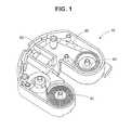
- FIG. 1depicts the strip path in a cartridge according to a preferred embodiment of the invention.
- FIG. 2Adepicts the engagement of sprocket teeth 70 with sprocket holes in the sensor strip 20 according to the invention.
- FIG. 2Bdepicts the engagement of sprocket teeth with sprocket holes in the sensor strip 20 according to a comparative example, including sprocket 60 a and sprocket teeth 70 a corresponding to the similarly numbered elements in the example of FIG. 2A according to the invention.
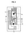
- FIG. 3depicts a sensor strip positioning mechanism in a unitary housing with a supply wheel, take up wheel, lancing mechanism, and power supply, user operated controls, display and processor for controlling different stages of the lancing and sensing operation.
- FIG. 4depicts a test site on the continuous sensor strip 20 .
- a cartridge 10is provided having continuous sensor strip 20 which is wound on supply wheel 30 and take up wheel 40 .
- the effective diameter of the wheelschanges.
- the identical amount of rotation imparted to the wheel by a motorwould result in a greater or lesser linear distance on the sensor strip 20 being advanced through the device.
- optimal operation of the sensorrequires accurate alignment of the test site in the opening 50 of the device, as well as alignment of device contacts (not shown) with electrodes on the sensor strip 20 .
- sprocket 60is provided in the device with encoder 62 and sprocket teeth 70 .
- the sprocket and/or encodermay be positioned in the device independently of the cartridge 10 , so that the cartridge containing the sensor strip may be made detachable and removable by the user.
- the encoderregisters the amount of linear distance that the strip advances and appropriate instructions are provided to the motor via processor 82 . Because the distance the strip travels is obtained directly from features on the sensor strip, rather than rotation of the supply wheel or the take up wheel, accurate positioning is ensured.
- a test site on the stripcomprises a lancet hole 100 , through which lancet needle passes, and an area between electrodes 110 and 120 where a blood sample accumulates after a lancing operation.
- the cartridgecan be positioned so that the cartridge opening 50 allows the user's skin to just touch the sensor strip.
- the lancet hole 100 on the striplines up with lancet mechanism 90 and a lancing operation is performed.
- a blood sampleaccumulates on the sensor strip and when a sufficient volume is obtained, the electrodes 110 and 120 are shorted, signaling the sensor strip to advance in travel direction 130 .
- a portion of the blood sampletravels along a capillary channel to a test site where a measurement, such as a blood glucose measurement, is conducted at a second pair of electrodes 140 , 150 .
- the usermay interface with the device through user operable controls and display 63 , 64 , 66 .
- gearsare provided that allow the strip to feed forward and backward, so that if an insufficient quantity of blood is obtained, the user can perform the lancing operation again using the same test site on the continuous strip.
- Each test site on the sensor stripcomprises a lancet hole, sensing electrodes which sense whether a sufficient volume has been detected, and a capillary channel between the sensing electrodes and the reagent wells where a blood characteristic is determined using a second set of electrodes.
- Each test sitemay be about 9 mm to about 19 mm in length, and the distance between the lancet holes of adjacent test sites on the strip may be in a range of about 20 mm to about 40 mm.
- the distance between sprocket holes 180is in a range of about 10 mm and about 20 mm, and the diameter of the sprocket should be sized accordingly.
- An estimate of the sprocket diametercan be calculated by subtracting the strip thickness from the diameter that would be arrived at using simply the hole-to hole distance on the strip.
- the stripcannot be considered to have negligible thickness for the teeth to line up in the holes of the strip (see FIG. 2A ).
- the sprocket diameteris calculated taking into account the strip thickness (i.e., according to the invention) so that it is slightly smaller than a comparative example shown in FIG. 2B .
- the sprocket diameteris too large, and the sensor strip slips off the sprocket teeth.
- the thickness of the sensor stripis in a range of about 10 mils to about 20 mils.
- the circumferential distance between individual teethis thus about 9.5 mm to about 19.5 mm.
- the diameter of the sprocketis established based on the number of teeth, so that a sprocket having 4 teeth, for example, has a diameter in a range of about 12 mm to about 26 mm.
- the sensor tapeis made out of the materials conventionally used for this purpose and the method of construction would be known to those of ordinary skill in the art.
- the substrate and structural layers of the strip defining wells and a capillarymay be made from polyethylene terephthalate (PET), while the electrodes may be made from a layer of gold or other conductive material, deposited by sputtering or other known means, and patterned.
- Processor 82receives signals from the electrodes 110 , 120 , 140 , and 150 via contact pads 112 , 152 , 122 , and 142 , which make contact with device contacts (not shown) in the device housing.
- the processor 82also receives signals from the sprocket encoder, which encodes the distance traveled by the strip, and from user-operated controls.
- the processorcoordinates these signals to provide instruction signals to the motor to advance the sensor strip, to the lancing mechanism to perform a lancing operation and to the test electrodes to perform a blood characteristic measurement.
- Processors which can be adapted for these purposesare commercially available and would be known to those of ordinary skill in the art.
- the elementsare powered by any suitable power supply 80 , such as a battery.
Landscapes
- Health & Medical Sciences (AREA)
- Life Sciences & Earth Sciences (AREA)
- Engineering & Computer Science (AREA)
- Biomedical Technology (AREA)
- Physics & Mathematics (AREA)
- General Health & Medical Sciences (AREA)
- Pathology (AREA)
- Biophysics (AREA)
- Hematology (AREA)
- Molecular Biology (AREA)
- Surgery (AREA)
- Public Health (AREA)
- Veterinary Medicine (AREA)
- Animal Behavior & Ethology (AREA)
- Medical Informatics (AREA)
- Heart & Thoracic Surgery (AREA)
- Chemical & Material Sciences (AREA)
- Analytical Chemistry (AREA)
- Immunology (AREA)
- Biochemistry (AREA)
- General Physics & Mathematics (AREA)
- Urology & Nephrology (AREA)
- Optics & Photonics (AREA)
- Food Science & Technology (AREA)
- Medicinal Chemistry (AREA)
- Dermatology (AREA)
- Measurement Of The Respiration, Hearing Ability, Form, And Blood Characteristics Of Living Organisms (AREA)
- Automatic Analysis And Handling Materials Therefor (AREA)
- Investigating Or Analysing Biological Materials (AREA)
Abstract
Description
Claims (17)
Priority Applications (6)
| Application Number | Priority Date | Filing Date | Title |
|---|---|---|---|
| US12/689,643US8956309B2 (en) | 2010-01-19 | 2010-01-19 | Sensor strip positioning mechanism |
| CA2727500ACA2727500C (en) | 2010-01-19 | 2011-01-12 | Sensor strip positioning mechanism |
| JP2011007996AJP5612492B2 (en) | 2010-01-19 | 2011-01-18 | Sensor strip positioning mechanism |
| ES11151268TES2393912T3 (en) | 2010-01-19 | 2011-01-18 | Positioning mechanism of a sensor strip |
| EP11151268AEP2345368B1 (en) | 2010-01-19 | 2011-01-18 | Sensor strip positioning mechanism |
| JP2014180382AJP5931981B2 (en) | 2010-01-19 | 2014-09-04 | Blood sample testing equipment |
Applications Claiming Priority (1)
| Application Number | Priority Date | Filing Date | Title |
|---|---|---|---|
| US12/689,643US8956309B2 (en) | 2010-01-19 | 2010-01-19 | Sensor strip positioning mechanism |
Publications (2)
| Publication Number | Publication Date |
|---|---|
| US20110178433A1 US20110178433A1 (en) | 2011-07-21 |
| US8956309B2true US8956309B2 (en) | 2015-02-17 |
Family
ID=43899716
Family Applications (1)
| Application Number | Title | Priority Date | Filing Date |
|---|---|---|---|
| US12/689,643Active - Reinstated2030-03-30US8956309B2 (en) | 2010-01-19 | 2010-01-19 | Sensor strip positioning mechanism |
Country Status (5)
| Country | Link |
|---|---|
| US (1) | US8956309B2 (en) |
| EP (1) | EP2345368B1 (en) |
| JP (2) | JP5612492B2 (en) |
| CA (1) | CA2727500C (en) |
| ES (1) | ES2393912T3 (en) |
Families Citing this family (7)
| Publication number | Priority date | Publication date | Assignee | Title |
|---|---|---|---|---|
| US8956309B2 (en)* | 2010-01-19 | 2015-02-17 | Becton, Dickinson And Company | Sensor strip positioning mechanism |
| EP2589337A1 (en)* | 2011-11-04 | 2013-05-08 | Roche Diagnostics GmbH | Analytical hand-held device and method for its operation |
| EP2953540B1 (en)* | 2013-02-11 | 2016-12-07 | Roche Diabetes Care GmbH | Handheld medical instrument and system for analyzing a body fluid |
| CN104813169B (en)* | 2013-05-12 | 2017-10-31 | B·布兰斯格洛夫 | test cartridge and analyzer device |
| WO2016061622A1 (en)* | 2014-10-19 | 2016-04-28 | Bransgrove Brandon | Tape positioning system and method |
| SE541514C2 (en) | 2017-12-28 | 2019-10-22 | Delaval Holding Ab | A cassette |
| CN114624336B (en)* | 2022-05-16 | 2022-09-02 | 四川升拓检测技术股份有限公司 | Signal detection device and method based on wheel type sound insulation impact echo acoustic frequency method |
Citations (18)
| Publication number | Priority date | Publication date | Assignee | Title |
|---|---|---|---|---|
| US5407554A (en) | 1993-05-10 | 1995-04-18 | Asulab S.A. | Electrochemical sensor with multiple zones on a disc and its application to the quantitative analysis of glucose |
| US5437999A (en) | 1994-02-22 | 1995-08-01 | Boehringer Mannheim Corporation | Electrochemical sensor |
| US5741634A (en) | 1993-08-03 | 1998-04-21 | A & D Company Limited | Throwaway type chemical sensor |
| US6143164A (en) | 1997-02-06 | 2000-11-07 | E. Heller & Company | Small volume in vitro analyte sensor |
| US20020041829A1 (en) | 1999-04-16 | 2002-04-11 | Pe Corporation (Ny) | Apparatus and method for transferring small volumes of substances |
| US6558402B1 (en) | 1999-08-03 | 2003-05-06 | Becton, Dickinson And Company | Lancer |
| US6878345B1 (en)* | 1997-12-08 | 2005-04-12 | Thomas W. Astle | Ultra high throughput bioassay screening system |
| US6881578B2 (en) | 2002-04-02 | 2005-04-19 | Lifescan, Inc. | Analyte concentration determination meters and methods of using the same |
| US6893545B2 (en) | 1997-09-12 | 2005-05-17 | Therasense, Inc. | Biosensor |
| WO2006059241A2 (en) | 2004-11-05 | 2006-06-08 | Albatros Technologies Gmbh & Co. Kg | Analyte sensing device mounted on a flexible substrate |
| US20070020143A1 (en)* | 2005-06-29 | 2007-01-25 | Manfred Seidenstricker | Test tape and analytical system |
| US7192405B2 (en) | 2002-09-30 | 2007-03-20 | Becton, Dickinson And Company | Integrated lancet and bodily fluid sensor |
| WO2007077212A2 (en) | 2006-01-05 | 2007-07-12 | Roche Diagnostics Gmbh | Lancet integrated test element tape dispenser |
| US7378270B2 (en)* | 2003-11-10 | 2008-05-27 | Sentec Scientific, Inc. | Device for analyte measurement |
| EP1967139A1 (en) | 2007-03-09 | 2008-09-10 | Roche Diagnostics GmbH | Disposable puncturing device and resuable handling device for a puncturing device |
| US7498132B2 (en) | 2000-02-02 | 2009-03-03 | Lifescan, Inc. | Electrochemical test strip kit for analyte determination |
| US7731900B2 (en)* | 2002-11-26 | 2010-06-08 | Roche Diagnostics Operations, Inc. | Body fluid testing device |
| EP2275034A1 (en) | 2009-07-14 | 2011-01-19 | Becton, Dickinson and Company | Blood glucose sensor |
Family Cites Families (8)
| Publication number | Priority date | Publication date | Assignee | Title |
|---|---|---|---|---|
| JP2001038696A (en)* | 1999-08-04 | 2001-02-13 | Yayoi Kk | Hole deburring method in punching process of embossed carrier tape and device therefor |
| AU1889001A (en)* | 1999-12-13 | 2001-06-18 | Arkray, Inc. | Body fluid measuring apparatus with lancet and lancet holder used for the measuring apparatus |
| US6988996B2 (en)* | 2001-06-08 | 2006-01-24 | Roche Diagnostics Operatons, Inc. | Test media cassette for bodily fluid testing device |
| US20030211619A1 (en)* | 2002-05-09 | 2003-11-13 | Lorin Olson | Continuous strip of fluid sampling and testing devices and methods of making, packaging and using the same |
| JP3108067U (en)* | 2004-10-05 | 2005-04-07 | 浦和電研株式会社 | Chip counter for reel-shaped taping parts |
| JP4134122B2 (en)* | 2005-09-05 | 2008-08-13 | カシオマイクロニクス株式会社 | Reel tape winding device and winding method |
| JP4935286B2 (en)* | 2005-10-12 | 2012-05-23 | パナソニック株式会社 | Blood sensor |
| US8956309B2 (en)* | 2010-01-19 | 2015-02-17 | Becton, Dickinson And Company | Sensor strip positioning mechanism |
- 2010
- 2010-01-19USUS12/689,643patent/US8956309B2/enactiveActive - Reinstated
- 2011
- 2011-01-12CACA2727500Apatent/CA2727500C/enactiveActive
- 2011-01-18JPJP2011007996Apatent/JP5612492B2/ennot_activeExpired - Fee Related
- 2011-01-18EPEP11151268Apatent/EP2345368B1/ennot_activeNot-in-force
- 2011-01-18ESES11151268Tpatent/ES2393912T3/enactiveActive
- 2014
- 2014-09-04JPJP2014180382Apatent/JP5931981B2/ennot_activeExpired - Fee Related
Patent Citations (18)
| Publication number | Priority date | Publication date | Assignee | Title |
|---|---|---|---|---|
| US5407554A (en) | 1993-05-10 | 1995-04-18 | Asulab S.A. | Electrochemical sensor with multiple zones on a disc and its application to the quantitative analysis of glucose |
| US5741634A (en) | 1993-08-03 | 1998-04-21 | A & D Company Limited | Throwaway type chemical sensor |
| US5437999A (en) | 1994-02-22 | 1995-08-01 | Boehringer Mannheim Corporation | Electrochemical sensor |
| US6143164A (en) | 1997-02-06 | 2000-11-07 | E. Heller & Company | Small volume in vitro analyte sensor |
| US6893545B2 (en) | 1997-09-12 | 2005-05-17 | Therasense, Inc. | Biosensor |
| US6878345B1 (en)* | 1997-12-08 | 2005-04-12 | Thomas W. Astle | Ultra high throughput bioassay screening system |
| US20020041829A1 (en) | 1999-04-16 | 2002-04-11 | Pe Corporation (Ny) | Apparatus and method for transferring small volumes of substances |
| US6558402B1 (en) | 1999-08-03 | 2003-05-06 | Becton, Dickinson And Company | Lancer |
| US7498132B2 (en) | 2000-02-02 | 2009-03-03 | Lifescan, Inc. | Electrochemical test strip kit for analyte determination |
| US6881578B2 (en) | 2002-04-02 | 2005-04-19 | Lifescan, Inc. | Analyte concentration determination meters and methods of using the same |
| US7192405B2 (en) | 2002-09-30 | 2007-03-20 | Becton, Dickinson And Company | Integrated lancet and bodily fluid sensor |
| US7731900B2 (en)* | 2002-11-26 | 2010-06-08 | Roche Diagnostics Operations, Inc. | Body fluid testing device |
| US7378270B2 (en)* | 2003-11-10 | 2008-05-27 | Sentec Scientific, Inc. | Device for analyte measurement |
| WO2006059241A2 (en) | 2004-11-05 | 2006-06-08 | Albatros Technologies Gmbh & Co. Kg | Analyte sensing device mounted on a flexible substrate |
| US20070020143A1 (en)* | 2005-06-29 | 2007-01-25 | Manfred Seidenstricker | Test tape and analytical system |
| WO2007077212A2 (en) | 2006-01-05 | 2007-07-12 | Roche Diagnostics Gmbh | Lancet integrated test element tape dispenser |
| EP1967139A1 (en) | 2007-03-09 | 2008-09-10 | Roche Diagnostics GmbH | Disposable puncturing device and resuable handling device for a puncturing device |
| EP2275034A1 (en) | 2009-07-14 | 2011-01-19 | Becton, Dickinson and Company | Blood glucose sensor |
Non-Patent Citations (1)
| Title |
|---|
| European Search Report in EP 11151268.7, dispatch date: Jun. 15, 2011 (English) (6 pages). |
Also Published As
| Publication number | Publication date |
|---|---|
| US20110178433A1 (en) | 2011-07-21 |
| JP5612492B2 (en) | 2014-10-22 |
| JP2014222255A (en) | 2014-11-27 |
| JP5931981B2 (en) | 2016-06-08 |
| JP2011149940A (en) | 2011-08-04 |
| CA2727500A1 (en) | 2011-07-19 |
| CA2727500C (en) | 2018-04-03 |
| EP2345368A1 (en) | 2011-07-20 |
| ES2393912T3 (en) | 2012-12-28 |
| EP2345368B1 (en) | 2012-08-22 |
Similar Documents
| Publication | Publication Date | Title |
|---|---|---|
| US8956309B2 (en) | Sensor strip positioning mechanism | |
| CA2708845C (en) | Blood glucose sensor | |
| EP2682745B1 (en) | Monitoring of fluid content | |
| WO2014147074A1 (en) | Method / device for generating a corrected value of an analyte concentration in a sample of a body fluid | |
| CN104918551B (en) | Sensor module and method of using the sensor module | |
| KR20030004355A (en) | Combined lancet and electrochemical analyte-testing apparatus | |
| CN101583393A (en) | Integrated sensor for analyzing biological samples | |
| HK1217364A1 (en) | Saliva glucose monitoring system | |
| CN1456886A (en) | Manufacturing method for physiological sample collector | |
| CN1456888A (en) | Physiological sample collector and use method thereof | |
| JP6080337B2 (en) | Electrode arrangement for blood test sensor strip | |
| US20170276632A1 (en) | Method and device for determining volumetric sufficiency in an electrochemical test strip | |
| JP2010210328A (en) | Instrument of measuring concentration of biocomponent | |
| EP2520932B1 (en) | Test strip for a medical meter |
Legal Events
| Date | Code | Title | Description |
|---|---|---|---|
| AS | Assignment | Owner name:BECTON, DICKINSON AND COMPANY, NEW JERSEY Free format text:ASSIGNMENT OF ASSIGNORS INTEREST;ASSIGNORS:MONDRO, JASON;SCHIFF, DAVID;GISLER, SCOTT W.;SIGNING DATES FROM 20100223 TO 20100303;REEL/FRAME:024110/0162 | |
| STCF | Information on status: patent grant | Free format text:PATENTED CASE | |
| MAFP | Maintenance fee payment | Free format text:PAYMENT OF MAINTENANCE FEE, 4TH YEAR, LARGE ENTITY (ORIGINAL EVENT CODE: M1551) Year of fee payment:4 | |
| AS | Assignment | Owner name:EMBECTA CORP., MASSACHUSETTS Free format text:ASSIGNMENT OF ASSIGNORS INTEREST;ASSIGNOR:BECTON, DICKINSON AND COMPANY;REEL/FRAME:059721/0617 Effective date:20220331 | |
| FEPP | Fee payment procedure | Free format text:MAINTENANCE FEE REMINDER MAILED (ORIGINAL EVENT CODE: REM.); ENTITY STATUS OF PATENT OWNER: LARGE ENTITY | |
| PRDP | Patent reinstated due to the acceptance of a late maintenance fee | Effective date:20230310 | |
| AS | Assignment | Owner name:MORGAN STANLEY SENIOR FUNDING, INC., AS COLLATERAL AGENT, MARYLAND Free format text:FIRST LIEN TERM PATENT SECURITY AGREEMENT;ASSIGNOR:EMBECTA CORP.;REEL/FRAME:063028/0318 Effective date:20230309 | |
| FEPP | Fee payment procedure | Free format text:PETITION RELATED TO MAINTENANCE FEES FILED (ORIGINAL EVENT CODE: PMFP); ENTITY STATUS OF PATENT OWNER: LARGE ENTITY Free format text:PETITION RELATED TO MAINTENANCE FEES GRANTED (ORIGINAL EVENT CODE: PMFG); ENTITY STATUS OF PATENT OWNER: LARGE ENTITY Free format text:SURCHARGE, PETITION TO ACCEPT PYMT AFTER EXP, UNINTENTIONAL (ORIGINAL EVENT CODE: M1558); ENTITY STATUS OF PATENT OWNER: LARGE ENTITY | |
| MAFP | Maintenance fee payment | Free format text:PAYMENT OF MAINTENANCE FEE, 8TH YEAR, LARGE ENTITY (ORIGINAL EVENT CODE: M1552); ENTITY STATUS OF PATENT OWNER: LARGE ENTITY Year of fee payment:8 | |
| AS | Assignment | Owner name:U.S. BANK TRUST COMPANY, NATIONAL ASSOCIATION, AS NOTES COLLATERAL AGENT, NEW JERSEY Free format text:FIRST LIEN PATENT SECURITY AGREEMENT (SENIOR SECURED NOTES);ASSIGNOR:EMBECTA CORP.;REEL/FRAME:063780/0053 Effective date:20230309 | |
| AS | Assignment | Owner name:U.S. BANK TRUST COMPANY, NATIONAL ASSOCIATION, AS NOTES COLLATERAL AGENT, NEW JERSEY Free format text:FIRST LIEN PATENT SECURITY AGREEMENT (SENIOR SECURED NOTES);ASSIGNOR:EMBECTA CORP.;REEL/FRAME:063083/0071 Effective date:20230309 |