US8955807B2 - Security bracket - Google Patents
Security bracketDownload PDFInfo
- Publication number
- US8955807B2 US8955807B2US12/858,651US85865110AUS8955807B2US 8955807 B2US8955807 B2US 8955807B2US 85865110 AUS85865110 AUS 85865110AUS 8955807 B2US8955807 B2US 8955807B2
- Authority
- US
- United States
- Prior art keywords
- camera
- security
- bracket assembly
- base portion
- lens
- Prior art date
- Legal status (The legal status is an assumption and is not a legal conclusion. Google has not performed a legal analysis and makes no representation as to the accuracy of the status listed.)
- Active, expires
Links
- 230000007246mechanismEffects0.000claimsabstractdescription16
- 230000008878couplingEffects0.000claims1
- 238000010168coupling processMethods0.000claims1
- 238000005859coupling reactionMethods0.000claims1
- 239000000853adhesiveSubstances0.000description1
- 230000001070adhesive effectEffects0.000description1
- 229920001690polydopaminePolymers0.000description1
- 230000001681protective effectEffects0.000description1
- 230000011514reflexEffects0.000description1
- 239000000126substanceSubstances0.000description1
Images


Classifications
- A—HUMAN NECESSITIES
- A47—FURNITURE; DOMESTIC ARTICLES OR APPLIANCES; COFFEE MILLS; SPICE MILLS; SUCTION CLEANERS IN GENERAL
- A47F—SPECIAL FURNITURE, FITTINGS, OR ACCESSORIES FOR SHOPS, STOREHOUSES, BARS, RESTAURANTS OR THE LIKE; PAYING COUNTERS
- A47F7/00—Show stands, hangers, or shelves, adapted for particular articles or materials
- A47F7/02—Show stands, hangers, or shelves, adapted for particular articles or materials for jewellery, dentures, watches, eye-glasses, lenses, or the like
- A47F7/024—Show stands, hangers, or shelves, adapted for particular articles or materials for jewellery, dentures, watches, eye-glasses, lenses, or the like with provisions for preventing unauthorised removal
- G—PHYSICS
- G03—PHOTOGRAPHY; CINEMATOGRAPHY; ANALOGOUS TECHNIQUES USING WAVES OTHER THAN OPTICAL WAVES; ELECTROGRAPHY; HOLOGRAPHY
- G03B—APPARATUS OR ARRANGEMENTS FOR TAKING PHOTOGRAPHS OR FOR PROJECTING OR VIEWING THEM; APPARATUS OR ARRANGEMENTS EMPLOYING ANALOGOUS TECHNIQUES USING WAVES OTHER THAN OPTICAL WAVES; ACCESSORIES THEREFOR
- G03B17/00—Details of cameras or camera bodies; Accessories therefor
- G03B17/56—Accessories
- G03B17/561—Support related camera accessories
- G03B17/568—
Definitions
- the invention disclosed heregenerally relates to retail security displays where large numbers of hand-held electronic devices (cell phones, PDAs, cameras, etc.) are offered for sale to the public via countertop display posts. More specifically, the invention relates to mounting bracket designs that are used on individual display posts.
- the invention disclosed hereis an improvement for a mounting member (commonly called a “puck”) that is used to display hand-held devices in a retail location. Pucks are often times located at each one of a plurality of post positions on a display countertop surface. The hand-held is mounted to the puck and then the puck, and hand-held, are lifted together from the display surface by a consumer who wishes to examine the product.
- a mounting membercommonly called a “puck”
- the present inventionis specific to puck-mounted cameras having a removable lens. Under normal circumstances, different types of security sensors are used in conjunction with the typical mounting puck. For example, it is common to use a pressure-activated security button at the physical interface where the body of the hand-held is pulled against a top surface of the puck by a mounting screw or similar type of attachment means.
- secondary sensor cablescreates a separate security circuit by applying a pressure-activated sensor switch somewhere to the outer surface of the body of the hand-held.
- the sensor switchis at the end of a short cable (interconnecting the sensor and puck).
- the sensor switchis connected to the hand-held's body by an adhesive substance (typically) that bonds the switch to the hand-held.
- secondary sensorsare secured to hand-helds by small straps that look like cable ties.
- DSLRDigital single lens reflex
- a typical DSLRis cylindrical in shape and lacks a sufficiently large, flat, and non-rotating surface for the attachment of a typical secondary security sensor switch, for example.
- a cable-tie strapthat tightly surrounds the lens because, among other things, it interferes with hand-operation of the lens by a potential purchaser.
- the present inventionis an improvement that is designed to be used in conjunction with typical display pucks.
- the typical camera with a removable lenswill have a release button or similar type of release mechanism near the lens and camera body interface. Pressing the release mechanism enables disengagement of the lens from the camera body.
- the present inventionis a security bracket assembly that partially armors the camera body and lens from the consumer.
- the security bracket assemblyhas a base portion that captures the lower part of the camera body.
- the base portionprovides the same general type of screw attachment as conventional puck-mounted attachment arrangements, although with greater flexibility.
- the security bracket assemblyalso includes a forward or frontal bracket portion.
- the forward bracket portionhas both a frontal surface that is spaced forwardly of the front side of the camera body and a side shield that is shaped to cover the region or space where the camera release mechanism is typically located, in a manner so that a potential thief cannot physically access the release mechanism or base of the lens.
- the frontal surface of the security bracket assemblyis curved so that it generally follows the outer curvature of a typical cylindrically-shaped DSLR.
- the frontal and side shield partsmake up an integrally molded, forward bracket component part of the overall assembly. This part of the assembly is detachably mounted to the base portion of the assembly, in a manner so that it can be removed by a salesperson or other authorized party, but without actually removing the camera from the puck or disconnecting and reconnecting any security sensors (secondary security cables or otherwise).
- the advantages offered by the inventionare two-fold. First, there are times when a salesperson may want to remove and replace lenses on the same camera. This might happen if a prospective purchaser wants to inspect the existing mount or the ease of swapping lenses.
- the detachable forward bracket part of the security bracket assemblyallows immediate hand-access to the lens for swapping lenses without otherwise needing to disconnect and reconnect any security or power cables.
- not all camera lenseshave the same length or diameter.
- Having a removable forward security bracket componentallows the swapping of bracket parts that have different shapes and curvatures, as needed, to adapt to different camera models or release mechanisms.
- the designalso makes it possible for security vendors to sell the removable forward part as a “kit” of replaceable brackets, thus giving the retailer the option of selecting the needed size and shape as product displays change.
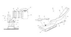
- FIG. 1is a pictorial view of a display post showing a security bracket assembly constructed in accordance with a preferred embodiment of the invention
- FIG. 2is a frontal view of the post and security bracket assembly shown in FIG. 1 ;
- FIG. 3is a side view of the post and security bracket assembly shown in FIGS. 1-2 , showing a camera about to be mounted to the bracket;
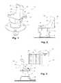
- FIG. 4is a perspective view of the security bracket assembly
- FIG. 5is an exploded view of the security bracket assembly
- FIG. 6is an end view of the security bracket assembly
- FIG. 7is a frontal view of the security bracket assembly
- FIG. 8is a top view of the security bracket assembly
- FIG. 9is a rear view of a removable forward or frontal portion of the security bracket assembly.
- FIG. 10is a side view of a rectangular base portion of the security bracket assembly
- FIG. 11is a pictorial view of the top-side of the base portion shown in FIG. 10 ;
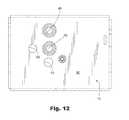
- FIG. 12is a bottom view of the base portion shown in FIGS. 10 and 11 .
- FIG. 1shown generally at 10 is a security bracket assembly constructed in accordance with a preferred embodiment of the invention.
- the security bracket assembly 10is shown connected to a mounting member or puck 12 .
- the puck 12normally rests on a base piece 14 that is mounted to a countertop or the like (not shown).
- FIG. 3shows a camera 15 (DSLR) about to be attached to the bracket assembly 10 . It is also possible to first connect the security bracket assembly 12 to the camera 15 and then mount camera and bracket to the puck 12 .
- DSLRcamera 15
- the security bracket assembly 10has a rectangular base portion, indicated generally at 16 .
- a screw 18 positioned within the base 16allows the bracket assembly 10 to be attached to the camera 15 .
- the base portion 16has an adaptor piece 20 that may be added or removed to the base portion 16 , as needed. When it is added, it creates a smooth top surface 22 (see FIG. 4 ) from front-to-back. When removed, it creates a slight “step” (see reference numeral 24 in the back portion of security assembly base portion 16 ), for adapting the security bracket 10 to a different camera footprint. As is best seen in FIGS. 3-5 , when installed, the adaptor piece 20 includes a rearward retaining tab 25 that rests against the lower, rear edge of the camera body.
- the security bracket assembly 10also has a removable forward or frontal bracket portion component 26 .
- the forward bracket component 26has frontal surface 27 with a curved portion 28 that follows the circumference of a camera lens.
- a side shield 30 of front bracket component 26prevents finger access to the camera lens underneath.
- the front bracket component 26is removable from the base 16 by a screw 32 (see FIG. 5 ).
- the screw 32is removed via a special tool 34 .
- a salespersonmay remove the screw, which permits the forward bracket component 26 to be removed from the overall security bracket assembly 10 , as indicated in the exploded view of FIG. 5 . This allows camera lenses to be swapped to and from the display without disconnecting or unmounting the camera body itself.
- the security bracket assembly 10may capture and partially surround the typical camera body and lens configuration.
- One way of using the security bracket assembly 10 described hereinvolves first attaching the assembly 10 to a camera and then mounting the bracket and camera together on a post (i.e. on the puck) on a countertop display.
- the forward-looking or frontal surface 27 of the removable forward bracket component or part 26is a certain distance from the front of the camera body (see item 36 in FIG. 3 ).
- the width of the side shield 30is selected accordingly so as to shield finger access to the interface between camera lens 38 and camera body 40 .
- the region where the lens release mechanism is generally locatedis indicated at 42 .
- different camera modelshave variations in the types of release mechanisms used.
- the rearward retaining tab 25is part of the adaptor piece 20 .
- the adaptor piece 20can be custom-measured to fit the different bodies of various kinds of camera models.
- the retaining tab 25is bent up in order to prevent the camera body from rotating relative to the base portion 16 of the security bracket assembly 10 .
- FIG. 9provides a rearward-looking view of the forward bracket component 26 .
- the side shield 30prevents finger access to the camera lens on the inside of the shield. Because one forward bracket 26 can be swapped with another, the bracket can be customized with additional protective structure 44 that adapts the forward bracket component 26 to the shape of buttons or different release mechanism configurations on the camera lens, as needed.
- FIG. 10is a view similar to FIG. 6 , but shows the adaptor piece 20 (and retaining tab 25 ) removed from the base.
- FIG. 11is a pictorial view of FIG. 10 .
- the underside of base portion 16may be provided with multiple numbers of threaded inserts 46 , 48 for enabling the best placement of the security bracket assembly 10 on a display post puck.
- the base portion 16may also have different anti-rotation port holes 50 , 52 for preventing the base portion 16 (and entire assembly 10 ) from being rotated off the puck.
- FIGS. 9 and 10illustrate where the forward bracket screw 32 threads into a fitting 54 in the side of the base portion 16 .
- the entire security bracket assembly 10is detachably mountable to the mounting member or puck 12 .
- the puck 12typically has a screw that is adapted to be threaded into one or the other threaded ports 46 , 48 illustrated on the underside surface 56 of base portion 16 .
- the removable forward part 26is preferably molded and has a horizontal section 58 that fits against the underside 56 of base portion 16 .
- the side shield 30is molded as a section of the same part. In use, one removable forward part 26 may be selected from a group and used, as needed, for the specific camera model that is to be lifted by the puck 12 .
Landscapes
- Physics & Mathematics (AREA)
- General Physics & Mathematics (AREA)
- Accessories Of Cameras (AREA)
Abstract
Description
Claims (2)
Priority Applications (1)
| Application Number | Priority Date | Filing Date | Title |
|---|---|---|---|
| US12/858,651US8955807B2 (en) | 2010-08-18 | 2010-08-18 | Security bracket |
Applications Claiming Priority (1)
| Application Number | Priority Date | Filing Date | Title |
|---|---|---|---|
| US12/858,651US8955807B2 (en) | 2010-08-18 | 2010-08-18 | Security bracket |
Publications (2)
| Publication Number | Publication Date |
|---|---|
| US20120043451A1 US20120043451A1 (en) | 2012-02-23 |
| US8955807B2true US8955807B2 (en) | 2015-02-17 |
Family
ID=45593307
Family Applications (1)
| Application Number | Title | Priority Date | Filing Date |
|---|---|---|---|
| US12/858,651Active2031-07-23US8955807B2 (en) | 2010-08-18 | 2010-08-18 | Security bracket |
Country Status (1)
| Country | Link |
|---|---|
| US (1) | US8955807B2 (en) |
Cited By (17)
| Publication number | Priority date | Publication date | Assignee | Title |
|---|---|---|---|---|
| US9786140B2 (en) | 2010-06-21 | 2017-10-10 | Mobile Tech, Inc. | Display for hand-held electronics |
| US9892604B2 (en) | 2016-04-15 | 2018-02-13 | Mobile Tech, Inc. | Gateway-based anti-theft security system and method |
| US10101770B2 (en) | 2016-07-29 | 2018-10-16 | Mobile Tech, Inc. | Docking system for portable computing device in an enclosure |
| US10198036B2 (en) | 2012-12-05 | 2019-02-05 | Mobile Tech, Inc. | Docking station for tablet device |
| US10251144B2 (en) | 2015-12-03 | 2019-04-02 | Mobile Tech, Inc. | Location tracking of products and product display assemblies in a wirelessly connected environment |
| US10269202B2 (en) | 2001-12-27 | 2019-04-23 | Mobile Tech, Inc. | Intelligent key system |
| US10373456B2 (en) | 2009-01-10 | 2019-08-06 | Mobile Tech, Inc. | Display for hand-held electronics |
| US10464780B2 (en) | 2014-12-09 | 2019-11-05 | Mobile Tech, Inc. | Tether lock |
| US10517056B2 (en) | 2015-12-03 | 2019-12-24 | Mobile Tech, Inc. | Electronically connected environment |
| US10593443B1 (en) | 2019-01-24 | 2020-03-17 | Mobile Tech, Inc. | Motion sensing cable for intelligent charging of devices |
| US10728868B2 (en) | 2015-12-03 | 2020-07-28 | Mobile Tech, Inc. | Remote monitoring and control over wireless nodes in a wirelessly connected environment |
| US10918224B2 (en) | 2013-10-08 | 2021-02-16 | Invue Security Products Inc. | Quick release sensor for merchandise display |
| US11109335B2 (en) | 2015-12-03 | 2021-08-31 | Mobile Tech, Inc. | Wirelessly connected hybrid environment of different types of wireless nodes |
| US11344140B2 (en) | 2009-01-10 | 2022-05-31 | Mobile Tech, Inc. | Display for hand-held electronics |
| US20220244625A1 (en)* | 2014-03-14 | 2022-08-04 | Really Right Stuff, Llc | Plate for camera equipment |
| US11540350B2 (en) | 2018-10-25 | 2022-12-27 | Mobile Tech, Inc. | Proxy nodes for expanding the functionality of nodes in a wirelessly connected environment |
| US20230151924A1 (en)* | 2021-11-18 | 2023-05-18 | 7-Eleven, Inc. | Accessory mounting system and apparatus |
Families Citing this family (6)
| Publication number | Priority date | Publication date | Assignee | Title |
|---|---|---|---|---|
| USD679571S1 (en)* | 2011-06-01 | 2013-04-09 | Peerless Industries, Inc. | Security bracket for use in securing audio/visual devices or the like |
| KR101263930B1 (en)* | 2013-01-11 | 2013-05-13 | (주)금오전자 | Apparatus preventing camera being robbed |
| WO2015066134A1 (en)* | 2013-10-30 | 2015-05-07 | Invue Security Products Inc. | Security bracket for an article of merchandise |
| WO2016033037A1 (en) | 2014-08-27 | 2016-03-03 | Invue Security Products Inc. | Systems and methods for locking a sensor to a base |
| EP3785575B1 (en)* | 2019-08-26 | 2023-07-19 | The Swatch Group Research and Development Ltd | Secure display case for watches |
| USD977946S1 (en)* | 2021-07-30 | 2023-02-14 | Optex Co., Ltd. | Bracket |
Citations (14)
| Publication number | Priority date | Publication date | Assignee | Title |
|---|---|---|---|---|
| US3612462A (en)* | 1969-08-26 | 1971-10-12 | Quick Set Inc | Instrument mount assembly |
| US4771273A (en)* | 1985-10-18 | 1988-09-13 | C&K Components, Inc. | Anti-tamper bracket |
| US20030128975A1 (en)* | 2002-01-07 | 2003-07-10 | Shevick Barry L. | Multi-purpose turntable for creation of three dimensional images |
| US6592088B2 (en)* | 2000-01-24 | 2003-07-15 | Eric Thompson | Toolless locking mount |
| US6773172B1 (en)* | 2003-08-20 | 2004-08-10 | Joseph M. Johnson | Quick-release clamp for photographic equipment |
| US6885817B2 (en)* | 2001-02-16 | 2005-04-26 | 6115187 Canada Inc. | Method and device for orienting a digital panoramic image |
| US7085491B2 (en)* | 2004-03-29 | 2006-08-01 | Long Perng Co., Ltd. | Adjustable optical apparatus adapter |
| US20090166483A1 (en)* | 2005-12-27 | 2009-07-02 | Invue Security Products Inc. | Device for display item including centering mechanism |
| US20090179127A1 (en)* | 2004-06-30 | 2009-07-16 | Btr Robotics Limited Liability Company | Pan systems |
| US20100215355A1 (en)* | 2009-02-24 | 2010-08-26 | Olien Michael A | Mounting device, system and method |
| US7883279B2 (en)* | 2008-12-22 | 2011-02-08 | Kendall Charles S | Camera adapter support |
| US20110309934A1 (en)* | 2010-06-21 | 2011-12-22 | Merchandising Technologies, Inc. | Display For Hand-Held Electronics |
| US20120037783A1 (en)* | 2010-08-11 | 2012-02-16 | Christopher Alexander | Adjustable Security Bracket |
| US8191851B2 (en)* | 2006-07-21 | 2012-06-05 | Artform International Limited | Method and apparatus for securing a device at a desired location |
- 2010
- 2010-08-18USUS12/858,651patent/US8955807B2/enactiveActive
Patent Citations (14)
| Publication number | Priority date | Publication date | Assignee | Title |
|---|---|---|---|---|
| US3612462A (en)* | 1969-08-26 | 1971-10-12 | Quick Set Inc | Instrument mount assembly |
| US4771273A (en)* | 1985-10-18 | 1988-09-13 | C&K Components, Inc. | Anti-tamper bracket |
| US6592088B2 (en)* | 2000-01-24 | 2003-07-15 | Eric Thompson | Toolless locking mount |
| US6885817B2 (en)* | 2001-02-16 | 2005-04-26 | 6115187 Canada Inc. | Method and device for orienting a digital panoramic image |
| US20030128975A1 (en)* | 2002-01-07 | 2003-07-10 | Shevick Barry L. | Multi-purpose turntable for creation of three dimensional images |
| US6773172B1 (en)* | 2003-08-20 | 2004-08-10 | Joseph M. Johnson | Quick-release clamp for photographic equipment |
| US7085491B2 (en)* | 2004-03-29 | 2006-08-01 | Long Perng Co., Ltd. | Adjustable optical apparatus adapter |
| US20090179127A1 (en)* | 2004-06-30 | 2009-07-16 | Btr Robotics Limited Liability Company | Pan systems |
| US20090166483A1 (en)* | 2005-12-27 | 2009-07-02 | Invue Security Products Inc. | Device for display item including centering mechanism |
| US8191851B2 (en)* | 2006-07-21 | 2012-06-05 | Artform International Limited | Method and apparatus for securing a device at a desired location |
| US7883279B2 (en)* | 2008-12-22 | 2011-02-08 | Kendall Charles S | Camera adapter support |
| US20100215355A1 (en)* | 2009-02-24 | 2010-08-26 | Olien Michael A | Mounting device, system and method |
| US20110309934A1 (en)* | 2010-06-21 | 2011-12-22 | Merchandising Technologies, Inc. | Display For Hand-Held Electronics |
| US20120037783A1 (en)* | 2010-08-11 | 2012-02-16 | Christopher Alexander | Adjustable Security Bracket |
Cited By (46)
| Publication number | Priority date | Publication date | Assignee | Title |
|---|---|---|---|---|
| US10984625B2 (en) | 2001-12-27 | 2021-04-20 | Mobile Tech, Inc. | Intelligent key system |
| US10269202B2 (en) | 2001-12-27 | 2019-04-23 | Mobile Tech, Inc. | Intelligent key system |
| US10453291B2 (en) | 2001-12-27 | 2019-10-22 | Mobile Tech, Inc. | Intelligent key system |
| US10977914B2 (en) | 2009-01-10 | 2021-04-13 | Mobile Tech, Inc. | Display for hand-held electronics |
| US10026281B2 (en) | 2009-01-10 | 2018-07-17 | Mobile Tech, Inc. | Display for hand-held electronics |
| US11344140B2 (en) | 2009-01-10 | 2022-05-31 | Mobile Tech, Inc. | Display for hand-held electronics |
| US10373456B2 (en) | 2009-01-10 | 2019-08-06 | Mobile Tech, Inc. | Display for hand-held electronics |
| US10083583B2 (en) | 2010-06-21 | 2018-09-25 | Mobile Tech, Inc. | Display for hand-held electronics |
| US9786140B2 (en) | 2010-06-21 | 2017-10-10 | Mobile Tech, Inc. | Display for hand-held electronics |
| US10217338B2 (en) | 2010-06-21 | 2019-02-26 | Mobile Tech, Inc. | Display for hand-held electronics |
| US10861300B2 (en) | 2010-06-21 | 2020-12-08 | Mobile Tech, Inc. | Display for hand-held electronics |
| US10198036B2 (en) | 2012-12-05 | 2019-02-05 | Mobile Tech, Inc. | Docking station for tablet device |
| US10198035B2 (en) | 2012-12-05 | 2019-02-05 | Mobile Tech, Inc. | Docking station for tablet device |
| US10782735B2 (en) | 2012-12-05 | 2020-09-22 | Mobile Tech, Inc. | Docking station for tablet device |
| US11259653B2 (en) | 2013-10-08 | 2022-03-01 | Invue Security Products Inc. | Quick release sensor for merchandise display |
| US10918224B2 (en) | 2013-10-08 | 2021-02-16 | Invue Security Products Inc. | Quick release sensor for merchandise display |
| US12433429B2 (en) | 2013-10-08 | 2025-10-07 | Invue Security Products Inc. | Quick release sensor for merchandise display |
| US11737582B2 (en) | 2013-10-08 | 2023-08-29 | Invue Security Products Inc. | Quick release sensor for merchandise display |
| US12055843B2 (en) | 2014-03-14 | 2024-08-06 | Really Right Stuff, Llc | Plate for camera equipment |
| US11796897B2 (en) | 2014-03-14 | 2023-10-24 | Really Right Stuff, Llc | Plate for camera equipment |
| US11619866B2 (en) | 2014-03-14 | 2023-04-04 | Really Right Stuff, Llc | Plate for camera equipment |
| US11487191B2 (en)* | 2014-03-14 | 2022-11-01 | Really Right Stuff, Llc | Plate for camera equipment |
| US20220244625A1 (en)* | 2014-03-14 | 2022-08-04 | Really Right Stuff, Llc | Plate for camera equipment |
| US10464780B2 (en) | 2014-12-09 | 2019-11-05 | Mobile Tech, Inc. | Tether lock |
| US10974926B2 (en) | 2014-12-09 | 2021-04-13 | Mobile Tech, Inc. | Tether lock |
| US10674466B2 (en) | 2015-12-03 | 2020-06-02 | Mobile Tech, Inc. | Location tracking of products and product display assemblies in a wirelessly connected environment |
| US10251144B2 (en) | 2015-12-03 | 2019-04-02 | Mobile Tech, Inc. | Location tracking of products and product display assemblies in a wirelessly connected environment |
| US10517056B2 (en) | 2015-12-03 | 2019-12-24 | Mobile Tech, Inc. | Electronically connected environment |
| US10524220B2 (en) | 2015-12-03 | 2019-12-31 | Mobile Tech, Inc. | Location tracking of products and product display assemblies in a wirelessly connected environment |
| US11109335B2 (en) | 2015-12-03 | 2021-08-31 | Mobile Tech, Inc. | Wirelessly connected hybrid environment of different types of wireless nodes |
| US10728868B2 (en) | 2015-12-03 | 2020-07-28 | Mobile Tech, Inc. | Remote monitoring and control over wireless nodes in a wirelessly connected environment |
| US10667227B2 (en) | 2015-12-03 | 2020-05-26 | Mobile Tech, Inc. | Electronically connected environment |
| US10540872B2 (en) | 2016-04-15 | 2020-01-21 | Mobile Tech, Inc. | Gateway-based anti-theft security system and method |
| US10776473B2 (en) | 2016-04-15 | 2020-09-15 | Mobile Tech, Inc. | Authorization control for an anti-theft security system |
| US10157522B2 (en) | 2016-04-15 | 2018-12-18 | Mobile Tech, Inc. | Authorization control for an anti-theft security system |
| US9959432B2 (en) | 2016-04-15 | 2018-05-01 | Mobile Tech, Inc. | Authorization control for an anti-theft security system |
| US11315398B2 (en) | 2016-04-15 | 2022-04-26 | Mobile Tech, Inc. | Gateway-based anti-theft security system and method |
| US9892604B2 (en) | 2016-04-15 | 2018-02-13 | Mobile Tech, Inc. | Gateway-based anti-theft security system and method |
| US10101770B2 (en) | 2016-07-29 | 2018-10-16 | Mobile Tech, Inc. | Docking system for portable computing device in an enclosure |
| US10281955B2 (en) | 2016-07-29 | 2019-05-07 | Mobile Tech, Inc. | Docking system for portable computing device |
| US10754381B2 (en) | 2016-07-29 | 2020-08-25 | Mobile Tech, Inc. | Docking system for portable computing device |
| US11540350B2 (en) | 2018-10-25 | 2022-12-27 | Mobile Tech, Inc. | Proxy nodes for expanding the functionality of nodes in a wirelessly connected environment |
| US10614682B1 (en) | 2019-01-24 | 2020-04-07 | Mobile Tech, Inc. | Motion sensing cable for tracking customer interaction with devices |
| US10593443B1 (en) | 2019-01-24 | 2020-03-17 | Mobile Tech, Inc. | Motion sensing cable for intelligent charging of devices |
| US20230151924A1 (en)* | 2021-11-18 | 2023-05-18 | 7-Eleven, Inc. | Accessory mounting system and apparatus |
| US11703177B2 (en)* | 2021-11-18 | 2023-07-18 | 7-Eleven, Inc. | Accessory mounting system and apparatus |
Also Published As
| Publication number | Publication date |
|---|---|
| US20120043451A1 (en) | 2012-02-23 |
Similar Documents
| Publication | Publication Date | Title |
|---|---|---|
| US8955807B2 (en) | Security bracket | |
| EP1279365B1 (en) | Removable cover for a glucose meter | |
| CA2837172C (en) | Back protective cover for tablet device | |
| USD503721S1 (en) | Computer icon for image viewing and image collection functions of a microscope system on a portion of a display panel or microscope display | |
| USD437601S1 (en) | Computer generated icon for a display screen | |
| US7830628B2 (en) | Lens and display accessory for portable imaging device | |
| USD606105S1 (en) | Surveillance camera | |
| USD438872S1 (en) | Computer generated icon for a display screen | |
| USD525629S1 (en) | Icon image on a portion of a computer screen | |
| USD599740S1 (en) | Adapter for charging device | |
| USD560804S1 (en) | Display housing for remote inspection device | |
| US8743538B2 (en) | Protective hinge cover for a mobile computing device | |
| US9560922B2 (en) | Shelf-mountable video display unit | |
| USD587273S1 (en) | Adapter plates for flat panel display mounting assembly | |
| US20140063238A1 (en) | Camera sensor having reversible sensor housing and reversible adapter | |
| CN101083388B (en) | Wire concealing device and electric appliance with the wire concealing device | |
| US20110186530A1 (en) | Device Display Unit | |
| USD599356S1 (en) | Adapter plates for flat panel display mounting assembly | |
| CN105849786B (en) | Flexible Sensors for Portable Electronic Devices | |
| USD606433S1 (en) | Display housing for video inspection device | |
| KR20170127153A (en) | Mobile cradle installing a device for a mobile | |
| US6678152B2 (en) | Assembly in a displaying apparatus | |
| USD442155S1 (en) | Video teleconferencing center with full screen display | |
| WO2015028101A1 (en) | Camera collapsible behind a display device and display device for use with the same | |
| EP1417912B1 (en) | System for public display of imaging devices,such as still cameras and video cameras |
Legal Events
| Date | Code | Title | Description |
|---|---|---|---|
| AS | Assignment | Owner name:MERCHANDISING TECHNOLOGIES, INC., OREGON Free format text:ASSIGNMENT OF ASSIGNORS INTEREST;ASSIGNORS:ALEXANDER, CHRISTOPHER;PITT, ERIC;WHEELER, WADE;REEL/FRAME:025175/0212 Effective date:20100819 | |
| AS | Assignment | Owner name:FIFTH THIRD BANK, OHIO Free format text:SECURITY AGREEMENT;ASSIGNOR:MOBILE TECH, INC.;REEL/FRAME:030937/0416 Effective date:20130801 | |
| AS | Assignment | Owner name:MOBILE TECH, INC., OREGON Free format text:ASSIGNMENT OF ASSIGNORS INTEREST;ASSIGNOR:MERCHANDISING TECHNOLOGIES, INC.;REEL/FRAME:030937/0993 Effective date:20130801 | |
| AS | Assignment | Owner name:CAPITALSOUTH PARTNERS SBIC FUND III, L.P., NORTH CAROLINA Free format text:SECURITY AGREEMENT;ASSIGNOR:MOBILE TECH, INC.;REEL/FRAME:031005/0148 Effective date:20130801 Owner name:CAPITALSOUTH PARTNERS SBIC FUND III, L.P., NORTH C Free format text:SECURITY AGREEMENT;ASSIGNOR:MOBILE TECH, INC.;REEL/FRAME:031005/0148 Effective date:20130801 | |
| STCF | Information on status: patent grant | Free format text:PATENTED CASE | |
| AS | Assignment | Owner name:PNC BANK, NATIONAL ASSOCIATION, PENNSYLVANIA Free format text:SECURITY INTEREST;ASSIGNOR:MOBILE TECH, INC.;REEL/FRAME:039370/0989 Effective date:20160805 | |
| AS | Assignment | Owner name:MOBILE TECH, INC., OREGON Free format text:RELEASE OF SECURITY INTEREST RECORDED AT R/FS 030937/0416 AND 032608/0623;ASSIGNOR:FIRTH THIRD BANK;REEL/FRAME:039752/0495 Effective date:20160805 | |
| MAFP | Maintenance fee payment | Free format text:PAYMENT OF MAINTENANCE FEE, 4TH YEAR, LARGE ENTITY (ORIGINAL EVENT CODE: M1551) Year of fee payment:4 | |
| MAFP | Maintenance fee payment | Free format text:PAYMENT OF MAINTENANCE FEE, 8TH YEAR, LARGE ENTITY (ORIGINAL EVENT CODE: M1552); ENTITY STATUS OF PATENT OWNER: LARGE ENTITY Year of fee payment:8 |