US8955260B2 - Vertical cabinet door with flush front face - Google Patents
Vertical cabinet door with flush front faceDownload PDFInfo
- Publication number
- US8955260B2 US8955260B2US13/686,465US201213686465AUS8955260B2US 8955260 B2US8955260 B2US 8955260B2US 201213686465 AUS201213686465 AUS 201213686465AUS 8955260 B2US8955260 B2US 8955260B2
- Authority
- US
- United States
- Prior art keywords
- door
- storage unit
- panel
- extending
- sized
- Prior art date
- Legal status (The legal status is an assumption and is not a legal conclusion. Google has not performed a legal analysis and makes no representation as to the accuracy of the status listed.)
- Expired - Fee Related, expires
Links
Images


Classifications
- A—HUMAN NECESSITIES
- A61—MEDICAL OR VETERINARY SCIENCE; HYGIENE
- A61G—TRANSPORT, PERSONAL CONVEYANCES, OR ACCOMMODATION SPECIALLY ADAPTED FOR PATIENTS OR DISABLED PERSONS; OPERATING TABLES OR CHAIRS; CHAIRS FOR DENTISTRY; FUNERAL DEVICES
- A61G12/00—Accommodation for nursing, e.g. in hospitals, not covered by groups A61G1/00 - A61G11/00, e.g. trolleys for transport of medicaments or food; Prescription lists
- A—HUMAN NECESSITIES
- A47—FURNITURE; DOMESTIC ARTICLES OR APPLIANCES; COFFEE MILLS; SPICE MILLS; SUCTION CLEANERS IN GENERAL
- A47B—TABLES; DESKS; OFFICE FURNITURE; CABINETS; DRAWERS; GENERAL DETAILS OF FURNITURE
- A47B81/00—Cabinets or racks specially adapted for other particular purposes, e.g. for storing guns or skis
- A—HUMAN NECESSITIES
- A61—MEDICAL OR VETERINARY SCIENCE; HYGIENE
- A61G—TRANSPORT, PERSONAL CONVEYANCES, OR ACCOMMODATION SPECIALLY ADAPTED FOR PATIENTS OR DISABLED PERSONS; OPERATING TABLES OR CHAIRS; CHAIRS FOR DENTISTRY; FUNERAL DEVICES
- A61G12/00—Accommodation for nursing, e.g. in hospitals, not covered by groups A61G1/00 - A61G11/00, e.g. trolleys for transport of medicaments or food; Prescription lists
- A61G12/002—Supply appliances, e.g. columns for gas, fluid, electricity supply
- A61G12/005—Supply appliances, e.g. columns for gas, fluid, electricity supply mounted on the wall
- E—FIXED CONSTRUCTIONS
- E05—LOCKS; KEYS; WINDOW OR DOOR FITTINGS; SAFES
- E05D—HINGES OR SUSPENSION DEVICES FOR DOORS, WINDOWS OR WINGS
- E05D13/00—Accessories for sliding or lifting wings, e.g. pulleys, safety catches
- E05D13/10—Counterbalance devices
- E05D13/12—Counterbalance devices with springs
- E05D13/1276—Counterbalance devices with springs with coiled ribbon springs, e.g. constant force springs
- E—FIXED CONSTRUCTIONS
- E05—LOCKS; KEYS; WINDOW OR DOOR FITTINGS; SAFES
- E05D—HINGES OR SUSPENSION DEVICES FOR DOORS, WINDOWS OR WINGS
- E05D15/00—Suspension arrangements for wings
- E05D15/16—Suspension arrangements for wings for wings sliding vertically more or less in their own plane
- E05D15/20—Suspension arrangements for wings for wings sliding vertically more or less in their own plane movable out of one plane into a second parallel plane
- E—FIXED CONSTRUCTIONS
- E05—LOCKS; KEYS; WINDOW OR DOOR FITTINGS; SAFES
- E05Y—INDEXING SCHEME ASSOCIATED WITH SUBCLASSES E05D AND E05F, RELATING TO CONSTRUCTION ELEMENTS, ELECTRIC CONTROL, POWER SUPPLY, POWER SIGNAL OR TRANSMISSION, USER INTERFACES, MOUNTING OR COUPLING, DETAILS, ACCESSORIES, AUXILIARY OPERATIONS NOT OTHERWISE PROVIDED FOR, APPLICATION THEREOF
- E05Y2900/00—Application of doors, windows, wings or fittings thereof
- E05Y2900/20—Application of doors, windows, wings or fittings thereof for furniture, e.g. cabinets
Definitions
- the present disclosurerelates headwalls for use in a healthcare facility. More particularly, the present disclosure relates to a headwall having a vertically sliding door to conceal devices for the delivery of medical care or other areas that may be used for storage.
- Clinical care settingssuch as a hospital room, for example, serve a two-fold purpose of delivering healthcare services.
- the hospital roomserves as an area for delivery of medical care.
- the hospital roomserves as a residence for a recuperating patient.
- the hospital roommust include state of the art technology accessible to the healthcare provider during the delivery of care.
- the vital signs of a patientare taken on a regular basis.
- other monitoring equipment and service delivery equipmentis required.
- vital signs monitoringmay be required in conjunction with ventilation equipment.
- the support for the equipmentis positioned at the head end of the bed in an architectural headwall unit.
- gasessuch as oxygen and compressed air may be delivered to the patient room.
- a vacuum linemay also be provided.
- Electrical service outletsmay also be provided with certain devices being connected to power circuits including emergency back-up for critical devices.
- the architectural headwall unitsmay also provide central lighting controls and may be configured to provide support for healthcare equipment such as monitoring devices and fluid collection canisters.
- the present inventioncomprises an apparatus and/or method that has any one or more of the features listed in the appended claims and/or any one or more of the following features, which alone or in any combination may comprise patentable subject matter:
- a headwall for a patient's roomincludes a panel having a vertically-extending front surface, an opening defined in the front surface of the headwall, and a door sized to be received in the opening.
- the dooris vertically movable from a first position where an outer face of the door is flush with the front surface of the panel to a second position where the outer face extends parallel to the front surface and the door is positioned behind the front surface.
- the doormay be vertically movable to a third position vertically positioned between the first position and the second position and where the door may extend at an angle relative to the front surface of the headwall.
- the doormay be located above the opening when placed in the second position.
- the headwallmay further include a first set of roller bearings coupled to an upper end of the door and a second set of roller bearings coupled to the door below the first set of roller bearings, and a first set of guide slots sized to receive the first set of roller bearings and a second set of guide slots sized to receive the second set of roller bearings.
- the second set of guide slotsmay be partially positioned behind the first set of guide slots.
- each guide slot of the first set of guide slots and each guide slot of the second set of guide slotsmay include a straight section positioned behind, and extending parallel to, the front surface of the headwall and a curved section.
- the curved section of each guide slot of the second set of guide slotsmay be an S-shaped section.
- the doormay include an upper surface extending at a non-orthogonal angle relative to the outer face of the door.
- the headwallmay include a counterbalance coupled to the door sized to maintain the door at each of the first position and the second position.
- the counterbalancemay be a constant force spring extending parallel to the front surface of the headwall.
- the headwallmay further include a utility trunk having a passageway defined therein.
- the passagewaymay be inaccessible when the door is placed in the first position and accessible through the opening defined in the front surface of the headwall when the door is placed in the second position.
- the doormay be located within the passageway when placed in the second position.
- a headwall for a patient's roomincludes a front panel having a vertically-extending surface having an opening defined therein, a cabinet secured to the front panel and having a storage chamber defined therein, and a door sized to be received in the opening.
- the dooris movable between a first position where the storage chamber is inaccessible and an outer face of the door is flush with the vertically-extending surface and a second position where the storage chamber is accessible through the opening and the outer face of the door extends parallel to the vertically-extending surface.
- the doormay be located behind the front panel and above the opening when placed in the second position.
- the headwallmay further include a first roller bearing coupled to an upper end of the door and a second roller bearing coupled to the door below the first roller bearing.
- a first guide slotmay be defined in a first support and may be sized to receive the first roller bearing.
- a second guide slotmay be defined in the first support and may be sized to receive the second roller bearing. The second guide slot may be partially positioned behind the first guide slot.
- the first guide slot and the second guide slotmay include a straight section positioned behind the front panel and extending parallel to the vertically-extending surface and a curved section.
- the curved section of the second guide slotmay be an S-shaped section.
- the headwallmay further include a constant force spring extending parallel to the vertically-extending surface of the front panel and coupled to the door. The constant force spring may be sized to counterbalance the door such that the door is maintained at each of the first position and the second position.
- a headwall for a patient's roomincludes a panel having a vertically-extending surface, a plurality of openings defined in the vertically-extending surface of the panel, and a plurality of doors. Each door is vertically movable from a first position where the door is received in the opening and an outer face of the door is flush with the vertically-extending surface of the panel to a second position where the door is positioned behind the panel and above the opening.
- the headwallmay further include a plurality of constant force springs extending parallel to the vertically-extending surface of the panel. Each constant force spring may be coupled to a separate door of the plurality of doors. The constant force spring may be sized to counterbalance the door such that the door is maintained at each of the first position and the second position.
- each doormay extend parallel to the vertically-extending surface of the panel when the door is placed in the second position. Additional features will become apparent to those skilled in the art upon consideration of the following detailed description of illustrative embodiments exemplifying the best mode as presently perceived.
- FIG. 1is a perspective view of a patient room in a hospital showing a headwall including a number of doors of the present invention
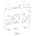
- FIG. 2is a perspective view of a patient room in a hospital showing the doors of the FIG. 1 in various positions;
- FIG. 3is a rear elevation cutaway view of back side of the headwall of FIG. 1 ;
- FIG. 4is a cross-sectional side elevation view of the headwall of FIG. 1 showing one of the doors in a closed position;
- FIG. 5is a cross-sectional side elevation view of the headwall of FIG. 1 showing one of the doors in partially opened position;
- FIG. 6is a cross-sectional side elevation view of the headwall of FIG. 1 showing one of the doors in a fully opened positioned.
- a patient room 10 of a hospital or other medical care facility, such as a nursing homeis shown.
- a headwall 12is shown positioned at a wall 14 , but it should be appreciated that in other embodiments the headwall 12 may be positioned at any of the walls of the room 10 .
- Headwallsare sometimes referred to as headwall units, but are herein simply referred to as headwalls.
- the headwall 12may be formed as a single unit or as a plurality of modular units.
- One example of a modular headwallis described in U.S. Patent Application Publication No. 2010/0095604 entitled “Modular Architectural Room System,” which is expressly incorporated herein by reference.
- the headwall 12includes a plurality of panels 16 that conceal gas pressure lines, vacuum hoses, electrical wiring, storage chambers, and other support for utilities positioned behind the headwall 12 .
- a nurse-call unit 18 , a plurality of outlets 20 , and other equipmentare shown mounted to the headwall 12 in the illustrative example, but these are simply optional components and may not be present in other embodiments. Furthermore, other types of equipment may be mounted to, or included in, headwall 12 as is known in the art.
- each of the panels 16defines a vertically-extending front surface 22 . It will be appreciated that in other embodiments the headwall 12 may include additional panels, which are placed adjacent to each other to define the front surfaces 22 .
- the headwall 12includes a utility trunk 30 and a cabinet 32 secured to the panel 16 .
- the utility trunk 30defines a passageway 34 that extends between the headwall 12 and the wall 14 .
- the passageway 34includes an opening 36 formed in the front surface 22 of one of the panels 16 .
- the opening 36permits the patient, caregiver, or other individuals to access the gas pressure lines, vacuum hoses, electrical wiring, and other support for utilities positioned within the passageway 34 .
- the cabinet 32defines a storage chamber 40 and includes an opening 42 formed in the front surface 22 of one of the panels 16 .
- the opening 42permits the patient, caregiver, or other individuals to access the storage chamber 40 .
- the headwallmay include additional utility trunks, cabinets, and other storage areas.
- a door 44is associated with each of the openings 36 , 42 and is vertically movable between an open position and a closed position. As shown in FIGS. 1 and 2 , the passageway 34 is inaccessible through the opening 36 when the door 44 is in a closed position (see FIG. 1 ) and is accessible when, for example, the door 44 is in an open position (see FIG. 2 ). Similarly, the storage chamber 40 is inaccessible through the opening 42 when another door 44 is in a closed position (see FIG. 1 ) and is accessible when the door 44 is in an open position (see FIG. 2 ).
- Each door 44includes a rigid body 50 having an outer face 52 extending from an upper end 54 to a lower end 56 .
- the door 44includes a handle 58 that may be used to open and close the door 44 .
- the outer face 52is flush with the vertically-extending front surface 22 of the panel 16 .
- the term “flush”is defined herein as forming a single continuous plane. This is distinguishable from, and, in contrast to, having one surface recessed behind or below another surface because the recessed surface does not form a single continuous plane with the non-recessed surface.
- the outer face 52 of the door 44 and the front surface 22 of the panel 16form a single continuous plane when the door 44 is closed.
- the door 44is moved to an open position, the door 44 is positioned behind the panel 16 , as shown in FIG. 2 .
- the headwall 12includes a frame 62 having a pair of support columns 64 supporting a header 66 .
- the door 44is positioned between the support columns 64 , and the rear face 68 of the door 44 has a plurality of roller mounts 70 secured thereto.
- Each roller mount 70includes a body 72 having a pair of flanges 74 extending outwardly therefrom.
- Each flange 74has a number of fasteners 76 extending therethrough to secure the roller mount 70 to the rear face 68 of the door 44 .
- Each roller mount 70also includes a pin 78 extending outwardly from the body 72 .
- a roller bearing 80is mounted to each pin 78 and is configured to rotate about a horizontal axis.
- each support column 64includes a pair of guide slots 82 , 84 , and each roller bearing 80 is received in a corresponding one of the slots 82 , 84 .
- the guide slots 82 , 84 formed in one column 64are mirror images of the guide slots 82 , 84 formed in the other column 64 .
- a roller bearing 86is secured to the door 44 at the upper end 54 and is received in one of the slots 82 formed in the column 64 .
- Each slot 82includes a substantially-straight upper section 88 and a curved lower section 90 .
- the upper section 88is positioned behind the panel 16 and extends parallel to the front surface 22 of the panel 16 , as shown in FIG. 4 .
- the lower section 90 of the slot 82is connected to the upper section 88 at an upper end 92 and extends downwardly to a lower end 94 .
- the roller bearing 86is positioned at the lower end 94 of the slot 82 .
- a roller bearing 96is secured to the door 44 below the roller bearing 86 and is received in one of the slots 84 .
- the roller bearing 86is positioned closer to the rear face 68 of the door 44 than the roller bearing 96 .
- each slot 84includes a substantially-straight upper section 98 and a curved lower section 100 .
- the upper section 98 of the slot 84is positioned behind the panel 16 and the upper section 88 of the slot 82 .
- the upper section 98 of the slot 84also extends parallel to the front surface 22 of the panel 16 .
- the lower section 100 of the slot 84is connected to the upper section 98 at an upper end 102 and extends downwardly to a lower end 104 . As shown in FIGS. 4-6 , the lower section 100 of the slot 84 follows an S-shaped path from the upper end 102 to the lower end 104 .
- the roller bearing 96is positioned at the lower end 104 of the slot 84 . As will be described in greater detail below, the roller bearings 86 , 96 are advanced along the guide slots 82 , 84 as the door 44 is moved between the open and closed positions.
- the headwall 12includes a counterbalancing device 110 sized to maintain the door 44 at any position relative to the opening 42 . In that way, the door 44 may be maintained at any position, without drifting up or down, until the patient, caregiver, or other individual applies an external force to the handle 58 .
- the counterbalancing device 110is a spring mechanism 112 .
- the counterbalancing device 110may be a system of counterweights and pulleys configured to balance the weight of the door 44 at any position until an external force is applied.
- the spring mechanism 112includes a base 114 and a constant force spring 116 that is sized to counterbalance the weight of the door 44 at any position.
- a constant force springis the Conforce® Constant Force Spring, which is commercially available from Vulcan Spring & Mfg. Co. of Telford, Pa.
- the spring 116includes a body 118 that is coupled at one end (not shown) to a spool 120 mounted on the base 114 . The other end 122 of the spring 116 is secured to the upper end 54 of the door 44 via a number of fasteners 124 . When the door 44 is closed, the body 118 of the spring 116 extends parallel to the surface 22 of the panel 16 .
- the base 114 of the spring mechanism 112has a pair of mounting legs 126 , 128 .
- the mounting legs 126 , 128are secured to the header 66 via a number of fasteners 130 .
- the base 114also includes a cylindrical bar 132 extending from one mounting leg 126 to the other mounting leg 128 .
- the spool 120is positioned over the bar 132 and is configured to rotate about a horizontal axis. As the door 44 is moved from the closed position to the open position, the spool 120 is rotated and the body 118 of the spring 116 is wound around the spool 120 as the door 44 is moved toward the header 66 . When the door is moved from the open position to the closed position, the body 118 of the spring 116 unwinds from the spool 120 .
- FIGS. 46The path of the door 44 as the door 44 is moved from the closed position to the open position is best seen in FIGS. 46 .
- the outer face 52 of the door 44is flush with the vertically-extending front surface 22 of the panel 16 .
- each of roller bearings 86 , 96are positioned at the lower ends 94 , 104 of their respective slots 82 , 84 .
- the door 44is moved upward and the roller bearings 86 , 96 are advanced along their respective slots 82 , 84 .
- the varying curvature of the lower sections 90 , 100causes the lower end 56 of the door 44 to pitch outward and the upper end 54 of the door 44 is pitched inward.
- the upper surface 136 of the door 44extends at a non-orthogonal angle relative to the outer face 52 of the door 44 , thereby ensuring that the upper end 54 of the door 44 avoids contact with a lower edge 138 of the panel 16 .
- the door 44may be moved to an intermediate position between the fully open and fully closed position. In that intermediate position, the roller bearing 86 is positioned at the upper end 92 of the lower section 90 of the slot 82 , and the outer face 52 of the door 44 is angled relative to the front surface 22 of the panel 16 .
- the pitch of the door 44changes such that the outer face 52 is not angled relative to the front surface 22 .
- the outer face 52extends parallel to the front surface 22 .
- the door 44is positioned behind the panel 16 in the passageway 34 or the storage chamber 40 of the headwall 12 .
- the door 44is also located above the opening 42 such that the patient, caregiver, or any other individual is permitted to access to the passageway 34 or the storage chamber 40 .
- the headwall 12may include elements other than those shown and described above.
- the headwall 12may have two or more counterbalancing devices 110 per door 44 .
- each door 44may include two constant force springs 116 sized to balance the weight of the door 44 at any position until an external force.
- the counterbalancing device 110may take other forms and may be embodied as an electric linear actuator that will raise or lower the door 44 .
- the linear actuatormay be controlled by the user through the use of a push button mounted to the panel 16 adjacent to the corresponding door 44 .
Landscapes
- Health & Medical Sciences (AREA)
- Engineering & Computer Science (AREA)
- Mechanical Engineering (AREA)
- Nursing (AREA)
- Life Sciences & Earth Sciences (AREA)
- Animal Behavior & Ethology (AREA)
- General Health & Medical Sciences (AREA)
- Public Health (AREA)
- Veterinary Medicine (AREA)
- Accommodation For Nursing Or Treatment Tables (AREA)
- Securing Of Glass Panes Or The Like (AREA)
Abstract
Description
Claims (18)
Priority Applications (1)
| Application Number | Priority Date | Filing Date | Title |
|---|---|---|---|
| US13/686,465US8955260B2 (en) | 2010-08-23 | 2012-11-27 | Vertical cabinet door with flush front face |
Applications Claiming Priority (2)
| Application Number | Priority Date | Filing Date | Title |
|---|---|---|---|
| US12/861,204US8375646B2 (en) | 2010-08-23 | 2010-08-23 | Vertical cabinet door with flush front face |
| US13/686,465US8955260B2 (en) | 2010-08-23 | 2012-11-27 | Vertical cabinet door with flush front face |
Related Parent Applications (1)
| Application Number | Title | Priority Date | Filing Date |
|---|---|---|---|
| US12/861,204ContinuationUS8375646B2 (en) | 2010-08-23 | 2010-08-23 | Vertical cabinet door with flush front face |
Publications (2)
| Publication Number | Publication Date |
|---|---|
| US20130082582A1 US20130082582A1 (en) | 2013-04-04 |
| US8955260B2true US8955260B2 (en) | 2015-02-17 |
Family
ID=44720581
Family Applications (2)
| Application Number | Title | Priority Date | Filing Date |
|---|---|---|---|
| US12/861,204Expired - Fee RelatedUS8375646B2 (en) | 2010-08-23 | 2010-08-23 | Vertical cabinet door with flush front face |
| US13/686,465Expired - Fee RelatedUS8955260B2 (en) | 2010-08-23 | 2012-11-27 | Vertical cabinet door with flush front face |
Family Applications Before (1)
| Application Number | Title | Priority Date | Filing Date |
|---|---|---|---|
| US12/861,204Expired - Fee RelatedUS8375646B2 (en) | 2010-08-23 | 2010-08-23 | Vertical cabinet door with flush front face |
Country Status (2)
| Country | Link |
|---|---|
| US (2) | US8375646B2 (en) |
| EP (1) | EP2423417A3 (en) |
Cited By (7)
| Publication number | Priority date | Publication date | Assignee | Title |
|---|---|---|---|---|
| US10791829B1 (en)* | 2017-05-31 | 2020-10-06 | Richard C. Carmichael | Vertically-sliding mount |
| US10822863B2 (en) | 2018-05-02 | 2020-11-03 | Pella Corporation | Sliding fenestration unit with coplanar panels |
| US11286709B2 (en) | 2019-11-06 | 2022-03-29 | Pella Corporation | Coplanar bi-fold and sliding door |
| US11359372B2 (en)* | 2019-06-20 | 2022-06-14 | Hall Labs Llc | Systems for reversibly dividing a space |
| US11466496B2 (en)* | 2020-02-07 | 2022-10-11 | Hyundai Motor Company | Device for opening and closing charging door |
| US11920403B2 (en) | 2019-01-09 | 2024-03-05 | Pella Corporation | Sliding and pivot fenestration unit |
| US12416189B1 (en) | 2024-03-13 | 2025-09-16 | Pella Corporation | Fenestration system with head slide |
Families Citing this family (23)
| Publication number | Priority date | Publication date | Assignee | Title |
|---|---|---|---|---|
| US9567792B1 (en)* | 2011-02-14 | 2017-02-14 | Joseph D Maresh | Cabinet door with retractable panel |
| US9237979B2 (en)* | 2011-04-11 | 2016-01-19 | Hill-Rom Services, Inc. | Gas distribution assembly |
| ITRM20120047A1 (en)* | 2012-02-13 | 2013-08-14 | Antonio Neri | HANDLING MECHANISM. |
| US8776435B2 (en)* | 2012-07-03 | 2014-07-15 | Magna Mirrors Of America, Inc. | Window assembly for vehicle |
| US9676548B2 (en) | 2012-09-14 | 2017-06-13 | Bradford Company | Container having generally L-shaped slotted tracks to facilitate movement of dunnage |
| US9004307B2 (en) | 2012-09-14 | 2015-04-14 | Bradford Company | Container having movable support member assemblies for supporting dunnage and movable door |
| US9233790B2 (en) | 2012-09-14 | 2016-01-12 | Bradford Company | Container having metal outer frame for supporting L-shaped tracks |
| US9010563B2 (en) | 2012-09-14 | 2015-04-21 | Bradford Company | Container having metal outer frame for supporting L-shaped tracks |
| US9629769B2 (en) | 2012-11-12 | 2017-04-25 | Hill-Rom Services, Inc. | Support system for a lift motor unit |
| DE202013003188U1 (en)* | 2013-04-08 | 2014-07-10 | Grass Gmbh & Co. Kg | Device for controlling movement of a furniture part and furniture with such a device |
| US9470028B2 (en) | 2013-05-06 | 2016-10-18 | Gregory A. Header | Sliding door assembly |
| US9073665B2 (en)* | 2013-08-26 | 2015-07-07 | Bradford Company | Container having door assembly and multiple layers of tracks |
| US9434510B2 (en) | 2013-08-26 | 2016-09-06 | Bradford Company | Container having door assembly and multiple layers of tracks |
| USD734568S1 (en)* | 2013-10-10 | 2015-07-14 | Elam E. Miller | Chicken coop automatic door |
| US9382037B2 (en) | 2013-10-15 | 2016-07-05 | Bradford Company | Container having multiple layers of tracks including at least one non-linear track |
| US9422081B2 (en) | 2013-11-15 | 2016-08-23 | Bradford Company | Container having non-linear and linear tracks for supporting movable dunnage |
| US9211999B2 (en) | 2013-11-15 | 2015-12-15 | Bradford Company | Container having non-linear tracks for supporting movable dunnage |
| US9282831B2 (en)* | 2014-05-16 | 2016-03-15 | Cierreesse S.R.L. | Food display counter |
| ES2558848B1 (en)* | 2014-08-06 | 2016-08-10 | Kiro Robotics, S.L. | GUILLOTINE WINDOW FOR ASEPTIC ENCLOSURES |
| US10760305B2 (en)* | 2017-07-07 | 2020-09-01 | Midmark Corporation | Self-locking guillotine door |
| US20220307260A1 (en)* | 2019-06-20 | 2022-09-29 | Adaptive XYZ, Inc. | System for Reversibly Dividing a Space |
| WO2020263231A1 (en) | 2019-06-25 | 2020-12-30 | Tgr Construction, Inc. | Bollard wall gate system |
| US11713606B2 (en)* | 2020-02-14 | 2023-08-01 | Engineered Hardware, Llc | Direct drive counter balancing system for overhead doors |
Citations (55)
| Publication number | Priority date | Publication date | Assignee | Title |
|---|---|---|---|---|
| US971751A (en) | 1908-07-02 | 1910-10-04 | Charles C Hoyt | Display device. |
| US1263683A (en) | 1915-11-08 | 1918-04-23 | Laust K Laursen | Sanitary cooking-table. |
| US1678444A (en) | 1927-02-21 | 1928-07-24 | George C Roedl | Window-sash counterbalance |
| US2171663A (en) | 1938-07-08 | 1939-09-05 | Marchand Adolph | Drawer-controlling means for medicine cabinets |
| US2773728A (en) | 1949-12-17 | 1956-12-11 | Ornas & La Barre | Medicine cabinets |
| US2992460A (en) | 1959-03-26 | 1961-07-18 | Harold T Hentges | Sliding door construction |
| US3101135A (en)* | 1960-09-14 | 1963-08-20 | Amarlite Corp | Window structure |
| US3345775A (en) | 1965-08-25 | 1967-10-10 | Diebold Inc | Fire door |
| US3417509A (en) | 1966-11-10 | 1968-12-24 | Louis J Cook | Slidable closure panel construction for walled structures |
| US3484993A (en)* | 1967-04-21 | 1969-12-23 | Wegmann & Co | Swingable sliding car door assembly |
| US3585757A (en)* | 1969-07-03 | 1971-06-22 | Mc Donnell Douglas Corp | Overhead opening plug door |
| US3802125A (en) | 1972-04-28 | 1974-04-09 | Boeing Co | Three track sliding aircraft door |
| GB1477843A (en) | 1975-09-18 | 1977-06-29 | Plc Eng Co Ltd | Sliding plug door gear |
| DE2628231B1 (en) | 1976-06-23 | 1977-12-01 | Uerdingen Ag Waggonfabrik | Railway passenger coach flush fitting door - has guide element on steering lever acting with curved track for opening |
| US4338485A (en) | 1980-11-10 | 1982-07-06 | Hill-Rom Company, Inc. | Headwall unit for patient servicing and method for installation |
| WO1984001140A1 (en) | 1982-09-13 | 1984-03-29 | Boeing Co | Overhead sliding door and foldable cabin panel assembly for an airplane |
| US4561211A (en) | 1983-08-05 | 1985-12-31 | General Motors Corporation | Vehicle door and window assembly |
| US4575967A (en) | 1984-06-22 | 1986-03-18 | Ferro Manufacturing Corporation | Flush glass window regulator |
| US4646211A (en) | 1984-11-19 | 1987-02-24 | Hill-Rom Company, Inc. | Service outlet wall and rail system for use thereon |
| US4753055A (en) | 1986-08-18 | 1988-06-28 | The Methodist Hospital System | Headwall unit for hospital rooms and the like |
| US4771575A (en) | 1987-08-21 | 1988-09-20 | General Motors Corporation | Vehicle flush glass door assembly having a bi-pivot living hinge guide means |
| US4821470A (en) | 1988-06-17 | 1989-04-18 | Hill-Rom Company, Inc. | Head wall for hospital bed |
| US5050943A (en) | 1990-04-24 | 1991-09-24 | Forma Scientific, Inc. | Biological safety cabinet with window counterbalance |
| US5060425A (en) | 1988-06-17 | 1991-10-29 | Hill-Rom Company, Inc. | Head wall for hospital bed |
| US5064147A (en) | 1990-02-12 | 1991-11-12 | The Boeing Company | Upwardly opening plug-type door for use as an over-wing emergency hatch |
| US5086586A (en) | 1991-04-23 | 1992-02-11 | General Motors Corporation | Vehicle side door flush glass system |
| US5099611A (en) | 1988-11-17 | 1992-03-31 | Excel Industries, Inc. | Window regulator mechanism with kick-out feature |
| US5108165A (en) | 1990-06-12 | 1992-04-28 | Westinghouse Electric Corp. | Flush-front cabinet door and hinge therefor |
| JPH05133157A (en) | 1991-11-12 | 1993-05-28 | Komatsu Wall Ind Co Ltd | Sliding door device |
| US5448859A (en) | 1988-03-04 | 1995-09-12 | Gaddis-Walker Electric, Inc. | Concealed services module |
| US5542214A (en) | 1995-01-06 | 1996-08-06 | Excel Industries, Inc. | Flush-closing multi-pane window assembly for motor vehicles |
| US5572829A (en)* | 1995-06-29 | 1996-11-12 | Stoltenberg; Donald A. | Power operated garage door |
| JPH10297848A (en) | 1997-04-25 | 1998-11-10 | Hitachi Building Syst Co Ltd | Damwaita |
| US5934776A (en) | 1997-02-28 | 1999-08-10 | Unifor S.P.A | Device for slowing the downwards travel of a vertically sliding wardrobe door |
| JP2001261269A (en) | 2000-03-16 | 2001-09-26 | Mitsubishi Electric Building Techno Service Co Ltd | Dumbwaiter |
| US6481156B1 (en) | 1999-01-06 | 2002-11-19 | Bob Richmond | Kennel door apparatus |
| US6497072B2 (en) | 1997-01-10 | 2002-12-24 | Frip Ab | Sliding panel for longitudinal and lateral movement in a frame structure |
| US6691462B2 (en) | 2000-02-26 | 2004-02-17 | SCHÜCO International KG | Sliding structure |
| US6691463B1 (en) | 1995-05-30 | 2004-02-17 | Robert A Richmond | Kennel door apparatus |
| US6742564B2 (en)* | 2000-04-12 | 2004-06-01 | Martin Door Manufacturing, Inc. | Spring force safety locking system for sectional doors |
| US6840009B2 (en) | 2002-02-14 | 2005-01-11 | Maria Ronay | Sliding window structure with sash guiding tracks |
| US6860311B1 (en) | 2003-07-02 | 2005-03-01 | Robert L Minor | Telescopic door and panel forming apparatus |
| US7040057B2 (en) | 2001-05-25 | 2006-05-09 | Hill-Rom Services, Inc. | Architectural system adaptable to patient acuity level |
| US20060225357A1 (en) | 2003-04-09 | 2006-10-12 | Guido Bortoluzzi | Sliding doors with cam guides for coplanar closing, particularly for pieces of furniture or similars |
| US7174678B2 (en) | 1999-04-22 | 2007-02-13 | Hill-Rom Services, Inc. | Modular patient room |
| US7393042B2 (en) | 2005-11-10 | 2008-07-01 | Alfstad-Seibel Andrea D | Sliding feed door for horse trailer |
| EP1947276A1 (en) | 2007-01-12 | 2008-07-23 | Schindler GmbH & Co. Fenster Fassaden Innenausbau KG | Opening element for opening and closing façade sections |
| US7448703B2 (en) | 2004-10-12 | 2008-11-11 | Julius Blum Gmbh | Retaining and adjustment device for movable furniture parts |
| US20080276551A1 (en) | 2007-05-07 | 2008-11-13 | Thomas Jody A | Headwall having movable cover |
| US20100095604A1 (en) | 2008-10-16 | 2010-04-22 | Newkirk David C | Modular Architectural Room System |
| US7735897B2 (en) | 2008-02-25 | 2010-06-15 | Pilkington North America, Inc. | Vehicle slider assembly |
| JP2010133221A (en) | 2008-10-29 | 2010-06-17 | Daiken Co Ltd | Sliding door device |
| US7775000B2 (en) | 2002-03-19 | 2010-08-17 | Modular Services Company | Modular in-wall medical services unit |
| US8113607B2 (en) | 2009-05-08 | 2012-02-14 | Steelcase Inc. | Storage assembly |
| US8375645B2 (en)* | 2007-03-05 | 2013-02-19 | Niitech Co., Ltd. | Sliding door device |
- 2010
- 2010-08-23USUS12/861,204patent/US8375646B2/ennot_activeExpired - Fee Related
- 2011
- 2011-08-19EPEP11178163Apatent/EP2423417A3/ennot_activeWithdrawn
- 2012
- 2012-11-27USUS13/686,465patent/US8955260B2/ennot_activeExpired - Fee Related
Patent Citations (60)
| Publication number | Priority date | Publication date | Assignee | Title |
|---|---|---|---|---|
| US971751A (en) | 1908-07-02 | 1910-10-04 | Charles C Hoyt | Display device. |
| US1263683A (en) | 1915-11-08 | 1918-04-23 | Laust K Laursen | Sanitary cooking-table. |
| US1678444A (en) | 1927-02-21 | 1928-07-24 | George C Roedl | Window-sash counterbalance |
| US2171663A (en) | 1938-07-08 | 1939-09-05 | Marchand Adolph | Drawer-controlling means for medicine cabinets |
| US2773728A (en) | 1949-12-17 | 1956-12-11 | Ornas & La Barre | Medicine cabinets |
| US2992460A (en) | 1959-03-26 | 1961-07-18 | Harold T Hentges | Sliding door construction |
| US3101135A (en)* | 1960-09-14 | 1963-08-20 | Amarlite Corp | Window structure |
| US3345775A (en) | 1965-08-25 | 1967-10-10 | Diebold Inc | Fire door |
| US3417509A (en) | 1966-11-10 | 1968-12-24 | Louis J Cook | Slidable closure panel construction for walled structures |
| US3484993A (en)* | 1967-04-21 | 1969-12-23 | Wegmann & Co | Swingable sliding car door assembly |
| US3585757A (en)* | 1969-07-03 | 1971-06-22 | Mc Donnell Douglas Corp | Overhead opening plug door |
| US3802125A (en) | 1972-04-28 | 1974-04-09 | Boeing Co | Three track sliding aircraft door |
| GB1477843A (en) | 1975-09-18 | 1977-06-29 | Plc Eng Co Ltd | Sliding plug door gear |
| DE2628231B1 (en) | 1976-06-23 | 1977-12-01 | Uerdingen Ag Waggonfabrik | Railway passenger coach flush fitting door - has guide element on steering lever acting with curved track for opening |
| US4338485A (en) | 1980-11-10 | 1982-07-06 | Hill-Rom Company, Inc. | Headwall unit for patient servicing and method for installation |
| WO1984001140A1 (en) | 1982-09-13 | 1984-03-29 | Boeing Co | Overhead sliding door and foldable cabin panel assembly for an airplane |
| US4561211A (en) | 1983-08-05 | 1985-12-31 | General Motors Corporation | Vehicle door and window assembly |
| US4575967A (en) | 1984-06-22 | 1986-03-18 | Ferro Manufacturing Corporation | Flush glass window regulator |
| US4646211A (en) | 1984-11-19 | 1987-02-24 | Hill-Rom Company, Inc. | Service outlet wall and rail system for use thereon |
| US4753055A (en) | 1986-08-18 | 1988-06-28 | The Methodist Hospital System | Headwall unit for hospital rooms and the like |
| US4771575A (en) | 1987-08-21 | 1988-09-20 | General Motors Corporation | Vehicle flush glass door assembly having a bi-pivot living hinge guide means |
| US5448859A (en) | 1988-03-04 | 1995-09-12 | Gaddis-Walker Electric, Inc. | Concealed services module |
| US5323565A (en) | 1988-06-17 | 1994-06-28 | Hill-Rom Company, Inc. | Head wall for hospital bed |
| US5653064A (en) | 1988-06-17 | 1997-08-05 | Hill-Rom Company, Inc. | Head wall for hospital bed |
| US5060425A (en) | 1988-06-17 | 1991-10-29 | Hill-Rom Company, Inc. | Head wall for hospital bed |
| US4821470A (en) | 1988-06-17 | 1989-04-18 | Hill-Rom Company, Inc. | Head wall for hospital bed |
| US5099611A (en) | 1988-11-17 | 1992-03-31 | Excel Industries, Inc. | Window regulator mechanism with kick-out feature |
| US5064147A (en) | 1990-02-12 | 1991-11-12 | The Boeing Company | Upwardly opening plug-type door for use as an over-wing emergency hatch |
| US5050943A (en) | 1990-04-24 | 1991-09-24 | Forma Scientific, Inc. | Biological safety cabinet with window counterbalance |
| US5108165A (en) | 1990-06-12 | 1992-04-28 | Westinghouse Electric Corp. | Flush-front cabinet door and hinge therefor |
| US5086586A (en) | 1991-04-23 | 1992-02-11 | General Motors Corporation | Vehicle side door flush glass system |
| JPH05133157A (en) | 1991-11-12 | 1993-05-28 | Komatsu Wall Ind Co Ltd | Sliding door device |
| US5542214A (en) | 1995-01-06 | 1996-08-06 | Excel Industries, Inc. | Flush-closing multi-pane window assembly for motor vehicles |
| US6691463B1 (en) | 1995-05-30 | 2004-02-17 | Robert A Richmond | Kennel door apparatus |
| US5572829A (en)* | 1995-06-29 | 1996-11-12 | Stoltenberg; Donald A. | Power operated garage door |
| US6497072B2 (en) | 1997-01-10 | 2002-12-24 | Frip Ab | Sliding panel for longitudinal and lateral movement in a frame structure |
| US5934776A (en) | 1997-02-28 | 1999-08-10 | Unifor S.P.A | Device for slowing the downwards travel of a vertically sliding wardrobe door |
| JPH10297848A (en) | 1997-04-25 | 1998-11-10 | Hitachi Building Syst Co Ltd | Damwaita |
| US6481156B1 (en) | 1999-01-06 | 2002-11-19 | Bob Richmond | Kennel door apparatus |
| US7174678B2 (en) | 1999-04-22 | 2007-02-13 | Hill-Rom Services, Inc. | Modular patient room |
| US7537030B2 (en) | 1999-04-22 | 2009-05-26 | Hill-Rom Services, Inc. | Patient point-of-care water sterilizer |
| US6691462B2 (en) | 2000-02-26 | 2004-02-17 | SCHÜCO International KG | Sliding structure |
| JP2001261269A (en) | 2000-03-16 | 2001-09-26 | Mitsubishi Electric Building Techno Service Co Ltd | Dumbwaiter |
| US6742564B2 (en)* | 2000-04-12 | 2004-06-01 | Martin Door Manufacturing, Inc. | Spring force safety locking system for sectional doors |
| US7219472B2 (en) | 2001-05-25 | 2007-05-22 | Hill-Rom Services, Inc. | Ceiling-mounted overbed table |
| US7040057B2 (en) | 2001-05-25 | 2006-05-09 | Hill-Rom Services, Inc. | Architectural system adaptable to patient acuity level |
| US6840009B2 (en) | 2002-02-14 | 2005-01-11 | Maria Ronay | Sliding window structure with sash guiding tracks |
| US7775000B2 (en) | 2002-03-19 | 2010-08-17 | Modular Services Company | Modular in-wall medical services unit |
| US20060225357A1 (en) | 2003-04-09 | 2006-10-12 | Guido Bortoluzzi | Sliding doors with cam guides for coplanar closing, particularly for pieces of furniture or similars |
| US6860311B1 (en) | 2003-07-02 | 2005-03-01 | Robert L Minor | Telescopic door and panel forming apparatus |
| US7448703B2 (en) | 2004-10-12 | 2008-11-11 | Julius Blum Gmbh | Retaining and adjustment device for movable furniture parts |
| US7393042B2 (en) | 2005-11-10 | 2008-07-01 | Alfstad-Seibel Andrea D | Sliding feed door for horse trailer |
| EP1947276A1 (en) | 2007-01-12 | 2008-07-23 | Schindler GmbH & Co. Fenster Fassaden Innenausbau KG | Opening element for opening and closing façade sections |
| US8375645B2 (en)* | 2007-03-05 | 2013-02-19 | Niitech Co., Ltd. | Sliding door device |
| US20080276551A1 (en) | 2007-05-07 | 2008-11-13 | Thomas Jody A | Headwall having movable cover |
| US8006440B2 (en) | 2007-05-07 | 2011-08-30 | Hill-Rom Services, Inc. | Headwall having movable cover |
| US7735897B2 (en) | 2008-02-25 | 2010-06-15 | Pilkington North America, Inc. | Vehicle slider assembly |
| US20100095604A1 (en) | 2008-10-16 | 2010-04-22 | Newkirk David C | Modular Architectural Room System |
| JP2010133221A (en) | 2008-10-29 | 2010-06-17 | Daiken Co Ltd | Sliding door device |
| US8113607B2 (en) | 2009-05-08 | 2012-02-14 | Steelcase Inc. | Storage assembly |
Non-Patent Citations (1)
| Title |
|---|
| European Search Report; European Application No. 11178163.9-1257, Oct. 15, 2012, 6 pages. |
Cited By (9)
| Publication number | Priority date | Publication date | Assignee | Title |
|---|---|---|---|---|
| US10791829B1 (en)* | 2017-05-31 | 2020-10-06 | Richard C. Carmichael | Vertically-sliding mount |
| US10822863B2 (en) | 2018-05-02 | 2020-11-03 | Pella Corporation | Sliding fenestration unit with coplanar panels |
| US12060748B2 (en) | 2018-05-02 | 2024-08-13 | Pella Corporation | Sliding fenestration unit with coplanar panels |
| US11920403B2 (en) | 2019-01-09 | 2024-03-05 | Pella Corporation | Sliding and pivot fenestration unit |
| US12359495B2 (en) | 2019-01-09 | 2025-07-15 | Pella Corporation | Slide and pivot fenestration unit |
| US11359372B2 (en)* | 2019-06-20 | 2022-06-14 | Hall Labs Llc | Systems for reversibly dividing a space |
| US11286709B2 (en) | 2019-11-06 | 2022-03-29 | Pella Corporation | Coplanar bi-fold and sliding door |
| US11466496B2 (en)* | 2020-02-07 | 2022-10-11 | Hyundai Motor Company | Device for opening and closing charging door |
| US12416189B1 (en) | 2024-03-13 | 2025-09-16 | Pella Corporation | Fenestration system with head slide |
Also Published As
| Publication number | Publication date |
|---|---|
| EP2423417A2 (en) | 2012-02-29 |
| US8375646B2 (en) | 2013-02-19 |
| US20130082582A1 (en) | 2013-04-04 |
| US20120043865A1 (en) | 2012-02-23 |
| EP2423417A3 (en) | 2012-11-14 |
Similar Documents
| Publication | Publication Date | Title |
|---|---|---|
| US8955260B2 (en) | Vertical cabinet door with flush front face | |
| US8006440B2 (en) | Headwall having movable cover | |
| EP2292202B1 (en) | Radial arm system for patient care equipment | |
| US4646211A (en) | Service outlet wall and rail system for use thereon | |
| US10159616B2 (en) | Modular wall for dividing rooms in a healthcare facility | |
| EP1985274B1 (en) | Endboard for a patient support | |
| US20120000616A1 (en) | Track and curtain system | |
| JP2008501877A (en) | Family zone module for hospital walls | |
| US20110209835A1 (en) | Headwall for a hosptial bed | |
| US10813476B2 (en) | Medical device adapter bracket | |
| EP1778053A2 (en) | Foldout bed headwall structure | |
| US8051610B2 (en) | Patient flatwall system | |
| CN211356363U (en) | Nursing bed | |
| JP4575138B2 (en) | Storage furniture and quasi-private rooms for large rooms | |
| JP7693692B2 (en) | Compact treatment, examination and waiting station | |
| CN211986419U (en) | Sterilizing device for operating room nursing | |
| JP2010216108A (en) | System for turning ward into semiprivate rooms | |
| JP2001238151A (en) | Floor head and floor head moving system | |
| JP2013094591A (en) | Partition furniture | |
| JP2012102523A (en) | Partition device |
Legal Events
| Date | Code | Title | Description |
|---|---|---|---|
| STCF | Information on status: patent grant | Free format text:PATENTED CASE | |
| CC | Certificate of correction | ||
| AS | Assignment | Owner name:JPMORGAN CHASE BANK, N.A., AS COLLATERAL AGENT, ILLINOIS Free format text:SECURITY INTEREST;ASSIGNORS:ALLEN MEDICAL SYSTEMS, INC.;HILL-ROM SERVICES, INC.;ASPEN SURGICAL PRODUCTS, INC.;AND OTHERS;REEL/FRAME:036582/0123 Effective date:20150908 Owner name:JPMORGAN CHASE BANK, N.A., AS COLLATERAL AGENT, IL Free format text:SECURITY INTEREST;ASSIGNORS:ALLEN MEDICAL SYSTEMS, INC.;HILL-ROM SERVICES, INC.;ASPEN SURGICAL PRODUCTS, INC.;AND OTHERS;REEL/FRAME:036582/0123 Effective date:20150908 | |
| AS | Assignment | Owner name:JPMORGAN CHASE BANK, N.A., AS COLLATERAL AGENT, ILLINOIS Free format text:SECURITY AGREEMENT;ASSIGNORS:HILL-ROM SERVICES, INC.;ASPEN SURGICAL PRODUCTS, INC.;ALLEN MEDICAL SYSTEMS, INC.;AND OTHERS;REEL/FRAME:040145/0445 Effective date:20160921 Owner name:JPMORGAN CHASE BANK, N.A., AS COLLATERAL AGENT, IL Free format text:SECURITY AGREEMENT;ASSIGNORS:HILL-ROM SERVICES, INC.;ASPEN SURGICAL PRODUCTS, INC.;ALLEN MEDICAL SYSTEMS, INC.;AND OTHERS;REEL/FRAME:040145/0445 Effective date:20160921 | |
| AS | Assignment | Owner name:THE HUNTINGTON NATIONAL BANK, OHIO Free format text:SECURITY INTEREST;ASSIGNOR:WITTROCK ENTERPRISES LLC;REEL/FRAME:040596/0911 Effective date:20161205 | |
| AS | Assignment | Owner name:WITTROCK ENTERPRISES LLC, OHIO Free format text:ASSIGNMENT OF ASSIGNORS INTEREST;ASSIGNORS:HILL-ROM, INC.;HILL-ROM COMPANY, INC.;HILL-ROM MANUFACTURING, INC.;AND OTHERS;REEL/FRAME:041787/0872 Effective date:20161205 | |
| FEPP | Fee payment procedure | Free format text:ENTITY STATUS SET TO SMALL (ORIGINAL EVENT CODE: SMAL) | |
| MAFP | Maintenance fee payment | Free format text:PAYMENT OF MAINTENANCE FEE, 4TH YR, SMALL ENTITY (ORIGINAL EVENT CODE: M2551); ENTITY STATUS OF PATENT OWNER: SMALL ENTITY Year of fee payment:4 | |
| AS | Assignment | Owner name:MORTARA INSTRUMENT, INC., WISCONSIN Free format text:RELEASE BY SECURED PARTY;ASSIGNOR:JPMORGAN CHASE BANK, N.A.;REEL/FRAME:050254/0513 Effective date:20190830 Owner name:WELCH ALLYN, INC., NEW YORK Free format text:RELEASE BY SECURED PARTY;ASSIGNOR:JPMORGAN CHASE BANK, N.A.;REEL/FRAME:050254/0513 Effective date:20190830 Owner name:HILL-ROM COMPANY, INC., ILLINOIS Free format text:RELEASE BY SECURED PARTY;ASSIGNOR:JPMORGAN CHASE BANK, N.A.;REEL/FRAME:050254/0513 Effective date:20190830 Owner name:VOALTE, INC., FLORIDA Free format text:RELEASE BY SECURED PARTY;ASSIGNOR:JPMORGAN CHASE BANK, N.A.;REEL/FRAME:050254/0513 Effective date:20190830 Owner name:ALLEN MEDICAL SYSTEMS, INC., ILLINOIS Free format text:RELEASE BY SECURED PARTY;ASSIGNOR:JPMORGAN CHASE BANK, N.A.;REEL/FRAME:050254/0513 Effective date:20190830 Owner name:HILL-ROM, INC., ILLINOIS Free format text:RELEASE BY SECURED PARTY;ASSIGNOR:JPMORGAN CHASE BANK, N.A.;REEL/FRAME:050254/0513 Effective date:20190830 Owner name:HILL-ROM SERVICES, INC., ILLINOIS Free format text:RELEASE BY SECURED PARTY;ASSIGNOR:JPMORGAN CHASE BANK, N.A.;REEL/FRAME:050254/0513 Effective date:20190830 Owner name:ANODYNE MEDICAL DEVICE, INC., FLORIDA Free format text:RELEASE BY SECURED PARTY;ASSIGNOR:JPMORGAN CHASE BANK, N.A.;REEL/FRAME:050254/0513 Effective date:20190830 Owner name:MORTARA INSTRUMENT SERVICES, INC., WISCONSIN Free format text:RELEASE BY SECURED PARTY;ASSIGNOR:JPMORGAN CHASE BANK, N.A.;REEL/FRAME:050254/0513 Effective date:20190830 | |
| FEPP | Fee payment procedure | Free format text:MAINTENANCE FEE REMINDER MAILED (ORIGINAL EVENT CODE: REM.); ENTITY STATUS OF PATENT OWNER: SMALL ENTITY | |
| LAPS | Lapse for failure to pay maintenance fees | Free format text:PATENT EXPIRED FOR FAILURE TO PAY MAINTENANCE FEES (ORIGINAL EVENT CODE: EXP.); ENTITY STATUS OF PATENT OWNER: SMALL ENTITY | |
| STCH | Information on status: patent discontinuation | Free format text:PATENT EXPIRED DUE TO NONPAYMENT OF MAINTENANCE FEES UNDER 37 CFR 1.362 | |
| FP | Lapsed due to failure to pay maintenance fee | Effective date:20230217 |