US8954168B2 - Implantable device lead including a distal electrode assembly with a coiled component - Google Patents
Implantable device lead including a distal electrode assembly with a coiled componentDownload PDFInfo
- Publication number
- US8954168B2 US8954168B2US13/800,159US201313800159AUS8954168B2US 8954168 B2US8954168 B2US 8954168B2US 201313800159 AUS201313800159 AUS 201313800159AUS 8954168 B2US8954168 B2US 8954168B2
- Authority
- US
- United States
- Prior art keywords
- distal
- electrode assembly
- lead
- medical device
- proximal
- Prior art date
- Legal status (The legal status is an assumption and is not a legal conclusion. Google has not performed a legal analysis and makes no representation as to the accuracy of the status listed.)
- Active
Links
- 239000004020conductorSubstances0.000claimsabstractdescription44
- 238000004804windingMethods0.000claimsdescription2
- 239000000463materialSubstances0.000description12
- 238000002595magnetic resonance imagingMethods0.000description8
- KDLHZDBZIXYQEI-UHFFFAOYSA-NPalladiumChemical compound[Pd]KDLHZDBZIXYQEI-UHFFFAOYSA-N0.000description6
- BQCADISMDOOEFD-UHFFFAOYSA-NSilverChemical compound[Ag]BQCADISMDOOEFD-UHFFFAOYSA-N0.000description4
- 230000000747cardiac effectEffects0.000description4
- 238000012986modificationMethods0.000description4
- 230000004048modificationEffects0.000description4
- BASFCYQUMIYNBI-UHFFFAOYSA-NplatinumChemical compound[Pt]BASFCYQUMIYNBI-UHFFFAOYSA-N0.000description4
- 239000010970precious metalSubstances0.000description4
- 210000005241right ventricleAnatomy0.000description4
- 238000004873anchoringMethods0.000description3
- 210000001174endocardiumAnatomy0.000description3
- 238000010438heat treatmentMethods0.000description3
- 238000003384imaging methodMethods0.000description3
- 238000002513implantationMethods0.000description3
- 238000000034methodMethods0.000description3
- 210000004165myocardiumAnatomy0.000description3
- 229910052763palladiumInorganic materials0.000description3
- 229910052709silverInorganic materials0.000description3
- 239000004332silverSubstances0.000description3
- 239000007787solidSubstances0.000description3
- 229910052715tantalumInorganic materials0.000description3
- GUVRBAGPIYLISA-UHFFFAOYSA-Ntantalum atomChemical compound[Ta]GUVRBAGPIYLISA-UHFFFAOYSA-N0.000description3
- 230000000712assemblyEffects0.000description2
- 238000000429assemblyMethods0.000description2
- 239000000919ceramicSubstances0.000description2
- 230000001684chronic effectEffects0.000description2
- 239000011248coating agentSubstances0.000description2
- 238000000576coating methodMethods0.000description2
- 230000008878couplingEffects0.000description2
- 238000010168coupling processMethods0.000description2
- 238000005859coupling reactionMethods0.000description2
- 230000000694effectsEffects0.000description2
- 230000005284excitationEffects0.000description2
- 238000003780insertionMethods0.000description2
- 230000037431insertionEffects0.000description2
- 210000005246left atriumAnatomy0.000description2
- 210000005240left ventricleAnatomy0.000description2
- 238000013507mappingMethods0.000description2
- 230000007246mechanismEffects0.000description2
- 229910001000nickel titaniumInorganic materials0.000description2
- HLXZNVUGXRDIFK-UHFFFAOYSA-Nnickel titaniumChemical compound[Ti].[Ti].[Ti].[Ti].[Ti].[Ti].[Ti].[Ti].[Ti].[Ti].[Ti].[Ni].[Ni].[Ni].[Ni].[Ni].[Ni].[Ni].[Ni].[Ni].[Ni].[Ni].[Ni].[Ni].[Ni]HLXZNVUGXRDIFK-UHFFFAOYSA-N0.000description2
- 229910052697platinumInorganic materials0.000description2
- 229920000642polymerPolymers0.000description2
- 229920002635polyurethanePolymers0.000description2
- 239000004814polyurethaneSubstances0.000description2
- 230000004044responseEffects0.000description2
- 210000005245right atriumAnatomy0.000description2
- 230000004936stimulating effectEffects0.000description2
- 230000001225therapeutic effectEffects0.000description2
- VRBFTYUMFJWSJY-UHFFFAOYSA-N28804-46-8Chemical compoundClC1CC(C=C2)=CC=C2C(Cl)CC2=CC=C1C=C2VRBFTYUMFJWSJY-UHFFFAOYSA-N0.000description1
- 239000004593EpoxySubstances0.000description1
- 238000005481NMR spectroscopyMethods0.000description1
- 239000004696Poly ether ether ketoneSubstances0.000description1
- RTAQQCXQSZGOHL-UHFFFAOYSA-NTitaniumChemical compound[Ti]RTAQQCXQSZGOHL-UHFFFAOYSA-N0.000description1
- 210000001015abdomenAnatomy0.000description1
- 238000007792additionMethods0.000description1
- 229910045601alloyInorganic materials0.000description1
- 239000000956alloySubstances0.000description1
- 238000013459approachMethods0.000description1
- 230000006793arrhythmiaEffects0.000description1
- 206010003119arrhythmiaDiseases0.000description1
- JUPQTSLXMOCDHR-UHFFFAOYSA-Nbenzene-1,4-diol;bis(4-fluorophenyl)methanoneChemical compoundOC1=CC=C(O)C=C1.C1=CC(F)=CC=C1C(=O)C1=CC=C(F)C=C1JUPQTSLXMOCDHR-UHFFFAOYSA-N0.000description1
- 239000000560biocompatible materialSubstances0.000description1
- 210000001217buttockAnatomy0.000description1
- 239000002131composite materialSubstances0.000description1
- 238000010276constructionMethods0.000description1
- 230000007797corrosionEffects0.000description1
- 238000005260corrosionMethods0.000description1
- 238000002788crimpingMethods0.000description1
- 238000013461designMethods0.000description1
- 238000011161developmentMethods0.000description1
- 239000003814drugSubstances0.000description1
- 229940079593drugDrugs0.000description1
- 230000005670electromagnetic radiationEffects0.000description1
- 230000003511endothelial effectEffects0.000description1
- 125000003700epoxy groupChemical group0.000description1
- 229920000840ethylene tetrafluoroethylene copolymerPolymers0.000description1
- 239000000835fiberSubstances0.000description1
- PCHJSUWPFVWCPO-UHFFFAOYSA-NgoldChemical compound[Au]PCHJSUWPFVWCPO-UHFFFAOYSA-N0.000description1
- 229910052737goldInorganic materials0.000description1
- 239000010931goldSubstances0.000description1
- 230000035876healingEffects0.000description1
- 238000009413insulationMethods0.000description1
- 229910052741iridiumInorganic materials0.000description1
- GKOZUEZYRPOHIO-UHFFFAOYSA-Niridium atomChemical compound[Ir]GKOZUEZYRPOHIO-UHFFFAOYSA-N0.000description1
- 238000004519manufacturing processMethods0.000description1
- 229910052751metalInorganic materials0.000description1
- 239000002184metalSubstances0.000description1
- 208000010125myocardial infarctionDiseases0.000description1
- 230000001537neural effectEffects0.000description1
- 239000012811non-conductive materialSubstances0.000description1
- 229920000647polyepoxidePolymers0.000description1
- 229920002530polyetherether ketonePolymers0.000description1
- 239000004810polytetrafluoroethyleneSubstances0.000description1
- 229920001343polytetrafluoroethylenePolymers0.000description1
- 230000035939shockEffects0.000description1
- 229920002379silicone rubberPolymers0.000description1
- 239000004945silicone rubberSubstances0.000description1
- 229910001220stainless steelInorganic materials0.000description1
- 239000010935stainless steelSubstances0.000description1
- 230000000638stimulationEffects0.000description1
- 239000000758substrateSubstances0.000description1
- 229910052719titaniumInorganic materials0.000description1
- 239000010936titaniumSubstances0.000description1
- WFKWXMTUELFFGS-UHFFFAOYSA-NtungstenChemical compound[W]WFKWXMTUELFFGS-UHFFFAOYSA-N0.000description1
- 229910052721tungstenInorganic materials0.000description1
- 239000010937tungstenSubstances0.000description1
- 210000003462veinAnatomy0.000description1
- 230000002861ventricularEffects0.000description1
- 238000003466weldingMethods0.000description1
Images


Classifications
- A—HUMAN NECESSITIES
- A61—MEDICAL OR VETERINARY SCIENCE; HYGIENE
- A61N—ELECTROTHERAPY; MAGNETOTHERAPY; RADIATION THERAPY; ULTRASOUND THERAPY
- A61N1/00—Electrotherapy; Circuits therefor
- A61N1/02—Details
- A61N1/04—Electrodes
- A61N1/05—Electrodes for implantation or insertion into the body, e.g. heart electrode
- A61N1/0587—Epicardial electrode systems; Endocardial electrodes piercing the pericardium
- A61N1/059—Anchoring means
- A—HUMAN NECESSITIES
- A61—MEDICAL OR VETERINARY SCIENCE; HYGIENE
- A61N—ELECTROTHERAPY; MAGNETOTHERAPY; RADIATION THERAPY; ULTRASOUND THERAPY
- A61N1/00—Electrotherapy; Circuits therefor
- A61N1/02—Details
- A61N1/04—Electrodes
- A61N1/05—Electrodes for implantation or insertion into the body, e.g. heart electrode
- A61N1/056—Transvascular endocardial electrode systems
- A61N1/057—Anchoring means; Means for fixing the head inside the heart
- A61N1/0573—Anchoring means; Means for fixing the head inside the heart chacterised by means penetrating the heart tissue, e.g. helix needle or hook
- A—HUMAN NECESSITIES
- A61—MEDICAL OR VETERINARY SCIENCE; HYGIENE
- A61N—ELECTROTHERAPY; MAGNETOTHERAPY; RADIATION THERAPY; ULTRASOUND THERAPY
- A61N1/00—Electrotherapy; Circuits therefor
- A61N1/02—Details
- A61N1/08—Arrangements or circuits for monitoring, protecting, controlling or indicating
- A61N1/086—Magnetic resonance imaging [MRI] compatible leads
- A61N2001/086—
Definitions
- the present disclosurerelates to implantable medical devices. More particularly, the present disclosure relates to a distal lead electrode assembly including a coiled electrode component and/or an electrically isolated moveable fixation helix.
- Magnetic resonance imagingis a non-invasive imaging procedure that utilizes nuclear magnetic resonance techniques to render images within a patient's body.
- MRI systemsemploy the use of a magnetic coil having a magnetic field strength of between about 0.2 to 3 Teslas (T).
- Tmagnetic field strength
- the body tissueis briefly exposed to radio frequency (RF) pulses of electromagnetic energy in a plane perpendicular to the magnetic field.
- RFradio frequency
- the electromagnetic radiation produced by the MRI systemmay be picked up by implantable device leads used in implantable medical devices such as pacemakers or cardiac defibrillators.
- This energymay be transferred through the lead to the electrode in contact with the tissue, which may lead to elevated temperatures at the point of contact.
- the degree of tissue heatingis typically related to factors such as the length of the lead, the conductivity or impedance of the lead, and the surface area of the lead electrodes. Exposure to a magnetic field may also induce an undesired voltage on the lead. Further, in some cases, certain components of the lead can cause image artifacts in the magnetic resonance image.
- a medical device leadincluding a distal lead electrode assembly including a coiled electrode component, as well as medical device systems including such electrode assemblies.
- a medical device leadin Example 1, includes an insulative body having a proximal region with a proximal end, and a distal region with a distal end.
- the medical device leadalso includes a connector coupled to the proximal end of the insulative body of the lead to electrically and mechanically connect the lead to an implantable pulse generator.
- the medical device leadfurther includes a conductor extending through the insulative body with a proximal end electrically connected to the connector.
- a distal electrode assembly at a distal end of the insulative bodyincludes a proximal portion electrically coupled to a distal end of the conductor, a distal portion, and an intermediate portion. The intermediate portion comprises a coiled element electrically connecting the proximal portion and distal portion.
- Example 2the medical device lead according to Example 1, wherein the distal portion of the distal electrode assembly includes a contact electrode having an outer diameter larger than outer diameters of the proximal portion and intermediate portion, and wherein the insulative body extends over the distal electrode assembly to the contact electrode such that the contact electrode is exposed at the distal end of the medical device lead.
- Example 3the medical device lead according to either Example 1 or 2, wherein the coiled element comprises a unifilar coil.
- Example 4the medical device lead according to any of Examples 1-3, wherein a resistance of the coiled element is less than about 100 ohms.
- Example 5the medical device lead according to any of Examples 1-4, and further comprising a fixation helix disposed within the distal electrode assembly and configured to extend from and retract into a distal end of the distal electrode assembly.
- Example 6the medical device lead according to any of Examples 1-5, and further comprising an insulative layer configured to electrically isolate the fixation helix from the distal electrode assembly.
- Example 7the medical device lead according to any of Examples 1-6, and further comprising a coupler disposed within the distal electrode assembly and fixedly attached to the fixation helix, wherein the coupler is rotatable with respect to the distal electrode assembly to translate the fixation helix longitudinally with respect to the distal electrode assembly.
- Example 8the medical device lead according to any of Examples 1-7, wherein the coupler includes a slot configured to receive a distal end of an actuating device to rotate the coupler.
- a distal electrode assembly for an implantable medical deviceincludes a proximal portion configured for electrical connection to a conductive coil that delivers electrical energy to the distal electrode assembly, a distal portion including a contact electrode, and an intermediate portion comprising a coiled element electrically connecting the proximal portion to the distal portion.
- Example 10the distal electrode assembly according to Example 9, wherein the coiled element comprises a unifilar coil.
- Example 11the distal electrode assembly according to either Example 9 or 10, wherein the unifilar coil has a filar diameter of 0.002-0.007 inch (0.051-0.178 mm).
- Example 12the distal electrode assembly according to any of Examples 9-11, wherein a resistance of the coiled element is less than about 100 ohms.
- Example 13the distal electrode assembly according to any of Examples 9-12, and further comprising a fixation helix disposed within the distal electrode assembly and configured to extend from and retract into a distal end of the distal electrode assembly.
- Example 14the distal electrode assembly according to any of Examples 9-13, and further comprising an insulative layer configured to electrically isolate the fixation helix from the distal electrode assembly.
- a medical device leadin Example 15, includes an insulative body having a proximal region with a proximal end, and a distal region with a distal end.
- the medical device leadalso includes a conductive coil extending through the insulative body, and a distal electrode assembly at a distal end of the insulative body.
- the distal electrode assemblyincludes a proximal portion electrically coupled to a distal end of the conductor, a distal portion, and an intermediate portion.
- the intermediate portioncomprises a coiled element electrically connecting the proximal portion and distal portion.
- the coiled elementcomprises a unifilar coil having a pitch of less than two.
- Example 16the medical device lead according to Example 15, and further comprising a fixation helix disposed within the distal electrode assembly and configured to extend from and retract into a distal end of the distal electrode assembly.
- Example 17the medical device lead according to either Example 15 or 16, wherein the distal portion of the distal electrode assembly includes a contact electrode having an outer diameter larger than outer diameters of the proximal portion and intermediate portion, and wherein the insulative body extends over the distal electrode assembly to the contact electrode such that the contact electrode is exposed at the distal end of the medical device lead.
- Example 18the medical device lead according to any of Examples 15-17, and further comprising a fixation helix disposed within the distal electrode assembly and configured to extend from and retract into a distal end of the distal electrode assembly.
- Example 19the medical device lead according to any of Examples 15-18, and further comprising an insulative layer configured to electrically isolate the fixation helix from the distal electrode assembly.
- Example 20the medical device lead according to any of Examples 15-19, and further comprising a coupler disposed within the distal electrode assembly and fixedly attached to the fixation helix, wherein the coupler is rotatable with respect to the distal electrode assembly to translate the fixation helix longitudinally with respect to the distal electrode assembly, and wherein the coupler includes a slot configured to receive a distal end of an actuating device to rotate the coupler.
- FIG. 1is a combined cutaway of a heart and a perspective view of an implantable medical device and lead in accordance with one embodiment.
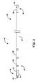
- FIG. 2is a side view of an embodiment of a lead as shown in FIG. 1 .
- FIG. 3Ais a sectioned side view of an embodiment of a distal end of a lead, including an electrode with a coiled portion.
- FIG. 3Bis a side view of the distal end of the lead shown in FIG. 3A .
- FIG. 4Ais a sectioned side view of an embodiment of an electrode portion of a lead, including an insulative layer between the electrode housing and fixation helix.
- FIG. 4Bis an exploded side view of the electrode portion shown in FIG. 4A .
- FIG. 1is a perspective view of an implantable medical device (IMD) 10 in accordance with one embodiment.
- the IMD 10includes a pulse generator 12 and a cardiac lead 14 .
- the lead 14operates to convey electrical signals between the heart 16 and the pulse generator 12 .
- the lead 14has a proximal region 18 and a distal region 20 .
- the lead 14includes a lead body, or flexible body 22 , extending from the proximal region 18 to the distal region 20 .
- the proximal region 18is coupled to the pulse generator 12 and the distal region 20 is coupled to the heart 16 .
- the distal region 20includes an extendable/retractable fixation helix 24 , which will be discussed in greater detail with respect to subsequent drawings, and which locates and/or secures the distal region 20 within the heart 16 .
- the distal region 20includes a plurality of tines or other structures for fixation of the lead 14 relative to the heart 20 (e.g., in a coronary vein or ventricular trabeculae).
- the distal region 20 of the lead 14has an axially compact design that accommodates a dedicated bipolar electrode configuration.
- the lead 14may alternatively have other electrode configurations.
- the distal region 20includes an electrically conductive electrode housing with a hollow interior that accommodates an extendible/retractable fixation helix 24 .
- the electrode housingincludes a length having a coiled component that connects proximal and distal portions of the electrode housing.
- the electrode housingis electrically isolated from the fixation helix 24 , such as with an insulative layer between the electrode housing and fixation helix 24 .
- the pulse generator 12typically includes a connector header 13 that couples the pulse generator 12 to the lead 14 .
- the connector header 13typically contains one or more bores 17 that is/are able to receive a connector (not shown) that is part of a connector assembly (not shown, but see 40 in FIG. 2 , discussed herein) formed near the proximal region 18 of the lead 14 , wherein electrical contacts (not shown) of the connector header 13 couple with lead contacts (not shown) of the connector assembly (not shown).
- the connector header 13can be attached to a hermetically sealed enclosure 15 that contains a battery, electronic circuitry, and other components known to those skilled in the art. Electrical contacts (not shown) in the connector header 13 can be a type known to those skilled in the art that are electrically connected via feedthroughs (not shown) mounted to extend through the hermetically sealed enclosure 15 in order to electrically couple the lead 14 with pulse generator 12 .
- the pulse generator 12can be implanted subcutaneously within an implantation location or pocket in the patient's chest or abdomen. In embodiments in which the lead 14 is a neural lead, the pulse generator may alternatively be implanted at the patient's back or buttocks.
- the pulse generator 12may be any implantable medical device known in the art or later developed, for delivering an electrical therapeutic stimulus to the patient.
- the pulse generator 12is a pacemaker, an implantable cardioverter/defibrillator (ICD), a cardiac resynchronization (CRT) device configured for bi-ventricular pacing, and/or includes combinations of pacing, CRT, and defibrillation capabilities.
- ICDimplantable cardioverter/defibrillator
- CRTcardiac resynchronization
- the lead body 22can be made from a flexible, biocompatible material suitable for lead construction.
- the lead body 22is made from a flexible, electrically insulative material.
- the lead body 22is made from silicone rubber.
- the lead body 22is made from polyurethane.
- respective segments of the lead body 22are made from different materials, so as to tailor the lead body 22 characteristics to its intended clinical and operating environments.
- proximal and distal ends of the lead body 22are made from different materials selected to provide desired functionalities.
- the heart 16includes a right atrium 26 , a right ventricle 28 , a left atrium 30 and a left ventricle 32 .
- the heart 16includes an endothelial inner lining or endocardium 34 covering the myocardium 36 .
- the fixation helix 24located at the distal region 20 of the lead, penetrates through the endocardium 34 , and is imbedded within the myocardium 36 .
- the lead 14may be configured as a passive fixation lead as discussed herein.
- the IMD 10includes a plurality of leads 14 .
- first lead 14adapted to convey electrical signals between the pulse generator 12 and the right ventricle 28
- second lead(not shown) adapted to convey electrical signals between the pulse generator 12 and the right atrium 26
- Additional leadsmay also be employed.
- a coronary venous lead(not shown) may be utilized for stimulating a left atrium 30 and/or a left ventricle 32 of the heart 16 .
- the fixation helix 24penetrates the endocardium 34 of the right ventricle 28 and is imbedded in the myocardium 36 of the heart 16 .
- the fixation helix 24is electrically active and thus can be used to sense the electrical activity of the heart 16 or to apply a stimulating pulse to the right ventricle 28 .
- the fixation helix 24is not electrically active.
- the lead 14is fixed relative to the heart 16 using passive structures (e.g., tines, spirals, etc.).
- the lead 14can be configured to convey electrical signals between the IMD 12 and the heart 16 .
- the lead 14can be utilized to deliver electrical stimuli for pacing the heart 16 .
- the lead 14can be utilized to deliver electric shocks to the heart 16 in response to an event such as a heart attack or arrhythmia.
- the IMD 12includes both pacing and defibrillation capabilities.
- the electrical signalsare carried between the IMD 12 and electrodes at the distal region 20 by one or more conductors extending through the lead 14 .
- the one or more conductorsare electrically coupled to a connector suitable for interfacing with the IMD 12 at the proximal region 18 of the lead 14 and to the one or more electrodes at the distal region 20 .
- the one or more conductorsinclude at least one composite conductor comprising a multiconductor wire.
- the multiconductor wiresare configured to deliver low voltage signals to the one or more electrodes.
- FIG. 2is an isometric illustration of a lead 14 according to some embodiments.
- a connector assembly 40is disposed at or near the proximal region 18 , or proximal end, of the lead 14 .
- the connector assembly 40includes a connector 42 and a terminal pin 44 .
- the connector 42is configured to be coupled to the lead body 22 and is configured to mechanically and electrically couple the lead 14 to the header 13 on the pulse generator 12 (see FIG. 1 ).
- the terminal pin 44includes an aperture (not shown) extending therethrough in order to accommodate a guide wire or an insertion stylet.
- a clinicianmay use a stylet inserted through the terminal pin 44 in the proximal region 40 to actuate the fixation helix 42 in the distal region 46 .
- the terminal pin 44extends proximally from the connector 42 and in some embodiments is coupled to a conductor member (not visible in this view) that extends longitudinally through the lead body 22 such that rotating the terminal pin 44 relative to the lead body 22 causes the conductor member to rotate within the lead body 22 .
- a distal assembly 46is disposed at or near the distal region 20 or distal end of the lead 14 or lead body 22 .
- the distal region 20 of the lead 14may include one or more electrodes.
- the distal region 20includes one or more coil electrodes 48 and 49 that can function as shocking electrodes for providing, for example, a defibrillation shock to the heart 16 .
- the coil electrodes 48 and 49include a coating that is configured to control (i.e., promote or discourage) tissue ingrowth.
- the lead 14may include only a single coil electrode.
- the lead 14also includes one or more low-voltage electrodes (e.g., ring electrodes), such as electrode 47 , along the lead body 22 in lieu of or in addition to the coil electrodes 48 , 49 .
- the low-voltage electrodesoperate as relatively low-voltage, pace/sense electrodes.
- a wide range of electrode combinationsmay be incorporated into the lead 14 within the scope of the various embodiments.
- the distal assembly 46includes a distal electrode assembly 50 , within which the fixation helix 24 , or helical electrode, is at least partially disposed.
- the distal electrode assembly 50accommodates a mechanism that enables the fixation helix 24 to move distally and proximally relative to the distal electrode assembly 50 , but that includes structure (not seen in this view) that limits distal travel of the fixation helix 24 (relative to the distal electrode assembly 50 ) in order to reduce or prevent over-extension of the fixation helix 24 .
- the distal end of the distal electrode assembly 50is electrically active to provide electrical signals at the surface of the endocardial tissue.
- fixation helix 24operates as an anchoring means for anchoring the distal region 20 of the lead 14 within the heart 16 .
- the lead 14is fixed relative to the heart 16 using passive structures (e.g., tines, spirals, etc.).
- the fixation helix 24is electrically active, and is used as a low-voltage, pace/sense electrode.
- the fixation helix 24is made of an electrically conductive material such as ELGILOYTM, MP35NTM, tungsten, tantalum, iridium, platinum, titanium, palladium, stainless steel as well as alloys of these materials.
- the fixation helix 24is electrically inactive and/or electrically isolated from the housing 50 with an insulative layer.
- the fixation helix 24could be made from a non-conductive material such as a polymer or ceramic.
- the lead 14is one exemplary implementation of a lead in accordance with the present disclosure, and other configurations for the lead 14 are also possible.
- coil electrodes 48 , 49are shown adjacent to each other, the coil electrode 49 may alternatively be disposed more proximally on the lead 14 .
- the lead 14may include a plurality of annular electrodes along the distal region 20 for providing pacing and/or sensing signals to adjacent tissue.
- FIG. 3Ais a sectioned side view
- FIG. 3Bis a side view of an embodiment of the distal region 46 of the lead 14 including distal electrode assembly 50 .
- the lead body 22is removed to better illustrate the features of the distal electrode assembly 50 .
- the distal electrode assembly 50includes a proximal portion 60 , an intermediate portion 62 , and a distal portion 64 .
- the intermediate portion 62mechanically and electrically couples the proximal portion 60 to the distal portion 64 .
- the proximal portion 60is configured for coupling with a distal end of a coil conductor 66 extending through the lead body 22 .
- a proximal end of the coil conductor 66(not shown) is connected to the connector assembly 40 at the proximal region 18 of the lead 14 .
- the coil conductor 66couples with a conductor coupling region 68 of the proximal portion 60 .
- the proximal portion 60may include a helical groove 69 that is sized and shaped to receive the distal end of the coil conductor 66 , such that the coil conductor 66 is secured with respect to the proximal portion 60 .
- connection of the proximal portion 60 with the distal end of the coil conductor 66thus electrically connects the electrode assembly 50 with the connector assembly 40 .
- the pitch of the coil conductor 66is increased at the distal end of the coil conductor 66 to allow the coil conductor 66 to couple with the proximal portion 60 .
- the coil conductor 66comprises one or more insulated filars that are stripped of insulation at the distal end of the coil conductor 66 to allow electrical contact between the coil conductor 66 and proximal portion 60 .
- the distal portion 64is disposed at the distal end of the lead 14 and is electrically coupled to the proximal portion 60 via the intermediate portion 62 .
- the distal portion 64includes a distal contact electrode 70 that has an outer diameter D 1 that is greater than the outer diameter D 2 of the proximal portion 60 and intermediate portion 62 .
- the contact electrode 70is configured to contact and deliver electrical energy to endocardial tissue when the lead 14 is implanted.
- the lead body 22extends over the proximal portion 60 , intermediate portion 62 , and parts of the distal portion 64 to the contact electrode 70 . That is, the contact electrode 70 remains exposed in the assembled lead 14 , while the remaining portions of the electrode assembly 50 are covered by the lead body 22 .
- the proximal portion 60may be comprised of the same or similar material as the distal portion 64 .
- the proximal portion 60 and distal portion 64may include precious metals such as gold, silver, or platinum.
- Exemplary materials for the proximal portion 60 and distal portion 64also include, but are not limited to, MPAg (MP35N with silver), MPTa (MP35N with tantalum), platinum-clad Ta, platinum-clad MP35N, MP35N, Nitinol, and palladium.
- the intermediate portion 62comprises a coiled element 72 that extends from the proximal portion 60 to the distal portion 64 .
- the coiled element 72includes one or more filars wound into a coil having an outer diameter substantially the same as adjacent sections of the proximal portion 60 and distal portion 64 .
- the coiled element 72is electrically and mechanically connected to the proximal portion 60 and distal portion 64 .
- the coiled element 72is connected to the proximal portion 60 and distal portion 64 by welding, swaging, or crimping the proximal and distal ends of the coiled element 72 to the proximal portion 60 and distal portion 64 , respectively.
- the coiled element 72is covered (e.g., overmolded) with a polymeric material to improve the durability of the coiled element 72 , provide suitable corrosion performance, and maintain the pitch and shape of the coiled element.
- the coiled element 72may have an outer diameter D 2 of less than about 0.1 inch (2.54 millimeter (mm)).
- the outer diameter D 2 of the coiled element 72is in the range of about 0.03 inch to about 0.1 inch (0.762-2.54 mm).
- the coiled element 72consists of a single filar of conductive material (i.e., unifilar) that is helically coiled with a plurality of co-radial turns. The turns of the coiled element 72 may be closely wound.
- the coiled element 72has a pitch of between about one and two times the filar diameter.
- the coiled element 72has a pitch approximately equal to the filar diameter (i.e., the turns of the coiled element 72 abut each other).
- the pitchmay be consistent along the length of the coiled element 72 , or may be varied along at least a portion of the coiled element 72 .
- One exemplary approach to incorporating variable pitch sections into the coiled element 72is described in U.S. Patent App. Pub. No. 2009/0149933, entitled “Implantable Lead Having a Variable Coil Conductor Pitch,” which is hereby incorporated by reference in its entirety.
- the direction of the pitch of the coiled element 72may also be a function of the winding direction of other coiled elements (e.g., coil conductor 66 ).
- the coiled element 72is wound in a direction opposite the coil conductor 66 .
- the filar of the coiled element 72has a diameter of between about 0.001 inch and 0.007 inch (0.025-0.178 mm).
- One exemplary material suitable for the coiled element 72is MP35N including a silver core (e.g., 25% to 50% silver).
- Other exemplary materials suitable for the coiled element 72include, but are not limited to, MPTa (MP35N with tantalum), platinum-clad Ta, platinum-clad MP35N, MP35N, Nitinol, and palladium.
- the filar of the coiled element 72is insulated.
- the coiled element 72is configured to have a resistance of less than about 100 ohms ( ⁇ ).
- a coiled element 72in the electrode assembly 50 provides several advantages over solid electrode assemblies.
- the proximal and distal portions 60 , 64may be comprised of precious metals.
- a coiled element 72to connect the proximal portion 60 to the distal portion 64 , less precious metal is used to fabricate the electrode assembly 50 versus an electrode assembly made of a solid length of material. Consequently, the overall cost to manufacture the lead 14 is reduced.
- the coiled element 72also generates fewer image artifacts in images generated using magnetic resonance imaging (MRI) while providing good radiopacity to discern the location of the electrode assembly 50 during imaging, since precious metals have a density that images well under the types of vision systems employed during implantation.
- MRImagnetic resonance imaging
- the lead 14can result in localized heating of the contact electrode 70 due to excitation of the lead conductors (e.g., coil conductor 66 ).
- Conductors with high inductanceare more resistant to excitation in MRI fields.
- the inductance of the conductoris determined by its geometric properties, including whether the conductor is straight or coiled.
- a coiled or wound conductorsuch as the coiled element 72
- several parametersinfluence its inductance, including the coil pitch, the outer diameter of the coiled element 72 , the cross-sectional area of the coiled element 72 , and the number of filars comprising the coiled element 72 .
- the coil pitch(i.e., the distance between the centers of adjacent coil turns) may be small (e.g., one to two times the cable filar diameter).
- the coiled element 72is shown having a pitch approximately equal to the filar diameter in FIGS. 3A and 3B (that is, turns of the coil are adjacent to each other).
- the pitch directionmay also be selected (e.g., in the opposite direction as the coil conductor 66 ) to control heating of the electrode assembly 50 under MRI conditions.
- the dimensions and characteristics of the coil 52may be selected to minimize the effects of magnetic resonance imaging (MRI) fields on the performance and response of the lead 14 .
- MRImagnetic resonance imaging
- the fixation helix 24may be disposed within a hollow interior of the electrode assembly 50 .
- the fixation helix 24is a tube of conductive material laser cut or Swiss cut into a helical shape.
- a coupler 76may be fixedly coupled to a proximal end of the fixation helix 24 to facilitate actuation of the fixation helix 24 .
- the coupler 76may include a slot 78 that is accessible via an inner lumen 80 of the lead 14 with a stylet.
- the styletmay be a bladed tip stylet having a distal feature sized and shaped to mate with the slot 78 .
- the styletis pushed through the lumen 80 from the proximal region 18 of the lead 14 until the distal end of the stylet interfaces with the slot 78 in the coupler 76 .
- the styletis then rotated to rotate the fixation helix 24 , which results in longitudinal movement of the fixation helix 24 relative to the lead 14 . This allows the distal tip of the fixation helix 24 to be advanced into tissue during implantation, or retracted back into the electrode assembly 50 .
- the fixation helix 24includes a torque tube 81 that is mechanically coupled to the fixation helix 24 (e.g., via the coupler 76 ).
- the torque tube 81may be mechanically coupled to the terminal pin 44 on the connector assembly 40 to allow rotation and advancement of the fixation helix 24 by rotating the terminal pin 44 . That is, the torque on the terminal pin 44 is transmitted to the fixation helix 24 via the torque tube 81 .
- the torque tube 81is comprised of one or more polymeric fibers that are covered by an insulative coating or sheath.
- the lumen 80 of the torque tube 81comprises a smooth surface to facilitate insertion of a stylet or guide wire.
- the electrode assembly 50may also include a peg 82 against which turns of the fixation helix 24 rotate to maintain axial stability during actuation of the fixation helix 24 .
- the peg 82enables the fixation helix 24 to move distally and proximally relative to the electrode assembly 50 , but limits distal travel of the fixation helix 24 (relative to the distal electrode assembly 50 ) in order to reduce or prevent over-extension of the fixation helix 24 .
- the peg 82may be made of a polymeric material, for example.
- the lead 14may be fixated using passive fixation structures (e.g., tines) disposed on an exterior surface of the distal region 46 , and/or a drug eluting element may be disposed in the hollow interior of the electrode assembly 50 in lieu of the fixation helix 24 .
- passive fixation structurese.g., tines
- a drug eluting elementmay be disposed in the hollow interior of the electrode assembly 50 in lieu of the fixation helix 24 .
- FIG. 4Ais a sectioned side view
- FIG. 4Bis an exploded side view, of another embodiment of an electrode assembly 50 of the lead 14 .
- the electrode assemblyincludes an outer conductive shell 90 , an insulative layer 92 , and a fixation helix 24 .
- the electrode assembly 50also includes a coupler 76 and a peg 82 having functionality similar to the embodiment illustrated in FIGS. 3A and 3B .
- the proximal end of the electrode assembly 50also includes a helical groove 69 sized and shaped to couple with a conductive coil, similar to the embodiment illustrated in FIGS. 3A and 3B .
- the conductive housing 90includes a contact electrode 70 at the distal end of the conductive housing 90 .
- the lead body 22in the assembled lead 14 the lead body 22 is disposed over the portions of the conductive housing 90 up to the contact electrode 70 , thereby leaving only the contact electrode 70 exposed at the distal end of the lead 14 .
- the electrode assembly 50includes an outer conductive shell 90 comprised of a solid length of conductive material in the embodiment illustrated in FIGS. 4A and 4B , the electrode assembly 50 may alternatively be configured to include a coiled element 72 as described herein.
- the insulative layer 92is disposed between the outer conductive shell 90 and the fixation helix 24 .
- the insulative layer 92electrically isolates the fixation helix 24 from the outer conductive shell 90 .
- the insulative layer 92may also be configured such that the fixation helix 24 is electrically inactive, and operates only as a fixation mechanism.
- the insulative layer 92may be comprised of a material including, but not limited to, high durometer polyurethanes, hybrid high durometer polymers, ceramic, and epoxies, PEEK, ETFE, PTFE and derivatives, and/or parylene C.
- the insulative layer 92is formed on a metal substrate.
- the tissue to be stimulated by the outer conductive shell 90is distanced from the tissue attached to the fixation helix 24 for anchoring the lead 14 .
- the tissue surrounding the fixation helix 24may be agitated or going through the healing process and, as a result, may have a higher chronic threshold than other surrounding tissue. Consequently, by electrically isolating the fixation helix 24 from the outer conductive shell 90 , the likelihood of electrical stimulation being delivered to tissue having a lower chronic threshold is increased.
- the conductive housing 90may be used in association with mapping systems to locate the distal region 46 of the lead 14 and/or facilitate development of a two- or three-dimensional representation of the heart 16 or one or more chambers of the heart 16 .
- the conductive housing 90may be employed for establishing relative location and orientation of the lead 14 with respect to a mapping catheter located in another portion of the heart 16 .
Landscapes
- Health & Medical Sciences (AREA)
- Cardiology (AREA)
- Heart & Thoracic Surgery (AREA)
- Animal Behavior & Ethology (AREA)
- Engineering & Computer Science (AREA)
- Biomedical Technology (AREA)
- Nuclear Medicine, Radiotherapy & Molecular Imaging (AREA)
- Radiology & Medical Imaging (AREA)
- Life Sciences & Earth Sciences (AREA)
- General Health & Medical Sciences (AREA)
- Public Health (AREA)
- Veterinary Medicine (AREA)
- Vascular Medicine (AREA)
- Electrotherapy Devices (AREA)
- Neurology (AREA)
Abstract
Description
This application claims priority to Provisional Application No. 61/654,446, filed Jun. 1, 2012, which is herein incorporated by reference in its entirety.
The present disclosure relates to implantable medical devices. More particularly, the present disclosure relates to a distal lead electrode assembly including a coiled electrode component and/or an electrically isolated moveable fixation helix.
Magnetic resonance imaging (MRI) is a non-invasive imaging procedure that utilizes nuclear magnetic resonance techniques to render images within a patient's body. Typically, MRI systems employ the use of a magnetic coil having a magnetic field strength of between about 0.2 to 3 Teslas (T). During the procedure, the body tissue is briefly exposed to radio frequency (RF) pulses of electromagnetic energy in a plane perpendicular to the magnetic field. The resultant electromagnetic energy from these pulses can be used to image the body tissue by measuring the relaxation properties of the excited atomic nuclei in the tissue.
During imaging, the electromagnetic radiation produced by the MRI system may be picked up by implantable device leads used in implantable medical devices such as pacemakers or cardiac defibrillators. This energy may be transferred through the lead to the electrode in contact with the tissue, which may lead to elevated temperatures at the point of contact. The degree of tissue heating is typically related to factors such as the length of the lead, the conductivity or impedance of the lead, and the surface area of the lead electrodes. Exposure to a magnetic field may also induce an undesired voltage on the lead. Further, in some cases, certain components of the lead can cause image artifacts in the magnetic resonance image.
Disclosed herein are various embodiments of a medical device lead including a distal lead electrode assembly including a coiled electrode component, as well as medical device systems including such electrode assemblies.
In Example 1, a medical device lead includes an insulative body having a proximal region with a proximal end, and a distal region with a distal end. The medical device lead also includes a connector coupled to the proximal end of the insulative body of the lead to electrically and mechanically connect the lead to an implantable pulse generator. The medical device lead further includes a conductor extending through the insulative body with a proximal end electrically connected to the connector. A distal electrode assembly at a distal end of the insulative body includes a proximal portion electrically coupled to a distal end of the conductor, a distal portion, and an intermediate portion. The intermediate portion comprises a coiled element electrically connecting the proximal portion and distal portion.
In Example 2, the medical device lead according to Example 1, wherein the distal portion of the distal electrode assembly includes a contact electrode having an outer diameter larger than outer diameters of the proximal portion and intermediate portion, and wherein the insulative body extends over the distal electrode assembly to the contact electrode such that the contact electrode is exposed at the distal end of the medical device lead.
In Example 3, the medical device lead according to either Example 1 or 2, wherein the coiled element comprises a unifilar coil.
In Example 4, the medical device lead according to any of Examples 1-3, wherein a resistance of the coiled element is less than about 100 ohms.
In Example 5, the medical device lead according to any of Examples 1-4, and further comprising a fixation helix disposed within the distal electrode assembly and configured to extend from and retract into a distal end of the distal electrode assembly.
In Example 6, the medical device lead according to any of Examples 1-5, and further comprising an insulative layer configured to electrically isolate the fixation helix from the distal electrode assembly.
In Example 7, the medical device lead according to any of Examples 1-6, and further comprising a coupler disposed within the distal electrode assembly and fixedly attached to the fixation helix, wherein the coupler is rotatable with respect to the distal electrode assembly to translate the fixation helix longitudinally with respect to the distal electrode assembly.
In Example 8, the medical device lead according to any of Examples 1-7, wherein the coupler includes a slot configured to receive a distal end of an actuating device to rotate the coupler.
In Example 9, a distal electrode assembly for an implantable medical device includes a proximal portion configured for electrical connection to a conductive coil that delivers electrical energy to the distal electrode assembly, a distal portion including a contact electrode, and an intermediate portion comprising a coiled element electrically connecting the proximal portion to the distal portion.
In Example 10, the distal electrode assembly according to Example 9, wherein the coiled element comprises a unifilar coil.
In Example 11, the distal electrode assembly according to either Example 9 or 10, wherein the unifilar coil has a filar diameter of 0.002-0.007 inch (0.051-0.178 mm).
In Example 12, the distal electrode assembly according to any of Examples 9-11, wherein a resistance of the coiled element is less than about 100 ohms.
In Example 13, the distal electrode assembly according to any of Examples 9-12, and further comprising a fixation helix disposed within the distal electrode assembly and configured to extend from and retract into a distal end of the distal electrode assembly.
In Example 14, the distal electrode assembly according to any of Examples 9-13, and further comprising an insulative layer configured to electrically isolate the fixation helix from the distal electrode assembly.
In Example 15, a medical device lead includes an insulative body having a proximal region with a proximal end, and a distal region with a distal end. The medical device lead also includes a conductive coil extending through the insulative body, and a distal electrode assembly at a distal end of the insulative body. The distal electrode assembly includes a proximal portion electrically coupled to a distal end of the conductor, a distal portion, and an intermediate portion. The intermediate portion comprises a coiled element electrically connecting the proximal portion and distal portion. The coiled element comprises a unifilar coil having a pitch of less than two.
In Example 16, the medical device lead according to Example 15, and further comprising a fixation helix disposed within the distal electrode assembly and configured to extend from and retract into a distal end of the distal electrode assembly.
In Example 17, the medical device lead according to either Example 15 or 16, wherein the distal portion of the distal electrode assembly includes a contact electrode having an outer diameter larger than outer diameters of the proximal portion and intermediate portion, and wherein the insulative body extends over the distal electrode assembly to the contact electrode such that the contact electrode is exposed at the distal end of the medical device lead.
In Example 18, the medical device lead according to any of Examples 15-17, and further comprising a fixation helix disposed within the distal electrode assembly and configured to extend from and retract into a distal end of the distal electrode assembly.
In Example 19, the medical device lead according to any of Examples 15-18, and further comprising an insulative layer configured to electrically isolate the fixation helix from the distal electrode assembly.
In Example 20, the medical device lead according to any of Examples 15-19, and further comprising a coupler disposed within the distal electrode assembly and fixedly attached to the fixation helix, wherein the coupler is rotatable with respect to the distal electrode assembly to translate the fixation helix longitudinally with respect to the distal electrode assembly, and wherein the coupler includes a slot configured to receive a distal end of an actuating device to rotate the coupler.
While multiple embodiments are disclosed, still other embodiments of the present invention will become apparent to those skilled in the art from the following detailed description, which shows and describes illustrative embodiments of the invention. Accordingly, the drawings and detailed description are to be regarded as illustrative in nature and not restrictive.
While the invention is amenable to various modifications and alternative forms, specific embodiments have been shown by way of example in the drawings and are described in detail below. The intention, however, is not to limit the invention to the particular embodiments described. On the contrary, the invention is intended to cover all modifications, equivalents, and alternatives falling within the scope of the invention as defined by the appended claims.
Thedistal region 20 of thelead 14 has an axially compact design that accommodates a dedicated bipolar electrode configuration. Thelead 14 may alternatively have other electrode configurations. As will be explained in further detail herein and shown in additional figures, thedistal region 20 includes an electrically conductive electrode housing with a hollow interior that accommodates an extendible/retractable fixation helix 24. In some embodiments, the electrode housing includes a length having a coiled component that connects proximal and distal portions of the electrode housing. In some embodiments, the electrode housing is electrically isolated from thefixation helix 24, such as with an insulative layer between the electrode housing andfixation helix 24.
Thepulse generator 12 typically includes aconnector header 13 that couples thepulse generator 12 to thelead 14. Theconnector header 13 typically contains one ormore bores 17 that is/are able to receive a connector (not shown) that is part of a connector assembly (not shown, but see40 inFIG. 2 , discussed herein) formed near theproximal region 18 of thelead 14, wherein electrical contacts (not shown) of theconnector header 13 couple with lead contacts (not shown) of the connector assembly (not shown).
Theconnector header 13 can be attached to a hermetically sealedenclosure 15 that contains a battery, electronic circuitry, and other components known to those skilled in the art. Electrical contacts (not shown) in theconnector header 13 can be a type known to those skilled in the art that are electrically connected via feedthroughs (not shown) mounted to extend through the hermetically sealedenclosure 15 in order to electrically couple the lead14 withpulse generator 12.
Thepulse generator 12 can be implanted subcutaneously within an implantation location or pocket in the patient's chest or abdomen. In embodiments in which thelead 14 is a neural lead, the pulse generator may alternatively be implanted at the patient's back or buttocks. Thepulse generator 12 may be any implantable medical device known in the art or later developed, for delivering an electrical therapeutic stimulus to the patient. In various embodiments, thepulse generator 12 is a pacemaker, an implantable cardioverter/defibrillator (ICD), a cardiac resynchronization (CRT) device configured for bi-ventricular pacing, and/or includes combinations of pacing, CRT, and defibrillation capabilities.
Thelead body 22 can be made from a flexible, biocompatible material suitable for lead construction. In various embodiments, thelead body 22 is made from a flexible, electrically insulative material. In one embodiment, thelead body 22 is made from silicone rubber. In another embodiment, thelead body 22 is made from polyurethane. In various embodiments, respective segments of thelead body 22 are made from different materials, so as to tailor thelead body 22 characteristics to its intended clinical and operating environments. In various embodiments, proximal and distal ends of thelead body 22 are made from different materials selected to provide desired functionalities.
Theheart 16 includes aright atrium 26, a right ventricle28, aleft atrium 30 and aleft ventricle 32. Theheart 16 includes an endothelial inner lining orendocardium 34 covering themyocardium 36. In some embodiments as illustrated, thefixation helix 24, located at thedistal region 20 of the lead, penetrates through theendocardium 34, and is imbedded within themyocardium 36. Alternatively, thelead 14 may be configured as a passive fixation lead as discussed herein. In one embodiment, theIMD 10 includes a plurality of leads14. For example, it may include afirst lead 14 adapted to convey electrical signals between thepulse generator 12 and the right ventricle28, and a second lead (not shown) adapted to convey electrical signals between thepulse generator 12 and theright atrium 26. Additional leads may also be employed. For example, in various embodiments, a coronary venous lead (not shown) may be utilized for stimulating aleft atrium 30 and/or aleft ventricle 32 of theheart 16.
In the illustrated embodiment shown inFIG. 1 , thefixation helix 24 penetrates theendocardium 34 of the right ventricle28 and is imbedded in themyocardium 36 of theheart 16. In some embodiments, thefixation helix 24 is electrically active and thus can be used to sense the electrical activity of theheart 16 or to apply a stimulating pulse to the right ventricle28. In other embodiments, thefixation helix 24 is not electrically active. In still other embodiments, thelead 14 is fixed relative to theheart 16 using passive structures (e.g., tines, spirals, etc.).
During operation, thelead 14 can be configured to convey electrical signals between theIMD 12 and theheart 16. For example, in those embodiments in which theIMD 12 is a pacemaker, thelead 14 can be utilized to deliver electrical stimuli for pacing theheart 16. In those embodiments in which theIMD 12 is an implantable cardiac defibrillator, thelead 14 can be utilized to deliver electric shocks to theheart 16 in response to an event such as a heart attack or arrhythmia. In some embodiments, theIMD 12 includes both pacing and defibrillation capabilities.
The electrical signals are carried between theIMD 12 and electrodes at thedistal region 20 by one or more conductors extending through thelead 14. The one or more conductors are electrically coupled to a connector suitable for interfacing with theIMD 12 at theproximal region 18 of thelead 14 and to the one or more electrodes at thedistal region 20. According to various embodiments, the one or more conductors include at least one composite conductor comprising a multiconductor wire. In some embodiments, the multiconductor wires are configured to deliver low voltage signals to the one or more electrodes.
Adistal assembly 46 is disposed at or near thedistal region 20 or distal end of thelead 14 orlead body 22. Depending on the functional requirements of the IMD10 (seeFIG. 1 ) and the therapeutic needs of a patient, thedistal region 20 of thelead 14 may include one or more electrodes. In the illustrated embodiment, thedistal region 20 includes one ormore coil electrodes heart 16. In some embodiments, thecoil electrodes lead 14 may include only a single coil electrode. In various other embodiments, thelead 14 also includes one or more low-voltage electrodes (e.g., ring electrodes), such aselectrode 47, along thelead body 22 in lieu of or in addition to thecoil electrodes lead 14 within the scope of the various embodiments.
Thedistal assembly 46 includes adistal electrode assembly 50, within which thefixation helix 24, or helical electrode, is at least partially disposed. As will be explained in greater detail herein, thedistal electrode assembly 50 accommodates a mechanism that enables thefixation helix 24 to move distally and proximally relative to thedistal electrode assembly 50, but that includes structure (not seen in this view) that limits distal travel of the fixation helix24 (relative to the distal electrode assembly50) in order to reduce or prevent over-extension of thefixation helix 24. In some embodiments, the distal end of thedistal electrode assembly 50 is electrically active to provide electrical signals at the surface of the endocardial tissue. As noted herein, thefixation helix 24 operates as an anchoring means for anchoring thedistal region 20 of thelead 14 within theheart 16. In alternative embodiments, thelead 14 is fixed relative to theheart 16 using passive structures (e.g., tines, spirals, etc.).
In some embodiments, thefixation helix 24, or helical electrode, is electrically active, and is used as a low-voltage, pace/sense electrode. In some embodiments, thefixation helix 24 is made of an electrically conductive material such as ELGILOY™, MP35N™, tungsten, tantalum, iridium, platinum, titanium, palladium, stainless steel as well as alloys of these materials. In alternative embodiments, thefixation helix 24 is electrically inactive and/or electrically isolated from thehousing 50 with an insulative layer. For example, thefixation helix 24 could be made from a non-conductive material such as a polymer or ceramic.
Thelead 14 is one exemplary implementation of a lead in accordance with the present disclosure, and other configurations for thelead 14 are also possible. For example, whilecoil electrodes coil electrode 49 may alternatively be disposed more proximally on thelead 14. As another example, thelead 14 may include a plurality of annular electrodes along thedistal region 20 for providing pacing and/or sensing signals to adjacent tissue.
Theproximal portion 60 is configured for coupling with a distal end of acoil conductor 66 extending through thelead body 22. In some embodiments, a proximal end of the coil conductor66 (not shown) is connected to theconnector assembly 40 at theproximal region 18 of thelead 14. In the embodiment shown, thecoil conductor 66 couples with aconductor coupling region 68 of theproximal portion 60. For example, theproximal portion 60 may include ahelical groove 69 that is sized and shaped to receive the distal end of thecoil conductor 66, such that thecoil conductor 66 is secured with respect to theproximal portion 60. The connection of theproximal portion 60 with the distal end of thecoil conductor 66 thus electrically connects theelectrode assembly 50 with theconnector assembly 40. In some embodiments, the pitch of thecoil conductor 66 is increased at the distal end of thecoil conductor 66 to allow thecoil conductor 66 to couple with theproximal portion 60. In some embodiments, thecoil conductor 66 comprises one or more insulated filars that are stripped of insulation at the distal end of thecoil conductor 66 to allow electrical contact between thecoil conductor 66 andproximal portion 60.
Thedistal portion 64 is disposed at the distal end of thelead 14 and is electrically coupled to theproximal portion 60 via theintermediate portion 62. In some embodiments, thedistal portion 64 includes adistal contact electrode 70 that has an outer diameter D1that is greater than the outer diameter D2of theproximal portion 60 andintermediate portion 62. Thecontact electrode 70 is configured to contact and deliver electrical energy to endocardial tissue when thelead 14 is implanted. In some embodiments, thelead body 22 extends over theproximal portion 60,intermediate portion 62, and parts of thedistal portion 64 to thecontact electrode 70. That is, thecontact electrode 70 remains exposed in the assembledlead 14, while the remaining portions of theelectrode assembly 50 are covered by thelead body 22.
Theproximal portion 60 may be comprised of the same or similar material as thedistal portion 64. Theproximal portion 60 anddistal portion 64 may include precious metals such as gold, silver, or platinum. Exemplary materials for theproximal portion 60 anddistal portion 64 also include, but are not limited to, MPAg (MP35N with silver), MPTa (MP35N with tantalum), platinum-clad Ta, platinum-clad MP35N, MP35N, Nitinol, and palladium.
Theintermediate portion 62 comprises a coiledelement 72 that extends from theproximal portion 60 to thedistal portion 64. The coiledelement 72 includes one or more filars wound into a coil having an outer diameter substantially the same as adjacent sections of theproximal portion 60 anddistal portion 64. As discussed herein, the coiledelement 72 is electrically and mechanically connected to theproximal portion 60 anddistal portion 64. In some embodiments, the coiledelement 72 is connected to theproximal portion 60 anddistal portion 64 by welding, swaging, or crimping the proximal and distal ends of the coiledelement 72 to theproximal portion 60 anddistal portion 64, respectively. In some embodiments, the coiledelement 72 is covered (e.g., overmolded) with a polymeric material to improve the durability of the coiledelement 72, provide suitable corrosion performance, and maintain the pitch and shape of the coiled element.
The coiledelement 72 may have an outer diameter D2of less than about 0.1 inch (2.54 millimeter (mm)). For example, in some exemplary implementations, the outer diameter D2of the coiledelement 72 is in the range of about 0.03 inch to about 0.1 inch (0.762-2.54 mm). In some embodiments, the coiledelement 72 consists of a single filar of conductive material (i.e., unifilar) that is helically coiled with a plurality of co-radial turns. The turns of the coiledelement 72 may be closely wound. For example, in some embodiments, the coiledelement 72 has a pitch of between about one and two times the filar diameter. In the illustrated embodiment, the coiledelement 72 has a pitch approximately equal to the filar diameter (i.e., the turns of the coiledelement 72 abut each other). The pitch may be consistent along the length of the coiledelement 72, or may be varied along at least a portion of the coiledelement 72. One exemplary approach to incorporating variable pitch sections into the coiledelement 72 is described in U.S. Patent App. Pub. No. 2009/0149933, entitled “Implantable Lead Having a Variable Coil Conductor Pitch,” which is hereby incorporated by reference in its entirety. The direction of the pitch of the coiledelement 72 may also be a function of the winding direction of other coiled elements (e.g., coil conductor66). For example, in some embodiments, the coiledelement 72 is wound in a direction opposite thecoil conductor 66.
In some embodiments, the filar of the coiledelement 72 has a diameter of between about 0.001 inch and 0.007 inch (0.025-0.178 mm). One exemplary material suitable for the coiledelement 72 is MP35N including a silver core (e.g., 25% to 50% silver). Other exemplary materials suitable for the coiledelement 72 include, but are not limited to, MPTa (MP35N with tantalum), platinum-clad Ta, platinum-clad MP35N, MP35N, Nitinol, and palladium. In some embodiments, the filar of the coiledelement 72 is insulated. In some embodiments, the coiledelement 72 is configured to have a resistance of less than about 100 ohms (Ω).
The inclusion of acoiled element 72 in theelectrode assembly 50 provides several advantages over solid electrode assemblies. For example, as discussed above, the proximal anddistal portions element 72 to connect theproximal portion 60 to thedistal portion 64, less precious metal is used to fabricate theelectrode assembly 50 versus an electrode assembly made of a solid length of material. Consequently, the overall cost to manufacture thelead 14 is reduced. At the same time, the coiledelement 72 also generates fewer image artifacts in images generated using magnetic resonance imaging (MRI) while providing good radiopacity to discern the location of theelectrode assembly 50 during imaging, since precious metals have a density that images well under the types of vision systems employed during implantation.
In addition, exposure of thelead 14 to MRI fields can result in localized heating of thecontact electrode 70 due to excitation of the lead conductors (e.g., coil conductor66). Conductors with high inductance (>1 pH) are more resistant to excitation in MRI fields. The inductance of the conductor is determined by its geometric properties, including whether the conductor is straight or coiled. For a coiled or wound conductor, such as thecoiled element 72, several parameters influence its inductance, including the coil pitch, the outer diameter of the coiledelement 72, the cross-sectional area of the coiledelement 72, and the number of filars comprising the coiledelement 72. For example, in some embodiments, the coil pitch (i.e., the distance between the centers of adjacent coil turns) may be small (e.g., one to two times the cable filar diameter). The coiledelement 72 is shown having a pitch approximately equal to the filar diameter inFIGS. 3A and 3B (that is, turns of the coil are adjacent to each other). The pitch direction may also be selected (e.g., in the opposite direction as the coil conductor66) to control heating of theelectrode assembly 50 under MRI conditions. Thus, the dimensions and characteristics of the coil52 may be selected to minimize the effects of magnetic resonance imaging (MRI) fields on the performance and response of thelead 14.
Thefixation helix 24 may be disposed within a hollow interior of theelectrode assembly 50. In some embodiments, thefixation helix 24 is a tube of conductive material laser cut or Swiss cut into a helical shape. Acoupler 76 may be fixedly coupled to a proximal end of thefixation helix 24 to facilitate actuation of thefixation helix 24. In some embodiments, thecoupler 76 may include aslot 78 that is accessible via aninner lumen 80 of thelead 14 with a stylet. For example, the stylet may be a bladed tip stylet having a distal feature sized and shaped to mate with theslot 78. To actuate thefixation helix 24, the stylet is pushed through thelumen 80 from theproximal region 18 of thelead 14 until the distal end of the stylet interfaces with theslot 78 in thecoupler 76. The stylet is then rotated to rotate thefixation helix 24, which results in longitudinal movement of thefixation helix 24 relative to thelead 14. This allows the distal tip of thefixation helix 24 to be advanced into tissue during implantation, or retracted back into theelectrode assembly 50.
In an alternative embodiment, thefixation helix 24 includes atorque tube 81 that is mechanically coupled to the fixation helix24 (e.g., via the coupler76). Thetorque tube 81 may be mechanically coupled to theterminal pin 44 on theconnector assembly 40 to allow rotation and advancement of thefixation helix 24 by rotating theterminal pin 44. That is, the torque on theterminal pin 44 is transmitted to thefixation helix 24 via thetorque tube 81. In some embodiments, thetorque tube 81 is comprised of one or more polymeric fibers that are covered by an insulative coating or sheath. In some embodiments, thelumen 80 of thetorque tube 81 comprises a smooth surface to facilitate insertion of a stylet or guide wire.
Theelectrode assembly 50 may also include apeg 82 against which turns of thefixation helix 24 rotate to maintain axial stability during actuation of thefixation helix 24. Thepeg 82 enables thefixation helix 24 to move distally and proximally relative to theelectrode assembly 50, but limits distal travel of the fixation helix24 (relative to the distal electrode assembly50) in order to reduce or prevent over-extension of thefixation helix 24. Thepeg 82 may be made of a polymeric material, for example.
In alternative embodiments, thelead 14 may be fixated using passive fixation structures (e.g., tines) disposed on an exterior surface of thedistal region 46, and/or a drug eluting element may be disposed in the hollow interior of theelectrode assembly 50 in lieu of thefixation helix 24.
Theinsulative layer 92 is disposed between the outerconductive shell 90 and thefixation helix 24. In some embodiments, theinsulative layer 92 electrically isolates thefixation helix 24 from the outerconductive shell 90. Theinsulative layer 92 may also be configured such that thefixation helix 24 is electrically inactive, and operates only as a fixation mechanism. Theinsulative layer 92 may be comprised of a material including, but not limited to, high durometer polyurethanes, hybrid high durometer polymers, ceramic, and epoxies, PEEK, ETFE, PTFE and derivatives, and/or parylene C. In some embodiments, theinsulative layer 92 is formed on a metal substrate.
In this configuration, the tissue to be stimulated by the outerconductive shell 90 is distanced from the tissue attached to thefixation helix 24 for anchoring thelead 14. The tissue surrounding thefixation helix 24 may be agitated or going through the healing process and, as a result, may have a higher chronic threshold than other surrounding tissue. Consequently, by electrically isolating thefixation helix 24 from the outerconductive shell 90, the likelihood of electrical stimulation being delivered to tissue having a lower chronic threshold is increased.
Theconductive housing 90 may be used in association with mapping systems to locate thedistal region 46 of thelead 14 and/or facilitate development of a two- or three-dimensional representation of theheart 16 or one or more chambers of theheart 16. For example, theconductive housing 90 may be employed for establishing relative location and orientation of thelead 14 with respect to a mapping catheter located in another portion of theheart 16.
Various modifications and additions can be made to the exemplary embodiments discussed without departing from the scope of the present invention. For example, while the embodiments described above refer to particular features, the scope of this invention also includes embodiments having different combinations of features and embodiments that do not include all of the described features. Accordingly, the scope of the present invention is intended to embrace all such alternatives, modifications, and variations as fall within the scope of the claims, together with all equivalents thereof.
Claims (20)
1. A medical device lead comprising:
an insulative body having a proximal region with a proximal end, and a distal region with a distal end;
a connector coupled to the proximal end of the insulative body of the lead configured to electrically and mechanically connect the lead to an implantable pulse generator;
a conductor extending through the insulative body, a proximal end of the conductor electrically connected to the connector; and
a distal electrode assembly at a distal end of the insulative body, the distal electrode assembly including a proximal portion that is mechanically and electrically coupled to a distal end of the conductor, a distal portion, an electrode at the distal portion, and an intermediate portion located between the proximal portion and the distal portion, wherein the distal end of the conductor terminates at the proximal portion of the distal electrode assembly, the intermediate portion is formed by a coiled element that terminates proximally with a first electrical connection at the proximal portion and distally with a second electrical connection at the distal portion to electrically connect the proximal portion to the distal portion, and the conductor is electrically connected to the electrode via the proximal portion, the intermediate portion, and the distal portion.
2. The medical device lead ofclaim 1 , wherein the electrode comprises a contact electrode that is part of the distal portion of the distal electrode assembly, the contact electrode having an outer diameter larger than outer diameters of the proximal portion and intermediate portion, and wherein the insulative body extends over the distal electrode assembly to the contact electrode such that the contact electrode is exposed at the distal end of the medical device lead.
3. The medical device lead ofclaim 1 , wherein the coiled element comprises a unifilar coil.
4. The medical device lead ofclaim 1 , wherein a resistance of the coiled element is less than about 100 ohms.
5. The medical device lead ofclaim 1 , and further comprising:
a fixation helix disposed within the distal electrode assembly and configured to extend from and retract into a distal end of the distal electrode assembly.
6. The medical device lead ofclaim 5 , and further comprising:
an insulative layer configured to electrically isolate the fixation helix from the distal electrode assembly.
7. The medical device lead ofclaim 5 , and further comprising:
a coupler disposed within the distal electrode assembly and fixedly attached to the fixation helix, wherein the coupler is rotatable with respect to the distal electrode assembly to translate the fixation helix longitudinally with respect to the distal electrode assembly.
8. The medical device lead ofclaim 7 , wherein the coupler includes a slot configured to receive a distal end of an actuating device to rotate the coupler.
9. A distal electrode assembly for an implantable medical device, the distal electrode assembly comprising:
a proximal portion configured for electrical connection to a conductive coil that delivers electrical energy to the distal electrode assembly, the proximal portion having an outer diameter;
a distal portion including a contact electrode, the distal portion having an outer diameter; and
an intermediate portion electrically connecting the proximal portion to the distal portion, wherein the intermediate portion comprises a coiled element that terminates proximally at a first electrical connection at the proximal portion and distally with a second electrical connection at the distal portion to electrically connect the proximal portion to the distal portion, the coiled element having an outer diameter that is substantially the same as the outer diameters of the proximal portion and the distal portion.
10. The distal electrode assembly ofclaim 9 , wherein the coiled element comprises a unifilar coil.
11. The distal electrode assembly ofclaim 10 , wherein the unifilar coil has a filar diameter of 0.001-0.007 inch (0.025-0.178 mm).
12. The distal electrode assembly ofclaim 9 , wherein a resistance of the coiled element is less than about 100 ohms.
13. The distal electrode assembly ofclaim 9 , and further comprising:
a fixation helix disposed within the distal electrode assembly and configured to extend from and retract into a distal end of the distal electrode assembly.
14. The distal electrode assembly ofclaim 13 , and further comprising:
an insulative layer configured to electrically isolate the fixation helix from the distal electrode assembly.
15. A medical device lead comprising:
an insulative body having a proximal region with a proximal end, and a distal region with a distal end;
a conductive coil extending through the insulative body; and
a distal electrode assembly at a distal end of the insulative body, the distal electrode assembly including an electrode, a proximal portion electrically and mechanically coupled to a distal end of the conductor, a distal portion supporting the electrode, and an intermediate portion, wherein the intermediate portion comprises a unifilar coil located between the proximal portion and the distal portion, the unifilar coil electrically connecting the proximal portion to the distal portion such that the conductive coil is electrically connected to the electrode, and wherein the unifilar coil has a coil winding pitch of less than two.
16. The medical device lead ofclaim 15 , and further comprising:
a fixation helix disposed within the distal electrode assembly and configured to extend from and retract into a distal end of the distal electrode assembly.
17. The medical device lead ofclaim 16 , wherein the electrode is a contact electrode having an outer diameter larger than outer diameters of the proximal portion and the intermediate portion, and wherein the insulative body extends over the distal electrode assembly to the contact electrode such that the contact electrode is exposed at the distal end of the medical device lead.
18. The medical device lead ofclaim 16 , and further comprising:
a fixation helix disposed within the distal electrode assembly and configured to extend from and retract into a distal end of the distal electrode assembly.
19. The medical device lead ofclaim 18 , and further comprising:
an insulative layer configured to electrically isolate the fixation helix from the distal electrode assembly.
20. The medical device lead ofclaim 19 , and further comprising:
a coupler disposed within the distal electrode assembly and fixedly attached to the fixation helix, wherein the coupler is rotatable with respect to the distal electrode assembly to translate the fixation helix longitudinally with respect to the distal electrode assembly, and wherein the coupler includes a slot configured to receive a distal end of an actuating device to rotate the coupler.
Priority Applications (2)
| Application Number | Priority Date | Filing Date | Title |
|---|---|---|---|
| US13/800,159US8954168B2 (en) | 2012-06-01 | 2013-03-13 | Implantable device lead including a distal electrode assembly with a coiled component |
| US14/580,107US9333344B2 (en) | 2012-06-01 | 2014-12-22 | Implantable device lead including a distal electrode assembly with a coiled component |
Applications Claiming Priority (2)
| Application Number | Priority Date | Filing Date | Title |
|---|---|---|---|
| US201261654446P | 2012-06-01 | 2012-06-01 | |
| US13/800,159US8954168B2 (en) | 2012-06-01 | 2013-03-13 | Implantable device lead including a distal electrode assembly with a coiled component |
Related Child Applications (1)
| Application Number | Title | Priority Date | Filing Date |
|---|---|---|---|
| US14/580,107ContinuationUS9333344B2 (en) | 2012-06-01 | 2014-12-22 | Implantable device lead including a distal electrode assembly with a coiled component |
Publications (2)
| Publication Number | Publication Date |
|---|---|
| US20130325093A1 US20130325093A1 (en) | 2013-12-05 |
| US8954168B2true US8954168B2 (en) | 2015-02-10 |
Family
ID=49671183
Family Applications (2)
| Application Number | Title | Priority Date | Filing Date |
|---|---|---|---|
| US13/800,159ActiveUS8954168B2 (en) | 2012-06-01 | 2013-03-13 | Implantable device lead including a distal electrode assembly with a coiled component |
| US14/580,107Expired - Fee RelatedUS9333344B2 (en) | 2012-06-01 | 2014-12-22 | Implantable device lead including a distal electrode assembly with a coiled component |
Family Applications After (1)
| Application Number | Title | Priority Date | Filing Date |
|---|---|---|---|
| US14/580,107Expired - Fee RelatedUS9333344B2 (en) | 2012-06-01 | 2014-12-22 | Implantable device lead including a distal electrode assembly with a coiled component |
Country Status (1)
| Country | Link |
|---|---|
| US (2) | US8954168B2 (en) |
Cited By (6)
| Publication number | Priority date | Publication date | Assignee | Title |
|---|---|---|---|---|
| US9504822B2 (en) | 2012-10-18 | 2016-11-29 | Cardiac Pacemakers, Inc. | Inductive element for providing MRI compatibility in an implantable medical device lead |
| US9504821B2 (en) | 2014-02-26 | 2016-11-29 | Cardiac Pacemakers, Inc. | Construction of an MRI-safe tachycardia lead |
| USD894396S1 (en) | 2019-03-08 | 2020-08-25 | Pacesetter, Inc. | Leadless biostimulator attachment feature |
| US11185704B2 (en) | 2017-11-06 | 2021-11-30 | Pacesetter, Inc. | Biostimulator having fixation element |
| US11541243B2 (en) | 2019-03-15 | 2023-01-03 | Pacesetter, Inc. | Biostimulator having coaxial fixation elements |
| US11577086B2 (en) | 2018-08-20 | 2023-02-14 | Pacesetter, Inc. | Fixation mechanisms for a leadless cardiac biostimulator |
Families Citing this family (12)
| Publication number | Priority date | Publication date | Assignee | Title |
|---|---|---|---|---|
| US9084883B2 (en) | 2009-03-12 | 2015-07-21 | Cardiac Pacemakers, Inc. | Thin profile conductor assembly for medical device leads |
| US9254380B2 (en) | 2009-10-19 | 2016-02-09 | Cardiac Pacemakers, Inc. | MRI compatible tachycardia lead |
| WO2011081713A1 (en) | 2009-12-31 | 2011-07-07 | Cardiac Pacemakers, Inc. | Mri conditionally safe lead with multi-layer conductor |
| US8391994B2 (en) | 2009-12-31 | 2013-03-05 | Cardiac Pacemakers, Inc. | MRI conditionally safe lead with low-profile multi-layer conductor for longitudinal expansion |
| JP2013537835A (en) | 2010-09-28 | 2013-10-07 | ザ ボード オブ トラスティーズ オブ ザ リーランド スタンフォード ジュニア ユニバーシティ | Devices and methods for positioning electrodes in tissue |
| US9872981B2 (en) | 2010-09-28 | 2018-01-23 | Biotrace Medical, Inc. | Device and method for positioning an electrode in a body cavity |
| US8954168B2 (en) | 2012-06-01 | 2015-02-10 | Cardiac Pacemakers, Inc. | Implantable device lead including a distal electrode assembly with a coiled component |
| JP6069499B2 (en) | 2012-08-31 | 2017-02-01 | カーディアック ペースメイカーズ, インコーポレイテッド | Lead wire with low peak MRI heating |
| EP3139994B1 (en) | 2014-05-09 | 2024-05-22 | Merit Medical Systems, Inc. | Device for positioning an electrode in a body cavity |
| US10164050B2 (en) | 2014-12-24 | 2018-12-25 | Taiwan Semiconductor Manufacturing Co., Ltd. | Structure and formation method of semiconductor device structure with gate stack |
| EP3442651B1 (en)* | 2016-04-15 | 2022-04-13 | Medtronic, Inc. | Medical device lead assembly with variable pitch coil |
| US20250108205A1 (en)* | 2023-09-28 | 2025-04-03 | Cardiac Pacemakers, Inc. | Conduction system pacing leads and methods of manufacturing |
Citations (297)
| Publication number | Priority date | Publication date | Assignee | Title |
|---|---|---|---|---|
| US3614692A (en) | 1970-06-02 | 1971-10-19 | Magnetech Ind Inc | Variable induction device |
| US4131759A (en) | 1977-08-10 | 1978-12-26 | United States Steel Corporation | Slip sleeve mechanism for a strength tapered caged armored electromechanical cable |
| US4135518A (en) | 1976-05-21 | 1979-01-23 | Medtronic, Inc. | Body implantable lead and electrode |
| US4146036A (en) | 1977-10-06 | 1979-03-27 | Medtronic, Inc. | Body-implantable lead with protector for tissue securing means |
| US4209019A (en) | 1979-01-05 | 1980-06-24 | Medtronic, Inc. | Stylet insertion guide and rotation control device for use with body implantable lead |
| US4253462A (en) | 1979-08-09 | 1981-03-03 | Medtronic, Inc. | Stylet |
| US4350169A (en) | 1979-01-05 | 1982-09-21 | Medtronic, Inc. | Flexible tip stiffening stylet for use with body implantable lead |
| US4381013A (en) | 1981-03-19 | 1983-04-26 | Medtronic, Inc. | "J" Stylet wire |
| US4404125A (en) | 1981-10-14 | 1983-09-13 | General Electric Company | Polyphenylene ether resin compositions for EMI electromagnetic interference shielding |
| US4437474A (en) | 1982-07-16 | 1984-03-20 | Cordis Corporation | Method for making multiconductor coil and the coil made thereby |
| US4484586A (en) | 1982-05-27 | 1984-11-27 | Berkley & Company, Inc. | Hollow conductive medical tubing |
| US4493329A (en) | 1982-08-19 | 1985-01-15 | Lynn Crawford | Implantable electrode having different stiffening and curvature maintaining characteristics along its length |
| US4574800A (en)* | 1984-12-07 | 1986-03-11 | Cordis Corporation | Implanted lead extractor |
| US4643202A (en) | 1985-04-15 | 1987-02-17 | Cordis Corporation | Multi-material insulation sheath for pacer lead |
| US4649938A (en) | 1985-04-29 | 1987-03-17 | Mcarthur William A | Tissue-stimulating electrode having sealed, low-friction extendable/retractable active fixation means |
| US4869970A (en) | 1986-07-14 | 1989-09-26 | Shipley Company Inc. | Radiation attenuation shielding |
| US5002067A (en) | 1989-08-23 | 1991-03-26 | Medtronic, Inc. | Medical electrical lead employing improved penetrating electrode |
| US5003975A (en) | 1988-04-19 | 1991-04-02 | Siemens-Pacesetter, Inc. | Automatic electrode configuration of an implantable pacemaker |
| US5020545A (en) | 1990-01-23 | 1991-06-04 | Siemens-Pacesetter, Inc. | Cardiac lead assembly and method of attaching a cardiac lead assembly |
| US5056516A (en) | 1989-11-02 | 1991-10-15 | Intermedics, Inc. | Implantable endocordial lead with torque-transmitting lanyard |
| US5074313A (en) | 1989-03-20 | 1991-12-24 | Cardiac Pacemakers, Inc. | Porous electrode with enhanced reactive surface |
| US5144960A (en)* | 1991-03-20 | 1992-09-08 | Medtronic, Inc. | Transvenous defibrillation lead and method of use |
| US5201865A (en) | 1991-10-28 | 1993-04-13 | Medtronic, Inc. | Medical lead impedance measurement system |
| US5217010A (en) | 1991-05-28 | 1993-06-08 | The Johns Hopkins University | Ecg amplifier and cardiac pacemaker for use during magnetic resonance imaging |
| US5222506A (en) | 1991-07-29 | 1993-06-29 | Medtronic, Inc. | Implantable medical lead with electrical cross-over adaptor |
| US5231996A (en) | 1992-01-28 | 1993-08-03 | Medtronic, Inc. | Removable endocardial lead |
| US5241957A (en) | 1991-11-18 | 1993-09-07 | Medtronic, Inc. | Bipolar temporary pacing lead and connector and permanent bipolar nerve wire |
| US5243911A (en) | 1990-09-18 | 1993-09-14 | Dow Robert L | Attenuator for protecting electronic equipment from undesired exposure to RF energy and/or lightning |
| US5246014A (en) | 1991-11-08 | 1993-09-21 | Medtronic, Inc. | Implantable lead system |
| US5259395A (en) | 1992-01-15 | 1993-11-09 | Siemens Pacesetter, Inc. | Pacemaker lead with extendable retractable lockable fixing helix |
| US5300108A (en) | 1993-01-05 | 1994-04-05 | Telectronics Pacing Systems, Inc. | Active fixation lead with a dual-pitch, free spinning compound screw |
| US5324322A (en) | 1992-04-20 | 1994-06-28 | Case Western Reserve University | Thin film implantable electrode and method of manufacture |
| US5330522A (en) | 1992-12-29 | 1994-07-19 | Siemens Pacesetter, Inc. | Ring electrode for a multilumen lead and method of constructing a multilumen lead |
| US5354327A (en) | 1993-04-07 | 1994-10-11 | Medtronic, Inc. | Conductor coil with specific ratio of torque to bending stiffness |
| US5370666A (en) | 1992-06-05 | 1994-12-06 | Siemens-Elema Ab | Pacemaker with power-consuming component inhibited during storage |
| US5378234A (en) | 1993-03-15 | 1995-01-03 | Pilot Cardiovascular Systems, Inc. | Coil polymer composite |
| US5387199A (en) | 1992-02-24 | 1995-02-07 | Baxter International Inc. | Polymer blends for torque transmitting catheters |
| US5417208A (en) | 1993-10-12 | 1995-05-23 | Arrow International Investment Corp. | Electrode-carrying catheter and method of making same |
| US5425755A (en) | 1992-12-04 | 1995-06-20 | Pacesetter, Inc. | Rotatable pin, screw-in pacing and sensing lead having Teflon-coated conductor coil |
| US5456707A (en) | 1993-10-22 | 1995-10-10 | Vitatron Medical Bv | Pacing lead with improved torsion characteristics |
| US5476485A (en) | 1993-09-21 | 1995-12-19 | Pacesetter, Inc. | Automatic implantable pulse generator |
| US5483022A (en) | 1994-04-12 | 1996-01-09 | Ventritex, Inc. | Implantable conductor coil formed from cabled composite wire |
| WO1996006655A1 (en) | 1994-08-29 | 1996-03-07 | Angeion Corporation | Low profile defibrillation catheter |
| US5522875A (en) | 1994-07-28 | 1996-06-04 | Medtronic, Inc. | Medical electrical lead system having a torque transfer stylet |
| US5522872A (en) | 1994-12-07 | 1996-06-04 | Ventritex, Inc. | Electrode-conductor sleeve joint for cardiac lead |
| US5534018A (en) | 1994-11-30 | 1996-07-09 | Medtronic, Inc. | Automatic lead recognition for implantable medical device |
| US5542173A (en)* | 1993-09-24 | 1996-08-06 | Ventritex, Inc. | Method of making flexible defibrillation electrode |
| US5545205A (en) | 1989-12-08 | 1996-08-13 | Cardiac Pacemakers, Inc. | Unitary intravascular defibrillating catheter with bipolar sensing |
| US5549646A (en) | 1994-12-06 | 1996-08-27 | Pacesetter, Inc. | Periodic electrical lead intergrity testing system and method for implantable cardiac stimulating devices |
| US5554139A (en) | 1993-12-24 | 1996-09-10 | Terumo Kabushiki Kaisha | Catheter |
| US5574249A (en) | 1994-07-18 | 1996-11-12 | Lindsay Audiophile Inc. | High resistivity inner shields for cabinets housing electronic circuitry |
| US5584873A (en) | 1995-05-08 | 1996-12-17 | Medtronic, Inc. | Medical lead with compression lumens |
| US5599576A (en) | 1995-02-06 | 1997-02-04 | Surface Solutions Laboratories, Inc. | Medical apparatus with scratch-resistant coating and method of making same |
| US5609622A (en) | 1993-02-01 | 1997-03-11 | W. L. Gore & Associates, Inc. | Implantable electrode with conductive polytetrafluoroethylene elecrode |
| US5618208A (en) | 1994-06-03 | 1997-04-08 | Siemens Medical Systems, Inc. | Fully insulated, fully shielded electrical connector arrangement |
| US5727552A (en) | 1996-01-11 | 1998-03-17 | Medtronic, Inc. | Catheter and electrical lead location system |
| US5728149A (en) | 1995-12-20 | 1998-03-17 | Medtronic, Inc. | Integral spiral band electrode for transvenous defibrillation leads |
| US5727553A (en) | 1996-03-25 | 1998-03-17 | Saad; Saad A. | Catheter with integral electromagnetic location identification device |
| US5755742A (en) | 1996-11-05 | 1998-05-26 | Medtronic, Inc. | Cardioversion/defibrillation lead impedance measurement system |
| US5760341A (en) | 1996-09-10 | 1998-06-02 | Medtronic, Inc. | Conductor cable for biomedical lead |
| US5766227A (en) | 1997-03-04 | 1998-06-16 | Nappholz; Tibor A. | EMI detection in an implantable pacemaker and the like |
| US5800496A (en) | 1996-06-24 | 1998-09-01 | Medtronic, Inc. | Medical electrical lead having a crush resistant lead body |
| US5810887A (en) | 1996-08-23 | 1998-09-22 | Rhythm Technologies, Inc. | Temporary catheter |
| US5817136A (en) | 1997-05-02 | 1998-10-06 | Pacesetter, Inc. | Rate-responsive pacemaker with minute volume determination and EMI protection |
| US5824026A (en) | 1996-06-12 | 1998-10-20 | The Spectranetics Corporation | Catheter for delivery of electric energy and a process for manufacturing same |
| US5833715A (en) | 1992-09-03 | 1998-11-10 | Pacesetter, Inc. | Implantable stimulation lead having an advanceable therapeutic drug delivery system |
| US5849031A (en) | 1997-12-16 | 1998-12-15 | Medtronic, Inc. | Method and apparatus for termination of tachyarrhythmias |
| US5891179A (en) | 1997-11-20 | 1999-04-06 | Paceseter, Inc. | Method and apparatus for monitoring and displaying lead impedance in real-time for an implantable medical device |
| US5891114A (en) | 1997-09-30 | 1999-04-06 | Target Therapeutics, Inc. | Soft-tip high performance braided catheter |
| US5935159A (en) | 1996-12-19 | 1999-08-10 | Medtronic, Inc. | Medical electrical lead |
| US5957966A (en) | 1998-02-18 | 1999-09-28 | Intermedics Inc. | Implantable cardiac lead with multiple shape memory polymer structures |
| US5957970A (en) | 1998-02-18 | 1999-09-28 | Medtronic, Inc. | Method of fabricating a medical electrical lead |
| US5968087A (en) | 1996-12-19 | 1999-10-19 | Medtronic, Inc. | Multi-component lead body for medical electrical leads |
| US6016447A (en) | 1998-10-27 | 2000-01-18 | Medtronic, Inc. | Pacemaker implant recognition |
| US6057031A (en) | 1997-08-21 | 2000-05-02 | Gfe Metalle Und Materialien Gmbh. | Plastic substrate with thin metal-containing layer |
| US6078840A (en) | 1997-04-30 | 2000-06-20 | Medtronic, Inc. | Medical electrical lead having improved fixation |
| US6083216A (en) | 1999-01-05 | 2000-07-04 | Intermedics Inc. | Bent cardiac lead with shape memory torque coil |
| US6101417A (en) | 1998-05-12 | 2000-08-08 | Pacesetter, Inc. | Implantable electrical device incorporating a magnetoresistive magnetic field sensor |
| US6106522A (en) | 1993-10-14 | 2000-08-22 | Ep Technologies, Inc. | Systems and methods for forming elongated lesion patterns in body tissue using straight or curvilinear electrode elements |
| US6141593A (en) | 1998-11-10 | 2000-10-31 | Intermedics Inc. | Cardiac lead with ETEE coated DBS coil |
| US6143013A (en) | 1995-04-28 | 2000-11-07 | Target Therapeutics, Inc. | High performance braided catheter |
| US6178355B1 (en) | 1997-04-29 | 2001-01-23 | Medtronic, Inc. | Intracardiac defibrillation leads |
| US6192280B1 (en) | 1999-06-02 | 2001-02-20 | Medtronic, Inc. | Guidewire placed implantable lead with tip seal |
| US6208881B1 (en) | 1998-10-20 | 2001-03-27 | Micropure Medical, Inc. | Catheter with thin film electrodes and method for making same |
| US6249708B1 (en) | 1997-08-26 | 2001-06-19 | Angeion Corporation | Fluted channel construction for a multi-conductor catheter lead |
| US6256541B1 (en) | 1998-04-17 | 2001-07-03 | Cardiac Pacemakers, Inc. | Endocardial lead having defibrillation and sensing electrodes with septal anchoring |
| US6259954B1 (en) | 1999-02-18 | 2001-07-10 | Intermedics Inc. | Endocardial difibrillation lead with strain-relief coil connection |
| US6289250B1 (en) | 1998-05-27 | 2001-09-11 | Kabushiki Kaisha Cardio-Pacing Research Laboratory | Implantable electrode lead |
| US6295476B1 (en) | 1999-11-01 | 2001-09-25 | Medtronic, Inc. | Medical lead conductor fracture visualization method and apparatus |
| US6304784B1 (en) | 1999-06-15 | 2001-10-16 | Arizona Board Of Regents, Acting For And On Behalf Of Arizona State University | Flexible probing device and methods for manufacturing the same |
| US6317633B1 (en) | 1999-01-19 | 2001-11-13 | Medtronic, Inc. | Implantable lead functional status monitor and method |
| US6360129B1 (en) | 1999-12-13 | 2002-03-19 | Cardiac Pacemakers, Inc. | Mannitol/hydrogel cap for tissue-insertable connections |
| US20020065544A1 (en) | 1999-11-29 | 2002-05-30 | Medtronic, Inc. | Medical electrical lead having variable bending stiffness |
| US6400992B1 (en) | 1999-03-18 | 2002-06-04 | Medtronic, Inc. | Co-extruded, multi-lumen medical lead |
| US20020072769A1 (en) | 2000-12-11 | 2002-06-13 | Sergiu Silvian | System and method of protecting transformer-driven switches from external magnetic fields |
| US6428537B1 (en) | 1998-05-22 | 2002-08-06 | Scimed Life Systems, Inc. | Electrophysiological treatment methods and apparatus employing high voltage pulse to render tissue temporarily unresponsive |
| US20020111664A1 (en) | 1999-09-29 | 2002-08-15 | Cardiac Pacemakers, Inc. | Low profile, ventricular, transvenous, epicardial defibrillation lead |
| US20020128689A1 (en) | 2001-02-20 | 2002-09-12 | Connelly Patrick R. | Electromagnetic interference immune tissue invasive system |
| US6456888B1 (en) | 2000-08-18 | 2002-09-24 | Cardiac Pacemakers, Inc. | Geometry for coupling and electrode to a conductor |
| US20020144720A1 (en) | 1997-08-20 | 2002-10-10 | Zahorik Russell C. | Method and apparatus for selective removal of material from wafer alignment marks |
| US6493591B1 (en) | 2000-07-19 | 2002-12-10 | Medtronic, Inc. | Implantable active fixation lead with guidewire tip |
| US6501994B1 (en) | 1997-12-24 | 2002-12-31 | Cardiac Pacemakers, Inc. | High impedance electrode tip |
| US6501991B1 (en) | 2000-06-21 | 2002-12-31 | Medtronic, Inc. | Electrically-isolated multiple conductor lead body |
| US6510345B1 (en) | 2000-04-24 | 2003-01-21 | Medtronic, Inc. | System and method of bridging a transreceiver coil of an implantable medical device during non-communication periods |
| US6516230B2 (en) | 2000-04-26 | 2003-02-04 | Medtronic, Inc. | Medical electrical lead with fiber core |
| US20030028231A1 (en) | 2001-08-01 | 2003-02-06 | Cardiac Pacemakers, Inc. | Radiopaque drug collar for implantable endocardial leads |
| US6526321B1 (en) | 1998-06-05 | 2003-02-25 | Intermedics, Inc. | Method for making cardiac leads with zone insulated electrodes |
| US20030050680A1 (en) | 2001-09-07 | 2003-03-13 | Gibson Scott R. | Electronic lead for a medical implant device, method of making same, and method and apparatus for inserting same |
| US20030083726A1 (en) | 2001-10-31 | 2003-05-01 | Medtronic, Inc. | Method and apparatus for shunting induced currents in an electrical lead |
| US20030083723A1 (en) | 2001-10-31 | 2003-05-01 | Wilkinson Jeffrey D. | Apparatus and method for shunting induced currents in an electrical lead |
| US6564107B1 (en) | 2000-08-21 | 2003-05-13 | Cardiac Pacemakers, Inc. | Coil-less lead system |
| US20030092303A1 (en) | 2001-11-09 | 2003-05-15 | Osypka Thomas P. | Multifilar conductor for cardiac leads |
| US20030093138A1 (en) | 2001-11-09 | 2003-05-15 | Osypka Thomas P. | High impedance drug eluting cardiac lead |
| US20030139794A1 (en) | 2002-01-18 | 2003-07-24 | Jenney Christopher R. | Body implantable lead including one or more conductive polymer electrodes and methods for fabricating same |
| US20030144716A1 (en) | 2002-01-29 | 2003-07-31 | Reinke James D. | Method and apparatus for shunting induced currents in an electrical lead |
| US20030144705A1 (en) | 2002-01-29 | 2003-07-31 | Medtronic, Inc. | Methods and apparatus for controlling a pacing system in the presence of EMI |
| US20030144719A1 (en) | 2002-01-29 | 2003-07-31 | Zeijlemaker Volkert A. | Method and apparatus for shielding wire for MRI resistant electrode systems |
| US20030144718A1 (en) | 2002-01-29 | 2003-07-31 | Zeijlemaker Volkert A. | Method and apparatus for shielding coating for MRI resistant electrode systems |
| US20030140931A1 (en) | 2002-01-29 | 2003-07-31 | Zeijlemaker Volkert A. | Medical implantable system for reducing magnetic resonance effects |
| US20030144720A1 (en) | 2002-01-29 | 2003-07-31 | Villaseca Eduardo H. | Electromagnetic trap for a lead |
| WO2003089045A2 (en) | 2002-04-11 | 2003-10-30 | Medtronic, Inc. | Implantable medical lead conductor insulation |
| US20030204217A1 (en) | 2002-04-25 | 2003-10-30 | Wilson Greatbatch | MRI-safe cardiac stimulation device |
| US20040014355A1 (en) | 2002-07-10 | 2004-01-22 | Osypka Thomas P. | Low profile cardiac leads |
| US6701191B2 (en) | 2001-05-30 | 2004-03-02 | Cardiac Pacemakers, Inc. | Lead having composite tubing |
| US20040064161A1 (en) | 2002-09-30 | 2004-04-01 | Gunderson Bruce D. | Method and apparatus for identifying lead-related conditions using lead impedance measurements |
| US20040064174A1 (en) | 2002-09-27 | 2004-04-01 | Belden Elisabeth L. | Methods and apparatus for joining small diameter conductors within medical electrical leads |
| US20040064173A1 (en) | 2002-09-27 | 2004-04-01 | Hine Douglas S. | Cardiac vein lead with flexible anode and method for forming same |
| US6721600B2 (en) | 2000-01-19 | 2004-04-13 | Medtronic, Inc. | Implantable lead functional status monitor and method |
| US6721604B1 (en) | 2000-07-27 | 2004-04-13 | Micronet Medical, Inc. | Reduced diameter, low resistance medical electrical lead |
| US20040088033A1 (en) | 2002-10-31 | 2004-05-06 | Smits Karel F.A.A. | Implantable medical lead designs |
| US20040097965A1 (en) | 2002-11-19 | 2004-05-20 | Gardeski Kenneth C. | Multilumen body for an implantable medical device |
| JP2004141679A (en) | 1996-04-30 | 2004-05-20 | Target Therapeutics Inc | Superelastic alloy braiding structure |
| US20040122490A1 (en) | 2002-09-25 | 2004-06-24 | Medtronic, Inc. | Implantable medical device communication system with pulsed power biasing |
| US20040153049A1 (en) | 2002-10-10 | 2004-08-05 | Hewitt Todd J. | Wire braid-reinforced microcatheter |
| US20040162600A1 (en) | 2003-02-14 | 2004-08-19 | Medtronic, Inc. | Reverse wound electrodes |
| US20040167442A1 (en) | 2003-02-26 | 2004-08-26 | Shireman Brice L. | Elongated intracorporal medical device |
| US20040172117A1 (en) | 2001-03-29 | 2004-09-02 | Rolf Hill | Electrically conductive lead and a method of producing such a lead |
| US20040193140A1 (en) | 2003-03-27 | 2004-09-30 | Scimed Life Systems,Inc. | Medical device |
| US6813521B2 (en)* | 2001-04-17 | 2004-11-02 | Medtronic, Inc. | Medical electrical lead |
| US20040243210A1 (en) | 2003-05-30 | 2004-12-02 | Morgan Kevin L. | Fixation of a left heart medical lead in the coronary sinus |
| US20040267107A1 (en) | 2003-06-24 | 2004-12-30 | Medtronic, Inc. | Medical electrical lead conductor formed from modified MP35N alloy |
| US6850803B1 (en) | 2000-06-16 | 2005-02-01 | Medtronic, Inc. | Implantable medical device with a recharging coil magnetic shield |
| US6854994B2 (en) | 2001-04-19 | 2005-02-15 | Medtronic, Inc. | Medical electrical lead connector arrangement including anti-rotation means |
| US6866044B2 (en) | 2000-09-18 | 2005-03-15 | Cameron Health, Inc. | Method of insertion and implantation of implantable cardioverter-defibrillator canisters |
| US20050070972A1 (en) | 2003-09-26 | 2005-03-31 | Wahlstrand Carl D. | Energy shunt for producing an MRI-safe implantable medical device |
| US20050090886A1 (en) | 2001-02-20 | 2005-04-28 | Biophan Technologies, Inc. | Medical device with an electrically conductive anti-antenna geometrical shaped member |
| US20050113676A1 (en) | 2003-04-02 | 2005-05-26 | Biophan Technologies, Inc. | Device and method for preventing magnetic-resonance imaging induced damage |
| JP2005515854A (en) | 2002-01-29 | 2005-06-02 | メドトロニック・インコーポレーテッド | Medical electrical leads |
| US6906256B1 (en) | 2002-01-22 | 2005-06-14 | Nanoset, Llc | Nanomagnetic shielding assembly |
| US20050136385A1 (en) | 2003-12-19 | 2005-06-23 | Brian Mann | Flexible lead for digital cardiac rhythm management |
| US6925334B1 (en) | 2003-08-04 | 2005-08-02 | Pacesetter, Inc. | Implantable medical lead having multiple, jointly insulated electrical conductors |
| US20050177135A1 (en) | 2004-02-06 | 2005-08-11 | Hildebrand Keith R. | Delivery of a sympatholytic cardiovascular agent to the central nervous system to counter heart failure and pathologies associated with heart failure |
| US20050182471A1 (en) | 2002-01-22 | 2005-08-18 | Xingwu Wang | Magnetically shielded conductor |
| US20050197677A1 (en) | 2004-02-12 | 2005-09-08 | Stevenson Robert A. | Apparatus and process for reducing the susceptability of active implantable medical devices to medical procedures such as magnetic resonance imaging |
| US6949929B2 (en) | 2003-06-24 | 2005-09-27 | Biophan Technologies, Inc. | Magnetic resonance imaging interference immune device |
| US20050222657A1 (en) | 2004-03-30 | 2005-10-06 | Wahlstrand Carl D | MRI-safe implantable lead |
| US20050222659A1 (en) | 2004-03-30 | 2005-10-06 | Medtronic, Inc. | Lead electrode for use in an MRI-safe implantable medical device |
| US20050222642A1 (en) | 2004-03-30 | 2005-10-06 | Medtronic, Inc. | Lead electrode for use in an MRI-safe implantable medical device |
| US20050222658A1 (en) | 2004-03-30 | 2005-10-06 | Medtronic, Inc. | Lead electrode for use in an MRI-safe implantable medical device |
| US20050222656A1 (en) | 2004-03-30 | 2005-10-06 | Wahlstrand Carl D | MRI-safe implantable medical device |
| US20050246007A1 (en) | 2004-04-28 | 2005-11-03 | Medtronic, Inc. | Novel lead body assemblies |
| US20050267556A1 (en) | 2004-05-28 | 2005-12-01 | Allan Shuros | Drug eluting implants to prevent cardiac apoptosis |
| US20050272280A1 (en) | 2001-10-22 | 2005-12-08 | Osypka Thomas P | Lead adaptor having low resistance conductors and/or encapsulated housing |
| US20050283167A1 (en) | 2003-08-25 | 2005-12-22 | Biophan Technologies, Inc. | Medical device with an electrically conductive anti-antenna member |
| US6985755B2 (en) | 2002-04-17 | 2006-01-10 | Broadcom Corporation | Reduced power consumption wireless interface device |
| US20060009819A1 (en) | 2004-07-12 | 2006-01-12 | Medtronic, Inc. | Medical electrical device including novel means for reducing high frequency electromagnetic field-induced tissue heating |
| US6993373B2 (en) | 2000-11-24 | 2006-01-31 | Koninklijke Philips Electronics, N.V. | Invasive device provided with a segmented electrical connection conductor |
| US20060030774A1 (en) | 2003-06-24 | 2006-02-09 | Biophan Technologies, Inc. | Magnetic resonance imaging interference immune device |
| US6999818B2 (en) | 2003-05-23 | 2006-02-14 | Greatbatch-Sierra, Inc. | Inductor capacitor EMI filter for human implant applications |
| US20060041293A1 (en) | 2004-08-19 | 2006-02-23 | Mehdizadeh Bruce R | Novel lead body-to-connector transition zone |
| US20060041296A1 (en) | 2004-08-23 | 2006-02-23 | Medtronic, Inc. | Novel medical electrode configurations |
| US20060041294A1 (en) | 2004-08-20 | 2006-02-23 | Biophan Technologies, Inc. | Magnetic resonance imaging interference immune device |
| US20060037461A1 (en) | 2003-08-21 | 2006-02-23 | Masayuki Yasumura | Switching power supply circuit |
| US7013182B1 (en) | 2000-05-04 | 2006-03-14 | Cardiac Pacemakers, Inc. | Conductive polymer sheath on defibrillator shocking coils |
| CN1762510A (en) | 2004-09-02 | 2006-04-26 | 巨佰-雪莱公司 | Apparatus and process for reducing the susceptability of active implantable medical devices to medical procedures such as magnetic resonance imaging |
| US20060089695A1 (en) | 2004-10-21 | 2006-04-27 | Medtronic, Inc. | Implantable medical lead with helical reinforcement |
| US20060089691A1 (en) | 2004-10-21 | 2006-04-27 | Medtronic, Inc. | Implantable medical lead with axially oriented coiled wire conductors |
| US20060089696A1 (en) | 2004-10-21 | 2006-04-27 | Medtronic, Inc. | Implantable medical lead with reinforced outer jacket |
| US7047075B2 (en) | 2003-04-17 | 2006-05-16 | Cardiac Pacemakers, Inc. | Apparatus for actively monitoring device for lead fixation in implantable tissue stimulators |
| US20060106442A1 (en) | 2004-05-19 | 2006-05-18 | The Board Of Trustees Of The Leland Stanford Junior University | Devices and methods for treating cardiac pathologies |
| US20060118758A1 (en) | 2004-09-15 | 2006-06-08 | Xingwu Wang | Material to enable magnetic resonance imaging of implantable medical devices |
| US20060129043A1 (en) | 2002-11-06 | 2006-06-15 | Ramot At Tel Aviv University Ltd. | System for and method of positioning cells and determing cellular activity thereof |
| US20060167536A1 (en) | 2005-01-25 | 2006-07-27 | Nygren Lea A | Method for fabrication of low-polarization implantable stimulation electrode |
| US20060200218A1 (en) | 2005-02-01 | 2006-09-07 | Wahlstrand Carl D | Extensible implantable medical lead |
| US7113827B2 (en) | 2003-01-17 | 2006-09-26 | Ela Medical S.A.S. | Determining the presence and type of probe associated with an active implantable medical device, in particular a cardiac pacemaker |
| WO2006105066A2 (en) | 2005-03-31 | 2006-10-05 | Medtronic. Inc. | Medical electrical lead with co-radial multi-conductor coil |
| US7127294B1 (en) | 2002-12-18 | 2006-10-24 | Nanoset Llc | Magnetically shielded assembly |
| US20060247748A1 (en) | 2005-04-29 | 2006-11-02 | Medtronic, Inc. | Lead electrode for use in an MRI-safe implantable medical device |
| US20060247747A1 (en) | 2005-04-29 | 2006-11-02 | Medtronic, Inc. | Lead electrode for use in an MRI-safe implantable medical device |
| US20060252314A1 (en) | 2005-05-04 | 2006-11-09 | Ergin Atalar | Electrical lead for an electronic device such as an implantable device |
| US20060253180A1 (en) | 2005-05-06 | 2006-11-09 | Cardiac Pacemakers, Inc. | Cable electrode assembly for a lead terminal and method therefor |
| US7135978B2 (en) | 2001-09-14 | 2006-11-14 | Calypso Medical Technologies, Inc. | Miniature resonating marker assembly |
| US20060271138A1 (en) | 2005-05-27 | 2006-11-30 | Biophan Technologies, Inc. | Electromagnetic interference immune pacing/defibrillation lead |
| US20060293737A1 (en) | 2005-06-22 | 2006-12-28 | Cardiac Pacemakers, Inc. | Multiple electrode implantable lead |
| US20070010702A1 (en) | 2003-04-08 | 2007-01-11 | Xingwu Wang | Medical device with low magnetic susceptibility |
| CN1905789A (en) | 2005-07-26 | 2007-01-31 | 严立贤 | Electromagnetic wave absorbing thin film structure and manufacturing method thereof |
| US20070027532A1 (en) | 2003-12-22 | 2007-02-01 | Xingwu Wang | Medical device |
| US7174219B2 (en) | 2004-03-30 | 2007-02-06 | Medtronic, Inc. | Lead electrode for use in an MRI-safe implantable medical device |
| US7174220B1 (en) | 2004-03-16 | 2007-02-06 | Pacesetter, Inc. | Construction of a medical electrical lead |
| US7205768B2 (en) | 2002-10-23 | 2007-04-17 | Koninklijke Philips Electronics N.V. | Connection lead for an electrical accessory device of an MRI system |
| WO2007047966A2 (en) | 2005-10-21 | 2007-04-26 | Surgi-Vision, Inc. | Mri-safe high impedance lead systems |
| US20070106332A1 (en) | 2005-11-04 | 2007-05-10 | Stephen Denker | MRI Compatible Implanted Electronic Medical Device |
| US20070112398A1 (en) | 2005-11-11 | 2007-05-17 | Greatbatch Ltd. | Tank filters placed in series with the lead wires or circuits of active medical devices to enhance mri compatibility |
| US7239916B2 (en) | 2001-07-17 | 2007-07-03 | Medtronic, Inc. | Method and apparatus for automatic implantable medical lead recognition and configuration |
| US20070156205A1 (en) | 2006-01-05 | 2007-07-05 | Larson Dennis E | Implantable medical device with inductive coil configurable for mechanical fixation |
| US7242987B2 (en) | 2003-06-19 | 2007-07-10 | Medtronic, Inc. | Medical lead adaptor |
| US20070179582A1 (en) | 2006-01-31 | 2007-08-02 | Marshall Mark T | Polymer reinforced coil conductor for torque transmission |
| US20070179577A1 (en) | 2006-01-31 | 2007-08-02 | Marshall Mark T | Medical electrical lead having improved inductance |
| US7257449B2 (en) | 2001-05-30 | 2007-08-14 | Cardiac Pacemakers, Inc. | Extendable/retractable lead having downsized lead body |
| US20070191914A1 (en) | 2006-02-16 | 2007-08-16 | Stessman Nicholas J | Mri detector for implantable medical device |
| US20070208383A1 (en) | 2002-04-11 | 2007-09-06 | Williams Terrell M | Medical electrical lead body designs incorporating energy dissipating shunt |
| CN101039619A (en) | 2004-08-09 | 2007-09-19 | 约翰斯·霍普金斯大学 | Implantable mri compatible stimulation leads and antennas and related systems and methods |
| WO2007118194A2 (en) | 2006-04-07 | 2007-10-18 | Biophan Technologies, Inc. | Resonance circuit for implantable devices and leads |
| US7289851B2 (en) | 2003-12-04 | 2007-10-30 | Medtronic, Inc. | Method and apparatus for identifying lead-related conditions using impedance trends and oversensing criteria |
| US20070255378A1 (en) | 2006-05-01 | 2007-11-01 | Polkinghorne Jeannette C | Lead with fibrous matrix coating and methods related thereto |
| US20080009905A1 (en) | 2006-06-23 | 2008-01-10 | Zeijlemaker Volkert A | Electrode system with shunt electrode |
| US20080033497A1 (en) | 2005-11-04 | 2008-02-07 | Cherik Bulkes | Mri compatible implanted electronic medical device and lead |
| US20080051854A1 (en) | 2005-11-04 | 2008-02-28 | Cherik Bulkes | Mri compatible implanted electronic medical device with power and data communication capability |
| US20080049376A1 (en) | 1998-11-04 | 2008-02-28 | Greatbatch Ltd. | Non-ferromagnetic tank filters in lead wires of active implantable medical devices to enhance mri compatibility |
| US20080057784A1 (en) | 2006-08-31 | 2008-03-06 | Cardiac Pacemakers, Inc. | Lead assembly including a polymer interconnect and methods related thereto |
| US20080058902A1 (en) | 2006-04-07 | 2008-03-06 | Biophan Technologies, Inc. | Resonance tuning module for implantable devices and leads |
| US7363090B2 (en) | 2001-04-13 | 2008-04-22 | Greatbatch Ltd. | Band stop filter employing a capacitor and an inductor tank circuit to enhance MRI compatibility of active implantable medical devices |
| WO2008051122A1 (en) | 2006-10-25 | 2008-05-02 | St. Jude Medical Ab | A medical implantable lead |
| US7369898B1 (en) | 2004-12-22 | 2008-05-06 | Pacesetter, Inc. | System and method for responding to pulsed gradient magnetic fields using an implantable medical device |
| US20080119917A1 (en) | 2006-11-17 | 2008-05-22 | Wolfgang Geistert | Electrode catheter for intervention purposes |
| US7378931B2 (en) | 2005-09-29 | 2008-05-27 | Murata Manufacturing Co., Ltd. | Multilayer coil component |
| US20080125754A1 (en) | 2006-07-17 | 2008-05-29 | Beer Lawrence P | Polymer tube with embedded electrically conductive patterns and method for providing electrically conductive paths in polymer tubing |
| US20080132985A1 (en) | 2006-11-30 | 2008-06-05 | Cardiac Pacemakers, Inc. | Rf rejecting lead |
| US20080129435A1 (en) | 2003-06-24 | 2008-06-05 | Medtronic, Inc. | Magnetic resonance imaging interference immune device |
| US20080140152A1 (en) | 2006-12-06 | 2008-06-12 | Spinal Modulation, Inc. | Implantable flexible circuit leads and methods of use |
| US7389148B1 (en) | 2004-05-05 | 2008-06-17 | Pacesetter, Inc. | Electrode design for defibrillation and/or sensing capabilities |
| US20080154348A1 (en) | 2006-12-18 | 2008-06-26 | Ergin Atalar | Mri compatible implantable devices |
| US20080208290A1 (en) | 2007-01-18 | 2008-08-28 | Medtronic, Inc. | Bi-directional connector assembly for an implantable medical device |
| US20080243218A1 (en) | 2007-03-19 | 2008-10-02 | Bottomley Paul A | Mri and rf compatible leads and related methods of operating and fabricating leads |
| US20080262584A1 (en) | 2007-03-19 | 2008-10-23 | Bottomley Paul A | Methods and apparatus for fabricating leads with conductors and related flexible lead configurations |
| US20080269831A1 (en) | 2007-04-25 | 2008-10-30 | Erickson John H | Implantable pulse generator comprising mri current limiting windings in header structure |
| US7453344B2 (en) | 2005-10-14 | 2008-11-18 | Murata Manufacturing Co., Ltd. | Multilayer coil component |
| US20090005825A1 (en) | 2007-06-27 | 2009-01-01 | Medtronic, Inc. | Mri-safe defibrillator electrodes |
| US20090024197A1 (en) | 2007-07-18 | 2009-01-22 | Cardiac Pacemakers, Inc. | Elution control via geometric features of an implantable substance matrix |
| US20090024180A1 (en) | 2006-01-13 | 2009-01-22 | Universitat Duisburg-Essen | Stimulation system, in particular a cardiac pacemaker |
| US20090099440A1 (en) | 2007-10-11 | 2009-04-16 | Ingmar Viohl | Reduction of rf induced tissue heating using discrete winding patterns |
| US20090099555A1 (en) | 2007-10-11 | 2009-04-16 | Ingmar Viohl | Reduction of rf induced tissue heating using conductive surface pattern |
| US20090118610A1 (en) | 2005-11-29 | 2009-05-07 | Karmarkar Parag V | Mri-guided localization and/or lead placement systems, related methods, devices and computer program products |
| US20090149934A1 (en) | 2007-12-06 | 2009-06-11 | Cardiac Pacemakers, Inc. | Implantable lead with shielding |
| US20090149933A1 (en) | 2007-12-06 | 2009-06-11 | Cardiac Pacemakers, Inc. | Implantable lead having a variable coil conductor pitch |
| US20090149920A1 (en) | 2007-12-06 | 2009-06-11 | Yingbo Li | Leads with high surface resistance |
| US20090198314A1 (en) | 2008-02-06 | 2009-08-06 | Foster Arthur J | Lead with mri compatible design features |
| US20090204171A1 (en) | 2008-02-11 | 2009-08-13 | Masoud Ameri | Mri shielding in electrodes using ac pacing |
| US20090210022A1 (en) | 2006-05-16 | 2009-08-20 | Koninklijke Philips Electronics, N.V. | Simplified biphasic defibrillator circuit with make-only switching |
| US20090270956A1 (en) | 2008-04-25 | 2009-10-29 | Pacesetter, Inc. | Implantable medical lead configured for improved mri safety |
| US20090270948A1 (en) | 2008-04-23 | 2009-10-29 | Enteromedics, Inc. | Antenna arrangements for implantable therapy device |
| WO2009137186A1 (en) | 2008-05-09 | 2009-11-12 | Cardiac Pacemakers, Inc. | Medical lead coil conductor with spacer element |
| US7630761B2 (en) | 2005-11-04 | 2009-12-08 | Cardiac Pacemakers, Inc. | Method and apparatus for modifying tissue to improve electrical stimulation efficacy |
| US20100106215A1 (en) | 2008-10-23 | 2010-04-29 | Stubbs Scott R | Systems and methods to detect implantable medical device configuaration changes affecting mri conditional safety |
| US20100103215A1 (en) | 2005-11-28 | 2010-04-29 | Akira Iriguchi | Jetting timing determining method, liquid-droplet jetting method and ink-jet printer |
| US20100114277A1 (en) | 2008-10-30 | 2010-05-06 | Pacesetter, Inc. | Mri compatible implantable medical lead and method of making same |
| US20100125320A1 (en) | 2008-11-20 | 2010-05-20 | Polkinghorne Jeannette C | Overmolded components for implantable medical leads and related methods |
| US20100137928A1 (en) | 2008-11-07 | 2010-06-03 | Duncan Jeffrey B | Implantable lead |
| WO2010078552A1 (en) | 2009-01-05 | 2010-07-08 | Kenergy, Inc. | Mri compatible electrical lead for an implantable electronic medical device |
| US20100174349A1 (en) | 2001-04-13 | 2010-07-08 | Greatbatch Ltd. | System for terminating abandoned implanted leads to minimize heating in high power electromagnetic field environments |
| US20100234929A1 (en) | 2009-03-12 | 2010-09-16 | Torsten Scheuermann | Thin profile conductor assembly for medical device leads |
| US20100249892A1 (en) | 2009-03-26 | 2010-09-30 | Cherik Bulkes | Mri compatible implanted lead-electrode interface |
| US20100292744A1 (en)* | 2007-11-14 | 2010-11-18 | St. Jude Medical Ab | A method of producing a ring electrode of an implantable lead |
| US20100331936A1 (en) | 2009-06-26 | 2010-12-30 | Christopher Perrey | Medical device lead including a unifilar coil with improved torque transmission capacity and reduced mri heating |
| US20110060394A1 (en) | 2009-09-10 | 2011-03-10 | Pacesetter, Inc. | Mri rf rejection module for implantable lead |
| US20110079423A1 (en) | 2009-10-06 | 2011-04-07 | Pacesetter, Inc. | Mri compatible implantable lead |
| US20110087302A1 (en) | 2009-10-09 | 2011-04-14 | Masoud Ameri | Mri compatible medical device lead including transmission line notch filters |
| US20110087299A1 (en) | 2009-10-08 | 2011-04-14 | Masoud Ameri | Medical device lead including a flared conductive coil |
| US20110093054A1 (en) | 2009-10-19 | 2011-04-21 | Masoud Ameri | Mri compatible tachycardia lead |
| US7933662B2 (en) | 2006-04-26 | 2011-04-26 | Marshall Mark T | Medical electrical lead including an inductance augmenter |
| EP1852810B1 (en) | 2006-05-05 | 2011-05-25 | Quality Electro Dynamics, LLC. | IC tags/RFID tags for magnetic resonance imaging applications |
| US7953499B2 (en) | 2003-09-30 | 2011-05-31 | Cardiac Pacemakers, Inc. | Drug-eluting electrode |
| US20110160816A1 (en) | 2009-12-30 | 2011-06-30 | Stubbs Scott R | Apparatus to selectively increase medical device lead inner conductor inductance |
| US20110160829A1 (en) | 2009-12-31 | 2011-06-30 | Foster Arthur J | Mri conditionally safe lead with multi-layer conductor |
| US20110160805A1 (en) | 2009-12-30 | 2011-06-30 | Blair Erbstoeszer | Implantable electrical lead including a cooling assembly to dissipate mri induced electrode heat |
| US20110160817A1 (en) | 2009-12-31 | 2011-06-30 | Foster Arthur J | Mri safe, multipolar active fixation stimulation lead with co-radial construction |
| US20110160828A1 (en) | 2009-12-31 | 2011-06-30 | Foster Arthur J | Mri conditionally safe lead with low-profile multi-layer conductor for longitudinal expansion |
| US20110160818A1 (en) | 2009-12-30 | 2011-06-30 | Roger Struve | Mri-conditionally safe medical device lead |
| US7991484B1 (en) | 2007-05-15 | 2011-08-02 | Pacesetter, Inc. | Active fixation medical lead and related method and system |
| US20110208280A1 (en) | 2010-02-19 | 2011-08-25 | Yingbo Li | Lead including conductors configured for reduced mri-induced currents |
| US8032230B1 (en) | 2007-10-09 | 2011-10-04 | Advanced Neuromodulation Systems, Inc. | Stimulation lead, stimulation system, and method for limiting MRI induced current in a stimulation lead |
| US20110288403A1 (en) | 2006-11-09 | 2011-11-24 | Greatbatch Ltd. | Multilayer helical wave filter for mri applications |
| US8099177B2 (en) | 2006-03-02 | 2012-01-17 | St. Jude Medical Ab | Implantable medical lead and method for the manufacture thereof |
| US20120016451A1 (en) | 2010-07-13 | 2012-01-19 | Roger Struve | Torque enhancement for mri-conditionally safe medical device lead |
| US20120022356A1 (en) | 2009-03-31 | 2012-01-26 | St Jude Medical Ab | implantable mri compatible medical lead with a rotatable control member |
| US8108054B2 (en) | 2009-02-04 | 2012-01-31 | Pacesetter, Inc. | Active fixation implantable medical lead configured to indicate via fluoroscopy embedment of helical anchor in cardiac tissue |
| US20120035698A1 (en) | 2006-11-09 | 2012-02-09 | Greatbatch Ltd. | Capacitor and inductor elements physically disposed in series whose lumped parameters are electrically connected in parallel to form a bandstop filter |
| US20120053662A1 (en) | 2010-08-30 | 2012-03-01 | Foster Arthur J | Lead conductor with pitch and torque control for mri conditionally safe use |
| US8145324B1 (en) | 2001-04-13 | 2012-03-27 | Greatbatch Ltd. | Implantable lead bandstop filter employing an inductive coil with parasitic capacitance to enhance MRI compatibility of active medical devices |
| US20120143273A1 (en) | 2010-12-07 | 2012-06-07 | Stubbs Scott R | Implantable lead including a spark gap to reduce heating in mri environments |
| US20120161901A1 (en) | 2006-06-08 | 2012-06-28 | Greatbatch Ltd. | Method of tuning bandstop filters for implantable medical leads |
| US20120253340A1 (en) | 2009-02-04 | 2012-10-04 | Greatbatch Ltd. | Composite rf current attenuator for a medical lead |
| US20130116764A1 (en)* | 2011-11-04 | 2013-05-09 | Joseph Walker | Implantable medical device lead including inner coil reverse-wound relative to shocking coil |
| US8543209B2 (en) | 2011-03-07 | 2013-09-24 | Greatbatch Ltd. | Secondary header for an implantable medical device incorporating an ISO DF4 connector and connector cavity and/or an IS4 connector and connector cavity |
| US20130282093A1 (en) | 2012-04-20 | 2013-10-24 | Cardiac Pacemakers, Inc. | Implantable medical device lead including a unifilar coiled cable |
| US20140067030A1 (en) | 2012-08-31 | 2014-03-06 | Cardiac Pacemakers, Inc. | Mri compatible lead coil |
| US8676344B2 (en) | 2009-09-02 | 2014-03-18 | Cardiac Pacemakers Inc. | Polyisobutylene urethane, urea and urethane/urea copolymers and medical leads containing the same |
Family Cites Families (11)
| Publication number | Priority date | Publication date | Assignee | Title |
|---|---|---|---|---|
| GB2126466B (en) | 1982-07-01 | 1986-03-12 | Molins Plc | Conveying and uniting rod-like articles of the tobacco industry |
| US7345684B2 (en) | 1998-06-25 | 2008-03-18 | Intel Corporation | Perceptually based display |
| US6813251B1 (en) | 1999-07-27 | 2004-11-02 | Intel Corporation | Split Transaction protocol for a bus system |
| US20030063946A1 (en) | 2000-12-18 | 2003-04-03 | Janet Williams | Disposable lotion applicator |
| JP4235482B2 (en) | 2003-04-22 | 2009-03-11 | オリエンタルモーター株式会社 | Control device for position control motor |
| US20060105066A1 (en) | 2003-07-22 | 2006-05-18 | Avoca, Inc. | Compounds for altering food intake in humans |
| US7964234B2 (en) | 2004-10-28 | 2011-06-21 | Neways, Inc. | High mineral content dietary supplement |
| US8306633B2 (en) | 2006-06-28 | 2012-11-06 | Cardiac Pacemakers, Inc. | Lead system having a non-stationary to stationary electrical interconnect and method therefor |
| US8670828B2 (en) | 2009-05-26 | 2014-03-11 | Cardiac Pacemakers, Inc. | Method and devices for coupling a lead conductor member to a functional component |
| US8954168B2 (en) | 2012-06-01 | 2015-02-10 | Cardiac Pacemakers, Inc. | Implantable device lead including a distal electrode assembly with a coiled component |
| US8983623B2 (en) | 2012-10-18 | 2015-03-17 | Cardiac Pacemakers, Inc. | Inductive element for providing MRI compatibility in an implantable medical device lead |
- 2013
- 2013-03-13USUS13/800,159patent/US8954168B2/enactiveActive
- 2014
- 2014-12-22USUS14/580,107patent/US9333344B2/ennot_activeExpired - Fee Related
Patent Citations (369)
| Publication number | Priority date | Publication date | Assignee | Title |
|---|---|---|---|---|
| US3614692A (en) | 1970-06-02 | 1971-10-19 | Magnetech Ind Inc | Variable induction device |
| US4135518A (en) | 1976-05-21 | 1979-01-23 | Medtronic, Inc. | Body implantable lead and electrode |
| US4131759A (en) | 1977-08-10 | 1978-12-26 | United States Steel Corporation | Slip sleeve mechanism for a strength tapered caged armored electromechanical cable |
| US4146036A (en) | 1977-10-06 | 1979-03-27 | Medtronic, Inc. | Body-implantable lead with protector for tissue securing means |
| US4209019A (en) | 1979-01-05 | 1980-06-24 | Medtronic, Inc. | Stylet insertion guide and rotation control device for use with body implantable lead |
| US4350169A (en) | 1979-01-05 | 1982-09-21 | Medtronic, Inc. | Flexible tip stiffening stylet for use with body implantable lead |
| US4253462A (en) | 1979-08-09 | 1981-03-03 | Medtronic, Inc. | Stylet |
| US4381013A (en) | 1981-03-19 | 1983-04-26 | Medtronic, Inc. | "J" Stylet wire |
| US4404125A (en) | 1981-10-14 | 1983-09-13 | General Electric Company | Polyphenylene ether resin compositions for EMI electromagnetic interference shielding |
| US4484586A (en) | 1982-05-27 | 1984-11-27 | Berkley & Company, Inc. | Hollow conductive medical tubing |
| US4437474A (en) | 1982-07-16 | 1984-03-20 | Cordis Corporation | Method for making multiconductor coil and the coil made thereby |
| US4493329A (en) | 1982-08-19 | 1985-01-15 | Lynn Crawford | Implantable electrode having different stiffening and curvature maintaining characteristics along its length |
| US4574800A (en)* | 1984-12-07 | 1986-03-11 | Cordis Corporation | Implanted lead extractor |
| US4643202A (en) | 1985-04-15 | 1987-02-17 | Cordis Corporation | Multi-material insulation sheath for pacer lead |
| US4649938A (en) | 1985-04-29 | 1987-03-17 | Mcarthur William A | Tissue-stimulating electrode having sealed, low-friction extendable/retractable active fixation means |
| US4869970A (en) | 1986-07-14 | 1989-09-26 | Shipley Company Inc. | Radiation attenuation shielding |
| US5003975A (en) | 1988-04-19 | 1991-04-02 | Siemens-Pacesetter, Inc. | Automatic electrode configuration of an implantable pacemaker |
| US5074313A (en) | 1989-03-20 | 1991-12-24 | Cardiac Pacemakers, Inc. | Porous electrode with enhanced reactive surface |
| US5002067A (en) | 1989-08-23 | 1991-03-26 | Medtronic, Inc. | Medical electrical lead employing improved penetrating electrode |
| US5056516A (en) | 1989-11-02 | 1991-10-15 | Intermedics, Inc. | Implantable endocordial lead with torque-transmitting lanyard |
| US5545205A (en) | 1989-12-08 | 1996-08-13 | Cardiac Pacemakers, Inc. | Unitary intravascular defibrillating catheter with bipolar sensing |
| US5020545A (en) | 1990-01-23 | 1991-06-04 | Siemens-Pacesetter, Inc. | Cardiac lead assembly and method of attaching a cardiac lead assembly |
| US5243911A (en) | 1990-09-18 | 1993-09-14 | Dow Robert L | Attenuator for protecting electronic equipment from undesired exposure to RF energy and/or lightning |
| US5144960A (en)* | 1991-03-20 | 1992-09-08 | Medtronic, Inc. | Transvenous defibrillation lead and method of use |
| US5217010A (en) | 1991-05-28 | 1993-06-08 | The Johns Hopkins University | Ecg amplifier and cardiac pacemaker for use during magnetic resonance imaging |
| US5222506A (en) | 1991-07-29 | 1993-06-29 | Medtronic, Inc. | Implantable medical lead with electrical cross-over adaptor |
| US5201865A (en) | 1991-10-28 | 1993-04-13 | Medtronic, Inc. | Medical lead impedance measurement system |
| US5246014A (en) | 1991-11-08 | 1993-09-21 | Medtronic, Inc. | Implantable lead system |
| US5241957A (en) | 1991-11-18 | 1993-09-07 | Medtronic, Inc. | Bipolar temporary pacing lead and connector and permanent bipolar nerve wire |
| US5259395A (en) | 1992-01-15 | 1993-11-09 | Siemens Pacesetter, Inc. | Pacemaker lead with extendable retractable lockable fixing helix |
| US5231996A (en) | 1992-01-28 | 1993-08-03 | Medtronic, Inc. | Removable endocardial lead |
| US5387199A (en) | 1992-02-24 | 1995-02-07 | Baxter International Inc. | Polymer blends for torque transmitting catheters |
| US5324322A (en) | 1992-04-20 | 1994-06-28 | Case Western Reserve University | Thin film implantable electrode and method of manufacture |
| US5370666A (en) | 1992-06-05 | 1994-12-06 | Siemens-Elema Ab | Pacemaker with power-consuming component inhibited during storage |
| US5833715A (en) | 1992-09-03 | 1998-11-10 | Pacesetter, Inc. | Implantable stimulation lead having an advanceable therapeutic drug delivery system |
| US5425755A (en) | 1992-12-04 | 1995-06-20 | Pacesetter, Inc. | Rotatable pin, screw-in pacing and sensing lead having Teflon-coated conductor coil |
| US5330522A (en) | 1992-12-29 | 1994-07-19 | Siemens Pacesetter, Inc. | Ring electrode for a multilumen lead and method of constructing a multilumen lead |
| US5300108A (en) | 1993-01-05 | 1994-04-05 | Telectronics Pacing Systems, Inc. | Active fixation lead with a dual-pitch, free spinning compound screw |
| US5609622A (en) | 1993-02-01 | 1997-03-11 | W. L. Gore & Associates, Inc. | Implantable electrode with conductive polytetrafluoroethylene elecrode |
| US5378234A (en) | 1993-03-15 | 1995-01-03 | Pilot Cardiovascular Systems, Inc. | Coil polymer composite |
| US5354327A (en) | 1993-04-07 | 1994-10-11 | Medtronic, Inc. | Conductor coil with specific ratio of torque to bending stiffness |
| US5476485A (en) | 1993-09-21 | 1995-12-19 | Pacesetter, Inc. | Automatic implantable pulse generator |
| US5542173A (en)* | 1993-09-24 | 1996-08-06 | Ventritex, Inc. | Method of making flexible defibrillation electrode |
| US5417208A (en) | 1993-10-12 | 1995-05-23 | Arrow International Investment Corp. | Electrode-carrying catheter and method of making same |
| US6106522A (en) | 1993-10-14 | 2000-08-22 | Ep Technologies, Inc. | Systems and methods for forming elongated lesion patterns in body tissue using straight or curvilinear electrode elements |
| US5456707A (en) | 1993-10-22 | 1995-10-10 | Vitatron Medical Bv | Pacing lead with improved torsion characteristics |
| US5554139A (en) | 1993-12-24 | 1996-09-10 | Terumo Kabushiki Kaisha | Catheter |
| US5483022A (en) | 1994-04-12 | 1996-01-09 | Ventritex, Inc. | Implantable conductor coil formed from cabled composite wire |
| US5618208A (en) | 1994-06-03 | 1997-04-08 | Siemens Medical Systems, Inc. | Fully insulated, fully shielded electrical connector arrangement |
| US5574249A (en) | 1994-07-18 | 1996-11-12 | Lindsay Audiophile Inc. | High resistivity inner shields for cabinets housing electronic circuitry |
| US5522875A (en) | 1994-07-28 | 1996-06-04 | Medtronic, Inc. | Medical electrical lead system having a torque transfer stylet |
| WO1996006655A1 (en) | 1994-08-29 | 1996-03-07 | Angeion Corporation | Low profile defibrillation catheter |
| US5534018A (en) | 1994-11-30 | 1996-07-09 | Medtronic, Inc. | Automatic lead recognition for implantable medical device |
| US5549646A (en) | 1994-12-06 | 1996-08-27 | Pacesetter, Inc. | Periodic electrical lead intergrity testing system and method for implantable cardiac stimulating devices |
| US5522872A (en) | 1994-12-07 | 1996-06-04 | Ventritex, Inc. | Electrode-conductor sleeve joint for cardiac lead |
| US5599576A (en) | 1995-02-06 | 1997-02-04 | Surface Solutions Laboratories, Inc. | Medical apparatus with scratch-resistant coating and method of making same |
| US6143013A (en) | 1995-04-28 | 2000-11-07 | Target Therapeutics, Inc. | High performance braided catheter |
| US5584873A (en) | 1995-05-08 | 1996-12-17 | Medtronic, Inc. | Medical lead with compression lumens |
| US5728149A (en) | 1995-12-20 | 1998-03-17 | Medtronic, Inc. | Integral spiral band electrode for transvenous defibrillation leads |
| US5727552A (en) | 1996-01-11 | 1998-03-17 | Medtronic, Inc. | Catheter and electrical lead location system |
| US5727553A (en) | 1996-03-25 | 1998-03-17 | Saad; Saad A. | Catheter with integral electromagnetic location identification device |
| JP2004141679A (en) | 1996-04-30 | 2004-05-20 | Target Therapeutics Inc | Superelastic alloy braiding structure |
| US5824026A (en) | 1996-06-12 | 1998-10-20 | The Spectranetics Corporation | Catheter for delivery of electric energy and a process for manufacturing same |
| US5800496A (en) | 1996-06-24 | 1998-09-01 | Medtronic, Inc. | Medical electrical lead having a crush resistant lead body |
| US5810887A (en) | 1996-08-23 | 1998-09-22 | Rhythm Technologies, Inc. | Temporary catheter |
| US5760341A (en) | 1996-09-10 | 1998-06-02 | Medtronic, Inc. | Conductor cable for biomedical lead |
| US5755742A (en) | 1996-11-05 | 1998-05-26 | Medtronic, Inc. | Cardioversion/defibrillation lead impedance measurement system |
| US5968087A (en) | 1996-12-19 | 1999-10-19 | Medtronic, Inc. | Multi-component lead body for medical electrical leads |
| US5935159A (en) | 1996-12-19 | 1999-08-10 | Medtronic, Inc. | Medical electrical lead |
| US5766227A (en) | 1997-03-04 | 1998-06-16 | Nappholz; Tibor A. | EMI detection in an implantable pacemaker and the like |
| US6178355B1 (en) | 1997-04-29 | 2001-01-23 | Medtronic, Inc. | Intracardiac defibrillation leads |
| US6078840A (en) | 1997-04-30 | 2000-06-20 | Medtronic, Inc. | Medical electrical lead having improved fixation |
| US5817136A (en) | 1997-05-02 | 1998-10-06 | Pacesetter, Inc. | Rate-responsive pacemaker with minute volume determination and EMI protection |
| US20020144720A1 (en) | 1997-08-20 | 2002-10-10 | Zahorik Russell C. | Method and apparatus for selective removal of material from wafer alignment marks |
| US6057031A (en) | 1997-08-21 | 2000-05-02 | Gfe Metalle Und Materialien Gmbh. | Plastic substrate with thin metal-containing layer |
| EP0897997B1 (en) | 1997-08-21 | 2003-02-26 | GfE Metalle und Materialien GmbH | Composite material |
| US6249708B1 (en) | 1997-08-26 | 2001-06-19 | Angeion Corporation | Fluted channel construction for a multi-conductor catheter lead |
| US5891114A (en) | 1997-09-30 | 1999-04-06 | Target Therapeutics, Inc. | Soft-tip high performance braided catheter |
| US5891179A (en) | 1997-11-20 | 1999-04-06 | Paceseter, Inc. | Method and apparatus for monitoring and displaying lead impedance in real-time for an implantable medical device |
| US5849031A (en) | 1997-12-16 | 1998-12-15 | Medtronic, Inc. | Method and apparatus for termination of tachyarrhythmias |
| US6501994B1 (en) | 1997-12-24 | 2002-12-31 | Cardiac Pacemakers, Inc. | High impedance electrode tip |
| US5957970A (en) | 1998-02-18 | 1999-09-28 | Medtronic, Inc. | Method of fabricating a medical electrical lead |
| US5957966A (en) | 1998-02-18 | 1999-09-28 | Intermedics Inc. | Implantable cardiac lead with multiple shape memory polymer structures |
| US6256541B1 (en) | 1998-04-17 | 2001-07-03 | Cardiac Pacemakers, Inc. | Endocardial lead having defibrillation and sensing electrodes with septal anchoring |
| US6101417A (en) | 1998-05-12 | 2000-08-08 | Pacesetter, Inc. | Implantable electrical device incorporating a magnetoresistive magnetic field sensor |
| US6428537B1 (en) | 1998-05-22 | 2002-08-06 | Scimed Life Systems, Inc. | Electrophysiological treatment methods and apparatus employing high voltage pulse to render tissue temporarily unresponsive |
| US6289250B1 (en) | 1998-05-27 | 2001-09-11 | Kabushiki Kaisha Cardio-Pacing Research Laboratory | Implantable electrode lead |
| US6526321B1 (en) | 1998-06-05 | 2003-02-25 | Intermedics, Inc. | Method for making cardiac leads with zone insulated electrodes |
| US6208881B1 (en) | 1998-10-20 | 2001-03-27 | Micropure Medical, Inc. | Catheter with thin film electrodes and method for making same |
| US6016447A (en) | 1998-10-27 | 2000-01-18 | Medtronic, Inc. | Pacemaker implant recognition |
| US20080049376A1 (en) | 1998-11-04 | 2008-02-28 | Greatbatch Ltd. | Non-ferromagnetic tank filters in lead wires of active implantable medical devices to enhance mri compatibility |
| US6141593A (en) | 1998-11-10 | 2000-10-31 | Intermedics Inc. | Cardiac lead with ETEE coated DBS coil |
| US6083216A (en) | 1999-01-05 | 2000-07-04 | Intermedics Inc. | Bent cardiac lead with shape memory torque coil |
| US6317633B1 (en) | 1999-01-19 | 2001-11-13 | Medtronic, Inc. | Implantable lead functional status monitor and method |
| US6259954B1 (en) | 1999-02-18 | 2001-07-10 | Intermedics Inc. | Endocardial difibrillation lead with strain-relief coil connection |
| US6434430B2 (en) | 1999-03-18 | 2002-08-13 | Medtronic, Inc. | Co-extruded, multi-lumen medical lead |
| US6400992B1 (en) | 1999-03-18 | 2002-06-04 | Medtronic, Inc. | Co-extruded, multi-lumen medical lead |
| US6192280B1 (en) | 1999-06-02 | 2001-02-20 | Medtronic, Inc. | Guidewire placed implantable lead with tip seal |
| US6304784B1 (en) | 1999-06-15 | 2001-10-16 | Arizona Board Of Regents, Acting For And On Behalf Of Arizona State University | Flexible probing device and methods for manufacturing the same |
| US20020111664A1 (en) | 1999-09-29 | 2002-08-15 | Cardiac Pacemakers, Inc. | Low profile, ventricular, transvenous, epicardial defibrillation lead |
| US6295476B1 (en) | 1999-11-01 | 2001-09-25 | Medtronic, Inc. | Medical lead conductor fracture visualization method and apparatus |
| US20020065544A1 (en) | 1999-11-29 | 2002-05-30 | Medtronic, Inc. | Medical electrical lead having variable bending stiffness |
| US6360129B1 (en) | 1999-12-13 | 2002-03-19 | Cardiac Pacemakers, Inc. | Mannitol/hydrogel cap for tissue-insertable connections |
| US6721600B2 (en) | 2000-01-19 | 2004-04-13 | Medtronic, Inc. | Implantable lead functional status monitor and method |
| US6510345B1 (en) | 2000-04-24 | 2003-01-21 | Medtronic, Inc. | System and method of bridging a transreceiver coil of an implantable medical device during non-communication periods |
| US6516230B2 (en) | 2000-04-26 | 2003-02-04 | Medtronic, Inc. | Medical electrical lead with fiber core |
| US7013182B1 (en) | 2000-05-04 | 2006-03-14 | Cardiac Pacemakers, Inc. | Conductive polymer sheath on defibrillator shocking coils |
| US6850803B1 (en) | 2000-06-16 | 2005-02-01 | Medtronic, Inc. | Implantable medical device with a recharging coil magnetic shield |
| US6501991B1 (en) | 2000-06-21 | 2002-12-31 | Medtronic, Inc. | Electrically-isolated multiple conductor lead body |
| US6493591B1 (en) | 2000-07-19 | 2002-12-10 | Medtronic, Inc. | Implantable active fixation lead with guidewire tip |
| US6721604B1 (en) | 2000-07-27 | 2004-04-13 | Micronet Medical, Inc. | Reduced diameter, low resistance medical electrical lead |
| US6456888B1 (en) | 2000-08-18 | 2002-09-24 | Cardiac Pacemakers, Inc. | Geometry for coupling and electrode to a conductor |
| US6564107B1 (en) | 2000-08-21 | 2003-05-13 | Cardiac Pacemakers, Inc. | Coil-less lead system |
| US6866044B2 (en) | 2000-09-18 | 2005-03-15 | Cameron Health, Inc. | Method of insertion and implantation of implantable cardioverter-defibrillator canisters |
| US6993373B2 (en) | 2000-11-24 | 2006-01-31 | Koninklijke Philips Electronics, N.V. | Invasive device provided with a segmented electrical connection conductor |
| US20020072769A1 (en) | 2000-12-11 | 2002-06-13 | Sergiu Silvian | System and method of protecting transformer-driven switches from external magnetic fields |
| US20020128689A1 (en) | 2001-02-20 | 2002-09-12 | Connelly Patrick R. | Electromagnetic interference immune tissue invasive system |
| US20050090886A1 (en) | 2001-02-20 | 2005-04-28 | Biophan Technologies, Inc. | Medical device with an electrically conductive anti-antenna geometrical shaped member |
| US20040172117A1 (en) | 2001-03-29 | 2004-09-02 | Rolf Hill | Electrically conductive lead and a method of producing such a lead |
| US20100174349A1 (en) | 2001-04-13 | 2010-07-08 | Greatbatch Ltd. | System for terminating abandoned implanted leads to minimize heating in high power electromagnetic field environments |
| US8200342B2 (en) | 2001-04-13 | 2012-06-12 | Greatbatch Ltd. | Methodology and apparatus to terminate abandoned active implantable medical device leads |
| US8000801B2 (en) | 2001-04-13 | 2011-08-16 | Greatbatch Ltd. | System for terminating abandoned implanted leads to minimize heating in high power electromagnetic field environments |
| US8145324B1 (en) | 2001-04-13 | 2012-03-27 | Greatbatch Ltd. | Implantable lead bandstop filter employing an inductive coil with parasitic capacitance to enhance MRI compatibility of active medical devices |
| US7363090B2 (en) | 2001-04-13 | 2008-04-22 | Greatbatch Ltd. | Band stop filter employing a capacitor and an inductor tank circuit to enhance MRI compatibility of active implantable medical devices |
| US6813521B2 (en)* | 2001-04-17 | 2004-11-02 | Medtronic, Inc. | Medical electrical lead |
| US6854994B2 (en) | 2001-04-19 | 2005-02-15 | Medtronic, Inc. | Medical electrical lead connector arrangement including anti-rotation means |
| US8046084B2 (en) | 2001-05-30 | 2011-10-25 | Cardiac Pacemakers, Inc. | Extendable/retractable lead having downsized lead body |
| US7257449B2 (en) | 2001-05-30 | 2007-08-14 | Cardiac Pacemakers, Inc. | Extendable/retractable lead having downsized lead body |
| US6701191B2 (en) | 2001-05-30 | 2004-03-02 | Cardiac Pacemakers, Inc. | Lead having composite tubing |
| US7239916B2 (en) | 2001-07-17 | 2007-07-03 | Medtronic, Inc. | Method and apparatus for automatic implantable medical lead recognition and configuration |
| US20030028231A1 (en) | 2001-08-01 | 2003-02-06 | Cardiac Pacemakers, Inc. | Radiopaque drug collar for implantable endocardial leads |
| US20030050680A1 (en) | 2001-09-07 | 2003-03-13 | Gibson Scott R. | Electronic lead for a medical implant device, method of making same, and method and apparatus for inserting same |
| JP2005501673A (en) | 2001-09-07 | 2005-01-20 | メドトロニック ミニメド インコーポレイテッド | ELECTRONIC LEAD FOR MEDICAL IMPLEMENTATION DEVICE, ITS MANUFACTURING METHOD, AND INSERTION METHOD AND DEVICE |
| US6671554B2 (en) | 2001-09-07 | 2003-12-30 | Medtronic Minimed, Inc. | Electronic lead for a medical implant device, method of making same, and method and apparatus for inserting same |
| US7535363B2 (en) | 2001-09-14 | 2009-05-19 | Calypso Medical Technologies, Inc. | Miniature resonating marker assembly |
| US7135978B2 (en) | 2001-09-14 | 2006-11-14 | Calypso Medical Technologies, Inc. | Miniature resonating marker assembly |
| US20050272280A1 (en) | 2001-10-22 | 2005-12-08 | Osypka Thomas P | Lead adaptor having low resistance conductors and/or encapsulated housing |
| US6944489B2 (en) | 2001-10-31 | 2005-09-13 | Medtronic, Inc. | Method and apparatus for shunting induced currents in an electrical lead |
| US20030083726A1 (en) | 2001-10-31 | 2003-05-01 | Medtronic, Inc. | Method and apparatus for shunting induced currents in an electrical lead |
| US20030083723A1 (en) | 2001-10-31 | 2003-05-01 | Wilkinson Jeffrey D. | Apparatus and method for shunting induced currents in an electrical lead |
| US20030092303A1 (en) | 2001-11-09 | 2003-05-15 | Osypka Thomas P. | Multifilar conductor for cardiac leads |
| US20030093136A1 (en) | 2001-11-09 | 2003-05-15 | Osypka Thomas P. | Cardiac lead with steroid eluting ring |
| US20030093138A1 (en) | 2001-11-09 | 2003-05-15 | Osypka Thomas P. | High impedance drug eluting cardiac lead |
| US6978185B2 (en) | 2001-11-09 | 2005-12-20 | Oscor Inc. | Multifilar conductor for cardiac leads |
| US20030139794A1 (en) | 2002-01-18 | 2003-07-24 | Jenney Christopher R. | Body implantable lead including one or more conductive polymer electrodes and methods for fabricating same |
| US6999821B2 (en) | 2002-01-18 | 2006-02-14 | Pacesetter, Inc. | Body implantable lead including one or more conductive polymer electrodes and methods for fabricating same |
| US6906256B1 (en) | 2002-01-22 | 2005-06-14 | Nanoset, Llc | Nanomagnetic shielding assembly |
| US20050182471A1 (en) | 2002-01-22 | 2005-08-18 | Xingwu Wang | Magnetically shielded conductor |
| US20030144718A1 (en) | 2002-01-29 | 2003-07-31 | Zeijlemaker Volkert A. | Method and apparatus for shielding coating for MRI resistant electrode systems |
| WO2003063946A2 (en) | 2002-01-29 | 2003-08-07 | Medtronic,Inc. | Apparatus and method for shunting induced currents in an electrical lead |
| US20030144716A1 (en) | 2002-01-29 | 2003-07-31 | Reinke James D. | Method and apparatus for shunting induced currents in an electrical lead |
| US7013180B2 (en) | 2002-01-29 | 2006-03-14 | Medtronic, Inc. | Conditioning of coupled electromagnetic signals on a lead |
| US7050855B2 (en) | 2002-01-29 | 2006-05-23 | Medtronic, Inc. | Medical implantable system for reducing magnetic resonance effects |
| US20030144705A1 (en) | 2002-01-29 | 2003-07-31 | Medtronic, Inc. | Methods and apparatus for controlling a pacing system in the presence of EMI |
| US20030144719A1 (en) | 2002-01-29 | 2003-07-31 | Zeijlemaker Volkert A. | Method and apparatus for shielding wire for MRI resistant electrode systems |
| US6985775B2 (en) | 2002-01-29 | 2006-01-10 | Medtronic, Inc. | Method and apparatus for shunting induced currents in an electrical lead |
| US20030140931A1 (en) | 2002-01-29 | 2003-07-31 | Zeijlemaker Volkert A. | Medical implantable system for reducing magnetic resonance effects |
| US20030144720A1 (en) | 2002-01-29 | 2003-07-31 | Villaseca Eduardo H. | Electromagnetic trap for a lead |
| US20030144721A1 (en) | 2002-01-29 | 2003-07-31 | Villaseca Eduardo H. | Conditioning of coupled electromagnetic signals on a lead |
| JP2005515852A (en) | 2002-01-29 | 2005-06-02 | メドトロニック・インコーポレーテッド | Method and apparatus for shielding coating for MRI-resistant electrode system |
| JP2005515854A (en) | 2002-01-29 | 2005-06-02 | メドトロニック・インコーポレーテッド | Medical electrical leads |
| WO2003063953A2 (en) | 2002-01-29 | 2003-08-07 | Medtronic,Inc. | Method and apparatus for shunting induced currents in an electrical lead |
| WO2003089045A2 (en) | 2002-04-11 | 2003-10-30 | Medtronic, Inc. | Implantable medical lead conductor insulation |
| US20070208383A1 (en) | 2002-04-11 | 2007-09-06 | Williams Terrell M | Medical electrical lead body designs incorporating energy dissipating shunt |
| US6985755B2 (en) | 2002-04-17 | 2006-01-10 | Broadcom Corporation | Reduced power consumption wireless interface device |
| US20030204217A1 (en) | 2002-04-25 | 2003-10-30 | Wilson Greatbatch | MRI-safe cardiac stimulation device |
| US7158837B2 (en) | 2002-07-10 | 2007-01-02 | Oscor Inc. | Low profile cardiac leads |
| US20040014355A1 (en) | 2002-07-10 | 2004-01-22 | Osypka Thomas P. | Low profile cardiac leads |
| US20040122490A1 (en) | 2002-09-25 | 2004-06-24 | Medtronic, Inc. | Implantable medical device communication system with pulsed power biasing |
| US20040064173A1 (en) | 2002-09-27 | 2004-04-01 | Hine Douglas S. | Cardiac vein lead with flexible anode and method for forming same |
| US20040064174A1 (en) | 2002-09-27 | 2004-04-01 | Belden Elisabeth L. | Methods and apparatus for joining small diameter conductors within medical electrical leads |
| US20040064161A1 (en) | 2002-09-30 | 2004-04-01 | Gunderson Bruce D. | Method and apparatus for identifying lead-related conditions using lead impedance measurements |
| US7047083B2 (en) | 2002-09-30 | 2006-05-16 | Medtronic, Inc. | Method and apparatus for identifying lead-related conditions using lead impedance measurements |
| US20040153049A1 (en) | 2002-10-10 | 2004-08-05 | Hewitt Todd J. | Wire braid-reinforced microcatheter |
| US7205768B2 (en) | 2002-10-23 | 2007-04-17 | Koninklijke Philips Electronics N.V. | Connection lead for an electrical accessory device of an MRI system |
| US20040088033A1 (en) | 2002-10-31 | 2004-05-06 | Smits Karel F.A.A. | Implantable medical lead designs |
| US20060129043A1 (en) | 2002-11-06 | 2006-06-15 | Ramot At Tel Aviv University Ltd. | System for and method of positioning cells and determing cellular activity thereof |
| US20040097965A1 (en) | 2002-11-19 | 2004-05-20 | Gardeski Kenneth C. | Multilumen body for an implantable medical device |
| US7127294B1 (en) | 2002-12-18 | 2006-10-24 | Nanoset Llc | Magnetically shielded assembly |
| US7113827B2 (en) | 2003-01-17 | 2006-09-26 | Ela Medical S.A.S. | Determining the presence and type of probe associated with an active implantable medical device, in particular a cardiac pacemaker |
| EP1594564A1 (en) | 2003-02-14 | 2005-11-16 | Medtronic, Inc. | Reverse wound electrodes |
| US20040162600A1 (en) | 2003-02-14 | 2004-08-19 | Medtronic, Inc. | Reverse wound electrodes |
| WO2004073791A1 (en) | 2003-02-14 | 2004-09-02 | Medtronic, Inc. | Reverse wound electrodes |
| US6920361B2 (en) | 2003-02-14 | 2005-07-19 | Medtronic, Inc. | Reverse wound electrodes |
| US20040167442A1 (en) | 2003-02-26 | 2004-08-26 | Shireman Brice L. | Elongated intracorporal medical device |
| US20040193140A1 (en) | 2003-03-27 | 2004-09-30 | Scimed Life Systems,Inc. | Medical device |
| US20050113876A1 (en) | 2003-04-02 | 2005-05-26 | Biophan Technologies, Inc. | Device and method for preventing magnetic-resonance imaging induced damage |
| US20050113676A1 (en) | 2003-04-02 | 2005-05-26 | Biophan Technologies, Inc. | Device and method for preventing magnetic-resonance imaging induced damage |
| US20050113873A1 (en) | 2003-04-02 | 2005-05-26 | Biophan Technologies, Inc. | Device and method for preventing magnetic-resonance imaging induced damage |
| US20070010702A1 (en) | 2003-04-08 | 2007-01-11 | Xingwu Wang | Medical device with low magnetic susceptibility |
| US7047075B2 (en) | 2003-04-17 | 2006-05-16 | Cardiac Pacemakers, Inc. | Apparatus for actively monitoring device for lead fixation in implantable tissue stimulators |
| US6999818B2 (en) | 2003-05-23 | 2006-02-14 | Greatbatch-Sierra, Inc. | Inductor capacitor EMI filter for human implant applications |
| US20040243210A1 (en) | 2003-05-30 | 2004-12-02 | Morgan Kevin L. | Fixation of a left heart medical lead in the coronary sinus |
| US7242987B2 (en) | 2003-06-19 | 2007-07-10 | Medtronic, Inc. | Medical lead adaptor |
| US20060030774A1 (en) | 2003-06-24 | 2006-02-09 | Biophan Technologies, Inc. | Magnetic resonance imaging interference immune device |
| US20080129435A1 (en) | 2003-06-24 | 2008-06-05 | Medtronic, Inc. | Magnetic resonance imaging interference immune device |
| US7123013B2 (en) | 2003-06-24 | 2006-10-17 | Biophan Technologies, Inc. | Magnetic resonance imaging interference immune device |
| US7388378B2 (en) | 2003-06-24 | 2008-06-17 | Medtronic, Inc. | Magnetic resonance imaging interference immune device |
| US6949929B2 (en) | 2003-06-24 | 2005-09-27 | Biophan Technologies, Inc. | Magnetic resonance imaging interference immune device |
| US20040267107A1 (en) | 2003-06-24 | 2004-12-30 | Medtronic, Inc. | Medical electrical lead conductor formed from modified MP35N alloy |
| US7138582B2 (en) | 2003-06-24 | 2006-11-21 | Medtronic, Inc. | Medical electrical lead conductor formed from modified MP35N alloy |
| US6925334B1 (en) | 2003-08-04 | 2005-08-02 | Pacesetter, Inc. | Implantable medical lead having multiple, jointly insulated electrical conductors |
| US20060037461A1 (en) | 2003-08-21 | 2006-02-23 | Masayuki Yasumura | Switching power supply circuit |
| US20050283167A1 (en) | 2003-08-25 | 2005-12-22 | Biophan Technologies, Inc. | Medical device with an electrically conductive anti-antenna member |
| WO2005030322A1 (en) | 2003-09-26 | 2005-04-07 | Medtronic, Inc. | Energy shunt for producing an mri-safe implantable medical device |
| US20050070972A1 (en) | 2003-09-26 | 2005-03-31 | Wahlstrand Carl D. | Energy shunt for producing an MRI-safe implantable medical device |
| US7953499B2 (en) | 2003-09-30 | 2011-05-31 | Cardiac Pacemakers, Inc. | Drug-eluting electrode |
| US7289851B2 (en) | 2003-12-04 | 2007-10-30 | Medtronic, Inc. | Method and apparatus for identifying lead-related conditions using impedance trends and oversensing criteria |
| US20050136385A1 (en) | 2003-12-19 | 2005-06-23 | Brian Mann | Flexible lead for digital cardiac rhythm management |
| US20070027532A1 (en) | 2003-12-22 | 2007-02-01 | Xingwu Wang | Medical device |
| US20050177135A1 (en) | 2004-02-06 | 2005-08-11 | Hildebrand Keith R. | Delivery of a sympatholytic cardiovascular agent to the central nervous system to counter heart failure and pathologies associated with heart failure |
| US20050197677A1 (en) | 2004-02-12 | 2005-09-08 | Stevenson Robert A. | Apparatus and process for reducing the susceptability of active implantable medical devices to medical procedures such as magnetic resonance imaging |
| US7765005B2 (en) | 2004-02-12 | 2010-07-27 | Greatbatch Ltd. | Apparatus and process for reducing the susceptability of active implantable medical devices to medical procedures such as magnetic resonance imaging |
| US7174220B1 (en) | 2004-03-16 | 2007-02-06 | Pacesetter, Inc. | Construction of a medical electrical lead |
| US20050222658A1 (en) | 2004-03-30 | 2005-10-06 | Medtronic, Inc. | Lead electrode for use in an MRI-safe implantable medical device |
| US7174219B2 (en) | 2004-03-30 | 2007-02-06 | Medtronic, Inc. | Lead electrode for use in an MRI-safe implantable medical device |
| US20050222656A1 (en) | 2004-03-30 | 2005-10-06 | Wahlstrand Carl D | MRI-safe implantable medical device |
| US20050222642A1 (en) | 2004-03-30 | 2005-10-06 | Medtronic, Inc. | Lead electrode for use in an MRI-safe implantable medical device |
| US7877150B2 (en) | 2004-03-30 | 2011-01-25 | Medtronic, Inc. | Lead electrode for use in an MRI-safe implantable medical device |
| US20050222659A1 (en) | 2004-03-30 | 2005-10-06 | Medtronic, Inc. | Lead electrode for use in an MRI-safe implantable medical device |
| US20050222657A1 (en) | 2004-03-30 | 2005-10-06 | Wahlstrand Carl D | MRI-safe implantable lead |
| US20050246007A1 (en) | 2004-04-28 | 2005-11-03 | Medtronic, Inc. | Novel lead body assemblies |
| US7389148B1 (en) | 2004-05-05 | 2008-06-17 | Pacesetter, Inc. | Electrode design for defibrillation and/or sensing capabilities |
| US20060106442A1 (en) | 2004-05-19 | 2006-05-18 | The Board Of Trustees Of The Leland Stanford Junior University | Devices and methods for treating cardiac pathologies |
| US20050267556A1 (en) | 2004-05-28 | 2005-12-01 | Allan Shuros | Drug eluting implants to prevent cardiac apoptosis |
| US7912552B2 (en) | 2004-07-12 | 2011-03-22 | Medtronic, Inc. | Medical electrical device including novel means for reducing high frequency electromagnetic field-induced tissue heating |
| US20060009819A1 (en) | 2004-07-12 | 2006-01-12 | Medtronic, Inc. | Medical electrical device including novel means for reducing high frequency electromagnetic field-induced tissue heating |
| US20080039709A1 (en) | 2004-08-09 | 2008-02-14 | Karmarkar Parag V | Implantable Mri compatible Stimulation Leads And Antennas And Related Systems And Methods |
| CN101039619A (en) | 2004-08-09 | 2007-09-19 | 约翰斯·霍普金斯大学 | Implantable mri compatible stimulation leads and antennas and related systems and methods |
| US20060041293A1 (en) | 2004-08-19 | 2006-02-23 | Mehdizadeh Bruce R | Novel lead body-to-connector transition zone |
| US20060041294A1 (en) | 2004-08-20 | 2006-02-23 | Biophan Technologies, Inc. | Magnetic resonance imaging interference immune device |
| US20060041296A1 (en) | 2004-08-23 | 2006-02-23 | Medtronic, Inc. | Novel medical electrode configurations |
| CN1762510A (en) | 2004-09-02 | 2006-04-26 | 巨佰-雪莱公司 | Apparatus and process for reducing the susceptability of active implantable medical devices to medical procedures such as magnetic resonance imaging |
| US20060118758A1 (en) | 2004-09-15 | 2006-06-08 | Xingwu Wang | Material to enable magnetic resonance imaging of implantable medical devices |
| US20060089695A1 (en) | 2004-10-21 | 2006-04-27 | Medtronic, Inc. | Implantable medical lead with helical reinforcement |
| US20060089696A1 (en) | 2004-10-21 | 2006-04-27 | Medtronic, Inc. | Implantable medical lead with reinforced outer jacket |
| US20060089691A1 (en) | 2004-10-21 | 2006-04-27 | Medtronic, Inc. | Implantable medical lead with axially oriented coiled wire conductors |
| US7369898B1 (en) | 2004-12-22 | 2008-05-06 | Pacesetter, Inc. | System and method for responding to pulsed gradient magnetic fields using an implantable medical device |
| US20060167536A1 (en) | 2005-01-25 | 2006-07-27 | Nygren Lea A | Method for fabrication of low-polarization implantable stimulation electrode |
| US20060200218A1 (en) | 2005-02-01 | 2006-09-07 | Wahlstrand Carl D | Extensible implantable medical lead |
| WO2006093685A1 (en) | 2005-02-25 | 2006-09-08 | Medtronic, Inc. | Lead electrode for use in an mri-safe implantable medical device |
| WO2006105066A2 (en) | 2005-03-31 | 2006-10-05 | Medtronic. Inc. | Medical electrical lead with co-radial multi-conductor coil |
| US20060229693A1 (en) | 2005-03-31 | 2006-10-12 | Bauer Ryan T | Medical electrical lead with co-radial multi-conductor coil |
| US20060247748A1 (en) | 2005-04-29 | 2006-11-02 | Medtronic, Inc. | Lead electrode for use in an MRI-safe implantable medical device |
| US20060247747A1 (en) | 2005-04-29 | 2006-11-02 | Medtronic, Inc. | Lead electrode for use in an MRI-safe implantable medical device |
| US7853332B2 (en) | 2005-04-29 | 2010-12-14 | Medtronic, Inc. | Lead electrode for use in an MRI-safe implantable medical device |
| US8027736B2 (en) | 2005-04-29 | 2011-09-27 | Medtronic, Inc. | Lead electrode for use in an MRI-safe implantable medical device |
| US20060252314A1 (en) | 2005-05-04 | 2006-11-09 | Ergin Atalar | Electrical lead for an electronic device such as an implantable device |
| US20110218422A1 (en) | 2005-05-04 | 2011-09-08 | Surgivision, Inc. | Electrical lead for an electronic device such as an implantable device |
| US7571010B2 (en) | 2005-05-06 | 2009-08-04 | Cardiac Pacemakers, Inc. | Cable electrode assembly for a lead terminal and method therefor |
| US20060253180A1 (en) | 2005-05-06 | 2006-11-09 | Cardiac Pacemakers, Inc. | Cable electrode assembly for a lead terminal and method therefor |
| US20060271138A1 (en) | 2005-05-27 | 2006-11-30 | Biophan Technologies, Inc. | Electromagnetic interference immune pacing/defibrillation lead |
| US20060293737A1 (en) | 2005-06-22 | 2006-12-28 | Cardiac Pacemakers, Inc. | Multiple electrode implantable lead |
| CN1905789A (en) | 2005-07-26 | 2007-01-31 | 严立贤 | Electromagnetic wave absorbing thin film structure and manufacturing method thereof |
| US7378931B2 (en) | 2005-09-29 | 2008-05-27 | Murata Manufacturing Co., Ltd. | Multilayer coil component |
| US7453344B2 (en) | 2005-10-14 | 2008-11-18 | Murata Manufacturing Co., Ltd. | Multilayer coil component |
| WO2007047966A2 (en) | 2005-10-21 | 2007-04-26 | Surgi-Vision, Inc. | Mri-safe high impedance lead systems |
| US20080051854A1 (en) | 2005-11-04 | 2008-02-28 | Cherik Bulkes | Mri compatible implanted electronic medical device with power and data communication capability |
| US7917213B2 (en) | 2005-11-04 | 2011-03-29 | Kenergy, Inc. | MRI compatible implanted electronic medical lead |
| US20080033497A1 (en) | 2005-11-04 | 2008-02-07 | Cherik Bulkes | Mri compatible implanted electronic medical device and lead |
| US20070106332A1 (en) | 2005-11-04 | 2007-05-10 | Stephen Denker | MRI Compatible Implanted Electronic Medical Device |
| US7630761B2 (en) | 2005-11-04 | 2009-12-08 | Cardiac Pacemakers, Inc. | Method and apparatus for modifying tissue to improve electrical stimulation efficacy |
| US20070112398A1 (en) | 2005-11-11 | 2007-05-17 | Greatbatch Ltd. | Tank filters placed in series with the lead wires or circuits of active medical devices to enhance mri compatibility |
| US20100103215A1 (en) | 2005-11-28 | 2010-04-29 | Akira Iriguchi | Jetting timing determining method, liquid-droplet jetting method and ink-jet printer |
| US20090118610A1 (en) | 2005-11-29 | 2009-05-07 | Karmarkar Parag V | Mri-guided localization and/or lead placement systems, related methods, devices and computer program products |
| US20070156205A1 (en) | 2006-01-05 | 2007-07-05 | Larson Dennis E | Implantable medical device with inductive coil configurable for mechanical fixation |
| US20090024180A1 (en) | 2006-01-13 | 2009-01-22 | Universitat Duisburg-Essen | Stimulation system, in particular a cardiac pacemaker |
| WO2007089986A1 (en) | 2006-01-31 | 2007-08-09 | Medtronic, Inc. | Polymer reinforced coil conductor for torque transmission |
| US20070179577A1 (en) | 2006-01-31 | 2007-08-02 | Marshall Mark T | Medical electrical lead having improved inductance |
| US20070179582A1 (en) | 2006-01-31 | 2007-08-02 | Marshall Mark T | Polymer reinforced coil conductor for torque transmission |
| US20070191914A1 (en) | 2006-02-16 | 2007-08-16 | Stessman Nicholas J | Mri detector for implantable medical device |
| US8099177B2 (en) | 2006-03-02 | 2012-01-17 | St. Jude Medical Ab | Implantable medical lead and method for the manufacture thereof |
| WO2007118194A2 (en) | 2006-04-07 | 2007-10-18 | Biophan Technologies, Inc. | Resonance circuit for implantable devices and leads |
| US20080132986A1 (en) | 2006-04-07 | 2008-06-05 | Medtronic, Inc. | Resonance tuning module for implantable devices and leads |
| US20080058902A1 (en) | 2006-04-07 | 2008-03-06 | Biophan Technologies, Inc. | Resonance tuning module for implantable devices and leads |
| US7933662B2 (en) | 2006-04-26 | 2011-04-26 | Marshall Mark T | Medical electrical lead including an inductance augmenter |
| US7689291B2 (en) | 2006-05-01 | 2010-03-30 | Cardiac Pacemakers, Inc. | Lead with fibrous matrix coating and methods related thereto |
| US20070255378A1 (en) | 2006-05-01 | 2007-11-01 | Polkinghorne Jeannette C | Lead with fibrous matrix coating and methods related thereto |
| EP1852810B1 (en) | 2006-05-05 | 2011-05-25 | Quality Electro Dynamics, LLC. | IC tags/RFID tags for magnetic resonance imaging applications |
| US20090210022A1 (en) | 2006-05-16 | 2009-08-20 | Koninklijke Philips Electronics, N.V. | Simplified biphasic defibrillator circuit with make-only switching |
| US20120161901A1 (en) | 2006-06-08 | 2012-06-28 | Greatbatch Ltd. | Method of tuning bandstop filters for implantable medical leads |
| US20080009905A1 (en) | 2006-06-23 | 2008-01-10 | Zeijlemaker Volkert A | Electrode system with shunt electrode |
| US20080125754A1 (en) | 2006-07-17 | 2008-05-29 | Beer Lawrence P | Polymer tube with embedded electrically conductive patterns and method for providing electrically conductive paths in polymer tubing |
| US20080057784A1 (en) | 2006-08-31 | 2008-03-06 | Cardiac Pacemakers, Inc. | Lead assembly including a polymer interconnect and methods related thereto |
| WO2008051122A1 (en) | 2006-10-25 | 2008-05-02 | St. Jude Medical Ab | A medical implantable lead |
| US20100016935A1 (en) | 2006-10-25 | 2010-01-21 | Hans Strandberg | Medical implantable lead |
| US20110288403A1 (en) | 2006-11-09 | 2011-11-24 | Greatbatch Ltd. | Multilayer helical wave filter for mri applications |
| US20120035698A1 (en) | 2006-11-09 | 2012-02-09 | Greatbatch Ltd. | Capacitor and inductor elements physically disposed in series whose lumped parameters are electrically connected in parallel to form a bandstop filter |
| US20080119917A1 (en) | 2006-11-17 | 2008-05-22 | Wolfgang Geistert | Electrode catheter for intervention purposes |
| US7610101B2 (en) | 2006-11-30 | 2009-10-27 | Cardiac Pacemakers, Inc. | RF rejecting lead |
| US8170688B2 (en) | 2006-11-30 | 2012-05-01 | Cardiac Pacemakers, Inc. | RF rejecting lead |
| US8670840B2 (en) | 2006-11-30 | 2014-03-11 | Cardiac Pacemakers, Inc. | RF rejecting lead |
| US20110238146A1 (en) | 2006-11-30 | 2011-09-29 | Wedan Steven R | Rf rejecting lead |
| US20130190850A1 (en) | 2006-11-30 | 2013-07-25 | Cardiac Pacemakers, Inc. | Rf rejecting lead |
| US8401671B2 (en) | 2006-11-30 | 2013-03-19 | Cardiac Pacemakers, Inc. | RF rejecting lead |
| US7986999B2 (en) | 2006-11-30 | 2011-07-26 | Cardiac Pacemakers, Inc. | RF rejecting lead |
| US20100010602A1 (en) | 2006-11-30 | 2010-01-14 | Wedan Steven R | Rf rejecting lead |
| US20120179233A1 (en) | 2006-11-30 | 2012-07-12 | Wedan Steven R | Rf rejecting lead |
| US20080132985A1 (en) | 2006-11-30 | 2008-06-05 | Cardiac Pacemakers, Inc. | Rf rejecting lead |
| US20080140152A1 (en) | 2006-12-06 | 2008-06-12 | Spinal Modulation, Inc. | Implantable flexible circuit leads and methods of use |
| US20080154348A1 (en) | 2006-12-18 | 2008-06-26 | Ergin Atalar | Mri compatible implantable devices |
| US20080208290A1 (en) | 2007-01-18 | 2008-08-28 | Medtronic, Inc. | Bi-directional connector assembly for an implantable medical device |
| US20080243218A1 (en) | 2007-03-19 | 2008-10-02 | Bottomley Paul A | Mri and rf compatible leads and related methods of operating and fabricating leads |
| US20080262584A1 (en) | 2007-03-19 | 2008-10-23 | Bottomley Paul A | Methods and apparatus for fabricating leads with conductors and related flexible lead configurations |
| US20080269831A1 (en) | 2007-04-25 | 2008-10-30 | Erickson John H | Implantable pulse generator comprising mri current limiting windings in header structure |
| US7991484B1 (en) | 2007-05-15 | 2011-08-02 | Pacesetter, Inc. | Active fixation medical lead and related method and system |
| US20090005825A1 (en) | 2007-06-27 | 2009-01-01 | Medtronic, Inc. | Mri-safe defibrillator electrodes |
| US20090024197A1 (en) | 2007-07-18 | 2009-01-22 | Cardiac Pacemakers, Inc. | Elution control via geometric features of an implantable substance matrix |
| US8032230B1 (en) | 2007-10-09 | 2011-10-04 | Advanced Neuromodulation Systems, Inc. | Stimulation lead, stimulation system, and method for limiting MRI induced current in a stimulation lead |
| US20090099555A1 (en) | 2007-10-11 | 2009-04-16 | Ingmar Viohl | Reduction of rf induced tissue heating using conductive surface pattern |
| US20090099440A1 (en) | 2007-10-11 | 2009-04-16 | Ingmar Viohl | Reduction of rf induced tissue heating using discrete winding patterns |
| US20100292744A1 (en)* | 2007-11-14 | 2010-11-18 | St. Jude Medical Ab | A method of producing a ring electrode of an implantable lead |
| US20090149920A1 (en) | 2007-12-06 | 2009-06-11 | Yingbo Li | Leads with high surface resistance |
| US20090149933A1 (en) | 2007-12-06 | 2009-06-11 | Cardiac Pacemakers, Inc. | Implantable lead having a variable coil conductor pitch |
| US20090149934A1 (en) | 2007-12-06 | 2009-06-11 | Cardiac Pacemakers, Inc. | Implantable lead with shielding |
| US8666508B2 (en) | 2008-02-06 | 2014-03-04 | Cardiac Pacemakers, Inc. | Lead with MRI compatible design features |
| US20090198314A1 (en) | 2008-02-06 | 2009-08-06 | Foster Arthur J | Lead with mri compatible design features |
| US20120271394A1 (en) | 2008-02-06 | 2012-10-25 | Foster Arthur J | Lead with mri compatible design features |
| US8244346B2 (en) | 2008-02-06 | 2012-08-14 | Cardiac Pacemakers, Inc. | Lead with MRI compatible design features |
| US8255055B2 (en) | 2008-02-11 | 2012-08-28 | Cardiac Pacemakers, Inc. | MRI shielding in electrodes using AC pacing |
| US20090204171A1 (en) | 2008-02-11 | 2009-08-13 | Masoud Ameri | Mri shielding in electrodes using ac pacing |
| US20090270948A1 (en) | 2008-04-23 | 2009-10-29 | Enteromedics, Inc. | Antenna arrangements for implantable therapy device |
| US20090270956A1 (en) | 2008-04-25 | 2009-10-29 | Pacesetter, Inc. | Implantable medical lead configured for improved mri safety |
| US8688236B2 (en) | 2008-05-09 | 2014-04-01 | Cardiac Pacemakers, Inc. | Medical lead coil conductor with spacer element |
| US20090281608A1 (en) | 2008-05-09 | 2009-11-12 | Cardiac Pacemakers, Inc. | Medical lead coil conductor with spacer element |
| US8103360B2 (en) | 2008-05-09 | 2012-01-24 | Foster Arthur J | Medical lead coil conductor with spacer element |
| WO2009137186A1 (en) | 2008-05-09 | 2009-11-12 | Cardiac Pacemakers, Inc. | Medical lead coil conductor with spacer element |
| US20120109270A1 (en) | 2008-05-09 | 2012-05-03 | Foster Arthur J | Medical lead coil conductor with spacer element |
| US20100106215A1 (en) | 2008-10-23 | 2010-04-29 | Stubbs Scott R | Systems and methods to detect implantable medical device configuaration changes affecting mri conditional safety |
| US20100114277A1 (en) | 2008-10-30 | 2010-05-06 | Pacesetter, Inc. | Mri compatible implantable medical lead and method of making same |
| US20100137928A1 (en) | 2008-11-07 | 2010-06-03 | Duncan Jeffrey B | Implantable lead |
| US20100125320A1 (en) | 2008-11-20 | 2010-05-20 | Polkinghorne Jeannette C | Overmolded components for implantable medical leads and related methods |
| US20100174348A1 (en) | 2009-01-05 | 2010-07-08 | Cherik Bulkes | Mri compatible electrical lead for an implanted electronic medical device |
| WO2010078552A1 (en) | 2009-01-05 | 2010-07-08 | Kenergy, Inc. | Mri compatible electrical lead for an implantable electronic medical device |
| US20120253340A1 (en) | 2009-02-04 | 2012-10-04 | Greatbatch Ltd. | Composite rf current attenuator for a medical lead |
| US8108054B2 (en) | 2009-02-04 | 2012-01-31 | Pacesetter, Inc. | Active fixation implantable medical lead configured to indicate via fluoroscopy embedment of helical anchor in cardiac tissue |
| US20100234929A1 (en) | 2009-03-12 | 2010-09-16 | Torsten Scheuermann | Thin profile conductor assembly for medical device leads |
| US20100249892A1 (en) | 2009-03-26 | 2010-09-30 | Cherik Bulkes | Mri compatible implanted lead-electrode interface |
| US20120022356A1 (en) | 2009-03-31 | 2012-01-26 | St Jude Medical Ab | implantable mri compatible medical lead with a rotatable control member |
| US20100331936A1 (en) | 2009-06-26 | 2010-12-30 | Christopher Perrey | Medical device lead including a unifilar coil with improved torque transmission capacity and reduced mri heating |
| US8332050B2 (en) | 2009-06-26 | 2012-12-11 | Cardiac Pacemakers, Inc. | Medical device lead including a unifilar coil with improved torque transmission capacity and reduced MRI heating |
| US20130190849A1 (en) | 2009-06-26 | 2013-07-25 | Christopher Perrey | Medical device lead including a unifilar coil with improved torque transmission capacity and reduced mri heating |
| US8676344B2 (en) | 2009-09-02 | 2014-03-18 | Cardiac Pacemakers Inc. | Polyisobutylene urethane, urea and urethane/urea copolymers and medical leads containing the same |
| US20110060394A1 (en) | 2009-09-10 | 2011-03-10 | Pacesetter, Inc. | Mri rf rejection module for implantable lead |
| US20110079423A1 (en) | 2009-10-06 | 2011-04-07 | Pacesetter, Inc. | Mri compatible implantable lead |
| US20110087299A1 (en) | 2009-10-08 | 2011-04-14 | Masoud Ameri | Medical device lead including a flared conductive coil |
| US8335572B2 (en) | 2009-10-08 | 2012-12-18 | Cardiac Pacemakers, Inc. | Medical device lead including a flared conductive coil |
| US20110087302A1 (en) | 2009-10-09 | 2011-04-14 | Masoud Ameri | Mri compatible medical device lead including transmission line notch filters |
| US20110093054A1 (en) | 2009-10-19 | 2011-04-21 | Masoud Ameri | Mri compatible tachycardia lead |
| US20110160805A1 (en) | 2009-12-30 | 2011-06-30 | Blair Erbstoeszer | Implantable electrical lead including a cooling assembly to dissipate mri induced electrode heat |
| US20110160816A1 (en) | 2009-12-30 | 2011-06-30 | Stubbs Scott R | Apparatus to selectively increase medical device lead inner conductor inductance |
| US8306630B2 (en) | 2009-12-30 | 2012-11-06 | Cardiac Pacemakers, Inc. | Apparatus to selectively increase medical device lead inner conductor inductance |
| US20110160818A1 (en) | 2009-12-30 | 2011-06-30 | Roger Struve | Mri-conditionally safe medical device lead |
| US20110160817A1 (en) | 2009-12-31 | 2011-06-30 | Foster Arthur J | Mri safe, multipolar active fixation stimulation lead with co-radial construction |
| US8391994B2 (en) | 2009-12-31 | 2013-03-05 | Cardiac Pacemakers, Inc. | MRI conditionally safe lead with low-profile multi-layer conductor for longitudinal expansion |
| US20130158641A1 (en) | 2009-12-31 | 2013-06-20 | Cardiac Pacemakers, Inc. | Mri conditionally safe lead with low-profile multi-layer conductor for longitudinal expansion |
| US20140155972A1 (en) | 2009-12-31 | 2014-06-05 | Cardiac Pacemakers, Inc. | Mri conditionally safe lead with low-profile conductor for longitudinal expansion |
| US20110160829A1 (en) | 2009-12-31 | 2011-06-30 | Foster Arthur J | Mri conditionally safe lead with multi-layer conductor |
| US8676351B2 (en) | 2009-12-31 | 2014-03-18 | Cardiac Pacemakers, Inc. | MRI conditionally safe lead with low-profile multi-layer conductor for longitudinal expansion |
| US20110160828A1 (en) | 2009-12-31 | 2011-06-30 | Foster Arthur J | Mri conditionally safe lead with low-profile multi-layer conductor for longitudinal expansion |
| US20110208280A1 (en) | 2010-02-19 | 2011-08-25 | Yingbo Li | Lead including conductors configured for reduced mri-induced currents |
| US20120016451A1 (en) | 2010-07-13 | 2012-01-19 | Roger Struve | Torque enhancement for mri-conditionally safe medical device lead |
| US20120053662A1 (en) | 2010-08-30 | 2012-03-01 | Foster Arthur J | Lead conductor with pitch and torque control for mri conditionally safe use |
| US20120143273A1 (en) | 2010-12-07 | 2012-06-07 | Stubbs Scott R | Implantable lead including a spark gap to reduce heating in mri environments |
| US8543209B2 (en) | 2011-03-07 | 2013-09-24 | Greatbatch Ltd. | Secondary header for an implantable medical device incorporating an ISO DF4 connector and connector cavity and/or an IS4 connector and connector cavity |
| US8666512B2 (en) | 2011-11-04 | 2014-03-04 | Cardiac Pacemakers, Inc. | Implantable medical device lead including inner coil reverse-wound relative to shocking coil |
| US20130116764A1 (en)* | 2011-11-04 | 2013-05-09 | Joseph Walker | Implantable medical device lead including inner coil reverse-wound relative to shocking coil |
| US20130282093A1 (en) | 2012-04-20 | 2013-10-24 | Cardiac Pacemakers, Inc. | Implantable medical device lead including a unifilar coiled cable |
| US20140067030A1 (en) | 2012-08-31 | 2014-03-06 | Cardiac Pacemakers, Inc. | Mri compatible lead coil |
Non-Patent Citations (31)
| Title |
|---|
| "High Voltage Engineering and Testing, 2nd Edition", edited by Hugh M. Ryan, Institution of Engineering and Technology, 2001, 15 pages. |
| Avalanche Breakdown, Wikipedia Article, captured Apr. 6, 2010, [http://en.wikipedia.org/wiki/Avalanche-breakdown]. |
| Avalanche Breakdown, Wikipedia Article, captured Apr. 6, 2010, [http://en.wikipedia.org/wiki/Avalanche—breakdown]. |
| Basso, Christophe, "SPICE Model Simulates Spark-Gap Arrestor", Electronics Design, Strategy, and News (EDN), Jul. 3, 1997, 4 pages. |
| Citel Inc., Data Sheet, BH Series 2 Electrode Miniature Gas Discharge Tube Surge Arrester-8mm, May 14, 2009, 2 pages. |
| Citel Inc., Data Sheet, BH Series 2 Electrode Miniature Gas Discharge Tube Surge Arrester—8mm, May 14, 2009, 2 pages. |
| File History for U.S. Appl. 11/015,807, filed Dec. 17, 2004 to Cooke, Daniel J. et al. |
| Gray, Robert W. et al., "Simple design changes to wires to substantially reduce MRI-induced heating at 1.5 T: implications for implanted leads", Magnetic Resonance Imaging 23 (2005) 887-891. |
| Hayes, David L., Chapter 4, "Generator and Lead Selection" from book entitled "Cardiac Pacing and Defibrillation A Clinical Approach", John Wiley & Sons, (c) 2000 Mayo Foundation, p. 129-157. |
| International Search Report and Written Opinion issued in PCT/US2008/085518 on Oct. 29, 2009, 15 pages. |
| International Search Report and Written Opinion issued in PCT/US2009/032838, mailed May 4, 2009, 14 pages. |
| International Search Report and Written Opinion issued in PCT/US2009/038629, mailed Jun. 29, 2009, 11 pages. |
| International Search Report and Written Opinion issued in PCT/US2009/056843, mailed Dec. 29, 2009, 13 pages. |
| International Search Report and Written Opinion issued in PCT/US2010/024062, mailed Sep. 27, 2010. |
| International Search Report and Written Opinion issued in PCT/US2010/033686 on Aug. 10, 2010, 12 pages. |
| International Search Report and Written Opinion issued in PCT/US2010/048620, mailed Apr. 5, 2011, 10 pages. |
| International Search Report and Written Opinion issued in PCT/US2010/053223, mailed Dec. 27, 2010, 11 pages. |
| International Search Report and Written Opinion issued in PCT/US2010/055130, mailed Mar. 10, 2011, 11 pages. |
| International Search Report and Written Opinion issued in PCT/US2010/055653, mailed Feb. 1, 2011, 14 pages. |
| International Search Report and Written Opinion issued in PCT/US2011/052541, dated Mar. 9, 2012, 22 pages. |
| International Search Report and Written Opinion issued in PCT/US2012/055673, mailed Dec. 13, 2012, 10 pages. |
| International Search Report and Written Opinion issued in PCT/US2013/037432, mailed Nov. 19, 2013, 17 pages. |
| International Search Report and Written Opinion issued in PCT/US2013/057732, mailed Dec. 13, 2013, 11 pages. |
| International Search Report and Written Opinion issued in PCT/US2013/065517, mailed Dec. 20, 2013, 11 pgs. |
| Invitation to Pay Additional Fees and Partial Search Report, dated Aug. 17, 2009, issued in PCT/US2008/085533, 6 pages. |
| Invitation to Pay Additional Fees and Partial Search Report, issued in PCT/US2010/024062, mailed May 7, 2010. |
| Partial International Search Report issued in PCT/US2011/052541, mailed Dec. 6, 2011, 4 pages. |
| Partial International Search Report issued in PCT/US2013/013432, mailed Jul. 17, 2013, 6 pages. |
| Partial International Search Report issued in PCT/US2013/037432, mailed Jul. 17, 2013, 6 pages. |
| Static Spark Gap Analysis, captured Dec. 24, 2002, [http;//www.richieburnett.co.uk/static.html]. |
| Third Party Submission Under 37 CFR 1.290 filed in U.S. Appl. No. 14/056,746 on May 20, 2014, 13 pages. |
Cited By (10)
| Publication number | Priority date | Publication date | Assignee | Title |
|---|---|---|---|---|
| US9504822B2 (en) | 2012-10-18 | 2016-11-29 | Cardiac Pacemakers, Inc. | Inductive element for providing MRI compatibility in an implantable medical device lead |
| US9504821B2 (en) | 2014-02-26 | 2016-11-29 | Cardiac Pacemakers, Inc. | Construction of an MRI-safe tachycardia lead |
| US9682231B2 (en) | 2014-02-26 | 2017-06-20 | Cardiac Pacemakers, Inc. | Construction of an MRI-safe tachycardia lead |
| US11185704B2 (en) | 2017-11-06 | 2021-11-30 | Pacesetter, Inc. | Biostimulator having fixation element |
| US11850435B2 (en) | 2017-11-06 | 2023-12-26 | Pacesetter, Inc. | Biostimulator having fixation element |
| US12427326B2 (en) | 2017-11-06 | 2025-09-30 | Pacesetter, Inc. | Biostimulator having fixation element |
| US11577086B2 (en) | 2018-08-20 | 2023-02-14 | Pacesetter, Inc. | Fixation mechanisms for a leadless cardiac biostimulator |
| USD894396S1 (en) | 2019-03-08 | 2020-08-25 | Pacesetter, Inc. | Leadless biostimulator attachment feature |
| US11541243B2 (en) | 2019-03-15 | 2023-01-03 | Pacesetter, Inc. | Biostimulator having coaxial fixation elements |
| US12179030B2 (en) | 2019-03-15 | 2024-12-31 | Pacesetter, Inc. | Biostimulator having coaxial fixation elements |
Also Published As
| Publication number | Publication date |
|---|---|
| US20150105846A1 (en) | 2015-04-16 |
| US9333344B2 (en) | 2016-05-10 |
| US20130325093A1 (en) | 2013-12-05 |
Similar Documents
| Publication | Publication Date | Title |
|---|---|---|
| US9333344B2 (en) | Implantable device lead including a distal electrode assembly with a coiled component | |
| US8688236B2 (en) | Medical lead coil conductor with spacer element | |
| US8825179B2 (en) | Implantable medical device lead including a unifilar coiled cable | |
| US9254380B2 (en) | MRI compatible tachycardia lead | |
| US8738150B2 (en) | Lead including conductors configured for reduced MRI-induced currents | |
| EP2773422B1 (en) | Implantable medical device lead including inner coil reverse-wound relative to defibrillation coil | |
| US8271097B2 (en) | MRI safe, multipolar active fixation stimulation lead with co-radial construction | |
| EP2908903B1 (en) | Inductive element for providing mri compatibility in an implantable medical device lead | |
| EP2519314A1 (en) | Apparatus to selectively increase medical device lead inner conductor inductance | |
| US8543224B2 (en) | Active fixation lead with helix securement mechanism | |
| US20130304170A1 (en) | Multipolar conductor for an implantable medical device |
Legal Events
| Date | Code | Title | Description |
|---|---|---|---|
| AS | Assignment | Owner name:CARDIAC PACEMAKERS, INC., MINNESOTA Free format text:ASSIGNMENT OF ASSIGNORS INTEREST;ASSIGNOR:FOSTER, ARTHUR J.;REEL/FRAME:030262/0009 Effective date:20130313 | |
| FEPP | Fee payment procedure | Free format text:PAYOR NUMBER ASSIGNED (ORIGINAL EVENT CODE: ASPN); ENTITY STATUS OF PATENT OWNER: LARGE ENTITY | |
| STCF | Information on status: patent grant | Free format text:PATENTED CASE | |
| MAFP | Maintenance fee payment | Free format text:PAYMENT OF MAINTENANCE FEE, 4TH YEAR, LARGE ENTITY (ORIGINAL EVENT CODE: M1551) Year of fee payment:4 | |
| MAFP | Maintenance fee payment | Free format text:PAYMENT OF MAINTENANCE FEE, 8TH YEAR, LARGE ENTITY (ORIGINAL EVENT CODE: M1552); ENTITY STATUS OF PATENT OWNER: LARGE ENTITY Year of fee payment:8 |