US8953919B2 - Datacommunications modules, cable-connector assemblies and components therefor - Google Patents
Datacommunications modules, cable-connector assemblies and components thereforDownload PDFInfo
- Publication number
- US8953919B2 US8953919B2US13/423,521US201213423521AUS8953919B2US 8953919 B2US8953919 B2US 8953919B2US 201213423521 AUS201213423521 AUS 201213423521AUS 8953919 B2US8953919 B2US 8953919B2
- Authority
- US
- United States
- Prior art keywords
- housing
- side walls
- bezel
- floor
- extending
- Prior art date
- Legal status (The legal status is an assumption and is not a legal conclusion. Google has not performed a legal analysis and makes no representation as to the accuracy of the status listed.)
- Active, expires
Links
Images


Classifications
- G—PHYSICS
- G02—OPTICS
- G02B—OPTICAL ELEMENTS, SYSTEMS OR APPARATUS
- G02B6/00—Light guides; Structural details of arrangements comprising light guides and other optical elements, e.g. couplings
- G02B6/44—Mechanical structures for providing tensile strength and external protection for fibres, e.g. optical transmission cables
- G02B6/4439—Auxiliary devices
- G02B6/444—Systems or boxes with surplus lengths
- G02B6/4452—Distribution frames
- G02B6/44526—Panels or rackmounts covering a whole width of the frame or rack
- G—PHYSICS
- G02—OPTICS
- G02B—OPTICAL ELEMENTS, SYSTEMS OR APPARATUS
- G02B6/00—Light guides; Structural details of arrangements comprising light guides and other optical elements, e.g. couplings
- G02B6/44—Mechanical structures for providing tensile strength and external protection for fibres, e.g. optical transmission cables
- G02B6/4439—Auxiliary devices
- G02B6/444—Systems or boxes with surplus lengths
- G02B6/44528—Patch-cords; Connector arrangements in the system or in the box
- G—PHYSICS
- G02—OPTICS
- G02B—OPTICAL ELEMENTS, SYSTEMS OR APPARATUS
- G02B6/00—Light guides; Structural details of arrangements comprising light guides and other optical elements, e.g. couplings
- G02B6/24—Coupling light guides
- G02B6/36—Mechanical coupling means
- G02B6/38—Mechanical coupling means having fibre to fibre mating means
- G02B6/3807—Dismountable connectors, i.e. comprising plugs
- G02B6/3873—Connectors using guide surfaces for aligning ferrule ends, e.g. tubes, sleeves, V-grooves, rods, pins, balls
- G02B6/3885—Multicore or multichannel optical connectors, i.e. one single ferrule containing more than one fibre, e.g. ribbon type
- G—PHYSICS
- G02—OPTICS
- G02B—OPTICAL ELEMENTS, SYSTEMS OR APPARATUS
- G02B6/00—Light guides; Structural details of arrangements comprising light guides and other optical elements, e.g. couplings
- G02B6/44—Mechanical structures for providing tensile strength and external protection for fibres, e.g. optical transmission cables
- G02B6/4439—Auxiliary devices
- G02B6/4471—Terminating devices ; Cable clamps
- G02B6/4472—Manifolds
Definitions
- the present inventionrelates generally to communications equipment, and more particularly to connectors and cables for communications.
- a network patching systemis typically used to interconnect the various communication lines within a closet, computer room or data center.
- the communication linesare terminated within a closet or cabinet in an organized manner via one or more patch panels mounted on a rack or frame.
- Multiple portsare included in the patch panel, typically in some type of organized array. Each of the different ports may be connected with a communications line.
- all communications linesmay terminate on the patch panels of the same rack or cabinet.
- multiple racks or cabinetsmay be used, wherein different communications lines terminate on different racks or cabinets. Interconnections between the various communications lines are made by connecting patch cords to the ports. By selectively connecting the various communications lines with patch cords, any combination of communications lines can be interconnected.
- Patch panels and other structures that provide ports for interconnectionoften have a bezel in which the ports are presented (either as a MPO adapter or a telecommunications jack).
- the bezelis typically formed of a polymeric material and fits within the panel or a separate housing.
- Such a devicemay be particularly desirable if the configuration of the bezel facilitates assembly, especially if the panel or housing is to be tamper-proof.
- embodiments of the present inventionare directed to a latch arrangement, comprising: a first component having a floor and opposed side walls that merge with the floor and extend upwardly therefrom, wherein each of the side walls includes a capture stub adjacent the floor that extends inwardly and a post that extends inwardly; and a second component having a main body and a pair of rearwardly-extending projections.
- Each of the projectionsincludes a recess in its lower edge and an aperture.
- embodiments of the present inventionare directed to an enclosure for a telecommunications system, comprising: a housing member with a floor and opposed side walls that merge with the floor, each of the side walls having a post that extends inwardly and an upper lip with an outwardly-facing slot; a bezel with a main body and a pair of rearwardly-extending projections, each of the rearwardly-extending projections having an aperture that receives a respective post of the housing member side walls, wherein the main body is positioned adjacent a forward edge of the housing floor; and a cover having a ceiling, a rear wall and opposed side walls, each of the opposed side walls having at least one inwardly-extending finger received in a respective slot of one of the housing member side walls, wherein the rear wall is positioned adjacent a rear edge of the housing floor.
- embodiments of the present inventionare directed to a telecommunications module, comprising: (a) an enclosure for a telecommunications system, comprising: a housing member with a floor and opposed side walls that merge with the floor, each of the side walls having a post that extends inwardly and an upper lip with an outwardly-facing slot; a bezel with a main body and a pair of rearwardly-extending projections, each of the rearwardly-extending projections having an aperture that receives a respective post of the housing member side walls, wherein the main body is positioned adjacent a forward edge of the housing floor; and a cover having a ceiling, a rear wall and opposed side walls, each of the opposed side walls having at least one inwardly-extending finger received in a respective slot of one of the housing member side walls, wherein the rear wall is positioned adjacent a rear edge of the housing floor; (b) an MPO adapter mounted in the housing; (c) a plurality of optical fibers attached to the MPO adapter;
- FIG. 1is an exploded perspective view of an optical fiber patching module according to embodiments of the invention.
- FIG. 2is a perspective view of the housing of the module of FIG. 1 .
- FIG. 2Ais an enlarged perspective view of a portion of a side wall of the housing of FIG. 2 .
- FIG. 3is a top perspective view of the cover of the module of FIG. 1 .
- FIG. 4is a bottom perspective view of the cover of FIG. 3 .
- FIG. 5is a front perspective view of the bezel of the module of FIG. 1 .
- FIG. 5Ais a rear perspective view of the bezel of FIG. 5 .
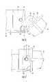
- FIG. 6is an enlarged internal side view of the bezel and housing side wall as the bezel approaches the side wall during assembly.
- FIG. 7is an enlarged side view as in FIG. 6 in which the bezel has been snapped into place with the housing.
- FIG. 8is a perspective view of portions of the assembled bezel and housing as in FIG. 7 .
- FIG. 9is a perspective view of the cover of FIG. 3 being assembled onto the bezel and housing of FIGS. 6-8 .
- FIG. 9Ais a section view of the side walls of the cover and housing and the bezel in an assembled condition.
- FIG. 10is a perspective view of the assembled casing of the module of FIG. 1 .
- spatially relative termssuch as “under”, “below”, “lower”, “over”, “upper” and the like, may be used herein for ease of description to describe one element or feature's relationship to another element(s) or feature(s) as illustrated in the figures. It will be understood that the spatially relative terms are intended to encompass different orientations of the device in use or operation in addition to the orientation depicted in the figures. For example, if the device in the figures is turned over, elements described as “under” or “beneath” other elements or features would then be oriented “over” or “above” the other elements or features. Thus, the exemplary term “under” can encompass both an orientation of over and under. The device may be otherwise oriented (rotated 90 degrees or at other orientations) and the spatially relative descriptors used herein interpreted accordingly.
- the module 10includes three main components: a housing 20 ; a cover 30 ; and a bezel 40 . These are described in detail below.
- the housing 20includes a floor 24 and two opposed side walls 22 .
- Each of the side walls 22has an inwardly-offset inverted L-shaped lip 23 at its upper edge that forms an outwardly-facing slot 23 a .
- a central projection 28extends upwardly from the center of the floor 24
- two MPO adapter holders 27extend upwardly from the rear portion of the floor 24 .
- a short post 25extends inwardly from a front portion of each side wall 22 .
- the end of the post 25is beveled, such that the post 25 is shorter in front and longer in back.
- a capture stub 26 having an arcuate surface 26 ais located at the front edge of the joint between the floor 24 and each side wall 22 .
- the arcuate surface 26 adefines generally a “quarter-circle” profile that defines an axis A that extends between the captures stubs 26 on either side of the housing 20 (see FIG. 6 ).
- the cover 30has a ceiling 32 , a rear wall 34 , and two very short opposed side walls 36 .
- the side walls 36include multiple inwardly-extending fingers 37 .
- the rear wall 34includes two apertures 35 for MPO adapters. Also, latches 38 with inwardly-extending hooks 38 a extend forwardly from the rear wall 34 .
- the bezel 40has a main panel 42 or other main body from which a plurality of chambers 44 extend forwardly. Pairs of latches 46 extend rearwardly from the main panel 42 . Also, near each end of the bezel 40 a latch panel 48 or other projection extends rearwardly. Each latch panel 48 has an aperture 50 near its upper, rear corner, and also has a cutout area or recess 52 in its front, lower corner recessed from the lower edge of the latch panel 48 .
- the bezel 40can be attached to the housing 20 by tilting the bezel 40 relative to the housing 20 .
- the lower edge of the latch panel 48 of the bezel 40is positioned above the projection 26 .
- the bezel 40can then be rotated so that the upper edge of the latch panel 48 fits below the lip 23 of the side wall 22 .
- the rear edge of the latch panel 48contacts the post 25 and forces it outwardly (aided by the beveled surface on the end of the post 25 ), thereby causing the side wall 22 to flex outwardly.
- the latch panel 48moves rearwardly a sufficient distance that the aperture 50 reaches the post 25 , the post 25 is received in the aperture 25 and the side wall 22 recovers from its flexed state.
- the projection 26 of the housing 20is also received in the recess 52 of the latch panel 48 , with the arcuate surface 26 a confronting the recess 52 , thereby securing the bezel 40 in place.
- the cover 30can be attached thereto.
- the cover 30is attached by positioning the cover 30 rearwardly of the housing/bezel assembly ( FIG. 9 ), aligning the fingers 37 of the side walls 36 with the slots 23 a of the lips 23 of the housing 20 , then sliding the cover 30 forward until the hooks 38 a of the latches 38 on the cover 30 clear the MPO adapter holders 27 of the housing 20 ( FIG. 9A ).
- the cover 30is firmly secured to the housing 20 by both the latches 38 and the interaction between the fingers 37 and the lips 23 of the housing 20 .
- the housing 20 , bezel 40 and cover 30form an overall casing 60 ( FIG. 10 ), in which the apertures 35 align with the MPO adapter holders 27 .
- This configurationprevents removal of the bezel 40 from the casing 60 without first removing the cover 30 from the housing 20 .
- the bezel 40cannot be removed first because the side walls 22 must be able to flex outwardly in order for the post 25 disengage from the aperture 50 , and the side walls 22 are prevented from significant outward flexure by the presence of the side walls 36 outside of the lips 23 .
- Removal of the cover 30requires the destruction of the latches 38 that interact with the MPO adapter holders 27 and/or marring the exterior of the cover 30 .
- one or more anti-tamper labelswere affixed on the seam between the cover 30 and the housing 20 , such labels would be torn if the cover 30 were removed. (Other anti-tampering features, such as spot welds or the like, may also be employed).
- the assembled casing 60has no external latches that one can use to force the casing 60 open. Thus, any opening of the module 10 can be detected.
- the internal components of the module 10include optical fibers 12 that are connected with MPO adapters 14 .
- the MPO adapters 14are mounted in the MPO adapter holders 27 .
- the fibers 12are attached to one of a plurality of caps 16 , each of which is mounted in one of the chambers 44 of the bezel 40 . Dust caps 18 fit into the front side of the chambers 44 .
- the fibers 12can be looped around the central projection 28 to maintain an acceptable bend radius.
- Assembly of the module 10can be carried out by first connecting the fibers 12 with the MPO adapters 14 and the caps 16 .
- the MPO adapters 14may then be mounted in the MPO adapter holders 27 and the caps 16 mounted in the chambers 44 of the bezel 40 via the latches 46 .
- the bezel 40is then snapped to the housing 20 in the manner illustrated in FIGS. 6-8 . (Alternatively, the bezel may be snapped into the housing 20 prior to the attachment of the caps 16 to the bezel 40 , and/or the MPO adapters 14 may be mounted in the MPO adapter holders 27 prior to the attachment of the bezel 40 to the housing 20 .
- the cover 30can then be slid onto the housing 20 so that the fingers 37 fit within the slots 23 a and the latches 38 engage the MPO adapter holders 27 ( FIGS. 9 and 9A ).
- the resulting module 10is compact, secure and tamper-resistant.
- Each of the housing 20 , cover 30 and bezel 40may be formed as monolithic structures and may comprise a polymeric material. Exemplary materials include polycarbonate, ABD and polyethylene.
- the housing 20should be formed of a material that enables the side walls 22 to deflect during the assembly of the housing 20 with the bezel 40 .
- the housing 20is illustrated with a beveled post 25 , the post may lack a beveled surface.
- the capture stub 26 amay have a different shape, may be positioned such that it is adjacent the floor 24 but does not merge with the floor 24 , and/or may be omitted in some embodiments.
- the lips 23may be omitted in certain embodiments.
- More or fewer MPO adapter holders 27may be employed.
- the relative positions of the capture stubs 26 and the posts 25may vary.
- the cover 30may have more or fewer fingers 37 that fit in the slots 23 a .
- the number of apertures 35may also vary depending on the number of MPO adapter holders 27 .
- the latches 38may vary in configuration, or may latch to a different structure on the housing 20 .
- the rear wall 34may be configured such that it is adjacent, but not rearward of, the rear edge of the housing floor 24 .
- the bezel 40may have more or fewer chambers 44 and/or latches 46 .
- the latch panels 48may take the form of a differently-configured rearward projection.
- the locations of the recess 52 and/or the aperture 50may vary depending on the locations of the capture stub 26 and the post 25 .
- the relative location of the main body 42may change, such that it is adjacent, but not in front of, the front edge of the floor 24 of the housing 20 .
- Other variations of the housing 20 , the cover 30 and the bezel 40may also be employed.
- the latch configurationmay be suitable for connecting components other than those of a telecommunications module.
Landscapes
- Physics & Mathematics (AREA)
- General Physics & Mathematics (AREA)
- Optics & Photonics (AREA)
- Light Guides In General And Applications Therefor (AREA)
Abstract
Description
Claims (13)
Priority Applications (1)
| Application Number | Priority Date | Filing Date | Title |
|---|---|---|---|
| US13/423,521US8953919B2 (en) | 2012-03-19 | 2012-03-19 | Datacommunications modules, cable-connector assemblies and components therefor |
Applications Claiming Priority (1)
| Application Number | Priority Date | Filing Date | Title |
|---|---|---|---|
| US13/423,521US8953919B2 (en) | 2012-03-19 | 2012-03-19 | Datacommunications modules, cable-connector assemblies and components therefor |
Publications (2)
| Publication Number | Publication Date |
|---|---|
| US20130242506A1 US20130242506A1 (en) | 2013-09-19 |
| US8953919B2true US8953919B2 (en) | 2015-02-10 |
Family
ID=49157408
Family Applications (1)
| Application Number | Title | Priority Date | Filing Date |
|---|---|---|---|
| US13/423,521Active2033-06-28US8953919B2 (en) | 2012-03-19 | 2012-03-19 | Datacommunications modules, cable-connector assemblies and components therefor |
Country Status (1)
| Country | Link |
|---|---|
| US (1) | US8953919B2 (en) |
Cited By (2)
| Publication number | Priority date | Publication date | Assignee | Title |
|---|---|---|---|---|
| WO2017106012A1 (en)* | 2015-12-16 | 2017-06-22 | Communications Systems, Inc. | Hardened network components and methods |
| US10514519B2 (en) | 2016-01-14 | 2019-12-24 | Ppc Broadband, Inc. | Stackable splitters |
Families Citing this family (3)
| Publication number | Priority date | Publication date | Assignee | Title |
|---|---|---|---|---|
| CN107102403A (en)* | 2017-05-19 | 2017-08-29 | 宁波日鼎电子科技有限公司 | A kind of welding adapter of fibre-optical splice protection |
| CA3153360A1 (en) | 2019-09-06 | 2021-03-11 | Opterna Am, Inc. | Modules for fiber optic cable distribution systems |
| CN120233493A (en)* | 2023-12-29 | 2025-07-01 | 华为技术有限公司 | Optical splitter, optical network system and assembly method of optical splitter |
Citations (12)
| Publication number | Priority date | Publication date | Assignee | Title |
|---|---|---|---|---|
| US5212761A (en)* | 1992-04-27 | 1993-05-18 | At&T Bell Laboratories | Fiber optic module |
| US6901200B2 (en)* | 2000-12-22 | 2005-05-31 | Fiber Optic Network Solutions, Inc. | Module and housing for optical fiber distribution and DWDM equipment |
| US20090220204A1 (en)* | 2008-02-28 | 2009-09-03 | Gil Ruiz | Splice revolver, splice module and method of organizing fiber strands in the splice module |
| US20100220967A1 (en)* | 2009-02-27 | 2010-09-02 | Cooke Terry L | Hinged Fiber Optic Module Housing and Module |
| US20100322583A1 (en)* | 2009-06-19 | 2010-12-23 | Cooke Terry L | High Density and Bandwidth Fiber Optic Apparatuses and Related Equipment and Methods |
| US20110038589A1 (en)* | 2009-08-13 | 2011-02-17 | Gil Ruiz | Fiber management component |
| US20110129185A1 (en)* | 2009-11-30 | 2011-06-02 | Lewallen C Paul | Articulated Strain Relief Boot on a Fiber Optic Module and Associated Methods |
| US20120106911A1 (en)* | 2010-10-29 | 2012-05-03 | Cooke Terry L | Stacked fiber optic modules and fiber optic equipment configured to support stacked fiber optic modules |
| US20120134639A1 (en)* | 2010-11-30 | 2012-05-31 | Giraud William J | Module with adapter side entry opening |
| US20120321267A1 (en)* | 2007-01-19 | 2012-12-20 | Adc Telecommunications, Inc. | Fiber optic adapter cassette and panel |
| US8356728B2 (en)* | 2007-02-28 | 2013-01-22 | Finisar Corporation | Rotatable top shell |
| US20130148936A1 (en)* | 2007-10-01 | 2013-06-13 | Clearfield, Inc. | Modular optical fiber cassettes |
- 2012
- 2012-03-19USUS13/423,521patent/US8953919B2/enactiveActive
Patent Citations (12)
| Publication number | Priority date | Publication date | Assignee | Title |
|---|---|---|---|---|
| US5212761A (en)* | 1992-04-27 | 1993-05-18 | At&T Bell Laboratories | Fiber optic module |
| US6901200B2 (en)* | 2000-12-22 | 2005-05-31 | Fiber Optic Network Solutions, Inc. | Module and housing for optical fiber distribution and DWDM equipment |
| US20120321267A1 (en)* | 2007-01-19 | 2012-12-20 | Adc Telecommunications, Inc. | Fiber optic adapter cassette and panel |
| US8356728B2 (en)* | 2007-02-28 | 2013-01-22 | Finisar Corporation | Rotatable top shell |
| US20130148936A1 (en)* | 2007-10-01 | 2013-06-13 | Clearfield, Inc. | Modular optical fiber cassettes |
| US20090220204A1 (en)* | 2008-02-28 | 2009-09-03 | Gil Ruiz | Splice revolver, splice module and method of organizing fiber strands in the splice module |
| US20100220967A1 (en)* | 2009-02-27 | 2010-09-02 | Cooke Terry L | Hinged Fiber Optic Module Housing and Module |
| US20100322583A1 (en)* | 2009-06-19 | 2010-12-23 | Cooke Terry L | High Density and Bandwidth Fiber Optic Apparatuses and Related Equipment and Methods |
| US20110038589A1 (en)* | 2009-08-13 | 2011-02-17 | Gil Ruiz | Fiber management component |
| US20110129185A1 (en)* | 2009-11-30 | 2011-06-02 | Lewallen C Paul | Articulated Strain Relief Boot on a Fiber Optic Module and Associated Methods |
| US20120106911A1 (en)* | 2010-10-29 | 2012-05-03 | Cooke Terry L | Stacked fiber optic modules and fiber optic equipment configured to support stacked fiber optic modules |
| US20120134639A1 (en)* | 2010-11-30 | 2012-05-31 | Giraud William J | Module with adapter side entry opening |
Cited By (4)
| Publication number | Priority date | Publication date | Assignee | Title |
|---|---|---|---|---|
| WO2017106012A1 (en)* | 2015-12-16 | 2017-06-22 | Communications Systems, Inc. | Hardened network components and methods |
| US10514519B2 (en) | 2016-01-14 | 2019-12-24 | Ppc Broadband, Inc. | Stackable splitters |
| US11163129B2 (en) | 2016-01-14 | 2021-11-02 | Ppc Broadband, Inc. | Stackable splitters |
| US11619793B2 (en) | 2016-01-14 | 2023-04-04 | Ppc Broadband, Inc. | Stackable splitters |
Also Published As
| Publication number | Publication date |
|---|---|
| US20130242506A1 (en) | 2013-09-19 |
Similar Documents
| Publication | Publication Date | Title |
|---|---|---|
| US7200314B2 (en) | Carrier for multiple splice trays | |
| US8953919B2 (en) | Datacommunications modules, cable-connector assemblies and components therefor | |
| AU709948B2 (en) | Rack mountable cable distribution enclosure | |
| US8195022B2 (en) | Fiber optic adapter cassette and panel | |
| US8705927B2 (en) | Universal cable management panel | |
| US7676135B2 (en) | Fiber patch panel | |
| US8437595B2 (en) | Fiber management shelf having removable door | |
| EP3105627B1 (en) | Managed connectivity in optical distribution frame | |
| US20200319421A1 (en) | Module and assembly for fiber optic interconnections | |
| US8275230B2 (en) | Stackable optical fiber retainer | |
| US9178345B2 (en) | Cable assembly having quick-locking connector and premise wiring systems utilizing same | |
| KR20140111692A (en) | Connector modules having optical connectors moveable between a retracted position and an extended position | |
| WO2010096500A2 (en) | Fiber management shelf having removable door, push-push fastening elements, stackable side retainer rings and reduced profile front retainer rings | |
| US11395436B2 (en) | Modular telecommunications patch panel system | |
| US6788550B1 (en) | Circuit card retention device | |
| WO2013139622A1 (en) | Pivotal support frame for a fiber optic adapter | |
| US6973249B2 (en) | Optical fiber trough for an optical interconnection system | |
| US6874944B1 (en) | Faceplate and optical fiber connector mounting assembly | |
| US20050185897A1 (en) | Small form factor transceiver front panel adapter | |
| CN112313551A (en) | Adapter retention mechanism |
Legal Events
| Date | Code | Title | Description |
|---|---|---|---|
| AS | Assignment | Owner name:COMMSCOPE INC. OF NORTH CAROLINA, NORTH CAROLINA Free format text:ASSIGNMENT OF ASSIGNORS INTEREST;ASSIGNOR:KEITH, SCOTT;REEL/FRAME:028019/0369 Effective date:20120404 | |
| AS | Assignment | Owner name:JPMORGAN CHASE BANK, N.A., AS COLLATERAL AGENT, NE Free format text:PATENT SECURITY AGREEMENT (ABL);ASSIGNORS:ALLEN TELECOM LLC;ANDREW LLC;COMMSCOPE, INC. OF NORTH CAROLINA;REEL/FRAME:029013/0044 Effective date:20120904 | |
| AS | Assignment | Owner name:JPMORGAN CHASE BANK, N.A., AS COLLATERAL AGENT, NE Free format text:PATENT SECURITY AGREEMENT (TL);ASSIGNORS:ALLEN TELECOM LLC;ANDREW LLC;COMMSCOPE, INC. OF NORTH CAROLINA;REEL/FRAME:029024/0899 Effective date:20120904 | |
| STCF | Information on status: patent grant | Free format text:PATENTED CASE | |
| AS | Assignment | Owner name:WILMINGTON TRUST, NATIONAL ASSOCIATION, AS COLLATERAL AGENT, CONNECTICUT Free format text:SECURITY INTEREST;ASSIGNORS:ALLEN TELECOM LLC;COMMSCOPE TECHNOLOGIES LLC;COMMSCOPE, INC. OF NORTH CAROLINA;AND OTHERS;REEL/FRAME:036201/0283 Effective date:20150611 Owner name:WILMINGTON TRUST, NATIONAL ASSOCIATION, AS COLLATE Free format text:SECURITY INTEREST;ASSIGNORS:ALLEN TELECOM LLC;COMMSCOPE TECHNOLOGIES LLC;COMMSCOPE, INC. OF NORTH CAROLINA;AND OTHERS;REEL/FRAME:036201/0283 Effective date:20150611 | |
| AS | Assignment | Owner name:COMMSCOPE, INC. OF NORTH CAROLINA, NORTH CAROLINA Free format text:RELEASE OF SECURITY INTEREST PATENTS (RELEASES RF 036201/0283);ASSIGNOR:WILMINGTON TRUST, NATIONAL ASSOCIATION;REEL/FRAME:042126/0434 Effective date:20170317 Owner name:REDWOOD SYSTEMS, INC., NORTH CAROLINA Free format text:RELEASE OF SECURITY INTEREST PATENTS (RELEASES RF 036201/0283);ASSIGNOR:WILMINGTON TRUST, NATIONAL ASSOCIATION;REEL/FRAME:042126/0434 Effective date:20170317 Owner name:ALLEN TELECOM LLC, NORTH CAROLINA Free format text:RELEASE OF SECURITY INTEREST PATENTS (RELEASES RF 036201/0283);ASSIGNOR:WILMINGTON TRUST, NATIONAL ASSOCIATION;REEL/FRAME:042126/0434 Effective date:20170317 Owner name:COMMSCOPE TECHNOLOGIES LLC, NORTH CAROLINA Free format text:RELEASE OF SECURITY INTEREST PATENTS (RELEASES RF 036201/0283);ASSIGNOR:WILMINGTON TRUST, NATIONAL ASSOCIATION;REEL/FRAME:042126/0434 Effective date:20170317 | |
| MAFP | Maintenance fee payment | Free format text:PAYMENT OF MAINTENANCE FEE, 4TH YEAR, LARGE ENTITY (ORIGINAL EVENT CODE: M1551) Year of fee payment:4 | |
| AS | Assignment | Owner name:REDWOOD SYSTEMS, INC., NORTH CAROLINA Free format text:RELEASE BY SECURED PARTY;ASSIGNOR:JPMORGAN CHASE BANK, N.A.;REEL/FRAME:048840/0001 Effective date:20190404 Owner name:ALLEN TELECOM LLC, ILLINOIS Free format text:RELEASE BY SECURED PARTY;ASSIGNOR:JPMORGAN CHASE BANK, N.A.;REEL/FRAME:048840/0001 Effective date:20190404 Owner name:ANDREW LLC, NORTH CAROLINA Free format text:RELEASE BY SECURED PARTY;ASSIGNOR:JPMORGAN CHASE BANK, N.A.;REEL/FRAME:048840/0001 Effective date:20190404 Owner name:COMMSCOPE, INC. OF NORTH CAROLINA, NORTH CAROLINA Free format text:RELEASE BY SECURED PARTY;ASSIGNOR:JPMORGAN CHASE BANK, N.A.;REEL/FRAME:048840/0001 Effective date:20190404 Owner name:COMMSCOPE TECHNOLOGIES LLC, NORTH CAROLINA Free format text:RELEASE BY SECURED PARTY;ASSIGNOR:JPMORGAN CHASE BANK, N.A.;REEL/FRAME:048840/0001 Effective date:20190404 Owner name:ALLEN TELECOM LLC, ILLINOIS Free format text:RELEASE BY SECURED PARTY;ASSIGNOR:JPMORGAN CHASE BANK, N.A.;REEL/FRAME:049260/0001 Effective date:20190404 Owner name:COMMSCOPE, INC. OF NORTH CAROLINA, NORTH CAROLINA Free format text:RELEASE BY SECURED PARTY;ASSIGNOR:JPMORGAN CHASE BANK, N.A.;REEL/FRAME:049260/0001 Effective date:20190404 Owner name:REDWOOD SYSTEMS, INC., NORTH CAROLINA Free format text:RELEASE BY SECURED PARTY;ASSIGNOR:JPMORGAN CHASE BANK, N.A.;REEL/FRAME:049260/0001 Effective date:20190404 Owner name:ANDREW LLC, NORTH CAROLINA Free format text:RELEASE BY SECURED PARTY;ASSIGNOR:JPMORGAN CHASE BANK, N.A.;REEL/FRAME:049260/0001 Effective date:20190404 Owner name:COMMSCOPE TECHNOLOGIES LLC, NORTH CAROLINA Free format text:RELEASE BY SECURED PARTY;ASSIGNOR:JPMORGAN CHASE BANK, N.A.;REEL/FRAME:049260/0001 Effective date:20190404 | |
| AS | Assignment | Owner name:WILMINGTON TRUST, NATIONAL ASSOCIATION, AS COLLATE Free format text:PATENT SECURITY AGREEMENT;ASSIGNOR:COMMSCOPE, INC. OF NORTH CAROLINA;REEL/FRAME:049678/0577 Effective date:20190404 Owner name:JPMORGAN CHASE BANK, N.A., NEW YORK Free format text:ABL SECURITY AGREEMENT;ASSIGNORS:COMMSCOPE, INC. OF NORTH CAROLINA;COMMSCOPE TECHNOLOGIES LLC;ARRIS ENTERPRISES LLC;AND OTHERS;REEL/FRAME:049892/0396 Effective date:20190404 Owner name:JPMORGAN CHASE BANK, N.A., NEW YORK Free format text:TERM LOAN SECURITY AGREEMENT;ASSIGNORS:COMMSCOPE, INC. OF NORTH CAROLINA;COMMSCOPE TECHNOLOGIES LLC;ARRIS ENTERPRISES LLC;AND OTHERS;REEL/FRAME:049905/0504 Effective date:20190404 Owner name:WILMINGTON TRUST, NATIONAL ASSOCIATION, AS COLLATERAL AGENT, CONNECTICUT Free format text:PATENT SECURITY AGREEMENT;ASSIGNOR:COMMSCOPE, INC. OF NORTH CAROLINA;REEL/FRAME:049678/0577 Effective date:20190404 | |
| AS | Assignment | Owner name:WILMINGTON TRUST, DELAWARE Free format text:SECURITY INTEREST;ASSIGNORS:ARRIS SOLUTIONS, INC.;ARRIS ENTERPRISES LLC;COMMSCOPE TECHNOLOGIES LLC;AND OTHERS;REEL/FRAME:060752/0001 Effective date:20211115 | |
| MAFP | Maintenance fee payment | Free format text:PAYMENT OF MAINTENANCE FEE, 8TH YEAR, LARGE ENTITY (ORIGINAL EVENT CODE: M1552); ENTITY STATUS OF PATENT OWNER: LARGE ENTITY Year of fee payment:8 | |
| AS | Assignment | Owner name:APOLLO ADMINISTRATIVE AGENCY LLC, NEW YORK Free format text:SECURITY INTEREST;ASSIGNORS:ARRIS ENTERPRISES LLC;COMMSCOPE TECHNOLOGIES LLC;COMMSCOPE INC., OF NORTH CAROLINA;AND OTHERS;REEL/FRAME:069889/0114 Effective date:20241217 | |
| AS | Assignment | Owner name:RUCKUS WIRELESS, LLC (F/K/A RUCKUS WIRELESS, INC.), NORTH CAROLINA Free format text:RELEASE OF SECURITY INTEREST AT REEL/FRAME 049905/0504;ASSIGNOR:JPMORGAN CHASE BANK, N.A., AS COLLATERAL AGENT;REEL/FRAME:071477/0255 Effective date:20241217 Owner name:COMMSCOPE TECHNOLOGIES LLC, NORTH CAROLINA Free format text:RELEASE OF SECURITY INTEREST AT REEL/FRAME 049905/0504;ASSIGNOR:JPMORGAN CHASE BANK, N.A., AS COLLATERAL AGENT;REEL/FRAME:071477/0255 Effective date:20241217 Owner name:COMMSCOPE, INC. OF NORTH CAROLINA, NORTH CAROLINA Free format text:RELEASE OF SECURITY INTEREST AT REEL/FRAME 049905/0504;ASSIGNOR:JPMORGAN CHASE BANK, N.A., AS COLLATERAL AGENT;REEL/FRAME:071477/0255 Effective date:20241217 Owner name:ARRIS SOLUTIONS, INC., NORTH CAROLINA Free format text:RELEASE OF SECURITY INTEREST AT REEL/FRAME 049905/0504;ASSIGNOR:JPMORGAN CHASE BANK, N.A., AS COLLATERAL AGENT;REEL/FRAME:071477/0255 Effective date:20241217 Owner name:ARRIS TECHNOLOGY, INC., NORTH CAROLINA Free format text:RELEASE OF SECURITY INTEREST AT REEL/FRAME 049905/0504;ASSIGNOR:JPMORGAN CHASE BANK, N.A., AS COLLATERAL AGENT;REEL/FRAME:071477/0255 Effective date:20241217 Owner name:ARRIS ENTERPRISES LLC (F/K/A ARRIS ENTERPRISES, INC.), NORTH CAROLINA Free format text:RELEASE OF SECURITY INTEREST AT REEL/FRAME 049905/0504;ASSIGNOR:JPMORGAN CHASE BANK, N.A., AS COLLATERAL AGENT;REEL/FRAME:071477/0255 Effective date:20241217 |