US8953570B2 - Radio frequency identification system and related operating methods - Google Patents
Radio frequency identification system and related operating methodsDownload PDFInfo
- Publication number
- US8953570B2 US8953570B2US12/953,078US95307810AUS8953570B2US 8953570 B2US8953570 B2US 8953570B2US 95307810 AUS95307810 AUS 95307810AUS 8953570 B2US8953570 B2US 8953570B2
- Authority
- US
- United States
- Prior art keywords
- rfid
- tag
- mobile device
- rfid tag
- target
- Prior art date
- Legal status (The legal status is an assumption and is not a legal conclusion. Google has not performed a legal analysis and makes no representation as to the accuracy of the status listed.)
- Active, expires
Links
Images


Classifications
- G—PHYSICS
- G06—COMPUTING OR CALCULATING; COUNTING
- G06K—GRAPHICAL DATA READING; PRESENTATION OF DATA; RECORD CARRIERS; HANDLING RECORD CARRIERS
- G06K17/00—Methods or arrangements for effecting co-operative working between equipments covered by two or more of main groups G06K1/00 - G06K15/00, e.g. automatic card files incorporating conveying and reading operations
- G06K17/0022—Methods or arrangements for effecting co-operative working between equipments covered by two or more of main groups G06K1/00 - G06K15/00, e.g. automatic card files incorporating conveying and reading operations arrangements or provisions for transferring data to distant stations, e.g. from a sensing device
- G—PHYSICS
- G01—MEASURING; TESTING
- G01S—RADIO DIRECTION-FINDING; RADIO NAVIGATION; DETERMINING DISTANCE OR VELOCITY BY USE OF RADIO WAVES; LOCATING OR PRESENCE-DETECTING BY USE OF THE REFLECTION OR RERADIATION OF RADIO WAVES; ANALOGOUS ARRANGEMENTS USING OTHER WAVES
- G01S13/00—Systems using the reflection or reradiation of radio waves, e.g. radar systems; Analogous systems using reflection or reradiation of waves whose nature or wavelength is irrelevant or unspecified
- G01S13/74—Systems using reradiation of radio waves, e.g. secondary radar systems; Analogous systems
- G01S13/82—Systems using reradiation of radio waves, e.g. secondary radar systems; Analogous systems wherein continuous-type signals are transmitted
- G—PHYSICS
- G01—MEASURING; TESTING
- G01S—RADIO DIRECTION-FINDING; RADIO NAVIGATION; DETERMINING DISTANCE OR VELOCITY BY USE OF RADIO WAVES; LOCATING OR PRESENCE-DETECTING BY USE OF THE REFLECTION OR RERADIATION OF RADIO WAVES; ANALOGOUS ARRANGEMENTS USING OTHER WAVES
- G01S13/00—Systems using the reflection or reradiation of radio waves, e.g. radar systems; Analogous systems using reflection or reradiation of waves whose nature or wavelength is irrelevant or unspecified
- G01S13/87—Combinations of radar systems, e.g. primary radar and secondary radar
- G01S13/878—Combination of several spaced transmitters or receivers of known location for determining the position of a transponder or a reflector
- G06K2017/0045—
Definitions
- Embodiments of the subject matter described hereinrelate generally to radio frequency identification (RFID). More particularly, embodiments of the subject matter relate to techniques and technologies for providing RFID services to a mobile device.
- RFIDradio frequency identification
- RFID systems and their basic operating principlesare well known.
- RFID systemsemploy fixed (stationary) RFID readers and/or portable RFID readers, both of which can be used to interrogate RFID tags associated with products, containers, or any items of interest.
- mobile RFID readershave been deployed, such mobile devices consume a substantial amount of power due to RFID radio operations.
- Such mobile devicesinclude cellular telephones, netbook and laptop computers, digital media players, and the like. Many of these mobile devices have wireless data communication capabilities (e.g., wireless local area network compatibility, BLUETOOTH short range wireless data communication compatibility, cellular network access, etc.). In addition, some mobile devices are provided with native global positioning system technology, accelerometers, navigation technology, and a variety of useful software applications.
- FIG. 1is a schematic representation of an exemplary RFID system that supports mobile devices
- FIG. 2is a schematic representation of an exemplary mobile device that is suitable for use in the RFID system depicted in FIG. 1 ;
- FIG. 3is a schematic representation of an exemplary RFID system controller that is suitable for use in the RFID system depicted in FIG. 1 ;
- FIG. 4is a flow chart that illustrates an exemplary method for operating an RFID system
- FIG. 5is a diagram that shows a mobile device and RFID tags in close proximity to the mobile device
- FIG. 6is a flow chart that illustrates an exemplary method for operating an RFID system
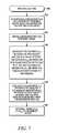
- FIG. 7is a flow chart that illustrates an exemplary method for locating an RFID tag
- FIG. 8is a diagram that shows various distance and angle relationships for an RFID reader, a target RFID tag, and a reference RFID tag.
- FIG. 9is a diagram that shows various distance and angle relationships for a fixed RFID reader, a target RFID tag, and a mobile RFID reader.
- the subject matter presented hererelates to an RFID system at accommodates mobile devices, including those that are unable to communicate with RFID tags using the RFID over-the-air interface (which is used by traditional RFID reader devices).
- An ordinary mobile devicecan be used as a “virtual” RFID reader in this context by offloading the RFID tag reading tasks to the RFID system backbone, which then sends the collected tag data to the mobile device in an appropriate manner.
- the tag datacan then be presented to the user of the mobile device.
- the tag data and/or information linked to or otherwise associated with the tag datacan be displayed at the mobile device in a manner that emulates the display of a traditional RFID reader.
- the mobile devicecould request certain RFID operations by communicating with one or more RFID readers and/or with an RFID system controller, either directly or indirectly.
- the mobile devicecommunicates with RFID readers and/or with an RIM system controller via infrastructure devices of a wireless local area network (WLAN), e.g., a wireless access device.
- WLANwireless local area network
- the mobile devicecommunicates with RFID readers and/or with an RFID system controller using an “external” data communication network such as a cellular network, a satellite network, a local area network (LAN), a wide area network (WAN), the Internet, or the like.
- This arrangementenables the RFID system to receive activation or tag interrogation requests from the mobile device and send tag data back to the mobile device in a quick, convenient, and efficient manner.
- a mobile deviceincluding one that lacks inherent RFID over-the-air interface or RFID tag locationing capabilities, may also be utilized to accurately locate a particular RFID tag of interest.
- the techniques and technologies presented herecan be implemented to locate a target RFID tag using only one RFID reader (that cooperates with a mobile device).
- this tag locating techniquerelies on a reference or “dummy” RFID tag attached to, incorporated within, or otherwise co-located with the mobile device.
- a designated RFID readeris activated to interrogate both the target RFID tag and the reference RFID tag.
- the received tag response signalsare then analyzed to calculate the position of the target RFID tag relative to the reference RFID tag (and, consequently, relative to the mobile device). Thereafter, the mobile device is provided with the position of the target RFID tag so that the position can be displayed or otherwise indicated to the user of the mobile device. In certain embodiments, the mobile device can provide navigation instructions or guidance to help the user find the target RFID tag.
- the RED system 100supports at least one mobile device 102 .
- the mobile deviceis unable to communicate with RFID tags using the RFID over-the-air interface.
- This particular embodiment of the RFID system 100includes, without limitation: an RFID system controller 104 ; one or more RFID readers 106 operatively coupled to the RFID system controller 104 ; a first network architecture 108 operatively coupled to the RFID system controller 104 ; and a second network architecture 110 operatively coupled to the RFID system controller 104 .
- the illustrated embodiment of the second network architecture 110includes one or more wireless local area network (WLAN) infrastructure devices, such as an access point device 111 .
- WLANwireless local area network
- the RFID system 100may be deployed in any area or location in which RFID reader coverage is desired.
- the RFID system 100may be deployed in a warehouse environment, a storage depot environment, a store front, a supermarket, or the like.
- the RFID system controller 104is deployed when centralized control and management of the RFID readers 106 is desired. It should be appreciated that the RFID system controller 104 could be realized as a standalone hardware device, as a software application running on a computer device, as a processing module or other logical construct integrated with a system component having additional functionality, or the like. For this particular embodiment, the RFID system controller 104 is coupled to (and communicates with) the RFID readers 106 via the first network architecture 108 . Additionally or alternatively, the RFID system controller 104 could communicate with the RFID readers 106 via the second network architecture 110 .
- the RFID system controller 104may be utilized to control the operation of the RFID readers 106 , to perform centralized collection and processing of RFID tag response signals, to manage data communication between the components of the RFID system 100 , to manage data communication between the RFID system 100 and devices or system external to the RFID system 100 , and/or to manage data communication between the RFID system 100 and the mobile device 102 .
- the RFID system controller 104can perform the following functions and operations, without limitation: receive service requests from mobile devices; translate service requests into commands; dispatch commands to RFID readers; receive tag data from RFID readers; filter received tag data (if needed or desired); and dispatch tag data (which may be filtered) to mobile devices.
- the RFID system controller 104could be suitably configured to perform other functions as needed for the particular system application.
- the RFID system controller 104could be implemented as a standalone piece of hardware in a network, or its functionality could be incorporated into any suitable component or device, such as an RFID switch device, a network server component, or the like.
- the RFID system controller 104may be suitably configured and designed to support wireless and/or wired data communication with the RFID readers 106 , the access point device 111 , the first network architecture 108 , the second network architecture 110 , and/or the mobile device 102 .
- the RFID system controller 104may support one or more of the following wireless data communication techniques, protocols, and methodologies, without limitation: IrDA (infrared); BLUETOOTH; ZIGBEE (and other variants of the IEEE 802.15 protocol); IEEE 802.11 (any variation); IEEE 802.16 (WiMAX or any other variation); cellular/wireless/cordless telecommunication protocols; satellite data communication protocols; wireless hospital or health care facility network protocols such as those operating in the WMTS bands; and proprietary wireless data communication protocols.
- IrDAinfrared
- BLUETOOTHZIGBEE
- ZIGBEEand other variants of the IEEE 802.15 protocol
- IEEE 802.11any variation
- IEEE 802.16WiMAX or any other variation
- cellular/wireless/cordless telecommunication protocolssatellite data communication protocols
- wireless hospital or health care facility network protocolssuch as those operating in the WMTS bands
- proprietary wireless data communication protocolssuch as those operating in the WMTS bands
- the RFID system controller 104may support one or more of the following traditional (non-wireless) data communication techniques, protocols, and methodologies, without limitation: Ethernet; home network communication protocols; USB; IEEE 1394 (Firewire); hospital network communication protocols; and proprietary data communication protocols.
- FIG. 1depicts the RFID system controller 104 as a distinct and separate component within the RFID system 100 .
- the functionality of the RFID system controller 104could be incorporated into one or more of the RFID readers 106 , into the access point device 111 , or distributed among a plurality of different components within the RFID system 100 .
- an RFID readeror any other component or device in the RFID system 100
- could function in place of the RFID system controller 104which may be desirable to reduce equipment cost and to simplify the system architecture.
- an implementation of the RFID system 100could rely on decentralized control and management of the RFID readers 106 , which could be designed and configured with enhanced functionality and processing intelligence.
- the RFID readers 106generate RFID interrogation signals and receive RFID tag response signals from RFID tags that are located within interrogation range.
- the RFID readers 106may leverage well known and conventional RFID techniques and technologies related to the generation of RFID interrogation signals and to the receipt, interpretation, and processing of RFID tag response signals.
- the RFID readers 106utilize the traditional RFID over-the-air interface to interrogate tags and to receive tag response signals.
- the RFID readers 106send the received tag data to the RFID system controller 104 for centralized processing and handling.
- An RFID reader 106 in the RFID system 100could be a “fixed” or stationary device, or a mobile and portable device.
- a fixed RFID reader 106would typically be connected to the RFID system controller 104 using a network cable or other tangible data communication link.
- a mobile RFID reader 106could communicate with the RFID system controller 104 using a wireless data communication link, a tangible interface cable, a network cable, a data communication cradle, or the like.
- one or more of the RFID readers 106could be suitably configured to support wireless anchor wired data communication with the mobile device 102 , the wireless access point device 111 , the RFID system controller 104 , and/or the first network architecture 108 .
- an RFID reader 106could use any of the wireless and/or wired data communication techniques, protocols, and technologies mentioned above for the RFID system controller 104 .
- the first and second network architectures 108 , 110can be realized using any number of physical, virtual, or logical components, including hardware, software, firmware, and/or processing logic configured to support data communication between an originating component and a destination component, where data communication is carried out in accordance with one or more designated communication protocols over one or more designated communication media.
- the network architectures 108 , 110may include or cooperate with, without limitation: a computer network such as a local area network (LAN) or a wide area network (WAN); a cellular telecommunication network; an 802.11 network (WLAN); an 802.16 network (WiMAX); the Internet; a hospital data communication network (WMTS or other); a control network; the public switched telephone network; a satellite communication network; or the like.
- a computer networksuch as a local area network (LAN) or a wide area network (WAN); a cellular telecommunication network; an 802.11 network (WLAN); an 802.16 network (WiMAX); the Internet; a hospital data communication network (WMTS
- FIG. 1depicts two separate network architectures 108 , 110
- an embodiment of the RFID system 100could utilize a single network architecture if so desired.
- FIG. 1illustrates one implementation where the first network architecture 108 could represent an intranet and where the second network architecture 110 could represent a public network. Alternatively, these two network architectures could be one and the same.
- either the first network architecture 108 or the second network architecture 110could be implemented as a set of networks arranged in a hierarchical manner.
- the second network architecture 110could include a plurality of different networks, such as an intranet LAN and a 3G wireless network.
- the first network architecturecould be realized as a LAN having multiple levels.
- the wireless access point device 111is suitably configured to support traditional operations in a WLAN environment. Accordingly, the wireless access point device 111 may be compatible with IEEE Specification 802.11 (any variation) for purposes of wireless communication with the mobile device 102 . Wireless access points and 802.11 networks are well known and, therefore, conventional aspects and conventional operating functions of the wireless access point device 111 will not be described in detail here. For the example described here, it is assumed that the wireless access point device 111 is coupled to the second network architecture 110 . Alternatively, in an optional arrangement, the wireless access point device 111 is coupled to the RFID system controller 104 via the first network architecture 108 . In certain implementations, the wireless access point device 111 is coupled to both the first network architecture 108 and the second network architecture 110 .
- the mobile device 102may be realized as any handheld, portable, or wireless device having any suitable form factor.
- the mobile device 102could be implemented as: a cellular telephone; a smartphone; a personal digital assistant; a portable video game device; a digital music player; a laptop, palmtop, tablet, or netbook computer; an electronic book device; a portable medical device; or a remote control device.
- the mobile device 102is unable to communicate with RFID tags using the traditional RFID over-the-air interface.
- the mobile device 102might be unable to interrogate RFID tags using the RFID over-the-air interface, and/or might be unable to receive RFID tag response signals using the RFID over-the-air interface.
- the mobile device 102may lack the inherent capability to emit over-the-air RFID interrogation signals, and/or the inherent capability to receive over-the-air RFID tag response signals that are generated in response to RFID interrogation signals.
- the mobile device 102is suitably configured to support one or more non-RFID wireless data communication techniques, protocols, and technologies.
- a typical embodimentwill support one or more cellular telephony standards (such as 3G) and one or more WLAN protocols (such as IEEE 802.11).
- the mobile device 102could support any of the non-RFID wireless data communication techniques described above for the RFID system controller 104 .
- the mobile device 102could be designed to accommodate data communication using a tangible cable, a network interface, a cradle or a docking station, or the like.
- FIG. 2is a schematic representation of an exemplary mobile device 200 that is suitable for use in the RFID system 100 .
- the mobile device 102may employ some or all of the generalized architecture, features, and functionality of the mobile device 200 .
- the mobile device 200generally includes, without limitation: a wireless module 202 ; a data port 204 ; at least one processor 206 ; a suitable amount of memory 208 ; a display 210 ; and a user interface 212 .
- the mobile device 200also includes or cooperate with one or more of the following elements: a global positioning system (GPS) module 214 ; one or more position and/or orientation sensors 216 ; and a reference RFID tag 218 .
- GPSglobal positioning system
- the mobile device 200will include other components and elements designed to carry out conventional operations that are unrelated to the described subject matter.
- the elements of the mobile device 200are coupled together as needed by a suitably configured interconnect architecture 220 that accommodates data transfer, control/command signals, supply voltages, etc.
- the wireless module 202is suitably configured to support wireless data communication operations performed by the mobile device 200 .
- the wireless module 202may cooperate with the wireless access point device 111 described above with reference to FIG. 1 .
- the wireless module 202may be compatible with a cellular telephone network for purposes of supporting cellular telephony.
- the wireless module 202can be designed and configured to support any of the wireless data communication protocols, techniques, and methodologies mentioned above for the RFID system controller.
- the wireless module 202may include or be realized as hardware, software, and/or firmware, such as an RF front end, a suitably configured radio module (which may be a standalone module or integrated with other or all functions of the mobile device 200 ), a wireless transmitter, a wireless receiver, a wireless transceiver, an infrared sensor, an electromagnetic transducer, or the like.
- the mobile device 200may include one or more antenna arrangements that cooperate with the wireless module 202 .
- the wireless module 202might be RFID-limited in the sense that it might lack at least some hardware, firmware, software, or processing intelligence that is needed to support communication (interrogation and/or receive) with RFID tags using the RFID over-the-air interface.
- the mobile device 200could be configured to support data communication using non-wireless techniques.
- the mobile device 200may include or cooperate with appropriate hardware, such as a suitably configured and formatted data port, connector, jack, plug, receptacle, socket, adaptor, or the like.
- the data port 204 depicted in FIG. 2is intended to represent any of these physical interface components.
- the processor 206may be implemented or performed with a general purpose processor, a content addressable memory, a digital signal processor, an application specific integrated circuit, a field programmable gate array, any suitable programmable logic device, discrete gate or transistor logic, discrete hardware components, or any combination designed to perform the mobile device functions described here.
- a processormay be realized as a microprocessor, a controller, a microcontroller, or a state machine.
- a processormay be implemented as a combination of computing devices, e.g., a combination of a digital signal processor and a microprocessor, a plurality of microprocessors, one or more microprocessors in conjunction with a digital signal processor core, or any other such configuration.
- the memory 208may be realized as RAM memory, flash memory, EPROM memory, EEPROM memory, registers, a hard disk, a removable disk, a CD-ROM, or any other form of storage medium known in the art.
- the memory 208can be coupled to the processor 206 such that the processor 206 can read information from, and write information to, the memory 208 .
- the memory 208may be integral to the processor 206 .
- the processor 206 and the memory 208may reside in an ASIC.
- the display 210represents the primary graphical interface of the mobile device 200 .
- the display 210may leverage known display technologies such as, without limitation: liquid crystal display, thin-film transistor, organic light-emitting diode, interferometric modulator display, touch screen, and/or other display technologies.
- the actual size, resolution, and operating specifications of the display 210can be selected to suit the needs of the particular application.
- the display 210could be operated to present RFID tag data to the user, to display control or configuration parameters of the RFID readers 106 (see FIG. 1 ), or to otherwise enable the user to interact with the RFID system 100 in an appropriate manner.
- the user interface 212may include or be realized as one or more buttons, input/output elements, switches, or other features that enable the user to interact with the mobile device 200 .
- the user interface 212can be manipulated as needed to enable the mobile device 200 to request RFID interrogation, to control or manage the operation of the RFID readers 106 , to view or process RFID tag data, and/or to otherwise interact with components, applications, or data associated with the RFID system 100 .
- the GPS module 214is configured in accordance with known technologies to enable the mobile device 200 to obtain or derive geographic position data that indicates the current position of the mobile device 200 .
- the GPS module 214receives GPS signals from GPS satellites and performs the required calculations and derivations to obtain geographic position data for the mobile device 200 .
- the geographic position information produced by the GPS module 214can be utilized by the RFID system 100 to identify RFID tags within close proximity of the mobile device 200 , to selectively activate RFID readers near the mobile device 200 , to filter the amount of RFID tag data delivered to the mobile device 200 , and/or to locate a particular target RFID tag of interest (as described in more detail below).
- One or more sensors 216may be provided with the mobile device 200 to provide information related to orientation, heading, movement, position, and/or acceleration of the mobile device 200 .
- the sensors 216could be realized as one or more of the following, without limitation: an accelerometer; a gyroscopic element; a force sensor; weights; optical emitters; or the like.
- the mobile device 200(or another component of the RFID system 100 ) can process the signals, sensor data, or electrical parameters produced by one or more of these sensors 216 to determine the position or orientation of the mobile device 200 , the direction or heading in which the user is pointing the mobile device 200 , etc.
- This additional position/orientation informationcan be utilized by the RFID system 100 to precisely identify an RFID tag (or tags) at which the mobile device 200 is aimed or to better define the current location of the mobile device 200 .
- the reference RFID tag 218may be attached or coupled to the mobile device 200 , temporarily affixed to the housing of the mobile device 200 , integrated with the mobile device 200 , contained within the housing of the mobile device 200 , or the like.
- the reference RFID tag 218may be an active tag or a passive tag, configured to function and operate in a conventional manner. In other words, the reference RFID tag 218 responds to an RFID interrogation signal by generating an appropriate RFID tag response signal.
- the reference RFID tag 218can be utilized to accurately determine the position of a target RFID tag (relative to the reference RFID tag 218 and, therefore, relative to the mobile device 200 ) using only one RFID reader.
- FIG. 3is a schematic representation of an exemplary RFID system controller 300 that is suitable for use in the RFID system 100 depicted in FIG. 1 .
- the RFID system controller 300may employ some or all of the generalized architecture, features, and functionality of the RFID system controller 104 (as described previously).
- the RFID system controller 300generally includes, without limitation: one or more network interfaces 302 ; at least one processor 304 ; and a suitable amount of memory 306 .
- the RFID system controller 300may also include one or more of the following elements if so desired: a wireless module 308 ; a display 310 ; and a user interface 312 .
- the RFID system controller 300will include other components and elements designed to carry out conventional operations that are unrelated to the described subject matter.
- the elements of the RFID system controller 300are coupled together as needed by a suitably configured interconnect architecture 314 that accommodates data transfer, control/command signals, supply voltages, etc.
- the network interface(s) 302represents hardware, software, firmware, processing logic, and the like, that allows the RFID system controller 300 to support data communication using one or more data communication networks.
- the network interface(s) 302allows the RFID system controller 300 to control and manage the RFID readers 106 (see FIG. 1 ).
- the network interface(s) 302may also enable the RFID system controller 300 to interact with WLAN infrastructure devices, a telecommunication network, a WAN such as the Internet, a LAN, or the like.
- the network interface(s) 302enable the RFID system controller 104 to communicate with the first and second network architectures 108 , 110 (see FIG. 1 ).
- the processor 304 and the memory 306may be generally configured as described above for their counterparts in the mobile device 200 .
- the processor 304will include the processing logic and intelligence needed to perform the RFID system controller functions described here, and the memory 306 can be coupled to the processor 304 such that the processor 304 can read information from, and write information to, the memory 306 .
- the memory 306may be integral to the processor 304 .
- the wireless module 308may be generally configured as described above for its counterpart in the mobile device 200 .
- the wireless module 308supports wireless data communication operations performed by the RFID system controller 300 , using one or more of the wireless data communication techniques described previously.
- the wireless module 308could be used to support wireless communication with one or more of the RFID readers, one or more of the wireless access point devices, and/or one or more mobile devices in the RFID system.
- the wireless module 308could be used to support wireless network communications using cellular or satellite network technology.
- An embodiment of the RFID system controller 300could be provided with the display 310 .
- the display 310can be generally configured as described above for its counterpart in the mobile device 200 .
- the display 310represents the primary graphical interface of the RFID system controller 300 .
- the display 310could be used to display control or configuration parameters of the RFID readers, or to otherwise enable the user to interact with the RFID system in an appropriate manner.
- the display 310could be used as a virtual display for one or more of the RFID readers in the system and/or as a virtual display for mobile devices in the system. For example, it may be convenient to display RFID tag data and/or to display the locations of the mobile devices within the RFID system.
- the RFID system controller 300could be provided with the user interface 312 .
- the user interface 312can be generally configured as described above for its counterpart in the mobile device 200 .
- the user interface 312allows the user to interact with the RFID system controller 300 as needed.
- the RFID system described hereprovides virtual or emulated RFID services to mobile devices, which might be unable to communicate with RFID tags using the over-the-air interface.
- a common mobile devicee.g., a cellular smartphone or a portable computer
- the mobile deviceemulates the functionality of an RFID reader while remaining energy efficient.
- the RFID systemmay be deployed in any suitable environment, such as a warehouse, a supermarket, a shopping center, or the like.
- Compatible mobile devicescan communicate with the RFID system infrastructure or backbone in some fashion.
- a compatible mobile devicemay use WLAN, ZIGBEE, BLUETOOTH wireless data communication links and/or or a wired or docked connection to communicate with the RFID system backbone.
- the RFID systemmay employ a centralized processing approach (using, for example, an RFID system controller) or a decentralized processing approach (where compatible mobile devices can communicate directly with one or more of the RFID readers in the system even though they might lack the ability to use the RFID over-the-air interface).
- a compatible mobile devicecould be used to configure, set up, and initialize the RFID readers, issue interrogation commands to the RFID readers, and/or obtain reports or events from the RFID readers.
- a compatible mobile devicecould be used to provide a virtual user interface (display) for the RFID readers.
- the native display of an RFID readercould be used to provide a virtual user interface for RFID functions of a compatible mobile device.
- a compatible mobile devicemay cooperate and communicate with the RFID system controller in a way that allows the mobile device to function as a virtual RFID reader even though it might lack the native ability to communicate with RFID tags using the over-the-air interface.
- the mobile devicecan send requests for RFID operations or services to the RFID system controller, which in turn initiates appropriate actions and issues the necessary control commands to satisfy the requests.
- the mobile devicecan also receive responses, RFID tag data, and other information from the RFID system controller.
- the mobile devicecould be used to provide a virtual or remote user interface (display) for the RFID system controller. This would enable a system administrator to remotely access the RFID system controller if so desired.
- the RFID system controllermight also function in a conventional manner and interact with the RFID readers as needed.
- the RFID system controllercan configure, set up, and initialize the RFID readers, issue interrogation commands to the RFID readers, and receive RFID tag data, reports, events, and other information from the RFID readers.
- information obtained by the RFID system controllercould be processed, analyzed, and/or forwarded to compatible mobile devices if so desired.
- the native display of the RFID system controller and/or the native display of an RFID readercould be used to provide a virtual user interface for RFID functions of a compatible mobile device.
- An RFID system as described herecan feed RFID tag data or related product/item information to compatible mobile devices.
- the RFID systemcan determine the current location of a requesting mobile device and only provide information associated with RFID tags that are located within a certain distance from the mobile device.
- the RFID systemobtains the current position of the mobile device in some fashion. For example, the mobile device could determine its own position or otherwise obtain data that is indicative of its position, and then send the position data to the RFID system backbone (directly to the RFID system controller or via one or more RFID readers without relying on the RFID over-the-air interface).
- the mobile devicecould be outfitted with proximity sensors, motion sensors, a gyroscope, an accelerometer, an infrared sensor, a camera, a GPS system, or the like.
- the RFID systemcould cooperate with a WLAN infrastructure that employs conventional triangulation or other location estimation techniques to determine the location of the mobile device.
- WLAN infrastructure device functionalitye.g., wireless access point functionality
- RFID readers or the RFID system controllercould be incorporated into one or more RFID readers or the RFID system controller, and such integrated RFID/WLAN components could determine the location of mobile devices without relying on a distinct and devoted WLAN architecture.
- the RFID system infrastructurefilters RFID tag data and associated information based at least in part on the current location of the requesting mobile device. For example, although the RFID system may interrogate RFID tags throughout a store, the tag data can be filtered such that the mobile device only receives a subset of the collected tag data, namely, tag data corresponding to tags that are located in close proximity to the mobile device. Such filtering techniques can be implemented to reduce the amount of data transmitted to the mobile device, and to reduce the amount of information to be processed and rendered by the mobile device. Advanced filtering techniques could also be used to contemplate sensor data collected by the mobile device.
- such sensor datacould be processed to determine: the direction or heading in which the user is looking; the direction or heading in which the user is facing; the direction or heading in which the mobile device is pointed; the physical orientation of the mobile device; or the like.
- This additional orientation, heading, or position datacould be used to determine whether the user is pointing the mobile device at a particular item of interest or zone of interest and, if so, to filter the interrogated tag data in an appropriate manner.
- the RFID systemcould filter the interrogated tag data in an intelligent manner and only send a “focused” subset of tag data to that mobile device.
- an RFID system as described herecould leverage a compatible mobile device (that may or may not lack the ability to communicate with RFID tags in the traditional sense) to accurately determine the location of an interrogated RFID tag of interest.
- the mobile deviceis provided with a reference RFID tag, and both the tag of interest and the reference tag are interrogated by the same RFID reader.
- the tag response datacan then be analyzed to accurately determine the location of the tag of interest relative to the location of the reference RFID tag.
- This location datacan be used to guide the user of the mobile device to the tag of interest, to display a map with the location of the tag of interest superimposed thereon, or the like.
- FIG. 4illustrates an exemplary process 100 for operating an RFID system.
- the various tasks performed in connection with a described processmay be performed by software, hardware, firmware, or any combination thereof.
- the following description of various processesmay refer to elements mentioned above in connection with FIGS. 1-3 .
- portions of a described processmay be performed by different elements of the described RFID system, e.g., a mobile device, an RFID reader, an RFID system controller, or functional modules thereof.
- a described processmay include any number of additional or alternative tasks, the tasks shown in the figures need not be performed in the illustrated order, and that a described process may be incorporated into a more comprehensive procedure or process having additional functionality not described in detail herein. Moreover, one or more of the tasks shown in connection with a described process could be omitted from an embodiment of the respective process as long as the intended overall functionality remains intact.
- the process 100will be described in the context of an RFID system that includes an RFID system controller to carry out centralized processing. It should be appreciated that the process 400 could be performed in an equivalent manner by an RFID system that employs decentralized processing.
- the illustrated embodiment of the process 400begins by receiving a request from a mobile device (task 402 ).
- the mobile devicelacks the ability to communicate directly with RFID tags in the traditional sense.
- this requestcan be generated and issued by the mobile device, and received (directly or indirectly) by the RFID system controller.
- the requestmay be a request to interrogate one or more RFID tags, a request to locate a particular item of interest having a target RFID tag associated therewith, a request for RFID system data, or the like. This particular example assumes that the request corresponds to an interrogation or scan request that originates from the mobile device.
- the process 400may also obtain the current location or position of the requesting mobile device (task 404 ) using one or more of the techniques, technologies, or methodologies described herein.
- the RFID system controllermay obtain the current location of the mobile device directly or indirectly from the mobile device, or from another component in the RFID system.
- the RFID system controllercould receive self-position data from the mobile device, where the self-position data indicates the location or geographic position of the mobile device relative to any reference or coordinate system understood by the RFID system.
- the self-position datamight indicate or be associated with the UPS coordinates of the mobile device, or it might indicate or be associated with the location of the mobile device relative to one or more reference points (such as RFID readers, wireless access point devices, a docking station, or the like).
- the self-position datamight include or be associated with a picture of the surrounding environment, as captured by the mobile device.
- the content of the picturecould be analyzed using image analysis techniques to ascertain the current location of the mobile device.
- the RFID system controllercould derive or otherwise calculate the current location of the mobile device from “raw” data provided by the mobile device and/or data provided by one or more other components in the RFID system.
- the location of the mobile devicecould be determined using network access information. In this regard, if the mobile device is communicating through a fixed wireless access point, the location of the access point is preconfigured and known, hence, the location of the mobile device can be determined or estimated because it will be in the operating range of that particular wireless access point. Accordingly, RFID readers near the known location of that wireless access point can be commanded to interrogate RFID tags as needed.
- the RFID systemcan process the current location of the mobile device in a number of different ways to support a variety of operations and features.
- the illustrated embodiment of the process 400identifies at least one RFID reader (from a plurality of available RFID readers in the RFID system) based on the current location of the mobile device (task 406 ).
- This featureassumes that the user of the mobile device is interested in RFID tag information for products or items in close proximity to the mobile device. Operating under this assumption can be desirable to conserve energy, to reduce the amount of collected tag data, and to reduce the amount of processing required to analyze, transmit, and display the desired tag data.
- task 406is optional, and that the RFID system could instead identify and activate all of the RFID readers under its control, if so desired.
- the process 400may then continue by generating an RFID interrogation signal (or signals) with at least one RFID reader of the RFID system (task 408 ).
- the RFID interrogation signalis generated by an RFID reader identified during task 406 .
- the RFID readerinterrogates the RFID tags within its respective interrogation range.
- the RFID readerobtains at least one RFID tag response signal that conveys tag data (task 410 ).
- an RFID tag within the interrogation range of the RFID readerwill react to the interrogation signal, and the resulting tag response signal can be detected by the interrogating RFID reader.
- the RFID readermay obtain a plurality of different tag response signals in response to a single interrogation signal.
- the process 400could obtain tag data at multiple RFID readers, each interrogating its own zone.
- the process 100may continue by processing the received tag response signals and/or the tag data conveyed in the tag response signals in an appropriate manner.
- the RFID system controllercould filter some or all of the received tag data based on the current location of the mobile device (task 412 ).
- the tag datacan be filtered in accordance with the location of the RFID tags relative to the current location of the mobile device. For example, it may be desirable to generate filtered tag data that corresponds to RFID tags that are located within a specified distance from the mobile device.
- FIG. 5is a diagram that shows a mobile device 500 and RFID tags 502 in close proximity to the mobile device 500 .
- the RFID system controllerobtains tag data for all of the RFID tags 502 shown in FIG. 5 .
- the set of tag datacan be filtered based on distance (e.g., a radius) from the current location of the mobile device 500 .
- FIG. 5depicts an area 504 that corresponds to a filtering criteria applied to the set of tag data.
- the filtered tag datawill only include tag data corresponding to those RFID tags 502 that are located within or near to the area 504 (these tags are shaded in FIG. 5 ).
- the filtered tag datarepresents a proper subset of the entire set of tag data that is originally collected by the RFID system controller.
- FIG. 5depicts a simple scenario where the area 504 is circular (or spherical) in shape. In practice, the filtering criteria need not be so simple, and the filtered tag data can be determined based on any formula, algorithm, or the like.
- the process 400can proceed by providing at least some of the collected tag data (and/or information associated with such tag data) to the mobile device (task 414 ).
- the process 400sends the filtered tag data to the mobile device, without sending any of the remaining tag data.
- the tag datacan be sent to the mobile device using one or more techniques and technologies, and using one or more data communication links.
- the tag datacould be sent from the RFID system controller to the mobile device using the on-site network architecture and possibly a tangible data communication interface such as a physical cable, a docking station, or a network port.
- the tag datacould be wirelessly transmitted from the RFID system controller to the mobile device using one or more non-RFID wireless data communication links.
- the RFID system controllercould manage the wireless transmission of the tag data from a WLAN infrastructure device (such as an access point device) to the mobile device.
- the RFID system controllercould send the tag data to an appropriate data communication network for routing, transmission, or delivery to the mobile device in accordance with one or more network transmission schemes. Accordingly, the tag data could be sent to the mobile device using one or more of: a cellular communication network; a satellite communication network; a WAN such as the Internet; a LAN; or the like.
- the mobile devicereceives at least some of the tag data that was sent from the RFID system backbone. Accordingly, the mobile device can present indicia of the received tag data to the user in an appropriate manner and an appropriate format (task 416 ). For example, the mobile device could display information corresponding to the tag data on its display element, generate audio that describes or represents the tag data, render a map, a store layout, or any navigation aid that indicates the location of the mobile device and/or the location of the tag(s) of interest, etc. In practice, the mobile device could be suitably configured to process, analyze, and present the received tag data in a manner that emulates the functionality of conventional RFID readers, using its native display, graphics, and user interface features.
- FIG. 6is a flow chart that illustrates another exemplary process 600 for operating an RFID system.
- the process 600will be described in the context of an RFID system that includes an RFID system controller to carry out centralized processing. It should be appreciated that the process 600 could be performed in an equivalent manner by an RFID system that employs decentralized, processing. Moreover, some of the tasks and operations associated with the process 600 are similar or identical to counterpart tasks and operations described above for the process 400 ; such common tasks and common aspects will not be redundantly described in detail here.
- the illustrated embodiment of the process 600begins by receiving a request from a mobile device (task 602 ).
- the mobile devicelacks the ability to communicate directly with RFID tags in the traditional sense.
- this requestcan be generated and issued by the mobile device, and received (directly or indirectly) by the RFID system controller.
- the requestmay be a request to locate or find a particular item of interest having a target RFID tag associated therewith. Assume, for example, that a user of the mobile device is searching for a specific product in a supermarket, such as a specific box of cereal. Assume further that the box of cereal has an RFID tag associated therewith.
- the usercould access a product list (which may be available online or provided by the supermarket), select or otherwise indicate the box of cereal, and issue a request to locate that box of cereal.
- a product listwhich may be available online or provided by the supermarket
- select or otherwise indicate the box of cerealand issue a request to locate that box of cereal.
- the requestalso identifies or otherwise indicates the reference RFID tag that is attached to it.
- the RFID system controlleractivates at least one RFID reader in the system, and the RFID reader interrogates the target RFID tag that is associated with the requested item of interest (task 604 ), and obtains an RFID tag response signal from the target RFID tag (task 606 ).
- the RFID readermay also receive additional RFID tag response signals corresponding to other RFID tags within the interrogation zone. Indeed, the different tag response signals and the tag data conveyed in the received tag response signals can be processed and otherwise handled in the manner described above with reference to tasks 412 , 414 , and 416 of the process 400 .
- the process 600may also obtain the current location or position of the requesting mobile device (task 608 ) using one or more of the techniques, technologies, or methodologies described previously.
- the process 600determines the location of the target RFID tag, relative to the current location of the mobile device (task 610 ).
- task 610could be performed by the RFID system controller, by one or more interrogating RFID readers, by one or more wireless access point devices, and/or by the mobile device.
- task 610may utilize any suitable technique, algorithm, or methodology to determine the location of the target RFID tag relative to the mobile device. For example, interrogation by two or more RFID readers (or two or more wireless access points) could be used to obtain data for purposes of triangulation-based location calculations.
- only one RFID readere.g., the reader that interrogates the target RFID tag
- the determined location of the target RFID tagis provided, sent, or transmitted to the mobile device (task 612 ).
- the RFID system controllerdetermines the location of the target RFID tag, then it can provide the determined location to the mobile device, directly or indirectly, and using one or more wireless and/or non-wireless data communication links.
- a wireless access point devicecalculates the location of the target RFID tag, then it could send the determined location to the mobile device using WLAN technology.
- the mobile devicereceives and processes the determined location of the target RFID tag. Accordingly, the mobile device can present indicia of the determined location to the user in an appropriate manner and using an appropriate format (task 614 ). For example, the mobile device could display one icon that represents the location of the target RFID tag, another icon that represents the location of the mobile device itself, and navigation or guidance information intended to lead the user to the target RFID tag. In this regard, the mobile device could render a map, a store layout, or any navigation aid that indicates the location of the mobile device and/or the location of the target RFID tag.
- the majority of the process 600can be repeated as needed to refresh the location data and to update the display of the mobile device. In this regard, if it is time to refresh the data or update the display, then the process 600 can be re-entered at task 604 . Repeated interrogation of the target RFID tag is desirable in certain systems that might utilize mobile RFID readers, and to support the tag locating process described below with reference to FIG. 7 . Thus, the process 600 can update the display of the mobile device as the user moves around in the RFID system environment, and the dynamic display will graphically indicate the location of the target RFID tag relative to the current position of the mobile device in an ongoing manner.
- task 610 of the process 600 described aboveis associated with the determination of the location of a target RFID tag.
- a non-RFID mobile devicetypically a fixed RFID reader.
- the fixed RFID readerwhich might be located in a warehouse, could be used to interrogate and read specific tags but, due to its size and functionality, it is immobile for all practical purposes and to search for a specific tag among a group of tags becomes difficult. Additional difficulty arises when the tags are mobile. For example, certain products such as items of clothing may move from a display rack, to a dressing room, and to a different rack.
- a handheld RFID reader devicecan be used to locate a target RFID tag associated with a product or any item of interest.
- Such handheld reader devicesmay employ an audible tone or alert such as a “beep-to-the-box” indicator that allows the user to be led to a specific tag by providing audio and/or visual cues as the user moves around the environment.
- a minimum of two RFID readersmust be used to identify the location of a tag using conventional triangulation methods.
- the tag locating approach described herelocates a target RFID tag using a mobile device that is unable to communicate with RFID tags using the traditional RFID over-the-air interface; the mobile device is deployed within the reading range of at least one RFID reader.
- the RFID reader and/or the mobile devicewill be equipped with the appropriate tag locating processing intelligence (RFID tag triangulation or any other suitable technique).
- the mobile devicehas the ability to communicate with the RFID reader or readers (using WLAN, Bluetooth or any other non-RFID communication media) that read the target RFID tag.
- the mobile devicecan identify and establish communication with one of the RFID readers that can actually read the tag.
- the mobile devicehas a reference RFID tag attached thereto or incorporated therein.
- the RFID readercan process the tag data obtained from the target RFID tag and the reference RFID tag to determine the location of the target RFID tag relative to the reference RFID tag. It should be appreciated that other electronic distance measurement techniques (such as GPS) could be leveraged if so desired.
- the RFID readeris implemented with software (algorithms) and hardware (antenna rotation and sensing mechanisms) to identify the distance and direction of the target RFID tag.
- the distance measurement between the RFID reader and the target RFID tagcan be accomplished by one of a number of different methods, or a combination thereof.
- the systemcould employ RSSI (Received Signal Strength Indication), Time-of-Arrival, Time-Difference-of-Arrival, frequency domain techniques, such as phase-frequency (d ⁇ /df), and OFDM methods. These methods for distance measurements are well known, and will not be described in detail here.
- the RFID readeris also capable of measuring the direction (angle of separation) of a tag from a reference point. This could be achieved with the help of highly directional antennas and scanning by antenna rotation (e.g., using a stepper motor) and/or by using rotation sensors (e.g., gyroscope, stepper motor steps, or some other rotation sensing devices).
- the RFID readerstarts scanning from a reference point and searches for a particular tag and then measures minimum distance (maximum RSSI) to identify the direction of the tag. This is one suitable technique for accurately measuring tag direction relative to a reference point.
- the tag locating approach described hereemploys an RFID reader with a known location and having the ability to measure the angular displacement between two RFID tags in its interrogation field. This can be accomplished with any conventional methodology. Assuming, for example, that the RFID reader is a fixed reader (which is the case for many warehouse and commercial deployments), it is possible to provide the RFID antenna with an electronic sensor to measure its angular displacement, along with a drive mechanism to rotate the antenna to the desired direction. For this embodiment, the RFID antenna is assumed to be a directional antenna.
- the tag locating approach presented herealso utilizes a non-RFID mobile device of the type described above, namely, one that is unable to communicate with RFID tags using the traditional over-the-air interface. However, as shown in FIG. 2 , the non-RFID mobile device is provisioned with a reference RFID tag that can be used to locate a target RFID tag.
- FIG. 7is a flow chart that illustrates an exemplary process 700 for locating an RFID tag in accordance with the approach presented above. Again, the process 700 may be performed in association with task 610 of the process 600 . The process 700 may be initiated in response to a request to locate a particular RFID tag of interest, as mentioned above for the process 600 .
- the process 700interrogates the target RFID tag and the reference RFID tag (located at the mobile device) with the designated RFID reader (task 702 ) to obtain respective RFID tag response signals.
- the RFID readerwill obtain one or more tag response signals corresponding to the target RFID tag, and one or more tag response signals corresponding to the reference RFID tag (task 704 ).
- tag response signalscan be analyzed and processed as needed to calculate, derive, or otherwise obtain certain measurements and parameters related to the location of the target RFID tag and the location of the reference RFID tag. These measurements and parameters will be discussed below with reference to FIG. 8 , which is a diagram that shows various distance and angle relationships for an RFID reader, a target RFID tag, and a reference RFID tag.
- the process 700may obtain or calculate (task 706 ): the distance (d 1 ) between the RFID reader and the target RFID tag; the distance (d 2 ) between the RFID reader and the reference RFID tag; and the angle of separation ( ⁇ 1 ) between the target RFID tag and the reference RFID tag, as measured from the RFID reader.
- the RFID readercan measure the distance d 1 by reading the target RFID tag, and mark the direction (i.e., the angle ⁇ 1 ).
- the RFID readercan measure the distance d 2 by reading the reference RFID tag. This information can be used to calculate the position of the target RFID tag relative to the reference RFID tag. In this regard, the position of the target RFID tag is calculated based on (or otherwise in response to) the RFID tag response signals received from the target RFID tag and the reference RFID tag.
- the process 700calculates or otherwise obtains (task 708 ) the distance (d 3 ) between the target RFID tag and the reference RFID tag, along with the angle of separation ( ⁇ 2 ) between the target RFID tag and the RFID reader, as measured from the reference RFID tag.
- task 706 and task 708are performed by the RFID reader and, thereafter, the distance d 3 and the angle of separation ⁇ 2 are transmitted to the mobile device (task 710 ) using a data communication path that does not rely on the RFID over-the-air interface. Thereafter, the mobile device can process these quantities in an appropriate manner to generate a display or other indication of the determined location (as described above for task 614 of the process 600 ).
- task 708could be performed by the mobile device if the values of d 1 , d 2 , and ⁇ 1 are sent to the mobile device.
- the RFID readerdetermines the distance d 1 of the target RFID tag and marks the direction of the target RFID tag as a reference point.
- the distance measurement for the reference RFID tag attached to the mobile device, relative to the RFID reader,is indicated by d 2 .
- This distanceis measured after the antenna (or the RFID reader) is rotated to identify the maximum signal strength obtained for the reference RFID tag.
- the angle of separation ⁇ 1can be measured using any suitable methodology or technology, such as a gyroscope, an amount of rotation or by any other electronic rotation sensing device. This example assumes that the RFID reader emits a beam in one direction and has a highly directional antenna, hence the direction of tags provides the angle of separation, and the measurements are well determined.
- More measurementscan be performed at different locations if so desired to provide additional information to help obtain a more accurate location of the target RFID tag.
- the location of the target RFID tagcan be easily determined using basic trigonometry.
- the above equationsprovide the relative location of the target RFID tag with respect to the reference RFID tag and, therefore, relative to the mobile device that is co-located with the reference RFID tag.
- any mobile devicethat has the ability to communicate with the RFID reader (via Bluetooth, WLAN, or any other means) could be used to locate a target RFID tag of interest using straightforward triangulation techniques.
- the tag locating process 700could be modified to locate specific RFID tags using a mobile or handheld RFID reader and another RFID reader, typically a fixed RFID reader.
- a mobile or handheld RFID reader and another RFID readertypically a fixed RFID reader.
- fixed RFID readers in a warehousecould read specific tags, but the accuracy of location information of the tags would be restricted to the full reading range of the fixed readers. Identifying the location of a particular tag that in the reading range of only one reader thus becomes difficult because that reader can only determine the range or distance to the read tag, but not the location of the read tag.
- a mobile RFID readerby itself can provide the range or distance to a read tag, but not the specific location of that tag.
- an exemplary tag locating techniqueemploys a fixed RFID reader and a mobile device having a reference RFID tag attached to it or otherwise co-located with it.
- the alternate approach described hereemploys a first RFID reader (which may be fixed or mobile, but for this example is a fixed reader) and a second RFID reader, which is a mobile reader.
- the alternate approachemploys a reference RFID tag attached to or otherwise co-located with the first RFID reader.
- FIG. 9is a diagram that shows various distance and angle relationships for the fixed RFID reader (and the reference RFID tag), a target RFID tag, and a mobile RFID reader.
- the mobile RFID readeris within the reading range of the fixed RFID reader, and the fixed RFID reader is equipped with a suitable locationing technology (e.g., GPS, RFID tag triangulation as described here, or the like). Moreover, the mobile RFID reader has the ability to communicate with the fixed RFID reader (and other readers in the system that read the target RFID tag) using WLAN, Bluetooth, or any other non-RFID communication media.
- the reference RFID tag that is co-located with the fixed RFID readercan be read by the mobile RFID reader. This enables the mobile RFID reader to process the tag data obtained from the target RFID tag and the reference RFID tag to determine the location of the target RFID in a manner similar to that described previously for the process 700 .
- the location of the target tagcan be determined using the following methodology.
- the mobile RFID readermeasures or otherwise determines the distance D 2 to the fixed RFID reader by reading the reference RFID tag that is co-located with the fixed RFID reader, and by using one of the available distance calculating techniques described above.
- the mobile RFID readermeasures or otherwise determines the distance D 3 to the target RFID tag.
- the fixed RFID readeralso interrogates the target RFID tag to determine the distance D 1 between the fixed RFID reader and the target RFID tag.
- the mobile RFID readercan then obtain the distance D 1 from the fixed RFID reader using one or more appropriate data communication links between the fixed RFID reader and the mobile RFID reader.
- the mobile RFID readercan then calculate the location of the target RFID tag, using the distances D 1 , D 2 , and D 3 , along with basic trigonometric relationships and formulas.
- the mobile RFID readercan calculate the angles subtended between the target RFID tag and the line formed between the fixed RFID reader and the mobile RFID reader and, in turn, calculate the distance H in the following manner:
- angles ⁇ 1 and ⁇ 2can also be calculated as follows:
- the distances N 1 and N 2can be calculated using basic and well known trigonometry, e.g., the Pythagorean Theorem.
- a mobile RFID readercan be used to locate a target RFID tag using triangulation techniques with the help of a second RFID reader (fixed or mobile), where the distance between the two readers can be dynamically calculated with the help of a reference RFID tag attached or otherwise co-located with the second RFID reader.
- the RFID readerscan employ any other means of locationing, such as GPS, to indicate their locations to other RFID readers.
Landscapes
- Engineering & Computer Science (AREA)
- Radar, Positioning & Navigation (AREA)
- Remote Sensing (AREA)
- Physics & Mathematics (AREA)
- General Physics & Mathematics (AREA)
- Computer Networks & Wireless Communication (AREA)
- General Engineering & Computer Science (AREA)
- Theoretical Computer Science (AREA)
- Mobile Radio Communication Systems (AREA)
Abstract
Description
d3=√{square root over (h2+n22)}, whereh=d1sin θ1
n2=d2−n1, wheren1=d1cos θ1
θ2=cos−1(n2/d3) or θ2=sin−1(h/d3)
Claims (15)
Priority Applications (4)
| Application Number | Priority Date | Filing Date | Title |
|---|---|---|---|
| US12/953,078US8953570B2 (en) | 2010-11-23 | 2010-11-23 | Radio frequency identification system and related operating methods |
| CN201180056316.7ACN103229192B (en) | 2010-11-23 | 2011-10-28 | Rfid system and related operating method |
| PCT/US2011/058345WO2012071132A1 (en) | 2010-11-23 | 2011-10-28 | Radio frequency identification system and related operating methods |
| EP11784852.3AEP2643794B1 (en) | 2010-11-23 | 2011-10-28 | Radio frequency identification system and related operating methods |
Applications Claiming Priority (1)
| Application Number | Priority Date | Filing Date | Title |
|---|---|---|---|
| US12/953,078US8953570B2 (en) | 2010-11-23 | 2010-11-23 | Radio frequency identification system and related operating methods |
Publications (2)
| Publication Number | Publication Date |
|---|---|
| US20120127976A1 US20120127976A1 (en) | 2012-05-24 |
| US8953570B2true US8953570B2 (en) | 2015-02-10 |
Family
ID=44993900
Family Applications (1)
| Application Number | Title | Priority Date | Filing Date |
|---|---|---|---|
| US12/953,078Active2033-03-05US8953570B2 (en) | 2010-11-23 | 2010-11-23 | Radio frequency identification system and related operating methods |
Country Status (4)
| Country | Link |
|---|---|
| US (1) | US8953570B2 (en) |
| EP (1) | EP2643794B1 (en) |
| CN (1) | CN103229192B (en) |
| WO (1) | WO2012071132A1 (en) |
Cited By (8)
| Publication number | Priority date | Publication date | Assignee | Title |
|---|---|---|---|---|
| US20150237664A1 (en)* | 2014-02-19 | 2015-08-20 | Canon Kabushiki Kaisha | Communication apparatus, information processing apparatus, and control method for the same |
| US9747768B1 (en) | 2016-02-25 | 2017-08-29 | Xerox Corporation | System and method for proving physical presence |
| US20190162617A1 (en)* | 2016-04-06 | 2019-05-30 | L'Air Liquide, Societe Anonyme pour I'Etude et I'Etude et I'Exploitation des Precedes Georges Cla | Method for calculating the autonomy of a gas distribution assembly |
| US10360778B1 (en)* | 2018-03-29 | 2019-07-23 | Abl Ip Holding Llc | Radio frequency locating and mapping of an asset and a user in a space |
| US10591593B2 (en) | 2016-03-19 | 2020-03-17 | Hipscience, Llc | Point of reference displacement and motion sensor |
| US10650621B1 (en) | 2016-09-13 | 2020-05-12 | Iocurrents, Inc. | Interfacing with a vehicular controller area network |
| US11213773B2 (en) | 2017-03-06 | 2022-01-04 | Cummins Filtration Ip, Inc. | Genuine filter recognition with filter monitoring system |
| WO2023113879A1 (en)* | 2021-12-15 | 2023-06-22 | X Development Llc | Power ramping of beacon signals to enhance location accuracy |
Families Citing this family (68)
| Publication number | Priority date | Publication date | Assignee | Title |
|---|---|---|---|---|
| US8890657B2 (en)* | 2009-10-30 | 2014-11-18 | Symbol Technologies, Inc. | System and method for operating an RFID system with head tracking |
| EP2577600A4 (en)* | 2010-06-01 | 2013-11-20 | Young-Joo Song | Electronic multimedia publishing systems and methods |
| US8953570B2 (en)* | 2010-11-23 | 2015-02-10 | Symbol Technologies, Inc. | Radio frequency identification system and related operating methods |
| CN102111876B (en)* | 2011-02-24 | 2013-10-09 | 华为技术有限公司 | A method and device for selecting a reference label for positioning |
| JP5729063B2 (en)* | 2011-03-22 | 2015-06-03 | 富士通株式会社 | COMMUNICATION SETTING METHOD, COMMUNICATION SETTING SERVER, RELAY DEVICE, AND COMMUNICATION SETTING PROGRAM |
| US20130099896A1 (en)* | 2011-10-24 | 2013-04-25 | Telefonaktiebolaget L M Ericsson (Publ) | Sensor Location and Tagging System |
| US8884744B2 (en) | 2011-12-29 | 2014-11-11 | Symbol Technologies, Inc. | Portable data tag reader device, system and method for identifying a location of a data tag using a read zone and location of the reader |
| US20130169414A1 (en)* | 2011-12-29 | 2013-07-04 | Symbol Technologies, Inc. | Method and apparatus for radio frequency identification (rfid) data transmission |
| US9189719B2 (en) | 2012-08-23 | 2015-11-17 | Hand Held Products, Inc. | Encoded information reading terminal including multiple encoded information reading devices |
| KR20250013311A (en)* | 2013-03-13 | 2025-01-31 | 심보틱 엘엘씨 | Storage and retrieval system rover interface |
| EP2994865A4 (en)* | 2013-05-08 | 2016-11-30 | Dematic Corp | Mobile picking method |
| CN103322957B (en)* | 2013-05-27 | 2015-12-02 | 国家电网公司 | Based on the method and apparatus that the bracing wire of radio-frequency (RF) identification to shaft tower calculates |
| KR101534097B1 (en)* | 2013-08-13 | 2015-07-06 | 삼성전자주식회사 | Apparatus for obtaining medical image and method for adjusting location of table by using the same |
| US9824250B2 (en)* | 2013-11-04 | 2017-11-21 | Trimble Inc. | Location information within an area defined by a grid of radio-frequency tag circuits |
| US10614407B2 (en)* | 2013-12-24 | 2020-04-07 | United Parcel Service Of America, Inc. | Systems, methods, and computer program products for processing package delivery exceptions |
| US9171448B1 (en) | 2014-06-11 | 2015-10-27 | Target Brands, Inc. | RFID tags for locating products |
| KR102250990B1 (en)* | 2014-07-09 | 2021-05-12 | 한국전자통신연구원 | Wireless identification system and operating method thereof |
| CN104268491B (en)* | 2014-09-18 | 2017-06-16 | 东南大学 | Using the track mobile devices radio frequency identification alignment system and method for data redundancy |
| US9733335B2 (en) | 2014-11-13 | 2017-08-15 | Symbol Technologies, Llc | RFID tag locationing using dynamic beacon tag association |
| US10536920B1 (en)* | 2015-01-09 | 2020-01-14 | Ethertronics, Inc. | System for location finding |
| US20180293635A1 (en)* | 2015-03-16 | 2018-10-11 | Nec Corporation | System, image recognition method, and recording medium |
| US9922510B2 (en)* | 2015-03-23 | 2018-03-20 | Arris Enterprises Llc | Alert based on detection of unexpected wireless device |
| CA2928057C (en)* | 2015-04-22 | 2022-05-24 | Staples, Inc. | Intelligent item tracking and expedited item reordering by stakeholders |
| US10210527B2 (en) | 2015-06-04 | 2019-02-19 | Chronicled, Inc. | Open registry for identity of things including social record feature |
| US20160358158A1 (en)* | 2015-06-04 | 2016-12-08 | Chronicled, Inc. | Open registry for identity of things including item location feature |
| US11354676B2 (en) | 2015-06-04 | 2022-06-07 | Chronicled, Inc. | Open registry for identity of things |
| US9658310B2 (en) | 2015-06-16 | 2017-05-23 | United Parcel Service Of America, Inc. | Concepts for identifying an asset sort location |
| US10495723B2 (en) | 2015-06-16 | 2019-12-03 | United Parcel Service Of America, Inc. | Identifying an asset sort location |
| US11107088B2 (en) | 2016-05-27 | 2021-08-31 | Chronicled, Inc. | Open registry for internet of things |
| US9949080B2 (en)* | 2016-06-02 | 2018-04-17 | Symbol Technologies, Llc | Arrangement for, and method of, finding and recovering lost mobile devices in a venue |
| CN106295751A (en)* | 2016-08-22 | 2017-01-04 | 中国电力科学研究院 | Substation equipment maintenance and repair operation location and safe early warning method |
| US11507714B2 (en) | 2020-01-28 | 2022-11-22 | Middle Chart, LLC | Methods and apparatus for secure persistent location based digital content |
| US11475177B2 (en) | 2017-02-22 | 2022-10-18 | Middle Chart, LLC | Method and apparatus for improved position and orientation based information display |
| US11625510B2 (en) | 2017-02-22 | 2023-04-11 | Middle Chart, LLC | Method and apparatus for presentation of digital content |
| US10984146B2 (en) | 2017-02-22 | 2021-04-20 | Middle Chart, LLC | Tracking safety conditions of an area |
| US11481527B2 (en) | 2017-02-22 | 2022-10-25 | Middle Chart, LLC | Apparatus for displaying information about an item of equipment in a direction of interest |
| US10824774B2 (en) | 2019-01-17 | 2020-11-03 | Middle Chart, LLC | Methods and apparatus for healthcare facility optimization |
| US11194938B2 (en)* | 2020-01-28 | 2021-12-07 | Middle Chart, LLC | Methods and apparatus for persistent location based digital content |
| US11468209B2 (en) | 2017-02-22 | 2022-10-11 | Middle Chart, LLC | Method and apparatus for display of digital content associated with a location in a wireless communications area |
| US11900021B2 (en) | 2017-02-22 | 2024-02-13 | Middle Chart, LLC | Provision of digital content via a wearable eye covering |
| US10740503B1 (en) | 2019-01-17 | 2020-08-11 | Middle Chart, LLC | Spatial self-verifying array of nodes |
| US12086507B2 (en) | 2017-02-22 | 2024-09-10 | Middle Chart, LLC | Method and apparatus for construction and operation of connected infrastructure |
| US12314638B2 (en) | 2017-02-22 | 2025-05-27 | Middle Chart, LLC | Methods and apparatus for secure persistent location based digital content associated with a three-dimensional reference |
| US10740502B2 (en) | 2017-02-22 | 2020-08-11 | Middle Chart, LLC | Method and apparatus for position based query with augmented reality headgear |
| US11900023B2 (en) | 2017-02-22 | 2024-02-13 | Middle Chart, LLC | Agent supportable device for pointing towards an item of interest |
| US11436389B2 (en) | 2017-02-22 | 2022-09-06 | Middle Chart, LLC | Artificial intelligence based exchange of geospatial related digital content |
| US12400048B2 (en) | 2020-01-28 | 2025-08-26 | Middle Chart, LLC | Methods and apparatus for two dimensional location based digital content |
| US10902160B2 (en) | 2017-02-22 | 2021-01-26 | Middle Chart, LLC | Cold storage environmental control and product tracking |
| JP7689357B2 (en) | 2017-03-28 | 2025-06-06 | オートマトン, インク. | Method and apparatus for locating RFID tags - Patents.com |
| MX2020000218A (en) | 2017-07-07 | 2020-08-10 | Apptricity Corp | Network edge controller and remote field service system. |
| US12045811B2 (en) | 2017-07-31 | 2024-07-23 | Chronicled Inc. | Secure and confidential custodial transaction system, method and device using zero-knowledge protocol |
| US10176349B1 (en)* | 2017-12-07 | 2019-01-08 | Kacchip, LLC | Indoor position and vector tracking system and method |
| WO2019232329A1 (en) | 2018-06-01 | 2019-12-05 | Capital One Services, Llc | Beacon-triggered activation of a near field communication application |
| US10638404B1 (en)* | 2018-12-13 | 2020-04-28 | Securus Technologies, Inc. | Controlled-environment facility mobile device location tracking |
| CN114731485B (en)* | 2019-11-30 | 2024-10-11 | 华为技术有限公司 | A method for determining positioning information and a communication device |
| CN111104994A (en)* | 2019-12-12 | 2020-05-05 | 烽火通信科技股份有限公司 | Intelligent infrastructure management system and method based on radio frequency identification technology |
| US11640486B2 (en) | 2021-03-01 | 2023-05-02 | Middle Chart, LLC | Architectural drawing based exchange of geospatial related digital content |
| CN111339794B (en)* | 2020-03-24 | 2023-06-27 | 中山大学 | Anti-collision resource competition method based on number of tags, mobile reader and readable storage medium |
| US12182837B1 (en)* | 2020-03-25 | 2024-12-31 | United Services Automobile Association (Usaa) | Obtaining and estimating repair or replacement information from a smart building |
| WO2021206753A1 (en) | 2020-04-07 | 2021-10-14 | Apptricity Corporation | Flexible radio beacons and flexible delivery structures and system and method for using |
| EP4133603A4 (en)* | 2020-04-07 | 2023-12-27 | Apptricity Corporation | RADIO FREQUENCY (RF) LOCATION BEACON WITH TUNABLE ANTENNAS AND CLOUD INTEGRATION |
| CN112183136B (en)* | 2020-09-15 | 2021-11-19 | 西安交通大学 | Method for directionally reading and tracking commercial label in real time, storage medium and equipment |
| CN112448872B (en)* | 2020-11-09 | 2021-10-15 | 珠海格力电器股份有限公司 | Object searching method and system |
| US11696351B2 (en)* | 2020-12-11 | 2023-07-04 | Zebra Technologies Corporation | Devices, systems and methods for establishing a bidirectional link between devices |
| JP2023082574A (en)* | 2021-12-02 | 2023-06-14 | 東芝テック株式会社 | Selection device and information processing system |
| JP2023082577A (en)* | 2021-12-02 | 2023-06-14 | 東芝テック株式会社 | Communication device |
| CN116567771A (en)* | 2022-01-30 | 2023-08-08 | 华为技术有限公司 | Data transmission method and device |
| CN118400690B (en)* | 2024-05-06 | 2025-01-10 | 湖南新云医疗装备工业有限公司 | A smart bed positioning system and method based on RFID |
Citations (75)
| Publication number | Priority date | Publication date | Assignee | Title |
|---|---|---|---|---|
| US6184847B1 (en) | 1998-09-22 | 2001-02-06 | Vega Vista, Inc. | Intuitive control of portable data displays |
| US6570487B1 (en)* | 1997-01-24 | 2003-05-27 | Axcess Inc. | Distributed tag reader system and method |
| US20040002305A1 (en)* | 2002-06-26 | 2004-01-01 | Nokia Corporation | System, apparatus, and method for effecting network connections via wireless devices using radio frequency identification |
| US20040066278A1 (en)* | 2002-10-04 | 2004-04-08 | Hughes Michael A. | Challenged-based tag authentication medel |
| US20040087273A1 (en)* | 2002-10-31 | 2004-05-06 | Nokia Corporation | Method and system for selecting data items for service requests |
| US20040134984A1 (en)* | 2002-10-25 | 2004-07-15 | Powell Kevin J. | Optimization of a binary tree traversal with secure communications |
| US20040190092A1 (en)* | 1999-09-17 | 2004-09-30 | Kia Silverbrook | Scanning device for coded data |
| US20040243519A1 (en)* | 2003-06-02 | 2004-12-02 | Nokia Corporation | Prompted electronic mobile-service information communications with validation |
| US20040266481A1 (en) | 2002-03-18 | 2004-12-30 | Jay Patel | RF ID tag reader utilizing a scanning antenna system and method |
| US6842774B1 (en) | 2000-03-24 | 2005-01-11 | Robert L. Piccioni | Method and system for situation tracking and notification |
| US20050113138A1 (en) | 2002-03-18 | 2005-05-26 | Greg Mendolia | RF ID tag reader utlizing a scanning antenna system and method |
| US20060022801A1 (en)* | 2004-07-30 | 2006-02-02 | Reva Systems Corporation | RFID tag data acquisition system |
| US20060044112A1 (en) | 2004-08-31 | 2006-03-02 | Raj Bridgelall | Wearable RFID reader and system |
| US20060052109A1 (en) | 2004-09-07 | 2006-03-09 | Ashman William C Jr | Motion-based user input for a wireless communication device |
| US20060206582A1 (en)* | 2003-11-17 | 2006-09-14 | David Finn | Portable music device with song tag capture |
| US20060238353A1 (en)* | 2005-03-29 | 2006-10-26 | Cox James N | RFID conveyor system |
| WO2006119563A1 (en) | 2005-05-12 | 2006-11-16 | Loc8Er Pty Ltd | Method and appartatus for locating objects |
| US7142120B2 (en) | 2004-06-29 | 2006-11-28 | Symbol Technologies, Inc. | Item finding using RF signalling |
| US20070069851A1 (en)* | 2005-09-28 | 2007-03-29 | Samsung Electronics Co., Ltd. | Radio frequency identification tag and radio frequency identification privacy protection system and method |
| US20070096909A1 (en) | 2005-10-28 | 2007-05-03 | Matthew Lally | Interactive networking device |
| US7221269B2 (en) | 2004-10-29 | 2007-05-22 | Kimberly-Clark Worldwide, Inc. | Self-adjusting portals with movable data tag readers for improved reading of data tags |
| US20070117623A1 (en)* | 2001-08-10 | 2007-05-24 | Igt | Dynamic casino tracking and optimization |
| US20070194945A1 (en)* | 2004-12-07 | 2007-08-23 | Paul Atkinson | Mobile Device for Selectively Activating a Target and Method of Using Same |
| US20070200712A1 (en)* | 2006-02-28 | 2007-08-30 | Symbol Technologies, Inc. | Smart RFID reader antennas |
| US20070236335A1 (en)* | 2006-03-29 | 2007-10-11 | Impinj, Inc. | Ahead-of-time scheduling of commands in RFID reader systems |
| US7315522B2 (en)* | 1998-02-19 | 2008-01-01 | Micron Technology, Inc. | Communication methods using slotted replies |
| US20080012689A1 (en)* | 2006-07-12 | 2008-01-17 | Yfy Rfid Technologies Company Limited | Radio frequency identification system and method thereof |
| US7327251B2 (en)* | 2004-05-28 | 2008-02-05 | Corbett Jr Bradford G | RFID system for locating people, objects and things |
| US20080100439A1 (en)* | 2006-10-31 | 2008-05-01 | Symbol Technologies, Inc. | Radio frequency identification (RFID) tag location systems and methods |
| US20080136681A1 (en) | 2006-12-04 | 2008-06-12 | Electronics And Telecommunications Research Institute | Apparatus and method for constituting character using head motion |
| US20080143532A1 (en)* | 2006-12-15 | 2008-06-19 | Symbol Technologies, Inc. | Context-driven RFID tag and system content |
| US20080191845A1 (en)* | 2007-02-09 | 2008-08-14 | Symbol Technologies, Inc. | Location-Based Power Management in RFID Applications |
| US7412898B1 (en)* | 2006-07-28 | 2008-08-19 | Disney Enterprises, Inc. | Load sensing system including RFID tagged fasteners |
| US20080198001A1 (en)* | 2006-08-31 | 2008-08-21 | Sanjay Sarma | Method and System for Performing Mobile RFID Asset Detection and Tracking |
| US20080224825A1 (en)* | 2005-07-25 | 2008-09-18 | Sebastian Nystrom | Method and Device For Operating a Multifunctional Near-Field Communication Device Supporting Several Data Formats |
| JP2008236651A (en) | 2007-03-23 | 2008-10-02 | Nec Corp | Location information providing system, rfid antenna apparatus, and mobile phone terminal |
| US20080243853A1 (en)* | 2007-03-30 | 2008-10-02 | Verizon Services Corp. | Method and system for notifying an invitee user when an inviting user accesses a social networking application |
| US20080269016A1 (en)* | 2007-04-30 | 2008-10-30 | Joseph Ungari | Adaptive Training System with Aerial Mobility |
| US20090009332A1 (en)* | 2007-07-03 | 2009-01-08 | Endotronix, Inc. | System and method for monitoring ingested medication via rf wireless telemetry |
| WO2009013646A2 (en) | 2007-07-26 | 2009-01-29 | Nokia Corporation | Gesture activated close-proximity communication |
| US20090051485A1 (en)* | 2004-03-10 | 2009-02-26 | Advanced Analysis And Integration Limited | Methods and Apparatus for Product Authentication |
| US20090058820A1 (en) | 2007-09-04 | 2009-03-05 | Microsoft Corporation | Flick-based in situ search from ink, text, or an empty selection region |
| US20090058606A1 (en) | 2007-08-27 | 2009-03-05 | Tobias Munch | Tracking system using radio frequency identification technology |
| US20090058638A1 (en)* | 2006-09-08 | 2009-03-05 | Symbol Technologies, Inc. | Methods and apparatus for a pervasive locationing and presence-detection system |
| US20090079571A1 (en) | 2007-09-25 | 2009-03-26 | Symbol Technologies, Inc. | Optimizing RFID Reader Duty Cycle Or Power To Preserve Battery Life |
| US20090079565A1 (en)* | 2007-09-26 | 2009-03-26 | General Electric Company | System and method for tracking an inventory within an asset |
| US20090121026A1 (en) | 2006-08-20 | 2009-05-14 | Scantask Ltd. | Palm-back support and a tool supported by |
| US20090222149A1 (en) | 2008-02-28 | 2009-09-03 | The Boeing Company | System and method for controlling swarm of remote unmanned vehicles through human gestures |
| US20090237223A1 (en)* | 2008-03-24 | 2009-09-24 | Intermec Ip Corp. | Rfid tag communication triggered by sensed energy |
| US20090243969A1 (en) | 2008-03-31 | 2009-10-01 | Brother Kogyo Kabushiki Kaisha | Display processor and display processing system |
| US20090322489A1 (en) | 2008-04-14 | 2009-12-31 | Christopher Jones | Machine vision rfid exciter triggering system |
| US20100007496A1 (en)* | 2008-07-10 | 2010-01-14 | Symbol Technologies, Inc. | Rfid wireless scanning system for non-rfid mobile devices, and related operating methods |
| US7650095B2 (en)* | 2005-05-09 | 2010-01-19 | Hewlett-Packard Development Company, L.P. | Tracking usage of a functional unit |
| US7650017B2 (en) | 2004-06-08 | 2010-01-19 | Kabushiki Kaisha Toshiba | Gesture detecting method, gesture detecting apparatus, and recording medium |
| US7652577B1 (en) | 2006-02-04 | 2010-01-26 | Checkpoint Systems, Inc. | Systems and methods of beamforming in radio frequency identification applications |
| US20100039237A1 (en)* | 2008-06-26 | 2010-02-18 | Sridhar Radhakrishnan | Framework for fast rfid tag reading in static and mobile environments |
| US20100109903A1 (en)* | 2008-11-03 | 2010-05-06 | Thingmagic, Inc. | Methods and Apparatuses For RFID Tag Range Determination |
| US20100127875A1 (en)* | 2008-11-21 | 2010-05-27 | Wong Alex C Y | Rfid systems |
| US20100205541A1 (en)* | 2009-02-11 | 2010-08-12 | Jeffrey A. Rapaport | social network driven indexing system for instantly clustering people with concurrent focus on same topic into on-topic chat rooms and/or for generating on-topic search results tailored to user preferences regarding topic |
| US20100207738A1 (en) | 2007-09-11 | 2010-08-19 | Rf Controls, Llc | Steerable phase array antenna rfid tag locater and tracking system and methods |
| US20100211431A1 (en)* | 2009-02-13 | 2010-08-19 | Lutnick Howard W | Method and apparatus for advertising on a mobile gaming device |
| US20100271187A1 (en)* | 2009-04-22 | 2010-10-28 | Franwell, Inc. | Wearable rfid system |
| US20100304684A1 (en)* | 2009-06-02 | 2010-12-02 | Mark Duron | Method and System for Chopped Antenna Impedance Measurements with an RFID Radio |
| US7873326B2 (en)* | 2006-07-11 | 2011-01-18 | Mojix, Inc. | RFID beam forming system |
| US20110043373A1 (en)* | 2009-08-20 | 2011-02-24 | Trimble Navigation Limited | Reverse RFID location system |
| US20110084811A1 (en)* | 2008-06-04 | 2011-04-14 | Chanwon Park | Rfid tag for rfid service and rfid service method thereof |
| US20110102149A1 (en) | 2009-10-30 | 2011-05-05 | Symbol Technologies, Inc. | System and method for operating an rfid system with head tracking |
| US7991644B2 (en)* | 2004-03-12 | 2011-08-02 | Harvest One Media, Llc | Systems and methods for automated mass media commerce |
| US20110200023A1 (en)* | 2010-02-17 | 2011-08-18 | Dave Murray | Method and system for determining a position fix indoors |
| US20110285502A1 (en)* | 2010-05-24 | 2011-11-24 | Barcoding, Inc. | RFID-Based Data Collection, Correlation And Transmission System, And Method For Collecting Data And Correlating Same To System Participant Identities And Actions Thereof |
| US8159329B1 (en)* | 2007-03-14 | 2012-04-17 | At&T Intellectual Property Ii, L.P. | Location determination and guidance using radio frequency identification |
| US20120094683A1 (en)* | 2009-09-21 | 2012-04-19 | Baruch Yoeli | Method to reduce database load in real time location systems |
| US8174365B2 (en)* | 2005-09-27 | 2012-05-08 | Renesas Electronics Corporation | IC tag, method of controlling the IC tag, and IC tag system |
| US20120119883A1 (en)* | 2010-11-16 | 2012-05-17 | Symbol Technologies, Inc. | Rfid reader device having a read-only mode, and related operating methods |
| US20120127976A1 (en)* | 2010-11-23 | 2012-05-24 | Symbol Technologies, Inc. | Radio frequency identification system and related operating methods |
Family Cites Families (4)
| Publication number | Priority date | Publication date | Assignee | Title |
|---|---|---|---|---|
| US7439860B2 (en)* | 2006-03-22 | 2008-10-21 | Assa Abloy Ab | Auto-tuned RFID reader antenna |
| US7683780B2 (en)* | 2006-07-24 | 2010-03-23 | Thingmagic, Inc. | Methods and apparatus for RFID tag placement |
| CN101896924A (en)* | 2007-12-20 | 2010-11-24 | 国际商业机器公司 | System and method for determining RFID tagged items encompassed in a given area |
| CN101515334A (en)* | 2009-04-07 | 2009-08-26 | 华中科技大学 | Electronic tag data filtering method used for radio frequency identification middleware |
- 2010
- 2010-11-23USUS12/953,078patent/US8953570B2/enactiveActive
- 2011
- 2011-10-28EPEP11784852.3Apatent/EP2643794B1/enactiveActive
- 2011-10-28CNCN201180056316.7Apatent/CN103229192B/enactiveActive
- 2011-10-28WOPCT/US2011/058345patent/WO2012071132A1/enactiveApplication Filing
Patent Citations (117)
| Publication number | Priority date | Publication date | Assignee | Title |
|---|---|---|---|---|
| US6570487B1 (en)* | 1997-01-24 | 2003-05-27 | Axcess Inc. | Distributed tag reader system and method |
| US7315522B2 (en)* | 1998-02-19 | 2008-01-01 | Micron Technology, Inc. | Communication methods using slotted replies |
| US6184847B1 (en) | 1998-09-22 | 2001-02-06 | Vega Vista, Inc. | Intuitive control of portable data displays |
| US20040190092A1 (en)* | 1999-09-17 | 2004-09-30 | Kia Silverbrook | Scanning device for coded data |
| US7128270B2 (en)* | 1999-09-17 | 2006-10-31 | Silverbrook Research Pty Ltd | Scanning device for coded data |
| US6842774B1 (en) | 2000-03-24 | 2005-01-11 | Robert L. Piccioni | Method and system for situation tracking and notification |
| US20070117623A1 (en)* | 2001-08-10 | 2007-05-24 | Igt | Dynamic casino tracking and optimization |
| US20070271113A1 (en)* | 2001-08-10 | 2007-11-22 | Igt | Dynamic Casino Tracking And Optimization |
| US8430749B2 (en)* | 2001-08-10 | 2013-04-30 | Igt | Dynamic casino tracking and optimization |
| US8425313B2 (en)* | 2001-08-10 | 2013-04-23 | Igt | Dynamic casino tracking and optimization |
| US20050113138A1 (en) | 2002-03-18 | 2005-05-26 | Greg Mendolia | RF ID tag reader utlizing a scanning antenna system and method |
| US20040266481A1 (en) | 2002-03-18 | 2004-12-30 | Jay Patel | RF ID tag reader utilizing a scanning antenna system and method |
| US20040203944A1 (en)* | 2002-06-26 | 2004-10-14 | Nokia Corporation | Apparatus and method for facilitating physical browsing on wireless devices using radio frequency identification |
| US7580678B2 (en)* | 2002-06-26 | 2009-08-25 | Nokia Corporation | System, apparatus, and method for effecting network connections via wireless devices using radio frequency identification |
| US20040002305A1 (en)* | 2002-06-26 | 2004-01-01 | Nokia Corporation | System, apparatus, and method for effecting network connections via wireless devices using radio frequency identification |
| US7920827B2 (en)* | 2002-06-26 | 2011-04-05 | Nokia Corporation | Apparatus and method for facilitating physical browsing on wireless devices using radio frequency identification |
| US6842106B2 (en)* | 2002-10-04 | 2005-01-11 | Battelle Memorial Institute | Challenged-based tag authentication model |
| US20040066278A1 (en)* | 2002-10-04 | 2004-04-08 | Hughes Michael A. | Challenged-based tag authentication medel |
| US7195173B2 (en)* | 2002-10-25 | 2007-03-27 | Symbol Technologies, Inc. | Optimization of a binary tree traversal with secure communications |
| US7497384B2 (en)* | 2002-10-25 | 2009-03-03 | Symbol Technologies, Inc. | Methods and systems for the negotiation of a population of RFID tags with improved security |
| US20060065731A1 (en)* | 2002-10-25 | 2006-03-30 | Symbol Technologies, Inc. | Methods and systems for the negotiation of a population of RFID tags with improved security |
| US20040134984A1 (en)* | 2002-10-25 | 2004-07-15 | Powell Kevin J. | Optimization of a binary tree traversal with secure communications |
| US7274909B2 (en)* | 2002-10-31 | 2007-09-25 | Nokia Corporation | Method and system for selecting data items for service requests |
| US7606533B2 (en)* | 2002-10-31 | 2009-10-20 | Nokia Corporation | Method and system for selecting data items for service requests |
| US20040087273A1 (en)* | 2002-10-31 | 2004-05-06 | Nokia Corporation | Method and system for selecting data items for service requests |
| US20060128408A1 (en)* | 2002-10-31 | 2006-06-15 | Marko Perttila | Method and system for selecting data items for service requests |
| US20040243519A1 (en)* | 2003-06-02 | 2004-12-02 | Nokia Corporation | Prompted electronic mobile-service information communications with validation |
| US20060206582A1 (en)* | 2003-11-17 | 2006-09-14 | David Finn | Portable music device with song tag capture |
| US20090051485A1 (en)* | 2004-03-10 | 2009-02-26 | Advanced Analysis And Integration Limited | Methods and Apparatus for Product Authentication |
| US7991644B2 (en)* | 2004-03-12 | 2011-08-02 | Harvest One Media, Llc | Systems and methods for automated mass media commerce |
| US7327251B2 (en)* | 2004-05-28 | 2008-02-05 | Corbett Jr Bradford G | RFID system for locating people, objects and things |
| US7650017B2 (en) | 2004-06-08 | 2010-01-19 | Kabushiki Kaisha Toshiba | Gesture detecting method, gesture detecting apparatus, and recording medium |
| US7142120B2 (en) | 2004-06-29 | 2006-11-28 | Symbol Technologies, Inc. | Item finding using RF signalling |
| US7667572B2 (en)* | 2004-07-30 | 2010-02-23 | Reva Systems Corporation | RFID tag data acquisition system |
| US20060022801A1 (en)* | 2004-07-30 | 2006-02-02 | Reva Systems Corporation | RFID tag data acquisition system |
| US7667575B2 (en)* | 2004-07-30 | 2010-02-23 | Reva Systems Corporation | Location virtualization in an RFID system |
| US20060022800A1 (en)* | 2004-07-30 | 2006-02-02 | Reva Systems Corporation | Scheduling in an RFID system having a coordinated RFID tag reader array |
| US20060170565A1 (en)* | 2004-07-30 | 2006-08-03 | Husak David J | Location virtualization in an RFID system |
| US20060022815A1 (en)* | 2004-07-30 | 2006-02-02 | Fischer Jeffrey H | Interference monitoring in an RFID system |
| US7692532B2 (en)* | 2004-07-30 | 2010-04-06 | Reva Systems Corporation | Interference monitoring in an RFID system |
| US7817014B2 (en)* | 2004-07-30 | 2010-10-19 | Reva Systems Corporation | Scheduling in an RFID system having a coordinated RFID tag reader array |
| US20060044112A1 (en) | 2004-08-31 | 2006-03-02 | Raj Bridgelall | Wearable RFID reader and system |
| US20060052109A1 (en) | 2004-09-07 | 2006-03-09 | Ashman William C Jr | Motion-based user input for a wireless communication device |
| US7221269B2 (en) | 2004-10-29 | 2007-05-22 | Kimberly-Clark Worldwide, Inc. | Self-adjusting portals with movable data tag readers for improved reading of data tags |
| US20070194945A1 (en)* | 2004-12-07 | 2007-08-23 | Paul Atkinson | Mobile Device for Selectively Activating a Target and Method of Using Same |
| US7554447B2 (en)* | 2005-03-29 | 2009-06-30 | Accu-Sort Systems, Inc. | RFID conveyor system |
| US20060238353A1 (en)* | 2005-03-29 | 2006-10-26 | Cox James N | RFID conveyor system |
| US7650095B2 (en)* | 2005-05-09 | 2010-01-19 | Hewlett-Packard Development Company, L.P. | Tracking usage of a functional unit |
| WO2006119563A1 (en) | 2005-05-12 | 2006-11-16 | Loc8Er Pty Ltd | Method and appartatus for locating objects |
| US20080224825A1 (en)* | 2005-07-25 | 2008-09-18 | Sebastian Nystrom | Method and Device For Operating a Multifunctional Near-Field Communication Device Supporting Several Data Formats |
| US8174365B2 (en)* | 2005-09-27 | 2012-05-08 | Renesas Electronics Corporation | IC tag, method of controlling the IC tag, and IC tag system |
| US20070069851A1 (en)* | 2005-09-28 | 2007-03-29 | Samsung Electronics Co., Ltd. | Radio frequency identification tag and radio frequency identification privacy protection system and method |
| US7755469B2 (en)* | 2005-09-28 | 2010-07-13 | Samsung Electronics, Co., Ltd. | Radio frequency identification tag and radio frequency identification privacy protection system and method |
| US20070096909A1 (en) | 2005-10-28 | 2007-05-03 | Matthew Lally | Interactive networking device |
| US7652577B1 (en) | 2006-02-04 | 2010-01-26 | Checkpoint Systems, Inc. | Systems and methods of beamforming in radio frequency identification applications |
| US20070200712A1 (en)* | 2006-02-28 | 2007-08-30 | Symbol Technologies, Inc. | Smart RFID reader antennas |
| US20070236335A1 (en)* | 2006-03-29 | 2007-10-11 | Impinj, Inc. | Ahead-of-time scheduling of commands in RFID reader systems |
| US7873326B2 (en)* | 2006-07-11 | 2011-01-18 | Mojix, Inc. | RFID beam forming system |
| US20080012689A1 (en)* | 2006-07-12 | 2008-01-17 | Yfy Rfid Technologies Company Limited | Radio frequency identification system and method thereof |
| US7412898B1 (en)* | 2006-07-28 | 2008-08-19 | Disney Enterprises, Inc. | Load sensing system including RFID tagged fasteners |
| US20090121026A1 (en) | 2006-08-20 | 2009-05-14 | Scantask Ltd. | Palm-back support and a tool supported by |
| US20080198001A1 (en)* | 2006-08-31 | 2008-08-21 | Sanjay Sarma | Method and System for Performing Mobile RFID Asset Detection and Tracking |
| US8477013B2 (en)* | 2006-08-31 | 2013-07-02 | Sanjay Sarma | Method and system for performing mobile RFID asset detection and tracking |
| US7961098B2 (en)* | 2006-09-08 | 2011-06-14 | Symbol Technologies, Inc. | Methods and apparatus for a pervasive locationing and presence-detection system |
| US20090058638A1 (en)* | 2006-09-08 | 2009-03-05 | Symbol Technologies, Inc. | Methods and apparatus for a pervasive locationing and presence-detection system |
| US20110109452A9 (en)* | 2006-09-08 | 2011-05-12 | Symbol Technologies, Inc. | Methods and apparatus for a pervasive locationing and presence-detection system |
| US8519823B2 (en)* | 2006-10-31 | 2013-08-27 | Symbol Technologies, Inc. | Radio frequency identification (RFID) tag location systems and methods |
| US20080100439A1 (en)* | 2006-10-31 | 2008-05-01 | Symbol Technologies, Inc. | Radio frequency identification (RFID) tag location systems and methods |
| US20080136681A1 (en) | 2006-12-04 | 2008-06-12 | Electronics And Telecommunications Research Institute | Apparatus and method for constituting character using head motion |
| US20080143532A1 (en)* | 2006-12-15 | 2008-06-19 | Symbol Technologies, Inc. | Context-driven RFID tag and system content |
| US7760095B2 (en)* | 2006-12-15 | 2010-07-20 | Symbol Technologies, Inc. | Context-driven RFID tag and system content |
| US20080191845A1 (en)* | 2007-02-09 | 2008-08-14 | Symbol Technologies, Inc. | Location-Based Power Management in RFID Applications |
| US8159329B1 (en)* | 2007-03-14 | 2012-04-17 | At&T Intellectual Property Ii, L.P. | Location determination and guidance using radio frequency identification |
| JP2008236651A (en) | 2007-03-23 | 2008-10-02 | Nec Corp | Location information providing system, rfid antenna apparatus, and mobile phone terminal |
| US7917594B2 (en)* | 2007-03-30 | 2011-03-29 | Verizon Patent And Licensing Inc. | Method and system for notifying an invitee user when an inviting user accesses a social networking application |
| US20080243853A1 (en)* | 2007-03-30 | 2008-10-02 | Verizon Services Corp. | Method and system for notifying an invitee user when an inviting user accesses a social networking application |
| US20100041517A1 (en)* | 2007-04-30 | 2010-02-18 | Nike, Inc. | Adaptive Training System With Aerial Mobility System |
| US7625314B2 (en)* | 2007-04-30 | 2009-12-01 | Nike, Inc. | Adaptive training system with aerial mobility system |
| US20080269016A1 (en)* | 2007-04-30 | 2008-10-30 | Joseph Ungari | Adaptive Training System with Aerial Mobility |
| US20080269017A1 (en)* | 2007-04-30 | 2008-10-30 | Nike, Inc. | Adaptive Training System |
| US20100035724A1 (en)* | 2007-04-30 | 2010-02-11 | Nike, Inc. | Adaptive Training System With Aerial Mobility System |
| US7658694B2 (en)* | 2007-04-30 | 2010-02-09 | Nike, Inc. | Adaptive training system |
| US7887459B2 (en)* | 2007-04-30 | 2011-02-15 | Nike, Inc. | Adaptive training system with aerial mobility system |
| US7878945B2 (en)* | 2007-04-30 | 2011-02-01 | Nike, Inc. | Adaptive training system with aerial mobility system |
| US20090009332A1 (en)* | 2007-07-03 | 2009-01-08 | Endotronix, Inc. | System and method for monitoring ingested medication via rf wireless telemetry |
| WO2009013646A2 (en) | 2007-07-26 | 2009-01-29 | Nokia Corporation | Gesture activated close-proximity communication |
| US20090058606A1 (en) | 2007-08-27 | 2009-03-05 | Tobias Munch | Tracking system using radio frequency identification technology |
| US20090058820A1 (en) | 2007-09-04 | 2009-03-05 | Microsoft Corporation | Flick-based in situ search from ink, text, or an empty selection region |
| US20100207738A1 (en) | 2007-09-11 | 2010-08-19 | Rf Controls, Llc | Steerable phase array antenna rfid tag locater and tracking system and methods |
| US20090079571A1 (en) | 2007-09-25 | 2009-03-26 | Symbol Technologies, Inc. | Optimizing RFID Reader Duty Cycle Or Power To Preserve Battery Life |
| US20090079565A1 (en)* | 2007-09-26 | 2009-03-26 | General Electric Company | System and method for tracking an inventory within an asset |
| US7928844B2 (en)* | 2007-09-26 | 2011-04-19 | General Electric Company | System and method for tracking an inventory within an asset |
| US20090222149A1 (en) | 2008-02-28 | 2009-09-03 | The Boeing Company | System and method for controlling swarm of remote unmanned vehicles through human gestures |
| US20090237223A1 (en)* | 2008-03-24 | 2009-09-24 | Intermec Ip Corp. | Rfid tag communication triggered by sensed energy |
| US20090243969A1 (en) | 2008-03-31 | 2009-10-01 | Brother Kogyo Kabushiki Kaisha | Display processor and display processing system |
| US20090322489A1 (en) | 2008-04-14 | 2009-12-31 | Christopher Jones | Machine vision rfid exciter triggering system |
| US20110084811A1 (en)* | 2008-06-04 | 2011-04-14 | Chanwon Park | Rfid tag for rfid service and rfid service method thereof |
| US20100039237A1 (en)* | 2008-06-26 | 2010-02-18 | Sridhar Radhakrishnan | Framework for fast rfid tag reading in static and mobile environments |
| US20100007496A1 (en)* | 2008-07-10 | 2010-01-14 | Symbol Technologies, Inc. | Rfid wireless scanning system for non-rfid mobile devices, and related operating methods |
| US20100109903A1 (en)* | 2008-11-03 | 2010-05-06 | Thingmagic, Inc. | Methods and Apparatuses For RFID Tag Range Determination |
| US8279112B2 (en)* | 2008-11-03 | 2012-10-02 | Trimble Navigation Limited | Methods and apparatuses for RFID tag range determination |
| US20100109844A1 (en)* | 2008-11-03 | 2010-05-06 | Thingmagic, Inc. | Methods and Apparatuses For RFID Tag Range Determination |
| US8446254B2 (en)* | 2008-11-03 | 2013-05-21 | Thingmagic, Inc. | Methods and apparatuses for RFID tag range determination |
| US20100127875A1 (en)* | 2008-11-21 | 2010-05-27 | Wong Alex C Y | Rfid systems |
| US20100205541A1 (en)* | 2009-02-11 | 2010-08-12 | Jeffrey A. Rapaport | social network driven indexing system for instantly clustering people with concurrent focus on same topic into on-topic chat rooms and/or for generating on-topic search results tailored to user preferences regarding topic |
| US20100211431A1 (en)* | 2009-02-13 | 2010-08-19 | Lutnick Howard W | Method and apparatus for advertising on a mobile gaming device |
| US8674810B2 (en)* | 2009-04-22 | 2014-03-18 | Franwell, Inc. | Wearable RFID system |
| US20100271187A1 (en)* | 2009-04-22 | 2010-10-28 | Franwell, Inc. | Wearable rfid system |
| US20100304684A1 (en)* | 2009-06-02 | 2010-12-02 | Mark Duron | Method and System for Chopped Antenna Impedance Measurements with an RFID Radio |
| US8135354B2 (en)* | 2009-06-02 | 2012-03-13 | Symbol Technologies, Inc. | Method and system for chopped antenna impedance measurements with an RFID radio |
| US20110043373A1 (en)* | 2009-08-20 | 2011-02-24 | Trimble Navigation Limited | Reverse RFID location system |
| US20120094683A1 (en)* | 2009-09-21 | 2012-04-19 | Baruch Yoeli | Method to reduce database load in real time location systems |
| US20110102149A1 (en) | 2009-10-30 | 2011-05-05 | Symbol Technologies, Inc. | System and method for operating an rfid system with head tracking |
| US20110200023A1 (en)* | 2010-02-17 | 2011-08-18 | Dave Murray | Method and system for determining a position fix indoors |
| US20110285502A1 (en)* | 2010-05-24 | 2011-11-24 | Barcoding, Inc. | RFID-Based Data Collection, Correlation And Transmission System, And Method For Collecting Data And Correlating Same To System Participant Identities And Actions Thereof |
| US20120119883A1 (en)* | 2010-11-16 | 2012-05-17 | Symbol Technologies, Inc. | Rfid reader device having a read-only mode, and related operating methods |
| US20120127976A1 (en)* | 2010-11-23 | 2012-05-24 | Symbol Technologies, Inc. | Radio frequency identification system and related operating methods |
Non-Patent Citations (12)
| Title |
|---|
| International Preliminary Report on Patentability and Written Opinion for counterpart International Patent Application No. PCT/US2010/058345 issued on Jun. 5, 2012. |
| International Preliminary Report on Patentability and Written Opinion for related counterpart International Patent Application No. PCT/US2010/052129 issued on May 1, 2012. |
| Johnny Chung Lee, "Head Tracking for Desktop VR Displays using the WiiRemote", Dec. 21, 2007, [retrieved on Oct. 29, 2009]; Retrived from Internet: . |
| Johnny Chung Lee, "Head Tracking for Desktop VR Displays using the WiiRemote", Dec. 21, 2007, [retrieved on Oct. 29, 2009]; Retrived from Internet: <URL: http://www.youtube.com/watch?v=Jd3-eiid-Uw>. |
| Non Final Office Action mailed Oct. 24, 2013 in U.S. Appl. No. 12/609,423, Lang Lin, filed Oct. 30, 2009. |
| Notice of Allowance mailed on Apr. 4, 2014 in U.S. Appl. No. 12/609,423, Lang Lin, filed Oct. 30, 2009. |
| Notice of Allowance mailed on Feb. 3, 2014 in U.S. Appl. No. 12/609,423, Lang Lin, filed Oct. 30, 2009. |
| Notice of Allowance mailed on May 29, 2014 in U.S. Appl. No. 12/609,423, Lang Lin, filed Oct. 30, 2009. |
| Office Action Dated Mar. 1, 2012 for Related U.S. Appl. No. 12/609,423. |
| PCT International Search Report Dated Feb. 2, 2011 for Related Application PCT/US2010/052129. |
| PCT International Search Report Dated Feb. 6, 2012 for Counterpart Application PCT/US2011/058345. |
| US Office Action Dated Nov. 13, 2012 for Related U.S. Appl. No. 12/609,423. |
Cited By (16)
| Publication number | Priority date | Publication date | Assignee | Title |
|---|---|---|---|---|
| US9380626B2 (en)* | 2014-02-19 | 2016-06-28 | Canon Kabushiki Kaisha | Communication apparatus, information processing apparatus, and control method for the same |
| US20150237664A1 (en)* | 2014-02-19 | 2015-08-20 | Canon Kabushiki Kaisha | Communication apparatus, information processing apparatus, and control method for the same |
| US9747768B1 (en) | 2016-02-25 | 2017-08-29 | Xerox Corporation | System and method for proving physical presence |
| US10591593B2 (en) | 2016-03-19 | 2020-03-17 | Hipscience, Llc | Point of reference displacement and motion sensor |
| US10942266B2 (en) | 2016-03-19 | 2021-03-09 | Hipscience, Llc | Sensor module for determining range information and related systems and methods |
| US20190162617A1 (en)* | 2016-04-06 | 2019-05-30 | L'Air Liquide, Societe Anonyme pour I'Etude et I'Etude et I'Exploitation des Precedes Georges Cla | Method for calculating the autonomy of a gas distribution assembly |
| US11692896B2 (en)* | 2016-04-06 | 2023-07-04 | L'Air Liquide, Société Anonyme pour l'Etude et l'Exploitation des Procédés Georges Claude | Method for calculating the autonomy of a gas distribution assembly |
| US20210072107A1 (en)* | 2016-04-06 | 2021-03-11 | L'Air Liquide, Société Anonyme pour l'Etude et l'Exploitation des Procédés Georges Claude | Method for calculating the autonomy of a gas distribution assembly |
| US10650621B1 (en) | 2016-09-13 | 2020-05-12 | Iocurrents, Inc. | Interfacing with a vehicular controller area network |
| US11232655B2 (en) | 2016-09-13 | 2022-01-25 | Iocurrents, Inc. | System and method for interfacing with a vehicular controller area network |
| US11213773B2 (en) | 2017-03-06 | 2022-01-04 | Cummins Filtration Ip, Inc. | Genuine filter recognition with filter monitoring system |
| US10360778B1 (en)* | 2018-03-29 | 2019-07-23 | Abl Ip Holding Llc | Radio frequency locating and mapping of an asset and a user in a space |
| US10810849B2 (en) | 2018-03-29 | 2020-10-20 | Abl Ip Holding Llc | Radio frequency locating and mapping of an asset and a user in a space |
| US10535241B2 (en) | 2018-03-29 | 2020-01-14 | Abl Ip Holding Llc | Radio frequency locating and mapping of an asset and a user in a space |
| WO2023113879A1 (en)* | 2021-12-15 | 2023-06-22 | X Development Llc | Power ramping of beacon signals to enhance location accuracy |
| US11902858B2 (en) | 2021-12-15 | 2024-02-13 | X Development Llc | Power ramping of beacon signals to enhance location accuracy |
Also Published As
| Publication number | Publication date |
|---|---|
| US20120127976A1 (en) | 2012-05-24 |
| WO2012071132A1 (en) | 2012-05-31 |
| CN103229192A (en) | 2013-07-31 |
| EP2643794B1 (en) | 2020-09-02 |
| CN103229192B (en) | 2016-06-08 |
| EP2643794A1 (en) | 2013-10-02 |
Similar Documents
| Publication | Publication Date | Title |
|---|---|---|
| US8953570B2 (en) | Radio frequency identification system and related operating methods | |
| CN111868546B (en) | Asset localization using direction finding features | |
| Farahsari et al. | A survey on indoor positioning systems for IoT-based applications | |
| US11893317B2 (en) | Method and apparatus for associating digital content with wireless transmission nodes in a wireless communication area | |
| US10621844B2 (en) | RFID reader and antenna system for locating items using a mobile device | |
| RU2689332C2 (en) | Adaptive positioning | |
| US11106837B2 (en) | Method and apparatus for enhanced position and orientation based information display | |
| US12307166B2 (en) | Acoustic positioning transmitter and receiver system and method | |
| KR20170019380A (en) | Localization using converged platforms | |
| KR20160090199A (en) | Apparatus and method for measuring indoor position using wireless signal | |
| US11475177B2 (en) | Method and apparatus for improved position and orientation based information display | |
| US20230314553A1 (en) | Indoor Positioning System and Method | |
| KR101633788B1 (en) | advertisement system using beacon node | |
| Siraj | ARCTIC: An IoT-based system for child tracking in day care | |
| Divya et al. | Indoor Navigation Using Ultra Wide Band | |
| KR20140074471A (en) | Method or location recognition of terminal using tag and terminal thereof | |
| Seleng | WiFi Round Trip Time for Indoor Navigation | |
| Memon et al. | Real-time indoor positioning and route guidance system by using beacons | |
| CN205958742U (en) | Indoor navigation system | |
| Duong | INav: Indoor Navigation Using Wi-Fi Signal System | |
| US9622045B2 (en) | Managing location profiles for personal area maps | |
| CN105719153A (en) | Indoor geomagnetic field measurement | |
| Li | Indoor Positioning System Research and Develop | |
| Wieczorek | A Location Based Service Framework for Pedestrian Navigation | |
| KR20180075844A (en) | Device for checking moving-route of user |
Legal Events
| Date | Code | Title | Description |
|---|---|---|---|
| AS | Assignment | Owner name:SYMBOL TECHNOLOGIES, INC., NEW YORK Free format text:ASSIGNMENT OF ASSIGNORS INTEREST;ASSIGNORS:LIN, LANG;HARISCHANDRA, CHANDRASHEKHARA;KHADE, DEEPAK;SIGNING DATES FROM 20101006 TO 20101011;REEL/FRAME:025400/0029 | |
| AS | Assignment | Owner name:MORGAN STANLEY SENIOR FUNDING, INC. AS THE COLLATERAL AGENT, MARYLAND Free format text:SECURITY AGREEMENT;ASSIGNORS:ZIH CORP.;LASER BAND, LLC;ZEBRA ENTERPRISE SOLUTIONS CORP.;AND OTHERS;REEL/FRAME:034114/0270 Effective date:20141027 Owner name:MORGAN STANLEY SENIOR FUNDING, INC. AS THE COLLATE Free format text:SECURITY AGREEMENT;ASSIGNORS:ZIH CORP.;LASER BAND, LLC;ZEBRA ENTERPRISE SOLUTIONS CORP.;AND OTHERS;REEL/FRAME:034114/0270 Effective date:20141027 | |
| STCF | Information on status: patent grant | Free format text:PATENTED CASE | |
| AS | Assignment | Owner name:SYMBOL TECHNOLOGIES, LLC, NEW YORK Free format text:CHANGE OF NAME;ASSIGNOR:SYMBOL TECHNOLOGIES, INC.;REEL/FRAME:036083/0640 Effective date:20150410 | |
| AS | Assignment | Owner name:SYMBOL TECHNOLOGIES, INC., NEW YORK Free format text:RELEASE BY SECURED PARTY;ASSIGNOR:MORGAN STANLEY SENIOR FUNDING, INC.;REEL/FRAME:036371/0738 Effective date:20150721 | |
| MAFP | Maintenance fee payment | Free format text:PAYMENT OF MAINTENANCE FEE, 4TH YEAR, LARGE ENTITY (ORIGINAL EVENT CODE: M1551) Year of fee payment:4 | |
| MAFP | Maintenance fee payment | Free format text:PAYMENT OF MAINTENANCE FEE, 8TH YEAR, LARGE ENTITY (ORIGINAL EVENT CODE: M1552); ENTITY STATUS OF PATENT OWNER: LARGE ENTITY Year of fee payment:8 |