US8952807B2 - Active wireless tag and auxiliary device for use with monitoring center for tracking individuals or objects - Google Patents
Active wireless tag and auxiliary device for use with monitoring center for tracking individuals or objectsDownload PDFInfo
- Publication number
- US8952807B2 US8952807B2US13/429,909US201213429909AUS8952807B2US 8952807 B2US8952807 B2US 8952807B2US 201213429909 AUS201213429909 AUS 201213429909AUS 8952807 B2US8952807 B2US 8952807B2
- Authority
- US
- United States
- Prior art keywords
- operational mode
- location
- tracking
- auxiliary device
- tracking device
- Prior art date
- Legal status (The legal status is an assumption and is not a legal conclusion. Google has not performed a legal analysis and makes no representation as to the accuracy of the status listed.)
- Active
Links
- 238000004891communicationMethods0.000claimsabstractdescription58
- 230000004044responseEffects0.000claimsabstractdescription22
- 238000000034methodMethods0.000claimsdescription20
- 238000012806monitoring deviceMethods0.000claimsdescription20
- 230000033001locomotionEffects0.000claimsdescription10
- 230000007704transitionEffects0.000claims11
- 230000010267cellular communicationEffects0.000claims3
- 238000012544monitoring processMethods0.000description29
- 230000001413cellular effectEffects0.000description21
- 238000001514detection methodMethods0.000description21
- 238000010586diagramMethods0.000description8
- 238000005259measurementMethods0.000description8
- 230000009471actionEffects0.000description6
- 230000006870functionEffects0.000description6
- 230000007717exclusionEffects0.000description5
- 230000007246mechanismEffects0.000description5
- 230000001133accelerationEffects0.000description3
- 239000003795chemical substances by applicationSubstances0.000description3
- 208000016570early-onset generalized limb-onset dystoniaDiseases0.000description3
- 230000001771impaired effectEffects0.000description3
- 230000005540biological transmissionEffects0.000description2
- 230000006855networkingEffects0.000description2
- 230000000737periodic effectEffects0.000description2
- 230000008569processEffects0.000description2
- 230000002123temporal effectEffects0.000description2
- 230000000007visual effectEffects0.000description2
- 238000009825accumulationMethods0.000description1
- 230000004913activationEffects0.000description1
- 230000001154acute effectEffects0.000description1
- 230000009286beneficial effectEffects0.000description1
- 230000008901benefitEffects0.000description1
- 238000012790confirmationMethods0.000description1
- 230000009977dual effectEffects0.000description1
- 230000000694effectsEffects0.000description1
- 238000005516engineering processMethods0.000description1
- 230000007613environmental effectEffects0.000description1
- 230000010354integrationEffects0.000description1
- 238000011835investigationMethods0.000description1
- 230000014759maintenance of locationEffects0.000description1
- 238000012986modificationMethods0.000description1
- 230000004048modificationEffects0.000description1
- 238000003032molecular dockingMethods0.000description1
- 230000003287optical effectEffects0.000description1
- 230000002265preventionEffects0.000description1
- 230000005855radiationEffects0.000description1
- 230000000717retained effectEffects0.000description1
- XLYOFNOQVPJJNP-UHFFFAOYSA-NwaterSubstancesOXLYOFNOQVPJJNP-UHFFFAOYSA-N0.000description1
Images


Classifications
- G07C9/00111—
- H—ELECTRICITY
- H04—ELECTRIC COMMUNICATION TECHNIQUE
- H04W—WIRELESS COMMUNICATION NETWORKS
- H04W4/00—Services specially adapted for wireless communication networks; Facilities therefor
- H04W4/02—Services making use of location information
- H04W4/029—Location-based management or tracking services
- G—PHYSICS
- G07—CHECKING-DEVICES
- G07C—TIME OR ATTENDANCE REGISTERS; REGISTERING OR INDICATING THE WORKING OF MACHINES; GENERATING RANDOM NUMBERS; VOTING OR LOTTERY APPARATUS; ARRANGEMENTS, SYSTEMS OR APPARATUS FOR CHECKING NOT PROVIDED FOR ELSEWHERE
- G07C9/00—Individual registration on entry or exit
- G07C9/20—Individual registration on entry or exit involving the use of a pass
- G07C9/28—Individual registration on entry or exit involving the use of a pass the pass enabling tracking or indicating presence
- G—PHYSICS
- G08—SIGNALLING
- G08B—SIGNALLING OR CALLING SYSTEMS; ORDER TELEGRAPHS; ALARM SYSTEMS
- G08B23/00—Alarms responsive to unspecified undesired or abnormal conditions
- G—PHYSICS
- G08—SIGNALLING
- G08B—SIGNALLING OR CALLING SYSTEMS; ORDER TELEGRAPHS; ALARM SYSTEMS
- G08B5/00—Visible signalling systems, e.g. personal calling systems, remote indication of seats occupied
- H—ELECTRICITY
- H04—ELECTRIC COMMUNICATION TECHNIQUE
- H04W—WIRELESS COMMUNICATION NETWORKS
- H04W4/00—Services specially adapted for wireless communication networks; Facilities therefor
- H04W4/02—Services making use of location information
- Y02B60/50—
- Y—GENERAL TAGGING OF NEW TECHNOLOGICAL DEVELOPMENTS; GENERAL TAGGING OF CROSS-SECTIONAL TECHNOLOGIES SPANNING OVER SEVERAL SECTIONS OF THE IPC; TECHNICAL SUBJECTS COVERED BY FORMER USPC CROSS-REFERENCE ART COLLECTIONS [XRACs] AND DIGESTS
- Y02—TECHNOLOGIES OR APPLICATIONS FOR MITIGATION OR ADAPTATION AGAINST CLIMATE CHANGE
- Y02D—CLIMATE CHANGE MITIGATION TECHNOLOGIES IN INFORMATION AND COMMUNICATION TECHNOLOGIES [ICT], I.E. INFORMATION AND COMMUNICATION TECHNOLOGIES AIMING AT THE REDUCTION OF THEIR OWN ENERGY USE
- Y02D30/00—Reducing energy consumption in communication networks
- Y02D30/70—Reducing energy consumption in communication networks in wireless communication networks
Definitions
- the present inventionrelates to systems which provide location tracking and monitoring of a portable tracking device or “tag” that is affixed to an individual or other object, and in which the device periodically communicates data to a remote monitoring station. More specifically, the present invention relates to the implementation of limited RF capability in the tag and another system device, hereinafter “auxiliary device” to provide improved system features and functions.
- Electronic location monitoring and tracking of individuals or objectscan be carried out in a number of ways. Determining the location of the tag can be provided using well-known techniques, such as GPS, cellular triangulation, or a combination of both. Further, in certain system applications, tamper detection capability and the ability to generate alarms upon detecting tampering or upon other conditions may be included. There are variants of electronic location monitoring and tracking systems. For example, some systems rely upon electronic monitoring at a fixed located such as the individual's home or place of employment. These systems can rely upon a land line telephone link and are commonly known as house arrest systems. These systems utilize a transmitter worn by the individual and a stationary receiver located at the monitoring location.
- the transmitterWhen the individual is an “offender”, i.e., a person under a government-supervised program, the transmitter incorporates tamper-detection capabilities and upon such detection may transmit an alarm.
- the worn transmittertransmits a signal a short distance to the receiver located at the monitoring location.
- the receivercommunicates with a central monitoring service over standard telephone lines.
- the tracking system of this typeis limited in that it can only provide an indication of the presence or absence of the individual at the monitored location at a given time. This type of system cannot offer location information if the individual leaves the monitored location.
- U.S. Pat. Nos. 5,867,103 and 6,160,481which are incorporated by reference herein, disclose a system which provides for a locational tracking of a plurality of monitored persons.
- the systemhas a portable monitoring device for each of the monitored persons.
- Each portable monitoring devicehas means to secure the device to a respective monitored person and may include means to detect tampering with the secured device for offender applications. Additionally, each portable monitoring device has means to receive a distinct signal generated by a detached sending unit.
- Each portable monitoring devicealso has means to transmit a signal containing data.
- the systemfurther has means to acquire the signal containing data transmitted by each respective portable monitoring device.
- the systemhas means to determine a positional location of the portable monitoring device based, at least in part, upon the distinct signal received by the portable monitoring device.
- the systemhas means to mark, at least within a range of time references, when the positional location reference was determined in the form of an occurrence reference.
- the systemhas means to store, for archival retention within a locational tracking database, at least a series of the position references and associative occurrence references of each portable monitoring devices of the tracking system.
- U.S. Pat. No. 6,774,797which is incorporated by reference herein, discloses a one-piece lightweight waterproof personal tracking tag which is attached to an individual using either a tamper detection strap or other suitable means of connection.
- the tagcommunicates with a global positioning satellite network and a wireless network to obtain geographic location information and to exchange data with a centralized data system.
- the tagmonitors the location of the wearer of the tag, compares the monitored location to a database of acceptable and unacceptable location and time parameters and provides updates to a centralized database system, the monitoring center, and receives downloads and updates from the system.
- the tagpreferably incorporates a microcontroller, flash memory, a cellular modem, a GPS receiver, tamper detection, and a rechargeable battery in a single lightweight unit.
- One or more individualsare provided with a tracking tag.
- Each of the tagsreports into the monitoring center on a periodic basis. The reporting basis can be on a predetermined schedule and/or can be based upon detection of a violation or other reportable condition detected by the tag itself.
- Information reporting by the various tagsis recorded and analyzed at the monitoring center by the data tracking system to determine if individual violations have occurred. The centralized data tracking system can then take an appropriate action to notify, respond to and/or correct the noted violation.
- the tag's ability to properly functionis limited by the capabilities of the tag's battery and the ability of the tag's circuitry to function properly in different locations.
- Current GPS based tracking systemswill not function properly when GPS reception becomes impaired or is lost.
- the demands of system applicationsplace increasing power loads and operating time requirements on the tag's batteries. Both of these shortcomings can be especially acute in offender tracking and monitoring applications where loss of offender locational monitoring is unacceptable. It would be desirable to provide a mechanism for efficiently extending the range of such GPS tracking systems particularly in areas in which GPS reception is impaired. It would also be desirable to provide such extended coverage where no action is required by the offender. It would also be desirable to provide such expanded coverage where removal of the offender's GPS device is not required.
- Embodiments hereinare directed to a location tracking device and auxiliary device for use with a monitoring center for tracking individuals or objects.
- the location tracking devicehas position determining circuitry and first wireless circuitry that communicates position data representative of the location of the tracking device to a remote location (e.g., a monitoring station).
- the tracking devicealso has second wireless circuitry that communicates with the auxiliary device.
- the tracking devicehas at least two operational modes. The tracking device switches operational modes when communication is established between the tracking device and the auxiliary device. The tracking device can switch modes automatically once communication is established between the tracking device and the auxiliary device.
- the monitoring stationcan direct the tracking device to switch operational modes based. The decision on whether to switch operation modes can be at least partially based on the received auxiliary device 10 (e.g., the monitoring station can create an inclusion zone as discussed below).
- the auxiliary devicegenerally has an associated auxiliary device 10 and wireless circuitry that communicates the auxiliary device 10 to the location tracking device.
- the auxiliary devicecan also include a housing and tamper detection circuitry that detects unauthorized movement or opening of the auxiliary device.
- the auxiliarycan be AC or battery powered and can be portable or can be placed in a user selectable location. This location can be known to the monitoring station and can be utilized to create an inclusion zone. In the alternative, the location of the auxiliary device can be unknown (e.g., portable auxiliary device). In this case, the location of the auxiliary device is effectively determined once communications is established with a tracking device (e.g., the tracking device can report its location and the auxiliary device 10 to the monitoring station). This can allow the monitoring station to create an exclusion zone as discussed below.
- a tracking devicee.g., the tracking device can report its location and the auxiliary device 10 to the monitoring station. This can allow the monitoring station to create an exclusion zone as discussed below.
- the tracking devicehas a first operational mode, when communication is not established with the auxiliary device, wherein the position determining circuitry is maintained in a normal power state.
- the tracking devicecan also have a second operational mode, when communication is established between the tracking device and the auxiliary device.
- the second wireless circuitryreceives the auxiliary device 10 from the auxiliary device and the first wireless circuitry communicates the auxiliary device 10 to the remote location.
- This modecan be used to create an exclusion zone.
- the decision to create an exclusion zonecan be at least partially based on the received auxiliary device 10 .
- the first wireless circuitrycomprises a cellular modem and the second wireless circuitry comprises an RF transceiver.
- the tracking devicecan also have a third operational mode, when communication is established between the tracking device and the auxiliary device. In the third operational mode, the position determining circuitry is placed in a reduced power state.
- the second wireless circuitryreceives the auxiliary device 10 from the auxiliary device and the first wireless circuitry communicates the auxiliary device 10 to the remote location. This mode can be used to create an inclusion zone. The decision to create an inclusion zone can be at least partially based on the received auxiliary device 10 .
- the tracking devicecan also include a battery for powering circuitry associated with, or internal to, the tracking device. Battery consumption is reduced when the position determining circuitry is placed in a reduced power state.
- the tracking devicecan also include a housing and a strap that secures the tracking device to an object or individual and tamper detection circuitry that detects unauthorized removal or opening of the tracking device.
- the tracking devicecan include signal strength circuitry associated with the second wireless circuitry. This signal strength circuitry can be used by the tracking device to determine whether radio energy received by the second wireless circuitry is below a predetermined threshold. This can provide range adjustment capability for the second wireless link.
- the tracking devicecan also include i) time slot allocation circuitry and/or ii) frequency allocation circuitry. This circuitry can allow the tracking device to minimize contention for frequencies or time slots associated with the second wireless circuitry.
- Embodiments hereinare also directed to a location tracking system that includes the tracking device and auxiliary device as discussed above.
- the systemcan also include a home monitoring unit (HMU) with third wireless circuitry that communicates with the auxiliary device wireless circuitry and/or the tracking device second wireless circuitry. This can expand the range of the HMU when communication is established between the location tracking device and the auxiliary device.
- HMUhome monitoring unit
- the monitoring stationcan perform i) proximity detection and/or ii) predictive correlation based on the location of the tracking device and the auxiliary device ID.
- Embodiments hereinare also directed to a location tracking method.
- the methodincludes providing a tracking device having position determining circuitry and first wireless circuitry that communicates position data representative of the location of the device to a remote location and second wireless circuitry.
- the methodalso includes providing an auxiliary device having wireless circuitry that communicates with the tracking device second wireless circuitry.
- the tracking devicehas at least two operational modes. The tracking device switches operational modes when communication is established between the location tracking device and the auxiliary device as discussed above.
- FIG. 1shows a block diagram of a system in accordance with an embodiment of the invention
- FIG. 2is a block diagram of a tracking tag in accordance with an embodiment of the invention.
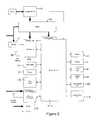
- FIG. 3shows a block diagram of an auxiliary device in accordance with an embodiment of the invention.
- FIG. 4shows a block diagram of an exemplary HMU range expansion scenario in accordance with an embodiment of the invention.
- FIG. 5shows a block diagram of an embodiment of the invention relating to the use of an HMU.
- FIG. 1shows a block diagram of a system in accordance with en embodiment of the invention.
- the systemincludes a central monitoring system (CMS) 10 , a tracking tag 20 operable to communicate with a Global Positioning Satellite (GPS) network 30 and one or more auxiliary devices 40 .
- CMScentral monitoring system
- GPSGlobal Positioning Satellite
- the strap or tagmay incorporate tamper detection using a variety of well-known technologies.
- the tag 20can be attached to an object or individual using a strap or other suitable means of connection.
- the tagcan be attached to a package that is being transported from one location to another.
- the tagcan be attached to in individual under “house arrest” that being monitored for compliance. Numerous other scenarios can be envisioned without departing from the scope of the invention.
- the tag 20communicates with the GPS network 30 and a wireless network 25 to respectively obtain geographic location information and to exchange data with the CMS 10 .
- the CMSmonitors the location of the tag (as well as the object or individual to which the tag is attached) and compares the monitored location to a database of acceptable and unacceptable location and time parameters.
- the taggenerally transmits position updates to the CMS and also receives downloads and updates from the CMS.
- the CMS 10In order to track one or more individuals or objects, each of which having an individual set of allowed geographic and temporal restrictions, the CMS 10 maintains a database 15 of individuals or objects and corresponding restrictions.
- the tag 20generally incorporates a microcontroller, flash memory, a cellular modem, a GPS receiver, tamper detection, and a rechargeable battery into a single unit as discussed in more detail below. While the foregoing description focuses primarily on tracking of individuals, it is understood that the invention is equally applicable to the tracking of objects as well.
- each such individualis provided with a tracking tag.
- each of the tagspreferably reports into the CMS 10 on an intermittent or periodic basis.
- the reporting basiscan be on a predetermined schedule and/or can be based upon detection of a violation or other reportable condition detected by the tag itself.
- Information reporting by the various tagsis recorded and analyzed at the CMS to determine if individual violations have occurred. The CMS can then take an appropriate action to notify, respond to and/or correct the noted violation.
- the systemalso includes at least one auxiliary device 40 .
- the auxiliary device 40works in conjunction with the tag 20 which will intermittently or periodically request the presence of an auxiliary device 40 by sending out a RF transmission (“ping”) and waiting for a reply from any auxiliary device in range via the short range radio (or RF) link 45 .
- the typical range in an exemplary systemis approximately 100 meters in open area.
- the auxiliary deviceincludes: power supply circuitry (e.g., for AC or DC power), battery charging circuitry, a battery backup for remote operations, a RF transceiver, a microcontroller and various alarm features to detect and report movement, power loss and light ingress as discussed in more detail below.
- Each auxiliary devicecan be identified by a unique serial number which is transmitted in its response to a ping from tag 20 .
- the auxiliary device serial numbercan also be transmitted in a last reported alarm status response.
- the auxiliary device 40can store any alarms in non volatile memory to ensure that in the event of loss of power data is retained.
- the auxiliary devicecan also retain the status of any alarms until it is able to reply to a valid request from tag 20 .
- FIG. 2is a block diagram of a tag 20 in accordance with an embodiment of the invention.
- the tag 20has a microcontroller 102 , associated flash memory 104 and a GPS receiver 106 which provides up GPS position information to the microcontroller 102 .
- the tagcan include a cellular modem 108 with an associated SIM card 110 provided for data communication between the tag 20 and the CMS 10 .
- the tag 20communicates through a wireless network 25 with the CMS 10 .
- a tag configured to communicate with the CMS via the a cellular networkis referred to herein as an “active” tag.
- the tag 20also communicates with one or more GPS satellites in the GPS network 30 .
- the tag 20also includes an RF transceiver 150 for communication between the tag and the auxiliary device 40 via the RF link 45 .
- This RF linkcreates an electronic tether between the tag and the auxiliary device.
- Suitable short range wireless integrated circuits and networking firmware for use in accordance with an embodiment of the inventionare available from a variety of sources including Micrel Inc., of San Jose, Calif. (www.micrel.com). Communication via the RF link 45 is discussed in more detail in the following section.
- the tagcan obtain position information either through the GPS network 30 and/or through position determination techniques utilized in the wireless network 25 .
- Wireless (cellular) based techniques for geographic location determinationcommonly referred to in the wireless industry as geolocation, can include triangulation, and estimated time of delivery (EOTD) based upon the cellular ID of the base stations from which a signal is received. It is understood that the system can utilize position information obtained from GPS or geolocation techniques or both as needed (e.g., to maximize the coverage area, power utilization and/or accuracy).
- the tagalso includes a battery 112 to power the microcontroller 102 , the cellular modem 108 , the GPS receiver 106 and the other components within the tag 20 .
- the battery 112resides within the unit in a sealed compartment and is not removed for recharging so as to avoid potential leaks which could result from removal and replacement of the battery. Because the unit must be worn by an individual at all times, the tag will be subjected to water in such environments as showering.
- the battery 112is recharged while it remains within the tag 20 by means of charger 113 .
- the tagmay also include a tamper detection mechanism 114 to avoid unauthorized removal or opening of the tag.
- the specific tamper detection mechanismcan be implemented in a variety of ways including: i) signal continuity detection, ii) electrical, optical or electromagnet switches or detectors that detect unauthorized opening of the tag and/or iii) electrical, thermal proximity devices which monitor the proximity of the tag to the individual or object.
- Accelerometer 115is also provided and can be used to monitor acceleration of the tag 20 .
- the microcontroller 102can be programmed to generate an alarm based on acceleration beyond a threshold or the like.
- the microcontroller 102controls the operation of the tag 20 .
- Regular poles of the cellular modem 108 and GPS receiver 106are carried out to monitor for incoming command messages and to monitoring the location of the tag.
- the parameters of the monitoring to be performedare programmed into the microcontroller 102 to respond to variations in the location of the tag and to respond to commands received from the CMS 10 through the cellular modem 108 .
- the flash memory 104holds the programmed code for the operation of the tag 20 .
- the codeis downloaded to the unit utilizing a serial link and can be modified and/or downloaded through the cellular modem connection 108 . In the alternative, the code can be downloaded via programming port 124 .
- Communication between the tag 20 and the CMS 10is carried out via the cellular modem 108 .
- the modemremains logged into the cellular network, allowing the tag to be called from the CMS to request current operating status.
- the tagcan also be polled by the CMS to download the position of the tag as measured by the GPS system and/or to download other operating parameters such as violation history, position history and/or battery status.
- the microcontroller codealso includes the ability to be manually placed into a sleep mode wherein the unit is not powered down but only inactive, upon receipt of an appropriate command from the CMS 10 . Powering down of the tag 20 can be used to prolong the life of the battery 112 . By allowing a power down to be controlled by the eMS, the tag can be powered down without the knowledge of the offender. Because the individual does not know when the unit is inactive, the individual cannot take advantage of inactivity to commit an offense without detection. The unit can reactivate after a set period of time, after being connected to a recharger or after receipt of a command to reactivate.
- the SIM card 110is sealed within the tag unit and cannot be accessed by the wearer.
- the SIM cardcontains details relating to cellular activation and/or the cellular service provider.
- the term “SIM card”is used herein a general sense and encompasses other devices for use with various types of cellular service such as a Universal Integrated Circuit Card (UICC), Removable User Identity Module (RUIM) or the like.
- the GPS moduleis used with an appropriate antenna 116 , such as a patch antenna mounted internal to the tag case.
- the GPS modulecan also include a battery backup 130 to maintain settings when main power is removed from the GPS module.
- the GPS modulewhen activated will obtain the current position of the tag. If no fix is obtained, the tag will report that no fix was obtained.
- the GPS receiveris used in the push to fix mode. The receiver is normally asleep and, only when requested, wakes to obtain the current position of the tag.
- the tag 20also collects cell 10 from the wireless system through the wireless cellular modem 108 and EOTD information when provided by the network.
- the use of cell ID and EOTDcan be used to determine the tag position, as is known in the art, however with less accuracy than the GPS receiver.
- the tag 20can use this secondary position information as a confirmation of the fix obtained by the GPS receiver or as a substitute for the GPS positioning when a GPS position is unavailable.
- the tag 20can include an audible alarm such as a buzzer 118 , a tactile alarm such as a vibrator 120 to provide an indication to the wearer that a condition requiring attention has been detected.
- the tagcan also include a panic button 122 to allow the wearer to alert the CMS 10 that a situation requiring attention exists. This button can be particularly useful when the tag is used by an individual being monitored because of the individuals potential need for assistance.
- Other visual alertssuch as Tricolor LED 126 (e.g., for system status and the like) and Tamper LED 128 can be provided.
- FIG. 3shows a block diagram of an auxiliary device 40 in accordance with an embodiment of the invention.
- the auxiliary device 40has a microcontroller 202 with associated internal memory and an RF transceiver 250 for communication between the tag 20 and the auxiliary device 40 via the RF link 45 . It is understood that the microcontroller 202 can utilize internal memory, external memory or both.
- the auxiliary devicealso includes a battery 212 to power the microcontroller 202 , RF transceiver 250 and the other components within the auxiliary device.
- the battery 212is recharged by means of charger 213 .
- the programming code for microcontroller 202can be downloaded via typical techniques. For example, the programming for microcontroller 202 can be burned into the appropriate memory device prior to or during assembly. In the alternative, programming code can be downloaded via optional programming port 224 .
- the auxiliary devicecan optionally include a tamper detection mechanism 214 to avoid unauthorized removal or opening of the auxiliary device.
- An accelerometer 215can optionally be provided and can be used to monitor movement of the auxiliary device.
- the microcontroller 202can be programmed to generate an alarm based on acceleration beyond a threshold or the like.
- the auxiliary device 40may also include an audible alarm such as a buzzer 218 to provide an indication that a condition requiring attention has been detected.
- the auxiliary deviceis preferable constructed with a small housing (e.g., 120 mm*80 mm*55 mm) and can be attached to AC power via a suitable cable or adapter (e.g., 12V adapter).
- the auxiliary devicecan be designed to be hard mounted via screws or other suitable fasteners.
- the auxiliary devicecan be temporarily placed in a location or even worn or carried by an individual (e.g., operating via battery power).
- the auxiliary devicecan be integrated into or attached to an article of clothing such as shoes, socks, pants, shirts, or jackets.
- the auxiliary devicecan be integrated into or attached to a backpack, purse, wallet or other convenient portable accessory.
- the tag 20will periodically poll (e.g., ping) for the presence of an auxiliary device 40 via the RF link 45 . If an auxiliary device is detected (i.e., the auxiliary device responds to the ping) and communications can be established with the auxiliary device, the operational parameters of the tag and/or the system can be altered.
- the auxiliary device 40will typically reply to a tag 20 with some or all of the following information: auxiliary device ID, tag ID, status of the auxiliary device (tamper, motion or power). This information is then transmitted to the CMS 10 by the tag 20 . It understood that a variety of communications protocols are suitable for use in accordance with an embodiment of the invention. It is also understood that in some embodiments, communications between the tag and the auxiliary device can be initiated by the auxiliary device.
- the tag 20relays messages from the auxiliary device to the CMS 10 via cellular modem 108 and wireless network 25 .
- This configurationis advantageous in that the auxiliary device does not require a cellular modem to communicate to the CMS. This results in considerable cost savings and minimizes power utilization.
- the location of the auxiliary device 40is fixed and is known to the CMS 10 (e.g., the location of the auxiliary device is stored in the CMS database 15 ).
- the systemis operable to establish an inclusion zone defined by the range of the auxiliary device.
- the CMSknows the location of the tag 20 . Operation in this mode proceeds as follows: the tag 20 detects an auxiliary device (i.e., the auxiliary device responds to a ping).
- the tagestablishes communications with the auxiliary device, and reports some or all of the following information to the CMS 10 : auxiliary device ID, tag ID, Status of the tag (tamper, low battery and charging), status of the auxiliary device (tamper, motion or power).
- the auxiliary devicecan also be configured to recognize one or more auxiliary device groups (e.g., 40 , 40 ′, 40 ′′, 40 ′′′) and then alter its operating mode subject to a receipt from the auxiliary device that it has no alarms pending.
- the tag 20may require a valid GPS fix before entering a reduced power state.
- the tag 20will contact the CMS 10 via the cellular modem 108 to confirm it is going to into a reduced power or sleep state (i.e., GPS receiver 106 can be at least partially powered down in order to save battery power).
- the tagcan maintain list of approved auxiliary devices and the tag can make the determination on whether or not to enter a reduced power state.
- This list of approved auxiliary devicescan be updated by the CMS as needed. This reduced power state is particularly advantageous in locations where GPS reception is impaired.
- the tag 20If the tag 20 cannot calculate its position via GPS, call in to the CMS 10 or if the tag receives an alarm status from the auxiliary device 40 , it will remain in normal operating mode and will continue to log its status. It is understood that the location of the auxiliary device 40 can be fixed after the auxiliary device is powered up in a given location. Upon the initial communication between the tag and the CMS, the system can enter the location of the auxiliary device 40 into the database 15 before allowing the tag to enter a low power mode.
- the tag 20Upon notification from an auxiliary device of any alarm (e.g., power loss, movement or tamper, lack of valid pings . . . ) the tag 20 will wake up and resume normal mode. The tag 20 will immediately call into the CMS 10 , download its status and that of the auxiliary device.
- any alarme.g., power loss, movement or tamper, lack of valid pings . . .
- the auxiliary device 40In this mode of operation, the location of the auxiliary device 40 need not be known to the CMS 10 . Further, for this mode of operation, the auxiliary device may be configured as a portable device that is battery operated. This can be provided by an integral auxiliary device or by configuring the auxiliary device to have a fixed component and a removable component respectively analogous to a notebook computer and its “docking station”. Operation in this mode proceeds as follows: the tag 20 detects an auxiliary device (i.e., the auxiliary device responds to the ping).
- the tagestablishes communications with the auxiliary device, and reports some or all of the following information to the CMS 10 : auxiliary device 10 , tag 10 , Status of the tag (tamper, low battery and charging), Status of the auxiliary device (tamper, motion or power).
- auxiliary device 10the tag 10 will continue with its normal operations and logging but with the additional details of the auxiliary device 10 received and its status. This logging can occur relatively frequently (e.g., every one minute).
- the tag 20will notify the central monitoring system of every auxiliary device heard; the tag 20 does not need to be configured with the auxiliary device details. This mode is advantageous in that the system can establish exclusion zones.
- the CMS 10can identify that unauthorized entry into that zone has taken place. This mode is also applicable to a dual tracking scenario such as the type disclosed in U.S. Pat. No. 5,867,103, which is again incorporated by reference herein.
- One or more auxiliary devicescan also be used to extend the range of a Home Monitoring Unit (HMU) when used in a traditional “house arrest” situation.
- HMUHome Monitoring Unit
- the HMU 300communicates with the CMS 10 via communication link 302 (typically a land line telephone link to the PSTN).
- the HMUis also provided with an RF receiver that is operable to monitor the RF link (or electronic tether) established between a tag 20 and an auxiliary device 40 .
- Each auxiliary device 40can be positioned such that it can receive information from a tag 20 via the RF link 45 .
- the auxiliary device 40is also positioned in range of the HMU.
- the HMU receiverto receive the reply message (from the auxiliary device to the tag) even when the tag is out of range. Receipt of the reply from the auxiliary device in effect allows the HMU to determine that the tag is within an acceptable range.
- the auxiliary devicewill only be treated as a valid source if it is previously assigned to the HMU and is not in a current alarm status.
- the RF link 45is utilized for communication between various devices.
- several devicesmay be utilized in relatively close proximity. These devices may ultimately be in contention for use of the RF link. That is two or more devices may try to communicate via the RF link simultaneously.
- the RF linkcan be implemented to eliminate or reduce contention issues.
- the RF linkcan be implemented with a plurality of frequencies that are allocated to various devices.
- the RF linkcan be implemented with a time slot allocation for each device. Such time slots can be assigned on a fixed or dynamic basis.
- the RF link 45is implemented with four frequencies.
- frequency number 1is utilized for communication between a tag and an HMU.
- the frequency bandis divided into a plurality of time slots, each of which can be assigned to a specific tag.
- Time slot allocationcan be performed on a fixed or dynamic basis. In the case of fixed time slot allocation, the given time slot can be directly programmed into the specific tag as well as the associated HMU prior to any communication taking place.
- the tag and HMUcan conduct initial communications (e.g., utilizing a pre-selected time slot) before a specific time slot is assigned to a specific tag.
- frequencies 2-4are generally utilized by a tag to communicate with an auxiliary device.
- tagwill intermittently or periodically request the presence of an auxiliary device by sending out a RF transmission (“ping”) and waiting for a reply from any auxiliary device in range via the RF link.
- pingRF transmission
- Each pingcan be transmitted on a different frequency (2-4) until communication between the tag and the auxiliary device is established.
- Specific frequencycan be selected on specific pattern or random frequency assignment.
- the receiver in the auxiliary device 40 or HMU 300 , 300 ′may include the capability to provide Received Signal Strength Indication measurements (RSSI).
- RSSIReceived Signal Strength Indication measurements
- RSSI measurementsdenote the received radio signal strength. These measurements can be utilized in connection with a variety of system functions. For example, RSSI can be used internally in a wireless networking card to determine when the amount of radio energy in the channel is below a certain threshold at which point the network card is clear to send (CTS). RSSI can be measured in the IF stage before the IF amplifier. In zero-IF systems, it can be done in the baseband signal chain, before the baseband amplifier. RSSI measurements can be output as a DC analog level. However, it is beneficial to sample RSSI measurements with an internal A/D converter so that resulting numeric codes available directly to the internal processor 202 ( FIG. 3 ). In the example below, typical RSSI measurements range from about 250 (noise level) to about 650 maximum.
- RSSIis utilized to determine the relative proximity or range of the tag 20 to an auxiliary device 40 or HMU 300 , 300 ′. This can be accomplished by selecting a pre determined RSSI value to set the acceptable range of the RF link 45 (i.e., the RSSI must remain above the pre-determined RSSI level to be considered within range).
- a calibration routinecan be utilized. For example, the tag can be placed into a range calibration mode in which it pings every few seconds. The tag can then be moved throughout the desired location during which the auxiliary device 40 or HMU 300 , 300 ′ records the lowest RSSI measurement.
- the systemcan optionally include an acceptable offset range for the RSSI measurement (e.g., user selectable) to account for environmental conditions.
- an acceptable offset range for the RSSI measuremente.g., user selectable
- a typical default level for the offset rangeis 50 .
- antenna typese.g., omnidirectional, directional . . .
- characteristicsgain, impedance, directionality, radiation efficiency and the like
- the auxiliary devicecan be utilized to establish an exclusion zone. This particular mode can be utilized to provide protection from monitored individuals.
- an embodiment of the inventionis particularly useful. Referring to FIG. 1 , the offender is fitted with a tag 20 .
- the tagcarries out reporting functions with the CMS 10 as outlined above e.g., via the wireless network 25 or HMU 300 (see FIG. 5 ).
- Each individual desiring enhanced protectionis provided with an auxiliary device (e.g., shown graphically as 40 , 40 ′, 40 ′′ . . . ).
- the auxiliary devicecan be integrated into an article of clothing such as shoes, socks, pants, shirts, or jackets.
- the auxiliary devicecan be integrated into or attached to a backpack, purse, wallet or other convenient portable accessory. It is understood that tamper detection mechanism 214 , buzzer 218 and/or accelerometer 215 can be omitted from auxiliary devices used in this context. This can further reduce the size and cost of such auxiliary devices. In this mode of operation, the location of the auxiliary devices 40 , 40 ′, 40 ′′ . . . need not be known to the CMS 10 .
- the tag 20detects an auxiliary device (i.e., the auxiliary device responds to the ping).
- the tagestablishes communications with the auxiliary device, and reports some or all of the following information to the CMS 10 : auxiliary device ID, tag 10 , status of the tag (low battery and charging), status of the auxiliary device (motion or power).
- auxiliary device IDi.e., the tag ID
- tag 10status of the tag (low battery and charging), status of the auxiliary device (motion or power).
- the tag 20will continue with its normal operations and logging but with the additional details of the auxiliary device 10 received and its status. This logging can occur relatively frequently (e.g., everyone minute).
- the tag 20will notify the central monitoring system of every auxiliary device heard; the tag 20 does not need to be configured with the auxiliary device details.
- auxiliary device 10can have a format that is generally associated with a certain class of individual (e.g., child) and/or the auxiliary device ID can include specific information (e.g., a serial number) that is specifically associated with a single individual (e.g., a specific child).
- the systemcan also provide predictive correlation for potential offenders such as sex offenders.
- the CMS 10contains sufficient information in the database 15 to identify the individual wearing tag 20 as well as the individuals or class of individuals carrying auxiliary devices 40 , 40 ′, 40 ′′ . . . .
- the CMScan take one or more actions. For example, the CMS can i) notify local authorities, ii) notify the appropriate agent or parole office, and/or iii) notify other individuals that can take appropriate action.
- the CMS 10 softwarecan also track trends over time. These trends can be tracked and analyzed to enhance the accuracy of any notification actions.
- the CMScan utilize a threshold in connection with or prior to issuing a notification.
- Exemplary trendscan include i) detection of auxiliary device ID associated with a child multiple times in the same general lat/long location as a sex offender, and/or ii) detection of auxiliary device ID associated with a child for more than a specified timer period in the same general lat/long location as a sex offender.
- the systemcan also provide notification of these trends to an agent for further investigation. This can alert the agent to trends that may not otherwise be apparent (e.g., the offender may be hanging around a school, bus stop, shopping mall, park or the like).
Landscapes
- Physics & Mathematics (AREA)
- General Physics & Mathematics (AREA)
- Engineering & Computer Science (AREA)
- Computer Networks & Wireless Communication (AREA)
- Signal Processing (AREA)
- Business, Economics & Management (AREA)
- Emergency Management (AREA)
- Mobile Radio Communication Systems (AREA)
- Radar Systems Or Details Thereof (AREA)
- Alarm Systems (AREA)
- Position Fixing By Use Of Radio Waves (AREA)
- Telephone Function (AREA)
Abstract
Description
| Frequency No. | Description | ||
| 1 | HMU | Dynamic | |
| 2 | Auxiliary Device | Frequency Allocation | |
| 3 | Auxiliary Device | Frequency Allocation | |
| 4 | Auxiliary Device | Frequency Allocation | |
- To confirm the known location of an individual to the vicinity of an auxiliary device or auxiliary device when GPS is unavailable i.e. at home or in a establishment i.e., hostel.
- To extend the operational life of the tag battery by allowing the tag to use the auxiliary device in a known location.
- To allow the auxiliary device to be positioned in areas of importance and to notify the central monitoring system when a tag is within range i.e. schools or victims properties.
- The auxiliary device with an extended battery back-up can be used in this mode by domestic violence victims or other persons who may require the device to operate as a mobile device. i.e. taking a trip to the mall or visiting the doctor. The generation of alarms (including audible and/or visual alarms) may be added as desired. This mode can also provide protection for children in cases where there is unauthorized or undesirable proximity between the child and a sex offender.
- To allow the auxiliary device to be positioned in such a way that with the operation of the HMU, a property can be effectively covered with the placement of auxiliary device to extend the HMU range.
- The auxiliary device can be used in a number of modes depending on parameter settings on the tag and if a Home Monitoring unit (HMU is present).
Claims (27)
Priority Applications (2)
| Application Number | Priority Date | Filing Date | Title |
|---|---|---|---|
| US13/429,909US8952807B2 (en) | 2006-08-29 | 2012-03-26 | Active wireless tag and auxiliary device for use with monitoring center for tracking individuals or objects |
| US14/590,073US9918187B2 (en) | 2006-08-29 | 2015-01-06 | Active wireless tag and auxiliary device for use with monitoring center for tracking individuals or objects |
Applications Claiming Priority (5)
| Application Number | Priority Date | Filing Date | Title |
|---|---|---|---|
| US84084406P | 2006-08-29 | 2006-08-29 | |
| US85923206P | 2006-11-15 | 2006-11-15 | |
| US11/847,106US7961092B2 (en) | 2006-08-29 | 2007-08-29 | Active wireless tag and auxiliary device for use with monitoring center for tracking individuals or objects |
| US13/093,346US8169316B2 (en) | 2006-08-29 | 2011-04-25 | Active wireless tag and auxiliary device for use with monitoring center for tracking individuals or objects |
| US13/429,909US8952807B2 (en) | 2006-08-29 | 2012-03-26 | Active wireless tag and auxiliary device for use with monitoring center for tracking individuals or objects |
Related Parent Applications (1)
| Application Number | Title | Priority Date | Filing Date |
|---|---|---|---|
| US13/093,346ContinuationUS8169316B2 (en) | 2006-08-29 | 2011-04-25 | Active wireless tag and auxiliary device for use with monitoring center for tracking individuals or objects |
Related Child Applications (1)
| Application Number | Title | Priority Date | Filing Date |
|---|---|---|---|
| US14/590,073ContinuationUS9918187B2 (en) | 2006-08-29 | 2015-01-06 | Active wireless tag and auxiliary device for use with monitoring center for tracking individuals or objects |
Publications (2)
| Publication Number | Publication Date |
|---|---|
| US20120244879A1 US20120244879A1 (en) | 2012-09-27 |
| US8952807B2true US8952807B2 (en) | 2015-02-10 |
Family
ID=39136824
Family Applications (6)
| Application Number | Title | Priority Date | Filing Date |
|---|---|---|---|
| US11/847,146Active2028-07-10US8009036B2 (en) | 2006-08-29 | 2007-08-29 | Wireless tag and auxiliary device for use with home monitoring unit for tracking individuals or objects |
| US11/847,106Active2028-06-04US7961092B2 (en) | 2006-08-29 | 2007-08-29 | Active wireless tag and auxiliary device for use with monitoring center for tracking individuals or objects |
| US13/093,346ActiveUS8169316B2 (en) | 2006-08-29 | 2011-04-25 | Active wireless tag and auxiliary device for use with monitoring center for tracking individuals or objects |
| US13/190,896ActiveUS8334769B2 (en) | 2006-08-29 | 2011-07-26 | Wireless tag and auxiliary device for use with home monitoring unit for tracking individuals or objects |
| US13/429,909ActiveUS8952807B2 (en) | 2006-08-29 | 2012-03-26 | Active wireless tag and auxiliary device for use with monitoring center for tracking individuals or objects |
| US14/590,073Active2027-11-03US9918187B2 (en) | 2006-08-29 | 2015-01-06 | Active wireless tag and auxiliary device for use with monitoring center for tracking individuals or objects |
Family Applications Before (4)
| Application Number | Title | Priority Date | Filing Date |
|---|---|---|---|
| US11/847,146Active2028-07-10US8009036B2 (en) | 2006-08-29 | 2007-08-29 | Wireless tag and auxiliary device for use with home monitoring unit for tracking individuals or objects |
| US11/847,106Active2028-06-04US7961092B2 (en) | 2006-08-29 | 2007-08-29 | Active wireless tag and auxiliary device for use with monitoring center for tracking individuals or objects |
| US13/093,346ActiveUS8169316B2 (en) | 2006-08-29 | 2011-04-25 | Active wireless tag and auxiliary device for use with monitoring center for tracking individuals or objects |
| US13/190,896ActiveUS8334769B2 (en) | 2006-08-29 | 2011-07-26 | Wireless tag and auxiliary device for use with home monitoring unit for tracking individuals or objects |
Family Applications After (1)
| Application Number | Title | Priority Date | Filing Date |
|---|---|---|---|
| US14/590,073Active2027-11-03US9918187B2 (en) | 2006-08-29 | 2015-01-06 | Active wireless tag and auxiliary device for use with monitoring center for tracking individuals or objects |
Country Status (4)
| Country | Link |
|---|---|
| US (6) | US8009036B2 (en) |
| CA (2) | CA2662023C (en) |
| GB (2) | GB2455451B (en) |
| WO (2) | WO2008027948A2 (en) |
Families Citing this family (89)
| Publication number | Priority date | Publication date | Assignee | Title |
|---|---|---|---|---|
| US7598855B2 (en) | 2005-02-01 | 2009-10-06 | Location Based Technologies, Inc. | Apparatus and method for locating individuals and objects using tracking devices |
| CA2604157A1 (en) | 2005-04-06 | 2006-10-12 | Omnilink Systems, Inc. | System and method for tracking, monitoring, collecting, reporting and communicating with the movement of individuals |
| ES2369039T3 (en)* | 2005-05-06 | 2011-11-24 | Omnilink Systems, Inc. | SYSTEM AND METHOD OF MONITORING THE MOVEMENT OF INDIVIDUALS AND PROPERTY. |
| US7330122B2 (en) | 2005-08-10 | 2008-02-12 | Remotemdx, Inc. | Remote tracking and communication device |
| US7737841B2 (en) | 2006-07-14 | 2010-06-15 | Remotemdx | Alarm and alarm management system for remote tracking devices |
| US8797210B2 (en) | 2006-07-14 | 2014-08-05 | Securealert, Inc. | Remote tracking device and a system and method for two-way voice communication between the device and a monitoring center |
| US7936262B2 (en) | 2006-07-14 | 2011-05-03 | Securealert, Inc. | Remote tracking system with a dedicated monitoring center |
| WO2008027948A2 (en) | 2006-08-29 | 2008-03-06 | Satellite Tracking Of People Llc | Active wireless tag and auxiliary device for use with monitoring center for tracking individuals or objects |
| KR100833511B1 (en)* | 2006-12-08 | 2008-05-29 | 한국전자통신연구원 | Passive tag with volatile memory |
| US7930927B2 (en)* | 2007-03-06 | 2011-04-26 | Bi Incorporated | Transdermal portable alcohol monitor and methods for using such |
| US8774827B2 (en)* | 2007-04-05 | 2014-07-08 | Location Based Technologies, Inc. | Apparatus and method for generating position fix of a tracking device in accordance with a subscriber service usage profile to conserve tracking device power |
| US8102256B2 (en) | 2008-01-06 | 2012-01-24 | Location Based Technologies Inc. | Apparatus and method for determining location and tracking coordinates of a tracking device |
| US20140253377A1 (en)* | 2007-10-31 | 2014-09-11 | Location Based Technologies, Inc. | Power conservation methods to update a position fix of a mobile location tracking device |
| US8115621B2 (en)* | 2007-05-01 | 2012-02-14 | Yoganand Rajala | Device for tracking the movement of individuals or objects |
| USD578918S1 (en) | 2007-05-01 | 2008-10-21 | Omnilink Systems, Inc. | Offender monitor |
| JP5114123B2 (en)* | 2007-07-24 | 2013-01-09 | トヨタ自動車株式会社 | In-vehicle device control system |
| US8566439B2 (en)* | 2007-10-01 | 2013-10-22 | Ebay Inc | Method and system for intelligent request refusal in response to a network deficiency detection |
| US20090191897A1 (en)* | 2008-01-24 | 2009-07-30 | Cortxt, Inc. | Environment Characterization for Mobile Devices |
| US8879983B2 (en)* | 2008-02-06 | 2014-11-04 | Hmicro, Inc. | Wireless communications systems using multiple radios |
| US8154401B1 (en) | 2008-02-08 | 2012-04-10 | Global Trek Xploration Corp. | System and method for communication with a tracking device |
| US8232876B2 (en) | 2008-03-07 | 2012-07-31 | Securealert, Inc. | System and method for monitoring individuals using a beacon and intelligent remote tracking device |
| US20100081458A1 (en)* | 2008-10-01 | 2010-04-01 | Qualcomm Incorporated | Mobile Terminal Motion Detection Methods and Systems |
| US9207664B2 (en)* | 2008-10-17 | 2015-12-08 | Rockwell Automation Technologies, Inc. | User interface devices for control of machine systems |
| US8217785B2 (en)* | 2008-10-28 | 2012-07-10 | Research In Motion Limited | Mobile tag tracking system |
| US8493219B2 (en)* | 2008-11-14 | 2013-07-23 | Bi Incorporated | Systems and methods for adaptive monitoring and tracking of a target having a learning period |
| ITBG20090003A1 (en)* | 2009-02-16 | 2010-08-17 | Fm S R L | METHOD AND SYSTEM FOR THE MANAGEMENT OF DISTRIBUTED RESOURCES ON THE TERRITORY. |
| US20100214070A1 (en)* | 2009-02-23 | 2010-08-26 | Susan Ramsay | System and Method for Tracking Items |
| US8657744B2 (en) | 2009-03-23 | 2014-02-25 | Bi Incorporated | Systems and methods for transdermal secretion detection |
| US8571486B2 (en) | 2009-05-28 | 2013-10-29 | Rockwell Automation Technologies, Inc. | Wireless user interface system performance monitoring |
| US8155711B2 (en)* | 2009-06-05 | 2012-04-10 | Qualcomm, Incorporated | Service search based on battery charger |
| US8576065B2 (en)* | 2009-12-03 | 2013-11-05 | Bi Incorporated | Systems and methods for variable collision avoidance |
| US8629776B2 (en) | 2009-12-03 | 2014-01-14 | Bi Incorporated | Systems and methods for disrupting criminal activity |
| US9355548B2 (en) | 2009-12-03 | 2016-05-31 | Bi Incorporated | Systems and methods for contact avoidance |
| US8199051B2 (en)* | 2009-12-18 | 2012-06-12 | Trueposition, Inc. | Satellite positioning receiver and proxy location system |
| CN201576186U (en)* | 2009-12-21 | 2010-09-08 | 托德·E·卡利普瑞斯 | Mobile monitoring device and monitoring system for electronic equipment |
| US8489113B2 (en)* | 2010-02-09 | 2013-07-16 | Omnilink Systems, Inc. | Method and system for tracking, monitoring and/or charging tracking devices including wireless energy transfer features |
| KR20110099990A (en)* | 2010-03-03 | 2011-09-09 | 삼성전자주식회사 | Method and apparatus for transmitting location information of portable terminal using auxiliary power |
| US20110234399A1 (en) | 2010-03-25 | 2011-09-29 | Nokia Corporation | Method and apparatus for providing a remote lost-and-found service |
| US8514070B2 (en) | 2010-04-07 | 2013-08-20 | Securealert, Inc. | Tracking device incorporating enhanced security mounting strap |
| US8744523B2 (en) | 2010-08-02 | 2014-06-03 | At&T Intellectual Property I, L.P. | Method and system for interactive home monitoring |
| US9807226B2 (en)* | 2010-10-08 | 2017-10-31 | CSC Holdings, LLC | Proximity-enhanced reconfiguration of telephone ring list |
| KR101733792B1 (en)* | 2010-11-10 | 2017-05-24 | 삼성전자주식회사 | Method and apparatus for correcting position |
| US10151844B1 (en)* | 2010-11-29 | 2018-12-11 | Maxim Integrated Products, Inc. | Local indoor positioning and navigation by detection of arbitrary signals |
| GB2495294A (en)* | 2011-10-04 | 2013-04-10 | Retrieva Ltd | Welfare monitoring and tracking device |
| US8560557B1 (en) | 2011-12-14 | 2013-10-15 | Corrisoft, LLC | Method and system of progress monitoring |
| CN103167400B (en)* | 2011-12-15 | 2016-01-13 | 富泰华工业(深圳)有限公司 | Portable electron device and method for tracing thereof |
| US8649755B2 (en) | 2011-12-16 | 2014-02-11 | Qualcomm Incorporated | Timing circuit calibration in devices with selectable power modes |
| US9066295B2 (en) | 2011-12-16 | 2015-06-23 | Qualcomm Incorporated | Power conservation techniques for use in devices with selectable power modes |
| WO2013096923A1 (en) | 2011-12-22 | 2013-06-27 | Earthsweep Llc | Method and system for electronic monitoring |
| US9558645B2 (en) | 2012-01-06 | 2017-01-31 | 3M Innovative Properties Company | Released offender geospatial location information trend analysis |
| AU2013207537B2 (en) | 2012-01-06 | 2015-04-16 | Attenti Electronic Monitoring Ltd | Released offender geospatial location information user application |
| US10157188B2 (en) | 2012-01-06 | 2018-12-18 | 3M Innovative Properties Company | Released offender geospatial location information clearinghouse |
| US9215578B2 (en) | 2012-01-27 | 2015-12-15 | Omnilink Systems, Inc. | Monitoring systems and methods |
| US9887887B2 (en) | 2012-07-09 | 2018-02-06 | Eturi Corp. | Information throttle based on compliance with electronic communication rules |
| US8966064B2 (en) | 2012-07-09 | 2015-02-24 | Parentsware, Llc | Agreement compliance controlled electronic device throttle |
| US9854393B2 (en) | 2012-07-09 | 2017-12-26 | Eturi Corp. | Partial information throttle based on compliance with an agreement |
| US10079931B2 (en) | 2012-07-09 | 2018-09-18 | Eturi Corp. | Information throttle that enforces policies for workplace use of electronic devices |
| US9847948B2 (en) | 2012-07-09 | 2017-12-19 | Eturi Corp. | Schedule and location responsive agreement compliance controlled device throttle |
| CN205692300U (en) | 2013-09-29 | 2016-11-16 | Invue安全产品公司 | A security system used to ensure goods are not stolen |
| GB2521668A (en)* | 2013-12-30 | 2015-07-01 | F Secure Corp | Locating of locating-incapable devices in a location tracking system |
| WO2015130273A1 (en)* | 2014-02-26 | 2015-09-03 | Empire Technology Development Llc | Presence-based device mode modification |
| US9876693B1 (en)* | 2014-03-25 | 2018-01-23 | United Parcel Service Of America, Inc. | Concepts for providing notifications for events of interest |
| DE102014212488B4 (en)* | 2014-06-27 | 2016-02-18 | Siemens Aktiengesellschaft | Securely providing a replica pseudorandom noise code to a receiver unit |
| EP3178052A1 (en)* | 2014-08-04 | 2017-06-14 | Quividi | Process for monitoring the audience in a targeted region |
| US9521513B2 (en) | 2014-10-21 | 2016-12-13 | Earthsweep Llc | Method and system of zone suspension in electronic monitoring |
| US10187742B2 (en)* | 2015-01-19 | 2019-01-22 | Haldor Advanced Technologies Ltd | System and method for tracking and monitoring surgical tools |
| US10223881B2 (en) | 2015-02-18 | 2019-03-05 | Invue Security Products Inc. | System and method for calibrating a wireless security range |
| US9571624B2 (en) | 2015-03-24 | 2017-02-14 | Intel IP Corporation | Apparatus, system and method of terminating a docking session between a mobile device and a docking device |
| US10482739B2 (en) | 2015-06-25 | 2019-11-19 | Invue Security Products Inc. | Wireless merchandise security system |
| US9503848B1 (en)* | 2015-07-01 | 2016-11-22 | Numerex Corp. | Method and system for locating a wireless tracking device associated with a network of alarm panels |
| US10730626B2 (en) | 2016-04-29 | 2020-08-04 | United Parcel Service Of America, Inc. | Methods of photo matching and photo confirmation for parcel pickup and delivery |
| US10726381B2 (en) | 2016-04-29 | 2020-07-28 | United Parcel Service Of America, Inc. | Methods for dispatching unmanned aerial delivery vehicles |
| US10445634B2 (en) | 2016-12-14 | 2019-10-15 | Trackonomy Systems, Inc. | Fabricating multifunction adhesive product for ubiquitous realtime tracking |
| US10878454B2 (en)* | 2016-12-23 | 2020-12-29 | Wipro Limited | Method and system for predicting a time instant for providing promotions to a user |
| EP3592065B1 (en)* | 2017-03-20 | 2021-09-01 | Guangdong Oppo Mobile Telecommunications Corp., Ltd. | Method for transmitting data, and terminal device |
| US10775792B2 (en) | 2017-06-13 | 2020-09-15 | United Parcel Service Of America, Inc. | Autonomously delivering items to corresponding delivery locations proximate a delivery route |
| US10070256B1 (en)* | 2017-08-16 | 2018-09-04 | Tile, Inc. | Tracking device operation in risk-classified geographic area |
| EP3688684B1 (en) | 2017-09-29 | 2025-02-26 | United Parcel Service Of America, Inc. | Predictive parcel damage identification, analysis, and mitigation |
| US10354510B2 (en)* | 2017-10-30 | 2019-07-16 | Harbinger Technology Corporation | Detection system for detecting moving object crossing border and method thereof |
| PE20201408A1 (en)* | 2017-11-03 | 2020-12-04 | Technopartner Rastreamento Eireli Me | SYSTEM AND METHOD OF TRACKING MOBILE ASSETS, FIRST NOTICES OF LOSS, TRACKING EQUIPMENT AND CORRESPONDING COMPUTER PROGRAMS |
| US10650663B2 (en)* | 2018-01-01 | 2020-05-12 | Bi Incorporated | Systems and methods for multi-device restriction zone maintenance |
| EP3531387B1 (en) | 2018-02-27 | 2020-12-02 | Upstreem SA | An electronic bracelet and an offender monitoring system |
| US10440063B1 (en) | 2018-07-10 | 2019-10-08 | Eturi Corp. | Media device content review and management |
| WO2020131906A1 (en)* | 2018-12-17 | 2020-06-25 | Hunter Jack C | Personal monitoring system |
| EP4186053A4 (en)* | 2020-07-24 | 2024-09-04 | Trackonomy Systems, Inc. | TEAR OFF TO POWER ON A WIRELESS NODE WITH MULTIPLE CUTOUTS FOR REUSE |
| US11701007B2 (en) | 2020-08-28 | 2023-07-18 | Bi Incorporated | Systems and methods for biometric tamper detection |
| US11665507B2 (en)* | 2020-09-15 | 2023-05-30 | Bi Incorporated | Systems and methods for intercept directing in a monitoring system |
| US11835949B2 (en)* | 2020-11-24 | 2023-12-05 | Mobile Industrial Robots A/S | Autonomous device safety system |
| US11721200B2 (en)* | 2021-06-03 | 2023-08-08 | Satellite Tracking Of People Llc | Predictive analysis support of remote tracking |
Citations (60)
| Publication number | Priority date | Publication date | Assignee | Title |
|---|---|---|---|---|
| US4827943A (en) | 1986-09-23 | 1989-05-09 | Advanced Medical Technologies, Inc. | Portable, multi-channel, physiological data monitoring system |
| US4918432A (en) | 1988-09-27 | 1990-04-17 | B. I. Incorporated | House arrest monitoring system |
| US5021765A (en) | 1988-05-07 | 1991-06-04 | Transaqua Technology Limited | Security system having detector means sensitive to the proximity of at least one detected object |
| US5255306A (en) | 1991-01-10 | 1993-10-19 | Bi Inc. | Cellular interface unit for use with an electronic house arrest monitoring system |
| US5461390A (en) | 1994-05-27 | 1995-10-24 | At&T Ipm Corp. | Locator device useful for house arrest and stalker detection |
| US5537102A (en) | 1991-08-13 | 1996-07-16 | Electronic Monitoring Systems, Inc. | Apparatus and method for a system capable of remotely validating the identity of individual and their location |
| US5646593A (en) | 1995-02-02 | 1997-07-08 | Hewlett Electronics | Child proximity detector |
| US5652570A (en) | 1994-05-19 | 1997-07-29 | Lepkofker; Robert | Individual location system |
| US5731757A (en) | 1996-08-19 | 1998-03-24 | Pro Tech Monitoring, Inc. | Portable tracking apparatus for continuous position determination of criminal offenders and victims |
| US5742233A (en) | 1997-01-21 | 1998-04-21 | Hoffman Resources, Llc | Personal security and tracking system |
| US5825283A (en) | 1996-07-03 | 1998-10-20 | Camhi; Elie | System for the security and auditing of persons and property |
| US5867103A (en) | 1997-09-10 | 1999-02-02 | Taylor, Jr.; John E. | Monitored person tracking system |
| US5870029A (en) | 1996-07-08 | 1999-02-09 | Harris Corporation | Remote mobile monitoring and communication system |
| WO1999012050A1 (en) | 1997-08-29 | 1999-03-11 | Garcia Martin Pedro Maria | System for the security and position control of persons via satellite |
| US5889474A (en) | 1992-05-18 | 1999-03-30 | Aeris Communications, Inc. | Method and apparatus for transmitting subject status information over a wireless communications network |
| US5892454A (en) | 1993-12-21 | 1999-04-06 | Trimble Navigation Ltd. | Hybrid monitoring of location of a site confinee |
| US5987379A (en) | 1997-10-30 | 1999-11-16 | Trimble Navigation Limited | Creation and monitoring of variable buffer zones |
| CA2332579A1 (en) | 1998-05-18 | 1999-11-25 | Maximal Innovative Intelligence Ltd. | A method for comparative visual rendering of data |
| US6014080A (en)* | 1998-10-28 | 2000-01-11 | Pro Tech Monitoring, Inc. | Body worn active and passive tracking device |
| US6054928A (en) | 1998-06-04 | 2000-04-25 | Lemelson Jerome H. | Prisoner tracking and warning system and corresponding methods |
| US6072396A (en) | 1994-12-30 | 2000-06-06 | Advanced Business Sciences | Apparatus and method for continuous electronic monitoring and tracking of individuals |
| US6075443A (en)* | 1998-07-31 | 2000-06-13 | Sarnoff Corporation | Wireless tether |
| US6130620A (en) | 1997-08-11 | 2000-10-10 | Electronic Monitoring Systems, Inc. | Remote monitoring system |
| US6181253B1 (en) | 1993-12-21 | 2001-01-30 | Trimble Navigation Limited | Flexible monitoring of location and motion |
| US6195552B1 (en) | 1998-05-25 | 2001-02-27 | Samsung Electronics Co., Ltd | Method and system for controlling a pilot measurement request order (PMRO) |
| WO2001026067A1 (en) | 1999-10-05 | 2001-04-12 | Bi Incorporated | Authentication techniques in a monitoring system |
| US6243039B1 (en) | 1998-04-21 | 2001-06-05 | Mci Communications Corporation | Anytime/anywhere child locator system |
| WO2001063318A1 (en) | 2000-02-24 | 2001-08-30 | Advanced Business Sciences, Inc. | Apparatus and method for continuous electronic monitoring/tracking of individuals |
| US20010032236A1 (en) | 1999-12-09 | 2001-10-18 | Ching-Fang Lin | Portable multi-tracking method and system |
| US6317049B1 (en) | 1998-02-17 | 2001-11-13 | Souhail Toubia | Apparatus and method for locating missing persons, animals, and objects |
| US20020173887A1 (en) | 2000-05-17 | 2002-11-21 | Flick Kenneth E. | Vehicle tracking unit having a self diagnostic mode and related methods |
| WO2003030108A1 (en) | 2001-09-28 | 2003-04-10 | Veridian Engineering, Inc. | System and method for tracking movement of individuals |
| US6606304B1 (en) | 1999-01-27 | 2003-08-12 | On Guard Plus | System for real-time monitor and response |
| US6606556B2 (en) | 1999-03-31 | 2003-08-12 | C2 Global Technologies, Inc. | Security and tracking system |
| US20040000993A1 (en)* | 2002-06-27 | 2004-01-01 | Koninklijke Philips Electronics N.V. | Out-of-range detector |
| US6697617B2 (en)* | 1999-10-18 | 2004-02-24 | Gateway, Inc. | Notification of a low-battery and maintaining communication in a wireless network |
| US6774797B2 (en) | 2002-05-10 | 2004-08-10 | On Guard Plus Limited | Wireless tag and monitoring center system for tracking the activities of individuals |
| US6775558B1 (en) | 1998-11-12 | 2004-08-10 | Nokia Mobile Phones Limited | Accessory interface within a multiple channel radio apparatus |
| US20040174264A1 (en) | 2003-03-05 | 2004-09-09 | Dmatek Ltd. | Monitoring and tracking network |
| US20040266458A1 (en)* | 2003-06-30 | 2004-12-30 | Kyocera Corporation | Mobile communication unit |
| US20050130672A1 (en) | 2001-10-25 | 2005-06-16 | Dean Richard F. | Method and system for determining mobile station position |
| US20050181805A1 (en) | 2003-10-17 | 2005-08-18 | Gallagher Michael D. | Method and system for determining the location of an unlicensed mobile access subscriber |
| US20050253703A1 (en)* | 2002-12-23 | 2005-11-17 | Tianqing He | Systems, methods, and computer program products for automatic tracking and/or remote monitoring of nuclear gauges and/or data communication therewith |
| US6987978B2 (en) | 2002-07-09 | 2006-01-17 | Hitachi, Ltd. | Wireless communication restriction device, repeater and base station |
| US20060012476A1 (en) | 2003-02-24 | 2006-01-19 | Russ Markhovsky | Method and system for finding |
| US20060199537A1 (en) | 2005-03-07 | 2006-09-07 | Broadcom Corporation | Automatic resource availability using Bluetooth |
| US7123141B2 (en) | 2003-08-20 | 2006-10-17 | Contestabile Robert A | Electronic monitoring systems and methods |
| US20070023496A1 (en)* | 2005-04-13 | 2007-02-01 | Hall Christopher J | House arrest apparatus |
| US20070103324A1 (en) | 2002-03-05 | 2007-05-10 | Aeromesh Corporation | Monitoring system and method |
| US20070115115A1 (en) | 2005-11-14 | 2007-05-24 | System Planning Corporation | System and method for lot based processing and tracking in a container security system using wireless communications |
| US7236091B2 (en) | 2005-02-10 | 2007-06-26 | Pinc Solutions | Position-tracking system |
| US20070152811A1 (en)* | 2005-12-30 | 2007-07-05 | Red Wing Technologies, Inc. | Remote device for a monitoring system |
| US7250860B2 (en) | 2004-09-30 | 2007-07-31 | Signature Control Systems, Inc. | Method and integrated system for networked control of an environment of a mobile object |
| US20070247359A1 (en)* | 2006-04-25 | 2007-10-25 | Ghazarian Ohanes D | Automatic GPS tracking system with passive battery circuitry |
| US20080036610A1 (en)* | 2006-08-08 | 2008-02-14 | Garmin Ltd. | Animal tracking apparatus and method |
| US7339469B2 (en) | 2004-11-22 | 2008-03-04 | Maersk Logistics Usa, Inc. | Shipping container monitoring and tracking system |
| WO2008027985A2 (en) | 2006-08-29 | 2008-03-06 | Satellite Tracking Of People Llc | Wireless tag and auxiliary device for use with home monitoring unit for tracking individuals or objects |
| US7446656B2 (en) | 2003-08-22 | 2008-11-04 | Strategic Technologies Inc. | Electronic location monitoring system |
| US7456355B2 (en) | 2004-03-10 | 2008-11-25 | G4S Justice Services (Canada) Inc. | Permanently closed enclosure apparatus and method for accessing an internal portion thereof |
| US7652571B2 (en) | 2006-07-10 | 2010-01-26 | Scott Technologies, Inc. | Graphical user interface for emergency apparatus and method for operating same |
Family Cites Families (19)
| Publication number | Priority date | Publication date | Assignee | Title |
|---|---|---|---|---|
| US6160481A (en)* | 1997-09-10 | 2000-12-12 | Taylor, Jr.; John E | Monitoring system |
| SE9904865D0 (en) | 1999-12-30 | 1999-12-30 | Satsafe Mls Ab | Communication independent ID unit |
| GB2363504A (en)* | 2000-06-16 | 2001-12-19 | Nokia Mobile Phones Ltd | A mobile phone including a device for preventing loss or theft |
| JP3791314B2 (en)* | 2000-09-14 | 2006-06-28 | 株式会社デンソー | In-vehicle device and service providing system |
| US6462660B1 (en)* | 2001-01-25 | 2002-10-08 | Agere Systems Guardian Corp. | Wireless piconet-based personal electronic property reminder |
| US7023356B2 (en)* | 2001-11-26 | 2006-04-04 | Aero-Vision Technologies, Inc. | System and method for monitoring individuals and objects associated with wireless identification tags |
| US7204425B2 (en)* | 2002-03-18 | 2007-04-17 | Precision Dynamics Corporation | Enhanced identification appliance |
| US6850163B1 (en)* | 2002-06-24 | 2005-02-01 | Bellsouth Intellectual Property Corporation | Systems and methods for providing notification of a location of a restrained party |
| KR100548554B1 (en)* | 2003-03-04 | 2006-02-02 | 주식회사 하이닉스반도체 | Test Vehicle Ball Grid Array Package |
| US6973298B2 (en)* | 2003-03-27 | 2005-12-06 | Kyocera Wireless Corp. | Location capable mobile handset |
| WO2006067935A1 (en)* | 2004-12-24 | 2006-06-29 | Murata Manufacturing Co., Ltd. | Demultiplexer |
| WO2006098930A2 (en)* | 2005-03-09 | 2006-09-21 | Stephen Jay Greenberg | Pet tracking systems, other tracking systems, and portable virtual fence |
| US7746922B2 (en)* | 2005-12-07 | 2010-06-29 | Cypress Semiconductor Corporation | Apparatus and method for frequency calibration between two radios |
| US20070200664A1 (en) | 2006-02-27 | 2007-08-30 | 1673892 Ontario, Inc. | System and method for providing and tracking equipment |
| US20080246656A1 (en)* | 2006-04-25 | 2008-10-09 | Ghazarian Ohanes D | Automatic GPS tracking system with passive battery circuitry |
| US8023959B2 (en)* | 2006-06-28 | 2011-09-20 | Motorola Mobility, Inc. | Method and system for personal area networks |
| JP2009543233A (en)* | 2006-07-06 | 2009-12-03 | アコリ ネットワークス,インコーポレイテッド | Application system load management |
| US8797210B2 (en)* | 2006-07-14 | 2014-08-05 | Securealert, Inc. | Remote tracking device and a system and method for two-way voice communication between the device and a monitoring center |
| US20080027985A1 (en)* | 2006-07-31 | 2008-01-31 | Microsoft Corporation | Generating spatial multimedia indices for multimedia corpuses |
- 2007
- 2007-08-29WOPCT/US2007/077080patent/WO2008027948A2/enactiveApplication Filing
- 2007-08-29WOPCT/US2007/077142patent/WO2008027985A2/enactiveApplication Filing
- 2007-08-29CACA2662023Apatent/CA2662023C/enactiveActive
- 2007-08-29USUS11/847,146patent/US8009036B2/enactiveActive
- 2007-08-29CACA2661910Apatent/CA2661910C/enactiveActive
- 2007-08-29GBGB0903439Apatent/GB2455451B/enactiveActive
- 2007-08-29GBGB0903440Apatent/GB2455015B/enactiveActive
- 2007-08-29USUS11/847,106patent/US7961092B2/enactiveActive
- 2011
- 2011-04-25USUS13/093,346patent/US8169316B2/enactiveActive
- 2011-07-26USUS13/190,896patent/US8334769B2/enactiveActive
- 2012
- 2012-03-26USUS13/429,909patent/US8952807B2/enactiveActive
- 2015
- 2015-01-06USUS14/590,073patent/US9918187B2/enactiveActive
Patent Citations (65)
| Publication number | Priority date | Publication date | Assignee | Title |
|---|---|---|---|---|
| US4827943A (en) | 1986-09-23 | 1989-05-09 | Advanced Medical Technologies, Inc. | Portable, multi-channel, physiological data monitoring system |
| US5021765A (en) | 1988-05-07 | 1991-06-04 | Transaqua Technology Limited | Security system having detector means sensitive to the proximity of at least one detected object |
| US4918432A (en) | 1988-09-27 | 1990-04-17 | B. I. Incorporated | House arrest monitoring system |
| US5255306A (en) | 1991-01-10 | 1993-10-19 | Bi Inc. | Cellular interface unit for use with an electronic house arrest monitoring system |
| US5537102A (en) | 1991-08-13 | 1996-07-16 | Electronic Monitoring Systems, Inc. | Apparatus and method for a system capable of remotely validating the identity of individual and their location |
| US5889474A (en) | 1992-05-18 | 1999-03-30 | Aeris Communications, Inc. | Method and apparatus for transmitting subject status information over a wireless communications network |
| US5892454A (en) | 1993-12-21 | 1999-04-06 | Trimble Navigation Ltd. | Hybrid monitoring of location of a site confinee |
| US6181253B1 (en) | 1993-12-21 | 2001-01-30 | Trimble Navigation Limited | Flexible monitoring of location and motion |
| US5652570A (en) | 1994-05-19 | 1997-07-29 | Lepkofker; Robert | Individual location system |
| US5461390A (en) | 1994-05-27 | 1995-10-24 | At&T Ipm Corp. | Locator device useful for house arrest and stalker detection |
| US6072396A (en) | 1994-12-30 | 2000-06-06 | Advanced Business Sciences | Apparatus and method for continuous electronic monitoring and tracking of individuals |
| US5646593A (en) | 1995-02-02 | 1997-07-08 | Hewlett Electronics | Child proximity detector |
| US5825283A (en) | 1996-07-03 | 1998-10-20 | Camhi; Elie | System for the security and auditing of persons and property |
| US5870029A (en) | 1996-07-08 | 1999-02-09 | Harris Corporation | Remote mobile monitoring and communication system |
| WO1999063357A1 (en) | 1996-07-08 | 1999-12-09 | Harris Corporation | A remote mobile monitoring and communication system |
| US5731757A (en) | 1996-08-19 | 1998-03-24 | Pro Tech Monitoring, Inc. | Portable tracking apparatus for continuous position determination of criminal offenders and victims |
| US5742233A (en) | 1997-01-21 | 1998-04-21 | Hoffman Resources, Llc | Personal security and tracking system |
| US6130620A (en) | 1997-08-11 | 2000-10-10 | Electronic Monitoring Systems, Inc. | Remote monitoring system |
| WO1999012050A1 (en) | 1997-08-29 | 1999-03-11 | Garcia Martin Pedro Maria | System for the security and position control of persons via satellite |
| US5867103A (en) | 1997-09-10 | 1999-02-02 | Taylor, Jr.; John E. | Monitored person tracking system |
| US5987379A (en) | 1997-10-30 | 1999-11-16 | Trimble Navigation Limited | Creation and monitoring of variable buffer zones |
| US6317049B1 (en) | 1998-02-17 | 2001-11-13 | Souhail Toubia | Apparatus and method for locating missing persons, animals, and objects |
| US6243039B1 (en) | 1998-04-21 | 2001-06-05 | Mci Communications Corporation | Anytime/anywhere child locator system |
| CA2332579A1 (en) | 1998-05-18 | 1999-11-25 | Maximal Innovative Intelligence Ltd. | A method for comparative visual rendering of data |
| US6195552B1 (en) | 1998-05-25 | 2001-02-27 | Samsung Electronics Co., Ltd | Method and system for controlling a pilot measurement request order (PMRO) |
| US6054928A (en) | 1998-06-04 | 2000-04-25 | Lemelson Jerome H. | Prisoner tracking and warning system and corresponding methods |
| US6437696B1 (en) | 1998-06-04 | 2002-08-20 | Jerome H. Lemelson | Prisoner tracking and warning system and corresponding methods |
| US6075443A (en)* | 1998-07-31 | 2000-06-13 | Sarnoff Corporation | Wireless tether |
| US6014080A (en)* | 1998-10-28 | 2000-01-11 | Pro Tech Monitoring, Inc. | Body worn active and passive tracking device |
| US6775558B1 (en) | 1998-11-12 | 2004-08-10 | Nokia Mobile Phones Limited | Accessory interface within a multiple channel radio apparatus |
| US6606304B1 (en) | 1999-01-27 | 2003-08-12 | On Guard Plus | System for real-time monitor and response |
| US6606556B2 (en) | 1999-03-31 | 2003-08-12 | C2 Global Technologies, Inc. | Security and tracking system |
| WO2001026067A1 (en) | 1999-10-05 | 2001-04-12 | Bi Incorporated | Authentication techniques in a monitoring system |
| US6697617B2 (en)* | 1999-10-18 | 2004-02-24 | Gateway, Inc. | Notification of a low-battery and maintaining communication in a wireless network |
| US20010032236A1 (en) | 1999-12-09 | 2001-10-18 | Ching-Fang Lin | Portable multi-tracking method and system |
| WO2001063318A1 (en) | 2000-02-24 | 2001-08-30 | Advanced Business Sciences, Inc. | Apparatus and method for continuous electronic monitoring/tracking of individuals |
| US20020173887A1 (en) | 2000-05-17 | 2002-11-21 | Flick Kenneth E. | Vehicle tracking unit having a self diagnostic mode and related methods |
| WO2003030108A1 (en) | 2001-09-28 | 2003-04-10 | Veridian Engineering, Inc. | System and method for tracking movement of individuals |
| US20050130672A1 (en) | 2001-10-25 | 2005-06-16 | Dean Richard F. | Method and system for determining mobile station position |
| US20070103324A1 (en) | 2002-03-05 | 2007-05-10 | Aeromesh Corporation | Monitoring system and method |
| US6774797B2 (en) | 2002-05-10 | 2004-08-10 | On Guard Plus Limited | Wireless tag and monitoring center system for tracking the activities of individuals |
| US20040000993A1 (en)* | 2002-06-27 | 2004-01-01 | Koninklijke Philips Electronics N.V. | Out-of-range detector |
| US6987978B2 (en) | 2002-07-09 | 2006-01-17 | Hitachi, Ltd. | Wireless communication restriction device, repeater and base station |
| US20050253703A1 (en)* | 2002-12-23 | 2005-11-17 | Tianqing He | Systems, methods, and computer program products for automatic tracking and/or remote monitoring of nuclear gauges and/or data communication therewith |
| US20060012476A1 (en) | 2003-02-24 | 2006-01-19 | Russ Markhovsky | Method and system for finding |
| US6998985B2 (en)* | 2003-03-05 | 2006-02-14 | Dmatek, Ltd. | Monitoring and tracking network |
| US20040174264A1 (en) | 2003-03-05 | 2004-09-09 | Dmatek Ltd. | Monitoring and tracking network |
| US20040266458A1 (en)* | 2003-06-30 | 2004-12-30 | Kyocera Corporation | Mobile communication unit |
| US7123141B2 (en) | 2003-08-20 | 2006-10-17 | Contestabile Robert A | Electronic monitoring systems and methods |
| US7446656B2 (en) | 2003-08-22 | 2008-11-04 | Strategic Technologies Inc. | Electronic location monitoring system |
| US20050181805A1 (en) | 2003-10-17 | 2005-08-18 | Gallagher Michael D. | Method and system for determining the location of an unlicensed mobile access subscriber |
| US7456355B2 (en) | 2004-03-10 | 2008-11-25 | G4S Justice Services (Canada) Inc. | Permanently closed enclosure apparatus and method for accessing an internal portion thereof |
| US7984540B2 (en) | 2004-03-10 | 2011-07-26 | G4S Justice Services (Canada) Inc. | Method of enclosing an electronic circuit with a permanently closed enclosure |
| US7250860B2 (en) | 2004-09-30 | 2007-07-31 | Signature Control Systems, Inc. | Method and integrated system for networked control of an environment of a mobile object |
| US7339469B2 (en) | 2004-11-22 | 2008-03-04 | Maersk Logistics Usa, Inc. | Shipping container monitoring and tracking system |
| US7236091B2 (en) | 2005-02-10 | 2007-06-26 | Pinc Solutions | Position-tracking system |
| US20060199537A1 (en) | 2005-03-07 | 2006-09-07 | Broadcom Corporation | Automatic resource availability using Bluetooth |
| US20070023496A1 (en)* | 2005-04-13 | 2007-02-01 | Hall Christopher J | House arrest apparatus |
| US20070115115A1 (en) | 2005-11-14 | 2007-05-24 | System Planning Corporation | System and method for lot based processing and tracking in a container security system using wireless communications |
| US20070152811A1 (en)* | 2005-12-30 | 2007-07-05 | Red Wing Technologies, Inc. | Remote device for a monitoring system |
| US20070247359A1 (en)* | 2006-04-25 | 2007-10-25 | Ghazarian Ohanes D | Automatic GPS tracking system with passive battery circuitry |
| US7652571B2 (en) | 2006-07-10 | 2010-01-26 | Scott Technologies, Inc. | Graphical user interface for emergency apparatus and method for operating same |
| US20080036610A1 (en)* | 2006-08-08 | 2008-02-14 | Garmin Ltd. | Animal tracking apparatus and method |
| WO2008027948A2 (en) | 2006-08-29 | 2008-03-06 | Satellite Tracking Of People Llc | Active wireless tag and auxiliary device for use with monitoring center for tracking individuals or objects |
| WO2008027985A2 (en) | 2006-08-29 | 2008-03-06 | Satellite Tracking Of People Llc | Wireless tag and auxiliary device for use with home monitoring unit for tracking individuals or objects |
Non-Patent Citations (3)
| Title |
|---|
| Examination Report Under Section 18(3), United Kingdom Application No. GB0903439.8, issued Sep. 20, 2011. |
| International Search Report and Written Opinion, International Application No. PCT/US07/77080, issued Apr. 14, 2008. |
| International Search Report and Written Opinion, International Application No. PCT/US07/77142, issued Mar. 6, 2008. |
Also Published As
| Publication number | Publication date |
|---|---|
| US20150189469A1 (en) | 2015-07-02 |
| GB0903440D0 (en) | 2009-04-08 |
| CA2661910A1 (en) | 2008-03-06 |
| CA2662023A1 (en) | 2008-03-06 |
| US8334769B2 (en) | 2012-12-18 |
| GB2455015B (en) | 2011-10-19 |
| US20080055109A1 (en) | 2008-03-06 |
| GB2455451B (en) | 2011-10-12 |
| GB2455015A (en) | 2009-06-03 |
| US7961092B2 (en) | 2011-06-14 |
| CA2662023C (en) | 2013-02-19 |
| WO2008027948A3 (en) | 2008-06-19 |
| GB2455451A (en) | 2009-06-17 |
| US20110201274A1 (en) | 2011-08-18 |
| US8169316B2 (en) | 2012-05-01 |
| US8009036B2 (en) | 2011-08-30 |
| US20110294521A1 (en) | 2011-12-01 |
| GB0903439D0 (en) | 2009-04-08 |
| WO2008027948A2 (en) | 2008-03-06 |
| WO2008027985A2 (en) | 2008-03-06 |
| US20120244879A1 (en) | 2012-09-27 |
| US9918187B2 (en) | 2018-03-13 |
| US20080174422A1 (en) | 2008-07-24 |
| CA2661910C (en) | 2013-03-05 |
| WO2008027985A3 (en) | 2008-07-10 |
Similar Documents
| Publication | Publication Date | Title |
|---|---|---|
| US8952807B2 (en) | Active wireless tag and auxiliary device for use with monitoring center for tracking individuals or objects | |
| US12417685B2 (en) | Monitoring system | |
| US7259671B2 (en) | Proximity aware personal alert system | |
| US6774797B2 (en) | Wireless tag and monitoring center system for tracking the activities of individuals | |
| US8937554B2 (en) | Low power location-tracking device with combined short-range and wide-area wireless and location capabilities | |
| US7382268B2 (en) | Device and method for tethering a person wirelessly with a cellular telephone | |
| US6720922B2 (en) | Radio-frequency badge for location measurement | |
| KR101624337B1 (en) | Power optimizations for challenging wan service conditions | |
| US8447265B2 (en) | Proximity based emergency communication system | |
| US20070023496A1 (en) | House arrest apparatus | |
| US20140085084A1 (en) | Passive active battery saver tracking system | |
| US20110028117A1 (en) | Mobile Computing and Communication Device for Use as a Mobile Phone in Normal Operation and as a Survivability Detection Device in a Disaster Situation | |
| JP2009042916A (en) | Crime prevention system and control method | |
| GB2400711A (en) | Wireless alarm system monitoring the position of valuables that is suitable for protecting computers or mobile phones which are using wireless data networks | |
| CA2932959C (en) | Indoor positioning and communications system | |
| CN113949995A (en) | Shopping cart positioning tag and shopping cart navigation system |
Legal Events
| Date | Code | Title | Description |
|---|---|---|---|
| AS | Assignment | Owner name:SATELLITE TRACKING OF PEOPLE LLC, TEXAS Free format text:ASSIGNMENT OF ASSIGNORS INTEREST;ASSIGNORS:FREATHY, STEPHEN;PRIDMORE, PAUL;LOGAN, STEVEN W;SIGNING DATES FROM 20071031 TO 20071108;REEL/FRAME:031731/0201 | |
| AS | Assignment | Owner name:DEUTSCHE BANK TRUST COMPANY AMERICAS, AS ADMINISTR Free format text:PATENT SECURITY AGREEMENT, FIRST LIEN;ASSIGNOR:SATELLITE TRACKING OF PEOPLE LLC;REEL/FRAME:031866/0803 Effective date:20131220 Owner name:DEUTSCHE BANK TRUST COMPANY AMERICAS, AS ADMINISTR Free format text:PATENT SECURITY AGREEMENT, SECOND LIEN;ASSIGNOR:SATELLITE TRACKING OF PEOPLE LLC;REEL/FRAME:031866/0782 Effective date:20131220 | |
| STCF | Information on status: patent grant | Free format text:PATENTED CASE | |
| AS | Assignment | Owner name:SATELLITE TRACKING OF PEOPLE LLC, TEXAS Free format text:RELEASE OF 2ND LIEN SECURITY INTEREST;ASSIGNOR:DEUTSCHE BANK TRUST COMPANY AMERICAS;REEL/FRAME:044638/0780 Effective date:20171101 Owner name:SATELLITE TRACKING OF PEOPLE LLC, TEXAS Free format text:RELEASE OF 1ST LIEN SECURITY INTEREST;ASSIGNOR:DEUTSCHE BANK TRUST COMPANY AMERICAS;REEL/FRAME:044652/0972 Effective date:20171101 | |
| AS | Assignment | Owner name:SATELLITE TRACKING OF PEOPLE LLC, TEXAS Free format text:SECOND LIEN TERMINATION AND RELEASE OF SECURITY INTEREST IN PATENTS RECORDED AT REEL 031866, FRAME 0782;ASSIGNOR:DEUTSCHE BANK TRUST COMPANY AMERICAS;REEL/FRAME:044361/0289 Effective date:20171101 Owner name:SATELLITE TRACKING OF PEOPLE LLC, TEXAS Free format text:FIRST LIEN TERMINATION AND RELEASE OF SECURITY INTEREST IN PATENTS RECORDED AT REEL 031866, FRAME 0803;ASSIGNOR:DEUTSCHE BANK TRUST COMPANY AMERICAS;REEL/FRAME:044746/0776 Effective date:20171101 | |
| AS | Assignment | Owner name:DEUTSCHE BANK AG NEW YORK BRANCH, AS COLLATERAL AGENT, NEW YORK Free format text:FIRST LIEN SECURITY AGREEMENT;ASSIGNORS:SECURUS TECHNOLOGIES HOLDINGS, INC.;SECURUS TECHNOLOGIES, INC.;SATELLITE TRACKING OF PEOPLE LLC;REEL/FRAME:044779/0573 Effective date:20171101 Owner name:DEUTSCHE BANK AG NEW YORK BRANCH, AS COLLATERAL AG Free format text:FIRST LIEN SECURITY AGREEMENT;ASSIGNORS:SECURUS TECHNOLOGIES HOLDINGS, INC.;SECURUS TECHNOLOGIES, INC.;SATELLITE TRACKING OF PEOPLE LLC;REEL/FRAME:044779/0573 Effective date:20171101 | |
| AS | Assignment | Owner name:DEUTSCHE BANK AG NEW YORK BRANCH, AS COLLATERAL AGENT, NEW YORK Free format text:SECOND LIEN SECURITY AGREEMENT;ASSIGNORS:SECURUS TECHNOLOGIES HOLDINGS, INC.;SECURUS TECHNOLOGIES, INC.;SATELLITE TRACKING OF PEOPLE LLC;REEL/FRAME:044368/0969 Effective date:20171101 Owner name:DEUTSCHE BANK AG NEW YORK BRANCH, AS COLLATERAL AG Free format text:SECOND LIEN SECURITY AGREEMENT;ASSIGNORS:SECURUS TECHNOLOGIES HOLDINGS, INC.;SECURUS TECHNOLOGIES, INC.;SATELLITE TRACKING OF PEOPLE LLC;REEL/FRAME:044368/0969 Effective date:20171101 | |
| FEPP | Fee payment procedure | Free format text:SURCHARGE FOR LATE PAYMENT, LARGE ENTITY (ORIGINAL EVENT CODE: M1554); ENTITY STATUS OF PATENT OWNER: LARGE ENTITY | |
| MAFP | Maintenance fee payment | Free format text:PAYMENT OF MAINTENANCE FEE, 4TH YEAR, LARGE ENTITY (ORIGINAL EVENT CODE: M1551); ENTITY STATUS OF PATENT OWNER: LARGE ENTITY Year of fee payment:4 | |
| AS | Assignment | Owner name:SECURUS TECHNOLOGIES, LLC, TEXAS Free format text:CHANGE OF NAME;ASSIGNOR:SECURUS TECHNOLOGIES, INC.;REEL/FRAME:053476/0289 Effective date:20191213 | |
| MAFP | Maintenance fee payment | Free format text:PAYMENT OF MAINTENANCE FEE, 8TH YEAR, LARGE ENTITY (ORIGINAL EVENT CODE: M1552); ENTITY STATUS OF PATENT OWNER: LARGE ENTITY Year of fee payment:8 | |
| AS | Assignment | Owner name:THE BANK OF NEW YORK MELLON TRUST COMPANY, N.A., ILLINOIS Free format text:SECURITY INTEREST;ASSIGNORS:ALLPAID, INC.;SATELLITE TRACKING OF PEOPLE LLC;SECURUS TECHNOLOGIES, LLC;REEL/FRAME:064699/0842 Effective date:20230626 | |
| AS | Assignment | Owner name:DEUTSCHE BANK AG NEW YORK BRANCH, AS COLLATERAL AGENT, NEW YORK Free format text:PRIORITY FIRST LIEN PATENT SECURITY AGREEMENT;ASSIGNORS:SECURUS TECHNOLOGIES, LLC;ALLPAID, INC.;SATELLITE TRACKING OF PEOPLE LLC;REEL/FRAME:066567/0620 Effective date:20231229 | |
| AS | Assignment | Owner name:WILMINGTON SAVINGS FUND SOCIETY, FSB AS COLLATERAL AGENT, DELAWARE Free format text:PRIORITY SECOND LIEN PATENT SECURITY AGREEMENT;ASSIGNORS:SECURUS TECHNOLOGIES, LLC;SATELLITE TRACKING OF PEOPLE LLC;ALLPAID, INC.;REEL/FRAME:066436/0420 Effective date:20231229 | |
| AS | Assignment | Owner name:DEUTSCHE BANK AG NEW YORK BRANCH AS COLLATERAL AGENT, NEW YORK Free format text:SUPER-PRIORITY FIRST LIEN PATENT SECURITY AGREEMENT;ASSIGNORS:SECURUS TECHNOLOGIES, LLC;SATELLITE TRACKING OF PEOPLE LLC;ALLPAID, INC.;REEL/FRAME:066945/0310 Effective date:20240328 | |
| AS | Assignment | Owner name:WILMINGTON SAVINGS FUND SOCIETY, FSB, DELAWARE Free format text:SECURITY INTEREST;ASSIGNORS:AVENTIV TECHNOLOGIES, LLC;SECURUS TECHNOLOGIES, LLC;SATELLITE TRACKING OF PEOPLE LLC;AND OTHERS;REEL/FRAME:066951/0054 Effective date:20240328 Owner name:ALLPAID, INC., CALIFORNIA Free format text:RELEASE BY SECURED PARTY;ASSIGNOR:ALTER DOMUS (US) LLC;REEL/FRAME:066952/0914 Effective date:20240328 Owner name:SECURUS TECHNOLOGIES, LLC, CALIFORNIA Free format text:RELEASE BY SECURED PARTY;ASSIGNOR:ALTER DOMUS (US) LLC;REEL/FRAME:066952/0914 Effective date:20240328 Owner name:AVENTIV TECHNOLOGIES, LLC, CALIFORNIA Free format text:RELEASE BY SECURED PARTY;ASSIGNOR:ALTER DOMUS (US) LLC;REEL/FRAME:066952/0914 Effective date:20240328 Owner name:ALLPAID, INC., CALIFORNIA Free format text:RELEASE BY SECURED PARTY;ASSIGNOR:ALTER DOMUS (US) LLC;REEL/FRAME:066951/0630 Effective date:20240328 Owner name:SECURUS TECHNOLOGIES, LLC, CALIFORNIA Free format text:RELEASE BY SECURED PARTY;ASSIGNOR:ALTER DOMUS (US) LLC;REEL/FRAME:066951/0630 Effective date:20240328 Owner name:AVENTIV TECHNOLOGIES, LLC, CALIFORNIA Free format text:RELEASE BY SECURED PARTY;ASSIGNOR:ALTER DOMUS (US) LLC;REEL/FRAME:066951/0630 Effective date:20240328 Owner name:ALLPAID, INC., CALIFORNIA Free format text:RELEASE BY SECURED PARTY;ASSIGNOR:ALTER DOMUS (US) LLC;REEL/FRAME:066951/0561 Effective date:20240328 Owner name:SECURUS TECHNOLOGIES, LLC, CALIFORNIA Free format text:RELEASE BY SECURED PARTY;ASSIGNOR:ALTER DOMUS (US) LLC;REEL/FRAME:066951/0561 Effective date:20240328 Owner name:AVENTIV TECHNOLOGIES, LLC, CALIFORNIA Free format text:RELEASE BY SECURED PARTY;ASSIGNOR:ALTER DOMUS (US) LLC;REEL/FRAME:066951/0561 Effective date:20240328 Owner name:ALLPAID, INC., CALIFORNIA Free format text:RELEASE BY SECURED PARTY;ASSIGNOR:ALTER DOMUS (US) LLC;REEL/FRAME:066951/0514 Effective date:20240328 Owner name:SECURUS TECHNOLOGIES, LLC, CALIFORNIA Free format text:RELEASE BY SECURED PARTY;ASSIGNOR:ALTER DOMUS (US) LLC;REEL/FRAME:066951/0514 Effective date:20240328 Owner name:AVENTIV TECHNOLOGIES, LLC, CALIFORNIA Free format text:RELEASE BY SECURED PARTY;ASSIGNOR:ALTER DOMUS (US) LLC;REEL/FRAME:066951/0514 Effective date:20240328 Owner name:ALLPAID, INC., CALIFORNIA Free format text:RELEASE BY SECURED PARTY;ASSIGNOR:ALTER DOMUS (US) LLC;REEL/FRAME:066951/0385 Effective date:20240328 Owner name:SECURUS TECHNOLOGIES, LLC, CALIFORNIA Free format text:RELEASE BY SECURED PARTY;ASSIGNOR:ALTER DOMUS (US) LLC;REEL/FRAME:066951/0385 Effective date:20240328 Owner name:AVENTIV TECHNOLOGIES, LLC, CALIFORNIA Free format text:RELEASE BY SECURED PARTY;ASSIGNOR:ALTER DOMUS (US) LLC;REEL/FRAME:066951/0385 Effective date:20240328 | |
| AS | Assignment | Owner name:WILMINGTON SAVINGS FUND SOCIETY, FSB, AS SUCCESSOR COLLATERAL AGENT, DELAWARE Free format text:ASSIGNMENT OF SECURITY INTEREST IN PATENTS;ASSIGNOR:DEUTSCHE BANK AG NEW YORK BRANCH, AS EXISTING COLLATERAL AGENT;REEL/FRAME:070903/0303 Effective date:20250416 |