US8951355B2 - Methods and devices to clear obstructions from medical tubes - Google Patents
Methods and devices to clear obstructions from medical tubesDownload PDFInfo
- Publication number
- US8951355B2 US8951355B2US13/748,819US201313748819AUS8951355B2US 8951355 B2US8951355 B2US 8951355B2US 201313748819 AUS201313748819 AUS 201313748819AUS 8951355 B2US8951355 B2US 8951355B2
- Authority
- US
- United States
- Prior art keywords
- medical tube
- tube
- guide
- clearance
- clearance member
- Prior art date
- Legal status (The legal status is an assumption and is not a legal conclusion. Google has not performed a legal analysis and makes no representation as to the accuracy of the status listed.)
- Active
Links
- 238000000034methodMethods0.000titleclaimsabstractdescription43
- 239000000463materialSubstances0.000claimsabstractdescription37
- 230000037361pathwayEffects0.000claimsabstractdescription12
- 239000012530fluidSubstances0.000claimsdescription49
- 238000004891communicationMethods0.000claimsdescription18
- 230000000284resting effectEffects0.000claimsdescription12
- 238000010168coupling processMethods0.000claimsdescription7
- 238000005859coupling reactionMethods0.000claimsdescription7
- 230000008878couplingEffects0.000claimsdescription6
- 238000013519translationMethods0.000claimsdescription3
- 230000028327secretionEffects0.000claimsdescription2
- 210000000038chestAnatomy0.000description140
- CURLTUGMZLYLDI-UHFFFAOYSA-NCarbon dioxideChemical compoundO=C=OCURLTUGMZLYLDI-UHFFFAOYSA-N0.000description12
- 208000027418Wounds and injuryDiseases0.000description12
- 206010052428WoundDiseases0.000description11
- 229910002092carbon dioxideInorganic materials0.000description11
- 238000001356surgical procedureMethods0.000description11
- 230000002485urinary effectEffects0.000description9
- 210000004072lungAnatomy0.000description8
- 210000004369bloodAnatomy0.000description6
- 239000008280bloodSubstances0.000description6
- 229910052751metalInorganic materials0.000description6
- 210000000115thoracic cavityAnatomy0.000description6
- 238000000576coating methodMethods0.000description5
- 239000003814drugSubstances0.000description5
- 230000013011matingEffects0.000description5
- 230000000414obstructive effectEffects0.000description5
- 238000010276constructionMethods0.000description4
- 230000007246mechanismEffects0.000description4
- 229920003023plasticPolymers0.000description4
- 239000011248coating agentSubstances0.000description3
- 229940079593drugDrugs0.000description3
- 208000015181infectious diseaseDiseases0.000description3
- 208000014674injuryDiseases0.000description3
- 230000014759maintenance of locationEffects0.000description3
- 239000002184metalSubstances0.000description3
- 229910001172neodymium magnetInorganic materials0.000description3
- 239000004033plasticSubstances0.000description3
- 229920001296polysiloxanePolymers0.000description3
- -1polytetrafluoroethylenePolymers0.000description3
- 229910000679solderInorganic materials0.000description3
- 238000013459approachMethods0.000description2
- 230000003115biocidal effectEffects0.000description2
- 230000015572biosynthetic processEffects0.000description2
- 210000001772blood plateletAnatomy0.000description2
- 210000003103bodily secretionAnatomy0.000description2
- 230000008859changeEffects0.000description2
- 239000003638chemical reducing agentSubstances0.000description2
- 239000003795chemical substances by applicationSubstances0.000description2
- 230000000295complement effectEffects0.000description2
- 230000006835compressionEffects0.000description2
- 238000007906compressionMethods0.000description2
- 239000000203mixtureSubstances0.000description2
- 238000012986modificationMethods0.000description2
- 230000004048modificationEffects0.000description2
- 210000004224pleuraAnatomy0.000description2
- 201000003144pneumothoraxDiseases0.000description2
- 238000009877renderingMethods0.000description2
- 230000000717retained effectEffects0.000description2
- 229940124597therapeutic agentDrugs0.000description2
- 238000002627tracheal intubationMethods0.000description2
- 230000008733traumaEffects0.000description2
- 238000003466weldingMethods0.000description2
- 241000894006BacteriaSpecies0.000description1
- 208000006017Cardiac TamponadeDiseases0.000description1
- HTTJABKRGRZYRN-UHFFFAOYSA-NHeparinChemical compoundOC1C(NC(=O)C)C(O)OC(COS(O)(=O)=O)C1OC1C(OS(O)(=O)=O)C(O)C(OC2C(C(OS(O)(=O)=O)C(OC3C(C(O)C(O)C(O3)C(O)=O)OS(O)(=O)=O)C(CO)O2)NS(O)(=O)=O)C(C(O)=O)O1HTTJABKRGRZYRN-UHFFFAOYSA-N0.000description1
- 206010028980NeoplasmDiseases0.000description1
- 229910000990Ni alloyInorganic materials0.000description1
- 239000004698PolyethyleneSubstances0.000description1
- 239000004743PolypropyleneSubstances0.000description1
- 208000007123Pulmonary AtelectasisDiseases0.000description1
- 208000002847Surgical WoundDiseases0.000description1
- 239000004809TeflonSubstances0.000description1
- 229920006362Teflon®Polymers0.000description1
- 208000007536ThrombosisDiseases0.000description1
- 208000026723Urinary tract diseaseDiseases0.000description1
- 208000012931Urologic diseaseDiseases0.000description1
- HZEWFHLRYVTOIW-UHFFFAOYSA-N[Ti].[Ni]Chemical compound[Ti].[Ni]HZEWFHLRYVTOIW-UHFFFAOYSA-N0.000description1
- 238000009825accumulationMethods0.000description1
- 230000001154acute effectEffects0.000description1
- 230000006978adaptationEffects0.000description1
- 230000002411adverseEffects0.000description1
- 238000005054agglomerationMethods0.000description1
- 230000002776aggregationEffects0.000description1
- 230000003872anastomosisEffects0.000description1
- 239000002246antineoplastic agentSubstances0.000description1
- 229940034982antineoplastic agentDrugs0.000description1
- 230000008901benefitEffects0.000description1
- 208000029162bladder diseaseDiseases0.000description1
- 210000001124body fluidAnatomy0.000description1
- 201000011510cancerDiseases0.000description1
- 239000001569carbon dioxideSubstances0.000description1
- 230000000747cardiac effectEffects0.000description1
- 210000001072colonAnatomy0.000description1
- 239000000356contaminantSubstances0.000description1
- 238000011109contaminationMethods0.000description1
- 239000013078crystalSubstances0.000description1
- 230000006378damageEffects0.000description1
- 238000004090dissolutionMethods0.000description1
- 230000002526effect on cardiovascular systemEffects0.000description1
- 239000013013elastic materialSubstances0.000description1
- 239000003527fibrinolytic agentSubstances0.000description1
- 238000011010flushing procedureMethods0.000description1
- 230000002496gastric effectEffects0.000description1
- 229960002897heparinDrugs0.000description1
- 229920000669heparinPolymers0.000description1
- 229920001477hydrophilic polymerPolymers0.000description1
- 239000007943implantSubstances0.000description1
- 230000002401inhibitory effectEffects0.000description1
- 238000003780insertionMethods0.000description1
- 230000037431insertionEffects0.000description1
- 230000002262irrigationEffects0.000description1
- 238000003973irrigationMethods0.000description1
- 230000000670limiting effectEffects0.000description1
- 239000007791liquid phaseSubstances0.000description1
- 210000001370mediastinumAnatomy0.000description1
- 150000002739metalsChemical class0.000description1
- 229910001000nickel titaniumInorganic materials0.000description1
- HLXZNVUGXRDIFK-UHFFFAOYSA-Nnickel titaniumChemical compound[Ti].[Ti].[Ti].[Ti].[Ti].[Ti].[Ti].[Ti].[Ti].[Ti].[Ti].[Ni].[Ni].[Ni].[Ni].[Ni].[Ni].[Ni].[Ni].[Ni].[Ni].[Ni].[Ni].[Ni].[Ni]HLXZNVUGXRDIFK-UHFFFAOYSA-N0.000description1
- 210000000056organAnatomy0.000description1
- 230000036961partial effectEffects0.000description1
- 210000003516pericardiumAnatomy0.000description1
- 229920000573polyethylenePolymers0.000description1
- 229920001155polypropylenePolymers0.000description1
- 229920001343polytetrafluoroethylenePolymers0.000description1
- 239000004810polytetrafluoroethyleneSubstances0.000description1
- 239000004814polyurethaneSubstances0.000description1
- 229920002635polyurethanePolymers0.000description1
- 230000008569processEffects0.000description1
- 230000002685pulmonary effectEffects0.000description1
- 238000011084recoveryMethods0.000description1
- 230000002829reductive effectEffects0.000description1
- 230000002441reversible effectEffects0.000description1
- 150000003839saltsChemical class0.000description1
- 230000037390scarringEffects0.000description1
- 239000010935stainless steelSubstances0.000description1
- 229910001220stainless steelInorganic materials0.000description1
- 238000002560therapeutic procedureMethods0.000description1
- 229920001169thermoplasticPolymers0.000description1
- 239000004416thermosoftening plasticSubstances0.000description1
- 229960000103thrombolytic agentDrugs0.000description1
- 230000000472traumatic effectEffects0.000description1
- 238000007514turningMethods0.000description1
- 210000003708urethraAnatomy0.000description1
- 208000026533urinary bladder diseaseDiseases0.000description1
- 208000014001urinary system diseaseDiseases0.000description1
- XLYOFNOQVPJJNP-UHFFFAOYSA-NwaterSubstancesOXLYOFNOQVPJJNP-UHFFFAOYSA-N0.000description1
Images


Classifications
- A—HUMAN NECESSITIES
- A61—MEDICAL OR VETERINARY SCIENCE; HYGIENE
- A61M—DEVICES FOR INTRODUCING MEDIA INTO, OR ONTO, THE BODY; DEVICES FOR TRANSDUCING BODY MEDIA OR FOR TAKING MEDIA FROM THE BODY; DEVICES FOR PRODUCING OR ENDING SLEEP OR STUPOR
- A61M1/00—Suction or pumping devices for medical purposes; Devices for carrying-off, for treatment of, or for carrying-over, body-liquids; Drainage systems
- A61M1/84—Drainage tubes; Aspiration tips
- A61M1/87—Details of the aspiration tip, not otherwise provided for
- A61B19/34—
- A—HUMAN NECESSITIES
- A61—MEDICAL OR VETERINARY SCIENCE; HYGIENE
- A61M—DEVICES FOR INTRODUCING MEDIA INTO, OR ONTO, THE BODY; DEVICES FOR TRANSDUCING BODY MEDIA OR FOR TAKING MEDIA FROM THE BODY; DEVICES FOR PRODUCING OR ENDING SLEEP OR STUPOR
- A61M25/00—Catheters; Hollow probes
- A—HUMAN NECESSITIES
- A61—MEDICAL OR VETERINARY SCIENCE; HYGIENE
- A61B—DIAGNOSIS; SURGERY; IDENTIFICATION
- A61B90/00—Instruments, implements or accessories specially adapted for surgery or diagnosis and not covered by any of the groups A61B1/00 - A61B50/00, e.g. for luxation treatment or for protecting wound edges
- A61B90/70—Cleaning devices specially adapted for surgical instruments
- A—HUMAN NECESSITIES
- A61—MEDICAL OR VETERINARY SCIENCE; HYGIENE
- A61M—DEVICES FOR INTRODUCING MEDIA INTO, OR ONTO, THE BODY; DEVICES FOR TRANSDUCING BODY MEDIA OR FOR TAKING MEDIA FROM THE BODY; DEVICES FOR PRODUCING OR ENDING SLEEP OR STUPOR
- A61M1/00—Suction or pumping devices for medical purposes; Devices for carrying-off, for treatment of, or for carrying-over, body-liquids; Drainage systems
- A61M1/83—Tube strippers, i.e. for clearing the contents of the tubes
- B—PERFORMING OPERATIONS; TRANSPORTING
- B08—CLEANING
- B08B—CLEANING IN GENERAL; PREVENTION OF FOULING IN GENERAL
- B08B9/00—Cleaning hollow articles by methods or apparatus specially adapted thereto
- B08B9/02—Cleaning pipes or tubes or systems of pipes or tubes
- B08B9/027—Cleaning the internal surfaces; Removal of blockages
- B08B9/04—Cleaning the internal surfaces; Removal of blockages using cleaning devices introduced into and moved along the pipes
- B08B9/043—Cleaning the internal surfaces; Removal of blockages using cleaning devices introduced into and moved along the pipes moved by externally powered mechanical linkage, e.g. pushed or drawn through the pipes
- B08B9/0436—Cleaning the internal surfaces; Removal of blockages using cleaning devices introduced into and moved along the pipes moved by externally powered mechanical linkage, e.g. pushed or drawn through the pipes provided with mechanical cleaning tools, e.g. scrapers, with or without additional fluid jets
- A—HUMAN NECESSITIES
- A61—MEDICAL OR VETERINARY SCIENCE; HYGIENE
- A61B—DIAGNOSIS; SURGERY; IDENTIFICATION
- A61B17/00—Surgical instruments, devices or methods
- A61B2017/00831—Material properties
- A61B2017/00876—Material properties magnetic
- A—HUMAN NECESSITIES
- A61—MEDICAL OR VETERINARY SCIENCE; HYGIENE
- A61B—DIAGNOSIS; SURGERY; IDENTIFICATION
- A61B90/00—Instruments, implements or accessories specially adapted for surgery or diagnosis and not covered by any of the groups A61B1/00 - A61B50/00, e.g. for luxation treatment or for protecting wound edges
- A61B90/70—Cleaning devices specially adapted for surgical instruments
- A61B2090/701—Cleaning devices specially adapted for surgical instruments for flexible tubular instruments, e.g. endoscopes
- A—HUMAN NECESSITIES
- A61—MEDICAL OR VETERINARY SCIENCE; HYGIENE
- A61M—DEVICES FOR INTRODUCING MEDIA INTO, OR ONTO, THE BODY; DEVICES FOR TRANSDUCING BODY MEDIA OR FOR TAKING MEDIA FROM THE BODY; DEVICES FOR PRODUCING OR ENDING SLEEP OR STUPOR
- A61M25/00—Catheters; Hollow probes
- A61M2025/0019—Cleaning catheters or the like, e.g. for reuse of the device, for avoiding replacement
- A—HUMAN NECESSITIES
- A61—MEDICAL OR VETERINARY SCIENCE; HYGIENE
- A61M—DEVICES FOR INTRODUCING MEDIA INTO, OR ONTO, THE BODY; DEVICES FOR TRANSDUCING BODY MEDIA OR FOR TAKING MEDIA FROM THE BODY; DEVICES FOR PRODUCING OR ENDING SLEEP OR STUPOR
- A61M27/00—Drainage appliance for wounds or the like, i.e. wound drains, implanted drains
Definitions
- the inventionrelates to methods and devices to clear obstructive debris from medical tubes. More particularly, it relates to such a device having a clearance member that can be actuated to draw such debris proximally in a medical tube without compromising the sterile field.
- Millions of medical tubesare used every year to drain bodily fluids and secretions from within body orifices.
- such tubescan be used to drain fluid from one's bladder, from the colon or other portions of the alimentary tract, or from the lungs or other organs in conjunction with various therapies.
- Medical tubesalso are used to drain blood and other fluids that typically accumulate within the body cavity following traumatic surgery.
- a tubeis inserted into the patient so that its terminal end is provided in or adjacent the space where it is desired to remove accumulated or pooled fluid, and the proximal end remains outside the patient's body, where it is typically connected to a suction source.
- Chest tubesare long, usually semi-stiff, plastic tubes that are inserted into the chest in the vicinity of the heart and lungs to drain collections of fluids or air from within the pleura, the mediastinum or pericardial space, or from within the thoracic cavity generally.
- Obstruction of a medical tubecan impact its effectiveness to remove the fluid and other material for which it was originally placed, eventually rendering the medical tube partially or totally non-functional.
- a non-functional tubecan have serious or potentially life-threatening consequences. For example, if there is a blockage in a chest tube following cardiac or pulmonary surgery, the resulting accumulation of fluid around the heart and lungs without adequate drainage can cause serious adverse events such as pericardial tamponade and pneumothorax.
- other medical tubesare prone to clogging as well, including feeding tubes, surgical wound drains, urinary catheters, cardiovascular catheters and others.
- Another techniqueis fan folding.
- the clinicianbends the chest tube in various ways to try to break up any long clots or other obstructions that extend along the axis of the medical tube.
- the aimis to produce several smaller pieces of debris, as opposed to one long piece, that will be more readily drawn proximally via the suction applied at the tube's proximal end.
- Still another techniqueis known as ‘stripping.’
- the cliniciantakes two fingers lubricated in some fashion, or the improvised device composed of a pair of pliers with rollers mentioned above, and ‘strips’ the tube.
- None of the above techniquesis particularly effective. Moreover, they are time consuming and can be quite painful if the patient is awake and alert when they are performed, due to tugging on the medical tube. Tugging on chest tubes whose terminal ends have been placed near the pleura or pericardium can be especially painful.
- the ‘stripping’ techniqueis known to generate short bursts of extreme negative pressure within chest tubes, which in turn draws a strong suction in the body cavity where its terminal end has been placed. This can be quite dangerous in certain circumstances. For example, negative pressures of magnitude greater than ⁇ 300 cm of water can be generated adjacent suture lines on coronary anastomosis, etc., which can disrupt some of the work that was done during a prior surgery. As a result, many surgeons have banned stripping their patients' chest tubes due to the potential for complications.
- a device for clearing obstructions from a medical tubeincludes a shuttle guide tube having an inner diameter, a shuttle member disposed outside the guide tube and adapted to translate along a length thereof, an elongate guide member, a clearance member attached to or formed integrally with the guide member, and a magnetic guide secured to the guide member.
- the magnetic guideis adapted to be magnetically coupled to the shuttle member through a wall of the guide tube so that translation of the shuttle member along the length thereof induces a corresponding translation of the guide wire.
- a method of clearing obstructions from a medical tubeincludes coupling a shuttle guide tube with a medical tube, and translating a shuttle member disposed outside the guide tube along a length thereof to correspondingly translate an elongate guide member that is at least partially disposed within the guide tube and magnetically coupled to the shuttle member through a wall of the guide tube. This correspondingly translates a clearance member attached to or formed with the guide member through the medical tube.
- Another method of clearing obstructions from a medical tubeincludes coupling a shuttle guide tube with a medical tube, thereby defining a sterile field within the respective tubes, and translating a shuttle member disposed outside the guide tube along a length thereof to correspondingly translate an elongate guide member that is at least partially disposed within the guide tube without compromising the sterile field, thereby correspondingly translating a clearance member attached to or formed with said guide member through the medical tube.
- a chest-tube assemblyincludes a chest tube, a clearance device adapted to couple with and dislodge debris accumulated within the chest tube, and a CO 2 sensor provided in fluid communication with the chest tube to sense the presence of CO 2 in the chest tube.
- FIG. 1is a schematic perspective illustration showing a clearance device coupled to a medical tube (chest tube) that has been placed in a patient recovering from surgery, to permit clearance of the medical tube of obstructions formed therein.
- a medical tubechest tube
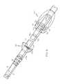
- FIG. 2is a perspective view, partially in section, of a clearance device according to an embodiment hereafter described.
- FIGS. 2 a - 2 dillustrate various embodiments of a clearance member disposed at the distal end of a guide wire, as well as an embodiment of the guide wire having a core-and-sheath construction ( FIG. 2 d ).
- FIGS. 3 a - 3 dillustrate various embodiments of a magnetic guide as hereafter described, as well as various modes of attachment thereof to a guide wire.
- FIG. 4illustrates a magnetic guide according to a disclosed embodiment, having retaining members attached at either end to retain the proximal region of the guide wire within the guide tube.
- FIG. 5is a perspective view, partially in section, of an embodiment of a clearance device as hereafter described and including one embodiment of a shuttle member and shuttle stop on the outside of the guide tube.
- the guide tubeis coupled to a chest tube to facilitate clearing obstructions therefrom.
- FIG. 6is a perspective view, partially in section, of an embodiment of a clearance device as hereafter described and including a further embodiment of a shuttle member and shuttle stop.
- FIG. 7is a perspective view of a clearance device coupled to a chest tube, according to an embodiment hereafter described.
- FIGS. 8 a - 8 care similar views as in FIG. 7 , but showing the shuttle member, and correspondingly the guide wire and clearance member, at different stages of advancement for clearing obstructions from the chest tube.
- FIG. 9is a side view, partially in section, of the distal region of a medical tube according to an embodiment hereafter described, which includes a clearance-member seat disposed at the distal end of the medical tube.
- FIG. 10is a perspective view of the distal region of a medical tube according to a further embodiment hereafter described, which includes a slot disposed in the inner wall of the medical tube that is adapted to house and accommodate the guide wire as it translates along the axis of the medical tube.
- FIG. 11is a schematic perspective illustration showing a clearance device coupled to a urinary catheter to permit clearance of the catheter of obstructions formed therein.
- FIG. 12is a schematic side view of a clearance device and a chest tube, wherein normally-closed mating connectors are provided at the mating ends of the respective chest tube and shuttle guide tube.
- proximal and distalare generally to be construed with reference to a patient that has been or is to be fitted with a medical tube, such as a chest tube.
- a medical tubee.g. chest tube
- a distal elementor the distal side or region of an element
- a proximal elementor the proximal side or region of an element.
- the “terminal” end of a tube, wire or memberrefers to its distal end.
- FIG. 1shows a schematic representation of a medical tube being used to drain accumulated fluid from within the body cavity of a patient, in accordance with an exemplary embodiment of the invention.
- the medical tubeis inserted into and used to drain fluid from the chest cavity of the patient, and so is referred to as a chest tube 10 .
- Chest tubes 10are a common type of medical drain tube and the remaining description will be provided with reference to chest tubes 10 .
- the chest tube 10enters the patient through the chest-cavity (body) wall, so that its distal end is positioned within the chest (body) at a location from which fluid is to be drained.
- the proximal end of the chest tube 10remains outside the body.
- the chest tube 10can be inserted into the patient in a conventional manner, and positioned and secured in place through the chest-cavity wall by the physician.
- a clearance device 100is fitted to the proximal end of the chest tube 10 .
- the clearance device 100includes a shuttle guide tube 110 (described below) that is connected to the proximal end of the chest tube 10 and is provided in fluid communication therewith.
- the clearance devicealso includes a clearance member 124 that can be reversibly advanced into and through the chest tube 10 to withdraw obstructive debris therefrom (also described below).
- the proximal end of the shuttle guide tube 110i.e. the end opposite the point of connection to the chest tube 10
- the suction sourcedraws a suction within the chest tube 10 , via the shuttle guide tube 110 and suction tube 210 (if present), both to draw fluid out of the body cavity and also to sustain the normal physiologic negative pressure within the chest.
- the clearance device 100includes the shuttle guide tube 110 mentioned above.
- the shuttle guide tube 110has a proximal end 111 and a distal end 112 .
- the proximal end 111 of the shuttle guide tube 110is adapted to be connected to a suction source preferably via a suction fitting 90 secured to its proximal end
- the distal end 112is adapted to be connected to a medical tube, such as chest tube 10 , preferably via a chest-tube fitting 92 secured to its distal end.
- Guide tube 110has a wall having an inner diameter 114 defining a guide-tube passageway 116 and an outer circumference 118 .
- a shuttle member 140is disposed over, preferably in contact with, the wall of the guide tube 110 at its outer circumference 118 and is adapted to translate along the length of the tube 110 to advance and withdraw the clearance member 124 as described below.
- a wire clearance assembly 120is at least partially disposed within the guide-tube passageway 116 .
- the wire clearance assembly 120includes an elongate guide member 122 and a clearance member 124 disposed in and secured to the distal region of the guide member 122 , preferably at its distal end.
- the guide member 122can be in the form of a guide wire, and the clearance member 124 can be formed by the guide wire.
- the terminal end of the guide wirecan be wound to form a loop 124 a at its terminal end. The remainder of this description is provided with reference to a guide wire as a preferred embodiment of the guide member 122 .
- a guide member 122is possible and will be readily ascertained by those having ordinary skill in the art; for example, an elongate flat metal or plastic strip, or other elongate form, that is flexible but biased to a straight configuration but capable to negotiate bends in the guide and medical tubes 110 , 10 may be used.
- FIG. 2 aillustrates one embodiment using a guide wire 122 , where the terminal portion of the guide wire 122 is wound to form loop 124 a , with a small amount of slack after forming the loop 124 a being wound tightly along the length of the wire 122 immediately proximal to the loop 124 a .
- the amount of slack to be so woundcan be, e.g., about or less than the diameter of the loop 124 a , or about or less than twice that diameter.
- the slackis preferably wound so that adjacent turnings of the slack over the guide wire 122 are immediately adjacent (preferably in contact with) one another, and substantially fully in contact with the portion of the wire 122 over which they are wound.
- the slack in the wire 122 after forming loop 124 acan be soldered to the portion of the wire 122 immediately proximal to the loop 124 a at solder joint 125 .
- the slackcan be positioned parallel to the portion of the guide wire 122 to which it is to be soldered, as shown in FIG. 2 b .
- itmay be wound around the guide wire 122 and then soldered.
- the length of the slackcan be similar as described above with respect to FIG. 2 a .
- the slackis to be soldered in parallel to the wire 122 as seen in FIG.
- loop 124 ait is preferable that its length be about or less than one radius (1 ⁇ 2 the diameter) of the loop 124 a .
- the diameter of loop 124 ais preferably selected to substantially correspond to the diameter of the inner wall of the chest tube 10 to which the clearance device 100 will be fitted, as described in more detail below.
- a mesh 124 b(seen schematically in FIG. 2 a ) can be provided extending across the diameter of the loop 124 a , having openings dimensioned to permit fluid to flow therethrough. In this embodiment, liquid-phase blood and other fluids will be permitted to pass through the mesh 124 b from the body cavity, into the chest-tube passageway 16 .
- the meshcan assist to draw the clot out of the passageway 16 upon withdrawal of the loop 124 a proximally, as described in more detail below.
- the guide wire 122can be attached at the perimeter of the loop 124 a , and can be formed integrally with the loop 124 a .
- the guide wire 122can be attached at the center of the loop 124 a via cross members 124 c as seen in FIG. 2 c .
- embodiments that include elements that obstruct the opening at the center of the loop 124 aare less preferred due to the potential to promote obstruction of the loop 124 a , e.g., by the formation of clot material attached to such elements.
- the loop 124 alies in a plane that is at a predetermined angle, for example 90°, to the longitudinal axis of the guide wire 122 at the point where the loop 124 a and guide wire 122 (e.g. the longitudinal expanse of the guide wire 122 if that wire is used to form the loop 124 a ) intersect.
- the precise anglemay be subject to some variance, for example due to flexure of the guide wire 122 and loop 124 a as they are advanced and/or drawn through the chest tube (explained below).
- the angle between the loop 124 a and guide wire 122is in the range of 75° to 105°, more preferably 80° to 100°, more preferably 85° to 95°.
- the guide wire 122can be made from conventional materials including plastics and metals. It is preferred that the guide wire 122 be made from a material having sufficient flexibility that it can reversibly bend to a radius of curvature of four centimeters, more preferably three centimeters, more preferably two centimeters or one centimeter, without snapping or substantially compromising its structural integrity. Suitable materials include nitinol, stainless steel and titanium-nickel alloys. In addition to being sufficiently flexible to negotiate bends in the chest tube 10 (or guide tube 110 ) on being advanced/retracted therethrough, the guide wire 122 should have sufficient stiffness or rigidity to be pushed through accumulated clot material within either tube without kinking or being caused to double back on itself.
- the requisite flexibility to negotiate bends simultaneous with the requisite stiffness to be pushed through clot materialmay be achieved by biasing the flexible guide wire 122 to a generally straight (linear) configuration. This can be achieved, for example, utilizing a core-and-sheath construction as illustrated in close-up view in FIG. 2D .
- the guide wire 122includes a core wire 128 and a sheath wire having a smaller diameter than the core wire 128 wound around the core wire 128 to provide a spiral-wound wire sheath 129 .
- the wire sheath 129can be made from any suitable material, e.g., including the same or similar materials useful for the core wire, noted above.
- the wire sheath 129will tend to bias the guide wire 122 (including core wire 128 and sheath 129 ) into a straight or linear configuration, while still permitting the wire 122 to bend in order to traverse bends in the chest tube 10 when in use.
- the guide wire 122(including core wire 128 and sheath 129 ) still preferably can be bent to the radii of curvature noted above without snapping or substantially compromising its structural integrity.
- the sheath 129stops short of the distal end of the guide wire 122 , where the core wire 128 emerges unsheathed and is formed into the loop 124 a at its distal end. In the embodiment shown in FIG.
- the slack in the core wire 128 after forming loop 124 ais soldered to the portion of the core wire 128 immediately proximal to the loop 124 a at solder joint 125 , similar as in the embodiment described above with respect to FIG. 2 b .
- the loop 124 amay be formed from the complete core-and-sheath construction of guide wire 122 , wherein the sheath 129 continues around the loop 124 a .
- a separate clearance member 124may be secured at or in the vicinity of the distal end of the guide wire 122 , whether a sheath 129 is employed or not.
- the guide wire 122may be coated substantially along its length with a friction-reducing material, to help prevent agglomeration of debris (such as blood clots) to the guide wire, and also to assist in transitioning the guide wire around bends in a chest tube 10 where it is to be inserted.
- Suitable coating materials for this purposeinclude, e.g., Teflon (polytetrafluoroethylene) compositions, polyurethane compositions, other hydrophilic polymers, and other coatings, including coatings comprising therapeutic agents such as a heparin coating or antibiotic coating.
- a magnetic guide 130is secured to the guide wire 122 in the proximal region thereof.
- the magnetic guide 130can comprise one or a plurality of first or inner magnetic elements 132 .
- the first magnetic elements 132can be permanent magnets. Alternatively, they can be metal elements having magnetic properties, which are not necessarily permanent magnets. As used herein, a metal element has magnetic properties if it is capable of being attracted by a permanent magnet via magnetic forces.
- the magnetic guide 130can be secured to the guide wire 122 via any suitable or conventional means.
- FIG. 3 aillustrates an exploded view of an exemplary embodiment of the magnetic guide 130 .
- a plurality (two are illustrated) of cylindrically-shaped permanent magnets 132 a having axial through boresare coaxially aligned adjacent one another, with washer 133 disposed therebetween.
- the magnets 132 aare oriented such that their respective North and South poles face the same direction. This results in the two magnets attracting one another at their adjacent faces. In practice, this results in the magnets 132 a attracting one another so that both contact the intermediate washer 133 , and sandwich and retain that washer between them.
- the guide wire 122extending from its distal end, passes through the axial bore of at least the distal-most magnet 132 a and is secured to the washer 133 , e.g. by welding or braising. Alternatively, the guide wire 122 can be secured to the washer 133 by wrapping it one or more times through the washer bore as illustrated in FIG. 3 b.
- a retention wire 134can be fed through the axial bore(s) of one or more first magnetic element(s) 132 . Portions of the retention wire 134 emerging from opposite ends of the element(s) 132 are wound into retentive wire loops 134 a , 134 b whose diameters are larger than the through bore(s) of the element(s) 132 .
- the guide wire 122then can be secured to the distal retentive wire loop 134 b via a proximal loop 121 thereof, which interlocks the retentive wire loop 134 b .
- the element(s) 132may or may not be permanent magnets.
- the guide wire 122may continue through the axial bore of the proximal-most magnet 132 a at least some distance as illustrated.
- the guide wire 122itself can form a retentive portion 124 d thereof that retains the first magnetic element(s) 132 in place secured in the proximal region thereof.
- the guide wireis fed through the axial bore(s) of the first magnetic element(s) 132 in a proximal region of the wire 122 .
- a portion of the guide wire emerging from the proximal end of the element(s) 132is wound into a first guide wire retentive loop 122 a .
- the guide wire 122is separately wound into a second guide wire retentive loop 122 b where it emerges from the distal end of the element(s) 132 , before proceeding toward the guide wire distal end.
- the guide wire retentive loops 122 a , 122 bfix the first magnetic element(s) 132 in position and secure it relative to the guide wire 122 in a proximal region thereof.
- first magnetic element(s) 132can be secured to the guide wire 122 in its proximal region. Numerous other modes of securement are possible, and will be readily discernible and implemented by the person having ordinary skill in the art. For example, there will be apparent to the person having ordinary skill in the art numerous additional ways to use loops, solder or braising joints, wire knots, and combinations of these, either in the guide wire 122 itself or in a separate retention wire 134 , with or without washers or other similar elements, to secure the first magnetic elements 132 to one another, and to secure all of them in place and attached to the proximal end or in the proximal region of the guide wire 122 .
- the guide wiremay be soldered or braised directly to one or more first magnetic element(s) 132 , with or without axial bores therein.
- first magnetic elements 132may optionally be present as one (or more) of each.
- using two permanent magnets as the elements 132should produce a stronger attractive force between them, resulting in more securely retaining them to the guide wire 122 .
- the wire clearance assembly 120preferably also includes proximal and distal retaining members 126 a and 126 b secured to the respective ends of the first magnetic element(s) 132 .
- the retaining members 126 a , 126 bare dimensioned so that they cannot pass through either the proximal or distal end, respectively, of the guide tube 110 , thereby retaining the first magnetic element(s) 132 and the associated proximal region of the guide wire 122 inside the tube 110 , within the guide tube passageway 116 .
- the retaining members 126 a , 126 bcan be provided in the form of wire loops having diameters substantially corresponding to that of the inner diameter 114 of the shuttle guide tube 110 , which will thereby be prevented from passing through the fittings at either end of the tube 110 , both of which preferably have smaller-diameter clearances compared to the guide tube 110 .
- both the chest tube 10 and the vacuum tube 210(if present) also have smaller inner-wall diameters than the shuttle guide tube 110 , thereby further preventing either retaining member 126 a , 126 b from exiting the guide tube 110 to enter the respective chest or vacuum tube.
- the retaining members 126 a , 126 bcan be made from lengths of wire that are retained to the first magnetic element(s) 132 in any suitable or conventional manner.
- each retaining member 126 a , 126 bcan be secured via a wire loop that interlocks with the respective guide wire retentive loop 122 a , 122 b or retentive wire loop 134 a , 134 b disposed at either end of the first magnetic element(s) 132 .
- retaining members 126 a , 126 bare large wire loops having diameters substantially corresponding to the inner diameter 114 , wherein tail sections 127 of each member 126 a , 126 b extend toward and terminate in a small loop that interlocks with the adjacent retentive wire loop 134 a , 134 b.
- shuttle member 140is disposed over, preferably in contact with, the outer circumference 118 of the guide tube 110 .
- the shuttle member 140has a through bore preferably having a diameter substantially corresponding to the outer circumference 118 , such that the shuttle member 140 can slidably and smoothly translate along the length of the guide tube 110 with the guide tube 110 received through its bore.
- the shuttle member 140includes one or a plurality of second or outer magnetic elements 142 embedded or enclosed within a shuttle housing 144 .
- the second magnetic element(s) 142can form all or part of the housing 144 .
- the shuttle member 140may consist only of the second magnetic element(s) 142 .
- the second magnetic elements 142are provided in the form of rings wherein the guide tube 110 passes through openings at the center of each said ring.
- the second magnetic elementscan be permanent magnets or, alternatively, metal elements having magnetic properties that are not necessarily permanent magnets.
- at least one of the first magnetic elements 132 or at least one of the second magnetic elements 142should be a permanent magnet.
- both the first and second magnetic elements 132 and 142are permanent magnets.
- a magnetic shield 146can be provided surrounding or substantially surrounding the second magnetic elements 142 , either within the shuttle housing 144 or as part of or forming that housing.
- the magnetic shield 146should not be disposed between the first and second magnetic element(s) 132 , 142 , however. Depending on the magnetic strength of the second magnetic elements 142 , such a shield 146 may be desirable in circumstances where a strong magnetic field may interfere with medical equipment to be located in close proximity with the clearance device 100 , for example an implanted pace maker. While the shield 146 cannot completely enclose the magnetic elements 142 (e.g. the tube 110 preferably passes through the shuttle member 140 and the first and second magnetic element(s) 132 , 142 must be able to magnetically interact with one another), it will help to reduce the magnetic field that extends beyond the shuttle member 140 .
- the first magnetic elements 132may be provided as metal elements that are not permanent magnets, or as relatively weak permanent magnets, so as not to create strong magnetic fields that may interfere with other equipment in the event they become decoupled from the second magnetic elements 142 .
- both the first and second magnetic elements 132 and 142have axially-aligned North-South polarity relative to the longitudinal axis of the guide tube 110 .
- magnetic elements 132 and 142 having radially-aligned North-South polaritycan be used. These are less preferred, however, due to the increased attraction between them through the guide-tube wall, which results in increased friction when translating the shuttle member 140 along the tube 110 length to advance or withdraw the clearance member 124 (explained below).
- magnets having axially-aligned polaritycan provide suitable attractive force between the magnetic elements 132 and 142 to retain the magnetic guide 130 and shuttle member 140 in tandem while translating the shuttle member 140 along the tube 110 length, without unduly increasing friction as they translate along the tube 110 .
- neodymium magnetsN5-N50
- Neodymium magnetsgenerally are the strongest permanent magnets, so it may not be desirable to use such magnets as both the first and the second magnetic elements 132 and 142 , otherwise undue friction against the tube 110 may result.
- the selection of particular magnets, having appropriate magnetic strengthis well within the capability of a person having ordinary skill in the art.
- the magnetic elements 132 and 142are selected to allow a high degree of attractive force to prevent as much as possible instances of magnetic de-coupling between the wire guide 130 and the shuttle member 140 , while at the same time minimizing their weight and bulk.
- a shuttle stop 150is secured to the outer circumference 118 of the guide tube 110 in a distal region thereof, preferably just proximal to the distal end of the guide tube 110 .
- the shuttle member 140 and shuttle stop 150preferably have complementary first and second parking surfaces 145 and 155 , which face one another. As the shuttle member 140 is translated distally along the length of the guide tube 110 , it approaches and ultimately reaches a parking station wherein the respective parking surfaces 145 and 155 are in contact or disposed adjacent one another.
- the shuttle stop 150has a parking magnetic element 152 enclosed or embedded within a shuttle stop housing 154 , just behind or forming the second parking surface 155 .
- the parking magnetic element 152can be made from similar or the same materials as the first and second magnetic elements 132 and 142 discussed above, except that at least the parking magnetic element 152 or second (outer) magnetic element 142 should be a permanent magnet. In this manner, the outer magnetic element 142 and parking magnetic element 152 will attract one another when the shuttle member 140 is parked against the shuttle stop 150 , thus retaining the shuttle in the parked position when not being actively used to actuate the clearance member 124 . In this embodiment, if present the magnetic shield 146 should not extend between the second magnetic element 142 and the parking magnetic element 152 .
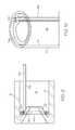
- FIG. 6shows an embodiment employing a click-and-park mechanism between the shuttle member 140 and the shuttle stop 150 .
- the shuttle stop 150defines a shuttle socket 156 to receive the distal portion of the shuttle member 140 therein.
- the shuttle socket 156includes a parking rib or flange 158 disposed around the circumference of the socket 156 wall and extending radially inward.
- the shuttle member 140has a complementary parking groove 148 disposed in the exterior circumference of the shuttle housing 144 , and an annular camming surface 149 disposed at or forming the distal end of the housing 144 .
- the groove 148is preferably disposed immediately behind the camming surface 149 .
- the flange 158initially engages the camming surface 149 , which radially expands the flange 158 as the shuttle member 140 is advanced, until the flange 158 is received and accommodated within the groove 148 , beyond the camming surface.
- the clearance device 100 described aboveis shown fitted to a chest tube 10 .
- the chest tube 10has a wall having an outer circumference 18 and an inner diameter 14 that defines a chest-tube passageway 16 .
- the diameter of the chest-tube passageway 16is smaller than that of the guide-tube passageway 116 (diameter 114 ).
- the distal end of the clearance device 100(shuttle guide tube 110 ) is fitted to the proximal end of the chest tube 10 via chest-tube fitting 92 .
- the chest-tube fitting 92preferably ensures a fluid-tight connection between the distal end of the shuttle guide tube 110 and the proximal end of the chest tube 10 , while providing fluid communication between the chest-tube passageway 16 and the guide-tube passageway 116 .
- a conventional barbed reducer fittingcan be used, as illustrated for the fitting 92 in the drawings.
- proximal end of the chest tube 10is forcibly fitted over the barbs provided at the outer surface of the fitting 92 , so that the barbs enter the chest-tube passageway 16 just at its proximal end to engage its inner diameter 14 in a conventional manner.
- the chest tube 10is made from a material having elastic properties, such as silicone, which will help ensure a fluid-tight seal because the tube 10 will tend to contract over the barbs of fitting 92 .
- a flexible, elastic tube 10e.g. made from silicone, also will result in reduced discomfort for the patient compared to more rigid chest-tube materials, such as polypropylene or polyethylene. However, if desired these and other rigid materials may be used. Other elastic materials, including elastic thermoplastics, also may be used in place of silicone, if desired.
- the chest tube 10is made from a clear (i.e. transparent or substantially transparent) plastic material, so the operator of the clearance device 100 described herein can visualize any clot material or other debris therein, as well as its removal as described below.
- the guide wire 122may be advanced into and withdrawn from the chest tube 10 to assist in clearing debris therefrom as follows.
- the magnetic guide 130 and shuttle member 140are magnetically attracted to one another by means of the cooperating magnetic elements 132 and 142 . This results in coupling the magnetic guide 130 to the shuttle member 140 via magnetic forces that act through the wall of the shuttle guide tube 110 . Consequently, sliding or translating the shuttle member 140 along the length of the shuttle guide tube 110 induces a corresponding translational movement of the magnetic guide 130 magnetically coupled thereto, and of the guide wire 122 that is secured to the magnetic guide 130 .
- the shuttle member 140is illustrated in the parked position, in contact with the shuttle stop 150 .
- the length of the guide wire 122 between its distal end and the point where it is secured to the wire guide 130is preferably selected to substantially equal the length of the chest tube 10 plus the length corresponding to the distance between the shuttle stop 150 and the point where the chest tube 10 engages the fitting 92 .
- the clearance member 124 at the distal end of the guide wire 122is disposed within the chest tube 10 adjacent its distal end and does not emerge from the chest tube 10 into the body cavity.
- thisis the parked position of the clearance member 124 , where it normally rests when the device 100 is not being used to actively remove debris from the chest tube 10 .
- the chest tube 10can have one or a plurality of apertures 119 through the wall of the tube 10 in the distal region thereof, to assist in suctioning and drawing fluid located in the body cavity where the chest tube 10 is placed.
- the clearance member 124is dimensioned and oriented so that it cannot pass through the apertures 119 , to emerge laterally from the chest tube 10 .
- the diameter of the wire loop 124 ais too large to fit through the width of apertures 119 based on its orientation, which is fixed relative to the guide wire 122 .
- it may be desired that the length of apertures 119also be smaller than the loop 124 a diameter.
- the clearance member 124is in the form of a wire loop 124 a .
- the diameter of the wire loop 124 apreferably substantially corresponds to the diameter of the inner diameter 14 of the chest tube 10 , such that the loop 124 a scrapes the inner diameter 14 as it translates along the chest-tube 10 length.
- the diameter of the wire itself that forms the wire loop 124 ais very small, preferably about or less than 10%, preferably 8%, preferably 6%, preferably 5% or 4%, the diameter of the inner diameter 14 , to provide a substantially unobstructed pathway from the distal end of the chest tube 10 into and through its passageway 16 , through the loop 124 a .
- Fluid and other debris drained from the body cavitypass into the chest-tube passageway 16 , through the loop 124 a , and proceed proximally toward the suction source 200 .
- the fluidcan form or produce clots that stick to the inner diameter 14 of the chest tube 10 .
- the clotsform or build, they begin to obstruct the chest-tube passageway 16 , inhibiting drainage. If left unchecked, such clots may completely obstruct the passageway 16 , rendering the chest tube 10 inoperative.
- the clearance member 124(e.g. loop 124 a ) is normally disposed adjacent the distal end of the chest tube 10 inside the chest-tube passageway 16 .
- This position of the clearance member 124corresponds to the shuttle member 140 being in the parked position adjacent or in contact with the shuttle stop 150 , as seen in FIG. 8 a .
- a nurse, physician or other operatorgrasps the shuttle member 140 and pulls it proximally along the length of the guide tube 110 , toward the tube's 110 proximal end.
- the attractive magnetic force between the first and second magnetic elements 132 and 142retains the magnetic guide 130 in tandem with the shuttle member 140 as the latter translates proximally, which in turn draws the guide wire 122 and clearance member 124 proximally through the chest-tube passageway 16 as seen in FIG. 8 b .
- the clearance member 124engages clot material and other debris in its path and forces such material and debris proximally ( FIGS. 8 b , 8 c ), toward the proximal end of the chest-tube passageway 16 and ultimately out of that passageway, and into the guide-tube passageway 116 ( FIG. 8 c ).
- the operatorgrasps the shuttle member 140 with one hand and the proximal end of the guide tube 110 with the other hand so that the pulling force applied to the shuttle member 140 is applied against a counter-force applied to the tube 110 via the other hand, and not against the sutures retaining the chest tube 10 in place in the patient.
- the same objectivecan be achieved by grasping a different portion of the guide tube 110 , or the shuttle stop 150 , with the other hand before sliding the shuttle member 140 .
- the clearance membercan be alternately withdrawn and advanced from/into the chest-tube passageway 16 to help break up clot material or other debris, as well as to aid in drawing such debris proximally.
- the shuttle member 140may be advanced back into its parked position adjacent or in contact with the shuttle stop 150 , which correspondingly will advance the clearance member 124 back into its normal resting position adjacent the distal end of the chest tube 10 .
- the inner diameter 114 of the guide tube 110preferably has a larger diameter than the inner diameter 14 of the chest tube 10 . Consequently, debris removed from the chest tube 10 and into the guide tube 110 will be less obstructive in the guide tube 110 , and more readily drawn out via suction applied by the suction source 200 . Alternatively, a guide tube 110 that eventually becomes fully obstructed will be more readily and easily replaced than a chest tube, which is surgically implanted through the patient's body wall and would require revision surgery, and additional opportunity for injury and infection, to replace.
- the retaining members 126 a , 126 b discussed abovewill prevent the magnetic guide 130 , and the proximal portion of the guide wire 122 where it is attached, from exiting the guide tube 110 .
- the retaining members 126 a , 126 bare dimensioned so they will not fit into either tube secured to the opposite ends of the guide tube 110 .
- the fittings 90 and 92 secured at opposite ends of the guide tube 110preferably are reduced-diameter fittings that have or taper to smaller inner diameters than the inner diameter of the guide tube 110 (passageway 116 ), which also will prevent the retaining members 126 a , 126 b from passing therethrough.
- the distal retaining member 126 ais positioned along the length of the guide wire 122 so as to prevent the clearance member 124 from emerging beyond the distal end of the chest tube 10 within the patient in the maximum state of advancement of the guide wire 122 , with the retaining member 126 a abutting either the fitting 92 or the proximal end of the chest tube 10 .
- de-coupled magnetic guide 130 and shuttle member 140may be magnetically re-coupled by advancing the shuttle member 140 forward until magnetic coupling therebetween is re-established, for example once the guide wire (and magnetic guide 130 ) are fully advanced as far as the retaining member 126 a will permit.
- the operatormay squeeze the chest tube 10 or guide tube 110 to manually engage the guide wire 122 through the tube wall and hold it in position while the shuttle member 140 is translated so as to magnetically re-engage the magnetic guide 130 through the guide-tube 110 wall.
- the shuttle stop 150is disposed in the distal region of the guide tube 110 , so that in the parked position of the shuttle member 140 the clearance member 124 is disposed adjacent the distal end of the chest tube 10 .
- the shuttle member 140to clear debris from the chest tube 10 , the shuttle member 140 , and consequently the clearance member 124 , is/are drawn proximally along the guide-tube 110 length, so the clearance member 124 engages and draws debris proximally, out from the chest tube 10 .
- the shuttle stop 150can be disposed facing the opposite direction in the proximal region of the guide tube 110 , so that when the shuttle member 140 is parked adjacent thereto the clearance member 124 is disposed adjacent the proximal end of the chest tube 10 .
- the shuttle member 140is advanced distally so that the clearance member 124 enters and approaches the distal end of the chest tube 10 (chest tube passageway 14 ), preferably past any debris therein, before being withdrawn again proximally to draw debris out of the chest tube 10 .
- This embodimentis less preferred, because it may result in advancing debris out of the distal end of the chest tube 10 when the clearance member 124 is first advanced therein from its resting position adjacent the proximal end of the chest tube 10 .
- the clearance member 124 disposed at the distal end of the guide wire 122there may be one or more additional clearance members 124 e disposed along the length of the guide wire 122 between the distal clearance member 124 and the proximal region of the guide wire 122 , to help dislodge clots and other debris along the length of the chest-tube passageway 116 , for example via a back-and-forth motion of the guide wire 122 .
- the chest tube 10can include a conical clearance-member seat 123 extending radially inward and in a proximal direction from the distal end of the chest tube 10 , within the chest-tube passageway 116 .
- a clearance member in the form of loop 124 ais seated at the distal end of the chest tube 10 after use, as by re-parking the shuttle member 140 at its parking station adjacent or in contact with shuttle stop 150 , the seat 123 projects through the clearance-member loop 124 a , thereby dislodging any clot material that may be adhered to the loop 124 a .
- such a clearance-member seat 123may be less preferred due to a tendency to increase the incidence of clogging the entrance to passageway 16 at the distal end of the chest tube 10 .
- the guide wire (or more generally guide member) 122can have a guide lumen 162 provided in fluid communication with one or more openings 164 disposed through the wall of the loop 124 a (or other clearance member 124 ).
- the guide lumen 162 and cooperating openings 164may be utilized to deliver flushing or irrigation fluid to assist in dislodging any material stuck to the clearance member loop 124 a .
- fluid expelled from guide lumen 162 through openings 164may be a solution provided to assist in the dislodgment, dissolution and/or breakup of the debris.
- Fluids suitable for the particular purposeinclude, but are not limited to, anti-thrombolytic agents, AlkalolTM, among others.
- such fluidmay be or include a therapeutic agent such as but not limited to antibiotic agents, anti-neoplastic agents, and other agents for a variety of purposes, including pain relief, treatment of infection, cancer, or to induce scarring (i.e. pleurodesis).
- Fluidmay be delivered into the guide lumen 162 , for example, by connecting a length of flexible tubing (not shown) to the proximal end of the guide wire 122 (in communication with the lumen 162 therein), and connecting the other length of flexible tubing to a fitting 115 (shown schematically in FIG. 1 ) located proximally of the guide tube 110 .
- the length of flexible tubingshould be sufficient to accommodate the full range of motion in the guide wire 122 without being disconnected from either the guide wire 122 or the fitting 115 , based on translating the shuttle member 140 along the full length of the guide tube 110 , from adjacent its proximal end up until further advancement is prevented by the shuttle stop.
- the fitting 115can have a conventional receiver on the outside to mate with a syringe or other fluid-delivery device, to communicate a fluid from the delivery device through the flexible tubing, and into and through the guide lumen 162 to emerge through openings 164 .
- the fittingcan be any conventional fitting to permit fluid communication from outside the sterile field to the flexible tubing without introducing or minimizing the introduction of contaminants therein from the outside. Positioning the fitting 115 proximal to the guide tube 110 should minimize the potential for contamination of the sterile field, so long as the suction remains active.
- the guide lumen 162may be used to detect carbon dioxide in the chest cavity as a means to determine whether there is a puncture in a patient's lung.
- the proximal end of the guide lumen 162is provided in fluid communication with a CO 2 -sensing instrument or appropriate litmus paper that can sense the presence of CO 2 , e.g. via a color change.
- This instrument/litmus papermay be provided in communication with the fitting 115 outside the sterile field.
- CO 2 -sensing equipmentin communication with the main chest-tube lumen (inner diameter 14 ), to sense the presence of CO 2 in the chest tube.
- Thiscan be achieved, for example, by placing a CO 2 -sensor, such as a sensing transducer or a holder for CO 2 -sensitive litmus paper, in-line between the chest tube 10 and the suction source 200 , for example between the guide tube 110 and suction tube 210 at the location of fitting 115 shown in FIG. 1 .
- CO 2 passing from the chest tube 10 to the suction sourcewill pass through the CO 2 sensor, permitting the sensor to alarm if CO 2 is detected.
- the CO 2 sensormay be coupled to the chest tube lumen via a lateral channel 330 , described below (see FIG. 12 ).
- a common size for a conventional chest tube 10is 32-French.
- the guide tube 110 of the clearance device 100 herein describedpreferably is larger, so as to have a larger inner diameter, for example 30-French or 28-French.
- the shuttle guide tube 110preferably has a larger inner diameter than the chest tube 10 , preferably at least two French sizes larger.
- the clearance loop 124 ais selected so that its loop diameter substantially corresponds with the inner-wall diameter of the chest tube 10 that is selected.
- the chest tube 10has a single inner lumen (defined by inner diameter 14 ) corresponding to the chest-tube passageway 16 , which has a circular cross-section.
- the inner surface of the chest tube 10 wallhas a substantially circular cross-section but also defines a slot 222 extending longitudinally along the length of the chest tube 10 , to accommodate the guide wire 122 therein.
- the guide wire 122terminates at its distal end in a modified loop 124 a whose shape corresponds substantially to the cross-section of the inner surface of the chest tube 10 wall, having the slot 222 therein.
- This embodimentmay be desirable in applications where the chest tube 10 may undergo relatively sharp bends, so that the slot 222 , which houses the guide wire 122 , can help prevent buckling of the wire 122 on advancement thereof.
- the medical tubeneed not be a chest tube.
- the clearance device 100 herein describedcan be used in conjunction with other medical tubes used to provide fluid communication between a location within a human or animal body and an external apparatus or environment, either to drain fluid or other material from the body (e.g. chest tube, urinary catheter or other drainage tube) or to deliver material from outside the body (e.g. NG-tube or intubation tube).
- the clearance device 100is coupled to a urinary catheter 310 to clear the catheter of obstructions that may form therein. Obstructions that may form within a urinary catheter include salt crystals and, in patients with bladder or urinary-tract disease processes, clotted blood.
- the shuttle guide tube 110is connected to the proximal end of the catheter 310 similarly as described above, to provide fluid communication between the catheter and guide tube 110 .
- a urinary cathetertypically has a bullet-type (e.g. domed or conical) cap 320 at its distal end, with a small lumen at its center, to assist in insertion of the catheter 310 into and through the patient's urethra.
- a urinary cathetertypically will have a much smaller diameter than a chest tube or other body drainage tube, or an intubation or feeding tube.
- the diameter of the shuttle guide tube 110can be dimensioned appropriately so that the guide tube 110 can be effectively mated in fluid communication with the particular medical tube with which it is to be used.
- appropriate reducer or expansion fittingsmay be used to mate otherwise mis-matched medical tube and shuttle guide tube diameters.
- the clearance device 100is used to clear obstructions from the catheter 310 , or from any other medical tube, similarly as for the chest tube 10 described above.
- the shuttle member 140is normally advanced and rests against shuttle stop 150 disposed around and near the distal end of the guide tube 110 , so that the guide wire 122 is fully advanced within the catheter, and the clearance member 124 a normally rests at the catheter's distal end.
- the shuttle member 140is drawn proximally along the length of tube 110 , causing the guide wire 122 and clearance member 124 a to be correspondingly drawn proximally through the catheter 310 , to thereby loosen any debris adhered to the catheter inner wall and draw it proximally, out from the catheter 310 and into the guide tube 140 .
- the guide tube 140is connected to a suction source at its proximal end (not shown in FIG. 11 ), to draw material out.
- a suction sourceat its proximal end (not shown in FIG. 11 ), to draw material out.
- the cathetermay include a lateral channel 330 in communication with and extending from the main catheter lumen, which can be connected to an alternative source of suction, to a Foley collection bag, a pressure transducer to provide real-time pressure data, or other desired apparatus or instrumentation.
- the lateral channel 330can be connected in fluid communication with an expandable retainer balloon disposed at the distal end of the catheter as known in the art (not shown), which when inflated acts to retain the distal end of the catheter within the bladder of a patient.
- the lateral channel 330can be used to deliver and withdraw inflation fluid from the retainer balloon, to either place or remove the catheter in/from the bladder.
- a similar lateral channel (or channels) as seen in FIG. 11can be provided with any medical tube used for any purpose, where it is desirable to have an additional access port into the medical tube, or into the body cavity where the distal end of the medical tube resides, such as to deliver medication.
- a medicationcan be delivered to the patient's body cavity by inserting a smaller catheter through the lateral channel 330 and snaking the smaller catheter up through the catheter 310 (or other medical tube) until it reaches or, if desired, just emerges from the distal end thereof.
- a syringe or other delivery device connected to the proximal end of the smaller cathetercan be used to deliver the medication or other fluid through the smaller catheter and into the body cavity where the distal end of the urinary catheter 310 (or other medical tube) has been placed.
- the medical tube (e.g. chest tube 10 ) and/or shuttle guide tube 110can be provided normally-closed valves or valve connectors 410 , 415 at their respective mating ends, as seen schematically in FIG. 12 .
- the clearance device 100can be removably secured in fluid communication with the chest tube 10 , wherein when the guide tube 110 and chest tube 10 are disconnected, their respective ends are sealed via normally-closed valves provided in the respective mating connectors 410 , 415 .
- Any suitable mating connectors that are normally closed but provide fluid communication through them once matedcan be used in this application, provided that the fluid opening through them when mated is large enough to accommodate the clearance member 124 therethrough.
- the tubes 10 and 110may be provided directly with normally-closed valves that can be manually actuated once the tubes have been secured in fluid communication.
- the embodiment described herewill be useful to change out an irreversibly blocked guide tube 110 with a fresh guide tube 110 in the unlikely event of such a blockage, without compromising the sterile field within the chest tube 10 .
- this constructionwill permit intermittent connection of the guide tube 110 to the chest tube, when necessary to clear an obstruction. This can be achieved, for example, by disconnecting the chest tube 10 from the normal suction source (not shown) and connecting it temporarily to the clearance device 100 (guide tube 110 ) as necessary to clear obstructions.
- the guide tube 110can be disconnected, and the chest tube 10 re-connected to its normal suction source.
- the valvesmay be manually actuated while the tubes 10 and 110 remain connected, so that when the guide wire and clearance member are fully withdrawn from the chest tube 10 , the valves are closed, and when the guide wire and clearance member are advanced within the chest tube 10 , the valves are open. In practice, this may be a less preferred embodiment because having the valves normally closed in operation will prevent suction from being applied within the chest tube 10 unless suction is drawn laterally (e.g. through a lateral channel 330 as described previously).
- this mode of operationwill prevent the clearance member 124 from normally resting at the distal end of the chest tube 10 when not in use, because the valves could not be closed with the guide wire 122 extending through them. Hence, the valves should not be maintained normally closed while the device 100 is in use when it is desired that the clearance member 124 normally rest at the distal end of the chest tube 10 .
- a guide wire manipulation device 50comprises an sonic transducer 52 coupled to an ultrasonic wave guide 54 , which in turn is coupled to the wire clearance member 120 .
- the wave guide 54is shown coupled, e.g. by welding or braizing, to the magnetic guide 130 . Because the magnetic guide 130 , guide wire 122 and clearance member 124 are all in continuous physical contact, sonic vibrations introduced at the wire guide 130 will be transmitted to the clearance member 124 .
- Sonic vibrations generated by the transducer 52are thus conducted through the guide wire 122 and to the clearance member 124 , to induce sonic motion to that member 124 as well as any surrounding fluid, further assisting in the breakup and/or dislodgment of any foreign or obstructing material in the chest tube 10 .
- the transducer 52can impart other forms of energy, such as sub-sonic vibrations, acoustic pulses, or even full or partial (e.g. back-and-forth or ‘whipping’) rotation to the wave guide 54 , which in turn will communicate the associated vibrations, or rotations to the guide wire 122 and ultimately to the clearance member 124 to assist in breaking up any debris.
- the manipulation device 50is disposed so as not to compromise the sterile environment within the chest tube 10 and guide tube 110 when in use.
- the wave guide 54exits the proximal end of the guide tube 110 on its way to the transducer 52 .
- the wave guide 54may then exit the vacuum pathway (between the guide tube 110 and suction source 200 ) via a lateral fitting or channel, e.g. through a suitable septum (not shown), to be connected to the transducer 52 . Because this exit occurs proximate the guide tube 110 relative to the suction pathway, so long as the suction from suction source 200 is maintained while in use, this should not introduce any foreign material into the chest tube 10 , or compromise the sterile filed therein.
- any fluid being conducted through guide lumen 162also will be subjected to such vibrations, resulting in sonically or sub-sonically excited fluid jets emerging from openings 164 , which will further assist in the dislodgment of debris.
Landscapes
- Health & Medical Sciences (AREA)
- Life Sciences & Earth Sciences (AREA)
- Engineering & Computer Science (AREA)
- Heart & Thoracic Surgery (AREA)
- Veterinary Medicine (AREA)
- Biomedical Technology (AREA)
- Animal Behavior & Ethology (AREA)
- General Health & Medical Sciences (AREA)
- Public Health (AREA)
- Surgery (AREA)
- Hematology (AREA)
- Anesthesiology (AREA)
- Mechanical Engineering (AREA)
- Oral & Maxillofacial Surgery (AREA)
- Nuclear Medicine, Radiotherapy & Molecular Imaging (AREA)
- Pathology (AREA)
- Medical Informatics (AREA)
- Molecular Biology (AREA)
- Vascular Medicine (AREA)
- Biophysics (AREA)
- Pulmonology (AREA)
- External Artificial Organs (AREA)
- Media Introduction/Drainage Providing Device (AREA)
- Surgical Instruments (AREA)
- Apparatus For Radiation Diagnosis (AREA)
- Infusion, Injection, And Reservoir Apparatuses (AREA)
Abstract
Description
Claims (30)
Priority Applications (4)
| Application Number | Priority Date | Filing Date | Title |
|---|---|---|---|
| US13/748,819US8951355B2 (en) | 2008-01-25 | 2013-01-24 | Methods and devices to clear obstructions from medical tubes |
| US14/599,929US10149960B2 (en) | 2008-01-25 | 2015-01-19 | Methods and devices to clear obstructions from medical tubes |
| US16/181,426US10898674B2 (en) | 2008-01-25 | 2018-11-06 | Methods and devices to clear obstructions from medical tubes |
| US17/136,451US20210113807A1 (en) | 2008-01-25 | 2020-12-29 | Methods and devices to clear obstructions from medical tubes |
Applications Claiming Priority (6)
| Application Number | Priority Date | Filing Date | Title |
|---|---|---|---|
| US2382908P | 2008-01-25 | 2008-01-25 | |
| US18985008P | 2008-08-22 | 2008-08-22 | |
| US12/359,826US7951243B2 (en) | 2008-01-25 | 2009-01-26 | Methods and devices to clear obstructions from medical tubes |
| US12/915,328US8048233B2 (en) | 2008-01-25 | 2010-10-29 | Methods and devices to clear obstructions from medical tubes |
| US13/251,940US8388759B2 (en) | 2008-01-25 | 2011-10-03 | Methods and devices to clear obstructions from medical tubes |
| US13/748,819US8951355B2 (en) | 2008-01-25 | 2013-01-24 | Methods and devices to clear obstructions from medical tubes |
Related Parent Applications (1)
| Application Number | Title | Priority Date | Filing Date |
|---|---|---|---|
| US13/251,940ContinuationUS8388759B2 (en) | 2008-01-25 | 2011-10-03 | Methods and devices to clear obstructions from medical tubes |
Related Child Applications (1)
| Application Number | Title | Priority Date | Filing Date |
|---|---|---|---|
| US14/599,929ContinuationUS10149960B2 (en) | 2008-01-25 | 2015-01-19 | Methods and devices to clear obstructions from medical tubes |
Publications (2)
| Publication Number | Publication Date |
|---|---|
| US20130144270A1 US20130144270A1 (en) | 2013-06-06 |
| US8951355B2true US8951355B2 (en) | 2015-02-10 |
Family
ID=40897979
Family Applications (7)
| Application Number | Title | Priority Date | Filing Date |
|---|---|---|---|
| US12/359,826Active2029-10-19US7951243B2 (en) | 2008-01-25 | 2009-01-26 | Methods and devices to clear obstructions from medical tubes |
| US12/915,328ActiveUS8048233B2 (en) | 2008-01-25 | 2010-10-29 | Methods and devices to clear obstructions from medical tubes |
| US13/251,940ActiveUS8388759B2 (en) | 2008-01-25 | 2011-10-03 | Methods and devices to clear obstructions from medical tubes |
| US13/748,819ActiveUS8951355B2 (en) | 2008-01-25 | 2013-01-24 | Methods and devices to clear obstructions from medical tubes |
| US14/599,929Active2030-08-11US10149960B2 (en) | 2008-01-25 | 2015-01-19 | Methods and devices to clear obstructions from medical tubes |
| US16/181,426ActiveUS10898674B2 (en) | 2008-01-25 | 2018-11-06 | Methods and devices to clear obstructions from medical tubes |
| US17/136,451PendingUS20210113807A1 (en) | 2008-01-25 | 2020-12-29 | Methods and devices to clear obstructions from medical tubes |
Family Applications Before (3)
| Application Number | Title | Priority Date | Filing Date |
|---|---|---|---|
| US12/359,826Active2029-10-19US7951243B2 (en) | 2008-01-25 | 2009-01-26 | Methods and devices to clear obstructions from medical tubes |
| US12/915,328ActiveUS8048233B2 (en) | 2008-01-25 | 2010-10-29 | Methods and devices to clear obstructions from medical tubes |
| US13/251,940ActiveUS8388759B2 (en) | 2008-01-25 | 2011-10-03 | Methods and devices to clear obstructions from medical tubes |
Family Applications After (3)
| Application Number | Title | Priority Date | Filing Date |
|---|---|---|---|
| US14/599,929Active2030-08-11US10149960B2 (en) | 2008-01-25 | 2015-01-19 | Methods and devices to clear obstructions from medical tubes |
| US16/181,426ActiveUS10898674B2 (en) | 2008-01-25 | 2018-11-06 | Methods and devices to clear obstructions from medical tubes |
| US17/136,451PendingUS20210113807A1 (en) | 2008-01-25 | 2020-12-29 | Methods and devices to clear obstructions from medical tubes |
Country Status (6)
| Country | Link |
|---|---|
| US (7) | US7951243B2 (en) |
| EP (2) | EP3581285A1 (en) |
| AU (1) | AU2009229185B2 (en) |
| CA (4) | CA3051894C (en) |
| ES (1) | ES2758792T3 (en) |
| WO (1) | WO2009120400A2 (en) |
Cited By (8)
| Publication number | Priority date | Publication date | Assignee | Title |
|---|---|---|---|---|
| WO2018164945A1 (en)* | 2017-03-06 | 2018-09-13 | Merit Medical Systems, Inc. | Vascular access assembly declotting systems and methods |
| US10792413B2 (en) | 2008-03-05 | 2020-10-06 | Merit Medical Systems, Inc. | Implantable and removable customizable body conduit |
| US10918769B2 (en) | 2017-04-03 | 2021-02-16 | Boehringer Technologie, LP | Medical drainage device with squeegee-based lumen cleaner and method of draining a biological fluid from the body of a patient |
| US10994076B1 (en) | 2019-07-25 | 2021-05-04 | Circulatech, Llc | Methods and devices to prevent obstructions in medical tubes |
| US11179543B2 (en) | 2017-07-14 | 2021-11-23 | Merit Medical Systems, Inc. | Releasable conduit connectors |
| US11331458B2 (en) | 2017-10-31 | 2022-05-17 | Merit Medical Systems, Inc. | Subcutaneous vascular assemblies for improving blood flow and related devices and methods |
| US11383072B2 (en) | 2017-01-12 | 2022-07-12 | Merit Medical Systems, Inc. | Methods and systems for selection and use of connectors between conduits |
| US11911585B2 (en) | 2017-07-20 | 2024-02-27 | Merit Medical Systems, Inc. | Methods and systems for coupling conduits |
Families Citing this family (62)
| Publication number | Priority date | Publication date | Assignee | Title |
|---|---|---|---|---|
| US8262645B2 (en) | 2007-11-21 | 2012-09-11 | Actuated Medical, Inc. | Devices for clearing blockages in in-situ artificial lumens |
| US9308348B2 (en) | 2007-11-21 | 2016-04-12 | Actuated Medical, Inc. | Devices and methods for clearing occlusions and for providing irrigation in in-situ artificial and natural lumens |
| US9352122B2 (en) | 2007-11-21 | 2016-05-31 | Actuated Medical, Inc. | Devices for clearing blockages in small bore in-situ artificial lumens |
| WO2009120400A2 (en) | 2008-01-25 | 2009-10-01 | Clear Catheter Systems, Llc | Methods and devices to clear obstructions from medical tubes |
| US10478125B2 (en)* | 2008-09-09 | 2019-11-19 | Pulmonx Corporation | Systems and methods for flushing an assessment catheter |
| US8882678B2 (en) | 2009-03-13 | 2014-11-11 | Atrium Medical Corporation | Pleural drainage system and method of use |
| US10232150B2 (en) | 2010-03-11 | 2019-03-19 | Merit Medical Systems, Inc. | Body cavity drainage devices and related methods |
| EP2399546B1 (en)* | 2010-06-28 | 2015-07-01 | W & H Dentalwerk Bürmoos GmbH | Cleaning or maintenance device for medical instruments |
| WO2012163415A1 (en)* | 2011-05-31 | 2012-12-06 | Ethicon Endo-Surgery, Inc. | Catheter for directing biliopancreatic secretions |
| JP6199866B2 (en) | 2011-09-06 | 2017-09-20 | メリット・メディカル・システムズ・インコーポレイテッドMerit Medical Systems,Inc. | Vascular access system having a connecting portion |
| US20130081653A1 (en)* | 2011-10-04 | 2013-04-04 | Theodosios Kountotsis | System and method for tube cleaning |
| US9302031B2 (en) | 2011-11-22 | 2016-04-05 | Cook Medical Technologies Llc | Tubular drainage device |
| US9707325B2 (en) | 2011-12-02 | 2017-07-18 | Cook Medical Technologies Llc | Drainage system with occlusion member |
| CN102772833B (en)* | 2012-08-17 | 2015-04-01 | 宁波健世生物科技有限公司 | Drainage system capable of effectively removing stoppers |
| US9561337B2 (en) | 2012-10-11 | 2017-02-07 | Actuated Medical, Inc. | Active system for in-situ clearing of secretions and occlusions in tubes |
| US10060296B2 (en)* | 2012-11-15 | 2018-08-28 | Kevin Lee Friesth | Quintuple-effect generation multi-cycle hybrid renewable energy system with integrated energy provisioning, storage facilities and amalgamated control system cross-reference to related applications |
| US10391285B2 (en)* | 2013-06-14 | 2019-08-27 | The Cleveland Clinic Foundation | Motion-assisted systems, devices and methods for minimizing obstruction of medical devices |
| US11191886B2 (en) | 2013-06-14 | 2021-12-07 | The Cleveland Clinic Foundation | Motion-assisted systems, devices and methods for minimizing obstruction of medical devices |
| WO2015013513A1 (en)* | 2013-07-25 | 2015-01-29 | Covidien Lp | Multifunctional telescoping cleaning device |
| FR3009976A1 (en)* | 2013-09-03 | 2015-03-06 | Behzad Vahida | SYSTEM FOR CLEANING A SURFACE |
| US9545462B2 (en)* | 2013-12-20 | 2017-01-17 | Northwestern University | Chest tube drainage system with analyzer |
| EP3107617B1 (en) | 2014-02-17 | 2023-07-19 | Clearflow, Inc. | Medical tube clearance device |
| EP3102277B1 (en) | 2014-02-17 | 2021-05-12 | Clearflow, Inc. | A device for clearing obstructions from a multi-lumen medical tube |
| US10029036B2 (en) | 2014-06-27 | 2018-07-24 | Merit Medical Systems, Inc. | Placement tools for body cavity drainage devices and related methods |
| US9821097B2 (en) | 2014-06-27 | 2017-11-21 | Merit Medical Systems, Inc. | Body cavity drainage devices including drainage tubes having inline portions and related methods |
| US9649415B2 (en) | 2014-06-27 | 2017-05-16 | Harrison M. Lazarus | Surgical kits for body cavity drainage and related methods |
| US9604033B2 (en) | 2014-06-27 | 2017-03-28 | Harrison M. Lazarus | Body cavity drainage devices with locking devices and related methods |
| US10315007B2 (en)* | 2014-07-15 | 2019-06-11 | Stryker Corporation | Vascular access system and method of use |
| US10258764B2 (en)* | 2014-07-30 | 2019-04-16 | Covidien Lp | Opening system for improving catheter delivery |
| EP3072541A1 (en) | 2015-03-27 | 2016-09-28 | Region Syddanmark | An improved chest drainage system and method |
| AU2016261628B2 (en) | 2015-05-13 | 2020-11-05 | Atrium Medical Corporation | Chest drainage system |
| GB2557500B8 (en) | 2015-07-29 | 2021-02-17 | Actuated Medical Inc | Devices for clearing blockages in artificial and natural lumens |
| US10525175B2 (en) | 2015-08-28 | 2020-01-07 | Epic Medical Concepts & Innovations, Inc. | System for clearing surgical chest drainage tube blockages |
| DE112016004770T5 (en) | 2015-10-19 | 2018-07-12 | Actuated Medical, Inc. | Device for the in-situ cleaning of occlusions in hoses |
| US11147944B2 (en) | 2015-10-19 | 2021-10-19 | Actuated Medical, Inc. | Handset for occlusion clearing device |
| JP7074666B2 (en) | 2015-11-25 | 2022-05-24 | メリット・メディカル・システムズ・インコーポレイテッド | Maneuverable sheath catheter and how to use |
| CN105641759B (en)* | 2016-04-07 | 2017-10-13 | 常州达尔文医疗器械科技有限公司 | Magnetic intraperitoneal drainage pipe device |
| US10032552B2 (en)* | 2016-08-30 | 2018-07-24 | Becton, Dickinson And Company | Cover for tissue penetrating device with integrated magnets and magnetic shielding |
| CN108237126A (en)* | 2016-12-27 | 2018-07-03 | 天津市升发科技股份有限公司 | A kind of aluminum pipe dredging tool |
| JP7285216B2 (en)* | 2017-02-06 | 2023-06-01 | マイクロベンション インコーポレイテッド | delivery adapter |
| JP7111374B2 (en) | 2017-02-16 | 2022-08-02 | クリアフロー, インコーポレイテッド | spool drive system |
| US10328251B2 (en)* | 2017-04-03 | 2019-06-25 | Becton, Dickinson And Company | Systems and methods to prevent catheter occlusion |
| US11559662B2 (en) | 2018-04-13 | 2023-01-24 | Merit Medical Systems, Inc. | Steerable drainage devices |
| CN109199530B (en)* | 2018-10-29 | 2021-04-09 | 大连科万维医疗科技有限公司 | Drainage tube assembly with function of cleaning blood clots and tissue fragments |
| CN115569246A (en) | 2019-01-11 | 2023-01-06 | 科里福罗公司 | Medical Tube Cleaning Device |
| US11504508B2 (en) | 2019-03-21 | 2022-11-22 | Jonathan Levine | Extended-tip angioplasty device and method |
| US11571543B2 (en)* | 2019-04-08 | 2023-02-07 | Becton, Dickinson And Company | Catheter system clamp, systems, and methods |
| US11925745B1 (en)* | 2019-11-27 | 2024-03-12 | Clearflow, Inc. | Clearance system for medical tubes such as surgical drains |
| US11744984B2 (en)* | 2020-03-23 | 2023-09-05 | Becton, Dickinson And Company | Vascular access device assembly facilitating single-handed patency probe advancement |
| US12128193B2 (en)* | 2020-03-23 | 2024-10-29 | Becton, Dickinson And Company | Extension set with a patency instrument |
| US12343145B2 (en)* | 2020-03-23 | 2025-07-01 | Becton, Dickinson And Company | Extension set and related systems and methods |
| US12201800B2 (en)* | 2020-03-27 | 2025-01-21 | Becton, Dickinson And Company | Extension set and related systems and methods |
| WO2022060974A1 (en)* | 2020-09-16 | 2022-03-24 | Clearflow, Inc. | Methods and devices for actuating a clearance device for clearing obstructions from medical tubes |
| CN112089900B (en)* | 2020-09-24 | 2025-07-15 | 张斌 | An anti-blocking closed irrigation drainage tube for treating deep spinal infection |
| CN116547031B (en)* | 2020-11-17 | 2025-05-13 | 科里福罗公司 | Medical tube cleaning device |
| CA3204229A1 (en)* | 2021-01-13 | 2022-07-21 | Megan Scherich | Vascular access instrument advancement devices, systems, and methods |
| US12419703B2 (en) | 2022-08-01 | 2025-09-23 | Imperative Care, Inc. | Robotic drive system for achieving supra-aortic access |
| US20230052862A1 (en) | 2021-08-12 | 2023-02-16 | Imperative Care, Inc. | Sterile packaging assembly for robotic interventional device |
| CN114377224B (en)* | 2022-01-21 | 2023-12-05 | 安徽平天湖投资控股集团有限公司 | Drainage device for oncology |
| US20240041480A1 (en) | 2022-08-02 | 2024-02-08 | Imperative Care, Inc. | Multi catheter system with integrated fluidics management |
| US20240181213A1 (en) | 2022-12-01 | 2024-06-06 | Imperative Care, Inc. | Drive table with shuttle |
| US12377206B2 (en) | 2023-05-17 | 2025-08-05 | Imperative Care, Inc. | Fluidics control system for multi catheter stack |
Citations (166)
| Publication number | Priority date | Publication date | Assignee | Title |
|---|---|---|---|---|
| US341653A (en) | 1886-05-11 | Brick-machine | ||
| US3946741A (en) | 1974-12-09 | 1976-03-30 | Adair Edwin Lloyd | Urethral catheter and body drainage device |
| US3957054A (en) | 1973-09-26 | 1976-05-18 | Mcfarlane Richard H | Surgical drainage tube |
| US3991762A (en) | 1974-09-30 | 1976-11-16 | Radford F Richard | Aspirating device for patient ventilation apparatus |
| US4006743A (en) | 1973-01-15 | 1977-02-08 | The Johns Hopkins University | System for continuous withdrawal of blood |
| US4056104A (en) | 1976-01-15 | 1977-11-01 | Burton Jaffe | Endotracheal tube |
| US4148319A (en) | 1976-12-29 | 1979-04-10 | Kasper Richard F | Urinary retention catheter |
| US4228802A (en) | 1977-06-15 | 1980-10-21 | Medical Products Institute Incorporated | Self-inflating and self-cleaning catheter assembly |
| US4257422A (en) | 1979-03-14 | 1981-03-24 | Minnesota Mining And Manufacturing Company | Surgical drain |
| US4317452A (en) | 1980-02-04 | 1982-03-02 | C. R. Bard, Inc. | Body fluid drain |
| US4324262A (en) | 1979-01-02 | 1982-04-13 | University Of Virginia Alumni Patents Foundation | Aspirating culture catheter and method of use |
| US4429693A (en) | 1980-09-16 | 1984-02-07 | Blake L W | Surgical fluid evacuator |
| US4445897A (en) | 1981-06-09 | 1984-05-01 | Ekbladh Fred V G | Catheter for postsurgical drainage |
| US4465481A (en) | 1981-02-26 | 1984-08-14 | Innovative Surgical Products, Inc. | Single piece wound drain catheter |
| US4523920A (en) | 1983-12-05 | 1985-06-18 | Sil-Fab Corporation | Surgical suction drain |
| US4569344A (en) | 1984-07-23 | 1986-02-11 | Ballard Medical Products | Aspirating/ventilating apparatus and method |
| US4692153A (en) | 1986-04-03 | 1987-09-08 | Berlin Richard B | Surgical wound drain device |
| US4696296A (en) | 1984-07-23 | 1987-09-29 | Ballard Medical Products | Aspirating/ventilating apparatus |
| US4698058A (en) | 1985-10-15 | 1987-10-06 | Albert R. Greenfeld | Ultrasonic self-cleaning catheter system for indwelling drains and medication supply |
| US4706671A (en) | 1985-05-02 | 1987-11-17 | Weinrib Harry P | Catheter with coiled tip |
| US4723549A (en) | 1986-09-18 | 1988-02-09 | Wholey Mark H | Method and apparatus for dilating blood vessels |
| US4728319A (en) | 1986-03-20 | 1988-03-01 | Helmut Masch | Intravascular catheter |
| US4762125A (en) | 1986-03-07 | 1988-08-09 | The University Of Texas System | Balloon-tipped suction catheter |
| US4771772A (en) | 1982-08-09 | 1988-09-20 | Medtronic, Inc. | Robotic implantable medical device and/or component restoration system |
| US4781678A (en) | 1986-03-06 | 1988-11-01 | Imtec S.A. | Surgical drain |
| US4865586A (en) | 1987-09-21 | 1989-09-12 | Martha Hedberg | Suction stylet for endotracheal intubation |
| US4865030A (en) | 1987-01-21 | 1989-09-12 | American Medical Systems, Inc. | Apparatus for removal of objects from body passages |
| US4889106A (en) | 1987-11-13 | 1989-12-26 | Kabushiki Kaisha Machida Seisakusho | Treating instrument for endoscope |
| US4909781A (en) | 1988-04-08 | 1990-03-20 | Husted Royce Hill | Catheter with flexible cutter |
| US4921488A (en) | 1988-01-15 | 1990-05-01 | Maitz Carlos A | Aspirator device for body fluids |
| US4950232A (en) | 1987-08-11 | 1990-08-21 | Surelab Superior Research Laboratories | Cerebrospinal fluid shunt system |
| US4967743A (en) | 1987-03-11 | 1990-11-06 | Ballard Medical Products | Neonatal closed system for involuntary aspiration and ventilation, and method |
| US5003657A (en) | 1987-07-08 | 1991-04-02 | Medipro | Device for unblocking intubation tubes and tracheotomy cannulas in vivo |
| US5009659A (en) | 1989-10-30 | 1991-04-23 | Schneider (Usa) Inc. | Fiber tip atherectomy catheter |
| US5062835A (en) | 1988-01-15 | 1991-11-05 | Maitz Carlos A | Aspirator device for body fluids |
| US5073164A (en) | 1990-05-02 | 1991-12-17 | Hollister William H | Suction catheter |
| US5141503A (en) | 1991-01-29 | 1992-08-25 | Sewell Jr Frank K | Wound suction drainage system |
| US5188618A (en) | 1991-05-03 | 1993-02-23 | Thomas Bruce W | Thrombus-mobilizing thoracostomy tube |
| US5215522A (en) | 1984-07-23 | 1993-06-01 | Ballard Medical Products | Single use medical aspirating device and method |
| US5240675A (en) | 1992-09-24 | 1993-08-31 | Wilk Peter J | Method for cleaning endoscope |
| US5260020A (en) | 1992-09-17 | 1993-11-09 | Wilk Peter J | Method and apparatus for catheter sterilization |
| US5261877A (en) | 1991-07-22 | 1993-11-16 | Dow Corning Wright | Method of performing a thrombectomy procedure |
| WO1994003226A1 (en) | 1992-07-30 | 1994-02-17 | Dar Società Per Azioni | Device for the internal cleaning and clearing of tubular bodies for medical use which are insertable in human bodies |
| US5297310A (en) | 1993-01-21 | 1994-03-29 | Dennis Cox | Cleaning brush for endoscopes |
| US5336177A (en) | 1993-04-29 | 1994-08-09 | Marcus William Y | Integral penetrating surgical drain device |
| US5349950A (en) | 1992-10-28 | 1994-09-27 | Smiths Industries Medical Systems, Inc. | Suction catheter assemblies |
| US5370610A (en) | 1993-02-09 | 1994-12-06 | Reynolds; James R. | Surgical drainage tube system |
| US5490503A (en) | 1994-04-29 | 1996-02-13 | Smiths Industries Medical Systems, Inc. | Suction catheter having multiple valves and collet assembly |
| US5505713A (en) | 1994-04-01 | 1996-04-09 | Minimed Inc. | Indwelling catheter with stable enzyme coating |
| US5514112A (en) | 1992-10-02 | 1996-05-07 | Boston Scientific Corporation | Drainage catheter and method of use |
| US5520635A (en) | 1994-12-16 | 1996-05-28 | Gelbfish; Gary A. | Method and associated device for removing clot |
| US5522801A (en) | 1995-01-18 | 1996-06-04 | Wang; Abe | Integrate-forming silicone balloon catheter |
| US5536248A (en) | 1992-05-11 | 1996-07-16 | Arrow Precision Products, Inc. | Method and apparatus for electrosurgically obtaining access to the biliary tree and placing a stent therein |
| US5599300A (en) | 1992-05-11 | 1997-02-04 | Arrow Precision Products, Inc. | Method for electrosurgically obtaining access to the biliary tree with an adjustably positionable needle-knife |
| US5599299A (en) | 1992-05-11 | 1997-02-04 | Arrow Precision Products, Inc. | Multi-lumen endoscopic catheter |
| US5630823A (en) | 1994-06-17 | 1997-05-20 | William Cook Europe A/S | Apparatus for fragmentation of a lung or heart embolus |
| US5653696A (en) | 1984-05-14 | 1997-08-05 | Surgical Systems & Instruments, Inc. | Stent unclogging method |
| US5688234A (en) | 1996-01-26 | 1997-11-18 | Cardiometrics Inc. | Apparatus and method for the treatment of thrombotic occlusions in vessels |
| US5693011A (en) | 1995-04-27 | 1997-12-02 | Surgical Dynamics, Inc. | Surgical suction cutting instrument |
| US5715815A (en) | 1995-03-28 | 1998-02-10 | Ballard Medical Products, Inc. | Sheath sterility preservation filter and seal for suction catheters |
| US5768741A (en) | 1996-09-27 | 1998-06-23 | Leiman; Basil C. | Flexible pipe cleaning device and system |
| US5772261A (en) | 1995-07-21 | 1998-06-30 | The Nemours Foundation | Cannula connector and method of connecting medical tubes |
| US5788710A (en) | 1996-04-30 | 1998-08-04 | Boston Scientific Corporation | Calculus removal |
| US5788681A (en) | 1992-05-11 | 1998-08-04 | Medical Innovations Corporation | Multi-lumen endoscopic catheter |
| US5807330A (en) | 1996-12-16 | 1998-09-15 | University Of Southern California | Angioplasty catheter |
| US5830127A (en) | 1996-08-05 | 1998-11-03 | Cybersonics, Inc. | Method and apparatus for cleaning endoscopes and the like |
| US5895398A (en) | 1996-02-02 | 1999-04-20 | The Regents Of The University Of California | Method of using a clot capture coil |
| US5897534A (en) | 1996-08-29 | 1999-04-27 | Team Medical, Llc | Body fluids and solids drainage system |
| US5902314A (en) | 1998-01-22 | 1999-05-11 | Koch; Craig S. | Medical instrument for removing lumen obstructions |
| US5911710A (en) | 1997-05-02 | 1999-06-15 | Schneider/Namic | Medical insertion device with hemostatic valve |
| US5911734A (en) | 1997-05-08 | 1999-06-15 | Embol-X, Inc. | Percutaneous catheter and guidewire having filter and medical device deployment capabilities |
| US5913852A (en) | 1995-07-21 | 1999-06-22 | Nemours Foundation | Drain cannula |
| US5921952A (en) | 1997-08-14 | 1999-07-13 | Boston Scientific Corporation | Drainage catheter delivery system |
| US5928218A (en) | 1994-12-16 | 1999-07-27 | Gelbfish; Gary A. | Medical material removal method and associated instrumentation |
| US5931821A (en) | 1996-03-05 | 1999-08-03 | Tyco Group S.A.R.L. | Chest drainage unit with controlled automatic excess negativity relief feature |
| US5964223A (en) | 1994-06-17 | 1999-10-12 | Trudell Medical Limited | Nebulizing catheter system and methods of use and manufacture |
| US5989241A (en) | 1995-11-24 | 1999-11-23 | Manan Medical Products, Inc. | Drainage catheter apparatus |
| US6045623A (en) | 1997-04-24 | 2000-04-04 | Cannon; Bradley Jay | Method and apparatus for cleaning catheter lumens |
| US6080170A (en) | 1996-07-26 | 2000-06-27 | Kensey Nash Corporation | System and method of use for revascularizing stenotic bypass grafts and other occluded blood vessels |
| US6082361A (en) | 1997-09-12 | 2000-07-04 | Morejon; Orlando | Endotracheal tube cleaning apparatus |
| US6129697A (en) | 1990-08-06 | 2000-10-10 | Possis Medical, Inc. | Thrombectomy and tissue removal device |
| US6168603B1 (en) | 1995-02-02 | 2001-01-02 | Boston Scientific Corporation | Surgical extractor |
| US6183450B1 (en) | 1999-06-04 | 2001-02-06 | William A Lois | Catheter de-clogging device |
| US6248100B1 (en) | 1997-08-14 | 2001-06-19 | Scimed Life Systems, Inc. | Drainage catheter delivery system |
| US20010018572A1 (en) | 1998-10-16 | 2001-08-30 | Kinsey P. Spencer | Releasable locking needle assembly with optional release accessory therefor |
| US6299604B1 (en) | 1998-08-20 | 2001-10-09 | Cook Incorporated | Coated implantable medical device |
| US20020058915A1 (en) | 1999-09-22 | 2002-05-16 | Akio Wakabayashi | Portable modular chest drainage system |
| US20020128601A1 (en) | 1995-08-25 | 2002-09-12 | Reilly David M. | Front load pressure jacket system with syringe holder |
| US6454775B1 (en) | 1999-12-06 | 2002-09-24 | Bacchus Vascular Inc. | Systems and methods for clot disruption and retrieval |
| US6508789B1 (en) | 2000-06-05 | 2003-01-21 | Merit Medical Systems, Inc. | Systems and methods for coupling a drainage catheter to a patient and decoupling the drainage catheter from the patient |
| US6514273B1 (en) | 2000-03-22 | 2003-02-04 | Endovascular Technologies, Inc. | Device for removal of thrombus through physiological adhesion |
| US20030069551A1 (en) | 2001-10-05 | 2003-04-10 | Axiom Medical, Inc. | Multipurpose drain |
| US6547761B2 (en) | 2000-01-07 | 2003-04-15 | Scimed Life Systems, Inc. | Drainage catheter |
| US6582400B1 (en) | 2000-10-24 | 2003-06-24 | Scimed Life Systems, Inc. | Variable tip catheter |
| US6629956B1 (en) | 1997-03-26 | 2003-10-07 | John M. Polidoro | Parenteral fluid transfer apparatus |
| US6638253B2 (en) | 2001-07-17 | 2003-10-28 | Eugene Michael Breznock | Method and apparatus for chest drainage |
| US20030216760A1 (en) | 2002-05-20 | 2003-11-20 | Eric Welch | Apparatus and system for removing an obstruction from a lumen |
| US6663650B2 (en) | 2000-06-29 | 2003-12-16 | Concentric Medical, Inc. | Systems, methods and devices for removing obstructions from a blood vessel |
| US20040006331A1 (en) | 2002-07-04 | 2004-01-08 | Semyon Shchervinsky | Drain catheters |
| US6679262B1 (en) | 1996-03-11 | 2004-01-20 | Orlando Morejon | Endotracheal tube cleaning apparatus |
| US6692459B2 (en) | 2000-07-18 | 2004-02-17 | George P. Teitelbaum | Anti-occlusion catheter |
| US6699331B1 (en) | 1998-08-20 | 2004-03-02 | Novapharm Research (Australia) Pty Ltd | Endoscope cleaning device |
| US6702830B1 (en) | 1999-09-17 | 2004-03-09 | Bacchus Vascular, Inc. | Mechanical pump for removal of fragmented matter and methods of manufacture and use |
| US20040073243A1 (en) | 2000-06-29 | 2004-04-15 | Concentric Medical, Inc., A Delaware Corporation | Systems, methods and devices for removing obstructions from a blood vessel |
| US20040078026A1 (en) | 2002-10-21 | 2004-04-22 | Wagner Robert B. | Method and apparatus for pleural drainage |
| US6730104B1 (en) | 2000-06-29 | 2004-05-04 | Concentric Medical, Inc. | Methods and devices for removing an obstruction from a blood vessel |
| US20040092956A1 (en) | 2000-11-03 | 2004-05-13 | John Liddicoat | Catheter for removal of solids from surgical drains |
| US6740096B2 (en) | 2002-01-16 | 2004-05-25 | Scimed Life Systems, Inc. | Treatment and removal of objects in anatomical lumens |
| US6783536B2 (en) | 2001-12-14 | 2004-08-31 | Brainlab Ag | Magnetic catheter navigation |
| US20040219028A1 (en) | 1999-09-17 | 2004-11-04 | BACCHUS VASCULAR INC., A Delaware Corporation | Mechanical pump for removal of fragmented matter and methods of manufacture and use |
| US20040230132A1 (en) | 2003-02-07 | 2004-11-18 | Alfred E. Mann Institute For Biomedical Engineering At The | Surgical drain with positioning and protective features |
| WO2004098654A2 (en) | 2003-05-02 | 2004-11-18 | Metolius Biomedical, Llc | Body-space drainage-tube debris removal |
| US6824545B2 (en) | 2000-06-29 | 2004-11-30 | Concentric Medical, Inc. | Systems, methods and devices for removing obstructions from a blood vessel |
| WO2004108051A2 (en) | 2003-06-11 | 2004-12-16 | C-Boot Ltd | Device and method for low pressure compresssion and valve for use in the system |
| US20050033348A1 (en) | 2000-06-29 | 2005-02-10 | Concentric Medical, Inc. | Systems, methods and devices for removing obstructions from a blood vessel |
| US6893424B2 (en) | 2002-07-04 | 2005-05-17 | Semyon Shchervinsky | Drain catheters |
| US20050125024A1 (en) | 2000-06-29 | 2005-06-09 | Concentric Medical, Inc., A Delaware Corporation | Systems, methods and devices for removing obstructions from a blood vessel |
| US6905484B2 (en) | 2002-09-30 | 2005-06-14 | Damage Control Surgical Technologies, Inc. | Method and apparatus for rapid deployment chest drainage |
| US20050154373A1 (en) | 2004-01-09 | 2005-07-14 | Deutsch Harvey L. | Drain with occlusion removing structure |
| US20050171478A1 (en) | 1998-01-13 | 2005-08-04 | Selmon Matthew R. | Catheter system for crossing total occlusions in vasculature |
| US20050171566A1 (en) | 2003-12-01 | 2005-08-04 | Terumo Kabushiki Kaisha | Wire for removing foreign matter in blood vessel and medical device using the wire |
| US20050216030A1 (en) | 2000-06-29 | 2005-09-29 | Concentric Medical, Inc. A Delaware Corporation | Systems, methods and devices for removing obstructions from a blood vessel |
| US20050216050A1 (en) | 2000-06-29 | 2005-09-29 | Concentric Medical, Inc. | Systems, methods and devices for removing obstructions from a blood vessel |
| US20050228363A1 (en) | 2004-04-08 | 2005-10-13 | Leiboff Arnold R | Tubular apparatus for drainage of the colon and method and guidewire for colonic intubation |
| US20050228417A1 (en) | 2004-03-26 | 2005-10-13 | Teitelbaum George P | Devices and methods for removing a matter from a body cavity of a patient |
| US20050288686A1 (en) | 2000-06-29 | 2005-12-29 | Concentric Medical, Inc., A Delaware Corporation | Systems, methods and devices for removing obstructions from a blood vessel |
| US20060004404A1 (en) | 2001-06-28 | 2006-01-05 | Lithotech Medical Ltd. | Method for manufacturing a surgical device for extracting a foreign object |
| WO2006071855A2 (en) | 2004-12-23 | 2006-07-06 | The Catheter Exchange, Inc. | Method and device for removing an occlusion |
| WO2006074283A2 (en) | 2005-01-07 | 2006-07-13 | The Catheter Exchange, Inc. | Drain with occlusion removing structure |
| US20060167416A1 (en) | 2004-11-23 | 2006-07-27 | Mark Mathis | Steerable device for accessing a target site and methods |
| US20060195137A1 (en) | 2000-06-29 | 2006-08-31 | Concentric Medical, Inc. A Delaware Corporation | Systems, methods and devices for removing obstructions from a blood vessel |
| US20060195069A1 (en) | 2004-09-24 | 2006-08-31 | Opie John C | Percutaneous diagnostic and therapeutic hematoma drain |
| US7101380B2 (en) | 2001-06-28 | 2006-09-05 | Lithotech Medical Ltd. | Surgical device for retrieval of foreign objects from a body |
| US7125402B1 (en) | 2002-05-29 | 2006-10-24 | Surgimark, Inc. | Surgical drain |
| US7135010B2 (en) | 2003-09-30 | 2006-11-14 | Damage Control Surgical Technologies, Inc. | Method and apparatus for rapid deployment chest drainage |
| US7141038B2 (en) | 2000-08-07 | 2006-11-28 | Abbeymoor Medical, Inc. | Endourethral device and method |
| US20070032779A1 (en) | 2005-08-05 | 2007-02-08 | Accisano Nicholas G Iii | Drainage catheter with lockable hub |
| US20070083189A1 (en) | 2005-03-16 | 2007-04-12 | Lampropoulos Fred P | Locking drainage catheter with rotatable lever handle and release tool |
| US7229433B2 (en) | 2003-09-08 | 2007-06-12 | Mullen Gary J | Apparatus for treating pneumothorax and/or hemothorax |
| US20070135795A1 (en) | 2005-11-03 | 2007-06-14 | Medical Instruments S.P.A. | Method and apparatus for delayed pericardial drainage |
| US20070149946A1 (en) | 2005-12-07 | 2007-06-28 | Viswanathan Raju R | Advancer system for coaxial medical devices |
| US7241299B2 (en) | 2002-09-17 | 2007-07-10 | Porges | Surgical extractor for extracting foreign bodies through natural or surgical passages |
| US20070179513A1 (en) | 2004-01-09 | 2007-08-02 | Deutsch Harvey L | Method and device for removing an occlusion |
| WO2007090057A2 (en) | 2006-01-31 | 2007-08-09 | The Cathether Exchange, Inc. | Device for placing an occlusion removing structure in an open-ended tubular structure |
| US20070198030A1 (en) | 2006-02-03 | 2007-08-23 | Martin Brian B | Methods for restoring blood flow within blocked vasculature |
| WO2007098376A2 (en) | 2006-02-17 | 2007-08-30 | The Catheter Exchange, Inc. | Device for placing an occlusion removing structure in a tubular structure with a substantially closed distal end |
| US20070208371A1 (en) | 2000-06-29 | 2007-09-06 | Concentric Medical, Inc. | Devices and methods for removing obstructions from a patient and methods for making obstruction removing devices |
| US20070288036A1 (en) | 2006-06-09 | 2007-12-13 | Niranjan Seshadri | Assembly for crossing a chronic total occlusion and method therefor |
| US20080045881A1 (en) | 2004-03-26 | 2008-02-21 | University Of Southern California | Devices and methods for removing a matter from a body cavity of a patient |
| US20080051720A1 (en) | 2000-03-10 | 2008-02-28 | Kensey Nash Corporation | Instrument Including Connector For Facilitating Connection Onto A Guide-Wire Without Access To The Ends Of The Guide-Wire And Method Of Use |
| US20080091146A1 (en) | 2006-07-05 | 2008-04-17 | Aspiration Medical Technology, Llc | Shunt apparatus for treating obesity by extracting food |
| WO2008059647A1 (en) | 2006-11-16 | 2008-05-22 | Minoru Kanno | Endoscope channel interior cleaning system and method of cleaning endoscope channel interior |
| US20080119869A1 (en) | 2006-11-21 | 2008-05-22 | Boston Scientific Scimed, Inc. | Medical retrieval devices |
| US20080183198A1 (en) | 2000-06-29 | 2008-07-31 | Concentric Medical, Inc. A Delaware Corporation | Systems, methods and devices for removing obstructions from a blood vessel |
| US20090062772A1 (en) | 2007-08-30 | 2009-03-05 | Syncro Medical Innovations, Inc. | Guided catheter with removable magnetic guide |
| US20090188531A1 (en) | 2008-01-25 | 2009-07-30 | Boyle Jr Edward M | Methods and devices to clear obstructions from medical tubes |
| US20090264833A1 (en) | 2008-01-25 | 2009-10-22 | Clear Catheter Systems, Llc | Methods and Devices to Clear Obstructions from Medical Tubes |
| US7610106B2 (en) | 2002-11-07 | 2009-10-27 | Yacoubian Vahe S | Epicardial heartwire with chest tube |
| US7780639B2 (en) | 2003-11-12 | 2010-08-24 | Van Lue Stephen J | Magnetic devices and apparatus for medical/surgical procedures and methods for using same |
| US7799046B2 (en) | 2001-12-14 | 2010-09-21 | The General Hospital Corporation | Dynamic cannula |
| US7811293B2 (en) | 2003-01-31 | 2010-10-12 | Philip J. Simpson | System and method for rapid placement of chest tubes |
| US7867241B2 (en) | 1998-02-24 | 2011-01-11 | Hansen Medical, Inc. | Flexible instrument |
| US20110023888A1 (en) | 2009-02-06 | 2011-02-03 | Endoclear, Llc | Methods for removing debris from medical tubes |
| US20110098660A1 (en) | 2009-10-23 | 2011-04-28 | Porreca Jr Louis O | Enteral Feeding Tube Having Unclogging Lumen |
| US20110106019A1 (en) | 2007-11-21 | 2011-05-05 | Piezo Resonance Innovations, Inc. | Devices for clearing blockages in in-situ artificial lumens |
| US7992561B2 (en) | 2006-09-25 | 2011-08-09 | Nellcor Puritan Bennett Llc | Carbon dioxide-sensing airway products and technique for using the same |
Family Cites Families (7)
| Publication number | Priority date | Publication date | Assignee | Title |
|---|---|---|---|---|
| US3416532A (en) | 1964-07-24 | 1968-12-17 | Grossman Alan Richard | Drainage tube with means for scraping away debris therewithin |
| SE469743B (en) | 1988-02-19 | 1993-09-06 | Bo Loevqvist | KATETERRENGOERARE |
| US5643229A (en) | 1994-07-22 | 1997-07-01 | Sinaiko; Edwin S. | Suction tube apparatus |
| JP4555452B2 (en) | 2000-10-12 | 2010-09-29 | 薫 川添 | Method and apparatus for cleaning medical device pipelines |
| US20040089305A1 (en)* | 2002-11-13 | 2004-05-13 | Vallarta John-Eric S. | Endotracheal tube safety device connector |
| DE102004013712B3 (en)* | 2004-03-18 | 2005-08-11 | Sauer, Manfred | System for operating a catheter comprises a catheter and a packaging formed as closable sleeves for receiving and/or introducing disinfecting liquid |
| US20090048651A1 (en)* | 2007-08-17 | 2009-02-19 | Biofisica Inc. | Medical electrode systems and methods |
- 2009
- 2009-01-26WOPCT/US2009/032000patent/WO2009120400A2/enactiveApplication Filing
- 2009-01-26AUAU2009229185Apatent/AU2009229185B2/enactiveActive
- 2009-01-26CACA3051894Apatent/CA3051894C/enactiveActive
- 2009-01-26EPEP19188702.5Apatent/EP3581285A1/enactivePending
- 2009-01-26CACA3166875Apatent/CA3166875A1/enactivePending
- 2009-01-26EPEP09726008.7Apatent/EP2249911B1/enactiveActive
- 2009-01-26CACA2712438Apatent/CA2712438C/enactiveActive
- 2009-01-26CACA2994429Apatent/CA2994429C/enactiveActive
- 2009-01-26USUS12/359,826patent/US7951243B2/enactiveActive
- 2009-01-26ESES09726008Tpatent/ES2758792T3/enactiveActive
- 2010
- 2010-10-29USUS12/915,328patent/US8048233B2/enactiveActive
- 2011
- 2011-10-03USUS13/251,940patent/US8388759B2/enactiveActive
- 2013
- 2013-01-24USUS13/748,819patent/US8951355B2/enactiveActive
- 2015
- 2015-01-19USUS14/599,929patent/US10149960B2/enactiveActive
- 2018
- 2018-11-06USUS16/181,426patent/US10898674B2/enactiveActive
- 2020
- 2020-12-29USUS17/136,451patent/US20210113807A1/enactivePending
Patent Citations (225)
| Publication number | Priority date | Publication date | Assignee | Title |
|---|---|---|---|---|
| US341653A (en) | 1886-05-11 | Brick-machine | ||
| US4006743A (en) | 1973-01-15 | 1977-02-08 | The Johns Hopkins University | System for continuous withdrawal of blood |
| US3957054A (en) | 1973-09-26 | 1976-05-18 | Mcfarlane Richard H | Surgical drainage tube |
| US3991762A (en) | 1974-09-30 | 1976-11-16 | Radford F Richard | Aspirating device for patient ventilation apparatus |
| US3946741A (en) | 1974-12-09 | 1976-03-30 | Adair Edwin Lloyd | Urethral catheter and body drainage device |
| US4056104A (en) | 1976-01-15 | 1977-11-01 | Burton Jaffe | Endotracheal tube |
| US4148319A (en) | 1976-12-29 | 1979-04-10 | Kasper Richard F | Urinary retention catheter |
| US4228802A (en) | 1977-06-15 | 1980-10-21 | Medical Products Institute Incorporated | Self-inflating and self-cleaning catheter assembly |
| US4324262A (en) | 1979-01-02 | 1982-04-13 | University Of Virginia Alumni Patents Foundation | Aspirating culture catheter and method of use |
| US4257422A (en) | 1979-03-14 | 1981-03-24 | Minnesota Mining And Manufacturing Company | Surgical drain |
| US4317452A (en) | 1980-02-04 | 1982-03-02 | C. R. Bard, Inc. | Body fluid drain |
| US4429693A (en) | 1980-09-16 | 1984-02-07 | Blake L W | Surgical fluid evacuator |
| US4465481A (en) | 1981-02-26 | 1984-08-14 | Innovative Surgical Products, Inc. | Single piece wound drain catheter |
| US4445897A (en) | 1981-06-09 | 1984-05-01 | Ekbladh Fred V G | Catheter for postsurgical drainage |
| US4771772A (en) | 1982-08-09 | 1988-09-20 | Medtronic, Inc. | Robotic implantable medical device and/or component restoration system |
| US4523920A (en) | 1983-12-05 | 1985-06-18 | Sil-Fab Corporation | Surgical suction drain |
| US5653696A (en) | 1984-05-14 | 1997-08-05 | Surgical Systems & Instruments, Inc. | Stent unclogging method |
| US4638539A (en) | 1984-07-23 | 1987-01-27 | Ballard Medical Products | Aspirating/ventilating apparatus and method |
| US4696296A (en) | 1984-07-23 | 1987-09-29 | Ballard Medical Products | Aspirating/ventilating apparatus |
| US5215522A (en) | 1984-07-23 | 1993-06-01 | Ballard Medical Products | Single use medical aspirating device and method |
| US4569344A (en) | 1984-07-23 | 1986-02-11 | Ballard Medical Products | Aspirating/ventilating apparatus and method |
| US4706671A (en) | 1985-05-02 | 1987-11-17 | Weinrib Harry P | Catheter with coiled tip |
| US4698058A (en) | 1985-10-15 | 1987-10-06 | Albert R. Greenfeld | Ultrasonic self-cleaning catheter system for indwelling drains and medication supply |
| US4781678A (en) | 1986-03-06 | 1988-11-01 | Imtec S.A. | Surgical drain |
| US4762125A (en) | 1986-03-07 | 1988-08-09 | The University Of Texas System | Balloon-tipped suction catheter |
| US4728319A (en) | 1986-03-20 | 1988-03-01 | Helmut Masch | Intravascular catheter |
| US4692153A (en) | 1986-04-03 | 1987-09-08 | Berlin Richard B | Surgical wound drain device |
| US4723549A (en) | 1986-09-18 | 1988-02-09 | Wholey Mark H | Method and apparatus for dilating blood vessels |
| US4865030A (en) | 1987-01-21 | 1989-09-12 | American Medical Systems, Inc. | Apparatus for removal of objects from body passages |
| US4967743A (en) | 1987-03-11 | 1990-11-06 | Ballard Medical Products | Neonatal closed system for involuntary aspiration and ventilation, and method |
| US5003657A (en) | 1987-07-08 | 1991-04-02 | Medipro | Device for unblocking intubation tubes and tracheotomy cannulas in vivo |
| US4950232A (en) | 1987-08-11 | 1990-08-21 | Surelab Superior Research Laboratories | Cerebrospinal fluid shunt system |
| US4865586A (en) | 1987-09-21 | 1989-09-12 | Martha Hedberg | Suction stylet for endotracheal intubation |
| US4889106A (en) | 1987-11-13 | 1989-12-26 | Kabushiki Kaisha Machida Seisakusho | Treating instrument for endoscope |
| US4921488A (en) | 1988-01-15 | 1990-05-01 | Maitz Carlos A | Aspirator device for body fluids |
| US5062835A (en) | 1988-01-15 | 1991-11-05 | Maitz Carlos A | Aspirator device for body fluids |
| US4909781A (en) | 1988-04-08 | 1990-03-20 | Husted Royce Hill | Catheter with flexible cutter |
| US5009659A (en) | 1989-10-30 | 1991-04-23 | Schneider (Usa) Inc. | Fiber tip atherectomy catheter |
| US5073164A (en) | 1990-05-02 | 1991-12-17 | Hollister William H | Suction catheter |
| US6129697A (en) | 1990-08-06 | 2000-10-10 | Possis Medical, Inc. | Thrombectomy and tissue removal device |
| US5141503A (en) | 1991-01-29 | 1992-08-25 | Sewell Jr Frank K | Wound suction drainage system |
| US5188618A (en) | 1991-05-03 | 1993-02-23 | Thomas Bruce W | Thrombus-mobilizing thoracostomy tube |
| US5261877A (en) | 1991-07-22 | 1993-11-16 | Dow Corning Wright | Method of performing a thrombectomy procedure |
| US5843028A (en) | 1992-05-11 | 1998-12-01 | Medical Innovations Corporation | Multi-lumen endoscopic catheter |
| US5788681A (en) | 1992-05-11 | 1998-08-04 | Medical Innovations Corporation | Multi-lumen endoscopic catheter |
| US5536248A (en) | 1992-05-11 | 1996-07-16 | Arrow Precision Products, Inc. | Method and apparatus for electrosurgically obtaining access to the biliary tree and placing a stent therein |
| US5599299A (en) | 1992-05-11 | 1997-02-04 | Arrow Precision Products, Inc. | Multi-lumen endoscopic catheter |
| US5599300A (en) | 1992-05-11 | 1997-02-04 | Arrow Precision Products, Inc. | Method for electrosurgically obtaining access to the biliary tree with an adjustably positionable needle-knife |
| WO1994003226A1 (en) | 1992-07-30 | 1994-02-17 | Dar Società Per Azioni | Device for the internal cleaning and clearing of tubular bodies for medical use which are insertable in human bodies |
| US5260020A (en) | 1992-09-17 | 1993-11-09 | Wilk Peter J | Method and apparatus for catheter sterilization |
| US5240675A (en) | 1992-09-24 | 1993-08-31 | Wilk Peter J | Method for cleaning endoscope |
| US5514112A (en) | 1992-10-02 | 1996-05-07 | Boston Scientific Corporation | Drainage catheter and method of use |
| US5349950A (en) | 1992-10-28 | 1994-09-27 | Smiths Industries Medical Systems, Inc. | Suction catheter assemblies |
| US5297310A (en) | 1993-01-21 | 1994-03-29 | Dennis Cox | Cleaning brush for endoscopes |
| US5370610A (en) | 1993-02-09 | 1994-12-06 | Reynolds; James R. | Surgical drainage tube system |
| US5336177A (en) | 1993-04-29 | 1994-08-09 | Marcus William Y | Integral penetrating surgical drain device |
| US5505713A (en) | 1994-04-01 | 1996-04-09 | Minimed Inc. | Indwelling catheter with stable enzyme coating |
| US5788678A (en) | 1994-04-01 | 1998-08-04 | Minimed Inc. | Indwelling catheter with stable enzyme coating |
| US5538511A (en) | 1994-04-01 | 1996-07-23 | Minimed Inc. | Indwelling catheter with stable enzyme coating |
| US5868720A (en) | 1994-04-01 | 1999-02-09 | Van Antwerp; William P. | Indwelling catheter with stable enzyme coating |
| US5490503A (en) | 1994-04-29 | 1996-02-13 | Smiths Industries Medical Systems, Inc. | Suction catheter having multiple valves and collet assembly |
| US5964223A (en) | 1994-06-17 | 1999-10-12 | Trudell Medical Limited | Nebulizing catheter system and methods of use and manufacture |
| US5630823A (en) | 1994-06-17 | 1997-05-20 | William Cook Europe A/S | Apparatus for fragmentation of a lung or heart embolus |
| US5928218A (en) | 1994-12-16 | 1999-07-27 | Gelbfish; Gary A. | Medical material removal method and associated instrumentation |
| US5520635A (en) | 1994-12-16 | 1996-05-28 | Gelbfish; Gary A. | Method and associated device for removing clot |
| US5522801A (en) | 1995-01-18 | 1996-06-04 | Wang; Abe | Integrate-forming silicone balloon catheter |
| US6780193B2 (en) | 1995-02-02 | 2004-08-24 | Boston Scientific Corporation | Surgical extractor |
| US6168603B1 (en) | 1995-02-02 | 2001-01-02 | Boston Scientific Corporation | Surgical extractor |
| US20050055033A1 (en) | 1995-02-02 | 2005-03-10 | Boston Scientific Corporation. | Surgical extractor |
| US6383196B1 (en) | 1995-02-02 | 2002-05-07 | Scimed Life Systems, Inc. | Surgical extractor |
| US5715815A (en) | 1995-03-28 | 1998-02-10 | Ballard Medical Products, Inc. | Sheath sterility preservation filter and seal for suction catheters |
| US5693011A (en) | 1995-04-27 | 1997-12-02 | Surgical Dynamics, Inc. | Surgical suction cutting instrument |
| US5772261A (en) | 1995-07-21 | 1998-06-30 | The Nemours Foundation | Cannula connector and method of connecting medical tubes |
| US5913852A (en) | 1995-07-21 | 1999-06-22 | Nemours Foundation | Drain cannula |
| US20020128601A1 (en) | 1995-08-25 | 2002-09-12 | Reilly David M. | Front load pressure jacket system with syringe holder |
| US5989241A (en) | 1995-11-24 | 1999-11-23 | Manan Medical Products, Inc. | Drainage catheter apparatus |
| US5688234A (en) | 1996-01-26 | 1997-11-18 | Cardiometrics Inc. | Apparatus and method for the treatment of thrombotic occlusions in vessels |
| US5895398A (en) | 1996-02-02 | 1999-04-20 | The Regents Of The University Of California | Method of using a clot capture coil |
| US6436112B2 (en) | 1996-02-02 | 2002-08-20 | The Regents Of The University Of California | Method of using a clot capture coil |
| US6485497B2 (en) | 1996-02-02 | 2002-11-26 | The Regents Of The University Of California | Method of using a clot capture coil |
| US6530935B2 (en) | 1996-02-02 | 2003-03-11 | Regents Of The University Of California, The | Clot capture coil and method of using the same |
| US6692508B2 (en) | 1996-02-02 | 2004-02-17 | The Regents Of The University Of California | Method of using a clot capture coil |
| US6692509B2 (en) | 1996-02-02 | 2004-02-17 | Regents Of The University Of California | Method of using a clot capture coil |
| US5931821A (en) | 1996-03-05 | 1999-08-03 | Tyco Group S.A.R.L. | Chest drainage unit with controlled automatic excess negativity relief feature |
| US6679262B1 (en) | 1996-03-11 | 2004-01-20 | Orlando Morejon | Endotracheal tube cleaning apparatus |
| US5788710A (en) | 1996-04-30 | 1998-08-04 | Boston Scientific Corporation | Calculus removal |
| US5957932A (en) | 1996-04-30 | 1999-09-28 | Boston Scientific Corporation | Calculus removal |
| US6080170A (en) | 1996-07-26 | 2000-06-27 | Kensey Nash Corporation | System and method of use for revascularizing stenotic bypass grafts and other occluded blood vessels |
| US5830127A (en) | 1996-08-05 | 1998-11-03 | Cybersonics, Inc. | Method and apparatus for cleaning endoscopes and the like |
| US5897534A (en) | 1996-08-29 | 1999-04-27 | Team Medical, Llc | Body fluids and solids drainage system |
| US5768741A (en) | 1996-09-27 | 1998-06-23 | Leiman; Basil C. | Flexible pipe cleaning device and system |
| US5807330A (en) | 1996-12-16 | 1998-09-15 | University Of Southern California | Angioplasty catheter |
| US6629956B1 (en) | 1997-03-26 | 2003-10-07 | John M. Polidoro | Parenteral fluid transfer apparatus |
| US6045623A (en) | 1997-04-24 | 2000-04-04 | Cannon; Bradley Jay | Method and apparatus for cleaning catheter lumens |
| US5911710A (en) | 1997-05-02 | 1999-06-15 | Schneider/Namic | Medical insertion device with hemostatic valve |
| US5911734A (en) | 1997-05-08 | 1999-06-15 | Embol-X, Inc. | Percutaneous catheter and guidewire having filter and medical device deployment capabilities |
| US6248100B1 (en) | 1997-08-14 | 2001-06-19 | Scimed Life Systems, Inc. | Drainage catheter delivery system |
| US5921952A (en) | 1997-08-14 | 1999-07-13 | Boston Scientific Corporation | Drainage catheter delivery system |
| US6264624B1 (en) | 1997-08-14 | 2001-07-24 | Boston Scientific Coporation | Drainage catheter delivery system |
| US6562024B2 (en) | 1997-08-14 | 2003-05-13 | Scimed Life Systems, Inc. | Drainage catheter delivery system |
| US6082361A (en) | 1997-09-12 | 2000-07-04 | Morejon; Orlando | Endotracheal tube cleaning apparatus |
| US20050171478A1 (en) | 1998-01-13 | 2005-08-04 | Selmon Matthew R. | Catheter system for crossing total occlusions in vasculature |
| US5902314A (en) | 1998-01-22 | 1999-05-11 | Koch; Craig S. | Medical instrument for removing lumen obstructions |
| US7867241B2 (en) | 1998-02-24 | 2011-01-11 | Hansen Medical, Inc. | Flexible instrument |
| US6699331B1 (en) | 1998-08-20 | 2004-03-02 | Novapharm Research (Australia) Pty Ltd | Endoscope cleaning device |
| US6299604B1 (en) | 1998-08-20 | 2001-10-09 | Cook Incorporated | Coated implantable medical device |
| US20010018572A1 (en) | 1998-10-16 | 2001-08-30 | Kinsey P. Spencer | Releasable locking needle assembly with optional release accessory therefor |
| US6183450B1 (en) | 1999-06-04 | 2001-02-06 | William A Lois | Catheter de-clogging device |
| US20040219028A1 (en) | 1999-09-17 | 2004-11-04 | BACCHUS VASCULAR INC., A Delaware Corporation | Mechanical pump for removal of fragmented matter and methods of manufacture and use |
| US6702830B1 (en) | 1999-09-17 | 2004-03-09 | Bacchus Vascular, Inc. | Mechanical pump for removal of fragmented matter and methods of manufacture and use |
| US20020058915A1 (en) | 1999-09-22 | 2002-05-16 | Akio Wakabayashi | Portable modular chest drainage system |
| US6454775B1 (en) | 1999-12-06 | 2002-09-24 | Bacchus Vascular Inc. | Systems and methods for clot disruption and retrieval |
| US6660014B2 (en) | 1999-12-06 | 2003-12-09 | Bacchus Vascular, Inc. | Systems and methods for clot disruption and retrieval |
| US6945977B2 (en) | 1999-12-06 | 2005-09-20 | Bacchus Vascular, Inc. | Systems and methods for clot disruption and retrieval |
| US6547761B2 (en) | 2000-01-07 | 2003-04-15 | Scimed Life Systems, Inc. | Drainage catheter |
| US6893418B2 (en) | 2000-01-07 | 2005-05-17 | Boston Scientific Scimed, Inc. | Drainage catheter with dilating member |
| US20080051720A1 (en) | 2000-03-10 | 2008-02-28 | Kensey Nash Corporation | Instrument Including Connector For Facilitating Connection Onto A Guide-Wire Without Access To The Ends Of The Guide-Wire And Method Of Use |
| US6514273B1 (en) | 2000-03-22 | 2003-02-04 | Endovascular Technologies, Inc. | Device for removal of thrombus through physiological adhesion |
| US7004954B1 (en) | 2000-03-22 | 2006-02-28 | Endovascular Technologies, Inc. | Device for removal of thrombus through physiological adhesion |
| US6508789B1 (en) | 2000-06-05 | 2003-01-21 | Merit Medical Systems, Inc. | Systems and methods for coupling a drainage catheter to a patient and decoupling the drainage catheter from the patient |
| US20080234706A1 (en) | 2000-06-29 | 2008-09-25 | Concentric Medical, Inc., A Delaware Corporation | Systems, methods and devices for removing obstructions from a blood vessel |
| US20050216050A1 (en) | 2000-06-29 | 2005-09-29 | Concentric Medical, Inc. | Systems, methods and devices for removing obstructions from a blood vessel |
| US20060195137A1 (en) | 2000-06-29 | 2006-08-31 | Concentric Medical, Inc. A Delaware Corporation | Systems, methods and devices for removing obstructions from a blood vessel |
| US20050288686A1 (en) | 2000-06-29 | 2005-12-29 | Concentric Medical, Inc., A Delaware Corporation | Systems, methods and devices for removing obstructions from a blood vessel |
| US6730104B1 (en) | 2000-06-29 | 2004-05-04 | Concentric Medical, Inc. | Methods and devices for removing an obstruction from a blood vessel |
| US20070208371A1 (en) | 2000-06-29 | 2007-09-06 | Concentric Medical, Inc. | Devices and methods for removing obstructions from a patient and methods for making obstruction removing devices |
| US20050216030A1 (en) | 2000-06-29 | 2005-09-29 | Concentric Medical, Inc. A Delaware Corporation | Systems, methods and devices for removing obstructions from a blood vessel |
| US7285126B2 (en) | 2000-06-29 | 2007-10-23 | Concentric Medical, Inc. | Systems, methods and devices for removing obstructions from a blood vessel |
| US20080215077A1 (en) | 2000-06-29 | 2008-09-04 | Concentric Medical, Inc. | Systems, methods and devices for removing obstructions from a blood vessel |
| US20080188876A1 (en) | 2000-06-29 | 2008-08-07 | Concentric Medical, Inc. A Delaware Corporation | Systems, methods and devices for removing obstructions from a blood vessel |
| US6824545B2 (en) | 2000-06-29 | 2004-11-30 | Concentric Medical, Inc. | Systems, methods and devices for removing obstructions from a blood vessel |
| US20080183197A1 (en) | 2000-06-29 | 2008-07-31 | Concentric Medical, Inc., A Delaware Corporation | Systems, methods and devices for removing obstructions from a blood vessel |
| US20080183198A1 (en) | 2000-06-29 | 2008-07-31 | Concentric Medical, Inc. A Delaware Corporation | Systems, methods and devices for removing obstructions from a blood vessel |
| US20050033348A1 (en) | 2000-06-29 | 2005-02-10 | Concentric Medical, Inc. | Systems, methods and devices for removing obstructions from a blood vessel |
| US20040073243A1 (en) | 2000-06-29 | 2004-04-15 | Concentric Medical, Inc., A Delaware Corporation | Systems, methods and devices for removing obstructions from a blood vessel |
| US20080177296A1 (en) | 2000-06-29 | 2008-07-24 | Concentric Medical, Inc. | Systems, methods and devices for removing obstructions from a blood vessel |
| US20050059995A1 (en) | 2000-06-29 | 2005-03-17 | Concentric Medical, Inc., A Delaware Corporation | Systems, methods and devices for removing obstructions from a blood vessel |
| US20050085849A1 (en) | 2000-06-29 | 2005-04-21 | Concentric Medical, Inc., A Delaware Corporation | Systems, methods and devices for removing obstructions from a blood vessel |
| US20080109032A1 (en) | 2000-06-29 | 2008-05-08 | Concentric Medical, Inc. A Delaware Corporation | Systems, methods and devices for removing obstructions from a blood vessel |
| US6663650B2 (en) | 2000-06-29 | 2003-12-16 | Concentric Medical, Inc. | Systems, methods and devices for removing obstructions from a blood vessel |
| US20050125024A1 (en) | 2000-06-29 | 2005-06-09 | Concentric Medical, Inc., A Delaware Corporation | Systems, methods and devices for removing obstructions from a blood vessel |
| US6692459B2 (en) | 2000-07-18 | 2004-02-17 | George P. Teitelbaum | Anti-occlusion catheter |
| US20040181191A1 (en) | 2000-07-18 | 2004-09-16 | Teitelbaum George P. | Anti-occlusion catheter |
| US7141038B2 (en) | 2000-08-07 | 2006-11-28 | Abbeymoor Medical, Inc. | Endourethral device and method |
| US20070078389A1 (en) | 2000-08-07 | 2007-04-05 | Whalen Mark J | Endourethral device & method |
| US6582400B1 (en) | 2000-10-24 | 2003-06-24 | Scimed Life Systems, Inc. | Variable tip catheter |
| US20060142697A1 (en) | 2000-10-24 | 2006-06-29 | Matthew Hawk | Elongated medical device with functional distal end |
| US7211067B2 (en) | 2000-10-24 | 2007-05-01 | Boston Scientific Scimed, Inc. | Elongated medical device with functional distal end |
| US6767338B2 (en) | 2000-10-24 | 2004-07-27 | Scimed Life Systems, Inc. | Variable tip catheter |
| US20040092956A1 (en) | 2000-11-03 | 2004-05-13 | John Liddicoat | Catheter for removal of solids from surgical drains |
| US7101380B2 (en) | 2001-06-28 | 2006-09-05 | Lithotech Medical Ltd. | Surgical device for retrieval of foreign objects from a body |
| US20060264974A1 (en) | 2001-06-28 | 2006-11-23 | Lithotech Medical Ltd. | Surgical device for retrieval of foreign objects from a body |
| US20060004404A1 (en) | 2001-06-28 | 2006-01-05 | Lithotech Medical Ltd. | Method for manufacturing a surgical device for extracting a foreign object |
| US7695467B2 (en) | 2001-07-17 | 2010-04-13 | Breznock Eugene M | Method and apparatus for chest drainage |
| US20060206097A1 (en) | 2001-07-17 | 2006-09-14 | Breznock Eugene M | Method and apparatus for chest drainage |
| US6638253B2 (en) | 2001-07-17 | 2003-10-28 | Eugene Michael Breznock | Method and apparatus for chest drainage |
| US7326197B2 (en) | 2001-07-17 | 2008-02-05 | Breznock Eugene M | Method and apparatus for chest drainage |
| US20030069551A1 (en) | 2001-10-05 | 2003-04-10 | Axiom Medical, Inc. | Multipurpose drain |
| US7799046B2 (en) | 2001-12-14 | 2010-09-21 | The General Hospital Corporation | Dynamic cannula |
| US6783536B2 (en) | 2001-12-14 | 2004-08-31 | Brainlab Ag | Magnetic catheter navigation |
| US7338501B2 (en) | 2002-01-16 | 2008-03-04 | Boston Scientific Scimed, Inc. | Treatment and removal of objects in anatomical lumens |
| US6740096B2 (en) | 2002-01-16 | 2004-05-25 | Scimed Life Systems, Inc. | Treatment and removal of objects in anatomical lumens |
| US20080177276A1 (en) | 2002-01-16 | 2008-07-24 | Boston Scientific Scimed, Inc. | Treatment and removal of objects in anatomical lumens |
| US20080188885A1 (en) | 2002-01-22 | 2008-08-07 | Concentric Medical, Inc., A Delaware Corporation. | Systems, methods and devices for removing obstructions from a blood vessel |
| US20080183205A1 (en) | 2002-01-22 | 2008-07-31 | Concentric Medical, Inc. | Systems, methods and devices for removing obstructions from a blood vessel |
| US20030216760A1 (en) | 2002-05-20 | 2003-11-20 | Eric Welch | Apparatus and system for removing an obstruction from a lumen |
| US7125402B1 (en) | 2002-05-29 | 2006-10-24 | Surgimark, Inc. | Surgical drain |
| US20040006331A1 (en) | 2002-07-04 | 2004-01-08 | Semyon Shchervinsky | Drain catheters |
| US6893424B2 (en) | 2002-07-04 | 2005-05-17 | Semyon Shchervinsky | Drain catheters |
| US6866657B2 (en) | 2002-07-04 | 2005-03-15 | Semyon Shchervinsky | Drain catheters |
| US7241299B2 (en) | 2002-09-17 | 2007-07-10 | Porges | Surgical extractor for extracting foreign bodies through natural or surgical passages |
| US6905484B2 (en) | 2002-09-30 | 2005-06-14 | Damage Control Surgical Technologies, Inc. | Method and apparatus for rapid deployment chest drainage |
| US6849061B2 (en) | 2002-10-21 | 2005-02-01 | Robert B. Wagner | Method and apparatus for pleural drainage |
| US20040078026A1 (en) | 2002-10-21 | 2004-04-22 | Wagner Robert B. | Method and apparatus for pleural drainage |
| US7610106B2 (en) | 2002-11-07 | 2009-10-27 | Yacoubian Vahe S | Epicardial heartwire with chest tube |
| US7811293B2 (en) | 2003-01-31 | 2010-10-12 | Philip J. Simpson | System and method for rapid placement of chest tubes |
| US7252659B2 (en) | 2003-02-07 | 2007-08-07 | Alfred E. Mann Institute For Biomedical Engineering At The University Of Southern California | Implanted surgical drain with sensing and transmitting elements for monitoring internal tissue condition |
| US7264616B2 (en) | 2003-02-07 | 2007-09-04 | Alfred E. Mann Institute For Biomedical Engineering At The University Of Southern California | Method of utilizing a surgical drain with sensors for monitoring internal tissue condition |
| US7244251B2 (en) | 2003-02-07 | 2007-07-17 | Alfred E. Mann Institute For Biomedical Engineering | Implanted surgical drain with multiple sensing elements for monitoring internal tissue condition |
| US7241287B2 (en) | 2003-02-07 | 2007-07-10 | Alfred E. Mann Institute For Biomedical Engineering At The University Of Southern California | Implanted surgical drain with drain holes for monitoring internal tissue condition |
| US7267671B2 (en) | 2003-02-07 | 2007-09-11 | Alfred E. Mann Institute For Biomedical Research At The University Of Southern California | Surgical drain with sensors for monitoring fluid lumen |
| US7419483B2 (en) | 2003-02-07 | 2008-09-02 | Alfred E. Mann Institute For Biomedical Engineering At The University Of Southern California | Surgical drain with positioning and protective features |
| US20040230132A1 (en) | 2003-02-07 | 2004-11-18 | Alfred E. Mann Institute For Biomedical Engineering At The | Surgical drain with positioning and protective features |
| WO2004098654A2 (en) | 2003-05-02 | 2004-11-18 | Metolius Biomedical, Llc | Body-space drainage-tube debris removal |
| US20110040285A1 (en) | 2003-05-02 | 2011-02-17 | Medical Device Innovations, LLC | Body-space drainage-tube debris removal |
| US20060264988A1 (en) | 2003-05-02 | 2006-11-23 | Metolius Biomedical, Llc | Body-space drainage-tube debris removal |
| US7854728B2 (en) | 2003-05-02 | 2010-12-21 | Medical Device Innovations, LLC | Body-space drainage-tube debris removal |
| WO2004108051A2 (en) | 2003-06-11 | 2004-12-16 | C-Boot Ltd | Device and method for low pressure compresssion and valve for use in the system |
| US7229433B2 (en) | 2003-09-08 | 2007-06-12 | Mullen Gary J | Apparatus for treating pneumothorax and/or hemothorax |
| US7135010B2 (en) | 2003-09-30 | 2006-11-14 | Damage Control Surgical Technologies, Inc. | Method and apparatus for rapid deployment chest drainage |
| US7780639B2 (en) | 2003-11-12 | 2010-08-24 | Van Lue Stephen J | Magnetic devices and apparatus for medical/surgical procedures and methods for using same |
| US20050171566A1 (en) | 2003-12-01 | 2005-08-04 | Terumo Kabushiki Kaisha | Wire for removing foreign matter in blood vessel and medical device using the wire |
| US20070179513A1 (en) | 2004-01-09 | 2007-08-02 | Deutsch Harvey L | Method and device for removing an occlusion |
| US20070049904A1 (en) | 2004-01-09 | 2007-03-01 | The Catheter Exchange, Inc. | Drain with occlusion removing structure |
| US20050154373A1 (en) | 2004-01-09 | 2005-07-14 | Deutsch Harvey L. | Drain with occlusion removing structure |
| WO2005067647A2 (en) | 2004-01-09 | 2005-07-28 | The Catheter Exchange, Inc. | Drain with occlusion removing structure |
| US20050228417A1 (en) | 2004-03-26 | 2005-10-13 | Teitelbaum George P | Devices and methods for removing a matter from a body cavity of a patient |
| US20080045881A1 (en) | 2004-03-26 | 2008-02-21 | University Of Southern California | Devices and methods for removing a matter from a body cavity of a patient |
| US7338478B2 (en) | 2004-04-08 | 2008-03-04 | Leiboff Arnold R | Tubular apparatus for drainage of the colon and method and guidewire for colonic intubation |
| US20050228363A1 (en) | 2004-04-08 | 2005-10-13 | Leiboff Arnold R | Tubular apparatus for drainage of the colon and method and guidewire for colonic intubation |
| US20060195069A1 (en) | 2004-09-24 | 2006-08-31 | Opie John C | Percutaneous diagnostic and therapeutic hematoma drain |
| US20060167416A1 (en) | 2004-11-23 | 2006-07-27 | Mark Mathis | Steerable device for accessing a target site and methods |
| WO2006071855A2 (en) | 2004-12-23 | 2006-07-06 | The Catheter Exchange, Inc. | Method and device for removing an occlusion |
| WO2006074283A2 (en) | 2005-01-07 | 2006-07-13 | The Catheter Exchange, Inc. | Drain with occlusion removing structure |
| US20070083189A1 (en) | 2005-03-16 | 2007-04-12 | Lampropoulos Fred P | Locking drainage catheter with rotatable lever handle and release tool |
| US20070032779A1 (en) | 2005-08-05 | 2007-02-08 | Accisano Nicholas G Iii | Drainage catheter with lockable hub |
| US20070135795A1 (en) | 2005-11-03 | 2007-06-14 | Medical Instruments S.P.A. | Method and apparatus for delayed pericardial drainage |
| US20070149946A1 (en) | 2005-12-07 | 2007-06-28 | Viswanathan Raju R | Advancer system for coaxial medical devices |
| WO2007090057A2 (en) | 2006-01-31 | 2007-08-09 | The Cathether Exchange, Inc. | Device for placing an occlusion removing structure in an open-ended tubular structure |
| US20090326513A1 (en) | 2006-01-31 | 2009-12-31 | Deutsch Harvey L | Device for placing an occlusion removing structure in an open-ended tubular structure |
| US20070198030A1 (en) | 2006-02-03 | 2007-08-23 | Martin Brian B | Methods for restoring blood flow within blocked vasculature |
| WO2007098376A2 (en) | 2006-02-17 | 2007-08-30 | The Catheter Exchange, Inc. | Device for placing an occlusion removing structure in a tubular structure with a substantially closed distal end |
| US20070288036A1 (en) | 2006-06-09 | 2007-12-13 | Niranjan Seshadri | Assembly for crossing a chronic total occlusion and method therefor |
| US20080091146A1 (en) | 2006-07-05 | 2008-04-17 | Aspiration Medical Technology, Llc | Shunt apparatus for treating obesity by extracting food |
| US7992561B2 (en) | 2006-09-25 | 2011-08-09 | Nellcor Puritan Bennett Llc | Carbon dioxide-sensing airway products and technique for using the same |
| WO2008059647A1 (en) | 2006-11-16 | 2008-05-22 | Minoru Kanno | Endoscope channel interior cleaning system and method of cleaning endoscope channel interior |
| US20090000045A1 (en) | 2006-11-16 | 2009-01-01 | Minoru Kanno | System of Cleaning an Inside of an Endoscope Channel and Method of Cleaning an Inside of an Endoscope Channel |
| US20080119869A1 (en) | 2006-11-21 | 2008-05-22 | Boston Scientific Scimed, Inc. | Medical retrieval devices |
| US20090062772A1 (en) | 2007-08-30 | 2009-03-05 | Syncro Medical Innovations, Inc. | Guided catheter with removable magnetic guide |
| US20110106019A1 (en) | 2007-11-21 | 2011-05-05 | Piezo Resonance Innovations, Inc. | Devices for clearing blockages in in-situ artificial lumens |
| US20090188531A1 (en) | 2008-01-25 | 2009-07-30 | Boyle Jr Edward M | Methods and devices to clear obstructions from medical tubes |
| US20090264833A1 (en) | 2008-01-25 | 2009-10-22 | Clear Catheter Systems, Llc | Methods and Devices to Clear Obstructions from Medical Tubes |
| US20110023888A1 (en) | 2009-02-06 | 2011-02-03 | Endoclear, Llc | Methods for removing debris from medical tubes |
| US8157919B2 (en) | 2009-02-06 | 2012-04-17 | Endoclear, Llc | Methods for removing debris from medical tubes |
| US20110098660A1 (en) | 2009-10-23 | 2011-04-28 | Porreca Jr Louis O | Enteral Feeding Tube Having Unclogging Lumen |
Non-Patent Citations (5)
| Title |
|---|
| International Search Report and Written Opinion issued Dec. 16, 2009 in related PCT Application No. PCT/US09/32000. |
| International Search Report and Written Opinion issued Jan. 13, 2010 in PCT Application No. PCT/US09/45954. |
| International Search Report and Written Opinion issued Nov. 19, 2004 in PCT Application No. PCT/US04/13728. |
| International Search Report issued Oct. 22, 2003 and International Preliminary Examination Report issued Aug. 16, 2004 in PCT Application No. PCT/US01/45648. |
| Supplementary Partial European Search Report dated Apr. 11, 2006 in European Patent Application No. 01986082.4. |
Cited By (10)
| Publication number | Priority date | Publication date | Assignee | Title |
|---|---|---|---|---|
| US10792413B2 (en) | 2008-03-05 | 2020-10-06 | Merit Medical Systems, Inc. | Implantable and removable customizable body conduit |
| US11383072B2 (en) | 2017-01-12 | 2022-07-12 | Merit Medical Systems, Inc. | Methods and systems for selection and use of connectors between conduits |
| WO2018164945A1 (en)* | 2017-03-06 | 2018-09-13 | Merit Medical Systems, Inc. | Vascular access assembly declotting systems and methods |
| US11026704B2 (en)* | 2017-03-06 | 2021-06-08 | Merit Medical Systems, Inc. | Vascular access assembly declotting systems and methods |
| US10918769B2 (en) | 2017-04-03 | 2021-02-16 | Boehringer Technologie, LP | Medical drainage device with squeegee-based lumen cleaner and method of draining a biological fluid from the body of a patient |
| US11179543B2 (en) | 2017-07-14 | 2021-11-23 | Merit Medical Systems, Inc. | Releasable conduit connectors |
| US11911585B2 (en) | 2017-07-20 | 2024-02-27 | Merit Medical Systems, Inc. | Methods and systems for coupling conduits |
| US11331458B2 (en) | 2017-10-31 | 2022-05-17 | Merit Medical Systems, Inc. | Subcutaneous vascular assemblies for improving blood flow and related devices and methods |
| US10994076B1 (en) | 2019-07-25 | 2021-05-04 | Circulatech, Llc | Methods and devices to prevent obstructions in medical tubes |
| US12005232B1 (en) | 2019-07-25 | 2024-06-11 | CirculaTech LLC | Methods and devices to prevent obstructions in medical tubes |
Also Published As
| Publication number | Publication date |
|---|---|
| AU2009229185A2 (en) | 2010-12-09 |
| CA3051894A1 (en) | 2009-10-01 |
| US10149960B2 (en) | 2018-12-11 |
| US8388759B2 (en) | 2013-03-05 |
| US20210113807A1 (en) | 2021-04-22 |
| CA2712438A1 (en) | 2009-10-01 |
| US20090188531A1 (en) | 2009-07-30 |
| US10898674B2 (en) | 2021-01-26 |
| CA2994429A1 (en) | 2009-10-01 |
| US20190076619A1 (en) | 2019-03-14 |
| CA3166875A1 (en) | 2009-10-01 |
| US8048233B2 (en) | 2011-11-01 |
| WO2009120400A2 (en) | 2009-10-01 |
| AU2009229185A1 (en) | 2009-10-01 |
| EP2249911A4 (en) | 2016-12-28 |
| CA2712438C (en) | 2018-06-05 |
| US7951243B2 (en) | 2011-05-31 |
| WO2009120400A3 (en) | 2010-02-25 |
| EP2249911B1 (en) | 2019-09-04 |
| CA3051894C (en) | 2022-09-06 |
| CA2994429C (en) | 2019-12-03 |
| US20110040286A1 (en) | 2011-02-17 |
| US20120017943A1 (en) | 2012-01-26 |
| ES2758792T3 (en) | 2020-05-06 |
| AU2009229185B2 (en) | 2013-11-21 |
| US20130144270A1 (en) | 2013-06-06 |
| EP3581285A1 (en) | 2019-12-18 |
| US20150150640A1 (en) | 2015-06-04 |
| EP2249911A2 (en) | 2010-11-17 |
Similar Documents
| Publication | Publication Date | Title |
|---|---|---|
| US10898674B2 (en) | Methods and devices to clear obstructions from medical tubes | |
| US8246752B2 (en) | Methods and devices to clear obstructions from medical tubes | |
| US20210196924A1 (en) | Medical tube clearance | |
| US11850349B2 (en) | Vacuum transfer tool for extendable catheter |
Legal Events
| Date | Code | Title | Description |
|---|---|---|---|
| AS | Assignment | Owner name:CLEARFLOW, INC., CALIFORNIA Free format text:CHANGE OF NAME;ASSIGNOR:CLEAR FLOW, INC.;REEL/FRAME:032413/0557 Effective date:20140305 Owner name:CLEAR FLOW, INC., CALIFORNIA Free format text:CHANGE OF NAME;ASSIGNOR:CLEAR CATHETER SYSTEMS, INC.;REEL/FRAME:032413/0522 Effective date:20140228 | |
| AS | Assignment | Owner name:APHELION MEDICAL FUND, L.P., CALIFORNIA Free format text:SECURITY INTEREST;ASSIGNOR:CLEARFLOW, INC.;REEL/FRAME:034151/0517 Effective date:20141027 Owner name:CALIFORNIA TECHNOLOGY PARTNERS II, L.P., CALIFORNI Free format text:SECURITY INTEREST;ASSIGNOR:CLEARFLOW, INC.;REEL/FRAME:034151/0517 Effective date:20141027 Owner name:RESEARCH CORPORATION TECHNOLOGIES, INC., ARIZONA Free format text:SECURITY INTEREST;ASSIGNOR:CLEARFLOW, INC.;REEL/FRAME:034151/0517 Effective date:20141027 | |
| STCF | Information on status: patent grant | Free format text:PATENTED CASE | |
| CC | Certificate of correction | ||
| MAFP | Maintenance fee payment | Free format text:PAYMENT OF MAINTENANCE FEE, 4TH YR, SMALL ENTITY (ORIGINAL EVENT CODE: M2551) Year of fee payment:4 | |
| AS | Assignment | Owner name:CLEARFLOW, INC., CALIFORNIA Free format text:RELEASE BY SECURED PARTY;ASSIGNORS:RESEARCH CORPORATION TECHNOLOGIES, INC.;APHELION MEDICAL FUND, L.P.;CALIFORNIA TECHNOLOGY PARTNERS II, L.P.;REEL/FRAME:050968/0205 Effective date:20191101 | |
| MAFP | Maintenance fee payment | Free format text:PAYMENT OF MAINTENANCE FEE, 8TH YR, SMALL ENTITY (ORIGINAL EVENT CODE: M2552); ENTITY STATUS OF PATENT OWNER: SMALL ENTITY Year of fee payment:8 |