US8951290B2 - Multi-axial connection system - Google Patents
Multi-axial connection systemDownload PDFInfo
- Publication number
- US8951290B2 US8951290B2US12/577,503US57750309AUS8951290B2US 8951290 B2US8951290 B2US 8951290B2US 57750309 AUS57750309 AUS 57750309AUS 8951290 B2US8951290 B2US 8951290B2
- Authority
- US
- United States
- Prior art keywords
- fastener
- rod
- head
- pressure cap
- pin
- Prior art date
- Legal status (The legal status is an assumption and is not a legal conclusion. Google has not performed a legal analysis and makes no representation as to the accuracy of the status listed.)
- Active, expires
Links
Images


Classifications
- A—HUMAN NECESSITIES
- A61—MEDICAL OR VETERINARY SCIENCE; HYGIENE
- A61B—DIAGNOSIS; SURGERY; IDENTIFICATION
- A61B17/00—Surgical instruments, devices or methods
- A61B17/56—Surgical instruments or methods for treatment of bones or joints; Devices specially adapted therefor
- A61B17/58—Surgical instruments or methods for treatment of bones or joints; Devices specially adapted therefor for osteosynthesis, e.g. bone plates, screws or setting implements
- A61B17/68—Internal fixation devices, including fasteners and spinal fixators, even if a part thereof projects from the skin
- A61B17/70—Spinal positioners or stabilisers, e.g. stabilisers comprising fluid filler in an implant
- A61B17/7001—Screws or hooks combined with longitudinal elements which do not contact vertebrae
- A61B17/7002—Longitudinal elements, e.g. rods
- A—HUMAN NECESSITIES
- A61—MEDICAL OR VETERINARY SCIENCE; HYGIENE
- A61B—DIAGNOSIS; SURGERY; IDENTIFICATION
- A61B17/00—Surgical instruments, devices or methods
- A61B17/56—Surgical instruments or methods for treatment of bones or joints; Devices specially adapted therefor
- A61B17/58—Surgical instruments or methods for treatment of bones or joints; Devices specially adapted therefor for osteosynthesis, e.g. bone plates, screws or setting implements
- A61B17/68—Internal fixation devices, including fasteners and spinal fixators, even if a part thereof projects from the skin
- A61B17/70—Spinal positioners or stabilisers, e.g. stabilisers comprising fluid filler in an implant
- A61B17/7001—Screws or hooks combined with longitudinal elements which do not contact vertebrae
- A61B17/7032—Screws or hooks with U-shaped head or back through which longitudinal rods pass
- A61B17/7034—Screws or hooks with U-shaped head or back through which longitudinal rods pass characterised by a lateral opening
- A—HUMAN NECESSITIES
- A61—MEDICAL OR VETERINARY SCIENCE; HYGIENE
- A61B—DIAGNOSIS; SURGERY; IDENTIFICATION
- A61B17/00—Surgical instruments, devices or methods
- A61B17/56—Surgical instruments or methods for treatment of bones or joints; Devices specially adapted therefor
- A61B17/58—Surgical instruments or methods for treatment of bones or joints; Devices specially adapted therefor for osteosynthesis, e.g. bone plates, screws or setting implements
- A61B17/68—Internal fixation devices, including fasteners and spinal fixators, even if a part thereof projects from the skin
- A61B17/70—Spinal positioners or stabilisers, e.g. stabilisers comprising fluid filler in an implant
- A61B17/7001—Screws or hooks combined with longitudinal elements which do not contact vertebrae
- A61B17/7035—Screws or hooks, wherein a rod-clamping part and a bone-anchoring part can pivot relative to each other
- A61B17/7037—Screws or hooks, wherein a rod-clamping part and a bone-anchoring part can pivot relative to each other wherein pivoting is blocked when the rod is clamped
- A—HUMAN NECESSITIES
- A61—MEDICAL OR VETERINARY SCIENCE; HYGIENE
- A61B—DIAGNOSIS; SURGERY; IDENTIFICATION
- A61B17/00—Surgical instruments, devices or methods
- A61B17/56—Surgical instruments or methods for treatment of bones or joints; Devices specially adapted therefor
- A61B17/58—Surgical instruments or methods for treatment of bones or joints; Devices specially adapted therefor for osteosynthesis, e.g. bone plates, screws or setting implements
- A61B17/68—Internal fixation devices, including fasteners and spinal fixators, even if a part thereof projects from the skin
- A61B17/70—Spinal positioners or stabilisers, e.g. stabilisers comprising fluid filler in an implant
- A61B17/7001—Screws or hooks combined with longitudinal elements which do not contact vertebrae
- A61B17/7041—Screws or hooks combined with longitudinal elements which do not contact vertebrae with single longitudinal rod offset laterally from single row of screws or hooks
- A—HUMAN NECESSITIES
- A61—MEDICAL OR VETERINARY SCIENCE; HYGIENE
- A61B—DIAGNOSIS; SURGERY; IDENTIFICATION
- A61B17/00—Surgical instruments, devices or methods
- A61B17/56—Surgical instruments or methods for treatment of bones or joints; Devices specially adapted therefor
- A61B17/58—Surgical instruments or methods for treatment of bones or joints; Devices specially adapted therefor for osteosynthesis, e.g. bone plates, screws or setting implements
- A61B17/68—Internal fixation devices, including fasteners and spinal fixators, even if a part thereof projects from the skin
- A61B17/84—Fasteners therefor or fasteners being internal fixation devices
- A61B17/86—Pins or screws or threaded wires; nuts therefor
- A61B17/8605—Heads, i.e. proximal ends projecting from bone
- A—HUMAN NECESSITIES
- A61—MEDICAL OR VETERINARY SCIENCE; HYGIENE
- A61B—DIAGNOSIS; SURGERY; IDENTIFICATION
- A61B17/00—Surgical instruments, devices or methods
- A61B17/56—Surgical instruments or methods for treatment of bones or joints; Devices specially adapted therefor
- A61B17/58—Surgical instruments or methods for treatment of bones or joints; Devices specially adapted therefor for osteosynthesis, e.g. bone plates, screws or setting implements
- A61B17/68—Internal fixation devices, including fasteners and spinal fixators, even if a part thereof projects from the skin
- A61B17/84—Fasteners therefor or fasteners being internal fixation devices
- A61B17/86—Pins or screws or threaded wires; nuts therefor
- A61B17/8625—Shanks, i.e. parts contacting bone tissue
- A61B17/8635—Tips of screws
- A—HUMAN NECESSITIES
- A61—MEDICAL OR VETERINARY SCIENCE; HYGIENE
- A61B—DIAGNOSIS; SURGERY; IDENTIFICATION
- A61B17/00—Surgical instruments, devices or methods
- A61B17/56—Surgical instruments or methods for treatment of bones or joints; Devices specially adapted therefor
- A61B17/58—Surgical instruments or methods for treatment of bones or joints; Devices specially adapted therefor for osteosynthesis, e.g. bone plates, screws or setting implements
- A61B17/68—Internal fixation devices, including fasteners and spinal fixators, even if a part thereof projects from the skin
- A61B17/70—Spinal positioners or stabilisers, e.g. stabilisers comprising fluid filler in an implant
- A61B17/7001—Screws or hooks combined with longitudinal elements which do not contact vertebrae
- A61B17/7032—Screws or hooks with U-shaped head or back through which longitudinal rods pass
- A—HUMAN NECESSITIES
- A61—MEDICAL OR VETERINARY SCIENCE; HYGIENE
- A61B—DIAGNOSIS; SURGERY; IDENTIFICATION
- A61B17/00—Surgical instruments, devices or methods
- A61B17/56—Surgical instruments or methods for treatment of bones or joints; Devices specially adapted therefor
- A61B17/58—Surgical instruments or methods for treatment of bones or joints; Devices specially adapted therefor for osteosynthesis, e.g. bone plates, screws or setting implements
- A61B17/68—Internal fixation devices, including fasteners and spinal fixators, even if a part thereof projects from the skin
- A61B17/84—Fasteners therefor or fasteners being internal fixation devices
- A61B17/86—Pins or screws or threaded wires; nuts therefor
- A61B17/864—Pins or screws or threaded wires; nuts therefor hollow, e.g. with socket or cannulated
- A—HUMAN NECESSITIES
- A61—MEDICAL OR VETERINARY SCIENCE; HYGIENE
- A61B—DIAGNOSIS; SURGERY; IDENTIFICATION
- A61B17/00—Surgical instruments, devices or methods
- A61B17/56—Surgical instruments or methods for treatment of bones or joints; Devices specially adapted therefor
- A61B17/58—Surgical instruments or methods for treatment of bones or joints; Devices specially adapted therefor for osteosynthesis, e.g. bone plates, screws or setting implements
- A61B17/68—Internal fixation devices, including fasteners and spinal fixators, even if a part thereof projects from the skin
- A61B17/84—Fasteners therefor or fasteners being internal fixation devices
- A61B17/86—Pins or screws or threaded wires; nuts therefor
- A61B2017/8655—Pins or screws or threaded wires; nuts therefor with special features for locking in the bone
Definitions
- the inventionrelates generally a multi-axial connection system for connecting elements in varied moveable and/or fixed positions. Moreover, the invention generally relates to attaching a fastener assembly of the multi-axial connection system to a bone and further to a rod for the purpose of bone fixation.
- U.S. Pat. No. 5,466,237relates to a variable locking stabilizer anchor seat and screw. More particularly, this patent relates to a bone interface anchor provided for use with a stabilizer rod for the internal fixation of a spine.
- the anchorhas a seat which accommodates the stabilizer rod and which receives a bone screw for the fixation of the seat to the bone.
- a compression membercooperates with the seat external to the stabilizer rod and can be tightened to cause a compressive force on the stabilizer rod.
- the stabilizer rodbears on a rounded surface of the bone screw so as to cause a mating interface between the seat and the bone screw. Subsequently, the position of the seat relative to the bone screw can be locked.
- U.S. Pat. No. 5,474,555relates to a spinal implant system. More particularly, this patent relates to an apparatus for the internal fixation of the spine.
- the apparatuscomprises an assembly having at least two anchors and an elongated stabilizer.
- the anchorseach have means to hold the anchor to the bone, and include receiving means which receive the stabilizer as well as securing means which cooperate with the receiving means by means of the interaction of mating threads to cause the application of compression on the stabilizer into the receiving means.
- U.S. Pat. No. 5,669,911relates to a polyaxial pedicle screw. More particularly, this patent relates to a polyaxial orthopedic device for use with rod implant apparatus.
- the deviceincludes a screw having a curvate head, a locking collar disposed therearound, and a receiving member having a linearly tapered socket in which the screw and the collar are nested.
- the locking collaris slotted and tapered, and has a semi-spherical interior volume into which the screw head is initially polyaxially held.
- the receiving memberhas a transverse channel formed in it for receiving a rod, and an axial bore having a linearly tapered chamber in the bottom portion thereof.
- the collaris inserted down the bore from the top to seat in the chamber, and the screw is subsequently inserted up through the bottom of the bore and into the collar.
- the linear taper of the chamberprovides a radially inward force on the locking collar when the collar is forced downward therein. This radially inward force causes the locking collar to crush lock against the head of the screw, therein locking the two at the given angulation. It is the placement of the rod in the transverse channel, against the top of the collar, and the subsequent locking down of the rod in the channel which provides the downward force against the locking collar, which in turn locks the screw in its given angulation.
- U.S. Pat. No. 5,879,350relates to a multi-axial bone screw assembly. More particularly, this patent relates to a multi-axial bone screw assembly including a bone screw having a partially spherical head. The bone screw head is truncated at an upper surface in which a tool receiving recess is defined.
- the assemblyincludes a receiver member including a central bore that defines a tapered recess to receive a contracting collet carrying the head of the bone screw.
- the bore of the receiver memberalso defines a channel communicating with the recess and configured to receive a spinal rod therein. A portion of the channel is threaded to receive a set screw above the rod.
- the assemblyalso includes a contracting collet disposed between the rod and the head of the bone screw.
- the colletdefines a partially spherical recess to receive the head of the bone screw, and includes deflectable fingers that substantially surround the screw head.
- the set screwcompresses the rod against the collet, which presses the collet into the tapered recess of the receiver member, thereby deflecting the fingers of the collet against the bone screw head.
- U.S. Pat. No. 6,063,090relates to a device for connecting a longitudinal support to a pedicle screw. More particularly, this patent relates to a device used to connect a longitudinal support to a pedicle screw by an accommodating head having a channel to accommodate the longitudinal support, wherein it is possible to freely choose from or mix laterally open, top open or closed accommodating heads.
- a top open accommodating headfacilitates, for example, insertion of the longitudinal support, whereas a lateral opening enables lateral corrections.
- the pedicle screw and the accommodating headare connected via a conical collet chuck in the accommodating head and by a spherical head on the pedicle screw.
- U.S. Pat. No. 6,582,436relates to a device for connecting a longitudinal support to a bone anchor. More particularly, this patent relates to a device for connecting a longitudinal support to a bone anchor having a rounded head.
- the deviceincludes a body defining a chamber for receiving the rounded head of the bone anchor and a first channel for receiving the longitudinal support. Further, a first sleeve is slidable over the body for compressing the chamber, a second sleeve is slidable over the body for biasing the longitudinal support against the first sleeve, and a fastener is operatively associated with the body for biasing the second sleeve toward the first sleeve.
- the longitudinal supportcontacts the first sleeve at first and second contact points or zones and one of the sleeves includes at least one extended portion for contacting the other sleeve at least one additional contact point or zone.
- U.S. Pat. No. 6,660,004relates to a multi-axial bone screw assembly. More particularly, this patent relates to a bottom-loading multi-axial bone anchor apparatus.
- the apparatusincludes a receiver member, a crown member, a bone anchor and a retaining member.
- the receiver memberdefines an upper opening and a lower opening, which may form part of the same opening, a channel, and a groove.
- the crown member and bone anchorare loaded into the lower opening of the receiver member, and the retaining member fits around the bone anchor and into the groove in the receiver member.
- the bone anchoris capable of multi-axial positioning with respect to the receiver member.
- An elongated memberis placed in the channel of the receiver member, contacting the crown member, and a compression member is applied via the upper opening. The compression member presses down on the elongated member, which presses down on the crown member and locks the bone anchor between the crown member and the retaining member.
- U.S. Pat. No. 6,740,086relates to a screw and rod fixation assembly and device. More particularly, this patent relates to a screw and rod fixation assembly for fixing a screw and, optionally, a rod.
- the screw and rod fixation assemblyincludes a screw, fixing mechanism, a substantially annular ring, rod seating mechanism, and locking mechanism.
- a system and a methodare provided that in some embodiments includes a multi-axial connection system.
- a fixation systemwhich can comprise a body, wherein the body has a first end and a second end, a body rod receiving channel disposed adjacent the first end of the body, a fastener head receiving chamber disposed adjacent the second end of the body, wherein the fastener head receiving chamber is tapered towards the second end of the body, and wherein the body rod receiving channel and the fastener head receiving chamber are operatively connected, a body engagement element fixably attached to the body, a pressure cap slidably engaged with the body engagement element and disposed within the body, and a compression element configured to cooperate with the body to urge a rod, when the rod is disposed within the body rod receiving channel, into contact with at least part of the pressure cap.
- a method of assembling a fixation systemincludes the steps of connecting a pressure cap to a body such that the pressure cap is slideably connected to the body, inserting a fastener having a fastener head into the body such that the head remains within a fastener head receiving chamber of the body, and connecting a compression element to the body.
- a fixation systemwhich can comprise a body, having a first end and a second end being offset from each other, an offset rod receiving channel disposed adjacent the first end of the body, an offset fastener head receiving chamber disposed adjacent the second end of the body, wherein the offset fastener head receiving chamber is tapered, a compression element configured to cooperate with the body to urge the compression element against a rod, when the rod is disposed within the offset rod receiving channel, and an offset compression element configured to cooperate with the body to urge the offset compression element against a head of a fastener, when the head of the fastener is disposed within the offset fastener head receiving chamber.
- a method of assembling a fixation systemincludes the steps of inserting a fastener having a fastener head into an offset body such that the head remains within an offset fastener head receiving chamber of the offset body, connecting a compression element to the body, and connecting an offset compression element to the body.
- FIG. 1shows an exploded perspective view of a fastener assembly according to an embodiment of the invention.
- FIG. 2shows a cross-sectional view of a partially assembled fastener assembly according to the embodiment of FIG. 1 (for clarity, this FIG. does not include the rod or compression member of FIG. 1 ).
- FIG. 3shows an exploded perspective view of a fastener assembly according to another embodiment of the invention.
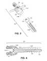
- FIG. 4shows a cross-sectional view of a partially assembled fastener assembly according to the embodiment of FIG. 3 (for clarity, this FIG. does not include the rod or compression member of FIG. 3 ).
- FIG. 5shows a side view of a fastener assembly according to another embodiment of the invention.
- FIG. 6shows a side view of a fastener assembly according to another embodiment of the invention.
- FIG. 7shows a side view of a fastener according to an embodiment of the invention.
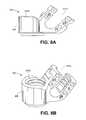
- FIGS. 8A and 8Bshow, respectively, an elevational view and a perspective view of an offset design according to an embodiment of the invention.
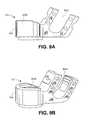
- FIGS. 9A and 9Bshow, respectively, an elevational view and a perspective view of an offset design according to an embodiment of the invention.
- FIGS. 10A and 10Bshow, respectively, an elevational view and a perspective view of an offset design according to an embodiment of the invention.
- FIG. 11shows a cross-sectional view of a fastener assembly according to an embodiment of the invention.
- FIG. 12shows a perspective, cross-sectional view of a fastener according to an embodiment of the invention.
- FIG. 13shows a perspective view of a multi-axial body according to an embodiment of the invention.
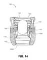
- FIG. 14shows a cross-sectional view of a closed body according to an embodiment of the invention.
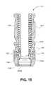
- FIG. 15shows a cross-sectional view of a reduction body according to an embodiment of the invention.
- FIG. 16shows a perspective view of a pressure cap according to an embodiment of the invention.
- FIG. 17shows a perspective view of a retention ring according to an embodiment of the invention.
- FIG. 18shows a perspective view of an offset set screw according to an embodiment of the invention.
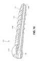
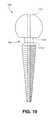
- FIG. 19shows a side view of an alternative fastener according to an embodiment of the invention.
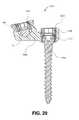
- FIG. 20shows a cross-sectional view of an offset fastener assembly according to an embodiment of the invention.
- FIG. 21shows a cross-sectional, perspective view of a body according to an embodiment of the invention.
- FIG. 22shows a perspective view of a pressure cap according to an embodiment of the invention.
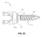
- FIG. 23shows an elevation view of a flange according to an embodiment of the invention.
- FIG. 24shows a perspective view of an orientation plug according to an embodiment of the invention.
- rodis intended to refer to any elongated structure.
- elongated structuremay be solid or hollow and may have any desired cross-section (e.g., circular, oval, square, rectangular).
- the term “interference fit”is intended to refer to physical contact between two or more components.
- the inventionallows engagement of the pedicle screw in the accommodating head after the pedicle screw has been inserted into bone.
- the inventionalso provides for a fixing mechanism for fixing a screw, wherein the fixing mechanism further includes an inner surface wall having a gripping portion and a non-gripping portion.
- the present inventionprovides for a substantially annular ring for guiding and providing mechanical and frictional force to a screw head.
- the present inventionprovides for a rod seating mechanism operatively engaged to the screw head and including at least one flexible portion capable of being compressed against a portion of a rod therein.
- the present inventionprovides for a locking mechanism for engaging the rod and the rod seating mechanism.
- the locking mechanismincludes a deflecting mechanism for deflecting the at least one flexible portion of the rod seating mechanism against and around the rod as the locking mechanism further engages the at least one flexible portion of the rod seating mechanism.
- Fastener Assembly 100may be used in connection with mounting Rod 101 relative to a spine of a patient (of course, one or more such Fastener Assemblies may be used with one or more Rods). More particularly, Fastener Assembly 100 may include Fastener 103 having Head 103 A at a first end and Bone Connection Element 103 B at a second end (Bone Connection Element 103 B may be adapted for attachment on, in and/or to the spine). Further, Head 103 A may include at least one Deformation Element 103 C thereon.
- Head 103 Amay be spherical.
- Fastener 103may be a bone screw and Bone Connection Element 103 B may comprise threads.
- Fastener 103may be a cannulated bone screw (see Cannulation 103 D of FIG. 2 ).
- Deformation Element 103 Cmay substantially surround Cannulation 103 D (e.g., where Cannulation 103 D exits Head 103 A).
- Deformation Element 103 Cmay be a substantially circular ring protruding from Head 103 A.
- Deformation Element 103 C(and/or any other portion of Fastener 103 (e.g., Head 103 A or the entire Fastener 103 )) may include a material which is: (a) softer than a material from which Rod 101 is formed; (b) harder than a material from which Rod 101 is formed; or (c) of essentially the same hardness as a material from which Rod 101 is formed (e.g., the same material from which Rod 101 is formed).
- Fastener Assembly 100may include Body 105 .
- Body 105may have a first end and a second end, wherein Rod Receiving Channel 105 A for receiving Rod 101 is disposed adjacent the first end of Body 105 and Fastener Head Receiving Chamber 105 B is disposed adjacent the second end of Body 105 (as seen in these FIGS., Fastener Head Receiving Chamber 105 B may be tapered towards the second end of Body 105 and Rod Receiving Channel 105 A and Fastener Head Receiving Chamber 105 B may be operatively connected (e.g., a hole in Body 105 may connect Rod Receiving Channel 105 A and Fastener Head Receiving Chamber 105 B)).
- Fastener Assembly 100may include Retention Ring 107 .
- This Retention Ring 107may be sized to fit at least partially around Head 103 A when Head 103 A is disposed within Fastener Head Receiving Chamber 105 B.
- Retention Ring 107may be, as shown in the FIGS., of a “split-ring” design.
- Compression Element 109may cooperate with Body 105 to push Rod 101 , when Rod 101 is disposed within Rod Receiving Channel 105 A, into contact with at least part of Deformation Element 103 C.
- Such contact between Rod 101 and Deformation Element 103 Cwill deform Deformation Element 103 C while pressing Head 103 A towards the tapered end (i.e., narrower end) of Fastener Head Receiving Chamber 105 B. This action will serve to fix the angular relationship of Fastener 103 relative to Rod 101 .
- the angular relationship of Fastener 103 relative to Rod 101may be fixed at least in part due to: (a) an interference fit (caused by radial compression) between at least a portion of an outside surface of Head 103 A and at least a portion of an inside surface of Retention Ring 107 ; (b) an interference fit (caused by radial compression) between at least a portion of an outside surface of Retention Ring 107 and at least a portion of an inside surface of Fastener Head Receiving Chamber 105 B; and/or (c) an interference fit between at least a portion of an outside surface of Rod 101 and Deformation Element 103 C.
- Compression Element 109may have threads which cooperate with complementary threads of Body 105 .
- Compression Element 109may have external threads which cooperate with complementary internal threads of Body 105 (e.g., Compression Element 109 may be a set screw).
- Compression Element 109may have internal threads which cooperate with complementary external threads of Body 105 (e.g., Compression Element 109 may be a nut).
- Compression Element 109may have one or more indentations, protrusions and/or drive faces for receiving torque from a drive tool (e.g., the female hex).
- a drive toole.g., the female hex
- FIGS. 1 and 2Reference will now be made to the elements shown in FIGS. 1 and 2 in connection with the description of an example installation procedure.
- Such an example installation procedureis applicable to this embodiment of the fastener assembly of the present invention and, of course, is intended to be illustrative and not restrictive.
- a guide wiremay first be attached to a pedicle of the spine.
- the free end of the guide wiremay then be passed through Fastener 103 (via Cannulation 103 D).
- Fastener 103e.g., a pedicle screw
- a pedicle screwmay then be inserted (e.g., screwed) into the pedicle of the spine.
- a pedicle screwmay be self-tapping into a hole bored into the pedicle or the hole bored into the pedicle may be pre-tapped.
- such a pedicle screwmay be driven into bone with any desired tool (e.g., a hand or power driver applying torque through Rod Receiving Channel 105 A and Fastener Head Receiving Chamber 105 B).
- such a pedicle screwmay be driven into bone with a torque applying tool that engages one or more indentations, protrusions and/or drive faces on Head 103 A (e.g., the four scallops).
- Fastener 103may be driven into bone by itself.
- a body/retention ring assemblye.g., including Body 105 having Retention Ring 107 already disposed within Fastener Head Receiving Chamber 105 B
- Fastener 103may be placed (or “snapped”) onto Fastener 103 .
- Rod 101may be placed in Rod Receiving Channel 105 A (with Rod 101 coming into contact with Deformation Element 103 C).
- Compression Element 109e.g., a set screw
- Compression Element 109clamps the components in a set position (that is, Compression Element 109 pushes Rod 101 against Deformation Element 103 C (and, depending upon the size and shape of Rod 101 , Deformation Element 103 C and Head 103 A, against a portion of Head 103 A)).
- Deformation Element 103 Cis deformed (e.g., to form a surface complementary to the portion of Rod 101 causing the deformation) and the result is improved locking (e.g., of the angular relationship between Rod 101 and Fastener 103 ).
- Deformation Element 103 Cis particularly useful in enabling secure locking of cannulated fasteners, such as cannulated pedicle screws (it is believed that a cannulation (without the use of a deformation element according to the present invention) may tend to compromise the ability to lock the multi-axial adjustability against the rod (e.g., due to a circular cross-section of the rod)).
- Fastener 103may be captured within body/retention ring assembly as discussed above and then the entire body/retention ring/fastener assembly may be attached to the bone (e.g., by using a driving tool such as a hand or power driver to drive the pedicle screw through the hole provided in Body 105 between Rod Receiving Channel 105 A and Fastener Head Receiving Chamber 105 B).
- a driving toolsuch as a hand or power driver to drive the pedicle screw through the hole provided in Body 105 between Rod Receiving Channel 105 A and Fastener Head Receiving Chamber 105 B).
- FIGS. 3 and 4another embodiment of the present invention is shown. This embodiment is similar to the embodiment shown in FIGS. 1 and 2 and, in this regard, the same elements will be identified by the same reference numerals (such similar elements will not be described again in detail). Of note, the main difference between the embodiment of these FIGS. 3 and 4 and the embodiment of FIGS. 1 and 2 is that in this embodiment Fastener Assembly 200 does not utilize Retention Ring 107 .
- Fastener Assembly 200may again be used in connection with mounting Rod 101 relative to a spine of a patient (of course, one or more such Fastener Assemblies may be used with one or more Rods). Further, Fastener Assembly 200 may include Fastener 103 (having Head 103 A, Bone Connection Element 103 B and at least one Deformation Element 103 C).
- Fastener Assembly 200may further include Body 105 ′ (Body 105 ′ may have a first end and a second end, wherein Rod Receiving Channel 105 A′ for receiving Rod 101 is disposed adjacent the first end of Body 105 ′ and Fastener Head Receiving Chamber 105 B′ is disposed adjacent the second end of Body 105 ′).
- Body 105 ′may have a first end and a second end, wherein Rod Receiving Channel 105 A′ for receiving Rod 101 is disposed adjacent the first end of Body 105 ′ and Fastener Head Receiving Chamber 105 B′ is disposed adjacent the second end of Body 105 ′).
- Fastener Head Receiving Chamber 105 B′may be tapered towards the second end of Body 105 ′ and a hole may be disposed through Body 105 ′ to connect Rod Receiving Channel 105 A′ and Fastener Head Receiving Chamber 105 B′.
- the tapered (i.e., narrow) end of Fastener Head Receiving Chamber 105 B′may be made sufficiently small so as to prohibit Head 103 A from passing therethrough (while Rod Receiving Channel 105 A′ and the hole in Body 105 ′ connecting Rod Receiving Channel 105 A′ to Fastener Head Receiving Chamber 105 B′ may be made sufficiently large so as to allow Head 103 A to pass therethrough).
- Fastener Assembly 200may be installed by inserting Fastener 103 through Body 105 ′ such that Head 103 A comes to rest in Fastener Head Receiving Chamber 105 B′ (see FIG. 4 ).
- Fastener 103may then be inserted (e.g., into the pedicle of the spine) as discussed above (e.g., a guide wire may be used to guide Fastener 103 and either a self-tapping bone screw may be driven into a hole in the bone or a pre-tapped hole in the bone may be provided).
- Compression Element 109may cooperate with Body 105 ′ to push Rod 101 , when Rod 101 is disposed within Rod Receiving Channel 105 A′, into contact with at least part of Deformation Element 103 C to deform Deformation Element 103 C while pressing Head 103 A towards the tapered end (i.e., narrower end) of Fastener Head Receiving Chamber 105 B.
- This actionwill fix the angular relationship of Fastener 103 relative to Rod 101 (the angular relationship of Fastener 103 relative to Rod 101 may be fixed at least in part due to: (a) an interference fit (caused by radial compression) between at least a portion of an outside surface of Head 103 A and at least a portion of an inside surface of Fastener Head Receiving Chamber 105 B′; and/or (b) an interference fit between at least a portion of an outside surface of Rod 101 and Deformation Element 103 C.
- Body 105 of FIGS. 1 and 2has an upward facing Rod Receiving Channel 105 A for receiving Rod 101 .
- Body 105 ′ of FIGS. 3 and 4has an upward facing Rod Receiving Channel 105 A′ for receiving Rod 101 .
- Body 500includes a sideward facing Rod Receiving Channel 501 for receiving Rod 101 (Fastener 103 , Compression Element 109 and Retention Ring 107 are shown in phantom and are essentially the same elements as described in detail above). Further, it is seen in FIG.
- Body 600includes a “tunnel-type” Rod Receiving Channel 601 for receiving Rod 101 (Fastener 103 , Compression Element 109 and Retention Ring 107 are shown in phantom and are essentially the same elements as described in detail above).
- Rod 101Rod 101
- FIGS. 5 and 6may operate as discussed above (e.g., the body may include a tapered chamber for facilitating an interference fit between the components disposed therein).
- Fastener 700is depicted here as a bone screw, although other types of bone attaching mechanisms may, of course, be utilized (e.g., a shaft having a hook on the end).
- Undercut 701is provided (Undercut 701 may be formed, for example, by a flattening of the Bottom of the Head 701 A of the bone screw and/or by a narrowing of a portion of the Shaft 701 B of the bone screw.
- Fastener 700may provide increased clearance in the area where Fastener 700 extends from the body of the fastener assembly (wherein such increased clearance may translate into an increase in a maximum angle that Fastener 700 may obtain in relation to the fastener body and/or the rod.
- FIGS. 8A and 8Bshow, respectively an elevational view and a perspective view of an offset design according to an embodiment of the invention.
- Body 805includes a lateral offset (e.g., an 8 mm lateral offset) between Fastener Head Receiving Chamber 805 B and Rod Receiving Channel 805 A.
- Rod Receiving Channel 805 Ais angled (e.g., 50 degrees) from vertical (and from a vertical axis disposed through Fastener Head Receiving Chamber 805 B).
- offset designmay be used in a manner similar to that described with respect to the non-offset designs (e.g., Body 105 ) disclosed herein (for example, a first compression element, such as a set screw (not shown in these FIGS. 8A and 8B ), may be used to fix the rod (not shown in these FIGS. 8A and 8B ) relative to the body and a second compression element, such as a set screw (not shown in these FIGS. 8A and 8B ), may be used to fix the bone screw (not shown in these FIGS. 8A and 8B ) relative to the body).
- a first compression elementsuch as a set screw (not shown in these FIGS. 8A and 8B )
- a second compression elementsuch as a set screw
- FIGS. 9A and 9Bshow, respectively an elevational view and a perspective view of an offset design according to an embodiment of the invention.
- Body 905includes a lateral offset (e.g., an 11 mm lateral offset) between Fastener Head Receiving Chamber 905 B and Rod Receiving Channel 905 A.
- Rod Receiving Channel 905 Ais angled (e.g., 25 degrees) from vertical (and from a vertical axis disposed through Fastener Head Receiving Chamber 905 B).
- offset designmay be used in a manner similar to that described with respect to the non-offset designs (e.g., Body 105 ) disclosed herein (for example, a first compression element, such as a set screw (not shown in these FIGS. 9A and 9B ), may be used to fix the rod (not shown in these FIGS. 9A and 9B ) relative to the body and a second compression element, such as a set screw (not shown in these FIGS. 9A and 9B ), may be used to fix the bone screw (not shown in these FIGS. 9A and 9B ) relative to the body).
- a first compression elementsuch as a set screw (not shown in these FIGS. 9A and 9B )
- a second compression elementsuch as a set screw
- Body 1005includes a lateral offset (e.g., a 14 mm lateral offset) between Fastener Head Receiving Chamber 1005 B and Rod Receiving Channel 1005 A. Further, Rod Receiving Channel 1005 A is angled (e.g., 15 degrees) from vertical (and from a vertical axis disposed through Fastener Head Receiving Chamber 1005 B).
- a lateral offsete.g., a 14 mm lateral offset
- Rod Receiving Channel 1005 Ais angled (e.g., 15 degrees) from vertical (and from a vertical axis disposed through Fastener Head Receiving Chamber 1005 B).
- offset designmay be used in a manner similar to that described with respect to the non-offset designs (e.g., Body 105 ) disclosed herein (for example, a first compression element, such as a set screw (not shown in these FIGS. 10A and 10B ), may be used to fix the rod (not shown in these FIGS. 10A and 10B ) relative to the body and a second compression element, such as a set screw (not shown in these FIGS. 10A and 10B ), may be used to fix the bone screw (not shown in these FIGS. 10A and 10B ) relative to the body).
- a first compression elementsuch as a set screw (not shown in these FIGS. 10A and 10B )
- a second compression elementsuch as a set screw
- the offset designsmay or may not utilize a screw with a deformation element.
- a screw with a deformation elementmay be utilized such that the compression element interfacing with the screw presses down on and deforms the deformation element.
- a screw with a deformation elementmay be utilized such that the compression element interfacing with the screw presses down on the screw head itself but the compression element includes a cavity adjacent the screw head and aligned with the deformation element such that the deformation element does not deform.
- the screw headmay not have a deformation element at all.
- the offset designsmay ease assembly of the fixation system (e.g., by providing a surgeon laterally offset/angled options when connecting the spinal rod(s)).
- the bodymay (before being fixed relative to the bone screw): (a) be circumferentially rotatable on the head of the bone screw around the longitudinal axis of the bone screw; and/or (b) have a desired degree of angular freedom (e.g., 26 degrees from the longitudinal axis of the bone screw (or 52 degrees from one side to the other).
- a desired degree of angular freedome.g., 26 degrees from the longitudinal axis of the bone screw (or 52 degrees from one side to the other).
- FIG. 11shows a cross-sectional view of a Fastener Assembly 1100 according to another embodiment of the invention.
- the Fastener Assembly 1100may be used in connection with a mounting rod relative to a spine of a patient (of course, one or more such Fastener Assemblies 1100 may be used with one or more rods). More particularly, the Fastener Assembly 1100 may include a Fastener 1103 having a Head 1103 A at a first end and a Bone Connection Element 1103 B at a second end ( FIG. 12 ).
- the Head 1103 Aalso includes a Drive Element 1106 (discussed below).
- the Fastener Assembly 1100also includes a Body 1105 , one or more Pins 1120 , a Pressure Cap 1140 , a Retention Ring 1107 , a Back Wall 1126 of the Fastener Head Receiving Chamber 1105 B, a Rod Receiving Channel 1105 A, a Line 1148 (illustrates an example length of Pin Receiving Slots 1146 ( FIG. 16 )) and a Compression Element 109 (not shown).
- the Compression Element 109engages the Body 1105 , as previously described.
- the Fastener 1103comprises the Head 1103 A at a first end and the Bone Connection Element 1103 B at a second end (the Bone Connection Element 1103 B may be adapted for attachment on, in and/or to the spine). At least a portion of the Head 1103 A may be spherical. In other embodiments, the Head 1103 A may include a flat surface on a top portion.
- the Head 1103 Afurther comprises the Drive Element 1106 for engaging a drive tool to attach the Fastener 1103 to the spine.
- Such a Drive Element 1106may be an indentation in the Head 1103 A shaped to engage a square drive tool, or alternatively any other drive tool having various engaging shapes.
- the Fastener 1103may be a bone screw and the Bone Connection Element 1103 B may comprise Threads 1130 and a Cannulation 1103 D.
- the Threads 1130may be of one or more lead designs.
- the Cannulation 1103 Dmay be used as previously described herein.
- the tip of the Bone Connection Element 1103 Bmay have Self-Tapping Flutes 1110 that assist the Bone Connection Element to attach to the spine. In one embodiment, there are three Self-Taping Flutes spaced about 120 degrees apart. In other embodiments, there may be two Self-Taping Flutes spaced about 180 degrees apart. Other embodiments can include one or more than three Self-Taping Flutes spaced at appropriate angles.
- the Fastener 1103may be a bone screw having a standard tip.
- the Fastener 1103may further be a non-cannulated bone screw with a tip having a self-tapping feature or a standard tip.
- the Body 1105may have a first end and a second end, wherein the Rod Receiving Channel 1105 A for receiving the Rod is disposed adjacent the first end of the Body 1105 and the Fastener Head Receiving Chamber 1105 B is disposed adjacent the second end of the Body 1105 .
- the Rod Receiving Channel 1105 Afurther includes Threads 1334 for engaging with the Compression Element 109 .
- Other embodimentsmay forego the Threads 1334 in favor of other lockable means.
- the Rodcan be inserted at the first end or simply through the Rod Receiving Channel 1105 A.
- the Fastener Head Receiving Chamber 1105 Bmay be tapered towards the second end of the Body 1105 , and the Rod Receiving Channel 1105 A and the Fastener Head Receiving Chamber 1105 B may be operatively connected.
- the operative connectionmay be a hole in the Body 1105 of sufficient diameter to allow passage of a drive tool through the hole as described in more detail below.
- the Body 1105maybe a multi-axial body as depicted in FIG. 13 comprising a u-shaped Rod Receiving Channel 1105 A.
- the Body 1105may comprise other configurations, including but not limited to, a closed body having a Rib 1450 which bridges the two sides of the Rod Receiving Channel 1105 A at the first end of the body (see FIG. 14 ), or a reduction body having Removable Extensions 1560 connected at the first end the body (see FIG. 15 ).
- the Body 1105may further comprise one or more Pin Mounting Cradles 1332 .
- the Pin Mounting Cradles 1332may be disposed on either side of the Body 1105 in the walls of the Rod Receiving Channel 1105 A.
- the Pin Mounting Cradles 1332are apertures that extend through the entire width of the walls of the Rod Receiving Channel 1105 A.
- the Pin Mounting Cradlescan have an outer diameter and an inner diameter, wherein the outer diameter is larger than the inner diameter ( FIG. 11 ).
- the outer diameterallows the entire Pin 1120 to pass through while the inner diameter allows only a portion of the Pin 1120 to pass through, such as a shaft of the Pin 1120 , and not the Pin's head. Additionally, the outer diameter allows the Pins 1120 to be placed flushed against the Body 1105 .
- Pins 1120are fixably mounted, such that the Pins 1120 protrude from the Pin Mounting Cradles 1332 into the Rod Receiving Channel 1105 A (see FIG. 11 ).
- One example method of fixably mounting the Pins 1120is by welding, however, other means of fixably mounting the Pins 1332 can also be used.
- the Pin Mounting Cradles 1332could also be depressions in the inner portions of the walls of the Rod Receiving Channel 1105 A, or any other feature that could fixably retain the position of the Pins 1120 .
- the Pins 1120may just be protrusions from the wall of the Rod Receiving Channel 1105 A which are part of the Body 1105 as constructed.
- the Body 1105can also include Cut Out 1370 and Holes 1375 located on various surfaces for mating with the Rod reduction and body insertion instrumentation (not shown).
- FIG. 14shows a cross-section view of a Closed Body 1400 according to an embodiment of the present invention.
- the Closed Body 1400can be essentially the same as the multi-axial body shown in FIG. 13 , including the Threads 1334 , the Cut Out 1370 , Pins 1120 , Pin Mounting Cradle 1332 , Fastener Head Receiving Chamber 1405 B, Pressure Cap 1140 , and Retention Ring 1107 , but includes Ribs 1450 .
- the Ribs 1450can be located in the first end of the Closed Body 1400 .
- the Rodcan be inserted through the Rod Receiving Channel 1405 A.
- FIG. 15shows a perspective view of a Reduction Body 1500 according to an embodiment of the present invention.
- the Reduction Body 1500like the multi-axial body, includes the Threads 1334 , the Cut Out 1370 , Pins 1120 , Pin Mounting Cradle 1332 , Fastener Head Receiving Chamber 1505 B, Pressure Cap 1140 , and Retention Ring 1107 , but further includes a Removable Extensions 1560 and Break Regions 1570 .
- the Removable Extensions 1560are configured to break off at the Break Regions 1570 after a set screw reduces the Rod into the Body below the Break Region 1570 .
- the Rod Receiving Channel 1505 Ais elongated so that a set screw engages the Threads 1334 and is threaded down the Removable Extensions 1560 and into the Body 1500 to reduce the Rod for the purposes of aiding deformity correction. Once the Removable Extensions 1560 are broken off then the Reduction Body resembles the multi-axial body 1105 .
- the Pressure Cap 1140may have a first end and a second end, wherein a Pressure Cap Rod Receiving Channel 1142 for receiving the Rod is disposed adjacent the first end of the Pressure Cap 1140 and a Head Receiving Face 1144 is disposed adjacent the second end of the Pressure Cap 1140 .
- the Pressure Cap Rod Receiving Channel 1142may have a “V” shape so as to increase the Rod contact area.
- the Head Receiving Face 1144may be tapered towards the first end of the Pressure Cap 1140 and form a conical shape. The top end of the conical shape (near the first end of the Pressure Cap) has a smaller diameter than the bottom end (near the second end of the Pressure Cap).
- the Head Receiving Face 1144may consist of a partially spherical diameter whose diameter is smaller than that of the Head 1103 A of the Fastener 1103 .
- the Pressure Cap Rod Receiving Channel 1142 and the Head Receiving Face 1144may be operatively connected.
- the operative connectionmay be a hole in the Pressure Cap 1140 of sufficient diameter to allow passage of a drive tool through the hole as described in more detail below.
- the Pressure Cap 1140may comprise one or more Pin Receiving Slots 1146 .
- the Pin Receiving Slots 1146are disposed on either side of the Pressure Cap 1140 in the walls of the Pressure Cap Rod Receiving Channel 1142 .
- the Pin Receiving Slots 1146are apertures that can extend through the entire width of the walls of the Rod Receiving Channel 1142 .
- the Pin Receiving Slots 1146can run the length of Line 1148 (shown in FIG. 11 ) of an axis of the Pressure Cap 1140 .
- the Pressure Cap 1140can be inserted into the Body 1105 such that the first end and the second end of the Body 1105 are adjacent to the first end and second end of the Pressure Cap 1140 , respectively.
- the Pin Receiving Slots 1146engage the Pins 1120 .
- the Pin Receiving Slots 1146are elongated so as to allow the Pressure Cap to slideably move within the Body 1105 between the first end and second end of the Body 1105 . Such movement is restricted by contact between the walls of the Pin Receiving Slot 1146 and the Pins 1120 .
- the length of Line 1148 of the Pin Receiving Slots 1146is such that when the Head 1103 A is disposed within the Fastener Head Receiving Chamber 1105 B and the Compression Element 109 is tightened, there is clearance between the Pins 1120 and the ends of the Pin Receiving Slots 1146 adjacent to the first end of the Pressure Cap 1140 .
- Pin Receiving Slot 1146could also be depressions in the outer portions of the walls of the Pressure Cap Rod Receiving Channel 1142 , or any other feature that could slideably engage the Pins 1120 .
- each of the Bodies 1105 , 1400 , 1500may be sized differently, such that the distance between the Rod Receiving Channel 1105 A, 1405 A, 1505 A, respectively, and the Fastener Head Receiving Chamber 1105 B, 1405 B, 1505 B, respectively, varies between the embodiments.
- the Pressure Cap 1140may be appropriately size by varying the distance between the Pressure Cap Rod Receiving Channel 1142 and the Head Receiving Face 1144 so that the Pressure Cap 1140 may function as described in connection with previous embodiments.
- Fastener Assembly 1100 of FIG. 11may include the Retention Ring 1107 .
- This Retention Ring 1107may be constructed to fit at least partially around the Head 1103 A when the Head 1103 A is disposed within the Fastener Head Receiving Chamber 1105 B.
- the Retention Ring 1107expands and contracts such that the Head 1103 A cannot be extracted from the Fastener Head Receiving Chamber 1105 B through the second end of the Body 1105 .
- the Retention Ring 1107may be, as shown in the FIG. 17 , of a “split-ring” design.
- the Retention Ring 1107may comprise a first end and a second end where a Slit 1762 extends fully between both ends.
- Exterior Wall 1764 of the Retention Ring 1107may taper from the first end to the second end having a substantially similar taper to that of the Fastener Head Receiving Chamber 1105 B.
- the Retention Ring 1107may further comprise an Upper Inner Taper 1766 adjacent to the first end, which has a taper substantially similar to the taper of the Exterior Wall 1764 , a Cylinder 1768 adjacent to the second end, and a Lower Inner Taper 1770 disposed between the Upper Inner Taper 1766 and the Cylinder 1768 , having a taper greater than that of the Upper Inner Taper 1766 .
- the Compression Element 109may cooperate with the Body 1105 to push a Rod, when the Rod is disposed within the Rod Receiving Channel 1105 A, into contact with at least part of the Pressure Cap Rod Receiving Channel 1142 .
- Such contact between the rod and the Pressure Cap Rod Receiving Channel 1142will slideably move the Pressure Cap 1140 causing the Head Receiving Face 1144 to press the Head 1103 A towards the tapered end (i.e., narrower end) of the Fastener Head Receiving Chamber 1105 B. This action will serve to fix the angular relationship of Fastener 1103 relative to the rod.
- the angular relationship of Fastener 1103 relative to the Rodmay be fixed at least in part due to: (a) an interference fit (caused by radial compression) between at least a portion of an outside surface of Head 1103 A and at least a portion of an inside surface of Retention Ring 1107 ; (b) an interference fit (caused by radial compression) between at least a portion of an outside surface of Retention Ring 1107 and at least a portion of an inside surface of Fastener Head Receiving Chamber 1105 B; and/or (c) an interference fit between at least a portion of the Head Receiving Face 1144 and an outside surface of Head 1103 A.
- the Fastener Assembly 1100may include the attachment of a Flange 1150 at the opening of the Fastener Head Receiving Chamber 1105 B.
- the Flange 1150may be a single piece including a Flange Slot 1152 .
- the single piecemay be of any shape, for example, circular or U-shaped, or it may comprise multiple pieces, any of which, when attached to the Fastener Assembly 1100 create a Flange Slot 1152 .
- the Flange Slot 1152may be a hole in the Flange 1150 or a space between pieces of the Flange 1150 .
- the Bone Connection Element 103 B of the Fastener 1103may extend through the Flange Slot 1152 .
- the Flange 1150may be attached in a variety of ways, including, for example, welding, gluing, or attaching via a connection element, before or after inserting the Fastener 1103 into the Fastener Head Receiving Chamber 1105 B.
- the Flange 1150may restrict the angular relationship of Fastener 1103 relative to the Rod by limiting the movement of the Fastener 1103 to one plane coinciding with the Flange Slot 1152 .
- the Orientation Plug 1160may include an Orientation Plug 1160 to restrict the angular relationship of Fastener 1103 relative to the Rod.
- the Orientation Plug 1160may have an Engagement Feature 1162 , a Rod Receiving Face 1164 , and a Projection 1166 .
- the Engagement Feature 1162may be shaped to engage with the Pin Receiving Slots 1146 (shown in FIG. 16 ) of the Pressure Cap 1140 .
- the Rod Receiving Face 1164may be shaped similarly to the Pressure Cap Rod Receiving Channel 1142 (shown in FIG. 16 ) so that it may contact the Rod but not interfere with the contact between the Rod and the Pressure Cap Rod Receiving Channel 1142 .
- the Projection 1166may be shaped such that it contacts the Drive Element 1106 (shown in FIG. 12 ) of the Fastener 1103 , limiting the movement of the Fastener in at least one direction.
- a guide wiremay first be attached to a pedicle of the spine.
- the free end of the guide wiremay then be passed through the Fastener 1103 (via the Cannulation 1103 D ( FIG. 12 )).
- the Fastener 1103e.g., a pedicle screw
- the Fastener 1103may then be inserted (e.g., screwed into) into the pedicle of the spine.
- a pedicle screwmay be self-tapping into a hole bored into the pedicle or the hole bored into the pedicle may be pre-tapped.
- such a pedicle screwmay be driven into bone with any desired tool (e.g., a hand or power driver applying torque through the hole provided in the Body 1105 between the Rod Receiving Channel 1105 A and the Fastener Head Receiving Chamber 1105 B, and the hole provided in the Pressure Cap 1140 between the Pressure Cap Rod Receiving Channel 1142 and the Head Receiving Face 1144 ).
- a hand or power driverapplying torque through the hole provided in the Body 1105 between the Rod Receiving Channel 1105 A and the Fastener Head Receiving Chamber 1105 B, and the hole provided in the Pressure Cap 1140 between the Pressure Cap Rod Receiving Channel 1142 and the Head Receiving Face 1144 ).
- such a pedicle screwmay be driven into bone with a torque applying drive tool that engages one or more indentations, protrusions and/or drive faces on the Head 1103 A (see, e.g., Drive Element 1106 of Head 1103 A in FIG. 12 ).
- the Fastener 1103may be driven into bone by itself.
- a body/retention device/pressure cap assemblye.g., including the Body 1105 having the Retention Ring 1107 already disposed within the Fastener Head Receiving Chamber 1105 B, the Pins 1120 already fixably disposed within the Pin Mounting Cradles 1332 , and the Pressure Cap 1140 already slideably engaged on the Pins 1332 ) may be placed (or “snapped”) onto Fastener 1103 .
- the Retention Ring 1107is pushed against the Back Wall 1126 (see FIG. 11 ) of the Fastener Head Receiving Chamber 1105 B and the Retention Ring 1107 is free to expand outward enabling the Head 1103 A to pass through.
- the Head 1103 Apushes through the bottom of the Retention Ring 1107 , the Head 1103 A remains captured (since the Retention Ring 1107 would have no room to expand as it was pulled forward by the Head 1103 A towards the tapered (i.e., narrowed) end of the Fastener Head Receiving Chamber 1105 B.
- the Head 1103 Apasses through the Retention Ring 1107 , the Head 1103 A contacts the Head Receiving Face 1144 (shown in FIG. 16 ) and slideably pushes the Pressure Cap 1140 toward the first end of the Body 1105 .
- the length of the Pin Receiving Slots 1146(shown in FIG. 16 ) is such that when the Head 1103 A is inserted into the Fastener Receiving Chamber 1105 B, there is enough clearance between the ends of the Pin Receiving Slots 1146 and Pins 1120 to allow for assembly.
- the rodmay be placed in the Rod Receiving Channel 1105 A and the Pressure Cap Rod Receiving Channel 1142 (shown in FIG. 16 ).
- the Compression Element 109e.g., a set screw
- the Compression Element 109clamps the components in a set position. That is, the Compression Element 109 pushes the rod against the Pressure Cap Rod Receiving Channel 1142 (shown in FIG. 16 ), which pressure slideably pushes the Pressure Cap 1140 toward the second end of the Body 1105 .
- the Head Receiving Face 1144pushes the Head 1103 A against the Retention Ring 1107 , which in turn pushes against the tapered inner walls of the body.
- the movable nature of the Pressure Cap 1140allows for some clearance between the Pins 1120 and Pin Receiving Slots 1146 (shown in FIG. 16 ) enabling clamping of the Head 1103 A to take place.
- the Flange 1150may be attached to the Fastener Assembly 1100 at any point after the Body 1105 is pushed onto the Head 102 (or vice-versa). Further, if using the Orientation Plug 1160 , it may be inserted into the Fastener Assembly 1100 at any point before inserting the Rod.
- the Fastener 1103may be captured within body/retention ring/pressure cap assembly as discussed above and then the entire body/retention ring/pressure cap/fastener assembly may be attached to the bone (e.g., by using a driving tool such as a hand or power driver to drive the pedicle screw through the hole provided in the Body 1105 between the Rod Receiving Channel 1105 A and the Fastener Head Receiving Chamber 1105 B, and the hole provided in the Pressure Cap 1140 between the Pressure Cap Rod Receiving Channel 1142 and the Head Receiving Face 1144 ).
- a driving toolsuch as a hand or power driver to drive the pedicle screw through the hole provided in the Body 1105 between the Rod Receiving Channel 1105 A and the Fastener Head Receiving Chamber 1105 B, and the hole provided in the Pressure Cap 1140 between the Pressure Cap Rod Receiving Channel 1142 and the Head Receiving Face 1144 ).
- the Flange 1150may be attached to the Fastener Assembly 1100 at any point, for example, the manufacturer may connect the Flange 1150 to the Fastener Assembly 1100 . If the Orientation Plug 1160 is used, then its insertion into the Fastener Assembly 1100 must wait until after the Fastener is driven into the bone.
- FIG. 11Another embodiment (not shown) of the present invention is similar to the embodiment shown in FIG. 11 and, in this regard, the same elements will be identified by the same reference numerals (such similar elements will not be described again in detail).
- the difference between the embodimentsis that in this embodiment the Fastener Assembly 1100 does not utilize Retention Ring 1107 , and that the tapered (i.e., narrow) end of the Fastener Head Receiving Chamber 1105 B may be made sufficiently small so as to prohibit the Head 1103 A from passing therethrough (while the Rod Receiving Channel 1105 A, the hole in the Body 1105 connecting the Rod Receiving Channel 1105 A to the Fastener Head Receiving Chamber 1105 B, may be made sufficiently large so as to allow Head 1103 A to pass therethrough).
- the angular relationship of Fastener 1103 relative to the Rodmay be restricted by the shape of the opening of the tapered end of the Fastener Head Receiving Chamber 1105 B through which extends the Fastener 1103 .
- An example (not shown) of such an openingmay be shaped like a slot, and the movement of the Fastener 1103 may be restricted to a single plane coinciding with the slot.
- the Fastener Head Receiving Chamber 1105 Bmay also be extend to encompass more of the Bone Connection Element 103 B to greater restrict the movement of the Fastener 1103 .
- the Fastener Assembly 1100may be installed by inserting the Fastener 1103 through the Body 1105 , such that the Head 1103 A comes to rest in the Fastener Head Receiving Chamber 1105 B.
- the Pressure Cap 1140is the inserted into the Body 1105 , and the Fastener 1103 may then be inserted (e.g., into the pedicle of the spine) as discussed above (e.g., a guide wire may be used to guide the Fastener 1103 and either a self-tapping bone screw may be driven into a hole in the bone or a pre-tapped hole in the bone may be provided).
- the Compression Element 109may cooperate with the Body 1105 to push the rod, when the rod is disposed within the Rod Receiving Channel 1105 A, into contact with at least part of the Pressure Cap Rod Receiving Channel 1142 to slideably move the Pressure Cap 1140 while pressing the Head 1103 A towards the tapered end (i.e., narrower end) of the Fastener Head Receiving Chamber 1105 B.
- This actionwill fix the angular relationship of Fastener 1103 relative to the rod (the angular relationship of the Fastener 1100 relative to the rod may be fixed at least in part due to: (a) an interference fit (caused by radial compression) between at least a portion of an outside surface of the Head 1103 A and at least a portion of an inside surface of the Fastener Head Receiving Chamber 1105 B; and/or (b) an interference fit between at least a portion of an outside surface of at least a portion of an outside surface of the Head 1103 A and the Head Receiving Face 1144 ).
- an interference fitcaused by radial compression
- an Offset Set Screw 1800has a first end and a second end, wherein an Offset Drive Feature 1850 is disposed adjacent to the first end of the Offset Set Screw 1800 and an Offset Head Receiving Face 1852 is disposed adjacent to the second end of the Offset Set Screw 1800 .
- the Offset Head Receiving Face 1852may be tapered toward the first end of the Offset Head Receiving Face 1852 along an inner surface and forms a conical shape inner surface.
- the conical shape inner surfaceis constructed and designed to receive the Head 1103 A of Fastener 1103 .
- the Offset Head Receiving Face 1852may consist of a partially spherical diameter whose diameter is smaller than that of the Head 1103 A of the Fastener 1103 .
- the diameter of the Offset Head Receiving Face 1852 at the first endis larger than the diameter at the second end and in another embodiment, the diameter of the Offset Head Receiving Face 1852 at the first end is less than the diameter at the second end.
- the Offset Drive Feature 1850 and the Offset Head Receiving Face 1852may be operatively connected through a hole in the Offset Set Screw 1800 .
- Threads 1854are configured to engage the threads of Offset Fastener Assembly 2000 , described below.
- the Offset Set Screw 1800may be comprised of multiple pieces.
- One such embodimentmay include a first piece, which may embody the Offset Head Receiving Face 1852 , to contact the Head 1103 A of Fastener 1103 , and a second piece, such as the Compression Element 109 (which may embody a set screw), to lockably retain the first piece.
- the first piecemay be placed in or threaded into the Offset Fastener Head Receiving Chamber 2022 of the Offset Fastener Assembly 2000 , described below, and the second piece may be fastened into the Offset Fastener Head Receiving Chamber 2022 retaining the first piece in place.
- FIG. 19wherein another embodiment of a Fastener 1900 for use with the invention is shown.
- the Fastener 1900is depicted here as a bone screw, although other types of bone attaching mechanisms may, of course, be utilized (e.g., a shaft having a hook on the end).
- an Undercut 1901is provided and may be formed, for example, by providing a Bottom of the Head 1901 A of the head of the bone screw and/or by providing a Shaft 1901 B of the bone screw.
- the Fastener 1900may provide increased clearance in the area where the Fastener 1900 extends from the body of the Fastener Assembly 1100 , wherein such increased clearance may translate into an increase in a maximum angle that the Fastener 1900 may obtain in relation to the fastener body and/or the rod.
- Cannulation 1902is also shown in FIG. 19 for the purposes previously described.
- the Offset Fastener Assembly 2000may be used in connection with a Rod 101 relative to a spine of a patient (of course, one or more such Fastener Assemblies may be used with one or more rods). More particularly, the Offset Fastener Assembly 2000 may include the Fastener 1103 , an Offset Body 2020 , Offset Set Screw 1800 , Retention Ring 1107 , and the Compression Element 109 .
- the Offset Body 2020includes a lateral offset (e.g., an 8 mm, 11 mm, or 14 mm lateral offset) between the Offset Fastener Head Receiving Chamber 2022 and the Offset Rod Receiving Channel 2024 .
- the Offset Rod Receiving Channel 2024is angled (e.g., 15 degrees, 25 degrees, or 50 degrees) from vertical (and from a vertical axis disposed through the Offset Fastener Head Receiving Chamber 2022 ). It is envisioned that the lateral offset between the Offset Fastener Head Receiving Chamber 2022 and the Offset Rod Receiving Channel 2024 is not limited to the example distances above, and that the distance of the offset may be of any length. It is further envisioned that the angle of the Offset Rod Receiving Channel 2024 is not limited to the example angles above, and that the angle may be of any degree and in any direction.
- the Offset Fastener Assembly 2000may include the attachment of a Flange at the opening of the Offset Fastener Head Receiving Chamber 2022 .
- the Flangemay be a single piece including a Flange Slot.
- the single piecemay be of any shape, for example, circular or U-shaped, or it may comprise multiple pieces that when attached to the Offset Fastener Assembly 2000 to create the Flange Slot.
- the Bone Connection Element 103 B of the Fastener 1103may extend through the Flange Slot.
- the Flangemay be attached in a variety of ways, including, for example, welding, gluing, or attaching via a connection element, before or after inserting the Fastener 1103 into the Offset Fastener Head Receiving Chamber 2022 .
- the Flangemay restrict the angular relationship of Fastener 1103 relative to the Rod by limiting the movement of the Fastener 1103 to one plane coinciding with the Flange Slot.
- FIG. 20depicts one such embodiment where the Compression Element 109 , such as a set screw, may be used to fix the Rod 101 relative to the Offset Body 2020 and the Offset Set Screw 1800 may be used to fix the Fastener 1103 relative to the Body.
- the Compression Element 109such as a set screw
- the offset designsmay ease assembly of the fixation system (e.g., by providing a surgeon laterally offset/angled options when connecting the spinal rod(s)).
- FIG. 21another embodiment of the Fastener Assembly 1100 may comprise a Body 2100 .
- the Body 2100may have a first end and a second end, wherein a Compression Element Receiving Chamber 2122 is disposed adjacent the first end of the Body 2100 and a Fastener Head Receiving Chamber 2105 B is disposed adjacent the second end of the Body 2100 .
- a Rod Receiving Channel 2105 A for receiving the Rodis disposed between the Compression Element Receiving Chamber 2122 and Fastener Head Receiving Camber 2105 B.
- the Compression Element Receiving Chamber 2122further includes Threads 2334 for engaging with the Compression Element 109 .
- the Threads 2334incorporate a Tab Channel 2336 to allow a Pressure Cap 2140 to slideably move within Body 2100 .
- the Rodcan be inserted through an Opening 2128 in a wall of the Body 2100 or simply through the Rod Receiving Channel 2105 A.
- the Fastener Head Receiving Chamber 2105 Bmay be tapered towards the second end of the Body 2100 , and the Compression Element Receiving Chamber 2122 , the Rod Receiving Channel 2105 A, and the Fastener Head Receiving Chamber 2105 B may be operatively connected.
- the operative connectionmay be a hole in the Body 2100 of sufficient diameter to allow passage of a drive tool through the hole as described herein.
- a Retention Ring 1107may be disposed within the Fastener Head Receiving Chamber 2105 B.
- the Body 2100may further comprise at least one Pin Mounting Cradle 1332 to fixably retain a Pin 2120 .
- the Pin Mounting Cradle 1332is disposed on a side of the Body 2100 in a wall of the Rod Receiving Channel 2105 A or a wall of the Compression Element Receiving Chamber 2122 .
- the Pin Mounting Cradle 1332is an aperture that extends through the entire width of the wall of a Tab Channel 2336 .
- the Pin Mounting Cradle 1332 and the Pin 2120are otherwise substantially similar to the Pin Mounting Cradle 1332 and the Pin 1120 (shown in FIG. 11 ) as described above, except that Pin 2120 is sized such that it does not extend into the Compression Element Receiving Chamber 2122 so that it does not interfere with the insertion of the Compression Element 109 .
- the Pressure Cap 2140may have a first end and a second end, wherein a Pressure Cap Rod Receiving Channel 2142 for receiving the rod is disposed adjacent the first end of the Pressure Cap 2140 and a Head Receiving Face 2144 is disposed adjacent the second end of the Pressure Cap 2140 .
- the Head Receiving Face 2144may be tapered towards the first end of the Pressure Cap 2140 , and the Pressure Cap Rod Receiving Channel 2142 and the Head Receiving Face 2144 may be operatively connected.
- the operative connectionmay be a hole in the Pressure Cap 2140 of sufficient diameter to allow passage of a drive tool through the hole as described herein.
- the Pressure Cap 2140further comprises a Guide Tab 2150 .
- the Guide Tab 2150is disposed within the Tab Channel 2336 .
- the Pressure Cap 2140can be inserted into the Body 2100 such that the first end and the second end of the Body 2100 are adjacent to the first end and second end of the Pressure Cap 2140 , respectively.
- the Tab Channel 2336engages the Guide Tab 2150 .
- the Tab Channel 2336is elongated so as to allow the Pressure Cap 2140 to slideably move within the Body 2100 between the first end and second end of the Body 2100 . Such movement is restricted by contact between the walls of the Tab Channel 2336 and a Pin 2120 with the Guide Tab 2150 .
- the length dimension of the Tab Channel 2336is such that when the Head 1103 A is disposed within the Fastener Head Receiving Chamber 2105 B, and the Compression Element 109 is tightened, the Guide Tab 2150 does not come in contact with the Pin 2120 . Further, the length of the Tab Channel 2336 is such that when the Head 1103 A is inserted into the Fastener Receiving Chamber 2105 B, there is enough clearance between the Guide Tab 2150 and the Pin 2120 to allow for assembly.
- the present inventionmay be placed at any desired level of the spine. Further, the present invention may be used in conjunction with a posterior spinal rod implantation. Further still, the controllable angulation provided by the present invention may be in any desired number of planes. Further still, the rod may be fixed axially and rotationally. Further still, any element described herein may be provided in any desired size (e.g., any element described herein may be provided in any desired custom size or any element described herein may be provided in any desired size selected from a “family” of sizes, such as small, medium, large).
- a bone screwmay be provided in a desired thread pitch, thread outer diameter, shaft outer diameter, shaft outer diameter to thread outer diameter ratio and/or length and a body element may be provided in any desired inner diameter, outer diameter, lateral offset, angle and/or length.
- the compression elementmay have a “break-off” feature for separating from the installed portion of the compression element when a desired amount of torque has been applied.
- one or more of the components of the fastener assemblymay be made from any of the following materials: (a) any biocompatible material (which biocompatible material may be treated to permit bone ingrowth or prohibit bone ingrowth—depending upon the desire of the surgeon); (b) a plastic; (c) a fiber; (d) a polymer; (e) a metal (a pure metal such as titanium and/or an alloy such as Ti—Al—Nb, Ti-6Al-4V, stainless steel); (f) any combination thereof.
- the guide wire for guiding the fastener via the cannulationmay be useful during a minimally invasive procedure, for example.
- the bone screwmay be adapted for placement in cancellous bone.
- the fastenermay employ a hook for attachment to bone.
- an outer surface of the head of the fastener, an outer surface of the rod, an outer surface of the retention ring, an inner surface of the retention ring and/or an inner surface of the bodymay have one or more features for increasing friction at the interface.
- any of the aforementioned componentsmay have: a roughened or treated surface (e.g., via sandblasting or knurling), a threaded surface, a grooved surface, a ridged surface, a surface with protrusions, and/or a surface with indentations.
- a minimum of two fastener assemblies for each rodmay be used (e.g., for stabilization purposes).
- any type and number of featuresmay be utilized for interfacing with an installation tool (see, e.g., the holes disposed on the outer surface of the body of the device—these holes may mate with corresponding retractable pins of an installation tool). Further still, any steps described herein may be carried out in any desired order (and any additional desired steps may be added and/or any desired steps deleted).
Landscapes
- Health & Medical Sciences (AREA)
- Orthopedic Medicine & Surgery (AREA)
- Life Sciences & Earth Sciences (AREA)
- Surgery (AREA)
- Neurology (AREA)
- Heart & Thoracic Surgery (AREA)
- Engineering & Computer Science (AREA)
- Biomedical Technology (AREA)
- Nuclear Medicine, Radiotherapy & Molecular Imaging (AREA)
- Medical Informatics (AREA)
- Molecular Biology (AREA)
- Animal Behavior & Ethology (AREA)
- General Health & Medical Sciences (AREA)
- Public Health (AREA)
- Veterinary Medicine (AREA)
- Surgical Instruments (AREA)
Abstract
Description
Claims (12)
Priority Applications (2)
| Application Number | Priority Date | Filing Date | Title |
|---|---|---|---|
| US12/577,503US8951290B2 (en) | 2004-08-27 | 2009-10-12 | Multi-axial connection system |
| US14/068,222US10194947B2 (en) | 2004-08-27 | 2013-10-31 | Multi-axial connection system |
Applications Claiming Priority (4)
| Application Number | Priority Date | Filing Date | Title |
|---|---|---|---|
| US10/928,955US20060058788A1 (en) | 2004-08-27 | 2004-08-27 | Multi-axial connection system |
| US11/388,666US8062339B2 (en) | 2004-08-27 | 2006-03-24 | Multi-axial connection system |
| US10502108P | 2008-10-13 | 2008-10-13 | |
| US12/577,503US8951290B2 (en) | 2004-08-27 | 2009-10-12 | Multi-axial connection system |
Related Parent Applications (1)
| Application Number | Title | Priority Date | Filing Date |
|---|---|---|---|
| US11/388,666Continuation-In-PartUS8062339B2 (en) | 2004-08-27 | 2006-03-24 | Multi-axial connection system |
Related Child Applications (1)
| Application Number | Title | Priority Date | Filing Date |
|---|---|---|---|
| US14/068,222DivisionUS10194947B2 (en) | 2004-08-27 | 2013-10-31 | Multi-axial connection system |
Publications (2)
| Publication Number | Publication Date |
|---|---|
| US20100094349A1 US20100094349A1 (en) | 2010-04-15 |
| US8951290B2true US8951290B2 (en) | 2015-02-10 |
Family
ID=42106850
Family Applications (2)
| Application Number | Title | Priority Date | Filing Date |
|---|---|---|---|
| US12/577,503Active2028-03-30US8951290B2 (en) | 2004-08-27 | 2009-10-12 | Multi-axial connection system |
| US14/068,222Active2028-09-04US10194947B2 (en) | 2004-08-27 | 2013-10-31 | Multi-axial connection system |
Family Applications After (1)
| Application Number | Title | Priority Date | Filing Date |
|---|---|---|---|
| US14/068,222Active2028-09-04US10194947B2 (en) | 2004-08-27 | 2013-10-31 | Multi-axial connection system |
Country Status (5)
| Country | Link |
|---|---|
| US (2) | US8951290B2 (en) |
| EP (2) | EP2370007B1 (en) |
| JP (2) | JP5759897B2 (en) |
| ES (1) | ES2566760T3 (en) |
| WO (1) | WO2010045219A1 (en) |
Cited By (24)
| Publication number | Priority date | Publication date | Assignee | Title |
|---|---|---|---|---|
| US20150088202A1 (en)* | 2013-09-25 | 2015-03-26 | Blackstone Medical, Inc. | Bone screw systems with pressure caps having biasing members |
| US9480501B2 (en) | 2013-10-21 | 2016-11-01 | Blackstone Medical, Inc. | Modular pedicle screw |
| US20160367292A1 (en)* | 2012-11-06 | 2016-12-22 | Globus Medical, Inc. | Low profile connectors |
| US9980758B2 (en) | 2013-11-27 | 2018-05-29 | Blackstone Medical, Inc. | Minimally invasive counter-torque wrench system |
| US10675061B2 (en) | 2016-02-26 | 2020-06-09 | Medos International Sarl | Polyaxial bone fixation element |
| US11026730B2 (en) | 2017-05-10 | 2021-06-08 | Medos International Sarl | Bone anchors with drag features and related methods |
| US11219470B2 (en) | 2019-07-30 | 2022-01-11 | Spine Wave, Inc. | Modular tensioned spinal screw |
| US20220160402A1 (en)* | 2013-02-09 | 2022-05-26 | Vertiscrew, Llc | Bone screw |
| US11559335B2 (en) | 2009-06-15 | 2023-01-24 | Roger P Jackson | Pivotal bone anchor assembly with insert tool deployment |
| US11690652B1 (en) | 2022-08-17 | 2023-07-04 | Zavation Medical Products Llc | Modular screw assembly |
| US11751916B2 (en) | 2009-06-15 | 2023-09-12 | Roger P. Jackson | Pivotal bone anchor assembly with polyaxial screw having frusto-conical upper surface |
| US11751918B2 (en)* | 2020-03-12 | 2023-09-12 | Biedermann Technologies Gmbh & Co. Kg | Coupling device for use with a bone anchoring element and bone anchoring device with such a coupling device |
| US11751915B2 (en) | 2021-07-09 | 2023-09-12 | Roger P. Jackson | Modular spinal fixation system with bottom-loaded universal shank heads |
| US11925392B2 (en) | 2007-05-23 | 2024-03-12 | Roger P. Jackson | Pivotal bone anchor assembly with bottom loaded spherical shank head having a planar upper surface |
| US12053209B2 (en) | 2022-01-18 | 2024-08-06 | Roger P. Jackson | Spinal fixation systems with modular receiver and ring retainer sub-assemblies for connecting with universal shank heads |
| US12070249B2 (en) | 2014-06-04 | 2024-08-27 | Jackson Roger P | Pivotal bone anchor assembly with bottom loaded shank head engaging retainer and closure engaging insert |
| US12082854B2 (en) | 2009-06-15 | 2024-09-10 | Roger P. Jackson | Method of assembling a pivotable bone anchor assembly with a slidable retaining structure |
| US12082853B2 (en) | 2014-10-21 | 2024-09-10 | Roger P. Jackson | Pivotal bone anchor assembly with positioner-retainer containment and insert tool deployment |
| US12137944B2 (en) | 2018-11-16 | 2024-11-12 | Jackson Roger P | Bone anchor assembly having a tool deployable insert in compressive overlapping engagement with a retainer |
| US12137945B2 (en) | 2018-09-13 | 2024-11-12 | Roger P. Jackson | Pivotal bone anchor system with modular receiver sub-assemblies and universal bone anchors |
| US12262920B2 (en) | 2004-11-23 | 2025-04-01 | Roger P. Jackson | Method of assembling a bottom-loaded pivotal bone anchor assembly with compression insert and two-part shank retainer |
| US12310631B2 (en) | 2021-03-05 | 2025-05-27 | Medos International Sárl | Multi-feature polyaxial screw |
| US12376886B2 (en) | 2008-08-01 | 2025-08-05 | Roger P. Jackson | Pivotal bone anchor assembly with retainer pre-positioned in expansion chamber and tool-deployable insert |
| US12376894B2 (en) | 2005-07-14 | 2025-08-05 | Roger P. Jackson | Pivotal bone anchor assembly with ring retainer and twist-in-place pressure insert |
Families Citing this family (86)
| Publication number | Priority date | Publication date | Assignee | Title |
|---|---|---|---|---|
| US7833250B2 (en) | 2004-11-10 | 2010-11-16 | Jackson Roger P | Polyaxial bone screw with helically wound capture connection |
| US7862587B2 (en) | 2004-02-27 | 2011-01-04 | Jackson Roger P | Dynamic stabilization assemblies, tool set and method |
| US8876868B2 (en) | 2002-09-06 | 2014-11-04 | Roger P. Jackson | Helical guide and advancement flange with radially loaded lip |
| US7621918B2 (en) | 2004-11-23 | 2009-11-24 | Jackson Roger P | Spinal fixation tool set and method |
| US7377923B2 (en) | 2003-05-22 | 2008-05-27 | Alphatec Spine, Inc. | Variable angle spinal screw assembly |
| US7776067B2 (en) | 2005-05-27 | 2010-08-17 | Jackson Roger P | Polyaxial bone screw with shank articulation pressure insert and method |
| US8926670B2 (en) | 2003-06-18 | 2015-01-06 | Roger P. Jackson | Polyaxial bone screw assembly |
| US7766915B2 (en) | 2004-02-27 | 2010-08-03 | Jackson Roger P | Dynamic fixation assemblies with inner core and outer coil-like member |
| US11419642B2 (en) | 2003-12-16 | 2022-08-23 | Medos International Sarl | Percutaneous access devices and bone anchor assemblies |
| US7179261B2 (en) | 2003-12-16 | 2007-02-20 | Depuy Spine, Inc. | Percutaneous access devices and bone anchor assemblies |
| US7527638B2 (en) | 2003-12-16 | 2009-05-05 | Depuy Spine, Inc. | Methods and devices for minimally invasive spinal fixation element placement |
| US8152810B2 (en) | 2004-11-23 | 2012-04-10 | Jackson Roger P | Spinal fixation tool set and method |
| JP2007525274A (en) | 2004-02-27 | 2007-09-06 | ロジャー・ピー・ジャクソン | Orthopedic implant rod reduction instrument set and method |
| US7160300B2 (en) | 2004-02-27 | 2007-01-09 | Jackson Roger P | Orthopedic implant rod reduction tool set and method |
| US11241261B2 (en) | 2005-09-30 | 2022-02-08 | Roger P Jackson | Apparatus and method for soft spinal stabilization using a tensionable cord and releasable end structure |
| US8475495B2 (en) | 2004-04-08 | 2013-07-02 | Globus Medical | Polyaxial screw |
| US7503924B2 (en) | 2004-04-08 | 2009-03-17 | Globus Medical, Inc. | Polyaxial screw |
| US20060058788A1 (en)* | 2004-08-27 | 2006-03-16 | Hammer Michael A | Multi-axial connection system |
| US8926672B2 (en) | 2004-11-10 | 2015-01-06 | Roger P. Jackson | Splay control closure for open bone anchor |
| US9168069B2 (en) | 2009-06-15 | 2015-10-27 | Roger P. Jackson | Polyaxial bone anchor with pop-on shank and winged insert with lower skirt for engaging a friction fit retainer |
| WO2006057837A1 (en) | 2004-11-23 | 2006-06-01 | Jackson Roger P | Spinal fixation tool attachment structure |
| US8308782B2 (en) | 2004-11-23 | 2012-11-13 | Jackson Roger P | Bone anchors with longitudinal connecting member engaging inserts and closures for fixation and optional angulation |
| US9980753B2 (en)* | 2009-06-15 | 2018-05-29 | Roger P Jackson | pivotal anchor with snap-in-place insert having rotation blocking extensions |
| US7901437B2 (en) | 2007-01-26 | 2011-03-08 | Jackson Roger P | Dynamic stabilization member with molded connection |
| CA2670988C (en) | 2006-12-08 | 2014-03-25 | Roger P. Jackson | Tool system for dynamic spinal implants |
| US10792074B2 (en) | 2007-01-22 | 2020-10-06 | Roger P. Jackson | Pivotal bone anchor assemly with twist-in-place friction fit insert |
| US8894685B2 (en) | 2007-04-13 | 2014-11-25 | DePuy Synthes Products, LLC | Facet fixation and fusion screw and washer assembly and method of use |
| US8888819B2 (en)* | 2007-08-31 | 2014-11-18 | DePuy Synthes Products, LLC | Connector for securing an offset spinal fixation element |
| US9060813B1 (en) | 2008-02-29 | 2015-06-23 | Nuvasive, Inc. | Surgical fixation system and related methods |
| US8100909B2 (en)* | 2008-03-27 | 2012-01-24 | Life Spine, Inc. | Self-contained assembly for installation of orthopedic implant components onto an orthopedic implant |
| US20100004693A1 (en)* | 2008-07-01 | 2010-01-07 | Peter Thomas Miller | Cam locking spine stabilization system and method |
| US8118837B2 (en)* | 2008-07-03 | 2012-02-21 | Zimmer Spine, Inc. | Tapered-lock spinal rod connectors and methods for use |
| US8167914B1 (en) | 2008-07-16 | 2012-05-01 | Zimmer Spine, Inc. | Locking insert for spine stabilization and method of use |
| US8197512B1 (en)* | 2008-07-16 | 2012-06-12 | Zimmer Spine, Inc. | System and method for spine stabilization using resilient inserts |
| EP2484300B1 (en)* | 2008-09-05 | 2015-05-20 | Biedermann Technologies GmbH & Co. KG | Stabilization device for bones, in particular for the spinal column |
| CN103826560A (en)* | 2009-06-15 | 2014-05-28 | 罗杰.P.杰克逊 | Polyaxial Bone Anchor with Socket Stem and Winged Inserts with Friction Fit Compression Collars |
| US11464549B2 (en) | 2009-06-15 | 2022-10-11 | Roger P. Jackson | Pivotal bone anchor assembly with horizontal tool engagement grooves and insert with upright arms having flared outer portions |
| US8998959B2 (en)* | 2009-06-15 | 2015-04-07 | Roger P Jackson | Polyaxial bone anchors with pop-on shank, fully constrained friction fit retainer and lock and release insert |
| US9668771B2 (en) | 2009-06-15 | 2017-06-06 | Roger P Jackson | Soft stabilization assemblies with off-set connector |
| EP2485654B1 (en) | 2009-10-05 | 2021-05-05 | Jackson P. Roger | Polyaxial bone anchor with non-pivotable retainer and pop-on shank, some with friction fit |
| WO2011050114A1 (en)* | 2009-10-21 | 2011-04-28 | International Spinal Innovations, Llc | Spinal plate with compression locking |
| EP2606842B1 (en)* | 2010-03-29 | 2018-08-29 | Biedermann Technologies GmbH & Co. KG | Bone anchoring device |
| US12383311B2 (en) | 2010-05-14 | 2025-08-12 | Roger P. Jackson | Pivotal bone anchor assembly and method for use thereof |
| US9198696B1 (en) | 2010-05-27 | 2015-12-01 | Nuvasive, Inc. | Cross-connector and related methods |
| US9113960B2 (en)* | 2010-06-08 | 2015-08-25 | Globus Medical, Inc. | Conforming bone stabilization receiver |
| US9089372B2 (en) | 2010-07-12 | 2015-07-28 | DePuy Synthes Products, Inc. | Pedicular facet fusion screw with plate |
| AU2011324058A1 (en) | 2010-11-02 | 2013-06-20 | Roger P. Jackson | Polyaxial bone anchor with pop-on shank and pivotable retainer |
| EP2460484A1 (en)* | 2010-12-01 | 2012-06-06 | FACET-LINK Inc. | Variable angle bone screw fixation assembly |
| US9247964B1 (en) | 2011-03-01 | 2016-02-02 | Nuasive, Inc. | Spinal Cross-connector |
| US9387013B1 (en) | 2011-03-01 | 2016-07-12 | Nuvasive, Inc. | Posterior cervical fixation system |
| JP5865479B2 (en) | 2011-03-24 | 2016-02-17 | ロジャー・ピー・ジャクソン | Multiaxial bone anchor with compound joint and pop-mounted shank |
| US9993269B2 (en) | 2011-07-15 | 2018-06-12 | Globus Medical, Inc. | Orthopedic fixation devices and methods of installation thereof |
| US9358047B2 (en) | 2011-07-15 | 2016-06-07 | Globus Medical, Inc. | Orthopedic fixation devices and methods of installation thereof |
| US9198694B2 (en) | 2011-07-15 | 2015-12-01 | Globus Medical, Inc. | Orthopedic fixation devices and methods of installation thereof |
| US9186187B2 (en) | 2011-07-15 | 2015-11-17 | Globus Medical, Inc. | Orthopedic fixation devices and methods of installation thereof |
| US8888827B2 (en) | 2011-07-15 | 2014-11-18 | Globus Medical, Inc. | Orthopedic fixation devices and methods of installation thereof |
| EP2559389B1 (en)* | 2011-08-18 | 2013-04-03 | Biedermann Technologies GmbH & Co. KG | Polyaxial bone anchoring device |
| US8911479B2 (en) | 2012-01-10 | 2014-12-16 | Roger P. Jackson | Multi-start closures for open implants |
| CN102579120A (en)* | 2012-02-23 | 2012-07-18 | 北京市富乐科技开发有限公司 | Full built-in expandable anterior spinal fixation system |
| US9510866B2 (en)* | 2012-08-15 | 2016-12-06 | Blackstone Medical, Inc. | Pivoting spinal fixation devices |
| US8911478B2 (en) | 2012-11-21 | 2014-12-16 | Roger P. Jackson | Splay control closure for open bone anchor |
| US10058354B2 (en) | 2013-01-28 | 2018-08-28 | Roger P. Jackson | Pivotal bone anchor assembly with frictional shank head seating surfaces |
| US8852239B2 (en) | 2013-02-15 | 2014-10-07 | Roger P Jackson | Sagittal angle screw with integral shank and receiver |
| US9566092B2 (en) | 2013-10-29 | 2017-02-14 | Roger P. Jackson | Cervical bone anchor with collet retainer and outer locking sleeve |
| US20150134006A1 (en) | 2013-11-08 | 2015-05-14 | Blackstone Medical, Inc. | Lockable Pedicle Fastener |
| US9717533B2 (en) | 2013-12-12 | 2017-08-01 | Roger P. Jackson | Bone anchor closure pivot-splay control flange form guide and advancement structure |
| US9451993B2 (en) | 2014-01-09 | 2016-09-27 | Roger P. Jackson | Bi-radial pop-on cervical bone anchor |
| US9597119B2 (en) | 2014-06-04 | 2017-03-21 | Roger P. Jackson | Polyaxial bone anchor with polymer sleeve |
| US9924975B2 (en) | 2014-10-21 | 2018-03-27 | Roger P. Jackson | Bone anchor having a snap-fit assembly |
| EP3217902B1 (en)* | 2014-11-13 | 2024-04-24 | Globus Medical, Inc | Bone attachment assembly |
| US9655656B2 (en)* | 2015-01-20 | 2017-05-23 | Amendia, Inc. | Modular pedicle screw assembly with a snap tulip |
| US10517647B2 (en) | 2016-05-18 | 2019-12-31 | Medos International Sarl | Implant connectors and related methods |
| US10321939B2 (en) | 2016-05-18 | 2019-06-18 | Medos International Sarl | Implant connectors and related methods |
| WO2018084325A1 (en)* | 2016-11-01 | 2018-05-11 | 김민나 | Vertebral implant screw assembly |
| US10398476B2 (en) | 2016-12-13 | 2019-09-03 | Medos International Sàrl | Implant adapters and related methods |
| US10492835B2 (en) | 2016-12-19 | 2019-12-03 | Medos International Sàrl | Offset rods, offset rod connectors, and related methods |
| US10238432B2 (en)* | 2017-02-10 | 2019-03-26 | Medos International Sàrl | Tandem rod connectors and related methods |
| US10561454B2 (en) | 2017-03-28 | 2020-02-18 | Medos International Sarl | Articulating implant connectors and related methods |
| US10966761B2 (en) | 2017-03-28 | 2021-04-06 | Medos International Sarl | Articulating implant connectors and related methods |
| US10610265B1 (en) | 2017-07-31 | 2020-04-07 | K2M, Inc. | Polyaxial bone screw with increased angulation |
| US11076890B2 (en) | 2017-12-01 | 2021-08-03 | Medos International Sàrl | Rod-to-rod connectors having robust rod closure mechanisms and related methods |
| US20220249131A1 (en)* | 2021-02-09 | 2022-08-11 | Rtg Scientific, Llc | Fastening devices, systems, and methods |
| US11439437B1 (en)* | 2021-06-09 | 2022-09-13 | Medos International Sarl | Bottom loading bone anchor assemblies with drag retaining ring and related methods |
| EP4312838A1 (en)* | 2021-06-22 | 2024-02-07 | Smith & Nephew, Inc. | Self-countersinking bone fastener and method for countersinking a bone fastener used in connection with an orthopedic implant |
| US11331125B1 (en) | 2021-10-07 | 2022-05-17 | Ortho Inventions, Llc | Low profile rod-to-rod coupler |
| US20230363802A1 (en)* | 2022-05-16 | 2023-11-16 | Warsaw Orthopedic, Inc. | Spinal implant system and method |
Citations (76)
| Publication number | Priority date | Publication date | Assignee | Title |
|---|---|---|---|---|
| US4946458A (en) | 1986-04-25 | 1990-08-07 | Harms Juergen | Pedicle screw |
| US5207678A (en) | 1989-07-20 | 1993-05-04 | Prufer | Pedicle screw and receiver member therefore |
| US5443467A (en) | 1993-03-10 | 1995-08-22 | Biedermann Motech Gmbh | Bone screw |
| US5466237A (en) | 1993-11-19 | 1995-11-14 | Cross Medical Products, Inc. | Variable locking stabilizer anchor seat and screw |
| US5474555A (en) | 1990-04-26 | 1995-12-12 | Cross Medical Products | Spinal implant system |
| US5496321A (en) | 1993-11-19 | 1996-03-05 | Cross Medical Products, Inc. | Rod anchor seat having a sliding interlocking rod connector |
| US5643261A (en) | 1994-03-10 | 1997-07-01 | Schafer Micomed Gmbh | Osteosynthesis device |
| US5647873A (en) | 1995-04-13 | 1997-07-15 | Fastenetix, L.L.C. | Bicentric polyaxial locking screw and coupling element |
| US5669911A (en) | 1995-04-13 | 1997-09-23 | Fastenetix, L.L.C. | Polyaxial pedicle screw |
| US5733286A (en) | 1997-02-12 | 1998-03-31 | Third Millennium Engineering, Llc | Rod securing polyaxial locking screw and coupling element assembly |
| WO1998012976A1 (en) | 1996-09-24 | 1998-04-02 | Sdgi Holdings, Inc. | Multi-axial bone screw assembly |
| US5782831A (en)* | 1996-11-06 | 1998-07-21 | Sdgi Holdings, Inc. | Method an device for spinal deformity reduction using a cable and a cable tensioning system |
| US5879350A (en) | 1996-09-24 | 1999-03-09 | Sdgi Holdings, Inc. | Multi-axial bone screw assembly |
| US5882350A (en) | 1995-04-13 | 1999-03-16 | Fastenetix, Llc | Polyaxial pedicle screw having a threaded and tapered compression locking mechanism |
| US5885286A (en) | 1996-09-24 | 1999-03-23 | Sdgi Holdings, Inc. | Multi-axial bone screw assembly |
| US5964760A (en) | 1996-10-18 | 1999-10-12 | Spinal Innovations | Spinal implant fixation assembly |
| US5997539A (en)* | 1997-05-15 | 1999-12-07 | Spinal Concepts, Inc. | Polyaxial pedicle screw having a compression locking rod gripping mechanism |
| US6050997A (en) | 1999-01-25 | 2000-04-18 | Mullane; Thomas S. | Spinal fixation system |
| US6063090A (en) | 1996-12-12 | 2000-05-16 | Synthes (U.S.A.) | Device for connecting a longitudinal support to a pedicle screw |
| US6113601A (en) | 1998-06-12 | 2000-09-05 | Bones Consulting, Llc | Polyaxial pedicle screw having a loosely coupled locking cap |
| US6187005B1 (en)* | 1998-09-11 | 2001-02-13 | Synthes (Usa) | Variable angle spinal fixation system |
| WO2001022893A1 (en) | 1999-09-27 | 2001-04-05 | Blackstone Medical, Inc. | A surgical screw system and related methods |
| US6248105B1 (en) | 1997-05-17 | 2001-06-19 | Synthes (U.S.A.) | Device for connecting a longitudinal support with a pedicle screw |
| US6280442B1 (en) | 1999-09-01 | 2001-08-28 | Sdgi Holdings, Inc. | Multi-axial bone screw assembly |
| US6383190B1 (en) | 1998-04-01 | 2002-05-07 | Parallax Medical, Inc. | High pressure applicator |
| US20020103487A1 (en) | 2001-01-30 | 2002-08-01 | Errico Thomas J. | Porous interbody fusion device having integrated polyaxial locking interference screws |
| US6436100B1 (en) | 1998-08-07 | 2002-08-20 | J. Lee Berger | Cannulated internally threaded bone screw and reduction driver device |
| US20030004512A1 (en) | 2000-09-15 | 2003-01-02 | Farris Robert A. | Posterior fixation system |
| US20030045879A1 (en) | 2001-07-04 | 2003-03-06 | Richard Minfelde | Connector for a spinal fixation member |
| US6565565B1 (en) | 1998-06-17 | 2003-05-20 | Howmedica Osteonics Corp. | Device for securing spinal rods |
| WO2003041601A1 (en) | 2001-11-14 | 2003-05-22 | Synthes Ag Chur | Device for joining a longitudinal support with a bone fixation means |
| US20030100896A1 (en) | 2001-11-27 | 2003-05-29 | Lutz Biedermann | Element with a shank and a holding element connected to it for connecting to a rod |
| US6582436B2 (en) | 1998-09-29 | 2003-06-24 | Synthes (U.S.A.) | Device for connecting a longitudinal support to a bone anchor |
| US20030163133A1 (en) | 2002-02-13 | 2003-08-28 | Moti Altarac | Posterior rod system |
| US6613050B1 (en) | 1996-10-24 | 2003-09-02 | Spinal Concepts, Inc. | Method and apparatus for spinal fixation |
| US20030167058A1 (en) | 2002-03-01 | 2003-09-04 | Endius Incorporated | Apparatus for connecting a longitudinal member to a bone portion |
| US6641586B2 (en) | 2002-02-01 | 2003-11-04 | Depuy Acromed, Inc. | Closure system for spinal fixation instrumentation |
| US20030216735A1 (en) | 2002-05-15 | 2003-11-20 | Moti Altarac | Variable locking spinal screw having a knurled collar |
| WO2004041100A1 (en) | 2002-10-30 | 2004-05-21 | Spinal Concepts, Inc. | Spinal stabilization system insertion and methods |
| US6740086B2 (en) | 2002-04-18 | 2004-05-25 | Spinal Innovations, Llc | Screw and rod fixation assembly and device |
| US20040102781A1 (en) | 2002-11-25 | 2004-05-27 | U & I Corporation | Bone fixation apparatus, method and tool for assembling the same |
| US20040127906A1 (en) | 2002-07-19 | 2004-07-01 | Culbert Brad S. | Method and apparatus for spinal fixation |
| US20040153068A1 (en) | 2003-02-05 | 2004-08-05 | Pioneer Laboratories, Inc. | Low profile spinal fixation system |
| US20040243126A1 (en) | 2001-09-14 | 2004-12-02 | Stryker Spine | Methods for stabilizing bone using spinal fixation devices |
| US20040267264A1 (en) | 2003-06-27 | 2004-12-30 | Konieczynski David D. | Polyaxial bone screw |
| US20050033289A1 (en) | 2003-05-06 | 2005-02-10 | Christopher Warren | Proximal anchors for bone fixation system |
| US6905500B2 (en) | 2001-10-31 | 2005-06-14 | U & I Corporation | Bone fixation apparatus |
| US20050131545A1 (en) | 2003-12-10 | 2005-06-16 | Alan Chervitz | Spinal facet implant with spherical implant apposition surface and bone bed and methods of use |
| US20050203515A1 (en) | 2003-12-30 | 2005-09-15 | Thomas Doherty | Bone anchor assemblies |
| US20050228392A1 (en) | 2004-04-12 | 2005-10-13 | Keyer Thomas R | Rod persuader |
| US20050261687A1 (en) | 2004-04-20 | 2005-11-24 | Laszlo Garamszegi | Pedicle screw assembly |
| US20060025771A1 (en) | 2000-08-23 | 2006-02-02 | Jackson Roger P | Helical reverse angle guide and advancement structure with break-off extensions |
| US20060149241A1 (en) | 2002-04-18 | 2006-07-06 | Marc Richelsoph | Screw and rod fixation assembly and device |
| US20060161153A1 (en) | 2004-10-25 | 2006-07-20 | Alphaspine, Inc. | Pedicle screw systems and methods of assembling/installing the same |
| US7081116B1 (en) | 1999-06-14 | 2006-07-25 | Scient'x | Implant for osteosynthesis device in particular of the backbone |
| US20060241600A1 (en) | 2005-03-23 | 2006-10-26 | Ensign Michael D | Percutaneous pedicle screw assembly |
| US20070055241A1 (en) | 2005-07-12 | 2007-03-08 | Wilfried Matthis | Bone anchoring device |
| US20070093826A1 (en) | 2005-10-04 | 2007-04-26 | Hawkes David T | Modular pedicle screw systems and methods of intra-operatively assembling the same |
| US20070093818A1 (en) | 2005-08-03 | 2007-04-26 | Lutz Biedermann | Bone anchoring device |
| US7223268B2 (en) | 2001-11-27 | 2007-05-29 | Biedermann Mötech GmbH | Locking device for securing a rod-shaped element in a holding element connected to a shank |
| US20070161996A1 (en) | 2005-10-12 | 2007-07-12 | Lutz Biedermann | Bone anchoring device |
| US20070161999A1 (en) | 2005-11-17 | 2007-07-12 | Lutz Biedermann | Bone anchoring device |
| US20070219556A1 (en) | 2004-10-20 | 2007-09-20 | Moti Altarac | System and methods for posterior dynamic stabilization of the spine |
| US20070270813A1 (en) | 2006-04-12 | 2007-11-22 | Laszlo Garamszegi | Pedicle screw assembly |
| US7306606B2 (en) | 2004-12-15 | 2007-12-11 | Orthopaedic Innovations, Inc. | Multi-axial bone screw mechanism |
| US20080015580A1 (en) | 2006-04-28 | 2008-01-17 | Nam Chao | Large diameter bone anchor assembly |
| US20080015597A1 (en) | 2006-04-28 | 2008-01-17 | Whipple Dale E | Large diameter bone anchor assembly |
| US20080015579A1 (en) | 2006-04-28 | 2008-01-17 | Whipple Dale E | Large diameter bone anchor assembly |
| US7322981B2 (en) | 2003-08-28 | 2008-01-29 | Jackson Roger P | Polyaxial bone screw with split retainer ring |
| US20080045953A1 (en) | 2006-07-14 | 2008-02-21 | Laszlo Garamszegi | Pedicle screw assembly with inclined surface seat |
| US7335202B2 (en) | 2002-12-02 | 2008-02-26 | Biedermann Motech Gmbh | Implant having a shaft and a hold element connected therewith for connecting with a rod |
| US7338490B2 (en) | 2002-05-21 | 2008-03-04 | Warsaw Orthopedic, Inc. | Reduction cable and bone anchor |
| US20080097436A1 (en) | 2006-04-21 | 2008-04-24 | Culbert Brad S | Method and apparatus for spinal fixation |
| US20080154315A1 (en) | 2005-02-22 | 2008-06-26 | Jackson Roger P | Polyaxial bone screw with spherical capture, compression and alignment and retention structures |
| US20080183216A1 (en) | 2007-01-26 | 2008-07-31 | Jackson Roger P | Dynamic stabilization member with molded connection |
| WO2008118295A2 (en) | 2007-03-26 | 2008-10-02 | Laszlo Garamszegi | Bottom-loading pedicle screw assembly |
Family Cites Families (4)
| Publication number | Priority date | Publication date | Assignee | Title |
|---|---|---|---|---|
| US5463261A (en)* | 1994-10-19 | 1995-10-31 | Minnesota Mining And Manufacturing Company | Power conservation device for a peripheral interface module |
| FR2810874B1 (en)* | 2000-06-30 | 2002-08-23 | Materiel Orthopedique En Abreg | IMPLANT FOR OSTEOSYNTHESIS DEVICE COMPRISING A PART FOR BONE ANCHORING AND A BODY FOR FIXING ON A ROD |
| JP4976371B2 (en)* | 2005-03-25 | 2012-07-18 | ブラックストーン メディカル,インコーポレイティド | Multi-axis connection system |
| AU2008206396A1 (en) | 2007-01-12 | 2008-07-24 | Lanx, Inc. | Bone fastener assembly |
- 2009
- 2009-10-12USUS12/577,503patent/US8951290B2/enactiveActive
- 2009-10-13EPEP09821110.5Apatent/EP2370007B1/ennot_activeNot-in-force
- 2009-10-13WOPCT/US2009/060488patent/WO2010045219A1/enactiveApplication Filing
- 2009-10-13ESES09821110.5Tpatent/ES2566760T3/enactiveActive
- 2009-10-13EPEP15186322.2Apatent/EP2990000A1/ennot_activeWithdrawn
- 2009-10-13JPJP2011531254Apatent/JP5759897B2/ennot_activeExpired - Fee Related
- 2013
- 2013-10-31USUS14/068,222patent/US10194947B2/enactiveActive
- 2015
- 2015-06-08JPJP2015115915Apatent/JP2015157165A/enactivePending
Patent Citations (103)
| Publication number | Priority date | Publication date | Assignee | Title |
|---|---|---|---|---|
| US4946458A (en) | 1986-04-25 | 1990-08-07 | Harms Juergen | Pedicle screw |
| US5207678A (en) | 1989-07-20 | 1993-05-04 | Prufer | Pedicle screw and receiver member therefore |
| US5474555A (en) | 1990-04-26 | 1995-12-12 | Cross Medical Products | Spinal implant system |
| US5443467A (en) | 1993-03-10 | 1995-08-22 | Biedermann Motech Gmbh | Bone screw |
| US5466237A (en) | 1993-11-19 | 1995-11-14 | Cross Medical Products, Inc. | Variable locking stabilizer anchor seat and screw |
| US5496321A (en) | 1993-11-19 | 1996-03-05 | Cross Medical Products, Inc. | Rod anchor seat having a sliding interlocking rod connector |
| US5643261A (en) | 1994-03-10 | 1997-07-01 | Schafer Micomed Gmbh | Osteosynthesis device |
| US5647873A (en) | 1995-04-13 | 1997-07-15 | Fastenetix, L.L.C. | Bicentric polyaxial locking screw and coupling element |
| US5669911A (en) | 1995-04-13 | 1997-09-23 | Fastenetix, L.L.C. | Polyaxial pedicle screw |
| US5690630A (en) | 1995-04-13 | 1997-11-25 | Fastenetix, Llc | Polyaxial pedicle screw |
| USRE37665E1 (en) | 1995-04-13 | 2002-04-16 | Fastenetix, Llc | Polyaxial pedicle screw having a threaded and tapered compression locking mechanism |
| USRE39089E1 (en) | 1995-04-13 | 2006-05-02 | Fastenetix, Llc | Polyaxial pedicle screw having a threaded and tapered compression locking mechanism |
| US5817094A (en) | 1995-04-13 | 1998-10-06 | Fastenetix, Llc | Polyaxial locking screw and coupling element |
| US5882350A (en) | 1995-04-13 | 1999-03-16 | Fastenetix, Llc | Polyaxial pedicle screw having a threaded and tapered compression locking mechanism |
| WO1998012976A1 (en) | 1996-09-24 | 1998-04-02 | Sdgi Holdings, Inc. | Multi-axial bone screw assembly |
| US5797911A (en) | 1996-09-24 | 1998-08-25 | Sdgi Holdings, Inc. | Multi-axial bone screw assembly |
| US5879350A (en) | 1996-09-24 | 1999-03-09 | Sdgi Holdings, Inc. | Multi-axial bone screw assembly |
| US5885286A (en) | 1996-09-24 | 1999-03-23 | Sdgi Holdings, Inc. | Multi-axial bone screw assembly |
| US5964760A (en) | 1996-10-18 | 1999-10-12 | Spinal Innovations | Spinal implant fixation assembly |
| US6613050B1 (en) | 1996-10-24 | 2003-09-02 | Spinal Concepts, Inc. | Method and apparatus for spinal fixation |
| US5782831A (en)* | 1996-11-06 | 1998-07-21 | Sdgi Holdings, Inc. | Method an device for spinal deformity reduction using a cable and a cable tensioning system |
| US6063090A (en) | 1996-12-12 | 2000-05-16 | Synthes (U.S.A.) | Device for connecting a longitudinal support to a pedicle screw |
| US5733286A (en) | 1997-02-12 | 1998-03-31 | Third Millennium Engineering, Llc | Rod securing polyaxial locking screw and coupling element assembly |
| US5997539A (en)* | 1997-05-15 | 1999-12-07 | Spinal Concepts, Inc. | Polyaxial pedicle screw having a compression locking rod gripping mechanism |
| US6248105B1 (en) | 1997-05-17 | 2001-06-19 | Synthes (U.S.A.) | Device for connecting a longitudinal support with a pedicle screw |
| US6383190B1 (en) | 1998-04-01 | 2002-05-07 | Parallax Medical, Inc. | High pressure applicator |
| US6113601A (en) | 1998-06-12 | 2000-09-05 | Bones Consulting, Llc | Polyaxial pedicle screw having a loosely coupled locking cap |
| US6565565B1 (en) | 1998-06-17 | 2003-05-20 | Howmedica Osteonics Corp. | Device for securing spinal rods |
| US6436100B1 (en) | 1998-08-07 | 2002-08-20 | J. Lee Berger | Cannulated internally threaded bone screw and reduction driver device |
| US6187005B1 (en)* | 1998-09-11 | 2001-02-13 | Synthes (Usa) | Variable angle spinal fixation system |
| US6582436B2 (en) | 1998-09-29 | 2003-06-24 | Synthes (U.S.A.) | Device for connecting a longitudinal support to a bone anchor |
| US6050997A (en) | 1999-01-25 | 2000-04-18 | Mullane; Thomas S. | Spinal fixation system |
| US7081116B1 (en) | 1999-06-14 | 2006-07-25 | Scient'x | Implant for osteosynthesis device in particular of the backbone |
| US6280442B1 (en) | 1999-09-01 | 2001-08-28 | Sdgi Holdings, Inc. | Multi-axial bone screw assembly |
| US6660004B2 (en) | 1999-09-01 | 2003-12-09 | Sdgi Holdings, Inc. | Multi-axial bone screw assembly |
| US20040116929A1 (en) | 1999-09-01 | 2004-06-17 | Barker B. Thomas | Multi-axial bone screw assembly |
| WO2001022893A1 (en) | 1999-09-27 | 2001-04-05 | Blackstone Medical, Inc. | A surgical screw system and related methods |
| US20060025771A1 (en) | 2000-08-23 | 2006-02-02 | Jackson Roger P | Helical reverse angle guide and advancement structure with break-off extensions |
| US20030004512A1 (en) | 2000-09-15 | 2003-01-02 | Farris Robert A. | Posterior fixation system |
| US6558387B2 (en) | 2001-01-30 | 2003-05-06 | Fastemetix, Llc | Porous interbody fusion device having integrated polyaxial locking interference screws |
| US20020103487A1 (en) | 2001-01-30 | 2002-08-01 | Errico Thomas J. | Porous interbody fusion device having integrated polyaxial locking interference screws |
| US20040024464A1 (en) | 2001-01-30 | 2004-02-05 | Errico Thomas J. | Porous interbody fusion device having integrated polyaxial locking interference screws |
| US6755830B2 (en) | 2001-07-04 | 2004-06-29 | Sofamor S.N.C. | Connector for a spinal fixation member |
| US20030045879A1 (en) | 2001-07-04 | 2003-03-06 | Richard Minfelde | Connector for a spinal fixation member |
| US20040243126A1 (en) | 2001-09-14 | 2004-12-02 | Stryker Spine | Methods for stabilizing bone using spinal fixation devices |
| US6905500B2 (en) | 2001-10-31 | 2005-06-14 | U & I Corporation | Bone fixation apparatus |
| WO2003041601A1 (en) | 2001-11-14 | 2003-05-22 | Synthes Ag Chur | Device for joining a longitudinal support with a bone fixation means |
| US20030100896A1 (en) | 2001-11-27 | 2003-05-29 | Lutz Biedermann | Element with a shank and a holding element connected to it for connecting to a rod |
| US7223268B2 (en) | 2001-11-27 | 2007-05-29 | Biedermann Mötech GmbH | Locking device for securing a rod-shaped element in a holding element connected to a shank |
| US6641586B2 (en) | 2002-02-01 | 2003-11-04 | Depuy Acromed, Inc. | Closure system for spinal fixation instrumentation |
| US20030163133A1 (en) | 2002-02-13 | 2003-08-28 | Moti Altarac | Posterior rod system |
| US7163538B2 (en) | 2002-02-13 | 2007-01-16 | Cross Medical Products, Inc. | Posterior rod system |
| US20030167058A1 (en) | 2002-03-01 | 2003-09-04 | Endius Incorporated | Apparatus for connecting a longitudinal member to a bone portion |
| US20060149241A1 (en) | 2002-04-18 | 2006-07-06 | Marc Richelsoph | Screw and rod fixation assembly and device |
| US20040193160A1 (en) | 2002-04-18 | 2004-09-30 | Marc Richelsoph | Screw and rod fixation asembly and device |
| US6740086B2 (en) | 2002-04-18 | 2004-05-25 | Spinal Innovations, Llc | Screw and rod fixation assembly and device |
| US20030216735A1 (en) | 2002-05-15 | 2003-11-20 | Moti Altarac | Variable locking spinal screw having a knurled collar |
| US7338490B2 (en) | 2002-05-21 | 2008-03-04 | Warsaw Orthopedic, Inc. | Reduction cable and bone anchor |
| US20040127906A1 (en) | 2002-07-19 | 2004-07-01 | Culbert Brad S. | Method and apparatus for spinal fixation |
| US20070123868A1 (en) | 2002-07-19 | 2007-05-31 | Culbert Brad S | Method and apparatus for spinal fixation |
| US20070118132A1 (en) | 2002-07-19 | 2007-05-24 | Triage Medical, Inc. | Method and apparatus for spinal fixation |
| US20040138662A1 (en) | 2002-10-30 | 2004-07-15 | Landry Michael E. | Spinal stabilization systems and methods |
| WO2004041100A1 (en) | 2002-10-30 | 2004-05-21 | Spinal Concepts, Inc. | Spinal stabilization system insertion and methods |
| US20040102781A1 (en) | 2002-11-25 | 2004-05-27 | U & I Corporation | Bone fixation apparatus, method and tool for assembling the same |
| US7335202B2 (en) | 2002-12-02 | 2008-02-26 | Biedermann Motech Gmbh | Implant having a shaft and a hold element connected therewith for connecting with a rod |
| WO2004071339A2 (en) | 2003-02-05 | 2004-08-26 | Pioneer Laboratories, Inc. | Low profile spinal fixation system |
| US20040153068A1 (en) | 2003-02-05 | 2004-08-05 | Pioneer Laboratories, Inc. | Low profile spinal fixation system |
| US20070055235A1 (en) | 2003-02-05 | 2007-03-08 | Pioneer Laboratories, Inc. | Low profile spinal fixation system |
| US20060015105A1 (en) | 2003-05-06 | 2006-01-19 | Christopher Warren | Proximal anchors for bone fixation system |
| US20050033289A1 (en) | 2003-05-06 | 2005-02-10 | Christopher Warren | Proximal anchors for bone fixation system |
| US6951561B2 (en) | 2003-05-06 | 2005-10-04 | Triage Medical, Inc. | Spinal stabilization device |
| US20040267264A1 (en) | 2003-06-27 | 2004-12-30 | Konieczynski David D. | Polyaxial bone screw |
| US7087057B2 (en) | 2003-06-27 | 2006-08-08 | Depuy Acromed, Inc. | Polyaxial bone screw |
| US20060241599A1 (en) | 2003-06-27 | 2006-10-26 | Konieczynski David D | Polyaxial Bone Screw |
| US7322981B2 (en) | 2003-08-28 | 2008-01-29 | Jackson Roger P | Polyaxial bone screw with split retainer ring |
| US20050131538A1 (en) | 2003-12-10 | 2005-06-16 | Alan Chervitz | Spinal facet implants with mating articulating bearing surface and methods of use |
| US20050131409A1 (en) | 2003-12-10 | 2005-06-16 | Alan Chervitz | Linked bilateral spinal facet implants and methods of use |
| US20050131545A1 (en) | 2003-12-10 | 2005-06-16 | Alan Chervitz | Spinal facet implant with spherical implant apposition surface and bone bed and methods of use |
| US20050131537A1 (en) | 2003-12-10 | 2005-06-16 | Hoy Robert W. | Spinal facet joint implant |
| US20050203515A1 (en) | 2003-12-30 | 2005-09-15 | Thomas Doherty | Bone anchor assemblies |
| US20050228392A1 (en) | 2004-04-12 | 2005-10-13 | Keyer Thomas R | Rod persuader |
| US20050261687A1 (en) | 2004-04-20 | 2005-11-24 | Laszlo Garamszegi | Pedicle screw assembly |
| US7678139B2 (en)* | 2004-04-20 | 2010-03-16 | Allez Spine, Llc | Pedicle screw assembly |
| US20070219556A1 (en) | 2004-10-20 | 2007-09-20 | Moti Altarac | System and methods for posterior dynamic stabilization of the spine |
| US20070225713A1 (en) | 2004-10-20 | 2007-09-27 | Moti Altarac | Systems and methods for posterior dynamic stabilization of the spine |
| US20070225712A1 (en) | 2004-10-20 | 2007-09-27 | Moti Altarac | Systems and methods for posterior dynamic stabilization of the spine |
| US20060161153A1 (en) | 2004-10-25 | 2006-07-20 | Alphaspine, Inc. | Pedicle screw systems and methods of assembling/installing the same |
| US7306606B2 (en) | 2004-12-15 | 2007-12-11 | Orthopaedic Innovations, Inc. | Multi-axial bone screw mechanism |
| US20080154315A1 (en) | 2005-02-22 | 2008-06-26 | Jackson Roger P | Polyaxial bone screw with spherical capture, compression and alignment and retention structures |
| US20060241600A1 (en) | 2005-03-23 | 2006-10-26 | Ensign Michael D | Percutaneous pedicle screw assembly |
| US20070055241A1 (en) | 2005-07-12 | 2007-03-08 | Wilfried Matthis | Bone anchoring device |
| US20070093818A1 (en) | 2005-08-03 | 2007-04-26 | Lutz Biedermann | Bone anchoring device |
| US20070093826A1 (en) | 2005-10-04 | 2007-04-26 | Hawkes David T | Modular pedicle screw systems and methods of intra-operatively assembling the same |
| US20070161996A1 (en) | 2005-10-12 | 2007-07-12 | Lutz Biedermann | Bone anchoring device |
| US20070161999A1 (en) | 2005-11-17 | 2007-07-12 | Lutz Biedermann | Bone anchoring device |
| US20070270813A1 (en) | 2006-04-12 | 2007-11-22 | Laszlo Garamszegi | Pedicle screw assembly |
| US20080097436A1 (en) | 2006-04-21 | 2008-04-24 | Culbert Brad S | Method and apparatus for spinal fixation |
| US20080015579A1 (en) | 2006-04-28 | 2008-01-17 | Whipple Dale E | Large diameter bone anchor assembly |
| US20080015597A1 (en) | 2006-04-28 | 2008-01-17 | Whipple Dale E | Large diameter bone anchor assembly |
| US20080015580A1 (en) | 2006-04-28 | 2008-01-17 | Nam Chao | Large diameter bone anchor assembly |
| US20080045953A1 (en) | 2006-07-14 | 2008-02-21 | Laszlo Garamszegi | Pedicle screw assembly with inclined surface seat |
| US20080183216A1 (en) | 2007-01-26 | 2008-07-31 | Jackson Roger P | Dynamic stabilization member with molded connection |
| WO2008118295A2 (en) | 2007-03-26 | 2008-10-02 | Laszlo Garamszegi | Bottom-loading pedicle screw assembly |
Non-Patent Citations (4)
| Title |
|---|
| Definitions of "Integrate" from Dictionary.com, accessed Oct. 20, 2009, 3 pages. |
| European Search Report and Written Opinion, EP 05 78 9259, dated May 20, 2009. |
| International Preliminary Report on Patentability, International Application No. PCT/US06/10738, dated Sep. 25, 2007. |
| Written Opinion and International Search Report, International Application No. PCT/US06/10738, dated Aug. 17, 2007. |
Cited By (34)
| Publication number | Priority date | Publication date | Assignee | Title |
|---|---|---|---|---|
| US12262920B2 (en) | 2004-11-23 | 2025-04-01 | Roger P. Jackson | Method of assembling a bottom-loaded pivotal bone anchor assembly with compression insert and two-part shank retainer |
| US12376894B2 (en) | 2005-07-14 | 2025-08-05 | Roger P. Jackson | Pivotal bone anchor assembly with ring retainer and twist-in-place pressure insert |
| US11925392B2 (en) | 2007-05-23 | 2024-03-12 | Roger P. Jackson | Pivotal bone anchor assembly with bottom loaded spherical shank head having a planar upper surface |
| US12376886B2 (en) | 2008-08-01 | 2025-08-05 | Roger P. Jackson | Pivotal bone anchor assembly with retainer pre-positioned in expansion chamber and tool-deployable insert |
| US11559335B2 (en) | 2009-06-15 | 2023-01-24 | Roger P Jackson | Pivotal bone anchor assembly with insert tool deployment |
| US12082854B2 (en) | 2009-06-15 | 2024-09-10 | Roger P. Jackson | Method of assembling a pivotable bone anchor assembly with a slidable retaining structure |
| US12207847B2 (en) | 2009-06-15 | 2025-01-28 | Roger P. Jackson | Modular pivotal bone anchor assembly having pre-loaded insert engageable with restrained pre-loaded expandable retainer |
| US11998247B2 (en) | 2009-06-15 | 2024-06-04 | Roger P. Jackson | Method of assembling a pivotal bone anchor assembly using insert tool deployment |
| US11751916B2 (en) | 2009-06-15 | 2023-09-12 | Roger P. Jackson | Pivotal bone anchor assembly with polyaxial screw having frusto-conical upper surface |
| US10485587B2 (en)* | 2012-11-06 | 2019-11-26 | Globus Medical, Inc | Low profile connectors |
| US20160367292A1 (en)* | 2012-11-06 | 2016-12-22 | Globus Medical, Inc. | Low profile connectors |
| US20220160402A1 (en)* | 2013-02-09 | 2022-05-26 | Vertiscrew, Llc | Bone screw |
| US9526529B2 (en)* | 2013-09-25 | 2016-12-27 | Blackstone Medical, Inc. | Bone screw systems with pressure caps having biasing members |
| US20150088202A1 (en)* | 2013-09-25 | 2015-03-26 | Blackstone Medical, Inc. | Bone screw systems with pressure caps having biasing members |
| US9480501B2 (en) | 2013-10-21 | 2016-11-01 | Blackstone Medical, Inc. | Modular pedicle screw |
| US9980758B2 (en) | 2013-11-27 | 2018-05-29 | Blackstone Medical, Inc. | Minimally invasive counter-torque wrench system |
| US12070249B2 (en) | 2014-06-04 | 2024-08-27 | Jackson Roger P | Pivotal bone anchor assembly with bottom loaded shank head engaging retainer and closure engaging insert |
| US12082853B2 (en) | 2014-10-21 | 2024-09-10 | Roger P. Jackson | Pivotal bone anchor assembly with positioner-retainer containment and insert tool deployment |
| US12167872B2 (en) | 2014-10-21 | 2024-12-17 | Roger P. Jackson | Bottom loaded pivotal bone anchor assembly with locking and blocking rings and insert tool deployment |
| US10675061B2 (en) | 2016-02-26 | 2020-06-09 | Medos International Sarl | Polyaxial bone fixation element |
| US11547449B2 (en) | 2016-02-26 | 2023-01-10 | Medos International Sarl | Polyaxial bone fixation element |
| US12396758B2 (en) | 2016-02-26 | 2025-08-26 | Medos International Sarl | Polyaxial bone fixation element |
| US11026730B2 (en) | 2017-05-10 | 2021-06-08 | Medos International Sarl | Bone anchors with drag features and related methods |
| US12137945B2 (en) | 2018-09-13 | 2024-11-12 | Roger P. Jackson | Pivotal bone anchor system with modular receiver sub-assemblies and universal bone anchors |
| US12137944B2 (en) | 2018-11-16 | 2024-11-12 | Jackson Roger P | Bone anchor assembly having a tool deployable insert in compressive overlapping engagement with a retainer |
| US12329417B2 (en) | 2019-07-30 | 2025-06-17 | Spine Wave, Inc. | Modular tensioned spinal screw |
| US11219470B2 (en) | 2019-07-30 | 2022-01-11 | Spine Wave, Inc. | Modular tensioned spinal screw |
| US11751918B2 (en)* | 2020-03-12 | 2023-09-12 | Biedermann Technologies Gmbh & Co. Kg | Coupling device for use with a bone anchoring element and bone anchoring device with such a coupling device |
| US12310631B2 (en) | 2021-03-05 | 2025-05-27 | Medos International Sárl | Multi-feature polyaxial screw |
| US12364515B2 (en) | 2021-03-05 | 2025-07-22 | Medos International Sàrl | Multi-feature polyaxial screw |
| US12096964B2 (en) | 2021-07-09 | 2024-09-24 | Roger P. Jackson | Modular bone anchor system with bottom loaded shank heads having a single shank head shape |
| US11751915B2 (en) | 2021-07-09 | 2023-09-12 | Roger P. Jackson | Modular spinal fixation system with bottom-loaded universal shank heads |
| US12053209B2 (en) | 2022-01-18 | 2024-08-06 | Roger P. Jackson | Spinal fixation systems with modular receiver and ring retainer sub-assemblies for connecting with universal shank heads |
| US11690652B1 (en) | 2022-08-17 | 2023-07-04 | Zavation Medical Products Llc | Modular screw assembly |
Also Published As
| Publication number | Publication date |
|---|---|
| EP2370007A1 (en) | 2011-10-05 |
| US20100094349A1 (en) | 2010-04-15 |
| ES2566760T3 (en) | 2016-04-15 |
| JP2012505059A (en) | 2012-03-01 |
| EP2370007B1 (en) | 2016-02-10 |
| JP2015157165A (en) | 2015-09-03 |
| EP2370007A4 (en) | 2013-05-29 |
| EP2990000A1 (en) | 2016-03-02 |
| US20140058454A1 (en) | 2014-02-27 |
| JP5759897B2 (en) | 2015-08-05 |
| US10194947B2 (en) | 2019-02-05 |
| WO2010045219A1 (en) | 2010-04-22 |
Similar Documents
| Publication | Publication Date | Title |
|---|---|---|
| US8951290B2 (en) | Multi-axial connection system | |
| US8062339B2 (en) | Multi-axial connection system | |
| US9375236B2 (en) | Multi-axial connection system | |
| US20230277222A1 (en) | Coupling device for coupling a rod to a bone anchoring element and bone anchoring device with such a coupling device | |
| CN102100577B (en) | Bone anchoring device | |
| US7972364B2 (en) | Locking assembly for securing a rod member in a receiver part for use in spinal or trauma surgery, bone anchoring device with such a locking assembly and tool therefor | |
| JP6073597B2 (en) | Polyaxial bone anchoring device with an enlarged pivot angle | |
| US10010353B2 (en) | Polyaxial bone anchoring device | |
| CA2584718A1 (en) | Polyaxial bone screw with discontinuous helically wound capture connection | |
| CN114052879A (en) | Bone Anchoring Device | |
| HK1102537A (en) | Multi-axial connection system |
Legal Events
| Date | Code | Title | Description |
|---|---|---|---|
| AS | Assignment | Owner name:BLACKSTONE MEDICAL, INC.,NEW JERSEY Free format text:ASSIGNMENT OF ASSIGNORS INTEREST;ASSIGNORS:HAMMER, MICHAEL;TERMYNA, STEPHEN;REEL/FRAME:023358/0711 Effective date:20091012 Owner name:BLACKSTONE MEDICAL, INC., NEW JERSEY Free format text:ASSIGNMENT OF ASSIGNORS INTEREST;ASSIGNORS:HAMMER, MICHAEL;TERMYNA, STEPHEN;REEL/FRAME:023358/0711 Effective date:20091012 | |
| STCF | Information on status: patent grant | Free format text:PATENTED CASE | |
| FEPP | Fee payment procedure | Free format text:SURCHARGE FOR LATE PAYMENT, LARGE ENTITY (ORIGINAL EVENT CODE: M1554); ENTITY STATUS OF PATENT OWNER: LARGE ENTITY | |
| MAFP | Maintenance fee payment | Free format text:PAYMENT OF MAINTENANCE FEE, 4TH YEAR, LARGE ENTITY (ORIGINAL EVENT CODE: M1551); ENTITY STATUS OF PATENT OWNER: LARGE ENTITY Year of fee payment:4 | |
| AS | Assignment | Owner name:JPMORGAN CHASE BANK, N.A., ILLINOIS Free format text:SECURITY INTEREST;ASSIGNOR:ORTHOFIX SPINAL IMPLANTS INC.;REEL/FRAME:050839/0856 Effective date:20191025 | |
| FEPP | Fee payment procedure | Free format text:MAINTENANCE FEE REMINDER MAILED (ORIGINAL EVENT CODE: REM.); ENTITY STATUS OF PATENT OWNER: LARGE ENTITY | |
| FEPP | Fee payment procedure | Free format text:7.5 YR SURCHARGE - LATE PMT W/IN 6 MO, LARGE ENTITY (ORIGINAL EVENT CODE: M1555); ENTITY STATUS OF PATENT OWNER: LARGE ENTITY | |
| MAFP | Maintenance fee payment | Free format text:PAYMENT OF MAINTENANCE FEE, 8TH YEAR, LARGE ENTITY (ORIGINAL EVENT CODE: M1552); ENTITY STATUS OF PATENT OWNER: LARGE ENTITY Year of fee payment:8 | |
| AS | Assignment | Owner name:ORTHOFIX US LLC, TEXAS Free format text:ENTITY CONVERSION;ASSIGNOR:ORTHOFIX INC.;REEL/FRAME:062635/0631 Effective date:20201231 Owner name:ORTHOFIX SPINAL IMPLANTS INC., DELAWARE Free format text:ARTICLES OF CHARTER SURRENDER;ASSIGNORS:BLACKSTONE MEDICAL, INC.;ORTHOFIX SPINAL IMPLANTS INC.;REEL/FRAME:062635/0212 Effective date:20181221 Owner name:ORTHOFIX INC., TEXAS Free format text:MERGER;ASSIGNOR:ORTHOFIX HOLDINGS, INC.;REEL/FRAME:062574/0843 Effective date:20201230 Owner name:ORTHOFIX HOLDINGS, INC., TEXAS Free format text:MERGER;ASSIGNOR:ORTHOFIX SPINAL IMPLANTS INC.;REEL/FRAME:062574/0715 Effective date:20201230 | |
| AS | Assignment | Owner name:JPMORGAN CHASE BANK, N.A., AS ADMINISTRATIVE AGENT, ILLINOIS Free format text:SECURITY INTEREST;ASSIGNOR:ORTHOFIX US LLC;REEL/FRAME:064588/0905 Effective date:20230807 | |
| AS | Assignment | Owner name:ORTHOFIX SPINAL IMPLANTS INC., TEXAS Free format text:RELEASE BY SECURED PARTY;ASSIGNOR:JPMORGAN CHASE BANK, N.A.;REEL/FRAME:065609/0247 Effective date:20231106 Owner name:ORTHOFIX US LLC, TEXAS Free format text:RELEASE BY SECURED PARTY;ASSIGNOR:JPMORGAN CHASE BANK, N.A.;REEL/FRAME:065588/0934 Effective date:20231106 | |
| AS | Assignment | Owner name:BLUE TORCH FINANCE LLC, AS COLLATERAL AGENT, NEW YORK Free format text:SECURITY INTEREST;ASSIGNOR:ORTHOFIX US LLC;REEL/FRAME:066256/0423 Effective date:20231106 | |
| AS | Assignment | Owner name:OXFORD FINANCE LLC, AS AGENT, VIRGINIA Free format text:SECURITY INTEREST;ASSIGNORS:ORTHOFIX MEDICAL INC.;ORTHOFIX US LLC;SPINAL KINETICS LLC;AND OTHERS;REEL/FRAME:069332/0761 Effective date:20241107 | |
| AS | Assignment | Owner name:THEKEN SPINE, LLC, CALIFORNIA Free format text:RELEASE BY SECURED PARTY;ASSIGNOR:BLUE TORCH FINANCE LLC;REEL/FRAME:069358/0110 Effective date:20241111 Owner name:SPINAL KINETICS LLC, CALIFORNIA Free format text:RELEASE BY SECURED PARTY;ASSIGNOR:BLUE TORCH FINANCE LLC;REEL/FRAME:069358/0110 Effective date:20241111 Owner name:SEASPINE ORTHOPEDICS CORPORATION, CALIFORNIA Free format text:RELEASE BY SECURED PARTY;ASSIGNOR:BLUE TORCH FINANCE LLC;REEL/FRAME:069358/0110 Effective date:20241111 Owner name:SEASPINE, INC., CALIFORNIA Free format text:RELEASE BY SECURED PARTY;ASSIGNOR:BLUE TORCH FINANCE LLC;REEL/FRAME:069358/0110 Effective date:20241111 Owner name:ORTHOFIX US, LLC, TEXAS Free format text:RELEASE BY SECURED PARTY;ASSIGNOR:BLUE TORCH FINANCE LLC;REEL/FRAME:069358/0110 Effective date:20241111 Owner name:ISOTIS ORTHOBIOLOGICS, INC., CALIFORNIA Free format text:RELEASE BY SECURED PARTY;ASSIGNOR:BLUE TORCH FINANCE LLC;REEL/FRAME:069358/0110 Effective date:20241111 |