US8951274B2 - Methods of high rate, low profile tissue removal - Google Patents
Methods of high rate, low profile tissue removalDownload PDFInfo
- Publication number
- US8951274B2 US8951274B2US12/432,691US43269109AUS8951274B2US 8951274 B2US8951274 B2US 8951274B2US 43269109 AUS43269109 AUS 43269109AUS 8951274 B2US8951274 B2US 8951274B2
- Authority
- US
- United States
- Prior art keywords
- tissue
- uterus
- tubular member
- inner tube
- distal end
- Prior art date
- Legal status (The legal status is an assumption and is not a legal conclusion. Google has not performed a legal analysis and makes no representation as to the accuracy of the status listed.)
- Active, expires
Links
- 238000000034methodMethods0.000titleclaimsabstractdescription50
- 239000012530fluidSubstances0.000claimsdescription88
- 210000004291uterusAnatomy0.000claimsdescription81
- 201000010260leiomyomaDiseases0.000claimsdescription24
- 206010046798Uterine leiomyomaDiseases0.000claimsdescription18
- 238000011282treatmentMethods0.000claimsdescription9
- 208000010579uterine corpus leiomyomaDiseases0.000claimsdescription3
- 201000007954uterine fibroidDiseases0.000claimsdescription3
- 238000005520cutting processMethods0.000abstractdescription15
- 210000000056organAnatomy0.000abstractdescription6
- 210000001519tissueAnatomy0.000description161
- 229920000642polymerPolymers0.000description41
- 239000000463materialSubstances0.000description31
- 238000002271resectionMethods0.000description30
- 239000002184metalSubstances0.000description29
- 229910052751metalInorganic materials0.000description29
- 230000008878couplingEffects0.000description21
- 238000010168coupling processMethods0.000description21
- 238000005859coupling reactionMethods0.000description21
- 230000007246mechanismEffects0.000description21
- 238000013519translationMethods0.000description20
- 229910001220stainless steelInorganic materials0.000description13
- 239000000853adhesiveSubstances0.000description12
- 230000001070adhesive effectEffects0.000description12
- 239000010935stainless steelSubstances0.000description11
- 238000012800visualizationMethods0.000description9
- 238000003384imaging methodMethods0.000description7
- 239000007788liquidSubstances0.000description7
- FAPWRFPIFSIZLT-UHFFFAOYSA-MSodium chlorideChemical compound[Na+].[Cl-]FAPWRFPIFSIZLT-UHFFFAOYSA-M0.000description6
- 230000000712assemblyEffects0.000description6
- 238000000429assemblyMethods0.000description6
- 238000009802hysterectomyMethods0.000description6
- 206010002091AnaesthesiaDiseases0.000description5
- 230000002159abnormal effectEffects0.000description5
- 230000037005anaesthesiaEffects0.000description5
- 230000008901benefitEffects0.000description5
- 210000003679cervix uteriAnatomy0.000description5
- 230000000295complement effectEffects0.000description5
- 210000002414legAnatomy0.000description5
- 239000011780sodium chlorideSubstances0.000description5
- DHMQDGOQFOQNFH-UHFFFAOYSA-NGlycineChemical compoundNCC(O)=ODHMQDGOQFOQNFH-UHFFFAOYSA-N0.000description4
- 230000010102embolizationEffects0.000description4
- 230000002093peripheral effectEffects0.000description4
- 239000000523sampleSubstances0.000description4
- 210000000685uterine arteryAnatomy0.000description4
- 208000002193PainDiseases0.000description3
- 208000027418Wounds and injuryDiseases0.000description3
- 238000013459approachMethods0.000description3
- 210000001367arteryAnatomy0.000description3
- POIUWJQBRNEFGX-XAMSXPGMSA-NcathelicidinChemical groupC([C@@H](C(=O)N[C@@H](CCCNC(N)=N)C(=O)N[C@@H](CCCCN)C(=O)N[C@@H](CO)C(=O)N[C@@H](CCCCN)C(=O)N[C@@H](CCC(O)=O)C(=O)N[C@@H](CCCCN)C(=O)N[C@@H]([C@@H](C)CC)C(=O)NCC(=O)N[C@@H](CCCCN)C(=O)N[C@@H](CCC(O)=O)C(=O)N[C@@H](CC=1C=CC=CC=1)C(=O)N[C@@H](CCCCN)C(=O)N[C@@H](CCCNC(N)=N)C(=O)N[C@@H]([C@@H](C)CC)C(=O)N[C@@H](C(C)C)C(=O)N[C@@H](CCC(N)=O)C(=O)N[C@@H](CCCNC(N)=N)C(=O)N[C@@H]([C@@H](C)CC)C(=O)N[C@@H](CCCCN)C(=O)N[C@@H](CC(O)=O)C(=O)N[C@@H](CC=1C=CC=CC=1)C(=O)N[C@@H](CC(C)C)C(=O)N[C@@H](CCCNC(N)=N)C(=O)N[C@@H](CC(N)=O)C(=O)N[C@@H](CC(C)C)C(=O)N[C@@H](C(C)C)C(=O)N1[C@@H](CCC1)C(=O)N[C@@H](CCCNC(N)=N)C(=O)N[C@@H]([C@@H](C)O)C(=O)N[C@@H](CCC(O)=O)C(=O)N[C@@H](CO)C(O)=O)NC(=O)[C@H](CC=1C=CC=CC=1)NC(=O)[C@H](CC(O)=O)NC(=O)CNC(=O)[C@H](CC(C)C)NC(=O)[C@@H](N)CC(C)C)C1=CC=CC=C1POIUWJQBRNEFGX-XAMSXPGMSA-N0.000description3
- 239000011248coating agentSubstances0.000description3
- 238000000576coating methodMethods0.000description3
- 238000004891communicationMethods0.000description3
- 230000006378damageEffects0.000description3
- 238000001514detection methodMethods0.000description3
- 230000005611electricityEffects0.000description3
- 208000014674injuryDiseases0.000description3
- 238000005304joiningMethods0.000description3
- 230000036407painEffects0.000description3
- 238000011422pharmacological therapyMethods0.000description3
- 230000002829reductive effectEffects0.000description3
- 238000001356surgical procedureMethods0.000description3
- XLYOFNOQVPJJNP-UHFFFAOYSA-NwaterSubstancesOXLYOFNOQVPJJNP-UHFFFAOYSA-N0.000description3
- CURLTUGMZLYLDI-UHFFFAOYSA-NCarbon dioxideChemical compoundO=C=OCURLTUGMZLYLDI-UHFFFAOYSA-N0.000description2
- 239000004471GlycineSubstances0.000description2
- 239000007864aqueous solutionSubstances0.000description2
- 239000008280bloodSubstances0.000description2
- 210000004369bloodAnatomy0.000description2
- 238000002474experimental methodMethods0.000description2
- 238000002695general anesthesiaMethods0.000description2
- XLXSAKCOAKORKW-AQJXLSMYSA-NgonadorelinChemical compoundC([C@@H](C(=O)NCC(=O)N[C@@H](CC(C)C)C(=O)N[C@@H](CCCNC(N)=N)C(=O)N1[C@@H](CCC1)C(=O)NCC(N)=O)NC(=O)[C@H](CO)NC(=O)[C@H](CC=1C2=CC=CC=C2NC=1)NC(=O)[C@H](CC=1N=CNC=1)NC(=O)[C@H]1NC(=O)CC1)C1=CC=C(O)C=C1XLXSAKCOAKORKW-AQJXLSMYSA-N0.000description2
- 210000001624hipAnatomy0.000description2
- 230000014759maintenance of locationEffects0.000description2
- 208000007106menorrhagiaDiseases0.000description2
- 238000012986modificationMethods0.000description2
- 230000004048modificationEffects0.000description2
- 210000000214mouthAnatomy0.000description2
- 229940021182non-steroidal anti-inflammatory drugDrugs0.000description2
- 239000011295pitchSubstances0.000description2
- 230000002035prolonged effectEffects0.000description2
- 230000002787reinforcementEffects0.000description2
- 230000000717retained effectEffects0.000description2
- 230000001225therapeutic effectEffects0.000description2
- 230000009974thixotropic effectEffects0.000description2
- 210000001215vaginaAnatomy0.000description2
- 238000005406washingMethods0.000description2
- 239000010963304 stainless steelSubstances0.000description1
- 229910001369BrassInorganic materials0.000description1
- 239000000579Gonadotropin-Releasing HormoneSubstances0.000description1
- 208000034693LacerationDiseases0.000description1
- JHWNWJKBPDFINM-UHFFFAOYSA-NLaurolactamChemical compoundO=C1CCCCCCCCCCCN1JHWNWJKBPDFINM-UHFFFAOYSA-N0.000description1
- 206010028980NeoplasmDiseases0.000description1
- 229920000299Nylon 12Polymers0.000description1
- 208000000114Pain ThresholdDiseases0.000description1
- 229910000589SAE 304 stainless steelInorganic materials0.000description1
- 201000001880Sexual dysfunctionDiseases0.000description1
- 101000857870Squalus acanthias GonadoliberinProteins0.000description1
- NRTOMJZYCJJWKI-UHFFFAOYSA-NTitanium nitrideChemical compound[Ti]#NNRTOMJZYCJJWKI-UHFFFAOYSA-N0.000description1
- 230000005856abnormalityEffects0.000description1
- 238000005299abrasionMethods0.000description1
- 210000003484anatomyAnatomy0.000description1
- 230000002457bidirectional effectEffects0.000description1
- 230000005540biological transmissionEffects0.000description1
- 230000000903blocking effectEffects0.000description1
- 230000036770blood supplyEffects0.000description1
- 210000004204blood vesselAnatomy0.000description1
- 210000004556brainAnatomy0.000description1
- 239000010951brassSubstances0.000description1
- 210000000481breastAnatomy0.000description1
- 229910002092carbon dioxideInorganic materials0.000description1
- 239000001569carbon dioxideSubstances0.000description1
- 230000000052comparative effectEffects0.000description1
- 238000010276constructionMethods0.000description1
- 238000007796conventional methodMethods0.000description1
- 230000003247decreasing effectEffects0.000description1
- 230000001419dependent effectEffects0.000description1
- 230000004064dysfunctionEffects0.000description1
- 210000005069earsAnatomy0.000description1
- 210000003238esophagusAnatomy0.000description1
- 238000005530etchingMethods0.000description1
- 210000002388eustachian tubeAnatomy0.000description1
- 238000001125extrusionMethods0.000description1
- 210000000887faceAnatomy0.000description1
- 210000001105femoral arteryAnatomy0.000description1
- 230000035558fertilityEffects0.000description1
- 210000000232gallbladderAnatomy0.000description1
- 239000007789gasSubstances0.000description1
- 239000003193general anesthetic agentSubstances0.000description1
- 229940035638gonadotropin-releasing hormoneDrugs0.000description1
- 210000002216heartAnatomy0.000description1
- 208000015181infectious diseaseDiseases0.000description1
- 238000001802infusionMethods0.000description1
- 238000003780insertionMethods0.000description1
- 230000037431insertionEffects0.000description1
- 230000003993interactionEffects0.000description1
- 210000003127kneeAnatomy0.000description1
- 238000002357laparoscopic surgeryMethods0.000description1
- 230000003902lesionEffects0.000description1
- 230000000670limiting effectEffects0.000description1
- 238000002690local anesthesiaMethods0.000description1
- 210000004072lungAnatomy0.000description1
- 238000012423maintenanceMethods0.000description1
- 230000013011matingEffects0.000description1
- 238000002324minimally invasive surgeryMethods0.000description1
- 238000012544monitoring processMethods0.000description1
- 210000001331noseAnatomy0.000description1
- 230000010355oscillationEffects0.000description1
- 230000037040pain thresholdEffects0.000description1
- 210000003695paranasal sinusAnatomy0.000description1
- 239000002245particleSubstances0.000description1
- 230000037361pathwayEffects0.000description1
- 230000002572peristaltic effectEffects0.000description1
- 238000003825pressingMethods0.000description1
- 230000008569processEffects0.000description1
- 239000000186progesteroneSubstances0.000description1
- 229960003387progesteroneDrugs0.000description1
- 230000001681protective effectEffects0.000description1
- 238000011084recoveryMethods0.000description1
- 210000000664rectumAnatomy0.000description1
- 230000009467reductionEffects0.000description1
- 230000001850reproductive effectEffects0.000description1
- 231100000872sexual dysfunctionToxicity0.000description1
- 238000007493shaping processMethods0.000description1
- 238000010008shearingMethods0.000description1
- 210000002832shoulderAnatomy0.000description1
- 210000002460smooth muscleAnatomy0.000description1
- 210000002784stomachAnatomy0.000description1
- 208000024891symptomDiseases0.000description1
- 230000007704transitionEffects0.000description1
- 210000003932urinary bladderAnatomy0.000description1
- 210000003462veinAnatomy0.000description1
- 238000003466weldingMethods0.000description1
Images


Classifications
- A—HUMAN NECESSITIES
- A61—MEDICAL OR VETERINARY SCIENCE; HYGIENE
- A61B—DIAGNOSIS; SURGERY; IDENTIFICATION
- A61B17/00—Surgical instruments, devices or methods
- A61B17/32—Surgical cutting instruments
- A61B17/320016—Endoscopic cutting instruments, e.g. arthroscopes, resectoscopes
- A61B17/32002—Endoscopic cutting instruments, e.g. arthroscopes, resectoscopes with continuously rotating, oscillating or reciprocating cutting instruments
- A—HUMAN NECESSITIES
- A61—MEDICAL OR VETERINARY SCIENCE; HYGIENE
- A61B—DIAGNOSIS; SURGERY; IDENTIFICATION
- A61B1/00—Instruments for performing medical examinations of the interior of cavities or tubes of the body by visual or photographical inspection, e.g. endoscopes; Illuminating arrangements therefor
- A61B1/303—Instruments for performing medical examinations of the interior of cavities or tubes of the body by visual or photographical inspection, e.g. endoscopes; Illuminating arrangements therefor for the vagina, i.e. vaginoscopes
- A—HUMAN NECESSITIES
- A61—MEDICAL OR VETERINARY SCIENCE; HYGIENE
- A61B—DIAGNOSIS; SURGERY; IDENTIFICATION
- A61B17/00—Surgical instruments, devices or methods
- A61B17/32—Surgical cutting instruments
- A61B17/3205—Excision instruments
- A61B17/32053—Punch like cutting instruments, e.g. using a cylindrical or oval knife
- A—HUMAN NECESSITIES
- A61—MEDICAL OR VETERINARY SCIENCE; HYGIENE
- A61B—DIAGNOSIS; SURGERY; IDENTIFICATION
- A61B17/00—Surgical instruments, devices or methods
- A61B17/34—Trocars; Puncturing needles
- A61B17/3417—Details of tips or shafts, e.g. grooves, expandable, bendable; Multiple coaxial sliding cannulas, e.g. for dilating
- A61B17/3421—Cannulas
- A—HUMAN NECESSITIES
- A61—MEDICAL OR VETERINARY SCIENCE; HYGIENE
- A61B—DIAGNOSIS; SURGERY; IDENTIFICATION
- A61B17/00—Surgical instruments, devices or methods
- A61B17/42—Gynaecological or obstetrical instruments or methods
- A—HUMAN NECESSITIES
- A61—MEDICAL OR VETERINARY SCIENCE; HYGIENE
- A61B—DIAGNOSIS; SURGERY; IDENTIFICATION
- A61B90/00—Instruments, implements or accessories specially adapted for surgery or diagnosis and not covered by any of the groups A61B1/00 - A61B50/00, e.g. for luxation treatment or for protecting wound edges
- A61B90/30—Devices for illuminating a surgical field, the devices having an interrelation with other surgical devices or with a surgical procedure
- A—HUMAN NECESSITIES
- A61—MEDICAL OR VETERINARY SCIENCE; HYGIENE
- A61M—DEVICES FOR INTRODUCING MEDIA INTO, OR ONTO, THE BODY; DEVICES FOR TRANSDUCING BODY MEDIA OR FOR TAKING MEDIA FROM THE BODY; DEVICES FOR PRODUCING OR ENDING SLEEP OR STUPOR
- A61M1/00—Suction or pumping devices for medical purposes; Devices for carrying-off, for treatment of, or for carrying-over, body-liquids; Drainage systems
- A61M1/84—Drainage tubes; Aspiration tips
- A61M1/842—Drainage tubes; Aspiration tips rotating
- A63M1/0082—
- A—HUMAN NECESSITIES
- A61—MEDICAL OR VETERINARY SCIENCE; HYGIENE
- A61B—DIAGNOSIS; SURGERY; IDENTIFICATION
- A61B17/00—Surgical instruments, devices or methods
- A61B17/28—Surgical forceps
- A61B17/29—Forceps for use in minimally invasive surgery
- A—HUMAN NECESSITIES
- A61—MEDICAL OR VETERINARY SCIENCE; HYGIENE
- A61B—DIAGNOSIS; SURGERY; IDENTIFICATION
- A61B17/00—Surgical instruments, devices or methods
- A61B17/32—Surgical cutting instruments
- A61B17/3201—Scissors
- A—HUMAN NECESSITIES
- A61—MEDICAL OR VETERINARY SCIENCE; HYGIENE
- A61B—DIAGNOSIS; SURGERY; IDENTIFICATION
- A61B17/00—Surgical instruments, devices or methods
- A61B17/32—Surgical cutting instruments
- A61B17/3205—Excision instruments
- A61B17/32056—Surgical snare instruments
- A—HUMAN NECESSITIES
- A61—MEDICAL OR VETERINARY SCIENCE; HYGIENE
- A61B—DIAGNOSIS; SURGERY; IDENTIFICATION
- A61B17/00—Surgical instruments, devices or methods
- A61B17/32—Surgical cutting instruments
- A61B17/3205—Excision instruments
- A61B17/3207—Atherectomy devices working by cutting or abrading; Similar devices specially adapted for non-vascular obstructions
- A61B17/320725—Atherectomy devices working by cutting or abrading; Similar devices specially adapted for non-vascular obstructions with radially expandable cutting or abrading elements
- A—HUMAN NECESSITIES
- A61—MEDICAL OR VETERINARY SCIENCE; HYGIENE
- A61B—DIAGNOSIS; SURGERY; IDENTIFICATION
- A61B17/00—Surgical instruments, devices or methods
- A61B17/32—Surgical cutting instruments
- A61B17/3205—Excision instruments
- A61B17/3207—Atherectomy devices working by cutting or abrading; Similar devices specially adapted for non-vascular obstructions
- A61B17/320758—Atherectomy devices working by cutting or abrading; Similar devices specially adapted for non-vascular obstructions with a rotating cutting instrument, e.g. motor driven
- A—HUMAN NECESSITIES
- A61—MEDICAL OR VETERINARY SCIENCE; HYGIENE
- A61B—DIAGNOSIS; SURGERY; IDENTIFICATION
- A61B17/00—Surgical instruments, devices or methods
- A61B17/32—Surgical cutting instruments
- A61B17/3205—Excision instruments
- A61B17/3207—Atherectomy devices working by cutting or abrading; Similar devices specially adapted for non-vascular obstructions
- A61B17/320783—Atherectomy devices working by cutting or abrading; Similar devices specially adapted for non-vascular obstructions through side-hole, e.g. sliding or rotating cutter inside catheter
- A—HUMAN NECESSITIES
- A61—MEDICAL OR VETERINARY SCIENCE; HYGIENE
- A61B—DIAGNOSIS; SURGERY; IDENTIFICATION
- A61B17/00—Surgical instruments, devices or methods
- A61B17/34—Trocars; Puncturing needles
- A61B17/3462—Trocars; Puncturing needles with means for changing the diameter or the orientation of the entrance port of the cannula, e.g. for use with different-sized instruments, reduction ports, adapter seals
- A—HUMAN NECESSITIES
- A61—MEDICAL OR VETERINARY SCIENCE; HYGIENE
- A61B—DIAGNOSIS; SURGERY; IDENTIFICATION
- A61B17/00—Surgical instruments, devices or methods
- A61B17/34—Trocars; Puncturing needles
- A61B17/3494—Trocars; Puncturing needles with safety means for protection against accidental cutting or pricking, e.g. limiting insertion depth, pressure sensors
- A61B17/3496—Protecting sleeves or inner probes; Retractable tips
- A—HUMAN NECESSITIES
- A61—MEDICAL OR VETERINARY SCIENCE; HYGIENE
- A61B—DIAGNOSIS; SURGERY; IDENTIFICATION
- A61B17/00—Surgical instruments, devices or methods
- A61B17/34—Trocars; Puncturing needles
- A61B17/3498—Valves therefor, e.g. flapper valves, slide valves
- A—HUMAN NECESSITIES
- A61—MEDICAL OR VETERINARY SCIENCE; HYGIENE
- A61B—DIAGNOSIS; SURGERY; IDENTIFICATION
- A61B10/00—Instruments for taking body samples for diagnostic purposes; Other methods or instruments for diagnosis, e.g. for vaccination diagnosis, sex determination or ovulation-period determination; Throat striking implements
- A61B10/02—Instruments for taking cell samples or for biopsy
- A61B2010/0208—Biopsy devices with actuators, e.g. with triggered spring mechanisms
- A—HUMAN NECESSITIES
- A61—MEDICAL OR VETERINARY SCIENCE; HYGIENE
- A61B—DIAGNOSIS; SURGERY; IDENTIFICATION
- A61B17/00—Surgical instruments, devices or methods
- A61B17/00234—Surgical instruments, devices or methods for minimally invasive surgery
- A61B2017/00292—Surgical instruments, devices or methods for minimally invasive surgery mounted on or guided by flexible, e.g. catheter-like, means
- A61B2017/003—Steerable
- A61B2017/00318—Steering mechanisms
- A61B2017/00331—Steering mechanisms with preformed bends
- A—HUMAN NECESSITIES
- A61—MEDICAL OR VETERINARY SCIENCE; HYGIENE
- A61B—DIAGNOSIS; SURGERY; IDENTIFICATION
- A61B17/00—Surgical instruments, devices or methods
- A61B2017/00681—Aspects not otherwise provided for
- A61B2017/00685—Archimedes screw
- A—HUMAN NECESSITIES
- A61—MEDICAL OR VETERINARY SCIENCE; HYGIENE
- A61B—DIAGNOSIS; SURGERY; IDENTIFICATION
- A61B17/00—Surgical instruments, devices or methods
- A61B2017/00681—Aspects not otherwise provided for
- A61B2017/00738—Aspects not otherwise provided for part of the tool being offset with respect to a main axis, e.g. for better view for the surgeon
- A—HUMAN NECESSITIES
- A61—MEDICAL OR VETERINARY SCIENCE; HYGIENE
- A61B—DIAGNOSIS; SURGERY; IDENTIFICATION
- A61B17/00—Surgical instruments, devices or methods
- A61B2017/00973—Surgical instruments, devices or methods pedal-operated
- A—HUMAN NECESSITIES
- A61—MEDICAL OR VETERINARY SCIENCE; HYGIENE
- A61B—DIAGNOSIS; SURGERY; IDENTIFICATION
- A61B17/00—Surgical instruments, devices or methods
- A61B17/28—Surgical forceps
- A61B17/29—Forceps for use in minimally invasive surgery
- A61B2017/2901—Details of shaft
- A61B2017/2905—Details of shaft flexible
- A—HUMAN NECESSITIES
- A61—MEDICAL OR VETERINARY SCIENCE; HYGIENE
- A61B—DIAGNOSIS; SURGERY; IDENTIFICATION
- A61B17/00—Surgical instruments, devices or methods
- A61B17/32—Surgical cutting instruments
- A61B2017/320004—Surgical cutting instruments abrasive
- A—HUMAN NECESSITIES
- A61—MEDICAL OR VETERINARY SCIENCE; HYGIENE
- A61B—DIAGNOSIS; SURGERY; IDENTIFICATION
- A61B17/00—Surgical instruments, devices or methods
- A61B17/32—Surgical cutting instruments
- A61B17/320016—Endoscopic cutting instruments, e.g. arthroscopes, resectoscopes
- A61B17/32002—Endoscopic cutting instruments, e.g. arthroscopes, resectoscopes with continuously rotating, oscillating or reciprocating cutting instruments
- A61B2017/320028—Endoscopic cutting instruments, e.g. arthroscopes, resectoscopes with continuously rotating, oscillating or reciprocating cutting instruments with reciprocating movements
- A—HUMAN NECESSITIES
- A61—MEDICAL OR VETERINARY SCIENCE; HYGIENE
- A61B—DIAGNOSIS; SURGERY; IDENTIFICATION
- A61B17/00—Surgical instruments, devices or methods
- A61B17/32—Surgical cutting instruments
- A61B2017/320064—Surgical cutting instruments with tissue or sample retaining means
- A—HUMAN NECESSITIES
- A61—MEDICAL OR VETERINARY SCIENCE; HYGIENE
- A61B—DIAGNOSIS; SURGERY; IDENTIFICATION
- A61B17/00—Surgical instruments, devices or methods
- A61B17/32—Surgical cutting instruments
- A61B17/3205—Excision instruments
- A61B17/3207—Atherectomy devices working by cutting or abrading; Similar devices specially adapted for non-vascular obstructions
- A61B17/320758—Atherectomy devices working by cutting or abrading; Similar devices specially adapted for non-vascular obstructions with a rotating cutting instrument, e.g. motor driven
- A61B2017/320775—Morcellators, impeller or propeller like means
- A—HUMAN NECESSITIES
- A61—MEDICAL OR VETERINARY SCIENCE; HYGIENE
- A61B—DIAGNOSIS; SURGERY; IDENTIFICATION
- A61B17/00—Surgical instruments, devices or methods
- A61B17/34—Trocars; Puncturing needles
- A61B17/3417—Details of tips or shafts, e.g. grooves, expandable, bendable; Multiple coaxial sliding cannulas, e.g. for dilating
- A61B17/3421—Cannulas
- A61B2017/3445—Cannulas used as instrument channel for multiple instruments
- A61B2017/3447—Linked multiple cannulas
- A—HUMAN NECESSITIES
- A61—MEDICAL OR VETERINARY SCIENCE; HYGIENE
- A61B—DIAGNOSIS; SURGERY; IDENTIFICATION
- A61B17/00—Surgical instruments, devices or methods
- A61B17/34—Trocars; Puncturing needles
- A61B17/3462—Trocars; Puncturing needles with means for changing the diameter or the orientation of the entrance port of the cannula, e.g. for use with different-sized instruments, reduction ports, adapter seals
- A61B2017/3466—Trocars; Puncturing needles with means for changing the diameter or the orientation of the entrance port of the cannula, e.g. for use with different-sized instruments, reduction ports, adapter seals for simultaneous sealing of multiple instruments
- A—HUMAN NECESSITIES
- A61—MEDICAL OR VETERINARY SCIENCE; HYGIENE
- A61B—DIAGNOSIS; SURGERY; IDENTIFICATION
- A61B17/00—Surgical instruments, devices or methods
- A61B17/42—Gynaecological or obstetrical instruments or methods
- A61B2017/4216—Operations on uterus, e.g. endometrium
- A—HUMAN NECESSITIES
- A61—MEDICAL OR VETERINARY SCIENCE; HYGIENE
- A61B—DIAGNOSIS; SURGERY; IDENTIFICATION
- A61B18/00—Surgical instruments, devices or methods for transferring non-mechanical forms of energy to or from the body
- A61B18/04—Surgical instruments, devices or methods for transferring non-mechanical forms of energy to or from the body by heating
- A61B18/12—Surgical instruments, devices or methods for transferring non-mechanical forms of energy to or from the body by heating by passing a current through the tissue to be heated, e.g. high-frequency current
- A61B18/14—Probes or electrodes therefor
- A61B2018/1405—Electrodes having a specific shape
- A61B2018/1407—Loop
- A—HUMAN NECESSITIES
- A61—MEDICAL OR VETERINARY SCIENCE; HYGIENE
- A61B—DIAGNOSIS; SURGERY; IDENTIFICATION
- A61B2217/00—General characteristics of surgical instruments
- A61B2217/002—Auxiliary appliance
- A61B2217/005—Auxiliary appliance with suction drainage system
- A—HUMAN NECESSITIES
- A61—MEDICAL OR VETERINARY SCIENCE; HYGIENE
- A61B—DIAGNOSIS; SURGERY; IDENTIFICATION
- A61B2217/00—General characteristics of surgical instruments
- A61B2217/002—Auxiliary appliance
- A61B2217/007—Auxiliary appliance with irrigation system
- A—HUMAN NECESSITIES
- A61—MEDICAL OR VETERINARY SCIENCE; HYGIENE
- A61B—DIAGNOSIS; SURGERY; IDENTIFICATION
- A61B8/00—Diagnosis using ultrasonic, sonic or infrasonic waves
- A61B8/12—Diagnosis using ultrasonic, sonic or infrasonic waves in body cavities or body tracts, e.g. by using catheters
Definitions
- the present inventionrelates generally to methods, systems and devices for the removal of tissue and relates more particularly to methods, systems, and devices well-suited for the removal of uterine fibroids and other abnormal gynecological tissues.
- uterine fibroidsoccur in a substantial percentage of the female population, perhaps in at least 20 to 40 percent of all women. Uterine fibroids are well-defined, non-cancerous tumors that are commonly found in the smooth muscle layer of the uterus. In many instances, uterine fibroids can grow to be several centimeters in diameter and may cause symptoms like menorrhagia (prolonged or heavy menstrual bleeding), pelvic pressure or pain, and reproductive dysfunction.
- uterine fibroidsCurrent treatments for uterine fibroids include pharmacological therapy, hysterectomy, uterine artery embolization, and hysteroscopic resection.
- Pharmacological therapytypically involves the administration of NSAIDS (non-steroidal anti-inflammatory drugs), estrogen-progesterone combinations, and GnRH (gonadotropin releasing hormone) analogues.
- NSAIDSnon-steroidal anti-inflammatory drugs
- estrogen-progesterone combinationsinclude GnRH (gonadotropin releasing hormone) analogues.
- GnRHgonadotropin releasing hormone
- Uterine artery embolizationinvolves inserting a catheter into a femoral artery and then guiding the catheter to a uterine fibroid artery. Small particles are then injected from the catheter into the fibroid artery, blocking its blood supply and causing it to eventually shrink and die.
- Hysteroscopic resectiontypically involves inserting a hysteroscope (i.e., an imaging scope) into the uterus through the vagina, i.e., transcervically, and then cutting away the fibroid from the uterus using a device delivered to the fibroid by the hysteroscope.
- a hysteroscopei.e., an imaging scope
- Hysteroscopic resectionstypically fall into one of two varieties.
- an electrocautery device in the form of a loop-shaped cutting wireis fixedly mounted on the distal end of the hysteroscope—the combination of the hysteroscope and the electrocautery device typically referred to as a resectoscope.
- the transmission of electrical current to the uterus with a resectoscopeis typically monopolar, and the circuit is completed by a conductive path to the power unit for the device through a conductive pad applied to the patient's skin. In this manner, tissue is removed by contacting the loop with the part of the uterus wall of interest. Examples of such devices are disclosed, for example, in U.S. Pat. No. 5,906,615, inventor Thompson, issued May 25, 1999.
- an electromechanical cutteris inserted through a working channel in the hysteroscope. Tissue is then removed by contacting the cutter, which typically has a rotating cutting instrument, with the part of the uterus wall of interest.
- Examples of the electromechanical cutter variety of hysteroscopic resectionare disclosed in, for example, U.S. Pat. No. 7,226,459, inventors Cesarini et al., issued Jun. 5, 2007; U.S. Pat. No. 6,032,673, inventors Savage et al., issued Mar. 7, 2000; U.S. Pat. No. 5,730,752, inventors Alden et al., issued Mar. 24, 1998; U.S. Patent Application Publication No. US 2006/0047185 A1, inventors Shener et al., published Mar. 2, 2006; and PCT International Publication No. WO 99/11184, published Mar. 11, 1999, all of which are incorporated herein by reference.
- the uterusPrior to fibroid removal, the uterus is typically distended to create a working space within the uterus. (Such a working space typically does not exist naturally in the uterus because the uterus is a flaccid organ. As such, the walls of the uterus are typically in contact with one another when in a relaxed state.)
- the conventional technique for creating such a working space within the uterusis to administer a fluid to the uterus through the hysteroscope under sufficient pressure to cause the uterus to become distended.
- Examples of the fluid used conventionally to distend the uterusinclude gases like carbon dioxide or, more commonly, liquids like water or certain aqueous solutions (e.g., a saline solution or a sugar-based aqueous solution).
- gases like carbon dioxide or, more commonly, liquids like water or certain aqueous solutionse.g., a saline solution or a sugar-based aqueous solution.
- a aqueous solutionse.g., a saline solution or a sugar-based aqueous solution.
- the distending fluidis administered under pressure (which pressure may be as great as 100 mm Hg or greater), there is a risk, especially when tissue is cut, that the distending fluid may be taken up by a blood vessel in the uterus, i.e., intravasation, which uptake may be quite harmful to the patient. Because excess intravasation can lead to death, it is customary to monitor the fluid uptake on a continuous basis using a scale system.
- hysteroscopic resectionis a highly effective and safe technique for removing uterine fibroids.
- one shortcoming with hysteroscopic resectionis that it typically requires that anesthesia be administered to the patient. This is because conventional resectoscopes typically have a diameter in excess of 7 mm and because conventional hysteroscopes of the type through which mechanical cutter-type devices are inserted typically have a diameter of about 9 mm.
- the cervixtypically cannot be dilated to a diameter greater than about 5.5 mm without causing considerable discomfort to the patient.
- hysteroscopic resectionis typically performed in a hospital operating room and, as a result, bears a large cost due to the setting and the support personnel required.
- the present inventionprovides a novel method, system and device for tissue removal.
- the method, system and device as described abovemay be used, for example, to remove uterine fibroids and other abnormal gynecological tissues.
- a tissue removal devicecomprising (a) a housing; (b) an outer tube, the outer tube being fixed to the housing and extending distally therefrom, the outer tube including a resection window; (c) an inner tube disposed within the outer tube, the inner tube being slidable and rotatable relative to the outer tube, the inner tube comprising a distal end; and (d) a drive mechanism for rotating the inner tube relative to the outer tube and, at the same time, for translationally oscillating the inner tube relative to the outer tube so that the distal end of the inner tube rotates while moving back and forth across the resection window, wherein said drive mechanism comprises a drive shaft shaped to include a double helical groove, said drive shaft being translationally stationary.
- a method of removing tissue from a site in a hollow organcomprises the steps of accessing the hollow organ with an elongate tubular device, and introducing fluid into the hollow organ. A vacuum is applied to remove fluid through the tubular device, and tissue is removed from the site. The device is configured such that the tissue is removed through the tubular device at a rate of at least about 1.4 cc per minute.
- the removing the tissue stepif accomplished at a rate of at least about 4 cc per minute.
- the tissuemay be removed through a lumen having a cross-sectional area of no greater than about 12.0 2 mm.
- the sitemay comprise an intrauterine site, and access may be accomplished transcervically under local anesthesia.
- the outside diameter of the tubular deviceis no more than about 3 mm.
- a method of removing tissue from a treatment sitecomprises the steps of providing an elongate tubular device, having an outer tube with a side opening and an inner tube moveably coaxially positioned within the outer tube.
- the tissue removal deviceis positioned at the treatment site so that tissue extends into the side opening, and the inner tube is moved with respect to the outer tube to sever tissue extending into the side opening.
- Vacuummay be applied to the tubular device to remove severed tissue, and the moving step may comprise rotating the inner tube at a speed of at least about 4,000 rpm.
- the moving stepmay additionally comprise translating the inner tube in an axial direction at a rate of at least about 1.5 cycles per second.
- the windowhas a rho value of no more than about 1.
- the windowhas a rho value within the range of from about 0.414 to about 1.
- the windowhas an axial dimension and a circumferential dimension, and a circumferential dimension is at least about 30% of the circumference of the outer tube. In some embodiments, the circumferential direction of the window is at least about 50% of the circumference of the outer tube.
- the applying a vacuum stepmay comprise applying a vacuum of at least about 350 mm Hg, and, in some embodiments, at least about 500 mm Hg.
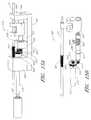
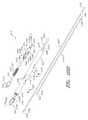
- FIG. 1is a partially exploded perspective view of a first embodiment of a tissue removal system constructed according to the teachings of the present invention
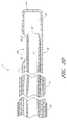
- FIGS. 2( a ) through 2 ( d )are various views of the tissue removal device shown in FIG. 1 , the tissue removal device being shown in FIGS. 2( a ) through 2 ( c ) together with the distal ends of the vacuum tube and the external drive shaft;
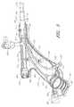
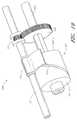
- FIG. 3is a perspective view of the introducer device shown in FIG. 1 ;
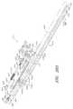
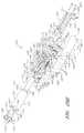
- FIGS. 4( a ) and 4 ( b )are exploded perspective views of the introducer device shown in FIG. 1 ;
- FIG. 5is a right perspective view of the introducer device shown in FIG. 1 , with the right half of the housing removed;
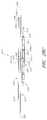
- FIG. 6is a longitudinal section view of the introducer device shown in FIG. 1 ;
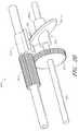
- FIG. 7is an enlarged fragmentary perspective view, shown in section, of the introducer device shown in FIG. 1 , with only the manifold, strain relief and sheath being shown;
- FIG. 8is an enlarged distal end view of the multi-lumen sheath of the introducer device shown in FIG. 1 ;
- FIG. 9is an enlarged fragmentary view of the instrument guide assembly of the introducer device shown in FIG. 1 ;
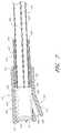
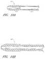
- FIGS. 10( a ) and 10 ( b )are fragmentary longitudinal section views of alternate inner tubular members that may be used in the tissue removal device shown in FIG. 1 ;
- FIG. 11is a side view of an alternate indicator sleeve that may be used in the tissue removal device shown in FIG. 1 ;
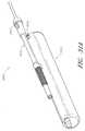
- FIG. 12is a fragmentary side view, partly in section, of an alternate combination of a tissue removal device and an introducer that may be used in the tissue removal system shown in FIG. 1 ;
- FIGS. 13( a ) and 13 ( b )are fragmentary side views, partly in section, of a further alternate combination of a tissue removal device and an introducer that may be used in the tissue removal system shown in FIG. 1 ;
- FIG. 14is a fragmentary side view, partly in section, of an alternate tissue removal device that may be used in the tissue removal system of FIG. 1 ;
- FIGS. 15( a ) and 15 ( b )are fragmentary perspective and fragmentary partially exploded perspective views, respectively, of another alternate tissue removal device that may be used in the tissue removal system of FIG. 1 ;
- FIG. 16is a fragmentary side view of another alternate tissue removal device that may be used in the tissue removal system of FIG. 1 ;
- FIG. 17is a fragmentary side view of another alternate tissue removal device that may be used in the tissue removal system of FIG. 1 ;
- FIG. 18is a fragmentary perspective view of another alternate tissue removal device that may be used in the tissue removal system of FIG. 1 ;
- FIG. 19is a fragmentary perspective view of another alternate tissue removal device that may be used in the tissue removal system of FIG. 1 ;
- FIG. 20is a fragmentary perspective view of another alternate tissue removal device that may be used in the tissue removal system of FIG. 1 ;
- FIG. 21is a fragmentary perspective view of another alternate tissue removal device that may be used in the tissue removal system of FIG. 1 ;
- FIGS. 22( a ) through 22 ( e )are various views of another alternate tissue removal device that may be used in the tissue removal system of FIG. 1 (the vacuum housing not being shown in FIGS. 22( c ) through 22 ( e ) to reveal components positioned therewithin);
- FIG. 23is a fragmentary section view of an obturator of the present invention inserted into the introducer shown in FIG. 1 ;
- FIG. 24is a side view of an alternate combination of an obturator and an introducer constructed according to the present invention.
- FIGS. 25( a ) and 25 ( b )are unassembled side and assembled section views, respectively, of another combination of an obturator and an introducer constructed according to the present invention
- FIGS. 26( a ) through 26 ( c )are fragmentary perspective views of another alternate introducer device to the introducer device shown in FIG. 1 , with the alternate introducer device being shown in partially exploded states in FIGS. 26( b ) and 26 ( c );
- FIG. 27is a perspective view of a second embodiment of a tissue removal system constructed according to the teachings of the present invention.
- FIGS. 28( a ) through 28 ( d )are bottom exploded perspective, top exploded perspective, bottom partially exploded, and fragmentary, partly in section, side views, respectively, of the morcellator assembly shown in FIG. 27 ;
- FIGS. 29( a ) and 29 ( b )are partially exploded top perspective and partially exploded bottom perspective views, respectively, of the drive assembly shown in FIG. 27 ;
- FIG. 30is a fragmentary, partially exploded, perspective view of an alternate tissue removal device that may be used in the tissue removal system of FIG. 27 ;
- FIGS. 31( a ) and 31 ( b )are fragmentary, partially exploded, perspective views of another alternate tissue removal device that may be used in the tissue removal system of FIG. 27 ;
- FIG. 32is a fragmentary, partially exploded, perspective view of another alternate tissue removal device that may be used in the tissue removal system of FIG. 27 ;
- FIG. 33is a fragmentary, partially exploded, perspective view of another alternate tissue removal device that may be used in the tissue removal system of FIG. 27 ;
- FIG. 34is a fragmentary section view of another alternate tissue removal device that may be used in the tissue removal system of FIG. 27 ;
- FIG. 35is a fragmentary section view of another alternate tissue removal device that may be used in the tissue removal system of FIG. 27 .
- the present inventionis described below primarily in the context of devices and procedures optimized for performing one or more therapeutic or diagnostic gynecological or urological procedures such as the removal of uterine fibroids or other abnormal uterine tissue.
- the devices and related procedures of the present inventionmay be used in a wide variety of applications throughout the body, through a variety of access pathways.
- the devices of the present inventioncan be optimized for use via open surgery, less invasive access such as laparoscopic access, or minimally invasive procedures such as via percutaneous access.
- the devices of the present inventioncan be configured for access to a therapeutic or diagnostic site via any of the body's natural openings to accomplish access via the ears, nose, mouth, and via trans-rectal, urethral and vaginal approach.
- the systems, methods, apparatus and devices of the present inventionmay be used to perform one or more additional procedures, including but not limited to access and tissue manipulation or removal from any of a variety of organs and tissues such as the bladder, breast, lung, stomach, bowel, esophagus, oral cavity, rectum, nasal sinus, Eustachian tubes, heart, gall bladder, spine, shoulder, knee, hip, brain, arteries, veins, and various ducts.
- Routes of accessinclude but are not limited to trans-cervical; trans-vaginal-wall; trans-uteral; trans-vesicle; trans-urethral; and other routes.
- FIG. 1there is shown a partially exploded perspective view of one embodiment of a tissue removal system, the tissue removal system being constructed according to the teachings of the present invention and being represented generally by reference numeral 5 .
- System 5is particularly well-suited for removing uterine fibroids and other abnormal gynecological tissues. However, it should be understood that system 5 is not limited to such a use and may be used in other anatomies that may be apparent to those of ordinary skill in the art.
- System 5may comprise a tissue removal device (or morcellator) 6 , an introducer device 7 , a flexible hysteroscope 8 , a fluid supply 9 , a vacuum assembly 10 , and a motor drive assembly 11 .
- tissue removal device 6may be seen in greater detail.
- Device 6may comprise complementary left and right housing halves 13 - 1 and 13 - 2 , respectively, each of which may be made of a rigid polymer or other suitable material.
- Halves 13 - 1 and 13 - 2may be joined together, for example, with screws 15 to form an elongated hollow housing 13 comprising a rounded side wall 16 , an open proximal end 17 , and an open distal end 19 .
- Housing 13may be bent or otherwise ergonomically shaped to fit comfortably in the hand of a user.
- a proximal cap 18may be mounted in proximal end 17 , cap 18 being shaped to include a pair of lumens 18 - 1 and 18 - 2 .
- Lumen 18 - 1may be used to receive, for example, an external drive shaft, and lumen 18 - 2 may be used to receive, for example, a vacuum tube.
- a distal cap 20may be mounted in distal end 19 , cap 20 being shaped to include a lumen, which may be used to receive, for example, a pair of coaxial cutting tubes.
- a plurality of ribs 14may be integrally formed and appropriately positioned along the respective interior surfaces of halves 13 - 1 and 13 - 2 , ribs 14 providing structural reinforcement to housing 13 and being used to align certain of the mechanical components that are positioned within housing 13 .
- Device 6may further comprise an internal drive shaft 21 adapted for rotation about its longitudinal axis.
- Shaft 21which may be an elongated unitary structure made of a suitably rigid metal or polymer, may be shaped to include a proximal end 23 and a distal end 25 .
- Proximal end 23 of shaft 21may be coaxially mounted over and fixed to the distal end 27 of an external drive shaft 29 , external drive shaft 29 being inserted through a retainer 28 mounted in housing 13 .
- the rotation of shaft 21may be mechanically coupled to the rotation of shaft 29 .
- Distal end 25 of shaft 21may be inserted through an opening 30 in an annular bushing 31 , which bushing 31 may be matingly mounted on a rib 14 - 1 via a circumferential slot 32 provided in bushing 31 .
- Device 6may further comprise a translation drive shaft 35 adapted for rotation about its longitudinal axis.
- Shaft 35which may be an elongated unitary structure made of a suitably rigid metal or polymer, may be shaped to include a proximal end 37 , an intermediate portion 39 , and a distal end 41 .
- Proximal end 37 of shaft 35may be coaxially mounted over and fixed to the distal end 25 of internal drive shaft 21 . In this manner, the rotation of shaft 35 may be mechanically coupled to the rotation of shaft 21 .
- Intermediate portion 39may be shaped to include a double helical portion comprising a right-handed threaded helical channel 42 and a left-handed threaded helical channel 43 .
- Helical channels 42 and 43may have identical or different pitches but preferably have identical pitches. Helical channels 42 and 43 may be smoothly blended together at their respective ends to form a continuous groove so that there may be a smooth transition from one helical channel to the other. Distal end 41 of shaft 35 may be appropriately dimensioned to be received within an opening 44 in an annular bushing 45 , which bushing 45 may be matingly mounted on a rib 14 - 2 via a circumferential slot 46 provided in bushing 45 . It should be noted that, although shaft 35 is adapted for rotation, shaft 35 is translationally stationary.
- Device 6may further comprise a gear assembly 50 adapted for rotation about its longitudinal axis.
- Gear assembly 50which may be an elongated unitary structure made of a suitably rigid metal or polymer, may be shaped to include a proximal spur gear 51 and a distal tube portion 52 .
- Gear assembly 50may be coaxially mounted over intermediate portion 39 of shaft 35 in an area between the double helical portion and distal end 41 , and gear assembly 50 may be fixed to shaft 35 using a pin inserted radially through tube portion 52 and into an opening provided in shaft 35 . In this manner, the rotation of spur gear 51 may be mechanically coupled to the rotation of shaft 35 .
- Device 6may further comprise an oscillating translation assembly 61 .
- Translation assembly 61may comprise a carriage 62 and a channel engagement member 63 .
- Carriage 62which may be a unitary structure made of a suitably rigid metal or polymer, may be shaped to include a proximal portion 64 , an intermediate portion 65 , and a distal portion 66 .
- the tops of proximal portion 64 and distal portion 66may extend beyond the top of intermediate portion 65 and may be shaped to include loops 67 - 1 and 67 - 2 , respectively, loops 67 - 1 and 67 - 2 being aligned with one another.
- a longitudinal bore 68 - 1may be provided near the bottom of carriage 62 , bore 68 - 1 being appropriately dimensioned to coaxially receive intermediate portion 39 of shaft 35 while permitting intermediate portion 39 to rotate freely therewithin.
- Channel engagement member 63which may be a unitary structure made of a suitably rigid metal or polymer, may be shaped to include a base 69 and a pawl 70 .
- Base 69may be disposed in an opening 68 - 2 that may extend downwardly from the top of intermediate portion 65 into communication with bore 68 - 1 , with pawl 70 traveling within the double helical portion of shaft 35 .
- pawl 70may continuously travel back and forth through the double helical portion of shaft 35 , thereby causing carriage 62 to oscillate translationally.
- the speed at which carriage 62 oscillates translationallymay be varied, for example, by varying the translational length of the double helical portion of shaft 35 , the angles of channels 42 and 43 , the rotational speed of shaft 29 , etc.
- Device 6may further comprise a shaft 72 adapted for rotation about its longitudinal axis.
- Shaft 72which may be an elongated, unitary, tubular structure made of a suitably rigid metal or polymer, may be shaped to include a proximal portion 72 - 1 and a distal portion 72 - 2 .
- Proximal portion 72 - 1may be inserted through loops 67 - 1 and 67 - 2 of carriage 62 and may freely rotate relative to loops 67 - 1 and 67 - 2 .
- Distal portion 72 - 2may be in the form of an elongated spur gear.
- Distal portion 72 - 2may be engaged with spur gear 51 of gear assembly 50 so that the rotation of spur gear 51 causes the rotation of shaft 72 .
- Distal portion 72 - 2may be elongated so that it may maintain engagement with spur gear 51 even as distal portion 72 - 2 moves translationally relative to spur gear 51 .
- the speed at which distal portion 72 - 2 rotates(and, therefore, the speed at which shaft 72 rotates) may be the same as or different than the speed at which spur gear 51 rotates, depending, for example, on the relative diameters of the two gears (the ratio of the rotational speeds of the two gears being inversely proportional to the ratio of the diameters of the two gears). Consequently, by appropriately dimensioning spur gear 51 and distal portion 72 - 2 , one can achieve a desired rotational speed, even where the rotational speed of the external drive shaft is fixed.
- distal portion 72 - 2has a diameter that is one-fourth the diameter of spur gear 51 and, therefore, rotates four times as fast as gear 51 . Therefore, if the external drive shaft has a speed of rotation of about 1500 rpm, gear 51 would rotate at 1500 rpm and distal portion 72 - 2 would rotate at 6000 rpm. As can be appreciated, the rotational speed of distal portion 72 - 2 does not depend on the interaction of translation assembly 61 with the double helical portion of shaft 35 ; consequently, distal portion 72 - 2 may attain higher or lower rotational speeds than would be possible based on the requirements of a desired translational speed. Notwithstanding the above, shaft 72 is translationally coupled to carriage 62 . Consequently, as carriage 62 oscillates translationally, so does shaft 72 .
- Device 6may further comprise a strain relief member 74 , which may be a unitary tubular structure made of a rigid polymer or metal.
- the proximal end of strain relief member 74may be fixedly mounted in a retainer 75 , which may be mounted at the distal end of housing 13 , with the distal end of strain relief 74 extending distally from housing 13 for a short distance, such as, for example, approximately 2 inches.
- Device 6may further comprise a cutting mechanism.
- the cutting mechanismmay comprise an outer tubular member 76 and an inner tubular member 77 , inner tubular member 77 moving rotationally and, at the same time, oscillating translationally relative to outer tubular member 76 in the manner to be described further below.
- Outer tubular member 76which may be a unitary structure made of stainless steel or another similarly suitable material, may be shaped to include an open proximal end, a closed distal end 81 , and a lumen 82 extending from open proximal end 79 to a point just prior to closed distal end 81 .
- Member 76may be coaxially mounted within strain relief member 74 , with the proximal end of member 76 disposed within the proximal end of strain relief member 74 and with distal end 81 of member 76 extending distally beyond the distal end of strain relief member 74 for an extended distance, such as, for example, five inches.
- the proximal end of member 76may be fixed within retainer 75 .
- Outer tubular member 76may be further shaped to include a resection window 89 into which tissue may be captured and drawn, window 89 being located proximate to distal end 81 , such as, for example, 0.25 inch from distal end 81 .
- Window 89may be shaped to include a proximal end 89 - 1 and a distal end 89 - 2 .
- Proximal end 89 - 1may slope gradually proximally, and distal end 89 - 2 may slope gradually distally.
- window 89may have a length of approximately 0.55 inch
- proximal end 89 - 1may be a radial end having a radius of curvature of, for example, 0.085 inch
- distal end 89 - 2may be a radial end having a radius of curvature of, for example, 0.150 inch.
- Window 89may extend over a substantial portion of the circumference of tubular member 76 , such as, for example, about 60% of the circumference.
- Outer tubular member 76may have an outer diameter less than about 5.5 mm. However, in order to reduce the risk of injury to the patient and in order to obviate the need for anesthesia to be administered to the patient, outer tubular member 76 preferably has an outer diameter less than about 5 mm, more preferably less than 4 mm, even more preferably less than 3 mm, and still even more preferably less than 2 mm. However, should device 6 be used in an operating room setting where general anesthesia is available, the diameter of the outer tubular member 76 could be increased to maximize tissue removal. In such a case, outer tubular member 76 could have a diameter generally less than about 12 mm, preferably less than about 11 mm, and for certain applications less than 10 mm.
- outer tubular member 76could be constructed having an outer diameter of no more than about 9 mm, in some applications less than about 8 mm, preferably less than 7 mm, and more preferably less than 6 mm where OD is desirably minimized.
- Inner tubular member 77which may be an elongated unitary structure made of stainless steel or another similarly suitable material, may be shaped to include a proximal end 91 , a distal end 92 , and a longitudinal lumen 93 .
- Distal end 92may be shaped to include an external bevel, such as, for example, an external bevel of approximately 20 degrees.
- An intermediate length of tubular member 77may be coaxially received within shaft 72 and may be fixedly coupled to shaft 72 for translational and rotational movement therewith.
- Proximal end 91 of tubular member 77may be slideably mounted within a vacuum tube connector 95 , which may, in turn, be coupled to a vacuum tube 393 inserted through lumen 18 - 2 of cap 18 .
- An O-ring 96may be mounted within connector 95 to maintain a good seal with tubular member 77 .
- An annular bushing 98 mounted within housing 13may be used to receive tubular member 77 and to maintain its alignment.
- Tubular members 76 and 77may be arranged so that, when tubular member 77 is in a fully retracted (i.e., proximal) position, distal end 92 of tubular member 77 may be withdrawn sufficiently to permit tissue to enter window 89 (preferably with distal end 92 of tubular member positioned proximal to window 89 ), and so that, when tubular member 77 is in a fully advanced (i.e., distal) position, distal end 92 of tubular member 77 may be positioned distally of distal end 89 - 2 of window 89 . In this manner, as tubular member 77 is moved translationally and rotationally past window 89 , tissue within window 89 may be sheared. To promote such a shearing of tissue, the outer diameter of inner tubular member 77 may be just slightly less (e.g., about 0.002 inch) than the inner diameter of outer tubular member 76 .
- the thermal energy created by the contact of the rotating inner tube 77 and outer tube 76can lead to galling where the two tubular members fuse together.
- the outer surface of inner tube 77has been covered with a low friction, low abrasion coating (i.e., Titanium Nitride).
- the coatingcan be carried by the inner surface of the outer tube 76 .
- the coatingmay have a Rockwell C hardness of at least about 50, preferably at least about 60 and in some devices at least about 70.
- Device 6may further comprise an indicator sleeve 98 .
- Sleeve 98which may be an elongated tubular member made of a material that is easily distinguishable visually from strain relief member 74 , may be coaxially mounted over strain relief member 74 and fixedly mounted thereto, with a proximal end 98 - 1 of sleeve 98 lying flush against the distal end of housing 13 .
- An example of a material suitable for use as sleeve 98may be a white or colored length of shrink-wrap material.
- Sleeve 98may be dimensioned so that, when device 6 is inserted into introducer device 7 , distal end 98 - 2 of sleeve 98 is visible to a user until distal end 81 of device 6 is advanced beyond the distal end of introducer 7 .
- distal end 98 - 2may be used to indicate when distal end 81 of device 6 lies flush with the distal end of introducer 7 . In this manner, a user may safely control the position of the distal end of device 6 and, therefore, keep it within introducer 7 when inserting device 6 into a patient, thereby reducing the risks for lacerations and perforations during introduction of device 6 .
- introducer 7may comprise a housing 121 .
- Housing 121may comprise a left handle half 123 and a right handle half 125 .
- Left handle half 123 and right handle half 125which may be molded or otherwise fabricated from a rigid polymer or other suitable material, may be joined by a plurality of screws 127 . Instead of being joined by screws 127 , left handle half 123 and right handle half 125 may be joined using a suitable adhesive, crush pins, or may be welded together ultrasonically or otherwise.
- Left handle half 123 and right handle half 125jointly define a hollow, gun-shaped structure comprising a handle portion 129 and a barrel portion 131 .
- Handle portion 129may be shaped to include an opening 133 provided at its bottom end 134 and an opening 135 provided along its distal face 136 near bottom end 134 .
- a slot 133 - 1may be provided in right handle half 125 , slot 133 - 1 extending from opening 133 towards barrel portion 131 for a short distance.
- Barrel portion 131may be shaped to include an opening 137 provided at its proximal end 138 and an opening 139 provided at its distal end 140 .
- barrel portion 131may be shaped to include a transverse opening 141 provided in right handle half 125 at a location intermediate to proximal end 138 and distal end 140 .
- left handle half 123 and right handle half 125may shaped to include complementary sets of ribs (not shown). Such ribs may provide structural reinforcement to left handle half 123 and right handle half 125 and may help to maintain the correct positioning and alignment of the components positioned within housing 121 .
- Introducer 7may further comprise a manifold 145 .
- Manifold 145which may be molded or otherwise fabricated from a rigid polymer or other suitable material, may be a unitary, branched structure shaped to include a main tubular member 147 and a side tubular member 149 .
- Main member 147may comprise a proximal end 151 , an open distal end 153 , a side wall 155 , and a longitudinal lumen 157 .
- Proximal end 151 of main member 147may be shaped to include a top opening 159 of comparatively greater diameter and a bottom opening 161 of comparatively smaller diameter.
- Side member 149may comprise an open proximal end 163 , an open distal end 165 , a side wall 167 , and a longitudinal lumen 169 .
- Lumen 169 of side member 149may be in fluid communication with lumen 157 of main member 147 through open distal end 165 .
- Manifold 145may be coupled to housing 121 using a pair of pins 171 and 173 that may extend from side wall 155 and that may be received within hollow embossments 175 and 177 , respectively, provided on the interior faces of left handle half 123 and right handle half 125 , respectively. With manifold 145 thus coupled to housing 121 , proximal end 151 of manifold 145 may be positioned in barrel portion 131 , with side wall 155 tightly fitting within opening 139 and with distal end 153 of manifold 145 extending distally a short distance beyond distal end 140 .
- Introducer 7may further comprise a strain relief member 181 .
- Strain relief member 181which may be molded or otherwise fabricated from a rigid polymer or other suitable material, may be a unitary tubular structure shaped to include an open proximal end 183 , an open distal end 185 , a side wall 187 , and a longitudinal lumen 189 .
- Strain relief member 181may be partially inserted into lumen 157 of manifold 145 and may be tightly fitted within lumen 157 and fixedly secured thereto using a suitable adhesive or the like, with proximal end 183 of strain relief member 181 being positioned just distal to open distal end 165 of side member 149 and with distal end 185 of strain relief member 181 extending distally a short distance beyond distal end 153 of main member 147 .
- Introducer 7may further comprise a sheath 191 , which is also shown separately in FIG. 8 .
- Sheath 191which may be extruded or otherwise fabricated from a suitable polymer, such as nylon 12, may be a rigid, unitary structure shaped to include a proximal end 192 , a distal end 193 , and a side wall 194 .
- Sheath 191may be further shaped to include a plurality of longitudinal lumens of fixed shape and size, such lumens including a top lumen 196 , a bottom lumen 197 , and a pair of side lumens 198 - 1 and 198 - 2 .
- top lumen 196may be used as an instrument lumen
- bottom lumen 197may be used as a visualization lumen
- side lumens 198 - 1 and 198 - 2may be used as inflow fluid supply lumens.
- Proximal end 192 of sheath 191may be partially inserted into lumen 189 of strain relief member 181 and may be tightly fitted within lumen 189 and fixedly secured thereto using a suitable adhesive or the like, with proximal end 192 of sheath 191 flush with proximal end 183 of strain relief member 181 and with distal end 193 of sheath 191 extending distally beyond distal end 185 of strain relief member 181 for several inches.
- Sheath 191which is preferably the only component of introducer 7 that is to be inserted into a patient, may be dimensioned to have an outer diameter of about 5.5 mm, with lumen 196 having a diameter of about 3 mm, lumen 197 having a diameter of about 2 mm, and lumens 198 - 1 and 198 - 2 each having a diameter of about 1.33 mm.
- the ratio of the outer diameter to the working channelis an exemplary metric of introducer efficiency. It can be seen that the optimal ratio would be about 1.0, preferably no more than about 2.1 and more preferably no more than about 1.9. In the case provided herein, the ratio of these diameters is about 1.83 while predicate systems have ratios of 2.25.
- sheath 191By thus dimensioning sheath 191 , if sheath 191 is inserted through the cervix of a patient, the risk of injury to the patient and the need for anesthesia to be administered to the patient may be minimized.
- the above dimensions for sheath 191are merely exemplary and may be varied depending upon how introducer 7 is to be used.
- Introducer 7may further comprise an instrument guide assembly mounted within housing 121 for providing a continuous channel aligned with lumen 196 into which tissue removal device 6 may be inserted.
- the instrument guide assemblymay comprise a guide body 201 .
- Body 201which may be molded or otherwise fabricated from a rigid polymer or other suitable material, may be a unitary tubular structure shaped to include a proximal portion 203 , a distal portion 205 and an intermediate portion 207 .
- Intermediate portion 207may be reduced in inner diameter and in outer diameter relative to proximal portion 203 and distal portion 205 so that an annular seat 208 is formed within body 201 at the juncture of intermediate portion 207 and distal portion 205 .
- the interior surface of body 201may taper inwardly from proximal portion 203 to intermediate portion 207 to facilitate insertion of device 6 into intermediate portion 207 and to delimit the extent to which device 6 may be inserted into body 201 .
- Body 201may be tightly fitted within opening 137 of housing 121 and fixedly secured thereto using a suitable adhesive or the like, with distal portion 205 and intermediate portion 207 of body 201 being positioned within barrel portion 131 of housing 121 and with proximal portion 203 of body 201 extending through opening 137 and continuing proximally for a short distance beyond proximal end 138 of housing 121 .
- the instrument guide assemblymay further comprise a sleeve 211 .
- Sleeve 211which may be molded or otherwise fabricated from a rigid polymer or other suitable material, may be a unitary, branched structure shaped to include a main tubular member 213 and a side tubular member 215 .
- Main member 213may comprise an open proximal end 216 , an open distal end 217 , and a longitudinal lumen 219 .
- Proximal end 216 of main member 213may be shaped to be tightly fitted within distal portion 205 of body 201 and may be bonded thereto using a suitable adhesive.
- Side member 215may comprise an open proximal end 220 , an open distal end 221 and a longitudinal lumen 223 .
- Lumen 223 of side member 215may be in fluid communication with lumen 219 of main member 213 through open proximal end 220 .
- Distal end 221 of side member 215may extend through opening 141 provided in right handle half 125 of housing 121 and may be coupled to a valve 228 .
- Valve 228may be an actively-controlled valve, such as a stopcock valve, or a passively-controlled valve, such as a spring-activated ball valve.
- Valve 228may be connected at its output end to a length of tubing (not shown), as well as to a fluid receptacle (not shown), for conducting, as well as collecting, for example, outflow fluid passing through valve 228 , for example, when device 6 is not present within introducer 7 .
- the instrument guide assemblymay further comprise the combination of a seal 231 and a valve 233 .
- Seal 231 and valve 233may be elastomeric members securely positioned between seat 208 of body 201 and proximal end 216 of sleeve 211 (see FIG. 9 ).
- Seal 231which may be located proximally relative to valve 233 , may include a central opening 235 . Opening 235 may be appropriately dimensioned so that, when device 6 is inserted therethrough, fluid may not readily pass proximally through seal 231 around the outside of device 6 .
- Valve 233which may be shaped to include a dome having a cross-slit at its top, may be designed so that, in the absence of device 6 being inserted therethrough, fluid may not readily pass proximally therethrough.
- the instrument guide assemblymay further comprise a tube 241 .
- Tube 241which may be a rigid hypotube made of stainless steel or the like, may comprise a proximal end 243 and a distal end 245 .
- Proximal end 243may be fixedly mounted within lumen 219 of sleeve 211 using a suitable adhesive or the like.
- Distal end 245 of tube 241may be tightly fitted within lumen 196 of sheath 191 and may be secured therewithin using a suitable adhesive or the like.
- Introducer 7may further comprise a visualization guide assembly mounted within housing 121 for providing a continuous channel aligned with lumen 197 into which hysteroscope 8 may be inserted.
- the visualization guide assemblymay comprise a guide body 251 .
- Body 251which may be molded or otherwise fabricated from a rigid polymer or other suitable material, may be a unitary tubular structure shaped to include a proximal portion 253 of comparatively greater diameter, a distal portion 255 of comparatively smaller diameter, and an intermediate portion 257 tapering in diameter from proximal portion 253 to distal portion 255 .
- Body 251may be disposed within handle portion 129 of housing 121 , with proximal portion 253 spaced inwardly a short distance from opening 133 and with distal portion 255 facing towards barrel portion 131 .
- Proximal portion 253may be tightly fitted between and fixedly secured to left handle half 123 and right handle half 125 of housing 121 using adhesive or other suitable means.
- proximal portion 253may be appropriately dimensioned to receive the proximal portion of hysteroscope 8 , with intermediate portion 257 of body 251 being appropriately dimensioned to serve as a stop to limit the extent to which hysteroscope 8 may be inserted into body 251 .
- An annular seat 258may be provided within distal portion 255 and may be spaced proximally relative to distal end 259 of distal portion 255 .
- the visualization guide assemblymay further comprise a guide connector 261 .
- Guide connector 261which may be molded or otherwise fabricated from a rigid polymer or other suitable material, may be a unitary tubular structure shaped to include a proximal portion 263 of comparatively greater diameter, a distal portion 265 of comparatively smaller diameter, and an intermediate portion 267 tapering in diameter from proximal portion 263 to distal portion 265 .
- Proximal portion 263may be shaped to be tightly fitted within distal portion 255 of body 251 and may be bonded thereto using a suitable adhesive.
- the visualization guide assemblymay further comprise the combination of a seal 271 and a valve 273 .
- Seal 271 and valve 273may be elastomeric members securely positioned between seat 258 of body 251 and proximal portion 263 of connector 261 .
- Seal 271which may be located proximally relative to valve 273 , may include a central opening appropriately dimensioned so that, when hysteroscope 8 is inserted therethrough, fluid may not readily pass proximally through seal 271 around the outside of hysteroscope 8 .
- Valve 273which may be shaped to include a dome having a cross-slit at its top, may be designed so that, in the absence of hysteroscope 8 being inserted therethrough, fluid may not readily pass proximally therethrough.
- the visualization guide assemblymay further comprise a tube 281 .
- Tube 281which may be a flexible unitary member fabricated from a suitable polymer or other material, may comprise a proximal end 283 , a distal end 285 , and a lumen 286 .
- Proximal end 283may be fixedly mounted within distal portion 265 of connector 261 using a suitable adhesive or the like.
- Distal end 285 of tube 281may be tightly fitted within lumen 197 of sheath 191 and may be secured therewithin using a suitable adhesive or the like.
- Lumen 286may be appropriately dimensioned so that the distal portion of hysteroscope 8 may be inserted thereinto and, in this manner, guided by tube 281 to lumen 197 .
- Introducer 7may further comprise a mechanism for reversibly coupling hysteroscope 8 to the visualization guide assembly.
- This mechanismmay comprise a cam lock 291 .
- Lock 291which may be fabricated from a rigid polymer or other suitable material, may be a unitary structure shaped to comprise a lever 292 and a fulcrum 293 .
- the fulcrum 293may be pivotally mounted on housing 121 using a pivot pin 294 inserted through a transverse opening 295 in fulcrum 293 and securely received at its opposite ends in openings 296 and 297 provided in left handle half 123 and right handle half 125 , respectively.
- Fulcrum 293may comprise a face 298 adapted to frictionally engage the proximal portion of hysteroscope 8 when lever 292 is pivoted towards handle portion 129 .
- Introducer 7may further comprise a tube 301 .
- Tube 301which may be fabricated from a suitable polymer or other material, may be a flexible unitary structure shaped to include a proximal end 303 and a distal end 305 .
- Proximal end 303may be secured to the distal end of a luer fitting 307 securely mounted within opening 135 of housing 121 .
- Distal end 305may be positioned within lumen 169 of manifold 145 and may be secured in place using an adhesive or other suitable means.
- luer fitting 307may be connected to the output of fluid supply 9 . In this manner, fluid dispensed through fitting 307 and into tube 301 may be conducted by tube 301 to manifold 145 . Thereafter, the fluid in manifold 145 may flow distally through lumens 198 - 1 and 198 - 2 of sheath 191 .
- hysteroscope 8which may be, for example, a conventional flexible hysteroscope, may comprise a proximal portion 311 and a distal portion 313 .
- Proximal portion 311which may be comparatively rigid, compact in length, and wide in diameter, may comprise an input port 315 , an output port 317 , and a distal end 318 .
- Distal portion 313which may be comparatively flexible, elongated in length, and narrow in diameter, may comprise a distal end 319 .
- Hysteroscope 8may be appropriately dimensioned so that distal end 318 of proximal portion 311 may be received in body 251 , with distal portion 313 extending distally through seal 271 , valve 273 , connector 261 , tube 281 and lumen 197 and with distal end 319 positioned at or a short distance beyond distal end 193 of sheath 191 .
- proximal portion 311 of hysteroscope 8may be provided with notches or other physical features that may be used to mate with or otherwise engage cam lock 291 .
- Distal end 319 of hysteroscope 8may be constructed to permit the viewing of objects, such as at 0, 15 or 30 degree angles, relative to the longitudinal axis of distal portion 313 . In this manner, by placing hysteroscope 8 in a particular angular orientation, hysteroscope 8 may be used to view the operation of the distal end of device 6 . Such an angular orientation may be ensured by orienting hysteroscope 8 so that input port 315 is aligned with and extends through slot 133 - 1 .
- Fluid supply 9may comprise a fluid-containing syringe, a peristaltic pump or another suitable fluid-dispensing device having an output end 321 that may be coupled to luer fitting 307 .
- Fluid supply 9may comprise automated means (not shown) for dispensing inflow fluid therefrom at a desired rate.
- Vacuum assembly 10may include a specimen collection container 391 and a vacuum source 392 .
- the distal end of an evacuation tube 393may be connected to the proximal end of vacuum tube connector 95 , and the proximal end of evacuation tube 393 may be coupled to a first port 394 of container 391 .
- the distal end of a tube 395may be coupled to a second port 396 of container 391 , and the proximal end of tube 395 may be coupled to vacuum source 392 .
- vacuum source 392may be used to apply suction to device 6 , and any withdrawn tissue, liquids or similar matter suctioned through device 6 may be collected in container 391 .
- Motor drive assembly 11which may be coupled to a source of electricity, such as an AC wall outlet, using a power cord (not shown), may include a housing 397 , in which there may be disposed electronics (not shown) and a motor (not shown).
- a foot pedal 398may be coupled to the motor drive assembly by a cable 398 - 1 and may be used as a power switch to selectively activate or de-activate the motor.
- the proximal end of shaft 29may be mechanically coupled for rotation to the motor, and the distal end of shaft 29 may be inserted through opening 18 - 1 in mounting block 18 and coupled to internal shaft 21 in the manner discussed above.
- a protective sheath 399may cover much of the length of shaft 29 .
- Motor drive assembly 11may further include a vacuum sensor 400 , which may be coupled to container 391 by a tube 401 , so that the pressure within container 391 may be monitored. In this manner, a sudden increase in vacuum pressure may indicate that a clog has occurred. The presence of a clog may be indicated via an alarm (not shown) located on housing 397 . The detection of a clog is often a clear indication that the further operation of device 6 may only aggravate the clogging situation and that a cessation of tissue removal may be necessary.
- Motor drive assembly 11may be configured to synchronize actuation of the motor with actuation of vacuum source 392 . In this manner, turning on the motor will turn on vacuum source 392 at the same time. Correspondingly, vacuum source 392 may be deactivated whenever the motor is turned off.
- distal end 319 of hysteroscope 8may be inserted first through the visualization guide channel of introducer 7 , next through manifold 145 , and then through lumen 197 of sheath 191 .
- cam lock 291may be used to secure proximal portion 311 of hysteroscope 8 to introducer 7 .
- Input end 315 and output end 317 of hysteroscope 8may then be coupled to a light source and to a camera, respectively. Alternatively, the camera may be omitted, and output end 317 may be observed directly with the unaided eye.
- Fluid supply 9may then be coupled to luer fitting 307 of introducer 7 .
- Distal end 193 of sheath 191may then be inserted transcervically, i.e., through the vagina and the cervix, into the uterus of the patient.
- the cervixPrior to introducing distal end 193 of sheath 191 into the patient, the cervix may be gradually dilated in the conventional manner using obturators of increasing diameter.
- the uterusmay then be washed of blood and other debris that may be present by dispensing fluid from fluid supply 9 into introducer 7 , which fluid may then exit introducer 7 distally through lumens 198 - 1 and 198 - 2 .
- Valve 228may be opened during this washing procedure so that fluid and any debris present in the uterus may exit the uterus proximally through lumen 196 of sheath 191 and, thereafter, may exit introducer 7 by passing proximally through tube 241 , into main member 213 of sleeve 211 , through side member 215 of sleeve 211 , and through valve 228 .
- valve 228may be closed while fluid may continue to be dispensed into the uterus through lumens 198 - 1 and 198 - 2 , thereby causing the uterus to become distended by the fluid.
- valve 228When the uterus becomes sufficiently distended by such fluid, valve 228 may be opened while fluid may continue to be dispensed into the uterus. In this manner, the uterus may be maintained at a desired degree of distension while fluid is continuously circulated through the uterus. With the uterus thus distended with fluid, hysteroscope 8 may be used to examine the interior of the uterus.
- tissue removal device 6may be loaded into introducer 7 , i.e., by inserting the distal ends of outer tubular member 76 and inner tubular member 77 distally through the instrument channel guide of introducer 7 and then through channel 196 of sheath 191 , with housing 13 remaining external to the patient. Device 6 may then be manipulated so that window 89 of outer tubular member 76 may be positioned in proximity to the fibroid or other targeted tissue. Next, vacuum source 392 may be operated so as to cause suction to be applied to inner tubular member 77 , thereby drawing tissue into outer tubular member 76 through window 89 .
- the motor of motor drive assembly 11may be actuated, thereby causing inner tubular member 77 simultaneously to rotate and to oscillate back and forth translationally within outer tubular member 76 , resulting in the tissue drawn through window 89 to be cut.
- the cut tissuemay then be suctioned from the patient through inner tubular member 77 by means of the aforementioned suction and, thereafter, collected in container 391 .
- vacuum source 392 and the motormay be turned off, device 6 may be withdrawn from introducer 7 , and introducer 7 may be withdrawn from the patient.
- Device 6may be designed to be a single use device. If so, device 6 may then be disconnected from evacuation tube 393 and flexible motor shaft 398 - 2 and disposed of properly.
- fluidmay be administered transcervically to the uterus by a fluid dispensing device in order to distend the uterus, and, thereafter, observation of the uterus may be accomplished, for example, by ultrasonic imaging using an ultrasonic probe inserted transcervically into the uterus.
- ultrasonic imagingmay be separate from device 6 or may be integrated into device 6 .
- imaging of the uterusmay be performed by MRI imaging.
- speed of rotational movement of inner tubular member 77at least 1100 rpm, more preferably at least 5000 rpm, even more preferably approximately 6000 rpm; frequency of oscillating translational movement of tubular member 77 —at least 1.5 cycles/second, more preferably about 2.5 to 4 cycles/second, even more preferably about 2.8 cycles/second; advance ratio of preferably less than 0.25, more preferably less than 0.15; and vacuum pressures in the range of 200 to 650 mmHg.
- the above parametersare selected to achieve a rate of tissue removal of at least 1.5
- system 5is constructed and operated so that, with a vacuum in excess of 300 mmHg, a volume of no more than about 300 cc/min of fluid is removed. This may involve, for example, applying suction only at specific times, for example, only when the motor for moving inner tubular member 77 is actuated or by closing resection window 89 with inner tubular member 77 each time the motor control is stopped.
- morcellatorsmay be built in accordance with the present invention to have a lower outside diameter or crossing profile than current commercial products such as the Smith & Nephew Hysteroscopic Morcellator, but at the same time accomplish a higher tissue resection rate.
- morcellators in accordance with the present inventionmay be operated at a significantly higher vacuum while managing total fluid flow within acceptable limits.
- the cross sectional area of the aspiration lumen in morcellators in accordance with the present inventionwill typically be no more than about 12.0 square millimeters, and often no more than about 10.0 square millimeters.
- a cross sectional area of the aspiration lumenwill be no more than about 8.0 millimeters squared, and, for certain applications, the area will be no more than about 7.5 square millimeters.
- the tissue resection rateis generally at least about 1.5 gm/min, and often at least about 1.8 gm/min. In certain embodiments, the tissue resection rate is at least about 2.0 gm/min, and, in one embodiment, 2.2 or more gm/min.
- Morcellators in accordance with the present inventionmay be constructed to have a fluid usage of no more than about 350 ml/min. In certain embodiments, fluid usage of no more than about 300 ml/min or no more than about 275 ml/min may be constructed.
- Applied vacuum to the morcellators of the present inventionwill generally be in the range of from about 200 to about 650 mm Hg.
- the morcellatorwill typically be run at a vacuum of at least about 350 mm Hg, and, often at least about 500 mm Hg.
- the cross sectional area of the aspiration lumenwas about 7.1 mm 2 , and yielded a tissue resection rate of about 1.4 gm/min, under vacuum of approximately 600 mm Hg.
- procedures accomplished in accordance with the present inventionwill require no more than about 10 minutes, and preferably, no more than about 8 or 9 minutes of active morcellation.
- total fluide.g. saline
- Distension fluidwill preferably be maintained at a low enough pressure and short enough time to keep the total saline intravasation below 2.5 liters.
- the fluid flow rate for aspiration of saline through the morcellatoris approximately 260 ml/min (e.g. within the range of from about 240 to about 280 ml/min).
- the tissue resection rateis typically in excess of about 2 gm/min.
- a device manufactured in accordance with the present inventionwas compared to the performance of a reciprocating hysteroscopic morcellator from Smith and Nephew.
- the vacuumwas maintained on average in the 200 to 270 mm Hg range, morcellator speed was approximately 1100 rpm, tissue resection rate was approximately 1.4 gm/min, the fluid flow rate through the morcellator was approximately 247 ml/min, and the outside diameter of the morcellator was 4.0 mm.
- the device constructed in accordance with the present inventionwas operated at a vacuum of 600 mm Hg, a speed of about 6000 rpm, to produce a resection rate of approximately 2.2 gm/min and an aspiration flow rate of about 266 ml/min through the morcellator.
- the outside diameter of the devicewas 3 mm.
- the morcellator in accordance with the present inventionthus produced a significantly higher resection rate, through a smaller outside diameter morcellator, at a roughly comparable flow rate of aspirated saline.
- the vacuumIn order to increase the resection rate of the predicate device, the vacuum must be significantly increased. For example, when the vacuum pressure in the predicate system was increased to about 670 mm Hg, the tissue cutting improved to 3.5 gm/min but fluid flow rate jumped to 540 ml/min.
- FIGS. 10( a ) and 10 ( b )there are shown fragmentary longitudinal section views of certain alternate inner tubular members that may be used in tissue removal device 6 .
- a first such alternate inner tubular memberis shown in FIG. 10( a ) and is represented generally by reference numeral 411 .
- Inner tubular member 411may be similar in certain respects to inner tubular member 77 ; however, one notable difference between the two tubular members is that, whereas inner tubular member 77 may be a unitary structure made from a single piece of material, inner tubular member 411 may be formed by joining together two separate pieces of material.
- inner tubular member 411may comprise a first piece in the form of a proximal stem 413 and a second piece in the form of a distal tip 415 , with distal tip 415 preferably having a length greater than the length of resection window 89 and more preferably having a length of less than about 2 inches and in one construction, about 1 inch.
- Proximal stem 413 and distal tip 415may be made of the same material or may be made of different materials. Comparatively hard stainless steel materials, such as 400-series stainless steels (e.g., 440C stainless steel) where hardness exceeds Rockwell C values of about 50, are preferred for distal tip 415 as these materials enable a much sharper edge to distal tip 415 to be created.
- proximal stem 413may be less hard stainless steel materials, such as 300-series stainless steels (e.g., 304 stainless steel), may be preferred for proximal stem 413 as these materials may be comparatively inexpensively formed into long tubular structures, for example, by extrusion whereas harder stainless steel materials must be machined to form tubular structures.
- the Rockwell C hardness of these proximal tube materialsis less than about 40.
- Proximal stem 413 and distal tip 415may be joined together by welding or other suitable techniques. Any of a variety of cutter edge and window configurations may be used, depending upon the desired performance, including any of those disclosed in U.S. patent application Ser. No. 12/098,250, filed Apr. 4, 2008 to Gruber, et al., the disclosure of which is hereby incorporated by reference in its entirety herein.
- tubular member 411may have a uniform inner diameter over its length
- the inner diameter of distal tip 415may be reduced as compared to the inner diameter of proximal stem 413 (e.g., 0.082 inch vs. 0.085 inch).
- This clearance within proximal stem 413facilitates the proximal movement of the specimen through tubular member 411 .
- Tubular member 421may be similar in certain respects to tubular member 411 , the principal difference between the two tubular members being that tubular member 421 may be a unitary structure made from a single piece of material, which may be, for example, a 17-7-series stainless steel.
- tubular member 421may be a unitary structure made from a single piece of material, which may be, for example, a 17-7-series stainless steel.
- tubular member 421may first swage or roll the distal end of the tubular structure to reduce the inner diameter of the distal end and then may increase the inner diameter of the remainder of the structure by mechanically honing, expanding, or chemically etching.
- FIG. 11there is shown a side view of an alternate indicator sleeve 431 that may be used in tissue removal device 6 .
- Indicator sleeve 431may be similar in most respects to indicator sleeve 98 , the principal difference between the two indicator sleeves being that sleeve 431 may be provided with labeled or unlabeled gradations 433 along its length to indicate the distance between each gradation and a distal end 431 - 1 of sleeve 431 .
- gradations 433indicate the relative distance between distal end 92 of device 6 and the distal end of introducer 7 .
- Gradations 433may comprise, for example, numerical markings, symbols, hash marks, rings, or the like.
- FIG. 12there is shown a fragmentary side view, partly in section, of an alternate combination of a tissue removal device and an introducer that may be used in tissue removal system 5 , the subject tissue removal device being represented generally by reference numeral 441 and the subject introducer being represented generally by reference numeral 443 .
- Device 441 and introducer 443may be similar in most respects to device 6 and introducer 7 , respectively, the principal differences being that device 441 may include, instead of sleeve 98 , a position indicator ring 445 fixedly mounted on strain relief member 74 , and introducer 443 may include, instead of proximal portion 203 of body 201 , a proximal portion 447 appropriately shaped to provide just enough interference with bumps 445 - 1 and 445 - 2 on ring 445 so that a user may be given a tactile indication that ring 445 is being inserted into proximal portion 447 .
- FIGS. 13( a ) and 13 ( b )there are shown fragmentary side views, partly in section, of another alternate combination of a tissue removal device and an introducer that may be used in tissue removal system 5 , the subject tissue removal device being represented generally by reference numeral 451 and the subject introducer being represented generally by reference numeral 453 .
- Device 451may be identical to device 441 .
- Introducer 453may be similar in most respects to introducer 7 , the principal difference between the two introducers being that introducer 453 may be shaped to include a sound chamber 455 and may additionally include a spring clip or band 457 .
- Clip 457may have a fixed end 457 - 1 that is mounted within sound chamber 455 and a free end 457 - 2 that is constructed so as to be deflected by ring 445 when ring 445 is moved distally past clip 457 . The deflection of clip 457 by ring 445 causes clip 457 to oscillate and to generate an audible signal.
- FIG. 14there is shown a fragmentary side view, partly in section, of an alternate tissue removal device that may be used in tissue removal system 5 , said tissue removal device being represented generally by reference numeral 470 .
- tissue removal device 470Certain aspects of device 470 not important to an understanding of the invention are neither shown nor described herein.
- Device 470may be similar in most respects to device 6 , the principal differences between the two devices being that, whereas device 6 may comprise a rotational mechanism comprising a spur gear 51 engaged with a gear-shaped distal portion 72 - 2 of a shaft 72 , device 470 instead may comprise a rotational mechanism comprising a shaft 472 comprising a tubular elastomeric distal portion 472 - 2 engaged for rotation with an elastomeric O-ring 474 fixedly mounted within a groove 476 of a cylindrical member 478 fixedly coupled to translation drive shaft 35 .
- FIGS. 15( a ) and 15 ( b )there are shown fragmentary perspective and exploded perspective views, respectively, of another alternate tissue removal device that may be used in tissue removal system 5 , said tissue removal device being represented generally by reference numeral 500 . Certain aspects of device 500 not important to an understanding of the invention are neither shown nor described herein.
- Device 500may be similar in many respects to device 6 , one difference between the respective tissue removal devices being that device 500 may comprise a mounting bracket 501 .
- Bracket 501which may be a unitary structure made of a rigid metal or polymer, may be shaped to include a base portion 503 , a proximal block 505 extending upwardly from the proximal end of base portion 503 , a distal block 507 extending upwardly from the distal end of base portion 503 , and an intermediate block 509 extending upwardly from an intermediate portion of base portion 503 .
- device 500may instead comprise an internal drive shaft 510 , a translation drive shaft 511 , and a gear assembly 512 .
- Internal drive shaft 510which may be an elongated unitary structure made of a suitably rigid metal or polymer, may be shaped to include a proximal end 513 and a distal end 515 . Proximal end 513 of shaft 510 may be coaxially mounted over and fixed to the distal end of external drive shaft 29 . In this manner, the rotation of shaft 510 may be mechanically coupled to the rotation of shaft 29 .
- shaft 510may be received within a longitudinal bore 520 provided in block 505 of bracket 501 .
- Gear assembly 512may be fixedly mounted on distal end 515 of shaft 510 so as to rotate with shaft 510 .
- Gear assembly 512may include a larger diameter proximal spur gear 523 and a smaller diameter distal spur gear 525 .
- Translation drive shaft 511which may be an elongated unitary structure made of a suitably rigid metal or polymer, may be shaped to include a proximal end 537 , an intermediate portion 539 , and a distal end 541 .
- Proximal end 537 of shaft 511may be in the shape of a spur gear, which may be engaged with distal gear 525 .
- the rotation of shaft 511may be mechanically coupled to the rotation of shaft 510 , with the speed of rotation of shaft 511 being dependent on the speed of rotation of shaft 510 and the relative sizes of gear 525 and proximal end 537 .
- Intermediate portion 539may extend through a longitudinal bore 509 - 1 provided in block 509 of bracket 501 .
- Intermediate portion 539may be shaped to include a double helical portion 540 similar to the double helical portion of shaft 35 .
- Distal end 541 of shaft 511may be appropriately dimensioned to be received within an opening 544 provided in block 507 of bracket 501 . It should be noted that, although shaft 511 is adapted for rotation, shaft 511 is translationally stationary.
- device 500may instead comprise an elongated shaft 551 mechanically coupled to inner tubular member 77 so as to rotate and to oscillate translationally therewith.
- Shaft 551which may be a unitary tubular structure made of a rigid metal or polymer, may be shaped to include a spur gear engaged with proximal gear 523 .
- the gearmay be elongated so that it may maintain engagement with proximal gear 523 even as the gear moves translationally relative to proximal gear 523 .
- the speed at which shaft 551 rotatesmay be the same as or different than the speed at which gear 523 rotates, depending, for example, on the relative diameters of the two gears (the ratio of the rotational speeds of the two gears being inversely proportional to the ratio of the diameters of the two gears). Consequently, by appropriately dimensioning the gears, one can achieve a desired rotational speed, even where the rotational speed of the external drive shaft is fixed.
- the gear of shaft 551may have a diameter that is one-third the diameter of gear 523 and, therefore, rotates three times as fast as gear 523 .
- proximal end 537 of shaft 511may have a diameter that is four-thirds the diameter of gear 525 and, therefore, rotates three-quarters as fast as gear 525 . Therefore, if the external drive shaft has a speed of rotation of about 2000 rpm, shaft 551 (and inner tubular member 77 ) would rotate at about 6000 rpm and shaft 511 would rotate at about 1500 rpm, which, with an appropriate shaping of the double helix portion of shaft 511 , could be used to achieve an oscillating translational speed for inner tubular member 77 of about 2.8 cycles/second.
- FIG. 16there is shown a fragmentary side view of an alternate tissue removal device that may be used in tissue removal system 5 , said tissue removal device being represented generally by reference numeral 570 . Certain aspects of device 570 not important to an understanding of the invention are neither shown nor described herein.
- Device 570may be similar in many respects to device 6 .
- One difference between the two devicesmay be that, whereas device 6 may fix inner drive shaft 21 to external drive shaft 29 for rotation therewith and may couple the rotation of inner tubular member 77 to inner drive shaft 21 through the engagement of shaft 72 and gear 51 , device 570 may instead fix inner tubular member 77 to external drive shaft 29 for rotation therewith and may couple the rotation of inner drive shaft 21 to inner tubular member 77 through the engagement of a pair of spur gears 572 and 574 .
- Gear 572may be coaxially inserted over and fixed to inner tubular member 77
- gear 574may be coaxially inserted over and fixed to inner drive shaft 21 .
- Gears 572 and 574may be sized to be, for example, in a 1:4 ratio, respectively, so that, if external drive shaft 29 rotates at about 6000 rpm, inner tubular member 77 also rotates at about 6000 rpm whereas inner drive shaft 21 rotates at about 1500 rpm.
- tissue removal devicethat may be used in tissue removal system 5 , said tissue removal device being represented generally by reference numeral 580 .
- Certain aspects of device 580 not important to an understanding of the inventionare neither shown nor described herein.
- Device 580may be similar in many respects to device 6 .
- One difference between the two devicesmay be that, whereas device 6 may fix inner drive shaft 21 to external drive shaft 29 for rotation therewith and may couple the rotation of inner tubular member 77 to inner drive shaft 21 through the engagement of shaft 72 and gear 51 , device 580 instead may couple the rotation of inner drive shaft 21 to external drive shaft 29 through the engagement of a pair of spur gears 582 and 584 and may couple the rotation of inner tubular member 77 to external drive shaft 29 through the engagement of a spur gear 586 with gear 582 .
- Gear 582may be coaxially inserted over and fixed to external drive shaft 29
- gear 584may be coaxially inserted over and fixed to inner drive shaft 21
- gear 586may be coaxially inserted over and fixed to inner tubular member 77 .
- Gears 582 and 584may be sized to be, for example, in a 1:2 ratio, respectively
- gears 582 and 586may be sized to be, for example, in a 2:1 ratio, respectively. In this manner, if external drive shaft 29 rotates at about 3000 rpm, inner tubular member 77 rotates at about 6000 rpm and inner drive shaft 21 rotates at about 1500 rpm.
- FIG. 18there is shown a fragmentary perspective view of an alternate tissue removal device that may be used in tissue removal system 5 , said tissue removal device being represented generally by reference numeral 600 . Certain aspects of device 600 not important to an understanding of the invention are neither shown nor described herein.
- Device 600may be similar in many respects to device 6 .
- One difference between the two devicesmay be their respective mechanisms for rotating and translationally reciprocating inner tubular member 77 .
- device 600may comprise an internal drive shaft 603 fixed to an external drive shaft (not shown) so as to rotate therewith.
- Internal drive shaft 603may comprise a proximal portion 605 and a distal portion 607 .
- a spur gear 609 and a bevel gear 611may be coaxially mounted over distal portion 607 and fixed thereto for rotation therewith, with bevel gear 611 being positioned distally relative to spur gear 609 .
- a spur gear 613may be coaxially mounted over inner tubular member 77 and fixed thereto for rotation therewith, gear 613 being engaged with gear 609 so that the rotation of internal drive shaft 603 causes the rotation of inner tubular member 77 .
- the speed of rotation of inner tubular member 77as compared to that of drive shaft 603 , may be controlled by the relative diameters of gears 609 and 613 ).
- a bevel gear 615positioned distally relative to internal drive shaft 603 , may be engaged with bevel gear 611 .
- a saddle 619may be coaxially mounted over inner tubular member 77 , saddle 619 being fixed to inner tubular member 77 for translational movement therewith but permitting tubular member 77 to freely rotate therewithin.
- Saddle 619 and bevel gear 615may be coupled to one another by a pin (not shown) extending upwardly from the top surface 621 of gear 615 and a slot (not shown) provided on the bottom surface of saddle 619 , the slot in saddle 619 receiving the pin on bevel gear 615 .
- the slot in saddle 619may be oriented perpendicularly to the longitudinal axis of inner tubular member 77 and may be appropriately dimensioned so that the pin on bevel gear 615 travels back and forth within the slot in saddle 619 as bevel gear 615 rotates. In this manner, the rotation of bevel gear 615 may cause the translational oscillation of inner tubular member 77 .
- FIG. 19there is shown a fragmentary perspective view of an alternate tissue removal device that may be used in tissue removal system 5 , said tissue removal device being represented generally by reference numeral 700 . Certain aspects of device 700 not important to an understanding of the invention are neither shown nor described herein.
- Device 700may be similar in many respects to device 6 .
- One difference between the two devicesmay be their respective mechanisms for rotating and translationally reciprocating inner tubular member 77 .
- device 700may comprise an internal drive shaft 703 fixed to an external drive shaft (not shown) so as to rotate therewith.
- a spur gear 705 and a translation cam 707may be coaxially mounted over drive shaft 703 and fixed thereto for rotation therewith, with translation cam 707 being positioned distally relative to spur gear 705 .
- a spur gear 711may be coaxially mounted over inner tubular member 77 and fixed thereto for rotation therewith, gear 711 being engaged with gear 705 so that the rotation of internal drive shaft 703 causes the rotation of inner tubular member 77 .
- a saddle 713may be coaxially mounted over inner tubular member 77 , saddle 713 being fixed to inner tubular member 77 for translational movement therewith but permitting tubular member 77 to freely rotate therewithin.
- Saddle 713 and translation cam 707may be coupled to one another by a pin (not shown) extending downwardly from saddle 713 and a looped groove 717 provided in cam 707 , groove 717 receiving the pin on saddle 713 .
- Groove 717 in cam 707may be shaped to extend from about the proximal end 707 - 1 of cam 707 to about the distal end 707 - 2 of cam 707 and back to about the proximal end 707 - 1 of cam 707 over the course of one rotation of cam 707 . In this manner, as cam 707 rotates and the pin travels back and forth within groove 717 , inner tubular member 77 may be translationally oscillated correspondingly.
- FIG. 20there is shown a fragmentary perspective view of an alternate tissue removal device that may be used in tissue removal system 5 , said tissue removal device being represented generally by reference numeral 800 . Certain aspects of device 800 not important to an understanding of the invention are neither shown nor described herein.
- Device 800may be similar in many respects to device 6 .
- One difference between the two devicesmay be their respective mechanisms for rotating and translationally reciprocating inner tubular member 77 .
- device 800may comprise an internal drive shaft 801 fixed to an external drive shaft (not shown) so as to rotate therewith.
- a spur gear 803may be coaxially mounted over drive shaft 801 and fixed thereto for rotation therewith.
- a translation cam 805may be coaxially mounted over drive shaft 801 and fixed thereto for rotation therewith.
- Translation cam 805may comprise a tubular portion 805 - 1 and a disc portion 805 - 2 , disc portion 805 - 2 being fixedly mounted on tubular portion 805 - 1 at a non-perpendicular angle relative to the longitudinal axis of tubular portion 805 - 2 .
- a spur gear 813may be coaxially mounted over inner tubular member 77 and fixed thereto for rotation therewith, gear 813 being engaged with gear 803 so that the rotation of internal drive shaft 801 causes the rotation of inner tubular member 77 . (The speed of rotation of inner tubular member 77 , as compared to that of drive shaft 801 , may be controlled by the relative diameters of gears 803 and 813 ).
- a saddle 819may be coaxially mounted over inner tubular member 77 , saddle 819 being fixed to inner tubular member 77 for translational movement therewith but permitting tubular member 77 to freely rotate therewithin.
- Saddle 819may be shaped to include a recess 821 , which may receive the top of disc portion 805 - 2 . In this manner, as drive shaft 801 rotates, causing disc portion 805 - 2 to “wobble” back and forth, saddle 819 , and thus inner tubular member 77 , may be translationally oscillated correspondingly.
- FIG. 21there is shown a fragmentary perspective view of an alternate tissue removal device that may be used in tissue removal system 5 , said tissue removal device being represented generally by reference numeral 900 . Certain aspects of device 900 not important to an understanding of the invention are neither shown nor described herein.
- Device 900may be similar in many respects to device 6 .
- One difference between the two devicesmay be their respective mechanisms for rotating and translationally reciprocating inner tubular member 77 .
- device 900may comprise an internal drive shaft 901 fixed to an external drive shaft (not shown) so as to rotate therewith.
- a spur gear 903 and a worm gear 905may be coaxially mounted over drive shaft 901 and fixed thereto for rotation therewith.
- a spur gear 907may be coaxially mounted over inner tubular member 77 and fixed thereto for rotation therewith, gear 907 being engaged with gear 903 so that the rotation of internal drive shaft 901 causes the rotation of inner tubular member 77 .
- a worm gear 911may be engaged with worm gear 905 so that worm gear 911 rotates as worm gear 905 rotates.
- a pin 913may be mounted near the periphery of a front face 911 - 1 of worm gear 911 .
- a reciprocation arm 915may have a first end secured to pin 913 and a second end secured to a block 917 translationally coupled to inner tubular member 77 . In this manner, as worm gear 911 rotates and the position of pin 913 on worm gear 911 changes, arm 915 moves block 917 and inner tubular member 77 back and forth translationally.
- tissue removal device 940which is shown in FIGS. 22( a ) through 22 ( e ). Certain aspects of device 940 not important to an understanding of the invention are neither shown nor described herein.
- Device 940is similar in certain respects to device 6 . However, one difference between the respective devices is that device 940 may comprise an inner tubular member 943 having a closed proximal end 945 and a side window 947 .
- a spring mount 949may be coaxially mounted over inner tubular member 943 and fixed thereto for rotation therewith.
- the proximal end of a spring 951may be fixed to spring mount 949 , and the distal end of spring 951 may be fixed to a valve member 953 coaxially mounted over inner tubular member 943 , valve member 953 being capable of rotating relative to inner tubular member 943 .
- Valve member 953may include a side window 955 .
- Side window 955may be alignable with side window 943 depending on the respective rotational positions of inner tubular member 943 and valve member 953 .
- a stop 957may be formed on inner tubular member 943 , stop 957 being detachably engageable with valve member 953 to couple the rotation of valve member 953 with inner tubular member 943 .
- a vacuum housing 959may be coaxially mounted over valve member 953 , valve member 953 being freely rotatable within vacuum housing 959 .
- Outer tubular member 76may be fixedly mounted on vacuum housing 959 .
- a pair of O-rings 961 - 1 and 961 - 2may be provided to function as seals.
- introducer 7preferably comprises valve 233 , which is designed to keep fluid from escaping from the patient when device 6 is not inserted into introducer 7 .
- valve 233is designed to keep fluid from escaping from the patient when device 6 is not inserted into introducer 7 .
- FIG. 23there is shown a fragmentary section view of an obturator 965 positioned within a channel of introducer 7 .
- Obturator 965may be shaped to include a blunt distal end 967 and a plurality of openings 969 leading to a longitudinally-extending channel 971 .
- Obturator 965may be positioned in instrument channel 196 , as shown, or may be positioned in fluid input channel 198 - 1 or fluid input channel 198 - 2 to provide bidirectional fluid flow (for example, with fluid inflow exiting channels 198 - 1 or 198 - 2 in the space between channels 198 - 1 or 198 - 2 and obturator 965 and with fluid outflow entering obturator 965 through openings 969 ).
- the fluid outflow entering channel 971 through openings 969may exit obturator 965 through the proximal end (not shown) of obturator 965 .
- obturator 972An alternate obturator 972 is shown in FIG. 24 , obturator 972 having a side opening 973 at an intermediate location along its length, side opening 973 being aligned with an outflow fluid channel 975 provided in an alternate introducer 977 .
- obturator 972may be made of a resilient member having a bend and introducer 977 may be provided with a sheath 978 made of a flexible material. In this manner, obturator 972 may be used to provide a bend to sheath 978 , which, by rotating the proximal end 979 of obturator 972 , may be used to steer the distal end of sheath 978 .
- FIGS. 25( a ) and 25 ( b )there is shown an alternate combination of an obturator and an introducer according to the present invention, the obturator being represented generally by reference numeral 980 and the introducer being represented generally by reference numeral 981 .
- Obturator 980which may be similar in many respects to obturator 965 , may comprise a distal member 982 and a proximal member 983 .
- Distal member 982may be tubular and may comprise an open distal end 984 , a closed proximal end 985 , and a side opening 986 , with proximal member 983 being mounted over proximal end 985 of distal member 982 .
- Introducer 981may be similar in many respects to introducer 7 , one difference between the respective introducers being that introducer 981 may additionally comprise a fluid outflow channel 987 .
- Channel 987may comprise a distal end 987 - 1 that may be aligned with side opening 986 of obturator 980 when obturator 980 is installed in introducer 981 .
- outflow fluidmay flow from obturator 980 to channel 987 and may exit introducer 981 through a proximal end 987 - 2 of channel 987 .
- Introducer 981may additionally comprise a valve 988 - 1 and a valve 989 - 2 .
- Valve 988 - 1which may be a stopcock valve, may be used to control the flow of fluid through channel 987 .
- Valve 988 - 2which may be a stopcock valve, may be used to control the flow of fluid through inflow channel 989 .
- FIGS. 26( a ) through 26 ( c )there are shown various views of an alternate introducer device to introducer device 7 , the alternate introducer device being represented generally by reference numeral 990 .
- Introducer device 990may be similar in many respects to introducer device 7 .
- Introducer device 990may comprise a sheath 191 having a top lumen 196 , a bottom lumen 197 and a pair of side lumens 198 - 1 and 198 - 2
- introducer device 990may comprise a top tubular member 991 , a bottom tubular member 992 , a sleeve 993 , and a distal cap 994 .
- Top tubular member 991may be used, for example, as an instrument channel to receive, for example, tissue removal device 6 or obturator 965 .
- Bottom tubular member 992may be used, as is shown, for example, to receive distal end 319 of hysteroscope 8 .
- Sleeve 993which may be made of stainless steel or the like, may be appropriately dimensioned to coaxially receive top tubular member 991 and bottom tubular member 992 and may be shaped to define a pair of fluid channels 995 on opposite sides of tubular members 991 and 992 in the spaces between the inner surface of sleeve 993 and the outer surfaces of tubular members 991 and 992 .
- a plurality of transverse openings 996may be provided in sleeve 993 near the distal end 997 thereof, openings 996 providing side access to fluid channels 995 .
- fluid inflow to the patientmay be provided by having the fluid pass distally through channels 995 and then exit radially through openings 996 .
- Fluid outflow from the patientmay travel proximally through cap 994 and then proximally through top tubular member 991 (for example, by passing through an instrument positioned in top tubular member 991 ). It is believed that the fluid flow pattern provided by introducer device 990 may be particularly effective in removing blood and other undesired fluids from a patient.
- Cap 994may include a retainer 998 , which may receive the distal ends of tubular members 991 and 992 and which may be inserted into and fixed to the distal end 997 of sleeve 993 .
- FIG. 27there is shown a partially exploded perspective view of a second embodiment of a tissue removal system, the tissue removal system being constructed according to the teachings of the present invention and being represented generally by reference numeral 1007 .
- System 1007may comprise a tissue removal device 1008 , a vacuum assembly 1009 , and a motor drive assembly 1010 . Although not shown in the present embodiment, system 1007 may also include an introducer device, a flexible hysteroscope, and a fluid supply similar to those of system 5 described above.
- Tissue removal device 1008may comprise a morcellator assembly 1013 and a drive assembly 1015 , morcellator assembly 1013 being removably mounted on drive assembly 1015 in the manner described further below.
- Morcellator assembly 1013may comprise a housing 1021 .
- Housing 1021which may be an elongated unitary structure made of a rigid polymer or metal, may be a generally tubular member shaped to include a proximal end 1023 , a distal end 1025 , and a side wall 1027 .
- Side wall 1027may be generally cylindrical, with a portion 1028 of its bottom surface being beveled.
- a longitudinal lumen 1029may extend from proximal end 1023 to distal end 1025 .
- An intermediate portion 1031 of lumen 1029may be expanded in diameter and may be accessible through an opening 1033 in side wall 1027 .
- a proximal portion 1035 of lumen 1029 extending distally from proximal end 1023 to a point spaced proximally from intermediate portion 1031may be expanded in diameter and may be internally threaded.
- Morcellator assembly 1013may additionally comprise a pair of tubular bushings 1041 and 1043 .
- Bushing 1041which may be a unitary structure made of a rigid polymer or metal, may be seated within intermediate portion 1031 of lumen 1029 , near its proximal end, and may be fixedly secured to housing 1021 with screws 1042 .
- Bushing 1043which may be a unitary structure made of a rigid polymer or metal, may be seated within intermediate portion 1031 of lumen 1029 , near its distal end, and may be fixedly secured to housing 1021 with screws 1044 .
- Bushing 1041may be shaped to include a bore 1045
- bushing 1043may be shaped to include a bore 1047 , bores 1045 and 1047 being coaxially aligned with lumen 1029 of housing 1021 .
- Morcellator assembly 1013may further comprise an elongated shaft 1051 .
- Shaft 1051which may be a unitary structure made of brass or another suitable rigid metal or polymer, may be shaped to include a proximal portion 1053 , a distal portion 1055 , an intermediate portion 1057 , and a longitudinal bore 1059 .
- Proximal portion 1053 of shaft 1051may be slidably mounted in bore 1045 of bushing 1041 and may be sized to freely rotate therewithin.
- Distal portion 1055 of shaft 1051may be slidably mounted in bore 1047 of bushing 1043 and may be sized to freely rotate therewithin.
- Intermediate portion 1057 of shaft 1051may be positioned between bushings 1041 and 1043 and may be in the shape of a gear having an enlarged external diameter relative to proximal portion 1053 and distal portion 1055 .
- Morcellator assembly 1013may further comprise a translational coupling block 1061 .
- Block 1061which may be a unitary structure made of a rigid polymer or metal, may be a tubular member shaped to include a proximal end 1063 , a distal end 1064 , a side wall 1065 , and a longitudinal bore 1066 .
- Block 1061may be coaxially mounted over proximal portion 1053 of shaft 1051 , with bore 1066 being sized relative to proximal portion 1053 so that proximal portion 1053 may freely rotate within bore 1066 .
- Side wall 1065 of block 1061may be shaped to correspond generally to the shape of intermediate portion 1031 of lumen 1029 .
- block 1061may be kept rotationally stationary within housing 1021 .
- Block 1061may be translationally fixed relative to shaft 1051 with a retaining ring 1067 inserted coaxially over proximal portion 1053 and secured to proximal portion 1053 with a set screw 1068 .
- a washer 1069may be inserted coaxially over proximal end 1053 of shaft 1051 between distal end 1063 of block 1061 and intermediate portion 1057 of shaft 1051 to prevent any wear caused by contact between intermediate portion 1057 against distal end 1063 of block 1061 as intermediate portion 1057 rotates.
- Side wall 1065 of block 1061may further be shaped to include a waist 1070 of reduced external diameter. In this manner, with block 1061 coaxially mounted over proximal portion 1053 of shaft 1051 , a pair of slots 1071 - 1 and 1071 - 2 may be formed between block 1061 and housing 1021 .
- Morcellator assembly 1013may further comprise a strain relief member 1072 .
- Strain relief member 1072which may be a unitary structure made of a rigid polymer or metal, may be a tubular member shaped to include a proximal portion 1073 and a distal portion 1074 .
- Proximal portion 1073may be slightly greater in diameter than distal portion 1074 and may include a bifurcating slot 1075 .
- Proximal portion 1073 of strain relief member 1072may be disposed within the distal portion of lumen 1029 , with distal portion 1074 of strain relief member 1072 extending distally from distal end 1025 of housing 1021 for a short distance, such as, for example, approximately 2 inches.
- Morcellator assembly 1013may further comprise a cutting mechanism.
- the cutting mechanismmay comprise an outer tubular member 1076 and an inner tubular member 1077 , inner tubular member 1077 moving rotationally and, at the same time, oscillating translationally relative to outer tubular member 1076 in the manner to be described further below.
- Outer tubular member 1076which may be a unitary structure made of stainless steel or another similarly suitable material, may be shaped to include an open proximal end 1079 , a closed distal end 1081 , and a lumen 1083 extending from open proximal end 1079 to a point just prior to closed distal end 1081 .
- Member 1076may be coaxially mounted within strain relief member 1072 , with proximal end 1079 of member 1076 disposed within proximal portion 1073 of strain relief member 1072 and with distal end 1081 of member 1076 extending distally beyond distal portion 1074 of strain relief member 1072 for an extended distance, such as, for example, five inches.
- the combination of proximal end 1079 of member 1076 and proximal portion 1073 of strain relief member 1072may be securely retained in housing 1021 using a screw 1085 inserted through an opening 1087 in housing 1021 , screw 1085 pressing proximal portion 1073 of strain relief member 1072 tightly against proximal end 1079 of member 1076 .
- Outer tubular member 1076may be further shaped to include a resection window 1089 into which tissue may be captured and drawn, window 1089 being located proximate to distal end 1081 , such as, for example, 0.25 inch from distal end 1081 .
- Window 1089may be shaped to include a proximal end 1089 - 1 and a distal end 1089 - 2 .
- Proximal end 1089 - 1may slope gradually proximally, and distal end 1089 - 2 may slope gradually distally.
- window 1089may have a length of approximately 0.55 inch
- proximal end 1089 - 1may be a radial end having a radius of curvature of, for example, 0.085 inch
- distal end 1089 - 2may be a radial end having a radius of curvature of, for example, 0.150 inch.
- Window 1089may extend over a substantial portion of the circumference of tubular member 1076 , such as, for example, about 60% of the circumference.
- Outer tubular member 1076may have an outer diameter less than about 5.5 mm. However, in order to reduce the risk of injury to the patient and in order to obviate the need for anesthesia to be administered to the patient, outer tubular member 1076 preferably has an outer diameter less than about 5 mm, more preferably less than 4 mm, even more preferably less than 3 mm, and still even more preferably less than 2 mm.
- Inner tubular member 1077which may be an elongated unitary structure made of stainless steel or another similarly suitable material, may be shaped to include a proximal end 1091 , a distal end 1092 , and a longitudinal lumen 1093 .
- Distal end 1092may be shaped to include an external bevel, such as, for example, an external bevel of approximately 20 degrees.
- An intermediate portion of tubular member 1077may be received within bore 1059 of shaft 1051 and may be fixedly coupled to shaft 1051 for translational and rotational movement therewith using a retaining ring 1094 - 1 , a slotted sleeve 1094 - 2 and a pair of set screws 1095 .
- proximal portion of ring 1094 - 1may be screwed onto the distal end of shaft 1051 , with the distal portion of ring 1094 - 1 extending over member 1077 .
- Sleeve 1094 - 2may be inserted coaxially between member 1077 and ring 1094 - 1 , and set screws 1095 may be inserted through a transverse opening 1096 in retaining ring 1094 - 1 to couple ring 1094 - 1 and sleeve 1094 - 2 to member 1077 .
- Tubular member 1077may have a suitable length so that, when tubular member 1077 is in a fully retracted (i.e., proximal) position, proximal end 1091 of tubular member 1077 may extend proximally a short distance from proximal end 1023 of housing 1021 and distal end 1092 of tubular member 1077 may be withdrawn sufficiently to permit tissue to enter window 1089 .
- tubular member 1077may have a length so that, when tubular member 1077 is in a fully advanced (i.e., distal) position, distal end 1092 of tubular member 1077 may be positioned distally of distal end 1089 - 2 of window 1089 .
- Morcellator assembly 1013may further comprise a fitting 1097 .
- Fitting 1097which may be a unitary structure made of a rigid polymer or metal, may be a tubular member shaped to include a proximal portion 1098 , a distal portion 1099 and a longitudinal lumen 1100 .
- Proximal portion 1098which may be barbed, may be coupled through a length of tubing to vacuum assembly 1009 .
- Distal portion 1099 of fitting 1097may be externally threaded for mating engagement with proximal portion 1035 of housing 1021 .
- Lumen 1100 of fitting 1097may be dimensioned to slidably receive proximal end 1091 of tubular member 1077 .
- An O-ring 1101may be disposed within lumen 1100 to provide a seal around tubular member 1077 .
- Drive assembly 1015may include a main body 1105 .
- Main body 1105which may be a unitary structure made of a rigid polymer or metal, may be a generally trough-shaped member shaped to include a distal end 1107 , a proximal end 1109 , and a side wall 1111 .
- Distal end 1107may be generally circular and may include a distal surface that includes a central portion 1115 and a peripheral portion 1117 .
- Central portion 1115may be recessed relative to peripheral portion 1117 .
- a central transverse opening 1119may be provided in central portion 1115 , and a pair of smaller transverse openings 1120 may be provided in central portion 1115 on opposite sides of central opening 1119 .
- Proximal end 1109may be generally circular and may include a proximal surface that includes a central portion 1123 and a peripheral portion 1125 . Central portion 1123 may be recessed relative to peripheral portion 1125 .
- a central transverse opening 1127may be provided in central portion 1123 , and a pair of smaller transverse openings 1129 may be provided in central portion 1123 on opposite sides of central opening 1127 .
- Side wall 1111may extend from distal end 1107 to proximal end 1109 but only over about the top half of their respective circumferences.
- a longitudinal groove 1131may be provided along the outer surface of side wall 1111 to receive a corresponding portion of housing 1021 of morcellator assembly 1013 .
- Groove 1131may include a first transverse slot 1133 extending though side wall 1111 and a second transverse slot 1135 extending through side wall 1111 .
- First transverse slot 1133may be spaced a short distance from distal end 1107 and may be oriented generally circumferentially relative to side wall 1111 .
- Second transverse slot 1135may be spaced a short distance from proximal end 1109 and from first transverse slot 1133 and may be oriented generally longitudinally relative to side wall 1111 .
- the inner surface of side wall 1111may additionally be shaped to include a block 1141 located between first transverse slot 1133 and second transverse slot 1135 .
- Block 1141may be shaped to include an exterior groove 1143 on its bottom surface, groove 1143 extending parallel to second transverse slot 1135 .
- a bracket 1145which may be a unitary structure made of a rigid polymer or metal, may be secured to the bottom surface of block 1141 with a pair of screws 1146 .
- Bracket 1145may be shaped to include a groove 1147 on its top surface that is complementarily shaped to groove 1143 , with grooves 1143 and 1147 jointly defining a channel of generally cylindrical shape.
- Drive assembly 1015may additionally comprise a mechanism for driving rotational movement of inner tubular member 1077 .
- a mechanismmay comprise a first motor 1151 .
- Motor 1151may comprise a first end 1152 having a shaft 1153 extending therefrom.
- First end 1152may be received within central portion 1115 of distal end 1107 of body 1105 and may be secured thereto with screws 1156 inserted through openings 1120 and into complementary openings 1157 in first end 1152 of motor 1151 .
- shaft 1153With motor 1151 thus secured to distal end 1107 , shaft 1153 may extend through central transverse opening 1119 and may freely rotate therewithin. Cables 1159 may be used to connect motor 1151 to control unit 1010 .
- the aforementioned mechanism for driving rotational movement of inner tubular member 1077may further comprise a coupling block 1161 and a gear 1162 .
- Coupling block 1161which may be a unitary structure made of a rigid polymer or metal, may be shaped to include a distal base 1163 and a proximal post, the proximal post extending proximally from base 1163 .
- Base 1163may be shaped to include a cavity 1164 accessible from its distal end into which shaft 1153 of motor 1151 may be received and secured with a screw 1165 , thereby mechanically coupling shaft 1153 to block 1161 .
- the proximal postmay be shaped to include a distal portion 1166 of increased diameter and a proximal portion 1167 of decreased diameter.
- Gear 1162which may be a unitary member made of a rigid polymer or metal, may be shaped to include a distal tube 1168 and a proximal toothed wheel 1169 .
- Tube 1168may be coaxially mounted on portion 1166 of block 1161 and mechanically coupled thereto with a screw 1170 .
- Wheel 1169may be positioned so that a portion of wheel 1169 extends through slot 1133 for engagement with intermediate portion 1057 of shaft 1051 . In this manner, rotation of wheel 1169 causes the rotation of shaft 1051 .
- Proximal portion 1167 of post 1165which may extend proximally a short distance beyond wheel 1169 , may be seated within a bearing 1173 , bearing 1173 being seated within the distal end of the channel jointly defined by block 1141 and bracket 1145 .
- Drive assembly 1015may further comprise a mechanism for driving oscillating translational movement of inner tubular member 1077 .
- a mechanismmay comprise a second motor 1181 .
- Motor 1181may comprise a first end 1182 having a shaft 1183 extending therefrom.
- First end 1182may be received within central portion 1123 of proximal end 1109 of body 1105 and may be secured thereto with screws 1186 inserted through openings 1129 and into complementary openings 1187 in first end 1182 of motor 1181 .
- shaft 1183With motor 1181 thus secured to proximal end 1109 , shaft 1183 may extend through central transverse opening 1127 and may freely rotate therewithin.
- a cable 1189may be used to connect motor 1181 to control unit 1010 .
- the aforementioned mechanism for driving oscillating translational movement of inner tubular member 1077may further comprise a coupling block 1191 , a threaded bolt 1192 , and a carriage 1193 .
- Coupling block 1191which may be a unitary structure made of a rigid polymer or metal, may be shaped to include a proximal opening 1194 and a distal opening 1195 .
- Proximal opening 1194may be dimensioned to securely receive shaft 1183 of motor 1181 , thereby mechanically coupling shaft 1183 to block 1191 .
- Distal opening 1195may be dimensioned to securely receive the proximal end of threaded bolt 1192 , thereby mechanically coupling bolt 1192 to block 1191 .
- the distal end of bolt 1192may be seated within a bearing 1196 , which, in turn, may be seated within the proximal end of the channel jointly defined by block 1141 and bracket 1145 .
- Carriage 1193which may be a unitary structure made of a rigid polymer or metal, may be shaped to include a bore 1197 and a pair of upwardly extending tines 1198 .
- a rigid collar 1199may be fixedly mounted within bore 1197 of carriage 1193 using a pair of screws 1200 .
- Collar 1199may be internally threaded to engage bolt 1192 .
- Carriage 1193may be mechanically coupled for translational movement to shaft 1051 by tines 1198 , with tines 1198 extending through slot 1135 of body 1105 and being received within slots 1071 - 1 and 1071 - 2 of morcellator assembly 1013 .
- the speed at which inner tubular member 1077 rotates and the speed at which inner tubular member 1077 oscillates translationallyare separately and independently controlled, with the rotation of inner tubular member 1077 being controlled by motor 1151 and with the oscillating translation of inner tubular member 1077 being controlled by motor 1181 .
- Body 1201which may be a unitary structure made of a rigid polymer or metal, may be shaped to include a distal end 1203 , a proximal end 1205 , a side wall 1207 , and a cavity 1208 .
- Distal end 1203may be generally semi-circular in shape
- proximal end 1205may be generally semi-annular in shape.
- Side wall 1207may be semi-annular in transverse cross-section and may extend from distal end 1203 to proximal end 1205 .
- a longitudinal groove 1209similar in shape to groove 1131 of body 1105 , may be provided along the top, outer surface of side wall 1207 to receive a corresponding portion of housing 1021 of morcellator assembly 1013 .
- Cavity 1208may be dimensioned to receive motor 1151 .
- a pair of longitudinal lumens 1213may be provided in body 1201 , lumens 1213 extending through distal end 1203 , proximal end 1205 , and side wall 1207 . Lumens 1213 may be aligned with corresponding threaded cavities 1215 in body 1105 so that proximal end 1205 of body 1201 and may be fixed to distal end 1107 of body 1105 using screws 1217 inserted through body 1201 and into cavities 1215 .
- Locking clip 1221which may be a unitary structure made of a rigid polymer or metal, may be shaped to include a base 1223 , a pair of parallel legs 1225 , and a pair of parallel feet 1227 .
- Legs 1225may extend upwardly from base 1223 , with legs 1225 being spaced inwardly a short distance from the ends of base 1223 .
- Feet 1227may extend transversely from legs 1225 .
- Base 1223may be received within a matingly-shaped recess 1229 provided on body 1105 and may be securely retained within recess 1229 by securing body 1201 to body 1105 .
- legs 1225extend upwardly beyond body 1105 and may be inserted into corresponding L-shaped slots 1230 in housing 1021 of morcellator assembly 1013 .
- clip 1221may be used to reversibly and lockably couple drive assembly 1015 to morcellator assembly 1013 . More specifically, to lockably couple drive assembly 1015 to morcellator assembly 1013 , one may insert feet 1227 into the proximal portions 1230 - 1 of slots 1230 and may then slide feet 1227 distally to the distal portions 1230 - 2 of slots 1230 . To uncouple drive assembly 1015 from morcellator 1013 , feet 1227 may be slid proximally from distal portions 1230 - 2 to proximal portions 1230 - 1 and may then be removed from slots 1230 .
- Body 1231which may be a unitary structure made of a rigid polymer or metal, may be a generally cylindrical member shaped to include a proximal end 1233 , a distal end 1235 , and a side wall 1237 .
- a cavity 1239may extend proximally from distal end 1235 , cavity 1239 being dimensioned to receive substantially all but first end 1182 and shaft 1183 of motor 1181 .
- a pair of longitudinal lumens 1241may be provided in body 1231 , lumens 1241 extending through proximal end 1233 , distal end 1235 , and side wall 1237 .
- Lumens 1241may be aligned with corresponding threaded cavities 1242 in body 1105 so that distal end 1235 of body 1231 may be fixed to proximal end 1109 of body 1105 using screws 1243 inserted through body 1231 and into cavities 1242 .
- a groove 1245may extend longitudinally from proximal end 1233 to distal end 1235 along the top surface of side wall 1237 . Groove 1245 may be aligned with groove 1131 of body 1105 in order to receive a corresponding portion of housing 1021 of morcellator assembly 1013 .
- Endplate 1251may be a unitary structure made of a rigid polymer or metal, may be a generally disc-shaped structure shaped to include a retaining loop 1253 at its top. Retaining loop 1253 may be dimensioned to receive the proximal end of housing 1021 of morcellator assembly 1013 .
- a pair of openings 1255may be provided in endplate 1251 . Openings 1255 may be aligned with corresponding threaded cavities 1257 in body 1231 so that endplate 1241 may be fixed to proximal end 1233 of body 1231 using screws 1259 inserted through endplate 1241 and into cavities 1257 .
- Cover 1261may be a unitary structure made of a rigid polymer or metal, may be in the shape of a half-pipe having a proximal end 1263 and a distal end 1265 . Cover 1261 may be dimensioned to complement side walls 1111 and 1207 of bodies 1105 and 1201 , respectively.
- cover 1261may be fixed to body 1105 with a screw 1267 inserted through an opening 1269 in cover 1261 and into a corresponding cavity 1271 in proximal end 1109 of body 1105 and with a screw 1273 inserted through an opening 1275 in cover 1261 and into a corresponding cavity 1277 in distal end 1107 of body 1105 .
- cover 1261may be fixed to body 1201 by joining cover 1261 to a block 1281 using a screw 1283 and by joining block 1281 to distal end 1203 of body 1201 using a pair of screws 1285 .
- vacuum assembly 1009may include a specimen collection container 1291 and a vacuum source 1292 .
- the distal end of an evacuation tube 1293may be inserted over fitting 1097 and may be secured thereto by a friction fit, and the proximal end of evacuation tube 1293 may be coupled to a first port 1294 of container 1291 .
- the distal end of a tube 1295may be coupled to a second port 1296 of container 1291 , and the proximal end of tube 1295 may be coupled to vacuum source 1292 .
- vacuum source 1292may be used to apply suction to device 1008 , and any withdrawn tissue, liquids or similar matter suctioned through device 1008 may be collected in container 1291 .
- Control unit 1010which may be coupled to a source of electricity, such as an AC wall outlet, using a power cord (not shown), may include electronics (not shown) for controlling the operation of motors 1151 and 1181 using a cable 1298 - 1 connected to cables 1159 and 1189 .
- a foot pedal 1297may be coupled to control unit 1010 by a cable 1298 - 2 and may be used as a power switch to selectively activate or de-activate motors 1151 and 1181 .
- Control unit 1010may further include a vacuum sensor 1299 , which may be coupled to container 1291 by a tube 1300 , so that the pressure within container 1291 may be monitored by control unit 1010 . In this manner, a sudden increase in vacuum pressure may indicate that a clog has occurred.
- Control unit 1010may be configured to synchronize actuation of drive assembly 1015 with actuation of vacuum source 1292 . In this manner, turning on drive assembly 1015 will turn on vacuum source 1292 at the same time. Correspondingly, vacuum source 1292 may be deactivated whenever drive assembly 1015 is turned off.
- the distal end of a hysteroscopemay be inserted transcervically into a patient, and a suitable fluid may be conducted through the inlet fluid port of the hysteroscope into the uterus until the uterus is distended. Observation of the uterus and detection of fibroids or other abnormal gynecological tissues may then be performed using the visualization channel of the hysteroscope.
- the distal ends of outer tubular member 1076 and inner tubular member 1077may be inserted through a working channel of the hysteroscope and into the uterus, with the remainder of system 1007 remaining proximal to the hysteroscope.
- Device 1008may then be manipulated so that window 1089 of outer tubular member 1076 may be positioned in proximity to the fibroid or other targeted tissue.
- vacuum source 1292may be operated so as to cause suction to be applied to inner tubular member 1077 , thereby drawing tissue into outer tubular member 1076 through window 1089 .
- motors 1151 and 1181may be operated so as to cause inner tubular member 1077 simultaneously to rotate and to oscillate back and forth translationally within outer tubular member 1076 , thereby causing the tissue drawn through window 1089 to be cut.
- the cut tissuemay then be suctioned from the patient through inner tubular member 1077 by means of the aforementioned suction and, thereafter, collected in container 1291 .
- Morcellator assembly 1013may then be detached from drive assembly 1015 and disconnected from vacuum source 1292 .
- Morcellator assembly 1013may be designed to be a single use device and, if so, may be disposed of after being used on a patient.
- drive assembly 1015may be used on a number of different patients prior to its disposal, with a different morcellator assembly 1013 preferably being used with each patient.
- fluidmay be administered transcervically to the uterus by a fluid dispensing device in order to distend the uterus, and, thereafter, observation of the uterus may be accomplished, for example, by ultrasonic imaging using an ultrasonic probe inserted transcervically into the uterus.
- ultrasonic imagingmay be separate from device 1008 or may be integrated into device 1008 .
- imaging of the uterusmay be performed by MRI imaging.
- FIG. 30there is shown a fragmentary exploded perspective view of an alternate tissue removal device adapted for use in system 1007 , said tissue removal device being represented generally by reference numeral 1450 .
- tissue removal device 1450For simplicity and clarity, certain aspects of device 1450 not important to an understanding of the invention are neither shown nor described herein.
- Device 1450may be similar in most respects to device 1008 , the principal differences between the two devices being that carriage 1193 and translational coupling block 1061 of device 1008 may be replaced with carriage 1461 and translational coupling block 1463 , respectively, of device 1450 .
- Carriage 1461 of device 1450may be similar in many respects to carriage 1193 of device 1008 , the principal difference between the two carriages being that carriage 1461 may include an upwardly biased spring-loaded pin 1465 .
- Translational coupling block 1463 of device 1450may be similar in many respects to translation coupling block 1061 of device 1008 , the principal differences between the two blocks being that (i) translation coupling block 1463 may be shaped to include a cavity 1467 adapted to receive pin 1465 and (ii) translation coupling block 1463 may be shaped to include ramped surfaces 1469 - 1 and 1469 - 2 sloping downwardly towards the open end of cavity 1467 from the proximal and distal ends, respectively, of translation coupling block 1463 .
- the morcellator assemblywhich comprises translation coupling block 1463
- the drive assemblywhich comprises carriage 1461
- the translational motor of device 1008may be actuated to move carriage 1461 translationally back and forth one complete cycle.
- carriage 1461 and translational coupling block 1463may be initially positioned translationally relative to one another, as carriage 1461 is moved translationally one complete cycle, pin 1465 is automatically assured of being aligned with cavity 1467 .
- pin 1465is initially positioned proximally relative to translation coupling block 1463 , as carriage 1461 is moved distally, the top surface of pin 1465 travels across ramped surface 1469 - 1 and is then received in cavity 1467 .
- pin 1465 and cavity 1467need not be aligned with one another as the morcellator assembly and the drive assembly are attached to one other.
- the morcellator assemblymay be a single-use item whereas the drive assembly may be a reusable item, pin 1465 and cavity 1467 may not initially be aligned with one another.
- FIGS. 31( a ) and 31 ( b )there are shown fragmentary, partially exploded, perspective views of another alternate tissue removal device adapted for use in system 1007 , said tissue removal device being represented generally by reference numeral 1500 .
- reference numeral 1500For simplicity and clarity, certain aspects of device 1500 not important to an understanding of the invention are neither shown nor described herein.
- Device 1500may comprise a morcellator assembly 1513 and a drive assembly 1515 .
- Morcellator assembly 1513 and drive assembly 1515may be similar in most respects to morcellator assembly 1013 and drive assembly 1015 , respectively, the principal differences between the respective morcellator assemblies and drive assemblies being that morcellator assembly 1513 and drive assembly 1515 may be detachably matingly secured to one another by means of a detent 1517 provided on morcellator assembly 1513 and a slot 1519 provided in drive assembly 1515 . Accordingly, when one wishes to use device 1500 , detent 1517 of morcellator assembly 1513 is preferably inserted into slot 1519 of drive assembly 1515 , thereby physically and operatively coupling together morcellator assembly 1513 and drive assembly 1515 .
- Device 1500may then be used in the same manner discussed above in connection with device 1008 .
- morcellator assembly 1513may be separated from drive assembly 1515 , for example, by pulling apart their respective proximal ends until detent 1517 is removed from slot 1519 . If desired, morcellator assembly 1513 may then be disposed of whereas drive assembly 1515 may be reused.
- FIG. 32there is shown a fragmentary, partially exploded, perspective view of another alternate tissue removal device adapted for use in system 1007 , said tissue removal device being represented generally by reference numeral 1600 .
- tissue removal device 1600For simplicity and clarity, certain aspects of device 1600 not important to an understanding of the invention are neither shown nor described herein.
- Device 1600may comprise a morcellator assembly 1613 and a drive assembly 1615 .
- Morcellator assembly 1613 and drive assembly 1615may be similar in most respects to morcellator assembly 1013 and drive assembly 1015 , respectively, the principal differences between the respective morcellator assemblies and drive assemblies being that morcellator assembly 1613 and drive assembly 1615 may be detachably secured to one another by means of hooks 1617 provided on morcellator assembly 1613 near its distal end and corresponding slots 1619 provided in drive assembly 1615 near its distal end.
- drive assembly 1615may further comprise a spring retention member 1621 at its proximal end for engaging the proximal end of morcellator 1613 .
- hooks 1617 of morcellator assembly 1613are preferably inserted into slots 1619 of drive assembly 1615 and then spring retention member 1621 engages the proximal end of morcellator assembly 1613 , thereby physically and operatively coupling together morcellator assembly 1613 and drive assembly 1615 .
- Device 1600may then be used in the same manner discussed above in connection with device 1008 .
- morcellator assembly 1613may be separated from drive assembly 1615 , for example, by pulling apart their respective proximal ends until hooks 1617 are removed from slots 1619 . If desired, morcellator assembly 1613 may then be disposed of whereas drive assembly 1615 may be reused.
- FIG. 33there is shown a fragmentary, partially exploded, perspective view of another alternate tissue removal device adapted for use in system 1007 , said tissue removal device being represented generally by reference numeral 1700 .
- tissue removal device 1700For simplicity and clarity, certain aspects of device 1700 not important to an understanding of the invention are neither shown nor described herein.
- Device 1700may comprise a morcellator assembly 1713 and a drive assembly 1715 .
- Morcellator assembly 1713 and drive assembly 1715may be similar in many respects to morcellator assembly 1013 and drive assembly 1015 , respectively, the principal differences between the respective morcellator assemblies and drive assemblies being that (i) morcellator assembly 1713 may be shaped to include a cavity 1717 and (ii) drive assembly 1715 may be shaped to be removably received within cavity 1717 of morcellator assembly 1713 .
- morcellator assembly 1713 and/or drive assembly 1715preferably includes a mechanism for releasably retaining drive assembly 1715 within cavity 1717 .
- drive assembly 1715is preferably inserted into cavity 1717 of morcellator assembly 1713 until morcellator assembly 1713 and drive assembly 1715 are physically and operatively coupled to one another.
- Device 1700may then be used in the same manner discussed above in connection with device 1008 .
- drive assembly 1715may be withdrawn from cavity 1717 of morcellator assembly 1713 . If desired, morcellator assembly 1713 may then be disposed of whereas drive assembly 1715 may be reused.
- one approach to this problemis to deliver a suitable material to the targeted tissue, which may then be used, with the application of suction, to create a seal to promote the drawing of the targeted tissue into the resection window of the device.
- FIG. 34there is shown an embodiment of a device designed for such a purpose, the device being represented generally by reference numeral 1800 . Certain aspects of device 1800 not important to an understanding of the invention are neither shown nor described herein.
- Device 1800may be similar in certain respects to device 6 .
- One difference between the two devicesis that device 1800 may comprise an inner tubular member 1803 and an outer tubular member 1805 .
- Inner tubular member 1803 and outer tubular member 1805may be similar to inner tubular member 77 and outer tubular member 76 , respectively, of device 6 , except that (i) outer tubular member 1805 may comprise a port 1807 adapted to receive a suitable liquid or gel (e.g., water, glycine, a thixotropic gel, etc.) from a supply (not shown) and (ii) inner tubular member 1803 may have an outer diameter that is about 0.005-0.006 inch less than the inner diameter of outer tubular member 1805 (as opposed to the about 0.002 inch of device 6 ) to permit the liquid or gel delivered to outer tubular member 1805 through port 1807 to be delivered to the targeted tissue through a resection window 1809 .
- a suitable liquid or gele.g., water, g
- FIG. 35An alternate tissue removal device to device 1800 is shown in FIG. 35 , said alternate tissue removal device being represented generally by reference numeral 1900 . Certain aspects of device 1900 not important to an understanding of the invention are neither shown nor described herein.
- Device 1900may be similar in most respects to device 6 , the principal difference between the two devices being that, whereas device 6 may comprise outer tubular member 76 , device 1900 may comprise an outer tubular member 1903 .
- Outer tubular member 1903may be similar to outer tubular member 76 , except that outer tubular member 1903 may be additionally shaped to include a channel 1905 having a proximal input port 1907 and a distal output port 1909 .
- Input port 1907may be adapted for connection to a supply (not shown) for receipt of a suitable liquid or gel (e.g., water, glycine, a thixotropic gel, etc.).
- Distal port 1909may be positioned proximate to a resection window 1911 .
Landscapes
- Health & Medical Sciences (AREA)
- Life Sciences & Earth Sciences (AREA)
- Surgery (AREA)
- Heart & Thoracic Surgery (AREA)
- Veterinary Medicine (AREA)
- General Health & Medical Sciences (AREA)
- Engineering & Computer Science (AREA)
- Biomedical Technology (AREA)
- Public Health (AREA)
- Animal Behavior & Ethology (AREA)
- Molecular Biology (AREA)
- Nuclear Medicine, Radiotherapy & Molecular Imaging (AREA)
- Medical Informatics (AREA)
- Pathology (AREA)
- Reproductive Health (AREA)
- Gynecology & Obstetrics (AREA)
- Orthopedic Medicine & Surgery (AREA)
- Pregnancy & Childbirth (AREA)
- Biophysics (AREA)
- Physics & Mathematics (AREA)
- Optics & Photonics (AREA)
- Radiology & Medical Imaging (AREA)
- Hematology (AREA)
- Anesthesiology (AREA)
- Vascular Medicine (AREA)
- Oral & Maxillofacial Surgery (AREA)
- Surgical Instruments (AREA)
Abstract
Description
Claims (20)
Priority Applications (16)
| Application Number | Priority Date | Filing Date | Title |
|---|---|---|---|
| US12/432,647US20090270812A1 (en) | 2007-04-06 | 2009-04-29 | Access device with enhanced working channel |
| US12/432,675US20090270895A1 (en) | 2007-04-06 | 2009-04-29 | Low advance ratio, high reciprocation rate tissue removal device |
| US12/432,702US20090270898A1 (en) | 2007-04-06 | 2009-04-29 | Tissue removal device with high reciprocation rate |
| US12/432,691US8951274B2 (en) | 2007-04-06 | 2009-04-29 | Methods of high rate, low profile tissue removal |
| ES16182254.9TES2687119T3 (en) | 2007-04-06 | 2010-04-29 | Tissue removal device with high reciprocating movement speed |
| EP10770377.9AEP2424449B1 (en) | 2007-04-06 | 2010-04-29 | Tissue removal device with high reciprocation rate |
| AU2010242907AAU2010242907B2 (en) | 2007-04-06 | 2010-04-29 | Tissue removal device with high reciprocation rate |
| PCT/US2010/033050WO2010127174A1 (en) | 2007-04-06 | 2010-04-29 | Tissue removal device with high reciprocation rate |
| CN201080018769.6ACN102438534B (en) | 2007-04-06 | 2010-04-29 | Tissue removal system and tissue removal device |
| PCT/US2010/033047WO2010127171A1 (en) | 2007-04-06 | 2010-04-29 | Access device with enhanced working channel |
| EP16182254.9AEP3132760B1 (en) | 2007-04-06 | 2010-04-29 | Tissue removal device with high reciprocation rate |
| CA2760328ACA2760328C (en) | 2007-04-06 | 2010-04-29 | Tissue removal device with high reciprocation rate |
| ES10770377.9TES2615827T3 (en) | 2007-04-06 | 2010-04-29 | Tissue extraction device with high oscillation frequency |
| BRPI1015278-4ABRPI1015278A2 (en) | 2009-04-29 | 2010-04-29 | tissue removal device with high reciprocity rate |
| CN201610066887.3ACN105726095A (en) | 2007-04-06 | 2010-04-29 | Tissue removal device |
| US12/917,351US20110034943A1 (en) | 2007-04-06 | 2010-11-01 | Low advance ratio, high reciprocation rate tissue removal device |
Applications Claiming Priority (10)
| Application Number | Priority Date | Filing Date | Title |
|---|---|---|---|
| US91061807P | 2007-04-06 | 2007-04-06 | |
| US91062507P | 2007-04-06 | 2007-04-06 | |
| US98691207P | 2007-11-09 | 2007-11-09 | |
| US12/098,250US8574253B2 (en) | 2007-04-06 | 2008-04-04 | Method, system and device for tissue removal |
| US12/098,318US20080249366A1 (en) | 2007-04-06 | 2008-04-04 | System for use in performing a medical procedure and introducer device suitable for use in said system |
| US12/432,647US20090270812A1 (en) | 2007-04-06 | 2009-04-29 | Access device with enhanced working channel |
| US12/432,686US9095366B2 (en) | 2007-04-06 | 2009-04-29 | Tissue cutter with differential hardness |
| US12/432,691US8951274B2 (en) | 2007-04-06 | 2009-04-29 | Methods of high rate, low profile tissue removal |
| US12/432,702US20090270898A1 (en) | 2007-04-06 | 2009-04-29 | Tissue removal device with high reciprocation rate |
| US12/432,675US20090270895A1 (en) | 2007-04-06 | 2009-04-29 | Low advance ratio, high reciprocation rate tissue removal device |
Related Parent Applications (1)
| Application Number | Title | Priority Date | Filing Date |
|---|---|---|---|
| US12/098,250Continuation-In-PartUS8574253B2 (en) | 2007-04-06 | 2008-04-04 | Method, system and device for tissue removal |
Publications (2)
| Publication Number | Publication Date |
|---|---|
| US20090270897A1 US20090270897A1 (en) | 2009-10-29 |
| US8951274B2true US8951274B2 (en) | 2015-02-10 |
Family
ID=55968834
Family Applications (5)
| Application Number | Title | Priority Date | Filing Date |
|---|---|---|---|
| US12/432,691Active2029-10-10US8951274B2 (en) | 2007-04-06 | 2009-04-29 | Methods of high rate, low profile tissue removal |
| US12/432,647AbandonedUS20090270812A1 (en) | 2007-04-06 | 2009-04-29 | Access device with enhanced working channel |
| US12/432,702AbandonedUS20090270898A1 (en) | 2007-04-06 | 2009-04-29 | Tissue removal device with high reciprocation rate |
| US12/432,675AbandonedUS20090270895A1 (en) | 2007-04-06 | 2009-04-29 | Low advance ratio, high reciprocation rate tissue removal device |
| US12/917,351AbandonedUS20110034943A1 (en) | 2007-04-06 | 2010-11-01 | Low advance ratio, high reciprocation rate tissue removal device |
Family Applications After (4)
| Application Number | Title | Priority Date | Filing Date |
|---|---|---|---|
| US12/432,647AbandonedUS20090270812A1 (en) | 2007-04-06 | 2009-04-29 | Access device with enhanced working channel |
| US12/432,702AbandonedUS20090270898A1 (en) | 2007-04-06 | 2009-04-29 | Tissue removal device with high reciprocation rate |
| US12/432,675AbandonedUS20090270895A1 (en) | 2007-04-06 | 2009-04-29 | Low advance ratio, high reciprocation rate tissue removal device |
| US12/917,351AbandonedUS20110034943A1 (en) | 2007-04-06 | 2010-11-01 | Low advance ratio, high reciprocation rate tissue removal device |
Country Status (7)
| Country | Link |
|---|---|
| US (5) | US8951274B2 (en) |
| EP (2) | EP3132760B1 (en) |
| CN (2) | CN102438534B (en) |
| AU (1) | AU2010242907B2 (en) |
| CA (1) | CA2760328C (en) |
| ES (2) | ES2687119T3 (en) |
| WO (2) | WO2010127171A1 (en) |
Cited By (56)
| Publication number | Priority date | Publication date | Assignee | Title |
|---|---|---|---|---|
| US20150090271A1 (en)* | 2013-10-01 | 2015-04-02 | Julian Cruzada | Impact force dampening of spring release |
| US9254142B2 (en) | 2011-04-11 | 2016-02-09 | Iogyn, Inc. | Tissue extraction devices and methods |
| US9339288B2 (en) | 2007-04-06 | 2016-05-17 | Hologic, Inc. | Uterine fibroid tissue removal device |
| US9427247B2 (en) | 1997-09-04 | 2016-08-30 | Smith & Nephew, Inc. | Surgical cutting device and method for its use |
| US9439677B2 (en) | 2012-01-20 | 2016-09-13 | Iogyn, Inc. | Medical device and methods |
| US9439720B2 (en) | 2011-09-01 | 2016-09-13 | Iogyn, Inc. | Tissue extraction devices and methods |
| US9498244B2 (en) | 2012-10-19 | 2016-11-22 | Iogyn, Inc. | Medical systems and methods |
| US9636130B2 (en) | 2001-10-26 | 2017-05-02 | Covidien Lp | Reciprocating rotary arthroscopic surgical instrument |
| US9901665B2 (en) | 2011-09-22 | 2018-02-27 | Boston Scientific Scimed, Inc. | Surgical fluid management systems and methods |
| US9907563B2 (en) | 2013-04-08 | 2018-03-06 | Boston Scientific Scimed, Inc. | Medical systems and methods |
| US9936861B2 (en) | 2004-08-27 | 2018-04-10 | Covidien Lp | Tissue resecting system |
| US9943639B2 (en) | 2013-10-28 | 2018-04-17 | Boston Scientific Scimed, Inc. | Fluid management system and methods |
| US10178942B2 (en) | 2015-08-27 | 2019-01-15 | Boston Scientific Scimed, Inc. | Fluid management systems and methods |
| US10251539B2 (en) | 2010-09-28 | 2019-04-09 | Covidien Lp | Hysteroscopic system |
| US10299819B2 (en) | 2016-07-28 | 2019-05-28 | Covidien Lp | Reciprocating rotary surgical cutting device and system for tissue resecting, and method for its use |
| US10321963B2 (en)* | 2015-08-04 | 2019-06-18 | Vanderbilt University | Apparatus and method for moving an elongate rod |
| US10363066B2 (en) | 2017-07-21 | 2019-07-30 | Gyrus Acmi, Inc. | Tissue resection device |
| WO2019191705A1 (en)* | 2018-03-29 | 2019-10-03 | Trice Medical, Inc. | Fully integrated endoscope with biopsy capabilities and methods of use |
| US10537227B2 (en) | 2015-08-27 | 2020-01-21 | Boston Scientific Scimed, Inc. | Medical devices and methods |
| US10631889B2 (en) | 2014-12-16 | 2020-04-28 | Covidien Lp | Surgical device with incorporated tissue extraction |
| US10772654B2 (en) | 2017-03-02 | 2020-09-15 | Covidien Lp | Fluid-driven tissue resecting instruments, systems, and methods |
| US10772652B2 (en) | 2015-01-28 | 2020-09-15 | Covidien Lp | Tissue resection system |
| US20200315426A1 (en)* | 2017-12-22 | 2020-10-08 | Olympus Corporation | Insertion apparatus and operation section of insertion apparatus |
| US10799264B2 (en) | 2015-06-18 | 2020-10-13 | Covidien Lp | Surgical instrument with suction control |
| US10842350B2 (en) | 2015-06-17 | 2020-11-24 | Covidien Lp | Endoscopic device with drip flange and methods of use thereof for an operative procedure |
| US10869684B2 (en) | 2018-02-13 | 2020-12-22 | Covidien Lp | Powered tissue resecting device |
| US10898218B2 (en) | 2019-02-25 | 2021-01-26 | Covidien Lp | Tissue resecting device including a motor cooling assembly |
| US10945752B2 (en) | 2019-03-20 | 2021-03-16 | Covidien Lp | Tissue resecting instrument including a rotation lock feature |
| US10945588B2 (en) | 2015-08-11 | 2021-03-16 | Trice Medical, Inc. | Fully integrated, disposable tissue visualization device |
| US11065147B2 (en) | 2018-10-18 | 2021-07-20 | Covidien Lp | Devices, systems, and methods for pre-heating fluid to be introduced into a patient during a surgical procedure |
| US11083481B2 (en) | 2019-02-22 | 2021-08-10 | Covidien Lp | Tissue resecting instrument including an outflow control seal |
| US11154318B2 (en) | 2019-02-22 | 2021-10-26 | Covidien Lp | Tissue resecting instrument including an outflow control seal |
| US11179172B2 (en) | 2019-12-05 | 2021-11-23 | Covidien Lp | Tissue resecting instrument |
| US11197710B2 (en) | 2018-10-26 | 2021-12-14 | Covidien Lp | Tissue resecting device including a blade lock and release mechanism |
| US11317947B2 (en) | 2020-02-18 | 2022-05-03 | Covidien Lp | Tissue resecting instrument |
| US20220202283A1 (en)* | 2019-09-17 | 2022-06-30 | Olympus Corporation | Insertion device and endoscope |
| US11376032B2 (en) | 2019-12-05 | 2022-07-05 | Covidien Lp | Tissue resecting instrument |
| US11419610B2 (en) | 2018-08-17 | 2022-08-23 | Empress Medical, Inc. | Device and method for passing tension member around tissue mass |
| US11419634B2 (en) | 2018-08-17 | 2022-08-23 | Empress Medical, Inc. | Causing ischemia in tumors |
| US11452806B2 (en) | 2019-10-04 | 2022-09-27 | Covidien Lp | Outflow collection vessels, systems, and components thereof for hysteroscopic surgical procedures |
| US11547446B2 (en) | 2014-01-13 | 2023-01-10 | Trice Medical, Inc. | Fully integrated, disposable tissue visualization device |
| US11547815B2 (en) | 2018-05-30 | 2023-01-10 | Covidien Lp | Systems and methods for measuring and controlling pressure within an internal body cavity |
| US11547782B2 (en)* | 2020-01-31 | 2023-01-10 | Covidien Lp | Fluid collecting sheaths for endoscopic devices and systems |
| US11553977B2 (en) | 2019-05-29 | 2023-01-17 | Covidien Lp | Hysteroscopy systems and methods for managing patient fluid |
| US11571233B2 (en) | 2020-11-19 | 2023-02-07 | Covidien Lp | Tissue removal handpiece with integrated suction |
| US11596429B2 (en) | 2020-04-20 | 2023-03-07 | Covidien Lp | Tissue resecting instrument |
| US11737777B2 (en) | 2020-02-05 | 2023-08-29 | Covidien Lp | Tissue resecting instruments |
| US11883626B2 (en) | 2019-06-27 | 2024-01-30 | Boston Scientific Scimed, Inc. | Detection of an endoscope to a fluid management system |
| US11883058B2 (en) | 2019-03-26 | 2024-01-30 | Covidien Lp | Jaw members, end effector assemblies, and ultrasonic surgical instruments including the same |
| US11890237B2 (en) | 2019-10-04 | 2024-02-06 | Covidien Lp | Outflow collection vessels, systems, and components thereof for hysteroscopic surgical procedures |
| US11903602B2 (en) | 2009-04-29 | 2024-02-20 | Hologic, Inc. | Uterine fibroid tissue removal device |
| US11957406B2 (en) | 2015-08-27 | 2024-04-16 | Minerva Surgical, Inc. | Tissue resecting device and methods |
| US12156673B2 (en) | 2020-10-07 | 2024-12-03 | Covidien Lp | Temperature measurement device for a handpiece of a surgical instrument |
| US12239322B2 (en) | 2018-08-17 | 2025-03-04 | Empress Medical, Inc. | Device and method for passing tension member around tissue mass |
| US12303109B2 (en) | 2021-12-22 | 2025-05-20 | Covidien Lp | Surgical systems and methods for component cooling while warming fluid to be introduced during a surgical procedure |
| US12364500B2 (en) | 2021-05-26 | 2025-07-22 | Covidien Lp | Tissue resecting instrument |
Families Citing this family (745)
| Publication number | Priority date | Publication date | Assignee | Title |
|---|---|---|---|---|
| US11229472B2 (en) | 2001-06-12 | 2022-01-25 | Cilag Gmbh International | Modular battery powered handheld surgical instrument with multiple magnetic position sensors |
| US20080121343A1 (en) | 2003-12-31 | 2008-05-29 | Microfabrica Inc. | Electrochemical Fabrication Methods Incorporating Dielectric Materials and/or Using Dielectric Substrates |
| US20070084897A1 (en) | 2003-05-20 | 2007-04-19 | Shelton Frederick E Iv | Articulating surgical stapling instrument incorporating a two-piece e-beam firing mechanism |
| US9060770B2 (en) | 2003-05-20 | 2015-06-23 | Ethicon Endo-Surgery, Inc. | Robotically-driven surgical instrument with E-beam driver |
| US8182501B2 (en) | 2004-02-27 | 2012-05-22 | Ethicon Endo-Surgery, Inc. | Ultrasonic surgical shears and method for sealing a blood vessel using same |
| US11890012B2 (en) | 2004-07-28 | 2024-02-06 | Cilag Gmbh International | Staple cartridge comprising cartridge body and attached support |
| US8215531B2 (en) | 2004-07-28 | 2012-07-10 | Ethicon Endo-Surgery, Inc. | Surgical stapling instrument having a medical substance dispenser |
| US9072535B2 (en) | 2011-05-27 | 2015-07-07 | Ethicon Endo-Surgery, Inc. | Surgical stapling instruments with rotatable staple deployment arrangements |
| US11998198B2 (en) | 2004-07-28 | 2024-06-04 | Cilag Gmbh International | Surgical stapling instrument incorporating a two-piece E-beam firing mechanism |
| US20060079879A1 (en) | 2004-10-08 | 2006-04-13 | Faller Craig N | Actuation mechanism for use with an ultrasonic surgical instrument |
| US10159482B2 (en) | 2005-08-31 | 2018-12-25 | Ethicon Llc | Fastener cartridge assembly comprising a fixed anvil and different staple heights |
| US7934630B2 (en) | 2005-08-31 | 2011-05-03 | Ethicon Endo-Surgery, Inc. | Staple cartridges for forming staples having differing formed staple heights |
| US11484312B2 (en) | 2005-08-31 | 2022-11-01 | Cilag Gmbh International | Staple cartridge comprising a staple driver arrangement |
| US7673781B2 (en) | 2005-08-31 | 2010-03-09 | Ethicon Endo-Surgery, Inc. | Surgical stapling device with staple driver that supports multiple wire diameter staples |
| US7669746B2 (en) | 2005-08-31 | 2010-03-02 | Ethicon Endo-Surgery, Inc. | Staple cartridges for forming staples having differing formed staple heights |
| US11246590B2 (en) | 2005-08-31 | 2022-02-15 | Cilag Gmbh International | Staple cartridge including staple drivers having different unfired heights |
| US9237891B2 (en) | 2005-08-31 | 2016-01-19 | Ethicon Endo-Surgery, Inc. | Robotically-controlled surgical stapling devices that produce formed staples having different lengths |
| US20070191713A1 (en) | 2005-10-14 | 2007-08-16 | Eichmann Stephen E | Ultrasonic device for cutting and coagulating |
| US20070106317A1 (en) | 2005-11-09 | 2007-05-10 | Shelton Frederick E Iv | Hydraulically and electrically actuated articulation joints for surgical instruments |
| US7621930B2 (en) | 2006-01-20 | 2009-11-24 | Ethicon Endo-Surgery, Inc. | Ultrasound medical instrument having a medical ultrasonic blade |
| US20110024477A1 (en) | 2009-02-06 | 2011-02-03 | Hall Steven G | Driven Surgical Stapler Improvements |
| US11278279B2 (en) | 2006-01-31 | 2022-03-22 | Cilag Gmbh International | Surgical instrument assembly |
| US11224427B2 (en) | 2006-01-31 | 2022-01-18 | Cilag Gmbh International | Surgical stapling system including a console and retraction assembly |
| US7845537B2 (en) | 2006-01-31 | 2010-12-07 | Ethicon Endo-Surgery, Inc. | Surgical instrument having recording capabilities |
| US20120292367A1 (en) | 2006-01-31 | 2012-11-22 | Ethicon Endo-Surgery, Inc. | Robotically-controlled end effector |
| US20110295295A1 (en) | 2006-01-31 | 2011-12-01 | Ethicon Endo-Surgery, Inc. | Robotically-controlled surgical instrument having recording capabilities |
| US8708213B2 (en) | 2006-01-31 | 2014-04-29 | Ethicon Endo-Surgery, Inc. | Surgical instrument having a feedback system |
| US11793518B2 (en) | 2006-01-31 | 2023-10-24 | Cilag Gmbh International | Powered surgical instruments with firing system lockout arrangements |
| US9861359B2 (en) | 2006-01-31 | 2018-01-09 | Ethicon Llc | Powered surgical instruments with firing system lockout arrangements |
| US7753904B2 (en) | 2006-01-31 | 2010-07-13 | Ethicon Endo-Surgery, Inc. | Endoscopic surgical instrument with a handle that can articulate with respect to the shaft |
| US8186555B2 (en) | 2006-01-31 | 2012-05-29 | Ethicon Endo-Surgery, Inc. | Motor-driven surgical cutting and fastening instrument with mechanical closure system |
| US8820603B2 (en) | 2006-01-31 | 2014-09-02 | Ethicon Endo-Surgery, Inc. | Accessing data stored in a memory of a surgical instrument |
| US8236010B2 (en) | 2006-03-23 | 2012-08-07 | Ethicon Endo-Surgery, Inc. | Surgical fastener and cutter with mimicking end effector |
| US8992422B2 (en) | 2006-03-23 | 2015-03-31 | Ethicon Endo-Surgery, Inc. | Robotically-controlled endoscopic accessory channel |
| US8322455B2 (en) | 2006-06-27 | 2012-12-04 | Ethicon Endo-Surgery, Inc. | Manually driven surgical cutting and fastening instrument |
| US10568652B2 (en) | 2006-09-29 | 2020-02-25 | Ethicon Llc | Surgical staples having attached drivers of different heights and stapling instruments for deploying the same |
| US7506791B2 (en) | 2006-09-29 | 2009-03-24 | Ethicon Endo-Surgery, Inc. | Surgical stapling instrument with mechanical mechanism for limiting maximum tissue compression |
| US10130359B2 (en) | 2006-09-29 | 2018-11-20 | Ethicon Llc | Method for forming a staple |
| US11980366B2 (en) | 2006-10-03 | 2024-05-14 | Cilag Gmbh International | Surgical instrument |
| US7763033B2 (en) | 2006-10-18 | 2010-07-27 | Interlace Medical, Inc. | System and methods for preventing intravasation during intrauterine procedures |
| US8025656B2 (en) | 2006-11-07 | 2011-09-27 | Hologic, Inc. | Methods, systems and devices for performing gynecological procedures |
| US9392935B2 (en) | 2006-11-07 | 2016-07-19 | Hologic, Inc. | Methods for performing a medical procedure |
| US8961551B2 (en) | 2006-12-22 | 2015-02-24 | The Spectranetics Corporation | Retractable separating systems and methods |
| US8632535B2 (en) | 2007-01-10 | 2014-01-21 | Ethicon Endo-Surgery, Inc. | Interlock and surgical instrument including same |
| US8684253B2 (en) | 2007-01-10 | 2014-04-01 | Ethicon Endo-Surgery, Inc. | Surgical instrument with wireless communication between a control unit of a robotic system and remote sensor |
| US8652120B2 (en) | 2007-01-10 | 2014-02-18 | Ethicon Endo-Surgery, Inc. | Surgical instrument with wireless communication between control unit and sensor transponders |
| US11291441B2 (en) | 2007-01-10 | 2022-04-05 | Cilag Gmbh International | Surgical instrument with wireless communication between control unit and remote sensor |
| US11039836B2 (en) | 2007-01-11 | 2021-06-22 | Cilag Gmbh International | Staple cartridge for use with a surgical stapling instrument |
| US20080169333A1 (en) | 2007-01-11 | 2008-07-17 | Shelton Frederick E | Surgical stapler end effector with tapered distal end |
| US7673782B2 (en) | 2007-03-15 | 2010-03-09 | Ethicon Endo-Surgery, Inc. | Surgical stapling instrument having a releasable buttress material |
| US8142461B2 (en) | 2007-03-22 | 2012-03-27 | Ethicon Endo-Surgery, Inc. | Surgical instruments |
| US8226675B2 (en) | 2007-03-22 | 2012-07-24 | Ethicon Endo-Surgery, Inc. | Surgical instruments |
| US8057498B2 (en) | 2007-11-30 | 2011-11-15 | Ethicon Endo-Surgery, Inc. | Ultrasonic surgical instrument blades |
| US8911460B2 (en) | 2007-03-22 | 2014-12-16 | Ethicon Endo-Surgery, Inc. | Ultrasonic surgical instruments |
| US8893946B2 (en) | 2007-03-28 | 2014-11-25 | Ethicon Endo-Surgery, Inc. | Laparoscopic tissue thickness and clamp load measuring devices |
| US9259233B2 (en) | 2007-04-06 | 2016-02-16 | Hologic, Inc. | Method and device for distending a gynecological cavity |
| US8951274B2 (en)* | 2007-04-06 | 2015-02-10 | Hologic, Inc. | Methods of high rate, low profile tissue removal |
| WO2008124650A1 (en) | 2007-04-06 | 2008-10-16 | Interlace Medical, Inc. | Method, system and device for tissue removal |
| US11564682B2 (en) | 2007-06-04 | 2023-01-31 | Cilag Gmbh International | Surgical stapler device |
| US8931682B2 (en) | 2007-06-04 | 2015-01-13 | Ethicon Endo-Surgery, Inc. | Robotically-controlled shaft based rotary drive systems for surgical instruments |
| US8408439B2 (en) | 2007-06-22 | 2013-04-02 | Ethicon Endo-Surgery, Inc. | Surgical stapling instrument with an articulatable end effector |
| US7753245B2 (en) | 2007-06-22 | 2010-07-13 | Ethicon Endo-Surgery, Inc. | Surgical stapling instruments |
| US11849941B2 (en) | 2007-06-29 | 2023-12-26 | Cilag Gmbh International | Staple cartridge having staple cavities extending at a transverse angle relative to a longitudinal cartridge axis |
| US8523889B2 (en) | 2007-07-27 | 2013-09-03 | Ethicon Endo-Surgery, Inc. | Ultrasonic end effectors with increased active length |
| US8808319B2 (en) | 2007-07-27 | 2014-08-19 | Ethicon Endo-Surgery, Inc. | Surgical instruments |
| US8882791B2 (en) | 2007-07-27 | 2014-11-11 | Ethicon Endo-Surgery, Inc. | Ultrasonic surgical instruments |
| US9044261B2 (en) | 2007-07-31 | 2015-06-02 | Ethicon Endo-Surgery, Inc. | Temperature controlled ultrasonic surgical instruments |
| US8512365B2 (en) | 2007-07-31 | 2013-08-20 | Ethicon Endo-Surgery, Inc. | Surgical instruments |
| US8430898B2 (en) | 2007-07-31 | 2013-04-30 | Ethicon Endo-Surgery, Inc. | Ultrasonic surgical instruments |
| EP2217157A2 (en) | 2007-10-05 | 2010-08-18 | Ethicon Endo-Surgery, Inc. | Ergonomic surgical instruments |
| US20120143134A1 (en)* | 2007-11-16 | 2012-06-07 | Hollis Jeffrey D | Method of Performing Laparoscopic Surgery Using a Multi-Access Channel Surgical Trocar |
| US10010339B2 (en) | 2007-11-30 | 2018-07-03 | Ethicon Llc | Ultrasonic surgical blades |
| US8561870B2 (en) | 2008-02-13 | 2013-10-22 | Ethicon Endo-Surgery, Inc. | Surgical stapling instrument |
| US8758391B2 (en) | 2008-02-14 | 2014-06-24 | Ethicon Endo-Surgery, Inc. | Interchangeable tools for surgical instruments |
| US7819298B2 (en) | 2008-02-14 | 2010-10-26 | Ethicon Endo-Surgery, Inc. | Surgical stapling apparatus with control features operable with one hand |
| US8657174B2 (en) | 2008-02-14 | 2014-02-25 | Ethicon Endo-Surgery, Inc. | Motorized surgical cutting and fastening instrument having handle based power source |
| US7866527B2 (en) | 2008-02-14 | 2011-01-11 | Ethicon Endo-Surgery, Inc. | Surgical stapling apparatus with interlockable firing system |
| JP5410110B2 (en) | 2008-02-14 | 2014-02-05 | エシコン・エンド−サージェリィ・インコーポレイテッド | Surgical cutting / fixing instrument with RF electrode |
| US11986183B2 (en) | 2008-02-14 | 2024-05-21 | Cilag Gmbh International | Surgical cutting and fastening instrument comprising a plurality of sensors to measure an electrical parameter |
| US8573465B2 (en) | 2008-02-14 | 2013-11-05 | Ethicon Endo-Surgery, Inc. | Robotically-controlled surgical end effector system with rotary actuated closure systems |
| US8636736B2 (en) | 2008-02-14 | 2014-01-28 | Ethicon Endo-Surgery, Inc. | Motorized surgical cutting and fastening instrument |
| US9179912B2 (en) | 2008-02-14 | 2015-11-10 | Ethicon Endo-Surgery, Inc. | Robotically-controlled motorized surgical cutting and fastening instrument |
| US11272927B2 (en) | 2008-02-15 | 2022-03-15 | Cilag Gmbh International | Layer arrangements for surgical staple cartridges |
| US9585657B2 (en) | 2008-02-15 | 2017-03-07 | Ethicon Endo-Surgery, Llc | Actuator for releasing a layer of material from a surgical end effector |
| US8795278B2 (en) | 2008-06-23 | 2014-08-05 | Microfabrica Inc. | Selective tissue removal tool for use in medical applications and methods for making and using |
| US9451977B2 (en) | 2008-06-23 | 2016-09-27 | Microfabrica Inc. | MEMS micro debrider devices and methods of tissue removal |
| US8968346B2 (en) | 2008-06-23 | 2015-03-03 | Microfabrica Inc. | Miniature shredding tool for use in medical applications and methods for making |
| US10939934B2 (en) | 2008-06-23 | 2021-03-09 | Microfabrica Inc. | Miniature shredding tools for use in medical applications, methods for making, and procedures for using |
| US9814484B2 (en)* | 2012-11-29 | 2017-11-14 | Microfabrica Inc. | Micro debrider devices and methods of tissue removal |
| US9089360B2 (en) | 2008-08-06 | 2015-07-28 | Ethicon Endo-Surgery, Inc. | Devices and techniques for cutting and coagulating tissue |
| US7954686B2 (en) | 2008-09-19 | 2011-06-07 | Ethicon Endo-Surgery, Inc. | Surgical stapler with apparatus for adjusting staple height |
| PL3476312T3 (en) | 2008-09-19 | 2024-03-11 | Ethicon Llc | Surgical stapler with apparatus for adjusting staple height |
| US9386983B2 (en) | 2008-09-23 | 2016-07-12 | Ethicon Endo-Surgery, Llc | Robotically-controlled motorized surgical instrument |
| US9005230B2 (en) | 2008-09-23 | 2015-04-14 | Ethicon Endo-Surgery, Inc. | Motorized surgical instrument |
| US11648005B2 (en) | 2008-09-23 | 2023-05-16 | Cilag Gmbh International | Robotically-controlled motorized surgical instrument with an end effector |
| US8210411B2 (en) | 2008-09-23 | 2012-07-03 | Ethicon Endo-Surgery, Inc. | Motor-driven surgical cutting instrument |
| US8608045B2 (en) | 2008-10-10 | 2013-12-17 | Ethicon Endo-Sugery, Inc. | Powered surgical cutting and stapling apparatus with manually retractable firing system |
| US10080578B2 (en) | 2008-12-16 | 2018-09-25 | Nico Corporation | Tissue removal device with adjustable delivery sleeve for neurosurgical and spinal surgery applications |
| US9216031B2 (en)* | 2008-12-16 | 2015-12-22 | Nico Corporation | Tissue removal device with adjustable fluid supply sleeve for neurosurgical and spinal surgery applications |
| US8517239B2 (en) | 2009-02-05 | 2013-08-27 | Ethicon Endo-Surgery, Inc. | Surgical stapling instrument comprising a magnetic element driver |
| US8444036B2 (en) | 2009-02-06 | 2013-05-21 | Ethicon Endo-Surgery, Inc. | Motor driven surgical fastener device with mechanisms for adjusting a tissue gap within the end effector |
| RU2525225C2 (en) | 2009-02-06 | 2014-08-10 | Этикон Эндо-Серджери, Инк. | Improvement of drive surgical suturing instrument |
| US8453907B2 (en) | 2009-02-06 | 2013-06-04 | Ethicon Endo-Surgery, Inc. | Motor driven surgical fastener device with cutting member reversing mechanism |
| US9700339B2 (en) | 2009-05-20 | 2017-07-11 | Ethicon Endo-Surgery, Inc. | Coupling arrangements and methods for attaching tools to ultrasonic surgical instruments |
| US8663220B2 (en) | 2009-07-15 | 2014-03-04 | Ethicon Endo-Surgery, Inc. | Ultrasonic surgical instruments |
| US8465471B2 (en) | 2009-08-05 | 2013-06-18 | Rocin Laboratories, Inc. | Endoscopically-guided electro-cauterizing power-assisted fat aspiration system for aspirating visceral fat tissue within the abdomen of a patient |
| US8348929B2 (en) | 2009-08-05 | 2013-01-08 | Rocin Laboratories, Inc. | Endoscopically-guided tissue aspiration system for safely removing fat tissue from a patient |
| US20110213336A1 (en) | 2009-08-05 | 2011-09-01 | Cucin Robert L | Method of and apparatus for sampling, processing and collecting tissue and reinjecting the same into human patients |
| US20110306950A1 (en)* | 2010-06-10 | 2011-12-15 | Cucin Robert L | Coaxially-Driven Tissue Aspiration Instruments |
| EP2282070B1 (en)* | 2009-08-06 | 2012-10-17 | ECP Entwicklungsgesellschaft mbH | Catheter device with a coupling device for a drive device |
| EP3175803A1 (en) | 2009-08-18 | 2017-06-07 | Microfabrica Inc. | Concentric cutting devices for use in minimally invasive medical procedures |
| US11090104B2 (en) | 2009-10-09 | 2021-08-17 | Cilag Gmbh International | Surgical generator for ultrasonic and electrosurgical devices |
| US9168054B2 (en) | 2009-10-09 | 2015-10-27 | Ethicon Endo-Surgery, Inc. | Surgical generator for ultrasonic and electrosurgical devices |
| USRE47996E1 (en) | 2009-10-09 | 2020-05-19 | Ethicon Llc | Surgical generator for ultrasonic and electrosurgical devices |
| US10441345B2 (en) | 2009-10-09 | 2019-10-15 | Ethicon Llc | Surgical generator for ultrasonic and electrosurgical devices |
| US9050093B2 (en) | 2009-10-09 | 2015-06-09 | Ethicon Endo-Surgery, Inc. | Surgical generator for ultrasonic and electrosurgical devices |
| US20110144674A1 (en)* | 2009-10-16 | 2011-06-16 | Keith Patrick Heaton | Debridement cutting heads, methods, and systems employing reduced pressure |
| EP2498668A4 (en)* | 2009-11-13 | 2013-08-07 | Hologic Inc | Access system with removable outflow channel |
| US8851354B2 (en) | 2009-12-24 | 2014-10-07 | Ethicon Endo-Surgery, Inc. | Surgical cutting instrument that analyzes tissue thickness |
| US8220688B2 (en) | 2009-12-24 | 2012-07-17 | Ethicon Endo-Surgery, Inc. | Motor-driven surgical cutting instrument with electric actuator directional control assembly |
| US20110160740A1 (en)* | 2009-12-28 | 2011-06-30 | Acclarent, Inc. | Tissue Removal in The Paranasal Sinus and Nasal Cavity |
| US8986334B2 (en)* | 2010-02-04 | 2015-03-24 | Nico Corporation | Tissue removal device with tissue grip |
| US8469981B2 (en) | 2010-02-11 | 2013-06-25 | Ethicon Endo-Surgery, Inc. | Rotatable cutting implement arrangements for ultrasonic surgical instruments |
| US8579928B2 (en) | 2010-02-11 | 2013-11-12 | Ethicon Endo-Surgery, Inc. | Outer sheath and blade arrangements for ultrasonic surgical instruments |
| US8961547B2 (en) | 2010-02-11 | 2015-02-24 | Ethicon Endo-Surgery, Inc. | Ultrasonic surgical instruments with moving cutting implement |
| US8951272B2 (en) | 2010-02-11 | 2015-02-10 | Ethicon Endo-Surgery, Inc. | Seal arrangements for ultrasonically powered surgical instruments |
| US8486096B2 (en) | 2010-02-11 | 2013-07-16 | Ethicon Endo-Surgery, Inc. | Dual purpose surgical instrument for cutting and coagulating tissue |
| GB2480498A (en) | 2010-05-21 | 2011-11-23 | Ethicon Endo Surgery Inc | Medical device comprising RF circuitry |
| US8795327B2 (en) | 2010-07-22 | 2014-08-05 | Ethicon Endo-Surgery, Inc. | Electrosurgical instrument with separate closure and cutting members |
| US9192431B2 (en) | 2010-07-23 | 2015-11-24 | Ethicon Endo-Surgery, Inc. | Electrosurgical cutting and sealing instrument |
| US8783543B2 (en) | 2010-07-30 | 2014-07-22 | Ethicon Endo-Surgery, Inc. | Tissue acquisition arrangements and methods for surgical stapling devices |
| EP2603131A1 (en)* | 2010-08-10 | 2013-06-19 | Cook Medical Technologies LLC | Endoscopic system for resection of tissue |
| US11298125B2 (en) | 2010-09-30 | 2022-04-12 | Cilag Gmbh International | Tissue stapler having a thickness compensator |
| US9307989B2 (en) | 2012-03-28 | 2016-04-12 | Ethicon Endo-Surgery, Llc | Tissue stapler having a thickness compensator incorportating a hydrophobic agent |
| US9386988B2 (en) | 2010-09-30 | 2016-07-12 | Ethicon End-Surgery, LLC | Retainer assembly including a tissue thickness compensator |
| US9629814B2 (en) | 2010-09-30 | 2017-04-25 | Ethicon Endo-Surgery, Llc | Tissue thickness compensator configured to redistribute compressive forces |
| US9232941B2 (en) | 2010-09-30 | 2016-01-12 | Ethicon Endo-Surgery, Inc. | Tissue thickness compensator comprising a reservoir |
| US9351730B2 (en) | 2011-04-29 | 2016-05-31 | Ethicon Endo-Surgery, Llc | Tissue thickness compensator comprising channels |
| US9332974B2 (en) | 2010-09-30 | 2016-05-10 | Ethicon Endo-Surgery, Llc | Layered tissue thickness compensator |
| US9055941B2 (en) | 2011-09-23 | 2015-06-16 | Ethicon Endo-Surgery, Inc. | Staple cartridge including collapsible deck |
| US9220501B2 (en) | 2010-09-30 | 2015-12-29 | Ethicon Endo-Surgery, Inc. | Tissue thickness compensators |
| US10945731B2 (en) | 2010-09-30 | 2021-03-16 | Ethicon Llc | Tissue thickness compensator comprising controlled release and expansion |
| US9788834B2 (en) | 2010-09-30 | 2017-10-17 | Ethicon Llc | Layer comprising deployable attachment members |
| US11925354B2 (en) | 2010-09-30 | 2024-03-12 | Cilag Gmbh International | Staple cartridge comprising staples positioned within a compressible portion thereof |
| US9364233B2 (en) | 2010-09-30 | 2016-06-14 | Ethicon Endo-Surgery, Llc | Tissue thickness compensators for circular surgical staplers |
| US9016542B2 (en) | 2010-09-30 | 2015-04-28 | Ethicon Endo-Surgery, Inc. | Staple cartridge comprising compressible distortion resistant components |
| US11812965B2 (en) | 2010-09-30 | 2023-11-14 | Cilag Gmbh International | Layer of material for a surgical end effector |
| US12213666B2 (en) | 2010-09-30 | 2025-02-04 | Cilag Gmbh International | Tissue thickness compensator comprising layers |
| US9277919B2 (en) | 2010-09-30 | 2016-03-08 | Ethicon Endo-Surgery, Llc | Tissue thickness compensator comprising fibers to produce a resilient load |
| US9314246B2 (en) | 2010-09-30 | 2016-04-19 | Ethicon Endo-Surgery, Llc | Tissue stapler having a thickness compensator incorporating an anti-inflammatory agent |
| US9301752B2 (en) | 2010-09-30 | 2016-04-05 | Ethicon Endo-Surgery, Llc | Tissue thickness compensator comprising a plurality of capsules |
| RU2013119928A (en) | 2010-09-30 | 2014-11-10 | Этикон Эндо-Серджери, Инк. | A STAPLING SYSTEM CONTAINING A RETAINING MATRIX AND A LEVELING MATRIX |
| US9301753B2 (en) | 2010-09-30 | 2016-04-05 | Ethicon Endo-Surgery, Llc | Expandable tissue thickness compensator |
| US8695866B2 (en) | 2010-10-01 | 2014-04-15 | Ethicon Endo-Surgery, Inc. | Surgical instrument having a power control circuit |
| US8608738B2 (en) | 2010-12-06 | 2013-12-17 | Soulor Surgical, Inc. | Apparatus for treating a portion of a reproductive system and related methods of use |
| WO2012092558A1 (en) | 2010-12-30 | 2012-07-05 | Hologic, Inc. | Hysteroscopic tissue removal system with improved fluid management and/or monitoring capabilities |
| WO2012094530A2 (en)* | 2011-01-05 | 2012-07-12 | Hologic, Inc. | Tissue removal system |
| US10307038B2 (en)* | 2011-03-29 | 2019-06-04 | Covidien Lp | System and method for performing surgical procedures with a modular surgical system |
| US8512326B2 (en) | 2011-06-24 | 2013-08-20 | Arqos Surgical, Inc. | Tissue extraction devices and methods |
| AU2012250197B2 (en) | 2011-04-29 | 2017-08-10 | Ethicon Endo-Surgery, Inc. | Staple cartridge comprising staples positioned within a compressible portion thereof |
| US11207064B2 (en) | 2011-05-27 | 2021-12-28 | Cilag Gmbh International | Automated end effector component reloading system for use with a robotic system |
| WO2012178119A2 (en) | 2011-06-24 | 2012-12-27 | Arqos Surgical, Inc. | Tissue extraction devices and methods |
| US9233193B2 (en) | 2011-06-29 | 2016-01-12 | Iogyn, Inc. | Surgical fluid management systems and methods |
| US9737362B2 (en) | 2011-07-06 | 2017-08-22 | Boston Scientific Scimed, Inc. | Tissue cutting systems and methods |
| US9259265B2 (en) | 2011-07-22 | 2016-02-16 | Ethicon Endo-Surgery, Llc | Surgical instruments for tensioning tissue |
| US9060760B2 (en) | 2011-08-18 | 2015-06-23 | Hologic, Inc. | Tissue removal system |
| US11291351B2 (en)* | 2011-08-19 | 2022-04-05 | Harold I. Daily | Hysteroscopes with curved tips |
| US9050084B2 (en) | 2011-09-23 | 2015-06-09 | Ethicon Endo-Surgery, Inc. | Staple cartridge including collapsible deck arrangement |
| JP5265823B1 (en)* | 2011-10-27 | 2013-08-14 | オリンパスメディカルシステムズ株式会社 | Ultrasonic observation equipment |
| US9597149B2 (en)* | 2011-11-04 | 2017-03-21 | Iogyn, Inc. | Tissue extraction devices and methods |
| US9351757B2 (en) | 2012-01-17 | 2016-05-31 | Covidien Lp | Material removal device and method of use |
| WO2013119545A1 (en) | 2012-02-10 | 2013-08-15 | Ethicon-Endo Surgery, Inc. | Robotically controlled surgical instrument |
| US9044230B2 (en) | 2012-02-13 | 2015-06-02 | Ethicon Endo-Surgery, Inc. | Surgical cutting and fastening instrument with apparatus for determining cartridge and firing motion status |
| JP6224070B2 (en) | 2012-03-28 | 2017-11-01 | エシコン・エンド−サージェリィ・インコーポレイテッドEthicon Endo−Surgery,Inc. | Retainer assembly including tissue thickness compensator |
| BR112014024098B1 (en) | 2012-03-28 | 2021-05-25 | Ethicon Endo-Surgery, Inc. | staple cartridge |
| US9198662B2 (en) | 2012-03-28 | 2015-12-01 | Ethicon Endo-Surgery, Inc. | Tissue thickness compensator having improved visibility |
| MX358135B (en) | 2012-03-28 | 2018-08-06 | Ethicon Endo Surgery Inc | Tissue thickness compensator comprising a plurality of layers. |
| US9237921B2 (en) | 2012-04-09 | 2016-01-19 | Ethicon Endo-Surgery, Inc. | Devices and techniques for cutting and coagulating tissue |
| US9439668B2 (en) | 2012-04-09 | 2016-09-13 | Ethicon Endo-Surgery, Llc | Switch arrangements for ultrasonic surgical instruments |
| US9241731B2 (en) | 2012-04-09 | 2016-01-26 | Ethicon Endo-Surgery, Inc. | Rotatable electrical connection for ultrasonic surgical instruments |
| US9724118B2 (en) | 2012-04-09 | 2017-08-08 | Ethicon Endo-Surgery, Llc | Techniques for cutting and coagulating tissue for ultrasonic surgical instruments |
| US9226766B2 (en) | 2012-04-09 | 2016-01-05 | Ethicon Endo-Surgery, Inc. | Serial communication protocol for medical device |
| US9101358B2 (en) | 2012-06-15 | 2015-08-11 | Ethicon Endo-Surgery, Inc. | Articulatable surgical instrument comprising a firing drive |
| US9289256B2 (en) | 2012-06-28 | 2016-03-22 | Ethicon Endo-Surgery, Llc | Surgical end effectors having angled tissue-contacting surfaces |
| US9028494B2 (en) | 2012-06-28 | 2015-05-12 | Ethicon Endo-Surgery, Inc. | Interchangeable end effector coupling arrangement |
| US20140005705A1 (en) | 2012-06-29 | 2014-01-02 | Ethicon Endo-Surgery, Inc. | Surgical instruments with articulating shafts |
| JP6290201B2 (en) | 2012-06-28 | 2018-03-07 | エシコン・エンド−サージェリィ・インコーポレイテッドEthicon Endo−Surgery,Inc. | Lockout for empty clip cartridge |
| US9125662B2 (en) | 2012-06-28 | 2015-09-08 | Ethicon Endo-Surgery, Inc. | Multi-axis articulating and rotating surgical tools |
| US9101385B2 (en) | 2012-06-28 | 2015-08-11 | Ethicon Endo-Surgery, Inc. | Electrode connections for rotary driven surgical tools |
| US20140001231A1 (en) | 2012-06-28 | 2014-01-02 | Ethicon Endo-Surgery, Inc. | Firing system lockout arrangements for surgical instruments |
| US12383267B2 (en) | 2012-06-28 | 2025-08-12 | Cilag Gmbh International | Robotically powered surgical device with manually-actuatable reversing system |
| US9561038B2 (en)* | 2012-06-28 | 2017-02-07 | Ethicon Endo-Surgery, Llc | Interchangeable clip applier |
| BR112014032776B1 (en) | 2012-06-28 | 2021-09-08 | Ethicon Endo-Surgery, Inc | SURGICAL INSTRUMENT SYSTEM AND SURGICAL KIT FOR USE WITH A SURGICAL INSTRUMENT SYSTEM |
| US9072536B2 (en) | 2012-06-28 | 2015-07-07 | Ethicon Endo-Surgery, Inc. | Differential locking arrangements for rotary powered surgical instruments |
| US11278284B2 (en) | 2012-06-28 | 2022-03-22 | Cilag Gmbh International | Rotary drive arrangements for surgical instruments |
| US9408606B2 (en) | 2012-06-28 | 2016-08-09 | Ethicon Endo-Surgery, Llc | Robotically powered surgical device with manually-actuatable reversing system |
| US20140005718A1 (en) | 2012-06-28 | 2014-01-02 | Ethicon Endo-Surgery, Inc. | Multi-functional powered surgical device with external dissection features |
| US9119657B2 (en) | 2012-06-28 | 2015-09-01 | Ethicon Endo-Surgery, Inc. | Rotary actuatable closure arrangement for surgical end effector |
| US9282974B2 (en) | 2012-06-28 | 2016-03-15 | Ethicon Endo-Surgery, Llc | Empty clip cartridge lockout |
| US9820768B2 (en) | 2012-06-29 | 2017-11-21 | Ethicon Llc | Ultrasonic surgical instruments with control mechanisms |
| US9326788B2 (en) | 2012-06-29 | 2016-05-03 | Ethicon Endo-Surgery, Llc | Lockout mechanism for use with robotic electrosurgical device |
| US9393037B2 (en) | 2012-06-29 | 2016-07-19 | Ethicon Endo-Surgery, Llc | Surgical instruments with articulating shafts |
| US9226767B2 (en) | 2012-06-29 | 2016-01-05 | Ethicon Endo-Surgery, Inc. | Closed feedback control for electrosurgical device |
| US9408622B2 (en) | 2012-06-29 | 2016-08-09 | Ethicon Endo-Surgery, Llc | Surgical instruments with articulating shafts |
| US9283045B2 (en)* | 2012-06-29 | 2016-03-15 | Ethicon Endo-Surgery, Llc | Surgical instruments with fluid management system |
| US9351754B2 (en) | 2012-06-29 | 2016-05-31 | Ethicon Endo-Surgery, Llc | Ultrasonic surgical instruments with distally positioned jaw assemblies |
| US9198714B2 (en) | 2012-06-29 | 2015-12-01 | Ethicon Endo-Surgery, Inc. | Haptic feedback devices for surgical robot |
| US20140005702A1 (en) | 2012-06-29 | 2014-01-02 | Ethicon Endo-Surgery, Inc. | Ultrasonic surgical instruments with distally positioned transducers |
| EP2900158B1 (en) | 2012-09-28 | 2020-04-15 | Ethicon LLC | Multi-function bi-polar forceps |
| US10201365B2 (en) | 2012-10-22 | 2019-02-12 | Ethicon Llc | Surgeon feedback sensing and display methods |
| US9095367B2 (en) | 2012-10-22 | 2015-08-04 | Ethicon Endo-Surgery, Inc. | Flexible harmonic waveguides/blades for surgical instruments |
| US20140135804A1 (en) | 2012-11-15 | 2014-05-15 | Ethicon Endo-Surgery, Inc. | Ultrasonic and electrosurgical devices |
| US9386984B2 (en) | 2013-02-08 | 2016-07-12 | Ethicon Endo-Surgery, Llc | Staple cartridge comprising a releasable cover |
| US9468438B2 (en) | 2013-03-01 | 2016-10-18 | Eticon Endo-Surgery, LLC | Sensor straightened end effector during removal through trocar |
| RU2672520C2 (en) | 2013-03-01 | 2018-11-15 | Этикон Эндо-Серджери, Инк. | Hingedly turnable surgical instruments with conducting ways for signal transfer |
| BR112015021082B1 (en) | 2013-03-01 | 2022-05-10 | Ethicon Endo-Surgery, Inc | surgical instrument |
| US9345481B2 (en) | 2013-03-13 | 2016-05-24 | Ethicon Endo-Surgery, Llc | Staple cartridge tissue thickness sensor system |
| US9629629B2 (en) | 2013-03-14 | 2017-04-25 | Ethicon Endo-Surgey, LLC | Control systems for surgical instruments |
| US10226273B2 (en) | 2013-03-14 | 2019-03-12 | Ethicon Llc | Mechanical fasteners for use with surgical energy devices |
| US9808244B2 (en) | 2013-03-14 | 2017-11-07 | Ethicon Llc | Sensor arrangements for absolute positioning system for surgical instruments |
| US9980743B2 (en) | 2013-03-15 | 2018-05-29 | The Spectranetics Corporation | Medical device for removing an implanted object using laser cut hypotubes |
| WO2014151814A1 (en) | 2013-03-15 | 2014-09-25 | The Spectranetics Corporation | Surgical instrument for removing an implanted object |
| US10842532B2 (en) | 2013-03-15 | 2020-11-24 | Spectranetics Llc | Medical device for removing an implanted object |
| US9918737B2 (en) | 2013-03-15 | 2018-03-20 | The Spectranetics Corporation | Medical device for removing an implanted object |
| US10448999B2 (en) | 2013-03-15 | 2019-10-22 | The Spectranetics Corporation | Surgical instrument for removing an implanted object |
| US9241728B2 (en) | 2013-03-15 | 2016-01-26 | Ethicon Endo-Surgery, Inc. | Surgical instrument with multiple clamping mechanisms |
| US9668765B2 (en) | 2013-03-15 | 2017-06-06 | The Spectranetics Corporation | Retractable blade for lead removal device |
| US9332984B2 (en) | 2013-03-27 | 2016-05-10 | Ethicon Endo-Surgery, Llc | Fastener cartridge assemblies |
| US9572577B2 (en) | 2013-03-27 | 2017-02-21 | Ethicon Endo-Surgery, Llc | Fastener cartridge comprising a tissue thickness compensator including openings therein |
| US9795384B2 (en) | 2013-03-27 | 2017-10-24 | Ethicon Llc | Fastener cartridge comprising a tissue thickness compensator and a gap setting element |
| US9826976B2 (en) | 2013-04-16 | 2017-11-28 | Ethicon Llc | Motor driven surgical instruments with lockable dual drive shafts |
| BR112015026109B1 (en) | 2013-04-16 | 2022-02-22 | Ethicon Endo-Surgery, Inc | surgical instrument |
| WO2014176206A2 (en) | 2013-04-24 | 2014-10-30 | Hologic, Inc. | Surgical system with expandable shield |
| US20140330286A1 (en)* | 2013-04-25 | 2014-11-06 | Michael P. Wallace | Methods and Devices for Removing Obstructing Material From the Human Body |
| US9486233B2 (en) | 2013-04-26 | 2016-11-08 | Iogyn, Inc. | Tissue resecting systems and methods |
| US9574644B2 (en) | 2013-05-30 | 2017-02-21 | Ethicon Endo-Surgery, Llc | Power module for use with a surgical instrument |
| EP3022064A4 (en) | 2013-07-16 | 2017-06-07 | Microfabrica Inc. | Counterfeiting deterent and security devices systems and methods |
| US9439674B2 (en) | 2013-07-25 | 2016-09-13 | Cardiovascular Systems, Inc. | Rotational atherectomy device with exchangeable drive shaft and meshing gears |
| US9907566B2 (en) | 2013-07-25 | 2018-03-06 | Cardiovascualar Systems, Inc. | Rotational atherectomy device with exchangeable drive shaft and meshing gears |
| US9724123B2 (en) | 2013-07-25 | 2017-08-08 | Cardiovascular Systems, Inc. | Rotational atherectomy device with exchangeable drive shaft and meshing gears |
| US9750526B2 (en) | 2013-07-25 | 2017-09-05 | Cardiovascular Systems, Inc. | Rotational atherectomy device with exchangeable drive shaft and meshing gears |
| US9924964B2 (en) | 2013-07-25 | 2018-03-27 | Cardiovascular Systems, Inc. | Rotational atherectomy device with exchangeable drive shaft and meshing gears |
| US9883887B2 (en) | 2013-07-25 | 2018-02-06 | Cardiovascular Systems, Inc. | Rotational atherectomy device with exchangeable drive shaft and meshing gears |
| KR20160043032A (en)* | 2013-08-16 | 2016-04-20 | 스미스 앤드 네퓨, 인크. | Surgical instrument |
| MX369362B (en) | 2013-08-23 | 2019-11-06 | Ethicon Endo Surgery Llc | Firing member retraction devices for powered surgical instruments. |
| US9775609B2 (en) | 2013-08-23 | 2017-10-03 | Ethicon Llc | Tamper proof circuit for surgical instrument battery pack |
| US10252441B2 (en) | 2013-08-28 | 2019-04-09 | Corning Incorporated | System and method for cutting a wet green ceramic article |
| US9814514B2 (en) | 2013-09-13 | 2017-11-14 | Ethicon Llc | Electrosurgical (RF) medical instruments for cutting and coagulating tissue |
| US9713469B2 (en)* | 2013-09-23 | 2017-07-25 | Ethicon Llc | Surgical stapler with rotary cam drive |
| US10709452B2 (en) | 2013-09-23 | 2020-07-14 | Ethicon Llc | Methods and systems for performing circular stapling |
| US20150083772A1 (en)* | 2013-09-23 | 2015-03-26 | Ethicon Endo-Surgery, Inc. | Surgical stapler with rotary cam drive and return |
| US9265926B2 (en) | 2013-11-08 | 2016-02-23 | Ethicon Endo-Surgery, Llc | Electrosurgical devices |
| JP2016540571A (en)* | 2013-12-02 | 2016-12-28 | エンドチョイス インコーポレイテッドEndochoice, Inc. | Fluid distributor for observation endoscope |
| GB2521228A (en) | 2013-12-16 | 2015-06-17 | Ethicon Endo Surgery Inc | Medical device |
| GB2521229A (en) | 2013-12-16 | 2015-06-17 | Ethicon Endo Surgery Inc | Medical device |
| US9724092B2 (en) | 2013-12-23 | 2017-08-08 | Ethicon Llc | Modular surgical instruments |
| US20150173749A1 (en) | 2013-12-23 | 2015-06-25 | Ethicon Endo-Surgery, Inc. | Surgical staples and staple cartridges |
| US9839428B2 (en) | 2013-12-23 | 2017-12-12 | Ethicon Llc | Surgical cutting and stapling instruments with independent jaw control features |
| US20150173756A1 (en) | 2013-12-23 | 2015-06-25 | Ethicon Endo-Surgery, Inc. | Surgical cutting and stapling methods |
| US9795436B2 (en) | 2014-01-07 | 2017-10-24 | Ethicon Llc | Harvesting energy from a surgical generator |
| US9962161B2 (en) | 2014-02-12 | 2018-05-08 | Ethicon Llc | Deliverable surgical instrument |
| US20140166724A1 (en) | 2014-02-24 | 2014-06-19 | Ethicon Endo-Surgery, Inc. | Staple cartridge including a barbed staple |
| JP6462004B2 (en) | 2014-02-24 | 2019-01-30 | エシコン エルエルシー | Fastening system with launcher lockout |
| WO2015134209A1 (en)* | 2014-03-03 | 2015-09-11 | The Spectranetics Corporation | Medical device for removing an implanted object |
| US9554854B2 (en) | 2014-03-18 | 2017-01-31 | Ethicon Endo-Surgery, Llc | Detecting short circuits in electrosurgical medical devices |
| US12232723B2 (en) | 2014-03-26 | 2025-02-25 | Cilag Gmbh International | Systems and methods for controlling a segmented circuit |
| US9913642B2 (en) | 2014-03-26 | 2018-03-13 | Ethicon Llc | Surgical instrument comprising a sensor system |
| US10013049B2 (en) | 2014-03-26 | 2018-07-03 | Ethicon Llc | Power management through sleep options of segmented circuit and wake up control |
| BR112016021943B1 (en) | 2014-03-26 | 2022-06-14 | Ethicon Endo-Surgery, Llc | SURGICAL INSTRUMENT FOR USE BY AN OPERATOR IN A SURGICAL PROCEDURE |
| US20150272580A1 (en) | 2014-03-26 | 2015-10-01 | Ethicon Endo-Surgery, Inc. | Verification of number of battery exchanges/procedure count |
| US10004497B2 (en) | 2014-03-26 | 2018-06-26 | Ethicon Llc | Interface systems for use with surgical instruments |
| US10092310B2 (en) | 2014-03-27 | 2018-10-09 | Ethicon Llc | Electrosurgical devices |
| US10463421B2 (en) | 2014-03-27 | 2019-11-05 | Ethicon Llc | Two stage trigger, clamp and cut bipolar vessel sealer |
| US9737355B2 (en) | 2014-03-31 | 2017-08-22 | Ethicon Llc | Controlling impedance rise in electrosurgical medical devices |
| US9913680B2 (en) | 2014-04-15 | 2018-03-13 | Ethicon Llc | Software algorithms for electrosurgical instruments |
| US20150297225A1 (en) | 2014-04-16 | 2015-10-22 | Ethicon Endo-Surgery, Inc. | Fastener cartridges including extensions having different configurations |
| CN106456176B (en) | 2014-04-16 | 2019-06-28 | 伊西康内外科有限责任公司 | Fastener Cartridge Including Extensions With Different Configurations |
| US10327764B2 (en) | 2014-09-26 | 2019-06-25 | Ethicon Llc | Method for creating a flexible staple line |
| BR112016023825B1 (en) | 2014-04-16 | 2022-08-02 | Ethicon Endo-Surgery, Llc | STAPLE CARTRIDGE FOR USE WITH A SURGICAL STAPLER AND STAPLE CARTRIDGE FOR USE WITH A SURGICAL INSTRUMENT |
| CN106456159B (en) | 2014-04-16 | 2019-03-08 | 伊西康内外科有限责任公司 | Fastener Cartridge Assembly and Nail Retainer Cover Arrangement |
| US10470768B2 (en) | 2014-04-16 | 2019-11-12 | Ethicon Llc | Fastener cartridge including a layer attached thereto |
| US10631888B2 (en)* | 2014-04-28 | 2020-04-28 | Emory University | Systems and methods for tissue treatment |
| US10045781B2 (en) | 2014-06-13 | 2018-08-14 | Ethicon Llc | Closure lockout systems for surgical instruments |
| US11540875B2 (en) | 2014-07-16 | 2023-01-03 | Microcube, Llc | Minimally invasive access channels into bodily regions |
| US10285724B2 (en) | 2014-07-31 | 2019-05-14 | Ethicon Llc | Actuation mechanisms and load adjustment assemblies for surgical instruments |
| WO2016027502A1 (en)* | 2014-08-21 | 2016-02-25 | オリンパス株式会社 | Hard mirror set |
| CN107072651B (en)* | 2014-09-04 | 2020-06-16 | 心血管系统股份有限公司 | Rotatable atherectomy device with replaceable drive shaft and meshing gears |
| US10135242B2 (en) | 2014-09-05 | 2018-11-20 | Ethicon Llc | Smart cartridge wake up operation and data retention |
| US11311294B2 (en) | 2014-09-05 | 2022-04-26 | Cilag Gmbh International | Powered medical device including measurement of closure state of jaws |
| BR112017004361B1 (en) | 2014-09-05 | 2023-04-11 | Ethicon Llc | ELECTRONIC SYSTEM FOR A SURGICAL INSTRUMENT |
| US10105142B2 (en) | 2014-09-18 | 2018-10-23 | Ethicon Llc | Surgical stapler with plurality of cutting elements |
| CN107427300B (en) | 2014-09-26 | 2020-12-04 | 伊西康有限责任公司 | Surgical suture buttresses and auxiliary materials |
| US11523821B2 (en) | 2014-09-26 | 2022-12-13 | Cilag Gmbh International | Method for creating a flexible staple line |
| US10076325B2 (en) | 2014-10-13 | 2018-09-18 | Ethicon Llc | Surgical stapling apparatus comprising a tissue stop |
| WO2016060882A1 (en)* | 2014-10-14 | 2016-04-21 | Cardiovascular Systems, Inc. | Rotational atherectomy device with exchangeable drive shaft and meshing gears |
| US9924944B2 (en) | 2014-10-16 | 2018-03-27 | Ethicon Llc | Staple cartridge comprising an adjunct material |
| FR3027509B1 (en)* | 2014-10-28 | 2021-05-14 | Herritech | ANIMAL VAGINAL PENETRATION ASSISTANT APPARATUS INCLUDING A VISION SYSTEM, ESPECIALLY FOR LOCALIZING THE UTERAL NECK |
| US11141153B2 (en) | 2014-10-29 | 2021-10-12 | Cilag Gmbh International | Staple cartridges comprising driver arrangements |
| US10517594B2 (en) | 2014-10-29 | 2019-12-31 | Ethicon Llc | Cartridge assemblies for surgical staplers |
| US9844376B2 (en) | 2014-11-06 | 2017-12-19 | Ethicon Llc | Staple cartridge comprising a releasable adjunct material |
| US10639092B2 (en) | 2014-12-08 | 2020-05-05 | Ethicon Llc | Electrode configurations for surgical instruments |
| US10736636B2 (en) | 2014-12-10 | 2020-08-11 | Ethicon Llc | Articulatable surgical instrument system |
| MX389118B (en) | 2014-12-18 | 2025-03-20 | Ethicon Llc | SURGICAL INSTRUMENT WITH AN ANVIL THAT CAN BE SELECTIVELY MOVED ON A DISCRETE, NON-MOBILE AXIS RELATIVE TO A STAPLE CARTRIDGE. |
| US10085748B2 (en) | 2014-12-18 | 2018-10-02 | Ethicon Llc | Locking arrangements for detachable shaft assemblies with articulatable surgical end effectors |
| US9844375B2 (en) | 2014-12-18 | 2017-12-19 | Ethicon Llc | Drive arrangements for articulatable surgical instruments |
| US10188385B2 (en) | 2014-12-18 | 2019-01-29 | Ethicon Llc | Surgical instrument system comprising lockable systems |
| US9943309B2 (en) | 2014-12-18 | 2018-04-17 | Ethicon Llc | Surgical instruments with articulatable end effectors and movable firing beam support arrangements |
| US9987000B2 (en) | 2014-12-18 | 2018-06-05 | Ethicon Llc | Surgical instrument assembly comprising a flexible articulation system |
| US9844374B2 (en) | 2014-12-18 | 2017-12-19 | Ethicon Llc | Surgical instrument systems comprising an articulatable end effector and means for adjusting the firing stroke of a firing member |
| US10117649B2 (en) | 2014-12-18 | 2018-11-06 | Ethicon Llc | Surgical instrument assembly comprising a lockable articulation system |
| US10245095B2 (en) | 2015-02-06 | 2019-04-02 | Ethicon Llc | Electrosurgical instrument with rotation and articulation mechanisms |
| USD770616S1 (en) | 2015-02-20 | 2016-11-01 | The Spectranetics Corporation | Medical device handle |
| USD765243S1 (en) | 2015-02-20 | 2016-08-30 | The Spectranetics Corporation | Medical device handle |
| US10159483B2 (en) | 2015-02-27 | 2018-12-25 | Ethicon Llc | Surgical apparatus configured to track an end-of-life parameter |
| EP3261513B1 (en)* | 2015-02-27 | 2025-09-10 | Covidien LP | Oblique tip endoscope with zero degree field angle |
| US10180463B2 (en) | 2015-02-27 | 2019-01-15 | Ethicon Llc | Surgical apparatus configured to assess whether a performance parameter of the surgical apparatus is within an acceptable performance band |
| US11154301B2 (en) | 2015-02-27 | 2021-10-26 | Cilag Gmbh International | Modular stapling assembly |
| US9993258B2 (en) | 2015-02-27 | 2018-06-12 | Ethicon Llc | Adaptable surgical instrument handle |
| US10548504B2 (en) | 2015-03-06 | 2020-02-04 | Ethicon Llc | Overlaid multi sensor radio frequency (RF) electrode system to measure tissue compression |
| US10045776B2 (en) | 2015-03-06 | 2018-08-14 | Ethicon Llc | Control techniques and sub-processor contained within modular shaft with select control processing from handle |
| US10245033B2 (en) | 2015-03-06 | 2019-04-02 | Ethicon Llc | Surgical instrument comprising a lockable battery housing |
| US9895148B2 (en) | 2015-03-06 | 2018-02-20 | Ethicon Endo-Surgery, Llc | Monitoring speed control and precision incrementing of motor for powered surgical instruments |
| US9924961B2 (en) | 2015-03-06 | 2018-03-27 | Ethicon Endo-Surgery, Llc | Interactive feedback system for powered surgical instruments |
| US10441279B2 (en) | 2015-03-06 | 2019-10-15 | Ethicon Llc | Multiple level thresholds to modify operation of powered surgical instruments |
| US10617412B2 (en) | 2015-03-06 | 2020-04-14 | Ethicon Llc | System for detecting the mis-insertion of a staple cartridge into a surgical stapler |
| US9993248B2 (en) | 2015-03-06 | 2018-06-12 | Ethicon Endo-Surgery, Llc | Smart sensors with local signal processing |
| US9901342B2 (en) | 2015-03-06 | 2018-02-27 | Ethicon Endo-Surgery, Llc | Signal and power communication system positioned on a rotatable shaft |
| JP2020121162A (en) | 2015-03-06 | 2020-08-13 | エシコン エルエルシーEthicon LLC | Time dependent evaluation of sensor data to determine stability element, creep element and viscoelastic element of measurement |
| US9808246B2 (en) | 2015-03-06 | 2017-11-07 | Ethicon Endo-Surgery, Llc | Method of operating a powered surgical instrument |
| US10687806B2 (en) | 2015-03-06 | 2020-06-23 | Ethicon Llc | Adaptive tissue compression techniques to adjust closure rates for multiple tissue types |
| US10342602B2 (en) | 2015-03-17 | 2019-07-09 | Ethicon Llc | Managing tissue treatment |
| US10321950B2 (en) | 2015-03-17 | 2019-06-18 | Ethicon Llc | Managing tissue treatment |
| US10595929B2 (en) | 2015-03-24 | 2020-03-24 | Ethicon Llc | Surgical instruments with firing system overload protection mechanisms |
| US10433844B2 (en) | 2015-03-31 | 2019-10-08 | Ethicon Llc | Surgical instrument with selectively disengageable threaded drive systems |
| CN107567313B (en)* | 2015-04-30 | 2020-12-01 | 塞普图鲁斯公司 | Tissue cutting device and system |
| WO2016191422A1 (en) | 2015-05-26 | 2016-12-01 | Covidien Lp | Systems and methods for generating a fluid bearing for an operative procedure |
| US10034684B2 (en) | 2015-06-15 | 2018-07-31 | Ethicon Llc | Apparatus and method for dissecting and coagulating tissue |
| US11020140B2 (en) | 2015-06-17 | 2021-06-01 | Cilag Gmbh International | Ultrasonic surgical blade for use with ultrasonic surgical instruments |
| WO2016205359A2 (en) | 2015-06-17 | 2016-12-22 | Smith & Nephew, Inc. | Surgical instrument with phase change cooling |
| US10154841B2 (en) | 2015-06-18 | 2018-12-18 | Ethicon Llc | Surgical stapling instruments with lockout arrangements for preventing firing system actuation when a cartridge is spent or missing |
| US10226253B2 (en)* | 2015-06-26 | 2019-03-12 | Ethicon Llc | Firing assembly for circular stapler |
| US10357303B2 (en) | 2015-06-30 | 2019-07-23 | Ethicon Llc | Translatable outer tube for sealing using shielded lap chole dissector |
| US11051873B2 (en) | 2015-06-30 | 2021-07-06 | Cilag Gmbh International | Surgical system with user adaptable techniques employing multiple energy modalities based on tissue parameters |
| US10034704B2 (en) | 2015-06-30 | 2018-07-31 | Ethicon Llc | Surgical instrument with user adaptable algorithms |
| US11129669B2 (en) | 2015-06-30 | 2021-09-28 | Cilag Gmbh International | Surgical system with user adaptable techniques based on tissue type |
| US10898256B2 (en) | 2015-06-30 | 2021-01-26 | Ethicon Llc | Surgical system with user adaptable techniques based on tissue impedance |
| US11141213B2 (en) | 2015-06-30 | 2021-10-12 | Cilag Gmbh International | Surgical instrument with user adaptable techniques |
| US10154852B2 (en) | 2015-07-01 | 2018-12-18 | Ethicon Llc | Ultrasonic surgical blade with improved cutting and coagulation features |
| US10835249B2 (en) | 2015-08-17 | 2020-11-17 | Ethicon Llc | Implantable layers for a surgical instrument |
| MX2022009705A (en) | 2015-08-26 | 2022-11-07 | Ethicon Llc | Surgical staples comprising hardness variations for improved fastening of tissue. |
| MX2018002392A (en) | 2015-08-26 | 2018-08-01 | Ethicon Llc | Staple cartridge assembly comprising various tissue compression gaps and staple forming gaps. |
| RU2725081C2 (en) | 2015-08-26 | 2020-06-29 | ЭТИКОН ЭлЭлСи | Strips with surgical staples allowing the presence of staples with variable properties and providing simple loading of the cartridge |
| US10980538B2 (en) | 2015-08-26 | 2021-04-20 | Ethicon Llc | Surgical stapling configurations for curved and circular stapling instruments |
| MX2022006189A (en) | 2015-09-02 | 2022-06-16 | Ethicon Llc | Surgical staple configurations with camming surfaces located between portions supporting surgical staples. |
| US10238390B2 (en) | 2015-09-02 | 2019-03-26 | Ethicon Llc | Surgical staple cartridges with driver arrangements for establishing herringbone staple patterns |
| US10076326B2 (en) | 2015-09-23 | 2018-09-18 | Ethicon Llc | Surgical stapler having current mirror-based motor control |
| US10363036B2 (en) | 2015-09-23 | 2019-07-30 | Ethicon Llc | Surgical stapler having force-based motor control |
| US10327769B2 (en) | 2015-09-23 | 2019-06-25 | Ethicon Llc | Surgical stapler having motor control based on a drive system component |
| US10085751B2 (en) | 2015-09-23 | 2018-10-02 | Ethicon Llc | Surgical stapler having temperature-based motor control |
| US10238386B2 (en) | 2015-09-23 | 2019-03-26 | Ethicon Llc | Surgical stapler having motor control based on an electrical parameter related to a motor current |
| US10105139B2 (en) | 2015-09-23 | 2018-10-23 | Ethicon Llc | Surgical stapler having downstream current-based motor control |
| US10299878B2 (en) | 2015-09-25 | 2019-05-28 | Ethicon Llc | Implantable adjunct systems for determining adjunct skew |
| US10980539B2 (en) | 2015-09-30 | 2021-04-20 | Ethicon Llc | Implantable adjunct comprising bonded layers |
| US11890015B2 (en) | 2015-09-30 | 2024-02-06 | Cilag Gmbh International | Compressible adjunct with crossing spacer fibers |
| US10433846B2 (en) | 2015-09-30 | 2019-10-08 | Ethicon Llc | Compressible adjunct with crossing spacer fibers |
| US10478188B2 (en) | 2015-09-30 | 2019-11-19 | Ethicon Llc | Implantable layer comprising a constricted configuration |
| US10194973B2 (en) | 2015-09-30 | 2019-02-05 | Ethicon Llc | Generator for digitally generating electrical signal waveforms for electrosurgical and ultrasonic surgical instruments |
| US10595930B2 (en) | 2015-10-16 | 2020-03-24 | Ethicon Llc | Electrode wiping surgical device |
| EP3376962B1 (en) | 2015-11-16 | 2019-04-03 | Hologic, Inc. | Tissue removal system |
| CN105380700B (en)* | 2015-12-24 | 2018-08-28 | 梁永辉 | A kind of micro- laryngeal scissors |
| US10265068B2 (en) | 2015-12-30 | 2019-04-23 | Ethicon Llc | Surgical instruments with separable motors and motor control circuits |
| US10368865B2 (en) | 2015-12-30 | 2019-08-06 | Ethicon Llc | Mechanisms for compensating for drivetrain failure in powered surgical instruments |
| US10292704B2 (en) | 2015-12-30 | 2019-05-21 | Ethicon Llc | Mechanisms for compensating for battery pack failure in powered surgical instruments |
| US10179022B2 (en) | 2015-12-30 | 2019-01-15 | Ethicon Llc | Jaw position impedance limiter for electrosurgical instrument |
| US10575892B2 (en) | 2015-12-31 | 2020-03-03 | Ethicon Llc | Adapter for electrical surgical instruments |
| US11229471B2 (en) | 2016-01-15 | 2022-01-25 | Cilag Gmbh International | Modular battery powered handheld surgical instrument with selective application of energy based on tissue characterization |
| US11129670B2 (en) | 2016-01-15 | 2021-09-28 | Cilag Gmbh International | Modular battery powered handheld surgical instrument with selective application of energy based on button displacement, intensity, or local tissue characterization |
| US12193698B2 (en) | 2016-01-15 | 2025-01-14 | Cilag Gmbh International | Method for self-diagnosing operation of a control switch in a surgical instrument system |
| US11051840B2 (en) | 2016-01-15 | 2021-07-06 | Ethicon Llc | Modular battery powered handheld surgical instrument with reusable asymmetric handle housing |
| US10716615B2 (en) | 2016-01-15 | 2020-07-21 | Ethicon Llc | Modular battery powered handheld surgical instrument with curved end effectors having asymmetric engagement between jaw and blade |
| US11213293B2 (en) | 2016-02-09 | 2022-01-04 | Cilag Gmbh International | Articulatable surgical instruments with single articulation link arrangements |
| BR112018016098B1 (en) | 2016-02-09 | 2023-02-23 | Ethicon Llc | SURGICAL INSTRUMENT |
| US10413291B2 (en) | 2016-02-09 | 2019-09-17 | Ethicon Llc | Surgical instrument articulation mechanism with slotted secondary constraint |
| US11224426B2 (en) | 2016-02-12 | 2022-01-18 | Cilag Gmbh International | Mechanisms for compensating for drivetrain failure in powered surgical instruments |
| US10448948B2 (en) | 2016-02-12 | 2019-10-22 | Ethicon Llc | Mechanisms for compensating for drivetrain failure in powered surgical instruments |
| US10258331B2 (en) | 2016-02-12 | 2019-04-16 | Ethicon Llc | Mechanisms for compensating for drivetrain failure in powered surgical instruments |
| US10555769B2 (en) | 2016-02-22 | 2020-02-11 | Ethicon Llc | Flexible circuits for electrosurgical instrument |
| US10413297B2 (en) | 2016-04-01 | 2019-09-17 | Ethicon Llc | Surgical stapling system configured to apply annular rows of staples having different heights |
| US10617413B2 (en) | 2016-04-01 | 2020-04-14 | Ethicon Llc | Closure system arrangements for surgical cutting and stapling devices with separate and distinct firing shafts |
| US11179150B2 (en) | 2016-04-15 | 2021-11-23 | Cilag Gmbh International | Systems and methods for controlling a surgical stapling and cutting instrument |
| US10426467B2 (en) | 2016-04-15 | 2019-10-01 | Ethicon Llc | Surgical instrument with detection sensors |
| US10828028B2 (en) | 2016-04-15 | 2020-11-10 | Ethicon Llc | Surgical instrument with multiple program responses during a firing motion |
| US10456137B2 (en) | 2016-04-15 | 2019-10-29 | Ethicon Llc | Staple formation detection mechanisms |
| US10405859B2 (en) | 2016-04-15 | 2019-09-10 | Ethicon Llc | Surgical instrument with adjustable stop/start control during a firing motion |
| US10492783B2 (en) | 2016-04-15 | 2019-12-03 | Ethicon, Llc | Surgical instrument with improved stop/start control during a firing motion |
| US11607239B2 (en) | 2016-04-15 | 2023-03-21 | Cilag Gmbh International | Systems and methods for controlling a surgical stapling and cutting instrument |
| US10335145B2 (en) | 2016-04-15 | 2019-07-02 | Ethicon Llc | Modular surgical instrument with configurable operating mode |
| US10357247B2 (en) | 2016-04-15 | 2019-07-23 | Ethicon Llc | Surgical instrument with multiple program responses during a firing motion |
| US11317917B2 (en) | 2016-04-18 | 2022-05-03 | Cilag Gmbh International | Surgical stapling system comprising a lockable firing assembly |
| US10363037B2 (en) | 2016-04-18 | 2019-07-30 | Ethicon Llc | Surgical instrument system comprising a magnetic lockout |
| US20170296173A1 (en) | 2016-04-18 | 2017-10-19 | Ethicon Endo-Surgery, Llc | Method for operating a surgical instrument |
| US9962180B2 (en) | 2016-04-27 | 2018-05-08 | Covidien Lp | Catheter including drive assembly for rotating and reciprocating tissue-removing element |
| US10702329B2 (en) | 2016-04-29 | 2020-07-07 | Ethicon Llc | Jaw structure with distal post for electrosurgical instruments |
| US10485607B2 (en) | 2016-04-29 | 2019-11-26 | Ethicon Llc | Jaw structure with distal closure for electrosurgical instruments |
| US10646269B2 (en) | 2016-04-29 | 2020-05-12 | Ethicon Llc | Non-linear jaw gap for electrosurgical instruments |
| US10456193B2 (en) | 2016-05-03 | 2019-10-29 | Ethicon Llc | Medical device with a bilateral jaw configuration for nerve stimulation |
| CN107411818B (en)* | 2016-05-23 | 2020-11-03 | 波士顿科学医学有限公司 | Fluidic devices, methods, and systems |
| US11864735B2 (en) | 2016-05-26 | 2024-01-09 | Covidien Lp | Continuous flow endoscope |
| JP6957532B2 (en) | 2016-06-24 | 2021-11-02 | エシコン エルエルシーEthicon LLC | Staple cartridges including wire staples and punched staples |
| USD826405S1 (en) | 2016-06-24 | 2018-08-21 | Ethicon Llc | Surgical fastener |
| USD850617S1 (en) | 2016-06-24 | 2019-06-04 | Ethicon Llc | Surgical fastener cartridge |
| USD847989S1 (en) | 2016-06-24 | 2019-05-07 | Ethicon Llc | Surgical fastener cartridge |
| US10893863B2 (en) | 2016-06-24 | 2021-01-19 | Ethicon Llc | Staple cartridge comprising offset longitudinal staple rows |
| JP6980705B2 (en) | 2016-06-24 | 2021-12-15 | エシコン エルエルシーEthicon LLC | Stapling system for use with wire staples and punched staples |
| US10245064B2 (en) | 2016-07-12 | 2019-04-02 | Ethicon Llc | Ultrasonic surgical instrument with piezoelectric central lumen transducer |
| US10893883B2 (en) | 2016-07-13 | 2021-01-19 | Ethicon Llc | Ultrasonic assembly for use with ultrasonic surgical instruments |
| US10842522B2 (en) | 2016-07-15 | 2020-11-24 | Ethicon Llc | Ultrasonic surgical instruments having offset blades |
| US10299803B2 (en) | 2016-08-04 | 2019-05-28 | Covidien Lp | Self-aligning drive coupler |
| US10376305B2 (en) | 2016-08-05 | 2019-08-13 | Ethicon Llc | Methods and systems for advanced harmonic energy |
| US10285723B2 (en) | 2016-08-09 | 2019-05-14 | Ethicon Llc | Ultrasonic surgical blade with improved heel portion |
| US10500000B2 (en) | 2016-08-16 | 2019-12-10 | Ethicon Llc | Surgical tool with manual control of end effector jaws |
| USD847990S1 (en) | 2016-08-16 | 2019-05-07 | Ethicon Llc | Surgical instrument |
| US10736649B2 (en) | 2016-08-25 | 2020-08-11 | Ethicon Llc | Electrical and thermal connections for ultrasonic transducer |
| US10952759B2 (en) | 2016-08-25 | 2021-03-23 | Ethicon Llc | Tissue loading of a surgical instrument |
| CN106388879A (en)* | 2016-08-30 | 2017-02-15 | 苏州品诺维新医疗科技有限公司 | Flexible shaft and manufacturing method therefor, and surgical operating system |
| CN106388878A (en)* | 2016-08-30 | 2017-02-15 | 苏州品诺维新医疗科技有限公司 | Power control device and control method thereof and surgical operating system |
| CN106236198A (en)* | 2016-08-30 | 2016-12-21 | 苏州品诺维新医疗科技有限公司 | A kind of operating theater instruments and control method, operation technique system |
| CN106377283A (en)* | 2016-08-30 | 2017-02-08 | 苏州品诺维新医疗科技有限公司 | Device and method of determining cutting head work state |
| CN106361410A (en)* | 2016-08-30 | 2017-02-01 | 苏州品诺维新医疗科技有限公司 | Power control device and control method thereof, and surgery operating system |
| CN106361408A (en)* | 2016-08-30 | 2017-02-01 | 苏州品诺维新医疗科技有限公司 | Scalpel head, scalpel and scalpel head control method |
| CN106175888A (en)* | 2016-08-30 | 2016-12-07 | 苏州品诺维新医疗科技有限公司 | The warning system of a kind of operating theater instruments, alarm method and control system |
| CN106361409A (en)* | 2016-08-30 | 2017-02-01 | 苏州品诺维新医疗科技有限公司 | Knife handle and control method thereof, and surgical operation system |
| CN106264674A (en)* | 2016-08-30 | 2017-01-04 | 苏州品诺维新医疗科技有限公司 | A kind of operating theater instruments and operational approach thereof |
| CN106308888A (en)* | 2016-08-30 | 2017-01-11 | 苏州品诺维新医疗科技有限公司 | Surgical instrument and operating method thereof |
| CN106166089A (en)* | 2016-08-30 | 2016-11-30 | 苏州品诺维新医疗科技有限公司 | A kind of power set, a kind of operating theater instruments and using method thereof |
| CN106481769A (en)* | 2016-08-30 | 2017-03-08 | 英姿医疗科技(杭州)有限公司 | A kind of driving means and the device drives method based on driving means |
| CN106361403A (en)* | 2016-08-30 | 2017-02-01 | 苏州品诺维新医疗科技有限公司 | Minimally invasive surgical knife, surgical system and control method for minimally invasive surgical knife |
| CN106236197A (en)* | 2016-08-30 | 2016-12-21 | 苏州品诺维新医疗科技有限公司 | A kind of operating theater instruments, operational approach and surgery systems |
| CN106264675A (en)* | 2016-08-30 | 2017-01-04 | 苏州品诺维新医疗科技有限公司 | A kind of operating theater instruments and speed regulating method thereof |
| JP6934940B2 (en)* | 2016-11-28 | 2021-09-15 | シー・アール・バード・インコーポレーテッドC R Bard Incorporated | Medical device components with ultrasonic flare and methods |
| US10603064B2 (en) | 2016-11-28 | 2020-03-31 | Ethicon Llc | Ultrasonic transducer |
| US11266430B2 (en) | 2016-11-29 | 2022-03-08 | Cilag Gmbh International | End effector control and calibration |
| CN110087565A (en) | 2016-12-21 | 2019-08-02 | 爱惜康有限责任公司 | Surgical stapling system |
| MX2019007295A (en) | 2016-12-21 | 2019-10-15 | Ethicon Llc | Surgical instrument system comprising an end effector lockout and a firing assembly lockout. |
| US10980536B2 (en) | 2016-12-21 | 2021-04-20 | Ethicon Llc | No-cartridge and spent cartridge lockout arrangements for surgical staplers |
| US10813638B2 (en) | 2016-12-21 | 2020-10-27 | Ethicon Llc | Surgical end effectors with expandable tissue stop arrangements |
| JP7010957B2 (en) | 2016-12-21 | 2022-01-26 | エシコン エルエルシー | Shaft assembly with lockout |
| US10695055B2 (en) | 2016-12-21 | 2020-06-30 | Ethicon Llc | Firing assembly comprising a lockout |
| US10568625B2 (en) | 2016-12-21 | 2020-02-25 | Ethicon Llc | Staple cartridges and arrangements of staples and staple cavities therein |
| US11134942B2 (en) | 2016-12-21 | 2021-10-05 | Cilag Gmbh International | Surgical stapling instruments and staple-forming anvils |
| US10687810B2 (en) | 2016-12-21 | 2020-06-23 | Ethicon Llc | Stepped staple cartridge with tissue retention and gap setting features |
| US10542982B2 (en) | 2016-12-21 | 2020-01-28 | Ethicon Llc | Shaft assembly comprising first and second articulation lockouts |
| US20180168615A1 (en) | 2016-12-21 | 2018-06-21 | Ethicon Endo-Surgery, Llc | Method of deforming staples from two different types of staple cartridges with the same surgical stapling instrument |
| US10758229B2 (en) | 2016-12-21 | 2020-09-01 | Ethicon Llc | Surgical instrument comprising improved jaw control |
| JP6983893B2 (en) | 2016-12-21 | 2021-12-17 | エシコン エルエルシーEthicon LLC | Lockout configuration for surgical end effectors and replaceable tool assemblies |
| US10993715B2 (en) | 2016-12-21 | 2021-05-04 | Ethicon Llc | Staple cartridge comprising staples with different clamping breadths |
| US11419606B2 (en) | 2016-12-21 | 2022-08-23 | Cilag Gmbh International | Shaft assembly comprising a clutch configured to adapt the output of a rotary firing member to two different systems |
| JP2020501815A (en) | 2016-12-21 | 2020-01-23 | エシコン エルエルシーEthicon LLC | Surgical stapling system |
| US11090048B2 (en) | 2016-12-21 | 2021-08-17 | Cilag Gmbh International | Method for resetting a fuse of a surgical instrument shaft |
| US10426471B2 (en) | 2016-12-21 | 2019-10-01 | Ethicon Llc | Surgical instrument with multiple failure response modes |
| US10485543B2 (en) | 2016-12-21 | 2019-11-26 | Ethicon Llc | Anvil having a knife slot width |
| US11684367B2 (en) | 2016-12-21 | 2023-06-27 | Cilag Gmbh International | Stepped assembly having and end-of-life indicator |
| US10945727B2 (en) | 2016-12-21 | 2021-03-16 | Ethicon Llc | Staple cartridge with deformable driver retention features |
| JP7010956B2 (en) | 2016-12-21 | 2022-01-26 | エシコン エルエルシー | How to staple tissue |
| US10973516B2 (en) | 2016-12-21 | 2021-04-13 | Ethicon Llc | Surgical end effectors and adaptable firing members therefor |
| US10898186B2 (en) | 2016-12-21 | 2021-01-26 | Ethicon Llc | Staple forming pocket arrangements comprising primary sidewalls and pocket sidewalls |
| US20180168625A1 (en) | 2016-12-21 | 2018-06-21 | Ethicon Endo-Surgery, Llc | Surgical stapling instruments with smart staple cartridges |
| US10582928B2 (en) | 2016-12-21 | 2020-03-10 | Ethicon Llc | Articulation lock arrangements for locking an end effector in an articulated position in response to actuation of a jaw closure system |
| US20180168648A1 (en) | 2016-12-21 | 2018-06-21 | Ethicon Endo-Surgery, Llc | Durability features for end effectors and firing assemblies of surgical stapling instruments |
| US11234723B2 (en)* | 2017-12-20 | 2022-02-01 | Mivi Neuroscience, Inc. | Suction catheter systems for applying effective aspiration in remote vessels, especially cerebral arteries |
| US11090046B2 (en) | 2017-06-20 | 2021-08-17 | Cilag Gmbh International | Systems and methods for controlling displacement member motion of a surgical stapling and cutting instrument |
| US10646220B2 (en) | 2017-06-20 | 2020-05-12 | Ethicon Llc | Systems and methods for controlling displacement member velocity for a surgical instrument |
| US10368864B2 (en) | 2017-06-20 | 2019-08-06 | Ethicon Llc | Systems and methods for controlling displaying motor velocity for a surgical instrument |
| US11071554B2 (en) | 2017-06-20 | 2021-07-27 | Cilag Gmbh International | Closed loop feedback control of motor velocity of a surgical stapling and cutting instrument based on magnitude of velocity error measurements |
| USD879808S1 (en) | 2017-06-20 | 2020-03-31 | Ethicon Llc | Display panel with graphical user interface |
| US10327767B2 (en) | 2017-06-20 | 2019-06-25 | Ethicon Llc | Control of motor velocity of a surgical stapling and cutting instrument based on angle of articulation |
| USD890784S1 (en) | 2017-06-20 | 2020-07-21 | Ethicon Llc | Display panel with changeable graphical user interface |
| US10813639B2 (en) | 2017-06-20 | 2020-10-27 | Ethicon Llc | Closed loop feedback control of motor velocity of a surgical stapling and cutting instrument based on system conditions |
| US10888321B2 (en) | 2017-06-20 | 2021-01-12 | Ethicon Llc | Systems and methods for controlling velocity of a displacement member of a surgical stapling and cutting instrument |
| US11382638B2 (en) | 2017-06-20 | 2022-07-12 | Cilag Gmbh International | Closed loop feedback control of motor velocity of a surgical stapling and cutting instrument based on measured time over a specified displacement distance |
| US11517325B2 (en) | 2017-06-20 | 2022-12-06 | Cilag Gmbh International | Closed loop feedback control of motor velocity of a surgical stapling and cutting instrument based on measured displacement distance traveled over a specified time interval |
| US10624633B2 (en) | 2017-06-20 | 2020-04-21 | Ethicon Llc | Systems and methods for controlling motor velocity of a surgical stapling and cutting instrument |
| US10881399B2 (en) | 2017-06-20 | 2021-01-05 | Ethicon Llc | Techniques for adaptive control of motor velocity of a surgical stapling and cutting instrument |
| US10881396B2 (en) | 2017-06-20 | 2021-01-05 | Ethicon Llc | Surgical instrument with variable duration trigger arrangement |
| US11653914B2 (en) | 2017-06-20 | 2023-05-23 | Cilag Gmbh International | Systems and methods for controlling motor velocity of a surgical stapling and cutting instrument according to articulation angle of end effector |
| US10779820B2 (en) | 2017-06-20 | 2020-09-22 | Ethicon Llc | Systems and methods for controlling motor speed according to user input for a surgical instrument |
| US10307170B2 (en) | 2017-06-20 | 2019-06-04 | Ethicon Llc | Method for closed loop control of motor velocity of a surgical stapling and cutting instrument |
| US10980537B2 (en) | 2017-06-20 | 2021-04-20 | Ethicon Llc | Closed loop feedback control of motor velocity of a surgical stapling and cutting instrument based on measured time over a specified number of shaft rotations |
| USD879809S1 (en) | 2017-06-20 | 2020-03-31 | Ethicon Llc | Display panel with changeable graphical user interface |
| US10390841B2 (en) | 2017-06-20 | 2019-08-27 | Ethicon Llc | Control of motor velocity of a surgical stapling and cutting instrument based on angle of articulation |
| US10993716B2 (en) | 2017-06-27 | 2021-05-04 | Ethicon Llc | Surgical anvil arrangements |
| US11266405B2 (en) | 2017-06-27 | 2022-03-08 | Cilag Gmbh International | Surgical anvil manufacturing methods |
| US11090049B2 (en) | 2017-06-27 | 2021-08-17 | Cilag Gmbh International | Staple forming pocket arrangements |
| US10772629B2 (en) | 2017-06-27 | 2020-09-15 | Ethicon Llc | Surgical anvil arrangements |
| US10856869B2 (en) | 2017-06-27 | 2020-12-08 | Ethicon Llc | Surgical anvil arrangements |
| US11324503B2 (en) | 2017-06-27 | 2022-05-10 | Cilag Gmbh International | Surgical firing member arrangements |
| USD854151S1 (en) | 2017-06-28 | 2019-07-16 | Ethicon Llc | Surgical instrument shaft |
| US11259805B2 (en) | 2017-06-28 | 2022-03-01 | Cilag Gmbh International | Surgical instrument comprising firing member supports |
| US11246592B2 (en) | 2017-06-28 | 2022-02-15 | Cilag Gmbh International | Surgical instrument comprising an articulation system lockable to a frame |
| US10716614B2 (en) | 2017-06-28 | 2020-07-21 | Ethicon Llc | Surgical shaft assemblies with slip ring assemblies with increased contact pressure |
| EP3420947B1 (en) | 2017-06-28 | 2022-05-25 | Cilag GmbH International | Surgical instrument comprising selectively actuatable rotatable couplers |
| USD851762S1 (en) | 2017-06-28 | 2019-06-18 | Ethicon Llc | Anvil |
| US10211586B2 (en) | 2017-06-28 | 2019-02-19 | Ethicon Llc | Surgical shaft assemblies with watertight housings |
| US11564686B2 (en) | 2017-06-28 | 2023-01-31 | Cilag Gmbh International | Surgical shaft assemblies with flexible interfaces |
| US10903685B2 (en) | 2017-06-28 | 2021-01-26 | Ethicon Llc | Surgical shaft assemblies with slip ring assemblies forming capacitive channels |
| US10765427B2 (en) | 2017-06-28 | 2020-09-08 | Ethicon Llc | Method for articulating a surgical instrument |
| US10758232B2 (en) | 2017-06-28 | 2020-09-01 | Ethicon Llc | Surgical instrument with positive jaw opening features |
| US11484310B2 (en) | 2017-06-28 | 2022-11-01 | Cilag Gmbh International | Surgical instrument comprising a shaft including a closure tube profile |
| USD869655S1 (en) | 2017-06-28 | 2019-12-10 | Ethicon Llc | Surgical fastener cartridge |
| USD906355S1 (en) | 2017-06-28 | 2020-12-29 | Ethicon Llc | Display screen or portion thereof with a graphical user interface for a surgical instrument |
| US11007022B2 (en) | 2017-06-29 | 2021-05-18 | Ethicon Llc | Closed loop velocity control techniques based on sensed tissue parameters for robotic surgical instrument |
| US10898183B2 (en) | 2017-06-29 | 2021-01-26 | Ethicon Llc | Robotic surgical instrument with closed loop feedback techniques for advancement of closure member during firing |
| US10258418B2 (en) | 2017-06-29 | 2019-04-16 | Ethicon Llc | System for controlling articulation forces |
| US10398434B2 (en) | 2017-06-29 | 2019-09-03 | Ethicon Llc | Closed loop velocity control of closure member for robotic surgical instrument |
| US10932772B2 (en) | 2017-06-29 | 2021-03-02 | Ethicon Llc | Methods for closed loop velocity control for robotic surgical instrument |
| US10820920B2 (en) | 2017-07-05 | 2020-11-03 | Ethicon Llc | Reusable ultrasonic medical devices and methods of their use |
| US11471155B2 (en) | 2017-08-03 | 2022-10-18 | Cilag Gmbh International | Surgical system bailout |
| US11974742B2 (en) | 2017-08-03 | 2024-05-07 | Cilag Gmbh International | Surgical system comprising an articulation bailout |
| US11944300B2 (en) | 2017-08-03 | 2024-04-02 | Cilag Gmbh International | Method for operating a surgical system bailout |
| US11304695B2 (en) | 2017-08-03 | 2022-04-19 | Cilag Gmbh International | Surgical system shaft interconnection |
| US10796471B2 (en) | 2017-09-29 | 2020-10-06 | Ethicon Llc | Systems and methods of displaying a knife position for a surgical instrument |
| USD907647S1 (en) | 2017-09-29 | 2021-01-12 | Ethicon Llc | Display screen or portion thereof with animated graphical user interface |
| US10729501B2 (en) | 2017-09-29 | 2020-08-04 | Ethicon Llc | Systems and methods for language selection of a surgical instrument |
| USD907648S1 (en) | 2017-09-29 | 2021-01-12 | Ethicon Llc | Display screen or portion thereof with animated graphical user interface |
| US10765429B2 (en) | 2017-09-29 | 2020-09-08 | Ethicon Llc | Systems and methods for providing alerts according to the operational state of a surgical instrument |
| USD917500S1 (en) | 2017-09-29 | 2021-04-27 | Ethicon Llc | Display screen or portion thereof with graphical user interface |
| US10743872B2 (en) | 2017-09-29 | 2020-08-18 | Ethicon Llc | System and methods for controlling a display of a surgical instrument |
| US11399829B2 (en) | 2017-09-29 | 2022-08-02 | Cilag Gmbh International | Systems and methods of initiating a power shutdown mode for a surgical instrument |
| EP3694390B1 (en)* | 2017-10-11 | 2023-12-20 | Meditrina, Inc. | Endoscope |
| US12156640B2 (en) | 2017-10-11 | 2024-12-03 | Meditrina, Inc. | Endoscope and method of use |
| US11090075B2 (en) | 2017-10-30 | 2021-08-17 | Cilag Gmbh International | Articulation features for surgical end effector |
| US11134944B2 (en) | 2017-10-30 | 2021-10-05 | Cilag Gmbh International | Surgical stapler knife motion controls |
| US10842490B2 (en) | 2017-10-31 | 2020-11-24 | Ethicon Llc | Cartridge body design with force reduction based on firing completion |
| US10779903B2 (en) | 2017-10-31 | 2020-09-22 | Ethicon Llc | Positive shaft rotation lock activated by jaw closure |
| US10828033B2 (en) | 2017-12-15 | 2020-11-10 | Ethicon Llc | Handheld electromechanical surgical instruments with improved motor control arrangements for positioning components of an adapter coupled thereto |
| US10743875B2 (en) | 2017-12-15 | 2020-08-18 | Ethicon Llc | Surgical end effectors with jaw stiffener arrangements configured to permit monitoring of firing member |
| US10779825B2 (en) | 2017-12-15 | 2020-09-22 | Ethicon Llc | Adapters with end effector position sensing and control arrangements for use in connection with electromechanical surgical instruments |
| US11033267B2 (en) | 2017-12-15 | 2021-06-15 | Ethicon Llc | Systems and methods of controlling a clamping member firing rate of a surgical instrument |
| US11071543B2 (en) | 2017-12-15 | 2021-07-27 | Cilag Gmbh International | Surgical end effectors with clamping assemblies configured to increase jaw aperture ranges |
| US10869666B2 (en) | 2017-12-15 | 2020-12-22 | Ethicon Llc | Adapters with control systems for controlling multiple motors of an electromechanical surgical instrument |
| US10779826B2 (en) | 2017-12-15 | 2020-09-22 | Ethicon Llc | Methods of operating surgical end effectors |
| US11197670B2 (en) | 2017-12-15 | 2021-12-14 | Cilag Gmbh International | Surgical end effectors with pivotal jaws configured to touch at their respective distal ends when fully closed |
| US11006955B2 (en) | 2017-12-15 | 2021-05-18 | Ethicon Llc | End effectors with positive jaw opening features for use with adapters for electromechanical surgical instruments |
| US10966718B2 (en) | 2017-12-15 | 2021-04-06 | Ethicon Llc | Dynamic clamping assemblies with improved wear characteristics for use in connection with electromechanical surgical instruments |
| US10687813B2 (en) | 2017-12-15 | 2020-06-23 | Ethicon Llc | Adapters with firing stroke sensing arrangements for use in connection with electromechanical surgical instruments |
| US10743874B2 (en) | 2017-12-15 | 2020-08-18 | Ethicon Llc | Sealed adapters for use with electromechanical surgical instruments |
| US10729509B2 (en) | 2017-12-19 | 2020-08-04 | Ethicon Llc | Surgical instrument comprising closure and firing locking mechanism |
| US10835330B2 (en) | 2017-12-19 | 2020-11-17 | Ethicon Llc | Method for determining the position of a rotatable jaw of a surgical instrument attachment assembly |
| US11020112B2 (en) | 2017-12-19 | 2021-06-01 | Ethicon Llc | Surgical tools configured for interchangeable use with different controller interfaces |
| USD910847S1 (en) | 2017-12-19 | 2021-02-16 | Ethicon Llc | Surgical instrument assembly |
| US10716565B2 (en) | 2017-12-19 | 2020-07-21 | Ethicon Llc | Surgical instruments with dual articulation drivers |
| US11045270B2 (en) | 2017-12-19 | 2021-06-29 | Cilag Gmbh International | Robotic attachment comprising exterior drive actuator |
| US12336705B2 (en) | 2017-12-21 | 2025-06-24 | Cilag Gmbh International | Continuous use self-propelled stapling instrument |
| US11179151B2 (en) | 2017-12-21 | 2021-11-23 | Cilag Gmbh International | Surgical instrument comprising a display |
| US11311290B2 (en) | 2017-12-21 | 2022-04-26 | Cilag Gmbh International | Surgical instrument comprising an end effector dampener |
| US11129680B2 (en) | 2017-12-21 | 2021-09-28 | Cilag Gmbh International | Surgical instrument comprising a projector |
| US11076853B2 (en) | 2017-12-21 | 2021-08-03 | Cilag Gmbh International | Systems and methods of displaying a knife position during transection for a surgical instrument |
| CN108175443B (en)* | 2018-01-24 | 2022-08-23 | 深圳市凯思特医疗科技股份有限公司 | Guide wire radiography device |
| JP2021166563A (en)* | 2018-05-15 | 2021-10-21 | オリンパス株式会社 | Optical treatment device and optical treatment method |
| JP7616642B2 (en) | 2018-05-17 | 2025-01-17 | ルート92メディカル・インコーポレイテッド | Suction catheter system and method of use |
| US11129600B2 (en)* | 2018-05-28 | 2021-09-28 | Transmed7 Llc | Devices and methods for soft tissue biopsy and tissue sample collection |
| CN108685597B (en)* | 2018-06-26 | 2024-06-21 | 南京法迈特科技发展有限公司 | Ultrasonic puncture biopsy needle and use method thereof |
| US10576248B2 (en)* | 2018-07-23 | 2020-03-03 | Crossbay Medical, Inc. | Apparatus and method for everting catheter for uterine access for biopsy and cytology |
| US10842492B2 (en) | 2018-08-20 | 2020-11-24 | Ethicon Llc | Powered articulatable surgical instruments with clutching and locking arrangements for linking an articulation drive system to a firing drive system |
| US11253256B2 (en) | 2018-08-20 | 2022-02-22 | Cilag Gmbh International | Articulatable motor powered surgical instruments with dedicated articulation motor arrangements |
| US11083458B2 (en) | 2018-08-20 | 2021-08-10 | Cilag Gmbh International | Powered surgical instruments with clutching arrangements to convert linear drive motions to rotary drive motions |
| US11045192B2 (en) | 2018-08-20 | 2021-06-29 | Cilag Gmbh International | Fabricating techniques for surgical stapler anvils |
| US11324501B2 (en) | 2018-08-20 | 2022-05-10 | Cilag Gmbh International | Surgical stapling devices with improved closure members |
| US11207065B2 (en) | 2018-08-20 | 2021-12-28 | Cilag Gmbh International | Method for fabricating surgical stapler anvils |
| US10912559B2 (en) | 2018-08-20 | 2021-02-09 | Ethicon Llc | Reinforced deformable anvil tip for surgical stapler anvil |
| US11291440B2 (en) | 2018-08-20 | 2022-04-05 | Cilag Gmbh International | Method for operating a powered articulatable surgical instrument |
| US11039834B2 (en) | 2018-08-20 | 2021-06-22 | Cilag Gmbh International | Surgical stapler anvils with staple directing protrusions and tissue stability features |
| US20200054321A1 (en) | 2018-08-20 | 2020-02-20 | Ethicon Llc | Surgical instruments with progressive jaw closure arrangements |
| US10779821B2 (en) | 2018-08-20 | 2020-09-22 | Ethicon Llc | Surgical stapler anvils with tissue stop features configured to avoid tissue pinch |
| USD914878S1 (en) | 2018-08-20 | 2021-03-30 | Ethicon Llc | Surgical instrument anvil |
| US10856870B2 (en) | 2018-08-20 | 2020-12-08 | Ethicon Llc | Switching arrangements for motor powered articulatable surgical instruments |
| US20210386441A1 (en)* | 2018-11-07 | 2021-12-16 | Richard Wolf Gmbh | Endoscopic instrument |
| US11950801B2 (en) | 2019-01-18 | 2024-04-09 | Boston Scientific Scimed, Inc. | Gearbox for atherectomy system |
| CN109770999B (en)* | 2019-01-28 | 2024-04-16 | 逸思(苏州)医疗科技有限公司 | Surgical cutter |
| WO2020172682A1 (en)* | 2019-02-22 | 2020-08-27 | Caldera Medical, Inc. | Apparatus and method for removal of intrauterine fibroid formations |
| US11172929B2 (en) | 2019-03-25 | 2021-11-16 | Cilag Gmbh International | Articulation drive arrangements for surgical systems |
| US11147553B2 (en) | 2019-03-25 | 2021-10-19 | Cilag Gmbh International | Firing drive arrangements for surgical systems |
| US11696761B2 (en) | 2019-03-25 | 2023-07-11 | Cilag Gmbh International | Firing drive arrangements for surgical systems |
| US11147551B2 (en) | 2019-03-25 | 2021-10-19 | Cilag Gmbh International | Firing drive arrangements for surgical systems |
| US11253254B2 (en) | 2019-04-30 | 2022-02-22 | Cilag Gmbh International | Shaft rotation actuator on a surgical instrument |
| US11903581B2 (en) | 2019-04-30 | 2024-02-20 | Cilag Gmbh International | Methods for stapling tissue using a surgical instrument |
| US11426251B2 (en) | 2019-04-30 | 2022-08-30 | Cilag Gmbh International | Articulation directional lights on a surgical instrument |
| US11648009B2 (en) | 2019-04-30 | 2023-05-16 | Cilag Gmbh International | Rotatable jaw tip for a surgical instrument |
| US11452528B2 (en) | 2019-04-30 | 2022-09-27 | Cilag Gmbh International | Articulation actuators for a surgical instrument |
| US11432816B2 (en) | 2019-04-30 | 2022-09-06 | Cilag Gmbh International | Articulation pin for a surgical instrument |
| US11471157B2 (en) | 2019-04-30 | 2022-10-18 | Cilag Gmbh International | Articulation control mapping for a surgical instrument |
| JP7147079B2 (en)* | 2019-05-17 | 2022-10-04 | ボストン サイエンティフィック サイムド,インコーポレイテッド | Medical imaging device and system |
| CA3142864A1 (en)* | 2019-06-07 | 2020-12-10 | Carl Zeiss Meditec Cataract Technology Inc. | Multi-stage trigger for ophthalmology cutting tool |
| US11413057B2 (en) | 2019-06-27 | 2022-08-16 | Covidien Lp | Tissue resecting instruments including auxiliary vacuum features |
| US11849924B2 (en) | 2019-06-27 | 2023-12-26 | Covidien Lp | Tissue resecting instruments including tissue collection cartridges |
| US11660163B2 (en) | 2019-06-28 | 2023-05-30 | Cilag Gmbh International | Surgical system with RFID tags for updating motor assembly parameters |
| US11638587B2 (en) | 2019-06-28 | 2023-05-02 | Cilag Gmbh International | RFID identification systems for surgical instruments |
| US11298127B2 (en) | 2019-06-28 | 2022-04-12 | Cilag GmbH Interational | Surgical stapling system having a lockout mechanism for an incompatible cartridge |
| US11298132B2 (en) | 2019-06-28 | 2022-04-12 | Cilag GmbH Inlernational | Staple cartridge including a honeycomb extension |
| US11627959B2 (en) | 2019-06-28 | 2023-04-18 | Cilag Gmbh International | Surgical instruments including manual and powered system lockouts |
| US11259803B2 (en) | 2019-06-28 | 2022-03-01 | Cilag Gmbh International | Surgical stapling system having an information encryption protocol |
| US11553971B2 (en) | 2019-06-28 | 2023-01-17 | Cilag Gmbh International | Surgical RFID assemblies for display and communication |
| US11771419B2 (en) | 2019-06-28 | 2023-10-03 | Cilag Gmbh International | Packaging for a replaceable component of a surgical stapling system |
| US11523822B2 (en) | 2019-06-28 | 2022-12-13 | Cilag Gmbh International | Battery pack including a circuit interrupter |
| US11426167B2 (en) | 2019-06-28 | 2022-08-30 | Cilag Gmbh International | Mechanisms for proper anvil attachment surgical stapling head assembly |
| US11051807B2 (en) | 2019-06-28 | 2021-07-06 | Cilag Gmbh International | Packaging assembly including a particulate trap |
| US11291451B2 (en) | 2019-06-28 | 2022-04-05 | Cilag Gmbh International | Surgical instrument with battery compatibility verification functionality |
| US11246678B2 (en) | 2019-06-28 | 2022-02-15 | Cilag Gmbh International | Surgical stapling system having a frangible RFID tag |
| US11399837B2 (en) | 2019-06-28 | 2022-08-02 | Cilag Gmbh International | Mechanisms for motor control adjustments of a motorized surgical instrument |
| US11376098B2 (en) | 2019-06-28 | 2022-07-05 | Cilag Gmbh International | Surgical instrument system comprising an RFID system |
| US11497492B2 (en) | 2019-06-28 | 2022-11-15 | Cilag Gmbh International | Surgical instrument including an articulation lock |
| US11464601B2 (en) | 2019-06-28 | 2022-10-11 | Cilag Gmbh International | Surgical instrument comprising an RFID system for tracking a movable component |
| US11224497B2 (en) | 2019-06-28 | 2022-01-18 | Cilag Gmbh International | Surgical systems with multiple RFID tags |
| US12004740B2 (en) | 2019-06-28 | 2024-06-11 | Cilag Gmbh International | Surgical stapling system having an information decryption protocol |
| US11219455B2 (en) | 2019-06-28 | 2022-01-11 | Cilag Gmbh International | Surgical instrument including a lockout key |
| US11241235B2 (en) | 2019-06-28 | 2022-02-08 | Cilag Gmbh International | Method of using multiple RFID chips with a surgical assembly |
| US11684434B2 (en) | 2019-06-28 | 2023-06-27 | Cilag Gmbh International | Surgical RFID assemblies for instrument operational setting control |
| US11478241B2 (en) | 2019-06-28 | 2022-10-25 | Cilag Gmbh International | Staple cartridge including projections |
| CN110368178A (en)* | 2019-08-09 | 2019-10-25 | 四川大学华西第二医院 | A kind of urethra prostatic comprehensive therapeutic apparatus |
| EP4061255A1 (en)* | 2019-11-20 | 2022-09-28 | Smith&Nephew, Inc. | Mechanical resection blade |
| US11529139B2 (en) | 2019-12-19 | 2022-12-20 | Cilag Gmbh International | Motor driven surgical instrument |
| US11911032B2 (en) | 2019-12-19 | 2024-02-27 | Cilag Gmbh International | Staple cartridge comprising a seating cam |
| US11304696B2 (en) | 2019-12-19 | 2022-04-19 | Cilag Gmbh International | Surgical instrument comprising a powered articulation system |
| US11559304B2 (en) | 2019-12-19 | 2023-01-24 | Cilag Gmbh International | Surgical instrument comprising a rapid closure mechanism |
| US11446029B2 (en) | 2019-12-19 | 2022-09-20 | Cilag Gmbh International | Staple cartridge comprising projections extending from a curved deck surface |
| US11504122B2 (en) | 2019-12-19 | 2022-11-22 | Cilag Gmbh International | Surgical instrument comprising a nested firing member |
| US11234698B2 (en) | 2019-12-19 | 2022-02-01 | Cilag Gmbh International | Stapling system comprising a clamp lockout and a firing lockout |
| US11701111B2 (en) | 2019-12-19 | 2023-07-18 | Cilag Gmbh International | Method for operating a surgical stapling instrument |
| US11576672B2 (en) | 2019-12-19 | 2023-02-14 | Cilag Gmbh International | Surgical instrument comprising a closure system including a closure member and an opening member driven by a drive screw |
| US11464512B2 (en) | 2019-12-19 | 2022-10-11 | Cilag Gmbh International | Staple cartridge comprising a curved deck surface |
| US11529137B2 (en) | 2019-12-19 | 2022-12-20 | Cilag Gmbh International | Staple cartridge comprising driver retention members |
| US12035913B2 (en) | 2019-12-19 | 2024-07-16 | Cilag Gmbh International | Staple cartridge comprising a deployable knife |
| US11607219B2 (en) | 2019-12-19 | 2023-03-21 | Cilag Gmbh International | Staple cartridge comprising a detachable tissue cutting knife |
| US11931033B2 (en) | 2019-12-19 | 2024-03-19 | Cilag Gmbh International | Staple cartridge comprising a latch lockout |
| US11844520B2 (en) | 2019-12-19 | 2023-12-19 | Cilag Gmbh International | Staple cartridge comprising driver retention members |
| US11291447B2 (en) | 2019-12-19 | 2022-04-05 | Cilag Gmbh International | Stapling instrument comprising independent jaw closing and staple firing systems |
| US11779387B2 (en) | 2019-12-30 | 2023-10-10 | Cilag Gmbh International | Clamp arm jaw to minimize tissue sticking and improve tissue control |
| US12082808B2 (en) | 2019-12-30 | 2024-09-10 | Cilag Gmbh International | Surgical instrument comprising a control system responsive to software configurations |
| US12343063B2 (en) | 2019-12-30 | 2025-07-01 | Cilag Gmbh International | Multi-layer clamp arm pad for enhanced versatility and performance of a surgical device |
| US12023086B2 (en) | 2019-12-30 | 2024-07-02 | Cilag Gmbh International | Electrosurgical instrument for delivering blended energy modalities to tissue |
| US11452525B2 (en) | 2019-12-30 | 2022-09-27 | Cilag Gmbh International | Surgical instrument comprising an adjustment system |
| US11660089B2 (en) | 2019-12-30 | 2023-05-30 | Cilag Gmbh International | Surgical instrument comprising a sensing system |
| US11944366B2 (en) | 2019-12-30 | 2024-04-02 | Cilag Gmbh International | Asymmetric segmented ultrasonic support pad for cooperative engagement with a movable RF electrode |
| US20210196362A1 (en) | 2019-12-30 | 2021-07-01 | Ethicon Llc | Electrosurgical end effectors with thermally insulative and thermally conductive portions |
| US11786294B2 (en) | 2019-12-30 | 2023-10-17 | Cilag Gmbh International | Control program for modular combination energy device |
| US11812957B2 (en) | 2019-12-30 | 2023-11-14 | Cilag Gmbh International | Surgical instrument comprising a signal interference resolution system |
| US12336747B2 (en) | 2019-12-30 | 2025-06-24 | Cilag Gmbh International | Method of operating a combination ultrasonic / bipolar RF surgical device with a combination energy modality end-effector |
| US12262937B2 (en) | 2019-12-30 | 2025-04-01 | Cilag Gmbh International | User interface for surgical instrument with combination energy modality end-effector |
| US11911063B2 (en) | 2019-12-30 | 2024-02-27 | Cilag Gmbh International | Techniques for detecting ultrasonic blade to electrode contact and reducing power to ultrasonic blade |
| US11696776B2 (en) | 2019-12-30 | 2023-07-11 | Cilag Gmbh International | Articulatable surgical instrument |
| US12064109B2 (en) | 2019-12-30 | 2024-08-20 | Cilag Gmbh International | Surgical instrument comprising a feedback control circuit |
| US11986201B2 (en) | 2019-12-30 | 2024-05-21 | Cilag Gmbh International | Method for operating a surgical instrument |
| US20210196357A1 (en) | 2019-12-30 | 2021-07-01 | Ethicon Llc | Electrosurgical instrument with asynchronous energizing electrodes |
| US11786291B2 (en) | 2019-12-30 | 2023-10-17 | Cilag Gmbh International | Deflectable support of RF energy electrode with respect to opposing ultrasonic blade |
| US11937866B2 (en) | 2019-12-30 | 2024-03-26 | Cilag Gmbh International | Method for an electrosurgical procedure |
| US12053224B2 (en) | 2019-12-30 | 2024-08-06 | Cilag Gmbh International | Variation in electrode parameters and deflectable electrode to modify energy density and tissue interaction |
| US12076006B2 (en) | 2019-12-30 | 2024-09-03 | Cilag Gmbh International | Surgical instrument comprising an orientation detection system |
| US12114912B2 (en) | 2019-12-30 | 2024-10-15 | Cilag Gmbh International | Non-biased deflectable electrode to minimize contact between ultrasonic blade and electrode |
| US11779329B2 (en) | 2019-12-30 | 2023-10-10 | Cilag Gmbh International | Surgical instrument comprising a flex circuit including a sensor system |
| US11937863B2 (en) | 2019-12-30 | 2024-03-26 | Cilag Gmbh International | Deflectable electrode with variable compression bias along the length of the deflectable electrode |
| US11684412B2 (en) | 2019-12-30 | 2023-06-27 | Cilag Gmbh International | Surgical instrument with rotatable and articulatable surgical end effector |
| US11950797B2 (en) | 2019-12-30 | 2024-04-09 | Cilag Gmbh International | Deflectable electrode with higher distal bias relative to proximal bias |
| CN111437009B (en)* | 2020-04-03 | 2025-01-24 | 英姿医疗科技(杭州)有限公司 | A planer and a planer system |
| USD975278S1 (en) | 2020-06-02 | 2023-01-10 | Cilag Gmbh International | Staple cartridge |
| USD966512S1 (en) | 2020-06-02 | 2022-10-11 | Cilag Gmbh International | Staple cartridge |
| USD975851S1 (en) | 2020-06-02 | 2023-01-17 | Cilag Gmbh International | Staple cartridge |
| USD967421S1 (en) | 2020-06-02 | 2022-10-18 | Cilag Gmbh International | Staple cartridge |
| USD975850S1 (en) | 2020-06-02 | 2023-01-17 | Cilag Gmbh International | Staple cartridge |
| USD974560S1 (en) | 2020-06-02 | 2023-01-03 | Cilag Gmbh International | Staple cartridge |
| USD976401S1 (en) | 2020-06-02 | 2023-01-24 | Cilag Gmbh International | Staple cartridge |
| CN111821004B (en)* | 2020-07-24 | 2021-02-05 | 青岛大学附属医院 | A uterine myomectomy device |
| US11871925B2 (en) | 2020-07-28 | 2024-01-16 | Cilag Gmbh International | Surgical instruments with dual spherical articulation joint arrangements |
| CN111938739B (en)* | 2020-09-07 | 2025-06-20 | 苏州英途康医疗科技有限公司 | A clip applier |
| USD1013170S1 (en) | 2020-10-29 | 2024-01-30 | Cilag Gmbh International | Surgical instrument assembly |
| US11452526B2 (en) | 2020-10-29 | 2022-09-27 | Cilag Gmbh International | Surgical instrument comprising a staged voltage regulation start-up system |
| US11534259B2 (en) | 2020-10-29 | 2022-12-27 | Cilag Gmbh International | Surgical instrument comprising an articulation indicator |
| US11844518B2 (en) | 2020-10-29 | 2023-12-19 | Cilag Gmbh International | Method for operating a surgical instrument |
| US11931025B2 (en) | 2020-10-29 | 2024-03-19 | Cilag Gmbh International | Surgical instrument comprising a releasable closure drive lock |
| US11517390B2 (en) | 2020-10-29 | 2022-12-06 | Cilag Gmbh International | Surgical instrument comprising a limited travel switch |
| US11717289B2 (en) | 2020-10-29 | 2023-08-08 | Cilag Gmbh International | Surgical instrument comprising an indicator which indicates that an articulation drive is actuatable |
| USD980425S1 (en) | 2020-10-29 | 2023-03-07 | Cilag Gmbh International | Surgical instrument assembly |
| US11896217B2 (en) | 2020-10-29 | 2024-02-13 | Cilag Gmbh International | Surgical instrument comprising an articulation lock |
| US11617577B2 (en) | 2020-10-29 | 2023-04-04 | Cilag Gmbh International | Surgical instrument comprising a sensor configured to sense whether an articulation drive of the surgical instrument is actuatable |
| US11779330B2 (en) | 2020-10-29 | 2023-10-10 | Cilag Gmbh International | Surgical instrument comprising a jaw alignment system |
| US12053175B2 (en) | 2020-10-29 | 2024-08-06 | Cilag Gmbh International | Surgical instrument comprising a stowed closure actuator stop |
| WO2022094228A1 (en) | 2020-10-30 | 2022-05-05 | Boston Scientific Scimed, Inc. | Atherectomy burrs with blood flow enhancements |
| US11737751B2 (en) | 2020-12-02 | 2023-08-29 | Cilag Gmbh International | Devices and methods of managing energy dissipated within sterile barriers of surgical instrument housings |
| US11678882B2 (en) | 2020-12-02 | 2023-06-20 | Cilag Gmbh International | Surgical instruments with interactive features to remedy incidental sled movements |
| US11944296B2 (en) | 2020-12-02 | 2024-04-02 | Cilag Gmbh International | Powered surgical instruments with external connectors |
| US11653920B2 (en) | 2020-12-02 | 2023-05-23 | Cilag Gmbh International | Powered surgical instruments with communication interfaces through sterile barrier |
| US11849943B2 (en) | 2020-12-02 | 2023-12-26 | Cilag Gmbh International | Surgical instrument with cartridge release mechanisms |
| US11890010B2 (en) | 2020-12-02 | 2024-02-06 | Cllag GmbH International | Dual-sided reinforced reload for surgical instruments |
| US11744581B2 (en) | 2020-12-02 | 2023-09-05 | Cilag Gmbh International | Powered surgical instruments with multi-phase tissue treatment |
| US11653915B2 (en) | 2020-12-02 | 2023-05-23 | Cilag Gmbh International | Surgical instruments with sled location detection and adjustment features |
| US11627960B2 (en) | 2020-12-02 | 2023-04-18 | Cilag Gmbh International | Powered surgical instruments with smart reload with separately attachable exteriorly mounted wiring connections |
| US11696757B2 (en) | 2021-02-26 | 2023-07-11 | Cilag Gmbh International | Monitoring of internal systems to detect and track cartridge motion status |
| US11950779B2 (en) | 2021-02-26 | 2024-04-09 | Cilag Gmbh International | Method of powering and communicating with a staple cartridge |
| US11950777B2 (en) | 2021-02-26 | 2024-04-09 | Cilag Gmbh International | Staple cartridge comprising an information access control system |
| US12108951B2 (en) | 2021-02-26 | 2024-10-08 | Cilag Gmbh International | Staple cartridge comprising a sensing array and a temperature control system |
| US11812964B2 (en) | 2021-02-26 | 2023-11-14 | Cilag Gmbh International | Staple cartridge comprising a power management circuit |
| US11751869B2 (en) | 2021-02-26 | 2023-09-12 | Cilag Gmbh International | Monitoring of multiple sensors over time to detect moving characteristics of tissue |
| US12324580B2 (en) | 2021-02-26 | 2025-06-10 | Cilag Gmbh International | Method of powering and communicating with a staple cartridge |
| US11980362B2 (en) | 2021-02-26 | 2024-05-14 | Cilag Gmbh International | Surgical instrument system comprising a power transfer coil |
| US11744583B2 (en) | 2021-02-26 | 2023-09-05 | Cilag Gmbh International | Distal communication array to tune frequency of RF systems |
| US11723657B2 (en) | 2021-02-26 | 2023-08-15 | Cilag Gmbh International | Adjustable communication based on available bandwidth and power capacity |
| US11701113B2 (en) | 2021-02-26 | 2023-07-18 | Cilag Gmbh International | Stapling instrument comprising a separate power antenna and a data transfer antenna |
| US11793514B2 (en) | 2021-02-26 | 2023-10-24 | Cilag Gmbh International | Staple cartridge comprising sensor array which may be embedded in cartridge body |
| US11749877B2 (en) | 2021-02-26 | 2023-09-05 | Cilag Gmbh International | Stapling instrument comprising a signal antenna |
| US11730473B2 (en) | 2021-02-26 | 2023-08-22 | Cilag Gmbh International | Monitoring of manufacturing life-cycle |
| US11925349B2 (en) | 2021-02-26 | 2024-03-12 | Cilag Gmbh International | Adjustment to transfer parameters to improve available power |
| US11759202B2 (en) | 2021-03-22 | 2023-09-19 | Cilag Gmbh International | Staple cartridge comprising an implantable layer |
| US11806011B2 (en) | 2021-03-22 | 2023-11-07 | Cilag Gmbh International | Stapling instrument comprising tissue compression systems |
| US11737749B2 (en) | 2021-03-22 | 2023-08-29 | Cilag Gmbh International | Surgical stapling instrument comprising a retraction system |
| US11717291B2 (en) | 2021-03-22 | 2023-08-08 | Cilag Gmbh International | Staple cartridge comprising staples configured to apply different tissue compression |
| US11723658B2 (en) | 2021-03-22 | 2023-08-15 | Cilag Gmbh International | Staple cartridge comprising a firing lockout |
| US11826012B2 (en) | 2021-03-22 | 2023-11-28 | Cilag Gmbh International | Stapling instrument comprising a pulsed motor-driven firing rack |
| US11826042B2 (en) | 2021-03-22 | 2023-11-28 | Cilag Gmbh International | Surgical instrument comprising a firing drive including a selectable leverage mechanism |
| US11896219B2 (en) | 2021-03-24 | 2024-02-13 | Cilag Gmbh International | Mating features between drivers and underside of a cartridge deck |
| US11832816B2 (en) | 2021-03-24 | 2023-12-05 | Cilag Gmbh International | Surgical stapling assembly comprising nonplanar staples and planar staples |
| US11857183B2 (en) | 2021-03-24 | 2024-01-02 | Cilag Gmbh International | Stapling assembly components having metal substrates and plastic bodies |
| US11849945B2 (en) | 2021-03-24 | 2023-12-26 | Cilag Gmbh International | Rotary-driven surgical stapling assembly comprising eccentrically driven firing member |
| US11944336B2 (en) | 2021-03-24 | 2024-04-02 | Cilag Gmbh International | Joint arrangements for multi-planar alignment and support of operational drive shafts in articulatable surgical instruments |
| US11849944B2 (en) | 2021-03-24 | 2023-12-26 | Cilag Gmbh International | Drivers for fastener cartridge assemblies having rotary drive screws |
| US11786239B2 (en) | 2021-03-24 | 2023-10-17 | Cilag Gmbh International | Surgical instrument articulation joint arrangements comprising multiple moving linkage features |
| US11793516B2 (en) | 2021-03-24 | 2023-10-24 | Cilag Gmbh International | Surgical staple cartridge comprising longitudinal support beam |
| US11786243B2 (en) | 2021-03-24 | 2023-10-17 | Cilag Gmbh International | Firing members having flexible portions for adapting to a load during a surgical firing stroke |
| US11744603B2 (en) | 2021-03-24 | 2023-09-05 | Cilag Gmbh International | Multi-axis pivot joints for surgical instruments and methods for manufacturing same |
| US12102323B2 (en) | 2021-03-24 | 2024-10-01 | Cilag Gmbh International | Rotary-driven surgical stapling assembly comprising a floatable component |
| US11896218B2 (en) | 2021-03-24 | 2024-02-13 | Cilag Gmbh International | Method of using a powered stapling device |
| US11903582B2 (en) | 2021-03-24 | 2024-02-20 | Cilag Gmbh International | Leveraging surfaces for cartridge installation |
| WO2022234448A1 (en)* | 2021-05-06 | 2022-11-10 | Covidien Lp | Tissue resection systems including fluid outflow management |
| EP4333741B1 (en)* | 2021-05-06 | 2025-08-27 | Covidien LP | Tissue resection systems including fluid outflow management |
| GB2606728A (en) | 2021-05-18 | 2022-11-23 | Rolls Royce Plc | A mechanism |
| GB2606727B (en) | 2021-05-18 | 2023-11-08 | Rolls Royce Plc | Actuator |
| US11826047B2 (en) | 2021-05-28 | 2023-11-28 | Cilag Gmbh International | Stapling instrument comprising jaw mounts |
| US11957337B2 (en) | 2021-10-18 | 2024-04-16 | Cilag Gmbh International | Surgical stapling assembly with offset ramped drive surfaces |
| US11980363B2 (en) | 2021-10-18 | 2024-05-14 | Cilag Gmbh International | Row-to-row staple array variations |
| US12239317B2 (en) | 2021-10-18 | 2025-03-04 | Cilag Gmbh International | Anvil comprising an arrangement of forming pockets proximal to tissue stop |
| US11877745B2 (en) | 2021-10-18 | 2024-01-23 | Cilag Gmbh International | Surgical stapling assembly having longitudinally-repeating staple leg clusters |
| US11937816B2 (en) | 2021-10-28 | 2024-03-26 | Cilag Gmbh International | Electrical lead arrangements for surgical instruments |
| US12089841B2 (en) | 2021-10-28 | 2024-09-17 | Cilag CmbH International | Staple cartridge identification systems |
| US12432790B2 (en) | 2021-10-28 | 2025-09-30 | Cilag Gmbh International | Method and device for transmitting UART communications over a security short range wireless communication |
| US20240065719A1 (en)* | 2022-08-31 | 2024-02-29 | Medtronic Xomed, Inc. | Microdebrider with improved cutting and reduced clogging |
| WO2024123371A1 (en)* | 2022-12-09 | 2024-06-13 | Bard Peripheral Vascular, Inc. | Biopsy devices and methods of operating the same |
| WO2025151199A1 (en) | 2024-01-10 | 2025-07-17 | Hologic, Inc. | Feedforward compensation for fluid management system in fluid distension procedure of uterus |
Citations (317)
| Publication number | Priority date | Publication date | Assignee | Title |
|---|---|---|---|---|
| US2708437A (en) | 1952-03-31 | 1955-05-17 | Elizabeth Painter Hutchins | Surgical instrument |
| US2849002A (en) | 1956-03-12 | 1958-08-26 | Vincent J Oddo | Haemostatic catheter |
| US3369034A (en) | 1964-04-27 | 1968-02-13 | Eversharp Inc | Process for separating saponifiables and unsaponifiables in marine animal oils |
| US3561429A (en) | 1968-05-23 | 1971-02-09 | Eversharp Inc | Instrument for obtaining a biopsy specimen |
| US4040311A (en) | 1974-06-10 | 1977-08-09 | Joe W. Page, Jr. | Dental handpiece |
| US4188952A (en) | 1973-12-28 | 1980-02-19 | Loschilov Vladimir I | Surgical instrument for ultrasonic separation of biological tissue |
| US4198981A (en) | 1978-03-27 | 1980-04-22 | Manfred Sinnreich | Intrauterine surgical device |
| US4203444A (en) | 1977-11-07 | 1980-05-20 | Dyonics, Inc. | Surgical instrument suitable for closed surgery such as of the knee |
| US4245623A (en)* | 1978-06-06 | 1981-01-20 | Erb Robert A | Method and apparatus for the hysteroscopic non-surgical sterilization of females |
| US4246902A (en) | 1978-03-10 | 1981-01-27 | Miguel Martinez | Surgical cutting instrument |
| US4261360A (en) | 1979-11-05 | 1981-04-14 | Urethral Devices Research, Inc. | Transurethral irrigation pressure controller |
| US4316465A (en) | 1979-03-30 | 1982-02-23 | Dotson Robert S Jun | Ophthalmic handpiece with pneumatically operated cutter |
| EP0010650B1 (en) | 1978-10-10 | 1983-03-23 | BioNexus, Inc. | Instrument for dispensing material into the fallopian tubes |
| EP0044877B1 (en) | 1980-07-26 | 1985-03-13 | Kurz, Karl-Heinz, Dr. med. | Device for determining the internal dimensions of the uterine cavity |
| EP0141589A1 (en) | 1983-10-21 | 1985-05-15 | Avvari Rangaswamy | Inflatable uterine hemostat |
| US4598710A (en) | 1984-01-20 | 1986-07-08 | Urban Engineering Company, Inc. | Surgical instrument and method of making same |
| US4598698A (en) | 1983-01-20 | 1986-07-08 | Warner-Lambert Technologies, Inc. | Diagnostic device |
| US4603694A (en) | 1983-03-08 | 1986-08-05 | Richards Medical Company | Arthroscopic shaver |
| US4650462A (en) | 1985-07-29 | 1987-03-17 | Minnesota Mining And Manufacturing Company | Irrigation system |
| US4662869A (en) | 1984-11-19 | 1987-05-05 | Wright Kenneth W | Precision intraocular apparatus |
| US4673393A (en) | 1984-12-28 | 1987-06-16 | Terumo Kabushiki Kaisha | Medical instrument |
| US4700694A (en) | 1984-02-20 | 1987-10-20 | Olympus Optical Co., Ltd. | Endoscope means and ovum picker employed by inserting through endoscope means |
| US4729763A (en) | 1986-06-06 | 1988-03-08 | Henrie Rodney A | Catheter for removing occlusive material |
| US4842578A (en) | 1986-03-12 | 1989-06-27 | Dyonics, Inc. | Surgical abrading instrument |
| US4848323A (en) | 1987-02-11 | 1989-07-18 | Daniel Den Hoed Stichting | Apparatus for, and method of, examining and/or illuminating a body cavity |
| US4850423A (en) | 1988-02-10 | 1989-07-25 | Halliburton Company | Air preheater water jet cleaning apparatus |
| US4895565A (en) | 1987-09-21 | 1990-01-23 | Cordis Corporation | Medical instrument valve |
| USRE33258E (en) | 1984-07-23 | 1990-07-10 | Surgical Dynamics Inc. | Irrigating, cutting and aspirating system for percutaneous surgery |
| US4949718A (en) | 1988-09-09 | 1990-08-21 | Gynelab Products | Intrauterine cauterizing apparatus |
| US4998527A (en)* | 1989-07-27 | 1991-03-12 | Percutaneous Technologies Inc. | Endoscopic abdominal, urological, and gynecological tissue removing device |
| US5078725A (en) | 1989-11-09 | 1992-01-07 | C. R. Bard, Inc. | Balloon catheter and techniques for dilating obstructed lumens and other luminal procedures |
| US5104377A (en) | 1989-08-10 | 1992-04-14 | C. R. Bard, Inc. | Uterine access device with automatic cervical adjustment |
| US5108414A (en) | 1989-11-09 | 1992-04-28 | C. R. Bard, Inc. | Techniques for dilating obstructed lumens and other luminal procedures |
| US5125903A (en) | 1991-08-01 | 1992-06-30 | Medtronic, Inc. | Hemostasis valve |
| US5163433A (en) | 1989-11-01 | 1992-11-17 | Olympus Optical Co., Ltd. | Ultrasound type treatment apparatus |
| US5163949A (en) | 1990-03-02 | 1992-11-17 | Bonutti Peter M | Fluid operated retractors |
| US5176628A (en) | 1989-10-27 | 1993-01-05 | Alcon Surgical, Inc. | Vitreous cutter |
| US5183031A (en) | 1991-05-13 | 1993-02-02 | Rossoff Leonard J | Fiberoptic intubating laryngoscope |
| US5190518A (en) | 1990-10-12 | 1993-03-02 | Katsuya Takasu | Surgical device for the treatment of hyper hidrosis |
| US5195541A (en) | 1991-10-18 | 1993-03-23 | Obenchain Theodore G | Method of performing laparoscopic lumbar discectomy |
| US5201756A (en) | 1990-06-20 | 1993-04-13 | Danforth Biomedical, Inc. | Radially-expandable tubular elements for use in the construction of medical devices |
| US5222971A (en) | 1990-10-09 | 1993-06-29 | Scimed Life Systems, Inc. | Temporary stent and methods for use and manufacture |
| US5246016A (en) | 1991-11-08 | 1993-09-21 | Baxter International Inc. | Transport catheter and multiple probe analysis method |
| US5259836A (en) | 1987-11-30 | 1993-11-09 | Cook Group, Incorporated | Hysterography device and method |
| US5269798A (en) | 1992-02-19 | 1993-12-14 | Linvatec Corporation | Surgical cutting instrument with movable, inner and outer tubular members |
| US5275609A (en) | 1990-06-22 | 1994-01-04 | Vance Products Incorporated | Surgical cutting instrument |
| US5284472A (en) | 1992-10-30 | 1994-02-08 | Allergan, Inc. | Vitreous cutter |
| WO1994007445A1 (en) | 1992-09-30 | 1994-04-14 | Neuwirth Robert S | Heated balloon medical apparatus with fluid agitating means |
| US5304115A (en) | 1991-01-11 | 1994-04-19 | Baxter International Inc. | Ultrasonic angioplasty device incorporating improved transmission member and ablation probe |
| US5312399A (en) | 1992-09-29 | 1994-05-17 | Hakky Said I | Laser resectoscope with mechanical cutting means and laser coagulating means |
| WO1994011052A1 (en) | 1992-11-06 | 1994-05-26 | Ko Sung Tao | Device for observation and manipulation of tissues |
| US5320091A (en) | 1992-04-27 | 1994-06-14 | Circon Corporation | Continuous flow hysteroscope |
| US5334183A (en) | 1985-08-28 | 1994-08-02 | Valleylab, Inc. | Endoscopic electrosurgical apparatus |
| FR2701401A1 (en) | 1993-02-10 | 1994-08-19 | Aubry Pascal | Angioplasty device |
| EP0366292B1 (en) | 1988-10-24 | 1994-08-31 | Konstantin L. Valtchev | Single channel balloon uterine injector |
| US5350390A (en) | 1992-03-25 | 1994-09-27 | Arieh Sher | Device for removal of intraluminal occlusions |
| US5361752A (en) | 1991-05-29 | 1994-11-08 | Origin Medsystems, Inc. | Retraction apparatus and methods for endoscopic surgery |
| US5377668A (en) | 1993-04-12 | 1995-01-03 | Optimed Technologies, Inc. | Apparatus and method for endoscopic diagnostics and therapy |
| US5392765A (en) | 1993-02-11 | 1995-02-28 | Circon Corporation | Continuous flow cystoscope |
| US5403276A (en) | 1993-02-16 | 1995-04-04 | Danek Medical, Inc. | Apparatus for minimally invasive tissue removal |
| WO1995010326A1 (en) | 1993-10-14 | 1995-04-20 | Vesta Medical, Inc. | Bipolar/monopolar endometrial ablation device and method |
| US5423844A (en) | 1993-10-22 | 1995-06-13 | Promex, Inc. | Rotary surgical cutting instrument |
| US5443470A (en) | 1992-05-01 | 1995-08-22 | Vesta Medical, Inc. | Method and apparatus for endometrial ablation |
| US5450843A (en) | 1991-05-29 | 1995-09-19 | Origin Medsystems, Inc. | Retraction apparatus and methods for endoscopic surgery |
| US5456689A (en)* | 1993-10-13 | 1995-10-10 | Arnold J. Kresch | Method and device for tissue resection |
| US5458112A (en)* | 1994-08-15 | 1995-10-17 | Arrow Precision Products, Inc. | Biliary biopsy device |
| WO1995032011A1 (en) | 1994-05-25 | 1995-11-30 | Inbae Yoon | Expandable multi-functional manipulating instruments |
| US5472439A (en) | 1993-10-06 | 1995-12-05 | American Cyanamid Company | Endoscopic surgical instrument with rotatable inner shaft |
| US5484401A (en) | 1992-11-04 | 1996-01-16 | Denver Biomaterials, Inc. | Treatment method for pleural effusion |
| US5490860A (en) | 1993-12-08 | 1996-02-13 | Sofamor Danek Properties, Inc. | Portable power cutting tool |
| US5503626A (en) | 1994-04-14 | 1996-04-02 | Bei Medical Systems | Fluid delivery system for hysteroscopic surgery |
| US5505730A (en) | 1994-06-24 | 1996-04-09 | Stuart D. Edwards | Thin layer ablation apparatus |
| WO1996015741A1 (en) | 1994-11-21 | 1996-05-30 | Wallsten Medical S.A. | Device for carrying out hyperthermia in a body cavity |
| EP0539125B1 (en) | 1991-10-18 | 1996-06-12 | Ethicon, Inc. | Endoscopic tissue manipulator |
| US5526822A (en) | 1994-03-24 | 1996-06-18 | Biopsys Medical, Inc. | Method and apparatus for automated biopsy and collection of soft tissue |
| EP0449663B1 (en) | 1990-03-29 | 1996-06-19 | United States Surgical Corporation | Abdominal cavity organ retractor |
| US5540658A (en) | 1994-06-27 | 1996-07-30 | Innerdyne, Inc. | Transcervical uterine access and sealing device |
| US5575788A (en) | 1994-06-24 | 1996-11-19 | Stuart D. Edwards | Thin layer ablation apparatus |
| US5601583A (en) | 1995-02-15 | 1997-02-11 | Smith & Nephew Endoscopy Inc. | Surgical instrument |
| US5602449A (en) | 1992-04-13 | 1997-02-11 | Smith & Nephew Endoscopy, Inc. | Motor controlled surgical system and method having positional control |
| US5618296A (en)* | 1995-07-24 | 1997-04-08 | Endomedix Corporation/Box 330 | Tissue morcellator system and method |
| US5624399A (en) | 1995-09-29 | 1997-04-29 | Ackrad Laboratories, Inc. | Catheter having an intracervical/intrauterine balloon made from polyurethane |
| US5624395A (en) | 1995-02-23 | 1997-04-29 | Cv Dynamics, Inc. | Urinary catheter having palpitatable valve and balloon and method for making same |
| EP0782427A1 (en) | 1994-08-08 | 1997-07-09 | YOON, InBae | Multifunctional devices having loop configured portions and collection systems for endoscopic surgical procedures and methods therefor |
| US5695511A (en) | 1994-11-29 | 1997-12-09 | Metamorphic Surgical Devices | Surgical instruments for minimally invasive procedures |
| US5697940A (en) | 1992-10-09 | 1997-12-16 | Boston Scientific Corporation | Multiple ligating band dispenser |
| US5709664A (en) | 1992-07-02 | 1998-01-20 | Applied Medical Resources Corporation | Trocar valve assembly |
| US5725525A (en) | 1993-03-16 | 1998-03-10 | Ep Technologies, Inc. | Multiple electrode support structures with integral hub and spline elements |
| US5730752A (en) | 1996-10-29 | 1998-03-24 | Femrx, Inc. | Tubular surgical cutters having aspiration flow control ports |
| US5738629A (en) | 1991-05-29 | 1998-04-14 | Origin Medsystems, Inc. | Self-retracting endoscope |
| US5741287A (en) | 1996-11-01 | 1998-04-21 | Femrx, Inc. | Surgical tubular cutter having a tapering cutting chamber |
| US5749889A (en) | 1996-02-13 | 1998-05-12 | Imagyn Medical, Inc. | Method and apparatus for performing biopsy |
| US5749845A (en) | 1995-01-25 | 1998-05-12 | Iotek, Inc. | Delivering an agent to an organ |
| US5755731A (en) | 1994-04-15 | 1998-05-26 | Smith & Nephew Dyonics, Inc. | Curved surgical instrument with segmented inner member |
| US5759185A (en) | 1994-10-24 | 1998-06-02 | Smith & Nephew, Inc. | Surgical instrument |
| WO1998029068A1 (en) | 1996-12-31 | 1998-07-09 | Gynecare, Inc. | Heated balloon having a reciprocating fluid agitator |
| WO1998018520A3 (en) | 1996-10-28 | 1998-07-09 | Ep Technologies | Asymmetric multiple electrode support structures |
| US5800493A (en) | 1995-04-26 | 1998-09-01 | Gynecare, Inc. | Intrauterine ablation system |
| US5807401A (en) | 1994-11-07 | 1998-09-15 | Grieshaber & Co. Ag Schaffhausen | Ophthalmic surgical apparatus for pulverizing and removing the lens nucleus from the eye of a living being |
| US5823971A (en) | 1993-10-29 | 1998-10-20 | Boston Scientific Corporation | Multiple biopsy sampling coring device |
| WO1998051244A1 (en) | 1997-05-12 | 1998-11-19 | Neuwirth Robert S | Intrauterine chemical necrosing method, composition, and apparatus |
| US5843046A (en) | 1997-05-29 | 1998-12-01 | Paul J. Motisi | Catheter apparatus |
| US5855549A (en) | 1993-08-18 | 1999-01-05 | Vista Medical Technologies, Inc. | Method of using an optical female urethroscope |
| US5857585A (en) | 1996-05-28 | 1999-01-12 | Act Medical, Inc. | Ligating band dispenser |
| US5865728A (en) | 1991-05-29 | 1999-02-02 | Origin Medsystems, Inc. | Method of using an endoscopic inflatable lifting apparatus to create an anatomic working space |
| US5873815A (en) | 1995-10-10 | 1999-02-23 | Conceptus, Inc. | Access catheter and method for maintaining separation between a falloposcope and a tubal wall |
| WO1999011184A1 (en) | 1997-09-04 | 1999-03-11 | Mark Hans Emanuel | Surgical endoscopic cutting device and method for its use |
| US5891134A (en) | 1996-09-24 | 1999-04-06 | Goble; Colin | System and method for applying thermal energy to tissue |
| US5899915A (en) | 1996-12-02 | 1999-05-04 | Angiotrax, Inc. | Apparatus and method for intraoperatively performing surgery |
| US5902251A (en) | 1996-05-06 | 1999-05-11 | Vanhooydonk; Neil C. | Transcervical intrauterine applicator for intrauterine hyperthermia |
| US5904680A (en) | 1992-09-25 | 1999-05-18 | Ep Technologies, Inc. | Multiple electrode support structures having optimal bio-mechanical characteristics |
| US5904649A (en) | 1998-04-03 | 1999-05-18 | Andrese; Craig A. | Organ retractors |
| EP0531710B1 (en) | 1991-08-05 | 1999-05-19 | United States Surgical Corporation | Surgical Retractor |
| US5906615A (en) | 1997-03-31 | 1999-05-25 | Femrx, Inc. | Serpentine ablation/coagulation electrode |
| US5911739A (en) | 1994-03-04 | 1999-06-15 | Ep Technologies, Inc. | Structures for supporting diagnostic or therapeutic elements in internal body regions |
| US5916198A (en) | 1997-08-05 | 1999-06-29 | Femrx, Inc. | Non-binding surgical valve |
| US5928161A (en) | 1997-07-03 | 1999-07-27 | The Regents Of The University Of California | Microbiopsy/precision cutting devices |
| US5941876A (en)* | 1996-03-11 | 1999-08-24 | Medical Scientific, Inc. | Electrosurgical rotating cutting device |
| US5954714A (en) | 1996-11-20 | 1999-09-21 | Gynecare, Inc. | Heated balloon having rotary fluid impeller |
| US5954715A (en) | 1997-06-05 | 1999-09-21 | Adiana, Inc. | Method and apparatus for tubal occlusion |
| US5961444A (en) | 1997-10-17 | 1999-10-05 | Medworks Corporation | In vitro fertilization procedure using direct vision |
| US5961532A (en) | 1997-08-29 | 1999-10-05 | Stryker Corporation | Surgical tool having flexible tubular inner member movable for tissue working |
| US5964777A (en) | 1997-12-11 | 1999-10-12 | Smith & Nephew, Inc. | Surgical cutting instrument |
| US5972000A (en) | 1992-11-13 | 1999-10-26 | Influence Medical Technologies, Ltd. | Non-linear anchor inserter device and bone anchors |
| US5979494A (en) | 1989-10-27 | 1999-11-09 | Bausch & Lomb Surgical, Inc. | Pneumatic controls for ophthalmic surgical system |
| WO1999060960A1 (en) | 1998-05-22 | 1999-12-02 | James Elliott | Endometrial ablation method and apparatus |
| US6002968A (en) | 1994-06-24 | 1999-12-14 | Vidacare, Inc. | Uterine treatment apparatus |
| WO2000000100A1 (en) | 1998-06-30 | 2000-01-06 | Ethicon, Inc. | Endometrial balloon ablation catheter having heater |
| US6017316A (en) | 1997-06-18 | 2000-01-25 | Biopsys Medical | Vacuum control system and method for automated biopsy device |
| US6022324A (en)* | 1998-01-02 | 2000-02-08 | Skinner; Bruce A. J. | Biopsy instrument |
| US6027514A (en) | 1997-12-17 | 2000-02-22 | Fox Hollow Technologies, Inc. | Apparatus and method for removing occluding material from body lumens |
| US6032673A (en) | 1994-10-13 | 2000-03-07 | Femrx, Inc. | Methods and devices for tissue removal |
| US6039748A (en) | 1997-08-05 | 2000-03-21 | Femrx, Inc. | Disposable laparoscopic morcellator |
| US6042590A (en) | 1997-06-16 | 2000-03-28 | Novomedics, Llc | Apparatus and methods for fallopian tube occlusion |
| WO2000012832A3 (en) | 1998-08-26 | 2000-06-15 | Molecular Geodesics Inc | Radially expandable device |
| US6080129A (en) | 1996-12-23 | 2000-06-27 | Conceptus, Inc. | Method and apparatus for performing hysterosalpingography |
| US6086544A (en) | 1999-03-31 | 2000-07-11 | Ethicon Endo-Surgery, Inc. | Control apparatus for an automated surgical biopsy device |
| US6099541A (en) | 1997-05-30 | 2000-08-08 | Summit Technology, Inc. | Surgical microtomes |
| US6117070A (en) | 1996-11-28 | 2000-09-12 | Fuji Photo Optical Co., Ltd. | Plug device for endoscopic instrument channel |
| US6119973A (en) | 1999-01-29 | 2000-09-19 | Owens Corning Fiberglas Technology, Inc. | Reciprocating apparatus and cam follower for winding a package |
| US6126635A (en) | 1993-09-29 | 2000-10-03 | Advanced Cardiovascular Systems, Inc. | Adjustable treatment chamber catheter |
| US6139570A (en) | 1997-05-19 | 2000-10-31 | Gynelab Products, Inc. | Disposable bladder for intrauterine use |
| WO2000066031A1 (en) | 1999-05-03 | 2000-11-09 | Connell Paul T O | Blood filter and method for treating vascular disease |
| US6149632A (en) | 1998-04-17 | 2000-11-21 | Smiths Industries Public Limited Company | Self-sealing septa |
| US6159209A (en)* | 1999-03-18 | 2000-12-12 | Canox International Ltd. | Automatic resectoscope |
| US6190357B1 (en) | 1998-04-21 | 2001-02-20 | Cardiothoracic Systems, Inc. | Expandable cannula for performing cardiopulmonary bypass and method for using same |
| US6216044B1 (en) | 1993-03-16 | 2001-04-10 | Ep Technologies, Inc. | Medical device with three dimensional collapsible basket structure |
| US6221007B1 (en) | 1996-05-03 | 2001-04-24 | Philip S. Green | System and method for endoscopic imaging and endosurgery |
| US6251121B1 (en) | 1996-12-02 | 2001-06-26 | Angiotrax, Inc. | Apparatus and methods for intraoperatively performing surgery |
| US20010008575A1 (en) | 2000-01-19 | 2001-07-19 | Rho Seung Phil | Method and apparatus for searching image of video recording and reproducing device |
| WO2001008575A9 (en) | 1999-07-30 | 2001-09-13 | Cardiofocus Inc | Optical fiber basket device for cardiac photoablation |
| US6293952B1 (en) | 1997-07-31 | 2001-09-25 | Circon Corporation | Medical instrument system for piercing through tissue |
| US20010039963A1 (en) | 2000-05-10 | 2001-11-15 | Spear Kenneth J. | Hose reel carrier assembly |
| US20010041900A1 (en) | 1999-12-21 | 2001-11-15 | Ovion, Inc. | Occluding device and method of use |
| US6319272B1 (en) | 1996-11-08 | 2001-11-20 | Boston Scientific Corporation | Transvaginal anchor implantation device and method of use |
| US20010047183A1 (en) | 2000-04-05 | 2001-11-29 | Salvatore Privitera | Surgical device for the collection of soft tissue |
| US6328686B1 (en) | 1997-03-18 | 2001-12-11 | American Medical Systems, Inc. | Transvaginal system and method for treating female urinary incontinence |
| US20010056222A1 (en) | 1999-02-18 | 2001-12-27 | Jurgen Rudischhauser | Endoscope |
| US20020010457A1 (en) | 2000-04-25 | 2002-01-24 | Impres Medical, Inc. | Method and apparatus for creating intrauterine adhesions |
| US20020013601A1 (en) | 2000-01-28 | 2002-01-31 | Nobles Anthony A. | Cavity enlarger method and apparatus |
| US20020020417A1 (en) | 1995-06-07 | 2002-02-21 | Nikolchev Julian N. | Contraceptive transcervical fallopian tube occlusion devices and methods |
| US6378524B1 (en) | 1998-11-06 | 2002-04-30 | Jesse M. Jones | Method of sterilizing females |
| US6387110B1 (en) | 1999-06-23 | 2002-05-14 | Smith & Nephew, Inc. | Coating for surgical blades |
| US6395012B1 (en) | 2000-05-04 | 2002-05-28 | Inbae Yoon | Apparatus and method for delivering and deploying an expandable body member in a uterine cavity |
| US20020068934A1 (en) | 1999-06-23 | 2002-06-06 | Edwards Stuart D. | Thin layer ablation apparatus |
| US6402701B1 (en) | 1999-03-23 | 2002-06-11 | Fna Concepts, Llc | Biopsy needle instrument |
| US20020082634A1 (en) | 2000-12-27 | 2002-06-27 | Ethicon, Inc. | Conformal surgical balloon with varying wall expansibility |
| US20020082519A1 (en) | 2000-11-06 | 2002-06-27 | Miller Michael E. | Biopsy apparatus |
| US6428539B1 (en)* | 2000-03-09 | 2002-08-06 | Origin Medsystems, Inc. | Apparatus and method for minimally invasive surgery using rotational cutting tool |
| US6428498B2 (en)* | 1998-04-14 | 2002-08-06 | Renan Uflacker | Suction catheter for rapidly debriding abscesses |
| US6432116B1 (en) | 1996-12-18 | 2002-08-13 | Ovion, Inc. | Occluding device and method of use |
| US6440061B1 (en) | 2000-03-24 | 2002-08-27 | Donald E. Wenner | Laparoscopic instrument system for real-time biliary exploration and stone removal |
| US6458076B1 (en) | 2000-02-01 | 2002-10-01 | 5 Star Medical | Multi-lumen medical device |
| US6471644B1 (en) | 2000-04-27 | 2002-10-29 | Medtronic, Inc. | Endoscopic stabilization device and method of use |
| US6494909B2 (en) | 2000-12-01 | 2002-12-17 | Prodesco, Inc. | Endovascular valve |
| US6517561B1 (en) | 2000-10-16 | 2003-02-11 | Robert E. Phillips | Motorized specimen cutter |
| US20030050639A1 (en) | 2001-09-12 | 2003-03-13 | Harmonia Medical Technologies | Surgical instrument and method of using the same |
| US6537207B1 (en) | 1999-04-07 | 2003-03-25 | Fovioptics, Inc. | Identification of protective covers for medical imaging devices |
| US6547784B1 (en) | 2000-06-23 | 2003-04-15 | Ethicon, Inc. | System and method for placement of a surgical instrument in a body cavity |
| US20030083684A1 (en)* | 2001-10-26 | 2003-05-01 | Cesarini Peter M. | Reciprocating rotary arthroscopic surgical instrument |
| US20030114875A1 (en) | 2001-12-17 | 2003-06-19 | Sjostrom Douglas D. | Cutting instrument |
| US20030153940A1 (en) | 2000-12-27 | 2003-08-14 | Martin Nohilly | Surgical balloon having varying wall thickness |
| US6612977B2 (en) | 2001-01-23 | 2003-09-02 | American Medical Systems Inc. | Sling delivery system and method of use |
| US6626940B2 (en) | 2001-06-15 | 2003-09-30 | Scimed Life Systems, Inc. | Medical device activation system |
| US6626924B1 (en) | 1998-06-01 | 2003-09-30 | Peter J. Klopotek | Surgical microtomes |
| US20040002703A1 (en) | 2002-06-28 | 2004-01-01 | Ethicon, Inc. | RF device for treating the uterus |
| US20040002702A1 (en) | 2002-06-28 | 2004-01-01 | Ethicon, Inc. | RF device for treating the uterus |
| US6673023B2 (en) | 2001-03-23 | 2004-01-06 | Stryker Puerto Rico Limited | Micro-invasive breast biopsy device |
| US6673101B1 (en) | 2002-10-09 | 2004-01-06 | Endovascular Technologies, Inc. | Apparatus and method for deploying self-expanding stents |
| US6682477B2 (en) | 2000-02-25 | 2004-01-27 | Richard Wolf Gmbh | Hysteroscope |
| US20040049211A1 (en) | 2002-06-12 | 2004-03-11 | Mitral Interventions, Inc. | Method and apparatus for tissue connection |
| US6705986B2 (en) | 2000-11-17 | 2004-03-16 | Embro Corporation | Vein harvesting system and method |
| US6709667B1 (en) | 1999-08-23 | 2004-03-23 | Conceptus, Inc. | Deployment actuation system for intrafallopian contraception |
| US20040092980A1 (en)* | 2001-10-26 | 2004-05-13 | Cesarini Peter M. | Reciprocating rotary arthroscopic surgical instrument |
| US6742236B1 (en) | 1999-09-20 | 2004-06-01 | Smith & Nephew, Inc. | Making closed end tubes for surgical instruments |
| US20040116955A1 (en) | 2002-12-12 | 2004-06-17 | Jonathan Foltz | Cervical canal dilator |
| US20040127932A1 (en) | 2002-09-12 | 2004-07-01 | Shah Tilak M. | Dip-molded polymeric medical devices with reverse thickness gradient, and method of making same |
| US6758882B2 (en) | 2000-08-31 | 2004-07-06 | Jfe Steel Corporation | Alloyed steel powder for powder metallurgy |
| US6763833B1 (en) | 1999-08-23 | 2004-07-20 | Conceptus, Inc. | Insertion/deployment catheter system for intrafallopian contraception |
| US6802825B2 (en) | 2001-07-03 | 2004-10-12 | Coopersurgical, Inc. | Access catheter apparatus for use in minimally invasive surgery and diagnostic procedures in the uterus and fallopian tubes |
| US20040204682A1 (en) | 2000-11-06 | 2004-10-14 | Smith Robert C. | Surgical sealing apparatus |
| US20040204732A1 (en) | 2003-04-12 | 2004-10-14 | Semeyn Muchnik | Tubular microsurgery cutting apparatus and method |
| US6812204B1 (en) | 1999-07-23 | 2004-11-02 | Gendel Limited | Delivery of an agent |
| US20040225187A1 (en) | 2002-01-11 | 2004-11-11 | Kamrava Michael M. | Endoscopic devices and method of use |
| US6821274B2 (en) | 2001-03-07 | 2004-11-23 | Gendel Ltd. | Ultrasound therapy for selective cell ablation |
| US6821282B2 (en) | 2000-11-27 | 2004-11-23 | Scimed Life Systems, Inc. | Full thickness resection device control handle |
| US6827703B1 (en) | 1999-11-24 | 2004-12-07 | Coopersurgical, Inc. | Single lumen balloon catheter apparatus |
| US20040255957A1 (en) | 2003-05-01 | 2004-12-23 | Robert Cafferata | Method and system for treating vulnerable plaque |
| EP0812573B1 (en) | 1996-06-12 | 2005-01-12 | Ethicon Endo-Surgery, Inc. | Endometrial ablation apparatus |
| US20050027245A1 (en) | 1996-02-23 | 2005-02-03 | Memory Medical Systems, Inc. | Medical instrument with slotted memory metal tube |
| US6858024B1 (en) | 1994-02-14 | 2005-02-22 | Scimed Life Systems, Inc. | Guide catheter having selected flexural modulus segments |
| US20050045183A1 (en) | 1996-12-18 | 2005-03-03 | Ovion, Inc. | Methods and devices for occluding body lumens and/or for delivering therapeutic agents |
| US20050080318A1 (en) | 2003-10-09 | 2005-04-14 | Squicciarini John B. | Multi-functional video scope |
| US20050090849A1 (en) | 2003-10-22 | 2005-04-28 | Adams Kenneth M. | Angled tissue cutting instruments and method of fabricating angled tissue cutting instrument having flexible inner tubular members of tube and single wrap construction |
| US20050096669A1 (en) | 1999-10-05 | 2005-05-05 | Omnisonics Medical Technologies, Inc. | Apparatus and method for an ultrasonic medical device to treat coronary thrombus bearing lesions |
| US20050107663A1 (en) | 2003-01-15 | 2005-05-19 | Usgi Medical Inc. | Endoluminal tool deployment system |
| US6896682B1 (en) | 2000-11-14 | 2005-05-24 | Biomedical Engineering Solutions, Inc. | Method and system for internal ligation of tubular structures |
| US20050113715A1 (en) | 2000-11-06 | 2005-05-26 | Jeffrey Schwindt | Biopsy apparatus |
| US20050113836A1 (en) | 2003-11-25 | 2005-05-26 | Lozier Antony J. | Expandable reamer |
| WO2005048862A2 (en) | 2003-11-18 | 2005-06-02 | Scimed Life Systems, Inc. | System and method for tissue ablation |
| US20050177168A1 (en) | 2004-02-11 | 2005-08-11 | Medtronic, Inc. | High speed surgical cutting instrument |
| US20050182397A1 (en) | 2004-02-04 | 2005-08-18 | Thomas Ryan | Device and method for ablation of body cavities |
| WO2005074844A1 (en) | 2004-02-02 | 2005-08-18 | Ams Research Corporation | Contraceptive with permeable and impermeable components |
| US20050222598A1 (en) | 2004-04-05 | 2005-10-06 | Manoa Medical, Inc., A Delaware Corporation | Tissue cutting device |
| US20050234437A1 (en) | 1999-07-14 | 2005-10-20 | Cardiofocus, Inc. | Deflectable sheath catheters with out-of-plane bent tip |
| US20050240206A1 (en) | 2004-04-21 | 2005-10-27 | Sjostrom Douglas D | Surgical instrument aspiration valve |
| US6960203B2 (en) | 2002-06-26 | 2005-11-01 | Ethicon, Inc. | Thermal ablation with deployable cage |
| US20050245960A1 (en) | 2004-04-29 | 2005-11-03 | Grundeman Paul F | Surgical expansion device |
| US20050245952A1 (en) | 2004-04-29 | 2005-11-03 | Feller Alan S | Apparatus and method for dermal punch and follicular unit circumferential incision |
| WO2005104966A1 (en) | 2004-04-30 | 2005-11-10 | Karl Storz Gmbh & Co. Kg | Surgical instrument system |
| US20050250933A1 (en) | 1994-04-06 | 2005-11-10 | Pierre Fabre Medicament | Peptide fragment of respiratory syncytial virus protein G, immunogenic agent, pharmaceutical composition containing it and preparation method |
| US20050250993A1 (en) | 2004-02-09 | 2005-11-10 | Jaeger John C | Speculum |
| US20050267408A1 (en) | 2004-05-27 | 2005-12-01 | Axel Grandt | Catheter having first and second guidewire tubes and overlapping stiffening members |
| US20050277970A1 (en) | 2004-05-26 | 2005-12-15 | Medtronic Xomed, Inc. | Surgical cutting instrument |
| US20050277975A1 (en) | 2004-06-09 | 2005-12-15 | Usgi Medical Corp. | Methods and apparatus for creating a working space within a body lumen or cavity |
| WO2005009504A3 (en) | 2003-07-18 | 2005-12-15 | Polyzen Inc | Inflatable dual balloon catheter |
| US6979332B2 (en) | 2003-11-04 | 2005-12-27 | Medtronic, Inc. | Surgical micro-resecting instrument with electrocautery and continuous aspiration features |
| US20050288551A1 (en) | 2004-04-28 | 2005-12-29 | Ams Research Corporation | Endoscopic delivery of medical devices |
| US20060004436A1 (en) | 2004-07-02 | 2006-01-05 | Amarant Paul D | Stent having arcuate struts |
| US20060009798A1 (en) | 2004-02-02 | 2006-01-12 | Ams Research Corporation | Methods and devices for occluding body lumens and/or enhancing tissue ingrowth |
| US6997925B2 (en) | 1997-07-08 | 2006-02-14 | Atrionx, Inc. | Tissue ablation device assembly and method for electrically isolating a pulmonary vein ostium from an atrial wall |
| US20060036138A1 (en) | 2004-08-06 | 2006-02-16 | Adam Heller | Devices and methods of screening for neoplastic and inflammatory disease |
| US20060047185A1 (en) | 2004-08-27 | 2006-03-02 | Cemal Shener | Tissue resecting system |
| US20060064074A1 (en) | 2004-09-21 | 2006-03-23 | Scimed Life Systems, Inc. | Rapid exchange catheters having a sealed guidewire lumen and methods of making the same |
| US20060089658A1 (en) | 2004-10-21 | 2006-04-27 | Harrington Douglas C | Method and apparatus for treating abnormal uterine bleeding |
| US7070559B2 (en) | 1999-03-12 | 2006-07-04 | Scimed Life Systems, Inc. | Controllable endoscopic sheath apparatus and related method of use |
| US20060189972A1 (en) | 2005-02-02 | 2006-08-24 | Gynesonics, Inc. | Method and device for uterine fibroid treatment |
| US20060200042A1 (en) | 2005-03-04 | 2006-09-07 | Ethicon Endo-Surgery, Inc. | Biopsy device incorporating an adjustable probe sleeve |
| US7105003B2 (en) | 1998-09-17 | 2006-09-12 | Karl Storz Gmbh & Co. Kg | Surgical instrument |
| EP1259180B1 (en) | 2000-03-01 | 2006-09-13 | Thermal Ablation Technologies Canada Inc. | Device for thermal ablation of a cavity |
| US20060212055A1 (en) | 2005-01-25 | 2006-09-21 | Karabey Halil I | Expandable occlusive structure |
| US20060229647A1 (en) | 1997-10-06 | 2006-10-12 | Smith & Nephew North America, A Delaware Corporation | Methods and apparatus for removing veins |
| US20060241586A1 (en) | 2005-04-22 | 2006-10-26 | Wilk Patent, Llc | Intra-abdominal medical device and associated method |
| US20060241630A1 (en) | 2004-02-11 | 2006-10-26 | Brunnett William C | High speed surgical cutting instrument |
| US20060241344A1 (en) | 2005-04-12 | 2006-10-26 | Wilk Patent, Llc | Intra-abdominal surgical method and associated apparatus |
| US7150713B2 (en) | 2003-10-16 | 2006-12-19 | Smith & Nephew, Inc. | Endoscopic device |
| US20060293560A1 (en) | 2005-06-24 | 2006-12-28 | Mimi Nguyen | Minimally invasive surgical stabilization devices and methods |
| US20070010845A1 (en) | 2005-07-08 | 2007-01-11 | Gorman Gong | Directionally controlled expandable device and methods for use |
| US7189206B2 (en) | 2003-02-24 | 2007-03-13 | Senorx, Inc. | Biopsy device with inner cutter |
| US7226460B2 (en) | 2004-08-02 | 2007-06-05 | Karl Storz Endovision, Inc. | Surgical instrument attachment system |
| US7241297B2 (en) | 2002-11-08 | 2007-07-10 | Sdgi Holdings, Inc. | Transpedicular intervertebral disk access methods and devices |
| US20070161957A1 (en) | 2006-01-06 | 2007-07-12 | Guenther Kevin V | Hysteroscope Seal |
| US20070232859A1 (en) | 2006-02-24 | 2007-10-04 | U.S. Endoscopy Group, Inc. | Endoscopic suction device |
| US20070227544A1 (en) | 2006-03-30 | 2007-10-04 | Betsy Swann | Methods and devices for deployment into a lumen |
| US20080051758A1 (en) | 2006-07-18 | 2008-02-28 | Boston Scientific Scimed, Inc. | Medical devices |
| US20080058595A1 (en) | 2006-06-14 | 2008-03-06 | Snoke Phillip J | Medical device introduction systems and methods |
| US20080065125A1 (en)* | 2000-12-20 | 2008-03-13 | Foxhollow Technologies, Inc. | High capacity debulking catheter with distal driven cutting wheel |
| US20080097471A1 (en) | 2006-10-18 | 2008-04-24 | Adams Ronald D | Systems for performing gynecological procedures with simultaneous tissue cutting and removal |
| US20080135053A1 (en) | 2006-11-07 | 2008-06-12 | William Harwick Gruber | Methods, systems and devices for performing gynecological procedures |
| US20080146872A1 (en) | 2006-11-07 | 2008-06-19 | Gruber William H | Mechanical distension systems for performing a medical procedure in a remote space |
| US20080147012A1 (en) | 2004-05-12 | 2008-06-19 | C.R.Bard, Inc. | Catheter with Removable Extension |
| US20080183192A1 (en) | 2007-01-26 | 2008-07-31 | Laurimed Llc | Contralateral insertion method to treat herniation with device using visualization components |
| US20080234715A1 (en) | 2003-09-11 | 2008-09-25 | Depuy Mitek, Inc. | Tissue Extraction and Collection Device |
| US20080249366A1 (en) | 2007-04-06 | 2008-10-09 | William Harwick Gruber | System for use in performing a medical procedure and introducer device suitable for use in said system |
| US20080249553A1 (en) | 2007-04-06 | 2008-10-09 | William Harwick Gruber | Method, system and device for tissue removal |
| US20080262302A1 (en) | 2007-04-17 | 2008-10-23 | Surgiquest, Incorporated | Endoluminal and transluminal surgical methods and devices |
| US20080281224A1 (en) | 2007-05-11 | 2008-11-13 | Johnson Michael E | Biopsy device needle tip |
| US7458940B2 (en) | 2000-11-06 | 2008-12-02 | Suros Surgical Systems, Inc. | Biopsy apparatus |
| US7462187B2 (en) | 2002-03-22 | 2008-12-09 | Gyrus Ent L.L.C. | Powered surgical apparatus, method of manufacturing powered surgical apparatus, and method of using powered surgical apparatus |
| US7468060B2 (en) | 1998-02-19 | 2008-12-23 | Respiratory Diagnostic, Inc. | Systems and methods for treating obesity and other gastrointestinal conditions |
| US20090005739A1 (en) | 2001-11-13 | 2009-01-01 | Applied Medical Resources Corporation | Multi-seal trocar system |
| US7481817B2 (en)* | 2003-02-13 | 2009-01-27 | Lsi Soultions, Inc. | Instrument for surgically cutting tissue and method of use |
| US7491212B2 (en) | 2003-02-19 | 2009-02-17 | Smith & Nephew, Inc. | Transmitting an actuating force along a curved instrument |
| US20090048485A1 (en) | 2006-07-19 | 2009-02-19 | Heisler Gary R | Endoscopic cutting instruments having improved cutting efficiency and reduced manufacturing costs |
| US20090054728A1 (en) | 2007-08-21 | 2009-02-26 | Trusty Robert M | Manipulatable guide system and methods for natural orifice translumenal endoscopic surgery |
| US20090177217A1 (en) | 2006-02-06 | 2009-07-09 | Mynosys Cellular Devices, Inc. | Microsurgical cutting instruments |
| WO2009111717A1 (en) | 2008-03-06 | 2009-09-11 | Trustees Of Boston University | Low cost disposable medical forceps to enable a hollow central channel for various functionalities |
| US7588545B2 (en) | 2003-09-10 | 2009-09-15 | Boston Scientific Scimed, Inc. | Forceps and collection assembly with accompanying mechanisms and related methods of use |
| US20090270897A1 (en) | 2007-04-06 | 2009-10-29 | Interlace Medical, Inc. | Methods of high rate, low profile tissue removal |
| US7611474B2 (en) | 2004-12-29 | 2009-11-03 | Ethicon Endo-Surgery, Inc. | Core sampling biopsy device with short coupled MRI-compatible driver |
| EP1635695B1 (en) | 2003-06-26 | 2009-11-04 | University of Dundee | Rectal expander |
| US7666200B2 (en)* | 2006-07-19 | 2010-02-23 | Target Medical Innovations Llc | Endoscopic cutting instrument with axial and rotary motion |
| US20100063360A1 (en) | 2006-11-28 | 2010-03-11 | Adiana, Inc. | Side-arm Port Introducer |
| US20100076343A1 (en) | 2005-04-05 | 2010-03-25 | Vetter James W | Methods and devices for removing tissue from a patient |
| US20100087798A1 (en) | 2008-09-24 | 2010-04-08 | Interlace Medical, Inc. | Systems, methods and devices for using a flowable medium for distending a hollow organ |
| US20100152533A1 (en) | 2008-12-16 | 2010-06-17 | Mark Joseph L | Tissue removal device for use with imaging devices in neurosurgical and spinal surgery applications |
| US20100152761A1 (en) | 2008-12-16 | 2010-06-17 | Mark Joseph L | Tissue removal device for neurosurgical and spinal surgery applications |
| US20100152758A1 (en) | 2008-12-16 | 2010-06-17 | Mark Joseph L | Tissue removal device for neurosurgical and spinal surgery applications |
| US20100160818A1 (en) | 2005-04-12 | 2010-06-24 | Ethicon Endo-Surgery, Inc. | MRI Biopsy Device |
| US7749254B2 (en) | 2003-06-20 | 2010-07-06 | Allergan, Inc. | Two-way slit valve |
| US7753857B2 (en) | 2004-09-29 | 2010-07-13 | Ethicon Endo-Surgery, Inc. | Tissue sample serial capturing biopsy device |
| US20100179480A1 (en) | 2007-09-27 | 2010-07-15 | Terumo Kabushiki Kaisha | Valve body and medical tool |
| US20100185153A1 (en) | 2007-09-27 | 2010-07-22 | Terumo Kabushiki Kaisha | Valve body and medical tool |
| US20100185222A1 (en) | 2006-08-11 | 2010-07-22 | Mynosys Cellular Devices, Inc. | Vacuum-Assisted Microscale Cutting Device |
| US20100217299A1 (en) | 2007-03-05 | 2010-08-26 | Zev Williams | Surgical removal of internal tissue |
| US7785250B2 (en) | 2005-08-11 | 2010-08-31 | Granit Medical Innovation, Llc | Endoscopic instrument assembly with separable operative tip and associated medical method |
| US20100222700A1 (en) | 2004-09-29 | 2010-09-02 | Hibner John A | BIOPSY Device With Sample Storage |
| US7806835B2 (en) | 2007-11-20 | 2010-10-05 | Devicor Medical Products, Inc. | Biopsy device with sharps reduction feature |
| US20100256662A1 (en) | 2008-10-23 | 2010-10-07 | Racenet Danyel J | Vacuum assisted surgical dissection tools |
| US20100312053A1 (en) | 2006-04-13 | 2010-12-09 | Larsen Dane M | Resectoscopic device and method |
| US20110046624A1 (en) | 2009-08-21 | 2011-02-24 | Maquet Cardiovascular Llc | Single handled endoscopic vessel harvesting system with rotation control |
| US20110077674A1 (en) | 2007-04-06 | 2011-03-31 | Interlace Medical, Inc. | Tissue cutter with differential hardness |
| US7938804B2 (en) | 2009-03-30 | 2011-05-10 | Tyco Healthcare Group Lp | Surgical access apparatus with seal and closure valve assembly |
| US20110118544A1 (en) | 2009-11-13 | 2011-05-19 | Interlace Medical, Inc. | Access system with removable outflow channel |
| US20110125177A1 (en) | 2008-09-23 | 2011-05-26 | Ethicon Endo-Surgery, Inc. | Motorized surgical instrument |
| US7963433B2 (en) | 2007-09-21 | 2011-06-21 | Tyco Healthcare Group Lp | Surgical device having multiple drivers |
| US7981130B2 (en) | 2003-12-11 | 2011-07-19 | Karl Storz Gmbh & Co. Kg | Medical instrument for cutting biological and especially human tissue |
Family Cites Families (21)
| Publication number | Priority date | Publication date | Assignee | Title |
|---|---|---|---|---|
| US3945375A (en)* | 1972-04-04 | 1976-03-23 | Surgical Design Corporation | Rotatable surgical instrument |
| DE2601802C3 (en)* | 1976-01-20 | 1979-02-08 | Richard Wolf Gmbh, 7134 Knittlingen | Instruments for the treatment of urethral strictures |
| US4369768A (en)* | 1980-07-30 | 1983-01-25 | Marko Vukovic | Arthroscope |
| GB2130889B (en)* | 1982-11-26 | 1986-06-18 | Wolf Gmbh Richard | Rectoscope |
| US4606330A (en)* | 1983-08-09 | 1986-08-19 | Richard Wolf Gmbh | Device for disintegrating stones in bodily cavities or ducts |
| US4950278A (en)* | 1986-08-06 | 1990-08-21 | Sachse Hans E | Endoscope for removal of tissue |
| US4809679A (en)* | 1986-11-19 | 1989-03-07 | Olympus Optical Co., Ltd. | Forceps plug for endoscopes |
| US5061238A (en)* | 1989-02-23 | 1991-10-29 | Linvatec Corporation | Surgical cutting instrument with titanium nitride coating on an inner tubular member |
| JPH06502779A (en)* | 1990-08-20 | 1994-03-31 | サストリ,スリ エイ. | Surgical tubular cutting instrument |
| US5507760A (en)* | 1993-11-09 | 1996-04-16 | Devices For Vascular Intervention, Inc. | Cutter device |
| US5569205A (en)* | 1994-07-14 | 1996-10-29 | Hart; Charles C. | Multiport trocar |
| US5860953A (en)* | 1995-11-21 | 1999-01-19 | Catheter Imaging Systems, Inc. | Steerable catheter having disposable module and sterilizable handle and method of connecting same |
| US5810776A (en)* | 1996-02-13 | 1998-09-22 | Imagyn Medical, Inc. | Method and apparatus for performing laparoscopy |
| CN2296698Y (en)* | 1997-05-06 | 1998-11-11 | 南京英特雷实业有限责任公司 | Screw cutter for intervertebral discs |
| WO1998049953A1 (en)* | 1997-05-09 | 1998-11-12 | Xomed Surgical Products, Inc. | Angled rotary tissue cutting instrument |
| US20040122327A1 (en)* | 2000-12-15 | 2004-06-24 | Amir Belson | Intrauterine imaging system |
| US6712759B2 (en)* | 2002-01-07 | 2004-03-30 | Acmi Corporation | Outflow system for an endoscope |
| US20060142775A1 (en)* | 2004-12-29 | 2006-06-29 | Depuy Mitek, Inc. | Surgical tool with cannulated rotary tip |
| CN101495051A (en)* | 2006-07-19 | 2009-07-29 | 目标医学创新公司 | Endoscopic cutting instrument with axial and rotary motion |
| AU2007338579A1 (en)* | 2006-12-22 | 2008-07-03 | Alcon Research, Ltd. | Method of operating a microsurgical instrument |
| US9825008B1 (en) | 2016-04-29 | 2017-11-21 | Taiwan Semiconductor Manufacturing Co., Ltd. | Package-on-package device with supplemental underfill and method for manufacturing the same |
- 2009
- 2009-04-29USUS12/432,691patent/US8951274B2/enactiveActive
- 2009-04-29USUS12/432,647patent/US20090270812A1/ennot_activeAbandoned
- 2009-04-29USUS12/432,702patent/US20090270898A1/ennot_activeAbandoned
- 2009-04-29USUS12/432,675patent/US20090270895A1/ennot_activeAbandoned
- 2010
- 2010-04-29AUAU2010242907Apatent/AU2010242907B2/enactiveActive
- 2010-04-29ESES16182254.9Tpatent/ES2687119T3/enactiveActive
- 2010-04-29CNCN201080018769.6Apatent/CN102438534B/enactiveActive
- 2010-04-29EPEP16182254.9Apatent/EP3132760B1/enactiveActive
- 2010-04-29EPEP10770377.9Apatent/EP2424449B1/enactiveActive
- 2010-04-29WOPCT/US2010/033047patent/WO2010127171A1/enactiveApplication Filing
- 2010-04-29CACA2760328Apatent/CA2760328C/enactiveActive
- 2010-04-29ESES10770377.9Tpatent/ES2615827T3/enactiveActive
- 2010-04-29CNCN201610066887.3Apatent/CN105726095A/enactivePending
- 2010-04-29WOPCT/US2010/033050patent/WO2010127174A1/enactiveApplication Filing
- 2010-11-01USUS12/917,351patent/US20110034943A1/ennot_activeAbandoned
Patent Citations (374)
| Publication number | Priority date | Publication date | Assignee | Title |
|---|---|---|---|---|
| US2708437A (en) | 1952-03-31 | 1955-05-17 | Elizabeth Painter Hutchins | Surgical instrument |
| US2849002A (en) | 1956-03-12 | 1958-08-26 | Vincent J Oddo | Haemostatic catheter |
| US3369034A (en) | 1964-04-27 | 1968-02-13 | Eversharp Inc | Process for separating saponifiables and unsaponifiables in marine animal oils |
| US3561429A (en) | 1968-05-23 | 1971-02-09 | Eversharp Inc | Instrument for obtaining a biopsy specimen |
| US4188952A (en) | 1973-12-28 | 1980-02-19 | Loschilov Vladimir I | Surgical instrument for ultrasonic separation of biological tissue |
| US4040311A (en) | 1974-06-10 | 1977-08-09 | Joe W. Page, Jr. | Dental handpiece |
| US4203444B1 (en) | 1977-11-07 | 1987-07-21 | ||
| US4203444A (en) | 1977-11-07 | 1980-05-20 | Dyonics, Inc. | Surgical instrument suitable for closed surgery such as of the knee |
| US4246902A (en) | 1978-03-10 | 1981-01-27 | Miguel Martinez | Surgical cutting instrument |
| US4198981A (en) | 1978-03-27 | 1980-04-22 | Manfred Sinnreich | Intrauterine surgical device |
| US4245623A (en)* | 1978-06-06 | 1981-01-20 | Erb Robert A | Method and apparatus for the hysteroscopic non-surgical sterilization of females |
| EP0010650B1 (en) | 1978-10-10 | 1983-03-23 | BioNexus, Inc. | Instrument for dispensing material into the fallopian tubes |
| US4316465A (en) | 1979-03-30 | 1982-02-23 | Dotson Robert S Jun | Ophthalmic handpiece with pneumatically operated cutter |
| US4261360A (en) | 1979-11-05 | 1981-04-14 | Urethral Devices Research, Inc. | Transurethral irrigation pressure controller |
| EP0044877B1 (en) | 1980-07-26 | 1985-03-13 | Kurz, Karl-Heinz, Dr. med. | Device for determining the internal dimensions of the uterine cavity |
| US4598698A (en) | 1983-01-20 | 1986-07-08 | Warner-Lambert Technologies, Inc. | Diagnostic device |
| US4603694A (en) | 1983-03-08 | 1986-08-05 | Richards Medical Company | Arthroscopic shaver |
| EP0141589A1 (en) | 1983-10-21 | 1985-05-15 | Avvari Rangaswamy | Inflatable uterine hemostat |
| US4598710A (en) | 1984-01-20 | 1986-07-08 | Urban Engineering Company, Inc. | Surgical instrument and method of making same |
| US4700694A (en) | 1984-02-20 | 1987-10-20 | Olympus Optical Co., Ltd. | Endoscope means and ovum picker employed by inserting through endoscope means |
| USRE33258E (en) | 1984-07-23 | 1990-07-10 | Surgical Dynamics Inc. | Irrigating, cutting and aspirating system for percutaneous surgery |
| US4662869A (en) | 1984-11-19 | 1987-05-05 | Wright Kenneth W | Precision intraocular apparatus |
| US4673393A (en) | 1984-12-28 | 1987-06-16 | Terumo Kabushiki Kaisha | Medical instrument |
| US4650462A (en) | 1985-07-29 | 1987-03-17 | Minnesota Mining And Manufacturing Company | Irrigation system |
| US5334183A (en) | 1985-08-28 | 1994-08-02 | Valleylab, Inc. | Endoscopic electrosurgical apparatus |
| US4842578A (en) | 1986-03-12 | 1989-06-27 | Dyonics, Inc. | Surgical abrading instrument |
| US4729763A (en) | 1986-06-06 | 1988-03-08 | Henrie Rodney A | Catheter for removing occlusive material |
| US4848323A (en) | 1987-02-11 | 1989-07-18 | Daniel Den Hoed Stichting | Apparatus for, and method of, examining and/or illuminating a body cavity |
| US4895565A (en) | 1987-09-21 | 1990-01-23 | Cordis Corporation | Medical instrument valve |
| US5259836A (en) | 1987-11-30 | 1993-11-09 | Cook Group, Incorporated | Hysterography device and method |
| US4850423A (en) | 1988-02-10 | 1989-07-25 | Halliburton Company | Air preheater water jet cleaning apparatus |
| US5730725A (en) | 1988-07-22 | 1998-03-24 | Yoon; Inbae | Expandable multifunctional manipulating instruments for various medical procedures and methods therefor |
| US5656013A (en) | 1988-07-22 | 1997-08-12 | Yoon; Inbae | Method of using an expandable multifunctional manipulating instrument for various medical procedures |
| US5514091A (en) | 1988-07-22 | 1996-05-07 | Yoon; Inbae | Expandable multifunctional manipulating instruments for various medical procedures |
| US5782800A (en) | 1988-07-22 | 1998-07-21 | Yoon; Inbae | Expandable multifunctional manipulating instruments for various medical procedures and methods therefor |
| US4949718A (en) | 1988-09-09 | 1990-08-21 | Gynelab Products | Intrauterine cauterizing apparatus |
| US4949718B1 (en) | 1988-09-09 | 1998-11-10 | Gynelab Products | Intrauterine cauterizing apparatus |
| EP0366292B1 (en) | 1988-10-24 | 1994-08-31 | Konstantin L. Valtchev | Single channel balloon uterine injector |
| US4998527A (en)* | 1989-07-27 | 1991-03-12 | Percutaneous Technologies Inc. | Endoscopic abdominal, urological, and gynecological tissue removing device |
| US5104377A (en) | 1989-08-10 | 1992-04-14 | C. R. Bard, Inc. | Uterine access device with automatic cervical adjustment |
| US5176628A (en) | 1989-10-27 | 1993-01-05 | Alcon Surgical, Inc. | Vitreous cutter |
| US5979494A (en) | 1989-10-27 | 1999-11-09 | Bausch & Lomb Surgical, Inc. | Pneumatic controls for ophthalmic surgical system |
| US5163433A (en) | 1989-11-01 | 1992-11-17 | Olympus Optical Co., Ltd. | Ultrasound type treatment apparatus |
| US5108414A (en) | 1989-11-09 | 1992-04-28 | C. R. Bard, Inc. | Techniques for dilating obstructed lumens and other luminal procedures |
| US5078725A (en) | 1989-11-09 | 1992-01-07 | C. R. Bard, Inc. | Balloon catheter and techniques for dilating obstructed lumens and other luminal procedures |
| US5163949A (en) | 1990-03-02 | 1992-11-17 | Bonutti Peter M | Fluid operated retractors |
| EP0449663B1 (en) | 1990-03-29 | 1996-06-19 | United States Surgical Corporation | Abdominal cavity organ retractor |
| US5201756A (en) | 1990-06-20 | 1993-04-13 | Danforth Biomedical, Inc. | Radially-expandable tubular elements for use in the construction of medical devices |
| US5275609A (en) | 1990-06-22 | 1994-01-04 | Vance Products Incorporated | Surgical cutting instrument |
| US5222971A (en) | 1990-10-09 | 1993-06-29 | Scimed Life Systems, Inc. | Temporary stent and methods for use and manufacture |
| US5190518A (en) | 1990-10-12 | 1993-03-02 | Katsuya Takasu | Surgical device for the treatment of hyper hidrosis |
| US5304115A (en) | 1991-01-11 | 1994-04-19 | Baxter International Inc. | Ultrasonic angioplasty device incorporating improved transmission member and ablation probe |
| US5183031A (en) | 1991-05-13 | 1993-02-02 | Rossoff Leonard J | Fiberoptic intubating laryngoscope |
| US5361752A (en) | 1991-05-29 | 1994-11-08 | Origin Medsystems, Inc. | Retraction apparatus and methods for endoscopic surgery |
| US5450843A (en) | 1991-05-29 | 1995-09-19 | Origin Medsystems, Inc. | Retraction apparatus and methods for endoscopic surgery |
| US5738629A (en) | 1991-05-29 | 1998-04-14 | Origin Medsystems, Inc. | Self-retracting endoscope |
| US5743850A (en) | 1991-05-29 | 1998-04-28 | Origin Medsystems, Inc. | Endoscopic inflatable retraction device with additional inflatable chamber |
| US5743851A (en) | 1991-05-29 | 1998-04-28 | Origin Medsystems, Inc. | Retraction apparatus and methods for endoscopic surgery |
| US5522790A (en) | 1991-05-29 | 1996-06-04 | Origin Medsystems, Inc. | Retraction apparatus and methods for endoscopic surgery |
| US5402772A (en) | 1991-05-29 | 1995-04-04 | Origin Medsystems, Inc. | Endoscopic expandable retraction device |
| US6605037B1 (en) | 1991-05-29 | 2003-08-12 | Sherwood Services Ag | Endoscopic inflatable retraction device |
| US5823945A (en) | 1991-05-29 | 1998-10-20 | Origin Medsystems, Inc. | Endoscopic inflatable retraction device with additional inflatable chamber |
| US5865728A (en) | 1991-05-29 | 1999-02-02 | Origin Medsystems, Inc. | Method of using an endoscopic inflatable lifting apparatus to create an anatomic working space |
| US5125903A (en) | 1991-08-01 | 1992-06-30 | Medtronic, Inc. | Hemostasis valve |
| EP0531710B1 (en) | 1991-08-05 | 1999-05-19 | United States Surgical Corporation | Surgical Retractor |
| EP0539125B1 (en) | 1991-10-18 | 1996-06-12 | Ethicon, Inc. | Endoscopic tissue manipulator |
| US5195541A (en) | 1991-10-18 | 1993-03-23 | Obenchain Theodore G | Method of performing laparoscopic lumbar discectomy |
| US5246016A (en) | 1991-11-08 | 1993-09-21 | Baxter International Inc. | Transport catheter and multiple probe analysis method |
| US5269798A (en) | 1992-02-19 | 1993-12-14 | Linvatec Corporation | Surgical cutting instrument with movable, inner and outer tubular members |
| US5350390A (en) | 1992-03-25 | 1994-09-27 | Arieh Sher | Device for removal of intraluminal occlusions |
| US5602449A (en) | 1992-04-13 | 1997-02-11 | Smith & Nephew Endoscopy, Inc. | Motor controlled surgical system and method having positional control |
| US5320091A (en) | 1992-04-27 | 1994-06-14 | Circon Corporation | Continuous flow hysteroscope |
| US5443470A (en) | 1992-05-01 | 1995-08-22 | Vesta Medical, Inc. | Method and apparatus for endometrial ablation |
| US5709664A (en) | 1992-07-02 | 1998-01-20 | Applied Medical Resources Corporation | Trocar valve assembly |
| US5904680A (en) | 1992-09-25 | 1999-05-18 | Ep Technologies, Inc. | Multiple electrode support structures having optimal bio-mechanical characteristics |
| US5312399A (en) | 1992-09-29 | 1994-05-17 | Hakky Said I | Laser resectoscope with mechanical cutting means and laser coagulating means |
| WO1994007445A1 (en) | 1992-09-30 | 1994-04-14 | Neuwirth Robert S | Heated balloon medical apparatus with fluid agitating means |
| US5697940A (en) | 1992-10-09 | 1997-12-16 | Boston Scientific Corporation | Multiple ligating band dispenser |
| US5284472A (en) | 1992-10-30 | 1994-02-08 | Allergan, Inc. | Vitreous cutter |
| US5484401A (en) | 1992-11-04 | 1996-01-16 | Denver Biomaterials, Inc. | Treatment method for pleural effusion |
| WO1994011052A1 (en) | 1992-11-06 | 1994-05-26 | Ko Sung Tao | Device for observation and manipulation of tissues |
| US5972000A (en) | 1992-11-13 | 1999-10-26 | Influence Medical Technologies, Ltd. | Non-linear anchor inserter device and bone anchors |
| FR2701401A1 (en) | 1993-02-10 | 1994-08-19 | Aubry Pascal | Angioplasty device |
| US5392765A (en) | 1993-02-11 | 1995-02-28 | Circon Corporation | Continuous flow cystoscope |
| US5403276A (en) | 1993-02-16 | 1995-04-04 | Danek Medical, Inc. | Apparatus for minimally invasive tissue removal |
| US6216044B1 (en) | 1993-03-16 | 2001-04-10 | Ep Technologies, Inc. | Medical device with three dimensional collapsible basket structure |
| US6805131B2 (en) | 1993-03-16 | 2004-10-19 | Ep Technologies, Inc. | Medical device with three dimensional collapsible basket structure |
| US20010029371A1 (en) | 1993-03-16 | 2001-10-11 | Kordis Thomas F. | Medical device with three dimensional collapsible basket structure |
| US5725525A (en) | 1993-03-16 | 1998-03-10 | Ep Technologies, Inc. | Multiple electrode support structures with integral hub and spline elements |
| US5377668A (en) | 1993-04-12 | 1995-01-03 | Optimed Technologies, Inc. | Apparatus and method for endoscopic diagnostics and therapy |
| US5855549A (en) | 1993-08-18 | 1999-01-05 | Vista Medical Technologies, Inc. | Method of using an optical female urethroscope |
| US6126635A (en) | 1993-09-29 | 2000-10-03 | Advanced Cardiovascular Systems, Inc. | Adjustable treatment chamber catheter |
| US5472439A (en) | 1993-10-06 | 1995-12-05 | American Cyanamid Company | Endoscopic surgical instrument with rotatable inner shaft |
| US5456689A (en)* | 1993-10-13 | 1995-10-10 | Arnold J. Kresch | Method and device for tissue resection |
| WO1995010326A1 (en) | 1993-10-14 | 1995-04-20 | Vesta Medical, Inc. | Bipolar/monopolar endometrial ablation device and method |
| US5423844A (en) | 1993-10-22 | 1995-06-13 | Promex, Inc. | Rotary surgical cutting instrument |
| US5823971A (en) | 1993-10-29 | 1998-10-20 | Boston Scientific Corporation | Multiple biopsy sampling coring device |
| US5490860A (en) | 1993-12-08 | 1996-02-13 | Sofamor Danek Properties, Inc. | Portable power cutting tool |
| US6858024B1 (en) | 1994-02-14 | 2005-02-22 | Scimed Life Systems, Inc. | Guide catheter having selected flexural modulus segments |
| US6216043B1 (en) | 1994-03-04 | 2001-04-10 | Ep Technologies, Inc. | Asymmetric multiple electrode support structures |
| US5911739A (en) | 1994-03-04 | 1999-06-15 | Ep Technologies, Inc. | Structures for supporting diagnostic or therapeutic elements in internal body regions |
| US5526822A (en) | 1994-03-24 | 1996-06-18 | Biopsys Medical, Inc. | Method and apparatus for automated biopsy and collection of soft tissue |
| US5775333A (en) | 1994-03-24 | 1998-07-07 | Ethicon Endo-Surgery, Inc. | Apparatus for automated biopsy and collection of soft tissue |
| US20050250933A1 (en) | 1994-04-06 | 2005-11-10 | Pierre Fabre Medicament | Peptide fragment of respiratory syncytial virus protein G, immunogenic agent, pharmaceutical composition containing it and preparation method |
| US5503626A (en) | 1994-04-14 | 1996-04-02 | Bei Medical Systems | Fluid delivery system for hysteroscopic surgery |
| US5755731A (en) | 1994-04-15 | 1998-05-26 | Smith & Nephew Dyonics, Inc. | Curved surgical instrument with segmented inner member |
| WO1995032011A1 (en) | 1994-05-25 | 1995-11-30 | Inbae Yoon | Expandable multi-functional manipulating instruments |
| US5964755A (en) | 1994-06-24 | 1999-10-12 | Vioacare International, Inc. | Thin layer ablation apparatus |
| US5505730A (en) | 1994-06-24 | 1996-04-09 | Stuart D. Edwards | Thin layer ablation apparatus |
| US5575788A (en) | 1994-06-24 | 1996-11-19 | Stuart D. Edwards | Thin layer ablation apparatus |
| US6002968A (en) | 1994-06-24 | 1999-12-14 | Vidacare, Inc. | Uterine treatment apparatus |
| US5540658A (en) | 1994-06-27 | 1996-07-30 | Innerdyne, Inc. | Transcervical uterine access and sealing device |
| EP0782427A1 (en) | 1994-08-08 | 1997-07-09 | YOON, InBae | Multifunctional devices having loop configured portions and collection systems for endoscopic surgical procedures and methods therefor |
| US5458112A (en)* | 1994-08-15 | 1995-10-17 | Arrow Precision Products, Inc. | Biliary biopsy device |
| US6032673A (en) | 1994-10-13 | 2000-03-07 | Femrx, Inc. | Methods and devices for tissue removal |
| US5759185A (en) | 1994-10-24 | 1998-06-02 | Smith & Nephew, Inc. | Surgical instrument |
| US5807401A (en) | 1994-11-07 | 1998-09-15 | Grieshaber & Co. Ag Schaffhausen | Ophthalmic surgical apparatus for pulverizing and removing the lens nucleus from the eye of a living being |
| EP0853468A1 (en) | 1994-11-21 | 1998-07-22 | Wallsten Medical S.A. | Device for carrying out hyperthermia in a body cavity |
| WO1996015741A1 (en) | 1994-11-21 | 1996-05-30 | Wallsten Medical S.A. | Device for carrying out hyperthermia in a body cavity |
| US5695511A (en) | 1994-11-29 | 1997-12-09 | Metamorphic Surgical Devices | Surgical instruments for minimally invasive procedures |
| US5749845A (en) | 1995-01-25 | 1998-05-12 | Iotek, Inc. | Delivering an agent to an organ |
| US5601583A (en) | 1995-02-15 | 1997-02-11 | Smith & Nephew Endoscopy Inc. | Surgical instrument |
| US5624395A (en) | 1995-02-23 | 1997-04-29 | Cv Dynamics, Inc. | Urinary catheter having palpitatable valve and balloon and method for making same |
| US5800493A (en) | 1995-04-26 | 1998-09-01 | Gynecare, Inc. | Intrauterine ablation system |
| US20020020417A1 (en) | 1995-06-07 | 2002-02-21 | Nikolchev Julian N. | Contraceptive transcervical fallopian tube occlusion devices and methods |
| US5618296A (en)* | 1995-07-24 | 1997-04-08 | Endomedix Corporation/Box 330 | Tissue morcellator system and method |
| US5624399A (en) | 1995-09-29 | 1997-04-29 | Ackrad Laboratories, Inc. | Catheter having an intracervical/intrauterine balloon made from polyurethane |
| US5873815A (en) | 1995-10-10 | 1999-02-23 | Conceptus, Inc. | Access catheter and method for maintaining separation between a falloposcope and a tubal wall |
| US5749889A (en) | 1996-02-13 | 1998-05-12 | Imagyn Medical, Inc. | Method and apparatus for performing biopsy |
| US20050027245A1 (en) | 1996-02-23 | 2005-02-03 | Memory Medical Systems, Inc. | Medical instrument with slotted memory metal tube |
| US20060206136A1 (en) | 1996-02-23 | 2006-09-14 | Memory Medical Systems, Inc. | Medical device with slotted memory metal tube |
| US7037321B2 (en) | 1996-02-23 | 2006-05-02 | Memory Medical Systems, Inc. | Medical device with slotted memory metal tube |
| US5941876A (en)* | 1996-03-11 | 1999-08-24 | Medical Scientific, Inc. | Electrosurgical rotating cutting device |
| US6221007B1 (en) | 1996-05-03 | 2001-04-24 | Philip S. Green | System and method for endoscopic imaging and endosurgery |
| US5902251A (en) | 1996-05-06 | 1999-05-11 | Vanhooydonk; Neil C. | Transcervical intrauterine applicator for intrauterine hyperthermia |
| US5857585A (en) | 1996-05-28 | 1999-01-12 | Act Medical, Inc. | Ligating band dispenser |
| EP0812573B1 (en) | 1996-06-12 | 2005-01-12 | Ethicon Endo-Surgery, Inc. | Endometrial ablation apparatus |
| US5891134A (en) | 1996-09-24 | 1999-04-06 | Goble; Colin | System and method for applying thermal energy to tissue |
| WO1998018520A3 (en) | 1996-10-28 | 1998-07-09 | Ep Technologies | Asymmetric multiple electrode support structures |
| US5730752A (en) | 1996-10-29 | 1998-03-24 | Femrx, Inc. | Tubular surgical cutters having aspiration flow control ports |
| US5741287A (en) | 1996-11-01 | 1998-04-21 | Femrx, Inc. | Surgical tubular cutter having a tapering cutting chamber |
| US6319272B1 (en) | 1996-11-08 | 2001-11-20 | Boston Scientific Corporation | Transvaginal anchor implantation device and method of use |
| US5954714A (en) | 1996-11-20 | 1999-09-21 | Gynecare, Inc. | Heated balloon having rotary fluid impeller |
| US6117070A (en) | 1996-11-28 | 2000-09-12 | Fuji Photo Optical Co., Ltd. | Plug device for endoscopic instrument channel |
| US6251121B1 (en) | 1996-12-02 | 2001-06-26 | Angiotrax, Inc. | Apparatus and methods for intraoperatively performing surgery |
| US5899915A (en) | 1996-12-02 | 1999-05-04 | Angiotrax, Inc. | Apparatus and method for intraoperatively performing surgery |
| US6432116B1 (en) | 1996-12-18 | 2002-08-13 | Ovion, Inc. | Occluding device and method of use |
| US20050045183A1 (en) | 1996-12-18 | 2005-03-03 | Ovion, Inc. | Methods and devices for occluding body lumens and/or for delivering therapeutic agents |
| US6080129A (en) | 1996-12-23 | 2000-06-27 | Conceptus, Inc. | Method and apparatus for performing hysterosalpingography |
| WO1998029068A1 (en) | 1996-12-31 | 1998-07-09 | Gynecare, Inc. | Heated balloon having a reciprocating fluid agitator |
| US6328686B1 (en) | 1997-03-18 | 2001-12-11 | American Medical Systems, Inc. | Transvaginal system and method for treating female urinary incontinence |
| US5906615A (en) | 1997-03-31 | 1999-05-25 | Femrx, Inc. | Serpentine ablation/coagulation electrode |
| WO1998051244A1 (en) | 1997-05-12 | 1998-11-19 | Neuwirth Robert S | Intrauterine chemical necrosing method, composition, and apparatus |
| US6139570A (en) | 1997-05-19 | 2000-10-31 | Gynelab Products, Inc. | Disposable bladder for intrauterine use |
| US5843046A (en) | 1997-05-29 | 1998-12-01 | Paul J. Motisi | Catheter apparatus |
| US6099541A (en) | 1997-05-30 | 2000-08-08 | Summit Technology, Inc. | Surgical microtomes |
| US5954715A (en) | 1997-06-05 | 1999-09-21 | Adiana, Inc. | Method and apparatus for tubal occlusion |
| US6068626A (en) | 1997-06-05 | 2000-05-30 | Adiana, Inc. | Method and apparatus for tubal occlusion |
| US6042590A (en) | 1997-06-16 | 2000-03-28 | Novomedics, Llc | Apparatus and methods for fallopian tube occlusion |
| US6565557B1 (en) | 1997-06-16 | 2003-05-20 | Board Of Regents, The University Of Texas System | Apparatus and methods for fallopian tube occlusion |
| US6017316A (en) | 1997-06-18 | 2000-01-25 | Biopsys Medical | Vacuum control system and method for automated biopsy device |
| US5928161A (en) | 1997-07-03 | 1999-07-27 | The Regents Of The University Of California | Microbiopsy/precision cutting devices |
| US6997925B2 (en) | 1997-07-08 | 2006-02-14 | Atrionx, Inc. | Tissue ablation device assembly and method for electrically isolating a pulmonary vein ostium from an atrial wall |
| US6293952B1 (en) | 1997-07-31 | 2001-09-25 | Circon Corporation | Medical instrument system for piercing through tissue |
| US5916198A (en) | 1997-08-05 | 1999-06-29 | Femrx, Inc. | Non-binding surgical valve |
| US6039748A (en) | 1997-08-05 | 2000-03-21 | Femrx, Inc. | Disposable laparoscopic morcellator |
| US5961532A (en) | 1997-08-29 | 1999-10-05 | Stryker Corporation | Surgical tool having flexible tubular inner member movable for tissue working |
| US20080058588A1 (en) | 1997-09-04 | 2008-03-06 | Smith & Nephew, Inc. | Surgical endoscopic cutting device and method for its use |
| US20080015621A1 (en) | 1997-09-04 | 2008-01-17 | Smith & Nephew, Inc. | Surgical endoscopic cutting device and method for its use |
| US7249602B1 (en)* | 1997-09-04 | 2007-07-31 | Smith & Nephew, Inc. | Surgical endoscopic cutting device and method for its use |
| WO1999011184A1 (en) | 1997-09-04 | 1999-03-11 | Mark Hans Emanuel | Surgical endoscopic cutting device and method for its use |
| US20060229647A1 (en) | 1997-10-06 | 2006-10-12 | Smith & Nephew North America, A Delaware Corporation | Methods and apparatus for removing veins |
| US5961444A (en) | 1997-10-17 | 1999-10-05 | Medworks Corporation | In vitro fertilization procedure using direct vision |
| US5964777A (en) | 1997-12-11 | 1999-10-12 | Smith & Nephew, Inc. | Surgical cutting instrument |
| US6027514A (en) | 1997-12-17 | 2000-02-22 | Fox Hollow Technologies, Inc. | Apparatus and method for removing occluding material from body lumens |
| US6022324A (en)* | 1998-01-02 | 2000-02-08 | Skinner; Bruce A. J. | Biopsy instrument |
| US7468060B2 (en) | 1998-02-19 | 2008-12-23 | Respiratory Diagnostic, Inc. | Systems and methods for treating obesity and other gastrointestinal conditions |
| US20090118699A1 (en) | 1998-02-19 | 2009-05-07 | Respiratory Diagnostic, Inc. | Systems and methods for treating obesity and other gastrointestinal conditions |
| US5904649A (en) | 1998-04-03 | 1999-05-18 | Andrese; Craig A. | Organ retractors |
| US6428498B2 (en)* | 1998-04-14 | 2002-08-06 | Renan Uflacker | Suction catheter for rapidly debriding abscesses |
| US6149632A (en) | 1998-04-17 | 2000-11-21 | Smiths Industries Public Limited Company | Self-sealing septa |
| US6190357B1 (en) | 1998-04-21 | 2001-02-20 | Cardiothoracic Systems, Inc. | Expandable cannula for performing cardiopulmonary bypass and method for using same |
| WO1999060960A1 (en) | 1998-05-22 | 1999-12-02 | James Elliott | Endometrial ablation method and apparatus |
| US6626924B1 (en) | 1998-06-01 | 2003-09-30 | Peter J. Klopotek | Surgical microtomes |
| WO2000000100A1 (en) | 1998-06-30 | 2000-01-06 | Ethicon, Inc. | Endometrial balloon ablation catheter having heater |
| WO2000012832A3 (en) | 1998-08-26 | 2000-06-15 | Molecular Geodesics Inc | Radially expandable device |
| US7105003B2 (en) | 1998-09-17 | 2006-09-12 | Karl Storz Gmbh & Co. Kg | Surgical instrument |
| US20090198149A1 (en) | 1998-10-23 | 2009-08-06 | Salvatore Privitera | Surgical device for the collection of soft tissue |
| US6378524B1 (en) | 1998-11-06 | 2002-04-30 | Jesse M. Jones | Method of sterilizing females |
| US6119973A (en) | 1999-01-29 | 2000-09-19 | Owens Corning Fiberglas Technology, Inc. | Reciprocating apparatus and cam follower for winding a package |
| US20010056222A1 (en) | 1999-02-18 | 2001-12-27 | Jurgen Rudischhauser | Endoscope |
| US7070559B2 (en) | 1999-03-12 | 2006-07-04 | Scimed Life Systems, Inc. | Controllable endoscopic sheath apparatus and related method of use |
| US6159209A (en)* | 1999-03-18 | 2000-12-12 | Canox International Ltd. | Automatic resectoscope |
| US6402701B1 (en) | 1999-03-23 | 2002-06-11 | Fna Concepts, Llc | Biopsy needle instrument |
| US6086544A (en) | 1999-03-31 | 2000-07-11 | Ethicon Endo-Surgery, Inc. | Control apparatus for an automated surgical biopsy device |
| US6537207B1 (en) | 1999-04-07 | 2003-03-25 | Fovioptics, Inc. | Identification of protective covers for medical imaging devices |
| WO2000066031A1 (en) | 1999-05-03 | 2000-11-09 | Connell Paul T O | Blood filter and method for treating vascular disease |
| US6387110B1 (en) | 1999-06-23 | 2002-05-14 | Smith & Nephew, Inc. | Coating for surgical blades |
| US20020068934A1 (en) | 1999-06-23 | 2002-06-06 | Edwards Stuart D. | Thin layer ablation apparatus |
| US20050234437A1 (en) | 1999-07-14 | 2005-10-20 | Cardiofocus, Inc. | Deflectable sheath catheters with out-of-plane bent tip |
| US6812204B1 (en) | 1999-07-23 | 2004-11-02 | Gendel Limited | Delivery of an agent |
| WO2001008575A9 (en) | 1999-07-30 | 2001-09-13 | Cardiofocus Inc | Optical fiber basket device for cardiac photoablation |
| US6709667B1 (en) | 1999-08-23 | 2004-03-23 | Conceptus, Inc. | Deployment actuation system for intrafallopian contraception |
| US6763833B1 (en) | 1999-08-23 | 2004-07-20 | Conceptus, Inc. | Insertion/deployment catheter system for intrafallopian contraception |
| US6742236B1 (en) | 1999-09-20 | 2004-06-01 | Smith & Nephew, Inc. | Making closed end tubes for surgical instruments |
| US20050096669A1 (en) | 1999-10-05 | 2005-05-05 | Omnisonics Medical Technologies, Inc. | Apparatus and method for an ultrasonic medical device to treat coronary thrombus bearing lesions |
| US6827703B1 (en) | 1999-11-24 | 2004-12-07 | Coopersurgical, Inc. | Single lumen balloon catheter apparatus |
| US20010041900A1 (en) | 1999-12-21 | 2001-11-15 | Ovion, Inc. | Occluding device and method of use |
| US20010008575A1 (en) | 2000-01-19 | 2001-07-19 | Rho Seung Phil | Method and apparatus for searching image of video recording and reproducing device |
| US20070225744A1 (en) | 2000-01-28 | 2007-09-27 | Nobles Anthony A | Cavity enlarger method and apparatus |
| US20020013601A1 (en) | 2000-01-28 | 2002-01-31 | Nobles Anthony A. | Cavity enlarger method and apparatus |
| US6458076B1 (en) | 2000-02-01 | 2002-10-01 | 5 Star Medical | Multi-lumen medical device |
| US6682477B2 (en) | 2000-02-25 | 2004-01-27 | Richard Wolf Gmbh | Hysteroscope |
| EP1259180B1 (en) | 2000-03-01 | 2006-09-13 | Thermal Ablation Technologies Canada Inc. | Device for thermal ablation of a cavity |
| US6428539B1 (en)* | 2000-03-09 | 2002-08-06 | Origin Medsystems, Inc. | Apparatus and method for minimally invasive surgery using rotational cutting tool |
| US6440061B1 (en) | 2000-03-24 | 2002-08-27 | Donald E. Wenner | Laparoscopic instrument system for real-time biliary exploration and stone removal |
| US20010047183A1 (en) | 2000-04-05 | 2001-11-29 | Salvatore Privitera | Surgical device for the collection of soft tissue |
| US20020010457A1 (en) | 2000-04-25 | 2002-01-24 | Impres Medical, Inc. | Method and apparatus for creating intrauterine adhesions |
| US6471644B1 (en) | 2000-04-27 | 2002-10-29 | Medtronic, Inc. | Endoscopic stabilization device and method of use |
| US6395012B1 (en) | 2000-05-04 | 2002-05-28 | Inbae Yoon | Apparatus and method for delivering and deploying an expandable body member in a uterine cavity |
| US20010039963A1 (en) | 2000-05-10 | 2001-11-15 | Spear Kenneth J. | Hose reel carrier assembly |
| US6547784B1 (en) | 2000-06-23 | 2003-04-15 | Ethicon, Inc. | System and method for placement of a surgical instrument in a body cavity |
| US6758882B2 (en) | 2000-08-31 | 2004-07-06 | Jfe Steel Corporation | Alloyed steel powder for powder metallurgy |
| US6517561B1 (en) | 2000-10-16 | 2003-02-11 | Robert E. Phillips | Motorized specimen cutter |
| US20050113715A1 (en) | 2000-11-06 | 2005-05-26 | Jeffrey Schwindt | Biopsy apparatus |
| US20090137927A1 (en) | 2000-11-06 | 2009-05-28 | Miller Michael E | Biopsy apparatus with vacuum relief |
| US7497833B2 (en) | 2000-11-06 | 2009-03-03 | Suros Surgical Systems, Inc. | Biopsy apparatus with vacuum relief |
| US20040204682A1 (en) | 2000-11-06 | 2004-10-14 | Smith Robert C. | Surgical sealing apparatus |
| US6638235B2 (en) | 2000-11-06 | 2003-10-28 | Suros Surgical Systems, Inc. | Biopsy apparatus |
| US20020082519A1 (en) | 2000-11-06 | 2002-06-27 | Miller Michael E. | Biopsy apparatus |
| US20040267157A1 (en) | 2000-11-06 | 2004-12-30 | Miller Michael E | Biopsy apparatus |
| US7458940B2 (en) | 2000-11-06 | 2008-12-02 | Suros Surgical Systems, Inc. | Biopsy apparatus |
| US6896682B1 (en) | 2000-11-14 | 2005-05-24 | Biomedical Engineering Solutions, Inc. | Method and system for internal ligation of tubular structures |
| US6705986B2 (en) | 2000-11-17 | 2004-03-16 | Embro Corporation | Vein harvesting system and method |
| US6821282B2 (en) | 2000-11-27 | 2004-11-23 | Scimed Life Systems, Inc. | Full thickness resection device control handle |
| US6494909B2 (en) | 2000-12-01 | 2002-12-17 | Prodesco, Inc. | Endovascular valve |
| US20080065125A1 (en)* | 2000-12-20 | 2008-03-13 | Foxhollow Technologies, Inc. | High capacity debulking catheter with distal driven cutting wheel |
| US6607545B2 (en) | 2000-12-27 | 2003-08-19 | Ethicon, Inc. | Conformal surgical balloon with varying wall expansibility |
| US20020082634A1 (en) | 2000-12-27 | 2002-06-27 | Ethicon, Inc. | Conformal surgical balloon with varying wall expansibility |
| US6951569B2 (en) | 2000-12-27 | 2005-10-04 | Ethicon, Inc. | Surgical balloon having varying wall thickness |
| US20050113857A1 (en) | 2000-12-27 | 2005-05-26 | Martin Nohilly | Surgical balloon having varying wall thickness |
| US20030153940A1 (en) | 2000-12-27 | 2003-08-14 | Martin Nohilly | Surgical balloon having varying wall thickness |
| US6612977B2 (en) | 2001-01-23 | 2003-09-02 | American Medical Systems Inc. | Sling delivery system and method of use |
| US6821274B2 (en) | 2001-03-07 | 2004-11-23 | Gendel Ltd. | Ultrasound therapy for selective cell ablation |
| US6673023B2 (en) | 2001-03-23 | 2004-01-06 | Stryker Puerto Rico Limited | Micro-invasive breast biopsy device |
| US6626940B2 (en) | 2001-06-15 | 2003-09-30 | Scimed Life Systems, Inc. | Medical device activation system |
| US6802825B2 (en) | 2001-07-03 | 2004-10-12 | Coopersurgical, Inc. | Access catheter apparatus for use in minimally invasive surgery and diagnostic procedures in the uterus and fallopian tubes |
| US20030050639A1 (en) | 2001-09-12 | 2003-03-13 | Harmonia Medical Technologies | Surgical instrument and method of using the same |
| US20030083684A1 (en)* | 2001-10-26 | 2003-05-01 | Cesarini Peter M. | Reciprocating rotary arthroscopic surgical instrument |
| US20040092980A1 (en)* | 2001-10-26 | 2004-05-13 | Cesarini Peter M. | Reciprocating rotary arthroscopic surgical instrument |
| US7510563B2 (en) | 2001-10-26 | 2009-03-31 | Smith & Nephew, Inc. | Reciprocating rotary arthroscopic surgical instrument |
| WO2003037194A1 (en) | 2001-10-26 | 2003-05-08 | Smith & Nephew, Inc. | Reciprocating rotary arthroscopic surgical instrument |
| US7226459B2 (en)* | 2001-10-26 | 2007-06-05 | Smith & Nephew, Inc. | Reciprocating rotary arthroscopic surgical instrument |
| US7922737B1 (en) | 2001-10-26 | 2011-04-12 | Smith & Nephew, Inc. | Reciprocating rotary arthroscopic surgical instrument |
| US20090005739A1 (en) | 2001-11-13 | 2009-01-01 | Applied Medical Resources Corporation | Multi-seal trocar system |
| US20030114875A1 (en) | 2001-12-17 | 2003-06-19 | Sjostrom Douglas D. | Cutting instrument |
| US20040225187A1 (en) | 2002-01-11 | 2004-11-11 | Kamrava Michael M. | Endoscopic devices and method of use |
| US7462187B2 (en) | 2002-03-22 | 2008-12-09 | Gyrus Ent L.L.C. | Powered surgical apparatus, method of manufacturing powered surgical apparatus, and method of using powered surgical apparatus |
| US20040049211A1 (en) | 2002-06-12 | 2004-03-11 | Mitral Interventions, Inc. | Method and apparatus for tissue connection |
| US6960203B2 (en) | 2002-06-26 | 2005-11-01 | Ethicon, Inc. | Thermal ablation with deployable cage |
| US20040002702A1 (en) | 2002-06-28 | 2004-01-01 | Ethicon, Inc. | RF device for treating the uterus |
| US20040002703A1 (en) | 2002-06-28 | 2004-01-01 | Ethicon, Inc. | RF device for treating the uterus |
| US20040127932A1 (en) | 2002-09-12 | 2004-07-01 | Shah Tilak M. | Dip-molded polymeric medical devices with reverse thickness gradient, and method of making same |
| US6673101B1 (en) | 2002-10-09 | 2004-01-06 | Endovascular Technologies, Inc. | Apparatus and method for deploying self-expanding stents |
| US7241297B2 (en) | 2002-11-08 | 2007-07-10 | Sdgi Holdings, Inc. | Transpedicular intervertebral disk access methods and devices |
| US20040116955A1 (en) | 2002-12-12 | 2004-06-17 | Jonathan Foltz | Cervical canal dilator |
| US20050107663A1 (en) | 2003-01-15 | 2005-05-19 | Usgi Medical Inc. | Endoluminal tool deployment system |
| US7481817B2 (en)* | 2003-02-13 | 2009-01-27 | Lsi Soultions, Inc. | Instrument for surgically cutting tissue and method of use |
| US7491212B2 (en) | 2003-02-19 | 2009-02-17 | Smith & Nephew, Inc. | Transmitting an actuating force along a curved instrument |
| US20080319342A1 (en) | 2003-02-24 | 2008-12-25 | Shabaz Martin V | Biopsy device with selectable tissue receiving aperture orientation and site illumination |
| US7189206B2 (en) | 2003-02-24 | 2007-03-13 | Senorx, Inc. | Biopsy device with inner cutter |
| US20040204732A1 (en) | 2003-04-12 | 2004-10-14 | Semeyn Muchnik | Tubular microsurgery cutting apparatus and method |
| US20040255957A1 (en) | 2003-05-01 | 2004-12-23 | Robert Cafferata | Method and system for treating vulnerable plaque |
| US7749254B2 (en) | 2003-06-20 | 2010-07-06 | Allergan, Inc. | Two-way slit valve |
| US20100274194A1 (en) | 2003-06-20 | 2010-10-28 | Allergan, Inc. | Two-way slit valve |
| EP1635695B1 (en) | 2003-06-26 | 2009-11-04 | University of Dundee | Rectal expander |
| WO2005009504A3 (en) | 2003-07-18 | 2005-12-15 | Polyzen Inc | Inflatable dual balloon catheter |
| US7588545B2 (en) | 2003-09-10 | 2009-09-15 | Boston Scientific Scimed, Inc. | Forceps and collection assembly with accompanying mechanisms and related methods of use |
| US20080234715A1 (en) | 2003-09-11 | 2008-09-25 | Depuy Mitek, Inc. | Tissue Extraction and Collection Device |
| US20050080318A1 (en) | 2003-10-09 | 2005-04-14 | Squicciarini John B. | Multi-functional video scope |
| US7150713B2 (en) | 2003-10-16 | 2006-12-19 | Smith & Nephew, Inc. | Endoscopic device |
| US20050090849A1 (en) | 2003-10-22 | 2005-04-28 | Adams Kenneth M. | Angled tissue cutting instruments and method of fabricating angled tissue cutting instrument having flexible inner tubular members of tube and single wrap construction |
| US6979332B2 (en) | 2003-11-04 | 2005-12-27 | Medtronic, Inc. | Surgical micro-resecting instrument with electrocautery and continuous aspiration features |
| WO2005048862A2 (en) | 2003-11-18 | 2005-06-02 | Scimed Life Systems, Inc. | System and method for tissue ablation |
| US20050113836A1 (en) | 2003-11-25 | 2005-05-26 | Lozier Antony J. | Expandable reamer |
| US7981130B2 (en) | 2003-12-11 | 2011-07-19 | Karl Storz Gmbh & Co. Kg | Medical instrument for cutting biological and especially human tissue |
| US20060009798A1 (en) | 2004-02-02 | 2006-01-12 | Ams Research Corporation | Methods and devices for occluding body lumens and/or enhancing tissue ingrowth |
| WO2005074844A1 (en) | 2004-02-02 | 2005-08-18 | Ams Research Corporation | Contraceptive with permeable and impermeable components |
| US20050182397A1 (en) | 2004-02-04 | 2005-08-18 | Thomas Ryan | Device and method for ablation of body cavities |
| US20050250993A1 (en) | 2004-02-09 | 2005-11-10 | Jaeger John C | Speculum |
| US20060241630A1 (en) | 2004-02-11 | 2006-10-26 | Brunnett William C | High speed surgical cutting instrument |
| US20050177168A1 (en) | 2004-02-11 | 2005-08-11 | Medtronic, Inc. | High speed surgical cutting instrument |
| US20050222598A1 (en) | 2004-04-05 | 2005-10-06 | Manoa Medical, Inc., A Delaware Corporation | Tissue cutting device |
| US20050240206A1 (en) | 2004-04-21 | 2005-10-27 | Sjostrom Douglas D | Surgical instrument aspiration valve |
| US20050288551A1 (en) | 2004-04-28 | 2005-12-29 | Ams Research Corporation | Endoscopic delivery of medical devices |
| US20050245960A1 (en) | 2004-04-29 | 2005-11-03 | Grundeman Paul F | Surgical expansion device |
| US20050245952A1 (en) | 2004-04-29 | 2005-11-03 | Feller Alan S | Apparatus and method for dermal punch and follicular unit circumferential incision |
| WO2005104966A1 (en) | 2004-04-30 | 2005-11-10 | Karl Storz Gmbh & Co. Kg | Surgical instrument system |
| US20080147012A1 (en) | 2004-05-12 | 2008-06-19 | C.R.Bard, Inc. | Catheter with Removable Extension |
| US20050277970A1 (en) | 2004-05-26 | 2005-12-15 | Medtronic Xomed, Inc. | Surgical cutting instrument |
| US20050267408A1 (en) | 2004-05-27 | 2005-12-01 | Axel Grandt | Catheter having first and second guidewire tubes and overlapping stiffening members |
| US20050277975A1 (en) | 2004-06-09 | 2005-12-15 | Usgi Medical Corp. | Methods and apparatus for creating a working space within a body lumen or cavity |
| US20060004436A1 (en) | 2004-07-02 | 2006-01-05 | Amarant Paul D | Stent having arcuate struts |
| US7226460B2 (en) | 2004-08-02 | 2007-06-05 | Karl Storz Endovision, Inc. | Surgical instrument attachment system |
| US20060036138A1 (en) | 2004-08-06 | 2006-02-16 | Adam Heller | Devices and methods of screening for neoplastic and inflammatory disease |
| US20060047185A1 (en) | 2004-08-27 | 2006-03-02 | Cemal Shener | Tissue resecting system |
| US20060064074A1 (en) | 2004-09-21 | 2006-03-23 | Scimed Life Systems, Inc. | Rapid exchange catheters having a sealed guidewire lumen and methods of making the same |
| US7753857B2 (en) | 2004-09-29 | 2010-07-13 | Ethicon Endo-Surgery, Inc. | Tissue sample serial capturing biopsy device |
| US20100222700A1 (en) | 2004-09-29 | 2010-09-02 | Hibner John A | BIOPSY Device With Sample Storage |
| US20060089658A1 (en) | 2004-10-21 | 2006-04-27 | Harrington Douglas C | Method and apparatus for treating abnormal uterine bleeding |
| US7611474B2 (en) | 2004-12-29 | 2009-11-03 | Ethicon Endo-Surgery, Inc. | Core sampling biopsy device with short coupled MRI-compatible driver |
| US20060212055A1 (en) | 2005-01-25 | 2006-09-21 | Karabey Halil I | Expandable occlusive structure |
| US20060189972A1 (en) | 2005-02-02 | 2006-08-24 | Gynesonics, Inc. | Method and device for uterine fibroid treatment |
| US20060200042A1 (en) | 2005-03-04 | 2006-09-07 | Ethicon Endo-Surgery, Inc. | Biopsy device incorporating an adjustable probe sleeve |
| US20100076343A1 (en) | 2005-04-05 | 2010-03-25 | Vetter James W | Methods and devices for removing tissue from a patient |
| US20100160818A1 (en) | 2005-04-12 | 2010-06-24 | Ethicon Endo-Surgery, Inc. | MRI Biopsy Device |
| US20060241344A1 (en) | 2005-04-12 | 2006-10-26 | Wilk Patent, Llc | Intra-abdominal surgical method and associated apparatus |
| US20060241586A1 (en) | 2005-04-22 | 2006-10-26 | Wilk Patent, Llc | Intra-abdominal medical device and associated method |
| US20060293560A1 (en) | 2005-06-24 | 2006-12-28 | Mimi Nguyen | Minimally invasive surgical stabilization devices and methods |
| US20070010845A1 (en) | 2005-07-08 | 2007-01-11 | Gorman Gong | Directionally controlled expandable device and methods for use |
| US7785250B2 (en) | 2005-08-11 | 2010-08-31 | Granit Medical Innovation, Llc | Endoscopic instrument assembly with separable operative tip and associated medical method |
| US20070161957A1 (en) | 2006-01-06 | 2007-07-12 | Guenther Kevin V | Hysteroscope Seal |
| US20090177217A1 (en) | 2006-02-06 | 2009-07-09 | Mynosys Cellular Devices, Inc. | Microsurgical cutting instruments |
| US20070232859A1 (en) | 2006-02-24 | 2007-10-04 | U.S. Endoscopy Group, Inc. | Endoscopic suction device |
| US20070227544A1 (en) | 2006-03-30 | 2007-10-04 | Betsy Swann | Methods and devices for deployment into a lumen |
| US20100312053A1 (en) | 2006-04-13 | 2010-12-09 | Larsen Dane M | Resectoscopic device and method |
| US20080058595A1 (en) | 2006-06-14 | 2008-03-06 | Snoke Phillip J | Medical device introduction systems and methods |
| US20080051758A1 (en) | 2006-07-18 | 2008-02-28 | Boston Scientific Scimed, Inc. | Medical devices |
| US20100198242A1 (en) | 2006-07-19 | 2010-08-05 | Target Medical Innovations, LLC | Endoscopic cutting instrument with axial and rotary motion |
| US20090048485A1 (en) | 2006-07-19 | 2009-02-19 | Heisler Gary R | Endoscopic cutting instruments having improved cutting efficiency and reduced manufacturing costs |
| US7666200B2 (en)* | 2006-07-19 | 2010-02-23 | Target Medical Innovations Llc | Endoscopic cutting instrument with axial and rotary motion |
| US20100185222A1 (en) | 2006-08-11 | 2010-07-22 | Mynosys Cellular Devices, Inc. | Vacuum-Assisted Microscale Cutting Device |
| US20080097470A1 (en) | 2006-10-18 | 2008-04-24 | Gruber William H | Systems for performing gynecological procedures with mechanical distension |
| US20110054488A1 (en) | 2006-10-18 | 2011-03-03 | Gruber William H | Systems and methods for preventing intravasation during intrauterine procedures |
| US7763033B2 (en) | 2006-10-18 | 2010-07-27 | Interlace Medical, Inc. | System and methods for preventing intravasation during intrauterine procedures |
| US20080097469A1 (en) | 2006-10-18 | 2008-04-24 | Gruber William H | Intrauterine access and procedure system with laterally deflectable sheath |
| US20080097471A1 (en) | 2006-10-18 | 2008-04-24 | Adams Ronald D | Systems for performing gynecological procedures with simultaneous tissue cutting and removal |
| US20080097468A1 (en) | 2006-10-18 | 2008-04-24 | Adams Ronald D | Systems for performing gynecological procedures with closed visualization lumen |
| US20080097467A1 (en) | 2006-10-18 | 2008-04-24 | Gruber William H | System and methods for preventing intravasation during intrauterine procedures |
| US20080146873A1 (en) | 2006-11-07 | 2008-06-19 | Adams Ronald D | Methods for performing a medical procedure |
| US20080135053A1 (en) | 2006-11-07 | 2008-06-12 | William Harwick Gruber | Methods, systems and devices for performing gynecological procedures |
| US20080146872A1 (en) | 2006-11-07 | 2008-06-19 | Gruber William H | Mechanical distension systems for performing a medical procedure in a remote space |
| US20100063360A1 (en) | 2006-11-28 | 2010-03-11 | Adiana, Inc. | Side-arm Port Introducer |
| US20080183192A1 (en) | 2007-01-26 | 2008-07-31 | Laurimed Llc | Contralateral insertion method to treat herniation with device using visualization components |
| US20100217299A1 (en) | 2007-03-05 | 2010-08-26 | Zev Williams | Surgical removal of internal tissue |
| US8574253B2 (en) | 2007-04-06 | 2013-11-05 | Hologic, Inc. | Method, system and device for tissue removal |
| US20080249534A1 (en) | 2007-04-06 | 2008-10-09 | Gruber William H | Method and device for distending a gynecological cavity |
| US20110077674A1 (en) | 2007-04-06 | 2011-03-31 | Interlace Medical, Inc. | Tissue cutter with differential hardness |
| WO2010127171A1 (en) | 2007-04-06 | 2010-11-04 | Interlace Medical, Inc. | Access device with enhanced working channel |
| WO2010127174A1 (en) | 2007-04-06 | 2010-11-04 | Interlace Medical, Inc. | Tissue removal device with high reciprocation rate |
| US20080249553A1 (en) | 2007-04-06 | 2008-10-09 | William Harwick Gruber | Method, system and device for tissue removal |
| US20090270897A1 (en) | 2007-04-06 | 2009-10-29 | Interlace Medical, Inc. | Methods of high rate, low profile tissue removal |
| US20090270895A1 (en) | 2007-04-06 | 2009-10-29 | Interlace Medical, Inc. | Low advance ratio, high reciprocation rate tissue removal device |
| US20110034943A1 (en) | 2007-04-06 | 2011-02-10 | Interlace Medical, Inc. | Low advance ratio, high reciprocation rate tissue removal device |
| US20080245371A1 (en) | 2007-04-06 | 2008-10-09 | William Harwick Gruber | Systems, methods and devices for performing gynecological procedures |
| US20080249366A1 (en) | 2007-04-06 | 2008-10-09 | William Harwick Gruber | System for use in performing a medical procedure and introducer device suitable for use in said system |
| US20080262302A1 (en) | 2007-04-17 | 2008-10-23 | Surgiquest, Incorporated | Endoluminal and transluminal surgical methods and devices |
| US20080281224A1 (en) | 2007-05-11 | 2008-11-13 | Johnson Michael E | Biopsy device needle tip |
| US20090054728A1 (en) | 2007-08-21 | 2009-02-26 | Trusty Robert M | Manipulatable guide system and methods for natural orifice translumenal endoscopic surgery |
| US20110192883A1 (en) | 2007-09-21 | 2011-08-11 | Tyco Healthcare Group Lp | Surgical device having multiple drivers |
| US7963433B2 (en) | 2007-09-21 | 2011-06-21 | Tyco Healthcare Group Lp | Surgical device having multiple drivers |
| US20100185153A1 (en) | 2007-09-27 | 2010-07-22 | Terumo Kabushiki Kaisha | Valve body and medical tool |
| US20100179480A1 (en) | 2007-09-27 | 2010-07-15 | Terumo Kabushiki Kaisha | Valve body and medical tool |
| US7806835B2 (en) | 2007-11-20 | 2010-10-05 | Devicor Medical Products, Inc. | Biopsy device with sharps reduction feature |
| WO2009111717A1 (en) | 2008-03-06 | 2009-09-11 | Trustees Of Boston University | Low cost disposable medical forceps to enable a hollow central channel for various functionalities |
| US20110125177A1 (en) | 2008-09-23 | 2011-05-26 | Ethicon Endo-Surgery, Inc. | Motorized surgical instrument |
| US20100087798A1 (en) | 2008-09-24 | 2010-04-08 | Interlace Medical, Inc. | Systems, methods and devices for using a flowable medium for distending a hollow organ |
| US20100256662A1 (en) | 2008-10-23 | 2010-10-07 | Racenet Danyel J | Vacuum assisted surgical dissection tools |
| US20100152758A1 (en) | 2008-12-16 | 2010-06-17 | Mark Joseph L | Tissue removal device for neurosurgical and spinal surgery applications |
| US20100152761A1 (en) | 2008-12-16 | 2010-06-17 | Mark Joseph L | Tissue removal device for neurosurgical and spinal surgery applications |
| US20100152533A1 (en) | 2008-12-16 | 2010-06-17 | Mark Joseph L | Tissue removal device for use with imaging devices in neurosurgical and spinal surgery applications |
| US7938804B2 (en) | 2009-03-30 | 2011-05-10 | Tyco Healthcare Group Lp | Surgical access apparatus with seal and closure valve assembly |
| US20110046624A1 (en) | 2009-08-21 | 2011-02-24 | Maquet Cardiovascular Llc | Single handled endoscopic vessel harvesting system with rotation control |
| US20110118544A1 (en) | 2009-11-13 | 2011-05-19 | Interlace Medical, Inc. | Access system with removable outflow channel |
Non-Patent Citations (22)
| Title |
|---|
| "When mechanical dilation is necessary, a few prerequisites can make a difference", OBG Management, Apr. 2009, vol. 21, No. 4, p. 29-33. |
| Cohen et al. "Hysteroscopic Morcellation for Treating Intrauterine Pathology"; Rev Obstet Gynecol. 2011 Summer; 4(2):73-80.* |
| International Search Report and Written Opinion dated Jan. 11, 2011, in PCT Application No. PCT/US10/56416 in 14 pages. |
| International Search Report and Written Opinion dated Jul. 6, 2010, PCT Application No. PCT/US2010/033047 in 13 pages. |
| International Search Report and Written Opinion dated Jun. 29, 2010, PCT Application No. PCT/US2010/033050 in 7 pages. |
| International Search Report and Written Opinion Received in PCT/US07/79449 Dated Jan. 28, 2008. |
| International Search Report and Written Opinion Received in PCT/US07/83833 Dated Jun. 5, 2008. |
| International Search Report and Written Opinion Received in PCT/US07/83982 Dated May 20, 2008. |
| International Search Report and Written Opinion Received in PCT/US08/59493 Dated Apr. 4, 2008. |
| International Search Report and Written Opinion Received in PCT/US08/59503 Dated Sep. 5, 2008. |
| International Search Report and Written Opinion Received in PCT/US08/59504 Dated Sep. 4, 2008. |
| Mark H. Emanuel, "The Intra Uterine Morcellator: A New Hysteroscopic Operating Technique to Remove Intrauterine Polyps and Myomas," Journal of Minimally Invasive Gynecology, vol. 12, p. 62-66 (2005). |
| Prosecution History of U.S. Appl. No. 12/432,675, including: Amendment and Response to Non-Final Office Action dated May 29, 2014, submitted on Aug. 29, 2014 Non-Final Office Action dated May 29, 2014 Final Office Action dated Jan. 5, 2012. |
| Prosecution History of U.S. Appl. No. 12/432,675, including: Final Office Action dated Oct. 24, 2014 Amendment and Response to Non-Final Office Action dated May 29, 2014, submitted on Aug. 29, 2014 Supplemental Amendment dated Jan. 16, 2013. |
| Prosecution History of U.S. Appl. No. 12/432,686, including: Amendment and Response to Non-Final Office Action dated Apr. 4, 2014, submitted on Sep. 4, 2014 Non-Final Office Action dated Apr. 4, 2014 Final Office Action dated Jun. 6, 2013. |
| Prosecution History of U.S. Appl. No. 12/432,702, including: Final Office Action dated Jan. 20, 2012 Amendment and Response to Non-Final Office Action dated Jun. 24, 2011, submitted on Nov. 10, 2011 Non-Final Office Action dated Jun. 24, 2011. |
| Reference AQ "Fishing Reel produced and sold by Shimano of Japan into the U.S. prior to Oct. 26, 2001," filed Oct. 17, 2005 in the prosecution file history of U.S. Appl. 09/983,810, 7 pages. |
| Trueclear Ultra, Reciprocating Morcellator 4.0, promotional piece, Smith & Nephew, Inc., 150 Minuteman Road, Andover, MA 01810 USA, dated Jul. 2012, 2 pages. |
| U.S. Appl. No. 12/432,647, including its prosecution history, and the Office Actions, Litscher, et al. |
| U.S. Appl. No. 12/432,675, including its prosecution history, and the Office Actions, Churchill, et al. |
| U.S. Appl. No. 12/432,686, including its prosecution history, and the Office Actions, Sullivan, et al. |
| U.S. Appl. No. 12/432,702, including its prosecution history, and the Office Actions, Adams, et al. |
Cited By (114)
| Publication number | Priority date | Publication date | Assignee | Title |
|---|---|---|---|---|
| US9427247B2 (en) | 1997-09-04 | 2016-08-30 | Smith & Nephew, Inc. | Surgical cutting device and method for its use |
| US10441306B2 (en) | 2001-10-26 | 2019-10-15 | Covidien Lp | Reciprocating rotary arthroscopic surgical instrument |
| US9636130B2 (en) | 2001-10-26 | 2017-05-02 | Covidien Lp | Reciprocating rotary arthroscopic surgical instrument |
| US10939810B2 (en) | 2004-08-27 | 2021-03-09 | Covidien Lp | Tissue resecting system |
| US10076237B2 (en) | 2004-08-27 | 2018-09-18 | Covidien Lp | Tissue resecting system |
| US9936861B2 (en) | 2004-08-27 | 2018-04-10 | Covidien Lp | Tissue resecting system |
| US9339288B2 (en) | 2007-04-06 | 2016-05-17 | Hologic, Inc. | Uterine fibroid tissue removal device |
| US10130389B2 (en) | 2007-04-06 | 2018-11-20 | Hologic, Inc. | Uterine fibroid tissue removal device |
| US11045217B2 (en) | 2007-04-06 | 2021-06-29 | Hologic, Inc. | Uterine fibroid tissue removal device |
| US9539019B2 (en) | 2007-04-06 | 2017-01-10 | Hologic, Inc. | Uterine fibroid tissue removal device |
| US11903602B2 (en) | 2009-04-29 | 2024-02-20 | Hologic, Inc. | Uterine fibroid tissue removal device |
| US11889993B2 (en) | 2010-09-28 | 2024-02-06 | Covidien Lp | Hysteroscopic system |
| US11229354B2 (en) | 2010-09-28 | 2022-01-25 | Covidien Lp | Hysteroscopic system |
| US12369788B2 (en) | 2010-09-28 | 2025-07-29 | Covidien Lp | Hysteroscopic system |
| US10251539B2 (en) | 2010-09-28 | 2019-04-09 | Covidien Lp | Hysteroscopic system |
| US9827037B2 (en) | 2011-04-11 | 2017-11-28 | Boston Scientific Scimed, Inc. | Tissue extraction devices and methods |
| US11832874B2 (en) | 2011-04-11 | 2023-12-05 | Minerva Surgical, Inc. | Tissue extraction devices and methods |
| US12310649B2 (en) | 2011-04-11 | 2025-05-27 | Minerva Surgical, Inc. | Tissue extraction devices and methods |
| US9254142B2 (en) | 2011-04-11 | 2016-02-09 | Iogyn, Inc. | Tissue extraction devices and methods |
| US12426943B2 (en) | 2011-09-01 | 2025-09-30 | Minerva Surgical, Inc. | Tissue extraction devices and methods |
| US12016618B2 (en) | 2011-09-01 | 2024-06-25 | Minerva Surgical, Inc. | Tissue extraction devices and methods |
| US9743979B2 (en) | 2011-09-01 | 2017-08-29 | Boston Scientific Scimed, Inc. | Tissue extraction devices and methods |
| US11259866B2 (en) | 2011-09-01 | 2022-03-01 | Minerva Surgical, Inc. | Tissue extraction devices and methods |
| US10603104B2 (en) | 2011-09-01 | 2020-03-31 | Boston Scientific Scimed, Inc. | Tissue extraction devices and methods |
| US9439720B2 (en) | 2011-09-01 | 2016-09-13 | Iogyn, Inc. | Tissue extraction devices and methods |
| US9901665B2 (en) | 2011-09-22 | 2018-02-27 | Boston Scientific Scimed, Inc. | Surgical fluid management systems and methods |
| US11986203B2 (en) | 2011-09-22 | 2024-05-21 | Boston Scientific Scimed, Inc. | Surgical fluid management systems and methods |
| US10751451B2 (en) | 2011-09-22 | 2020-08-25 | Boston Scientific Scimed, Inc. | Surgical fluid management systems and methods |
| US11350985B2 (en) | 2012-01-20 | 2022-06-07 | Minerva Surgical, Inc. | Medical device and methods |
| US9439677B2 (en) | 2012-01-20 | 2016-09-13 | Iogyn, Inc. | Medical device and methods |
| US11957407B2 (en) | 2012-01-20 | 2024-04-16 | Minerva Surgical, Inc. | Medical device and methods |
| US10531912B2 (en) | 2012-01-20 | 2020-01-14 | Boston Scientific Scimed, Inc. | Medical device and methods |
| US11653972B2 (en) | 2012-10-19 | 2023-05-23 | Minerva Surgical, Inc. | Medical systems and methods |
| US9498244B2 (en) | 2012-10-19 | 2016-11-22 | Iogyn, Inc. | Medical systems and methods |
| US11660138B2 (en) | 2012-10-19 | 2023-05-30 | Minerva Surgical, Inc. | Medical systems and methods |
| US10806510B2 (en) | 2012-10-19 | 2020-10-20 | Minerva Surgical, Inc. | Medical systems and methods |
| US12042214B2 (en) | 2012-10-19 | 2024-07-23 | Minerva Surgical, Inc. | Medical systems and methods |
| US12397099B2 (en) | 2013-04-08 | 2025-08-26 | Boston Scientific Scimed, Inc. | Medical systems and methods |
| US10716584B2 (en) | 2013-04-08 | 2020-07-21 | Boston Scientific Scimed, Inc. | Medical systems and methods |
| US11571228B2 (en) | 2013-04-08 | 2023-02-07 | Boston Scientific Scimed, Inc. | Medical systems and methods |
| US9907563B2 (en) | 2013-04-08 | 2018-03-06 | Boston Scientific Scimed, Inc. | Medical systems and methods |
| US20150090271A1 (en)* | 2013-10-01 | 2015-04-02 | Julian Cruzada | Impact force dampening of spring release |
| US9943639B2 (en) | 2013-10-28 | 2018-04-17 | Boston Scientific Scimed, Inc. | Fluid management system and methods |
| US10786619B2 (en) | 2013-10-28 | 2020-09-29 | Boston Scientific Scimed, Inc. | Fluid management system and methods |
| US11628244B2 (en) | 2013-10-28 | 2023-04-18 | Boston Scientific Scimed, Inc. | Fluid management system and methods |
| US12324889B2 (en) | 2013-10-28 | 2025-06-10 | Boston Scientific Scimed, Inc. | Fluid management system and methods |
| US11547446B2 (en) | 2014-01-13 | 2023-01-10 | Trice Medical, Inc. | Fully integrated, disposable tissue visualization device |
| US11871952B2 (en) | 2014-12-16 | 2024-01-16 | Covidien Lp | Surgical device with incorporated tissue extraction |
| US10631889B2 (en) | 2014-12-16 | 2020-04-28 | Covidien Lp | Surgical device with incorporated tissue extraction |
| US10772652B2 (en) | 2015-01-28 | 2020-09-15 | Covidien Lp | Tissue resection system |
| US11666354B2 (en) | 2015-01-28 | 2023-06-06 | Covidien Lp | Tissue resection system |
| US11659977B2 (en) | 2015-06-17 | 2023-05-30 | Covidien Lp | Endoscopic device with drip flange and methods of use thereof for an operative procedure |
| US10842350B2 (en) | 2015-06-17 | 2020-11-24 | Covidien Lp | Endoscopic device with drip flange and methods of use thereof for an operative procedure |
| US11712262B2 (en) | 2015-06-18 | 2023-08-01 | Covidien Lp | Surgical instrument with suction control |
| US12268412B2 (en) | 2015-06-18 | 2025-04-08 | Covidien Lp | Surgical instrument with suction control |
| US10799264B2 (en) | 2015-06-18 | 2020-10-13 | Covidien Lp | Surgical instrument with suction control |
| US10321963B2 (en)* | 2015-08-04 | 2019-06-18 | Vanderbilt University | Apparatus and method for moving an elongate rod |
| US10945588B2 (en) | 2015-08-11 | 2021-03-16 | Trice Medical, Inc. | Fully integrated, disposable tissue visualization device |
| US10537227B2 (en) | 2015-08-27 | 2020-01-21 | Boston Scientific Scimed, Inc. | Medical devices and methods |
| US11957406B2 (en) | 2015-08-27 | 2024-04-16 | Minerva Surgical, Inc. | Tissue resecting device and methods |
| US12402939B2 (en) | 2015-08-27 | 2025-09-02 | Minerva Surgical, Inc. | Tissue resecting device and methods |
| US10531785B2 (en) | 2015-08-27 | 2020-01-14 | Boston Scientific Scimed, Inc. | Fluid management systems and methods |
| US10178942B2 (en) | 2015-08-27 | 2019-01-15 | Boston Scientific Scimed, Inc. | Fluid management systems and methods |
| US10349815B2 (en) | 2015-08-27 | 2019-07-16 | Boston Scientific Scimed, Inc. | Fluid management systems and methods |
| US12076041B2 (en) | 2016-07-28 | 2024-09-03 | Covidien Lp | Reciprocating rotary surgical cutting device and system for tissue resecting, and method for its use |
| US10299819B2 (en) | 2016-07-28 | 2019-05-28 | Covidien Lp | Reciprocating rotary surgical cutting device and system for tissue resecting, and method for its use |
| US11172954B2 (en) | 2016-07-28 | 2021-11-16 | Covidien Lp | Reciprocating rotary surgical cutting device and system for tissue resecting, and method for its use |
| US10772654B2 (en) | 2017-03-02 | 2020-09-15 | Covidien Lp | Fluid-driven tissue resecting instruments, systems, and methods |
| US11622787B2 (en) | 2017-03-02 | 2023-04-11 | Covidien Lp | Fluid-driven tissue resecting instruments, systems, and methods |
| US10363066B2 (en) | 2017-07-21 | 2019-07-30 | Gyrus Acmi, Inc. | Tissue resection device |
| US11147588B2 (en) | 2017-07-21 | 2021-10-19 | Gyrus Acmi, Inc. | Tissue resection device |
| US11596297B2 (en)* | 2017-12-22 | 2023-03-07 | Olympus Corporation | Insertion apparatus and operation section of insertion apparatus |
| US20200315426A1 (en)* | 2017-12-22 | 2020-10-08 | Olympus Corporation | Insertion apparatus and operation section of insertion apparatus |
| US10869684B2 (en) | 2018-02-13 | 2020-12-22 | Covidien Lp | Powered tissue resecting device |
| US11806036B2 (en) | 2018-02-13 | 2023-11-07 | Covidien Lp | Powered tissue resecting device |
| WO2019191705A1 (en)* | 2018-03-29 | 2019-10-03 | Trice Medical, Inc. | Fully integrated endoscope with biopsy capabilities and methods of use |
| US11622753B2 (en) | 2018-03-29 | 2023-04-11 | Trice Medical, Inc. | Fully integrated endoscope with biopsy capabilities and methods of use |
| US12370329B2 (en) | 2018-05-30 | 2025-07-29 | Covidien Lp | Systems and methods for measuring and controlling pressure within an internal body cavity |
| US11547815B2 (en) | 2018-05-30 | 2023-01-10 | Covidien Lp | Systems and methods for measuring and controlling pressure within an internal body cavity |
| US11419634B2 (en) | 2018-08-17 | 2022-08-23 | Empress Medical, Inc. | Causing ischemia in tumors |
| US11419610B2 (en) | 2018-08-17 | 2022-08-23 | Empress Medical, Inc. | Device and method for passing tension member around tissue mass |
| US12239322B2 (en) | 2018-08-17 | 2025-03-04 | Empress Medical, Inc. | Device and method for passing tension member around tissue mass |
| US11065147B2 (en) | 2018-10-18 | 2021-07-20 | Covidien Lp | Devices, systems, and methods for pre-heating fluid to be introduced into a patient during a surgical procedure |
| US12324768B2 (en) | 2018-10-18 | 2025-06-10 | Covidien Lp | Devices, systems, and methods for pre-heating fluid to be introduced into a patient during a surgical procedure |
| US11197710B2 (en) | 2018-10-26 | 2021-12-14 | Covidien Lp | Tissue resecting device including a blade lock and release mechanism |
| US12376899B2 (en) | 2018-10-26 | 2025-08-05 | Covidien Lp | Tissue resecting device including a blade lock and release mechanism |
| US11154318B2 (en) | 2019-02-22 | 2021-10-26 | Covidien Lp | Tissue resecting instrument including an outflow control seal |
| US11083481B2 (en) | 2019-02-22 | 2021-08-10 | Covidien Lp | Tissue resecting instrument including an outflow control seal |
| US11744606B2 (en) | 2019-02-22 | 2023-09-05 | Covidien Lp | Tissue resecting instrument including an outflow control seal |
| US11871950B2 (en) | 2019-02-25 | 2024-01-16 | Covidien Lp | Tissue resecting device including a motor cooling assembly |
| US10898218B2 (en) | 2019-02-25 | 2021-01-26 | Covidien Lp | Tissue resecting device including a motor cooling assembly |
| US11819234B2 (en) | 2019-03-20 | 2023-11-21 | Covidien Lp | Tissue resecting instrument including a rotation lock feature |
| US10945752B2 (en) | 2019-03-20 | 2021-03-16 | Covidien Lp | Tissue resecting instrument including a rotation lock feature |
| US12285186B2 (en) | 2019-03-20 | 2025-04-29 | Covidien Lp | Tissue resecting instrument including a rotation lock feature |
| US11883058B2 (en) | 2019-03-26 | 2024-01-30 | Covidien Lp | Jaw members, end effector assemblies, and ultrasonic surgical instruments including the same |
| US11553977B2 (en) | 2019-05-29 | 2023-01-17 | Covidien Lp | Hysteroscopy systems and methods for managing patient fluid |
| US11883626B2 (en) | 2019-06-27 | 2024-01-30 | Boston Scientific Scimed, Inc. | Detection of an endoscope to a fluid management system |
| US20220202283A1 (en)* | 2019-09-17 | 2022-06-30 | Olympus Corporation | Insertion device and endoscope |
| US12245750B2 (en)* | 2019-09-17 | 2025-03-11 | Olympus Corporation | Insertion device and endoscope |
| US11452806B2 (en) | 2019-10-04 | 2022-09-27 | Covidien Lp | Outflow collection vessels, systems, and components thereof for hysteroscopic surgical procedures |
| US11890237B2 (en) | 2019-10-04 | 2024-02-06 | Covidien Lp | Outflow collection vessels, systems, and components thereof for hysteroscopic surgical procedures |
| US11179172B2 (en) | 2019-12-05 | 2021-11-23 | Covidien Lp | Tissue resecting instrument |
| US11376032B2 (en) | 2019-12-05 | 2022-07-05 | Covidien Lp | Tissue resecting instrument |
| US11980382B2 (en) | 2019-12-05 | 2024-05-14 | Covidien Lp | Tissue resecting instrument |
| US11547782B2 (en)* | 2020-01-31 | 2023-01-10 | Covidien Lp | Fluid collecting sheaths for endoscopic devices and systems |
| US11737777B2 (en) | 2020-02-05 | 2023-08-29 | Covidien Lp | Tissue resecting instruments |
| US11317947B2 (en) | 2020-02-18 | 2022-05-03 | Covidien Lp | Tissue resecting instrument |
| US12076049B2 (en) | 2020-02-18 | 2024-09-03 | Covidien Lp | Tissue resecting instrument |
| US11596429B2 (en) | 2020-04-20 | 2023-03-07 | Covidien Lp | Tissue resecting instrument |
| US12226115B2 (en) | 2020-04-20 | 2025-02-18 | Covidien Lp | Tissue resecting instrument |
| US12156673B2 (en) | 2020-10-07 | 2024-12-03 | Covidien Lp | Temperature measurement device for a handpiece of a surgical instrument |
| US11571233B2 (en) | 2020-11-19 | 2023-02-07 | Covidien Lp | Tissue removal handpiece with integrated suction |
| US12364500B2 (en) | 2021-05-26 | 2025-07-22 | Covidien Lp | Tissue resecting instrument |
| US12303109B2 (en) | 2021-12-22 | 2025-05-20 | Covidien Lp | Surgical systems and methods for component cooling while warming fluid to be introduced during a surgical procedure |
Also Published As
| Publication number | Publication date |
|---|---|
| CN102438534A (en) | 2012-05-02 |
| US20090270897A1 (en) | 2009-10-29 |
| US20090270812A1 (en) | 2009-10-29 |
| US20090270898A1 (en) | 2009-10-29 |
| CN102438534B (en) | 2016-03-02 |
| CN105726095A (en) | 2016-07-06 |
| CA2760328A1 (en) | 2010-11-04 |
| AU2010242907B2 (en) | 2015-05-21 |
| ES2615827T3 (en) | 2017-06-08 |
| AU2010242907A1 (en) | 2011-09-15 |
| WO2010127174A1 (en) | 2010-11-04 |
| CA2760328C (en) | 2017-01-17 |
| EP2424449A4 (en) | 2015-05-27 |
| US20090270895A1 (en) | 2009-10-29 |
| EP3132760A1 (en) | 2017-02-22 |
| WO2010127171A1 (en) | 2010-11-04 |
| EP3132760B1 (en) | 2018-06-13 |
| ES2687119T3 (en) | 2018-10-23 |
| EP2424449A1 (en) | 2012-03-07 |
| US20110034943A1 (en) | 2011-02-10 |
| EP2424449B1 (en) | 2016-11-16 |
Similar Documents
| Publication | Publication Date | Title |
|---|---|---|
| US11045217B2 (en) | Uterine fibroid tissue removal device | |
| US8951274B2 (en) | Methods of high rate, low profile tissue removal | |
| US11903602B2 (en) | Uterine fibroid tissue removal device | |
| US11229425B2 (en) | Tissue removal system | |
| US8574253B2 (en) | Method, system and device for tissue removal | |
| US20110118544A1 (en) | Access system with removable outflow channel | |
| BRPI1015278A2 (en) | tissue removal device with high reciprocity rate |
Legal Events
| Date | Code | Title | Description |
|---|---|---|---|
| AS | Assignment | Owner name:INTERLACE MEDICAL, INC., MASSACHUSETTS Free format text:ASSIGNMENT OF ASSIGNORS INTEREST;ASSIGNORS:ADAMS, RONALD DAVID;CHIN, ALBERT CHUN-CHI;SULLIVAN, ROY HEWITT;AND OTHERS;SIGNING DATES FROM 20090608 TO 20090611;REEL/FRAME:022955/0700 Owner name:INTERLACE MEDICAL, INC., MASSACHUSETTS Free format text:ASSIGNMENT OF ASSIGNORS INTEREST;ASSIGNORS:ADAMS, RONALD DAVID;CHIN, ALBERT CHUN-CHI;SULLIVAN, ROY HEWITT;AND OTHERS;REEL/FRAME:022955/0700;SIGNING DATES FROM 20090608 TO 20090611 | |
| AS | Assignment | Owner name:HOLOGIC, INC., MASSACHUSETTS Free format text:ASSIGNMENT OF ASSIGNORS INTEREST;ASSIGNOR:INTERLACE MEDICAL, INC.;REEL/FRAME:025835/0684 Effective date:20110211 | |
| AS | Assignment | Owner name:GOLDMAN SACHS BANK USA, NEW YORK Free format text:SECURITY AGREEMENT;ASSIGNORS:HOLOGIC, INC.;BIOLUCENT, LLC;CYTYC CORPORATION;AND OTHERS;REEL/FRAME:028810/0745 Effective date:20120801 | |
| FEPP | Fee payment procedure | Free format text:PAYOR NUMBER ASSIGNED (ORIGINAL EVENT CODE: ASPN); ENTITY STATUS OF PATENT OWNER: LARGE ENTITY | |
| STCF | Information on status: patent grant | Free format text:PATENTED CASE | |
| AS | Assignment | Owner name:CYTYC SURGICAL PRODUCTS, LIMITED PARTNERSHIP, MASSACHUSETTS Free format text:SECURITY INTEREST RELEASE REEL/FRAME 028810/0745;ASSIGNOR:GOLDMAN SACHS BANK USA, AS COLLATERAL AGENT;REEL/FRAME:035820/0239 Effective date:20150529 Owner name:CYTYC CORPORATION, MASSACHUSETTS Free format text:SECURITY INTEREST RELEASE REEL/FRAME 028810/0745;ASSIGNOR:GOLDMAN SACHS BANK USA, AS COLLATERAL AGENT;REEL/FRAME:035820/0239 Effective date:20150529 Owner name:BIOLUCENT, LLC, MASSACHUSETTS Free format text:SECURITY INTEREST RELEASE REEL/FRAME 028810/0745;ASSIGNOR:GOLDMAN SACHS BANK USA, AS COLLATERAL AGENT;REEL/FRAME:035820/0239 Effective date:20150529 Owner name:CYTYC SURGICAL PRODUCTS, LIMITED PARTNERSHIP, MASS Free format text:SECURITY INTEREST RELEASE REEL/FRAME 028810/0745;ASSIGNOR:GOLDMAN SACHS BANK USA, AS COLLATERAL AGENT;REEL/FRAME:035820/0239 Effective date:20150529 Owner name:THIRD WAVE TECHNOLOGIES, INC., MASSACHUSETTS Free format text:SECURITY INTEREST RELEASE REEL/FRAME 028810/0745;ASSIGNOR:GOLDMAN SACHS BANK USA, AS COLLATERAL AGENT;REEL/FRAME:035820/0239 Effective date:20150529 Owner name:HOLOGIC, INC., MASSACHUSETTS Free format text:SECURITY INTEREST RELEASE REEL/FRAME 028810/0745;ASSIGNOR:GOLDMAN SACHS BANK USA, AS COLLATERAL AGENT;REEL/FRAME:035820/0239 Effective date:20150529 Owner name:GEN-PROBE INCORPORATED, MASSACHUSETTS Free format text:SECURITY INTEREST RELEASE REEL/FRAME 028810/0745;ASSIGNOR:GOLDMAN SACHS BANK USA, AS COLLATERAL AGENT;REEL/FRAME:035820/0239 Effective date:20150529 Owner name:SUROS SURGICAL SYSTEMS, INC., MASSACHUSETTS Free format text:SECURITY INTEREST RELEASE REEL/FRAME 028810/0745;ASSIGNOR:GOLDMAN SACHS BANK USA, AS COLLATERAL AGENT;REEL/FRAME:035820/0239 Effective date:20150529 | |
| AS | Assignment | Owner name:BANK OF AMERICA, N.A., AS COLLATERAL AGENT, NORTH CAROLINA Free format text:SECURITY AGREEMENT;ASSIGNORS:HOLOGIC, INC.;BIOLUCENT, LLC;CYTYC CORPORATION;AND OTHERS;REEL/FRAME:036307/0199 Effective date:20150529 Owner name:BANK OF AMERICA, N.A., AS COLLATERAL AGENT, NORTH Free format text:SECURITY AGREEMENT;ASSIGNORS:HOLOGIC, INC.;BIOLUCENT, LLC;CYTYC CORPORATION;AND OTHERS;REEL/FRAME:036307/0199 Effective date:20150529 | |
| AS | Assignment | Owner name:CYTYC SURGICAL PRODUCTS, LIMITED PARTNERSHIP, MASSACHUSETTS Free format text:CORRECTIVE ASSIGNMENT TO CORRECT THE INCORRECT PATENT NO. 8081301 PREVIOUSLY RECORDED AT REEL: 035820 FRAME: 0239. ASSIGNOR(S) HEREBY CONFIRMS THE SECURITY INTEREST RELEASE;ASSIGNOR:GOLDMAN SACHS BANK USA, AS COLLATERAL AGENT;REEL/FRAME:044727/0529 Effective date:20150529 Owner name:GOLDMAN SACHS BANK USA, NEW YORK Free format text:CORRECTIVE ASSIGNMENT TO CORRECT THE INCORRECT PATENT NO. 8081301 PREVIOUSLY RECORDED AT REEL: 028810 FRAME: 0745. ASSIGNOR(S) HEREBY CONFIRMS THE SECURITY AGREEMENT;ASSIGNORS:HOLOGIC, INC.;BIOLUCENT, LLC;CYTYC CORPORATION;AND OTHERS;REEL/FRAME:044432/0565 Effective date:20120801 Owner name:THIRD WAVE TECHNOLOGIES, INC., MASSACHUSETTS Free format text:CORRECTIVE ASSIGNMENT TO CORRECT THE INCORRECT PATENT NO. 8081301 PREVIOUSLY RECORDED AT REEL: 035820 FRAME: 0239. ASSIGNOR(S) HEREBY CONFIRMS THE SECURITY INTEREST RELEASE;ASSIGNOR:GOLDMAN SACHS BANK USA, AS COLLATERAL AGENT;REEL/FRAME:044727/0529 Effective date:20150529 Owner name:HOLOGIC, INC., MASSACHUSETTS Free format text:CORRECTIVE ASSIGNMENT TO CORRECT THE INCORRECT PATENT NO. 8081301 PREVIOUSLY RECORDED AT REEL: 035820 FRAME: 0239. ASSIGNOR(S) HEREBY CONFIRMS THE SECURITY INTEREST RELEASE;ASSIGNOR:GOLDMAN SACHS BANK USA, AS COLLATERAL AGENT;REEL/FRAME:044727/0529 Effective date:20150529 Owner name:CYTYC SURGICAL PRODUCTS, LIMITED PARTNERSHIP, MASS Free format text:CORRECTIVE ASSIGNMENT TO CORRECT THE INCORRECT PATENT NO. 8081301 PREVIOUSLY RECORDED AT REEL: 035820 FRAME: 0239. ASSIGNOR(S) HEREBY CONFIRMS THE SECURITY INTEREST RELEASE;ASSIGNOR:GOLDMAN SACHS BANK USA, AS COLLATERAL AGENT;REEL/FRAME:044727/0529 Effective date:20150529 Owner name:BIOLUCENT, LLC, MASSACHUSETTS Free format text:CORRECTIVE ASSIGNMENT TO CORRECT THE INCORRECT PATENT NO. 8081301 PREVIOUSLY RECORDED AT REEL: 035820 FRAME: 0239. ASSIGNOR(S) HEREBY CONFIRMS THE SECURITY INTEREST RELEASE;ASSIGNOR:GOLDMAN SACHS BANK USA, AS COLLATERAL AGENT;REEL/FRAME:044727/0529 Effective date:20150529 Owner name:CYTYC CORPORATION, MASSACHUSETTS Free format text:CORRECTIVE ASSIGNMENT TO CORRECT THE INCORRECT PATENT NO. 8081301 PREVIOUSLY RECORDED AT REEL: 035820 FRAME: 0239. ASSIGNOR(S) HEREBY CONFIRMS THE SECURITY INTEREST RELEASE;ASSIGNOR:GOLDMAN SACHS BANK USA, AS COLLATERAL AGENT;REEL/FRAME:044727/0529 Effective date:20150529 Owner name:GEN-PROBE INCORPORATED, MASSACHUSETTS Free format text:CORRECTIVE ASSIGNMENT TO CORRECT THE INCORRECT PATENT NO. 8081301 PREVIOUSLY RECORDED AT REEL: 035820 FRAME: 0239. ASSIGNOR(S) HEREBY CONFIRMS THE SECURITY INTEREST RELEASE;ASSIGNOR:GOLDMAN SACHS BANK USA, AS COLLATERAL AGENT;REEL/FRAME:044727/0529 Effective date:20150529 Owner name:SUROS SURGICAL SYSTEMS, INC., MASSACHUSETTS Free format text:CORRECTIVE ASSIGNMENT TO CORRECT THE INCORRECT PATENT NO. 8081301 PREVIOUSLY RECORDED AT REEL: 035820 FRAME: 0239. ASSIGNOR(S) HEREBY CONFIRMS THE SECURITY INTEREST RELEASE;ASSIGNOR:GOLDMAN SACHS BANK USA, AS COLLATERAL AGENT;REEL/FRAME:044727/0529 Effective date:20150529 | |
| FEPP | Fee payment procedure | Free format text:ENTITY STATUS SET TO UNDISCOUNTED (ORIGINAL EVENT CODE: BIG.) | |
| MAFP | Maintenance fee payment | Free format text:PAYMENT OF MAINTENANCE FEE, 4TH YEAR, LARGE ENTITY (ORIGINAL EVENT CODE: M1551) Year of fee payment:4 | |
| MAFP | Maintenance fee payment | Free format text:PAYMENT OF MAINTENANCE FEE, 8TH YEAR, LARGE ENTITY (ORIGINAL EVENT CODE: M1552); ENTITY STATUS OF PATENT OWNER: LARGE ENTITY Year of fee payment:8 |