US8950578B2 - Lancet dispenser - Google Patents
Lancet dispenserDownload PDFInfo
- Publication number
- US8950578B2 US8950578B2US11/763,949US76394907AUS8950578B2US 8950578 B2US8950578 B2US 8950578B2US 76394907 AUS76394907 AUS 76394907AUS 8950578 B2US8950578 B2US 8950578B2
- Authority
- US
- United States
- Prior art keywords
- dispenser
- container body
- medical
- lancet
- opening
- Prior art date
- Legal status (The legal status is an assumption and is not a legal conclusion. Google has not performed a legal analysis and makes no representation as to the accuracy of the status listed.)
- Active, expires
Links
Images


Classifications
- A61B19/0288—
- A—HUMAN NECESSITIES
- A61—MEDICAL OR VETERINARY SCIENCE; HYGIENE
- A61B—DIAGNOSIS; SURGERY; IDENTIFICATION
- A61B5/00—Measuring for diagnostic purposes; Identification of persons
- A61B5/15—Devices for taking samples of blood
- A61B5/150007—Details
- A61B5/150015—Source of blood
- A61B5/150022—Source of blood for capillary blood or interstitial fluid
- A61B19/0262—
- A—HUMAN NECESSITIES
- A61—MEDICAL OR VETERINARY SCIENCE; HYGIENE
- A61B—DIAGNOSIS; SURGERY; IDENTIFICATION
- A61B5/00—Measuring for diagnostic purposes; Identification of persons
- A61B5/14—Devices for taking samples of blood ; Measuring characteristics of blood in vivo, e.g. gas concentration within the blood, pH-value of blood
- A61B5/1405—Devices for taking blood samples
- A61B5/1411—Devices for taking blood samples by percutaneous method, e.g. by lancet
- A—HUMAN NECESSITIES
- A61—MEDICAL OR VETERINARY SCIENCE; HYGIENE
- A61B—DIAGNOSIS; SURGERY; IDENTIFICATION
- A61B5/00—Measuring for diagnostic purposes; Identification of persons
- A61B5/15—Devices for taking samples of blood
- A61B5/150007—Details
- A61B5/150206—Construction or design features not otherwise provided for; manufacturing or production; packages; sterilisation of piercing element, piercing device or sampling device
- A61B5/150259—Improved gripping, e.g. with high friction pattern or projections on the housing surface or an ergonometric shape
- A—HUMAN NECESSITIES
- A61—MEDICAL OR VETERINARY SCIENCE; HYGIENE
- A61B—DIAGNOSIS; SURGERY; IDENTIFICATION
- A61B5/00—Measuring for diagnostic purposes; Identification of persons
- A61B5/15—Devices for taking samples of blood
- A61B5/150007—Details
- A61B5/150206—Construction or design features not otherwise provided for; manufacturing or production; packages; sterilisation of piercing element, piercing device or sampling device
- A61B5/150305—Packages specially adapted for piercing devices or blood sampling devices
- A—HUMAN NECESSITIES
- A61—MEDICAL OR VETERINARY SCIENCE; HYGIENE
- A61B—DIAGNOSIS; SURGERY; IDENTIFICATION
- A61B5/00—Measuring for diagnostic purposes; Identification of persons
- A61B5/15—Devices for taking samples of blood
- A61B5/150007—Details
- A61B5/150374—Details of piercing elements or protective means for preventing accidental injuries by such piercing elements
- A61B5/150381—Design of piercing elements
- A61B5/150412—Pointed piercing elements, e.g. needles, lancets for piercing the skin
- A—HUMAN NECESSITIES
- A61—MEDICAL OR VETERINARY SCIENCE; HYGIENE
- A61B—DIAGNOSIS; SURGERY; IDENTIFICATION
- A61B5/00—Measuring for diagnostic purposes; Identification of persons
- A61B5/15—Devices for taking samples of blood
- A61B5/150007—Details
- A61B5/150374—Details of piercing elements or protective means for preventing accidental injuries by such piercing elements
- A61B5/150381—Design of piercing elements
- A61B5/150503—Single-ended needles
- A—HUMAN NECESSITIES
- A61—MEDICAL OR VETERINARY SCIENCE; HYGIENE
- A61B—DIAGNOSIS; SURGERY; IDENTIFICATION
- A61B5/00—Measuring for diagnostic purposes; Identification of persons
- A61B5/15—Devices for taking samples of blood
- A61B5/150007—Details
- A61B5/150374—Details of piercing elements or protective means for preventing accidental injuries by such piercing elements
- A61B5/150534—Design of protective means for piercing elements for preventing accidental needle sticks, e.g. shields, caps, protectors, axially extensible sleeves, pivotable protective sleeves
- A61B5/150541—Breakable protectors, e.g. caps, shields or sleeves, i.e. protectors separated destructively, e.g. by breaking a connecting area
- A61B5/150549—Protectors removed by rotational movement, e.g. torsion or screwing
- A—HUMAN NECESSITIES
- A61—MEDICAL OR VETERINARY SCIENCE; HYGIENE
- A61B—DIAGNOSIS; SURGERY; IDENTIFICATION
- A61B5/00—Measuring for diagnostic purposes; Identification of persons
- A61B5/15—Devices for taking samples of blood
- A61B5/150007—Details
- A61B5/150374—Details of piercing elements or protective means for preventing accidental injuries by such piercing elements
- A61B5/150534—Design of protective means for piercing elements for preventing accidental needle sticks, e.g. shields, caps, protectors, axially extensible sleeves, pivotable protective sleeves
- A61B5/15058—Joining techniques used for protective means
- A61B5/150618—Integrally moulded protectors, e.g. protectors simultaneously moulded together with a further component, e.g. a hub, of the piercing element
- A—HUMAN NECESSITIES
- A61—MEDICAL OR VETERINARY SCIENCE; HYGIENE
- A61B—DIAGNOSIS; SURGERY; IDENTIFICATION
- A61B5/00—Measuring for diagnostic purposes; Identification of persons
- A61B5/15—Devices for taking samples of blood
- A61B5/150007—Details
- A61B5/150374—Details of piercing elements or protective means for preventing accidental injuries by such piercing elements
- A61B5/150534—Design of protective means for piercing elements for preventing accidental needle sticks, e.g. shields, caps, protectors, axially extensible sleeves, pivotable protective sleeves
- A61B5/150694—Procedure for removing protection means at the time of piercing
- A61B5/150717—Procedure for removing protection means at the time of piercing manually removed
- A—HUMAN NECESSITIES
- A61—MEDICAL OR VETERINARY SCIENCE; HYGIENE
- A61B—DIAGNOSIS; SURGERY; IDENTIFICATION
- A61B5/00—Measuring for diagnostic purposes; Identification of persons
- A61B5/15—Devices for taking samples of blood
- A61B5/151—Devices specially adapted for taking samples of capillary blood, e.g. by lancets, needles or blades
- A61B5/15101—Details
- A61B5/15103—Piercing procedure
- A61B5/15105—Purely manual piercing, i.e. the user pierces the skin without the assistance of any driving means or driving devices
- A—HUMAN NECESSITIES
- A61—MEDICAL OR VETERINARY SCIENCE; HYGIENE
- A61B—DIAGNOSIS; SURGERY; IDENTIFICATION
- A61B5/00—Measuring for diagnostic purposes; Identification of persons
- A61B5/15—Devices for taking samples of blood
- A61B5/151—Devices specially adapted for taking samples of capillary blood, e.g. by lancets, needles or blades
- A61B5/15142—Devices intended for single use, i.e. disposable
- A—HUMAN NECESSITIES
- A61—MEDICAL OR VETERINARY SCIENCE; HYGIENE
- A61B—DIAGNOSIS; SURGERY; IDENTIFICATION
- A61B50/00—Containers, covers, furniture or holders specially adapted for surgical or diagnostic appliances or instruments, e.g. sterile covers
- A61B50/30—Containers specially adapted for packaging, protecting, dispensing, collecting or disposing of surgical or diagnostic appliances or instruments
- A61B50/3001—Containers specially adapted for packaging, protecting, dispensing, collecting or disposing of surgical or diagnostic appliances or instruments for sharps
- A—HUMAN NECESSITIES
- A61—MEDICAL OR VETERINARY SCIENCE; HYGIENE
- A61B—DIAGNOSIS; SURGERY; IDENTIFICATION
- A61B50/00—Containers, covers, furniture or holders specially adapted for surgical or diagnostic appliances or instruments, e.g. sterile covers
- A61B50/30—Containers specially adapted for packaging, protecting, dispensing, collecting or disposing of surgical or diagnostic appliances or instruments
- A61B50/36—Containers specially adapted for packaging, protecting, dispensing, collecting or disposing of surgical or diagnostic appliances or instruments for collecting or disposing of used articles
- A61B50/362—Containers specially adapted for packaging, protecting, dispensing, collecting or disposing of surgical or diagnostic appliances or instruments for collecting or disposing of used articles for sharps
- A61B2019/0209—
- A61B2019/021—
- A—HUMAN NECESSITIES
- A61—MEDICAL OR VETERINARY SCIENCE; HYGIENE
- A61B—DIAGNOSIS; SURGERY; IDENTIFICATION
- A61B50/00—Containers, covers, furniture or holders specially adapted for surgical or diagnostic appliances or instruments, e.g. sterile covers
- A61B2050/005—Containers, covers, furniture or holders specially adapted for surgical or diagnostic appliances or instruments, e.g. sterile covers with a lid or cover
- A61B2050/0051—Containers, covers, furniture or holders specially adapted for surgical or diagnostic appliances or instruments, e.g. sterile covers with a lid or cover closable by rotation
- A61B2050/0056—Containers, covers, furniture or holders specially adapted for surgical or diagnostic appliances or instruments, e.g. sterile covers with a lid or cover closable by rotation about a lateral axis in the lid plane
- A—HUMAN NECESSITIES
- A61—MEDICAL OR VETERINARY SCIENCE; HYGIENE
- A61B—DIAGNOSIS; SURGERY; IDENTIFICATION
- A61B50/00—Containers, covers, furniture or holders specially adapted for surgical or diagnostic appliances or instruments, e.g. sterile covers
- A61B2050/005—Containers, covers, furniture or holders specially adapted for surgical or diagnostic appliances or instruments, e.g. sterile covers with a lid or cover
- A61B2050/0051—Containers, covers, furniture or holders specially adapted for surgical or diagnostic appliances or instruments, e.g. sterile covers with a lid or cover closable by rotation
- A61B2050/0057—Containers, covers, furniture or holders specially adapted for surgical or diagnostic appliances or instruments, e.g. sterile covers with a lid or cover closable by rotation about a transverse axis in the lid plane
- A—HUMAN NECESSITIES
- A61—MEDICAL OR VETERINARY SCIENCE; HYGIENE
- A61M—DEVICES FOR INTRODUCING MEDIA INTO, OR ONTO, THE BODY; DEVICES FOR TRANSDUCING BODY MEDIA OR FOR TAKING MEDIA FROM THE BODY; DEVICES FOR PRODUCING OR ENDING SLEEP OR STUPOR
- A61M5/00—Devices for bringing media into the body in a subcutaneous, intra-vascular or intramuscular way; Accessories therefor, e.g. filling or cleaning devices, arm-rests
- A61M5/178—Syringes
- A61M5/31—Details
- A61M2005/3117—Means preventing contamination of the medicament compartment of a syringe
- A61M2005/3118—Means preventing contamination of the medicament compartment of a syringe via the distal end of a syringe, i.e. syringe end for mounting a needle cannula
- A61M2005/312—Means preventing contamination of the medicament compartment of a syringe via the distal end of a syringe, i.e. syringe end for mounting a needle cannula comprising sealing means, e.g. severable caps, to be removed prior to injection by, e.g. tearing or twisting
- A—HUMAN NECESSITIES
- A61—MEDICAL OR VETERINARY SCIENCE; HYGIENE
- A61M—DEVICES FOR INTRODUCING MEDIA INTO, OR ONTO, THE BODY; DEVICES FOR TRANSDUCING BODY MEDIA OR FOR TAKING MEDIA FROM THE BODY; DEVICES FOR PRODUCING OR ENDING SLEEP OR STUPOR
- A61M5/00—Devices for bringing media into the body in a subcutaneous, intra-vascular or intramuscular way; Accessories therefor, e.g. filling or cleaning devices, arm-rests
- A61M5/178—Syringes
- A61M5/31—Details
- A61M5/32—Needles; Details of needles pertaining to their connection with syringe or hub; Accessories for bringing the needle into, or holding the needle on, the body; Devices for protection of needles
- A61M5/3202—Devices for protection of the needle before use, e.g. caps
- A61M5/3204—Needle cap remover, i.e. devices to dislodge protection cover from needle or needle hub, e.g. deshielding devices
- A—HUMAN NECESSITIES
- A61—MEDICAL OR VETERINARY SCIENCE; HYGIENE
- A61M—DEVICES FOR INTRODUCING MEDIA INTO, OR ONTO, THE BODY; DEVICES FOR TRANSDUCING BODY MEDIA OR FOR TAKING MEDIA FROM THE BODY; DEVICES FOR PRODUCING OR ENDING SLEEP OR STUPOR
- A61M5/00—Devices for bringing media into the body in a subcutaneous, intra-vascular or intramuscular way; Accessories therefor, e.g. filling or cleaning devices, arm-rests
- A61M5/178—Syringes
- A61M5/31—Details
- A61M5/32—Needles; Details of needles pertaining to their connection with syringe or hub; Accessories for bringing the needle into, or holding the needle on, the body; Devices for protection of needles
- A61M5/3205—Apparatus for removing or disposing of used needles or syringes, e.g. containers; Means for protection against accidental injuries from used needles
Definitions
- the present inventionrelates generally to the field of dispensers for medical devices. More specifically, the present invention pertains to dispensers for lancets, sharps, or other medical instruments.
- Lancing devices or “lancets”are commonly used in a variety of medical applications for obtaining blood samples from a patient. In diabetic applications, for example, such devices are frequently used to obtain a blood sample for measuring an individual's blood glucose levels to ensure that they are within a permissible range. Other medical blood diagnostics frequently require the collection of a blood sample from an individual to be examined. Typically, such devices may be used obtain a relatively small blood sample on the order of only a few micro-liters by pushing a sharp lancet through the individual's skin such as into the finger pad or earlobe.
- the lancetstypically have a needle tip coupled to a handle or base that can be gripped by the user or inserted into a lancing device for piercing the skin. A removable cap is often provided over the needle tip to prevent the individual from accidentally sticking themselves with the tip prior to use, and to facilitate the sterile storage of the lancets within the packaging.
- the packaging for lancetsis typically accomplished in loose form, with several lancets disposed in a disordered arrangement within a cardboard box or within a tube.
- the lancetsmay each be individually stored within a blister pack or other sterilized packaging medium.
- the usermanually removes a lancet from the packaging and grips the base of the lancet.
- the protective cap provided over the needle tipis then removed by the user, exposing the needle tip for use. Once a blood sample has been obtained, the lancet can then be sealed again by inserting the protective cap back over the needle tip.
- the used lancetcan then be disposed within a waste container.
- the process of retrieving a new lancet from the packaging and removing the protective cap to expose the needle tipcan be difficult for some individuals due to the relatively small size of the lancet and since the individual's dexterity may be lowered due to their medical condition. For diabetics, for example, the individual's hypoglycemic state may make the process of removing the protective cap more difficult or even prohibitive.
- the difficulty associated with dispensement and cap removalmay, in some circumstances, encourage the individual to reuse the lancet several times, which is unacceptable for hygienic reasons.
- the lancetsare often designed to be used only once and become rapidly blunt, such reuse of the lancet may lead to increasing pain and discomfort by the user.
- An illustrative medical dispensercan include a container body having a top, a bottom, and a number of sidewalls defining an interior chamber adapted to contain a number of medical instruments.
- An opening mechanism on the container bodycan be actuated between a first position and a second position for opening or closing an opening on the container body, allowing the user to gain access to the contents within the interior chamber.
- a gripping element formed on the exterior of the container bodycan be configured to receive a portion of a medical instrument to prepare the instrument for use.
- the gripping elementcan include an indentation formed on the top of the container body configured in size and shape to receive a portion of the protective cap on an inserted lancet.
- the protective capcan be removed from the lancet, for example, by inserting the cap into the indentation and then pivoting the lid into place adjacent to the protective cap. Holding the cap securely in place within the indentation via the lid, the user can then rotate the handle grip of the lancet relative to the container body to remove the protective cap from the handle grip.
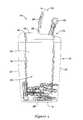
- FIG. 1is a perspective view showing an illustrative medical dispenser in accordance with an illustrative embodiment
- FIG. 2is a top view of the medical dispenser of FIG. 1 ;
- FIG. 3is a side view showing the removal of a lancet from the medical dispenser of FIG. 1 ;
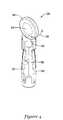
- FIG. 4is a perspective view of a lancet
- FIG. 5is a perspective view showing the protective cap removed from the lancet of FIG. 4 ;
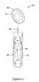
- FIG. 6is a perspective view showing the lancet of FIG. 4 inserted into the indentation on the medical dispenser;
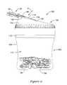
- FIG. 7is a cross-sectional view showing the lancet of FIG. 6 restrained within the indentation
- FIG. 8is a perspective view showing a medical dispenser in accordance with another illustrative embodiment
- FIG. 9is a top view of the medical dispenser of FIG. 8 ;
- FIG. 10is a side view showing the removal of a lancet from the medical dispenser of FIG. 8 ;
- FIG. 11is a perspective view showing the insertion of a lancet into the indentation
- FIG. 12is a cross-sectional view showing the lancet inserted into the indentation
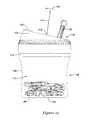
- FIG. 13is a perspective view showing a medical dispenser in accordance with another illustrative embodiment having multiple lids
- FIG. 14is a side cross-sectional view showing the medical dispenser of FIG. 13 equipped with an interior partition or dividing wall.
- the dispenser 10may include a container body 12 having a top 14 , a bottom 16 , and a number of sidewalls 18 , 20 , 22 , 24 , which together define a container structure having an interior chamber 26 adapted to contain a number of unused lancets, sharps, or other medical instruments therein.
- the interior chamber 26may contain a number of unused lancets 28 that can be used by diabetic individuals for testing their blood sugar/glucose levels.
- the dispenser 10may have a substantially rectangular shape with sidewalls 22 and 24 having a curved or rounded shape to facilitate gripping of the container body 12 by the user's hands. It should be understood, however, that the container body 12 may have any number of differently shaped configurations other than that depicted in FIG. 1 .
- the dispenser 10can be configured to function as either a disposable dispenser or a reusable dispenser.
- a seam 32 separating the top 14 from a lower portion 30 of the container body 12may permit the top 14 to be temporarily removed, allowing the user to refill the interior chamber 26 with unused lancets 28 or other medical instruments, as desired.
- the top 14can be fixedly secured to the lower portion 30 of the container body 12 to prevent the top 14 from being removed by the user.
- the top 14 and lower portion 30 of the container body 12may be formed integrally as a single piece.
- the dispenser 10can be fabricated from acrylonitrile butadiene styrene (ABS), high density polyethylene (HDPE), or other suitable polymeric material.
- ABSacrylonitrile butadiene styrene
- HDPEhigh density polyethylene
- the dispenser 10may also be fabricated from other materials such as nylon or metal. Manufacturing of the dispenser 10 can be accomplished by injection molding, extruding, stamping, and/or other suitable process depending on the material used.
- the dispenser materialmay be substantially clear or opaque, allowing the user to view the contents within the interior chamber 26 of the dispenser 10 .
- the top 14may include a flip-top lid 34 , which when opened, exposes an opening through which one or more unused lancets 28 can be removed from within the interior chamber 26 .
- the flip-top lid 34may be hingedly connected to a portion of the top 14 via a hinge 36 .
- the lid 34may be hingedly connected to the top 14 via a living hinge.
- Other means for hingedly connecting the lid 34 to the top 14may be employed such as, for example, a friction hinge, lift-off hinge, or butt hinge.
- a small notch 38 adjacent to a pivoting end 40 of the lid 34can be provided to facilitate lifting of the lid 34 with the user's fingers.
- the top 14 of the dispenser 10may further include a gripping element which, as is discussed in greater detail below with respect to FIG. 5 , can be used to facilitate removal of the protective caps 58 from the lancets 28 .
- the gripping elementmay include an indentation 42 inset a short distance below a top surface 44 on the exterior of the container body 12 , and can have an elliptical and, in some cases, circular shape that conforms generally to the size and shape of the protective cap.
- the size and shape of the indentation 42may vary, however, depending on the configuration of the protective cap 58 or other portion of the medical instrument being removed.
- the indentation 42may be located adjacent to the side 22 opposite the free end 40 of the lid 34 , or can be located elsewhere on the container body 12 , if desired.
- FIG. 2is a top view of the medical dispenser 10 of FIG. 1 .
- the lid 34may have a fixed end 46 , a number of sides 48 , 50 , and an unconstrained, pivoting end 40 opposite the fixed end 46 .
- the lid 34may have an elongated shape with the sides 48 , 50 having a length greater than the length of the ends 40 , 46 .
- the lid 34may be opened by inserting the user's finger into the notch 38 and then prying the lid 34 upwardly. As further shown in FIG.
- thiscauses the lid 34 to pivot about the hinge 36 and open in the direction indicated generally by arrow 52 , exposing an opening 54 within the top 14 that can be used to remove a lancet 28 or other medical instrument from within the interior chamber 26 . Removal of a lancet 28 may occur, for example, by tilting the dispenser 10 upside down and then shaking the container body 12 until a lancet 28 is released through the opening 54 .
- the opening 54can be sized and shaped to permit only a single lancet 28 from being removed from the dispenser 10 at a time, or alternatively, can be configured to permit multiple lancets 28 to be removed at once.
- FIG. 4-5are perspective views showing an illustrative lancet 28 that can be stored within the dispenser 10 of FIG. 1 .
- the lancet 28may have a handle grip 56 for gripping the lancet 28 and a protective cap 58 that can be used to cover and maintain the sterility of the sharp needle tip 60 .
- the handle grip 56may include a number of ribs 62 to facilitate gripping of the handle grip 56 .
- the cap 58in turn, may have a bulbous shaped formed by a number of outwardly extending dimples 64 on each side of the cap 58 , which may also facilitate gripping of the cap 58 .
- the protective cap 58Prior to use, and as shown in FIG. 4 , the protective cap 58 can be removably attached to the handle grip 56 at a tear joint 66 .
- removal of the protective cap 58is accomplished manually gripping the handle grip 56 with the user's fingers, and then twisting the protective cap 58 in either a clockwise or counterclockwise direction, as indicated generally by arrow 66 in FIG. 4 .
- the twisting of the protective cap 58 in this mannercauses the cap 58 to pivot about the joint 62 , causing the cap 58 to tear off from the handle grip 56 .
- the removal of the protective cap 58 from the lancet 28exposes the needle tip 60 for use.
- the lancet 28can then be used to obtain a blood sample by pricking the needle tip 60 into the user's finger, earlobe, or other anatomy and then collecting the blood sample on a test strip or the like. In some cases, the lancet 28 can be loaded into a lancing device for collecting a blood sample, if desired.
- the removal of the protective cap 58 from the lancet 28may be difficult for certain users depending on the user's dexterity and strength.
- the relatively small size of the handle grip 56 provided on many commercially available lancets 28may make it difficult for the user to adequately grip the protective cap 28 as it is removed from the handle grip 56 .
- the usermay insert the cap 58 into the indentation 42 on the top 14 of the container body 12 , and then open the lid 34 fully.
- the lid 34can be configured to restrain the cap 58 within the indentation 42 , thereby preventing its removal.
- the usermay hold the protective cap 58 in place within the indentation 42 by applying a downwardly directed force to the lid 34 in the direction indicated generally by arrow F. In this position, and as shown further in a cross-sectional view in FIG.
- the cap 58is restrained within the indentation 42 due to the bulbous shape of the dimples 64 and the downwardly directed force F of the lid 34 , which applies friction to the cap 58 .
- the handle grip 56can then be rotated while holding the dispenser 10 stationary, or alternatively rotating the dispenser 10 while holding the handle grip 56 stationary, causing the handle grip 56 to tear-away from the protective cap 58 .
- the protective cap 58can then be removed from within the indentation 42 and either discarded or saved for future use.
- FIG. 8is a perspective view of a medical dispenser 100 in accordance with another illustrative embodiment.
- the medical dispenser 100may be similar to that described above with respect to FIG. 1 , including a container body 102 having top 104 , a bottom 106 , and a sidewall 108 , which together define a container structure having an interior chamber 110 adapted to store a number of unused lancets, sharps, or other medical instruments therein.
- the interior chamber 110may contain a number of unused lancets 28 that can be used to obtain a blood sample from the user.
- the dispenser 100has a substantially cylindrical shape, although other configurations are possible.
- the dispenser 100can be configured to function as either a disposable dispenser, or alternatively, as a reusable dispenser that can be reloaded with lancets 28 or other medical instruments.
- the top 104can be made removable from the sidewall 108 via a seam 112 , allowing the user to refill the interior chamber 110 by removing the top 104 .
- the top 104can be fixedly secured to or formed integrally with the sidewall 108 to prevent the top 104 from being removed by the user.
- the top 104may include a flip-top lid 114 which, when opened, exposes an opening 134 through which one or more lancets 28 can be removed from within the interior chamber 110 .
- the flip-top lid 112may be hingedly connected to a portion of the top 104 via a hinge 116 such as a living hinge, friction hinge, lift-off hinge, butt hinge, etc.
- a tab 118 extending from the free end 120 of the lid 114can be provided to facilitate lifting of the lid 114 with the user's fingers.
- the top 104 of the dispenser 100may further include a gripping element such as an indentation 122 that can be used to facilitate removal of the protective caps 58 from the lancets 28 .
- the indentation 122may be formed on the top surface 124 of the container body 102 , and can have an elliptical and, in some cases, circular shape that conforms generally to the size and shape of the protective cap 58 .
- the configuration of the indentation 122including its size, shape and/or location on the container body 12 may vary from that depicted, however.
- FIG. 9is a top view of the medical dispenser 100 of FIG. 1 .
- the lid 114may have a fixed end 126 , a number of sides 128 , 130 , and an unconstrained, pivoting end 120 opposite the fixed end 126 .
- the lid 114may have a semi-circular shape, although other configurations are possible. In use, the lid 114 may be opened by grasping the tab 118 and then prying the lid 114 open. As further shown in FIG.
- thiscauses the lid 114 to pivot about the hinge 116 and open in the direction indicated generally by arrow 132 , exposing an opening 134 within the top 104 that can be used to remove one or more lancets 28 or other medical instruments from within the interior chamber 110 . Removal of a lancet 28 may occur, for example, by tilting the dispenser 100 upside down and then shaking the container body 102 until a lancet 28 is released through the opening 134 .
- the opening 134can be sized and shaped to permit only a single lancet 28 from being removed from the dispenser 100 at a time, or alternatively, can be configured to permit multiple lancets 28 to be removed at once.
- FIG. 11is a perspective view showing the insertion of a lancet 28 into the indentation 122 .
- the lid 114can be configured to restrain the cap 58 within the indentation 122 thereby preventing its removal. The user may then hold the protective cap 58 in place by applying a downwardly directed force F to the lid 114 .
- the cap 58is restrained within the indentation 122 due to the bulbous shape of the dimples 64 and the downwardly directed force F of the lid 114 , which applies friction to the cap 58 . In this position, the cap 58 can then be removed from the handle grip 56 and then removed from within the indentation 122 and either discarded or saved for future use.
- the top surface 124 of the container body 102may be sloped at an angle, orienting the indentation 122 at an angle slightly offset from horizontal.
- this offset orientation of the indentation 122acts to orient the lancet handle grip 56 at a slight vertical angle when inserted into the indentation 122 in order to facilitate gripping of the handle grip 56 by the user's fingers as the protective cap 58 is being removed.
- the medical dispensers 10 , 100each include a single lid that can be used to access the contents within the interior chamber, it should be understood that the dispenser can be further equipped with one or more additional lids, if desired.
- the medical dispenser 100may be equipped with a second lid 136 that can also be opened to gain access to the contents within the interior chamber 110 .
- the second lid 136may be smaller than the first lid 114 , allowing each of the lids 114 , 136 to function differently.
- the relatively large lid 114may be used to refill the dispenser 100 with unused lancets or to dispense multiple lancets 28 at a time whereas the relatively small lid 136 may be used to serially dispense lancets 28 one at a time.
- Other configurationsare possible, however.
- the medical dispenser 10 , 100can also be configured to receive used lancets or other such medical instruments, if desired.
- the container body 102can include an interior partition or dividing wall 138 that separates a first interior chamber 140 of the dispenser 100 from a second interior chamber 142 thereof.
- the first interior chamber 138can be configured to store one or more unused medical devices (e.g. lancets) whereas the second interior chamber 140 can be configured to receive used medical waste.
- the first and second interior chambers 138 , 140can be isolated from each other to maintain the sterility of the unused lancets 28 within the first chamber 138 .
- Access to the first interior chamber 138can be accomplished via the first lid 114 , which can be opened to expose a first opening 134 on the top 104 to gain access to the unused lancets.
- Access to the second interior chamber 140can be accomplished, in turn, via the second lid 136 , which can be opened to expose a second opening 144 on the top 104 for receiving used lancets.
Landscapes
- Health & Medical Sciences (AREA)
- Life Sciences & Earth Sciences (AREA)
- Engineering & Computer Science (AREA)
- Surgery (AREA)
- Veterinary Medicine (AREA)
- General Health & Medical Sciences (AREA)
- Public Health (AREA)
- Biomedical Technology (AREA)
- Heart & Thoracic Surgery (AREA)
- Medical Informatics (AREA)
- Molecular Biology (AREA)
- Animal Behavior & Ethology (AREA)
- Physics & Mathematics (AREA)
- Pathology (AREA)
- Biophysics (AREA)
- Hematology (AREA)
- Nuclear Medicine, Radiotherapy & Molecular Imaging (AREA)
- Dermatology (AREA)
- Manufacturing & Machinery (AREA)
- Diabetes (AREA)
- Measurement Of The Respiration, Hearing Ability, Form, And Blood Characteristics Of Living Organisms (AREA)
Abstract
Description
Claims (22)
Priority Applications (6)
| Application Number | Priority Date | Filing Date | Title |
|---|---|---|---|
| US11/763,949US8950578B2 (en) | 2007-06-15 | 2007-06-15 | Lancet dispenser |
| PCT/US2008/066393WO2008157125A1 (en) | 2007-06-15 | 2008-06-10 | Lancet dispenser |
| CA2690862ACA2690862A1 (en) | 2007-06-15 | 2008-06-10 | Lancet dispenser |
| EP08770560AEP2166948A1 (en) | 2007-06-15 | 2008-06-10 | Lancet dispenser |
| JP2010512294AJP2010529890A (en) | 2007-06-15 | 2008-06-10 | Lancet dispenser |
| AU2008266284AAU2008266284A1 (en) | 2007-06-15 | 2008-06-10 | Lancet dispenser |
Applications Claiming Priority (1)
| Application Number | Priority Date | Filing Date | Title |
|---|---|---|---|
| US11/763,949US8950578B2 (en) | 2007-06-15 | 2007-06-15 | Lancet dispenser |
Publications (2)
| Publication Number | Publication Date |
|---|---|
| US20080308441A1 US20080308441A1 (en) | 2008-12-18 |
| US8950578B2true US8950578B2 (en) | 2015-02-10 |
Family
ID=39758784
Family Applications (1)
| Application Number | Title | Priority Date | Filing Date |
|---|---|---|---|
| US11/763,949Active2031-09-04US8950578B2 (en) | 2007-06-15 | 2007-06-15 | Lancet dispenser |
Country Status (6)
| Country | Link |
|---|---|
| US (1) | US8950578B2 (en) |
| EP (1) | EP2166948A1 (en) |
| JP (1) | JP2010529890A (en) |
| AU (1) | AU2008266284A1 (en) |
| CA (1) | CA2690862A1 (en) |
| WO (1) | WO2008157125A1 (en) |
Cited By (4)
| Publication number | Priority date | Publication date | Assignee | Title |
|---|---|---|---|---|
| USD841158S1 (en) | 2017-10-04 | 2019-02-19 | West Pharmaceutical Services, Inc. | Container lid |
| USD841157S1 (en)* | 2017-10-04 | 2019-02-19 | West Pharmaceutical Services, Inc. | Container and lid |
| USD841805S1 (en)* | 2017-10-04 | 2019-02-26 | West Pharmaceutical Services, Inc. | Container lid |
| US20220304763A1 (en)* | 2019-12-24 | 2022-09-29 | Roche Diabetes Care, Inc. | Disposal system |
Families Citing this family (7)
| Publication number | Priority date | Publication date | Assignee | Title |
|---|---|---|---|---|
| GB2497735A (en) | 2011-12-16 | 2013-06-26 | Owen Mumford Ltd | Needle Tip Storage and Removal Device |
| WO2014150650A1 (en)* | 2013-03-15 | 2014-09-25 | Surgitrac Corporation | Surgical object and fluid monitoring system having highly sensitive and reliable detection of objects being placed in a container |
| US9347817B2 (en) | 2013-03-15 | 2016-05-24 | Surgitrac Corporation | Surgical object and comprehensive fluid monitoring system having capability of mobile monitoring and having highly sensitive and reliable detection of objects being placed in a container |
| WO2017189174A1 (en)* | 2016-04-28 | 2017-11-02 | Becton, Dickinson And Company | Pen needle magazine |
| JP6255469B1 (en)* | 2016-12-22 | 2017-12-27 | タキゲン製造株式会社 | Auxiliary device for blood collection puncture device |
| EP3681558A4 (en)* | 2017-09-12 | 2021-06-09 | Merit Medical Systems, Inc. | Medical device dispenser and method of use |
| CN109200401B (en)* | 2018-10-30 | 2021-06-04 | 郑州大学第一附属医院 | Medical care tool scissors |
Citations (26)
| Publication number | Priority date | Publication date | Assignee | Title |
|---|---|---|---|---|
| US4230118A (en)* | 1977-08-05 | 1980-10-28 | Holman Rury R | Automatic lancet |
| US4452243A (en)* | 1981-07-20 | 1984-06-05 | Cloverline, Inc. | Sanitary blood lancet device |
| US4577630A (en)* | 1984-02-14 | 1986-03-25 | Becton, Dickinson And Co. | Reusable breach loading target pressure activated lancet firing device |
| US4715374A (en) | 1986-11-14 | 1987-12-29 | Medicore, Inc. | Disposable automatic lancet |
| US4869366A (en)* | 1987-09-22 | 1989-09-26 | John Bruno | Receptacle assembly for storage and disposal of potentially injurious implements such as used scalpel blades, hypodermic needles and the like |
| US4874103A (en)* | 1986-10-01 | 1989-10-17 | Winfield Corporation | Receptacle for receiving infectious waste material |
| US4995871A (en)* | 1988-02-04 | 1991-02-26 | Snow Brand Milk Products Co., Ltd. | Needle detacher for syringe |
| US5152775A (en)* | 1990-10-04 | 1992-10-06 | Norbert Ruppert | Automatic lancet device and method of using the same |
| US5269800A (en)* | 1992-12-10 | 1993-12-14 | Davis Manufacturing Systems Inc. | Blood lancing device |
| US5282822A (en) | 1993-01-19 | 1994-02-01 | Sherwood Medical Company | Lancet ejector for lancet injector |
| US5322164A (en)* | 1993-01-19 | 1994-06-21 | Sage Products, Inc. | Needle disposal container and disposal system |
| US5339993A (en)* | 1992-03-13 | 1994-08-23 | Magenta Corporation | Shaker closure |
| US5415312A (en)* | 1993-04-21 | 1995-05-16 | Aladdin Synergetics, Inc. | Closure for a liquid container |
| US5791471A (en) | 1997-08-01 | 1998-08-11 | Radmand; Reza | Dental sharps containment device and method of using the same "needle protection device" (NPD) |
| US6042595A (en)* | 1999-03-02 | 2000-03-28 | Apls Co., Ltd. | Lancet apparatus for producing a precisely controlled incision |
| US6089397A (en)* | 1999-04-09 | 2000-07-18 | Amhil Enterprises | Cup lid having improved drink-through opening |
| USD437223S1 (en)* | 1999-09-30 | 2001-02-06 | Valid, Llc | Container lid |
| US6247592B1 (en)* | 1996-06-21 | 2001-06-19 | Bio-Plexus, Inc. | System for disposal of contaminated medical products |
| US20030106820A1 (en)* | 2001-12-05 | 2003-06-12 | Fritz Kirchhofer | Holding device for a needle protection cap and a packaging container for cannula supports comprising a holding device |
| US20030132129A1 (en)* | 2002-01-14 | 2003-07-17 | Erickson Charles W. | Container for transportation and dispensing of unused syringes and for storage of used syringes |
| US6612456B1 (en)* | 2000-10-12 | 2003-09-02 | Wincup Holdings, Inc. | Drink-through cup lid having selectively inwardly and outwardly rotatable hinged portion |
| US6783537B1 (en) | 1998-09-07 | 2004-08-31 | Roche Diagnostics Gmbh | Lancet dispenser |
| US20050216046A1 (en) | 2004-03-11 | 2005-09-29 | Futumeds Sdn. Bhd | Lancet activating device |
| US20060278545A1 (en) | 2005-06-14 | 2006-12-14 | Roche Diagnostics Operations, Inc. | Biocidal blood glucose strip and lancet or sharps disposal device |
| US20070119740A1 (en)* | 2005-11-30 | 2007-05-31 | Trent Clegg | Sharps holding device |
| WO2007065110A2 (en) | 2005-11-30 | 2007-06-07 | Merit Medical Systems, Inc. | Medical instrument holder |
- 2007
- 2007-06-15USUS11/763,949patent/US8950578B2/enactiveActive
- 2008
- 2008-06-10JPJP2010512294Apatent/JP2010529890A/ennot_activeWithdrawn
- 2008-06-10AUAU2008266284Apatent/AU2008266284A1/ennot_activeAbandoned
- 2008-06-10EPEP08770560Apatent/EP2166948A1/ennot_activeWithdrawn
- 2008-06-10WOPCT/US2008/066393patent/WO2008157125A1/enactiveApplication Filing
- 2008-06-10CACA2690862Apatent/CA2690862A1/ennot_activeAbandoned
Patent Citations (27)
| Publication number | Priority date | Publication date | Assignee | Title |
|---|---|---|---|---|
| US4230118A (en)* | 1977-08-05 | 1980-10-28 | Holman Rury R | Automatic lancet |
| US4452243A (en)* | 1981-07-20 | 1984-06-05 | Cloverline, Inc. | Sanitary blood lancet device |
| US4577630A (en)* | 1984-02-14 | 1986-03-25 | Becton, Dickinson And Co. | Reusable breach loading target pressure activated lancet firing device |
| US4874103A (en)* | 1986-10-01 | 1989-10-17 | Winfield Corporation | Receptacle for receiving infectious waste material |
| US4715374A (en) | 1986-11-14 | 1987-12-29 | Medicore, Inc. | Disposable automatic lancet |
| US4869366A (en)* | 1987-09-22 | 1989-09-26 | John Bruno | Receptacle assembly for storage and disposal of potentially injurious implements such as used scalpel blades, hypodermic needles and the like |
| US4995871A (en)* | 1988-02-04 | 1991-02-26 | Snow Brand Milk Products Co., Ltd. | Needle detacher for syringe |
| US5152775A (en)* | 1990-10-04 | 1992-10-06 | Norbert Ruppert | Automatic lancet device and method of using the same |
| US5339993A (en)* | 1992-03-13 | 1994-08-23 | Magenta Corporation | Shaker closure |
| US5269800A (en)* | 1992-12-10 | 1993-12-14 | Davis Manufacturing Systems Inc. | Blood lancing device |
| US5282822A (en) | 1993-01-19 | 1994-02-01 | Sherwood Medical Company | Lancet ejector for lancet injector |
| US5322164A (en)* | 1993-01-19 | 1994-06-21 | Sage Products, Inc. | Needle disposal container and disposal system |
| US5415312A (en)* | 1993-04-21 | 1995-05-16 | Aladdin Synergetics, Inc. | Closure for a liquid container |
| US6247592B1 (en)* | 1996-06-21 | 2001-06-19 | Bio-Plexus, Inc. | System for disposal of contaminated medical products |
| US5791471A (en) | 1997-08-01 | 1998-08-11 | Radmand; Reza | Dental sharps containment device and method of using the same "needle protection device" (NPD) |
| US6783537B1 (en) | 1998-09-07 | 2004-08-31 | Roche Diagnostics Gmbh | Lancet dispenser |
| US20050027211A1 (en) | 1998-09-07 | 2005-02-03 | Hans-Juergen Kuhr | Lancet dispenser |
| US6042595A (en)* | 1999-03-02 | 2000-03-28 | Apls Co., Ltd. | Lancet apparatus for producing a precisely controlled incision |
| US6089397A (en)* | 1999-04-09 | 2000-07-18 | Amhil Enterprises | Cup lid having improved drink-through opening |
| USD437223S1 (en)* | 1999-09-30 | 2001-02-06 | Valid, Llc | Container lid |
| US6612456B1 (en)* | 2000-10-12 | 2003-09-02 | Wincup Holdings, Inc. | Drink-through cup lid having selectively inwardly and outwardly rotatable hinged portion |
| US20030106820A1 (en)* | 2001-12-05 | 2003-06-12 | Fritz Kirchhofer | Holding device for a needle protection cap and a packaging container for cannula supports comprising a holding device |
| US20030132129A1 (en)* | 2002-01-14 | 2003-07-17 | Erickson Charles W. | Container for transportation and dispensing of unused syringes and for storage of used syringes |
| US20050216046A1 (en) | 2004-03-11 | 2005-09-29 | Futumeds Sdn. Bhd | Lancet activating device |
| US20060278545A1 (en) | 2005-06-14 | 2006-12-14 | Roche Diagnostics Operations, Inc. | Biocidal blood glucose strip and lancet or sharps disposal device |
| US20070119740A1 (en)* | 2005-11-30 | 2007-05-31 | Trent Clegg | Sharps holding device |
| WO2007065110A2 (en) | 2005-11-30 | 2007-06-07 | Merit Medical Systems, Inc. | Medical instrument holder |
Cited By (5)
| Publication number | Priority date | Publication date | Assignee | Title |
|---|---|---|---|---|
| USD841158S1 (en) | 2017-10-04 | 2019-02-19 | West Pharmaceutical Services, Inc. | Container lid |
| USD841157S1 (en)* | 2017-10-04 | 2019-02-19 | West Pharmaceutical Services, Inc. | Container and lid |
| USD841805S1 (en)* | 2017-10-04 | 2019-02-26 | West Pharmaceutical Services, Inc. | Container lid |
| US20220304763A1 (en)* | 2019-12-24 | 2022-09-29 | Roche Diabetes Care, Inc. | Disposal system |
| US12138088B2 (en)* | 2019-12-24 | 2024-11-12 | Roche Diabetes Care, Inc. | Disposal system |
Also Published As
| Publication number | Publication date |
|---|---|
| CA2690862A1 (en) | 2008-12-24 |
| WO2008157125A1 (en) | 2008-12-24 |
| JP2010529890A (en) | 2010-09-02 |
| EP2166948A1 (en) | 2010-03-31 |
| US20080308441A1 (en) | 2008-12-18 |
| AU2008266284A1 (en) | 2008-12-24 |
Similar Documents
| Publication | Publication Date | Title |
|---|---|---|
| US8950578B2 (en) | Lancet dispenser | |
| US6783537B1 (en) | Lancet dispenser | |
| EP1374769B1 (en) | Device for taking blood samples to be tested, for example for the level of glucose contained therein | |
| US4867309A (en) | Safe-disposal container for used hypodermic needles and the like | |
| US20070196242A1 (en) | Used test strip storage container | |
| US4920977A (en) | Blood collection assembly with lancet and microcollection tube | |
| US4994068A (en) | Combination sterile pad support and lancet containing lancet disposal element | |
| US20100000905A1 (en) | Strip vial and cap | |
| US6485438B1 (en) | Cup to assist with urine specimen sampling | |
| NO891568L (en) | PROEVEBEHOLDER. | |
| US5334348A (en) | Urine sampler | |
| WO1991011375A1 (en) | Disposable sharp instrument container | |
| EP2253269A1 (en) | Blood collecting puncture device and magazine used for the same | |
| JPS61234873A (en) | Needle protector | |
| JPS62112531A (en) | Closure apparatus of blood sampling needle disposal system | |
| JP2024160382A (en) | Disposal System | |
| EP0541091A1 (en) | Urine sampler | |
| JP3346104B2 (en) | Blood collection needle, blood collection needle holder and reduced-pressure blood sampler using these | |
| JP2009133704A (en) | Stool collection equipment | |
| HK40081353A (en) | Disposal system | |
| JPH0559309U (en) | Specimen sample container rack | |
| JP2012030854A (en) | Storage case |
Legal Events
| Date | Code | Title | Description |
|---|---|---|---|
| AS | Assignment | Owner name:ULTIMED INC., MINNESOTA Free format text:ASSIGNMENT OF ASSIGNORS INTEREST;ASSIGNORS:ERICKSON, THOMAS E.;ERICKSON, JAMES J.;REEL/FRAME:019445/0993 Effective date:20070613 | |
| STCF | Information on status: patent grant | Free format text:PATENTED CASE | |
| FEPP | Fee payment procedure | Free format text:ENTITY STATUS SET TO UNDISCOUNTED (ORIGINAL EVENT CODE: BIG.) | |
| MAFP | Maintenance fee payment | Free format text:PAYMENT OF MAINTENANCE FEE, 4TH YEAR, LARGE ENTITY (ORIGINAL EVENT CODE: M1551) Year of fee payment:4 | |
| AS | Assignment | Owner name:UM STRATEGIC CAPITAL DEBTCO, LLC, FLORIDA Free format text:SECURITY INTEREST;ASSIGNOR:ULTIMED, INC.;REEL/FRAME:053250/0860 Effective date:20200716 | |
| AS | Assignment | Owner name:UM STRATEGIC CAPITAL DEBTCO, LLC, FLORIDA Free format text:CORRECTIVE ASSIGNMENT TO CORRECT THE SCHEDULE A ATTACHED TO THE PATENT SECURITY AGREEMENT PREVIOUSLY RECORDED ON REEL 053250 FRAME 0860. ASSIGNOR(S) HEREBY CONFIRMS THE SECURITY INTEREST;ASSIGNOR:ULTIMED, INC.;REEL/FRAME:053273/0542 Effective date:20200716 | |
| MAFP | Maintenance fee payment | Free format text:PAYMENT OF MAINTENANCE FEE, 8TH YEAR, LARGE ENTITY (ORIGINAL EVENT CODE: M1552); ENTITY STATUS OF PATENT OWNER: LARGE ENTITY Year of fee payment:8 |