US8950519B2 - Polycrystalline diamond compacts with partitioned substrate, polycrystalline diamond table, or both - Google Patents
Polycrystalline diamond compacts with partitioned substrate, polycrystalline diamond table, or bothDownload PDFInfo
- Publication number
- US8950519B2 US8950519B2US13/234,252US201113234252AUS8950519B2US 8950519 B2US8950519 B2US 8950519B2US 201113234252 AUS201113234252 AUS 201113234252AUS 8950519 B2US8950519 B2US 8950519B2
- Authority
- US
- United States
- Prior art keywords
- substrate
- pcd table
- pdc
- pcd
- partition
- Prior art date
- Legal status (The legal status is an assumption and is not a legal conclusion. Google has not performed a legal analysis and makes no representation as to the accuracy of the status listed.)
- Active, expires
Links
Images


Classifications
- E—FIXED CONSTRUCTIONS
- E21—EARTH OR ROCK DRILLING; MINING
- E21B—EARTH OR ROCK DRILLING; OBTAINING OIL, GAS, WATER, SOLUBLE OR MELTABLE MATERIALS OR A SLURRY OF MINERALS FROM WELLS
- E21B10/00—Drill bits
- E21B10/46—Drill bits characterised by wear resisting parts, e.g. diamond inserts
- E21B10/56—Button-type inserts
- E21B10/567—Button-type inserts with preformed cutting elements mounted on a distinct support, e.g. polycrystalline inserts
- E21B10/5673—Button-type inserts with preformed cutting elements mounted on a distinct support, e.g. polycrystalline inserts having a non planar or non circular cutting face
- B—PERFORMING OPERATIONS; TRANSPORTING
- B24—GRINDING; POLISHING
- B24D—TOOLS FOR GRINDING, BUFFING OR SHARPENING
- B24D18/00—Manufacture of grinding tools or other grinding devices, e.g. wheels, not otherwise provided for
- E—FIXED CONSTRUCTIONS
- E21—EARTH OR ROCK DRILLING; MINING
- E21B—EARTH OR ROCK DRILLING; OBTAINING OIL, GAS, WATER, SOLUBLE OR MELTABLE MATERIALS OR A SLURRY OF MINERALS FROM WELLS
- E21B10/00—Drill bits
- E21B10/46—Drill bits characterised by wear resisting parts, e.g. diamond inserts
- E21B10/54—Drill bits characterised by wear resisting parts, e.g. diamond inserts the bit being of the rotary drag type, e.g. fork-type bits
- E21B10/55—Drill bits characterised by wear resisting parts, e.g. diamond inserts the bit being of the rotary drag type, e.g. fork-type bits with preformed cutting elements
- E—FIXED CONSTRUCTIONS
- E21—EARTH OR ROCK DRILLING; MINING
- E21B—EARTH OR ROCK DRILLING; OBTAINING OIL, GAS, WATER, SOLUBLE OR MELTABLE MATERIALS OR A SLURRY OF MINERALS FROM WELLS
- E21B10/00—Drill bits
- E21B10/46—Drill bits characterised by wear resisting parts, e.g. diamond inserts
- E21B10/56—Button-type inserts
- E21B10/567—Button-type inserts with preformed cutting elements mounted on a distinct support, e.g. polycrystalline inserts
- E21B10/5676—Button-type inserts with preformed cutting elements mounted on a distinct support, e.g. polycrystalline inserts having a cutting face with different segments, e.g. mosaic-type inserts
- E—FIXED CONSTRUCTIONS
- E21—EARTH OR ROCK DRILLING; MINING
- E21B—EARTH OR ROCK DRILLING; OBTAINING OIL, GAS, WATER, SOLUBLE OR MELTABLE MATERIALS OR A SLURRY OF MINERALS FROM WELLS
- E21B10/00—Drill bits
- E21B10/46—Drill bits characterised by wear resisting parts, e.g. diamond inserts
- E21B10/56—Button-type inserts
- E21B10/567—Button-type inserts with preformed cutting elements mounted on a distinct support, e.g. polycrystalline inserts
- E21B10/573—Button-type inserts with preformed cutting elements mounted on a distinct support, e.g. polycrystalline inserts characterised by support details, e.g. the substrate construction or the interface between the substrate and the cutting element
- E21B10/5735—Interface between the substrate and the cutting element
- E—FIXED CONSTRUCTIONS
- E21—EARTH OR ROCK DRILLING; MINING
- E21B—EARTH OR ROCK DRILLING; OBTAINING OIL, GAS, WATER, SOLUBLE OR MELTABLE MATERIALS OR A SLURRY OF MINERALS FROM WELLS
- E21B23/00—Apparatus for displacing, setting, locking, releasing or removing tools, packers or the like in boreholes or wells
- E21B23/04—Apparatus for displacing, setting, locking, releasing or removing tools, packers or the like in boreholes or wells operated by fluid means, e.g. actuated by explosion
- E21B23/0419—Apparatus for displacing, setting, locking, releasing or removing tools, packers or the like in boreholes or wells operated by fluid means, e.g. actuated by explosion using down-hole motor and pump arrangements for generating hydraulic pressure
- E—FIXED CONSTRUCTIONS
- E21—EARTH OR ROCK DRILLING; MINING
- E21B—EARTH OR ROCK DRILLING; OBTAINING OIL, GAS, WATER, SOLUBLE OR MELTABLE MATERIALS OR A SLURRY OF MINERALS FROM WELLS
- E21B4/00—Drives for drilling, used in the borehole
- E21B4/003—Bearing, sealing, lubricating details
- F—MECHANICAL ENGINEERING; LIGHTING; HEATING; WEAPONS; BLASTING
- F16—ENGINEERING ELEMENTS AND UNITS; GENERAL MEASURES FOR PRODUCING AND MAINTAINING EFFECTIVE FUNCTIONING OF MACHINES OR INSTALLATIONS; THERMAL INSULATION IN GENERAL
- F16C—SHAFTS; FLEXIBLE SHAFTS; ELEMENTS OR CRANKSHAFT MECHANISMS; ROTARY BODIES OTHER THAN GEARING ELEMENTS; BEARINGS
- F16C33/00—Parts of bearings; Special methods for making bearings or parts thereof
- F16C33/02—Parts of sliding-contact bearings
- F16C33/04—Brasses; Bushes; Linings
- F16C33/043—Sliding surface consisting mainly of ceramics, cermets or hard carbon, e.g. diamond like carbon [DLC]
- F—MECHANICAL ENGINEERING; LIGHTING; HEATING; WEAPONS; BLASTING
- F16—ENGINEERING ELEMENTS AND UNITS; GENERAL MEASURES FOR PRODUCING AND MAINTAINING EFFECTIVE FUNCTIONING OF MACHINES OR INSTALLATIONS; THERMAL INSULATION IN GENERAL
- F16C—SHAFTS; FLEXIBLE SHAFTS; ELEMENTS OR CRANKSHAFT MECHANISMS; ROTARY BODIES OTHER THAN GEARING ELEMENTS; BEARINGS
- F16C33/00—Parts of bearings; Special methods for making bearings or parts thereof
- F16C33/02—Parts of sliding-contact bearings
- F16C33/04—Brasses; Bushes; Linings
- F16C33/26—Brasses; Bushes; Linings made from wire coils; made from a number of discs, rings, rods, or other members
- F—MECHANICAL ENGINEERING; LIGHTING; HEATING; WEAPONS; BLASTING
- F16—ENGINEERING ELEMENTS AND UNITS; GENERAL MEASURES FOR PRODUCING AND MAINTAINING EFFECTIVE FUNCTIONING OF MACHINES OR INSTALLATIONS; THERMAL INSULATION IN GENERAL
- F16C—SHAFTS; FLEXIBLE SHAFTS; ELEMENTS OR CRANKSHAFT MECHANISMS; ROTARY BODIES OTHER THAN GEARING ELEMENTS; BEARINGS
- F16C17/00—Sliding-contact bearings for exclusively rotary movement
- F16C17/02—Sliding-contact bearings for exclusively rotary movement for radial load only
- F—MECHANICAL ENGINEERING; LIGHTING; HEATING; WEAPONS; BLASTING
- F16—ENGINEERING ELEMENTS AND UNITS; GENERAL MEASURES FOR PRODUCING AND MAINTAINING EFFECTIVE FUNCTIONING OF MACHINES OR INSTALLATIONS; THERMAL INSULATION IN GENERAL
- F16C—SHAFTS; FLEXIBLE SHAFTS; ELEMENTS OR CRANKSHAFT MECHANISMS; ROTARY BODIES OTHER THAN GEARING ELEMENTS; BEARINGS
- F16C17/00—Sliding-contact bearings for exclusively rotary movement
- F16C17/04—Sliding-contact bearings for exclusively rotary movement for axial load only
- F—MECHANICAL ENGINEERING; LIGHTING; HEATING; WEAPONS; BLASTING
- F16—ENGINEERING ELEMENTS AND UNITS; GENERAL MEASURES FOR PRODUCING AND MAINTAINING EFFECTIVE FUNCTIONING OF MACHINES OR INSTALLATIONS; THERMAL INSULATION IN GENERAL
- F16C—SHAFTS; FLEXIBLE SHAFTS; ELEMENTS OR CRANKSHAFT MECHANISMS; ROTARY BODIES OTHER THAN GEARING ELEMENTS; BEARINGS
- F16C2206/00—Materials with ceramics, cermets, hard carbon or similar non-metallic hard materials as main constituents
- F16C2206/02—Carbon based material
- F16C2206/04—Diamond like carbon [DLC]
- F—MECHANICAL ENGINEERING; LIGHTING; HEATING; WEAPONS; BLASTING
- F16—ENGINEERING ELEMENTS AND UNITS; GENERAL MEASURES FOR PRODUCING AND MAINTAINING EFFECTIVE FUNCTIONING OF MACHINES OR INSTALLATIONS; THERMAL INSULATION IN GENERAL
- F16C—SHAFTS; FLEXIBLE SHAFTS; ELEMENTS OR CRANKSHAFT MECHANISMS; ROTARY BODIES OTHER THAN GEARING ELEMENTS; BEARINGS
- F16C2352/00—Apparatus for drilling
Definitions
- PDCswear-resistant, polycrystalline diamond compacts
- drilling toolse.g., cutting elements, gage trimmers, etc.
- machining equipmente.g., machining equipment, bearing apparatuses, wire-drawing machinery, and in other mechanical apparatuses.
- a PDC cutting elementtypically includes a superabrasive diamond layer commonly known as a diamond table.
- the diamond tableis formed and bonded to a substrate using a high-pressure/high-temperature (“HPHT”) process.
- HPHThigh-pressure/high-temperature
- the PDC cutting elementmay be brazed directly into a preformed pocket, socket, or other receptacle formed in a bit body.
- the substratemay often be brazed or otherwise joined to an attachment member, such as a cylindrical backing.
- a rotary drill bittypically includes a number of PDC cutting elements affixed to the bit body.
- a stud carrying the PDCmay be used as a PDC cutting element when mounted to a bit body of a rotary drill bit by press-fitting, brazing, or otherwise securing the stud into a receptacle formed in the bit body.
- PDCsare normally fabricated by placing a cemented carbide substrate into a container or cartridge with a volume of diamond particles positioned on a surface of the cemented carbide substrate. A number of such cartridges may be loaded into an HPHT press. The substrate(s) and volume(s) of diamond particles are then processed under HPHT conditions in the presence of a catalyst material that causes the diamond particles to bond to one another to form a matrix of bonded diamond grains defining a polycrystalline diamond (“PCD”) table.
- the catalyst materialis often a metal-solvent catalyst (e.g., cobalt, nickel, iron, or alloys thereof) that is used for promoting intergrowth of the diamond particles.
- a constituent of the cemented carbide substratesuch as cobalt from a cobalt-cemented tungsten carbide substrate, liquefies and sweeps from a region adjacent to the volume of diamond particles into interstitial regions between the diamond particles during the HPHT process.
- the cobaltacts as a catalyst to promote intergrowth between the diamond particles, which results in formation of a matrix of bonded diamond grains having diamond-to-diamond bonding therebetween, with interstitial regions between the bonded diamond grains being occupied by the solvent catalyst.
- the solvent catalystmay be at least partially removed from the PCD table of the PDC by acid leaching.
- Various embodiments of the present inventionare directed to methods of relieving residual stresses within a PCD table of a PDC. At least partial relief of such stresses reduces the tendency of the PCD table (which may be relatively brittle) to crack or otherwise fracture during use as a result of an impact or similar event.
- a PDCincluding a PCD table bonded to a substrate (e.g., tungsten carbide or other carbide substrate) is provided.
- the PCD tableincludes a plurality of diamond grains that are bonded together.
- the PCD table, the substrate, or bothare partitioned (e.g., by EDM cutting, laser cutting, grinding, etc.).
- PDCsthat include a stress relieving partition formed into at least one of the substrate or PCD table.
- a PDCmay include a substrate, a PCD table including a plurality of bonded diamond grains in which the PCD table is bonded to the substrate.
- the PCD tableincludes an exterior working surface and at least one lateral surface.
- At least one stress relieving partitionis formed into at least one of the substrate or the PCD table to at least partially relieve stress within the PCD table.
- partitioning of at least one of the PCD table or substratedecreases the residual stress within the PCD table, providing improved durability.
- partitioning of the PCD tableprovides a boundary that can stop propagation of a crack within the PCD table, should a crack form. Stopping progression of such a crack allows damage to be limited to and contained within one portion of the PCD table, preventing it from spreading to other portions across the partition.
- FIG. 1is an isometric view of an example PDC
- FIG. 2is a flow diagram describing an embodiment of a method for partitioning a substrate, PCD table, or both of a PDC in order to relieve residual stresses within the PCD table;
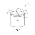
- FIG. 3is an isometric view of a PDC including a partitioning cut formed into the PCD table according to an embodiment
- FIGS. 3A-3Care cross-sectional views of PDCs including a partition formed into the PCD table and in which the respective partitioning cuts extend to different lengths relative to the location of an interface between the PCD table and the substrate according to various embodiments;
- FIG. 3Dis an isometric view of a PDC including a domed PCD layer including partitioning cuts formed into the domed PCD table;
- FIGS. 4A-4Care top plan views of PDCs similar to that shown in FIG. 3 , but including different partition configurations according to various embodiments;
- FIGS. 5A-5Dare cross-sectional views of PDCs including a partition formed into the substrate and in which the respective partitioning cuts extend to different lengths relative to the location of an interface between the substrate and the PCD table according to various embodiments;
- FIG. 6is a graph showing residual stresses for PCD tables as a result of various partitioning configurations
- FIGS. 7A-7Care isometric views of various embodiments of PDCs including a spring mechanism formed into the substrate of the PDC in order to increase the ability of the adjacent PCD table to flex and absorb energy as a result of an impact;
- FIG. 7Dis a cross-sectional view of another embodiment of a PDC including a spring mechanism disposed within the substrate of the PDC;
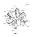
- FIG. 8is an isometric view of an embodiment of a rotary drill bit that may employ one or more PDCs according to any of the disclosed embodiments;
- FIG. 9is a top elevation view of the rotary drill bit shown in FIG. 8 ;
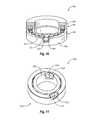
- FIG. 10is an isometric cut-away view of an embodiment of a thrust-bearing apparatus that may employ one or more PDCs according to any of the disclosed embodiments;
- FIG. 11is an isometric cut-away view of an embodiment of a radial bearing apparatus that may employ one or more PDCs according to any of the disclosed embodiments.
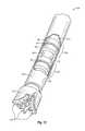
- FIG. 12is a schematic isometric cut-away view of an embodiment of a subterranean drilling system including the thrust-bearing apparatus shown in FIG. 10 .
- Embodiments of the present inventionare directed to PDCs including a substrate, and a PCD table including a plurality of bonded diamond grains that is bonded to the substrate.
- the PCD tableincludes an exterior working surface and at least one lateral surface.
- At least one stress relieving partitionis formed into the substrate, the PCD table, or both to at least partially relieve stress within the PCD table. At least partial relief of the residual stresses of the PCD table improves the overall durability of the PCD table.
- Further embodiments of the present inventionare directed to related methods of fabricating such PDCs including one or more stress relieving partitions formed into the substrate, PCD table, or both.
- the PCD elements partitioned for at least partial stress relief disclosed hereininclude PCDs fabricated according to one-step and two-step methods, as discussed in more detail hereinbelow. It may also be possible to form a partition into a freestanding PCD table or substrate, prior to final bonding of the two together.
- a one-step PDCmay include a PCD table integrally formed and bonded to a cemented carbide substrate.
- the PCD tableincludes directly bonded-together diamond crystals exhibiting diamond-to-diamond bonding (e.g., sp 3 bonding) therebetween that define a plurality of interstitial regions.
- An example PDC 100 including a PCD table 102 and a cemented carbide substrate 104is shown in FIG. 1 .
- the PCD table 102includes at least one lateral surface 105 , an upper exterior working surface 103 , and may include an optional chamfer 107 formed therebetween. It is noted that at least a portion of the at least one lateral surface 105 and/or the chamfer 107 may also function as a working surface (e.g., that contacts a subterranean formation during drilling operations).
- a metal-solvent catalyste.g., iron, nickel, cobalt, or alloys thereof
- the cemented carbide substrate 104may comprise tungsten carbide, tantalum carbide, vanadium carbide, niobium carbide, chromium carbide, titanium carbide, or combinations of the foregoing carbides cemented with iron, nickel, cobalt, or alloys of the foregoing metals.
- the cemented carbide substratemay comprise cobalt-cemented tungsten carbide.
- a one-step PDCmay be formed by placing un-bonded diamond particles adjacent to a cemented carbide substrate and subjecting the diamond particles and the cemented carbide substrate to an HPHT process under diamond stable HPHT conditions.
- metal-solvent catalyst from the cemented carbide substrateat least partially melts and sweeps into interstitial regions between the diamond crystals to catalyze growth of diamond and formation of diamond-to-diamond bonding between adjacent diamond particles so that a PCD table is formed that bonds to the cemented carbide substrate upon cooling from the HPHT process.
- a two-step PDCmay also be formed in which an at least partially leached PCD table (i.e., a freestanding PCD table) may be placed adjacent to a cemented carbide substrate and subjected to an HPHT process under diamond stable conditions.
- an infiltrant from the cemented carbide substrateinfiltrates into the interstitial regions of the at least partially leached PCD table and bonds the infiltrated PCD table to the cemented carbide substrate upon cooling from the HPHT process.
- the at least partially leached PCD tablemay be formed by separating the PCD table from a one-step PDC by removing the cemented carbide substrate via any suitable process (e.g., grinding, machining, laser cutting, EDM cutting, or combinations thereof).
- the metal-solvent catalyst present within the PCD tablemay be leached from the PCD table in a suitable acid.
- the at least partially leached PCD tablemay be formed by other methods, such as sintering diamond particles in the presence of a metal-solvent catalyst to form a PCD table or disk and leaching the PCD table in a suitable acid.
- both one-step and two-step PDCsmay be subjected to a leaching process to remove a portion of the metal-solvent catalyst or infiltrant from the PCD table to a selected depth and from one or more exterior surfaces. Removal of the metal-solvent catalyst or infiltrant may help improve thermal stability and/or wear resistance of the PCD table during use.
- leaching the PCD table 102may form a leached region that extends inwardly from the exterior surface 103 , the lateral surface 105 , and the chamfer 107 to a selected leached depth.
- Such a selected leached depthmay be about 100 ⁇ m to about 1000 ⁇ m, about 100 ⁇ m to about 300 ⁇ m, about 300 ⁇ m to about 425 ⁇ m, about 350 ⁇ m to about 400 ⁇ m, about 350 ⁇ m to about 375 ⁇ m, about 375 ⁇ m to about 400 ⁇ m, about 500 ⁇ m to about 650 ⁇ m, or about 650 ⁇ m to about 800 ⁇ m.
- the bonded together diamond grains of the PCD tablemay exhibit an average grain size of about 100 ⁇ m or less, about 40 ⁇ m or less, such as about 30 ⁇ m or less, about 25 ⁇ m or less, or about 20 ⁇ m or less.
- the average grain size of the diamond grainsmay be about 10 ⁇ m to about 18 ⁇ m, about 8 ⁇ m to about 15 ⁇ m, about 9 ⁇ m to about 12 ⁇ m, or about 15 ⁇ m to about 25 ⁇ m.
- the average grain size of the diamond grainsmay be about 10 ⁇ m or less, such as about 2 ⁇ m to about 5 ⁇ m or submicron.
- the diamond particle size distribution of the diamond particlesmay exhibit a single mode, or may be a bimodal or greater grain size distribution.
- the diamond particles of the one or more layers of diamond particlesmay comprise a relatively larger size and at least one relatively smaller size.
- the phrases “relatively larger” and “relatively smaller”refer to particle sizes (by any suitable method) that differ by at least a factor of two (e.g., 30 ⁇ m and 15 ⁇ m).
- the diamond particlesmay include a portion exhibiting a relatively larger average particle size (e.g., 50 ⁇ m, 40 ⁇ m, 30 ⁇ m, 20 ⁇ m, 15 ⁇ m, 12 ⁇ m, 10 ⁇ m, 8 ⁇ m) and another portion exhibiting at least one relatively smaller average particle size (e.g., 6 ⁇ m, 5 ⁇ m, 4 ⁇ m, 3 ⁇ m, 2 ⁇ m, 1 ⁇ m, 0.5 ⁇ m, less than 0.5 ⁇ m, 0.1 ⁇ m, less than 0.1 ⁇ m).
- a relatively larger average particle sizee.g., 50 ⁇ m, 40 ⁇ m, 30 ⁇ m, 20 ⁇ m, 15 ⁇ m, 12 ⁇ m, 10 ⁇ m, 8 ⁇ m
- at least one relatively smaller average particle sizee.g., 6 ⁇ m, 5 ⁇ m, 4 ⁇ m, 3 ⁇ m, 2 ⁇ m, 1 ⁇ m, 0.5 ⁇ m, less than 0.5 ⁇ m,
- the diamond particlesmay include a portion exhibiting a relatively larger average particle size between about 10 ⁇ m and about 40 ⁇ m and another portion exhibiting a relatively smaller average particle size between about 1 ⁇ m and 4 ⁇ m.
- the diamond particlesmay comprise three or more different average particle sizes (e.g., one relatively larger average particle size and two or more relatively smaller average particle sizes), without limitation.
- the as-sintered diamond grain sizemay differ from the average particle size of the diamond particles prior to sintering due to a variety of different physical processes, such as grain growth, diamond particles fracturing, carbon provided from another carbon source (e.g., dissolved carbon in the metal-solvent catalyst), or combinations of the foregoing.
- the PCD table 102may exhibit a thickness of at least about 0.040 inch, such as about 0.045 inch to about 1 inch, about 0.045 inch to about 0.500 inch, about 0.050 inch to about 0.200 inch, about 0.065 inch to about 0.100 inch, or about 0.070 inch to about 0.100 inch (e.g., about 0.09 inch).
- the PCD table 102may be formed separately from or integral with the substrate 104 in an HPHT process. When formed separately, the PCD table 102 may be subsequently attached to the substrate 104 in another HPHT process (i.e., the PCD is fabricated in a two-step process).
- the temperature of such HPHT processesmay typically be at least about 1000° C. (e.g., about 1200° C. to about 1600° C.) and the pressure of the HPHT process may typically be at least about 4.0 GPa (e.g., about 5.0 GPa to about 12.0 GPa, about 7.0 GPa to about 9.0 GPa, about 6.0 GPa to about 8.0 GPa, or about 9.0 GPa to about 12.0 GPa).
- Techniques for brazing the PCD table to the substrateare disclosed in U.S. application Ser. No. 11/545,929, which incorporated by reference below.
- FIG. 2shows a flow diagram generally describing an embodiment of a method S10 for at least partially relieving residual stresses within a PCD table of the PDC.
- a PDC including a PCD table bonded to a substrateis provided.
- the PCD tableincludes a plurality of diamond grains that are bonded together.
- the PDCmay be similar to that shown in FIG. 1 .
- CTEcoefficient of thermal expansion
- inherent residual stressesare present within the PDC structure.
- At least a portion of the residual stressescan be relieved by forming a partition (e.g., a cut) into the PCD table, the substrate, or both.
- a partitionis formed into the PCD table, the substrate or both.
- the modified PDC including one or more partitionsexhibits a decreased level of residual stress within the PCD table, which may improve the durability and usability of the PDC, even if it is damaged during use.
- the partitioncan arrest or direct propagation of a crack in the PCD table at the partition should a crack form during use.
- FIG. 3is an isometric view of a PDC 200 including a partition 208 formed into PCD table 102 .
- the partitioning cut 208is shown as being generally aligned with a diameter of the PCD table 102 , partitioning table 102 into two substantially equal portions 102 a and 102 b .
- the partitioning cut 208is shown as extending nearly to interface 110 between the substrate 104 and the PCD table 102 (e.g., leaving a PDC table thickness of less than about 0.1 inch).
- the partitioning cut 208may be disposed entirely within PCD table 102 (as shown), may extend to the interface 110 , or may even extend somewhat past the interface 110 into the substrate 104 .
- Extension of the partitioning cut 208 beyond the interface 110may be beneficial where the PCD table 102 has been sintered with the substrate 104 to at least partially relieve stresses associated with a zone of the substrate 104 adjacent interface 110 that is depleted of metal-solvent catalyst relative to adjacent deeper portions of the substrate 104 .
- the metal-solvent catalyst depletion zonemay be more brittle than adjacent regions in the substrate including higher cobalt or other metal solvent catalyst levels.
- the cut 208may advantageously extend into or past such a depletion zone.
- a metal-solvent catalyst or infiltrantis swept into the region of the PCD table 102 , thereby depleting a portion of the substrate 104 of cobalt or other metal-solvent catalyst/infiltrant that is disposed adjacent to the interface 110 .
- the partitioning cut 208may be extended into a depletion zone or past this zone of the substrate 104 to better relieve stresses resulting from the presence of the depleted zone adjacent the PDC table 102 .
- the partitioning cut 208may leave a PCD table thickness between greater than 0 and about 0.1 inch, between about 0.005 inch and about 0.07 inch, or between about 0.05 inch and about 0.1 inch.
- FIG. 3Ashows an embodiment in which the portioning cut 208 is entirely disposed within the PCD table 102 , leaving a PCD thickness as described above.
- FIG. 3Bshows an embodiment in which the portioning cut 208 extends to the interface 110 .
- FIG. 3Cshows an embodiment in which the portioning cut 208 extends beyond the interface 110 , into the substrate 104 .
- the partitioning cut 208may extend between greater than 0 and about 0.1 inch into substrate 104 , between about 0.005 inch and about 0.07 inch into substrate 104 , or between about 0.008 inch and about 0.1 inch into substrate 104 .
- a depletion zonemay typically extend to a depth between about 0.008 inch to about 0.05 inch.
- the width of partitioning cut 208may be of any desired value.
- the partitioning cut 208may be formed by EDM or laser cutting.
- the width of the partitioning cut 208may be about 0.001 inch to about 0.2 inch, about 0.005 inch to about 0.05 inch, about 0.01 inch to about 0.1 inch, about 0.0001 to about 0.001 inch, or less than about 0.001 inch.
- FIG. 3Dis an isometric view of a PDC 200 ′ including a substrate 104 ′ bonded to a PCD layer 102 ′ with a convexly-curved top working surface 103 ′.
- the substrate, PCD layer, or both of such a PDCmay be partitioned to at least partially relieve stresses.
- a plurality of partitioning cuts 208 ′may be formed about a periphery of the PCD layer 102 ′ proximate to the interface surface 110 ′ between the PCD layer 102 ′ and the substrate 104 ′.
- the partitioning cuts 208 ′may be formed into the convexly-curved top working surface 103 ′ of the PCD layer 102 ′.
- the one or more partitioning cuts 208 ′may terminate at the interfacial surface 110 ′ or may extend beyond the interfacial surface 110 ′ into the substrate 104 ′ (shown with the broken lines).
- FIGS. 4A-4Cillustrate top plan views of various embodiments of configurations by which PCD table 102 may be partitioned.
- FIG. 3illustrates an embodiment where a single partitioning cut 208 divides the PCD table 102 into the two portions 102 a , 102 b .
- FIG. 4Aillustrates an embodiment where the PCD table 102 is partitioned into four substantially equal portions 302 a - 302 d .
- Two partitioning cuts 308may be formed in a top surface of PCD table 102 , along the diameter of PCD table 102 so as to intersect substantially perpendicularly.
- FIG. 3illustrates an embodiment where a single partitioning cut 208 divides the PCD table 102 into the two portions 102 a , 102 b .
- FIG. 4Aillustrates an embodiment where the PCD table 102 is partitioned into four substantially equal portions 302 a - 302 d .
- Two partitioning cuts 308may be formed in a top surface of PCD
- FIG. 4Billustrates an embodiment where the PCD table 102 is partitioned into three substantially equal portions 402 a - 402 c where three partitioning cuts 408 are spaced about 120° apart. Each cut 408 is located at a radius of PCD table 102 , each spaced about 120° apart.
- FIG. 4Cshows another embodiment similar to that of FIG. 4B , but in which a central generally circular partitioning cut 508 c is also formed. The radius partitioning cuts 508 do not extend to the center of PCD table 102 , but end at the intersection with central generally circular cut 508 c .
- the generally circular partitioning cut 508 cdefines a central portion 502 d , while the other partitioning cuts 508 further define boundaries of portions the 502 a - 502 c .
- partitioning of the PCD table 102may extend short of the interface 110 , to the interface 110 , or beyond the interface 110 and into the substrate 104 (e.g., past a depleted zone).
- the PCD tablemay be completely partitioned (e.g., the cuts may extend to the interface 110 ), and the PCD table may subsequently be bonded back together (e.g., by HPHT processing with an associated substrate).
- Alternative partitioning configurationsare possible, e.g., along various radius positions similar to the embodiment shown in FIG. 3D .
- the partitioning cut(s)may not be disposed along a radius or diameter, but offset so as to divide the partitioned component into portions of any desired size or shape.
- the illustrated configurationsare only embodiments, and various other partitioning configurations may be employed.
- FIGS. 5A-5Cillustrate cross-sectional views of various configurations by which the substrate of PDC 100 may be partitioned.
- the substratemay be partitioned in any configuration desired, for example, similar to the two, three, or four portions shown with respect to partitioning of PCD table 102 in FIGS. 3 and 4 A- 4 C.
- partitioning of the substrate 104may extend to the interface 110 , short of the interface 110 , or extend past interface the 110 (i.e., into the PCD table 102 ).
- FIG. 5Ashows a partitioning cut 608 of the substrate 104 terminating generally at the interface 110 between the substrate 104 and the PCD table 102 according to an embodiment.
- FIGS. 5B and 5Cboth show configurations in which the partitioning cut 608 terminates short of the interface 110 so that the entirety of the partitioning cut 608 is disposed within substrate the 104 according to an embodiment.
- FIG. 5Dshows an example in which partitioning cut 608 extends beyond the interface 110 , into the PCD table 102 .
- the interface 110is shown in the various Figures as being generally planar, this is not required.
- the interface 110may be non-planar (e.g., curved, having a plurality of projections, having a plurality of recesses, or combinations of the foreging), or may provide for varying thickness of the adjacent substrate, PCD table, or both.
- additional partitioning cutsmay be formed in the PCD table 102 , if desired (e.g., as shown in FIGS. 3 and 4 A- 4 C), so that both the substrate and PCD table are partitioned.
- the partitionsmay be offset relative to one another so as to not intersect one another for increased strength.
- the partitioning cut 608may leave a substrate thickness between about 0 and about 0.1 inch, between about 0.005 inch and about 0.07 inch, or between about 0.05 inch and about 0.1 inch.
- FIG. 5Bmay represent a partitioning cut 608 that extends to within about 0.01 inch (e.g., about 0.01 inch or less) from the interface 110 .
- FIG. 5Cmay represent a partitioning cut 608 that extends to within about 0.05 inch (e.g., about 0.05 inch or less) from the interface 110 .
- the partitioning cutsmay be formed by any suitable technique, including, but not limited to, grinding, machining, laser cutting, electro-discharge machining (“EDM”), combinations thereof, or other suitable technique.
- EDM techniquesincludes plunge EDM, wire EDM, or combinations thereof, without limitation.
- the foregoing material removal techniquesremove a selected amount of material from the substrate 104 , the PCD table 102 , or both, to form the portioning cut with a desired depth and width.
- Typical widths for the partitioning cut 608may be about 0.001 inch to about 0.2 inch, about 0.005 inch to about 0.05 inch, about 0.01 inch to about 0.1 inch, about 0.0001 to about 0.001 inch, or less than about 0.001 inch.
- FIG. 6shows actual testing data associated with partitioning cuts 608 similar to those shown in FIGS. 5A-5C , in which the substrate is partitioned.
- a standard PDC including no partitioning cutsexhibits residual stress values within the PCD table that are quite variable depending on the thickness of the substrate.
- the residual stress datais calculated by measuring the strain relieved in the PCD table as the substrate is progressively ground away. Stress may be calculated from the measured relieved strain values assuming a modulus of elasticity (E) of 1.24 ⁇ 10 8 psi and a Poisson's ratio (v) of 0.23 for the PCD table.
- Emodulus of elasticity
- vPoisson's ratio
- the residual stress profile as a function of substrate thicknessis very different from the standard PDC.
- the residual stressis tensile in character no matter the thickness of the substrate, and is relatively constant, remaining between about 0.5 ⁇ 10 4 psi to about 1 ⁇ 10 4 psi.
- the substrateis partitioned (e.g., as shown in FIG. 5B ) to a distance about 0.01 inch from the PCD table-substrate interface, the residual stress profile is similar, although somewhat higher.
- the residual stressis tensile in character no matter the substrate thickness, and is relatively constant, remaining between about 1 ⁇ 10 4 psi to about 1.75 ⁇ 10 4 psi.
- the residual stress profileis again similar, although higher still.
- the residual stressis still tensile in character no matter the substrate thickness, and is relatively constant, remaining between about 4 ⁇ 10 4 psi to about 4.5 ⁇ 10 4 psi.
- some embodimentsmay further include a spring mechanism 112 within substrate 104 to allow the adjacent PCD table 102 to flex and better absorb energy as a result of an impact.
- Various spring mechanisms 112may be formed into substrate 104 by removal of select portions of substrate 104 .
- FIG. 7Ashows an embodiment of a PDC 700 including a PCD table 102 that has been partitioned by two substantially perpendicular diameter cuts 708 (i.e., similar to that shown in FIG. 4A ).
- a substrate 104is bonded to the PCD table 102 at the interface 110 .
- the spring mechanism 112includes a plurality of generally longitudinally extending (i.e., vertical in the orientation of FIG.
- relief cuts 114which may be similar to partitioning cuts 608 described above. Such relief cuts 114 may typically not extend the full width of substrate 104 , but be formed in an outer peripheral surface and extend partially into the substrate 104 to a selected depth. While such relief cuts 114 may also provide stress relief as described above relative to the partitioning cuts 608 , the relief cuts 114 may provide a spring mechanism within the substrate 104 for improved impact resistance for the PCD table 102 .
- the cuts 114may be formed to any desired depth, and may extend towards the center of PDC 100 , defined along longitudinal axis A (e.g., cuts 114 may be formed along radius lines extending outward from axis A).
- formation of the spring mechanism 112may be accomplished by bonding a solid backup substrate portion to a partitioned substrate portion.
- Providing a solid backup substrate portionmay add strength to the substrate and may be formed from any of the cemented carbide materials disclosed herein.
- FIG. 7Aillustrates one such embodiment, where the the substrate 104 includes a solid backup bottom portion 104 a and a partitioned top portion 104 b .
- the two portions 104 a and 104 bmay be bonded together along interface 110 a via brazing, diffusion bonding, or an HPHT bonding process.
- FIG. 7Bshows another embodiment of a configuration 700 ′ similar to the PDC 700 shown in FIG. 7A , but in which the spring mechanism 112 ′ comprises a helically extending groove 116 extending around a periphery (e.g., a circumference) of the substrate 104 .
- the height “H” and depth “D” of the helical groove 116may be selected depending on desired spring characteristics.
- the depth “D”may be about 0.01 to about 0.5 times a diameter or other lateral dimension of the PDC 700 ′, such as about 0.02 cm to about 1 cm, or about 0.6 cm to about 0.8 cm.
- FIG. 7Cshows another embodiment of a configuration 700 ′′ similar to the PDC 100 shown in FIG. 7B , but in which the spring mechanism 112 ′′ comprises a groove 118 that is not helical, but extends around the substrate 104 at a substantially constant distance from the interface 110 .
- the spring mechanismmay be provided adjacent to the interface 110 .
- the spring mechanismmay extend substantially the full height of the substrate 104 , or (as shown), may be disposed within only a “top” portion of the substrate 104 , adjacent to the interface 110 so as to be disposed in close proximity to the PCD table 102 .
- the disclosed spring mechanism 112provides an improved ability for the adjacent PDC table 102 to flex and absorb energy as a result of an impact.
- a given impact that would result in fracture of the PCD table of a PDC (e.g., such as that shown in FIG. 1 ) that does not include a spring mechanismmay comparatively exhibit a different outcome when a spring mechanism (e.g., as shown in FIGS. 7A-7C ) is included in the substrate 104 .
- a PDC as shown in FIGS. 7A-7Cmay be expected to exhibit less of a tendency for the PCD table to fracture when subjected to a given impact.
- the PDCs and PCD tablesmay exhibit increased durability.
- Such configurationsmay be particularly beneficial for drilling applications when encountering a hard rock formation. It may also be beneficial with impact loading.
- a compliant materiale.g., a rubber or other polymer such as silicone or a thermoplastic elastomer
- a compliant materialmay be disposed within the groove to provide a selected stiffness to the spring mechanism.
- Providing both partitioning of the PCD table and a spring mechanism as shown in FIGS. 7A-7Cmay be particularly beneficial, as the partitioning of the PCD table 102 at least partially relieves stresses within the PCD table as shown in FIG. 6 , while also limiting any damage to a PCD table to the portion in which the crack first appears.
- the crackmay be able to propagate to the partition cut defining the boundary of the particular PCD table portion, but its progress may be arrested at this point by the presence of the partitioning cut.
- providing a spring mechanism as shown in FIGS. 7A-7Cprovides additional durability to inhibit a crack from forming in the first place, as the impact can be at least somewhat absorbed by the spring mechanism and the ability of the above PCD table to flex.
- a crackis less likely to form in the first instance, and if a crack does form (as the result of a relatively large magnitude impact), the damage caused by the crack may be limited to the portion in which it forms or directed along the partitioning cut.
- FIG. 7Dillustrates one such PDC 700 ′′′ including a PCD table 702 bonded to a substrate 704 .
- a bottom portion of substrate 704may be received within a cavity 710 defined by a substrate sleeve portion 706 .
- the substrate sleeve portion 706may include a base portion 708 with a spring mechanism 712 disposed within the cavity 710 .
- the spring mechanism 712may be a compression spring and/or other biasing element such as a resilient material.
- the substrate portions 704 and 706may provide a generally flush periphery at their interface when the spring mechanism 712 is compressed.
- the lower portion 705 of the substrate portion 704may be laterally smaller than the adjacent upper section of the substrate portion 704 so that the lower portion 705 may be received within the cavity 710 of the sleeve portion 706 of the substrate 704 .
- the internal surface of the sleeve portion 706may include a flange surface 714 that is configured to abut against an oppositely disposed flange 716 . Abutment between the flanges 714 and 716 provides a stop, which limits how far substrate portion 704 can be biased upwards by the spring mechanism 712 .
- partitioning cutsare shown in PCD table 702 or the substrate portion 704 , such cuts may optionally be provided. Similarly, any of the embodiments shown in FIGS. 7A-7C may have the partitioning cuts formed in the PCD table 102 omitted.
- the PDCs including features and/or formed according to the various embodiments disclosed hereinmay be used as PDC cutting elements on a rotary drill bit, within thrust bearing assemblies, rotary bearing assemblies, and other applications.
- one or more PDCs that have been partitioned according to any of the disclosed embodimentsmay be attached to a bit body of a rotary drill bit, brazed or otherwise joined into a bearing assembly, or otherwise incorporated into a desired product.
- partitioning cuts formed into the substratemay be at least partially filled with braze alloy or other material, e.g., when brazing or otherwise joining the PDC into a bearing assembly or other product.
- FIG. 8is an isometric view and FIG. 9 is a top elevation view of an embodiment of a rotary drill bit 800 that includes at least one PDC configured and/or fabricated according to any of the disclosed PDC embodiments.
- the rotary drill bit 800comprises a bit body 802 that includes radially and longitudinally extending blades 804 having leading faces 806 , and a threaded pin connection 808 for connecting the bit body 802 to a drilling string.
- the bit body 802defines a leading end structure for drilling into a subterranean formation by rotation about a longitudinal axis 810 and application of weight-on-bit.
- At least one PDCconfigured according to any of the previously described PDC embodiments, may be affixed to the bit body 802 .
- each of a plurality of PDCs 812is secured to the blades 804 of the bit body 802 ( FIG. 8 ).
- each PDC 812may include a PCD table 814 bonded to a substrate 816 .
- the PDCs 812may comprise any PDC disclosed herein, without limitation.
- a number of the PDCs 812may not have been partitioned as described herein.
- circumferentially adjacent blades 804define so-called junk slots 820 therebetween.
- the rotary drill bit 800includes a plurality of nozzle cavities 818 for communicating drilling fluid from the interior of the rotary drill bit 800 to the PDCs 812 .
- FIGS. 8 and 9merely depict one embodiment of a rotary drill bit that employs at least one PDC in accordance with the disclosed embodiments, without limitation.
- the rotary drill bit 800is used to represent any number of earth-boring tools or drilling tools, including, for example, core bits, roller-cone bits, fixed-cutter bits, eccentric bits, bi-center bits, reamers, reamer wings, or any other downhole tool including superabrasive compacts, without limitation.
- the PDCs including one or more partitioning cuts according to embodiments disclosed hereinmay also be utilized in applications other than cutting technology.
- the disclosed PDC embodimentsmay be used in bearings or other articles of manufacture including at least one PCD table or compact.
- FIG. 10is an isometric cut-away view of an embodiment of a thrust-bearing apparatus 900 , which may utilize any of the disclosed PDC embodiments as bearing elements.
- the thrust-bearing apparatus 900includes respective thrust-bearing assemblies 902 .
- Each thrust-bearing assembly 902includes an annular support ring 904 that may be fabricated from a material, such as carbon steel, stainless steel, or another suitable material.
- Each support ring 904includes a plurality of recesses (not labeled) that receives a corresponding bearing element 906 .
- Each bearing element 906may be mounted to a corresponding support ring 904 within a corresponding recess by brazing, press-fitting, using fasteners, or another suitable mounting technique.
- each bearing element 906may include a substrate 908 and a PCD table 910 , with the PCD table 910 including a bearing surface 912 .
- the bearing surfaces 912 of one of the thrust-bearing assemblies 902bears against the opposing bearing surfaces 912 of the other one of the bearing assemblies 902 .
- one of the thrust-bearing assemblies 902may be operably coupled to a shaft to rotate therewith and may be termed a “rotor.”
- the other one of the thrust-bearing assemblies 902may be held stationary and may be termed a “stator.”
- FIG. 11is an isometric cut-away view of an embodiment of a radial bearing apparatus 1000 , which may employ PDCs that have been partitioned according to any of the disclosed embodiments.
- the radial bearing apparatus 1000includes an inner race 1002 positioned generally within an outer race 1004 .
- the outer race 1004includes a plurality of bearing elements 1006 mounted thereto that have respective bearing surfaces 1008 .
- the bearing surface 1008 of elements 1006 mounted to outer race 1004may be concavely curved.
- the inner race 1002also includes a plurality of bearing elements 1010 affixed thereto that have respective bearing surfaces 1012 .
- the bearing surface 1012 of elements 1010 mounted to inner race 1002may be convexly curved to mate with the concave curvature of bearing surface 1008 .
- One or more, or all of the bearing elements 1006 and 1010may be partitioned according to any of the embodiments disclosed herein.
- the inner race 1002is positioned generally within the outer race 1004 and, thus, the inner race 1002 and outer race 1004 may be configured so that the bearing surfaces 1008 and 1012 may at least partially contact one another and move relative to each other as the inner race 1002 and outer race 1004 rotate relative to each other during use.
- the radial-bearing apparatus 1000may be employed in a variety of mechanical applications.
- so-called “roller cone” rotary drill bitsmay benefit from a radial-bearing apparatus disclosed herein.
- the inner race 1002may be mounted to a spindle of a roller cone and the outer race 1004 may be mounted to an inner bore formed within a cone and that such an outer race 1004 and inner race 1002 may be assembled to form a radial-bearing apparatus.
- FIG. 12is a schematic isometric cut-away view of a subterranean drilling system 1100 that includes at least one of the thrust-bearing apparatuses 900 shown in FIG. 10 according to another embodiment.
- the subterranean drilling system 1100includes a housing 1102 enclosing a downhole drilling motor 1104 (i.e., a motor, turbine, or any other device capable of rotating an output shaft) that is operably connected to an output shaft 1106 .
- a first thrust-bearing apparatus 900 a( FIG. 10 ) is operably coupled to the downhole drilling motor 1104 .
- a second thrust-bearing apparatus 900 b( FIG. 10 ) is operably coupled to the output shaft 1106 .
- a rotary drill bit 1108configured to engage a subterranean formation and drill a borehole is connected to the output shaft 1106 .
- the rotary drill bit 1108is shown as a roller cone bit including a plurality of roller cones 1110 .
- FIGS. 8-9may employ different types of rotary drill bits, such as a so-called “fixed cutter” drill bit shown in FIGS. 8-9 .
- pipe sectionsmay be connected to the subterranean drilling system 1100 to form a drill string capable of progressively drilling the borehole to a greater depth within the earth.
- a first one of the thrust-bearing assemblies 902 of the thrust-bearing apparatus 900 ais configured as a stator that does not rotate and a second one of the thrust-bearing assemblies 902 of the thrust-bearing apparatus 900 a is configured as a rotor that is attached to the output shaft 1106 and rotates with the output shaft 1106 .
- the on-bottom thrust generated when the drill bit 1108 engages the bottom of the boreholemay be carried, at least in part, by the first thrust-bearing apparatus 900 a .
- a first one of the thrust-bearing assemblies 902 of the second thrust-bearing apparatus 900 bis configured as a stator that does not rotate and a second one of the thrust-bearing assemblies 902 of the thrust-bearing apparatus 900 b is configured as a rotor that is attached to the output shaft 1106 and rotates with the output shaft 1106 .
- Fluid flow through the power section of the downhole drilling motor 1104may cause what is commonly referred to as “off-bottom thrust,” which may be carried, at least in part, by the second thrust-bearing apparatus 900 b.
- drilling fluidmay be circulated through the downhole drilling motor 1104 to generate torque and effect rotation of the output shaft 1106 and the rotary drill bit 1108 attached thereto so that a borehole may be drilled.
- a portion of the drilling fluidmay also be used to lubricate opposing bearing surfaces of the bearing elements 906 of the thrust-bearing assemblies 902 .
- PDCs including one or more partitioning cuts as disclosed hereinmay be used in any apparatus or structure in which at least one PDC is typically used.
- a rotor and a stator, assembled to form a thrust-bearing apparatusmay each include one or more PDCs (e.g., the PDC of FIG. 3 ) configured according to any of the embodiments disclosed herein and may be operably assembled to a downhole drilling assembly.
- PDCse.g., the PDC of FIG. 3
Landscapes
- Engineering & Computer Science (AREA)
- Life Sciences & Earth Sciences (AREA)
- Mining & Mineral Resources (AREA)
- Geology (AREA)
- Mechanical Engineering (AREA)
- General Engineering & Computer Science (AREA)
- Environmental & Geological Engineering (AREA)
- Fluid Mechanics (AREA)
- Physics & Mathematics (AREA)
- General Life Sciences & Earth Sciences (AREA)
- Geochemistry & Mineralogy (AREA)
- Chemical & Material Sciences (AREA)
- Crystallography & Structural Chemistry (AREA)
- Ceramic Engineering (AREA)
- Manufacturing & Machinery (AREA)
- Earth Drilling (AREA)
- Micromachines (AREA)
- Inorganic Chemistry (AREA)
Abstract
Description
Claims (33)
Priority Applications (5)
| Application Number | Priority Date | Filing Date | Title |
|---|---|---|---|
| US13/234,252US8950519B2 (en) | 2011-05-26 | 2011-09-16 | Polycrystalline diamond compacts with partitioned substrate, polycrystalline diamond table, or both |
| US13/432,224US9297411B2 (en) | 2011-05-26 | 2012-03-28 | Bearing assemblies, apparatuses, and motor assemblies using the same |
| US14/452,206US9334694B2 (en) | 2011-05-26 | 2014-08-05 | Polycrystalline diamond compacts with partitioned substrate, polycrystalline diamond table, or both |
| US15/065,192US20160186805A1 (en) | 2011-05-26 | 2016-03-09 | Bearing assemblies, apparatuses, and motor assemblies using the same |
| US15/134,158US20160230471A1 (en) | 2011-05-26 | 2016-04-20 | Polycrystalline diamond compacts with partitioned substrate, polycrystalline diamond table, or both |
Applications Claiming Priority (3)
| Application Number | Priority Date | Filing Date | Title |
|---|---|---|---|
| US13/116,566US8863864B1 (en) | 2011-05-26 | 2011-05-26 | Liquid-metal-embrittlement resistant superabrasive compact, and related drill bits and methods |
| US13/166,007US9062505B2 (en) | 2011-06-22 | 2011-06-22 | Method for laser cutting polycrystalline diamond structures |
| US13/234,252US8950519B2 (en) | 2011-05-26 | 2011-09-16 | Polycrystalline diamond compacts with partitioned substrate, polycrystalline diamond table, or both |
Related Parent Applications (2)
| Application Number | Title | Priority Date | Filing Date |
|---|---|---|---|
| US13/116,566Continuation-In-PartUS8863864B1 (en) | 2011-05-26 | 2011-05-26 | Liquid-metal-embrittlement resistant superabrasive compact, and related drill bits and methods |
| US13/166,007Continuation-In-PartUS9062505B2 (en) | 2011-05-26 | 2011-06-22 | Method for laser cutting polycrystalline diamond structures |
Related Child Applications (2)
| Application Number | Title | Priority Date | Filing Date |
|---|---|---|---|
| US13/432,224Continuation-In-PartUS9297411B2 (en) | 2011-05-26 | 2012-03-28 | Bearing assemblies, apparatuses, and motor assemblies using the same |
| US14/452,206ContinuationUS9334694B2 (en) | 2011-05-26 | 2014-08-05 | Polycrystalline diamond compacts with partitioned substrate, polycrystalline diamond table, or both |
Publications (2)
| Publication Number | Publication Date |
|---|---|
| US20140367176A1 US20140367176A1 (en) | 2014-12-18 |
| US8950519B2true US8950519B2 (en) | 2015-02-10 |
Family
ID=52018263
Family Applications (3)
| Application Number | Title | Priority Date | Filing Date |
|---|---|---|---|
| US13/234,252Active2032-06-03US8950519B2 (en) | 2011-05-26 | 2011-09-16 | Polycrystalline diamond compacts with partitioned substrate, polycrystalline diamond table, or both |
| US14/452,206ActiveUS9334694B2 (en) | 2011-05-26 | 2014-08-05 | Polycrystalline diamond compacts with partitioned substrate, polycrystalline diamond table, or both |
| US15/134,158AbandonedUS20160230471A1 (en) | 2011-05-26 | 2016-04-20 | Polycrystalline diamond compacts with partitioned substrate, polycrystalline diamond table, or both |
Family Applications After (2)
| Application Number | Title | Priority Date | Filing Date |
|---|---|---|---|
| US14/452,206ActiveUS9334694B2 (en) | 2011-05-26 | 2014-08-05 | Polycrystalline diamond compacts with partitioned substrate, polycrystalline diamond table, or both |
| US15/134,158AbandonedUS20160230471A1 (en) | 2011-05-26 | 2016-04-20 | Polycrystalline diamond compacts with partitioned substrate, polycrystalline diamond table, or both |
Country Status (1)
| Country | Link |
|---|---|
| US (3) | US8950519B2 (en) |
Cited By (10)
| Publication number | Priority date | Publication date | Assignee | Title |
|---|---|---|---|---|
| US20140367177A1 (en)* | 2011-05-26 | 2014-12-18 | Us Synthetic Corporation | Polycrystalline diamond compacts with partitioned substrate, polycrystalline diamond table, or both |
| US9297411B2 (en) | 2011-05-26 | 2016-03-29 | Us Synthetic Corporation | Bearing assemblies, apparatuses, and motor assemblies using the same |
| US9759015B2 (en) | 2011-05-26 | 2017-09-12 | Us Synthetic Corporation | Liquid-metal-embrittlement resistant superabrasive compacts |
| US9999962B2 (en) | 2011-06-22 | 2018-06-19 | Us Synthetic Corporation | Method for laser cutting polycrystalline diamond structures |
| US10022840B1 (en) | 2013-10-16 | 2018-07-17 | Us Synthetic Corporation | Polycrystalline diamond compact including crack-resistant polycrystalline diamond table |
| USD835163S1 (en) | 2016-03-30 | 2018-12-04 | Us Synthetic Corporation | Superabrasive compact |
| US10399206B1 (en) | 2016-01-15 | 2019-09-03 | Us Synthetic Corporation | Polycrystalline diamond compacts, methods of fabricating the same, and methods of using the same |
| US11009071B2 (en)* | 2017-06-07 | 2021-05-18 | Us Synthetic Corporation | Bearing assemblies, related bearing apparatuses, and related methods |
| US20220403706A1 (en)* | 2021-06-18 | 2022-12-22 | Suzhou Superior Industrial Technology Co. Ltd | Drill bit cutters with stepped surfaces |
| USD1035731S1 (en) | 2017-06-07 | 2024-07-16 | Us Synthetic Corporation | Radial bearing |
Families Citing this family (11)
| Publication number | Priority date | Publication date | Assignee | Title |
|---|---|---|---|---|
| US8950649B2 (en) | 2013-03-14 | 2015-02-10 | Us Synthetic Corporation | Apparatus for brazing radial bearings and related methods |
| US9534450B2 (en) | 2013-07-22 | 2017-01-03 | Baker Hughes Incorporated | Thermally stable polycrystalline compacts for reduced spalling, earth-boring tools including such compacts, and related methods |
| US9845642B2 (en)* | 2014-03-17 | 2017-12-19 | Baker Hughes Incorporated | Cutting elements having non-planar cutting faces with selectively leached regions, earth-boring tools including such cutting elements, and related methods |
| US9714545B2 (en) | 2014-04-08 | 2017-07-25 | Baker Hughes Incorporated | Cutting elements having a non-uniform annulus leach depth, earth-boring tools including such cutting elements, and related methods |
| US9605488B2 (en) | 2014-04-08 | 2017-03-28 | Baker Hughes Incorporated | Cutting elements including undulating boundaries between catalyst-containing and catalyst-free regions of polycrystalline superabrasive materials and related earth-boring tools and methods |
| US9863189B2 (en) | 2014-07-11 | 2018-01-09 | Baker Hughes Incorporated | Cutting elements comprising partially leached polycrystalline material, tools comprising such cutting elements, and methods of forming wellbores using such cutting elements |
| ITUB20154122A1 (en)* | 2015-10-01 | 2017-04-01 | Thermodyn Sas | AUXILIARY SYSTEM TO SUPPORT A TREE OF A TURBOMACH AND TURBOMACCHINE EQUIPPED WITH THIS SYSTEM |
| CN106761428B (en)* | 2017-03-14 | 2019-04-23 | 河南四方达超硬材料股份有限公司 | A kind of efficient chip removal preform composite polycrystal-diamond of probing |
| US11873684B2 (en)* | 2017-03-14 | 2024-01-16 | Sf Diamond Co., Ltd. | Polycrystalline diamond compact |
| USD888788S1 (en) | 2017-06-07 | 2020-06-30 | Us Synthetic Corporation | Radial bearing |
| US11958133B1 (en)* | 2019-01-04 | 2024-04-16 | Us Synthetic Corporation | Methods to shape a cemented carbide substrate using a laser |
Citations (76)
| Publication number | Priority date | Publication date | Assignee | Title |
|---|---|---|---|---|
| US4268276A (en) | 1978-04-24 | 1981-05-19 | General Electric Company | Compact of boron-doped diamond and method for making same |
| US4322390A (en) | 1980-10-27 | 1982-03-30 | Uop Inc. | Hydrometallurgical recovery of copper, cobalt nickel with reductive and oxidative leaching |
| UST102901I4 (en) | 1981-08-31 | 1983-04-05 | Method of fabricating a bearing | |
| US4410054A (en) | 1981-12-03 | 1983-10-18 | Maurer Engineering Inc. | Well drilling tool with diamond radial/thrust bearings |
| US4468138A (en) | 1981-09-28 | 1984-08-28 | Maurer Engineering Inc. | Manufacture of diamond bearings |
| US4560014A (en) | 1982-04-05 | 1985-12-24 | Smith International, Inc. | Thrust bearing assembly for a downhole drill motor |
| US4629373A (en) | 1983-06-22 | 1986-12-16 | Megadiamond Industries, Inc. | Polycrystalline diamond body with enhanced surface irregularities |
| US4738322A (en) | 1984-12-21 | 1988-04-19 | Smith International Inc. | Polycrystalline diamond bearing system for a roller cone rock bit |
| US4789251A (en) | 1986-05-19 | 1988-12-06 | Smith International, Inc. | Cooling networks for PCD bearing surfaces |
| US4811801A (en) | 1988-03-16 | 1989-03-14 | Smith International, Inc. | Rock bits and inserts therefor |
| US4913247A (en) | 1988-06-09 | 1990-04-03 | Eastman Christensen Company | Drill bit having improved cutter configuration |
| US4951762A (en)* | 1988-07-28 | 1990-08-28 | Sandvik Ab | Drill bit with cemented carbide inserts |
| US4984642A (en) | 1989-05-17 | 1991-01-15 | Societe Industrielle De Combustible Nucleaire | Composite tool comprising a polycrystalline diamond active part |
| US4993505A (en) | 1989-12-18 | 1991-02-19 | Smith International, Inc. | Diamond insert grinding process |
| US5016718A (en) | 1989-01-26 | 1991-05-21 | Geir Tandberg | Combination drill bit |
| US5054246A (en)* | 1988-09-09 | 1991-10-08 | Cornelius Phaal | Abrasive compacts |
| US5092687A (en) | 1991-06-04 | 1992-03-03 | Anadrill, Inc. | Diamond thrust bearing and method for manufacturing same |
| US5120327A (en) | 1991-03-05 | 1992-06-09 | Diamant-Boart Stratabit (Usa) Inc. | Cutting composite formed of cemented carbide substrate and diamond layer |
| US5135061A (en) | 1989-08-04 | 1992-08-04 | Newton Jr Thomas A | Cutting elements for rotary drill bits |
| US5154245A (en) | 1990-04-19 | 1992-10-13 | Sandvik Ab | Diamond rock tools for percussive and rotary crushing rock drilling |
| US5180022A (en) | 1991-05-23 | 1993-01-19 | Brady William J | Rotary mining tools |
| EP0543461A2 (en) | 1991-11-22 | 1993-05-26 | Anadrill International SA | High performance bearing pad for thrust bearing |
| US5267398A (en) | 1991-06-04 | 1993-12-07 | Anadrill, Inc. | Method for manufacturing a diamond thrust bearing |
| JPH06170571A (en) | 1992-12-07 | 1994-06-21 | Kohan Kogyo Kk | Laser polishing method for diamond and device and diamond product formed by utilizing this method and device |
| US5342129A (en) | 1992-03-30 | 1994-08-30 | Dennis Tool Company | Bearing assembly with sidewall-brazed PCD plugs |
| US5364192A (en) | 1992-10-28 | 1994-11-15 | Damm Oliver F R A | Diamond bearing assembly |
| US5368398A (en) | 1992-10-28 | 1994-11-29 | Csir | Diamond bearing assembly |
| US5460233A (en) | 1993-03-30 | 1995-10-24 | Baker Hughes Incorporated | Diamond cutting structure for drilling hard subterranean formations |
| US5480233A (en) | 1994-10-14 | 1996-01-02 | Cunningham; James K. | Thrust bearing for use in downhole drilling systems |
| US5512235A (en) | 1994-05-06 | 1996-04-30 | General Electric Company | Supported polycrystalline compacts having improved physical properties and method for making same |
| US5544713A (en) | 1993-08-17 | 1996-08-13 | Dennis Tool Company | Cutting element for drill bits |
| US5558170A (en)* | 1992-12-23 | 1996-09-24 | Baroid Technology, Inc. | Method and apparatus for improving drill bit stability |
| US5667028A (en)* | 1995-08-22 | 1997-09-16 | Smith International, Inc. | Multiple diamond layer polycrystalline diamond composite cutters |
| US5979578A (en)* | 1997-06-05 | 1999-11-09 | Smith International, Inc. | Multi-layer, multi-grade multiple cutting surface PDC cutter |
| US6135219A (en)* | 1996-04-17 | 2000-10-24 | Baker Hughes Inc | Earth-boring bit with super-hard cutting elements |
| US6145608A (en) | 1993-11-22 | 2000-11-14 | Baker Hughes Incorporated | Superhard cutting structure having reduced surface roughness and bit for subterranean drilling so equipped |
| US6190096B1 (en)* | 1996-08-07 | 2001-02-20 | Kennametal Inc. | Indexable cutting insert with indexing marks |
| US6258139B1 (en) | 1999-12-20 | 2001-07-10 | U S Synthetic Corporation | Polycrystalline diamond cutter with an integral alternative material core |
| US6419034B1 (en)* | 1998-02-13 | 2002-07-16 | Smith International, Inc. | Engineered enhanced inserts for rock drilling bits |
| US20040007394A1 (en)* | 2002-07-12 | 2004-01-15 | Griffin Nigel Dennis | Cutter and method of manufacture thereof |
| US6793681B1 (en) | 1994-08-12 | 2004-09-21 | Diamicron, Inc. | Prosthetic hip joint having a polycrystalline diamond articulation surface and a plurality of substrate layers |
| US20040190804A1 (en) | 2003-03-26 | 2004-09-30 | Baker Hughes Incorporated | Diamond bearing with cooling/lubrication channels |
| US20050077091A1 (en)* | 2003-08-29 | 2005-04-14 | Richard Butland | Cutting element structure for roller cone bit |
| US20050133277A1 (en)* | 2003-08-28 | 2005-06-23 | Diamicron, Inc. | Superhard mill cutters and related methods |
| US7108598B1 (en) | 2001-07-09 | 2006-09-19 | U.S. Synthetic Corporation | PDC interface incorporating a closed network of features |
| US20070034147A1 (en) | 2003-07-30 | 2007-02-15 | Wort Christopher J H | Method of manufacturing diamond substrates |
| US20070046119A1 (en) | 2005-08-26 | 2007-03-01 | Us Synthetic Corporation | Bearing apparatuses, systems including same, and related methods |
| US20070187155A1 (en) | 2006-02-09 | 2007-08-16 | Smith International, Inc. | Thermally stable ultra-hard polycrystalline materials and compacts |
| US7316279B2 (en) | 2004-10-28 | 2008-01-08 | Diamond Innovations, Inc. | Polycrystalline cutter with multiple cutting edges |
| US20090114628A1 (en) | 2007-11-05 | 2009-05-07 | Digiovanni Anthony A | Methods and apparatuses for forming cutting elements having a chamfered edge for earth-boring tools |
| US7533740B2 (en)* | 2005-02-08 | 2009-05-19 | Smith International Inc. | Thermally stable polycrystalline diamond cutting elements and bits incorporating the same |
| US7552782B1 (en) | 2006-11-02 | 2009-06-30 | Us Synthetic Corporation | Thrust-bearing assembly |
| US7559695B2 (en) | 2005-10-11 | 2009-07-14 | Us Synthetic Corporation | Bearing apparatuses, systems including same, and related methods |
| US7585342B2 (en)* | 2006-07-28 | 2009-09-08 | Adico, Asia Polydiamond Company, Ltd. | Polycrystalline superabrasive composite tools and methods of forming the same |
| US20090242525A1 (en) | 2008-03-31 | 2009-10-01 | Electro Scientific Industries, Inc. | Laser machining of fired ceramic and other hard and/or thick materials |
| US20090260877A1 (en)* | 2008-04-21 | 2009-10-22 | Wirth Sean W | Cutting Elements and Earth-Boring Tools Having Grading Features, Methods of Forming Such Elements and Tools, and Methods of Grading Cutting Element Loss in Earth-Boring Tools |
| US7608333B2 (en) | 2004-09-21 | 2009-10-27 | Smith International, Inc. | Thermally stable diamond polycrystalline diamond constructions |
| US7670406B2 (en) | 2004-09-16 | 2010-03-02 | Belashchenko Vladimir E | Deposition system, method and materials for composite coatings |
| US20100218995A1 (en) | 2009-02-27 | 2010-09-02 | Us Synthetic Corporation | Bearing apparatuses, systems including same, and related methods |
| US20100314176A1 (en) | 2009-06-12 | 2010-12-16 | Smith International, Inc. | Cutter assemblies, downhole tools incorporating such cutter assemblies and methods of making such downhole tools |
| US7866418B2 (en) | 2008-10-03 | 2011-01-11 | Us Synthetic Corporation | Rotary drill bit including polycrystalline diamond cutting elements |
| US7870913B1 (en) | 2007-07-18 | 2011-01-18 | Us Synthetic Corporation | Bearing assemblies, and bearing apparatuses and motor assemblies using same |
| US20110017520A1 (en) | 2009-07-24 | 2011-01-27 | Diamond Innovations, Inc. | Metal-free supported polycrystalline diamond and method to form |
| US20110031036A1 (en)* | 2009-08-07 | 2011-02-10 | Baker Hughes Incorporated | Superabrasive cutters with grooves on the cutting face, and drill bits and drilling tools so equipped |
| US7896551B2 (en) | 2007-10-15 | 2011-03-01 | Us Synthetic Corporation | Hydrodynamic bearing assemblies, and hydrodynamic bearing apparatuses and motor assemblies using same |
| US7901137B1 (en) | 2008-01-11 | 2011-03-08 | Us Synthetic Corporation | Bearing assembly, and bearing apparatus and motor assembly using same |
| US20110073379A1 (en) | 2009-09-25 | 2011-03-31 | Baker Hughes Incorporated | Cutting element and method of forming thereof |
| US20110174544A1 (en) | 2007-07-18 | 2011-07-21 | Us Synthetic Corporation | Bearing Assemblies, Bearing Apparatuses Using the Same, and Related Methods |
| US7998573B2 (en) | 2006-12-21 | 2011-08-16 | Us Synthetic Corporation | Superabrasive compact including diamond-silicon carbide composite, methods of fabrication thereof, and applications therefor |
| US8020471B2 (en) | 2005-11-21 | 2011-09-20 | Schlumberger Technology Corporation | Method for manufacturing a drill bit |
| US8034136B2 (en) | 2006-11-20 | 2011-10-11 | Us Synthetic Corporation | Methods of fabricating superabrasive articles |
| US20120048626A1 (en)* | 2010-08-24 | 2012-03-01 | Varel Europe S.A.S. | PCD Cutter With Fins |
| US20120175652A1 (en) | 2011-01-06 | 2012-07-12 | Electro Scientific Industries, Inc. | Method and apparatus for improved singulation of light emitting devices |
| US20120281938A1 (en) | 2011-04-19 | 2012-11-08 | Us Synthetic Corporation | Tilting superhard bearing elements in bearing assemblies, apparatuses, and motor assemblies using the same |
| US8383984B2 (en) | 2010-04-02 | 2013-02-26 | Electro Scientific Industries, Inc. | Method and apparatus for laser singulation of brittle materials |
| US8393419B1 (en)* | 2008-03-13 | 2013-03-12 | Us Synthetic Corporation | Superabrasive elements having indicia and related apparatus and methods |
Family Cites Families (21)
| Publication number | Priority date | Publication date | Assignee | Title |
|---|---|---|---|---|
| US3342667A (en) | 1963-08-23 | 1967-09-19 | Woodmont Products Inc | Dry fluorocarbon bearing material |
| US4592433A (en)* | 1984-10-04 | 1986-06-03 | Strata Bit Corporation | Cutting blank with diamond strips in grooves |
| US4662348A (en) | 1985-06-20 | 1987-05-05 | Megadiamond, Inc. | Burnishing diamond |
| US4852671A (en)* | 1987-03-17 | 1989-08-01 | Diamant Boart-Stratabit (Usa) Inc. | Diamond cutting element |
| US5172778A (en)* | 1991-11-14 | 1992-12-22 | Baker-Hughes, Inc. | Drill bit cutter and method for reducing pressure loading of cutters |
| US5351772A (en)* | 1993-02-10 | 1994-10-04 | Baker Hughes, Incorporated | Polycrystalline diamond cutting element |
| AU675106B2 (en) | 1993-03-26 | 1997-01-23 | De Beers Industrial Diamond Division (Proprietary) Limited | Bearing assembly |
| US5590729A (en)* | 1993-12-09 | 1997-01-07 | Baker Hughes Incorporated | Superhard cutting structures for earth boring with enhanced stiffness and heat transfer capabilities |
| US5788001A (en)* | 1996-04-18 | 1998-08-04 | Camco Drilling Group Limited Of Hycalog | Elements faced with superhard material |
| US6315067B1 (en)* | 1998-04-16 | 2001-11-13 | Diamond Products International, Inc. | Cutting element with stress reduction |
| US6187068B1 (en)* | 1998-10-06 | 2001-02-13 | Phoenix Crystal Corporation | Composite polycrystalline diamond compact with discrete particle size areas |
| US6447560B2 (en)* | 1999-02-19 | 2002-09-10 | Us Synthetic Corporation | Method for forming a superabrasive polycrystalline cutting tool with an integral chipbreaker feature |
| DE602004007797T2 (en)* | 2003-05-27 | 2008-04-30 | Element Six (Pty) Ltd. | POLYCRYSTALLINE ABRASIVE DIAMOND SEGMENTS |
| US7553740B2 (en) | 2005-05-26 | 2009-06-30 | Fairchild Semiconductor Corporation | Structure and method for forming a minimum pitch trench-gate FET with heavy body region |
| US8561727B1 (en)* | 2009-10-28 | 2013-10-22 | Us Synthetic Corporation | Superabrasive cutting elements and systems and methods for manufacturing the same |
| US9062505B2 (en)* | 2011-06-22 | 2015-06-23 | Us Synthetic Corporation | Method for laser cutting polycrystalline diamond structures |
| US8863864B1 (en) | 2011-05-26 | 2014-10-21 | Us Synthetic Corporation | Liquid-metal-embrittlement resistant superabrasive compact, and related drill bits and methods |
| US9297411B2 (en) | 2011-05-26 | 2016-03-29 | Us Synthetic Corporation | Bearing assemblies, apparatuses, and motor assemblies using the same |
| US8950519B2 (en)* | 2011-05-26 | 2015-02-10 | Us Synthetic Corporation | Polycrystalline diamond compacts with partitioned substrate, polycrystalline diamond table, or both |
| US8807247B2 (en)* | 2011-06-21 | 2014-08-19 | Baker Hughes Incorporated | Cutting elements for earth-boring tools, earth-boring tools including such cutting elements, and methods of forming such cutting elements for earth-boring tools |
| GB2510341B (en)* | 2013-01-30 | 2019-12-18 | Nov Downhole Eurasia Ltd | Cutting Element |
- 2011
- 2011-09-16USUS13/234,252patent/US8950519B2/enactiveActive
- 2014
- 2014-08-05USUS14/452,206patent/US9334694B2/enactiveActive
- 2016
- 2016-04-20USUS15/134,158patent/US20160230471A1/ennot_activeAbandoned
Patent Citations (86)
| Publication number | Priority date | Publication date | Assignee | Title |
|---|---|---|---|---|
| US4268276A (en) | 1978-04-24 | 1981-05-19 | General Electric Company | Compact of boron-doped diamond and method for making same |
| US4322390A (en) | 1980-10-27 | 1982-03-30 | Uop Inc. | Hydrometallurgical recovery of copper, cobalt nickel with reductive and oxidative leaching |
| UST102901I4 (en) | 1981-08-31 | 1983-04-05 | Method of fabricating a bearing | |
| US4468138A (en) | 1981-09-28 | 1984-08-28 | Maurer Engineering Inc. | Manufacture of diamond bearings |
| US4410054A (en) | 1981-12-03 | 1983-10-18 | Maurer Engineering Inc. | Well drilling tool with diamond radial/thrust bearings |
| US4560014A (en) | 1982-04-05 | 1985-12-24 | Smith International, Inc. | Thrust bearing assembly for a downhole drill motor |
| US4629373A (en) | 1983-06-22 | 1986-12-16 | Megadiamond Industries, Inc. | Polycrystalline diamond body with enhanced surface irregularities |
| US4738322A (en) | 1984-12-21 | 1988-04-19 | Smith International Inc. | Polycrystalline diamond bearing system for a roller cone rock bit |
| US4789251A (en) | 1986-05-19 | 1988-12-06 | Smith International, Inc. | Cooling networks for PCD bearing surfaces |
| US4811801A (en) | 1988-03-16 | 1989-03-14 | Smith International, Inc. | Rock bits and inserts therefor |
| US4913247A (en) | 1988-06-09 | 1990-04-03 | Eastman Christensen Company | Drill bit having improved cutter configuration |
| US4951762A (en)* | 1988-07-28 | 1990-08-28 | Sandvik Ab | Drill bit with cemented carbide inserts |
| US5054246A (en)* | 1988-09-09 | 1991-10-08 | Cornelius Phaal | Abrasive compacts |
| US5016718A (en) | 1989-01-26 | 1991-05-21 | Geir Tandberg | Combination drill bit |
| US4984642A (en) | 1989-05-17 | 1991-01-15 | Societe Industrielle De Combustible Nucleaire | Composite tool comprising a polycrystalline diamond active part |
| US5135061A (en) | 1989-08-04 | 1992-08-04 | Newton Jr Thomas A | Cutting elements for rotary drill bits |
| US4993505A (en) | 1989-12-18 | 1991-02-19 | Smith International, Inc. | Diamond insert grinding process |
| US5154245A (en) | 1990-04-19 | 1992-10-13 | Sandvik Ab | Diamond rock tools for percussive and rotary crushing rock drilling |
| US5120327A (en) | 1991-03-05 | 1992-06-09 | Diamant-Boart Stratabit (Usa) Inc. | Cutting composite formed of cemented carbide substrate and diamond layer |
| US5180022A (en) | 1991-05-23 | 1993-01-19 | Brady William J | Rotary mining tools |
| US5267398A (en) | 1991-06-04 | 1993-12-07 | Anadrill, Inc. | Method for manufacturing a diamond thrust bearing |
| US5092687A (en) | 1991-06-04 | 1992-03-03 | Anadrill, Inc. | Diamond thrust bearing and method for manufacturing same |
| EP0543461A2 (en) | 1991-11-22 | 1993-05-26 | Anadrill International SA | High performance bearing pad for thrust bearing |
| US5342129A (en) | 1992-03-30 | 1994-08-30 | Dennis Tool Company | Bearing assembly with sidewall-brazed PCD plugs |
| US5364192A (en) | 1992-10-28 | 1994-11-15 | Damm Oliver F R A | Diamond bearing assembly |
| US5368398A (en) | 1992-10-28 | 1994-11-29 | Csir | Diamond bearing assembly |
| JPH06170571A (en) | 1992-12-07 | 1994-06-21 | Kohan Kogyo Kk | Laser polishing method for diamond and device and diamond product formed by utilizing this method and device |
| US5558170A (en)* | 1992-12-23 | 1996-09-24 | Baroid Technology, Inc. | Method and apparatus for improving drill bit stability |
| US5460233A (en) | 1993-03-30 | 1995-10-24 | Baker Hughes Incorporated | Diamond cutting structure for drilling hard subterranean formations |
| US5544713A (en) | 1993-08-17 | 1996-08-13 | Dennis Tool Company | Cutting element for drill bits |
| US6145608A (en) | 1993-11-22 | 2000-11-14 | Baker Hughes Incorporated | Superhard cutting structure having reduced surface roughness and bit for subterranean drilling so equipped |
| US5512235A (en) | 1994-05-06 | 1996-04-30 | General Electric Company | Supported polycrystalline compacts having improved physical properties and method for making same |
| US6793681B1 (en) | 1994-08-12 | 2004-09-21 | Diamicron, Inc. | Prosthetic hip joint having a polycrystalline diamond articulation surface and a plurality of substrate layers |
| US5480233A (en) | 1994-10-14 | 1996-01-02 | Cunningham; James K. | Thrust bearing for use in downhole drilling systems |
| US5667028A (en)* | 1995-08-22 | 1997-09-16 | Smith International, Inc. | Multiple diamond layer polycrystalline diamond composite cutters |
| US6135219A (en)* | 1996-04-17 | 2000-10-24 | Baker Hughes Inc | Earth-boring bit with super-hard cutting elements |
| US6190096B1 (en)* | 1996-08-07 | 2001-02-20 | Kennametal Inc. | Indexable cutting insert with indexing marks |
| US5979578A (en)* | 1997-06-05 | 1999-11-09 | Smith International, Inc. | Multi-layer, multi-grade multiple cutting surface PDC cutter |
| US6272753B2 (en)* | 1997-06-05 | 2001-08-14 | Smith International, Inc. | Multi-layer, multi-grade multiple cutting surface PDC cutter |
| US6419034B1 (en)* | 1998-02-13 | 2002-07-16 | Smith International, Inc. | Engineered enhanced inserts for rock drilling bits |
| US6460637B1 (en)* | 1998-02-13 | 2002-10-08 | Smith International, Inc. | Engineered enhanced inserts for rock drilling bits |
| US6258139B1 (en) | 1999-12-20 | 2001-07-10 | U S Synthetic Corporation | Polycrystalline diamond cutter with an integral alternative material core |
| US7108598B1 (en) | 2001-07-09 | 2006-09-19 | U.S. Synthetic Corporation | PDC interface incorporating a closed network of features |
| US20040007394A1 (en)* | 2002-07-12 | 2004-01-15 | Griffin Nigel Dennis | Cutter and method of manufacture thereof |
| US20040190804A1 (en) | 2003-03-26 | 2004-09-30 | Baker Hughes Incorporated | Diamond bearing with cooling/lubrication channels |
| US20070034147A1 (en) | 2003-07-30 | 2007-02-15 | Wort Christopher J H | Method of manufacturing diamond substrates |
| US20050133277A1 (en)* | 2003-08-28 | 2005-06-23 | Diamicron, Inc. | Superhard mill cutters and related methods |
| US20050077091A1 (en)* | 2003-08-29 | 2005-04-14 | Richard Butland | Cutting element structure for roller cone bit |
| US7152701B2 (en)* | 2003-08-29 | 2006-12-26 | Smith International, Inc. | Cutting element structure for roller cone bit |
| US7670406B2 (en) | 2004-09-16 | 2010-03-02 | Belashchenko Vladimir E | Deposition system, method and materials for composite coatings |
| US7608333B2 (en) | 2004-09-21 | 2009-10-27 | Smith International, Inc. | Thermally stable diamond polycrystalline diamond constructions |
| US7316279B2 (en) | 2004-10-28 | 2008-01-08 | Diamond Innovations, Inc. | Polycrystalline cutter with multiple cutting edges |
| US8157029B2 (en)* | 2005-02-08 | 2012-04-17 | Smith International, Inc. | Thermally stable polycrystalline diamond cutting elements and bits incorporating the same |
| US7533740B2 (en)* | 2005-02-08 | 2009-05-19 | Smith International Inc. | Thermally stable polycrystalline diamond cutting elements and bits incorporating the same |
| US20100270088A1 (en)* | 2005-02-08 | 2010-10-28 | Youhe Zhang | Thermally stable polycrystalline diamond cutting elements and bits incorporating the same |
| US20100226759A1 (en) | 2005-08-26 | 2010-09-09 | Us Synthetic Corporation | Bearing apparatuses, systems including same, and related methods |
| US7946768B2 (en) | 2005-08-26 | 2011-05-24 | Us Synthetic Corporation | Bearing apparatuses, systems including same, and related methods |
| US20070046119A1 (en) | 2005-08-26 | 2007-03-01 | Us Synthetic Corporation | Bearing apparatuses, systems including same, and related methods |
| US7703982B2 (en) | 2005-08-26 | 2010-04-27 | Us Synthetic Corporation | Bearing apparatuses, systems including same, and related methods |
| US7559695B2 (en) | 2005-10-11 | 2009-07-14 | Us Synthetic Corporation | Bearing apparatuses, systems including same, and related methods |
| US8020471B2 (en) | 2005-11-21 | 2011-09-20 | Schlumberger Technology Corporation | Method for manufacturing a drill bit |
| US20070187155A1 (en) | 2006-02-09 | 2007-08-16 | Smith International, Inc. | Thermally stable ultra-hard polycrystalline materials and compacts |
| US7585342B2 (en)* | 2006-07-28 | 2009-09-08 | Adico, Asia Polydiamond Company, Ltd. | Polycrystalline superabrasive composite tools and methods of forming the same |
| US7552782B1 (en) | 2006-11-02 | 2009-06-30 | Us Synthetic Corporation | Thrust-bearing assembly |
| US8034136B2 (en) | 2006-11-20 | 2011-10-11 | Us Synthetic Corporation | Methods of fabricating superabrasive articles |
| US7998573B2 (en) | 2006-12-21 | 2011-08-16 | Us Synthetic Corporation | Superabrasive compact including diamond-silicon carbide composite, methods of fabrication thereof, and applications therefor |
| US7870913B1 (en) | 2007-07-18 | 2011-01-18 | Us Synthetic Corporation | Bearing assemblies, and bearing apparatuses and motor assemblies using same |
| US20110174544A1 (en) | 2007-07-18 | 2011-07-21 | Us Synthetic Corporation | Bearing Assemblies, Bearing Apparatuses Using the Same, and Related Methods |
| US7896551B2 (en) | 2007-10-15 | 2011-03-01 | Us Synthetic Corporation | Hydrodynamic bearing assemblies, and hydrodynamic bearing apparatuses and motor assemblies using same |
| US20090114628A1 (en) | 2007-11-05 | 2009-05-07 | Digiovanni Anthony A | Methods and apparatuses for forming cutting elements having a chamfered edge for earth-boring tools |
| US8147142B1 (en) | 2008-01-11 | 2012-04-03 | Us Synthetic Corporation | Bearing assembly, and bearing apparatus and motor assembly using same |
| US7901137B1 (en) | 2008-01-11 | 2011-03-08 | Us Synthetic Corporation | Bearing assembly, and bearing apparatus and motor assembly using same |
| US8393419B1 (en)* | 2008-03-13 | 2013-03-12 | Us Synthetic Corporation | Superabrasive elements having indicia and related apparatus and methods |
| US20090242525A1 (en) | 2008-03-31 | 2009-10-01 | Electro Scientific Industries, Inc. | Laser machining of fired ceramic and other hard and/or thick materials |
| US8534391B2 (en)* | 2008-04-21 | 2013-09-17 | Baker Hughes Incorporated | Cutting elements and earth-boring tools having grading features |
| US20090260877A1 (en)* | 2008-04-21 | 2009-10-22 | Wirth Sean W | Cutting Elements and Earth-Boring Tools Having Grading Features, Methods of Forming Such Elements and Tools, and Methods of Grading Cutting Element Loss in Earth-Boring Tools |
| US7866418B2 (en) | 2008-10-03 | 2011-01-11 | Us Synthetic Corporation | Rotary drill bit including polycrystalline diamond cutting elements |
| US20100218995A1 (en) | 2009-02-27 | 2010-09-02 | Us Synthetic Corporation | Bearing apparatuses, systems including same, and related methods |
| US20100314176A1 (en) | 2009-06-12 | 2010-12-16 | Smith International, Inc. | Cutter assemblies, downhole tools incorporating such cutter assemblies and methods of making such downhole tools |
| US20110017520A1 (en) | 2009-07-24 | 2011-01-27 | Diamond Innovations, Inc. | Metal-free supported polycrystalline diamond and method to form |
| US20110031036A1 (en)* | 2009-08-07 | 2011-02-10 | Baker Hughes Incorporated | Superabrasive cutters with grooves on the cutting face, and drill bits and drilling tools so equipped |
| US20110073379A1 (en) | 2009-09-25 | 2011-03-31 | Baker Hughes Incorporated | Cutting element and method of forming thereof |
| US8383984B2 (en) | 2010-04-02 | 2013-02-26 | Electro Scientific Industries, Inc. | Method and apparatus for laser singulation of brittle materials |
| US20120048626A1 (en)* | 2010-08-24 | 2012-03-01 | Varel Europe S.A.S. | PCD Cutter With Fins |
| US20120175652A1 (en) | 2011-01-06 | 2012-07-12 | Electro Scientific Industries, Inc. | Method and apparatus for improved singulation of light emitting devices |
| US20120281938A1 (en) | 2011-04-19 | 2012-11-08 | Us Synthetic Corporation | Tilting superhard bearing elements in bearing assemblies, apparatuses, and motor assemblies using the same |
Non-Patent Citations (26)
| Title |
|---|
| Davis, J.R. Editor, "Corrosion Behavior of Nickel and Nickel Alloys", Nickel, Cobalt, and Their Alloys, ASM Specialty Handbook, Jan. 1, 2000, pp. 157. |
| Davis, J.R., Editor, "Failures from Various Mechanisms and Related Environmental Factors", Metals Handbook Desk Edition, Second Edition (ASM International), published Dec. 1998, pp. 1231-1232. |
| Howes, "The Graphitzation of Diamond", 1962, Proc. Phys. Soc., vol. 80, pp. 648-662. |
| International Search Report from International Application No. PCT/US2013/033324 mailed Aug. 30, 2013. |
| Joseph, B., et al.-Liquid metal embrittlement: A state-of-the-art appraisal-The European Physical Journal Applied Physics, 1999. |
| Pilkey, "Formulas for Stress, Strain, and Structural Matrices", 2005, John Wiley & Sons, 2nd Edition, pp. 255-305. |
| Smith International, Geodiamond, "Quick Cutter", available as of Nov. 9, 2010, (3 pages). |
| Tze-Pin Lin, Michael Hood, George A. Cooper, and Redd H. Smith, Residual Stresses in Polycrystalline Diamond Compacts, J. Am. Ceram. Soc. 77[6] pp. 1562-1568 (1994). |
| U.S. Appl. No. 11/545,929, filed Oct. 10, 2006, Bertagnolli. |
| U.S. Appl. No. 12/558,939, filed Sep. 14, 2009, Miess et al. |
| U.S. Appl. No. 12/961,787, filed Dec. 7, 2010, Mukhopadhyay et al. |
| U.S. Appl. No. 13/116,566, filed Aug. 1, 2013, Office Action. |
| U.S. Appl. No. 13/116,566, filed May 26, 2011, Miess. |
| U.S. Appl. No. 13/116,566, mailed Jun. 9, 2014, Notice of Allowance. |
| U.S. Appl. No. 13/116,566, mailed Mar. 26, 2014, Office Action. |
| U.S. Appl. No. 13/116,566, mailed Oct. 1, 2014, Issue Notification. |
| U.S. Appl. No. 13/116,566, mailed Oct. 2, 2013, Office Action. |
| U.S. Appl. No. 13/166,007, filed Jun. 22, 2011, Chapman et al. |
| U.S. Appl. No. 13/166,007, mailed May 21, 2014, Office Action. |
| U.S. Appl. No. 13/166,007, mailed Oct. 23, 2013, Office Action. |
| U.S. Appl. No. 13/432,224, filed Mar. 28, 2012, Peterson et al. |
| U.S. Appl. No. 13/432,224, mailed Jul. 3, 2014, Office Action. |
| U.S. Appl. No. 13/432,224, mailed Sep. 10, 2014, Office Action. |
| U.S. Appl. No. 14/452,206, filed Aug. 5, 2014, Gonzalez et al. |
| U.S. Appl. No. 14/481,592, filed Sep. 9, 2014, Miess. |
| Written Opinion from International Application No. PCT/US2013/033324 mailed Aug. 30, 2013. |
Cited By (16)
| Publication number | Priority date | Publication date | Assignee | Title |
|---|---|---|---|---|
| US20140367177A1 (en)* | 2011-05-26 | 2014-12-18 | Us Synthetic Corporation | Polycrystalline diamond compacts with partitioned substrate, polycrystalline diamond table, or both |
| US9297411B2 (en) | 2011-05-26 | 2016-03-29 | Us Synthetic Corporation | Bearing assemblies, apparatuses, and motor assemblies using the same |
| US9334694B2 (en)* | 2011-05-26 | 2016-05-10 | Us Synthetic Corporation | Polycrystalline diamond compacts with partitioned substrate, polycrystalline diamond table, or both |
| US9759015B2 (en) | 2011-05-26 | 2017-09-12 | Us Synthetic Corporation | Liquid-metal-embrittlement resistant superabrasive compacts |
| US9999962B2 (en) | 2011-06-22 | 2018-06-19 | Us Synthetic Corporation | Method for laser cutting polycrystalline diamond structures |
| US12042906B2 (en) | 2011-06-22 | 2024-07-23 | Us Synthetic Corporation | Method for laser cutting polycrystalline diamond structures |
| US10946500B2 (en) | 2011-06-22 | 2021-03-16 | Us Synthetic Corporation | Methods for laser cutting a polycrystalline diamond structure |
| US10864614B1 (en) | 2013-10-16 | 2020-12-15 | Us Synthetic Corporation | Methods of forming polycrystalline diamond compact including crack-resistant polycrystalline diamond table |
| US10022840B1 (en) | 2013-10-16 | 2018-07-17 | Us Synthetic Corporation | Polycrystalline diamond compact including crack-resistant polycrystalline diamond table |
| US10399206B1 (en) | 2016-01-15 | 2019-09-03 | Us Synthetic Corporation | Polycrystalline diamond compacts, methods of fabricating the same, and methods of using the same |
| US11865672B1 (en) | 2016-01-15 | 2024-01-09 | Us Synthetic Corporation | Polycrystalline diamond compacts, methods of fabricating the same, and methods of using the same |
| USD835163S1 (en) | 2016-03-30 | 2018-12-04 | Us Synthetic Corporation | Superabrasive compact |
| US11009071B2 (en)* | 2017-06-07 | 2021-05-18 | Us Synthetic Corporation | Bearing assemblies, related bearing apparatuses, and related methods |
| US11512533B2 (en) | 2017-06-07 | 2022-11-29 | Us Synthetic Corporation | Bearing assemblies, related bearing apparatuses, and related methods |
| USD1035731S1 (en) | 2017-06-07 | 2024-07-16 | Us Synthetic Corporation | Radial bearing |
| US20220403706A1 (en)* | 2021-06-18 | 2022-12-22 | Suzhou Superior Industrial Technology Co. Ltd | Drill bit cutters with stepped surfaces |
Also Published As
| Publication number | Publication date |
|---|---|
| US20140367176A1 (en) | 2014-12-18 |
| US20140367177A1 (en) | 2014-12-18 |
| US9334694B2 (en) | 2016-05-10 |
| US20160230471A1 (en) | 2016-08-11 |
Similar Documents
| Publication | Publication Date | Title |
|---|---|---|
| US9334694B2 (en) | Polycrystalline diamond compacts with partitioned substrate, polycrystalline diamond table, or both | |
| US12084920B1 (en) | Polycrystalline diamond compacts and methods of fabricating same | |
| US20190242193A1 (en) | Polycrystalline diamond compacts | |
| US9808910B2 (en) | Polycrystalline diamond compacts | |
| US8505655B1 (en) | Superabrasive inserts including an arcuate peripheral surface | |
| US10307891B2 (en) | Attack inserts with differing surface finishes, assemblies, systems including same, and related methods | |
| US8361429B2 (en) | Polycrystalline diamond materials and related products | |
| US9435160B2 (en) | Polycrystalline diamond compact including a substrate having a raised interfacial surface bonded to a polycrystalline diamond table, and applications therefor | |
| US7971663B1 (en) | Polycrystalline diamond compact including thermally-stable polycrystalline diamond body held in barrier receptacle and applications therefor | |
| EP2812523A1 (en) | Shaped cutting elements for earth-boring tools and earth-boring tools including such cutting elements | |
| US9777537B1 (en) | Polycrystalline diamond compacts | |
| US8784517B1 (en) | Polycrystalline diamond compacts, methods of fabricating same, and applications therefor | |
| US10107043B1 (en) | Superabrasive elements, drill bits, and bearing apparatuses | |
| US11958133B1 (en) | Methods to shape a cemented carbide substrate using a laser |
Legal Events
| Date | Code | Title | Description |
|---|---|---|---|
| AS | Assignment | Owner name:US SYNTHETIC CORPORATION, UTAH Free format text:ASSIGNMENT OF ASSIGNORS INTEREST;ASSIGNORS:GONZALEZ, JAIR J.;BERTAGNOLLI, KENNETH E.;MUKHOPADHYAY, DEBKUMAR;AND OTHERS;SIGNING DATES FROM 20110831 TO 20110908;REEL/FRAME:026917/0729 | |
| FEPP | Fee payment procedure | Free format text:PAYOR NUMBER ASSIGNED (ORIGINAL EVENT CODE: ASPN); ENTITY STATUS OF PATENT OWNER: LARGE ENTITY | |
| STCF | Information on status: patent grant | Free format text:PATENTED CASE | |
| CC | Certificate of correction | ||
| AS | Assignment | Owner name:JPMORGAN CHASE BANK, N.A., NEW YORK Free format text:SECURITY AGREEMENT;ASSIGNORS:APERGY (DELAWARE) FORMATION, INC.;APERGY BMCS ACQUISITION CORP.;APERGY ENERGY AUTOMATION, LLC;AND OTHERS;REEL/FRAME:046117/0015 Effective date:20180509 | |
| MAFP | Maintenance fee payment | Free format text:PAYMENT OF MAINTENANCE FEE, 4TH YEAR, LARGE ENTITY (ORIGINAL EVENT CODE: M1551) Year of fee payment:4 | |
| AS | Assignment | Owner name:BANK OF AMERICA, N.A., NORTH CAROLINA Free format text:SECURITY INTEREST;ASSIGNORS:ACE DOWNHOLE, LLC;APERGY BMCS ACQUISITION CORP.;HARBISON-FISCHER, INC.;AND OTHERS;REEL/FRAME:053790/0001 Effective date:20200603 | |
| AS | Assignment | Owner name:WINDROCK, INC., TEXAS Free format text:RELEASE BY SECURED PARTY;ASSIGNOR:BANK OF AMERICA, N.A.;REEL/FRAME:060305/0001 Effective date:20220607 Owner name:US SYNTHETIC CORPORATION, TEXAS Free format text:RELEASE BY SECURED PARTY;ASSIGNOR:BANK OF AMERICA, N.A.;REEL/FRAME:060305/0001 Effective date:20220607 Owner name:NORRISEAL-WELLMARK, INC., TEXAS Free format text:RELEASE BY SECURED PARTY;ASSIGNOR:BANK OF AMERICA, N.A.;REEL/FRAME:060305/0001 Effective date:20220607 Owner name:APERGY BMCS ACQUISITION CORP., TEXAS Free format text:RELEASE BY SECURED PARTY;ASSIGNOR:BANK OF AMERICA, N.A.;REEL/FRAME:060305/0001 Effective date:20220607 Owner name:THETA OILFIELD SERVICES, INC., TEXAS Free format text:RELEASE BY SECURED PARTY;ASSIGNOR:BANK OF AMERICA, N.A.;REEL/FRAME:060305/0001 Effective date:20220607 Owner name:SPIRIT GLOBAL ENERGY SOLUTIONS, INC., TEXAS Free format text:RELEASE BY SECURED PARTY;ASSIGNOR:BANK OF AMERICA, N.A.;REEL/FRAME:060305/0001 Effective date:20220607 Owner name:QUARTZDYNE, INC., TEXAS Free format text:RELEASE BY SECURED PARTY;ASSIGNOR:BANK OF AMERICA, N.A.;REEL/FRAME:060305/0001 Effective date:20220607 Owner name:PCS FERGUSON, INC., TEXAS Free format text:RELEASE BY SECURED PARTY;ASSIGNOR:BANK OF AMERICA, N.A.;REEL/FRAME:060305/0001 Effective date:20220607 Owner name:NORRIS RODS, INC., TEXAS Free format text:RELEASE BY SECURED PARTY;ASSIGNOR:BANK OF AMERICA, N.A.;REEL/FRAME:060305/0001 Effective date:20220607 Owner name:HARBISON-FISCHER, INC., TEXAS Free format text:RELEASE BY SECURED PARTY;ASSIGNOR:BANK OF AMERICA, N.A.;REEL/FRAME:060305/0001 Effective date:20220607 Owner name:ACE DOWNHOLE, LLC, TEXAS Free format text:RELEASE BY SECURED PARTY;ASSIGNOR:BANK OF AMERICA, N.A.;REEL/FRAME:060305/0001 Effective date:20220607 | |
| MAFP | Maintenance fee payment | Free format text:PAYMENT OF MAINTENANCE FEE, 8TH YEAR, LARGE ENTITY (ORIGINAL EVENT CODE: M1552); ENTITY STATUS OF PATENT OWNER: LARGE ENTITY Year of fee payment:8 | |
| AS | Assignment | Owner name:CHAMPIONX LLC, TEXAS Free format text:RELEASE OF SECURITY INTEREST IN PATENTS;ASSIGNOR:JPMORGAN CHASE BANK, N.A.;REEL/FRAME:072004/0019 Effective date:20250716 Owner name:APERGY ESP SYSTEMS, LLC, TEXAS Free format text:RELEASE OF SECURITY INTEREST IN PATENTS;ASSIGNOR:JPMORGAN CHASE BANK, N.A.;REEL/FRAME:072004/0019 Effective date:20250716 Owner name:APERGY BMCS ACQUISITION CORP, TEXAS Free format text:RELEASE OF SECURITY INTEREST IN PATENTS;ASSIGNOR:JPMORGAN CHASE BANK, N.A.;REEL/FRAME:072004/0019 Effective date:20250716 Owner name:HARBISON-FISCHER, INC., TEXAS Free format text:RELEASE OF SECURITY INTEREST IN PATENTS;ASSIGNOR:JPMORGAN CHASE BANK, N.A.;REEL/FRAME:072004/0019 Effective date:20250716 Owner name:NORRIS RODS, INC.,, TEXAS Free format text:RELEASE OF SECURITY INTEREST IN PATENTS;ASSIGNOR:JPMORGAN CHASE BANK, N.A.;REEL/FRAME:072004/0019 Effective date:20250716 Owner name:NORRISEAL-WELLMARK, INC., TEXAS Free format text:RELEASE OF SECURITY INTEREST IN PATENTS;ASSIGNOR:JPMORGAN CHASE BANK, N.A.;REEL/FRAME:072004/0019 Effective date:20250716 Owner name:PCS FERGUSON, INC., TEXAS Free format text:RELEASE OF SECURITY INTEREST IN PATENTS;ASSIGNOR:JPMORGAN CHASE BANK, N.A.;REEL/FRAME:072004/0019 Effective date:20250716 Owner name:QUARTZDYNE, INC., TEXAS Free format text:RELEASE OF SECURITY INTEREST IN PATENTS;ASSIGNOR:JPMORGAN CHASE BANK, N.A.;REEL/FRAME:072004/0019 Effective date:20250716 Owner name:US SYNTHETIC CORPORATION, TEXAS Free format text:RELEASE OF SECURITY INTEREST IN PATENTS;ASSIGNOR:JPMORGAN CHASE BANK, N.A.;REEL/FRAME:072004/0019 Effective date:20250716 |