US8950318B2 - Brewer system with active brewing mechanism and buffer reservoir piston compression of brewing substance - Google Patents
Brewer system with active brewing mechanism and buffer reservoir piston compression of brewing substanceDownload PDFInfo
- Publication number
- US8950318B2 US8950318B2US12/934,362US93436209AUS8950318B2US 8950318 B2US8950318 B2US 8950318B2US 93436209 AUS93436209 AUS 93436209AUS 8950318 B2US8950318 B2US 8950318B2
- Authority
- US
- United States
- Prior art keywords
- beverage
- brewing
- hollow body
- controllably
- piston
- Prior art date
- Legal status (The legal status is an assumption and is not a legal conclusion. Google has not performed a legal analysis and makes no representation as to the accuracy of the status listed.)
- Active, expires
Links
Images


Classifications
- A—HUMAN NECESSITIES
- A47—FURNITURE; DOMESTIC ARTICLES OR APPLIANCES; COFFEE MILLS; SPICE MILLS; SUCTION CLEANERS IN GENERAL
- A47J—KITCHEN EQUIPMENT; COFFEE MILLS; SPICE MILLS; APPARATUS FOR MAKING BEVERAGES
- A47J31/00—Apparatus for making beverages
- A47J31/18—Apparatus in which ground coffee or tea-leaves are immersed in the hot liquid in the beverage container
- A—HUMAN NECESSITIES
- A47—FURNITURE; DOMESTIC ARTICLES OR APPLIANCES; COFFEE MILLS; SPICE MILLS; SUCTION CLEANERS IN GENERAL
- A47J—KITCHEN EQUIPMENT; COFFEE MILLS; SPICE MILLS; APPARATUS FOR MAKING BEVERAGES
- A47J31/00—Apparatus for making beverages
- A47J31/44—Parts or details or accessories of beverage-making apparatus
- A47J31/46—Dispensing spouts, pumps, drain valves or like liquid transporting devices
- A47J31/462—Dispensing spouts, pumps, drain valves or like liquid transporting devices with an intermediate liquid storage tank
- A47J31/467—Dispensing spouts, pumps, drain valves or like liquid transporting devices with an intermediate liquid storage tank for the infusion
- A—HUMAN NECESSITIES
- A47—FURNITURE; DOMESTIC ARTICLES OR APPLIANCES; COFFEE MILLS; SPICE MILLS; SUCTION CLEANERS IN GENERAL
- A47J—KITCHEN EQUIPMENT; COFFEE MILLS; SPICE MILLS; APPARATUS FOR MAKING BEVERAGES
- A47J31/00—Apparatus for making beverages
- A47J31/44—Parts or details or accessories of beverage-making apparatus
- A47J31/52—Alarm-clock-controlled mechanisms for coffee- or tea-making apparatus ; Timers for coffee- or tea-making apparatus; Electronic control devices for coffee- or tea-making apparatus
Definitions
- the present disclosurerelates to an apparatus, system, and method of use for producing beverages.
- the apparatusincludes at least a modular brewing mechanism.
- the systemincludes a reservoir for retaining a volume of beverage produced by the brewing mechanism.
- the systemincludes controls for dispensing a single cup of beverage while producing multiple cycles of beverage for transfer to the reservoir.
- the systemalso includes controls for monitoring freshness of beverage, controllably disposing of beverage, and controlling production of single cup or batch production of beverage.
- the method and apparatusincludes controllable pressurized brewing in a column or chamber using a controllable piston moving in the chamber and which may include controlling steep time, pressurization, extraction time, active controllable agitation of the brewing substance, as well as other brewing characteristics.
- beverage producing systemshave been produced.
- One form of beverage productionis referred to as “brewing”. Brewing involves the dispensing of heated water into a brewing substance, such as coffee, tea, herbs, botanicals, as well as other substances.
- a brewing substancesuch as coffee, tea, herbs, botanicals, as well as other substances.
- the heated waterinfuses and extracts flavors from the brewing substance.
- the brewing substance and wateris contained within a filter structure to allow beverage to drain from the infused brewing substance and water mixture.
- Drip brewing systemsallow the beverage to drain through a filter under force of gravity.
- An example of a drip brewing systeminvolves a brewing funnel which contains the brewing substance and receives water.
- the funnelis lined with a filter material, either disposable or reusable.
- the brewing substanceis placed in the filter of the funnel and water is dispensed over the brewing substance.
- Beveragedrains from the filter through an opening in the funnel for dispensing into a cup or larger container such as a carafe.
- Some automated systemshave been developed which employ a brewing chamber constructed to approximate a funnel and filter structure.
- the automated mechanismincludes a piston which moves through a central portion of the chamber to controllably open and close a drain area within the chamber.
- the controllable pistonalso includes a water line which can be used to controllably dispense water over brewing substance contained in the chamber. This system generally works on similar principles similar to the drip brewing system such that gravity is employed, at least in part, to drain beverage from the system.
- French pressAnother form of brewing system involves a technique referred to as “French press”.
- a French press systemcoffee is placed in a container and water is pour over the coffee and is maintained in direct contact for the duration of the brewing process.
- the heated wateris mixed with the brewing substance to produce a beverage.
- a plungerwhich includes a filter is placed in the container and pressed downwardly over the water and brewing substance mixture. Beverage passes through the filter and remains on top of the filter with the remaining spent brewing substance being trapped between the filter and the bottom of the container.
- the brewed beveragecan then be dispensed from the container.
- This form of brewing techniqueuses a reverse, vacuum, or suction French press technique.
- coffeeis dispensed into a brewing chamber. Water is combined with the coffee and may be allowed to steep.
- the pistonis moved to draw the brewed beverage through a filter under force of suction and allow brewed beverage to drain from the chamber. The spent grounds are then removed from the filter in preparation for subsequent brewing cycle.
- One of the problems with some of the prior art techniquesis that while they are capable of brewing sufficient single cups they provide little flexibility in producing larger volumes. Similarly, some of the techniques which produce larger volumes of beverage are generally not capable of producing single cups. As such it would be desirable to provide a system which produces high quality single cup beverages using a brewing technique and which is also capable of brewing larger volumes. It would be useful to provide a controllable apparatus which can produce single cups of brewed beverage. It would also be desirable to provide a brewing apparatus which can controllably produce larger volumes of brewed beverage using the same mechanism as is used to produce single cups and to dispense the volume into a buffer reservoir for subsequent controlled dispensing. Such a system would be useful to improve efficiency, quality and cost effectiveness of a brewing system. Such a system would be capable of accommodating low demand brew periods as well as peak demand brew periods.
- FIG. 1is a perspective view of a beverage producing apparatus which includes a control panel on a housing or cabinet for controlling the dispensing of beverage into a serving container or cup;
- FIG. 2is a partial fragmentary view of the beverage producing apparatus shown in FIG. 1 revealing a heated water reservoir used to produce heated water for use in the brewing process, and a buffer reservoir for containing a volume of beverage produced by the apparatus, the proximity of the heated water reservoir and buffer reservoir providing efficient energy utilization such that any heat escaping from the heated water reservoir to the ambient environment within the housing can be used to benefit maintenance of a desired temperature in the buffer reservoir;
- FIG. 3is a view of the beverage producing apparatus as shown in FIG. 1 in which a cabinet door has been opened to reveal a modular brewing mechanism and in which a grounds tray has been removed from the cabinet;
- FIG. 4is a top perspective view of the cabinet showing displacement of a top panel to reveal a pair of beverage hoppers used to supply beverage brewing substance to the modular brewing mechanism;
- FIG. 5shows the beverage producing apparatus of FIG. 1 in which the brewing mechanism has been removed from the cabinet
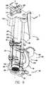
- FIG. 6is a perspective view of the brewing mechanism showing the brew chamber column, column pressurizing piston, guide rails which controllably guide movement of the column, a column driving mechanism including a cam and a drive motor for the driving the cam such that operations of the drive motor drives the cam to controllably move the column upwardly and downwardly along the rails, a motor system for controllably driving the piston generally axially, downwardly along the column, and a brewing substance chute positioned relative to an open mouth of the column for controllably facilitating dispensing of brewing substance into the column during a brewing cycle;
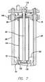
- FIG. 7is a cross sectional view taken along lines 7 - 7 in FIG. 6 showing the relationship between the various components described in FIG. 6 ;
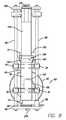
- FIG. 8is a front elevational view of the brewing mechanism shown in FIG. 6 in which the piston, column, and chute positioned in a “home” position prior to alignment for a brewing cycle;
- FIG. 9is a right side view of the brewing mechanism shown in FIG. 8 with the components in the “home” position;
- FIG. 10is a front elevational view of the brewing mechanism as shown in FIG. 6 in which the components have been controllably positioned in a “fill” position for dispensing beverage making substance into the brewing column, the brewing column being downwardly positioned to seal over a filter structure, the piston being driven into the upward most position, and the chute positioned relative to the mouth for dispensing beverage making substance into the column on top of the filter structure;
- FIG. 11is a side elevational view of the brewing mechanism as shown in FIG. 10 ;
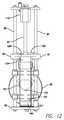
- FIG. 12shows the components in a position during the beverage producing process in which the piston is driven downwardly over water and beverage making substance to pressurize the contents of the cylinder and controllably drive beverage out of the column through the filter structure to provide extraction of beverage from the combination of beverage making substance and water;
- FIG. 13is a right side elevational view of the mechanism in this progressive brewing step
- FIG. 14is a front elevational view of the brewing mechanism showing removal of the spent brewing substance from the filter structure, the piston remaining in the downward position while the column is displaced upwardly by operation of the cam with the column being guided along the rails and traveling upwardly axially relative to the piston;
- FIG. 15is a right side elevational view of the progressive step as shown in FIG. 14 ;
- FIGS. 16-19show enlarged perspective views of the spent beverage making substance being removed from the filter structure, the linkage associated with the controllable arm used to displace the drained and spent beverage making substance from the filter structure, and mechanisms used to actuate the arm during the process of removing the spent and drained beverage making substance;
- FIG. 20is an enlarged cross sectional view of the base of the brewer mechanism showing one embodiment of an agitator for agitating the beverage making substance;
- FIG. 21is a diagrammatic illustration of the system showing the couplings, connections, and relationships between various components of the system
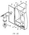
- FIG. 22shows the beverage producing apparatus of FIG. 1 in which an alternate brewing mechanism has been removed from the cabinet, the general information relating to FIGS. 1-4 generally applying to this alternate embodiment as shown in FIG. 22 ;
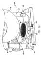
- FIG. 23is a perspective view of the brewing mechanism showing the brew chamber, operating shaft and motor, cover assembly which are all operative to controllably produce and dispense a beverage;
- FIG. 24is a cross sectional view taken along lines 24 - 24 in FIG. 23 showing the relationship between the various components described in FIG. 23 ;
- FIG. 25is an enlarged cross sectional view based on the view as shown in FIG. 24 further showing a filter carried on the piston and an outlet tube operatively coupled and in communication with a recessed area proximate to filter for dispensing brewed beverage from the chamber;
- FIG. 26is a cross sectional perspective view showing the first step of a brewing cycle in which a beverage brewing substance is disposed in the chamber and in which heated water is added to agitate the slurry substance retained in the chamber;
- FIG. 27is an enlarged perspective view of the assembly during a dispense portion or dispense stage of the brewing cycle with a cover positioned over the chamber and the piston moving upwardly through the chamber to drive brewed beverage through the filter and through the outlet tube;
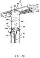
- FIG. 28is a similar view of the assembly in which the brewing cycles complete, the piston has pressed liquid out of the spent grounds and the grounds are upwardly presented by the piston for removal by the cover trolley;
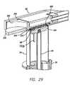
- FIG. 29is a perspective view similar to that as shown in FIG. 26 in which the cover trolley has advanced forwardly to push the spent and drained coffee from the piston for disposal thereof;
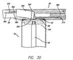
- FIG. 30is a view of the trolley as it is advancing forwardly (with the spent grounds removed therefrom) to illustrate the movement of a scraper portion on the leading edge of the trolley and associated structures which help to agitate, shake or otherwise move this portion to help dislodge spent grounds from the scraper;
- FIG. 31is a cross sectional view of the trolley assembly
- FIG. 32is an enlarged detailed view of the trolley assembly and associated guide rail structures which help facilitate movement of the leading edge of the trolley;
- FIG. 33is an enlarged view showing additional structures on the trolley
- FIG. 34is an enlarged view showing the structures
- FIG. 35is a cross sectional perspective view showing the piston in the upwardly most position for cleaning.
- a beverage producing apparatus 30which is in the form of a brewer system including an active column brewing mechanism 40 .
- Active brewing in such a column brewing mechanism 40is differentiated from passive brewing such that components of the mechanism 40 operate on the brewing substance and water to produce a beverage.
- the active brewing mechanismincludes controllable features to provide controlled actuation of the components of the mechanism 40 to provide alteration of the resultant brewed beverage characteristics and taste profile.
- the present disclosureis intended to be a broad general disclosure relating to the structures and methods for producing a beverage using the teachings of the present disclosure.
- the present disclosureshould be understood to be applicable for use with a variety of manual, semiautomatic, or automatic beverage making apparatus including, but not limited to, brewing systems.
- One of skill in the art empowered with the teachings as provided hereincan find utility and application for this disclosure in a variety of mechanisms and systems.
- Brewing substance or beverage making substanceis referred to by way of illustration and not limitation. While reference to the brewing substance “coffee” will be used throughout this description in the interest of clarity and simplicity, it will be understood that any form of beverage making substance may be used to produce a beverage. It should be noted that the present disclosure may refer to a coffee in reference to beverage making substance throughout the remainder of the description in the interest of clarity and simplicity. However, it will be understood that any form of beverage making substance may be used to produce a beverage and the term coffee is intended to be broadly interpreted.
- beverage substancessuch as ground coffee, tea, herbs, botanicals, liquid beverage concentrate, ground, pulverized, rough cut, whole, powdered beverage concentrate, flaked, granular, freeze dried or other forms of materials including liquid, gel, crystal or obtain a desired beverage or other food product or any other forms of beverage substance or food products.
- Terms including beverage, brewed, brewing, brewing substance, brewed liquid, and brewed beverage as may be used hereinare intended to be broadly defined as including, but not limited to, the brewing of coffee, tea and any other beverages. This broad interpretation is also intended to include, but is not limited to any process of dispensing, infusing, steeping, reconstituting, diluting, dissolving, saturating or passing a liquid through or otherwise mixing or combining a beverage substance with a liquid such as water without limitation to the temperature of such liquid unless specified.
- wateris referred to in the specification by way of illustration and not limitation. It is understood that the liquid or water it to be broadly interpreted to include any type of liquid used to produce a beverage, including, but not limited to water, milk, juices, etc.
- the apparatus 30includes a housing 32 having a cabinet portion 37 , a cabinet door 34 , and a top panel 36 .
- a control panel 60is provided on a front face of the housing 32 .
- a dispensing area 33is provided for positioning a serving container, as illustrated, a cup under a dispensing nozzle 35 positioned therein. While a dispensing area 33 is shown and described having a volume and dimensions generally compatible with a single cup, it is envisioned that this area 33 could be sized and dimensioned to receive a carafe or other larger volume container for filling at the brewing apparatus 30 . All variations of container size and container types are included within the scope of the present disclosure with the disclosure intended to not be limiting. While reference to a cup will be used herein in the interest of clarity and simplicity it will be used by way of illustration and not limitation.
- hopper openings 31 , 39Positioned under the top panel (see FIG. 4 ) are hopper openings 31 , 39 which allow an operator to fill two types of ground coffee into the apparatus 30 .
- the ground coffeemay be in the form of decaf and regular or different flavors as well as coffee and tea or other substances.
- the top panel 36covers the hoppers 31 , 39 to prevent inadvertent placement of other substances into the hoppers 31 , 39 .
- a grinding systemmay be used with the present apparatus. As such, the hoppers 31 , 39 would hold fresh coffee beans or other beverage making substance for grinding and dispensing into the beverage making system.
- the brewing mechanism 40dispenses beverage into a dispensing assembly 42 which is connected to the nozzle 35 for dispensing beverage to the container.
- the mechanism 40is removable from the dispensing apparatus 42 so that it can be removed from the cabinet portion 37 of the housing 30 (see FIG. 5 ).
- the brewing mechanismcan dispense multiple quantities, for example repeated brewing cycles, to dispense beverage into a buffer reservoir 44 .
- the buffer reservoir 44can be provided as a thermally insulated container which can accommodate multiple dispensing volumes of beverage produced by or from the brewing mechanism 40 .
- the reservoir 44can include a heater 43 (see, FIG. 21 ).
- the brewing mechanismcan be configured for dispensing single cup quantities of coffee, for example, 12 ounces, 14 ounces, and 16 ounces. Of course a variety of other single cup volumes can be defined; however, the brewing mechanism 40 generally is configured for producing single cup volumes.
- the buffer reservoir 44is sized and configured for retaining multiple volumes of beverage dispensed from the brewing mechanism 40 .
- the buffer reservoir 44may be dimensioned in multiples of 16 ounces. For example, 4, 5 or 6 times the maximum brewing mechanism dispensing volume. This will allow the apparatus to develop a buffer quantity and retain the buffer quantity in the reservoir. This will allow an operator to dispense from the buffer reservoir 44 while the brewing mechanism 40 is operating periodically or generally continuously to produce multiple cycles of beverage and dispensing the beverage into the reservoir 44 .
- the systemcan be produced with a stand alone brewing system without the buffer reservoir 44 . Such a stand alone system could be used for producing quantities of beverage on demand without the option of directing volumes of coffee to the buffer reservoir 44 .
- the reservoir 44includes a level detector 41 which is coupled to a controller 47 with the brewing mechanism 40 so that the brewing mechanism 40 does not overtake the maximum capacity of the buffer reservoir. In other words, the brewing mechanism will only initiate a brewing cycle 40 when a buffer reservoir level sensor 41 indicates that it can receive at least a maximum volume of beverage brewed by the brewing mechanism.
- a low level detector 45is provided in the buffer reservoir to provide a signal to the controller 47 to initiate a brewing cycle if a low level condition satisfies various parameters associated with a programmed brewing cycle and buffer accumulation strategy.
- the apparatuscan be connected to a pressurized water line or source 50 to provide a continuous flow of water through a control valve 52 to a heated water reservoir 54 of a water delivery system for delivering or dispensing water to the brew column or chamber.
- the heated water delivery systemis coupled to the controller for controllably dispensing water to the column or chamber.
- the heated water reservoir 54controllably provides water to the brewing mechanism 40 .
- the heated water reservoir 54may be sized and dimensioned to provide heated water for brewing cycles on a repeatable, generally continuous basis.
- a heater 51is associated with the reservoir 54 to provide heat energy to the water in the reservoir 54
- the buffer reservoir 44also includes a drain control valve 58 which is connected to the controller to controllably drain beverage after a predetermined period of time or other characteristics associated with the beverage. This will allow the system to automatically purge beverage that might be outside of freshness, taste or other parameters. For example, if beverage is allowed to be held within the reservoir for a predetermined period of time, perhaps 20 minutes, the drain valve 58 can be controllably opened by the controller 47 to purge the buffer reservoir.
- the controller 47can also monitor the brewing cycles of the brewing mechanism 40 so as to provide a freshness calculation. This may be important to avoid purging freshly brewed coffee after a predetermined period of time from a fresh brewing cycle. However, if a brewing cycle has not occurred within a predetermined period of time the drain valve 58 can be opened on the assumption that no new beverage has been added to the reservoir 44 and any beverage retained in the reservoir 44 may fall outside of the time/freshness limitation parameters.
- a first control panel 60is provided on the apparatus 30 .
- the control panelcan include a variety of control buttons, switches or other controls which will allow a user to dispense a single cup of multiple sizes for example at a second control panel 62 or may program the apparatus 30 using control panel 60 .
- biometric interfacessuch as fingerprint detection, hand detection, or any other biometric detection device may be used. This may be important to prevent unintended operators from controlling or otherwise programming the apparatus 30 .
- the biometric interface components at the control panel 60may also be used by customers to identify themselves to the apparatus 30 .
- a customercould walk up to the brewer, place a thumb on the biometric thumbprint sensor whereupon the brewer would dispense a chosen beverage identified with that customer.
- This of coursewould require programming to identify the various customers; nevertheless, the programming portion is within the scope of skills of one of ordinary skill in the art based on the teachings of the present disclosure.
- the programmingwould allow a user to set a taste profile, choice of brewing substance, temperature as well as other characteristics associated with the customer.
- the systemcan be designed to allow the customer to fine tune or refine their own personal recipe and taste preferences over time and save these choices in association with their biometric information.
- Other forms of interfacesare completely included within the scope of the present application including card base memory systems, RFID, fob retained memory devices such as RFIDs and any form of customer associated interface identification devices currently available or hereinafter developed which can be used in conjunction with the present beverage making apparatus 30 .
- the brewing mechanism 40as described in prior portions of this disclosure includes an active beverage producing system which pressurizes a volume of water and brewing substance retained in a hollow body in the form of a tube or column or brew chamber 70 .
- the brewing mechanism 40as shown in a “home” or ready position.
- the hollow column 70includes an upper mouth 72 and a lower base 74 .
- a wall 76 extending between and defining the mouth 72 and base 74include guides 78 depending from the wall 76 .
- the guidesare sized and dimensioned for engaging guide rails 80 .
- the pair of spaced apart guide rails 80 , 80help guide the movement of the column 70 along a central axis 82 .
- a filter structure 86is provided on a stationary foundation 92 .
- the base 74 of the column 70is positioned over and engaged with the filter structure 86 for sealing the base 74 .
- a spent brewing substance removal assembly 90is provided on the foundation 92 generally proximate to the filter 86 also retained on the foundation 92 .
- Movement of the column 70is synchronized and controlled by a column driver 95 which includes a cam 96 controllably operated by a drive motor 98 .
- the cam 96includes cam grooves 100 engaged with corresponding cam follower 102 on the column.
- the cam follower 102rides in the cam channel 100 to follow the cam.
- a piston 104is attached to an upper portion 106 of the mechanism 40 .
- the upper portion 106provides a platform for retaining a lead screw 108 which drives the piston 104 .
- a stepper motor 110is carried on the upper portion 106 and connected to the lead screw 108 by a belt 112 and corresponding gears 114 , 116 .
- the stepper motor 110could also be embodied as a gear motor with the use of position feed back to control the operation of the motor.
- a coffee directing chute assembly 120is provided proximate the mouth 72 of the column 70 .
- the chutedirects coffee controllably dispensed by hopper drives 97 , 99 (see, FIG. 21 ) from the hoppers 31 , 39 into the column 70 .
- the piston 104includes a seal 130 retained on a lower portion thereof for moveable sealing engagement with an inner surface 132 of the column 70 .
- the lead screw 108 driven by the gear 116engages a corresponding threaded portion 140 of the piston 104 to controllably drive the piston 104 upwardly and downwardly along the central axis 82 .
- the central axis 82is parallel to the axis of the corresponding guide rails 80 , 80 the moveable components of the mechanism 40 can be operated smoothly and in synchronization provided by the motors 110 , 98 which are coupled to the controller.
- the guides 78also referred to as trolleys, include bearings which smoothly operate along the guide rails 80 , 80 .
- the mechanism 40is positioned in the “home” position.
- the piston 104 and the column 70are disengaged from each other.
- the column 70is disengaged from the filter structure 86 .
- Disengagement of these components in the home positionhelps maintain the life and integrity of the contacts between these components, and helps to maintain air circulation relative to these components.
- the seal 130 of the piston 104is disengaged from the inside surface 132 of the column 70 .
- the leading edge 160 of the piston 104is retained in an upper portion 162 of the column 70 , the diameter of the upper portion 162 is greater than the diameter of the seal 130 and as such there is no contact.
- positioning of the leading edge 160 in the upper portion 162helps to align the piston 104 with the column 70 during the brew process.
- the column 70is raised to disengage the base 74 from the filer structure 86 . This helps to allow the filter 86 to air to allow drying of the filter structure. This prevents the promotion of any undesirable moisture effects on the filter.
- the follower 102 or cam followeris engaged with the cam in the upper position.
- the components of the brew mechanism 40are positioned for receiving brewing substance.
- the column 70is displaced downwardly to seal the base 74 relative to the filter structure 86 .
- the chute 120is controllably moved to position a lip 180 of the chute 120 relative to the mouth 72 of the column 70 .
- the chuteis retained on arms 182 including a cam or cam follower 184 which, when contacted by the upper portion 188 of the piston 104 causes the arms 182 pivotally retained pivot point 191 to cam inwardly towards the piston 104 .
- the inward movement of the arms 182 and the chute 120 attached theretocauses positioning of the lip 180 relative to the mouth 72 .
- coffee hoppers 31 , 39include a drive mechanism which can be coupled to the controller for controllably dispensing a predetermine quantity of coffee to the chute 120 .
- the augerscontrollably move coffee from the hoppers 31 , 39 , coffee is directed down the chute 120 into the column 70 .
- a volume of coffee 190is accumulated on top of the filter structure 86 inside the column 70 .
- the pistonmoves downwardly and heated water is dispensed into the chamber through the heated water line 200 .
- the heated water lineis positioned at the upper portion 162 of the column 70 . This allows the water to wash the inside surface 132 of the column 70 to rinse any particles or other brewing substance that may have accumulated thereon during the dispensing process. Water will fall through the column and accumulated on top of the brewing substance 190 to initiate the infusion process. Beverage is prevented from dripping through the outlet fitting 204 by use of a low pressure check valve 205 down stream for the fitting 204 .
- the filter structure 86is generally sized and dimensioned with a sufficiently proportioned opening in the mesh or other filter material to prevent significant drips as a result of gravity. Rather, the brewing process will include the active compression of the water retained in the column to drive the beverage from the combination of brewing substance 190 and water 206 .
- a cushion of air or air gap 210(see FIG. 12 ) is retained in the column.
- This air gap 210forms when the volume of water dispensed into the column is slightly less than the maximum volume of the column at the reduced diameter area 212 . This air gap 210 will be described in greater detail below.
- the outlet fitting 204directs coffee either to the nozzle 35 or to the buffer reservoir 44 as previously described.
- the controllable interface 42allows the mechanism 40 to be quickly and easily removed therefrom for cleaning, maintenance, repair or replacement.
- One of the advantages of a modular brewing mechanismis that the brewing mechanism can be easily and efficiently replaced to prevent down time of the apparatus 30 .
- the pistoncontinues downward movement along the axis 82 with the guide rails 80 guiding movement of the cylinder 70 by means of the trollies 78 .
- trollies 78are provided on the upper portion 188 of the piston 104 to help guide movement of the piston along the axis 82 .
- the active brewing cycle created by movement of the pistonapproximates a French press type of operation. This system also enhances the controllability of the French press operation to provide more subtlety, control, and recipe tuning.
- the cycleproceeds as shown in FIGS. 14 and 15 .
- the pistongenerally stops at the base 74 of the column 70 .
- the column 70is moved upwardly along the axis 82 a sufficient dimension to allow the arm mechanism 90 to controllably operate for subsequent removal of the spent brewing substance from the filter structure 86 .
- the spent brewing substance 190 in its somewhat dried stateis more manageable and can be controlled for removal from the brewing mechanism.
- the removal mechanism 90displaces a puck of brewing substance from the brewing mechanism 40 to the grounds tray or bin 101 . After the spent grounds 190 have been removed, the piston and column cycle to return to the home position as shown in FIGS. 8 and 9 .
- the puck removing mechanism 90includes an arm 240 which is connected to actuation mechanism 242 . Operation of the actuation mechanism 242 acts to move or rotate the arm 40 to displace the puck from the filter structure 86 . In other words, the arms 240 acts to flip or scrape the puck 190 away from the filter structure 86 .
- the arm moving mechanismincludes a follower extension 246 which travels along a channel to 248 .
- the follower mechanism 246is coupled to a spring 250 which acts to return the follower mechanism after the associated cam lug 252 carried on the cam 96 moves out of position.
- the arm 240is out of position behind the column during the home position and brewing process as described above. After the brewing process is complete and the piston 104 and column 70 move upwardly away from the filter structure 86 , the arm 240 rotates in position across the filter structure to flip the puck 190 away from the filter structure 86 .
- the spring mechanism 250causes the arm to retract after movement of the follower 246 is completed.
- FIGS. 23-35Disclosed in FIGS. 23-35 is an alternate embodiment of the system, apparatus, and method as disclosed in corresponding FIGS. 1-20 .
- FIGS. 1-4 and FIG. 21 as described abovegenerally relate the alternate embodiment shown in FIGS. 23-35 .
- the brewing mechanism 40includes a piston which moves downwardly.
- the brewing mechanismcan produce brewed beverage by single cup or to a reservoir. In the alternate embodiment, however, the piston moves upwardly.
- a brewing mechanismfor use in brewing a single cup or in brewing multiple batches to a reservoir.
- air agitationis provided in the brewing chamber to agitate the beverage brewing substance to produce a desired result.
- ground brewing substanceis combined with water and drained through a filter mechanism to produce a brewed beverage.
- characteristics of the brewed beveragecan be controlled to achieve a desired result.
- FIG. 21applies to both embodiments with the brewing mechanism shown therein construed to be either the application of the embodiment shown in FIGS. 5-20 or the embodiment shown in FIG. 22-35 .
- the brewing mechanismwill ultimately produce a brewed beverage which is dispensed through a passage to a dispensing assembly 42 .
- the agitating assembly 300is common to both such that air can be introduced into the brewing mechanism to agitate the brewing substance during a brew cycle.
- the hoppers 31 , 39 and the dispensing mechanism 97 , 99can be used to controllably dispense brewing substance into the brewing mechanism.
- the heated water reservoiris controllably operated by the controller 47 to controllably dispense heated water through 206 to the brewing mechanism in both embodiments.
- the brewing mechanism 40as described in prior portions of this disclosure includes an active beverage producing system which pressurizes a volume of water and brewing substance retained in a hollow body in the form of a column or brew chamber 70 .
- the brewing mechanism 40as shown in a “home” or ready position.
- the hollow column 70includes an upper mouth 72 and a lower base 74 .
- a wall 76 extending between and defining the mouth 72 and base 74is supported on spacers 78 .
- the spacersprovide a dimensional separation between a motor 98 and a connected piston shaft 95 .
- the brewing mechanism 40can be used with an apparatus such as shown in FIGS. 1-4 .
- this brewing mechanism 40can be configured in a number of other embodiments.
- the brewing mechanism 40could be placed in stand alone system which is operated by a barista similar to that as might be achieved by using an espresso machine. Regardless of this specific embodiment in which the brewing mechanism 40 is placed, further discussion with regard to the structures and functions of this mechanism will be described below.
- An uppermost portion of the mechanism 40includes a cover assembly 92 which is displaceably carried on guide rails 94 for generally axial movement 96 by means of a motor 98 .
- the cover assembly 92will be described in greater detail below with regard to FIGS. 30-34 .
- the cover assembly 92helps to cover the opening 72 of the brew chamber 70 during the brewing process. Additionally, the cover assembly is operated so as to undercover the brew chamber at the conclusion of the brewing process and displace the generally drained, spent quantity of compressed brewing substance by sliding or shifting relative to the rails 94 by operation of the motor 98 .
- a piston 104is operatively attached to the drive shaft 95 and is axially displaceable 105 within the hollow cavity of the column 70 .
- the pistonmoves axially upwardly and downwardly 105 during the brewing cycle.
- the piston 104includes a filter structure 86 carried proximate a face 87 of the piston 104 .
- One or more recesses 89are formed in the face 87 of the piston 104 with the filter structure 86 overlying the recesses.
- An outlet tube 103is operatively coupled and in communication with the recesses 89 to provide a path through which brewed beverage will flow.
- the motor 98operates a lead screw 95 to vertically displace the piston 104 attached to the lead screw 95 upwardly and downwardly through the chamber.
- a seal 200 on the piston 104helps to seal the piston against the inside surface 202 of the brew chamber.
- An anti-rotation bracket 204is provided to produce vertical displacement 105 of the piston 104 in the brew chamber. As shown in FIG. 24 , the brew chamber with the piston in the bottom most position is ready for receipt of ground coffee and hot brewing water in order to produce a brewed beverage.
- FIG. 25an enlarged cross sectional view of the lower portion of the brew chamber and piston is shown.
- recesses 89are provided in the face 87 of the piston to provide a collection cavity for a beverage which is forced through the filter 86 .
- Beverage which collects in the recessesis drained through the outlet tube 101 .
- the outlet tubeis attached to the lower portion of the piston and travels upwardly and downwardly with the piston as it is driven by the lead screw 95 .
- the upward force of the piston against the cover 92result in pressurizing of the contents of the chamber thereby creating a pressurized displacement of beverage through the filter and out through the outlet tube.
- a quantity of beverage brewing substance 190is shown placed on top of the piston 104 and heated water 302 has been placed in the brew chamber for combination with the brewing substance 190 .
- the coffee and watermay be added by mechanized dispensing systems such as the hoppers and a water delivery system or water systems for dispensing these ingredients. Additionally, if the brewing mechanism 40 is used as a stand alone mechanism without the additional automatically controlled features, an operator can place a desired quantity of brewing substance and water into a brew chamber manually.
- Air 306is may be injected into the brew chamber either through the outlet tube by way of operation of a control valve which can switch between allowing air to be moved into the chamber or brew dispensed or by way of a separate air introduction line. Air can be introduced into the recesses underneath the filter so as to force the air up through the filter. Delivery of air through the filter helps to agitate or otherwise mix the beverage brewing substance with the water retained in the chamber. This agitation helps to enhance the brewing characteristics of the coffee or other beverage.
- the introduction of air and air agitationis accomplished with the cover displaced or substantially displaced away from the opening of the chamber. This allows additional or excess air to escape from the chamber and controlled to build up of pressure within the chamber. After sufficient time of steeping, agitation, or both, the cover assembly shifts to cover the mouth of the brew chamber. As shown in FIG. 27 , a seal 310 is positioned to cooperatively seal a rim or mouth 72 of the chamber. This seals the brew chamber during the ongoing brewing operation.
- the pistonWith a seal brew chamber, the piston is upwardly shifted 105 thereby compressing the trapped air 312 between the seal 310 and the water 302 .
- the brewing substance 190will tend to settle during this stage of the brewing cycle.
- Continued upward movement of the piston 104drives the brewed beverage 320 through the outlet tube 101 .
- Continued upward movement after significant draining of the beverage through the filterresults in enforcing the air 312 through the (now spent beverage brewing substance 190 to help drain moisture from the brewing substance). Draining of moisture from the brewing substance helps to make the substance more manageable at the end of the brewing cycle. Additionally, forcing some volume of air 312 through the outlet tube 101 helps to promote clearing and draining of the tube 101 .
- the pistoncontinues its upward travel to displace the spent brewing substance 330 beyond the rim 72 of the brewing chamber. This position is achieved by displacement of the cover assembly away from the mouth of the chamber after the end of the brew cycle. By displacing the cover assembly away from the brew chamber a leading edge on the cover assembly including the wiper 340 is positioned to help facilitate removal of the spent brewing substance 330 .
- the cover assemblyis translated generally linearly over the chamber thereby engaging the wiper with the spent brewing substance and displacing it from the top of the piston. This also helps to facilitate wiping of the top surface 350 of the piston 104 . Wiping is accomplished by a squeegee structure 352 carried on the wiper 340 . A leading edge of the squeegee material 354 extends down sufficiently so as to create a wiping action to clean the surface 350 of the filter.
- the guide rails 94include removal channels 360 and return channels 362 .
- the rails 94are mere images of each other and as such only one will be described with reference to FIG. 30 .
- the removal channel 60includes a series of shaker bumps or structures 364 .
- a guide pin 366is provided on the wiper 340 . The guide pin travels in the channels 360 , 362 to provide action on the wiper 340 .
- the pins 366guide the wiper along the removal channel 360 .
- a toggle 372allows the pins to pass as the cover assembly is shifted over the piston at the end of the brewing cycle. However, the toggle 372 causes the pins to ride up into the return channel 362 on the return trip. This results in disengaging the wiper 340 from the surface of the piston on the return trip. This helps to prevent excessive wear on the filter portion of the piston and other benefits.
- the pins 366encounter the bumps 364 . These cause the pins to agitate the wiper 340 up and down at the hinged structure 370 . The shaking or bumping movement of the wiper 340 helps to assure that the spent brewing substance is dislodged from the wiper. On the return trip the bumps 364 are once again encountered helping to provide further assurance that the spent brewing substance is disengaged.
- Knocking the loose moist grounds from the wiper 340helps to assure that they are not redeposited on the brewing filter during the retraction portion. This also helps assure that grounds and other debris are not accumulated on the backside 354 of the squeegee edge 354 .
- FIG. 31shows structures associated with the cover assembly including the lead screw 380 coupled to the motor 98 to generally linearly drive the assembly along the channels 94 .
- Additional pairs of guide channels 382 , 384 and associated guide pins 386 , 388help to maintain a generally linear movement of the cover assembly relative to the chamber.
- the wiper 340 retainedis relative to the cover assembly by means of spring structures 390 proximate to the hinge 370 . These provide a forward, downward action on the wiper 340 to engage a squeegee 352 relative to the filter 86 . This results in better engagement of the leading edge 354 of the squeegee when cleaning the filter 86 .
- the springs 390are compressed when the assembly is retracted as described above.
- the piston 104can be upwardly displaced to allow it to be serviced. Servicing may include more detail cleaning, disassembly, replacement of seals as well as other actions. This also allows removal of the piston 104 for access to the shaft.
- the mechanismoperates to controllably compress the combination of water and coffee slurry so as to produce a brewed beverage and dispense it from the mechanism. Air agitation may be introduced to further enhance and achieve different characteristics of the brewed beverage. Also, the system can be controlled so as to control additional characteristics or achieve additional characteristics of the brewed beverage. The benefits of the upward compression of the slurry help to make the spent brewing substance more manageable at the end of the brewing cycle. Additionally, the dispensing of beverage through the filter carried on the piston helps maintain sanitary dispensing conditions and easily assessable and cleanable structures. In this regard, the piston is removable for cleaning of the filter and recesses. Similarly, the outlet tube 101 can be easily removed for sanitation or replacement. As such all of the food contact surfaces in the mechanism including the chamber can be easily, efficiently and thoroughly cleaned.
- the movement of the piston 104 downwardly through the column 70can be controlled to allow steep time.
- the pistoncan be driven using the motor 110 to produce a pulsing effect. In other words, an initial complete volume of water can be allowed to steep with the brewing substance 190 .
- the stepper motor 110can pulse the piston 104 downwardly to dispense proportional volumes of beverage from the column 70 .
- the piston 104can be driven generally continuously to controllably dispense beverage from the column. Regardless of the technique used, a range of controllability of beverage dispensing can be provided by the present beverage mechanism 40 and the system associated with the apparatus 30 .
- an agitating assembly 300is provided.
- the agitating assembly 300includes a check valve 302 carried in a chamber 304 . Air is driven into the chamber 304 by way of an air pump 306 communicating with the chamber and coupled to the controller 47 .
- the check valve 302prevents liquids from flowing into the line connected to the pump 306 . Air is introduced into the water and coffee slurry thereby agitating the slurry to enhance the contact between the coffee and water. Agitation can be operated at any opportune time during the brewing process. One example of use of agitation is after dispensing coffee and water into the column.
- agitating assembly 300can be used with the present system such as, but not limited to, mechanical, magnetic, and acoustic agitators.
Landscapes
- Engineering & Computer Science (AREA)
- Food Science & Technology (AREA)
- Apparatus For Making Beverages (AREA)
- Devices For Dispensing Beverages (AREA)
Abstract
Description
Claims (7)
Priority Applications (1)
| Application Number | Priority Date | Filing Date | Title |
|---|---|---|---|
| US12/934,362US8950318B2 (en) | 2008-03-24 | 2009-03-24 | Brewer system with active brewing mechanism and buffer reservoir piston compression of brewing substance |
Applications Claiming Priority (4)
| Application Number | Priority Date | Filing Date | Title |
|---|---|---|---|
| US3907108P | 2008-03-24 | 2008-03-24 | |
| US10053708P | 2008-09-26 | 2008-09-26 | |
| PCT/US2009/038125WO2009120708A1 (en) | 2008-03-24 | 2009-03-24 | Brewer system with active brewing mechanism and buffer reservoir piston compression of brewing substance |
| US12/934,362US8950318B2 (en) | 2008-03-24 | 2009-03-24 | Brewer system with active brewing mechanism and buffer reservoir piston compression of brewing substance |
Publications (2)
| Publication Number | Publication Date |
|---|---|
| US20110086148A1 US20110086148A1 (en) | 2011-04-14 |
| US8950318B2true US8950318B2 (en) | 2015-02-10 |
Family
ID=41114307
Family Applications (1)
| Application Number | Title | Priority Date | Filing Date |
|---|---|---|---|
| US12/934,362Active2030-12-01US8950318B2 (en) | 2008-03-24 | 2009-03-24 | Brewer system with active brewing mechanism and buffer reservoir piston compression of brewing substance |
Country Status (8)
| Country | Link |
|---|---|
| US (1) | US8950318B2 (en) |
| EP (1) | EP2262402B1 (en) |
| JP (1) | JP5905720B2 (en) |
| CN (1) | CN102083344B (en) |
| BR (1) | BRPI0909236A8 (en) |
| CA (1) | CA2719757A1 (en) |
| MX (1) | MX2010010486A (en) |
| WO (1) | WO2009120708A1 (en) |
Cited By (7)
| Publication number | Priority date | Publication date | Assignee | Title |
|---|---|---|---|---|
| US20150118367A1 (en)* | 2010-02-17 | 2015-04-30 | Koninklijke Douwe Egberts B.V. | Coffee bean packaging cartridge and coffee beverage system including the same |
| US20150305546A1 (en)* | 2012-12-12 | 2015-10-29 | Nestec S.A. | Beverage production device using centrifugation for extracting a liquid comprising heat loss compensating means |
| WO2017100326A1 (en)* | 2015-12-07 | 2017-06-15 | Bunn-O-Matic Corporation | Brewer system, method and apparatus |
| US9980599B2 (en) | 2009-02-17 | 2018-05-29 | Koninklijke Douwe Egberts B.V. | Coffee bean packaging cartridge and coffee beverage system including same |
| US10292524B2 (en)* | 2016-05-10 | 2019-05-21 | Fuji Electric Co., Ltd. | Beverage extraction device |
| US11523703B2 (en) | 2018-01-23 | 2022-12-13 | Bunn-O-Matic Corporation | Brewer system, method and apparatus |
| US11659953B2 (en) | 2016-12-13 | 2023-05-30 | Bunn-O-Matic Corporation | Bean to cup positive pressure brewer |
Families Citing this family (21)
| Publication number | Priority date | Publication date | Assignee | Title |
|---|---|---|---|---|
| JP6272772B2 (en)* | 2011-11-23 | 2018-01-31 | スターバックス・コーポレイション | Beverage extraction apparatus, system and method |
| EP2937023B1 (en)* | 2012-12-18 | 2018-08-08 | Main Power InnoTech (Shenzhen) Manufacturing Co. Ltd. | Full-automatic tea making device |
| ITPN20130035A1 (en) | 2013-06-26 | 2014-12-27 | Osmap Asia Pacific Pte Ltd | PERFECT MACHINE FOR THE PREPARATION OF ONE OR A PLURALITY OF DRINKS |
| WO2015077237A2 (en) | 2013-11-20 | 2015-05-28 | Starbucks Corporation D/B/A Starbucks Coffee Company | Cooking system power management |
| USD738667S1 (en) | 2013-11-20 | 2015-09-15 | Starbucks Corporation | Beverage brewing apparatus |
| NL2011928C2 (en) | 2013-12-10 | 2015-06-11 | Bravilor Holding Bv | DEVICE FOR PREPARING DRINK WITH A BUFFER RESERVOIR. |
| US10492640B2 (en) | 2014-06-27 | 2019-12-03 | Deepak Jain | System and method for producing and dispensing beverages |
| CN104840103A (en)* | 2015-04-28 | 2015-08-19 | 周林斌 | Water flowing device of bean grinding coffee pot |
| EP3287086B1 (en) | 2015-05-29 | 2020-09-02 | Olympus Corporation | Medical device |
| TR201515628A2 (en)* | 2015-12-08 | 2017-06-21 | Arcelik As | A COFFEE MACHINE WITH IMPROVED USER SAFETY |
| CN107149407B (en)* | 2016-03-04 | 2019-10-11 | 威斯达电器(中山)制造有限公司 | Coffee machine and its control method |
| JP6866735B2 (en)* | 2016-05-10 | 2021-04-28 | 富士電機株式会社 | Beverage extractor |
| US11330931B2 (en) | 2016-09-29 | 2022-05-17 | Levo Oil Infusion | Apparatus and method for infusing and dispensing oils, and drying and heating infusing materials |
| US9795246B1 (en)* | 2016-09-29 | 2017-10-24 | Levo Oil Infusion, Llc | Apparatus for infusing and dispensing oils |
| JP6816599B2 (en) | 2016-12-22 | 2021-01-20 | 富士電機株式会社 | Beverage extractor |
| WO2018116736A1 (en)* | 2016-12-22 | 2018-06-28 | 富士電機株式会社 | Beverage extraction device |
| IT201700058729A1 (en)* | 2017-05-30 | 2018-11-30 | Simonelli Group Spa | COFFEE MACHINE WITH PRE-INFUSION SYSTEM. |
| WO2019099373A1 (en) | 2017-11-16 | 2019-05-23 | LEVO Oil Infusion, Inc. | Apparatus and method for infusing oils |
| US12349832B2 (en)* | 2018-12-24 | 2025-07-08 | Carimali S.P.A. | Brewing device for preparing beverages |
| WO2022146147A1 (en)* | 2020-12-30 | 2022-07-07 | Amazon Nuts S.A.C. | Machine for the preparation of beverages based on nuts and the like |
| US12029344B2 (en) | 2022-04-01 | 2024-07-09 | Meticulous Home, Inc. | System and method for automated brew cycles |
Citations (144)
| Publication number | Priority date | Publication date | Assignee | Title |
|---|---|---|---|---|
| US1751397A (en) | 1928-03-29 | 1930-03-18 | Delsuc Emile Camille | Coffee filter |
| US2485246A (en)* | 1944-06-02 | 1949-10-18 | Donald F Swanson | Coffee-making apparatus and automatic control means therefor |
| US2584187A (en)* | 1949-03-28 | 1952-02-05 | Jack W Crist | Electric stove with portable grill |
| US2660948A (en) | 1947-10-16 | 1953-12-01 | Conrad J Forschner | Coffee maker |
| US2673920A (en)* | 1950-07-20 | 1954-03-30 | Heat X Changer Co Inc | Electric heater for water or the like |
| US2786929A (en)* | 1954-11-22 | 1957-03-26 | Gen Electric | Cooking appliance |
| US2955527A (en)* | 1956-07-16 | 1960-10-11 | O A Turman | Coffee maker and dispenser |
| US3106149A (en)* | 1960-08-15 | 1963-10-08 | John P Vukasin | Automatic beverage brewing machine |
| US3266410A (en) | 1962-09-01 | 1966-08-16 | Organizzazione Novi S R L | Machine for preparing coffee infusion |
| US3288049A (en) | 1963-05-17 | 1966-11-29 | Paliz A G | Infusor-type coffee apparatus |
| US3343478A (en)* | 1966-06-23 | 1967-09-26 | Charter Design And Mfg Corp | Automatic coffee maker |
| US3347150A (en)* | 1965-09-16 | 1967-10-17 | Superior Tea & Coffee Co | Semi-automatic coffee urn |
| US3349690A (en) | 1964-10-15 | 1967-10-31 | Melikian Inc Rudd | Beverage brewing apparatus |
| US3379117A (en)* | 1965-10-22 | 1968-04-23 | Levine Alfred B | Programmed automatic coffee machine |
| FR1565033A (en) | 1967-04-21 | 1969-04-25 | ||
| US3478670A (en)* | 1968-06-28 | 1969-11-18 | Westinghouse Electric Corp | Air operated single cup coffee brewer |
| US3517603A (en)* | 1968-02-06 | 1970-06-30 | Wilhelm H Bruenjes | Infusion type coffee urns |
| US3565641A (en) | 1968-04-08 | 1971-02-23 | Alan M King | Coffee brewing machine |
| US3589273A (en) | 1969-06-11 | 1971-06-29 | Cory Corp | Hot water supply apparatus |
| US3632982A (en)* | 1969-11-13 | 1972-01-04 | Gen Electric | Combination electric griddle and cooktop |
| US3727541A (en) | 1971-06-07 | 1973-04-17 | Reynolds Products | Hot water supply system for brewer |
| US3797375A (en)* | 1972-03-16 | 1974-03-19 | Jenn Air Corp | Stove with selectively interchangeable cooking apparatus |
| DE2432141A1 (en) | 1974-07-04 | 1976-01-22 | Protechnica Verkauf Gmbh | Fast-brewing filter coffee maker with metal sieve - includes compressed air supply causing grains to cake and act as fine filter |
| US4098175A (en) | 1975-06-06 | 1978-07-04 | Hagezet Aktiengesellschaft | Automatic coffee-brewing machine |
| US4207809A (en)* | 1978-03-20 | 1980-06-17 | Restaurant Technology, Inc. | Dual reservoir coffee urn |
| US4271752A (en) | 1978-04-12 | 1981-06-09 | Paolo Valente | Coffee making assembly |
| US4271753A (en)* | 1979-11-23 | 1981-06-09 | Refreshment Machinery Incorporated | Brewing mechanism |
| US4309939A (en)* | 1979-09-14 | 1982-01-12 | Bunn-O-Matic Corporation | Beverage brewing apparatus |
| USD269011S (en)* | 1981-07-13 | 1983-05-17 | Wilbur Curtis Company, Inc. | Coffee brewer |
| US4415788A (en)* | 1981-06-08 | 1983-11-15 | Jenn-Air Corporation | Induction cartridge |
| US4431892A (en)* | 1981-07-17 | 1984-02-14 | Jenn-Air Corporation | Ventilated modular cooktop cartridge |
| US4506596A (en) | 1984-05-29 | 1985-03-26 | Toshiba Electric Appliances Co., Ltd. | Beverage brewing apparatus |
| US4550651A (en) | 1982-11-19 | 1985-11-05 | Richard B. Mindlin | Batch-brewing coffee system |
| WO1986005670A1 (en) | 1985-03-28 | 1986-10-09 | Peter Mathijs Boumans | Method for coffee making and coffee making machine for preparing every time a cup of coffee to taste |
| US4632023A (en) | 1984-04-12 | 1986-12-30 | King Alan M | Coffee brewer |
| US4653390A (en) | 1985-05-29 | 1987-03-31 | W. M. Still & Sons Limited | Apparatus for making tea or coffee |
| US4653389A (en) | 1985-05-29 | 1987-03-31 | W. M. Still & Sons Limited | Boilers or tanks for hot water |
| EP0280345A1 (en) | 1987-02-24 | 1988-08-31 | De Erven de Wed. J. van Nelle B.V. | Device for the preparation of coffee |
| US4778978A (en)* | 1986-02-26 | 1988-10-18 | E.G.O. Elektro-Gerate Blanc U. Fischer | Cooking unit with radiant heaters |
| US4779520A (en) | 1986-12-22 | 1988-10-25 | Melitta-Werke Bentz & Sohn | Coffee maker or tea maker |
| US4791859A (en)* | 1987-08-27 | 1988-12-20 | King Alan M | Coffee brewer |
| US4797296A (en) | 1986-03-08 | 1989-01-10 | Cafina Ag | Piston-cylinder-assembly for a coffee brewing apparatus and a method of its operation |
| US4863066A (en)* | 1986-06-02 | 1989-09-05 | Technicon Instruments Corporation | System for dispensing precisely metered quantities of a fluid and method of utilizing the system |
| US4869231A (en)* | 1989-01-03 | 1989-09-26 | General Electric Company | Lift-up cooktop mounting arrangement for domestic range |
| US4869158A (en)* | 1989-02-13 | 1989-09-26 | Bunn-O-Matic Corp. | Elevated beverage brewer with side discharge |
| US4885986A (en) | 1987-07-09 | 1989-12-12 | Lucio Grossi | Automatic compact machine for the production of coffee and infusions, especially for domestic use |
| US4967647A (en)* | 1989-09-05 | 1990-11-06 | King Alan M | Air supply for a coffee maker |
| US5000082A (en)* | 1988-07-27 | 1991-03-19 | Food Equipment Technologies Company, Inc. | Beverage maker and method of making beverage |
| EP0473289A1 (en) | 1990-07-27 | 1992-03-04 | Westomatic Vending Services Limited | Brewer unit |
| US5127317A (en) | 1989-06-23 | 1992-07-07 | Sanden Corporation | Beverage extracting apparatus for vending machines |
| US5134925A (en)* | 1991-04-10 | 1992-08-04 | Bunn-O-Matic Corporation | Automatic brewer |
| US5146839A (en) | 1990-02-08 | 1992-09-15 | Wmf Wurttembergische Metallwarenfabrik Ag | Brewing means for a coffee machine |
| US5158793A (en)* | 1988-07-12 | 1992-10-27 | Edward Helbling | Coffee machine with product selectivity |
| US5179373A (en)* | 1989-10-26 | 1993-01-12 | Motorola, Inc. | Information network |
| US5186096A (en) | 1989-11-07 | 1993-02-16 | Estro S.R.L. | Coffee brewing machine |
| US5197373A (en) | 1989-07-28 | 1993-03-30 | J. M. De Jong Duke Automatenfabriek B.V. | Apparatus for preparing beverages, such as coffee or tea, by extraction |
| US5215074A (en)* | 1992-05-29 | 1993-06-01 | General Electric Company | Lift-up cooktop locator with combined function as support rod race |
| US5230278A (en)* | 1991-04-10 | 1993-07-27 | Bunn-O-Matic Corporation | Automatic brewer |
| WO1993015640A1 (en) | 1992-02-12 | 1993-08-19 | Royden Lewis Baxter | Beverage preparing assemblies |
| US5245914A (en)* | 1990-09-18 | 1993-09-21 | Vitous Charles J | Dual tea brewer |
| US5259296A (en) | 1992-03-02 | 1993-11-09 | Jura Elektroapparate Ag | Brewing apparatus |
| US5297472A (en) | 1992-09-29 | 1994-03-29 | Vki Technologies, Inc. | Beverage extraction device |
| US5303639A (en)* | 1991-04-10 | 1994-04-19 | Bunn-O-Matic Corporation | Automatic brewer |
| US5309821A (en)* | 1992-05-28 | 1994-05-10 | Bunn-O-Matic Corporation | Coffee brewing urn |
| US5309819A (en)* | 1993-06-10 | 1994-05-10 | Bunn-O-Matic Corporation | Dual motor drive automatic beverage brewing apparatus |
| US5312637A (en)* | 1993-06-21 | 1994-05-17 | Bunn-O-Matic Corporation | One-cup brewer |
| US5393540A (en)* | 1991-04-10 | 1995-02-28 | Bunn-O-Matic Corporation | Automatic beverage brewing method |
| US5406882A (en)* | 1994-03-30 | 1995-04-18 | Shaanan Holdings Inc. | Brewer |
| US5471910A (en) | 1993-09-02 | 1995-12-05 | Hgz Maschinenbau Ag | Automatic coffee machine |
| US5476033A (en)* | 1993-01-27 | 1995-12-19 | Cimbali S.P.A. | Automatic machine for coffee beverage, deliverable as coffee alone or, combined with milk, in the form of cappuccino |
| US5505845A (en)* | 1992-03-25 | 1996-04-09 | Bunn-O-Matic Corporation | Waste disposal tray for an automatic coffee maker |
| US5515772A (en)* | 1993-11-19 | 1996-05-14 | J. M. De Jong Duke Automatenfabriek B.V. | Apparatus for brewing a drink |
| JPH0962931A (en) | 1995-08-29 | 1997-03-07 | Sanyo Electric Co Ltd | Automatic beverage vending machine |
| US5623574A (en) | 1995-09-25 | 1997-04-22 | Bunn-O-Matic Corporation | Heated water apparatus |
| US5638739A (en) | 1996-07-08 | 1997-06-17 | Shaanan Holdings Inc. | Brewer |
| US5722313A (en)* | 1995-07-31 | 1998-03-03 | J. Lough Limited | Machine for making beverages such as espresso coffee with automatic ground coffee introduction and dregs expulsion |
| US5847364A (en)* | 1997-04-07 | 1998-12-08 | General Electric Company | Radiant heater support system |
| US5859410A (en)* | 1997-04-07 | 1999-01-12 | General Electric Company | Mounting system for radiant cooktop heating elements |
| US5865096A (en)* | 1998-07-24 | 1999-02-02 | Sanden Corp. | Coffee brewing apparatus |
| US5896805A (en)* | 1996-06-11 | 1999-04-27 | Sanden Corporation | Coffee extracting apparatus and method in which coffee grounds are expelled from an extracting container by pressed air |
| US5913963A (en) | 1998-06-01 | 1999-06-22 | King; Alan M. | Single cup brewer having special brew chamber |
| US5937738A (en) | 1996-06-11 | 1999-08-17 | Sanden Corporation | Coffee extracting apparatus for extracting coffee essence with use of compressed air stored in an accumulator |
| US5941163A (en) | 1996-04-13 | 1999-08-24 | Kwangju Electronics Co., Ltd | Brewed coffee vending machine |
| US5957035A (en) | 1997-10-10 | 1999-09-28 | Richter; Walter M. | Swirling oscillation coffee maker |
| US6079314A (en)* | 1997-05-16 | 2000-06-27 | Office Perks Gourmet Coffee Service Inc. | Beverage brewer chamber assembly |
| US6079317A (en) | 1998-12-15 | 2000-06-27 | Sanyo Electric Co., Ltd. | Beverage extraction apparatus |
| US6098524A (en) | 1998-09-16 | 2000-08-08 | Crane Co. | Hot beverage vending machine |
| US6155158A (en)* | 1999-10-12 | 2000-12-05 | Bunn-O-Matic Corporation | Beverage brewing system |
| US6176172B1 (en) | 1999-09-14 | 2001-01-23 | Crane Co. | Table-top coffee vending machine and method |
| US6220147B1 (en) | 1997-06-13 | 2001-04-24 | Affinitea Brewing Technologies, Inc. | Beverage preparation and layering device for an espresso machine |
| US6250208B1 (en) | 1998-12-24 | 2001-06-26 | Lipton, Division Of Conopco, Inc. | Tea brewing apparatus |
| US6271504B1 (en)* | 2000-10-18 | 2001-08-07 | Maytag Corporation | Versatile surface heating cartridge for cooking appliance |
| US6279461B1 (en) | 1998-12-15 | 2001-08-28 | Sanyo Electric Co., Ltd. | Beverage extraction apparatus |
| WO2001074212A1 (en) | 2000-03-31 | 2001-10-11 | De Jong Duke | Coffee-making device with pressure control |
| US6324964B1 (en) | 1997-12-30 | 2001-12-04 | Anton Niederberger | Automatic tea-making machine |
| US6399925B1 (en)* | 2000-10-18 | 2002-06-04 | Maytag Corporation | Versatile surface heating cartridge for cooking appliance |
| US6401597B1 (en) | 2000-09-05 | 2002-06-11 | Crane Co. | Coffee vending machine filter paper support |
| US6439105B1 (en)* | 2000-07-31 | 2002-08-27 | Bunn-O-Matic Corporation | Multiple direction holder and beverage making apparatus |
| US6455818B1 (en)* | 2001-08-23 | 2002-09-24 | Maytag Corporation | Downdraft filter assembly for a cooking appliance |
| US6488976B1 (en) | 1999-12-13 | 2002-12-03 | Affinitea Brewing Technologies, Inc. | Method and apparatus for brewing tea with an espresso machine |
| US6492622B2 (en)* | 2000-04-08 | 2002-12-10 | Schott Glas | Cooking arrangement for cooking food such as a stove, a cooktop, and other cooking appliances, with an easy-to-clean surface |
| US6513419B2 (en) | 1998-12-31 | 2003-02-04 | Wmf Wurttembergische Metallwarenfabrik Ag | Coffee machine |
| US6564697B2 (en) | 2000-11-30 | 2003-05-20 | Lipton, Division Of Conopco, Inc. | Tea brewing method and apparatus |
| WO2003101264A1 (en) | 2002-05-31 | 2003-12-11 | Presso Limited | Apparatus for making espresso coffee |
| US6674051B2 (en)* | 2001-12-14 | 2004-01-06 | Maytag Corporation | Heater cloaking grill grate system for downdraft cooking appliance |
| US20040045952A1 (en)* | 2002-09-05 | 2004-03-11 | Maytag Corporation | Cooking appliance having concealed cooking feature |
| WO2004023949A1 (en) | 2002-08-28 | 2004-03-25 | Niro-Plan Ag | Dispensing device for drinks |
| US6712066B1 (en)* | 2003-04-10 | 2004-03-30 | Maytag Corporation | Rear alignment and support system for a cooking appliance cooktop |
| US20040177762A1 (en) | 1999-08-14 | 2004-09-16 | The Procter & Gramble Company | Process for providing customized varieties and strengths of fresh-brewed coffee on demand |
| US20040177761A1 (en) | 2003-03-12 | 2004-09-16 | Samsung Gwang Ju Electronics Co., Ltd. | Coffee extracting apparatus for a coffee machine |
| US6827003B2 (en)* | 2000-08-02 | 2004-12-07 | Rolland Versini | Percolator unit with mobile infusion chamber and detachable without using tools |
| US6829981B2 (en)* | 1998-08-11 | 2004-12-14 | Food Equipment Technologies Company, Inc. | Coffee brewer with independent control of dispense period and batch quantity and method |
| US20050160919A1 (en) | 2004-01-28 | 2005-07-28 | Werner Balkau | Brewing device for a coffee maker |
| WO2006003128A1 (en) | 2004-07-05 | 2006-01-12 | Wittenborg A/S | Brewed-beverage vending machine provided with means for cleaning the brewing filter |
| US20060096469A1 (en) | 2004-11-09 | 2006-05-11 | Seb S.A. | Automatic distributor for infused or brewed beverages |
| US7066079B2 (en) | 2004-05-14 | 2006-06-27 | Hgz Maschinenbau Ag | Automatic coffee machine |
| US20060174773A1 (en) | 2004-03-01 | 2006-08-10 | Keurig Incorporated | Dispensing system with vacuum-filled metering chamber |
| US20060230946A1 (en) | 2005-04-13 | 2006-10-19 | Yun-Chung Cheng | Method And Device For Making Coffee |
| US7158918B2 (en) | 2000-09-12 | 2007-01-02 | Bunn-O-Matic Corporation | Machine performance monitoring system and billing method |
| US7162391B2 (en) | 2000-09-12 | 2007-01-09 | Bunn-O-Matic Corporation | Remote beverage equipment monitoring and control system and method |
| US7163126B2 (en) | 2004-02-17 | 2007-01-16 | Bunn-O-Matic Corporation | Heated water control system, method, and apparatus |
| EP1747738A1 (en) | 2005-07-25 | 2007-01-31 | Izumi Products Company | Beverage maker |
| US20070034083A1 (en) | 2003-04-23 | 2007-02-15 | Van Hattem Jan C | Beverage brewing device |
| WO2007027206A2 (en) | 2005-04-11 | 2007-03-08 | Coffee Equipment Company | Machine for brewing a beverage such as coffee and related method |
| US7197377B2 (en) | 2003-06-26 | 2007-03-27 | Bunn-O-Matic Corporation | Method of limiting brewer operation to authorized substances |
| WO2007035877A2 (en) | 2005-04-11 | 2007-03-29 | Coffee Equipment Company | Machine for brewing a beverage such as coffee and related method |
| US7223427B2 (en) | 1999-06-21 | 2007-05-29 | Bunn-O-Matic Corporation | Beverage maker interface |
| US7227106B2 (en)* | 2003-09-09 | 2007-06-05 | Samsung Electronics Co., Ltd. | Modular grill cooker and multipurpose cooking apparatus having the same |
| US7228066B2 (en) | 2001-04-30 | 2007-06-05 | Bunn-O-Matic Corporation | Variable flow spray system |
| US7268698B2 (en) | 2001-05-07 | 2007-09-11 | Bunn-O-Matic Corporation | Beverage communication system |
| US7270050B2 (en)* | 2005-05-14 | 2007-09-18 | Appliance Development Corporation | Beverage making apparatus |
| USD551901S1 (en) | 2006-04-06 | 2007-10-02 | Coffee Equipment Company | Operator interface for beverage brewer |
| USD557057S1 (en)* | 2005-11-10 | 2007-12-11 | Emil Shultis | Dispenser for liquids |
| USD562051S1 (en) | 2006-04-06 | 2008-02-19 | Coffee Equipment Company | Beverage brewer |
| US20080223464A1 (en)* | 2007-03-15 | 2008-09-18 | Merrell Douglas E | Flow Diverters for Valves, Valves, and In-Floor Pool Cleaning Systems |
| US20080264266A1 (en)* | 2005-12-23 | 2008-10-30 | Rancilio Macchine Per Caffe' S P.A. | Infusion Unit for Infusion Preparation, Infusion Machine, Device for Ejection of Exhausted Infusion Powder and Method for Making the Same |
| US20090317526A1 (en) | 2008-06-18 | 2009-12-24 | Christopher Tacklind | Coffee brewing system |
| US20100203207A1 (en) | 2006-08-23 | 2010-08-12 | Bunn-O-Matic Corporation | Air pressure brewer |
| US20100203209A1 (en)* | 2009-02-12 | 2010-08-12 | William Fishbein | Beverage brewing process and system |
| US7827904B2 (en) | 2002-05-06 | 2010-11-09 | Bunn-O-Matic Corporation | Apparatus and method for brewer control |
| US7849784B2 (en) | 2005-05-18 | 2010-12-14 | Adler Alan J | Coffee or tea filtering press |
| US20110097466A1 (en) | 2009-10-28 | 2011-04-28 | Vastardis Dean J | Vacuum brewed beverage machine and vacuum brewing method |
| US8011920B2 (en)* | 2006-12-22 | 2011-09-06 | David Deng | Valve assemblies for heating devices |
| US8210093B2 (en)* | 2005-10-28 | 2012-07-03 | Bunn-O-Matic Corporation | Lime tolerant brewing system and method |
Family Cites Families (5)
| Publication number | Priority date | Publication date | Assignee | Title |
|---|---|---|---|---|
| US479296A (en)* | 1892-07-19 | Samuel murray | ||
| DK162369C (en)* | 1982-07-19 | 1992-03-23 | Mars G B Ltd | METHOD AND DISPENSES FOR THE PREPARATION OF AN INFUSIONAL BEVERAGE |
| JP2869924B2 (en)* | 1993-09-28 | 1999-03-10 | 大崎電気工業株式会社 | Beverage dispensing device for beverage brewing device |
| GB2303354B (en)* | 1995-07-15 | 1999-03-24 | Coca Cola & Schweppes Beverage | Drinks-dispensing apparatus |
| JP2008531162A (en)* | 2005-02-28 | 2008-08-14 | コーヒー ネーション リミテッド | Equipment for producing beverages |
- 2009
- 2009-03-24EPEP09725061.7Apatent/EP2262402B1/ennot_activeNot-in-force
- 2009-03-24WOPCT/US2009/038125patent/WO2009120708A1/enactiveApplication Filing
- 2009-03-24MXMX2010010486Apatent/MX2010010486A/enunknown
- 2009-03-24JPJP2011501986Apatent/JP5905720B2/ennot_activeExpired - Fee Related
- 2009-03-24USUS12/934,362patent/US8950318B2/enactiveActive
- 2009-03-24CACA2719757Apatent/CA2719757A1/ennot_activeAbandoned
- 2009-03-24BRBRPI0909236Apatent/BRPI0909236A8/ennot_activeIP Right Cessation
- 2009-03-24CNCN200980115796.2Apatent/CN102083344B/ennot_activeExpired - Fee Related
Patent Citations (157)
| Publication number | Priority date | Publication date | Assignee | Title |
|---|---|---|---|---|
| US1751397A (en) | 1928-03-29 | 1930-03-18 | Delsuc Emile Camille | Coffee filter |
| US2485246A (en)* | 1944-06-02 | 1949-10-18 | Donald F Swanson | Coffee-making apparatus and automatic control means therefor |
| US2660948A (en) | 1947-10-16 | 1953-12-01 | Conrad J Forschner | Coffee maker |
| US2584187A (en)* | 1949-03-28 | 1952-02-05 | Jack W Crist | Electric stove with portable grill |
| US2673920A (en)* | 1950-07-20 | 1954-03-30 | Heat X Changer Co Inc | Electric heater for water or the like |
| US2786929A (en)* | 1954-11-22 | 1957-03-26 | Gen Electric | Cooking appliance |
| US2955527A (en)* | 1956-07-16 | 1960-10-11 | O A Turman | Coffee maker and dispenser |
| US3106149A (en)* | 1960-08-15 | 1963-10-08 | John P Vukasin | Automatic beverage brewing machine |
| US3266410A (en) | 1962-09-01 | 1966-08-16 | Organizzazione Novi S R L | Machine for preparing coffee infusion |
| US3288049A (en) | 1963-05-17 | 1966-11-29 | Paliz A G | Infusor-type coffee apparatus |
| US3349690A (en) | 1964-10-15 | 1967-10-31 | Melikian Inc Rudd | Beverage brewing apparatus |
| US3347150A (en)* | 1965-09-16 | 1967-10-17 | Superior Tea & Coffee Co | Semi-automatic coffee urn |
| US3379117A (en)* | 1965-10-22 | 1968-04-23 | Levine Alfred B | Programmed automatic coffee machine |
| US3343478A (en)* | 1966-06-23 | 1967-09-26 | Charter Design And Mfg Corp | Automatic coffee maker |
| FR1565033A (en) | 1967-04-21 | 1969-04-25 | ||
| US3517603A (en)* | 1968-02-06 | 1970-06-30 | Wilhelm H Bruenjes | Infusion type coffee urns |
| US3565641A (en) | 1968-04-08 | 1971-02-23 | Alan M King | Coffee brewing machine |
| US3478670A (en)* | 1968-06-28 | 1969-11-18 | Westinghouse Electric Corp | Air operated single cup coffee brewer |
| US3589273A (en) | 1969-06-11 | 1971-06-29 | Cory Corp | Hot water supply apparatus |
| US3632982A (en)* | 1969-11-13 | 1972-01-04 | Gen Electric | Combination electric griddle and cooktop |
| US3727541A (en) | 1971-06-07 | 1973-04-17 | Reynolds Products | Hot water supply system for brewer |
| US3797375A (en)* | 1972-03-16 | 1974-03-19 | Jenn Air Corp | Stove with selectively interchangeable cooking apparatus |
| DE2432141A1 (en) | 1974-07-04 | 1976-01-22 | Protechnica Verkauf Gmbh | Fast-brewing filter coffee maker with metal sieve - includes compressed air supply causing grains to cake and act as fine filter |
| US4098175A (en) | 1975-06-06 | 1978-07-04 | Hagezet Aktiengesellschaft | Automatic coffee-brewing machine |
| US4207809A (en)* | 1978-03-20 | 1980-06-17 | Restaurant Technology, Inc. | Dual reservoir coffee urn |
| US4271752A (en) | 1978-04-12 | 1981-06-09 | Paolo Valente | Coffee making assembly |
| US4309939A (en)* | 1979-09-14 | 1982-01-12 | Bunn-O-Matic Corporation | Beverage brewing apparatus |
| US4271753A (en)* | 1979-11-23 | 1981-06-09 | Refreshment Machinery Incorporated | Brewing mechanism |
| US4415788A (en)* | 1981-06-08 | 1983-11-15 | Jenn-Air Corporation | Induction cartridge |
| USD269011S (en)* | 1981-07-13 | 1983-05-17 | Wilbur Curtis Company, Inc. | Coffee brewer |
| US4431892A (en)* | 1981-07-17 | 1984-02-14 | Jenn-Air Corporation | Ventilated modular cooktop cartridge |
| US4550651A (en) | 1982-11-19 | 1985-11-05 | Richard B. Mindlin | Batch-brewing coffee system |
| US4632023A (en) | 1984-04-12 | 1986-12-30 | King Alan M | Coffee brewer |
| US4506596A (en) | 1984-05-29 | 1985-03-26 | Toshiba Electric Appliances Co., Ltd. | Beverage brewing apparatus |
| WO1986005670A1 (en) | 1985-03-28 | 1986-10-09 | Peter Mathijs Boumans | Method for coffee making and coffee making machine for preparing every time a cup of coffee to taste |
| US4823685A (en) | 1985-03-28 | 1989-04-25 | Boumans Peter M | Apparatus for preparing hot drinks |
| US4653390A (en) | 1985-05-29 | 1987-03-31 | W. M. Still & Sons Limited | Apparatus for making tea or coffee |
| US4653389A (en) | 1985-05-29 | 1987-03-31 | W. M. Still & Sons Limited | Boilers or tanks for hot water |
| US4778978A (en)* | 1986-02-26 | 1988-10-18 | E.G.O. Elektro-Gerate Blanc U. Fischer | Cooking unit with radiant heaters |
| US4797296A (en) | 1986-03-08 | 1989-01-10 | Cafina Ag | Piston-cylinder-assembly for a coffee brewing apparatus and a method of its operation |
| US4863066A (en)* | 1986-06-02 | 1989-09-05 | Technicon Instruments Corporation | System for dispensing precisely metered quantities of a fluid and method of utilizing the system |
| US4779520A (en) | 1986-12-22 | 1988-10-25 | Melitta-Werke Bentz & Sohn | Coffee maker or tea maker |
| EP0280345A1 (en) | 1987-02-24 | 1988-08-31 | De Erven de Wed. J. van Nelle B.V. | Device for the preparation of coffee |
| US4885986A (en) | 1987-07-09 | 1989-12-12 | Lucio Grossi | Automatic compact machine for the production of coffee and infusions, especially for domestic use |
| US4791859A (en)* | 1987-08-27 | 1988-12-20 | King Alan M | Coffee brewer |
| US5158793A (en)* | 1988-07-12 | 1992-10-27 | Edward Helbling | Coffee machine with product selectivity |
| US5000082A (en)* | 1988-07-27 | 1991-03-19 | Food Equipment Technologies Company, Inc. | Beverage maker and method of making beverage |
| US4869231A (en)* | 1989-01-03 | 1989-09-26 | General Electric Company | Lift-up cooktop mounting arrangement for domestic range |
| US4869158A (en)* | 1989-02-13 | 1989-09-26 | Bunn-O-Matic Corp. | Elevated beverage brewer with side discharge |
| US5127317A (en) | 1989-06-23 | 1992-07-07 | Sanden Corporation | Beverage extracting apparatus for vending machines |
| US5197373A (en) | 1989-07-28 | 1993-03-30 | J. M. De Jong Duke Automatenfabriek B.V. | Apparatus for preparing beverages, such as coffee or tea, by extraction |
| US4967647A (en)* | 1989-09-05 | 1990-11-06 | King Alan M | Air supply for a coffee maker |
| US5179373A (en)* | 1989-10-26 | 1993-01-12 | Motorola, Inc. | Information network |
| US5186096A (en) | 1989-11-07 | 1993-02-16 | Estro S.R.L. | Coffee brewing machine |
| US5146839A (en) | 1990-02-08 | 1992-09-15 | Wmf Wurttembergische Metallwarenfabrik Ag | Brewing means for a coffee machine |
| EP0473289A1 (en) | 1990-07-27 | 1992-03-04 | Westomatic Vending Services Limited | Brewer unit |
| US5245914A (en)* | 1990-09-18 | 1993-09-21 | Vitous Charles J | Dual tea brewer |
| US5230278A (en)* | 1991-04-10 | 1993-07-27 | Bunn-O-Matic Corporation | Automatic brewer |
| US5134925A (en)* | 1991-04-10 | 1992-08-04 | Bunn-O-Matic Corporation | Automatic brewer |
| US5255593A (en)* | 1991-04-10 | 1993-10-26 | Bunn-O-Matic Corporation | Automatic brewer |
| US5303639A (en)* | 1991-04-10 | 1994-04-19 | Bunn-O-Matic Corporation | Automatic brewer |
| US5372832A (en)* | 1991-04-10 | 1994-12-13 | Bunn-O-Matic Corporation | Automatic brewer |
| US5393540A (en)* | 1991-04-10 | 1995-02-28 | Bunn-O-Matic Corporation | Automatic beverage brewing method |
| WO1993015640A1 (en) | 1992-02-12 | 1993-08-19 | Royden Lewis Baxter | Beverage preparing assemblies |
| US5259296A (en) | 1992-03-02 | 1993-11-09 | Jura Elektroapparate Ag | Brewing apparatus |
| US5505845A (en)* | 1992-03-25 | 1996-04-09 | Bunn-O-Matic Corporation | Waste disposal tray for an automatic coffee maker |
| US5309821A (en)* | 1992-05-28 | 1994-05-10 | Bunn-O-Matic Corporation | Coffee brewing urn |
| US5215074A (en)* | 1992-05-29 | 1993-06-01 | General Electric Company | Lift-up cooktop locator with combined function as support rod race |
| US5297472A (en) | 1992-09-29 | 1994-03-29 | Vki Technologies, Inc. | Beverage extraction device |
| US5476033A (en)* | 1993-01-27 | 1995-12-19 | Cimbali S.P.A. | Automatic machine for coffee beverage, deliverable as coffee alone or, combined with milk, in the form of cappuccino |
| US5309819A (en)* | 1993-06-10 | 1994-05-10 | Bunn-O-Matic Corporation | Dual motor drive automatic beverage brewing apparatus |
| US5312637A (en)* | 1993-06-21 | 1994-05-17 | Bunn-O-Matic Corporation | One-cup brewer |
| US5471910A (en) | 1993-09-02 | 1995-12-05 | Hgz Maschinenbau Ag | Automatic coffee machine |
| US5515772A (en)* | 1993-11-19 | 1996-05-14 | J. M. De Jong Duke Automatenfabriek B.V. | Apparatus for brewing a drink |
| US5406882A (en)* | 1994-03-30 | 1995-04-18 | Shaanan Holdings Inc. | Brewer |
| US5722313A (en)* | 1995-07-31 | 1998-03-03 | J. Lough Limited | Machine for making beverages such as espresso coffee with automatic ground coffee introduction and dregs expulsion |
| JPH0962931A (en) | 1995-08-29 | 1997-03-07 | Sanyo Electric Co Ltd | Automatic beverage vending machine |
| US5647055A (en) | 1995-09-25 | 1997-07-08 | Bunn-O-Matic Corporation | Method for cyclically dispensing water from a heated water apparatus |
| US5623574A (en) | 1995-09-25 | 1997-04-22 | Bunn-O-Matic Corporation | Heated water apparatus |
| US5941163A (en) | 1996-04-13 | 1999-08-24 | Kwangju Electronics Co., Ltd | Brewed coffee vending machine |
| US5896805A (en)* | 1996-06-11 | 1999-04-27 | Sanden Corporation | Coffee extracting apparatus and method in which coffee grounds are expelled from an extracting container by pressed air |
| US5937738A (en) | 1996-06-11 | 1999-08-17 | Sanden Corporation | Coffee extracting apparatus for extracting coffee essence with use of compressed air stored in an accumulator |
| US5638739A (en) | 1996-07-08 | 1997-06-17 | Shaanan Holdings Inc. | Brewer |
| US5847364A (en)* | 1997-04-07 | 1998-12-08 | General Electric Company | Radiant heater support system |
| US5859410A (en)* | 1997-04-07 | 1999-01-12 | General Electric Company | Mounting system for radiant cooktop heating elements |
| US6079314A (en)* | 1997-05-16 | 2000-06-27 | Office Perks Gourmet Coffee Service Inc. | Beverage brewer chamber assembly |
| US6220147B1 (en) | 1997-06-13 | 2001-04-24 | Affinitea Brewing Technologies, Inc. | Beverage preparation and layering device for an espresso machine |
| US5957035A (en) | 1997-10-10 | 1999-09-28 | Richter; Walter M. | Swirling oscillation coffee maker |
| US6324964B1 (en) | 1997-12-30 | 2001-12-04 | Anton Niederberger | Automatic tea-making machine |
| US5913963A (en) | 1998-06-01 | 1999-06-22 | King; Alan M. | Single cup brewer having special brew chamber |
| US5865096A (en)* | 1998-07-24 | 1999-02-02 | Sanden Corp. | Coffee brewing apparatus |
| US20050051033A1 (en)* | 1998-08-11 | 2005-03-10 | Lassota Zbigniew G. | Coffee brewer with continuous dispense rate control and method |
| US8613245B1 (en)* | 1998-08-11 | 2013-12-24 | Food Equipment Technologies Company, Inc. | Coffee brewer with automatic rate selectable dispense system and method |
| US6829981B2 (en)* | 1998-08-11 | 2004-12-14 | Food Equipment Technologies Company, Inc. | Coffee brewer with independent control of dispense period and batch quantity and method |
| US6098524A (en) | 1998-09-16 | 2000-08-08 | Crane Co. | Hot beverage vending machine |
| US6279461B1 (en) | 1998-12-15 | 2001-08-28 | Sanyo Electric Co., Ltd. | Beverage extraction apparatus |
| US6079317A (en) | 1998-12-15 | 2000-06-27 | Sanyo Electric Co., Ltd. | Beverage extraction apparatus |
| US6250208B1 (en) | 1998-12-24 | 2001-06-26 | Lipton, Division Of Conopco, Inc. | Tea brewing apparatus |
| US6513419B2 (en) | 1998-12-31 | 2003-02-04 | Wmf Wurttembergische Metallwarenfabrik Ag | Coffee machine |
| US7223427B2 (en) | 1999-06-21 | 2007-05-29 | Bunn-O-Matic Corporation | Beverage maker interface |
| US20040177762A1 (en) | 1999-08-14 | 2004-09-16 | The Procter & Gramble Company | Process for providing customized varieties and strengths of fresh-brewed coffee on demand |
| US6176172B1 (en) | 1999-09-14 | 2001-01-23 | Crane Co. | Table-top coffee vending machine and method |
| US6298769B1 (en) | 1999-09-14 | 2001-10-09 | Crane Co. | Table-top coffee vending machine and method |
| US6391360B1 (en) | 1999-09-14 | 2002-05-21 | Crane Co. | Table-top coffee vending machine and method |
| US6155158A (en)* | 1999-10-12 | 2000-12-05 | Bunn-O-Matic Corporation | Beverage brewing system |
| US6488976B1 (en) | 1999-12-13 | 2002-12-03 | Affinitea Brewing Technologies, Inc. | Method and apparatus for brewing tea with an espresso machine |
| US6739240B2 (en)* | 2000-03-31 | 2004-05-25 | De Jong Duke | Coffee-making device with pressure control |
| WO2001074212A1 (en) | 2000-03-31 | 2001-10-11 | De Jong Duke | Coffee-making device with pressure control |
| US6492622B2 (en)* | 2000-04-08 | 2002-12-10 | Schott Glas | Cooking arrangement for cooking food such as a stove, a cooktop, and other cooking appliances, with an easy-to-clean surface |
| US6439105B1 (en)* | 2000-07-31 | 2002-08-27 | Bunn-O-Matic Corporation | Multiple direction holder and beverage making apparatus |
| US6827003B2 (en)* | 2000-08-02 | 2004-12-07 | Rolland Versini | Percolator unit with mobile infusion chamber and detachable without using tools |
| US6401597B1 (en) | 2000-09-05 | 2002-06-11 | Crane Co. | Coffee vending machine filter paper support |
| US7162391B2 (en) | 2000-09-12 | 2007-01-09 | Bunn-O-Matic Corporation | Remote beverage equipment monitoring and control system and method |
| US7158918B2 (en) | 2000-09-12 | 2007-01-02 | Bunn-O-Matic Corporation | Machine performance monitoring system and billing method |
| US6399925B1 (en)* | 2000-10-18 | 2002-06-04 | Maytag Corporation | Versatile surface heating cartridge for cooking appliance |
| US6271504B1 (en)* | 2000-10-18 | 2001-08-07 | Maytag Corporation | Versatile surface heating cartridge for cooking appliance |
| US6564697B2 (en) | 2000-11-30 | 2003-05-20 | Lipton, Division Of Conopco, Inc. | Tea brewing method and apparatus |
| US7228066B2 (en) | 2001-04-30 | 2007-06-05 | Bunn-O-Matic Corporation | Variable flow spray system |
| US7268698B2 (en) | 2001-05-07 | 2007-09-11 | Bunn-O-Matic Corporation | Beverage communication system |
| US6455818B1 (en)* | 2001-08-23 | 2002-09-24 | Maytag Corporation | Downdraft filter assembly for a cooking appliance |
| US6674051B2 (en)* | 2001-12-14 | 2004-01-06 | Maytag Corporation | Heater cloaking grill grate system for downdraft cooking appliance |
| US7827904B2 (en) | 2002-05-06 | 2010-11-09 | Bunn-O-Matic Corporation | Apparatus and method for brewer control |
| WO2003101264A1 (en) | 2002-05-31 | 2003-12-11 | Presso Limited | Apparatus for making espresso coffee |
| WO2004023949A1 (en) | 2002-08-28 | 2004-03-25 | Niro-Plan Ag | Dispensing device for drinks |
| US6903309B2 (en)* | 2002-09-05 | 2005-06-07 | Maytag Corporation | Cooking appliance having concealed cooking feature |
| US20040045952A1 (en)* | 2002-09-05 | 2004-03-11 | Maytag Corporation | Cooking appliance having concealed cooking feature |
| US20040177761A1 (en) | 2003-03-12 | 2004-09-16 | Samsung Gwang Ju Electronics Co., Ltd. | Coffee extracting apparatus for a coffee machine |
| US7024985B2 (en)* | 2003-03-12 | 2006-04-11 | Samsung Gwangju Electronics Co., Ltd. | Coffee extracting apparatus for a coffee machine |
| US6712066B1 (en)* | 2003-04-10 | 2004-03-30 | Maytag Corporation | Rear alignment and support system for a cooking appliance cooktop |
| US20070034083A1 (en) | 2003-04-23 | 2007-02-15 | Van Hattem Jan C | Beverage brewing device |
| US7197377B2 (en) | 2003-06-26 | 2007-03-27 | Bunn-O-Matic Corporation | Method of limiting brewer operation to authorized substances |
| US7227106B2 (en)* | 2003-09-09 | 2007-06-05 | Samsung Electronics Co., Ltd. | Modular grill cooker and multipurpose cooking apparatus having the same |
| US20050160919A1 (en) | 2004-01-28 | 2005-07-28 | Werner Balkau | Brewing device for a coffee maker |
| US7163126B2 (en) | 2004-02-17 | 2007-01-16 | Bunn-O-Matic Corporation | Heated water control system, method, and apparatus |
| US20060174773A1 (en) | 2004-03-01 | 2006-08-10 | Keurig Incorporated | Dispensing system with vacuum-filled metering chamber |
| US7066079B2 (en) | 2004-05-14 | 2006-06-27 | Hgz Maschinenbau Ag | Automatic coffee machine |
| WO2006003128A1 (en) | 2004-07-05 | 2006-01-12 | Wittenborg A/S | Brewed-beverage vending machine provided with means for cleaning the brewing filter |
| US20060096469A1 (en) | 2004-11-09 | 2006-05-11 | Seb S.A. | Automatic distributor for infused or brewed beverages |
| WO2007027206A2 (en) | 2005-04-11 | 2007-03-08 | Coffee Equipment Company | Machine for brewing a beverage such as coffee and related method |
| US20090095165A1 (en) | 2005-04-11 | 2009-04-16 | Coffee Equipment Company | Machine for brewing a beverage such as coffee and related method |
| WO2007035877A2 (en) | 2005-04-11 | 2007-03-29 | Coffee Equipment Company | Machine for brewing a beverage such as coffee and related method |
| US20070068393A1 (en) | 2005-04-11 | 2007-03-29 | Coffee Equipment Company | Machine for brewing a beverage such as coffee and related method |
| US20060230946A1 (en) | 2005-04-13 | 2006-10-19 | Yun-Chung Cheng | Method And Device For Making Coffee |
| US7270050B2 (en)* | 2005-05-14 | 2007-09-18 | Appliance Development Corporation | Beverage making apparatus |
| US7849784B2 (en) | 2005-05-18 | 2010-12-14 | Adler Alan J | Coffee or tea filtering press |
| EP1747738A1 (en) | 2005-07-25 | 2007-01-31 | Izumi Products Company | Beverage maker |
| US8210093B2 (en)* | 2005-10-28 | 2012-07-03 | Bunn-O-Matic Corporation | Lime tolerant brewing system and method |
| USD557057S1 (en)* | 2005-11-10 | 2007-12-11 | Emil Shultis | Dispenser for liquids |
| US20080264266A1 (en)* | 2005-12-23 | 2008-10-30 | Rancilio Macchine Per Caffe' S P.A. | Infusion Unit for Infusion Preparation, Infusion Machine, Device for Ejection of Exhausted Infusion Powder and Method for Making the Same |
| USD562051S1 (en) | 2006-04-06 | 2008-02-19 | Coffee Equipment Company | Beverage brewer |
| USD551901S1 (en) | 2006-04-06 | 2007-10-02 | Coffee Equipment Company | Operator interface for beverage brewer |
| US20100203207A1 (en) | 2006-08-23 | 2010-08-12 | Bunn-O-Matic Corporation | Air pressure brewer |
| US8011920B2 (en)* | 2006-12-22 | 2011-09-06 | David Deng | Valve assemblies for heating devices |
| US20080223464A1 (en)* | 2007-03-15 | 2008-09-18 | Merrell Douglas E | Flow Diverters for Valves, Valves, and In-Floor Pool Cleaning Systems |
| US20090317526A1 (en) | 2008-06-18 | 2009-12-24 | Christopher Tacklind | Coffee brewing system |
| US20100203209A1 (en)* | 2009-02-12 | 2010-08-12 | William Fishbein | Beverage brewing process and system |
| US20110097466A1 (en) | 2009-10-28 | 2011-04-28 | Vastardis Dean J | Vacuum brewed beverage machine and vacuum brewing method |
Non-Patent Citations (4)
| Title |
|---|
| Int'l Search Report & Written Opinion issued in application No. PCT/US09/38125 (2009). |
| Office Action issued in App. No. EP 09725061.7 (2012). |
| Office Action issued in App. No. JP 2011-501986, pp. 1-2 (Jan. 10, 2014). |
| Supplemental Search Report issued in App. No. EP 09725061.7 (2011). |
Cited By (12)
| Publication number | Priority date | Publication date | Assignee | Title |
|---|---|---|---|---|
| US9980599B2 (en) | 2009-02-17 | 2018-05-29 | Koninklijke Douwe Egberts B.V. | Coffee bean packaging cartridge and coffee beverage system including same |
| US10499763B2 (en) | 2009-02-17 | 2019-12-10 | Koninklijke Douwe Egberts B.V. | Coffee bean packaging cartridge and coffee beverage system including same |
| US20150118367A1 (en)* | 2010-02-17 | 2015-04-30 | Koninklijke Douwe Egberts B.V. | Coffee bean packaging cartridge and coffee beverage system including the same |
| US20150305546A1 (en)* | 2012-12-12 | 2015-10-29 | Nestec S.A. | Beverage production device using centrifugation for extracting a liquid comprising heat loss compensating means |
| US10405689B2 (en)* | 2012-12-12 | 2019-09-10 | Societe Des Produits Nestle S.A. | Beverage production device using centrifugation for extracting a liquid comprising heat loss compensating means |
| WO2017100326A1 (en)* | 2015-12-07 | 2017-06-15 | Bunn-O-Matic Corporation | Brewer system, method and apparatus |
| CN108471901A (en)* | 2015-12-07 | 2018-08-31 | 班奥麦迪克公司 | Brew machine system, method and apparatus |
| US10779675B2 (en) | 2015-12-07 | 2020-09-22 | Bunn-O-Matic Corporation | Brewer system, method and apparatus |
| CN108471901B (en)* | 2015-12-07 | 2024-01-30 | 班奥麦迪克公司 | Brewing machine system, method and device |
| US10292524B2 (en)* | 2016-05-10 | 2019-05-21 | Fuji Electric Co., Ltd. | Beverage extraction device |
| US11659953B2 (en) | 2016-12-13 | 2023-05-30 | Bunn-O-Matic Corporation | Bean to cup positive pressure brewer |
| US11523703B2 (en) | 2018-01-23 | 2022-12-13 | Bunn-O-Matic Corporation | Brewer system, method and apparatus |
Also Published As
| Publication number | Publication date |
|---|---|
| US20110086148A1 (en) | 2011-04-14 |
| JP5905720B2 (en) | 2016-04-20 |
| CN102083344A (en) | 2011-06-01 |
| EP2262402A4 (en) | 2012-01-04 |
| BRPI0909236A8 (en) | 2019-02-12 |
| JP2011515198A (en) | 2011-05-19 |
| BRPI0909236A2 (en) | 2018-03-13 |
| MX2010010486A (en) | 2010-12-06 |
| WO2009120708A1 (en) | 2009-10-01 |
| EP2262402B1 (en) | 2015-11-25 |
| CN102083344B (en) | 2015-12-02 |
| CA2719757A1 (en) | 2009-10-01 |
| EP2262402A1 (en) | 2010-12-22 |
Similar Documents
| Publication | Publication Date | Title |
|---|---|---|
| US8950318B2 (en) | Brewer system with active brewing mechanism and buffer reservoir piston compression of brewing substance | |
| US8663724B1 (en) | Automated beverage brewing method | |
| CN103402407B (en) | Beverage cooking apparatus and method | |
| CN103402408B (en) | Drink cooking apparatus and method | |
| CN105030070B (en) | Beverage preparation device and method | |
| CN103442581B (en) | Beverage preparation device and method | |
| KR20130004910A (en) | Accelerated low pressure brewer | |
| CN103796561A (en) | Brewing machine with pressing force | |
| US20240172887A1 (en) | Axially operable brewing system | |
| EP4081083B1 (en) | Coffee machine | |
| CA3119292C (en) | Autonomous rapid batch beverage maker, system and method | |
| CN119277978A (en) | Coffee brewing equipment | |
| WO2024227816A1 (en) | Method for brewing coffee | |
| HK1187220B (en) | Brewed beverage appliance and method | |
| HK1187503B (en) | Brewed beverage appliance and method |
Legal Events
| Date | Code | Title | Description |
|---|---|---|---|
| AS | Assignment | Owner name:BUNN-O-MATIC CORPORATION, ILLINOIS Free format text:ASSIGNMENT OF ASSIGNORS INTEREST;ASSIGNOR:FORD, DAVID;REEL/FRAME:022759/0151 Effective date:20090420 | |
| AS | Assignment | Owner name:JPMORGAN CHASE BANK, N.A., ILLINOIS Free format text:SECURITY AGREEMENT;ASSIGNOR:BUNN-O-MATIC CORPORATION;REEL/FRAME:025633/0733 Effective date:20110103 | |
| STCF | Information on status: patent grant | Free format text:PATENTED CASE | |
| MAFP | Maintenance fee payment | Free format text:PAYMENT OF MAINTENANCE FEE, 4TH YEAR, LARGE ENTITY (ORIGINAL EVENT CODE: M1551) Year of fee payment:4 | |
| AS | Assignment | Owner name:JPMORGAN CHASE BANK, N.A., AS AGENT, ILLINOIS Free format text:SECURITY INTEREST;ASSIGNOR:BUNN-O-MATIC CORPORATION;REEL/FRAME:048788/0316 Effective date:20190326 | |
| MAFP | Maintenance fee payment | Free format text:PAYMENT OF MAINTENANCE FEE, 8TH YEAR, LARGE ENTITY (ORIGINAL EVENT CODE: M1552); ENTITY STATUS OF PATENT OWNER: LARGE ENTITY Year of fee payment:8 | |
| AS | Assignment | Owner name:BUNN-O-MATIC CORPORATION, ILLINOIS Free format text:RELEASE BY SECURED PARTY;ASSIGNOR:JPMORGAN CHASE BANK, N.A., AS ADMINISTRATIVE AGENT;REEL/FRAME:064206/0235 Effective date:20230620 | |
| AS | Assignment | Owner name:BUNN COMMERCIAL LP, ILLINOIS Free format text:ENTITY CONVERSION;ASSIGNOR:BUNN-O-MATIC CORPORATION;REEL/FRAME:072183/0854 Effective date:20250718 |