US8950051B2 - Cable trough method with separate side elements - Google Patents
Cable trough method with separate side elementsDownload PDFInfo
- Publication number
- US8950051B2 US8950051B2US10/685,770US68577003AUS8950051B2US 8950051 B2US8950051 B2US 8950051B2US 68577003 AUS68577003 AUS 68577003AUS 8950051 B2US8950051 B2US 8950051B2
- Authority
- US
- United States
- Prior art keywords
- plate
- side elements
- elements
- edges
- edge
- Prior art date
- Legal status (The legal status is an assumption and is not a legal conclusion. Google has not performed a legal analysis and makes no representation as to the accuracy of the status listed.)
- Expired - Fee Related
Links
Images


Classifications
- H—ELECTRICITY
- H02—GENERATION; CONVERSION OR DISTRIBUTION OF ELECTRIC POWER
- H02G—INSTALLATION OF ELECTRIC CABLES OR LINES, OR OF COMBINED OPTICAL AND ELECTRIC CABLES OR LINES
- H02G3/00—Installations of electric cables or lines or protective tubing therefor in or on buildings, equivalent structures or vehicles
- H02G3/02—Details
- H02G3/06—Joints for connecting lengths of protective tubing or channels, to each other or to casings, e.g. to distribution boxes; Ensuring electrical continuity in the joint
- H02G3/0608—Joints for connecting non cylindrical conduits, e.g. channels
- H—ELECTRICITY
- H04—ELECTRIC COMMUNICATION TECHNIQUE
- H04Q—SELECTING
- H04Q1/00—Details of selecting apparatus or arrangements
- H04Q1/02—Constructional details
- H04Q1/06—Cable ducts or mountings specially adapted for exchange installations
- Y—GENERAL TAGGING OF NEW TECHNOLOGICAL DEVELOPMENTS; GENERAL TAGGING OF CROSS-SECTIONAL TECHNOLOGIES SPANNING OVER SEVERAL SECTIONS OF THE IPC; TECHNICAL SUBJECTS COVERED BY FORMER USPC CROSS-REFERENCE ART COLLECTIONS [XRACs] AND DIGESTS
- Y10—TECHNICAL SUBJECTS COVERED BY FORMER USPC
- Y10T—TECHNICAL SUBJECTS COVERED BY FORMER US CLASSIFICATION
- Y10T29/00—Metal working
- Y10T29/49—Method of mechanical manufacture
- Y10T29/49826—Assembling or joining
- Y10T29/49892—Joining plate edge perpendicularly to frame
Definitions
- This applicationrelates to a system for the management and routing of cables, such as telecommunications cables. More particularly, this invention pertains to troughs, fittings, and couplings for the system.
- optical fibersfor signal transmissions
- optical fiber cable managementrequires industry attention.
- optical fiber managementOne area of optical fiber management that is necessary is the routing of optical fibers from one piece of equipment to another.
- optical fiber cablesmay be routed between fiber distribution equipment and optical line terminating equipment.
- the cable routingcan take place in concealed ceiling areas or in any other manner to route cables from one location to another. Copper cables, hybrid cables or other transmission cables also need proper management and protection.
- routing systemsinclude a plurality of trough members such as troughs and couplings for forming the cable routing paths.
- the trough system membersare joined together by couplings.
- U.S. Pat. No. 5,067,678 to Henneberger et al dated Nov. 26, 1991concerns a cable routing system that includes a plurality of troughs and fittings.
- the '678 patentfurther discloses a coupling (element 250 in FIG. 1 of the '678 patent) for joining trough members and fittings.
- a plurality of hardwareis disclosed for joining the trough members.
- U.S. Pat. Nos. 5,316,243 and 5,752,781show additional examples of couplings.
- the systemmay include various downspouts and T-fittings to connect to telecommunications connector bays beneath the routing system, or to connect to other equipment. Having enough space for the cables passing through the system is a particular concern as higher and higher densities are desired for the connector bays.
- a telecommunications cable management systemincludes a planar base element including a planar top surface and at least one side for receiving a side element for cable routing and management.
- the base elementhas a planar top surface, opposite lateral sides and opposite ends.
- Each of the sidesreceives one or more side elements with a mating arrangement between the sides of the base element and the side elements.
- the side elementsmay include one or more of the following: upstanding wall portions, side exits extending horizontally, downspouts, and corners with radius protective shapes.
- the base elements and the upstanding wall portionsmay have a continuous cross-section, and can be cut to the desired length for the cable management system.
- the downspout and side exit elementsmay also include a multiple component construction wherein a central section of each can be cut to the desired width.
- the mating arrangementallows assembly of the system on site, such as by snapping the side elements in place.
- the mating arrangementallows removal of one or more side elements to vary the system configuration after initial assembly.
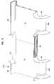
- FIG. 1is a perspective view of a first arrangement of a cable management system positioned over a bay in accordance with the present invention
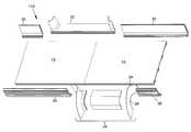
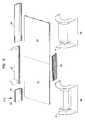
- FIG. 2is an exploded perspective view of the first arrangement of FIG. 1 ;
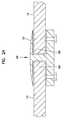
- FIG. 2Ais a cross-sectional side view of end portions of two base elements linked with a coupling
- FIG. 3is a perspective view of a second arrangement of a cable management system for positioning over a bay in accordance with the present invention
- FIG. 4is an exploded perspective view of the second arrangement of FIG. 3 ;
- FIG. 5is a perspective view of a third arrangement of a cable management system for positioning over a bay in accordance with the present invention.
- FIG. 6is an exploded perspective view of the third arrangement of FIG. 5 ;
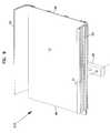
- FIG. 7is a perspective view the planar base element with a mounting bracket attached thereto;
- FIG. 8is a bottom perspective view of the base element and the mounting bracket of FIG. 7 ;
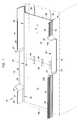
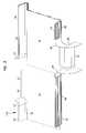
- FIG. 9is a perspective view of the base element and the mounting bracket of FIG. 7 , and further including two upstanding side elements showing a fourth arrangement in accordance with the present invention.
- FIG. 10is an end view of the fourth arrangement of FIG. 9 , shown without the mounting bracket;
- FIG. 11is an exploded end view of the arrangement of FIG. 10 ;
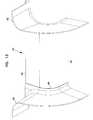
- FIG. 12is a perspective view of one of the side exit elements
- FIG. 13is a perspective view of one of the downspout elements
- FIG. 14is an exploded perspective view of the downspout element of FIG. 13 ;
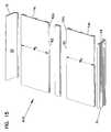
- FIG. 15is an exploded perspective view of a fifth arrangement in accordance with the present invention.
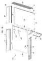
- FIG. 16is an exploded perspective view of a sixth arrangement in accordance with the present invention.
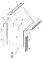
- FIG. 17is a perspective view of a seventh arrangement in accordance with the present invention.
- FIG. 18is an exploded perspective view of the seventh arrangement
- FIG. 19is a perspective view of an eighth arrangement in accordance with the present invention.
- FIG. 20is an exploded perspective view of the arrangement shown in FIG. 19 ;
- FIG. 21is a perspective view of a ninth arrangement in accordance with the present invention.
- FIG. 22is an exploded perspective view of the arrangement shown in FIG. 21 .
- the present inventionrelates to a cable management system with improved flexibility and customization capabilities over prior art cable management systems.
- One aspect of the present inventionis the use of components which are assembled to form the cable management system.
- Various components and configurationsare anticipated in accordance with the present invention.
- Various examples of the components and configurationsare illustrated in FIGS. 1-22 . However, it is to be appreciated that numerous other components and configurations are possible.
- a system 10 for cable managementis positioned over a cabinet, a frame or bay 12 .
- Bay 12may include an array of connectors or other telecommunications equipment for connecting to the cables in system 10 .
- System 10is hung from the ceiling or mounted to bays 12 , with various brackets and hardware as described below.
- System 10includes at least one base element 14 and various side elements 16 .
- a mating arrangement 18mounts the separate side elements 16 to base element 14 .
- Base element 14preferably has a continuous cross-section, and can be cut to the desired length L 1 .
- side elements 16include upstanding wall elements 20 and side exit elements 22 .
- the mating arrangement 18includes a tongue and groove.
- Other mating arrangementsare possible, such as identically shaped edges joined together by couplings or links.
- Wall elements 20preferably have a continuous cross-section, and can be cut to the desired length L 2 .
- base elements 14 a, bare included in system 10 to define the appropriate cable routing pathways along with side elements 16 of the desired type and size mated to base elements 14 a, b .
- Side exit elements 22can lead to other troughs, fittings or couplings of system 10 , including additional base elements 14 of the desired width and with the desired side elements 16 .
- base element 14includes a planar top 40 , and an opposite facing bottom 42 .
- Bottom 42includes ribs 44 , and channels 46 .
- base element 14has a continuous cross-section in the longitudinal direction (Arrow A in FIG. 1 ). Other cross-sections, such as honeycomb, are anticipated for base element 14 .
- Base element 14includes end edges 48 , which are linear.
- One or more links or couplers 50can be inserted into channels 46 to connect base elements 14 a, b at joint 49 .
- An alternative coupler 51is shown in FIG. 2A . Coupler 51 captures the end edges 48 .
- the two base elements 14 in FIGS. 1 and 2can be made as a single piece.
- Base element 14further includes side edges 52 which define channels 54 of the groove for the tongue and groove mating arrangement 18 between base element 14 , and side elements 16 . Side edges 52 are also linear. As shown, side elements 16 can overlap two or more base elements 14 .
- a modified system 110includes a downspout element 26 which replaces one of the side exit elements 22 .
- Downspout element 26is a further example of a side element 16 matable to one or more base elements 14 .
- a further modified system 210including a repositioned first downspout element 26 a and a second downspout element 26 b .
- any exposed corners associated with the devicesare provided with a sufficient radius to avoid damage to the cables. See corners 27 , 29 for elements 22 , 26 , respectively.
- base element 14is shown including a bracket 28 to be mounted to bottom 42 , such as with fasteners 30 received by channels 46 .
- Bracket 28is mounted to system support structure, such as structure supported by bay 12 , or hung from the ceiling, along line 31 .
- channel 54 of base element 14permits snap mounting of side elements 16 to side edges 52 of base elements 14 in the direction of Arrow B in FIG. 11 to form a further system 310 .
- the same snap mounting between side elements 16 and base element 14is present in systems 10 , 110 and 210 .
- the various separate components (i.e. base elements and side elements) of the present inventionare mountable together to form the cable routing system.
- the preferred mating arrangement between the base elements 14 and side elements 16is a snap mount.
- fasteners or couplers to connect the components togethercan be used instead of snaps for the mating arrangement.
- the joints between base elements 14 , or the joints between side elements 16can be by any of a variety of mating arrangements. Couplers, tongue and groove, or others can be used. It is to be noted that not every joint between the side elements 16 needs to be with a coupler or tongue and groove type mating arrangement. Butt joints may be sufficient for some portions of the cable management system.
- wall elements 20include a horizontal section 60 , forming the tongue portion of the tongue and groove mounting arrangement. Curved section 64 extends generally upwardly to generally vertical wall section 66 . Wall section 66 includes a channel 68 similar in profile to channels 46 . The use of channels 46 , 68 , permits other system components to mount thereto. Both wall elements 20 and base elements 14 have continuous cross-sections, and can be conveniently made by an extrusion process and cut to the desired length.
- side exit element 22includes a linear edge 70 , two upstanding sidewalls 72 and a center section 74 which is generally horizontal. While the preferred embodiment of side exit element 22 is a one-piece design, a multi-piece design separated along lines 78 can be provided as will be further described below. Sidewalls 72 are preferably curved to avoid sharp edges that could damage the cables routed in system 10 .
- downspout element 26includes a linear edge 80 , two sidewalls 82 , and a center section 84 .
- Sidewalls 82are curved at regions 82 a to avoid sharp edges.
- Sidewalls 82extend vertically downwardly at regions 82 b along with region 84 a of center region 84 .
- sidewalls 82 and center section 84can be provided as separate elements, as shown in FIG. 14 , where sidewalls 82 and center section 84 include matable edges 86 , 88 , preferably lying in a single plane, which is matable to form downspout element 26 .
- Center section 84can be cut to width W 1 , to further customize the design.
- the mating arrangement 89 between sidewalls 82 and center section 84can be any of a variety of structures, such as a tongue and groove. A similar separation of parts with a mating arrangement therebetween can be adopted for side exit element 22 .
- base elements 14 , and side elements 16an appropriate system for cable management can be configured with relative ease. If desired, it is preferable that the system be modifiable at a later date.
- side elements 16are separable from base elements 14 , so as to change from one type of side element to another. For example, removing an upstanding wall element 20 , and replacing it with a side exit element 22 or a downspout element 26 , and also possibly a shorter wall element 20 is conveniently handled by the present invention.
- FIG. 15shows a further system 410 , including two modified base elements 14 c , and a linking or coupling section 90 .
- Modified base elements 14 care narrower in width W 2 than base elements 14 noted above.
- Linking element 90extends laterally between laterally extending base elements 14 c .
- Linking section 90includes a reciprocal profile 92 for mating with side edges 52 a.
- linking section 90may be provided with an upstanding divider wall 94 in a further system 510 .
- FIGS. 17 and 18a 90-degree bend is provided in system 610 .
- T-couplings 102are shown for joining side edge 52 of base element 14 d to end edge 48 of base element 14 e .
- FIG. 18also shows an internal corner 96 and an external corner 98 with sidewall segment 99 .
- L-couplings 106join base elements 14 f and 14 g .
- Internal corner 108 and external corner 110join to base elements 14 f, g and wall elements 20 .
- FIGS. 21 and 22a 45-degree vertical height change is provided in system 810 .
- End 114is at a greater vertical height than end 116 .
- FIG. 21shows one manner of using separate parts 118 - 123 to construct the system 810 .
- widths W 3can be provided such as 12 inches, 18 inches, 24 inches, or other. Further widths can be handled by using intermediate lateral linking sections or couplings as noted above (i.e. 12 inches and 18 inches, 18 inches and 18 inches).
- planar base elements noted aboveprovide a platform which a wide variety of cable routing systems can be assembled with the desired widths, lengths and side elements to enable efficient and protective routing of the cables.
- Such customization and flexibility both during assembly, and preferably at a later time if modifications are needed,is achieved by using the matable base element(s) and side element(s) of the types noted above and in the various examples illustrated in the drawings.
Landscapes
- Engineering & Computer Science (AREA)
- Computer Networks & Wireless Communication (AREA)
- Architecture (AREA)
- Civil Engineering (AREA)
- Structural Engineering (AREA)
- Installation Of Indoor Wiring (AREA)
- Communication Cables (AREA)
- Waveguide Aerials (AREA)
- Near-Field Transmission Systems (AREA)
- Multi-Conductor Connections (AREA)
- Structure Of Telephone Exchanges (AREA)
- Laying Of Electric Cables Or Lines Outside (AREA)
- Electric Cable Arrangement Between Relatively Moving Parts (AREA)
Abstract
Description
Claims (9)
Priority Applications (1)
| Application Number | Priority Date | Filing Date | Title |
|---|---|---|---|
| US10/685,770US8950051B2 (en) | 2000-09-26 | 2003-10-14 | Cable trough method with separate side elements |
Applications Claiming Priority (2)
| Application Number | Priority Date | Filing Date | Title |
|---|---|---|---|
| US09/669,279US6631875B1 (en) | 2000-09-26 | 2000-09-26 | Cable trough with separate side elements |
| US10/685,770US8950051B2 (en) | 2000-09-26 | 2003-10-14 | Cable trough method with separate side elements |
Related Parent Applications (1)
| Application Number | Title | Priority Date | Filing Date |
|---|---|---|---|
| US09/669,279DivisionUS6631875B1 (en) | 2000-09-26 | 2000-09-26 | Cable trough with separate side elements |
Publications (2)
| Publication Number | Publication Date |
|---|---|
| US20040124321A1 US20040124321A1 (en) | 2004-07-01 |
| US8950051B2true US8950051B2 (en) | 2015-02-10 |
Family
ID=24685786
Family Applications (2)
| Application Number | Title | Priority Date | Filing Date |
|---|---|---|---|
| US09/669,279Expired - LifetimeUS6631875B1 (en) | 2000-09-26 | 2000-09-26 | Cable trough with separate side elements |
| US10/685,770Expired - Fee RelatedUS8950051B2 (en) | 2000-09-26 | 2003-10-14 | Cable trough method with separate side elements |
Family Applications Before (1)
| Application Number | Title | Priority Date | Filing Date |
|---|---|---|---|
| US09/669,279Expired - LifetimeUS6631875B1 (en) | 2000-09-26 | 2000-09-26 | Cable trough with separate side elements |
Country Status (6)
| Country | Link |
|---|---|
| US (2) | US6631875B1 (en) |
| EP (2) | EP1848079A1 (en) |
| AT (1) | ATE366473T1 (en) |
| AU (1) | AU2001293093A1 (en) |
| DE (1) | DE60129234T2 (en) |
| WO (1) | WO2002027879A2 (en) |
Cited By (10)
| Publication number | Priority date | Publication date | Assignee | Title |
|---|---|---|---|---|
| US20140341523A1 (en)* | 2011-12-22 | 2014-11-20 | Tyco Electronics Raychem Bvba | Overhead cable termination arrangement |
| US20170222412A1 (en)* | 2014-07-31 | 2017-08-03 | Igus Gmbh | Guide device |
| US20180314025A1 (en)* | 2015-10-19 | 2018-11-01 | Commscope Technologies Llc | Articulating optical fiber guide system |
| USD868004S1 (en) | 2018-04-25 | 2019-11-26 | Telect, Inc. | Cable trough lip |
| US10601208B2 (en) | 2016-05-06 | 2020-03-24 | Commscope, Inc. Of North Carolina | Optimized cable raceway and methods |
| USD887992S1 (en) | 2018-04-25 | 2020-06-23 | Telect, Inc. | Cable trough attachment assembly |
| US11217973B2 (en)* | 2017-09-28 | 2022-01-04 | Igus Gmbh | Guide device for a line |
| US11452376B2 (en)* | 2020-02-25 | 2022-09-27 | King Slide Works Co., Ltd. | Furniture assembly and mounting device and mounting method thereof |
| US11646556B2 (en) | 2019-10-17 | 2023-05-09 | Panduit Corp. | Raceway system |
| US11784475B2 (en) | 2021-01-12 | 2023-10-10 | Panduit Corp. | Intersection system for overhead cable trays |
Families Citing this family (35)
| Publication number | Priority date | Publication date | Assignee | Title |
|---|---|---|---|---|
| US6631875B1 (en)* | 2000-09-26 | 2003-10-14 | Adc Telecommunications, Inc. | Cable trough with separate side elements |
| US7562779B2 (en)* | 2003-04-10 | 2009-07-21 | Panduit Corp. | Cable management rack with pass-through tray |
| US6951986B1 (en)* | 2004-12-29 | 2005-10-04 | Sbc Knowledge Ventures, L.P. | Adjustable routing device for routing fiber optic jumpers from fiber optic jumper raceways |
| US7362941B2 (en) | 2005-01-21 | 2008-04-22 | Cooper Technologies, Inc. | Cable management system |
| US7693386B2 (en)* | 2005-05-31 | 2010-04-06 | Panduit Corp. | Parallel path cable routing system |
| US7471868B2 (en)* | 2005-10-07 | 2008-12-30 | Adc Telecommunications, Inc. | Cable trough system and method |
| US20070234384A1 (en)* | 2006-03-16 | 2007-10-04 | Gary Rein | Integrated command center for flat screen televisions, and internet protocol monitors |
| US20090189495A1 (en)* | 2006-08-02 | 2009-07-30 | Gary Rein | Integrated command center for flat screen televisions, and internet protocol monitors |
| US20090027573A1 (en)* | 2006-08-02 | 2009-01-29 | Gary Rein | Integrated command center for flat screen televisions, and internet protocol monitors |
| USD576107S1 (en) | 2007-01-26 | 2008-09-02 | Adc Telecommunications, Inc. | Fiber trough lateral component |
| USD576108S1 (en) | 2007-01-26 | 2008-09-02 | Adc Telecommunications, Inc. | Fiber trough horizontal T component |
| US7742675B2 (en)* | 2007-01-26 | 2010-06-22 | Adc Telecommunications, Inc. | Cable trough system and method |
| USD576956S1 (en) | 2007-01-26 | 2008-09-16 | Adc Telecommunications, Inc. | Fiber trough base |
| USD577684S1 (en) | 2007-01-26 | 2008-09-30 | Adc Telecommunications, Inc. | Fiber trough snaps |
| USD576559S1 (en) | 2007-01-26 | 2008-09-09 | Adc Telecommunications, Inc. | Fiber trough horizontal T component |
| USD576109S1 (en) | 2007-01-26 | 2008-09-02 | Adc Telecommunications, Inc. | Fiber trough base |
| USD576560S1 (en) | 2007-01-26 | 2008-09-09 | Adc Telecommunications, Inc. | Fiber trough horizontal T component |
| USD576106S1 (en) | 2007-01-26 | 2008-09-02 | Adc Telecommunications, Inc. | Fiber trough lateral component |
| US7501576B2 (en)* | 2007-06-12 | 2009-03-10 | Gagliardi Thomas P | Ceiling raceway |
| US7740209B2 (en)* | 2007-07-27 | 2010-06-22 | Hewlett-Packard Development Company, L.P. | Cable routing device |
| US8233763B2 (en)* | 2007-12-07 | 2012-07-31 | Adc Telecommunications, Inc. | Flexible cover for cable trough system |
| US7673835B2 (en)* | 2007-12-07 | 2010-03-09 | Adc Telecommunications, Inc. | Telescoping cover for cable trough system |
| US7627224B1 (en)* | 2008-12-24 | 2009-12-01 | At&T Intellectual Property I, L.P. | Cabinet fiber manager |
| GB0901544D0 (en)* | 2009-01-30 | 2009-03-11 | Trojan Services Ltd | A combined cable trough and walkway |
| US8666216B2 (en) | 2011-05-18 | 2014-03-04 | Telect, Inc. | Adjustable trough-couplers |
| US8628157B2 (en)* | 2011-09-06 | 2014-01-14 | Ofs Fitel, Llc | Cabinet cable management |
| CA2829522C (en)* | 2012-10-09 | 2019-04-02 | Thomas & Betts International, Inc. | Joint strip |
| US9213160B2 (en) | 2013-03-15 | 2015-12-15 | Telect, Inc. | Adjustable trough-couplers |
| CN105393152B (en)* | 2013-05-20 | 2019-05-07 | Adc电信股份有限公司 | Outlet structure of cable routing system |
| CN103795012B (en)* | 2014-01-27 | 2017-08-25 | 中铁建设集团设备安装有限公司 | A kind of hiding support bridge device and its installation method |
| US20190331260A1 (en)* | 2018-04-25 | 2019-10-31 | Telect, Inc. | Cable Trough System |
| USD899374S1 (en)* | 2019-02-21 | 2020-10-20 | Allstar Marketing Group, Llc | Multi-socket hub |
| US12259592B2 (en)* | 2019-07-19 | 2025-03-25 | Commscope Technologies Llc | Cable troughs for managing fiber optic cables |
| BR102020005429A2 (en)* | 2020-03-18 | 2021-09-28 | Flávio Albertini Diaferia | IMPROVEMENTS IN SET OF MODULAR BEDS FOR STRUCTURED FIBER OPTIC WIRING |
| WO2025050191A1 (en)* | 2023-09-04 | 2025-03-13 | Diaferia Flavio | Set of trays obtained by modular connections for structured fibre optic cabling |
Citations (77)
| Publication number | Priority date | Publication date | Assignee | Title |
|---|---|---|---|---|
| US799320A (en) | 1904-02-09 | 1905-09-12 | Orrin G Franks | Metal column, girder, and beam. |
| US2072383A (en)* | 1934-02-06 | 1937-03-02 | Rottman George | Knock down cabinet |
| US2823056A (en) | 1954-10-20 | 1958-02-11 | T J Cope Inc | Connecting means for cable-supporting trough systems and the like |
| US2834622A (en) | 1954-12-15 | 1958-05-13 | T J Cope Inc | Connecting means for cable-supporting trough systems and the like |
| US3022972A (en) | 1959-07-21 | 1962-02-27 | Burndy Corp | Supporting trough |
| DE1130492B (en) | 1959-07-28 | 1962-05-30 | Ursus Kunststoff G M B H | Conduit |
| US3042351A (en) | 1960-05-27 | 1962-07-03 | Bois Marvin A Du | Cable trays |
| US3053358A (en) | 1961-07-05 | 1962-09-11 | Porter Co Inc H K | Adjustable cable way connector |
| US3351699A (en)* | 1965-03-19 | 1967-11-07 | Danzer Metal Works Co | Raceway for electrical cables and wires adapted to retain rf energy |
| US3610719A (en)* | 1967-11-08 | 1971-10-05 | Leslie W L Alston | Drawers for furniture |
| US3761603A (en) | 1972-11-14 | 1973-09-25 | Amp Inc | Wiring raceway |
| FR2238828A1 (en) | 1973-07-24 | 1975-02-21 | Intermercury Finance Trading C | |
| US4042288A (en)* | 1972-12-08 | 1977-08-16 | L. B. (Plastics) Limited | Extruded plastic panel drawers |
| US4077434A (en) | 1976-05-27 | 1978-03-07 | Federal Cartridge Corporation | Sealed lay-in conduit duct |
| US4105051A (en) | 1975-07-25 | 1978-08-08 | Andrea Visentin | Prefabricated composable duct element |
| US4403817A (en)* | 1980-03-31 | 1983-09-13 | Eucatex S.A. Industria E Comercio | Drawer for furniture |
| US4440460A (en)* | 1981-08-06 | 1984-04-03 | Brighoff John C | Furniture and drawer therefor |
| US4462647A (en)* | 1983-03-14 | 1984-07-31 | Gerald Key | Knock-down cupboard |
| SU1272387A1 (en) | 1979-03-11 | 1986-11-23 | Государственный Проектный Институт "Электропроект" | Collapsible duct for laying wires and cables |
| DE3742448A1 (en) | 1987-12-15 | 1989-06-29 | Philips Patentverwaltung | Cable duct |
| US4874322A (en) | 1987-09-28 | 1989-10-17 | Amp Incorporated | Surface applied wiring apparatus |
| US4907767A (en) | 1988-08-12 | 1990-03-13 | Hubbell Incorporated | Stackable modular duct assemblies |
| US4951716A (en)* | 1987-12-17 | 1990-08-28 | Yazaki Corporation | Locking mechanism |
| USD321682S (en) | 1989-07-31 | 1991-11-19 | Roy Henneberger | Guiding through, 90 degree down elbow for optical fibers |
| US5067678A (en) | 1989-07-31 | 1991-11-26 | Adc Telecommunications, Inc. | Optic cable management system |
| USD321862S (en) | 1989-07-31 | 1991-11-26 | Roy Henneberger | Guiding trough, horizontal T for optical fibers |
| US5091607A (en)* | 1990-06-11 | 1992-02-25 | Compatico, Inc. | Energy distribution raceway |
| US5160811A (en) | 1990-04-27 | 1992-11-03 | Tyton Corporation | Duct transition converter and flexible connectors including same |
| US5161580A (en) | 1990-08-27 | 1992-11-10 | Tyton Corporation | Cable duct fitting with removable cover |
| JPH05172281A (en)* | 1991-12-25 | 1993-07-09 | Ee O Y Syst Kenkyusho:Kk | Duct assembling method and seam joint structure of duct |
| US5240209A (en) | 1992-11-17 | 1993-08-31 | Telect, Inc. | Telecommunication multiple cable carrier |
| US5271585A (en) | 1990-10-01 | 1993-12-21 | Zetena Jr Maurice F | Modular fiber optics raceway permitting flexible installation |
| US5316243A (en) | 1989-07-31 | 1994-05-31 | Adc Telecommunications, Inc. | Optic cable management |
| US5335349A (en) | 1992-12-14 | 1994-08-02 | Telect, Inc. | Telecommunication overhead cable distribution assembly |
| US5469893A (en)* | 1993-12-21 | 1995-11-28 | Panduit Corp. | Tab and slot fiber optic fitting |
| US5503354A (en) | 1994-01-04 | 1996-04-02 | Telect, Inc. | Telecommunication overhead cable distribution universal support bracket |
| DE29610947U1 (en) | 1996-06-24 | 1996-08-22 | Miranda, Giovanni, 78549 Spaichingen | Cable duct profile |
| FR2735557A1 (en) | 1995-06-14 | 1996-12-20 | Seine Const Elec | Coupling for `U' sections cable troughs |
| US5752781A (en)* | 1997-03-14 | 1998-05-19 | Adc Telecommunications, Inc. | Fiber trough coupling |
| US5753855A (en)* | 1994-11-17 | 1998-05-19 | Panduit Corp. | Wiring duct fittings |
| EP0863594A2 (en) | 1997-03-06 | 1998-09-09 | Albert Ackermann GmbH & Co. KG | Electrical installation channel |
| US5813738A (en)* | 1997-06-20 | 1998-09-29 | Cheng; Wen Sen | Furniture combination |
| US5893617A (en)* | 1997-05-02 | 1999-04-13 | M. F. Interior Design Co., Ltd. | Connecting assembly for horizontal boards and wall boards of a cabinet |
| US5899025A (en) | 1996-03-22 | 1999-05-04 | Steelcase Inc. | Furniture system (pathways-spaceframe) |
| US5923753A (en) | 1997-11-17 | 1999-07-13 | Adc Telecommunications, Inc. | Optic cable exit trough with bypass |
| EP0933850A1 (en) | 1998-01-27 | 1999-08-04 | Placo S.r.l. | A modular ducting device |
| US5937131A (en) | 1997-11-17 | 1999-08-10 | Adc Telecommunications, Inc. | Optical cable exit trough |
| US5995699A (en) | 1998-01-05 | 1999-11-30 | The Wiremold Company | Fiber optic cable raceway system cross reference to related applications |
| US6037543A (en) | 1994-11-17 | 2000-03-14 | Panduit Corp. | Wiring duct fittings |
| US6037538A (en) | 1997-04-28 | 2000-03-14 | Brooks; Gary Douglas | Cable raceway |
| US6076779A (en) | 1999-08-04 | 2000-06-20 | Adc Telecommunications, Inc. | Cable guiding trough |
| US6198047B1 (en) | 1999-02-08 | 2001-03-06 | Charles Barr | Cable tray with power channel |
| US6394564B1 (en)* | 1997-06-03 | 2002-05-28 | Knoll, Inc. | Overhead storage unit |
| US6424779B1 (en) | 2000-08-28 | 2002-07-23 | Steven W. Ellison | Fiber trough coupling system |
| US20020096606A1 (en)* | 2000-06-01 | 2002-07-25 | Bernard William A. | Cable duct coupler |
| US6450458B1 (en)* | 2000-06-01 | 2002-09-17 | Panduit Corp. | Cable duct coupler with locking clip |
| US6522823B1 (en) | 2000-11-06 | 2003-02-18 | Adc Telecommunications, Inc. | Low profile cable exit trough |
| US20030047343A1 (en)* | 2001-09-12 | 2003-03-13 | Ferris Matthew D. | Snap together cable trough system |
| US6535683B1 (en)* | 2000-10-06 | 2003-03-18 | Adc Telecommunications, Inc. | Cable exit trough with cover |
| US6559378B1 (en)* | 2001-10-31 | 2003-05-06 | Panduit Corp. | Reducer fitting for routing system |
| US6586680B1 (en) | 2000-06-02 | 2003-07-01 | Panduit Corp. | Modular bend radius control fixture |
| US6625373B1 (en) | 2000-10-06 | 2003-09-23 | Adc Telecommunications, Inc. | Cable exit trough with insert |
| US6631875B1 (en)* | 2000-09-26 | 2003-10-14 | Adc Telecommunications, Inc. | Cable trough with separate side elements |
| US6709186B2 (en) | 2001-11-16 | 2004-03-23 | Adc Telecommunications, Inc. | Coupler for cable trough |
| US6708918B2 (en)* | 2001-03-01 | 2004-03-23 | Adc Telecommunications, Inc. | Cable guiding fins |
| US6715719B2 (en) | 2002-03-27 | 2004-04-06 | Adc Telecommunications, Inc. | Coupler for cable trough |
| US6727434B2 (en)* | 2001-07-13 | 2004-04-27 | Legrand | Accessory for trunking comprising lengths of trunking with different heights |
| US6739795B1 (en)* | 2000-05-25 | 2004-05-25 | Adc Telecommunications, Inc. | Telescoping trough |
| US6810191B2 (en)* | 2001-07-20 | 2004-10-26 | Adc Telecommunications, Inc. | Cable trough cover |
| US6883882B2 (en)* | 2003-05-02 | 2005-04-26 | Uma Team Enterprise Co., Ltd. | Cabinet assembly |
| US7034227B2 (en)* | 2002-08-19 | 2006-04-25 | Fox Ron W | Cable trough |
| US7045707B1 (en)* | 2005-03-07 | 2006-05-16 | The Wiremold Company | Surface mounted perimeter raceway offset assembly |
| US20070092196A1 (en) | 2005-10-07 | 2007-04-26 | Yilmaz Bayazit | Cable trough system and method |
| US7315680B1 (en)* | 2006-06-21 | 2008-01-01 | Adc Telecommunications, Inc. | Cable routing devices with integrated couplers |
| US7742675B2 (en)* | 2007-01-26 | 2010-06-22 | Adc Telecommunications, Inc. | Cable trough system and method |
| US7825342B2 (en)* | 2007-08-20 | 2010-11-02 | Panduit Corp. | Compact spillover fitting and method of use thereof |
| US8193448B2 (en)* | 2009-10-29 | 2012-06-05 | American Power Conversion Corporation | Systems and methods of managing cables |
Family Cites Families (6)
| Publication number | Priority date | Publication date | Assignee | Title |
|---|---|---|---|---|
| US321862A (en)* | 1885-07-07 | Door oob | ||
| US321682A (en)* | 1885-07-07 | campbell | ||
| US933850A (en)* | 1909-05-03 | 1909-09-14 | Nesbitt H Robinson | Stovepipe-coupling. |
| US1272387A (en)* | 1914-01-12 | 1918-07-16 | Culter & Proctor Stove Co | Stove. |
| US3742448A (en)* | 1972-02-02 | 1973-06-26 | Gen Motors Corp | Vehicle seat belt warning and control system |
| ZA973850B (en)* | 1996-05-06 | 1997-12-02 | Reddy Research Foundation | Novel antidiabetic compounds having hypolipidaemic, anti-hypertensive properties, process for their preparation and pharmaceutical compositions containing them. |
- 2000
- 2000-09-26USUS09/669,279patent/US6631875B1/ennot_activeExpired - Lifetime
- 2001
- 2001-09-25AUAU2001293093Apatent/AU2001293093A1/ennot_activeAbandoned
- 2001-09-25EPEP07012377Apatent/EP1848079A1/ennot_activeWithdrawn
- 2001-09-25WOPCT/US2001/030029patent/WO2002027879A2/enactiveIP Right Grant
- 2001-09-25EPEP01973523Apatent/EP1323220B1/ennot_activeExpired - Lifetime
- 2001-09-25DEDE60129234Tpatent/DE60129234T2/ennot_activeExpired - Lifetime
- 2001-09-25ATAT01973523Tpatent/ATE366473T1/ennot_activeIP Right Cessation
- 2003
- 2003-10-14USUS10/685,770patent/US8950051B2/ennot_activeExpired - Fee Related
Patent Citations (87)
| Publication number | Priority date | Publication date | Assignee | Title |
|---|---|---|---|---|
| US799320A (en) | 1904-02-09 | 1905-09-12 | Orrin G Franks | Metal column, girder, and beam. |
| US2072383A (en)* | 1934-02-06 | 1937-03-02 | Rottman George | Knock down cabinet |
| US2823056A (en) | 1954-10-20 | 1958-02-11 | T J Cope Inc | Connecting means for cable-supporting trough systems and the like |
| US2834622A (en) | 1954-12-15 | 1958-05-13 | T J Cope Inc | Connecting means for cable-supporting trough systems and the like |
| US3022972A (en) | 1959-07-21 | 1962-02-27 | Burndy Corp | Supporting trough |
| DE1130492B (en) | 1959-07-28 | 1962-05-30 | Ursus Kunststoff G M B H | Conduit |
| US3042351A (en) | 1960-05-27 | 1962-07-03 | Bois Marvin A Du | Cable trays |
| US3053358A (en) | 1961-07-05 | 1962-09-11 | Porter Co Inc H K | Adjustable cable way connector |
| US3351699A (en)* | 1965-03-19 | 1967-11-07 | Danzer Metal Works Co | Raceway for electrical cables and wires adapted to retain rf energy |
| US3610719A (en)* | 1967-11-08 | 1971-10-05 | Leslie W L Alston | Drawers for furniture |
| US3761603A (en) | 1972-11-14 | 1973-09-25 | Amp Inc | Wiring raceway |
| US4042288A (en)* | 1972-12-08 | 1977-08-16 | L. B. (Plastics) Limited | Extruded plastic panel drawers |
| FR2238828A1 (en) | 1973-07-24 | 1975-02-21 | Intermercury Finance Trading C | |
| US3927698A (en) | 1973-07-24 | 1975-12-23 | Intermercury Finance & Trad | Installation channel |
| US4105051A (en) | 1975-07-25 | 1978-08-08 | Andrea Visentin | Prefabricated composable duct element |
| US4077434A (en) | 1976-05-27 | 1978-03-07 | Federal Cartridge Corporation | Sealed lay-in conduit duct |
| SU1272387A1 (en) | 1979-03-11 | 1986-11-23 | Государственный Проектный Институт "Электропроект" | Collapsible duct for laying wires and cables |
| US4403817A (en)* | 1980-03-31 | 1983-09-13 | Eucatex S.A. Industria E Comercio | Drawer for furniture |
| US4440460A (en)* | 1981-08-06 | 1984-04-03 | Brighoff John C | Furniture and drawer therefor |
| US4462647A (en)* | 1983-03-14 | 1984-07-31 | Gerald Key | Knock-down cupboard |
| US4874322A (en) | 1987-09-28 | 1989-10-17 | Amp Incorporated | Surface applied wiring apparatus |
| DE3742448A1 (en) | 1987-12-15 | 1989-06-29 | Philips Patentverwaltung | Cable duct |
| US4951716A (en)* | 1987-12-17 | 1990-08-28 | Yazaki Corporation | Locking mechanism |
| US4907767A (en) | 1988-08-12 | 1990-03-13 | Hubbell Incorporated | Stackable modular duct assemblies |
| US5316243A (en) | 1989-07-31 | 1994-05-31 | Adc Telecommunications, Inc. | Optic cable management |
| US5067678A (en) | 1989-07-31 | 1991-11-26 | Adc Telecommunications, Inc. | Optic cable management system |
| USD321862S (en) | 1989-07-31 | 1991-11-26 | Roy Henneberger | Guiding trough, horizontal T for optical fibers |
| USD321682S (en) | 1989-07-31 | 1991-11-19 | Roy Henneberger | Guiding through, 90 degree down elbow for optical fibers |
| US5160811A (en) | 1990-04-27 | 1992-11-03 | Tyton Corporation | Duct transition converter and flexible connectors including same |
| US5091607A (en)* | 1990-06-11 | 1992-02-25 | Compatico, Inc. | Energy distribution raceway |
| US5161580A (en) | 1990-08-27 | 1992-11-10 | Tyton Corporation | Cable duct fitting with removable cover |
| US5316244A (en) | 1990-10-01 | 1994-05-31 | Zetena Jr Maurice F | Supporting brackets for cable raceways |
| US5271585A (en) | 1990-10-01 | 1993-12-21 | Zetena Jr Maurice F | Modular fiber optics raceway permitting flexible installation |
| JPH05172281A (en)* | 1991-12-25 | 1993-07-09 | Ee O Y Syst Kenkyusho:Kk | Duct assembling method and seam joint structure of duct |
| US5240209A (en) | 1992-11-17 | 1993-08-31 | Telect, Inc. | Telecommunication multiple cable carrier |
| US5335349A (en) | 1992-12-14 | 1994-08-02 | Telect, Inc. | Telecommunication overhead cable distribution assembly |
| US5469893A (en)* | 1993-12-21 | 1995-11-28 | Panduit Corp. | Tab and slot fiber optic fitting |
| US5503354A (en) | 1994-01-04 | 1996-04-02 | Telect, Inc. | Telecommunication overhead cable distribution universal support bracket |
| US5753855A (en)* | 1994-11-17 | 1998-05-19 | Panduit Corp. | Wiring duct fittings |
| US6037543A (en) | 1994-11-17 | 2000-03-14 | Panduit Corp. | Wiring duct fittings |
| FR2735557A1 (en) | 1995-06-14 | 1996-12-20 | Seine Const Elec | Coupling for `U' sections cable troughs |
| US5899025A (en) | 1996-03-22 | 1999-05-04 | Steelcase Inc. | Furniture system (pathways-spaceframe) |
| DE29610947U1 (en) | 1996-06-24 | 1996-08-22 | Miranda, Giovanni, 78549 Spaichingen | Cable duct profile |
| US6107575A (en) | 1996-06-24 | 2000-08-22 | Hilti Aktiengesellschaft | Cable channel section |
| EP0863594A2 (en) | 1997-03-06 | 1998-09-09 | Albert Ackermann GmbH & Co. KG | Electrical installation channel |
| US5752781A (en)* | 1997-03-14 | 1998-05-19 | Adc Telecommunications, Inc. | Fiber trough coupling |
| US6037538A (en) | 1997-04-28 | 2000-03-14 | Brooks; Gary Douglas | Cable raceway |
| US5893617A (en)* | 1997-05-02 | 1999-04-13 | M. F. Interior Design Co., Ltd. | Connecting assembly for horizontal boards and wall boards of a cabinet |
| US6394564B1 (en)* | 1997-06-03 | 2002-05-28 | Knoll, Inc. | Overhead storage unit |
| US5813738A (en)* | 1997-06-20 | 1998-09-29 | Cheng; Wen Sen | Furniture combination |
| US5937131A (en) | 1997-11-17 | 1999-08-10 | Adc Telecommunications, Inc. | Optical cable exit trough |
| US5923753A (en) | 1997-11-17 | 1999-07-13 | Adc Telecommunications, Inc. | Optic cable exit trough with bypass |
| US5995699A (en) | 1998-01-05 | 1999-11-30 | The Wiremold Company | Fiber optic cable raceway system cross reference to related applications |
| EP0933850A1 (en) | 1998-01-27 | 1999-08-04 | Placo S.r.l. | A modular ducting device |
| US6198047B1 (en) | 1999-02-08 | 2001-03-06 | Charles Barr | Cable tray with power channel |
| US6076779A (en) | 1999-08-04 | 2000-06-20 | Adc Telecommunications, Inc. | Cable guiding trough |
| US6739795B1 (en)* | 2000-05-25 | 2004-05-25 | Adc Telecommunications, Inc. | Telescoping trough |
| US7383634B2 (en)* | 2000-05-25 | 2008-06-10 | Adc Telecommunications, Inc. | Method of assembling a cable routing system |
| US8083187B2 (en)* | 2000-06-01 | 2011-12-27 | Panduit Corp. | Cable duct coupler |
| US6450458B1 (en)* | 2000-06-01 | 2002-09-17 | Panduit Corp. | Cable duct coupler with locking clip |
| US20020096606A1 (en)* | 2000-06-01 | 2002-07-25 | Bernard William A. | Cable duct coupler |
| US7226022B2 (en)* | 2000-06-01 | 2007-06-05 | Panduit Corp. | Cable duct coupler |
| US6634605B2 (en)* | 2000-06-01 | 2003-10-21 | Panduit Corp. | Cable duct coupler |
| US6586680B1 (en) | 2000-06-02 | 2003-07-01 | Panduit Corp. | Modular bend radius control fixture |
| US6424779B1 (en) | 2000-08-28 | 2002-07-23 | Steven W. Ellison | Fiber trough coupling system |
| US6631875B1 (en)* | 2000-09-26 | 2003-10-14 | Adc Telecommunications, Inc. | Cable trough with separate side elements |
| US6535683B1 (en)* | 2000-10-06 | 2003-03-18 | Adc Telecommunications, Inc. | Cable exit trough with cover |
| US6625373B1 (en) | 2000-10-06 | 2003-09-23 | Adc Telecommunications, Inc. | Cable exit trough with insert |
| US6522823B1 (en) | 2000-11-06 | 2003-02-18 | Adc Telecommunications, Inc. | Low profile cable exit trough |
| US6708918B2 (en)* | 2001-03-01 | 2004-03-23 | Adc Telecommunications, Inc. | Cable guiding fins |
| US6727434B2 (en)* | 2001-07-13 | 2004-04-27 | Legrand | Accessory for trunking comprising lengths of trunking with different heights |
| US6810191B2 (en)* | 2001-07-20 | 2004-10-26 | Adc Telecommunications, Inc. | Cable trough cover |
| US6934456B2 (en)* | 2001-07-20 | 2005-08-23 | Adc Telecommunications, Inc. | Cable trough cover |
| US7224880B2 (en)* | 2001-07-20 | 2007-05-29 | Adc Telecommunications, Inc. | Cable trough cover |
| US7113685B2 (en)* | 2001-07-20 | 2006-09-26 | Adc Telecommunications, Inc. | Cable trough cover |
| US20030047343A1 (en)* | 2001-09-12 | 2003-03-13 | Ferris Matthew D. | Snap together cable trough system |
| US6559378B1 (en)* | 2001-10-31 | 2003-05-06 | Panduit Corp. | Reducer fitting for routing system |
| US6709186B2 (en) | 2001-11-16 | 2004-03-23 | Adc Telecommunications, Inc. | Coupler for cable trough |
| US6715719B2 (en) | 2002-03-27 | 2004-04-06 | Adc Telecommunications, Inc. | Coupler for cable trough |
| US7034227B2 (en)* | 2002-08-19 | 2006-04-25 | Fox Ron W | Cable trough |
| US6883882B2 (en)* | 2003-05-02 | 2005-04-26 | Uma Team Enterprise Co., Ltd. | Cabinet assembly |
| US7045707B1 (en)* | 2005-03-07 | 2006-05-16 | The Wiremold Company | Surface mounted perimeter raceway offset assembly |
| US20070092196A1 (en) | 2005-10-07 | 2007-04-26 | Yilmaz Bayazit | Cable trough system and method |
| US7315680B1 (en)* | 2006-06-21 | 2008-01-01 | Adc Telecommunications, Inc. | Cable routing devices with integrated couplers |
| US7742675B2 (en)* | 2007-01-26 | 2010-06-22 | Adc Telecommunications, Inc. | Cable trough system and method |
| US7825342B2 (en)* | 2007-08-20 | 2010-11-02 | Panduit Corp. | Compact spillover fitting and method of use thereof |
| US8193448B2 (en)* | 2009-10-29 | 2012-06-05 | American Power Conversion Corporation | Systems and methods of managing cables |
Non-Patent Citations (15)
| Title |
|---|
| ADC Telecommunications brochure entitled "ADC Fiberguide� System Express Exit(TM) 2x2,"2 pages, dated May 1999. |
| ADC Telecommunications brochure entitled "ADC Fiberguide® System Express Exit™ 2x2,"2 pages, dated May 1999. |
| ADC Telecommunications brochure entitled "Fiber Guide(TM) Fiber Management System," 6 pages, dated Jun. 1989. |
| ADC Telecommunications brochure entitled "Fiber Guide™ Fiber Management System," 6 pages, dated Jun. 1989. |
| ADC Telecommunications brochure entitled "FiberGuide� Fiber Management Systems," 33 pages, dated Oct. 1995. |
| ADC Telecommunications brochure entitled "FiberGuide� Fiber Management Systems," 37 pages dated Jun. 1998. |
| ADC Telecommunications brochure entitled "FiberGuide® Fiber Management Systems," 33 pages, dated Oct. 1995. |
| ADC Telecommunications brochure entitled "FiberGuide® Fiber Management Systems," 37 pages dated Jun. 1998. |
| ADC Telecommunications brochure entitled FiberGuide� Fiber Management Systems, 56 pages, dated Sep. 2000. |
| ADC Telecommunications brochure entitled FiberGuide� Fiber Management Systems, 90 pages, dated May 2005. |
| ADC Telecommunications brochure entitled FiberGuide® Fiber Management Systems, 56 pages, dated Sep. 2000. |
| ADC Telecommunications brochure entitled FiberGuide® Fiber Management Systems, 90 pages, dated May 2005. |
| European Search Report mailed Sep. 18, 2007. |
| U.S. Appl. No. 11/698,799, filed Jan. 26, 2007. |
| Warren & Brown & Staff brochure pages entitled "lightpaths," Issue 2, 11 pages, dated 1995. |
Cited By (15)
| Publication number | Priority date | Publication date | Assignee | Title |
|---|---|---|---|---|
| US20140341523A1 (en)* | 2011-12-22 | 2014-11-20 | Tyco Electronics Raychem Bvba | Overhead cable termination arrangement |
| US10693285B2 (en)* | 2014-07-31 | 2020-06-23 | Igus Gmbh | Guide device |
| US20170222412A1 (en)* | 2014-07-31 | 2017-08-03 | Igus Gmbh | Guide device |
| US10823929B2 (en)* | 2015-10-19 | 2020-11-03 | Commscope Technologies Llc | Articulating optical fiber guide system |
| US20200088966A1 (en)* | 2015-10-19 | 2020-03-19 | Commscope Technologies Llc | Articulating optical fiber guide system |
| US10444459B2 (en)* | 2015-10-19 | 2019-10-15 | Commscope Technologies Llc | Articulating optical fiber guide system |
| US20180314025A1 (en)* | 2015-10-19 | 2018-11-01 | Commscope Technologies Llc | Articulating optical fiber guide system |
| US11487072B2 (en)* | 2015-10-19 | 2022-11-01 | Commscope Technologies Llc | Articulating optical fiber guide system |
| US10601208B2 (en) | 2016-05-06 | 2020-03-24 | Commscope, Inc. Of North Carolina | Optimized cable raceway and methods |
| US11217973B2 (en)* | 2017-09-28 | 2022-01-04 | Igus Gmbh | Guide device for a line |
| USD868004S1 (en) | 2018-04-25 | 2019-11-26 | Telect, Inc. | Cable trough lip |
| USD887992S1 (en) | 2018-04-25 | 2020-06-23 | Telect, Inc. | Cable trough attachment assembly |
| US11646556B2 (en) | 2019-10-17 | 2023-05-09 | Panduit Corp. | Raceway system |
| US11452376B2 (en)* | 2020-02-25 | 2022-09-27 | King Slide Works Co., Ltd. | Furniture assembly and mounting device and mounting method thereof |
| US11784475B2 (en) | 2021-01-12 | 2023-10-10 | Panduit Corp. | Intersection system for overhead cable trays |
Also Published As
| Publication number | Publication date |
|---|---|
| US20040124321A1 (en) | 2004-07-01 |
| ATE366473T1 (en) | 2007-07-15 |
| AU2001293093A1 (en) | 2002-04-08 |
| WO2002027879A3 (en) | 2003-03-13 |
| DE60129234T2 (en) | 2008-03-06 |
| EP1323220A2 (en) | 2003-07-02 |
| EP1323220B1 (en) | 2007-07-04 |
| EP1848079A8 (en) | 2007-11-28 |
| US6631875B1 (en) | 2003-10-14 |
| DE60129234D1 (en) | 2007-08-16 |
| WO2002027879A2 (en) | 2002-04-04 |
| EP1848079A1 (en) | 2007-10-24 |
Similar Documents
| Publication | Publication Date | Title |
|---|---|---|
| US8950051B2 (en) | Cable trough method with separate side elements | |
| US9356436B2 (en) | Cable trough system and method | |
| US8254744B2 (en) | Cable trough system and method | |
| US5923753A (en) | Optic cable exit trough with bypass | |
| US8768135B2 (en) | Optical cable exit trough | |
| US7383634B2 (en) | Method of assembling a cable routing system | |
| HK1108300A (en) | Cable through with separate side elements |
Legal Events
| Date | Code | Title | Description |
|---|---|---|---|
| STCF | Information on status: patent grant | Free format text:PATENTED CASE | |
| AS | Assignment | Owner name:TYCO ELECTRONICS SERVICES GMBH, SWITZERLAND Free format text:ASSIGNMENT OF ASSIGNORS INTEREST;ASSIGNOR:ADC TELECOMMUNICATIONS, INC.;REEL/FRAME:036060/0174 Effective date:20110930 | |
| AS | Assignment | Owner name:COMMSCOPE EMEA LIMITED, IRELAND Free format text:ASSIGNMENT OF ASSIGNORS INTEREST;ASSIGNOR:TYCO ELECTRONICS SERVICES GMBH;REEL/FRAME:036956/0001 Effective date:20150828 | |
| AS | Assignment | Owner name:COMMSCOPE TECHNOLOGIES LLC, NORTH CAROLINA Free format text:ASSIGNMENT OF ASSIGNORS INTEREST;ASSIGNOR:COMMSCOPE EMEA LIMITED;REEL/FRAME:037012/0001 Effective date:20150828 | |
| AS | Assignment | Owner name:JPMORGAN CHASE BANK, N.A., AS COLLATERAL AGENT, ILLINOIS Free format text:PATENT SECURITY AGREEMENT (TERM);ASSIGNOR:COMMSCOPE TECHNOLOGIES LLC;REEL/FRAME:037513/0709 Effective date:20151220 Owner name:JPMORGAN CHASE BANK, N.A., AS COLLATERAL AGENT, ILLINOIS Free format text:PATENT SECURITY AGREEMENT (ABL);ASSIGNOR:COMMSCOPE TECHNOLOGIES LLC;REEL/FRAME:037514/0196 Effective date:20151220 Owner name:JPMORGAN CHASE BANK, N.A., AS COLLATERAL AGENT, IL Free format text:PATENT SECURITY AGREEMENT (TERM);ASSIGNOR:COMMSCOPE TECHNOLOGIES LLC;REEL/FRAME:037513/0709 Effective date:20151220 Owner name:JPMORGAN CHASE BANK, N.A., AS COLLATERAL AGENT, IL Free format text:PATENT SECURITY AGREEMENT (ABL);ASSIGNOR:COMMSCOPE TECHNOLOGIES LLC;REEL/FRAME:037514/0196 Effective date:20151220 | |
| DC | Disclaimer filed | Free format text:DISCLAIMS THE TERM OF THIS PATENT WHICH WOULD EXTEND BEYOND Effective date:20150221 | |
| MAFP | Maintenance fee payment | Free format text:PAYMENT OF MAINTENANCE FEE, 4TH YEAR, LARGE ENTITY (ORIGINAL EVENT CODE: M1551) Year of fee payment:4 | |
| AS | Assignment | Owner name:ANDREW LLC, NORTH CAROLINA Free format text:RELEASE BY SECURED PARTY;ASSIGNOR:JPMORGAN CHASE BANK, N.A.;REEL/FRAME:048840/0001 Effective date:20190404 Owner name:ALLEN TELECOM LLC, ILLINOIS Free format text:RELEASE BY SECURED PARTY;ASSIGNOR:JPMORGAN CHASE BANK, N.A.;REEL/FRAME:048840/0001 Effective date:20190404 Owner name:COMMSCOPE, INC. OF NORTH CAROLINA, NORTH CAROLINA Free format text:RELEASE BY SECURED PARTY;ASSIGNOR:JPMORGAN CHASE BANK, N.A.;REEL/FRAME:048840/0001 Effective date:20190404 Owner name:COMMSCOPE TECHNOLOGIES LLC, NORTH CAROLINA Free format text:RELEASE BY SECURED PARTY;ASSIGNOR:JPMORGAN CHASE BANK, N.A.;REEL/FRAME:048840/0001 Effective date:20190404 Owner name:REDWOOD SYSTEMS, INC., NORTH CAROLINA Free format text:RELEASE BY SECURED PARTY;ASSIGNOR:JPMORGAN CHASE BANK, N.A.;REEL/FRAME:048840/0001 Effective date:20190404 Owner name:REDWOOD SYSTEMS, INC., NORTH CAROLINA Free format text:RELEASE BY SECURED PARTY;ASSIGNOR:JPMORGAN CHASE BANK, N.A.;REEL/FRAME:049260/0001 Effective date:20190404 Owner name:COMMSCOPE TECHNOLOGIES LLC, NORTH CAROLINA Free format text:RELEASE BY SECURED PARTY;ASSIGNOR:JPMORGAN CHASE BANK, N.A.;REEL/FRAME:049260/0001 Effective date:20190404 Owner name:ANDREW LLC, NORTH CAROLINA Free format text:RELEASE BY SECURED PARTY;ASSIGNOR:JPMORGAN CHASE BANK, N.A.;REEL/FRAME:049260/0001 Effective date:20190404 Owner name:COMMSCOPE, INC. OF NORTH CAROLINA, NORTH CAROLINA Free format text:RELEASE BY SECURED PARTY;ASSIGNOR:JPMORGAN CHASE BANK, N.A.;REEL/FRAME:049260/0001 Effective date:20190404 Owner name:ALLEN TELECOM LLC, ILLINOIS Free format text:RELEASE BY SECURED PARTY;ASSIGNOR:JPMORGAN CHASE BANK, N.A.;REEL/FRAME:049260/0001 Effective date:20190404 | |
| AS | Assignment | Owner name:WILMINGTON TRUST, NATIONAL ASSOCIATION, AS COLLATE Free format text:PATENT SECURITY AGREEMENT;ASSIGNOR:COMMSCOPE TECHNOLOGIES LLC;REEL/FRAME:049892/0051 Effective date:20190404 Owner name:JPMORGAN CHASE BANK, N.A., NEW YORK Free format text:ABL SECURITY AGREEMENT;ASSIGNORS:COMMSCOPE, INC. OF NORTH CAROLINA;COMMSCOPE TECHNOLOGIES LLC;ARRIS ENTERPRISES LLC;AND OTHERS;REEL/FRAME:049892/0396 Effective date:20190404 Owner name:JPMORGAN CHASE BANK, N.A., NEW YORK Free format text:TERM LOAN SECURITY AGREEMENT;ASSIGNORS:COMMSCOPE, INC. OF NORTH CAROLINA;COMMSCOPE TECHNOLOGIES LLC;ARRIS ENTERPRISES LLC;AND OTHERS;REEL/FRAME:049905/0504 Effective date:20190404 Owner name:WILMINGTON TRUST, NATIONAL ASSOCIATION, AS COLLATERAL AGENT, CONNECTICUT Free format text:PATENT SECURITY AGREEMENT;ASSIGNOR:COMMSCOPE TECHNOLOGIES LLC;REEL/FRAME:049892/0051 Effective date:20190404 | |
| FEPP | Fee payment procedure | Free format text:MAINTENANCE FEE REMINDER MAILED (ORIGINAL EVENT CODE: REM.); ENTITY STATUS OF PATENT OWNER: LARGE ENTITY | |
| LAPS | Lapse for failure to pay maintenance fees | Free format text:PATENT EXPIRED FOR FAILURE TO PAY MAINTENANCE FEES (ORIGINAL EVENT CODE: EXP.); ENTITY STATUS OF PATENT OWNER: LARGE ENTITY | |
| STCH | Information on status: patent discontinuation | Free format text:PATENT EXPIRED DUE TO NONPAYMENT OF MAINTENANCE FEES UNDER 37 CFR 1.362 | |
| FP | Lapsed due to failure to pay maintenance fee | Effective date:20230210 | |
| AS | Assignment | Owner name:RUCKUS WIRELESS, LLC (F/K/A RUCKUS WIRELESS, INC.), NORTH CAROLINA Free format text:RELEASE OF SECURITY INTEREST AT REEL/FRAME 049905/0504;ASSIGNOR:JPMORGAN CHASE BANK, N.A., AS COLLATERAL AGENT;REEL/FRAME:071477/0255 Effective date:20241217 Owner name:COMMSCOPE TECHNOLOGIES LLC, NORTH CAROLINA Free format text:RELEASE OF SECURITY INTEREST AT REEL/FRAME 049905/0504;ASSIGNOR:JPMORGAN CHASE BANK, N.A., AS COLLATERAL AGENT;REEL/FRAME:071477/0255 Effective date:20241217 Owner name:COMMSCOPE, INC. OF NORTH CAROLINA, NORTH CAROLINA Free format text:RELEASE OF SECURITY INTEREST AT REEL/FRAME 049905/0504;ASSIGNOR:JPMORGAN CHASE BANK, N.A., AS COLLATERAL AGENT;REEL/FRAME:071477/0255 Effective date:20241217 Owner name:ARRIS SOLUTIONS, INC., NORTH CAROLINA Free format text:RELEASE OF SECURITY INTEREST AT REEL/FRAME 049905/0504;ASSIGNOR:JPMORGAN CHASE BANK, N.A., AS COLLATERAL AGENT;REEL/FRAME:071477/0255 Effective date:20241217 Owner name:ARRIS TECHNOLOGY, INC., NORTH CAROLINA Free format text:RELEASE OF SECURITY INTEREST AT REEL/FRAME 049905/0504;ASSIGNOR:JPMORGAN CHASE BANK, N.A., AS COLLATERAL AGENT;REEL/FRAME:071477/0255 Effective date:20241217 Owner name:ARRIS ENTERPRISES LLC (F/K/A ARRIS ENTERPRISES, INC.), NORTH CAROLINA Free format text:RELEASE OF SECURITY INTEREST AT REEL/FRAME 049905/0504;ASSIGNOR:JPMORGAN CHASE BANK, N.A., AS COLLATERAL AGENT;REEL/FRAME:071477/0255 Effective date:20241217 |