US8948592B2 - Method for auto-configuration of a wavelength selective switch in an optical network - Google Patents
Method for auto-configuration of a wavelength selective switch in an optical networkDownload PDFInfo
- Publication number
- US8948592B2 US8948592B2US12/714,600US71460010AUS8948592B2US 8948592 B2US8948592 B2US 8948592B2US 71460010 AUS71460010 AUS 71460010AUS 8948592 B2US8948592 B2US 8948592B2
- Authority
- US
- United States
- Prior art keywords
- wss
- input ports
- optical
- wavelength
- wavelengths
- Prior art date
- Legal status (The legal status is an assumption and is not a legal conclusion. Google has not performed a legal analysis and makes no representation as to the accuracy of the status listed.)
- Active, expires
Links
- 230000003287optical effectEffects0.000titleclaimsabstractdescription110
- 238000000034methodMethods0.000titleabstractdescription51
- 230000000903blocking effectEffects0.000claimsdescription10
- 238000012544monitoring processMethods0.000description9
- 238000005516engineering processMethods0.000description8
- 230000006870functionEffects0.000description6
- 230000008859changeEffects0.000description5
- 238000010586diagramMethods0.000description5
- 239000000835fiberSubstances0.000description4
- 230000003993interactionEffects0.000description4
- 230000003595spectral effectEffects0.000description4
- 208000010119wrinkly skin syndromeDiseases0.000description4
- 238000013461designMethods0.000description3
- 238000001514detection methodMethods0.000description3
- 239000013307optical fiberSubstances0.000description3
- 238000013459approachMethods0.000description2
- 238000004891communicationMethods0.000description2
- 239000000470constituentSubstances0.000description2
- 230000000977initiatory effectEffects0.000description2
- 230000000712assemblyEffects0.000description1
- 238000000429assemblyMethods0.000description1
- 230000002238attenuated effectEffects0.000description1
- 230000002457bidirectional effectEffects0.000description1
- 239000002131composite materialSubstances0.000description1
- 230000007246mechanismEffects0.000description1
- 230000008569processEffects0.000description1
- 230000001902propagating effectEffects0.000description1
- 238000001228spectrumMethods0.000description1
- 230000001052transient effectEffects0.000description1
Images


Classifications
- H—ELECTRICITY
- H04—ELECTRIC COMMUNICATION TECHNIQUE
- H04Q—SELECTING
- H04Q11/00—Selecting arrangements for multiplex systems
- H04Q11/0001—Selecting arrangements for multiplex systems using optical switching
- H04Q11/0005—Switch and router aspects
- H—ELECTRICITY
- H04—ELECTRIC COMMUNICATION TECHNIQUE
- H04J—MULTIPLEX COMMUNICATION
- H04J14/00—Optical multiplex systems
- H04J14/02—Wavelength-division multiplex systems
- H04J14/0201—Add-and-drop multiplexing
- H—ELECTRICITY
- H04—ELECTRIC COMMUNICATION TECHNIQUE
- H04J—MULTIPLEX COMMUNICATION
- H04J14/00—Optical multiplex systems
- H04J14/02—Wavelength-division multiplex systems
- H04J14/0201—Add-and-drop multiplexing
- H04J14/0202—Arrangements therefor
- H04J14/021—Reconfigurable arrangements, e.g. reconfigurable optical add/drop multiplexers [ROADM] or tunable optical add/drop multiplexers [TOADM]
- H04J14/0212—Reconfigurable arrangements, e.g. reconfigurable optical add/drop multiplexers [ROADM] or tunable optical add/drop multiplexers [TOADM] using optical switches or wavelength selective switches [WSS]
- H—ELECTRICITY
- H04—ELECTRIC COMMUNICATION TECHNIQUE
- H04J—MULTIPLEX COMMUNICATION
- H04J14/00—Optical multiplex systems
- H04J14/02—Wavelength-division multiplex systems
- H04J14/0201—Add-and-drop multiplexing
- H04J14/0202—Arrangements therefor
- H04J14/0204—Broadcast and select arrangements, e.g. with an optical splitter at the input before adding or dropping
- H—ELECTRICITY
- H04—ELECTRIC COMMUNICATION TECHNIQUE
- H04J—MULTIPLEX COMMUNICATION
- H04J14/00—Optical multiplex systems
- H04J14/02—Wavelength-division multiplex systems
- H04J14/0201—Add-and-drop multiplexing
- H04J14/0202—Arrangements therefor
- H04J14/0206—Express channels arrangements
- H—ELECTRICITY
- H04—ELECTRIC COMMUNICATION TECHNIQUE
- H04Q—SELECTING
- H04Q11/00—Selecting arrangements for multiplex systems
- H04Q11/0001—Selecting arrangements for multiplex systems using optical switching
- H04Q11/0005—Switch and router aspects
- H04Q2011/0037—Operation
Definitions
- the present inventionrelates generally to wavelength multiplexed optical communication systems and methods, and more particularly relates to methods of operating wavelength selective switches in such networks.
- Modern optical communication networksconveniently employ multi-channel wavelength-multiplexed optical signals.
- Such signalsare comprised of a plurality of spectral channels, each having a distinct center wavelength and an associated bandwidth.
- the center wavelengths of adjacent channelsare spaced at a predetermined wavelength or frequency interval, and the plurality of spectral channels may be wavelength division multiplexed (WDM) to form a composite multi-channel, or WDM, signal of the optical network.
- WDMwavelength division multiplexed
- Each spectral channelalso referred to herein as the wavelength channel or simply the wavelength, is capable of carrying separate and independent information.
- one or more spectral channelsmay be dropped from or added to the WDM optical signal, as by using, for example, a reconfigurable optical add-drop multiplexer (ROADM).
- ROADMreconfigurable optical add-drop multiplexer
- a ROADM at the optical switching nodemay be constructed using one or more wavelength selective switches (WSS) configured as ADD and/or DROP modules.
- WSSwavelength selective switches
- Wavelength selective switching in telecommunications networksis a relatively new technology that enables agility at the physical, i.e. optical, layer of the network. It allows wavelengths carrying data of any protocol or at any rate to be quickly and dynamically re-directed through networks to accommodate changes in demand for bandwidth, or changes in network topology, such as due to addition of new nodes to the network, addition of new wavelengths or services to the network, failures of links or nodes within the network, etc. Examples of WSS and ROADM devices are disclosed in U.S. Pat. Nos.
- WSS technologythat is available today supports switching of 80 or more channels through a single device, with the port count of a typical WSS being between typcially 3 and 10 or even greater.
- One type of WSS devices conveniently used todayhas one ‘common’ port, while all others are ‘add/drop’ ports, where each supported wavelength can be routed between the common port and any one, and typically only one, of the add/drop ports, or ‘blocked’ entirely (i.e., highly attenuated).
- this or similar technologycould be extended to support much greater numbers of wavelengths and ports, or to support the ability to route wavelengths between any two ports.
- WSSsare typically bi-directional in nature. That is, once the path for a given wavelength through the WSS has been configured from one port to another, modulated or unmodulated light of that wavelength can propagate in either direction between the two ports.
- WSS technologyenables reconfiguration of wavelength paths through networks using software control, without the need for technicians to change physical connections between devices in the network, such as to change optical fibre connections between fixed optical multiplexer/demultiplexer devices at network nodes where wavelengths are being added to or dropped from the optical network.
- control of telecommunications networks todaystill often relies on human intervention to determine the optimal wavelength configuration, and then to implement or initiate the desired change.
- Network-level control softwareis used to reduce this burden by allowing the operator to configure a wavelength path through the entire network, and automating the configuration of individual WSS devices and ROADM nodes within the network.
- An object of the present inventionis to provide a means by which wavelength configuration in a network may be simplified and/or automated and, WSS devices in a WDM optical network may be automatically configured at the WSS device and/or network node level without the drawbacks of network-level wavelength control.
- a wavelength selective switch (WSS) devicein a wavelength division multiplexed (WDM) optical network
- WSS devicehaving an output optical port and a plurality of input optical ports, and being coupled to a WSS controller for selectively provisioning optical connections between the input optical ports and the output optical port at one or more of a plurality of supported wavelengths.
- the methodcomprises: a) determining which of the supported wavelengths are received at each of the input ports using at least one optical channel monitor (OCM) coupled to the WSS device; and, b) using the WSS controller to selectively provision optical connections from respective input optical ports to the output optical port at those of the supported wavelengths that are received at a single input optical port of the WSS device, and to block connections between the input optical ports and the output optical port at those of the supported wavelengths that are not received at any of the input optical ports.
- OCMoptical channel monitor
- the methodcomprises the steps of: c) receiving, by the WSS controller, information from the at least one OCM which of the supported wavelengths are present at at least one of the input optical ports; d) based on the information received from the at least one OCM, determining by the WSS controller which of the received wavelengths are present at one and only one of the input optical ports; and, e) at each of the wavelengths identified in step (d), provisioning by the WSS controller an optical connection in the WSS device between a corresponding input optical port and the output optical port.
- a WSS devicecomprising a WSS element having an input port and a plurality of output ports for selectively switching any of a plurality of supported wavelength from any of the input ports to the output port or for blocking thereof, the WSS device further comprising a WSS controller coupled to the WSS element for controlling the switching, and further comprising one or more optical channel monitors coupled to the input and/or output ports of the WSS element and to the WSS controller, wherein the WSS controller is programmed to auto-configure the WSS element that is connected in an optical WDM network, by performing the steps of: co-operating with the one or more OCM to detect the presence of the supported wavelengths at each of the input ports; and, controlling the WSS element in such a way that i) any the supported wavelengths that is not detected by the OCM at any of the input ports is blocked by the WSS element from reaching the output port; ii) any wavelength whose presence is detected by the OCM at one and only one of the input ports is switched to the output port; and
- FIG. 1is a block diagram of an exemplary controlled WSS device according to the present invention
- FIG. 2is a block diagram of a WSS device having an optical channel monitor at each input port;
- FIG. 3is a block diagram of a WSS device having an optical channel monitor at each input port
- FIG. 4is a block diagram of a WSS device having a single optical channel monitor connected to the input ports thereof with a port selector switch;
- FIG. 5is a general flowchart of the method for auto-configuration of a WSS device according to the present invention.
- FIG. 6is a flowchart of one embodiment of the method for auto-configuration of a WSS device according to the present invention.
- FIG. 7is a flowchart of another embodiment of the method for auto-configuration of a WSS device according to the present invention.
- FIG. 8is a flowchart of a process for detecting the presence of supported wavelengths at each of the input ports of the WSS device using an OCM coupled to the output port thereof;
- FIG. 9is a flowchart of one implementation of the method for auto-configuration of a WSS device according to an embodiment of the present invention.
- FIG. 10is a block diagram of an exemplary linear section of a WDM network wherein the method of the present invention may be applied.
- One aspect of the current inventionprovides a means by which a controlled WSS device can automatically configure itself based on the detection of wavelengths, i.e. wavelength-multiplexed optical channels, present at one or more inputs into the device.
- wavelengthsi.e. wavelength-multiplexed optical channels
- the uniform in frequency spacing of the supported wavelengths channelsis not a requirement for the present invention.
- the supported wavelength channelssimply as the wavelengths, according to the channel central wavelengths ⁇ i , so that the presence of a wavelength at a port of an optical device is understood as the presence of an optical signal of a suitable strength which spectrum is centered at said wavelength.
- the number N of supported wavelengths in the networkmay be network-specific, with typical examples being 8, 10, 40 and 80.
- WSS device 100an exemplary configuration of a controlled WSS, denoted as a WSS device 100 .
- WSSwavelength selective switch
- WSS device 100an exemplary configuration of a controlled WSS, denoted as a WSS device 100 .
- WSSwavelength selective switch
- many types of WSSsare known in the art, some of which are described in U.S. Pat. Nos. 6,487,334; 6,498,872; 6,707,959; 7,039,267; 7,027,684; 7,302,134; 7,236,660; 7,212,704, which are incorporated herein by reference.
- a WSStypically includes a dispersive element for separating light into constituent wavelengths or for combining multiple spatially dispersed wavelengths into a single output light beam, and an electrically controlled array of light manipulating elements such as a MEMS array or an LC cell array for attenuating or blocking dispersed light on a wavelength by wavelength basis.
- Controlled WSS deviceis used to mean a WSS that is controlled, for example, configured and monitored, by software or firmware running on a suitable controller or processor (CPU) that is connected to it. Configuring the WSS device includes configuring wavelength paths through the WSS device from the input ports to the output port, and may optionally include configuring of the optical output power of each wavelength.
- the term “WSS device”may be also used to refer to a controlled WSS device.
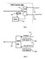
- the controlled WSS device 100includes a WSS element 110 , which has an output optical port 112 and n>1 input optical ports 111 1 to 111 n , hereinafter generally referred to as the input ports 111 .
- the WSS 110has a control port and is operatively connected to a WSS controller 115 , to receive control signals therefrom for selectively provisioning or blocking optical paths or connections between each of the input ports and the output port at any, or at least some, of the supported wavelengths individually.
- the h WSS controller 115may be embodied using a suitably programmed microprocessor or the like, and is programmed or otherwise configured to generate signals for selectively provisioning optical connections between each of the input ports 111 and the output port 112 at any, or at least some, of the supported wavelengths ⁇ i , or blocking such connections at any of the wavelengths.
- the WSS controller 115 for controlling the operation of the WSS 110may be physically located in the same module as the WSS 110 , or it may be co-located on a printed circuit board assembly (PCBA) with the WSS element 110 , as illustrated in FIG. 1 ; or it may be located on a separate PCBA that can communicate with the WSS element 110 ; or otherwise depending on application.
- the WSS controller 115 for controlling the operation of the WSS 110is co-located with the WSS 110 at the same node.
- the WSS device 100also includes at least one optical channel monitor (OCM) 125 , which is capable of monitoring the presence of supported wavelengths ⁇ i at the input and/or output ports of the WSS 110 , and in some embodiments is also capable of measuring the optical channel power at said wavelengths as known in the arts.
- OCMoptical channel monitor
- the OCM 125is optically coupled at the output port 112 for monitoring the wavelength content of the WSS output, and is also operatively coupled to the WSS controller 115 , which is programmed to collect results of the optical channel monitoring from the OPM 125 .
- the WSS controller 115which is programmed to collect results of the optical channel monitoring from the OPM 125 .
- There are many technologies available for detecting channel presence on an optical fiber and suitable for utilizing the OCM 125including but not limited to, a WDM de-multiplexer coupled to an array of photo detectors, an OSA-like device, etc; suitable OCMs utilizing these and other suitable technologies are well known and commercially available.
- other OCMs 125 1 - 125 nmay be coupled to each of the input ports 111 of the WSS 110 as illustrated in FIG. 2 to monitor the presence and, optionally, power of optical channels at the input ports 111 of the WSS 110 .
- the optical channel monitoring at the input ports 111 of the WSS 110may be carried out using a single OPM 125 connected to the plurality of input ports 111 through a port selection switch 140 , thereby enabling sequential monitoring of the wavelength content at each of the input ports 111 .
- the controller 115(not shown in FIG. 3 ) is also operatively coupled to the port selector switch 140 for controlling thereof.
- the nodeincludes two reconfigurable optical add-drop modules (ROADM) 201 and 301 , which enable selectively adding and dropping wavelength onto and from the network.
- ROADMreconfigurable optical add-drop modules
- Each of the ROADMs 201 and 301includes an input passive optical splitter 230 , 330 , each of which having a single input port 231 , 331 for receiving a WDM optical signal propagating in the network in a respective direction, and a plurality of output optical ports 232 , 332 ; one of the output ports serves as an express output port, while one or more of the other output ports serving as drop ports, as indicated in FIG. 4 .
- Each of the ROADMs 201 and 301further includes an output controlled WSS device substantially similar to the controlled WSS device 100 , and comprised of a WSS element 210 , 310 coupled to a WSS controller 215 , 315 .
- each of the controlled WSS devices of the ROADMs 201 , 301include one or more OCMs as illustrated in FIG. 1 , 2 , or 3 for monitoring the wavelengths at the inputs and/or the output of the respective WSS.
- Each of the WSS 210 , 310has a single output port 212 , 312 for launching a WDM optical signal from the node into the network in a respective direction of propagation.
- Each of the WSS 210 , 310further has a plurality of input optical ports 211 , 311 , with one of the input ports 211 , 311 serving as an express input port, while one or more of the other input ports 211 , 311 serving as add ports for adding wavelengths to the network, as indicated in FIG. 4 .
- the express output port of a respective one of the splitters 230 , 330is connected to the express input port of a respective one of the WSS 310 , 210 .
- the WDM signal from the networkis first received in the input optical port 231 of the splitter 230 , which splits between the output ports 232 , with each received wavelength present at each output port.
- Optical signals from the drop ports of the splitter 230are then dropped from the network; for example, they may be de-multiplexed and then passed to a different local network and/or to end users, or converted to electrical signals as known in the art.
- a portion of the input WDM signalis passed from the express output port of the splitter 230 onto the express input port of the WSS 310 .
- the WSS 310may also be receiving other “add” optical signals at other input ports thereof designated as the “add” ports, for adding those “add” optical signals onto the network.
- the WSSoperates to selectively and reconfigurably combine “express” wavelengths received from the splitter 230 with the “add” wavelengths received at the “add” input ports of the WSS 310 .
- the WSS 310may also have to block from the “express” optical signal received at the express input port those of the wavelengths that were dropped at the splitter 230 , in particular if the “add” optical signals at the “add” input ports 311 of the WSS 310 are carried by same wavelengths.
- the WSS 310has to be configured so as to provide optical connections from the input ports thereof to the output port at port-specific wavelengths, and to block some of the wavelength depending on network requirements.
- configuring a ROADMsuch as that illustrated in FIG. 4 requires configuring its constituent WSS devices, which includes configuring of wavelength paths through the device, and may also include the configuration of the optical output power of each wavelength at the output of the WSS device.
- configuring ROADMs and WSSs in optical networkshas been performed, or suggested to be performed remotely from a central control node using sophisticated network control software operating over a control layer of the network.
- the present inventionprovides a method for automated self-configuration of the WSS devices in an optical networks, and in particular at ROADM nodes of optical network.
- the methodprovides a means by which a controlled WSS device can automatically configure itself based on the detection of wavelengths (channels) present at one or more inputs into the device.
- the WSS controller 115( 215 , 315 ) is programmed to control and/or cooperate with the at least one OCM 125 to detect the presence of the supported wavelengths at each of the input ports 111 ( 211 , 311 respectively), and to control the WSS 110 ( 210 , 310 ) in such a way that i) wavelengths (channels) that are not detected by the respective OCM on any input port 111 ( 211 , 311 ) are blocked by the WSS 110 ( 210 , 310 ), ii) any wavelength whose presence is detected by the OCM at one and only one of the input ports 111 ( 211 , 311 ) is switched to the common output port 112 ( 212 , 312 ), and iii) any wavelength whose presence is detected at more than one of the input ports 111 ( 211 , 311 ) is either blocked at each of the input ports until user intervention resolves the conflict, or is blocked at all but one of the input ports 111 (
- the methodrequires no user interaction or external control, such as from software running on a processor that is external to the controlled WSS element, to complete the WSS configuration, and therefore simplifies and reduces the amount of user interaction required in order to configure the device.
- the methodmay be initiated by software command to the controller that is directly controlling the WSS, direct physical input from an operator, such as a pushbutton or switch, or any other means.
- the methodrequires the ability for the WSS controller in the controlled WSS device to monitor the presence of optical channels on each input port individually.
- embodiments of the methodmay also provide a mechanism by which the output power of each channel is automatically adjusted.
- Channel powersmay be adjusted in one of the following ways: to achieve a pre-determined power profile with respect to one another, including (but not limited to) a flat profile where all channels are output from the device with the same optical power level; and/or to achieve a pre-determined absolute power for each channel.
- the adjustment of the channel powerrequires that the controlled WSS device supports, within the WSS element itself or otherwise, variable attenuation of optical power levels on a per-channel, or per-wavelength basis; one skilled in the art will appreciate that known in the art WSS devices often include the per-channel variable attenuation capability by design, which can be advantageously used by the present invention.
- FIGS. 5-7illustrating steps of the method in various embodiments thereof, and also with reference to the controlled WSS device 100 of FIG. 1 by way of example; it will be appreciated that the method steps described hereinbelow are equally applicable to the WSS devices 210 , 310 in the ROADM Degree 1, 2 modules illustrated in FIG. 4 .
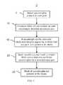
- FIG. 5there is shown a flowchart illustrating basic steps of the method in one embodiment (1) thereof. As illustrated, the method may include the following general steps:
- one or more OCMssuch as the OCM 125 in the embodiment of FIG. 1 or FIG. 3 , or the plurality of OCMs in the embodiment of FIG. 2 , are used to detect which of the supported wavelengths ⁇ i are received at each of the input optical ports of the WSS 110 .
- the WSS controller 115collects resulting information, for example in the form of listings of wavelengths determined to be present at each of the n input ports 111 of the WSS 110 .
- the WSS controller 115operates the WSS device 110 so as to selectively provision optical connections from respective input optical ports 111 to the output optical port 112 for those of the supported wavelengths ⁇ i that are received at one and only one of the input optical ports 11 of the WSS device.
- connections between the input optical ports 111 and the output optical port 112 at those of the supported wavelengths that are not received at any of the input optical ports,are blocked within the WSS 110 .
- the WSS controller 115may operate the WSS 110 so as to block, for each of the input ports 111 , all supported wavelengths that are not received at that port.
- the WSS controller 115maybe programmed in such a way that the aforedescribed steps 110 are performed as an automated start-up procedure when the controlled WSS device 100 is first connected into a network.
- the WSS 110may be initially provided in a default state wherein the connections between each of the input ports 111 and the output port 112 are blocked for all supported wavelength; in that case, step 112 is not required, and the WSS controller 115 will only need to signal to the WSS 110 , which of the received wavelengths are to be “unblocked” at each of the input ports 11 to couple to the output port 112 .
- a same supported wavelengthmay be present at two or more of the input ports 111 , indicating a wavelength conflict which needs to be resolved.
- a wavelength conflictmay be resolved by either temporally blocking the wavelength's passage to the output port from each of the input ports where it is detected and awaiting a user input resolving the conflict, or, in embodiments wherein the input ports are assigned priorities which are made known to the WSS controller, by selecting one of said input ports for opening a path therefrom to the output port for the wavelength in conflict according to the ports priorities, while blocking the passage of the conflicting wavelength in the WSS 110 from all other input ports 111 .
- the auto-configuration algorithm that is carried out by the WSS controllermay also be pre-configured to favor one or more of the input ports, for example, a port that is being used as the ‘express’ port in the ROADM node configuration such as illustrated in FIG. 4 . If a conflicting wavelength has been detected on one such favored port and one or more non-favoured, e.g. “add”, ports, the method will automatically configure the WSS to allow the wavelength to pass from the favored input port to the common output port, and block the wavelength on all other ports. In one embodiment, if a conflicting wavelength has been detected on more than one favored port, the method will block the conflicting wavelength on all input ports, complete the algorithm, and notify the operator of the conflict.
- a conflicting wavelengthhas been detected on more than one favored port
- the methodwill block the conflicting wavelength on all input ports, complete the algorithm, and notify the operator of the conflict.
- FIG. 6there is illustrates an embodiment 2 of the method wherein the controlled WSS device 100 is programmed to perform the following steps:
- the WSS controller 115obtains information from the one or more OCMs 125 about the supported wavelengths that are present at each of the input ports 111 of the WSS 110 .
- the WSS controller 115is programmed to identify wavelength conflicts by verifying if any of the detected wavelengths is present at two or more of the input ports 111 .
- the WSS controller 115provisions at step 10 an optical connection from an input port 111 , wherein said wavelength has been detected, to the output port 112 (the I/O connection).
- step 15the WSS controller 115 determines that a wavelength conflict is present, the WSS controller signals to the WSS 110 to block the conflicting wavelength or wavelengths in the WSS 110 from reaching the output port 112 from any of the input ports 111 , including the input ports where their presence have been detected by the OCM 125 .
- an alarmmay be generated at this point that signals that an external intervention is required to resolve a conflict.
- the WSS controller 115upon receiving a user input indicating which of the input ports 111 receiving the conflicting wavelength should be coupled at said wavelength to the output port 112 , the WSS controller 115 operates the WSS 110 so as to optically couple the selected by the user input port to the output port 125 for the conflicted wavelength.
- the WSS controller 115may operate the WSS 110 to block optical connections between each of the input ports 111 and the output port 112 at those of the supported wavelengths that were not detected as present at a corresponding input port.
- the input ports 111are assigned priorities, which are known to the WSS controller 115 ; for example, the WSS controller 115 may include, or be operatively coupled to, a memory element wherein the port priority information is saved, such as in a look-up table.
- the WSS controller 115may include, or be operatively coupled to, a memory element wherein the port priority information is saved, such as in a look-up table.
- those of the input ports 111 that are designated as “add” ports, see FIG. 4may have higher priority associated therewith than the “express” input port, or vice versa depending on a particular system design.
- some or all of the “add” portsmay also have differing priorities assigned thereto. Accordingly, in the embodiment of the method illustrated in FIG.
- step 10 of provisioning I/O connections for each of the wavelengths that is detected at one and only one of the input ports 111is accompanied by step 15 a , wherein the WSS controller 115 identifies a wavelength ⁇ k that is present at two or more of the input ports 111 , thereby detecting a wavelength conflict, and, based on the port priority information that is saved in the memory of the WSS controller, identifies among the input ports 111 receiving said wavelength ⁇ k the port that has the highest priority among all the ports 111 at which the wavelength ⁇ k has been detected, and then provisions an I/O connection at the wavelength ⁇ k between the output port 112 and the identified input port 111 with the comparatively highest priority, while blocking the passage of said wavelength from all other input ports.
- the WSS controller 115may operate the WSS 110 so as to set the output optical power of each of the supported wavelengths that reach the output port 112 according to pre-determined power settings. In doing so, the WSS controller 115 may utilize the per-wavelengths optical power readings obtained from the OCM 125 , and per-wavelength optical attenuation capabilities that many types of known WSS devices posses. This step may also be optionally perfumed in the embodiments of FIGS. 5 and 6 .
- the method of the present inventionrequires that the WSS device 100 has the capability of detecting which of the supported wavelengths are present at each of the input ports 111 , or receives this information elsewhere. This can be easily accomplished in the embodiments wherein the WSS device 100 has one or more OCMs connected in a way that enables monitoring of the input ports 111 individually, for example as shown in FIGS. 2 and 3 . However, it may be advantageous to have a single OCM connected at the output of the WSS 110 , as illustrated in FIG. 1 ; apart from requiring less hardware, this also enables the direct monitoring of the optical power in each of the wavelength channels at the output of the WSS 110 , thereby facilitating the setting of the output power levels for each of the wavelengths.
- the step of detecting the wavelengths that are present at each of the input ports 111 of the WSS 110may be carried out as illustrated in FIG. 8 .
- the WSS controller 115is programmed to perform, at the start of the WSS auto-configuration procedure, the following steps:
- the WSS controller 115directs the WSS 110 , i.e. by sending a suitable control signal to the control port thereof, to block connections between the output port 112 and all but one of the input ports 111 at all of the supported wavelengths, so as to open an optical path to the output port from a single selected input port.
- the OCM 125is operated so as to detect which of the supported wavelengths are present at the output port 112 , thereby establishing the wavelength channels that are present at the selected input port. Steps 50 and 55 are then repeated each time selecting a different input port to connect to the output port, until all input ports are tested, while saving thereby obtained port/wavelength information in the controller memory.
- the aforedescribed method for auto-configuration of the WSS device in an optical networkprovides means by which a ROADM node comprised of one or more WSS devices, such as that illustrated in FIG. 4 , can automatically configure itself based on the detection of wavelengths (channels) present at one or more inputs into the node. Except may be for initiating it, the method requires no user interaction to complete the WSS configuration and therefore simplifies, and reduces the amount of, user interaction required in order to configure the ROADM.
- the methodmay be initiated by software command to the node, direct physical input from an operator, such as a pushbutton or switch, or any other suitable means as would be known in the art.
- Configuration of the ROADM nodemay include the configuration of some or all wavelength paths through the node, as well as the configuration of some or all optical output power levels of wavelengths at the output of the node.
- FIG. 4illustrates a common architecture wherein a WSS ( 210 , 310 ) is used to add wavelengths to a ROADM degree, and a power splitter ( 230 , 330 ) is used to drop wavelengths at the node.
- a WSSfor both adding and dropping
- a WSS for droppingand an optical power coupler or a fixed Wavelength Division Multiplexer for adding.
- Distribution of control functions in the nodecan vary between centralization of these functions for all ‘degrees’ on a single control element, to increasing distribution of these functions across other CPUs, or controllers, within the node, which may physically exist on diverse printed circuit board assemblies within the domain of the same logical node.
- FIG. 4illustrates a node control architecture with a common node controller 205 with a processor 255 , where control functions that span diverse physical elements within the node are centralized, and separate WSS controllers 215 , 315 for each degree of the ROADM node.
- the node controller 205may assume functions performed by the WSS controllers 215 , 315 .
- One aspect of the inventionprovides an automated start-up procedure for a multi-degree ROADM node in an optical network utilizing WSS devices for adding wavelengths onto the network, such as the 2-degree ROADM node illustrated in FIG. 4 .
- the methodutilizes OCMs coupled to the each of the WSS devices as described hereinabove for detecting the presence of supported wavelength at each of the input ports of the WSSs, and optionally for monitoring the optical power in each of the wavelengths appearing at the output port of the respective WSS.
- the methodmay include performing the aforedescribed WSS auto-configuration procedures, see FIGS. 5-8 , for each of the WSS devices used to add channels to the network, such as the WSS devices 210 and 310 of the node of FIG. 4 .
- the methodin one aspect thereof may include all or some of the following features:
- the input ports 211 , 311 to the WSS device 210 , 310may be designated as Add or Express inputs, with the output port 212 , 312 designated as Common;
- any wavelength whose presence is detected on both an Express input and an Add input of the same degreeare assumed to be added at the node. Therefore the wavelength is blocked on the express input, and routed from the Add input to the Common output, such as from one of the “Add” input ports 311 to the output port 312 of the WSS 310 .
- blocking a supported wavelength when it is not detected on an Add or Express port of the same degree of the ROADM nodeis advantageous as it enables to avoid potential wavelength conflicts downstream at another node in the network. Furthermore, blocking of the wavelength that is not detected at the WSS inputs allows the corresponding channel to be added in a graceful, controlled manner in the future. For example, it would not be unusual for a technician to plug in a transponder of a particular wavelength and connect it up to the network. If that wavelength were unblocked through all the switching elements in the network, there are a number of potential problems that could arise, such as conflicts with other channels in the network or a sudden power transient.
- a wavelengthis generally considered to be “blocked” at a selected input port of the WSS, when the attenuation it experiences on the way from this input port to the output port exceeds a pre-determined value, typically 20 dB or greater, or as specified by the system design.
- This functionis typically implemented within the WSS element itself, as WSS devices typically support wavelength power control as well as the switching between optical ports. However, this does not necessarily have to be the case: A WSS could be used to perform the switching, and a separate suitable device could perform the wavelength power control, although this may be less efficient and more costly.
- the auto-configuration procedure of the present invention in one of the aforedescribed or similar embodiments thereofmay be advantageously utilized in various network scenarios, such as at a first start-up of the network or a section thereof, or when replacing one or more components of a ROADM node, such as the WSS device itself, or periodically during the operation, etc.
- FIG. 9there is schematically illustrated a portion of a WDM network in the form of a linear chain of 2-degree ROADM nodes or sites connected by fiber-optic links between two terminal sides wherein express WDM optical signals are terminated, i.e. generated and converted into electrical signals.
- the chainis bi-directional, including two substantially identical one-directional chains utilizing a fiber pair formed of two optical fibers for transmitting signals in the opposite directions.
- a self-configuration start-up procedure for such a networkcan be performed using features of the present invention as described hereinbelow. For clarity of the description only, it is assumed hereinbelow that the ROADM chain of FIG.
- fibre pair 9is being turned up from left to right in one direction of the fibre pair, which is referred to as “east-bound”, then right to left for the other, i.e. the “west-bound”, direction.
- the term “operator” used hereinbelowmay refer to a person, group off persons, or to a suitable software running on one or more processors, which may be either co-located at a same control site, or distributed between sites and communicating over a control layer of the network, or otherwise.
Landscapes
- Engineering & Computer Science (AREA)
- Computer Networks & Wireless Communication (AREA)
- Signal Processing (AREA)
- Optical Communication System (AREA)
Abstract
Description
Claims (7)
Priority Applications (2)
| Application Number | Priority Date | Filing Date | Title |
|---|---|---|---|
| US12/714,600US8948592B2 (en) | 2009-02-27 | 2010-03-01 | Method for auto-configuration of a wavelength selective switch in an optical network |
| US14/608,228US9706273B2 (en) | 2009-02-27 | 2015-01-29 | Method for auto-configuration of a wavelength selective switch in an optical network |
Applications Claiming Priority (2)
| Application Number | Priority Date | Filing Date | Title |
|---|---|---|---|
| US15597909P | 2009-02-27 | 2009-02-27 | |
| US12/714,600US8948592B2 (en) | 2009-02-27 | 2010-03-01 | Method for auto-configuration of a wavelength selective switch in an optical network |
Related Child Applications (1)
| Application Number | Title | Priority Date | Filing Date |
|---|---|---|---|
| US14/608,228ContinuationUS9706273B2 (en) | 2009-02-27 | 2015-01-29 | Method for auto-configuration of a wavelength selective switch in an optical network |
Publications (2)
| Publication Number | Publication Date |
|---|---|
| US20100221004A1 US20100221004A1 (en) | 2010-09-02 |
| US8948592B2true US8948592B2 (en) | 2015-02-03 |
Family
ID=42663765
Family Applications (2)
| Application Number | Title | Priority Date | Filing Date |
|---|---|---|---|
| US12/714,600Active2031-12-16US8948592B2 (en) | 2009-02-27 | 2010-03-01 | Method for auto-configuration of a wavelength selective switch in an optical network |
| US14/608,228ActiveUS9706273B2 (en) | 2009-02-27 | 2015-01-29 | Method for auto-configuration of a wavelength selective switch in an optical network |
Family Applications After (1)
| Application Number | Title | Priority Date | Filing Date |
|---|---|---|---|
| US14/608,228ActiveUS9706273B2 (en) | 2009-02-27 | 2015-01-29 | Method for auto-configuration of a wavelength selective switch in an optical network |
Country Status (2)
| Country | Link |
|---|---|
| US (2) | US8948592B2 (en) |
| CA (1) | CA2695050C (en) |
Cited By (1)
| Publication number | Priority date | Publication date | Assignee | Title |
|---|---|---|---|---|
| US20150139643A1 (en)* | 2009-02-27 | 2015-05-21 | Jds Uniphase Corporation | Method for auto-configuration of a wavelength selective switch in an optical network |
Families Citing this family (39)
| Publication number | Priority date | Publication date | Assignee | Title |
|---|---|---|---|---|
| US8170417B2 (en)* | 2009-02-06 | 2012-05-01 | At&T Intellectual Property I, L.P. | Mechanism to detect an unstable wavelength channel and limit its impact on a ROADM network |
| JP5257211B2 (en)* | 2009-04-09 | 2013-08-07 | 富士通株式会社 | Optical transmission equipment |
| WO2011047715A1 (en)* | 2009-10-20 | 2011-04-28 | Telefonaktiebolaget Lm Ericsson (Publ) | Optical transport switching node with framer |
| US20110135301A1 (en) | 2009-12-08 | 2011-06-09 | Vello Systems, Inc. | Wavelocker for Improving Laser Wavelength Accuracy in WDM Networks |
| JP5682256B2 (en)* | 2010-11-24 | 2015-03-11 | 富士通株式会社 | Optical insertion device and optical branching device |
| JP5699769B2 (en)* | 2011-04-13 | 2015-04-15 | 富士通株式会社 | Optical channel monitor and optical transmission device |
| US9794019B2 (en)* | 2011-04-28 | 2017-10-17 | Hewlett Packard Enterprise Development Lp | Prioritized optical arbitration systems and methods |
| US8971705B2 (en)* | 2011-09-02 | 2015-03-03 | Ciena Corporation | Transient and switching event stabilization of fiber optic transport systems |
| US8989197B2 (en)* | 2012-04-02 | 2015-03-24 | Nec Laboratories America, Inc. | Reconfigurable branching unit for submarine optical communication networks |
| EP2874328A4 (en)* | 2012-08-07 | 2015-10-28 | Huawei Tech Co Ltd | METHOD AND APPARATUS FOR OBTAINING INTERNAL FIBER CONNECTION RELATION IN A RECONFIGURABLE OPTICAL INSERTION-EXTRACTION MULTIPLEXER |
| US9276696B2 (en) | 2012-10-19 | 2016-03-01 | Ciena Corporation | Systems and methods for channel additions over multiple cascaded optical nodes |
| US9755738B2 (en)* | 2013-03-20 | 2017-09-05 | Nistica, Inc. | Crosstalk suppression in a multi-photodetector optical channel monitor |
| AU2014235949B2 (en) | 2013-03-20 | 2017-09-07 | Nistica, Inc. | Wavelength selective switch having integrated channel monitor |
| US9819436B2 (en) | 2013-08-26 | 2017-11-14 | Coriant Operations, Inc. | Intranodal ROADM fiber management apparatuses, systems, and methods |
| US10009671B2 (en)* | 2014-01-17 | 2018-06-26 | Tellabs Operations, Inc. | Methods and apparatus for providing configuration discovery using intra-nodal test channel |
| CN104753624B (en)* | 2015-03-02 | 2018-04-06 | 国家电网公司 | A kind of ROADM based on WSS |
| US10349153B2 (en)* | 2015-03-23 | 2019-07-09 | Nec Corporation | Optical multiplexing and demultiplexing device, and method of controlling optical multiplexing and demultiplexing device |
| US9577763B2 (en) | 2015-04-22 | 2017-02-21 | Ciena Corporation | Spectrum controller systems and methods in optical networks |
| US9680570B2 (en) | 2015-04-30 | 2017-06-13 | Nistica, Inc. | Optical channel monitor for a wavelength selective switch employing a single photodiode |
| US9628174B2 (en) | 2015-06-30 | 2017-04-18 | Ii-Vi Incorporated | Optical channel monitor with integral optical switch |
| US10148383B2 (en) | 2015-06-30 | 2018-12-04 | Ii-Vi Incorporated | Optical channel monitor with integral optical switch |
| EP3185447A1 (en)* | 2015-12-22 | 2017-06-28 | Xieon Networks S.à r.l. | Optical network element for transmitting and/or receiving wdm signals |
| JP6578962B2 (en)* | 2016-01-25 | 2019-09-25 | 富士通株式会社 | Optical transmission device, optical transmission system, and optical signal output control method |
| CN106303768B (en)* | 2016-08-31 | 2019-10-18 | 武汉光迅科技股份有限公司 | The photosynthetic wave separater module for having automatic discovery feature |
| US9986317B1 (en) | 2016-11-29 | 2018-05-29 | Ciena Corporation | Systems and methods modeling optical sources in optical spectrum controllers for control thereof |
| US9985726B1 (en) | 2016-11-29 | 2018-05-29 | Ciena Corporation | Systems and methods for a preemptive controller for photonic line systems |
| CN108121036B (en)* | 2016-11-29 | 2019-11-22 | 华为技术有限公司 | A wavelength selective switch and optical signal transmission system |
| US11113800B2 (en)* | 2017-01-18 | 2021-09-07 | Nvidia Corporation | Filtering image data using a neural network |
| US10050737B1 (en) | 2017-05-04 | 2018-08-14 | Ciena Corporation | Methods and apparatus for pre-programming layer-0 service turn up speeds for photonic service provisioning or restoration |
| US10536235B2 (en) | 2017-05-04 | 2020-01-14 | Ciena Corporation | Logical control seams in optical networks to improve restoration speed or timing for capacity adds |
| US11290192B2 (en)* | 2018-02-15 | 2022-03-29 | Corning Incorporated | Quantum communication methods and systems for mitigating the detector dead time of photon detectors |
| KR20200131905A (en) | 2018-04-13 | 2020-11-24 | 콤스코프 테크놀로지스, 엘엘씨 | Configurable wide area distributed antenna system |
| CN109088777B (en)* | 2018-09-14 | 2021-12-31 | 武汉光迅科技股份有限公司 | Device and method for matching optical fiber connection of ROADM service side |
| US10686543B1 (en) | 2019-03-05 | 2020-06-16 | Ciena Corporation | Time and margin constrained routing, spectrum, and restoration speed assignment in optical networks |
| US20220140907A1 (en)* | 2019-03-25 | 2022-05-05 | Nec Corporation | Optical add/drop multiplexer and optical transmission method |
| CN111541956B (en)* | 2020-04-20 | 2021-11-23 | 深圳市三旺通信股份有限公司 | Optical port self-adaption method, device, switch and computer readable storage medium |
| JP2023179957A (en)* | 2022-06-08 | 2023-12-20 | 富士通株式会社 | Optical switching device, optical switching system, and optical switching method |
| CN114124287B (en)* | 2020-08-31 | 2025-02-28 | 华为技术有限公司 | Optical signal control method and device, optical transmission node and optical transmission system |
| WO2024188463A1 (en)* | 2023-03-15 | 2024-09-19 | Telefonaktiebolaget Lm Ericsson (Publ) | Programmable wavelength-selective splitter and a method for remotely configuring a programmable wavelength-selective splitter |
Citations (22)
| Publication number | Priority date | Publication date | Assignee | Title |
|---|---|---|---|---|
| US5539559A (en)* | 1990-12-18 | 1996-07-23 | Bell Communications Research Inc. | Apparatus and method for photonic contention resolution in a large ATM switch |
| US20020131687A1 (en)* | 2001-03-19 | 2002-09-19 | Wilde Jeffrey P. | Reconfigurable optical add-drop multiplexers with servo control and dynamic spectral power management capabilities |
| US6487334B2 (en) | 2000-11-20 | 2002-11-26 | Jds Uniphase Inc. | Optical switch |
| US6498872B2 (en) | 2000-02-17 | 2002-12-24 | Jds Uniphase Inc. | Optical configuration for a dynamic gain equalizer and a configurable add/drop multiplexer |
| US6549699B2 (en)* | 2001-03-19 | 2003-04-15 | Capella Photonics, Inc. | Reconfigurable all-optical multiplexers with simultaneous add-drop capability |
| US6707959B2 (en) | 2001-07-12 | 2004-03-16 | Jds Uniphase Inc. | Wavelength switch |
| US6760511B2 (en) | 2001-03-19 | 2004-07-06 | Capella Photonics, Inc. | Reconfigurable optical add-drop multiplexers employing polarization diversity |
| US6819940B1 (en)* | 1999-09-13 | 2004-11-16 | Mitsubishi Denki Kabushiki Kaisha | Mobile communications system |
| US7027684B2 (en) | 2002-05-20 | 2006-04-11 | Metconnex Canada Inc. | Wavelength selective switch |
| US7039267B2 (en) | 2000-11-20 | 2006-05-02 | Jds Uniphase Inc. | Optical switch |
| US20060228072A1 (en)* | 2005-04-11 | 2006-10-12 | Capella Photonics, Inc., A Delaware Corporation | Optimized reconfigurable optical add-drop multiplexer architecture with MEMS-based attenuation or power management |
| US20070077069A1 (en)* | 2000-10-04 | 2007-04-05 | Farmer James O | System and method for communicating optical signals upstream and downstream between a data service provider and subscribers |
| US7212704B2 (en) | 2004-10-12 | 2007-05-01 | Jds Uniphase Corporation | Systems and methods for optical switching to colorless ports and colored ports |
| US7236660B2 (en) | 2002-05-20 | 2007-06-26 | Jds Uniphase Corporation | Reconfigurable optical add-drop module, system and method |
| US20070237451A1 (en)* | 2006-04-06 | 2007-10-11 | Paul Colbourne | Multi-unit planar lightwave circuit wavelength dispersive device |
| US7302134B2 (en)* | 2002-05-20 | 2007-11-27 | Jds Uniphase Corporation | Wavelength selective switch with a 2D arrangement of optical ports |
| US20070274724A1 (en)* | 2006-05-25 | 2007-11-29 | Gumaste Ashwin A | Wavelength Selective Switch Design Configurations for Mesh Light-Trails |
| US20080101743A1 (en)* | 2006-10-30 | 2008-05-01 | Philip Duggan | Mws drift feedback compensator using voa and input power dithering |
| US20080193127A1 (en)* | 2007-02-09 | 2008-08-14 | Ciena Corporation | System and method for a channel guard in a reconfigurable optical add-drop multiplexer |
| US7529441B2 (en)* | 2003-06-30 | 2009-05-05 | Calient Networks, Inc. | Wavelength routing optical switch |
| US7653311B2 (en) | 2004-03-30 | 2010-01-26 | Hitachi Communication Technologies, Ltd. | Optical wavelength add-drop multiplexer |
| US20100061727A1 (en)* | 2008-09-09 | 2010-03-11 | Paul Colbourne | HITLESS MxN WAVELENGTH SELECTIVE SWITCH |
Family Cites Families (16)
| Publication number | Priority date | Publication date | Assignee | Title |
|---|---|---|---|---|
| US6771905B1 (en)* | 1999-06-07 | 2004-08-03 | Corvis Corporation | Optical transmission systems including optical switching devices, control apparatuses, and methods |
| US7130541B2 (en)* | 2000-10-04 | 2006-10-31 | Wave7 Optics, Inc. | System and method for communicating optical signals upstream and downstream between a data service provider and subscriber |
| US20030039003A1 (en)* | 2001-08-27 | 2003-02-27 | Bogdan Jakobik | Architectural arrangement for core optical networks |
| US7085492B2 (en)* | 2001-08-27 | 2006-08-01 | Ibsen Photonics A/S | Wavelength division multiplexed device |
| US7254327B1 (en)* | 2003-01-31 | 2007-08-07 | Ciena Corporation | Switching status and performance monitoring technology for wavelength selective switch and optical networks |
| US7366370B2 (en)* | 2004-08-20 | 2008-04-29 | Nortel Networks Limited | Technique for photonic switching |
| JP4303710B2 (en)* | 2005-07-15 | 2009-07-29 | 富士通株式会社 | Optical transmission equipment |
| JP5151455B2 (en)* | 2007-12-20 | 2013-02-27 | 富士通株式会社 | Optical transmission equipment |
| US8320759B2 (en)* | 2008-03-05 | 2012-11-27 | Tellabs Operations, Inc. | Methods and apparatus for reconfigurable add drop multiplexers |
| US8948592B2 (en)* | 2009-02-27 | 2015-02-03 | Jds Uniphase Corporation | Method for auto-configuration of a wavelength selective switch in an optical network |
| JP5257211B2 (en)* | 2009-04-09 | 2013-08-07 | 富士通株式会社 | Optical transmission equipment |
| WO2011047715A1 (en)* | 2009-10-20 | 2011-04-28 | Telefonaktiebolaget Lm Ericsson (Publ) | Optical transport switching node with framer |
| JP5672011B2 (en)* | 2011-01-04 | 2015-02-18 | 富士通株式会社 | Wavelength selective switch and wavelength shift correction method |
| JP2013106187A (en)* | 2011-11-14 | 2013-05-30 | Hitachi Ltd | Device, system and method for wavelength multiplex optical transmission |
| EP2860571A4 (en)* | 2012-06-11 | 2015-07-08 | Fujitsu Ltd | OPTICAL TRANSMISSION APPARATUS |
| US9078054B2 (en)* | 2012-10-15 | 2015-07-07 | Sumitomo Electric Industries, Ltd. | Optical module used in optical communication systems, method of updating firmware of optical module used in optical communication systems, and trouble tracing system |
- 2010
- 2010-03-01USUS12/714,600patent/US8948592B2/enactiveActive
- 2010-03-01CACA2695050Apatent/CA2695050C/enactiveActive
- 2015
- 2015-01-29USUS14/608,228patent/US9706273B2/enactiveActive
Patent Citations (25)
| Publication number | Priority date | Publication date | Assignee | Title |
|---|---|---|---|---|
| US5539559A (en)* | 1990-12-18 | 1996-07-23 | Bell Communications Research Inc. | Apparatus and method for photonic contention resolution in a large ATM switch |
| US6819940B1 (en)* | 1999-09-13 | 2004-11-16 | Mitsubishi Denki Kabushiki Kaisha | Mobile communications system |
| US6498872B2 (en) | 2000-02-17 | 2002-12-24 | Jds Uniphase Inc. | Optical configuration for a dynamic gain equalizer and a configurable add/drop multiplexer |
| US20070077069A1 (en)* | 2000-10-04 | 2007-04-05 | Farmer James O | System and method for communicating optical signals upstream and downstream between a data service provider and subscribers |
| US6487334B2 (en) | 2000-11-20 | 2002-11-26 | Jds Uniphase Inc. | Optical switch |
| US7039267B2 (en) | 2000-11-20 | 2006-05-02 | Jds Uniphase Inc. | Optical switch |
| US6661948B2 (en)* | 2001-03-19 | 2003-12-09 | Capella Photonics, Inc. | Reconfigurable optical add and drop modules with servo control and dynamic spectral power management capabilities |
| US6760511B2 (en) | 2001-03-19 | 2004-07-06 | Capella Photonics, Inc. | Reconfigurable optical add-drop multiplexers employing polarization diversity |
| US6625346B2 (en) | 2001-03-19 | 2003-09-23 | Capella Photonics, Inc. | Reconfigurable optical add-drop multiplexers with servo control and dynamic spectral power management capabilities |
| US6549699B2 (en)* | 2001-03-19 | 2003-04-15 | Capella Photonics, Inc. | Reconfigurable all-optical multiplexers with simultaneous add-drop capability |
| US20020131687A1 (en)* | 2001-03-19 | 2002-09-19 | Wilde Jeffrey P. | Reconfigurable optical add-drop multiplexers with servo control and dynamic spectral power management capabilities |
| US6687431B2 (en)* | 2001-03-19 | 2004-02-03 | Capella Photonics, Inc. | Reconfigurable optical add-drop multiplexers with servo control and dynamic spectral power management capabilities |
| US6707959B2 (en) | 2001-07-12 | 2004-03-16 | Jds Uniphase Inc. | Wavelength switch |
| US7302134B2 (en)* | 2002-05-20 | 2007-11-27 | Jds Uniphase Corporation | Wavelength selective switch with a 2D arrangement of optical ports |
| US7027684B2 (en) | 2002-05-20 | 2006-04-11 | Metconnex Canada Inc. | Wavelength selective switch |
| US7236660B2 (en) | 2002-05-20 | 2007-06-26 | Jds Uniphase Corporation | Reconfigurable optical add-drop module, system and method |
| US7529441B2 (en)* | 2003-06-30 | 2009-05-05 | Calient Networks, Inc. | Wavelength routing optical switch |
| US7653311B2 (en) | 2004-03-30 | 2010-01-26 | Hitachi Communication Technologies, Ltd. | Optical wavelength add-drop multiplexer |
| US7212704B2 (en) | 2004-10-12 | 2007-05-01 | Jds Uniphase Corporation | Systems and methods for optical switching to colorless ports and colored ports |
| US20060228072A1 (en)* | 2005-04-11 | 2006-10-12 | Capella Photonics, Inc., A Delaware Corporation | Optimized reconfigurable optical add-drop multiplexer architecture with MEMS-based attenuation or power management |
| US20070237451A1 (en)* | 2006-04-06 | 2007-10-11 | Paul Colbourne | Multi-unit planar lightwave circuit wavelength dispersive device |
| US20070274724A1 (en)* | 2006-05-25 | 2007-11-29 | Gumaste Ashwin A | Wavelength Selective Switch Design Configurations for Mesh Light-Trails |
| US20080101743A1 (en)* | 2006-10-30 | 2008-05-01 | Philip Duggan | Mws drift feedback compensator using voa and input power dithering |
| US20080193127A1 (en)* | 2007-02-09 | 2008-08-14 | Ciena Corporation | System and method for a channel guard in a reconfigurable optical add-drop multiplexer |
| US20100061727A1 (en)* | 2008-09-09 | 2010-03-11 | Paul Colbourne | HITLESS MxN WAVELENGTH SELECTIVE SWITCH |
Non-Patent Citations (2)
| Title |
|---|
| "Blocking." In Hargrave's Communications Dictionary, Wiley. Hoboken: Wiley, 2001. http://search.credoreference.com/content/entry/hargravecomms/blocking/0 (accessed Apr. 30, 2014.).* |
| Blocking. (2001). In Hargrave's Communications Dictionary, Wiley. Retrieved from http://www.credoreference.com/entry/hargravecomms/blocking.* |
Cited By (2)
| Publication number | Priority date | Publication date | Assignee | Title |
|---|---|---|---|---|
| US20150139643A1 (en)* | 2009-02-27 | 2015-05-21 | Jds Uniphase Corporation | Method for auto-configuration of a wavelength selective switch in an optical network |
| US9706273B2 (en)* | 2009-02-27 | 2017-07-11 | Lumentum Operations Llc | Method for auto-configuration of a wavelength selective switch in an optical network |
Also Published As
| Publication number | Publication date |
|---|---|
| US20150139643A1 (en) | 2015-05-21 |
| US9706273B2 (en) | 2017-07-11 |
| CA2695050A1 (en) | 2010-08-27 |
| CA2695050C (en) | 2019-01-15 |
| US20100221004A1 (en) | 2010-09-02 |
Similar Documents
| Publication | Publication Date | Title |
|---|---|---|
| US9706273B2 (en) | Method for auto-configuration of a wavelength selective switch in an optical network | |
| US8965220B2 (en) | Reconfigurable optical add/drop multiplexer and procedure for outputting optical signals from such multiplexer | |
| Amaya et al. | Architecture on demand for transparent optical networks | |
| US7254336B2 (en) | Method of seamless migration from scaleable OADM to a network switching node | |
| US9014562B2 (en) | Optical line terminal arrangement, apparatus and methods | |
| WO2016109248A1 (en) | System and method for local interconnection of optical nodes | |
| JP4843659B2 (en) | Optical transmission network system, optical transmission device, and passband allocation method using them | |
| EP2979383B1 (en) | Optical switch | |
| EP2025086A1 (en) | Tunable bidirectional add/drop multiplexer/demultiplexer for optical transmission systems | |
| EP2982066B1 (en) | Optical switch | |
| EP3166243A1 (en) | Method and apparatus for providing path protection in an optical transmission network | |
| US20040042795A1 (en) | Integrated reconfigurable optical add/drop multiplexer | |
| US9332326B2 (en) | Optical transmission device and monitoring method of optical signal | |
| US7110638B2 (en) | Reconfigurable optical node with distributed spectral filtering | |
| WO2013115905A1 (en) | Contentionless add-drop multiplexer | |
| CN107949994B (en) | OADM node and method in a WDM system | |
| KR20080092803A (en) | Reconfigurable Branch-coupled Multiplexer and Method Using Wavelength-Adjustable Laser | |
| JP4488813B2 (en) | Method and system for managing directly connected optical elements | |
| EP4586523A1 (en) | Optical add drop multiplexers with asymmetrical filtering | |
| JP2001094512A (en) | Optical line monitoring system | |
| EP2928097A1 (en) | Optical switching | |
| Robinson | How ROADM technology is simplifying network management | |
| Munoz et al. | Optical transport network of the ADRENALINE testbed: GMPLS metropolitan all-optical tuneable AWG-based R-OADM ring | |
| WO2011058547A1 (en) | Optical communication network having flexible operability | |
| KR20080092897A (en) | Reconfigurable Branch-coupled Multiplexer and Method Using Wavelength-Adjustable Laser |
Legal Events
| Date | Code | Title | Description |
|---|---|---|---|
| AS | Assignment | Owner name:JDS UNIPHASE CORPORATION, CALIFORNIA Free format text:ASSIGNMENT OF ASSIGNORS INTEREST;ASSIGNORS:HASLAM, THOMAS;COOMBER, DAVID;DOLISKA, DANIEL;AND OTHERS;SIGNING DATES FROM 20100225 TO 20100301;REEL/FRAME:024197/0242 | |
| STCF | Information on status: patent grant | Free format text:PATENTED CASE | |
| AS | Assignment | Owner name:LUMENTUM OPERATIONS LLC, CALIFORNIA Free format text:ASSIGNMENT OF ASSIGNORS INTEREST;ASSIGNOR:JDS UNIPHASE CORPORATION;REEL/FRAME:036420/0340 Effective date:20150731 | |
| AS | Assignment | Owner name:VIAVI SOLUTIONS INC., CALIFORNIA Free format text:CHANGE OF NAME;ASSIGNOR:JDS UNIPHASE CORPORATION;REEL/FRAME:037057/0627 Effective date:20150731 | |
| FEPP | Fee payment procedure | Free format text:PAYOR NUMBER ASSIGNED (ORIGINAL EVENT CODE: ASPN); ENTITY STATUS OF PATENT OWNER: LARGE ENTITY | |
| AS | Assignment | Owner name:LUMENTUM OPERATIONS LLC, CALIFORNIA Free format text:CORRECTIVE ASSIGNMENT TO CORRECT THE PATENTS LISTED ON PAGE A-A33 PREVIOUSLY RECORDED ON REEL 036420 FRAME 0340. ASSIGNOR(S) HEREBY CONFIRMS THE PATENT NUMBERS 7,868,247 AND 6,476,312 WERE LISTED IN ERROR AND SHOULD BE REMOVED;ASSIGNOR:JDS UNIPHASE CORPORATION;REEL/FRAME:037562/0513 Effective date:20150731 Owner name:LUMENTUM OPERATIONS LLC, CALIFORNIA Free format text:CORRECTIVE ASSIGNMENT TO CORRECT INCORRECT PATENTS 7,868,247 AND 6,476,312 ON PAGE A-A33 PREVIOUSLY RECORDED ON REEL 036420 FRAME 0340. ASSIGNOR(S) HEREBY CONFIRMS THE ASSIGNMENT;ASSIGNOR:JDS UNIPHASE CORPORATION;REEL/FRAME:037562/0513 Effective date:20150731 | |
| AS | Assignment | Owner name:LUMENTUM OPERATIONS LLC, CALIFORNIA Free format text:CORRECTIVE ASSIGNMENT TO CORRECT THE PATENTS LISTED ON PAGE A-A33 PATENT NUMBERS 7,868,247 AND 6,476,312 WERE LISTED IN ERROR AND SHOULD BE REMOVED. PREVIOUSLY RECORDED ON REEL 036420 FRAME 0340. ASSIGNOR(S) HEREBY CONFIRMS THE ASSIGNMENT;ASSIGNOR:JDS UNIPHASE CORPORATION;REEL/FRAME:037627/0641 Effective date:20150731 Owner name:LUMENTUM OPERATIONS LLC, CALIFORNIA Free format text:CORRECTIVE ASSIGNMENT TO CORRECT PATENTS 7,868,247 AND 6,476,312 LISTED ON PAGE A-A33 PREVIOUSLY RECORDED ON REEL 036420 FRAME 0340. ASSIGNOR(S) HEREBY CONFIRMS THE ASSIGNMENT;ASSIGNOR:JDS UNIPHASE CORPORATION;REEL/FRAME:037627/0641 Effective date:20150731 | |
| MAFP | Maintenance fee payment | Free format text:PAYMENT OF MAINTENANCE FEE, 4TH YEAR, LARGE ENTITY (ORIGINAL EVENT CODE: M1551) Year of fee payment:4 | |
| AS | Assignment | Owner name:DEUTSCHE BANK AG NEW YORK BRANCH, AS COLLATERAL AGENT, NEW YORK Free format text:PATENT SECURITY AGREEMENT;ASSIGNORS:LUMENTUM OPERATIONS LLC;OCLARO FIBER OPTICS, INC.;OCLARO, INC.;REEL/FRAME:047788/0511 Effective date:20181210 Owner name:DEUTSCHE BANK AG NEW YORK BRANCH, AS COLLATERAL AG Free format text:PATENT SECURITY AGREEMENT;ASSIGNORS:LUMENTUM OPERATIONS LLC;OCLARO FIBER OPTICS, INC.;OCLARO, INC.;REEL/FRAME:047788/0511 Effective date:20181210 | |
| AS | Assignment | Owner name:OCLARO FIBER OPTICS, INC., CALIFORNIA Free format text:RELEASE BY SECURED PARTY;ASSIGNOR:DEUTSCHE AG NEW YORK BRANCH;REEL/FRAME:051287/0556 Effective date:20191212 Owner name:OCLARO, INC., CALIFORNIA Free format text:RELEASE BY SECURED PARTY;ASSIGNOR:DEUTSCHE AG NEW YORK BRANCH;REEL/FRAME:051287/0556 Effective date:20191212 Owner name:LUMENTUM OPERATIONS LLC, CALIFORNIA Free format text:RELEASE BY SECURED PARTY;ASSIGNOR:DEUTSCHE AG NEW YORK BRANCH;REEL/FRAME:051287/0556 Effective date:20191212 | |
| AS | Assignment | Owner name:WELLS FARGO BANK, NATIONAL ASSOCIATION, AS ADMINISTRATIVE AGENT, COLORADO Free format text:SECURITY INTEREST;ASSIGNORS:VIAVI SOLUTIONS INC.;3Z TELECOM, INC.;ACTERNA LLC;AND OTHERS;REEL/FRAME:052729/0321 Effective date:20200519 | |
| AS | Assignment | Owner name:RPC PHOTONICS, INC., NEW YORK Free format text:TERMINATIONS OF SECURITY INTEREST AT REEL 052729, FRAME 0321;ASSIGNOR:WELLS FARGO BANK, NATIONAL ASSOCIATION, AS ADMINISTRATIVE AGENT;REEL/FRAME:058666/0639 Effective date:20211229 Owner name:VIAVI SOLUTIONS INC., CALIFORNIA Free format text:TERMINATIONS OF SECURITY INTEREST AT REEL 052729, FRAME 0321;ASSIGNOR:WELLS FARGO BANK, NATIONAL ASSOCIATION, AS ADMINISTRATIVE AGENT;REEL/FRAME:058666/0639 Effective date:20211229 | |
| MAFP | Maintenance fee payment | Free format text:PAYMENT OF MAINTENANCE FEE, 8TH YEAR, LARGE ENTITY (ORIGINAL EVENT CODE: M1552); ENTITY STATUS OF PATENT OWNER: LARGE ENTITY Year of fee payment:8 |