US8947495B2 - Telepresence apparatus for immersion of a human image in a physical environment - Google Patents
Telepresence apparatus for immersion of a human image in a physical environmentDownload PDFInfo
- Publication number
- US8947495B2 US8947495B2US13/705,965US201213705965AUS8947495B2US 8947495 B2US8947495 B2US 8947495B2US 201213705965 AUS201213705965 AUS 201213705965AUS 8947495 B2US8947495 B2US 8947495B2
- Authority
- US
- United States
- Prior art keywords
- image
- video
- remote
- participant
- silhouette
- Prior art date
- Legal status (The legal status is an assumption and is not a legal conclusion. Google has not performed a legal analysis and makes no representation as to the accuracy of the status listed.)
- Expired - Fee Related, expires
Links
Images


Classifications
- H—ELECTRICITY
- H04—ELECTRIC COMMUNICATION TECHNIQUE
- H04N—PICTORIAL COMMUNICATION, e.g. TELEVISION
- H04N7/00—Television systems
- H04N7/14—Systems for two-way working
- H04N7/15—Conference systems
- H—ELECTRICITY
- H04—ELECTRIC COMMUNICATION TECHNIQUE
- H04N—PICTORIAL COMMUNICATION, e.g. TELEVISION
- H04N7/00—Television systems
- H04N7/14—Systems for two-way working
- H04N7/141—Systems for two-way working between two video terminals, e.g. videophone
- H04N7/142—Constructional details of the terminal equipment, e.g. arrangements of the camera and the display
Definitions
- This specificationrelates generally to two-way multimedia communications, and more particularly to methods and apparatus for enabling an individual to participate in a meeting from a remote location.
- Modern communication technologiesenable people to conduct meetings without being physically present at the same location. It has become commonplace for individuals at different locations to use telephone conferencing and/or video communications technologies to conduct business meetings, conference calls, and other forms of interaction.
- Existing communication systems used to conduct such meetingstypically employ a video display screen displaying an image of a remote participant including the background of the remote participant's location (e.g., home, home office).
- a video teleconferencing apparatuscomprises a video display screen; a support member configured to support the screen; a video camera mounted on the support member, where the video camera having a line of sight directed rearward of the screen; and an image-processing module configured to superimpose a silhouette image of a remote participant on a local background image captured by the video camera to produce a superimposed image, and to display the superimposed image on the video display screen.
- the silhouette imageis an image of a human body or object that has been isolated from a background image. More particularly, the silhouette image may be a video image of only the body of the remote participant, which is isolated from a video image of the remote participant that includes the remote participant's background scene.
- Some embodiments of the above video teleconferencing apparatusfurther comprise a base unit on which the support member is rotatably supported.
- Some embodiments of any of the above video teleconferencing apparatusesfurther comprise a control module configured to rotate the base unit, and thereby rotate the video display screen, in response to commands generated at a remote location.
- Some embodiments of any of the above video teleconferencing apparatusesfurther comprise a communication interface in communication with the image-processing module and with a remote device at the remote participant's location.
- the communication interfaceis configured to receive a video image of the remote participant from the remote device.
- the image-processing moduleis configured to extract a silhouette image of the remote participant from the video image received from the remote device.
- the communication interfaceis configured to receive the silhouette image of a remote participant from the remote device.
- Some embodiments of any of the above video teleconferencing apparatusesfurther comprise a powered base on which the base unit is removably supported, such that the base unit along with the support member, video display screen and video camera can be removed from the powered base without being encumbered by power connectors or communication connectors.
- the powered basecomprises an induction-charging unit configured to inductively charge a rechargeable battery on the base unit.
- the powered basecomprised a wireless communication unit configured to communicate with a wireless communication unit of the base unit.
- a computer-implemented method for video teleconferencingcomprises receiving, by an image-processing module, a video image of a local background captured by a video camera directed behind a telepresence device at a local meeting location; superimposing, by the image-processing module, a silhouette image of a remote participant on the video image of the local background captured by the video camera to produce a superimposed image, and displaying, by the image-processing device, the superimposed image on a video display screen on the telepresence device.
- Some embodiments of the above computer-implemented methodfurther comprise receiving, by the image-processing module, a video image of the remote participant from a remote device.
- Some embodiments of any of the above computer-implemented methodsfurther comprise extracting, by the image-processing module, a silhouette image of the remote participant from the video image received from the remote device.
- Some embodiments of any of the above computer-implemented methodsfurther comprise receiving, by the image-processing module, the silhouette image of the remote participant from the remote device.
- Some embodiments of any of the above computer-implemented methodsfurther comprise rotating the telepresence device in response to commands generated at a remote location.
- a non-transitory, tangible computer-readable mediumstoring instructions adapted to be executed by a computer processor to perform a method for video teleconferencing comprising receiving, by the computer processor, a video image of a local background captured by a video camera directed behind a telepresence device at a local meeting location; superimposing, by the computer processor, a silhouette image of a remote participant on the video image of the local background captured by the video camera to produce a superimposed image, and displaying, by the computer processor, the superimposed image on a video display screen on the telepresence device.
- the methodfurther comprises receiving, by the computer processor, a video image of the remote participant from a remote device.
- the methodfurther comprises extracting, by the computer processor, a silhouette image of the remote participant from the video image received from the remote device.
- the methodfurther comprises receiving, by the computer processor, the silhouette image of the remote participant from the remote device.
- the methodfurther comprises rotating the telepresence device in response to commands generated at a remote location.
- FIG. 1shows an example of a communication system, in accordance with an embodiment of the invention
- FIG. 2shows an exemplary device in a meeting room
- FIG. 3shows a front profile view of the exemplary device shown in FIG. 2 ;
- FIG. 4shows a front view of the exemplary device shown in FIG. 3 ;
- FIG. 5shows a profile view of the exemplary device shown in FIGS. 3-4 ;
- FIG. 6shows a back profile view of the exemplary device shown in FIGS. 3-5 ;
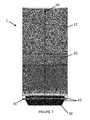
- FIG. 7shows a back view of the exemplary device shown in FIGS. 3-6 ;
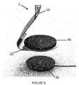
- FIG. 8shows a close-up view of the base unit and powered base of the exemplary device shown in FIGS. 3-7 ;
- FIG. 9shows a close-up view of the back side the exemplary device shown in FIGS. 3-8 .
- the present applicationis directed to systems and methods that allow a remote meeting participant to establish a telepresence (or virtual presence) at a remote meeting location and participate in a meeting remotely.
- the remote participantmay establish a telepresence at a remote meeting location by means of a telepresence device, which provides a video image of the remote meeting participant on a video display screen and allows the remote participant to rotate the video display screen and pan the remote meeting location as the meeting progresses and the active conversational role passes from one participant to another.
- the telepresence devicemay display a silhouette image of the remote meeting participant without the image of the background scene of the remote participant's location (e.g., office, home or home office).
- the silhouette imageis an image of a human body or object that has been isolated from a background image. More particularly, the silhouette image may be a video image of only the body of the remote participant, which is isolated from a video image of the remote participant that includes the remote participant's background scene.
- the telepresence devicemay be equipped with a rear-facing camera that captures a video image of the background scene behind the telepresence device at the meeting location. Accordingly, the silhouette image of the remote meeting participant may be superimposed on the video image of the background scene at the meeting location, which is captured by the rear-facing camera. Thus, by incorporating the silhouette image of the remote participant with the background image behind the telepresence device at the meeting location, the telepresence device may create the illusion that the remote participant is actually at the meeting location.
- FIG. 1illustrates a communication system 100 that enables an individual to participate in a meeting from a remote location.
- Communication system 100comprises a telepresence device 1 located at a meeting location 110 , a network 120 , and a remote device 130 .
- the telepresence device 1is placed at a selected meeting location 110 , for example on a table among individuals who are present in a conference room.
- the telepresence device 1is linked to the remote device 130 present at a remote location via the network 120 .
- the network 120may comprise one or more of a number of different types of networks, such as, for example, an intranet, a local area network (LAN), a wide area network (WAN), an internet, Fibre Channel-based storage area network (SAN) or Ethernet. Other networks may be used. Alternatively, the network 120 may comprise a combination of different types of networks.
- the telepresence device 1may be linked to the remote device 130 via a direct connection.
- a remote participant at a location remote from the meeting location 110operates the remote device 130 .
- the remote device 130conveys, to the remote participant, audio and video signals received from the telepresence device 1 , and transmits audio and video signals to the telepresence device 1 .
- the remote device 130also transmits to the telepresence device 1 control signals received from the remote participant. In this manner, the remote participant may employ the remote device 130 to control the telepresence device 100 remotely.
- the telepresence device 1may enable the remote participant to receive audio and video signals from the meeting location 110 in a manner that simulates the sensation of being physically present at the meeting location.
- FIGS. 3-9show an exemplary embodiment of the telepresence device 1 .
- the exemplary telepresence device 1comprises a video display screen 5 mounted near the top of a support member 10 .
- the support member 10has a substantially horizontal base portion 20 configured to rest on a powered base 30 and to be removed from the powered base 30 .
- the support member 10is adapted to be lifted off of the powered base 30 and placed anywhere within wireless communication range of the powered base 30 without being encumbered by power connectors or communication connectors.
- the horizontal base portion 20includes a functional base unit 40 , which may be integrally formed with the base portion 20 or separately formed and attached to the base portion 20 .
- the support member 10has a front side 11 and a back side 12 .
- a forward-facing camera 13may be mounted on the front side of the support member 10 .
- sensing devices 15such as infrared or acoustic sensing devices for detecting the proximity and bearings of human conference participants
- a loudspeaker or stereophonic loudspeaker pair 16may also be mounted on the front side of support member, exemplarily at a location below screen 5 .
- a rear-facing camera 50may be positioned near the uppermost edge of the back side 12 of the support member 10 , such that the rear-facing camera 50 captures a video image of the background scenery beging the telepresence device 1 .
- the rear-facing camerais configured to have a line of sight opposite to the line of sight of the forward-facing camera 13 , and rearward of the video display screen 5 .
- Functional base unit 40may comprise a processor, a communication interface, a memory and a transceiver.
- the processormay control various operations of functional base unit 40 by executing computer program instructions which various computational and communication functions described herein.
- the computer program instructionsmay be stored in a non-transitory computer readable medium such as a random access memory (RAM), one or more disk drives, one or more optical disks, one or more tape drives, etc.
- Processormay comprise hardware, software, or a combination of hardware and software.
- processorcomprises operating system software controlled by hardware, such as a central processing unit (CPU).
- the processoris configured to execute an image-processing module.
- the image-processing moduleis configured to receive a video image signal of the background of the telepresence device 1 from the rear-facing camera 50 of the telepresence device 1 . Further, the image-processing module superimposes a silhouette image of a remote participant on the background image as captured by the rear-facing camera 50 .
- the silhouette imageis a video image of the remote participant that has been isolated from the remote participant's background scene.
- the remote device 130 situated in the remote locationcaptures a video image of the remote participant, including the background scene at the remote participant's location.
- a silhouette extraction programmay be executed to produce a silhouette image of the remote participant by isolating a video image of the remote participant from the remote participant's background scene.
- the silhouette extraction programmay be executed at the remote location and then the silhouette image may be sent to the image-processing module of the telepresence device 1 via network 120 .
- the image of the remote participantmay be sent to the image processing module of the telepresence device 1 via the network 120 and then the silhouette extraction program may be executed by the image-processing module to produce a silhouette image of the remote participant by isolating the video image of the remote participant from the remote participant's background scene.
- the image-processing module of the telepresence device 1has the silhouette image of the remote participant, the image-processing module superimposes the silhouette image of the remote participant on a background image of the local meeting location captured by the rear-facing camera, and displays the superimposed image on the video display screen 5 .
- the rear-facing camerais used to emulate the background of the physical conference room, so that to the physically present conference participants, the video display screen will appear to be transparent.
- FIG. 2shows that the window panels 60 , which constitute a physical portion of the background view as seen from within the conference room, are also displayed on the video display screen as image element 70 .
- the montage of the silhouette image combined with the view captured by the rear-facing camerais life-like, and it creates the illusion that the remote user is actually in the room. This produces the enhanced experience of physical immersion.
- the communication interfacemay be configured to provide a communication gateway through which data may be transmitted between components of functional base unit 40 and the network 120 via the powered base 30 .
- the communication interfacemay transmit to the remote device 130 , via network 120 , audio signals received by the microphones 14 and video signals received by the forward-facing camera 13 .
- the communication interfacemay also be configured to receive audio signals and video signals from the remote device 130 , via the network 120 , and transmit the audio and video signals to the speakers 14 , and to video display screen 5 , respectively.
- the communication interfacemay also receive control signals received from the remote device 130 , and transmit the control signals to a control module of the functional base unit 40 .
- the communication interfacemay be implemented using a number of different mechanisms, such as one or more enterprise systems connection cards, modems, or network interfaces. Other types of interfaces may be used.
- the memory of functional base unit 40may be configured to be accessed by the processor and/or other components of functional base unit 40 to store various types of information.
- the memory of functional base unit 40may comprise any one or more of a variety of different types of non-transitory computer readable media, such as random access memory (RAM), one or more disk drives, one or more optical disks, one or more tape drives, etc. Other types of memory devices may be used.
- the wireless communication unit of functional base unit 40is adapted to wirelessly communicate with powered base 30 and, through the powered base 30 , to external communication networks of various kinds, which may include, e.g., local WiFi and Ethernet networks, as well as the public telephone network and the internet.
- Functional base unit 40may also include a rechargeable battery, which is adapted to be inductively charged by the power base 30 , for use as a power source when separated from powered base 30 .
- Functional base unit 40may also includes a motor and a mechanical linkage for rotating support member 10 about a vertical axis.
- horizontal base portion 20may be fixed, e.g., to an underlying rotatable turntable (not shown in the Figures).
- the motormay be drivingly connected, through base portion 20 and the turntable, to a non-rotating base plate that underlies the turntable and to which the turntable is rotatably mounted.
- the functional base unit 40may comprise one or more electromechanical components such as servos, motors, control circuitry, gears, etc., configured to enable the support member 10 to be rotated in response to control signals.
- the functional base unit 40may also comprise one or more microprocessors and memory devices to facilitate its operation.
- the functional base unit 40may comprise a control module.
- the control modulemay be configured to receive control signals from remote the control device 130 (shown in FIG. 1 ), and to control the movement of support member 10 in response to the control signals.
- the control modulemay generate electrical signals and transmit such signals to servos and/or other components in functional base unit 40 in response to control signals received from the remote device 130 .
- the control modulemay also control functions of the forward-facing camera 13 , video display screen 5 , speakers 16 , and microphones 14 based on control signals received from remote device 130 .
- the control modulemay comprise a software program that includes multiple modules or subroutines providing respective services or functions. In other embodiments, the control module may comprise multiple software programs. In alternative embodiments, the control module may comprise hardware, or a combination of hardware and software. Further, the control module may comprise a non-transitory computer readable medium, such as a magnetic disk, magnetic tape, or optical disk that includes instructions in the form of computer code operable to perform various functions. In some embodiments, some or the entire control module may comprise instructions in the form of computer code that are stored in the memory of functional base unit 40 .
- the powered base 30may include an induction charging unit and a wireless communication unit.
- the induction-charging unitmay be configured to inductively charge the rechargeable battery of the functional base 40 .
- the wireless communication unit of powered base 30may be configured to communicate with the wireless communication unit of functional base unit 40 . Further the wireless communication unit of powered base 30 may be connected to and configured to communicate with external communication networks of various kinds, such as local WiFi and Ethernet networks, as well as the public telephone network and the internet.
- functional base unit 40configured to wirelessly communicate with powered base 30 and, through the powered base 30 , to external communication networks of various kinds, which may include, e.g., local WiFi and Ethernet networks, as well as the public telephone network and the internet.
- the telepresence device 1may be dimensioned so that the eye-level of the remote participant's image can be brought to the eye-level of the participants in the physical conference room.
- the video display screencan be rotated so that the remote participant can pan the physical conference room as the meeting progresses and the active conversational role passes from one participant to another.
- FIG. 1may include a transparent LCD/LED monitor.
- the display portion of the immersion devicewill appear to be as transparent as a pane of glass.
- the operation of silhouette extractionwill cause the remote user's silhouette image to appear without a surrounding frame, as though it were floating above the base of the device.
Landscapes
- Engineering & Computer Science (AREA)
- Multimedia (AREA)
- Signal Processing (AREA)
- Two-Way Televisions, Distribution Of Moving Picture Or The Like (AREA)
Abstract
Description
Claims (20)
Priority Applications (1)
| Application Number | Priority Date | Filing Date | Title |
|---|---|---|---|
| US13/705,965US8947495B2 (en) | 2011-12-06 | 2012-12-05 | Telepresence apparatus for immersion of a human image in a physical environment |
Applications Claiming Priority (2)
| Application Number | Priority Date | Filing Date | Title |
|---|---|---|---|
| US201161567332P | 2011-12-06 | 2011-12-06 | |
| US13/705,965US8947495B2 (en) | 2011-12-06 | 2012-12-05 | Telepresence apparatus for immersion of a human image in a physical environment |
Publications (2)
| Publication Number | Publication Date |
|---|---|
| US20130141519A1 US20130141519A1 (en) | 2013-06-06 |
| US8947495B2true US8947495B2 (en) | 2015-02-03 |
Family
ID=48523712
Family Applications (1)
| Application Number | Title | Priority Date | Filing Date |
|---|---|---|---|
| US13/705,965Expired - Fee RelatedUS8947495B2 (en) | 2011-12-06 | 2012-12-05 | Telepresence apparatus for immersion of a human image in a physical environment |
Country Status (1)
| Country | Link |
|---|---|
| US (1) | US8947495B2 (en) |
Cited By (1)
| Publication number | Priority date | Publication date | Assignee | Title |
|---|---|---|---|---|
| US10580335B2 (en) | 2015-08-18 | 2020-03-03 | Toyota Motor Engineering & Manufacturing North America, Inc. | Portable display apparatuses |
Families Citing this family (15)
| Publication number | Priority date | Publication date | Assignee | Title |
|---|---|---|---|---|
| US9323250B2 (en) | 2011-01-28 | 2016-04-26 | Intouch Technologies, Inc. | Time-dependent navigation of telepresence robots |
| US9098611B2 (en) | 2012-11-26 | 2015-08-04 | Intouch Technologies, Inc. | Enhanced video interaction for a user interface of a telepresence network |
| US8767586B2 (en) | 2011-06-20 | 2014-07-01 | At&T Intellectual Property I, L.P. | Methods, systems, and products for network topology |
| EP2735075B1 (en)* | 2011-07-24 | 2016-06-01 | Makita Corporation | Charger for hand-held power tool, power tool system and method of charging a power tool battery |
| EP2735078B1 (en) | 2011-07-24 | 2017-10-04 | Makita Corporation | Power tool system and adapter therefor |
| US20130088562A1 (en)* | 2011-10-07 | 2013-04-11 | Hanwha Solution & Consulting Co., Ltd | Communication terminal for providing silhouette function on video screen for video call and method thereof |
| US8947495B2 (en)* | 2011-12-06 | 2015-02-03 | Alcatel Lucent | Telepresence apparatus for immersion of a human image in a physical environment |
| WO2013176760A1 (en) | 2012-05-22 | 2013-11-28 | Intouch Technologies, Inc. | Graphical user interfaces including touchpad driving interfaces for telemedicine devices |
| US9361021B2 (en) | 2012-05-22 | 2016-06-07 | Irobot Corporation | Graphical user interfaces including touchpad driving interfaces for telemedicine devices |
| US10075656B2 (en) | 2013-10-30 | 2018-09-11 | At&T Intellectual Property I, L.P. | Methods, systems, and products for telepresence visualizations |
| US9210377B2 (en) | 2013-10-30 | 2015-12-08 | At&T Intellectual Property I, L.P. | Methods, systems, and products for telepresence visualizations |
| US10999088B2 (en)* | 2018-11-20 | 2021-05-04 | Dell Products, L.P. | Proximity and context-based telepresence in collaborative environments |
| US10785421B2 (en) | 2018-12-08 | 2020-09-22 | Fuji Xerox Co., Ltd. | Systems and methods for implementing personal camera that adapts to its surroundings, both co-located and remote |
| US10609332B1 (en)* | 2018-12-21 | 2020-03-31 | Microsoft Technology Licensing, Llc | Video conferencing supporting a composite video stream |
| US11178357B1 (en) | 2020-09-22 | 2021-11-16 | Roku, Inc. | Streaming a video chat from a mobile device to a display device using a rotating base |
Citations (22)
| Publication number | Priority date | Publication date | Assignee | Title |
|---|---|---|---|---|
| US4831645A (en)* | 1986-09-26 | 1989-05-16 | Siemens Aktiengesellschaft | Apparatus for positioning the head of a patient for producing x-ray pictures |
| US4862277A (en)* | 1987-10-19 | 1989-08-29 | Nec Home Electronics Ltd. | Imaging device with hand wobble display circuit |
| US4875225A (en)* | 1987-02-16 | 1989-10-17 | Siemens Aktiengesellschaft | X-ray video system and method for the transillumination of an examination subject |
| US5023651A (en)* | 1986-02-19 | 1991-06-11 | Gilchrist Studios Group Limited | Method of and apparatus for re-creating images |
| US5159361A (en)* | 1989-03-09 | 1992-10-27 | Par Technology Corporation | Method and apparatus for obtaining the topography of an object |
| US6323971B1 (en)* | 2000-10-23 | 2001-11-27 | Zebra Imaging, Inc. | Hologram incorporating a plane with a projected image |
| US6507357B2 (en)* | 2000-11-29 | 2003-01-14 | Applied Minds, Inc. | Method and apparatus for maintaining eye contact in teleconferencing using reflected images |
| US20030020974A1 (en)* | 2001-06-11 | 2003-01-30 | Yuki Matsushima | Image processing apparatus, image processing method and information recording medium |
| US20030191577A1 (en)* | 2002-04-05 | 2003-10-09 | Jean-Claude Decaux | Road safety street furniture |
| US6755861B2 (en)* | 2001-10-16 | 2004-06-29 | Granit Medical Innovation, Inc. | Device for providing a portion of an organism with a desired shape |
| US6792140B2 (en)* | 2001-04-26 | 2004-09-14 | Mitsubish Electric Research Laboratories, Inc. | Image-based 3D digitizer |
| US6803946B1 (en)* | 1998-07-27 | 2004-10-12 | Matsushita Electric Industrial Co., Ltd. | Video camera apparatus with preset operation and a video camera monitor system including the same |
| US6909451B1 (en)* | 1998-09-04 | 2005-06-21 | Nurakhmed Nurislamovich Latypov | Method for generating video programs, variants, and system for realizing this method |
| US7006122B2 (en)* | 2003-06-27 | 2006-02-28 | Brother Kogyo Kaushiki Kaisha | Television conference system |
| US20090310855A1 (en)* | 2006-07-27 | 2009-12-17 | Giambattista Gennari | Event detection method and video surveillance system using said method |
| US20110188776A1 (en)* | 1997-06-09 | 2011-08-04 | Seiko Epson Corporation | Image processing method and image processing apparatus |
| US8139122B2 (en)* | 2007-08-20 | 2012-03-20 | Matthew Rolston Photographer, Inc. | Camera with operation for modifying visual perception |
| US8233028B2 (en)* | 2007-07-26 | 2012-07-31 | Avaya Inc. | Dynamic visual background for call-center agents |
| US8234578B2 (en)* | 2006-07-25 | 2012-07-31 | Northrop Grumman Systems Corporatiom | Networked gesture collaboration system |
| US8279254B2 (en)* | 2007-08-02 | 2012-10-02 | Siemens Enterprise Communications Gmbh & Co. Kg | Method and system for video conferencing in a virtual environment |
| US20130141519A1 (en)* | 2011-12-06 | 2013-06-06 | Alcatel-Lucent Usa Inc. | Telepresence apparatus for immersion of a human image in a physical environment |
| US8692930B2 (en)* | 2007-08-20 | 2014-04-08 | Matthew Rolston Photographer, Inc. | Mobile device with operation for modifying visual perception |
- 2012
- 2012-12-05USUS13/705,965patent/US8947495B2/ennot_activeExpired - Fee Related
Patent Citations (23)
| Publication number | Priority date | Publication date | Assignee | Title |
|---|---|---|---|---|
| US5023651A (en)* | 1986-02-19 | 1991-06-11 | Gilchrist Studios Group Limited | Method of and apparatus for re-creating images |
| US4831645A (en)* | 1986-09-26 | 1989-05-16 | Siemens Aktiengesellschaft | Apparatus for positioning the head of a patient for producing x-ray pictures |
| US4875225A (en)* | 1987-02-16 | 1989-10-17 | Siemens Aktiengesellschaft | X-ray video system and method for the transillumination of an examination subject |
| US4862277A (en)* | 1987-10-19 | 1989-08-29 | Nec Home Electronics Ltd. | Imaging device with hand wobble display circuit |
| US5159361A (en)* | 1989-03-09 | 1992-10-27 | Par Technology Corporation | Method and apparatus for obtaining the topography of an object |
| US20110188776A1 (en)* | 1997-06-09 | 2011-08-04 | Seiko Epson Corporation | Image processing method and image processing apparatus |
| US6803946B1 (en)* | 1998-07-27 | 2004-10-12 | Matsushita Electric Industrial Co., Ltd. | Video camera apparatus with preset operation and a video camera monitor system including the same |
| US6909451B1 (en)* | 1998-09-04 | 2005-06-21 | Nurakhmed Nurislamovich Latypov | Method for generating video programs, variants, and system for realizing this method |
| US6323971B1 (en)* | 2000-10-23 | 2001-11-27 | Zebra Imaging, Inc. | Hologram incorporating a plane with a projected image |
| US6507357B2 (en)* | 2000-11-29 | 2003-01-14 | Applied Minds, Inc. | Method and apparatus for maintaining eye contact in teleconferencing using reflected images |
| US6792140B2 (en)* | 2001-04-26 | 2004-09-14 | Mitsubish Electric Research Laboratories, Inc. | Image-based 3D digitizer |
| US20030020974A1 (en)* | 2001-06-11 | 2003-01-30 | Yuki Matsushima | Image processing apparatus, image processing method and information recording medium |
| US6755861B2 (en)* | 2001-10-16 | 2004-06-29 | Granit Medical Innovation, Inc. | Device for providing a portion of an organism with a desired shape |
| US20030191577A1 (en)* | 2002-04-05 | 2003-10-09 | Jean-Claude Decaux | Road safety street furniture |
| US7006122B2 (en)* | 2003-06-27 | 2006-02-28 | Brother Kogyo Kaushiki Kaisha | Television conference system |
| US8234578B2 (en)* | 2006-07-25 | 2012-07-31 | Northrop Grumman Systems Corporatiom | Networked gesture collaboration system |
| US20090310855A1 (en)* | 2006-07-27 | 2009-12-17 | Giambattista Gennari | Event detection method and video surveillance system using said method |
| US8233028B2 (en)* | 2007-07-26 | 2012-07-31 | Avaya Inc. | Dynamic visual background for call-center agents |
| US8279254B2 (en)* | 2007-08-02 | 2012-10-02 | Siemens Enterprise Communications Gmbh & Co. Kg | Method and system for video conferencing in a virtual environment |
| US8139122B2 (en)* | 2007-08-20 | 2012-03-20 | Matthew Rolston Photographer, Inc. | Camera with operation for modifying visual perception |
| US8625023B2 (en)* | 2007-08-20 | 2014-01-07 | Matthew Rolston Photographer, Inc. | Video camera mirror system with operation for modifying visual perception |
| US8692930B2 (en)* | 2007-08-20 | 2014-04-08 | Matthew Rolston Photographer, Inc. | Mobile device with operation for modifying visual perception |
| US20130141519A1 (en)* | 2011-12-06 | 2013-06-06 | Alcatel-Lucent Usa Inc. | Telepresence apparatus for immersion of a human image in a physical environment |
Cited By (1)
| Publication number | Priority date | Publication date | Assignee | Title |
|---|---|---|---|---|
| US10580335B2 (en) | 2015-08-18 | 2020-03-03 | Toyota Motor Engineering & Manufacturing North America, Inc. | Portable display apparatuses |
Also Published As
| Publication number | Publication date |
|---|---|
| US20130141519A1 (en) | 2013-06-06 |
Similar Documents
| Publication | Publication Date | Title |
|---|---|---|
| US8947495B2 (en) | Telepresence apparatus for immersion of a human image in a physical environment | |
| US10834359B2 (en) | Information processing apparatus, information processing method, and program | |
| US9524588B2 (en) | Enhanced communication between remote participants using augmented and virtual reality | |
| US10368032B2 (en) | Eye contact enabling device for video conferencing | |
| US11343471B2 (en) | Information processing device and information processing method for communication using three-dimensional space | |
| US20170237941A1 (en) | Realistic viewing and interaction with remote objects or persons during telepresence videoconferencing | |
| CN110583013A (en) | Telepresence system | |
| US11089262B1 (en) | Virtual eye contact in video interaction | |
| KR20140137302A (en) | Portable transparent display with life-size image for teleconference | |
| US20110267421A1 (en) | Method and Apparatus for Two-Way Multimedia Communications | |
| CN110324555B (en) | Video communication device and method | |
| CN110324554B (en) | Video communication device and method | |
| CN109061903A (en) | Data display method, device, intelligent glasses and storage medium | |
| TW202018649A (en) | Asymmetric video conferencing system and method thereof | |
| CN114727120B (en) | Live audio stream acquisition method and device, electronic equipment and storage medium | |
| US10469800B2 (en) | Always-on telepresence device | |
| CN110324559B (en) | Video communication apparatus and method | |
| US10986310B2 (en) | Information processing apparatus, information processing method, and program | |
| JP4595397B2 (en) | Image display method, terminal device, and interactive dialogue system | |
| US20140160296A1 (en) | Distance mirror television (dmtv) apparatus and method thereof | |
| US20250211457A1 (en) | Telepresence with a human avatar | |
| CN102638670A (en) | Method, device and system for automatically photographing in videoconference system | |
| EP4425303A1 (en) | Method and system for hosting a metaverse virtual conference | |
| HK40071541B (en) | Live audio stream acquiring method, device, electronic equipment and storage medium | |
| CN206237449U (en) | One kind can remote interaction robot system |
Legal Events
| Date | Code | Title | Description |
|---|---|---|---|
| AS | Assignment | Owner name:ALCATEL-LUCENT USA INC., NEW JERSEY Free format text:ASSIGNMENT OF ASSIGNORS INTEREST;ASSIGNORS:SAYEED, ZULFIQUAR;KOTCH, JAMES;SIGNING DATES FROM 20121213 TO 20130124;REEL/FRAME:029755/0801 | |
| AS | Assignment | Owner name:CREDIT SUISSE AG, NEW YORK Free format text:SECURITY INTEREST;ASSIGNOR:ALCATEL-LUCENT USA INC.;REEL/FRAME:030510/0627 Effective date:20130130 | |
| FEPP | Fee payment procedure | Free format text:PAYOR NUMBER ASSIGNED (ORIGINAL EVENT CODE: ASPN); ENTITY STATUS OF PATENT OWNER: LARGE ENTITY | |
| AS | Assignment | Owner name:ALCATEL LUCENT, FRANCE Free format text:ASSIGNMENT OF ASSIGNORS INTEREST;ASSIGNOR:ALCATEL-LUCENT USA INC.;REEL/FRAME:032121/0290 Effective date:20140123 | |
| AS | Assignment | Owner name:ALCATEL-LUCENT USA INC., NEW JERSEY Free format text:RELEASE BY SECURED PARTY;ASSIGNOR:CREDIT SUISSE AG;REEL/FRAME:033949/0016 Effective date:20140819 | |
| STCF | Information on status: patent grant | Free format text:PATENTED CASE | |
| MAFP | Maintenance fee payment | Free format text:PAYMENT OF MAINTENANCE FEE, 4TH YEAR, LARGE ENTITY (ORIGINAL EVENT CODE: M1551) Year of fee payment:4 | |
| FEPP | Fee payment procedure | Free format text:MAINTENANCE FEE REMINDER MAILED (ORIGINAL EVENT CODE: REM.); ENTITY STATUS OF PATENT OWNER: LARGE ENTITY | |
| LAPS | Lapse for failure to pay maintenance fees | Free format text:PATENT EXPIRED FOR FAILURE TO PAY MAINTENANCE FEES (ORIGINAL EVENT CODE: EXP.); ENTITY STATUS OF PATENT OWNER: LARGE ENTITY | |
| STCH | Information on status: patent discontinuation | Free format text:PATENT EXPIRED DUE TO NONPAYMENT OF MAINTENANCE FEES UNDER 37 CFR 1.362 | |
| FP | Lapsed due to failure to pay maintenance fee | Effective date:20230203 |