US8947350B2 - System and method for generating screen pointing information in a television control device - Google Patents
System and method for generating screen pointing information in a television control deviceDownload PDFInfo
- Publication number
- US8947350B2 US8947350B2US12/774,321US77432110AUS8947350B2US 8947350 B2US8947350 B2US 8947350B2US 77432110 AUS77432110 AUS 77432110AUS 8947350 B2US8947350 B2US 8947350B2
- Authority
- US
- United States
- Prior art keywords
- television
- control device
- screen
- sensors
- pointing
- Prior art date
- Legal status (The legal status is an assumption and is not a legal conclusion. Google has not performed a legal analysis and makes no representation as to the accuracy of the status listed.)
- Active, expires
Links
Images


Classifications
- G—PHYSICS
- G06—COMPUTING OR CALCULATING; COUNTING
- G06F—ELECTRIC DIGITAL DATA PROCESSING
- G06F3/00—Input arrangements for transferring data to be processed into a form capable of being handled by the computer; Output arrangements for transferring data from processing unit to output unit, e.g. interface arrangements
- G06F3/01—Input arrangements or combined input and output arrangements for interaction between user and computer
- G06F3/03—Arrangements for converting the position or the displacement of a member into a coded form
- G06F3/0304—Detection arrangements using opto-electronic means
- G—PHYSICS
- G06—COMPUTING OR CALCULATING; COUNTING
- G06F—ELECTRIC DIGITAL DATA PROCESSING
- G06F3/00—Input arrangements for transferring data to be processed into a form capable of being handled by the computer; Output arrangements for transferring data from processing unit to output unit, e.g. interface arrangements
- G06F3/01—Input arrangements or combined input and output arrangements for interaction between user and computer
- G06F3/03—Arrangements for converting the position or the displacement of a member into a coded form
- G06F3/033—Pointing devices displaced or positioned by the user, e.g. mice, trackballs, pens or joysticks; Accessories therefor
- G06F3/0346—Pointing devices displaced or positioned by the user, e.g. mice, trackballs, pens or joysticks; Accessories therefor with detection of the device orientation or free movement in a 3D space, e.g. 3D mice, 6-DOF [six degrees of freedom] pointers using gyroscopes, accelerometers or tilt-sensors
- H—ELECTRICITY
- H04—ELECTRIC COMMUNICATION TECHNIQUE
- H04N—PICTORIAL COMMUNICATION, e.g. TELEVISION
- H04N21/00—Selective content distribution, e.g. interactive television or video on demand [VOD]
- H04N21/40—Client devices specifically adapted for the reception of or interaction with content, e.g. set-top-box [STB]; Operations thereof
- H04N21/47—End-user applications
- H04N21/482—End-user interface for program selection
- G—PHYSICS
- G06—COMPUTING OR CALCULATING; COUNTING
- G06F—ELECTRIC DIGITAL DATA PROCESSING
- G06F3/00—Input arrangements for transferring data to be processed into a form capable of being handled by the computer; Output arrangements for transferring data from processing unit to output unit, e.g. interface arrangements
- G06F3/01—Input arrangements or combined input and output arrangements for interaction between user and computer
- G06F3/03—Arrangements for converting the position or the displacement of a member into a coded form
- G06F3/0304—Detection arrangements using opto-electronic means
- G06F3/0308—Detection arrangements using opto-electronic means comprising a plurality of distinctive and separately oriented light emitters or reflectors associated to the pointing device, e.g. remote cursor controller with distinct and separately oriented LEDs at the tip whose radiations are captured by a photo-detector associated to the screen
- G—PHYSICS
- G06—COMPUTING OR CALCULATING; COUNTING
- G06F—ELECTRIC DIGITAL DATA PROCESSING
- G06F3/00—Input arrangements for transferring data to be processed into a form capable of being handled by the computer; Output arrangements for transferring data from processing unit to output unit, e.g. interface arrangements
- G06F3/01—Input arrangements or combined input and output arrangements for interaction between user and computer
- G06F3/03—Arrangements for converting the position or the displacement of a member into a coded form
- G06F3/0304—Detection arrangements using opto-electronic means
- G06F3/0325—Detection arrangements using opto-electronic means using a plurality of light emitters or reflectors or a plurality of detectors forming a reference frame from which to derive the orientation of the object, e.g. by triangulation or on the basis of reference deformation in the picked up image
- G—PHYSICS
- G06—COMPUTING OR CALCULATING; COUNTING
- G06F—ELECTRIC DIGITAL DATA PROCESSING
- G06F3/00—Input arrangements for transferring data to be processed into a form capable of being handled by the computer; Output arrangements for transferring data from processing unit to output unit, e.g. interface arrangements
- G06F3/01—Input arrangements or combined input and output arrangements for interaction between user and computer
- G06F3/03—Arrangements for converting the position or the displacement of a member into a coded form
- G06F3/033—Pointing devices displaced or positioned by the user, e.g. mice, trackballs, pens or joysticks; Accessories therefor
- G06F3/038—Control and interface arrangements therefor, e.g. drivers or device-embedded control circuitry
- G06F3/0386—Control and interface arrangements therefor, e.g. drivers or device-embedded control circuitry for light pen
- G—PHYSICS
- G06—COMPUTING OR CALCULATING; COUNTING
- G06F—ELECTRIC DIGITAL DATA PROCESSING
- G06F3/00—Input arrangements for transferring data to be processed into a form capable of being handled by the computer; Output arrangements for transferring data from processing unit to output unit, e.g. interface arrangements
- G06F3/01—Input arrangements or combined input and output arrangements for interaction between user and computer
- G06F3/03—Arrangements for converting the position or the displacement of a member into a coded form
- G06F3/041—Digitisers, e.g. for touch screens or touch pads, characterised by the transducing means
- G06F3/0412—Digitisers structurally integrated in a display
- G—PHYSICS
- G06—COMPUTING OR CALCULATING; COUNTING
- G06F—ELECTRIC DIGITAL DATA PROCESSING
- G06F3/00—Input arrangements for transferring data to be processed into a form capable of being handled by the computer; Output arrangements for transferring data from processing unit to output unit, e.g. interface arrangements
- G06F3/01—Input arrangements or combined input and output arrangements for interaction between user and computer
- G06F3/03—Arrangements for converting the position or the displacement of a member into a coded form
- G06F3/041—Digitisers, e.g. for touch screens or touch pads, characterised by the transducing means
- G06F3/042—Digitisers, e.g. for touch screens or touch pads, characterised by the transducing means by opto-electronic means
- G06F3/0428—Digitisers, e.g. for touch screens or touch pads, characterised by the transducing means by opto-electronic means by sensing at the edges of the touch surface the interruption of optical paths, e.g. an illumination plane, parallel to the touch surface which may be virtual
- H—ELECTRICITY
- H04—ELECTRIC COMMUNICATION TECHNIQUE
- H04N—PICTORIAL COMMUNICATION, e.g. TELEVISION
- H04N21/00—Selective content distribution, e.g. interactive television or video on demand [VOD]
- H04N21/20—Servers specifically adapted for the distribution of content, e.g. VOD servers; Operations thereof
- H04N21/23—Processing of content or additional data; Elementary server operations; Server middleware
- H04N21/234—Processing of video elementary streams, e.g. splicing of video streams or manipulating encoded video stream scene graphs
- H04N21/2343—Processing of video elementary streams, e.g. splicing of video streams or manipulating encoded video stream scene graphs involving reformatting operations of video signals for distribution or compliance with end-user requests or end-user device requirements
- H04N21/234318—Processing of video elementary streams, e.g. splicing of video streams or manipulating encoded video stream scene graphs involving reformatting operations of video signals for distribution or compliance with end-user requests or end-user device requirements by decomposing into objects, e.g. MPEG-4 objects
- H—ELECTRICITY
- H04—ELECTRIC COMMUNICATION TECHNIQUE
- H04N—PICTORIAL COMMUNICATION, e.g. TELEVISION
- H04N21/00—Selective content distribution, e.g. interactive television or video on demand [VOD]
- H04N21/20—Servers specifically adapted for the distribution of content, e.g. VOD servers; Operations thereof
- H04N21/23—Processing of content or additional data; Elementary server operations; Server middleware
- H04N21/238—Interfacing the downstream path of the transmission network, e.g. adapting the transmission rate of a video stream to network bandwidth; Processing of multiplex streams
- H04N21/2389—Multiplex stream processing, e.g. multiplex stream encrypting
- H04N21/23892—Multiplex stream processing, e.g. multiplex stream encrypting involving embedding information at multiplex stream level, e.g. embedding a watermark at packet level
- H—ELECTRICITY
- H04—ELECTRIC COMMUNICATION TECHNIQUE
- H04N—PICTORIAL COMMUNICATION, e.g. TELEVISION
- H04N21/00—Selective content distribution, e.g. interactive television or video on demand [VOD]
- H04N21/20—Servers specifically adapted for the distribution of content, e.g. VOD servers; Operations thereof
- H04N21/23—Processing of content or additional data; Elementary server operations; Server middleware
- H04N21/24—Monitoring of processes or resources, e.g. monitoring of server load, available bandwidth, upstream requests
- H04N21/2408—Monitoring of the upstream path of the transmission network, e.g. client requests
- H—ELECTRICITY
- H04—ELECTRIC COMMUNICATION TECHNIQUE
- H04N—PICTORIAL COMMUNICATION, e.g. TELEVISION
- H04N21/00—Selective content distribution, e.g. interactive television or video on demand [VOD]
- H04N21/20—Servers specifically adapted for the distribution of content, e.g. VOD servers; Operations thereof
- H04N21/25—Management operations performed by the server for facilitating the content distribution or administrating data related to end-users or client devices, e.g. end-user or client device authentication, learning user preferences for recommending movies
- H04N21/258—Client or end-user data management, e.g. managing client capabilities, user preferences or demographics, processing of multiple end-users preferences to derive collaborative data
- H04N21/25808—Management of client data
- H04N21/25841—Management of client data involving the geographical location of the client
- H—ELECTRICITY
- H04—ELECTRIC COMMUNICATION TECHNIQUE
- H04N—PICTORIAL COMMUNICATION, e.g. TELEVISION
- H04N21/00—Selective content distribution, e.g. interactive television or video on demand [VOD]
- H04N21/20—Servers specifically adapted for the distribution of content, e.g. VOD servers; Operations thereof
- H04N21/25—Management operations performed by the server for facilitating the content distribution or administrating data related to end-users or client devices, e.g. end-user or client device authentication, learning user preferences for recommending movies
- H04N21/266—Channel or content management, e.g. generation and management of keys and entitlement messages in a conditional access system, merging a VOD unicast channel into a multicast channel
- H04N21/2668—Creating a channel for a dedicated end-user group, e.g. insertion of targeted commercials based on end-user profiles
- H—ELECTRICITY
- H04—ELECTRIC COMMUNICATION TECHNIQUE
- H04N—PICTORIAL COMMUNICATION, e.g. TELEVISION
- H04N21/00—Selective content distribution, e.g. interactive television or video on demand [VOD]
- H04N21/40—Client devices specifically adapted for the reception of or interaction with content, e.g. set-top-box [STB]; Operations thereof
- H04N21/41—Structure of client; Structure of client peripherals
- H04N21/4104—Peripherals receiving signals from specially adapted client devices
- H04N21/4126—The peripheral being portable, e.g. PDAs or mobile phones
- H04N21/41265—The peripheral being portable, e.g. PDAs or mobile phones having a remote control device for bidirectional communication between the remote control device and client device
- H—ELECTRICITY
- H04—ELECTRIC COMMUNICATION TECHNIQUE
- H04N—PICTORIAL COMMUNICATION, e.g. TELEVISION
- H04N21/00—Selective content distribution, e.g. interactive television or video on demand [VOD]
- H04N21/40—Client devices specifically adapted for the reception of or interaction with content, e.g. set-top-box [STB]; Operations thereof
- H04N21/41—Structure of client; Structure of client peripherals
- H04N21/422—Input-only peripherals, i.e. input devices connected to specially adapted client devices, e.g. global positioning system [GPS]
- H04N21/42204—User interfaces specially adapted for controlling a client device through a remote control device; Remote control devices therefor
- H04N21/42206—User interfaces specially adapted for controlling a client device through a remote control device; Remote control devices therefor characterized by hardware details
- H04N21/42208—Display device provided on the remote control
- H04N21/42209—Display device provided on the remote control for displaying non-command information, e.g. electronic program guide [EPG], e-mail, messages or a second television channel
- H—ELECTRICITY
- H04—ELECTRIC COMMUNICATION TECHNIQUE
- H04N—PICTORIAL COMMUNICATION, e.g. TELEVISION
- H04N21/00—Selective content distribution, e.g. interactive television or video on demand [VOD]
- H04N21/40—Client devices specifically adapted for the reception of or interaction with content, e.g. set-top-box [STB]; Operations thereof
- H04N21/41—Structure of client; Structure of client peripherals
- H04N21/422—Input-only peripherals, i.e. input devices connected to specially adapted client devices, e.g. global positioning system [GPS]
- H04N21/42204—User interfaces specially adapted for controlling a client device through a remote control device; Remote control devices therefor
- H04N21/42206—User interfaces specially adapted for controlling a client device through a remote control device; Remote control devices therefor characterized by hardware details
- H04N21/42222—Additional components integrated in the remote control device, e.g. timer, speaker, sensors for detecting position, direction or movement of the remote control, microphone or battery charging device
- H—ELECTRICITY
- H04—ELECTRIC COMMUNICATION TECHNIQUE
- H04N—PICTORIAL COMMUNICATION, e.g. TELEVISION
- H04N21/00—Selective content distribution, e.g. interactive television or video on demand [VOD]
- H04N21/40—Client devices specifically adapted for the reception of or interaction with content, e.g. set-top-box [STB]; Operations thereof
- H04N21/43—Processing of content or additional data, e.g. demultiplexing additional data from a digital video stream; Elementary client operations, e.g. monitoring of home network or synchronising decoder's clock; Client middleware
- H04N21/432—Content retrieval operation from a local storage medium, e.g. hard-disk
- H04N21/4325—Content retrieval operation from a local storage medium, e.g. hard-disk by playing back content from the storage medium
- H—ELECTRICITY
- H04—ELECTRIC COMMUNICATION TECHNIQUE
- H04N—PICTORIAL COMMUNICATION, e.g. TELEVISION
- H04N21/00—Selective content distribution, e.g. interactive television or video on demand [VOD]
- H04N21/40—Client devices specifically adapted for the reception of or interaction with content, e.g. set-top-box [STB]; Operations thereof
- H04N21/43—Processing of content or additional data, e.g. demultiplexing additional data from a digital video stream; Elementary client operations, e.g. monitoring of home network or synchronising decoder's clock; Client middleware
- H04N21/433—Content storage operation, e.g. storage operation in response to a pause request, caching operations
- H04N21/4334—Recording operations
- H—ELECTRICITY
- H04—ELECTRIC COMMUNICATION TECHNIQUE
- H04N—PICTORIAL COMMUNICATION, e.g. TELEVISION
- H04N21/00—Selective content distribution, e.g. interactive television or video on demand [VOD]
- H04N21/40—Client devices specifically adapted for the reception of or interaction with content, e.g. set-top-box [STB]; Operations thereof
- H04N21/43—Processing of content or additional data, e.g. demultiplexing additional data from a digital video stream; Elementary client operations, e.g. monitoring of home network or synchronising decoder's clock; Client middleware
- H04N21/436—Interfacing a local distribution network, e.g. communicating with another STB or one or more peripheral devices inside the home
- H—ELECTRICITY
- H04—ELECTRIC COMMUNICATION TECHNIQUE
- H04N—PICTORIAL COMMUNICATION, e.g. TELEVISION
- H04N21/00—Selective content distribution, e.g. interactive television or video on demand [VOD]
- H04N21/40—Client devices specifically adapted for the reception of or interaction with content, e.g. set-top-box [STB]; Operations thereof
- H04N21/43—Processing of content or additional data, e.g. demultiplexing additional data from a digital video stream; Elementary client operations, e.g. monitoring of home network or synchronising decoder's clock; Client middleware
- H04N21/438—Interfacing the downstream path of the transmission network originating from a server, e.g. retrieving encoded video stream packets from an IP network
- H—ELECTRICITY
- H04—ELECTRIC COMMUNICATION TECHNIQUE
- H04N—PICTORIAL COMMUNICATION, e.g. TELEVISION
- H04N21/00—Selective content distribution, e.g. interactive television or video on demand [VOD]
- H04N21/40—Client devices specifically adapted for the reception of or interaction with content, e.g. set-top-box [STB]; Operations thereof
- H04N21/43—Processing of content or additional data, e.g. demultiplexing additional data from a digital video stream; Elementary client operations, e.g. monitoring of home network or synchronising decoder's clock; Client middleware
- H04N21/44—Processing of video elementary streams, e.g. splicing a video clip retrieved from local storage with an incoming video stream or rendering scenes according to encoded video stream scene graphs
- H04N21/44008—Processing of video elementary streams, e.g. splicing a video clip retrieved from local storage with an incoming video stream or rendering scenes according to encoded video stream scene graphs involving operations for analysing video streams, e.g. detecting features or characteristics in the video stream
- H—ELECTRICITY
- H04—ELECTRIC COMMUNICATION TECHNIQUE
- H04N—PICTORIAL COMMUNICATION, e.g. TELEVISION
- H04N21/00—Selective content distribution, e.g. interactive television or video on demand [VOD]
- H04N21/40—Client devices specifically adapted for the reception of or interaction with content, e.g. set-top-box [STB]; Operations thereof
- H04N21/45—Management operations performed by the client for facilitating the reception of or the interaction with the content or administrating data related to the end-user or to the client device itself, e.g. learning user preferences for recommending movies, resolving scheduling conflicts
- H04N21/4508—Management of client data or end-user data
- H04N21/4524—Management of client data or end-user data involving the geographical location of the client
- H—ELECTRICITY
- H04—ELECTRIC COMMUNICATION TECHNIQUE
- H04N—PICTORIAL COMMUNICATION, e.g. TELEVISION
- H04N21/00—Selective content distribution, e.g. interactive television or video on demand [VOD]
- H04N21/40—Client devices specifically adapted for the reception of or interaction with content, e.g. set-top-box [STB]; Operations thereof
- H04N21/45—Management operations performed by the client for facilitating the reception of or the interaction with the content or administrating data related to the end-user or to the client device itself, e.g. learning user preferences for recommending movies, resolving scheduling conflicts
- H04N21/462—Content or additional data management, e.g. creating a master electronic program guide from data received from the Internet and a Head-end, controlling the complexity of a video stream by scaling the resolution or bit-rate based on the client capabilities
- H04N21/4622—Retrieving content or additional data from different sources, e.g. from a broadcast channel and the Internet
- H—ELECTRICITY
- H04—ELECTRIC COMMUNICATION TECHNIQUE
- H04N—PICTORIAL COMMUNICATION, e.g. TELEVISION
- H04N21/00—Selective content distribution, e.g. interactive television or video on demand [VOD]
- H04N21/40—Client devices specifically adapted for the reception of or interaction with content, e.g. set-top-box [STB]; Operations thereof
- H04N21/47—End-user applications
- H04N21/472—End-user interface for requesting content, additional data or services; End-user interface for interacting with content, e.g. for content reservation or setting reminders, for requesting event notification, for manipulating displayed content
- H04N21/4722—End-user interface for requesting content, additional data or services; End-user interface for interacting with content, e.g. for content reservation or setting reminders, for requesting event notification, for manipulating displayed content for requesting additional data associated with the content
- H04N21/4725—End-user interface for requesting content, additional data or services; End-user interface for interacting with content, e.g. for content reservation or setting reminders, for requesting event notification, for manipulating displayed content for requesting additional data associated with the content using interactive regions of the image, e.g. hot spots
- H—ELECTRICITY
- H04—ELECTRIC COMMUNICATION TECHNIQUE
- H04N—PICTORIAL COMMUNICATION, e.g. TELEVISION
- H04N21/00—Selective content distribution, e.g. interactive television or video on demand [VOD]
- H04N21/40—Client devices specifically adapted for the reception of or interaction with content, e.g. set-top-box [STB]; Operations thereof
- H04N21/47—End-user applications
- H04N21/472—End-user interface for requesting content, additional data or services; End-user interface for interacting with content, e.g. for content reservation or setting reminders, for requesting event notification, for manipulating displayed content
- H04N21/4728—End-user interface for requesting content, additional data or services; End-user interface for interacting with content, e.g. for content reservation or setting reminders, for requesting event notification, for manipulating displayed content for selecting a Region Of Interest [ROI], e.g. for requesting a higher resolution version of a selected region
- H—ELECTRICITY
- H04—ELECTRIC COMMUNICATION TECHNIQUE
- H04N—PICTORIAL COMMUNICATION, e.g. TELEVISION
- H04N21/00—Selective content distribution, e.g. interactive television or video on demand [VOD]
- H04N21/40—Client devices specifically adapted for the reception of or interaction with content, e.g. set-top-box [STB]; Operations thereof
- H04N21/47—End-user applications
- H04N21/478—Supplemental services, e.g. displaying phone caller identification, shopping application
- H04N21/47805—Electronic banking
- H—ELECTRICITY
- H04—ELECTRIC COMMUNICATION TECHNIQUE
- H04N—PICTORIAL COMMUNICATION, e.g. TELEVISION
- H04N21/00—Selective content distribution, e.g. interactive television or video on demand [VOD]
- H04N21/40—Client devices specifically adapted for the reception of or interaction with content, e.g. set-top-box [STB]; Operations thereof
- H04N21/47—End-user applications
- H04N21/478—Supplemental services, e.g. displaying phone caller identification, shopping application
- H04N21/47815—Electronic shopping
- H—ELECTRICITY
- H04—ELECTRIC COMMUNICATION TECHNIQUE
- H04N—PICTORIAL COMMUNICATION, e.g. TELEVISION
- H04N21/00—Selective content distribution, e.g. interactive television or video on demand [VOD]
- H04N21/40—Client devices specifically adapted for the reception of or interaction with content, e.g. set-top-box [STB]; Operations thereof
- H04N21/47—End-user applications
- H04N21/478—Supplemental services, e.g. displaying phone caller identification, shopping application
- H04N21/4782—Web browsing, e.g. WebTV
- H—ELECTRICITY
- H04—ELECTRIC COMMUNICATION TECHNIQUE
- H04N—PICTORIAL COMMUNICATION, e.g. TELEVISION
- H04N21/00—Selective content distribution, e.g. interactive television or video on demand [VOD]
- H04N21/40—Client devices specifically adapted for the reception of or interaction with content, e.g. set-top-box [STB]; Operations thereof
- H04N21/47—End-user applications
- H04N21/482—End-user interface for program selection
- H04N21/4826—End-user interface for program selection using recommendation lists, e.g. of programs or channels sorted out according to their score
- H—ELECTRICITY
- H04—ELECTRIC COMMUNICATION TECHNIQUE
- H04N—PICTORIAL COMMUNICATION, e.g. TELEVISION
- H04N21/00—Selective content distribution, e.g. interactive television or video on demand [VOD]
- H04N21/40—Client devices specifically adapted for the reception of or interaction with content, e.g. set-top-box [STB]; Operations thereof
- H04N21/47—End-user applications
- H04N21/482—End-user interface for program selection
- H04N21/4828—End-user interface for program selection for searching program descriptors
- H—ELECTRICITY
- H04—ELECTRIC COMMUNICATION TECHNIQUE
- H04N—PICTORIAL COMMUNICATION, e.g. TELEVISION
- H04N21/00—Selective content distribution, e.g. interactive television or video on demand [VOD]
- H04N21/80—Generation or processing of content or additional data by content creator independently of the distribution process; Content per se
- H04N21/81—Monomedia components thereof
- H04N21/812—Monomedia components thereof involving advertisement data
- H—ELECTRICITY
- H04—ELECTRIC COMMUNICATION TECHNIQUE
- H04N—PICTORIAL COMMUNICATION, e.g. TELEVISION
- H04N21/00—Selective content distribution, e.g. interactive television or video on demand [VOD]
- H04N21/80—Generation or processing of content or additional data by content creator independently of the distribution process; Content per se
- H04N21/81—Monomedia components thereof
- H04N21/8126—Monomedia components thereof involving additional data, e.g. news, sports, stocks, weather forecasts
- H04N21/8133—Monomedia components thereof involving additional data, e.g. news, sports, stocks, weather forecasts specifically related to the content, e.g. biography of the actors in a movie, detailed information about an article seen in a video program
- H—ELECTRICITY
- H04—ELECTRIC COMMUNICATION TECHNIQUE
- H04N—PICTORIAL COMMUNICATION, e.g. TELEVISION
- H04N21/00—Selective content distribution, e.g. interactive television or video on demand [VOD]
- H04N21/80—Generation or processing of content or additional data by content creator independently of the distribution process; Content per se
- H04N21/81—Monomedia components thereof
- H04N21/8166—Monomedia components thereof involving executable data, e.g. software
- H04N21/8173—End-user applications, e.g. Web browser, game
- H—ELECTRICITY
- H04—ELECTRIC COMMUNICATION TECHNIQUE
- H04N—PICTORIAL COMMUNICATION, e.g. TELEVISION
- H04N21/00—Selective content distribution, e.g. interactive television or video on demand [VOD]
- H04N21/80—Generation or processing of content or additional data by content creator independently of the distribution process; Content per se
- H04N21/83—Generation or processing of protective or descriptive data associated with content; Content structuring
- H04N21/845—Structuring of content, e.g. decomposing content into time segments
- H—ELECTRICITY
- H04—ELECTRIC COMMUNICATION TECHNIQUE
- H04N—PICTORIAL COMMUNICATION, e.g. TELEVISION
- H04N21/00—Selective content distribution, e.g. interactive television or video on demand [VOD]
- H04N21/80—Generation or processing of content or additional data by content creator independently of the distribution process; Content per se
- H04N21/85—Assembly of content; Generation of multimedia applications
- H04N21/854—Content authoring
- H04N21/8545—Content authoring for generating interactive applications
- H—ELECTRICITY
- H04—ELECTRIC COMMUNICATION TECHNIQUE
- H04N—PICTORIAL COMMUNICATION, e.g. TELEVISION
- H04N21/00—Selective content distribution, e.g. interactive television or video on demand [VOD]
- H04N21/80—Generation or processing of content or additional data by content creator independently of the distribution process; Content per se
- H04N21/85—Assembly of content; Generation of multimedia applications
- H04N21/858—Linking data to content, e.g. by linking an URL to a video object, by creating a hotspot
- H—ELECTRICITY
- H04—ELECTRIC COMMUNICATION TECHNIQUE
- H04N—PICTORIAL COMMUNICATION, e.g. TELEVISION
- H04N5/00—Details of television systems
- H04N5/44—Receiver circuitry for the reception of television signals according to analogue transmission standards
- H04N5/445—Receiver circuitry for the reception of television signals according to analogue transmission standards for displaying additional information
- H04N2005/4428—
- H04N2005/4432—
- H—ELECTRICITY
- H04—ELECTRIC COMMUNICATION TECHNIQUE
- H04N—PICTORIAL COMMUNICATION, e.g. TELEVISION
- H04N21/00—Selective content distribution, e.g. interactive television or video on demand [VOD]
- H04N21/40—Client devices specifically adapted for the reception of or interaction with content, e.g. set-top-box [STB]; Operations thereof
- H04N21/41—Structure of client; Structure of client peripherals
- H04N21/422—Input-only peripherals, i.e. input devices connected to specially adapted client devices, e.g. global positioning system [GPS]
- H04N21/42204—User interfaces specially adapted for controlling a client device through a remote control device; Remote control devices therefor
- H04N21/42206—User interfaces specially adapted for controlling a client device through a remote control device; Remote control devices therefor characterized by hardware details
- H—ELECTRICITY
- H04—ELECTRIC COMMUNICATION TECHNIQUE
- H04N—PICTORIAL COMMUNICATION, e.g. TELEVISION
- H04N5/00—Details of television systems
- H04N5/76—Television signal recording
- H—ELECTRICITY
- H04—ELECTRIC COMMUNICATION TECHNIQUE
- H04N—PICTORIAL COMMUNICATION, e.g. TELEVISION
- H04N9/00—Details of colour television systems
- H04N9/79—Processing of colour television signals in connection with recording
- H04N9/80—Transformation of the television signal for recording, e.g. modulation, frequency changing; Inverse transformation for playback
- H04N9/82—Transformation of the television signal for recording, e.g. modulation, frequency changing; Inverse transformation for playback the individual colour picture signal components being recorded simultaneously only
- H04N9/8205—Transformation of the television signal for recording, e.g. modulation, frequency changing; Inverse transformation for playback the individual colour picture signal components being recorded simultaneously only involving the multiplexing of an additional signal and the colour video signal
Definitions
- FIG. 1is a diagram illustrating an exemplary television system in accordance with various aspects of the present invention.
- FIG. 2is a diagram illustrating an exemplary television control device in accordance with various aspects of the present invention.
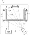
- FIG. 3is a diagram illustrating an exemplary television system with on-screen television sensors in accordance with various aspects of the present invention.
- FIG. 4is a diagram illustrating an exemplary television system with off-screen television sensors in accordance with various aspects of the present invention.
- FIG. 5is a diagram illustrating an exemplary television system with off-television sensors in accordance with various aspects of the present invention.
- FIG. 6is a diagram illustrating an exemplary television system with television receiver sensors in accordance with various aspects of the present invention.
- FIG. 7is a diagram illustrating an exemplary television system with television controller sensors in accordance with various aspects of the present invention.
- FIG. 8is a diagram illustrating an exemplary television control device in accordance with various aspects of the present invention.
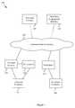
- FIG. 9is a flow diagram illustrating the generation of on-screen pointing information in accordance with various aspects of the present invention.
- FIG. 10is a flow diagram illustrating the generation of on-screen pointing information in accordance with various aspects of the present invention.
- modules, components or circuitsmay generally comprise hardware and/or a combination of hardware and software (e.g., including firmware).
- modulesmay also, for example, comprise a computer readable medium (e.g., a non-transitory medium) comprising instructions (e.g., software instructions) that, when executed by a processor, cause the processor to perform various functional aspects of the present invention. Accordingly, the scope of various aspects of the present invention should not be limited by characteristics of particular hardware and/or software implementations of a module, component or circuit unless explicitly claimed as such.
- various aspects of the present inventionmay be implemented by one or more processors (e.g., a microprocessor, digital signal processor, baseband processor, microcontroller, etc.) executing software instructions (e.g., stored in volatile and/or non-volatile memory).
- processorse.g., a microprocessor, digital signal processor, baseband processor, microcontroller, etc.
- software instructionse.g., stored in volatile and/or non-volatile memory
- aspects of the present inventionmay be implemented by an application-specific integrated circuit (“ASIC”) and/or other hardware components.
- ASICapplication-specific integrated circuit
- any or all of the functional modules discussed hereinmay share various hardware and/or software components.
- any or all of the functional modules discussed hereinmay be implemented wholly or in-part by a shared processor executing software instructions.
- various software sub-modules that may be executed by one or more processorsmay be shared between various software modules. Accordingly, the scope of various aspects of the present invention should not be limited by arbitrary boundaries between various hardware and/or software components, unless explicitly claimed.
- a communication networkis generally the communication infrastructure through which a communication device (e.g., a portable communication device, television, television control device, television provider, television programming provider, television receiver, video recording device, etc.) may communicate with other systems.
- a communication networkmay comprise a cable and/or satellite television communication network, a cellular communication network, a wireless metropolitan area network (WMAN), a wireless local area network (WLAN), a wireless personal area network (WPAN), any home or premises communication network, etc.
- WMANwireless metropolitan area network
- WLANwireless local area network
- WPANwireless personal area network
- a particular communication networkmay, for example, generally have a corresponding communication protocol according to which a communication device may communicate with the communication network. Unless so claimed, the scope of various aspects of the present invention should not be limited by characteristics of a particular type of communication network.
- Such a pointing locationrefers to a location on the television screen to which a user (either directly or with a pointing device) is pointing. Such a pointing location is to be distinguished from other types of on-screen location identification, such as, for example, using arrow keys and/or a mouse to move a cursor or to traverse blocks (e.g., on an on-screen program guide) without pointing.
- Such television programminggenerally includes various types of television programming (e.g., television programs, news programs, sports programs, music television, movies, television series programs and/or associated advertisements, educational programs, live or recorded, broadcast/multicast/unicast, etc.).
- Such television programming video contentis to be distinguished from other non-programming video content that may be displayed on a television screen (e.g., an electronic program guide, user interface menu, a television set-up menu, a typical web page, a document, a graphical video game, etc.).
- Various aspects of the present inventionmay, for example, comprise determining an on-screen pointing location during the presentation of television programming on the screen of the television.
- the exemplary system 100includes a television provider 110 .
- the television provider 110may, for example, comprise a television network company, a cable company, a movie-providing company, a news company, an educational institution, etc.
- the television provider 110may, for example, be an original source of television programming (or related information).
- the television provider 110may be a communication company that provides programming distribution services (e.g., a cable television company, a satellite television company, a telecommunication company, a data network provider, etc.).
- the television provider 110may, for example, provide programming and non-programming information and/or video content.
- the television provider 110may, for example, provide information related to a television program (e.g., information describing or otherwise related to selectable objects in programming, etc.).
- the exemplary television system 100may also include a third party program information provider 120 .
- a third party program information provider 120may, for example, provide information related to a television program.
- Such informationmay, for example, comprise information describing selectable objects in programming, program guide information, etc.
- the exemplary television system 100may include one or more communication networks (e.g., the communication network(s) 130 ).
- the exemplary communication network 130may comprise characteristics of any of a variety of types of communication networks over which video content and/or information related to video content may be communicated.
- the communication network 130may compare characteristics of a cable television network, a satellite television network, a telecommunication network, the Internet, a local area network (LAN), a personal area network (PAN), a metropolitan area network (MAN), any of a variety of different types of home networks, etc.
- LANlocal area network
- PANpersonal area network
- MANmetropolitan area network
- the exemplary television system 100may include a first television 140 .
- a first television 140may, for example, comprise networking capability enabling such television 140 to communicate directly with the communication network 130 .
- the first television 140may comprise one or more embedded television receivers or transceivers (e.g., a cable television receiver, satellite television transceiver, Internet modem, etc.).
- the first television 140may comprise one or more recording devices (e.g., for recording and/or playing back video content, television programming, etc.).
- the exemplary television system 100may include a first television controller 160 .
- a first television controller 160may, for example, operate to (e.g., which includes operating when enabled to) control operation of the first television 140 .
- the first television controller 160may comprise characteristics of any of a variety of television controlling devices.
- the first television controller 160may comprise characteristics of a dedicated television control device, a universal remote control, a cellular telephone or personal computing device with television control capability, etc.
- the first television controller 160may, for example, transmit signals directly to the first television 140 to control operation of the first television 140 .
- the first television controller 160may also, for example, operate to transmit signals (e.g., via the communication network 130 ) to the television provider 110 to control video content being provided to the first television 140 , or to conduct other transactions (e.g., business transactions, etc.).
- the first television controller 160may operate to communicate screen pointing information with the first television 140 and/or other devices.
- various aspects of the present inventioninclude a user pointing to a location on a television screen (e.g., pointing to an object or person presented in television programming). In such a scenario, the user may perform such pointing in any of a variety of manners.
- One of such exemplary mannersincludes pointing with a television control device.
- the first television controller 160provides a non-limiting example of a device that a user may utilize to point to an on-screen location. The following discussion of FIGS. 2-10 will present various non-limiting illustrative aspects of such a television controller.
- the exemplary television system 100may also include a television receiver 150 .
- the television receivermay, for example, operate to provide a communication link between a television and/or television controller and a communication network and/or information provider.
- the television receiver 150may operate to provide a communication link between the second television 141 and the communication network 130 , or between the second television 141 and the television provider 110 (and/or third party program information provider 120 ) via the communication network 130 .
- the television receiver 150may comprise characteristics of any of a variety of types of television receivers.
- the television receiver 150may comprise characteristics of a cable television receiver, a satellite television receiver, etc.
- the television receiver 150may comprise a data communication network modem for data network communications (e.g., with the Internet, a LAN, PAN, MAN, telecommunication network, etc.).
- the television receiver 150may also, for example, comprise recording capability (e.g., programming recording and playback, etc.).
- the exemplary television system 100may include a second television controller 161 .
- a second television controller 161may, for example, operate to control operation of the second television 141 and the television receiver 150 .
- the second television controller 161may comprise characteristics of any of a variety of television controlling devices.
- the second television controller 161may comprise characteristics of a dedicated television control device, a dedicated television receiver control device, a universal remote control, a cellular telephone or personal computing device with television control capability, etc.
- the second television controller 161may, for example, transmit signals directly to the second television 141 to control operation of the second television 141 .
- the second television controller 161may, for example, transmit signals directly to the television receiver 150 to control operation of the television receiver 150 .
- the second television controller 161may additionally, for example, operate to transmit signals (e.g., via the television receiver 150 and the communication network 130 ) to the television provider 110 to control video content being provided to the television receiver 150 , or to conduct other transactions (e.g., business transactions, etc.).
- various aspects of the present inventioninclude a user pointing to a location on a television screen (e.g., pointing to an object or person presented in television programming).
- the usermay perform such pointing in any of a variety of manners.
- One of such exemplary mannersincludes pointing with a television control device.
- the second television controller 161provides one non-limiting example of a device that a user may utilize to point to an on-screen location.
- FIGS. 2-10will present various non-limiting illustrative aspects of such a television controller.
- the exemplary television system 100was provided to provide a non-limiting illustrative foundation for discussion of various aspects of the present invention. Thus, the scope of various aspects of the present invention should not be limited by any characteristics of the exemplary television system 100 unless explicitly claimed.
- FIG. 2such figure is a diagram illustrating an exemplary television control device 200 (e.g., a remote control device) in accordance with various aspects of the present invention.
- the exemplary television control device 200may, for example, share any or all characteristics with the exemplary television control devices 160 , 161 illustrated in FIG. 1 and discussed previously and/or with any of the exemplary television control devices discussed herein.
- the exemplary television control device 200includes a first communication interface module 210 .
- the first communication interface module 210may, for example, operate to communicate over any of a variety of communication media and utilizing any of a variety of communication protocols.
- the first communication interface module 210is illustrated coupled to a wireless RF antenna via a wireless port 212 , the wireless medium is merely illustrative and non-limiting.
- the first communication interface module 210may, for example, operate to communicate with one or more communication networks (e.g., cable television networks, satellite television networks, telecommunication networks, the Internet, local area networks, personal area networks, metropolitan area networks, etc.) via which television video content (e.g., television programming), television control information, and/or other data is communicated.
- communication networkse.g., cable television networks, satellite television networks, telecommunication networks, the Internet, local area networks, personal area networks, metropolitan area networks, etc.
- the first communication module 210may operate to communicate with local sources of television video content (e.g., video recorders, receivers, gaming devices, etc.). Additionally, for example, the first communication module 210 may operate to communicate with a second television controller (e.g., directly or via one or more intermediate communication networks). Further for example, the first communication module 210 may operate to communicate with a television utilizing any of a variety of television communication connections and/or protocols (e.g., composite video, component video, HDMI, etc.). Still further, for example, the first communication module 210 may operate to communicate with screen pointing sensors.
- local sources of television video contente.g., video recorders, receivers, gaming devices, etc.
- a second television controllere.g., directly or via one or more intermediate communication networks.
- the first communication module 210may operate to communicate with a television utilizing any of a variety of television communication connections and/or protocols (e.g., composite video, component video, HDMI, etc.). Still further, for example, the first communication module 210
- the exemplary television control device 200includes a second communication interface module 220 .
- the second communication interface module 220may, for example, operate to communicate over any of a variety of communication media and utilizing any of a variety of communication protocols.
- the second communication interface module 220may communicate via a wireless RF communication port 222 and antenna, or may communicate via a non-tethered optical communication port 224 (e.g., utilizing laser diodes, photodiodes, etc.).
- the second communication interface module 220may communicate via a tethered optical communication port 226 (e.g., utilizing a fiber optic cable), or may communicate via a wired communication port 228 (e.g., utilizing coaxial cable, twisted pair, HDMI cable, Ethernet cable, any of a variety of wired component and/or composite video connections, etc.).
- the second communication interface module 220may, for example, operate to communicate with one or more communication networks (e.g., cable television networks, satellite television networks, telecommunication networks, the Internet, local area networks, personal area networks, metropolitan area networks, etc.) via which television video content, television control information, and/or other data is communicated.
- communication networkse.g., cable television networks, satellite television networks, telecommunication networks, the Internet, local area networks, personal area networks, metropolitan area networks, etc.
- the second communication module 220may operate to communicate with local sources of television video content (e.g., video recorders, other receivers, gaming devices, etc.). Additionally, for example, the second communication module 220 may operate to communicate with a second television controller (e.g., directly or via one or more intervening communication networks). Further for example, the second communication module 220 may operate to communicate with a television utilizing any of a variety of television communication connections and/or protocols (e.g., composite video, component video, HDMI, etc.). Still further, for example, the second communication module 220 may operate to communicate with screen pointing sensors.
- local sources of television video contente.g., video recorders, other receivers, gaming devices, etc.
- the second communication module 220may operate to communicate with a second television controller (e.g., directly or via one or more intervening communication networks). Further for example, the second communication module 220 may operate to communicate with a television utilizing any of a variety of television communication connections and/or protocols (e.g., composite video, component video,
- the exemplary television control device 200may also comprise additional communication interface modules, which are not illustrated. Such additional communication interface modules may, for example, share any or all aspects with the first 210 and second 220 communication interface modules discussed above.
- the exemplary television control device 200may also comprise a communication module 230 .
- the communication module 230may, for example, operate to control and/or coordinate operation of the first communication interface module 210 and the second communication interface module 220 (and/or additional communication interface modules as needed).
- the communication module 230may, for example, provide a convenient communication interface by which other components of the television control device 200 may utilize the first 210 and second 220 communication interface modules. Additionally, for example, in an exemplary scenario where a plurality of communication interface modules are sharing a medium and/or network, the communication module 230 may coordinate communications to reduce collisions and/or other interference between the communication interface modules 210 , 220 .
- the exemplary television control device 200may comprise one or more television interface modules 235 .
- the television interface module 235may, for example, operate to manage communications between the television control device 200 and one or more televisions that are communicatively coupled thereto (e.g., via the first 210 and/or second 220 communication interface modules).
- the television interface module 235may operate to communicate general television programming video information to a television (e.g., while the television control device 200 is operating to determine an on-screen pointing location).
- the television interface module 235may output a signal to the television, television receiver or a second television controller or other device with a display, where such signal comprises characteristics adapted to cause the television (or other device) to output a visual indication of on-screen pointing location.
- Such an indicationmay, for example, be communicated with (e.g., as a part of) other information (e.g., video information, general device control information, etc.) being communicated to the television (or other device), or such an indication may be communicated to the television (or other device) independent of other information.
- the exemplary television control device 200may additionally comprise one or more user interface modules 240 .
- the user interface module 240may generally operate to provide user interface functionality to a user of the television control device 200 .
- the user interface module 240may operate to provide for user control of any or all standard television and/or television receiver commands (e.g., channel control, on/off, television output settings, input selection, etc.).
- the user interface module 240may, for example, operate and/or respond to user commands utilizing user interface features disposed on the television receiver (e.g., buttons, touch screen, microphone, etc.) and may also utilize the communication module 230 (and/or first 210 and second 220 communication interface modules) to communicate with a television controller, television receiver, another television control device and/or any other television system component.
- user interface features of the television control device 200may comprise utilization of the television (e.g., utilizing the television screen for menu-driven or other GUI associated with television, television receiver and/or television controller operation).
- the user interface module 240may also operate to interface with and/or control operation of any of a variety of sensors that may be utilized to ascertain an on-screen pointing location. Non-limiting examples of such sensors will be provided later (e.g., in the discussion of FIGS. 3-7 and elsewhere herein).
- the user interface module 240may operate to receive signals associated with respective sensors (e.g., raw or processed signals directly from the sensors, through intermediate devices (e.g., a television, television control, surround sound system, etc.), via the communication interface modules 210 , 220 , etc.).
- the user interface module 240may operate to control the transmission of signals (e.g., RF signals, optical signals, acoustic signals, etc.) from such sensors.
- signalse.g., RF signals, optical signals, acoustic signals, etc.
- the exemplary television control device 200may comprise one or more processors 250 .
- the processor 250may, for example, comprise one or more of a general purpose processor, digital signal processor, application-specific processor, microcontroller, microprocessor, etc.
- the processor 250may operate in accordance with software (or firmware) instructions.
- softwareor firmware instructions.
- any or all functionality discussed hereinmay be performed by a processor executing instructions.
- various modulesare illustrated as separate blocks or modules in FIG. 2 for illustrative clarity, such illustrative modules, or a portion thereof, may be implemented by the processor 250 .
- the exemplary television control device 200may comprise one or more memories 260 . As discussed above, various aspects may be performed by one or more processors executing instructions. Such instructions may, for example, be stored in the one or more memories 260 . Such memory 260 may, for example, comprise characteristics of any of a variety of types of memory. For example and without limitation, such memory 260 may comprise one or more memory chips (e.g., ROM, RAM, EPROM, EEPROM, flash memory, one-time-programmable OTP memory, etc.), hard drive memory, CD memory, DVD memory, etc.
- memory chipse.g., ROM, RAM, EPROM, EEPROM, flash memory, one-time-programmable OTP memory, etc.
- the exemplary television control device 200may also comprise one or more calibration modules 251 that operate to perform various calibration activities. Examples of such calibration activities will be provided later in this discussion. Briefly, such calibration activities may, for example, comprise interacting with a user and/or user pointing device (e.g., if different from the television control device 200 ) to determine sensor signals under known circumstances (e.g., determine sensor signals in response to known screen pointing circumstances), and processing such sensor signals to develop algorithms (e.g., transformation matrices, static positional equations, etc.) to determine screen pointing location based on sensor signals received during normal operation. As will also be discussed later, such calibration may also be utilized to establish signal gain (or energy) patterns utilized in determining pointing location.
- algorithmse.g., transformation matrices, static positional equations, etc.
- the exemplary television control device 200may comprise one or more location-determining modules 252 .
- various on-screen pointing location determinationsmay comprise processing location information.
- knowing the location of a usere.g., including the location of a pointing device (e.g., which could be the television control device 200 ) being utilized by the user
- knowing exactly where a pointing device is locatede.g., in three-dimensional space or where a pointing device is located along a line (e.g., knowing device location in two-dimensional space or land surface coordinates) relative to the television screen (and/or relative to the television control device) may remove a number of unknown variables from applicable positional equations.
- positional informationmay, in various exemplary scenarios, also comprise orientation information for a pointing device (e.g., yaw, pitch and/or roll).
- orientation informationmay be determined in various manners (e.g., through gyroscopic means, sensor alignment with known references, etc.).
- the location-determining module 252may operate to determine user (or pointing device) location in any of a variety of manners. For example and without limitation, in an exemplary scenario where the pointing device is different from the control device 200 , the location-determining module 252 may operate to receive location information from the pointing device (e.g., via one of the communication interface modules 210 , 220 ). For example, such a pointing device may comprise positioning system capability (e.g., global positioning system, assisted GPS, cellular or other triangulation systems, etc.) and communicate information describing the position of the pointing device to the television control device 200 . In an exemplary scenario where the television control device 200 is the pointing device, the television control device 200 may comprise on-board position-determining capability.
- positioning system capabilitye.g., global positioning system, assisted GPS, cellular or other triangulation systems, etc.
- the location-determining module 252may (e.g., via the user interface modules 240 ) utilize sensor signals to determine the position (which may include orientation) of the pointing device (or user thereof). For example, signals may arrive at the pointing device at different sensors at different times (or at different phases). Such temporal or phase differences may be processed to determine the location of the pointing device relative to the known location of such sensors. Further for example, the location-determining module 252 may operate to communicate pointing device location information with an external system that operates to determine the location of the pointing device. Such an external system may, for example, comprise a cellular telephony triangulation system, a home or premises-based triangulation system, a global positioning system, an assisted global positioning system, etc. In a non-limiting exemplary scenario where the control device 200 is the pointing device, the location information communicated with the external system may be location information associated with the control device 200 .
- the exemplary television control device 200may also comprise one or more sensor processing module(s) 253 .
- the sensor processing module 253may operate to receive sensor information (e.g., from the user interface module(s) 240 , from the television interface module 235 , from the communication interface modules 210 , 220 , etc.) and process such received sensor information to determine a location on the television screen to which a user is pointing.
- sensor informatione.g., from the user interface module(s) 240 , from the television interface module 235 , from the communication interface modules 210 , 220 , etc.
- processingmay, for example, comprise selecting a sensor with the strongest signal, interpolating between a plurality of sensors, interpolating between a plurality of sensors having strongest signals, determining gain (or energy) pattern intersections, etc.
- Various aspects of the present inventioncomprise, for example, determining on-screen pointing location during presentation of television programming (e.g., programming received from a television broadcaster, video recording device, etc.
- FIG. 3is a diagram illustrating an exemplary television system 300 with on-screen television sensors in accordance with various aspects of the present invention.
- the television system 300includes a television 301 comprising a television screen 303 .
- the television system 300also includes a television controller 320 (or other pointing device) pointing to an on-screen pointing location 330 along a line 325 between the television controller 320 and the on-screen pointing location 330 .
- the television controller 320may, for example, share any or all aspects with the exemplary television controllers 160 , 161 and 200 discussed previously and with all other television controllers discussed herein.
- the television control device 320may, for example, be communicatively coupled directly to the television 301 via a communication link 353 .
- the television control device 320may also, for example, be communicatively coupled directly to the television receiver 350 via communication link 352 .
- the television control device 320may additionally, for example, be communicatively coupled indirectly to the television 301 via the television receiver 350 through communication links 351 and 352 . Accordingly, various aspects of the television control device 320 will be explained herein with reference to various components of the exemplary television control device 200 illustrated in FIG. 2 .
- the television system 300also comprises a television receiver 350 that is communicatively coupled to the television 301 via a communication link 351 (e.g., a two-way communication link providing video information to the television 301 and/or receiving sensor information from the television 301 for communication to the television control device 320 ).
- the exemplary television receiver 350is also communicatively coupled to the television controller 320 via a communication link 352 .
- the exemplary television screen 303comprises an array of sensors integrated into the television screen 303 .
- One of such sensorsis labeled sensor 310 .
- Any of a variety of sensor typesmay be utilized, non-limiting examples of which include light sensors or photo detectors (e.g., photo diodes) and RF sensors (e.g., antenna elements or loops).
- the array of sensorsmay be integrated in the television screen 303 in any of a variety of manners, non-limiting examples of which will now be provided.
- the television screen 303may comprise an array of liquid crystal display (LCD) pixels for presenting video media to a user.
- LCDliquid crystal display
- An array of photo diodes and/or antenna elementsmay be integrated between or behind LCD pixels.
- every LCD pixelmay be associated with a corresponding photo diode and/or antenna element, or every N ⁇ M block of LCD pixels may be associated with a corresponding photo diode or antenna element.
- an array of photo diodes and/or RF antenna elementsmay be formed into a substrate beneath or behind transparent LCD substrates.
- a photo diode array and/or antenna element arraymay be interposed between or behind an array of LCD thin film transistors.
- an array of photo diodes and/or RF antenna elements (or other sensors)may be incorporated into a transparent screen overlay. Note that is such an implementation, such transparent screen overlay may be installed after-market. For example, a user that has a television control device 320 with the capability to determine on-screen pointing location may install the transparent screen overlay.
- Such communication linkmay, for example, be adapted to communicate information from each sensor to the television control device 320 serially (e.g., in a time-multiplexed manner) and/or in parallel.
- passive photo detectorsmay receive varying amounts of respective light energy depending on the pointing direction of a light source (e.g., a light source of the television control device 320 or other pointing device) aimed at the screen 303 .
- received signalse.g., pulsed signals
- received signalsmay arrive at different sensors at different respective times/phases (e.g., being indicative of relative position and/or pointing direction, which may also be utilized in a pointing determination).
- photo detectorsmay, for example, be tuned to react to particular light frequencies to reduce interference from output pixel light and/or associated reflections, ambient light, etc.
- photo diodesmay be tuned to detect light that is not visible to the human eye, visible light frequencies that are relatively rare, light patterns that are unlikely to occur in a television program (e.g., particular pulse codes), etc.
- an array of antenna elementsmay be formed on a substrate and placed behind light producing and/or filtering elements in an LCD screen (e.g., so as to avoid interfering with emitted light) or may be formed on a transparent substrate within or in front of the lighted region of the LCD display (e.g., utilizing microscopic antenna elements that are too small to significantly interfere with light emitted from the display).
- an implementationmay be integrated with the television screen 303 , but may also be added as an overlay (e.g., as a production option or an after-market user or technician installation).
- passive antennasmay receive varying respective amounts of RF energy depending on the pointing direction of a directional RF source (e.g., a directional RF source of the television control device 320 or other pointing device) aimed at the screen.
- received signalse.g., pulsed signals
- a usermay point a pointing device (e.g., a the television control device 320 , a laser pointer, directional RF transmitter, specifically designed eyewear, a mobile computing device, a mobile communication device, a gesture tracking device or glove, etc.) at the television screen 303 , where the pointing device directs transmitted energy (e.g., light energy, RF energy, acoustic energy, etc.) at a particular location on the television screen 303 to which the pointing device is being pointed.
- transmitted energye.g., light energy, RF energy, acoustic energy, etc.
- Such transmitted energywill likely be transmitted directionally and be associated with an intensity or gain pattern with the highest intensity likely at the center of the pattern (i.e., along the pointing line 325 ) and decreasing as a function of angle from the center of the pattern (or distance on the screen from the on-screen pointing location).
- each sensor of the array of sensors integrated into the screen 303will likely receive some respective amount of energy.
- the sensor nearest the screen pointing location 330i.e., along the pointing line 325
- the sensor adjacent to the screen pointing location 330will likely receive a next highest range of energy
- sensors away from the pointing location 330will likely receive progressively less amounts of energy from the pointing device (e.g., the television control device 320 ) as a function of distance from the pointing location 330 , until such energy is lost in the noise floor.
- the television control device 320may receive signals indicative of the energy received by the sensors of the sensor array.
- the television control device 320may receive such signals in various manners, depending on the degree of integration of such sensors into the television 301 .
- the television control device 320may receive such signals via a communication interface between the television control device 320 and the television 301 (e.g., via communication link 353 , or via a communication interface between the television 301 and television control device 320 via the television receiver 350 (e.g., via communication links 351 and 352 )).
- the television control device 320may receive such signals via a communication link directly between the television control device 320 and the sensors, where such a communication link may be independent of other communication links between the television control device 320 and the television 301 .
- Such communication linkmay, for example, be adapted to communicate information from each sensor to the television control device 320 serially (e.g., in a time-multiplexed manner) and/or in parallel.
- the user interface module 240may then, for example, provide information of such received sensor signals to the sensor processing module 253 for processing.
- the sensor processing module 253may then, for example, operate to process such information to determine the screen pointing location.
- the sensor processing module 253may perform such processing in any of a variety of manners, non-limiting examples of which will be provided below.
- the sensor processing module 253may operate to select the sensor with the highest received energy and determine that the location of such selected sensor is the on-screen pointing location. For example, in an exemplary scenario where the spatial resolution of screen-integrated sensors is relatively fine, such operation may reliably yield a desired level of accuracy without undue processing overhead.
- the sensor processing module 253may operate to select the sensor with the highest received energy and a plurality of sensors adjacent to such sensor. Then, for example, the sensor processing module 253 may interpolate between the locations of such sensors (e.g., based, at least in part, on weighting). For example, in a first dimension in which a sensor to the right of the highest energy sensor has a higher received energy than a sensor to the left of the highest energy sensor, the sensor processing module 253 may determine that the pointing location is to the right of the highest energy sensor. How much distance to the right may, for example, be determined as a function of the ratio between respective energies received by the right and left sensors. Such calculation may, for example, be a linear or non-linear calculation. Such calculation may also, for example, consider the expected energy pattern of a transmitting pointing device (e.g., in a scenario where energy fall-off is logarithmic as opposed to linear).
- the sensor processing module 253may operate to select all sensors receiving a threshold amount of energy (e.g., an absolute threshold level, a threshold level relative to the highest energy sensor, etc.). Then, for example, the sensor processing module 253 may interpolate between the locations of such sensors (e.g., based, at least in part, on respective energy weighting). For example, the sensor processing module 253 may perform non-linear splining between sensors in a horizontal direction with sensor location on a first axis and sensor energy on a second axis. The sensor processing module 253 may then operate to select the point on the sensor location axis corresponding to the peak sensor energy on the vertical axis. Such splining and selecting may then be repeated in the vertical direction. Alternatively for example, the sensor processing module 253 may operate to perform multi-dimensional splining to create a surface based on sensor energy and select the highest point on such surface and the corresponding screen coordinates of such surface.
- a threshold amount of energye.g., an absolute threshold level,
- the sensor processing module 253may operate to select a first sensor (e.g., the sensor with the highest received energy). Then, for example, the sensor processing module 253 may utilize information of the relative distance between the selected sensor and the pointing device (e.g., the television control device 320 ), information of the gain pattern for the signal transmitted from the pointing device to the selected sensor, and calibration information to determine where the pointing device may be pointed in order for the sensor to receive such energy. For example, this may result in a first closed figure (e.g., a circle, cloverleaf, etc.) drawn around the sensor on the screen plane.
- a first closed figuree.g., a circle, cloverleaf, etc.
- the sensor processing module 253may repeat the procedure for a second sensor (e.g., a sensor with the second highest received energy), resulting in a second closed figure.
- the sensor processing module 253may then, for example, determine the point(s) of intersection between the first and second figures. If only one point of intersection lies within the border of the screen, then such point of intersection might be utilized as an estimate of the pointing location.
- the sensor processing module 253may repeat the procedure for a third sensor (e.g., the sensor with the third highest energy, a sensor generally along the line perpendicular to a line segment between the first and second sensors, etc.) and determine a point nearest the intersection of the first, second and third closed figures. Such a point of intersection may then be utilized as an estimate of the pointing location.
- a third sensore.g., the sensor with the third highest energy, a sensor generally along the line perpendicular to a line segment between the first and second sensors, etc.
- the above-mentioned examples of screen-integrated sensors and related pointing location determinationswere presented as exemplary illustrations. Though the above-mentioned examples generally discuss light and/or RF energy sensors, other types of sensors may also be integrated into a television screen or overlaid thereon.
- the sensorsmay comprise acoustic sensors that operate to sense acoustic energy (e.g., directed acoustic energy directed to a pointing location on the screen).
- acoustic energye.g., directed acoustic energy directed to a pointing location on the screen.
- directed acoustic energymay be formed at frequencies beyond the range of human hearing (e.g., and at frequencies beyond the range of pet hearing as well).
- various energy radiation patternsmay be used, and/or a plurality of energy radiation patterns may be used.
- a pointing devicee.g., the television control device 320
- a pointing devicemay transmit one or more energy emissions that move relative to the pointing direction (e.g., in a raster pattern or any other pattern).
- the television control device 320may communicate information of such determined location in various manners.
- the sensor processing module 253 of the television control device 200may utilize the television interface module 235 to communicate information of such on-screen pointing location to the television 301 for presentation to the user.
- the sensor processing module 253may utilize the user interface module 240 to communicate information of such on-screen pointing location to the user (e.g., on a display of the television control device 200 ). Such communication will also be addressed in the discussions of FIGS. 9-10 .
- FIG. 4is a diagram illustrating an exemplary television system 400 with off-screen television sensors in accordance with various aspects of the present invention.
- the television system 400includes a television 401 comprising a television screen 403 .
- the television system 400also includes a television controller 420 (or other pointing device) pointing to an on-screen pointing location 430 along a pointing line 425 between the television controller 420 and the on-screen pointing location 430 .
- the television controller 420may, for example, share any or all aspects with the exemplary television controllers 160 , 161 , 200 and 320 discussed previously and with all other television controllers discussed herein.
- the television control device 420may, for example, be communicatively coupled directly to the television 401 via a communication link 453 .
- the television control device 420may also, for example, be communicatively coupled directly to the television receiver 450 via communication link 452 .
- the television control device 420may additionally, for example, be communicatively coupled indirectly to the television 401 via the television receiver 450 through communication links 451 and 452 . Accordingly, various aspects of the television control device 420 will be explained herein with reference to various components of the exemplary television control device 200 illustrated in FIG. 2 .
- the television system 400also comprises a television receiver 450 that is communicatively coupled to the television 401 via a communication link 451 (e.g., a two-way communication link providing video information to the television 401 and/or receiving sensor information from the television 401 for communication to the television control device 420 ).
- the exemplary television receiver 450is also communicatively coupled to the television controller 420 via a communication link 452 .
- the exemplary television 401comprises an array of sensors integrated into the television 401 around the border of the screen 403 .
- Three of such sensorsare labeled 410 , 411 and 412 .
- any of a variety of sensor typesmay be utilized, non-limiting examples of which include light sensors or photo detectors (e.g., photo diodes), RF sensors (e.g., antenna elements), acoustic sensors (e.g., microphones), etc.
- the array of sensorsmay be integrated around the television screen 403 in any of a variety of manners.
- such sensorsmay be integrated in a border of the television screen 403 that is not used for outputting video content.
- Such a configurationmay, for example, avoid sensor interference with video content being displayed on the screen.
- such sensorsmay be mounted to a border material of the television 401 .
- an array of photo detectorse.g., photo diodes
- antenna elementse.g., individual antennas or elements of an antenna array, for example, a phased array
- every screen pixel row and/or columnmay be associated with a pair of corresponding photo diodes and/or antenna elements, or every N ⁇ M block of screen pixels may be associated with one or more corresponding photo diodes or antenna elements (e.g., a row and column sensor, two row and two column elements, etc.).
- passive photo detectorsmay receive varying amounts of respective light energy depending on the pointing direction of a light source (e.g., a directional light source of the television control device 420 ) pointed at the screen.
- received signalse.g., pulsed signals
- received signalsmay arrive at different sensors at different respective times/phases (e.g., being indicative of relative position and/or pointing direction, which may also be utilized in a pointing determination).
- photo detectorsmay, for example, be tuned to react to particular light frequencies to reduce interference from output pixel light and/or associated reflections.
- photo diodesmay be tuned to detect light that is not visible to the human eye, visible light frequencies that are relatively rare, light patterns that are unlikely to occur in a television program (e.g., particular pulse codes), etc.
- the photo detectors integrated with the television body off-screenmay comprise photo diodes that operate to detect energy from a laser pointer or directed infrared energy from a television controller or other pointing device.
- various aspectsmay comprise mounting (e.g., adhering) sensors to the television body off-screen. Such sensor installation may, for example, occur at the factory or after-market by a technician or user.
- an array of antenna elementsmay be positioned around the border of the screen 403 .
- passive antennasor elements of an overall antenna matrix
- received signalse.g., pulsed signals
- received signalsmay arrive at different antennas at different respective times/phases (e.g., being indicative of relative position and/or pointing direction, which may also be utilized in a pointing determination).
- various aspectsmay comprise mounting (e.g., adhering) sensors to the television body off-screen. Such sensor installation may, for example, occur at the factory or after-market by a technician or user.
- a usermay point a pointing device (e.g., a remote controller 420 , a laser pointer, directional RF transmitter, specifically designed eyewear, a mobile computing device, a mobile communication device, a gesture tracking device or glove, etc.) at the television screen 403 , where the pointing device directs transmitted energy (e.g., light and/or RF energy and/or acoustic energy) at a particular location on the television screen 403 to which the device is being pointed.
- transmitted energye.g., light and/or RF energy and/or acoustic energy
- transmitted energywill likely be transmitted directionally and be associated with an intensity or gain pattern with the highest intensity likely at the center of the pattern (i.e., along the pointing line 425 ) and decreasing as a function of angle from the center of the pattern.
- Such a gain patternis generally represented in FIG. 4 by the concentric circles around the on-screen pointing location 430 . Note, however, that in practice such a gain pattern is likely to be more complex than the illustrated pattern (e.g., including lobes with respective peaks and nulls).
- each sensor of the sensors integrated into the television 401 around the border of the screen 403will likely receive some respective amount of energy.
- the sensor nearest the screen pointing location 430i.e., along the pointing line 425
- the sensor nearest the screen pointing location 430will likely receive the highest amount of energy
- sensors along the particular axis adjacent to the screen pointing location 430will likely receive a next highest range of energy
- sensors away from the pointing location 430will likely receive progressively less amounts of energy from the pointing device (e.g., the television control device 420 ), as a function of distance from the pointing location 430 or as a function of the angular displacement from the pointing line 425 , until such energy is lost in the noise floor.
- sensor 410is closest to the pointing location 430 and will likely receive the highest energy, with sensors adjacent to the left and right of sensor 410 receiving the next highest amounts of energy, and so on. Also, along the vertical axis, sensors 411 and 412 will likely receive close to the highest amount of energy, with sensors above and below such sensors 411 , 412 receiving the next highest amounts of energy and so on.
- the television control device 420may receive signals indicative of the energy received by the sensors of the television 401 .
- the television control device 420may receive such signals in various manners, depending on the degree of integration of such sensors into the television 401 .
- the television control device 420may receive such signals via a communication interface between the television control device 420 and the television 401 (e.g., via communication link 453 or via a communication interface between the television 401 and the television control device 420 via the television receiver 450 (e.g., via communication links 451 and 452 )).
- the television control device 420may receive such signals via a communication link directly between the television control device 420 and the sensors, where such a communication link may be independent of other communication links between the television control device 420 and the television 401 .
- Such communication link(s)may, for example, be adapted to communicate information from each sensor to the television control device 420 serially (e.g., in a time-multiplexed manner) and/or in parallel.
- the user interface module 240may then, for example, provide information of such received sensor signals to the sensor processing module 253 for processing.
- the sensor processing module 253may then, for example, operate to process such information to determine the screen pointing location.
- the sensor processing module 253may perform such processing in any of a variety of manners, non-limiting examples of which will be provided below.
- the sensor processing module 253may operate to select the sensor with the highest received energy along each of the horizontal and vertical axes and determine that the respective locations of such selected sensors correspond to the horizontal and vertical coordinates of the on-screen pointing location. For example, in an exemplary scenario where the spatial resolution of screen border sensors is relatively fine, such operation may reliably yield a desired level of accuracy without undue processing overhead. For example, the sensor processing module 253 may determine that sensors 410 and 411 have the highest received energy for the horizontal and vertical axes, respectively, and thus determine that the on-screen pointing location is represented in the horizontal axis by the horizontal location of the sensor 410 and represented in the vertical axis by the vertical location of the sensor 411 .
- the sensor processing module 253may select a midpoint between such sensors (e.g., the vertical midpoint between sensors 411 and 412 ).
- the sensor processing module 253may operate to select, for each screen axis, the sensor with the highest received energy and a plurality of sensors adjacent to such sensor. Then, for example, the sensor processing module 253 may interpolate between the locations of such sensors (e.g., based, at least in part, on weighting). For example, in the horizontal dimension in which a sensor to the right of the highest energy sensor 410 has a higher received energy than a sensor to the left of the highest energy sensor 410 , the sensor processing module 253 may determine that the pointing location along the horizontal axis is to the right of the highest energy sensor 410 . How much distance to the right may, for example, be determined as a function of the ratio between respective energies received by the right and left sensors.
- Such calculationmay, for example, be a linear or non-linear calculation. Such calculation may also, for example, consider the expected energy pattern of a transmitting pointing device (e.g., in a scenario where energy fall-off is logarithmic as opposed to linear). The sensor processing module 253 may then, for example, repeat such operation in the vertical direction.
- the sensor processing module 253may operate to select all sensors in each of the axes receiving a threshold amount of energy (e.g., an absolute threshold level, a threshold level relative to the highest energy sensor, etc.). Then, for example, the sensor processing module 253 may interpolate between the locations of such sensors (e.g., based, at least in part, on respective energy weighting). For example, the sensor processing module 253 may perform non-linear splining between sensors in a horizontal direction with sensor location on a first axis and sensor energy on a second axis. The sensor processing module 253 may then operate to select the point on the sensor location axis corresponding to the peak sensor energy on the vertical axis.
- a threshold amount of energye.g., an absolute threshold level, a threshold level relative to the highest energy sensor, etc.
- the sensor processing module 253may interpolate between the locations of such sensors (e.g., based, at least in part, on respective energy weighting). For example, the sensor processing module 253 may
- Such splining and selectingmay then be repeated in the vertical screen direction.
- the sensor processing module 253may operate to perform multi-dimensional splining to create a surface based on sensor energy and select the highest point on such surface and the corresponding screen coordinates of such surface.
- the television control device 420may communicate information of such determined location in various manners.
- the sensor processing module 253 of the television control device 200may utilize the television interface module 235 to communicate information of such on-screen pointing location to the television 401 for presentation to the user.
- the sensor processing module 253may utilize the user interface module 240 to communicate information of such on-screen pointing location to the user (e.g., on a display of the television control device 200 ). Such communication will also be addressed in the discussions of FIGS. 9-10 .
- FIG. 5is a diagram illustrating an exemplary television system 500 with off-television sensors in accordance with various aspects of the present invention.
- the television system 500includes a television 501 comprising a television screen 503 .
- the television system 500also includes a television controller 520 (or other pointing device) pointing to an on-screen pointing location 530 along a pointing line 525 between the television controller 520 and the on-screen pointing location 530 .
- the television controller 520may, for example, share any or all aspects with the exemplary television controllers 160 , 161 , 200 , 320 and 420 discussed previously and with all other television controllers discussed herein. Accordingly, various aspects of the television control device 520 will be explained herein with reference to various components of the exemplary television control device 200 illustrated in FIG. 2 .
- the television control device 520may, for example, be communicatively coupled directly to the television 501 via a communication link (not illustrated).
- the television control device 520may also, for example, be communicatively coupled directly to the television receiver 550 via communication link 562 .
- the television control device 520may additionally, for example, be communicatively coupled indirectly to the television 501 via the television receiver 550 through communication links 561 and 562 . Accordingly, various aspects of the television control device 520 will be explained herein with reference to various components of the exemplary television control device 200 illustrated in FIG. 2 .
- the television system 500also comprises a television receiver 550 that is communicatively coupled to the television 501 via a communication link 561 (e.g., a two-way communication link providing video information to the television 501 and/or receiving sensor information from the television 501 for communication to the television control device 520 ).
- a communication link 561e.g., a two-way communication link providing video information to the television 501 and/or receiving sensor information from the television 501 for communication to the television control device 520 .
- the television control device 520is illustrated with one or more communication links 563 to the various sensors 551 - 556 independent of other communication links (e.g., links to the television 501 , links to the television receiver 550 , etc.).
- the television control device 520e.g., a user interface module 240
- the exemplary television control device 520may also be communicatively coupled to other pointing devices and/or television control devices.
- the exemplary television system 500comprises an array of sensors integrated into audio speaker components (e.g., surround sound speakers) positioned around the television 501 .
- the television system 500comprises a left speaker 531 comprising a top sensor 552 and a bottom sensor 551 .
- the television system 500comprises a right speaker 533 comprising a top sensor 556 and a bottom sensor 555 .
- the television system 500comprises a center speaker 532 comprising a left sensor 553 and a right sensor 554 .
- any of a variety of sensor typesmay be utilized, non-limiting examples of which include light sensors or photo detectors (e.g., photo diodes), RF sensors (e.g., antenna elements), acoustic sensors (e.g., microphones), etc.
- light sensors or photo detectorse.g., photo diodes
- RF sensorse.g., antenna elements
- acoustic sensorse.g., microphones
- the audio speaker component example discussed hereinis merely illustrative and that such sensors may be installed in any of a variety of locations (e.g., dedicated sensor boxes, attached to furniture, etc.).
- the array of sensorsmay be positioned around the television 501 in any of a variety of manners.
- such sensorsmay be positioned around the television 501 generally in the same plane as the television screen 503 .
- on-screen pointing locationmay be determined in a manner similar to the interpolation and/or gain pattern intersection discussed above with regard to off-screen and/or on-screen sensors.
- a calibration proceduremay be implemented (e.g., by the calibration module 251 ). Such calibration will be discussed in more detail below.
- one or more photo detectorse.g., photo diodes
- antenna elementse.g., individual antennas or elements of an antenna array
- passive photo detectorsmay receive varying amounts of respective light energy depending on the pointing direction of a light source (e.g., a directional light source of the television control device 520 ) aimed at the screen.
- directed energye.g., light, RF, acoustic, etc.
- a pointing devicee.g., the television control device 520
- sensors off-screenor even off-television
- received signalsmay arrive at different sensors at different respective times/phases (e.g., being indicative of relative position and/or pointing direction, which may also be utilized in a pointing determination).
- photo diodesmay, for example, be tuned to react to particular light frequencies to reduce interference from output pixel light and/or associated reflections, ambient light, room lighting, etc.
- photo diodesmay be tuned to detect light that is not visible to the human eye, visible light frequencies that are relatively rare, light patterns that are unlikely to occur in a television program (e.g., particular pulse codes), etc.
- the photo detectors integrated with off-television componentsmay comprise photo diodes that operate to detect energy from a laser pointer or directed infrared energy from a television controller (or other pointing device).
- various aspectsmay comprise mounting (e.g., adhering) sensors to various off-television components. Such sensor installation may, for example, occur at the factory or after-market by a technician or user.
- an array of antenna elementsmay be positioned around off-television components (e.g., in surround sound components).
- passive antennasor elements of an overall antenna matrix
- received signalse.g., pulsed signals
- various aspectsmay comprise mounting (e.g., adhering) sensors to the off-television components. Such sensor installation may, for example, occur at the factory or after-market by a technician or user.
- a usermay point a pointing device (e.g., a television controller 520 (e.g., a remote control device), a laser pointer, directional RF transmitter, specifically designed eyewear, a mobile computing device, a mobile communication device, a gesture tracking device or glove, etc.) at the television screen 503 , where the pointing device directs transmitted energy (e.g., light and/or RF energy and/or acoustic energy) at a particular location on the television screen 503 to which the user is pointing with the pointing device.
- transmitted energye.g., light and/or RF energy and/or acoustic energy
- Such transmitted energywill likely be transmitted directionally and be associated with an intensity or gain pattern with the highest intensity at the center of the pattern (i.e., along the pointing line 525 ) and decreasing as a function of angle from the center of the pattern (or distance from the center point).
- Such a gain patternwas discussed previously in the discussion of FIG. 4 .
- each sensor of the sensors integrated into the television system 500 off-televisionwill likely receive some respective amount of energy.
- the sensor nearest to the screen pointing location 530i.e., along the pointing line 525
- the sensor nearest to the screen pointing location 530will likely receive the highest amount of energy
- a sensor next nearest to the screen pointing location 530will likely receive a next highest range of energy
- sensors away from the pointing location 530will likely receive progressively less amounts of energy from the pointing device (e.g., the television control device 420 ), as a function of distance from the pointing location 530 and/or angle off the pointing line 525 (e.g., until such energy is lost in the noise floor).
- sensor 553is nearest to the pointing location 530 and will likely receive the highest energy
- sensor 552is next nearest to the pointing location 530 and will likely receive the next highest energy, and so on.
- signals from a same sensormay be utilized in determining multiple axes of pointing location.
- a calibration proceduremay be performed when the system 500 is configured to assist in such pointing determination.
- the television control device 520may receive signals indicative of the energy received by the sensors of the television system 500 .
- the television control device 520may receive such signals in various manners, depending on the degree of integration of such sensors into the television 501 .
- the television control device 520may receive such signals via a communication interface between the television control device 520 and the respective off-television components (e.g., via a communication link 563 between the television control device 520 and the surround sound speaker components 531 - 533 ).
- the television control device 520may receive such signals via a communication link directly between the television control device 520 and the individual sensors (e.g., communication link 563 ), where such a communication link may be independent of other communication links between the television control device 520 and the television 501 and/or independent of other communication links between the television control device 520 and other television system 500 components (e.g., television receiver 550 and the surround sound speaker components 531 - 533 ).
- a communication link directly between the television control device 520 and the individual sensorse.g., communication link 563
- such a communication linkmay be independent of other communication links between the television control device 520 and the television 501 and/or independent of other communication links between the television control device 520 and other television system 500 components (e.g., television receiver 550 and the surround sound speaker components 531 - 533 ).
- the user interface module 240may then, for example, provide information of such received sensor signals to the sensor processing module 253 for processing.
- the sensor processing module 253may then, for example, operate to process such information to determine the screen pointing location.
- the sensor processing module 253may perform such processing in any of a variety of manners, non-limiting examples of which will be provided below.
- the sensor processing module 253may operate to estimate a position between sensor positions based on relative sensor energy.
- sensor 552may correspond to a relatively high amount of energy
- sensor 556may correspond to a relatively low amount of received energy.
- the sensor processing module 253may, for example, estimate a horizontal position relatively closer to sensor 552 by an amount proportional to the relative difference between respective amounts of energy.
- the sensor processing module 253may perform a similar estimation utilizing sensors 551 and 555 . Various horizontal position estimations may then be averaged.
- respective energies for the left speaker 531 sensorsmay be averaged, respective energies for the right speaker 533 sensors may be averaged, and such left and right speaker average energies may then be utilized to determine a horizontal pointing location.
- the sensor processing module 253may then, for example, perform a similar pointing direction estimate in the vertical direction.
- a calibration proceduremay be performed to determine an expected sensor energy level (e.g., absolute or relative) when the user is pointing at the sensor.
- an expected sensor energy levele.g., absolute or relative
- a first linee.g., a circle or arc
- a second linee.g., a circle or arc
- the intersection of the first and second linesutilized as an estimate of pointing location. Additional lines associated with other sensors may also be utilized. Such additional lines may, for example, be utilized when selecting between multiple line intersections and/or for greater accuracy or resolution.
- the television control device 520may communicate information of such determined location in various manners.
- the sensor processing module 253 of the television control device 200may utilize the television interface module 235 to communicate information of such on-screen pointing location to the television 501 for presentation to the user.
- the sensor processing module 253may utilize the user interface module 240 to communicate information of such on-screen pointing location to the user (e.g., on a display of the television control device 200 ). Such communication will also be addressed in the discussions of FIGS. 9-10 .
- FIG. 6is a diagram illustrating an exemplary television system 600 with television receiver sensors in accordance with various aspects of the present invention.
- the television system 600includes a television 601 comprising a television screen 603 .
- the television system 600also includes a television controller 620 (or other pointing device) pointing to an on-screen pointing location 630 along a pointing line 625 between the television controller 620 and the on-screen pointing location 630 .
- the television controller 620may, for example, share any or all aspects with the exemplary television controllers 160 , 161 , 200 , 320 , 420 and 520 discussed previously and with all other television controllers discussed herein. Accordingly, various aspects of the television control device 620 will be explained herein with reference to various components of the exemplary television control device 200 illustrated in FIG. 2 .
- the television control device 620may, for example, be communicatively coupled directly to the television 601 via a communication link (not illustrated).
- the television control device 620may also, for example, be communicatively coupled directly to the television receiver 650 via communication link 653 .
- the television control device 620may additionally, for example, be communicatively coupled indirectly to the television 601 via the television receiver 650 through communication links 651 and 652 . Accordingly, various aspects of the television control device 620 will be explained herein with reference to various components of the exemplary television control device 200 illustrated in FIG. 2 .
- the television system 600also comprises a television receiver 650 that is communicatively coupled to the television 601 via a communication link 651 (e.g., a two-way communication link providing video information to the television 601 and/or communicating sensor information and/or screen pointing information with the television 601 ).
- the television receiver 650comprises an array of screen pointing sensors. A portion of the sensors are labeled ( 661 - 665 ) for discussion purposes. Note that such sensors may be arranged in any of a variety of configurations (e.g., matrix configuration, border configuration, placed only at the front corners, etc.).
- the pointing sensorsmay, for example, be integrated into the television receiver 650 and/or attached to the television receiver 650 in any of a variety of manners (e.g., in any manner similar to those discussed previously with regard to the televisions and/or television system components discussed previously).
- the television control device 620may receive additional sensor information from other sensors via the television communication line 653 and/or other communication links.
- the exemplary television control device 620is also communicatively coupled to the television receiver 650 via a communication link 652 .
- the exemplary television receiver 650comprises an array of sensors integrated into the television receiver 650 .
- the television receiver 650comprises a lower left sensor 661 , upper left sensor 662 , upper right sensor 663 , lower right sensor 664 and center sensor 665 .
- any of a variety of sensor typesmay be utilized, non-limiting examples of which include light sensors or photo detectors (e.g., photo diodes), RF sensors (e.g., antenna elements), acoustic sensors (e.g., microphones), etc.
- the exemplary television receiver 650may be positioned around the television 601 in any of a variety of manners.
- the television receiver 650(and thus the sensors) may be positioned around the television 601 in an orientation such that the front face of the television receiver 650 (and thus the sensors) is generally in the same plane as the television screen 603 .
- Such placementis not necessary, but may be advantageous from an accuracy perspective.
- on-screen pointing locationmay be determined in a manner similar to the interpolation and/or gain pattern intersection discussed above with regard to off-screen and/or on-screen sensors.
- a calibration proceduremay be implemented (e.g., by the calibration module 251 ). Such calibration was discussed previously and will also be revisited below.
- one or more photo detectorse.g., photo diodes
- antenna elementse.g., individual antennas or elements of an antenna array
- additional sensors positioned away from the television receiver 650may also be utilized (e.g., any of the previously discussed sensor placements).
- passive photo detectorsmay receive varying amounts of respective light energy depending on the pointing direction of a light source (e.g., a directional light source of the television control device 620 ) aimed at the screen.
- a light sourcee.g., a directional light source of the television control device 620
- directed energye.g., light, RF, acoustic, etc.
- sensors off-screene.g., sensors integrated into the television receiver 650
- received signalse.g., pulsed signals
- may arrive at different sensors at different respective times/phasese.g., being indicative of relative position and/or pointing direction, which may also be utilized in a pointing determination).
- photo diodesmay, for example, be tuned to react to particular light frequencies to reduce interference from output pixel light and/or associated reflections, ambient light, room lighting, etc.
- photo diodesmay be tuned to detect light that is not visible to the human eye, visible light frequencies that are relatively rare, light patterns that are unlikely to occur in a television program (e.g., particular pulse codes), etc.
- the photo detectors integrated with the television receiver 650may comprise photo diodes that operate to detect energy from a laser pointer or directed infrared energy from the television control device 620 (or other pointing device).
- various aspectsmay comprise mounting (e.g., adhering) sensors to various television receiver 650 locations and/or to various off-receiver components.
- Such sensor installationmay, for example, occur at the factory or after-market by a technician or user.
- an array of antenna elementsmay be positioned at locations on the television receiver 650 (e.g., only on the television receiver 650 and/or at locations around the television receiver 650 ).
- passive antennasor elements of an overall antenna matrix
- received signalse.g., pulsed signals
- may arrive at different antennas at different respective times/phasese.g., being indicative of relative position and/or pointing direction, which may also be utilized in a pointing determination.
- various aspectsmay comprise mounting (e.g., adhering) sensors to the television receiver 650 . Such sensor installation may, for example, occur at the factory or after-market by a technician or user.
- a usermay point a pointing device (e.g., the remote control device 620 , a laser pointer, directional RF transmitter, specifically designed eyewear, a mobile computing device, a mobile communication device, a gesture tracking device or glove, etc.) at the television screen 603 , where the pointing device directs transmitted energy (e.g., light and/or RF energy and/or acoustic energy) at a particular location on the television screen 603 to which the user is pointing with the pointing device.
- transmitted energye.g., light and/or RF energy and/or acoustic energy
- Such transmitted energywill likely be transmitted directionally and be associated with an intensity or gain (or energy) pattern with the highest intensity at the center of the pattern (i.e., along the pointing line 625 ) and decreasing as a function of angle from the center of the pattern.
- intensity or gainor energy
- each sensor of the sensors integrated into the television receiver 650 off-televisionwill likely receive some respective amount of energy.
- the sensor nearest to the screen pointing location 630i.e., along the pointing line 625
- a sensor next nearest to the screen pointing location 630will likely receive a next highest range of energy
- sensors away from the pointing location 630will likely receive progressively less amounts of energy from the pointing device 620 , as a function of distance from the pointing location 630 and/or angle off the pointing line 625 (e.g., until such energy is lost in the noise floor).
- sensor 662is nearest to the pointing location 630 and will likely receive the highest energy
- sensors 661 and 663are further from the pointing location 630 , etc., and so on.
- signals from a same sensormay be utilized in determining multiple axes of pointing location.
- a calibration proceduremay be performed when the system 600 is configured to assist in such pointing determination.
- the television control device 620may receive signals indicative of the energy received by the sensors of the television receiver 650 (e.g., via the communication link 652 between the television control device 620 and the television receiver 650 and/or via a communication link directly between the television control device 620 and the sensors).
- the television receiver 650may receive such signals in various manners, depending on the degree of integration of such sensors into the television receiver 650 and/or various components of the television system 600 .
- the television control device 620may receive such signals via communication link 652 .
- the television control device 620may receive information from such sensors via direct communication link or via communication link with the various components with which such sensors are integrated.
- the communication module 230may then, for example, provide information of such received sensor signals to the sensor processing module 253 for processing.
- the sensor processing module 253may then, for example, operate to process such information to determine the screen pointing location.
- the sensor processing module 253may perform such processing in any of a variety of manners, non-limiting examples of which will be provided below.
- the sensor processing module 253may operate to estimate a position between sensor positions based on relative sensor energy.
- sensor 662may correspond to a relatively high amount of energy
- sensor 663may correspond to a relatively low amount of received energy.
- the sensor processing module 253may, for example, estimate a horizontal position relatively closer to sensor 662 by an amount proportional to the relative difference between respective amounts of energy.
- the sensor processing module 253may perform a similar estimation utilizing sensors 661 and 664 . Various horizontal position estimations may then be averaged.
- respective energies for the left side sensors 661 , 662may be averaged, respective energies for the right side sensors 663 , 664 sensors may be averaged, and such left and right speaker average energies may then be utilized (e.g., in conjunction with energy pattern characteristics) to determine a horizontal pointing location.
- the sensor processing module 253may then, for example, perform a similar pointing direction estimate in the vertical direction.
- Such horizontal and/or vertical positionsmay, for example, be translated between respective locations/directions of the sensor arrangement and respective locations/directions of the television screen 603 .
- Calibrations proceduresmay, for example, be utilized to establish the spatial relationship between the sensor positioning and on-screen location.
- a calibration proceduremay be performed to determine an expected sensor energy level (e.g., absolute or relative) when the user is pointing at the sensor (and/or other known locations).
- an expected sensor energy levele.g., absolute or relative
- a first linee.g., a circle or arc
- a second linee.g., a circle or arc
- the intersection of the first and second linesutilized as an estimate of pointing location. Additional lines associated with other sensors may also be utilized.
- Such additional linesmay, for example, be utilized when selecting between multiple line intersections or to increase accuracy and/or resolution of the pointing determination.
- line intersection solutionmay be applied to any of the previously discussed scenarios (e.g., as illustrated in FIGS. 3-5 ) or other scenarios discussed herein.
- FIGS. 3-5A non-limiting example of this was presented in the discussion of FIG. 3 , and another example will be provided in the following discussion of FIG. 7 .
- the television receiver 650may communicate information of such determined location in various manners.
- the sensor processing module 253 of the television control device 200may utilize the television interface module 235 to communicate information of such on-screen pointing location to the television 601 for presentation to the user on the television screen 603 .
- the sensor processing module 253may utilize the user interface module 240 to communicate information of such on-screen pointing location to the user (e.g., on a display of the television control device 620 ). Such communication will also be addressed in the discussions of FIGS. 9-10 .
- FIG. 7is a diagram illustrating an exemplary television system 700 utilizing pointing device sensors in accordance with various aspects of the present invention.
- the exemplary television system 700includes a television 701 having a television screen 703 .
- the television system 700also includes a television controller 720 (or other pointing device) pointing to an on-screen pointing location 730 along a pointing line 725 between the television controller 720 and the on-screen pointing location 730 .
- the television controller 720may, for example, share any or all aspects with the exemplary television controllers 160 , 161 , 200 , 320 , 420 , 520 and 620 discussed previously and with all other television controllers discussed herein. Accordingly, various aspects of the television control device 720 will be explained herein with reference to various components of the exemplary television control device 200 illustrated in FIG. 2 .
- the television control device 720may, for example, be communicatively coupled directly to the television 701 via a communication link 753 .
- the television control device 720may also, for example, be communicatively coupled directly to the television receiver 750 via communication link 752 .
- the television control device 720may additionally, for example, be communicatively coupled indirectly to the television 701 via the television receiver 750 through communication links 751 and 752 . Accordingly, various aspects of the television control device 720 will be explained herein with reference to various components of the exemplary television control device 200 illustrated in FIG. 2 .
- the television system 700also comprises a television receiver 750 that is communicatively coupled to the television 701 via a communication link 751 (e.g., a two-way communication link providing video information to the television 701 and/or receiving sensor information from the television 701 ).
- the exemplary television receiver 750is also communicatively coupled to the television controller 720 via a communication link 752 .
- sensor informationmay be communicated to the television control device 720 (e.g., via internal communication link). Such information may then be communicated to the sensor processing module 253 for the determination of an on-screen pointing location.
- the television 701includes eight emitters (e.g., light emitters, RF transmitters, etc.) located around the border of the television screen 703 .
- emittersmay be positioned anywhere proximate the television system 700 .
- the television 701includes a first emitter 711 , second emitter 712 , third emitter 713 , fourth emitter 714 , fifth emitter 715 , sixth emitter 716 , seventh emitter 717 and eighth emitter 718 .
- Such emittersmay each emit a signal that may be received at sensors on-board the television control device 720 . Such sensors may, for example, make up a directional receiver.
- the controller 720(or other pointing device) may be pointed to a location 730 on the screen 703 along a pointing line 725 .
- the sensors on-board the controller 720will receive the emitted signals at respective signal levels.
- Such sensor signalsmay then be processed in a manner similar to the manners discussed above to determine the on-screen pointing direction for the pointing device 720 .
- the pointing devicemay measure respective signal energies received from each of the emitters (e.g., each distinguishable by frequency, coding, timing and/or timeslotting, etc.) and communicate such information to the television receiver 750 .
- the sensor processing module 253may, for example, select a first emitter 712 (e.g., the emitter corresponding to the highest energy received at the pointing device). The sensor processing module 253 may then process the location of the pointing device, the receive gain pattern for the pointing device, and the energy received from the first emitter 712 to determine a first figure (e.g., an arc 752 ) along which the pointing device, if pointed, would be expected to receive the measured energy. Similarly, the sensor processing module 253 may perform such a procedure for a second emitter 711 resulting in a second figure (e.g., an arc 751 ). The intersection of such arcs may be utilized as an estimate of on-screen pointing location.
- a first emitter 712e.g., the emitter corresponding to the highest energy received at the pointing device.
- the sensor processing module 253may then process the location of the pointing device, the receive gain pattern for the pointing device, and the energy received from the first emitter 712 to
- the sensor processing module 253may perform such a procedure for a third emitter 714 resulting in a third figure (e.g., an arc 754 ), and so on.
- a third figuree.g., an arc 754
- the intersection of the three arcs 752 , 751 , 754may then be utilized as an estimate of on-screen pointing location.
- the solutionneed not be based on a known position (location) of the pointing device, nor on absolute received energy levels.
- differences in received energy from the various emittersmay be processed with or without position information of the on-screen pointing device.
- the pointing device 720may have six degrees of freedom (e.g., three positional degrees of freedom and three orientational degrees of freedom).
- the unknown six degrees of freedom for the pointing device 720may be ascertained by processing six known values related to such six degrees of freedom (e.g., related by a known signal energy pattern).
- measurements associated with six emitters on the televisionmay be utilized to solve for the six degrees of freedom of the pointing device 720 .
- the calibration module 251 of the television control device 200may operate to perform calibration operations. Such calibrating may be performed in any of a variety of manners. For example and without limitation, calibration may be utilized to determine expected received energy when transmitters and receivers are located and oriented in a particular manner.
- a non-limiting example of a calibration proceduremay comprise presenting an on-screen target at various locations and measuring respective sensor signals received when the pointing device is being pointed at such targets.
- a calibration proceduremay comprise directing a user (e.g., using the user interface module 240 ) to point to each of a plurality of sensors to determine an expected amount of received energy when the user is pointing directly at such sensors.
- signal energy (or gain) patternmay be utilized in various on-screen pointing determinations.
- Such an energy (or gain) patternmay be predefined for a particular pointing device (e.g., at the factory), but may also be measured by the television control device 200 .
- the calibration module 251may direct the user to utilize a pointing device to point to a location on the screen and process information received from multiple sensors (e.g., embedded in the screen, embedded in the television around the border of the screen, located in off-television devices, located on the television control device 720 , located in the pointing device, etc.) to develop a custom gain pattern for the particular pointing device (e.g., for the television control device 200 ).
- such calibrationmay determine the shape of the gain pattern, the signal energy falloff characteristics, etc.
- the television control device 200may comprise one or more location modules 252 that operate to determine relevant position information.
- the location module 252may operate to perform such location determining (e.g., of the user or pointing device and/or the television) in any of a variety of manners.
- the location module 252may utilize a communication interface module 210 , 220 to receive position information (e.g., of the television control device 200 or other pointing device) from an external source of such information (e.g., global positioning system, cellular triangulation system, home triangulation system, etc.).
- the location module 252may receive position information from internal components of the television control device 200 (e.g., where such television control device 200 has position-determining capability).
- the television control device 200may comprise GPS (or A-GPS) capability to determine its position.
- the television control device 200 location module 252may wirelessly communicate information of the television control device's position to the sensor processing module 253 .
- the location module 232may operate to process sensor information to determine location of the pointing device (e.g., location in relation to the television screen). For example, as mentioned previously, a signal (e.g., a pulse) transmitted from a pointing device to the television (or vice versa) will arrive at different sensors at different points in time depending on the respective distance from the pointing device to each sensor. The location module 232 may process such time-of-arrival information at various sensors to determine the position of the pointing device relative to the television.
- a signale.g., a pulse
- the location module 232may process such time-of-arrival information at various sensors to determine the position of the pointing device relative to the television.
- the location module 232may also operate to process phase difference information (in addition to timing information or instead of such information) to determine pointing device location.
- the television control device 200may utilize such information in any of a variety of manners.
- the sensor processing module 253may operate to generate information of the determined on-screen pointing location, and one or more modules of the television control device 200 may operate to communicate a signal (e.g., to a television, television receiver, other display device, U/I modules 240 of the television control device 200 , etc.) that comprises characteristics that cause presentation of a visual indication (e.g., on the television screen, controller screen, other display, etc.) to indicate to the user the on-screen location to which the television control device 200 has determined the user is pointing.
- a signale.g., to a television, television receiver, other display device, U/I modules 240 of the television control device 200 , etc.
- a visual indicatione.g., on the television screen, controller screen, other display, etc.
- Such a visual indicationmay, for example, comprise characteristics of a cursor or other graphical construct, bright spot, highlighting, color variation, brightness variation, etc.
- the television 701 or television control device 720may operate to overlay such indication on video content (e.g., television programming) being presented to the user (e.g., presented on the television screen, presented on a screen of the television controller, etc.).
- the sensor processing module 253may provide information of the determined on-screen pointing location to one or more other modules of the television control device 200 (e.g., the processing module 250 and/or other modules thereof) to identify an object in video content (e.g., television programming) to which a user is pointing.
- one or more modules of the television control device 200may operate to communicate signals (e.g., to a television, other modules of the television controller having a screen, other display device, etc.) that cause highlighting of an object to which the user is pointing and/or provide information regarding such object.
- various modules of the television control device 200may operate to communicate on-screen pointing location information to television system components separate from the television (e.g., to a television receiver, video recorder, remote programming source, communication network infrastructure, advertising company, provider of goods and/or services, etc.).
- FIG. 2provided a diagram illustrating an exemplary television control device 200 in accordance with various aspects of the present invention.
- FIG. 8provides another diagram illustrating an exemplary television control device 800 in accordance with various aspects of the present invention.
- the exemplary television control device 800may share any or all aspects with any of the television control devices discussed herein and illustrated in FIGS. 1-7 .
- the exemplary television control device 800(or various modules thereof) may operate to perform any or all functionality discussed herein.
- the components of the exemplary television control device 800may be co-located a single housing.
- the television control device 800comprises a processor 830 .
- a processor 830may, for example, share any or all characteristics with the processor 250 discussed with regard to FIG. 2 .
- the television control device 800comprises a memory 840 .
- Such memory 840may, for example, share any or all characteristics with the memory 260 discussed with regard to FIG. 2 .
- the television control device 800may comprise any of a variety of user interface module(s) 850 .
- Such user interface module(s) 850may, for example, share any or all characteristics with the user interface module(s) 240 discussed previously with regard to FIG. 2 .
- the user interface module(s) 850may comprise: a display device, a camera (for still or moving picture acquisition), a speaker, an earphone (e.g., wired or wireless), a microphone, a video screen (e.g., a touch screen display), a vibrating mechanism, a keypad, a remote control interface, and/or any of a variety of other user interface devices (e.g., a mouse, a trackball, a touch pad, touch screen, light pen, game controlling device, etc.).
- the exemplary television control device 800may also, for example, comprise any of a variety of communication modules ( 805 , 806 , and 810 ). Such communication module(s) may, for example, share any or all characteristics with the communication interface module(s) 210 , 220 discussed previously with regard to FIG. 2 .
- the communication interface module(s) 810may comprise: a Bluetooth interface module; an IEEE 802.11, 802.15, 802.16 and/or 802.20 module; any of a variety of cellular telecommunication interface modules (e.g., GSM/GPRS/EDGE, CDMA/CDMA2000/1x-EV-DO, WCDMA/HSDPA/HSUPA, TDMA/PDC, WiMAX, etc.); any of a variety of position-related communication interface modules (e.g., GPS, A-GPS, etc.); any of a variety of wired/tethered communication interface modules (e.g., USB, Fire Wire, RS-232, HDMI, component and/or composite video, Ethernet, wireline and/or cable modem, etc.); any of a variety of communication interface modules related to communicating with external memory devices; etc.
- the exemplary television control device 800is also illustrated as comprising various wired 806 and/or wireless 805 front-end modules that may, for example, be included in the communication interface modules and
- the exemplary television control device 800may also comprise any of a variety of signal processing module(s) 890 .
- Such signal processing module(s) 890may, for example, be utilized to assist in processing various types of information discussed previously (e.g., with regard to sensor processing, position determination, video processing, image processing, audio processing, general user interface information data processing, etc.).
- the signal processing module(s) 890may comprise: video/graphics processing modules (e.g.
- audio processing modulese.g., MP3, AAC, MIDI, QCELP, AMR, CMX, etc.
- tactile processing modulese.g., Keypad I/O, touch screen processing, motor control, etc.
- FIG. 9is a flow diagram 900 illustrating the generation of on-screen pointing information (e.g., in a television control device) in accordance with various aspects of the present invention.
- the exemplary method 900may, for example, share any or all characteristics with the television control device operation discussed previously.
- the exemplary method 900may be implemented by any or all of the television control devices (e.g., 160 , 161 , 200 , 220 , 320 , 420 , 520 , 620 , 720 and 800 ) discussed previously.
- the exemplary method 900may comprise any or all functional aspects discussed previously with regard to such exemplary television control devices.
- the exemplary method 900may begin executing at step 905 .
- the exemplary method 900may begin executing in response to any of a variety of causes and/or conditions.
- the method 900may begin executing in response to a user command to begin, detected user interaction with a pointing device (e.g., a television controller), detected user presence in the vicinity, detected user interaction with a television implementing the method 900 , etc.
- the method 900may begin executing in response to a television presenting programming or other video content for which on-screen pointing is enabled and/or relevant.
- the exemplary method 900may, for example at step 910 , comprise receiving pointing sensor information.
- step 910may comprise any or all sensor information receiving characteristics described previously with regard the various modules of the exemplary television control devices illustrated in FIGS. 1-8 and discussed previously.
- step 910may share any or all sensor information receiving characteristics discussed previously with regard to at least the user interface module 240 , television interface module 235 , processor module 250 , communication interface modules 210 , 220 , sensor processing module 253 , location module 252 and calibration module 251 .
- Step 910may, for example, comprise receiving sensor information from (or associated with) sensors integrated in the television control device. Also for example, step 910 may comprise receiving sensor information from (or associated with) off-controller sensors (e.g., integrated with or attached to a television, off-television sensors, sensors integrated with a pointing device different from the television control device, sensors integrated with a television receiver, etc. As discussed previously, such sensors may comprise any of a variety of characteristics, including without limitation, characteristics of light sensors, RF sensors, acoustic sensors, active and/or passive sensors, etc.
- off-controller sensorse.g., integrated with or attached to a television, off-television sensors, sensors integrated with a pointing device different from the television control device, sensors integrated with a television receiver, etc.
- sensorsmay comprise any of a variety of characteristics, including without limitation, characteristics of light sensors, RF sensors, acoustic sensors, active and/or passive sensors, etc.
- step 910may comprise receiving pointing sensor information. Accordingly, the scope of various aspects of the present invention should not be limited by characteristics of any particular manner of receiving pointing sensor information unless explicitly claimed.
- the exemplary method 900may, at step 920 , comprise processing received sensor information (e.g., as received at step 910 ) to determine a location on a screen of the television to which a user is pointing (e.g., pointing with a pointing device).
- step 920may comprise any or all pointing location processing characteristics described previously with regard the various modules of the exemplary television controllers illustrated in FIGS. 1-8 and discussed previously.
- step 920may share any or all pointing location determining characteristics discussed previously with regard to at least the processor module 250 , sensor processing module 253 , location module 252 and calibration module 251 .
- Step 920may, for example, comprise determining on-screen pointing location in any of a variety of manners.
- step 920may comprise determining on-screen pointing location based on a location of a selected sensor, based on interpolation between sensor locations (e.g., linear and/or non-linear interpolation), based on determining energy pattern intersection(s), etc. Many examples of such determining were provided previously.
- step 920may comprise processing received sensor information (e.g., independently and/or in conjunction with other information) to determine a location on a screen of the television to which a user is pointing (e.g., while the television is presenting programming to the user). Accordingly, the scope of various aspects of the present invention should not be limited by characteristics of any particular manner of performing such processing unless explicitly claimed.
- the exemplary method 900may, at step 930 , comprise generating information indicative of a determined on-screen pointing location (e.g., as determined at step 920 ).
- step 930may comprise any or all pointing location information generation characteristics described previously with regard the various modules of the exemplary television control devices illustrated in FIGS. 1-8 and discussed previously.
- step 930may share any or all information generation characteristics discussed previously with regard to at least the processor module 250 , sensor processing module 253 , location module 252 , calibration module 251 , television interface module 235 , user interface module 240 and/or communication interface modules 210 , 220 .
- Step 930may, for example, comprise generating such information in any of a variety of manners.
- step 930may comprise generating on-screen pointing location data to communicate to internal modules of the television control device, to equipment external to the television control device (e.g., to the television and/or television receiver), to television network components, to a television programming source, etc.
- Such informationmay, for example, be communicated to various system components and may also be presented to the user (e.g., utilizing visual feedback displayed on a screen of a television, television controller, etc.).
- Such informationmay, for example, be generated in the form of screen coordinates, identification of a video content object (e.g., a programming object or person) to which an on-screen pointing location corresponds, generation of an on-screen cursor or highlight or other graphical feature, etc.
- a video content objecte.g., a programming object or person
- step 930may comprise generating information indicative of a determined on-screen pointing location. Accordingly, the scope of various aspects of the present invention should not be limited by characteristics of any particular manner of generating such information unless explicitly claimed.
- the exemplary method 900may, at step 995 , comprise performing continued processing.
- Such continued processingmay comprise characteristics of any of a variety of types of continued processing, various examples of which were presented previously.
- step 995may comprise looping execution flow back up to any earlier step (e.g., step 910 ).
- step 995may comprise presenting a graphical feature on a television control device screen indicative of where the user is pointing on a television screen.
- step 995may comprise communicating information to a television that causes the television to output a graphical feature on the television screen indicative of where the user is pointing (e.g., such information may comprise characteristics that cause the television to overlay such graphical indication on programming being presented on the television screen.
- step 995may comprise presenting (or causing the presentation of) visual feedback indicia of the on-screen pointing location for a user. Further for example, step 995 may comprise communicating information of the on-screen pointing location to system components external to the television control device implementing the method 900 (e.g., to a television, television receiver, another television controller, etc.). Further for example, step 995 may comprise utilizing the on-screen pointing information to identify a video content object (e.g., an object presented in television programming) to which a user is pointing, etc.
- a video content objecte.g., an object presented in television programming
- step 995may comprise performing continued processing. Accordingly, the scope of various aspects of the present invention should not be limited by characteristics of any particular manner of performing continued processing unless explicitly claimed.
- FIG. 10such figure is a flow diagram 1000 illustrating the generation of on-screen pointing information (e.g., in a television control device) in accordance with various aspects of the present invention.
- the exemplary method 1000may, for example, share any or all characteristics with the television control device operation discussed previously (e.g., in reference to FIGS. 1-9 ).
- the exemplary method 1000may begin executing at step 1005 .
- Step 1005may, for example, share any or all characteristics with step 905 of the exemplary method 900 illustrated in FIG. 9 and discussed previously.
- the exemplary method 1000may, for example at step 1008 , comprise performing a calibration procedure with the user.
- a calibration proceduremay, for example, be performed to develop a manner of processing received sensor information to determine on-screen pointing location.
- Step 1008may, for example, comprise any or all calibration aspects discussed previously (e.g., with reference to the calibration module 251 ).
- the exemplary method 1000may, for example at step 1010 , comprise receiving pointing sensor information.
- step 1010may comprise any or all sensor information receiving characteristics described previously with regard the various modules of the exemplary television control devices illustrated in FIGS. 1-8 and FIG. 9 (e.g., step 910 ) and discussed previously.
- the exemplary method 1000may, for example at step 1015 , comprise determining user position (e.g., determining position of a user pointing device).
- step 1015may comprise any or all position determining characteristics discussed previously with regard to FIGS. 1-9 .
- positionmay also, for example, include orientation.
- step 1015may share any or all position determining characteristics discussed previously with regard to at least the processor module 250 , sensor processing module 253 , location module 252 and calibration module 251 .
- step 1015may comprise determining user position based, at least in part, on received sensor signals.
- step 1015may comprise determining user position based, at least in part, on position information received from one or more systems external to the television control device implementing the method 1000 .
- step 1015may comprise determining user position (e.g., pointing device position). Accordingly, the scope of various aspects of the present invention should not be limited by characteristics of any particular manner of determining user position unless explicitly claimed.
- the exemplary method 1000may, for example, at step 1020 , comprise processing received sensor information (e.g., as received at step 1010 ) and/or user position information (e.g., as determined at step 1015 ) to determine a location on a screen of the television to which a user is pointing (e.g., pointing with the television control device implementing the method or other pointing device).
- step 1020may comprise any or all pointing location determination characteristics described previously with regard the various modules of the exemplary television control devices illustrated in FIGS. 1-8 and FIG. 9 (e.g., step 920 ) and discussed previously.
- step 1020may share any or all pointing location determining characteristics discussed previously with regard to at least the processor module 250 , sensor processing module 253 , location module 252 and calibration module 251 .
- Step 1020may, for example, comprise determining on-screen pointing location in any of a variety of manners.
- step 1020may comprise determining on-screen pointing location based on a location of a selected sensor, based on location of the pointing device, based on interpolation between sensor locations (e.g., linear and/or non-linear interpolation), based on energy pattern intersection points, etc. Many examples of such determining were provided previously.
- step 1020may comprise processing received sensor information and/or user position information to determine a location on a screen of the television to which a user is pointing (e.g., pointing with the television control device implementing the method 1000 or other pointing device). Accordingly, the scope of various aspects of the present invention should not be limited by characteristics of any particular manner of performing such processing unless explicitly claimed.
- the exemplary method 1000may, at step 1030 , comprise generating information indicative of a determined on-screen pointing location (e.g., as determined at step 1020 ).
- step 1030may comprise any or all information generation characteristics described previously with regard the various modules of the exemplary television control devices illustrated in FIGS. 1-8 and FIG. 9 (e.g., step 930 ) and discussed previously.
- step 1030may share any or all information generation characteristics discussed previously with regard to at least the processor module 250 , sensor processing module 253 , location module 252 , calibration module 251 , television interface module 235 , user interface module 240 and/or communication interface modules 210 , 220 .
- the exemplary method 1000may, at step 1095 , comprise performing continued processing.
- Such continued processingmay comprise characteristics of any of a variety of types of continued processing, various examples of which were presented previously.
- step 1095may comprise looping execution flow back up to any earlier step (e.g., step 1008 ).
- step 1095may comprise presenting a graphical feature on a television control device screen indicative of where the user is pointing on a television screen.
- step 1095may comprise communicating information to a television that causes the television to output a graphical feature on the television screen indicative of where the user is pointing (e.g., such information may comprise characteristics that cause the television to overlay such graphical indication on programming being presented on the television screen.
- step 1095may comprise presenting (and/or causing the presentation of) visual feedback indicia of the on-screen pointing location for a user. Further for example, step 1095 may comprise communicating information of the on-screen pointing location to system components external to the television receiver implementing the method 1000 . Further for example, step 1095 may comprise utilizing the on-screen pointing information to identify a video content object (e.g., an object presented in television programming) to which a user is pointing, etc.
- a video content objecte.g., an object presented in television programming
- step 1095may comprise performing continued processing. Accordingly, the scope of various aspects of the present invention should not be limited by characteristics of any particular manner of performing continued processing unless explicitly claimed.
- various aspects of the present inventionprovide a system and method in a television controller (e.g., a television control device) for generating screen pointing information.
- a television controllere.g., a television control device
- various changesmay be made and equivalents may be substituted without departing from the scope of the invention.
- many modificationsmay be made to adapt a particular situation or material to the teachings of the invention without departing from its scope. Therefore, it is intended that the invention not be limited to the particular embodiment disclosed, but that the invention will include all embodiments falling within the scope of the appended claims.
Landscapes
- Engineering & Computer Science (AREA)
- Multimedia (AREA)
- Signal Processing (AREA)
- Human Computer Interaction (AREA)
- General Engineering & Computer Science (AREA)
- Theoretical Computer Science (AREA)
- Databases & Information Systems (AREA)
- Physics & Mathematics (AREA)
- General Physics & Mathematics (AREA)
- Software Systems (AREA)
- Business, Economics & Management (AREA)
- Computer Graphics (AREA)
- Computer Security & Cryptography (AREA)
- Marketing (AREA)
- Accounting & Taxation (AREA)
- Finance (AREA)
- User Interface Of Digital Computer (AREA)
- Two-Way Televisions, Distribution Of Moving Picture Or The Like (AREA)
- Position Input By Displaying (AREA)
- Selective Calling Equipment (AREA)
Abstract
Description
Claims (32)
Priority Applications (2)
| Application Number | Priority Date | Filing Date | Title |
|---|---|---|---|
| US12/774,321US8947350B2 (en) | 2009-09-14 | 2010-05-05 | System and method for generating screen pointing information in a television control device |
| US14/572,916US20150106857A1 (en) | 2009-09-14 | 2014-12-17 | System And Method For Generating Screen Pointing Information In A Television Control Device |
Applications Claiming Priority (2)
| Application Number | Priority Date | Filing Date | Title |
|---|---|---|---|
| US24223409P | 2009-09-14 | 2009-09-14 | |
| US12/774,321US8947350B2 (en) | 2009-09-14 | 2010-05-05 | System and method for generating screen pointing information in a television control device |
Related Child Applications (1)
| Application Number | Title | Priority Date | Filing Date |
|---|---|---|---|
| US14/572,916ContinuationUS20150106857A1 (en) | 2009-09-14 | 2014-12-17 | System And Method For Generating Screen Pointing Information In A Television Control Device |
Publications (2)
| Publication Number | Publication Date |
|---|---|
| US20110063206A1 US20110063206A1 (en) | 2011-03-17 |
| US8947350B2true US8947350B2 (en) | 2015-02-03 |
Family
ID=43730008
Family Applications (34)
| Application Number | Title | Priority Date | Filing Date |
|---|---|---|---|
| US12/774,154Active2031-11-12US9110517B2 (en) | 2009-09-14 | 2010-05-05 | System and method for generating screen pointing information in a television |
| US12/774,221AbandonedUS20110063522A1 (en) | 2009-09-14 | 2010-05-05 | System and method for generating television screen pointing information using an external receiver |
| US12/774,380Active2031-05-27US8990854B2 (en) | 2009-09-14 | 2010-05-05 | System and method in a television for providing user-selection of objects in a television program |
| US12/774,321Active2031-09-04US8947350B2 (en) | 2009-09-14 | 2010-05-05 | System and method for generating screen pointing information in a television control device |
| US12/850,945Active2031-08-28US9081422B2 (en) | 2009-09-14 | 2010-08-05 | System and method in a television controller for providing user-selection of objects in a television program |
| US12/850,866Active2031-02-23US9098128B2 (en) | 2009-09-14 | 2010-08-05 | System and method in a television receiver for providing user-selection of objects in a television program |
| US12/850,911Active2030-12-04US9197941B2 (en) | 2009-09-14 | 2010-08-05 | System and method in a television controller for providing user-selection of objects in a television program |
| US12/851,075AbandonedUS20110067069A1 (en) | 2009-09-14 | 2010-08-05 | System and method in a parallel television system for providing for user-selection of an object in a television program |
| US12/850,832AbandonedUS20110067047A1 (en) | 2009-09-14 | 2010-08-05 | System and method in a distributed system for providing user-selection of objects in a television program |
| US12/851,036Expired - Fee RelatedUS9462345B2 (en) | 2009-09-14 | 2010-08-05 | System and method in a television system for providing for user-selection of an object in a television program |
| US12/881,096ActiveUS9258617B2 (en) | 2009-09-14 | 2010-09-13 | System and method in a television system for presenting information associated with a user-selected object in a television program |
| US12/881,031AbandonedUS20110066929A1 (en) | 2009-09-14 | 2010-09-13 | System and method for providing information of selectable objects in a still image file and/or data stream |
| US12/880,749Active2030-09-26US9110518B2 (en) | 2009-09-14 | 2010-09-13 | System and method in a television system for responding to user-selection of an object in a television program utilizing an alternative communication network |
| US12/880,888Active2030-10-07US8819732B2 (en) | 2009-09-14 | 2010-09-13 | System and method in a television system for providing information associated with a user-selected person in a television program |
| US12/880,851AbandonedUS20110067051A1 (en) | 2009-09-14 | 2010-09-13 | System and method in a television system for providing advertising information associated with a user-selected object in a television program |
| US12/881,067Active2030-10-03US9043833B2 (en) | 2009-09-14 | 2010-09-13 | System and method in a television system for presenting information associated with a user-selected object in a television program |
| US12/880,965ActiveUS9271044B2 (en) | 2009-09-14 | 2010-09-13 | System and method for providing information of selectable objects in a television program |
| US12/880,594Active2030-11-25US8839307B2 (en) | 2009-09-14 | 2010-09-13 | System and method in a local television system for responding to user-selection of an object in a television program |
| US12/881,004Active2031-08-19US8931015B2 (en) | 2009-09-14 | 2010-09-13 | System and method for providing information of selectable objects in a television program in an information stream independent of the television program |
| US12/880,530AbandonedUS20110067054A1 (en) | 2009-09-14 | 2010-09-13 | System and method in a distributed system for responding to user-selection of an object in a television program |
| US12/881,110ActiveUS9137577B2 (en) | 2009-09-14 | 2010-09-13 | System and method of a television for providing information associated with a user-selected information element in a television program |
| US12/880,668Active2031-09-11US8832747B2 (en) | 2009-09-14 | 2010-09-13 | System and method in a television system for responding to user-selection of an object in a television program based on user location |
| US14/457,451AbandonedUS20150012939A1 (en) | 2009-09-14 | 2014-08-12 | System And Method In A Television System For Providing Advertising Information Associated With A User-Selected Object In A Television Program |
| US14/467,408AbandonedUS20140366062A1 (en) | 2009-09-14 | 2014-08-25 | System And Method In A Television System For Providing Information Associated With A User-Selected Person In A Television Program |
| US14/480,020AbandonedUS20140380401A1 (en) | 2009-09-14 | 2014-09-08 | System And Method In A Local Television System For Responding To User-Selection Of An Object In A Television Program |
| US14/479,670AbandonedUS20140380381A1 (en) | 2009-09-14 | 2014-09-08 | System And Method In A Television System For Responding To User-Selection Of An Object In A Television Program Based On User Location |
| US14/488,778AbandonedUS20150007222A1 (en) | 2009-09-14 | 2014-09-17 | System And Method For Providing Information Of Selectable Objects In A Television Program In An Information Stream Independent Of The Television Program |
| US14/572,916AbandonedUS20150106857A1 (en) | 2009-09-14 | 2014-12-17 | System And Method For Generating Screen Pointing Information In A Television Control Device |
| US14/603,457AbandonedUS20150135217A1 (en) | 2009-09-14 | 2015-01-23 | System And Method In A Television For Providing User-Selection Of Objects In A Television Program |
| US14/625,810AbandonedUS20150172769A1 (en) | 2009-09-14 | 2015-02-19 | System And Method In A Television System For Presenting Information Associated With A User-Selected Object In A Television Program |
| US14/731,983AbandonedUS20150296263A1 (en) | 2009-09-14 | 2015-06-05 | System And Method In A Television Controller For Providing User-Selection Of Objects In A Television Program |
| US14/753,183AbandonedUS20150304721A1 (en) | 2009-09-14 | 2015-06-29 | System And Method In A Television Receiver For Providing User-Selection Of Objects In A Television Program |
| US14/805,961AbandonedUS20150326931A1 (en) | 2009-09-14 | 2015-07-22 | System And Method In A Television System For Responding To User-Selection Of An Object In A Television Program Utilizing An Alternative Communication Network |
| US14/851,225AbandonedUS20160007090A1 (en) | 2009-09-14 | 2015-09-11 | System And Method Of A Television For Providing Information Associated With A User-Selected Information Element In A Television Program |
Family Applications Before (3)
| Application Number | Title | Priority Date | Filing Date |
|---|---|---|---|
| US12/774,154Active2031-11-12US9110517B2 (en) | 2009-09-14 | 2010-05-05 | System and method for generating screen pointing information in a television |
| US12/774,221AbandonedUS20110063522A1 (en) | 2009-09-14 | 2010-05-05 | System and method for generating television screen pointing information using an external receiver |
| US12/774,380Active2031-05-27US8990854B2 (en) | 2009-09-14 | 2010-05-05 | System and method in a television for providing user-selection of objects in a television program |
Family Applications After (30)
| Application Number | Title | Priority Date | Filing Date |
|---|---|---|---|
| US12/850,945Active2031-08-28US9081422B2 (en) | 2009-09-14 | 2010-08-05 | System and method in a television controller for providing user-selection of objects in a television program |
| US12/850,866Active2031-02-23US9098128B2 (en) | 2009-09-14 | 2010-08-05 | System and method in a television receiver for providing user-selection of objects in a television program |
| US12/850,911Active2030-12-04US9197941B2 (en) | 2009-09-14 | 2010-08-05 | System and method in a television controller for providing user-selection of objects in a television program |
| US12/851,075AbandonedUS20110067069A1 (en) | 2009-09-14 | 2010-08-05 | System and method in a parallel television system for providing for user-selection of an object in a television program |
| US12/850,832AbandonedUS20110067047A1 (en) | 2009-09-14 | 2010-08-05 | System and method in a distributed system for providing user-selection of objects in a television program |
| US12/851,036Expired - Fee RelatedUS9462345B2 (en) | 2009-09-14 | 2010-08-05 | System and method in a television system for providing for user-selection of an object in a television program |
| US12/881,096ActiveUS9258617B2 (en) | 2009-09-14 | 2010-09-13 | System and method in a television system for presenting information associated with a user-selected object in a television program |
| US12/881,031AbandonedUS20110066929A1 (en) | 2009-09-14 | 2010-09-13 | System and method for providing information of selectable objects in a still image file and/or data stream |
| US12/880,749Active2030-09-26US9110518B2 (en) | 2009-09-14 | 2010-09-13 | System and method in a television system for responding to user-selection of an object in a television program utilizing an alternative communication network |
| US12/880,888Active2030-10-07US8819732B2 (en) | 2009-09-14 | 2010-09-13 | System and method in a television system for providing information associated with a user-selected person in a television program |
| US12/880,851AbandonedUS20110067051A1 (en) | 2009-09-14 | 2010-09-13 | System and method in a television system for providing advertising information associated with a user-selected object in a television program |
| US12/881,067Active2030-10-03US9043833B2 (en) | 2009-09-14 | 2010-09-13 | System and method in a television system for presenting information associated with a user-selected object in a television program |
| US12/880,965ActiveUS9271044B2 (en) | 2009-09-14 | 2010-09-13 | System and method for providing information of selectable objects in a television program |
| US12/880,594Active2030-11-25US8839307B2 (en) | 2009-09-14 | 2010-09-13 | System and method in a local television system for responding to user-selection of an object in a television program |
| US12/881,004Active2031-08-19US8931015B2 (en) | 2009-09-14 | 2010-09-13 | System and method for providing information of selectable objects in a television program in an information stream independent of the television program |
| US12/880,530AbandonedUS20110067054A1 (en) | 2009-09-14 | 2010-09-13 | System and method in a distributed system for responding to user-selection of an object in a television program |
| US12/881,110ActiveUS9137577B2 (en) | 2009-09-14 | 2010-09-13 | System and method of a television for providing information associated with a user-selected information element in a television program |
| US12/880,668Active2031-09-11US8832747B2 (en) | 2009-09-14 | 2010-09-13 | System and method in a television system for responding to user-selection of an object in a television program based on user location |
| US14/457,451AbandonedUS20150012939A1 (en) | 2009-09-14 | 2014-08-12 | System And Method In A Television System For Providing Advertising Information Associated With A User-Selected Object In A Television Program |
| US14/467,408AbandonedUS20140366062A1 (en) | 2009-09-14 | 2014-08-25 | System And Method In A Television System For Providing Information Associated With A User-Selected Person In A Television Program |
| US14/480,020AbandonedUS20140380401A1 (en) | 2009-09-14 | 2014-09-08 | System And Method In A Local Television System For Responding To User-Selection Of An Object In A Television Program |
| US14/479,670AbandonedUS20140380381A1 (en) | 2009-09-14 | 2014-09-08 | System And Method In A Television System For Responding To User-Selection Of An Object In A Television Program Based On User Location |
| US14/488,778AbandonedUS20150007222A1 (en) | 2009-09-14 | 2014-09-17 | System And Method For Providing Information Of Selectable Objects In A Television Program In An Information Stream Independent Of The Television Program |
| US14/572,916AbandonedUS20150106857A1 (en) | 2009-09-14 | 2014-12-17 | System And Method For Generating Screen Pointing Information In A Television Control Device |
| US14/603,457AbandonedUS20150135217A1 (en) | 2009-09-14 | 2015-01-23 | System And Method In A Television For Providing User-Selection Of Objects In A Television Program |
| US14/625,810AbandonedUS20150172769A1 (en) | 2009-09-14 | 2015-02-19 | System And Method In A Television System For Presenting Information Associated With A User-Selected Object In A Television Program |
| US14/731,983AbandonedUS20150296263A1 (en) | 2009-09-14 | 2015-06-05 | System And Method In A Television Controller For Providing User-Selection Of Objects In A Television Program |
| US14/753,183AbandonedUS20150304721A1 (en) | 2009-09-14 | 2015-06-29 | System And Method In A Television Receiver For Providing User-Selection Of Objects In A Television Program |
| US14/805,961AbandonedUS20150326931A1 (en) | 2009-09-14 | 2015-07-22 | System And Method In A Television System For Responding To User-Selection Of An Object In A Television Program Utilizing An Alternative Communication Network |
| US14/851,225AbandonedUS20160007090A1 (en) | 2009-09-14 | 2015-09-11 | System And Method Of A Television For Providing Information Associated With A User-Selected Information Element In A Television Program |
Country Status (4)
| Country | Link |
|---|---|
| US (34) | US9110517B2 (en) |
| EP (1) | EP2328347A3 (en) |
| CN (1) | CN102025933A (en) |
| TW (1) | TW201132122A (en) |
Families Citing this family (154)
| Publication number | Priority date | Publication date | Assignee | Title |
|---|---|---|---|---|
| US2596967A (en)* | 1948-11-19 | 1952-05-20 | Westinghouse Electric Corp | Fluorine-containing organosilicon compounds |
| US8074248B2 (en) | 2005-07-26 | 2011-12-06 | Activevideo Networks, Inc. | System and method for providing video content associated with a source image to a television in a communication network |
| EP1999883A4 (en) | 2006-03-14 | 2013-03-06 | Divx Llc | Federated digital rights management scheme including trusted systems |
| US9042454B2 (en) | 2007-01-12 | 2015-05-26 | Activevideo Networks, Inc. | Interactive encoded content system including object models for viewing on a remote device |
| US9826197B2 (en) | 2007-01-12 | 2017-11-21 | Activevideo Networks, Inc. | Providing television broadcasts over a managed network and interactive content over an unmanaged network to a client device |
| US11265082B2 (en) | 2007-05-24 | 2022-03-01 | Federal Law Enforcement Development Services, Inc. | LED light control assembly and system |
| US9455783B2 (en) | 2013-05-06 | 2016-09-27 | Federal Law Enforcement Development Services, Inc. | Network security and variable pulse wave form with continuous communication |
| US9100124B2 (en) | 2007-05-24 | 2015-08-04 | Federal Law Enforcement Development Services, Inc. | LED Light Fixture |
| US20080317475A1 (en) | 2007-05-24 | 2008-12-25 | Federal Law Enforcement Development Services, Inc. | Led light interior room and building communication system |
| EP2281230A1 (en)* | 2008-04-10 | 2011-02-09 | Karl Christopher Hansen | Simple-to-use optical wireless remote control |
| US8775454B2 (en) | 2008-07-29 | 2014-07-08 | James L. Geer | Phone assisted ‘photographic memory’ |
| US9128981B1 (en) | 2008-07-29 | 2015-09-08 | James L. Geer | Phone assisted ‘photographic memory’ |
| AU2010203605B2 (en) | 2009-01-07 | 2015-05-14 | Divx, Llc | Singular, collective and automated creation of a media guide for online content |
| US8890773B1 (en) | 2009-04-01 | 2014-11-18 | Federal Law Enforcement Development Services, Inc. | Visible light transceiver glasses |
| US9110517B2 (en)* | 2009-09-14 | 2015-08-18 | Broadcom Corporation | System and method for generating screen pointing information in a television |
| US8629938B2 (en)* | 2009-10-05 | 2014-01-14 | Sony Corporation | Multi-point television motion sensor system and method |
| KR101689019B1 (en)* | 2009-11-02 | 2016-12-23 | 삼성전자주식회사 | Display apparatus for supporting a search service, User terminal for performing a search of object, and methods thereof |
| US8781122B2 (en) | 2009-12-04 | 2014-07-15 | Sonic Ip, Inc. | Elementary bitstream cryptographic material transport systems and methods |
| NL2004780C2 (en)* | 2010-05-28 | 2012-01-23 | Activevideo Networks B V | VISUAL ELEMENT METHOD AND SYSTEM. |
| US8717289B2 (en)* | 2010-06-22 | 2014-05-06 | Hsni Llc | System and method for integrating an electronic pointing device into digital image data |
| US8683514B2 (en)* | 2010-06-22 | 2014-03-25 | Verizon Patent And Licensing Inc. | Enhanced media content transport stream for media content delivery systems and methods |
| US8910218B2 (en)* | 2010-07-15 | 2014-12-09 | Verizon Patent And Licensing Inc. | Method and apparatus for providing control of set-top boxes |
| US8330033B2 (en) | 2010-09-13 | 2012-12-11 | Apple Inc. | Graphical user interface for music sequence programming |
| WO2012039694A1 (en)* | 2010-09-21 | 2012-03-29 | Echostar Ukraine, L.L.C. | Synchronizing user interfaces of content receivers and entertainment system components |
| CA2814070A1 (en) | 2010-10-14 | 2012-04-19 | Activevideo Networks, Inc. | Streaming digital video between video devices using a cable television system |
| US20120106972A1 (en)* | 2010-10-29 | 2012-05-03 | Sunrex Technology Corp. | Universal remote control |
| KR20120091496A (en)* | 2010-12-23 | 2012-08-20 | 한국전자통신연구원 | A system of providing a broadcast service and a method of providing thereof |
| US9247312B2 (en) | 2011-01-05 | 2016-01-26 | Sonic Ip, Inc. | Systems and methods for encoding source media in matroska container files for adaptive bitrate streaming using hypertext transfer protocol |
| CN102693061B (en)* | 2011-03-22 | 2016-06-15 | 中兴通讯股份有限公司 | Method for information display in terminal TV business, terminal and system |
| WO2012138660A2 (en) | 2011-04-07 | 2012-10-11 | Activevideo Networks, Inc. | Reduction of latency in video distribution networks using adaptive bit rates |
| EP2518992A1 (en)* | 2011-04-28 | 2012-10-31 | Axel Springer Digital TV Guide GmbH | Apparatus and method for managing a personal channel |
| US8185448B1 (en) | 2011-06-10 | 2012-05-22 | Myslinski Lucas J | Fact checking method and system |
| US9015037B2 (en) | 2011-06-10 | 2015-04-21 | Linkedin Corporation | Interactive fact checking system |
| US9087048B2 (en) | 2011-06-10 | 2015-07-21 | Linkedin Corporation | Method of and system for validating a fact checking system |
| US9176957B2 (en) | 2011-06-10 | 2015-11-03 | Linkedin Corporation | Selective fact checking method and system |
| US8599311B2 (en)* | 2011-07-14 | 2013-12-03 | Amimon Ltd. | Methods circuits devices and systems for transmission and display of video |
| JP2014529930A (en) | 2011-08-05 | 2014-11-13 | フォックス スポーツ プロダクションズ,インコーポレイティッド | Selective capture and display of a portion of a native image |
| US11039109B2 (en) | 2011-08-05 | 2021-06-15 | Fox Sports Productions, Llc | System and method for adjusting an image for a vehicle mounted camera |
| US20130036442A1 (en)* | 2011-08-05 | 2013-02-07 | Qualcomm Incorporated | System and method for visual selection of elements in video content |
| US9467708B2 (en) | 2011-08-30 | 2016-10-11 | Sonic Ip, Inc. | Selection of resolutions for seamless resolution switching of multimedia content |
| US8909922B2 (en) | 2011-09-01 | 2014-12-09 | Sonic Ip, Inc. | Systems and methods for playing back alternative streams of protected content protected using common cryptographic information |
| US8964977B2 (en) | 2011-09-01 | 2015-02-24 | Sonic Ip, Inc. | Systems and methods for saving encoded media streamed using adaptive bitrate streaming |
| US20130061268A1 (en)* | 2011-09-03 | 2013-03-07 | Ariel Inventions Llc | Systems, devices, and methods for integrated searching and retrieving internet or digital content across a communication network for a multimedia platform |
| US8689255B1 (en)* | 2011-09-07 | 2014-04-01 | Imdb.Com, Inc. | Synchronizing video content with extrinsic data |
| US20130117698A1 (en)* | 2011-10-31 | 2013-05-09 | Samsung Electronics Co., Ltd. | Display apparatus and method thereof |
| JP2013123127A (en)* | 2011-12-09 | 2013-06-20 | Fujitsu Mobile Communications Ltd | User terminal and communication method |
| AT512350B1 (en)* | 2011-12-20 | 2017-06-15 | Isiqiri Interface Tech Gmbh | COMPUTER PLANT AND CONTROL PROCESS THEREFOR |
| US9596515B2 (en) | 2012-01-04 | 2017-03-14 | Google Inc. | Systems and methods of image searching |
| EP2815582B1 (en) | 2012-01-09 | 2019-09-04 | ActiveVideo Networks, Inc. | Rendering of an interactive lean-backward user interface on a television |
| KR20130088662A (en)* | 2012-01-31 | 2013-08-08 | 한국전자통신연구원 | Apparatus, method and system for providing additional information through a digital media content |
| US9800945B2 (en) | 2012-04-03 | 2017-10-24 | Activevideo Networks, Inc. | Class-based intelligent multiplexing over unmanaged networks |
| US9123084B2 (en) | 2012-04-12 | 2015-09-01 | Activevideo Networks, Inc. | Graphical application integration with MPEG objects |
| WO2013188590A2 (en)* | 2012-06-12 | 2013-12-19 | Realnetworks, Inc. | Context-aware video api systems and methods |
| US10440432B2 (en) | 2012-06-12 | 2019-10-08 | Realnetworks, Inc. | Socially annotated presentation systems and methods |
| US9800951B1 (en) | 2012-06-21 | 2017-10-24 | Amazon Technologies, Inc. | Unobtrusively enhancing video content with extrinsic data |
| US8773591B1 (en)* | 2012-08-13 | 2014-07-08 | Nongqiang Fan | Method and apparatus for interacting with television screen |
| KR20140029049A (en)* | 2012-08-31 | 2014-03-10 | 삼성전자주식회사 | Display apparat and input signal processing method using the same |
| US8955021B1 (en) | 2012-08-31 | 2015-02-10 | Amazon Technologies, Inc. | Providing extrinsic data for video content |
| US9113128B1 (en) | 2012-08-31 | 2015-08-18 | Amazon Technologies, Inc. | Timeline interface for video content |
| CN104620203A (en) | 2012-09-06 | 2015-05-13 | 英特飞斯公司 | Absolute and relative positioning sensor fusion in an interactive display system |
| US9549217B2 (en)* | 2012-09-17 | 2017-01-17 | Echostar Technologies L.L.C. | Notification controls for television viewing |
| CN103313091A (en)* | 2012-09-27 | 2013-09-18 | 中兴通讯股份有限公司 | Speed-multiplying playing method, device and system |
| US20140129330A1 (en)* | 2012-11-05 | 2014-05-08 | Velvet Ape, Inc. | Methods for Targeted Advertising |
| US9389745B1 (en) | 2012-12-10 | 2016-07-12 | Amazon Technologies, Inc. | Providing content via multiple display devices |
| US9483159B2 (en) | 2012-12-12 | 2016-11-01 | Linkedin Corporation | Fact checking graphical user interface including fact checking icons |
| TW201427401A (en)* | 2012-12-18 | 2014-07-01 | Hon Hai Prec Ind Co Ltd | Television, remote controller and menu displaying method |
| US9191457B2 (en) | 2012-12-31 | 2015-11-17 | Sonic Ip, Inc. | Systems, methods, and media for controlling delivery of content |
| US9313510B2 (en) | 2012-12-31 | 2016-04-12 | Sonic Ip, Inc. | Use of objective quality measures of streamed content to reduce streaming bandwidth |
| US10424009B1 (en) | 2013-02-27 | 2019-09-24 | Amazon Technologies, Inc. | Shopping experience using multiple computing devices |
| US20140279867A1 (en)* | 2013-03-14 | 2014-09-18 | Ami Entertainment Network, Llc | Method and apparatus for providing real time television listings for venues |
| US9906785B2 (en) | 2013-03-15 | 2018-02-27 | Sonic Ip, Inc. | Systems, methods, and media for transcoding video data according to encoding parameters indicated by received metadata |
| US10397292B2 (en) | 2013-03-15 | 2019-08-27 | Divx, Llc | Systems, methods, and media for delivery of content |
| WO2014145921A1 (en) | 2013-03-15 | 2014-09-18 | Activevideo Networks, Inc. | A multiple-mode system and method for providing user selectable video content |
| US9374411B1 (en) | 2013-03-21 | 2016-06-21 | Amazon Technologies, Inc. | Content recommendations using deep data |
| US20140317660A1 (en)* | 2013-04-22 | 2014-10-23 | LiveRelay Inc. | Enabling interaction between social network users during synchronous display of video channel |
| US9094737B2 (en) | 2013-05-30 | 2015-07-28 | Sonic Ip, Inc. | Network video streaming with trick play based on separate trick play files |
| US9294785B2 (en) | 2013-06-06 | 2016-03-22 | Activevideo Networks, Inc. | System and method for exploiting scene graph information in construction of an encoded video sequence |
| US9219922B2 (en) | 2013-06-06 | 2015-12-22 | Activevideo Networks, Inc. | System and method for exploiting scene graph information in construction of an encoded video sequence |
| EP3005712A1 (en) | 2013-06-06 | 2016-04-13 | ActiveVideo Networks, Inc. | Overlay rendering of user interface onto source video |
| US11019300B1 (en) | 2013-06-26 | 2021-05-25 | Amazon Technologies, Inc. | Providing soundtrack information during playback of video content |
| US9967305B2 (en) | 2013-06-28 | 2018-05-08 | Divx, Llc | Systems, methods, and media for streaming media content |
| US20150012840A1 (en)* | 2013-07-02 | 2015-01-08 | International Business Machines Corporation | Identification and Sharing of Selections within Streaming Content |
| US10024971B2 (en) | 2013-07-16 | 2018-07-17 | Walter Fields | Apparatus, system and method for locating a lost instrument or object |
| KR102123062B1 (en) | 2013-08-06 | 2020-06-15 | 삼성전자주식회사 | Method of aquiring information about contents, image display apparatus using thereof and server system of providing information about contents |
| US10194189B1 (en) | 2013-09-23 | 2019-01-29 | Amazon Technologies, Inc. | Playback of content using multiple devices |
| US20150095320A1 (en) | 2013-09-27 | 2015-04-02 | Trooclick France | Apparatus, systems and methods for scoring the reliability of online information |
| US10169424B2 (en) | 2013-09-27 | 2019-01-01 | Lucas J. Myslinski | Apparatus, systems and methods for scoring and distributing the reliability of online information |
| CN103500042B (en)* | 2013-09-30 | 2017-04-05 | 合肥京东方光电科技有限公司 | A kind of optical-touched screen and display device |
| US9343112B2 (en)* | 2013-10-31 | 2016-05-17 | Sonic Ip, Inc. | Systems and methods for supplementing content from a server |
| US20150117837A1 (en)* | 2013-10-31 | 2015-04-30 | Sonic Ip, Inc. | Systems and methods for supplementing content at a user device |
| US20150128194A1 (en)* | 2013-11-05 | 2015-05-07 | Huawei Device Co., Ltd. | Method and mobile terminal for switching playback device |
| CN103686413A (en)* | 2013-12-19 | 2014-03-26 | 宇龙计算机通信科技(深圳)有限公司 | Auxiliary display method and device |
| US20150198941A1 (en) | 2014-01-15 | 2015-07-16 | John C. Pederson | Cyber Life Electronic Networking and Commerce Operating Exchange |
| US20160011675A1 (en)* | 2014-02-20 | 2016-01-14 | Amchael Visual Technology Corporation | Absolute Position 3D Pointing using Light Tracking and Relative Position Detection |
| US8990234B1 (en) | 2014-02-28 | 2015-03-24 | Lucas J. Myslinski | Efficient fact checking method and system |
| US9643722B1 (en) | 2014-02-28 | 2017-05-09 | Lucas J. Myslinski | Drone device security system |
| US12271955B2 (en) | 2014-02-28 | 2025-04-08 | Lucas J. Myslinski | Drone device |
| US9972055B2 (en) | 2014-02-28 | 2018-05-15 | Lucas J. Myslinski | Fact checking method and system utilizing social networking information |
| US9838740B1 (en) | 2014-03-18 | 2017-12-05 | Amazon Technologies, Inc. | Enhancing video content with personalized extrinsic data |
| US10482658B2 (en)* | 2014-03-31 | 2019-11-19 | Gary Stephen Shuster | Visualization and control of remote objects |
| WO2015153890A1 (en) | 2014-04-02 | 2015-10-08 | Hillcrest Laboratories, Inc. | Systems and methods for touch screens associated with a display |
| US9866878B2 (en) | 2014-04-05 | 2018-01-09 | Sonic Ip, Inc. | Systems and methods for encoding and playing back video at different frame rates using enhancement layers |
| US9788029B2 (en) | 2014-04-25 | 2017-10-10 | Activevideo Networks, Inc. | Intelligent multiplexing using class-based, multi-dimensioned decision logic for managed networks |
| US9661254B2 (en)* | 2014-05-16 | 2017-05-23 | Shadowbox Media, Inc. | Video viewing system with video fragment location |
| JP6476601B2 (en)* | 2014-06-10 | 2019-03-06 | 富士ゼロックス株式会社 | Object image information management server, object related information management server and program |
| US9928352B2 (en)* | 2014-08-07 | 2018-03-27 | Tautachrome, Inc. | System and method for creating, processing, and distributing images that serve as portals enabling communication with persons who have interacted with the images |
| US9189514B1 (en) | 2014-09-04 | 2015-11-17 | Lucas J. Myslinski | Optimized fact checking method and system |
| US10299012B2 (en)* | 2014-10-28 | 2019-05-21 | Disney Enterprises, Inc. | Descriptive metadata extraction and linkage with editorial content |
| US10264329B2 (en)* | 2014-10-28 | 2019-04-16 | Disney Enterprises, Inc. | Descriptive metadata extraction and linkage with editorial content |
| JP5735696B1 (en)* | 2014-11-05 | 2015-06-17 | 株式会社 ディー・エヌ・エー | GAME PROGRAM AND INFORMATION PROCESSING DEVICE |
| US11758238B2 (en) | 2014-12-13 | 2023-09-12 | Fox Sports Productions, Llc | Systems and methods for displaying wind characteristics and effects within a broadcast |
| US11159854B2 (en) | 2014-12-13 | 2021-10-26 | Fox Sports Productions, Llc | Systems and methods for tracking and tagging objects within a broadcast |
| US10248982B2 (en)* | 2014-12-23 | 2019-04-02 | Ebay Inc. | Automated extraction of product data from production data of visual media content |
| KR20160144817A (en)* | 2015-06-09 | 2016-12-19 | 삼성전자주식회사 | Display apparatus, pointing apparatus, pointing system and control methods thereof |
| US20170048953A1 (en) | 2015-08-11 | 2017-02-16 | Federal Law Enforcement Development Services, Inc. | Programmable switch and system |
| US10271109B1 (en) | 2015-09-16 | 2019-04-23 | Amazon Technologies, LLC | Verbal queries relative to video content |
| CN105607785B (en)* | 2016-01-04 | 2019-11-12 | 京东方科技集团股份有限公司 | Touch display system and touch operation device |
| US10021461B2 (en)* | 2016-02-29 | 2018-07-10 | Rovi Guides, Inc. | Systems and methods for performing an action based on context of a feature in a media asset |
| US10110968B2 (en)* | 2016-04-19 | 2018-10-23 | Google Llc | Methods, systems and media for interacting with content using a second screen device |
| US20180052227A1 (en)* | 2016-08-16 | 2018-02-22 | GM Global Technology Operations LLC | Beam pattern diversity-based target location estimation |
| CN109791346B (en) | 2016-09-27 | 2021-04-20 | 斯纳普公司 | Eyewear device mode indication |
| CN106991108A (en)* | 2016-09-27 | 2017-07-28 | 阿里巴巴集团控股有限公司 | The method for pushing and device of a kind of information |
| US10762148B1 (en)* | 2016-12-19 | 2020-09-01 | Wells Fargo Bank, N.A. | Dissemination of information updates across devices |
| US11134316B1 (en) | 2016-12-28 | 2021-09-28 | Shopsee, Inc. | Integrated shopping within long-form entertainment |
| US10171862B2 (en)* | 2017-02-16 | 2019-01-01 | International Business Machines Corporation | Interactive video search and presentation |
| US10498795B2 (en) | 2017-02-17 | 2019-12-03 | Divx, Llc | Systems and methods for adaptive switching between multiple content delivery networks during adaptive bitrate streaming |
| US10353379B2 (en) | 2017-02-28 | 2019-07-16 | Sap Se | Manufacturing process data collection and analytics |
| US10440439B2 (en) | 2017-02-28 | 2019-10-08 | The Directv Group, Inc. | Method and apparatus for media content streaming and reminder notifications |
| US10678216B2 (en) | 2017-02-28 | 2020-06-09 | Sap Se | Manufacturing process data collection and analytics |
| US10649666B1 (en)* | 2017-05-10 | 2020-05-12 | Ambarella International Lp | Link-list shortening logic |
| CN111417974A (en)* | 2017-09-13 | 2020-07-14 | 源数码有限公司 | Rule-based assistance data |
| US20190208236A1 (en)* | 2018-01-02 | 2019-07-04 | Source Digital, Inc. | Coordinates as ancillary data |
| CN108123858A (en)* | 2018-01-03 | 2018-06-05 | 深圳市数视通科技股份有限公司 | A kind of Domestic News system based on the integration of three networks |
| WO2019191708A1 (en) | 2018-03-30 | 2019-10-03 | Realnetworks, Inc. | Socially annotated audiovisual content |
| US11006043B1 (en) | 2018-04-03 | 2021-05-11 | Snap Inc. | Image-capture control |
| CN108882003A (en)* | 2018-07-25 | 2018-11-23 | 安徽新华学院 | A kind of electronic software control system that can detect excellent race automatically |
| CN110858914B (en)* | 2018-08-23 | 2021-11-26 | 阿里巴巴(中国)有限公司 | Video material recommendation method and device |
| US11896909B2 (en) | 2018-12-14 | 2024-02-13 | Sony Interactive Entertainment LLC | Experience-based peer recommendations |
| US11080748B2 (en) | 2018-12-14 | 2021-08-03 | Sony Interactive Entertainment LLC | Targeted gaming news and content feeds |
| US11247130B2 (en) | 2018-12-14 | 2022-02-15 | Sony Interactive Entertainment LLC | Interactive objects in streaming media and marketplace ledgers |
| US11269944B2 (en) | 2018-12-14 | 2022-03-08 | Sony Interactive Entertainment LLC | Targeted gaming news and content feeds |
| US10881962B2 (en) | 2018-12-14 | 2021-01-05 | Sony Interactive Entertainment LLC | Media-activity binding and content blocking |
| KR102656963B1 (en) | 2019-04-03 | 2024-04-16 | 삼성전자 주식회사 | Electronic device and Method of controlling thereof |
| US20210065719A1 (en)* | 2019-08-29 | 2021-03-04 | Comcast Cable Communications, Llc | Methods and systems for intelligent content controls |
| US11213748B2 (en) | 2019-11-01 | 2022-01-04 | Sony Interactive Entertainment Inc. | Content streaming with gameplay launch |
| CN111552429B (en)* | 2020-04-29 | 2021-07-23 | 杭州海康威视数字技术股份有限公司 | Graph selection method and device and electronic equipment |
| US11420130B2 (en) | 2020-05-28 | 2022-08-23 | Sony Interactive Entertainment Inc. | Media-object binding for dynamic generation and displaying of play data associated with media |
| US11602687B2 (en) | 2020-05-28 | 2023-03-14 | Sony Interactive Entertainment Inc. | Media-object binding for predicting performance in a media |
| US11442987B2 (en) | 2020-05-28 | 2022-09-13 | Sony Interactive Entertainment Inc. | Media-object binding for displaying real-time play data for live-streaming media |
| US12070696B2 (en) | 2020-11-09 | 2024-08-27 | Sony Interactive Entertainment Inc. | Replayable activities for interactive content titles |
| JP2022155848A (en)* | 2021-03-31 | 2022-10-14 | Johnan株式会社 | Information processing system |
| US11671657B2 (en) | 2021-06-30 | 2023-06-06 | Rovi Guides, Inc. | Method and apparatus for shared viewing of media content |
| US11985389B2 (en)* | 2021-07-12 | 2024-05-14 | Avago Technologies International Sales Pte. Limited | Object or region of interest video processing system and method |
| EP4290266A4 (en)* | 2021-08-23 | 2024-10-09 | Samsung Electronics Co., Ltd. | ELECTRONIC DEVICE FOR CONTROLLING AN EXTERNAL ELECTRONIC DEVICE AND ASSOCIATED OPERATING METHOD |
Citations (99)
| Publication number | Priority date | Publication date | Assignee | Title |
|---|---|---|---|---|
| US5111511A (en) | 1988-06-24 | 1992-05-05 | Matsushita Electric Industrial Co., Ltd. | Image motion vector detecting apparatus |
| US5408258A (en) | 1993-04-21 | 1995-04-18 | The Arbitron Company | Method of automatically qualifying a signal reproduction device for installation of monitoring equipment |
| US5543851A (en) | 1995-03-13 | 1996-08-06 | Chang; Wen F. | Method and apparatus for translating closed caption data |
| US5602568A (en)* | 1994-12-22 | 1997-02-11 | Goldstar Co., Ltd. | Point type remote control apparatus and the method thereof |
| US5708845A (en)* | 1995-09-29 | 1998-01-13 | Wistendahl; Douglass A. | System for mapping hot spots in media content for interactive digital media program |
| US5718845A (en) | 1990-12-12 | 1998-02-17 | Enichem S.P.A. | Tricyanovinyl substitution process for NLO polymers |
| US5721584A (en) | 1994-07-22 | 1998-02-24 | Sony Corporation | Two-way broadcast system and receiving system |
| US5727141A (en) | 1995-05-05 | 1998-03-10 | Apple Computer, Inc. | Method and apparatus for identifying user-selectable regions within multiple display frames |
| US5793361A (en) | 1994-06-09 | 1998-08-11 | Corporation For National Research Initiatives | Unconstrained pointing interface for natural human interaction with a display-based computer system |
| US5929849A (en) | 1996-05-02 | 1999-07-27 | Phoenix Technologies, Ltd. | Integration of dynamic universal resource locators with television presentations |
| US6097441A (en) | 1997-12-31 | 2000-08-01 | Eremote, Inc. | System for dual-display interaction with integrated television and internet content |
| US6122660A (en) | 1999-02-22 | 2000-09-19 | International Business Machines Corporation | Method for distributing digital TV signal and selection of content |
| US6255961B1 (en) | 1998-05-08 | 2001-07-03 | Sony Corporation | Two-way communications between a remote control unit and one or more devices in an audio/visual environment |
| US20010019368A1 (en) | 2000-03-01 | 2001-09-06 | Pace Micro Technology | Broadcast data receiving |
| US20010023436A1 (en) | 1998-09-16 | 2001-09-20 | Anand Srinivasan | Method and apparatus for multiplexing seperately-authored metadata for insertion into a video data stream |
| US6314569B1 (en) | 1998-11-25 | 2001-11-06 | International Business Machines Corporation | System for video, audio, and graphic presentation in tandem with video/audio play |
| US20010047298A1 (en) | 2000-03-31 | 2001-11-29 | United Video Properties,Inc. | System and method for metadata-linked advertisements |
| US6349410B1 (en) | 1999-08-04 | 2002-02-19 | Intel Corporation | Integrating broadcast television pause and web browsing |
| US20020040482A1 (en) | 2000-04-08 | 2002-04-04 | Sextro Gary L. | Features for interactive television |
| US20020042925A1 (en) | 2000-07-24 | 2002-04-11 | Koji Ebisu | Television receiver, receiver and program execution method |
| US20020056136A1 (en) | 1995-09-29 | 2002-05-09 | Wistendahl Douglass A. | System for converting existing TV content to interactive TV programs operated with a standard remote control and TV set-top box |
| US20020069405A1 (en) | 2000-09-20 | 2002-06-06 | Chapin Paul W. | System and method for spokesperson interactive television advertisements |
| US6407779B1 (en) | 1999-03-29 | 2002-06-18 | Zilog, Inc. | Method and apparatus for an intuitive universal remote control system |
| US20020078446A1 (en) | 2000-08-30 | 2002-06-20 | Jon Dakss | Method and apparatus for hyperlinking in a television broadcast |
| US20020090114A1 (en) | 1995-07-27 | 2002-07-11 | Rhoads Geoffrey B. | Watermark enabled video objects |
| US20020136432A1 (en) | 2000-11-10 | 2002-09-26 | Hiroyuki Koike | Method and apparatus for processing information of an object |
| US20030005445A1 (en) | 1995-10-02 | 2003-01-02 | Schein Steven M. | Systems and methods for linking television viewers with advertisers and broadcasters |
| US20030023981A1 (en) | 2001-07-25 | 2003-01-30 | Thomas Lemmons | Method and apparatus for transmission of interactive and enhanced television data |
| US20030035075A1 (en) | 2001-08-20 | 2003-02-20 | Butler Michelle A. | Method and system for providing improved user input capability for interactive television |
| US20030115602A1 (en) | 1995-06-07 | 2003-06-19 | Knee Robert Alan | Electronic television program guide schedule system and method with data feed access |
| US20030145326A1 (en) | 2002-01-31 | 2003-07-31 | Koninklijke Philips Electronics N.V. | Subscription to TV channels/shows based on recommendation generated by a TV recommender |
| US20030212996A1 (en) | 1996-02-08 | 2003-11-13 | Wolzien Thomas R. | System for interconnection of audio program data transmitted by radio to remote vehicle or individual with GPS location |
| US20030236752A1 (en) | 2002-06-19 | 2003-12-25 | Eastman Kodak Company | Method and system for selling goods and/or services over a communication network between multiple users |
| US20040078814A1 (en) | 2002-03-29 | 2004-04-22 | Digeo, Inc. | Module-based interactive television ticker |
| US20040119701A1 (en) | 2002-12-19 | 2004-06-24 | Mulligan Roger C. | Lattice touch-sensing system |
| US20040236865A1 (en) | 1996-03-08 | 2004-11-25 | Actv, Inc. | Enhanced video programming system and method for incorporating and displaying retrieved integrated internet information segments |
| US20050028208A1 (en) | 1998-07-17 | 2005-02-03 | United Video Properties, Inc. | Interactive television program guide with remote access |
| US20050153687A1 (en) | 2004-01-13 | 2005-07-14 | Nokia Corporation | Providing location information |
| US6931660B1 (en) | 2000-01-28 | 2005-08-16 | Opentv, Inc. | Interactive television system and method for simultaneous transmission and rendering of multiple MPEG-encoded video streams |
| US20050193425A1 (en) | 2000-07-24 | 2005-09-01 | Sanghoon Sull | Delivery and presentation of content-relevant information associated with frames of audio-visual programs |
| US20050229227A1 (en) | 2004-04-13 | 2005-10-13 | Evenhere, Inc. | Aggregation of retailers for televised media programming product placement |
| US20050251835A1 (en) | 2004-05-07 | 2005-11-10 | Microsoft Corporation | Strategies for pausing and resuming the presentation of programs |
| US20050262542A1 (en) | 1998-08-26 | 2005-11-24 | United Video Properties, Inc. | Television chat system |
| US20060037044A1 (en) | 1993-03-29 | 2006-02-16 | Microsoft Corporation | Pausing television programming in response to selection of hypertext link |
| US20060099964A1 (en) | 2004-11-05 | 2006-05-11 | Ebay Inc. | System and method for location based content correlation |
| US7053965B1 (en) | 2003-06-10 | 2006-05-30 | Fan Nong-Qiang | Remote control for controlling a computer using a screen of a television |
| US7057670B2 (en) | 2000-04-27 | 2006-06-06 | Dan Kikinis | Cursor control system |
| US20060152489A1 (en) | 2005-01-12 | 2006-07-13 | John Sweetser | Handheld vision based absolute pointing system |
| US20060174273A1 (en) | 2004-11-20 | 2006-08-03 | Samsung Electronics Co., Ltd. | Method of displaying service in DMB, and method and apparatus for managing preferred service |
| US20060195878A1 (en) | 2000-04-12 | 2006-08-31 | Lg Electronics Inc. | Apparatus and method for providing and obtaining product information through a broadcast signal |
| US7102616B1 (en) | 1999-03-05 | 2006-09-05 | Microsoft Corporation | Remote control device with pointing capacity |
| US20060241864A1 (en)* | 2005-04-22 | 2006-10-26 | Outland Research, Llc | Method and apparatus for point-and-send data transfer within an ubiquitous computing environment |
| US20070097275A1 (en) | 2001-09-27 | 2007-05-03 | Universal Electronics Inc. | Two way communication using light links |
| US20070130581A1 (en) | 2000-02-02 | 2007-06-07 | Del Sesto Eric E | Interactive content delivery methods and apparatus |
| US20070157260A1 (en) | 2005-12-29 | 2007-07-05 | United Video Properties, Inc. | Interactive media guidance system having multiple devices |
| US20070195205A1 (en) | 2006-02-21 | 2007-08-23 | Lowe Jerry B | Remote control system and method |
| US20070266406A1 (en) | 2004-11-09 | 2007-11-15 | Murali Aravamudan | Method and system for performing actions using a non-intrusive television with reduced text input |
| US7301530B2 (en) | 2001-09-11 | 2007-11-27 | Samsung Electronics Co., Ltd. | Pointer control method, pointing apparatus, and host apparatus therefor |
| US20070277201A1 (en) | 2000-03-30 | 2007-11-29 | Microsoft Corporation | System and method to facilitate programming of an associated recording device |
| WO2007137611A1 (en) | 2006-05-31 | 2007-12-06 | Telecom Italia S.P.A. | Method and tv receiver for storing contents associated to tv programs |
| US20070300263A1 (en) | 2006-06-23 | 2007-12-27 | Barton James M | Method and apparatus for advertisement placement in a user dialog on a set-top box |
| US20080052750A1 (en) | 2006-08-28 | 2008-02-28 | Anders Grunnet-Jepsen | Direct-point on-demand information exchanges |
| US20080066097A1 (en) | 2004-10-13 | 2008-03-13 | Woodhyun Park | Method Of Realizing Interactive Advertisement Under Digital Braodcasting Environment By Extending Program Associated Data-Broadcasting To Internet Area |
| US20080066129A1 (en) | 2000-02-29 | 2008-03-13 | Goldpocket Interactive, Inc. | Method and Apparatus for Interaction with Hyperlinks in a Television Broadcast |
| US7344084B2 (en) | 2005-09-19 | 2008-03-18 | Sony Corporation | Portable video programs |
| US20080109851A1 (en) | 2006-10-23 | 2008-05-08 | Ashley Heather | Method and system for providing interactive video |
| US20080136754A1 (en) | 2006-12-06 | 2008-06-12 | Sony Corporation | Display apparatus, display-apparatus control method and program |
| US20080172693A1 (en) | 2007-01-16 | 2008-07-17 | Microsoft Corporation | Representing Television Programs Using Video Objects |
| US20080209480A1 (en) | 2006-12-20 | 2008-08-28 | Eide Kurt S | Method for enhanced video programming system for integrating internet data for on-demand interactive retrieval |
| US20080204603A1 (en) | 2007-02-27 | 2008-08-28 | Hideharu Hattori | Video displaying apparatus and video displaying method |
| US20080204605A1 (en) | 2007-02-28 | 2008-08-28 | Leonard Tsai | Systems and methods for using a remote control unit to sense television characteristics |
| US20090021473A1 (en)* | 2002-12-08 | 2009-01-22 | Grant Danny A | Haptic Communication Devices |
| US20090037947A1 (en) | 2007-07-30 | 2009-02-05 | Yahoo! Inc. | Textual and visual interactive advertisements in videos |
| US20090083815A1 (en) | 2007-09-19 | 2009-03-26 | Mcmaster Orlando | Generating synchronized interactive link maps linking tracked video objects to other multimedia content in real-time |
| US7536706B1 (en) | 1998-08-24 | 2009-05-19 | Sharp Laboratories Of America, Inc. | Information enhanced audio video encoding system |
| US7535456B2 (en)* | 2004-04-30 | 2009-05-19 | Hillcrest Laboratories, Inc. | Methods and devices for removing unintentional movement in 3D pointing devices |
| US20090165041A1 (en) | 2007-12-21 | 2009-06-25 | Penberthy John S | System and Method for Providing Interactive Content with Video Content |
| US20090165048A1 (en) | 2007-12-19 | 2009-06-25 | United Video Properties, Inc. | Methods and devices for presenting guide listings and guidance data in three dimensions in an interactive media guidance application |
| US20090187862A1 (en) | 2008-01-22 | 2009-07-23 | Sony Corporation | Method and apparatus for the intuitive browsing of content |
| US20090217317A1 (en) | 2008-02-26 | 2009-08-27 | At&T Knowledge Ventures, L.P. | System and method for promoting marketable items |
| US20090235312A1 (en) | 2008-03-11 | 2009-09-17 | Amir Morad | Targeted content with broadcast material |
| US20090237572A1 (en) | 2006-11-16 | 2009-09-24 | Kazuyuki Kishimoto | Image display device and image display method |
| US7612748B2 (en) | 2004-03-19 | 2009-11-03 | Sony Corporation | Information processing apparatus and method, recording medium, and program |
| US20100064320A1 (en) | 2006-03-13 | 2010-03-11 | Verizon Services Corp. | Integrating data on program popularity into an on-screen program guide |
| US20100098074A1 (en) | 2008-10-22 | 2010-04-22 | Backchannelmedia Inc. | Systems and methods for providing a network link between broadcast content and content located on a computer network |
| US20100162303A1 (en) | 2008-12-23 | 2010-06-24 | Cassanova Jeffrey P | System and method for selecting an object in a video data stream |
| US20100157152A1 (en) | 2008-12-18 | 2010-06-24 | Thomson Licensing | Display device with feedback elements and method for monitoring |
| US7805747B2 (en) | 1996-12-23 | 2010-09-28 | Corporate Media Partners | Method and system for providing interactive look-and-feel in a digital broadcast via an X-Y protocol |
| US7890380B2 (en) | 2007-05-07 | 2011-02-15 | At&T Intellectual Property I, L.P. | Method, system, and computer readable medium for implementing sales of products using a trace of an object |
| US7889175B2 (en)* | 2007-06-28 | 2011-02-15 | Panasonic Corporation | Touchpad-enabled remote controller and user interaction methods |
| US20110067062A1 (en) | 2009-09-14 | 2011-03-17 | Jeyhan Karaoguz | System and method for providing information of selectable objects in a television program |
| US20110141013A1 (en) | 2009-12-14 | 2011-06-16 | Alcatel-Lucent Usa, Incorporated | User-interface apparatus and method for user control |
| US20110179435A1 (en) | 2005-12-29 | 2011-07-21 | Charles Cordray | Systems and methods for managing content |
| US7987478B2 (en) | 2007-08-28 | 2011-07-26 | Sony Ericsson Mobile Communications Ab | Methods, devices, and computer program products for providing unobtrusive video advertising content |
| US8095423B2 (en) | 2006-03-17 | 2012-01-10 | Grant Allen Lee Nichols | Interactive international bulk trade television |
| US8181212B2 (en) | 2008-10-30 | 2012-05-15 | Frederic Sigal | Method of providing a frame-based object redirection overlay for a video stream |
| US8223136B2 (en)* | 2005-06-07 | 2012-07-17 | Intel Corporation | Error detection and prevention inacoustic data |
| US8359628B2 (en) | 2007-10-05 | 2013-01-22 | Sony Corporation | Display device and transmitting device |
| US8421746B2 (en)* | 2006-09-07 | 2013-04-16 | Porto Vinci Ltd. Limited Liability Company | Device control using multi-dimensional motion sensing and a wireless home entertainment hub |
Family Cites Families (119)
| Publication number | Priority date | Publication date | Assignee | Title |
|---|---|---|---|---|
| US7207053B1 (en) | 1992-12-09 | 2007-04-17 | Sedna Patent Services, Llc | Method and apparatus for locally targeting virtual objects within a terminal |
| US5784056A (en)* | 1995-12-29 | 1998-07-21 | Sun Microsystems, Inc. | System and method for temporally varying pointer icons |
| US5661502A (en)* | 1996-02-16 | 1997-08-26 | Ast Research, Inc. | Self-adjusting digital filter for smoothing computer mouse movement |
| US5894843A (en)* | 1996-02-20 | 1999-04-20 | Cardiothoracic Systems, Inc. | Surgical method for stabilizing the beating heart during coronary artery bypass graft surgery |
| US6006256A (en)* | 1996-03-11 | 1999-12-21 | Opentv, Inc. | System and method for inserting interactive program content within a television signal originating at a remote network |
| US6057831A (en) | 1996-08-14 | 2000-05-02 | Samsung Electronics Co., Ltd. | TV graphical user interface having cursor position indicator |
| GB2358779B (en)* | 1996-12-13 | 2001-10-10 | Ibm | System, method, and pointing device for remote operation of data processing apparatus |
| US7617508B2 (en)* | 2003-12-12 | 2009-11-10 | At&T Intellectual Property I, L.P. | Methods and systems for collaborative capture of television viewer generated clickstreams |
| KR100288976B1 (en) | 1997-01-08 | 2001-05-02 | 윤종용 | Method for constructing and recognizing menu commands of television receiver |
| US6317714B1 (en) | 1997-02-04 | 2001-11-13 | Microsoft Corporation | Controller and associated mechanical characters operable for continuously performing received control data while engaging in bidirectional communications over a single communications channel |
| US6045588A (en)* | 1997-04-29 | 2000-04-04 | Whirlpool Corporation | Non-aqueous washing apparatus and method |
| US7809138B2 (en) | 1999-03-16 | 2010-10-05 | Intertrust Technologies Corporation | Methods and apparatus for persistent control and protection of content |
| WO2000005892A1 (en) | 1998-07-23 | 2000-02-03 | Diva Systems Corporation | System for generating, distributing and receiving an interactive user interface |
| US6626570B2 (en)* | 1998-10-16 | 2003-09-30 | Kenneth Fox Supply Company | Produce bag with draw top |
| US7694319B1 (en) | 1998-11-02 | 2010-04-06 | United Video Properties, Inc. | Interactive program guide with continuous data stream and client-server data supplementation |
| US6532592B1 (en) | 1998-11-09 | 2003-03-11 | Sony Corporation | Bi-directional remote control unit and method of using the same |
| US6282713B1 (en) | 1998-12-21 | 2001-08-28 | Sony Corporation | Method and apparatus for providing on-demand electronic advertising |
| GB9902235D0 (en)* | 1999-02-01 | 1999-03-24 | Emuse Corp | Interactive system |
| KR100696087B1 (en) | 1999-02-08 | 2007-03-20 | 코닌클리케 필립스 일렉트로닉스 엔.브이. | Method and apparatus for displaying an electronic program guide |
| US8479251B2 (en) | 1999-03-31 | 2013-07-02 | Microsoft Corporation | System and method for synchronizing streaming content with enhancing content using pre-announced triggers |
| JP4497577B2 (en) | 1999-04-05 | 2010-07-07 | キヤノン株式会社 | Multi-beam optical scanning device |
| US7325245B1 (en)* | 1999-09-30 | 2008-01-29 | Intel Corporation | Linking to video information |
| JP2003518284A (en)* | 1999-12-22 | 2003-06-03 | コーニンクレッカ フィリップス エレクトロニクス エヌ ヴィ | Pointer coordinate assignment |
| US7293279B1 (en) | 2000-03-09 | 2007-11-06 | Sedna Patent Services, Llc | Advanced set top terminal having a program pause feature with voice-to-text conversion |
| US8205223B2 (en) | 2000-04-12 | 2012-06-19 | Lg Electronics Inc. | Method and video device for accessing information |
| IL153048A0 (en) | 2000-05-31 | 2003-06-24 | Optinetix Israel Ltd | Systems and methods for distributing information through broadcast media |
| US20020056109A1 (en)* | 2000-07-25 | 2002-05-09 | Tomsen Mai-Lan | Method and system to provide a personalized shopping channel VIA an interactive video casting system |
| US7103908B2 (en) | 2000-07-25 | 2006-09-05 | Diego, Inc. | Method and system to save context for deferred transaction via interactive television |
| JP2002057645A (en)* | 2000-08-10 | 2002-02-22 | Ntt Docomo Inc | Data transfer method and mobile server |
| AU2001292914A1 (en)* | 2000-09-21 | 2002-04-02 | Digital Network Shopping, Llc | Method and apparatus for digital shopping |
| US6920244B2 (en)* | 2000-10-06 | 2005-07-19 | Rochester Institute Of Technology | Data-efficient and self adapting imaging spectrometry method and an apparatus thereof |
| US8224078B2 (en)* | 2000-11-06 | 2012-07-17 | Nant Holdings Ip, Llc | Image capture and identification system and process |
| US20020069404A1 (en)* | 2000-11-28 | 2002-06-06 | Navic Systems, Incorporated | Targeted promotion deployment |
| US7305697B2 (en)* | 2001-02-02 | 2007-12-04 | Opentv, Inc. | Service gateway for interactive television |
| US20050039214A1 (en)* | 2001-02-21 | 2005-02-17 | Lorenz Kim E. | System and method for providing direct, context-sensitive customer support in an interactive television system |
| US20020120934A1 (en)* | 2001-02-28 | 2002-08-29 | Marc Abrahams | Interactive television browsing and buying method |
| US20020162120A1 (en)* | 2001-04-25 | 2002-10-31 | Slade Mitchell | Apparatus and method to provide supplemental content from an interactive television system to a remote device |
| US8255299B2 (en)* | 2001-04-26 | 2012-08-28 | Vivien Johan Cambridge | Visual remote control and tactile interaction system |
| AU2002318948C1 (en) | 2001-08-02 | 2009-08-13 | Opentv, Inc. | Post production visual alterations |
| WO2003017129A1 (en) | 2001-08-16 | 2003-02-27 | Goldpocket Interactive | Interactive television tracking system |
| US6896618B2 (en)* | 2001-09-20 | 2005-05-24 | Igt | Point of play registration on a gaming machine |
| US20030079224A1 (en) | 2001-10-22 | 2003-04-24 | Anton Komar | System and method to provide additional information associated with selectable display areas |
| US20030182393A1 (en)* | 2002-03-25 | 2003-09-25 | Sony Corporation | System and method for retrieving uniform resource locators from television content |
| US6967566B2 (en)* | 2002-04-05 | 2005-11-22 | Creative Kingdoms, Llc | Live-action interactive adventure game |
| WO2003088671A1 (en) | 2002-04-05 | 2003-10-23 | Matsushita Electric Industrial Co., Ltd. | Asynchronous integration of portable handheld device |
| US7266835B2 (en) | 2002-06-27 | 2007-09-04 | Digeo, Inc. | Method and apparatus for secure transactions in an interactive television ticker |
| US20040095317A1 (en)* | 2002-11-20 | 2004-05-20 | Jingxi Zhang | Method and apparatus of universal remote pointing control for home entertainment system and computer |
| WO2004051909A2 (en)* | 2002-12-02 | 2004-06-17 | Matsushita Electric Industrial Co., Ltd. | Portable device for viewing real-time synchronized information from broadcasting sources |
| EP1463052A1 (en)* | 2003-03-25 | 2004-09-29 | Deutsche Thomson-Brandt Gmbh | Method for representing animated menu buttons |
| US20040221025A1 (en)* | 2003-04-29 | 2004-11-04 | Johnson Ted C. | Apparatus and method for monitoring computer networks |
| JP2004347320A (en)* | 2003-05-15 | 2004-12-09 | Advantest Corp | Display and method for measuring and displaying signal |
| US8635643B2 (en) | 2003-06-30 | 2014-01-21 | At&T Intellectual Property I, L.P. | System and method for providing interactive media content over a network |
| WO2005027509A1 (en)* | 2003-09-12 | 2005-03-24 | Matsushita Electric Industrial Co., Ltd. | Image displaying apparatus and method |
| US20050086690A1 (en)* | 2003-10-16 | 2005-04-21 | International Business Machines Corporation | Interactive, non-intrusive television advertising |
| US20050132420A1 (en)* | 2003-12-11 | 2005-06-16 | Quadrock Communications, Inc | System and method for interaction with television content |
| US8286203B2 (en) | 2003-12-19 | 2012-10-09 | At&T Intellectual Property I, L.P. | System and method for enhanced hot key delivery |
| US7979877B2 (en)* | 2003-12-23 | 2011-07-12 | Intellocity Usa Inc. | Advertising methods for advertising time slots and embedded objects |
| US20050234782A1 (en)* | 2004-04-14 | 2005-10-20 | Schackne Raney J | Clothing and model image generation, combination, display, and selection |
| US20050289593A1 (en)* | 2004-05-26 | 2005-12-29 | Skipjam Corp. | Method and system for displaying and selecting content of an electronic program guide |
| US7335456B2 (en)* | 2004-05-27 | 2008-02-26 | International Business Machines Corporation | Top coat material and use thereof in lithography processes |
| US7542072B2 (en)* | 2004-07-28 | 2009-06-02 | The University Of Maryland | Device using a camera and light polarization for the remote displacement of a cursor on a display |
| TWI236289B (en)* | 2004-08-11 | 2005-07-11 | Pixart Imaging Inc | Interactive device capable of improving image processing |
| JP4991541B2 (en)* | 2004-08-12 | 2012-08-01 | コーニンクレッカ フィリップス エレクトロニクス エヌ ヴィ | Method and system for controlling a display |
| US7576757B2 (en)* | 2004-11-24 | 2009-08-18 | General Electric Company | System and method for generating most read images in a PACS workstation |
| JP2006260028A (en)* | 2005-03-16 | 2006-09-28 | Sony Corp | Remote control system, remote controller, remote control method, information processor, information processing method and program |
| US20060259930A1 (en) | 2005-05-10 | 2006-11-16 | Rothschild Leigh M | System and method for obtaining information on digital media content |
| US20060268895A1 (en)* | 2005-05-17 | 2006-11-30 | Kotzin Michael D | Linking a mobile wireless communication device to a proximal consumer broadcast device |
| US7814022B2 (en) | 2005-06-10 | 2010-10-12 | Aniruddha Gupte | Enhanced media method and apparatus for use in digital distribution system |
| US20070150368A1 (en)* | 2005-09-06 | 2007-06-28 | Samir Arora | On-line personalized content and merchandising environment |
| US20070078732A1 (en)* | 2005-09-14 | 2007-04-05 | Crolley C W | Interactive information access system |
| JP4453647B2 (en)* | 2005-10-28 | 2010-04-21 | セイコーエプソン株式会社 | Moving image display device and moving image display method |
| US7464688B2 (en)* | 2005-12-21 | 2008-12-16 | Yu Robert C | Active radical initiator for internal combustion engines |
| US20070156521A1 (en)* | 2005-12-29 | 2007-07-05 | United Video Properties, Inc. | Systems and methods for commerce in media program related merchandise |
| US20070199014A1 (en)* | 2006-02-22 | 2007-08-23 | E-Cast, Inc. | Consumer portal |
| JP2007251446A (en)* | 2006-03-15 | 2007-09-27 | Sharp Corp | Receiving device, receiving system |
| WO2007115224A2 (en) | 2006-03-30 | 2007-10-11 | Sri International | Method and apparatus for annotating media streams |
| US8775452B2 (en) | 2006-09-17 | 2014-07-08 | Nokia Corporation | Method, apparatus and computer program product for providing standard real world to virtual world links |
| US8813118B2 (en)* | 2006-10-03 | 2014-08-19 | Verizon Patent And Licensing Inc. | Interactive content for media content access systems and methods |
| US20080089551A1 (en) | 2006-10-16 | 2008-04-17 | Ashley Heather | Interactive TV data track synchronization system and method |
| US9218213B2 (en)* | 2006-10-31 | 2015-12-22 | International Business Machines Corporation | Dynamic placement of heterogeneous workloads |
| WO2008055204A2 (en)* | 2006-10-31 | 2008-05-08 | Dotted Pair, Inc. | System and method for interacting with item catalogs |
| US8269746B2 (en)* | 2006-11-27 | 2012-09-18 | Microsoft Corporation | Communication with a touch screen |
| WO2008070572A2 (en)* | 2006-12-01 | 2008-06-12 | Hsn Lp | Method and system for improved interactive television processing |
| CA2571617A1 (en)* | 2006-12-15 | 2008-06-15 | Desktopbox Inc. | Simulcast internet media distribution system and method |
| KR100818990B1 (en) | 2006-12-28 | 2008-04-04 | 삼성전자주식회사 | Apparatus and method for converting motion signals |
| US8239215B2 (en)* | 2007-01-17 | 2012-08-07 | Mitochon Systems, Inc. | Apparatus and method for revenue distribution generated from delivering healthcare advertisements via EMR systems, RHIN, and electronic advertising servers |
| US8265957B2 (en) | 2007-01-18 | 2012-09-11 | At&T Intellectual Property I, L.P. | Methods, systems, and computer-readable media for disease management |
| US20080184132A1 (en) | 2007-01-31 | 2008-07-31 | Zato Thomas J | Media content tagging |
| US8181206B2 (en)* | 2007-02-28 | 2012-05-15 | Time Warner Cable Inc. | Personal content server apparatus and methods |
| KR20080099592A (en)* | 2007-05-10 | 2008-11-13 | 엘지전자 주식회사 | Remote control unit and remote operation method |
| US8102365B2 (en)* | 2007-05-14 | 2012-01-24 | Apple Inc. | Remote control systems that can distinguish stray light sources |
| US8290513B2 (en)* | 2007-06-28 | 2012-10-16 | Apple Inc. | Location-based services |
| US20090006211A1 (en) | 2007-07-01 | 2009-01-01 | Decisionmark Corp. | Network Content And Advertisement Distribution System and Method |
| JPWO2009014206A1 (en)* | 2007-07-26 | 2010-10-07 | シャープ株式会社 | Remote control device and television broadcast receiver |
| US8744118B2 (en) | 2007-08-03 | 2014-06-03 | At&T Intellectual Property I, L.P. | Methods, systems, and products for indexing scenes in digital media |
| US20090113475A1 (en)* | 2007-08-21 | 2009-04-30 | Yi Li | Systems and methods for integrating search capability in interactive video |
| KR101348346B1 (en)* | 2007-09-06 | 2014-01-08 | 삼성전자주식회사 | Pointing apparatus, pointer controlling apparatus, pointing method and pointer controlling method |
| EP2213046B1 (en) | 2007-09-14 | 2018-07-04 | NEC Corporation | Method and system for optimizing network performances |
| US8145920B2 (en)* | 2007-09-17 | 2012-03-27 | Intel Corporation | Techniques for collaborative power management for heterogeneous networks |
| US8140012B1 (en)* | 2007-10-25 | 2012-03-20 | At&T Mobility Ii Llc | Bluetooth security profile |
| US8875212B2 (en) | 2008-04-15 | 2014-10-28 | Shlomo Selim Rakib | Systems and methods for remote control of interactive video |
| US8271357B2 (en)* | 2007-12-11 | 2012-09-18 | Ebay Inc. | Presenting items based on activity rates |
| JP5228498B2 (en)* | 2008-01-22 | 2013-07-03 | 富士通株式会社 | retrieval method |
| US8758102B2 (en)* | 2008-03-25 | 2014-06-24 | Wms Gaming, Inc. | Generating casino floor maps |
| US20090256811A1 (en)* | 2008-04-15 | 2009-10-15 | Sony Ericsson Mobile Communications Ab | Optical touch screen |
| US8676030B2 (en) | 2008-04-15 | 2014-03-18 | Shlomo Selim Rakib | Methods and systems for interacting with viewers of video content |
| US8760401B2 (en) | 2008-04-21 | 2014-06-24 | Ron Kimmel | System and method for user object selection in geographic relation to a video display |
| US9256882B2 (en) | 2008-05-27 | 2016-02-09 | At&T Intellectual Property I, Lp. | Methods, communications devices, and computer program products for selecting an advertisement to initiate device-to-device communications |
| RU2011113538A (en)* | 2008-09-08 | 2012-10-20 | Шарп Кабусика Кайся (Jp) | IMAGE DISPLAY SYSTEM, DISPLAY FOR IMAGE DISPLAY AND REMOTE CONTROL DEVICE |
| US8239359B2 (en)* | 2008-09-23 | 2012-08-07 | Disney Enterprises, Inc. | System and method for visual search in a video media player |
| KR100972932B1 (en)* | 2008-10-16 | 2010-07-28 | 인하대학교 산학협력단 | Touch screen panel |
| US7756758B2 (en)* | 2008-12-08 | 2010-07-13 | Hsn Lp | Method and system for improved E-commerce shopping |
| US8413188B2 (en)* | 2009-02-20 | 2013-04-02 | At&T Intellectual Property I, Lp | System and method for processing image objects in video data |
| US20100257448A1 (en) | 2009-04-06 | 2010-10-07 | Interactical Llc | Object-Based Interactive Programming Device and Method |
| EP2264580A2 (en)* | 2009-06-10 | 2010-12-22 | Samsung Electronics Co., Ltd. | Method and apparatus for processing motion data |
| US9118468B2 (en)* | 2009-07-23 | 2015-08-25 | Qualcomm Incorporated | Asynchronous time division duplex operation in a wireless network |
| US8272012B2 (en)* | 2009-07-29 | 2012-09-18 | Echostar Technologies L.L.C. | User-controlled data/video integration by a video control system |
| US9232167B2 (en) | 2009-08-04 | 2016-01-05 | Echostar Technologies L.L.C. | Video system and remote control with touch interface for supplemental content display |
| JP2013042196A (en)* | 2009-12-21 | 2013-02-28 | Panasonic Corp | Reproduction device |
- 2010
- 2010-05-05USUS12/774,154patent/US9110517B2/enactiveActive
- 2010-05-05USUS12/774,221patent/US20110063522A1/ennot_activeAbandoned
- 2010-05-05USUS12/774,380patent/US8990854B2/enactiveActive
- 2010-05-05USUS12/774,321patent/US8947350B2/enactiveActive
- 2010-08-05USUS12/850,945patent/US9081422B2/enactiveActive
- 2010-08-05USUS12/850,866patent/US9098128B2/enactiveActive
- 2010-08-05USUS12/850,911patent/US9197941B2/enactiveActive
- 2010-08-05USUS12/851,075patent/US20110067069A1/ennot_activeAbandoned
- 2010-08-05USUS12/850,832patent/US20110067047A1/ennot_activeAbandoned
- 2010-08-05USUS12/851,036patent/US9462345B2/ennot_activeExpired - Fee Related
- 2010-08-30EPEP10009014.1Apatent/EP2328347A3/ennot_activeWithdrawn
- 2010-09-13USUS12/881,096patent/US9258617B2/enactiveActive
- 2010-09-13USUS12/881,031patent/US20110066929A1/ennot_activeAbandoned
- 2010-09-13USUS12/880,749patent/US9110518B2/enactiveActive
- 2010-09-13USUS12/880,888patent/US8819732B2/enactiveActive
- 2010-09-13USUS12/880,851patent/US20110067051A1/ennot_activeAbandoned
- 2010-09-13USUS12/881,067patent/US9043833B2/enactiveActive
- 2010-09-13USUS12/880,965patent/US9271044B2/enactiveActive
- 2010-09-13USUS12/880,594patent/US8839307B2/enactiveActive
- 2010-09-13USUS12/881,004patent/US8931015B2/enactiveActive
- 2010-09-13USUS12/880,530patent/US20110067054A1/ennot_activeAbandoned
- 2010-09-13USUS12/881,110patent/US9137577B2/enactiveActive
- 2010-09-13USUS12/880,668patent/US8832747B2/enactiveActive
- 2010-09-14TWTW99131055Apatent/TW201132122A/enunknown
- 2010-09-14CNCN2010102811775Apatent/CN102025933A/enactivePending
- 2014
- 2014-08-12USUS14/457,451patent/US20150012939A1/ennot_activeAbandoned
- 2014-08-25USUS14/467,408patent/US20140366062A1/ennot_activeAbandoned
- 2014-09-08USUS14/480,020patent/US20140380401A1/ennot_activeAbandoned
- 2014-09-08USUS14/479,670patent/US20140380381A1/ennot_activeAbandoned
- 2014-09-17USUS14/488,778patent/US20150007222A1/ennot_activeAbandoned
- 2014-12-17USUS14/572,916patent/US20150106857A1/ennot_activeAbandoned
- 2015
- 2015-01-23USUS14/603,457patent/US20150135217A1/ennot_activeAbandoned
- 2015-02-19USUS14/625,810patent/US20150172769A1/ennot_activeAbandoned
- 2015-06-05USUS14/731,983patent/US20150296263A1/ennot_activeAbandoned
- 2015-06-29USUS14/753,183patent/US20150304721A1/ennot_activeAbandoned
- 2015-07-22USUS14/805,961patent/US20150326931A1/ennot_activeAbandoned
- 2015-09-11USUS14/851,225patent/US20160007090A1/ennot_activeAbandoned
Patent Citations (107)
| Publication number | Priority date | Publication date | Assignee | Title |
|---|---|---|---|---|
| US5111511A (en) | 1988-06-24 | 1992-05-05 | Matsushita Electric Industrial Co., Ltd. | Image motion vector detecting apparatus |
| US5718845A (en) | 1990-12-12 | 1998-02-17 | Enichem S.P.A. | Tricyanovinyl substitution process for NLO polymers |
| US20060037044A1 (en) | 1993-03-29 | 2006-02-16 | Microsoft Corporation | Pausing television programming in response to selection of hypertext link |
| US5408258A (en) | 1993-04-21 | 1995-04-18 | The Arbitron Company | Method of automatically qualifying a signal reproduction device for installation of monitoring equipment |
| US5793361A (en) | 1994-06-09 | 1998-08-11 | Corporation For National Research Initiatives | Unconstrained pointing interface for natural human interaction with a display-based computer system |
| US5721584A (en) | 1994-07-22 | 1998-02-24 | Sony Corporation | Two-way broadcast system and receiving system |
| US5602568A (en)* | 1994-12-22 | 1997-02-11 | Goldstar Co., Ltd. | Point type remote control apparatus and the method thereof |
| US5543851A (en) | 1995-03-13 | 1996-08-06 | Chang; Wen F. | Method and apparatus for translating closed caption data |
| US5727141A (en) | 1995-05-05 | 1998-03-10 | Apple Computer, Inc. | Method and apparatus for identifying user-selectable regions within multiple display frames |
| US20030115602A1 (en) | 1995-06-07 | 2003-06-19 | Knee Robert Alan | Electronic television program guide schedule system and method with data feed access |
| US20020090114A1 (en) | 1995-07-27 | 2002-07-11 | Rhoads Geoffrey B. | Watermark enabled video objects |
| US20020056136A1 (en) | 1995-09-29 | 2002-05-09 | Wistendahl Douglass A. | System for converting existing TV content to interactive TV programs operated with a standard remote control and TV set-top box |
| US5708845A (en)* | 1995-09-29 | 1998-01-13 | Wistendahl; Douglass A. | System for mapping hot spots in media content for interactive digital media program |
| US20030005445A1 (en) | 1995-10-02 | 2003-01-02 | Schein Steven M. | Systems and methods for linking television viewers with advertisers and broadcasters |
| US20030212996A1 (en) | 1996-02-08 | 2003-11-13 | Wolzien Thomas R. | System for interconnection of audio program data transmitted by radio to remote vehicle or individual with GPS location |
| US20040236865A1 (en) | 1996-03-08 | 2004-11-25 | Actv, Inc. | Enhanced video programming system and method for incorporating and displaying retrieved integrated internet information segments |
| US5929849A (en) | 1996-05-02 | 1999-07-27 | Phoenix Technologies, Ltd. | Integration of dynamic universal resource locators with television presentations |
| US7805747B2 (en) | 1996-12-23 | 2010-09-28 | Corporate Media Partners | Method and system for providing interactive look-and-feel in a digital broadcast via an X-Y protocol |
| US6097441A (en) | 1997-12-31 | 2000-08-01 | Eremote, Inc. | System for dual-display interaction with integrated television and internet content |
| US6255961B1 (en) | 1998-05-08 | 2001-07-03 | Sony Corporation | Two-way communications between a remote control unit and one or more devices in an audio/visual environment |
| US20120079525A1 (en) | 1998-07-17 | 2012-03-29 | United Video Properties, Inc. | Interactive television program guide with remote access |
| US20050028208A1 (en) | 1998-07-17 | 2005-02-03 | United Video Properties, Inc. | Interactive television program guide with remote access |
| US7536706B1 (en) | 1998-08-24 | 2009-05-19 | Sharp Laboratories Of America, Inc. | Information enhanced audio video encoding system |
| US20050262542A1 (en) | 1998-08-26 | 2005-11-24 | United Video Properties, Inc. | Television chat system |
| US20010023436A1 (en) | 1998-09-16 | 2001-09-20 | Anand Srinivasan | Method and apparatus for multiplexing seperately-authored metadata for insertion into a video data stream |
| US6314569B1 (en) | 1998-11-25 | 2001-11-06 | International Business Machines Corporation | System for video, audio, and graphic presentation in tandem with video/audio play |
| US6122660A (en) | 1999-02-22 | 2000-09-19 | International Business Machines Corporation | Method for distributing digital TV signal and selection of content |
| US7102616B1 (en) | 1999-03-05 | 2006-09-05 | Microsoft Corporation | Remote control device with pointing capacity |
| US6407779B1 (en) | 1999-03-29 | 2002-06-18 | Zilog, Inc. | Method and apparatus for an intuitive universal remote control system |
| US6349410B1 (en) | 1999-08-04 | 2002-02-19 | Intel Corporation | Integrating broadcast television pause and web browsing |
| US6931660B1 (en) | 2000-01-28 | 2005-08-16 | Opentv, Inc. | Interactive television system and method for simultaneous transmission and rendering of multiple MPEG-encoded video streams |
| US20070130581A1 (en) | 2000-02-02 | 2007-06-07 | Del Sesto Eric E | Interactive content delivery methods and apparatus |
| US7631338B2 (en) | 2000-02-02 | 2009-12-08 | Wink Communications, Inc. | Interactive content delivery methods and apparatus |
| US20080066129A1 (en) | 2000-02-29 | 2008-03-13 | Goldpocket Interactive, Inc. | Method and Apparatus for Interaction with Hyperlinks in a Television Broadcast |
| US20010019368A1 (en) | 2000-03-01 | 2001-09-06 | Pace Micro Technology | Broadcast data receiving |
| US20070277201A1 (en) | 2000-03-30 | 2007-11-29 | Microsoft Corporation | System and method to facilitate programming of an associated recording device |
| US20010047298A1 (en) | 2000-03-31 | 2001-11-29 | United Video Properties,Inc. | System and method for metadata-linked advertisements |
| US20020040482A1 (en) | 2000-04-08 | 2002-04-04 | Sextro Gary L. | Features for interactive television |
| US20060195878A1 (en) | 2000-04-12 | 2006-08-31 | Lg Electronics Inc. | Apparatus and method for providing and obtaining product information through a broadcast signal |
| US7057670B2 (en) | 2000-04-27 | 2006-06-06 | Dan Kikinis | Cursor control system |
| US20050193425A1 (en) | 2000-07-24 | 2005-09-01 | Sanghoon Sull | Delivery and presentation of content-relevant information associated with frames of audio-visual programs |
| US20020042925A1 (en) | 2000-07-24 | 2002-04-11 | Koji Ebisu | Television receiver, receiver and program execution method |
| US20020078446A1 (en) | 2000-08-30 | 2002-06-20 | Jon Dakss | Method and apparatus for hyperlinking in a television broadcast |
| US20020069405A1 (en) | 2000-09-20 | 2002-06-06 | Chapin Paul W. | System and method for spokesperson interactive television advertisements |
| US20020136432A1 (en) | 2000-11-10 | 2002-09-26 | Hiroyuki Koike | Method and apparatus for processing information of an object |
| US20030023981A1 (en) | 2001-07-25 | 2003-01-30 | Thomas Lemmons | Method and apparatus for transmission of interactive and enhanced television data |
| US20030035075A1 (en) | 2001-08-20 | 2003-02-20 | Butler Michelle A. | Method and system for providing improved user input capability for interactive television |
| US7301530B2 (en) | 2001-09-11 | 2007-11-27 | Samsung Electronics Co., Ltd. | Pointer control method, pointing apparatus, and host apparatus therefor |
| US20070097275A1 (en) | 2001-09-27 | 2007-05-03 | Universal Electronics Inc. | Two way communication using light links |
| US20030145326A1 (en) | 2002-01-31 | 2003-07-31 | Koninklijke Philips Electronics N.V. | Subscription to TV channels/shows based on recommendation generated by a TV recommender |
| US20040078814A1 (en) | 2002-03-29 | 2004-04-22 | Digeo, Inc. | Module-based interactive television ticker |
| US20030236752A1 (en) | 2002-06-19 | 2003-12-25 | Eastman Kodak Company | Method and system for selling goods and/or services over a communication network between multiple users |
| US20090021473A1 (en)* | 2002-12-08 | 2009-01-22 | Grant Danny A | Haptic Communication Devices |
| US20040119701A1 (en) | 2002-12-19 | 2004-06-24 | Mulligan Roger C. | Lattice touch-sensing system |
| US7053965B1 (en) | 2003-06-10 | 2006-05-30 | Fan Nong-Qiang | Remote control for controlling a computer using a screen of a television |
| US20050153687A1 (en) | 2004-01-13 | 2005-07-14 | Nokia Corporation | Providing location information |
| US7612748B2 (en) | 2004-03-19 | 2009-11-03 | Sony Corporation | Information processing apparatus and method, recording medium, and program |
| US20050229227A1 (en) | 2004-04-13 | 2005-10-13 | Evenhere, Inc. | Aggregation of retailers for televised media programming product placement |
| US7535456B2 (en)* | 2004-04-30 | 2009-05-19 | Hillcrest Laboratories, Inc. | Methods and devices for removing unintentional movement in 3D pointing devices |
| US20050251835A1 (en) | 2004-05-07 | 2005-11-10 | Microsoft Corporation | Strategies for pausing and resuming the presentation of programs |
| US20080066097A1 (en) | 2004-10-13 | 2008-03-13 | Woodhyun Park | Method Of Realizing Interactive Advertisement Under Digital Braodcasting Environment By Extending Program Associated Data-Broadcasting To Internet Area |
| US20060099964A1 (en) | 2004-11-05 | 2006-05-11 | Ebay Inc. | System and method for location based content correlation |
| US20070266406A1 (en) | 2004-11-09 | 2007-11-15 | Murali Aravamudan | Method and system for performing actions using a non-intrusive television with reduced text input |
| US20060174273A1 (en) | 2004-11-20 | 2006-08-03 | Samsung Electronics Co., Ltd. | Method of displaying service in DMB, and method and apparatus for managing preferred service |
| US7864159B2 (en) | 2005-01-12 | 2011-01-04 | Thinkoptics, Inc. | Handheld vision based absolute pointing system |
| US20060152489A1 (en) | 2005-01-12 | 2006-07-13 | John Sweetser | Handheld vision based absolute pointing system |
| US20060241864A1 (en)* | 2005-04-22 | 2006-10-26 | Outland Research, Llc | Method and apparatus for point-and-send data transfer within an ubiquitous computing environment |
| US8223136B2 (en)* | 2005-06-07 | 2012-07-17 | Intel Corporation | Error detection and prevention inacoustic data |
| US7344084B2 (en) | 2005-09-19 | 2008-03-18 | Sony Corporation | Portable video programs |
| US20110179435A1 (en) | 2005-12-29 | 2011-07-21 | Charles Cordray | Systems and methods for managing content |
| US20070157260A1 (en) | 2005-12-29 | 2007-07-05 | United Video Properties, Inc. | Interactive media guidance system having multiple devices |
| US20070195205A1 (en) | 2006-02-21 | 2007-08-23 | Lowe Jerry B | Remote control system and method |
| US20100064320A1 (en) | 2006-03-13 | 2010-03-11 | Verizon Services Corp. | Integrating data on program popularity into an on-screen program guide |
| US8095423B2 (en) | 2006-03-17 | 2012-01-10 | Grant Allen Lee Nichols | Interactive international bulk trade television |
| WO2007137611A1 (en) | 2006-05-31 | 2007-12-06 | Telecom Italia S.P.A. | Method and tv receiver for storing contents associated to tv programs |
| US20070300263A1 (en) | 2006-06-23 | 2007-12-27 | Barton James M | Method and apparatus for advertisement placement in a user dialog on a set-top box |
| US20080052750A1 (en) | 2006-08-28 | 2008-02-28 | Anders Grunnet-Jepsen | Direct-point on-demand information exchanges |
| US8421746B2 (en)* | 2006-09-07 | 2013-04-16 | Porto Vinci Ltd. Limited Liability Company | Device control using multi-dimensional motion sensing and a wireless home entertainment hub |
| US20080109851A1 (en) | 2006-10-23 | 2008-05-08 | Ashley Heather | Method and system for providing interactive video |
| US20090237572A1 (en) | 2006-11-16 | 2009-09-24 | Kazuyuki Kishimoto | Image display device and image display method |
| US20080136754A1 (en) | 2006-12-06 | 2008-06-12 | Sony Corporation | Display apparatus, display-apparatus control method and program |
| US20080209480A1 (en) | 2006-12-20 | 2008-08-28 | Eide Kurt S | Method for enhanced video programming system for integrating internet data for on-demand interactive retrieval |
| US20080172693A1 (en) | 2007-01-16 | 2008-07-17 | Microsoft Corporation | Representing Television Programs Using Video Objects |
| US20080204603A1 (en) | 2007-02-27 | 2008-08-28 | Hideharu Hattori | Video displaying apparatus and video displaying method |
| US20080204605A1 (en) | 2007-02-28 | 2008-08-28 | Leonard Tsai | Systems and methods for using a remote control unit to sense television characteristics |
| US7890380B2 (en) | 2007-05-07 | 2011-02-15 | At&T Intellectual Property I, L.P. | Method, system, and computer readable medium for implementing sales of products using a trace of an object |
| US7889175B2 (en)* | 2007-06-28 | 2011-02-15 | Panasonic Corporation | Touchpad-enabled remote controller and user interaction methods |
| US20090037947A1 (en) | 2007-07-30 | 2009-02-05 | Yahoo! Inc. | Textual and visual interactive advertisements in videos |
| US7987478B2 (en) | 2007-08-28 | 2011-07-26 | Sony Ericsson Mobile Communications Ab | Methods, devices, and computer program products for providing unobtrusive video advertising content |
| US20090083815A1 (en) | 2007-09-19 | 2009-03-26 | Mcmaster Orlando | Generating synchronized interactive link maps linking tracked video objects to other multimedia content in real-time |
| US8359628B2 (en) | 2007-10-05 | 2013-01-22 | Sony Corporation | Display device and transmitting device |
| US20090165048A1 (en) | 2007-12-19 | 2009-06-25 | United Video Properties, Inc. | Methods and devices for presenting guide listings and guidance data in three dimensions in an interactive media guidance application |
| US20090165041A1 (en) | 2007-12-21 | 2009-06-25 | Penberthy John S | System and Method for Providing Interactive Content with Video Content |
| US20090187862A1 (en) | 2008-01-22 | 2009-07-23 | Sony Corporation | Method and apparatus for the intuitive browsing of content |
| US20090217317A1 (en) | 2008-02-26 | 2009-08-27 | At&T Knowledge Ventures, L.P. | System and method for promoting marketable items |
| US20090235312A1 (en) | 2008-03-11 | 2009-09-17 | Amir Morad | Targeted content with broadcast material |
| US20100098074A1 (en) | 2008-10-22 | 2010-04-22 | Backchannelmedia Inc. | Systems and methods for providing a network link between broadcast content and content located on a computer network |
| US8181212B2 (en) | 2008-10-30 | 2012-05-15 | Frederic Sigal | Method of providing a frame-based object redirection overlay for a video stream |
| US20100157152A1 (en) | 2008-12-18 | 2010-06-24 | Thomson Licensing | Display device with feedback elements and method for monitoring |
| US20100162303A1 (en) | 2008-12-23 | 2010-06-24 | Cassanova Jeffrey P | System and method for selecting an object in a video data stream |
| US20110067062A1 (en) | 2009-09-14 | 2011-03-17 | Jeyhan Karaoguz | System and method for providing information of selectable objects in a television program |
| US20110063523A1 (en) | 2009-09-14 | 2011-03-17 | Jeyhan Karaoguz | System and method in a television controller for providing user-selection of objects in a television program |
| US20110067063A1 (en) | 2009-09-14 | 2011-03-17 | Jeyhan Karaoguz | System and method in a television system for presenting information associated with a user-selected object in a televison program |
| US20110067069A1 (en) | 2009-09-14 | 2011-03-17 | Jeyhan Karaoguz | System and method in a parallel television system for providing for user-selection of an object in a television program |
| US20110067064A1 (en) | 2009-09-14 | 2011-03-17 | Jeyhan Karaoguz | System and method in a television system for presenting information associated with a user-selected object in a television program |
| US20110066929A1 (en) | 2009-09-14 | 2011-03-17 | Jeyhan Karaoguz | System and method for providing information of selectable objects in a still image file and/or data stream |
| US20110141013A1 (en) | 2009-12-14 | 2011-06-16 | Alcatel-Lucent Usa, Incorporated | User-interface apparatus and method for user control |
Non-Patent Citations (49)
| Title |
|---|
| Final Office Action from related U.S. Appl No. 12/880,888 dated Dec. 6, 2012. |
| Final Office Action from related U.S. Appl. No. 12/774,154 dated Apr. 10, 2013. |
| Final Office Action from related U.S. Appl. No. 12/774,221 dated Feb. 26, 2013. |
| Final Office Action from related U.S. Appl. No. 12/774,380 dated Jun. 11, 2013. |
| Final Office Action from related U.S. Appl. No. 12/850,832 dated Feb. 25, 2013. |
| Final Office Action from related U.S. Appl. No. 12/850,866 dated Mar. 29, 2013. |
| Final Office Action from related U.S. Appl. No. 12/850,911 dated Oct. 5, 2012. |
| Final Office Action from related U.S. Appl. No. 12/850,945 dated Apr. 26, 2013. |
| Final Office Action from related U.S. Appl. No. 12/851,036 dated Feb. 26, 2013. |
| Final Office Action from related U.S. Appl. No. 12/851,075 dated Mar. 5, 2013. |
| Final Office Action from related U.S. Appl. No. 12/880,530 dated Jan. 14, 2013. |
| Final Office Action from related U.S. Appl. No. 12/880,594 dated Nov. 28, 2012. |
| Final Office Action from related U.S. Appl. No. 12/880,749 dated Feb. 1, 2013. |
| Final Office Action from related U.S. Appl. No. 12/880,851 dated Nov. 14, 2012. |
| Final Office Action from related U.S. Appl. No. 12/880,851 dated Sep. 10, 2013. |
| Final Office Action from related U.S. Appl. No. 12/880,965 dated Jan. 11, 2013. |
| Final Office Action from related U.S. Appl. No. 12/881,004 dated Mar. 7, 2013. |
| Final Office Action from related U.S. Appl. No. 12/881,067 dated Oct. 9, 2012. |
| Final Office Action from related U.S. Appl. No. 12/881,096 dated Jan. 23, 2013. |
| Final Office Action from related U.S. Appl. No. 12/881,110 dated Oct. 17, 2012. |
| Non-Final Office Action from related U.S. Appl. No. 12/774,154 dated Aug. 14, 2013. |
| Non-Final Office Action from related U.S. Appl. No. 12/774,221 dated Sep. 20, 2013. |
| Non-Final Office Action from related U.S. Appl. No. 12/850,945 dated Aug. 27, 2013. |
| Non-Final Office Action from related U.S. Appl. No. 12/880,668 dated Jun. 10, 2013. |
| Non-Final Office Action from related U.S. Appl. No. 12/880,749 dated Oct. 4, 2013. |
| Non-Final Office Action from related U.S. Appl. No. 12/881,031 dated Sep. 10, 2013. |
| Office Action from related U.S. Appl. No. 12/774,154 dated Dec. 5, 2012. |
| Office Action from related U.S. Appl. No. 12/774,221 dated Aug. 29, 2012. |
| Office Action from related U.S. Appl. No. 12/774,380 dated Jan. 8, 2013. |
| Office Action from related U.S. Appl. No. 12/774,380 dated Jul. 9, 2012. |
| Office Action from related U.S. Appl. No. 12/850,832 dated Aug. 15, 2012. |
| Office Action from related U.S. Appl. No. 12/850,866 dated Jun. 20, 2012. |
| Office Action from related U.S. Appl. No. 12/850,866 dated Oct. 4, 2012. |
| Office Action from related U.S. Appl. No. 12/850,911 dated Jun. 20, 2012. |
| Office Action from related U.S. Appl. No. 12/850,945 dated Aug. 2, 2012. |
| Office Action from related U.S. Appl. No. 12/851,036 dated Aug. 22, 2012. |
| Office Action from related U.S. Appl. No. 12/851,075 dated Sep. 5, 2012. |
| Office Action from related U.S. Appl. No. 12/880,530 dated Aug. 2, 2012. |
| Office Action from related U.S. Appl. No. 12/880,594 dated Jun. 19, 2012. |
| Office Action from related U.S. Appl. No. 12/880,668 dated Jan. 2, 2013. |
| Office Action from related U.S. Appl. No. 12/880,668 dated Jul. 2, 2012. |
| Office Action from related U.S. Appl. No. 12/880,749 dated Aug. 30, 2012. |
| Office Action from related U.S. Appl. No. 12/880,851 dated Jun. 20, 2012. |
| Office Action from related U.S. Appl. No. 12/880,888 dated Jul. 2, 2012. |
| Office Action from related U.S. Appl. No. 12/880,965 dated Jun. 25, 2012. |
| Office Action from related U.S. Appl. No. 12/881,004 dated Nov. 1, 2012. |
| Office Action from related U.S. Appl. No. 12/881,067 dated Jun. 27, 2012. |
| Office Action from related U.S. Appl. No. 12/881,096 dated Jun. 19, 2012. |
| Office Action from related U.S. Appl. No. 12/881,110 dated May 29, 2012. |
Also Published As
Similar Documents
| Publication | Publication Date | Title |
|---|---|---|
| US8947350B2 (en) | System and method for generating screen pointing information in a television control device | |
| JP7650907B2 (en) | Radio Tuning of Audio Sources | |
| TW202243500A (en) | Systems and methods for ultra-wideband applications | |
| US9516241B2 (en) | Beamforming method and apparatus for sound signal | |
| US12299339B2 (en) | Electronic system for producing a coordinated output using wireless localization of multiple portable electronic devices | |
| EP3391671A1 (en) | Apparatus and method for detecting loudspeaker connection or positioning errors during calibration of a multi channel audio system | |
| KR20110082664A (en) | Display device and control method thereof | |
| US11740350B2 (en) | Ultrasonic sensor | |
| US9693168B1 (en) | Ultrasonic speaker assembly for audio spatial effect | |
| US11157111B2 (en) | Ultrafine LED display that includes sensor elements | |
| KR102578695B1 (en) | Method and electronic device for managing multiple devices | |
| JP2006157638A (en) | Remote control device, electronic device, display device, and control device for game machine | |
| US11914803B2 (en) | Electronic device for controlling external electronic devices using relative position information and operating method thereof | |
| KR102578447B1 (en) | Image display device and method for controlling the same | |
| KR102795295B1 (en) | A display device | |
| EP4216214A1 (en) | Controller and system comprising same | |
| US9439046B2 (en) | Method for measuring position, non-transitory recording medium storing position measurement program, and radio apparatus | |
| US12438627B2 (en) | Ultra-wideband enabled one-for-all smart remote | |
| WO2024131484A1 (en) | Sound field calibration method and electronic device | |
| CN117836650A (en) | Electronic device for controlling external electronic device and method of operating the same | |
| KR20240025335A (en) | Electronic device for outputting sound and operation method thereof | |
| CN118972653A (en) | Display device and voice signal acquisition method | |
| US20190227166A1 (en) | Using direction of arrival with unique audio signature for object location detection | |
| CN120345267A (en) | Listener-centric speaker acoustic mapping for flexible rendering | |
| JP2011023822A (en) | Radio communication system and control method of the same |
Legal Events
| Date | Code | Title | Description |
|---|---|---|---|
| AS | Assignment | Owner name:BROADCOM CORPORATION, CALIFORNIA Free format text:ASSIGNMENT OF ASSIGNORS INTEREST;ASSIGNORS:KARAOGUZ, JEYHAN;SESHADRI, NAMBIRAJAN;SIGNING DATES FROM 20100504 TO 20100505;REEL/FRAME:024454/0027 | |
| STCF | Information on status: patent grant | Free format text:PATENTED CASE | |
| AS | Assignment | Owner name:BANK OF AMERICA, N.A., AS COLLATERAL AGENT, NORTH CAROLINA Free format text:PATENT SECURITY AGREEMENT;ASSIGNOR:BROADCOM CORPORATION;REEL/FRAME:037806/0001 Effective date:20160201 Owner name:BANK OF AMERICA, N.A., AS COLLATERAL AGENT, NORTH Free format text:PATENT SECURITY AGREEMENT;ASSIGNOR:BROADCOM CORPORATION;REEL/FRAME:037806/0001 Effective date:20160201 | |
| AS | Assignment | Owner name:BROADCOM CORPORATION, CALIFORNIA Free format text:TERMINATION AND RELEASE OF SECURITY INTEREST IN PATENTS;ASSIGNOR:BANK OF AMERICA, N.A., AS COLLATERAL AGENT;REEL/FRAME:041712/0001 Effective date:20170119 | |
| MAFP | Maintenance fee payment | Free format text:PAYMENT OF MAINTENANCE FEE, 4TH YEAR, LARGE ENTITY (ORIGINAL EVENT CODE: M1551) Year of fee payment:4 | |
| MAFP | Maintenance fee payment | Free format text:PAYMENT OF MAINTENANCE FEE, 8TH YEAR, LARGE ENTITY (ORIGINAL EVENT CODE: M1552); ENTITY STATUS OF PATENT OWNER: LARGE ENTITY Year of fee payment:8 |