US8945227B2 - Spinal implant co-insertion system and method - Google Patents
Spinal implant co-insertion system and methodDownload PDFInfo
- Publication number
- US8945227B2 US8945227B2US13/017,622US201113017622AUS8945227B2US 8945227 B2US8945227 B2US 8945227B2US 201113017622 AUS201113017622 AUS 201113017622AUS 8945227 B2US8945227 B2US 8945227B2
- Authority
- US
- United States
- Prior art keywords
- plate
- cage
- inserter
- spinal implant
- recited
- Prior art date
- Legal status (The legal status is an assumption and is not a legal conclusion. Google has not performed a legal analysis and makes no representation as to the accuracy of the status listed.)
- Active, expires
Links
- 238000003780insertionMethods0.000titleclaimsabstractdescription36
- 239000007943implantSubstances0.000titleclaimsabstractdescription29
- 238000000034methodMethods0.000titleabstractdescription13
- 238000001356surgical procedureMethods0.000claimsabstractdescription12
- 238000002513implantationMethods0.000claimsdescription8
- 230000037431insertionEffects0.000claimsdescription6
- 230000000295complement effectEffects0.000claimsdescription5
- 230000000087stabilizing effectEffects0.000claimsdescription3
- 230000008878couplingEffects0.000description10
- 238000010168coupling processMethods0.000description10
- 238000005859coupling reactionMethods0.000description10
- 210000000988bone and boneAnatomy0.000description5
- 239000000463materialSubstances0.000description4
- 230000008901benefitEffects0.000description3
- 239000000560biocompatible materialSubstances0.000description2
- 229920000049Carbon (fiber)Polymers0.000description1
- 229910001069Ti alloyInorganic materials0.000description1
- RTAQQCXQSZGOHL-UHFFFAOYSA-NTitaniumChemical compound[Ti]RTAQQCXQSZGOHL-UHFFFAOYSA-N0.000description1
- 239000000654additiveSubstances0.000description1
- 230000000996additive effectEffects0.000description1
- 239000004917carbon fiberSubstances0.000description1
- 239000002131composite materialSubstances0.000description1
- 230000007246mechanismEffects0.000description1
- 229910052751metalInorganic materials0.000description1
- 239000002184metalSubstances0.000description1
- 229910001092metal group alloyInorganic materials0.000description1
- 150000002739metalsChemical class0.000description1
- 229920000642polymerPolymers0.000description1
- 239000010936titaniumSubstances0.000description1
- 229910052719titaniumInorganic materials0.000description1
Images


Classifications
- A—HUMAN NECESSITIES
- A61—MEDICAL OR VETERINARY SCIENCE; HYGIENE
- A61F—FILTERS IMPLANTABLE INTO BLOOD VESSELS; PROSTHESES; DEVICES PROVIDING PATENCY TO, OR PREVENTING COLLAPSING OF, TUBULAR STRUCTURES OF THE BODY, e.g. STENTS; ORTHOPAEDIC, NURSING OR CONTRACEPTIVE DEVICES; FOMENTATION; TREATMENT OR PROTECTION OF EYES OR EARS; BANDAGES, DRESSINGS OR ABSORBENT PADS; FIRST-AID KITS
- A61F2/00—Filters implantable into blood vessels; Prostheses, i.e. artificial substitutes or replacements for parts of the body; Appliances for connecting them with the body; Devices providing patency to, or preventing collapsing of, tubular structures of the body, e.g. stents
- A61F2/02—Prostheses implantable into the body
- A61F2/30—Joints
- A61F2/44—Joints for the spine, e.g. vertebrae, spinal discs
- A61F2/4455—Joints for the spine, e.g. vertebrae, spinal discs for the fusion of spinal bodies, e.g. intervertebral fusion of adjacent spinal bodies, e.g. fusion cages
- A61F2/447—Joints for the spine, e.g. vertebrae, spinal discs for the fusion of spinal bodies, e.g. intervertebral fusion of adjacent spinal bodies, e.g. fusion cages substantially parallelepipedal, e.g. having a rectangular or trapezoidal cross-section
- A—HUMAN NECESSITIES
- A61—MEDICAL OR VETERINARY SCIENCE; HYGIENE
- A61B—DIAGNOSIS; SURGERY; IDENTIFICATION
- A61B17/00—Surgical instruments, devices or methods
- A61B17/16—Instruments for performing osteoclasis; Drills or chisels for bones; Trepans
- A61B17/17—Guides or aligning means for drills, mills, pins or wires
- A61B17/1728—Guides or aligning means for drills, mills, pins or wires for holes for bone plates or plate screws
- A—HUMAN NECESSITIES
- A61—MEDICAL OR VETERINARY SCIENCE; HYGIENE
- A61B—DIAGNOSIS; SURGERY; IDENTIFICATION
- A61B17/00—Surgical instruments, devices or methods
- A61B17/56—Surgical instruments or methods for treatment of bones or joints; Devices specially adapted therefor
- A61B17/58—Surgical instruments or methods for treatment of bones or joints; Devices specially adapted therefor for osteosynthesis, e.g. bone plates, screws or setting implements
- A61B17/68—Internal fixation devices, including fasteners and spinal fixators, even if a part thereof projects from the skin
- A61B17/70—Spinal positioners or stabilisers, e.g. stabilisers comprising fluid filler in an implant
- A61B17/7059—Cortical plates
- A—HUMAN NECESSITIES
- A61—MEDICAL OR VETERINARY SCIENCE; HYGIENE
- A61B—DIAGNOSIS; SURGERY; IDENTIFICATION
- A61B17/00—Surgical instruments, devices or methods
- A61B17/56—Surgical instruments or methods for treatment of bones or joints; Devices specially adapted therefor
- A61B17/58—Surgical instruments or methods for treatment of bones or joints; Devices specially adapted therefor for osteosynthesis, e.g. bone plates, screws or setting implements
- A61B17/68—Internal fixation devices, including fasteners and spinal fixators, even if a part thereof projects from the skin
- A61B17/80—Cortical plates, i.e. bone plates; Instruments for holding or positioning cortical plates, or for compressing bones attached to cortical plates
- A61B17/808—Instruments for holding or positioning bone plates, or for adjusting screw-to-plate locking mechanisms
- A—HUMAN NECESSITIES
- A61—MEDICAL OR VETERINARY SCIENCE; HYGIENE
- A61F—FILTERS IMPLANTABLE INTO BLOOD VESSELS; PROSTHESES; DEVICES PROVIDING PATENCY TO, OR PREVENTING COLLAPSING OF, TUBULAR STRUCTURES OF THE BODY, e.g. STENTS; ORTHOPAEDIC, NURSING OR CONTRACEPTIVE DEVICES; FOMENTATION; TREATMENT OR PROTECTION OF EYES OR EARS; BANDAGES, DRESSINGS OR ABSORBENT PADS; FIRST-AID KITS
- A61F2/00—Filters implantable into blood vessels; Prostheses, i.e. artificial substitutes or replacements for parts of the body; Appliances for connecting them with the body; Devices providing patency to, or preventing collapsing of, tubular structures of the body, e.g. stents
- A61F2/02—Prostheses implantable into the body
- A61F2/30—Joints
- A61F2/44—Joints for the spine, e.g. vertebrae, spinal discs
- A61F2/4455—Joints for the spine, e.g. vertebrae, spinal discs for the fusion of spinal bodies, e.g. intervertebral fusion of adjacent spinal bodies, e.g. fusion cages
- A—HUMAN NECESSITIES
- A61—MEDICAL OR VETERINARY SCIENCE; HYGIENE
- A61F—FILTERS IMPLANTABLE INTO BLOOD VESSELS; PROSTHESES; DEVICES PROVIDING PATENCY TO, OR PREVENTING COLLAPSING OF, TUBULAR STRUCTURES OF THE BODY, e.g. STENTS; ORTHOPAEDIC, NURSING OR CONTRACEPTIVE DEVICES; FOMENTATION; TREATMENT OR PROTECTION OF EYES OR EARS; BANDAGES, DRESSINGS OR ABSORBENT PADS; FIRST-AID KITS
- A61F2/00—Filters implantable into blood vessels; Prostheses, i.e. artificial substitutes or replacements for parts of the body; Appliances for connecting them with the body; Devices providing patency to, or preventing collapsing of, tubular structures of the body, e.g. stents
- A61F2/02—Prostheses implantable into the body
- A61F2/30—Joints
- A61F2/46—Special tools for implanting artificial joints
- A61F2/4603—Special tools for implanting artificial joints for insertion or extraction of endoprosthetic joints or of accessories thereof
- A61F2/4611—Special tools for implanting artificial joints for insertion or extraction of endoprosthetic joints or of accessories thereof of spinal prostheses
- A—HUMAN NECESSITIES
- A61—MEDICAL OR VETERINARY SCIENCE; HYGIENE
- A61F—FILTERS IMPLANTABLE INTO BLOOD VESSELS; PROSTHESES; DEVICES PROVIDING PATENCY TO, OR PREVENTING COLLAPSING OF, TUBULAR STRUCTURES OF THE BODY, e.g. STENTS; ORTHOPAEDIC, NURSING OR CONTRACEPTIVE DEVICES; FOMENTATION; TREATMENT OR PROTECTION OF EYES OR EARS; BANDAGES, DRESSINGS OR ABSORBENT PADS; FIRST-AID KITS
- A61F2/00—Filters implantable into blood vessels; Prostheses, i.e. artificial substitutes or replacements for parts of the body; Appliances for connecting them with the body; Devices providing patency to, or preventing collapsing of, tubular structures of the body, e.g. stents
- A61F2/02—Prostheses implantable into the body
- A61F2/30—Joints
- A61F2002/30001—Additional features of subject-matter classified in A61F2/28, A61F2/30 and subgroups thereof
- A61F2002/30316—The prosthesis having different structural features at different locations within the same prosthesis; Connections between prosthetic parts; Special structural features of bone or joint prostheses not otherwise provided for
- A61F2002/30329—Connections or couplings between prosthetic parts, e.g. between modular parts; Connecting elements
- A61F2002/30433—Connections or couplings between prosthetic parts, e.g. between modular parts; Connecting elements using additional screws, bolts, dowels, rivets or washers e.g. connecting screws
- A—HUMAN NECESSITIES
- A61—MEDICAL OR VETERINARY SCIENCE; HYGIENE
- A61F—FILTERS IMPLANTABLE INTO BLOOD VESSELS; PROSTHESES; DEVICES PROVIDING PATENCY TO, OR PREVENTING COLLAPSING OF, TUBULAR STRUCTURES OF THE BODY, e.g. STENTS; ORTHOPAEDIC, NURSING OR CONTRACEPTIVE DEVICES; FOMENTATION; TREATMENT OR PROTECTION OF EYES OR EARS; BANDAGES, DRESSINGS OR ABSORBENT PADS; FIRST-AID KITS
- A61F2/00—Filters implantable into blood vessels; Prostheses, i.e. artificial substitutes or replacements for parts of the body; Appliances for connecting them with the body; Devices providing patency to, or preventing collapsing of, tubular structures of the body, e.g. stents
- A61F2/02—Prostheses implantable into the body
- A61F2/30—Joints
- A61F2002/30001—Additional features of subject-matter classified in A61F2/28, A61F2/30 and subgroups thereof
- A61F2002/30316—The prosthesis having different structural features at different locations within the same prosthesis; Connections between prosthetic parts; Special structural features of bone or joint prostheses not otherwise provided for
- A61F2002/30535—Special structural features of bone or joint prostheses not otherwise provided for
- A61F2002/30593—Special structural features of bone or joint prostheses not otherwise provided for hollow
- A—HUMAN NECESSITIES
- A61—MEDICAL OR VETERINARY SCIENCE; HYGIENE
- A61F—FILTERS IMPLANTABLE INTO BLOOD VESSELS; PROSTHESES; DEVICES PROVIDING PATENCY TO, OR PREVENTING COLLAPSING OF, TUBULAR STRUCTURES OF THE BODY, e.g. STENTS; ORTHOPAEDIC, NURSING OR CONTRACEPTIVE DEVICES; FOMENTATION; TREATMENT OR PROTECTION OF EYES OR EARS; BANDAGES, DRESSINGS OR ABSORBENT PADS; FIRST-AID KITS
- A61F2/00—Filters implantable into blood vessels; Prostheses, i.e. artificial substitutes or replacements for parts of the body; Appliances for connecting them with the body; Devices providing patency to, or preventing collapsing of, tubular structures of the body, e.g. stents
- A61F2/02—Prostheses implantable into the body
- A61F2/30—Joints
- A61F2/30767—Special external or bone-contacting surface, e.g. coating for improving bone ingrowth
- A61F2/30771—Special external or bone-contacting surface, e.g. coating for improving bone ingrowth applied in original prostheses, e.g. holes or grooves
- A61F2002/30772—Apertures or holes, e.g. of circular cross section
- A61F2002/30784—Plurality of holes
- A61F2002/30787—Plurality of holes inclined obliquely with respect to each other
Definitions
- This inventionrelates to spinal implants and, more particularly, to a co-insertion system and method for substantially simultaneously inserting or implanting a cage and plate in a patient during a surgical procedure.
- surgeonswill typically place two components.
- the firstis a bone-filled generally cuboidal device, termed a cage, in-between the adjacent vertebrae.
- the secondis a plate device bridging the adjacent vertebrae and attached to the vertebrae via bone screws or similar means.
- the placement of these two devicesis performed in a serial fashion with additive operative time. Additionally, different insertion instruments are utilized for the plate and cage components, resulting in increased cost, complexity and duplication.
- One object of the inventionis to provide a combination cage-plate device with a co-inserter that allows for substantially simultaneous loading and placement of both the cage and plate on the co-inserter.
- Another object of the inventionis to provide a system and method for simultaneous co-implantation of the separate plate and cage components of an implant.
- Still another object of the inventionis to provide an inserter for inserting a cage and plate that can be removed following implementation of the two independent and un-coupled components.
- one embodiment of the inventioncomprises a spinal implant co-insertion system comprising an inserter having a handle and an inserter fastener, a cage having at least one coupler adapted to be fastened to the inserter fastener a plate, the inserter being adapted to simultaneously receive the plate and the cage for simultaneous co-implantation of the plate and cage.
- another embodiment of the inventioncomprises a plate for use in a spinal implant co-insertion system, comprising a body, the body having an internal wall that defines a through-hole for receiving an inserter having an inserter end that is screwed into a cage so that the inserter can simultaneously receive the cage and the plate so that they can be simultaneously implanted during a surgical procedure.
- another embodiment of the inventioncomprises a method for co-inserting a cage and a plate during a surgical procedure, the method comprising the steps of coupling an inserter to the cage and the plate so that the inserter simultaneously receives and supports the cage and plate, simultaneously implanting the cage and plate using the inserter during a surgical procedure, removing the inserter from the cage and removing the inserter from the plate.
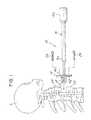
- FIG. 1is a view illustrating a system for co-insertion of an implant having a cage and plate during a surgical procedure in accordance with one embodiment of the invention
- FIG. 2is a perspective view showing the system of FIG. 1 ;
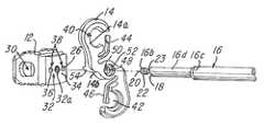
- FIG. 3is an exploded view showing the cage, plate and inserter shown in assembled form in FIGS. 1 and 2 ;
- FIG. 4is a view showing various details of the plate
- FIG. 5is another exploded view showing the plate with a threaded aperture for threadably receiving the inserter
- FIGS. 6A and 6Bare views of an embodiment showing the inserter traversing a substantial depth of the cage and fastener to a rear wall;
- FIGS. 7A-7Care various fragmentary views illustrating different exemplary embodiments for fastening or coupling the inserter to the cage.
- the system 10includes the inserter 16 which comprises a grip or first end 16 a and a second end 16 b that is threaded as described later herein.
- the inserter 16further comprises an integral elongated portion 16 c which couples the first end 16 a to the second end 16 b.
- the inserter 16comprises a stop or shoulder 18 . As described in more detail later herein, the shoulder 18 ( FIG. 3 ) engages the plate 14 as described later herein.
- the second end 16 bcomprises an inserter fastener 20 which in the illustration being described comprises threads 22 .
- the inserter fastener 20is shown as having threads 22 in the illustration, it should be understood that the inserter fastener 20 could be any suitable means for coupling the inserter 16 to at least one of the cage 12 or plate 14 so that they may be substantially simultaneously mounted on the inserter 16 and implanted into a patient P ( FIG. 1 ) during a surgical procedure.
- the illustration describedshows a threaded coupling between the cage 12 and inserter 16
- a non-threaded fastener, coupler or coupling meansmay be used.
- FIG. 7Ashows a camming coupling 21 a at the end 16 b with a complementary coupling aperture 21 b in the cage 12 .
- FIG. 7Bshows a keying connection 23 a with a complementary keying coupling aperture 23 b .
- FIG. 7Cshows a spreading or clamping coupling 25 a at end 16 b and a complementary spreading or clamping aperture 25 b.
- FIG. 1shows the inserter 16 being used to substantially simultaneously insert the cage 12 and plate 14 into the patient such that the cage 12 becomes situated between a first vertebra 24 and a second vertebra 26 as illustrated.
- at least one or a plurality of screws 28may be received in at least one aperture 40 and 42 of the plate 14 and screwed into, for example, the first vertebra 24 in a manner conventionally known in order to secure the plate 14 thereto.
- the plate 14is not secured, coupled or fixed to the cage 12 and can move, migrate or float with respect thereto.
- the cage 12 and plate 14are separate components.
- the cage 12comprises a plurality of apertures 30 through which a graft material 15 ( FIG. 1 ) may be inserted or packed into the cage 12 .
- the cage 12further comprises at least one coupler 32 .
- the at least one coupler 32has a threaded cage wall 32 a that defines a threaded opening 34 for receiving the threads 22 of the inserter 16 as illustrated in FIGS. 1-3 .
- the at least one coupler 32 and inserter fastener 20may be any suitable means or method for affixing a portion, such as the second end 16 b , of the inserter 16 to the cage 12 after the inserter 16 has received the plate 14 .
- the inserter fastener 20is at the second end 16 b of the inserter 16 , it should be understood that it does not necessarily have to be on the second end 16 b , and it could be situated at other locations on the inserter 16 .
- the cage 12further comprises at least one or a plurality of aligning walls 36 that define at least one or a plurality of aligning apertures 38 as shown.
- the function and operation of the at least one or a plurality of aligning apertures 38will be described later herein.
- the plate 14comprises a first side 14 a and a second side 14 b as shown.
- the plate 14is adapted or configured to define a plurality of screw receiving openings 40 and 42 which have an associated integral lock 44 and 46 , respectively.
- the operation of the integral lockis similar to that described in U.S. Pat. Nos. 7,182,782; 7,641,701; 7,655,028 and U.S. Patent Publications 2006/0195100; 2007/0123885; 2008/0021476 and 2010/0145453, all of which are incorporated herein by reference and made a part hereof.
- Features of the plates in those referencesmay also be used in the embodiments being described.
- the plate 14has an internal wall 48 that defines a through-hole 50 for receiving the second end 16 b of the inserter 16 .
- the through-hole 50is not threaded and is sized to permit the threads 22 of inserter 16 to pass through the through-hole 50 .
- the second end 16 b of the inserter 16has a shank or elongated portion 25 , a portion of which comprises the threads 22 and an unthreaded portion 23 as illustrated in FIG. 3 .
- the internal wall 48becomes operatively associated with the unthreaded portion 23 after the second end 16 b is inserted in the through-hole 50 as shown.
- the plate 14may further comprise a receiving shoulder 52 for receiving the stop or shoulder 18 so that the plate 14 does not ride along an unthreaded shank portion or end 16 d of the inserter 16 .
- the second end 16 bis inserted through the through-hole 50 of the plate 14 and then screwed into the threaded opening 34 so that the plate 14 becomes secured between the stop or shoulder 18 and the cage 12 as shown.
- the inserter 16may be used to position the cage 12 between the first vertebra 24 and the second vertebra 26 and held in place while at least one screw 28 is received in the at least one aperture 40 and 42 and screwed into bone.
- the inserter 16is unscrewed from the cage 12 and withdrawn from the plate 14 and the patient.
- At least one of or both of the cage 12 or plate 14may comprise at least one or plurality of aligners 54 and 56 ( FIG. 4 ).
- the at least one or plurality of aligners 54 and 56are integrally formed in the plate 14 as shown.
- the at least one or plurality of aligners 54 and 56are received in the aligning apertures 38 and cause the plate 14 to be generally aligned with the cage 12 after the inserter 16 receives the plate 14 and cage 12 .
- other means for aligning the plate 14 relative to the cage 12may be provided.
- the at least one or plurality of aligners 54 and 56facilitate aligning the cage 12 to the plate 14 and also facilitate preventing the plate 14 or cage 12 from any rotational movement when the inserter 16 is unscrewed or dismounted from the cage 12 and plate 14 .
- the at least one or plurality of aligners 54 and 56are integral projections that extend away from surface 14 b as shown in FIGS. 4 and 5 .
- FIG. 5illustrates another embodiment wherein the plate 14 comprises an internal threaded wall 60 as shown.
- the second end 16 b of the inserter 16has threads 22 that are long enough to screw into both the plate 14 and the cage 12 to threadably secure the cage 12 and plate 14 together.
- the end 16 d of the inserter 16is passed through the through-hole 50 and then screwed into the threaded opening 34 in the cage 12 .
- the threaded second end 16 b of the inserter 16is screwed first into the internal wall 48 of the plate 14 and then into the threaded opening 34 of the cage 12 to secure the cage 12 and plate 14 to the inserter 16 .
- the stop or shoulder 18is received in the receiving shoulder 52 of the plate 14 .
- the inserter 16substantially simultaneously receives and supports the cage 12 and plate 14 so that simultaneous implanting of the cage 12 and plate 14 using the inserter 16 can be performed during a surgical procedure.
- the co-insertion system 10enables the cage 12 and the plate 14 to substantially simultaneously be positioned such that the cage 12 is received in the area between the vertebra 24 and vertebra 26 .
- the inserter 16may be unscrewed or rotated and removed from the cage 12 and plate 14 .
- the inserter 16may be held in place while at least one of the plurality of screws 28 is used to secure the plate 14 to at least one of the vertebra 24 or 26 .
- the inserter 16may be unscrewed from the cage 12 and/or plate 14 . It should be understood, therefore, that the inserter 16 is first removed from the cage 12 and then removed from the plate 14 at the end of the surgical procedure. In contrast the inserter 16 is inserted first through the plate 14 and then into the cage 12 when the inserter 16 is mounted to these components.
- the at least one or plurality of aligners 54 and 56may be used to align and maintain alignment of the cage 12 and plate 14 together.
- the system and method 10enable the co-insertion or substantially simultaneous insertion of the cage 12 and plate 14 using a single tool, namely, the inserter 16 .
- the cage 12is first packed or loaded with the graft material 15 ( FIG. 1 ) either before or after the plate 14 and cage 12 are mounted on the inserter 16 .
- the graft material 15may be inserted or packed into the cage 12 after it is positioned in the patient.
- At least one or a plurality of bone-penetrating prongsmay be situated on the second side 14 b of the plate 14 to penetrate the bone and facilitate stabilizing the plate 14 during or following insertion or when the inserter 16 is removed from the plate 14 and cage 12 .
- the at least one or plurality of aligners 54 and 56are illustrated as being integral with the plate 14 , other types of aligners could be used and/or the aligners could be situated on or even integral with the cage 12 , with the plate 14 being adapted to receive the at least one or plurality of aligners 54 and 56 , such as by providing receiving apertures in the plate 14 .
- Another feature of the system and method 10 described hereinis that it facilitates or enables implantation of two independent and un-coupled components, namely the cage 12 and plate 14 .
- the cage 12 and plate 14are not coupled directly together in the illustrations being described.
- this feature of the plate 14 relative to the cage 12can be provided similar to that which is shown in U.S. Pat. No. 7,182,782, which is owned by the Assignee of the present application and which is incorporated herein by reference and made a part hereof.
- the plate 14may be comprised of a shortened length plate 14 which does not extend past the upper and lower borders of the cage 12 .
- the plate 14may incorporate various screw-plate locking mechanisms to prevent rotation and/or expulsion of fixation screws 28 .
- the plate 14may comprise various screw arrangements and/or angulations, such as one upward screw 28 or downward screw alone; one upward and one downward; two upward and one downward; one upward and two downward; or two upward and two downward or the like.
- the cage 12may comprise a reduced, fenestrated or eliminated front wall, such that the inserter 16 can transverse the plate 14 and a substantial depth of the cage 12 with the inserter 16 engaging a rearward wall 12 a of the cage 12 .
- This featureis illustrated in FIGS. 6A and 6B and shows the inserter 16 traversing the depth of the cage 12 so that it can fasten to a rear wall 12 a of the cage 12 as shown.
- the inserter 16 to cage 12 mechanical couplingmay incorporate various fixation means mentioned earlier, such as threading, camming, keying, spreading, clamping and otherwise reversibly locking the inserter 16 to the cage 12 .
- the componentscan be made from any biocompatible material.
- Potential biocompatible materialscomprise metals (for example, titanium), metal alloys (for example, titanium alloy), carbon fibers, composites, polymers or hybrid materials.
Landscapes
- Health & Medical Sciences (AREA)
- Orthopedic Medicine & Surgery (AREA)
- Engineering & Computer Science (AREA)
- Biomedical Technology (AREA)
- Life Sciences & Earth Sciences (AREA)
- Neurology (AREA)
- Animal Behavior & Ethology (AREA)
- Veterinary Medicine (AREA)
- Heart & Thoracic Surgery (AREA)
- Public Health (AREA)
- General Health & Medical Sciences (AREA)
- Transplantation (AREA)
- Surgery (AREA)
- Oral & Maxillofacial Surgery (AREA)
- Vascular Medicine (AREA)
- Cardiology (AREA)
- Nuclear Medicine, Radiotherapy & Molecular Imaging (AREA)
- Medical Informatics (AREA)
- Molecular Biology (AREA)
- Physical Education & Sports Medicine (AREA)
- Dentistry (AREA)
- Prostheses (AREA)
Abstract
Description
Claims (21)
Priority Applications (2)
| Application Number | Priority Date | Filing Date | Title |
|---|---|---|---|
| US13/017,622US8945227B2 (en) | 2010-02-01 | 2011-01-31 | Spinal implant co-insertion system and method |
| US14/593,348US20150119992A1 (en) | 2010-02-01 | 2015-01-09 | Spinal implant co-insertion system and method |
Applications Claiming Priority (2)
| Application Number | Priority Date | Filing Date | Title |
|---|---|---|---|
| US30010210P | 2010-02-01 | 2010-02-01 | |
| US13/017,622US8945227B2 (en) | 2010-02-01 | 2011-01-31 | Spinal implant co-insertion system and method |
Related Child Applications (1)
| Application Number | Title | Priority Date | Filing Date |
|---|---|---|---|
| US14/593,348ContinuationUS20150119992A1 (en) | 2010-02-01 | 2015-01-09 | Spinal implant co-insertion system and method |
Publications (2)
| Publication Number | Publication Date |
|---|---|
| US20110190892A1 US20110190892A1 (en) | 2011-08-04 |
| US8945227B2true US8945227B2 (en) | 2015-02-03 |
Family
ID=44342317
Family Applications (2)
| Application Number | Title | Priority Date | Filing Date |
|---|---|---|---|
| US13/017,622Active2032-02-15US8945227B2 (en) | 2010-02-01 | 2011-01-31 | Spinal implant co-insertion system and method |
| US14/593,348AbandonedUS20150119992A1 (en) | 2010-02-01 | 2015-01-09 | Spinal implant co-insertion system and method |
Family Applications After (1)
| Application Number | Title | Priority Date | Filing Date |
|---|---|---|---|
| US14/593,348AbandonedUS20150119992A1 (en) | 2010-02-01 | 2015-01-09 | Spinal implant co-insertion system and method |
Country Status (1)
| Country | Link |
|---|---|
| US (2) | US8945227B2 (en) |
Cited By (25)
| Publication number | Priority date | Publication date | Assignee | Title |
|---|---|---|---|---|
| US20130060337A1 (en)* | 2011-09-06 | 2013-03-07 | Samuel Petersheim | Spinal Plate |
| US20150119992A1 (en)* | 2010-02-01 | 2015-04-30 | X-Spine Systems, Inc. | Spinal implant co-insertion system and method |
| US20170049579A1 (en)* | 2015-08-19 | 2017-02-23 | Raymond J. Quinlan | Spinal Fusion Device And Method Of Using Same |
| US20180221155A1 (en)* | 2012-08-03 | 2018-08-09 | Globus Medical, Inc. | Intervertebral implant |
| US10085847B2 (en) | 2011-11-17 | 2018-10-02 | Zimmer Biomet Spine, Inc. | Modular anchor bone fusion cage |
| US10327910B2 (en) | 2013-03-14 | 2019-06-25 | X-Spine Systems, Inc. | Spinal implant and assembly |
| US20200289178A1 (en)* | 2019-01-11 | 2020-09-17 | Gordon D Donald | Self-aligning plating system and method |
| US10932922B2 (en) | 2018-04-20 | 2021-03-02 | JWD Products, LLC | Spinal implant insertion tool |
| US11026726B2 (en) | 2012-06-29 | 2021-06-08 | K2M, Inc. | Minimal-profile anterior cervical plate and cage apparatus and method of using same |
| US11058552B2 (en)* | 2017-06-21 | 2021-07-13 | NVision Biomedical Technologies, LLC | Anterior lumbar interbody fusion cage and plate |
| US11224524B2 (en) | 2015-02-02 | 2022-01-18 | Spinal Elements, Inc. | Interbody implant inserter |
| US11253368B2 (en) | 2017-02-14 | 2022-02-22 | Nanohive Medical Llc | Methods of designing high x-ray lucency lattice structures |
| US11273058B2 (en)* | 2019-05-07 | 2022-03-15 | Spinal Elements, Inc. | Cervical plate and inserter |
| US11291558B2 (en)* | 2018-07-26 | 2022-04-05 | Nanohive Medical Llc | Dynamic implant fixation plate |
| US11298244B2 (en) | 2019-01-31 | 2022-04-12 | K2M, Inc. | Interbody implants and instrumentation |
| US11304737B1 (en)* | 2020-11-19 | 2022-04-19 | Design Enterprises, Llc | Placement jigs for osteosynthesis systems and related methods |
| US11324609B2 (en) | 2018-04-20 | 2022-05-10 | JWD Products, LLC | Spinal implant insertion tool |
| US11351038B2 (en) | 2012-02-17 | 2022-06-07 | Spinal Elements, Inc. | Interbody fusion device |
| US11497617B2 (en) | 2019-01-16 | 2022-11-15 | Nanohive Medical Llc | Variable depth implants |
| US11534307B2 (en) | 2019-09-16 | 2022-12-27 | K2M, Inc. | 3D printed cervical standalone implant |
| US11648124B2 (en) | 2017-04-01 | 2023-05-16 | Nanohive Medical Llc | Methods of designing three-dimensional lattice structures for implants |
| US20230255793A1 (en)* | 2018-10-10 | 2023-08-17 | K2M, Inc. | Sagittal Balance Systems And Methods Of Use Thereof |
| US11737879B2 (en)* | 2013-10-18 | 2023-08-29 | Kenan Aksu | Sacroiliac joint implants and implantation methods |
| US11931266B2 (en) | 2016-06-07 | 2024-03-19 | Nanohive Medical Llc | Implant with independent endplates |
| US20240382317A1 (en)* | 2023-05-16 | 2024-11-21 | Globus Medical, Inc. | Modular lateral plating system and related methods |
Families Citing this family (33)
| Publication number | Priority date | Publication date | Assignee | Title |
|---|---|---|---|---|
| US9039768B2 (en) | 2006-12-22 | 2015-05-26 | Medos International Sarl | Composite vertebral spacers and instrument |
| US20090248092A1 (en) | 2008-03-26 | 2009-10-01 | Jonathan Bellas | Posterior Intervertebral Disc Inserter and Expansion Techniques |
| US9283010B2 (en)* | 2008-05-05 | 2016-03-15 | Trimed, Incorporated | Contoured bone plate for fracture fixation having hook members and holder/impactor for same |
| US9526620B2 (en) | 2009-03-30 | 2016-12-27 | DePuy Synthes Products, Inc. | Zero profile spinal fusion cage |
| US10842642B2 (en)* | 2009-04-16 | 2020-11-24 | Nuvasive, Inc. | Methods and apparatus of performing spine surgery |
| US9393129B2 (en) | 2009-12-10 | 2016-07-19 | DePuy Synthes Products, Inc. | Bellows-like expandable interbody fusion cage |
| EP2547273A4 (en)* | 2010-03-19 | 2014-10-29 | Josef Gorek | ANTERIOR SUPPORT FOR SPINAL FASTENING |
| US20120078373A1 (en) | 2010-09-23 | 2012-03-29 | Thomas Gamache | Stand alone intervertebral fusion device |
| US20120078372A1 (en) | 2010-09-23 | 2012-03-29 | Thomas Gamache | Novel implant inserter having a laterally-extending dovetail engagement feature |
| US11529241B2 (en) | 2010-09-23 | 2022-12-20 | DePuy Synthes Products, Inc. | Fusion cage with in-line single piece fixation |
| US8940030B1 (en) | 2011-01-28 | 2015-01-27 | Nuvasive, Inc. | Spinal fixation system and related methods |
| US9636230B2 (en)* | 2011-08-25 | 2017-05-02 | Vikram Talwar | Interbody fusion implant and screw guide |
| US9668783B2 (en) | 2011-09-06 | 2017-06-06 | Atul Goel | Devices and method for treatment of spondylotic disease |
| US9248028B2 (en) | 2011-09-16 | 2016-02-02 | DePuy Synthes Products, Inc. | Removable, bone-securing cover plate for intervertebral fusion cage |
| US20140058446A1 (en)* | 2011-09-28 | 2014-02-27 | Avi Bernstein | Spinal implant system |
| US9913732B2 (en)* | 2011-11-02 | 2018-03-13 | Spinesmith Partners, L.P. | Interbody fusion device with separable retention component for lateral approach and associated methods |
| US9198764B2 (en) | 2012-01-31 | 2015-12-01 | Blackstone Medical, Inc. | Intervertebral disc prosthesis and method |
| US9271836B2 (en)* | 2012-03-06 | 2016-03-01 | DePuy Synthes Products, Inc. | Nubbed plate |
| US10182921B2 (en) | 2012-11-09 | 2019-01-22 | DePuy Synthes Products, Inc. | Interbody device with opening to allow packing graft and other biologics |
| EP2945574B1 (en)* | 2013-01-16 | 2019-12-18 | Retrospine Pty Ltd. | Spinal plate selection and positioning system |
| US20140257483A1 (en)* | 2013-03-05 | 2014-09-11 | Karl W. Swann | Method and device for cervical bone marrow aspiration for use in an anterior cervical discectomy and fusion procedure |
| US9180022B2 (en)* | 2013-06-28 | 2015-11-10 | DePuy Synthes Products, Inc. | Spinal alignment clip |
| US10603187B2 (en)* | 2013-07-17 | 2020-03-31 | Aesculap Implant Systems, Llc | Spinal interbody device, system and method |
| US9526629B2 (en)* | 2013-09-27 | 2016-12-27 | Amedica Corporation | Spinal implants and related instruments and methods |
| US9283091B2 (en)* | 2013-10-07 | 2016-03-15 | Warsaw Orthopedic, Inc. | Spinal implant system and method |
| US9730802B1 (en)* | 2014-01-14 | 2017-08-15 | Nuvasive, Inc. | Spinal fusion implant and related methods |
| US9642723B2 (en) | 2014-02-27 | 2017-05-09 | Alphatec Spine, Inc. | Spinal implants and insertion instruments |
| US9603718B2 (en)* | 2014-02-27 | 2017-03-28 | Alphatec Spine, Inc. | Spacer with temporary fixation plate |
| CN204158475U (en)* | 2014-10-27 | 2015-02-18 | 上海三友医疗器械有限公司 | A kind of fusion device and clamping device thereof |
| WO2017175024A2 (en)* | 2015-08-31 | 2017-10-12 | Retrospine Pty Ltd | Spinal plate selection and positioning system |
| US10092403B2 (en)* | 2015-10-20 | 2018-10-09 | Alphatec Spine, Inc. | Systems and methods for securely assembling a spinal implant |
| AU2017100001A4 (en)* | 2016-07-26 | 2017-02-23 | Prism Surgical Designs Pty Ltd | A Spinal Fixation and Guidance System |
| US10940016B2 (en) | 2017-07-05 | 2021-03-09 | Medos International Sarl | Expandable intervertebral fusion cage |
Citations (67)
| Publication number | Priority date | Publication date | Assignee | Title |
|---|---|---|---|---|
| US5423826A (en) | 1993-02-05 | 1995-06-13 | Danek Medical, Inc. | Anterior cervical plate holder/drill guide and method of use |
| US5423825A (en) | 1992-06-10 | 1995-06-13 | Levine; Andrew S. | Spinal fusion instruments and methods |
| US5522899A (en) | 1988-06-28 | 1996-06-04 | Sofamor Danek Properties, Inc. | Artificial spinal fusion implants |
| US5599279A (en) | 1994-03-16 | 1997-02-04 | Gus J. Slotman | Surgical instruments and method useful for endoscopic spinal procedures |
| US5653761A (en) | 1994-03-18 | 1997-08-05 | Pisharodi; Madhavan | Method of lumbar intervertebral disk stabilization |
| US5722977A (en) | 1996-01-24 | 1998-03-03 | Danek Medical, Inc. | Method and means for anterior lumbar exact cut with quadrilateral osteotome and precision guide/spacer |
| US5782919A (en) | 1995-03-27 | 1998-07-21 | Sdgi Holdings, Inc. | Interbody fusion device and method for restoration of normal spinal anatomy |
| US5888224A (en) | 1993-09-21 | 1999-03-30 | Synthesis (U.S.A.) | Implant for intervertebral space |
| US6030390A (en) | 1999-01-08 | 2000-02-29 | Mehdizadeh; Hamid M. | Disc space spreader |
| US6039761A (en) | 1997-02-12 | 2000-03-21 | Li Medical Technologies, Inc. | Intervertebral spacer and tool and method for emplacement thereof |
| US6042582A (en) | 1997-05-20 | 2000-03-28 | Ray; Charles D. | Instrumentation and method for facilitating insertion of spinal implant |
| US6063088A (en) | 1997-03-24 | 2000-05-16 | United States Surgical Corporation | Method and instrumentation for implant insertion |
| US6066174A (en) | 1995-10-16 | 2000-05-23 | Sdgi Holdings, Inc. | Implant insertion device |
| US6074390A (en) | 1997-01-02 | 2000-06-13 | St. Francis Medical Technologies, Inc. | Spine distraction implant and method |
| US6083225A (en) | 1996-03-14 | 2000-07-04 | Surgical Dynamics, Inc. | Method and instrumentation for implant insertion |
| US6096038A (en) | 1988-06-13 | 2000-08-01 | Michelson; Gary Karlin | Apparatus for inserting spinal implants |
| US6113602A (en) | 1999-03-26 | 2000-09-05 | Sulzer Spine-Tech Inc. | Posterior spinal instrument guide and method |
| US6139551A (en) | 1995-06-07 | 2000-10-31 | Sdgi Holdings, Inc. | Anterior spinal instrumentation and method for implantation and revision |
| US6159215A (en) | 1997-12-19 | 2000-12-12 | Depuy Acromed, Inc. | Insertion instruments and method for delivering a vertebral body spacer |
| US6174311B1 (en) | 1998-10-28 | 2001-01-16 | Sdgi Holdings, Inc. | Interbody fusion grafts and instrumentation |
| US6210412B1 (en) | 1988-06-13 | 2001-04-03 | Gary Karlin Michelson | Method for inserting frusto-conical interbody spinal fusion implants |
| US6224607B1 (en) | 1999-01-25 | 2001-05-01 | Gary K. Michelson | Instrumentation and method for creating an intervertebral space for receiving an implant |
| US6235059B1 (en) | 1996-04-03 | 2001-05-22 | Scient'x (Societe A Responsabilite Limitee) | Intersomatic setting and fusion system |
| US6261296B1 (en) | 1998-10-02 | 2001-07-17 | Synthes U.S.A. | Spinal disc space distractor |
| US6267763B1 (en) | 1999-03-31 | 2001-07-31 | Surgical Dynamics, Inc. | Method and apparatus for spinal implant insertion |
| US6270498B1 (en) | 1988-06-13 | 2001-08-07 | Gary Karlin Michelson | Apparatus for inserting spinal implants |
| US6319257B1 (en) | 1999-12-20 | 2001-11-20 | Kinamed, Inc. | Inserter assembly |
| US6432106B1 (en)* | 1999-11-24 | 2002-08-13 | Depuy Acromed, Inc. | Anterior lumbar interbody fusion cage with locking plate |
| US6478800B1 (en) | 2000-05-08 | 2002-11-12 | Depuy Acromed, Inc. | Medical installation tool |
| US6576017B2 (en) | 2001-02-06 | 2003-06-10 | Sdgi Holdings, Inc. | Spinal implant with attached ligament and methods |
| US6635087B2 (en) | 2001-08-29 | 2003-10-21 | Christopher M. Angelucci | Laminoplasty implants and methods of use |
| US6652533B2 (en) | 2001-09-20 | 2003-11-25 | Depuy Acromed, Inc. | Medical inserter tool with slaphammer |
| US6666866B2 (en) | 2000-11-07 | 2003-12-23 | Osteotech, Inc. | Spinal intervertebral implant insertion tool |
| US6770074B2 (en) | 1988-06-13 | 2004-08-03 | Gary Karlin Michelson | Apparatus for use in inserting spinal implants |
| US6896676B2 (en) | 2003-03-06 | 2005-05-24 | Spinecore, Inc. | Instrumentation and methods for use in implanting a cervical disc replacement device |
| US6926737B2 (en) | 1998-10-21 | 2005-08-09 | Roger P. Jackson | Spinal fusion apparatus and method |
| US6972019B2 (en) | 2001-01-23 | 2005-12-06 | Michelson Gary K | Interbody spinal implant with trailing end adapted to receive bone screws |
| US6991654B2 (en) | 2002-10-21 | 2006-01-31 | Sdgi Holdings, Inc. | Systems and techniques for restoring and maintaining intervertebral anatomy |
| US20060036250A1 (en)* | 2004-08-12 | 2006-02-16 | Lange Eric C | Antero-lateral plating systems for spinal stabilization |
| US20060195100A1 (en) | 2003-09-30 | 2006-08-31 | X-Spine Systems, Inc. | Spinal fusion system utilizing an implant plate having at least one integral lock |
| US7112222B2 (en)* | 2003-03-31 | 2006-09-26 | Depuy Spine, Inc. | Anterior lumbar interbody fusion cage with locking plate |
| US7163561B2 (en) | 2000-07-10 | 2007-01-16 | Warsaw Orthopedic, Inc. | Flanged interbody spinal fusion implants |
| US7172627B2 (en) | 2001-04-03 | 2007-02-06 | Scient'x | Stabilized interbody fusion system for vertebrae |
| US7182782B2 (en) | 2003-09-30 | 2007-02-27 | X-Spine Systems, Inc. | Spinal fusion system and method for fusing spinal bones |
| US20070123885A1 (en) | 2003-09-30 | 2007-05-31 | X-Spine Systems, Inc. | Screw locking mechanism and method |
| US7232464B2 (en) | 2002-02-19 | 2007-06-19 | Synthes (Usa) | Intervertebral implant |
| US7235105B2 (en)* | 2003-09-18 | 2007-06-26 | Jackson Roger P | Threaded center line cage with winged end gap |
| US7244258B2 (en) | 1999-02-04 | 2007-07-17 | Warsaw Orthopedic, Inc. | Methods and instrumentation for vertebral interbody fusion |
| US7252673B2 (en) | 2003-09-10 | 2007-08-07 | Warsaw Orthopedic, Inc. | Devices and methods for inserting spinal implants |
| US7300441B2 (en) | 2003-08-20 | 2007-11-27 | Sdgi Holdings, Inc. | Technique and instrumentation for preparation of vertebral members |
| US20080021476A1 (en) | 2003-09-30 | 2008-01-24 | X-Spine Systems, Inc. | Spinal fusion system utilizing an implant plate having at least one integral lock and ratchet lock |
| US20080161925A1 (en)* | 2006-10-04 | 2008-07-03 | Seaspine, Inc. | Articulating spinal implant |
| US20080221695A1 (en)* | 2007-03-01 | 2008-09-11 | Jacofsky Marc C | Spinal interbody spacer device |
| US20080294262A1 (en)* | 2005-12-05 | 2008-11-27 | Jerome Levieux | Cages for Setting and Intersomatically Fusing Vertebrae |
| US20090012529A1 (en)* | 2007-07-02 | 2009-01-08 | Jason Blain | Device and method for delivery of multiple heterogenous orthopedic implants |
| US7537603B2 (en) | 2002-07-22 | 2009-05-26 | Acumed Llc | Bone fusion system |
| US7547306B2 (en) | 2001-06-04 | 2009-06-16 | Warsaw Orthopedic, Inc. | Method for installation of dynamic, single-lock anterior cervical plate system having non-detachably fastened and moveable segments |
| US20090182430A1 (en)* | 2008-01-16 | 2009-07-16 | Aesculap Implant Systems, Inc. | Dynamic interbody |
| US7594931B2 (en) | 2001-07-13 | 2009-09-29 | Ldr Medical | Vertebral cage device with modular fixation |
| US7621938B2 (en) | 2004-01-15 | 2009-11-24 | Warsaw Orthopedic, Inc. | Spinal implant construct and method for implantation |
| US7628816B2 (en) | 2003-04-23 | 2009-12-08 | Friedrich Magerl | Spondylodesis device |
| US7637952B2 (en) | 2002-03-11 | 2009-12-29 | Zimmer Spine, Inc. | Instrumentation and procedure for implanting spinal implant devices |
| US7641701B2 (en) | 2003-09-30 | 2010-01-05 | X-Spine Systems, Inc. | Spinal fusion system and method for fusing spinal bones |
| US7704250B2 (en) | 2001-06-06 | 2010-04-27 | Warsaw Orthopedic, Inc. | Instrumentation for use with dynamic multilock anterior cervical plate system having non-detachably fastened and moveable segments |
| US7740630B2 (en) | 2001-06-04 | 2010-06-22 | Warsaw Orthopedic, Inc. | Anterior cervical plate system having vertebral body engaging anchors and connecting plate |
| US7758616B2 (en) | 2001-04-06 | 2010-07-20 | Warsaw Orthopedic, Inc. | Anterior plating system and method |
| US7815681B2 (en)* | 2006-04-28 | 2010-10-19 | Warsaw Orthopedic, Inc. | Orthopedic support locating or centering feature and method |
Family Cites Families (70)
| Publication number | Priority date | Publication date | Assignee | Title |
|---|---|---|---|---|
| CA1146301A (en)* | 1980-06-13 | 1983-05-17 | J. David Kuntz | Intervertebral disc prosthesis |
| US6066175A (en)* | 1993-02-16 | 2000-05-23 | Henderson; Fraser C. | Fusion stabilization chamber |
| US5520690A (en)* | 1995-04-13 | 1996-05-28 | Errico; Joseph P. | Anterior spinal polyaxial locking screw plate assembly |
| FR2767675B1 (en)* | 1997-08-26 | 1999-12-03 | Materiel Orthopedique En Abreg | INTERSOMATIC IMPLANT AND ANCILLARY OF PREPARATION SUITABLE FOR ALLOWING ITS POSITION |
| US6113637A (en)* | 1998-10-22 | 2000-09-05 | Sofamor Danek Holdings, Inc. | Artificial intervertebral joint permitting translational and rotational motion |
| US6156037A (en)* | 1998-10-28 | 2000-12-05 | Sdgi Holdings, Inc. | Anterior lateral spine cage-plate fixation device and technique |
| US6231610B1 (en)* | 1999-08-25 | 2001-05-15 | Allegiance Corporation | Anterior cervical column support device |
| FR2799639B1 (en)* | 1999-10-18 | 2002-07-19 | Dimso Sa | TOOTHED FACED INTERVERTEBRAL DISC PROSTHESIS |
| ATE390100T1 (en)* | 2000-02-22 | 2008-04-15 | Warsaw Orthopedic Inc | SPINAL IMPLANT AND INTRODUCTION DEVICE |
| FR2811543B1 (en)* | 2000-07-12 | 2003-07-04 | Spine Next Sa | INTERSOMATIC IMPLANT |
| US6402756B1 (en)* | 2001-02-15 | 2002-06-11 | Third Millennium Engineering, Llc | Longitudinal plate assembly having an adjustable length |
| ATE272374T1 (en)* | 2001-12-10 | 2004-08-15 | Link Waldemar Gmbh Co | INSERTION INSTRUMENT FOR SLED PROSTHESES |
| US7238203B2 (en)* | 2001-12-12 | 2007-07-03 | Vita Special Purpose Corporation | Bioactive spinal implants and method of manufacture thereof |
| US20050096657A1 (en)* | 2002-02-26 | 2005-05-05 | Alex Autericque | Osteosynthesis or arthrodesis material comprising a bony plate |
| US20040092929A1 (en)* | 2002-09-27 | 2004-05-13 | Zindrick Michael R. | Spinal plate with means to secure a graft |
| CA2515247C (en)* | 2003-02-06 | 2010-10-05 | Synthes (U.S.A.) | Intervertebral implant |
| AU2004220634B2 (en)* | 2003-03-06 | 2009-09-17 | Spinecore, Inc. | Instrumentation and methods for use in implanting a cervical disc replacement device |
| US7819903B2 (en)* | 2003-03-31 | 2010-10-26 | Depuy Spine, Inc. | Spinal fixation plate |
| US9078706B2 (en)* | 2003-09-30 | 2015-07-14 | X-Spine Systems, Inc. | Intervertebral fusion device utilizing multiple mobile uniaxial and bidirectional screw interface plates |
| US7837732B2 (en)* | 2003-11-20 | 2010-11-23 | Warsaw Orthopedic, Inc. | Intervertebral body fusion cage with keels and implantation methods |
| US8480742B2 (en)* | 2005-08-02 | 2013-07-09 | Perumala Corporation | Total artificial disc |
| US20070032873A1 (en)* | 2005-08-02 | 2007-02-08 | Perumala Corporation | Total artificial intervertebral disc |
| US7918891B1 (en)* | 2004-03-29 | 2011-04-05 | Nuvasive Inc. | Systems and methods for spinal fusion |
| WO2005117725A2 (en)* | 2004-05-27 | 2005-12-15 | Depuy Spine, Inc. | Tri-joint implant |
| US7470273B2 (en)* | 2004-06-25 | 2008-12-30 | Ebi, Llc | Tool for intervertebral implant manipulation |
| US20060106387A1 (en)* | 2004-11-16 | 2006-05-18 | Depuy Spine, Inc. | Spinal plate system and method of use |
| US20060116766A1 (en)* | 2004-12-01 | 2006-06-01 | Jean-Philippe Lemaire | Anterior lumbar interbody implant |
| US20060149284A1 (en)* | 2004-12-15 | 2006-07-06 | Sdgi Holdings, Inc. | Insertion device and method for inserting a member within the body |
| US20060235403A1 (en)* | 2005-03-17 | 2006-10-19 | Jason Blain | Flanged interbody fusion device with locking plate |
| US7435261B1 (en)* | 2005-03-24 | 2008-10-14 | Frank Castro | Spinal implant and method of using spinal implant |
| US8673006B2 (en)* | 2005-03-24 | 2014-03-18 | Igip, Llc | Spinal implant |
| US8361149B2 (en)* | 2005-03-24 | 2013-01-29 | Cardinal Spine, Llc | Wedge-like spinal implant |
| US8246683B2 (en)* | 2005-03-24 | 2012-08-21 | Cardinal Spine, Llc | Spinal implant |
| US8226718B2 (en)* | 2005-03-24 | 2012-07-24 | Cardinal Spine, Llc | Spinal implant and method of using spinal implant |
| US7662186B2 (en)* | 2005-05-06 | 2010-02-16 | Titan Spine, Llc | Anterior interbody spinal implant |
| US8545568B2 (en)* | 2005-05-06 | 2013-10-01 | Titan Spine, Llc | Method of using instruments and interbody spinal implants to enhance distraction |
| WO2007056516A2 (en)* | 2005-11-09 | 2007-05-18 | Abdou M S | Bone fixation systems and methods of implantation |
| US20070198016A1 (en)* | 2006-02-21 | 2007-08-23 | Osteomed, L.P. | Compression stabilizing spacers |
| WO2008115975A1 (en)* | 2006-03-22 | 2008-09-25 | Alpinespine Llc | Pivotable interbody spacer system and method |
| FR2904213B1 (en)* | 2006-07-27 | 2008-10-10 | Creaspine Soc Par Actions Simp | INTERVERTEBRAL IMPLANT FOR BONE MELTING |
| GB0623801D0 (en)* | 2006-11-29 | 2007-01-10 | Surgicraft Ltd | Orthopaedic implants and prosthesis |
| US7824427B2 (en)* | 2007-01-16 | 2010-11-02 | Perez-Cruet Miquelangelo J | Minimally invasive interbody device |
| US8211148B2 (en)* | 2007-04-24 | 2012-07-03 | Warsaw Orthopedic | Prostheses for locking an artificial disc in an intervertebral disc space |
| US8480715B2 (en)* | 2007-05-22 | 2013-07-09 | Zimmer Spine, Inc. | Spinal implant system and method |
| US8216312B2 (en)* | 2007-05-31 | 2012-07-10 | Zimmer Spine, Inc. | Spinal interbody system and method |
| US20080312742A1 (en)* | 2007-06-12 | 2008-12-18 | Dennis Lee Abernathie | Anterior Spinal Fusion and Fixation Cage with Integrated Plate and Method of Use |
| WO2009092961A2 (en)* | 2008-01-15 | 2009-07-30 | Henry Graf | Intervertebral stabilization assembly for arthrodesis, comprising an impaction cage body, and an ancillary device for implanting same |
| US20090182428A1 (en)* | 2008-01-16 | 2009-07-16 | Custom Spine, Inc. | Flanged interbody device |
| US8449554B2 (en)* | 2008-03-07 | 2013-05-28 | K2M, Inc. | Intervertebral implant and instrument with removable section |
| WO2009132302A1 (en)* | 2008-04-25 | 2009-10-29 | Pioneer Surgical Technology, Inc. | Bone plate system |
| US8470044B2 (en)* | 2008-05-05 | 2013-06-25 | Maurice Bertholet | Intervertebral prosthetic device |
| EP2328519B1 (en)* | 2008-06-05 | 2014-12-31 | Alphatec Spine, Inc. | Modular anterior locking interbody cage |
| EP2135562B1 (en)* | 2008-06-20 | 2015-09-09 | Arthrex, Inc. | Wedged profile plate |
| US8425514B2 (en)* | 2008-06-25 | 2013-04-23 | Westmark Medical, Llc. | Spinal fixation device |
| USD603503S1 (en)* | 2008-07-03 | 2009-11-03 | Theken Spine, Llc | Cervical plate |
| US9301785B2 (en)* | 2008-10-21 | 2016-04-05 | K2M, Inc. | Spinal buttress plate |
| US8216316B2 (en)* | 2008-12-17 | 2012-07-10 | X-Spine Systems, Inc. | Prosthetic implant with biplanar angulation and compound angles |
| US20100168798A1 (en)* | 2008-12-30 | 2010-07-01 | Clineff Theodore D | Bioactive composites of polymer and glass and method for making same |
| US8257443B2 (en)* | 2009-02-19 | 2012-09-04 | Aflatoon Kamran | Open body box form interbody fusion cage |
| US9220547B2 (en)* | 2009-03-27 | 2015-12-29 | Spinal Elements, Inc. | Flanged interbody fusion device |
| US9526620B2 (en)* | 2009-03-30 | 2016-12-27 | DePuy Synthes Products, Inc. | Zero profile spinal fusion cage |
| US8491658B1 (en)* | 2009-07-12 | 2013-07-23 | Mohammad Etminan | Interbody fusion implant and related methods |
| US20110082550A1 (en)* | 2009-10-07 | 2011-04-07 | Yeh An-Shih | Intervertebral fixation device |
| US8454623B2 (en)* | 2009-11-11 | 2013-06-04 | Alphatec Spine, Inc | Instrument for insertion and deployment of features on an implant |
| US20110172775A1 (en)* | 2010-01-07 | 2011-07-14 | Eric Flickinger | Interbody implant with graft retaining bone cap |
| US8262697B2 (en)* | 2010-01-14 | 2012-09-11 | X-Spine Systems, Inc. | Modular interspinous fixation system and method |
| US8945227B2 (en)* | 2010-02-01 | 2015-02-03 | X-Spine Systems, Inc. | Spinal implant co-insertion system and method |
| US8480747B2 (en)* | 2010-08-11 | 2013-07-09 | Warsaw Orthopedic, Inc. | Interbody spinal implants with extravertebral support plates |
| US8454694B2 (en)* | 2011-03-03 | 2013-06-04 | Warsaw Orthopedic, Inc. | Interbody device and plate for spinal stabilization and instruments for positioning same |
| US9089438B2 (en)* | 2011-06-28 | 2015-07-28 | Spinal Elements, Inc. | Apparatus for promoting movement of nutrients to intervertebral space and method of use |
- 2011
- 2011-01-31USUS13/017,622patent/US8945227B2/enactiveActive
- 2015
- 2015-01-09USUS14/593,348patent/US20150119992A1/ennot_activeAbandoned
Patent Citations (77)
| Publication number | Priority date | Publication date | Assignee | Title |
|---|---|---|---|---|
| US6210412B1 (en) | 1988-06-13 | 2001-04-03 | Gary Karlin Michelson | Method for inserting frusto-conical interbody spinal fusion implants |
| US6096038A (en) | 1988-06-13 | 2000-08-01 | Michelson; Gary Karlin | Apparatus for inserting spinal implants |
| US6270498B1 (en) | 1988-06-13 | 2001-08-07 | Gary Karlin Michelson | Apparatus for inserting spinal implants |
| US6770074B2 (en) | 1988-06-13 | 2004-08-03 | Gary Karlin Michelson | Apparatus for use in inserting spinal implants |
| US5522899A (en) | 1988-06-28 | 1996-06-04 | Sofamor Danek Properties, Inc. | Artificial spinal fusion implants |
| US5423825A (en) | 1992-06-10 | 1995-06-13 | Levine; Andrew S. | Spinal fusion instruments and methods |
| US5423826A (en) | 1993-02-05 | 1995-06-13 | Danek Medical, Inc. | Anterior cervical plate holder/drill guide and method of use |
| US5888224A (en) | 1993-09-21 | 1999-03-30 | Synthesis (U.S.A.) | Implant for intervertebral space |
| US5599279A (en) | 1994-03-16 | 1997-02-04 | Gus J. Slotman | Surgical instruments and method useful for endoscopic spinal procedures |
| US5653761A (en) | 1994-03-18 | 1997-08-05 | Pisharodi; Madhavan | Method of lumbar intervertebral disk stabilization |
| US6093207A (en) | 1994-03-18 | 2000-07-25 | Pisharodi; Madhavan | Middle expanded, removable intervertebral disk stabilizer disk |
| US5782919A (en) | 1995-03-27 | 1998-07-21 | Sdgi Holdings, Inc. | Interbody fusion device and method for restoration of normal spinal anatomy |
| US6139551A (en) | 1995-06-07 | 2000-10-31 | Sdgi Holdings, Inc. | Anterior spinal instrumentation and method for implantation and revision |
| US6066174A (en) | 1995-10-16 | 2000-05-23 | Sdgi Holdings, Inc. | Implant insertion device |
| US5722977A (en) | 1996-01-24 | 1998-03-03 | Danek Medical, Inc. | Method and means for anterior lumbar exact cut with quadrilateral osteotome and precision guide/spacer |
| US6083225A (en) | 1996-03-14 | 2000-07-04 | Surgical Dynamics, Inc. | Method and instrumentation for implant insertion |
| US6235059B1 (en) | 1996-04-03 | 2001-05-22 | Scient'x (Societe A Responsabilite Limitee) | Intersomatic setting and fusion system |
| US6478796B2 (en) | 1997-01-02 | 2002-11-12 | St. Francis Medical Technologies, Inc. | Spin distraction implant and method |
| US6074390A (en) | 1997-01-02 | 2000-06-13 | St. Francis Medical Technologies, Inc. | Spine distraction implant and method |
| US6039761A (en) | 1997-02-12 | 2000-03-21 | Li Medical Technologies, Inc. | Intervertebral spacer and tool and method for emplacement thereof |
| US6063088A (en) | 1997-03-24 | 2000-05-16 | United States Surgical Corporation | Method and instrumentation for implant insertion |
| US6042582A (en) | 1997-05-20 | 2000-03-28 | Ray; Charles D. | Instrumentation and method for facilitating insertion of spinal implant |
| US6159215A (en) | 1997-12-19 | 2000-12-12 | Depuy Acromed, Inc. | Insertion instruments and method for delivering a vertebral body spacer |
| US6261296B1 (en) | 1998-10-02 | 2001-07-17 | Synthes U.S.A. | Spinal disc space distractor |
| US6926737B2 (en) | 1998-10-21 | 2005-08-09 | Roger P. Jackson | Spinal fusion apparatus and method |
| US6610065B1 (en) | 1998-10-28 | 2003-08-26 | Sdgi Holdings, Inc. | Interbody fusion implants and instrumentation |
| US6174311B1 (en) | 1998-10-28 | 2001-01-16 | Sdgi Holdings, Inc. | Interbody fusion grafts and instrumentation |
| US6030390A (en) | 1999-01-08 | 2000-02-29 | Mehdizadeh; Hamid M. | Disc space spreader |
| US6224607B1 (en) | 1999-01-25 | 2001-05-01 | Gary K. Michelson | Instrumentation and method for creating an intervertebral space for receiving an implant |
| US7244258B2 (en) | 1999-02-04 | 2007-07-17 | Warsaw Orthopedic, Inc. | Methods and instrumentation for vertebral interbody fusion |
| US6113602A (en) | 1999-03-26 | 2000-09-05 | Sulzer Spine-Tech Inc. | Posterior spinal instrument guide and method |
| US6267763B1 (en) | 1999-03-31 | 2001-07-31 | Surgical Dynamics, Inc. | Method and apparatus for spinal implant insertion |
| US6432106B1 (en)* | 1999-11-24 | 2002-08-13 | Depuy Acromed, Inc. | Anterior lumbar interbody fusion cage with locking plate |
| US6319257B1 (en) | 1999-12-20 | 2001-11-20 | Kinamed, Inc. | Inserter assembly |
| US6478800B1 (en) | 2000-05-08 | 2002-11-12 | Depuy Acromed, Inc. | Medical installation tool |
| US7163561B2 (en) | 2000-07-10 | 2007-01-16 | Warsaw Orthopedic, Inc. | Flanged interbody spinal fusion implants |
| US6666866B2 (en) | 2000-11-07 | 2003-12-23 | Osteotech, Inc. | Spinal intervertebral implant insertion tool |
| US6972019B2 (en) | 2001-01-23 | 2005-12-06 | Michelson Gary K | Interbody spinal implant with trailing end adapted to receive bone screws |
| US6576017B2 (en) | 2001-02-06 | 2003-06-10 | Sdgi Holdings, Inc. | Spinal implant with attached ligament and methods |
| US7172627B2 (en) | 2001-04-03 | 2007-02-06 | Scient'x | Stabilized interbody fusion system for vertebrae |
| US7758616B2 (en) | 2001-04-06 | 2010-07-20 | Warsaw Orthopedic, Inc. | Anterior plating system and method |
| US7547306B2 (en) | 2001-06-04 | 2009-06-16 | Warsaw Orthopedic, Inc. | Method for installation of dynamic, single-lock anterior cervical plate system having non-detachably fastened and moveable segments |
| US7740630B2 (en) | 2001-06-04 | 2010-06-22 | Warsaw Orthopedic, Inc. | Anterior cervical plate system having vertebral body engaging anchors and connecting plate |
| US7704250B2 (en) | 2001-06-06 | 2010-04-27 | Warsaw Orthopedic, Inc. | Instrumentation for use with dynamic multilock anterior cervical plate system having non-detachably fastened and moveable segments |
| US7594931B2 (en) | 2001-07-13 | 2009-09-29 | Ldr Medical | Vertebral cage device with modular fixation |
| US6635087B2 (en) | 2001-08-29 | 2003-10-21 | Christopher M. Angelucci | Laminoplasty implants and methods of use |
| US6652533B2 (en) | 2001-09-20 | 2003-11-25 | Depuy Acromed, Inc. | Medical inserter tool with slaphammer |
| US7618456B2 (en) | 2002-02-19 | 2009-11-17 | Synthes Usa, Llc | Intervertebral implant |
| US7232464B2 (en) | 2002-02-19 | 2007-06-19 | Synthes (Usa) | Intervertebral implant |
| US7637952B2 (en) | 2002-03-11 | 2009-12-29 | Zimmer Spine, Inc. | Instrumentation and procedure for implanting spinal implant devices |
| US7537603B2 (en) | 2002-07-22 | 2009-05-26 | Acumed Llc | Bone fusion system |
| US6991654B2 (en) | 2002-10-21 | 2006-01-31 | Sdgi Holdings, Inc. | Systems and techniques for restoring and maintaining intervertebral anatomy |
| US7648511B2 (en) | 2003-03-06 | 2010-01-19 | Spinecore, Inc. | Instrumentation and methods for use in implanting a cervical disc replacement device |
| US7674292B2 (en) | 2003-03-06 | 2010-03-09 | Spinecore, Inc. | Instrumentation and methods for use in implanting a cervical disc replacement device |
| US7641665B2 (en) | 2003-03-06 | 2010-01-05 | Spinecore, Inc. | Instrumentation and methods for use in implementing a cervical disc replacement device |
| US7637911B2 (en) | 2003-03-06 | 2009-12-29 | Spinecore, Inc. | Instrumentation and methods for use in implanting a cervical disc replacement device |
| US6896676B2 (en) | 2003-03-06 | 2005-05-24 | Spinecore, Inc. | Instrumentation and methods for use in implanting a cervical disc replacement device |
| US7112222B2 (en)* | 2003-03-31 | 2006-09-26 | Depuy Spine, Inc. | Anterior lumbar interbody fusion cage with locking plate |
| US7628816B2 (en) | 2003-04-23 | 2009-12-08 | Friedrich Magerl | Spondylodesis device |
| US7300441B2 (en) | 2003-08-20 | 2007-11-27 | Sdgi Holdings, Inc. | Technique and instrumentation for preparation of vertebral members |
| US7252673B2 (en) | 2003-09-10 | 2007-08-07 | Warsaw Orthopedic, Inc. | Devices and methods for inserting spinal implants |
| US7235105B2 (en)* | 2003-09-18 | 2007-06-26 | Jackson Roger P | Threaded center line cage with winged end gap |
| US20070123885A1 (en) | 2003-09-30 | 2007-05-31 | X-Spine Systems, Inc. | Screw locking mechanism and method |
| US20080021476A1 (en) | 2003-09-30 | 2008-01-24 | X-Spine Systems, Inc. | Spinal fusion system utilizing an implant plate having at least one integral lock and ratchet lock |
| US20060195100A1 (en) | 2003-09-30 | 2006-08-31 | X-Spine Systems, Inc. | Spinal fusion system utilizing an implant plate having at least one integral lock |
| US7641701B2 (en) | 2003-09-30 | 2010-01-05 | X-Spine Systems, Inc. | Spinal fusion system and method for fusing spinal bones |
| US20100145453A1 (en) | 2003-09-30 | 2010-06-10 | X-Spine Systems, Inc. | Fusion system and method for fusing spinal bones |
| US7182782B2 (en) | 2003-09-30 | 2007-02-27 | X-Spine Systems, Inc. | Spinal fusion system and method for fusing spinal bones |
| US7655028B2 (en) | 2003-09-30 | 2010-02-02 | X-Spine Systems, Inc. | Spinal fusion system and method for fusing spinal bones |
| US7621938B2 (en) | 2004-01-15 | 2009-11-24 | Warsaw Orthopedic, Inc. | Spinal implant construct and method for implantation |
| US20060036250A1 (en)* | 2004-08-12 | 2006-02-16 | Lange Eric C | Antero-lateral plating systems for spinal stabilization |
| US20080294262A1 (en)* | 2005-12-05 | 2008-11-27 | Jerome Levieux | Cages for Setting and Intersomatically Fusing Vertebrae |
| US7815681B2 (en)* | 2006-04-28 | 2010-10-19 | Warsaw Orthopedic, Inc. | Orthopedic support locating or centering feature and method |
| US20080161925A1 (en)* | 2006-10-04 | 2008-07-03 | Seaspine, Inc. | Articulating spinal implant |
| US20080221695A1 (en)* | 2007-03-01 | 2008-09-11 | Jacofsky Marc C | Spinal interbody spacer device |
| US20090012529A1 (en)* | 2007-07-02 | 2009-01-08 | Jason Blain | Device and method for delivery of multiple heterogenous orthopedic implants |
| US20090182430A1 (en)* | 2008-01-16 | 2009-07-16 | Aesculap Implant Systems, Inc. | Dynamic interbody |
Cited By (51)
| Publication number | Priority date | Publication date | Assignee | Title |
|---|---|---|---|---|
| US20150119992A1 (en)* | 2010-02-01 | 2015-04-30 | X-Spine Systems, Inc. | Spinal implant co-insertion system and method |
| US20200121472A1 (en)* | 2011-09-06 | 2020-04-23 | Globus Medical, Inc. | Spinal plate |
| US10543104B2 (en) | 2011-09-06 | 2020-01-28 | Globus Medical, Inc. | Spinal plate |
| US20130060337A1 (en)* | 2011-09-06 | 2013-03-07 | Samuel Petersheim | Spinal Plate |
| US11684486B2 (en)* | 2011-09-06 | 2023-06-27 | Globus Medical, Inc. | Spinal plate |
| US9427330B2 (en)* | 2011-09-06 | 2016-08-30 | Globus Medical, Inc. | Spinal plate |
| US20230248537A1 (en)* | 2011-09-06 | 2023-08-10 | Globus Medical, Inc. | Spinal plate |
| US10085847B2 (en) | 2011-11-17 | 2018-10-02 | Zimmer Biomet Spine, Inc. | Modular anchor bone fusion cage |
| US11351038B2 (en) | 2012-02-17 | 2022-06-07 | Spinal Elements, Inc. | Interbody fusion device |
| US11026726B2 (en) | 2012-06-29 | 2021-06-08 | K2M, Inc. | Minimal-profile anterior cervical plate and cage apparatus and method of using same |
| US10973653B2 (en)* | 2012-08-03 | 2021-04-13 | Globus Medical, Inc. | Intervertebral implant |
| US20180221155A1 (en)* | 2012-08-03 | 2018-08-09 | Globus Medical, Inc. | Intervertebral implant |
| US11857434B2 (en) | 2013-03-14 | 2024-01-02 | X-Spine Systems, Inc. | Spinal implant and assembly |
| US10327910B2 (en) | 2013-03-14 | 2019-06-25 | X-Spine Systems, Inc. | Spinal implant and assembly |
| US11737879B2 (en)* | 2013-10-18 | 2023-08-29 | Kenan Aksu | Sacroiliac joint implants and implantation methods |
| US11890206B2 (en) | 2015-02-02 | 2024-02-06 | Spinal Elements, Inc. | Interbody implant inserter |
| US11224524B2 (en) | 2015-02-02 | 2022-01-18 | Spinal Elements, Inc. | Interbody implant inserter |
| US20170049579A1 (en)* | 2015-08-19 | 2017-02-23 | Raymond J. Quinlan | Spinal Fusion Device And Method Of Using Same |
| US10610375B2 (en)* | 2015-08-19 | 2020-04-07 | Raymond J. Quinlan | Spinal fusion device and method of using same |
| US11931266B2 (en) | 2016-06-07 | 2024-03-19 | Nanohive Medical Llc | Implant with independent endplates |
| US11992408B2 (en) | 2017-02-14 | 2024-05-28 | Nanohive Medical Llc | Methods of designing high x-ray lucency lattice structures |
| US11253368B2 (en) | 2017-02-14 | 2022-02-22 | Nanohive Medical Llc | Methods of designing high x-ray lucency lattice structures |
| US12036126B2 (en) | 2017-04-01 | 2024-07-16 | Nanohive Medical Llc | Three-dimensional lattice structures for implants |
| US12102539B2 (en) | 2017-04-01 | 2024-10-01 | Nanohive Medical Llc | Methods of designing three-dimensional lattice structures for implants |
| US11648124B2 (en) | 2017-04-01 | 2023-05-16 | Nanohive Medical Llc | Methods of designing three-dimensional lattice structures for implants |
| US11806240B2 (en) | 2017-04-01 | 2023-11-07 | Nanohive Medical Llc | Three-dimensional lattice structures for implants |
| US11058552B2 (en)* | 2017-06-21 | 2021-07-13 | NVision Biomedical Technologies, LLC | Anterior lumbar interbody fusion cage and plate |
| US11324609B2 (en) | 2018-04-20 | 2022-05-10 | JWD Products, LLC | Spinal implant insertion tool |
| US10932922B2 (en) | 2018-04-20 | 2021-03-02 | JWD Products, LLC | Spinal implant insertion tool |
| US11291558B2 (en)* | 2018-07-26 | 2022-04-05 | Nanohive Medical Llc | Dynamic implant fixation plate |
| US20230022520A1 (en)* | 2018-07-26 | 2023-01-26 | Nanohive Medical Llc | Dynamic implant fixation plate |
| US12239551B2 (en)* | 2018-10-10 | 2025-03-04 | K2M, Inc. | Sagittal balance systems and methods of use thereof |
| US20230255793A1 (en)* | 2018-10-10 | 2023-08-17 | K2M, Inc. | Sagittal Balance Systems And Methods Of Use Thereof |
| US20200289178A1 (en)* | 2019-01-11 | 2020-09-17 | Gordon D Donald | Self-aligning plating system and method |
| US11779378B2 (en)* | 2019-01-11 | 2023-10-10 | Medcom Advisors, Llc | Self-aligning plating system and method |
| US11497617B2 (en) | 2019-01-16 | 2022-11-15 | Nanohive Medical Llc | Variable depth implants |
| US11918487B2 (en) | 2019-01-31 | 2024-03-05 | K2M, Inc. | Interbody implants and instrumentation |
| US11617659B2 (en) | 2019-01-31 | 2023-04-04 | K2M, Inc. | Tritanium Al implants and instrumentation |
| US11969357B2 (en) | 2019-01-31 | 2024-04-30 | K2M, Inc. | Tritanium AL implants and instrumentation |
| US11298244B2 (en) | 2019-01-31 | 2022-04-12 | K2M, Inc. | Interbody implants and instrumentation |
| US12303401B2 (en) | 2019-01-31 | 2025-05-20 | K2M, Inc. | Tritanium AL implants and instrumentation |
| US12226320B2 (en) | 2019-01-31 | 2025-02-18 | K2M, Inc. | Tritanium AL implants and instrumentation |
| US11273058B2 (en)* | 2019-05-07 | 2022-03-15 | Spinal Elements, Inc. | Cervical plate and inserter |
| US11911294B2 (en)* | 2019-05-07 | 2024-02-27 | Spinal Elements, Inc. | Cervical plate and inserter |
| US20220160520A1 (en)* | 2019-05-07 | 2022-05-26 | Spinal Elements, Inc. | Cervical plate and inserter |
| US20240225855A1 (en)* | 2019-05-07 | 2024-07-11 | Spinal Elements, Inc. | Cervical plate and inserter |
| US12318123B2 (en)* | 2019-05-07 | 2025-06-03 | Spinal Elements, Inc. | Cervical plate and inserter |
| US11534307B2 (en) | 2019-09-16 | 2022-12-27 | K2M, Inc. | 3D printed cervical standalone implant |
| US12409045B2 (en) | 2019-09-16 | 2025-09-09 | Vb Spine Us Opco Llc | 3D printed cervical standalone implant |
| US11304737B1 (en)* | 2020-11-19 | 2022-04-19 | Design Enterprises, Llc | Placement jigs for osteosynthesis systems and related methods |
| US20240382317A1 (en)* | 2023-05-16 | 2024-11-21 | Globus Medical, Inc. | Modular lateral plating system and related methods |
Also Published As
| Publication number | Publication date |
|---|---|
| US20110190892A1 (en) | 2011-08-04 |
| US20150119992A1 (en) | 2015-04-30 |
Similar Documents
| Publication | Publication Date | Title |
|---|---|---|
| US8945227B2 (en) | Spinal implant co-insertion system and method | |
| US20220338906A1 (en) | Spinous process fusion devices and methods thereof | |
| US11684486B2 (en) | Spinal plate | |
| JP4290913B2 (en) | Bone stabilizer with a secure clamping mechanism for cervical fixation | |
| US9730804B2 (en) | Locking spinal fusion device | |
| CN102781373B (en) | Anchoring device, intervertebral implant and implantation instrument | |
| KR100629549B1 (en) | Spine Bone Composite Plate And Bone Composite System | |
| US5601553A (en) | Locking plate and bone screw | |
| US6989012B2 (en) | Plating system for stabilizing a bony segment | |
| US9149365B2 (en) | Low profile plate | |
| US20140277504A1 (en) | Bone Fusion Implant Device | |
| US11678998B2 (en) | Decoupled spacer and plate and method of installing the same | |
| KR101869575B1 (en) | Lamina implant set | |
| US20130060291A1 (en) | Spinal Plate | |
| US20080183172A1 (en) | Retention feature for plate guides | |
| KR20160145538A (en) | Anchoring device for a spinal implant, spinal implant and implantation instrumentation | |
| JP2007503928A (en) | Spinal deformity correction method using an anterior rod / plate system | |
| JP2013176575A (en) | Interlaminar-interspinous vertebral stabilization system | |
| US8696713B2 (en) | Anchoring device for posteriorly attaching adjacent verterbrae | |
| US20130053899A1 (en) | Bone plate with hook portion | |
| US20090270925A1 (en) | Bone plate system and method | |
| US10932922B2 (en) | Spinal implant insertion tool | |
| US11324609B2 (en) | Spinal implant insertion tool |
Legal Events
| Date | Code | Title | Description |
|---|---|---|---|
| AS | Assignment | Owner name:X-SPINE SYSTEMS, INC., OHIO Free format text:ASSIGNMENT OF ASSIGNORS INTEREST;ASSIGNOR:KIRSCHMAN, DAVID LOUIS;REEL/FRAME:025854/0835 Effective date:20110131 | |
| STCF | Information on status: patent grant | Free format text:PATENTED CASE | |
| AS | Assignment | Owner name:ROS ACQUISITION OFFSHORE, LP, CAYMAN ISLANDS Free format text:SECURITY INTEREST;ASSIGNORS:BACTERIN INTERNATIONAL, INC.;X-SPINE SYSTEMS, INC.;REEL/FRAME:036252/0338 Effective date:20150731 | |
| CC | Certificate of correction | ||
| AS | Assignment | Owner name:SILICON VALLEY BANK, TEXAS Free format text:SECURITY AGREEMENT;ASSIGNORS:XTANT MEDICAL HOLDINGS, INC.;BACTERIN INTERNATIONAL, INC.;X-SPINE SYSTEMS, INC.;AND OTHERS;REEL/FRAME:038884/0063 Effective date:20160525 | |
| FEPP | Fee payment procedure | Free format text:SURCHARGE FOR LATE PAYMENT, SMALL ENTITY (ORIGINAL EVENT CODE: M2554); ENTITY STATUS OF PATENT OWNER: SMALL ENTITY | |
| MAFP | Maintenance fee payment | Free format text:PAYMENT OF MAINTENANCE FEE, 4TH YR, SMALL ENTITY (ORIGINAL EVENT CODE: M2551); ENTITY STATUS OF PATENT OWNER: SMALL ENTITY Year of fee payment:4 | |
| AS | Assignment | Owner name:BACTERIN INTERNATIONAL, INC., MONTANA Free format text:RELEASE BY SECURED PARTY;ASSIGNOR:ROS ACQUISITION OFFSHORE LP;REEL/FRAME:056323/0218 Effective date:20210506 Owner name:X-SPINE SYSTEMS, INC., MONTANA Free format text:RELEASE BY SECURED PARTY;ASSIGNOR:ROS ACQUISITION OFFSHORE LP;REEL/FRAME:056323/0218 Effective date:20210506 | |
| AS | Assignment | Owner name:MIDCAP FINANCIAL TRUST, MARYLAND Free format text:SECURITY INTEREST (REVOLVING);ASSIGNORS:XTANT MEDICAL HOLDINGS, INC.;XTANT MEDICAL, INC.;BACTERIN INTERNATIONAL, INC.;AND OTHERS;REEL/FRAME:056323/0536 Effective date:20210506 Owner name:MIDCAP FINANCIAL TRUST, MARYLAND Free format text:SECURITY INTEREST (TERM);ASSIGNORS:XTANT MEDICAL HOLDINGS, INC.;XTANT MEDICAL, INC.;BACTERIN INTERNATIONAL, INC.;AND OTHERS;REEL/FRAME:056323/0586 Effective date:20210506 | |
| AS | Assignment | Owner name:XTANT MEDICAL HOLDINGS, INC., MONTANA Free format text:RELEASE BY SECURED PARTY;ASSIGNOR:SILICON VALLEY BANK;REEL/FRAME:056493/0457 Effective date:20210503 Owner name:BACTERIN INTERNATIONAL, INC., MONTANA Free format text:RELEASE BY SECURED PARTY;ASSIGNOR:SILICON VALLEY BANK;REEL/FRAME:056493/0457 Effective date:20210503 Owner name:X-SPINE SYSTEMS, INC., MONTANA Free format text:RELEASE BY SECURED PARTY;ASSIGNOR:SILICON VALLEY BANK;REEL/FRAME:056493/0457 Effective date:20210503 Owner name:XTANT MEDICAL, INC., MONTANA Free format text:RELEASE BY SECURED PARTY;ASSIGNOR:SILICON VALLEY BANK;REEL/FRAME:056493/0457 Effective date:20210503 | |
| AS | Assignment | Owner name:BACTERIN INTERNATIONAL, INC., MONTANA Free format text:RELEASE BY SECURED PARTY;ASSIGNOR:ROS ACQUISITION OFFSHORE LP;REEL/FRAME:056627/0795 Effective date:20210506 Owner name:X-SPINE SYSTEMS, INC., MONTANA Free format text:RELEASE BY SECURED PARTY;ASSIGNOR:ROS ACQUISITION OFFSHORE LP;REEL/FRAME:056627/0795 Effective date:20210506 | |
| MAFP | Maintenance fee payment | Free format text:PAYMENT OF MAINTENANCE FEE, 8TH YR, SMALL ENTITY (ORIGINAL EVENT CODE: M2552); ENTITY STATUS OF PATENT OWNER: SMALL ENTITY Year of fee payment:8 | |
| AS | Assignment | Owner name:MIDCAP FINANCIAL TRUST, MARYLAND Free format text:SECURITY INTEREST;ASSIGNORS:XTANT MEDICAL, INC.;BACTERIN INTERNATIONAL, INC.;X-SPINE SYSTEMS, INC.;AND OTHERS;REEL/FRAME:068539/0665 Effective date:20240307 Owner name:MIDCAP FUNDING IV TRUST, MARYLAND Free format text:SECURITY INTEREST;ASSIGNORS:XTANT MEDICAL, INC.;BACTERIN INTERNATIONAL, INC.;X-SPINE SYSTEMS, INC.;AND OTHERS;REEL/FRAME:068539/0492 Effective date:20240307 |