US8945220B2 - Soft tissue spacer - Google Patents
Soft tissue spacerDownload PDFInfo
- Publication number
- US8945220B2 US8945220B2US12/985,674US98567411AUS8945220B2US 8945220 B2US8945220 B2US 8945220B2US 98567411 AUS98567411 AUS 98567411AUS 8945220 B2US8945220 B2US 8945220B2
- Authority
- US
- United States
- Prior art keywords
- spacer
- cavity
- recess
- bone
- tissue
- Prior art date
- Legal status (The legal status is an assumption and is not a legal conclusion. Google has not performed a legal analysis and makes no representation as to the accuracy of the status listed.)
- Expired - Lifetime, expires
Links
Images


Classifications
- A—HUMAN NECESSITIES
- A61—MEDICAL OR VETERINARY SCIENCE; HYGIENE
- A61F—FILTERS IMPLANTABLE INTO BLOOD VESSELS; PROSTHESES; DEVICES PROVIDING PATENCY TO, OR PREVENTING COLLAPSING OF, TUBULAR STRUCTURES OF THE BODY, e.g. STENTS; ORTHOPAEDIC, NURSING OR CONTRACEPTIVE DEVICES; FOMENTATION; TREATMENT OR PROTECTION OF EYES OR EARS; BANDAGES, DRESSINGS OR ABSORBENT PADS; FIRST-AID KITS
- A61F2/00—Filters implantable into blood vessels; Prostheses, i.e. artificial substitutes or replacements for parts of the body; Appliances for connecting them with the body; Devices providing patency to, or preventing collapsing of, tubular structures of the body, e.g. stents
- A61F2/02—Prostheses implantable into the body
- A61F2/28—Bones
- A61F2/2803—Bones for mandibular reconstruction
- A—HUMAN NECESSITIES
- A61—MEDICAL OR VETERINARY SCIENCE; HYGIENE
- A61F—FILTERS IMPLANTABLE INTO BLOOD VESSELS; PROSTHESES; DEVICES PROVIDING PATENCY TO, OR PREVENTING COLLAPSING OF, TUBULAR STRUCTURES OF THE BODY, e.g. STENTS; ORTHOPAEDIC, NURSING OR CONTRACEPTIVE DEVICES; FOMENTATION; TREATMENT OR PROTECTION OF EYES OR EARS; BANDAGES, DRESSINGS OR ABSORBENT PADS; FIRST-AID KITS
- A61F2/00—Filters implantable into blood vessels; Prostheses, i.e. artificial substitutes or replacements for parts of the body; Appliances for connecting them with the body; Devices providing patency to, or preventing collapsing of, tubular structures of the body, e.g. stents
- A61F2/02—Prostheses implantable into the body
- A61F2/28—Bones
- A—HUMAN NECESSITIES
- A61—MEDICAL OR VETERINARY SCIENCE; HYGIENE
- A61C—DENTISTRY; APPARATUS OR METHODS FOR ORAL OR DENTAL HYGIENE
- A61C8/00—Means to be fixed to the jaw-bone for consolidating natural teeth or for fixing dental prostheses thereon; Dental implants; Implanting tools
- A61C8/0003—Not used, see subgroups
- A61C8/0004—Consolidating natural teeth
- A61C8/0006—Periodontal tissue or bone regeneration
- A—HUMAN NECESSITIES
- A61—MEDICAL OR VETERINARY SCIENCE; HYGIENE
- A61F—FILTERS IMPLANTABLE INTO BLOOD VESSELS; PROSTHESES; DEVICES PROVIDING PATENCY TO, OR PREVENTING COLLAPSING OF, TUBULAR STRUCTURES OF THE BODY, e.g. STENTS; ORTHOPAEDIC, NURSING OR CONTRACEPTIVE DEVICES; FOMENTATION; TREATMENT OR PROTECTION OF EYES OR EARS; BANDAGES, DRESSINGS OR ABSORBENT PADS; FIRST-AID KITS
- A61F2/00—Filters implantable into blood vessels; Prostheses, i.e. artificial substitutes or replacements for parts of the body; Appliances for connecting them with the body; Devices providing patency to, or preventing collapsing of, tubular structures of the body, e.g. stents
- A61F2/02—Prostheses implantable into the body
- A61F2/28—Bones
- A61F2/2846—Support means for bone substitute or for bone graft implants, e.g. membranes or plates for covering bone defects
- A—HUMAN NECESSITIES
- A61—MEDICAL OR VETERINARY SCIENCE; HYGIENE
- A61L—METHODS OR APPARATUS FOR STERILISING MATERIALS OR OBJECTS IN GENERAL; DISINFECTION, STERILISATION OR DEODORISATION OF AIR; CHEMICAL ASPECTS OF BANDAGES, DRESSINGS, ABSORBENT PADS OR SURGICAL ARTICLES; MATERIALS FOR BANDAGES, DRESSINGS, ABSORBENT PADS OR SURGICAL ARTICLES
- A61L27/00—Materials for grafts or prostheses or for coating grafts or prostheses
- A61L27/14—Macromolecular materials
- A61L27/16—Macromolecular materials obtained by reactions only involving carbon-to-carbon unsaturated bonds
- A—HUMAN NECESSITIES
- A61—MEDICAL OR VETERINARY SCIENCE; HYGIENE
- A61L—METHODS OR APPARATUS FOR STERILISING MATERIALS OR OBJECTS IN GENERAL; DISINFECTION, STERILISATION OR DEODORISATION OF AIR; CHEMICAL ASPECTS OF BANDAGES, DRESSINGS, ABSORBENT PADS OR SURGICAL ARTICLES; MATERIALS FOR BANDAGES, DRESSINGS, ABSORBENT PADS OR SURGICAL ARTICLES
- A61L27/00—Materials for grafts or prostheses or for coating grafts or prostheses
- A61L27/50—Materials characterised by their function or physical properties, e.g. injectable or lubricating compositions, shape-memory materials, surface modified materials
- A61L27/54—Biologically active materials, e.g. therapeutic substances
- A—HUMAN NECESSITIES
- A61—MEDICAL OR VETERINARY SCIENCE; HYGIENE
- A61L—METHODS OR APPARATUS FOR STERILISING MATERIALS OR OBJECTS IN GENERAL; DISINFECTION, STERILISATION OR DEODORISATION OF AIR; CHEMICAL ASPECTS OF BANDAGES, DRESSINGS, ABSORBENT PADS OR SURGICAL ARTICLES; MATERIALS FOR BANDAGES, DRESSINGS, ABSORBENT PADS OR SURGICAL ARTICLES
- A61L31/00—Materials for other surgical articles, e.g. stents, stent-grafts, shunts, surgical drapes, guide wires, materials for adhesion prevention, occluding devices, surgical gloves, tissue fixation devices
- A61L31/04—Macromolecular materials
- A61L31/048—Macromolecular materials obtained by reactions only involving carbon-to-carbon unsaturated bonds
- A—HUMAN NECESSITIES
- A61—MEDICAL OR VETERINARY SCIENCE; HYGIENE
- A61L—METHODS OR APPARATUS FOR STERILISING MATERIALS OR OBJECTS IN GENERAL; DISINFECTION, STERILISATION OR DEODORISATION OF AIR; CHEMICAL ASPECTS OF BANDAGES, DRESSINGS, ABSORBENT PADS OR SURGICAL ARTICLES; MATERIALS FOR BANDAGES, DRESSINGS, ABSORBENT PADS OR SURGICAL ARTICLES
- A61L31/00—Materials for other surgical articles, e.g. stents, stent-grafts, shunts, surgical drapes, guide wires, materials for adhesion prevention, occluding devices, surgical gloves, tissue fixation devices
- A61L31/14—Materials characterised by their function or physical properties, e.g. injectable or lubricating compositions, shape-memory materials, surface modified materials
- A61L31/16—Biologically active materials, e.g. therapeutic substances
- C—CHEMISTRY; METALLURGY
- C08—ORGANIC MACROMOLECULAR COMPOUNDS; THEIR PREPARATION OR CHEMICAL WORKING-UP; COMPOSITIONS BASED THEREON
- C08L—COMPOSITIONS OF MACROMOLECULAR COMPOUNDS
- C08L23/00—Compositions of homopolymers or copolymers of unsaturated aliphatic hydrocarbons having only one carbon-to-carbon double bond; Compositions of derivatives of such polymers
- C08L23/02—Compositions of homopolymers or copolymers of unsaturated aliphatic hydrocarbons having only one carbon-to-carbon double bond; Compositions of derivatives of such polymers not modified by chemical after-treatment
- C08L23/04—Homopolymers or copolymers of ethene
- C08L23/06—Polyethene
- A—HUMAN NECESSITIES
- A61—MEDICAL OR VETERINARY SCIENCE; HYGIENE
- A61B—DIAGNOSIS; SURGERY; IDENTIFICATION
- A61B17/00—Surgical instruments, devices or methods
- A61B17/56—Surgical instruments or methods for treatment of bones or joints; Devices specially adapted therefor
- A61B17/58—Surgical instruments or methods for treatment of bones or joints; Devices specially adapted therefor for osteosynthesis, e.g. bone plates, screws or setting implements
- A61B17/68—Internal fixation devices, including fasteners and spinal fixators, even if a part thereof projects from the skin
- A61B17/80—Cortical plates, i.e. bone plates; Instruments for holding or positioning cortical plates, or for compressing bones attached to cortical plates
- A61B17/8061—Cortical plates, i.e. bone plates; Instruments for holding or positioning cortical plates, or for compressing bones attached to cortical plates specially adapted for particular bones
- A61B17/8071—Cortical plates, i.e. bone plates; Instruments for holding or positioning cortical plates, or for compressing bones attached to cortical plates specially adapted for particular bones for the jaw
- A—HUMAN NECESSITIES
- A61—MEDICAL OR VETERINARY SCIENCE; HYGIENE
- A61B—DIAGNOSIS; SURGERY; IDENTIFICATION
- A61B17/00—Surgical instruments, devices or methods
- A61B17/56—Surgical instruments or methods for treatment of bones or joints; Devices specially adapted therefor
- A61B17/58—Surgical instruments or methods for treatment of bones or joints; Devices specially adapted therefor for osteosynthesis, e.g. bone plates, screws or setting implements
- A61B17/68—Internal fixation devices, including fasteners and spinal fixators, even if a part thereof projects from the skin
- A61B17/80—Cortical plates, i.e. bone plates; Instruments for holding or positioning cortical plates, or for compressing bones attached to cortical plates
- A61B17/8085—Cortical plates, i.e. bone plates; Instruments for holding or positioning cortical plates, or for compressing bones attached to cortical plates with pliable or malleable elements or having a mesh-like structure, e.g. small strips
- A—HUMAN NECESSITIES
- A61—MEDICAL OR VETERINARY SCIENCE; HYGIENE
- A61F—FILTERS IMPLANTABLE INTO BLOOD VESSELS; PROSTHESES; DEVICES PROVIDING PATENCY TO, OR PREVENTING COLLAPSING OF, TUBULAR STRUCTURES OF THE BODY, e.g. STENTS; ORTHOPAEDIC, NURSING OR CONTRACEPTIVE DEVICES; FOMENTATION; TREATMENT OR PROTECTION OF EYES OR EARS; BANDAGES, DRESSINGS OR ABSORBENT PADS; FIRST-AID KITS
- A61F2/00—Filters implantable into blood vessels; Prostheses, i.e. artificial substitutes or replacements for parts of the body; Appliances for connecting them with the body; Devices providing patency to, or preventing collapsing of, tubular structures of the body, e.g. stents
- A61F2/02—Prostheses implantable into the body
- A61F2/30—Joints
- A61F2/30767—Special external or bone-contacting surface, e.g. coating for improving bone ingrowth
- A—HUMAN NECESSITIES
- A61—MEDICAL OR VETERINARY SCIENCE; HYGIENE
- A61F—FILTERS IMPLANTABLE INTO BLOOD VESSELS; PROSTHESES; DEVICES PROVIDING PATENCY TO, OR PREVENTING COLLAPSING OF, TUBULAR STRUCTURES OF THE BODY, e.g. STENTS; ORTHOPAEDIC, NURSING OR CONTRACEPTIVE DEVICES; FOMENTATION; TREATMENT OR PROTECTION OF EYES OR EARS; BANDAGES, DRESSINGS OR ABSORBENT PADS; FIRST-AID KITS
- A61F2/00—Filters implantable into blood vessels; Prostheses, i.e. artificial substitutes or replacements for parts of the body; Appliances for connecting them with the body; Devices providing patency to, or preventing collapsing of, tubular structures of the body, e.g. stents
- A61F2/02—Prostheses implantable into the body
- A61F2/30—Joints
- A61F2/3094—Designing or manufacturing processes
- A—HUMAN NECESSITIES
- A61—MEDICAL OR VETERINARY SCIENCE; HYGIENE
- A61F—FILTERS IMPLANTABLE INTO BLOOD VESSELS; PROSTHESES; DEVICES PROVIDING PATENCY TO, OR PREVENTING COLLAPSING OF, TUBULAR STRUCTURES OF THE BODY, e.g. STENTS; ORTHOPAEDIC, NURSING OR CONTRACEPTIVE DEVICES; FOMENTATION; TREATMENT OR PROTECTION OF EYES OR EARS; BANDAGES, DRESSINGS OR ABSORBENT PADS; FIRST-AID KITS
- A61F2/00—Filters implantable into blood vessels; Prostheses, i.e. artificial substitutes or replacements for parts of the body; Appliances for connecting them with the body; Devices providing patency to, or preventing collapsing of, tubular structures of the body, e.g. stents
- A61F2/0077—Special surfaces of prostheses, e.g. for improving ingrowth
- A61F2002/009—Special surfaces of prostheses, e.g. for improving ingrowth for hindering or preventing attachment of biological tissue
- A—HUMAN NECESSITIES
- A61—MEDICAL OR VETERINARY SCIENCE; HYGIENE
- A61F—FILTERS IMPLANTABLE INTO BLOOD VESSELS; PROSTHESES; DEVICES PROVIDING PATENCY TO, OR PREVENTING COLLAPSING OF, TUBULAR STRUCTURES OF THE BODY, e.g. STENTS; ORTHOPAEDIC, NURSING OR CONTRACEPTIVE DEVICES; FOMENTATION; TREATMENT OR PROTECTION OF EYES OR EARS; BANDAGES, DRESSINGS OR ABSORBENT PADS; FIRST-AID KITS
- A61F2/00—Filters implantable into blood vessels; Prostheses, i.e. artificial substitutes or replacements for parts of the body; Appliances for connecting them with the body; Devices providing patency to, or preventing collapsing of, tubular structures of the body, e.g. stents
- A61F2/02—Prostheses implantable into the body
- A61F2/28—Bones
- A61F2/2803—Bones for mandibular reconstruction
- A61F2002/2807—Chin implants
- A—HUMAN NECESSITIES
- A61—MEDICAL OR VETERINARY SCIENCE; HYGIENE
- A61F—FILTERS IMPLANTABLE INTO BLOOD VESSELS; PROSTHESES; DEVICES PROVIDING PATENCY TO, OR PREVENTING COLLAPSING OF, TUBULAR STRUCTURES OF THE BODY, e.g. STENTS; ORTHOPAEDIC, NURSING OR CONTRACEPTIVE DEVICES; FOMENTATION; TREATMENT OR PROTECTION OF EYES OR EARS; BANDAGES, DRESSINGS OR ABSORBENT PADS; FIRST-AID KITS
- A61F2/00—Filters implantable into blood vessels; Prostheses, i.e. artificial substitutes or replacements for parts of the body; Appliances for connecting them with the body; Devices providing patency to, or preventing collapsing of, tubular structures of the body, e.g. stents
- A61F2/02—Prostheses implantable into the body
- A61F2/28—Bones
- A61F2002/2835—Bone graft implants for filling a bony defect or an endoprosthesis cavity, e.g. by synthetic material or biological material
- A—HUMAN NECESSITIES
- A61—MEDICAL OR VETERINARY SCIENCE; HYGIENE
- A61F—FILTERS IMPLANTABLE INTO BLOOD VESSELS; PROSTHESES; DEVICES PROVIDING PATENCY TO, OR PREVENTING COLLAPSING OF, TUBULAR STRUCTURES OF THE BODY, e.g. STENTS; ORTHOPAEDIC, NURSING OR CONTRACEPTIVE DEVICES; FOMENTATION; TREATMENT OR PROTECTION OF EYES OR EARS; BANDAGES, DRESSINGS OR ABSORBENT PADS; FIRST-AID KITS
- A61F2/00—Filters implantable into blood vessels; Prostheses, i.e. artificial substitutes or replacements for parts of the body; Appliances for connecting them with the body; Devices providing patency to, or preventing collapsing of, tubular structures of the body, e.g. stents
- A61F2/02—Prostheses implantable into the body
- A61F2/30—Joints
- A61F2002/30001—Additional features of subject-matter classified in A61F2/28, A61F2/30 and subgroups thereof
- A61F2002/30108—Shapes
- A61F2002/3011—Cross-sections or two-dimensional shapes
- A61F2002/30112—Rounded shapes, e.g. with rounded corners
- A61F2002/30125—Rounded shapes, e.g. with rounded corners elliptical or oval
- A—HUMAN NECESSITIES
- A61—MEDICAL OR VETERINARY SCIENCE; HYGIENE
- A61F—FILTERS IMPLANTABLE INTO BLOOD VESSELS; PROSTHESES; DEVICES PROVIDING PATENCY TO, OR PREVENTING COLLAPSING OF, TUBULAR STRUCTURES OF THE BODY, e.g. STENTS; ORTHOPAEDIC, NURSING OR CONTRACEPTIVE DEVICES; FOMENTATION; TREATMENT OR PROTECTION OF EYES OR EARS; BANDAGES, DRESSINGS OR ABSORBENT PADS; FIRST-AID KITS
- A61F2/00—Filters implantable into blood vessels; Prostheses, i.e. artificial substitutes or replacements for parts of the body; Appliances for connecting them with the body; Devices providing patency to, or preventing collapsing of, tubular structures of the body, e.g. stents
- A61F2/02—Prostheses implantable into the body
- A61F2/30—Joints
- A61F2002/30001—Additional features of subject-matter classified in A61F2/28, A61F2/30 and subgroups thereof
- A61F2002/30108—Shapes
- A61F2002/3011—Cross-sections or two-dimensional shapes
- A61F2002/30112—Rounded shapes, e.g. with rounded corners
- A61F2002/30136—Rounded shapes, e.g. with rounded corners undulated or wavy, e.g. serpentine-shaped or zigzag-shaped
- A—HUMAN NECESSITIES
- A61—MEDICAL OR VETERINARY SCIENCE; HYGIENE
- A61F—FILTERS IMPLANTABLE INTO BLOOD VESSELS; PROSTHESES; DEVICES PROVIDING PATENCY TO, OR PREVENTING COLLAPSING OF, TUBULAR STRUCTURES OF THE BODY, e.g. STENTS; ORTHOPAEDIC, NURSING OR CONTRACEPTIVE DEVICES; FOMENTATION; TREATMENT OR PROTECTION OF EYES OR EARS; BANDAGES, DRESSINGS OR ABSORBENT PADS; FIRST-AID KITS
- A61F2/00—Filters implantable into blood vessels; Prostheses, i.e. artificial substitutes or replacements for parts of the body; Appliances for connecting them with the body; Devices providing patency to, or preventing collapsing of, tubular structures of the body, e.g. stents
- A61F2/02—Prostheses implantable into the body
- A61F2/30—Joints
- A61F2002/30001—Additional features of subject-matter classified in A61F2/28, A61F2/30 and subgroups thereof
- A61F2002/30667—Features concerning an interaction with the environment or a particular use of the prosthesis
- A61F2002/30672—Features concerning an interaction with the environment or a particular use of the prosthesis temporary
- A—HUMAN NECESSITIES
- A61—MEDICAL OR VETERINARY SCIENCE; HYGIENE
- A61F—FILTERS IMPLANTABLE INTO BLOOD VESSELS; PROSTHESES; DEVICES PROVIDING PATENCY TO, OR PREVENTING COLLAPSING OF, TUBULAR STRUCTURES OF THE BODY, e.g. STENTS; ORTHOPAEDIC, NURSING OR CONTRACEPTIVE DEVICES; FOMENTATION; TREATMENT OR PROTECTION OF EYES OR EARS; BANDAGES, DRESSINGS OR ABSORBENT PADS; FIRST-AID KITS
- A61F2/00—Filters implantable into blood vessels; Prostheses, i.e. artificial substitutes or replacements for parts of the body; Appliances for connecting them with the body; Devices providing patency to, or preventing collapsing of, tubular structures of the body, e.g. stents
- A61F2/02—Prostheses implantable into the body
- A61F2/30—Joints
- A61F2/30767—Special external or bone-contacting surface, e.g. coating for improving bone ingrowth
- A61F2002/30932—Special external or bone-contacting surface, e.g. coating for improving bone ingrowth for retarding or preventing ingrowth of bone tissue
- A61F2002/30981—
- A—HUMAN NECESSITIES
- A61—MEDICAL OR VETERINARY SCIENCE; HYGIENE
- A61F—FILTERS IMPLANTABLE INTO BLOOD VESSELS; PROSTHESES; DEVICES PROVIDING PATENCY TO, OR PREVENTING COLLAPSING OF, TUBULAR STRUCTURES OF THE BODY, e.g. STENTS; ORTHOPAEDIC, NURSING OR CONTRACEPTIVE DEVICES; FOMENTATION; TREATMENT OR PROTECTION OF EYES OR EARS; BANDAGES, DRESSINGS OR ABSORBENT PADS; FIRST-AID KITS
- A61F2230/00—Geometry of prostheses classified in groups A61F2/00 - A61F2/26 or A61F2/82 or A61F9/00 or A61F11/00 or subgroups thereof
- A61F2230/0002—Two-dimensional shapes, e.g. cross-sections
- A61F2230/0004—Rounded shapes, e.g. with rounded corners
- A61F2230/0008—Rounded shapes, e.g. with rounded corners elliptical or oval
- A—HUMAN NECESSITIES
- A61—MEDICAL OR VETERINARY SCIENCE; HYGIENE
- A61F—FILTERS IMPLANTABLE INTO BLOOD VESSELS; PROSTHESES; DEVICES PROVIDING PATENCY TO, OR PREVENTING COLLAPSING OF, TUBULAR STRUCTURES OF THE BODY, e.g. STENTS; ORTHOPAEDIC, NURSING OR CONTRACEPTIVE DEVICES; FOMENTATION; TREATMENT OR PROTECTION OF EYES OR EARS; BANDAGES, DRESSINGS OR ABSORBENT PADS; FIRST-AID KITS
- A61F2310/00—Prostheses classified in A61F2/28 or A61F2/30 - A61F2/44 being constructed from or coated with a particular material
- A61F2310/00005—The prosthesis being constructed from a particular material
- A61F2310/00011—Metals or alloys
- A61F2310/00017—Iron- or Fe-based alloys, e.g. stainless steel
- A—HUMAN NECESSITIES
- A61—MEDICAL OR VETERINARY SCIENCE; HYGIENE
- A61F—FILTERS IMPLANTABLE INTO BLOOD VESSELS; PROSTHESES; DEVICES PROVIDING PATENCY TO, OR PREVENTING COLLAPSING OF, TUBULAR STRUCTURES OF THE BODY, e.g. STENTS; ORTHOPAEDIC, NURSING OR CONTRACEPTIVE DEVICES; FOMENTATION; TREATMENT OR PROTECTION OF EYES OR EARS; BANDAGES, DRESSINGS OR ABSORBENT PADS; FIRST-AID KITS
- A61F2310/00—Prostheses classified in A61F2/28 or A61F2/30 - A61F2/44 being constructed from or coated with a particular material
- A61F2310/00005—The prosthesis being constructed from a particular material
- A61F2310/00011—Metals or alloys
- A61F2310/00023—Titanium or titanium-based alloys, e.g. Ti-Ni alloys
- A—HUMAN NECESSITIES
- A61—MEDICAL OR VETERINARY SCIENCE; HYGIENE
- A61F—FILTERS IMPLANTABLE INTO BLOOD VESSELS; PROSTHESES; DEVICES PROVIDING PATENCY TO, OR PREVENTING COLLAPSING OF, TUBULAR STRUCTURES OF THE BODY, e.g. STENTS; ORTHOPAEDIC, NURSING OR CONTRACEPTIVE DEVICES; FOMENTATION; TREATMENT OR PROTECTION OF EYES OR EARS; BANDAGES, DRESSINGS OR ABSORBENT PADS; FIRST-AID KITS
- A61F2310/00—Prostheses classified in A61F2/28 or A61F2/30 - A61F2/44 being constructed from or coated with a particular material
- A61F2310/00005—The prosthesis being constructed from a particular material
- A61F2310/00011—Metals or alloys
- A61F2310/00029—Cobalt-based alloys, e.g. Co-Cr alloys or Vitallium
- A—HUMAN NECESSITIES
- A61—MEDICAL OR VETERINARY SCIENCE; HYGIENE
- A61F—FILTERS IMPLANTABLE INTO BLOOD VESSELS; PROSTHESES; DEVICES PROVIDING PATENCY TO, OR PREVENTING COLLAPSING OF, TUBULAR STRUCTURES OF THE BODY, e.g. STENTS; ORTHOPAEDIC, NURSING OR CONTRACEPTIVE DEVICES; FOMENTATION; TREATMENT OR PROTECTION OF EYES OR EARS; BANDAGES, DRESSINGS OR ABSORBENT PADS; FIRST-AID KITS
- A61F2310/00—Prostheses classified in A61F2/28 or A61F2/30 - A61F2/44 being constructed from or coated with a particular material
- A61F2310/00005—The prosthesis being constructed from a particular material
- A61F2310/00179—Ceramics or ceramic-like structures
- A—HUMAN NECESSITIES
- A61—MEDICAL OR VETERINARY SCIENCE; HYGIENE
- A61F—FILTERS IMPLANTABLE INTO BLOOD VESSELS; PROSTHESES; DEVICES PROVIDING PATENCY TO, OR PREVENTING COLLAPSING OF, TUBULAR STRUCTURES OF THE BODY, e.g. STENTS; ORTHOPAEDIC, NURSING OR CONTRACEPTIVE DEVICES; FOMENTATION; TREATMENT OR PROTECTION OF EYES OR EARS; BANDAGES, DRESSINGS OR ABSORBENT PADS; FIRST-AID KITS
- A61F2310/00—Prostheses classified in A61F2/28 or A61F2/30 - A61F2/44 being constructed from or coated with a particular material
- A61F2310/00389—The prosthesis being coated or covered with a particular material
- A61F2310/0097—Coating or prosthesis-covering structure made of pharmaceutical products, e.g. antibiotics
- A—HUMAN NECESSITIES
- A61—MEDICAL OR VETERINARY SCIENCE; HYGIENE
- A61F—FILTERS IMPLANTABLE INTO BLOOD VESSELS; PROSTHESES; DEVICES PROVIDING PATENCY TO, OR PREVENTING COLLAPSING OF, TUBULAR STRUCTURES OF THE BODY, e.g. STENTS; ORTHOPAEDIC, NURSING OR CONTRACEPTIVE DEVICES; FOMENTATION; TREATMENT OR PROTECTION OF EYES OR EARS; BANDAGES, DRESSINGS OR ABSORBENT PADS; FIRST-AID KITS
- A61F2310/00—Prostheses classified in A61F2/28 or A61F2/30 - A61F2/44 being constructed from or coated with a particular material
- A61F2310/00389—The prosthesis being coated or covered with a particular material
- A61F2310/00976—Coating or prosthesis-covering structure made of proteins or of polypeptides, e.g. of bone morphogenic proteins BMP or of transforming growth factors TGF
- A—HUMAN NECESSITIES
- A61—MEDICAL OR VETERINARY SCIENCE; HYGIENE
- A61L—METHODS OR APPARATUS FOR STERILISING MATERIALS OR OBJECTS IN GENERAL; DISINFECTION, STERILISATION OR DEODORISATION OF AIR; CHEMICAL ASPECTS OF BANDAGES, DRESSINGS, ABSORBENT PADS OR SURGICAL ARTICLES; MATERIALS FOR BANDAGES, DRESSINGS, ABSORBENT PADS OR SURGICAL ARTICLES
- A61L2300/00—Biologically active materials used in bandages, wound dressings, absorbent pads or medical devices
Definitions
- the present inventionrelates to the field of treating a removed area of tissue or bone with an implant, methods of treating a removed area of diseased, damaged, or defective bone and/or tissue with an implant, systems of combining an implant with a bone plate, kits including implants, and the implants themselves. More particularly, a soft tissue spacer is provided as a flexible implant for temporarily remaining in a resection cavity during treatment of the resection area.
- the inventionmay be particularly useful in procedures involving removal of at least a portion of a bone and tissue and subsequent treatment thereof, but the invention may be used in other suitable areas of the body as well.
- Implants for a variety of prosthetic proceduresare widely accepted in numerous fields.
- diseased, damaged, or defective bone and/or tissuesuch as malignant tumors
- an implantmay be inserted to occupy the space left by the removed tissue or bone.
- Some casesrequire the introduction of a permanent implant which remains in the resection cavity indefinitely. It is generally desirable that such an implant be of sufficient strength and biocompatibility to coexist and integrate with adjacent remaining tissue and bone.
- Implants for replacing boneare typically autografts, allografts, or ceramics such as calcium phosphate or calcium sulfate, or metals such as stainless steel or titanium.
- permanent implantscan also lead to drawbacks. For instance, while many permanent implants are constructed of load-bearing materials, implants made of such materials may not react well to procedures such as radiation treatment. Metal implants may act as a “lens” during radiation treatment, effectively refocusing and intensifying radiation waves onto to a small location on the patient's or surgeon's body. Autografts require lengthy procedures (e.g. harvesting, shaping, and implantation) and thus time constraints may not allow their use.
- Permanent autografts and allograftsmay react poorly to chemotherapy treatments.
- Chemotherapyaims to kill cancer cells, as they are normally weaker than surrounding healthy cells.
- typically the cells in autografts and allograftsare of a somewhat weakened state when inserted in a resection cavity. Therefore, chemotherapy can have the adverse effect of destroying the autograft or allograft cells themselves, thereby weakening the permanent implant and rendering it less effective.
- allografts and autograftsmay not be effective.
- a temporary implantmay be used to occupy a resection cavity left by the removal of the afflicted area of tissue and bone.
- a permanent implanti.e. allograft or autograft
- Temporary implants used in this mannermay assist surgeons by maintaining the size of the resection cavity from the time of the first removal of bone and/or tissue to the time of the permanent implant introduction and placement. If the cavity were left unfilled during the chemotherapy or radiation therapy period, the soft tissue surrounding the site could intrude into the cavity left by the primary removal of bone and/or tissue, thereby interfering with subsequent installation of a permanent implant.
- a temporary implantwould provide the advantage of resisting such soft tissue intrusion, while also providing a short term cosmetic replacement body to approximate the patient's original anatomy during the chemotherapy or radiation period.
- An orthopedic tissue spacercomprising a body portion have first and second ends, an outer surface and a longitudinal axis, at least one of the end configured to engage a first bone segment, wherein at least a portion of the body portion is flexible and the outer surface is configured to resist tissue adhesion thereto.
- the flexibility of the body portionmay be achieved by providing at least one recess through at least a portion of the body. At least one recess may have a depth les than a cross-sectional dimension of the spacer. At least one recess may further have a length, wherein the depth of the recess is variable along the length of the recess.
- the body portionmay have a plurality of recesses, wherein at least two recesses have different dimensions.
- the body portionmay also have a plurality of recesses, wherein the recesses are approximately equally spaced along the longitudinal axis of the spacer.
- the biocompatible material of the spacermay also be bioinert.
- the biocompatible materialmay also be Ultra High Molecular Weight Polyethylene (UHMWPE) or Poly Ether Ether Ketone (PEEK).
- UHMWPEUltra High Molecular Weight Polyethylene
- PEEKPoly Ether Ether Ketone
- the biocompatible materialmay also be capable of resisting tissue ingrowth and/or adhesion.
- the body portionmay further comprise an outer surface that is generally elliptical in cross-section, or shaped to approximate the cross section of the resected bone.
- the ends of the spacermay have different shapes from one another. Each end may have a shape that substantially conforms to a contacted bone segment.
- At least a portion of the spacermay be coated with at least one therapeutic agent.
- the therapeutic agentmay be an antibiotic or an antiseptic.
- the therapeutic agentmay be applied by spraying, dipping, soaking, impregnating, or chemical vapor deposition, or a combination thereof.
- the therapeutic agentmay be selected from a group comprising IGF (insulin-like growth factors), TGF (transforming growth factors), FGB (fibroblast growth factors), EGF (epidermal growth factors), BMP (bone morphogenic proteins) and PDGF (platelet-derived growth factors).
- the spacermay have a bore, the bore having a longitudinal axis substantially parallel or non-parallel to that of the body portion.
- the boremay comprise about 90% of the cross sectional area of the spacer.
- the thickness of the boremay also be substantially smaller than the corresponding thickness of the ends.
- the spacermay also have a plurality of bores suitable for accepting at least one suture.
- the spacermay further comprise an outer surface, and a bore having an inner surface than substantially conforms to the shape of the outer surface.
- the spacermay be preformed in a preselected shape.
- the preselected shapemay be configured to substantially mimic at least a portion of removed bone.
- the removed bonemay be a portion of a human mandible.
- At least a portion of the body portion of the spacermay have a dull finish or a roughened finish to reduce glare in the surgical work site. At least one end of the spacer may also have a roughened finish to enhance engagement of the end with the associated bone segment.
- a method of treating a resection cavitycomprising the steps of (a) removing a first amount of tissue from a body site, at least a portion of the tissue being diseased, damaged, or defective, thereby leaving a cavity, (b) selecting a first spacer for temporary introduction into a cavity, (c) placing the first spacer into the cavity, and (d) performing at least one treatment on the body site.
- the methodmay also comprise the removal of bone from the body site.
- a second amount of bone or tissuemay also be removed.
- the spacermay also be removed from the cavity after a treatment.
- a second spacermay be selected and placed for permanent introduction into the cavity.
- a portion of the spacermay be removed prior to use.
- the spacermay be flexed prior to use, in order to better conform to a body site.
- the spacermay be flexed so that upon insertion, the ends of the spacer impart forces on at least a portion of the cavity.
- a bone platemay be attached adjacent to the body site prior to insertion of the spacer.
- the spacermay be fixed attached to the bone plate.
- the treatment of the methodmay consist of chemotherapy and/or radiation treatment.
- the spacermay be sutured to the adjacent bone or tissue after insertion.
- a system of treating a resection cavitycomprising a spacer having a body portion comprised of a biocompatible material having first and second sides, and a central longitudinal axis; wherein at least one of the sides is a bone engaging side; wherein at least a portion of the body portion may be flexed by an external force; and a least one plate fixedly attached to the spacer.
- the bone platemay be attached to the spacer with an adhesive.
- the bone platemay be attached to the spacer with a fastener.
- the spacermay have at least one bore for receiving a fastener.
- kitscomprising a plurality of spacers, at least one bone plate; wherein at least one spacer is selected for temporary introduction into a resection cavity.
- the kitmay also contain at least one fastener, or at least one tool.
- the toolmay be an alignment instrument or a cutting instrument.
- the dimensions of the spacermay vary based primarily on the size of the resection cavity to be occupied. In most instances, the spacer shape will be chosen to best replicate the size and shape of the tissue and bone removed during the resection procedure.
- the spacermay be modified or otherwise customized during surgery to precisely fit the individual patient's resection cavity.
- a custom shaped implantmay also be manufactured to fit the individual patient based on information taken by CT or MRI imaging of at least a portion of the patient prior to surgery.
- the recessesmay be of a variety of configurations and depths.
- at least one recesshas a depth less than the distance between the front side and rear side.
- at least one recesshas a depth equal to the distance between the front side and rear side.
- the depth and corresponding volume of each recessis at least in part determinative of the flexibility of the spacer at the particular location of each recess.
- the depth of a single recessmay vary along the longitudinal axis of the recess. For instance, this option may be utilized when deeper recesses are sought near the center of the spacer, but shallower cuts are required around the ends of the spacer.
- At least two recesses in a single spacermay each have different dimensions. Further, all recesses in a single spacer may be of a different size and shape than any other recess in the same spacer. Any combination or pattern of recesses is contemplated to allow surgeons to utilize spacers that best fit the desired physical characteristics of the resection cavity.
- the recesses in the front sidemay be substantially parallel and approximately equally spaced along the longitudinal axis of the spacer.
- the depth, width, and length of the recessesmay vary depending on numerous factors, including the dimensions of the spacer and the amount of flexibility desired by the surgeon.
- the first resection proceduremay encompass the removal of tissue, bone, or both. Subsequently resection procedures may be necessary to remove the desired amount of tissue, bone, or both. Any subsequent resection procedures may occur at any time after the first resection procedure.
- the selection of the first spacermay also occur prior to the step of performing the first resection procedure. This option provides the surgeon with an estimate of the final cavity size and shape, before beginning the first resection procedure.
- the first spacermay also be removed after the treatment has occurred. At this time, the surgeon may be ready to fit the cavity with a permanent implant. Alternatively, the surgeon may feel it is necessary to conduct another resection procedure.
- a second spacermay also be selected to be introduced to the cavity and subsequently placed within the cavity.
- the second spacermay be temporary or permanent.
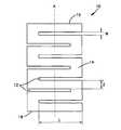
- FIG. 1is a top view of a first exemplary embodiment of the spacer according to the present invention
- FIG. 2is a side view of the spacer of FIG. 1 ;
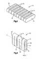
- FIG. 3is a perspective view of the spacer of FIG. 1 , showing at least a portion of the spacer coated by a therapeutic agent and further showing an end having a generally elliptical shape;
- FIG. 4is a perspective view of a second embodiment of a spacer with a bore running through the longitudinal axis of the spacer;
- FIG. 5Ais a side view of a third embodiment of a spacer having a preformed curvature
- FIG. 5Bis a top view of the spacer of FIG. 5A ;
- FIG. 6Ais a side view of a fourth embodiment of a spacer having a preformed curvature, displaced around axis B;
- FIG. 6Bis a top view of the spacer of FIG. 6A ;
- FIG. 7Ais a side view of a fifth embodiment of a spacer having a curved preformed shape with at least one end conforming to that of a part of a mandible and an angled opposite end;
- FIG. 7Bis a top view of the spacer of FIG. 7A ;
- FIG. 8is a perspective view of a mandible with a resection cavity
- FIG. 9is a perspective view of the mandible of FIG. 8 , to which the spacer of FIG. 1 in combination with a bone plate has been secured.
- an exemplary nonstructural solid spacer 10for use as a temporary soft tissue spacer in a human body.
- the spacer 10may be configured to be placed between, for example, cut bone ends obtained as a result of the removal of a damaged or diseased portion of bone.
- a temporary spacermay be used where additional therapeutic treatments will be performed on the patient in the resection area (e.g. chemotherapy, radiation), since such treatments may hinder reintegration of a permanent spacer such as allograft (i.e. bone).
- the spacer 10may have physical characteristics (size and shape) similar to those of the replaced bone and tissue (and the permanent implant) so as to provide the patient with as normal an appearance as possible during the subsequent treatment period.
- the spacer 10may have an outer surface 14 and first and second bone engaging ends 16 , 18 and an axis A.
- the surfaces and ends of the spacer 10may be flat, curved or may take on any appropriate shape to provide a desired overall shape of the spacer.
- the outer surface 14 and ends 16 , 18may be roughened to improve the retention of the spacer 10 within the resection cavity 70 .
- the relief cuts 12 in the spacer 10may allow the spacer to bend, expand, or contract to closely fit the occupied cavity.
- the spacer 10may be bent, expanded, or contracted along at least one axis.
- the relief cuts 12are substantially parallel to each other and are approximately equally spaced along the longitudinal axis A of the spacer 10 .
- the relief cuts 12are also oriented substantially perpendicular to the longitudinal axis A, thus allowing expansion or contraction of the spacer 10 .
- the positioning of the relief cuts 12may be varied in width, length and angular orientation, depending at least in part by the amount of flexibility desired from the spacer 10 and the overall size and shape of the spacer 10 .
- the relief cuts 12may have three dimensions: length L, width W, and depth D.
- each dimensionmay be varied depending on the amount and/or direction of flexibility desired and the overall size and shape of the spacer 10 .
- the length Lmay vary from 0.1 mm to 30 mm
- the width Wmay be about 0.1 mm or greater.
- the depth Dmay vary from 0.1 mm to 20 mm
- each of the dimensions L, W and Dmay be from about 0% to about 90% of the corresponding spacer dimension.
- the distance Z between relief cuts 12may also be varied.
- the dimensions of the relief cuts 12also may be varied between separate relief cuts 12 in a single spacer 10 . Further, the dimensions of a single relief cut 12 may be varied within a single relief cut 12 as well.
- a relief cut 12may be preferable to vary the depth D of a relief cut 12 along its length L to provide a deeper relief cut 12 near the center of the spacer 10 and a consequently shallower relief cut 12 near the edges of the spacer 10 .
- Such an arrangementmay provide the spacer 10 with greater flexibility along its longitudinal axis A and less flexible along its edges.
- the spacermay have relief cuts 12 configured to allow the spacer 10 to be flexed in a direction that would allow approximation of the mandible curvature, but would provide stiffness in a perpendicular direction.
- the width W of a particular relief cutmay be varied along its length L to provide additional flexibility in a desired direction.
- the inventive spacer 10may incorporate any combination of relief cuts 12 having any of a variety of dimensions as desired to provide a spacer 10 having a desired flexibility for fitting a particular targeted anatomical resection cavity.
- the spacer 10may have general cross-sectional dimensions of from about (20 mm by 8 mm) to about (30 mm by 12 mm)
- the relief cuts 12may extend to a depth D approximately equal to one-half the height X of the spacer 10 .
- the depth Dis also consistent among all relief cuts 12 in this embodiment.
- the depth D of the relief cuts 12may be less than half of the distance X.
- the depth D of the relief cuts 12may be a distance greater than half the distance X.
- the relief cuts 12may extend completely through the body 60 of the spacer 10 as to create a relief cut 12 that passes from the outer surface 14 at one point, through the body 60 , and out the outer surface 14 at another point.
- the spacermay have at least two ends 16 , 18 , each of which may have a generally elliptical shape.
- the ends 16 , 18may be of any desired shape or dimension to create the desired shape of the spacer 10 as a whole.
- the ends 16 , 18may be of different shapes from one another.
- the cross-sectional shape and dimensions of the spacer 10may vary over the longitudinal axis A, at least in part as a function of dimensional differences in the ends 16 , 18 .
- Providing a spacer with a varying cross-sectional shapemay be desirable to allow a more precise fit between spacer 10 and an irregular-shaped resection cavity 70 .
- a spacer 10may have a bore 30 with an axis C (not shown) substantially collinear to the longitudinal axis A of the spacer 10 .
- the bore 30may provide the spacer 10 with enhanced flexibility as compared to the previously described embodiments.
- the bore 30also may make the spacer 10 lighter.
- the size and shape of the bore 30may approximate the shape of the outer edge 32 of the spacer 10 , so as to maintain a generally consistent thickness T of the spacer 10 .
- the spacer 10may be provided having a thickness T in the range of from about 1.5 mm to about 5 mm It should be noted that a constant thickness T is not critical, and thus a spacer having a varying thickness T along its length may also be provided.
- the bore 30may be of any shape of size appropriate to provide a spacer 10 of desired flexibility.
- the outer edge 32 shapemay be elliptical, while the inner edge 34 shape may be circular, square, etc.
- the cross-sectional shape and size of the bore 30may also vary along the length of the longitudinal axis A.
- the bore 30may comprise at least one channel for passing an object, such as a suture, cable or other support, through at least a portion of the body 60 of the spacer 10 . Additionally, more than one bore 30 may be provided in a single spacer 10 .
- FIGS. 5A-7Bshow several views of a spacer 10 having a variety of preformed shapes.
- the spacer 10 of FIG. 5Ais a generally concave design, which may be useful in an irregular resection cavity 70 , where the cavity results as a result of “carving out” diseased or damaged bone in the shape of an trough.
- the dimensions of individual relief cuts 12may vary depending at least in part on the location of a relief cut 12 in relation an axis for displacement.
- FIG. 5Bis a top view of the spacer 10 in FIG. 5A .
- the spacer 10 of FIG. 6Ais a generally convex design shown from a side view. This particular design may be useful for temporarily replacing the front section of a human mandible 50 .
- the spacer 10is displaced around the axes B.
- FIG. 6Bis a top view of the spacer 10 of FIG. 6A .
- the spacer 10 of FIG. 7Ais an irregular design shown from a side view. This embodiment may be used to temporarily replace a portion of the midsection of a human mandible 50 (as seen in FIG. 8 ), in which the lateral boundaries of the resection cavity 70 are irregularly-shaped bone walls 54 .
- the first side 16is shaped to generally conform to the irregular cross-sectional shape of a mandible, while the second side is angled.
- FIG. 7Bis a top view of the spacer 10 of FIG. 7A .
- the spacer 10may have a preformed shape to generally correspond to the intended use and/or positioning of the spacer 10 .
- the outer surface 14 , and ends 16 , 18may also be individually preformed to more closely fit the bone ends of the targeted bone cavity 70 .
- the surgeonmay alter the shape or design of a spacer 10 to fit the particular anatomy of the patient.
- the surgeonmay remove at least a portion of the spacer 10 prior to use. This may occur, for example, by a surgeon cutting off at least a portion of one or both ends 16 , 18 of the spacer 10 , or by removing a portion or portions of the body of the spacer.
- a surgeonmay also cut custom relief cuts 12 in a spacer, or alter existing relief cuts 12 to make them deeper or longer.
- the shape of the spacermay be altered using any of a variety of standard surgical tools such as burrs, reciprocating saws, drills, etc., that are available to a surgeon in the operating room.
- a surgeonmay alter the shape of a spacer 10 regardless of whether or not the spacer 10 is preformed.
- an exemplary patient mandible 50is shown having teeth 52 and a resection cavity 70 .
- the illustrated resection cavity 70may be the result of a procedure involving the removal of diseased or defective tissue and/or bone, however other procedures (e.g. cosmetic reshaping) are also contemplated, such as where a patient suffers from a congenital deformity or bone deficit.
- Walls 54may define at least a portion of the surface area of the resection cavity 70 .
- the shape and total surface area of the walls 54may depend at least in part on the size and shape of the tissue and/or bone removed during a resection procedure.
- the contour of surface of the walls 54may vary as well. Sound bone portions 56 A, 56 B may remain intact on either side of the resection cavity 70 .
- a spacer 10is illustrated as fixedly attached within a resection cavity 70 in a mandible 50 using a bone plate 40 having fixation holes 44 .
- the spacer 10is placed within the resection cavity 70 and the bone plate 40 is fixedly attached (e.g. using bone screws placed in the fixation holes 44 ) to both the spacer 10 and the mandible 50 .
- the bone plate 40may be useful for maintaining the spacer 10 within the resection cavity 70 because the spacer 10 itself is not intended to be a load-bearing element. Thus, the spacer may not be able to effectively resist the in-situ forces of musculature and soft tissue without an additional retention device such as a bone plate.
- the bone plate 40may therefore assist in preventing the movement or displacement of the spacer 10 by external forces (e.g. chewing or other soft tissue forces) on an exposed portion of the spacer 10 during use. Such displacement may be undesirable because it may allow soft tissue and bone ingrowth into the resection cavity. Further, spacer 10 movement may cause infection in and around the resection cavity 70 .
- external forcese.g. chewing or other soft tissue forces
- the bone plate 40may be attached to the spacer 10 and the walls 56 A, 56 B in a variety of ways.
- FIG. 9shows the bone plate 40 fixedly attached to the spacer by fasteners 42 that are received in the spacer 10 by bores.
- the number, size, and arrangement of fasteners 42may vary depending at least in part on the size of the bone plate 40 and the securing force necessary to provide adequate immobilization of the spacer 10 .
- the bone plate 40may be attached to the spacer 10 by any appropriate means, including but not limited to screws, nails, clamps, pins, sutures, adhesives, or any combination thereof.
- the bone plate 40may have any appropriate number and configuration of fastener holes, and may be flexible or deformable to allow the surgeon to shape the ends of the plate to fit the anatomy of the patient.
- the plate 40may be made of any suitable material known in the art, including metals such as titanium or stainless steel, or polymers, resorbable polymers, etc.
- the spacer 10is described herein as being adapted for fixation to the adjacent bone segments using a bone plate 40 , other fixation techniques may also be used.
- bone screwsmay be screwed directly through the spacer and into the adjacent bone segments.
- the spacermay have preformed bone screw holes.
- the spacermay be provided with one or more integral or preformed flaps configured to engage an outer surface of the bone ends. Such flaps may be provided with preformed bone screw holes for screwing the spacer to the adjacent bone.
- the spacer 10may be provided with one or more holes suitable for receiving sutures to allow the surgeon to suture the spacer 10 to the surrounding bone and tissue.
- Such holesmay be of any appropriate shape and configuration, and may be angled with respect to the longitudinal axis of the spacer 10 to allow easier threading of suture material through the spacer.
- the spacer 10may be coated with a therapeutic agent 20 , which may help prevent infection in the site after the spacer 10 is inserted within the resection cavity 70 .
- the therapeutic agent 20may be any agent appropriate to prevent infection within the resection cavity 70 , including antibiotics and antiseptics.
- a non-limiting list of therapeutic agents useful in procedures involving spacersincludes, but is not limited to, bone growth induction catalysts such as bone morphogenetic proteins, growth factors, peptides, and the like, antivirals, antibiotics, chemotherapy drugs, growth factors, endothelial growth factors, insulin growth factors, or the like, or a combination thereof.
- the spacer 10may be coated with more than one therapeutic agent 20 .
- the therapeutic agent 20may be applied to the spacer 10 by any appropriate means, including but not limited to spraying, impregnating, soaking, dipping, or chemical vapor deposition (CVD).
- the therapeutic agent 20may be applied to the spacer 10 by dipping or soaking the spacer in a dissolved resorbable material such as polylactate which contains a desired concentration of the therapeutic agent 20 .
- a discussion of one manner of application of such therapeutic agents to implantsmay be found in U.S. Non-provisional patent application Ser. No. 09/801,752, by Schmidmaier et al., filed Mar. 9, 2001, entitled “Biologically Active Implants,” the entire contents of which is incorporated herein by reference.
- an exemplary method of using the inventive spacer 10is further provided, with reference to the system depicted in FIG. 9 .
- the surgeonmay remove the affected tissue, along with a small portion of healthy tissue on all sides, leaving a resection cavity 70 .
- the surgeonmay then select a spacer 10 for placement in the resection cavity 70 .
- the spacer 10may be coated with at least one therapeutic agent 20 .
- the application of therapeutic agent 20may occur prior to selection or placement of the spacer 10 .
- the surgeonmay compress, expand, or in some other way change the shape (e.g., remove at least a portion) of the spacer 10 in order to closely conform it to the resection cavity 70 .
- the spacer 10may then be inserted into the resection cavity 70 .
- the spacer 10may be selected to have a length slightly greater than the length of the resection cavity 70 , such that when the spacer 10 is inserted into the cavity a small end force is applied to the ends 16 , 18 via the walls 54 , thus provisionally retaining the spacer 10 within the resection cavity 70 .
- the ends 16 , 18 of the spacer 10therefore may be positioned at least in part against the walls 54 of the resection cavity 70 along the length of the mandible 50 .
- the ends 16 , 18may engage bone or tissue.
- the relief cuts 12 of the spacer 10may provide flexibility to allow the spacer 10 to expand or compress to occupy the resection cavity 70 .
- at least one bone plate 40may be fixedly attached to the spacer 10 and the surrounding bone or tissue. Alternatively, the bone plate 40 may be applied to the spacer 10 prior to placing the spacer 10 in the resection cavity 70 .
- the surgeonalso may “trial fit” the spacer 10 within the resection cavity 70 by repeatedly inserting and removing the spacer 10 in the resection cavity 70 , each time reshaping (cutting) the spacer 10 as required to obtain a desired fit. Once the desired spacer shape is obtained, the spacer 10 and bone plate 40 may be secured to the bone ends 56 A, 56 B. It is noted that while the spacer 10 is disclosed in combination with a bone plate 40 , the spacer 10 may be secured to the bone ends 56 A, 56 B using any appropriate method, as earlier described. Likewise, the spacer 10 may be used without any additional fixation means.
- An additional amount of therapeutic agent 20may be applied to the spacer 10 , bone plate 40 , and/or resection cavity 70 at this stage, just prior to closure of the surgical site. This may be preferable due to the loss of some amount of therapeutic agent 20 during the preparation and placement of the spacer 10 in the resection cavity and/or the attachment of the spacer 10 and bone plate 40 .
- the surgeonmay then commence treatment of the surgical site.
- treatmentsinclude, but are not limited to, radiation treatment, chemotherapy, isobaric treatments, or the like.
- the spacermay also be used simply to allow swelling to subside during the post-operative period and to allow general healing to take place.
- a permanent implantsuch as one made from autograft, allograft, metallic, ceramic, polymer, or other suitable material may then be inserted into the resection cavity 70 .
- the spacer 10may also be used in other parts of body.
- One such useis in the hip.
- the spacer 10may be useful to serve as an implant for a resection cavity 70 created by taking a graft from an iliac crest. Such grafts are commonly used in spinal fusion or other bone grafting procedures.
- Other areas for use of the inventive spacer 10are any of the bones of the craniofacial region, including the cheekbone.
- the spacer 10may be made of a biocompatible material, for example Ultra High Molecular Weight Polyethylene (UHMW PE). However, the spacer 10 may be constructed out of any appropriate biocompatible material. In addition to UHMW PE, other acceptable biocompatible materials for use with the present invention include, but are not limited to titanium alloys, stainless steel, cobalt chrome alloy and PEEK.
- the chosen biocompatible materialshould provide a spacer 10 that can conform or be conformable to opposing bone ends of a resection cavity 70 (see, e.g., FIG. 8 ) and should be capable of maintaining the cavity relatively free from soft tissue intrusion for an extended period of time, during which a procedure such as radiation or chemotherapy treatments is performed.
- the biocompatible materialshould be resistant to tissue and bone ingrowth or adhesion while placed in the resection cavity 70 .
- the spacer 10should be configured to be readily removable from the resection cavity 70 so that a permanent implant may be easily installed once the radiation or chemotherapy procedures are complete.
- the outer surface 14 and ends 16 , 18 of the spacer 10may also be dulled, which may be useful to prevent glare or reflection from the light source of an endoscope used during the procedure.
Landscapes
- Health & Medical Sciences (AREA)
- Life Sciences & Earth Sciences (AREA)
- Public Health (AREA)
- Veterinary Medicine (AREA)
- Animal Behavior & Ethology (AREA)
- General Health & Medical Sciences (AREA)
- Chemical & Material Sciences (AREA)
- Biomedical Technology (AREA)
- Engineering & Computer Science (AREA)
- Oral & Maxillofacial Surgery (AREA)
- Transplantation (AREA)
- Epidemiology (AREA)
- Heart & Thoracic Surgery (AREA)
- Vascular Medicine (AREA)
- Medicinal Chemistry (AREA)
- Orthopedic Medicine & Surgery (AREA)
- Cardiology (AREA)
- Chemical Kinetics & Catalysis (AREA)
- Molecular Biology (AREA)
- Surgery (AREA)
- Dermatology (AREA)
- Developmental Biology & Embryology (AREA)
- Dentistry (AREA)
- Plastic & Reconstructive Surgery (AREA)
- Prostheses (AREA)
- Polymers & Plastics (AREA)
- Organic Chemistry (AREA)
- Materials For Medical Uses (AREA)
Abstract
Description
Claims (20)
Priority Applications (1)
| Application Number | Priority Date | Filing Date | Title |
|---|---|---|---|
| US12/985,674US8945220B2 (en) | 2004-06-04 | 2011-01-06 | Soft tissue spacer |
Applications Claiming Priority (2)
| Application Number | Priority Date | Filing Date | Title |
|---|---|---|---|
| US10/860,885US7887587B2 (en) | 2004-06-04 | 2004-06-04 | Soft tissue spacer |
| US12/985,674US8945220B2 (en) | 2004-06-04 | 2011-01-06 | Soft tissue spacer |
Related Parent Applications (1)
| Application Number | Title | Priority Date | Filing Date |
|---|---|---|---|
| US10/860,885DivisionUS7887587B2 (en) | 2004-06-04 | 2004-06-04 | Soft tissue spacer |
Publications (2)
| Publication Number | Publication Date |
|---|---|
| US20110098760A1 US20110098760A1 (en) | 2011-04-28 |
| US8945220B2true US8945220B2 (en) | 2015-02-03 |
Family
ID=35450048
Family Applications (2)
| Application Number | Title | Priority Date | Filing Date |
|---|---|---|---|
| US10/860,885Active2026-10-06US7887587B2 (en) | 2004-06-04 | 2004-06-04 | Soft tissue spacer |
| US12/985,674Expired - LifetimeUS8945220B2 (en) | 2004-06-04 | 2011-01-06 | Soft tissue spacer |
Family Applications Before (1)
| Application Number | Title | Priority Date | Filing Date |
|---|---|---|---|
| US10/860,885Active2026-10-06US7887587B2 (en) | 2004-06-04 | 2004-06-04 | Soft tissue spacer |
Country Status (10)
| Country | Link |
|---|---|
| US (2) | US7887587B2 (en) |
| EP (1) | EP1755496A4 (en) |
| JP (1) | JP2008501435A (en) |
| KR (1) | KR101166181B1 (en) |
| CN (1) | CN101027016B (en) |
| AU (1) | AU2005249556A1 (en) |
| BR (1) | BRPI0511813A (en) |
| CA (1) | CA2568941C (en) |
| WO (1) | WO2005117760A2 (en) |
| ZA (1) | ZA200700095B (en) |
Cited By (2)
| Publication number | Priority date | Publication date | Assignee | Title |
|---|---|---|---|---|
| US10357367B2 (en)* | 2017-09-11 | 2019-07-23 | DePuy Synthes Products, Inc. | Patient-specific mandible graft cage |
| US11071571B2 (en)* | 2015-12-23 | 2021-07-27 | Karl Leibinger Medizintechnik Gmbh & Co. Kg | Implant for reinforcing a bone, comprising a bore vector specifying hole and surrounding plate for a jaw replacement, and implant production method |
Families Citing this family (39)
| Publication number | Priority date | Publication date | Assignee | Title |
|---|---|---|---|---|
| US7887587B2 (en)* | 2004-06-04 | 2011-02-15 | Synthes Usa, Llc | Soft tissue spacer |
| US9943410B2 (en)* | 2011-02-28 | 2018-04-17 | DePuy Synthes Products, Inc. | Modular tissue scaffolds |
| US8870871B2 (en)* | 2007-01-17 | 2014-10-28 | University Of Massachusetts Lowell | Biodegradable bone plates and bonding systems |
| EP2344081B1 (en)* | 2008-08-26 | 2013-01-16 | Boiangiu, Andy | A dental bone implant |
| US20110054627A1 (en)* | 2009-09-01 | 2011-03-03 | Bear Brian J | Biologic Soft Tissue Arthroplasty Spacer and Joint Resurfacing of Wrist and Hand |
| CN102085121A (en)* | 2009-12-02 | 2011-06-08 | 吴学森 | Absorbable periodontitis septal pad and preparation method thereof |
| US8486116B2 (en) | 2010-01-08 | 2013-07-16 | Biomet Manufacturing Ring Corporation | Variable angle locking screw |
| US9066733B2 (en) | 2010-04-29 | 2015-06-30 | DePuy Synthes Products, Inc. | Orthognathic implant and methods of use |
| US8435270B2 (en) | 2010-04-29 | 2013-05-07 | Synthes Usa, Llc | Orthognathic implant and methods of use |
| US8790379B2 (en) | 2010-06-23 | 2014-07-29 | Zimmer, Inc. | Flexible plate fixation of bone fractures |
| EP3639775B1 (en) | 2010-06-23 | 2024-07-17 | Zimmer, Inc. | Flexible plate fixation of bone fractures |
| CN103298429B (en)* | 2010-11-15 | 2015-11-25 | 新特斯有限责任公司 | Graft Collection and Containment System for Bone Defects |
| US8728129B2 (en) | 2011-01-07 | 2014-05-20 | Biomet Manufacturing, Llc | Variable angled locking screw |
| US20120244498A1 (en)* | 2011-03-23 | 2012-09-27 | Zimmer Dental, Inc. | Formable resorbable biomaterial interface for dental implant devices |
| ITRM20110168A1 (en)* | 2011-03-31 | 2012-10-01 | Alma Mater Studiorum Uni D I Bologna | SURGICAL DEVICE FOR THE RECONSTRUCTION OF BONE STRUCTURES. |
| WO2012155003A1 (en)* | 2011-05-10 | 2012-11-15 | Peter Nakaji | Cranial plating and bur hole cover system |
| CN102415920A (en)* | 2011-07-27 | 2012-04-18 | 浙江工业大学 | Manufacturing method of individual stent used for mandibular defect tissue engineering repair |
| JP6147747B2 (en)* | 2011-08-25 | 2017-06-14 | シンセス・ゲーエムベーハーSynthes GmbH | Transparent implant made of PEEK or PMMA with an uncured polymer adhesive layer |
| US9295508B2 (en) | 2012-02-03 | 2016-03-29 | Zimmer, Inc. | Bone plate for elastic osteosynthesis |
| US9539069B2 (en) | 2012-04-26 | 2017-01-10 | Zimmer Dental, Inc. | Dental implant wedges |
| US9554877B2 (en)* | 2012-07-31 | 2017-01-31 | Zimmer, Inc. | Dental regenerative device made of porous metal |
| US20140038132A1 (en)* | 2012-07-31 | 2014-02-06 | Zimmer Trabecular Metal Technology, Inc. | Dental regenerative device made of porous metal |
| CN102920535B (en)* | 2012-11-26 | 2014-07-23 | 北京爱康宜诚医疗器材股份有限公司 | Jawbone restoration |
| US9114013B2 (en) | 2014-01-24 | 2015-08-25 | J. Randall Jordan | Malar implant with dual-plane adhesion |
| EP3407837B1 (en)* | 2016-01-28 | 2021-07-07 | DePuy Synthes Products, Inc. | Helical bone graft containment cage |
| BR112018015139A2 (en) | 2016-01-28 | 2018-12-18 | Depuy Synthes Products Inc | graft containment cage separation accessory |
| GB201614171D0 (en)* | 2016-08-18 | 2016-10-05 | Fitzbionics Ltd | An implant for repair of bone defects |
| JP2018042855A (en)* | 2016-09-15 | 2018-03-22 | 国立大学法人神戸大学 | Spacer for radiation therapy |
| EP3534846A2 (en)* | 2016-11-03 | 2019-09-11 | DePuy Synthes Products, Inc. | Fold-up containment device for bone defects |
| BR112019015878A2 (en)* | 2017-02-06 | 2020-04-14 | Depuy Synthes Products Inc | foldable graft containment cage |
| US11364121B2 (en) | 2017-02-27 | 2022-06-21 | Vertical Spine LLC | Engineered bone graft implant and methods of using the same |
| US11612486B2 (en)* | 2017-03-23 | 2023-03-28 | Cadskills Bvba | Bone prosthesis and method for its placement |
| DE102017115403A1 (en)* | 2017-07-10 | 2019-01-10 | Karl Leibinger Medizintechnik Gmbh & Co. Kg | Bioresorbable bone implant and manufacturing process |
| WO2019056059A1 (en)* | 2017-09-21 | 2019-03-28 | Tmj Orthopaedics Pty Ltd | A surgical procedure for cancerous mandibular reconstruction and a temporary mandibular spacer therefor |
| RU2652742C1 (en)* | 2018-01-09 | 2018-04-28 | Алексей Валерьевич Юмашев | Method of rehabilitation of patients after resection of the affected area of the mandible with primary osteosarcoma of the lower jaw |
| TWI716156B (en)* | 2019-10-18 | 2021-01-11 | 財團法人工業技術研究院 | Mandibular reconstruction prosthesis |
| US11324538B2 (en) | 2019-12-04 | 2022-05-10 | Biomet Manufacturing, Llc | Active bone plate |
| TWI775199B (en)* | 2020-10-30 | 2022-08-21 | 汪昇朋 | Support device and method of using the same |
| CN113230002B (en)* | 2021-06-22 | 2024-05-14 | 安阳市第六人民医院(安阳市口腔医院) | Preparation method of personalized titanium mesh for bone defect reconstruction of dental implant area |
Citations (163)
| Publication number | Priority date | Publication date | Assignee | Title |
|---|---|---|---|---|
| US3178728A (en) | 1962-10-22 | 1965-04-20 | Robert W Christensen | Surgical prosthesis for the temporomandibular joint |
| US3488779A (en) | 1967-09-27 | 1970-01-13 | Robert W Christensen | Orthopedic prosthetic appliances for attachment to bone |
| US3579643A (en) | 1968-12-12 | 1971-05-25 | Douglas H Morgan | Artificial articular eminence for the mandibular joint |
| US3710789A (en) | 1970-12-04 | 1973-01-16 | Univ Minnesota | Method of repairing bone fractures with expanded metal |
| US3720959A (en) | 1970-08-26 | 1973-03-20 | G Hahn | Mandibular prosthetic apparatus |
| US3805300A (en) | 1972-07-28 | 1974-04-23 | Cutter Lab | Tendon prosthesis |
| US3849805A (en) | 1972-11-01 | 1974-11-26 | Attending Staff Ass Los Angele | Bone induction in an alloplastic tray |
| US3867728A (en)* | 1971-12-30 | 1975-02-25 | Cutter Lab | Prosthesis for spinal repair |
| US3955567A (en) | 1974-11-08 | 1976-05-11 | Stryker Corporation | Bone brace |
| US4164794A (en) | 1977-04-14 | 1979-08-21 | Union Carbide Corporation | Prosthetic devices having coatings of selected porous bioengineering thermoplastics |
| US4186448A (en) | 1976-04-16 | 1980-02-05 | Brekke John H | Device and method for treating and healing a newly created bone void |
| US4344191A (en) | 1981-01-15 | 1982-08-17 | Wagner Kurt J | Chin implant |
| USD270373S (en) | 1981-04-27 | 1983-08-30 | Straith Richard E | Facial implant |
| US4484570A (en) | 1980-05-28 | 1984-11-27 | Synthes Ltd. | Device comprising an implant and screws for fastening said implant to a bone, and a device for connecting two separated pieces of bone |
| US4502161A (en) | 1981-09-21 | 1985-03-05 | Wall W H | Prosthetic meniscus for the repair of joints |
| US4521192A (en)* | 1982-09-14 | 1985-06-04 | Linkow Leonard I | Oral implant for oversized dental support openings |
| US4599086A (en)* | 1985-06-07 | 1986-07-08 | Doty James R | Spine stabilization device and method |
| US4636215A (en) | 1984-01-11 | 1987-01-13 | Rei, Inc. | Combination tray and condylar prosthesis for mandibular reconstruction and the like |
| USD290878S (en) | 1984-03-26 | 1987-07-14 | Giampapa Vincent C | Mid-facial maxilla skeletal implant |
| USD290877S (en) | 1984-03-26 | 1987-07-14 | Giampapa Vincent C | Mid-facial zygoma skeletal implant |
| USD290879S (en) | 1984-03-26 | 1987-07-14 | Giampapa Vincent C | Mid-facial zygomatic arch skeletal implant |
| US4693722A (en) | 1983-08-19 | 1987-09-15 | Wall William H | Prosthetic temporomanibular condyle utilizing a prosthetic meniscus |
| US4704126A (en) | 1985-04-15 | 1987-11-03 | Richards Medical Company | Chemical polishing process for titanium and titanium alloy surgical implants |
| US4713077A (en) | 1985-02-19 | 1987-12-15 | Small Irwin A | Method of applying a chin implant, drill guide tool and implant |
| US4726808A (en) | 1986-06-30 | 1988-02-23 | Collins Thomas A | Mandibular prosthesis |
| US4731082A (en) | 1987-07-21 | 1988-03-15 | Giunta Stephen X | Pre-maxillary implant |
| US4756862A (en) | 1977-04-14 | 1988-07-12 | Amoco Corporation | Prosthetic devices having coatings of selected porous bioengineering thermoplastics |
| US4778472A (en) | 1985-04-30 | 1988-10-18 | Vitek, Inc. | Implant for reconstruction of temporomanibular joint |
| US4787906A (en) | 1987-03-02 | 1988-11-29 | Haris Andras G | Controlled tissue growth and graft containment |
| US4790849A (en) | 1985-08-23 | 1988-12-13 | Edward Terino | Malar implant and method of inserting the prothesis |
| US4888018A (en) | 1988-12-27 | 1989-12-19 | Giampapa Vincent C | Method of positioning and securing a chin implant |
| US4917701A (en) | 1988-09-12 | 1990-04-17 | Morgan Douglas H | Temporomandibular joint prostheses |
| US4969901A (en) | 1988-06-28 | 1990-11-13 | Binder William J | Plastic surgery implant |
| US4990160A (en) | 1988-02-16 | 1991-02-05 | Edward Terino | Extended chin and mandible implants |
| US5084051A (en) | 1986-11-03 | 1992-01-28 | Toermaelae Pertti | Layered surgical biocomposite material |
| USD326157S (en) | 1989-04-05 | 1992-05-12 | Giunta Stephen X | Chin implant |
| US5139497A (en) | 1991-11-25 | 1992-08-18 | Timesh, Inc. | Orbital repair implant |
| USD329700S (en) | 1990-04-20 | 1992-09-22 | Terino Edward O | Back jaw surgical implant |
| USD330422S (en) | 1989-04-07 | 1992-10-20 | Harry Mittelman | Geniomandibular groove implant |
| USD330421S (en) | 1989-04-07 | 1992-10-20 | Harry Mittelman | Geniomandibular groove implant |
| US5195951A (en) | 1991-03-25 | 1993-03-23 | Giampapa Vincent C | Chin implant |
| US5201736A (en) | 1992-01-13 | 1993-04-13 | Strauss Sorrell I | Maxillofacial bone clamp |
| US5201737A (en) | 1991-04-11 | 1993-04-13 | Oswald Leibinger Gmbh | Plate for covering a drill hole in a skull cap and for fixing a cranial bone cover |
| USD340982S (en) | 1990-10-09 | 1993-11-02 | Terino Edward O | Pre-maxillary implant |
| US5263953A (en)* | 1991-12-31 | 1993-11-23 | Spine-Tech, Inc. | Apparatus and system for fusing bone joints |
| WO1994001064A1 (en) | 1992-07-14 | 1994-01-20 | Giampapa Vincent C | Sub-malar facial implant |
| US5380328A (en) | 1993-08-09 | 1995-01-10 | Timesh, Inc. | Composite perforated implant structures |
| US5380329A (en) | 1992-07-28 | 1995-01-10 | Dental Marketing Specialists, Inc. | Bone augmentation method and apparatus |
| US5383931A (en) | 1992-01-03 | 1995-01-24 | Synthes (U.S.A.) | Resorbable implantable device for the reconstruction of the orbit of the human skull |
| US5413600A (en) | 1993-05-19 | 1995-05-09 | Mittelman; Harry | Nasal-labial implant |
| US5413577A (en) | 1987-04-07 | 1995-05-09 | Pollock; Richard A. | Anatomical precontoured plating |
| US5443515A (en)* | 1994-01-26 | 1995-08-22 | Implex Corporation | Vertebral body prosthetic implant with slidably positionable stabilizing member |
| DE4414675C1 (en) | 1994-04-27 | 1995-09-28 | Kirsch Axel | Covering device for bone defects and method for their production |
| US5468242A (en) | 1993-11-19 | 1995-11-21 | Leibinger Gmbh | Form-fitting mesh implant |
| US5489305A (en) | 1994-10-03 | 1996-02-06 | Timesh, Inc. | Mandibular prostheses |
| US5492697A (en) | 1990-03-05 | 1996-02-20 | Board Of Regents, Univ. Of Texas System | Biodegradable implant for fracture nonunions |
| US5496371A (en) | 1991-06-10 | 1996-03-05 | United States Surgical Corporation | Prosthetic implant |
| US5501706A (en) | 1994-11-29 | 1996-03-26 | Wildflower Communications, Inc. | Medical implant structure and method for using the same |
| US5503164A (en) | 1994-01-28 | 1996-04-02 | Osteogenics, Inc. | Device and method for repair of craniomaxillofacial bone defects including burr holes |
| US5514179A (en) | 1993-08-10 | 1996-05-07 | Brennan; H. George | Modular facial implant system |
| US5545226A (en) | 1992-05-29 | 1996-08-13 | Porex Technologies Corp. | Implants for cranioplasty |
| US5549620A (en) | 1994-12-06 | 1996-08-27 | Bremer; Paul | Brain surgery with craniotomy pin |
| US5549680A (en) | 1994-02-10 | 1996-08-27 | Biomet, Inc. | Apparatus for total temporomandibular joint replacement |
| US5554194A (en) | 1995-06-07 | 1996-09-10 | United States Surgical Corporation | Modular surgical implant |
| US5569250A (en) | 1994-03-01 | 1996-10-29 | Sarver; David R. | Method and apparatus for securing adjacent bone portions |
| US5578036A (en) | 1993-12-06 | 1996-11-26 | Stone; Kevin T. | Method and apparatus for fixation of bone during surgical procedures |
| WO1997016136A1 (en) | 1995-10-31 | 1997-05-09 | Lanka Limited | Plug for the cranial bone |
| US5683459A (en) | 1986-01-28 | 1997-11-04 | Thm Biomedical, Inc. | Method and apparatus for biodegradable, osteogenic, bone graft substitute device |
| WO1997041791A1 (en) | 1996-05-03 | 1997-11-13 | Sofamor Danek Properties, Inc. | Cranioplasty plates and method of installation |
| US5690631A (en) | 1996-09-11 | 1997-11-25 | Walter Lorenz Surgical, Inc. | Multi-configurable plating system |
| WO1997043978A1 (en) | 1996-05-22 | 1997-11-27 | Sofamor Danek Properties, Inc. | Dental implant and alveolar process augmentation structures and method of installation |
| US5707373A (en) | 1996-04-26 | 1998-01-13 | Ikonos Corporation | Bone fastener and instrument for insertion thereof |
| US5725549A (en) | 1994-03-11 | 1998-03-10 | Advanced Cardiovascular Systems, Inc. | Coiled stent with locking ends |
| US5728157A (en) | 1989-02-15 | 1998-03-17 | Xomed Surgical Products, Inc. | Biocompatible composite prostheses |
| DE19634697C1 (en) | 1996-08-28 | 1998-04-23 | Aesculap Ag & Co Kg | Connecting component used in surgery for fixing cap segment removed from skull capsule to remaining skull cap |
| US5766176A (en) | 1996-09-11 | 1998-06-16 | Walter Lorenz Surgical, Inc. | Formable mesh |
| US5765567A (en)* | 1995-03-22 | 1998-06-16 | Knowlton; Edward W. | Surgical method for breast reconstruction using a tissue flap |
| WO1998034552A1 (en)* | 1997-02-06 | 1998-08-13 | Surgical Dynamics | Expandable non-threaded spinal fusion device |
| US5800436A (en) | 1996-02-03 | 1998-09-01 | Lerch; Karl-Dieter | Device for postoperative fixation back into the cranium of a plug of bone removed therefrom during a surgical operation |
| WO1998046153A1 (en) | 1997-04-11 | 1998-10-22 | Kinamed, Inc. | Burr hole cover for cranial surgery |
| GB2324470A (en) | 1997-04-24 | 1998-10-28 | Customflex Limited | Prosthetic implants |
| US5863297A (en) | 1995-10-11 | 1999-01-26 | Osteobiologics, Inc. | Moldable, hand-shapable biodegradable implant material |
| US5876447A (en) | 1996-02-14 | 1999-03-02 | Implantech Associates | Silicone implant for facial plastic surgery |
| US5882351A (en) | 1995-09-29 | 1999-03-16 | Biomedical Enterprises, Inc. | Fasteners having coordinated self-seeking conforming members and uses thereof |
| US5895427A (en) | 1989-07-06 | 1999-04-20 | Sulzer Spine-Tech Inc. | Method for spinal fixation |
| US5895387A (en) | 1996-10-09 | 1999-04-20 | Romulo Guerrero | Method of craniofacial bone distraction |
| US5899939A (en) | 1998-01-21 | 1999-05-04 | Osteotech, Inc. | Bone-derived implant for load-supporting applications |
| US5919234A (en) | 1996-08-19 | 1999-07-06 | Macropore, Inc. | Resorbable, macro-porous, non-collapsing and flexible membrane barrier for skeletal repair and regeneration |
| US5975904A (en) | 1997-12-05 | 1999-11-02 | Spiegel; Jeffrey H. | Articulated bone reconstruction bar |
| US5980540A (en) | 1997-04-11 | 1999-11-09 | Kinamed, Inc. | Perforated cover for covering spaces in the cranium and conforming to the shape of the cranium |
| US5989292A (en) | 1994-12-21 | 1999-11-23 | Van Loon; Jan-Paul | Adjustable temporomandibular surgical implant |
| US6022351A (en) | 1999-02-23 | 2000-02-08 | Bremer; Paul W. | Skull closure device and procedure |
| US6053919A (en) | 1995-07-03 | 2000-04-25 | Synthes (U. S. A) | Bone fragment-fixing device |
| US6060641A (en) | 1998-05-14 | 2000-05-09 | Baylor College Of Medicine | Modular mandibular prosthesis |
| JP2000135230A (en) | 1998-10-30 | 2000-05-16 | Kyocera Corp | Artificial skull members |
| JP2000139938A (en) | 1998-11-12 | 2000-05-23 | Ngk Spark Plug Co Ltd | Fixure for bone flap |
| JP2000139939A (en) | 1998-11-12 | 2000-05-23 | Ngk Spark Plug Co Ltd | Fixure for bone flap |
| US6071291A (en) | 1997-10-21 | 2000-06-06 | Howmedica Leibinger Gmbh & Co. Kg (Leibinger) | Micro dynamic mesh |
| FR2786687A1 (en) | 1998-12-04 | 2000-06-09 | Somepic Technologie | Closure implant for craniotomy has implant with inner plate and external flange engaging surfaces of cranium |
| US6093201A (en) | 1999-01-19 | 2000-07-25 | Ethicon, Inc. | Biocompatible absorbable polymer plating system for tissue fixation |
| US6123731A (en) | 1998-02-06 | 2000-09-26 | Osteotech, Inc. | Osteoimplant and method for its manufacture |
| US6126663A (en) | 1999-04-15 | 2000-10-03 | Hair; John Hunter | Expandable bone connector |
| US6143036A (en) | 1997-12-18 | 2000-11-07 | Comfort Biomedical, Inc. | Bone augmentation for prosthetic implants and the like |
| US6168631B1 (en) | 1997-08-29 | 2001-01-02 | Kinetikos Medical, Inc. | Subtalar implant system and method for insertion and removal |
| US6176879B1 (en) | 1998-07-02 | 2001-01-23 | Implex Aktienegesellschaft Hearing Technology | Medical implant |
| US6197037B1 (en) | 1999-07-29 | 2001-03-06 | John Hunter Hair | Surgical fastener for joining adjacent bone portions |
| US6206882B1 (en) | 1999-03-30 | 2001-03-27 | Surgical Dynamics Inc. | Plating system for the spine |
| US6221075B1 (en) | 1998-03-06 | 2001-04-24 | Bionx Implants Oy | Bioabsorbable, deformable fixation plate |
| US20010002446A1 (en) | 1996-04-05 | 2001-05-31 | Plouhar Pamela L. | Tissue graft construct for replacement of cartilaginous structures |
| JP2001161703A (en) | 1999-11-09 | 2001-06-19 | Bioplate Inc | Bone alignment and fixation device and method of installing the same |
| US6254639B1 (en) | 1996-09-25 | 2001-07-03 | Ninian Peckitt | Prosthetic implants |
| US6258091B1 (en) | 1996-02-14 | 2001-07-10 | Walter Lorenz Surgical Inc. | Bone fastener and instrument for insertion thereof |
| US20010014831A1 (en) | 1998-12-14 | 2001-08-16 | Scarborough Nelson L. | Bone graft, method of making bone graft and guided bone regeneration method |
| US6277150B1 (en) | 1999-06-11 | 2001-08-21 | Gore Enterprise Holdings, Inc. | Facial implant having one porous surface |
| US6280473B1 (en) | 1996-08-19 | 2001-08-28 | Macropore, Inc. | Resorbable, macro-porous, non-collapsing and flexible membrane barrier for skeletal repair and regeneration |
| US20010018614A1 (en) | 1999-03-16 | 2001-08-30 | Bianchi John R. | Implants for orthopedic applications |
| US6294187B1 (en) | 1999-02-23 | 2001-09-25 | Osteotech, Inc. | Load-bearing osteoimplant, method for its manufacture and method of repairing bone using same |
| US6293967B1 (en) | 1998-10-29 | 2001-09-25 | Conor Medsystems, Inc. | Expandable medical device with ductile hinges |
| WO2001072244A1 (en) | 2000-03-24 | 2001-10-04 | Tutogen Medical Gmbh | Implant for cranioplastics |
| WO2001078798A1 (en) | 2000-02-10 | 2001-10-25 | Regeneration Technologies, Inc. | Assembled implant |
| US6328765B1 (en) | 1998-12-03 | 2001-12-11 | Gore Enterprise Holdings, Inc. | Methods and articles for regenerating living tissue |
| US20020004660A1 (en) | 2000-02-24 | 2002-01-10 | Stryker Instruments | Bioabsorbable plates. fasteners, tools and method of using same |
| US20020016593A1 (en) | 2000-07-27 | 2002-02-07 | Hearn James P. | Cranial flap clamp and instrument for use therewith |
| JP2002045367A (en) | 2000-08-03 | 2002-02-12 | In System Kyodo Kumiai | Fixing implement for bone flad |
| US6364909B1 (en)* | 1995-07-18 | 2002-04-02 | Iowa State University Research Foundation, Inc. | Method of restructuring bone |
| US6371987B1 (en) | 1998-04-23 | 2002-04-16 | Medinorm Ag Medizintechnische Produkte | Device for connecting vertebrae of the vertebral column |
| US6379363B1 (en) | 1999-09-24 | 2002-04-30 | Walter Lorenz Surgical, Inc. | Method and apparatus for reattachment of a cranial flap using a cranial clamp |
| US6391059B1 (en) | 1998-04-07 | 2002-05-21 | Macropore, Inc. | Membrane with tissue-guiding surface corrugations |
| US20020062127A1 (en) | 1998-02-18 | 2002-05-23 | W.L. Lorenz | Method and apparatus for mandibular osteosynthesis |
| US20020062128A1 (en) | 2000-09-15 | 2002-05-23 | Amis James Peter | Cranial flap fixation device |
| US6409764B1 (en) | 1998-12-03 | 2002-06-25 | Charles F. White | Methods and articles for regenerating bone or peridontal tissue |
| US20020095156A1 (en) | 2001-01-16 | 2002-07-18 | Axiomed, Inc. | Apparatus for attaching a cranial flap |
| USD461248S1 (en) | 2000-02-10 | 2002-08-06 | Regeneration Technologies, Inc. | Assembled bone implants |
| US20020120346A1 (en) | 2001-02-28 | 2002-08-29 | Boyer Michael L. | Demineralized bone-derived implants |
| US6461385B1 (en) | 1997-12-18 | 2002-10-08 | Comfort Biomedical Inc. | Method and apparatus for augmenting osteointegration of prosthetic implant devices |
| US20020169455A1 (en) | 2001-02-23 | 2002-11-14 | Brett Bannerman | System and method for fixation of cranial flaps |
| US20020169066A1 (en) | 2001-04-16 | 2002-11-14 | Cerabio, L.L.C. | Dense porous structures for use as bone substitutes |
| US20020177850A1 (en) | 2001-05-24 | 2002-11-28 | Bremer Paul W. | Skull closure |
| US6491725B1 (en) | 1999-10-20 | 2002-12-10 | Asahi Kogaku Kogyo Kabushiki Kaisha | Keyhole button |
| US6511482B1 (en) | 1999-11-09 | 2003-01-28 | Bioplate, Inc. | Cranial bone flap fixation clip |
| US20030023313A1 (en) | 2001-07-27 | 2003-01-30 | Byers Patricia H. | Intra-oral article for cosmetically stretching and reconfiguring cheek skin and method for customizing same |
| JP2003038504A (en) | 2001-07-31 | 2003-02-12 | Manii Kk | Fixation device |
| US20030036760A1 (en) | 2000-09-27 | 2003-02-20 | Chung-Chun Yeh | Post-surgical device comprising an adjustment ferrule for fixing a parietal bone under treatment |
| US20030039676A1 (en) | 1999-02-23 | 2003-02-27 | Boyce Todd M. | Shaped load-bearing osteoimplant and methods of making same |
| US20030045935A1 (en) | 2001-02-28 | 2003-03-06 | Angelucci Christopher M. | Laminoplasty implants and methods of use |
| US6544266B1 (en) | 1999-01-22 | 2003-04-08 | Australian Surgical Design And Manufacture Pty, Ltd. | Method and apparatus for delivering bio-active compounds to specified sites in the body |
| US20030083750A1 (en) | 2001-10-30 | 2003-05-01 | Schulter Carl W. | Biocompatible form and method of fabrication |
| US20030100900A1 (en) | 2001-11-29 | 2003-05-29 | Wellisz Tadeusz Z. | Bone alignment and fixation device and installation method, using multiple clip section attachment structure |
| US20030100901A1 (en) | 2001-11-29 | 2003-05-29 | Wellisz Tadeusz Z. | Bone alignment and fixation device and installation method, using attachment structure |
| US20030100902A1 (en) | 2001-11-29 | 2003-05-29 | Wellisz Tadeusz Z. | Bone alignment and fixation device and installation method, using guide tab |
| US20030100898A1 (en) | 2001-11-26 | 2003-05-29 | Wellisz Tadeusz Z. | Bone alignment and fixation plate and installation method |
| US20030100899A1 (en) | 2001-11-26 | 2003-05-29 | Wellisz Tadeusz Z. | Bone alignment and fixation device and installation method, using bowed strut attachment structure |
| US6572623B1 (en) | 2000-07-25 | 2003-06-03 | Medtronic Ps Medical, Inc. | Method and apparatus for attaching a cranial flap |
| US20030125743A1 (en) | 2001-09-25 | 2003-07-03 | Roman Shawn David | Cranial clamp and method for fixating a bone plate |
| US6599323B2 (en) | 2000-12-21 | 2003-07-29 | Ethicon, Inc. | Reinforced tissue implants and methods of manufacture and use |
| US20030149484A1 (en) | 2002-02-02 | 2003-08-07 | Michelson Gary K. | Spinal fusion implant having deployable bone engaging projections, instrumentation, and methods for use thereof |
| WO2003028587A3 (en) | 2001-10-02 | 2003-08-21 | Rex Medical Lp | Spinal implant and method of use |
| US20040106927A1 (en)* | 2002-03-01 | 2004-06-03 | Ruffner Brian M. | Vertebral distractor |
| WO2004047689A1 (en)* | 2002-11-21 | 2004-06-10 | Sdgi Holdings, Inc. | Systems and techniques for intravertebral spinal stablization with expandable devices |
| US6998134B2 (en) | 1998-09-11 | 2006-02-14 | Gerhard Schmidmaier | Biologically active implants |
| WO2005117760A3 (en) | 2004-06-04 | 2006-09-14 | Hfsc Co | Soft tissue spacer |
| US7156880B2 (en) | 2002-06-13 | 2007-01-02 | Kensey Nash Corporation | Devices and methods for treating defects in the tissue of a living being |
| US7655047B2 (en)* | 2003-04-16 | 2010-02-02 | Porex Surgical, Inc. | Craniofacial implant |
Family Cites Families (8)
| Publication number | Priority date | Publication date | Assignee | Title |
|---|---|---|---|---|
| US270373A (en)* | 1883-01-09 | Coffee-roaster | ||
| US628765A (en)* | 1899-04-13 | 1899-07-11 | John Collette | Hose-coupling. |
| US4450591A (en)* | 1981-12-10 | 1984-05-29 | Rappaport Mark J | Internal anti-proratory plug assembly and process of installing the same |
| US4483864A (en)* | 1983-02-04 | 1984-11-20 | University Of Iowa Research Foundation | Non-classical topical treatment for glaucoma |
| US5320644A (en)* | 1991-08-30 | 1994-06-14 | Sulzer Brothers Limited | Intervertebral disk prosthesis |
| US6019792A (en)* | 1998-04-23 | 2000-02-01 | Cauthen Research Group, Inc. | Articulating spinal implant |
| US6080158A (en)* | 1999-08-23 | 2000-06-27 | Lin; Chih-I | Intervertebral fusion device |
| US20030229348A1 (en)* | 2000-05-25 | 2003-12-11 | Sevrain Lionel C. | Auxiliary vertebrae connecting device |
- 2004
- 2004-06-04USUS10/860,885patent/US7887587B2/enactiveActive
- 2005
- 2005-06-03WOPCT/US2005/019595patent/WO2005117760A2/enactiveApplication Filing
- 2005-06-03CNCN2005800254558Apatent/CN101027016B/ennot_activeExpired - Fee Related
- 2005-06-03JPJP2007515627Apatent/JP2008501435A/enactivePending
- 2005-06-03KRKR1020077000006Apatent/KR101166181B1/ennot_activeExpired - Fee Related
- 2005-06-03AUAU2005249556Apatent/AU2005249556A1/ennot_activeAbandoned
- 2005-06-03CACA2568941Apatent/CA2568941C/ennot_activeExpired - Fee Related
- 2005-06-03EPEP05758767Apatent/EP1755496A4/ennot_activeWithdrawn
- 2005-06-03ZAZA200700095Apatent/ZA200700095B/enunknown
- 2005-06-03BRBRPI0511813-1Apatent/BRPI0511813A/ennot_activeIP Right Cessation
- 2011
- 2011-01-06USUS12/985,674patent/US8945220B2/ennot_activeExpired - Lifetime
Patent Citations (193)
| Publication number | Priority date | Publication date | Assignee | Title |
|---|---|---|---|---|
| US3178728A (en) | 1962-10-22 | 1965-04-20 | Robert W Christensen | Surgical prosthesis for the temporomandibular joint |
| US3488779A (en) | 1967-09-27 | 1970-01-13 | Robert W Christensen | Orthopedic prosthetic appliances for attachment to bone |
| US3579643A (en) | 1968-12-12 | 1971-05-25 | Douglas H Morgan | Artificial articular eminence for the mandibular joint |
| US3720959A (en) | 1970-08-26 | 1973-03-20 | G Hahn | Mandibular prosthetic apparatus |
| US3710789A (en) | 1970-12-04 | 1973-01-16 | Univ Minnesota | Method of repairing bone fractures with expanded metal |
| US3867728A (en)* | 1971-12-30 | 1975-02-25 | Cutter Lab | Prosthesis for spinal repair |
| US3805300A (en) | 1972-07-28 | 1974-04-23 | Cutter Lab | Tendon prosthesis |
| US3849805A (en) | 1972-11-01 | 1974-11-26 | Attending Staff Ass Los Angele | Bone induction in an alloplastic tray |
| US3955567A (en) | 1974-11-08 | 1976-05-11 | Stryker Corporation | Bone brace |
| US4186448A (en) | 1976-04-16 | 1980-02-05 | Brekke John H | Device and method for treating and healing a newly created bone void |
| US4164794A (en) | 1977-04-14 | 1979-08-21 | Union Carbide Corporation | Prosthetic devices having coatings of selected porous bioengineering thermoplastics |
| US4756862A (en) | 1977-04-14 | 1988-07-12 | Amoco Corporation | Prosthetic devices having coatings of selected porous bioengineering thermoplastics |
| US4484570A (en) | 1980-05-28 | 1984-11-27 | Synthes Ltd. | Device comprising an implant and screws for fastening said implant to a bone, and a device for connecting two separated pieces of bone |
| US4344191A (en) | 1981-01-15 | 1982-08-17 | Wagner Kurt J | Chin implant |
| USD270373S (en) | 1981-04-27 | 1983-08-30 | Straith Richard E | Facial implant |
| US4502161A (en) | 1981-09-21 | 1985-03-05 | Wall W H | Prosthetic meniscus for the repair of joints |
| US4502161B1 (en) | 1981-09-21 | 1989-07-25 | ||
| US4521192A (en)* | 1982-09-14 | 1985-06-04 | Linkow Leonard I | Oral implant for oversized dental support openings |
| US4693722A (en) | 1983-08-19 | 1987-09-15 | Wall William H | Prosthetic temporomanibular condyle utilizing a prosthetic meniscus |
| US4636215A (en) | 1984-01-11 | 1987-01-13 | Rei, Inc. | Combination tray and condylar prosthesis for mandibular reconstruction and the like |
| USD290877S (en) | 1984-03-26 | 1987-07-14 | Giampapa Vincent C | Mid-facial zygoma skeletal implant |
| USD290879S (en) | 1984-03-26 | 1987-07-14 | Giampapa Vincent C | Mid-facial zygomatic arch skeletal implant |
| USD290878S (en) | 1984-03-26 | 1987-07-14 | Giampapa Vincent C | Mid-facial maxilla skeletal implant |
| US4713077A (en) | 1985-02-19 | 1987-12-15 | Small Irwin A | Method of applying a chin implant, drill guide tool and implant |
| US4704126A (en) | 1985-04-15 | 1987-11-03 | Richards Medical Company | Chemical polishing process for titanium and titanium alloy surgical implants |
| US4778472A (en) | 1985-04-30 | 1988-10-18 | Vitek, Inc. | Implant for reconstruction of temporomanibular joint |
| US4599086A (en)* | 1985-06-07 | 1986-07-08 | Doty James R | Spine stabilization device and method |
| US4790849A (en) | 1985-08-23 | 1988-12-13 | Edward Terino | Malar implant and method of inserting the prothesis |
| US5683459A (en) | 1986-01-28 | 1997-11-04 | Thm Biomedical, Inc. | Method and apparatus for biodegradable, osteogenic, bone graft substitute device |
| US4726808A (en) | 1986-06-30 | 1988-02-23 | Collins Thomas A | Mandibular prosthesis |
| US5084051A (en) | 1986-11-03 | 1992-01-28 | Toermaelae Pertti | Layered surgical biocomposite material |
| US4787906A (en) | 1987-03-02 | 1988-11-29 | Haris Andras G | Controlled tissue growth and graft containment |
| US5413577A (en) | 1987-04-07 | 1995-05-09 | Pollock; Richard A. | Anatomical precontoured plating |
| US4731082A (en) | 1987-07-21 | 1988-03-15 | Giunta Stephen X | Pre-maxillary implant |
| US4990160A (en) | 1988-02-16 | 1991-02-05 | Edward Terino | Extended chin and mandible implants |
| US4969901A (en) | 1988-06-28 | 1990-11-13 | Binder William J | Plastic surgery implant |
| US4917701A (en) | 1988-09-12 | 1990-04-17 | Morgan Douglas H | Temporomandibular joint prostheses |
| US4888018A (en) | 1988-12-27 | 1989-12-19 | Giampapa Vincent C | Method of positioning and securing a chin implant |
| US5728157A (en) | 1989-02-15 | 1998-03-17 | Xomed Surgical Products, Inc. | Biocompatible composite prostheses |
| USD326157S (en) | 1989-04-05 | 1992-05-12 | Giunta Stephen X | Chin implant |
| USD330422S (en) | 1989-04-07 | 1992-10-20 | Harry Mittelman | Geniomandibular groove implant |
| USD330421S (en) | 1989-04-07 | 1992-10-20 | Harry Mittelman | Geniomandibular groove implant |
| US5895427A (en) | 1989-07-06 | 1999-04-20 | Sulzer Spine-Tech Inc. | Method for spinal fixation |
| US5492697A (en) | 1990-03-05 | 1996-02-20 | Board Of Regents, Univ. Of Texas System | Biodegradable implant for fracture nonunions |
| USD329700S (en) | 1990-04-20 | 1992-09-22 | Terino Edward O | Back jaw surgical implant |
| USD340982S (en) | 1990-10-09 | 1993-11-02 | Terino Edward O | Pre-maxillary implant |
| US5195951A (en) | 1991-03-25 | 1993-03-23 | Giampapa Vincent C | Chin implant |
| US5201737A (en) | 1991-04-11 | 1993-04-13 | Oswald Leibinger Gmbh | Plate for covering a drill hole in a skull cap and for fixing a cranial bone cover |
| USRE37249E1 (en) | 1991-04-11 | 2001-06-26 | Oswald Leibinger Gmbh | Plate for covering a drill hole in a skull cap and for fixing a cranial bone cover |
| US5421831A (en) | 1991-04-19 | 1995-06-06 | Giampapa; Vincent C. | Sub-malar facial implant |
| US5496371A (en) | 1991-06-10 | 1996-03-05 | United States Surgical Corporation | Prosthetic implant |
| US5658516A (en) | 1991-06-10 | 1997-08-19 | United States Surgical Corporation | Method of making a prospthetic implant |
| US5139497A (en) | 1991-11-25 | 1992-08-18 | Timesh, Inc. | Orbital repair implant |
| US5263953A (en)* | 1991-12-31 | 1993-11-23 | Spine-Tech, Inc. | Apparatus and system for fusing bone joints |
| US5383931A (en) | 1992-01-03 | 1995-01-24 | Synthes (U.S.A.) | Resorbable implantable device for the reconstruction of the orbit of the human skull |
| US5201736A (en) | 1992-01-13 | 1993-04-13 | Strauss Sorrell I | Maxillofacial bone clamp |
| US5545226A (en) | 1992-05-29 | 1996-08-13 | Porex Technologies Corp. | Implants for cranioplasty |
| WO1994001064A1 (en) | 1992-07-14 | 1994-01-20 | Giampapa Vincent C | Sub-malar facial implant |
| US5380329A (en) | 1992-07-28 | 1995-01-10 | Dental Marketing Specialists, Inc. | Bone augmentation method and apparatus |
| US5413600A (en) | 1993-05-19 | 1995-05-09 | Mittelman; Harry | Nasal-labial implant |
| US5380328A (en) | 1993-08-09 | 1995-01-10 | Timesh, Inc. | Composite perforated implant structures |
| US5514179A (en) | 1993-08-10 | 1996-05-07 | Brennan; H. George | Modular facial implant system |
| US5468242A (en) | 1993-11-19 | 1995-11-21 | Leibinger Gmbh | Form-fitting mesh implant |
| US5578036A (en) | 1993-12-06 | 1996-11-26 | Stone; Kevin T. | Method and apparatus for fixation of bone during surgical procedures |
| US5443515A (en)* | 1994-01-26 | 1995-08-22 | Implex Corporation | Vertebral body prosthetic implant with slidably positionable stabilizing member |
| US5503164A (en) | 1994-01-28 | 1996-04-02 | Osteogenics, Inc. | Device and method for repair of craniomaxillofacial bone defects including burr holes |
| US5549680A (en) | 1994-02-10 | 1996-08-27 | Biomet, Inc. | Apparatus for total temporomandibular joint replacement |
| US5569250A (en) | 1994-03-01 | 1996-10-29 | Sarver; David R. | Method and apparatus for securing adjacent bone portions |
| US5725549A (en) | 1994-03-11 | 1998-03-10 | Advanced Cardiovascular Systems, Inc. | Coiled stent with locking ends |
| US5824088A (en) | 1994-04-27 | 1998-10-20 | Kirsch; Axel | Cover device for bone voids and method for the manufacture thereof |
| DE4414675C1 (en) | 1994-04-27 | 1995-09-28 | Kirsch Axel | Covering device for bone defects and method for their production |
| US5489305A (en) | 1994-10-03 | 1996-02-06 | Timesh, Inc. | Mandibular prostheses |
| US5501706A (en) | 1994-11-29 | 1996-03-26 | Wildflower Communications, Inc. | Medical implant structure and method for using the same |
| US5549620A (en) | 1994-12-06 | 1996-08-27 | Bremer; Paul | Brain surgery with craniotomy pin |
| US5989292A (en) | 1994-12-21 | 1999-11-23 | Van Loon; Jan-Paul | Adjustable temporomandibular surgical implant |
| US5765567A (en)* | 1995-03-22 | 1998-06-16 | Knowlton; Edward W. | Surgical method for breast reconstruction using a tissue flap |
| US5554194A (en) | 1995-06-07 | 1996-09-10 | United States Surgical Corporation | Modular surgical implant |
| US6053919A (en) | 1995-07-03 | 2000-04-25 | Synthes (U. S. A) | Bone fragment-fixing device |
| US6364909B1 (en)* | 1995-07-18 | 2002-04-02 | Iowa State University Research Foundation, Inc. | Method of restructuring bone |
| US5882351A (en) | 1995-09-29 | 1999-03-16 | Biomedical Enterprises, Inc. | Fasteners having coordinated self-seeking conforming members and uses thereof |
| US5863297A (en) | 1995-10-11 | 1999-01-26 | Osteobiologics, Inc. | Moldable, hand-shapable biodegradable implant material |
| WO1997016136A1 (en) | 1995-10-31 | 1997-05-09 | Lanka Limited | Plug for the cranial bone |
| US6090999A (en) | 1995-10-31 | 2000-07-18 | Lanka Limited | Plug for the cranial bone |
| US20020040224A1 (en) | 1996-02-03 | 2002-04-04 | Karl-Dieter Lerch | Device for postoperative fixation back into the cranium of a plug of bone removed therefrom during a surgical operation |
| US6068631A (en) | 1996-02-03 | 2000-05-30 | Lerch; Karl-Dieter | Device for postoperative fixation back into the cranium of a plug of bone removed therefrom during a surgical operation |
| US6270500B1 (en) | 1996-02-03 | 2001-08-07 | Karl-Dieter Lerch | Device for postoperative fixation back into the cranium of a plug of bone removed therefrom during a surgical operation |
| US5800436A (en) | 1996-02-03 | 1998-09-01 | Lerch; Karl-Dieter | Device for postoperative fixation back into the cranium of a plug of bone removed therefrom during a surgical operation |
| US6328743B2 (en) | 1996-02-03 | 2001-12-11 | Karl-Dieter Lerch | Device for postoperative fixation back into the cranium of a plug of bone removed therefrom during a surgical operation |
| US20010011173A1 (en) | 1996-02-03 | 2001-08-02 | Karl-Dieter Lerch | Device for postoperative fixation back into the cranium of a plug of bone removed therefrom during a surgical operation |
| US6258091B1 (en) | 1996-02-14 | 2001-07-10 | Walter Lorenz Surgical Inc. | Bone fastener and instrument for insertion thereof |
| US5876447A (en) | 1996-02-14 | 1999-03-02 | Implantech Associates | Silicone implant for facial plastic surgery |
| US20020004661A1 (en) | 1996-02-14 | 2002-01-10 | Sevrain Lionel C. | Bone fastener and instrument for insertion thereof |
| US6589244B1 (en) | 1996-02-14 | 2003-07-08 | Walter Lorenz Surgical, Inc. | Bone fastener and instrument for insertion thereof |
| US20010002446A1 (en) | 1996-04-05 | 2001-05-31 | Plouhar Pamela L. | Tissue graft construct for replacement of cartilaginous structures |
| US5707373A (en) | 1996-04-26 | 1998-01-13 | Ikonos Corporation | Bone fastener and instrument for insertion thereof |
| US5814048A (en) | 1996-05-03 | 1998-09-29 | Sofamor Danek Properties, Inc. | Cranioplasty plates and method of installation |
| WO1997041791A1 (en) | 1996-05-03 | 1997-11-13 | Sofamor Danek Properties, Inc. | Cranioplasty plates and method of installation |
| US5769637A (en) | 1996-05-22 | 1998-06-23 | Sofamor Danek Properties, Inc. | Dental implant and alveolar process augmentation structures and method of installation |
| WO1997043978A1 (en) | 1996-05-22 | 1997-11-27 | Sofamor Danek Properties, Inc. | Dental implant and alveolar process augmentation structures and method of installation |
| US5919234A (en) | 1996-08-19 | 1999-07-06 | Macropore, Inc. | Resorbable, macro-porous, non-collapsing and flexible membrane barrier for skeletal repair and regeneration |
| US6280473B1 (en) | 1996-08-19 | 2001-08-28 | Macropore, Inc. | Resorbable, macro-porous, non-collapsing and flexible membrane barrier for skeletal repair and regeneration |
| DE19634697C1 (en) | 1996-08-28 | 1998-04-23 | Aesculap Ag & Co Kg | Connecting component used in surgery for fixing cap segment removed from skull capsule to remaining skull cap |
| US5766176A (en) | 1996-09-11 | 1998-06-16 | Walter Lorenz Surgical, Inc. | Formable mesh |
| US5690631A (en) | 1996-09-11 | 1997-11-25 | Walter Lorenz Surgical, Inc. | Multi-configurable plating system |
| US6254639B1 (en) | 1996-09-25 | 2001-07-03 | Ninian Peckitt | Prosthetic implants |
| US5895387A (en) | 1996-10-09 | 1999-04-20 | Romulo Guerrero | Method of craniofacial bone distraction |
| WO1998034552A1 (en)* | 1997-02-06 | 1998-08-13 | Surgical Dynamics | Expandable non-threaded spinal fusion device |
| US5980540A (en) | 1997-04-11 | 1999-11-09 | Kinamed, Inc. | Perforated cover for covering spaces in the cranium and conforming to the shape of the cranium |
| WO1998046153A1 (en) | 1997-04-11 | 1998-10-22 | Kinamed, Inc. | Burr hole cover for cranial surgery |
| US5961519A (en) | 1997-04-11 | 1999-10-05 | Kinamed, Inc. | Burr hole cover for cranial surgery |
| GB2324470A (en) | 1997-04-24 | 1998-10-28 | Customflex Limited | Prosthetic implants |
| US6168631B1 (en) | 1997-08-29 | 2001-01-02 | Kinetikos Medical, Inc. | Subtalar implant system and method for insertion and removal |
| EP0910993B1 (en) | 1997-10-21 | 2002-07-17 | Stryker Leibinger GmbH & Co. KG | Mesh for fixing bone fragments or for bridging bone defects |
| US6071291A (en) | 1997-10-21 | 2000-06-06 | Howmedica Leibinger Gmbh & Co. Kg (Leibinger) | Micro dynamic mesh |
| US5975904A (en) | 1997-12-05 | 1999-11-02 | Spiegel; Jeffrey H. | Articulated bone reconstruction bar |
| US6143036A (en) | 1997-12-18 | 2000-11-07 | Comfort Biomedical, Inc. | Bone augmentation for prosthetic implants and the like |
| US6461385B1 (en) | 1997-12-18 | 2002-10-08 | Comfort Biomedical Inc. | Method and apparatus for augmenting osteointegration of prosthetic implant devices |
| US5899939A (en) | 1998-01-21 | 1999-05-04 | Osteotech, Inc. | Bone-derived implant for load-supporting applications |
| US6294041B1 (en) | 1998-02-06 | 2001-09-25 | Osteotech, Inc. | Method for an osteoimplant manufacture |
| US6123731A (en) | 1998-02-06 | 2000-09-26 | Osteotech, Inc. | Osteoimplant and method for its manufacture |
| US20020062127A1 (en) | 1998-02-18 | 2002-05-23 | W.L. Lorenz | Method and apparatus for mandibular osteosynthesis |
| US6221075B1 (en) | 1998-03-06 | 2001-04-24 | Bionx Implants Oy | Bioabsorbable, deformable fixation plate |
| US6391059B1 (en) | 1998-04-07 | 2002-05-21 | Macropore, Inc. | Membrane with tissue-guiding surface corrugations |
| US6371987B1 (en) | 1998-04-23 | 2002-04-16 | Medinorm Ag Medizintechnische Produkte | Device for connecting vertebrae of the vertebral column |
| US6060641A (en) | 1998-05-14 | 2000-05-09 | Baylor College Of Medicine | Modular mandibular prosthesis |
| US6176879B1 (en) | 1998-07-02 | 2001-01-23 | Implex Aktienegesellschaft Hearing Technology | Medical implant |
| US6998134B2 (en) | 1998-09-11 | 2006-02-14 | Gerhard Schmidmaier | Biologically active implants |
| US6293967B1 (en) | 1998-10-29 | 2001-09-25 | Conor Medsystems, Inc. | Expandable medical device with ductile hinges |
| JP2000135230A (en) | 1998-10-30 | 2000-05-16 | Kyocera Corp | Artificial skull members |
| JP2000139938A (en) | 1998-11-12 | 2000-05-23 | Ngk Spark Plug Co Ltd | Fixure for bone flap |
| JP2000139939A (en) | 1998-11-12 | 2000-05-23 | Ngk Spark Plug Co Ltd | Fixure for bone flap |
| US6409764B1 (en) | 1998-12-03 | 2002-06-25 | Charles F. White | Methods and articles for regenerating bone or peridontal tissue |
| US6328765B1 (en) | 1998-12-03 | 2001-12-11 | Gore Enterprise Holdings, Inc. | Methods and articles for regenerating living tissue |
| FR2786687A1 (en) | 1998-12-04 | 2000-06-09 | Somepic Technologie | Closure implant for craniotomy has implant with inner plate and external flange engaging surfaces of cranium |
| US20010014831A1 (en) | 1998-12-14 | 2001-08-16 | Scarborough Nelson L. | Bone graft, method of making bone graft and guided bone regeneration method |
| US6093201A (en) | 1999-01-19 | 2000-07-25 | Ethicon, Inc. | Biocompatible absorbable polymer plating system for tissue fixation |
| US6544266B1 (en) | 1999-01-22 | 2003-04-08 | Australian Surgical Design And Manufacture Pty, Ltd. | Method and apparatus for delivering bio-active compounds to specified sites in the body |
| US20030039676A1 (en) | 1999-02-23 | 2003-02-27 | Boyce Todd M. | Shaped load-bearing osteoimplant and methods of making same |
| US6294187B1 (en) | 1999-02-23 | 2001-09-25 | Osteotech, Inc. | Load-bearing osteoimplant, method for its manufacture and method of repairing bone using same |
| US6022351A (en) | 1999-02-23 | 2000-02-08 | Bremer; Paul W. | Skull closure device and procedure |
| US20010043940A1 (en) | 1999-02-23 | 2001-11-22 | Boyce Todd M. | Load-bearing osteoimplant, method for its manufacture and method of repairing bone using same |
| US20010018614A1 (en) | 1999-03-16 | 2001-08-30 | Bianchi John R. | Implants for orthopedic applications |
| US6206882B1 (en) | 1999-03-30 | 2001-03-27 | Surgical Dynamics Inc. | Plating system for the spine |
| US6126663A (en) | 1999-04-15 | 2000-10-03 | Hair; John Hunter | Expandable bone connector |
| US6355044B1 (en) | 1999-04-15 | 2002-03-12 | John Hunter Hair | Expandable bone connector |
| US6277150B1 (en) | 1999-06-11 | 2001-08-21 | Gore Enterprise Holdings, Inc. | Facial implant having one porous surface |
| US6197037B1 (en) | 1999-07-29 | 2001-03-06 | John Hunter Hair | Surgical fastener for joining adjacent bone portions |
| US6379363B1 (en) | 1999-09-24 | 2002-04-30 | Walter Lorenz Surgical, Inc. | Method and apparatus for reattachment of a cranial flap using a cranial clamp |
| US6491725B1 (en) | 1999-10-20 | 2002-12-10 | Asahi Kogaku Kogyo Kabushiki Kaisha | Keyhole button |
| JP2001161703A (en) | 1999-11-09 | 2001-06-19 | Bioplate Inc | Bone alignment and fixation device and method of installing the same |
| US6511482B1 (en) | 1999-11-09 | 2003-01-28 | Bioplate, Inc. | Cranial bone flap fixation clip |
| USD461248S1 (en) | 2000-02-10 | 2002-08-06 | Regeneration Technologies, Inc. | Assembled bone implants |
| WO2001078798A1 (en) | 2000-02-10 | 2001-10-25 | Regeneration Technologies, Inc. | Assembled implant |
| JP2003530915A (en) | 2000-02-10 | 2003-10-21 | リジェネレーション テクノロジーズ インク. | Assembled implant |
| US20020004660A1 (en) | 2000-02-24 | 2002-01-10 | Stryker Instruments | Bioabsorbable plates. fasteners, tools and method of using same |
| WO2001072244A1 (en) | 2000-03-24 | 2001-10-04 | Tutogen Medical Gmbh | Implant for cranioplastics |
| US6572623B1 (en) | 2000-07-25 | 2003-06-03 | Medtronic Ps Medical, Inc. | Method and apparatus for attaching a cranial flap |
| US20020016593A1 (en) | 2000-07-27 | 2002-02-07 | Hearn James P. | Cranial flap clamp and instrument for use therewith |
| JP2002045367A (en) | 2000-08-03 | 2002-02-12 | In System Kyodo Kumiai | Fixing implement for bone flad |
| US20020062128A1 (en) | 2000-09-15 | 2002-05-23 | Amis James Peter | Cranial flap fixation device |
| US20030036760A1 (en) | 2000-09-27 | 2003-02-20 | Chung-Chun Yeh | Post-surgical device comprising an adjustment ferrule for fixing a parietal bone under treatment |
| US6599323B2 (en) | 2000-12-21 | 2003-07-29 | Ethicon, Inc. | Reinforced tissue implants and methods of manufacture and use |
| US20020095156A1 (en) | 2001-01-16 | 2002-07-18 | Axiomed, Inc. | Apparatus for attaching a cranial flap |
| US20020169455A1 (en) | 2001-02-23 | 2002-11-14 | Brett Bannerman | System and method for fixation of cranial flaps |
| US20020120347A1 (en) | 2001-02-28 | 2002-08-29 | Boyer Ii Michael L. | Demineralized bone implants |
| US20030045935A1 (en) | 2001-02-28 | 2003-03-06 | Angelucci Christopher M. | Laminoplasty implants and methods of use |
| US20020120346A1 (en) | 2001-02-28 | 2002-08-29 | Boyer Michael L. | Demineralized bone-derived implants |
| US20020120338A1 (en) | 2001-02-28 | 2002-08-29 | Boyer Michael L. | Implants formed with demineralized bone |
| US20020169066A1 (en) | 2001-04-16 | 2002-11-14 | Cerabio, L.L.C. | Dense porous structures for use as bone substitutes |
| US20020177850A1 (en) | 2001-05-24 | 2002-11-28 | Bremer Paul W. | Skull closure |
| US20030023313A1 (en) | 2001-07-27 | 2003-01-30 | Byers Patricia H. | Intra-oral article for cosmetically stretching and reconfiguring cheek skin and method for customizing same |
| JP2003038504A (en) | 2001-07-31 | 2003-02-12 | Manii Kk | Fixation device |
| US20030125743A1 (en) | 2001-09-25 | 2003-07-03 | Roman Shawn David | Cranial clamp and method for fixating a bone plate |
| WO2003028587A3 (en) | 2001-10-02 | 2003-08-21 | Rex Medical Lp | Spinal implant and method of use |
| US20030083750A1 (en) | 2001-10-30 | 2003-05-01 | Schulter Carl W. | Biocompatible form and method of fabrication |
| US6645250B2 (en)* | 2001-10-30 | 2003-11-11 | Carl W. Schulter | Biocompatible form and method of fabrication |
| US20030100899A1 (en) | 2001-11-26 | 2003-05-29 | Wellisz Tadeusz Z. | Bone alignment and fixation device and installation method, using bowed strut attachment structure |
| US20030100898A1 (en) | 2001-11-26 | 2003-05-29 | Wellisz Tadeusz Z. | Bone alignment and fixation plate and installation method |
| US20030100900A1 (en) | 2001-11-29 | 2003-05-29 | Wellisz Tadeusz Z. | Bone alignment and fixation device and installation method, using multiple clip section attachment structure |
| US20030100902A1 (en) | 2001-11-29 | 2003-05-29 | Wellisz Tadeusz Z. | Bone alignment and fixation device and installation method, using guide tab |
| US20030100901A1 (en) | 2001-11-29 | 2003-05-29 | Wellisz Tadeusz Z. | Bone alignment and fixation device and installation method, using attachment structure |
| US6582435B2 (en) | 2001-11-29 | 2003-06-24 | Bioplate, Inc. | Bone alignment and fixation device and installation method, using guide tab |
| US20030149484A1 (en) | 2002-02-02 | 2003-08-07 | Michelson Gary K. | Spinal fusion implant having deployable bone engaging projections, instrumentation, and methods for use thereof |
| US6767367B1 (en) | 2002-02-02 | 2004-07-27 | Gary K. Michelson | Spinal fusion implant having deployable bone engaging projections |
| US20040106927A1 (en)* | 2002-03-01 | 2004-06-03 | Ruffner Brian M. | Vertebral distractor |
| US7166133B2 (en) | 2002-06-13 | 2007-01-23 | Kensey Nash Corporation | Devices and methods for treating defects in the tissue of a living being |
| US7156880B2 (en) | 2002-06-13 | 2007-01-02 | Kensey Nash Corporation | Devices and methods for treating defects in the tissue of a living being |
| WO2004047689A1 (en)* | 2002-11-21 | 2004-06-10 | Sdgi Holdings, Inc. | Systems and techniques for intravertebral spinal stablization with expandable devices |
| US7655047B2 (en)* | 2003-04-16 | 2010-02-02 | Porex Surgical, Inc. | Craniofacial implant |
| WO2005117760A3 (en) | 2004-06-04 | 2006-09-14 | Hfsc Co | Soft tissue spacer |
| KR20070028511A (en) | 2004-06-04 | 2007-03-12 | 신세스 게엠바하 | Soft Tissue spacer |
| US7887587B2 (en) | 2004-06-04 | 2011-02-15 | Synthes Usa, Llc | Soft tissue spacer |
| CN101027016B (en) | 2004-06-04 | 2013-01-30 | 芯赛斯公司 | Soft Tissue Isolator |
Non-Patent Citations (10)
| Title |
|---|
| Baker, J., Jr., "Repair of Concavity of Thoracic Wall with Silicone Elastomer Implant", 56 Plastic & Reconstructive Surgery, 1975, 212-215. |
| Bhathena, H.M., "Primacy Reconstruction of Mandible in Head and Neck Cancer with Silastic Implant-A Review of 69 Cases", 2 Acta Chirurgiae Plasticae 40, 1998, 31-35. |
| Cupic, Z., "Long-Term Follow-Up of Charnley Arthroplasty of the Hip", 141 Clinical Orthopaedics and Related Research, 1979, 28-43. |
| Gregory et al., "Improving the Mandibular Reconstruction Plate: Technical Innovation", 45 J.R. Coll. Surg. Edinb., 2000,120-121. |
| Hinderer, U.T., "Malar Implants for Improvement of the Facial Appearance", 56 Plastic & Reconstructive Surgery, 1975, 157-165. |
| International Patent Application No. PCT/US2005/019595: International Search Report dated Jul. 14, 2006, 3 pages. |
| Lekkes, K., "Absolute Augmentation of the Mandible", 6 Int. J. Oral Surg., 1977, 147-152. |
| Ogata, K., "The Influence of Spacers on Forces Exerted on the Abutment Teeth of Complete Mandibular Overdentures", 17 Journal of Oral Rehabilitation, 1990, 269-278. |
| Sim, F.H., "Replacement of the Proximal Humerus with a Ceramic Prosthesis: A Preliminary Report", 146 Clinical Orthopaedics and Related Research, 1980, 161-174. |
| Weinberg, L.A., "Treatment Prostheses in TMJ Dysfunction-Pain Syndrome", 39 The Journal of Prosthetic Dentistry, 1978, 654-669. |
Cited By (2)
| Publication number | Priority date | Publication date | Assignee | Title |
|---|---|---|---|---|
| US11071571B2 (en)* | 2015-12-23 | 2021-07-27 | Karl Leibinger Medizintechnik Gmbh & Co. Kg | Implant for reinforcing a bone, comprising a bore vector specifying hole and surrounding plate for a jaw replacement, and implant production method |
| US10357367B2 (en)* | 2017-09-11 | 2019-07-23 | DePuy Synthes Products, Inc. | Patient-specific mandible graft cage |
Also Published As
| Publication number | Publication date |
|---|---|
| US20050273165A1 (en) | 2005-12-08 |
| CN101027016A (en) | 2007-08-29 |
| US7887587B2 (en) | 2011-02-15 |
| CN101027016B (en) | 2013-01-30 |
| CA2568941C (en) | 2014-04-01 |
| JP2008501435A (en) | 2008-01-24 |
| KR20070028511A (en) | 2007-03-12 |
| WO2005117760A3 (en) | 2006-09-14 |
| KR101166181B1 (en) | 2012-07-18 |
| EP1755496A2 (en) | 2007-02-28 |
| ZA200700095B (en) | 2008-05-28 |
| AU2005249556A1 (en) | 2005-12-15 |
| US20110098760A1 (en) | 2011-04-28 |
| BRPI0511813A (en) | 2008-01-29 |
| WO2005117760A2 (en) | 2005-12-15 |
| EP1755496A4 (en) | 2009-08-05 |
| CA2568941A1 (en) | 2005-12-15 |
Similar Documents
| Publication | Publication Date | Title |
|---|---|---|
| US8945220B2 (en) | Soft tissue spacer | |
| US10653529B2 (en) | Joint arthroplasty systems, methods and components | |
| US9320549B2 (en) | Spinal fixation plates | |
| EP1957128B1 (en) | Craniofacial implant | |
| EP3906898B1 (en) | Instruments for midline insertion of spinal implant | |
| CA2175284C (en) | Modular surgical implant | |
| WO2007014164A2 (en) | Site specific minimally invasive joint implants | |
| US20100063590A1 (en) | Laminoplasty implant | |
| US9474620B2 (en) | Talonavicular joint prosthesis and its method of implantation | |
| US20240148508A1 (en) | Multi-Part Implant Having a Support Element and a Functional Element | |
| JP2025513086A (en) | Stemless Semi-Constrained Implantable Joint Replacement Device |
Legal Events
| Date | Code | Title | Description |
|---|---|---|---|
| AS | Assignment | Owner name:DEPUY SPINE, LLC, MASSACHUSETTS Free format text:ASSIGNMENT OF ASSIGNORS INTEREST;ASSIGNOR:SYNTHES USA, LLC;REEL/FRAME:030358/0945 Effective date:20121230 Owner name:HAND INNOVATIONS LLC, FLORIDA Free format text:ASSIGNMENT OF ASSIGNORS INTEREST;ASSIGNOR:DEPUY SPINE, LLC;REEL/FRAME:030359/0001 Effective date:20121230 Owner name:DEPUY SYNTHES PRODUCTS, LLC, MASSACHUSETTS Free format text:CHANGE OF NAME;ASSIGNOR:HAND INNOVATIONS LLC;REEL/FRAME:030359/0036 Effective date:20121231 | |
| AS | Assignment | Owner name:SYNTHES USA, LLC, PENNSYLVANIA Free format text:CHANGE OF NAME;ASSIGNOR:SYNTHES (U.S.A.);REEL/FRAME:031807/0457 Effective date:20081231 Owner name:SYNTHES U.S.A., PENNSYLVANIA Free format text:ASSIGNMENT OF ASSIGNORS INTEREST;ASSIGNORS:GRIFFITHS, BRYAN;HAMEL, ROSS J.;SIGNING DATES FROM 20040429 TO 20040512;REEL/FRAME:031807/0421 | |
| STCF | Information on status: patent grant | Free format text:PATENTED CASE | |
| AS | Assignment | Owner name:HAND INNOVATIONS LLC, FLORIDA Free format text:CORRECTIVE ASSIGNMENT TO CORRECT THE INCORRECT APPL. NO. 13/486,591 PREVIOUSLY RECORDED AT REEL: 030359 FRAME: 0001. ASSIGNOR(S) HEREBY CONFIRMS THE ASSIGNMENT;ASSIGNOR:DEPUY SPINE, LLC;REEL/FRAME:042621/0565 Effective date:20121230 | |
| AS | Assignment | Owner name:DEPUY SPINE, LLC, MASSACHUSETTS Free format text:CORRECTIVE ASSIGNMENT TO CORRECT THE INCORRECT APPLICATION NO. US 13/486,591 PREVIOUSLY RECORDED ON REEL 030358 FRAME 0945. ASSIGNOR(S) HEREBY CONFIRMS THE ASSIGNMENT;ASSIGNOR:SYNTHES USA, LLC;REEL/FRAME:042687/0849 Effective date:20121230 | |
| MAFP | Maintenance fee payment | Free format text:PAYMENT OF MAINTENANCE FEE, 4TH YEAR, LARGE ENTITY (ORIGINAL EVENT CODE: M1551) Year of fee payment:4 | |
| MAFP | Maintenance fee payment | Free format text:PAYMENT OF MAINTENANCE FEE, 8TH YEAR, LARGE ENTITY (ORIGINAL EVENT CODE: M1552); ENTITY STATUS OF PATENT OWNER: LARGE ENTITY Year of fee payment:8 |