US8945190B2 - Method and apparatus for spinal fixation - Google Patents
Method and apparatus for spinal fixationDownload PDFInfo
- Publication number
- US8945190B2 US8945190B2US13/334,644US201113334644AUS8945190B2US 8945190 B2US8945190 B2US 8945190B2US 201113334644 AUS201113334644 AUS 201113334644AUS 8945190 B2US8945190 B2US 8945190B2
- Authority
- US
- United States
- Prior art keywords
- proximal
- anchor
- distal
- fixation
- vertebra
- Prior art date
- Legal status (The legal status is an assumption and is not a legal conclusion. Google has not performed a legal analysis and makes no representation as to the accuracy of the status listed.)
- Expired - Lifetime, expires
Links
- 238000000034methodMethods0.000titleclaimsdescription55
- 210000000988bone and boneAnatomy0.000claimsabstractdescription98
- 230000014759maintenance of locationEffects0.000claimsdescription25
- 230000006835compressionEffects0.000abstractdescription18
- 238000007906compressionMethods0.000abstractdescription18
- 230000006641stabilisationEffects0.000abstractdescription10
- 238000011105stabilizationMethods0.000abstractdescription10
- 230000033001locomotionEffects0.000description22
- 239000000463materialSubstances0.000description19
- 230000000295complement effectEffects0.000description18
- 239000007943implantSubstances0.000description13
- 230000008569processEffects0.000description12
- 230000008878couplingEffects0.000description10
- 238000010168coupling processMethods0.000description10
- 238000005859coupling reactionMethods0.000description10
- 230000004927fusionEffects0.000description8
- 230000005012migrationEffects0.000description7
- 238000013508migrationMethods0.000description7
- 230000002146bilateral effectEffects0.000description6
- 230000001054cortical effectEffects0.000description6
- 238000002513implantationMethods0.000description6
- RTAQQCXQSZGOHL-UHFFFAOYSA-NTitaniumChemical compound[Ti]RTAQQCXQSZGOHL-UHFFFAOYSA-N0.000description5
- 230000004323axial lengthEffects0.000description5
- 210000003811fingerAnatomy0.000description5
- 210000004705lumbosacral regionAnatomy0.000description5
- 229920000642polymerPolymers0.000description5
- 230000001954sterilising effectEffects0.000description5
- 238000004659sterilization and disinfectionMethods0.000description5
- 239000010936titaniumSubstances0.000description5
- 229910052719titaniumInorganic materials0.000description5
- 210000002517zygapophyseal jointAnatomy0.000description5
- 208000027418Wounds and injuryDiseases0.000description4
- 230000008901benefitEffects0.000description4
- 230000006378damageEffects0.000description4
- 239000000203mixtureSubstances0.000description4
- 230000037361pathwayEffects0.000description4
- -1poly(p-dioxanone)Polymers0.000description4
- 210000001519tissueAnatomy0.000description4
- RKDVKSZUMVYZHH-UHFFFAOYSA-N1,4-dioxane-2,5-dioneChemical compoundO=C1COC(=O)CO1RKDVKSZUMVYZHH-UHFFFAOYSA-N0.000description3
- 230000009102absorptionEffects0.000description3
- 238000010521absorption reactionMethods0.000description3
- 201000010099diseaseDiseases0.000description3
- 208000037265diseases, disorders, signs and symptomsDiseases0.000description3
- 230000035876healingEffects0.000description3
- 238000003780insertionMethods0.000description3
- 230000037431insertionEffects0.000description3
- JJTUDXZGHPGLLC-UHFFFAOYSA-NlactideChemical compoundCC1OC(=O)C(C)OC1=OJJTUDXZGHPGLLC-UHFFFAOYSA-N0.000description3
- 238000002684laminectomyMethods0.000description3
- 210000004872soft tissueAnatomy0.000description3
- 239000007787solidSubstances0.000description3
- 239000010935stainless steelSubstances0.000description3
- 229910001220stainless steelInorganic materials0.000description3
- 239000000126substanceSubstances0.000description3
- 210000000115thoracic cavityAnatomy0.000description3
- 208000037873arthrodesisDiseases0.000description2
- 230000000975bioactive effectEffects0.000description2
- 210000004204blood vesselAnatomy0.000description2
- 238000010276constructionMethods0.000description2
- 239000004035construction materialSubstances0.000description2
- 229920001577copolymerPolymers0.000description2
- 230000002708enhancing effectEffects0.000description2
- 208000014674injuryDiseases0.000description2
- 238000009434installationMethods0.000description2
- 210000003041ligamentAnatomy0.000description2
- 229910052751metalInorganic materials0.000description2
- 239000002184metalSubstances0.000description2
- 230000000704physical effectEffects0.000description2
- 210000000954sacrococcygeal regionAnatomy0.000description2
- 210000000278spinal cordAnatomy0.000description2
- 210000003813thumbAnatomy0.000description2
- VPVXHAANQNHFSF-UHFFFAOYSA-N1,4-dioxan-2-oneChemical compoundO=C1COCCO1VPVXHAANQNHFSF-UHFFFAOYSA-N0.000description1
- GUTLYIVDDKVIGB-OUBTZVSYSA-NCobalt-60Chemical compound[60Co]GUTLYIVDDKVIGB-OUBTZVSYSA-N0.000description1
- IAYPIBMASNFSPL-UHFFFAOYSA-NEthylene oxideChemical compoundC1CO1IAYPIBMASNFSPL-UHFFFAOYSA-N0.000description1
- 206010041591Spinal osteoarthritisDiseases0.000description1
- 208000007103SpondylolisthesisDiseases0.000description1
- 239000002253acidSubstances0.000description1
- 230000001154acute effectEffects0.000description1
- 239000000956alloySubstances0.000description1
- 229910045601alloyInorganic materials0.000description1
- 210000003484anatomyAnatomy0.000description1
- 238000004873anchoringMethods0.000description1
- 230000002491angiogenic effectEffects0.000description1
- 239000003242anti bacterial agentSubstances0.000description1
- 230000003466anti-cipated effectEffects0.000description1
- 229940088710antibiotic agentDrugs0.000description1
- 239000000560biocompatible materialSubstances0.000description1
- 230000015572biosynthetic processEffects0.000description1
- 210000001124body fluidAnatomy0.000description1
- 239000010839body fluidSubstances0.000description1
- 230000008468bone growthEffects0.000description1
- 239000003795chemical substances by applicationSubstances0.000description1
- 230000000973chemotherapeutic effectEffects0.000description1
- 239000011247coating layerSubstances0.000description1
- 239000002131composite materialSubstances0.000description1
- 238000005520cutting processMethods0.000description1
- 238000006073displacement reactionMethods0.000description1
- 238000005553drillingMethods0.000description1
- 238000010894electron beam technologyMethods0.000description1
- 239000003527fibrinolytic agentSubstances0.000description1
- 239000006260foamSubstances0.000description1
- 239000006261foam materialSubstances0.000description1
- 210000002683footAnatomy0.000description1
- 239000012634fragmentSubstances0.000description1
- 239000003102growth factorSubstances0.000description1
- 239000000122growth hormoneSubstances0.000description1
- 229920001519homopolymerPolymers0.000description1
- 210000002414legAnatomy0.000description1
- 238000004519manufacturing processMethods0.000description1
- 238000005259measurementMethods0.000description1
- 150000002739metalsChemical class0.000description1
- 210000001872metatarsal boneAnatomy0.000description1
- 238000012986modificationMethods0.000description1
- 230000004048modificationEffects0.000description1
- 210000005036nerveAnatomy0.000description1
- 210000000944nerve tissueAnatomy0.000description1
- 230000000399orthopedic effectEffects0.000description1
- 238000004806packaging method and processMethods0.000description1
- 229920002463poly(p-dioxanone) polymerPolymers0.000description1
- 230000005855radiationEffects0.000description1
- 230000009103reabsorptionEffects0.000description1
- 230000004044responseEffects0.000description1
- 230000000717retained effectEffects0.000description1
- 230000000630rising effectEffects0.000description1
- 238000010079rubber tappingMethods0.000description1
- 208000005198spinal stenosisDiseases0.000description1
- 208000005801spondylosisDiseases0.000description1
- 230000000087stabilizing effectEffects0.000description1
- 239000000725suspensionSubstances0.000description1
- YFHICDDUDORKJB-UHFFFAOYSA-Ntrimethylene carbonateChemical compoundO=C1OCCCO1YFHICDDUDORKJB-UHFFFAOYSA-N0.000description1
- 210000000689upper legAnatomy0.000description1
- 230000000007visual effectEffects0.000description1
- PAPBSGBWRJIAAV-UHFFFAOYSA-Nε-CaprolactoneChemical compoundO=C1CCCCCO1PAPBSGBWRJIAAV-UHFFFAOYSA-N0.000description1
Images


Classifications
- A—HUMAN NECESSITIES
- A61—MEDICAL OR VETERINARY SCIENCE; HYGIENE
- A61B—DIAGNOSIS; SURGERY; IDENTIFICATION
- A61B17/00—Surgical instruments, devices or methods
- A61B17/56—Surgical instruments or methods for treatment of bones or joints; Devices specially adapted therefor
- A61B17/58—Surgical instruments or methods for treatment of bones or joints; Devices specially adapted therefor for osteosynthesis, e.g. bone plates, screws or setting implements
- A61B17/68—Internal fixation devices, including fasteners and spinal fixators, even if a part thereof projects from the skin
- A61B17/84—Fasteners therefor or fasteners being internal fixation devices
- A61B17/86—Pins or screws or threaded wires; nuts therefor
- A—HUMAN NECESSITIES
- A61—MEDICAL OR VETERINARY SCIENCE; HYGIENE
- A61B—DIAGNOSIS; SURGERY; IDENTIFICATION
- A61B17/00—Surgical instruments, devices or methods
- A61B17/56—Surgical instruments or methods for treatment of bones or joints; Devices specially adapted therefor
- A61B17/58—Surgical instruments or methods for treatment of bones or joints; Devices specially adapted therefor for osteosynthesis, e.g. bone plates, screws or setting implements
- A61B17/68—Internal fixation devices, including fasteners and spinal fixators, even if a part thereof projects from the skin
- A61B17/70—Spinal positioners or stabilisers, e.g. stabilisers comprising fluid filler in an implant
- A61B17/7062—Devices acting on, attached to, or simulating the effect of, vertebral processes, vertebral facets or ribs ; Tools for such devices
- A61B17/7064—Devices acting on, attached to, or simulating the effect of, vertebral facets; Tools therefor
- A—HUMAN NECESSITIES
- A61—MEDICAL OR VETERINARY SCIENCE; HYGIENE
- A61B—DIAGNOSIS; SURGERY; IDENTIFICATION
- A61B17/00—Surgical instruments, devices or methods
- A61B17/56—Surgical instruments or methods for treatment of bones or joints; Devices specially adapted therefor
- A61B17/58—Surgical instruments or methods for treatment of bones or joints; Devices specially adapted therefor for osteosynthesis, e.g. bone plates, screws or setting implements
- A61B17/68—Internal fixation devices, including fasteners and spinal fixators, even if a part thereof projects from the skin
- A61B17/84—Fasteners therefor or fasteners being internal fixation devices
- A61B17/86—Pins or screws or threaded wires; nuts therefor
- A61B17/8685—Pins or screws or threaded wires; nuts therefor comprising multiple separate parts
- A—HUMAN NECESSITIES
- A61—MEDICAL OR VETERINARY SCIENCE; HYGIENE
- A61B—DIAGNOSIS; SURGERY; IDENTIFICATION
- A61B17/00—Surgical instruments, devices or methods
- A61B17/04—Surgical instruments, devices or methods for suturing wounds; Holders or packages for needles or suture materials
- A61B17/0401—Suture anchors, buttons or pledgets, i.e. means for attaching sutures to bone, cartilage or soft tissue; Instruments for applying or removing suture anchors
- A—HUMAN NECESSITIES
- A61—MEDICAL OR VETERINARY SCIENCE; HYGIENE
- A61B—DIAGNOSIS; SURGERY; IDENTIFICATION
- A61B17/00—Surgical instruments, devices or methods
- A61B17/56—Surgical instruments or methods for treatment of bones or joints; Devices specially adapted therefor
- A61B17/58—Surgical instruments or methods for treatment of bones or joints; Devices specially adapted therefor for osteosynthesis, e.g. bone plates, screws or setting implements
- A61B17/68—Internal fixation devices, including fasteners and spinal fixators, even if a part thereof projects from the skin
- A61B17/70—Spinal positioners or stabilisers, e.g. stabilisers comprising fluid filler in an implant
- A61B17/7001—Screws or hooks combined with longitudinal elements which do not contact vertebrae
- A61B17/7002—Longitudinal elements, e.g. rods
- A61B17/7004—Longitudinal elements, e.g. rods with a cross-section which varies along its length
- A61B17/7007—Parts of the longitudinal elements, e.g. their ends, being specially adapted to fit around the screw or hook heads
- A—HUMAN NECESSITIES
- A61—MEDICAL OR VETERINARY SCIENCE; HYGIENE
- A61B—DIAGNOSIS; SURGERY; IDENTIFICATION
- A61B17/00—Surgical instruments, devices or methods
- A61B17/56—Surgical instruments or methods for treatment of bones or joints; Devices specially adapted therefor
- A61B17/58—Surgical instruments or methods for treatment of bones or joints; Devices specially adapted therefor for osteosynthesis, e.g. bone plates, screws or setting implements
- A61B17/68—Internal fixation devices, including fasteners and spinal fixators, even if a part thereof projects from the skin
- A61B17/70—Spinal positioners or stabilisers, e.g. stabilisers comprising fluid filler in an implant
- A61B17/7001—Screws or hooks combined with longitudinal elements which do not contact vertebrae
- A61B17/7002—Longitudinal elements, e.g. rods
- A61B17/701—Longitudinal elements with a non-circular, e.g. rectangular, cross-section
- A—HUMAN NECESSITIES
- A61—MEDICAL OR VETERINARY SCIENCE; HYGIENE
- A61B—DIAGNOSIS; SURGERY; IDENTIFICATION
- A61B17/00—Surgical instruments, devices or methods
- A61B17/56—Surgical instruments or methods for treatment of bones or joints; Devices specially adapted therefor
- A61B17/58—Surgical instruments or methods for treatment of bones or joints; Devices specially adapted therefor for osteosynthesis, e.g. bone plates, screws or setting implements
- A61B17/68—Internal fixation devices, including fasteners and spinal fixators, even if a part thereof projects from the skin
- A61B17/70—Spinal positioners or stabilisers, e.g. stabilisers comprising fluid filler in an implant
- A61B17/7049—Connectors, not bearing on the vertebrae, for linking longitudinal elements together
- A—HUMAN NECESSITIES
- A61—MEDICAL OR VETERINARY SCIENCE; HYGIENE
- A61B—DIAGNOSIS; SURGERY; IDENTIFICATION
- A61B17/00—Surgical instruments, devices or methods
- A61B17/56—Surgical instruments or methods for treatment of bones or joints; Devices specially adapted therefor
- A61B17/58—Surgical instruments or methods for treatment of bones or joints; Devices specially adapted therefor for osteosynthesis, e.g. bone plates, screws or setting implements
- A61B17/68—Internal fixation devices, including fasteners and spinal fixators, even if a part thereof projects from the skin
- A61B17/80—Cortical plates, i.e. bone plates; Instruments for holding or positioning cortical plates, or for compressing bones attached to cortical plates
- A61B17/8033—Cortical plates, i.e. bone plates; Instruments for holding or positioning cortical plates, or for compressing bones attached to cortical plates having indirect contact with screw heads, or having contact with screw heads maintained with the aid of additional components, e.g. nuts, wedges or head covers
- A61B17/8047—Cortical plates, i.e. bone plates; Instruments for holding or positioning cortical plates, or for compressing bones attached to cortical plates having indirect contact with screw heads, or having contact with screw heads maintained with the aid of additional components, e.g. nuts, wedges or head covers wherein the additional element surrounds the screw head in the plate hole
- A—HUMAN NECESSITIES
- A61—MEDICAL OR VETERINARY SCIENCE; HYGIENE
- A61B—DIAGNOSIS; SURGERY; IDENTIFICATION
- A61B17/00—Surgical instruments, devices or methods
- A61B17/04—Surgical instruments, devices or methods for suturing wounds; Holders or packages for needles or suture materials
- A61B17/0401—Suture anchors, buttons or pledgets, i.e. means for attaching sutures to bone, cartilage or soft tissue; Instruments for applying or removing suture anchors
- A61B2017/0414—Suture anchors, buttons or pledgets, i.e. means for attaching sutures to bone, cartilage or soft tissue; Instruments for applying or removing suture anchors having a suture-receiving opening, e.g. lateral opening
- A—HUMAN NECESSITIES
- A61—MEDICAL OR VETERINARY SCIENCE; HYGIENE
- A61B—DIAGNOSIS; SURGERY; IDENTIFICATION
- A61B17/00—Surgical instruments, devices or methods
- A61B17/04—Surgical instruments, devices or methods for suturing wounds; Holders or packages for needles or suture materials
- A61B17/0401—Suture anchors, buttons or pledgets, i.e. means for attaching sutures to bone, cartilage or soft tissue; Instruments for applying or removing suture anchors
- A61B2017/042—Suture anchors, buttons or pledgets, i.e. means for attaching sutures to bone, cartilage or soft tissue; Instruments for applying or removing suture anchors plastically deformed during insertion
- A61B2017/0422—Suture anchors, buttons or pledgets, i.e. means for attaching sutures to bone, cartilage or soft tissue; Instruments for applying or removing suture anchors plastically deformed during insertion by insertion of a separate member into the body of the anchor
- A61B2017/0424—Suture anchors, buttons or pledgets, i.e. means for attaching sutures to bone, cartilage or soft tissue; Instruments for applying or removing suture anchors plastically deformed during insertion by insertion of a separate member into the body of the anchor the separate member staying in the anchor after placement
- A—HUMAN NECESSITIES
- A61—MEDICAL OR VETERINARY SCIENCE; HYGIENE
- A61B—DIAGNOSIS; SURGERY; IDENTIFICATION
- A61B17/00—Surgical instruments, devices or methods
- A61B17/04—Surgical instruments, devices or methods for suturing wounds; Holders or packages for needles or suture materials
- A61B17/0401—Suture anchors, buttons or pledgets, i.e. means for attaching sutures to bone, cartilage or soft tissue; Instruments for applying or removing suture anchors
- A61B2017/042—Suture anchors, buttons or pledgets, i.e. means for attaching sutures to bone, cartilage or soft tissue; Instruments for applying or removing suture anchors plastically deformed during insertion
- A61B2017/0422—Suture anchors, buttons or pledgets, i.e. means for attaching sutures to bone, cartilage or soft tissue; Instruments for applying or removing suture anchors plastically deformed during insertion by insertion of a separate member into the body of the anchor
- A61B2017/0425—Suture anchors, buttons or pledgets, i.e. means for attaching sutures to bone, cartilage or soft tissue; Instruments for applying or removing suture anchors plastically deformed during insertion by insertion of a separate member into the body of the anchor the anchor or the separate member comprising threads, e.g. a set screw in the anchor
- A—HUMAN NECESSITIES
- A61—MEDICAL OR VETERINARY SCIENCE; HYGIENE
- A61B—DIAGNOSIS; SURGERY; IDENTIFICATION
- A61B17/00—Surgical instruments, devices or methods
- A61B17/04—Surgical instruments, devices or methods for suturing wounds; Holders or packages for needles or suture materials
- A61B17/0401—Suture anchors, buttons or pledgets, i.e. means for attaching sutures to bone, cartilage or soft tissue; Instruments for applying or removing suture anchors
- A61B2017/0438—Suture anchors, buttons or pledgets, i.e. means for attaching sutures to bone, cartilage or soft tissue; Instruments for applying or removing suture anchors slotted, i.e. having a longitudinal slot for enhancing their elasticity
- A—HUMAN NECESSITIES
- A61—MEDICAL OR VETERINARY SCIENCE; HYGIENE
- A61B—DIAGNOSIS; SURGERY; IDENTIFICATION
- A61B17/00—Surgical instruments, devices or methods
- A61B17/04—Surgical instruments, devices or methods for suturing wounds; Holders or packages for needles or suture materials
- A61B17/0401—Suture anchors, buttons or pledgets, i.e. means for attaching sutures to bone, cartilage or soft tissue; Instruments for applying or removing suture anchors
- A61B2017/044—Suture anchors, buttons or pledgets, i.e. means for attaching sutures to bone, cartilage or soft tissue; Instruments for applying or removing suture anchors with a threaded shaft, e.g. screws
- A—HUMAN NECESSITIES
- A61—MEDICAL OR VETERINARY SCIENCE; HYGIENE
- A61B—DIAGNOSIS; SURGERY; IDENTIFICATION
- A61B17/00—Surgical instruments, devices or methods
- A61B17/56—Surgical instruments or methods for treatment of bones or joints; Devices specially adapted therefor
- A61B17/58—Surgical instruments or methods for treatment of bones or joints; Devices specially adapted therefor for osteosynthesis, e.g. bone plates, screws or setting implements
- A61B17/68—Internal fixation devices, including fasteners and spinal fixators, even if a part thereof projects from the skin
- A61B2017/681—Alignment, compression, or distraction mechanisms
- A61B2019/307—
- A—HUMAN NECESSITIES
- A61—MEDICAL OR VETERINARY SCIENCE; HYGIENE
- A61B—DIAGNOSIS; SURGERY; IDENTIFICATION
- A61B90/00—Instruments, implements or accessories specially adapted for surgery or diagnosis and not covered by any of the groups A61B1/00 - A61B50/00, e.g. for luxation treatment or for protecting wound edges
- A61B90/03—Automatic limiting or abutting means, e.g. for safety
- A61B2090/037—Automatic limiting or abutting means, e.g. for safety with a frangible part, e.g. by reduced diameter
Definitions
- the present inventionrelates to medical devices and, more particularly, to methods and apparatus for spinal stabilization.
- the human spineis a flexible weight bearing column formed from a plurality of bones called vertebrae. There are thirty three vertebrae, which can be grouped into one of five regions (cervical, thoracic, lumbar, sacral, and coccygeal). Moving down the spine, there are generally seven cervical vertebra, twelve thoracic vertebra, five lumbar vertebra, five sacral vertebra, and four coccygeal vertebra. The vertebra of the cervical, thoracic, and lumbar regions of the spine are typically separate throughout the life of an individual.
- the vertebra of the sacral and coccygeal regions in an adultare fused to form two bones, the five sacral vertebra which into extend the formation of the sacrum and the four coccygeal vertebra which into the coccyx.
- each vertebracontains an anterior, solid segment or body and a posterior segment or arch.
- the archis generally formed of two pedicles and two laminae, supporting seven processes—four articular, two transverse, and one spinous.
- the first cervical vertebra(atlas vertebra) has neither a body nor spinous process.
- the second cervical vertebra(axis vertebra) has an odontoid process, which is a strong, prominent process, shaped like a tooth, rising perpendicularly from the upper surface of the body of the axis vertebra.
- odontoid processwhich is a strong, prominent process, shaped like a tooth, rising perpendicularly from the upper surface of the body of the axis vertebra.
- the human vertebrae and associated connective elementsare subjected to a variety of diseases and conditions which cause pain and disability. Among these diseases and conditions are spondylosis, spondylolisthesis, vertebral instability, spinal stenosis and degenerated, herniated, or degenerated and herniated intervertebral discs. Additionally, the vertebrae and associated connective elements are subject to injuries, including fractures and torn ligaments and surgical manipulations, including laminectomies.
- fixation systemsthat are used for the stabilization of fractures and/or fusions of various portions of the spine.
- fixation systemsmay include a variety of longitudinal elements such as rods or plates which span two or more vertebra and are affixed to the vertebra by various fixation elements such as wires, staples, and screws (often inserted through the pedicles of the vertebra). These systems may be affixed to either the posterior or the anterior side of the spine. In other applications, one or more bone screws may be inserted through adjacent vertebrae to provide stabilization.
- a method of providing compression across two vertebracomprises advancing a fixation device having a distal portion with a bone anchor and a proximal portion through a portion of a first vertebra and positioning the bone anchor into a second vertebra.
- a proximal anchoris axially advanced to provide compression across the two vertebra.
- the bone anchoris rotated to secure the fixation device to the first vertebra.
- the fixation deviceis advanced through the inferior facet of a superior vertebra and into the base of the transverse process of the immediately inferior vertebra.
- the fixation deviceis advanced through the inferior facet of a superior vertebra and into the base of the facet or pedicle of the immediately inferior vertebra.
- These methodsmay additionally comprise the step of uncoupling the first portion from the second portion, such as for device removal following fusion.
- the methodmay include repeating some of these steps to provide bilateral symmetry.
- a method of providing compression across two vertebracomprises advancing a fixation device having a distal portion with a bone anchor and a proximal portion through a portion of a first vertebra and positioning the bone anchor into a second vertebra, the fixation device may be advanced through an aperture on an implantable support structure such as a plate, a rod or a cage, and anchored into a vertebral body to attach the support structure to the vertebral body.
- an implantable support structuresuch as a plate, a rod or a cage
- a spinal fixation devicecomprises an elongate body, having a proximal end and a distal end; a distal anchor on the distal end; a retention structure on the body, proximal to the distal anchor; and a proximal anchor, moveably carried by the body.
- At least one complementary retention structureis provided on the proximal anchor and is configured to permit proximal movement of the body with respect to the proximal anchor but resist distal movement of the body with respect the proximal anchor.
- a flangeis configured to receive the proximal anchor. The proximal anchor and the flange having complementary surface structures to permit angular adjustment with respect to the longitudinal axis of the proximal anchor and the body and the longitudinal axis of the flange.
- a method of providing spinal fixationcomprises the steps of advancing a fixation device that comprises a body having a first portion that forms a bone anchor and a second portion that forms a proximal end; through a portion of a first vertebra, advancing the bone anchor of the fixation device into a second vertebra, advancing a proximal anchor distally along the fixation device; and distally advancing proximal anchor with respect to the body to adjust compression across the first and second vertebrae.
- a method of providing spinal fixationcomprises the steps of advancing a first fixation device that comprises a body having a first portion that forms a distal bone anchor and a second portion that forms a proximal end into a first vertebra, advancing a second fixation device that comprises a body having a first portion that forms a distal bone anchor and a second portion that forms a proximal end into a second vertebra, coupling a first portion of a fixation structure to the first fixation device, coupling a second portion of the fixation structure to the second fixation device, securing the first fixation structure to the first vertebra by advancing a first proximal anchor distally along the body of the first fixation device and proximally retracting the proximal anchor with respect to the body; and securing the second fixation structure to the second vertebra by advancing a second proximal anchor distally along the body of the second fixation device and proximally retracting the second
- FIG. 1a side elevational view of a portion of a vertebra having a exemplary embodiment of a fixation device implanted therein.
- FIG. 2is a side perspective view of an exemplary fixation device similar to that of FIG. 1 .
- FIG. 3is a side elevational view of the fixation device of FIG. 2 .
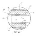
- FIG. 4is a cross-sectional view taken through line 4 - 4 of FIG. 3 .
- FIG. 4Ais an enlarged view of portion 4 A of FIG. 4 .
- FIG. 4Bis an enlarged view of portion 4 B of FIG. 4 with the fixation device in a first position.
- FIG. 4Cis an enlarged view of portion 4 C of FIG. 4 with the fixation device in a second position.
- FIG. 5is a cross-sectional view taken through line 5 - 5 of FIG. 3 .
- FIG. 6Ais a side perspective view of another embodiment of a proximal anchor for the bone fixation device of FIG. 1 .
- FIG. 6Bis a cross-sectional view of the proximal anchor of FIG. 6A .
- FIG. 6Cis a side perspective view of another embodiment of a proximal anchor for the bone fixation device of FIG. 1 .
- FIG. 6Dis a cross-sectional view of the proximal anchor of FIG. 6C .
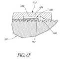
- FIG. 6Eis a cross-sectional view of another embodiment of a proximal anchor for the bone fixation device of FIG. 1 .
- FIG. 6Fis a cross-sectional view of the proximal anchor of FIG. 6E .
- FIG. 7is a cross sectional view through an angularly adjustable proximal anchor plate.
- FIG. 8is a front perspective view of the proximal anchor plate of FIG. 7 .
- FIG. 9is a bottom perspective view of a modified embodiment of a bone fixation device.
- FIG. 10is an unassembled side perspective view of the bone fixation device of FIG. 9 .
- FIG. 11is an unassembled side view of the bone fixation device of FIG. 9 .
- FIG. 12is a cross-sectional view of the flange and proximal anchor of the bone fixation device of FIG. 11 .
- FIG. 13is an unassembled bottom perspective view of the bone fixation device of FIG. 9 .
- FIG. 14is an unassembled side perspective view of another modified embodiment of a bone fixation device.
- FIG. 15is an unassembled side view of the bone fixation device of FIG. 9 .
- FIG. 16is a posterior view of a portion of the spinal column and a fixation system including the fixation device of FIG. 1 .
- FIG. 17is a posterior view of the spinal column and a modified fixation system that includes the fixation device of FIG. 1 .
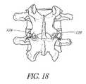
- FIG. 18is a posterior view of a portion of the lumbar spine with the fixation device of FIG. 9 used as a trans-facet screw.
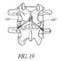
- FIG. 19is a posterior view of a portion of the lumbar spine with the fixation device of FIG. 9 used as a trans-laminar screw.
- FIG. 20is a posterior view of a portion of the lumbar spine with the fixation device of FIG. 9 used as a facet-pedicle screw.
- FIG. 21is a side perspective view of another embodiment of a bone fixation device.
- FIG. 22is a front view of the bone fixation device of FIG. 20 .
- FIG. 23is a cross-sectional view of the bone fixation device of FIG. 20 .
- fixation devices of the present inventionwill be disclosed primarily in the context of a spinal fixation procedure, the methods and structures disclosed herein are intended for application in any of a variety medical applications, as will be apparent to those of skill in the art in view of the disclosure herein.
- the bone fixation devicemay be applicable to proximal fractures of the femur and a wide variety of fractures and osteotomies, the hand, such as interphalangeal and metacarpophalangeal arthrodesis, transverse phalangeal and metacarpal fracture fixation, spiral phalangeal and metacarpal fracture fixation, oblique phalangeal and metacarpal fracture fixation, intercondylar phalangeal and metacarpal fracture fixation, phalangeal and metacarpal osteotomy fixation as well as others known in the art. See e.g., U.S. Pat. No. 6,511,481, which is hereby incorporated by reference herein.
- a wide variety of phalangeal and metatarsal osteotomies and fractures of the footmay also be stabilized using the bone fixation devices described herein. These include, among others, distal metaphyseal osteotomies such as those described by Austin and Reverdin-Laird, base wedge osteotomies, oblique diaphyseal, digital arthrodesis as well as a wide variety of others that will be known to those of skill in the art.
- Fractures of the fibular and tibial malleoli, pilon fractures and other fractures of the bones of the legmay be fixated and stabilized with these bone fixation devices with or without the use of plates, both absorbable or non-absorbing types, and with alternate embodiments of the current invention
- the fixation devicesmay also be used to attach tissue or structure to the bone, such as in ligament reattachment and other soft tissue attachment procedures. Plates and washers, with or without tissue spikes for soft tissue attachment, and other implants may also be attached to bone, using either resorbable or nonresorbable fixation devices depending upon the implant and procedure.
- the fixation devicesmay also be used to attach sutures to the bone, such as in any of a variety of tissue suspension procedures.
- the bone fixation device described hereinmay be used with or without plate(s) or washer(s), all of which can be either permanent, absorbable, or combinations.
- FIG. 1there as illustrated a side elevational view of an exemplary embodiment of a bone fixation device 12 .
- a pair of fixation devices 12are positioned within adjacent vertabrae 10 .
- the bone fixation device 12may be used in a variety of techniques to stabilize the spine.
- the bone fixation devices 12may be used as pedicle or facet screws that may be unilaterally or bilaterally symmetrically mounted on adjacent or non-adjacent vertebrae and used in combination one or more linkage rods or plates to facilitate fusion of one or more vertebrae.
- the bone fixation devices 12 disclosed hereinmay also be used as a fixation screw to secure two adjacent vertebra to each other in a trans-laminar, trans-facet or facet-pedicle (e.g., the Boucher technique) applications.
- a trans-laminar, trans-facet or facet-pediclee.g., the Boucher technique
- the bone fixation devices disclosed hereinmay be used for posterior stability after laminectomy, artificial disc replacement, repairing odontoid fractures and other fractures of the spine, and other applications for providing temporary or permanent stability in the spinal column.
- the fixation device 12comprises a body 28 that extends between a proximal end 30 and a distal end 32 .
- the length, diameter and construction materials of the body 28can be varied, depending upon the intended clinical application. In embodiments optimized for spinal fixation in an adult human population, the body 28 will generally be within the range of from about 20-90 mm in length and within the range of from about 3.0-8.5 mm in maximum diameter.
- the length of the helical anchordiscussed below, may be about 8-80 millimeters. Of course, it is understood that these dimensions are illustrative and that they may be varied as required for a particular patient or procedure.
- the body 28comprises titanium.
- other metals or bioabsorbable or nonabsorbable polymeric materialsmay be utilized, depending upon the dimensions and desired structural integrity of the finished fixation device 12 .
- the distal end 32 of the body 28is provided with a cancellous bone anchor or distal cortical bone anchor 34 .
- the distal bone anchor 34is adapted to be rotationally inserted into a portion (e.g., the facet or pedicle) of a first vertebra.
- the distal anchor 34comprises a helical locking structure 72 for engaging cancellous and/or distal cortical bone.
- the locking structure 72comprises a flange that is wrapped around an axial lumen. The flange extends through at least one and generally from about two to about 50 or more full revolutions depending upon the axial length of the distal anchor and intended application. The flange will generally complete from about 2 to about 20 revolutions.
- the helical flange 72is preferably provided with a pitch and an axial spacing to optimize the retention force within cancellous bone, to optimize compression.
- the helical flange 72 of the illustrated embodimenthas a generally triangular cross-sectional shape (see FIG. 4 ).
- the helical flange 72can have any of a variety of cross sectional shapes, such as rectangular, oval or other as deemed desirable for a particular application through routine experimentation in view of the disclosure herein.
- the outer edge of the helical flange 72defines an outer boundary.
- the ratio of the diameter of the outer boundary to the diameter of the central lumencan be optimized with respect to the desired retention force within the cancellous bone and giving due consideration to the structural integrity and strength of the distal anchor 34 .
- Another aspect of the distal anchor 34 that can be optimizedis the shape of the outer boundary and the central core, which in the illustrated embodiment are generally cylindrical.
- the distal end 32 and/or the outer edges of the helical flange 72may be atraumatic (e.g., blunt or soft). This inhibits the tendency of the fixation device 12 to migrate anatomically distally and potentially out of the vertebrae after implantation. Distal migration is also inhibited by the dimensions and presence of a proximal anchor 50 , which will be described below. In the spinal column, distal migration is particularly disadvantageous because the distal anchor may harm the tissue, nerves, blood vessels and spinal cord which lie within and/or surround the spine.
- the various distal anchors described in co-pending U.S. patent application Ser. No. 10/012,687, filed Nov. 13, 2001can be incorporated into the fixation device 12 described herein.
- the entire contents of this applicationis hereby expressly incorporated by reference.
- the distal anchormay comprise a single helical thread surrounding a central core, much as in a conventional screw, which has been cannulated to facilitate placement over a wire.
- a double helical threadmay be utilized, with the distal end of the first thread rotationally offset from the distal end of the second thread.
- a double helical threadcan enable a greater axial travel for a given degree of rotation and greater retention force than a corresponding single helical thread.
- Specific distal anchor designscan be optimized for the intended use, taking into account desired performance characteristics, the integrity of the distal bone, and whether the distal anchor is intended to engage exclusively cancellous bone or will also engage cortical bone.
- the body 28comprises a first portion 36 and a second portion 38 that are coupled together at a junction 40 .
- the first portion 36carries the distal anchor 34 while the second portion 38 forms the proximal end 30 of the body 28 .
- the second portion 38may be used to pull the body 28 and therefore will sometimes be referred to as a “pull-pin”.
- the first and second portions 36 , 38are preferably detachably coupled to each other at the junction 40 .
- the first and second portions 36 , 38are detachably coupled to each other via interlocking threads. Specifically, as best seen in FIG.
- the body 28includes an inner surface 41 , which defines a central lumen 42 that preferably extends from the proximal end 30 to the distal end 32 throughout the body 28 .
- the inner surface 41includes a first threaded portion 44 .
- the first threaded portion 44is configured to mate with a second threaded portion 46 , which is located on the outer surface 45 of the second portion 38 .
- the interlocking annular threads of the first and second threaded portions 44 , 46allow the first and second portions 36 , 38 to be detachably coupled to each other. In one modified embodiment, the orientation of the first and second threaded portions 44 , 46 can be reversed.
- first threaded portion 44can be located on the outer surface of the first portion 36 and the second threaded portion 46 can be located on the inner surface 41 at the distal end of the second portion 38 .
- Any of a variety of other releasable complementary engagement structuresmay also be used, to allow removal of second portion 38 following implantation, as is discussed below.
- the second portion 38can comprise any of a variety of tensioning elements for permitting proximal tension to be placed on the distal anchor 34 while the proximal anchor is advanced distally to compress the fracture.
- tensioning elementsfor permitting proximal tension to be placed on the distal anchor 34 while the proximal anchor is advanced distally to compress the fracture.
- any of a variety of tubes or wirescan be removably attached to the first portion 36 and extend proximally to the proximal handpiece.
- the first portion 36can include a releasable connector in the form of a latching element, such as an eye or hook.
- the second portion 38can include a complementary releasable connector (e.g., a complementary hook) for engaging the first portion 36 .
- the second portion 38can be detachably coupled to the first portion 36 such proximal traction can be applied to the first portion 36 through the second portion as will be explained below.
- the second portion 48may be provided with an eye or hook, or transverse bar, around which or through which a suture or wire may be advanced, both ends of which are retained at the proximal end of the device. Following proximal tension on the tensioning element during the compression step, one end of the suture or wire is released, and the other end may be pulled free of the device.
- Alternate releasable proximal tensioning structuresmay be devised by those of skill in the art in view of the disclosure herein. It should also be appreciated that the body may be from a single piece as described in U.S. Pat. No. 6,511,481, which has been incorporated by reference herein.
- the body 28is cannulated to accommodate installation over a placement wire as is understood in the art.
- the cross section of the illustrated central cannulationis circular but in other embodiments may be non circular, e.g., hexagonal, to accommodate a corresponding male tool for installation or removal of the second portion 38 of the body 28 as explained above.
- the body 28may partially or wholly solid.
- the proximal end 30 of the body 28may be provided with a rotational coupling 70 , for allowing the second portion 38 of the body 28 to be rotationally coupled to a rotation device.
- the proximal end 30 of the body 28may be desirably rotated to accomplish one or two discrete functions. In one application, the proximal end 30 is rotated to remove the second portion 38 of the body 28 following tensioning of the device to anchor an attachment to the bone. Rotation of the rotational coupling 70 may also be utilized to rotationally drive the distal anchor into the bone. Any of a variety of rotation devices may be utilized, such as electric drills or hand tools, which allow the clinician to manually rotate the proximal end 30 of the body.
- the rotational coupling 70may have any of a variety of cross sectional configurations, such as one or more flats or splines.
- the rotational coupling 70comprises a proximal projection of the body 28 having an axial recess with a polygonal cross section, such as a hexagonal cross section.
- the rotational coupling 70is illustrated as a female component, machined or milled or attached to the proximal end 30 of the body 28 .
- the rotational couplingmay also be in the form of a male element, such as a hexagonal or other noncircular cross sectioned projection.
- the proximal end 30 of the fixation deviceis provided with a proximal anchor 50 .
- Proximal anchor 50is axially distally moveable along the body 28 , to permit compression of between the distal and proximal ends 32 , 30 of the fixation device 12 .
- complimentary locking structuressuch as threads or ratchet like structures between the proximal anchor 50 and the body 28 resist proximal movement of the anchor 50 with respect to the body 28 under normal use conditions.
- the proximal anchor 50preferably can be axially advanced along the body 28 with and/or without rotation as will be apparent from the disclosure herein.
- the proximal anchor 50comprises a housing 52 such as a tubular body, for coaxial movement along the body 28 .
- the housing 50may have diameter sized to fit through an opening formed in fixation bar or plate.
- the distal end of the housing 52preferably extends distally past the junction 40 between the first portion 36 and the second portion 38 .
- the housing 52is provided with one or more surface structures 54 such as a radially inwardly projecting flange 56 (see FIGS. 4B and 4C ), for cooperating with complementary surface structures 58 on the first portion 36 of the body 28 .
- the complimentary surface structures 58comprise a series of annular ridges or grooves 60 .
- the surface structures 54 and complementary surface structures 58permit distal axial travel of the proximal anchor 50 with respect to the body 28 , but resist proximal travel of the proximal anchor 50 with respect to the body 28 .
- the proximal end of the flange 56is biased towards the longitudinal axis of the body 28 .
- the flange 56engages the grooves or ridges 60 of the complementary surface structures 58 . This prevents proximal movement of the proximal anchor 50 with respect to the body 28 .
- the flange 56can bend outwardly away from the body 28 and the ridges 60 so as to allow the proximal anchor 50 to move distally.
- Retention structures 58are spaced axially apart along the body 28 , between a proximal limit 62 and a distal limit 64 .
- the axial distance between proximal limit 62 and distal limit 64is related to the desired axial working range of the proximal anchor 50 , and thus the range of functional sizes of the fixation device 12 .
- the fixation device 12 of the exemplary embodimentcan provide compression between the distal anchor 34 and the proximal anchor 50 vertebrae throughout a range of motion following the placement of the distal anchor in a vertebra.
- the distal anchormay be positioned within the cancellous and/or distal cortical bone of a vertebra, and the proximal anchor may be distally advanced with respect to the distal anchor throughout a range to provide compression without needing to relocate the distal anchor and without needing to initially locate the distal anchor in a precise position with respect to the proximal side of the bone or another vertebra.
- Providing a working range throughout which tensioning of the proximal anchor is independent from setting the distal anchorallows a single device to be useful for a wide variety of spinal fixation procedures, as well as eliminates the need for accurate device measurement.
- this arrangementallows the clinician to adjust the compression force during the procedure without adjusting the position of the distal anchor. In this manner, the clinician may focus on positioning the distal anchor sufficiently within the vertebra to avoid or reduce the potential for distal migration out of the vertebra, which may damage the particularly delicate tissue, blood vessels, nerves and/or spinal cord surrounding or within the spinal column.
- the working rangeis at least about 10% of the overall length of the device, and may be as much as 20% or 50% or more of the overall device length.
- working ranges of up to about 10 mm or moremay be provided, since estimates within that range can normally be readily accomplished within the clinical setting.
- the embodiments disclosed hereincan be scaled to have a greater or a lesser working range, as will be apparent to those of skill in the art in view of the disclosure herein.
- the proximal anchor 50includes a flange 66 that, as will be explained below, may be configured to sit against the outer surface of a vertebra and/or a fixation rod or plate.
- the flange 66is preferably an annular flange, to optimize the footprint or contact surface area between the flange 66 and the bone or fixation rod or plate.
- Circular or polygonal shaped flanges for use in spinal fixationwill generally have a diameter of at least about 3 mm greater than the adjacent body 28 and often within the range of from about 2 mm to about 30 mm or more greater than the adjacent body 28 .
- the fixation devicemay include an antirotation lock between the first portion 36 of the body 28 and the proximal collar 50 .
- the first portion 36includes a pair of flat sides 80 , which interact with corresponding flat structures 82 in the proximal collar 50 .
- One or three or more axially extending flatsmay also be used.
- rotation of the proximal collar 50is transmitted to the first portion 36 and distal anchor 34 of the body 28 .
- splines or other interfit structurescan be used to prevent relative rotation of the proximal anchor and the first portion 36 of the body 28 .
- the flange 66is preferably provided with a gripping structure to permit an insertion tool to rotate the flange 66 .
- a gripping structuremay be provided, such as one or more slots, flats, bores or the like.
- the flange 44is provided with a polygonal, and, in particular, a pentagonal or hexagonal recess 84 (see FIG. 4 ).
- the housing 52 of the proximal anchor 50can include one or more one or more barbs that extend radially outwardly from the tubular housing 52 .
- Such barbsprovide for self tightening after the device has been implanted in the patient as described in a co-pending U.S. patent application Ser. No. 10/012,687, filed Nov. 13, 2001, which was incorporated by reference above.
- the barbsmay be radially symmetrically distributed about the longitudinal axis of the housing 52 .
- Each barbis provided with a transverse engagement surface, for anchoring the proximal anchor 50 in the bone.
- the transverse engagement surfacemay lie on a plane which is transverse to the longitudinal axis of the housing 50 or may be inclined with respect to the longitudinal axis of the tubular 50 . In either arrangement, the transverse engagement surface 43 generally faces the contacting surface 68 of the flange 44 . As such, the transverse engagement surface inhibits proximal movement of the proximal anchor with respect to the bone.
- FIGS. 6A and 6Billustrate another embodiment of a proximal anchor 100 .
- This embodimentalso includes a tubular housing 102 and a flange 104 that may be configured as describe above with respect to FIGS. 2-4 .
- the tubular housing 102may include an anti-rotational lock, which, in the illustrated embodiment, is in the form of one or more sides 106 that interact with corresponding flat structures formed in the body 28 as described above.
- the surfaces structurescomprises one or more teeth or grooves 112 , which are configured to engage the complementary surfaces structures on the body 28 (see FIG. 2 ).
- One or more slots or openings 110are formed in the tubular housing 102 to form one or more bridges 112 , which carry the teeth 102 .
- the anchor proximal anchor 100may be pushed towards the distal end of the body and the teeth 102 can slide along the and over the complementary surface structures 58 on the body 28 .
- the bridge 113may flex slightly away from the body 28 to allow such movement.
- the number and shape of the openings 110 and bridges 112may be varied depending of the desired flexing of the bridges 112 when the proximal anchor 110 is moved distally over the body and the desired retention force of the distal anchor when appropriately tensioned.
- the teeth on the proximal anchor 100 and the grooves on the body 28may be configured such that the proximal anchor 100 can be rotated or threaded onto the pin in the distal direct and/or so that that the proximal anchor can be removed by rotation.
- the illustrated embodimentalso advantageously includes visual indicia 114 (e.g., marks, grooves, ridges etc.) on the tubular housing 102 for indicating the depth of the proximal housing 100 within the bone.
- FIGS. 6C and 6Dillustrate another embodiment of a proximal anchor 150 .
- the proximal anchor 150comprises a housing 152 such as a tubular body, for coaxial movement along the body 28 .
- the proximal anchor 150also includes a flange 154 that is configured that to set against the outer surface of, for example, a bone or fixation bar or rod.
- the flange 154defines a contacting surface 156 , which preferably forms an obtuse angle with respect to the exterior of the housing 152 .
- the contacting surface 154may be perpendicular or form an acute angle with respect to the housing 152 .
- the complementary retention structures 54comprise one or more inwardly projecting teeth or flanges 158 , for cooperating with the complementary rentention structures 58 on the body 28 .
- the complementary retention structures 58 of the bodypreferably comprise a plurality of annular ridges or grooves a first surface and a second surface.
- the first surfacegenerally faces the proximal direction and is preferably inclined with respect to the longitudinal axis of the body 28 .
- the second surfacegenerally faces the distal direction and lies generally perpendicular to the longitudinal axis of the body 28 .
- the proximal anchor 150preferably includes one or more of axial slots 160 .
- the axial slots 160cooperate to form lever arm(s) on which the teeth or projections 158 are positioned.
- the teeth 158can slide along the first surface and ride over the retention structures 58 of the body 28 as the teeth 158 are flexed away from the body 28 .
- the bonemay push on the angled portion contacting surface 156 of the proximal anchor 150 .
- This forceis transmitted to the teeth 158 through the lever arms.
- the teeth 158are prevented from flexing away from the body 28 , which keeps the teeth 158 engaged with the retention structures 58 of the body 28 .
- proximal movement of the proximal anchor 150 with respect to the body 28is resisted.
- the axial length and width of the slots 160may be varied, depending upon the desired flexing of the lever arms when the proximal anchor 150 is moved distally over the body 28 and the desired retention force of the distal anchor when appropriately tensioned.
- axial lengths and widths of the slots 160are approximately 0.5 mm for a proximal anchor having a length of approximately 4 mm, an inner diameter of approximately 3 mm.
- the slots 160extend through the flange 154 and at least partially into the housing 152 .
- the proximal anchor 150includes four teeth or flanges 158 , which are positioned near the proximal end of the anchor 150 .
- the proximal anchor 150may include more or lest teeth and/or the teeth may be positioned mor distally or proximally on the anchor 150 .
- these retention structuresmay be configured such that the proximal anchor 150 may be proximally and/or distally advanced with rotation by providing for a screw like configuration between the retention structures.
- a proximal anchor 180is illustrated in FIGS. 6E and 6F .
- the proximal anchor 180may include a tubular housing 152 and a flange 154 with a bone contacting surface 156 .
- the complementary structure of the proximal anchor 180comprises an annular ring 182 , which is positioned within an annular recess 184 that is preferably positioned at the distal end of the tubular housing 152 .
- the annular recess 184includes a proximal portion 186 and a distal portion 188 .
- the proximal portion 186is sized and dimensioned such that as the proximal anchor 180 is advanced distally over the body 28 the annular ring 182 can ride over the complementary retention structures 58 of the body 28 . That is, the proximal portion 182 provides a space for the annular ring 182 can move radially away from the body 28 as the proximal anchor 180 is advanced distally.
- the annular ring 182is made from a material that provides sufficient strength and elasticity such as, for example, stainless steel or titanium.
- the annular ring 182is preferably split such that it can be positioned over the body 405 .
- the annular ring 182includes a plurality of teeth 192 although in modified embodiments the annular ring 182 may be formed without the teeth.
- the distal portion 188 of the recess 184is sized and dimensioned such that after the proximal anchor 180 is appropriately tensioned the annular ring 192 becomes wedged between the body 28 and an angled engagement surface of the distal portion 188 . In this manner, proximal movement of the proximal anchor 180 with respect to the body is prevented.
- the ring 192can be formed without a gap.
- Other embodiments and further details of the proximal anchor described abovecan be found in U.S.
- the contacting surface 68 of the flange 44is tapered and generally faces the outer surface of the vertebra, fixation rod, and/or plate.
- the bone contacting surface 69can reside in or approximately on a plane, which is perpendicular with respect to the longitudinal axis of the body 28 .
- other angular relationships between the bone contacting surface 68 of the flange 66 and the longitudinal axis of the body 28 and housing 52may be utilized, depending upon the anticipated entrance angle of the body 28 and associated entrance point surface of the vertebra.
- the clinicianmay be provided an array of proximal anchors 50 of varying angular relationships between the contacting surface 68 and the longitudinal axis of the body 28 and housing 52 (e.g., 90°, 100°, 110°, 120°, and 130°).
- a single body 28can be associated with the array such as in a single sterile package.
- the clinicianupon identifying the entrance angle of the body 28 and the associated entrance point surface orientation of the facet joint of the spine can choose the anchor 50 from the array with the best fit angular relationship, for use with the body 28 .
- the proximal anchor 50may be used with a washer 66 ′ that is angularly adjustable with respect to the longitudinal axis of the body 28 .
- the proximal anchor 50 and the washer 66 ′include corresponding semi-spherical or radiused surfaces 45 a and 45 b .
- the surface 45 bsurrounds an aperture 49 in the washer 66 .
- This arrangementallows the proximal anchor 50 to extend through and pivot with respect to the washer 66 ′.
- the angular relationship between the bone contacting surface 68 ′ of the washer 66 ′ and the longitudinal axis of the body 28can vary in response to the entrance angle.
- FIGS. 9-13illustrate another embodiment of a bone fixation device 200 with an angularly adjustable proximal anchor 202 .
- similar reference numbersare used to identify components that are similar components described above.
- the bone fixation device 200comprises a body 28 that extending between a proximal end 30 and a distal end 32 .
- the distal end 32 of the bodyis provide with a bone anchor 34 as described above.
- the illustrated body 28is cannulated; however, it should be appreciated that in modified embodiments the body 28 can be solid.
- the proximal end of the anchoris provided with a hexagonal recess, which can be used in combination with a rotational tool to rotate the body 28 .
- modified embodimentsmay use a variety of different male or female anti-rotational couplings.
- the illustrated fixation deviceincludes an annular flange 202 and proximal anchor 204 .
- the proximal anchor 204defines a housing 206 that is axially distally moveable along the body 28 .
- Complimentary locking structures 54 , 58 on the housing 206 and the body 28such as threads or ratchet like structures resist proximal movement of the anchor 204 with respect to the body 28 under normal use conditions.
- the complimentary locking structures 54 , 48may permit the anchor 204 to be axially advanced along the body 28 by rotation.
- the complimentary locking structures 54 , 58may permit the anchor 204 to be axially advanced along the body 24 without rotation.
- the illustrated proximal anchor 204also includes a gap 205 such that the illustrated anchor 204 forms a split ring collar. In modified embodiments, the proximal anchor 204 can be formed without the gap 205 .
- the proximal anchor 204preferably includes a smooth and more preferably rounded or spherical outer surface portion 208 , which is configured to fit within a corresponding smooth and preferably rounded recessed portion 210 in the flange 202 .
- the flange 202resists distal movement of the proximal anchor 204 while permitting at least limited rotation of between the proximal anchor 204 and the flange 202 .
- the illustrate arrangementallows for angular movement of the flange 202 with respect to the anchor 204 to accommodate variable anatomical angles of the bone surface.
- the flange 202may seat directly against the outer surface of a vertebra. Because the outer surface of the vertebra is typically non-planar and/or the angle of insertion is not perpendicular to the outer surface of the vertebra, a fixed flange may contact only a portion of the outer surface of the vertebra. This may cause the vertebra to crack due to high stress concentrations.
- the angularly adjustable flange 202can rotate with respect to the body and thereby the bone contacting surface may be positioned more closely to the outer surface. More bone contacting surface is thereby utilized and the stress is spread out over a larger area.
- the flange 202which has a larger diameter than the proximal anchor 50 , effectively increases the shaft to head diameter of the fixation device, thereby increasing the size of the loading surface and reducing stress concentrations.
- the flange 202includes a plurality of bone engagement features 212 , which in the illustrated embodiment comprises a one or more spikes 212 positioned on a contacting surface 216 of the flange 202 .
- the spikes 212provide additional gripping support especially when the flange 202 is positioned against, for example, uneven bone surfaces and/or soft tissue.
- the flange 202may be formed without the bone engagement features 212 .
- Other structures for the bone engagement feature 212may also be used, such as, for example, ridges, serrations etc.
- the illustrated embodimentalso includes a tapered upper surface 214 that in certain embodiments may be flat.
- FIGS. 14 and 15illustrate a modified embodiment of the angularity adjustable fixation device 200 .
- the proximal anchor 204 ′includes an upper portion 211 and a lower portion 213 .
- the upper portion 211is configured as described above with respect to the housing.
- the lower portion in the illustrated embodimentis generally tubular and a generally smaller diameter than the upper portion.
- the lower portionincludes complementary retention structures 54 and generally provides the fixation device with a greater range of adjustable compression and additional retention structures as compared to the previous embodiment.
- a patient with a spinal instabilityis identified.
- the distal ends 32 of one or more bone fixation devices described hereinare advanced into the anterior vertebral body or other suitable portion of one or more vertebrae.
- the fixation deviceis typically used to couple one vertebra that is unstable, separated or displaced to another vertebra, which is not unstable, separated or displaced.
- this methodmay also be applied to three or more vertebrae.
- the S-1 portion of the sacrummay be used to stabilize the L5 vertebrae.
- the fixation devicesmay be inserted into the vertebrae with bilateral symmetry such that such two vertebrae are coupled together with two or more fixation devices on a left side of the spine being connected using one or more rods and/or plates to two or more fixation devices on a right side of the spine.
- the distal anchor of these fixation devicesmay be inserted through the pedicle and/or the facet of the vertebrae.
- the fixation deviceswill be utilized to secure adjacent vertebral bodies in combination with another fusion procedure or implant, such as the implantation of a spinal cage, plate or other device for fusing adjacent vertebral bodies.
- the fixation devicesmay operate in conjunction with a cage or other implant to provide three point stability across a disc space, to assist in resisting mobility between two vertebral bodies.
- the fixation devicemay simply be advanced through a portion of a first vertebra and into a second, preferably adjacent, vertebra.
- the fixation devicemay extend through the facet of the first vertebra and the distal anchor may be inserted through the facet or pedicle of the second vertebra.
- the proximal anchormay be carried by the fixation device prior to advancing the body into the vertebrae, or may be attached following placement of the body within the vertebrae.
- stabilization implantse.g., a fixation plate and/or rod
- a fixation plate and/or rodmay be placed over or coupled to the body or the proximal anchor before the proximal anchor is placed on the body.
- proximal tractionis applied to the proximal end 30 of body 28 , such as by conventional hemostats, pliers or a calibrated loading device, while distal force is applied to the proximal anchor.
- the proximal anchoris advanced distally with respect to the body until the proximal anchor fits snugly against the outer surface of the vertebra or a fixation plate/rod.
- Appropriate tensioning of the fixation deviceis accomplished by tactile feedback or through the use of a calibration device for applying a predetermined load on the implantation device.
- one advantage of the structure of the illustrated embodimentsis the ability to adjust compression independently of the setting of the distal anchor 34 within the vertebra.
- the second portion 38 of the body 28is preferably detached from the first portion 36 and removed. In the illustrated embodiment, this involves rotating the second portion 38 with respect to the first portion via the coupling 70 . In other embodiment, this may involve cutting the proximal end of the body 28 .
- the proximal end of the bodymay be separated by cauterizing.
- Cauterizingmay fuse the proximal anchor 50 to the body 32 thereby adding to the retention force between the proximal anchor 50 and the body 28 .
- Such fusion between the proximal anchor and the bodymay be particularly advantageous if the pin and the proximal anchor are made from a bioabsorbable and/or biodegradable material. In this manner, as the material of the proximal anchor and/or the pin is absorbed or degrades, the fusion caused by the cauterizing continues to provide retention force between the proximal anchor and the body.
- additional fixations devicesmay be implanted and/or additional stabilization implants (e.g., rods, plates, etc.) may be coupled to the body.
- additional stabilization implantse.g., rods, plates, etc.
- the access sitemay be closed and dressed in accordance with conventional wound closure techniques.
- the second portion 38may form part of the driving device, which is used to rotate the proximal anchor 50 and thus cancellous bone anchor 34 into the vertebrae.
- the second portion 38is used to apply proximal traction. After appropriate tensioning, the second portion 38 can be de-coupled from the first portion 36 and removed with the driving device.
- the second portion 38may be connected to a rotatable control such as a thumb wheel on the deployment device.
- a containermay be opened at the clinical site exposing the proximal end of the implant, such that the distal end of the second portion 38 may be removably coupled thereto. Proximal retraction of the hand tool will pull the implant out of its packaging.
- the implantmay then be positioned within the aperture in the bone, rotated to set the distal anchor, and the hand piece may be manipulated to place proximal traction on the second portion 38 while simultaneously distally advancing the proximal anchor. Following appropriate tensioning, the second portion 38 may be disengaged from the implant, and removed from the patient.
- the second portion 38may be disengaged from the implant by rotating a thumb wheel or other rotational control on the hand piece.
- the second portion 38comprises a pull wire
- following appropriate tensioning across the fracturea first end of the pull wire is released such that the pull wire may be removed from the implant by proximal retraction of the second end which may be attached to the hand piece.
- the clinicianwill have access to an array of fixation devices 12 , having, for example, different diameters, axial lengths and, if applicable, angular relationships. These may be packaged one or more per package in sterile or non-sterile envelopes or peelable pouches, or in dispensing cartridges which may each hold a plurality of devices 12 . The clinician will assess the dimensions and load requirements, and select a fixation device from the array, which meets the desired specifications.
- the fixation device 12 ofmay be used with a variety spinal cages, plates or other devices for fusing adjacent vertebral bodies.
- FIG. 16illustrates a pair of fixation devices screws 12 A, 12 B according to the exemplary embodiments being used with a pair of fixation bars 300 , 302 for spinal fixation.
- the fixation devices 12 A, 12 B and the fixation bars 300 , 302are illustrated as fixing the L3 and L4 vertebrae relative to each other; however, theses components can be used to fix other adjacent or non-adjacent vertebrae in the lumbar region, as well as the thoracolumbar junction, or elsewhere on the spine as long as an axial path between two vertebra to compress the two vertebrae.
- the first fixation device 12 Ais inserted through the lamina of the L3 vertebra in the region of the facet joint on the left side of the sagittal plane.
- the first fixation device 12 Awill extend in an anterior direction through the facet joint and angles laterally outwardly into the left base of the transverse process of the inferior vertebra L4.
- a second fixation device 12 Bextends in an anterior direction through the lamina on the opposite (right) side of the sagittal plane.
- the second fixation device 12 Bextends through the facet joint on the right side of the sagittal plane and angles laterally outwardly into the right base of the transverse process of the L4 vertebra.
- the fixation devices 12 A, 12 Bdiverge in the anterior direction, and are also angled slightly in the inferior direction.
- fixation devices 12 A, 12 Bmay be fitted within a fixation bar 300 , 302 .
- fixation bar 300 , 302 of FIG. 15is merely exemplary and the fixation device may be used with other types and styles of fixation bars.
- the fixation bars 300 and 302are generally mirror images of each other.
- the exemplary fixation bars 300 , 302includes an inferior portion 304 having a plurality of cylindrical bores 306 .
- Each of the bores 306are generally oriented along parallel axes and spaced in an inferior-superior direction along the inferior bar portion 304 .
- the fixation devices 12 A, 12 Bextend through one of the bores 306 .
- the relative length of the bar 300 , 302can be varied to provide adjustability for different sized vertebra.
- Each bar 300 , 302has a finger 308 that extends in a superior, and slightly lateral, direction from the inferior portion 306 .
- the finger 308extends in a superior direction across the cephalad side of the lateral process of L3 and curves in a superior and anterior direction over the superior aspect of the lateral pedicle of L3.
- the finger 308then extends in an inferior direction and slightly laterally inwardly before terminating in an anterior end 316 short of the spinal cavity 50 .
- the superior portion of the finger 308thus forms a hook that extends over and around the L3 pedicle to secure the bar from movement in an inferior direction as well as to prevent rotational movement about the longitudinal axis of the bar.
- the body 28 of the fixation devicecan be inserted through the bore 306 .
- the housing 52 of the proximal anchor 50is also dimensioned such that it has a diameter that is slightly less than the diameter of the bores 42 so as to allow rotational and reciprocal movement of the fixation device 12 A, 12 B in the bore 306 , but not to allow the fixation device 12 A, 12 B toggle relative to its longitudinal axis.
- the flange 66 of the proximal anchor 50has a diameter that is larger than the bore 42 .
- the combination of the finger 44 wrapped around the superior portion of the lateral process 46 and the coaction of the fixation device 12 A holding inferior portion 304 in placewill prevent the toggling of the fixation device 12 A, 12 B relative to the lamina on the superior vertebra.
- the inferior portion 304 of the bar 300 , 302may also carry a plurality of lateral weakened zones 318 in the form of lateral notches on both surfaces of the inferior portion 304 between each of the bores 306 .
- one or more sections containing bores 306can be broken away from the stabilization bar to adjust the length of the inferior portion 304 , so that unnecessary portions of the inferior portion can be removed.
- the left stabilization bar 300is shown with the lower two segments of the inferior portion removed.
- the second portion 38 of the body 28are also illustrated as being removed after the stabilization bars 300 and 302 .
- Proximal retraction of the body 28 with respect to the proximal anchor 50will compress the inferior portion 304 against the vertebra and will hold the stabilization bars 300 , 302 rigidly and prevent toggling of the screws.
- One advantage of the illustrated embodimentis that compression of the inferior portion 304 against the vertebra may be adjusted independently of the setting of the distal anchor in the spine.
- FIG. 17illustrates a modified embodiment of a spinal fixation system.
- four fixation devices 12 A, 12 B, 12 C, 12 Dare positioned in the facets of adjacent vertebra on both the left and right side of the vertebra column.
- a first set of the fixation devices 12 A, 12 Bare used to secure opposing ends of a first fixation plate 400 to the facets of adjacent vertebrae and a second set of fixation devices 12 C, 12 D are be used to secure opposing ends of a second fixation plate 400 ′ to the opposing facets on the adjacent vertebra.
- the fixation plates 400 , 400 ′may include a series of overlapping bores 401 through which the body of the fixation device 12 A, 12 B may extend.
- the proximal anchor 50may then be inserted over the body (not shown) and proximal retraction may be used to secure the fixation plate 400 against the vertebra.
- the fixation hardwaremay also include cross-links 402 , which span across the midline between corresponding fixation devices 12 A, 12 B, 12 C, 12 D on opposite sides of the spine.
- the cross-links 402also includes bores through which the body and the tubular portion of the housing 50 extends.
- the fixation hardwaremay not include the cross-links 402 .
- fixation devices described hereinmay be used as pedicle screws to secure a fixation rod or plate that extends between two or more vertebrae. Such applications may be used unilaterally or with bilateral symmetry.
- the use of the fixation device 12advantageously allows the compression of the plates or fixation bars against the vertebrae to be adjusted independently of the setting of the distal anchor 34 . That is, the proximal anchor 50 is advanced distally with respect to the body 28 until the proper compression load is applied across the fixation bars/plates and the vertebrae.
- the proximal anchorcan be coupled to or form a part of the plate or fixation bar. Such an arrangement provides for self tightening after the device has been implanted into the patient.
- the fixation devices 12 A, 12 Bmay be used to provide stability without additional hardware.
- the fixation device 12 A, 12 Bis used as a trans-facet screw. That is, the fixation device extends through a facet of a first vertebra and into the facet of a second, typically inferior, vertebrae. As in the illustrated embodiment, this procedure is typically (but not necessarily) preformed with bilateral symmetry.
- the fixation devices 12 A, 12 Bcan be used to stabilize two vertebrae, such as L3 and L4 to each other pending the healing of a fusion.
- the body 28 of fixation devices 12 A, 12 Bhas a length of approximately 10 mm-30 mm and the diameter of the body is approximately 3 mm to 5.5 mm.
- FIG. 19illustrates a modified arrangement for spinal fixation in which the fixation devices 12 A′, 12 B′ are used as trans-laminar facet screws.
- the fixation deviceextends through the spinous process and facet of a first vertebra and into the facet of a second, typically inferior, vertebra.
- this procedureis typically (but not necessarily) preformed with bilateral symmetry.
- the body 28 of fixation devices 12 A, 12 Bhas a length of approximately 50 mm-90 mm and the diameter of the body is approximately 4 mm to 5.5 mm.
- FIG. 20illustrates another modified arrangement for spinal fixation in which the fixation device 12 A′′, 12 B′′ is used as a facet-pedical screw (e.g., as used in the Boucher technique).
- the fixation deviceextends through the facet of a first vertebra and into the pedicle a second, typically inferior, vertebra.
- this procedureis typically (but not necessarily) preformed with bilateral symmetry.
- the fixation device 12 A, 12 B the body 28is approximately 20-40 millimeters in length and 3.0-5.5 millimeters in diameter.
- the flange of the proximal anchoris typically supported directly against the outer surface of a vertebra. Because the outer surface is typically non-planar and/or the insertion angle of the fixation device is not perpendicular to the outer surface, an angularly fixed flange may contact only a portion of the outer surface. That is, the contact surface of the flange may not sit flush on the outer surface of the vertebra. This may cause the vertebra to crack due to high stress concentrations. This can result in poor fusion rates.
- the angularly adjustable flanges of the embodiments described with reference to FIGS. 7-15are particularly advantageous because the flange can rotate with respect to the body and thereby the bone contacting surface may be positioned more closely to the outer surface of the vertebra. This results in more bone contacting surface being utilized and the stress supported by the fixation device is spread out over a larger area of the vertebra.
- These angularly adjustable flangesmay also be used with the spinal cages and rods.
- the angle of the body fixation devicemay be not be perpendicular to the contact surface of the fixation rod or plate. In such situations, the angularly adjustable flange allows the flange to rotate and sit flush against the fixation rod and plate.
- openingsmay be provided in the flange so that the flange may be coupled to the fixation rod or plate by for example screws or bolts.
- the counter borewill typically have a diameter that is slightly larger than the outer diameter of the proximal anchor so that the proximal anchor may sit at least partially below the outer surface of the vertebra.
- the fixationmay desirably include a through bore, opening through the distal cortex of the distal facet.
- the fixation device described abovemay be utilized either in a blind hole application, which the distal anchor is buried within the bone, or a through bore application is which the distal helix extends into and potentially through the distal cortex.
- a through bore fixation devicesuch as the fixation device 500 illustrated in FIGS. 21-23 may also be used.
- the through bore bone fixation device 500includes a body 28 extending between a proximal end 30 and a distal end 32 .
- the distal end 32includes a distal anchor 34 which will be described in more detail below.
- the proximal end 30may include break points 31 . In other embodiments, the proximal end 30 may not include break points 31 or may be used with a pull pin 38 as described above with reference to FIG. 4 .
- Retention structures 58are spaced axially along the body 28 between a proximal limit 62 and a distal limit 64 .
- the retention structures 58may be configured to interact with a proximal anchor to permit one way ratchet like movement and/or screw-type movement.
- the body 28may be used with any of the proximal anchors described above including the angularly adjustable flanges and proximal anchors described above with respect to FIGS. 7-15 .
- the distal anchor 34comprises a plurality of friction enhancing or interference fit structures such as ramped extensions or barbs 502 , for engaging the distal cortical bone or other surface or interior cancellous bone.
- each barb 502may be radially symmetrically distributed about the longitudinal axis of the body 28 .
- Each barb 502is provided with a transverse engagement surface 504 , for contacting the distal surface of the cortical bone or other structure or surface against which the barb 502 is to anchor.
- Transverse engagement surfaces 504may lie on a plane which is transverse to the longitudinal axis of the body 28 , or may be inclined with respect to the longitudinal axis of the body 28 .
- each barb 502 in the illustrated embodimentis carried by a flexible or hinged lever arm 506 .
- Lever arms 506may be formed by creating a plurality of axial slots 508 in the sidewall of the body.
- the axial slots 508cooperate with a central lumen 510 to isolate each barb 502 on a unique lever arm 506 .
- the axial length of the axial slots 508may be varied, depending upon the desired length over which flexing is desirably distributed, the desired range of lateral motion, and may vary depending upon the desired construction material.
- each of the slots 508 at the distal end 30is selected to cooperate with the dimensions of the barbs 502 to permit radial inward deflection of each of the barbs 502 so that the body 26 may be press fit through a predrilled hole having an inside diameter approximately equal to the outside diameter of the pin 28 just proximal to the transverse engagement surfaces 502 .
- each of the slots 508tapers in circumferential direction width from a relatively larger dimension at the distal end 30 to a relatively smaller dimension at the proximal limit of the axial slot 508 .
- the fixation device 500may be used with a locking guide wire 520 .
- the guide wirehas a distal end 522 and a proximal end 524 .
- the illustrated guide wire 520comprises a locking portion 526 that is located at the distal end 522 of the guide wire 520 and an elongated portion 528 that preferably extends from the distal portion 522 to the proximal end 524 of the guide wire 520 .
- the diameter D 1 of the elongated portion 528is generally smaller than the diameter D 2 of the locking portion 526 .
- the guide wire 502can be made from stainless steel, titanium, or any other suitable material.
- the locking portion 526 on guidewire 502can take any of a variety of forms, and accomplish the intended function as will be apparent to those of skill in the art in view of the disclosure herein.
- a generally cylindrical locking structureas illustrated, may be used.
- any of a variety of other configurations in which the cross section is greater than the cross section of the proximal portion 528may be used.
- Conical, spherical, or other shapesmay be utilized, depending upon the degree of compression desired and the manner in which the locking portion 156 is designed to interfit with the distal end 30 of the pin.
- the guide wire 502is configured such that its proximal end can be threaded through the lumen 510 of the pin 26 .
- the lumen 510preferably comprises a first portion 530 and a second portion 532 .
- the first portion 530is generally located at the distal end 30 within the region of the lever arms of the pin 26 .
- the second portion 532preferably extends from the first portion 530 to the proximal end 28 of the pin 28 .
- the inside diameter of the first portion 530is generally larger than the diameter of the second portion 532 .
- the junction between the first portion 530 and the second portion 532forms a transverse annular engagement surface 534 , which lies transverse to the longitudinal axis of the body 28 .
- the guide wire 520is configured such that its proximal end can be threaded through the lumen 510 of the body 38 .
- the diameter D 1 of the elongated portion 528is less than the diameter of the second portion 530 of the lumen 11 .
- the diameter D 2 of locking portion 526preferably is slightly smaller than equal to or larger than the diameter of the first portion 530 and larger than the diameter of the second portion 532 . This arrangement allows the locking portion 536 to be retracted proximally into the first portion 530 but prevents the locking portion 536 from passing proximally through the body 28 .
- any of a variety of friction enhancing surfaces or surface structuresmay be provided, to resist distal migration of the locking guidewire 502 , post deployment.
- any of a variety of radially inwardly or radially outwardly directed surface structuresmay be provided along the length of the locking guidewire 520 , to cooperate with a corresponding surface structure on the inside surface of the lumen 510 , to removably retain the locking guidewire 520 therein.
- a cylindrical grooveis provided on the inside surface of the lumen 510 to cooperate with annular ridge 540 on the outside diameter of the locking potion 526
- the complementary surface structuresmay be toleranced such that the locking guidewire or guide pin may be proximally retracted into the lumen 520 to engage the locking structure, but the locking structure provides a sufficient resistance to distal migration of the locking guidewire 502 such that it is unlikely or impossible to become disengaged under normal use.
- the illustrated locking portion 526also includes an radially outwardly directed flange 542 .
- the clinicianassesses the bone, selects a bone drill and drills a through hole, the distal end of the guide wire 520 and the distal end 30 of the body 28 are advanced through the through hole until the distal portion 526 and the barbs 502 exit the distal aperture.
- the proximal anchormay be positioned on the bone fixation device 500 prior to positioning of the pin body 28 in the through hole, or following placement of the pin body 28 within through hole.
- the guide wire 520is preferably thereafter retracted until the distal portion 526 enters, at least partially, the first portion 530 of the pin 26 .
- the proximal anchor 36can then be rotated or otherwise distally advanced with respect to the body 28 so as to seat the distal anchor 34 snugly against the distal component of the bone or a fixation plate or rod. As such, at least a part of the distal portion 526 of the guide wire 520 becomes locked within the body 28 . This prevents the barbs 502 and lever arms 506 from being compressed radially inward and ensures that the barbs 502 remain seated snugly against the distal component of the bone.
- the proximal end of the body 32 and the proximal end of the guide wire 520are preferably cut off or otherwise removed.
- the fixation pin of FIGS. 21-23may be used in any through bore applications such as between adjacent facets or other structural components of the spine. This includes both the fixation of adjacent bone fragments with or without the attachment of additional hardware such as plates and rods, as has been discussed elsewhere herein.
- the fixation pin 500may also be used to engage the distal surface of the proximal cortex, to achieve fixation in the spine.
- fixation devices described abovemay be made from either conventional bioabsorbable materials or conventional non-absorbable materials, combinations thereof and equivalents thereof.
- natural materialssuch as allografts may be used.
- absorbable materialsinclude homopolymers and copolymers of lactide, glycolide, trimethylene carbonate, caprolactone, and p-dioxanone and blends thereof. The following two blends may be useful: 1) the blend of poly(p-dioxanone) and a lactide/glycolide copolymer, as disclosed in U.S. Pat. No.
- the fixation devicesmay also be made from conventional non-absorbable, biocompatible materials including stainless steel, titanium, alloys thereof, polymers, composites and the like and equivalents thereof.
- the distal anchorcomprises a metal helix
- the body and the proximal anchorcomprise a bioabsorbable material.
- the distal anchorcomprises a bioabsorbable material
- the body and proximal anchorcomprise either a bioabsorbable material or a non-absorbable material.
- each of the distal anchor and the bodycomprise a non-absorbable material, connected by an absorbable link. This may be accomplished by providing a concentric fit between the distal anchor and the body, with a transverse absorbable pin extending therethrough. This embodiment will enable removal of the body following dissipation of the pin, while leaving the distal anchor within the bone.
- the components of the inventionmay contain one or more bioactive substances, such as antibiotics, chemotherapeutic substances, angiogenic growth factors, substances for accelerating the healing of the wound, growth hormones, antithrombogenic agents, bone growth accelerators or agents, and the like.
- bioactive substancessuch as antibiotics, chemotherapeutic substances, angiogenic growth factors, substances for accelerating the healing of the wound, growth hormones, antithrombogenic agents, bone growth accelerators or agents, and the like.
- bioactive implantsmay be desirable because they contribute to the healing of the injury in addition to providing mechanical support.
- the componentsmay be provided with any of a variety of structural modifications to accomplish various objectives, such as osteoincorporation, or more rapid or uniform absorption into the body.
- osteoincorporationmay be enhanced by providing a micropitted or otherwise textured surface on the components.
- capillary pathwaysmay be provided throughout the body and collar, such as by manufacturing the anchor and body from an open cell foam material, which produces tortuous pathways through the device. This construction increases the surface area of the device which is exposed to body fluids, thereby generally increasing the absorption rate.
- Capillary pathwaysmay alternatively be provided by laser drilling or other technique, which will be understood by those of skill in the art in view of the disclosure herein.
- the extent to which the anchor can be permeated by capillary pathways or open cell foam passagewaysmay be determined by balancing the desired structural integrity of the device with the desired reabsorption time, taking into account the particular strength and absorption characteristics of the desired polymer.
- U.S. Pat. No. 6,005,161is described in U.S. Pat. No. 6,005,161 as a poly(hydroxy) acid in the form of an interconnecting, open-cell meshwork which duplicates the architecture of human cancellous bone from the iliac crest and possesses physical property (strength) values in excess of those demonstrated by human (mammalian) iliac crest cancellous bone.
- the gross structureis said to maintain physical property values at least equal to those of human, iliac crest, cancellous bone for a minimum of 90 days following implantation.
- the disclosure of U.S. Pat. No. 6,005,161is incorporated by reference in its entirety herein.
- distal anchormay be configured to be used with a pre-drilled hole and/or self tapping.
- the components of the present inventionmay be sterilized by any of the well known sterilization techniques, depending on the type of material. Suitable sterilization techniques include heat sterilization, radiation sterilization, such as cobalt 60 irradiation or electron beams, ethylene oxide sterilization, and the like.
- any of the bone fixation devices of the present inventioncan be readily varied depending upon the intended application, as will be apparent to those of skill in the art in view of the disclosure herein.
- the present inventionhas been described in terms of certain preferred embodiments, other embodiments of the invention including variations in dimensions, configuration and materials will be apparent to those of skill in the art in view of the disclosure herein.
- all features discussed in connection with any one embodiment hereincan be readily adapted for use in other embodiments herein.
- the use of different terms or reference numerals for similar features in different embodimentsdoes not imply differences other than those which may be expressly set forth. Accordingly, the present invention is intended to be described solely by reference to the appended claims, and not limited to the preferred embodiments disclosed herein.
Landscapes
- Health & Medical Sciences (AREA)
- Orthopedic Medicine & Surgery (AREA)
- Life Sciences & Earth Sciences (AREA)
- Surgery (AREA)
- Neurology (AREA)
- Heart & Thoracic Surgery (AREA)
- General Health & Medical Sciences (AREA)
- Biomedical Technology (AREA)
- Nuclear Medicine, Radiotherapy & Molecular Imaging (AREA)
- Medical Informatics (AREA)
- Molecular Biology (AREA)
- Animal Behavior & Ethology (AREA)
- Engineering & Computer Science (AREA)
- Public Health (AREA)
- Veterinary Medicine (AREA)
- Surgical Instruments (AREA)
- Prostheses (AREA)
- Crystals, And After-Treatments Of Crystals (AREA)
- Separation By Low-Temperature Treatments (AREA)
Abstract
Description
Claims (10)
Priority Applications (2)
| Application Number | Priority Date | Filing Date | Title |
|---|---|---|---|
| US13/334,644US8945190B2 (en) | 2002-07-19 | 2011-12-22 | Method and apparatus for spinal fixation |
| US14/574,859US9713486B2 (en) | 2002-07-19 | 2014-12-18 | Method and apparatus for spinal fixation |
Applications Claiming Priority (5)
| Application Number | Priority Date | Filing Date | Title |
|---|---|---|---|
| US39758802P | 2002-07-19 | 2002-07-19 | |
| US42405502P | 2002-11-05 | 2002-11-05 | |
| US10/623,193US7824429B2 (en) | 2002-07-19 | 2003-07-18 | Method and apparatus for spinal fixation |
| US11/623,290US8109977B2 (en) | 2002-07-19 | 2007-01-15 | Method and apparatus for spinal fixation |
| US13/334,644US8945190B2 (en) | 2002-07-19 | 2011-12-22 | Method and apparatus for spinal fixation |
Related Parent Applications (1)
| Application Number | Title | Priority Date | Filing Date |
|---|---|---|---|
| US11/623,290ContinuationUS8109977B2 (en) | 2002-07-19 | 2007-01-15 | Method and apparatus for spinal fixation |
Related Child Applications (1)
| Application Number | Title | Priority Date | Filing Date |
|---|---|---|---|
| US14/574,859ContinuationUS9713486B2 (en) | 2002-07-19 | 2014-12-18 | Method and apparatus for spinal fixation |
Publications (2)
| Publication Number | Publication Date |
|---|---|
| US20120191136A1 US20120191136A1 (en) | 2012-07-26 |
| US8945190B2true US8945190B2 (en) | 2015-02-03 |
Family
ID=30773029
Family Applications (5)
| Application Number | Title | Priority Date | Filing Date |
|---|---|---|---|
| US10/623,193Expired - LifetimeUS7824429B2 (en) | 2002-07-19 | 2003-07-18 | Method and apparatus for spinal fixation |
| US11/623,270Active2026-10-25US7993377B2 (en) | 2002-07-19 | 2007-01-15 | Method and apparatus for spinal fixation |
| US11/623,290Active2026-11-23US8109977B2 (en) | 2002-07-19 | 2007-01-15 | Method and apparatus for spinal fixation |
| US13/334,644Expired - LifetimeUS8945190B2 (en) | 2002-07-19 | 2011-12-22 | Method and apparatus for spinal fixation |
| US14/574,859Expired - Fee RelatedUS9713486B2 (en) | 2002-07-19 | 2014-12-18 | Method and apparatus for spinal fixation |
Family Applications Before (3)
| Application Number | Title | Priority Date | Filing Date |
|---|---|---|---|
| US10/623,193Expired - LifetimeUS7824429B2 (en) | 2002-07-19 | 2003-07-18 | Method and apparatus for spinal fixation |
| US11/623,270Active2026-10-25US7993377B2 (en) | 2002-07-19 | 2007-01-15 | Method and apparatus for spinal fixation |
| US11/623,290Active2026-11-23US8109977B2 (en) | 2002-07-19 | 2007-01-15 | Method and apparatus for spinal fixation |
Family Applications After (1)
| Application Number | Title | Priority Date | Filing Date |
|---|---|---|---|
| US14/574,859Expired - Fee RelatedUS9713486B2 (en) | 2002-07-19 | 2014-12-18 | Method and apparatus for spinal fixation |
Country Status (8)
| Country | Link |
|---|---|
| US (5) | US7824429B2 (en) |
| EP (2) | EP2100565A1 (en) |
| JP (2) | JP4988203B2 (en) |
| AT (1) | ATE447894T1 (en) |
| AU (1) | AU2003261286B2 (en) |
| DE (1) | DE60330010D1 (en) |
| ES (1) | ES2336551T3 (en) |
| WO (1) | WO2004008949A2 (en) |
Cited By (33)
| Publication number | Priority date | Publication date | Assignee | Title |
|---|---|---|---|---|
| US9039743B2 (en) | 2004-08-09 | 2015-05-26 | Si-Bone Inc. | Systems and methods for the fusion of the sacral-iliac joint |
| US9044321B2 (en) | 2012-03-09 | 2015-06-02 | Si-Bone Inc. | Integrated implant |
| US9375323B2 (en) | 2004-08-09 | 2016-06-28 | Si-Bone Inc. | Apparatus, systems, and methods for achieving trans-iliac lumbar fusion |
| US9414933B2 (en)* | 2011-04-07 | 2016-08-16 | Vexim Sa | Expandable orthopedic device |
| US9492201B2 (en) | 2004-08-09 | 2016-11-15 | Si-Bone Inc. | Apparatus, systems and methods for achieving anterior lumbar interbody fusion |
| US9561063B2 (en) | 2004-08-09 | 2017-02-07 | Si-Bone Inc. | Systems and methods for the fixation or fusion of bone |
| US9622783B2 (en) | 2004-08-09 | 2017-04-18 | Si-Bone Inc. | Systems and methods for the fixation or fusion of bone |
| US9662157B2 (en) | 2014-09-18 | 2017-05-30 | Si-Bone Inc. | Matrix implant |
| US9662158B2 (en) | 2004-08-09 | 2017-05-30 | Si-Bone Inc. | Systems and methods for the fixation or fusion of bone at or near a sacroiliac joint |
| US9713486B2 (en) | 2002-07-19 | 2017-07-25 | DePuy Synthes Products, Inc. | Method and apparatus for spinal fixation |
| US9839448B2 (en) | 2013-10-15 | 2017-12-12 | Si-Bone Inc. | Implant placement |
| US9883951B2 (en) | 2012-08-30 | 2018-02-06 | Interventional Spine, Inc. | Artificial disc |
| US9936983B2 (en) | 2013-03-15 | 2018-04-10 | Si-Bone Inc. | Implants for spinal fixation or fusion |
| US9949843B2 (en) | 2004-08-09 | 2018-04-24 | Si-Bone Inc. | Apparatus, systems, and methods for the fixation or fusion of bone |
| US10098751B2 (en) | 2004-06-09 | 2018-10-16 | Vexim | Methods and apparatuses for bone restoration |
| US10166033B2 (en) | 2014-09-18 | 2019-01-01 | Si-Bone Inc. | Implants for bone fixation or fusion |
| US10363140B2 (en) | 2012-03-09 | 2019-07-30 | Si-Bone Inc. | Systems, device, and methods for joint fusion |
| US10376206B2 (en) | 2015-04-01 | 2019-08-13 | Si-Bone Inc. | Neuromonitoring systems and methods for bone fixation or fusion procedures |
| US10426533B2 (en) | 2012-05-04 | 2019-10-01 | Si-Bone Inc. | Fenestrated implant |
| US10603080B2 (en) | 2013-12-23 | 2020-03-31 | Vexim | Expansible intravertebral implant system with posterior pedicle fixation |
| US10772667B2 (en) | 2017-12-22 | 2020-09-15 | Medos International Sarl | Bone screw with cutting tip |
| US11116519B2 (en) | 2017-09-26 | 2021-09-14 | Si-Bone Inc. | Systems and methods for decorticating the sacroiliac joint |
| US11147688B2 (en) | 2013-10-15 | 2021-10-19 | Si-Bone Inc. | Implant placement |
| US11234830B2 (en) | 2019-02-14 | 2022-02-01 | Si-Bone Inc. | Implants for spinal fixation and or fusion |
| US11369419B2 (en) | 2019-02-14 | 2022-06-28 | Si-Bone Inc. | Implants for spinal fixation and or fusion |
| US11376050B2 (en) | 2017-06-27 | 2022-07-05 | Medos International Sarl | Bone screw |
| US11571245B2 (en) | 2019-11-27 | 2023-02-07 | Si-Bone Inc. | Bone stabilizing implants and methods of placement across SI joints |
| US11633292B2 (en) | 2005-05-24 | 2023-04-25 | Si-Bone Inc. | Apparatus, systems, and methods for the fixation or fusion of bone |
| US11752011B2 (en) | 2020-12-09 | 2023-09-12 | Si-Bone Inc. | Sacro-iliac joint stabilizing implants and methods of implantation |
| US12083026B2 (en) | 2019-12-09 | 2024-09-10 | Si-Bone Inc. | Sacro-iliac joint stabilizing implants and methods of implantation |
| US12419668B2 (en) | 2019-11-21 | 2025-09-23 | Si-Bone Inc. | Rod coupling assemblies for bone stabilization constructs |
| US12427028B2 (en) | 2018-03-28 | 2025-09-30 | Si-Bone Inc. | Threaded implants and methods of use across bone segments |
| US12433733B2 (en) | 2023-08-15 | 2025-10-07 | Si-Bone Inc. | Pelvic stabilization implants, methods of use and manufacture |
Families Citing this family (209)
| Publication number | Priority date | Publication date | Assignee | Title |
|---|---|---|---|---|
| US7641657B2 (en) | 2003-06-10 | 2010-01-05 | Trans1, Inc. | Method and apparatus for providing posterior or anterior trans-sacral access to spinal vertebrae |
| US6740090B1 (en)* | 2000-02-16 | 2004-05-25 | Trans1 Inc. | Methods and apparatus for forming shaped axial bores through spinal vertebrae |
| US7744599B2 (en) | 2000-02-16 | 2010-06-29 | Trans1 Inc. | Articulating spinal implant |
| US6558390B2 (en) | 2000-02-16 | 2003-05-06 | Axiamed, Inc. | Methods and apparatus for performing therapeutic procedures in the spine |
| DK1578315T3 (en) | 2000-02-16 | 2008-10-06 | Trans1 Inc | Device for vertebral column distribution and fusion |
| US7014633B2 (en) | 2000-02-16 | 2006-03-21 | Trans1, Inc. | Methods of performing procedures in the spine |
| US7686807B2 (en) | 2001-03-22 | 2010-03-30 | Interventional Spine, Inc. | Tool for bone fixation device |
| US6511481B2 (en)* | 2001-03-30 | 2003-01-28 | Triage Medical, Inc. | Method and apparatus for fixation of proximal femoral fractures |
| US6887243B2 (en) | 2001-03-30 | 2005-05-03 | Triage Medical, Inc. | Method and apparatus for bone fixation with secondary compression |
| WO2003007829A1 (en)* | 2001-07-20 | 2003-01-30 | Spinal Concepts, Inc. | Spinal stabilization system and method |
| US8828067B2 (en)* | 2001-10-18 | 2014-09-09 | Orthoip, Llc | Bone screw system and method |
| US20100268285A1 (en)* | 2001-10-18 | 2010-10-21 | Orthoip, Llc | Bone screw system and method for the fixation of bone fractures |
| US8702768B2 (en) | 2001-10-18 | 2014-04-22 | Orthoip, Llc | Cannulated bone screw system and method |
| US9060809B2 (en) | 2001-10-18 | 2015-06-23 | Orthoip, Llc | Lagwire system and method for the fixation of bone fractures |
| US20110034925A1 (en)* | 2001-10-18 | 2011-02-10 | Orthoip, Llc | Lagwire system and method for the fixation of bone fractures |
| US8679167B2 (en) | 2001-10-18 | 2014-03-25 | Orthoip, Llc | System and method for a cap used in the fixation of bone fractures |
| US6736819B2 (en)* | 2001-10-18 | 2004-05-18 | Kishore Tipirneni | System and method for fixation of bone fractures |
| CA2471843C (en)* | 2001-12-24 | 2011-04-12 | Synthes (U.S.A.) | Device for osteosynthesis |
| US6793678B2 (en) | 2002-06-27 | 2004-09-21 | Depuy Acromed, Inc. | Prosthetic intervertebral motion disc having dampening |
| US7175625B2 (en)* | 2002-11-25 | 2007-02-13 | Triage Medical | Soft tissue anchor and method of using same |
| JP2006519088A (en)* | 2003-02-28 | 2006-08-24 | トリアージ メディカル、 インコーポレイテッド | Distal bone anchor attachment tool with secondary compression |
| WO2004098453A2 (en)* | 2003-05-06 | 2004-11-18 | Triage Medical, Inc. | Proximal anchors for bone fixation system |
| AU2004283727A1 (en) | 2003-10-23 | 2005-05-06 | Trans1 Inc. | Tools and tool kits for performing minimally invasive procedures on the spine |
| US7588590B2 (en) | 2003-12-10 | 2009-09-15 | Facet Solutions, Inc | Spinal facet implant with spherical implant apposition surface and bone bed and methods of use |
| US8333789B2 (en) | 2007-01-10 | 2012-12-18 | Gmedelaware 2 Llc | Facet joint replacement |
| US8562649B2 (en) | 2004-02-17 | 2013-10-22 | Gmedelaware 2 Llc | System and method for multiple level facet joint arthroplasty and fusion |
| US9451990B2 (en)* | 2004-02-17 | 2016-09-27 | Globus Medical, Inc. | Facet joint replacement instruments and methods |
| US7507242B2 (en) | 2004-06-02 | 2009-03-24 | Facet Solutions | Surgical measurement and resection framework |
| US9504583B2 (en)* | 2004-06-10 | 2016-11-29 | Spinal Elements, Inc. | Implant and method for facet immobilization |
| US9387313B2 (en) | 2004-08-03 | 2016-07-12 | Interventional Spine, Inc. | Telescopic percutaneous tissue dilation systems and related methods |
| WO2006017507A2 (en) | 2004-08-03 | 2006-02-16 | Triage Medical | Telescopic percutaneous tissue dilation systems and related methods |
| US8951290B2 (en) | 2004-08-27 | 2015-02-10 | Blackstone Medical, Inc. | Multi-axial connection system |
| US20060058788A1 (en)* | 2004-08-27 | 2006-03-16 | Hammer Michael A | Multi-axial connection system |
| US8226690B2 (en) | 2005-07-22 | 2012-07-24 | The Board Of Trustees Of The Leland Stanford Junior University | Systems and methods for stabilization of bone structures |
| US8162985B2 (en) | 2004-10-20 | 2012-04-24 | The Board Of Trustees Of The Leland Stanford Junior University | Systems and methods for posterior dynamic stabilization of the spine |
| US8025680B2 (en) | 2004-10-20 | 2011-09-27 | Exactech, Inc. | Systems and methods for posterior dynamic stabilization of the spine |
| US8267969B2 (en) | 2004-10-20 | 2012-09-18 | Exactech, Inc. | Screw systems and methods for use in stabilization of bone structures |
| WO2006058221A2 (en) | 2004-11-24 | 2006-06-01 | Abdou Samy M | Devices and methods for inter-vertebral orthopedic device placement |
| US7648523B2 (en) | 2004-12-08 | 2010-01-19 | Interventional Spine, Inc. | Method and apparatus for spinal stabilization |
| US7857832B2 (en)* | 2004-12-08 | 2010-12-28 | Interventional Spine, Inc. | Method and apparatus for spinal stabilization |
| WO2006102443A2 (en)* | 2005-03-22 | 2006-09-28 | Archus Orthopedics, Inc. | Minimally invasive spine restoration systems, devices, methods and kits |
| US20060264954A1 (en)* | 2005-04-07 | 2006-11-23 | Sweeney Thomas M Ii | Active compression screw system and method for using the same |
| WO2007011755A2 (en)* | 2005-07-14 | 2007-01-25 | Globus Medical, Inc. | Vertebral marker devices and installation methods |
| US8523865B2 (en) | 2005-07-22 | 2013-09-03 | Exactech, Inc. | Tissue splitter |
| DE102005053819A1 (en)* | 2005-11-11 | 2007-05-16 | Khd Humboldt Wedag Gmbh | Rotary kiln burner |
| WO2007063399A1 (en)* | 2005-12-01 | 2007-06-07 | De Villiers, Malan | Orthopaedic fastener |
| US8262696B2 (en)* | 2006-02-24 | 2012-09-11 | Medical Design, LLC | Multilevel facet/laminar fixation system |
| KR20090015073A (en) | 2006-04-21 | 2009-02-11 | 인터벤셔널 스파인, 인코포레이티드 | Methods and instruments for spinal fixation |
| WO2007136532A2 (en)* | 2006-05-03 | 2007-11-29 | St. Jude Medical, Inc. | Soft body tissue remodeling methods and apparatus |
| ATE505145T1 (en)* | 2006-06-07 | 2011-04-15 | Disc Motion Technologies Inc | PEDICLE SCREW |
| US8096996B2 (en) | 2007-03-20 | 2012-01-17 | Exactech, Inc. | Rod reducer |
| US11395626B2 (en) | 2006-12-07 | 2022-07-26 | DePuy Synthes Products, Inc. | Sensor for intervertebral fusion indicia |
| WO2008070863A2 (en) | 2006-12-07 | 2008-06-12 | Interventional Spine, Inc. | Intervertebral implant |
| US8568453B2 (en)* | 2007-01-29 | 2013-10-29 | Samy Abdou | Spinal stabilization systems and methods of use |
| DE102007004718A1 (en) | 2007-01-31 | 2008-08-07 | Danfoss A/S | Connecting arrangement for connecting a first element with a second element of a particular liquid-conducting device |
| US8133261B2 (en)* | 2007-02-26 | 2012-03-13 | Depuy Spine, Inc. | Intra-facet fixation device and method of use |
| US8828061B2 (en)* | 2007-03-19 | 2014-09-09 | Us Spine, Inc. | Vertebral stabilization devices and associated surgical methods |
| US20080255619A1 (en)* | 2007-04-10 | 2008-10-16 | Schneiderman Gary A | Posterior spinal fixation with colinear facet screw |
| US8197513B2 (en)* | 2007-04-13 | 2012-06-12 | Depuy Spine, Inc. | Facet fixation and fusion wedge and method of use |
| US8043334B2 (en)* | 2007-04-13 | 2011-10-25 | Depuy Spine, Inc. | Articulating facet fusion screw |
| US8894685B2 (en)* | 2007-04-13 | 2014-11-25 | DePuy Synthes Products, LLC | Facet fixation and fusion screw and washer assembly and method of use |
| CN101854887B (en)* | 2007-05-01 | 2013-09-25 | 斯百诺辛普利斯提有限责任公司 | Interspinous implants and methods for implanting same |
| US7947065B2 (en) | 2008-11-14 | 2011-05-24 | Ortho Innovations, Llc | Locking polyaxial ball and socket fastener |
| US7942911B2 (en) | 2007-05-16 | 2011-05-17 | Ortho Innovations, Llc | Polyaxial bone screw |
| US8197518B2 (en) | 2007-05-16 | 2012-06-12 | Ortho Innovations, Llc | Thread-thru polyaxial pedicle screw system |
| US7951173B2 (en) | 2007-05-16 | 2011-05-31 | Ortho Innovations, Llc | Pedicle screw implant system |
| US7942909B2 (en) | 2009-08-13 | 2011-05-17 | Ortho Innovations, Llc | Thread-thru polyaxial pedicle screw system |
| US7942910B2 (en) | 2007-05-16 | 2011-05-17 | Ortho Innovations, Llc | Polyaxial bone screw |
| US7998176B2 (en) | 2007-06-08 | 2011-08-16 | Interventional Spine, Inc. | Method and apparatus for spinal stabilization |
| US8900307B2 (en) | 2007-06-26 | 2014-12-02 | DePuy Synthes Products, LLC | Highly lordosed fusion cage |
| CA2702044C (en) | 2007-10-12 | 2013-09-10 | Edward Jordan Stoll, Jr. | Toggle bolt suture anchor kit |
| EP2923664B1 (en) | 2007-10-17 | 2019-01-02 | ARO Medical ApS | Systems and apparatuses for torsional stabilisation |
| US9101410B1 (en) | 2007-10-24 | 2015-08-11 | Robert E. Urrea | Facet joint fusion device and method for using same |
| WO2009070721A1 (en)* | 2007-11-28 | 2009-06-04 | Pioneer Surgical Technology, Inc | Device for securing an implant to tissue |
| CA2781407A1 (en) | 2008-01-14 | 2009-07-23 | Michael P. Brenzel | Apparatus and methods for fracture repair |
| EP2237748B1 (en) | 2008-01-17 | 2012-09-05 | Synthes GmbH | An expandable intervertebral implant |
| EP2242437B1 (en)* | 2008-01-24 | 2014-03-26 | Globus Medical, Inc. | Facet fixation prosthesis |
| US20090198152A1 (en)* | 2008-02-02 | 2009-08-06 | Stanley Kim | Finger tip tourniquet |
| CA2717610A1 (en)* | 2008-03-06 | 2009-09-11 | Synthes Usa, Llc | Facet interference screw |
| US8936641B2 (en) | 2008-04-05 | 2015-01-20 | DePuy Synthes Products, LLC | Expandable intervertebral implant |
| US20110106170A1 (en)* | 2008-08-14 | 2011-05-05 | Doerr Timothy E | Tack for spine fixation |
| US20100211109A1 (en)* | 2008-08-14 | 2010-08-19 | Doerr Timothy E | Tack for spine fixation |
| CN102123674A (en)* | 2008-08-15 | 2011-07-13 | 活动脊柱技术有限公司 | Dynamic pedicle screw |
| US20100057127A1 (en)* | 2008-08-26 | 2010-03-04 | Mcguire Brian | Expandable Laminoplasty Fixation System |
| US20100191286A1 (en)* | 2008-10-03 | 2010-07-29 | Butler Jesse P | Facet compression system and related surgical methods |
| US10278692B2 (en)* | 2008-10-23 | 2019-05-07 | CMC Group LLC | Sling suspension system for supporting the thumb of a patient after basal joint arthroplasty |
| US20100106254A1 (en) | 2008-10-23 | 2010-04-29 | Delsignore Jeanne L | Surgical implantable stabilizer sling for basal joint arthroplasty |
| US8075603B2 (en) | 2008-11-14 | 2011-12-13 | Ortho Innovations, Llc | Locking polyaxial ball and socket fastener |
| US20100191291A1 (en)* | 2009-01-29 | 2010-07-29 | Phan Christopher U | Bone fixation device and methods for treating spinal stenosis |
| US9861399B2 (en) | 2009-03-13 | 2018-01-09 | Spinal Simplicity, Llc | Interspinous process implant having a body with a removable end portion |
| US9757164B2 (en) | 2013-01-07 | 2017-09-12 | Spinal Simplicity Llc | Interspinous process implant having deployable anchor blades |
| US8945184B2 (en)* | 2009-03-13 | 2015-02-03 | Spinal Simplicity Llc. | Interspinous process implant and fusion cage spacer |
| US20100249783A1 (en)* | 2009-03-24 | 2010-09-30 | Warsaw Orthopedic, Inc. | Drug-eluting implant cover |
| US20100249846A1 (en)* | 2009-03-25 | 2010-09-30 | Simonson Peter M | Variable height, multi-axial bone screw assembly |
| US9526620B2 (en) | 2009-03-30 | 2016-12-27 | DePuy Synthes Products, Inc. | Zero profile spinal fusion cage |
| US9414864B2 (en) | 2009-04-15 | 2016-08-16 | Warsaw Orthopedic, Inc. | Anterior spinal plate with preformed drug-eluting device affixed thereto |
| US9078712B2 (en) | 2009-04-15 | 2015-07-14 | Warsaw Orthopedic, Inc. | Preformed drug-eluting device to be affixed to an anterior spinal plate |
| WO2010121234A1 (en)* | 2009-04-17 | 2010-10-21 | Hodge W Andrew | Internal joint bracing system and suture anchoring assembly therefore |
| US8961576B2 (en) | 2010-04-18 | 2015-02-24 | Advanced Bone Anchor, Llc | Internal joint bracing system and suture anchoring assembly therefore |
| US20100280554A1 (en)* | 2009-05-01 | 2010-11-04 | Rahul Vaidya | Novel V construct and method of spinal stabilization after transforminal lumbar interbody fusion using the construct |
| US8529609B2 (en) | 2009-12-01 | 2013-09-10 | Osteomed Llc | Polyaxial facet fixation screw system |
| US20100331891A1 (en)* | 2009-06-24 | 2010-12-30 | Interventional Spine, Inc. | System and method for spinal fixation |
| US20110040332A1 (en)* | 2009-08-11 | 2011-02-17 | Interventional Spine, Inc. | Spinous process spacer and implantation procedure |
| US9078707B2 (en) | 2009-12-01 | 2015-07-14 | Osteomed Llc | Polyaxial facet fixation screw system with cannula inserter |
| US8998966B2 (en) | 2009-12-01 | 2015-04-07 | Osteomed, Llc | Polyaxial facet fixation screw system with fixation augmentation |
| US8764806B2 (en) | 2009-12-07 | 2014-07-01 | Samy Abdou | Devices and methods for minimally invasive spinal stabilization and instrumentation |
| US9393129B2 (en) | 2009-12-10 | 2016-07-19 | DePuy Synthes Products, Inc. | Bellows-like expandable interbody fusion cage |
| US9480511B2 (en) | 2009-12-17 | 2016-11-01 | Engage Medical Holdings, Llc | Blade fixation for ankle fusion and arthroplasty |
| US20110178520A1 (en) | 2010-01-15 | 2011-07-21 | Kyle Taylor | Rotary-rigid orthopaedic rod |
| WO2011091052A1 (en) | 2010-01-20 | 2011-07-28 | Kyle Taylor | Apparatus and methods for bone access and cavity preparation |
| US8142477B2 (en) | 2010-01-21 | 2012-03-27 | Warsaw Orthopedic, Inc. | Retaining system |
| WO2011112615A1 (en) | 2010-03-08 | 2011-09-15 | Krinke Todd A | Apparatus and methods for securing a bone implant |
| US8979860B2 (en) | 2010-06-24 | 2015-03-17 | DePuy Synthes Products. LLC | Enhanced cage insertion device |
| US9907560B2 (en) | 2010-06-24 | 2018-03-06 | DePuy Synthes Products, Inc. | Flexible vertebral body shavers |
| US8623091B2 (en) | 2010-06-29 | 2014-01-07 | DePuy Synthes Products, LLC | Distractible intervertebral implant |
| US20120010658A1 (en)* | 2010-07-08 | 2012-01-12 | X-Spine Systems, Inc. | Spinal stabilization system utilizing screw and external facet and/or lamina fixation |
| US8986355B2 (en) | 2010-07-09 | 2015-03-24 | DePuy Synthes Products, LLC | Facet fusion implant |
| US9089372B2 (en) | 2010-07-12 | 2015-07-28 | DePuy Synthes Products, Inc. | Pedicular facet fusion screw with plate |
| WO2012030712A1 (en) | 2010-08-30 | 2012-03-08 | Zimmer Spine, Inc. | Polyaxial pedicle screw |
| US20120078372A1 (en) | 2010-09-23 | 2012-03-29 | Thomas Gamache | Novel implant inserter having a laterally-extending dovetail engagement feature |
| US9402732B2 (en) | 2010-10-11 | 2016-08-02 | DePuy Synthes Products, Inc. | Expandable interspinous process spacer implant |
| US8425611B2 (en) | 2010-10-26 | 2013-04-23 | Warsaw Orthopedic, Inc. | Expandable orthopedic implant system and method |
| US20120109203A1 (en)* | 2010-11-01 | 2012-05-03 | Warsaw Orthopedic, Inc. | Spinous process implant with extended post |
| US8409257B2 (en) | 2010-11-10 | 2013-04-02 | Warsaw Othopedic, Inc. | Systems and methods for facet joint stabilization |
| EP2651341B1 (en) | 2010-12-16 | 2017-01-04 | Engage Medical Holdings, LLC | Arthroplasty systems and methods |
| US9138219B2 (en) | 2010-12-29 | 2015-09-22 | Tarsus Medical Inc. | Methods and devices for treating a syndesmosis injury |
| US9713463B2 (en)* | 2011-01-13 | 2017-07-25 | Howmedica Osteonics Corp | Toggle bolt assembly and method of assembly |
| US9039765B2 (en) | 2011-01-21 | 2015-05-26 | Warsaw Orhtopedic, Inc. | Implant system and method for stabilization of a sacro-iliac joint |
| US20120215262A1 (en)* | 2011-02-16 | 2012-08-23 | Interventional Spine, Inc. | Spinous process spacer and implantation procedure |
| US8518087B2 (en) | 2011-03-10 | 2013-08-27 | Interventional Spine, Inc. | Method and apparatus for minimally invasive insertion of intervertebral implants |
| US8394129B2 (en) | 2011-03-10 | 2013-03-12 | Interventional Spine, Inc. | Method and apparatus for minimally invasive insertion of intervertebral implants |
| US9265620B2 (en) | 2011-03-18 | 2016-02-23 | Raed M. Ali, M.D., Inc. | Devices and methods for transpedicular stabilization of the spine |
| EP2685921B1 (en)* | 2011-03-18 | 2019-03-13 | Raed M. Ali, M.D., Inc. | Transpedicular access to intervertebral spaces and related spinal fusion systems and methods |
| US9687278B2 (en)* | 2011-03-21 | 2017-06-27 | Ronald Childs | Sleeve for bone fixation device |
| US8840644B2 (en) | 2011-03-24 | 2014-09-23 | Howmedica Osteonics Corp. | Toggle bolt suture anchor |
| CN103596511B (en)* | 2011-05-17 | 2017-07-28 | 新特斯有限责任公司 | Telescoping Screws for Femoral Neck Fractures |
| US8652136B2 (en) | 2011-08-15 | 2014-02-18 | Zimmer, Gmbh | Femoral fracture fixation device |
| US9724132B2 (en) | 2011-08-31 | 2017-08-08 | DePuy Synthes Products, Inc. | Devices and methods for cervical lateral fixation |
| US9113853B1 (en) | 2011-08-31 | 2015-08-25 | Nuvasive, Inc. | Systems and methods for performing spine surgery |
| US8845728B1 (en) | 2011-09-23 | 2014-09-30 | Samy Abdou | Spinal fixation devices and methods of use |
| US9254130B2 (en) | 2011-11-01 | 2016-02-09 | Hyun Bae | Blade anchor systems for bone fusion |
| US9561059B1 (en) | 2011-11-23 | 2017-02-07 | Nuvasive, Inc. | Minimally invasive facet release |
| US20130226240A1 (en) | 2012-02-22 | 2013-08-29 | Samy Abdou | Spinous process fixation devices and methods of use |
| US20130226239A1 (en)* | 2012-02-23 | 2013-08-29 | Moti Altarac | Facet screw and method for spinal stabilization |
| US20130245703A1 (en)* | 2012-03-02 | 2013-09-19 | Interventional Spine, Inc. | Method and apparatus for sacroiliac joint fixation |
| US10238382B2 (en) | 2012-03-26 | 2019-03-26 | Engage Medical Holdings, Llc | Blade anchor for foot and ankle |
| US9393126B2 (en)* | 2012-04-20 | 2016-07-19 | Peter L. Mayer | Bilaterally placed disc prosthesis for spinal implant and method of bilateral placement |
| US9364339B2 (en) | 2012-04-30 | 2016-06-14 | Peter L. Mayer | Unilaterally placed expansile spinal prosthesis |
| CN104684507B (en)* | 2012-05-07 | 2017-04-19 | 史密夫和内修有限公司 | Compaction pliers having removable cutting inserts |
| US9474538B2 (en)* | 2012-07-18 | 2016-10-25 | Warsaw Orthopedic, Inc. | Systems and methods for guiding anchors for facet fixation |
| US20140031934A1 (en)* | 2012-07-26 | 2014-01-30 | Warsaw Orthopedic, Inc. | Sacro-iliac joint implant system and method |
| EP2877127B1 (en) | 2012-07-26 | 2019-08-21 | Synthes GmbH | Expandable implant |
| US9198767B2 (en) | 2012-08-28 | 2015-12-01 | Samy Abdou | Devices and methods for spinal stabilization and instrumentation |
| US9320617B2 (en) | 2012-10-22 | 2016-04-26 | Cogent Spine, LLC | Devices and methods for spinal stabilization and instrumentation |
| US9775648B2 (en)* | 2012-11-13 | 2017-10-03 | Louis E. Greenberg | Orthopedic implant having non-circular cross section and method of use thereof |
| US8998968B1 (en) | 2012-11-28 | 2015-04-07 | Choice Spine, Lp | Facet screw system |
| US9717601B2 (en) | 2013-02-28 | 2017-08-01 | DePuy Synthes Products, Inc. | Expandable intervertebral implant, system, kit and method |
| US9724149B2 (en)* | 2013-03-07 | 2017-08-08 | Warsaw Orhtopedic, Inc. | Surgical implant system and method |
| US9522070B2 (en) | 2013-03-07 | 2016-12-20 | Interventional Spine, Inc. | Intervertebral implant |
| US9277928B2 (en) | 2013-03-11 | 2016-03-08 | Interventional Spine, Inc. | Method and apparatus for minimally invasive insertion of intervertebral implants |
| US10687962B2 (en) | 2013-03-14 | 2020-06-23 | Raed M. Ali, M.D., Inc. | Interbody fusion devices, systems and methods |
| US9730737B2 (en)* | 2013-03-14 | 2017-08-15 | Atlas Spine, Inc. | Facet fixation with anchor wire |
| WO2014159225A2 (en) | 2013-03-14 | 2014-10-02 | Baxano Surgical, Inc. | Spinal implants and implantation system |
| US9993353B2 (en) | 2013-03-14 | 2018-06-12 | DePuy Synthes Products, Inc. | Method and apparatus for minimally invasive insertion of intervertebral implants |
| US9861495B2 (en) | 2013-03-14 | 2018-01-09 | Raed M. Ali, M.D., Inc. | Lateral interbody fusion devices, systems and methods |
| US9968460B2 (en) | 2013-03-15 | 2018-05-15 | Medsmart Innovation Inc. | Dynamic spinal segment replacement |
| US9453526B2 (en) | 2013-04-30 | 2016-09-27 | Degen Medical, Inc. | Bottom-loading anchor assembly |
| US9522028B2 (en) | 2013-07-03 | 2016-12-20 | Interventional Spine, Inc. | Method and apparatus for sacroiliac joint fixation |
| CN105939677A (en) | 2013-12-12 | 2016-09-14 | 康文图斯整形外科公司 | Tissue displacement tools and methods |
| US11484301B2 (en) | 2014-01-14 | 2022-11-01 | Simparo Inc. | Suture-locking washer for use with a bone anchor, and method for supporting the thumb of a patient after basal joint arthroplasty, and other novel orthopedic apparatus and other novel orthopedic procedures |
| US11240613B2 (en)* | 2014-01-30 | 2022-02-01 | Cochlear Limited | Bone conduction implant |
| US10166055B2 (en)* | 2014-05-16 | 2019-01-01 | Biomet C.V. | Method and apparatus for bone fixation |
| US10413334B2 (en) | 2014-05-27 | 2019-09-17 | DePuy Synthes Products, Inc. | Method and apparatus for spondylolysis repair |
| EP3193755B1 (en) | 2014-09-19 | 2022-02-09 | In Queue Innovations, LLC | Fusion systems of assembly and use |
| BR112017005408B1 (en)* | 2014-09-19 | 2022-05-10 | Duet Spine Holdings, Llc | Single-level fusion system and assembly method thereof |
| WO2016070191A1 (en)* | 2014-11-01 | 2016-05-06 | Numagenesis, Llc (State Of North Carolina) | Compression fixation system |
| WO2016100158A1 (en) | 2014-12-15 | 2016-06-23 | Smith & Nephew, Inc. | Active fracture compression implants |
| US11426290B2 (en) | 2015-03-06 | 2022-08-30 | DePuy Synthes Products, Inc. | Expandable intervertebral implant, system, kit and method |
| US20180070986A1 (en)* | 2015-03-12 | 2018-03-15 | Spinal Balance, Inc. | Pedicle Reconstruction Device |
| US20160296254A1 (en)* | 2015-04-07 | 2016-10-13 | II John R. Dimar | System and method for pedicular and laminar spinal fixation |
| US9913727B2 (en) | 2015-07-02 | 2018-03-13 | Medos International Sarl | Expandable implant |
| US10952866B2 (en) | 2015-10-13 | 2021-03-23 | DePuy Synthes Products, Inc. | Intervertebral implant and bone graft inserter |
| US10857003B1 (en) | 2015-10-14 | 2020-12-08 | Samy Abdou | Devices and methods for vertebral stabilization |
| US10531905B2 (en) | 2016-04-19 | 2020-01-14 | Globus Medical, Inc. | Implantable compression screws |
| EP3474784A2 (en) | 2016-06-28 | 2019-05-01 | Eit Emerging Implant Technologies GmbH | Expandable and angularly adjustable intervertebral cages with articulating joint |
| US11510788B2 (en) | 2016-06-28 | 2022-11-29 | Eit Emerging Implant Technologies Gmbh | Expandable, angularly adjustable intervertebral cages |
| WO2020005971A1 (en)* | 2018-06-26 | 2020-01-02 | Integrity Implants, Inc. | Length adjustable modular screw system |
| US10390955B2 (en) | 2016-09-22 | 2019-08-27 | Engage Medical Holdings, Llc | Bone implants |
| US10973648B1 (en) | 2016-10-25 | 2021-04-13 | Samy Abdou | Devices and methods for vertebral bone realignment |
| US10744000B1 (en) | 2016-10-25 | 2020-08-18 | Samy Abdou | Devices and methods for vertebral bone realignment |
| US10537436B2 (en) | 2016-11-01 | 2020-01-21 | DePuy Synthes Products, Inc. | Curved expandable cage |
| US10888433B2 (en) | 2016-12-14 | 2021-01-12 | DePuy Synthes Products, Inc. | Intervertebral implant inserter and related methods |
| US10456272B2 (en) | 2017-03-03 | 2019-10-29 | Engage Uni Llc | Unicompartmental knee arthroplasty |
| US11540928B2 (en) | 2017-03-03 | 2023-01-03 | Engage Uni Llc | Unicompartmental knee arthroplasty |
| US10398563B2 (en) | 2017-05-08 | 2019-09-03 | Medos International Sarl | Expandable cage |
| US11109898B2 (en)* | 2017-06-09 | 2021-09-07 | K2M, Inc. | Fixation systems and methods of repairing a pars fracture |
| US11344424B2 (en) | 2017-06-14 | 2022-05-31 | Medos International Sarl | Expandable intervertebral implant and related methods |
| WO2019010252A2 (en) | 2017-07-04 | 2019-01-10 | Conventus Orthopaedics, Inc. | APPARATUS AND METHODS FOR TREATING BONES |
| US10940016B2 (en) | 2017-07-05 | 2021-03-09 | Medos International Sarl | Expandable intervertebral fusion cage |
| WO2019213560A1 (en) | 2018-05-04 | 2019-11-07 | Numagenesis, Llc (State Of North Carolina) | Compression fixation system |
| US11179248B2 (en) | 2018-10-02 | 2021-11-23 | Samy Abdou | Devices and methods for spinal implantation |
| US11446156B2 (en) | 2018-10-25 | 2022-09-20 | Medos International Sarl | Expandable intervertebral implant, inserter instrument, and related methods |
| US11426286B2 (en) | 2020-03-06 | 2022-08-30 | Eit Emerging Implant Technologies Gmbh | Expandable intervertebral implant |
| US11957393B2 (en) | 2020-05-12 | 2024-04-16 | Globus Medical, Inc. | Locking variable length compression screw |
| US11850160B2 (en) | 2021-03-26 | 2023-12-26 | Medos International Sarl | Expandable lordotic intervertebral fusion cage |
| US11752009B2 (en) | 2021-04-06 | 2023-09-12 | Medos International Sarl | Expandable intervertebral fusion cage |
| US12090064B2 (en) | 2022-03-01 | 2024-09-17 | Medos International Sarl | Stabilization members for expandable intervertebral implants, and related systems and methods |
| US12133664B2 (en) | 2022-12-13 | 2024-11-05 | Spinal Simplicity, Llc | Medical implant |
| CN118415733B (en)* | 2024-04-26 | 2025-01-03 | 中国人民解放军总医院第六医学中心 | Variable-rigidity fixing rod for spinal surgery |
Citations (242)
| Publication number | Priority date | Publication date | Assignee | Title |
|---|---|---|---|---|
| US2077804A (en) | 1936-05-19 | 1937-04-20 | Morrison Gordon Monroe | Device for treating fractures of the neck of the femur |
| US2121193A (en) | 1932-12-21 | 1938-06-21 | Hanicke Paul Gustav Erich | Fracture clamping apparatus |
| US2485531A (en) | 1948-01-13 | 1949-10-18 | Dzus William | Surgical toggle bolt |
| US2489870A (en) | 1946-03-02 | 1949-11-29 | Dzus William | Bone fastening device |
| US2570465A (en) | 1949-08-01 | 1951-10-09 | Joseph S Lundholm | Means for fixation of hip fractures |
| US3489143A (en) | 1967-12-15 | 1970-01-13 | William X Halloran | Convertible hip pin |
| US4052988A (en) | 1976-01-12 | 1977-10-11 | Ethicon, Inc. | Synthetic absorbable surgical devices of poly-dioxanone |
| US4175555A (en) | 1977-02-24 | 1979-11-27 | Interfix Limited | Bone screw |
| US4275717A (en) | 1979-07-27 | 1981-06-30 | Zimmer Usa, Inc. | Intramedullary fixation device for fractured tubular bones |
| US4456005A (en) | 1982-09-30 | 1984-06-26 | Lichty Terry K | External compression bone fixation device |
| US4463753A (en) | 1980-01-04 | 1984-08-07 | Gustilo Ramon B | Compression bone screw |
| US4532660A (en) | 1982-05-17 | 1985-08-06 | National Research Development Corporation | Endoprosthetic bone joint devices |
| GB2157788A (en) | 1984-04-11 | 1985-10-30 | Anthony John Nield | Anchoring devices |
| GB2173565A (en) | 1985-04-03 | 1986-10-15 | Hatif Himoud | Expansion screw for surgical use |
| US4632101A (en) | 1985-01-31 | 1986-12-30 | Yosef Freedland | Orthopedic fastener |
| US4640271A (en) | 1985-11-07 | 1987-02-03 | Zimmer, Inc. | Bone screw |
| US4667663A (en) | 1983-07-13 | 1987-05-26 | Keizo Miyata | Intramedullary nail used to unite separated fragments of fractured long bone |
| US4688561A (en) | 1985-09-17 | 1987-08-25 | Reese H William | Bone handling apparatus and method |
| US4721103A (en) | 1985-01-31 | 1988-01-26 | Yosef Freedland | Orthopedic device |
| US4743257A (en) | 1985-05-08 | 1988-05-10 | Materials Consultants Oy | Material for osteosynthesis devices |
| US4790304A (en) | 1984-01-20 | 1988-12-13 | Lior Rosenberg | Self-locking pin device particularly useful for internally fixing bone fractures |
| US4796612A (en) | 1986-08-06 | 1989-01-10 | Reese Hewitt W | Bone clamp and method |
| JPS6452439U (en) | 1987-09-29 | 1989-03-31 | ||
| US4827917A (en) | 1986-12-30 | 1989-05-09 | Richards Medical Company | Fermoral fracture device |
| US4873976A (en) | 1984-02-28 | 1989-10-17 | Schreiber Saul N | Surgical fasteners and method |
| US4898186A (en) | 1986-09-11 | 1990-02-06 | Gunze Limited | Osteosynthetic pin |
| US4903692A (en) | 1989-05-08 | 1990-02-27 | Reese Hewitt W | Bone clamp installation tool |
| US4917554A (en) | 1988-04-09 | 1990-04-17 | Cryotherm Limited | Screw unit to join semi-rigid mats together |
| US4940467A (en) | 1988-02-03 | 1990-07-10 | Tronzo Raymond G | Variable length fixation device |
| US4968317A (en) | 1987-01-13 | 1990-11-06 | Toermaelae Pertti | Surgical materials and devices |
| US4978334A (en) | 1988-09-08 | 1990-12-18 | Toye Frederic J | Apparatus and method for providing passage into body viscus |
| WO1991009572A1 (en) | 1989-12-21 | 1991-07-11 | Bakinsky Nauchno-Issledovatelsky Institut Travmatologii I Ortopedii | Compressing screw for osteosynthesis |
| US5059193A (en) | 1989-11-20 | 1991-10-22 | Spine-Tech, Inc. | Expandable spinal implant and surgical method |
| US5062849A (en) | 1989-03-21 | 1991-11-05 | Bristol-Myers Squibb Company | Joint for coupling two elongated prosthesis sections |
| US5092891A (en) | 1990-03-08 | 1992-03-03 | Kummer Frederick J | Cement plug for the medullary canal of a bone and coacting tool for installing same |
| US5098433A (en) | 1989-04-12 | 1992-03-24 | Yosef Freedland | Winged compression bolt orthopedic fastener |
| US5116336A (en) | 1990-03-19 | 1992-05-26 | Synthes (U.S.A.) | Osteosynthetic anchor bolt |
| US5122133A (en) | 1990-10-26 | 1992-06-16 | Smith & Nephew Richards Inc. | Compression screw for a joint endoprosthesis |
| US5122141A (en) | 1990-08-30 | 1992-06-16 | Zimmer, Inc. | Modular intramedullary nail |
| US5167664A (en) | 1991-08-26 | 1992-12-01 | Zimmer, Inc. | Ratcheting bone screw |
| US5167663A (en) | 1986-12-30 | 1992-12-01 | Smith & Nephew Richards Inc. | Femoral fracture device |
| EP0525352A1 (en) | 1991-07-22 | 1993-02-03 | Synthes AG, Chur | Resorbable fixation device with controlled stiffness for treating bodily material in vivo and introducer therefor |
| US5217462A (en) | 1991-03-05 | 1993-06-08 | Pfizer Hospital Products Group, Inc. | Screw and driver |
| US5234431A (en) | 1991-04-03 | 1993-08-10 | Waldemar Link Gmbh & Co. | Bone plate arrangement |
| US5242447A (en) | 1992-02-06 | 1993-09-07 | Howmedica Inc. | Pin with tapered root diameter |
| US5246441A (en) | 1989-09-08 | 1993-09-21 | Linvatec Corporation | Bioabsorbable tack for joining bodily tissue |
| US5250049A (en) | 1992-01-10 | 1993-10-05 | Michael Roger H | Bone and tissue connectors |
| US5300074A (en) | 1990-12-17 | 1994-04-05 | Synthes (U.S.A.) | Two-part angle plate |
| US5334184A (en) | 1992-06-30 | 1994-08-02 | Bimman Lev A | Apparatus for intramedullary fixation broken bones |
| US5364398A (en) | 1986-06-23 | 1994-11-15 | Pfizer Hospital Products Group, Inc. | Modular femoral fixation system |
| JPH06319742A (en) | 1993-04-21 | 1994-11-22 | Amei Technol Inc | Fixing system and fixing method for fixing medical cable, medical cable fixing device, and crimping and cutting device |
| US5370646A (en) | 1992-11-16 | 1994-12-06 | Reese; H. William | Bone clamp and installation tool |
| US5370647A (en) | 1991-01-23 | 1994-12-06 | Surgical Innovations, Inc. | Tissue and organ extractor |
| US5382248A (en) | 1992-09-10 | 1995-01-17 | H. D. Medical, Inc. | System and method for stabilizing bone segments |
| US5387213A (en) | 1991-02-05 | 1995-02-07 | Safir S.A.R.L. | Osseous surgical implant particularly for an intervertebral stabilizer |
| US5395317A (en) | 1991-10-30 | 1995-03-07 | Smith & Nephew Dyonics, Inc. | Unilateral biportal percutaneous surgical procedure |
| FR2699065B1 (en) | 1992-12-10 | 1995-03-10 | Hardy Jean Marie | Self-compressing screw for the treatment of epiphyseal and / or osteochondral fractures. |
| US5415661A (en) | 1993-03-24 | 1995-05-16 | University Of Miami | Implantable spinal assist device |
| US5449359A (en) | 1991-09-05 | 1995-09-12 | Groiso; Jorge A. | Elastic clip for osteosynthesis |
| US5452748A (en) | 1994-01-07 | 1995-09-26 | Simmons; John M. | Synchronized dual thread connector |
| US5470333A (en) | 1993-03-11 | 1995-11-28 | Danek Medical, Inc. | System for stabilizing the cervical and the lumbar region of the spine |
| US5496318A (en) | 1993-01-08 | 1996-03-05 | Advanced Spine Fixation Systems, Inc. | Interspinous segmental spine fixation device |
| US5498265A (en) | 1991-03-05 | 1996-03-12 | Howmedica Inc. | Screw and driver |
| US5501695A (en) | 1992-05-27 | 1996-03-26 | The Anspach Effort, Inc. | Fastener for attaching objects to bones |
| US5520690A (en) | 1995-04-13 | 1996-05-28 | Errico; Joseph P. | Anterior spinal polyaxial locking screw plate assembly |
| US5527312A (en) | 1994-08-19 | 1996-06-18 | Salut, Ltd. | Facet screw anchor |
| US5536127A (en) | 1994-10-13 | 1996-07-16 | Pennig; Dietmar | Headed screw construction for use in fixing the position of an intramedullary nail |
| US5540688A (en) | 1991-05-30 | 1996-07-30 | Societe "Psi" | Intervertebral stabilization device incorporating dampers |
| US5545164A (en) | 1992-12-28 | 1996-08-13 | Advanced Spine Fixation Systems, Incorporated | Occipital clamp assembly for cervical spine rod fixation |
| US5549610A (en) | 1994-10-31 | 1996-08-27 | Smith & Nephew Richards Inc. | Femoral intramedullary nail |
| US5558674A (en) | 1993-12-17 | 1996-09-24 | Smith & Nephew Richards, Inc. | Devices and methods for posterior spinal fixation |
| US5569248A (en) | 1992-03-17 | 1996-10-29 | Danek Medical, Inc. | Apparatus for subcutaneous suprafascial pedicular internal fixation |
| US5569548A (en) | 1993-08-05 | 1996-10-29 | Murata Manufacturing Co., Ltd. | Zinc oxide piezoelectric crystal film on sapphire plane |
| US5591168A (en) | 1993-10-25 | 1997-01-07 | Tornier S.A. | Device for stabilizing fractures of the upper end of the femur |
| US5609634A (en) | 1992-07-07 | 1997-03-11 | Voydeville; Gilles | Intervertebral prosthesis making possible rotatory stabilization and flexion/extension stabilization |
| US5626613A (en) | 1995-05-04 | 1997-05-06 | Arthrex, Inc. | Corkscrew suture anchor and driver |
| US5628751A (en) | 1993-06-21 | 1997-05-13 | United States Surgical Corporation | Orthopedic fastener applicator with rotational or longitudinal driver |
| US5645599A (en) | 1994-07-26 | 1997-07-08 | Fixano | Interspinal vertebral implant |
| US5649931A (en) | 1996-01-16 | 1997-07-22 | Zimmer, Inc. | Orthopaedic apparatus for driving and/or removing a bone screw |
| US5662683A (en) | 1995-08-22 | 1997-09-02 | Ortho Helix Limited | Open helical organic tissue anchor and method of facilitating healing |
| US5667508A (en) | 1996-05-01 | 1997-09-16 | Fastenetix, Llc | Unitary locking cap for use with a pedicle screw |
| US5669915A (en) | 1995-03-22 | 1997-09-23 | Aesculap Ag | Drilling jig for surgical drilling tools |
| US5713903A (en) | 1991-03-22 | 1998-02-03 | United States Surgical Corporation | Orthopedic fastener |
| US5720753A (en) | 1991-03-22 | 1998-02-24 | United States Surgical Corporation | Orthopedic fastener |
| US5725541A (en) | 1996-01-22 | 1998-03-10 | The Anspach Effort, Inc. | Soft tissue fastener device |
| US5728116A (en) | 1994-01-13 | 1998-03-17 | Ethicon, Inc. | Spiral surgical tack |
| JPH1085232A (en) | 1996-09-19 | 1998-04-07 | Takiron Co Ltd | Washer for bone joint screw |
| US5741282A (en) | 1996-01-22 | 1998-04-21 | The Anspach Effort, Inc. | Soft tissue fastener device |
| US5782865A (en) | 1995-08-25 | 1998-07-21 | Grotz; Robert Thomas | Stabilizer for human joints |
| FR2745709B1 (en) | 1996-03-08 | 1998-08-14 | Caffiniere Jean Yves De | COMPRESSION RECOVERY SCREW FOR PERCUTANEOUS OSTEOSYNTHESIS |
| FR2728778B1 (en) | 1994-12-30 | 1998-08-21 | Diebold Patrice Francois | TRANS- OR INTRA-BONE IMPLANT FOR THE APPROXIMATION AND PRESSURIZATION OF BONE AND ANCILLARY FRAGMENTS FOR THE IMPLEMENTATION OF THIS IMPLANT |
| US5810821A (en) | 1997-03-28 | 1998-09-22 | Biomet Inc. | Bone fixation screw system |
| US5849004A (en) | 1996-07-17 | 1998-12-15 | Bramlet; Dale G. | Surgical anchor |
| US5871485A (en) | 1998-03-18 | 1999-02-16 | Rao; G.V. Subba | Device for internal fixation of femoral neck fractures |
| JPH1189854A (en) | 1997-09-16 | 1999-04-06 | Kobe Steel Ltd | Cervical vertebra correcting holder |
| US5893850A (en) | 1996-11-12 | 1999-04-13 | Cachia; Victor V. | Bone fixation device |
| US5908422A (en) | 1997-01-13 | 1999-06-01 | Synthes (U.S.A) | Helical osteosynthetic implant |
| US5928235A (en) | 1993-06-01 | 1999-07-27 | Endocare Ag | Osteosynthesis auxiliary for the treatment of subtrochanteric, peritrochanteric, and femoral-neck fractures |
| US5928244A (en) | 1996-10-04 | 1999-07-27 | United States Surgical Corporation | Tissue fastener implantation apparatus and method |
| US5935129A (en) | 1997-03-07 | 1999-08-10 | Innovasive Devices, Inc. | Methods and apparatus for anchoring objects to bone |
| US5947999A (en) | 1996-12-03 | 1999-09-07 | Groiso; Jorge A. | Surgical clip and method |
| US5948000A (en) | 1996-10-03 | 1999-09-07 | United States Surgical Corporation | System for suture anchor placement |
| US5954747A (en) | 1997-11-20 | 1999-09-21 | Clark; Ron | Meniscus repair anchor system |
| US5954722A (en) | 1997-07-29 | 1999-09-21 | Depuy Acromed, Inc. | Polyaxial locking plate |
| US5957924A (en) | 1997-05-22 | 1999-09-28 | Bionx Implants Oy | Installation tool for suture anchor |
| US5968044A (en) | 1990-09-25 | 1999-10-19 | Innovasive Devices, Inc. | Bone fastener |
| US5976139A (en) | 1996-07-17 | 1999-11-02 | Bramlet; Dale G. | Surgical fastener assembly |
| US5984927A (en) | 1998-03-03 | 1999-11-16 | Ethicon, Inc. | Device for sutureless attachment of soft tissue to bone |
| US5984966A (en) | 1998-03-02 | 1999-11-16 | Bionx Implants Oy | Bioabsorbable bone block fixation implant |
| US5989255A (en) | 1998-08-06 | 1999-11-23 | Smith & Nephew | Orthopaedic done screw apparatus |
| US5993459A (en) | 1996-10-04 | 1999-11-30 | Larsen; Scott | Suture anchor installation system with insertion tool |
| US5997538A (en) | 1998-03-23 | 1999-12-07 | New York Society For The Ruptured And Crippled Maintaining The Hospital For Special Surgery | Rotationally ratcheting bone screw |
| US5997541A (en) | 1996-01-18 | 1999-12-07 | Synthes (U.S.A) | Threaded washer |
| WO1999062417A1 (en) | 1998-06-04 | 1999-12-09 | Synthes Ag Chur | Surgical blind rivet with closing element |
| US6001101A (en) | 1994-07-05 | 1999-12-14 | Depuy France | Screw device with threaded head for permitting the coaptation of two bone fragments |
| US6001100A (en) | 1997-08-19 | 1999-12-14 | Bionx Implants Oy | Bone block fixation implant |
| US6005161A (en) | 1986-01-28 | 1999-12-21 | Thm Biomedical, Inc. | Method and device for reconstruction of articular cartilage |
| US6004327A (en) | 1993-08-03 | 1999-12-21 | Stryker Technologies Corporation | Ratcheting compression device |
| US6007566A (en) | 1997-03-25 | 1999-12-28 | Mitek Surgical Products, Inc. | System for anchoring tissue to bone |
| US6007580A (en) | 1995-06-13 | 1999-12-28 | Bionx Implants Oy | Joint prosthesis |
| US6010513A (en) | 1997-11-26 | 2000-01-04 | Bionx Implants Oy | Device for installing a tissue fastener |
| US6015410A (en) | 1997-12-23 | 2000-01-18 | Bionx Implants Oy | Bioabsorbable surgical implants for endoscopic soft tissue suspension procedure |
| US6019762A (en) | 1998-04-30 | 2000-02-01 | Orthodyne, Inc. | Adjustable length orthopedic fixation device |
| US6048342A (en) | 1997-01-02 | 2000-04-11 | St. Francis Medical Technologies, Inc. | Spine distraction implant |
| US6068648A (en) | 1998-01-26 | 2000-05-30 | Orthodyne, Inc. | Tissue anchoring system and method |
| US6083244A (en) | 1996-09-13 | 2000-07-04 | Tendon Technology, Ltd. | Apparatus and method for tendon or ligament repair |
| US6102914A (en) | 1996-07-23 | 2000-08-15 | Biomat B.V. | Detachably connecting cap for a screw used in orthopaedic surgery |
| US6126661A (en) | 1997-01-20 | 2000-10-03 | Orthofix S.R.L. | Intramedullary cavity nail and kit for the treatment of fractures of the hip |
| EP1046376A1 (en) | 1999-04-22 | 2000-10-25 | Newdeal | Compression screw for Osteosynthesis and ancillary equipment for fitting same |
| US6149669A (en)* | 1997-10-30 | 2000-11-21 | Li Medical Technologies, Inc. | Surgical fastener assembly method of use |
| US6168595B1 (en) | 1997-02-11 | 2001-01-02 | Orthomatrix, Inc. | Modular intramedullary fixation system and insertion instrumentation |
| US6183472B1 (en) | 1998-04-09 | 2001-02-06 | Howmedica Gmbh | Pedicle screw and an assembly aid therefor |
| WO2000067652B1 (en) | 1999-05-11 | 2001-06-07 | Gerhard Hehl | Implant for operative treatment of femoral neck fractures and the like |
| US6248108B1 (en) | 1998-09-30 | 2001-06-19 | Bionx Implants Oy | Bioabsorbable surgical screw and washer system |
| US6251111B1 (en) | 1999-10-20 | 2001-06-26 | Sdgi Holdings, Inc. | Jack for pulling a vertebral anchor |
| US6267767B1 (en) | 1998-11-06 | 2001-07-31 | Karl Storz Gmbh & Co. Kg | Instrumentarium and method for implanting a cruciate ligament replacement in a knee joint |
| US6287313B1 (en) | 1999-11-23 | 2001-09-11 | Sdgi Holdings, Inc. | Screw delivery system and method |
| US6306136B1 (en) | 1997-07-28 | 2001-10-23 | Dimso (Distribution Medicales Du Sud-Ouest) | Implant, in particular front cervical plate |
| US20010049530A1 (en) | 1996-11-12 | 2001-12-06 | Culbert Brad S. | Bone fixation system with radially extendable anchor |
| US20010049529A1 (en) | 1996-11-12 | 2001-12-06 | Cachia Victor V. | Bone fixation system |
| FR2800601B1 (en) | 1999-11-05 | 2002-01-04 | Europ Foot Platform | ANKLE PROSTHESIS |
| US6355043B1 (en) | 1999-03-01 | 2002-03-12 | Sulzer Orthopedics Ltd. | Bone screw for anchoring a marrow nail |
| US6361538B1 (en) | 2000-01-31 | 2002-03-26 | Depuy Orthopaedics, Inc. | Method for treating orthopedic fractures with a fixation member |
| US6361537B1 (en) | 2001-05-18 | 2002-03-26 | Cinci M. Anderson | Surgical plate with pawl and process for repair of a broken bone |
| US6371989B1 (en) | 1996-09-13 | 2002-04-16 | Jean-Luc Chauvin | Method of providing proper vertebral spacing |
| US6379363B1 (en) | 1999-09-24 | 2002-04-30 | Walter Lorenz Surgical, Inc. | Method and apparatus for reattachment of a cranial flap using a cranial clamp |
| US6379355B1 (en) | 1997-01-02 | 2002-04-30 | St. Francis Medical Technologies, Inc. | Spine distraction implant and method |
| US6423061B1 (en) | 2000-03-14 | 2002-07-23 | Amei Technologies Inc. | High tibial osteotomy method and apparatus |
| US6423067B1 (en) | 1999-04-29 | 2002-07-23 | Theken Surgical Llc | Nonlinear lag screw with captive driving device |
| US6440169B1 (en) | 1998-02-10 | 2002-08-27 | Dimso | Interspinous stabilizer to be fixed to spinous processes of two vertebrae |
| EP0853929B1 (en) | 1997-01-16 | 2002-09-04 | Buechel-Pappas Trust | Orthopedic prosthesis employing bone screws and cement |
| US6458134B1 (en) | 1999-08-17 | 2002-10-01 | Pioneer Laboratories, Inc. | Bone connector system with anti-rotational feature |
| US20020143334A1 (en) | 2001-03-30 | 2002-10-03 | Hoffmann Gerard Von | Method and apparatus for bone fixation with secondary compression |
| US20020143331A1 (en) | 1998-10-20 | 2002-10-03 | Zucherman James F. | Inter-spinous process implant and method with deformable spacer |
| US20020151895A1 (en) | 2001-02-16 | 2002-10-17 | Soboleski Donald A. | Method and device for treating scoliosis |
| US6468309B1 (en) | 2000-10-05 | 2002-10-22 | Cleveland Clinic Foundation | Method and apparatus for stabilizing adjacent bones |
| US6468277B1 (en) | 2000-04-04 | 2002-10-22 | Ethicon, Inc. | Orthopedic screw and method |
| FR2801189B1 (en) | 1999-11-24 | 2002-10-25 | Newdeal | IMPLANT FOR BONE SHORTENING, AND PARTICULARLY, METATARSIAN |
| FR2808182B1 (en) | 2000-04-28 | 2002-10-31 | Newdeal Sa | COMPRESSION SPINDLE FOR THE SOLIDARIZATION OF PHALANGES |
| US6485491B1 (en) | 2000-09-15 | 2002-11-26 | Sdgi Holdings, Inc. | Posterior fixation system |
| US6485518B1 (en) | 1999-12-10 | 2002-11-26 | Nuvasive | Facet screw and bone allograft intervertebral support and fusion system |
| US6488693B2 (en) | 2000-01-26 | 2002-12-03 | Hearport, Inc. | Vascular incisor and method |
| US6491714B1 (en) | 1996-05-03 | 2002-12-10 | William F. Bennett | Surgical tissue repair and attachment apparatus and method |
| US6506192B1 (en) | 1998-10-26 | 2003-01-14 | Musculoskeletal Transplant Foundation | Allograft bone fixation screw |
| US20030028250A1 (en) | 1999-10-22 | 2003-02-06 | Archus Orthopedics, Inc. | Prostheses, systems and methods for replacement of natural facet joints with artifical facet joint surfaces |
| US6520907B1 (en) | 1996-03-22 | 2003-02-18 | Sdgi Holdings, Inc. | Methods for accessing the spinal column |
| US6527774B2 (en) | 2000-11-08 | 2003-03-04 | The Cleveland Clinic Foundation | Apparatus for attaching fractured sections of bone |
| US6540747B1 (en) | 1999-04-16 | 2003-04-01 | Nuvasive, Inc. | System for securing joints together |
| US20030063582A1 (en) | 1998-12-23 | 2003-04-03 | Northern Telecom Limited | Wireless communication system in which a base station controller routes packet data between roaming mobile units and a coupled packet data network |
| US20030065330A1 (en) | 1998-10-20 | 2003-04-03 | St. Francis Medical Technologies, Inc. | Deflectable spacer for use as an interspinous process implant and method |
| US6544265B2 (en) | 2000-11-08 | 2003-04-08 | The Cleveland Clinic Foundation | Apparatus for implantation into bone related applications |
| US20030069582A1 (en) | 2001-03-30 | 2003-04-10 | Culbert Brad S. | Method and apparatus for bone fixation with secondary compression |
| US6547795B2 (en) | 2001-08-13 | 2003-04-15 | Depuy Acromed, Inc. | Surgical guide system for stabilization of the spine |
| US6547793B1 (en) | 1996-12-06 | 2003-04-15 | David A. McGuire | Systems and methods for producing osteotomies |
| US6551319B2 (en) | 2000-11-08 | 2003-04-22 | The Cleveland Clinic Foundation | Apparatus for implantation into bone |
| US6551322B1 (en) | 2000-10-05 | 2003-04-22 | The Cleveland Clinic Foundation | Apparatus for implantation into bone |
| US6558389B2 (en) | 1999-11-30 | 2003-05-06 | Ron Clark | Endosteal tibial ligament fixation with adjustable tensioning |
| US6562049B1 (en) | 2000-03-01 | 2003-05-13 | Cook Vascular Incorporated | Medical introducer apparatus |
| US6579293B1 (en) | 2000-08-02 | 2003-06-17 | Rama E. Chandran | Intramedullary rod with interlocking oblique screw for tibio-calcaneal arthrodesis |
| US6582453B1 (en) | 2000-07-14 | 2003-06-24 | Opus Medical, Inc. | Method and apparatus for attaching connective tissues to bone using a suture anchoring device |
| US6585740B2 (en) | 1998-11-26 | 2003-07-01 | Synthes (U.S.A.) | Bone screw |
| US6585730B1 (en) | 2000-08-30 | 2003-07-01 | Opus Medical, Inc. | Method and apparatus for attaching connective tissues to bone using a knotless suture anchoring device |
| US6589249B2 (en) | 1998-05-12 | 2003-07-08 | Scimed Life Systems, Inc. | Manual bone anchor placement devices |
| US6599297B1 (en) | 1996-09-02 | 2003-07-29 | Nobel Biocare Ab | Device for ventilating the middle ear |
| WO2003043488A3 (en) | 2001-11-19 | 2003-07-31 | Triage Medical Inc | Proximal anchors for bone fixation system |
| US6610091B1 (en) | 1999-10-22 | 2003-08-26 | Archus Orthopedics Inc. | Facet arthroplasty devices and methods |
| US6626944B1 (en) | 1998-02-20 | 2003-09-30 | Jean Taylor | Interspinous prosthesis |
| US6648893B2 (en) | 2000-10-27 | 2003-11-18 | Blackstone Medical, Inc. | Facet fixation devices |
| US20030220643A1 (en) | 2002-05-24 | 2003-11-27 | Ferree Bret A. | Devices to prevent spinal extension |
| US6669729B2 (en) | 2002-03-08 | 2003-12-30 | Kingsley Richard Chin | Apparatus and method for the replacement of posterior vertebral elements |
| US6669698B1 (en) | 2000-10-24 | 2003-12-30 | Sdgi Holdings, Inc. | Vertebrae fastener placement guide |
| EP1374784A1 (en) | 2002-06-18 | 2004-01-02 | Stryker Spine | Variable depth bone drill guide |
| US6673074B2 (en) | 2001-08-02 | 2004-01-06 | Endius Incorporated | Apparatus for retaining bone portions in a desired spatial relationship |
| US20040049190A1 (en) | 2002-08-09 | 2004-03-11 | Biedermann Motech Gmbh | Dynamic stabilization device for bones, in particular for vertebrae |
| US6733534B2 (en) | 2002-01-29 | 2004-05-11 | Sdgi Holdings, Inc. | System and method for spine spacing |
| US20040097941A1 (en) | 2002-11-20 | 2004-05-20 | Millennium Medical Technologies Inc. | Compression bone fragment wire |
| US6752831B2 (en) | 2000-12-08 | 2004-06-22 | Osteotech, Inc. | Biocompatible osteogenic band for repair of spinal disorders |
| US20040127906A1 (en) | 2002-07-19 | 2004-07-01 | Culbert Brad S. | Method and apparatus for spinal fixation |
| US6761720B1 (en) | 1999-10-15 | 2004-07-13 | Spine Next | Intervertebral implant |
| US6770075B2 (en) | 2001-05-17 | 2004-08-03 | Robert S. Howland | Spinal fixation apparatus with enhanced axial support and methods for use |
| US20040186482A1 (en) | 2003-03-21 | 2004-09-23 | Kolb Eric D. | Modular drill guide |
| US6796983B1 (en) | 1997-01-02 | 2004-09-28 | St. Francis Medical Technologies, Inc. | Spine distraction implant and method |
| US6808526B1 (en) | 1998-07-13 | 2004-10-26 | Sepitec Foundation | Osteosynthesis screw, especially for application by a translaminar vertebral screw |
| WO2004078220A9 (en) | 2003-02-28 | 2004-10-28 | Triage Medical Inc | Tool for bone fixation device |
| US20040225292A1 (en) | 2003-05-05 | 2004-11-11 | Sasso Ricardo C. | Bone anchor and methods of using the same |
| US20040254575A1 (en) | 2003-06-13 | 2004-12-16 | Obenchain Theodore G. | Method and apparatus for stabilization of facet joint |
| US6835205B2 (en) | 2000-04-04 | 2004-12-28 | Spinalabs, Llc | Devices and methods for the treatment of spinal disorders |
| US20050033434A1 (en) | 2003-08-06 | 2005-02-10 | Sdgi Holdings, Inc. | Posterior elements motion restoring device |
| WO2004078221A3 (en) | 2003-02-28 | 2005-04-14 | Triage Medical Inc | Deployment tool for distal bone anchors with secondary compression |
| US20050090833A1 (en) | 2003-10-24 | 2005-04-28 | Dipoto Gene | Methods and apparatuses for fixation of the spine through an access device |
| WO2004098453A3 (en) | 2003-05-06 | 2005-05-12 | Triage Medical Inc | Proximal anchors for bone fixation system |
| WO2004064603A3 (en) | 2003-01-16 | 2005-05-12 | Triage Medical Inc | Locking plate for bone anchors |
| US20050119657A1 (en) | 2003-10-28 | 2005-06-02 | Goldsmith Michael E. | Facet triangle spinal fixation device and method of use |
| US20050143734A1 (en) | 1996-11-12 | 2005-06-30 | Cachia Victor V. | Bone fixation system with radially extendable anchor |
| US20050149030A1 (en) | 2003-12-19 | 2005-07-07 | Depuy Spine, Inc. | Facet joint fixation system |
| US6921403B2 (en) | 2000-02-16 | 2005-07-26 | Trans1 Inc. | Method and apparatus for spinal distraction and fusion |
| US6923811B1 (en) | 1999-05-10 | 2005-08-02 | Spray Venture Partners | Systems and methods for spinal fixation |
| US20050177240A1 (en) | 2004-02-06 | 2005-08-11 | Jason Blain | Vertebral facet joint prosthesis and method of fixation |
| US6929606B2 (en) | 2001-01-29 | 2005-08-16 | Depuy Spine, Inc. | Retractor and method for spinal pedicle screw placement |
| US6945975B2 (en) | 2003-07-07 | 2005-09-20 | Aesculap, Inc. | Bone fixation assembly and method of securement |
| US20050216026A1 (en) | 2004-01-14 | 2005-09-29 | Culbert Brad S | Guidance system for spinal stabilization |
| US20050256525A1 (en) | 2002-11-14 | 2005-11-17 | Brad Culbert | Dilation introducer for orthopedic surgery |
| US20060030872A1 (en) | 2004-08-03 | 2006-02-09 | Brad Culbert | Dilation introducer for orthopedic surgery |
| US20060036246A1 (en) | 2004-08-03 | 2006-02-16 | Carl Allen L | Device and method for correcting a spinal deformity |
| US20060036259A1 (en) | 2004-08-03 | 2006-02-16 | Carl Allen L | Spine treatment devices and methods |
| WO2006017507A2 (en) | 2004-08-03 | 2006-02-16 | Triage Medical | Telescopic percutaneous tissue dilation systems and related methods |
| US20060036323A1 (en) | 2004-08-03 | 2006-02-16 | Carl Alan L | Facet device and method |
| US20060058790A1 (en) | 2004-08-03 | 2006-03-16 | Carl Allen L | Spinous process reinforcement device and method |
| US20060079908A1 (en) | 2004-09-29 | 2006-04-13 | The Cleveland Clinic Foundation | Minimally invasive method and apparatus for placing facet screws and fusing adjacent vertebrae |
| US20060084977A1 (en) | 2004-09-29 | 2006-04-20 | The Cleveland Clinic Foundation | Minimally invasive method and apparatus for fusing adjacent vertebrae |
| US20060100707A1 (en) | 2003-07-08 | 2006-05-11 | David Stinson | Prostheses, tools and methods for replacement of natural facet joints with artificial facet joint surfaces |
| US20060122609A1 (en) | 2004-12-08 | 2006-06-08 | Srdjan Mirkovic | Method and apparatus for spinal stabilization |
| US20060122610A1 (en) | 2004-12-08 | 2006-06-08 | Culbert Brad S | Method and apparatus for spinal stabilization |
| US7074203B1 (en) | 1990-09-25 | 2006-07-11 | Depuy Mitek, Inc. | Bone anchor and deployment device therefor |
| WO2006108067A2 (en) | 2005-04-05 | 2006-10-12 | Triage Medical, Inc. | Tissue dilation systems and related methods |
| WO2007124130A2 (en) | 2006-04-21 | 2007-11-01 | Interventional Spine, Inc. | Method and apparatus for spinal fixation |
| US7422594B2 (en) | 2003-06-20 | 2008-09-09 | Stryker Trauma Gmbh | Drilling tool guide wire alignment device |
| US20080306537A1 (en) | 2007-06-08 | 2008-12-11 | Interventional Spine, Inc. | Method and apparatus for spinal stabilization |
| US7488326B2 (en) | 2004-01-02 | 2009-02-10 | Zimmer Technology, Inc. | Combination targeting guide and driver instrument for use in orthopaedic surgical procedures |
| US20090149857A1 (en) | 2004-08-03 | 2009-06-11 | Triage Medical | Telescopic Percutaneous Tissue Dilation Systems and Related Methods |
| US7625378B2 (en) | 2002-09-30 | 2009-12-01 | Warsaw Orthopedic, Inc. | Devices and methods for securing a bone plate to a bony segment |
| US7699878B2 (en) | 2002-11-13 | 2010-04-20 | Synthes Usa, Llc | Method for locking an artificial facet between two vertebral bodies |
Family Cites Families (20)
| Publication number | Priority date | Publication date | Assignee | Title |
|---|---|---|---|---|
| US1268701A (en) | 1916-05-12 | 1918-06-04 | Frederick Herman Ehrhardt | Combined book and hat holder. |
| US3698391A (en) | 1970-12-16 | 1972-10-17 | David T Mahony | Meatal dilator |
| US4646741A (en) | 1984-11-09 | 1987-03-03 | Ethicon, Inc. | Surgical fastener made from polymeric blends |
| US4667683A (en)* | 1985-06-11 | 1987-05-26 | Biolectron, Inc. | Audiometer |
| US4889119A (en) | 1985-07-17 | 1989-12-26 | Ethicon, Inc. | Surgical fastener made from glycolide-rich polymer blends |
| LU86368A1 (en)* | 1986-03-24 | 1987-11-11 | Oreal | PROCESS FOR PREPARING AND DISPENSING A PRODUCT COMPRISING AT LEAST TWO COMPONENTS, AND DEVICE FOR IMPLEMENTING SAME |
| JPS6452439A (en) | 1987-08-25 | 1989-02-28 | Fujitsu Ltd | Ultrasonic diagnostic apparatus |
| US4978349A (en) | 1989-08-03 | 1990-12-18 | Synthes (U.S.A.) | Fixation plate |
| JP2777003B2 (en)* | 1991-06-28 | 1998-07-16 | 帝人株式会社 | Polyester film for magnetic recording medium and method for producing the same |
| PT100685A (en)* | 1991-07-15 | 1994-05-31 | Danek Group Inc | SPINAL FIXING SYSTEM |
| NL9202277A (en)* | 1992-12-29 | 1994-07-18 | Pelt & Hooykaas | Process for the preparation of a layered, clay-like material and a process for rendering waste material immobilizable. |
| JPH07184922A (en)* | 1993-12-28 | 1995-07-25 | Terumo Corp | Washer for joining bone |
| FR2726778A1 (en) | 1994-11-14 | 1996-05-15 | Parveau Mab | Automatic feed line for machining e.g. extruded PVC channels |
| EP0934026B1 (en) | 1996-10-24 | 2009-07-15 | Zimmer Spine Austin, Inc | Apparatus for spinal fixation |
| US6083344A (en)* | 1997-05-29 | 2000-07-04 | Applied Materials, Inc. | Multi-zone RF inductively coupled source configuration |
| DE19832798C1 (en) | 1998-07-21 | 1999-11-04 | Aesculap Ag & Co Kg | Instrument for installation of surgical bone plates |
| EP1161185A2 (en) | 1999-03-09 | 2001-12-12 | St. Jude Medical Cardiovascular Group, Inc. | Medical grafting methods and apparatus |
| EP1101448B1 (en)* | 1999-11-17 | 2007-04-25 | The University of Hong Kong | Anterior transpedicular fixation system for maintaining a vertebral column |
| JP4450401B2 (en)* | 2000-12-15 | 2010-04-14 | 本田技研工業株式会社 | Snowblower scraper |
| US7587587B2 (en)* | 2002-12-05 | 2009-09-08 | Broadcom Corporation | Data path security processing |
- 2003
- 2003-07-18JPJP2005505552Apatent/JP4988203B2/ennot_activeExpired - Lifetime
- 2003-07-18ESES03766043Tpatent/ES2336551T3/ennot_activeExpired - Lifetime
- 2003-07-18EPEP09164698Apatent/EP2100565A1/ennot_activeWithdrawn
- 2003-07-18ATAT03766043Tpatent/ATE447894T1/ennot_activeIP Right Cessation
- 2003-07-18WOPCT/US2003/023645patent/WO2004008949A2/enactiveApplication Filing
- 2003-07-18USUS10/623,193patent/US7824429B2/ennot_activeExpired - Lifetime
- 2003-07-18EPEP03766043Apatent/EP1523278B1/ennot_activeExpired - Lifetime
- 2003-07-18AUAU2003261286Apatent/AU2003261286B2/ennot_activeExpired
- 2003-07-18DEDE60330010Tpatent/DE60330010D1/ennot_activeExpired - Lifetime
- 2007
- 2007-01-15USUS11/623,270patent/US7993377B2/enactiveActive
- 2007-01-15USUS11/623,290patent/US8109977B2/enactiveActive
- 2010
- 2010-09-30JPJP2010222380Apatent/JP2011019940A/enactivePending
- 2011
- 2011-12-22USUS13/334,644patent/US8945190B2/ennot_activeExpired - Lifetime
- 2014
- 2014-12-18USUS14/574,859patent/US9713486B2/ennot_activeExpired - Fee Related
Patent Citations (297)
| Publication number | Priority date | Publication date | Assignee | Title |
|---|---|---|---|---|
| US2121193A (en) | 1932-12-21 | 1938-06-21 | Hanicke Paul Gustav Erich | Fracture clamping apparatus |
| US2077804A (en) | 1936-05-19 | 1937-04-20 | Morrison Gordon Monroe | Device for treating fractures of the neck of the femur |
| US2489870A (en) | 1946-03-02 | 1949-11-29 | Dzus William | Bone fastening device |
| US2485531A (en) | 1948-01-13 | 1949-10-18 | Dzus William | Surgical toggle bolt |
| US2570465A (en) | 1949-08-01 | 1951-10-09 | Joseph S Lundholm | Means for fixation of hip fractures |
| US3489143A (en) | 1967-12-15 | 1970-01-13 | William X Halloran | Convertible hip pin |
| US4052988A (en) | 1976-01-12 | 1977-10-11 | Ethicon, Inc. | Synthetic absorbable surgical devices of poly-dioxanone |
| US4175555A (en) | 1977-02-24 | 1979-11-27 | Interfix Limited | Bone screw |
| US4275717A (en) | 1979-07-27 | 1981-06-30 | Zimmer Usa, Inc. | Intramedullary fixation device for fractured tubular bones |
| US4463753A (en) | 1980-01-04 | 1984-08-07 | Gustilo Ramon B | Compression bone screw |
| US4532660A (en) | 1982-05-17 | 1985-08-06 | National Research Development Corporation | Endoprosthetic bone joint devices |
| US4456005A (en) | 1982-09-30 | 1984-06-26 | Lichty Terry K | External compression bone fixation device |
| US4667663A (en) | 1983-07-13 | 1987-05-26 | Keizo Miyata | Intramedullary nail used to unite separated fragments of fractured long bone |
| US4790304A (en) | 1984-01-20 | 1988-12-13 | Lior Rosenberg | Self-locking pin device particularly useful for internally fixing bone fractures |
| US4873976A (en) | 1984-02-28 | 1989-10-17 | Schreiber Saul N | Surgical fasteners and method |
| GB2157788A (en) | 1984-04-11 | 1985-10-30 | Anthony John Nield | Anchoring devices |
| US4632101A (en) | 1985-01-31 | 1986-12-30 | Yosef Freedland | Orthopedic fastener |
| US4721103A (en) | 1985-01-31 | 1988-01-26 | Yosef Freedland | Orthopedic device |
| GB2173565A (en) | 1985-04-03 | 1986-10-15 | Hatif Himoud | Expansion screw for surgical use |
| US4743257C1 (en) | 1985-05-08 | 2002-05-28 | Materials Consultants Oy | Material for osteosynthesis devices |
| US4743257A (en) | 1985-05-08 | 1988-05-10 | Materials Consultants Oy | Material for osteosynthesis devices |
| US4688561A (en) | 1985-09-17 | 1987-08-25 | Reese H William | Bone handling apparatus and method |
| US4640271A (en) | 1985-11-07 | 1987-02-03 | Zimmer, Inc. | Bone screw |
| US6005161A (en) | 1986-01-28 | 1999-12-21 | Thm Biomedical, Inc. | Method and device for reconstruction of articular cartilage |
| US5364398A (en) | 1986-06-23 | 1994-11-15 | Pfizer Hospital Products Group, Inc. | Modular femoral fixation system |
| US5772662A (en) | 1986-06-23 | 1998-06-30 | Howmedica Inc. | Femoral fixation system |
| US4796612A (en) | 1986-08-06 | 1989-01-10 | Reese Hewitt W | Bone clamp and method |
| US4898186A (en) | 1986-09-11 | 1990-02-06 | Gunze Limited | Osteosynthetic pin |
| US5167663A (en) | 1986-12-30 | 1992-12-01 | Smith & Nephew Richards Inc. | Femoral fracture device |
| US4827917A (en) | 1986-12-30 | 1989-05-09 | Richards Medical Company | Fermoral fracture device |
| US4968317B1 (en) | 1987-01-13 | 1999-01-05 | Biocon Oy | Surgical materials and devices |
| US4968317A (en) | 1987-01-13 | 1990-11-06 | Toermaelae Pertti | Surgical materials and devices |
| JPS6452439U (en) | 1987-09-29 | 1989-03-31 | ||
| US4940467A (en) | 1988-02-03 | 1990-07-10 | Tronzo Raymond G | Variable length fixation device |
| US4917554A (en) | 1988-04-09 | 1990-04-17 | Cryotherm Limited | Screw unit to join semi-rigid mats together |
| US4978334A (en) | 1988-09-08 | 1990-12-18 | Toye Frederic J | Apparatus and method for providing passage into body viscus |
| US5062849A (en) | 1989-03-21 | 1991-11-05 | Bristol-Myers Squibb Company | Joint for coupling two elongated prosthesis sections |
| US5098433A (en) | 1989-04-12 | 1992-03-24 | Yosef Freedland | Winged compression bolt orthopedic fastener |
| US4903692A (en) | 1989-05-08 | 1990-02-27 | Reese Hewitt W | Bone clamp installation tool |
| US5246441A (en) | 1989-09-08 | 1993-09-21 | Linvatec Corporation | Bioabsorbable tack for joining bodily tissue |
| US5059193A (en) | 1989-11-20 | 1991-10-22 | Spine-Tech, Inc. | Expandable spinal implant and surgical method |
| WO1991009572A1 (en) | 1989-12-21 | 1991-07-11 | Bakinsky Nauchno-Issledovatelsky Institut Travmatologii I Ortopedii | Compressing screw for osteosynthesis |
| US5092891A (en) | 1990-03-08 | 1992-03-03 | Kummer Frederick J | Cement plug for the medullary canal of a bone and coacting tool for installing same |
| US5116336A (en) | 1990-03-19 | 1992-05-26 | Synthes (U.S.A.) | Osteosynthetic anchor bolt |
| US5122141A (en) | 1990-08-30 | 1992-06-16 | Zimmer, Inc. | Modular intramedullary nail |
| US7074203B1 (en) | 1990-09-25 | 2006-07-11 | Depuy Mitek, Inc. | Bone anchor and deployment device therefor |
| US5968044A (en) | 1990-09-25 | 1999-10-19 | Innovasive Devices, Inc. | Bone fastener |
| US5122133A (en) | 1990-10-26 | 1992-06-16 | Smith & Nephew Richards Inc. | Compression screw for a joint endoprosthesis |
| US5300074A (en) | 1990-12-17 | 1994-04-05 | Synthes (U.S.A.) | Two-part angle plate |
| US5370647A (en) | 1991-01-23 | 1994-12-06 | Surgical Innovations, Inc. | Tissue and organ extractor |
| US5387213A (en) | 1991-02-05 | 1995-02-07 | Safir S.A.R.L. | Osseous surgical implant particularly for an intervertebral stabilizer |
| US5217462A (en) | 1991-03-05 | 1993-06-08 | Pfizer Hospital Products Group, Inc. | Screw and driver |
| US5498265A (en) | 1991-03-05 | 1996-03-12 | Howmedica Inc. | Screw and driver |
| US5720753A (en) | 1991-03-22 | 1998-02-24 | United States Surgical Corporation | Orthopedic fastener |
| US5713903A (en) | 1991-03-22 | 1998-02-03 | United States Surgical Corporation | Orthopedic fastener |
| US5234431A (en) | 1991-04-03 | 1993-08-10 | Waldemar Link Gmbh & Co. | Bone plate arrangement |
| US5540688A (en) | 1991-05-30 | 1996-07-30 | Societe "Psi" | Intervertebral stabilization device incorporating dampers |
| EP0525352A1 (en) | 1991-07-22 | 1993-02-03 | Synthes AG, Chur | Resorbable fixation device with controlled stiffness for treating bodily material in vivo and introducer therefor |
| US5167664A (en) | 1991-08-26 | 1992-12-01 | Zimmer, Inc. | Ratcheting bone screw |
| US5449359A (en) | 1991-09-05 | 1995-09-12 | Groiso; Jorge A. | Elastic clip for osteosynthesis |
| US5395317A (en) | 1991-10-30 | 1995-03-07 | Smith & Nephew Dyonics, Inc. | Unilateral biportal percutaneous surgical procedure |
| US5250049A (en) | 1992-01-10 | 1993-10-05 | Michael Roger H | Bone and tissue connectors |
| US5242447A (en) | 1992-02-06 | 1993-09-07 | Howmedica Inc. | Pin with tapered root diameter |
| US5728097A (en) | 1992-03-17 | 1998-03-17 | Sdgi Holding, Inc. | Method for subcutaneous suprafascial internal fixation |
| US6793656B1 (en) | 1992-03-17 | 2004-09-21 | Sdgi Holdings, Inc. | Systems and methods for fixation of adjacent vertebrae |
| US5569248A (en) | 1992-03-17 | 1996-10-29 | Danek Medical, Inc. | Apparatus for subcutaneous suprafascial pedicular internal fixation |
| US5501695A (en) | 1992-05-27 | 1996-03-26 | The Anspach Effort, Inc. | Fastener for attaching objects to bones |
| US5334184A (en) | 1992-06-30 | 1994-08-02 | Bimman Lev A | Apparatus for intramedullary fixation broken bones |
| US5609634A (en) | 1992-07-07 | 1997-03-11 | Voydeville; Gilles | Intervertebral prosthesis making possible rotatory stabilization and flexion/extension stabilization |
| US5382248A (en) | 1992-09-10 | 1995-01-17 | H. D. Medical, Inc. | System and method for stabilizing bone segments |
| US5370646A (en) | 1992-11-16 | 1994-12-06 | Reese; H. William | Bone clamp and installation tool |
| FR2699065B1 (en) | 1992-12-10 | 1995-03-10 | Hardy Jean Marie | Self-compressing screw for the treatment of epiphyseal and / or osteochondral fractures. |
| US5545164A (en) | 1992-12-28 | 1996-08-13 | Advanced Spine Fixation Systems, Incorporated | Occipital clamp assembly for cervical spine rod fixation |
| US5496318A (en) | 1993-01-08 | 1996-03-05 | Advanced Spine Fixation Systems, Inc. | Interspinous segmental spine fixation device |
| US5470333A (en) | 1993-03-11 | 1995-11-28 | Danek Medical, Inc. | System for stabilizing the cervical and the lumbar region of the spine |
| US5415661A (en) | 1993-03-24 | 1995-05-16 | University Of Miami | Implantable spinal assist device |
| JPH06319742A (en) | 1993-04-21 | 1994-11-22 | Amei Technol Inc | Fixing system and fixing method for fixing medical cable, medical cable fixing device, and crimping and cutting device |
| EP0625336A2 (en) | 1993-04-21 | 1994-11-23 | AMEI TECHNOLOGIES Inc. | System and method for securing a medical cable |
| US5928235A (en) | 1993-06-01 | 1999-07-27 | Endocare Ag | Osteosynthesis auxiliary for the treatment of subtrochanteric, peritrochanteric, and femoral-neck fractures |
| US5628751A (en) | 1993-06-21 | 1997-05-13 | United States Surgical Corporation | Orthopedic fastener applicator with rotational or longitudinal driver |
| US6004327A (en) | 1993-08-03 | 1999-12-21 | Stryker Technologies Corporation | Ratcheting compression device |
| US5569548A (en) | 1993-08-05 | 1996-10-29 | Murata Manufacturing Co., Ltd. | Zinc oxide piezoelectric crystal film on sapphire plane |
| US5591168A (en) | 1993-10-25 | 1997-01-07 | Tornier S.A. | Device for stabilizing fractures of the upper end of the femur |
| US5558674A (en) | 1993-12-17 | 1996-09-24 | Smith & Nephew Richards, Inc. | Devices and methods for posterior spinal fixation |
| US5452748A (en) | 1994-01-07 | 1995-09-26 | Simmons; John M. | Synchronized dual thread connector |
| US6036701A (en) | 1994-01-13 | 2000-03-14 | Ethicon, Inc. | Spiral surgical tack |
| US5728116A (en) | 1994-01-13 | 1998-03-17 | Ethicon, Inc. | Spiral surgical tack |
| US5904696A (en) | 1994-01-13 | 1999-05-18 | Ethicon, Inc. | Spiral surgical tack |
| US6001101A (en) | 1994-07-05 | 1999-12-14 | Depuy France | Screw device with threaded head for permitting the coaptation of two bone fragments |
| US5645599A (en) | 1994-07-26 | 1997-07-08 | Fixano | Interspinal vertebral implant |
| US5527312A (en) | 1994-08-19 | 1996-06-18 | Salut, Ltd. | Facet screw anchor |
| US5536127A (en) | 1994-10-13 | 1996-07-16 | Pennig; Dietmar | Headed screw construction for use in fixing the position of an intramedullary nail |
| US5549610A (en) | 1994-10-31 | 1996-08-27 | Smith & Nephew Richards Inc. | Femoral intramedullary nail |
| FR2728778B1 (en) | 1994-12-30 | 1998-08-21 | Diebold Patrice Francois | TRANS- OR INTRA-BONE IMPLANT FOR THE APPROXIMATION AND PRESSURIZATION OF BONE AND ANCILLARY FRAGMENTS FOR THE IMPLEMENTATION OF THIS IMPLANT |
| US5669915A (en) | 1995-03-22 | 1997-09-23 | Aesculap Ag | Drilling jig for surgical drilling tools |
| US5725588A (en) | 1995-04-13 | 1998-03-10 | Fastenetix, Llc | Acetabular cup having polyaxial locking screws |
| US5520690A (en) | 1995-04-13 | 1996-05-28 | Errico; Joseph P. | Anterior spinal polyaxial locking screw plate assembly |
| US5626613A (en) | 1995-05-04 | 1997-05-06 | Arthrex, Inc. | Corkscrew suture anchor and driver |
| US6007580A (en) | 1995-06-13 | 1999-12-28 | Bionx Implants Oy | Joint prosthesis |
| US20030229350A1 (en) | 1995-08-22 | 2003-12-11 | Kay David B. | Open helical organic tissue anchor having recessible head and method of making the organic tissue anchor |
| US5662683A (en) | 1995-08-22 | 1997-09-02 | Ortho Helix Limited | Open helical organic tissue anchor and method of facilitating healing |
| US5782865A (en) | 1995-08-25 | 1998-07-21 | Grotz; Robert Thomas | Stabilizer for human joints |
| US5649931A (en) | 1996-01-16 | 1997-07-22 | Zimmer, Inc. | Orthopaedic apparatus for driving and/or removing a bone screw |
| US5997541A (en) | 1996-01-18 | 1999-12-07 | Synthes (U.S.A) | Threaded washer |
| US5741282A (en) | 1996-01-22 | 1998-04-21 | The Anspach Effort, Inc. | Soft tissue fastener device |
| US5725541A (en) | 1996-01-22 | 1998-03-10 | The Anspach Effort, Inc. | Soft tissue fastener device |
| FR2745709B1 (en) | 1996-03-08 | 1998-08-14 | Caffiniere Jean Yves De | COMPRESSION RECOVERY SCREW FOR PERCUTANEOUS OSTEOSYNTHESIS |
| US6183474B1 (en) | 1996-03-13 | 2001-02-06 | Dale G. Bramlet | Surgical fastener assembly |
| US6520907B1 (en) | 1996-03-22 | 2003-02-18 | Sdgi Holdings, Inc. | Methods for accessing the spinal column |
| US5667508A (en) | 1996-05-01 | 1997-09-16 | Fastenetix, Llc | Unitary locking cap for use with a pedicle screw |
| US6491714B1 (en) | 1996-05-03 | 2002-12-10 | William F. Bennett | Surgical tissue repair and attachment apparatus and method |
| US5976139A (en) | 1996-07-17 | 1999-11-02 | Bramlet; Dale G. | Surgical fastener assembly |
| US5849004A (en) | 1996-07-17 | 1998-12-15 | Bramlet; Dale G. | Surgical anchor |
| US6102914A (en) | 1996-07-23 | 2000-08-15 | Biomat B.V. | Detachably connecting cap for a screw used in orthopaedic surgery |
| US6599297B1 (en) | 1996-09-02 | 2003-07-29 | Nobel Biocare Ab | Device for ventilating the middle ear |
| US6083244A (en) | 1996-09-13 | 2000-07-04 | Tendon Technology, Ltd. | Apparatus and method for tendon or ligament repair |
| US6371989B1 (en) | 1996-09-13 | 2002-04-16 | Jean-Luc Chauvin | Method of providing proper vertebral spacing |
| JPH1085232A (en) | 1996-09-19 | 1998-04-07 | Takiron Co Ltd | Washer for bone joint screw |
| US5948000A (en) | 1996-10-03 | 1999-09-07 | United States Surgical Corporation | System for suture anchor placement |
| US5928244A (en) | 1996-10-04 | 1999-07-27 | United States Surgical Corporation | Tissue fastener implantation apparatus and method |
| US5993459A (en) | 1996-10-04 | 1999-11-30 | Larsen; Scott | Suture anchor installation system with insertion tool |
| US20010049530A1 (en) | 1996-11-12 | 2001-12-06 | Culbert Brad S. | Bone fixation system with radially extendable anchor |
| US20010049529A1 (en) | 1996-11-12 | 2001-12-06 | Cachia Victor V. | Bone fixation system |
| US6648890B2 (en) | 1996-11-12 | 2003-11-18 | Triage Medical, Inc. | Bone fixation system with radially extendable anchor |
| US5893850A (en) | 1996-11-12 | 1999-04-13 | Cachia; Victor V. | Bone fixation device |
| US20050143734A1 (en) | 1996-11-12 | 2005-06-30 | Cachia Victor V. | Bone fixation system with radially extendable anchor |
| US6632224B2 (en) | 1996-11-12 | 2003-10-14 | Triage Medical, Inc. | Bone fixation system |
| US5947999A (en) | 1996-12-03 | 1999-09-07 | Groiso; Jorge A. | Surgical clip and method |
| US6547793B1 (en) | 1996-12-06 | 2003-04-15 | David A. McGuire | Systems and methods for producing osteotomies |
| US6796983B1 (en) | 1997-01-02 | 2004-09-28 | St. Francis Medical Technologies, Inc. | Spine distraction implant and method |
| US6048342A (en) | 1997-01-02 | 2000-04-11 | St. Francis Medical Technologies, Inc. | Spine distraction implant |
| US6379355B1 (en) | 1997-01-02 | 2002-04-30 | St. Francis Medical Technologies, Inc. | Spine distraction implant and method |
| US5908422A (en) | 1997-01-13 | 1999-06-01 | Synthes (U.S.A) | Helical osteosynthetic implant |
| EP0853929B1 (en) | 1997-01-16 | 2002-09-04 | Buechel-Pappas Trust | Orthopedic prosthesis employing bone screws and cement |
| US6126661A (en) | 1997-01-20 | 2000-10-03 | Orthofix S.R.L. | Intramedullary cavity nail and kit for the treatment of fractures of the hip |
| US6168595B1 (en) | 1997-02-11 | 2001-01-02 | Orthomatrix, Inc. | Modular intramedullary fixation system and insertion instrumentation |
| US5935129A (en) | 1997-03-07 | 1999-08-10 | Innovasive Devices, Inc. | Methods and apparatus for anchoring objects to bone |
| US6007566A (en) | 1997-03-25 | 1999-12-28 | Mitek Surgical Products, Inc. | System for anchoring tissue to bone |
| US5810821A (en) | 1997-03-28 | 1998-09-22 | Biomet Inc. | Bone fixation screw system |
| US6022352A (en) | 1997-03-28 | 2000-02-08 | Biomet, Inc. | Bone fixation screw system |
| US5957924A (en) | 1997-05-22 | 1999-09-28 | Bionx Implants Oy | Installation tool for suture anchor |
| US6306136B1 (en) | 1997-07-28 | 2001-10-23 | Dimso (Distribution Medicales Du Sud-Ouest) | Implant, in particular front cervical plate |
| US5954722A (en) | 1997-07-29 | 1999-09-21 | Depuy Acromed, Inc. | Polyaxial locking plate |
| US6001100A (en) | 1997-08-19 | 1999-12-14 | Bionx Implants Oy | Bone block fixation implant |
| JPH1189854A (en) | 1997-09-16 | 1999-04-06 | Kobe Steel Ltd | Cervical vertebra correcting holder |
| US6149669A (en)* | 1997-10-30 | 2000-11-21 | Li Medical Technologies, Inc. | Surgical fastener assembly method of use |
| US5954747A (en) | 1997-11-20 | 1999-09-21 | Clark; Ron | Meniscus repair anchor system |
| US6010513A (en) | 1997-11-26 | 2000-01-04 | Bionx Implants Oy | Device for installing a tissue fastener |
| US6015410A (en) | 1997-12-23 | 2000-01-18 | Bionx Implants Oy | Bioabsorbable surgical implants for endoscopic soft tissue suspension procedure |
| US6068648A (en) | 1998-01-26 | 2000-05-30 | Orthodyne, Inc. | Tissue anchoring system and method |
| US6440169B1 (en) | 1998-02-10 | 2002-08-27 | Dimso | Interspinous stabilizer to be fixed to spinous processes of two vertebrae |
| US6626944B1 (en) | 1998-02-20 | 2003-09-30 | Jean Taylor | Interspinous prosthesis |
| US5984966A (en) | 1998-03-02 | 1999-11-16 | Bionx Implants Oy | Bioabsorbable bone block fixation implant |
| US5984927A (en) | 1998-03-03 | 1999-11-16 | Ethicon, Inc. | Device for sutureless attachment of soft tissue to bone |
| US5871485A (en) | 1998-03-18 | 1999-02-16 | Rao; G.V. Subba | Device for internal fixation of femoral neck fractures |
| US5997538A (en) | 1998-03-23 | 1999-12-07 | New York Society For The Ruptured And Crippled Maintaining The Hospital For Special Surgery | Rotationally ratcheting bone screw |
| US6183472B1 (en) | 1998-04-09 | 2001-02-06 | Howmedica Gmbh | Pedicle screw and an assembly aid therefor |
| US6019762A (en) | 1998-04-30 | 2000-02-01 | Orthodyne, Inc. | Adjustable length orthopedic fixation device |
| US6589249B2 (en) | 1998-05-12 | 2003-07-08 | Scimed Life Systems, Inc. | Manual bone anchor placement devices |
| WO1999062417A1 (en) | 1998-06-04 | 1999-12-09 | Synthes Ag Chur | Surgical blind rivet with closing element |
| US6808526B1 (en) | 1998-07-13 | 2004-10-26 | Sepitec Foundation | Osteosynthesis screw, especially for application by a translaminar vertebral screw |
| US5989255A (en) | 1998-08-06 | 1999-11-23 | Smith & Nephew | Orthopaedic done screw apparatus |
| US6248108B1 (en) | 1998-09-30 | 2001-06-19 | Bionx Implants Oy | Bioabsorbable surgical screw and washer system |
| US20030065330A1 (en) | 1998-10-20 | 2003-04-03 | St. Francis Medical Technologies, Inc. | Deflectable spacer for use as an interspinous process implant and method |
| US20020143331A1 (en) | 1998-10-20 | 2002-10-03 | Zucherman James F. | Inter-spinous process implant and method with deformable spacer |
| US6506192B1 (en) | 1998-10-26 | 2003-01-14 | Musculoskeletal Transplant Foundation | Allograft bone fixation screw |
| US6267767B1 (en) | 1998-11-06 | 2001-07-31 | Karl Storz Gmbh & Co. Kg | Instrumentarium and method for implanting a cruciate ligament replacement in a knee joint |
| US6585740B2 (en) | 1998-11-26 | 2003-07-01 | Synthes (U.S.A.) | Bone screw |
| US20030063582A1 (en) | 1998-12-23 | 2003-04-03 | Northern Telecom Limited | Wireless communication system in which a base station controller routes packet data between roaming mobile units and a coupled packet data network |
| US6355043B1 (en) | 1999-03-01 | 2002-03-12 | Sulzer Orthopedics Ltd. | Bone screw for anchoring a marrow nail |
| US6540747B1 (en) | 1999-04-16 | 2003-04-01 | Nuvasive, Inc. | System for securing joints together |
| US6319254B1 (en) | 1999-04-22 | 2001-11-20 | Newdeal | Compression osteosynthesis screw, and an ancillaty device for use therewith |
| EP1046376A1 (en) | 1999-04-22 | 2000-10-25 | Newdeal | Compression screw for Osteosynthesis and ancillary equipment for fitting same |
| US6423067B1 (en) | 1999-04-29 | 2002-07-23 | Theken Surgical Llc | Nonlinear lag screw with captive driving device |
| US6923811B1 (en) | 1999-05-10 | 2005-08-02 | Spray Venture Partners | Systems and methods for spinal fixation |
| WO2000067652B1 (en) | 1999-05-11 | 2001-06-07 | Gerhard Hehl | Implant for operative treatment of femoral neck fractures and the like |
| US6458134B1 (en) | 1999-08-17 | 2002-10-01 | Pioneer Laboratories, Inc. | Bone connector system with anti-rotational feature |
| US6379363B1 (en) | 1999-09-24 | 2002-04-30 | Walter Lorenz Surgical, Inc. | Method and apparatus for reattachment of a cranial flap using a cranial clamp |
| US6761720B1 (en) | 1999-10-15 | 2004-07-13 | Spine Next | Intervertebral implant |
| US6251111B1 (en) | 1999-10-20 | 2001-06-26 | Sdgi Holdings, Inc. | Jack for pulling a vertebral anchor |
| US20040006391A1 (en) | 1999-10-22 | 2004-01-08 | Archus Orthopedics Inc. | Facet arthroplasty devices and methods |
| US20050283238A1 (en) | 1999-10-22 | 2005-12-22 | Reiley Mark A | Facet arthroplasty devices and methods |
| US6610091B1 (en) | 1999-10-22 | 2003-08-26 | Archus Orthopedics Inc. | Facet arthroplasty devices and methods |
| US20030028250A1 (en) | 1999-10-22 | 2003-02-06 | Archus Orthopedics, Inc. | Prostheses, systems and methods for replacement of natural facet joints with artifical facet joint surfaces |
| FR2800601B1 (en) | 1999-11-05 | 2002-01-04 | Europ Foot Platform | ANKLE PROSTHESIS |
| US20010027320A1 (en) | 1999-11-23 | 2001-10-04 | Rick Sasso | Screw delivery system and method |
| US6562046B2 (en) | 1999-11-23 | 2003-05-13 | Sdgi Holdings, Inc. | Screw delivery system and method |
| US6287313B1 (en) | 1999-11-23 | 2001-09-11 | Sdgi Holdings, Inc. | Screw delivery system and method |
| FR2801189B1 (en) | 1999-11-24 | 2002-10-25 | Newdeal | IMPLANT FOR BONE SHORTENING, AND PARTICULARLY, METATARSIAN |
| US6558389B2 (en) | 1999-11-30 | 2003-05-06 | Ron Clark | Endosteal tibial ligament fixation with adjustable tensioning |
| US6485518B1 (en) | 1999-12-10 | 2002-11-26 | Nuvasive | Facet screw and bone allograft intervertebral support and fusion system |
| US6488693B2 (en) | 2000-01-26 | 2002-12-03 | Hearport, Inc. | Vascular incisor and method |
| US6361538B1 (en) | 2000-01-31 | 2002-03-26 | Depuy Orthopaedics, Inc. | Method for treating orthopedic fractures with a fixation member |
| US6921403B2 (en) | 2000-02-16 | 2005-07-26 | Trans1 Inc. | Method and apparatus for spinal distraction and fusion |
| US6562049B1 (en) | 2000-03-01 | 2003-05-13 | Cook Vascular Incorporated | Medical introducer apparatus |
| US6423061B1 (en) | 2000-03-14 | 2002-07-23 | Amei Technologies Inc. | High tibial osteotomy method and apparatus |
| US6835205B2 (en) | 2000-04-04 | 2004-12-28 | Spinalabs, Llc | Devices and methods for the treatment of spinal disorders |
| US6468277B1 (en) | 2000-04-04 | 2002-10-22 | Ethicon, Inc. | Orthopedic screw and method |
| FR2808182B1 (en) | 2000-04-28 | 2002-10-31 | Newdeal Sa | COMPRESSION SPINDLE FOR THE SOLIDARIZATION OF PHALANGES |
| US6582453B1 (en) | 2000-07-14 | 2003-06-24 | Opus Medical, Inc. | Method and apparatus for attaching connective tissues to bone using a suture anchoring device |
| US6579293B1 (en) | 2000-08-02 | 2003-06-17 | Rama E. Chandran | Intramedullary rod with interlocking oblique screw for tibio-calcaneal arthrodesis |
| US6585730B1 (en) | 2000-08-30 | 2003-07-01 | Opus Medical, Inc. | Method and apparatus for attaching connective tissues to bone using a knotless suture anchoring device |
| US6485491B1 (en) | 2000-09-15 | 2002-11-26 | Sdgi Holdings, Inc. | Posterior fixation system |
| US6551322B1 (en) | 2000-10-05 | 2003-04-22 | The Cleveland Clinic Foundation | Apparatus for implantation into bone |
| US6468309B1 (en) | 2000-10-05 | 2002-10-22 | Cleveland Clinic Foundation | Method and apparatus for stabilizing adjacent bones |
| US6669698B1 (en) | 2000-10-24 | 2003-12-30 | Sdgi Holdings, Inc. | Vertebrae fastener placement guide |
| US7060068B2 (en) | 2000-10-24 | 2006-06-13 | Sdgi Holdings, Inc. | Vertebrae fastener placement guide |
| US6648893B2 (en) | 2000-10-27 | 2003-11-18 | Blackstone Medical, Inc. | Facet fixation devices |
| US6544265B2 (en) | 2000-11-08 | 2003-04-08 | The Cleveland Clinic Foundation | Apparatus for implantation into bone related applications |
| US6527774B2 (en) | 2000-11-08 | 2003-03-04 | The Cleveland Clinic Foundation | Apparatus for attaching fractured sections of bone |
| US6551319B2 (en) | 2000-11-08 | 2003-04-22 | The Cleveland Clinic Foundation | Apparatus for implantation into bone |
| US6752831B2 (en) | 2000-12-08 | 2004-06-22 | Osteotech, Inc. | Biocompatible osteogenic band for repair of spinal disorders |
| US6929606B2 (en) | 2001-01-29 | 2005-08-16 | Depuy Spine, Inc. | Retractor and method for spinal pedicle screw placement |
| US20020151895A1 (en) | 2001-02-16 | 2002-10-17 | Soboleski Donald A. | Method and device for treating scoliosis |
| US20050137595A1 (en) | 2001-03-30 | 2005-06-23 | Hoffmann Gerard V. | Method and apparatus for spinal fusion |
| US20040199162A1 (en) | 2001-03-30 | 2004-10-07 | Von Hoffmann Gerard | Method and apparatus for bone fixation with secondary compression |
| US6890333B2 (en)* | 2001-03-30 | 2005-05-10 | Triage Medical, Inc. | Method and apparatus for bone fixation with secondary compression |
| US6887243B2 (en) | 2001-03-30 | 2005-05-03 | Triage Medical, Inc. | Method and apparatus for bone fixation with secondary compression |
| US20050131411A1 (en) | 2001-03-30 | 2005-06-16 | Culbert Brad S. | Method and apparatus for bone fixation with secondary compression |
| US20090069813A1 (en) | 2001-03-30 | 2009-03-12 | Interventional Spine, Inc. | Method and apparatus for bone fixation with secondary compression |
| US6908465B2 (en) | 2001-03-30 | 2005-06-21 | Triage Medical, Inc. | Distal bone anchors for bone fixation with secondary compression |
| US20020143334A1 (en) | 2001-03-30 | 2002-10-03 | Hoffmann Gerard Von | Method and apparatus for bone fixation with secondary compression |
| US6511481B2 (en)* | 2001-03-30 | 2003-01-28 | Triage Medical, Inc. | Method and apparatus for fixation of proximal femoral fractures |
| US20020143335A1 (en) | 2001-03-30 | 2002-10-03 | Von Hoffmann Gerard | Distal bone anchors for bone fixation with secondary compression |
| US20050251142A1 (en) | 2001-03-30 | 2005-11-10 | Hoffmann Gerard V | Distal bone anchors for bone fixation with secondary compression |
| US7556629B2 (en) | 2001-03-30 | 2009-07-07 | Interventional Spine, Inc. | Method and apparatus for bone fixation with secondary compression |
| US20030069582A1 (en) | 2001-03-30 | 2003-04-10 | Culbert Brad S. | Method and apparatus for bone fixation with secondary compression |
| US6770075B2 (en) | 2001-05-17 | 2004-08-03 | Robert S. Howland | Spinal fixation apparatus with enhanced axial support and methods for use |
| US6361537B1 (en) | 2001-05-18 | 2002-03-26 | Cinci M. Anderson | Surgical plate with pawl and process for repair of a broken bone |
| US6673074B2 (en) | 2001-08-02 | 2004-01-06 | Endius Incorporated | Apparatus for retaining bone portions in a desired spatial relationship |
| US6547795B2 (en) | 2001-08-13 | 2003-04-15 | Depuy Acromed, Inc. | Surgical guide system for stabilization of the spine |
| US20080108996A1 (en) | 2001-08-23 | 2008-05-08 | Interventional Spine, Inc. | Deployment tool for distal bone anchors with secondary compression |
| US7326211B2 (en) | 2001-08-23 | 2008-02-05 | Interventional Spine, Inc. | Deployment tool for distal bone anchors with secondary compression |
| US6685706B2 (en) | 2001-11-19 | 2004-02-03 | Triage Medical, Inc. | Proximal anchors for bone fixation system |
| US20060195103A1 (en) | 2001-11-19 | 2006-08-31 | Marty Padget | Proximal anchors for bone fixation system |
| WO2003043488A3 (en) | 2001-11-19 | 2003-07-31 | Triage Medical Inc | Proximal anchors for bone fixation system |
| US6942668B2 (en) | 2001-11-19 | 2005-09-13 | Triage Medical, Inc. | Proximal anchors for bone fixation system |
| US6733534B2 (en) | 2002-01-29 | 2004-05-11 | Sdgi Holdings, Inc. | System and method for spine spacing |
| US6669729B2 (en) | 2002-03-08 | 2003-12-30 | Kingsley Richard Chin | Apparatus and method for the replacement of posterior vertebral elements |
| US20030220643A1 (en) | 2002-05-24 | 2003-11-27 | Ferree Bret A. | Devices to prevent spinal extension |
| EP1374784A1 (en) | 2002-06-18 | 2004-01-02 | Stryker Spine | Variable depth bone drill guide |
| US8109977B2 (en) | 2002-07-19 | 2012-02-07 | Interventional Spine, Inc. | Method and apparatus for spinal fixation |
| US7824429B2 (en) | 2002-07-19 | 2010-11-02 | Interventional Spine, Inc. | Method and apparatus for spinal fixation |
| US20070123868A1 (en) | 2002-07-19 | 2007-05-31 | Culbert Brad S | Method and apparatus for spinal fixation |
| US7993377B2 (en) | 2002-07-19 | 2011-08-09 | Interventional Spine, Inc. | Method and apparatus for spinal fixation |
| US20040127906A1 (en) | 2002-07-19 | 2004-07-01 | Culbert Brad S. | Method and apparatus for spinal fixation |
| WO2004008949A3 (en) | 2002-07-19 | 2004-07-01 | Triage Medical Inc | Method and apparatus for spinal fixation |
| US20070118132A1 (en) | 2002-07-19 | 2007-05-24 | Triage Medical, Inc. | Method and apparatus for spinal fixation |
| US20040049190A1 (en) | 2002-08-09 | 2004-03-11 | Biedermann Motech Gmbh | Dynamic stabilization device for bones, in particular for vertebrae |
| US7625378B2 (en) | 2002-09-30 | 2009-12-01 | Warsaw Orthopedic, Inc. | Devices and methods for securing a bone plate to a bony segment |
| US7699878B2 (en) | 2002-11-13 | 2010-04-20 | Synthes Usa, Llc | Method for locking an artificial facet between two vertebral bodies |
| US20050256525A1 (en) | 2002-11-14 | 2005-11-17 | Brad Culbert | Dilation introducer for orthopedic surgery |
| US20040097941A1 (en) | 2002-11-20 | 2004-05-20 | Millennium Medical Technologies Inc. | Compression bone fragment wire |
| US7070601B2 (en) | 2003-01-16 | 2006-07-04 | Triage Medical, Inc. | Locking plate for bone anchors |
| US20060217711A1 (en) | 2003-01-16 | 2006-09-28 | Stevens Bruce E | Locking plate for bone anchors |
| WO2004064603A3 (en) | 2003-01-16 | 2005-05-12 | Triage Medical Inc | Locking plate for bone anchors |
| WO2004078220A9 (en) | 2003-02-28 | 2004-10-28 | Triage Medical Inc | Tool for bone fixation device |
| WO2004078221A3 (en) | 2003-02-28 | 2005-04-14 | Triage Medical Inc | Deployment tool for distal bone anchors with secondary compression |
| US20040186482A1 (en) | 2003-03-21 | 2004-09-23 | Kolb Eric D. | Modular drill guide |
| US20040225292A1 (en) | 2003-05-05 | 2004-11-11 | Sasso Ricardo C. | Bone anchor and methods of using the same |
| US20060015105A1 (en) | 2003-05-06 | 2006-01-19 | Christopher Warren | Proximal anchors for bone fixation system |
| WO2004098453A3 (en) | 2003-05-06 | 2005-05-12 | Triage Medical Inc | Proximal anchors for bone fixation system |
| US6951561B2 (en) | 2003-05-06 | 2005-10-04 | Triage Medical, Inc. | Spinal stabilization device |
| US20040254575A1 (en) | 2003-06-13 | 2004-12-16 | Obenchain Theodore G. | Method and apparatus for stabilization of facet joint |
| US7422594B2 (en) | 2003-06-20 | 2008-09-09 | Stryker Trauma Gmbh | Drilling tool guide wire alignment device |
| US6945975B2 (en) | 2003-07-07 | 2005-09-20 | Aesculap, Inc. | Bone fixation assembly and method of securement |
| US20060100707A1 (en) | 2003-07-08 | 2006-05-11 | David Stinson | Prostheses, tools and methods for replacement of natural facet joints with artificial facet joint surfaces |
| US20050033434A1 (en) | 2003-08-06 | 2005-02-10 | Sdgi Holdings, Inc. | Posterior elements motion restoring device |
| US20050090833A1 (en) | 2003-10-24 | 2005-04-28 | Dipoto Gene | Methods and apparatuses for fixation of the spine through an access device |
| US20050119657A1 (en) | 2003-10-28 | 2005-06-02 | Goldsmith Michael E. | Facet triangle spinal fixation device and method of use |
| US20050149030A1 (en) | 2003-12-19 | 2005-07-07 | Depuy Spine, Inc. | Facet joint fixation system |
| US7488326B2 (en) | 2004-01-02 | 2009-02-10 | Zimmer Technology, Inc. | Combination targeting guide and driver instrument for use in orthopaedic surgical procedures |
| US20050216026A1 (en) | 2004-01-14 | 2005-09-29 | Culbert Brad S | Guidance system for spinal stabilization |
| US7846183B2 (en) | 2004-02-06 | 2010-12-07 | Spinal Elements, Inc. | Vertebral facet joint prosthesis and method of fixation |
| US20050177240A1 (en) | 2004-02-06 | 2005-08-11 | Jason Blain | Vertebral facet joint prosthesis and method of fixation |
| US20060036259A1 (en) | 2004-08-03 | 2006-02-16 | Carl Allen L | Spine treatment devices and methods |
| US20060036323A1 (en) | 2004-08-03 | 2006-02-16 | Carl Alan L | Facet device and method |
| US20060036324A1 (en) | 2004-08-03 | 2006-02-16 | Dan Sachs | Adjustable spinal implant device and method |
| WO2006017507A2 (en) | 2004-08-03 | 2006-02-16 | Triage Medical | Telescopic percutaneous tissue dilation systems and related methods |
| US20060058790A1 (en) | 2004-08-03 | 2006-03-16 | Carl Allen L | Spinous process reinforcement device and method |
| US20090149857A1 (en) | 2004-08-03 | 2009-06-11 | Triage Medical | Telescopic Percutaneous Tissue Dilation Systems and Related Methods |
| US20060030872A1 (en) | 2004-08-03 | 2006-02-09 | Brad Culbert | Dilation introducer for orthopedic surgery |
| US20060036256A1 (en) | 2004-08-03 | 2006-02-16 | Carl Allen L | Spine stabilization device and method |
| US20060036246A1 (en) | 2004-08-03 | 2006-02-16 | Carl Allen L | Device and method for correcting a spinal deformity |
| US20080287981A1 (en) | 2004-08-03 | 2008-11-20 | Interventional Spine, Inc. | Dilation introducer and methods for orthopedic surgery |
| US20060079908A1 (en) | 2004-09-29 | 2006-04-13 | The Cleveland Clinic Foundation | Minimally invasive method and apparatus for placing facet screws and fusing adjacent vertebrae |
| US20060085010A1 (en) | 2004-09-29 | 2006-04-20 | The Cleveland Clinic Foundation | Minimally invasive method and apparatus for placing facet screws and fusing adjacent vertebrae |
| US20060084977A1 (en) | 2004-09-29 | 2006-04-20 | The Cleveland Clinic Foundation | Minimally invasive method and apparatus for fusing adjacent vertebrae |
| US20070016191A1 (en) | 2004-12-08 | 2007-01-18 | Culbert Brad S | Method and apparatus for spinal stabilization |
| WO2006063083A1 (en) | 2004-12-08 | 2006-06-15 | Triage Medical, Inc. | Method and apparatus for spinal stabilization |
| US20060122610A1 (en) | 2004-12-08 | 2006-06-08 | Culbert Brad S | Method and apparatus for spinal stabilization |
| US20060122609A1 (en) | 2004-12-08 | 2006-06-08 | Srdjan Mirkovic | Method and apparatus for spinal stabilization |
| US20090105745A1 (en) | 2005-04-05 | 2009-04-23 | Triage Medical | Tissue Dilation Systems and Related Methods |
| WO2006108067A2 (en) | 2005-04-05 | 2006-10-12 | Triage Medical, Inc. | Tissue dilation systems and related methods |
| US20080097436A1 (en) | 2006-04-21 | 2008-04-24 | Culbert Brad S | Method and apparatus for spinal fixation |
| WO2007124130A2 (en) | 2006-04-21 | 2007-11-01 | Interventional Spine, Inc. | Method and apparatus for spinal fixation |
| US20080306537A1 (en) | 2007-06-08 | 2008-12-11 | Interventional Spine, Inc. | Method and apparatus for spinal stabilization |
Non-Patent Citations (9)
| Title |
|---|
| Apr. 11, 2007 International Search Report for App. No. PCT/US03/23645 (the PCT counterpart of the parent application) filed Jul. 18, 2003. |
| Apr. 13, 2006 International Search Report for Application No. PCT/US2005/044321 (The PCT counterpart of the parent application). |
| Apr. 19, 2007 International Search Report for European Application No. 02 719 402.6 filed Mar. 29, 2002. |
| Apr. 19, 2007 Office Action for European Application No. 02 719 402.6, filed Mar. 5, 2002. |
| Aug. 4, 2009 Extended European Search Report for European Application No. 09164698., 5 pages. |
| King, M.D. Don, "Internal Fixation for Lumbosacral Fusion", The Journal of Bone and Joint Surgery. J Bone Joint Surg Am. 1948; 30:560-578. |
| Mar. 23, 2011 Office Action for Japanese Application No. 2005-505552 filed Jul. 18, 2003. |
| Mar. 31, 2010 Office Action for Japanese Patent Application No. 2005-505552 filed on Jul. 18, 2003. |
| May 27, 2009 Office Action for Japanese Patent Application No. 2005-50552 filed on Jul. 18, 2003. |
Cited By (70)
| Publication number | Priority date | Publication date | Assignee | Title |
|---|---|---|---|---|
| US9713486B2 (en) | 2002-07-19 | 2017-07-25 | DePuy Synthes Products, Inc. | Method and apparatus for spinal fixation |
| US10813771B2 (en) | 2004-06-09 | 2020-10-27 | Vexim | Methods and apparatuses for bone restoration |
| US11752004B2 (en) | 2004-06-09 | 2023-09-12 | Stryker European Operations Limited | Systems and implants for bone restoration |
| US10098751B2 (en) | 2004-06-09 | 2018-10-16 | Vexim | Methods and apparatuses for bone restoration |
| US9622783B2 (en) | 2004-08-09 | 2017-04-18 | Si-Bone Inc. | Systems and methods for the fixation or fusion of bone |
| US9675394B2 (en) | 2004-08-09 | 2017-06-13 | Si-Bone Inc. | Systems and methods for the fixation or fusion of bone at or near a sacroiliac joint |
| US9561063B2 (en) | 2004-08-09 | 2017-02-07 | Si-Bone Inc. | Systems and methods for the fixation or fusion of bone |
| US9486264B2 (en) | 2004-08-09 | 2016-11-08 | Si-Bone Inc. | Systems and methods for the fixation or fusion of bone using compressive implants |
| US9662128B2 (en) | 2004-08-09 | 2017-05-30 | Si-Bone Inc. | Systems and methods for the fusion of the sacral-iliac joint |
| US9039743B2 (en) | 2004-08-09 | 2015-05-26 | Si-Bone Inc. | Systems and methods for the fusion of the sacral-iliac joint |
| US9662158B2 (en) | 2004-08-09 | 2017-05-30 | Si-Bone Inc. | Systems and methods for the fixation or fusion of bone at or near a sacroiliac joint |
| US9949843B2 (en) | 2004-08-09 | 2018-04-24 | Si-Bone Inc. | Apparatus, systems, and methods for the fixation or fusion of bone |
| US9375323B2 (en) | 2004-08-09 | 2016-06-28 | Si-Bone Inc. | Apparatus, systems, and methods for achieving trans-iliac lumbar fusion |
| US9743969B2 (en) | 2004-08-09 | 2017-08-29 | Si-Bone Inc. | Systems and methods for the fixation or fusion of bone |
| US9820789B2 (en) | 2004-08-09 | 2017-11-21 | Si-Bone Inc. | Systems and methods for the fixation or fusion of bone |
| US10004547B2 (en) | 2004-08-09 | 2018-06-26 | Si-Bone Inc. | Systems and methods for the fixation or fusion of bone at or near a sacroiliac joint |
| US9956013B2 (en) | 2004-08-09 | 2018-05-01 | Si-Bone Inc. | Systems and methods for the fixation or fusion of bone |
| US9492201B2 (en) | 2004-08-09 | 2016-11-15 | Si-Bone Inc. | Apparatus, systems and methods for achieving anterior lumbar interbody fusion |
| US11633292B2 (en) | 2005-05-24 | 2023-04-25 | Si-Bone Inc. | Apparatus, systems, and methods for the fixation or fusion of bone |
| US12004961B2 (en) | 2005-05-24 | 2024-06-11 | Si-Bone Inc. | Apparatus, systems, and methods for the fixation or fusion of bone |
| US11986397B2 (en) | 2005-05-24 | 2024-05-21 | Si-Bone Inc. | Apparatus, systems, and methods for the fixation or fusion of bone |
| US9414933B2 (en)* | 2011-04-07 | 2016-08-16 | Vexim Sa | Expandable orthopedic device |
| US11672664B2 (en) | 2012-03-09 | 2023-06-13 | Si-Bone Inc. | Systems, devices, and methods for joint fusion |
| US11471286B2 (en) | 2012-03-09 | 2022-10-18 | Si-Bone Inc. | Systems, devices, and methods for joint fusion |
| US11337821B2 (en) | 2012-03-09 | 2022-05-24 | Si-Bone Inc. | Integrated implant |
| US10201427B2 (en) | 2012-03-09 | 2019-02-12 | Si-Bone Inc. | Integrated implant |
| US10363140B2 (en) | 2012-03-09 | 2019-07-30 | Si-Bone Inc. | Systems, device, and methods for joint fusion |
| US12213886B2 (en) | 2012-03-09 | 2025-02-04 | Si-Bone Inc. | Systems, devices, and methods for joint fusion |
| US9044321B2 (en) | 2012-03-09 | 2015-06-02 | Si-Bone Inc. | Integrated implant |
| US10426533B2 (en) | 2012-05-04 | 2019-10-01 | Si-Bone Inc. | Fenestrated implant |
| US11291485B2 (en) | 2012-05-04 | 2022-04-05 | Si-Bone Inc. | Fenestrated implant |
| US12023079B2 (en) | 2012-05-04 | 2024-07-02 | Si-Bone Inc. | Fenestrated implant |
| US11478287B2 (en) | 2012-05-04 | 2022-10-25 | Si-Bone Inc. | Fenestrated implant |
| US11446069B2 (en) | 2012-05-04 | 2022-09-20 | Si-Bone Inc. | Fenestrated implant |
| US9883951B2 (en) | 2012-08-30 | 2018-02-06 | Interventional Spine, Inc. | Artificial disc |
| US9936983B2 (en) | 2013-03-15 | 2018-04-10 | Si-Bone Inc. | Implants for spinal fixation or fusion |
| US10959758B2 (en) | 2013-03-15 | 2021-03-30 | Si-Bone Inc. | Implants for spinal fixation or fusion |
| US11980399B2 (en) | 2013-03-15 | 2024-05-14 | Si-Bone Inc. | Implants for spinal fixation or fusion |
| US9839448B2 (en) | 2013-10-15 | 2017-12-12 | Si-Bone Inc. | Implant placement |
| US11147688B2 (en) | 2013-10-15 | 2021-10-19 | Si-Bone Inc. | Implant placement |
| US12220326B2 (en) | 2013-10-15 | 2025-02-11 | Si-Bone Inc. | Implant placement |
| US11998245B2 (en) | 2013-12-23 | 2024-06-04 | Stryker European Operations Limited | System including an intravertebral implant and a pedicle fixation for treating a vertebral body |
| US11344335B2 (en) | 2013-12-23 | 2022-05-31 | Stryker European Operations Limited | Methods of deploying an intravertebral implant having a pedicle fixation element |
| US10603080B2 (en) | 2013-12-23 | 2020-03-31 | Vexim | Expansible intravertebral implant system with posterior pedicle fixation |
| US10166033B2 (en) | 2014-09-18 | 2019-01-01 | Si-Bone Inc. | Implants for bone fixation or fusion |
| US9662157B2 (en) | 2014-09-18 | 2017-05-30 | Si-Bone Inc. | Matrix implant |
| US11071573B2 (en) | 2014-09-18 | 2021-07-27 | Si-Bone Inc. | Matrix implant |
| US12161374B2 (en) | 2014-09-18 | 2024-12-10 | Si-Bone Inc. | Matrix implant |
| US10194962B2 (en) | 2014-09-18 | 2019-02-05 | Si-Bone Inc. | Matrix implant |
| US11684378B2 (en) | 2014-09-18 | 2023-06-27 | Si-Bone Inc. | Implants for bone fixation or fusion |
| US10376206B2 (en) | 2015-04-01 | 2019-08-13 | Si-Bone Inc. | Neuromonitoring systems and methods for bone fixation or fusion procedures |
| US11376050B2 (en) | 2017-06-27 | 2022-07-05 | Medos International Sarl | Bone screw |
| US11116519B2 (en) | 2017-09-26 | 2021-09-14 | Si-Bone Inc. | Systems and methods for decorticating the sacroiliac joint |
| US11877756B2 (en) | 2017-09-26 | 2024-01-23 | Si-Bone Inc. | Systems and methods for decorticating the sacroiliac joint |
| US11751925B2 (en) | 2017-12-22 | 2023-09-12 | Medos International Sarl | Bone screw with cutting tip |
| US10772667B2 (en) | 2017-12-22 | 2020-09-15 | Medos International Sarl | Bone screw with cutting tip |
| US12427028B2 (en) | 2018-03-28 | 2025-09-30 | Si-Bone Inc. | Threaded implants and methods of use across bone segments |
| US11234830B2 (en) | 2019-02-14 | 2022-02-01 | Si-Bone Inc. | Implants for spinal fixation and or fusion |
| US11678997B2 (en) | 2019-02-14 | 2023-06-20 | Si-Bone Inc. | Implants for spinal fixation and or fusion |
| US12427034B2 (en) | 2019-02-14 | 2025-09-30 | Si-Bone Inc. | Implants for spinal fixation and or fusion |
| US12076251B2 (en) | 2019-02-14 | 2024-09-03 | Si-Bone Inc. | Implants for spinal fixation and or fusion |
| US11369419B2 (en) | 2019-02-14 | 2022-06-28 | Si-Bone Inc. | Implants for spinal fixation and or fusion |
| US12419668B2 (en) | 2019-11-21 | 2025-09-23 | Si-Bone Inc. | Rod coupling assemblies for bone stabilization constructs |
| US11672570B2 (en) | 2019-11-27 | 2023-06-13 | Si-Bone Inc. | Bone stabilizing implants and methods of placement across SI Joints |
| US12201330B2 (en) | 2019-11-27 | 2025-01-21 | Si-Bone Inc. | Bone stabilizing implants and methods of placement across si joints |
| US11571245B2 (en) | 2019-11-27 | 2023-02-07 | Si-Bone Inc. | Bone stabilizing implants and methods of placement across SI joints |
| US12083026B2 (en) | 2019-12-09 | 2024-09-10 | Si-Bone Inc. | Sacro-iliac joint stabilizing implants and methods of implantation |
| US12042402B2 (en) | 2020-12-09 | 2024-07-23 | Si-Bone Inc. | Sacro-iliac joint stabilizing implants and methods of implantation |
| US11752011B2 (en) | 2020-12-09 | 2023-09-12 | Si-Bone Inc. | Sacro-iliac joint stabilizing implants and methods of implantation |
| US12433733B2 (en) | 2023-08-15 | 2025-10-07 | Si-Bone Inc. | Pelvic stabilization implants, methods of use and manufacture |
Also Published As
| Publication number | Publication date |
|---|---|
| AU2003261286B2 (en) | 2009-10-29 |
| WO2004008949A2 (en) | 2004-01-29 |
| ES2336551T3 (en) | 2010-04-14 |
| JP4988203B2 (en) | 2012-08-01 |
| JP2011019940A (en) | 2011-02-03 |
| US20120191136A1 (en) | 2012-07-26 |
| JP2005533627A (en) | 2005-11-10 |
| EP1523278A2 (en) | 2005-04-20 |
| DE60330010D1 (en) | 2009-12-24 |
| US20070118132A1 (en) | 2007-05-24 |
| EP2100565A1 (en) | 2009-09-16 |
| ATE447894T1 (en) | 2009-11-15 |
| EP1523278B1 (en) | 2009-11-11 |
| US20150257806A1 (en) | 2015-09-17 |
| US7993377B2 (en) | 2011-08-09 |
| WO2004008949A3 (en) | 2004-07-01 |
| EP1523278A4 (en) | 2007-05-09 |
| US20070123868A1 (en) | 2007-05-31 |
| US9713486B2 (en) | 2017-07-25 |
| AU2003261286A1 (en) | 2004-02-09 |
| US8109977B2 (en) | 2012-02-07 |
| US7824429B2 (en) | 2010-11-02 |
| US20040127906A1 (en) | 2004-07-01 |
Similar Documents
| Publication | Publication Date | Title |
|---|---|---|
| US9713486B2 (en) | Method and apparatus for spinal fixation | |
| US10639074B2 (en) | Method and apparatus for spinal stabilization | |
| US11006991B2 (en) | Method and apparatus for sacroiliac joint fixation | |
| US7857832B2 (en) | Method and apparatus for spinal stabilization | |
| US7998176B2 (en) | Method and apparatus for spinal stabilization | |
| US20130245703A1 (en) | Method and apparatus for sacroiliac joint fixation | |
| US10413334B2 (en) | Method and apparatus for spondylolysis repair |
Legal Events
| Date | Code | Title | Description |
|---|---|---|---|
| STCF | Information on status: patent grant | Free format text:PATENTED CASE | |
| AS | Assignment | Owner name:SILICON VALLEY BANK, CALIFORNIA Free format text:SECURITY INTEREST;ASSIGNOR:INTERVENTIONAL SPINE, INC.;REEL/FRAME:036955/0771 Effective date:20151019 | |
| CC | Certificate of correction | ||
| AS | Assignment | Owner name:TRIAGE MEDICAL, INC., CALIFORNIA Free format text:ASSIGNMENT OF ASSIGNORS INTEREST;ASSIGNORS:CULBERT, BRAD S.;STEVENS, BRUCE E.;REEL/FRAME:039879/0736 Effective date:20040112 Owner name:INTERVENTIONAL SPINE, INC., CALIFORNIA Free format text:CHANGE OF NAME;ASSIGNOR:TRIAGE MEDICAL, INC.;REEL/FRAME:040172/0235 Effective date:20061128 | |
| AS | Assignment | Owner name:DEPUY SYNTHES PRODUCTS, INC., MASSACHUSETTS Free format text:ASSIGNMENT OF ASSIGNORS INTEREST;ASSIGNOR:INTERVENTIONAL SPINE, INC.;REEL/FRAME:041913/0103 Effective date:20161214 | |
| FEPP | Fee payment procedure | Free format text:ENTITY STATUS SET TO UNDISCOUNTED (ORIGINAL EVENT CODE: BIG.) | |
| MAFP | Maintenance fee payment | Free format text:PAYMENT OF MAINTENANCE FEE, 4TH YEAR, LARGE ENTITY (ORIGINAL EVENT CODE: M1551) Year of fee payment:4 | |
| AS | Assignment | Owner name:DEPUY SYNTHES PRODUCTS, INC., MASSACHUSETTS Free format text:CORRECTIVE ASSIGNMENT TO CORRECT THE PROPERTY NUMBER PREVIOUSLY RECORDED AT REEL: 14913 FRAME: 103. ASSIGNOR(S) HEREBY CONFIRMS THE ASSIGNMENT;ASSIGNOR:INTERVENTIONAL SPINE, INC.;REEL/FRAME:052349/0156 Effective date:20161214 Owner name:DEPUY SYNTHES PRODUCTS, INC., MASSACHUSETTS Free format text:CORRECTIVE ASSIGNMENT TO CORRECT THE PROPERTY NUMBER PREVIOUSLY RECORDED AT REEL: 45065 FRAME: 001. ASSIGNOR(S) HEREBY CONFIRMS THE ASSIGNMENT;ASSIGNOR:INTERVENTIONAL SPINE, INC.;REEL/FRAME:052349/0752 Effective date:20161214 | |
| AS | Assignment | Owner name:DEPUY SYNTHES PRODUCTS, INC., MASSACHUSETTS Free format text:CORRECTIVE ASSIGNMENT TO CORRECT THE INCORRECTLY RECORDED PATENT PROPERTIES (US 9277928 AND US 9855058) PREVIOUSLY RECORDED ON REEL 041913 FRAME 0103. ASSIGNOR(S) HEREBY CONFIRMS THE ASSIGNMENT;ASSIGNOR:INTERVENTIONAL SPINE, INC.;REEL/FRAME:054097/0590 Effective date:20161214 | |
| MAFP | Maintenance fee payment | Free format text:PAYMENT OF MAINTENANCE FEE, 8TH YEAR, LARGE ENTITY (ORIGINAL EVENT CODE: M1552); ENTITY STATUS OF PATENT OWNER: LARGE ENTITY Year of fee payment:8 |