US8945152B2 - Multi-actuating trigger anchor delivery system - Google Patents
Multi-actuating trigger anchor delivery systemDownload PDFInfo
- Publication number
- US8945152B2 US8945152B2US11/775,162US77516207AUS8945152B2US 8945152 B2US8945152 B2US 8945152B2US 77516207 AUS77516207 AUS 77516207AUS 8945152 B2US8945152 B2US 8945152B2
- Authority
- US
- United States
- Prior art keywords
- assembly
- anchor
- trigger
- actuating
- needle
- Prior art date
- Legal status (The legal status is an assumption and is not a legal conclusion. Google has not performed a legal analysis and makes no representation as to the accuracy of the status listed.)
- Active, expires
Links
- IFTRQJLVEBNKJK-UHFFFAOYSA-NCCC1CCCC1Chemical compoundCCC1CCCC1IFTRQJLVEBNKJK-UHFFFAOYSA-N0.000description1
Images


Classifications
- A—HUMAN NECESSITIES
- A61—MEDICAL OR VETERINARY SCIENCE; HYGIENE
- A61B—DIAGNOSIS; SURGERY; IDENTIFICATION
- A61B17/00—Surgical instruments, devices or methods
- A61B17/04—Surgical instruments, devices or methods for suturing wounds; Holders or packages for needles or suture materials
- A61B17/0401—Suture anchors, buttons or pledgets, i.e. means for attaching sutures to bone, cartilage or soft tissue; Instruments for applying or removing suture anchors
- A—HUMAN NECESSITIES
- A61—MEDICAL OR VETERINARY SCIENCE; HYGIENE
- A61B—DIAGNOSIS; SURGERY; IDENTIFICATION
- A61B17/00—Surgical instruments, devices or methods
- A61B17/04—Surgical instruments, devices or methods for suturing wounds; Holders or packages for needles or suture materials
- A61B17/0469—Suturing instruments for use in minimally invasive surgery, e.g. endoscopic surgery
- A—HUMAN NECESSITIES
- A61—MEDICAL OR VETERINARY SCIENCE; HYGIENE
- A61B—DIAGNOSIS; SURGERY; IDENTIFICATION
- A61B17/00—Surgical instruments, devices or methods
- A61B17/04—Surgical instruments, devices or methods for suturing wounds; Holders or packages for needles or suture materials
- A61B17/0482—Needle or suture guides
- A—HUMAN NECESSITIES
- A61—MEDICAL OR VETERINARY SCIENCE; HYGIENE
- A61B—DIAGNOSIS; SURGERY; IDENTIFICATION
- A61B17/00—Surgical instruments, devices or methods
- A61B17/04—Surgical instruments, devices or methods for suturing wounds; Holders or packages for needles or suture materials
- A61B17/0487—Suture clamps, clips or locks, e.g. for replacing suture knots; Instruments for applying or removing suture clamps, clips or locks
- A—HUMAN NECESSITIES
- A61—MEDICAL OR VETERINARY SCIENCE; HYGIENE
- A61B—DIAGNOSIS; SURGERY; IDENTIFICATION
- A61B17/00—Surgical instruments, devices or methods
- A61B17/04—Surgical instruments, devices or methods for suturing wounds; Holders or packages for needles or suture materials
- A61B17/06—Needles ; Sutures; Needle-suture combinations; Holders or packages for needles or suture materials
- A61B17/062—Needle manipulators
- A61B17/0625—Needle manipulators the needle being specially adapted to interact with the manipulator, e.g. being ridged to snap fit in a hole of the manipulator
- A—HUMAN NECESSITIES
- A61—MEDICAL OR VETERINARY SCIENCE; HYGIENE
- A61B—DIAGNOSIS; SURGERY; IDENTIFICATION
- A61B17/00—Surgical instruments, devices or methods
- A61B17/10—Surgical instruments, devices or methods for applying or removing wound clamps, e.g. containing only one clamp or staple; Wound clamp magazines
- A—HUMAN NECESSITIES
- A61—MEDICAL OR VETERINARY SCIENCE; HYGIENE
- A61F—FILTERS IMPLANTABLE INTO BLOOD VESSELS; PROSTHESES; DEVICES PROVIDING PATENCY TO, OR PREVENTING COLLAPSING OF, TUBULAR STRUCTURES OF THE BODY, e.g. STENTS; ORTHOPAEDIC, NURSING OR CONTRACEPTIVE DEVICES; FOMENTATION; TREATMENT OR PROTECTION OF EYES OR EARS; BANDAGES, DRESSINGS OR ABSORBENT PADS; FIRST-AID KITS
- A61F2/00—Filters implantable into blood vessels; Prostheses, i.e. artificial substitutes or replacements for parts of the body; Appliances for connecting them with the body; Devices providing patency to, or preventing collapsing of, tubular structures of the body, e.g. stents
- A61F2/0004—Closure means for urethra or rectum, i.e. anti-incontinence devices or support slings against pelvic prolapse
- A61F2/0022—Closure means for urethra or rectum, i.e. anti-incontinence devices or support slings against pelvic prolapse placed deep in the body opening
- A—HUMAN NECESSITIES
- A61—MEDICAL OR VETERINARY SCIENCE; HYGIENE
- A61F—FILTERS IMPLANTABLE INTO BLOOD VESSELS; PROSTHESES; DEVICES PROVIDING PATENCY TO, OR PREVENTING COLLAPSING OF, TUBULAR STRUCTURES OF THE BODY, e.g. STENTS; ORTHOPAEDIC, NURSING OR CONTRACEPTIVE DEVICES; FOMENTATION; TREATMENT OR PROTECTION OF EYES OR EARS; BANDAGES, DRESSINGS OR ABSORBENT PADS; FIRST-AID KITS
- A61F2/00—Filters implantable into blood vessels; Prostheses, i.e. artificial substitutes or replacements for parts of the body; Appliances for connecting them with the body; Devices providing patency to, or preventing collapsing of, tubular structures of the body, e.g. stents
- A61F2/0004—Closure means for urethra or rectum, i.e. anti-incontinence devices or support slings against pelvic prolapse
- A61F2/0031—Closure means for urethra or rectum, i.e. anti-incontinence devices or support slings against pelvic prolapse for constricting the lumen; Support slings for the urethra
- A61F2/0036—Closure means for urethra or rectum, i.e. anti-incontinence devices or support slings against pelvic prolapse for constricting the lumen; Support slings for the urethra implantable
- A61F2/0045—Support slings
- A—HUMAN NECESSITIES
- A61—MEDICAL OR VETERINARY SCIENCE; HYGIENE
- A61F—FILTERS IMPLANTABLE INTO BLOOD VESSELS; PROSTHESES; DEVICES PROVIDING PATENCY TO, OR PREVENTING COLLAPSING OF, TUBULAR STRUCTURES OF THE BODY, e.g. STENTS; ORTHOPAEDIC, NURSING OR CONTRACEPTIVE DEVICES; FOMENTATION; TREATMENT OR PROTECTION OF EYES OR EARS; BANDAGES, DRESSINGS OR ABSORBENT PADS; FIRST-AID KITS
- A61F2/00—Filters implantable into blood vessels; Prostheses, i.e. artificial substitutes or replacements for parts of the body; Appliances for connecting them with the body; Devices providing patency to, or preventing collapsing of, tubular structures of the body, e.g. stents
- A61F2/0063—Implantable repair or support meshes, e.g. hernia meshes
- A—HUMAN NECESSITIES
- A61—MEDICAL OR VETERINARY SCIENCE; HYGIENE
- A61B—DIAGNOSIS; SURGERY; IDENTIFICATION
- A61B17/00—Surgical instruments, devices or methods
- A61B17/00234—Surgical instruments, devices or methods for minimally invasive surgery
- A—HUMAN NECESSITIES
- A61—MEDICAL OR VETERINARY SCIENCE; HYGIENE
- A61B—DIAGNOSIS; SURGERY; IDENTIFICATION
- A61B17/00—Surgical instruments, devices or methods
- A61B17/02—Surgical instruments, devices or methods for holding wounds open, e.g. retractors; Tractors
- A61B17/0218—Surgical instruments, devices or methods for holding wounds open, e.g. retractors; Tractors for minimally invasive surgery
- A—HUMAN NECESSITIES
- A61—MEDICAL OR VETERINARY SCIENCE; HYGIENE
- A61B—DIAGNOSIS; SURGERY; IDENTIFICATION
- A61B17/00—Surgical instruments, devices or methods
- A61B17/04—Surgical instruments, devices or methods for suturing wounds; Holders or packages for needles or suture materials
- A61B17/0467—Instruments for cutting sutures
- A—HUMAN NECESSITIES
- A61—MEDICAL OR VETERINARY SCIENCE; HYGIENE
- A61B—DIAGNOSIS; SURGERY; IDENTIFICATION
- A61B17/00—Surgical instruments, devices or methods
- A61B17/32—Surgical cutting instruments
- A—HUMAN NECESSITIES
- A61—MEDICAL OR VETERINARY SCIENCE; HYGIENE
- A61B—DIAGNOSIS; SURGERY; IDENTIFICATION
- A61B17/00—Surgical instruments, devices or methods
- A61B17/34—Trocars; Puncturing needles
- A61B17/3468—Trocars; Puncturing needles for implanting or removing devices, e.g. prostheses, implants, seeds, wires
- A—HUMAN NECESSITIES
- A61—MEDICAL OR VETERINARY SCIENCE; HYGIENE
- A61B—DIAGNOSIS; SURGERY; IDENTIFICATION
- A61B17/00—Surgical instruments, devices or methods
- A61B17/34—Trocars; Puncturing needles
- A61B17/3478—Endoscopic needles, e.g. for infusion
- A—HUMAN NECESSITIES
- A61—MEDICAL OR VETERINARY SCIENCE; HYGIENE
- A61B—DIAGNOSIS; SURGERY; IDENTIFICATION
- A61B17/00—Surgical instruments, devices or methods
- A61B17/42—Gynaecological or obstetrical instruments or methods
- A—HUMAN NECESSITIES
- A61—MEDICAL OR VETERINARY SCIENCE; HYGIENE
- A61B—DIAGNOSIS; SURGERY; IDENTIFICATION
- A61B17/00—Surgical instruments, devices or methods
- A61B2017/00017—Electrical control of surgical instruments
- A61B2017/00022—Sensing or detecting at the treatment site
- A—HUMAN NECESSITIES
- A61—MEDICAL OR VETERINARY SCIENCE; HYGIENE
- A61B—DIAGNOSIS; SURGERY; IDENTIFICATION
- A61B17/00—Surgical instruments, devices or methods
- A61B17/00234—Surgical instruments, devices or methods for minimally invasive surgery
- A61B2017/00238—Type of minimally invasive operation
- A61B2017/00274—Prostate operation, e.g. prostatectomy, turp, bhp treatment
- A—HUMAN NECESSITIES
- A61—MEDICAL OR VETERINARY SCIENCE; HYGIENE
- A61B—DIAGNOSIS; SURGERY; IDENTIFICATION
- A61B17/00—Surgical instruments, devices or methods
- A61B2017/0046—Surgical instruments, devices or methods with a releasable handle; with handle and operating part separable
- A—HUMAN NECESSITIES
- A61—MEDICAL OR VETERINARY SCIENCE; HYGIENE
- A61B—DIAGNOSIS; SURGERY; IDENTIFICATION
- A61B17/00—Surgical instruments, devices or methods
- A61B2017/00743—Type of operation; Specification of treatment sites
- A61B2017/00792—Plastic surgery
- A—HUMAN NECESSITIES
- A61—MEDICAL OR VETERINARY SCIENCE; HYGIENE
- A61B—DIAGNOSIS; SURGERY; IDENTIFICATION
- A61B17/00—Surgical instruments, devices or methods
- A61B2017/00743—Type of operation; Specification of treatment sites
- A61B2017/00796—Breast surgery
- A—HUMAN NECESSITIES
- A61—MEDICAL OR VETERINARY SCIENCE; HYGIENE
- A61B—DIAGNOSIS; SURGERY; IDENTIFICATION
- A61B17/00—Surgical instruments, devices or methods
- A61B2017/00743—Type of operation; Specification of treatment sites
- A61B2017/00805—Treatment of female stress urinary incontinence
- A—HUMAN NECESSITIES
- A61—MEDICAL OR VETERINARY SCIENCE; HYGIENE
- A61B—DIAGNOSIS; SURGERY; IDENTIFICATION
- A61B17/00—Surgical instruments, devices or methods
- A61B17/04—Surgical instruments, devices or methods for suturing wounds; Holders or packages for needles or suture materials
- A61B17/0401—Suture anchors, buttons or pledgets, i.e. means for attaching sutures to bone, cartilage or soft tissue; Instruments for applying or removing suture anchors
- A61B2017/0404—Buttons
- A—HUMAN NECESSITIES
- A61—MEDICAL OR VETERINARY SCIENCE; HYGIENE
- A61B—DIAGNOSIS; SURGERY; IDENTIFICATION
- A61B17/00—Surgical instruments, devices or methods
- A61B17/04—Surgical instruments, devices or methods for suturing wounds; Holders or packages for needles or suture materials
- A61B17/0401—Suture anchors, buttons or pledgets, i.e. means for attaching sutures to bone, cartilage or soft tissue; Instruments for applying or removing suture anchors
- A61B2017/0409—Instruments for applying suture anchors
- A—HUMAN NECESSITIES
- A61—MEDICAL OR VETERINARY SCIENCE; HYGIENE
- A61B—DIAGNOSIS; SURGERY; IDENTIFICATION
- A61B17/00—Surgical instruments, devices or methods
- A61B17/04—Surgical instruments, devices or methods for suturing wounds; Holders or packages for needles or suture materials
- A61B17/0401—Suture anchors, buttons or pledgets, i.e. means for attaching sutures to bone, cartilage or soft tissue; Instruments for applying or removing suture anchors
- A61B2017/0417—T-fasteners
- A—HUMAN NECESSITIES
- A61—MEDICAL OR VETERINARY SCIENCE; HYGIENE
- A61B—DIAGNOSIS; SURGERY; IDENTIFICATION
- A61B17/00—Surgical instruments, devices or methods
- A61B17/04—Surgical instruments, devices or methods for suturing wounds; Holders or packages for needles or suture materials
- A61B17/0401—Suture anchors, buttons or pledgets, i.e. means for attaching sutures to bone, cartilage or soft tissue; Instruments for applying or removing suture anchors
- A61B2017/0419—H-fasteners
- A—HUMAN NECESSITIES
- A61—MEDICAL OR VETERINARY SCIENCE; HYGIENE
- A61B—DIAGNOSIS; SURGERY; IDENTIFICATION
- A61B17/00—Surgical instruments, devices or methods
- A61B17/04—Surgical instruments, devices or methods for suturing wounds; Holders or packages for needles or suture materials
- A61B17/0401—Suture anchors, buttons or pledgets, i.e. means for attaching sutures to bone, cartilage or soft tissue; Instruments for applying or removing suture anchors
- A61B2017/0446—Means for attaching and blocking the suture in the suture anchor
- A61B2017/0448—Additional elements on or within the anchor
- A61B2017/045—Additional elements on or within the anchor snug fit within the anchor
- A—HUMAN NECESSITIES
- A61—MEDICAL OR VETERINARY SCIENCE; HYGIENE
- A61B—DIAGNOSIS; SURGERY; IDENTIFICATION
- A61B17/00—Surgical instruments, devices or methods
- A61B17/04—Surgical instruments, devices or methods for suturing wounds; Holders or packages for needles or suture materials
- A61B17/0401—Suture anchors, buttons or pledgets, i.e. means for attaching sutures to bone, cartilage or soft tissue; Instruments for applying or removing suture anchors
- A61B2017/0446—Means for attaching and blocking the suture in the suture anchor
- A61B2017/0454—Means for attaching and blocking the suture in the suture anchor the anchor being crimped or clamped on the suture
- A—HUMAN NECESSITIES
- A61—MEDICAL OR VETERINARY SCIENCE; HYGIENE
- A61B—DIAGNOSIS; SURGERY; IDENTIFICATION
- A61B17/00—Surgical instruments, devices or methods
- A61B17/04—Surgical instruments, devices or methods for suturing wounds; Holders or packages for needles or suture materials
- A61B17/0401—Suture anchors, buttons or pledgets, i.e. means for attaching sutures to bone, cartilage or soft tissue; Instruments for applying or removing suture anchors
- A61B2017/0464—Suture anchors, buttons or pledgets, i.e. means for attaching sutures to bone, cartilage or soft tissue; Instruments for applying or removing suture anchors for soft tissue
- A—HUMAN NECESSITIES
- A61—MEDICAL OR VETERINARY SCIENCE; HYGIENE
- A61B—DIAGNOSIS; SURGERY; IDENTIFICATION
- A61B17/00—Surgical instruments, devices or methods
- A61B17/04—Surgical instruments, devices or methods for suturing wounds; Holders or packages for needles or suture materials
- A61B17/0487—Suture clamps, clips or locks, e.g. for replacing suture knots; Instruments for applying or removing suture clamps, clips or locks
- A61B2017/0488—Instruments for applying suture clamps, clips or locks
- A—HUMAN NECESSITIES
- A61—MEDICAL OR VETERINARY SCIENCE; HYGIENE
- A61B—DIAGNOSIS; SURGERY; IDENTIFICATION
- A61B17/00—Surgical instruments, devices or methods
- A61B17/04—Surgical instruments, devices or methods for suturing wounds; Holders or packages for needles or suture materials
- A61B17/06—Needles ; Sutures; Needle-suture combinations; Holders or packages for needles or suture materials
- A61B2017/06052—Needle-suture combinations in which a suture is extending inside a hollow tubular needle, e.g. over the entire length of the needle
- A—HUMAN NECESSITIES
- A61—MEDICAL OR VETERINARY SCIENCE; HYGIENE
- A61B—DIAGNOSIS; SURGERY; IDENTIFICATION
- A61B17/00—Surgical instruments, devices or methods
- A61B17/04—Surgical instruments, devices or methods for suturing wounds; Holders or packages for needles or suture materials
- A61B17/06—Needles ; Sutures; Needle-suture combinations; Holders or packages for needles or suture materials
- A61B17/06166—Sutures
- A61B2017/06176—Sutures with protrusions, e.g. barbs
- A—HUMAN NECESSITIES
- A61—MEDICAL OR VETERINARY SCIENCE; HYGIENE
- A61B—DIAGNOSIS; SURGERY; IDENTIFICATION
- A61B17/00—Surgical instruments, devices or methods
- A61B17/068—Surgical staplers, e.g. containing multiple staples or clamps
- A61B2017/0688—Packages or dispensers for surgical staplers
- A—HUMAN NECESSITIES
- A61—MEDICAL OR VETERINARY SCIENCE; HYGIENE
- A61B—DIAGNOSIS; SURGERY; IDENTIFICATION
- A61B18/00—Surgical instruments, devices or methods for transferring non-mechanical forms of energy to or from the body
- A61B2018/00315—Surgical instruments, devices or methods for transferring non-mechanical forms of energy to or from the body for treatment of particular body parts
- A61B2018/00547—Prostate
Definitions
- the present inventionrelates generally to medical devices and methods, and more particularly to systems and associated methods for manipulating or retracting tissues and anatomical or other structures within the body of human or animal subjects for the purpose of treating diseases or disorders and/or for cosmetic or reconstructive or other purposes.
- Such proceduresare often carried out for the purpose of treating or palliating the effects of diseases or disorders (e.g., hyperplasic conditions, hypertrophic conditions, neoplasias, prolapses, herniations, stenoses, constrictions, compressions, transpositions, congenital malformations, etc.) and/or for cosmetic purposes (e.g., face lifts, breast lifts, brow lifts, etc.) and/or for research and development purposes (e.g., to create animal models that mimic various pathological conditions).
- diseases or disorderse.g., hyperplasic conditions, hypertrophic conditions, neoplasias, prolapses, herniations, stenoses, constrictions, compressions, transpositions, congenital malformations, etc.
- cosmetic purposese.g., face lifts, breast lifts, brow lifts, etc.
- research and development purposese.g., to create animal models that mimic various pathological conditions.
- BPHBenign Prostatic Hyperplasia
- the prostate glandenlarges throughout a man's life.
- the prostatic capsule around the prostate glandmay prevent the prostate gland from enlarging further. This causes the inner region of the prostate gland to squeeze the urethra. This pressure on the urethra increases resistance to urine flow through the region of the urethra enclosed by the prostate.
- the urinary bladderhas to exert more pressure to force urine through the increased resistance of the urethra.
- Chronic over-exertioncauses the muscular walls of the urinary bladder to remodel and become stiffer. This combination of increased urethral resistance to urine flow and stiffness and hypertrophy of urinary bladder walls leads to a variety of lower urinary tract symptoms (LUTS) that may severely reduce the patient's quality of life.
- LUTSlower urinary tract symptoms
- LUTSmay also be present in patients with prostate cancer, prostate infections, and chronic use of certain medications (e.g. ephedrine, pseudoephedrine, phenylpropanolamine, antihistamines such as diphenhydramine, chlorpheniramine etc.) that cause urinary retention especially in men with prostate enlargement.
- certain medicationse.g. ephedrine, pseudoephedrine, phenylpropanolamine, antihistamines such as diphenhydramine, chlorpheniramine etc.
- BPHis rarely life threatening, it can lead to numerous clinical conditions including urinary retention, renal insufficiency, recurrent urinary tract infection, incontinence, hematuria, and bladder stones.
- Medications for treating BPH symptomsinclude phytotherapy and prescription medications.
- plant productssuch as Saw Palmetto, African Pygeum, Serenoa Repens (sago palm) and South African star grass are administered to the patient.
- Prescription medicationsare prescribed as first line therapy in patients with symptoms that are interfering with their daily activities.
- Two main classes of prescription medicationsare alpha-1a-adrenergic receptors blockers and 5-alpha-reductase inhibitors.
- Alpha-1a-adrenergic receptors blockersblock that activity of alpha-1a-adrenergic receptors that are responsible for causing constriction of smooth muscle cells in the prostate. Thus, blocking the activity of alpha-1a-adrenergic receptors causes prostatic smooth muscle relaxation.
- 5-alpha-reductase inhibitorsblock the conversion of testosterone to dihydrotestosterone.
- Dihydrotestosteronecauses growth of epithelial cells in the prostate gland.
- 5-alpha-reductase inhibitorscause regression of epithelial cells in the prostate gland and hence reduce the volume of the prostate gland which in turn reduces the severity of the symptoms.
- Surgical procedures for treating BPH symptomsinclude Transurethal Resection of Prostate (TURP), Transurethral Electrovaporization of Prostate (TVP), Transurethral Incision of the Prostate (TUIP), Laser Prostatectomy and Open Prostatectomy.
- TURPTransurethal Resection of Prostate
- TVPTransurethral Electrovaporization of Prostate
- TUIPTransurethral Incision of the Prostate
- Laser ProstatectomyOpen Prostatectomy.
- Transurethal Resection of Prostateis the most commonly practiced surgical procedure implemented for the treatment of BPH.
- prostatic urethral obstructionis reduced by removing most of the prostatic urethra and a sizeable volume of the surrounding prostate gland. This is carried out under general or spinal anesthesia.
- a urologistvisualizes the urethra by inserting a resectoscope, that houses an optical lens in communication with a video camera, into the urethra such that the distal region of the resectoscope is in the region of the urethra surrounded by the prostate gland.
- the distal region of the resectoscopeconsists of an electric cutting loop that can cut prostatic tissue when an electric current is applied to the device.
- An electric return padis placed on the patient to close the cutting circuit.
- the electric cutting loopis used to scrape away tissue from the inside of the prostate gland.
- the tissue that is scraped awayis flushed out of the urinary system using an irrigation fluid.
- the loopis also used to cauterize transected vessels during the operation.
- TVPTransurethral Electrovaporization of the Prostate
- a part of prostatic tissue squeezing the urethrais desiccated or vaporized. This is carried out under general or spinal anesthesia.
- a resectoscopeis inserted transurethrally such that the distal region of the resectoscope is in the region of the urethra surrounded by the prostate gland.
- the distal region of the resectoscopeconsists of a rollerball or a grooved roller electrode.
- a controlled amount of electric currentis passed through the electrode.
- the surrounding tissueis rapidly heated up and vaporized to create a vaporized space.
- the region of urethra that is blocked by the surrounding prostate glandis opened up.
- TUIPTransurethral Incision of the Prostate
- the resistance to urine flowis reduced by making one or more incisions in the prostate gland in the region where the urethra meets the urinary bladder.
- This procedureis performed under general or spinal anesthesia.
- one or more incisionsare made in the muscle of the bladder neck, which is the region where the urethra meets the urinary bladder.
- the incisionsare in most cases are deep enough to cut the surrounding prostate gland tissue including the prostatic capsule. This releases any compression on the bladder neck and causes the bladder neck to spring apart.
- the incisionscan be made using a resectoscope, laser beam etc.
- VLAPVisual Laser Ablation of the Prostate
- HoLEPHolmium Laser Resection/Enucleation of the Prostate
- VLAPa neodymium:yttrium-aluminum-gamet (Nd:YAG) laser is used to ablate tissue by causing coagulation necrosis. The procedure is performed under visual guidance.
- a holmium: Yttrium-aluminum-gamet laseris used for direct contact ablation of tissue. Both these techniques are used to remove tissue obstructing the urethral passage to reduce the severity of BPH symptoms.
- PVPPhotoselective Vaporization of the Prostate
- laser energyis used to vaporize prostatic tissue to relieve obstruction to urine flow in the urethra.
- the type of laser usedis the Potassium-Titanyl-Phosphate (KTP) laser.
- KTPPotassium-Titanyl-Phosphate
- the wavelength of this laseris highly absorbed by oxyhemoglobin. This laser vaporizes cellular water and hence is used to remove tissue that is obstructing the urethra.
- Open ProstatectomyAnother example of a surgical procedure for treating BPH symptoms is Open Prostatectomy.
- the prostate glandis surgically removed by an open surgery. This is done under general anesthesia.
- the prostate glandis removed through an incision in the lower abdomen or the perineum.
- the procedureis used mostly in patients that have a large (greater than approximately 100 grams) prostate gland.
- Minimally invasive procedures for treating BPH symptomsinclude Transurethral Microwave Thermotherapy (TUMT), Transurethral Needle Ablation (TUNA), Interstitial Laser Coagulation (ILC), and Prostatic Stents.
- TUMTTransurethral Microwave Thermotherapy
- TUNATransurethral Needle Ablation
- ILCInterstitial Laser Coagulation
- Prostatic Stentsinclude Transurethral Microwave Thermotherapy (TUMT), Transurethral Needle Ablation (TUNA), Interstitial Laser Coagulation (ILC), and Prostatic Stents.
- microwave energyis used to generate heat that destroys hyperplastic prostate tissue.
- This procedureis performed under local anesthesia.
- a microwave antennais inserted in the urethra.
- a rectal thermosensing unitis inserted into the rectum to measure rectal temperature. Rectal temperature measurements are used to prevent overheating of the anatomical region.
- the microwave antennais then used to deliver microwaves to lateral lobes of the prostate gland. The microwaves are absorbed as they pass through prostate tissue. This generates heat which in turn destroys the prostate tissue.
- the destruction of prostate tissuereduces the degree of squeezing of the urethra by the prostate gland thus reducing the severity of BPH symptoms.
- TUNATransurethral Needle Ablation
- heat induced coagulation necrosis of prostate tissue regionscauses the prostate gland to shrink. It is performed using local anesthetic and intravenous or oral sedation.
- a delivery catheteris inserted into the urethra.
- the delivery cathetercomprises two radiofrequency needles that emerge at an angle of 90 degrees from the delivery catheter.
- the two radiofrequency needlesare aligned at an angle of 40 degrees to each other so that they penetrate the lateral lobes of the prostate.
- a radiofrequency currentis delivered through the radiofrequency needles to heat the tissue of the lateral lobes to 70-100 degree Celsius at a radiofrequency power of approximately 456 KHz for approximately 4 minutes per lesion. This creates coagulation defects in the lateral lobes. The coagulation defects cause shrinkage of prostatic tissue which in turn reduces the degree of squeezing of the urethra by the prostate gland thus reducing the severity of BPH symptoms.
- ILCInterstitial Laser Coagulation
- laser induced necrosis of prostate tissue regionscauses the prostate gland to shrink. It is performed using regional anesthesia, spinal or epidural anesthesia or local anesthesia (periprostatic block).
- a cystoscope sheathis inserted into the urethra and the region of the urethra surrounded by the prostate gland is inspected.
- a laser fiberis inserted into the urethra.
- the laser fiberhas a sharp distal tip to facilitate the penetration of the laser scope into prostatic tissue.
- the distal tip of the laser fiberhas a distal-diffusing region that distributes laser energy 360° along the terminal 3 mm of the laser fiber.
- the distal tipis inserted into the middle lobe of the prostate gland and laser energy is delivered through the distal tip for a desired time. This heats the middle lobe and causes laser induced necrosis of the tissue around the distal tip. Thereafter, the distal tip is withdrawn from the middle lobe. The same procedure of inserting the distal tip into a lobe and delivering laser energy is repeated with the lateral lobes. This causes tissue necrosis in several regions of the prostate gland which in turn causes the prostate gland to shrink. Shrinkage of the prostate gland reduces the degree of squeezing of the urethra by the prostate thus reducing the severity of BPH symptoms.
- Prostatic StentsAnother example of a minimally invasive procedure for treating BPH symptoms is implanting Prostatic Stents.
- the region of urethra surrounded by the prostateis mechanically supported to reduce the constriction caused by an enlarged prostate.
- Prostatic stentsare flexible devices that are expanded after their insertion in the urethra. They mechanically support the urethra by pushing the obstructing prostatic tissue away from the urethra. This reduces the constriction of the urethra and improves urine flow past the prostate gland thereby reducing the severity of BPH symptoms.
- Surgical treatments of BPHcarry a risk of complications including erectile dysfunction; retrograde ejaculation; urinary incontinence; complications related to anesthesia; damage to the penis or urethra, need for a repeat surgery etc.
- TURPwhich is the gold standard in treatment of BPH, carries a high risk of complications.
- Adverse events associated with this procedureare reported to include retrograde ejaculation (65% of patients), post-operative irritation (15%), erectile dysfunction (10%), need for transfusion (8%), bladder neck constriction (7%), infection (6%), significant hematuria (6%), acute urinary retention (5%), need for secondary procedure (5%), and incontinence (3%)
- Typical recovery from TURPinvolves several days of inpatient hospital treatment with an indwelling urethral catheter, followed by several weeks in which obstructive symptoms are relieved but there is pain or discomfort during micturition.
- the reduction in the symptom score after minimally invasive proceduresis not as large as the reduction in symptom score after TURP. Up to 25% of patients who receive these minimally invasive procedures ultimately undergo a TURP within 2 years.
- the improvement in the symptom scoregenerally does not occur immediately after the procedure. For example, it takes an average of one month for a patient to notice improvement in symptoms after TUMT and 1.5 months to notice improvement after ILC. In fact, symptoms are typically worse for these therapies that heat or cook tissue, because of the swelling and necrosis that occurs in the initial weeks following the procedures. Prostatic stents often offer more immediate relief from obstruction but are now rarely used because of high adverse effect rates.
- Stentshave the risk of migration from the original implant site (up to 12.5% of patients), encrustation (up to 27.5%), incontinence (up to 3%), and recurrent pain and discomfort. In published studies, these adverse effects necessitated 8% to 47% of stents to be explanted. Overgrowth of tissue through the stent and complex stent geometries have made their removal quite difficult and invasive.
- catheterizationis indicated because the therapy actually causes obstruction during a period of time post operatively, and in other cases it is indicated because of post-operative bleeding and potentially occlusive clot formation.
- drug therapiesare easy to administer, the results are suboptimal, take significant time to take effect, and often entail undesired side effects.
- UIurinary incontinence
- the severity of UIvaries and, in severe cases, the disorder can be totally debilitating, keeping the patient largely homebound. It is usually associated with a cystocele, which results from sagging of the neck of the urinary bladder into or even outside the vagina
- the treatments for UIinclude behavioral therapy, muscle strengthening exercises (e.g., Kegel exercises), drug therapy, electrical stimulation of the pelvic nerves, use of intravaginal devices and surgery.
- an incisionis typically made in the abdominal wall a few inches below the navel and a network of connectors are placed to support the bladder neck.
- the connectorsare anchored to the pubic bone and to other structures within the pelvis, essentially forming a cradle which supports the urinary bladder.
- sling proceduresIn sling procedures, an incision is typically made in the wall of the vagina and a sling is crafted of either natural tissue or synthetic (man-made) material to support the bladder neck. Both ends of the sling may be attached to the pubic bone or tied in front of the abdomen just above the pubic bone. In some sling procedures a synthetic tape is used to form the sling and the ends of the synthetic tape are not tied but rather pulled up above the pubic bone.
- these proceduresare performed by creating incisions through the skin, dissecting to a plane beneath muscles and fascia, freeing the muscles, fascia and overlying skin from underlying structures (e.g., bone or other muscles), lifting or repositioning the freed muscles, fascia and overlying skin and then attaching the repositioned tissues to underlying or nearby structures (e.g., bone, periostium, other muscles) to hold the repositioned tissues in their new (e.g., lifted) position. In some cases excess skin may also be removed during the procedure.
- underlying structurese.g., bone or other muscles
- connector suspension liftshave been developed where one end of a standard or modified connector thread is attached to muscle and the other end is anchored to bone, periostium or another structure to lift and reposition the tissues as desired.
- Some of these connector suspension techniqueshave been performed through cannulas or needles inserted though relatively small incisions of puncture wounds.
- the present inventionaddresses these and other needs.
- the present inventionis directed towards an apparatus and method for deploying an anchor assembly within a patient's body.
- the apparatus of the present inventionincludes various subassemblies which are mobilized via a multi-actuating trigger.
- the operation of the subassembliesis coordinated and synchronized to minimize operator steps and to ensure accurate and precise implantation of a single or multiple anchor assemblies.
- the multi-actuating trigger anchor delivery system of the present inventionincludes a handle assembly operatively connected to a core assembly.
- the handle assemblycan be permanently connected to the core assembly or the core assembly can be attachable to the handle assembly such that the handle can be used with multiple core assemblies over time.
- the core assemblyhouses a plurality of components for constructing anchor assemblies.
- the handle assemblyfurther includes a rocker arm assembly, a spool or rotary assembly and a trigger assembly which cooperate to accomplish the various functions of the delivery system.
- the spool assemblyincludes one or more spring assemblies loaded with sufficient energy to advance and deploy components for multiple anchor assemblies.
- the spool assemblyis particularly advantageous in that it allows several anchor assemblies of at least 6 cm of length each to be stored in a relatively small device that fits in a user's hand. It is further advantageous in that it allows the physician to insert the device only once into the patient to deliver multiple anchor assemblies at different locations before having to withdraw the device.
- the rocker arm assemblyincludes one or more spring assemblies loaded with sufficient energy to advance and retract the core assembly a plurality of times.
- the delivery systemfurther includes a reset assembly that may recharge one or more springs within the handle and core assemblies. It can be appreciated that rocker arm and spool housing actuation can be accomplished by manual advancement, elastomers, compressed gas, or motor.
- the present inventionis directed towards a delivery device which accomplishes the delivery of a first or distal anchor assembly component at a first location within a patient's body and the delivery of a second or proximal anchor assembly component at a second location within the patient.
- the devicealso accomplishes imparting a tension during delivery and a tension between implanted anchor components as well as cutting the anchor assembly to a desired length and assembling the proximal anchor in situ.
- the procedurecan be viewed employing a scope incorporated into the device.
- the delivery devicecan be sized and shaped to be compatible with a sheath in the range of 18 to 24 F, preferably a 19 F sheath.
- a first trigger pullresults in a needle assembly being advanced within a patient to an interventional site.
- a second trigger pullaccomplishes the deployment of a first anchor component of an anchor assembly at the interventional site and a third trigger pull facilitates withdrawing the needle assembly.
- a fourth trigger depressionfacilitates the assembly and release of a second component of an anchor assembly at the interventional site.
- a reset assemblyis further provided to reset aspects of the delivery system.
- the present inventionalso contemplates a reversible procedure as well as an anchor assembly with sufficient visibility when viewed ultrasonically, by xray, MRI or other imaging modalities.
- the implant procedureis reversible by severing a connector of an anchor assembly and removing an anchor of the anchor assembly such as by so removing a proximally placed anchor previously implanted in an urethra.
- the anchor assembliescan be formed of structures facilitating ultrasound viewing or other imaging modalities.
- the anchor assemblycan be configured to accomplish retracting, lifting, compressing, supporting or repositioning tissue within the body of a human or animal subject.
- the apparatus configured to deploy the anchor assembly as well as the anchor assembly itselfare configured to complement and cooperate with body anatomy.
- the anchor assemblymay be coated or imbedded with therapeutic or diagnostic substances, in particular Botulinum toxin, or such substances can be introduced into or near an interventional site by the anchor deployment device or other structure.
- structure of the anchor assemblyis designed to invaginate within or complement tissue anatomy to thereby facilitate healing and minimize infection risk or risk of calculus formation.
- the anchor delivery deviceincludes structure to form desired angles between an extended position of the needle assembly relative to the device.
- a distal end portion of the anchor delivery devicebe configured to facilitate the testing of the effectiveness of positioning of an anchor assembly.
- the distal end portionis configured in a manner to allow the device operator to mimic the effect a second anchor member will have prior to anchor delivery.
- the anchor delivery deviceincludes a handle assembly with a trigger attached thereto.
- the triggeris associated with a body of the handle assembly and is operatively attached to the needle assembly and structure that advances the first anchor member.
- the triggeris also operatively associated with structure that accomplishes assembling first and second parts of the second anchor member to each other and to the connector member or by forming a single-piece second anchor member around the connector member.
- the handle assemblyis equipped with structure that is configured in one contemplated embodiment, to effect the cutting of the anchor assembly to a desired length and deployment of the structure at an interventional site.
- the anchor delivery deviceincludes a generally elongate tubular housing assembly member extending distally from a handle assembly including a trigger.
- the proximal end of the handle assemblyis equipped with mounting structure configured to receive a telescope or other endoscopic viewing instrument.
- a bore sized to receive the telescopeextends distally through a body of the handle assembly and continues through an outer tubular cover member forming the generally elongate member.
- Housed within the tubular housing assemblyare a telescope tube having an interior defining a distal section of the bore sized to receive the telescope, an upper tubular member assembly sized to receive a plurality of first components of the second anchor member and a needle housing configured to receive the needle assembly.
- the generally elongate tubular housingincludes a terminal end portion defined by a nose assembly which retains a plurality of second components of the second anchor members.
- the first anchor memberincludes a tubular portion, a mid-section and a tail portion.
- the tail portion of the memberfurther includes a connector section which acts as a spring.
- a terminal end portion of the tailis further contemplated to have a surface area larger than the connector section to provide a platform for engaging tissue.
- one component of the second anchor memberis embodied in a pin having a first distal end equipped with a pair of spaced arms and a second proximal end including grooves facilitating pushability.
- the inventionmay be used to facilitate volitional or non-volitional flow of a body fluid through a body lumen, modify the size or shape of a body lumen or cavity, treat prostate enlargement, treat urinary incontinence, support or maintain positioning of a tissue, organ or graft, perform a cosmetic lifting or repositioning procedure, form anastomotic connections, and/or treat various other disorders where a natural or pathologic tissue or organ is pressing on or interfering with an adjacent anatomical structure.
- the inventionhas a myriad of other potential surgical, therapeutic, cosmetic or reconstructive applications, such as where a tissue, organ, graft or other material requires retracting, lifting, repositioning, compression or support.
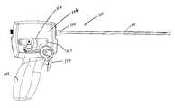
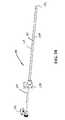
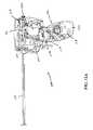
- FIG. 1Ais an elevation view, depicting a multi-actuating trigger anchor delivery system of the present invention
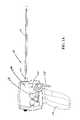
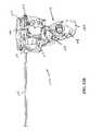
- FIG. 1Bis an elevation view, depicting the system of FIG. 1A with the handle case removed;
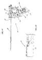
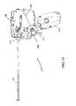
- FIG. 1Cis a rotated elevation view, depicting the system of FIG. 1B without the handle case;
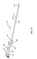
- FIG. 1Dis a detail view, depicting a distal end portion of the device of FIG. 1C ;
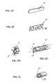
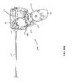
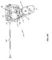
- FIG. 2Ais a perspective view, depicting a core assembly of the multi-actuating trigger anchor delivery system of FIG. 1B ;
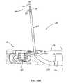
- FIG. 2Bis a perspective view, depicting a shaft assembly of the core assembly of FIG. 2A ;
- FIG. 2Cis a perspective view, depicting another approach to forming sections of a shaft assembly
- FIG. 2Dis a perspective view, depicting an alternate approach to structure of a distal end portion of the system
- FIG. 2Eis a perspective view, depicting a first step in forming an alternative approach to a shaft assembly
- FIG. 2Fis a perspective view, depicting a second step in forming an alternative approach to a shaft assembly
- FIG. 2Gis a perspective view, depicting a third step in forming an alternative approach to a shaft assembly
- FIG. 2His a perspective view, depicting a fourth step in forming an alternative approach to a shaft assembly
- FIG. 2Iis a perspective view, depicting a fifth step in forming an alternative approach to a shaft assembly
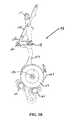
- FIG. 3Ais an elevation view, depicting a rocker arm assembly of the multi-actuating trigger anchor delivery system of FIG. 1B ;
- FIG. 3Bis an elevation view, depicting the rocker arm assembly of FIG. 3A with a crank spring assembly removed;
- FIG. 3Cis an elevation view, depicting the rocker arm assembly of FIG. 3B with a large crank gear removed;
- FIG. 3Dis an elevation view, depicting the rocker arm assembly of FIG. 3C with a rocker arm ratchet removed;
- FIG. 3Eis a rotated elevation view, depicting the rocker arm assembly of FIG. 3D ;
- FIG. 3Fis an isometric view, depicting the juxtaposition of the crank bearing assembly and the cam bearing assembly
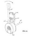
- FIG. 4Ais a rotated perspective view, depicting the spool assembly of the multi-actuating trigger anchor delivery system of FIG. 1B ;
- FIG. 4Bis an exploded view, depicting the spool assembly of FIG. 4A ;
- FIG. 5Ais an enlarged elevation view, depicting a trigger assembly of the multi-actuating trigger anchor delivery system of FIG. 1B ;
- FIG. 5Bis an elevation view, depicting the trigger assembly of FIG. 5A with a mounting block removed;
- FIG. 5Cis an elevation view, depicting the trigger assembly of FIG. 5B with a bell crank assembly removed;
- FIG. 5Dis a rotated perspective view, depicting the trigger assembly of FIG. 5C with a mounting block cap removed;
- FIG. 5Eis an enlarged view, depicting the double pawl in a default position
- FIG. 5Fis an enlarged view, depicting the double pawl after trigger depression
- FIG. 5Gis an enlarged view, depicting the bell crank frame including a bell crank follower
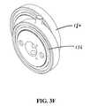
- FIG. 6Ais an enlarged perspective view, depicting a reset assembly of the multi-actuating trigger anchor delivery system of FIG. 1C ;
- FIG. 6Bis a perspective view, depicting the assembly of FIG. 6A with a reset knob and reset one way wheel removed;
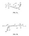
- FIG. 7Ais a perspective view, depicting one preferred embodiment of a first anchor member of an anchor assembly of the present matter
- FIG. 7Bis a side view, depicting the first anchor member of FIG. 7A attached to a connecting member;
- FIG. 7Cis a perspective view, depicting components of one of the preferred embodiments of the second anchor member in a configuration prior to assembly.
- FIG. 7Dis a perspective view, depicting an assembled second anchor member of the present invention attached to a connecting member.
- FIG. 8is a cross-sectional view, depicting a first step of treating a prostate gland using the present invention
- FIG. 9Ais a left side view, depicting the multi-actuating trigger anchor delivery system of FIG. 1A with the left handle half and reset assembly removed;
- FIG. 9Bis a left side view, depicting the assembly of FIG. 9A with the trigger depressed;
- FIG. 9Cis a left side view, depicting the assembly of FIG. 9A with the trigger partially returned and the rocker arm assembly removed;
- FIG. 9Dis a partial cross-sectional view, depicting the distal end portion of the anchor deployment device and the lateral advancement of a needle assembly
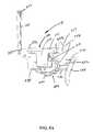
- FIG. 9Eis a cross-sectional view, depicting a second step of treating a prostate gland using the present invention.
- FIG. 10Ais a left side view, depicting the assembly of FIG. 9C with the trigger being activated for a second time;
- FIG. 10Bis a left side view, depicting the assembly of FIG. 10A with the trigger further depressed;
- FIG. 10Cis a left side view, depicting the assembly of FIG. 10B with the trigger completely depressed;
- FIG. 10Dis a perspective view, depicting a distal end portion of the anchor deployment device of FIG. 9D after deployment of the first anchor;
- FIG. 10Eis a cross-sectional view of the extendable tip, depicting the assembly of FIG. 10D ;
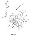
- FIG. 10Fis a cross-sectional view, depicting a further step of a method of treating a prostate gland using the present invention.
- FIG. 11Ais a left side view, depicting the assembly of FIG. 9A in a ready position for a third actuation
- FIG. 11Bis a left side view, depicting the assembly of FIG. 11A with the trigger partially depressed;
- FIG. 11Cis a left side view, depicting the assembly of FIG. 11B with the trigger completely depressed;
- FIG. 11Dis a perspective view, depicting the assembly of FIG. 9D after the complete retraction of the needle assembly
- FIG. 11Eis a cross-sectional view, depicting yet another step of a method of treating a prostate gland using the present invention.
- FIG. 12Ais a left side view, depicting the assembly of FIG. 9A in a ready position for a fourth actuation
- FIG. 12Bis a left side view, depicting an intermediate stage of the depression of the trigger of the assembly of FIG. 12A ;
- FIG. 12Cis a left side view, depicting the complete depression of the trigger of the assembly of FIG. 12B with partial rotation of the cam;
- FIG. 12Dis a partial cross-sectional view, depicting the assembly of FIG. 9D with the cover removed;
- FIG. 12Eis a partial cross-sectional view, depicting the deployment device of FIG. 12D with a second component of the second anchor member being advanced toward a first component of the second anchor member;
- FIG. 12Fis a left side view, depicting the assembly of FIG. 12C with full rotation of the cam and the outer tube assembly pulled proximally;
- FIG. 12Gis a perspective view, depicting the assembly of FIG. 9D of the delivery device with the second component completely advanced into locking engagement with the first component and the connector member cut;
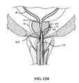
- FIG. 12His a cross-sectional view, depicting yet a further step involved in treating a prostate gland using the present invention.
- FIG. 13is a left side view, depicting the multi-actuator trigger anchor delivery assembly of the present invention with the reset mechanism configured to recharge the system;
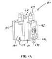
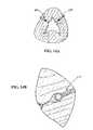
- FIG. 14Ais a cross-sectional view, depicting the implantation of anchor assemblies at an interventional site.
- FIG. 14Bis an enlarged view, depicting one anchor component of the assemblies shown in FIG. 14A .
- the present inventionis embodied in a device configured to deliver anchor assemblies within a patient's body.
- the present inventioncan be employed for various medical purposes including but not limited to retracting, lifting, compressing, supporting or repositioning tissues, organs, anatomical structures, grafts or other material found within a patient's body. Such tissue manipulation is intended to facilitate the treatment of diseases or disorders.
- the disclosed inventionhas applications in cosmetic or reconstruction purposes or in areas relating the development or research of medical treatments.
- the anchor assembly of the present inventionis contemplated to be formed of a structure which is visible by ultrasound. Accordingly, the anchor assembly can be viewed during ultrasonic body scans such as during normal trans-rectal ultrasound when a medical professional is conducting diagnoses or treatment associated with conditions like prostate cancer.
- one portion of an anchor assemblyis positioned and implanted against a first section of anatomy.
- a second portion of the anchor assemblyis then positioned and implanted adjacent a second section of anatomy for the purpose of retracting, lifting, compressing, supporting or repositioning the second section of anatomy with respect to the first section of anatomy as well as for the purpose of retracting, lifting, compressing, supporting or repositioning the first section of anatomy with respect to the second section of anatomy.
- both a first and second portion of the anchor assemblycan be configured to accomplish the desired retracting, lifting, compressing, supporting or repositioning of anatomy due to tension supplied thereto via a connector assembly affixed to the first and second portions of the anchor assembly.
- FIGS. 1A-Dthere is shown one embodiment of a multi-actuating trigger anchor delivery system 100 of the present invention.
- This deviceis configured to include structure that is capable of both gaining access to an interventional site as well as assembling and implanting one or more anchor assemblies within a patient's body.
- the device 100is configured to assemble and implant four anchor assemblies.
- the deviceis further contemplated to be compatible for use with a 19 F sheath.
- the deviceadditionally includes structure configured to receive a conventional remote viewing device (e.g., an endoscope) so that the steps being performed at the interventional site can be observed.
- a conventional remote viewing devicee.g., an endoscope
- the multi-actuating trigger anchor delivery device 100includes a handle assembly 102 connected to an elongate tissue access assembly 104 .
- the elongate tissue access assembly 104houses components employed to construct a plurality of anchor assemblies.
- the anchor delivery system 100further includes a number of subassemblies.
- a handle case assembly 106including mating handle halves which encase the handle assembly 102 .
- the handle assembly 102is sized and shaped to fit comfortably within an operator's hand and can be formed from conventional materials. Windows 107 can be formed in the handle case assembly 106 to provide access to internal mechanism of the device so that a manual override is available to the operator in the event the interventional procedure needs to be abandoned.
- a core assembly 110extends through the handle assembly 102 , and includes the components defining the elongate tissue access assembly 104 .
- the handle assembly 102further includes a trigger system assembly 114 , a spool assembly 116 and a rocker arm assembly 118 . These assemblies cooperate to accomplish gaining access to an interventional site as well as the assembly and implantation of an anchor assembly at the interventional site.
- a terminal end portion 119 of the anchor delivery systemincludes a distal tip assembly 128 shaped to provide an atraumatic surface as well as one which facilitates desired positioning of components of an anchor assembly (See FIG. 1D ). That is, by including structure that can mimic the ultimate position of a proximally oriented component of an anchor assembly, an operator can test the effect of the anchor assembly prior to implantation. Once the operator confirms that the subject anchor component will be positioned as desired, the implantation of the anchor is then undertaken and accomplished.
- the core assembly 110retains the components necessary to assembling a plurality of anchor assemblies.
- the core assembly 110includes a shaft assembly 120 , a ratchet block assembly 122 , an outer cover block assembly 124 , a stop assembly 126 and a distal tip assembly 128 .
- the core assembly 110is permanently attached to the handle assembly 102 .
- the core assemblyis temporarily attached to the handle assembly to allow for reuse of the handle assembly and disposal of the core assembly.
- the shaft assembly 120further includes an elongate endoscope tube 130 which extends from a scope rear mount 132 through a front plate assembly 134 and distally to a terminal end 136 of the shaft assembly 120 .
- the endoscope tubeaccommodates a removable endoscope.
- a pusher tube assembly 138extending distally from the front plate assembly 134 and arranged generally parallel to the endoscope tube 130 is a pusher tube assembly 138 including an anchor alignment tube for maintaining alignment of anchor components within the tube.
- Another elongate tubular housing 140configured to receive a needle assembly also extends longitudinally from the front plate assembly 134 .
- the front plate assemblyfurther includes a sheath sealing plate 143 which is configured to create a seal between and amongst the elongate components extending therethrough (See FIG. 2A ).
- distal tip assembly 128may be integral to one half of the elongate shaft.
- One or both of the halves 196will have elongate channels 147 that may be semi-circular or even square shared, but would functionally constrain and house both the telescope and needle assembly in their unique channels. In a simple construction the second half may merely close off the open channels 147 to constrain the telescope and needle assembly.
- the distal curved needle housing 148 that vectors the needle tip through the urethral wall (or other body lumen)is integral to one or both of the halves where if biased to one half the guiding surface may provide more intimacy and improved performance.
- the pin storage tube 149may be a Nitinol or stainless steel tube that is either or both laser cut or laser welded with assembly features. Such assembly features may be folded over tabs or points that may be captured between the shaft extrusion assembly, thus integrating the parts to functionally act like the current invention at a lower complexity or cost.
- an alternative construction of the shaft assembly 120may incorporate a stamped metal element that is a single elongate strip 151 of thin wall stainless steel (See FIGS. 2E-I ). Fenetrations, castellations or tabs 153 ( FIG. 2F ) may be stamped around the edges so as to be formed 155 ( FIGS. 2G and H) to retain hypotubes adjacent to each other at distinct points that may later be insert molded over or inserted into a simple plastic injected molded shell 159 ( FIG. 2I ). The metal formed insert would provide more structural stiffness and accuracy in assembly in contrast to singular plastic shaft assembly.
- the formed stripmay appear as a wave pattern with intermittent tabs formed in the opposite direction of the locally formed strip resulting in a plurality of concentric paths that hypotubes may be assembled through and fixed into position.
- the core assembly 120is further equipped with guide rails 145 which both lend structural support to the assembly as well as guides along which various of the subassemblies are translated with the actuation of the trigger assembly.
- the core assembly 120includes a longitudinally translatable outer tube assembly 142 (See FIG. 2A ), a distal end of which is received within the distal tip assembly 128 (See also FIG. 1D ).
- the distal tip assemblyhouses a plurality of rings or cylinders and a spring biased feeder.
- the rocker arm assembly 118 of the handle assemblyis described as is its interaction with the trigger system assembly 114 .
- the rocker arm assemblyinteracts with the multi-actuating trigger assembly to convert each single trigger pull into four different actions of the anchor delivery system 100 .
- rocker arm assembly 118is grounded at two points, at a rocker arm pivot point 173 and at a crank shaft 172 . Both of these elements are free to rotate, but not translate.
- a mid-section of the assembly 118is characterized by a scotch yoke structure. As is conventionally known, the scotch yoke can be employed to convert rotational motion into linear motion.
- the rocker arm assembly 118is powered by a spring assembly 162 and through interaction between the trigger assembly 114 and a rocker pawl 163 , this spring assembly 162 is selectively activated to effect rotation of a crank bearing assembly 176 which is attached in an off-center position to a cam bearing assembly 180 .
- This in turncauses the cam bearing 180 to be guided along barriers defined by an oval recess 178 formed in a lower rocker arm portion 152 of the rocker arm assembly 118 .
- Such actionresults in the rocker arm assembly 118 to pivot at its lower end about the rocker pivot point 173 and at its top end, linear motion results. This linear motion is employed to selectively translate the spool assembly 116 longitudinally.
- the rocker arm assembly 118includes an upper rocker arm assembly 150 , a lower rocker arm assembly 152 and upper 154 and lower 156 break away links.
- a terminal end 157 of the upper rocker arm 150is provided with a slot which slideably engages complementary structure on the spool assembly 116 , the interconnection of which facilitates the transition of articulating movement of the rocker arm assembly into longitudinal motion of the spool assembly 116 .
- a spring(not shown) connects the upper rocker arm assembly 150 to the upper break away link 154 .
- the damper assemblies 166function as a mode of speed modulation which governs the action of the large gear 164 and thus the action of the rocker arm assembly 118 in response to the trigger assembly 114 .
- the damper assemblies 166are filled with a selected amount of fluid having a known viscosity. The amount and viscosity of the fluid can be varied to achieve the desired dampening effect.
- the lower rocker arm assembly 152includes a pair of spaced pivot points 158 , 160 to which the upper rocker arm 150 and the lower break away link 156 are pivotably connected. Further, a pivoting connection exists between the upper 154 and lower 156 break away links.
- the rocker arm assemblyfurther includes a crank spring assembly 162 mounted on the lower rocker arm assembly 152 .
- crank spring assembly 162With the crank spring assembly 162 removed (See FIG. 3B ), the engagement between a large gear 164 and a pair of spaced damper assemblies 166 can be better appreciated. Configured on the same side of the lower rocker arm assembly 152 and adjacent to the large gear 164 is a rocker arm ratchet 168 (See FIG. 3C ). A crank arbor 170 is positioned on an outside surface of the rocker arm ratchet 168 . It is to be recognized that as a result of the actuation of the trigger assembly the crank spring assembly 162 drives the crank 170 counter clockwise and thereby moves the rocker arm assembly 118 forward and backwards about rocker arm pivot point 173 .
- Each of the rocker arm ratchet 168 and crank arbor 170are configured upon a centrally configured crank shaft 172 , the crank shaft passing through a curved slot 174 formed in the lower rocker arm 152 (See FIG. 3D ).
- crank bearing 176configured on a portion of the crank bearing 176 and within an oval recess 178 formed in the lower rocker arm 152 is a cam bearing 180 .
- the crank bearing 176is rotationally coupled to the crank shaft 172 and thereby converts the rotational motion to linear motion at the terminal end 157 of the upper rocker arm 150 as in a scotch yoke.
- the crank spring assembly 162is kept from unloading by a spring-loaded, rocker pawl 163 (See FIG. 3C ), the rocker pawl being tripped during certain stages of trigger activations.
- the assemblyis equipped with a no-skip feature. That is, as best seen in FIG.
- the rocker arm ratchet 168is equipped with a no-skip cam surface 175 .
- a no skip link cam follower 177engages the no skip cam surface 175 . This action results in properly positioning the components to prevent pawl skipping and double needle deployment due to high crank speed and low reaction speed of the pawl 163 after tripping.
- a torsion spring 179is provided at the vertically positioned pivot point 158 to prevent high speeds in the lower rocker arm 152 to help control the speed of rotation of the rocker arm ratchet 168 .
- the rocker arm ratchet 168includes only two teeth which are alternatively engaged by the rocker arm pawl assembly 163 . These teeth are spaced such that an advance stroke occurs on one pawl trip and a retract stroke occurs on the next pawl trip.
- the upper 154 and lower 156break away links break in that the pivot joint between the two members translates inwardly toward the upper rocker arm assembly 150 .
- This breakaway actionallows the lower rocker arm 152 to continue through an entire stroke while the upper breakaway link rocker arm 154 rotates in an opposite direction such that no further translation is imparted upon the terminal end 157 , the spool assembly 116 and the needle assembly connected thereto stop at a depth set by the stop assembly 126 . Accordingly, this mechanism controls the movement of the spool assembly as more fully described below.
- the windows 107 formed in the handle 106can be used to also access portions of the rocker assembly 118 or the handle housing 106 itself can be removed to do so.
- the crank bearing assembly 176can be manually turned to accomplish desired movement of components turning the rocker arm assembly.
- a bailout featureis thus provided to, for example, retract the needle assembly.
- the spool assembly 190is used to push anchor components from the distal end of the anchor delivery device.
- the rotary mechanismis particularly advantageous in that it allows several anchor assemblies (e.g. four) with approximately 6 cm (corresponds to 1 ⁇ 2 of circumference of spool) of connector material such as monofilament PET, 0.015 inch diameter between anchors to be stored in a relatively small device that fits in a user's hand.
- the spool assembly 190further includes a tension housing assembly 192 , a deploy housing assembly 194 , and a damper assembly 196 .
- the tension housing assembly 192is configured between a housing cap 198 and the deploy housing assembly 194 .
- the spool assembly 190further includes a circular recess 200 in the tension housing 201 that is sized and shaped to receive a tension arbor with tension spring.
- the tension springapplies one pound of tension to an implant component once the component has been deployed, but less and more tension can be provided as desired.
- the assemblyis configured so that no tension is applied prior to implantation.
- the tension spring 204is loaded up to 1 ⁇ 2 turn as the needle is retracted, thereby tensioning the suture, and then it unloads, thereby retracting the capsular anchor assembly after the urethral anchor is delivered and the suture is cut.
- the housing cap 198retains the tension arbor 202 and tension spring 204 within the circular recess 200 .
- the spool housing 190may further include bushings 206 which fit within holes 208 formed through a pair of spaced arms 209 extending from a top of the tension housing assembly 192 .
- the bushings 206provide a surface for smooth movement along rails 140 of the core assembly 110 (See FIG. 2A ).
- the deploy housing assembly 194is configured with a first circular recess 208 facing the tension housing assembly 192 .
- the first recess 208is sized and shaped to receive a spool assembly with a central shaft 230 .
- the adjacently arranged tension housing assembly 192retains the spool assembly 210 within the first recess 208 .
- a wire(not shown) is wound around the spool assembly 210 . This wire is bonded to an implant (anchor) assembly and transmits the driving force and tensioning torque from the spool assembly 190 to the implant components during the deployment of an anchor assembly.
- a second recess(not shown) is formed in an opposite side of the deploy housing assembly 194 which faces the damper assembly 196 .
- This second circular recessis sized and shaped to receive a spool ratchet disc 214 sandwiched between a deployment arbor with central shaft 216 and a suture deploy spring 218 which is initially fully loaded with enough energy to drive four distal anchor members out of the needle.
- the damper assembly 196retains the spool ratchet disc 214 , deployment arbor 216 and suture deploy spring 218 within the second recess of the deploy housing assembly 194 .
- the deploy housing assembly 190is further equipped with a spring loaded suture deploy pawl assembly 219 received within a recess formed in a bottom lateral surface of the housing 194 .
- the spool ratchet disc 214is coupled to the deployment arbor 216 in a manner such that the deployment spring (not shown) is refrained from unloading until the deploy pawl 219 is tripped.
- the no-skip mechanismagain here prevents double deployments if the primary mechanism moves faster than the pawl's 219 response times.
- the damper assembly 196includes a damper body 224 and a damper rotor 220 which have multiple interleaved circular surfaces such that the damper rotor 220 can rotate within the damper body 224 .
- the gaps between the interleaved surfacesare filled with viscous dampening fluid (not shown).
- the damper rotor 220has a square peg which positively and permanently engages into the square port of the deploy arbor 216 , thereby providing speed modulation to the deploy spring 218 as it is unloaded to deploy the distal anchor member out of the needle.
- a central shaft 230is configured through the tension housing assembly 192 and extends to within the deploy housing assembly 194 .
- a square section 231 of the shaft 230is always engaged in the spool assembly 190 with either the deployment arbor 216 or the tension arbor 202 .
- the square section of the central shaft 230is engaged with the deployment arbor 216 and is disengaged from the tension arbor 202 .
- a throwout arm assembly 232is retained on the central shaft 230 and includes a forked substructure 234 configured to engage complementing structure of the trigger assembly 114 . The throwout arm assembly is activated by the trigger assembly to translate the shaft 230 between the deployment arbor 216 and the tension arbor 202 at desired time points in the delivery process.
- the window 107 formed in the handle case assembly 106can be configured to provide convenient direct access to components of the spool assembly 190 in the event any of the components become stuck. For example, force can be directly applied to the throwout arm 232 so that the shuttle action of the assembly can be facilitated.
- the trigger assembly 114includes a trigger rack assembly 240 , a trigger cam assembly 242 , a lower cam assembly 244 and a bell crank assembly 246 , each of which are attached or separately associated with a mounting block assembly 248 .
- a pawl assembly 249is further provided to alternatively engage the lower cam assembly.
- a pin drive rear link 250is also provided and which is pivotably attached to the lower cam assembly 244 .
- the trigger rack assembly 240includes a mechanical rack 252 extending from a trigger 254 sized and shaped to receive a portion of an operator's hand. Also extending from the trigger 254 is a phasing dowel 256 which is configured to limit the depression of the trigger 254 .
- the trigger rack assembly 240further includes a spring 258 for biasing the assembly away from the mounting block assembly 248 .
- the rack 252 of the trigger rack assembly 240engages the trigger cam assembly 242 .
- the trigger cam assembly 242further includes a trigger pinion 259 (See FIG. 5D ) with teeth which mate with the teeth of the rack 252 .
- the trigger pinion 259is placed adjacent to a cam subassembly 260 , each of which are positioned on a central trigger shaft 262 .
- the lower cam assembly 244includes a link 264 , one end of which travels through an open V-shaped slot formed in the lower cam plate 266 . Also formed in the lower cam plate 266 is a through hole 267 for receiving a shaft of a reset assembly (described below in connection with FIGS. 6A and 6B ). The opposite end of the link 264 is configured to slide within a slot 269 formed within the pin drive rear link 250 . A top end 268 of the pin drive rear link 250 is operatively associated with structure for advancing components of the anchor assembly through the core assembly 120 .
- the bell crank assembly 246includes a T-shaped frame 270 at the top of which are a pair of spaced arms 272 ( FIG. 5A ). Configured between the arms is a bell crank rail 274 . On a back side of the structure is configured a bell crank follower 275 (See FIG. 5G ).
- the trigger assembly 114further includes a deploy plate assembly 280 .
- This assemblyincludes a deployment plate 282 to which are pivotably attached a first link 284 and a second link 286 .
- a double pawl assembly 288is further provided, the operation of which is controlled by a sprag actuator 290 which is mounted to the trigger rack 242 .
- the double pawl assembly 288is configured to act as a trigger control mechanism. In a first default position, the double pawl assembly 288 engages the rack assembly 240 in a manner which permits the trigger 254 to be depressed while allowing for and holding partial depression and preventing incomplete depression (See FIG. 5E ). Once the trigger 254 is completely depressed, the sprag actuator 290 engages the double pawl assembly causing it to rotate such that the default engagement between the rack assembly 240 and the double pawl assembly 288 is eliminated (See FIG. 5F ). Thereafter, the rack assembly 240 can return via the bias spring 258 to its original position (See FIG. 5D ).
- the double pawl assemblypermits the trigger 254 and rack assembly 240 to return to the original position and prevents an incomplete return to the original position. That is, the double pawl assembly controls the trigger stroke bi-directionally.
- the engagement between the double pawl assembly 288 and the sprag actuator 290limits the degree to which the trigger can be depressed as well as facilitates the return of the trigger 254 to its default or un-depressed position.
- the single trigger 254actuates all steps of deployment through operative association with the rocker pawl assembly 163 and the throwout arm assembly 232 . That is, activation of the trigger 254 causes the bell crank assembly 270 to pivot laterally taking with it the throwout arm assembly 232 . By way of its connection to the central shaft 230 , the throwout arm accomplishes the shuttling of the shaft 230 between functions performed by the spool assembly 190 . Moreover, actuation of the trigger 254 further accomplishes the alternative engagement and disengagement between the rocker pawl 163 and the crank arbor 170 . This engagement and disengagement permits the longitudinal movement of the spool assembly 190 between rear and forward positions. As a needle assembly and pusher assemblies are operatively linked to this mount, this longitudinal movement is likewise controlled by the trigger 254 actuation.
- the trigger cam 260includes a plurality of slots 291 formed in a periphery thereof. These slots 291 receive a terminal end of the phasing dowel 256 so that continued rotation of the trigger cam 260 in response to trigger depression is inhibited by the engagement between these parts.
- a roller clutch(not shown) configured within the trigger cam 260 provides yet further control by inhibiting the cam 260 from moving except during an inward trigger stroke.
- the window 107 in the handle case 106can further be configured to provide access to components of the trigger assembly 114 . That is, the double pawl assembly 388 can be manually engaged, for example, to thereby override a jam. Likewise, other components of the assembly 114 can be so engaged to facilitate proper function.
- the handle assembly 102further includes a reset assembly 300 (See FIGS. 1 C and 6 A-B) for resetting the delivery system after deploying and implanting an anchor assembly to be ready to deploy another anchor assembly.
- the reset assembly 300includes a reset knob 302 rotatably mounted to a reset plate 303 and having an interior configured to receive an engagement spring 304 .
- a lever 305is further provided for easy manipulation of the assembly.
- a pair of bearings 306 , 308are provided to mate with the reset knob 302 and to provide a surface for engaging a shaft 309 extending laterally through hole 267 of the trigger assembly 114 .
- a knob latch 310is configured to releasably engage the knob 302 .
- the reset assembly 300also includes a one way reset wheel assembly 312 mounted to the reset plate 303 to which a reset link 314 is rotatably connected.
- the reset wheel assembly 312prevents backwards motion of the shaft until the reset action is complete.
- the reset actionrecharges the spring 304 which powers the urethral cam 244 ( FIG. 5D ).
- Near an opposite terminal end of the reset link 314is a threaded projector 316 adapted to engage complementary structure of the knob 302 (See FIG. 6B ).
- the reset assembly 300also includes a one way reset clutch 320 configured concentrically within a reset bearing 322 .
- Also contained within the reset assemblyis a U-shaped reset wire form 324 . Bumpers 326 are provided to deflect the U-shaped wire form 324 which acts on the bumpers 326 to push the one way reset wheel 312 out of the top dead center and bottom dead center positions where the link 314 cannot rotate the wheel 312 .
- springshave been described as the mechanism for actuating the various assemblies when the trigger is pulled, however, it is also within the scope of the invention to use other mechanisms such as motor, compressed gas, elastomers and the like.
- FIGS. 7A-DOne preferred embodiment of an anchor assembly of the present invention is depicted in FIGS. 7A-D .
- the first or distal anchor component 370In its unconstrained configuration, the first or distal anchor component 370 includes a first tubular portion 372 which is generally orthogonal to a second tail portion 374 . It is to be noted, however, that while housed in a delivery assembly and prior to deployment at a target area, the first anchor component 370 is constrained to define a generally straight configuration, only subsequently assuming the unconstrained configuration upon deployment from the delivery device.
- the tubular portion 372 of the first anchor component 370includes a plurality of tabs 376 which can be deformed or deflected to accomplish affixing the component 370 to a connector assembly 378 (See FIG. 7B ). It has been found that three such tabs 376 , two on one side of the tubular portion 372 and one on an opposite side provide a sufficient connecting force and a desired balance between the connector 378 and first anchor component 370 and to move the first anchor component 370 by applying a force either in the proximal or distal direction.
- the first anchor component 370can be laser cut from a tube formed of nitinol or other appropriate material.
- a mid-section 380 of the component 370provides a structural transition from the tubular portion 372 to the tail portion 374 .
- a portion of a side wallis removed in the mid-section area 380 .
- a further portion of the side wallis removed to define a connecting section 382 of the tail 374 which extends from the mid-section 380 .
- This connector section 382acts as a spring to accomplish the relative unconstrained angle assumed between the tail 374 and tubular portion 372 .
- a terminal end portion 383 of the tail 374embodies structure having a surface area which is larger than that of the connector section 382 to thereby provide a substantial platform for engaging tissue at a target site.
- the second anchor component 384includes a first part 386 and a second part 388 .
- the first anchor component 370is positioned at a target site by employing a delivery device such as that disclosed below (or previously), the second anchor component 384 is assembled in situ.
- the first part 386 of the second anchor component 384includes an internal bore 390 sized to receive a portion of the second part 388 of the second anchor component 384 in a locking engagement.
- An external surface of the first part 386is sized and shaped to include a proximal collar 391 spaced from a mid-section 392 , each of which have generally cylindrical profiles.
- a smaller diameter, outer cylindrical portion 393is configured between the proximal collar 391 and mid-section 392 of the component and a distal cylindrical portion 394 having yet a smaller cylindrical profile defines a distal end thereof.
- the second part 388 of the second anchor component 384includes a solid generally cylindrical back end 395 , extending from which are a pair of spaced prongs 396 . Terminal ends of the prongs 396 can be tapered to both facilitate the insertion of the prongs 396 within the internal bore 390 of the first part 386 as well as to receive a section of the connector assembly 378 .
- the prong structurecommences at a narrowed slot 397 which steps outwardly to a wider dimension to thereby define the space between the prongs 396 .
- This narrow slot 397provides the second part 388 with desired structural rigidity to receive the connector assembly 378 and to facilitate lockingly engaging the connection between the first 386 and second 388 parts.
- the space between the prongs 396in one embodiment can be dimensional relative to the diameter of the connector 378 such that is has sufficient clamping force such that the first part 386 is not needed and therefore is optional for providing additional security.
- the anchor assemblycan include one anchor member (e.g., first anchor) whose initial engagement with a connector is generally coaxial and another anchor member (e.g., second anchor) with an initial engagement being generally perpendicular with the connector.
- one anchor membere.g., first anchor
- another anchor membere.g., second anchor
- These assembliescan further be employed to deliver therapeutic or diagnostic substances to the interventional site.
- substances that cause the prostate to decrease in sizesuch as 5-alpha-reductase inhibitors can be introduced at the treatment site.
- a particular advantageous procedureis to use the needle of the anchor delivery device to inject 100 to 200 units of botulinum toxin (such as available from Allergan, Inc.) dissolved in 4 mL of saline either before, during or after deploying the anchor assembly.
- 2 mLare injected in each lobe of the prostate.
- Another advantageous procedureis to use the needle of the anchor delivery device to inject 100 to 300 units of botulinum toxin dissolved in 10 to 30 mL of saline into the base of the bladder, bladder lateral walls and/or trigone.
- 0.5 to 1.0 mLare injected into about 20 to 30 sites in the bladder for treating over-active bladder.
- Other substances but not limited thereto, which may be introduced at the siteinclude various scarring agents, rapamycin and its analogues and derivatives, paclitaxel and its analogues and derivatives, phytochemicals, alpha-1a-adrenergic receptor blocking agents, smooth muscle relaxants and other agents that inhibit the conversion of testosterone to dihydrotestosterone.
- the endoscope deviceis employed to view the positioning of a multi-actuating trigger anchor delivery device 100 at the interventional site, for example, the elongate tissue access assembly 104 of the device is inserted into the penis of a patient and advanced until the distal end 128 is adjacent an interventional site in the urethra (UT) adjacent the bladder (UB; See FIG. 8 ).
- UTurethra
- Uurethra
- the present inventionalso contemplates steps for sizing the anatomy.
- the present inventionalso involves the placement of an ultrasonic or other device in the patient's body, such as in the rectum, to measure the necessary depth of insertion of the distal end of the needle assembly within the patient's body.
- This informationcan be used to set or create a depth stop for the needle assembly by the operator using a knob (not shown) on the outside of the handle connected to the stop assembly 126 so that during deployment the distal end of the needle assembly extends all the way through the prostate from inside the urethra to outside of the prostate capsule.
- the multi-actuating trigger anchor delivery device 100is employed to assemble and implant an anchor assembly at an interventional site.
- the trigger 254 of the trigger assembly 114is depressed until through its inter-connection with the rocker arm assembly 118 via the trigger cam subassembly 260 , the rocker pawl follower 163 is released from a locking engagement with the rocker arm ratchet 168 (See FIG. 9A ).
- Such actionaccomplishes the advancement of a needle assembly 400 within the elongate tubular housing 140 via its connection with the spool assembly 116 (See FIG. 9D ).
- the depth stop assembly 410can be positioned as desired to control the depth to which the needle assembly 400 is projected. The selected position may be based on anatomical measurements made by various imaging techniques such as ultrasound.
- the trigger 254permits the trigger 114 to return to a ready position, leaving the spool assembly 116 in its forward position (See FIG. 9C ).
- the articulation of the double pawl assembly 288 from its default positionfacilitates this return of the trigger assembly 114 to the ready position.
- the advancement of the needle assembly 400consequently results in the needle passing through the prostate gland (PG) (See FIG. 9E ).
- PGprostate gland
- a terminal end of the needle 400is positioned to extend beyond the prostate gland (PG) but it is to be recognized that the degree of needle insertion can be modified for a particular purpose.
- the trigger assembly 114is employed again to effect the deployment of the distal anchor component 370 (See FIGS. 10A-F ).
- a first half of a trigger 254 pullcauses the spool shaft 230 to move to the deploy side 194 of the spool assembly 190 (FIGS. 10 A and 4 A-B).
- Thisis accomplished via cooperation with the bell crank assembly 246 (See also FIG. 5A ) which drives the throw out arm assembly 232 (See also FIGS. 4A-B ). More specifically, with the depression of the trigger 254 , the trigger cam 260 rotates.
- the bell crank follower 275See FIG.
- the deploy plate 280 of the trigger assembly 114(See also FIG. 5D ) is positioned in a raised configuration. This raised position results from the vertical movement of a deploy plate push rod (not shown) which at one end rides along a periphery of the trigger cam 260 and at another end engages the deploy plate 280 . As the push rod engages upon raised sections of the periphery of the trigger cam 260 , the rod is translated vertically which causes the deploy plate 280 to rise. Being so positioned, the deploy plate assembly 280 actuates the suture deploy pawl assembly 219 (See also FIGS.
- the two-toothed spool deploy ratchet 214permits one half-turn of the spool assembly 210 before reengaging with the suture deploy pawl assembly 219 and arresting the suture advancement.
- the deploy plate assembly 280 and the deploy pawl assembly 219are back in their default positions ( FIG. 10C ).
- a wire assembly 402engages the connector 378 through a permanent connection such as a polyimide tube with adhesive.
- a permanent connectionsuch as a polyimide tube with adhesive.
- the wire assembly 402has been shown in FIG. 10E for demonstrative purposes as its actual position may be further within the needle assembly 400 at this stage of device use.
- a connector diameter of approximately 40% of the inside diameter of the needle assembly 400 or greateris beneficial to pay out the connector 378 to prevent kinking of the connector material.
- the connectoris preferably about 0.015 inch diameter PET monofilament. Moreover, at this stage no tension is supplied to the connector 378 and first anchor component 370 by the tension housing assembly 192 .
- the first anchor component 370is ejected from the needle housing beyond an outer surface of a prostate gland (PG).
- PGprostate gland
- the first anchor component 370can surgically be placed within the prostate gland (PG) or in other procedures at any position within a patient.
- the multi-actuating trigger anchor delivery system 100is manipulated to withdraw the needle assembly 400 from the interventional site.
- the trigger 254is again returned to a ready position.
- the central shaft 230is shuttled back to the tension side 192 of the spool assembly 116 (See also FIGS. 4A-B ). Again, it is the cooperation of the bell crank assembly 246 and the throw out arm assembly 232 that facilitates the shuttling of the central shaft 230 .
- the next step of the implant procedurecan be accomplished. That is, as the trigger 254 is depressed for the fourth time ( FIG. 12B ), the pawl assembly 249 of the trigger assembly 114 is released from a locking engagement with the lower cam assembly 244 of the trigger assembly 114 (See also FIG. 5A ). The complete depression of the trigger 254 ( FIG. 12C ) then effects the horizontal driving of the shaft 264 by the lower cam plate 266 of the lower cam assembly 244 (See also FIG. 5C ). Consequently, the pin drive rear link 250 is translated forwardly and through its connection to the ratchet block assembly 122 (see also FIG. 2A ), a pusher assembly (not shown) placed in apposition with rear-most second part 388 of the second anchor component is also advanced forwardly.
- a next step in the context of prostate treatmentinvolves positioning the proximal anchor assembly, for example, within a desired section of the urethra of the patient. Prior to doing so, the patient can be monitored to determine whether there has been any evidence of improvement through the placement of the anchor. One such symptom is whether there has been any urination. After so checking, the proximal anchor assembly can be implanted.
- a second part 388 of the second anchor componentis advanced into engagement with the connector 378 of the anchor assembly.
- the second part 388is then further advanced into engagement with the first part 386 of the second anchor ( FIG. 12G ).
- the outer tube assembly(not shown) is pulled proximally to cut the connector 378 (See FIG. 12G ) and release the assembled second anchor assembly from the distal end 128 of the multi-actuator trigger anchor delivery system 100 .
- the proximal motion of the outer tube assemblyis accomplished through the cooperation of an outer tube link 420 and the lower cam assembly 244 . That is, as the lower cam assembly 244 rotates forwardly, its camming surface engages and rotates the outer tube link 420 in an opposite direction. By way of its connection to the outer tube assembly, the outer tube link 420 drives the outer tube assembly rearwardly.
- the assembled anchor assemblyis placed across the prostate gland (PG) with the first anchor component 370 configured against an outer surface of the prostate gland (PG) and the second anchor component 384 implanted with the urethra (UT).
- PGprostate gland
- UTurethra
- the lever 305 of the reset assembly 300is actuated to reset the system for assembling and implanting another second anchor component 384 . That is, the lever 300 is pulled back to recharge the spring 304 of the reset assembly 300 to thereby return all of the assemblies to the correct position for accomplishing the assembly and release of the second anchor component 384 .
- the steps and mechanisms involved in delivering other components of the anchor assemblyare effected with pre-loaded energy so that a desired number (e.g. four) of such components can be implanted.
- the present inventioncontemplates both pushing directly on anchor portions of an anchor assembly as well as pushing directly upon the connector of the anchor assembly.
- the distal or first anchor componentis advanced and deployed through a needle assembly and at least one component of the proximal or second anchor component is advanced and deployed through a generally tubular portion of the anchor deployment device.
- both a single anchor assembly or multiple anchor assembliescan be delivered and deployed at an intervention site by the deployment device. Consequently, in the context of prostate treatment, the present invention accomplishes both the compression of the prostate gland and the opening of the prostatic urethra, the delivering of an implant at the interventional site, and applying tension between ends of the implant.
- drug deliveryis both contemplated and described as a further remedy in BPH and over active bladder treatment.
- the anchor assembly(See FIGS. 14A and 14B ) of the present invention accomplishes desired tissue manipulation, compression or retraction as well as cooperates with the target anatomy to provide an atraumatic support structure.
- the shape and contour of the anchor assembly 500can be configured so that the assembly invaginates within target tissue, such as within natural folds formed in the urethra by the opening of the urethra lumen by the anchor assembly.
- target tissuesuch as within natural folds formed in the urethra by the opening of the urethra lumen by the anchor assembly.
- wispy or pillowy tissue in the areacollapses around the anchor structure.
- the natural tissuecan grow over the anchor assembly 500 and new cell growth occurs over time.
- Such cooperation with target tissuefacilitates healing and avoids unwanted side effects such as calcification or infection at the interventional site.
- Manners in which healing can be promotedcan include employing abrasive materials, textured connectors, biologics and drugs.
- one portion of an anchorcan be placed within an urethra. It has been found that configuring such anchors so that ten o'clock and two o'clock positions (when looking along the axis of the urethra) are supported or retained, effectively holds the anatomy open and also can facilitate invagination of the anchor portion within natural tissue. This is particularly true in the regions of anatomy near the bladder and the juncture at which the ejaculatory duct connects to the urethra.
- all components of the anchor assembly or selected portions thereofmay be coated or embedded with therapeutic or diagnostic substances (e.g. drugs or therapeutic agents).
- therapeutic or diagnostic substancese.g. drugs or therapeutic agents.
- the anchor assemblycan be coated or imbedded with substances such as 5-alpha-reductase which cause the prostate to decrease in size.
- substances contemplatedinclude but are not limited to phytochemicals generally, alpha-1a-adrenergic receptor blocking agents, smooth muscle relaxants, and agents that inhibit the conversion of testosterone to dihydrotestosterone.
- the connector 95can for example, be coated with a polymer matrix or gel coating which retains the therapeutic or diagnostic substance and facilitates accomplishing the timed release thereof
- bacteriostatic coatingscan be applied to various portions of the anchor assemblies described herein. Such coatings can have various thicknesses or a specific thickness such that it along with the connector itself matches the profile of a cylindrical portion of an anchor member affixed to the connector.
- the co-delivery of a therapeutic or diagnostic gel or other substances through the implant deployment device or another medical device (i.e. catheter), and moreover an anchor assembly including the sameis contemplated.
- the deployment deviceincludes a reservoir holding the gel substance and through which an anchor device can be advance to pick up a desired quantity of therapeutic or diagnostic gel substance.
- the timing of the dual advancement of the needle and connector assemblies and subsequent relative motion between the assembliesis coordinated. That is, the needle assembly first provides access to an interventional site and then the connector assembly is extended beyond a terminal end of the needle assembly through the relative motion of the needle and connector assemblies.
- the anchor delivery devicecan include the ability to detect forces being applied thereby or other environmental conditions.
- Various sections of the devicecan include such devices and in one contemplated approach sensors can be placed along the needle assembly. In this way, an operator can detect for example, whether the needle has breached the target anatomical structure at the interventional site and the extent to which such breaching has occurred.
- Other sensors which can detect particular environmental featurescan also be employed such as blood or other chemical or constituent sensors.
- one or more pressure sensors or sensors providing feedback on the state of deployment of the anchor assembly during delivery or after implantationare contemplated. For example, tension or depth feedback can be monitored by these sensors. Further, such sensors can be incorporated into the anchor assembly itself, other structure of the deployment device or in the anatomy.
- connection of an anchor assemblycan be severed and a proximal (or second) anchor component removed from the patient's body.
- the physiciancan simply cut the connector and simultaneously remove the second anchor previously implanted for example, in the patient's urethra.
- An aspect that the various embodiments of the present invention provideis the ability to deliver multiple, preferably four, anchor assemblies having a customizable length and distal anchor components, each anchor assembly being implanted at a different location without having to remove the device from the patient.
- the various embodimentsprovide for variable needle depth and variable connector length for each of the multiple anchor assemblies delivered.
- Other aspects of the various embodiments of the present inventionare load-based delivery, preferably 1 pound, of an anchor assembly, anchor assembly delivery with a device having integrated connector, (e.g. suture), cutting, and anchor assembly delivery with an endoscope in the device.
- the delivery deviceis uniquely configured to place such a load (half pound to five pounds) between spaced first anchor members as well as between or on an implanted first anchor and the delivery device.
- the needle assembly acting as a penetrating membercan be cooperatively connected to a mechanism which produces a desired tension between the various anchor members while the needle assembly is retracted. Moreover, this load can be accomplished between first and second implanted anchor members.
- one or more componentssuch as distal anchor, proximal anchor, connector, of the one or more anchor devices disclosed herein may be designed to be completely or partially biodegradable or biofragmentable.
- the devices and methods disclosed hereinmay be used to treat a variety of pathologies in a variety of tubular organs or organs comprising a cavity or a wall.
- organsinclude, but are not limited to urethra, bowel, stomach, esophagus, trachea, bronchii, bronchial passageways, veins (e.g. for treating varicose veins or valvular insufficiency), arteries, lymphatic vessels, ureters, bladder, cardiac atria or ventricles, uterus, fallopian tubes, etc.
Landscapes
- Health & Medical Sciences (AREA)
- Life Sciences & Earth Sciences (AREA)
- Surgery (AREA)
- General Health & Medical Sciences (AREA)
- Public Health (AREA)
- Biomedical Technology (AREA)
- Heart & Thoracic Surgery (AREA)
- Veterinary Medicine (AREA)
- Engineering & Computer Science (AREA)
- Animal Behavior & Ethology (AREA)
- Molecular Biology (AREA)
- Nuclear Medicine, Radiotherapy & Molecular Imaging (AREA)
- Medical Informatics (AREA)
- Urology & Nephrology (AREA)
- Cardiology (AREA)
- Oral & Maxillofacial Surgery (AREA)
- Transplantation (AREA)
- Vascular Medicine (AREA)
- Rheumatology (AREA)
- Surgical Instruments (AREA)
Abstract
Description
Claims (15)
Priority Applications (30)
| Application Number | Priority Date | Filing Date | Title |
|---|---|---|---|
| US11/775,162US8945152B2 (en) | 2005-05-20 | 2007-07-09 | Multi-actuating trigger anchor delivery system |
| PCT/US2008/069560WO2009009617A1 (en) | 2007-07-09 | 2008-07-09 | Multi-actuating trigger anchor delivery system |
| EP08772483.7AEP2164427B1 (en) | 2007-07-09 | 2008-07-09 | Multi-actuating trigger anchor delivery system |
| CN201410345568.7ACN104083183B (en) | 2007-07-09 | 2008-07-09 | Multi-actuating trigger anchor delivery system |
| CN200880106011.0ACN101795641B (en) | 2007-07-09 | 2008-07-09 | Multi-Actuation Trigger Anchor Delivery System |
| US12/512,731US9034001B2 (en) | 2005-05-20 | 2009-07-30 | Slotted anchor device |
| US12/512,674US8216254B2 (en) | 2005-05-20 | 2009-07-30 | Anchor delivery system with replaceable cartridge |
| US12/852,243US8333776B2 (en) | 2005-05-20 | 2010-08-06 | Anchor delivery system |
| US12/852,729US8394113B2 (en) | 2005-05-20 | 2010-08-09 | Coiled anchor device |
| US12/852,748US9149266B2 (en) | 2005-05-20 | 2010-08-09 | Deforming anchor device |
| US12/852,939US8668705B2 (en) | 2005-05-20 | 2010-08-09 | Latching anchor device |
| US12/979,075US8628542B2 (en) | 2005-05-20 | 2010-12-27 | Median lobe destruction apparatus and method |
| US12/979,078US8529584B2 (en) | 2005-05-20 | 2010-12-27 | Median lobe band implant apparatus and method |
| US12/979,089US8834492B2 (en) | 2005-05-20 | 2010-12-27 | Continuous indentation lateral lobe apparatus and method |
| US12/979,065US8491606B2 (en) | 2005-05-20 | 2010-12-27 | Median lobe retraction apparatus and method |
| US13/489,793US20120245600A1 (en) | 2005-05-20 | 2012-06-06 | Anchor delivery system with replaceable cartridge |
| US13/692,876US8939996B2 (en) | 2005-05-20 | 2012-12-03 | Anchor delivery System |
| US13/763,987US8888799B2 (en) | 2005-05-20 | 2013-02-11 | Coiled anchor device |
| US13/830,684US20130296889A1 (en) | 2005-05-20 | 2013-03-14 | Anchor delivery system |
| US13/833,299US9504461B2 (en) | 2005-05-20 | 2013-03-15 | Anchor delivery system |
| US13/845,826US9402711B2 (en) | 2005-05-20 | 2013-03-18 | Median lobe band implant apparatus and method |
| US13/928,130US20130289342A1 (en) | 2005-05-20 | 2013-06-26 | Median lobe retraction apparatus and method |
| US14/089,760US10426509B2 (en) | 2005-05-20 | 2013-11-26 | Median lobe destruction apparatus and method |
| US14/145,821US9486203B2 (en) | 2005-05-20 | 2013-12-31 | Latching anchor device |
| US14/454,556US9931192B2 (en) | 2005-05-20 | 2014-08-07 | Continuous indentation lateral lobe apparatus and method |
| US14/579,879US20150142017A1 (en) | 2005-05-20 | 2014-12-22 | Multi-actuating trigger anchor delivery system |
| US15/342,408US10265061B2 (en) | 2005-05-20 | 2016-11-03 | Latching anchor device |
| US15/974,899US10925587B2 (en) | 2005-05-20 | 2018-05-09 | Anchor delivery system |
| US16/234,336US20190133567A1 (en) | 2005-05-20 | 2018-12-27 | Latching anchor device |
| US16/562,806US11504149B2 (en) | 2005-05-20 | 2019-09-06 | Median lobe destruction apparatus and method |
Applications Claiming Priority (5)
| Application Number | Priority Date | Filing Date | Title |
|---|---|---|---|
| US11/134,870US7758594B2 (en) | 2005-05-20 | 2005-05-20 | Devices, systems and methods for treating benign prostatic hyperplasia and other conditions |
| US11/318,246US7645286B2 (en) | 2005-05-20 | 2005-12-22 | Devices, systems and methods for retracting, lifting, compressing, supporting or repositioning tissues or anatomical structures |
| US11/492,690US7896891B2 (en) | 2005-05-20 | 2006-07-24 | Apparatus and method for manipulating or retracting tissue and anatomical structure |
| US11/671,914US8157815B2 (en) | 2005-05-20 | 2007-02-06 | Integrated handle assembly for anchor delivery system |
| US11/775,162US8945152B2 (en) | 2005-05-20 | 2007-07-09 | Multi-actuating trigger anchor delivery system |
Related Parent Applications (2)
| Application Number | Title | Priority Date | Filing Date |
|---|---|---|---|
| US11/671,914Continuation-In-PartUS8157815B2 (en) | 2005-05-20 | 2007-02-06 | Integrated handle assembly for anchor delivery system |
| US11/671,914ContinuationUS8157815B2 (en) | 2005-05-20 | 2007-02-06 | Integrated handle assembly for anchor delivery system |
Related Child Applications (12)
| Application Number | Title | Priority Date | Filing Date |
|---|---|---|---|
| US11/833,660Continuation-In-PartUS8940001B2 (en) | 2005-05-20 | 2007-08-03 | Devices, systems and methods for retracting, lifting, compressing, supporting or repositioning tissues or anatomical structures |
| US12/512,731Continuation-In-PartUS9034001B2 (en) | 2005-05-20 | 2009-07-30 | Slotted anchor device |
| US12/512,674Continuation-In-PartUS8216254B2 (en) | 2005-05-20 | 2009-07-30 | Anchor delivery system with replaceable cartridge |
| US12/797,089ContinuationUS8303117B2 (en) | 2009-06-16 | 2010-06-09 | Projection optical system and projection-type display apparatus using the same |
| US12/852,243Continuation-In-PartUS8333776B2 (en) | 2005-05-20 | 2010-08-06 | Anchor delivery system |
| US12/852,748Continuation-In-PartUS9149266B2 (en) | 2005-05-20 | 2010-08-09 | Deforming anchor device |
| US12/852,939Continuation-In-PartUS8668705B2 (en) | 2005-05-20 | 2010-08-09 | Latching anchor device |
| US12/979,075Continuation-In-PartUS8628542B2 (en) | 2005-05-20 | 2010-12-27 | Median lobe destruction apparatus and method |
| US12/979,089Continuation-In-PartUS8834492B2 (en) | 2005-05-20 | 2010-12-27 | Continuous indentation lateral lobe apparatus and method |
| US12/979,089ContinuationUS8834492B2 (en) | 2005-05-20 | 2010-12-27 | Continuous indentation lateral lobe apparatus and method |
| US13/833,299Continuation-In-PartUS9504461B2 (en) | 2005-05-20 | 2013-03-15 | Anchor delivery system |
| US14/579,879DivisionUS20150142017A1 (en) | 2005-05-20 | 2014-12-22 | Multi-actuating trigger anchor delivery system |
Publications (2)
| Publication Number | Publication Date |
|---|---|
| US20080039893A1 US20080039893A1 (en) | 2008-02-14 |
| US8945152B2true US8945152B2 (en) | 2015-02-03 |
Family
ID=56290994
Family Applications (2)
| Application Number | Title | Priority Date | Filing Date |
|---|---|---|---|
| US11/775,162Active2031-04-26US8945152B2 (en) | 2005-05-20 | 2007-07-09 | Multi-actuating trigger anchor delivery system |
| US14/579,879AbandonedUS20150142017A1 (en) | 2005-05-20 | 2014-12-22 | Multi-actuating trigger anchor delivery system |
Family Applications After (1)
| Application Number | Title | Priority Date | Filing Date |
|---|---|---|---|
| US14/579,879AbandonedUS20150142017A1 (en) | 2005-05-20 | 2014-12-22 | Multi-actuating trigger anchor delivery system |
Country Status (1)
| Country | Link |
|---|---|
| US (2) | US8945152B2 (en) |
Families Citing this family (87)
| Publication number | Priority date | Publication date | Assignee | Title |
|---|---|---|---|---|
| US8128640B2 (en) | 2005-02-07 | 2012-03-06 | Ivy Sports Medicine LLC | System and method for all-inside suture fixation for implant attachment and soft tissue repair |
| JP5030797B2 (en) | 2005-02-07 | 2012-09-19 | アイビー スポーツ メディシン、エルエルシー | System and method for fully internal suture fixation of implant placement and soft tissue repair |
| US10195014B2 (en) | 2005-05-20 | 2019-02-05 | Neotract, Inc. | Devices, systems and methods for treating benign prostatic hyperplasia and other conditions |
| US9549739B2 (en) | 2005-05-20 | 2017-01-24 | Neotract, Inc. | Devices, systems and methods for treating benign prostatic hyperplasia and other conditions |
| US10925587B2 (en) | 2005-05-20 | 2021-02-23 | Neotract, Inc. | Anchor delivery system |
| US8603106B2 (en) | 2005-05-20 | 2013-12-10 | Neotract, Inc. | Integrated handle assembly for anchor delivery system |
| US7645286B2 (en) | 2005-05-20 | 2010-01-12 | Neotract, Inc. | Devices, systems and methods for retracting, lifting, compressing, supporting or repositioning tissues or anatomical structures |
| US8425535B2 (en) | 2005-05-20 | 2013-04-23 | Neotract, Inc. | Multi-actuating trigger anchor delivery system |
| US8668705B2 (en) | 2005-05-20 | 2014-03-11 | Neotract, Inc. | Latching anchor device |
| US8945152B2 (en) | 2005-05-20 | 2015-02-03 | Neotract, Inc. | Multi-actuating trigger anchor delivery system |
| US9504461B2 (en) | 2005-05-20 | 2016-11-29 | Neotract, Inc. | Anchor delivery system |
| US8628542B2 (en) | 2005-05-20 | 2014-01-14 | Neotract, Inc. | Median lobe destruction apparatus and method |
| US7758594B2 (en) | 2005-05-20 | 2010-07-20 | Neotract, Inc. | Devices, systems and methods for treating benign prostatic hyperplasia and other conditions |
| US20070067034A1 (en)* | 2005-08-31 | 2007-03-22 | Chirico Paul E | Implantable devices and methods for treating micro-architecture deterioration of bone tissue |
| US8998923B2 (en)* | 2005-08-31 | 2015-04-07 | Spinealign Medical, Inc. | Threaded bone filling material plunger |
| US20080294204A1 (en)* | 2007-03-07 | 2008-11-27 | Spineworks Medical, Inc. | Systems, methods, and devices for soft tissue attachment to bone |
| US20090005821A1 (en)* | 2007-06-29 | 2009-01-01 | Spineworks Medical, Inc. | Methods and devices for stabilizing bone compatible for use with bone screws |
| US8961551B2 (en) | 2006-12-22 | 2015-02-24 | The Spectranetics Corporation | Retractable separating systems and methods |
| US9028520B2 (en) | 2006-12-22 | 2015-05-12 | The Spectranetics Corporation | Tissue separating systems and methods |
| WO2008109566A1 (en)* | 2007-03-02 | 2008-09-12 | Spinealign Medical, Inc. | Fracture fixation system and method |
| US20090276048A1 (en)* | 2007-05-08 | 2009-11-05 | Chirico Paul E | Devices and method for bilateral support of a compression-fractured vertebral body |
| WO2008137192A1 (en)* | 2007-05-08 | 2008-11-13 | Spinealign Medical, Inc. | Systems, devices and methods for stabilizing bone |
| US20090216260A1 (en)* | 2008-02-20 | 2009-08-27 | Souza Alison M | Interlocking handle |
| US8272383B2 (en) | 2008-05-06 | 2012-09-25 | Nxthera, Inc. | Systems and methods for male sterilization |
| US20090292323A1 (en)* | 2008-05-20 | 2009-11-26 | Chirico Paul E | Systems, devices and methods for posterior lumbar interbody fusion |
| US20090299378A1 (en)* | 2008-06-02 | 2009-12-03 | Knopp Peter G | Controlled deployment handles for bone stabilization devices |
| US20100168748A1 (en)* | 2008-07-16 | 2010-07-01 | Knopp Peter G | Morselizer |
| US9561068B2 (en) | 2008-10-06 | 2017-02-07 | Virender K. Sharma | Method and apparatus for tissue ablation |
| US10695126B2 (en) | 2008-10-06 | 2020-06-30 | Santa Anna Tech Llc | Catheter with a double balloon structure to generate and apply a heated ablative zone to tissue |
| US9561066B2 (en) | 2008-10-06 | 2017-02-07 | Virender K. Sharma | Method and apparatus for tissue ablation |
| US9700365B2 (en)* | 2008-10-06 | 2017-07-11 | Santa Anna Tech Llc | Method and apparatus for the ablation of gastrointestinal tissue |
| US10064697B2 (en) | 2008-10-06 | 2018-09-04 | Santa Anna Tech Llc | Vapor based ablation system for treating various indications |
| CN105434039B (en) | 2008-11-06 | 2019-01-15 | 恩克斯特拉公司 | System and method for treating prostata tissue |
| CN102271595A (en) | 2008-11-06 | 2011-12-07 | 恩克斯特拉公司 | Systems and methods for treatment of bph |
| JP2012508068A (en) | 2008-11-06 | 2012-04-05 | エヌエックスセラ インコーポレイテッド | System and method for treatment of prostate tissue |
| WO2010078488A2 (en)* | 2008-12-31 | 2010-07-08 | Spinealign Medical, Inc. | Self-expanding bone stabilization devices |
| US8388611B2 (en)* | 2009-01-14 | 2013-03-05 | Nxthera, Inc. | Systems and methods for treatment of prostatic tissue |
| US20100179416A1 (en)* | 2009-01-14 | 2010-07-15 | Michael Hoey | Medical Systems and Methods |
| US9833277B2 (en)* | 2009-04-27 | 2017-12-05 | Nxthera, Inc. | Systems and methods for prostate treatment |
| EP2549963B1 (en) | 2010-03-25 | 2023-08-23 | Boston Scientific Scimed, Inc. | Systems for prostate treatment |
| EP2372208B1 (en)* | 2010-03-25 | 2013-05-29 | Tenaris Connections Limited | Threaded joint with elastomeric seal flange |
| US20120253388A1 (en)* | 2011-03-29 | 2012-10-04 | Tyco Healthcare Group Lp | Anchor Member For Looped Sutures |
| US9161749B2 (en) | 2011-04-14 | 2015-10-20 | Neotract, Inc. | Method and apparatus for treating sexual dysfunction |
| EP2734148B1 (en) | 2011-07-22 | 2019-06-05 | Boston Scientific Scimed, Inc. | Pelvic implant system |
| US9414903B2 (en)* | 2011-07-22 | 2016-08-16 | Astora Women's Health, Llc | Pelvic implant system and method |
| CN103917200B (en) | 2011-09-13 | 2016-03-30 | 恩克斯特拉公司 | Systems and methods for prostate treatment |
| US10292801B2 (en) | 2012-03-29 | 2019-05-21 | Neotract, Inc. | System for delivering anchors for treating incontinence |
| EP2833815B1 (en) | 2012-04-03 | 2020-11-11 | Boston Scientific Scimed, Inc. | Induction coil vapor generator |
| US10130353B2 (en) | 2012-06-29 | 2018-11-20 | Neotract, Inc. | Flexible system for delivering an anchor |
| US9413896B2 (en) | 2012-09-14 | 2016-08-09 | The Spectranetics Corporation | Tissue slitting methods and systems |
| EP3964151A3 (en) | 2013-01-17 | 2022-03-30 | Virender K. Sharma | Apparatus for tissue ablation |
| US9883885B2 (en) | 2013-03-13 | 2018-02-06 | The Spectranetics Corporation | System and method of ablative cutting and pulsed vacuum aspiration |
| US10383691B2 (en) | 2013-03-13 | 2019-08-20 | The Spectranetics Corporation | Last catheter with helical internal lumen |
| US9283040B2 (en) | 2013-03-13 | 2016-03-15 | The Spectranetics Corporation | Device and method of ablative cutting with helical tip |
| US9456872B2 (en) | 2013-03-13 | 2016-10-04 | The Spectranetics Corporation | Laser ablation catheter |
| US9291663B2 (en) | 2013-03-13 | 2016-03-22 | The Spectranetics Corporation | Alarm for lead insulation abnormality |
| US10835279B2 (en) | 2013-03-14 | 2020-11-17 | Spectranetics Llc | Distal end supported tissue slitting apparatus |
| BR112015022358A2 (en) | 2013-03-14 | 2017-07-18 | Nxthera Inc | method for treating abnormal prostate tissue, and, method for treating prostate cancer, and, prostate cancer therapy system |
| US9980743B2 (en) | 2013-03-15 | 2018-05-29 | The Spectranetics Corporation | Medical device for removing an implanted object using laser cut hypotubes |
| US10448999B2 (en) | 2013-03-15 | 2019-10-22 | The Spectranetics Corporation | Surgical instrument for removing an implanted object |
| US9668765B2 (en) | 2013-03-15 | 2017-06-06 | The Spectranetics Corporation | Retractable blade for lead removal device |
| US10842532B2 (en) | 2013-03-15 | 2020-11-24 | Spectranetics Llc | Medical device for removing an implanted object |
| WO2014151814A1 (en) | 2013-03-15 | 2014-09-25 | The Spectranetics Corporation | Surgical instrument for removing an implanted object |
| US9918737B2 (en) | 2013-03-15 | 2018-03-20 | The Spectranetics Corporation | Medical device for removing an implanted object |
| US9968395B2 (en) | 2013-12-10 | 2018-05-15 | Nxthera, Inc. | Systems and methods for treating the prostate |
| US10194970B2 (en) | 2013-12-10 | 2019-02-05 | Nxthera, Inc. | Vapor ablation systems and methods |
| EP3113701B1 (en) | 2014-03-03 | 2020-07-22 | The Spectranetics Corporation | Multiple configuration surgical cutting device |
| US12053203B2 (en) | 2014-03-03 | 2024-08-06 | Spectranetics, Llc | Multiple configuration surgical cutting device |
| US10405924B2 (en) | 2014-05-30 | 2019-09-10 | The Spectranetics Corporation | System and method of ablative cutting and vacuum aspiration through primary orifice and auxiliary side port |
| US10342593B2 (en) | 2015-01-29 | 2019-07-09 | Nxthera, Inc. | Vapor ablation systems and methods |
| USD765243S1 (en) | 2015-02-20 | 2016-08-30 | The Spectranetics Corporation | Medical device handle |
| USD770616S1 (en) | 2015-02-20 | 2016-11-01 | The Spectranetics Corporation | Medical device handle |
| CA2982372A1 (en) | 2015-05-13 | 2016-11-17 | Nxthera, Inc. | Systems and methods for treating the bladder with condensable vapor |
| EP3302297B1 (en)* | 2015-05-28 | 2022-04-20 | 4Tech Inc. | Off-center tissue anchors with tension members |
| US12364537B2 (en) | 2016-05-02 | 2025-07-22 | Santa Anna Tech Llc | Catheter with a double balloon structure to generate and apply a heated ablative zone to tissue |
| US11331140B2 (en) | 2016-05-19 | 2022-05-17 | Aqua Heart, Inc. | Heated vapor ablation systems and methods for treating cardiac conditions |
| US10932769B2 (en) | 2016-05-26 | 2021-03-02 | Ivy Sports Medicine, Llc | System and method for all-inside suture fixation for implant attachment and soft tissue repair |
| JP7129980B2 (en) | 2016-12-21 | 2022-09-02 | ボストン サイエンティフィック サイムド,インコーポレイテッド | Steam cautery system and method |
| WO2018129466A1 (en) | 2017-01-06 | 2018-07-12 | Nxthera, Inc. | Transperineal vapor ablation systems and methods |
| ES2953556T3 (en) | 2017-12-23 | 2023-11-14 | Teleflex Life Sciences Ltd | Expandable Tissue Docking Apparatus |
| EP3801324B1 (en) | 2018-06-01 | 2025-05-28 | Aqua Medical, Inc. | Vapor generation and delivery systems |
| CN110742663B (en)* | 2019-11-22 | 2024-11-15 | 茵络(无锡)医疗器械有限公司 | Valve repair device |
| CN114286646B (en) | 2020-08-03 | 2024-03-08 | 泰利福生命科学有限公司 | Handle and cassette system for medical intervention |
| JP2025502033A (en) | 2022-01-10 | 2025-01-24 | ジフィーステント ピーティーワイ リミテッド | Stent insertion device and method |
| CN115886906B (en)* | 2022-02-21 | 2025-04-15 | 益佳达医疗科技(上海)有限公司 | Anchor conveyors and conveying systems |
| EP4558055A1 (en)* | 2022-07-19 | 2025-05-28 | Anchora Medical Ltd. | Minimally-invasive endoscopic suturing device |
| CN119214703B (en)* | 2024-09-27 | 2025-08-22 | 苏州飞马医疗科技有限公司 | Prostate stapler device |
Citations (420)
| Publication number | Priority date | Publication date | Assignee | Title |
|---|---|---|---|---|
| US659422A (en) | 1900-06-12 | 1900-10-09 | George W Shidler | Surgical instrument. |
| US780392A (en) | 1903-09-14 | 1905-01-17 | Brown Straw Binder Company | Straw-bundle tie. |
| US789467A (en) | 1903-06-12 | 1905-05-09 | Stillman A West | Method of tying knots. |
| US2485531A (en) | 1948-01-13 | 1949-10-18 | Dzus William | Surgical toggle bolt |
| US2579192A (en) | 1950-08-15 | 1951-12-18 | George H Sciaroni | Suturing instrument |
| US2646298A (en) | 1952-07-15 | 1953-07-21 | Joseph C Leary | Method of knot tying |
| US2697624A (en) | 1951-11-03 | 1954-12-21 | John A Thomas | Portable knot tying device |
| US2734299A (en) | 1956-02-14 | Igudolph | ||
| US2825592A (en) | 1954-01-06 | 1958-03-04 | Semple James Mckenzie | Portable knot tying device for smooth filaments |
| US3326586A (en) | 1965-07-09 | 1967-06-20 | Robert M Frost | Snell knot tying tool |
| US3470834A (en) | 1968-03-08 | 1969-10-07 | Dennison Mfg Co | Fastener attaching device |
| US3521918A (en) | 1968-08-14 | 1970-07-28 | Richard L Hammond | Fishline knotting fixture and cutter |
| US3541591A (en) | 1968-04-26 | 1970-11-17 | Henry J Hoegerman | Method and apparatus for closing wounds |
| US3664345A (en) | 1970-07-06 | 1972-05-23 | Clyde Harwell Dabbs | Surgical buttons |
| US3713680A (en) | 1971-02-09 | 1973-01-30 | S Pagano | Knot typing device for barrel knots |
| US3716058A (en) | 1970-07-17 | 1973-02-13 | Atlanta Res Inst | Barbed suture |
| US3756638A (en) | 1972-02-22 | 1973-09-04 | L Stockberger | Knot tyer |
| US3873140A (en) | 1973-10-15 | 1975-03-25 | Moodus Sports Products | Fish hook holder and knot tying device |
| US3875648A (en) | 1973-04-04 | 1975-04-08 | Dennison Mfg Co | Fastener attachment apparatus and method |
| US3886933A (en) | 1973-10-10 | 1975-06-03 | Olympus Optical Co | Ureteral catheter device |
| US3931667A (en) | 1974-05-08 | 1976-01-13 | Dennison Manufacturing Company | Interlocking attachment device |
| US3976079A (en) | 1974-08-01 | 1976-08-24 | Samuels Peter B | Securing devices for sutures |
| US4006747A (en) | 1975-04-23 | 1977-02-08 | Ethicon, Inc. | Surgical method |
| US4137920A (en) | 1976-01-20 | 1979-02-06 | Richarg Wolf Gmbh | Endoscopes |
| US4164225A (en) | 1977-12-28 | 1979-08-14 | Johnson & Lorenz, Inc. | Surgical suturing instrument |
| US4210148A (en) | 1978-11-03 | 1980-07-01 | Stivala Oscar G | Retention suture system |
| US4235238A (en) | 1978-05-11 | 1980-11-25 | Olympus Optical Co., Ltd. | Apparatus for suturing coeliac tissues |
| SU825094A1 (en) | 1976-12-25 | 1981-04-30 | Lovenetskij Petr S | Dilator of prostate |
| US4291698A (en) | 1978-12-09 | 1981-09-29 | Intermedicat Gmbh | Button for surgical applications |
| JPS5836559Y2 (en) | 1979-05-26 | 1983-08-17 | 三菱鉛筆株式会社 | Head and side-knock type shampoo pencil |
| US4409974A (en) | 1981-06-29 | 1983-10-18 | Freedland Jeffrey A | Bone-fixating surgical implant device |
| US4419094A (en) | 1981-06-08 | 1983-12-06 | The Kendall Company | Suprapubic catheter system |
| US4493323A (en) | 1982-12-13 | 1985-01-15 | University Of Iowa Research Foundation | Suturing device and method for using same |
| US4513746A (en) | 1981-10-09 | 1985-04-30 | United States Surgical Corp. | Instrument for applying plastic-like surgical fastening devices |
| US4621640A (en) | 1984-01-09 | 1986-11-11 | Mulhollan James S | Mechanical needle carrier and method for its use |
| WO1987001270A1 (en) | 1985-09-06 | 1987-03-12 | Acufex Microsurgical Inc. | Surgical fastener |
| US4655771A (en) | 1982-04-30 | 1987-04-07 | Shepherd Patents S.A. | Prosthesis comprising an expansible or contractile tubular body |
| US4657461A (en) | 1984-10-26 | 1987-04-14 | Smith Gareth J | Anchoring bolt |
| US4705040A (en) | 1985-11-18 | 1987-11-10 | Medi-Tech, Incorporated | Percutaneous fixation of hollow organs |
| US4714281A (en) | 1987-01-02 | 1987-12-22 | Peck Richard M | Device and method for tying a twisted clinch knot |
| EP0133886B1 (en) | 1983-07-01 | 1988-01-07 | Deere & Company | Automatic control system for a pick-up implement of a harvester |
| US4738255A (en) | 1986-04-07 | 1988-04-19 | Biotron Labs, Inc. | Suture anchor system |
| US4741330A (en) | 1983-05-19 | 1988-05-03 | Hayhurst John O | Method and apparatus for anchoring and manipulating cartilage |
| US4744364A (en) | 1987-02-17 | 1988-05-17 | Intravascular Surgical Instruments, Inc. | Device for sealing percutaneous puncture in a vessel |
| US4750492A (en) | 1985-02-27 | 1988-06-14 | Richards Medical Company | Absorbable suture apparatus, method and installer |
| US4762128A (en) | 1986-12-09 | 1988-08-09 | Advanced Surgical Intervention, Inc. | Method and apparatus for treating hypertrophy of the prostate gland |
| US4823794A (en) | 1982-07-12 | 1989-04-25 | Pierce William S | Surgical pledget |
| US4863439A (en) | 1987-11-02 | 1989-09-05 | S. Robert Kovac | Surgical cannula |
| US4899743A (en) | 1987-12-15 | 1990-02-13 | Mitek Surgical Products, Inc. | Suture anchor installation tool |
| US4926860A (en) | 1988-02-05 | 1990-05-22 | Flexmedics Corporation | ARthroscopic instrumentation and method |
| US4946468A (en) | 1989-06-06 | 1990-08-07 | Mitek Surgical Products, Inc. | Suture anchor and suture anchor installation tool |
| US4955913A (en) | 1985-03-28 | 1990-09-11 | Robinson Walter C | Surgical tie |
| US4968315A (en) | 1987-12-15 | 1990-11-06 | Mitek Surgical Products, Inc. | Suture anchor and suture anchor installation tool |
| US5002550A (en) | 1989-06-06 | 1991-03-26 | Mitek Surgical Products, Inc. | Suture anchor installation tool |
| US5019032A (en) | 1990-04-03 | 1991-05-28 | Robertson Jack R | Refined suspension procedure with implement for treating female stress incontinence |
| US5041129A (en) | 1990-07-02 | 1991-08-20 | Acufex Microsurgical, Inc. | Slotted suture anchor and method of anchoring a suture |
| US5046513A (en) | 1987-05-18 | 1991-09-10 | Mitek Surgical Products, Inc. | Method for anchoring suture to bone |
| US5053046A (en) | 1988-08-22 | 1991-10-01 | Woodrow W. Janese | Dural sealing needle and method of use |
| EP0246836B1 (en) | 1986-05-19 | 1991-12-18 | Cook Incorporated | Visceral anchor |
| US5078731A (en) | 1990-06-05 | 1992-01-07 | Hayhurst John O | Suture clip |
| US5080660A (en) | 1990-05-11 | 1992-01-14 | Applied Urology, Inc. | Electrosurgical electrode |
| US5098374A (en) | 1987-09-02 | 1992-03-24 | Engineers & Doctors A/A | Device for the placing of a partial catheter in a body cavity |
| US5100421A (en) | 1991-02-05 | 1992-03-31 | Cyprus Endosurgical Tools, Inc. | Christoudias curved needle suture assembly |
| WO1992010142A1 (en) | 1990-12-10 | 1992-06-25 | Howmedica Inc. | A device and method for interstitial laser energy delivery |
| US5127393A (en) | 1991-05-28 | 1992-07-07 | Medilase, Inc. | Flexible endoscope with rigid introducer |
| US5129912A (en) | 1991-01-07 | 1992-07-14 | Laparomed Corporation | Device and method for applying suture |
| US5133713A (en) | 1990-03-27 | 1992-07-28 | Huang Jong Khing | Apparatus of a spinning type of resectoscope for prostatectomy |
| US5160339A (en) | 1991-06-18 | 1992-11-03 | Ethicon, Inc. | Endoscopic suture clip |
| US5159925A (en) | 1988-09-09 | 1992-11-03 | Gynelab, Inc. | Cauterizing apparatus and method for laparoscopic cholecystostomy, gallbladder ablation and treatment of benign prostate hypertrophy |
| WO1993004727A1 (en) | 1991-08-30 | 1993-03-18 | American Medical Systems | Balloon-catheter |
| US5203787A (en) | 1990-11-19 | 1993-04-20 | Biomet, Inc. | Suture retaining arrangement |
| US5207672A (en) | 1989-05-03 | 1993-05-04 | Intra-Sonix, Inc. | Instrument and method for intraluminally relieving stenosis |
| US5217470A (en) | 1991-04-29 | 1993-06-08 | Weston Peter V | Apparatuses and methods for formation and use of a slipknot as a surgical suture knot |
| US5217486A (en) | 1992-02-18 | 1993-06-08 | Mitek Surgical Products, Inc. | Suture anchor and installation tool |
| US5234454A (en) | 1991-08-05 | 1993-08-10 | Akron City Hospital | Percutaneous intragastric balloon catheter and method for controlling body weight therewith |
| US5236445A (en) | 1990-07-02 | 1993-08-17 | American Cyanamid Company | Expandable bone anchor and method of anchoring a suture to a bone |
| WO1993015664A1 (en) | 1992-02-06 | 1993-08-19 | American Medical Systems, Inc. | Apparatus and method for interstitial treatment |
| US5237984A (en) | 1991-06-24 | 1993-08-24 | Xomed-Treace Inc. | Sheath for endoscope |
| US5258015A (en) | 1991-05-03 | 1993-11-02 | American Cyanamid Company | Locking filament caps |
| US5267960A (en) | 1990-03-19 | 1993-12-07 | Omnitron International Inc. | Tissue engaging catheter for a radioactive source wire |
| US5269809A (en) | 1990-07-02 | 1993-12-14 | American Cyanamid Company | Locking mechanism for use with a slotted suture anchor |
| US5269802A (en) | 1991-09-10 | 1993-12-14 | Garber Bruce B | Prostatic stent |
| US5300099A (en) | 1992-03-06 | 1994-04-05 | Urologix, Inc. | Gamma matched, helical dipole microwave antenna |
| US5322501A (en) | 1992-10-02 | 1994-06-21 | Mahmud Durrani Ayaz | Continent urethral stent for treating and preventing urethral stricture after surgery |
| US5330488A (en) | 1993-03-23 | 1994-07-19 | Goldrath Milton H | Verres needle suturing kit |
| US5334200A (en) | 1993-03-02 | 1994-08-02 | Lanny L. Johnson | Suture knot making device and method for use |
| US5336240A (en) | 1991-03-04 | 1994-08-09 | Liebscherkunststofftechnik | Bone-dowel assembly for anchoring a suture |
| US5354271A (en) | 1993-08-05 | 1994-10-11 | Voda Jan K | Vascular sheath |
| US5364408A (en) | 1992-09-04 | 1994-11-15 | Laurus Medical Corporation | Endoscopic suture system |
| US5366490A (en) | 1992-08-12 | 1994-11-22 | Vidamed, Inc. | Medical probe device and method |
| US5368599A (en) | 1992-10-08 | 1994-11-29 | United States Surgical Corporation | Surgical fastening apparatus with suture array |
| US5370646A (en) | 1992-11-16 | 1994-12-06 | Reese; H. William | Bone clamp and installation tool |
| US5380334A (en) | 1993-02-17 | 1995-01-10 | Smith & Nephew Dyonics, Inc. | Soft tissue anchors and systems for implantation |
| EP0632999A1 (en) | 1993-07-01 | 1995-01-11 | United States Surgical Corporation | Soft tissue repair system and method |
| US5391182A (en) | 1993-08-03 | 1995-02-21 | Origin Medsystems, Inc. | Apparatus and method for closing puncture wounds |
| US5403348A (en) | 1993-05-14 | 1995-04-04 | Bonutti; Peter M. | Suture anchor |
| US5405352A (en) | 1991-04-09 | 1995-04-11 | Weston; Peter V. | Suture knot, method for its formation and use, and knot forming apparatus |
| US5411520A (en) | 1991-11-08 | 1995-05-02 | Kensey Nash Corporation | Hemostatic vessel puncture closure system utilizing a plug located within the puncture tract spaced from the vessel, and method of use |
| US5417691A (en) | 1982-05-20 | 1995-05-23 | Hayhurst; John O. | Apparatus and method for manipulating and anchoring tissue |
| US5435805A (en) | 1992-08-12 | 1995-07-25 | Vidamed, Inc. | Medical probe device with optical viewing capability |
| US5470337A (en) | 1994-05-17 | 1995-11-28 | Moss; Gerald | Surgical fastener |
| US5472446A (en) | 1993-06-02 | 1995-12-05 | De La Torre; Roger A. | Surgical instrument for tying a knot in a length of suture at a remote location |
| US5480406A (en) | 1994-10-07 | 1996-01-02 | United States Surgical Corporation | Method of employing surgical suturing apparatus to tie knots |
| US5499994A (en) | 1993-07-30 | 1996-03-19 | American Medical Systems, Inc. | Dilation device for the urethra |
| US5501690A (en) | 1994-09-02 | 1996-03-26 | Ethicon Endo-Surgery | Suturing device |
| US5507754A (en) | 1993-08-20 | 1996-04-16 | United States Surgical Corporation | Apparatus and method for applying and adjusting an anchoring device |
| RU2062121C1 (en) | 1989-10-13 | 1996-06-20 | Давыдов Владимир Александрович | Dilating device |
| US5531763A (en) | 1994-10-07 | 1996-07-02 | United States Surgical Corporation | Suture cinching apparatus |
| US5540704A (en) | 1992-09-04 | 1996-07-30 | Laurus Medical Corporation | Endoscopic suture system |
| US5545171A (en) | 1994-09-22 | 1996-08-13 | Vidamed, Inc. | Anastomosis catheter |
| US5545178A (en) | 1994-04-29 | 1996-08-13 | Kensey Nash Corporation | System for closing a percutaneous puncture formed by a trocar to prevent tissue at the puncture from herniating |
| US5550172A (en) | 1995-02-07 | 1996-08-27 | Ethicon, Inc. | Utilization of biocompatible adhesive/sealant materials for securing surgical devices |
| US5554162A (en) | 1994-12-02 | 1996-09-10 | Delange; Gregory S. | Method and device for surgically joining luminal structures |
| US5562689A (en) | 1993-08-20 | 1996-10-08 | United States Surgical Corporation | Apparatus and method for applying and adjusting an anchoring device |
| US5569305A (en) | 1993-05-14 | 1996-10-29 | Bonutti; Peter M. | Apparatus for anchoring a suture |
| US5571104A (en) | 1993-06-10 | 1996-11-05 | Mitek Surgical Products, Inc. | Surgical anchor and method for using the same |
| US5573540A (en) | 1994-07-18 | 1996-11-12 | Yoon; Inbae | Apparatus and method for suturing an opening in anatomical tissue |
| US5578044A (en) | 1992-09-04 | 1996-11-26 | Laurus Medical Corporation | Endoscopic suture system |
| US5591177A (en) | 1993-12-09 | 1997-01-07 | Lehrer; Theodor | Apparatus and method of extracorporeally applying and locking laparoscopic suture and loop ligatures |
| US5593421A (en) | 1995-06-06 | 1997-01-14 | Bauer; William | Suture element delivery device and method |
| US5611515A (en) | 1991-12-03 | 1997-03-18 | Boston Scientic Corporation | Bladder neck suspension procedure |
| US5626614A (en) | 1995-12-22 | 1997-05-06 | Applied Medical Resources Corporation | T-anchor suturing device and method for using same |
| US5630824A (en) | 1994-06-01 | 1997-05-20 | Innovasive Devices, Inc. | Suture attachment device |
| US5647836A (en) | 1995-09-28 | 1997-07-15 | Blake, Iii; Joseph W. | Method and means for treating female urinary incontinence |
| US5665109A (en) | 1994-12-29 | 1997-09-09 | Yoon; Inbae | Methods and apparatus for suturing tissue |
| US5667486A (en) | 1993-04-27 | 1997-09-16 | Ams Medinvent, S.A. | Prostatic stent |
| US5667488A (en) | 1992-08-12 | 1997-09-16 | Vidamed, Inc. | Transurethral needle ablation device and method for the treatment of the prostate |
| US5669917A (en) | 1994-02-24 | 1997-09-23 | Lasersurge, Inc. | Surgical crimping device and method of use |
| US5690677A (en) | 1994-02-17 | 1997-11-25 | Arthrex, Inc. | Method for installing a suture anchor through a cannulated tissue-shifting guide |
| US5690649A (en) | 1995-12-05 | 1997-11-25 | Li Medical Technologies, Inc. | Anchor and anchor installation tool and method |
| US5697950A (en) | 1996-02-07 | 1997-12-16 | Linvatec Corporation | Pre-loaded suture anchor |
| US5707394A (en) | 1996-02-07 | 1998-01-13 | Bristol-Myers Squibb Company | Pre-loaded suture anchor with rigid extension |
| US5716368A (en) | 1993-06-02 | 1998-02-10 | General Surgical Innovations, Inc. | Knotmaker with curved elongate member used in tying a ligature |
| US5718717A (en) | 1996-08-19 | 1998-02-17 | Bonutti; Peter M. | Suture anchor |
| US5725556A (en) | 1995-12-15 | 1998-03-10 | M & R Medical, Inc. | Suture locking apparatus |
| US5741276A (en) | 1996-03-28 | 1998-04-21 | Innovative Surgical Instruments | Apparatus for facilitating the performance of surgical procedures such as the placement of sutures, ligatures and the like |
| US5746753A (en) | 1996-05-13 | 1998-05-05 | Boston Scientific Corporation | Needle grasping apparatus |
| US5749889A (en) | 1996-02-13 | 1998-05-12 | Imagyn Medical, Inc. | Method and apparatus for performing biopsy |
| US5752963A (en) | 1996-08-19 | 1998-05-19 | Bristol-Myers Squibb Company | Suture anchor driver |
| RU2112571C1 (en) | 1995-04-11 | 1998-06-10 | Педдер Валерий Викторович | Method for treatment of chronic prostatitis and device for its realization (variants) |
| US5782862A (en) | 1996-07-01 | 1998-07-21 | Bonutti; Peter M. | Suture anchor inserter assembly and method |
| US5782864A (en) | 1997-04-03 | 1998-07-21 | Mitek Surgical Products, Inc. | Knotless suture system and method |
| US5800445A (en) | 1995-10-20 | 1998-09-01 | United States Surgical Corporation | Tissue tagging device |
| US5807403A (en) | 1992-11-13 | 1998-09-15 | Technion Research And Development Foundation, Ltd. | Medical anchor device with suture thread and method for implantation into bone |
| FR2750031B1 (en) | 1996-06-19 | 1998-09-18 | Martin Jean Jacques | BONE ANCHORING DEVICE FOR SUTURE WIRE AND INSTRUMENT FOR THE IMPLEMENTATION OF THIS DEVICE |
| US5810853A (en) | 1996-01-16 | 1998-09-22 | Yoon; Inbae | Knotting element for use in suturing anatomical tissue and methods therefor |
| US5810848A (en) | 1996-08-21 | 1998-09-22 | Hayhurst; John O. | Suturing system |
| US5814072A (en) | 1996-11-15 | 1998-09-29 | Bonutti; Peter M. | Method and apparatus for use in anchoring a suture |
| US5830221A (en) | 1996-09-20 | 1998-11-03 | United States Surgical Corporation | Coil fastener applier |
| US5830179A (en) | 1996-04-09 | 1998-11-03 | Endocare, Inc. | Urological stent therapy system and method |
| US5846254A (en) | 1997-04-08 | 1998-12-08 | Ethicon Endo-Surgery, Inc. | Surgical instrument for forming a knot |
| US5845645A (en) | 1993-05-14 | 1998-12-08 | Bonutti; Peter M. | Method of anchoring a suture |
| US5861002A (en) | 1991-10-18 | 1999-01-19 | Desai; Ashvin H. | Endoscopic surgical instrument |
| US5868762A (en) | 1997-09-25 | 1999-02-09 | Sub-Q, Inc. | Percutaneous hemostatic suturing device and method |
| US5873891A (en) | 1994-12-14 | 1999-02-23 | Influence Medical Technologies, Ltd. | Staple and thread assembly particularly for use in power-driven staplers for medical suturing |
| US5879357A (en) | 1995-10-20 | 1999-03-09 | United States Surgical Corporation | Apparatus for marking tissue location |
| RU2128012C1 (en) | 1998-03-11 | 1999-03-27 | Оспанов Орал Базарбаевич | Compression anastomosis apparatus |
| US5899921A (en) | 1997-07-25 | 1999-05-04 | Innovasive Devices, Inc. | Connector device and method for surgically joining and securing flexible tissue repair members |
| US5899911A (en) | 1993-08-25 | 1999-05-04 | Inlet Medical, Inc. | Method of using needle-point suture passer to retract and reinforce ligaments |
| US5904696A (en) | 1994-01-13 | 1999-05-18 | Ethicon, Inc. | Spiral surgical tack |
| US5904679A (en) | 1989-01-18 | 1999-05-18 | Applied Medical Resources Corporation | Catheter with electrosurgical cutter |
| US5908447A (en) | 1998-02-06 | 1999-06-01 | Intermedics Inc. | Breakaway structure for body implantable medical device |
| US5908428A (en) | 1997-05-27 | 1999-06-01 | United States Surgical Corporation | Stitching devices for heart valve replacement surgery |
| US5919198A (en) | 1997-04-17 | 1999-07-06 | Ethicon Endo-Surgery, Inc. | Disposable cartridge with drivers |
| US5919202A (en) | 1989-12-05 | 1999-07-06 | Yoon; Inbae | Surgical instrument with jaws and movable internal needle and method for use thereof |
| US5921982A (en) | 1993-07-30 | 1999-07-13 | Lesh; Michael D. | Systems and methods for ablating body tissue |
| US5921986A (en) | 1998-02-06 | 1999-07-13 | Bonutti; Peter M. | Bone suture |
| US5928252A (en) | 1997-01-21 | 1999-07-27 | Regen Biologics, Inc. | Device and method for driving a needle and meniscal repair |
| US5931844A (en) | 1998-03-31 | 1999-08-03 | Smith & Nephew, Inc. | Surgical drive tool |
| US5944739A (en) | 1998-03-12 | 1999-08-31 | Surgical Dynamics, Inc. | Suture anchor installation system |
| US5948002A (en) | 1996-11-15 | 1999-09-07 | Bonutti; Peter M. | Apparatus and method for use in positioning a suture anchor |
| US5948001A (en) | 1996-10-03 | 1999-09-07 | United States Surgical Corporation | System for suture anchor placement |
| US5954057A (en) | 1997-02-12 | 1999-09-21 | Li Medical Technologies, Inc. | Soft tissue suspension clip, clip assembly, emplacement tool and method |
| US5954747A (en) | 1997-11-20 | 1999-09-21 | Clark; Ron | Meniscus repair anchor system |
| US5964732A (en) | 1997-02-07 | 1999-10-12 | Abbeymoor Medical, Inc. | Urethral apparatus with position indicator and methods of use thereof |
| US5971447A (en) | 1998-04-15 | 1999-10-26 | Steck, Iii; William F | Fisherman's knot tying device |
| US6010514A (en) | 1998-03-17 | 2000-01-04 | Burney; Bryan T. | Suturing assembly and method of use |
| US6011525A (en) | 1997-07-04 | 2000-01-04 | Piole; Philippe | Variable helical antenna |
| US6015428A (en) | 1997-06-03 | 2000-01-18 | Anthony C. Pagedas | Integrally formed suture and suture lock |
| US6030393A (en) | 1998-09-15 | 2000-02-29 | Corlew; Earvin L. | Needle and procedure for relieving urinary incontinence |
| US6033413A (en) | 1998-04-20 | 2000-03-07 | Endocare, Inc. | Stent delivery system |
| US6048351A (en) | 1992-09-04 | 2000-04-11 | Scimed Life Systems, Inc. | Transvaginal suturing system |
| US6053908A (en) | 1999-01-07 | 2000-04-25 | Design Standards Corporation | Ratchet assembly for surgical instrument |
| US6056722A (en) | 1997-09-18 | 2000-05-02 | Iowa-India Investments Company Limited Of Douglas | Delivery mechanism for balloons, drugs, stents and other physical/mechanical agents and methods of use |
| US6056772A (en) | 1993-02-04 | 2000-05-02 | Bonutti; Peter M. | Method and apparatus for positioning a suture anchor |
| US6066160A (en) | 1998-11-23 | 2000-05-23 | Quickie Llc | Passive knotless suture terminator for use in minimally invasive surgery and to facilitate standard tissue securing |
| US6068648A (en) | 1998-01-26 | 2000-05-30 | Orthodyne, Inc. | Tissue anchoring system and method |
| US6080167A (en) | 1998-04-28 | 2000-06-27 | Lyell; Mark S. | Anastomotic instrument |
| US6086608A (en) | 1996-02-22 | 2000-07-11 | Smith & Nephew, Inc. | Suture collet |
| US6110183A (en) | 1998-12-22 | 2000-08-29 | Cook Incorporated | Suture anchor device |
| US6117161A (en) | 1995-06-06 | 2000-09-12 | Li Medical Tecnologies, Inc. | Fastener and fastening method, particularly for fastening sutures to bone |
| US6117133A (en) | 1998-04-03 | 2000-09-12 | Zappala; Stephen M. | Multiple-lumen sheath for a resectoscope |
| US6120539A (en) | 1997-05-01 | 2000-09-19 | C. R. Bard Inc. | Prosthetic repair fabric |
| US6132438A (en) | 1995-06-07 | 2000-10-17 | Ep Technologies, Inc. | Devices for installing stasis reducing means in body tissue |
| US6139555A (en) | 1996-04-19 | 2000-10-31 | Applied Medical Resources Corporation | Grasping clip applier |
| US6143006A (en) | 1998-04-18 | 2000-11-07 | Chan; Kwan-Ho | Apparatus and method for tying and tensioning knots |
| US6152935A (en) | 1996-12-11 | 2000-11-28 | Ethicon, Inc. | Meniscal repair device having integral spring member |
| US6159207A (en) | 1997-07-31 | 2000-12-12 | Yoon; Inbae | Protected ablation method and apparatus |
| US6159234A (en) | 1997-08-01 | 2000-12-12 | Peter M. Bonutti | Method and apparatus for securing a suture |
| US6200329B1 (en) | 1998-08-31 | 2001-03-13 | Smith & Nephew, Inc. | Suture collet |
| US6206895B1 (en) | 1999-07-13 | 2001-03-27 | Scion Cardio-Vascular, Inc. | Suture with toggle and delivery system |
| US6206907B1 (en) | 1999-05-07 | 2001-03-27 | Cardia, Inc. | Occlusion device with stranded wire support arms |
| WO2001026588A2 (en) | 1999-10-13 | 2001-04-19 | Yeung Jeffrey E | Methods and devices for treating urinary incontinence or obstruction |
| WO2001028432A1 (en) | 1999-10-21 | 2001-04-26 | Edwards Lifesciences Corporation | Minimally invasive mitral valve repair method and apparatus |
| US6228096B1 (en) | 1999-03-31 | 2001-05-08 | Sam R. Marchand | Instrument and method for manipulating an operating member coupled to suture material while maintaining tension on the suture material |
| US6258124B1 (en) | 1999-05-10 | 2001-07-10 | C. R. Bard, Inc. | Prosthetic repair fabric |
| US6261302B1 (en) | 1998-06-26 | 2001-07-17 | Ethicon Endo-Surgery, Inc. | Applier for implantable surgical marker |
| US6280460B1 (en) | 1998-02-13 | 2001-08-28 | Heartport, Inc. | Devices and methods for performing vascular anastomosis |
| US6287317B1 (en) | 1997-06-28 | 2001-09-11 | Transvascular, Inc. | Transluminal methods and devices for closing, forming attachments to, and/or forming anastomotic junctions in, luminal anatomical structures |
| US6290711B1 (en) | 1999-08-13 | 2001-09-18 | Innovasive Devices, Inc. | Connector device and method for surgically joining and securing flexible tissue repair members |
| US20010041916A1 (en) | 2000-05-03 | 2001-11-15 | Bonutti Peter M. | Method of securing body tissue |
| US6322112B1 (en) | 2000-09-14 | 2001-11-27 | Franklin R. Duncan | Knot tying methods and apparatus |
| WO2001095818A1 (en) | 2000-06-12 | 2001-12-20 | Yeung Jeffrey E | Intervertebral disc repair |
| US6332889B1 (en) | 1998-08-27 | 2001-12-25 | Onux Medical, Inc. | Surgical suturing instrument and method of use |
| WO2002028289A1 (en) | 2000-09-29 | 2002-04-11 | Boston Scientific Limited | Method for performing endoluminal fundoplication and apparatus for use in the method |
| WO2002032321A1 (en) | 2000-10-19 | 2002-04-25 | Yeung Jeffrey E | Urethral muscle controlled micro-invasive sphincteric closure device |
| US6398795B1 (en) | 2000-11-30 | 2002-06-04 | Scimed Life Systems, Inc. | Stapling and cutting in resectioning for full thickness resection devices |
| US20020095154A1 (en) | 2000-04-04 | 2002-07-18 | Atkinson Robert E. | Devices and methods for the treatment of spinal disorders |
| US6425900B1 (en) | 2000-10-19 | 2002-07-30 | Ethicon Endo-Surgery | Method for attaching hernia mesh |
| US20020107540A1 (en) | 2001-01-23 | 2002-08-08 | Whalen Mark J. | Endourethral device & method |
| US6436107B1 (en) | 1996-02-20 | 2002-08-20 | Computer Motion, Inc. | Method and apparatus for performing minimally invasive surgical procedures |
| US20020128684A1 (en) | 2001-02-12 | 2002-09-12 | Opus Medical, Inc. | Method and apparatus for attaching connective tissues to bone using a knotless suture anchoring device |
| US6461355B2 (en) | 1999-05-27 | 2002-10-08 | Ams Research Corporation | Insulated electrode and method of assembly |
| US20020161382A1 (en) | 2001-03-29 | 2002-10-31 | Neisz Johann J. | Implant inserted without bone anchors |
| US6482235B1 (en) | 1999-08-18 | 2002-11-19 | Intrinsic Orthopedics, Inc. | Devices and methods of vertebral disc augmentation |
| US6488691B1 (en) | 1998-06-24 | 2002-12-03 | Brendan J. Carroll | Laparascopic incision closure device |
| US6494888B1 (en) | 1999-06-22 | 2002-12-17 | Ndo Surgical, Inc. | Tissue reconfiguration |
| US20020193809A1 (en) | 2001-06-14 | 2002-12-19 | Meade John C. | Apparatus and method for surgical suturing with thread management |
| US6500184B1 (en) | 2001-01-31 | 2002-12-31 | Yung C. Chan | Suturing apparatus and method of suturing |
| US6506196B1 (en) | 1999-06-22 | 2003-01-14 | Ndo Surgical, Inc. | Device and method for correction of a painful body defect |
| US6506190B1 (en) | 1998-05-21 | 2003-01-14 | Christopher J. Walshe | Tissue anchor system |
| WO2002030335A3 (en) | 2000-10-06 | 2003-01-16 | Myocor Inc | Endovascular splinting devices |
| US6517569B2 (en) | 1998-09-14 | 2003-02-11 | Endocare, Inc. | Insertion device for stents and methods for use |
| US6527794B1 (en) | 1999-08-10 | 2003-03-04 | Ethicon, Inc. | Self-locking suture anchor |
| US6527702B2 (en) | 2000-02-01 | 2003-03-04 | Abbeymoor Medical, Inc. | Urinary flow control device and method |
| US6530932B1 (en) | 2000-08-30 | 2003-03-11 | Ethicon Endo-Surgery, Inc. | Anastomosis device having improved tissue presentation |
| US6533796B1 (en) | 2000-10-11 | 2003-03-18 | Lsi Solutions, Inc. | Loader for surgical suturing instrument |
| US6544230B1 (en) | 1998-03-31 | 2003-04-08 | Transvascular, Inc. | Catheters, systems and methods for percutaneous in situ arterio-venous bypass |
| US6547725B1 (en) | 1998-08-10 | 2003-04-15 | Coroneo, Inc. | Surgical suture and associated anchoring mechanism for tissue retraction |
| US6551328B2 (en) | 1997-11-03 | 2003-04-22 | Symbiosis Corporation | Surgical instrument for invagination and fundoplication |
| US6551333B2 (en) | 2000-10-19 | 2003-04-22 | Ethicon Endo-Surgery, Inc. | Method for attaching hernia mesh |
| US6565578B1 (en) | 1995-09-06 | 2003-05-20 | Wilson-Cook Medical Inc. | Channel mounted activating mechanism for an endoscopic ligator |
| US6572653B1 (en) | 2001-12-07 | 2003-06-03 | Rush E. Simonson | Vertebral implant adapted for posterior insertion |
| US6572626B1 (en) | 2000-10-19 | 2003-06-03 | Ethicon Endo-Surgery, Inc. | Surgical instrument having a fastener delivery mechanism |
| US20030109769A1 (en) | 2000-10-20 | 2003-06-12 | Lowery Guy Russell | Brachytherapy seed deployment system |
| US6582453B1 (en) | 2000-07-14 | 2003-06-24 | Opus Medical, Inc. | Method and apparatus for attaching connective tissues to bone using a suture anchoring device |
| US6592609B1 (en) | 1999-08-09 | 2003-07-15 | Bonutti 2003 Trust-A | Method and apparatus for securing tissue |
| US6596013B2 (en) | 2001-09-20 | 2003-07-22 | Scimed Life Systems, Inc. | Method and apparatus for treating septal defects |
| US6599311B1 (en) | 1998-06-05 | 2003-07-29 | Broncus Technologies, Inc. | Method and assembly for lung volume reduction |
| WO2003077772A1 (en) | 2002-03-14 | 2003-09-25 | Yeung Jeffrey E | Suture anchor and approximating device |
| US6626916B1 (en) | 1998-12-31 | 2003-09-30 | Teresa T. Yeung | Tissue fastening devices and methods for sustained holding strength |
| US6626919B1 (en) | 1997-12-29 | 2003-09-30 | Lee L. Swanstrom | Method and apparatus for attaching or locking an implant to an anatomic vessel or hollow organ wall |
| US6626913B1 (en) | 1999-03-03 | 2003-09-30 | Smith & Nephew, Inc. | Methods, systems, and instruments for inserting prosthetic implants |
| US6629534B1 (en) | 1999-04-09 | 2003-10-07 | Evalve, Inc. | Methods and apparatus for cardiac valve repair |
| US20030191497A1 (en) | 2002-04-05 | 2003-10-09 | Cook Incorporated | Sliding suture anchor |
| US20030199860A1 (en) | 2002-04-22 | 2003-10-23 | Loeb Marvin P. | Devices and methods for directed, interstitial ablation of tissue |
| US20030204195A1 (en) | 2002-04-24 | 2003-10-30 | Michael Keane | Device for inserting surgical implants |
| US6641592B1 (en) | 1999-11-19 | 2003-11-04 | Lsi Solutions, Inc. | System for wound closure |
| WO2003039334A3 (en) | 2001-10-18 | 2003-11-13 | Abbeymoor Medical Inc | Endourethral device & method |
| US6656182B1 (en) | 1982-05-20 | 2003-12-02 | John O. Hayhurst | Tissue manipulation |
| US6660008B1 (en) | 2001-06-07 | 2003-12-09 | Opus Medical, Inc. | Method and apparatus for attaching connective tissues to bone using a suture anchoring device |
| US6663589B1 (en) | 2000-06-20 | 2003-12-16 | Haim Halevy | Catheter system |
| US6663633B1 (en) | 2000-10-25 | 2003-12-16 | Pierson, Iii Raymond H. | Helical orthopedic fixation and reduction device, insertion system, and associated methods |
| US6663639B1 (en) | 1999-06-22 | 2003-12-16 | Ndo Surgical, Inc. | Methods and devices for tissue reconfiguration |
| US20030236535A1 (en)* | 2002-05-08 | 2003-12-25 | Olympus Optical Co., Ltd. | Apparatus for ligating/suturing living tissues and system for resecting/suturing living tissues |
| RU2221501C2 (en) | 2002-02-28 | 2004-01-20 | Оспанов Орал Базарбаевич | Method for laparoscopic performance of compression anastomosis |
| US20040030217A1 (en) | 2001-02-02 | 2004-02-12 | Yeung Jeffrey E | Urethral muscle controlled micro-invasive sphincteric closure device |
| US20040043052A1 (en) | 2002-05-24 | 2004-03-04 | Angiotech Pharmaceuticals, Inc. | Compositions and methods for coating medical implants |
| WO2004017845A1 (en) | 2002-08-23 | 2004-03-04 | Kvinno Centre Pty Ltd | Anchoring device and its implementation |
| US6702846B2 (en) | 1996-04-09 | 2004-03-09 | Endocare, Inc. | Urological stent therapy system and method |
| WO2004019788A2 (en) | 2002-08-29 | 2004-03-11 | Boston Scientific Limited | Devices and methods for fastening tissue layers |
| US6706047B2 (en) | 2000-02-15 | 2004-03-16 | Eva Corporation | Suture support assembly |
| US6709493B2 (en) | 2001-03-26 | 2004-03-23 | Gore Enterprise Holdings, Inc. | Device for reducing the presence of moisture within an enclosure containing a heat source |
| US6715804B2 (en) | 2002-07-05 | 2004-04-06 | Daniel James Beers | Fisherman's knot tier |
| US6719709B2 (en) | 2000-08-31 | 2004-04-13 | Abbeymoor Medical, Inc. | Diagnostic urethral assembly and method |
| US20040078046A1 (en) | 2002-10-16 | 2004-04-22 | Barzell Winston E. | Suturing system and method |
| US6736823B2 (en) | 2002-05-10 | 2004-05-18 | C.R. Bard, Inc. | Prosthetic repair fabric |
| US6736854B2 (en) | 2002-05-10 | 2004-05-18 | C. R. Bard, Inc. | Prosthetic repair fabric with erosion resistant edge |
| US6740098B2 (en) | 1998-05-11 | 2004-05-25 | Surgical Connections, Inc. | Surgical stabilizer devices and methods |
| WO2004019787A3 (en) | 2002-08-29 | 2004-06-17 | Boston Scient Ltd | Tissue fasteners and related deployment systems and methods |
| US20040122456A1 (en) | 2002-12-11 | 2004-06-24 | Saadat Vahid C. | Methods and apparatus for gastric reduction |
| US20040122474A1 (en) | 2002-12-19 | 2004-06-24 | Scimed Life Systems, Inc. | Anchoring to soft tissue |
| US6767037B2 (en) | 2001-09-27 | 2004-07-27 | Depuy Mitek, Inc. | Sliding and locking surgical knot |
| US20040147958A1 (en) | 2002-12-11 | 2004-07-29 | Usgi Medical | Apparatus and methods for forming and securing gastrointestinal tissue folds |
| US6773438B1 (en) | 2000-10-19 | 2004-08-10 | Ethicon Endo-Surgery | Surgical instrument having a rotary lockout mechanism |
| US6790213B2 (en) | 2002-01-07 | 2004-09-14 | C.R. Bard, Inc. | Implantable prosthesis |
| US20040193191A1 (en) | 2003-02-06 | 2004-09-30 | Guided Delivery Systems, Inc. | Devices and methods for heart valve repair |
| US20040193194A1 (en) | 1999-06-22 | 2004-09-30 | Ndo Surgical, Inc., A Massachusetts Corporation | Tissue reconfiguration |
| US6802846B2 (en) | 2001-02-12 | 2004-10-12 | Ams Research Corporation | Foreign body retrieval device and method |
| US6821291B2 (en) | 2001-06-01 | 2004-11-23 | Ams Research Corporation | Retrievable stent and method of use thereof |
| US6821282B2 (en) | 2000-11-27 | 2004-11-23 | Scimed Life Systems, Inc. | Full thickness resection device control handle |
| WO2004103189A1 (en) | 2003-05-16 | 2004-12-02 | C.R. Bard, Inc. | Single intubation, multi-stitch endoscopic suturing system |
| US20040243227A1 (en) | 2002-06-13 | 2004-12-02 | Guided Delivery Systems, Inc. | Delivery devices and methods for heart valve repair |
| US20040243178A1 (en) | 2003-06-02 | 2004-12-02 | Linvatec Corporation | Push-in suture anchor, insertion tool, and method for inserting a push-in suture anchor |
| US20040243180A1 (en) | 2001-09-28 | 2004-12-02 | Donnelly Lisa M. | Absorbable bone anchor |
| EP1484023A1 (en) | 2003-06-06 | 2004-12-08 | Olympus Corporation | Anastomosing instrument |
| JP2004344427A (en) | 2003-05-22 | 2004-12-09 | Pentax Corp | Magnetic anchor guidance system for endoscope and treatment method by endoscope using magnetic anchor guidance system |
| US6835200B2 (en) | 1999-06-22 | 2004-12-28 | Ndo Surgical. Inc. | Method and devices for tissue reconfiguration |
| WO2004030569A3 (en) | 2002-10-01 | 2004-12-29 | Ample Medical Inc | Devices, systems, and methods for reshaping a heart valve annulus |
| US20050055087A1 (en) | 2003-09-04 | 2005-03-10 | Guided Delivery Systems, Inc. | Devices and methods for cardiac annulus stabilization and treatment |
| EP1082941B1 (en) | 1999-09-10 | 2005-03-23 | Zimmer Technology, Inc. | Tissue repair device |
| US20050065550A1 (en) | 2003-02-06 | 2005-03-24 | Guided Delivery Systems, Inc. | Delivery devices and methods for heart valve repair |
| WO2005034738A2 (en) | 2003-10-10 | 2005-04-21 | Proximare, Inc. | Patent foramen ovale (pfo) closure devices, delivery apparatus and related methods and systems |
| US20050107811A1 (en) | 2002-06-13 | 2005-05-19 | Guided Delivery Systems, Inc. | Delivery devices and methods for heart valve repair |
| US6905475B2 (en) | 2001-10-12 | 2005-06-14 | Ams Reseach Corporation | Method of injecting a drug and echogenic bubbles into prostate tissue |
| US6908473B2 (en) | 2000-04-14 | 2005-06-21 | Jeffry B. Skiba | Tissue anchoring devices, biological vessel suspending devices and systems and methods utilizing same |
| US20050154401A1 (en) | 2004-01-08 | 2005-07-14 | Scimed Life Systems, Inc. | Suturing device for implantable device |
| WO2005065412A2 (en) | 2003-12-31 | 2005-07-21 | Valentx, Inc. | Devices and methods for treating morbid obesity |
| US6921361B2 (en) | 2000-07-24 | 2005-07-26 | Olympus Corporation | Endoscopic instrument for forming an artificial valve |
| US20050165272A1 (en) | 2003-12-01 | 2005-07-28 | Yuta Okada | Endoscope system |
| US6926732B2 (en) | 2001-06-01 | 2005-08-09 | Ams Research Corporation | Stent delivery device and method |
| US20050203550A1 (en) | 2004-03-11 | 2005-09-15 | Laufer Michael D. | Surgical fastener |
| US20050203344A1 (en) | 2002-03-02 | 2005-09-15 | Tyco Healthcare Group Lp | Endoscopic organ retraction system and method of using the same |
| US20050216040A1 (en) | 2004-03-23 | 2005-09-29 | Michael Gertner | Devices and methods to treat a patient |
| US20050216078A1 (en) | 2002-06-13 | 2005-09-29 | Guided Delivery Systems, Inc. | Delivery devices and methods for heart valve repair |
| EP1584295A2 (en) | 2004-04-07 | 2005-10-12 | Olympus Corporation | Ligature and suture device for medical application |
| US20050251177A1 (en) | 2004-05-07 | 2005-11-10 | Usgi Medical Inc. | Apparatus and methods for rapid deployment of tissue anchors |
| US20050251157A1 (en) | 2004-05-07 | 2005-11-10 | Usgi Medical Inc. | Apparatus and methods for positioning and securing anchors |
| US20050267405A1 (en) | 2004-05-26 | 2005-12-01 | Shah Tilak M | Gastro-occlusive device |
| US20050273138A1 (en) | 2003-12-19 | 2005-12-08 | Guided Delivery Systems, Inc. | Devices and methods for anchoring tissue |
| US6986784B1 (en) | 1999-05-14 | 2006-01-17 | C. R. Bard, Inc. | Implant anchor systems |
| US6986775B2 (en) | 2002-06-13 | 2006-01-17 | Guided Delivery Systems, Inc. | Devices and methods for heart valve repair |
| US6991647B2 (en) | 1999-06-03 | 2006-01-31 | Ams Research Corporation | Bioresorbable stent |
| US20060025819A1 (en) | 2004-05-14 | 2006-02-02 | Nobis Rudolph H | T-type suture anchoring devices and methods of using same |
| US20060025750A1 (en) | 2002-06-13 | 2006-02-02 | Guided Delivery Systems, Inc. | Delivery devices and methods for heart valve repair |
| US20060026750A1 (en) | 2004-08-03 | 2006-02-09 | Rodney Ballance | Superscrubber |
| US6997940B2 (en) | 1998-02-06 | 2006-02-14 | Bonutti Ip, Llc | Bone suture assembly |
| US7008381B2 (en) | 2001-02-16 | 2006-03-07 | Jacques Phillibert Janssens | Device for taking a tissue sample |
| US7011688B2 (en) | 2002-05-10 | 2006-03-14 | C.R. Bard, Inc. | Prosthetic repair fabric |
| US20060058817A1 (en) | 2002-06-13 | 2006-03-16 | Guided Delivery Systems, Inc. | Delivery devices and methods for heart valve repair |
| US7015253B2 (en) | 2001-07-10 | 2006-03-21 | American Medical Systems, Inc. | Regimen for treating prostate tissue and surgical kit for use in the regimen |
| EP1016377B1 (en) | 1998-12-30 | 2006-04-26 | Ethicon Inc. | Suture locking device |
| US20060089646A1 (en) | 2004-10-26 | 2006-04-27 | Bonutti Peter M | Devices and methods for stabilizing tissue and implants |
| US7041111B2 (en) | 2002-08-02 | 2006-05-09 | Boston Scientific Scimed, Inc. | Placing sutures |
| US7048698B2 (en) | 2001-06-22 | 2006-05-23 | Abbeymoor Medical, Inc. | Urethral profiling device and methodology |
| US7048747B2 (en) | 1999-09-14 | 2006-05-23 | Abbott Laboratories | Device and method for performing end-to-side anastomosis |
| US7060077B2 (en) | 1992-09-04 | 2006-06-13 | Boston Scientific Scimed, Inc. | Suturing instruments and methods of use |
| US7063715B2 (en) | 2002-07-11 | 2006-06-20 | Olympus Corporation | Endoscopic suture apparatus |
| US20060167477A1 (en) | 2001-11-20 | 2006-07-27 | Arcia Rovil P | Device and method for performing end-to-side anastomosis |
| US7083638B2 (en) | 2001-02-12 | 2006-08-01 | Arthrocare Corporation | Method and apparatus for attaching connective tissues to bone using a knotless suture anchoring device |
| US7089064B2 (en) | 1998-05-08 | 2006-08-08 | Ams Research Corporation | Therapeutic prostatic thermotherapy |
| US7090690B2 (en) | 2002-11-19 | 2006-08-15 | Arthrocare Corporation | Devices and methods for repairing soft tissue |
| US7105004B2 (en) | 2002-10-21 | 2006-09-12 | Start Llc | One-hand locking and releasing handheld medical instrument |
| US20060241694A1 (en) | 2005-04-20 | 2006-10-26 | Daniel Cerundolo | Suture fixation device and method for surgical repair |
| US20060265042A1 (en) | 2005-05-20 | 2006-11-23 | Exploramed Nc2, Inc. | Devices, systems and methods for retracting, lifting, compressing, supporting or repositioning tissues or anatomical structures |
| US7141038B2 (en) | 2000-08-07 | 2006-11-28 | Abbeymoor Medical, Inc. | Endourethral device and method |
| US20060276871A1 (en) | 2005-05-20 | 2006-12-07 | Exploramed Nc2, Inc. | Devices, systems and methods for treating benign prostatic hyperplasia and other conditions |
| US20060282081A1 (en) | 2004-04-16 | 2006-12-14 | Fanton Gary S | Apparatus and method for securing tissue to bone with a suture |
| EP1006909B1 (en) | 1997-04-11 | 2007-01-24 | Medtronic Vidamed, Inc. | Transurethral needle ablation device with replaceable stylet cartridge |
| US7179225B2 (en) | 2003-08-26 | 2007-02-20 | Shluzas Alan E | Access systems and methods for minimally invasive surgery |
| US20070049970A1 (en) | 2005-09-01 | 2007-03-01 | Ovalis Inc. | Suture-based systems and methods for treating septal defects |
| US20070049929A1 (en) | 2005-05-20 | 2007-03-01 | Catanese Joseph Iii | Apparatus and method for manipulating or retracting tissue and anatomical structure |
| US20070060931A1 (en) | 2005-09-14 | 2007-03-15 | Rhaphis Medical, Inc. | Suturing Device, System, and Method |
| US20070088362A1 (en) | 2004-10-26 | 2007-04-19 | Bonutti,Ip, Llc | Apparatus and methods for surgery |
| WO2007053516A2 (en) | 2005-10-28 | 2007-05-10 | Halkey-Roberts Corporation | Tapered anchor for tendon graft |
| US20070112385A1 (en) | 2005-11-15 | 2007-05-17 | Conlon Sean P | Expandable suture anchor |
| US7226558B2 (en) | 2000-11-22 | 2007-06-05 | Bard Peripheral Vascular, Inc. | Method of making an expanded polytetrafluoroethylene structure |
| WO2007064906A2 (en) | 2005-12-01 | 2007-06-07 | Ndo Surgical, Inc. | Devices and methods for endoluminal gastric restriction and tissue manipulation |
| US7232448B2 (en) | 2004-06-17 | 2007-06-19 | Ethicon, Inc. - Usa | Minimally invasive stitching device |
| US20070142846A1 (en) | 2005-05-20 | 2007-06-21 | Neotract, Inc. | Integrated handle assembly for anchor delivery system |
| US7288063B2 (en) | 2002-07-23 | 2007-10-30 | Sherwood Services Ag | IVS obturator instrument and procedure |
| US20070260259A1 (en) | 2006-03-22 | 2007-11-08 | Fanton Gary S | Bone anchor installer and method of use |
| US7303108B2 (en) | 2003-09-29 | 2007-12-04 | Ethicon Endo-Surgery, Inc. | Surgical stapling instrument incorporating a multi-stroke firing mechanism with a flexible rack |
| US20080009888A1 (en) | 2006-07-07 | 2008-01-10 | Usgi Medical, Inc. | Low profile tissue anchors, tissue anchor systems, and methods for their delivery and use |
| US20080021445A1 (en) | 2004-10-13 | 2008-01-24 | Medtronic, Inc. | Transurethral needle ablation system |
| US7322974B2 (en) | 2004-08-10 | 2008-01-29 | Medtronic, Inc. | TUNA device with integrated saline reservoir |
| US20080033458A1 (en) | 2005-05-20 | 2008-02-07 | Neotract, Inc. | Multi-actuating trigger anchor delivery system |
| US20080039893A1 (en) | 2005-05-20 | 2008-02-14 | Neotract, Inc. | Multi-actuating trigger anchor delivery system |
| US20080045978A1 (en) | 2000-10-19 | 2008-02-21 | Kuhns Jesse J | Method For Delivering a Plurality of Fasteners |
| US7334822B1 (en) | 2004-05-20 | 2008-02-26 | Hines Jr Robert S | Bimini twist knot tying device |
| US7340300B2 (en) | 2003-04-25 | 2008-03-04 | Medtronic, Inc. | Neurostimulation delivery during transurethral prostate treatment |
| US20080058710A1 (en) | 2006-08-15 | 2008-03-06 | Wilk Peter J | Surgical kit, closure device, and associated method |
| US20080065120A1 (en) | 2005-10-31 | 2008-03-13 | Zannis Anthony D | Surgical instrument, kit and method for creating mattress-type stitches |
| US20080082113A1 (en) | 2006-10-03 | 2008-04-03 | Alure Medical, Inc. | Minimally invasive tissue support |
| WO2008043044A2 (en) | 2006-10-04 | 2008-04-10 | Ndo Surgical, Inc. | Devices and methods for endoluminal gastric restriction tissue manipulation, and drug delivery |
| US20080086172A1 (en) | 2006-10-05 | 2008-04-10 | Martin David T | Suture anchor |
| US20080091220A1 (en) | 2006-10-13 | 2008-04-17 | Chu Michael S H | Placing multiple sutures |
| WO2008043917A2 (en) | 2006-10-11 | 2008-04-17 | Compagnie Europeenne D'etude Et De Recherche De Dispositifs Pour L'implantation Par Laparoscopie | Multiple-needle surgical wire guide for a hollow organ and corresponding system |
| EP1670361B1 (en) | 2003-09-11 | 2008-04-23 | Abbott Laboratories | Articulating suturing device with cutting blade |
| US20080119874A1 (en) | 2002-10-07 | 2008-05-22 | Michael Merves | Instrument handle for storing suture and needles |
| US20080154378A1 (en) | 2006-12-22 | 2008-06-26 | Warsaw Orthopedic, Inc. | Bone implant having engineered surfaces |
| US7399304B2 (en) | 2000-03-03 | 2008-07-15 | C.R. Bard, Inc. | Endoscopic tissue apposition device with multiple suction ports |
| US7402166B2 (en) | 2002-02-15 | 2008-07-22 | A&P Feigl Family Limited Partnership | Devices and methods for positioning sutures |
| US20080195145A1 (en) | 2007-02-13 | 2008-08-14 | Bonutti Peter M | Tissue fixation system and method |
| US7417175B2 (en) | 2001-05-09 | 2008-08-26 | Taiho Pharmaceuticals Co., Ltd. | Interstitial prostatism model animal |
| US20080208220A1 (en) | 2007-02-27 | 2008-08-28 | Olympus Medical Systems Corporation | Suture instrument |
| US20080228202A1 (en) | 2007-03-16 | 2008-09-18 | Ethicon Endo-Surgery, Inc. | Endoscopic tissue approximation system |
| US20080269737A1 (en) | 2007-04-26 | 2008-10-30 | Medtronic, Inc. | Fluid sensor for ablation therapy |
| US20090012537A1 (en) | 2004-08-31 | 2009-01-08 | Green David T | System for securing a suture |
| WO2009009617A1 (en) | 2007-07-09 | 2009-01-15 | Neotract, Inc. | Multi-actuating trigger anchor delivery system |
| US7481771B2 (en) | 2002-01-22 | 2009-01-27 | Cardiomems, Inc. | Implantable wireless sensor for pressure measurement within the heart |
| US20090112537A1 (en) | 2007-10-29 | 2009-04-30 | Oki Electric Industry Co., Ltd. | Location expression detection device and computer readable medium |
| US7553317B2 (en) | 2004-05-07 | 2009-06-30 | Ethicon Endo-Surgery, Inc. | Instrument for effecting anastomosis of respective tissues defining two body lumens |
| US7608108B2 (en) | 2005-04-29 | 2009-10-27 | Jmea Corporation | Tissue repair system |
| US20100010631A1 (en) | 2006-05-19 | 2010-01-14 | John Fritz Otte | Method and articles for treatment of stress urinary incontinence |
| WO2010011832A1 (en) | 2008-07-25 | 2010-01-28 | Ethicon Endo-Surgery, Inc. | Fastener deploying device with sisposable cartridge for gastric volume reduction |
| US20100030262A1 (en) | 2005-05-20 | 2010-02-04 | Neotract, Inc. | Anchor delivery system with replaceable cartridge |
| US7658311B2 (en) | 2007-06-22 | 2010-02-09 | Ethicon Endo-Surgery, Inc. | Surgical stapling instrument with a geared return mechanism |
| EP1884198B1 (en) | 2006-08-04 | 2010-03-10 | DePuy Mitek, Inc. | Suture anchor system with tension relief mechanism |
| US20100063542A1 (en) | 2008-09-08 | 2010-03-11 | Van Der Burg Erik | Knotless suture anchor for soft tissue repair and method of use |
| US7704261B2 (en) | 2004-04-07 | 2010-04-27 | Olympus Corporation | Ligature and suture device for medical application, ligature and suture system for medical application, and ligaturing and suturing method for medical application |
| US20100114162A1 (en) | 1999-12-02 | 2010-05-06 | Smith & Nephew, Inc. | Methods for Tissue Repair |
| US7727248B2 (en) | 2001-06-25 | 2010-06-01 | Ethicon Endo-Surgery, Inc. | Surgical clip |
| US7736374B2 (en) | 2004-05-07 | 2010-06-15 | Usgi Medical, Inc. | Tissue manipulation and securement system |
| US20100286679A1 (en) | 2009-04-27 | 2010-11-11 | Michael Hoey | Systems and Methods for Prostate Treatment |
| US20100286106A1 (en) | 2008-03-10 | 2010-11-11 | Yigal Gat | Methods and apparatus for treating the prostate |
| EP1884199B1 (en) | 2006-08-04 | 2011-01-26 | DePuy Mitek, Inc. | Suture anchor with lock and alignment mechanism |
| US20110040312A1 (en) | 2005-05-20 | 2011-02-17 | Neotract, Inc. | Deforming anchor device |
| US20110046648A1 (en) | 2005-05-20 | 2011-02-24 | Neotract, Inc. | Latching anchor device |
| US20110160747A1 (en) | 2005-05-20 | 2011-06-30 | Neotract, Inc. | Continuous Indentation Lateral Lobe Apparatus and Method |
| US20110166564A1 (en) | 2005-05-20 | 2011-07-07 | Neotract, Inc. | Median Lobe Destruction Apparatus and Method |
| EP1852071B1 (en) | 2006-05-02 | 2012-12-12 | Ethicon Endo-Surgery, Inc. | Suture tensioning device |
| DE10159470B4 (en) | 2001-12-04 | 2012-12-13 | Ovesco Endoscopy Gmbh | Surgical instrument with anchor device at the head end |
| US8333776B2 (en) | 2005-05-20 | 2012-12-18 | Neotract, Inc. | Anchor delivery system |
| US8394113B2 (en) | 2005-05-20 | 2013-03-12 | Neotract, Inc. | Coiled anchor device |
| US8425535B2 (en) | 2005-05-20 | 2013-04-23 | Neotract, Inc. | Multi-actuating trigger anchor delivery system |
| US8491606B2 (en) | 2005-05-20 | 2013-07-23 | Neotract, Inc. | Median lobe retraction apparatus and method |
| US20130267772A1 (en) | 2005-05-20 | 2013-10-10 | Neotract, Inc. | Median lobe band implant apparatus and method |
| US20130274799A1 (en) | 2005-05-20 | 2013-10-17 | Neotract, Inc. | Anchor delivery system |
| US20130296889A1 (en) | 2005-05-20 | 2013-11-07 | Neotract, Inc. | Anchor delivery system |
- 2007
- 2007-07-09USUS11/775,162patent/US8945152B2/enactiveActive
- 2014
- 2014-12-22USUS14/579,879patent/US20150142017A1/ennot_activeAbandoned
Patent Citations (502)
| Publication number | Priority date | Publication date | Assignee | Title |
|---|---|---|---|---|
| US2734299A (en) | 1956-02-14 | Igudolph | ||
| US659422A (en) | 1900-06-12 | 1900-10-09 | George W Shidler | Surgical instrument. |
| US789467A (en) | 1903-06-12 | 1905-05-09 | Stillman A West | Method of tying knots. |
| US780392A (en) | 1903-09-14 | 1905-01-17 | Brown Straw Binder Company | Straw-bundle tie. |
| US2485531A (en) | 1948-01-13 | 1949-10-18 | Dzus William | Surgical toggle bolt |
| US2579192A (en) | 1950-08-15 | 1951-12-18 | George H Sciaroni | Suturing instrument |
| US2697624A (en) | 1951-11-03 | 1954-12-21 | John A Thomas | Portable knot tying device |
| US2646298A (en) | 1952-07-15 | 1953-07-21 | Joseph C Leary | Method of knot tying |
| US2825592A (en) | 1954-01-06 | 1958-03-04 | Semple James Mckenzie | Portable knot tying device for smooth filaments |
| US3326586A (en) | 1965-07-09 | 1967-06-20 | Robert M Frost | Snell knot tying tool |
| US3470834A (en) | 1968-03-08 | 1969-10-07 | Dennison Mfg Co | Fastener attaching device |
| US3541591A (en) | 1968-04-26 | 1970-11-17 | Henry J Hoegerman | Method and apparatus for closing wounds |
| US3521918A (en) | 1968-08-14 | 1970-07-28 | Richard L Hammond | Fishline knotting fixture and cutter |
| US3664345A (en) | 1970-07-06 | 1972-05-23 | Clyde Harwell Dabbs | Surgical buttons |
| US3716058A (en) | 1970-07-17 | 1973-02-13 | Atlanta Res Inst | Barbed suture |
| US3713680A (en) | 1971-02-09 | 1973-01-30 | S Pagano | Knot typing device for barrel knots |
| US3756638A (en) | 1972-02-22 | 1973-09-04 | L Stockberger | Knot tyer |
| US3875648A (en) | 1973-04-04 | 1975-04-08 | Dennison Mfg Co | Fastener attachment apparatus and method |
| US3886933A (en) | 1973-10-10 | 1975-06-03 | Olympus Optical Co | Ureteral catheter device |
| US3873140A (en) | 1973-10-15 | 1975-03-25 | Moodus Sports Products | Fish hook holder and knot tying device |
| US3931667A (en) | 1974-05-08 | 1976-01-13 | Dennison Manufacturing Company | Interlocking attachment device |
| US3976079A (en) | 1974-08-01 | 1976-08-24 | Samuels Peter B | Securing devices for sutures |
| US4006747A (en) | 1975-04-23 | 1977-02-08 | Ethicon, Inc. | Surgical method |
| US4137920A (en) | 1976-01-20 | 1979-02-06 | Richarg Wolf Gmbh | Endoscopes |
| SU825094A1 (en) | 1976-12-25 | 1981-04-30 | Lovenetskij Petr S | Dilator of prostate |
| US4164225A (en) | 1977-12-28 | 1979-08-14 | Johnson & Lorenz, Inc. | Surgical suturing instrument |
| US4235238A (en) | 1978-05-11 | 1980-11-25 | Olympus Optical Co., Ltd. | Apparatus for suturing coeliac tissues |
| US4210148A (en) | 1978-11-03 | 1980-07-01 | Stivala Oscar G | Retention suture system |
| US4291698A (en) | 1978-12-09 | 1981-09-29 | Intermedicat Gmbh | Button for surgical applications |
| JPS5836559Y2 (en) | 1979-05-26 | 1983-08-17 | 三菱鉛筆株式会社 | Head and side-knock type shampoo pencil |
| US4419094A (en) | 1981-06-08 | 1983-12-06 | The Kendall Company | Suprapubic catheter system |
| US4409974A (en) | 1981-06-29 | 1983-10-18 | Freedland Jeffrey A | Bone-fixating surgical implant device |
| US4513746A (en) | 1981-10-09 | 1985-04-30 | United States Surgical Corp. | Instrument for applying plastic-like surgical fastening devices |
| US4655771A (en) | 1982-04-30 | 1987-04-07 | Shepherd Patents S.A. | Prosthesis comprising an expansible or contractile tubular body |
| US4655771B1 (en) | 1982-04-30 | 1996-09-10 | Medinvent Ams Sa | Prosthesis comprising an expansible or contractile tubular body |
| US5417691A (en) | 1982-05-20 | 1995-05-23 | Hayhurst; John O. | Apparatus and method for manipulating and anchoring tissue |
| US6656182B1 (en) | 1982-05-20 | 2003-12-02 | John O. Hayhurst | Tissue manipulation |
| US4823794A (en) | 1982-07-12 | 1989-04-25 | Pierce William S | Surgical pledget |
| US4493323A (en) | 1982-12-13 | 1985-01-15 | University Of Iowa Research Foundation | Suturing device and method for using same |
| US4741330A (en) | 1983-05-19 | 1988-05-03 | Hayhurst John O | Method and apparatus for anchoring and manipulating cartilage |
| EP0133886B1 (en) | 1983-07-01 | 1988-01-07 | Deere & Company | Automatic control system for a pick-up implement of a harvester |
| US4621640A (en) | 1984-01-09 | 1986-11-11 | Mulhollan James S | Mechanical needle carrier and method for its use |
| US4657461A (en) | 1984-10-26 | 1987-04-14 | Smith Gareth J | Anchoring bolt |
| US4750492A (en) | 1985-02-27 | 1988-06-14 | Richards Medical Company | Absorbable suture apparatus, method and installer |
| US4955913A (en) | 1985-03-28 | 1990-09-11 | Robinson Walter C | Surgical tie |
| WO1987001270A1 (en) | 1985-09-06 | 1987-03-12 | Acufex Microsurgical Inc. | Surgical fastener |
| US4669473A (en) | 1985-09-06 | 1987-06-02 | Acufex Microsurgical, Inc. | Surgical fastener |
| US4705040A (en) | 1985-11-18 | 1987-11-10 | Medi-Tech, Incorporated | Percutaneous fixation of hollow organs |
| US4738255A (en) | 1986-04-07 | 1988-04-19 | Biotron Labs, Inc. | Suture anchor system |
| US5123914A (en) | 1986-05-19 | 1992-06-23 | Cook Incorporated | Visceral anchor for visceral wall mobilization |
| EP0246836B1 (en) | 1986-05-19 | 1991-12-18 | Cook Incorporated | Visceral anchor |
| US4762128A (en) | 1986-12-09 | 1988-08-09 | Advanced Surgical Intervention, Inc. | Method and apparatus for treating hypertrophy of the prostate gland |
| US4714281A (en) | 1987-01-02 | 1987-12-22 | Peck Richard M | Device and method for tying a twisted clinch knot |
| US4744364A (en) | 1987-02-17 | 1988-05-17 | Intravascular Surgical Instruments, Inc. | Device for sealing percutaneous puncture in a vessel |
| US5554171A (en) | 1987-05-18 | 1996-09-10 | Mitek Surgical Products, Inc. | Suture anchor |
| US5725557A (en) | 1987-05-18 | 1998-03-10 | Mitek Surgical Products, Inc. | Suture anchor |
| US5358511A (en) | 1987-05-18 | 1994-10-25 | Mitek Surgical Products, Inc. | Suture anchor |
| US5046513A (en) | 1987-05-18 | 1991-09-10 | Mitek Surgical Products, Inc. | Method for anchoring suture to bone |
| US5192303A (en) | 1987-05-18 | 1993-03-09 | Mitek Surgical Products, Inc. | Suture anchor |
| US5098374A (en) | 1987-09-02 | 1992-03-24 | Engineers & Doctors A/A | Device for the placing of a partial catheter in a body cavity |
| US4863439A (en) | 1987-11-02 | 1989-09-05 | S. Robert Kovac | Surgical cannula |
| US4968315A (en) | 1987-12-15 | 1990-11-06 | Mitek Surgical Products, Inc. | Suture anchor and suture anchor installation tool |
| US4899743A (en) | 1987-12-15 | 1990-02-13 | Mitek Surgical Products, Inc. | Suture anchor installation tool |
| US4926860A (en) | 1988-02-05 | 1990-05-22 | Flexmedics Corporation | ARthroscopic instrumentation and method |
| US5053046A (en) | 1988-08-22 | 1991-10-01 | Woodrow W. Janese | Dural sealing needle and method of use |
| US5159925A (en) | 1988-09-09 | 1992-11-03 | Gynelab, Inc. | Cauterizing apparatus and method for laparoscopic cholecystostomy, gallbladder ablation and treatment of benign prostate hypertrophy |
| US5904679A (en) | 1989-01-18 | 1999-05-18 | Applied Medical Resources Corporation | Catheter with electrosurgical cutter |
| US5207672A (en) | 1989-05-03 | 1993-05-04 | Intra-Sonix, Inc. | Instrument and method for intraluminally relieving stenosis |
| US4946468A (en) | 1989-06-06 | 1990-08-07 | Mitek Surgical Products, Inc. | Suture anchor and suture anchor installation tool |
| US5002550A (en) | 1989-06-06 | 1991-03-26 | Mitek Surgical Products, Inc. | Suture anchor installation tool |
| RU2062121C1 (en) | 1989-10-13 | 1996-06-20 | Давыдов Владимир Александрович | Dilating device |
| US5919202A (en) | 1989-12-05 | 1999-07-06 | Yoon; Inbae | Surgical instrument with jaws and movable internal needle and method for use thereof |
| US5267960A (en) | 1990-03-19 | 1993-12-07 | Omnitron International Inc. | Tissue engaging catheter for a radioactive source wire |
| US5133713A (en) | 1990-03-27 | 1992-07-28 | Huang Jong Khing | Apparatus of a spinning type of resectoscope for prostatectomy |
| US5019032A (en) | 1990-04-03 | 1991-05-28 | Robertson Jack R | Refined suspension procedure with implement for treating female stress incontinence |
| US5080660A (en) | 1990-05-11 | 1992-01-14 | Applied Urology, Inc. | Electrosurgical electrode |
| US5078731A (en) | 1990-06-05 | 1992-01-07 | Hayhurst John O | Suture clip |
| US5236445A (en) | 1990-07-02 | 1993-08-17 | American Cyanamid Company | Expandable bone anchor and method of anchoring a suture to a bone |
| US5041129A (en) | 1990-07-02 | 1991-08-20 | Acufex Microsurgical, Inc. | Slotted suture anchor and method of anchoring a suture |
| US5269809A (en) | 1990-07-02 | 1993-12-14 | American Cyanamid Company | Locking mechanism for use with a slotted suture anchor |
| EP0464480B1 (en) | 1990-07-02 | 1995-03-29 | American Cyanamid Company | Improved slotted suture anchor |
| US5203787A (en) | 1990-11-19 | 1993-04-20 | Biomet, Inc. | Suture retaining arrangement |
| WO1992010142A1 (en) | 1990-12-10 | 1992-06-25 | Howmedica Inc. | A device and method for interstitial laser energy delivery |
| US5129912B1 (en) | 1991-01-07 | 1999-11-09 | Urohealth Systems Inc | Device and method for applying suture |
| US5129912B2 (en) | 1991-01-07 | 2000-01-11 | Urohealth Systems Inc | Device and method for applying suture |
| US5129912A (en) | 1991-01-07 | 1992-07-14 | Laparomed Corporation | Device and method for applying suture |
| US5100421A (en) | 1991-02-05 | 1992-03-31 | Cyprus Endosurgical Tools, Inc. | Christoudias curved needle suture assembly |
| US5336240A (en) | 1991-03-04 | 1994-08-09 | Liebscherkunststofftechnik | Bone-dowel assembly for anchoring a suture |
| US5405352A (en) | 1991-04-09 | 1995-04-11 | Weston; Peter V. | Suture knot, method for its formation and use, and knot forming apparatus |
| US5217470A (en) | 1991-04-29 | 1993-06-08 | Weston Peter V | Apparatuses and methods for formation and use of a slipknot as a surgical suture knot |
| US5258015A (en) | 1991-05-03 | 1993-11-02 | American Cyanamid Company | Locking filament caps |
| US5127393A (en) | 1991-05-28 | 1992-07-07 | Medilase, Inc. | Flexible endoscope with rigid introducer |
| US5160339A (en) | 1991-06-18 | 1992-11-03 | Ethicon, Inc. | Endoscopic suture clip |
| US5237984A (en) | 1991-06-24 | 1993-08-24 | Xomed-Treace Inc. | Sheath for endoscope |
| US5234454A (en) | 1991-08-05 | 1993-08-10 | Akron City Hospital | Percutaneous intragastric balloon catheter and method for controlling body weight therewith |
| WO1993004727A1 (en) | 1991-08-30 | 1993-03-18 | American Medical Systems | Balloon-catheter |
| US5269802A (en) | 1991-09-10 | 1993-12-14 | Garber Bruce B | Prostatic stent |
| US5861002A (en) | 1991-10-18 | 1999-01-19 | Desai; Ashvin H. | Endoscopic surgical instrument |
| US5411520A (en) | 1991-11-08 | 1995-05-02 | Kensey Nash Corporation | Hemostatic vessel puncture closure system utilizing a plug located within the puncture tract spaced from the vessel, and method of use |
| US5611515A (en) | 1991-12-03 | 1997-03-18 | Boston Scientic Corporation | Bladder neck suspension procedure |
| WO1993015664A1 (en) | 1992-02-06 | 1993-08-19 | American Medical Systems, Inc. | Apparatus and method for interstitial treatment |
| US5217486A (en) | 1992-02-18 | 1993-06-08 | Mitek Surgical Products, Inc. | Suture anchor and installation tool |
| US5300099A (en) | 1992-03-06 | 1994-04-05 | Urologix, Inc. | Gamma matched, helical dipole microwave antenna |
| US20050010203A1 (en) | 1992-08-12 | 2005-01-13 | Medtronic Vidamed, Inc. | Medical probe device and method |
| US5435805A (en) | 1992-08-12 | 1995-07-25 | Vidamed, Inc. | Medical probe device with optical viewing capability |
| US5667488A (en) | 1992-08-12 | 1997-09-16 | Vidamed, Inc. | Transurethral needle ablation device and method for the treatment of the prostate |
| US5536240A (en) | 1992-08-12 | 1996-07-16 | Vidamed, Inc. | Medical probe device and method |
| US5366490A (en) | 1992-08-12 | 1994-11-22 | Vidamed, Inc. | Medical probe device and method |
| US5749846A (en) | 1992-08-12 | 1998-05-12 | Vidamed, Inc. | Medical probe device with optical viewing capability |
| US6048351A (en) | 1992-09-04 | 2000-04-11 | Scimed Life Systems, Inc. | Transvaginal suturing system |
| US5578044A (en) | 1992-09-04 | 1996-11-26 | Laurus Medical Corporation | Endoscopic suture system |
| US5364408A (en) | 1992-09-04 | 1994-11-15 | Laurus Medical Corporation | Endoscopic suture system |
| US7060077B2 (en) | 1992-09-04 | 2006-06-13 | Boston Scientific Scimed, Inc. | Suturing instruments and methods of use |
| US5540704A (en) | 1992-09-04 | 1996-07-30 | Laurus Medical Corporation | Endoscopic suture system |
| US5322501A (en) | 1992-10-02 | 1994-06-21 | Mahmud Durrani Ayaz | Continent urethral stent for treating and preventing urethral stricture after surgery |
| US5368599A (en) | 1992-10-08 | 1994-11-29 | United States Surgical Corporation | Surgical fastening apparatus with suture array |
| US5807403A (en) | 1992-11-13 | 1998-09-15 | Technion Research And Development Foundation, Ltd. | Medical anchor device with suture thread and method for implantation into bone |
| US5370646A (en) | 1992-11-16 | 1994-12-06 | Reese; H. William | Bone clamp and installation tool |
| US6056772A (en) | 1993-02-04 | 2000-05-02 | Bonutti; Peter M. | Method and apparatus for positioning a suture anchor |
| US5380334A (en) | 1993-02-17 | 1995-01-10 | Smith & Nephew Dyonics, Inc. | Soft tissue anchors and systems for implantation |
| US5334200A (en) | 1993-03-02 | 1994-08-02 | Lanny L. Johnson | Suture knot making device and method for use |
| US5330488A (en) | 1993-03-23 | 1994-07-19 | Goldrath Milton H | Verres needle suturing kit |
| US5667486A (en) | 1993-04-27 | 1997-09-16 | Ams Medinvent, S.A. | Prostatic stent |
| US6500195B2 (en) | 1993-05-14 | 2002-12-31 | Peter M. Bonutti | Method and apparatus for anchoring a suture |
| US5569305A (en) | 1993-05-14 | 1996-10-29 | Bonutti; Peter M. | Apparatus for anchoring a suture |
| USRE36974E (en) | 1993-05-14 | 2000-11-28 | Bonutti; Peter M. | Suture anchor |
| US5845645A (en) | 1993-05-14 | 1998-12-08 | Bonutti; Peter M. | Method of anchoring a suture |
| US5522846A (en) | 1993-05-14 | 1996-06-04 | Bonutti; Peter M. | Suture anchor |
| US5403348A (en) | 1993-05-14 | 1995-04-04 | Bonutti; Peter M. | Suture anchor |
| US5733306A (en) | 1993-05-14 | 1998-03-31 | Bonutti; Peter M. | Method and apparatus for anchoring a suture |
| US5716368A (en) | 1993-06-02 | 1998-02-10 | General Surgical Innovations, Inc. | Knotmaker with curved elongate member used in tying a ligature |
| US5472446A (en) | 1993-06-02 | 1995-12-05 | De La Torre; Roger A. | Surgical instrument for tying a knot in a length of suture at a remote location |
| US5571104A (en) | 1993-06-10 | 1996-11-05 | Mitek Surgical Products, Inc. | Surgical anchor and method for using the same |
| EP0632999A1 (en) | 1993-07-01 | 1995-01-11 | United States Surgical Corporation | Soft tissue repair system and method |
| US5921982A (en) | 1993-07-30 | 1999-07-13 | Lesh; Michael D. | Systems and methods for ablating body tissue |
| US5499994A (en) | 1993-07-30 | 1996-03-19 | American Medical Systems, Inc. | Dilation device for the urethra |
| US5391182A (en) | 1993-08-03 | 1995-02-21 | Origin Medsystems, Inc. | Apparatus and method for closing puncture wounds |
| US5354271A (en) | 1993-08-05 | 1994-10-11 | Voda Jan K | Vascular sheath |
| US5507754A (en) | 1993-08-20 | 1996-04-16 | United States Surgical Corporation | Apparatus and method for applying and adjusting an anchoring device |
| US5562689A (en) | 1993-08-20 | 1996-10-08 | United States Surgical Corporation | Apparatus and method for applying and adjusting an anchoring device |
| US5899911A (en) | 1993-08-25 | 1999-05-04 | Inlet Medical, Inc. | Method of using needle-point suture passer to retract and reinforce ligaments |
| US5591177A (en) | 1993-12-09 | 1997-01-07 | Lehrer; Theodor | Apparatus and method of extracorporeally applying and locking laparoscopic suture and loop ligatures |
| US5904696A (en) | 1994-01-13 | 1999-05-18 | Ethicon, Inc. | Spiral surgical tack |
| US6036701A (en) | 1994-01-13 | 2000-03-14 | Ethicon, Inc. | Spiral surgical tack |
| US5690677A (en) | 1994-02-17 | 1997-11-25 | Arthrex, Inc. | Method for installing a suture anchor through a cannulated tissue-shifting guide |
| US5669917A (en) | 1994-02-24 | 1997-09-23 | Lasersurge, Inc. | Surgical crimping device and method of use |
| US5545178A (en) | 1994-04-29 | 1996-08-13 | Kensey Nash Corporation | System for closing a percutaneous puncture formed by a trocar to prevent tissue at the puncture from herniating |
| US5470337A (en) | 1994-05-17 | 1995-11-28 | Moss; Gerald | Surgical fastener |
| US5630824A (en) | 1994-06-01 | 1997-05-20 | Innovasive Devices, Inc. | Suture attachment device |
| US5573540A (en) | 1994-07-18 | 1996-11-12 | Yoon; Inbae | Apparatus and method for suturing an opening in anatomical tissue |
| US5501690A (en) | 1994-09-02 | 1996-03-26 | Ethicon Endo-Surgery | Suturing device |
| US5545171A (en) | 1994-09-22 | 1996-08-13 | Vidamed, Inc. | Anastomosis catheter |
| US5480406A (en) | 1994-10-07 | 1996-01-02 | United States Surgical Corporation | Method of employing surgical suturing apparatus to tie knots |
| US5531763A (en) | 1994-10-07 | 1996-07-02 | United States Surgical Corporation | Suture cinching apparatus |
| US5554162A (en) | 1994-12-02 | 1996-09-10 | Delange; Gregory S. | Method and device for surgically joining luminal structures |
| US5873891A (en) | 1994-12-14 | 1999-02-23 | Influence Medical Technologies, Ltd. | Staple and thread assembly particularly for use in power-driven staplers for medical suturing |
| US5665109A (en) | 1994-12-29 | 1997-09-09 | Yoon; Inbae | Methods and apparatus for suturing tissue |
| US5550172A (en) | 1995-02-07 | 1996-08-27 | Ethicon, Inc. | Utilization of biocompatible adhesive/sealant materials for securing surgical devices |
| RU2112571C1 (en) | 1995-04-11 | 1998-06-10 | Педдер Валерий Викторович | Method for treatment of chronic prostatitis and device for its realization (variants) |
| US6117161A (en) | 1995-06-06 | 2000-09-12 | Li Medical Tecnologies, Inc. | Fastener and fastening method, particularly for fastening sutures to bone |
| US5593421A (en) | 1995-06-06 | 1997-01-14 | Bauer; William | Suture element delivery device and method |
| US6132438A (en) | 1995-06-07 | 2000-10-17 | Ep Technologies, Inc. | Devices for installing stasis reducing means in body tissue |
| US6565578B1 (en) | 1995-09-06 | 2003-05-20 | Wilson-Cook Medical Inc. | Channel mounted activating mechanism for an endoscopic ligator |
| US5647836A (en) | 1995-09-28 | 1997-07-15 | Blake, Iii; Joseph W. | Method and means for treating female urinary incontinence |
| US5800445A (en) | 1995-10-20 | 1998-09-01 | United States Surgical Corporation | Tissue tagging device |
| US5879357A (en) | 1995-10-20 | 1999-03-09 | United States Surgical Corporation | Apparatus for marking tissue location |
| US5690649A (en) | 1995-12-05 | 1997-11-25 | Li Medical Technologies, Inc. | Anchor and anchor installation tool and method |
| US5725556A (en) | 1995-12-15 | 1998-03-10 | M & R Medical, Inc. | Suture locking apparatus |
| US5626614A (en) | 1995-12-22 | 1997-05-06 | Applied Medical Resources Corporation | T-anchor suturing device and method for using same |
| US5810853A (en) | 1996-01-16 | 1998-09-22 | Yoon; Inbae | Knotting element for use in suturing anatomical tissue and methods therefor |
| US5707394A (en) | 1996-02-07 | 1998-01-13 | Bristol-Myers Squibb Company | Pre-loaded suture anchor with rigid extension |
| US5697950A (en) | 1996-02-07 | 1997-12-16 | Linvatec Corporation | Pre-loaded suture anchor |
| US5749889A (en) | 1996-02-13 | 1998-05-12 | Imagyn Medical, Inc. | Method and apparatus for performing biopsy |
| US6436107B1 (en) | 1996-02-20 | 2002-08-20 | Computer Motion, Inc. | Method and apparatus for performing minimally invasive surgical procedures |
| US6086608A (en) | 1996-02-22 | 2000-07-11 | Smith & Nephew, Inc. | Suture collet |
| US5741276A (en) | 1996-03-28 | 1998-04-21 | Innovative Surgical Instruments | Apparatus for facilitating the performance of surgical procedures such as the placement of sutures, ligatures and the like |
| US6702846B2 (en) | 1996-04-09 | 2004-03-09 | Endocare, Inc. | Urological stent therapy system and method |
| US5830179A (en) | 1996-04-09 | 1998-11-03 | Endocare, Inc. | Urological stent therapy system and method |
| US6139555A (en) | 1996-04-19 | 2000-10-31 | Applied Medical Resources Corporation | Grasping clip applier |
| US5746753A (en) | 1996-05-13 | 1998-05-05 | Boston Scientific Corporation | Needle grasping apparatus |
| FR2750031B1 (en) | 1996-06-19 | 1998-09-18 | Martin Jean Jacques | BONE ANCHORING DEVICE FOR SUTURE WIRE AND INSTRUMENT FOR THE IMPLEMENTATION OF THIS DEVICE |
| US5897574A (en) | 1996-07-01 | 1999-04-27 | Bonutti; Peter M. | Suture anchor inserter assembly and method |
| US5782862A (en) | 1996-07-01 | 1998-07-21 | Bonutti; Peter M. | Suture anchor inserter assembly and method |
| US6572635B1 (en) | 1996-08-19 | 2003-06-03 | Bonutti 2003 Trust-A | Suture anchor |
| US5718717A (en) | 1996-08-19 | 1998-02-17 | Bonutti; Peter M. | Suture anchor |
| US5752963A (en) | 1996-08-19 | 1998-05-19 | Bristol-Myers Squibb Company | Suture anchor driver |
| US5810848A (en) | 1996-08-21 | 1998-09-22 | Hayhurst; John O. | Suturing system |
| US5830221A (en) | 1996-09-20 | 1998-11-03 | United States Surgical Corporation | Coil fastener applier |
| US5948001A (en) | 1996-10-03 | 1999-09-07 | United States Surgical Corporation | System for suture anchor placement |
| US5948002A (en) | 1996-11-15 | 1999-09-07 | Bonutti; Peter M. | Apparatus and method for use in positioning a suture anchor |
| US5814072A (en) | 1996-11-15 | 1998-09-29 | Bonutti; Peter M. | Method and apparatus for use in anchoring a suture |
| US6312448B1 (en) | 1996-11-15 | 2001-11-06 | Peter M. Bonutti | Apparatus and method for use in positioning an anchor |
| US6428562B2 (en) | 1996-11-15 | 2002-08-06 | Peter M. Bonutti | Apparatus and method for use in positioning an anchor |
| US6033430A (en) | 1996-11-15 | 2000-03-07 | Bonutti; Peter M. | Apparatus and method for use in positioning a suture anchor |
| US6156044A (en) | 1996-12-11 | 2000-12-05 | Ethicon, Inc. | Meniscal repair device |
| US6152935A (en) | 1996-12-11 | 2000-11-28 | Ethicon, Inc. | Meniscal repair device having integral spring member |
| US5928252A (en) | 1997-01-21 | 1999-07-27 | Regen Biologics, Inc. | Device and method for driving a needle and meniscal repair |
| US5964732A (en) | 1997-02-07 | 1999-10-12 | Abbeymoor Medical, Inc. | Urethral apparatus with position indicator and methods of use thereof |
| US5954057A (en) | 1997-02-12 | 1999-09-21 | Li Medical Technologies, Inc. | Soft tissue suspension clip, clip assembly, emplacement tool and method |
| US5782864A (en) | 1997-04-03 | 1998-07-21 | Mitek Surgical Products, Inc. | Knotless suture system and method |
| US5846254A (en) | 1997-04-08 | 1998-12-08 | Ethicon Endo-Surgery, Inc. | Surgical instrument for forming a knot |
| EP1006909B1 (en) | 1997-04-11 | 2007-01-24 | Medtronic Vidamed, Inc. | Transurethral needle ablation device with replaceable stylet cartridge |
| US5919198A (en) | 1997-04-17 | 1999-07-06 | Ethicon Endo-Surgery, Inc. | Disposable cartridge with drivers |
| US6270530B1 (en) | 1997-05-01 | 2001-08-07 | C.R. Bard, Inc. | Prosthetic repair fabric |
| US6120539A (en) | 1997-05-01 | 2000-09-19 | C. R. Bard Inc. | Prosthetic repair fabric |
| US5908428A (en) | 1997-05-27 | 1999-06-01 | United States Surgical Corporation | Stitching devices for heart valve replacement surgery |
| US6015428A (en) | 1997-06-03 | 2000-01-18 | Anthony C. Pagedas | Integrally formed suture and suture lock |
| US6287317B1 (en) | 1997-06-28 | 2001-09-11 | Transvascular, Inc. | Transluminal methods and devices for closing, forming attachments to, and/or forming anastomotic junctions in, luminal anatomical structures |
| US6491707B2 (en) | 1997-06-28 | 2002-12-10 | Transvascular, Inc. | Transluminal methods and devices for closing, forming attachments to, and/or forming anastomotic junctions in, luminal anatomical structures |
| US6011525A (en) | 1997-07-04 | 2000-01-04 | Piole; Philippe | Variable helical antenna |
| US5899921A (en) | 1997-07-25 | 1999-05-04 | Innovasive Devices, Inc. | Connector device and method for surgically joining and securing flexible tissue repair members |
| US6159207A (en) | 1997-07-31 | 2000-12-12 | Yoon; Inbae | Protected ablation method and apparatus |
| US6159234A (en) | 1997-08-01 | 2000-12-12 | Peter M. Bonutti | Method and apparatus for securing a suture |
| US6569187B1 (en) | 1997-08-01 | 2003-05-27 | Peter M. Bonutti | Method and apparatus for securing a suture |
| US6056722A (en) | 1997-09-18 | 2000-05-02 | Iowa-India Investments Company Limited Of Douglas | Delivery mechanism for balloons, drugs, stents and other physical/mechanical agents and methods of use |
| US5868762A (en) | 1997-09-25 | 1999-02-09 | Sub-Q, Inc. | Percutaneous hemostatic suturing device and method |
| US6551328B2 (en) | 1997-11-03 | 2003-04-22 | Symbiosis Corporation | Surgical instrument for invagination and fundoplication |
| US5954747A (en) | 1997-11-20 | 1999-09-21 | Clark; Ron | Meniscus repair anchor system |
| US6626919B1 (en) | 1997-12-29 | 2003-09-30 | Lee L. Swanstrom | Method and apparatus for attaching or locking an implant to an anatomic vessel or hollow organ wall |
| US6068648A (en) | 1998-01-26 | 2000-05-30 | Orthodyne, Inc. | Tissue anchoring system and method |
| US6117160A (en) | 1998-02-06 | 2000-09-12 | Bonutti; Peter M. | Bone suture |
| US6997940B2 (en) | 1998-02-06 | 2006-02-14 | Bonutti Ip, Llc | Bone suture assembly |
| US5908447A (en) | 1998-02-06 | 1999-06-01 | Intermedics Inc. | Breakaway structure for body implantable medical device |
| US5921986A (en) | 1998-02-06 | 1999-07-13 | Bonutti; Peter M. | Bone suture |
| US6280460B1 (en) | 1998-02-13 | 2001-08-28 | Heartport, Inc. | Devices and methods for performing vascular anastomosis |
| RU2128012C1 (en) | 1998-03-11 | 1999-03-27 | Оспанов Орал Базарбаевич | Compression anastomosis apparatus |
| US5944739A (en) | 1998-03-12 | 1999-08-31 | Surgical Dynamics, Inc. | Suture anchor installation system |
| US6010514A (en) | 1998-03-17 | 2000-01-04 | Burney; Bryan T. | Suturing assembly and method of use |
| US6544230B1 (en) | 1998-03-31 | 2003-04-08 | Transvascular, Inc. | Catheters, systems and methods for percutaneous in situ arterio-venous bypass |
| US5931844A (en) | 1998-03-31 | 1999-08-03 | Smith & Nephew, Inc. | Surgical drive tool |
| US6117133A (en) | 1998-04-03 | 2000-09-12 | Zappala; Stephen M. | Multiple-lumen sheath for a resectoscope |
| US5971447A (en) | 1998-04-15 | 1999-10-26 | Steck, Iii; William F | Fisherman's knot tying device |
| US6143006A (en) | 1998-04-18 | 2000-11-07 | Chan; Kwan-Ho | Apparatus and method for tying and tensioning knots |
| US6033413A (en) | 1998-04-20 | 2000-03-07 | Endocare, Inc. | Stent delivery system |
| US6080167A (en) | 1998-04-28 | 2000-06-27 | Lyell; Mark S. | Anastomotic instrument |
| US7089064B2 (en) | 1998-05-08 | 2006-08-08 | Ams Research Corporation | Therapeutic prostatic thermotherapy |
| US7093601B2 (en) | 1998-05-08 | 2006-08-22 | Ams Research Corporation | Therapeutic prostatic thermotherapy |
| US6740098B2 (en) | 1998-05-11 | 2004-05-25 | Surgical Connections, Inc. | Surgical stabilizer devices and methods |
| US6506190B1 (en) | 1998-05-21 | 2003-01-14 | Christopher J. Walshe | Tissue anchor system |
| US6599311B1 (en) | 1998-06-05 | 2003-07-29 | Broncus Technologies, Inc. | Method and assembly for lung volume reduction |
| US6488691B1 (en) | 1998-06-24 | 2002-12-03 | Brendan J. Carroll | Laparascopic incision closure device |
| US6261302B1 (en) | 1998-06-26 | 2001-07-17 | Ethicon Endo-Surgery, Inc. | Applier for implantable surgical marker |
| US6547725B1 (en) | 1998-08-10 | 2003-04-15 | Coroneo, Inc. | Surgical suture and associated anchoring mechanism for tissue retraction |
| US6332889B1 (en) | 1998-08-27 | 2001-12-25 | Onux Medical, Inc. | Surgical suturing instrument and method of use |
| US6200329B1 (en) | 1998-08-31 | 2001-03-13 | Smith & Nephew, Inc. | Suture collet |
| US6517569B2 (en) | 1998-09-14 | 2003-02-11 | Endocare, Inc. | Insertion device for stents and methods for use |
| US6030393A (en) | 1998-09-15 | 2000-02-29 | Corlew; Earvin L. | Needle and procedure for relieving urinary incontinence |
| US6066160A (en) | 1998-11-23 | 2000-05-23 | Quickie Llc | Passive knotless suture terminator for use in minimally invasive surgery and to facilitate standard tissue securing |
| US6110183A (en) | 1998-12-22 | 2000-08-29 | Cook Incorporated | Suture anchor device |
| EP1016377B1 (en) | 1998-12-30 | 2006-04-26 | Ethicon Inc. | Suture locking device |
| US20080091237A1 (en) | 1998-12-30 | 2008-04-17 | Schwartz Herbert E | Suture locking device |
| US6626916B1 (en) | 1998-12-31 | 2003-09-30 | Teresa T. Yeung | Tissue fastening devices and methods for sustained holding strength |
| US6053908A (en) | 1999-01-07 | 2000-04-25 | Design Standards Corporation | Ratchet assembly for surgical instrument |
| US6626913B1 (en) | 1999-03-03 | 2003-09-30 | Smith & Nephew, Inc. | Methods, systems, and instruments for inserting prosthetic implants |
| US6228096B1 (en) | 1999-03-31 | 2001-05-08 | Sam R. Marchand | Instrument and method for manipulating an operating member coupled to suture material while maintaining tension on the suture material |
| US6629534B1 (en) | 1999-04-09 | 2003-10-07 | Evalve, Inc. | Methods and apparatus for cardiac valve repair |
| US6206907B1 (en) | 1999-05-07 | 2001-03-27 | Cardia, Inc. | Occlusion device with stranded wire support arms |
| US6258124B1 (en) | 1999-05-10 | 2001-07-10 | C. R. Bard, Inc. | Prosthetic repair fabric |
| US6986784B1 (en) | 1999-05-14 | 2006-01-17 | C. R. Bard, Inc. | Implant anchor systems |
| US6461355B2 (en) | 1999-05-27 | 2002-10-08 | Ams Research Corporation | Insulated electrode and method of assembly |
| US6991647B2 (en) | 1999-06-03 | 2006-01-31 | Ams Research Corporation | Bioresorbable stent |
| US6663639B1 (en) | 1999-06-22 | 2003-12-16 | Ndo Surgical, Inc. | Methods and devices for tissue reconfiguration |
| US6506196B1 (en) | 1999-06-22 | 2003-01-14 | Ndo Surgical, Inc. | Device and method for correction of a painful body defect |
| US6494888B1 (en) | 1999-06-22 | 2002-12-17 | Ndo Surgical, Inc. | Tissue reconfiguration |
| US7153314B2 (en) | 1999-06-22 | 2006-12-26 | Ndo Surgical | Tissue reconfiguration |
| US20060025789A1 (en) | 1999-06-22 | 2006-02-02 | Ndo Surgical, Inc., A Massachusetts Corporation | Methods and devices for tissue reconfiguration |
| US20040193194A1 (en) | 1999-06-22 | 2004-09-30 | Ndo Surgical, Inc., A Massachusetts Corporation | Tissue reconfiguration |
| US20040194790A1 (en) | 1999-06-22 | 2004-10-07 | Ndo Surgical, Inc. | Tissue reconfiguration |
| US6821285B2 (en) | 1999-06-22 | 2004-11-23 | Ndo Surgical, Inc. | Tissue reconfiguration |
| US6835200B2 (en) | 1999-06-22 | 2004-12-28 | Ndo Surgical. Inc. | Method and devices for tissue reconfiguration |
| US6773441B1 (en) | 1999-06-22 | 2004-08-10 | Ndo Surgical, Inc. | Methods and devices for tissue reconfiguration |
| US6319263B1 (en) | 1999-07-13 | 2001-11-20 | Scion Cardio-Vascular, Inc. | Suture with toggle and delivery system |
| US6206895B1 (en) | 1999-07-13 | 2001-03-27 | Scion Cardio-Vascular, Inc. | Suture with toggle and delivery system |
| US20010044639A1 (en) | 1999-07-13 | 2001-11-22 | Levinson Melvin E. | Suture with toggle and delivery system |
| US6730112B2 (en) | 1999-07-13 | 2004-05-04 | Scion Cardio-Vascular, Inc. | Suture with toggle and delivery system |
| US6592609B1 (en) | 1999-08-09 | 2003-07-15 | Bonutti 2003 Trust-A | Method and apparatus for securing tissue |
| US6660023B2 (en) | 1999-08-10 | 2003-12-09 | Ethicon, Inc. | Self-locking suture anchor |
| US7081126B2 (en) | 1999-08-10 | 2006-07-25 | Ethicon, Inc. | Self-locking suture anchor |
| US6527794B1 (en) | 1999-08-10 | 2003-03-04 | Ethicon, Inc. | Self-locking suture anchor |
| US6290711B1 (en) | 1999-08-13 | 2001-09-18 | Innovasive Devices, Inc. | Connector device and method for surgically joining and securing flexible tissue repair members |
| US6482235B1 (en) | 1999-08-18 | 2002-11-19 | Intrinsic Orthopedics, Inc. | Devices and methods of vertebral disc augmentation |
| EP1082941B1 (en) | 1999-09-10 | 2005-03-23 | Zimmer Technology, Inc. | Tissue repair device |
| US7048747B2 (en) | 1999-09-14 | 2006-05-23 | Abbott Laboratories | Device and method for performing end-to-side anastomosis |
| WO2001026588A2 (en) | 1999-10-13 | 2001-04-19 | Yeung Jeffrey E | Methods and devices for treating urinary incontinence or obstruction |
| WO2001028432A1 (en) | 1999-10-21 | 2001-04-26 | Edwards Lifesciences Corporation | Minimally invasive mitral valve repair method and apparatus |
| US6641592B1 (en) | 1999-11-19 | 2003-11-04 | Lsi Solutions, Inc. | System for wound closure |
| US20100114162A1 (en) | 1999-12-02 | 2010-05-06 | Smith & Nephew, Inc. | Methods for Tissue Repair |
| US7001327B2 (en) | 2000-02-01 | 2006-02-21 | Abbeymoor Medical, Inc. | Urinary flow control device and method |
| US6527702B2 (en) | 2000-02-01 | 2003-03-04 | Abbeymoor Medical, Inc. | Urinary flow control device and method |
| US6706047B2 (en) | 2000-02-15 | 2004-03-16 | Eva Corporation | Suture support assembly |
| US7399304B2 (en) | 2000-03-03 | 2008-07-15 | C.R. Bard, Inc. | Endoscopic tissue apposition device with multiple suction ports |
| US20020095154A1 (en) | 2000-04-04 | 2002-07-18 | Atkinson Robert E. | Devices and methods for the treatment of spinal disorders |
| US6908473B2 (en) | 2000-04-14 | 2005-06-21 | Jeffry B. Skiba | Tissue anchoring devices, biological vessel suspending devices and systems and methods utilizing same |
| US7087073B2 (en) | 2000-05-03 | 2006-08-08 | Marctec, Llc | Method of securing body tissue |
| US20010041916A1 (en) | 2000-05-03 | 2001-11-15 | Bonutti Peter M. | Method of securing body tissue |
| WO2001095818A1 (en) | 2000-06-12 | 2001-12-20 | Yeung Jeffrey E | Intervertebral disc repair |
| US6663589B1 (en) | 2000-06-20 | 2003-12-16 | Haim Halevy | Catheter system |
| US6582453B1 (en) | 2000-07-14 | 2003-06-24 | Opus Medical, Inc. | Method and apparatus for attaching connective tissues to bone using a suture anchoring device |
| US6921361B2 (en) | 2000-07-24 | 2005-07-26 | Olympus Corporation | Endoscopic instrument for forming an artificial valve |
| US7141038B2 (en) | 2000-08-07 | 2006-11-28 | Abbeymoor Medical, Inc. | Endourethral device and method |
| US6530932B1 (en) | 2000-08-30 | 2003-03-11 | Ethicon Endo-Surgery, Inc. | Anastomosis device having improved tissue presentation |
| US6719709B2 (en) | 2000-08-31 | 2004-04-13 | Abbeymoor Medical, Inc. | Diagnostic urethral assembly and method |
| US6322112B1 (en) | 2000-09-14 | 2001-11-27 | Franklin R. Duncan | Knot tying methods and apparatus |
| WO2002028289A1 (en) | 2000-09-29 | 2002-04-11 | Boston Scientific Limited | Method for performing endoluminal fundoplication and apparatus for use in the method |
| WO2002030335A3 (en) | 2000-10-06 | 2003-01-16 | Myocor Inc | Endovascular splinting devices |
| US6533796B1 (en) | 2000-10-11 | 2003-03-18 | Lsi Solutions, Inc. | Loader for surgical suturing instrument |
| US6773438B1 (en) | 2000-10-19 | 2004-08-10 | Ethicon Endo-Surgery | Surgical instrument having a rotary lockout mechanism |
| US20080045978A1 (en) | 2000-10-19 | 2008-02-21 | Kuhns Jesse J | Method For Delivering a Plurality of Fasteners |
| US6572626B1 (en) | 2000-10-19 | 2003-06-03 | Ethicon Endo-Surgery, Inc. | Surgical instrument having a fastener delivery mechanism |
| US6425900B1 (en) | 2000-10-19 | 2002-07-30 | Ethicon Endo-Surgery | Method for attaching hernia mesh |
| WO2002032321A1 (en) | 2000-10-19 | 2002-04-25 | Yeung Jeffrey E | Urethral muscle controlled micro-invasive sphincteric closure device |
| US6551333B2 (en) | 2000-10-19 | 2003-04-22 | Ethicon Endo-Surgery, Inc. | Method for attaching hernia mesh |
| US20030109769A1 (en) | 2000-10-20 | 2003-06-12 | Lowery Guy Russell | Brachytherapy seed deployment system |
| US6663633B1 (en) | 2000-10-25 | 2003-12-16 | Pierson, Iii Raymond H. | Helical orthopedic fixation and reduction device, insertion system, and associated methods |
| US7226558B2 (en) | 2000-11-22 | 2007-06-05 | Bard Peripheral Vascular, Inc. | Method of making an expanded polytetrafluoroethylene structure |
| US6821282B2 (en) | 2000-11-27 | 2004-11-23 | Scimed Life Systems, Inc. | Full thickness resection device control handle |
| US6398795B1 (en) | 2000-11-30 | 2002-06-04 | Scimed Life Systems, Inc. | Stapling and cutting in resectioning for full thickness resection devices |
| US20020107540A1 (en) | 2001-01-23 | 2002-08-08 | Whalen Mark J. | Endourethral device & method |
| US7108655B2 (en) | 2001-01-23 | 2006-09-19 | Abbeymoor Medical, Inc. | Endourethral device and method |
| US6500184B1 (en) | 2001-01-31 | 2002-12-31 | Yung C. Chan | Suturing apparatus and method of suturing |
| US20040030217A1 (en) | 2001-02-02 | 2004-02-12 | Yeung Jeffrey E | Urethral muscle controlled micro-invasive sphincteric closure device |
| US6770076B2 (en) | 2001-02-12 | 2004-08-03 | Opus Medical, Inc. | Method and apparatus for attaching connective tissues to bone using a knotless suture anchoring device |
| US7695494B2 (en) | 2001-02-12 | 2010-04-13 | Arthrocare Corporation | Method and apparatus for attaching connective tissues to bone using a knotless suture anchoring device |
| US6802846B2 (en) | 2001-02-12 | 2004-10-12 | Ams Research Corporation | Foreign body retrieval device and method |
| US20020128684A1 (en) | 2001-02-12 | 2002-09-12 | Opus Medical, Inc. | Method and apparatus for attaching connective tissues to bone using a knotless suture anchoring device |
| US7083638B2 (en) | 2001-02-12 | 2006-08-01 | Arthrocare Corporation | Method and apparatus for attaching connective tissues to bone using a knotless suture anchoring device |
| US20040260345A1 (en) | 2001-02-12 | 2004-12-23 | Opus Medical, Inc. | Method and apparatus for attaching connective tissues to bone using a knotless suture anchoring device |
| US20040243179A1 (en) | 2001-02-12 | 2004-12-02 | Opus Medical, Inc. | Method and apparatus for attaching connective tissues to bone using a knotless suture anchoring device |
| US7008381B2 (en) | 2001-02-16 | 2006-03-07 | Jacques Phillibert Janssens | Device for taking a tissue sample |
| US6709493B2 (en) | 2001-03-26 | 2004-03-23 | Gore Enterprise Holdings, Inc. | Device for reducing the presence of moisture within an enclosure containing a heat source |
| US20020161382A1 (en) | 2001-03-29 | 2002-10-31 | Neisz Johann J. | Implant inserted without bone anchors |
| US7417175B2 (en) | 2001-05-09 | 2008-08-26 | Taiho Pharmaceuticals Co., Ltd. | Interstitial prostatism model animal |
| US6926732B2 (en) | 2001-06-01 | 2005-08-09 | Ams Research Corporation | Stent delivery device and method |
| US6821291B2 (en) | 2001-06-01 | 2004-11-23 | Ams Research Corporation | Retrievable stent and method of use thereof |
| US6660008B1 (en) | 2001-06-07 | 2003-12-09 | Opus Medical, Inc. | Method and apparatus for attaching connective tissues to bone using a suture anchoring device |
| US20020193809A1 (en) | 2001-06-14 | 2002-12-19 | Meade John C. | Apparatus and method for surgical suturing with thread management |
| US7048698B2 (en) | 2001-06-22 | 2006-05-23 | Abbeymoor Medical, Inc. | Urethral profiling device and methodology |
| US7727248B2 (en) | 2001-06-25 | 2010-06-01 | Ethicon Endo-Surgery, Inc. | Surgical clip |
| US7015253B2 (en) | 2001-07-10 | 2006-03-21 | American Medical Systems, Inc. | Regimen for treating prostate tissue and surgical kit for use in the regimen |
| US6596013B2 (en) | 2001-09-20 | 2003-07-22 | Scimed Life Systems, Inc. | Method and apparatus for treating septal defects |
| US6767037B2 (en) | 2001-09-27 | 2004-07-27 | Depuy Mitek, Inc. | Sliding and locking surgical knot |
| US20040243180A1 (en) | 2001-09-28 | 2004-12-02 | Donnelly Lisa M. | Absorbable bone anchor |
| US6905475B2 (en) | 2001-10-12 | 2005-06-14 | Ams Reseach Corporation | Method of injecting a drug and echogenic bubbles into prostate tissue |
| US6991596B2 (en) | 2001-10-18 | 2006-01-31 | Abbeymoor Medical, Inc. | Endourethral device and method |
| WO2003039334A3 (en) | 2001-10-18 | 2003-11-13 | Abbeymoor Medical Inc | Endourethral device & method |
| US20060167477A1 (en) | 2001-11-20 | 2006-07-27 | Arcia Rovil P | Device and method for performing end-to-side anastomosis |
| DE10159470B4 (en) | 2001-12-04 | 2012-12-13 | Ovesco Endoscopy Gmbh | Surgical instrument with anchor device at the head end |
| US6572653B1 (en) | 2001-12-07 | 2003-06-03 | Rush E. Simonson | Vertebral implant adapted for posterior insertion |
| US6790213B2 (en) | 2002-01-07 | 2004-09-14 | C.R. Bard, Inc. | Implantable prosthesis |
| US7481771B2 (en) | 2002-01-22 | 2009-01-27 | Cardiomems, Inc. | Implantable wireless sensor for pressure measurement within the heart |
| US7402166B2 (en) | 2002-02-15 | 2008-07-22 | A&P Feigl Family Limited Partnership | Devices and methods for positioning sutures |
| RU2221501C2 (en) | 2002-02-28 | 2004-01-20 | Оспанов Орал Базарбаевич | Method for laparoscopic performance of compression anastomosis |
| US20050203344A1 (en) | 2002-03-02 | 2005-09-15 | Tyco Healthcare Group Lp | Endoscopic organ retraction system and method of using the same |
| US20060030884A1 (en) | 2002-03-14 | 2006-02-09 | Yeung Jeffrey E | Suture anchor and approximating device |
| WO2003077772A1 (en) | 2002-03-14 | 2003-09-25 | Yeung Jeffrey E | Suture anchor and approximating device |
| US6699263B2 (en) | 2002-04-05 | 2004-03-02 | Cook Incorporated | Sliding suture anchor |
| US20030191497A1 (en) | 2002-04-05 | 2003-10-09 | Cook Incorporated | Sliding suture anchor |
| US20030199860A1 (en) | 2002-04-22 | 2003-10-23 | Loeb Marvin P. | Devices and methods for directed, interstitial ablation of tissue |
| US20030204195A1 (en) | 2002-04-24 | 2003-10-30 | Michael Keane | Device for inserting surgical implants |
| US6951565B2 (en) | 2002-04-24 | 2005-10-04 | Linvatec Biomaterials Ltd. | Device for inserting surgical implants |
| US20030236535A1 (en)* | 2002-05-08 | 2003-12-25 | Olympus Optical Co., Ltd. | Apparatus for ligating/suturing living tissues and system for resecting/suturing living tissues |
| US7011688B2 (en) | 2002-05-10 | 2006-03-14 | C.R. Bard, Inc. | Prosthetic repair fabric |
| US6736823B2 (en) | 2002-05-10 | 2004-05-18 | C.R. Bard, Inc. | Prosthetic repair fabric |
| US6736854B2 (en) | 2002-05-10 | 2004-05-18 | C. R. Bard, Inc. | Prosthetic repair fabric with erosion resistant edge |
| US20040043052A1 (en) | 2002-05-24 | 2004-03-04 | Angiotech Pharmaceuticals, Inc. | Compositions and methods for coating medical implants |
| US20060025750A1 (en) | 2002-06-13 | 2006-02-02 | Guided Delivery Systems, Inc. | Delivery devices and methods for heart valve repair |
| US20050107812A1 (en) | 2002-06-13 | 2005-05-19 | Guided Delivery Systems, Inc. | Delivery devices and methods for heart valve repair |
| US20050107811A1 (en) | 2002-06-13 | 2005-05-19 | Guided Delivery Systems, Inc. | Delivery devices and methods for heart valve repair |
| US20040243227A1 (en) | 2002-06-13 | 2004-12-02 | Guided Delivery Systems, Inc. | Delivery devices and methods for heart valve repair |
| US20060058817A1 (en) | 2002-06-13 | 2006-03-16 | Guided Delivery Systems, Inc. | Delivery devices and methods for heart valve repair |
| US20050216078A1 (en) | 2002-06-13 | 2005-09-29 | Guided Delivery Systems, Inc. | Delivery devices and methods for heart valve repair |
| US6986775B2 (en) | 2002-06-13 | 2006-01-17 | Guided Delivery Systems, Inc. | Devices and methods for heart valve repair |
| US6715804B2 (en) | 2002-07-05 | 2004-04-06 | Daniel James Beers | Fisherman's knot tier |
| US7063715B2 (en) | 2002-07-11 | 2006-06-20 | Olympus Corporation | Endoscopic suture apparatus |
| US7288063B2 (en) | 2002-07-23 | 2007-10-30 | Sherwood Services Ag | IVS obturator instrument and procedure |
| US7041111B2 (en) | 2002-08-02 | 2006-05-09 | Boston Scientific Scimed, Inc. | Placing sutures |
| WO2004017845A1 (en) | 2002-08-23 | 2004-03-04 | Kvinno Centre Pty Ltd | Anchoring device and its implementation |
| WO2004019787A3 (en) | 2002-08-29 | 2004-06-17 | Boston Scient Ltd | Tissue fasteners and related deployment systems and methods |
| WO2004019788A2 (en) | 2002-08-29 | 2004-03-11 | Boston Scientific Limited | Devices and methods for fastening tissue layers |
| WO2004030569A3 (en) | 2002-10-01 | 2004-12-29 | Ample Medical Inc | Devices, systems, and methods for reshaping a heart valve annulus |
| US20080119874A1 (en) | 2002-10-07 | 2008-05-22 | Michael Merves | Instrument handle for storing suture and needles |
| US20040078046A1 (en) | 2002-10-16 | 2004-04-22 | Barzell Winston E. | Suturing system and method |
| US7105004B2 (en) | 2002-10-21 | 2006-09-12 | Start Llc | One-hand locking and releasing handheld medical instrument |
| US20050177181A1 (en) | 2002-11-01 | 2005-08-11 | Jonathan Kagan | Devices and methods for treating morbid obesity |
| US7090690B2 (en) | 2002-11-19 | 2006-08-15 | Arthrocare Corporation | Devices and methods for repairing soft tissue |
| US7416554B2 (en) | 2002-12-11 | 2008-08-26 | Usgi Medical Inc | Apparatus and methods for forming and securing gastrointestinal tissue folds |
| US20040147958A1 (en) | 2002-12-11 | 2004-07-29 | Usgi Medical | Apparatus and methods for forming and securing gastrointestinal tissue folds |
| US20040122456A1 (en) | 2002-12-11 | 2004-06-24 | Saadat Vahid C. | Methods and apparatus for gastric reduction |
| US20040122474A1 (en) | 2002-12-19 | 2004-06-24 | Scimed Life Systems, Inc. | Anchoring to soft tissue |
| US20040193191A1 (en) | 2003-02-06 | 2004-09-30 | Guided Delivery Systems, Inc. | Devices and methods for heart valve repair |
| US20050065550A1 (en) | 2003-02-06 | 2005-03-24 | Guided Delivery Systems, Inc. | Delivery devices and methods for heart valve repair |
| US7340300B2 (en) | 2003-04-25 | 2008-03-04 | Medtronic, Inc. | Neurostimulation delivery during transurethral prostate treatment |
| WO2004103189A1 (en) | 2003-05-16 | 2004-12-02 | C.R. Bard, Inc. | Single intubation, multi-stitch endoscopic suturing system |
| JP2004344427A (en) | 2003-05-22 | 2004-12-09 | Pentax Corp | Magnetic anchor guidance system for endoscope and treatment method by endoscope using magnetic anchor guidance system |
| US7320701B2 (en) | 2003-06-02 | 2008-01-22 | Linvatec Corporation | Push-in suture anchor, insertion tool, and method for inserting a push-in suture anchor |
| US20040243178A1 (en) | 2003-06-02 | 2004-12-02 | Linvatec Corporation | Push-in suture anchor, insertion tool, and method for inserting a push-in suture anchor |
| EP1484023A1 (en) | 2003-06-06 | 2004-12-08 | Olympus Corporation | Anastomosing instrument |
| EP1484023B1 (en) | 2003-06-06 | 2011-05-11 | Olympus Corporation | Anastomosing instrument |
| US7179225B2 (en) | 2003-08-26 | 2007-02-20 | Shluzas Alan E | Access systems and methods for minimally invasive surgery |
| US20060025784A1 (en) | 2003-09-04 | 2006-02-02 | Guided Delivery Systems, Inc. | Delivery devices and methods for heart valve repair |
| US20050055087A1 (en) | 2003-09-04 | 2005-03-10 | Guided Delivery Systems, Inc. | Devices and methods for cardiac annulus stabilization and treatment |
| EP1670361B1 (en) | 2003-09-11 | 2008-04-23 | Abbott Laboratories | Articulating suturing device with cutting blade |
| US7303108B2 (en) | 2003-09-29 | 2007-12-04 | Ethicon Endo-Surgery, Inc. | Surgical stapling instrument incorporating a multi-stroke firing mechanism with a flexible rack |
| WO2005034738A2 (en) | 2003-10-10 | 2005-04-21 | Proximare, Inc. | Patent foramen ovale (pfo) closure devices, delivery apparatus and related methods and systems |
| US20050165272A1 (en) | 2003-12-01 | 2005-07-28 | Yuta Okada | Endoscope system |
| US20050273138A1 (en) | 2003-12-19 | 2005-12-08 | Guided Delivery Systems, Inc. | Devices and methods for anchoring tissue |
| WO2005065412A2 (en) | 2003-12-31 | 2005-07-21 | Valentx, Inc. | Devices and methods for treating morbid obesity |
| US20050154401A1 (en) | 2004-01-08 | 2005-07-14 | Scimed Life Systems, Inc. | Suturing device for implantable device |
| US20050203550A1 (en) | 2004-03-11 | 2005-09-15 | Laufer Michael D. | Surgical fastener |
| US20050216040A1 (en) | 2004-03-23 | 2005-09-29 | Michael Gertner | Devices and methods to treat a patient |
| US20070173888A1 (en) | 2004-03-23 | 2007-07-26 | Michael Gertner | Methods and devices for percutaneously modifying organs to treat patients |
| WO2005094447A2 (en) | 2004-03-23 | 2005-10-13 | Minimus Surgical Systems, Inc. | Devices and methods to treat a patient |
| US7255675B2 (en) | 2004-03-23 | 2007-08-14 | Michael Gertner | Devices and methods to treat a patient |
| US7704261B2 (en) | 2004-04-07 | 2010-04-27 | Olympus Corporation | Ligature and suture device for medical application, ligature and suture system for medical application, and ligaturing and suturing method for medical application |
| US7326221B2 (en) | 2004-04-07 | 2008-02-05 | Olympus Corporation | Ligature and suture device for medical application, and ligaturing and suturing method for medical application |
| EP1584295A2 (en) | 2004-04-07 | 2005-10-12 | Olympus Corporation | Ligature and suture device for medical application |
| US20060282081A1 (en) | 2004-04-16 | 2006-12-14 | Fanton Gary S | Apparatus and method for securing tissue to bone with a suture |
| US20050251157A1 (en) | 2004-05-07 | 2005-11-10 | Usgi Medical Inc. | Apparatus and methods for positioning and securing anchors |
| US7553317B2 (en) | 2004-05-07 | 2009-06-30 | Ethicon Endo-Surgery, Inc. | Instrument for effecting anastomosis of respective tissues defining two body lumens |
| US7736374B2 (en) | 2004-05-07 | 2010-06-15 | Usgi Medical, Inc. | Tissue manipulation and securement system |
| US20050251177A1 (en) | 2004-05-07 | 2005-11-10 | Usgi Medical Inc. | Apparatus and methods for rapid deployment of tissue anchors |
| US20060025819A1 (en) | 2004-05-14 | 2006-02-02 | Nobis Rudolph H | T-type suture anchoring devices and methods of using same |
| US7334822B1 (en) | 2004-05-20 | 2008-02-26 | Hines Jr Robert S | Bimini twist knot tying device |
| US20050267405A1 (en) | 2004-05-26 | 2005-12-01 | Shah Tilak M | Gastro-occlusive device |
| US7232448B2 (en) | 2004-06-17 | 2007-06-19 | Ethicon, Inc. - Usa | Minimally invasive stitching device |
| US20060026750A1 (en) | 2004-08-03 | 2006-02-09 | Rodney Ballance | Superscrubber |
| US7322974B2 (en) | 2004-08-10 | 2008-01-29 | Medtronic, Inc. | TUNA device with integrated saline reservoir |
| US20090012537A1 (en) | 2004-08-31 | 2009-01-08 | Green David T | System for securing a suture |
| US20080021445A1 (en) | 2004-10-13 | 2008-01-24 | Medtronic, Inc. | Transurethral needle ablation system |
| US20070088362A1 (en) | 2004-10-26 | 2007-04-19 | Bonutti,Ip, Llc | Apparatus and methods for surgery |
| US20060089646A1 (en) | 2004-10-26 | 2006-04-27 | Bonutti Peter M | Devices and methods for stabilizing tissue and implants |
| US20060241694A1 (en) | 2005-04-20 | 2006-10-26 | Daniel Cerundolo | Suture fixation device and method for surgical repair |
| US7608108B2 (en) | 2005-04-29 | 2009-10-27 | Jmea Corporation | Tissue repair system |
| US20110046648A1 (en) | 2005-05-20 | 2011-02-24 | Neotract, Inc. | Latching anchor device |
| US20060276871A1 (en) | 2005-05-20 | 2006-12-07 | Exploramed Nc2, Inc. | Devices, systems and methods for treating benign prostatic hyperplasia and other conditions |
| US8628542B2 (en) | 2005-05-20 | 2014-01-14 | Neotract, Inc. | Median lobe destruction apparatus and method |
| US20130296935A1 (en) | 2005-05-20 | 2013-11-07 | Neotract, Inc. | Multi-actuating trigger anchor delivery system |
| US20130296889A1 (en) | 2005-05-20 | 2013-11-07 | Neotract, Inc. | Anchor delivery system |
| US20130289342A1 (en) | 2005-05-20 | 2013-10-31 | Neotract, Inc. | Median lobe retraction apparatus and method |
| US20130274799A1 (en) | 2005-05-20 | 2013-10-17 | Neotract, Inc. | Anchor delivery system |
| US20130267772A1 (en) | 2005-05-20 | 2013-10-10 | Neotract, Inc. | Median lobe band implant apparatus and method |
| US20130211431A1 (en) | 2005-05-20 | 2013-08-15 | Neotract, Inc. | Coiled anchor device |
| US20080039893A1 (en) | 2005-05-20 | 2008-02-14 | Neotract, Inc. | Multi-actuating trigger anchor delivery system |
| US20080039874A1 (en) | 2005-05-20 | 2008-02-14 | Neotract, Inc. | Devices, systems and methods for retracting, lifting, compressing, supporting or repositioning tissues or anatomical structures |
| US8491606B2 (en) | 2005-05-20 | 2013-07-23 | Neotract, Inc. | Median lobe retraction apparatus and method |
| US20080039894A1 (en) | 2005-05-20 | 2008-02-14 | Neotract, Inc. | Devices, systems and methods for retracting, lifting, compressing, supporting or repositioning tissues or anatomical structures |
| US20080033488A1 (en) | 2005-05-20 | 2008-02-07 | Neotract, Inc. | Devices, systems and methods for retracting, lifting, compressing, supporting or repositioning tissues or anatomical structures |
| US8425535B2 (en) | 2005-05-20 | 2013-04-23 | Neotract, Inc. | Multi-actuating trigger anchor delivery system |
| US20130096582A1 (en) | 2005-05-20 | 2013-04-18 | Neotract, Inc. | Anchor delivery system |
| US8394113B2 (en) | 2005-05-20 | 2013-03-12 | Neotract, Inc. | Coiled anchor device |
| US8333776B2 (en) | 2005-05-20 | 2012-12-18 | Neotract, Inc. | Anchor delivery system |
| US20080033458A1 (en) | 2005-05-20 | 2008-02-07 | Neotract, Inc. | Multi-actuating trigger anchor delivery system |
| US7758594B2 (en) | 2005-05-20 | 2010-07-20 | Neotract, Inc. | Devices, systems and methods for treating benign prostatic hyperplasia and other conditions |
| US8216254B2 (en) | 2005-05-20 | 2012-07-10 | Neotract, Inc. | Anchor delivery system with replaceable cartridge |
| US8157815B2 (en) | 2005-05-20 | 2012-04-17 | Neotract, Inc. | Integrated handle assembly for anchor delivery system |
| US8043309B2 (en) | 2005-05-20 | 2011-10-25 | Neotract, Inc. | Devices, systems and methods for retracting, lifting, compressing, supporting or repositioning tissues or anatomical structures |
| US20070142846A1 (en) | 2005-05-20 | 2007-06-21 | Neotract, Inc. | Integrated handle assembly for anchor delivery system |
| US7645286B2 (en) | 2005-05-20 | 2010-01-12 | Neotract, Inc. | Devices, systems and methods for retracting, lifting, compressing, supporting or repositioning tissues or anatomical structures |
| US8007503B2 (en) | 2005-05-20 | 2011-08-30 | Neotract, Inc. | Apparatus and method for manipulating or retracting tissue and anatomical structure |
| US20110166564A1 (en) | 2005-05-20 | 2011-07-07 | Neotract, Inc. | Median Lobe Destruction Apparatus and Method |
| US20100030262A1 (en) | 2005-05-20 | 2010-02-04 | Neotract, Inc. | Anchor delivery system with replaceable cartridge |
| US20110160747A1 (en) | 2005-05-20 | 2011-06-30 | Neotract, Inc. | Continuous Indentation Lateral Lobe Apparatus and Method |
| US20070049929A1 (en) | 2005-05-20 | 2007-03-01 | Catanese Joseph Iii | Apparatus and method for manipulating or retracting tissue and anatomical structure |
| US7914542B2 (en) | 2005-05-20 | 2011-03-29 | Neotract, Inc. | Devices, systems and methods for treating benign prostatic hyperplasia and other conditions |
| US7905889B2 (en) | 2005-05-20 | 2011-03-15 | Neotract, Inc. | Integrated handle assembly for anchor delivery system |
| US7896891B2 (en) | 2005-05-20 | 2011-03-01 | Neotract, Inc. | Apparatus and method for manipulating or retracting tissue and anatomical structure |
| US20060265042A1 (en) | 2005-05-20 | 2006-11-23 | Exploramed Nc2, Inc. | Devices, systems and methods for retracting, lifting, compressing, supporting or repositioning tissues or anatomical structures |
| US20110040312A1 (en) | 2005-05-20 | 2011-02-17 | Neotract, Inc. | Deforming anchor device |
| US7766923B2 (en) | 2005-05-20 | 2010-08-03 | Neotract, Inc. | Integrated handle assembly for anchor delivery system |
| US20070049970A1 (en) | 2005-09-01 | 2007-03-01 | Ovalis Inc. | Suture-based systems and methods for treating septal defects |
| US20070060931A1 (en) | 2005-09-14 | 2007-03-15 | Rhaphis Medical, Inc. | Suturing Device, System, and Method |
| WO2007053516A2 (en) | 2005-10-28 | 2007-05-10 | Halkey-Roberts Corporation | Tapered anchor for tendon graft |
| US20080065120A1 (en) | 2005-10-31 | 2008-03-13 | Zannis Anthony D | Surgical instrument, kit and method for creating mattress-type stitches |
| US20070112385A1 (en) | 2005-11-15 | 2007-05-17 | Conlon Sean P | Expandable suture anchor |
| WO2007064906A2 (en) | 2005-12-01 | 2007-06-07 | Ndo Surgical, Inc. | Devices and methods for endoluminal gastric restriction and tissue manipulation |
| US20070260259A1 (en) | 2006-03-22 | 2007-11-08 | Fanton Gary S | Bone anchor installer and method of use |
| EP1852071B1 (en) | 2006-05-02 | 2012-12-12 | Ethicon Endo-Surgery, Inc. | Suture tensioning device |
| US20100010631A1 (en) | 2006-05-19 | 2010-01-14 | John Fritz Otte | Method and articles for treatment of stress urinary incontinence |
| WO2008006084A3 (en) | 2006-07-07 | 2008-12-04 | Usgi Medical Inc | Low profile tissue anchors, tissue anchor systems, and methods for their delivery and use |
| US20080009888A1 (en) | 2006-07-07 | 2008-01-10 | Usgi Medical, Inc. | Low profile tissue anchors, tissue anchor systems, and methods for their delivery and use |
| EP1884198B1 (en) | 2006-08-04 | 2010-03-10 | DePuy Mitek, Inc. | Suture anchor system with tension relief mechanism |
| EP1884199B1 (en) | 2006-08-04 | 2011-01-26 | DePuy Mitek, Inc. | Suture anchor with lock and alignment mechanism |
| US20080058710A1 (en) | 2006-08-15 | 2008-03-06 | Wilk Peter J | Surgical kit, closure device, and associated method |
| US20080082113A1 (en) | 2006-10-03 | 2008-04-03 | Alure Medical, Inc. | Minimally invasive tissue support |
| WO2008043044A2 (en) | 2006-10-04 | 2008-04-10 | Ndo Surgical, Inc. | Devices and methods for endoluminal gastric restriction tissue manipulation, and drug delivery |
| US20080086172A1 (en) | 2006-10-05 | 2008-04-10 | Martin David T | Suture anchor |
| US7674275B2 (en) | 2006-10-05 | 2010-03-09 | Ethicon Endo-Surgery, Inc. | Suture anchor |
| WO2008043917A2 (en) | 2006-10-11 | 2008-04-17 | Compagnie Europeenne D'etude Et De Recherche De Dispositifs Pour L'implantation Par Laparoscopie | Multiple-needle surgical wire guide for a hollow organ and corresponding system |
| US20080091220A1 (en) | 2006-10-13 | 2008-04-17 | Chu Michael S H | Placing multiple sutures |
| US20080154378A1 (en) | 2006-12-22 | 2008-06-26 | Warsaw Orthopedic, Inc. | Bone implant having engineered surfaces |
| US20080195145A1 (en) | 2007-02-13 | 2008-08-14 | Bonutti Peter M | Tissue fixation system and method |
| US20080208220A1 (en) | 2007-02-27 | 2008-08-28 | Olympus Medical Systems Corporation | Suture instrument |
| US20080228202A1 (en) | 2007-03-16 | 2008-09-18 | Ethicon Endo-Surgery, Inc. | Endoscopic tissue approximation system |
| US20080269737A1 (en) | 2007-04-26 | 2008-10-30 | Medtronic, Inc. | Fluid sensor for ablation therapy |
| US7658311B2 (en) | 2007-06-22 | 2010-02-09 | Ethicon Endo-Surgery, Inc. | Surgical stapling instrument with a geared return mechanism |
| WO2009009617A1 (en) | 2007-07-09 | 2009-01-15 | Neotract, Inc. | Multi-actuating trigger anchor delivery system |
| US20090112537A1 (en) | 2007-10-29 | 2009-04-30 | Oki Electric Industry Co., Ltd. | Location expression detection device and computer readable medium |
| US20100286106A1 (en) | 2008-03-10 | 2010-11-11 | Yigal Gat | Methods and apparatus for treating the prostate |
| WO2010011832A1 (en) | 2008-07-25 | 2010-01-28 | Ethicon Endo-Surgery, Inc. | Fastener deploying device with sisposable cartridge for gastric volume reduction |
| US20100063542A1 (en) | 2008-09-08 | 2010-03-11 | Van Der Burg Erik | Knotless suture anchor for soft tissue repair and method of use |
| US20100286679A1 (en) | 2009-04-27 | 2010-11-11 | Michael Hoey | Systems and Methods for Prostate Treatment |
| WO2012091954A2 (en) | 2010-12-27 | 2012-07-05 | Neotract, Inc. | Median lobe destruction apparatus and method |
Non-Patent Citations (47)
| Title |
|---|
| Borzhievski, et al., "Tactics of the Surgical Treatment of Patients With Prostatic Adenoma and Acute Urinary Retention", Urologia Nefrol (Mosk), 1987, Jan.-Feb. (1):39-43. |
| Borzhievski, et al., "Tactics of the Surgical Treatment of Patients With Prostatic Adenoma and Acute Urinary Retention", Urologia Nefrol (Mosk), Jan.-Feb. 1987, (1):39-43. |
| Daito Takashi, "Low-Invasive Treatment for BPH", Medico vol. 34, No. 10, p. 366-369, 2003. |
| Daito Takashi, "Low-Invasive Treatment for BPH", Medico vol. 34, No. 10, p. 366-369. |
| European Search Report for Application No. EP11154962, mailed on May 19, 2011, 2 pages. |
| European Search Report for Application No. EP11154976, mailed on May 19, 2011, 2 pages. |
| Extended European Search Report for Application No. EP06845991.6, mailed on Mar. 22, 2013, 7 pages. |
| Extended European Search Report for Application No. EP08729001.1, mailed on Feb. 4, 2014, 6 pages. |
| International Search Report for Application No. PCT/US2006/019372, mailed on May 2, 2008, 1 page. |
| International Search Report for Application No. PCT/US2006/48962, mailed on Dec. 10, 2008, 2 pages. |
| International Search Report for Application No. PCT/US2007/074019, mailed on Jul. 25, 2008, 3 pages. |
| International Search Report for Application No. PCT/US2007/74019, mailed on Jul. 25, 2008, 1 page. |
| International Search Report for Application No. PCT/US2008/053001, mailed on Jun. 17, 2008, 3 pages. |
| International Search Report for Application No. PCT/US2008/69560, mailed on Sep. 8, 2008, 1 page. |
| International Search Report for Application No. PCT/US2009/052275, mailed on Oct. 9, 2009, 4 pages. |
| International Search Report for Application No. PCT/US2009/52271, mailed on Apr. 7, 2010, 6 pages. |
| International Search Report for Application No. PCT/US2009/52275, mailed on Oct. 9, 2009, 4 pages. |
| International Search Report for Application No. PCT/US2011/041200, mailed on Feb. 17, 2012, 5 pages. |
| International Search Report for Application No. PCT/US2011/065348, mailed on Jun. 21, 2012, 5 pages. |
| International Search Report for Application No. PCT/US2011/065358, mailed on Jun. 21, 2012, 9 pages. |
| International Search Report for Application No. PCT/US2011/065377, mailed on Aug. 29, 2012, 11 pages. |
| International Search Report for Application No. PCT/US2011/065386, mailed on Jun. 28, 2012, 4 pages. |
| Klaus Hofner, et al., "Operative Therapie des benignen Prostatasyndroms", Medizin, Dtsch Arztebl 2007; 104(36):A 2424-9. |
| Koyanagi Tomohiko, et al., "Surgery View of 21st Century", Urological Surgery, vol. 84, No. 1, p. 47-53, 2001. |
| Koyanagi Tomohiko, et al., "Surgery View of 21st Century", Urological Surgery, vol. 84, No. 1, p. 47-53. |
| O. Reich, et al., "Benignes Prostatasyndrom (BPS)", Der Urologe A Issue vol. 45, No. 6, Jun. 2006, p. 769-782. |
| O.A. Bacharova, et al., "The Effect of Rhodiolae Rosea Extract on Incidence Rate of Superficial Bladder Carcinoma Relapses", Kozin 1995. |
| Ohashi Teruhisa, "Urinary Dysfunction by Lower Urinary Tract Obstraction in Male", Pharma Medica vol. 8, No. 8, p. 35-39, 1990. |
| Ohashi Teruhisa, "Urinary Dysfunction by Lower Urinary Tract Obstraction in Male", Pharma Medica vol. 8, No. 8, p. 35-39. |
| Osamu Miyake, "Medical Examination and Treatment for BPH", Pharma Med vol. 22, No. 3, 2004, p. 97-103. |
| P. Schauer et al., "New applications for endoscopy: the emerging field of endoluminal and transgastric bariatric surgery," Surgical Endoscopy, Accepted Jun. 7, 2006. |
| R. Hubmann, "Geschichte der transurethralen Prostataeingriffe", Geschichte der Medizin, Urologe [B] 2000 40:152-160. |
| Richard Berges et al., "Alternative Minimalinvasive Therapien Beim Benignen Prostatasyndrom", Medizin, Jg. 104, Heft 37, Sep. 14, 2007. |
| Rudolf Hartung, et al., "Instrumentelle Therapie der benignen Prostatahyperplasie", Medizin, Deutsches Ärzteblatt 97, Heft 15, Apr. 14, 2000. |
| S. Kruck, et al., "Aktuelle Therapiemöglichkeiten des Benignen Prostata-Syndroms", J Urol Urogynakol 2009; 16 (1): 19-22. |
| S. Kruck, et al., "Aktuelle Therapiemöglichkeiten des Benignen Prostata-Syndroms", J Urol Urogynäkol 2009; 16 (1):19-22. |
| Sharp, Howard T., M.D., et al., "Instruments and Methods-The 4-S Modification of the Roeder Knot: How to Tie It", Obstetrics & Gynecology, p. 1004-1006, vol. 90, No. 6, Dec. 1997. |
| Sharp, Howard T., M.D., et al., "Instruments and Methods—The 4-S Modification of the Roeder Knot: How to Tie It", Obstetrics & Gynecology, p. 1004-1006, vol. 90, No. 6, Dec. 1997. |
| Supplementary European Search Report for Application No. EP06770621, mailed on Sep. 20, 2012, 3 pages. |
| Supplementary European Search Report for Application No. EP07840462.1, mailed on May 29, 2012, 8 pages. |
| Supplementary European Search Report for Application No. EP08729001.1, mailed on Feb. 21, 2014, 1 page. |
| Translation of Office Action mailed Apr. 16, 2014 for Japanese Patent Application No. 2012104915 filed Apr. 11, 2011. |
| Trapeznikov et al., "New Technologies in the Treatment of Benign Prostatic Hyperplasia", Urologia Nefrol (Mosk) 1996, Jul.-Aug. (4):41-47. |
| Trapeznikov et al., "New Technologies in the Treatment of Benign Prostatic Hyperplasia", Urologia Nefrol (Mosk) Jul.-Aug. 1996, (4):41-47. |
| U. Jonas, et al., "Benigne Prostatahyperplasie", Der Urologe 2006-[Sonderheft] 45:134-144. |
| U. Jonas, et al., "Benigne Prostatahyperplasie", Der Urologe 2006—[Sonderheft] 45:134-144. |
| Yeung, Jeff, "Treating Urinary Stress Incontinence Without Incision with Endoscopic Suture Anchor & Approximating Device," Aleeva Medical Inc., 2007. |
Also Published As
| Publication number | Publication date |
|---|---|
| US20150142017A1 (en) | 2015-05-21 |
| US20080039893A1 (en) | 2008-02-14 |
Similar Documents
| Publication | Publication Date | Title |
|---|---|---|
| US8945152B2 (en) | Multi-actuating trigger anchor delivery system | |
| US7909836B2 (en) | Multi-actuating trigger anchor delivery system | |
| US9320511B2 (en) | Multi-actuating trigger anchor delivery system | |
| US8758366B2 (en) | Multi-actuating trigger anchor delivery system | |
| US10299780B2 (en) | Apparatus and method for manipulating or retracting tissue and anatomical structure | |
| US8216254B2 (en) | Anchor delivery system with replaceable cartridge | |
| US8715298B2 (en) | Apparatus and method for manipulating or retracting tissue and anatomical structure | |
| US8394113B2 (en) | Coiled anchor device | |
| US20080033456A1 (en) | Integrated handle assembly for anchor delivery system |
Legal Events
| Date | Code | Title | Description |
|---|---|---|---|
| AS | Assignment | Owner name:NEOTRACT, INC., CALIFORNIA Free format text:ASSIGNMENT OF ASSIGNORS INTEREST;ASSIGNORS:MCLEAN, MATT;CHENG, FLORIA;MERRICK, DANIEL;AND OTHERS;REEL/FRAME:020057/0273;SIGNING DATES FROM 20071030 TO 20071031 Owner name:NEOTRACT, INC., CALIFORNIA Free format text:ASSIGNMENT OF ASSIGNORS INTEREST;ASSIGNORS:MCLEAN, MATT;CHENG, FLORIA;MERRICK, DANIEL;AND OTHERS;SIGNING DATES FROM 20071030 TO 20071031;REEL/FRAME:020057/0273 | |
| AS | Assignment | Owner name:CAPITAL ROYALTY PARTNERS II L.P., TEXAS Free format text:SHORT-FORM PATENT SECURITY AGREEMENT;ASSIGNOR:NEOTRACT, INC.;REEL/FRAME:032525/0104 Effective date:20140324 Owner name:PARALLEL INVESTMENT OPPORTUNITIES PARTNERS II L.P. Free format text:SHORT-FORM PATENT SECURITY AGREEMENT;ASSIGNOR:NEOTRACT, INC.;REEL/FRAME:032525/0104 Effective date:20140324 Owner name:CAPITAL ROYALTY PARTNERS II - PARALLEL FUND "A" L. Free format text:SHORT-FORM PATENT SECURITY AGREEMENT;ASSIGNOR:NEOTRACT, INC.;REEL/FRAME:032525/0104 Effective date:20140324 | |
| STCF | Information on status: patent grant | Free format text:PATENTED CASE | |
| AS | Assignment | Owner name:NEOTRACT, INC., CALIFORNIA Free format text:RELEASE BY SECURED PARTY;ASSIGNORS:CAPITAL ROYALTY PARTNERS II L.P.;CAPITAL ROYALTY PARTNERS II - PARALLEL FUND "A" L.P.;PARALLEL INVESTMENT OPPORTUNITIES PARTNERS II L.P.;REEL/FRAME:044114/0608 Effective date:20171002 | |
| FEPP | Fee payment procedure | Free format text:ENTITY STATUS SET TO UNDISCOUNTED (ORIGINAL EVENT CODE: BIG.) | |
| MAFP | Maintenance fee payment | Free format text:PAYMENT OF MAINTENANCE FEE, 4TH YEAR, LARGE ENTITY (ORIGINAL EVENT CODE: M1551) Year of fee payment:4 | |
| AS | Assignment | Owner name:JPMORGAN CHASE BANK, N.A., AS ADMINISTRATIVE AGENT Free format text:SECURITY INTEREST;ASSIGNOR:NEOTRACT, INC.;REEL/FRAME:050619/0780 Effective date:20190925 Owner name:JPMORGAN CHASE BANK, N.A., AS ADMINISTRATIVE AGENT, ILLINOIS Free format text:SECURITY INTEREST;ASSIGNOR:NEOTRACT, INC.;REEL/FRAME:050619/0780 Effective date:20190925 | |
| AS | Assignment | Owner name:TELEFLEX LIFE SCIENCES LIMITED, MALTA Free format text:ASSIGNMENT OF ASSIGNORS INTEREST;ASSIGNOR:NEOTRACT, INC.;REEL/FRAME:058592/0907 Effective date:20211210 | |
| AS | Assignment | Owner name:TELEFLEX LIFE SCIENCES LIMITED, MALTA Free format text:ASSIGNMENT OF ASSIGNORS INTEREST;ASSIGNOR:NEOTRACT, INC.;REEL/FRAME:058917/0381 Effective date:20211210 | |
| MAFP | Maintenance fee payment | Free format text:PAYMENT OF MAINTENANCE FEE, 8TH YEAR, LARGE ENTITY (ORIGINAL EVENT CODE: M1552); ENTITY STATUS OF PATENT OWNER: LARGE ENTITY Year of fee payment:8 | |
| AS | Assignment | Owner name:TELEFLEX LIFE SCIENCES LLC, DELAWARE Free format text:MERGER;ASSIGNOR:TELEFLEX LIFE SCIENCES III LLC;REEL/FRAME:066305/0802 Effective date:20231212 Owner name:TELEFLEX LIFE SCIENCES III LLC, DELAWARE Free format text:ASSIGNMENT OF ASSIGNORS INTEREST;ASSIGNOR:TELEFLEX LIFE SCIENCES LIMITED;REEL/FRAME:066305/0073 Effective date:20231211 | |
| AS | Assignment | Owner name:TELEFLEX LIFE SCIENCES III LLC, DELAWARE Free format text:ASSIGNMENT OF ASSIGNORS INTEREST;ASSIGNOR:TELEFLEX LIFE SCIENCES LIMITED;REEL/FRAME:066617/0582 Effective date:20231211 Owner name:TELEFLEX LIFE SCIENCES LLC, DELAWARE Free format text:MERGER;ASSIGNOR:TELEFLEX LIFE SCIENCES III LLC;REEL/FRAME:066621/0980 Effective date:20231212 |