US8945144B2 - Microwave spacers and method of use - Google Patents
Microwave spacers and method of useDownload PDFInfo
- Publication number
- US8945144B2 US8945144B2US12/877,182US87718210AUS8945144B2US 8945144 B2US8945144 B2US 8945144B2US 87718210 AUS87718210 AUS 87718210AUS 8945144 B2US8945144 B2US 8945144B2
- Authority
- US
- United States
- Prior art keywords
- lumens
- arcuate slot
- microwave
- energy delivery
- microwave energy
- Prior art date
- Legal status (The legal status is an assumption and is not a legal conclusion. Google has not performed a legal analysis and makes no representation as to the accuracy of the status listed.)
- Active, expires
Links
Images


Classifications
- A—HUMAN NECESSITIES
- A61—MEDICAL OR VETERINARY SCIENCE; HYGIENE
- A61B—DIAGNOSIS; SURGERY; IDENTIFICATION
- A61B18/00—Surgical instruments, devices or methods for transferring non-mechanical forms of energy to or from the body
- A61B18/18—Surgical instruments, devices or methods for transferring non-mechanical forms of energy to or from the body by applying electromagnetic radiation, e.g. microwaves
- A61B18/1815—Surgical instruments, devices or methods for transferring non-mechanical forms of energy to or from the body by applying electromagnetic radiation, e.g. microwaves using microwaves
- A—HUMAN NECESSITIES
- A61—MEDICAL OR VETERINARY SCIENCE; HYGIENE
- A61B—DIAGNOSIS; SURGERY; IDENTIFICATION
- A61B17/00—Surgical instruments, devices or methods
- A61B17/34—Trocars; Puncturing needles
- A61B17/3403—Needle locating or guiding means
- A—HUMAN NECESSITIES
- A61—MEDICAL OR VETERINARY SCIENCE; HYGIENE
- A61B—DIAGNOSIS; SURGERY; IDENTIFICATION
- A61B17/00—Surgical instruments, devices or methods
- A61B17/34—Trocars; Puncturing needles
- A61B17/3403—Needle locating or guiding means
- A61B2017/3405—Needle locating or guiding means using mechanical guide means
- A61B2017/3407—Needle locating or guiding means using mechanical guide means including a base for support on the body
- A—HUMAN NECESSITIES
- A61—MEDICAL OR VETERINARY SCIENCE; HYGIENE
- A61B—DIAGNOSIS; SURGERY; IDENTIFICATION
- A61B17/00—Surgical instruments, devices or methods
- A61B17/34—Trocars; Puncturing needles
- A61B17/3403—Needle locating or guiding means
- A61B2017/3405—Needle locating or guiding means using mechanical guide means
- A61B2017/3411—Needle locating or guiding means using mechanical guide means with a plurality of holes, e.g. holes in matrix arrangement
- A—HUMAN NECESSITIES
- A61—MEDICAL OR VETERINARY SCIENCE; HYGIENE
- A61B—DIAGNOSIS; SURGERY; IDENTIFICATION
- A61B18/00—Surgical instruments, devices or methods for transferring non-mechanical forms of energy to or from the body
- A61B18/18—Surgical instruments, devices or methods for transferring non-mechanical forms of energy to or from the body by applying electromagnetic radiation, e.g. microwaves
- A61B18/1815—Surgical instruments, devices or methods for transferring non-mechanical forms of energy to or from the body by applying electromagnetic radiation, e.g. microwaves using microwaves
- A61B2018/1861—Surgical instruments, devices or methods for transferring non-mechanical forms of energy to or from the body by applying electromagnetic radiation, e.g. microwaves using microwaves with an instrument inserted into a body lumen or cavity, e.g. a catheter
Definitions
- the present disclosurerelates to apparatuses, systems and methods for providing energy to biological tissue and, more particularly, apparatuses, systems and methods for precise placement of microwave energy delivery devices during a surgical procedure.
- Electrosurgeryinvolves application of high radio-frequency electrical current to a surgical site to cut, ablate, coagulate or seal tissue.
- a source or active electrodedelivers radio-frequency energy from the electrosurgical generator at a predetermined frequency to the tissue and a return electrode carries the current back to the generator.
- the source electrodeis typically part of the surgical instrument held by the surgeon and applied to the tissue to be treated and a patient return electrode is placed remotely from the active electrode to carry the current back to the generator.
- the active and return electrodesare placed in close proximity to each other, e.g., at the surgical site, and electrosurgical currents are passed therebetween.
- the antenna of the microwave energy delivery devicegenerates electromagnetic fields in the adjacent tissue without the generation of electrosurgical currents between an active electrode and a return electrode as discussed hereinabove.
- Radio-frequency energymay be delivered to targeted tissue in an ablation procedure by electrosurgical probes or by an electrosurgical antenna.
- electrode pairsare positioned in the surgical site to deliver high frequency electrosurgical currents between the pairs of active (+) and return ( ⁇ ) electrodes.
- An active (+) electrode and a return ( ⁇ ) electrodemay be positioned in a spaced apart relationship on the shaft of an electrosurgical probe such that electrosurgical currents are passed along, or parallel to the shaft.
- a first probemay function as an active (+) electrode and a second probe may function as a return ( ⁇ ) electrode.
- the first and second probesare positioned in a spaced apart relationship relative to each other such that electrosurgical currents are passed between the active (+) and return ( ⁇ ) electrodes resulting in the ablation of tissue positioned between the two probes.
- the ablation regionis defined by the spacing between the active (+) and return ( ⁇ ) electrodes and heating of tissue is typically confined therebetween.
- current pathways in tissue between the active (+) and return ( ⁇ ) electrodeproduce localized heating between the two probes.
- Radio-frequency energy in a microwave frequency rangemay be delivered to a targeted tissue by a microwave energy delivery device with a microwave antenna on the distal tip.
- the antenna of the microwave energy delivery devicewhen provided with a microwave energy signal, generates electromagnetic fields in the adjacent tissue without the generation of electrosurgical currents between an active electrode and a return electrode as discussed hereinabove.
- the ablation region produced by ablation probesis defined by the current path between the electrodes
- the ablation region (shape and area) produced by a microwave energy delivery deviceis defined by the type of antenna, the frequency of the microwave energy signal and the power level of the microwave energy signal.
- an ablation region generated by a microwave energy delivery devicemay be symmetric about the tip and shaft of the microwave energy delivery device, directed to only one side of the shaft or if the antenna is unchoked, the ablation region may include a “tail” portion that extends proximally along the elongated shaft of the microwave energy delivery device.
- microwave energy delivery devicesneed not be configured to interact with each other.
- microwave energy delivery devicestypically do not interact since any interaction would be due to the intermingling of the electromagnetic fields generated by the two devices (i.e., the two devices placed in close proximity may result in the overlapping of electromagnetic fields generated by each microwave energy delivery device).
- the overlapping electromagnetic fieldsmay result in unpredictable results as the electromagnetic fields may cancel each other (resulting in no heating), the electromagnetic fields may combine (resulting in the generation of pockets of extremely high current densities) or any combination thereof.
- controlling the interaction between microwave energy delivery devicesbecomes even more complicated when the surgical procedures requires the insertion of a plurality of microwave energy delivery devices.
- the unpredictable nature of the overlapping electromagnetic fieldscan be overcome by precisely placing the microwave energy delivery devices in a target tissue.
- the energy delivery device spacerincludes a body including a plurality of device apertures and an arcuate slot defined therein.
- the plurality of device aperturesincludes two or more lumens each configured to receive an energy delivery device therethrough.
- the arcuate slothas a length, a width and a radius of curvature. The arcuate slot is configured to receive an additional energy delivery device therethrough.
- the spacermay further include a plurality of ribs configured to form one or more air flow apertures.
- the ribsmay connect the lumens and the arcuate slot.
- the bodymay also include a patient facing surface that includes at least one channel configured to space a portion of the patient facing surface away from patient tissue.
- the radial center of the arcuate slot radius of curvatureis related to the radial center of a lumen.
- One position along the length of the arcuate slot and two of the lumensmay form a substantially straight line and the radial centers of two lumens and the radial center of the position along the length of the arcuate slot may be evenly spaced along the substantially straight line.
- Another position along the length of the arcuate slot and two of the lumensmay form the corners of an isosceles triangle and another position along the length of the arcuate slot and two of the lumens may form the corners of an isosceles right triangle.
- the bodymay include three lumens, each configured to receive a microwave energy delivery devices therethrough, and the radial centers of the three lumens may form the corners of an equilateral triangle.
- the device apertures formed by the bodyare substantially parallel and the microwave energy delivery devices inserted through the lumens and the arcuate slot may be substantially parallel.
- an electrosurgical ablation systemin another embodiment, includes a microwave energy source, a plurality of microwave energy delivery devices and a microwave spacer.
- the microwave energy delivery deviceseach include a microwave antenna at a distal tip configured to receive microwave energy signals from the microwave energy source and to radiate microwave energy at a predetermined frequency.
- the microwave spacerincludes a body including a plurality of device apertures defined therein.
- the device aperturesmay include two or more lumens and an arcuate slot having a length, a width and a radius of curvature.
- the lumensare each configured to receive one or more microwave energy delivery device therethrough.
- the arcuate slotis configured to receive an additional microwave energy delivery device therethrough.
- the lumens and the arcuate slotare configured to guide microwave energy delivery devices.
- the bodymay further include a plurality of ribs configured to form one or more air flow aperture.
- the ribsmay connect the lumens and the arcuate slot.
- the bodymay include a patient facing surface with one or more channels configured to space a portion of the patient facing surface away from patient tissue.
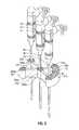
- FIG. 1is a perspective view of a microwave spacer, in accordance with the present disclosure that is configured to position three microwave energy delivery devices in a straight line configuration with a first spacing;
- FIG. 2is a perspective view of another embodiment of a microwave spacer, in accordance with the present disclosure that is configured to position three microwave energy delivery devices in a straight line configuration with a second spacing;
- FIG. 3is a perspective view of the microwave spacer of FIG. 1 ;
- FIG. 4is a perspective view of the microwave spacer of FIG. 2 ;
- FIG. 5Ais a bottom view of the microwave spacer of FIG. 1 ;
- FIG. 5Bis a perspective view of the patient facing surface of the microwave spacer of FIG. 1 ;
- FIG. 6is a perspective view of the microwave spacer of FIG. 1 in a configuration that positions the devices at the corners of an equilateral triangle;
- FIG. 7is a perspective view of the microwave spacer of FIG. 1 in a configuration that places the devices at the corners of a first isosceles triangle;
- FIG. 8is a perspective view of the microwave spacer of FIG. 1 in a configuration that places the devices at the corners of a second isosceles triangle;
- FIG. 9is a top, perspective view of the microwave spacer of FIG. 1 with a microwave energy delivery device positioned in a selected position along the length of an arcuate slot defined within the spacer;
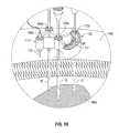
- FIG. 10is a top, perspective view of the microwave spacer positioned on patient tissue with the distal portions of the microwave energy delivery devices inserted in target tissue;
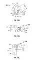
- FIG. 11Ais a perspective view of a pivotable microwave spacer, in accordance with another embodiment of the present disclosure that is configured to position three microwave energy delivery devices at the corners of an equilateral triangle;
- FIG. 11Bis a perspective view of the pivotable microwave spacer of FIG. 11A configured to position three microwave energy delivery devices in a straight line configuration;
- FIG. 12A-12Care top views of the pivotable microwave spacer of FIG. 11A in various angular positions
- FIG. 13is a top, perspective view of the patient facing surface of the pivotable microwave spacer of FIG. 11A ;
- FIG. 14is a top, perspective view of the pivotable microwave spacer of FIG. 11A positioned on patient tissue with the distal portion of the microwave energy delivery devices inserted in target tissue.
- FIGS. 1 and 2show perspective views of microwave spacers 100 , 200 in accordance with one embodiment the present disclosure.
- Microwave spacers 100 , 200are generally constructed for use with a particular microwave energy delivery device 10 .
- the microwave energy delivery devices 10 illustrated in FIGS. 1 and 2are penetrating microwave energy delivery devices sold by Covidien under the trademark EvidentTM Microwave Ablation percutaneous antennas.
- Microwave spacers 100 , 200 of the present disclosuremay be adapted for use with any suitable tissue penetrating microwave energy delivery devices that include an antenna on the distal end and require controlled spacing therebetween.
- Microwave spacers 100 , 200 of the present disclosuremay be adapted for use with any suitable device that requires controlled spacing therebetween such as, for example, devices configure to deliver radio-frequency energy, ultrasonic energy, cryogenic energy, thermal energy, laser energy or any combination of devices or energy sources thereof.
- Each body 110 , 210 of the respective microwave spacers 100 , 200forms a plurality of apertures that include a central tubular lumen 102 a , 202 a , a first side tubular lumen 104 a , 204 a , a second side tubular lumen 106 a , 206 a and an arcuate slot 112 a , 212 a defined therein that extend through each body 110 , 210 , respectively (see FIGS. 3 and 4 ).
- the microwave spacers 100 , 200include three sets of fixed position apertures (i.e., the central tubular lumen 102 a , 202 a the first side tubular lumen 104 a , 204 a and the second side tubular lumen 106 a , 206 b ) and one selectable aperture (i.e., arcuate slots 112 a , 212 a ).
- microwave spacers 100 , 200are configured to arrange, align, position and/or configure the microwave energy delivery devices 10 for use in a surgical procedure.
- microwave spacers 100 , 200are configured to arrange microwave energy delivery devices 10 in a substantially straight line or linear configuration (a linear configuration as shown in FIGS. 1 and 2 , an equilateral triangular configuration as shown in FIGS. 5B and 6 or an isosceles triangle configuration forming an angle from between about 90° and 180°).
- Each body 110 , 120 of respective microwave spacers 100 , 200may form a plurality of device apertures therein and the apertures may include any combination of apertures types (i.e., fixed position apertures and/or selectable position apertures).
- the first side tubular lumen 104 a , 204 a and the second side tubular lumen 106 a , 206 amay be replaced with a selectable position aperture, similar to the arcuate slot 112 a , 212 a , positioned radially outward from the central tubular lumen 102 a , 202 a .
- Another embodimentmay include at least one arcuate slot and a plurality of fixed apertures or at least one fixed aperture and a plurality of arcuate slots.
- Microwave spacers 100 , 200may include a plurality of sizes and/or spacing arrangements.
- FIG. 1illustrates a 1.5 cm microwave spacer 100
- FIG. 2illustrates a 2.0 cm microwave spacer 200 .
- the size of the microwave spacer 100 , and/or the number and spacing of the fixed lumens 102 a , 104 a , 106 a and/or the arcuate slot 112 amay be related to the type of ablation device, a parameter related to the energy delivered by the ablation device (i.e., power, current, voltage and/or frequency of the energy), the type of surgical procedure performed and/or the length of the surgical procedure.
- Patient facing surfaces 110 a , 210 a of respective microwave spacers 100 , 200face the patient and may be configured to facilitate contact with patient tissue.
- a portion of the patient facing surfacee.g., surface 110 a
- a portion of the patient facing surface 110 amay include a coating or non-slip material configured to adhere to the patient, such as, for example, an adhesive coating, a non-skid cover or any other suitable surface or coating that aids in securing the microwave spacer 100 to the patient.
- the microwave spacer(e.g., spacer 100 ) may include a plurality of appendages (i.e., feet and/or legs—not explicitly shown) or channels to elevate and/or space a portion of the patient facing surface 110 a of the microwave spacer 100 with respect to patient tissue 160 (See FIG. 10 ).
- appendagesi.e., feet and/or legs—not explicitly shown
- channelsto elevate and/or space a portion of the patient facing surface 110 a of the microwave spacer 100 with respect to patient tissue 160 (See FIG. 10 ).
- microwave spacer 100is described in further detail, however, it is contemplated that any of the features described herein may be applied to microwave spacer 200 .
- the features of the microwave spacer 200 illustrated in FIG. 4are labeled with like-numbers of corresponding features illustrated in FIG. 3 .
- Body 110includes a plurality of apertures/fixed lumens 102 a , 104 a , 106 a , 112 a to guide at least a portion of the microwave energy delivery devices 10 .
- the fixed apertureswhich include the central tubular lumen 102 a , the first side tubular lumen 104 a and the second side tubular lumen 106 a , position a microwave energy delivery device 10 in a fixed relationship with respect to the other fixed lumens 102 a , 104 a , 106 a and microwave energy delivery devices 10 inserted therethrough.
- the adjustable aperturese.g., arcuate slot 112 a , positions one or more microwave energy delivery devices 10 in an adjustable relationship with respect to the fixed lumens 102 a , 104 a , 106 a.
- the arcuate slot 112 ais configured to receive a microwave energy delivery device 10 through a plurality of positions along its length “L”.
- the arcuate slot 112 ais formed along a portion of an arc formed with a radial center positioned at the radial center of the central tubular lumen 102 a and a radius of curvature (e.g., see FIG. 5A distance “D 1 ”).
- the length “L” of the arcuate slot 112 ais the circumferential length between the radial centers of microwave energy delivery devices inserted through the first end 112 b and the second end 112 c of the arcuate slot 112 a .
- the width “W”is the width of the arcuate slot 112 a measured along the radius “R”.
- the width “W”is configured to receive a microwave energy delivery device 10 therethrough.
- the length of the arcuate slot 112 ais selected such that a microwave energy delivery device may be positioned at a plurality of positions along the length “L” of the arcuate slot 112 a to form a plurality of desirable configurations with respect the fixed lumens 102 a , 104 a , 106 a , as described herein and illustrated in FIGS. 1 , 5 B and 7 - 9 .
- the radius of curvature of the arcuate slot 112 ais selected such that radial center of the radius of curvature, formed by the arcuate slot 112 a , is related to one of the fixed apertures, e.g., as illustrated in FIG. 1 , the radial center of the arcuate slot 112 a is the radial center of the central tubular lumen 102 a.
- microwave spacers 100 , 200include a central stem 102 , 202 defining a central tubular lumen 102 a , 202 a therethrough.
- Microwave spacers 100 , 200further include a first side tubular stem 104 , 204 defining first side tubular lumen 104 a , 204 a therethrough, and second side tubular stems 106 , 206 defining a second side tubular lumen 106 a , 206 a therethrough.
- First side tubular stems 104 , 204are connected to respective central stems 102 , 202 by a first bridge 108 a , 208 a and second side tubular stem 106 , 206 is connected to central stem 102 , 202 by a second bridge 108 b , 208 b.
- first bridge 108 a , 208 a and second bridge 108 b , 208 bare off-set or angled from one another by an angle “ ⁇ ” equal to 60°.
- First side tubular lumen 104 a , 204 a of first side tubular stem 104 , 204 and second side tubular lumen 106 a , 206 a of second side tubular stem 106 , 206are each spaced from central tubular lumen 102 a , 202 a of central stem 102 , 202 by an equivalent distance “D 1 ”.
- the distance “D 1 ”may relate to the type of ablation device, a parameter related to the energy delivered by the ablation device (i.e., power, current, voltage and/or frequency of the energy), the type of surgical procedure performed and/or the length of the surgical procedure. In one embodiment, the distance “D 1 ” is equal to about 0.591 in.
- Microwave spacer 100may be configured such that fixed lumens 102 a , 104 a and 106 a of respective tubular stems 102 , 104 and 106 are parallel with respect to one another. Additionally, each fixed lumen 102 a , 104 a and 106 a of respective tubular stems 102 , 104 and 106 may be sized and dimensioned to slideably receive a shaft 14 (see FIGS. 1 and 2 ) of a particularly-sized microwave energy delivery device 10 .
- FIG. 5Bis a perspective view of the patient facing surface 110 a of the microwave spacer 100 .
- Patient facing surface 110 amay include one or more legs 140 to elevate a portion of the body 110 with respect to patient tissue (not explicitly shown) thereby allowing air to freely flow between the patient and at least a portion of the patient facing surface 110 a (i.e., exterior bridge 109 , first bridge 108 a , second bridge 108 b , first guide body support bridge 114 a and second guide body support bridge 114 b .)
- thermal energy generated at the surface of the patient tissuedissipates through the first airflow aperture 130 a and/or the second airflow aperture 130 b .
- a convection air currentis generated wherein heated air, within the first airflow aperture 130 a and/or second airflow aperture 130 b , rises. This convection air current draws fluid through the space formed between the patient facing surface 110 a and patient tissue.
- microwave spacer 100further includes an arcuate guide body 112 defining an arcuate slot 112 a therethrough.
- Arcuate guide body 112is connected to central stem 102 by a first guide body support bridge 114 a and a second guide body support bridge 114 b .
- Second guide body support bridge 114 bis axially-aligned with first bridge 108 a .
- First guide body support bridge 114 ais oriented at an angle “ ⁇ 1 ” relative to first bridge 108 a and oriented at an angle “ ⁇ 2 ” with respect to second bridge 108 b . In one embodiment the angle “ ⁇ 1 ” is about 90° and the angle “ ⁇ 2 ” is about 150°.
- a first end 112 b of arcuate slot 112 a of arcuate guide body 112is axially aligned with first side tubular lumen 104 a of first side tubular stem 104 .
- a second end 112 c of arcuate slot 112 ais oriented at an angle “ ⁇ 1 ” relative to first side tubular lumen 104 a of first side tubular stem 104 and is oriented at an angle “ ⁇ 2 ” with respect to second side tubular lumen 106 a of second side tubular stem 106 .
- First end 112 b of arcuate slot 112 a of arcuate guide body 112 and second end 112 c of arcuate slot 112 a of arcuate guide body 112are each spaced from central tubular lumen 102 a of central stem 102 by an equivalent distance “D 1 ”.
- arcuate slot 112 a of arcuate guide body 112defines a radius of curvature having its center located along the central axis of central stem 102 and that is parallel to fixed lumens 102 a , 104 a and 106 a of respective tubular stems 102 , 104 and 106 . Additionally, arcuate slot 112 a of arcuate guide body 112 is sized and dimensioned to slidably receive a shaft 14 of a microwave energy delivery device 10 therethrough, as illustrated in FIGS. 1 and 2 .
- tubular stems 102 , 104 and 106 , and arcuate guide body 112have a height “H” that is sufficient to maintain substantial parallelism of the shafts 14 of the microwave energy delivery devices 10 inserted into the respective fixed lumens 102 a , 104 a , 106 a and arcuate slot 112 a thereof.
- the height “H”is sufficiently long to guide the microwave energy delivery devices 10 such that the distal ends of the devices are positioned in a desirable spaced apart relationship relative to each other such that the spacing of the distal tips S 1 , S 2 and S 3 are desirably spaced and the spacing between the distal tips S 1 , S 2 and S 3 is substantially equal.
- the shafts 14 of the microwave energy delivery devices 10are not substantially parallel to each other. As such, the spacing between the distal tips S 1 , S 2 and S 3 may increase or decrease as the microwave energy delivery devices 10 are inserted through the microwave spacer 100 .
- Microwave spacer 100may be constructed from any suitable material, such as a non-conductive plastic material (e.g., nylon or polyamide) or a ceramic.
- Microwave spacer 100is configured to provide a plurality of microwave energy delivery device 10 orientations with varying spacing between each microwave energy delivery device 10 .
- FIGS. 1 and 2illustrate a straight line configuration of the microwave energy delivery devices 10 . Additional orientations and spacing between microwave energy delivery devices 10 are further illustrated in FIGS. 5B , and 6 - 9 .
- the three fixed lumens 102 a , 104 a , 106 aposition the radial centers of the microwave energy delivery devices 10 such that the radial centers form the corners of an equilateral triangle, wherein the sides of the triangle are equal to a distance “D 1 ”, as illustrated in FIG. 5A and the equilateral triangle angle ⁇ is equal 60°.
- central tubular lumen 102 a , first side tubular lumen 104 a and the second end 112 c of the arcuate slot 112 aposition the radial centers of the shafts 14 of the microwave energy delivery devices 10 such that the radial centers form the corners of a right isosceles triangle with angles of 90°, 45° and 45°.
- central tubular lumen 102 a , second side tubular lumen 106 a and the first end 112 b of the arcuate slot 112 aposition the radial centers of the shafts 14 of the microwave energy delivery devices 10 such that the radial centers form the corners of an obtuse triangle with angles of 120°, 30° and 30°.
- FIG. 9illustrates that the shaft 14 of the microwave energy delivery device 10 inserted into arcuate slot 112 a may be positioned at any point along the length of the arcuate slot 112 a , thereby providing a plurality of configurations in which the microwave energy delivery devices 10 may be arranged.
- bridges 108 a , 108 b , 109 , 114 a , 114 bprovide structural strength to the microwave spacer 100 thereby preventing deflection and/or preventing the microwave spacer 100 from changing shape or form.
- first bridge 108 a , second bridge 108 b and exterior bridge 109 of the body 110form the sides of a first airflow aperture 130 a .
- First guide body support bridge 114 a , second guide body support bridge 114 b and arcuate guide body 112form the sides of a second airflow aperture 130 b .
- First airflow aperture 130 a and second airflow aperture 130 bare configured to allow heat (generated at the surface of the patient tissue) to dissipate through the microwave spacer 100 .
- the body 110may include one or more passageways, such as first airflow aperture 130 a or second airflow aperture 130 b , for air to flow between the patient facing surface 110 a and patient tissue (not explicitly shown). Thermal energy generated at the surface of the patient tissue (not explicitly shown) dissipates through the first airflow aperture 130 a and/or the second airflow aperture 130 b .
- Body 110 of the microwave spacer 100may be formed from a light weight material resistant to thermal heating.
- the patient facing surface 110 amay include one or more channels 111 a , 111 b , 111 c formed therein.
- Channels 111 a , 111 b , 111 cform a fluid pathway for air to flow between the patient facing surface 110 a and patient tissue (not explicitly shown).
- tissue surfacei.e., tissue directly below the patient facing surface 110 a of the microwave spacer 100
- a convection air currentis generated wherein the heated air, within the first airflow aperture 130 a and/or second airflow aperture 130 b , rises.
- each bridge 108 a , 108 b , 109 , 114 a and 114 bmay include one or more channels, formed along the patient facing surface 110 a , to provide a fluid pathway for a convection air current to flow.
- a microwave spacer 100is placed on patient tissue 160 adjacent a target tissue 160 a or tissue targeted for a medical procedure, (i.e., an ablation procedure, a resection procedure or any other suitable electrosurgical procedure that requires electrosurgical energy delivery).
- the clinicianmay utilize an imaging/positioning system, such as, for example, an ultrasonic system, an x-ray system, a CT scan or any other suitable imaging/positioning system (not explicitly shown) to determine proper positioning of the microwave spacer 100 with respect to the target tissue 160 a .
- Each of the microwave energy delivery devices 10is inserted into a selected fixed lumen 102 a , 104 a and/or a selected position of the arcuate slot 112 a .
- the imaging systemmay be used during the insertion step to determine when each microwave energy delivery device 10 is properly positioned in target tissue 160 a .
- the microwave ablation proceduremay require the use of any number and/or combination of fixed lumens 102 a , 104 a , 106 a and/or arcuate slot 112 a .
- Apertures not used for the insertion of microwave energy delivery devices 10may be used for the placement of a probe or sensor configured to measure a property of the target tissue such as, for example, a temperature (i.e., thermocouple, RTD or inferred heat measuring device), impedance and/or a tissue fluid content.
- a method for placing a plurality of microwave energy delivery devices 10 and ablating tissueincludes the steps of placing the microwave spacer 100 on a portion of patient tissue 160 adjacent a target tissue 160 a ; inserting two or more microwave energy delivery devices 10 through fixed lumens 102 a , 104 a , 106 a formed in the body 110 of the microwave spacer 100 into the target tissue 160 a ; selecting a position on the arcuate slot 112 a ; inserting at least one microwave energy delivery device 10 through the arcuate slot 112 a into the target tissue 160 a ; connecting the three or more microwave energy delivery devices 10 to a microwave energy source (not explicitly shown); ablating the target tissue 160 a by delivering microwave energy through the microwave energy delivery devices 10 ; and cooling patient tissue 160 by providing airflow through a plurality of airflow apertures formed through the body 110 of the microwave spacer 100 .
- Another method for placing a plurality of microwave energy delivery devices 10 and ablating tissueincludes the steps of: placing the microwave spacer 100 on a portion of patient tissue 160 adjacent a target tissue 160 a ; inserting two or more microwave energy delivery devices 10 through fixed apertures formed in the body 110 of the microwave spacer 100 ; advancing an antenna 12 of the microwave energy delivery devices 10 to the target tissue 160 a ; inserting another microwave energy delivery device 10 in a selected insertion position in an arcuate slot 112 a forming in the body 110 of microwave spacer 100 and into the target tissue; connecting the microwave energy delivery devices 10 to a microwave energy source; and ablating the target tissue by delivering microwave energy through the microwave energy delivery devices 10 .
- the methodsmay further include the step of cooling the patient's tissue by providing airflow through a plurality of channels 111 a , 111 b , 111 c formed in the body 110 of the microwave spacer 100 .
- One or more of the afore described methodsmay further include the step of inserting one or more sensors 115 through a lumen (i.e., fixed lumens 102 a , 104 a , 106 a , as illustrated in FIG. 10 , or a selected position on arcuate slot 112 a ) formed in the body 110 of the microwave spacer 100 into the target tissue.
- the sensor 115may be configured to measure a property of the target tissue such as, for example, a temperature (i.e., thermocouple, RTD or inferred heat measuring device), impedance and/or a tissue fluid content.
- FIGS. 11A-14show various views of a pivotable microwave spacer 300 in accordance with the present disclosure.
- Pivotable microwave spacer 300is generally constructed for use with a particular microwave energy delivery device 10 .
- the microwave energy delivery devices 10 illustrated in FIGS. 11A , 11 B, 13 and 14are sold by Covidien under the trademark Evident TM Microwave Ablation percutaneous antennas.
- Pivotable microwave spacer 300 of the present disclosuremay be adapted for use with any suitable device that requires controlled spacing therebetween such as, for example, devices configure configured to deliver radio-frequency energy, ultrasonic energy, cryogenic energy, thermal energy, laser energy or any combination of devices or energy sources thereof.
- the body 310 of the pivotable microwave spacer 300includes a first body 311 and a second body 312 pivotally attached thereto.
- First body 311includes an upper first body member 311 a , a lower first body member 311 b and a first body spacer 311 c .
- Second body 312includes a second body member 312 a and a second body stop 312 b .
- Upper first body member 311 a and lower first body member 311 beach form a portion of the pivot aperture 304 therein.
- Second body member 312 aforms a second body pivot aperture 304 b therein disposed in vertical registration with respect to first body pivot aperture 304 a formed in the first body 311 .
- First body pivot aperture 304 a and second body pivot aperture 304 bpivotally attach the first body 311 and second body 312 about the pivot aperture 304 .
- first body 311forms a first body aperture 302 and the second body 312 forms a second body aperture 306 .
- first body aperture 302 , the pivot aperture 304 and the second body aperture 306are equally spaced from each other thereby forming the corners of an equilateral triangle.
- first body 311 and/or second body 312 of the pivotable microwave spacer 300may form two or more apertures therein.
- the first body 311 and/or the second body 312form at least two apertures therein and form a pivotable microwave spacer 300 for positioning microwave energy delivery devices 10 along a resection line wherein the resection line includes at least one variable angle.
- the angular relationship between the first body 311 and second body 312is adjustable between a minimum angular relationship and a maximum angular relationship.
- the size and/or position of the second body stop 312 bdetermine the maximum and minimum angular relationship between the first body 311 and the second body 312 .
- the second body stop 312 blimits the angular relationship between the first body 311 and the second body 312 between about 60° and about 300°, wherein the second body stop 312 b makes contact with the upper first body member 311 a at the minimum and maximum angular relationships between the first body 311 and second body 312 .
- the second body stop 312 blimits the angular relationship between the first body 311 and the second body 312 between about 30° to about 330°. In yet another embodiment, the second body stop 312 b limits the angular relationship between the first body 311 and second body 312 between about 60° and 270° wherein at 60° the centers of the apertures 302 , 304 , 306 form the corners of an equilateral triangle and at 270° form the corners of an isosceles right triangle wherein a right angle is formed at the pivot aperture 304 (composed of first body pivot aperture 304 a and second body pivot aperture 304 b.
- FIGS. 11A and 11Billustrate only two positions of a plurality of angular positions wherein the angle between the first body 311 and the second body 320 varies between about 60° and about 300°.
- the angular relationship between the first body 311 and the second body 312 of the pivotable microwave spacer 300may be determined by providing an angular gauge 360 as illustrated in FIGS. 12A-12C and described hereinbelow.
- the pivotable microwave spacer 300 illustrated in FIGS. 12A-12Cis configured to provide adjustability between 60° and 300°.
- An angular gauge 360as described herein, may be adapted to provide the angular relationship of any such pivoting microwave spacer.
- Angular gauge 360includes a first angular indicator 325 and a second angular indicator 326 .
- First angular indicator 325provides angular measurements between 60° and 180° and second angular indicator 326 provides measurements between 180° and 300°.
- FIG. 12Aillustrates the angular relationship between the first body 311 and second body 312 , as indicated by the first angular indicator 325 , equal to 60° (pivoted fully counter-clockwise with the first body 311 in contact with the second body stop 312 b ).
- FIG. 12Aillustrates the angular relationship between the first body 311 and second body 312 , as indicated by the first angular indicator 325 , equal to 60° (pivoted fully counter-clockwise with the first body 311 in contact with the second body stop 312 b ).
- FIG. 12Billustrates the angular relationship between the first body 311 and the second body 312 , as measured by the first angular indicator 325 and/or the second angular indicator 326 , equal to 180° (longitudinal side edges of First body 311 and second body 312 in alignment).
- FIG. 12Cillustrates the angular relationship between the first body 311 and the second body 312 , measured by the second angular indicator 326 , equal to 270°.
- Angular gauge 360indicates the angular position between the first body 311 and the second body 312 through the entire range of rotation between the first body 311 and the second body 312 .
- pivotable microwave spacer 300may further include a locking and/or holding mechanism (e.g., ratchet 395 and catch 390 or notch 391 and recessed channels 396 ) to lock and/or hold the first body 311 in a desirable position with respect to the second body 312 .
- Ratchet 395includes a plurality of ratchet teeth 395 a configured to engage catch 390 .
- Catch 390is biased against ratchet 395 and engages one or more ratchet teeth 395 a or any portion of the ratchet 395 thereby preventing further rotation of the first body 311 with respect to the second body 312 .
- Catch release 390 apositioned in catch release aperture 311 d formed in the first body 311 , when pressed disengages the catch 390 from the ratchet 395 .
- the first body 311 and second body 312include mechanically interfacing surfaces configured to engage and/or lock the first body 311 in a desirable position with respect to the second body 312 .
- upper first body member 311 a of the first body 311may form a notch 391 that engages at least one of a plurality of recessed channels 396 a - 396 ad formed in the second body member 312 a of the second body 312 .
- notch 391aligns with the plurality of recessed channels 396 and incrementally engages the recessed channels (e.g., engages recessed channel 396 a and subsequently engages channel 396 b , etc. . . .
- recessed channels 396 a - 396 admay be incrementally spaced, such as, for example, spaced in 10° intervals as illustrated in FIG. 13B .
- pivotable microwave spacer 300may include a plurality of legs 340 a - 340 f configured to facilitate contact with the patient. Legs 340 a - 340 f are configured to elevate at least a portion of the pivotable microwave spacer 300 such that the pivotable microwave spacer 300 is substantially parallel to patient tissue.
- feet 340 e , 340 fare only included on the second body 312 wherein each foot e.g., foot e.g., foot 340 e , 340 f , elevates the second body 312 the thickness “T” of the lower first body member 311 b .
- Legs 340 a - 340 fmay include a coating or non-slip material that adheres to the patient, such as, for example, an adhesive coating, a non-skid cover or any other suitable surface or coating that aids in securing the pivotable microwave spacer 300 to the patient.
- a coating or non-slip materialthat adheres to the patient, such as, for example, an adhesive coating, a non-skid cover or any other suitable surface or coating that aids in securing the pivotable microwave spacer 300 to the patient.
- the pivotable microwave spacers 300may include an arcuate slot or non-arcuate slot as described hereinabove.
- pivotable microwave spacer 300is placed on patient tissue 160 adjacent a target tissue 160 a e.g., tissue targeted for a medical procedure, (i.e., an ablation procedure, a resection procedure or any other suitable electrosurgical procedure that requires electrosurgical energy delivery).
- a medical procedurei.e., an ablation procedure, a resection procedure or any other suitable electrosurgical procedure that requires electrosurgical energy delivery.
- the clinicianmay utilize an imaging/positioning system, such as, for example, an ultrasonic system, an x-ray system, a CT scan or any other suitable imaging/positioning system (not explicitly shown) to determine proper positioning of the pivotable microwave spacer 300 with respect to the target tissue 160 a .
- Each of the microwave energy delivery devices 10is inserted into a respective aperture 302 , 304 , 306 and into patient tissue 160 .
- An imaging systemmay be used during the insertion step to determine when each microwave energy delivery device 10 is properly positioned in target tissue 160 a .
- Apertures not used for the insertion of microwave energy delivery devices 10may be used for the placement of a sensor 115 configured to measure a property of the target tissue such as, for example, a temperature (i.e., thermocouple, RTD or inferred heat measuring device), impedance and/or a tissue fluid content.
- a microwave spacerin the spirit of the present disclosure is formed by including three or more bodies that form an interlocking microwave spacer, wherein each of the three or more bodies includes at least one aperture formed therein.
- the three or more bodiesmay be daisy-chained together or may be grouped together in a specific pattern.
- the connection between the three or more bodiesmay be accomplished by connection points formed on the bodies or by utilizing a linking connector configured to link together two or more microwave spacers.
- a method for placing a plurality of microwave energy delivery devices 10 and ablating tissueincludes the steps of: selecting an ablation pattern; providing a pivotable microwave spacer 300 ; adjusting the angular relationship between the first body 311 and second body 312 of the pivotable microwave spacer 300 ; placing the pivotable microwave spacer 300 on a portion of patient tissue 160 adjacent a target tissue 160 a ; inserting two or more microwave energy delivery devices 10 through apertures formed in the first body 311 and/or the second body 312 of the pivotable microwave spacer 300 and into the target tissue 160 a ; connecting the microwave energy delivery devices 10 to a microwave energy source (not explicitly shown), and ablating the target tissue 160 a by delivering microwave energy through the microwave energy delivery devices 10 .
- the methodmay further include the step of cooling patient tissue 160 by providing airflow between the pivotable microwave spacer 300 and patient tissue 160 .
- the methodsmay further include the step of inserting one or more sensors 315 through an available aperture (e.g., apertures 302 , 304 , 306 formed in the pivotable microwave spacer 300 ) and into the target tissue 160 a .
- the sensor 315may measure one or more properties of the target tissue 160 a such as, for example, temperature (i.e., thermocouple, RTD or inferred heat measuring device), impedance and/or a tissue fluid content.
Landscapes
- Health & Medical Sciences (AREA)
- Surgery (AREA)
- Life Sciences & Earth Sciences (AREA)
- Medical Informatics (AREA)
- Animal Behavior & Ethology (AREA)
- Engineering & Computer Science (AREA)
- Biomedical Technology (AREA)
- Heart & Thoracic Surgery (AREA)
- Veterinary Medicine (AREA)
- Molecular Biology (AREA)
- Nuclear Medicine, Radiotherapy & Molecular Imaging (AREA)
- General Health & Medical Sciences (AREA)
- Public Health (AREA)
- Physics & Mathematics (AREA)
- Electromagnetism (AREA)
- Otolaryngology (AREA)
- Pathology (AREA)
- Surgical Instruments (AREA)
Abstract
Description
Claims (20)
Priority Applications (2)
| Application Number | Priority Date | Filing Date | Title |
|---|---|---|---|
| US12/877,182US8945144B2 (en) | 2010-09-08 | 2010-09-08 | Microwave spacers and method of use |
| US14/603,499US9943366B2 (en) | 2010-09-08 | 2015-01-23 | Microwave spacers and method of use |
Applications Claiming Priority (1)
| Application Number | Priority Date | Filing Date | Title |
|---|---|---|---|
| US12/877,182US8945144B2 (en) | 2010-09-08 | 2010-09-08 | Microwave spacers and method of use |
Related Child Applications (1)
| Application Number | Title | Priority Date | Filing Date |
|---|---|---|---|
| US14/603,499ContinuationUS9943366B2 (en) | 2010-09-08 | 2015-01-23 | Microwave spacers and method of use |
Publications (2)
| Publication Number | Publication Date |
|---|---|
| US20120059365A1 US20120059365A1 (en) | 2012-03-08 |
| US8945144B2true US8945144B2 (en) | 2015-02-03 |
Family
ID=45771229
Family Applications (2)
| Application Number | Title | Priority Date | Filing Date |
|---|---|---|---|
| US12/877,182Active2033-12-05US8945144B2 (en) | 2010-09-08 | 2010-09-08 | Microwave spacers and method of use |
| US14/603,499Active2032-03-09US9943366B2 (en) | 2010-09-08 | 2015-01-23 | Microwave spacers and method of use |
Family Applications After (1)
| Application Number | Title | Priority Date | Filing Date |
|---|---|---|---|
| US14/603,499Active2032-03-09US9943366B2 (en) | 2010-09-08 | 2015-01-23 | Microwave spacers and method of use |
Country Status (1)
| Country | Link |
|---|---|
| US (2) | US8945144B2 (en) |
Cited By (9)
| Publication number | Priority date | Publication date | Assignee | Title |
|---|---|---|---|---|
| US20150164585A1 (en)* | 2010-09-08 | 2015-06-18 | Covidien Lp | Microwave spacers and method of use |
| US9743985B2 (en) | 2010-12-23 | 2017-08-29 | Covidien Lp | Microwave field-detecting needle assemblies, methods of manufacturing same, methods of adjusting an ablation field radiating into tissue using same, and systems including same |
| US10265140B2 (en) | 2009-05-11 | 2019-04-23 | TriAgenics, Inc. | Therapeutic tooth bud ablation |
| US10298255B2 (en) | 2013-03-15 | 2019-05-21 | TriAgenics, Inc. | Therapeutic tooth bud ablation |
| US10335248B2 (en) | 2009-05-11 | 2019-07-02 | TriAgenics, Inc. | Therapeutic tooth bud ablation |
| US10765490B2 (en) | 2013-03-15 | 2020-09-08 | TriAgenics, Inc. | Therapeutic tooth bud ablation |
| US11058488B2 (en) | 2011-01-05 | 2021-07-13 | Covidien Lp | Energy-delivery devices with flexible fluid-cooled shaft, inflow / outflow junctions suitable for use with same, and systems including same |
| US11207116B2 (en)* | 2013-12-12 | 2021-12-28 | Medtronic Cryocath Lp | Real-time lesion formation assessment |
| US11583337B2 (en) | 2019-06-06 | 2023-02-21 | TriAgenics, Inc. | Ablation probe systems |
Families Citing this family (2)
| Publication number | Priority date | Publication date | Assignee | Title |
|---|---|---|---|---|
| US9028476B2 (en) | 2011-02-03 | 2015-05-12 | Covidien Lp | Dual antenna microwave resection and ablation device, system and method of use |
| WO2023196808A2 (en)* | 2022-04-04 | 2023-10-12 | Ann And Robert H. Lurie Children's Hospital Of Chicago | Neonate lumbar puncture device |
Citations (183)
| Publication number | Priority date | Publication date | Assignee | Title |
|---|---|---|---|---|
| DE390937C (en) | 1922-10-13 | 1924-03-03 | Adolf Erb | Device for internal heating of furnace furnaces for hardening, tempering, annealing, quenching and melting |
| DE1099658B (en) | 1959-04-29 | 1961-02-16 | Siemens Reiniger Werke Ag | Automatic switch-on device for high-frequency surgical devices |
| FR1275415A (en) | 1960-09-26 | 1961-11-10 | Device for detecting disturbances for electrical installations, in particular electrosurgery | |
| DE1139927B (en) | 1961-01-03 | 1962-11-22 | Friedrich Laber | High-frequency surgical device |
| DE1149832B (en) | 1961-02-25 | 1963-06-06 | Siemens Reiniger Werke Ag | High frequency surgical apparatus |
| FR1347865A (en) | 1962-11-22 | 1964-01-04 | Improvements to diathermo-coagulation devices | |
| DE1439302A1 (en) | 1963-10-26 | 1969-01-23 | Siemens Ag | High-frequency surgical device |
| US3631363A (en) | 1969-11-14 | 1971-12-28 | Gen Electric | High-frequency cavity oscillator having improved tuning means |
| SU401367A1 (en) | 1971-10-05 | 1973-10-12 | Тернопольский государственный медицинский институт | BIAKTIVNYE ELECTRO SURGICAL INSTRUMENT |
| DE2439587A1 (en) | 1973-08-23 | 1975-02-27 | Matburn Holdings Ltd | ELECTROSURGICAL DEVICE |
| DE2455174A1 (en) | 1973-11-21 | 1975-05-22 | Termiflex Corp | INPUT / OUTPUT DEVICE FOR DATA EXCHANGE WITH DATA PROCESSING DEVICES |
| DE2407559A1 (en) | 1974-02-16 | 1975-08-28 | Dornier System Gmbh | Tissue heat treatment probe - has water cooling system which ensures heat development only in treated tissues |
| DE2415263A1 (en) | 1974-03-29 | 1975-10-02 | Aesculap Werke Ag | Surgical H.F. coagulation probe has electrode tongs - with exposed ends of insulated conductors forming tong-jaws |
| DE2429021A1 (en) | 1974-06-18 | 1976-01-08 | Erbe Elektromedizin | Remote control for HF surgical instruments - uses cable with two conductors at most |
| FR2235669B1 (en) | 1973-07-07 | 1976-05-07 | Lunacek Boris | |
| DE2460481A1 (en) | 1974-12-20 | 1976-06-24 | Delma Elektro Med App | Electrode grip for remote HF surgical instrument switching - has shaped insulated piece with contact ring of sterilizable (silicon) rubber |
| DE2627679A1 (en) | 1975-06-26 | 1977-01-13 | Marcel Lamidey | HEMATISTIC HIGH FREQUENCY EXTRACTOR FORCEPS |
| FR2276027B3 (en) | 1974-06-25 | 1977-05-06 | Medical Plastics Inc | |
| DE2823291A1 (en) | 1978-05-27 | 1979-11-29 | Rainer Ing Grad Koch | Coagulation instrument automatic HF switching circuit - has first lead to potentiometer and second to transistor base |
| SU727201A2 (en) | 1977-11-02 | 1980-04-15 | Киевский Научно-Исследовательский Институт Нейрохирургии | Electric surgical apparatus |
| FR2313708B1 (en) | 1975-06-02 | 1980-07-04 | Sybron Corp | |
| DE2504280C3 (en) | 1975-02-01 | 1980-08-28 | Hans Heinrich Prof. Dr. 8035 Gauting Meinke | Device for cutting and / or coagulating human tissue with high frequency current |
| DE2803275C3 (en) | 1978-01-26 | 1980-09-25 | Aesculap-Werke Ag Vormals Jetter & Scheerer, 7200 Tuttlingen | Remote switching device for switching a monopolar HF surgical device |
| DE3045996A1 (en) | 1980-12-05 | 1982-07-08 | Medic Eschmann Handelsgesellschaft für medizinische Instrumente mbH, 2000 Hamburg | Electro-surgical scalpel instrument - has power supply remotely controlled by surgeon |
| USD266842S (en) | 1980-06-27 | 1982-11-09 | Villers Mark W | Phonograph record spacer |
| DE2540968C2 (en) | 1975-09-13 | 1982-12-30 | Erbe Elektromedizin GmbH, 7400 Tübingen | Device for switching on the coagulation current of a bipolar coagulation forceps |
| DE2602517C3 (en) | 1975-01-23 | 1983-01-13 | Dentsply International Inc., 17404 York, Pa. | Device for monitoring the current return conductor in an electrosurgical HF device |
| FR2517953A1 (en) | 1981-12-10 | 1983-06-17 | Alvar Electronic | Diaphanometer for optical examination of breast tissue structure - measures tissue transparency using two plates and optical fibre bundle cooperating with photoelectric cells |
| US4397313A (en) | 1981-08-03 | 1983-08-09 | Clini-Therm Corporation | Multiple microwave applicator system and method for microwave hyperthermia treatment |
| US4462412A (en) | 1980-04-02 | 1984-07-31 | Bsd Medical Corporation | Annular electromagnetic radiation applicator for biological tissue, and method |
| USD278306S (en) | 1980-06-30 | 1985-04-09 | Mcintosh Lois A | Microwave oven rack |
| DE3143421C2 (en) | 1980-11-04 | 1985-05-02 | The Agency Of Industrial Science And Technology, Tokio/Tokyo | Laser scalpel |
| FR2502935B1 (en) | 1981-03-31 | 1985-10-04 | Dolley Roger | METHOD AND DEVICE FOR CONTROLLING THE COAGULATION OF TISSUES USING A HIGH FREQUENCY CURRENT |
| US4572190A (en) | 1983-05-26 | 1986-02-25 | Cgr/Mev | Hyperthermia apparatus |
| FR2573301B3 (en) | 1984-11-16 | 1987-04-30 | Lamidey Gilles | SURGICAL PLIERS AND ITS CONTROL AND CONTROL APPARATUS |
| DE2946728C2 (en) | 1979-11-20 | 1987-07-30 | Erbe Elektromedizin Gmbh, 7400 Tuebingen, De | |
| DE3120102C2 (en) | 1981-05-20 | 1987-08-20 | Fischer Met Gmbh, 7800 Freiburg, De | |
| EP0246350A1 (en) | 1986-05-23 | 1987-11-25 | Erbe Elektromedizin GmbH. | Coagulation electrode |
| US4723544A (en)* | 1986-07-09 | 1988-02-09 | Moore Robert R | Hemispherical vectoring needle guide for discolysis |
| DE8712328U1 (en) | 1987-09-11 | 1988-02-18 | Jakoubek, Franz, 7201 Emmingen-Liptingen | Endoscopy forceps |
| DE3711511C1 (en) | 1987-04-04 | 1988-06-30 | Hartmann & Braun Ag | Method for determining gas concentrations in a gas mixture and sensor for measuring thermal conductivity |
| DE3510586C2 (en) | 1985-03-23 | 1988-07-28 | Erbe Elektromedizin Gmbh, 7400 Tuebingen, De | |
| US4798215A (en) | 1984-03-15 | 1989-01-17 | Bsd Medical Corporation | Hyperthermia apparatus |
| DE2820908C2 (en) | 1977-05-16 | 1989-11-16 | Joseph Coubron Fr Skovajsa | |
| US5097844A (en) | 1980-04-02 | 1992-03-24 | Bsd Medical Corporation | Hyperthermia apparatus having three-dimensional focusing |
| EP0481685A1 (en) | 1990-10-15 | 1992-04-22 | Cook Incorporated | Medical device for localizing a lesion |
| JPH055106Y2 (en) | 1986-02-28 | 1993-02-09 | ||
| DE4238263A1 (en) | 1991-11-15 | 1993-05-19 | Minnesota Mining & Mfg | Adhesive comprising hydrogel and crosslinked polyvinyl:lactam - is used in electrodes for biomedical application providing low impedance and good mechanical properties when water and/or moisture is absorbed from skin |
| EP0521264A3 (en) | 1991-07-03 | 1993-06-16 | W.L. Gore & Associates Gmbh | Antenna device with feed |
| EP0556705A1 (en) | 1992-02-20 | 1993-08-25 | DELMA ELEKTRO-UND MEDIZINISCHE APPARATEBAU GESELLSCHAFT mbH | High frequency surgery device |
| EP0558429A1 (en) | 1992-02-26 | 1993-09-01 | PECHINEY RECHERCHE (Groupement d'Intérêt Economique géré par l'ordonnance no. 67-821 du 23 Septembre 1967) | Method of simultaneous measuring of electrical resistivety and thermal conductivity |
| JPH0540112Y2 (en) | 1987-03-03 | 1993-10-12 | ||
| EP0572131A1 (en) | 1992-05-21 | 1993-12-01 | Everest Medical Corporation | Surgical scissors with bipolar coagulation feature |
| JPH06343644A (en) | 1993-05-04 | 1994-12-20 | Gyrus Medical Ltd | Surgical peritoneoscope equipment |
| USD354218S (en) | 1992-10-01 | 1995-01-10 | Fiberslab Pty Limited | Spacer for use in concrete construction |
| DE4303882C2 (en) | 1993-02-10 | 1995-02-09 | Kernforschungsz Karlsruhe | Combination instrument for separation and coagulation for minimally invasive surgery |
| US5417210A (en) | 1992-05-27 | 1995-05-23 | International Business Machines Corporation | System and method for augmentation of endoscopic surgery |
| DE3604823C2 (en) | 1986-02-15 | 1995-06-01 | Lindenmeier Heinz | High frequency generator with automatic power control for high frequency surgery |
| US5449360A (en)* | 1991-08-23 | 1995-09-12 | Schreiber; Saul N. | Osteotomy device and method |
| JPH07265328A (en) | 1993-11-01 | 1995-10-17 | Gyrus Medical Ltd | Electrode assembly for electric surgery device and electric surgery device using it |
| JPH0856955A (en) | 1994-06-29 | 1996-03-05 | Gyrus Medical Ltd | Electric surgical apparatus |
| JPH08252263A (en) | 1994-12-21 | 1996-10-01 | Gyrus Medical Ltd | Electronic surgical incision instrument and electronic surgical incision device using the same |
| DE29616210U1 (en) | 1996-09-18 | 1996-11-14 | Olympus Winter & Ibe Gmbh, 22045 Hamburg | Handle for surgical instruments |
| JPH0910223A (en) | 1995-06-23 | 1997-01-14 | Gyrus Medical Ltd | Generator and system for electric operation |
| DE19608716C1 (en) | 1996-03-06 | 1997-04-17 | Aesculap Ag | Bipolar surgical holding instrument |
| US5623931A (en) | 1994-10-11 | 1997-04-29 | Siemens Medical Systems, Inc. | Needle guide for use with ultrasound imaging systems |
| US5626607A (en) | 1995-04-03 | 1997-05-06 | Heartport, Inc. | Clamp assembly and method of use |
| DE3904558C2 (en) | 1989-02-15 | 1997-09-18 | Lindenmeier Heinz | Automatically power-controlled high-frequency generator for high-frequency surgery |
| WO1997041924A1 (en) | 1996-05-06 | 1997-11-13 | Thermal Therapeutics, Inc. | Transcervical intrauterine applicator for intrauterine hyperthermia |
| EP0541930B1 (en) | 1991-10-17 | 1998-03-25 | Smith & Nephew, Inc. | Transmission link for use in surgical instruments |
| WO1997043971A3 (en) | 1996-05-22 | 1998-04-02 | Somnus Medical Tech Inc | Method and apparatus for ablating turbinates |
| DE19751106A1 (en) | 1996-11-27 | 1998-05-28 | Eastman Kodak Co | Laser printer with array of laser diodes |
| DE19717411A1 (en) | 1997-04-25 | 1998-11-05 | Aesculap Ag & Co Kg | Monitoring of thermal loading of patient tissue in contact region of neutral electrode of HF treatment unit |
| DE3942998C2 (en) | 1989-12-27 | 1998-11-26 | Delma Elektro Med App | High frequency electrosurgical unit |
| WO1999004710A1 (en) | 1997-07-25 | 1999-02-04 | Cosman Eric R | Cluster ablation electrode system |
| DE19751108A1 (en) | 1997-11-18 | 1999-05-20 | Beger Frank Michael Dipl Desig | Electrosurgical operation tool, especially for diathermy |
| DE19801173C1 (en) | 1998-01-15 | 1999-07-15 | Kendall Med Erzeugnisse Gmbh | Clamp connector for film electrodes |
| US5924992A (en) | 1997-11-26 | 1999-07-20 | Acuson Corporation | Semi-compliant needle guide for use with ultrasound transducers |
| JPH11244298A (en) | 1997-12-19 | 1999-09-14 | Gyrus Medical Ltd | Electric surgical instrument |
| EP0836868A3 (en) | 1996-10-18 | 1999-11-24 | Gebr. Berchtold GmbH & Co. | High frequency surgical apparatus and method for operating same |
| US6031375A (en) | 1997-11-26 | 2000-02-29 | The Johns Hopkins University | Method of magnetic resonance analysis employing cylindrical coordinates and an associated apparatus |
| USD424693S (en) | 1999-04-08 | 2000-05-09 | Pruter Rick L | Needle guide for attachment to an ultrasound transducer probe |
| DE19848540A1 (en) | 1998-10-21 | 2000-05-25 | Reinhard Kalfhaus | Circuit layout and method for operating a single- or multiphase current inverter connects an AC voltage output to a primary winding and current and a working resistance to a transformer's secondary winding and current. |
| WO2000048672A1 (en) | 1999-02-19 | 2000-08-24 | Knowlton Edward W | Stomach treatment apparatus and method |
| WO2000051513A1 (en) | 1999-03-05 | 2000-09-08 | Plc Medical Systems, Inc. | Energy delivery system and method for performing myocardial revascularization |
| JP2000350732A (en) | 1999-05-21 | 2000-12-19 | Gyrus Medical Ltd | Electrosurgical system, generator for electrosurgery, and method for cutting or excising tissue by electrosurgery |
| WO2001001847A1 (en) | 1999-07-06 | 2001-01-11 | Inbae Yoon | Penetrating endoscope and endoscopic surgical instrument with cmos image sensor and display |
| JP2001008944A (en) | 1999-05-28 | 2001-01-16 | Gyrus Medical Ltd | Electric surgical signal generator and electric surgical system |
| JP2001029356A (en) | 1999-06-11 | 2001-02-06 | Gyrus Medical Ltd | Electric and surgical signal generator |
| JP2001128990A (en) | 1999-05-28 | 2001-05-15 | Gyrus Medical Ltd | Electro surgical instrument and electrosurgical tool converter |
| US6241725B1 (en) | 1993-12-15 | 2001-06-05 | Sherwood Services Ag | High frequency thermal ablation of cancerous tumors and functional targets with image data assistance |
| DE4339049C2 (en) | 1993-11-16 | 2001-06-28 | Erbe Elektromedizin | Surgical system configuration facility |
| US6267770B1 (en) | 1997-05-15 | 2001-07-31 | Regents Of The University Of Minnesota | Remote actuation of trajectory guide |
| EP1070518A3 (en) | 1999-07-19 | 2001-10-17 | Sherwood Services AG | Modulated high frequency tissue modification |
| US20020022836A1 (en) | 1999-03-05 | 2002-02-21 | Gyrus Medical Limited | Electrosurgery system |
| US6355033B1 (en) | 1999-06-17 | 2002-03-12 | Vivant Medical | Track ablation device and methods of use |
| US6375606B1 (en) | 1999-03-17 | 2002-04-23 | Stereotaxis, Inc. | Methods of and apparatus for treating vascular defects |
| WO2001074252A3 (en) | 2000-03-31 | 2002-05-23 | Rita Medical Systems Inc | Tissue biopsy and treatment apparatus and method |
| US6451015B1 (en) | 1998-11-18 | 2002-09-17 | Sherwood Services Ag | Method and system for menu-driven two-dimensional display lesion generator |
| WO2002061880A3 (en) | 2001-01-31 | 2002-11-07 | Consiglio Nazionale Ricerche | Interstitial microwave antenna with miniaturized choke for hyperthermia and surgery |
| WO2002045790A3 (en) | 2000-12-08 | 2002-11-21 | Medtronic Ave Inc | Hyperthermia radiation apparatus and method for treatment of malignant tumors |
| EP1278007A1 (en) | 2001-07-18 | 2003-01-22 | Lumitex, Inc. | Light delivery systems and applications thereof |
| EP1159926A3 (en) | 2000-06-03 | 2003-03-19 | Aesculap Ag | Scissor- or forceps-like surgical instrument |
| US6564806B1 (en) | 2000-02-18 | 2003-05-20 | Thomas J. Fogarty | Device for accurately marking tissue |
| US6603994B2 (en) | 2000-12-28 | 2003-08-05 | Scimed Life Systems, Inc. | Apparatus and method for internally inducing a magnetic field in an aneurysm to embolize aneurysm with magnetically-controllable substance |
| DE10224154A1 (en) | 2002-05-27 | 2003-12-18 | Celon Ag Medical Instruments | Application device for electrosurgical device for body tissue removal via of HF current has electrode subset selected from active electrode set in dependence on measured impedance of body tissue |
| USD487039S1 (en) | 2002-11-27 | 2004-02-24 | Robert Bosch Corporation | Spacer |
| US6725080B2 (en)* | 2000-03-01 | 2004-04-20 | Surgical Navigation Technologies, Inc. | Multiple cannula image guided tool for image guided procedures |
| US20040242992A1 (en) | 2003-03-25 | 2004-12-02 | Olympus Corporation | Treatment system |
| US20040267256A1 (en) | 2003-06-24 | 2004-12-30 | Garabedian Robert J. | Compound lesion alignment device |
| WO2004112628B1 (en) | 2003-06-23 | 2005-02-03 | Microsulis Ltd | Radiation applicator for microwave medical treatment |
| DE10328514B3 (en) | 2003-06-20 | 2005-03-03 | Aesculap Ag & Co. Kg | Endoscopic surgical scissor instrument has internal pushrod terminating at distal end in transverse cylindrical head |
| US20050149101A1 (en) | 2002-02-27 | 2005-07-07 | Abdolhamid Huschmand Nia | Non-traumatic surgical kit for uterine operations |
| US20050149010A1 (en) | 2003-07-18 | 2005-07-07 | Vivant Medical, Inc. | Devices and methods for cooling microwave antennas |
| WO2005016119A3 (en) | 2003-08-08 | 2005-12-01 | Medwaves Inc | Radio-frequency based catheter system and method for ablating biological tissues |
| DE202005015147U1 (en) | 2005-09-26 | 2006-02-09 | Health & Life Co., Ltd., Chung-Ho | Biosensor test strip with identifying function for biological measuring instruments has functioning electrode and counter electrode, identification zones with coating of electrically conductive material and reaction zone |
| US7008421B2 (en) | 2002-08-21 | 2006-03-07 | Resect Medical, Inc. | Apparatus and method for tissue resection |
| EP1186274B1 (en) | 2000-09-12 | 2006-04-05 | AFX, Inc. | Surgical microwave ablation assembly |
| DE102004022206B4 (en) | 2004-05-04 | 2006-05-11 | Bundesrepublik Deutschland, vertr. d. d. Bundesministerium für Wirtschaft und Arbeit, dieses vertr. d. d. Präsidenten der Physikalisch-Technischen Bundesanstalt | Sensor for measuring thermal conductivity comprises a strip composed of two parallel sections, and two outer heating strips |
| FR2862813B1 (en) | 2003-11-20 | 2006-06-02 | Pellenc Sa | METHOD FOR BALANCED LOADING OF LITHIUM-ION OR POLYMER LITHIUM BATTERY |
| US20060122581A1 (en) | 2004-11-09 | 2006-06-08 | Moshe Ein-Gal | Multiple energy delivery device |
| US7197363B2 (en) | 2002-04-16 | 2007-03-27 | Vivant Medical, Inc. | Microwave antenna having a curved configuration |
| US20070135821A1 (en)* | 2005-12-09 | 2007-06-14 | Shabaz Martin V | Guide block for biopsy or surgical devices |
| JP2000342599A5 (en) | 2000-05-19 | 2007-06-28 | ||
| US20070233157A1 (en)* | 2006-03-29 | 2007-10-04 | Mark Joseph L | Flexible needle guide |
| US7278991B2 (en) | 2001-02-28 | 2007-10-09 | Angiodynamics, Inc. | Tissue surface treatment apparatus and method |
| US7282049B2 (en) | 2004-10-08 | 2007-10-16 | Sherwood Services Ag | Electrosurgical system employing multiple electrodes and method thereof |
| US20080183165A1 (en) | 2007-01-31 | 2008-07-31 | Steven Paul Buysse | Thermal Feedback Systems and Methods of Using the Same |
| USD576932S1 (en) | 2005-03-01 | 2008-09-16 | Robert Bosch Gmbh | Spacer |
| US7439736B2 (en) | 2002-09-27 | 2008-10-21 | The Trustees Of Dartmouth College | Imaging by magnetic resonance adsorption, elastography and tomography |
| US7452331B1 (en) | 1999-04-08 | 2008-11-18 | Rick L Pruter | Vascular adjustable multi-gauge tilt-out method and apparatus for guiding needles |
| US7467015B2 (en) | 2004-04-29 | 2008-12-16 | Neuwave Medical, Inc. | Segmented catheter for tissue ablation |
| US20090138005A1 (en) | 2007-11-27 | 2009-05-28 | Vivant Medical, Inc. | Targeted Cooling of Deployable Microwave Antenna |
| USD594737S1 (en) | 2008-10-28 | 2009-06-23 | Mmi Management Services Lp | Rebar chair |
| USD594736S1 (en) | 2008-08-13 | 2009-06-23 | Saint-Gobain Ceramics & Plastics, Inc. | Spacer support |
| US7553309B2 (en) | 2004-10-08 | 2009-06-30 | Covidien Ag | Electrosurgical system employing multiple electrodes and method thereof |
| US20090171203A1 (en) | 2006-05-02 | 2009-07-02 | Ofer Avital | Cryotherapy Insertion System and Method |
| US7565207B2 (en) | 2005-11-22 | 2009-07-21 | Bsd Medical Corporation | Apparatus for creating hyperthermia in tissue |
| US20090187180A1 (en) | 2008-01-23 | 2009-07-23 | Vivant Medical, Inc. | Choked Dielectric Loaded Tip Dipole Microwave Antenna |
| US20090192510A1 (en) | 2008-01-29 | 2009-07-30 | Tyco Healthcare Group Lp | Polyp Encapsulation System and Method |
| US20090198226A1 (en) | 2008-01-31 | 2009-08-06 | Vivant Medical, Inc. | Medical Device Including Member that Deploys in a Spiral-Like Configuration and Method |
| US20090198227A1 (en) | 2008-01-31 | 2009-08-06 | Vivant Medical, Inc. | Articulating Ablation Device and Method |
| US20090222002A1 (en) | 2008-03-03 | 2009-09-03 | Vivant Medical, Inc. | Intracooled Percutaneous Microwave Ablation Probe |
| US20090248005A1 (en) | 2008-03-27 | 2009-10-01 | Rusin Christopher T | Microwave Ablation Devices Including Expandable Antennas and Methods of Use |
| US20090248006A1 (en) | 2008-03-31 | 2009-10-01 | Paulus Joseph A | Re-Hydration Antenna for Ablation |
| US20090264877A1 (en) | 2008-04-17 | 2009-10-22 | Vivant Medical, Inc. | High-Strength Microwave Antenna Coupling |
| US20090264899A1 (en)* | 2008-04-17 | 2009-10-22 | Medtronic, Inc. | Method And Apparatus For Cannula Fixation For An Array Insertion Tube Set |
| US20090295674A1 (en) | 2008-05-29 | 2009-12-03 | Kenlyn Bonn | Slidable Choke Microwave Antenna |
| US20090306652A1 (en)* | 2008-06-09 | 2009-12-10 | Buysse Steven P | Ablation Needle Guide |
| US20090306659A1 (en) | 2008-06-09 | 2009-12-10 | Buysse Steven P | Surface Ablation Process With Electrode Cooling Methods |
| US20090326620A1 (en) | 2008-06-26 | 2009-12-31 | Francesca Rossetto | Deployable Microwave Antenna for Treating Tissue |
| US7642451B2 (en) | 2008-01-23 | 2010-01-05 | Vivant Medical, Inc. | Thermally tuned coaxial cable for microwave antennas |
| US20100030206A1 (en) | 2008-07-29 | 2010-02-04 | Brannan Joseph D | Tissue Ablation System With Phase-Controlled Channels |
| US20100030208A1 (en) | 2008-07-29 | 2010-02-04 | Tyco Healthcare Group Lp | Method for Ablation Volume Determination and Geometric Reconstruction |
| US20100030210A1 (en)* | 2008-08-01 | 2010-02-04 | Paulus Joseph A | Polyphase Electrosurgical System and Method |
| US20100036379A1 (en) | 2008-02-07 | 2010-02-11 | Tyco Healthcare Group Lp | Endoscopic Instrument for Tissue Identification |
| US20100045558A1 (en) | 2008-08-25 | 2010-02-25 | Vivant Medical, Inc. | Dual-Band Dipole Microwave Ablation Antenna |
| US20100045559A1 (en) | 2008-08-25 | 2010-02-25 | Vivant Medical, Inc. | Dual-Band Dipole Microwave Ablation Antenna |
| US20100049185A1 (en) | 2008-08-25 | 2010-02-25 | Vivant Medical, Inc. | Microwave Antenna Assembly Having a Dielectric Body Portion With Radial Partitions of Dielectric Material |
| US20100049193A1 (en) | 2008-08-19 | 2010-02-25 | Mark Huseman | Insulated Tube for Suction Coagulator |
| US20100053015A1 (en) | 2008-08-28 | 2010-03-04 | Vivant Medical, Inc. | Microwave Antenna |
| US20100057070A1 (en) | 2008-09-03 | 2010-03-04 | Vivant Medical, Inc. | Microwave Shielding Apparatus |
| US20100076422A1 (en) | 2008-09-24 | 2010-03-25 | Tyco Healthcare Group Lp | Thermal Treatment of Nucleus Pulposus |
| US20100082082A1 (en) | 2001-11-02 | 2010-04-01 | Mani Prakash | High-Strength Microwave Antenna Assemblies |
| USD613412S1 (en)* | 2009-08-06 | 2010-04-06 | Vivant Medical, Inc. | Vented microwave spacer |
| US20100087808A1 (en) | 2008-10-03 | 2010-04-08 | Vivant Medical, Inc. | Combined Frequency Microwave Ablation System, Devices and Methods of Use |
| US7697972B2 (en) | 2002-11-19 | 2010-04-13 | Medtronic Navigation, Inc. | Navigation system for cardiac therapies |
| US20100094272A1 (en) | 2008-10-13 | 2010-04-15 | Vivant Medical, Inc. | Antenna Assemblies for Medical Applications |
| US20100094273A1 (en) | 2008-10-13 | 2010-04-15 | Vivant Medical, Inc. | Antenna Assemblies for Medical Applications |
| US20100097284A1 (en) | 2008-10-17 | 2010-04-22 | Vivant Medical, Inc. | Choked Dielectric Loaded Tip Dipole Microwave Antenna |
| US20100217251A1 (en) | 2009-02-20 | 2010-08-26 | Vivant Medical, Inc. | Leaky-Wave Antennas for Medical Applications |
| US20100217252A1 (en) | 2009-02-20 | 2010-08-26 | Vivant Medical, Inc. | Leaky-Wave Antennas for Medical Applications |
| US20100228251A1 (en)* | 2007-09-07 | 2010-09-09 | Hoerlle Andreas | Coagulation stencil and application device |
| US20100234839A1 (en) | 2009-03-10 | 2010-09-16 | Vivant Medical, Inc. | Cooled Dielectrically Buffered Microwave Dipole Antenna |
| US20100256624A1 (en) | 2009-04-01 | 2010-10-07 | Vivant Medical, Inc. | Microwave Ablation System with User-Controlled Ablation Size and Method of Use |
| US20100262134A1 (en) | 2009-04-14 | 2010-10-14 | Vivant Medical, Inc. | Frequency Identification for Microwave Ablation Probes |
| FR2864439B1 (en) | 2003-12-30 | 2010-12-03 | Image Guided Therapy | DEVICE FOR TREATING A VOLUME OF BIOLOGICAL TISSUE BY LOCALIZED HYPERTHERMIA |
| US20110034919A1 (en)* | 2009-08-06 | 2011-02-10 | Vivant Medical, Inc. | Vented Positioner and Spacer and Method of Use |
| US20110077636A1 (en)* | 2009-09-29 | 2011-03-31 | Vivant Medical, Inc. | Management of Voltage Standing Wave Ratio at Skin Surface During Microwave Ablation |
| US20120101487A1 (en)* | 2010-10-22 | 2012-04-26 | Vivant Medical, Inc. | Microwave Spacers and Methods of Use |
| EP1810627B1 (en) | 2006-01-24 | 2012-09-05 | Covidien AG | System for controlling delivery of energy to divide tissue |
| US20120265098A1 (en)* | 2011-04-13 | 2012-10-18 | Mcghie Thomas W | Biopsy needle stand |
| USD673685S1 (en)* | 2010-09-08 | 2013-01-01 | Vivant Medical, Inc. | Microwave device spacer and positioner with arcuate slot |
Family Cites Families (5)
| Publication number | Priority date | Publication date | Assignee | Title |
|---|---|---|---|---|
| JP2806511B2 (en) | 1990-07-31 | 1998-09-30 | 松下電工株式会社 | Manufacturing method of sintered alloy |
| JP2951418B2 (en) | 1991-02-08 | 1999-09-20 | トキコ株式会社 | Sample liquid component analyzer |
| GB9911956D0 (en) | 1999-05-21 | 1999-07-21 | Gyrus Medical Ltd | Electrosurgery system and method |
| US8945144B2 (en)* | 2010-09-08 | 2015-02-03 | Covidien Lp | Microwave spacers and method of use |
| FR3040673B1 (en) | 2015-09-09 | 2017-08-25 | Peugeot Citroen Automobiles Sa | METHOD AND DEVICE FOR DRIVING ASSISTANCE USING MEASURING PERIPHERAL OF AT LEAST ONE PHYSIOLOGICAL PARAMETER |
- 2010
- 2010-09-08USUS12/877,182patent/US8945144B2/enactiveActive
- 2015
- 2015-01-23USUS14/603,499patent/US9943366B2/enactiveActive
Patent Citations (196)
| Publication number | Priority date | Publication date | Assignee | Title |
|---|---|---|---|---|
| DE390937C (en) | 1922-10-13 | 1924-03-03 | Adolf Erb | Device for internal heating of furnace furnaces for hardening, tempering, annealing, quenching and melting |
| DE1099658B (en) | 1959-04-29 | 1961-02-16 | Siemens Reiniger Werke Ag | Automatic switch-on device for high-frequency surgical devices |
| FR1275415A (en) | 1960-09-26 | 1961-11-10 | Device for detecting disturbances for electrical installations, in particular electrosurgery | |
| DE1139927B (en) | 1961-01-03 | 1962-11-22 | Friedrich Laber | High-frequency surgical device |
| DE1149832B (en) | 1961-02-25 | 1963-06-06 | Siemens Reiniger Werke Ag | High frequency surgical apparatus |
| FR1347865A (en) | 1962-11-22 | 1964-01-04 | Improvements to diathermo-coagulation devices | |
| DE1439302A1 (en) | 1963-10-26 | 1969-01-23 | Siemens Ag | High-frequency surgical device |
| US3631363A (en) | 1969-11-14 | 1971-12-28 | Gen Electric | High-frequency cavity oscillator having improved tuning means |
| SU401367A1 (en) | 1971-10-05 | 1973-10-12 | Тернопольский государственный медицинский институт | BIAKTIVNYE ELECTRO SURGICAL INSTRUMENT |
| FR2235669B1 (en) | 1973-07-07 | 1976-05-07 | Lunacek Boris | |
| DE2439587A1 (en) | 1973-08-23 | 1975-02-27 | Matburn Holdings Ltd | ELECTROSURGICAL DEVICE |
| DE2455174A1 (en) | 1973-11-21 | 1975-05-22 | Termiflex Corp | INPUT / OUTPUT DEVICE FOR DATA EXCHANGE WITH DATA PROCESSING DEVICES |
| DE2407559A1 (en) | 1974-02-16 | 1975-08-28 | Dornier System Gmbh | Tissue heat treatment probe - has water cooling system which ensures heat development only in treated tissues |
| DE2415263A1 (en) | 1974-03-29 | 1975-10-02 | Aesculap Werke Ag | Surgical H.F. coagulation probe has electrode tongs - with exposed ends of insulated conductors forming tong-jaws |
| DE2429021A1 (en) | 1974-06-18 | 1976-01-08 | Erbe Elektromedizin | Remote control for HF surgical instruments - uses cable with two conductors at most |
| FR2276027B3 (en) | 1974-06-25 | 1977-05-06 | Medical Plastics Inc | |
| DE2460481A1 (en) | 1974-12-20 | 1976-06-24 | Delma Elektro Med App | Electrode grip for remote HF surgical instrument switching - has shaped insulated piece with contact ring of sterilizable (silicon) rubber |
| DE2602517C3 (en) | 1975-01-23 | 1983-01-13 | Dentsply International Inc., 17404 York, Pa. | Device for monitoring the current return conductor in an electrosurgical HF device |
| DE2504280C3 (en) | 1975-02-01 | 1980-08-28 | Hans Heinrich Prof. Dr. 8035 Gauting Meinke | Device for cutting and / or coagulating human tissue with high frequency current |
| FR2313708B1 (en) | 1975-06-02 | 1980-07-04 | Sybron Corp | |
| DE2627679A1 (en) | 1975-06-26 | 1977-01-13 | Marcel Lamidey | HEMATISTIC HIGH FREQUENCY EXTRACTOR FORCEPS |
| DE2540968C2 (en) | 1975-09-13 | 1982-12-30 | Erbe Elektromedizin GmbH, 7400 Tübingen | Device for switching on the coagulation current of a bipolar coagulation forceps |
| DE2820908C2 (en) | 1977-05-16 | 1989-11-16 | Joseph Coubron Fr Skovajsa | |
| SU727201A2 (en) | 1977-11-02 | 1980-04-15 | Киевский Научно-Исследовательский Институт Нейрохирургии | Electric surgical apparatus |
| DE2803275C3 (en) | 1978-01-26 | 1980-09-25 | Aesculap-Werke Ag Vormals Jetter & Scheerer, 7200 Tuttlingen | Remote switching device for switching a monopolar HF surgical device |
| DE2823291A1 (en) | 1978-05-27 | 1979-11-29 | Rainer Ing Grad Koch | Coagulation instrument automatic HF switching circuit - has first lead to potentiometer and second to transistor base |
| DE2946728C2 (en) | 1979-11-20 | 1987-07-30 | Erbe Elektromedizin Gmbh, 7400 Tuebingen, De | |
| US4462412A (en) | 1980-04-02 | 1984-07-31 | Bsd Medical Corporation | Annular electromagnetic radiation applicator for biological tissue, and method |
| US5097844A (en) | 1980-04-02 | 1992-03-24 | Bsd Medical Corporation | Hyperthermia apparatus having three-dimensional focusing |
| USD266842S (en) | 1980-06-27 | 1982-11-09 | Villers Mark W | Phonograph record spacer |
| USD278306S (en) | 1980-06-30 | 1985-04-09 | Mcintosh Lois A | Microwave oven rack |
| DE3143421C2 (en) | 1980-11-04 | 1985-05-02 | The Agency Of Industrial Science And Technology, Tokio/Tokyo | Laser scalpel |
| DE3045996A1 (en) | 1980-12-05 | 1982-07-08 | Medic Eschmann Handelsgesellschaft für medizinische Instrumente mbH, 2000 Hamburg | Electro-surgical scalpel instrument - has power supply remotely controlled by surgeon |
| FR2502935B1 (en) | 1981-03-31 | 1985-10-04 | Dolley Roger | METHOD AND DEVICE FOR CONTROLLING THE COAGULATION OF TISSUES USING A HIGH FREQUENCY CURRENT |
| DE3120102C2 (en) | 1981-05-20 | 1987-08-20 | Fischer Met Gmbh, 7800 Freiburg, De | |
| US4397313A (en) | 1981-08-03 | 1983-08-09 | Clini-Therm Corporation | Multiple microwave applicator system and method for microwave hyperthermia treatment |
| FR2517953A1 (en) | 1981-12-10 | 1983-06-17 | Alvar Electronic | Diaphanometer for optical examination of breast tissue structure - measures tissue transparency using two plates and optical fibre bundle cooperating with photoelectric cells |
| US4572190A (en) | 1983-05-26 | 1986-02-25 | Cgr/Mev | Hyperthermia apparatus |
| US4798215A (en) | 1984-03-15 | 1989-01-17 | Bsd Medical Corporation | Hyperthermia apparatus |
| FR2573301B3 (en) | 1984-11-16 | 1987-04-30 | Lamidey Gilles | SURGICAL PLIERS AND ITS CONTROL AND CONTROL APPARATUS |
| DE3510586C2 (en) | 1985-03-23 | 1988-07-28 | Erbe Elektromedizin Gmbh, 7400 Tuebingen, De | |
| DE3604823C2 (en) | 1986-02-15 | 1995-06-01 | Lindenmeier Heinz | High frequency generator with automatic power control for high frequency surgery |
| JPH055106Y2 (en) | 1986-02-28 | 1993-02-09 | ||
| EP0246350A1 (en) | 1986-05-23 | 1987-11-25 | Erbe Elektromedizin GmbH. | Coagulation electrode |
| US4723544A (en)* | 1986-07-09 | 1988-02-09 | Moore Robert R | Hemispherical vectoring needle guide for discolysis |
| JPH0540112Y2 (en) | 1987-03-03 | 1993-10-12 | ||
| DE3711511C1 (en) | 1987-04-04 | 1988-06-30 | Hartmann & Braun Ag | Method for determining gas concentrations in a gas mixture and sensor for measuring thermal conductivity |
| DE8712328U1 (en) | 1987-09-11 | 1988-02-18 | Jakoubek, Franz, 7201 Emmingen-Liptingen | Endoscopy forceps |
| DE3904558C2 (en) | 1989-02-15 | 1997-09-18 | Lindenmeier Heinz | Automatically power-controlled high-frequency generator for high-frequency surgery |
| DE3942998C2 (en) | 1989-12-27 | 1998-11-26 | Delma Elektro Med App | High frequency electrosurgical unit |
| EP0481685A1 (en) | 1990-10-15 | 1992-04-22 | Cook Incorporated | Medical device for localizing a lesion |
| EP0521264A3 (en) | 1991-07-03 | 1993-06-16 | W.L. Gore & Associates Gmbh | Antenna device with feed |
| US5449360A (en)* | 1991-08-23 | 1995-09-12 | Schreiber; Saul N. | Osteotomy device and method |
| EP0541930B1 (en) | 1991-10-17 | 1998-03-25 | Smith & Nephew, Inc. | Transmission link for use in surgical instruments |
| DE4238263A1 (en) | 1991-11-15 | 1993-05-19 | Minnesota Mining & Mfg | Adhesive comprising hydrogel and crosslinked polyvinyl:lactam - is used in electrodes for biomedical application providing low impedance and good mechanical properties when water and/or moisture is absorbed from skin |
| EP0556705A1 (en) | 1992-02-20 | 1993-08-25 | DELMA ELEKTRO-UND MEDIZINISCHE APPARATEBAU GESELLSCHAFT mbH | High frequency surgery device |
| EP0558429A1 (en) | 1992-02-26 | 1993-09-01 | PECHINEY RECHERCHE (Groupement d'Intérêt Economique géré par l'ordonnance no. 67-821 du 23 Septembre 1967) | Method of simultaneous measuring of electrical resistivety and thermal conductivity |
| EP0572131A1 (en) | 1992-05-21 | 1993-12-01 | Everest Medical Corporation | Surgical scissors with bipolar coagulation feature |
| US5417210A (en) | 1992-05-27 | 1995-05-23 | International Business Machines Corporation | System and method for augmentation of endoscopic surgery |
| USD354218S (en) | 1992-10-01 | 1995-01-10 | Fiberslab Pty Limited | Spacer for use in concrete construction |
| DE4303882C2 (en) | 1993-02-10 | 1995-02-09 | Kernforschungsz Karlsruhe | Combination instrument for separation and coagulation for minimally invasive surgery |
| JPH06343644A (en) | 1993-05-04 | 1994-12-20 | Gyrus Medical Ltd | Surgical peritoneoscope equipment |
| JPH07265328A (en) | 1993-11-01 | 1995-10-17 | Gyrus Medical Ltd | Electrode assembly for electric surgery device and electric surgery device using it |
| DE4339049C2 (en) | 1993-11-16 | 2001-06-28 | Erbe Elektromedizin | Surgical system configuration facility |
| US6241725B1 (en) | 1993-12-15 | 2001-06-05 | Sherwood Services Ag | High frequency thermal ablation of cancerous tumors and functional targets with image data assistance |
| JPH0856955A (en) | 1994-06-29 | 1996-03-05 | Gyrus Medical Ltd | Electric surgical apparatus |
| US5623931A (en) | 1994-10-11 | 1997-04-29 | Siemens Medical Systems, Inc. | Needle guide for use with ultrasound imaging systems |
| JPH08252263A (en) | 1994-12-21 | 1996-10-01 | Gyrus Medical Ltd | Electronic surgical incision instrument and electronic surgical incision device using the same |
| US5626607A (en) | 1995-04-03 | 1997-05-06 | Heartport, Inc. | Clamp assembly and method of use |
| JPH0910223A (en) | 1995-06-23 | 1997-01-14 | Gyrus Medical Ltd | Generator and system for electric operation |
| DE19608716C1 (en) | 1996-03-06 | 1997-04-17 | Aesculap Ag | Bipolar surgical holding instrument |
| WO1997041924A1 (en) | 1996-05-06 | 1997-11-13 | Thermal Therapeutics, Inc. | Transcervical intrauterine applicator for intrauterine hyperthermia |
| WO1997043971A3 (en) | 1996-05-22 | 1998-04-02 | Somnus Medical Tech Inc | Method and apparatus for ablating turbinates |
| DE29616210U1 (en) | 1996-09-18 | 1996-11-14 | Olympus Winter & Ibe Gmbh, 22045 Hamburg | Handle for surgical instruments |
| EP0836868A3 (en) | 1996-10-18 | 1999-11-24 | Gebr. Berchtold GmbH & Co. | High frequency surgical apparatus and method for operating same |
| DE19751106A1 (en) | 1996-11-27 | 1998-05-28 | Eastman Kodak Co | Laser printer with array of laser diodes |
| DE19717411A1 (en) | 1997-04-25 | 1998-11-05 | Aesculap Ag & Co Kg | Monitoring of thermal loading of patient tissue in contact region of neutral electrode of HF treatment unit |
| US6267770B1 (en) | 1997-05-15 | 2001-07-31 | Regents Of The University Of Minnesota | Remote actuation of trajectory guide |
| WO1999004710A1 (en) | 1997-07-25 | 1999-02-04 | Cosman Eric R | Cluster ablation electrode system |
| DE19751108A1 (en) | 1997-11-18 | 1999-05-20 | Beger Frank Michael Dipl Desig | Electrosurgical operation tool, especially for diathermy |
| US5924992A (en) | 1997-11-26 | 1999-07-20 | Acuson Corporation | Semi-compliant needle guide for use with ultrasound transducers |
| US6031375A (en) | 1997-11-26 | 2000-02-29 | The Johns Hopkins University | Method of magnetic resonance analysis employing cylindrical coordinates and an associated apparatus |
| JPH11244298A (en) | 1997-12-19 | 1999-09-14 | Gyrus Medical Ltd | Electric surgical instrument |
| DE19801173C1 (en) | 1998-01-15 | 1999-07-15 | Kendall Med Erzeugnisse Gmbh | Clamp connector for film electrodes |
| DE19848540A1 (en) | 1998-10-21 | 2000-05-25 | Reinhard Kalfhaus | Circuit layout and method for operating a single- or multiphase current inverter connects an AC voltage output to a primary winding and current and a working resistance to a transformer's secondary winding and current. |
| US6451015B1 (en) | 1998-11-18 | 2002-09-17 | Sherwood Services Ag | Method and system for menu-driven two-dimensional display lesion generator |
| US20030032951A1 (en) | 1998-11-18 | 2003-02-13 | Rittman William J. | Method and system for menu-driven two-dimensional display lesion generator |
| WO2000048672A1 (en) | 1999-02-19 | 2000-08-24 | Knowlton Edward W | Stomach treatment apparatus and method |
| WO2000051513A1 (en) | 1999-03-05 | 2000-09-08 | Plc Medical Systems, Inc. | Energy delivery system and method for performing myocardial revascularization |
| US20020022836A1 (en) | 1999-03-05 | 2002-02-21 | Gyrus Medical Limited | Electrosurgery system |
| US6375606B1 (en) | 1999-03-17 | 2002-04-23 | Stereotaxis, Inc. | Methods of and apparatus for treating vascular defects |
| US7452331B1 (en) | 1999-04-08 | 2008-11-18 | Rick L Pruter | Vascular adjustable multi-gauge tilt-out method and apparatus for guiding needles |
| USD424693S (en) | 1999-04-08 | 2000-05-09 | Pruter Rick L | Needle guide for attachment to an ultrasound transducer probe |
| US7226446B1 (en) | 1999-05-04 | 2007-06-05 | Dinesh Mody | Surgical microwave ablation assembly |
| US20070203480A1 (en) | 1999-05-04 | 2007-08-30 | Dinesh Mody | Surgical microwave ablation assembly |
| JP2000350732A (en) | 1999-05-21 | 2000-12-19 | Gyrus Medical Ltd | Electrosurgical system, generator for electrosurgery, and method for cutting or excising tissue by electrosurgery |
| JP2001008944A (en) | 1999-05-28 | 2001-01-16 | Gyrus Medical Ltd | Electric surgical signal generator and electric surgical system |
| JP2001128990A (en) | 1999-05-28 | 2001-05-15 | Gyrus Medical Ltd | Electro surgical instrument and electrosurgical tool converter |
| JP2001029356A (en) | 1999-06-11 | 2001-02-06 | Gyrus Medical Ltd | Electric and surgical signal generator |
| US6652520B2 (en) | 1999-06-17 | 2003-11-25 | Vivant Medical, Inc. | Modular biopsy and microwave ablation needle delivery apparatus adapted to in situ assembly and method of use |
| US6355033B1 (en) | 1999-06-17 | 2002-03-12 | Vivant Medical | Track ablation device and methods of use |
| WO2001001847A1 (en) | 1999-07-06 | 2001-01-11 | Inbae Yoon | Penetrating endoscope and endoscopic surgical instrument with cmos image sensor and display |
| EP1070518A3 (en) | 1999-07-19 | 2001-10-17 | Sherwood Services AG | Modulated high frequency tissue modification |
| US6564806B1 (en) | 2000-02-18 | 2003-05-20 | Thomas J. Fogarty | Device for accurately marking tissue |
| US6725080B2 (en)* | 2000-03-01 | 2004-04-20 | Surgical Navigation Technologies, Inc. | Multiple cannula image guided tool for image guided procedures |
| WO2001074252A3 (en) | 2000-03-31 | 2002-05-23 | Rita Medical Systems Inc | Tissue biopsy and treatment apparatus and method |
| JP2000342599A5 (en) | 2000-05-19 | 2007-06-28 | ||
| EP1159926A3 (en) | 2000-06-03 | 2003-03-19 | Aesculap Ag | Scissor- or forceps-like surgical instrument |
| EP1186274B1 (en) | 2000-09-12 | 2006-04-05 | AFX, Inc. | Surgical microwave ablation assembly |
| WO2002045790A3 (en) | 2000-12-08 | 2002-11-21 | Medtronic Ave Inc | Hyperthermia radiation apparatus and method for treatment of malignant tumors |
| US6603994B2 (en) | 2000-12-28 | 2003-08-05 | Scimed Life Systems, Inc. | Apparatus and method for internally inducing a magnetic field in an aneurysm to embolize aneurysm with magnetically-controllable substance |
| WO2002061880A3 (en) | 2001-01-31 | 2002-11-07 | Consiglio Nazionale Ricerche | Interstitial microwave antenna with miniaturized choke for hyperthermia and surgery |
| US7278991B2 (en) | 2001-02-28 | 2007-10-09 | Angiodynamics, Inc. | Tissue surface treatment apparatus and method |
| US7422586B2 (en) | 2001-02-28 | 2008-09-09 | Angiodynamics, Inc. | Tissue surface treatment apparatus and method |
| US7625371B2 (en) | 2001-02-28 | 2009-12-01 | Angiodynamics, Inc. | Tissue surface treatment apparatus and method |
| US20090076497A1 (en) | 2001-02-28 | 2009-03-19 | Angiodynamics, Inc. | Tissue surface treatment apparatus and method |
| EP1278007A1 (en) | 2001-07-18 | 2003-01-22 | Lumitex, Inc. | Light delivery systems and applications thereof |
| US20100082082A1 (en) | 2001-11-02 | 2010-04-01 | Mani Prakash | High-Strength Microwave Antenna Assemblies |
| US20050149101A1 (en) | 2002-02-27 | 2005-07-07 | Abdolhamid Huschmand Nia | Non-traumatic surgical kit for uterine operations |
| US7197363B2 (en) | 2002-04-16 | 2007-03-27 | Vivant Medical, Inc. | Microwave antenna having a curved configuration |
| DE10224154A1 (en) | 2002-05-27 | 2003-12-18 | Celon Ag Medical Instruments | Application device for electrosurgical device for body tissue removal via of HF current has electrode subset selected from active electrode set in dependence on measured impedance of body tissue |
| US20060142757A1 (en) | 2002-08-21 | 2006-06-29 | Daniel Steven A | Apparatus and method for tissue resection |
| US7008421B2 (en) | 2002-08-21 | 2006-03-07 | Resect Medical, Inc. | Apparatus and method for tissue resection |
| US7439736B2 (en) | 2002-09-27 | 2008-10-21 | The Trustees Of Dartmouth College | Imaging by magnetic resonance adsorption, elastography and tomography |
| US7697972B2 (en) | 2002-11-19 | 2010-04-13 | Medtronic Navigation, Inc. | Navigation system for cardiac therapies |
| USD487039S1 (en) | 2002-11-27 | 2004-02-24 | Robert Bosch Corporation | Spacer |
| US20040242992A1 (en) | 2003-03-25 | 2004-12-02 | Olympus Corporation | Treatment system |
| DE10328514B3 (en) | 2003-06-20 | 2005-03-03 | Aesculap Ag & Co. Kg | Endoscopic surgical scissor instrument has internal pushrod terminating at distal end in transverse cylindrical head |
| WO2004112628B1 (en) | 2003-06-23 | 2005-02-03 | Microsulis Ltd | Radiation applicator for microwave medical treatment |
| WO2005009528A1 (en) | 2003-06-24 | 2005-02-03 | Boston Scientific Limited | Compound lesion alignment device |
| US20040267256A1 (en) | 2003-06-24 | 2004-12-30 | Garabedian Robert J. | Compound lesion alignment device |
| US20050149010A1 (en) | 2003-07-18 | 2005-07-07 | Vivant Medical, Inc. | Devices and methods for cooling microwave antennas |
| WO2005016119A3 (en) | 2003-08-08 | 2005-12-01 | Medwaves Inc | Radio-frequency based catheter system and method for ablating biological tissues |
| FR2862813B1 (en) | 2003-11-20 | 2006-06-02 | Pellenc Sa | METHOD FOR BALANCED LOADING OF LITHIUM-ION OR POLYMER LITHIUM BATTERY |
| FR2864439B1 (en) | 2003-12-30 | 2010-12-03 | Image Guided Therapy | DEVICE FOR TREATING A VOLUME OF BIOLOGICAL TISSUE BY LOCALIZED HYPERTHERMIA |
| US7467015B2 (en) | 2004-04-29 | 2008-12-16 | Neuwave Medical, Inc. | Segmented catheter for tissue ablation |
| DE102004022206B4 (en) | 2004-05-04 | 2006-05-11 | Bundesrepublik Deutschland, vertr. d. d. Bundesministerium für Wirtschaft und Arbeit, dieses vertr. d. d. Präsidenten der Physikalisch-Technischen Bundesanstalt | Sensor for measuring thermal conductivity comprises a strip composed of two parallel sections, and two outer heating strips |
| EP1645235B1 (en) | 2004-10-08 | 2010-08-11 | Covidien AG | Electrosurgical system employing multiple electrodes |
| US7282049B2 (en) | 2004-10-08 | 2007-10-16 | Sherwood Services Ag | Electrosurgical system employing multiple electrodes and method thereof |
| EP1645234B1 (en) | 2004-10-08 | 2010-05-05 | Covidien AG | Electrosurgical system employing multiple electrodes |
| US20080021448A1 (en) | 2004-10-08 | 2008-01-24 | Orszulak James H | Electrosurgical system employing multiple electrodes and method thereof |
| US7553309B2 (en) | 2004-10-08 | 2009-06-30 | Covidien Ag | Electrosurgical system employing multiple electrodes and method thereof |
| US20060122581A1 (en) | 2004-11-09 | 2006-06-08 | Moshe Ein-Gal | Multiple energy delivery device |
| USD576932S1 (en) | 2005-03-01 | 2008-09-16 | Robert Bosch Gmbh | Spacer |
| DE202005015147U1 (en) | 2005-09-26 | 2006-02-09 | Health & Life Co., Ltd., Chung-Ho | Biosensor test strip with identifying function for biological measuring instruments has functioning electrode and counter electrode, identification zones with coating of electrically conductive material and reaction zone |
| US7565207B2 (en) | 2005-11-22 | 2009-07-21 | Bsd Medical Corporation | Apparatus for creating hyperthermia in tissue |
| US20070135821A1 (en)* | 2005-12-09 | 2007-06-14 | Shabaz Martin V | Guide block for biopsy or surgical devices |
| EP1810627B1 (en) | 2006-01-24 | 2012-09-05 | Covidien AG | System for controlling delivery of energy to divide tissue |
| US20070233157A1 (en)* | 2006-03-29 | 2007-10-04 | Mark Joseph L | Flexible needle guide |
| US20090171203A1 (en) | 2006-05-02 | 2009-07-02 | Ofer Avital | Cryotherapy Insertion System and Method |
| US20080183165A1 (en) | 2007-01-31 | 2008-07-31 | Steven Paul Buysse | Thermal Feedback Systems and Methods of Using the Same |
| US20100228251A1 (en)* | 2007-09-07 | 2010-09-09 | Hoerlle Andreas | Coagulation stencil and application device |
| US20090138005A1 (en) | 2007-11-27 | 2009-05-28 | Vivant Medical, Inc. | Targeted Cooling of Deployable Microwave Antenna |
| US20090187180A1 (en) | 2008-01-23 | 2009-07-23 | Vivant Medical, Inc. | Choked Dielectric Loaded Tip Dipole Microwave Antenna |
| US20100101825A1 (en) | 2008-01-23 | 2010-04-29 | Vivant Medical, Inc. | Thermally Tuned Coaxial Cable for Microwave Antennas |
| US7642451B2 (en) | 2008-01-23 | 2010-01-05 | Vivant Medical, Inc. | Thermally tuned coaxial cable for microwave antennas |
| US20090192510A1 (en) | 2008-01-29 | 2009-07-30 | Tyco Healthcare Group Lp | Polyp Encapsulation System and Method |
| US20090198227A1 (en) | 2008-01-31 | 2009-08-06 | Vivant Medical, Inc. | Articulating Ablation Device and Method |
| US20090198226A1 (en) | 2008-01-31 | 2009-08-06 | Vivant Medical, Inc. | Medical Device Including Member that Deploys in a Spiral-Like Configuration and Method |
| US20100036379A1 (en) | 2008-02-07 | 2010-02-11 | Tyco Healthcare Group Lp | Endoscopic Instrument for Tissue Identification |
| US20090222002A1 (en) | 2008-03-03 | 2009-09-03 | Vivant Medical, Inc. | Intracooled Percutaneous Microwave Ablation Probe |
| US20090248005A1 (en) | 2008-03-27 | 2009-10-01 | Rusin Christopher T | Microwave Ablation Devices Including Expandable Antennas and Methods of Use |
| US20090248006A1 (en) | 2008-03-31 | 2009-10-01 | Paulus Joseph A | Re-Hydration Antenna for Ablation |
| US20090264877A1 (en) | 2008-04-17 | 2009-10-22 | Vivant Medical, Inc. | High-Strength Microwave Antenna Coupling |
| US20090264899A1 (en)* | 2008-04-17 | 2009-10-22 | Medtronic, Inc. | Method And Apparatus For Cannula Fixation For An Array Insertion Tube Set |
| US20090295674A1 (en) | 2008-05-29 | 2009-12-03 | Kenlyn Bonn | Slidable Choke Microwave Antenna |
| US20090306652A1 (en)* | 2008-06-09 | 2009-12-10 | Buysse Steven P | Ablation Needle Guide |
| US20090306659A1 (en) | 2008-06-09 | 2009-12-10 | Buysse Steven P | Surface Ablation Process With Electrode Cooling Methods |
| US20090326620A1 (en) | 2008-06-26 | 2009-12-31 | Francesca Rossetto | Deployable Microwave Antenna for Treating Tissue |
| US20100030208A1 (en) | 2008-07-29 | 2010-02-04 | Tyco Healthcare Group Lp | Method for Ablation Volume Determination and Geometric Reconstruction |
| US20100030206A1 (en) | 2008-07-29 | 2010-02-04 | Brannan Joseph D | Tissue Ablation System With Phase-Controlled Channels |
| US20100030210A1 (en)* | 2008-08-01 | 2010-02-04 | Paulus Joseph A | Polyphase Electrosurgical System and Method |
| USD594736S1 (en) | 2008-08-13 | 2009-06-23 | Saint-Gobain Ceramics & Plastics, Inc. | Spacer support |
| US20100049193A1 (en) | 2008-08-19 | 2010-02-25 | Mark Huseman | Insulated Tube for Suction Coagulator |
| US20100045559A1 (en) | 2008-08-25 | 2010-02-25 | Vivant Medical, Inc. | Dual-Band Dipole Microwave Ablation Antenna |
| US20100049185A1 (en) | 2008-08-25 | 2010-02-25 | Vivant Medical, Inc. | Microwave Antenna Assembly Having a Dielectric Body Portion With Radial Partitions of Dielectric Material |
| US20100045558A1 (en) | 2008-08-25 | 2010-02-25 | Vivant Medical, Inc. | Dual-Band Dipole Microwave Ablation Antenna |
| US20100053015A1 (en) | 2008-08-28 | 2010-03-04 | Vivant Medical, Inc. | Microwave Antenna |
| US20100057070A1 (en) | 2008-09-03 | 2010-03-04 | Vivant Medical, Inc. | Microwave Shielding Apparatus |
| US20100076422A1 (en) | 2008-09-24 | 2010-03-25 | Tyco Healthcare Group Lp | Thermal Treatment of Nucleus Pulposus |
| US20100087808A1 (en) | 2008-10-03 | 2010-04-08 | Vivant Medical, Inc. | Combined Frequency Microwave Ablation System, Devices and Methods of Use |
| US20100094273A1 (en) | 2008-10-13 | 2010-04-15 | Vivant Medical, Inc. | Antenna Assemblies for Medical Applications |
| US20100094272A1 (en) | 2008-10-13 | 2010-04-15 | Vivant Medical, Inc. | Antenna Assemblies for Medical Applications |
| US20100097284A1 (en) | 2008-10-17 | 2010-04-22 | Vivant Medical, Inc. | Choked Dielectric Loaded Tip Dipole Microwave Antenna |
| USD594737S1 (en) | 2008-10-28 | 2009-06-23 | Mmi Management Services Lp | Rebar chair |
| US20100217251A1 (en) | 2009-02-20 | 2010-08-26 | Vivant Medical, Inc. | Leaky-Wave Antennas for Medical Applications |
| US20100217252A1 (en) | 2009-02-20 | 2010-08-26 | Vivant Medical, Inc. | Leaky-Wave Antennas for Medical Applications |
| US20100234839A1 (en) | 2009-03-10 | 2010-09-16 | Vivant Medical, Inc. | Cooled Dielectrically Buffered Microwave Dipole Antenna |
| US20100256624A1 (en) | 2009-04-01 | 2010-10-07 | Vivant Medical, Inc. | Microwave Ablation System with User-Controlled Ablation Size and Method of Use |
| US20100262134A1 (en) | 2009-04-14 | 2010-10-14 | Vivant Medical, Inc. | Frequency Identification for Microwave Ablation Probes |
| US20110034919A1 (en)* | 2009-08-06 | 2011-02-10 | Vivant Medical, Inc. | Vented Positioner and Spacer and Method of Use |
| USD613412S1 (en)* | 2009-08-06 | 2010-04-06 | Vivant Medical, Inc. | Vented microwave spacer |
| US20110077636A1 (en)* | 2009-09-29 | 2011-03-31 | Vivant Medical, Inc. | Management of Voltage Standing Wave Ratio at Skin Surface During Microwave Ablation |
| USD673685S1 (en)* | 2010-09-08 | 2013-01-01 | Vivant Medical, Inc. | Microwave device spacer and positioner with arcuate slot |
| US20120101487A1 (en)* | 2010-10-22 | 2012-04-26 | Vivant Medical, Inc. | Microwave Spacers and Methods of Use |
| US20120265098A1 (en)* | 2011-04-13 | 2012-10-18 | Mcghie Thomas W | Biopsy needle stand |
Non-Patent Citations (248)
| Title |
|---|
| Alexander et al., "Magnetic Resonance Image-Directed Stereotactic Neurosurgery: Use of Image Fusion with Computerized Tomography to Enhance Spatial Accuracy" Journal Neurosurgery, 83 (1995), pp. 271-276. |
| Anderson et al., "A Numerical Study of Rapid Heating for High Temperature Radio Frequency Hyperthermia" International Journal of Bio-Medical Computing, 35 (1994), pp. 297-307. |
| Anonymous. (1987) Homer Mammalok(TM) Breast Lesion Needle/Wire Localizer, Namic® Angiographic Systems Division, Glens Falls, New York, (Hospital products price list), 4 pages. |
| Anonymous. (1987) Homer Mammalok™ Breast Lesion Needle/Wire Localizer, Namic® Angiographic Systems Division, Glens Falls, New York, (Hospital products price list), 4 pages. |
| Anonymous. (1999) Auto Suture MIBB Site Marker: Single Use Clip Applier, United States Surgical (Product instructions), 2 pages. |
| Anonymous. (1999) MIBB Site Marker, United States Surgical (Sales brochure), 4 pages. |
| Anonymous. (2001) Disposable Chiba Biopsy Needles and Trays, Biopsy and Special Purpose Needles Cook Diagnostic and Interventional Products Catalog (products list), 4 pages. |
| Anonymous. Blunt Tubes with Finished Ends. Pointed Cannula, Popper & Sons Biomedical Instrument Division, (Products Price List), one page, Jul. 19, 2000. |
| Anonymous. Ground Cannulae, ISPG, New Milford, CT, (Advertisement) one page, Jul. 19, 2000. |
| B. F. Mullan et al., (May 1999) "Lung Nodules: Improved Wire for CT-Guided Localization," Radiology 211:561-565. |
| B. Levy M.D. et al., "Randomized Trial of Suture Versus Electrosurgical Bipolar Vessel Sealing in Vaginal Hysterectomy" Obstetrics & Gynecology, vol. 102, No. 1, Jul. 2003. |
| B. Levy M.D. et al., "Update on Hysterectomy New Technologies and Techniques" OBG Management, Feb. 2003. |
| B. Levy M.D., "Use of a New Vessel Ligation Device During Vaginal Hysterectomy" FIGO 2000, Washington, D.C. |
| B. T. Heniford M.D. et al., "Initial Research and Clinical Results with an Electrothermal Bipolar Vessel Sealer" Oct. 1999. |
| Bergdahl et al., "Studies on Coagulation and the Development of an Automatic Computerized Bipolar Coagulator" Journal of Neurosurgery 75:1 (Jul. 1991), pp. 148-151. |
| Bulletin of the American Physical Society, vol. 47, No. 5, Aug. 2002, p. 41. |
| C. F. Gottlieb et al., "Interstitial Microwave Hyperthermia Applicators having Submillimetre Diameters", Int. J. Hyperthermia, vol. 6, No. 3, pp. 707-714, 1990. |
| C. H. Durney et al., "Antennas for Medical Applications", Antenna Handbook: Theory Application and Design, p. 24-40, Van Nostrand Reinhold, 1988 New York, V.T. Lo, S.W. Lee. |
| Carbonell et al., "Comparison of the Gyrus PlasmaKinetic Sealer and the Valleylab LigaSure(TM) Device in the Hemostasis of Small, Medium, and Large-Sized Arteries" Carolinas Laparoscopic and Advanced Surgery Program, Carolinas Medical Center, Charlotte, NC 2003. |
| Carbonell et al., "Comparison of the Gyrus PlasmaKinetic Sealer and the Valleylab LigaSure™ Device in the Hemostasis of Small, Medium, and Large-Sized Arteries" Carolinas Laparoscopic and Advanced Surgery Program, Carolinas Medical Center, Charlotte, NC 2003. |
| Carus et al., "Initial Experience With the LigaSure(TM) Vessel Sealing System in Abdominal Surgery" Innovations That Work, Jun. 2002. |
| Carus et al., "Initial Experience With the LigaSure™ Vessel Sealing System in Abdominal Surgery" Innovations That Work, Jun. 2002. |
| Chicharo et al., "A Sliding Goertzel Algorithm" Aug. 1996 DOS pp. 283-297 Signal Processing, Elsevier Science Publishers B.V. Amsterdam, NL, vol. 52, No. 3. |
| Chou, C.K., (1995) "Radiofrequency Hyperthermia in Cancer Therapy," Chapter 941n Biologic Effects of Nonionizing Electromagnetic Fields, CRC Press, Inc., pp. 1424-1428. |
| Chung et al., "Clinical Experience of Sutureless Closed Hemorrhoidectomy with LigaSure(TM)" Diseases of the Colon & Rectum, vol. 46, No. 1, Jan. 2003. |
| Chung et al., "Clinical Experience of Sutureless Closed Hemorrhoidectomy with LigaSure™" Diseases of the Colon & Rectum, vol. 46, No. 1, Jan. 2003. |
| Cosman et al., "Methods of Making Nervous System Lesions" In William RH, Rengachary SS (eds): Neurosurgery, New York: McGraw.Hill, vol. 111, (1984), pp. 2490-2499. |
| Cosman et al., "Methods of Making Nervous System Lesions" In William RH, Rengachary SS (eds): Neurosurgery, New York: McGraw•Hill, vol. 111, (1984), pp. 2490-2499. |
| Cosman et al., "Radiofrequency Lesion Generation and its Effect on Tissue Impedence", Applied Neurophysiology, 51:230-242, 1988. |
| Cosman et al., "Theoretical Aspects of Radiofrequency Lesions in the Dorsal Root Entry Zone" Neurosurgery 15:(1984), pp. 945-950. |
| Crawford et al., "Use of the LigaSure(TM) Vessel Sealing System in Urologic Cancer Surger" Grand Rounds in Urology 1999, vol. 1, Issue 4, pp. 10-17. |
| Crawford et al., "Use of the LigaSure™ Vessel Sealing System in Urologic Cancer Surger" Grand Rounds in Urology 1999, vol. 1, Issue 4, pp. 10-17. |
| Dulemba et al., "Use of a Bipolar Electrothermal Vessel Sealer in Laparoscopically Assisted Vaginal Hysterectomy" Sales/Product Literature; Jan. 2004. |
| E. David Crawford, "Evaluation of a New Vessel Sealing Device in Urologic Cancer Surgery" Sales/Product Literature 2000. |
| E. David Crawford, "Use of a Novel Vessel Sealing Technology in Management of the Dorsal Veinous Complex" Sales/Product Literature 2000. |
| Esterline Product Literature, "Light Key: Visualize a Virtual Keyboard. One With no Moving Parts", 4 pages. |
| Esterline, "Light Key Projection Keyboard" 2004 Advanced Input Systems, located at: <http://www.advanced-input.com/lightkey> last visited on Feb. 10, 2005. |
| Esterline, "Light Key Projection Keyboard" 2004 Advanced Input Systems, located at: last visited on Feb. 10, 2005. |
| European Search Report EP 03721482 dated Feb. 6, 2006. |
| European Search Report EP 04009964 dated Jul. 28, 2004. |
| European Search Report EP 04013772 dated Apr. 11, 2005. |
| European Search Report EP 04015980 dated Nov. 3, 2004. |
| European Search Report EP 04015981.6 dated Oct. 25, 2004. |
| European Search Report EP 04027314 dated Mar. 31, 2005. |
| European Search Report EP 04027479 dated Mar. 17, 2005. |
| European Search Report EP 04027705 dated Feb. 10, 2005. |
| European Search Report EP 04710258 dated Oct. 15, 2004. |
| European Search Report EP 04752343.6 dated Jul. 31, 2007. |
| European Search Report EP 04778192.7 dated Jul. 1, 2009. |
| European Search Report EP 05002027.0 dated May 12, 2005. |
| European Search Report EP 05002769.7 dated Jun. 19, 2006. |
| European Search Report EP 05013463.4 dated Oct. 7, 2005. |
| European Search Report EP 05013895 dated Oct. 21, 2005. |
| European Search Report EP 05014156.3 dated Jan. 4, 2006. |
| European Search Report EP 05016399 dated Jan. 13, 2006. |
| European Search Report EP 05017281 dated Nov. 24, 2005. |
| European Search Report EP 05019130.3 dated Oct. 27, 2005. |
| European Search Report EP 05019882 dated Feb. 16, 2006. |
| European Search Report EP 05020665.5 dated Feb. 27, 2006. |
| European Search Report EP 05020666.3 dated Feb. 27, 2006. |
| European Search Report EP 05021025.1 dated Mar. 13, 2006. |
| European Search Report EP 05021197.8 dated Feb. 20, 2006. |
| European Search Report EP 05021777 dated Feb. 23, 2006. |
| European Search Report EP 05021779.3 dated Feb. 2, 2006. |
| European Search Report EP 05021780.1 dated Feb. 23, 2006. |
| European Search Report EP 05021935 dated Jan. 27, 2006. |
| European Search Report EP 05021936.9 dated Feb. 6, 2006. |
| European Search Report EP 05021937.7 dated Jan. 23, 2006. |
| European Search Report EP 05021939 dated Jan. 27, 2006. |
| European Search Report EP 05021944.3 dated Jan. 25, 2006. |
| European Search Report EP 05022350.2 dated Jan. 30, 2006. |
| European Search Report EP 05023017.6 dated Feb. 24, 2006. |
| European Search Report EP 05025423.4 dated Jan. 19, 2007. |
| European Search Report EP 05025424 dated Jan. 30, 2007. |
| European Search Report EP 05810523 dated Jan. 29, 2009. |
| European Search Report EP 06000708.5 dated May 15, 2006. |
| European Search Report EP 06002279.5 dated Mar. 30, 2006. |
| European Search Report EP 06005185.1 dated May 10, 2006. |
| European Search Report EP 06005540 dated Sep. 24, 2007. |
| European Search Report EP 06006717.0 dated Aug. 11, 2006. |
| European Search Report EP 06006961 dated Oct. 22, 2007. |
| European Search Report EP 06006963 dated Jul. 25, 2006. |
| European Search Report EP 06008779.8 dated Jul. 13, 2006. |
| European Search Report EP 06009435 dated Jul. 13, 2006. |
| European Search Report EP 06010499.9 dated Jan. 29, 2008. |
| European Search Report EP 06014461.5 dated Oct. 31, 2006. |
| European Search Report EP 06018206.0 dated Oct. 20, 2006. |
| European Search Report EP 06019768 dated Jan. 17, 2007. |
| European Search Report EP 06020574.7 dated Oct. 2, 2007. |
| European Search Report EP 06020583.8 dated Feb. 7, 2007. |
| European Search Report EP 06020584.6 dated Feb. 1, 2007. |
| European Search Report EP 06020756.0 dated Feb. 16, 2007. |
| European Search Report EP 06022028.2 dated Feb. 13, 2007. |
| European Search Report EP 06023756.7 dated Feb. 21, 2008. |
| European Search Report EP 06024122.1 dated Apr. 16, 2007. |
| European Search Report EP 06024123.9 dated Mar. 6, 2007. |
| European Search Report EP 06025700.3 dated Apr. 12, 2007. |
| European Search Report EP 07000885.9 dated May 15, 2007. |
| European Search Report EP 07001480.8 dated Apr. 19, 2007. |
| European Search Report EP 07001481.6 dated May 2, 2007. |
| European Search Report EP 07001485.7 dated May 23, 2007. |
| European Search Report EP 07001488.1 dated Jun. 5, 2007. |
| European Search Report EP 07001489.9 dated Dec. 20, 2007. |
| European Search Report EP 07001491 dated Jun. 6, 2007. |
| European Search Report EP 07001527.6 dated May 18, 2007. |
| European Search Report EP 07007783.9 dated Aug. 14, 2007. |
| European Search Report EP 07008207.8 dated Sep. 13, 2007. |
| European Search Report EP 07009026.1 dated Oct. 8, 2007. |
| European Search Report EP 07009028 dated Jul. 16, 2007. |
| European Search Report EP 07009029.5 dated Jul. 20, 2007. |
| European Search Report EP 07009321.6 dated Aug. 28, 2007. |
| European Search Report EP 07009322.4 dated Jan. 14, 2008. |
| European Search Report EP 07010672.9 dated Oct. 16, 2007. |
| European Search Report EP 07010673.7 dated Oct. 5, 2007. |
| European Search Report EP 07013779.9 dated Oct. 26, 2007. |
| European Search Report EP 07015191.5 dated Jan. 23, 2007. |
| European Search Report EP 07015601.3 dated Jan. 4, 2007. |
| European Search Report EP 07015602.1 dated Dec. 20, 2007. |
| European Search Report EP 07018375.1 dated Jan. 8, 2008. |
| European Search Report EP 07018821 dated Jan. 14, 2008. |
| European Search Report EP 07019173.9 dated Feb. 12, 2008. |
| European Search Report EP 07019174.7 dated Jan. 29, 2008. |
| European Search Report EP 07019178.8 dated Feb. 12, 2008. |
| European Search Report EP 07020283.3 dated Feb. 5, 2008. |
| European Search Report EP 07253835.8 dated Dec. 20, 2007. |
| European Search Report EP 08001019 dated Sep. 23, 2008. |
| European Search Report EP 08004975 dated Jul. 24, 2008. |
| European Search Report EP 08006731.7 dated Jul. 29, 2008. |
| European Search Report EP 08006733 dated Jul. 7, 2008. |
| European Search Report EP 08006734.1 dated Aug. 18, 2008. |
| European Search Report EP 08006735.8 dated Jan. 8, 2009. |
| European Search Report EP 08011282 dated Aug. 14, 2009. |
| European Search Report EP 08011705 dated Aug. 20, 2009. |
| European Search Report EP 08012829.1 dated Oct. 29, 2008. |
| European Search Report EP 08015842 dated Dec. 5, 2008. |
| European Search Report EP 08019920.1 dated Mar. 27, 2009. |
| European Search Report EP 08169973.8 dated Apr. 6, 2009. |
| European Search Report EP 09156861.8 dated Aug. 4, 2009. |
| European Search Report EP 09161502.1 dated Sep. 2, 2009. |
| European Search Report EP 09166708 dated Oct. 15, 2009. |
| European Search Report EP 98300964.8 dated Dec. 13, 2000. |
| European Search Report EP 98944778 dated Nov. 7, 2000. |
| European Search Report EP 98958575.7 dated Oct. 29, 2002. |
| Geddes et al., "The Measurement of Physiologic Events by Electrical Impedence" Am. J. MI, Jan. Mar. 1964, pp. 16-27. |
| Goldberg et al., "Image-guided Radiofrequency Tumor Ablation: Challenges and Opportunities-Part I", (2001) J Vasc. Interv. Radiol, vol. 12, pp. 1021-1032. |
| Goldberg et al., "Tissue Ablation with Radiofrequency: Effect of Probe Size, Gauge, Duration, and Temperature on Lesion Volume" Acad Radio (1995) vol. 2, No. 5, pp. 399-404. |
| H. Schwarzmaier et al., "Magnetic Resonance Imaging of Microwave Induced Tissue Heating" Dept. of Laser Medicine & Dept. of Diagnostic Radiology; Heinrich-Heine-University, Duesseldorf, Germany; Dec. 8, 1994; pp. 729-731. |
| Heniford et al., "Initial Results with an Electrothermal Bipolar Vessel Sealer" Surgical Endoscopy (2001) 15:799-801. |
| Herman at al., "Laparoscopic Intestinal Resection With the LigaSure(TM) Vessel Sealing System: A Case Report" Innovations That Work, Feb. 2002. |
| Herman at al., "Laparoscopic Intestinal Resection With the LigaSure™ Vessel Sealing System: A Case Report" Innovations That Work, Feb. 2002. |
| Ian D. McRury et al., The Effect of Ablation Sequence and Duration on Lesion Shape Using Rapidly Pulsed Radiofrequency Energy Through Electrodes, Feb. 2000, Springer Netherlands, vol. 4; No. 1, pp. 307-320. |
| International Search Report PCT/US01/11218 dated Aug. 14, 2001. |
| International Search Report PCT/US01/11224 dated Nov. 13, 2001. |
| International Search Report PCT/US01/11340 dated Aug. 16, 2001. |
| International Search Report PCT/US01/11420 dated Oct. 16, 2001. |
| International Search Report PCT/US02/01890 dated Jul. 25, 2002. |
| International Search Report PCT/US02/11100 dated Jul. 16, 2002. |
| International Search Report PCT/US03/09483 dated Aug. 13, 2003. |
| International Search Report PCT/US03/22900 dated Dec. 2, 2003. |
| International Search Report PCT/US03/37110 dated Jul. 25, 2005. |
| International Search Report PCT/US03/37111 dated Jul. 28, 2004. |
| International Search Report PCT/US03/37310 dated Aug. 13, 2004. |
| International Search Report PCT/US04/04685 dated Aug. 27, 2004. |
| International Search Report PCT/US04/13273 dated Dec. 15, 2004. |
| International Search Report PCT/US04/15311 dated Jan. 12, 2004. |
| International Search Report PCT/US05/36168 dated Aug. 28, 2006. |
| International Search Report PCT/US08/052460 dated Apr. 24, 2008. |
| International Search Report PCT/US09/31658 dated Mar. 11, 2009. |
| International Search Report PCT/US98/18640 dated Jan. 29, 1998. |
| International Search Report PCT/US98/23950 dated Jan. 14, 1998. |
| International Search Report PCT/US99/24869 dated Feb. 11, 2000. |
| Jarrett et al., "Use of the LigaSure(TM) Vessel Sealing System for Peri-Hilar Vessels in Laparoscopic Nephrectomy" Sales/Product Literature 2000. |
| Jarrett et al., "Use of the LigaSure™ Vessel Sealing System for Peri-Hilar Vessels in Laparoscopic Nephrectomy" Sales/Product Literature 2000. |
| Johnson et al., "Evaluation of a Bipolar Electrothermal Vessel Sealing Device in Hemorrhoidectomy" Sales/Product Literature, Jan. 2004. |
| Johnson, "Evaluation of the LigaSure(TM) Vessel Sealing System in Hemorrhoidectormy" American College of Surgeons (ACS) Clinic La Congress Poster (2000). |
| Johnson, "Evaluation of the LigaSure™ Vessel Sealing System in Hemorrhoidectormy" American College of Surgeons (ACS) Clinic La Congress Poster (2000). |
| Johnson, "Use of the LigaSure(TM) Vessel Sealing System in Bloodless Hemorrhoidectomy" Innovations That Work, Mar. 2000. |
| Johnson, "Use of the LigaSure™ Vessel Sealing System in Bloodless Hemorrhoidectomy" Innovations That Work, Mar. 2000. |
| Joseph G. Andriole M.D. et al., "Biopsy Needle Characteristics Assessed in the Laboratory", Radiology 148: 659-662, Sep. 1983. |
| Joseph Ortenberg, "LigaSure(TM) System Used in Laparoscopic 1st and 2nd Stage Orchiopexy" Innovations That Work, Nov. 2002. |
| Joseph Ortenberg, "LigaSure™ System Used in Laparoscopic 1st and 2nd Stage Orchiopexy" Innovations That Work, Nov. 2002. |
| Kennedy et al., "High-burst-strength, feedback-controlled bipolar vessel sealing" Surgical Endoscopy (1998) 12: 876-878. |
| Kopans, D.B. et al., (Nov. 1985) "Spring Hookwire Breast Lesion Localizer: Use with Rigid-Compression. Mammographic Systems," Radiology 157(2):537-538. |
| Koyle et al., "Laparoscopic Palomo Varicocele Ligation in Children and Adolescents" Pediatric Endosurgery & Innovative Techniques, vol. 6, No. 1, 2002. |
| LigaSure(TM) Vessel Sealing System, the Seal of Confidence in General , Gynecologic, Urologic, and Laparaoscopic Surgery, Sales/Product Literature, Jan. 2004. |
| LigaSure™ Vessel Sealing System, the Seal of Confidence in General , Gynecologic, Urologic, and Laparaoscopic Surgery, Sales/Product Literature, Jan. 2004. |
| Livraghi et al., (1995) "Saline-enhanced RF Tissue Ablation in the Treatment of Liver Metastases", Radiology, pp. 205-210. |
| Lyndon B. Johnson Space Center, Houston, Texas, "Compact Directional Microwave Antenna for Localized Heating," NASA Tech Briefs, Mar. 2008. |
| M. A. Astrahan, "A Localized Current Field Hyperthermia System for Use with 192-Iridium Interstitial Implants" Medical Physics. 9(3), May/Jun. 1982. |
| Magdy F. Iskander et al., "Design Optimization of Interstitial Antennas", IEEE Transactions on Biomedical Engineering, vol. 36, No. 2, Feb. 1989, pp. 238-246. |
| McGahan et al., (1995) "Percutaneous Ultrasound-guided Radiofrequency Electrocautery Ablation of Prostate Tissue in Dogs", Acad Radiol, vol. 2, No. 1: pp. 61-65. |
| McLellan et al., "Vessel Sealing for Hemostasis During Pelvic Surgery" Int'l Federation of Gynecology and Obstetrics FIGO World Congress 2000, Washington, DC. |
| MDTech product literature (Dec. 1999) "FlexStrand": product description, 1 page. |
| MDTech product literature (Mar. 2000) I'D Wire: product description, 1 page. |
| Medtrex Brochure "The O.R. Pro 300" 1 page, Sep. 1998. |
| Michael Choti, "Abdominoperineal Resection with the LigaSure(TM) Vessel Sealing System and LigaSure(TM) Atlas 20 cm Open Instrument" Innovations That Work, Jun. 2003. |
| Michael Choti, "Abdominoperineal Resection with the LigaSure™ Vessel Sealing System and LigaSure™ Atlas 20 cm Open Instrument" Innovations That Work, Jun. 2003. |
| Muller et al., "Extended Left Hemicolectomy Using the LigaSure(TM) Vessel Sealing System" Innovations That Work. LJ, Sep. 1999. |
| Muller et al., "Extended Left Hemicolectomy Using the LigaSure™ Vessel Sealing System" Innovations That Work. LJ, Sep. 1999. |
| Murakami, R. et al., (1995). "Treatment of Hepatocellular Carcinoma: Value of Percutaneous Microwave Coagulation," American Journal of Radiology (AJR) 164:1159-1164. |
| Ni Wei et al., "A Signal Processing Method for the Coriolis Mass Flowmeter Based on a Normalized . . ." Journal of Applied Sciences.Yingyong Kexue Xuebao, Shangha CN, vol. 23, No. 2:(Mar. 2005); pp. 160-184. |
| Ni Wei et al., "A Signal Processing Method for the Coriolis Mass Flowmeter Based on a Normalized . . ." Journal of Applied Sciences•Yingyong Kexue Xuebao, Shangha CN, vol. 23, No. 2:(Mar. 2005); pp. 160-184. |
| Ogden, "Goertzel Alternative to the Fourier Transform" Jun. 1993 pp. 485-487 Electronics World; Reed Business Publishing, Sutton, Surrey, BG, vol. 99, No. 9, 1687. |
| Olsson M.D. et al., "Radical Cystectomy in Females" Current Surgical Techniques in Urology, vol. 14, Issue 3, 2001. |
| Organ, L W., "Electrophysiologic Principles of Radiofrequency Lesion Making" Appl. Neurophysiol, vol. 39: pp. 69-76 (1976/77). |
| P.R. Stauffer et al., "Interstitial Heating Technologies", Thermoradiotheray and Thermochemotherapy (1995) vol. I, Biology, Physiology, Physics, pp. 279-320. |
| Palazzo et al., "Randomized clinical trial of LigaSure(TM) versus open haemorrhoidectomy" British Journal of Surgery 2002,89,154-157 "Innovations in Electrosurgery" Sales/Product Literature; Dec. 31, 2000. |
| Palazzo et al., "Randomized clinical trial of LigaSure™ versus open haemorrhoidectomy" British Journal of Surgery 2002,89,154-157 "Innovations in Electrosurgery" Sales/Product Literature; Dec. 31, 2000. |
| Paul G. Horgan, "A Novel Technique for Parenchymal Division During Hepatectomy" The American Journal of Surgery, vol. 181, No. 3, OApr. 2001, pp. 236-237. |
| Peterson et al., "Comparison of Healing Process Following Ligation with Sutures and Bipolar Vessel Sealing" Surgical Technology International (2001). |
| R. Gennari et al., (Jun. 2000) "Use of Technetium-99m-Labeled Colloid Albumin for Preoperative and Intraoperative Localization of Non palpable Breast Lesions," American College of Surgeons. 190(6):692-699. |
| Reidenbach, (1995) "First Experimental Results with Special Applicators for High-Frequency Interstitial Thermotherapy", Society Minimally Invasive Therapy, 4(Suppl 1):40 (Abstr). |
| Richard Wolf Medical Instruments Corp. Brochure, "Kleppinger Bipolar Forceps & Bipolar Generator" 3 pages, Jan. 1989. |
| Rothenberg et al., "Use of the LigaSure(TM) Vessel Sealing System in Minimally Invasive Surgery in Children" Int'l Pediatric Endosurgery Group (I PEG) 2000. |
| Rothenberg et al., "Use of the LigaSure™ Vessel Sealing System in Minimally Invasive Surgery in Children" Int'l Pediatric Endosurgery Group (I PEG) 2000. |
| S. Humphries Jr. et al., "FiniteElement Codes to Model Electrical Heating and Non.Llnear Thermal Transport in Biological Media", Proc. ASME HTD-355, 131 (1997). |
| S. Humphries Jr. et al., "FiniteElement Codes to Model Electrical Heating and Non•Llnear Thermal Transport in Biological Media", Proc. ASME HTD-355, 131 (1997). |
| Sayfan et al., "Sutureless Closed Hemorrhoidectomy: A New Technique" Annals of Surgery, vol. 234, No. 1, Jul. 2001, pp. 21-24. |
| Sengupta et al., "Use of a Computer-Controlled Bipolar Diathermy System in Radical Prostatectomies and Other Open Urological Surgery" ANZ Journal of Surgery (2001)71.9 pp. 538-540. |
| Sigel et al., "The Mechanism of Blood Vessel Closure by High Frequency Electrocoagulation" Surgery Gynecology & Obstetrics, Oct. 1965 pp. 823-831. |
| Solbiati et al., (2001) "Percutaneous Radio-frequency Ablation of Hepatic Metastases from Colorectal Cancer: Long-term Results in 117 Patients", Radiology, vol. 221, pp. 159-166. |
| Strasberg et al., "Use of a Bipolar Vassel-Sealing Device for Parenchymal Transection During Liver Surgery" Journal of Gastrointestinal Surgery, vol. 6, No. 4, Jul./Aug. 2002 pp. 569-574. |
| Sugita et al., "Bipolar Coagulator with Automatic Thermocontrol" J. Neurosurg., vol. 41, Dec. 1944, pp. 777-779. |
| Sylvain Labonte et al., "Monopole Antennas for Microwave Catheter Ablation", IEEE Trans. on Microwave Theory and Techniques, vol. 44, No. 10, pp. 1832-1840, Oct. 1995. |
| T. Matsukawa et al., "Percutaneous Microwave Coagulation Therapy in Liver Tumors", Acta Radiologica, vol. 38, pp. 410-415, 1997. |
| T. Seki et al., (1994) "Ultrasonically Guided Percutaneous Microwave Coagulation Therapy for Small Hepatocellular Carcinoma," Cancer 74(3):817.825. |
| T. Seki et al., (1994) "Ultrasonically Guided Percutaneous Microwave Coagulation Therapy for Small Hepatocellular Carcinoma," Cancer 74(3):817•825. |
| U.S. Appl. No. 08/136,098, filed Oct. 14, 1993. |
| U.S. Appl. No. 08/483,742, filed Jun. 7, 1995. |
| U.S. Appl. No. 12/436,231, filed May 6, 2009. |
| U.S. Appl. No. 12/436,237, filed May 6, 2009. |
| U.S. Appl. No. 12/436,239, filed May 6, 2009. |
| U.S. Appl. No. 12/472,831, filed May 27, 2009. |
| U.S. Appl. No. 12/475,082, filed May 29, 2009. |
| U.S. Appl. No. 12/476,960, filed Jun. 2, 2009. |
| U.S. Appl. No. 12/536,616, filed Aug. 6, 2009. |
| U.S. Appl. No. 12/877,182, filed Sep. 8, 2010. |
| Urologix, Inc.-Medical Professionals: Targis(TM) Technology (Date Unknown). "Overcoming the Challenge" located at: last visited on Apr. 27, 2001, 3 pages. |
| Urologix, Inc.-Medical Professionals: Targis™ Technology (Date Unknown). "Overcoming the Challenge" located at: <http://www.urologix.com!medicaUtechnology.html > last visited on Apr. 27, 2001, 3 pages. |
| Urrutia et al., (1988). "Retractable-Barb Needle for Breast Lesion Localization: Use in 60 Cases," Radiology 169(3):845-847. |
| ValleyLab Brochure, "Electosurgery: A Historical Overview", Innovations in Electrosurgery, 1999. |
| Valleylab Brochure, "Reducing Needlestick Injuries in the Operating Room" 1 page, Mar. 2001. |
| Valleylab Brochure, "Valleylab Electroshield Monitoring System" 2 pages, Nov. 1995. |
| Vallfors et al., "Automatically Controlled Bipolar Electrocoagulation-'COA-COMP'" Neurosurgical Review 7:2-3 (1984) pp. 187-190. |
| W. Scott Helton, "LigaSure(TM) Vessel Sealing System: Revolutionary Hemostasis Product for General Surgery" Sales/Product Literature 1999. |
| W. Scott Helton, "LigaSure™ Vessel Sealing System: Revolutionary Hemostasis Product for General Surgery" Sales/Product Literature 1999. |
| Wald et al., "Accidental Bums", JAMA, Aug. 16, 1971, vol. 217, No. 7, pp. 916-921. |
| Walt Boyles, "Instrumentation Reference Book", 2002, Butterworth-Heinemann, pp. 262-264. |
Cited By (21)
| Publication number | Priority date | Publication date | Assignee | Title |
|---|---|---|---|---|
| US10265140B2 (en) | 2009-05-11 | 2019-04-23 | TriAgenics, Inc. | Therapeutic tooth bud ablation |
| US10285778B2 (en) | 2009-05-11 | 2019-05-14 | TriAgenics, Inc. | Therapeutic tooth bud ablation |
| US10299885B2 (en)* | 2009-05-11 | 2019-05-28 | TriAgenics, Inc. | Therapeutic tooth bud ablation |
| US10335248B2 (en) | 2009-05-11 | 2019-07-02 | TriAgenics, Inc. | Therapeutic tooth bud ablation |
| US12076198B2 (en) | 2009-05-11 | 2024-09-03 | TriAgenics, Inc. | Therapeutic tooth bud ablation |
| US10820963B2 (en) | 2009-05-11 | 2020-11-03 | TriAgenics, Inc. | Therapeutic tooth bud ablation |
| US9943366B2 (en)* | 2010-09-08 | 2018-04-17 | Covidien Lp | Microwave spacers and method of use |
| US20150164585A1 (en)* | 2010-09-08 | 2015-06-18 | Covidien Lp | Microwave spacers and method of use |
| US9743985B2 (en) | 2010-12-23 | 2017-08-29 | Covidien Lp | Microwave field-detecting needle assemblies, methods of manufacturing same, methods of adjusting an ablation field radiating into tissue using same, and systems including same |
| US11058488B2 (en) | 2011-01-05 | 2021-07-13 | Covidien Lp | Energy-delivery devices with flexible fluid-cooled shaft, inflow / outflow junctions suitable for use with same, and systems including same |
| US10298255B2 (en) | 2013-03-15 | 2019-05-21 | TriAgenics, Inc. | Therapeutic tooth bud ablation |
| US11173012B2 (en) | 2013-03-15 | 2021-11-16 | TriAgenics, Inc. | Therapeutic tooth bud ablation |
| US11399915B2 (en) | 2013-03-15 | 2022-08-02 | TriAgenics, Inc. | Therapeutic tooth bud ablation |
| US11730564B2 (en) | 2013-03-15 | 2023-08-22 | TriAgenics, Inc. | Therapeutic tooth bud ablation |
| US11864961B2 (en) | 2013-03-15 | 2024-01-09 | TriAgenics, Inc. | Therapeutic tooth bud ablation |
| US10765490B2 (en) | 2013-03-15 | 2020-09-08 | TriAgenics, Inc. | Therapeutic tooth bud ablation |
| US12336872B2 (en) | 2013-03-15 | 2025-06-24 | TriAgenics, Inc. | Therapeutic tooth bud ablation |
| US11207116B2 (en)* | 2013-12-12 | 2021-12-28 | Medtronic Cryocath Lp | Real-time lesion formation assessment |
| US20220071682A1 (en)* | 2013-12-12 | 2022-03-10 | Medtronic Cryocath Lp | Real-time lesion formation assessment |
| US12029467B2 (en)* | 2013-12-12 | 2024-07-09 | Medtronic Cryocath Lp | Real-time lesion formation assessment |
| US11583337B2 (en) | 2019-06-06 | 2023-02-21 | TriAgenics, Inc. | Ablation probe systems |
Also Published As
| Publication number | Publication date |
|---|---|
| US20150164585A1 (en) | 2015-06-18 |
| US20120059365A1 (en) | 2012-03-08 |
| US9943366B2 (en) | 2018-04-17 |
Similar Documents
| Publication | Publication Date | Title |
|---|---|---|
| US8945144B2 (en) | Microwave spacers and method of use | |
| US9031668B2 (en) | Vented positioner and spacer and method of use | |
| US11583330B2 (en) | Devices and methods for remote temperature monitoring in fluid enhanced ablation therapy | |
| US11284937B2 (en) | Flexible RF ablation needle | |
| US11510723B2 (en) | Tumor ablation device and related systems and methods | |
| US10736694B2 (en) | Electrosurgical devices with directional radiation pattern | |
| US9763728B2 (en) | Ablation needle guide | |
| US20200345412A1 (en) | Methods and systems for spinal radio frequency neurotomy | |
| ES2694274T3 (en) | System for performing electrosurgical procedures | |
| US8968289B2 (en) | Microwave spacers and methods of use | |
| AU2015264779B2 (en) | Electrosurgical devices with directional radiation pattern | |
| AU2013263812B2 (en) | Electrosurgical devices with directional radiation pattern | |
| HK1183783B (en) | Systems and methods for tissue ablation |
Legal Events
| Date | Code | Title | Description |
|---|---|---|---|
| AS | Assignment | Owner name:VIVANT MEDICAL, INC., COLORADO Free format text:ASSIGNMENT OF ASSIGNORS INTEREST;ASSIGNOR:CUNNINGHAM, ROBERT B.;REEL/FRAME:024951/0191 Effective date:20100901 | |
| AS | Assignment | Owner name:COVIDIEN LP, MASSACHUSETTS Free format text:ASSIGNMENT OF ASSIGNORS INTEREST;ASSIGNOR:VIVANT LLC;REEL/FRAME:030982/0606 Effective date:20130402 Owner name:VIVANT LLC, COLORADO Free format text:CHANGE OF NAME;ASSIGNOR:VIVANT MEDICAL, INC.;REEL/FRAME:030982/0599 Effective date:20121226 | |
| STCF | Information on status: patent grant | Free format text:PATENTED CASE | |
| AS | Assignment | Owner name:VIVANT MEDICAL LLC, COLORADO Free format text:CORRECTIVE ASSIGNMENT TO CORRECT THE ASSIGNEE NAME PREVIOUSLY RECORDED ON REEL 030982 FRAME 599. ASSIGNOR(S) HEREBY CONFIRMS THE CHANGE OF NAME OF VIVANT MEDICAL, INC. TO VIVANT MEDICAL LLC;ASSIGNOR:VIVANT MEDICAL, INC.;REEL/FRAME:037172/0176 Effective date:20121226 | |
| AS | Assignment | Owner name:COVIDIEN LP, MASSACHUSETTS Free format text:ASSIGNMENT OF ASSIGNORS INTEREST;ASSIGNOR:VIVANT MEDICAL LLC;REEL/FRAME:038250/0869 Effective date:20121228 | |
| MAFP | Maintenance fee payment | Free format text:PAYMENT OF MAINTENANCE FEE, 4TH YEAR, LARGE ENTITY (ORIGINAL EVENT CODE: M1551) Year of fee payment:4 | |
| MAFP | Maintenance fee payment | Free format text:PAYMENT OF MAINTENANCE FEE, 8TH YEAR, LARGE ENTITY (ORIGINAL EVENT CODE: M1552); ENTITY STATUS OF PATENT OWNER: LARGE ENTITY Year of fee payment:8 |