US8945135B2 - Patellar prostheses and instrumentation - Google Patents
Patellar prostheses and instrumentationDownload PDFInfo
- Publication number
- US8945135B2 US8945135B2US13/367,278US201213367278AUS8945135B2US 8945135 B2US8945135 B2US 8945135B2US 201213367278 AUS201213367278 AUS 201213367278AUS 8945135 B2US8945135 B2US 8945135B2
- Authority
- US
- United States
- Prior art keywords
- bore
- guide
- collet
- axis
- distal end
- Prior art date
- Legal status (The legal status is an assumption and is not a legal conclusion. Google has not performed a legal analysis and makes no representation as to the accuracy of the status listed.)
- Expired - Fee Related, expires
Links
Images


Classifications
- A—HUMAN NECESSITIES
- A61—MEDICAL OR VETERINARY SCIENCE; HYGIENE
- A61F—FILTERS IMPLANTABLE INTO BLOOD VESSELS; PROSTHESES; DEVICES PROVIDING PATENCY TO, OR PREVENTING COLLAPSING OF, TUBULAR STRUCTURES OF THE BODY, e.g. STENTS; ORTHOPAEDIC, NURSING OR CONTRACEPTIVE DEVICES; FOMENTATION; TREATMENT OR PROTECTION OF EYES OR EARS; BANDAGES, DRESSINGS OR ABSORBENT PADS; FIRST-AID KITS
- A61F2/00—Filters implantable into blood vessels; Prostheses, i.e. artificial substitutes or replacements for parts of the body; Appliances for connecting them with the body; Devices providing patency to, or preventing collapsing of, tubular structures of the body, e.g. stents
- A61F2/02—Prostheses implantable into the body
- A61F2/30—Joints
- A61F2/38—Joints for elbows or knees
- A61F2/3877—Patellae or trochleae
- A—HUMAN NECESSITIES
- A61—MEDICAL OR VETERINARY SCIENCE; HYGIENE
- A61B—DIAGNOSIS; SURGERY; IDENTIFICATION
- A61B17/00—Surgical instruments, devices or methods
- A61B17/14—Surgical saws
- A61B17/15—Guides therefor
- A61B17/154—Guides therefor for preparing bone for knee prosthesis
- A61B17/158—Cutting patella
- A—HUMAN NECESSITIES
- A61—MEDICAL OR VETERINARY SCIENCE; HYGIENE
- A61B—DIAGNOSIS; SURGERY; IDENTIFICATION
- A61B17/00—Surgical instruments, devices or methods
- A61B17/16—Instruments for performing osteoclasis; Drills or chisels for bones; Trepans
- A61B17/1662—Instruments for performing osteoclasis; Drills or chisels for bones; Trepans for particular parts of the body
- A61B17/1675—Instruments for performing osteoclasis; Drills or chisels for bones; Trepans for particular parts of the body for the knee
- A61B17/1677—Instruments for performing osteoclasis; Drills or chisels for bones; Trepans for particular parts of the body for the knee for the patella
- A—HUMAN NECESSITIES
- A61—MEDICAL OR VETERINARY SCIENCE; HYGIENE
- A61B—DIAGNOSIS; SURGERY; IDENTIFICATION
- A61B17/00—Surgical instruments, devices or methods
- A61B17/16—Instruments for performing osteoclasis; Drills or chisels for bones; Trepans
- A61B17/17—Guides or aligning means for drills, mills, pins or wires
- A61B17/1739—Guides or aligning means for drills, mills, pins or wires specially adapted for particular parts of the body
- A61B17/1764—Guides or aligning means for drills, mills, pins or wires specially adapted for particular parts of the body for the knee
- A61B17/1767—Guides or aligning means for drills, mills, pins or wires specially adapted for particular parts of the body for the knee for the patella
- A61B2019/462—
- A—HUMAN NECESSITIES
- A61—MEDICAL OR VETERINARY SCIENCE; HYGIENE
- A61B—DIAGNOSIS; SURGERY; IDENTIFICATION
- A61B90/00—Instruments, implements or accessories specially adapted for surgery or diagnosis and not covered by any of the groups A61B1/00 - A61B50/00, e.g. for luxation treatment or for protecting wound edges
- A61B90/06—Measuring instruments not otherwise provided for
- A61B2090/062—Measuring instruments not otherwise provided for penetration depth
Definitions
- This disclosurerelates to systems, methods and instrumentation for total knee arthroplasty. More specifically, this disclosure relates to implantable patellar prostheses, instrumentation for patellar reaming and resection, and methods for patellar arthroplasty.
- Patellar arthroplastymay be performed to treat cartilage damage, arthritis, or injury to the patellofemoral joint.
- a patellar arthroplastya portion of the patella is replaced with a patellar implant or prosthesis.
- the prosthesismay have a posterior-facing bearing surface for articulation with the natural medial and lateral condyles situated on the distal end of the femur, or for articulation with a femoral implant.
- An anterior surface of the implantanchors to the remaining natural or prepared patella.
- Patellar implants known in the artinclude onlay and inset style implants. Patella reaming guides are used presently in patellar resurfacing procedures for both onlay and inset style patella implants.
- onlay implantsan oversized reamer collet is used to surround the entire exposed posterior surface of the patella and resurface the complete posterior patella with one reaming step.
- inset implantsa slightly smaller reamer collet is used to ream only a portion of the patella.
- Onlay implantsmay be oval shaped to approximate the exposed cut area. Alternatively, some onlay implants are smaller than the exposed area and leave a portion of the cut bone exposed, which may create problems with soft tissue ingrowth.
- onlay patellar implantsmay be more prone to migrating or loosening then inset implants.
- the reaming step used to prepare the patella for the onlay implantalso does little to conserve the amount of bone volume remaining in the patella, which can lead to complications such as patellar fracture.
- an inset “button” implantmay completely cover the resurfaced portion of the bone, the smaller prosthesis area may not sufficiently remove all areas of diseased cartilage and the patient may be left with pathology. Need exists for patellar implants and bone preparation instrumentation which conserve bone volume while also allowing for removal of all areas of diseased cartilage.
- Patellar implants known in the artinclude a single flat, or uni-planar, anterior surface for anchoring to patellar bone.
- a single flat anchoring surfacemay not provide resistance to shear loads, and may therefore be more prone to loosening and migration. Need exists for implants with geometry that leverages two or more non-parallel surfaces at the bone-contacting interface, in order to provide better resistance to shear loads and be more resistant to loosening and migration.
- Having two or more planes at the bone-contacting interfaceallows the patella to be prepared to better match the native patella geometry, and may contribute to patellar bone conservation.
- better overall coverage of the articular surfacemay be provided by an implant having two or more planes at the bone-contacting interface. Instrumentation and methods for preparing a multi-planar prepared bone surface for receiving an implant with a multi-planar anchoring surface are also needed.
- FIG. 1Ais an inferior view of a natural patella
- FIG. 1Bis a posterior view of the patella of FIG. 1A
- FIG. 1Cis an anterior view of the patella of FIG. 1A ;
- FIG. 2Ais an isometric posterior view of a bi-planar prosthetic patellar implant
- FIG. 2Bis an anterior perspective view of the patellar implant of FIG. 2A
- FIG. 2Cis a posterior view of the patellar prosthesis of FIG. 2A
- FIG. 2Dis an anterior view of the patellar implant of FIG. 2A
- FIG. 2Eis a superior view of the patellar implant of FIG. 2A
- FIG. 2Fis a superior cross-sectional view of the patellar implant of FIG. 2A taken along section line F-F in FIG. 2C ;
- FIG. 3Ais an isometric view of a bi-planar prosthetic patellar implant attached to a prepared patella
- FIG. 3Bis an inferior view of the implant and patella of FIG. 3A
- FIG. 3Cis a cross-sectional inferior view of the implant and patella of FIG. 3A taken along line C-C of FIG. 3A ;
- FIG. 4Ais an isometric posterior view of a prosthetic patellar implant having two convex anterior attachment surfaces;
- FIG. 4Bis an anterior perspective view of the patellar implant of FIG. 4A ;
- FIG. 4Cis a posterior view of the patellar implant of FIG. 4A ;
- FIG. 4Dis an anterior view of the patellar implant of FIG. 4A ;
- FIG. 4Eis a superior view of the patellar implant of FIG. 4A ;
- FIG. 4Fis a superior cross-sectional view of the patellar implant of FIG. 4A taken along section line F-F in FIG. 4C ;
- FIG. 5is a partially exploded view of a reaming assembly including a modular clamping apparatus, a reamer, a depth gauge assembly, a drill, a drill guide, and a dual axis reaming guide;
- FIG. 6Ais a side view of the dual axis reaming guide of FIG. 5 ;
- FIG. 6Bis an opposite side view of the dual axis reaming guide of FIG. 6A ;
- FIG. 6Cis a top perspective view of the dual axis reaming guide of FIG. 6A ;
- FIG. 6Dis a bottom view of the dual axis reaming guide of FIG. 6A ;
- FIG. 7is a side view of the drill of FIG. 5 ;
- FIG. 8is a side view of the reamer of FIG. 5 ;
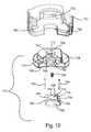
- FIG. 9Ais an isometric view of the depth gauge assembly of FIG. 5 , the depth gauge assembly including a depth gauge and a depth stop;
- FIG. 9Bis a side view of the depth gauge assembly of FIG. 9A ;
- FIG. 10is an exploded view of the depth gauge assembly of FIG. 9A ;
- FIG. 11Ais a medial side view of the drill guide of FIG. 5 ;
- FIG. 11Bis a lateral side view of the drill guide of FIG. 11A ;
- FIG. 11Cis another side view of the drill guide of FIG. 11A ;
- FIG. 11Dis a top view of the drill guide of FIG. 11A ;
- FIG. 11Eis a bottom view of the drill guide of FIG. 11A ;
- FIG. 12is a perspective view of the modular clamping apparatus, reamer, depth gauge assembly, and dual axis reaming guide of FIG. 5 with a patella clamped between the clamping apparatus and the dual axis reaming guide and the reamer lowered into one side of the dual axis reaming guide;
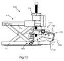
- FIG. 13is a perspective view of a resection assembly including a modular clamping apparatus, a force-limiting clamp assembly, an adjustable restraint arm assembly, and a resection cutting guide, a resected patella on an anterior clamp of the resection assembly;
- FIG. 14is a top view of the resection assembly of FIG. 13 , showing cross hairs and lines for orienting a patella in the clamping apparatus;
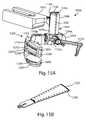
- FIG. 15Ais a perspective view of the force-limiting clamp assembly, adjustable restraint arm assembly, and resection cutting guide of FIG. 13 ;
- FIG. 15Bis a sawblade suitable for use with the resection cutting guide;
- FIG. 16is a partially exploded view of the force-limiting clamp assembly, adjustable restraint arm assembly, and resection cutting guide of FIG. 13 , with dashed lines indicating interior features of a portion of the force-limiting clamp assembly;
- FIG. 17is a partially exploded view of the force-limiting clamp assembly and adjustable restraint arm assembly of FIG. 13 ;
- FIG. 18is a medial side view of the resection assembly of FIG. 13 ;
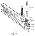
- FIG. 19is a partially exploded perspective view of the clamping apparatus of FIG. 13 with a another drill guide mounted on the apparatus, and a another drill;
- FIG. 20Ais a top view of the drill guide of FIG. 19 ;
- FIG. 20Bis a bottom perspective view of the drill guide of FIG. 19 ;
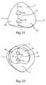
- FIG. 21is a posterior perspective view of a patella resected and drilled according to methods disclosed herein using instrumentation shown in FIGS. 13-20B ;
- FIG. 22is a posterior perspective view of a patella reamed and drilled according to methods disclosed herein using instrumentation shown in FIGS. 5-12 ;
- FIG. 23is a perspective view of the resection assembly of FIG. 13 with a recut spacing guide and a resected patella;
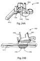
- FIG. 24Ais a perspective view of the recut spacing guide of FIG. 23 ; and FIG. 24B is a bottom perspective view of the recut spacing guide of FIG. 23 .
- the present disclosurerelates to patellar implants and instrumentation and methods for preparation and implantation of these devices.
- Those of skill in the artwill recognize that the following description is merely illustrative of the principles of the disclosure, which may be applied in various ways to provide many different alternative embodiments. This description is made for the purpose of illustrating the general principles of this invention and is not meant to limit the inventive concepts in the appended claims.
- the present disclosureis made in the context of total knee arthroplasty for the purposes of illustrating the concepts of the design, it is contemplated that the present design and/or variations thereof may be suited to applications outside the field of total knee arthroplasty.
- the present design and/or variations thereofmay be suited to applications in knee hemiarthroplasty, patellar resurfacing alone, ankle arthroplasty, or other surgical arts.
- the present disclosurerelates to prosthetic patellar implants intended to replace the articulating surface of the posterior portion of the patella during a total knee arthroplasty procedure.
- the prosthetic patellamay have an anatomic asymmetric footprint with a medialized apical surface.
- the anatomic geometry of the disclosed patella prosthesesmay cover a greater portion of the resurfaced patella in order to minimize the incidence of soft tissue ingrowth.
- the devices and techniques described withinillustrate several concepts for achieving a strong geometric interface between the patellar implant and the resurfaced bone, minimizing the amount of bone removal required and creating anatomic coverage of the posterior patellar surface with repeatable results.
- the described implantscontain multiple anterior features to better withstand shear loading forces at the implant-bone mating interface, which may improve the implant's resistance to loosening and migration.
- the disclosed embodimentsseek to improve the art and remedy the weaknesses not addressed by present devices.
- the disclosed method of patella preparation and implant designwill allow a person skilled in the art to: remove all arthritic pathology at the articulating surface, maximize the amount of patellar bone preserved, minimize the area of uncovered resurfaced patellar bone, and maximize the implant to bone surface retention strength.
- Another key feature of the method and implant designis its inability to be installed in an incorrect manner. Often times if the implant site is obscured by bone cement the surgeon may be unsure of the proper implant orientation. By using differently sized medial and lateral reamers, for one example, only one possible configuration for implant installation will exist. This ensures that the implant setting procedure is self-aligning, reducing the amount of clinical error, time and surgeon frustration.
- Superiormeans toward the head. Inferior means away from the head. Anterior means toward the front. Posterior means toward the back. Medial means toward the midline, or plane of bilateral symmetry, of the body. Lateral means away from the midline of the body. Proximal means toward the trunk of the body. Distal means away from the trunk.
- a sagittal planedivides a body into bilaterally symmetric right and left portions.
- a coronal planedivides a body into anterior and posterior portions.
- a transverse planedivides a body into superior and inferior portions.
- a system for preparing a boneincludes a first guide, the first guide including: a first collet, the first collet having a proximal end and a distal end, a first bore extending therethrough, the first bore centered about a first axis; a second collet, the second collet having a proximal end and a distal end and a second bore extending therethrough, the second bore radially centered about a second axis, wherein the first and second axes diverge from one another at an angle and the first and second bores partially overlap one another.
- Embodiments of this aspect of the disclosuremay include one or more of the following features:
- the first boredefines a first cylindrical envelope and the second bore defines a second cylindrical envelope, wherein the first and second cylindrical envelopes partially overlap one another.
- the radial diameters of the first and second boresare equal.
- the radial diameters of the first and second boresare unequal.
- the first and second colletsshare a common distal end.
- the proximal ends of the first and second colletsare separated from one another.
- the first boreis partially defined by a semicircular first wall extending between the proximal end and the distal end of the first collet
- the second boreis partially defined by a semicircular second wall extending between the proximal end and the distal end of the second collet.
- At least one of the first and second wallshas a window extending through the wall and in communication with the respective bore.
- a connecting bridgeis formed between the first and second collets.
- the first wallis shaped to receive and guide a bone preparation instrument through the first bore along the first axis
- the second wallis shaped to receive and guide a bone preparation instrument through the second bore along the second axis.
- a clamping apparatushaving a first clamp, a second clamp carried on the first guide, wherein the first guide is attached to the clamping apparatus, and the clamping apparatus is actuable to increase and decrease a distance between the first clamp and the second clamp.
- the angleis between about 20° and about 60°.
- the anglemay be between about 30° and about 50°.
- the anglemay be 40°.
- the systemincludes a second guide having a third bore, wherein the second guide is carried by the first guide, the second guide shaped to guide a bone preparation instrument through the third bore.
- the third boremay be radially centered about a third axis.
- the third axismay be non-parallel with the first axis and the second axis.
- the second guideis receivable in one of the first and second collets, the collet having a first engagement feature which cooperates with the second guide to secure the second guide within the collet in a selected orientation.
- the second guidemay have a second engagement feature, wherein the first and second engagement features include a track and a rail slidably receivable in the track along a straight path.
- a method for preparingincludes positioning a first guide adjacent the bone, the first guide including: a first collet, the first collet having a proximal end and a distal end, and a first bore extending therethrough, the first bore radially centered about a first axis; a second collet, the second collet having a proximal end and a distal end, and a second bore extending therethrough, the second bore radially centered about a second axis, wherein the first and second axes diverge from one another at an angle and the first and second bores partially overlap one another.
- Embodiments of this aspect of the disclosuremay include one or more of the following features and steps:
- the first and second colletsshare a common distal end.
- the proximal ends of the first and second colletsare separated from one another.
- the first boreis partially defined by a semicircular first wall extending between the proximal end and the distal end of the first collet
- the second boreis partially defined a by a semicircular second wall extending between the proximal end and the distal end of the second collet. Inserting a bone preparation instrument into the first bore, the first collet guiding the bone preparation instrument along the first axis toward the bone.
- a clamping apparatushaving a first clamp, wherein positioning the first guide adjacent the bone further includes clamping the bone between the first clamp and the first guide.
- the angleis between about 20° and about 60°.
- the anglemay be between about 30° and about 50°.
- the anglemay be 40°.
- Embodiments of the second aspectmay include one or more of the following features or steps: Attaching a second guide to the first guide, the second guide having a third bore radially centered about a third axis. The third axis may be non-parallel with the first axis and the second axis. Attaching the second guide to the first guide further includes inserting the second guide into engagement within one of the first and second collets. Inserting the second guide into engagement within one of the first and second collets further comprises sliding a first engagement feature on the collet along a straight path into engagement with a second engagement feature on the second guide to secure the second guide within the collet in a fixed orientation. Inserting a bone preparation instrument into the third bore, the second guide guiding the bone preparation instrument along the third axis toward the bone.
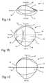
- FIGS. 1A-1Cviews of a stylized example of a right patella, or kneecap, are shown.
- FIG. 1Ais an inferior view of the patella
- FIG. 1Bis a posterior view
- FIG. 1Cis an anterior view.
- Patella 2has a dorsal or anterior side 4 , a posterior side 6 , an apex 8 , a base 10 , a medial border 12 and a lateral border 14 .
- the anterior surfaceconnects to the quadriceps femoris muscles, and the posterior surface articulates with the patellar surface of the condyles of the femur.
- a vertical ridge 16extends generally superior-inferiorally across the patella, dividing the posterior surface into a medial facet 18 and a lateral facet 20 .
- the patellamay be characterized as having a superior-inferior axis 22 , a medial-lateral axis 24 , and an anterior-posterior axis 26 .
- the vertical ridge 16is medialized, meaning is it offset toward the medial side from the superior-inferior 22 axis of the patella.
- Patellar implant 100which may be referred to as a bi-planar implant, includes an anterior side 102 having an anterior attachment surface 104 , which may be a bone-contacting surface. Generally opposite the anterior side 102 is a posterior side 106 having a posterior articulation surface 108 . In the embodiment shown, the posterior articulation surface includes a medial articulation surface 118 and a lateral articulation surface 120 .
- a dome 116which may spherical, includes a portion of both surfaces 118 , 120 and may be medialized, or offset toward the medial articulation surface 118 from the sagittal centerline of the implant.
- the posterior articulation surfacemay include other shapes which may be rounded, convex, faceted, complexly curved, domed, saddle-shaped, sombrero-shaped, stepped, radially symmetrical, bilaterally symmetrical, asymmetrical, irregular, or any other shape known in the art capable of articulating with natural or prosthetic femoral condyles.
- the implant 100further includes a medial end 122 , a lateral end 124 , a first end 126 , and a second end 128 .
- the embodiment shown in FIGS. 2A-2Fis bilaterally symmetrical, meaning in this instance that a division of the implant medially-laterally along the transverse plane will result in two mirror-image halves.
- implant 100may be implanted as a right or left patella by rotating the implant to the proper orientation.
- the implant 100is shown as a right patellar implant because first end 126 is shown on the superior side and second end 128 is shown on the inferior side. In a left implant, the first and second ends would be reversed, i.e.
- first end 126would be inferior and second end 128 would be superior.
- a perimeter 130circumscribes the outer edge of the implant 100 adjacent the anterior side 102 .
- the shape of the implant as seen from the anterior and posterior views shown in FIGS. 2C and 2Dis oval; an oval or ovoid implant provides better coverage of a resected patella than a circular implant and may reduce the incidence of patellar crepitus.
- a thickness or anterior-posterior height of implant 100may be measured between the anterior and posterior surfaces, and is typically measured normal to the tangent of dome 116 , as shown by dashed line 131 .
- the implant 100may be manufactured in a variety of sizes in which the medial-lateral, inferior-superior and/or anterior-posterior dimensions may vary. For example, the ratio of medial-lateral to inferior-superior dimension may range between about 1.17 and about 1.27.
- the anterior side 102is shaped for attachment to a resected posterior surface of a patella.
- the anterior attachment surface 104can be described as bi-planar, and includes a medial attachment surface 132 and a lateral attachment surface 134 .
- Attachment surfaces 132 , 134are substantially planar, defining first and second planes, respectively. In the embodiment shown, first and second planes are not co-planar, but other embodiments may include co-planar medial and lateral attachment surfaces.
- Medial attachment surface 132terminates laterally at a lateral bounding edge 133 .
- Lateral attachment surface 134terminates medially at a medial bounding edge 135 .
- the anterior attachment surface 104is peaked; the medial and lateral attachment surfaces are angled relative to one another and their bounding edges 133 , 135 converge at a common interior corner, or intersection 136 .
- Intersection 136which lies along a straight line intersecting with the perimeter 130 at the first and second ends 126 , 128 of the implant, extends generally superior-inferiorly on the opposite side of the implant from, and centered on, the dome 116 .
- the planar medial and lateral attachment surfaces 132 , 134form an angle a between them. Angle a may match the angle between the medial and lateral facets of a native patella. In some embodiments, angle a is between about 90° and about 180°. In some embodiments, angle a is between about 120° and about 150°. In some embodiments, angle a is about 130° plus or minus 10°. In some embodiments, angle a is 140°.
- the intersection or peak of the anterior attachment surfacemay be offset from the dome 116 , or highest point of the posterior articulation surface.
- the lateral attachment surface of patellar implants disclosed hereinmay be wider than the medial attachment surface; in the embodiment shown, lateral attachment surface 134 is 25% wider, measured medial-laterally, than the medial attachment surface 132 .
- the inferior-superior dimension of each of the medial and lateral attachment surfaces, measured mid-facetmay be approximately equal to one another; in other embodiments they may be unequal.
- Pegs 138project anteriorly from the anterior attachment surface 104 .
- Pegs 138may be cylindrical and include one or more grooves 140 which help to retain the implant when used with bone cement for attachment to the patella. The cement will flow into the groove, creating a cement mantle to permanently lock in place the implant.
- Other shapes for pegs 138 and for other embodiments disclosed hereinare contemplated, including square, hexagonal, pentagonal, toothed, or irregular.
- the number and distribution of pegs 138may vary.
- the peg 138 locationsare consistent throughout a range of implant sizes upsizing and downsizing options from smallest to largest size.
- the pegs 138 shown on implant 100are medialized, where they may be implanted into the thickest, healthiest remaining bone along the ridge 16 of the patella. This may provide a more secure attachment than pegs placed where they would be implanted more toward the medial and/or lateral borders of the patella, into thinner bone.
- the inclusion of more than one pegprovides additional lateral and rotational stability compared to a single peg design.
- the anterior attachment surface 104further includes a medial recess 142 and lateral recess 144 , which are formed as curved indentations undercut into the anterior side 102 .
- the curved shapes of the recessesmay match the outer curvature of the implant.
- the recesses 142 , 144may include grooves 146 which may provide increased surface area to improve cement fixation of the implant to the patella.
- the recesses 142 , 144are placed near the outer perimeter 130 of the implant and farther away from the center of the implant, to provide increased resistance to loading.
- Other embodiments of the patellar implantmay vary in the number, shape and/or distribution of any recesses, or may include no recesses.
- Patellar implant 100further includes a superior or first pocket 150 and an inferior or second pocket 152 .
- Each pocketis formed along a portion of the intersection of the perimeter 130 and the anterior attachment surface 104 , and forms a recess into the anterior attachment surface.
- Each pocketmay straddle, or cross, the intersection 136 .
- the inclusion of pockets 150 , 152may allow retention of more patellar bone at the area of the medial ridge than if the recessed pockets were not present. Additionally, the pockets allow the implant to be fit without additional surface clean-up steps such as rongeuring the residual native bone volume away.
- FIGS. 3A through 3Cshow a patellar implant 101 implanted on to a prepared patella 2 .
- Implant 101may have many of the same features as implant 100 , only differing in relative size, and shape of the posterior articulation surface.
- the posterior side 6 of patella 2has been reamed or resected to include prepared medial facet 28 and prepared lateral facet 30 , divided by a prepared medial ridge 32 .
- the medial attachment surface 132is immediately adjacent, parallel to, and flatly abutting the prepared medial facet 28
- the lateral attachment surface 134is immediately adjacent, parallel to, and flatly abutting the prepared lateral facet 30 .
- Peg 138is received in a peg hole 34 .
- Recesses 142 , 144are adjacent to and in communication with the prepared medial and lateral facets 28 and 30 , respectively. Although not visible, a cement mantle may attach the implant to the prepared surfaces, and occupy the recesses 142 , 144 and any space between the peg 138 and surfaces of the peg hole 34 . Pocket 152 bridges over ridge 32 , allowing retention of additional patellar bone.
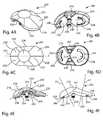
- Patellar implant 200includes an anterior side 202 having an anterior attachment surface 204 , which may be a bone-contacting surface. Generally opposite the anterior side 202 is a posterior side 206 having a posterior articulation surface 208 .
- the posterior articulation surface 208includes a medial articulation surface 218 and a lateral articulation surface 220 .
- a dome 216which may be spherical, includes a portion of both surfaces 218 , 220 and may be medialized, or offset toward the medial articulation surface 218 from the sagittal centerline of the implant.
- the implant 200further includes a medial end 222 , a lateral end 224 , a first end 226 , and a second end 228 .
- the embodiment shown in FIGS. 4A-4Fis bilaterally symmetrical, meaning in this instance that a division of the implant medially-laterally along the transverse plane will result in two minor-image halves.
- implant 200may be implanted as a right or left patella by rotating the implant to the proper orientation.
- FIGS. 4A and 4Cthe implant 200 is shown as a right patellar implant because first end 226 is shown on the superior side and second end 228 is shown on the inferior side. In a left implant, the first and second ends would be reversed, i.e.
- first end 226would be inferior and second end 228 would be superior.
- a perimeter 230circumscribes the outer edge of the implant 200 adjacent the anterior side 202 .
- the shape of the implant as seen from the anterior and posterior views shown in FIGS. 4C and 4Dmay be described as ovoid.
- a thickness or height of implant 200may be measured between the anterior and posterior surfaces, and is typically measured normal to the tangent of dome 216 , as shown by dashed line 231 .
- the implant 200may be manufactured in a variety of sizes in which the medial-lateral, inferior-superior and/or anterior-posterior dimensions may vary.
- Pegs 238project anteriorly from the anterior attachment surface 204 .
- Pegs 238may be cylindrical and include one or more grooves 240 which help to retain the implant when used with bone cement for attachment to the patella.
- the number and distribution of pegs 238may vary.
- the pegs 238 shown on implant 200may be medialized, so they can be implanted into the thickest, healthiest remaining bone along the ridge 16 of the patella.
- the anterior side 202is shaped for attachment to a resected posterior surface of a patella.
- the anterior attachment surface 204includes a medial attachment surface 232 and a lateral attachment surface 234 .
- Medial attachment surface 232terminates laterally at a lateral bounding edge 233 .
- Lateral attachment surface 234terminates medially at a medial bounding edge 235 .
- the anterior attachment surface 204is peaked; the medial and lateral attachment surfaces are angled relative to one another and their bounding edges 233 , 235 converge at a common interior corner, or intersection 236 .
- Intersection 236lies along a straight line generally superior-inferiorly on the opposite side of the implant from, and centered relative to dome 216 .
- each of the medial and lateral attachment surfaces 232 , 234measured mid-facet, are unequal, as the lateral attachment surface 234 is taller than the medial attachment surface 232 .
- the medial and lateral attachment surfacesmay be equal in surface area.
- the medial and lateral portions of the implant 200are angled relative to one another.
- Dashed line 258 in FIG. 4Erepresent a plane along which the medial portion is aligned
- dashed line 259represents a plane along which the lateral portion is aligned.
- the planes 258 , 259are angled relative to one another at an angle a, which can have the same values as disclosed for angle a of patellar implant 100 .
- the anterior attachment surface 204includes a medial convexity 254 protruding from the medial attachment surface and a lateral convexity 256 protruding from the lateral attachment surface, seen in profile in FIGS. 4E and 4F .
- Each convexitymay be formed radially about an axis 255 , 257 normal to its respective attachment surface and normal to the respective medial and lateral planes 258 , 259 .
- the medial and lateral convexities 254 , 256may be contoured to complementarily match concavities reamed into the prepared patellar surfaces, and may provide additional resistance to shearing forces.
- the shape of each individual convexity 254 or 256may be radially symmetrical, for example a dome shape, or in other embodiments may be asymmetrical.
- the thickness or height of each convexitymay vary according to implant size or patient determined factors.
- the anterior attachment surface 204further includes a medial recess 242 and lateral recess 244 , which are formed as curved indentations undercut into the anterior side 202 , and may be formed on the medial and lateral convexities 254 , 256 .
- the curved shapes of the recessesmay match the outer curvature of the implant.
- the recesses 242 , 244may include grooves 246 which may provide increased surface area to improve cement fixation of the implant to the patella.
- Patellar implant 200further includes a superior or first pocket 250 and an inferior or second pocket 252 .
- Each pocketis formed along a portion of the intersection of the perimeter 230 and the anterior attachment surface 204 , and forms a recess into the anterior attachment surface.
- Each pocketmay cross the intersection 236 or an axis coaxial with the intersection 236 .
- the inclusion of pockets 250 , 252may allow retention of more patellar bone at the area of the medial ridge than if the recessed pockets were not present.
- the patellar implants disclosed hereincan be formed of a single solid construction, for example formed from a block of UHMWPE (ultra-high molecular weight polyethylene). Alternately, an implant may be of a composite porous metal and UHMWPE construction. It is appreciated that other embodiments of the implants disclosed herein include the use of alternative materials including but not limited to, PEEK, titanium and titanium alloys, Nitinol, cobalt chrome, stainless steel, ceramics, polyethylene, cross-linked polyethylene, UHMWPE, and biocompatible materials, among others. They may also encompass a variety of surface treatments to encourage bony attachment such as porous coatings, hydroxyapatite, and TCP, among others. Any implant disclosed herein may include a radiographic marker for imaging purposes.
- FIGS. 5 through 12show instruments and steps for preparation of a patella for implantation of a patellar implant. It is appreciated that the instruments and methods disclosed herein may be used with the patellar implants of this disclosure including implants 100 or 200 , or may used with other patellar implants.
- FIGS. 5 through 12show a reaming assembly and associated instrumentation which may be used to ream a patella for implantation of a patellar implant with convex attachment surfaces, for example patellar implant 200 . However, it is appreciated that the methods disclosed with reference to FIGS. 5 through 12 could be modified for implantation of a patellar implant with planar attachment surfaces.
- FIGS. 5 through 12show instruments and steps for preparation of a patella for implantation of a patellar implant. It is appreciated that the instruments and methods disclosed herein may be used with the patellar implants of this disclosure including implants 100 or 200 , or may used with other patellar implants.
- FIGS. 5 through 12show a reaming assembly and associated instrumentation which
- FIGS. 13 through 20Bshow a resection assembly and associated instrumentation which may be used to ream a patella for implantation of a patellar implant with bi-planar attachment surfaces, for example patellar implant 100 .
- the methods disclosed with reference to FIGS. 13 through 20Bcould be modified for implantation of a patellar implant with convex or concave attachment surfaces.
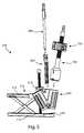
- a perspective viewshows a reaming assembly 500 .
- Reaming assembly 500includes a modular clamping apparatus 510 , on which a dual axis reaming guide 600 is mounted.
- a reamer 700 with adjustable depth gauge assembly 750is shown, and a drill 800 with drill guide 850 .
- Reamer 700 and drill 800are examples of bone preparation instruments that may be used with reaming assembly 500 ; it is appreciated that other bone preparations instruments could also be used with the assembly, including rongeurs, punches, mills, rasps, and shavers, among others.
- the modular clamping apparatusincludes a first clamp arm 512 connected to a second clamp arm 514 by a cross-connection.
- Actuation of an actuator 16can move first and second clamp arms 512 , 514 toward or away from one another to clamp or release an object placed between the clamp arms.
- Clamping arm 512further comprises a first clamp 520 which may be an anterior clamp.
- Anterior clamp 520may have a concave surface for receiving a convex anterior surface of a patella.
- One or more posts or pegs 522may be present on the anterior clamp 520 which may assist in restraining the patella.
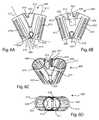
- Reaming guide 600includes a first or proximal end 602 , and a second or distal end 604 which may function as a second, or posterior reaming clamp 606 when the guide 600 is operatively attached to the modular clamping apparatus.
- Posterior reaming clamp 606may include teeth, spikes, serrations or other features to assist in gripping a patella.
- Reaming guide 600further includes a first or medial collet 610 having a first bore 608 centered around a longitudinal first collet axis 611 , and a second or lateral collet 612 having a second bore 609 centered around a longitudinal second collet axis 613 .
- First collet axis 611diverges from second collet axis 613 by an angle b.
- angle bis 40°.
- angle bis between about 30° and about 50°.
- angle bis between about 20° and about 60°.
- Each collet bore 608 , 609defines a cylindrical envelope from the first end 602 to the second end 604 .
- First collet 608partially defined by a semicircular first wall 603 extending between the proximal end and the distal end of the first collet 610
- the second bore 609is partially defined by a semicircular second wall 605 extending between the proximal end and the distal end of the second collet 612 .
- the posterior reaming clamp 606is arched as it transitions between the distal ends of the first and second collets 610 , 612 .
- the arch shape of the posterior reaming clamp 606may closely match the contour of the posterior surface of a patella.
- the posterior reaming clampmay comprise a medial segment 618 , a lateral segment 620 , and an arch segment 619 intermediate the medial and lateral segments 618 , 620 .
- the medial and lateral segments 618 , 620may be perpendicular to their respective collet axes 611 , 613 , and are angled relative to each another at angle c.
- Angle cmay be the same as angle a of the patellar implants 100 , 200 .
- angle cis 140°.
- angle cis between about 90° and about 180°.
- angle cis between about 120° and about 150°.
- angle cis about 130° plus or minus 10°.
- a bridge 614which may be triangular, spans the distance between the medial and lateral collets 610 , 612 toward the proximal end 602 .
- a V-shaped medial ridge guide 616is formed in the bridge 614 .
- a cylindrical envelope defined by each collet boremay be in communication with one another and partially overlap one another, as shown by dashed line circles 611 and 613 , which represent the distal ends of the medial and lateral cylindrical envelopes, respectively.
- At least one window 622is formed in guide 600 to allow viewing of reaming instruments and steps.
- An attachment fittingwhich may be shaped as a slot 624 may be present on the guide 600 for releasable attachment to the modular clamping apparatus 510 .
- a drill guide slot 630extends along a portion of the lateral collet 612 .
- the drill guide slot 630includes at least one drill guide track 632 .
- the drill guide slot 630 and tracks 632are shaped to co-axially accept drill guide 850 .
- a reamer 700may be guided through medial and lateral collets 610 , 612 to ream a posterior patellar surface in preparation for implantation of an implant.
- Reamer 700includes an attachment section 702 for attachment to a powered drive, a reamer shaft 704 , and a reamer head 706 .
- Reamer shaft 704includes a series of flanges 708 distributed along at least a portion of the shaft.
- the flanges 708may take the forms of ridges formed on, or grooves or indentations incised into or through, the surface of the shaft.
- the reamer head 706includes a distal cutting surface 710 with at least one cutting edge 712 formed thereon.
- One or more cutting windows 714may be included on the head.
- the distal cutting surfacemay be planar to form a planar reamed surface on a reamed bone, convex to form a concave reamed surface, or concave to form a convex reamed surface.
- the diameter of the reamer head 706may be the same as the diameters of the bores 608 , 609 .
- FIGS. 9A , 9 B and 10show depth gauge assembly 750 which may be snapped onto reamer 700 to control the reaming depth as the reamer 700 is used in reaming assembly 500 .
- Depth gauge assembly 750may be made of plastic, and may include an outer housing 752 which may also be called a depth gauge, an inner housing 754 , and a slider 756 .
- Outer housing 752is generally U-shaped, and includes an outer housing recess 760 shaped to receive the inner housing 754 .
- Outer housing 752may also include a bottom surface 753 , gripping features and indicia.
- Inner housing 754may be shaped as a truncated disc, and is sized and shaped to fit within the outer housing recess 760 .
- An inner housing bore 762extends between top 764 and bottom 766 surfaces of the inner housing 754 .
- An inner housing recess 768is formed in the interior of the inner housing 754 and is shaped to receive the slider 756 .
- a plurality of pin holes 770extend through the inner housing 754 , and a blind spring hole 772 is indented in the inner housing 754 , in communication with the inner housing recess 768 .
- the slider 756includes a slider bore 776 extending between the top and bottom of the slider 756 , the slider bore 776 circumscribed by a bore wall 778 . At least one protruding step 780 is formed along a portion of the bore wall 778 . The steps 780 are shaped to mesh with flanges 708 on the reamer shaft 704 . A pair of elongated slots 782 extend between the top and bottom of the slider 756 , to receive connecting pins 784 . An actuation surface, which may be a button 786 , is formed on one exterior surface of the slider 756 , and a back wall 788 is opposite the actuation surface.
- a spring 790is received in the blind spring hole 772 of the inner housing 753 .
- Slider 756is received in inner housing recess 768 , trapping the spring 790 in the blind spring hole 772 and against the slider back wall 788 .
- Pins 784extend through pin holes 770 and elongated slots 782 . The elongated shapes of the slots 782 allow slider 756 to travel a limited distance within inner housing recess 768 when assembled with the pins.
- the inner housing 754 and slider 756are received in the outer housing recess 760 .
- slider bore 776When the button 786 is depressed, slider bore 776 may become coaxially aligned with inner housing bore 762 , and the assembly 750 may be slid on to the reamer shaft 704 , with reamer shaft 704 passing through bores 776 , 762 .
- steps 780may engage with flanges 708 on reamer shaft 704 to lock the depth gauge assembly 750 at a desired position on the reamer shaft.
- the slider 756 and inner housing 754may be assembled together with pins 784 and spring 790 as previously described, and slid on the reamer shaft 704 .
- outer housing 752may be slid or snapped on to the inner housing 754 .
- a tab 792 on the outer housing 752may form a snap fit with a portion of the inner housing 754 .
- drill 800may be used with drill guide 850 to drill implant peg holes into a prepared patella at a desired location and depth.
- Drill 800includes an attachment section 802 for attachment to a powered drive, a drill shaft 804 , and a bit 806 .
- a drill depth stop 808which may be shaped as a collar, is formed on a portion of the drill shaft 804 .
- the drill guide 850is generally elongated and tubular, extending between a first drill guide end 852 which may be proximal, a second drill guide end 854 which may be distal, a medial drill guide side 856 , a lateral drill guide side 858 , and first and second intermediate drill guide sides 860 , 862 interposed between the medial and lateral drill guide sides 856 , 858 .
- First and second drill guide rails 864 , 866are formed on the first and second drill intermediate drill guide sides 860 , 862 , respectively.
- a third drill guide rail 868is formed on the lateral drill guide side 858 .
- the drill guide railsare shaped to be slidingly received in the drill guide tracks 632 and slot 630 in the reaming guide 600 .
- the inclusion of the third rail 868 and slot 630may ensure proper positioning of the drill guide relative to the collet as the drill guide can preferably only fit in one selected orientation.
- the locations of the drill guide tracks and railsmay be reversed, for example, rails may be formed on the reaming guide collet and tracks may be formed on the drill guide.
- the tracks and railsmay include dovetails or other complementary features to ensure a close guiding fit between the drill guide and the collet.
- an alignment surface 870which may be asymmetrically shaped to align the drill guide on the patellar surface.
- the alignment surface 870may include a medial surface portion 872 and a lateral surface portion 874 which diverge from one another to form an alignment notch 875 .
- a lip or shoulder 876serves as a stop to control depth of insertion of the drill guide 850 into the reaming guide 600 .
- a first drill guide bore 880 and a second drill guide bore 882extend between the first and second drill guide ends 852 , 854 .
- the first and second drill guide bores 880 , 882may be slightly laterally offset relative to the alignment surface 870 , as seen in FIG. 11E . This slight lateral offset may allow openings for implant pegs to be drilled into the thickest available portion of the patella. In other embodiments, only one, or multiple drill guide bores may be present.
- Patella 2may be clamped between anterior clamp 520 and posterior clamp 606 , with arch segment 619 spanning the medial ridge 16 of the patella and medial ridge guide 616 aligned with the medial ridge 16 .
- Reamer 700in a non-powered or non-reaming state, with attached depth gauge assembly 750 is advanced into medial collet 610 until the reamer head 706 contacts the patella. As the reamer is inserted, the position of depth gauge assembly 750 is adjusted. The depth gauge assembly is moved until the bottom surface 753 of the assembly 750 rests on the proximal end 602 of the medial collet 610 .
- the depth gauge 752is removed.
- the gap formed between the bottom 766 of the remaining depth stop 757 and the proximal end 602is the proper reaming depth.
- the reamer 700is powered to ream the patella medial facet through the medial collet 610 until the bottom 766 of the depth stop 757 contacts the proximal end 602 of the collet.
- the reamer 700may be withdrawn from the medial collet 610 .
- the depth gauge 752is snapped back onto the depth gauge assembly 750 , and the reaming procedure is repeated through the lateral collet 612 , reaming the lateral facet of the patella 2 . Referring to FIG.
- the reaming of the medial and lateral facets of the patella 2may create a prepared medial ridge 32 between medial and lateral reamed facet surfaces 36 , 38 .
- Differently sized reamer heads 706may be used to produce differently sized medial and lateral reamed facet surfaces.
- the angle between the two reamed facet surfaces 36 , 38may match angle a of patellar implant 100 or 200 and matches angle c of reaming guide 600 . If a flat reamer is used, the reamed facet surfaces 36 , 38 are planar. If a convex reamer is used, the reamed facet surfaces 36 , 38 include concavities.
- both reamed facet surfaces 36 , 38can be reamed without requiring re-clamping of the patella, and that the surfaces can be reamed in either order. It is also appreciated that the depth stop assembly 750 can be independent of the clamping apparatus 510 , and that the depth stop assembly 750 provides proper reaming depth determination across at least two divergent planes and along at least two divergent reaming trajectories.
- the drill guide 850may be inserted into the lateral collet 612 of the reaming guide 600 without re-clamping or adjusting the position of the patella.
- First and second 864 , 866 railsare axially received in tracks 632
- third rail 868is received in slot 630 .
- the drill guide 850may be slid into engagement within the collet 612 until alignment notch 875 rests on the prepared medial ridge 32 of the patella 2 . Once the drill guide 850 touches the bone, it serves to indicate the location of the top of the patella, and thus controls the depth of the drill when it is inserted into the drill guide.
- Drill 700is powered and advanced through each of the drill bores 880 , 882 , to drill holes for implant pegs or posts.
- the depth of each holemay be limited by contact of drill depth stop 808 with drill guide first end 852 .
- the reaming guide 600may be removed from the clamping apparatus 510 and a patellar implant fastened to the prepared patella, with implant pegs received in the holes.
- Cementmay be used to attach the implant to the patella, and the cement may flow into recesses formed on the attachment surfaces of the implant, and/or into grooves on the implant recesses or pegs.
- the reamed facet surfaces 36 , 38may be planar and may complementarily match the attachment surfaces 132 , 134 of implant 100 .
- the reamed facet surfaces 36 , 38include concavities and may complementarily match the attachment surfaces 232 , 234 of implant 200 .
- a resection assemblywhich may be used to create one or more resected surfaces on a patella posterior surface is shown.
- the resectionmay be preparation for implantation of an implant such as 100 , 101 , or 200 , for example.
- Resection assembly 1000includes a force-limiting clamp assembly 1050 , an adjustable restraint arm assembly 1150 , and a resection cutting guide 1200 .
- Resection assembly 1000may be used to securely clamp and/or restrain a patella while planar patellar resections are made along a medial resection trajectory 1002 and a lateral resection trajectory 1004 .
- Resection assembly 1000may be referred to as a bi-planar, or a bi-planar/flat resection assembly.
- clamp assembly 1050may be removably mounted on clamping apparatus 510 .
- Clamping assembly 1050includes an attachment portion 1052 for connection to the clamping apparatus 510 , a clamp body 1054 and a force-limiting mechanism 1056 .
- Clamp body 1054includes a clamping surface 1060 which may be a posterior clamping surface, which may have a notch 1062 .
- One or more teeth 1064may protrude from the clamping surface 1060 .
- the clamping surface 1060may be concavely curved as shown, or on other embodiments may be flat or convex.
- the force-limiting mechanism 1056includes a first housing 1070 which may be a distal housing.
- the first housing 1070includes a base portion 1072 through which a base passage 1074 extends, opening out on opposite sides of the base portion.
- a pin 1076may be captured in the base passage 1074 and may travel the length of the base passage 1074 .
- a boss portion 1078protrudes proximally from the base portion 1072 and may be of a smaller diameter than the base portion.
- a spring 1082encircles the boss portion and rests on a proximal end 1080 of the base portion 1072 .
- the force-limiting mechanism 1056further includes a second housing 1086 which may be a proximal housing.
- Second housing 1086may be generally cylindrical and tubular, with an interior bore 1088 defined by a housing wall 1090 .
- a pair of transverse pin holes 1092perforate the housing wall 1090 opposite one another, and are sized and shaped to receive pin 1076 .
- the interior bore 1088includes a proximal bore section 1094 and a distal bore section 1096 ; the diameter of the proximal bore section 1094 is sized to receive the boss portion 1078 , and is less than the inner diameter of the spring 1082 .
- the diameter of the distal bore section 1096is sized to receive the base portion 1072 when the force-limiting mechanism 1056 is operatively assembled.
- indiciamay include cross hairs 1100 , including a medial ridge line 1102 and an inferior/superior center line 1104 .
- a continuation of the medial ridge line 1102 a and of the inferior/superior center line 1104 amay be found.
- the cross hairs 1100 and continuation lines 1102 a , 1104 amay be used by a practitioner to properly position a patella in the resection assembly in order to control the final location of the peak of the spherical dome on the posterior articulation surface of the implant, for example 116 or 216 .
- Clamp body 1054includes a dock 1152 which may project laterally from the clamp body and carries a restraint arm.
- a plug bore 1154extends through at least a portion of dock 1152 .
- an arm opening 1156extends through opposite sides of the dock.
- a plug 1158is sized to be received in the plug bore 1154 .
- Plug 1158includes an arm slot 1160 extending through the plug. In communication with the arm slot 1160 and formed into the plug 1158 is at least one flange 1162 which protrudes into the arm slot 1160 .
- a restraint arm 1164includes a proximal arm end cap 1166 , an arm shaft 1168 , and a distal restraint end 1170 .
- the restraint end 1170curves generally perpendicularly away from the shaft 1168 and may include a divot 1172 or other feature for receiving a patella.
- a plurality of ratchet teeth 1174can be incised along a portion of the restraint arm 1164 .
- a plug spring 1178is received in plug bore 1154 .
- Plug 1158is received in plug bore 1154 , capturing the spring 1178 in the plug bore 1154 .
- Restraint arm 1164is extended through arm openings 1156 and arm slot 1160 ; cap 1166 may be removable for assembly purposes.
- Ratchet teeth 1174mesh with flanges 1162 and the spring bias of spring 1178 holds and locks the arm 1164 at a selected position relative to dock 1152 .
- the position of arm 1164can be adjusted by pressing plug 1158 toward dock 1152 to overcome the spring bias and unlock or release teeth 1174 from flanges 1162 .
- the armmay be translated through arm openings 1156 and arm slot 1160 to another position, and plug 1158 released to lock the arm in the newly selected position.
- the restraint arm 1164may also be rotatable, in addition to translatable, relative to the clamp body 1054 .
- the dock 1152 carrying the arm 1164may be selectively rotatable relative to the claim body.
- the restraint arm 1164may be selectively rotatable relative to the dock.
- the resection cutting guide 1200includes cutting guide body 1202 which may be formed integrally with clamping body 1054 or may be selectively detachable.
- the cutting guide 1200includes at least one resection guide feature, which may be a slot for guiding a blade or saw 1250 in resecting a patellar surface.
- a cutting guide body 1202includes a lateral facet resection slot 1204 , a medial facet resection slot 1206 , and a flat resection slot 1208 which may be intermediate the lateral and medial facet resection slots.
- Each resection slotmay be defined by an upper and lower plate on either side of the slot, the plates providing planar surfaces parallel to the slot to rigidly guide a blade such as saw 1250 .
- Lateral facet resection slot 1204is defined by upper lateral slot plate 1210 and lower lateral slot plate 1212 .
- Flat resection slot 1208is defined by upper flat slot plate 1214 and lower flat slot plate 1216 .
- Medial facet resection slot 1206is defined by upper medial slot plate 1218 and lower medial slot plate 1220 .
- the platesmay be joined together at the cutting guide body 1202 . The heights and widths of the slots may vary to accept differently sized blades.
- Drill guide 1300includes an attachment portion 1302 and a drill guide body 1304 .
- Drill guide body 1304includes a foot portion 1306 and a drill guide portion 1308 .
- Foot portion 1306includes a medial foot 1310 and a lateral foot 1312 , and a groove 1314 intermediate and separating the medial and lateral feet 1310 , 1312 .
- the medial 1310 and lateral 1312 feetprovide a bi-planar clamping surface which can self-align with resected bi-planar surfaces on a prepared patella.
- a plurality of gripping featuressuch as teeth or ridges 1316 may be formed on the feet 1310 , 1312 .
- First and second drill bores 1320 , 1322extend through the drill guide portion 1308 and open out at the foot portion 1306 .
- the first and second drill bores 1320 , 1322may be laterally offset relative to the groove 1314 .
- a set of crosshairs 1324 including a medial ridge line 1326 , an inferior/superior center line 1328 , and respective continuation lines like those set forth above with regard to the clamp body 1054may be present on the drill guide.
- Drill 1350includes an attachment section 1352 for attachment to a powered drive, a drill shaft 1354 , and a bit 1356 .
- a drill depth stop 1358which may be shaped as a collar, is formed on a portion of the drill.
- Patella 2may be positioned on anterior clamp 520 and positionally adjusted for proper anatomic alignment.
- the practitionerviews the assembly and patella from a top down perspective, as seen in FIG. 14 .
- the cross hairs 1100 , lines 1102 , 1104 and continuation lines 1102 a , 1104 aare viewed in relation to the patella, and the patella 2 may be positioned so the natural patellar medial ridge is lined up with the medial ridge lines 1102 , 1102 a .
- the patellamay be positioned so that a desired location for a prepared medial ridge is lined up with the medial ridge lines 1102 , 1102 a . Selection of a desired location may be based on the relative health of the available bone material.
- clamp assembly 1050When the patella is selectively positioned on the anterior clamp 520 , clamp assembly 1050 is lowered toward the exposed posterior surface of the patella to clamp the patella between the anterior clamp 520 and the posterior clamping surface 1060 . Teeth 1064 may assist in gripping the patella. As clamping occurs, compressive force is applied to the clamp assembly 1050 and the patella, but the force applied to the patella is limited by the spring 1082 of the force-limiting mechanism 1056 . As force is applied to the modular clamping apparatus, the spring 1082 begins to deflect and compressive force is applied to the patella. As a result, the amount of compressive force applied to the patella is directly related to the amount of spring deflection and not the amount of load applied to the modular clamping apparatus. This may reduce the occurrence of over clamping the patella which can lead to saw binding during the resection procedure.
- the restraint arm assembly 1150may be actuated to provide lateral restraint to the clamped patella.
- the restraint arm 1164may be ratcheted as set forth previously to translate the arm 1164 until distal restraint end 1170 is brought into contact with the patella, which may be at the lateral edge of the patella.
- the restraint armmay provide a rigid supporting arm that creates the reaction forces necessary to provide a stable clamping mechanism. With the clamps 520 , 1060 and restraint arm 1164 in place, the patella is firmly clamped anteriorly, posteriorly, and laterally.
- a sawblade 1250as seen in FIG.
- Peg or post holes suitable for receiving, for example, pegs 138 or 238may be drilled into the resected patella using drill guide 1300 .
- Drill guide 1300may be attached to clamping apparatus 510 , and adjusted until foot portion 1306 is in contact with the resected patella, with medial foot 1310 contacting prepared medial facet 28 and lateral foot 1312 contacting prepared lateral facet 30 .
- the prepared medial ridge 32is aligned with and partially received in groove 1314 .
- Crosshairs 1324 and lines 1326 , 1328may be viewed to assist in properly aligning the foot portion 1306 with the patella.
- the patella 2is clamped between anterior clamp 520 and foot portion 1306 , which functions as a posterior clamp.
- Drill 1350is guided through drill bores 1320 , 1322 to drill one or more holes in the patella.
- FIG. 21shows a resected patella 2 which may be produced by the methods set forth with reference to FIGS. 13-20B .
- the posterior surfacehas been prepared to form a prepared patellar surface 27 which includes the prepared medial facet 28 , the prepared lateral facet 30 , divided by the prepared medial ridge 32 .
- Two peg holes 34are recessed into the prepared surface 27 , and are slightly offset toward the prepared lateral facet 30 , relative to the medial ridge 32 .
- the resectionsextend to the outer borders of the patella.
- a patellar implantsuch as implant 100 described above, or an onlay implant may be attached to the prepared patella as described previously.
- FIG. 22shows a reamed patella 2 which may be prepared by the methods set forth with reference to FIGS. 5-12 .
- the posterior surfacehas been prepared to form a prepared patellar surface 35 which includes a reamed medial facet 36 and a reamed lateral facet 38 , divided by the prepared medial ridge 32 .
- the reamed areasare inset or recessed into the posterior side 6 .
- Two peg holes 34are recessed into the prepared surface 35 , and are slightly offset toward the reamed lateral facet 38 , relative to the medial ridge 32 .
- the reamed areasmay extend to the outer borders of the patella, or may be spaced apart from the medial and/or lateral borders.
- a patellar implantsuch as implant 200 described above, or an inlay implant may be attached to the prepared patella as described previously.
- a patellar trialPrior to implantation or attachment of a patellar implant, a patellar trial may be positioned on the patella.
- the height, or thickness of the prepared patella and trialmay be measured and compared with a desired height. If the measured height is substantially equal to the desired height, the implant may be attached with cement or other materials. In one embodiment, the measured height is considered substantially equal to the desired height if the two measurements are within 1+/ ⁇ 1 millimeter, or 2 millimeters or less.
- cementmay be used to attach the implant to the patella, and the cement may flow into recesses formed on the attachment surfaces of the implant, and/or into grooves on the implant recesses or pegs.
- the cementmay form a mantle between the prepared patellar surface and the anterior attachment surface of the implant.
- FIGS. 23-24Bshow a recut spacing guide that may be used with resection assembly 1000 if measurement of a resected patella shows that the resected patella is taller than desired.
- Recut spacing guide 1400may be snapped via tabs 1402 , 1404 or otherwise coupled onto clamp body 1054 .
- the spacing guide 1400includes a medial foot 1406 and a lateral foot 1408 .
- the feet 1406 , 1408may include ridges 1410 , teeth or other engagement features to ensure a secure contact with the resected patella. Space is provided between the medial and lateral feet to allow for the medial ridge of the patella.
- the trajectory of a cutting slot 1412is parallel with the lateral foot 1408 .
- the recut spacing guidemay be sized to provide additional resection cuts of, for example, 1 mm, 2 mm, or any other desired height.
- the recut spacing guideis snapped on to clamp body 1054 and lowered via clamping apparatus 510 until the medial and lateral feet 1406 , 1408 rest on the resected medial and lateral facets 28 , 30 , respectively.
- the resected facets 28 , 30are further resected by inserting sawblade 1250 or other cutting edge through the medial facet resection slot 1206 and resecting the medial facet 28 , and by inserting the cutting edge through the lateral facet resection slot 1204 and the cutting slot 1412 and resecting the lateral facet 30 .
- the additional resectionscan be made in either order. Following resection, the patella can again be measured. If the desired height has been attained, a patellar implant may be attached. If additional resection is needed, the steps above may be repeated until the desired height is attained.
- Coupledis defined as connected, although not necessarily directly, and not necessarily mechanically.
- a step of a method or an element of a devicethat “comprises,” “has,” “includes” or “contains” one or more features, possesses those one or more features, but is not limited to possessing only those one or more features.
- a device or structure that is configured in a certain wayis configured in at least that way, but may also be configured in ways that are not listed.
- any patellar implant disclosed hereinmay be implanted onto a patellar prepared with any of the patellar preparation instrumentation or methods disclosed herein.
- Features of instrumentation from one examplemay be applied to instrumentation from another example.
- the described embodimentsare to be considered in all respects only as illustrative and not restrictive. The scope of the invention is, therefore, indicated by the appended claims rather than by the foregoing description. All changes which come within the meaning and range of equivalency of the claims are to be embraced within their scope.
Landscapes
- Health & Medical Sciences (AREA)
- Life Sciences & Earth Sciences (AREA)
- Surgery (AREA)
- Orthopedic Medicine & Surgery (AREA)
- General Health & Medical Sciences (AREA)
- Oral & Maxillofacial Surgery (AREA)
- Veterinary Medicine (AREA)
- Engineering & Computer Science (AREA)
- Biomedical Technology (AREA)
- Heart & Thoracic Surgery (AREA)
- Public Health (AREA)
- Animal Behavior & Ethology (AREA)
- Dentistry (AREA)
- Nuclear Medicine, Radiotherapy & Molecular Imaging (AREA)
- Medical Informatics (AREA)
- Molecular Biology (AREA)
- Transplantation (AREA)
- Physical Education & Sports Medicine (AREA)
- Vascular Medicine (AREA)
- Cardiology (AREA)
- Prostheses (AREA)
- Surgical Instruments (AREA)
Abstract
Description
Claims (24)
Priority Applications (2)
| Application Number | Priority Date | Filing Date | Title |
|---|---|---|---|
| US13/367,278US8945135B2 (en) | 2011-02-14 | 2012-02-06 | Patellar prostheses and instrumentation |
| US13/761,629US9675399B2 (en) | 2011-02-14 | 2013-02-07 | Patient specific implants and instrumentation for patellar prostheses |
Applications Claiming Priority (5)
| Application Number | Priority Date | Filing Date | Title |
|---|---|---|---|
| US201161442661P | 2011-02-14 | 2011-02-14 | |
| US201161479173P | 2011-04-26 | 2011-04-26 | |
| US201161512296P | 2011-07-27 | 2011-07-27 | |
| US13/367,278US8945135B2 (en) | 2011-02-14 | 2012-02-06 | Patellar prostheses and instrumentation |
| US13/367,192US8747478B2 (en) | 2011-02-14 | 2012-02-06 | Patellar prostheses and instrumentation |
Related Parent Applications (1)
| Application Number | Title | Priority Date | Filing Date |
|---|---|---|---|
| US13/367,192Continuation-In-PartUS8747478B2 (en) | 2011-02-14 | 2012-02-06 | Patellar prostheses and instrumentation |
Related Child Applications (1)
| Application Number | Title | Priority Date | Filing Date |
|---|---|---|---|
| US13/761,629Continuation-In-PartUS9675399B2 (en) | 2011-02-14 | 2013-02-07 | Patient specific implants and instrumentation for patellar prostheses |
Publications (2)
| Publication Number | Publication Date |
|---|---|
| US20120209278A1 US20120209278A1 (en) | 2012-08-16 |
| US8945135B2true US8945135B2 (en) | 2015-02-03 |
Family
ID=45688253
Family Applications (2)
| Application Number | Title | Priority Date | Filing Date |
|---|---|---|---|
| US13/367,192Expired - Fee RelatedUS8747478B2 (en) | 2011-02-14 | 2012-02-06 | Patellar prostheses and instrumentation |
| US13/367,278Expired - Fee RelatedUS8945135B2 (en) | 2011-02-14 | 2012-02-06 | Patellar prostheses and instrumentation |
Family Applications Before (1)
| Application Number | Title | Priority Date | Filing Date |
|---|---|---|---|
| US13/367,192Expired - Fee RelatedUS8747478B2 (en) | 2011-02-14 | 2012-02-06 | Patellar prostheses and instrumentation |
Country Status (6)
| Country | Link |
|---|---|
| US (2) | US8747478B2 (en) |
| EP (1) | EP2675399B1 (en) |
| AU (2) | AU2012218086B2 (en) |
| CA (1) | CA2824616C (en) |
| ES (1) | ES2569184T3 (en) |
| WO (1) | WO2012112332A1 (en) |
Cited By (8)
| Publication number | Priority date | Publication date | Assignee | Title |
|---|---|---|---|---|
| US20150073419A1 (en)* | 2013-09-06 | 2015-03-12 | Zimmer, Inc | Patient-specific surgical guide for intra-operative production of patient-specific augment |
| US20170156890A1 (en)* | 2014-07-09 | 2017-06-08 | Episurf Ip-Management Ab | Design method of a rig |
| US20180344330A1 (en)* | 2017-06-05 | 2018-12-06 | Conmed Corporation | Multi-Barrel Drill Guide |
| US10555815B2 (en) | 2014-07-09 | 2020-02-11 | Episurf Ip-Management Ab | Surgical kit for cartilage repair comprising implant and a set of tools |
| US10603049B2 (en) | 2011-09-02 | 2020-03-31 | Episurf Ip-Management Ab | Implant specific drill bit in surgical kit for cartilage repair |
| US10893948B2 (en) | 2017-11-02 | 2021-01-19 | Howmedica Osteonics Corp. | Rotary arc patella articulating geometry |
| US11000387B2 (en) | 2011-09-02 | 2021-05-11 | Episurf Ip-Management Ab | Implant for cartilage repair |
| US11471173B2 (en) | 2017-06-05 | 2022-10-18 | Conmed Corporation | Multi-barrel drill guide and anchor deployment assembly |
Families Citing this family (39)
| Publication number | Priority date | Publication date | Assignee | Title |
|---|---|---|---|---|
| US7163541B2 (en) | 2002-12-03 | 2007-01-16 | Arthrosurface Incorporated | Tibial resurfacing system |
| US7678151B2 (en)* | 2000-05-01 | 2010-03-16 | Ek Steven W | System and method for joint resurface repair |
| US6520964B2 (en) | 2000-05-01 | 2003-02-18 | Std Manufacturing, Inc. | System and method for joint resurface repair |
| US6610067B2 (en) | 2000-05-01 | 2003-08-26 | Arthrosurface, Incorporated | System and method for joint resurface repair |
| US8177841B2 (en) | 2000-05-01 | 2012-05-15 | Arthrosurface Inc. | System and method for joint resurface repair |
| US7901408B2 (en) | 2002-12-03 | 2011-03-08 | Arthrosurface, Inc. | System and method for retrograde procedure |
| US7914545B2 (en) | 2002-12-03 | 2011-03-29 | Arthrosurface, Inc | System and method for retrograde procedure |
| US8388624B2 (en) | 2003-02-24 | 2013-03-05 | Arthrosurface Incorporated | Trochlear resurfacing system and method |
| AU2004293042A1 (en) | 2003-11-20 | 2005-06-09 | Arthrosurface, Inc. | Retrograde delivery of resurfacing devices |
| WO2006004885A2 (en) | 2004-06-28 | 2006-01-12 | Arthrosurface, Inc. | System for articular surface replacement |
| US7828853B2 (en) | 2004-11-22 | 2010-11-09 | Arthrosurface, Inc. | Articular surface implant and delivery system |
| US9358029B2 (en) | 2006-12-11 | 2016-06-07 | Arthrosurface Incorporated | Retrograde resection apparatus and method |
| EP2262448A4 (en) | 2008-03-03 | 2014-03-26 | Arthrosurface Inc | Bone resurfacing system and method |
| US12285197B2 (en) | 2008-10-10 | 2025-04-29 | Acumed Llc | Bone fixation system with opposed mounting portions |
| US10945743B2 (en) | 2009-04-17 | 2021-03-16 | Arthrosurface Incorporated | Glenoid repair system and methods of use thereof |
| AU2010236182A1 (en) | 2009-04-17 | 2011-11-24 | Arthrosurface Incorporated | Glenoid resurfacing system and method |
| WO2010121250A1 (en) | 2009-04-17 | 2010-10-21 | Arthrosurface Incorporated | Glenoid resurfacing system and method |
| EP2542165A4 (en)* | 2010-03-05 | 2015-10-07 | Arthrosurface Inc | Tibial resurfacing system and method |
| US9066716B2 (en) | 2011-03-30 | 2015-06-30 | Arthrosurface Incorporated | Suture coil and suture sheath for tissue repair |
| WO2013049849A2 (en)* | 2011-09-30 | 2013-04-04 | Acute Innovations, Llc, An Oregon Limited Liability Company | Bone fixation system with opposed mounting portions |
| EP2804565B1 (en) | 2011-12-22 | 2018-03-07 | Arthrosurface Incorporated | System for bone fixation |
| WO2014008126A1 (en) | 2012-07-03 | 2014-01-09 | Arthrosurface Incorporated | System and method for joint resurfacing and repair |
| FR2997620B1 (en)* | 2012-11-06 | 2015-10-02 | Implants Service Orthopedie Iso | SYSTEM FOR AIDING A CUTTING ON A KNEE ROD |
| US9289222B2 (en)* | 2013-02-01 | 2016-03-22 | Biomet Sports Medicine, Llc | Apparatus and method for repairing bone defects |
| US9289306B2 (en) | 2013-03-15 | 2016-03-22 | Catalyst Orthopaedics Llc | Humeral arthroplasty |
| US9492200B2 (en) | 2013-04-16 | 2016-11-15 | Arthrosurface Incorporated | Suture system and method |
| USD735338S1 (en) | 2013-10-31 | 2015-07-28 | Catalyst Orthopaedics Llc | Humeral component for shoulder arthroplasty |
| US9931219B2 (en) | 2014-03-07 | 2018-04-03 | Arthrosurface Incorporated | Implant and anchor assembly |
| US10624748B2 (en) | 2014-03-07 | 2020-04-21 | Arthrosurface Incorporated | System and method for repairing articular surfaces |
| US11607319B2 (en) | 2014-03-07 | 2023-03-21 | Arthrosurface Incorporated | System and method for repairing articular surfaces |
| WO2016004993A1 (en)* | 2014-07-09 | 2016-01-14 | Episurf Ip-Management Ab | Design method of a rig |
| US10588696B2 (en)* | 2016-08-03 | 2020-03-17 | Mako Surgical Corp. | Patella implant planning |
| US11160663B2 (en) | 2017-08-04 | 2021-11-02 | Arthrosurface Incorporated | Multicomponent articular surface implant |
| US10842637B2 (en) | 2018-08-01 | 2020-11-24 | b-ONE Ortho, Corp. | Patellar implant |
| WO2020186099A1 (en) | 2019-03-12 | 2020-09-17 | Arthrosurface Incorporated | Humeral and glenoid articular surface implant systems and methods |
| CN110916753B (en)* | 2019-11-29 | 2020-11-10 | 上海交通大学 | Mechanical arm tail end two-section type stabilizing device for craniotomy |
| US12226317B2 (en) | 2019-12-17 | 2025-02-18 | Depuy Ireland Unlimited Company | Metal-backed tibial component of an orthopaedic knee prosthesis and associated method of making the same |
| US11357635B2 (en) | 2019-12-17 | 2022-06-14 | Depuy Ireland Unlimited Company | Metal-backed patella component of an orthopaedic knee prosthesis and associated method of making the same |
| EP3981341B1 (en)* | 2020-10-06 | 2023-05-03 | Aesculap AG | Patella preparation system |
Citations (85)
| Publication number | Priority date | Publication date | Assignee | Title |
|---|---|---|---|---|
| US3878566A (en) | 1974-05-08 | 1975-04-22 | Richards Mfg Co | Patello-femoral prosthesis |
| US3927423A (en) | 1974-06-07 | 1975-12-23 | Alfred B Swanson | Patellar implant and method |
| US4039266A (en) | 1976-07-19 | 1977-08-02 | Connell John W O | Combination stop collar and cutting tool |
| US4158894A (en) | 1978-03-13 | 1979-06-26 | Worrell Richard V | Patellar prosthesis and method of implanting the same |
| US4565192A (en) | 1984-04-12 | 1986-01-21 | Shapiro James A | Device for cutting a patella and method therefor |
| US4633862A (en) | 1985-05-30 | 1987-01-06 | Petersen Thomas D | Patellar resection sawguide |
| US4706660A (en) | 1985-05-30 | 1987-11-17 | Petersen Thomas D | Patellar clamp |
| US4710075A (en) | 1986-10-01 | 1987-12-01 | Boehringer Mannheim Corporation | Adjustable drill gauge |
| US4944756A (en) | 1988-02-03 | 1990-07-31 | Pfizer Hospital Products Group | Prosthetic knee joint with improved patellar component tracking |
| US5021055A (en) | 1990-09-19 | 1991-06-04 | Intermedics Orthopedics, Inc. | Patellar clamp and surgical saw guide |
| EP0474320A1 (en) | 1988-02-03 | 1992-03-11 | Howmedica Inc. | Femoral distractor |
| US5108401A (en) | 1991-04-12 | 1992-04-28 | New York Society For The Relief Of The Ruptured And Crippled, Maintaining The Hospital For Special Surgery | Patella cutting clamp |
| US5129908A (en) | 1990-01-23 | 1992-07-14 | Petersen Thomas D | Method and instruments for resection of the patella |
| US5129907A (en) | 1990-12-10 | 1992-07-14 | Zimmer, Inc. | Patellar clamp and reamer with adjustable stop |
| US5147365A (en) | 1991-08-19 | 1992-09-15 | Intermedics Orthopedics, Inc. | Patellar osteotomy guide |
| US5180384A (en) | 1991-02-08 | 1993-01-19 | Mikhail Michael W E | Method for implanting a patellar prosthesis |
| US5222955A (en)* | 1991-02-08 | 1993-06-29 | Mikhail Michael W E | Method for implanting a patellar prosthesis |
| US5236462A (en) | 1991-04-23 | 1993-08-17 | Mikhail Michael W E | Metal-backed patellar prosthesis |
| EP0575232A1 (en) | 1992-06-16 | 1993-12-22 | Developpement Implants Orthopediques Et Medicaux | Patellar cutting apparatus for implanting a total knee prosthesis |
| US5306278A (en)* | 1992-09-11 | 1994-04-26 | Ace Medical Company | Corticotomy drill guide |
| US5312411A (en)* | 1992-10-27 | 1994-05-17 | Smith & Nephew Richards, Inc. | Uni-compartmental femoral knee instruments and prosthesis |
| WO1994010914A1 (en) | 1992-11-16 | 1994-05-26 | Wright Medical Technology, Inc. | System and method for profiling a patella |
| WO1994013214A1 (en) | 1992-12-14 | 1994-06-23 | Lars | Ancillary material for fitting a femoro-patellar prosthesis |
| US5342364A (en) | 1993-05-17 | 1994-08-30 | Mikhail Michael W E | Patellar implant stem trimmer |
| US5383937A (en) | 1990-04-11 | 1995-01-24 | Mikhail; W. E. Michael | Recessed patellar prosthesis |
| US5437676A (en) | 1994-01-27 | 1995-08-01 | Developpement D'implants Orthopediques Et Medicaux | Kneecap cutting device for the fitting of a total knee replacement |
| EP0676182A1 (en) | 1994-03-23 | 1995-10-11 | Howmedica International Inc. | Prosthetic patello femoral joint assembly |
| US5480443A (en) | 1992-01-31 | 1996-01-02 | Elias; Sarmed G. | Artifical implant component and method for securing same |
| US5486177A (en) | 1994-12-20 | 1996-01-23 | Intermedics Orthopedics, Inc. | Patella planer with adjustable stop |
| US5520692A (en) | 1995-02-28 | 1996-05-28 | Wright Medical Technology, Inc. | Adjustable depth patella recessing guide and method |
| US5522901A (en) | 1992-06-26 | 1996-06-04 | Eska Implants Gmbh | Implant for replacing a rear patella part |
| US5536271A (en) | 1994-06-02 | 1996-07-16 | Depuy, Inc. | Patella reaming system |
| WO1996025115A1 (en) | 1995-02-15 | 1996-08-22 | Smith & Nephew Richards Inc. | Patella clamp apparatus |
| US5580353A (en) | 1994-04-19 | 1996-12-03 | Mendes; David | Prosthetic patella implant of the knee joint |
| US5593450A (en) | 1995-02-27 | 1997-01-14 | Johnson & Johnson Professional, Inc. | Oval domed shaped patella prosthesis |
| US5609640A (en) | 1991-07-05 | 1997-03-11 | Johnson; David P. | Patella prostheses |
| US5616146A (en) | 1994-05-16 | 1997-04-01 | Murray; William M. | Method and apparatus for machining bone to fit an orthopedic surgical implant |
| US5690637A (en) | 1995-04-13 | 1997-11-25 | France Bloc | Guide for patellar cuts |
| US5702467A (en) | 1996-06-12 | 1997-12-30 | Johnson & Johnson Professional, Inc. | Patellar resurfacing component |
| US5716360A (en) | 1995-06-30 | 1998-02-10 | U.S. Medical Products | Patella recession instrument and method for anatomically-shaped patellar prostheses |
| US5824099A (en) | 1995-01-19 | 1998-10-20 | Mendes; David | Surgical method and tool for repairing a patella of the knee joint |
| US5871540A (en) | 1996-07-30 | 1999-02-16 | Osteonics Corp. | Patellar implant component and method |
| US5885298A (en) | 1994-02-23 | 1999-03-23 | Biomet, Inc. | Patellar clamp and reamer with adjustable stop |
| US5941884A (en) | 1998-10-09 | 1999-08-24 | Osteonics Corp. | Patella preparation apparatus and method |
| US6080162A (en) | 1998-09-28 | 2000-06-27 | Depuy Orthopaedics, Inc. | Modular orthopaedic clamping tool |
| US6146423A (en) | 1999-01-28 | 2000-11-14 | Implex Corporation | Patella replacement apparatus |
| US6159246A (en) | 1994-04-19 | 2000-12-12 | Mendes; David | Surgical method and tool for repairing a patella of the knee joint |
| US6190415B1 (en) | 1997-04-04 | 2001-02-20 | T. Derek V. Cooke | Deep flexion knee prosthesis |
| US6277121B1 (en) | 1998-09-09 | 2001-08-21 | Brian D. Burkinshaw | Patella reaming system |
| US20030120346A1 (en) | 2001-08-07 | 2003-06-26 | James Mercinek | Patellar prosthetic arrangement and associated surgical method |
| US6602258B1 (en) | 1995-05-31 | 2003-08-05 | Lawrence Katz | Apparatus for reaming a patella |
| US6602292B2 (en) | 2001-03-06 | 2003-08-05 | Centerpulse Orthopedic Inc. | Mobile bearing patella prosthesis |
| US6800094B2 (en) | 2003-01-21 | 2004-10-05 | Zimmer Technology, Inc. | Mobile bearing patellar prosthesis with orbital translation |
| US6802864B2 (en) | 2001-10-30 | 2004-10-12 | Toriner Sa | Patellar implant and knee prosthesis incorporating such an implant |
| US20050015092A1 (en)* | 2003-07-16 | 2005-01-20 | Rathbun David S. | Plating system with multiple function drill guide |
| US6866667B2 (en) | 2002-09-03 | 2005-03-15 | Symmetry Medical, Inc. | Patellar milling clamp |
| US6913463B2 (en)* | 2002-02-20 | 2005-07-05 | Gordon D. Blacklock | Drilling guide for dental implantation |
| US20070118141A1 (en) | 2003-02-13 | 2007-05-24 | Howmedica Osteonics Corp. | Modular patella instrument |
| US20070162142A1 (en) | 2005-06-15 | 2007-07-12 | Vitruvian Orthopaedics, Llc | Knee surgery method and apparatus |
| US20070198022A1 (en) | 2001-05-25 | 2007-08-23 | Conformis, Inc. | Patient Selectable Joint Arthroplasty Devices and Surgical Tools |
| US7316687B2 (en)* | 2001-08-24 | 2008-01-08 | Zimmer Technology, Inc. | Blade plate and instruments |
| US7344540B2 (en) | 2002-02-26 | 2008-03-18 | Zimmer, Inc. | Patella resection guide |
| US20080188855A1 (en) | 2007-02-06 | 2008-08-07 | Zimmer Technology, Inc. | Femoral trochlea prostheses |
| US20080300689A1 (en) | 2006-01-23 | 2008-12-04 | Mc Kinnon Brian W | Patellar Components |
| US20090036993A1 (en) | 2004-04-22 | 2009-02-05 | Robert Metzger | Patellar implant |
| US20090222103A1 (en) | 2001-05-25 | 2009-09-03 | Conformis, Inc. | Articular Implants Providing Lower Adjacent Cartilage Wear |
| US7604639B2 (en) | 2002-05-10 | 2009-10-20 | Smith & Nephew, Inc. | Patellar cutting guide |
| US7618451B2 (en) | 2001-05-25 | 2009-11-17 | Conformis, Inc. | Patient selectable joint arthroplasty devices and surgical tools facilitating increased accuracy, speed and simplicity in performing total and partial joint arthroplasty |
| US20090326662A1 (en) | 2008-06-30 | 2009-12-31 | Goldstein Wayne M | Implantable patella component having a thickened superior edge |
| US20090326661A1 (en) | 2008-06-30 | 2009-12-31 | Wright Abraham P | Implantable patella component having a thickened superior edge |
| US20100030223A1 (en) | 2006-10-12 | 2010-02-04 | Waldemar Link Gmbh & Co., Kg | Modular patella instrument |
| US20100057211A1 (en) | 2008-09-03 | 2010-03-04 | Biomet Manufacturing Corp. | Revision patella prosthesis |
| US7713305B2 (en) | 2000-05-01 | 2010-05-11 | Arthrosurface, Inc. | Articular surface implant |
| US20100131068A1 (en) | 2006-05-15 | 2010-05-27 | Biomet Manufacturing Corp. | Porous Titanium Modular Revision Patella System |
| US20100160917A1 (en) | 2001-05-25 | 2010-06-24 | Conformis, Inc. | Joint Arthroplasty Devices and Surgical Tools |
| US20100160915A1 (en) | 2006-10-18 | 2010-06-24 | Howmedica Osteonics Corp. | Mis patellar preparation |
| US20100174379A1 (en) | 2005-12-28 | 2010-07-08 | Mcminn Derek James Wallace | Knee prostheses |
| US20100191245A1 (en)* | 2003-02-24 | 2010-07-29 | Arthrosurface Incorporated | Trochlear Resurfacing System and Method |
| US7799077B2 (en) | 2002-10-07 | 2010-09-21 | Conformis, Inc. | Minimally invasive joint implant with 3-dimensional geometry matching the articular surfaces |
| US20100241237A1 (en) | 2008-09-22 | 2010-09-23 | Buechel-Pappas Trust | Fixed bearing joint endoprosthesis with combined congruent - incongruent prosthetic articulations |
| US20100305574A1 (en) | 2001-05-25 | 2010-12-02 | Conformis, Inc. | Patient Selectable Joint Arthroplasty Devices and Surgical Tools |
| US20110029093A1 (en) | 2001-05-25 | 2011-02-03 | Ray Bojarski | Patient-adapted and improved articular implants, designs and related guide tools |
| US8123699B2 (en)* | 2007-09-04 | 2012-02-28 | Lyon Thomas R | Method and apparatus for aspiration |
| US8187282B2 (en)* | 2003-03-10 | 2012-05-29 | Tornier Sas | Ancillary tool for positioning a glenoid implant |
| US8308781B2 (en)* | 2004-05-04 | 2012-11-13 | Codman & Shurtleff, Inc. | Multiple lumen sensor attachment |
- 2012
- 2012-02-06EPEP12704591.2Apatent/EP2675399B1/ennot_activeNot-in-force
- 2012-02-06USUS13/367,192patent/US8747478B2/ennot_activeExpired - Fee Related
- 2012-02-06CACA2824616Apatent/CA2824616C/ennot_activeExpired - Fee Related
- 2012-02-06AUAU2012218086Apatent/AU2012218086B2/ennot_activeCeased
- 2012-02-06WOPCT/US2012/024026patent/WO2012112332A1/enactiveApplication Filing
- 2012-02-06ESES12704591.2Tpatent/ES2569184T3/enactiveActive
- 2012-02-06USUS13/367,278patent/US8945135B2/ennot_activeExpired - Fee Related
- 2015
- 2015-08-05AUAU2015210381Apatent/AU2015210381B2/ennot_activeCeased
Patent Citations (93)
| Publication number | Priority date | Publication date | Assignee | Title |
|---|---|---|---|---|
| US3878566A (en) | 1974-05-08 | 1975-04-22 | Richards Mfg Co | Patello-femoral prosthesis |
| US3927423A (en) | 1974-06-07 | 1975-12-23 | Alfred B Swanson | Patellar implant and method |
| US4039266A (en) | 1976-07-19 | 1977-08-02 | Connell John W O | Combination stop collar and cutting tool |
| US4158894A (en) | 1978-03-13 | 1979-06-26 | Worrell Richard V | Patellar prosthesis and method of implanting the same |
| US4565192A (en) | 1984-04-12 | 1986-01-21 | Shapiro James A | Device for cutting a patella and method therefor |
| US4633862A (en) | 1985-05-30 | 1987-01-06 | Petersen Thomas D | Patellar resection sawguide |
| US4706660A (en) | 1985-05-30 | 1987-11-17 | Petersen Thomas D | Patellar clamp |
| US4710075A (en) | 1986-10-01 | 1987-12-01 | Boehringer Mannheim Corporation | Adjustable drill gauge |
| EP0474320A1 (en) | 1988-02-03 | 1992-03-11 | Howmedica Inc. | Femoral distractor |
| US4944756A (en) | 1988-02-03 | 1990-07-31 | Pfizer Hospital Products Group | Prosthetic knee joint with improved patellar component tracking |
| US5129908A (en) | 1990-01-23 | 1992-07-14 | Petersen Thomas D | Method and instruments for resection of the patella |
| US5383937A (en) | 1990-04-11 | 1995-01-24 | Mikhail; W. E. Michael | Recessed patellar prosthesis |
| US5021055A (en) | 1990-09-19 | 1991-06-04 | Intermedics Orthopedics, Inc. | Patellar clamp and surgical saw guide |
| US5129907A (en) | 1990-12-10 | 1992-07-14 | Zimmer, Inc. | Patellar clamp and reamer with adjustable stop |
| US5180384A (en) | 1991-02-08 | 1993-01-19 | Mikhail Michael W E | Method for implanting a patellar prosthesis |
| US5222955A (en)* | 1991-02-08 | 1993-06-29 | Mikhail Michael W E | Method for implanting a patellar prosthesis |
| US5284482A (en) | 1991-02-08 | 1994-02-08 | Mikhail Michael W E | Universal patellar clamp |
| US5108401A (en) | 1991-04-12 | 1992-04-28 | New York Society For The Relief Of The Ruptured And Crippled, Maintaining The Hospital For Special Surgery | Patella cutting clamp |
| US5236462A (en) | 1991-04-23 | 1993-08-17 | Mikhail Michael W E | Metal-backed patellar prosthesis |
| US5609640A (en) | 1991-07-05 | 1997-03-11 | Johnson; David P. | Patella prostheses |
| US5147365A (en) | 1991-08-19 | 1992-09-15 | Intermedics Orthopedics, Inc. | Patellar osteotomy guide |
| US5480443A (en) | 1992-01-31 | 1996-01-02 | Elias; Sarmed G. | Artifical implant component and method for securing same |
| EP0575232A1 (en) | 1992-06-16 | 1993-12-22 | Developpement Implants Orthopediques Et Medicaux | Patellar cutting apparatus for implanting a total knee prosthesis |
| US5522901A (en) | 1992-06-26 | 1996-06-04 | Eska Implants Gmbh | Implant for replacing a rear patella part |
| US5306278A (en)* | 1992-09-11 | 1994-04-26 | Ace Medical Company | Corticotomy drill guide |
| US5312411A (en)* | 1992-10-27 | 1994-05-17 | Smith & Nephew Richards, Inc. | Uni-compartmental femoral knee instruments and prosthesis |
| WO1994010914A1 (en) | 1992-11-16 | 1994-05-26 | Wright Medical Technology, Inc. | System and method for profiling a patella |
| WO1994013214A1 (en) | 1992-12-14 | 1994-06-23 | Lars | Ancillary material for fitting a femoro-patellar prosthesis |
| US5342364A (en) | 1993-05-17 | 1994-08-30 | Mikhail Michael W E | Patellar implant stem trimmer |
| US5437676A (en) | 1994-01-27 | 1995-08-01 | Developpement D'implants Orthopediques Et Medicaux | Kneecap cutting device for the fitting of a total knee replacement |
| US5885298A (en) | 1994-02-23 | 1999-03-23 | Biomet, Inc. | Patellar clamp and reamer with adjustable stop |
| EP0676182A1 (en) | 1994-03-23 | 1995-10-11 | Howmedica International Inc. | Prosthetic patello femoral joint assembly |
| US5609644A (en) | 1994-03-23 | 1997-03-11 | Howmedica International | Prosthetic patello femoral joint assembly |
| US6159246A (en) | 1994-04-19 | 2000-12-12 | Mendes; David | Surgical method and tool for repairing a patella of the knee joint |
| US5580353A (en) | 1994-04-19 | 1996-12-03 | Mendes; David | Prosthetic patella implant of the knee joint |
| US5616146A (en) | 1994-05-16 | 1997-04-01 | Murray; William M. | Method and apparatus for machining bone to fit an orthopedic surgical implant |
| US5536271A (en) | 1994-06-02 | 1996-07-16 | Depuy, Inc. | Patella reaming system |
| US5486177A (en) | 1994-12-20 | 1996-01-23 | Intermedics Orthopedics, Inc. | Patella planer with adjustable stop |
| US5824099A (en) | 1995-01-19 | 1998-10-20 | Mendes; David | Surgical method and tool for repairing a patella of the knee joint |
| US5575793A (en)* | 1995-02-15 | 1996-11-19 | Smith & Nephew Richards Inc. | Patella clamp apparatus |
| WO1996025115A1 (en) | 1995-02-15 | 1996-08-22 | Smith & Nephew Richards Inc. | Patella clamp apparatus |
| US5593450A (en) | 1995-02-27 | 1997-01-14 | Johnson & Johnson Professional, Inc. | Oval domed shaped patella prosthesis |
| US5520692A (en) | 1995-02-28 | 1996-05-28 | Wright Medical Technology, Inc. | Adjustable depth patella recessing guide and method |
| US5690637A (en) | 1995-04-13 | 1997-11-25 | France Bloc | Guide for patellar cuts |
| US6602258B1 (en) | 1995-05-31 | 2003-08-05 | Lawrence Katz | Apparatus for reaming a patella |
| US5716360A (en) | 1995-06-30 | 1998-02-10 | U.S. Medical Products | Patella recession instrument and method for anatomically-shaped patellar prostheses |
| US5702467A (en) | 1996-06-12 | 1997-12-30 | Johnson & Johnson Professional, Inc. | Patellar resurfacing component |
| US5871540A (en) | 1996-07-30 | 1999-02-16 | Osteonics Corp. | Patellar implant component and method |
| US6190415B1 (en) | 1997-04-04 | 2001-02-20 | T. Derek V. Cooke | Deep flexion knee prosthesis |
| US6277121B1 (en) | 1998-09-09 | 2001-08-21 | Brian D. Burkinshaw | Patella reaming system |
| US6080162A (en) | 1998-09-28 | 2000-06-27 | Depuy Orthopaedics, Inc. | Modular orthopaedic clamping tool |
| US5941884A (en) | 1998-10-09 | 1999-08-24 | Osteonics Corp. | Patella preparation apparatus and method |
| US6146423A (en) | 1999-01-28 | 2000-11-14 | Implex Corporation | Patella replacement apparatus |
| US7713305B2 (en) | 2000-05-01 | 2010-05-11 | Arthrosurface, Inc. | Articular surface implant |
| US6602292B2 (en) | 2001-03-06 | 2003-08-05 | Centerpulse Orthopedic Inc. | Mobile bearing patella prosthesis |
| US20100305574A1 (en) | 2001-05-25 | 2010-12-02 | Conformis, Inc. | Patient Selectable Joint Arthroplasty Devices and Surgical Tools |
| US7618451B2 (en) | 2001-05-25 | 2009-11-17 | Conformis, Inc. | Patient selectable joint arthroplasty devices and surgical tools facilitating increased accuracy, speed and simplicity in performing total and partial joint arthroplasty |
| US20110066193A1 (en) | 2001-05-25 | 2011-03-17 | Conformis, Inc. | Surgical Tools for Arthroplasty |
| US20100160917A1 (en) | 2001-05-25 | 2010-06-24 | Conformis, Inc. | Joint Arthroplasty Devices and Surgical Tools |
| US8105330B2 (en) | 2001-05-25 | 2012-01-31 | Conformis, Inc. | Patient selectable joint arthroplasty devices and surgical tools |
| US20110029093A1 (en) | 2001-05-25 | 2011-02-03 | Ray Bojarski | Patient-adapted and improved articular implants, designs and related guide tools |
| US20070198022A1 (en) | 2001-05-25 | 2007-08-23 | Conformis, Inc. | Patient Selectable Joint Arthroplasty Devices and Surgical Tools |
| US20090222103A1 (en) | 2001-05-25 | 2009-09-03 | Conformis, Inc. | Articular Implants Providing Lower Adjacent Cartilage Wear |
| US7981158B2 (en) | 2001-05-25 | 2011-07-19 | Conformis, Inc. | Patient selectable joint arthroplasty devices and surgical tools |
| US20030120346A1 (en) | 2001-08-07 | 2003-06-26 | James Mercinek | Patellar prosthetic arrangement and associated surgical method |
| US7316687B2 (en)* | 2001-08-24 | 2008-01-08 | Zimmer Technology, Inc. | Blade plate and instruments |
| US20080027458A1 (en)* | 2001-08-24 | 2008-01-31 | Zimmer Technology, Inc. | Blade plate and instruments |
| US6802864B2 (en) | 2001-10-30 | 2004-10-12 | Toriner Sa | Patellar implant and knee prosthesis incorporating such an implant |
| US6913463B2 (en)* | 2002-02-20 | 2005-07-05 | Gordon D. Blacklock | Drilling guide for dental implantation |
| US7344540B2 (en) | 2002-02-26 | 2008-03-18 | Zimmer, Inc. | Patella resection guide |
| US7604639B2 (en) | 2002-05-10 | 2009-10-20 | Smith & Nephew, Inc. | Patellar cutting guide |
| US6866667B2 (en) | 2002-09-03 | 2005-03-15 | Symmetry Medical, Inc. | Patellar milling clamp |
| US7799077B2 (en) | 2002-10-07 | 2010-09-21 | Conformis, Inc. | Minimally invasive joint implant with 3-dimensional geometry matching the articular surfaces |
| US6800094B2 (en) | 2003-01-21 | 2004-10-05 | Zimmer Technology, Inc. | Mobile bearing patellar prosthesis with orbital translation |
| US20070118141A1 (en) | 2003-02-13 | 2007-05-24 | Howmedica Osteonics Corp. | Modular patella instrument |
| US20100191245A1 (en)* | 2003-02-24 | 2010-07-29 | Arthrosurface Incorporated | Trochlear Resurfacing System and Method |
| US8187282B2 (en)* | 2003-03-10 | 2012-05-29 | Tornier Sas | Ancillary tool for positioning a glenoid implant |
| US20050015092A1 (en)* | 2003-07-16 | 2005-01-20 | Rathbun David S. | Plating system with multiple function drill guide |
| US20090036993A1 (en) | 2004-04-22 | 2009-02-05 | Robert Metzger | Patellar implant |
| US8308781B2 (en)* | 2004-05-04 | 2012-11-13 | Codman & Shurtleff, Inc. | Multiple lumen sensor attachment |
| US20070162142A1 (en) | 2005-06-15 | 2007-07-12 | Vitruvian Orthopaedics, Llc | Knee surgery method and apparatus |
| US20100174379A1 (en) | 2005-12-28 | 2010-07-08 | Mcminn Derek James Wallace | Knee prostheses |
| US20080300689A1 (en) | 2006-01-23 | 2008-12-04 | Mc Kinnon Brian W | Patellar Components |
| US20100131068A1 (en) | 2006-05-15 | 2010-05-27 | Biomet Manufacturing Corp. | Porous Titanium Modular Revision Patella System |
| US20100030223A1 (en) | 2006-10-12 | 2010-02-04 | Waldemar Link Gmbh & Co., Kg | Modular patella instrument |
| US7758651B2 (en) | 2006-10-18 | 2010-07-20 | Howmedica Osteonics Corp. | Mis patellar preparation |
| US20100160915A1 (en) | 2006-10-18 | 2010-06-24 | Howmedica Osteonics Corp. | Mis patellar preparation |
| US20080188855A1 (en) | 2007-02-06 | 2008-08-07 | Zimmer Technology, Inc. | Femoral trochlea prostheses |
| US8123699B2 (en)* | 2007-09-04 | 2012-02-28 | Lyon Thomas R | Method and apparatus for aspiration |
| US20090326661A1 (en) | 2008-06-30 | 2009-12-31 | Wright Abraham P | Implantable patella component having a thickened superior edge |
| US20090326662A1 (en) | 2008-06-30 | 2009-12-31 | Goldstein Wayne M | Implantable patella component having a thickened superior edge |
| US20100057211A1 (en) | 2008-09-03 | 2010-03-04 | Biomet Manufacturing Corp. | Revision patella prosthesis |
| US20100241237A1 (en) | 2008-09-22 | 2010-09-23 | Buechel-Pappas Trust | Fixed bearing joint endoprosthesis with combined congruent - incongruent prosthetic articulations |
Non-Patent Citations (37)
| Title |
|---|
| Baldwin, Anatomic Dimensions of the Patella Measured During Total Knee Arthroplasty, Journal of Arthroplasty vol. 20 No. 2, 2005. |
| Biomet, Patella Alignment and Tracking, Form No. Y-BEM-099/011599/H. |
| Biomet; Maxim-The Complete Knee System, Maxim Complete Knee System Primary/Posterior Stabilized Surgical Technique. Form# Y-BMT-380/081594/M. |
| Biomet; Vanguard PRF Partial Knee Patellofemoral Replacement System. Surgical Technique Form No. BO10455.0 Rev. 083110. |
| Brick, The Patellofemoral Component of Total Knee Arthroplasty, Clinincal Orthopaedics and Related Research, pp. 163-178. |
| Dennis, The John Insall Award, Control-Matched Evaluation of Painful Patellar Crepitus after Total Knee Arthroplasty, Clinic of Orthop Related Research, 2011, 469:10-17. |
| DePuy P.F.C, Patella Planing System, Reference Guide and Surgical Technique 1.5M1102 0601-45-050 (Rev.1). |
| Erak, Ten Year Results of an Inset Biconvex Patella Prosthesis in Primary Knee Arthroplasty, Clinic Ortho Related Research, 2009, 467:1781-1792. |
| Erak, The Cemented Inset Biconvex Patella in Revision Knee Arthroplasty, The Knee 16, 2009, 211-215. |
| Exam Report dated Dec. 3, 2014 in European Application No. 12704591.2. |
| Hitt, Anthropometric Measurements of the Human Knee: Correlation to the Sizing of Current Knee Arthroplasty Systems, The Journal of Bone and Joint Surgery Col. 85-A supplement 4, 2003. |
| Hoffmann, Patellar Component Medialization in Total Knee Arthroplasty, The Journal of Arthroplasty, vol. 12, No. 2, 1997. |
| Hsu, Wear and Deformation of Patellar Components in Total Knee Arthroplasty, Clinical Orthopaedics and Related Research No. 246, Sep. 1989. |
| International Preliminary Report on Patentability dated Aug. 21, 2013 in Application No. PCT/US2012/024026. |
| International Search Report dated Jun. 13, 2012 in Application No. PCT/US2012/024026. |
| Introna, Sex Determination by Discriminant Analysis of Patella Measurements, Forensic Science International 95, 1998, 39-45. |
| Iranpour, The Width: Thickness Ration of the Patella, Clinic Orthopaedic Related Research, 2008, 466, 1198-1203. |
| Jordan, The Long Term Results of Metal Backed Mobile Bearing Patella, Clinic Orthopaedics and Related Researd No. 436, pp. 11-118, 2005. |
| Luis S. M. Gomes; Patellar Prosthesis Positioning in total Knee Arthroplasty (A Roentgenographc Study. Clinica1 Orthopaedics and Related Research p. 72-81 No. 236, Nov. 1988. |
| Notice of Allowance dated Jan. 27, 2014 in U.S. Appl. No. 13/367,192. |
| Office Action dated Jun. 21, 2013 in U.S. Appl. No. 13/367,192. |
| Omega Surgical Instruments, Inc. Product Catalog. 2011 11.4. |
| Ranawat, Patellar Crepitation in the P.F.C. Sigma Total Knee System, Ortho SupperSite, www.orthosupersite.com. |
| Rick Basset, Michael Jacobs; Ascent Total Knee System, Anterior Referencing Surgical Technique. Form No. Y-BMT-546/103100/M. |
| Smith & Nephew, Knee System Catalog, Oct. 16, 2003. |
| Smith & Nephew; Genesis II Total Knee System-Patella Large Reamer Resurfacing System, Surgical Technique 40420108 7128-1285 Mar. 2005. |
| Smith & Nephew; Journey Deuce Bi-Compartmental Knee System Surgical Technique #40960101 May 2007. |
| Smith & Nephew; Journey-Bi-Cruciate Stabilized Knee System; Surgical Technique, #40490101 Mar. 2006. |
| Smith & Nephew; Minimally Invasive TKA Genesis II Anterior Cut First, Surgical Technique. #40420105 7128-1226 Nov. 2003. |
| Smith & Nephew; PROFIX Surgical Technique. Jan. 1998 7128-0492. |
| Smith & Nephew; Profix Total Knee System,Minimally Invasive TKA PROFIX Distal Cut First. Surgical Technique 40430103 7128-1257 Oct. 2004. |
| Stryker Saw Catalog p. 241-291. |
| Waldemar Link, Lubinus Total Patella Glide Replacement Prosthesis, 705d-en/3.91, 1978. |
| Wright Medical, Prophecy Pre-Operative Navigation Guides, Surgical Technique, MK 623-1008 R910. |
| Wright; Advance- Patellar Reaming System, Surgical Technique. MK025-110. |
| Wright; Odyssey, Less-Invasive Distal Cut First Instrumentation for the Advance Knee System. Surgical Technique. MK 016-106 Rev. 10.09. |
| Written Opinion dated Jun. 13, 2012 in Application No. PCT/US2012/024026. |
Cited By (17)
| Publication number | Priority date | Publication date | Assignee | Title |
|---|---|---|---|---|
| US11000387B2 (en) | 2011-09-02 | 2021-05-11 | Episurf Ip-Management Ab | Implant for cartilage repair |
| US10603049B2 (en) | 2011-09-02 | 2020-03-31 | Episurf Ip-Management Ab | Implant specific drill bit in surgical kit for cartilage repair |
| US10966733B2 (en) | 2011-09-02 | 2021-04-06 | Episurf Ip-Management Ab | Implant specific drill bit in surgical kit for cartilage repair |
| US20150073419A1 (en)* | 2013-09-06 | 2015-03-12 | Zimmer, Inc | Patient-specific surgical guide for intra-operative production of patient-specific augment |
| US9173665B2 (en)* | 2013-09-06 | 2015-11-03 | Zimmer, Inc. | Patient-specific surgical guide for intra-operative production of patient-specific augment |
| US20170156890A1 (en)* | 2014-07-09 | 2017-06-08 | Episurf Ip-Management Ab | Design method of a rig |
| US10470886B2 (en)* | 2014-07-09 | 2019-11-12 | Episurf Ip-Management Ab | Method of a rig |
| US10555815B2 (en) | 2014-07-09 | 2020-02-11 | Episurf Ip-Management Ab | Surgical kit for cartilage repair comprising implant and a set of tools |
| CN111182842A (en)* | 2017-06-05 | 2020-05-19 | 康曼德公司 | Multi-cylinder drill guide |
| US10631884B2 (en)* | 2017-06-05 | 2020-04-28 | Conmed Corporation | Multi-barrel drill guide |
| US20180344330A1 (en)* | 2017-06-05 | 2018-12-06 | Conmed Corporation | Multi-Barrel Drill Guide |
| AU2018280029B2 (en)* | 2017-06-05 | 2021-05-13 | Conmed Corporation | Multi-barrel drill guide |
| US11344321B2 (en)* | 2017-06-05 | 2022-05-31 | Conmed Corporation | Multi-barrel drill guide |
| US11471173B2 (en) | 2017-06-05 | 2022-10-18 | Conmed Corporation | Multi-barrel drill guide and anchor deployment assembly |
| AU2021215258B2 (en)* | 2017-06-05 | 2022-12-22 | Conmed Corporation | Multi-barrel drill guide |
| CN111182842B (en)* | 2017-06-05 | 2023-05-09 | 康曼德公司 | Multi-barrel drilling guide |
| US10893948B2 (en) | 2017-11-02 | 2021-01-19 | Howmedica Osteonics Corp. | Rotary arc patella articulating geometry |
Also Published As
| Publication number | Publication date |
|---|---|
| AU2012218086A1 (en) | 2013-07-11 |
| CA2824616C (en) | 2018-09-18 |
| US20120209393A1 (en) | 2012-08-16 |
| EP2675399A1 (en) | 2013-12-25 |
| CA2824616A1 (en) | 2012-08-23 |
| AU2015210381A1 (en) | 2015-09-03 |
| AU2015210381B2 (en) | 2016-10-13 |
| ES2569184T3 (en) | 2016-05-09 |
| WO2012112332A1 (en) | 2012-08-23 |
| AU2012218086B2 (en) | 2015-10-08 |
| US8747478B2 (en) | 2014-06-10 |
| US20120209278A1 (en) | 2012-08-16 |
| EP2675399B1 (en) | 2016-02-03 |
Similar Documents
| Publication | Publication Date | Title |
|---|---|---|
| US8945135B2 (en) | Patellar prostheses and instrumentation | |
| US9675399B2 (en) | Patient specific implants and instrumentation for patellar prostheses | |
| US8226726B2 (en) | Method and instrumentation for patello-femoral joint replacement | |
| EP0666728B1 (en) | Orthopaedic cutting instrument and prosthetic device | |
| JP4944103B2 (en) | Patellar femoral implant and device | |
| JP4607948B2 (en) | Bone replacement system | |
| EP2967891B1 (en) | Humeral arthroplasty | |
| US20040138756A1 (en) | Method for preparing radial and carpal bones for a wrist prosthesis | |
| WO1994009730A9 (en) | Orthopaedic cutting instrument and prosthetic device | |
| EP2685915B1 (en) | Guide tool for resection of patellofemoral joint | |
| US20250169960A1 (en) | Implant systems for repair of a humeral head |
Legal Events
| Date | Code | Title | Description |
|---|---|---|---|
| AS | Assignment | Owner name:RIES, MICHAEL D., CALIFORNIA Free format text:ASSIGNMENT OF ASSIGNORS INTEREST;ASSIGNOR:MEDICINELODGE, INC. DBA IMDS CO-INNOVATION;REEL/FRAME:028337/0402 Effective date:20120403 Owner name:MEDICINELODGE, INC. DBA IMDS CO-INNOVATION, UTAH Free format text:ASSIGNMENT OF ASSIGNORS INTEREST;ASSIGNORS:SLATER, NICHOLAS;BUTTERS, JOSHUA A.;HOOF, JORDAN A.;AND OTHERS;SIGNING DATES FROM 20120330 TO 20120430;REEL/FRAME:028338/0001 Owner name:MEDICINELODGE, INC. DBA IMDS CO-INNOVATION, UTAH Free format text:ASSIGNMENT OF ASSIGNORS INTEREST;ASSIGNOR:RIES, MICHAEL D.;REEL/FRAME:028338/0396 Effective date:20120411 | |
| AS | Assignment | Owner name:RIES, MICHAEL D., CALIFORNIA Free format text:ASSIGNMENT OF ASSIGNORS INTEREST;ASSIGNORS:COORSTEK MEDICAL LLC DBA IMDS;MEDICINELODGE, INC.;IMDS CORPORATION;AND OTHERS;REEL/FRAME:033143/0179 Effective date:20140619 | |
| STCF | Information on status: patent grant | Free format text:PATENTED CASE | |
| MAFP | Maintenance fee payment | Free format text:PAYMENT OF MAINTENANCE FEE, 4TH YR, SMALL ENTITY (ORIGINAL EVENT CODE: M2551) Year of fee payment:4 | |
| FEPP | Fee payment procedure | Free format text:MAINTENANCE FEE REMINDER MAILED (ORIGINAL EVENT CODE: REM.); ENTITY STATUS OF PATENT OWNER: SMALL ENTITY | |
| LAPS | Lapse for failure to pay maintenance fees | Free format text:PATENT EXPIRED FOR FAILURE TO PAY MAINTENANCE FEES (ORIGINAL EVENT CODE: EXP.); ENTITY STATUS OF PATENT OWNER: SMALL ENTITY | |
| STCH | Information on status: patent discontinuation | Free format text:PATENT EXPIRED DUE TO NONPAYMENT OF MAINTENANCE FEES UNDER 37 CFR 1.362 | |
| FP | Lapsed due to failure to pay maintenance fee | Effective date:20230203 |