US8945113B2 - Electrosurgical tissue ablation systems capable of detecting excessive bending of a probe and alerting a user - Google Patents
Electrosurgical tissue ablation systems capable of detecting excessive bending of a probe and alerting a userDownload PDFInfo
- Publication number
- US8945113B2 US8945113B2US13/440,690US201213440690AUS8945113B2US 8945113 B2US8945113 B2US 8945113B2US 201213440690 AUS201213440690 AUS 201213440690AUS 8945113 B2US8945113 B2US 8945113B2
- Authority
- US
- United States
- Prior art keywords
- probe
- bending
- electrosurgical
- fluid
- flow
- Prior art date
- Legal status (The legal status is an assumption and is not a legal conclusion. Google has not performed a legal analysis and makes no representation as to the accuracy of the status listed.)
- Active, expires
Links
Images


Classifications
- A—HUMAN NECESSITIES
- A61—MEDICAL OR VETERINARY SCIENCE; HYGIENE
- A61B—DIAGNOSIS; SURGERY; IDENTIFICATION
- A61B18/00—Surgical instruments, devices or methods for transferring non-mechanical forms of energy to or from the body
- A61B18/18—Surgical instruments, devices or methods for transferring non-mechanical forms of energy to or from the body by applying electromagnetic radiation, e.g. microwaves
- A61B18/1815—Surgical instruments, devices or methods for transferring non-mechanical forms of energy to or from the body by applying electromagnetic radiation, e.g. microwaves using microwaves
- A—HUMAN NECESSITIES
- A61—MEDICAL OR VETERINARY SCIENCE; HYGIENE
- A61B—DIAGNOSIS; SURGERY; IDENTIFICATION
- A61B90/00—Instruments, implements or accessories specially adapted for surgery or diagnosis and not covered by any of the groups A61B1/00 - A61B50/00, e.g. for luxation treatment or for protecting wound edges
- A61B90/06—Measuring instruments not otherwise provided for
- A—HUMAN NECESSITIES
- A61—MEDICAL OR VETERINARY SCIENCE; HYGIENE
- A61B—DIAGNOSIS; SURGERY; IDENTIFICATION
- A61B18/00—Surgical instruments, devices or methods for transferring non-mechanical forms of energy to or from the body
- A—HUMAN NECESSITIES
- A61—MEDICAL OR VETERINARY SCIENCE; HYGIENE
- A61B—DIAGNOSIS; SURGERY; IDENTIFICATION
- A61B90/00—Instruments, implements or accessories specially adapted for surgery or diagnosis and not covered by any of the groups A61B1/00 - A61B50/00, e.g. for luxation treatment or for protecting wound edges
- A61B90/08—Accessories or related features not otherwise provided for
- A—HUMAN NECESSITIES
- A61—MEDICAL OR VETERINARY SCIENCE; HYGIENE
- A61B—DIAGNOSIS; SURGERY; IDENTIFICATION
- A61B18/00—Surgical instruments, devices or methods for transferring non-mechanical forms of energy to or from the body
- A61B2018/00005—Cooling or heating of the probe or tissue immediately surrounding the probe
- A61B2018/00011—Cooling or heating of the probe or tissue immediately surrounding the probe with fluids
- A61B2018/00023—Cooling or heating of the probe or tissue immediately surrounding the probe with fluids closed, i.e. without wound contact by the fluid
- A—HUMAN NECESSITIES
- A61—MEDICAL OR VETERINARY SCIENCE; HYGIENE
- A61B—DIAGNOSIS; SURGERY; IDENTIFICATION
- A61B18/00—Surgical instruments, devices or methods for transferring non-mechanical forms of energy to or from the body
- A61B2018/00571—Surgical instruments, devices or methods for transferring non-mechanical forms of energy to or from the body for achieving a particular surgical effect
- A61B2018/00577—Ablation
- A—HUMAN NECESSITIES
- A61—MEDICAL OR VETERINARY SCIENCE; HYGIENE
- A61B—DIAGNOSIS; SURGERY; IDENTIFICATION
- A61B18/00—Surgical instruments, devices or methods for transferring non-mechanical forms of energy to or from the body
- A61B2018/00636—Sensing and controlling the application of energy
- A61B2018/00773—Sensed parameters
- A61B2018/00791—Temperature
- A—HUMAN NECESSITIES
- A61—MEDICAL OR VETERINARY SCIENCE; HYGIENE
- A61B—DIAGNOSIS; SURGERY; IDENTIFICATION
- A61B18/00—Surgical instruments, devices or methods for transferring non-mechanical forms of energy to or from the body
- A61B18/18—Surgical instruments, devices or methods for transferring non-mechanical forms of energy to or from the body by applying electromagnetic radiation, e.g. microwaves
- A61B18/1815—Surgical instruments, devices or methods for transferring non-mechanical forms of energy to or from the body by applying electromagnetic radiation, e.g. microwaves using microwaves
- A61B2018/1823—Generators therefor
- A—HUMAN NECESSITIES
- A61—MEDICAL OR VETERINARY SCIENCE; HYGIENE
- A61B—DIAGNOSIS; SURGERY; IDENTIFICATION
- A61B18/00—Surgical instruments, devices or methods for transferring non-mechanical forms of energy to or from the body
- A61B18/18—Surgical instruments, devices or methods for transferring non-mechanical forms of energy to or from the body by applying electromagnetic radiation, e.g. microwaves
- A61B18/1815—Surgical instruments, devices or methods for transferring non-mechanical forms of energy to or from the body by applying electromagnetic radiation, e.g. microwaves using microwaves
- A61B2018/183—Surgical instruments, devices or methods for transferring non-mechanical forms of energy to or from the body by applying electromagnetic radiation, e.g. microwaves using microwaves characterised by the type of antenna
- A61B2018/1838—Dipole antennas
- A—HUMAN NECESSITIES
- A61—MEDICAL OR VETERINARY SCIENCE; HYGIENE
- A61B—DIAGNOSIS; SURGERY; IDENTIFICATION
- A61B18/00—Surgical instruments, devices or methods for transferring non-mechanical forms of energy to or from the body
- A61B18/18—Surgical instruments, devices or methods for transferring non-mechanical forms of energy to or from the body by applying electromagnetic radiation, e.g. microwaves
- A61B18/1815—Surgical instruments, devices or methods for transferring non-mechanical forms of energy to or from the body by applying electromagnetic radiation, e.g. microwaves using microwaves
- A61B2018/183—Surgical instruments, devices or methods for transferring non-mechanical forms of energy to or from the body by applying electromagnetic radiation, e.g. microwaves using microwaves characterised by the type of antenna
- A61B2018/1846—Helical antennas
- A—HUMAN NECESSITIES
- A61—MEDICAL OR VETERINARY SCIENCE; HYGIENE
- A61B—DIAGNOSIS; SURGERY; IDENTIFICATION
- A61B18/00—Surgical instruments, devices or methods for transferring non-mechanical forms of energy to or from the body
- A61B18/18—Surgical instruments, devices or methods for transferring non-mechanical forms of energy to or from the body by applying electromagnetic radiation, e.g. microwaves
- A61B18/1815—Surgical instruments, devices or methods for transferring non-mechanical forms of energy to or from the body by applying electromagnetic radiation, e.g. microwaves using microwaves
- A61B2018/183—Surgical instruments, devices or methods for transferring non-mechanical forms of energy to or from the body by applying electromagnetic radiation, e.g. microwaves using microwaves characterised by the type of antenna
- A61B2018/1853—Monopole antennas
- A—HUMAN NECESSITIES
- A61—MEDICAL OR VETERINARY SCIENCE; HYGIENE
- A61B—DIAGNOSIS; SURGERY; IDENTIFICATION
- A61B18/00—Surgical instruments, devices or methods for transferring non-mechanical forms of energy to or from the body
- A61B18/18—Surgical instruments, devices or methods for transferring non-mechanical forms of energy to or from the body by applying electromagnetic radiation, e.g. microwaves
- A61B18/1815—Surgical instruments, devices or methods for transferring non-mechanical forms of energy to or from the body by applying electromagnetic radiation, e.g. microwaves using microwaves
- A61B2018/1861—Surgical instruments, devices or methods for transferring non-mechanical forms of energy to or from the body by applying electromagnetic radiation, e.g. microwaves using microwaves with an instrument inserted into a body lumen or cavity, e.g. a catheter
- A—HUMAN NECESSITIES
- A61—MEDICAL OR VETERINARY SCIENCE; HYGIENE
- A61B—DIAGNOSIS; SURGERY; IDENTIFICATION
- A61B90/00—Instruments, implements or accessories specially adapted for surgery or diagnosis and not covered by any of the groups A61B1/00 - A61B50/00, e.g. for luxation treatment or for protecting wound edges
- A61B90/06—Measuring instruments not otherwise provided for
- A61B2090/064—Measuring instruments not otherwise provided for for measuring force, pressure or mechanical tension
- A—HUMAN NECESSITIES
- A61—MEDICAL OR VETERINARY SCIENCE; HYGIENE
- A61B—DIAGNOSIS; SURGERY; IDENTIFICATION
- A61B90/00—Instruments, implements or accessories specially adapted for surgery or diagnosis and not covered by any of the groups A61B1/00 - A61B50/00, e.g. for luxation treatment or for protecting wound edges
- A61B90/08—Accessories or related features not otherwise provided for
- A61B2090/0807—Indication means
Definitions
- the present disclosurerelates to electrosurgical devices and, more particularly, to electrosurgical tissue ablation systems capable of detecting excessive bending of a probe shaft and alerting a user.
- Electrosurgeryinvolves application of high radio frequency electrical current to a surgical site to cut, ablate, coagulate or seal tissue.
- a source or active electrodedelivers radio frequency energy from the electrosurgical generator to the tissue and a return electrode carries the current back to the generator.
- the source electrodeis typically part of the surgical instrument held by the surgeon and applied to the tissue to be treated.
- a patient return electrodeis placed remotely from the active electrode to carry the current back to the generator.
- tissue ablation electrosurgerythe radio frequency energy may be delivered to targeted tissue by an antenna or probe.
- microwave antenna assembliesthere are several types of microwave antenna assemblies in use, e.g., monopole, dipole and helical, which may be used in tissue ablation applications.
- monopole and dipole antenna assembliesmicrowave energy generally radiates perpendicularly away from the axis of the conductor.
- Monopole antenna assembliestypically include a single, elongated conductor.
- a typical dipole antenna assemblyincludes two elongated conductors, which are linearly aligned and positioned end-to-end relative to one another with an electrical insulator placed therebetween.
- Helical antenna assembliesinclude a helically-shaped conductor connected to a ground plane.
- Helical antenna assembliescan operate in a number of modes including normal mode (broadside), in which the field radiated by the helix is maximum in a perpendicular plane to the helix axis, and axial mode (end fire), in which maximum radiation is along the helix axis.
- the tuning of a helical antenna assemblymay be determined, at least in part, by the physical characteristics of the helical antenna element, e.g., the helix diameter, the pitch or distance between coils of the helix, and the position of the helix in relation to the probe assembly to which it is mounted.
- the typical microwave antennahas a long, thin inner conductor that extends along the longitudinal axis of the probe and is surrounded by a dielectric material and is further surrounded by an outer conductor around the dielectric material such that the outer conductor also extends along the axis of the probe.
- a portion or portions of the outer conductorcan be selectively removed.
- This type of constructionis typically referred to as a “leaky waveguide” or “leaky coaxial” antenna.
- Another variation on the microwave probeinvolves having the tip formed in a uniform spiral pattern, such as a helix, to provide the necessary configuration for effective radiation. This variation can be used to direct energy in a particular direction, e.g., perpendicular to the axis, in a forward direction (i.e., towards the distal end of the antenna), or combinations thereof.
- tissue in an overly-heated areamay become desiccated and charred.
- tissue temperatureincreases to 100° C.
- tissuewill lose water content due to evaporation or by the diffusion of liquid water from treated cells, and the tissue becomes desiccated. This desiccation of the tissue changes the electrical and other material properties of the tissue, and may impede treatment.
- the electrical resistance of the tissueincreases, making it increasingly more difficult to supply power to the tissue.
- Desiccated tissuemay also adhere to the device, hindering delivery of power.
- tissue temperatures in excess of 100° C.the solid contents of the tissue begin to char.
- charred tissueis relatively high in resistance to current and may impede treatment.
- Microwave ablation probesmay utilize fluid circulation to cool thermally-active components and dielectrically load the antenna radiating section.
- a microwave ablation deviceif proper cooling is not maintained, e.g., flow of coolant fluid is interrupted or otherwise insufficient to cool device components sensitive to thermal failure, the ablation device may be susceptible to rapid failures due to the heat generated from the increased reflected power. In such cases, the time to failure is dependent on the power delivered to the antenna assembly and the duration and degree to which coolant flow is reduced or interrupted.
- Cooling the ablation probemay enhance the overall heating pattern of the antenna, prevent damage to the antenna and prevent harm to the clinician or patient. During some procedures, the amount of cooling may not be sufficient to prevent excessive heating and resultant adverse tissue effects.
- Some systems for cooling an ablation devicemay allow the ablation device to be over-cooled, such as when the device is operating at low power settings. Over-cooling may prevent proper treatment or otherwise impede device tissue effect by removing thermal energy from the targeted ablation site.
- Microwave ablation probescome in many lengths with probes exceeding 30 cm being considered.
- the probe shafttypically includes a glass-fiber cooling jacket which is the main structural member of the probe. There is a certain degree of flexibility inherent in the jacket. However, excessive bending loads on the shaft can cause a sudden failure to occur, resulting in the jacket snapping at the point at which maximum load is placed on the jacket.
- a steel hypo-tubeis fitted inside the jacket in the proximal end which functions as a stiffener.
- the hypo-tubepresents design compromises to the cooling system and it is not generally desirable. However, if the hypo-tube were to be removed, bending loads on the shaft are likely to approach a point at which fracture of the cooling jacket is likely to occur. Even with the hypo-tube incorporated within the shaft or other stiffener, it is desirable to prevent excessive bending of the probe shaft during electrosurgical procedures.
- the present disclosurerelates to an electrosurgical system including an electrosurgical device having a probe, such as an ablation probe, configured to direct energy to tissue, and circuitry for detecting bending, including excessive bending, of the probe.
- the circuitryalerts the user of bending, especially excessive bending of the probe, by activating an alarm, such as an audible alarm, lighting one or more LEDs or other light sources, tactile feedback, or any other means.
- the probe of the electrosurgical systemcan have one or more temperature sensors associated with the electrosurgical device, a fluid-flow path leading to the electrosurgical device, and a flow-control device disposed in fluid communication with the fluid-flow path.
- the systemcan further include a processor unit communicatively-coupled to the one or more temperature sensors and communicatively-coupled to the flow-control device.
- the processor unitis configured to control the flow-control device based on determination of a desired fluid-flow rate using one or more electrical signals outputted from the one or more temperature sensors.
- the processor unit in embodiments described hereinis also configured to determine the amount of bending of the probe shaft and whether a predetermined bending threshold has been met or exceeded.
- the probecan also include at least one tissue sensor that is configured to sense a tissue property, e.g., tissue impedance, at or near an ablation surgical site.
- the present disclosurerelates to an electrosurgical system including an electrosurgical device having a probe configured to direct energy to tissue, circuitry for detecting bending, including excessive bending, of the probe, and a coolant supply system configured to provide coolant fluid to the electrosurgical device.
- the bending detection circuitryincludes one or more bending detection members, such as a piezo transducer (sometimes referred to as piezo sensor or generator) capable of converting mechanical energy into electrical energy.
- the piezo transduceris provided within an outer jacket of the probe.
- the piezo transducercan also be provided within a strain relief of the probe. The strain relief is at a proximal end of the probe where the probe attaches to a handle.
- the one or more piezo transducerssense a compression load or mechanical stress on one side of the strain relief and/or outer jacket, such as a glass-fiber cooling jacket, as the probe bends.
- the sensoroutputs an electrical signal which alerts a user once a threshold voltage is reached.
- the usercan be alerted by the circuitry activating an audible alarm, lighting one or more LEDs or other light sources, tactile feedback, or any other means.
- the electrical signalcan be fed to the processor unit for determining whether the threshold voltage has been reached or surpassed prior to the circuitry alerting the user.
- the one or more bending detection membersare electrical contacts positioned on the outer jacket of the probe and configured to contact a respective one of two or more electrical contacts positioned in opposing surfaces of a stationary fixture or protrusion of the electrosurgical system. Contact between the electrical contacts is made when the probe is bent a predetermined amount.
- a closed circuitis created by one of the contacts positioned on the probe contacting one of the contacts positioned on the stationary fixture. The closed circuit alerts the user of the excessive bending of the probe by activating an audible alarm, lighting one or more LEDs or other light sources, tactile feedback, or any other means.
- the coolant supply systemcan include, for example, as described in U.S. patent application Ser. No. 13/043,694, a coolant source, a first fluid-flow path fluidly-coupled to the electrosurgical device to provide fluid flow from the coolant source to the electrosurgical device, a second fluid-flow path fluidly-coupled to the electrosurgical device to provide fluid flow from the energy applicator to the coolant source, a third fluid-flow path fluidly-coupled to the first fluid-flow path and the second fluid-flow path, and a flow-control device disposed in fluid communication with the third fluid-flow path.
- the systemalso includes one or more temperature sensors associated with the electrosurgical device and a feedback control system configured to provide a thermal-feedback-controlled rate of fluid flow to the electrosurgical device.
- the feedback control systemincludes a processor unit communicatively-coupled to the one or more temperature sensors and communicatively-coupled to the flow-control device.
- the processor unitis configured to control the flow-control device based on determination of a desired fluid-flow rate using one or more electrical signals outputted from the one or more temperature sensors.
- the present disclosurealso relates to methods of detecting bending of a probe and alerting a user when a predetermined bending threshold has been reached or surpassed.
- the bendingmay be detected while directing energy to tissue using a fluid-cooled antenna assembly and performing a tissue ablation procedure.
- the tissue ablation proceduremay include performing at least one method as described, for example, in U.S. patent application Ser. No. 13/043,694.
- One method described thereinincludes the initial step of providing an energy applicator.
- the energy applicatorincludes an antenna assembly and a hub providing at least one coolant connection to the energy applicator.
- the methodalso includes the steps of providing a coolant supply system including a fluid-flow path fluidly-coupled to the hub for providing fluid flow to the energy applicator, positioning the energy applicator in tissue for the delivery of energy to tissue when the antenna assembly is energized, and providing a thermal-feedback-controlled rate of fluid flow to the antenna assembly when energized using a feedback control system operably-coupled to a flow-control device disposed in fluid communication with the fluid-flow path.
- Another method described in U.S. patent application Ser. No. 13/043,694includes the initial step of providing an energy applicator and a coolant supply system configured to provide coolant fluid to the energy applicator.
- the energy applicatorincludes an antenna assembly and a coolant chamber configured to circulate coolant fluid around at least a portion of the antenna assembly.
- the coolant chamberis fluidly-coupled to the coolant supply system.
- the methodalso includes the steps of positioning the energy applicator in tissue for the delivery of energy to tissue when the antenna assembly is energized, and providing a thermal-feedback-controlled rate of fluid flow to the antenna assembly when energized by using a feedback control system including a processor unit configured to control a flow-control device associated with the coolant supply system based on determination of a desired fluid-flow rate using one or more electrical signals outputted from one or more temperature sensors associated with the energy applicator.
- an electrosurgical systemwhich includes an electrosurgical device having a probe configured to direct energy to tissue; and bending detection circuitry having one or more bending detection members positioned on the probe for detecting bending of the probe.
- the one or more bending detection membersinclude one or more actuators.
- the one or more actuatorsare piezoelectric bending actuators having two or more layers.
- the probeincludes a strain relief
- the one or more bending detection membersinclude one or more actuators positioned in the strain relief.
- the one or more actuatorsare piezoelectric bending actuators.
- the one or more piezoelectric bending actuatorsinclude two or more layers.
- the one or more bending detection membersinclude one or more electrical contacts positioned on the probe for making contact with another electrical contact not positioned on the probe when the probe is bent.
- the bending detection circuitrycomprises means for alerting a user of bending of the probe.
- the electrosurgical devicefurther includes an antenna assembly and a coolant chamber configured to circulate coolant fluid around at least a portion of the antenna assembly.
- the electrosurgical systemfurther includes an electrosurgical generator for activating the electrosurgical device, and one or more temperature sensors associated with the electrosurgical device.
- a processor unitis communicatively-coupled to the one or more temperature sensors. The processor unit is configured to control the flow-control device based on determination of a desired fluid-flow rate using at least one electrical signal outputted from the one or more temperature sensors.
- the electrosurgical systemfurther includes a fluid-flow path leading to the electrosurgical device; a flow-control device disposed in fluid communication with the fluid-flow path; and a processor unit communicatively-coupled to the flow-control device.
- the present disclosurefurther provides a method for detecting bending of a probe of an electrosurgical system.
- the methodincludes positioning one or more bending detection members on the probe; and detecting the bending of the probe by the one or more bending detection members.
- the methodfurther includes alerting a user of the bending of the probe.
- the one or more bending detection membersinclude one or more actuators.
- the one or more actuatorsare positioned in a strain relief of the probe.
- the one or more bending detection membersinclude one or more electrical contacts positioned on the probe for making contact with another electrical contact not positioned on the probe when the probe is bent.
- proximalrefers to that portion of the apparatus, or component thereof, closer to the user and the term “distal” refers to that portion of the apparatus, or component thereof, farther from the user.
- Electromagnetic energyis generally classified by increasing energy or decreasing wavelength into radio waves, microwaves, infrared, visible light, ultraviolet, X-rays and gamma-rays.
- microwavegenerally refers to electromagnetic waves in the frequency range of 300 megahertz (MHz) (3 ⁇ 10 8 cycles/second) to 300 gigahertz (GHz) (3 ⁇ 10 11 cycles/second).
- ablation proceduregenerally refers to any ablation procedure, such as, for example, microwave ablation, radiofrequency (RF) ablation, or microwave or RF ablation-assisted resection.
- energy applicatorgenerally refers to any device that can be used to transfer energy from a power generating source, such as a microwave or RF electrosurgical generator, to tissue.
- power generating sourcesuch as a microwave or RF electrosurgical generator
- transmission linegenerally refers to any transmission medium that can be used for the propagation of signals from one point to another.
- fluidgenerally refers to a liquid, a gas, a liquid containing a dissolved gas or dissolved gases, a mixture of gas and liquid, gas and suspended solids, liquid and suspended solids, or a mixture of gas, liquid and suspended solids.
- rate of fluid flowgenerally refers to volumetric flow rate. Volumetric flow rate may be defined as a measure of the volume of fluid passing a point in a system per unit time, e.g., cubic meters per second (m 3 s ⁇ 1 ) in SI units, or cubic feet per second (cu ft/s). Generally speaking, volumetric fluid-flow rate can be calculated as the product of the cross-sectional area for flow and the flow velocity.
- the fluid-flow ratein the given through-flow direction, may be considered to be a function of the variable restriction geometry for a given flow passage configuration and pressure drop across the restriction.
- the term “fluid-flow rate”is interchangeable with the term “rate of fluid flow”.
- pressure sensorgenerally refers to any pressure-sensing device capable of generating a signal representative of a pressure value.
- pressure transduceris interchangeable with the term “pressure sensor”.
- non-transitory computer-readable mediainclude all computer-readable media, with the sole exception being a transitory, propagating signal.
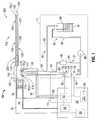
- FIG. 1is a schematic diagram of an electrosurgical system including an energy-delivery device and circuitry for detecting bending, including excessive bending, of an ablation probe of the electrosurgical system in accordance with an embodiment of the present disclosure
- FIG. 2is a perspective, phantom view of the ablation probe and a strain relief surrounding a portion of the ablation probe having one or more piezoelectric bending actuators or generators for detecting bending, including excessive bending, of the probe in accordance with an embodiment of the present disclosure;
- FIG. 3is a cross-sectional view of the ablation probe and the strain relief shown by FIG. 2 being bent in a first direction causing a two-layer piezoelectric bending actuator or generator within the strain relief to bend (one layer of the actuator is compressed and the other layer is stretched);
- FIG. 4is a perspective, cut-away view of an ablation probe of the electrosurgical system shown by FIG. 1 having one or more piezoelectric bending actuators or generators for detecting bending, including excessive bending, of the probe in accordance with another embodiment of the present disclosure;
- FIG. 5is a cross-sectional view of the ablation probe shown by FIG. 4 being bent in a first direction causing a two-layer piezoelectric bending actuator or generator within the ablation probe to bend (one layer of the actuator is compressed and the other layer is stretched);
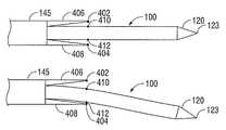
- FIG. 6is a perspective view of an alternative embodiment of the ablation probe of the electrosurgical system shown by FIG. 1 having at least two electrical contacts on a shaft of the probe and at least two electrical contacts in proximity to the shaft for detecting bending, including excessive bending, of the probe in accordance with the present disclosure;
- FIG. 7is perspective view of the ablation probe of FIG. 6 showing an electrical contact on the shaft of the probe making contact with an electrical contact in proximity to the shaft due to bending of the probe.
- a phrase in the form “A/B”means A or B.
- a phrase in the form “A and/or B”means “(A), (B), or (A and B)”.
- a phrase in the form “at least one of A, B, or C”means “(A), (B), (C), (A and B), (A and C), (B and C), or (A, B and C)”.
- Various embodiments of the present disclosureprovide systems for detecting bending, including excessive bending, of an electrosurgical device, such as an ablation probe, of an electrosurgical system.
- the ablation probefor exemplary purposes in describing the various embodiments of the present disclosure, is an ablation probe including a fluid-cooled antenna assembly. Additionally, the electrosurgical system includes a thermal-feedback-controlled rate of fluid flow to control the fluid flow to the ablation probe. It is contemplated that embodiments of the present disclosure for detecting bending, including excessive bending, of an ablation probe or other electrosurgical device can be implemented, integrated and/or otherwise incorporated in other systems and electrosurgical devices which are not described or mentioned herein.
- embodiments of the present disclosureto certain systems, especially electrosurgical systems, is for exemplary purposes only and shall not be construed as limiting the embodiments described herein to only these systems and variants thereof. That is, for example, embodiments may be implemented using electromagnetic radiation at microwave frequencies or at other frequencies.
- An electrosurgical systemincluding a detection system for detecting bending, including excessive bending, of an ablation probe, a coolant supply system and a feedback control system configured to provide a thermal-feedback-controlled rate of fluid flow to an energy applicator, according to various embodiments, is designed and configured to operate between about 300 MHz and about 10 GHz.
- Systems for detecting bending of the ablation probe and for thermal-feedback-controlled rate of fluid flow to electrosurgical devices, as described herein,may be used in conjunction with various types of devices, such as microwave antenna assemblies having either a straight or looped radiating antenna portion, etc., which may be inserted into or placed adjacent to tissue to be treated.
- Various embodiments of the presently-disclosed electrosurgical systemsincluding a detection system for detecting bending, including excessive bending, of an ablation probe and feedback control system configured to provide a thermal-feedback-controlled rate of fluid flow to an energy applicator disposed in fluid communication with a coolant supply system are suitable for microwave ablation and for use to pre-coagulate tissue for microwave ablation-assisted surgical resection.
- various methods described hereinbeloware targeted toward microwave ablation and the complete destruction of target tissue, it is to be understood that methods for directing electromagnetic radiation may be used with other therapies in which the target tissue is partially destroyed or damaged, such as, for example, to prevent the conduction of electrical impulses within heart tissue.
- the teachings of the present disclosuremay also apply to a monopole, helical, or other suitable type of antenna assembly.
- FIG. 1shows an electrosurgical system 10 according to an embodiment of the present disclosure that includes an energy applicator or probe 100 , an electrosurgical power generating source 28 , e.g., a microwave or RF electrosurgical generator, detection circuitry 84 for detecting bending, including excessive bending of the probe 100 using at least one signal transmitted to the detection circuitry 84 via transmission line 15 , and a feedback control system 14 operably associated with a coolant supply system 11 .
- Probe 100is operably-coupled to the electrosurgical power generating source 28 , and disposed in fluid communication with the coolant supply system 11 .
- one or more components of the coolant supply system 11may be integrated fully or partially into the electrosurgical power generating source 28 .
- Coolant supply system 11which is described in more detail later in this description, is configured to provide coolant fluid “F” to the probe 100 .
- Probe 100which is described in more detail later in this description, may be integrally associated with a hub 142 configured to provide electrical and/or coolant connections to the probe.
- the probe 100includes a strain relief 200 .
- the strain relief 200is fixed to a surface of the hub 142 to counter mechanical stress when the probe 100 bends during an electrosurgical procedure.
- the strain relief 200includes one or more piezoelectric bending actuators or generators for detecting bending, including excessive bending, of the probe 100 .
- the probe 100may extend from a handle assembly (not shown).
- FIG. 2there is shown a perspective, phantom view of ablation probe 100 and strain relief 200 with the bending detection circuitry 84 having one or more bending detection members, such as one or more piezoelectric bending actuators or generators 202 , within the strain relief 200 for use in detecting bending, including excessive bending, of the probe 100 .
- FIG. 3shows a cross-sectional view of the ablation probe 100 and strain relief 200 shown by FIG. 2 being bent in a first direction causing the two-layer piezoelectric bending actuator or generator 202 within the strain relief 200 to bend. That is, during bending of the outer jacket 139 of the probe 100 , the strain relief 200 also bends.
- the bending of the strain relief 200causes one layer 204 of the actuator 202 to be stretched and the other layer 206 to be compressed (see FIG. 3 ).
- the bending of the strain relief 200 and the actuator therein 202is detected by the detection circuitry 84 . If the bending is detected to be beyond a predetermined threshold, i.e., excessive bending is detected by the detection circuitry 84 , the detection circuitry 84 generates a signal for activating an audible alarm, lighting one or more LEDs or other light sources, tactile feedback, or any other means for notifying the user of the excessive bending.
- FIGS. 4 and 5there is shown a perspective, cut-away view and a cross-sectional view, respectively, of an alternate embodiment.
- one or more piezoelectric bending actuators or generators 202are placed within the ablation probe 100 , such as, for example, under the outer jacket 139 of the probe 100 instead of within the strain relief 200 .
- the bending detection circuitry 84utilizes the one or more piezoelectric bending actuators or generators 202 within the probe 100 to detect bending, including excessive bending, of the probe 100 .
- FIG. 5illustrates the ablation probe 100 shown by FIG. 4 being bent in a first direction causing the two-layer piezoelectric bending actuator or generator 202 within the probe 100 to bend. That is, during bending of the outer jacket 139 of the probe 100 , one layer 204 ′ of the actuator 202 is stretched and the other layer 206 ′ is compressed. The bending of the outer jacket 139 and the actuator 202 therein is detected by the detection circuitry 84 .
- the detection circuitry 84If the bending is detected to be beyond a predetermined threshold, i.e., excessive bending is detected by the detection circuitry 84 , the detection circuitry 84 generates a signal for activating an audible alarm, lighting one or more LEDs or other light sources, tactile feedback, or any other means for notifying the user of the excessive bending.
- the one or more piezoelectric bending actuators or generators 202can be replaced or used in conjunction with any other device or apparatus capable of detecting bending of the probe 100 . It is also envisioned in an alternate embodiment that a piezoelectric bending actuator or generator 202 may be placed within the strain relief 200 and within the probe 100 .
- the actuator 202 shown in the embodiments of FIGS. 2-5can be a multilayer ceramic piezoelectric bending actuator available from Noliac A/S based in Denmark or piezoelectric bending actuators available from Piezo Systems, Inc., Woburn, Mass. Even though FIGS. 2 and 3 , show a two-layer bending actuator 202 , other types of bending actuators can be used, such as 2-layer circular bending disk actuators, 4-layer rectangular bending actuators, etc.
- two or more electrical contacts 402 , 404are positioned in opposing surfaces of two stationary fixtures, protrusions or extensions 406 , 408 extending from the hub body 145 .
- the bending detection membersinclude two or more electrical contacts 410 , 412 positioned on the outer jacket 139 of the probe 100 and configured to contact a respective one of the two electrical contacts 402 , 404 positioned on the two stationary fixtures 406 , 408 when the probe 100 is bent a predetermined amount.
- a closed circuitis created by one of the contacts 410 , 412 positioned on the probe 100 contacting one of the contacts 402 , 404 positioned on the fixtures 406 , 408 as shown by FIG. 7 .
- the closed circuitalerts the user of the excessive bending of the probe 100 by activating an audible alarm, lighting one or more LEDs or other light sources, tactile feedback, or any other means.
- the electrosurgical system 10includes one or more sensors capable of generating a signal indicative of a temperature of a medium in contact therewith (referred to herein as temperature sensors) and/or one or more sensors capable of generating a signal indicative of a rate of fluid flow (referred to herein as flow sensors).
- the feedback control system 14may be configured to provide a thermal-feedback-controlled rate of fluid flow to the probe 100 using one or more signals output from one or more temperature sensors and/or one or more flow sensors operably associated with the probe 100 and/or conduit fluidly-coupled to the probe 100 .
- FIG. 2An embodiment of a feedback control system, such as the feedback control system 14 of FIG. 1 , in accordance with the present disclosure, is shown in more detail in FIG. 2 . It is to be understood, however, that other feedback control system embodiments (e.g., feedback control systems 414 and 514 shown in FIGS. 4 and 5 , respectively) may be used in conjunction with coolant supply systems in various configurations. In some embodiments, the feedback control system 14 , or component(s) thereof, may be integrated fully or partially into the electrosurgical power generating source 28 .
- the feedback control system 14or component(s) thereof, may be integrated fully or partially into the electrosurgical power generating source 28 .
- the feedback control system 14is operably associated with a processor unit 82 disposed within or otherwise associated with the electrosurgical power generating source 28 .
- Processor unit 82may be communicatively-coupled to one or more components or modules of the electrosurgical power generating source 28 , e.g., a user interface 121 and a generator module 86 .
- Processor unit 82may additionally, or alternatively, be communicatively-coupled to one or more temperature sensors (e.g., two sensors “TS 1 ” and “TS 2 ” shown in FIG. 1 ) and/or one or more flow sensors (e.g., one sensor “FS 1 ” shown in FIG.
- Transmission linesmay be provided to electrically couple the temperature sensors, flow sensors and/or other sensors, e.g., pressure sensors, to the processor unit 82 .
- Feedback control system embodimentsmay additionally, or alternatively, be operably associated with a processor unit deployed in a standalone configuration, and/or a processor unit disposed within the probe 100 or otherwise associated therewith.
- the feedback control systemmay be operably associated with a processor unit disposed within the handle assembly. Examples of handle assembly embodiments are disclosed in commonly assigned U.S. patent application Ser. No. 12/686,726 filed on Jan. 13, 2010, entitled “ABLATION DEVICE WITH USER INTERFACE AT DEVICE HANDLE, SYSTEM INCLUDING SAME, AND METHOD OF ABLATING TISSUE USING SAME”.
- Electrosurgical power generating source 28may include any generator suitable for use with electrosurgical devices, and may be configured to provide various frequencies of electromagnetic energy. In some embodiments, the electrosurgical power generating source 28 is configured to provide microwave energy at an operational frequency from about 300 MHz to about 10 GHz. In some embodiments, the electrosurgical power generating source 28 is configured to provide electrosurgical energy at an operational frequency from about 400 KHz to about 500 KHz. An embodiment of an electrosurgical power generating source, such as the electrosurgical power generating source 28 of FIG. 1 , in accordance with the present disclosure, is shown in more detail in FIG. 3 .
- Probe 100may include one or more antennas of any suitable type, such as an antenna assembly (or antenna array) suitable for use in tissue ablation applications.
- the probe 100is described as including a single antenna assembly 112 .
- the antenna assembly 112is substantially disposed within a sheath 138 .
- Probe 100generally includes a coolant chamber 137 defined about the antenna assembly 112 .
- the coolant chamber 137which is described in more detail later in this description, includes an interior lumen defined by the sheath 138 .
- Probe 100may include a feedline 110 coupled to the antenna assembly 112 .
- a transmission line 16may be provided to electrically couple the feedline 110 to the electrosurgical power generating source 28 .
- Feedline 110may be coupled to a connection hub 142 , which is described in more detail later in this description, to facilitate the flow of coolant and/or buffering fluid into, and out of, the probe 100 .
- the feedback control system 14is operably associated with a flow-control device 50 disposed in fluid communication with a fluid-flow path of the coolant supply system 11 (e.g., first coolant path 19 ) fluidly-coupled to the probe 100 .
- Flow-control device 50may include any suitable device capable of regulating or controlling the rate of fluid flow passing though the flow-control device 50 , e.g., a valve of any suitable type operable to selectively impede or restrict flow of fluid through passages in the valve.
- Processor unit 82may be configured to control the flow-control device 50 based on determination of a desired fluid-flow rate using temperature data received from one or more temperature sensors (e.g., “TS 1 ”, “TS 2 ” through “TS N ” shown in FIG. 1 ).
- a desired fluid-flow rateusing temperature data received from one or more temperature sensors (e.g., “TS 1 ”, “TS 2 ” through “TS N ” shown in FIG. 1 ).
- the flow-control device 50includes a valve 52 including a valve body 54 and an electromechanical actuator 56 operatively-coupled to the valve body 54 .
- Valve body 54may be implemented as a ball valve, gate valve, butterfly valve, plug valve, or any other suitable type of valve.
- the actuator 56is communicatively-coupled to with the processor unit 82 via a transmission line 32 .
- Processor unit 82may be configured to control the flow-control device 50 by activating the actuator 56 to selectively adjust the fluid-flow rate in a fluid-flow path (e.g., first coolant path 19 of the coolant supply system 11 ) fluidly-coupled to the connection hub 142 to achieve a desired fluid-flow rate.
- a fluid-flow pathe.g., first coolant path 19 of the coolant supply system 11
- the desired fluid-flow ratemay be determined by a computer program and/or logic circuitry associated with the processor unit 82 .
- the desired fluid-flow ratemay additionally, or alternatively, be selected from a look-up table “T X,Y ” (shown in FIGS. 2 and 5 ) or determined by a computer algorithm stored within a memory device 8 (shown in FIGS. 2 and 5 ).
- Embodiments including a suitable pressure-relief device 40 disposed in fluid communication with the diversion flow path 21may allow the fluid-movement device 60 to run at a substantially constant speed and/or under a near-constant load (head pressure) regardless of the selective adjustment of the fluid-flow rate in the first coolant path 19 .
- a suitable pressure-relief device 40 disposed in fluid communication with the diversion flow path 21in accordance with the present disclosure, may allow the fluid-movement device 60 to be implemented as a single speed device, e.g., a single speed pump.
- Feedback control system 14may utilize data “D” (e.g., data representative of a mapping of temperature data to settings for properly adjusting one or more operational parameters of the flow-control device 50 to achieve a desired temperature and/or a desired ablation) stored in a look-up table “T X,Y ” (shown in FIGS. 2 and 5 ), where X denotes columns and Y denotes rows, or other data structure, to determine the desired fluid-flow rate.
- data “D”e.g., data representative of a mapping of temperature data to settings for properly adjusting one or more operational parameters of the flow-control device 50 to achieve a desired temperature and/or a desired ablation
- T X,Yshown in FIGS. 2 and 5
- the electrosurgical system 10includes a first temperature sensor “TS 1 ” capable of generating a signal indicative of a temperature of a medium in contact therewith and a second temperature sensor “TS 2 ” capable of generating a signal indicative of a temperature of a medium in contact therewith.
- Feedback control system 14may be configured to utilize signals received from the first temperature sensor “TS 1 ” and/or the second temperature sensor “TS 2 ” to control the flow-control device 50 .
- the electrosurgical system 10includes a flow sensor “FS 1 ” communicatively-coupled to the processor unit 82 , e.g., via a transmission line 36 .
- the flow sensor “FS 1 ”may be disposed in fluid communication with the first coolant path 19 or the second coolant path 20 .
- Processor unit 82may be configured to control the flow-control device 50 based on determination of a desired fluid-flow rate using one or more signals received from the flow sensor “FS 1 ”.
- the processor unit 82may be configured to control the flow-control device 50 based on determination of a desired fluid-flow rate using one or more signals received from the flow sensor “FS 1 ” in conjunction with one or more signals received from the first temperature sensor “TS 1 ” and/or the second temperature sensor “TS 2 ”.
- the electrosurgical system 10 shown in FIG. 1includes one flow sensor “FS 1 ”
- alternative embodimentsmay be implemented with a plurality of flow sensors (e.g., “FS 1 ”, “FS 2 ” through “FS M ” shown in FIG. 1 ) adapted to provide a measurement of the rate of fluid flow into and/or out of the probe 100 and/or conduit fluidly-coupled to the probe 100 .
- Electrosurgical system 10may additionally, or alternatively, include one or more pressure sensors configured to provide a measurement of the fluid pressure in the probe 100 and/or conduit fluidly-coupled the probe 100 .
- the electrosurgical system 10includes one or more pressure sensors (e.g., pressure sensor 70 ) disposed in fluid communication with one or more fluid-flow paths (e.g., first coolant path 19 ) of the coolant supply system 11 as opposed to a pressure sensor disposed within the probe 100 , reducing cost and complexity of the probe 100 .
- the processor unit 82is operably associated with a pressure sensor 70 disposed in fluid communication with a fluid-flow path of the coolant supply system 11 .
- Processor unit 82may be communicatively-coupled to the pressure sensor 70 via a transmission line 30 or wireless link.
- Processor unit 82may additionally, or alternatively, be operably associated with one or more pressure sensors disposed within the probe 100 , e.g., disposed in fluid communication with the coolant chamber 137 .
- Pressure sensor 70may include any suitable type of pressure sensor, pressure transducer, pressure transmitter, or pressure switch.
- Pressure sensor 70(also referred to herein as “pressure transducer”) may include a variety of components, e.g., resistive elements, capacitive elements and/or piezo-resistive elements, and may be disposed at any suitable position in the coolant supply system 11 .
- the pressure transducer 70is disposed in fluid communication with the first coolant path 19 located between the fluid-movement device 60 and the flow-control device 50 , e.g., placed at or near the flow-control device 50 .
- the processor unit 82may be configured to control the flow-control device 50 based on determination of a desired fluid-flow rate using pressure data received from one or more pressure sensors. In some embodiments, the processor unit 82 may be configured to control the flow-control device 50 based on determination of a desired fluid-flow rate using one or more signals received from the first temperature sensor “TS 1 ” and/or the second temperature sensor “TS 2 ” and/or the flow sensor “FS 1 ” in conjunction with one or more signals received from the pressure transducer 70 .
- the processor unit 82may be configured to control the amount of power delivered to the antenna assembly 112 based on time and power settings provided by the user in conjunction with sensed temperature signals indicative of a temperature of a medium, e.g., coolant fluid “F”, in contact with one or one temperature sensors operably associated with the antenna assembly 112 and/or the connection hub 142 .
- the processor unit 82may be configured to increase and/or decrease the amount of power delivered to the antenna assembly 112 when sensed temperature signals indicative of a temperature below/above a predetermined temperature threshold are received by processor unit 82 , e.g., over a predetermined time interval.
- Processor unit 82may be configured to control one or more operating parameters associated with the electrosurgical power generating source 28 based on determination of whether the pressure level of fluid in the probe 100 and/or conduit fluidly-coupled to the probe 100 is above a predetermined threshold using pressure data received from one or more pressure sensors, e.g., pressure transducer 70 .
- operating parameters associated with the electrosurgical power generating source 28include without limitation temperature, impedance, power, current, voltage, mode of operation, and duration of application of electromagnetic energy.
- the output signal of the pressure transducer 70is received by the processor unit 82 and used for determination of whether the pressure level of fluid in the probe 100 and/or conduit fluidly-coupled to the probe 100 is above a predetermined threshold in order to control when power is delivered to the antenna assembly 112 .
- the processor unit 82in response to a determination that the pressure level of fluid in the probe 100 and/or conduit fluidly-coupled to the probe 100 is below the predetermined threshold, the processor unit 82 may be configured to decrease the amount of power delivered to the antenna assembly 112 and/or to stop energy delivery between the electrosurgical power generating source 28 and the probe 100 .
- the processor unit 82may be configured to enable energy delivery between the electrosurgical power generating source 28 and the probe 100 based on determination that the pressure level of fluid in the probe 100 and/or conduit fluidly-coupled to the probe 100 is above the predetermined threshold.
- the pressure transducer 70is adapted to output a predetermined signal to indicate a sensed pressure below that of the burst pressure of the pressure-relief device 40 .
- a computer program and/or logic circuitry associated with the processor unit 82may be configured to enable the electrosurgical power generating source 28 and the flow-control device 50 in response to a signal from the pressure transducer 70 .
- a computer program and/or logic circuitry associated with the processor unit 82may be configured to output a signal indicative of an error code and/or to activate an indicator unit 129 if a certain amount of time elapses between the point at which energy delivery to the probe 100 is enabled and when the pressure signal is detected, e.g., to ensure that the fluid-movement device 60 is turned on and/or that the probe 100 is receiving flow of fluid before the antenna assembly 112 can be activated.
- connection hub 142couples the antenna assembly 112 to a connection hub 142 .
- Connection hub 142may have a variety of suitable shapes, e.g., cylindrical, rectangular, etc.
- Connection hub 142generally includes a hub body 145 defining an outlet fluid port 177 and an inlet fluid port 179 .
- Hub body 145may include one or more branches, e.g., three branches 164 , 178 and 176 , extending from one or more portions of the hub body 145 .
- one or more branches extending from the hub body 145may be configured to house one or more connectors and/or ports, e.g., to facilitate the flow of coolant and/or buffering fluid into, and out of, the connection hub 142 .
- the hub body 145includes a first branch 164 adapted to house a cable connector 165 , a second branch 178 adapted to house the inlet fluid port 179 , and a third branch 176 adapted to house the outlet fluid port 177 .
- a first branch 164adapted to house a cable connector 165
- a second branch 178adapted to house the inlet fluid port 179
- a third branch 176adapted to house the outlet fluid port 177 .
- hub embodimentsare disclosed in commonly assigned U.S. patent application Ser. No. 12/401,268 filed on Mar. 10, 2009, entitled “COOLED DIELECTRICALLY BUFFERED MICROWAVE DIPOLE ANTENNA”, and U.S. Pat. No. 7,311,703, entitled “DEVICES AND METHODS FOR COOLING MICROWAVE ANTENNAS”.
- the flow sensor “FS 1 ”is disposed in fluid communication with the first coolant path 19 , e.g., disposed within the inlet fluid port 179 or otherwise associated with the second branch 178
- the second temperature sensor “TS 2 ”is disposed in fluid communication with the second coolant path 20 , e.g., disposed within the outlet fluid port 177 or otherwise associated with the third branch 176
- the second temperature sensor “TS 2 ”may be disposed within the inlet fluid port 179 or otherwise associated with the second branch 178
- the flow sensor “FS 1 ”may be disposed within the outlet fluid port 177 or otherwise associated with the third branch 176 .
- Coolant supply system 11generally includes a substantially closed loop having a first coolant path 19 leading to the probe 100 and a second coolant path 20 leading from the probe 100 , a coolant source 90 , and a fluid-movement device 60 , e.g., disposed in fluid communication with the first coolant path 19 .
- the coolant supply system 11includes a third coolant path 21 (also referred to herein as a “diversion flow path”) disposed in fluid communication with the first coolant path 19 and the second coolant path 20 .
- the conduit layouts of the first coolant path 19 , second coolant path 20 and third coolant path 21may be varied from the configuration depicted in FIG. 1 .
- a pressure-relief device 40may be disposed in fluid communication with the diversion flow path 21 .
- Pressure-relief device 40may include any type of device, e.g., a spring-loaded pressure-relief valve, adapted to open at a predetermined set pressure and to flow a rated capacity at a specified over-pressure.
- one or more flow-restrictor devices(not shown) suitable for preventing backflow of fluid into the first coolant path 19 may be disposed in fluid communication with the diversion flow path 21 .
- Flow-restrictor devicesmay include a check valve or any other suitable type of unidirectional flow restrictor or backflow preventer, and may be disposed at any suitable position in the diversion flow path 21 to prevent backflow of fluid from the diversion flow path 21 into the first coolant path 19 .
- the first coolant path 19includes a first coolant supply line 66 leading from the coolant source 90 to the fluid-movement device 60 , a second coolant supply line 67 leading from the fluid-movement device 60 to the flow-control device 50 , and a third coolant supply line 68 leading from the flow-control device 50 to the inlet fluid port 179 defined in the second branch 178 of the connection hub body 145 , and the second coolant path 20 includes a first coolant return line 95 leading from the outlet fluid port 177 defined in the third branch 176 of the hub body 145 to the coolant source 90 .
- Embodiments including the diversion flow path 21may include a second coolant return line 94 fluidly-coupled to the second coolant supply line 67 and the first coolant return line 95 .
- Pressure-relief device 40may be disposed at any suitable position in the second coolant return line 94 .
- the spacing and relative dimensions of coolant supply lines and coolant return linesmay be varied from the configuration depicted in FIG. 1 .
- Coolant source 90may be any suitable housing containing a reservoir of coolant fluid “F”.
- Coolant fluid “F”may be any suitable fluid that can be used for cooling or buffering the probe 100 , e.g., deionized water, or other suitable cooling medium.
- Coolant fluid “F”may have dielectric properties and may provide dielectric impedance buffering for the antenna assembly 112 .
- Coolant fluid “F”may be a conductive fluid, such as a saline solution, which may be delivered to the target tissue, e.g., to decrease impedance and allow increased power to be delivered to the target tissue.
- a coolant fluid “F” compositionmay vary depending upon desired cooling rates and the desired tissue impedance matching properties.
- liquidsincluding, but not limited to, water, saline, perfluorocarbon, such as the commercially available Fluorinert® perfluorocarbon liquid offered by Minnesota Mining and Manufacturing Company (3M), liquid chlorodifluoromethane, etc.
- gasessuch as nitrous oxide, nitrogen, carbon dioxide, etc.
- a combination of liquids and/or gasesincluding, for example, those mentioned above, may be utilized as the coolant fluid “F”.
- the fluid-movement device 60is provided in the first coolant path 19 to move the coolant fluid “F” through the first coolant path 19 and into, and out of, the probe 100 .
- Fluid-movement device 60may include valves, pumps, power units, actuators, fittings, manifolds, etc.
- the position of the fluid-movement device 60e.g., in relation to the coolant source 90 , may be varied from the configuration depicted in FIG. 1 .
- 1includes a single, fluid-movement device 60 located in the first coolant path 19 , various combinations of different numbers of fluid-movement devices, variedly-sized and variedly-spaced apart from each other, may be provided in the first coolant path 19 and/or the second coolant path 20 .
- the probe 100includes a feedline 110 that couples the antenna assembly 112 to a hub, e.g., connection hub 142 , that provides electrical and/or coolant connections to the probe 100 .
- Feedline 110may be formed from a suitable flexible, semi-rigid or rigid microwave conductive cable.
- Feedline 110may be constructed of a variety of electrically-conductive materials, e.g., copper, gold, or other conductive metals with similar conductivity values.
- Feedline 110may be made of stainless steel, which generally offers the strength required to puncture tissue and/or skin.
- the antenna assembly 112includes a distal radiating portion 105 and a proximal radiating portion 140 .
- a junction member(not shown), which is generally made of a dielectric material, couples the proximal radiating section 140 and the distal radiating section 105 .
- the distal and proximal radiating sections 105 , 140align at the junction member and are also supported by an inner conductor (not shown) that extends at least partially through the distal radiating section 105 .
- Antenna assembly 112may be provided with an end cap or tapered portion 120 , which may terminate in a sharp tip 123 to allow for insertion into tissue with minimal resistance.
- a straight probe with a sharp tipthat may be suitable for use as the energy applicator 100 is commercially available under the trademark EVIDENTTM offered by Covidien.
- the end cap or tapered portion 120may include other shapes, such as, for example, a tip 123 that is rounded, flat, square, hexagonal, or cylindroconical.
- End cap or tapered portion 120may be formed of a material having a high dielectric constant, and may be a trocar.
- Sheath 138generally includes an outer jacket 139 defining a lumen into which the antenna assembly 112 , or portion thereof, may be positioned.
- the sheath 138is disposed over and encloses the feedline 110 , the proximal radiating portion 140 and the distal radiating portion 105 , and may at least partially enclose the end cap or tapered portion 120 .
- the outer jacket 139may be formed of any suitable material, such as, for example, polymeric or ceramic materials.
- the outer jacket 139may be a water-cooled catheter formed of a material having low electrical conductivity.
- a coolant chamber 137is defined by the outer jacket 139 and the end cap or tapered portion 120 .
- Coolant chamber 137is disposed in fluid communication with the inlet fluid port 179 and the outlet fluid port 177 and adapted to circulate coolant fluid “F” therethrough, and may include baffles, multiple lumens, flow restricting devices, or other structures that may redirect, concentrate, or disperse flow depending on their shape. Examples of coolant chamber embodiments are disclosed in commonly assigned U.S. patent application Ser. No. 12/350,292 filed on Jan. 8, 2009, entitled “CHOKED DIELECTRIC LOADED TIP DIPOLE MICROWAVE ANTENNA”, commonly assigned U.S. patent application Ser. No.
- the probe 100is inserted into or placed adjacent to tissue and microwave energy is supplied thereto.
- Ultrasound or computed tomography (CT) guidancemay be used to accurately guide the probe 100 into the area of tissue to be treated.
- Probe 100may be placed percutaneously or atop tissue, e.g., using conventional surgical techniques by surgical staff.
- a clinicianmay pre-determine the length of time that microwave energy is to be applied.
- Application durationmay depend on many factors such as tumor size and location and whether the tumor was a secondary or primary cancer.
- the duration of microwave energy application using the probe 100may depend on the progress of the heat distribution within the tissue area that is to be destroyed and/or the surrounding tissue.
- Single or multiple probes 100may be used to provide ablations in short procedure times, e.g., a few seconds to minutes, to destroy cancerous cells in the target tissue region.
- a plurality of probes 100may be placed in variously arranged configurations to substantially simultaneously ablate a target tissue region, making faster procedures possible. Multiple probes 100 can be used to synergistically create a large ablation or to ablate separate sites simultaneously. Tissue ablation size and geometry is influenced by a variety of factors, such as the energy applicator design, number of energy applicators used simultaneously, time and wattage.
- microwave energy having a wavelength, lambda (A)is transmitted through the antenna assembly 112 , e.g., along the proximal and distal radiating portions 140 , 105 , and radiated into the surrounding medium, e.g., tissue.
- the length of the antenna for efficient radiationmay be dependent on the effective wavelength ⁇ eff which is dependent upon the dielectric properties of the medium being radiated.
- Antenna assembly 112through which microwave energy is transmitted at a wavelength ⁇ , may have differing effective wavelengths ⁇ eff depending upon the surrounding medium, e.g., liver tissue as opposed to breast tissue.
- the electrosurgical system 10includes a first temperature sensor “TS 1 ” disposed within a distal radiating portion 105 of the antenna assembly 112 .
- First temperature sensor “TS 1 ”may be disposed within or contacting the end cap or tapered portion 120 . It is to be understood that the first temperature sensor “TS 1 ” may be disposed at any suitable position to allow for the sensing of temperature.
- Processor unit 82may be electrically connected by a transmission line 34 to the first temperature sensor “TS 1 ”.
- Sensed temperature signals indicative of a temperature of a medium in contact with the first temperature sensor “TS 1 ”may be utilized by the processor unit 82 to control the flow of electrosurgical energy and/or the flow rate of coolant to attain the desired ablation.
- Electrosurgical system 10may additionally, or alternatively, include a second temperature sensor TS 2 ′′ disposed within the outlet fluid port 177 or otherwise associated with the third branch 176 of the hub body 145 .
- Processor unit 82may be electrically connected by a transmission line 38 to the second temperature sensor “TS 2 ”.
- First temperature sensor “TS 1 ” and/or the second temperature sensor “TS 2 ”may be a thermocouple, thermistor, or other temperature sensing device.
- a plurality of sensorsmay be utilized including units extending outside the tip 123 to measure temperatures at various locations in the proximity of the tip 123 .
- a memory device 8 in operable connection with the processor unit 82can be provided.
- the memory device 8may be associated with the electrosurgical power generating source 28 .
- the memory device 8may be implemented as a storage device integrated into the electrosurgical power generating source 28 .
- the memory device 8may be implemented as an external device communicatively-coupled to the electrosurgical power generating source 28 .
- the processor unit 82is communicatively-coupled to the flow-control device 50 , e.g., via a transmission line “L 5 ”, and may be communicatively-coupled to the fluid-movement device 60 , e.g., via a transmission line “L 6 ”.
- the processor unit 82may be configured to control one or more operational parameters of the fluid-movement device 60 to selectively adjust the fluid-flow rate in a fluid-flow path (e.g., first coolant path 19 ) of the coolant supply system 11 .
- the fluid-movement device 60is implemented as a multi-speed pump, and the processor unit 82 may be configured to vary the pump speed to selectively adjust the fluid-flow rate to attain a desired fluid-flow rate.
- Processor unit 82may be configured to execute a series of instructions to control one or more operational parameters of the flow-control device 50 based on determination of a desired fluid-flow rate using temperature data received from one or more temperature sensors, e.g., “TS 1 ”, “TS 2 ” through “TS N ”, where N is an integer.
- the temperature datamay be transmitted via transmission lines “L 1 ”, “L 2 ” through “L N ” or wirelessly transmitted.
- One or more flow sensorse.g., “FS 1 ”, “FS 2 ” through “FS M ”, where M is an integer, may additionally, or alternatively, be communicatively-coupled to the processor unit 82 , e.g., via transmission lines “L 3 ”, “L 4 ” through “L M ”.
- signals indicative of the rate of fluid flow into and/or out of the probe 100 and/or conduit fluidly-coupled the probe 100 received from one or more flow sensors “FS 1 ”, “FS 2 ” through “FS M ”may be used by the processor unit 82 to determine a desired fluid-flow rate.
- flow datamay be used by the processor unit 82 in conjunction with temperature data, or independently of temperature data, to determine a desired fluid-flow rate.
- the desired fluid-flow ratemay be selected from a look-up table “T X,Y ” or determined by a computer algorithm stored within the memory device 8 .
- an analog signal that is proportional to the temperature detected by a temperature sensormay be taken as a voltage input that can be compared to a look-up table “T X,Y ” for temperature and fluid-flow rate, and a computer program and/or logic circuitry associated with the processor unit 82 may be used to determine the needed duty cycle of the pulse width modulation (PWM) to control actuation of a valve (e.g., valve 52 ) to attain the desired fluid-flow rate.
- PWMpulse width modulation
- Processor unit 82may be configured to execute a series of instructions such that the flow-control device 50 and the fluid-movement device 60 are cooperatively controlled by the processor unit 82 , e.g., based on determination of a desired fluid-flow rate using temperature data and/or flow data, to selectively adjust the fluid-flow rate in a fluid-flow path (e.g., first coolant path 19 ) of the coolant supply system 11 .
- a fluid-flow pathe.g., first coolant path 19
- Feedback control system 14may be adapted to control the flow-control device 50 to allow flow (e.g., valve 52 held open) for longer periods of time as the sensed temperature rises, and shorter periods of time as the sensed temperature falls.
- Electrosurgical system 10may be adapted to override PWM control of the flow-control device 50 to hold the valve 52 open upon initial activation of the antenna assembly 112 .
- a timermay be utilized to prevent the control device 50 from operating for a predetermined time interval (e.g., about one minute) after the antenna assembly 112 has been activated.
- the predetermined time interval to override PWM control of the flow-control device 50may be varied depending on setting, e.g., time and power settings, provided by the user.
- the electrosurgical power generating source 28may be adapted to perform a self-check routine that includes determination that the flow-control device 50 is open before enabling energy delivery between the electrosurgical power generating source 28 and the probe 100 .
- the above-described systems including circuitry for detecting excessive bending of a probemay be used in conjunction with a variety of electrosurgical devices adapted for treating tissue.
- Embodimentsmay be used in conjunction with electrosurgical devices adapted to direct energy to tissue, such as ablation probes, e.g., placed percutaneously or surgically, and/or ablation devices suitable for use in surface ablation applications.
- circuitry for detecting excessive bending of a probemay be suitable for a variety of uses and applications, including medical procedures, e.g., tissue ablation, resection, cautery, vascular thrombosis, treatment of cardiac arrhythmias and dysrhythmias, electrosurgery, etc.
Landscapes
- Health & Medical Sciences (AREA)
- Surgery (AREA)
- Life Sciences & Earth Sciences (AREA)
- Medical Informatics (AREA)
- Animal Behavior & Ethology (AREA)
- Engineering & Computer Science (AREA)
- Biomedical Technology (AREA)
- Heart & Thoracic Surgery (AREA)
- Nuclear Medicine, Radiotherapy & Molecular Imaging (AREA)
- Molecular Biology (AREA)
- Veterinary Medicine (AREA)
- General Health & Medical Sciences (AREA)
- Public Health (AREA)
- Otolaryngology (AREA)
- Oral & Maxillofacial Surgery (AREA)
- Pathology (AREA)
- Physics & Mathematics (AREA)
- Electromagnetism (AREA)
- Surgical Instruments (AREA)
Abstract
Description
Claims (22)
Priority Applications (6)
| Application Number | Priority Date | Filing Date | Title |
|---|---|---|---|
| US13/440,690US8945113B2 (en) | 2012-04-05 | 2012-04-05 | Electrosurgical tissue ablation systems capable of detecting excessive bending of a probe and alerting a user |
| CN201710504253.6ACN107174339B (en) | 2012-04-05 | 2013-04-03 | Electrosurgical tissue ablation system capable of detecting excessive bending of a probe and alerting a user |
| CN201310113566.0ACN103431906B (en) | 2012-04-05 | 2013-04-03 | Electrosurgical tissue removal system capable of detecting excessive probe bending and alerting user |
| EP13162091.6AEP2647345B1 (en) | 2012-04-05 | 2013-04-03 | Electrosurgical tissue ablation systems capable of detecting excessive bending of a probe and alerting a user |
| US14/599,604US9597151B2 (en) | 2012-04-05 | 2015-01-19 | Electrosurgical tissue ablation systems and methods capable of detecting excessive bending of a probe and alerting a user |
| US15/451,765US20170172689A1 (en) | 2012-04-05 | 2017-03-07 | System and method for detecting bending of an electrosurgical device |
Applications Claiming Priority (1)
| Application Number | Priority Date | Filing Date | Title |
|---|---|---|---|
| US13/440,690US8945113B2 (en) | 2012-04-05 | 2012-04-05 | Electrosurgical tissue ablation systems capable of detecting excessive bending of a probe and alerting a user |
Related Child Applications (1)
| Application Number | Title | Priority Date | Filing Date |
|---|---|---|---|
| US14/599,604ContinuationUS9597151B2 (en) | 2012-04-05 | 2015-01-19 | Electrosurgical tissue ablation systems and methods capable of detecting excessive bending of a probe and alerting a user |
Publications (2)
| Publication Number | Publication Date |
|---|---|
| US20130267946A1 US20130267946A1 (en) | 2013-10-10 |
| US8945113B2true US8945113B2 (en) | 2015-02-03 |
Family
ID=48047869
Family Applications (3)
| Application Number | Title | Priority Date | Filing Date |
|---|---|---|---|
| US13/440,690Active2033-05-31US8945113B2 (en) | 2012-04-05 | 2012-04-05 | Electrosurgical tissue ablation systems capable of detecting excessive bending of a probe and alerting a user |
| US14/599,604Expired - Fee RelatedUS9597151B2 (en) | 2012-04-05 | 2015-01-19 | Electrosurgical tissue ablation systems and methods capable of detecting excessive bending of a probe and alerting a user |
| US15/451,765AbandonedUS20170172689A1 (en) | 2012-04-05 | 2017-03-07 | System and method for detecting bending of an electrosurgical device |
Family Applications After (2)
| Application Number | Title | Priority Date | Filing Date |
|---|---|---|---|
| US14/599,604Expired - Fee RelatedUS9597151B2 (en) | 2012-04-05 | 2015-01-19 | Electrosurgical tissue ablation systems and methods capable of detecting excessive bending of a probe and alerting a user |
| US15/451,765AbandonedUS20170172689A1 (en) | 2012-04-05 | 2017-03-07 | System and method for detecting bending of an electrosurgical device |
Country Status (3)
| Country | Link |
|---|---|
| US (3) | US8945113B2 (en) |
| EP (1) | EP2647345B1 (en) |
| CN (2) | CN107174339B (en) |
Cited By (13)
| Publication number | Priority date | Publication date | Assignee | Title |
|---|---|---|---|---|
| US20150150627A1 (en)* | 2012-04-05 | 2015-06-04 | Covidien Lp | Electrosurgical tissue ablation systems capable of detecting excessive bending of a probe and alerting a user |
| US20150257778A1 (en)* | 2014-03-11 | 2015-09-17 | Michael Rontal | Surgical device employing a cantilevered beam dissector |
| USRE46362E1 (en) | 2009-11-16 | 2017-04-11 | Covidien Lp | Twin sealing chamber hub |
| US9993296B2 (en) | 2012-08-07 | 2018-06-12 | Covidien Lp | Microwave ablation catheter and method of utilizing the same |
| US10022186B2 (en) | 2008-08-28 | 2018-07-17 | Covidien Lp | Microwave antenna with cooled handle |
| US10080603B2 (en) | 2012-10-02 | 2018-09-25 | Covidien Lp | Devices and methods for optical detection of tissue contact |
| US10631922B2 (en) | 2008-02-07 | 2020-04-28 | Covidien Lp | Endoscopic instrument for tissue identification |
| US10813692B2 (en) | 2016-02-29 | 2020-10-27 | Covidien Lp | 90-degree interlocking geometry for introducer for facilitating deployment of microwave radiating catheter |
| US10828102B2 (en) | 2012-12-17 | 2020-11-10 | Covidien Lp | Ablation probe with tissue sensing configuration |
| US11103307B2 (en) | 2014-12-31 | 2021-08-31 | Covidien Lp | System and method for treating COPD and emphysema |
| US11432870B2 (en) | 2016-10-04 | 2022-09-06 | Avent, Inc. | Cooled RF probes |
| US11510732B2 (en) | 2012-06-29 | 2022-11-29 | Covidien Lp | Microwave antenna probes |
| US11974805B2 (en) | 2014-08-26 | 2024-05-07 | Covidien Lp | Microwave ablation system |
Families Citing this family (17)
| Publication number | Priority date | Publication date | Assignee | Title |
|---|---|---|---|---|
| US8552915B2 (en) | 2009-06-19 | 2013-10-08 | Covidien Lp | Microwave ablation antenna radiation detector |
| US8430871B2 (en) | 2009-10-28 | 2013-04-30 | Covidien Lp | System and method for monitoring ablation size |
| US9993283B2 (en) | 2012-10-02 | 2018-06-12 | Covidien Lp | Selectively deformable ablation device |
| CN105377128B (en) | 2013-03-15 | 2019-02-22 | 9234438加拿大股份有限公司 | Electrosurgical mapping tools and methods |
| US9987087B2 (en) | 2013-03-29 | 2018-06-05 | Covidien Lp | Step-down coaxial microwave ablation applicators and methods for manufacturing same |
| US10813691B2 (en) | 2014-10-01 | 2020-10-27 | Covidien Lp | Miniaturized microwave ablation assembly |
| US20170119461A1 (en)* | 2015-10-29 | 2017-05-04 | Kyphon Sárl | Electrosurgical Apparatus with Temperature Sensing and Methods of use thereof |
| US11197715B2 (en) | 2016-08-02 | 2021-12-14 | Covidien Lp | Ablation cable assemblies and a method of manufacturing the same |
| US10376309B2 (en) | 2016-08-02 | 2019-08-13 | Covidien Lp | Ablation cable assemblies and a method of manufacturing the same |
| US11065053B2 (en) | 2016-08-02 | 2021-07-20 | Covidien Lp | Ablation cable assemblies and a method of manufacturing the same |
| US11648047B2 (en) | 2017-10-06 | 2023-05-16 | Vive Scientific, Llc | System and method to treat obstructive sleep apnea |
| DE112018005767T5 (en) | 2017-11-07 | 2020-10-22 | Evanesc Therapeutics, Inc. | Device for the treatment of tumors using evanescent waves |
| CN111684650B (en)* | 2018-03-29 | 2024-12-24 | 直观外科手术操作公司 | Systems and methods related to flexible antennas |
| US20200261251A1 (en)* | 2019-02-19 | 2020-08-20 | Covidien Lp | Gastric positioning device |
| US12436034B2 (en) | 2019-05-15 | 2025-10-07 | Tdk Electronics Ag | Ferroelectric sensor |
| WO2022187821A1 (en)* | 2021-03-01 | 2022-09-09 | Bluexthermal, Inc. | Device and method for thermal modulation of tissue |
| JP2025501314A (en) | 2022-01-04 | 2025-01-17 | ブルーエックスサーマル, インコーポレイテッド | Ocular Area Heat Transfer Devices and Associated Systems - Patent application |
Citations (133)
| Publication number | Priority date | Publication date | Assignee | Title |
|---|---|---|---|---|
| DE390937C (en) | 1922-10-13 | 1924-03-03 | Adolf Erb | Device for internal heating of furnace furnaces for hardening, tempering, annealing, quenching and melting |
| DE1099658B (en) | 1959-04-29 | 1961-02-16 | Siemens Reiniger Werke Ag | Automatic switch-on device for high-frequency surgical devices |
| FR1275415A (en) | 1960-09-26 | 1961-11-10 | Device for detecting disturbances for electrical installations, in particular electrosurgery | |
| DE1139927B (en) | 1961-01-03 | 1962-11-22 | Friedrich Laber | High-frequency surgical device |
| DE1149832B (en) | 1961-02-25 | 1963-06-06 | Siemens Reiniger Werke Ag | High frequency surgical apparatus |
| FR1347865A (en) | 1962-11-22 | 1964-01-04 | Improvements to diathermo-coagulation devices | |
| DE1439302A1 (en) | 1963-10-26 | 1969-01-23 | Siemens Ag | High-frequency surgical device |
| SU401367A1 (en) | 1971-10-05 | 1973-10-12 | Тернопольский государственный медицинский институт | BIAKTIVNYE ELECTRO SURGICAL INSTRUMENT |
| DE2439587A1 (en) | 1973-08-23 | 1975-02-27 | Matburn Holdings Ltd | ELECTROSURGICAL DEVICE |
| DE2455174A1 (en) | 1973-11-21 | 1975-05-22 | Termiflex Corp | INPUT / OUTPUT DEVICE FOR DATA EXCHANGE WITH DATA PROCESSING DEVICES |
| DE2407559A1 (en) | 1974-02-16 | 1975-08-28 | Dornier System Gmbh | Tissue heat treatment probe - has water cooling system which ensures heat development only in treated tissues |
| DE2415263A1 (en) | 1974-03-29 | 1975-10-02 | Aesculap Werke Ag | Surgical H.F. coagulation probe has electrode tongs - with exposed ends of insulated conductors forming tong-jaws |
| DE2429021A1 (en) | 1974-06-18 | 1976-01-08 | Erbe Elektromedizin | Remote control for HF surgical instruments - uses cable with two conductors at most |
| FR2235669B1 (en) | 1973-07-07 | 1976-05-07 | Lunacek Boris | |
| DE2460481A1 (en) | 1974-12-20 | 1976-06-24 | Delma Elektro Med App | Electrode grip for remote HF surgical instrument switching - has shaped insulated piece with contact ring of sterilizable (silicon) rubber |
| DE2602517A1 (en) | 1975-01-23 | 1976-07-29 | Dentsply Int Inc | ELECTROSURGICAL DEVICE |
| DE2504280A1 (en) | 1975-02-01 | 1976-08-05 | Hans Heinrich Prof Dr Meinke | DEVICE FOR ELECTRIC TISSUE CUTTING IN SURGERY |
| DE2627679A1 (en) | 1975-06-26 | 1977-01-13 | Marcel Lamidey | HEMATISTIC HIGH FREQUENCY EXTRACTOR FORCEPS |
| DE2540968A1 (en) | 1975-09-13 | 1977-03-17 | Erbe Elektromedizin | Circuit for bipolar coagulation tweezers - permits preparation of tissues prior to coagulation |
| FR2276027B3 (en) | 1974-06-25 | 1977-05-06 | Medical Plastics Inc | |
| DE2820908A1 (en) | 1977-05-16 | 1978-11-23 | Joseph Skovajsa | DEVICE FOR THE LOCAL TREATMENT OF A PATIENT IN PARTICULAR FOR ACUPUNCTURE OR AURICULAR THERAPY |
| DE2803275A1 (en) | 1978-01-26 | 1979-08-02 | Aesculap Werke Ag | HF surgical appts. with active treatment and patient electrodes - has sensor switching generator to small voltage when hand-operated switch is closed |
| DE2823291A1 (en) | 1978-05-27 | 1979-11-29 | Rainer Ing Grad Koch | Coagulation instrument automatic HF switching circuit - has first lead to potentiometer and second to transistor base |
| SU727201A2 (en) | 1977-11-02 | 1980-04-15 | Киевский Научно-Исследовательский Институт Нейрохирургии | Electric surgical apparatus |
| FR2313708B1 (en) | 1975-06-02 | 1980-07-04 | Sybron Corp | |
| US4249539A (en) | 1979-02-09 | 1981-02-10 | Technicare Corporation | Ultrasound needle tip localization system |
| DE2946728A1 (en) | 1979-11-20 | 1981-05-27 | Erbe Elektromedizin GmbH & Co KG, 7400 Tübingen | HF surgical appts. for use with endoscope - provides cutting or coagulation current at preset intervals and of selected duration |
| USD263020S (en) | 1980-01-22 | 1982-02-16 | Rau Iii David M | Retractable knife |
| DE3143421A1 (en) | 1980-11-04 | 1982-05-27 | The Agency of Industrial Science and Technology, Tokyo | Laser scalpel |
| DE3045996A1 (en) | 1980-12-05 | 1982-07-08 | Medic Eschmann Handelsgesellschaft für medizinische Instrumente mbH, 2000 Hamburg | Electro-surgical scalpel instrument - has power supply remotely controlled by surgeon |
| USD266842S (en) | 1980-06-27 | 1982-11-09 | Villers Mark W | Phonograph record spacer |
| DE3120102A1 (en) | 1981-05-20 | 1982-12-09 | F.L. Fischer GmbH & Co, 7800 Freiburg | ARRANGEMENT FOR HIGH-FREQUENCY COAGULATION OF EGG WHITE FOR SURGICAL PURPOSES |
| FR2517953A1 (en) | 1981-12-10 | 1983-06-17 | Alvar Electronic | Diaphanometer for optical examination of breast tissue structure - measures tissue transparency using two plates and optical fibre bundle cooperating with photoelectric cells |
| US4407294A (en) | 1982-01-07 | 1983-10-04 | Technicare Corporation | Ultrasound tissue probe localization system |
| USD278306S (en) | 1980-06-30 | 1985-04-09 | Mcintosh Lois A | Microwave oven rack |
| FR2502935B1 (en) | 1981-03-31 | 1985-10-04 | Dolley Roger | METHOD AND DEVICE FOR CONTROLLING THE COAGULATION OF TISSUES USING A HIGH FREQUENCY CURRENT |
| DE3510586A1 (en) | 1985-03-23 | 1986-10-02 | Erbe Elektromedizin GmbH, 7400 Tübingen | Control device for a high-frequency surgical instrument |
| FR2573301B3 (en) | 1984-11-16 | 1987-04-30 | Lamidey Gilles | SURGICAL PLIERS AND ITS CONTROL AND CONTROL APPARATUS |
| DE3604823A1 (en) | 1986-02-15 | 1987-08-27 | Flachenecker Gerhard | HIGH FREQUENCY GENERATOR WITH AUTOMATIC PERFORMANCE CONTROL FOR HIGH FREQUENCY SURGERY |
| EP0246350A1 (en) | 1986-05-23 | 1987-11-25 | Erbe Elektromedizin GmbH. | Coagulation electrode |
| DE8712328U1 (en) | 1987-09-11 | 1988-02-18 | Jakoubek, Franz, 7201 Emmingen-Liptingen | Endoscopy forceps |
| USD295893S (en) | 1985-09-25 | 1988-05-24 | Acme United Corporation | Disposable surgical clamp |
| USD295894S (en) | 1985-09-26 | 1988-05-24 | Acme United Corporation | Disposable surgical scissors |
| DE3711511C1 (en) | 1987-04-04 | 1988-06-30 | Hartmann & Braun Ag | Method for determining gas concentrations in a gas mixture and sensor for measuring thermal conductivity |
| DE3904558A1 (en) | 1989-02-15 | 1990-08-23 | Flachenecker Gerhard | Radio-frequency generator with automatic power control for radio-frequency surgery |
| DE3942998A1 (en) | 1989-12-27 | 1991-07-04 | Delma Elektro Med App | Electro-surgical HF instrument for contact coagulation - has monitoring circuit evaluating HF voltage at electrodes and delivering switch=off signal |
| US5095910A (en) | 1990-04-18 | 1992-03-17 | Advanced Technology Laboratories, Inc. | Ultrasonic imaging of biopsy needle |
| EP0521264A2 (en) | 1991-07-03 | 1993-01-07 | W.L. Gore & Associates GmbH | Antenna device with feed |
| JPH055106Y2 (en) | 1986-02-28 | 1993-02-09 | ||
| DE4238263A1 (en) | 1991-11-15 | 1993-05-19 | Minnesota Mining & Mfg | Adhesive comprising hydrogel and crosslinked polyvinyl:lactam - is used in electrodes for biomedical application providing low impedance and good mechanical properties when water and/or moisture is absorbed from skin |
| EP0556705A1 (en) | 1992-02-20 | 1993-08-25 | DELMA ELEKTRO-UND MEDIZINISCHE APPARATEBAU GESELLSCHAFT mbH | High frequency surgery device |
| EP0558429A1 (en) | 1992-02-26 | 1993-09-01 | PECHINEY RECHERCHE (Groupement d'Intérêt Economique géré par l'ordonnance no. 67-821 du 23 Septembre 1967) | Method of simultaneous measuring of electrical resistivety and thermal conductivity |
| JPH0540112Y2 (en) | 1987-03-03 | 1993-10-12 | ||
| US5334193A (en)* | 1992-11-13 | 1994-08-02 | American Cardiac Ablation Co., Inc. | Fluid cooled ablation catheter |
| DE4303882A1 (en) | 1993-02-10 | 1994-08-18 | Kernforschungsz Karlsruhe | Combined instrument for separating and coagulating in minimally invasive surgery |
| JPH06343644A (en) | 1993-05-04 | 1994-12-20 | Gyrus Medical Ltd | Surgical peritoneoscope equipment |
| USD354218S (en) | 1992-10-01 | 1995-01-10 | Fiberslab Pty Limited | Spacer for use in concrete construction |
| US5391199A (en)* | 1993-07-20 | 1995-02-21 | Biosense, Inc. | Apparatus and method for treating cardiac arrhythmias |
| EP0648515A1 (en) | 1993-10-15 | 1995-04-19 | SADIS BRUKER SPECTROSPIN, SOCIETE ANONYME DE DIFFUSION DE L'INSTRUMENTATION SCIENTIFIQUE BRUKER SPECTROSPIN (S.A. à Direct.) | Antenna for microwave heating of tissue and catheter with one or more antennas |
| DE4339049A1 (en) | 1993-11-16 | 1995-05-18 | Erbe Elektromedizin | Surgical system and instruments configuration device |
| CN1103807A (en) | 1993-11-17 | 1995-06-21 | 刘中一 | Multi-frequency micro-wave therapeutic instrument |
| JPH07265328A (en) | 1993-11-01 | 1995-10-17 | Gyrus Medical Ltd | Electrode assembly for electric surgery device and electric surgery device using it |
| US5469853A (en) | 1992-12-11 | 1995-11-28 | Tetrad Corporation | Bendable ultrasonic probe and sheath for use therewith |
| JPH0856955A (en) | 1994-06-29 | 1996-03-05 | Gyrus Medical Ltd | Electric surgical apparatus |
| JPH08252263A (en) | 1994-12-21 | 1996-10-01 | Gyrus Medical Ltd | Electronic surgical incision instrument and electronic surgical incision device using the same |
| DE29616210U1 (en) | 1996-09-18 | 1996-11-14 | Olympus Winter & Ibe Gmbh, 22045 Hamburg | Handle for surgical instruments |
| US5585718A (en) | 1993-02-05 | 1996-12-17 | Seiko Seiki Kabushiki Kaisha | Device for detecting the bending magnitude of a shaft |
| JPH09492A (en) | 1995-06-21 | 1997-01-07 | Olympus Optical Co Ltd | Treatment tool inserting and detaching device for endoscope |
| JPH0910223A (en) | 1995-06-23 | 1997-01-14 | Gyrus Medical Ltd | Generator and system for electric operation |
| WO1997003609A1 (en) | 1995-07-16 | 1997-02-06 | Ultra-Guide Ltd. | Free-hand aiming of a needle guide |
| DE19608716C1 (en) | 1996-03-06 | 1997-04-17 | Aesculap Ag | Bipolar surgical holding instrument |
| US5647373A (en) | 1993-11-07 | 1997-07-15 | Ultra-Guide Ltd. | Articulated needle guide for ultrasound imaging and method of using same |
| US5724978A (en) | 1996-09-20 | 1998-03-10 | Cardiovascular Imaging Systems, Inc. | Enhanced accuracy of three-dimensional intraluminal ultrasound (ILUS) image reconstruction |
| EP0836868A2 (en) | 1996-10-18 | 1998-04-22 | Gebr. Berchtold GmbH & Co. | High frequency surgical apparatus and method for operating same |
| DE19751106A1 (en) | 1996-11-27 | 1998-05-28 | Eastman Kodak Co | Laser printer with array of laser diodes |
| US5829444A (en) | 1994-09-15 | 1998-11-03 | Visualization Technology, Inc. | Position tracking and imaging system for use in medical applications |
| DE19717411A1 (en) | 1997-04-25 | 1998-11-05 | Aesculap Ag & Co Kg | Monitoring of thermal loading of patient tissue in contact region of neutral electrode of HF treatment unit |
| EP0882955A1 (en) | 1997-06-06 | 1998-12-09 | Endress + Hauser GmbH + Co. | Level measuring apparatus using microwaves |
| US5861021A (en)* | 1996-06-17 | 1999-01-19 | Urologix Inc | Microwave thermal therapy of cardiac tissue |
| DE19751108A1 (en) | 1997-11-18 | 1999-05-20 | Beger Frank Michael Dipl Desig | Electrosurgical operation tool, especially for diathermy |
| WO1999033394A1 (en) | 1997-12-31 | 1999-07-08 | Ultraguide Ltd. | Calibration method and apparatus for calibrating position sensors on scanning transducers |
| DE19801173C1 (en) | 1998-01-15 | 1999-07-15 | Kendall Med Erzeugnisse Gmbh | Clamp connector for film electrodes |
| WO1999027837A3 (en) | 1997-11-27 | 1999-07-22 | Ultraguide Ltd | System and method for guiding the movements of a device to a target particularly for medical applications |
| JPH11244298A (en) | 1997-12-19 | 1999-09-14 | Gyrus Medical Ltd | Electric surgical instrument |
| US5957844A (en) | 1996-12-03 | 1999-09-28 | Surgical Navigation Specialist Inc. | Apparatus and method for visualizing ultrasonic images |
| USD424693S (en) | 1999-04-08 | 2000-05-09 | Pruter Rick L | Needle guide for attachment to an ultrasound transducer probe |
| USD424694S (en) | 1998-10-23 | 2000-05-09 | Sherwood Services Ag | Forceps |
| USD425201S (en) | 1998-10-23 | 2000-05-16 | Sherwood Services Ag | Disposable electrode assembly |
| DE19848540A1 (en) | 1998-10-21 | 2000-05-25 | Reinhard Kalfhaus | Circuit layout and method for operating a single- or multiphase current inverter connects an AC voltage output to a primary winding and current and a working resistance to a transformer's secondary winding and current. |
| WO2000036985A3 (en) | 1998-12-18 | 2000-11-09 | Kai Desinger | Electrode assembly for a surgical instrument provided for carrying out an electrothermal coagulation of tissue |
| JP2000342599A (en) | 1999-05-21 | 2000-12-12 | Gyrus Medical Ltd | Generator for electrosurgical operation, electrosurgical operation system, method for operating this system and method for performing amputation and resection of tissue by electrosurgical operation |
| JP2000350732A (en) | 1999-05-21 | 2000-12-19 | Gyrus Medical Ltd | Electrosurgical system, generator for electrosurgery, and method for cutting or excising tissue by electrosurgery |
| JP2001003776A (en) | 1999-06-22 | 2001-01-09 | Mitsubishi Electric Corp | Automatic transmission control device |
| JP2001008944A (en) | 1999-05-28 | 2001-01-16 | Gyrus Medical Ltd | Electric surgical signal generator and electric surgical system |
| JP2001029356A (en) | 1999-06-11 | 2001-02-06 | Gyrus Medical Ltd | Electric and surgical signal generator |
| JP2001037775A (en) | 1999-07-26 | 2001-02-13 | Olympus Optical Co Ltd | Treatment device |
| JP2001128990A (en) | 1999-05-28 | 2001-05-15 | Gyrus Medical Ltd | Electro surgical instrument and electrosurgical tool converter |
| US6272371B1 (en)* | 1997-01-03 | 2001-08-07 | Biosense Inc. | Bend-responsive catheter |
| JP2001231870A (en) | 2000-02-23 | 2001-08-28 | Olympus Optical Co Ltd | Moisturizing treatment apparatus |
| USD449886S1 (en) | 1998-10-23 | 2001-10-30 | Sherwood Services Ag | Forceps with disposable electrode |
| EP1159926A2 (en) | 2000-06-03 | 2001-12-05 | Aesculap Ag | Scissor- or forceps-like surgical instrument |
| USD457958S1 (en) | 2001-04-06 | 2002-05-28 | Sherwood Services Ag | Vessel sealer and divider |
| USD457959S1 (en) | 2001-04-06 | 2002-05-28 | Sherwood Services Ag | Vessel sealer |
| US6626832B1 (en) | 1999-04-15 | 2003-09-30 | Ultraguide Ltd. | Apparatus and method for detecting the bending of medical invasive tools in medical interventions |
| DE10224154A1 (en) | 2002-05-27 | 2003-12-18 | Celon Ag Medical Instruments | Application device for electrosurgical device for body tissue removal via of HF current has electrode subset selected from active electrode set in dependence on measured impedance of body tissue |
| US20040034279A1 (en) | 2002-03-22 | 2004-02-19 | Olympus Optical Co., Ltd. | Endoscope apparatus having electric bending endoscope |
| USD487039S1 (en) | 2002-11-27 | 2004-02-24 | Robert Bosch Corporation | Spacer |
| DE10310765A1 (en) | 2003-03-12 | 2004-09-30 | Dornier Medtech Systems Gmbh | Medical thermotherapy instrument, e.g. for treatment of benign prostatic hypertrophy (BPH), has an antenna that can be set to radiate at least two different frequency microwave signals |
| USD496997S1 (en) | 2003-05-15 | 2004-10-05 | Sherwood Services Ag | Vessel sealer and divider |
| USD499181S1 (en) | 2003-05-15 | 2004-11-30 | Sherwood Services Ag | Handle for a vessel sealer and divider |
| DE10328514B3 (en) | 2003-06-20 | 2005-03-03 | Aesculap Ag & Co. Kg | Endoscopic surgical scissor instrument has internal pushrod terminating at distal end in transverse cylindrical head |
| DE102004022206A1 (en) | 2004-05-04 | 2005-12-01 | Bundesrepublik Deutschland, vertr. d. d. Bundesministerium für Wirtschaft und Arbeit, dieses vertr. d. d. Präsidenten der Physikalisch-Technischen Bundesanstalt | Sensor for measuring thermal conductivity comprises a strip composed of two parallel sections, and two outer heating strips |
| DE202005015147U1 (en) | 2005-09-26 | 2006-02-09 | Health & Life Co., Ltd., Chung-Ho | Biosensor test strip with identifying function for biological measuring instruments has functioning electrode and counter electrode, identification zones with coating of electrically conductive material and reaction zone |
| FR2862813B1 (en) | 2003-11-20 | 2006-06-02 | Pellenc Sa | METHOD FOR BALANCED LOADING OF LITHIUM-ION OR POLYMER LITHIUM BATTERY |
| USD525361S1 (en) | 2004-10-06 | 2006-07-18 | Sherwood Services Ag | Hemostat style elongated dissecting and dividing instrument |
| USD531311S1 (en) | 2004-10-06 | 2006-10-31 | Sherwood Services Ag | Pistol grip style elongated dissecting and dividing instrument |
| USD533942S1 (en) | 2004-06-30 | 2006-12-19 | Sherwood Services Ag | Open vessel sealer with mechanical cutter |
| USD535027S1 (en) | 2004-10-06 | 2007-01-09 | Sherwood Services Ag | Low profile vessel sealing and cutting mechanism |
| USD541418S1 (en) | 2004-10-06 | 2007-04-24 | Sherwood Services Ag | Lung sealing device |
| USD541938S1 (en) | 2004-04-09 | 2007-05-01 | Sherwood Services Ag | Open vessel sealer with mechanical cutter |
| USD564662S1 (en) | 2004-10-13 | 2008-03-18 | Sherwood Services Ag | Hourglass-shaped knife for electrosurgical forceps |
| US7368860B2 (en) | 2005-02-11 | 2008-05-06 | The Regents Of The University Od California | High performance piezoelectric actuator |
| JP2008142467A (en) | 2006-12-13 | 2008-06-26 | Murata Mfg Co Ltd | Coaxial probe |
| USD576932S1 (en) | 2005-03-01 | 2008-09-16 | Robert Bosch Gmbh | Spacer |
| USD594737S1 (en) | 2008-10-28 | 2009-06-23 | Mmi Management Services Lp | Rebar chair |
| USD594736S1 (en) | 2008-08-13 | 2009-06-23 | Saint-Gobain Ceramics & Plastics, Inc. | Spacer support |
| USD606203S1 (en) | 2008-07-04 | 2009-12-15 | Cambridge Temperature Concepts, Ltd. | Hand-held device |
| WO2010035831A1 (en) | 2008-09-29 | 2010-04-01 | 京セラ株式会社 | Cutting insert, cutting tool, and cutting method using cutting insert and cutting tool |
| USD613412S1 (en) | 2009-08-06 | 2010-04-06 | Vivant Medical, Inc. | Vented microwave spacer |
| DE102009015699A1 (en) | 2008-10-30 | 2010-05-06 | Rohde & Schwarz Gmbh & Co. Kg | Broadband antenna |
| FR2864439B1 (en) | 2003-12-30 | 2010-12-03 | Image Guided Therapy | DEVICE FOR TREATING A VOLUME OF BIOLOGICAL TISSUE BY LOCALIZED HYPERTHERMIA |
| USD634010S1 (en) | 2009-08-05 | 2011-03-08 | Vivant Medical, Inc. | Medical device indicator guide |
| US7946183B2 (en) | 2007-10-01 | 2011-05-24 | Brother Kogyo Kabushiki Kaisha | Bending-detection apparatus |
Family Cites Families (29)
| Publication number | Priority date | Publication date | Assignee | Title |
|---|---|---|---|---|
| JPS60211451A (en) | 1984-04-05 | 1985-10-23 | Asahi Chem Ind Co Ltd | Photosensitive elastomer composition |
| US4600017A (en)* | 1984-07-19 | 1986-07-15 | Cordis Corporation | Pacing lead with sensor |
| US4960109A (en)* | 1988-06-21 | 1990-10-02 | Massachusetts Institute Of Technology | Multi-purpose temperature sensing probe for hyperthermia therapy |
| NZ319403A (en)* | 1995-09-21 | 2000-02-28 | Tyco Group Sarl | Tapered and reinforced catheter |
| US5902251A (en)* | 1996-05-06 | 1999-05-11 | Vanhooydonk; Neil C. | Transcervical intrauterine applicator for intrauterine hyperthermia |
| US6212434B1 (en)* | 1998-07-22 | 2001-04-03 | Cardiac Pacemakers, Inc. | Single pass lead system |
| US7494488B2 (en)* | 1998-05-28 | 2009-02-24 | Pearl Technology Holdings, Llc | Facial tissue strengthening and tightening device and methods |
| US6836687B2 (en)* | 2000-03-31 | 2004-12-28 | Medtronic, Inc. | Method and system for delivery of a medical electrical lead within a venous system |
| US6572526B1 (en)* | 2000-06-09 | 2003-06-03 | Varian Medical Systems, Inc. | Apparatus for and methods of controlling injection needle for brachytherapy |
| US7311703B2 (en) | 2003-07-18 | 2007-12-25 | Vivant Medical, Inc. | Devices and methods for cooling microwave antennas |
| US8064985B2 (en)* | 2003-09-12 | 2011-11-22 | Ge Medical Systems Global Technology Company | System and method for determining the position of a flexible instrument used in a tracking system |
| US7819870B2 (en)* | 2005-10-13 | 2010-10-26 | St. Jude Medical, Atrial Fibrillation Division, Inc. | Tissue contact and thermal assessment for brush electrodes |
| DE102004017834B4 (en)* | 2004-04-13 | 2011-01-27 | Siemens Ag | catheter device |
| BRPI0618421A2 (en)* | 2005-10-27 | 2011-08-30 | St Jude Medical Atrial Fibrill | systems and methods for electrode contact evaluation |
| CN101365381A (en)* | 2005-12-09 | 2009-02-11 | 弹性医疗系统有限责任公司 | Configurable, flexible apparatus and method for personal health monitoring and delivery |
| US7662151B2 (en)* | 2006-02-15 | 2010-02-16 | Boston Scientific Scimed, Inc. | Contact sensitive probes |
| US8989528B2 (en)* | 2006-02-22 | 2015-03-24 | Hansen Medical, Inc. | Optical fiber grating sensors and methods of manufacture |
| US8007494B1 (en)* | 2006-04-27 | 2011-08-30 | Encision, Inc. | Device and method to prevent surgical burns |
| US8567265B2 (en)* | 2006-06-09 | 2013-10-29 | Endosense, SA | Triaxial fiber optic force sensing catheter |
| US8048063B2 (en)* | 2006-06-09 | 2011-11-01 | Endosense Sa | Catheter having tri-axial force sensor |
| US20080097501A1 (en)* | 2006-06-22 | 2008-04-24 | Tyco Healthcare Group Lp | Ultrasonic probe deflection sensor |
| GB2441306A (en)* | 2006-09-01 | 2008-03-05 | Microsulis Ltd | Endometrial treatment device with stepper actuator, angular sweep rate sensor and bending deflection sensor |
| WO2009007047A2 (en)* | 2007-07-06 | 2009-01-15 | Eth Zurich | Piezoelectric device for detecting or generating forces and torques in multiple directions |
| US8211102B2 (en)* | 2007-12-21 | 2012-07-03 | St. Jude Medical, Atrial Fibrillation Division, Inc. | Contact sensing flexible conductive polymer electrode |
| US9629678B2 (en)* | 2008-12-30 | 2017-04-25 | St. Jude Medical, Atrial Fibrillation Division, Inc. | Controlled irrigated catheter ablation systems and methods thereof |
| US9730749B2 (en)* | 2009-04-17 | 2017-08-15 | Domain Surgical, Inc. | Surgical scalpel with inductively heated regions |
| US8529476B2 (en)* | 2009-12-28 | 2013-09-10 | Biosense Webster (Israel), Ltd. | Catheter with strain gauge sensor |
| US20110184313A1 (en)* | 2010-01-22 | 2011-07-28 | The Regents Of The University Of Michigan | Cauterization Device and Method of Cauterizing |
| US8945113B2 (en)* | 2012-04-05 | 2015-02-03 | Covidien Lp | Electrosurgical tissue ablation systems capable of detecting excessive bending of a probe and alerting a user |
- 2012
- 2012-04-05USUS13/440,690patent/US8945113B2/enactiveActive
- 2013
- 2013-04-03CNCN201710504253.6Apatent/CN107174339B/enactiveActive
- 2013-04-03EPEP13162091.6Apatent/EP2647345B1/enactiveActive
- 2013-04-03CNCN201310113566.0Apatent/CN103431906B/enactiveActive
- 2015
- 2015-01-19USUS14/599,604patent/US9597151B2/ennot_activeExpired - Fee Related
- 2017
- 2017-03-07USUS15/451,765patent/US20170172689A1/ennot_activeAbandoned
Patent Citations (135)
| Publication number | Priority date | Publication date | Assignee | Title |
|---|---|---|---|---|
| DE390937C (en) | 1922-10-13 | 1924-03-03 | Adolf Erb | Device for internal heating of furnace furnaces for hardening, tempering, annealing, quenching and melting |
| DE1099658B (en) | 1959-04-29 | 1961-02-16 | Siemens Reiniger Werke Ag | Automatic switch-on device for high-frequency surgical devices |
| FR1275415A (en) | 1960-09-26 | 1961-11-10 | Device for detecting disturbances for electrical installations, in particular electrosurgery | |
| DE1139927B (en) | 1961-01-03 | 1962-11-22 | Friedrich Laber | High-frequency surgical device |
| DE1149832B (en) | 1961-02-25 | 1963-06-06 | Siemens Reiniger Werke Ag | High frequency surgical apparatus |
| FR1347865A (en) | 1962-11-22 | 1964-01-04 | Improvements to diathermo-coagulation devices | |
| DE1439302A1 (en) | 1963-10-26 | 1969-01-23 | Siemens Ag | High-frequency surgical device |
| SU401367A1 (en) | 1971-10-05 | 1973-10-12 | Тернопольский государственный медицинский институт | BIAKTIVNYE ELECTRO SURGICAL INSTRUMENT |
| FR2235669B1 (en) | 1973-07-07 | 1976-05-07 | Lunacek Boris | |
| DE2439587A1 (en) | 1973-08-23 | 1975-02-27 | Matburn Holdings Ltd | ELECTROSURGICAL DEVICE |
| DE2455174A1 (en) | 1973-11-21 | 1975-05-22 | Termiflex Corp | INPUT / OUTPUT DEVICE FOR DATA EXCHANGE WITH DATA PROCESSING DEVICES |
| DE2407559A1 (en) | 1974-02-16 | 1975-08-28 | Dornier System Gmbh | Tissue heat treatment probe - has water cooling system which ensures heat development only in treated tissues |
| DE2415263A1 (en) | 1974-03-29 | 1975-10-02 | Aesculap Werke Ag | Surgical H.F. coagulation probe has electrode tongs - with exposed ends of insulated conductors forming tong-jaws |
| DE2429021A1 (en) | 1974-06-18 | 1976-01-08 | Erbe Elektromedizin | Remote control for HF surgical instruments - uses cable with two conductors at most |
| FR2276027B3 (en) | 1974-06-25 | 1977-05-06 | Medical Plastics Inc | |
| DE2460481A1 (en) | 1974-12-20 | 1976-06-24 | Delma Elektro Med App | Electrode grip for remote HF surgical instrument switching - has shaped insulated piece with contact ring of sterilizable (silicon) rubber |
| DE2602517A1 (en) | 1975-01-23 | 1976-07-29 | Dentsply Int Inc | ELECTROSURGICAL DEVICE |
| DE2504280A1 (en) | 1975-02-01 | 1976-08-05 | Hans Heinrich Prof Dr Meinke | DEVICE FOR ELECTRIC TISSUE CUTTING IN SURGERY |
| FR2313708B1 (en) | 1975-06-02 | 1980-07-04 | Sybron Corp | |
| DE2627679A1 (en) | 1975-06-26 | 1977-01-13 | Marcel Lamidey | HEMATISTIC HIGH FREQUENCY EXTRACTOR FORCEPS |
| DE2540968A1 (en) | 1975-09-13 | 1977-03-17 | Erbe Elektromedizin | Circuit for bipolar coagulation tweezers - permits preparation of tissues prior to coagulation |
| DE2820908A1 (en) | 1977-05-16 | 1978-11-23 | Joseph Skovajsa | DEVICE FOR THE LOCAL TREATMENT OF A PATIENT IN PARTICULAR FOR ACUPUNCTURE OR AURICULAR THERAPY |
| SU727201A2 (en) | 1977-11-02 | 1980-04-15 | Киевский Научно-Исследовательский Институт Нейрохирургии | Electric surgical apparatus |
| DE2803275A1 (en) | 1978-01-26 | 1979-08-02 | Aesculap Werke Ag | HF surgical appts. with active treatment and patient electrodes - has sensor switching generator to small voltage when hand-operated switch is closed |
| DE2823291A1 (en) | 1978-05-27 | 1979-11-29 | Rainer Ing Grad Koch | Coagulation instrument automatic HF switching circuit - has first lead to potentiometer and second to transistor base |
| US4249539A (en) | 1979-02-09 | 1981-02-10 | Technicare Corporation | Ultrasound needle tip localization system |
| DE2946728A1 (en) | 1979-11-20 | 1981-05-27 | Erbe Elektromedizin GmbH & Co KG, 7400 Tübingen | HF surgical appts. for use with endoscope - provides cutting or coagulation current at preset intervals and of selected duration |
| USD263020S (en) | 1980-01-22 | 1982-02-16 | Rau Iii David M | Retractable knife |
| USD266842S (en) | 1980-06-27 | 1982-11-09 | Villers Mark W | Phonograph record spacer |
| USD278306S (en) | 1980-06-30 | 1985-04-09 | Mcintosh Lois A | Microwave oven rack |
| DE3143421A1 (en) | 1980-11-04 | 1982-05-27 | The Agency of Industrial Science and Technology, Tokyo | Laser scalpel |
| DE3045996A1 (en) | 1980-12-05 | 1982-07-08 | Medic Eschmann Handelsgesellschaft für medizinische Instrumente mbH, 2000 Hamburg | Electro-surgical scalpel instrument - has power supply remotely controlled by surgeon |
| FR2502935B1 (en) | 1981-03-31 | 1985-10-04 | Dolley Roger | METHOD AND DEVICE FOR CONTROLLING THE COAGULATION OF TISSUES USING A HIGH FREQUENCY CURRENT |
| DE3120102A1 (en) | 1981-05-20 | 1982-12-09 | F.L. Fischer GmbH & Co, 7800 Freiburg | ARRANGEMENT FOR HIGH-FREQUENCY COAGULATION OF EGG WHITE FOR SURGICAL PURPOSES |
| FR2517953A1 (en) | 1981-12-10 | 1983-06-17 | Alvar Electronic | Diaphanometer for optical examination of breast tissue structure - measures tissue transparency using two plates and optical fibre bundle cooperating with photoelectric cells |
| US4407294A (en) | 1982-01-07 | 1983-10-04 | Technicare Corporation | Ultrasound tissue probe localization system |
| FR2573301B3 (en) | 1984-11-16 | 1987-04-30 | Lamidey Gilles | SURGICAL PLIERS AND ITS CONTROL AND CONTROL APPARATUS |
| DE3510586A1 (en) | 1985-03-23 | 1986-10-02 | Erbe Elektromedizin GmbH, 7400 Tübingen | Control device for a high-frequency surgical instrument |
| USD295893S (en) | 1985-09-25 | 1988-05-24 | Acme United Corporation | Disposable surgical clamp |
| USD295894S (en) | 1985-09-26 | 1988-05-24 | Acme United Corporation | Disposable surgical scissors |
| DE3604823A1 (en) | 1986-02-15 | 1987-08-27 | Flachenecker Gerhard | HIGH FREQUENCY GENERATOR WITH AUTOMATIC PERFORMANCE CONTROL FOR HIGH FREQUENCY SURGERY |
| JPH055106Y2 (en) | 1986-02-28 | 1993-02-09 | ||
| EP0246350A1 (en) | 1986-05-23 | 1987-11-25 | Erbe Elektromedizin GmbH. | Coagulation electrode |
| JPH0540112Y2 (en) | 1987-03-03 | 1993-10-12 | ||
| DE3711511C1 (en) | 1987-04-04 | 1988-06-30 | Hartmann & Braun Ag | Method for determining gas concentrations in a gas mixture and sensor for measuring thermal conductivity |
| DE8712328U1 (en) | 1987-09-11 | 1988-02-18 | Jakoubek, Franz, 7201 Emmingen-Liptingen | Endoscopy forceps |
| DE3904558A1 (en) | 1989-02-15 | 1990-08-23 | Flachenecker Gerhard | Radio-frequency generator with automatic power control for radio-frequency surgery |
| DE3942998A1 (en) | 1989-12-27 | 1991-07-04 | Delma Elektro Med App | Electro-surgical HF instrument for contact coagulation - has monitoring circuit evaluating HF voltage at electrodes and delivering switch=off signal |
| US5095910A (en) | 1990-04-18 | 1992-03-17 | Advanced Technology Laboratories, Inc. | Ultrasonic imaging of biopsy needle |
| EP0521264A2 (en) | 1991-07-03 | 1993-01-07 | W.L. Gore & Associates GmbH | Antenna device with feed |
| DE4238263A1 (en) | 1991-11-15 | 1993-05-19 | Minnesota Mining & Mfg | Adhesive comprising hydrogel and crosslinked polyvinyl:lactam - is used in electrodes for biomedical application providing low impedance and good mechanical properties when water and/or moisture is absorbed from skin |
| EP0556705A1 (en) | 1992-02-20 | 1993-08-25 | DELMA ELEKTRO-UND MEDIZINISCHE APPARATEBAU GESELLSCHAFT mbH | High frequency surgery device |
| EP0558429A1 (en) | 1992-02-26 | 1993-09-01 | PECHINEY RECHERCHE (Groupement d'Intérêt Economique géré par l'ordonnance no. 67-821 du 23 Septembre 1967) | Method of simultaneous measuring of electrical resistivety and thermal conductivity |
| USD354218S (en) | 1992-10-01 | 1995-01-10 | Fiberslab Pty Limited | Spacer for use in concrete construction |
| US5334193A (en)* | 1992-11-13 | 1994-08-02 | American Cardiac Ablation Co., Inc. | Fluid cooled ablation catheter |
| US5469853A (en) | 1992-12-11 | 1995-11-28 | Tetrad Corporation | Bendable ultrasonic probe and sheath for use therewith |
| US5585718A (en) | 1993-02-05 | 1996-12-17 | Seiko Seiki Kabushiki Kaisha | Device for detecting the bending magnitude of a shaft |
| DE4303882A1 (en) | 1993-02-10 | 1994-08-18 | Kernforschungsz Karlsruhe | Combined instrument for separating and coagulating in minimally invasive surgery |
| JPH06343644A (en) | 1993-05-04 | 1994-12-20 | Gyrus Medical Ltd | Surgical peritoneoscope equipment |
| US5391199A (en)* | 1993-07-20 | 1995-02-21 | Biosense, Inc. | Apparatus and method for treating cardiac arrhythmias |
| EP0648515A1 (en) | 1993-10-15 | 1995-04-19 | SADIS BRUKER SPECTROSPIN, SOCIETE ANONYME DE DIFFUSION DE L'INSTRUMENTATION SCIENTIFIQUE BRUKER SPECTROSPIN (S.A. à Direct.) | Antenna for microwave heating of tissue and catheter with one or more antennas |
| JPH07265328A (en) | 1993-11-01 | 1995-10-17 | Gyrus Medical Ltd | Electrode assembly for electric surgery device and electric surgery device using it |
| US5647373A (en) | 1993-11-07 | 1997-07-15 | Ultra-Guide Ltd. | Articulated needle guide for ultrasound imaging and method of using same |
| DE4339049A1 (en) | 1993-11-16 | 1995-05-18 | Erbe Elektromedizin | Surgical system and instruments configuration device |
| CN1103807A (en) | 1993-11-17 | 1995-06-21 | 刘中一 | Multi-frequency micro-wave therapeutic instrument |
| JPH0856955A (en) | 1994-06-29 | 1996-03-05 | Gyrus Medical Ltd | Electric surgical apparatus |
| US5829444A (en) | 1994-09-15 | 1998-11-03 | Visualization Technology, Inc. | Position tracking and imaging system for use in medical applications |
| JPH08252263A (en) | 1994-12-21 | 1996-10-01 | Gyrus Medical Ltd | Electronic surgical incision instrument and electronic surgical incision device using the same |
| JPH09492A (en) | 1995-06-21 | 1997-01-07 | Olympus Optical Co Ltd | Treatment tool inserting and detaching device for endoscope |
| JPH0910223A (en) | 1995-06-23 | 1997-01-14 | Gyrus Medical Ltd | Generator and system for electric operation |
| WO1997003609A1 (en) | 1995-07-16 | 1997-02-06 | Ultra-Guide Ltd. | Free-hand aiming of a needle guide |
| US6216029B1 (en) | 1995-07-16 | 2001-04-10 | Ultraguide Ltd. | Free-hand aiming of a needle guide |
| DE19608716C1 (en) | 1996-03-06 | 1997-04-17 | Aesculap Ag | Bipolar surgical holding instrument |
| US5861021A (en)* | 1996-06-17 | 1999-01-19 | Urologix Inc | Microwave thermal therapy of cardiac tissue |
| DE29616210U1 (en) | 1996-09-18 | 1996-11-14 | Olympus Winter & Ibe Gmbh, 22045 Hamburg | Handle for surgical instruments |
| US5724978A (en) | 1996-09-20 | 1998-03-10 | Cardiovascular Imaging Systems, Inc. | Enhanced accuracy of three-dimensional intraluminal ultrasound (ILUS) image reconstruction |
| EP0836868A2 (en) | 1996-10-18 | 1998-04-22 | Gebr. Berchtold GmbH & Co. | High frequency surgical apparatus and method for operating same |
| DE19751106A1 (en) | 1996-11-27 | 1998-05-28 | Eastman Kodak Co | Laser printer with array of laser diodes |
| US5957844A (en) | 1996-12-03 | 1999-09-28 | Surgical Navigation Specialist Inc. | Apparatus and method for visualizing ultrasonic images |
| US6272371B1 (en)* | 1997-01-03 | 2001-08-07 | Biosense Inc. | Bend-responsive catheter |
| DE19717411A1 (en) | 1997-04-25 | 1998-11-05 | Aesculap Ag & Co Kg | Monitoring of thermal loading of patient tissue in contact region of neutral electrode of HF treatment unit |
| EP0882955A1 (en) | 1997-06-06 | 1998-12-09 | Endress + Hauser GmbH + Co. | Level measuring apparatus using microwaves |
| DE19751108A1 (en) | 1997-11-18 | 1999-05-20 | Beger Frank Michael Dipl Desig | Electrosurgical operation tool, especially for diathermy |
| WO1999027837A3 (en) | 1997-11-27 | 1999-07-22 | Ultraguide Ltd | System and method for guiding the movements of a device to a target particularly for medical applications |
| JPH11244298A (en) | 1997-12-19 | 1999-09-14 | Gyrus Medical Ltd | Electric surgical instrument |
| WO1999033394A1 (en) | 1997-12-31 | 1999-07-08 | Ultraguide Ltd. | Calibration method and apparatus for calibrating position sensors on scanning transducers |
| DE19801173C1 (en) | 1998-01-15 | 1999-07-15 | Kendall Med Erzeugnisse Gmbh | Clamp connector for film electrodes |
| DE19848540A1 (en) | 1998-10-21 | 2000-05-25 | Reinhard Kalfhaus | Circuit layout and method for operating a single- or multiphase current inverter connects an AC voltage output to a primary winding and current and a working resistance to a transformer's secondary winding and current. |
| USD424694S (en) | 1998-10-23 | 2000-05-09 | Sherwood Services Ag | Forceps |
| USD425201S (en) | 1998-10-23 | 2000-05-16 | Sherwood Services Ag | Disposable electrode assembly |
| USD449886S1 (en) | 1998-10-23 | 2001-10-30 | Sherwood Services Ag | Forceps with disposable electrode |
| WO2000036985A3 (en) | 1998-12-18 | 2000-11-09 | Kai Desinger | Electrode assembly for a surgical instrument provided for carrying out an electrothermal coagulation of tissue |
| USD424693S (en) | 1999-04-08 | 2000-05-09 | Pruter Rick L | Needle guide for attachment to an ultrasound transducer probe |
| US6626832B1 (en) | 1999-04-15 | 2003-09-30 | Ultraguide Ltd. | Apparatus and method for detecting the bending of medical invasive tools in medical interventions |
| JP2000350732A (en) | 1999-05-21 | 2000-12-19 | Gyrus Medical Ltd | Electrosurgical system, generator for electrosurgery, and method for cutting or excising tissue by electrosurgery |
| JP2000342599A (en) | 1999-05-21 | 2000-12-12 | Gyrus Medical Ltd | Generator for electrosurgical operation, electrosurgical operation system, method for operating this system and method for performing amputation and resection of tissue by electrosurgical operation |
| JP2001008944A (en) | 1999-05-28 | 2001-01-16 | Gyrus Medical Ltd | Electric surgical signal generator and electric surgical system |
| JP2001128990A (en) | 1999-05-28 | 2001-05-15 | Gyrus Medical Ltd | Electro surgical instrument and electrosurgical tool converter |
| JP2001029356A (en) | 1999-06-11 | 2001-02-06 | Gyrus Medical Ltd | Electric and surgical signal generator |
| JP2001003776A (en) | 1999-06-22 | 2001-01-09 | Mitsubishi Electric Corp | Automatic transmission control device |
| JP2001037775A (en) | 1999-07-26 | 2001-02-13 | Olympus Optical Co Ltd | Treatment device |
| JP2001231870A (en) | 2000-02-23 | 2001-08-28 | Olympus Optical Co Ltd | Moisturizing treatment apparatus |
| EP1159926A2 (en) | 2000-06-03 | 2001-12-05 | Aesculap Ag | Scissor- or forceps-like surgical instrument |
| USD457958S1 (en) | 2001-04-06 | 2002-05-28 | Sherwood Services Ag | Vessel sealer and divider |
| USD457959S1 (en) | 2001-04-06 | 2002-05-28 | Sherwood Services Ag | Vessel sealer |
| US7331924B2 (en) | 2002-03-22 | 2008-02-19 | Olympus Corporation | Endoscope apparatus having electric bending endoscope |
| US20040034279A1 (en) | 2002-03-22 | 2004-02-19 | Olympus Optical Co., Ltd. | Endoscope apparatus having electric bending endoscope |
| DE10224154A1 (en) | 2002-05-27 | 2003-12-18 | Celon Ag Medical Instruments | Application device for electrosurgical device for body tissue removal via of HF current has electrode subset selected from active electrode set in dependence on measured impedance of body tissue |
| USD487039S1 (en) | 2002-11-27 | 2004-02-24 | Robert Bosch Corporation | Spacer |
| DE10310765A1 (en) | 2003-03-12 | 2004-09-30 | Dornier Medtech Systems Gmbh | Medical thermotherapy instrument, e.g. for treatment of benign prostatic hypertrophy (BPH), has an antenna that can be set to radiate at least two different frequency microwave signals |
| USD496997S1 (en) | 2003-05-15 | 2004-10-05 | Sherwood Services Ag | Vessel sealer and divider |
| USD499181S1 (en) | 2003-05-15 | 2004-11-30 | Sherwood Services Ag | Handle for a vessel sealer and divider |
| DE10328514B3 (en) | 2003-06-20 | 2005-03-03 | Aesculap Ag & Co. Kg | Endoscopic surgical scissor instrument has internal pushrod terminating at distal end in transverse cylindrical head |
| FR2862813B1 (en) | 2003-11-20 | 2006-06-02 | Pellenc Sa | METHOD FOR BALANCED LOADING OF LITHIUM-ION OR POLYMER LITHIUM BATTERY |
| FR2864439B1 (en) | 2003-12-30 | 2010-12-03 | Image Guided Therapy | DEVICE FOR TREATING A VOLUME OF BIOLOGICAL TISSUE BY LOCALIZED HYPERTHERMIA |
| USD541938S1 (en) | 2004-04-09 | 2007-05-01 | Sherwood Services Ag | Open vessel sealer with mechanical cutter |
| DE102004022206A1 (en) | 2004-05-04 | 2005-12-01 | Bundesrepublik Deutschland, vertr. d. d. Bundesministerium für Wirtschaft und Arbeit, dieses vertr. d. d. Präsidenten der Physikalisch-Technischen Bundesanstalt | Sensor for measuring thermal conductivity comprises a strip composed of two parallel sections, and two outer heating strips |
| USD533942S1 (en) | 2004-06-30 | 2006-12-19 | Sherwood Services Ag | Open vessel sealer with mechanical cutter |
| USD541418S1 (en) | 2004-10-06 | 2007-04-24 | Sherwood Services Ag | Lung sealing device |
| USD531311S1 (en) | 2004-10-06 | 2006-10-31 | Sherwood Services Ag | Pistol grip style elongated dissecting and dividing instrument |
| USD525361S1 (en) | 2004-10-06 | 2006-07-18 | Sherwood Services Ag | Hemostat style elongated dissecting and dividing instrument |
| USD535027S1 (en) | 2004-10-06 | 2007-01-09 | Sherwood Services Ag | Low profile vessel sealing and cutting mechanism |
| USD564662S1 (en) | 2004-10-13 | 2008-03-18 | Sherwood Services Ag | Hourglass-shaped knife for electrosurgical forceps |
| US7368860B2 (en) | 2005-02-11 | 2008-05-06 | The Regents Of The University Od California | High performance piezoelectric actuator |
| USD576932S1 (en) | 2005-03-01 | 2008-09-16 | Robert Bosch Gmbh | Spacer |
| DE202005015147U1 (en) | 2005-09-26 | 2006-02-09 | Health & Life Co., Ltd., Chung-Ho | Biosensor test strip with identifying function for biological measuring instruments has functioning electrode and counter electrode, identification zones with coating of electrically conductive material and reaction zone |
| JP2008142467A (en) | 2006-12-13 | 2008-06-26 | Murata Mfg Co Ltd | Coaxial probe |
| US7946183B2 (en) | 2007-10-01 | 2011-05-24 | Brother Kogyo Kabushiki Kaisha | Bending-detection apparatus |
| USD606203S1 (en) | 2008-07-04 | 2009-12-15 | Cambridge Temperature Concepts, Ltd. | Hand-held device |
| USD594736S1 (en) | 2008-08-13 | 2009-06-23 | Saint-Gobain Ceramics & Plastics, Inc. | Spacer support |
| WO2010035831A1 (en) | 2008-09-29 | 2010-04-01 | 京セラ株式会社 | Cutting insert, cutting tool, and cutting method using cutting insert and cutting tool |
| USD594737S1 (en) | 2008-10-28 | 2009-06-23 | Mmi Management Services Lp | Rebar chair |
| DE102009015699A1 (en) | 2008-10-30 | 2010-05-06 | Rohde & Schwarz Gmbh & Co. Kg | Broadband antenna |
| USD634010S1 (en) | 2009-08-05 | 2011-03-08 | Vivant Medical, Inc. | Medical device indicator guide |
| USD613412S1 (en) | 2009-08-06 | 2010-04-06 | Vivant Medical, Inc. | Vented microwave spacer |
Non-Patent Citations (339)
| Title |
|---|
| Alexander et al., "Magnetic Resonance Image-Directed Stereotactic Neurosurgery: Use of Image Fusion with Computerized Tomography to Enhance Spatial Accuracy" Journal Neurosurgery, 83 (1995), pp. 271-276. |
| Anderson et al., "A Numerical Study of Rapid Heating for High Temperature Radio Frequency Hyperthermia" International Journal of Bio-Medical Computing, 35 (1994), pp. 297-307. |
| Anonymous, Ground Cannulae, ISPG, New Milford, CT, (Advertisement) one page, Jul. 19, 2000. |
| Anonymous. (1987) Homer Mammalok(TM) Breast Lesion Needle/Wire Localizer, Namic ® Angiographic Systems Division, Glens Falls, New York, (Hospital products price list), 4 pages. |
| Anonymous. (1987) Homer Mammalok™ Breast Lesion Needle/Wire Localizer, Namic ® Angiographic Systems Division, Glens Falls, New York, (Hospital products price list), 4 pages. |
| Anonymous. (1999) Auto Suture MIBB Site Marker: Single Use Clip Applier, United States Surgical (Product instructions), 2 pages. |
| Anonymous. (1999) MIBB Site Marker, United States Surgical (Sales brochure), 4 pages. |
| Anonymous. (2001) Disposable Chiba Biopsy Needles and Trays, Biopsy and Special Purpose Needles Cook Diagnostic and Interventional Products Catalog (products list), 4 pages. |
| Anonymous. Blunt Tubes with Finished Ends. Pointed Cannula, Popper & Sons Biomedical Instrument Division, (Products Price List), one page, Jul. 19, 2000. |
| B. F. Mullan et al., (May 1999) "Lung Nodules: Improved Wire for CT-Guided Localization," Radiology 211:561-565. |
| B. Levy M.D. et al., "Randomized Trial of Suture Versus Electrosurgical Bipolar Vessel Sealing in Vaginal Hysterectomy" Obstetrics & Gynecology, vol. 102, No. 1, Jul. 2003. |
| B. Levy M.D. et al., "Update on Hysterectomy New Technologies and Techniques" OBG Management, Feb. 2003. |
| B. Levy M.D., "Use of a New Vessel Ligation Device During Vaginal Hysterectomy" FIGO 2000, Washington, D.C. |
| B. T. Heniford M.D. et al., "Initial Research and Clinical Results with an Electrothermal Bipolar Vessel Sealer" Oct. 1999. |
| Bergdahl et al., "Studies on Coagulation and the Development of an Automatic Computerized Bipolar Coagulator" Journal of Neurosurgery 75:1 (Jul. 1991), pp. 148-151. |
| Bulletin of the American Physical Society, vol. 47, No. 5, Aug. 2002, p. 41. |
| C. F. Gottlieb et al., "Interstitial Microwave Hyperthermia Applicators having Submillimetre Diameters", Int. J. Hyperthermia, vol. 6, No. 3, pp. 707-714, 1990. |
| C. H. Durney et al., "Antennas for Medical Applications", Antenna Handbook: Theory Application and Design, p. 24-40, Van Nostrand Reinhold, 1988 New York, V.T. Lo, S.W. Lee. |
| Carbonell et al., "Comparison of the Gyrus PlasmaKinetic Sealer and the Valleylab LigaSure(TM) Device in the Hemostasis of Small, Medium, and Large-Sized Arteries" Carolinas Laparoscopic and Advanced Surgery Program, Carolinas Medical Center, Charlotte, NC 2003. |
| Carbonell et al., "Comparison of the Gyrus PlasmaKinetic Sealer and the Valleylab LigaSure™ Device in the Hemostasis of Small, Medium, and Large-Sized Arteries" Carolinas Laparoscopic and Advanced Surgery Program, Carolinas Medical Center, Charlotte, NC 2003. |
| Carus et al., "Initial Experience With the LigaSure(TM) Vessel Sealing System in Abdominal Surgery" Innovations That Work, Jun. 2002. |
| Carus et al., "Initial Experience With the LigaSure™ Vessel Sealing System in Abdominal Surgery" Innovations That Work, Jun. 2002. |
| Chicharo et al., "A Sliding Goertzel Algorithm" Aug. 1996 DOS pp. 283-297 Signal Processing, Elsevier Science Publishers B.V. Amsterdam, NL, vol. 52, No. 3. |
| Chou, C.K., (1995) "Radiofrequency Hyperthermia in Cancer Therapy," Chapter 941n Biologic Effects of Nonionizing Electromagnetic Fields, CRC Press, Inc., pp. 1424-1428. |
| Chung et al., "Clinical Experience of Sutureless Closed Hemorrhoidectomy with LigaSure(TM)" Diseases of the Colon & Rectum, vol. 46, No. 1, Jan. 2003. |
| Chung et al., "Clinical Experience of Sutureless Closed Hemorrhoidectomy with LigaSure™" Diseases of the Colon & Rectum, vol. 46, No. 1, Jan. 2003. |
| Cosman et al., "Methods of Making Nervous System Lesions" in William RH, Rengachary SS (eds): Neurosurgery, New York: McGraw-Hill, vol. III, (1984), pp. 2490-2499. |
| Cosman et al., "Radiofrequency Lesion Generation and its Effect on Tissue Impedence", Applied Neurophysiology, 51:230-242, 1988. |
| Cosman et al., "Theoretical Aspects of Radiofrequency Lesions in the Dorsal Root Entry Zone" Neurosurgery 15:(1984), pp. 945-950. |
| Crawford et al., "Use of the LigaSure(TM) Vessel Sealing System in Urologic Cancer Surger" Grand Rounds in Urology 1999, vol. 1, Issue 4, pp. 10-17. |
| Crawford et al., "Use of the LigaSure™ Vessel Sealing System in Urologic Cancer Surger" Grand Rounds in Urology 1999, vol. 1, Issue 4, pp. 10-17. |
| Dulemba et al., "Use of a Bipolar Electrothermal Vessel Sealer in Laparoscopically Assisted Vaginal Hysterectomy" Sales/Product Literature; Jan. 2004. |
| E. David Crawford, "Evaluation of a New Vessel Sealing Device in Urologic Cancer Surgery" Sales/Product Literature 2000. |
| E. David Crawford, "Use of a Novel Vessel Sealing Technology in Management of the Dorsal Veinous Complex" Sales/Product Literature 2000. |
| Esterline Product Literature, "Light Key: Visualize a Virtual Keyboard. One With No Moving Parts", Nov. 1, 2003; 4 pages. |
| Esterline, "Light Key Projection Keyboard" Advanced Input Systems, located at: <http://www.advanced-input.com/lightkey> 2002. |
| Esterline, "Light Key Projection Keyboard" Advanced Input Systems, located at: 2002. |
| European Search Report EP 02786604.5 dated Feb. 10, 2010. |
| European Search Report EP 03721482 dated Feb. 6, 2006. |
| European Search Report EP 04009964 dated Jul. 28, 2004. |
| European Search Report EP 04013772 dated Apr. 11, 2005. |
| European Search Report EP 04015980 dated Nov. 3, 2004. |
| European Search Report EP 04015981.6 dated Oct. 25, 2004. |
| European Search Report EP 04027314 dated Mar. 31, 2005. |
| European Search Report EP 04027479 dated Mar. 17, 2005. |
| European Search Report EP 04027705 dated Feb. 10, 2005. |
| European Search Report EP 04710258 dated Oct. 15, 2004. |
| European Search Report EP 04752343.6 dated Jul. 31, 2007. |
| European Search Report EP 04778192.7 dated Jul. 1, 2009. |
| European Search Report EP 05002027.0 dated May 12, 2005. |
| European Search Report EP 05002769.7 dated Jun. 19, 2006. |
| European Search Report EP 05013463.4 dated Oct. 7, 2005. |
| European Search Report EP 05013895 dated Oct. 21, 2005. |
| European Search Report EP 05014156.3 dated Jan. 4, 2006. |
| European Search Report EP 05016399 dated Jan. 13, 2006. |
| European Search Report EP 05017281 dated Nov. 24, 2005. |
| European Search Report EP 05019130.3 dated Oct. 27, 2005. |
| European Search Report EP 05019882 dated Feb. 16, 2006. |
| European Search Report EP 05020665.5 dated Feb. 27, 2006. |
| European Search Report EP 05020666.3 dated Feb. 27, 2006. |
| European Search Report EP 05021025.1 dated Mar. 13, 2006. |
| European Search Report EP 05021197.8 dated Feb. 20, 2006. |
| European Search Report EP 05021777 dated Feb. 23, 2006. |
| European Search Report EP 05021779.3 dated Feb. 2, 2006. |
| European Search Report EP 05021780.1 dated Feb. 23, 2006. |
| European Search Report EP 05021935 dated Jan. 27, 2006. |
| European Search Report EP 05021936.9 dated Feb. 6, 2006. |
| European Search Report EP 05021937.7 dated Jan. 23, 2006. |
| European Search Report EP 05021939 dated Jan. 27, 2006. |
| European Search Report EP 05021944.3 dated Jan. 25, 2006. |
| European Search Report EP 05022350.2 dated Jan. 30, 2006. |
| European Search Report EP 05023017.6 dated Feb. 24, 2006. |
| European Search Report EP 05025423.4 dated Jan. 19, 2007. |
| European Search Report EP 05025424 dated Jan. 30, 2007. |
| European Search Report EP 05810523 dated Jan. 29, 2009. |
| European Search Report EP 06000708.5 dated May 15, 2006. |
| European Search Report EP 06002279.5 dated Mar. 30, 2006. |
| European Search Report EP 06005185.1 dated May 10, 2006. |
| European Search Report EP 06005540 dated Sep. 24, 2007. |
| European Search Report EP 06006717.0 dated Aug. 11, 2006. |
| European Search Report EP 06006961 dated Oct. 22, 2007. |
| European Search Report EP 06006963 dated Aug. 4, 2006. |
| European Search Report EP 06008779.8 dated Jul. 13, 2006. |
| European Search Report EP 06009435 dated Jul. 13, 2006. |
| European Search Report EP 06010499.9 dated Jan. 29, 2008. |
| European Search Report EP 06014461.5 dated Oct. 31, 2006. |
| European Search Report EP 06018206.0 dated Oct. 20, 2006. |
| European Search Report EP 06019768 dated Jan. 17, 2007. |
| European Search Report EP 06020574.7 dated Oct. 2, 2007. |
| European Search Report EP 06020583.8 dated Feb. 7, 2007. |
| European Search Report EP 06020584.6 dated Feb. 1, 2007. |
| European Search Report EP 06020756.0 dated Feb. 16, 2007. |
| European Search Report EP 06022028.2 dated Feb. 13, 2007. |
| European Search Report EP 06023756.7 dated Feb. 21, 2008. |
| European Search Report EP 06024122.1 dated Apr. 16, 2007. |
| European Search Report EP 06024123.9 dated Mar. 6, 2007. |
| European Search Report EP 06025700.3 dated Apr. 12, 2007. |
| European Search Report EP 07000885.9 dated May 15, 2007. |
| European Search Report EP 07001480.8 dated Apr. 19, 2007. |
| European Search Report EP 07001481.6 dated May 2, 2007. |
| European Search Report EP 07001485.7 dated May 23, 2007. |
| European Search Report EP 07001488.1 dated Jun. 5, 2007. |
| European Search Report EP 07001489.9 dated Dec. 20, 2007. |
| European Search Report EP 07001491 dated Jun. 6, 2007. |
| European Search Report EP 07001527.6 dated May 18, 2007. |
| European Search Report EP 07007783.9 dated Aug. 14, 2007. |
| European Search Report EP 07008207.8 dated Sep. 13, 2007. |
| European Search Report EP 07009026.1 dated Oct. 8, 2007. |
| European Search Report EP 07009028 dated Jul. 16, 2007. |
| European Search Report EP 07009029.5 dated Jul. 20, 2007. |
| European Search Report EP 07009321.6 dated Aug. 28, 2007. |
| European Search Report EP 07009322.4 dated Jan. 14, 2008. |
| European Search Report EP 07010672.9 dated Oct. 16, 2007. |
| European Search Report EP 07010673.7 dated Oct. 5, 2007. |
| European Search Report EP 07013779.9 dated Oct. 26, 2007. |
| European Search Report EP 07015191.5 dated Jan. 23, 2008. |
| European Search Report EP 07015601.3 dated Jan. 4, 2008. |
| European Search Report EP 07015602.1 dated Dec. 20, 2007. |
| European Search Report EP 07018375.1 dated Jan. 8, 2008. |
| European Search Report EP 07018821 dated Jan. 14, 2008. |
| European Search Report EP 07019173.9 dated Feb. 12, 2008. |
| European Search Report EP 07019174.7 dated Jan. 29, 2008. |
| European Search Report EP 07019178.8 dated Feb. 12, 2008. |
| European Search Report EP 07020283.3 dated Feb. 5, 2008. |
| European Search Report EP 07253835.8 dated Dec. 20, 2007. |
| European Search Report EP 08001016.8 dated Jan. 4, 2008. |
| European Search Report EP 08001019 dated Sep. 23, 2008. |
| European Search Report EP 08004974.5 dated Apr. 6, 2011. |
| European Search Report EP 08004975 dated Jul. 24, 2008. |
| European Search Report EP 08006731.7 dated Jul. 29, 2008. |
| European Search Report EP 08006733 dated Jul. 7, 2008. |
| European Search Report EP 08006734.1 dated Aug. 18, 2008. |
| European Search Report EP 08006735.8 dated Jan. 8, 2009. |
| European Search Report EP 08007924.7 partial dated Aug. 17, 2010. |
| European Search Report EP 08011282 dated Aug. 14, 2009. |
| European Search Report EP 08011705 dated Aug. 20, 2009. |
| European Search Report EP 08011705.4 extended dated Nov. 4, 2009. |
| European Search Report EP 08012829.1 dated Oct. 29, 2008. |
| European Search Report EP 08015842 dated Dec. 5, 2008. |
| European Search Report EP 08019920.1 dated Mar. 27, 2009. |
| European Search Report EP 08020530.5 dated May 27, 2009. |
| European Search Report EP 08169973.8 dated Apr. 6, 2009. |
| European Search Report EP 09010873.9 extended dated Nov. 13, 2009. |
| European Search Report EP 09010877.0 extended dated Dec. 3, 2009. |
| European Search Report EP 09012389.4 dated Jul. 6, 2010. |
| European Search Report EP 09151621 dated Jun. 18, 2009. |
| European Search Report EP 09156861.8 dated Aug. 4, 2009. |
| European Search Report EP 09161502.1 dated Sep. 2, 2009. |
| European Search Report EP 09161502.1 extended dated Oct. 30, 2009. |
| European Search Report EP 09165976.3 extended dated Mar. 17, 2010. |
| European Search Report EP 09166708 dated Oct. 15, 2009. |
| European Search Report EP 09166708.9 dated Mar. 18, 2010. |
| European Search Report EP 09169376.2 extended dated Dec. 16, 2009. |
| European Search Report EP 09172188.6 extended dated Apr. 23, 2010. |
| European Search Report EP 09172838.6 extended dated Jan. 20, 2010. |
| European Search Report EP 09173268.5 extended dated Jan. 27, 2010. |
| European Search Report EP 09704429.1 extended dated Mar. 23, 2011. |
| European Search Report EP 10001767.2 extended dated Jun. 18, 2010. |
| European Search Report EP 10004950.1 extended dated Jul. 2, 2010. |
| European Search Report EP 10004951.9 extended dated Jul. 2, 2010. |
| European Search Report EP 10005533.4 extended dated Sep. 24, 2010. |
| European Search Report EP 10005534.2 extended dated Sep. 17, 2010. |
| European Search Report EP 10006373.4 extended dated Oct. 11, 2010. |
| European Search Report EP 10008139.7 extended dated Nov. 30, 2010. |
| European Search Report EP 10008140.5 extended dated Dec. 28, 2010. |
| European Search Report EP 10008533.1 extended dated Dec. 20, 2010. |
| European Search Report EP 10008850.9 extended dated Nov. 30, 2010. |
| European Search Report EP 10009392.1 extended dated Sep. 19, 2011. |
| European Search Report EP 10009731.0 extended dated Jan. 28, 2011. |
| European Search Report EP 10009732.8 extended dated Jan. 26, 2011. |
| European Search Report EP 10010943.8 extended dated Feb. 1, 2011. |
| European Search Report EP 10011750.6 extended dated Feb. 1, 2011. |
| European Search Report EP 10014042.5 extended dated Feb. 18, 2011. |
| European Search Report EP 10014080.5 extended dated Mar. 17, 2011. |
| European Search Report EP 10014081.3 extended dated Mar. 17, 2011. |
| European Search Report EP 10014705.7 extended dated Apr. 27, 2011. |
| European Search Report EP 10158944.8 extended dated Jun. 21, 2010. |
| European Search Report EP 10161596.1 extended dated Jul. 28, 2010. |
| European Search Report EP 10161722.3 extended dated Jun. 16, 2010. |
| European Search Report EP 10163235.4 dated Aug. 10, 2010. |
| European Search Report EP 10172634.7 dated Nov. 9, 2010. |
| European Search Report EP 10185413.1 dated Dec. 7, 2010. |
| European Search Report EP 10185413.1 dated Mar. 14, 2011. |
| European Search Report EP 10191321.8 dated Apr. 7, 2011. |
| European Search Report EP 11000548.5 extended dated Apr. 14, 2011. |
| European Search Report EP 11000669.9 extended dated Jun. 30, 2011. |
| European Search Report EP 11001596.3 extended dated Jul. 4, 2011. |
| European Search Report EP 11001872.8 extended dated Jul. 6, 2011. |
| European Search Report EP 11004942 dated Oct. 4, 2011. |
| European Search Report EP 11009036.2 dated Feb. 13, 2012. |
| European Search Report EP 11010024.5 dated Apr. 20, 2012. |
| European Search Report EP 11010046.8 dated Apr. 17, 2012. |
| European Search Report EP 11010093.0 dated Mar. 27, 2012. |
| European Search Report EP 11010175.5 dated May 10, 2012. |
| European Search Report EP 11010176.3 dated Apr. 2, 2012. |
| European Search Report EP 11010177.1 dated May 10, 2012. |
| European Search Report EP 11174318.3 dated Nov. 7, 2011. |
| European Search Report EP 11185926.0 dated Feb. 3, 2012. |
| European Search Report EP 12000334.8 dated May 4, 2012. |
| European Search Report EP 12000335.5 dated May 10, 2012. |
| European Search Report EP 12000336.3 dated May 14, 2012. |
| European Search Report EP 12001841.1 dated Jul. 16, 2012. |
| European Search Report EP 98300964.8 dated Dec. 13, 2000. |
| European Search Report EP 98944778 dated Nov. 7, 2000. |
| European Search Report EP 98958575.7 dated Oct. 29, 2002. |
| Geddes et al., "The Measurement of Physiologic Events by Electrical Impedence" Am. J. M1, Jan. Mar. 1964, pp. 16-27. |
| Goldberg et al. (1995) "Saline-enhanced RF Ablation: Demonstration of Efficacy and Optimization of Parameters", Radiology, 197(P): 140 (Abstr). |
| Goldberg et al., "Image-guided Radiofrequency Tumor Ablation: Challenges and Opportunities-Part I", (2001) J Vasc. Interv. Radiol, vol. 12, pp. 1021-1032. |
| Goldberg et al., "Tissue Ablation with Radiofrequency: Effect of Probe Size, Gauge, Duration, and Temperature on Lesion Volume" Acad Radio (1995) vol. 2, No. 5, pp. 399-404. |
| H. Schwarzmaier et al., "Magnetic Resonance Imaging of Microwave Induced Tissue Heating" Dept. of Laser Medicine & Dept. of Diagnostic Radiology; Heinrich-Heine-University, Duesseldorf, Germany; Dec. 8, 1994; pp. 729-731. |
| Heniford et al., "Initial Results with an Electrothermal Bipolar Vessel Sealer" Surgical Endoscopy (2001) 15:799-801. |
| Herman at al., "Laparoscopic Intestinal Resection With the LigaSure(TM) Vessel Sealing System: A Case Report" Innovations That Work, Feb. 2002. |
| Herman at al., "Laparoscopic Intestinal Resection With the LigaSure™ Vessel Sealing System: A Case Report" Innovations That Work, Feb. 2002. |
| Humphries Jr. et al., "Finite.Element Codes to Model Electrical Heating and Non.Llnear Thermal Transport in Biological Media", Proc. ASME HTD-355, 131 (1997). |
| Humphries Jr. et al., "Finite•Element Codes to Model Electrical Heating and Non•Llnear Thermal Transport in Biological Media", Proc. ASME HTD-355, 131 (1997). |
| Ian D. McRury et al., The Effect of Ablation Sequence and Duration on Lesion Shape Using Rapidly Pulsed Radiofrequency Energy Through Electrodes, Feb. 2000, Springer Netherlands, vol. 4; No. 1, pp. 307-320. |
| International Search Report PCT/US01/11218 dated Aug. 14, 2001. |
| International Search Report PCT/US01/11224 dated Nov. 13, 2001. |
| International Search Report PCT/US01/11340 dated Aug. 16, 2001. |
| International Search Report PCT/US01/11420 dated Oct. 16, 2001. |
| International Search Report PCT/US02/01890 dated Jul. 25, 2002. |
| International Search Report PCT/US02/11100 dated Jul. 16, 2002. |
| International Search Report PCT/US03/09483 dated Aug. 13, 2003. |
| International Search Report PCT/US03/22900 dated Dec. 2, 2003. |
| International Search Report PCT/US03/37110 dated Jul. 25, 2005. |
| International Search Report PCT/US03/37111 dated Jul. 28, 2004. |
| International Search Report PCT/US03/37310 dated Aug. 13, 2004. |
| International Search Report PCT/US04/04685 dated Aug. 27, 2004. |
| International Search Report PCT/US04/13273 dated Dec. 15, 2004. |
| International Search Report PCT/US04/15311 dated Jan. 12, 2005. |
| International Search Report PCT/US05/36168 dated Aug. 28, 2006. |
| International Search Report PCT/US08/052460 dated Apr. 24, 2008. |
| International Search Report PCT/US09/31658 dated Mar. 11, 2009. |
| International Search Report PCT/US10/032796 dated Jul. 28, 2010. |
| International Search Report PCT/US97/05066 dated Jun. 24, 1997. |
| International Search Report PCT/US98/18640 dated Jan. 29, 1999. |
| International Search Report PCT/US98/23950 dated Jan. 14, 1999. |
| International Search Report PCT/US99/24869 dated Feb. 11, 2000. |
| Jarrett et al., "Use of the LigaSure(TM) Vessel Sealing System for Peri-Hilar Vessels in Laparoscopic Nephrectomy" Sales/Product Literature 2000. |
| Jarrett et al., "Use of the LigaSure™ Vessel Sealing System for Peri-Hilar Vessels in Laparoscopic Nephrectomy" Sales/Product Literature 2000. |
| Johnson et al., "Evaluation of a Bipolar Electrothermal Vessel Sealing Device in Hemorrhoidectomy" Sales/Product Literature, Jan. 2004. |
| Johnson et al., "New Low-Profile Applicators for Local Heating of Tissues", IEEE Transactions on Biomedical Engineering, vol. BME-31, No. 1, Jan. 1984, pp. 28-37. |
| Johnson, "Evaluation of the LigaSure(TM) Vessel Sealing System in Hemorrhoidectormy" American College of Surgeons (ACS) Clinic La Congress Poster (2000). |
| Johnson, "Evaluation of the LigaSure™ Vessel Sealing System in Hemorrhoidectormy" American College of Surgeons (ACS) Clinic La Congress Poster (2000). |
| Johnson, "Use of the LigaSure(TM) Vessel Sealing System in Bloodless Hemorrhoidectomy" Innovations That Work, Mar. 2000. |
| Johnson, "Use of the LigaSure™ Vessel Sealing System in Bloodless Hemorrhoidectomy" Innovations That Work, Mar. 2000. |
| Joseph G. Andriole M.D. et al., "Biopsy Needle Characteristics Assessed in the Laboratory", Radiology 148: 659-662, Sep. 1983. |
| Joseph Ortenberg, "LigaSure(TM) System Used in Laparoscopic 1st and 2nd Stage Orchiopexy" Innovations That Work, Nov. 2002. |
| Joseph Ortenberg, "LigaSure™ System Used in Laparoscopic 1st and 2nd Stage Orchiopexy" Innovations That Work, Nov. 2002. |
| K. Ogata, Modern Control Engineering, Prentice-Hall, Englewood Cliffs, N.J., 1970. |
| Kennedy et al., "High-burst-strength, feedback-controlled bipolar vessel sealing" Surgical Endoscopy (1998) 12: 876-878. |
| Kopans, D.B. et al., (Nov. 1985) "Spring Hookwire Breast Lesion Localizer: Use with Rigid-Compression. Mammographic Systems," Radiology 157(2):537-538. |
| Koyle et al., "Laparoscopic Palomo Varicocele Ligation in Children and Adolescents" Pediatric Endosurgery & Innovative Techniques, vol. 6, No. 1, 2002. |
| LigaSure(TM) Vessel Sealing System, the Seal of Confidence in General , Gynecologic, Urologic, and Laparaoscopic Surgery, Sales/Product Literature, Jan. 2004. |
| LigaSure™ Vessel Sealing System, the Seal of Confidence in General , Gynecologic, Urologic, and Laparaoscopic Surgery, Sales/Product Literature, Jan. 2004. |
| Livraghi et al., (1995) "Saline-enhanced RF Tissue Ablation in the Treatment of Liver Metastases", Radiology, p. 140 (Abstr). |
| Lyndon B. Johnson Space Center, Houston, Texas, "Compact Directional Microwave Antenna for Localized Heating," NASA Tech Briefs, Mar. 2008. |
| M. A. Astrahan, "A Localized Current Field Hyperthermia System for Use with 192-Iridium Interstitial Implants" Medical Physics. 9(3), May/Jun. 1982. |
| Magdy F. Iskander et al., "Design Optimization of Interstitial Antennas", IEEE Transactions on Biomedical Engineering, vol. 36, No. 2, Feb. 1989, pp. 238-246. |
| McGahan et al., (1995) "Percutaneous Ultrasound-guided Radiofrequency Electrocautery Ablation of Prostate Tissue in Dogs", Acad Radiol, vol. 2, No. 1: pp. 61-65. |
| McLellan et al., "Vessel Sealing for Hemostasis During Pelvic Surgery" Int'l Federation of Gynecology and Obstetrics Figo World Congress 2000, Washington, DC. |
| MDTech product literature (Dec. 1999) "FlexStrand": product description, 1 page. |
| MDTech product literature (Mar. 2000) I'D Wire: product description, 1 page. |
| Medtrex Brochure "The O.R. Pro 300" 1 page, Sep. 1998. |
| Michael Choti, "Abdominoperineal Resection with the LigaSure™ Vessel Sealing System and LigaSure™ Atlas 20 cm Open Instrument" Innovations That Work, Jun. 2003. |
| Muller et al., "Extended Left Hemicolectomy Using the LigaSure™ Vessel Sealing System" Innovations That Work. LJ, Sep. 1999. |
| Murakami, R. et al., (1995). "Treatment of Hepatocellular Carcinoma: Value of Percutaneous Microwave Coagulation," American Journal of Radiology (AJR) 164:1159-1164. |
| Ni Wei et al., "A Signal Processing Method for the Coriolis Mass Flowmeter Based on a Normalized . . ." Journal of Applied Sciences•Yingyong Kexue Xuebao, Shangha CN, vol. 23, No. 2:(Mar. 2005); pp. 160-184. |
| Ogden, "Goertzel Alternative to the Fourier Transform" Jun. 1993 pp. 485-487 Electronics World; Reed Business Publishing, Sutton, Surrey, BG, vol. 99, No. 9, 1687. |
| Olsson M.D. et al., "Radical Cystectomy in Females" Current Surgical Techniques in Urology, vol. 14, Issue 3, 2001. |
| Organ, L W., "Electrophysiologic Principles of Radiofrequency Lesion Making" Appl. Neurophysiol, vol. 39: pp. 69-76 (1976/77). |
| P.R. Stauffer et al., "Interstitial Heating Technologies", Thermoradiotheray and Thermochemotherapy (1995) vol. I, Biology, Physiology, Physics, pp. 279-320. |
| Palazzo et al., "Randomized clinical trial of LigaSure™ versus open haemorrhoidectomy" British Journal of Surgery 2002,89,154-157 "Innovations in Electrosurgery" Sales/Product Literature; Dec. 31, 2000. |
| Paul G. Horgan, "A Novel Technique for Parenchymal Division During Hepatectomy" The American Journal of Surgery, vol. 181, No. 3, Apr. 2001, pp. 236-237. |
| Peterson et al., "Comparison of Healing Process Following Ligation with Sutures and Bipolar Vessel Sealing" Surgical Technology International (2001). |
| R. Gennari et al., (Jun. 2000) "Use of Technetium-99m-Labeled Colloid Albumin for Preoperative and Intraoperative Localization of Non palpable Breast Lesions," American College of Surgeons. 190(6):692-699. |
| Reidenbach, (1995) "First Experimental Results with Special Applicators for High-Frequency Interstitial Thermotherapy", Society Minimally Invasive Therapy, 4(Suppl 1):40 (Abstr). |
| Richard Wolf Medical Instruments Corp. Brochure, "Kleppinger Bipolar Forceps & Bipolar Generator" 3 pages, Jan. 1989. |
| Rothenberg et al., "Use of the LigaSure™ Vessel Sealing System in Minimally Invasive Surgery in Children" Int'l Pediatric Endosurgery Group (1 PEG) 2000. |
| Sayfan et al., "Sutureless Closed Hemorrhoidectomy: A New Technique" Annals of Surgery, vol. 234, No. 1, Jul. 2001, pp. 21-24. |
| Sengupta et al., "Use of a Computer-Controlled Bipolar Diathermy System in Radical Prostatectomies and Other Open Urological Surgery" ANZ Journal of Surgery (2001) 71.9 pp. 538-540. |
| Sigel et al., "The Mechanism of Blood Vessel Closure by High Frequency Electrocoagulation" Surgery Gynecology & Obstetrics, Oct. 1965 pp. 823-831. |
| Solbiati et al. (1995) "Percutaneous US-guided RF Tissue Ablation of Liver Metastases: Long-term Follow-up", Radiology, pp. 195-203. |
| Solbiati et al., (2001) "Percutaneous Radio-frequency Ablation of Hepatic Metastases from Colorectal Cancer: Long-term Results in 117 Patients", Radiology, vol. 221, pp. 159-166. |
| Strasberg et al., "Use of a Bipolar Vassel-Sealing Device for Parenchymal Transection During Liver Surgery" Journal of Gastrointestinal Surgery, vol. 6, No. 4, Jul./Aug. 2002 pp. 569-574. |
| Stuart W. Young, Nuclear Magnetic Resonance Imaging—Basic Principles, Raven Press, New York, 1984. |
| Sugita et al., "Bipolar Coagulator with Automatic Thermocontrol" J. Neurosurg., vol. 41, Dec. 1944, pp. 777-779. |
| Sylvain Labonte et al., "Monopole Antennas for Microwave Catheter Ablation", IEEE Trans. on Microwave Theory and Techniques, vol. 44, No. 10, pp. 1832-1840, Oct. 1995. |
| T. Matsukawa et al., "Percutaneous Microwave Coagulation Therapy in Liver Tumors", Acta Radiologica, vol. 38, pp. 410-415, 1997. |
| T. Seki et al., (1994) "Ultrasonically Guided Percutaneous Microwave Coagulation Therapy for Small Hepatocellular Carcinoma," Cancer 74(3):817•825. |
| U.S. Appl. No. 08/136,098, filed Oct. 14, 1993, Roger A. Stern. |
| U.S. Appl. No. 08/483,742, filed Jun. 7, 1995, Roger A. Stern. |
| U.S. Appl. No. 13/050,729, filed Mar. 17, 2011, Casey M. Ladtkow. |
| U.S. Appl. No. 13/083,185, filed Apr. 8, 2011, Arnold V. DeCarlo. |
| U.S. Appl. No. 13/083,256, filed Apr. 8, 2011, Joseph D. Brannan. |
| U.S. Appl. No. 13/113,736, filed May 23, 2011, Ladtkow et al. |
| U.S. Appl. No. 13/118,929, filed May 31, 2011, Bonn et al. |
| U.S. Appl. No. 13/206,075, filed Aug. 9, 2011, Lee et al. |
| U.S. Appl. No. 13/236,997, filed Sep. 20, 2011, Behnke II, et al. |
| U.S. Appl. No. 13/237,068, filed Sep. 20, 2011, Behnke II, et al. |
| U.S. Appl. No. 13/237,187, filed Sep. 20, 2011, Behnke II, et al. |
| U.S. Appl. No. 13/237,342, filed Sep. 20, 2011, Behnke II, et al. |
| U.S. Appl. No. 13/237,488, filed Sep. 20, 2011, Behnke II, et al. |
| U.S. Appl. No. 13/343,788, filed Jan. 5, 2012, William O. Reid Jr. |
| U.S. Appl. No. 13/343,798, filed Jan. 5, 2012, William O. Reid Jr. |
| U.S. Appl. No. 13/344,753, filed Jan. 6, 2012, Lee et al. |
| U.S. Appl. No. 13/344,790, filed Jan. 6, 2012, Lee et al. |
| U.S. Appl. No. 13/400,223, filed Feb. 20, 2012, Anthony B. Ross. |
| U.S. Appl. No. 13/419,981, filed Mar. 14, 2012, Joseph D. Brannan. |
| U.S. Appl. No. 13/430,810, filed Mar. 27, 2012, Joseph D. Brannan. |
| U.S. Appl. No. 13/440,690, filed Apr. 5, 2012, Joseph D. Brannan. |
| U.S. Appl. No. 13/460,440, filed Apr. 30, 2012, Arnold V. DeCarlo. |
| U.S. Appl. No. 13/464,021, filed May 4, 2012, Joseph D. Brannan. |
| U.S. Appl. No. 13/477,260, filed May 22, 2012, William R. Reid, Jr. |
| U.S. Appl. No. 13/477,307, filed May 22, 2012, Casey M. Ladtkow. |
| U.S. Appl. No. 13/477,320, filed May 22, 2012, Joseph D. Brannan. |
| U.S. Appl. No. 13/483,858, filed May 30, 2012, Francesca Rossetto. |
| U.S. Appl. No. 13/488,964, filed Jun. 5, 2012, Steven P. Buysse. |
| U.S. Appl. No. 13/525,853, filed Jun. 18, 2012, Joseph A. Paulus. |
| U.S. Appl. No. 13/526,676, filed Jun. 19, 2012, Francesca Rossetto. |
| U.S. Appl. No. 13/539,650, filed Jul. 2, 2012, Joseph A. Paulus. |
| U.S. Appl. No. 13/539,690, filed Jul. 2, 2012, Steven P. Buysse. |
| U.S. Appl. No. 13/539,725, filed Jul. 2, 2012, Steven P. Buysse. |
| U.S. Appl. No. 13/539,875, filed Jul. 2, 2012, Mani N. Prakash. |
| U.S. Appl. No. 13/551,005, filed Jul. 17, 2012, Chris Rusin. |
| U.S. Appl. No. 13/567,624, filed Aug. 6, 2012, Mani N. Prakash. |
| U.S. Appl. No. 13/568,679, filed Aug. 7, 2012, Robert J. Behnke, II. |
| U.S. Appl. No. 13/596,785, filed Aug. 28, 2012, Richard A. Willyard. |
| U.S. Appl. No. 13/598,141, filed Aug. 29, 2012, Kenlyn S. Bonn. |
| Urologix, Inc.—Medical Professionals: Targis™ Technology (Date Unknown). "Overcoming the Challenge" located at: <http://www.urologix.com!medicaUtechnology.html > Nov. 18, 1999; 3 pages. |
| Urrutia et al., (1988). "Retractable-Barb Needle for Breast Lesion Localization: Use in 60 Cases," Radiology 169(3):845-847. |
| ValleyLab Brochure, "Electosurgery: A Historical Overview", Innovations in Electrosurgery, 1999. |
| Valleylab Brochure, "Reducing Needlestick Injuries in the Operating Room" 1 page, Mar. 2001. |
| Valleylab Brochure, "Valleylab Electroshield Monitoring System" 2 pages, Nov. 1995. |
| Vallfors et al., "Automatically Controlled Bipolar Electrocoagulation-‘COA-COMP’" Neurosurgical Review 7:2-3 (1984) pp. 187-190. |
| W. Scott Helton, "LigaSure™ Vessel Sealing System: Revolutionary Hemostasis Product for General Surgery" Sales/Product Literature 1999. |
| Wald et al., "Accidental Bums", JAMA, Aug. 16, 1971, vol. 217, No. 7, pp. 916-921. |
| Walt Boyles, "Instrumentation Reference Book", 2002, Butterworth-Heinemann, pp. 262-264. |
| Wonnell et al., "Evaluation of Microwave and Radio Frequency Catheter Ablation in a Myocardium-Equivalent Phantom Model", IEEE Transactions on Biomedical Engineering, vol. 39, No. 10, Oct. 1992; pp. 1086-1095. |
Cited By (21)
| Publication number | Priority date | Publication date | Assignee | Title |
|---|---|---|---|---|
| US11540873B2 (en) | 2008-02-07 | 2023-01-03 | Covidien Lp | Surgical instrument for tissue identification |
| US10631922B2 (en) | 2008-02-07 | 2020-04-28 | Covidien Lp | Endoscopic instrument for tissue identification |
| US10022186B2 (en) | 2008-08-28 | 2018-07-17 | Covidien Lp | Microwave antenna with cooled handle |
| US11147620B2 (en) | 2008-08-28 | 2021-10-19 | Covidien Lp | Microwave antenna with cooled hub |
| USRE46362E1 (en) | 2009-11-16 | 2017-04-11 | Covidien Lp | Twin sealing chamber hub |
| US20170172689A1 (en)* | 2012-04-05 | 2017-06-22 | Covidien Lp | System and method for detecting bending of an electrosurgical device |
| US20150150627A1 (en)* | 2012-04-05 | 2015-06-04 | Covidien Lp | Electrosurgical tissue ablation systems capable of detecting excessive bending of a probe and alerting a user |
| US9597151B2 (en)* | 2012-04-05 | 2017-03-21 | Covidien Lp | Electrosurgical tissue ablation systems and methods capable of detecting excessive bending of a probe and alerting a user |
| US11510732B2 (en) | 2012-06-29 | 2022-11-29 | Covidien Lp | Microwave antenna probes |
| US9993295B2 (en) | 2012-08-07 | 2018-06-12 | Covidien Lp | Microwave ablation catheter and method of utilizing the same |
| US11678934B2 (en) | 2012-08-07 | 2023-06-20 | Covidien Lp | Microwave ablation system |
| US9993296B2 (en) | 2012-08-07 | 2018-06-12 | Covidien Lp | Microwave ablation catheter and method of utilizing the same |
| US10080603B2 (en) | 2012-10-02 | 2018-09-25 | Covidien Lp | Devices and methods for optical detection of tissue contact |
| US10828102B2 (en) | 2012-12-17 | 2020-11-10 | Covidien Lp | Ablation probe with tissue sensing configuration |
| US9486235B2 (en)* | 2014-03-11 | 2016-11-08 | Michael Rontal | Surgical device employing a cantilevered beam dissector |
| US20150257778A1 (en)* | 2014-03-11 | 2015-09-17 | Michael Rontal | Surgical device employing a cantilevered beam dissector |
| US11974805B2 (en) | 2014-08-26 | 2024-05-07 | Covidien Lp | Microwave ablation system |
| US11103307B2 (en) | 2014-12-31 | 2021-08-31 | Covidien Lp | System and method for treating COPD and emphysema |
| US12178506B2 (en) | 2014-12-31 | 2024-12-31 | Covidien Lp | System and method for treating COPD and emphysema |
| US10813692B2 (en) | 2016-02-29 | 2020-10-27 | Covidien Lp | 90-degree interlocking geometry for introducer for facilitating deployment of microwave radiating catheter |
| US11432870B2 (en) | 2016-10-04 | 2022-09-06 | Avent, Inc. | Cooled RF probes |
Also Published As
| Publication number | Publication date |
|---|---|
| EP2647345A2 (en) | 2013-10-09 |
| CN107174339A (en) | 2017-09-19 |
| US20150150627A1 (en) | 2015-06-04 |
| CN107174339B (en) | 2020-07-14 |
| US20170172689A1 (en) | 2017-06-22 |
| EP2647345B1 (en) | 2022-11-09 |
| US20130267946A1 (en) | 2013-10-10 |
| US9597151B2 (en) | 2017-03-21 |
| CN103431906B (en) | 2017-07-07 |
| CN103431906A (en) | 2013-12-11 |
| EP2647345A3 (en) | 2017-01-04 |
Similar Documents
| Publication | Publication Date | Title |
|---|---|---|
| US9597151B2 (en) | Electrosurgical tissue ablation systems and methods capable of detecting excessive bending of a probe and alerting a user | |
| US11147622B2 (en) | Systems for thermal-feedback-controlled rate of fluid flow to fluid-cooled antenna assembly and methods of directing energy to tissue using same | |
| EP2497437B1 (en) | Systems for thermal-feedback-controlled rate of fluid flow to fluid-cooled antenna assembly | |
| US9833288B2 (en) | Methods and systems for enhancing ultrasonic visibilty of energy-delivery devices within tissue | |
| US9332959B2 (en) | Methods and systems for enhancing ultrasonic visibility of energy-delivery devices within tissue | |
| US9750571B2 (en) | Re-hydration antenna for ablation | |
| US20130345552A1 (en) | Methods and systems for enhancing ultrasonic visibility of energy-delivery devices within tissue | |
| AU2014206157B2 (en) | Systems for thermal-feedback-controlled rate of fluid flow to fluid-cooled antenna assembly and methods of directing energy to tissue using same | |
| AU2015203459B2 (en) | Re-hydration antenna for ablation | |
| AU2013242809B2 (en) | Re-hydration antenna for ablation |
Legal Events
| Date | Code | Title | Description |
|---|---|---|---|
| AS | Assignment | Owner name:VIVANT MEDICAL, INC., COLORADO Free format text:ASSIGNMENT OF ASSIGNORS INTEREST;ASSIGNORS:BRANNAN, JOSEPH D.;WILLYARD, RICHARD A.;REEL/FRAME:027998/0478 Effective date:20120402 | |
| AS | Assignment | Owner name:COVIDIEN LP, MASSACHUSETTS Free format text:ASSIGNMENT OF ASSIGNORS INTEREST;ASSIGNOR:VIVANT MEDICAL, LLC;REEL/FRAME:029912/0031 Effective date:20121228 Owner name:VIVANT LLC, COLORADO Free format text:CHANGE OF NAME;ASSIGNOR:VIVANT MEDICAL, INC.;REEL/FRAME:029912/0131 Effective date:20121226 | |
| AS | Assignment | Owner name:COVIDIEN LP, MASSACHUSETTS Free format text:ASSIGNMENT OF ASSIGNORS INTEREST;ASSIGNOR:VIVANT LLC;REEL/FRAME:030640/0593 Effective date:20130402 | |
| STCF | Information on status: patent grant | Free format text:PATENTED CASE | |
| AS | Assignment | Owner name:VIVANT MEDICAL LLC, COLORADO Free format text:CHANGE OF NAME;ASSIGNOR:VIVANT MEDICAL, INC.;REEL/FRAME:038299/0168 Effective date:20121226 | |
| MAFP | Maintenance fee payment | Free format text:PAYMENT OF MAINTENANCE FEE, 4TH YEAR, LARGE ENTITY (ORIGINAL EVENT CODE: M1551) Year of fee payment:4 | |
| MAFP | Maintenance fee payment | Free format text:PAYMENT OF MAINTENANCE FEE, 8TH YEAR, LARGE ENTITY (ORIGINAL EVENT CODE: M1552); ENTITY STATUS OF PATENT OWNER: LARGE ENTITY Year of fee payment:8 |