US8944420B2 - Splashguard for high flow vacuum bubbler vessel - Google Patents
Splashguard for high flow vacuum bubbler vesselDownload PDFInfo
- Publication number
- US8944420B2 US8944420B2US13/350,989US201213350989AUS8944420B2US 8944420 B2US8944420 B2US 8944420B2US 201213350989 AUS201213350989 AUS 201213350989AUS 8944420 B2US8944420 B2US 8944420B2
- Authority
- US
- United States
- Prior art keywords
- container
- baffle disc
- outlet
- liquid
- deflector ledge
- Prior art date
- Legal status (The legal status is an assumption and is not a legal conclusion. Google has not performed a legal analysis and makes no representation as to the accuracy of the status listed.)
- Active, expires
Links
Images


Classifications
- B—PERFORMING OPERATIONS; TRANSPORTING
- B01—PHYSICAL OR CHEMICAL PROCESSES OR APPARATUS IN GENERAL
- B01F—MIXING, e.g. DISSOLVING, EMULSIFYING OR DISPERSING
- B01F23/00—Mixing according to the phases to be mixed, e.g. dispersing or emulsifying
- B01F23/20—Mixing gases with liquids
- F—MECHANICAL ENGINEERING; LIGHTING; HEATING; WEAPONS; BLASTING
- F17—STORING OR DISTRIBUTING GASES OR LIQUIDS
- F17C—VESSELS FOR CONTAINING OR STORING COMPRESSED, LIQUEFIED OR SOLIDIFIED GASES; FIXED-CAPACITY GAS-HOLDERS; FILLING VESSELS WITH, OR DISCHARGING FROM VESSELS, COMPRESSED, LIQUEFIED, OR SOLIDIFIED GASES
- F17C3/00—Vessels not under pressure
- B01F3/04—
- F—MECHANICAL ENGINEERING; LIGHTING; HEATING; WEAPONS; BLASTING
- F17—STORING OR DISTRIBUTING GASES OR LIQUIDS
- F17C—VESSELS FOR CONTAINING OR STORING COMPRESSED, LIQUEFIED OR SOLIDIFIED GASES; FIXED-CAPACITY GAS-HOLDERS; FILLING VESSELS WITH, OR DISCHARGING FROM VESSELS, COMPRESSED, LIQUEFIED, OR SOLIDIFIED GASES
- F17C2201/00—Vessel construction, in particular geometry, arrangement or size
- F17C2201/01—Shape
- F17C2201/0104—Shape cylindrical
- F17C2201/0119—Shape cylindrical with flat end-piece
- F—MECHANICAL ENGINEERING; LIGHTING; HEATING; WEAPONS; BLASTING
- F17—STORING OR DISTRIBUTING GASES OR LIQUIDS
- F17C—VESSELS FOR CONTAINING OR STORING COMPRESSED, LIQUEFIED OR SOLIDIFIED GASES; FIXED-CAPACITY GAS-HOLDERS; FILLING VESSELS WITH, OR DISCHARGING FROM VESSELS, COMPRESSED, LIQUEFIED, OR SOLIDIFIED GASES
- F17C2201/00—Vessel construction, in particular geometry, arrangement or size
- F17C2201/03—Orientation
- F17C2201/032—Orientation with substantially vertical main axis
- F—MECHANICAL ENGINEERING; LIGHTING; HEATING; WEAPONS; BLASTING
- F17—STORING OR DISTRIBUTING GASES OR LIQUIDS
- F17C—VESSELS FOR CONTAINING OR STORING COMPRESSED, LIQUEFIED OR SOLIDIFIED GASES; FIXED-CAPACITY GAS-HOLDERS; FILLING VESSELS WITH, OR DISCHARGING FROM VESSELS, COMPRESSED, LIQUEFIED, OR SOLIDIFIED GASES
- F17C2201/00—Vessel construction, in particular geometry, arrangement or size
- F17C2201/05—Size
- F17C2201/056—Small (<1 m3)
- F—MECHANICAL ENGINEERING; LIGHTING; HEATING; WEAPONS; BLASTING
- F17—STORING OR DISTRIBUTING GASES OR LIQUIDS
- F17C—VESSELS FOR CONTAINING OR STORING COMPRESSED, LIQUEFIED OR SOLIDIFIED GASES; FIXED-CAPACITY GAS-HOLDERS; FILLING VESSELS WITH, OR DISCHARGING FROM VESSELS, COMPRESSED, LIQUEFIED, OR SOLIDIFIED GASES
- F17C2205/00—Vessel construction, in particular mounting arrangements, attachments or identifications means
- F17C2205/03—Fluid connections, filters, valves, closure means or other attachments
- F17C2205/0302—Fittings, valves, filters, or components in connection with the gas storage device
- F17C2205/0323—Valves
- F17C2205/0329—Valves manually actuated
- F—MECHANICAL ENGINEERING; LIGHTING; HEATING; WEAPONS; BLASTING
- F17—STORING OR DISTRIBUTING GASES OR LIQUIDS
- F17C—VESSELS FOR CONTAINING OR STORING COMPRESSED, LIQUEFIED OR SOLIDIFIED GASES; FIXED-CAPACITY GAS-HOLDERS; FILLING VESSELS WITH, OR DISCHARGING FROM VESSELS, COMPRESSED, LIQUEFIED, OR SOLIDIFIED GASES
- F17C2209/00—Vessel construction, in particular methods of manufacturing
- F17C2209/22—Assembling processes
- F17C2209/228—Assembling processes by screws, bolts or rivets
- F—MECHANICAL ENGINEERING; LIGHTING; HEATING; WEAPONS; BLASTING
- F17—STORING OR DISTRIBUTING GASES OR LIQUIDS
- F17C—VESSELS FOR CONTAINING OR STORING COMPRESSED, LIQUEFIED OR SOLIDIFIED GASES; FIXED-CAPACITY GAS-HOLDERS; FILLING VESSELS WITH, OR DISCHARGING FROM VESSELS, COMPRESSED, LIQUEFIED, OR SOLIDIFIED GASES
- F17C2209/00—Vessel construction, in particular methods of manufacturing
- F17C2209/23—Manufacturing of particular parts or at special locations
- F17C2209/234—Manufacturing of particular parts or at special locations of closing end pieces, e.g. caps
- F—MECHANICAL ENGINEERING; LIGHTING; HEATING; WEAPONS; BLASTING
- F17—STORING OR DISTRIBUTING GASES OR LIQUIDS
- F17C—VESSELS FOR CONTAINING OR STORING COMPRESSED, LIQUEFIED OR SOLIDIFIED GASES; FIXED-CAPACITY GAS-HOLDERS; FILLING VESSELS WITH, OR DISCHARGING FROM VESSELS, COMPRESSED, LIQUEFIED, OR SOLIDIFIED GASES
- F17C2223/00—Handled fluid before transfer, i.e. state of fluid when stored in the vessel or before transfer from the vessel
- F17C2223/01—Handled fluid before transfer, i.e. state of fluid when stored in the vessel or before transfer from the vessel characterised by the phase
- F17C2223/0146—Two-phase
- F17C2223/0153—Liquefied gas, e.g. LPG, GPL
- F—MECHANICAL ENGINEERING; LIGHTING; HEATING; WEAPONS; BLASTING
- F17—STORING OR DISTRIBUTING GASES OR LIQUIDS
- F17C—VESSELS FOR CONTAINING OR STORING COMPRESSED, LIQUEFIED OR SOLIDIFIED GASES; FIXED-CAPACITY GAS-HOLDERS; FILLING VESSELS WITH, OR DISCHARGING FROM VESSELS, COMPRESSED, LIQUEFIED, OR SOLIDIFIED GASES
- F17C2223/00—Handled fluid before transfer, i.e. state of fluid when stored in the vessel or before transfer from the vessel
- F17C2223/03—Handled fluid before transfer, i.e. state of fluid when stored in the vessel or before transfer from the vessel characterised by the pressure level
- F17C2223/033—Small pressure, e.g. for liquefied gas
- F—MECHANICAL ENGINEERING; LIGHTING; HEATING; WEAPONS; BLASTING
- F17—STORING OR DISTRIBUTING GASES OR LIQUIDS
- F17C—VESSELS FOR CONTAINING OR STORING COMPRESSED, LIQUEFIED OR SOLIDIFIED GASES; FIXED-CAPACITY GAS-HOLDERS; FILLING VESSELS WITH, OR DISCHARGING FROM VESSELS, COMPRESSED, LIQUEFIED, OR SOLIDIFIED GASES
- F17C2223/00—Handled fluid before transfer, i.e. state of fluid when stored in the vessel or before transfer from the vessel
- F17C2223/04—Handled fluid before transfer, i.e. state of fluid when stored in the vessel or before transfer from the vessel characterised by other properties of handled fluid before transfer
- F17C2223/042—Localisation of the removal point
- F17C2223/046—Localisation of the removal point in the liquid
- F17C2223/047—Localisation of the removal point in the liquid with a dip tube
- F—MECHANICAL ENGINEERING; LIGHTING; HEATING; WEAPONS; BLASTING
- F17—STORING OR DISTRIBUTING GASES OR LIQUIDS
- F17C—VESSELS FOR CONTAINING OR STORING COMPRESSED, LIQUEFIED OR SOLIDIFIED GASES; FIXED-CAPACITY GAS-HOLDERS; FILLING VESSELS WITH, OR DISCHARGING FROM VESSELS, COMPRESSED, LIQUEFIED, OR SOLIDIFIED GASES
- F17C2225/00—Handled fluid after transfer, i.e. state of fluid after transfer from the vessel
- F17C2225/01—Handled fluid after transfer, i.e. state of fluid after transfer from the vessel characterised by the phase
- F17C2225/0107—Single phase
- F17C2225/0123—Single phase gaseous, e.g. CNG, GNC
- F—MECHANICAL ENGINEERING; LIGHTING; HEATING; WEAPONS; BLASTING
- F17—STORING OR DISTRIBUTING GASES OR LIQUIDS
- F17C—VESSELS FOR CONTAINING OR STORING COMPRESSED, LIQUEFIED OR SOLIDIFIED GASES; FIXED-CAPACITY GAS-HOLDERS; FILLING VESSELS WITH, OR DISCHARGING FROM VESSELS, COMPRESSED, LIQUEFIED, OR SOLIDIFIED GASES
- F17C2225/00—Handled fluid after transfer, i.e. state of fluid after transfer from the vessel
- F17C2225/03—Handled fluid after transfer, i.e. state of fluid after transfer from the vessel characterised by the pressure level
- F17C2225/033—Small pressure, e.g. for liquefied gas
- F—MECHANICAL ENGINEERING; LIGHTING; HEATING; WEAPONS; BLASTING
- F17—STORING OR DISTRIBUTING GASES OR LIQUIDS
- F17C—VESSELS FOR CONTAINING OR STORING COMPRESSED, LIQUEFIED OR SOLIDIFIED GASES; FIXED-CAPACITY GAS-HOLDERS; FILLING VESSELS WITH, OR DISCHARGING FROM VESSELS, COMPRESSED, LIQUEFIED, OR SOLIDIFIED GASES
- F17C2225/00—Handled fluid after transfer, i.e. state of fluid after transfer from the vessel
- F17C2225/04—Handled fluid after transfer, i.e. state of fluid after transfer from the vessel characterised by other properties of handled fluid after transfer
- F17C2225/042—Localisation of the filling point
- F17C2225/046—Localisation of the filling point in the liquid
- F17C2225/047—Localisation of the filling point in the liquid with a dip tube
- F—MECHANICAL ENGINEERING; LIGHTING; HEATING; WEAPONS; BLASTING
- F17—STORING OR DISTRIBUTING GASES OR LIQUIDS
- F17C—VESSELS FOR CONTAINING OR STORING COMPRESSED, LIQUEFIED OR SOLIDIFIED GASES; FIXED-CAPACITY GAS-HOLDERS; FILLING VESSELS WITH, OR DISCHARGING FROM VESSELS, COMPRESSED, LIQUEFIED, OR SOLIDIFIED GASES
- F17C2250/00—Accessories; Control means; Indicating, measuring or monitoring of parameters
- F17C2250/04—Indicating or measuring of parameters as input values
- F17C2250/0404—Parameters indicated or measured
- F17C2250/0408—Level of content in the vessel
- F—MECHANICAL ENGINEERING; LIGHTING; HEATING; WEAPONS; BLASTING
- F17—STORING OR DISTRIBUTING GASES OR LIQUIDS
- F17C—VESSELS FOR CONTAINING OR STORING COMPRESSED, LIQUEFIED OR SOLIDIFIED GASES; FIXED-CAPACITY GAS-HOLDERS; FILLING VESSELS WITH, OR DISCHARGING FROM VESSELS, COMPRESSED, LIQUEFIED, OR SOLIDIFIED GASES
- F17C2270/00—Applications
- F17C2270/05—Applications for industrial use
- F17C2270/0518—Semiconductors
Definitions
- the electronics fabrication industryuses chemical precursor containers that convert liquid chemicals into chemical vapor for delivery to electronics fabrication reactors, i.e. tools, for conducting chemical vapor deposition (“CVD”).
- CVDis a favored technique for forming layers, films and other depositions in the construction of electronic fabrications such as integrated circuits or computer chips.
- Liquids or solidsare preferred as sources of supply because of the efficiency of transport and storage of a volume of chemical precursor, but the industry frequently prefers to actually deliver the chemical precursor at the site of the tool in the form of a vapor, i.e. CVD.
- some fabricationsare conducted using direct liquid injection (“DLI”), although even then, the liquid is vaporized in the tool after delivery.
- DLIdirect liquid injection
- the containersWhen using vapor delivery for CVD, the containers typically have an inert carrier gas passed through them or bubbled, i.e., bubbler, to carry entrained chemical precursor vapor in the inert carrier gas to the tool.
- Bubblerstypically have a downtube inlet where the carrier gas is introduced into the container under the surface of the liquid chemical precursor wherein the carrier gas bubbles up through the liquid chemical precursor, entraining the chemical precursor as the carrier gas surfaces the liquid as a bubble and exits the container or bubbler by an outlet set above the liquid level of the chemical precursor.
- the present inventionis a container having a diptube inlet ending proximate a base of the container; at least one baffle disc, configured as a shallow downwardly open cone, positioned between the outlet of the diptube and an outlet of the container, configured to provide a narrow annular space between the baffle disc and an inner surface of a sidewall of the container; an annular, radially inward projecting deflector ledge on the sidewall, proximate the baffle disc; the baffle disc and deflector ledge capable of minimizing liquid droplets from entering the outlet to the container, a shoulder having an annular radially inward projecting edge spaced axially below the innermost edge of the deflector ledge, and a level sensor which ends near the base of the container capable of having a liquid surface level above the end of the level sense.
- the present inventionis also a process of delivering a chemical precursor vapor from a container comprising; passing a carrier gas through a diptube of the container; entraining liquid chemical precursor from the container into the carrier gas; passing the entrained chemical precursor and carrier gas past an annular, radially inward projecting deflector ledge on the sidewall and at least one baffle disc in a narrow annular space between an outermost edge of the baffle disc and the inner surface of the container sidewall
- FIG. 1is a schematic side view of an embodiment of the present invention in partial section.
- FIG. 2is a partial schematic side view of an embodiment of the present invention in cross-section.
- FIG. 3is a partial schematic side view of a second embodiment of the present invention in cross-section.
- FIG. 4is a partial schematic side view of a third embodiment of the present invention in cross-section.
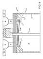
- FIG. 5is a partial schematic side view of a fourth embodiment of the present invention in cross-section.
- the present inventionis a vapor generation bubbler container designed for service in high vacuum or high flowrate conditions.
- the designprevents splashing and transport of aerosol droplets into the outlet delivery line that would result in erratic chemical mass flow delivery.
- the bubbler container of the present inventionallows liquid chemical to be delivered from the container as a vapor at high vacuum, without the splashing and the formation of aerosol droplets in the outlet of the container that result in erratic chemical mass delivery rate.
- the present inventionhas a lower surface design that enables a constant saturation of a carrier gas with chemical vapor down to very low levels of the residual chemical. Yet, the present invention prevents splashing and the formation of aerosol droplets into the outlet of the container, that would result in erratic chemical mass delivery rate, even when the chemical level in the container is high.
- containers used for high vacuum service or high flowrate servicehad to be used with only a partial charge of chemical (i.e.: 50% full). This required the semiconductor manufacturer to change the container more often (taking down the tool), and added to the cost of the chemical, because of the increased container processing fees.
- This inventionenables use of the container from a full liquid chemical level down to a very low level and reduces semiconductor tool downtime. Also, since it is effective at limiting the chemical aerosol particles in the outlet, it can reduce particulate generation that might result from degradation of the aerosol droplets that deposit in the outlet and all of the delivery piping to the processing chamber or tool. In this description, its is preferred to have a container of cylindrical shape with the axis of the cylinder in the vertical plane. Thus, descriptions of axial and radial are with respect to that type of container shape and orientation.
- the present inventionuses an annular radially inward projecting deflector ledge on the inner surface of the sidewall of the container in conjunction with one or more baffle discs at the upper part of the container that requires the carrier gas entrained with chemical precursor to pass indirectly to the outlet of the container by flowing tortuously to the radially innermost edge of the deflector ledge and to the outside of the baffle discs in a narrow annular space between the inner diameter of the bubbler inner surface sidewall and the outermost diameter or circumferential or perimeter edge of the baffle discs. This will be illustrated with reference to a preferred embodiment of the present invention.
- FIG. 1shows a bubbler container 10 of the present invention having a cylindrical bubbler sidewall 12 with a diptube inlet 14 terminating at its inlet end below the surface of the liquid chemical precursor, illustrated as approximately at line 15 , but above the container base 13 .
- the splash guardcomprises: (1) a baffle disc 24 ; and, (2) an annular, radially inward projecting deflecting ledge 22 on the inside surface 23 of the sidewall 12 , wherein the baffle disc 24 has an outermost circumferential perimeter edge shape, preferably circular, and being concave downward, such as a shallow downwardly open cone; which baffle disc 24 and deflector ledge 22 act in cooperation to make a tortuous flow path for chemical precursor leaving the container 10 .
- the baffle disc 24is concave downward to further frustrate direct flow of chemical precursor to the outlet 16 and to collect condensed chemical precursor for return by coalesced droplets falling back into the stored chemical precursor (not illustrated).
- the baffle disc 24has a diameter slightly less than the inside diameter of the cylindrical inner surface 23 of the sidewall 12 of the container 10 .
- the space between the circumferential perimeter outermost edge of the baffle disc 24 and the inside surface 23 of the sidewall 12 of the container 10is sufficient to allow gas to pass through the space with minimal pressure drop, but sufficiently narrow to minimize the passage of liquid that may be ejected from the liquid content of the bubbler under high flow rates of carrier gas through the diptube or significant pressure fluctuations.
- the container 10has an upper portion 17 and a lower portion 11 and an exemplary liquid surface level 15 , subject to change based upon the extent of fill and the duration of dispense, but typically below deflector ledge 22 and baffle disc 24 and above the ends ( 27 a and 27 b , respectively) of the inlet 14 and the level sensor 28 .
- FIG. 2shows an isolation of the internal structure of the container of the embodiment without the diptube 14 being illustrated.
- a level sense 28is shown in the middle of the container to monitor liquid chemical levels. The level sensor ends near the base 13 of the container 10 .
- Valve 30controls the introduction of push or carrier gas through inlet 14 into the lower portion of the container, where it bubbles up through the liquid chemical, entraining a vapor of the chemical in the bubbles of the carrier gas.
- the bubbling action of the carrier gas as it exits the lower end of the inlet diptube 14can create violent agitation of the liquid chemical.
- a high vacuum on the outlet 16 when valve 26 is openedcan also cause violent or severe agitation of the liquid chemical. Either of these can lead to liquid chemical bubbling or splashing toward the outlet 16 .
- the annular, radially inward projecting deflector ledge 22 associated with the sidewall 12 of the container or bubbler 10acts to deflect any bubbling or splashing liquid chemical from nearing the outermost edge of the baffle disc 24 to protect the inlet end 32 of the outlet 16 from ingesting liquid chemical, rather than the designed chemical vapor entrained in carrier gas.
- the baffle disc 24 and the deflector ledge 22form a tortuous flow path 38 for chemical precursor leaving the container 10 .
- the deflector ledge 22is formed from a part of the sidewall 12 during the milling of the container or bubbler 10 from a solid piece of stainless steel stock.
- the deflector ledge 22can have a conical shaped cross-sectional construction, ending in its innermost edge 34 radially inside the outermost edge 36 of the baffle disc 24 .
- Deflector ledgecan be an annular rim formed completely around the inner surface 23 of the sidewall 12 .
- the combination of the baffle disc 24 and the deflector ledge 22forms a tortuous flowpath 38 for the carrier gas and entrained chemical vapor, such path being extremely difficult for liquid phase chemical to follow.
- the baffle disc 24is spaced axially above the deflector ledge 22 to provide an extremely narrow flowpath, sufficient for vapor, but difficult for liquid flow, that is, proximate one another.
- the baffle disc 24can be spaced axially below the deflector ledge 22 .
- the present inventionenvisions multiple baffle discs, such as a baffle disc 24 spaced axially above and a baffle disc 24 a spaced axially below the deflector ledge, FIG. 3 ; two baffle discs 24 and 24 b spaced axially above the deflector ledge, FIG. 5 ; two baffle discs 24 c and 24 d spaced axially below the deflector ledge, FIG. 4 ; a deflector ledge spaced axially above and below each baffle disc; and a plurality of baffle discs and deflector ledges; all preferably proximate one another as defined above.
- the deflector ledgeincludes a shoulder 21 formed as an annular radially inward projecting edge spaced axially below the innermost edge 34 of the deflector ledge 22 .
- the deflector ledge 22 and shoulder 21are proportioned such that the deflector ledge 22 projects radially inward beyond the radially inward projection of the shoulder 21 .
- This shouldercan be an integral part of the overall deflector ledge 22 and can be machined at the same time as the deflector ledge from a single stock of stainless steel or other metal.
- Shoulder 21performs two functions. Shoulder 21 forms a sharp angle to the inner surface 23 and thus redirects liquid flowing up the inner surface into the interior of the container 10 and away from the tortuous pathway 38 formed by the respective edges of the baffle disc 24 and the deflector ledge 22 . In addition, any liquid that collects on the deflector ledge 22 drains to the shoulder 21 and then falls back into the liquid chemical contained in the lower portion of the container or bubbler 10 .
- Baffle disc 24 and deflector ledge 22are shown preferably at the upper region 17 of the container, but it is understood that other positioning are contemplated as long as they are above where the standard upper limit of the chemical filled in the container, or headspace or freeboard, as those skilled in the art would describe it, but at least above level 15 .
- deflector ledge 22 and shoulder 21are shown in this embodiment as being integral to one another and the sidewall, its is contemplated that both the deflector ledge 22 and the shoulder 21 could be separate pieces attached to the sidewall 12 , such as by welding, friction fit or mechanical fastening, such as bolts, screws and similar fasteners. Even as separate pieces, deflector ledge 22 and shoulder 21 could be integral to one another or separate pieces from one another.
- the deflector ledge 22 , shoulder 21 , and baffle disc 24cooperate to form a tortuous flowpath 38 for chemical to be dispensed through the outlet 16 .
- the liquidtends to foam above the liquid surface 15 into the headspace in the upper region 17 of the container 10 .
- the tortuous flowpath 38 formed by the deflector ledge 22 , shoulder 21 and baffle disc 24substantially prevent such foam from reaching the outlet 16 .
- the present inventionprovides superior minimization of liquid entrainment of droplets in the outlet and downstream piping of a container connected to a CVD tool of an electronics fabrication system.
- Using either a single baffle disc or multiples of the baffle disc, in combination with a deflector ledgeprovides the desired minimization of liquid droplet entrainment in the outlet 16 of the bubbler.
- baffle discshave been shown as circular discs with a concavity where the disc is slightly smaller than the inside diameter of the cylindrical vessel or bubbler sidewall, it is understood that any baffle of any shape which provides only a narrow annular space at the inner sidewall of the container is within the scope of the present invention.
- any form of deflector ledge having a smoot radially inward projection edge or an edge having some deviation from a smooth annular curveis contemplated as a part of the present invention.
- the vessel 10can also be used for product flow in the opposite direction where outlet 16 functions as a pressurizing gas inlet to form a pressure head on liquid contained in the vessel 10 and force the liquid, in liquid phase, out the diptube 14 for liquid delivery from the container using a pressurizing gas, in contrast to the vapor delivery described above.
Landscapes
- Engineering & Computer Science (AREA)
- Mechanical Engineering (AREA)
- General Engineering & Computer Science (AREA)
- Chemical & Material Sciences (AREA)
- Chemical Kinetics & Catalysis (AREA)
- Chemical Vapour Deposition (AREA)
Abstract
Description
Claims (11)
Priority Applications (5)
| Application Number | Priority Date | Filing Date | Title |
|---|---|---|---|
| US13/350,989US8944420B2 (en) | 2009-03-19 | 2012-01-16 | Splashguard for high flow vacuum bubbler vessel |
| TW102101206ATWI480418B (en) | 2012-01-16 | 2013-01-11 | Splashguard for high flow vacuum bubbler vessel |
| KR1020130004916AKR20130084265A (en) | 2012-01-16 | 2013-01-16 | Splashguard for high flow vacuum bubbler vessel |
| CN2013100252648ACN103205732A (en) | 2012-01-16 | 2013-01-16 | Splashguard for high flow vacuum bubbler vessel |
| JP2013005439AJP5596804B2 (en) | 2012-01-16 | 2013-01-16 | Splash guard for high flow vacuum bubbler containers |
Applications Claiming Priority (2)
| Application Number | Priority Date | Filing Date | Title |
|---|---|---|---|
| US12/407,279US8162296B2 (en) | 2009-03-19 | 2009-03-19 | Splashguard for high flow vacuum bubbler vessel |
| US13/350,989US8944420B2 (en) | 2009-03-19 | 2012-01-16 | Splashguard for high flow vacuum bubbler vessel |
Related Parent Applications (1)
| Application Number | Title | Priority Date | Filing Date |
|---|---|---|---|
| US12/407,279Continuation-In-PartUS8162296B2 (en) | 2009-03-19 | 2009-03-19 | Splashguard for high flow vacuum bubbler vessel |
Publications (2)
| Publication Number | Publication Date |
|---|---|
| US20130015594A1 US20130015594A1 (en) | 2013-01-17 |
| US8944420B2true US8944420B2 (en) | 2015-02-03 |
Family
ID=47518489
Family Applications (1)
| Application Number | Title | Priority Date | Filing Date |
|---|---|---|---|
| US13/350,989Active2030-10-09US8944420B2 (en) | 2009-03-19 | 2012-01-16 | Splashguard for high flow vacuum bubbler vessel |
Country Status (1)
| Country | Link |
|---|---|
| US (1) | US8944420B2 (en) |
Cited By (2)
| Publication number | Priority date | Publication date | Assignee | Title |
|---|---|---|---|---|
| US20140191423A1 (en)* | 2006-12-15 | 2014-07-10 | Air Products And Chemicals, Inc. | Splashguard and Inlet Diffuser for High Vacuum, High Flow Bubbler Vessel |
| US10443128B2 (en) | 2015-04-18 | 2019-10-15 | Versum Materials Us, Llc | Vessel and method for delivery of precursor materials |
Citations (26)
| Publication number | Priority date | Publication date | Assignee | Title |
|---|---|---|---|---|
| US1339609A (en) | 1917-07-02 | 1920-05-11 | Stinson Tractor Company | Dust-collector for carbureters |
| US2405494A (en) | 1944-03-29 | 1946-08-06 | Cedar Corp N O | Air treating apparatus |
| US2886127A (en) | 1956-02-14 | 1959-05-12 | Martin Parry Corp | Vacuum cleaner construction |
| US4350505A (en)* | 1976-12-17 | 1982-09-21 | Loffland Brothers Company | Device for reduction of oxygen content in drilling fluid |
| US4450118A (en) | 1981-04-29 | 1984-05-22 | U.S. Philips Corporation | Apparatus for saturating a gas with the vapor of a liquid |
| JPS60170965A (en) | 1984-02-16 | 1985-09-04 | Seiko Instr & Electronics Ltd | Protective circuit |
| US4591464A (en) | 1983-11-22 | 1986-05-27 | Mitsubishi Denki Kabushiki Kaisha | Method and apparatus for evaporating a liquid organic metal |
| JPS63149521A (en) | 1986-12-12 | 1988-06-22 | Fuji Electric Co Ltd | Liquid level measuring device for solid solution storage tank |
| JPH034657A (en) | 1989-06-01 | 1991-01-10 | Mitsubishi Electric Corp | TV doorbell |
| EP0420596A1 (en) | 1989-09-26 | 1991-04-03 | Canon Kabushiki Kaisha | Gas feeding device and deposition film forming apparatus employing the same |
| US5199963A (en)* | 1992-07-30 | 1993-04-06 | Scarp Arcoline J | Dual filtering vacuum system |
| WO1994006529A1 (en) | 1992-09-21 | 1994-03-31 | Mitsubishi Denki Kabushiki Kaisha | Liquid gasification apparatus |
| JPH06196419A (en) | 1992-12-24 | 1994-07-15 | Canon Inc | Chemical vapor deposition apparatus and semiconductor device manufacturing method using the same |
| US5589110A (en) | 1992-11-20 | 1996-12-31 | Mitsubishi Electric Corp | Container for liquid metal organic compound |
| JPH09234320A (en) | 1996-03-01 | 1997-09-09 | Bio Giken Kogyo:Kk | Treatment method for waste gas and apparatus therefor |
| JPH10228892A (en) | 1997-02-13 | 1998-08-25 | Matsushita Electric Ind Co Ltd | Liquid storage plug for lead-acid battery |
| US20020145210A1 (en) | 2001-04-09 | 2002-10-10 | Tompkins Gregory Edward | Bubbler for use in vapor generation systems |
| US6520218B1 (en) | 1998-09-03 | 2003-02-18 | Advanced Technology Materials, Inc. | Container chemical guard |
| US20030042630A1 (en) | 2001-09-05 | 2003-03-06 | Babcoke Jason E. | Bubbler for gas delivery |
| EP1329540A2 (en) | 2000-07-03 | 2003-07-23 | Epichem Limited | An apparatus for the delivery of precursors in the vapour phase to epitaxial reactor sites |
| US20040013577A1 (en) | 2002-07-17 | 2004-01-22 | Seshadri Ganguli | Method and apparatus for providing gas to a processing chamber |
| US6874770B2 (en) | 2001-11-30 | 2005-04-05 | Aviza Technology, Inc. | High flow rate bubbler system and method |
| JP2005197148A (en) | 2004-01-09 | 2005-07-21 | Yuasa Corp | Liquid cap for lead acid battery and lead acid battery |
| US7077388B2 (en) | 2002-07-19 | 2006-07-18 | Asm America, Inc. | Bubbler for substrate processing |
| EP1932942A2 (en) | 2006-12-15 | 2008-06-18 | Air Products and Chemicals, Inc. | Splashguard and inlet diffuser for high vacuum, high flow bubbler vessel |
| US20100237085A1 (en) | 2009-03-19 | 2010-09-23 | Air Products And Chemicals, Inc. | Splashguard for High Flow Vacuum Bubbler Vessel |
- 2012
- 2012-01-16USUS13/350,989patent/US8944420B2/enactiveActive
Patent Citations (35)
| Publication number | Priority date | Publication date | Assignee | Title |
|---|---|---|---|---|
| US1339609A (en) | 1917-07-02 | 1920-05-11 | Stinson Tractor Company | Dust-collector for carbureters |
| US2405494A (en) | 1944-03-29 | 1946-08-06 | Cedar Corp N O | Air treating apparatus |
| US2886127A (en) | 1956-02-14 | 1959-05-12 | Martin Parry Corp | Vacuum cleaner construction |
| US4350505A (en)* | 1976-12-17 | 1982-09-21 | Loffland Brothers Company | Device for reduction of oxygen content in drilling fluid |
| US4450118A (en) | 1981-04-29 | 1984-05-22 | U.S. Philips Corporation | Apparatus for saturating a gas with the vapor of a liquid |
| US4591464A (en) | 1983-11-22 | 1986-05-27 | Mitsubishi Denki Kabushiki Kaisha | Method and apparatus for evaporating a liquid organic metal |
| JPS60170965A (en) | 1984-02-16 | 1985-09-04 | Seiko Instr & Electronics Ltd | Protective circuit |
| JPS63149521A (en) | 1986-12-12 | 1988-06-22 | Fuji Electric Co Ltd | Liquid level measuring device for solid solution storage tank |
| JPH034657A (en) | 1989-06-01 | 1991-01-10 | Mitsubishi Electric Corp | TV doorbell |
| EP0420596A1 (en) | 1989-09-26 | 1991-04-03 | Canon Kabushiki Kaisha | Gas feeding device and deposition film forming apparatus employing the same |
| US5199963A (en)* | 1992-07-30 | 1993-04-06 | Scarp Arcoline J | Dual filtering vacuum system |
| WO1994006529A1 (en) | 1992-09-21 | 1994-03-31 | Mitsubishi Denki Kabushiki Kaisha | Liquid gasification apparatus |
| US5520858A (en) | 1992-09-21 | 1996-05-28 | Mitsubishi Denki Kabushiki Kaisha | Liquid vaporizing apparatus |
| US5589110A (en) | 1992-11-20 | 1996-12-31 | Mitsubishi Electric Corp | Container for liquid metal organic compound |
| US5776255A (en) | 1992-12-24 | 1998-07-07 | Canon Kabushiki Kaisha | Chemical vapor deposition apparatus |
| JPH06196419A (en) | 1992-12-24 | 1994-07-15 | Canon Inc | Chemical vapor deposition apparatus and semiconductor device manufacturing method using the same |
| JPH09234320A (en) | 1996-03-01 | 1997-09-09 | Bio Giken Kogyo:Kk | Treatment method for waste gas and apparatus therefor |
| JPH10228892A (en) | 1997-02-13 | 1998-08-25 | Matsushita Electric Ind Co Ltd | Liquid storage plug for lead-acid battery |
| US6520218B1 (en) | 1998-09-03 | 2003-02-18 | Advanced Technology Materials, Inc. | Container chemical guard |
| EP1329540A2 (en) | 2000-07-03 | 2003-07-23 | Epichem Limited | An apparatus for the delivery of precursors in the vapour phase to epitaxial reactor sites |
| US20020145210A1 (en) | 2001-04-09 | 2002-10-10 | Tompkins Gregory Edward | Bubbler for use in vapor generation systems |
| US20030042630A1 (en) | 2001-09-05 | 2003-03-06 | Babcoke Jason E. | Bubbler for gas delivery |
| JP2005511272A (en) | 2001-11-30 | 2005-04-28 | アヴィザ テクノロジー インコーポレイテッド | High flow bubbler system and method |
| US6874770B2 (en) | 2001-11-30 | 2005-04-05 | Aviza Technology, Inc. | High flow rate bubbler system and method |
| WO2004007793A2 (en) | 2002-07-17 | 2004-01-22 | Applied Materials, Inc. | Method and apparatus for providing gas to a processing chamber |
| US20040013577A1 (en) | 2002-07-17 | 2004-01-22 | Seshadri Ganguli | Method and apparatus for providing gas to a processing chamber |
| JP2005533179A (en) | 2002-07-17 | 2005-11-04 | アプライド マテリアルズ インコーポレイテッド | Method and apparatus for supplying gas to a processing chamber |
| US7077388B2 (en) | 2002-07-19 | 2006-07-18 | Asm America, Inc. | Bubbler for substrate processing |
| JP2005197148A (en) | 2004-01-09 | 2005-07-21 | Yuasa Corp | Liquid cap for lead acid battery and lead acid battery |
| EP1932942A2 (en) | 2006-12-15 | 2008-06-18 | Air Products and Chemicals, Inc. | Splashguard and inlet diffuser for high vacuum, high flow bubbler vessel |
| US20080143002A1 (en) | 2006-12-15 | 2008-06-19 | Air Products And Chemicals, Inc. | Splashguard and Inlet Diffuser for High Vacuum, High Flow Bubbler Vessel |
| JP2008150709A (en) | 2006-12-15 | 2008-07-03 | Air Products & Chemicals Inc | Splashguard and inlet diffuser for high vacuum, high flow bubbler vessel |
| US8708320B2 (en)* | 2006-12-15 | 2014-04-29 | Air Products And Chemicals, Inc. | Splashguard and inlet diffuser for high vacuum, high flow bubbler vessel |
| US20100237085A1 (en) | 2009-03-19 | 2010-09-23 | Air Products And Chemicals, Inc. | Splashguard for High Flow Vacuum Bubbler Vessel |
| US8162296B2 (en)* | 2009-03-19 | 2012-04-24 | Air Products And Chemicals, Inc. | Splashguard for high flow vacuum bubbler vessel |
Non-Patent Citations (1)
| Title |
|---|
| GO Element 2008 catalogue, Semiconductor/High Purity Products, Pyongtaek Korea 459-050, www.goelement.co.kr. |
Cited By (4)
| Publication number | Priority date | Publication date | Assignee | Title |
|---|---|---|---|---|
| US20140191423A1 (en)* | 2006-12-15 | 2014-07-10 | Air Products And Chemicals, Inc. | Splashguard and Inlet Diffuser for High Vacuum, High Flow Bubbler Vessel |
| US20140193578A1 (en)* | 2006-12-15 | 2014-07-10 | Air Products And Chemicals, Inc. | Splashguard and Inlet Diffuser for High Vacuum, High Flow Bubbler Vessel |
| US9435027B2 (en)* | 2006-12-15 | 2016-09-06 | Air Products And Chemicals, Inc. | Splashguard and inlet diffuser for high vacuum, high flow bubbler vessel |
| US10443128B2 (en) | 2015-04-18 | 2019-10-15 | Versum Materials Us, Llc | Vessel and method for delivery of precursor materials |
Also Published As
| Publication number | Publication date |
|---|---|
| US20130015594A1 (en) | 2013-01-17 |
Similar Documents
| Publication | Publication Date | Title |
|---|---|---|
| US8162296B2 (en) | Splashguard for high flow vacuum bubbler vessel | |
| US9435027B2 (en) | Splashguard and inlet diffuser for high vacuum, high flow bubbler vessel | |
| TWI617695B (en) | Container for chemical precursors in a deposition process and method for storing and transporting liquid chemical precursors to processing equipment | |
| CN101405433B (en) | Method and apparatus for reducing particle contamination in a deposition system | |
| US8944420B2 (en) | Splashguard for high flow vacuum bubbler vessel | |
| Vahlas et al. | Liquid and solid precursor delivery systems in gas phase processes | |
| TWI480418B (en) | Splashguard for high flow vacuum bubbler vessel | |
| US9399198B2 (en) | Venturi ejector for a chemical dispenser | |
| KR102415265B1 (en) | Aerosol-free vessel for bubbling chemical precursors in deposition processes | |
| JP4065366B2 (en) | Ultrasonic device for spraying liquid |
Legal Events
| Date | Code | Title | Description |
|---|---|---|---|
| AS | Assignment | Owner name:AIR PRODUCTS AND CHEMICALS, INC., PENNSYLVANIA Free format text:ASSIGNMENT OF ASSIGNORS INTEREST;ASSIGNORS:BIRTCHER, CHARLES MICHAEL;STEIDL, THOMAS ANDREW;REEL/FRAME:027942/0660 Effective date:20120319 | |
| STCF | Information on status: patent grant | Free format text:PATENTED CASE | |
| AS | Assignment | Owner name:CITIBANK, N.A., AS COLLATERAL AGENT, DELAWARE Free format text:PATENT SECURITY AGREEMENT;ASSIGNOR:VERSUM MATERIALS US, LLC;REEL/FRAME:040503/0442 Effective date:20160930 | |
| AS | Assignment | Owner name:VERSUM MATERIALS US, LLC, ARIZONA Free format text:ASSIGNMENT OF ASSIGNORS INTEREST;ASSIGNOR:AIR PRODUCTS AND CHEMICALS, INC.;REEL/FRAME:041772/0733 Effective date:20170214 | |
| MAFP | Maintenance fee payment | Free format text:PAYMENT OF MAINTENANCE FEE, 4TH YEAR, LARGE ENTITY (ORIGINAL EVENT CODE: M1551) Year of fee payment:4 | |
| AS | Assignment | Owner name:VERSUM MATERIALS US, LLC, ARIZONA Free format text:RELEASE BY SECURED PARTY;ASSIGNOR:CITIBANK, N.A., AS AGENT;REEL/FRAME:050647/0001 Effective date:20191007 | |
| MAFP | Maintenance fee payment | Free format text:PAYMENT OF MAINTENANCE FEE, 8TH YEAR, LARGE ENTITY (ORIGINAL EVENT CODE: M1552); ENTITY STATUS OF PATENT OWNER: LARGE ENTITY Year of fee payment:8 |