US8944056B2 - Humidification arrangement for a respiratory apparatus - Google Patents
Humidification arrangement for a respiratory apparatusDownload PDFInfo
- Publication number
- US8944056B2 US8944056B2US12/449,355US44935508AUS8944056B2US 8944056 B2US8944056 B2US 8944056B2US 44935508 AUS44935508 AUS 44935508AUS 8944056 B2US8944056 B2US 8944056B2
- Authority
- US
- United States
- Prior art keywords
- gas
- gas conduit
- water
- liquid water
- lumen
- Prior art date
- Legal status (The legal status is an assumption and is not a legal conclusion. Google has not performed a legal analysis and makes no representation as to the accuracy of the status listed.)
- Expired - Fee Related, expires
Links
Images


Classifications
- A—HUMAN NECESSITIES
- A61—MEDICAL OR VETERINARY SCIENCE; HYGIENE
- A61M—DEVICES FOR INTRODUCING MEDIA INTO, OR ONTO, THE BODY; DEVICES FOR TRANSDUCING BODY MEDIA OR FOR TAKING MEDIA FROM THE BODY; DEVICES FOR PRODUCING OR ENDING SLEEP OR STUPOR
- A61M16/00—Devices for influencing the respiratory system of patients by gas treatment, e.g. ventilators; Tracheal tubes
- A61M16/10—Preparation of respiratory gases or vapours
- A61M16/14—Preparation of respiratory gases or vapours by mixing different fluids, one of them being in a liquid phase
- A61M16/16—Devices to humidify the respiration air
- A—HUMAN NECESSITIES
- A61—MEDICAL OR VETERINARY SCIENCE; HYGIENE
- A61M—DEVICES FOR INTRODUCING MEDIA INTO, OR ONTO, THE BODY; DEVICES FOR TRANSDUCING BODY MEDIA OR FOR TAKING MEDIA FROM THE BODY; DEVICES FOR PRODUCING OR ENDING SLEEP OR STUPOR
- A61M16/00—Devices for influencing the respiratory system of patients by gas treatment, e.g. ventilators; Tracheal tubes
- A61M16/0003—Accessories therefor, e.g. sensors, vibrators, negative pressure
- A—HUMAN NECESSITIES
- A61—MEDICAL OR VETERINARY SCIENCE; HYGIENE
- A61M—DEVICES FOR INTRODUCING MEDIA INTO, OR ONTO, THE BODY; DEVICES FOR TRANSDUCING BODY MEDIA OR FOR TAKING MEDIA FROM THE BODY; DEVICES FOR PRODUCING OR ENDING SLEEP OR STUPOR
- A61M16/00—Devices for influencing the respiratory system of patients by gas treatment, e.g. ventilators; Tracheal tubes
- A61M16/0057—Pumps therefor
- A—HUMAN NECESSITIES
- A61—MEDICAL OR VETERINARY SCIENCE; HYGIENE
- A61M—DEVICES FOR INTRODUCING MEDIA INTO, OR ONTO, THE BODY; DEVICES FOR TRANSDUCING BODY MEDIA OR FOR TAKING MEDIA FROM THE BODY; DEVICES FOR PRODUCING OR ENDING SLEEP OR STUPOR
- A61M16/00—Devices for influencing the respiratory system of patients by gas treatment, e.g. ventilators; Tracheal tubes
- A61M16/06—Respiratory or anaesthetic masks
- A—HUMAN NECESSITIES
- A61—MEDICAL OR VETERINARY SCIENCE; HYGIENE
- A61M—DEVICES FOR INTRODUCING MEDIA INTO, OR ONTO, THE BODY; DEVICES FOR TRANSDUCING BODY MEDIA OR FOR TAKING MEDIA FROM THE BODY; DEVICES FOR PRODUCING OR ENDING SLEEP OR STUPOR
- A61M16/00—Devices for influencing the respiratory system of patients by gas treatment, e.g. ventilators; Tracheal tubes
- A61M16/08—Bellows; Connecting tubes ; Water traps; Patient circuits
- A61M16/0875—Connecting tubes
- A—HUMAN NECESSITIES
- A61—MEDICAL OR VETERINARY SCIENCE; HYGIENE
- A61M—DEVICES FOR INTRODUCING MEDIA INTO, OR ONTO, THE BODY; DEVICES FOR TRANSDUCING BODY MEDIA OR FOR TAKING MEDIA FROM THE BODY; DEVICES FOR PRODUCING OR ENDING SLEEP OR STUPOR
- A61M16/00—Devices for influencing the respiratory system of patients by gas treatment, e.g. ventilators; Tracheal tubes
- A61M16/10—Preparation of respiratory gases or vapours
- A61M16/1075—Preparation of respiratory gases or vapours by influencing the temperature
- A61M16/109—Preparation of respiratory gases or vapours by influencing the temperature the humidifying liquid or the beneficial agent
- A—HUMAN NECESSITIES
- A61—MEDICAL OR VETERINARY SCIENCE; HYGIENE
- A61M—DEVICES FOR INTRODUCING MEDIA INTO, OR ONTO, THE BODY; DEVICES FOR TRANSDUCING BODY MEDIA OR FOR TAKING MEDIA FROM THE BODY; DEVICES FOR PRODUCING OR ENDING SLEEP OR STUPOR
- A61M16/00—Devices for influencing the respiratory system of patients by gas treatment, e.g. ventilators; Tracheal tubes
- A61M16/10—Preparation of respiratory gases or vapours
- A61M16/1075—Preparation of respiratory gases or vapours by influencing the temperature
- A61M16/1095—Preparation of respiratory gases or vapours by influencing the temperature in the connecting tubes
- A—HUMAN NECESSITIES
- A61—MEDICAL OR VETERINARY SCIENCE; HYGIENE
- A61M—DEVICES FOR INTRODUCING MEDIA INTO, OR ONTO, THE BODY; DEVICES FOR TRANSDUCING BODY MEDIA OR FOR TAKING MEDIA FROM THE BODY; DEVICES FOR PRODUCING OR ENDING SLEEP OR STUPOR
- A61M16/00—Devices for influencing the respiratory system of patients by gas treatment, e.g. ventilators; Tracheal tubes
- A61M16/10—Preparation of respiratory gases or vapours
- A61M16/14—Preparation of respiratory gases or vapours by mixing different fluids, one of them being in a liquid phase
- A61M16/142—Preparation of respiratory gases or vapours by mixing different fluids, one of them being in a liquid phase with semi-permeable walls separating the liquid from the respiratory gas
- A—HUMAN NECESSITIES
- A61—MEDICAL OR VETERINARY SCIENCE; HYGIENE
- A61M—DEVICES FOR INTRODUCING MEDIA INTO, OR ONTO, THE BODY; DEVICES FOR TRANSDUCING BODY MEDIA OR FOR TAKING MEDIA FROM THE BODY; DEVICES FOR PRODUCING OR ENDING SLEEP OR STUPOR
- A61M16/00—Devices for influencing the respiratory system of patients by gas treatment, e.g. ventilators; Tracheal tubes
- A61M16/10—Preparation of respiratory gases or vapours
- A61M16/105—Filters
- A61M16/1055—Filters bacterial
- A—HUMAN NECESSITIES
- A61—MEDICAL OR VETERINARY SCIENCE; HYGIENE
- A61M—DEVICES FOR INTRODUCING MEDIA INTO, OR ONTO, THE BODY; DEVICES FOR TRANSDUCING BODY MEDIA OR FOR TAKING MEDIA FROM THE BODY; DEVICES FOR PRODUCING OR ENDING SLEEP OR STUPOR
- A61M16/00—Devices for influencing the respiratory system of patients by gas treatment, e.g. ventilators; Tracheal tubes
- A61M16/10—Preparation of respiratory gases or vapours
- A61M16/105—Filters
- A61M16/106—Filters in a path
- A—HUMAN NECESSITIES
- A61—MEDICAL OR VETERINARY SCIENCE; HYGIENE
- A61M—DEVICES FOR INTRODUCING MEDIA INTO, OR ONTO, THE BODY; DEVICES FOR TRANSDUCING BODY MEDIA OR FOR TAKING MEDIA FROM THE BODY; DEVICES FOR PRODUCING OR ENDING SLEEP OR STUPOR
- A61M16/00—Devices for influencing the respiratory system of patients by gas treatment, e.g. ventilators; Tracheal tubes
- A61M16/10—Preparation of respiratory gases or vapours
- A61M16/14—Preparation of respiratory gases or vapours by mixing different fluids, one of them being in a liquid phase
- A61M16/16—Devices to humidify the respiration air
- A61M16/161—Devices to humidify the respiration air with means for measuring the humidity
- A—HUMAN NECESSITIES
- A61—MEDICAL OR VETERINARY SCIENCE; HYGIENE
- A61M—DEVICES FOR INTRODUCING MEDIA INTO, OR ONTO, THE BODY; DEVICES FOR TRANSDUCING BODY MEDIA OR FOR TAKING MEDIA FROM THE BODY; DEVICES FOR PRODUCING OR ENDING SLEEP OR STUPOR
- A61M16/00—Devices for influencing the respiratory system of patients by gas treatment, e.g. ventilators; Tracheal tubes
- A61M16/10—Preparation of respiratory gases or vapours
- A61M16/14—Preparation of respiratory gases or vapours by mixing different fluids, one of them being in a liquid phase
- A61M16/16—Devices to humidify the respiration air
- A61M16/162—Water-reservoir filling system, e.g. automatic
- A—HUMAN NECESSITIES
- A61—MEDICAL OR VETERINARY SCIENCE; HYGIENE
- A61M—DEVICES FOR INTRODUCING MEDIA INTO, OR ONTO, THE BODY; DEVICES FOR TRANSDUCING BODY MEDIA OR FOR TAKING MEDIA FROM THE BODY; DEVICES FOR PRODUCING OR ENDING SLEEP OR STUPOR
- A61M16/00—Devices for influencing the respiratory system of patients by gas treatment, e.g. ventilators; Tracheal tubes
- A61M16/0003—Accessories therefor, e.g. sensors, vibrators, negative pressure
- A61M2016/003—Accessories therefor, e.g. sensors, vibrators, negative pressure with a flowmeter
- A—HUMAN NECESSITIES
- A61—MEDICAL OR VETERINARY SCIENCE; HYGIENE
- A61M—DEVICES FOR INTRODUCING MEDIA INTO, OR ONTO, THE BODY; DEVICES FOR TRANSDUCING BODY MEDIA OR FOR TAKING MEDIA FROM THE BODY; DEVICES FOR PRODUCING OR ENDING SLEEP OR STUPOR
- A61M2205/00—General characteristics of the apparatus
- A61M2205/33—Controlling, regulating or measuring
- A61M2205/3331—Pressure; Flow
- A61M2205/3334—Measuring or controlling the flow rate
- A—HUMAN NECESSITIES
- A61—MEDICAL OR VETERINARY SCIENCE; HYGIENE
- A61M—DEVICES FOR INTRODUCING MEDIA INTO, OR ONTO, THE BODY; DEVICES FOR TRANSDUCING BODY MEDIA OR FOR TAKING MEDIA FROM THE BODY; DEVICES FOR PRODUCING OR ENDING SLEEP OR STUPOR
- A61M2205/00—General characteristics of the apparatus
- A61M2205/33—Controlling, regulating or measuring
- A61M2205/3368—Temperature
- A—HUMAN NECESSITIES
- A61—MEDICAL OR VETERINARY SCIENCE; HYGIENE
- A61M—DEVICES FOR INTRODUCING MEDIA INTO, OR ONTO, THE BODY; DEVICES FOR TRANSDUCING BODY MEDIA OR FOR TAKING MEDIA FROM THE BODY; DEVICES FOR PRODUCING OR ENDING SLEEP OR STUPOR
- A61M2206/00—Characteristics of a physical parameter; associated device therefor
- A61M2206/10—Flow characteristics
- A61M2206/14—Static flow deviators in tubes disturbing laminar flow in tubes, e.g. archimedes screws
Definitions
- the present inventionrelates to humidification arrangements used to control the humidity of breathable gases used in all forms of respiratory apparatus ventilation systems including invasive and non-invasive ventilation, Continuous Positive Airway Pressure (CPAP), Bilevel therapy and treatment for sleep disordered breathing (SDB) conditions such as Obstructive Sleep Apnea (OSA), and for various other respiratory disorders and diseases.
- CPAPContinuous Positive Airway Pressure
- SDBsleep disordered breathing
- OSAObstructive Sleep Apnea
- Respiratory apparatuscommonly have means to alter the humidity of the breathable gas in order to reduce drying of the patient's airway and consequent patient discomfort and associated complications.
- PAPpositive airway pressure
- humidifiers typeshave been proposed, including humidifiers that are either integrated with or configured to be coupled to the relevant respiratory apparatus. While passive humidifiers can provide some relief, generally a heated humidifier is required to provide sufficient humidity and temperature to the air so that patient will be comfortable.
- Humidifierstypically comprise a water tub having a capacity of several hundred milliliters, a heating element for heating the water in the tub, a control to enable the level of humidification to be varied, a gas inlet to receive gas from the PAP device, and a gas outlet adapted to be connected to a gas conduit that delivers the humidified pressurized gas to the patient's mask.
- Tub-of-water humidifiersare also vulnerable to liquid water spillage if they are not maintained in the vertical. Spillage of liquid water can either travel into the gas conduit to the patient or back into the PAP device and associated electronics or deplete the reservoir of humidifying water. In either of the cases the spillage of water is undesirable.
- U.S. Pat. No. 4,146,597, U.S. Pat. No. 4,861,523, U.S. Pat. No. 5,367,604 and U.S. Pat. No. 6,010,118disclose the use of a discrete in-line unit placed somewhere along the gas conduit to the patient.
- discrete humidification unitshave the disadvantages of being bulky to the patient and impeding the free movement of the gas conduit as the patient moves.
- Another humidification schemeis to have a water source enclosed within a tube of a semi-permeable membrane which is then inserted into the gas conduit.
- the tubemay also incorporate heating elements to aid in the generation of water vapour. Examples of such prior art are U.S. Pat. No. 3,871,373, U.S. Pat. No. 4,708,831 and U.S. Pat. No. 6,201,223.
- U.S. Pat. No. 6,662,802describes an arrangement for collection of water condensation within the gas conduit and then its re-vaporisation into the gas flow, to reduce the effect of condensation within the gas conduit and to restore the humidity in the gas conduit.
- the apparatusdoes not have the capacity to increase the absolute humidity beyond what can be gathered as a water source from the condensate in the gas conduit. That is, the arrangement cannot increase the absolute humidity, merely restore it to the absolute humidity at which the gas is supplied to the conduit.
- the present inventionaims to provide an alternative humidifier apparatus which overcomes or ameliorates the disadvantages of the prior art, or at least provides a useful choice.
- the inventionprovides a flexible gas conduit for delivering breathable gas from a PAP device to a patient interface, such as a mask, including a lumen for transport of the breathable gas and a conduit wall including a humidification apparatus.
- the humidification apparatuscomprises a semi-permeable membrane portion which provides a portion of the inner wall between the gas flow within the lumen of the gas conduit and a water channel in the gas conduit.
- the semi-permeable membrane portionhas the characteristic of allowing water vapour to pass through it but not liquid water. Water vapour passing through the semi-permeable membrane portion may then be entrained into the gas flow to the patient interface.
- the humidification apparatus of the inventionmay comprise a wick and/or capillary action device which is associated with one or more portions of the inner wall of the gas conduit.
- the wick and/or capillary action deviceprovides water for vaporisation into the gas flow passing through the gas conduit.
- a further form of the inventionprovides a heater which is in thermal contact with the humidification apparatus.
- the heatermay be used to increase the rate of vaporisation of the water within the humidification apparatus.
- the humidification apparatus and heatermay each be divided into one or more separate portions along the gas conduit.
- the separate portions of each meansmay be separately controlled.
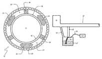
- FIG. 1is a schematic view of the PAP device, gas conduit as the humidifying apparatus and the patient mask, in an embodiment of the present invention.
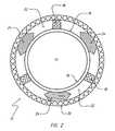
- FIG. 2is an enlarged transverse sectional view taken along the lines 2 - 2 in FIG. 1 , which illustrates an embodiment of the humidification apparatus using water channels.
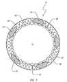
- FIG. 3is an alternative embodiment of FIG. 2 using multiple water tubes to form the inner wall of the gas conduit.
- FIG. 4is an isometric view illustrating an alternative embodiment to FIG. 2 .
- FIG. 5is longitudinal sectional view taken along the lines 5 - 5 in FIG. 4 .
- FIG. 6is an alternative embodiment of FIG. 2 , where a wick device is used in the humidification apparatus.
- FIG. 7is a circuit diagram of a heating control circuit employing a PTC thermistor control.
- FIG. 8is a cut-away perspective view of an alternative embodiment of the humidification apparatus where the wick device is located in the water channel.
- FIG. 9is a longitudinal cross-sectional view of FIG. 8 along the lines 9 - 9 .
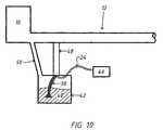
- FIG. 10schematically shows the humidification apparatus of FIG. 8 connected with a PAP device and a cut-away representation of a water reservoir.
- FIG. 1schematically shows a PAP device 10 which produces a gas flow and gas pressure that is fed into a flexible conduit 12 .
- the flexible gas conduit 12has a central lumen 13 ( FIG. 2 ) for conveying the gas flow to the patient mask 14 which is attached to the upper and/or lower airway of the patient or alternatively directly into the patient's airway via a tracheostomy tube.
- the humidifying apparatus of the present embodimentsconsists of the gas conduit 12 incorporating a humidification apparatus within it.
- FIG. 2illustrates a cross-sectional view of a humidification apparatus within a flexible gas conduit 12 , according to a first embodiment.
- the humidification apparatusmay have one or more semi-permeable membrane portions 16 which forms one or more portions of an inner wall of a double-walled conduit 12 and which allows water vapour to pass through the membrane but not liquid water.
- the inner wall of the double walled conduit 12may be made entirely of semi permeable membrane portions 16 .
- the semi-permeable membrane portionmay be formed of a material which has fine pores or perforations and may also be hydrophobic, the fineness of the porosity or the perforations and/or the degree of hydrophobic to hydrophilic nature being adapted to result in the desired effect of semi-permeability.
- the semi-permeable membrane portion 16forms the inner wall, adjacent to the central lumen 13 , of the flexible gas conduit 12 as shown in FIG. 2 .
- Structural reinforcing members 18extend along the wall of the conduit to provide support to the semi-permeable membrane portion 16 and to the outer wall 20 of the gas conduit 12 .
- the reinforcing members 18also have a spacing function in order that a water channel 22 (or water delivery passage) is formed within the gas conduit 12 between the semi-permeable membrane portion 16 and the outer wall 20 .
- the structural reinforcing members and/or spacers 18may be longitudinal, as shown in FIGS. 2 and 3 , or helical as illustrated in FIGS. 4 and 5 or a combination of these arrangements, but in all the arrangements the reinforcing supports 18 allows the gas conduit 12 to flex to a degree sufficient to allow its use as a flexible gas conduit.
- the heater 24is in thermal contact with the water in the water channel 22 and in electrical contact with the electronics associated with the PAP device 10 .
- the heater 24heats the water in the water channel in order to increase the production of water vapour, which migrates through the semi-permeable membrane portion 16 to mix with the gas flow within the lumen 13 of the gas conduit 12 and thus raise the humidity of the gas travelling through the gas conduit 12 .
- the heater 24may consist of a heating element which may for example consist of a resistive conductor.
- the conductormay consist of multiple resistive conductors connected to each other in series, parallel or segmented along the length of the gas conduit 12 in order to allow uniform, variable and/or sectional heating along the conduit.
- Such a heating element 24may be controlled by one or more positive temperature coefficient (PTC) thermistors 32 electrically in series with the power supply 34 and the resistive conductors 24 , for example as shown in the circuit diagram of FIG. 7 .
- the PTC thermistor 32operates to decrease heating as the temperature increases towards a desired temperature for the gas flow.
- the PTC thermistor 32may be located preferably at the end of the gas conduit 12 towards or at the patient's mask 14 , and in one embodiment is located on or incorporated in a cuff of the conduit for connection of the patient interface/mask.
- the thermistor 32may consist of a discrete semiconductor component such as a “bead” thermistor. Alternatively the function of the thermistor 32 may be served by a conductive thermoplastic elastomer (PTC-TPE) with PTC electrical properties.
- PTC-TPEconductive thermoplastic elastomer
- the PTC-TPEcan be moulded into a form to fit the patient end of the gas conduit 12 as a cuff portion or a portion of the patient mask 14 . Therefore the temperature sensor may be integral to the gas conduit 12 or patient mask 14 or any other associated component.
- the heater 24may be a flexible tape heater as described in the PCT Patent Application No. PCT/AU2007/001715 “Humidifier for a Respiratory Apparatus”, the contents of which are incorporated herein by reference.
- the heating element 24is formed by printed circuit techniques applied to a surface of a flexible substrate such as silicone rubber, all-polyimide or PTFE. Included in the printed circuit techniques which may be used are etched foil, printing and vacuum deposition techniques. The ThermofoilTM range of the type of flexible heaters by Minco of Minneapolis USA, described at www.minco.com, are examples of commercially available strip heaters which may be modified for use in the present application.
- the flexible tape heatermay be formed as a heating element, for example in the form of a resistive wire or ribbon, laminated between tapes of polycarbonate or other suitable plastics film.
- the outer wall 20 of the gas conduit 12may provide, protection, insulation and additional structural support to the other elements of the humidifying apparatus but still allows the gas conduit 12 to flex in use.
- water tubes 26are formed of semi-permeable membrane portion, for example of the materials discussed above in relation to FIG. 2 .
- the water tubes 26are then joined together in a side by side arrangement to form the inner wall of the gas conduit 12 .
- the water tubes 26may be in a helical or longitudinal or any other suitable configuration to form the inner wall of the gas conduit 12 .
- the heater 24is adjacent to the water tubes 26 as shown in FIG. 3 , to facilitate heat transfer to the water in the tubes.
- Water within the water tubes 26may be heated by the heater 24 to aid in the production of water vapour which migrates through the semi-permeable membrane portion and into the gas flow of the gas conduit 12 .
- the whole arrangementmay be encapsulated by an outer wall 20 which may also serve to provide structural support 18 or insulation while still allowing the gas conduit 12 to flex appropriately with patient movement.
- FIGS. 4 and 5illustrate another embodiment of the humidifying apparatus utilising a semi-permeable membrane portion 16 within a gas conduit 12 where the direction of gas flow is given by the arrow 28 .
- This embodiment of the humidification apparatushas a helical configuration for the semi-permeable membrane portion 16 , the structural reinforcing member or members 18 , the water channel 22 and the heating element 24 .
- the helical configuration of the outer wall 20may be similar to conventional conduits that are in common use in respiratory apparatus.
- the humidification apparatusmay be readily substituted into existing respiratory device by exchanging the gas conduit 12 .
- the humidification apparatusmay occupy one or more sectors of the circumference of the inner wall of the gas conduit 12 .
- the semi-permeable membrane portion 16then occupies only a portion of the inner wall of the gas conduit 12 .
- the portions of the inner wall formed by the semi-permeable membrane portion 16may be segmented along the length of the gas conduit 12 inner wall.
- the water supply to the water channel 22 or the water tubes 26 in the above embodimentsmay comprise a single filling at the start of an overnight therapy session of CPAP for OSA, the volume of the water channel 22 or water tubes 26 being a sufficient water supply.
- a water reservoir(not shown) may be used, which may be an external reservoir or may form part of the gas conduit.
- the water reservoirmay be located in a portion of the outer wall 20 of the gas conduit 12 .
- the location of the water reservoir along the gas conduit 12may be at a suitable point along the conduit to allow gravity feed or the use of micro-pump for the water supply.
- the water reservoirmay be located with the PAP device 10 where the connection for the water channels 22 and water tubes 26 to the water reservoir is associated with the connection of the gas conduit 12 to the PAP device 10 .
- the water channels 22 or water tubes 26may be in a loop arrangement so that water can be circulated through them and back to the water reservoir.
- the water channels 22 or water tubes 26may individually have an open end for water supply with the other end being closed, but may have a pore or perforation sufficient to allow gas to escape from the water channel 22 or water tube 26 as it fills or draws water.
- wick and/or capillary action device 30within the gas conduit 12 as shown in cross-section in FIG. 6 .
- references to “wick”includes the term “and/or capillary action”.
- the wick device 30has the ability to conduct water upon or within the wick device 30 such that water is available for vaporisation into the lumen 13 of the conduit. In addition a capillary action may also be involved within the wick device 30 .
- An example of a suitable wick device 30is a material which is hydrophilic so that the water has a tendency to spread across the extent of the material. Materials that may be suitable include cotton, activated perfluorinated polymer (e.g. “NAFION” stabilised perfluorosulfonic acid/PTFE copolymer by DuPont), polyester copolymer (e.g. SYMPATEX polyester/polyether copolymer by Sympatex Technologies GmbH of Germany) and polyester fabrics (e.g. COOLMAX polyester fabrics by Invista of USA). Alternatively a material may be imparted hydrophilic characteristics by using a particular liquid film or the application of a gel or solid film.
- activated perfluorinated polymere.g. “NAFION” stabilised per
- the wick device 30may have an internal structural form of a fabric (as shown in FIG. 6 ), sponge, a film, a bundle of fibres or a hydrophilic porous, flexible solid eg plastic, metal or ceramic.
- the external form of the wick device 30may be a continuous liner upon the inner wall of the gas conduit 12 or in a strip form that is continuous or in longitudinal segments or a helical arrangement about the inner wall of the gas conduit 12 .
- An alternative embodimentmay be the formation of hydrophilic villi (not shown) along the inner wall of the gas conduit 12 , such hydrophilic villi serving to increase the area of interaction between the water film upon the hydrophilic villi and the gas in the gas conduit 12 .
- the wick device 30may be in the form of a very porous membrane that may extend partially or wholly across the transverse cross section of the gas flow path in the gas conduit 12 , the material forming the membrane being as per that described above for the wick.
- a heater 24 for the wick device 30may also be present as shown in FIG. 6 , having any one of the suitable forms described above.
- the wick device 30may be wrapped partially or wholly around a heater 24 that is secured to the inner wall of the gas conduit 12 .
- the outer wall 20 and reinforcing 18 shown in FIG. 6serve the functions described above for the semi-permeable membrane portion embodiments in FIGS. 2 to 5 .
- the water supply for the wick device 30may be in the forms described above for the semi-permeable membrane portion 16 , for example the use of a single fill of water, a water reservoir either as a separate component or co-located with the gas conduit 12 or with the PAP device 10 .
- a water reservoireither as a separate component or co-located with the gas conduit 12 or with the PAP device 10 .
- one or more narrow, open-ended pipes, with or without perforations along the pipe lengthmay be used to supply water from a water reservoir to various locations along the wick device 30 .
- the wick device 30has the advantage of self limiting the amount of free liquid water in the gas conduit 12 . Free liquid as large droplets or puddles in the gas conduit 12 may be entrained into the gas flow, obstruct the gas conduit 12 or flow back into the PAP device 10 . However the wick device 30 only draws as much liquid water as necessary to make a thin film across the wick device 30 and in addition any condensing water may be transferred by the wick device 30 to other areas on the wick or to the water supply.
- the wick device 30 embodiment of the humidification apparatusmay also be of appropriate transverse cross-sectional dimensions to facilitate its substitution with conventional conduits or insertion into conventional conduits for respiratory apparatus, as described above for the semi-permeable membrane portion 16 humidifying apparatus.
- FIG. 8schematically shows a cut-away perspective view of an alternative embodiment of the humidification apparatus.
- a perforated wall 36forms the inner surface of the gas conduit 12 and is the boundary to the lumen 13 .
- the perforated wall 36has many through holes 38 that may range in width from 0.2 micro-meters to 1 mm. If the smaller hole 38 sizes are used the perforated wall 36 may act as a semi-permeable membrane which allows the passage of water vapour but not liquid water.
- About the perforated walla helical winding of a structural support and spacer 18 is present along the length of the gas conduit 12 , in a fashion similar to that described for FIGS. 4 and 5 .
- An outer wall 20joins the structural support and spacer 18 so that a water channel 22 is formed between the perforated wall 36 and the outer wall 20 .
- the water channel 22proceeds up the length of the gas conduit 12 in a helical manner in a similar manner to that described for FIGS. 4 and 5 .
- a wick device 30is wound about the perforated wall 36 as illustrated in FIG. 8 .
- a heater 24is also wound about the perforated wall 36 , adjacent to and in thermal contact with the wick device 30 .
- the wick device 30may be wrapped around the heater 24 or form a sleeve about the heater 24 .
- the wick device 30 and the heater 24may be in any one of the forms described above.
- the wick device 30draws water 40 from a water reservoir 42 and into the water channel 22 .
- the wateris heated in the water channel 22 by the heater 24 to generate vapour 44 (see FIG. 9 ) that moves through the holes 38 of the perforated wall 36 and into the gas which travels through the lumen 13 in the direction shown by arrows 28 .
- the structural support and spacer 18 with the wick device 30 and heater 24may be in a longitudinal arrangement along the gas conduit 12 .
- the structural support and spacer 18may be absent whilst the wick device 30 forms a sleeve over an inner conduit formed by the perforated wall, with the outer wall 20 of the gas conduit enclosing the wick device 30 sleeve and the heater 24 .
- FIG. 9is a longitudinal cross-sectional view of FIG. 8 along the lines 9 - 9 , schematically illustrating the operation of the humidification apparatus.
- water vapour 44evaporates from the liquid water upon and/or within the wick device 30 and into the water channel 22 .
- the water vapour 44moves through the holes 38 of the perforated wall 36 and into the gas which travels through the lumen 13 in the direction shown by the arrows 28 .
- the water channel 22 in this embodimentcontains water as a liquid and a substantial amount of water vapour. This is in contrast to the water channel 22 embodiments of FIGS. 2 , 4 & 5 where substantially less or no water vapour is present in the water channel 22 .
- FIG. 10schematically shows the humidification apparatus of the present embodiment connected with the PAP device 10 and a cut-away representation of the water reservoir 42 .
- the humidification apparatus within the gas conduit 12is connected to the water reservoir 42 and the heater power supply 46 via a water supply pipe 48 .
- the water reservoir 42is a sealed vessel that is pressurised by a pressurising pipe 50 which is connected to the PAP device 10 and the gas conduit 12 .
- the water channel 22( FIGS. 8 & 9 ) is pressurised via the water reservoir 42 through the connecting water supply pipe 48 .
- the gas pressurisation of the water reservoir 42 and the water channel 22 to the same pressure as the gas in the lumen 13enables the water vapour 44 generated in the water channel 22 to freely migrate and/or diffuse through the perforated wall 36 and into the lumen 13 .
- the pressurising pipe 50is combined with the water supply pipe 48 such that initial pressurisation of the water channel 22 and water reservoir 42 occurs through the perforated wall 36 from the lumen 13 . After initial pressurisation the pressure in the water channel 22 is maintained and exceeded by the heated production of water vapour 44 from the wick device 30 and the heater 24 .
- a devicefor introducing additional gas pressure into the water reservoir 42 is connected to the pressurising pipe 50 .
- the additional gas pressureis used accelerate the water vapour transfer from the water channel 22 to the lumen 13 , since there will be a continuous gas flow from the water channel 22 into the lumen 13 .
- An alternate embodiment of all the embodiments of the humidification apparatus described aboveincludes the use of a semi-permeable membrane across the transverse cross-section of lumen 13 .
- the transverse semi-permeable membrane(not shown) would be located close to the patient mask 14 , but may be located at another or multiple locations along the gas conduit 12 .
- the purpose of the transverse semi-permeable membraneis to prevent the passage of water droplets along the gas conduit 12 to the patient.
- Another alternate embodiment of all the embodiments of the humidification apparatus that use a semi-permeable membrane as described above,includes the use of a semi-permeable membrane that has multiple layers (not shown).
- the layers of semi-permeable membranesdiffer in their ability to repel liquid water (hydrophobicity), structural strength and ability to retain the precipitates of dissolved ions in the liquid water, for example Calcium Carbonates and various other precipitates commonly found in mineralised or “hard water”.
- the first semi-permeable membrane layer adjacent the liquid watermay have the least hydrophobicity but the greatest ability to retain the precipitates as they are deposited in the process of water vaporisation through the semi-permeable membrane layers. Consequently the first semi-permeable membrane also has the greatest structural strength so that it does not fail with the accumulation of precipitates.
- Successive semi-permeable membrane layershave increasing hydrophobic properties with reducing structural strength.
- the semi-permeable membrane layersact as a graded filter as well as a graded barrier to liquid water.
- the multiple layer semi-permeable membranemay also be used across the transverse cross-section of lumen 13 as described above.
- the multiple layer semi-permeable membranemay also function as a graded filter for mucous and the like which may be introduced into the gas conduit 12 when the patient exhales.
- the humidification apparatus embodiments described abovedo not suffer from the problem of tilting and consequential spillage of water that a conventional tub humidifier is prone to. This is because the liquid water is enclosed as in the case of the semi-permeable membrane portion 16 or the liquid water is only present as a thin film as in the case of the wick device 30 .
- the humidification apparatushas been described above with its humidification apparatus 16 , 30 and heater 24 segmented in location along the gas conduit 12 .
- the segmentationmay be in the form of multiple separate segments of the humidification apparatus 16 , 30 and/or with the heater 24 .
- Such an embodimentmay produce humidity in one more segments of the gas conduit 12 , then in one or more other segments of the gas conduit 12 the condensate could be collected and then re-vaporised with the heater 24 .
- the segmentation of the humidification apparatus 16 , 30 and the heater 24may also be in time of operation for each segment of the humidification apparatus.
- humidificationmay be timed to the patient's inspiration, such that sufficient water vapour is delivered into the passing gas stream during inspiration to maintain a desired humidity.
- the level of humidity in the gas conduitmay be regulated by the use of a humidity sensor (not shown) and a gas flow sensor (not shown) to detect inspiration. The output of these sensors is then used to control the level of heating with the heater and for the supply of water to the humidification apparatus.
- the humidity sensormay be located where-ever convenient along the gas conduit 12 , most preferably at some distance from the patient end of the gas conduit.
- the gas flow sensormay be located within the PAP device 10 , gas conduit 12 or the patient mask 14 .
- the gas flow sensormay consist of a temperature sensor located near the patient end of the gas conduit 12 or in the patient mask 14 . In such positions the patient's respiration cycle of inspiration to respiration may be sensed by changes in the sensed temperature.
- Another example of timed operation of the humidification apparatus 16 , 30 and heater 24is at a cold start-up in cold climates where it is desirable to provide warm air to the patient firstly and then humidified warm air.
- the humidification apparatus in the conduitmay not have water supplied to it so that when the heater starts there is no energy intensive heating of water and consequently the heating of the gas flow is rapid.
- wateris then supplied to the humidification apparatus to begin humidification before the onset of adverse respiratory symptoms associated with the breathing of low humidity air.
- the watermay also be supplied at a slower controlled rate at the beginning of the humidification.
- wick device 30may be a removable liner and/or an insert that may be replaced in the gas conduit 12 .
- Sterilisationmay be provided within the humidification apparatus to counteract the growth and lodgement of disease causing agents within the humidification apparatus.
- thismay include a method and device to produce a sterilising temperature within the humidifying apparatus, for example through the heater 24 described above.
- An alternative sterilisationmay be by the use of a chemical treatment of one or more surfaces or materials within the apparatus, for example the wick or semi-permeable membrane portion may be permanently impregnated with a chemical that inactivates viruses and arrests bacterial growth.
- a sterilising fluidmay be supplied to the humidification apparatus 16 , 30 instead of water, for a short period when the humidification apparatus is not connected to the patient.
- the semi-permeable membrane 16 and/or the perforated wall 36may have a pore size less than 0.2 micrometers sufficiently small to prevent the passage of viruses and bacteria from the water within the water channel 22 or water tubes 26 to the gas within the lumen 13 .
- the semi-permeable membrane 16 or the perforated wall 36may have an adjacent membrane layer which performs the function of preventing the passage of viruses and bacteria whilst allowing the free passage of water vapour.
- a sterile filter(not shown) may be used across the transverse cross-section of lumen 13 .
- the sterile filterprevents the passage of viruses and bacteria but allows the passage of gas and water vapour through the lumen 13 .
- the sterile filtermay be placed across the lumen 13 at the patient mask 14 end of the humidification apparatus or any other convenient location across the lumen 13 .
- the gas conduit 12may contain an ultraviolet light device (not shown) within a portion of the length of the gas conduit 12 .
- the ultraviolet light deviceilluminates all the gas and water vapour within the lumen 13 and is of sufficient intensity and appropriate wavelength to inactivate all bacteria and viruses within the lumen 13 .
- the ultraviolet light device portion of the gas conduit 12may be located at the patient mask 14 end of the humidification apparatus.
- the internal wall of the gas conduit 12may have projections (not shown) extending into the lumen 13 . These projections may serve to facilitate the turbulent mixing of the gas stream with the water vapour issued from the humidification apparatus 16 , 30 and hence promote faster humidification of the gas stream. Alternatively the projections may also contain extensions of the humidification apparatus 16 , 30 . These projections may facilitate the transfer of the water vapour from the humidification apparatus 16 , 30 located at the slow boundary layer of the gas flow at the wall of lumen 13 , to the faster and more turbulent gas flow in the body of the lumen 13 .
- the humidification apparatus embodiments described abovehave the advantage of presenting a large area of interaction between the gas flow stream and the water compared to that for a conventional water tub humidifiers.
- the present humidification apparatus inventionis compact and incorporated unobtrusively within the gas conduit 12 to the patient.
- the gas conduit 12may have a flexibility which is comparable to that of a conventional conduit in the prior art.
- the word “comprising”is to be understood in its “open” sense, that is, in the sense of “including”, and thus not limited to its “closed” sense, that is the sense of “consisting only of”.
- a corresponding meaningis to be attributed to the corresponding words “comprise, comprised and comprises where they appear.
Landscapes
- Health & Medical Sciences (AREA)
- Emergency Medicine (AREA)
- Pulmonology (AREA)
- Engineering & Computer Science (AREA)
- Anesthesiology (AREA)
- Biomedical Technology (AREA)
- Heart & Thoracic Surgery (AREA)
- Hematology (AREA)
- Life Sciences & Earth Sciences (AREA)
- Animal Behavior & Ethology (AREA)
- General Health & Medical Sciences (AREA)
- Public Health (AREA)
- Veterinary Medicine (AREA)
- Air Humidification (AREA)
- Respiratory Apparatuses And Protective Means (AREA)
Abstract
Description
- Porous polytetrafluroethylene (PTFE) materials, microporous PTFE membranes and expanded PTFE (ePTFE) from Gore-tex®, W.L. Gore & Associates, Inc of Maryland USA.
- Tyvek® spun polyethylene sheet material from DuPont.
- PTFE mesh sold as Fluorcarbon SPECTRA/MESH® by Spectrum Laboratories of Rancho Dominguez, Calif. USA.
- Fibrous membranes consisting of auxetic fibres (fibres with a negative Poisson's Ratio).
A more comprehensive discussion of suitable semi-permeable membrane materials is included in Patent Application No. WO 2006/069415 A1 “Respiratory Mask having Gas Washout Vent and Gas Washout Vent Assembly for Respiratory Mask”, the contents of which are incorporated herein by reference.
Claims (47)
Applications Claiming Priority (3)
| Application Number | Priority Date | Filing Date | Title |
|---|---|---|---|
| AU2007900653AAU2007900653A0 (en) | 2007-02-09 | Humidification Arrangement for a Respiratory Apparatus | |
| AU2007900653 | 2007-02-09 | ||
| PCT/AU2008/000145WO2008095245A1 (en) | 2007-02-09 | 2008-02-06 | Humidification arrangement for a respiratory apparatus |
Related Parent Applications (1)
| Application Number | Title | Priority Date | Filing Date |
|---|---|---|---|
| PCT/AU2008/000145A-371-Of-InternationalWO2008095245A1 (en) | 2007-02-09 | 2008-02-06 | Humidification arrangement for a respiratory apparatus |
Related Child Applications (1)
| Application Number | Title | Priority Date | Filing Date |
|---|---|---|---|
| US14/571,341ContinuationUS9987453B2 (en) | 2007-02-09 | 2014-12-16 | Humidification arrangement for a respiratory apparatus |
Publications (2)
| Publication Number | Publication Date |
|---|---|
| US20100083965A1 US20100083965A1 (en) | 2010-04-08 |
| US8944056B2true US8944056B2 (en) | 2015-02-03 |
Family
ID=39681184
Family Applications (7)
| Application Number | Title | Priority Date | Filing Date |
|---|---|---|---|
| US12/449,355Expired - Fee RelatedUS8944056B2 (en) | 2007-02-09 | 2008-02-06 | Humidification arrangement for a respiratory apparatus |
| US14/571,341Active2029-11-02US9987453B2 (en) | 2007-02-09 | 2014-12-16 | Humidification arrangement for a respiratory apparatus |
| US15/969,837Active2028-05-21US11207485B2 (en) | 2007-02-09 | 2018-05-03 | Humidification arrangement for a respiratory apparatus |
| US17/207,583ActiveUS11129955B2 (en) | 2007-02-09 | 2021-03-19 | Humidification arrangement for a respiratory apparatus |
| US17/486,235ActiveUS11623062B2 (en) | 2007-02-09 | 2021-09-27 | Humidification arrangement for a respiratory apparatus |
| US17/532,138AbandonedUS20220072260A1 (en) | 2007-02-09 | 2021-11-22 | Humidification arrangement for a respiratory apparatus |
| US18/182,133PendingUS20230211111A1 (en) | 2007-02-09 | 2023-03-10 | Humidification arrangement for a respiratory apparatus |
Family Applications After (6)
| Application Number | Title | Priority Date | Filing Date |
|---|---|---|---|
| US14/571,341Active2029-11-02US9987453B2 (en) | 2007-02-09 | 2014-12-16 | Humidification arrangement for a respiratory apparatus |
| US15/969,837Active2028-05-21US11207485B2 (en) | 2007-02-09 | 2018-05-03 | Humidification arrangement for a respiratory apparatus |
| US17/207,583ActiveUS11129955B2 (en) | 2007-02-09 | 2021-03-19 | Humidification arrangement for a respiratory apparatus |
| US17/486,235ActiveUS11623062B2 (en) | 2007-02-09 | 2021-09-27 | Humidification arrangement for a respiratory apparatus |
| US17/532,138AbandonedUS20220072260A1 (en) | 2007-02-09 | 2021-11-22 | Humidification arrangement for a respiratory apparatus |
| US18/182,133PendingUS20230211111A1 (en) | 2007-02-09 | 2023-03-10 | Humidification arrangement for a respiratory apparatus |
Country Status (2)
| Country | Link |
|---|---|
| US (7) | US8944056B2 (en) |
| WO (1) | WO2008095245A1 (en) |
Cited By (3)
| Publication number | Priority date | Publication date | Assignee | Title |
|---|---|---|---|---|
| US10828457B2 (en)* | 2011-07-14 | 2020-11-10 | Fisher & Paykel Healthcare Limited | Humidifier |
| US11129955B2 (en) | 2007-02-09 | 2021-09-28 | ResMed Pty Ltd | Humidification arrangement for a respiratory apparatus |
| US12053586B2 (en) | 2016-07-21 | 2024-08-06 | Fisher & Paykel Healthcare Limited | Medical tubes for breathing circuit |
Families Citing this family (75)
| Publication number | Priority date | Publication date | Assignee | Title |
|---|---|---|---|---|
| NZ609725A (en) | 2007-07-31 | 2014-10-31 | Resmed Ltd | Heating element, humidifier for respiratory apparatus including heating element and respiratory apparatus |
| US9903371B2 (en)* | 2008-09-17 | 2018-02-27 | Resmed Limited | Cuff for air delivery conduit |
| JP5734842B2 (en)* | 2009-04-06 | 2015-06-17 | 株式会社Tkb | Artificial airway and breathing circuit having the artificial airway |
| US20120017905A1 (en)* | 2009-04-06 | 2012-01-26 | Yasuhiko Sata | Artificial nose and breathing circuit provided with the artificial nose |
| US8783298B2 (en)* | 2009-07-29 | 2014-07-22 | Kast Silicone Ltd. | Breathing hose |
| USD742508S1 (en) | 2013-07-12 | 2015-11-03 | Resmed Limited | Air delivery tube with cuff |
| US8479740B2 (en)* | 2009-11-23 | 2013-07-09 | Covidien Lp | Airway devices with integral humidification |
| AU2015201563B2 (en)* | 2010-04-27 | 2017-04-06 | Fisher & Paykel Healthcare Limited | Apparatus for Supplying Gases to a Patient |
| US9295801B2 (en)* | 2010-05-25 | 2016-03-29 | Fisher & Paykel Healthcare Limited | Breathing tube |
| EP2616122A4 (en)* | 2010-09-15 | 2014-07-02 | Gen Hospital Corp | METHOD AND APPARATUS FOR HEATING INTRAVENOUS FLUIDS |
| CA2811423C (en)* | 2010-09-30 | 2019-03-12 | Breathe Technologies, Inc. | Methods, systems and devices for humidifying a respiratory tract |
| RU2594241C2 (en)* | 2010-12-17 | 2016-08-10 | Конинклейке Филипс Электроникс Н.В. | Humidifying system for humidification of gas delivered to patient |
| DK3685877T3 (en) | 2011-06-03 | 2023-10-02 | Fisher & Paykel Healthcare Ltd | MEDICAL TUBES CONSISTING OF CONDUCTIVE FILAMENTS AND METHODS OF PRODUCTION |
| US8844533B2 (en) | 2011-06-22 | 2014-09-30 | Breathe Technologies, Inc. | Ventilation mask with integrated piloted exhalation valve |
| US9038634B2 (en) | 2011-06-22 | 2015-05-26 | Breathe Technologies, Inc. | Ventilation mask with integrated piloted exhalation valve |
| US9616194B2 (en) | 2011-06-22 | 2017-04-11 | Breathe Technologies, Inc. | Ventilation mask with integrated piloted exhalation valve and method of ventilating a patient using the same |
| US9205220B2 (en) | 2011-09-30 | 2015-12-08 | Carefusion 207, Inc. | Fluted heater wire |
| US9067036B2 (en) | 2011-09-30 | 2015-06-30 | Carefusion 207, Inc. | Removing condensation from a breathing circuit |
| US9212673B2 (en) | 2011-09-30 | 2015-12-15 | Carefusion 207, Inc. | Maintaining a water level in a humidification component |
| US10168046B2 (en) | 2011-09-30 | 2019-01-01 | Carefusion 207, Inc. | Non-metallic humidification component |
| US8733348B2 (en) | 2011-09-30 | 2014-05-27 | Carefusion 207, Inc. | Humidifying respiratory gases |
| EP3738638A1 (en) | 2012-03-15 | 2020-11-18 | Fisher & Paykel Healthcare Limited | Respiratory gas humidification system |
| EP2830694B1 (en) | 2012-03-30 | 2021-12-08 | Fisher & Paykel Healthcare Limited | Humidification apparatus |
| US9272113B2 (en)* | 2012-03-30 | 2016-03-01 | Carefusion 207, Inc. | Transporting liquid in a respiratory component |
| GB2575894A (en) | 2012-04-27 | 2020-01-29 | Fisher & Paykel Healthcare Ltd | Usability features for respiratory humidification system |
| US10155098B2 (en)* | 2012-06-25 | 2018-12-18 | Fisher & Paykel Healthcare Limited | Medical components with microstructures for humidification and condensate management |
| GB2575363B (en)* | 2012-11-14 | 2020-04-22 | Fisher & Paykel Healthcare Ltd | Zone heating for respiratory circuits |
| GB2527210B (en)* | 2012-12-04 | 2020-02-05 | Fisher & Paykel Healthcare Ltd | A Breathing Tube and Method of Manufacturing a Breathing Tube |
| JP6376356B2 (en) | 2013-01-15 | 2018-08-22 | ダブリュー.オー.エム.ワールド オブ メディシン ゲーエムベーハー | Insufflation tube for laparoscopy with humidity conditioning material and heating element |
| WO2014117179A1 (en) | 2013-01-28 | 2014-07-31 | Hancock Medical, Inc. | Position control devices and methods for use with positive airway pressure systems |
| US9878121B2 (en) | 2013-03-13 | 2018-01-30 | Breathe Technologies, Inc. | Ventilation mask with heat and moisture exchange device |
| EP3909633B1 (en) | 2013-03-14 | 2023-11-22 | Fisher & Paykel Healthcare Limited | Humidification chamber with a mixing element comprising microstructures |
| WO2014150744A1 (en)* | 2013-03-15 | 2014-09-25 | Hancock Medical, Inc. | Positive airway pressure systems |
| US20140338668A1 (en)* | 2013-05-15 | 2014-11-20 | U-Biomed Inc. | Respiratory Mask for Controlling Body Temperature and Method of Controlling Body Temperature by Using Respiratory Gas |
| JP6663850B2 (en) | 2013-09-13 | 2020-03-13 | フィッシャー アンド ペイケル ヘルスケア リミテッド | Humidification system connection |
| US10814091B2 (en) | 2013-10-24 | 2020-10-27 | Fisher & Paykel Healthcare Limited | System for delivery of respiratory gases |
| EP3062751B1 (en)* | 2013-10-30 | 2017-08-09 | KCI Licensing, Inc. | Condensate absorbing and dissipating system |
| CN106029147B (en)* | 2013-12-20 | 2020-01-21 | 费雪派克医疗保健有限公司 | Humidification system connection |
| US10449319B2 (en) | 2014-02-07 | 2019-10-22 | Fisher & Paykel Healthcare Limited | Respiratory humidification system |
| US10874819B2 (en) | 2014-03-14 | 2020-12-29 | Fisher & Paykel Healthcare Limited | Humidification system |
| CN111265754B (en) | 2014-03-17 | 2023-06-06 | 费雪派克医疗保健有限公司 | Medical tube for respiratory system |
| USD762843S1 (en) | 2014-03-18 | 2016-08-02 | Resmed Limited | Air delivery tube |
| CN106535971B (en) | 2014-06-03 | 2020-12-04 | 费雪派克医疗保健有限公司 | Flow mixers for respiratory therapy systems |
| CN112316272B (en)* | 2014-07-07 | 2023-10-31 | 费雪派克医疗保健有限公司 | Medical tube and connector for gas delivery system |
| WO2016028525A1 (en) | 2014-08-18 | 2016-02-25 | Hancock Medical, Inc. | Portable pap device with humidification |
| CA3175751A1 (en)* | 2014-09-03 | 2016-03-10 | Fisher & Paykel Healthcare Limited | Deterministically controlled humidification system |
| US9649468B2 (en) | 2014-09-03 | 2017-05-16 | Fisher & Paykel Healthcare Limited | Respiratory gas humidifier |
| DE102014018602A1 (en) | 2014-12-17 | 2016-06-23 | Drägerwerk AG & Co. KGaA | Narkosemittelverdunstereinheit |
| US10722663B2 (en) | 2015-02-06 | 2020-07-28 | Fisher & Paykel Healthcare Limited | System for humidification of medical gases |
| US10864346B2 (en)* | 2015-03-05 | 2020-12-15 | ResMed Pty Ltd | Humidifier for a respiratory therapy device |
| WO2017043981A1 (en) | 2015-09-09 | 2017-03-16 | Po-Yen Liu | Zone heating for respiratory circuits |
| US11504492B2 (en)* | 2015-10-08 | 2022-11-22 | ResMed Pty Ltd | Air conduit for a respiratory device |
| EP3363489A4 (en)* | 2015-10-16 | 2018-10-24 | Metran Co., Ltd. | Humidifier and respiratory assist device |
| JPWO2017065047A1 (en)* | 2015-10-16 | 2018-08-02 | 株式会社メトラン | Humidifier and respiratory assistance device |
| EP3386578B1 (en) | 2015-12-11 | 2023-01-25 | Fisher & Paykel Healthcare Limited | Humidification system |
| AU2017208699B2 (en)* | 2016-01-21 | 2022-02-03 | Fisher & Paykel Healthcare Limited | System for humidification of medical gases |
| USD805630S1 (en) | 2016-02-02 | 2017-12-19 | Resmed Limited | Air delivery tube |
| CN109069785B (en)* | 2016-04-13 | 2021-04-02 | 株式会社美全 | Humidifier and breathing assistance device |
| EP3457926A4 (en) | 2016-05-19 | 2020-09-09 | Hancock Medical, Inc. | SYSTEM FOR DETECTING POSITIONAL OBSTRUCTIVE SLEEP APNEA |
| EP3528880B1 (en)* | 2016-10-19 | 2021-07-07 | Teleflex Medical Incorporated | Moisture removal and condensation and humidity management apparatus for a breathing circuit |
| EP3551978B1 (en) | 2016-12-07 | 2022-01-26 | Fisher&Paykel Healthcare Limited | Sensing arrangements for medical devices |
| EP3544662B1 (en) | 2016-12-22 | 2024-11-27 | Fisher & Paykel Healthcare Limited | Medical tubes and methods of manufacture |
| WO2018126299A1 (en)* | 2017-01-09 | 2018-07-12 | Resmed Limited | A humidifier for a respiratory therapy device |
| US10953185B2 (en)* | 2017-03-31 | 2021-03-23 | Koninklijke Philips N.V. | Moisture wicking conduit and system |
| WO2018198081A1 (en)* | 2017-04-27 | 2018-11-01 | Fisher & Paykel Healthcare Limited | A humidification device and system |
| EP4173664A3 (en) | 2017-07-10 | 2023-05-31 | Medline Industries, LP | Moisture removal and condensation and humidity management apparatus for a breathing circuit |
| US20190091435A1 (en)* | 2017-09-28 | 2019-03-28 | Koninklijke Philips N.V. | Inflatable conduit and headgear including same |
| US12083272B2 (en)* | 2020-04-01 | 2024-09-10 | Rudolph Oelofse | Multi-person medical ventilator |
| CN113521473A (en)* | 2020-04-09 | 2021-10-22 | 费雪派克医疗保健有限公司 | Breathing catheter |
| CN112451826A (en)* | 2020-07-30 | 2021-03-09 | 北京万生人和科技有限公司 | Oxygen humidifying pipeline |
| US11951259B2 (en)* | 2021-03-31 | 2024-04-09 | Foxxmed Ltd. | Medical tube for use with user interface in respiratory therapy |
| JP2024515537A (en)* | 2021-04-30 | 2024-04-10 | ヴェーオーエム ワールド オブ メディスン ゲーエムベーハー | Laparoscopic air insufflation tube with heating element, humidifying material, and device for determining moisture content |
| US12311139B2 (en)* | 2021-08-10 | 2025-05-27 | Joon Bu Park | Negative Poisson's ratio materials for medical applications |
| KR102719545B1 (en)* | 2022-01-26 | 2024-10-21 | 최석원 | Breathing circuit device for ventilator |
| WO2025023345A1 (en)* | 2023-07-26 | 2025-01-30 | 최석원 | Breathing circuit device for ventilator |
Citations (19)
| Publication number | Priority date | Publication date | Assignee | Title |
|---|---|---|---|---|
| US3871373A (en) | 1972-10-30 | 1975-03-18 | Richard R Jackson | Humidifying gas |
| US4146597A (en) | 1976-04-24 | 1979-03-27 | Dragerwerk Aktiengesellschaft | Respiratory air humidifier for respirators |
| US4708831A (en) | 1985-05-22 | 1987-11-24 | Fisher & Paykel Limited | Methods of and/or apparatus for humidifying gases |
| US4829997A (en) | 1988-02-18 | 1989-05-16 | University Of Victoria | Portable heat exchanger for inhalation rewarming |
| US4861523A (en) | 1987-07-13 | 1989-08-29 | Beran Anthony V | Humidification in respiratory systems |
| US5367604A (en) | 1992-04-24 | 1994-11-22 | Fisher & Paykel Limited | Humidifier apparatus and/or gases distribution chambers and/or temperature probe |
| EP0672430A2 (en) | 1994-03-15 | 1995-09-20 | FISHER & PAYKEL LIMITED | A humidifier conduit |
| WO1997047348A1 (en) | 1996-06-13 | 1997-12-18 | Mallinckrodt Medical, Inc. | Ventilation tube, particularly for medical devices |
| US5738808A (en)* | 1995-03-31 | 1998-04-14 | Asahi Glass Company Ltd. | Humidifier for inhalant gas |
| JPH11316035A (en) | 1998-04-30 | 1999-11-16 | Kimura Kohki Co Ltd | Heat exchange coil for air conditioner |
| US6010118A (en) | 1996-12-18 | 2000-01-04 | William A. Cook Australia Pty, Ltd. | Medical humidifier |
| US6201223B1 (en) | 1996-08-23 | 2001-03-13 | Respironics, Inc. | Humidification control unit and method of manufacturing same |
| US6394084B1 (en) | 1996-07-16 | 2002-05-28 | Respironics, Inc. | Humidification unit, method of making same, and ventilatory system using such a humidification unit |
| US6662802B2 (en) | 2000-06-21 | 2003-12-16 | Fisher & Paykel Healthcare Limited | Conduit with heated wick |
| US20040074493A1 (en)* | 2000-03-21 | 2004-04-22 | Fisher & Paykel Healthcare Limited | Breathing assistance apparatus |
| WO2006069415A1 (en) | 2004-12-30 | 2006-07-06 | Resmed Limited | Respiratory mask having gas washout vent and gas washout vent assembly for respiratory mask |
| WO2007087277A2 (en) | 2006-01-23 | 2007-08-02 | Luxtron Corporation | Electrical device measurement probes |
| US7469719B2 (en)* | 2002-09-09 | 2008-12-30 | Fisher & Paykel Healthcare Limited | Limb for breathing circuit |
| US20090320840A1 (en)* | 2006-11-08 | 2009-12-31 | Resmed Ltd. | Humidifer for respiratory apparatus |
Family Cites Families (12)
| Publication number | Priority date | Publication date | Assignee | Title |
|---|---|---|---|---|
| US3945378A (en)* | 1974-03-18 | 1976-03-23 | Paluch Bernard R | Positive pressure breathing circuit |
| US3865106A (en)* | 1974-03-18 | 1975-02-11 | Bernard P Palush | Positive pressure breathing circuit |
| WO1997018001A1 (en)* | 1995-11-13 | 1997-05-22 | Fisher & Paykel Limited | Heated respiratory conduit |
| BR0102116B1 (en)* | 2000-05-10 | 2010-09-21 | component for a breathing circuit member. | |
| US7559324B2 (en)* | 2000-06-21 | 2009-07-14 | Fisher & Paykel Healthcare Limited | Conduit with heated wick |
| US7476212B2 (en)* | 2003-06-12 | 2009-01-13 | Michael Spearman | Medical gas humidification system |
| US8944056B2 (en) | 2007-02-09 | 2015-02-03 | Resmed Limited | Humidification arrangement for a respiratory apparatus |
| US8550075B2 (en)* | 2007-06-28 | 2013-10-08 | Resmed Limited | Removable and/or replaceable humidifier |
| NZ609725A (en)* | 2007-07-31 | 2014-10-31 | Resmed Ltd | Heating element, humidifier for respiratory apparatus including heating element and respiratory apparatus |
| EP3909633B1 (en)* | 2013-03-14 | 2023-11-22 | Fisher & Paykel Healthcare Limited | Humidification chamber with a mixing element comprising microstructures |
| US10500364B2 (en)* | 2013-03-15 | 2019-12-10 | Fisher & Paykel Healthcare Limited | Drying expiratory limb with tailored temperature profile and multi-lumen configuration |
| US10722663B2 (en)* | 2015-02-06 | 2020-07-28 | Fisher & Paykel Healthcare Limited | System for humidification of medical gases |
- 2008
- 2008-02-06USUS12/449,355patent/US8944056B2/ennot_activeExpired - Fee Related
- 2008-02-06WOPCT/AU2008/000145patent/WO2008095245A1/enactiveApplication Filing
- 2014
- 2014-12-16USUS14/571,341patent/US9987453B2/enactiveActive
- 2018
- 2018-05-03USUS15/969,837patent/US11207485B2/enactiveActive
- 2021
- 2021-03-19USUS17/207,583patent/US11129955B2/enactiveActive
- 2021-09-27USUS17/486,235patent/US11623062B2/enactiveActive
- 2021-11-22USUS17/532,138patent/US20220072260A1/ennot_activeAbandoned
- 2023
- 2023-03-10USUS18/182,133patent/US20230211111A1/enactivePending
Patent Citations (20)
| Publication number | Priority date | Publication date | Assignee | Title |
|---|---|---|---|---|
| US3871373A (en) | 1972-10-30 | 1975-03-18 | Richard R Jackson | Humidifying gas |
| US4146597A (en) | 1976-04-24 | 1979-03-27 | Dragerwerk Aktiengesellschaft | Respiratory air humidifier for respirators |
| US4708831A (en) | 1985-05-22 | 1987-11-24 | Fisher & Paykel Limited | Methods of and/or apparatus for humidifying gases |
| US4861523A (en) | 1987-07-13 | 1989-08-29 | Beran Anthony V | Humidification in respiratory systems |
| US4829997A (en) | 1988-02-18 | 1989-05-16 | University Of Victoria | Portable heat exchanger for inhalation rewarming |
| US5367604A (en) | 1992-04-24 | 1994-11-22 | Fisher & Paykel Limited | Humidifier apparatus and/or gases distribution chambers and/or temperature probe |
| EP0672430A2 (en) | 1994-03-15 | 1995-09-20 | FISHER & PAYKEL LIMITED | A humidifier conduit |
| US5738808A (en)* | 1995-03-31 | 1998-04-14 | Asahi Glass Company Ltd. | Humidifier for inhalant gas |
| WO1997047348A1 (en) | 1996-06-13 | 1997-12-18 | Mallinckrodt Medical, Inc. | Ventilation tube, particularly for medical devices |
| US6877510B2 (en) | 1996-07-16 | 2005-04-12 | Respironics, Inc. | Unit for adjusting humidification |
| US6394084B1 (en) | 1996-07-16 | 2002-05-28 | Respironics, Inc. | Humidification unit, method of making same, and ventilatory system using such a humidification unit |
| US6201223B1 (en) | 1996-08-23 | 2001-03-13 | Respironics, Inc. | Humidification control unit and method of manufacturing same |
| US6010118A (en) | 1996-12-18 | 2000-01-04 | William A. Cook Australia Pty, Ltd. | Medical humidifier |
| JPH11316035A (en) | 1998-04-30 | 1999-11-16 | Kimura Kohki Co Ltd | Heat exchange coil for air conditioner |
| US20040074493A1 (en)* | 2000-03-21 | 2004-04-22 | Fisher & Paykel Healthcare Limited | Breathing assistance apparatus |
| US6662802B2 (en) | 2000-06-21 | 2003-12-16 | Fisher & Paykel Healthcare Limited | Conduit with heated wick |
| US7469719B2 (en)* | 2002-09-09 | 2008-12-30 | Fisher & Paykel Healthcare Limited | Limb for breathing circuit |
| WO2006069415A1 (en) | 2004-12-30 | 2006-07-06 | Resmed Limited | Respiratory mask having gas washout vent and gas washout vent assembly for respiratory mask |
| WO2007087277A2 (en) | 2006-01-23 | 2007-08-02 | Luxtron Corporation | Electrical device measurement probes |
| US20090320840A1 (en)* | 2006-11-08 | 2009-12-31 | Resmed Ltd. | Humidifer for respiratory apparatus |
Non-Patent Citations (2)
| Title |
|---|
| International Preliminary Report on Patentability dated Aug. 11, 2009 (6 pages). |
| International Search Report for PCT/AU2008/00145, mailed Feb. 28, 2008. |
Cited By (7)
| Publication number | Priority date | Publication date | Assignee | Title |
|---|---|---|---|---|
| US11129955B2 (en) | 2007-02-09 | 2021-09-28 | ResMed Pty Ltd | Humidification arrangement for a respiratory apparatus |
| US11207485B2 (en) | 2007-02-09 | 2021-12-28 | ResMed Pty Ltd | Humidification arrangement for a respiratory apparatus |
| US11623062B2 (en) | 2007-02-09 | 2023-04-11 | ResMed Pty Ltd | Humidification arrangement for a respiratory apparatus |
| US10828457B2 (en)* | 2011-07-14 | 2020-11-10 | Fisher & Paykel Healthcare Limited | Humidifier |
| US11559654B2 (en) | 2011-07-14 | 2023-01-24 | Fisher & Paykel Healthcare Limited | Humidifier |
| US12144930B2 (en) | 2011-07-14 | 2024-11-19 | Fisher & Paykel Healthcare Limited | Humidifier |
| US12053586B2 (en) | 2016-07-21 | 2024-08-06 | Fisher & Paykel Healthcare Limited | Medical tubes for breathing circuit |
Also Published As
| Publication number | Publication date |
|---|---|
| US20210205564A1 (en) | 2021-07-08 |
| US11623062B2 (en) | 2023-04-11 |
| US20220008678A1 (en) | 2022-01-13 |
| US20230211111A1 (en) | 2023-07-06 |
| US20150101607A1 (en) | 2015-04-16 |
| US20220072260A1 (en) | 2022-03-10 |
| US20100083965A1 (en) | 2010-04-08 |
| US9987453B2 (en) | 2018-06-05 |
| US11129955B2 (en) | 2021-09-28 |
| US11207485B2 (en) | 2021-12-28 |
| US20180243525A1 (en) | 2018-08-30 |
| WO2008095245A1 (en) | 2008-08-14 |
Similar Documents
| Publication | Publication Date | Title |
|---|---|---|
| US11623062B2 (en) | Humidification arrangement for a respiratory apparatus | |
| US20220072261A1 (en) | Removable and/or replaceable humidifier | |
| US20250262402A1 (en) | Medical tubes and methods of manufacture | |
| JP5734843B2 (en) | Artificial nose and breathing circuit having the artificial nose | |
| JP5734842B2 (en) | Artificial airway and breathing circuit having the artificial airway | |
| JP4406177B2 (en) | Breathing circuit lumen and breathing circuit | |
| EP1507568B1 (en) | Device for heating and moistening a breathing gas | |
| JP4865942B2 (en) | Medical air hose with fluid heater inside | |
| JP7118965B2 (en) | filter assembly | |
| JP7389170B2 (en) | Medical tubing for breathing circuits | |
| WO2009015410A1 (en) | Heating element, humidifier for respiratory apparatus including heating element, and respiratory apparatus | |
| WO2008055307A1 (en) | Humidifier for respiratory apparatus | |
| US20250144352A1 (en) | Conduits and other components with wicking properties and associated methods |
Legal Events
| Date | Code | Title | Description |
|---|---|---|---|
| AS | Assignment | Owner name:RESMED LTD.,AUSTRALIA Free format text:ASSIGNMENT OF ASSIGNORS INTEREST;ASSIGNORS:VIRR, ALEXANDER;KLASEK, PAUL JAN;ROW, NATHAN JOHN;SIGNING DATES FROM 20080225 TO 20080313;REEL/FRAME:023069/0407 Owner name:RESMED LTD.,AUSTRALIA Free format text:ASSIGNMENT OF ASSIGNORS INTEREST;ASSIGNOR:DARKIN, DONALD;REEL/FRAME:023071/0714 Effective date:20080401 Owner name:RESMED LTD., AUSTRALIA Free format text:ASSIGNMENT OF ASSIGNORS INTEREST;ASSIGNOR:DARKIN, DONALD;REEL/FRAME:023071/0714 Effective date:20080401 Owner name:RESMED LTD., AUSTRALIA Free format text:ASSIGNMENT OF ASSIGNORS INTEREST;ASSIGNORS:VIRR, ALEXANDER;KLASEK, PAUL JAN;ROW, NATHAN JOHN;SIGNING DATES FROM 20080225 TO 20080313;REEL/FRAME:023069/0407 | |
| FEPP | Fee payment procedure | Free format text:PAYOR NUMBER ASSIGNED (ORIGINAL EVENT CODE: ASPN); ENTITY STATUS OF PATENT OWNER: LARGE ENTITY | |
| STCF | Information on status: patent grant | Free format text:PATENTED CASE | |
| MAFP | Maintenance fee payment | Free format text:PAYMENT OF MAINTENANCE FEE, 4TH YEAR, LARGE ENTITY (ORIGINAL EVENT CODE: M1551) Year of fee payment:4 | |
| AS | Assignment | Owner name:RESMED PTY LTD, AUSTRALIA Free format text:CHANGE OF NAME;ASSIGNOR:RESMED LIMITED;REEL/FRAME:050005/0461 Effective date:20190301 | |
| FEPP | Fee payment procedure | Free format text:MAINTENANCE FEE REMINDER MAILED (ORIGINAL EVENT CODE: REM.); ENTITY STATUS OF PATENT OWNER: LARGE ENTITY | |
| LAPS | Lapse for failure to pay maintenance fees | Free format text:PATENT EXPIRED FOR FAILURE TO PAY MAINTENANCE FEES (ORIGINAL EVENT CODE: EXP.); ENTITY STATUS OF PATENT OWNER: LARGE ENTITY | |
| STCH | Information on status: patent discontinuation | Free format text:PATENT EXPIRED DUE TO NONPAYMENT OF MAINTENANCE FEES UNDER 37 CFR 1.362 | |
| FP | Lapsed due to failure to pay maintenance fee | Effective date:20230203 |