US8942562B2 - Integrated commercial communications network using radio frequency and free space optical data communication - Google Patents
Integrated commercial communications network using radio frequency and free space optical data communicationDownload PDFInfo
- Publication number
- US8942562B2 US8942562B2US13/149,804US201113149804AUS8942562B2US 8942562 B2US8942562 B2US 8942562B2US 201113149804 AUS201113149804 AUS 201113149804AUS 8942562 B2US8942562 B2US 8942562B2
- Authority
- US
- United States
- Prior art keywords
- fso
- transceiver
- mmw
- data
- integrated apparatus
- Prior art date
- Legal status (The legal status is an assumption and is not a legal conclusion. Google has not performed a legal analysis and makes no representation as to the accuracy of the status listed.)
- Expired - Fee Related, expires
Links
Images


Classifications
- H—ELECTRICITY
- H04—ELECTRIC COMMUNICATION TECHNIQUE
- H04B—TRANSMISSION
- H04B10/00—Transmission systems employing electromagnetic waves other than radio-waves, e.g. infrared, visible or ultraviolet light, or employing corpuscular radiation, e.g. quantum communication
- H04B10/40—Transceivers
- H—ELECTRICITY
- H04—ELECTRIC COMMUNICATION TECHNIQUE
- H04B—TRANSMISSION
- H04B10/00—Transmission systems employing electromagnetic waves other than radio-waves, e.g. infrared, visible or ultraviolet light, or employing corpuscular radiation, e.g. quantum communication
- H04B10/11—Arrangements specific to free-space transmission, i.e. transmission through air or vacuum
- H04B10/112—Line-of-sight transmission over an extended range
- H04B10/1121—One-way transmission
- H—ELECTRICITY
- H04—ELECTRIC COMMUNICATION TECHNIQUE
- H04B—TRANSMISSION
- H04B10/00—Transmission systems employing electromagnetic waves other than radio-waves, e.g. infrared, visible or ultraviolet light, or employing corpuscular radiation, e.g. quantum communication
- H04B10/11—Arrangements specific to free-space transmission, i.e. transmission through air or vacuum
Definitions
- This applicationrelates to both radio frequency as well as free space optical data communication, particularly E-band millimeter wave Radio Frequency data communication.
- E-band millimeter wave Radio Frequency (RF) spectrumIn 2003, the FCC-licensed for use 13 GHz of spectrum in the 70 GHz and 80 GHz bands, also known as the E-band millimeter wave Radio Frequency (RF) spectrum. Ten bands in this spectrum were made commercially available for a broad range of fixed wireless applications operating at gigabit data transfer rates. Applications include point-to-point local wireless networks and broadband internet access. Communication of data through E-band signals potentially serves as a cheap alternative to more costly fiber solutions, particularly in urban areas due to the cost of laying fiber. E-band RF data transfer is a particularly cost effective solution for filling the gap for short-haul wireless connectivity in the so-called “last mile” between network service providers and customers. E-band RF data transfer can also offer data rates that overlap with lower the end of rates available with fiber-based solutions.
- RFRadio Frequency
- E-band data transmissionBecause of its location in the radio frequency spectrum (71-76 and 81-86 GHz), E-band data transmission is not very susceptible to interference due to fog, airborne particulates such as dust and atmospheric turbulence. E-band data transmission, however, is susceptible to degraded performance due to rain. Rain interferes with radio wave transmission in the E-band, such that during a rain storm, data transmission would necessitate repeated data retransmission at best or interrupted service at worst.
- Radio waves in the E-bandhave a narrow, pencil beam-like characteristic, and as a result antennas producing E-band signals can be placed in close proximity to one another without concern for adjacent channel interference.
- an E-band transmitterdue to the narrow pencil-like characteristic of the E-band RF beam, an E-band transmitter must be precisely pointed at its receiver in order to ensure data transmission. Twist and sway movements due to wind and other weather can more easily disrupt data transmission in the E-band versus data transmissions that occurs at lower frequencies.
- mmWmillimeter wave
- RFRadio Frequency
- FSOFree Space Optical
- the apparatusmay be used as part of a larger commercial communications network.
- the apparatusensures high level of carrier availability, even under stressing environmental conditions.
- the apparatusfurther ensures that at least a mmW RF control link remains operational in the unlikely event that both rain and fog occur together.
- Components of the apparatusinclude a mmW transceiver and a FSO transceiver.
- the transceiversare mounted on a stabilized mounting platform connected to a gimbal assembly inside a sheltered enclosure.
- the sheltered enclosureis mounted on a stationary platform, for example at a cell site or a network point of presence, and is positioned at a height above the ground in order to line up with an adjacent cell site that is located a distance away, but still within line-of-sight.
- the sheltered enclosurealso includes stationary equipment for supporting the stabilized mounting platform.
- the stationary equipmentincludes electronics for electrical power conditioning and distribution, as well as a drive controller for the gimbal assembly, and the bulk of the signal processing electronics. Electronics on the stabilized platform are minimized to reduce its power consumption and weight.
- the gimbal assemblyensures that both the mmW RF antenna and the FSO transceivers are accurately pointed at an adjacent cell site containing the complement apparatus. Due to narrowness of both the mmW RF and FSO carrier beams, a high degree of stabilization is necessary for the moving platform.
- the gimbal assemblycan correct for environmental effects that would otherwise disrupt communication by either of the transceivers (e.g., cell site vibration and sway). Coarse closed loop operation of the gimbal assembly is initially provided by the mmW RF transceiver, after which fine acquisition is performed by the FSO transceiver.
- the FSO transceiverincludes fast steering mirror assembly that sends directional corrections to the gimbal assembly for pointing and stabilization of the transceivers.
- the apparatusis capable of rapid reacquisition of a communications link.
- the apparatususes a low data rate backchannel on the mmW RF carrier, which spreads a baseband carrier signal using a spread spectrum code, allowing for a much greater receiver sensitivity.
- the mmW RF linkis able to provide the gimbal assembly with at least the minimal amount of connectivity necessary to provide coarse control correction, even under inclement weather. This assists the FSO transceiver in reacquiring an optical link.
- the FSO linkmay be configured to have a significantly higher data rate than the RF link.
- the apparatusis also capable of prioritizing the transmission of data.
- higher priority datais transmitted by both transceivers, and lower priority data is transmitted only by the FSO transceiver.
- the RF and FSO linkshave similar data rates, then high priority data may be sent on both links, and low priority data may be split between the remaining RF and FSO data capacity.
- the data transmitted by the transceiversincorporates data protection and loss mitigation techniques.
- data to be transmittedmay be preprocessed to incorporate forward error correction to improve robustness against packet loss.
- packet retransmissioncan be used to recover data lost to momentary connection outages.
- FIG. 1is a system diagram of an integrated commercial communications network using two integrated communications apparatuses to communicate through free space.
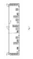
- FIG. 2is a side view of an integrated communications apparatus including an E-band mmW RF and a FSO transceiver, both mounted onto a gimbal-controlled platform, according to one embodiment.
- FIG. 3is a diagram illustrating the components of the transceiver related to signal acquisition and reacquisition, according to one embodiment.
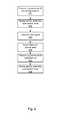
- FIG. 4is a flowchart illustrating the process for communications link acquisition and reacquisition by the integrated communications apparatus, according to one embodiment.
- FIG. 5is a block diagram of the electronics of the integrated communications apparatus, according to one embodiment.
- An integrated communication apparatusmay be used as part of a commercial communications network to facilitate the exchange of fully duplexed data with another similar device.
- the apparatusis configured to maintain high carrier availability, or uptime, even in adverse weather conditions.
- the apparatusincludes two transceivers, a millimeter wave (mmW) Radio Frequency (RF) transceiver, and a Free Space Optical (FSO) transceiver.
- mmWmillimeter wave
- RFRadio Frequency
- FSOFree Space Optical
- the mmW RF transceiveroperates in the E-band RF range, or 13 GHz of spectrum in the 70 GHz and 80 GHz radio frequency bands.
- the mmW RF transceiveris capable of operating outside the E-band RF range.
- the mmW RF transceivermay be used to transmit data and/or establish a link with an adjacent apparatus.
- the E-band RF electronicssupport both a high data rate waveform, and an additional low data rate waveform with at least 20 dB of improved sensitivity.
- the low data rate waveformis intended primarily to provide a very robust command and control backchannel, and to assist in initial link acquisition or link re-acquisition.
- Benefits of the disclosed apparatusinclude enhancement of existing systems for commercial communications by augmenting presently available mmW RF systems which are subject to interruption from weather effects.
- the combination of mmW RF and FSO transceiversis complimentary, whereby the FSO supports connectivity during rain, which interrupts mmW RF transmission, and conversely the mmW RF supports connectivity during conditions where fog, snow, airborne particulate matter, and atmospheric turbulence interrupt the FSO.
- Integrating a mmW RF transceiver with a FSO transceiverprovides an alternative solution to ground-based fiber optic communication systems.
- Fiber systemsare expensive to deploy, as there is significant cost associated with the trenching and laying fiber in urban areas.
- the integrated communication apparatusprovides a lower cost alternative to building a fiber optic network.
- the apparatusis able to transmit data over more than one connection. This allows data of different priorities to be transmitted in the most efficient manner possible based on the weather conditions affecting the transceivers.
- the apparatusalso resistant to malicious attempts to defeat or interrupt data delivery through jamming, interception or hacking, as data is capable of being transmitted over both RF and FSO transmission mediums.
- FIG. 1is a system diagram of an integrated commercial communications network using two integrated communications apparatuses to communicate through free space.
- An integrated communications apparatus 100 a located at a first cell siteis configured to communicate with another integrated communications apparatus 100 b at a second cell site located remotely from the first cell site.
- the two apparatuses 100do not have to be identical, so long as both devices are capable of transmitting and receiving both mmW RF 101 and FSO 102 transmissions at the relevant frequencies.
- the integrated communication apparatus 100may be a stand-alone cell site, or attached to a cell site that performs other communications or network operations.
- the transceivers of the apparatus 100 aare directed at another similar device 100 b positioned a distance away within line of sight.
- the distance between apparatusesmay depend upon historical weather data for the area being serviced. For example, if the service area frequently experiences rain or fog, the distance between sites may be smaller than if these weather conditions are less frequent or severe. Often, an apparatus will be positioned at a prescribed height above ground to prevent interruption of line of sight due to building or landscape features.
- the apparatusmay be land-based, maritime-based (i.e., mounted on a seaborne vessel), or airborne.
- FIG. 2is a side view of an integrated communications apparatus including an E-band mmW RF and a FSO transceiver, both mounted onto a gimbal-controlled platform, according to one embodiment.
- the apparatus 100includes an environmental enclosure 203 . Inside the environmental enclosure 203 , a mmW RF transceiver 204 and a FSO transceiver 205 are coupled to a gimbal assembly 206 . In one embodiment, the gimbal assembly 206 is located external to the environmental enclosure 203 .
- environmental enclosure 203includes one or more apertures for transmitting signals. Each aperture is transparent to the transmissions at least one of the transceivers. In one embodiment, each aperture is constructed using a different material transparent to the transmissions of its associated transceiver. In one embodiment, the environmental enclosure 203 has a single common aperture, made of a material having qualities that allow propagation of both E-band mmW RF 101 and FSO 102 transmissions. In the example embodiment shown in FIG. 2 , the apparatus 100 has only a single aperture 211 . In this embodiment, the housing of the environmental enclosure 203 is substantially transparent to mmW RF transmissions 101 . The aperture 211 for the FSO transceiver includes an optical window to FSO transmissions 102 .
- the environmental enclosure 203provides protection against environmental deterioration or destruction for all internal electrical and mechanical components of the apparatus.
- the environmental enclosure 203may also provide for internal environment control of properties such as temperature, humidly, condensation, and moisture.
- the environmental enclosure 203may also employ a heater, wiper, or other mechanism 212 to preclude or limit precipitation or ice formation on the aperture 211 .
- Both the mmW transceiver 204 and the FSO transceiver 205are mounted on a moving platform 209 .
- the FSO transceiver 205is mounted to an optical bench, and the optical bench is mounted on the movable platform 209 .
- the optical bench and moving platform 209are identical.
- the moving platform 209is connected to the environmental enclosure 203 through gimbal assembly 206 .
- Gimbal assembly 206allows the transceivers to rotate within a range of motion on two axes dimensions, in order to assist the transceivers in forming communications links with other similar devices. Through their common mounting on the moving platform 209 , the motion of both is controlled by the gimbal assembly 206 .
- the transceiversshare a near-common boresight.
- the environmental enclosure 203also contains a stationary platform circuit board 207 and a moving platform circuit board 208 which together transmit, receive, and process data.
- the stationary platform circuit board 207is located off of the moving platform 209 , and thus does not move with gimbal 206 motion.
- the stationary platform circuit board 207exchanges power and data with external electronics separate from the apparatus 100 through cables and/or fibers 213 that pass through a port 210 in the environmental enclosure 203 .
- the moving platform circuit board 208is located on the moving platform.
- the moving platform circuit board 208includes those electronics that are only able to function in close proximity to the transceivers, or are best able to function in close proximity to the transceivers. Generally, it is preferable to minimize the mass and heat loading of the gimbal assembly 206 . Thus, electronics not required to be on the moving platform circuit board 208 are instead located on the stationary platform circuit board 207 . Removing unnecessary electronics from the moving platform circuit board 208 has the added benefit of minimizing the thermal loading of the moving platform 209 . In one embodiment, no electronics require close proximity to the transceivers, thus the moving platform circuit board 208 is omitted and all electronics for the apparatus are located on the stationary platform circuit board 207 .
- Data received at the transceiversis communicated to the moving platform circuit board 208 , which may perform some data processing before sending the data to the stationary platform circuit board 207 for possible further processing.
- the stationary platform circuit board 207sends the data to external electronics through cables 213 .
- FIG. 3is a diagram illustrating the components of the transceivers related to signal acquisition and reacquisition, according to one embodiment.
- the mmW RF transceiver 204includes a mmW RF antenna 314 for transmitting and receiving mmW RF transmissions.
- the mmW RF antenna 314is 0.3 meters in diameter, and has a field angle of approximately 0.9 degrees.
- the mmW RF antenna 314is also used in coarse steering correction for the gimbal assembly 206 .
- the FSO transceiver 205includes a FSO telescope 319 .
- the FSO telescopeconsists of an FSO boresight.
- the FSO telescope 319consists of a laser 315 for transmitting FSO transmissions.
- the laser 315consists of a fully duplexed eye-safe 1550 nm central wavelength laser carrier.
- the FSO transceiver 205additionally includes adaptive optics 316 .
- the adaptive optics 316include a wavefront sensor 317 .
- the adaptive optics 316can consist of a low order system providing wavefront tip-tilt correction only, or a high order system providing higher order wavefront aberration correction (e.g., focus and higher).
- the adaptive optics 316provides improved wavefront phase coherency for FSO transmissions, despite the presence of atmospheric turbulence.
- the adaptive optics 316does this by providing for correction of both an inbound and/or outbound optical wavefront to improve the wavefront's optical point spread function, thereby maximizing the FSO transceiver carrier throughput.
- the adaptive optics 316also measure the arriving optical wavefront and use the resulting measurements as data to determine how to best orient the movable platform 209 towards the adjacent apparatus.
- the adaptive optics 316include fast steering assembly 318 .
- the fast steering assembly 318includes a fast steering mirror (FSM) 321 and a FSM control 320 .
- the FSM control 320consists of a motor drive coupled to the movable platform 209 .
- the control system between the FSO transceiver 205 and the gimbal assembly 206results in the transmission and reception of nearly collimated optical beams for establishing links and communicating data.
- the apparatus 100is able to communicate FSO data over significantly larger distances than comparable FSO devices that must use divergent optical beams.
- the FSO optical beamspreads over an angular range of less than one-tenth of a degree in any given direction.
- the FSOhas a link uptime of at least 99.9999% at a distance of four miles.
- both transceivers 204 and 205share a common moving platform 209 , both transceivers generally move together in response to gimbal 206 motion.
- the FSO transceiver 205is independently steerable from the mmW RF transceiver 204 using the FSM 408 .
- the wavefront sensor 317measures the intensity conjugates of the arriving optical beam, and provides fine control data to the FSM control 320 .
- the FSM control 320uses the control data to move and/or rotate the FSM 321 in order to precisely position the FSO optical boresight independent of the motion of the movable platform 209 .
- the FSO optical boresightis positioned to maximize the irradiance received at wavefront sensor 317 from an arriving optical beam.
- Gimbal assembly 206provides stabilization for the transceivers, and controls coarse and fine motion for the movable platform 209 containing the transceivers.
- the gimbal assembly 206is coupled to the transceivers and uses received transmissions from remote cell sites to orient the movable platform 209 towards a remote apparatus in order to establish FSO and mmW communications links.
- the gimbal assembly 206also responds to external weather influences that would affect the position and orientation of the movable platform 209 .
- the gimbal assembly 206includes an Inertial Measurement Unit (IMU) 313 which provides a local frame of reference for the position, velocity, and angular rotation of the gimbal assembly 206 .
- the IMU 313includes accelerometers and gyroscopes. Thus, the IMU is capable of detecting motion of the movable platform 209 due to external weather forces that cause apparatus motion, such as twist and sway.
- IMUInertial Measurement Unit
- FIG. 4is a flowchart illustrating the process for communications link acquisition and reacquisition by the integrated communications apparatus 100 , according to one embodiment.
- apparatus at two cell sitesare mechanically aligned 430 to point towards one another.
- the mechanical alignmentneed only be performed once, upon initial installation of the apparatus.
- the apparatusacquires an initial communications link with another remote apparatus by transmitting 431 a mmW RF signal on a mmW monitoring channel.
- a mmW RF transceiver 204“channels” represent specific time and radio frequency ranges that are recognized by the electronics of the apparatus 100 to perform specific purposes, such as data transfer or link acquisition/reacquisition.
- the monitoring channelmay be a portion of the RF data channel, or alternatively the enhanced sensitivity back channel may also be used for this function.
- the gimbal assembly 206sweeps 432 over a search area using a coordinated scanning technique.
- the coordinated scanning techniqueminimizes the search area scanned to find the remote apparatus.
- the goal of the transmission 431is to detect the presence of another remote apparatus, through the reception of mmW RF transmissions from the remote apparatus.
- the search area being scanned or swept by the gimbal assembly 206converges based upon the distribution of mmW RF data being received from various volumes of scanned space. High amounts of received RF and FSO signal in a particular area are indicative of a apparatus in that area.
- the operation of the mmW RF transceiver 204 in conjunction with the gimbal assembly 206 to obtain an initial communications linkmay be referred to as “coarse correction” or “coarse control.”
- the FSO transceiver 205may also transmit 433 a FSO signal.
- the FSO transceiver 205will begin to receive incoming FSO transmissions from the remote apparatus at the wavefront sensor 317 .
- a scanning techniqueis applied to the FSM control 320 to scan 434 the FSM 320 over a search area in order to more precisely located the remote apparatus.
- a centroid algorithmis applied to the FSM control 320 to help the FSM mirror 321 better locate the remote apparatus.
- the FSM control 320communicates with the gimbal assembly 206 to more precisely orient the movable platform 209 to maximize communication link strength.
- the operation of the FSO transceiver 205 in conjunction with the gimbal assembly 206 and the FSM control 320 to obtain a stronger communications linkmay be referred to as “fine correction or “fine control.”
- the mmW RF transceiver 204transmits 435 a signal over a mmW backchannel to reacquire the communications link.
- the mmW backchannelis a low bandwidth mmW RF channel used to maintain coarse control of the gimbal assembly 206 when the FSO transceiver 205 cannot connect with its remote counterpart.
- the transmitted 435 mmW backchannelconsists of a baseband signal using a spreading code, which spreads baseband signal over a low and wide frequency range, where the frequency range is low and wide relative to the frequency range of the mmW RF data channel.
- a baseband signalhas a low frequency noise-like structure.
- the baseband signal transmissionincludes data.
- a received mmW RF baseband signal from an adjacent apparatusis processed by the apparatus 100 in order to recover transmitted data.
- the mmW RF transceiver 204transmits 435 a signal on the mmW backchannel, the gimbal assembly 206 sweeps 436 over a search area.
- the apparatus 100reduces the search area scanned using feedback provided by reception of RF transmissions from the remote apparatus over the mmW backchannel.
- the feedbackfunctions to maintain coarse pointing control of gimbal assembly 206 while the FSO transceiver attempts to reacquire the optical link.
- Fine feedbackis provided to the gimbal assembly 206 by data received at the FSO transceiver 205 ,
- the apparatusalso monitors the health of both mmW and FSO data links in real time over the mmW backchannel.
- health monitoringalso includes information regarding the real time status of the gimbal assembly 206 . This information may be externally communicated to a user interested in monitoring the health of the communications network links.
- the data signal sent over the backchannel from a first apparatus to a second apparatusprovides control information for the intensity with which the second apparatus should transmit optical signals via the FSO transceiver from the second apparatus to the first apparatus.
- the control informationis based on the intensity of optical signals received at the FSO transceiver of the first apparatus.
- FIG. 5is a block diagram of the electronics of the integrated communications apparatus, according to one embodiment.
- Datais communicated within the apparatus 100 between the transceivers 204 and 205 , through the electronics, and out to an external interface in either an electronic format, such as gigabit Ethernet format, or in an optical format.
- the electronics of the apparatus 100include a stationary platform circuit board 207 and a moving platform circuit board 208 .
- the stationary platform circuit board 207may communicate between the moving platform circuit board 208 and with an external electronics interface associated with a user. External power 309 is received at the stationary platform circuit board 207 and is conditioned 317 and distributed 318 for use by the moving platform circuit board 208 or other components of the apparatus 100 .
- the stationary platform circuit board 207also contains drive electronics (DACs) 319 for gimbal assembly 206 , as well as drive electronics 319 for the fast steering mirror control 320 of the FSO transceiver 205 .
- DACsdrive electronics
- the stationary platform circuit board 207includes a Data Path FPGA 310 that comprises logic for processing of transceiver data 312 and an optical power control 313 .
- the Data Path Field Programmable Gate Array (FPGA) 310may include or be attached to a microprocessor unit (MPU) 311 .
- FPGA 310interfaces to moving platform circuit board 208 with stationary platform circuit board 207 through link serial interconnects 308 a and 308 b .
- Interconnects 308allow the stationary platform circuit board 207 to control operational functionality of transceivers 204 and 205 .
- the link serial interconnects 308include interconnect 308 c which provides coaxial functionality and incorporates E-band baseband and intermediate frequency (IF) electronics 304 .
- E-baseband and IF electronics 304ports RF data between moving platform and stationary circuit boards 207 and 208 in quadrature.
- the stationary platform circuit board 207may also include a variable optical attenuator (VOA) 315 to control the amplitude of the data received over optical fiber output 314 a from the FSO transceiver 205 .
- the stationary platform circuit board 207also includes an Erbium Doped Fiber Amplifier (EDFA) 316 to control the amplitude of the data to be transmitted by the FSO transceiver 205 .
- the EDFAmay be followed by a VOA to allow rapid high accuracy control of the transmit power level.
- Data received (Rx) and transmitted (Tx) by the transceiversis transported to and from the moving platform circuit board 208 to the stationary platform circuit board 207 through connection 314 .
- Connection 314may be an electrical cable or optical fiber depending upon the embodiment.
- the connection 314 a with the FSO transceiver 205comprises an optical fiber
- the connection 314 b with the mmW RF transceiver 204comprises a cable.
- the moving platform circuit board 208communicates data received at the transceivers 204 and 205 to the stationary platform circuit board 207 , and may also communicate with an external interface.
- the moving platform circuit board 208consists of a FPGA 303 .
- the moving platform FPGA 303also includes a bi-directional external interface through link 308 b .
- the moving platform 303may include or be connected to a digital signal processor (DSP) 322 .
- DSPdigital signal processor
- the moving platform FPGA 303communicates with a temperature sensors 320 and serial peripheral interface (SPI) flash sensors 321 , which output to an external interface.
- SPIserial peripheral interface
- the moving platform FPGA 303communicates with the FSO transceiver 205 through three sensors: an inertial stabilization sensor 325 capable of measuring the motion of the moving platform 209 to provide feedback to the gimbal assembly 206 , a FSM drive electronics 324 coupled to the FSM control 320 for controlling the direction of the FSO transceiver 205 , and a quadrature cell control electronics 323 for closed-loop optical beam stabilization.
- an inertial stabilization sensor 325capable of measuring the motion of the moving platform 209 to provide feedback to the gimbal assembly 206
- FSM drive electronics 324coupled to the FSM control 320 for controlling the direction of the FSO transceiver 205
- quadrature cell control electronics 323for closed-loop optical beam stabilization.
- Both transceivers 204 and 205 of the apparatus 100are capable of transmitting data at more than one data carrier rate, and may transmit over more than one channel at the same time.
- the mmW RF transceiver 204transmits data over several channels simultaneously using a phase shift keying digital modulation scheme.
- the FSO transceiver 205may transmit over multiple channels simultaneously using dense wavelength division multiplexing (DWDM).
- DWDMdense wavelength division multiplexing
- the transceiversmay employ forward error control correction (FEC) to an outbound data stream in order to reduce the need for retransmission of lost bits.
- FECforward error control correction
- the transceiversmay also be configured to retransmit lost data in response to a retransmission signal received from the adjacent apparatus.
- the apparatus 100is capable of transmitting data of different priorities at different times and over different transceivers depending upon link conditions.
- datais broken out into high priority data and low priority data.
- both the FSO transceiver link and mmW RF transceiver linkare active, both high and low priority data are transported by the FSO transceiver 205 . Concurrently, only high priority data is also transmitted by the mmW RF transceiver 204 . This redundancy reduces the need for retransmission of lost high priority data, thereby increasing the overall speed at which high priority data is transmitted. Low priority data, in contrast, is transmitted only by the FSO transceiver 205 . The FSO transceiver 205 transmits both high and low priority data because it generally has a higher transmission capacity than the mmW RF transceiver 204 .
- FSO transceiver 205In the event of rain, data transmitted by the mmW RF transceiver 204 may not be received, however data transmitted by the FSO transceiver 205 will be received.
- the FSO transceiver 205does not experience performance degradation due to rain because the radius of raindrops is significantly larger than the wavelength of the FSO optical carrier allowing for less cross-sectional scattering of the propagated laser beam radiation.
- data transmitted by the FSO transceiver 205may not be received, however data transmitted by the mmW RF transceiver 204 will be received.
- FSO transceiver 205 emissionsare susceptible to interference due to clouds, dense fog, snow, airborne volcanic particulates.
- the apparatus 100is able to transmit data over at least one connection under a range of different adverse weather conditions. In one embodiment, as high priority data is transmitted over both transceivers, high priority data will be received by a remote apparatus even under the above described weather conditions.
- low priority datamay be transmitted as high priority data in order to ensure maximum use of available transmission capacity and to minimize delays due to transmission time.
Landscapes
- Physics & Mathematics (AREA)
- Electromagnetism (AREA)
- Engineering & Computer Science (AREA)
- Computer Networks & Wireless Communication (AREA)
- Signal Processing (AREA)
- Optical Communication System (AREA)
- Radio Relay Systems (AREA)
Abstract
Description
Claims (26)
Priority Applications (11)
| Application Number | Priority Date | Filing Date | Title |
|---|---|---|---|
| US13/149,804US8942562B2 (en) | 2011-05-31 | 2011-05-31 | Integrated commercial communications network using radio frequency and free space optical data communication |
| JP2014513559AJP2014520434A (en) | 2011-05-31 | 2012-05-22 | Integrated commercial communication network using radio frequency and optical wireless data communication |
| EP12792604.6AEP2719096A4 (en) | 2011-05-31 | 2012-05-22 | Integrated commercial communications networks using radio frequency and free space optical data communication |
| PCT/US2012/038948WO2012166430A1 (en) | 2011-05-31 | 2012-05-22 | Integrated commercial communications networks using radio frequency and free space optical data communication |
| CN201280038136.0ACN103748812A (en) | 2011-05-31 | 2012-05-22 | Integrated commercial communications networks using radio frequency and free space optical data communication |
| AU2012262809AAU2012262809A1 (en) | 2011-05-31 | 2012-05-22 | Integrated commercial communications networks using radio frequency and free space optical data communication |
| KR20137034725AKR20140037147A (en) | 2011-05-31 | 2012-05-22 | Integrated commercial communications network using radio frequency and free space optical data communication |
| CA2837302ACA2837302C (en) | 2011-05-31 | 2012-05-22 | Integrated commercial communications network using radio frequency and free space optical data communication |
| RU2013155236/07ARU2013155236A (en) | 2011-05-31 | 2012-05-22 | INTEGRAL COMMERCIAL COMMUNICATION NETWORK WITH USE OF RADIO FREQUENCY AND OPTICAL DATA EXCHANGE IN FREE SPACE |
| IL229610AIL229610A0 (en) | 2011-05-31 | 2013-11-25 | Integrated commercial communications networks using radio frequency and free space optical data communication |
| US14/568,672US9166684B2 (en) | 2011-05-31 | 2014-12-12 | Integrated commercial communications network using radio frequency and free space optical data communication |
Applications Claiming Priority (1)
| Application Number | Priority Date | Filing Date | Title |
|---|---|---|---|
| US13/149,804US8942562B2 (en) | 2011-05-31 | 2011-05-31 | Integrated commercial communications network using radio frequency and free space optical data communication |
Related Child Applications (1)
| Application Number | Title | Priority Date | Filing Date |
|---|---|---|---|
| US14/568,672ContinuationUS9166684B2 (en) | 2011-05-31 | 2014-12-12 | Integrated commercial communications network using radio frequency and free space optical data communication |
Publications (2)
| Publication Number | Publication Date |
|---|---|
| US20120308235A1 US20120308235A1 (en) | 2012-12-06 |
| US8942562B2true US8942562B2 (en) | 2015-01-27 |
Family
ID=47259757
Family Applications (2)
| Application Number | Title | Priority Date | Filing Date |
|---|---|---|---|
| US13/149,804Expired - Fee RelatedUS8942562B2 (en) | 2011-05-31 | 2011-05-31 | Integrated commercial communications network using radio frequency and free space optical data communication |
| US14/568,672ActiveUS9166684B2 (en) | 2011-05-31 | 2014-12-12 | Integrated commercial communications network using radio frequency and free space optical data communication |
Family Applications After (1)
| Application Number | Title | Priority Date | Filing Date |
|---|---|---|---|
| US14/568,672ActiveUS9166684B2 (en) | 2011-05-31 | 2014-12-12 | Integrated commercial communications network using radio frequency and free space optical data communication |
Country Status (10)
| Country | Link |
|---|---|
| US (2) | US8942562B2 (en) |
| EP (1) | EP2719096A4 (en) |
| JP (1) | JP2014520434A (en) |
| KR (1) | KR20140037147A (en) |
| CN (1) | CN103748812A (en) |
| AU (1) | AU2012262809A1 (en) |
| CA (1) | CA2837302C (en) |
| IL (1) | IL229610A0 (en) |
| RU (1) | RU2013155236A (en) |
| WO (1) | WO2012166430A1 (en) |
Cited By (10)
| Publication number | Priority date | Publication date | Assignee | Title |
|---|---|---|---|---|
| US20150139636A1 (en)* | 2013-09-13 | 2015-05-21 | Smg Holdings--Anova Technologies, Llc | Self-healing data transmission system and method to achieve deterministic and lower latency |
| US20150215041A1 (en)* | 2014-01-28 | 2015-07-30 | SA Photonics, Inc. | Data Retransmission For Atmospheric Free Space Optical Communication System |
| US9319133B2 (en) | 2014-04-11 | 2016-04-19 | Aoptix Technologies, Inc. | Aligning transceiver systems of a data transmission network |
| US9973274B1 (en) | 2015-10-07 | 2018-05-15 | SA Photonics, Inc. | Fast tracking free space optical module |
| US10215936B2 (en) | 2015-08-21 | 2019-02-26 | SA Photonics, Inc. | Free space optical (FSO) system |
| US10389442B2 (en)* | 2015-08-21 | 2019-08-20 | SA Photonics, Inc. | Free space optical (FSO) system |
| US11431411B2 (en)* | 2019-01-24 | 2022-08-30 | X Development Llc | Reacquiring communication link based on historical data |
| US11595121B2 (en) | 2020-06-26 | 2023-02-28 | Airbus Operations Limited | Pointing unit |
| US11909439B2 (en) | 2021-04-23 | 2024-02-20 | SA Photonics, Inc. | Wavefront sensor with inner detector and outer detector |
| US20240275484A1 (en)* | 2021-09-21 | 2024-08-15 | X Development Llc | Integrated on-chip wireless optical communication terminal |
Families Citing this family (29)
| Publication number | Priority date | Publication date | Assignee | Title |
|---|---|---|---|---|
| US8942562B2 (en)* | 2011-05-31 | 2015-01-27 | A Optix Technologies, Inc. | Integrated commercial communications network using radio frequency and free space optical data communication |
| WO2013107853A1 (en)* | 2012-01-20 | 2013-07-25 | Technische Universiteit Eindhoven | Two-dimensional optical beam steering module |
| WO2013181674A2 (en)* | 2012-06-01 | 2013-12-05 | Vubiq Incorporated | Automatic antenna pointing and stabilization system and method thereof |
| US9094163B2 (en)* | 2012-08-28 | 2015-07-28 | Aoptix Technologies, Inc. | Assessment and correction of transmitted data |
| US8971720B2 (en) | 2013-02-28 | 2015-03-03 | Aoptix Technologies, Inc. | Low latency data transmission network |
| US9264137B2 (en)* | 2013-03-02 | 2016-02-16 | Aoptix Technologies, Inc. | Rapid in-the-field auto-alignment for radio frequency and free-space optical data communication transceivers |
| US10181895B2 (en)* | 2014-09-04 | 2019-01-15 | Honeywell International Inc. | Free space laser and millimetre wave(MMW) network for airborne relay networks |
| US9438338B1 (en)* | 2015-04-13 | 2016-09-06 | The Boeing Company | System for bidirectional free-space laser communication of gigabit Ethernet telemetry data |
| US10312998B2 (en)* | 2015-09-24 | 2019-06-04 | Lockheed Martin Corporation | Hybrid communications assembly for spacecraft |
| CN105429702A (en)* | 2015-11-09 | 2016-03-23 | 长春理工大学 | A Small Space Laser Communication System |
| US10951308B2 (en)* | 2016-03-29 | 2021-03-16 | Nec Corporation | Apparatus for conversion between wireless signals and spatial light communication signals |
| DE102016116224B4 (en)* | 2016-08-31 | 2018-05-09 | Deutsche Telekom Ag | Method and system for wireless data transmission |
| US10374696B2 (en)* | 2016-12-29 | 2019-08-06 | Facebook, Inc. | Bidirectional satellite communications |
| US10498449B2 (en)* | 2017-03-15 | 2019-12-03 | Nec Corporation | Secured hybrid coded modulation for 5G—and beyond—access networks |
| CN107528637A (en)* | 2017-05-19 | 2017-12-29 | 哈尔滨工业大学 | Ultrahigh speed data transmission laser system in a kind of star |
| US20190261262A1 (en)* | 2018-02-22 | 2019-08-22 | Collinear Networks, Inc. | Hybrid wireless link employing free-space optical communication, radio frequency communication, and intelligent frame and packet switching |
| CN108923852A (en)* | 2018-07-13 | 2018-11-30 | 广东工业大学 | A kind of mixing FSO/RF link trunking transmission method, device and source node |
| KR20210057037A (en)* | 2018-09-11 | 2021-05-20 | 바스프 에스이 | Receiver including light-emitting collector for optical data communication |
| CN109257092A (en)* | 2018-11-05 | 2019-01-22 | 广东工业大学 | A kind of satellite communication system |
| GB201900975D0 (en)* | 2019-01-24 | 2019-03-13 | Bae Systems Plc | Communication apparatus |
| US11100020B2 (en) | 2019-02-27 | 2021-08-24 | EOS Defense Systems USA, Inc. | Hybrid control plane data link agent and protocol |
| US11277203B1 (en) | 2020-01-22 | 2022-03-15 | Architecture Technology Corporation | Hybrid communications based upon aerial networks |
| US11290183B2 (en)* | 2020-02-10 | 2022-03-29 | SA Photonics, Inc. | Feed-forward control of free space optical communication system based on inertial measurement unit |
| RU2745036C1 (en)* | 2020-04-30 | 2021-03-18 | Олег Леонидович Головков | Aircraft with optical communication |
| US11777601B1 (en)* | 2021-07-21 | 2023-10-03 | T-Mobile Innovations Llc | Systems and methods for providing wireless communications to a device using both optical and radio frequency transmission |
| US11784713B2 (en)* | 2021-09-02 | 2023-10-10 | Scidatek Inc. | Wide and fully flexible two-electromagnetic-beam steering device |
| CN115085792B (en)* | 2022-05-31 | 2023-09-26 | 华东师范大学 | Relay transmission method for unmanned aerial vehicle auxiliary satellite-vehicle |
| JPWO2024023965A1 (en)* | 2022-07-27 | 2024-02-01 | ||
| JP7741518B2 (en)* | 2022-07-28 | 2025-09-18 | Ntt株式会社 | Transmitter, receiver, communication system, and method for acquiring positioning information |
Citations (23)
| Publication number | Priority date | Publication date | Assignee | Title |
|---|---|---|---|---|
| US4829162A (en)* | 1985-12-23 | 1989-05-09 | Hughes Aircraft Co. | Maintenance of uniform optical window properties |
| US4866732A (en)* | 1985-02-04 | 1989-09-12 | Mitel Telecom Limited | Wireless telephone system |
| US20020075542A1 (en)* | 2000-12-18 | 2002-06-20 | Kumar Addepalli Sateesh | Dynamic mixing TDM data with data packets |
| US20020196506A1 (en)* | 2001-06-26 | 2002-12-26 | Zyoptics, Inc. | Atmospheric optical data transmission system |
| US20030025631A1 (en)* | 2001-07-26 | 2003-02-06 | Kim Jonnathan H. | First-arriving-pulse detection apparatus and associated methods |
| US20030163555A1 (en)* | 2001-02-28 | 2003-08-28 | Abdella Battou | Multi-tiered control architecture for adaptive optical networks, and methods and apparatus therefor |
| US20030231584A1 (en)* | 2002-06-17 | 2003-12-18 | Harris Corporation | Free space optical terminal with ad hoc network back-up and associated methods |
| US20040037566A1 (en)* | 2000-01-13 | 2004-02-26 | Lightpointe Communications, Inc. | Hybrid wireless optical and radio frequency communication link |
| US20040141753A1 (en)* | 2003-01-21 | 2004-07-22 | Lightpointe Communications, Inc. | Apparatus and method for tracking in free-space optical communication systems |
| US20050094718A1 (en)* | 2002-12-20 | 2005-05-05 | Bridgewave Communications, Inc. | Wideband digital radio with transmit modulation cancellation |
| US20050196166A1 (en)* | 2004-02-12 | 2005-09-08 | Adaptive Optics Associates, Inc. | Wavefront sensing system employing active updating of reference positions and subaperture locations on wavefront sensor |
| US20070031150A1 (en)* | 2005-08-02 | 2007-02-08 | Donald Fisher | Communication transceiver architecture |
| US20070031151A1 (en)* | 2005-08-02 | 2007-02-08 | James Cunningham | Acquisition, pointing, and tracking architecture for laser communication |
| US7194159B1 (en)* | 2004-12-27 | 2007-03-20 | Aoptix Technologies, Inc. | Asymmetric optical circulator |
| US20070241886A1 (en)* | 2006-04-11 | 2007-10-18 | Breeding Russell M | Inertial sensor tracking system |
| US20080018855A1 (en)* | 2004-03-22 | 2008-01-24 | Larichev Andrey V | Aberrometer Provided with a Visual Acuity Testing System |
| US20080044187A1 (en)* | 2002-06-27 | 2008-02-21 | Krill Jerry A | Mobile Communications System |
| US20080153549A1 (en)* | 2001-05-02 | 2008-06-26 | Eric Korevaar | Wireless millimeter wave communication system |
| US20080207200A1 (en)* | 2001-05-02 | 2008-08-28 | Trex Enterprises Corp. | Cellular communication system with high speed content distribution |
| US20090002220A1 (en)* | 2007-06-29 | 2009-01-01 | John Lovberg | Millimeter wave imager with visible or infrared overlay for brownout assist |
| US20090184860A1 (en)* | 2007-11-16 | 2009-07-23 | Chan Victor J | E-Band Receiver And Bit Error Measurement |
| US20120068880A1 (en)* | 2010-09-17 | 2012-03-22 | Raytheon Company | System and Method for Dual-Band Antenna Pointing, Acquisition, And Tracking |
| US20120220315A1 (en)* | 2009-06-30 | 2012-08-30 | Nokia Corportion | Apparatus and methods |
Family Cites Families (9)
| Publication number | Priority date | Publication date | Assignee | Title |
|---|---|---|---|---|
| US6931183B2 (en)* | 1996-03-29 | 2005-08-16 | Dominion Lasercom, Inc. | Hybrid electro-optic cable for free space laser antennas |
| US7095957B1 (en)* | 2000-08-17 | 2006-08-22 | At&T Corp. | Optical/radio local access network |
| US20020122230A1 (en)* | 2001-03-05 | 2002-09-05 | Hossein Izadpanah | Hybrid RF and optical wireless communication link and network structure incorporating it therein |
| US20040071470A1 (en)* | 2002-10-09 | 2004-04-15 | Lightpointe Communications, Inc. | Free-space optics microroom |
| US20040120717A1 (en)* | 2002-12-18 | 2004-06-24 | Lightpointe Communications, Inc. | Extended source free-space optical communication system |
| US6816112B1 (en)* | 2003-05-30 | 2004-11-09 | Lockheed Martin Corporation | Hybrid RF/optical acquisition and tracking system and method |
| BRPI0722344A2 (en)* | 2007-12-27 | 2014-03-18 | Ericsson Telecomunicacoes Sa | FSO TRANSCEIVER |
| WO2011154057A1 (en)* | 2010-06-09 | 2011-12-15 | Telefonaktiebolaget L M Ericsson (Publ) | Wireless communications links |
| US8942562B2 (en)* | 2011-05-31 | 2015-01-27 | A Optix Technologies, Inc. | Integrated commercial communications network using radio frequency and free space optical data communication |
- 2011
- 2011-05-31USUS13/149,804patent/US8942562B2/ennot_activeExpired - Fee Related
- 2012
- 2012-05-22AUAU2012262809Apatent/AU2012262809A1/ennot_activeAbandoned
- 2012-05-22CACA2837302Apatent/CA2837302C/ennot_activeExpired - Fee Related
- 2012-05-22KRKR20137034725Apatent/KR20140037147A/ennot_activeWithdrawn
- 2012-05-22CNCN201280038136.0Apatent/CN103748812A/enactivePending
- 2012-05-22JPJP2014513559Apatent/JP2014520434A/enactivePending
- 2012-05-22WOPCT/US2012/038948patent/WO2012166430A1/enactiveApplication Filing
- 2012-05-22RURU2013155236/07Apatent/RU2013155236A/ennot_activeApplication Discontinuation
- 2012-05-22EPEP12792604.6Apatent/EP2719096A4/ennot_activeWithdrawn
- 2013
- 2013-11-25ILIL229610Apatent/IL229610A0/enunknown
- 2014
- 2014-12-12USUS14/568,672patent/US9166684B2/enactiveActive
Patent Citations (24)
| Publication number | Priority date | Publication date | Assignee | Title |
|---|---|---|---|---|
| US4866732A (en)* | 1985-02-04 | 1989-09-12 | Mitel Telecom Limited | Wireless telephone system |
| US4829162A (en)* | 1985-12-23 | 1989-05-09 | Hughes Aircraft Co. | Maintenance of uniform optical window properties |
| US20040037566A1 (en)* | 2000-01-13 | 2004-02-26 | Lightpointe Communications, Inc. | Hybrid wireless optical and radio frequency communication link |
| US6763195B1 (en)* | 2000-01-13 | 2004-07-13 | Lightpointe Communications, Inc. | Hybrid wireless optical and radio frequency communication link |
| US20020075542A1 (en)* | 2000-12-18 | 2002-06-20 | Kumar Addepalli Sateesh | Dynamic mixing TDM data with data packets |
| US20030163555A1 (en)* | 2001-02-28 | 2003-08-28 | Abdella Battou | Multi-tiered control architecture for adaptive optical networks, and methods and apparatus therefor |
| US20080153549A1 (en)* | 2001-05-02 | 2008-06-26 | Eric Korevaar | Wireless millimeter wave communication system |
| US20080207200A1 (en)* | 2001-05-02 | 2008-08-28 | Trex Enterprises Corp. | Cellular communication system with high speed content distribution |
| US20020196506A1 (en)* | 2001-06-26 | 2002-12-26 | Zyoptics, Inc. | Atmospheric optical data transmission system |
| US20030025631A1 (en)* | 2001-07-26 | 2003-02-06 | Kim Jonnathan H. | First-arriving-pulse detection apparatus and associated methods |
| US20030231584A1 (en)* | 2002-06-17 | 2003-12-18 | Harris Corporation | Free space optical terminal with ad hoc network back-up and associated methods |
| US20080044187A1 (en)* | 2002-06-27 | 2008-02-21 | Krill Jerry A | Mobile Communications System |
| US20050094718A1 (en)* | 2002-12-20 | 2005-05-05 | Bridgewave Communications, Inc. | Wideband digital radio with transmit modulation cancellation |
| US20040141753A1 (en)* | 2003-01-21 | 2004-07-22 | Lightpointe Communications, Inc. | Apparatus and method for tracking in free-space optical communication systems |
| US20050196166A1 (en)* | 2004-02-12 | 2005-09-08 | Adaptive Optics Associates, Inc. | Wavefront sensing system employing active updating of reference positions and subaperture locations on wavefront sensor |
| US20080018855A1 (en)* | 2004-03-22 | 2008-01-24 | Larichev Andrey V | Aberrometer Provided with a Visual Acuity Testing System |
| US7194159B1 (en)* | 2004-12-27 | 2007-03-20 | Aoptix Technologies, Inc. | Asymmetric optical circulator |
| US20070031151A1 (en)* | 2005-08-02 | 2007-02-08 | James Cunningham | Acquisition, pointing, and tracking architecture for laser communication |
| US20070031150A1 (en)* | 2005-08-02 | 2007-02-08 | Donald Fisher | Communication transceiver architecture |
| US20070241886A1 (en)* | 2006-04-11 | 2007-10-18 | Breeding Russell M | Inertial sensor tracking system |
| US20090002220A1 (en)* | 2007-06-29 | 2009-01-01 | John Lovberg | Millimeter wave imager with visible or infrared overlay for brownout assist |
| US20090184860A1 (en)* | 2007-11-16 | 2009-07-23 | Chan Victor J | E-Band Receiver And Bit Error Measurement |
| US20120220315A1 (en)* | 2009-06-30 | 2012-08-30 | Nokia Corportion | Apparatus and methods |
| US20120068880A1 (en)* | 2010-09-17 | 2012-03-22 | Raytheon Company | System and Method for Dual-Band Antenna Pointing, Acquisition, And Tracking |
Non-Patent Citations (1)
| Title |
|---|
| Patent Cooperation Treaty, International Search Report and Written Opinion, International Patent Application No. PCT/US2012/038948, Aug. 14, 2012, 15 pages. |
Cited By (14)
| Publication number | Priority date | Publication date | Assignee | Title |
|---|---|---|---|---|
| US20150139636A1 (en)* | 2013-09-13 | 2015-05-21 | Smg Holdings--Anova Technologies, Llc | Self-healing data transmission system and method to achieve deterministic and lower latency |
| US20150215041A1 (en)* | 2014-01-28 | 2015-07-30 | SA Photonics, Inc. | Data Retransmission For Atmospheric Free Space Optical Communication System |
| US10075233B2 (en)* | 2014-01-28 | 2018-09-11 | SA Photonics, Inc. | Data retransmission for atmospheric free space optical communication system |
| US9319133B2 (en) | 2014-04-11 | 2016-04-19 | Aoptix Technologies, Inc. | Aligning transceiver systems of a data transmission network |
| US10389442B2 (en)* | 2015-08-21 | 2019-08-20 | SA Photonics, Inc. | Free space optical (FSO) system |
| US10215936B2 (en) | 2015-08-21 | 2019-02-26 | SA Photonics, Inc. | Free space optical (FSO) system |
| US9973274B1 (en) | 2015-10-07 | 2018-05-15 | SA Photonics, Inc. | Fast tracking free space optical module |
| US11431411B2 (en)* | 2019-01-24 | 2022-08-30 | X Development Llc | Reacquiring communication link based on historical data |
| US11705967B2 (en) | 2019-01-24 | 2023-07-18 | X Development Llc | Reacquiring communication link based on historical data |
| US20230318706A1 (en)* | 2019-01-24 | 2023-10-05 | X Development Llc | Reacquiring communication link based on historical data |
| US12081266B2 (en)* | 2019-01-24 | 2024-09-03 | X Development Llc | Reacquiring communication link based on historical data |
| US11595121B2 (en) | 2020-06-26 | 2023-02-28 | Airbus Operations Limited | Pointing unit |
| US11909439B2 (en) | 2021-04-23 | 2024-02-20 | SA Photonics, Inc. | Wavefront sensor with inner detector and outer detector |
| US20240275484A1 (en)* | 2021-09-21 | 2024-08-15 | X Development Llc | Integrated on-chip wireless optical communication terminal |
Also Published As
| Publication number | Publication date |
|---|---|
| AU2012262809A1 (en) | 2014-01-09 |
| US20120308235A1 (en) | 2012-12-06 |
| CN103748812A (en) | 2014-04-23 |
| JP2014520434A (en) | 2014-08-21 |
| IL229610A0 (en) | 2014-01-30 |
| KR20140037147A (en) | 2014-03-26 |
| US9166684B2 (en) | 2015-10-20 |
| EP2719096A4 (en) | 2015-04-22 |
| RU2013155236A (en) | 2015-07-10 |
| WO2012166430A1 (en) | 2012-12-06 |
| CA2837302C (en) | 2017-06-27 |
| US20150098707A1 (en) | 2015-04-09 |
| CA2837302A1 (en) | 2012-12-06 |
| EP2719096A1 (en) | 2014-04-16 |
Similar Documents
| Publication | Publication Date | Title |
|---|---|---|
| US9166684B2 (en) | Integrated commercial communications network using radio frequency and free space optical data communication | |
| US9264137B2 (en) | Rapid in-the-field auto-alignment for radio frequency and free-space optical data communication transceivers | |
| JP4753444B2 (en) | Communication transceiver architecture | |
| AU2014280835B2 (en) | A stabilized platform for a wireless communication link | |
| US20120308239A1 (en) | Active Tracking for Free-Space Optical Communication Systems | |
| EP1952562B1 (en) | Acquisition, pointing, and tracking architecture for laser communication | |
| US7680516B2 (en) | Mobile millimeter wave communication link | |
| US11606140B2 (en) | Free space optical terminal with dither based alignment | |
| WO2002089357A1 (en) | Millimeter wave communication link | |
| EP1158704B1 (en) | Method and apparatus for aligning telescopes within a free-space optical communication system | |
| US8755692B2 (en) | Wireless data transmission with terahertz waves | |
| Ma et al. | Outage performance analysis and parameter optimization of hovering UAV-based FSO system | |
| WO2019198074A1 (en) | Optical communication network for pico satellites | |
| CN108886193B (en) | Rotatable antenna arrangement for LOS-MIMO | |
| CA2357943A1 (en) | Method and apparatus for controlling received power levels within a free-space optical communication system | |
| JP3799904B2 (en) | Communication device | |
| Ravishankar et al. | Free space optics and radio frequency signals in spacial communication | |
| US20250274198A1 (en) | Beam Dump and Power Meter such as for Free-Space Optical Communication Systems | |
| EP1391058A1 (en) | Millimeter wave communication link |
Legal Events
| Date | Code | Title | Description |
|---|---|---|---|
| AS | Assignment | Owner name:AOPTIX TECHNOLOGIES, INC., CALIFORNIA Free format text:ASSIGNMENT OF ASSIGNORS INTEREST;ASSIGNORS:PUSARLA, CHANDRASEKHAR;SIVAPRAKASAM, SRINIVAS;SHIRAN, JOSEPH;AND OTHERS;SIGNING DATES FROM 20110518 TO 20110627;REEL/FRAME:026513/0587 | |
| AS | Assignment | Owner name:SILICON VALLEY BANK, CALIFORNIA Free format text:SECURITY INTEREST;ASSIGNOR:AOPTIX TECHNOLOGIES, INC.;REEL/FRAME:033225/0493 Effective date:20140624 | |
| AS | Assignment | Owner name:GOLD HILL CAPITAL 2008, LP, CALIFORNIA Free format text:SECURITY INTEREST;ASSIGNOR:AOPTIX TECHNOLOGIES, INC.;REEL/FRAME:033247/0438 Effective date:20140624 | |
| STCF | Information on status: patent grant | Free format text:PATENTED CASE | |
| CC | Certificate of correction | ||
| AS | Assignment | Owner name:AOPTIX TECHNOLOGIES, INC, CALIFORNIA Free format text:RELEASE BY SECURED PARTY;ASSIGNOR:GOLD HILL CAPITOL 2008, LP;REEL/FRAME:040326/0051 Effective date:20160711 Owner name:COLLINEAR NETWORKS, INC., COLORADO Free format text:ASSIGNMENT OF ASSIGNORS INTEREST;ASSIGNOR:AOPTIX (ASSIGNEMTN FOR THE BENEFIT OF THE CREDITORS), LLC;REEL/FRAME:040326/0851 Effective date:20160831 | |
| AS | Assignment | Owner name:AOPTIX (ASSIGNMENT FOR THE BENEFIT OF CREDITORS), Free format text:ASSIGNMENT OF ASSIGNORS INTEREST;ASSIGNOR:AOPTIX TECHNOLOGIES, INC;REEL/FRAME:040596/0395 Effective date:20160201 | |
| MAFP | Maintenance fee payment | Free format text:PAYMENT OF MAINTENANCE FEE, 4TH YR, SMALL ENTITY (ORIGINAL EVENT CODE: M2551) Year of fee payment:4 | |
| AS | Assignment | Owner name:COLLINEAR NET (ASSIGNMENT FOR THE BENEFIT OF CREDITORS), LLC, CALIFORNIA Free format text:ASSIGNMENT OF ASSIGNORS INTEREST;ASSIGNOR:COLLINEAR NETWORKS, INC.;REEL/FRAME:054614/0183 Effective date:20200413 Owner name:EOS DEFENSE SYSTEMS USA, INC., ALABAMA Free format text:ASSIGNMENT OF ASSIGNORS INTEREST;ASSIGNOR:COLLINEAR NET (ASSIGNMENT FOR THE BENEFIT OF CREDITORS), LLC;REEL/FRAME:054614/0518 Effective date:20200616 | |
| FEPP | Fee payment procedure | Free format text:ENTITY STATUS SET TO UNDISCOUNTED (ORIGINAL EVENT CODE: BIG.); ENTITY STATUS OF PATENT OWNER: LARGE ENTITY | |
| FEPP | Fee payment procedure | Free format text:MAINTENANCE FEE REMINDER MAILED (ORIGINAL EVENT CODE: REM.); ENTITY STATUS OF PATENT OWNER: LARGE ENTITY | |
| LAPS | Lapse for failure to pay maintenance fees | Free format text:PATENT EXPIRED FOR FAILURE TO PAY MAINTENANCE FEES (ORIGINAL EVENT CODE: EXP.); ENTITY STATUS OF PATENT OWNER: LARGE ENTITY | |
| STCH | Information on status: patent discontinuation | Free format text:PATENT EXPIRED DUE TO NONPAYMENT OF MAINTENANCE FEES UNDER 37 CFR 1.362 | |
| FP | Lapsed due to failure to pay maintenance fee | Effective date:20230127 |