US8942395B2 - Pointing element enhanced speaker system - Google Patents
Pointing element enhanced speaker systemDownload PDFInfo
- Publication number
- US8942395B2 US8942395B2US11/705,310US70531007AUS8942395B2US 8942395 B2US8942395 B2US 8942395B2US 70531007 AUS70531007 AUS 70531007AUS 8942395 B2US8942395 B2US 8942395B2
- Authority
- US
- United States
- Prior art keywords
- speaker
- location
- adjustment
- characteristic information
- venue
- Prior art date
- Legal status (The legal status is an assumption and is not a legal conclusion. Google has not performed a legal analysis and makes no representation as to the accuracy of the status listed.)
- Active, expires
Links
- 238000005259measurementMethods0.000claimsdescription114
- 238000000034methodMethods0.000claimsdescription21
- 238000004891communicationMethods0.000claimsdescription14
- 230000007246mechanismEffects0.000claimsdescription12
- 230000015654memoryEffects0.000claimsdescription12
- 230000000153supplemental effectEffects0.000claimsdescription11
- 238000005286illuminationMethods0.000claimsdescription10
- 238000012360testing methodMethods0.000claimsdescription7
- 230000004044responseEffects0.000claimsdescription6
- 230000000977initiatory effectEffects0.000claimsdescription3
- 230000003213activating effectEffects0.000claims2
- 238000013461designMethods0.000abstractdescription2
- 238000003491arrayMethods0.000description11
- 238000004458analytical methodMethods0.000description6
- 230000005236sound signalEffects0.000description6
- 239000006185dispersionSubstances0.000description5
- 238000006073displacement reactionMethods0.000description4
- 230000003287optical effectEffects0.000description4
- 238000012545processingMethods0.000description4
- 230000008901benefitEffects0.000description3
- 230000001934delayEffects0.000description3
- 230000008569processEffects0.000description3
- 238000013479data entryMethods0.000description2
- 238000005516engineering processMethods0.000description2
- 230000003993interactionEffects0.000description2
- 230000008859changeEffects0.000description1
- 238000010276constructionMethods0.000description1
- 230000008878couplingEffects0.000description1
- 238000010168coupling processMethods0.000description1
- 238000005859coupling reactionMethods0.000description1
- 238000004141dimensional analysisMethods0.000description1
- 230000008713feedback mechanismEffects0.000description1
- 238000001914filtrationMethods0.000description1
- 230000002452interceptive effectEffects0.000description1
- 239000000463materialSubstances0.000description1
- 238000012544monitoring processMethods0.000description1
- 210000003813thumbAnatomy0.000description1
Images


Classifications
- H—ELECTRICITY
- H04—ELECTRIC COMMUNICATION TECHNIQUE
- H04R—LOUDSPEAKERS, MICROPHONES, GRAMOPHONE PICK-UPS OR LIKE ACOUSTIC ELECTROMECHANICAL TRANSDUCERS; DEAF-AID SETS; PUBLIC ADDRESS SYSTEMS
- H04R27/00—Public address systems
- H—ELECTRICITY
- H04—ELECTRIC COMMUNICATION TECHNIQUE
- H04R—LOUDSPEAKERS, MICROPHONES, GRAMOPHONE PICK-UPS OR LIKE ACOUSTIC ELECTROMECHANICAL TRANSDUCERS; DEAF-AID SETS; PUBLIC ADDRESS SYSTEMS
- H04R29/00—Monitoring arrangements; Testing arrangements
- H04R29/001—Monitoring arrangements; Testing arrangements for loudspeakers
- H04R29/002—Loudspeaker arrays
Definitions
- This disclosurerelates to speaker systems.
- this disclosurerelates to a pointing element enhanced speaker system for providing consistent sound at any given venue.
- tuning the sound quality at a new venuemay include ensuring consistent volume levels, optimizing the dispersion pattern, detecting and eliminating any phasing inconsistencies, or configuring other sound signal characteristics throughout the venue. As one venue may differ significantly from the next, the system configuration that provided maximum dispersion at the previous venue, for example, may not be well-suited for the next venue.
- Speaker arraysprovide multiple aligned speakers that the speaker system drives in an interrelated manner in an attempt to achieve specific audio reproduction characteristics, such as dispersion.
- the interrelation between speakerscan increase the difficulty of adapting the speaker system to produce the desired sound output.
- sound techniciansemployed a simplified procedure in which the sound technician would monitor and collect data at a single sound control station typically located near the center or rear portion of the venue. The sound technicians then optimized the sound output at that location. While optimizing sound output at a central location may be fast, the sound output at potentially many other locations throughout the venue was often poor.
- a pointing element enhanced speaker systemaddresses the need for consistent sound regardless of venue. Despite wide variations in the design and architecture of different venues, the pointing element enhanced speaker system ensures that performers are able to deliver the sound that they desire for their audiences as they move from one venue to the next. The pointing element enhanced speaker system directs a sound technician precisely to the locations where sound output tuning measurements are desired.
- the pointing element enhanced speaker systemidentifies a measurement location in a venue using a pointing element associated with a speaker.
- the pointing element enhanced speaker systemreceives location characteristic information about the measurement location and determines an adjustment parameter from the location characteristic information.
- the pointing element enhanced speaker systemmay also adjust the speaker according to the adjustment parameter.
- the pointing elementmay be a mechanical pointer, an electronically controlled pointer such as a laser, or may be implemented with other pointing technologies or combinations of technologies.
- the pointing element enhanced speaker systemmay exercise automated control over electronic pointers to direct measurement technicians to the appropriate measurement locations.
- FIG. 1shows a pointing element enhanced speaker system.
- FIG. 2shows acts the pointing element enhanced speaker system may take to adjust a speaker system located in a venue to provide the sound desired for the venue.
- FIG. 3shows acts the pointing element enhanced speaker system may take to iteratively adjust a speaker system located in a venue.
- FIG. 4shows acts the pointing element enhanced speaker system may take to a speaker system in a venue.
- FIG. 5shows acts the pointing element enhanced speaker system may take to adjust a speaker system in a venue.
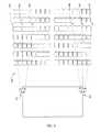
- FIG. 6shows a venue including identified measurement locations corresponding to multiple speakers.
- FIG. 7shows the venue shown in FIG. 6 including speakers adjusted to improve sound quality within the venue.
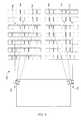
- FIG. 8shows a venue including identified measurement locations relative to multiple speaker groups.
- FIG. 9shows the venue shown in FIG. 8 including speaker groups adjusted to improve sound quality within the venue.
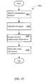
- FIG. 10shows the acts the pointing element enhanced speaker system may take to determine venue information.
- FIG. 11shows a pointing element enhanced speaker system.
- FIG. 12shows a speaker using multiple pointing elements to illuminate a surface.
- FIG. 13shows a speaker using multiple pointing elements to illuminate a surface.
- FIG. 1shows a pointing element enhanced speaker system 100 (“system 100 ”).
- the system 100uses pointing elements associated with one or more speakers or speaker arrays located in a venue to help provide a desired sound output from a speaker system.
- FIG. 1shows two pointing elements 186 and 188 associated with two of the speakers 182 .
- the desired sound outputmay be one that has a particular dispersion pattern, particular loudness, frequency content, or directionality at one or more selected venue locations, or that has any other sonic attributes that the speaker system should produce.
- the system 100includes a system processor 102 and a system memory 104 .
- the system processor 102may execute an adjustment control program 106 to identify a measurement location in the venue from which to obtain location characteristic information 108 , for example.
- the system 100may determine adjustment parameters for speaker system components that take into consideration the location characteristic information 108 as well as venue information 110 , equipment information 112 , and other information in order to adapt a speaker system for delivering the desired sound output.
- the location characteristic information 108 , venue information 110 , and equipment information 112may additionally or alternatively be obtained from databases 114 , through operator input at an external input 116 (e.g., a keyboard, a speech recognition interface, or a mouse), through a communication interface 118 (e.g., through a network connection to a data warehouse, to equipment in the speaker system, such as an amplifier or mixer, or to other logic) or from other sources.
- an external input 116e.g., a keyboard, a speech recognition interface, or a mouse
- a communication interface 118e.g., through a network connection to a data warehouse, to equipment in the speaker system, such as an amplifier or mixer, or to other logic
- the databases 114may be local or remote databases that store venue information, equipment information, or location characteristic information or that store the results of previous venue, equipment, and location characteristic information gathering, analysis, or determinations.
- the location characteristic information 108may include distance information 120 , such as the distance between the measurement location and a speaker, group of speakers, or other reference point.
- the location characteristic information 108may also include acoustic signal information such as amplitude 122 , phasing 124 , frequency 126 , reverberation 128 , or other information characteristic of an acoustic signal.
- the location characteristic information 108may capture the signal characteristics that exist at any given measurement location (e.g., the amplitude or reverberation decay time of the audio signal at the measurement location) as well as the physical characteristics of the measurement location (e.g., the distance to the speaker).
- the venue information 110may include a full or partial layout of the venue or other architectural parameters (e.g., dimensions, materials, or construction information), or other physical data about the venue.
- One example of the venue information 110is the physical volume of the venue 130 .
- Other examples of venue information 110include the number and/or location of audio absorbing surfaces 132 and the number and/or location of audio reflective surfaces 133 .
- Additional examples of venue information 110include the venue size 134 , venue shape 136 , venue seating capacity or arrangement 138 , the venue dimensions 140 , and stage information 142 .
- the stage information 142may include the locations, sizes, orientations, or arrangements of one or more stages in the venue.
- the venue informationmay be expressed in objective or subjective terms.
- the venue size 134may be expressed in terms of measured dimensions, or expressed as ‘large’, ‘medium’, or ‘small’.
- the system 100may also obtain setup information as part of the venue information 110 .
- the setup informationmay specify the position and/or orientation of the speakers after initial setup.
- the setup informationmay be manually input by a technician, automatically sensed by the speaker (e.g., using GPS sensors, roll, pitch, or yaw sensors, or other sensors) and transmitted to the system 100 , or may be obtained in other ways.
- the equipment information 112may specify equipment characteristics for equipment in the speaker system.
- the equipment information 112may include speaker data 144 , amplifier data 146 , pre-amp data 148 , connection data 150 , or other equipment information.
- the speaker data 144 , amplifier data 146 , and pre-amp data 148may specify the number of speakers, amplifiers, and pre-amplifiers, their connection topology, the speaker models, physical or electrical characteristics, including efficiency, power capability, frequency response, and dispersion pattern.
- the connection data 150may specify the type, length, and electrical characteristics of system interconnections, such as speaker cables and amplifier/pre-amplifier audio cables. Other equipment information may be provided.
- the location characteristic information 108 , venue information 110 , and equipment information 112may be obtained from the databases 114 , through an external input 116 , through a communication interface 118 or from other sources.
- the system 100may implement data entry user interfaces that facilitate obtaining the information 108 , 110 , and 112 .
- the data entry user interfacemay be a graphical or text input user interface provided on the display 172 .
- the display 172may be one or more displays local to the system 100 , or may be displays integrated into or associated with any of the speaker system equipment (e.g., an LCD display on an amplifier).
- the external input 116may be a system keyboard, mouse, or other input device, or additionally or alternatively may be keys, buttons, thumb wheels, or other interface devices provided by a component interface in the speaker system (e.g., an amplifier control interface).
- the systemimplements a “wizard” interface.
- the wizard interfacemay include one or more display prompts and input selectors that progressively lead the operator through each step of the information gathering process.
- the wizard interfacemay provide convenient drop down menu selections, radio button selections, text input interfaces, interactive graphical elements (e.g., manipulable lines, charts, widgets, or graphical elements) and other interface elements through which the operator provides the information 108 , 110 , and/or 112 .
- the adjustment parameters 152may include physical adjustment parameters 154 and electrical parameters 156 . Any of the adjustment parameters 152 may be provided on a per-component basis, such as for each speaker or amplifier, or may be provided on a group basis, such as for two or more speakers in a speaker array. In other words, the granularity of the adjustment parameters 152 may be as coarse or as fine as desired.
- the physical adjustment parameters 154may include x, y, and/or z-axis adjustment information 158 , 160 , and/or 162 for one of more speakers.
- the x, y, and z-axis adjustment information 158 , 160 , and 162represents a location adjustment for the speaker in an x, y, and/or z direction relative to the speaker or other adjustment reference point.
- the physical adjustment parameters 154may also include a yaw adjustment 164 , pitch adjustment 166 , roll adjustment 168 and/or other information related to adjusting physical speaker alignment.
- the adjustment parameters 152may be given in other coordinate systems, however, such as a spherical or cylindrical coordinate system.
- the electrical parameters 156may specify amplitude, time alignment, phase, and frequency adjustment information 176 , 178 , and 180 , or other adjustment information.
- the electrical parameters 156may be expressed relative to other system components (e.g., a phase difference for speaker 1 relative to speaker 2 ), or relative to a fixed metric (e.g., a phase of 35 degrees behind a fixed reference signal).
- the electrical parameters 156may account for interactions between system components, such as the interactions of multiple speakers in a speaker array.
- the processor 102executes the adjustment control program 106 (“program 106 ”).
- the program 106may coordinate the processing performed by the pointing element enhanced speaker system 100 .
- the program 106may activate and/or position the pointing elements, gather the location characteristic information 108 and store it in the memory 104 , initiate execution of, or pass the information to, an analysis program, receive adjustment parameter results from the analysis program and store them in the memory 104 , and suggest, initiate, or carry out physical, electrical, or other speaker adjustments based on the adjustment parameters.
- the system 100may also include special purpose processors.
- DSPsDigital Signal Processors
- the DSPs 164may digitally manipulate signal samples that determine the sound output from one or more speaker system speakers 182 , including applying signal processing algorithms, applying the electrical adjustment parameters 156 , or taking other processing steps.
- the DSPs 164may interface with driver logic 166 , such as pre-amplifiers, amplifiers, signal conditioners, or any other logic that influences an audio signal delivered to the speakers 182 .
- the system 100may include physical positioning adjustment mechanisms 170 coupled to one or more of the speakers 182 .
- the physical positioning adjustment mechanisms 170facilitate physical speaker adjustment using motors, gears, gimbals, or other positioning elements. While FIG. 1 shows the processor 102 connected to the mechanisms 170 , the system 100 may provide additional or different control logic to drive the mechanisms 170 , such as special purpose motor controllers, amplifiers, and feedback mechanisms.
- the system 100may receive audio information on one or more audio inputs 184 or other sources (e.g., from music files stored in the database 114 ).
- the audio inputs 184may be analog inputs, digital inputs, optical inputs, or other types of signal inputs.
- the audio inputs 184may include an analog microphone, pre-amp, or CD player input, a Musical Instrument Digital Interface input, an optical Sony/Philips Digital Interface input, or other type of audio input.
- the system 100may process the audio information for delivery to the speakers 182 .
- FIG. 2shows acts 200 that the system 100 and program 106 may take to adjust a speaker system in a venue to provide a desired sound output from the speaker system.
- the system 100may activate an electrically controlled pointing element associated with the speaker (Act 202 ).
- the pointing elementmay be an integral part of the speaker, secured to the speaker, arranged relative to the speaker, or otherwise associated with the speaker, such that the pointing element identifies a measurement location in the venue for the speaker.
- each pointing elementguides the technician to the measurement location by using the pointing device associated with that speaker.
- the pointing devicemay, as examples, point in a line of sight along an axis through the bass, treble, tweeter, or other speaker cone, or along a line of sight along a side of the speaker enclosure.
- the pointing deviceindicates (e.g., by illuminating in the visible or non-visible wavelengths) a measurement location in the venue at which the speaker contributes to the desired sound.
- a speakermay include multiple pointing elements associated with multiple speaker characteristics.
- the speakermay include a pointing element for each speaker cone.
- the speakermay include a pointing element for one or more surfaces, edges, or corners of the speaker.
- the system 100may then adjust each element or characteristic based on the location characteristic information returned from each corresponding measurement location.
- the system 100may activate adjustment mechanisms such as gears, motors, gimbals, tracks, carriages, or other physical positioning devices to adjust the x, y, and z location of the speaker or component of the speaker, or the roll, pitch, and yaw of the speak or a component of the speaker.
- the system 100may also adjust the electrical characteristics of the speaker using amplifiers, phase delays, filters, or other circuitry that influences the phase, frequency, or amplitude of the audio signal fed to the speaker.
- the system 100may provide individual adjustments to each speaker or to groups of speakers in the speaker array by adjusting the speaker signals fed to individual speakers or groups of speakers.
- the system 100identifies the measurement location for the speaker (Act 204 ).
- the pointing elementmay vary widely in implementation.
- the pointing elementmay be a laser secured to the speaker that identifies the measurement location by pointing to a spot in the venue.
- the pointing elementmay alternatively comprise a lamp indicator pointing system.
- the lamp indicator pointing systemmay include a bulb, incandescent lamp, LED, or other light emitting device.
- the pointing devicemay be located at the back of the speaker, with an opening defined at the front of the speaker. By looking for the light, a technician may move through the venue and identify the measurement location as the location where the light emitting device is visible through the opening defined at the front of the speaker.
- the light emitting devicemay include a colored LED and a colored lens located at the front of the speaker such that the alignment of the LED and colored lens produces a specific color. For example, alignment of a red LED and blue lens may result in seeing a purple light. The location at which a technician sees a purple light may be indicated as the measurement location for the speaker.
- the pointing elementmay transmit electromagnetic energy to the measurement location.
- the electromagnetic energyneed not be in the visible wavelengths, but may instead be detectible by a receiver that the technician carries.
- the electromagnetic energymay embed, encode, or otherwise carry information.
- the informationmay be defined using modulation techniques and may be organized into communication frames or data packets, as examples.
- the informationmay include speaker, pointing element, or measurement location identification information, technician instructions, or any other information.
- the pointing elementmay also be a mechanical device.
- the pointing elementmay be a first shape (e.g., a circle) located at the back of the speaker and a second shape (e.g., a circle with a different diameter) located at the front of the speaker.
- the location within the venue where the shape at the front and back of the speaker are lined-upmay be identified as the measurement location for that speaker.
- the system 100may receive location characteristic information 108 obtained from or based on the measurement location (Act 206 ).
- the location characteristic information 108may be the distance 120 between the speaker and the measurement location.
- the location characteristic information 108may also include information such as amplitude 122 , phasing 124 , frequency 126 , reverberation 128 , or other sound information measured at the measurement location.
- the system 100may instruct one or more speakers located in the venue to emit a test signal for measurement. After the measurements are taken, the system 100 receives the location characteristic information 108 related to the test signal as detected at the measurement location.
- the technicianmay activate one or more speakers or pointing elements manually or electronically, such as through a remote control.
- the system 100may receive the location characteristic information 106 wirelessly, through a direct connection, through manual input, or through other communication methods.
- the system 100may receive location characteristic information 108 collected at the measurement location on a laptop, PDA, or other device that supports a wireless communication.
- the location characteristic information 108may alternatively be stored on a portable electronic device and then connected to the system 100 , or a computer or other computing device in communication with or included within the system 100 .
- the system 100may also receive location characteristic information 106 reflected from the measurement location.
- the pointing elementis optical in nature, such as a laser
- a mirror or other reflecting devicemay reflect the optical signal to a sensor (e.g., attached to the speaker) to determine the distance 120 between the speaker and the measurement location.
- the adjustment parameters 152may include amounts by which the speaker or signal sent to the speaker may be adjusted to improve the sound quality produced by the speaker.
- the adjustment parameters 152may include yaw 164 , pitch 166 , and/or roll 168 adjustments (e.g., angular displacements) of the speaker.
- the adjustment parameters 152may also include recommended adjustments (e.g., displacement distances) of the speaker in an x, y, and/or z directions.
- the system 100may adjust electrical characteristics of any of the system components by determining and applying the electrical adjustment parameters 156 . Any of the adjustments may apply to an individual speaker, whether or not part of a speaker array, or to groups or subsets of speakers, including multiple speakers in a speaker array.
- supplemental measurement locationsmay include specifying any point in the venue as a supplemental measurement location (Act 205 ).
- the technicianmay obtain location characteristic information from the supplemental measurement locations in addition to or as an alternative to the pointing element identified measurement locations.
- the system 100may communicate supplemental measurement locations to a communication device carried by the technician.
- the supplemental measurement locationsmay be identified using coordinates (e.g., CPS coordinates), using descriptive information (e.g., the first row—center seat; last row—center seat; each corner of the venue, the far left and far right isles on the floor, first row and last row; or in the balcony), or in other manners.
- the supplemental measurement locationmay be part of a pre-established set of known measurement locations from which to obtain location characteristic information for a venue.
- the system 100may determine the adjustment parameters 152 from the pointing element identified measurement locations alone, the supplemental locations alone, or from both types of locations.
- the program 106may initiate execution of one or more characteristic analysis program 174 .
- the analysis programs 174may evaluate the location characteristic information 108 and determine or establish the adjustment parameters 152 .
- the analysis programmay vary between implementations depending on the desired analysis.
- the system 100may include multiple analysis programs, analysis programs specific to a particular venue, analysis programs specific to a particular adjustment parameter, or other analysis program configurations.
- the system 100may determine whether speaker system adjustments are recommended (Act 210 ). For example, the system 100 may determine whether the analysis program has returned non-zero linear or angular adjustment parameters or electrical adjustment parameters. The system 100 may alternatively compare the adjustment parameters 152 to one or more thresholds. The system 100 may include a threshold for each adjustment parameter, such as an x-axis threshold or yaw threshold. When at least one of the adjustment parameters 152 exceeds the corresponding threshold, the system 100 may determine that speaker system adjustment is recommended.
- a threshold for each adjustment parametersuch as an x-axis threshold or yaw threshold.
- the system 100may also compare an aggregate threshold to an aggregate adjustment value.
- the aggregate adjustment valuemay take into account an aggregate (e.g., a weighted sum) of the adjustment parameters 152 that is analyzed to determine whether adjustment is recommended. For example, the system 100 may consider the recommended adjustment for each individual adjustment parameter 152 as influenced by a weight (e.g., x, y, and z displacement parameters may be given more or less weight than roll, pitch, and yaw displacement parameters). When the aggregate adjustment value does not exceed the aggregate threshold, the system 100 may determine that no adjustment is recommended.
- a weighte.g., x, y, and z displacement parameters may be given more or less weight than roll, pitch, and yaw displacement parameters.
- the system 100may adjust the speaker system according to the adjustment parameters 152 (Act 212 ).
- the system 100may control motors, gimbals, gears, translational slides, rotational couplings, or other physical positioning adjustment mechanisms 170 coupled to one or more speakers 182 to facilitate physical speaker adjustment for any of the speakers connected to the speaker system, including speakers in speaker arrays as well as stand alone speakers.
- the system 100may issue motor control commands or assert motor control signals that cause a motor to adjust the speaker 144 in the x, y, or z direction, or rotate the speakers along a roll, pitch, or yaw axis.
- the system 100may adjust phase delay, amplitude adjustment, or filtering logic to adjust the electrical characteristics of the audio signals delivered to any speaker or multiple speakers, including speakers in a speaker array or stand alone speakers. Additionally or alternatively, the system 100 may display the adjustment parameters 152 on the display 172 . A technician may then adjust the speaker system according to the displayed adjustment parameters 152 .
- FIG. 3shows an extension of FIG. 2 .
- FIG. 3illustrates acts 300 the system 100 may take to iteratively adjust a speaker system located in a venue.
- the system 100obtains location characteristic information and adjusts the speaker as noted above with regard to FIG. 2 .
- the system 100may determine whether to obtain additional location characteristic information (Act 214 ).
- the system 100may continue receiving location characteristic information and making speaker system adjustments as long as desired. For example, the system 100 may repeat the adjustment process until the system 100 no longer recommends speaker system adjustments. As another example, the system 100 may repeat the measurement and adjustment steps for a pre-determined number of iterations.
- FIG. 4shows acts 400 the adjustment control program 106 may take to adjust the speaker system in response to location characteristic information obtained from locations specified by pointing elements associated with multiple speakers in a venue.
- the system 100identifies the speakers located in the venue for which associated pointing elements will specify measurement locations (Act 402 ).
- the system 100may consider all of the speakers in the venue or a subset of the speakers in the venue, such as the speakers directed to a specific section of the venue. As one example, a technician may manually identify the speakers that the system 100 should adjust. However, the system 100 may also automatically determine the speakers to adjust, based on, for example, speaker specification data or other equipment information 112 in the memory 104 .
- the system 100selects the next speaker (Act 404 ). With respect to the selected speaker, the system 100 activates the pointing element associated with that speaker to identify the measurement location, activates one or more speakers (e.g., to generate sound, such as emitting a test signal), and receives location characteristic information (Acts 202 - 206 ). The system 100 also determines speaker system adjustment parameters (e.g., by initiating execution of an analysis program and receiving the speaker adjustment parameters), determines whether adjustment is recommended, and if so adjusts the speaker system (Acts 208 - 212 ). The system 100 continues by determining whether additional speakers in the venue should be considered (Act 406 ). If so, the system 100 selects the next speaker and proceeds as noted above.
- speaker system adjustment parameterse.g., by initiating execution of an analysis program and receiving the speaker adjustment parameters
- FIG. 5shows an example in which the system 100 obtains location characteristic information from multiple measurement locations for determining adjustment parameters.
- the system 100determines measurement locations for consideration (Act 502 ).
- a pointing element associated with one or more speakersmay be used to identify the measurement location from which to obtain location characteristic information.
- the system 100selects the pointing element (Act 504 ).
- the system 100activates one or more speakers to generate sound, such as a test signal (Act 506 ). The sound may change or may stay the same between measurement locations.
- the system 100activates the pointing element (Act 202 ) that identifies a desired measurement location in the venue (Act 204 ).
- the system 100receives location characteristic information 108 from the measurement location (Act 206 ), including, as examples, audio characteristics of the sound generated by the speakers at the measurement location, physical information (e.g., distance), and other location characteristic information.
- the system 100determines whether there are more measurement locations to be considered (Act 508 ). Where there are more measurement locations to be considered, the system 100 selects the next pointing element that will identify the next measurement location and continues to obtain additional location characteristic information.
- the system 100may consider the location characteristic information 108 obtained from multiple measurement locations identified by pointing elements associated with speakers in the speaker array to determine the adjustment parameters 152 for a speaker or for multiple speakers in the array.
- the system 100determines adjustment parameters 152 for the speaker system (Act 510 ), such as physical or electrical adjustment parameters for one or more speakers.
- the system 100determines whether adjustment is recommended (Act 512 ). If so, the system 100 adjusts the speaker system according to the adjustment parameters 152 (Act 514 ). To that end, the system 100 may make or initiate physical adjustments to one or more speakers, make or initiate electrical adjustments to one or more speaker signals that feed a speaker or speaker array, or take other actions.
- FIG. 6shows a venue 600 .
- Several measurement locations 602 - 608are identified in the venue and correspond to pointing elements associated with the individual speakers 614 - 620 , respectively.
- the measurement locations 602 - 608may be identified, for example, by illuminating rays 622 , 624 , 626 , and 628 generated by a lamp, LED, laser, or other illumination source attached to the speakers 614 - 620 .
- a technicianmay visit each measurement location 602 - 608 and measure location characteristic information. The location characteristic information is returned to the system 100 for consideration and potential speaker adjustments.
- FIG. 7shows the venue 600 with the speakers 610 - 620 adjusted to improve the sound.
- the system 100obtained adjustment parameters and adjusted the speakers 610 - 620 physically or electrically.
- the system 100may iteratively adjust the speakers using location characteristic information obtained from the new measurement locations 702 - 710 .
- FIG. 8shows an example of a venue 800 including identified measurement locations 802 - 812 relative to two speaker arrays 814 and 816 .
- a pointing element associated with each speaker in each speaker array 814 and 816mechanically or electronically illuminates a particular measurement location 802 - 812 associated with a particular speaker.
- the system 100receives location characteristic information 106 obtained at the measurement locations 802 - 812 and obtains the adjustment parameters 110 .
- the system 100responsively recommends adjustment or performs adjustment of the speaker system, which may include adjustment of the arrays 814 and 816 according to the adjustment parameters 152 .
- FIG. 9shows the venue 800 shown in FIG. 8 including speaker arrays 814 and 816 adjusted to improve the sound.
- the system 100received the location characteristic information measured at the measurement locations 602 - 608 , obtained adjustment parameters, and electrically or physically adjusted the speakers in the speaker arrays 814 and 816 .
- the system 100may iteratively adjust the speakers in the speaker arrays 814 and 816 , or make other speaker system adjustments, using location characteristic information obtained from the new measurement locations 902 - 912 .
- FIG. 10shows the acts 1000 the system 100 may take to determine venue information 108 .
- the system 100identifies a measurement location using a pointing element (Act 1002 ) and may instruct one or more speakers to emit a test signal (Act 1004 ).
- the system 100receives location characteristic information 106 measured at the measurement location (Act 1006 ).
- the location characteristic informationmay provide the amplitude 122 , phasing 124 , frequency 126 , reverberation 128 or any other acoustic signal features of the test signal.
- the system 100may analyze the location characteristic information 108 to determine the venue information 110 (Act 1008 ). For example, the system 100 may initiate execution of a venue analysis program that determines the venue information 110 from the location characteristic information. Alternatively or additionally, the system 100 may accept operator input that specifies the venue information 110 or request venue information 110 from local or remote databases 114 .
- FIG. 11shows the system 100 coupled to a stand alone speaker 1102 and a speaker array 1104 .
- One or more of the speakersincludes a pointing element (e.g., the pointing element 1106 ) that indicates a measurement location to a technician.
- One or more of the speakersmay also be coupled to a physical adjustment mechanism (e.g., the physical adjustment mechanism 1108 ).
- the adjustment mechanismsmay be controlled by the system 100 or, additionally or alternatively, manually adjusted by a technician.
- the system 100is connected to electrical adjustment logic 1116 , such as filters, amplifiers, phase delays, time delays, or other electrical parameter adjustment logic configured to provide electrically adjusted speaker signals.
- the electrical adjustment logic 1116may be provided for any one or more stand alone speakers, or any one or more speakers alone or grouped together in one or more speaker arrays.
- a measurement device 1110communicates location characteristic information obtained from the measurement locations to the system 100 .
- the measurement device 1110may interface with the communication interface 1114 .
- the communication interface 1114may be a wireless interface (e.g., a WiFi, ZigBee, or WiMax interface), a wired network interface (e.g., an Ethernet network interface), a serial, parallel, USB, or firewire port, or other communication interface.
- the adjustment control program 106may also include instructions for displaying the adjustment parameters 152 on a user interface 1112 .
- a technicianmay use the displayed adjustment parameters 152 to manually adjust the speaker 1102 or speaker array 1104 .
- the user interface 1112may accept input from the technician to validate, accept, reject, or modify the recommended adjustments before the system 100 performs the adjustments.
- the user interface 1112may be displayed on the display 172 (e.g., local to the system 100 ), on the measurement device 1110 , or may be communicated through the communication interface 1114 to any of the speaker system equipment for local display, thereby allowing the technician to make adjustments while moving in the venue, gathering additional location characteristic information or performing other tasks.
- FIG. 12shows a portion of a venue 1200 in which the system 100 uses the speaker 1202 to determine characteristics of the venue 1200 .
- the speaker 1202includes a first pointing element 1204 and a second pointing element 1206 . Additional or fewer pointing elements may be used.
- the system 100activates the pointing elements 1204 and 1206 in any order or combination to illuminate measurement locations 1210 and 1212 on the physical venue feature 1208 .
- the physical venue feature 1208is an angled wall, however any other venue feature may be illuminated with one or more pointing elements.
- the measurement device 1110collects location characteristic information at each of the measurement locations 1210 and 1212 .
- the measurement device 1110may collect distance information from each measurement location 1210 and 1212 to the pointing element that illuminates the respective measurement location 1210 and 1212 .
- the technician, measurement device 1110 , system 100 , or other entitymay analyze the location characteristic information to determine venue information.
- the different distances to the different pointing elementsmay be analyzed to determine the angle of the wall at which the speaker 1202 points.
- the system 100may take any such venue information into consideration in determining the adjustment parameters 152 .
- the arrangement shown in FIG. 12provides a two dimensional analysis of the feature 1208 .
- FIG. 13shows a second example of determining characteristics of a venue.
- the system 100uses the speaker 1302 to determine characteristics of the venue wall 1304 .
- the speaker 1302includes three pointing elements: a first pointing element 1306 , a second pointing element 1308 , and a third pointing element 1310 . Additional or fewer pointing elements may be used.
- the pointing elements 1306 , 1308 , and 1310are located on the front planar surface of the speaker 1302 and provide illumination normal to the surface, but may instead be located or associated with the speaker 1302 in other locations, arrangements, or angles.
- the system 100activates the pointing elements 1306 , 1308 , and 1310 in any order or combination to illuminate the measurement locations 1312 , 1314 , and 1316 on the venue wall 1304 .
- the venue wall 1304forms a plane that is not parallel with the front surface of the speaker.
- the measurement locations 1312 , 1314 , and 1316identify vertices of a triangle 1318 that differ in distance from their respective pointing elements 1306 , 1308 , and 1310 .
- the measurement device 1110may determine such location characteristic information and communicate the location characteristic information back to the system 100 .
- the system 100may then determine that the venue wall 1034 forms a plane that is not parallel to the front surface of the speaker 1302 by analyzing the distance measurements.
- the system 100may derive a wide variety of venue information for consideration in making speaker adjustments from the location characteristic information, such as location of the venue wall 1304 , the relative angles formed by the venue wall 1304 with respect to a basis measurement, such as the front of the speaker, or any other venue information.
- location characteristic informationsuch as location of the venue wall 1304
- relative angles formed by the venue wall 1304 with respect to a basis measurementsuch as the front of the speaker, or any other venue information.
- the pointing elementsmay fill other roles in the system 100 .
- the system 100may activate the pointing elements to provide a light show, as error, warning, or status indicators, or to communicate other information.
- the system 100activates and deactivates the pointing elements (e.g., during a performance) in synchronism with audio signals, according to a pre-programmed pattern and timing sequence stored in the memory 104 , in response to manual input through the user interface 1112 , in response to input received at the communication interface 1114 , randomly, or in other manners.
- the machine-readable mediamay include, for example, secondary storage devices such as hard disks, floppy disks, and CD-ROMs; a signal received from a network; or other forms of ROM or RAM either currently known or later developed.
- Specific components of a pointing element enhanced speaker systemmay include additional or different components.
- a processormay be implemented as a microprocessor, a microcontroller, a DSP, an application specific integrated circuit (ASIC), discrete logic, or a combination of other types of circuits or logic.
- memoriesmay be DRAM, SRAM, Flash or any other type of memory.
- the processing capability of the system 100may be distributed among multiple system components, such as among processors embedded in amplifiers, mixers, or speakers.
- the system componentsmay be networked together to exchange venue, equipment, and location characteristic information 108 , 110 , and 112 , or to exchange adjustment parameters 152 .
- Parameters, databases, and other data structuresmay be separately stored and managed, may be incorporated into a single memory or database, or may be logically and physically organized in many different ways.
- Programs and instruction setsmay be parts of a single program, separate programs, or distributed across several memories and processors.
Landscapes
- Physics & Mathematics (AREA)
- Engineering & Computer Science (AREA)
- Acoustics & Sound (AREA)
- Signal Processing (AREA)
- Health & Medical Sciences (AREA)
- General Health & Medical Sciences (AREA)
- Otolaryngology (AREA)
- Circuit For Audible Band Transducer (AREA)
Abstract
Description
Claims (26)
Priority Applications (1)
| Application Number | Priority Date | Filing Date | Title |
|---|---|---|---|
| US11/705,310US8942395B2 (en) | 2007-01-17 | 2007-02-12 | Pointing element enhanced speaker system |
Applications Claiming Priority (2)
| Application Number | Priority Date | Filing Date | Title |
|---|---|---|---|
| US88101107P | 2007-01-17 | 2007-01-17 | |
| US11/705,310US8942395B2 (en) | 2007-01-17 | 2007-02-12 | Pointing element enhanced speaker system |
Publications (2)
| Publication Number | Publication Date |
|---|---|
| US20080170729A1 US20080170729A1 (en) | 2008-07-17 |
| US8942395B2true US8942395B2 (en) | 2015-01-27 |
Family
ID=39617808
Family Applications (1)
| Application Number | Title | Priority Date | Filing Date |
|---|---|---|---|
| US11/705,310Active2030-07-25US8942395B2 (en) | 2007-01-17 | 2007-02-12 | Pointing element enhanced speaker system |
Country Status (1)
| Country | Link |
|---|---|
| US (1) | US8942395B2 (en) |
Cited By (35)
| Publication number | Priority date | Publication date | Assignee | Title |
|---|---|---|---|---|
| US20140037117A1 (en)* | 2011-04-18 | 2014-02-06 | Dolby International Ab | Method and system for upmixing audio to generate 3d audio |
| US20150346731A1 (en)* | 2014-05-28 | 2015-12-03 | Harman International Industries, Inc. | Techniques for arranging stage elements on a stage |
| US9544707B2 (en) | 2014-02-06 | 2017-01-10 | Sonos, Inc. | Audio output balancing |
| US9549258B2 (en) | 2014-02-06 | 2017-01-17 | Sonos, Inc. | Audio output balancing |
| US9612792B2 (en)* | 2015-06-15 | 2017-04-04 | Intel Corporation | Dynamic adjustment of audio production |
| US9658820B2 (en) | 2003-07-28 | 2017-05-23 | Sonos, Inc. | Resuming synchronous playback of content |
| US9681223B2 (en) | 2011-04-18 | 2017-06-13 | Sonos, Inc. | Smart line-in processing in a group |
| US9729115B2 (en) | 2012-04-27 | 2017-08-08 | Sonos, Inc. | Intelligently increasing the sound level of player |
| US9734242B2 (en) | 2003-07-28 | 2017-08-15 | Sonos, Inc. | Systems and methods for synchronizing operations among a plurality of independently clocked digital data processing devices that independently source digital data |
| US9749760B2 (en) | 2006-09-12 | 2017-08-29 | Sonos, Inc. | Updating zone configuration in a multi-zone media system |
| US9748646B2 (en) | 2011-07-19 | 2017-08-29 | Sonos, Inc. | Configuration based on speaker orientation |
| US9756424B2 (en) | 2006-09-12 | 2017-09-05 | Sonos, Inc. | Multi-channel pairing in a media system |
| US9766853B2 (en) | 2006-09-12 | 2017-09-19 | Sonos, Inc. | Pair volume control |
| US9787550B2 (en) | 2004-06-05 | 2017-10-10 | Sonos, Inc. | Establishing a secure wireless network with a minimum human intervention |
| US9977561B2 (en) | 2004-04-01 | 2018-05-22 | Sonos, Inc. | Systems, methods, apparatus, and articles of manufacture to provide guest access |
| US10031716B2 (en) | 2013-09-30 | 2018-07-24 | Sonos, Inc. | Enabling components of a playback device |
| US10061379B2 (en) | 2004-05-15 | 2018-08-28 | Sonos, Inc. | Power increase based on packet type |
| EP3383070A1 (en) | 2017-03-31 | 2018-10-03 | Harman International Industries, Incorporated | Apparatus and method for generating a speaker installation code for a speaker array in a venue |
| US10306364B2 (en) | 2012-09-28 | 2019-05-28 | Sonos, Inc. | Audio processing adjustments for playback devices based on determined characteristics of audio content |
| US10359987B2 (en) | 2003-07-28 | 2019-07-23 | Sonos, Inc. | Adjusting volume levels |
| US10613817B2 (en) | 2003-07-28 | 2020-04-07 | Sonos, Inc. | Method and apparatus for displaying a list of tracks scheduled for playback by a synchrony group |
| US10869128B2 (en) | 2018-08-07 | 2020-12-15 | Pangissimo Llc | Modular speaker system |
| US11106425B2 (en) | 2003-07-28 | 2021-08-31 | Sonos, Inc. | Synchronizing operations among a plurality of independently clocked digital data processing devices |
| US11106424B2 (en) | 2003-07-28 | 2021-08-31 | Sonos, Inc. | Synchronizing operations among a plurality of independently clocked digital data processing devices |
| US11265652B2 (en) | 2011-01-25 | 2022-03-01 | Sonos, Inc. | Playback device pairing |
| US11294618B2 (en) | 2003-07-28 | 2022-04-05 | Sonos, Inc. | Media player system |
| US11403062B2 (en) | 2015-06-11 | 2022-08-02 | Sonos, Inc. | Multiple groupings in a playback system |
| US11429343B2 (en) | 2011-01-25 | 2022-08-30 | Sonos, Inc. | Stereo playback configuration and control |
| US11481182B2 (en) | 2016-10-17 | 2022-10-25 | Sonos, Inc. | Room association based on name |
| US11650784B2 (en) | 2003-07-28 | 2023-05-16 | Sonos, Inc. | Adjusting volume levels |
| US11894975B2 (en) | 2004-06-05 | 2024-02-06 | Sonos, Inc. | Playback device connection |
| US11995374B2 (en) | 2016-01-05 | 2024-05-28 | Sonos, Inc. | Multiple-device setup |
| US12155527B2 (en) | 2011-12-30 | 2024-11-26 | Sonos, Inc. | Playback devices and bonded zones |
| US12167216B2 (en) | 2006-09-12 | 2024-12-10 | Sonos, Inc. | Playback device pairing |
| US12245009B2 (en) | 2019-07-22 | 2025-03-04 | D&M Holdings Inc. | Wireless audio system, wireless speaker, and group joining method for wireless speaker |
Families Citing this family (14)
| Publication number | Priority date | Publication date | Assignee | Title |
|---|---|---|---|---|
| DE102004057500B3 (en)* | 2004-11-29 | 2006-06-14 | Fraunhofer-Gesellschaft zur Förderung der angewandten Forschung e.V. | Device and method for controlling a sound system and public address system |
| JP4989934B2 (en)* | 2006-07-14 | 2012-08-01 | パナソニック株式会社 | Speaker system |
| CN101448186B (en)* | 2007-11-26 | 2012-07-18 | 鸿富锦精密工业(深圳)有限公司 | System and method for automatic regulating sound effect of a loudspeaker |
| US7991175B2 (en)* | 2008-10-06 | 2011-08-02 | Bang & Olufsen A/S | Method and a system to adjust the acoustical performance of a loudspeaker |
| US9661428B2 (en)* | 2010-08-17 | 2017-05-23 | Harman International Industries, Inc. | System for configuration and management of live sound system |
| US8737634B2 (en)* | 2011-03-18 | 2014-05-27 | The United States Of America As Represented By The Secretary Of The Navy | Wide area noise cancellation system and method |
| US20140329567A1 (en)* | 2013-05-01 | 2014-11-06 | Elwha Llc | Mobile device with automatic volume control |
| US9635483B2 (en)* | 2014-02-17 | 2017-04-25 | Bang & Olufsen A/S | System and a method of providing sound to two sound zones |
| US20150365773A1 (en)* | 2014-06-13 | 2015-12-17 | Sound Services, Llc | Audio Direction Distance Detection |
| US9716929B1 (en) | 2016-01-05 | 2017-07-25 | Bose Corporation | Relative positioning of speakers |
| US10334337B2 (en) | 2016-02-18 | 2019-06-25 | Bose Corporation | Speaker |
| US9794662B1 (en) | 2016-03-29 | 2017-10-17 | Bose Corporation | Connection apparatus |
| GB2560878B (en)* | 2017-02-24 | 2021-10-27 | Google Llc | A panel loudspeaker controller and a panel loudspeaker |
| US10516963B2 (en)* | 2017-08-04 | 2019-12-24 | Harman International Industries, Incorporated | Adjusting the perceived elevation of an audio image on a solid cinema screen |
Citations (10)
| Publication number | Priority date | Publication date | Assignee | Title |
|---|---|---|---|---|
| US5430802A (en)* | 1992-06-24 | 1995-07-04 | Page; Steven L. | Audio speaker system |
| US20010029675A1 (en)* | 1999-12-21 | 2001-10-18 | James Webb | Laser beam alignment device |
| US20020025053A1 (en)* | 2000-02-11 | 2002-02-28 | Lydecker George H. | Speaker alignment tool |
| US20020136414A1 (en)* | 2001-03-21 | 2002-09-26 | Jordan Richard J. | System and method for automatically adjusting the sound and visual parameters of a home theatre system |
| US20050008165A1 (en)* | 2003-05-14 | 2005-01-13 | Sound Associates, Inc. | Automated system for adjusting line array speakers |
| US20050035246A1 (en)* | 2003-07-28 | 2005-02-17 | Coleman Ludlow Peter | Remotely controllable revolving support for speaker |
| US6859417B1 (en)* | 1999-05-07 | 2005-02-22 | Micron Technology, Inc. | Range finding audio system |
| US7367423B2 (en)* | 2004-10-25 | 2008-05-06 | Qsc Audio Products, Inc. | Speaker assembly with aiming device |
| US7372771B2 (en)* | 2004-06-15 | 2008-05-13 | Park In-Kyu | Electronic distance measuring apparatus |
| US20080137893A1 (en)* | 2006-12-12 | 2008-06-12 | Ross Marcus E | Laser inclinometer audio direction |
- 2007
- 2007-02-12USUS11/705,310patent/US8942395B2/enactiveActive
Patent Citations (11)
| Publication number | Priority date | Publication date | Assignee | Title |
|---|---|---|---|---|
| US5430802A (en)* | 1992-06-24 | 1995-07-04 | Page; Steven L. | Audio speaker system |
| US6859417B1 (en)* | 1999-05-07 | 2005-02-22 | Micron Technology, Inc. | Range finding audio system |
| US20010029675A1 (en)* | 1999-12-21 | 2001-10-18 | James Webb | Laser beam alignment device |
| US20020025053A1 (en)* | 2000-02-11 | 2002-02-28 | Lydecker George H. | Speaker alignment tool |
| US20020136414A1 (en)* | 2001-03-21 | 2002-09-26 | Jordan Richard J. | System and method for automatically adjusting the sound and visual parameters of a home theatre system |
| US20050008165A1 (en)* | 2003-05-14 | 2005-01-13 | Sound Associates, Inc. | Automated system for adjusting line array speakers |
| US7706558B2 (en)* | 2003-05-14 | 2010-04-27 | Domonic Sack | Automated system for adjusting line array speakers |
| US20050035246A1 (en)* | 2003-07-28 | 2005-02-17 | Coleman Ludlow Peter | Remotely controllable revolving support for speaker |
| US7372771B2 (en)* | 2004-06-15 | 2008-05-13 | Park In-Kyu | Electronic distance measuring apparatus |
| US7367423B2 (en)* | 2004-10-25 | 2008-05-06 | Qsc Audio Products, Inc. | Speaker assembly with aiming device |
| US20080137893A1 (en)* | 2006-12-12 | 2008-06-12 | Ross Marcus E | Laser inclinometer audio direction |
Cited By (149)
| Publication number | Priority date | Publication date | Assignee | Title |
|---|---|---|---|---|
| US10949163B2 (en) | 2003-07-28 | 2021-03-16 | Sonos, Inc. | Playback device |
| US9740453B2 (en) | 2003-07-28 | 2017-08-22 | Sonos, Inc. | Obtaining content from multiple remote sources for playback |
| US11635935B2 (en) | 2003-07-28 | 2023-04-25 | Sonos, Inc. | Adjusting volume levels |
| US11625221B2 (en) | 2003-07-28 | 2023-04-11 | Sonos, Inc | Synchronizing playback by media playback devices |
| US11556305B2 (en) | 2003-07-28 | 2023-01-17 | Sonos, Inc. | Synchronizing playback by media playback devices |
| US9658820B2 (en) | 2003-07-28 | 2017-05-23 | Sonos, Inc. | Resuming synchronous playback of content |
| US11550536B2 (en) | 2003-07-28 | 2023-01-10 | Sonos, Inc. | Adjusting volume levels |
| US11550539B2 (en) | 2003-07-28 | 2023-01-10 | Sonos, Inc. | Playback device |
| US9727303B2 (en) | 2003-07-28 | 2017-08-08 | Sonos, Inc. | Resuming synchronous playback of content |
| US9727302B2 (en) | 2003-07-28 | 2017-08-08 | Sonos, Inc. | Obtaining content from remote source for playback |
| US9727304B2 (en) | 2003-07-28 | 2017-08-08 | Sonos, Inc. | Obtaining content from direct source and other source |
| US9733891B2 (en) | 2003-07-28 | 2017-08-15 | Sonos, Inc. | Obtaining content from local and remote sources for playback |
| US9734242B2 (en) | 2003-07-28 | 2017-08-15 | Sonos, Inc. | Systems and methods for synchronizing operations among a plurality of independently clocked digital data processing devices that independently source digital data |
| US9733892B2 (en) | 2003-07-28 | 2017-08-15 | Sonos, Inc. | Obtaining content based on control by multiple controllers |
| US9733893B2 (en) | 2003-07-28 | 2017-08-15 | Sonos, Inc. | Obtaining and transmitting audio |
| US10289380B2 (en) | 2003-07-28 | 2019-05-14 | Sonos, Inc. | Playback device |
| US11301207B1 (en) | 2003-07-28 | 2022-04-12 | Sonos, Inc. | Playback device |
| US11294618B2 (en) | 2003-07-28 | 2022-04-05 | Sonos, Inc. | Media player system |
| US11200025B2 (en) | 2003-07-28 | 2021-12-14 | Sonos, Inc. | Playback device |
| US11132170B2 (en) | 2003-07-28 | 2021-09-28 | Sonos, Inc. | Adjusting volume levels |
| US11106424B2 (en) | 2003-07-28 | 2021-08-31 | Sonos, Inc. | Synchronizing operations among a plurality of independently clocked digital data processing devices |
| US9778897B2 (en) | 2003-07-28 | 2017-10-03 | Sonos, Inc. | Ceasing playback among a plurality of playback devices |
| US11106425B2 (en) | 2003-07-28 | 2021-08-31 | Sonos, Inc. | Synchronizing operations among a plurality of independently clocked digital data processing devices |
| US9778898B2 (en) | 2003-07-28 | 2017-10-03 | Sonos, Inc. | Resynchronization of playback devices |
| US9778900B2 (en) | 2003-07-28 | 2017-10-03 | Sonos, Inc. | Causing a device to join a synchrony group |
| US11080001B2 (en) | 2003-07-28 | 2021-08-03 | Sonos, Inc. | Concurrent transmission and playback of audio information |
| US10970034B2 (en) | 2003-07-28 | 2021-04-06 | Sonos, Inc. | Audio distributor selection |
| US10963215B2 (en) | 2003-07-28 | 2021-03-30 | Sonos, Inc. | Media playback device and system |
| US10296283B2 (en) | 2003-07-28 | 2019-05-21 | Sonos, Inc. | Directing synchronous playback between zone players |
| US10956119B2 (en) | 2003-07-28 | 2021-03-23 | Sonos, Inc. | Playback device |
| US11650784B2 (en) | 2003-07-28 | 2023-05-16 | Sonos, Inc. | Adjusting volume levels |
| US10303431B2 (en) | 2003-07-28 | 2019-05-28 | Sonos, Inc. | Synchronizing operations among a plurality of independently clocked digital data processing devices |
| US10282164B2 (en) | 2003-07-28 | 2019-05-07 | Sonos, Inc. | Synchronizing operations among a plurality of independently clocked digital data processing devices |
| US10303432B2 (en) | 2003-07-28 | 2019-05-28 | Sonos, Inc | Playback device |
| US10754613B2 (en) | 2003-07-28 | 2020-08-25 | Sonos, Inc. | Audio master selection |
| US10754612B2 (en) | 2003-07-28 | 2020-08-25 | Sonos, Inc. | Playback device volume control |
| US10031715B2 (en) | 2003-07-28 | 2018-07-24 | Sonos, Inc. | Method and apparatus for dynamic master device switching in a synchrony group |
| US10747496B2 (en) | 2003-07-28 | 2020-08-18 | Sonos, Inc. | Playback device |
| US10613817B2 (en) | 2003-07-28 | 2020-04-07 | Sonos, Inc. | Method and apparatus for displaying a list of tracks scheduled for playback by a synchrony group |
| US10545723B2 (en) | 2003-07-28 | 2020-01-28 | Sonos, Inc. | Playback device |
| US10445054B2 (en) | 2003-07-28 | 2019-10-15 | Sonos, Inc. | Method and apparatus for switching between a directly connected and a networked audio source |
| US10387102B2 (en) | 2003-07-28 | 2019-08-20 | Sonos, Inc. | Playback device grouping |
| US10365884B2 (en) | 2003-07-28 | 2019-07-30 | Sonos, Inc. | Group volume control |
| US10120638B2 (en) | 2003-07-28 | 2018-11-06 | Sonos, Inc. | Synchronizing operations among a plurality of independently clocked digital data processing devices |
| US10359987B2 (en) | 2003-07-28 | 2019-07-23 | Sonos, Inc. | Adjusting volume levels |
| US10324684B2 (en) | 2003-07-28 | 2019-06-18 | Sonos, Inc. | Playback device synchrony group states |
| US10133536B2 (en) | 2003-07-28 | 2018-11-20 | Sonos, Inc. | Method and apparatus for adjusting volume in a synchrony group |
| US10140085B2 (en) | 2003-07-28 | 2018-11-27 | Sonos, Inc. | Playback device operating states |
| US10146498B2 (en) | 2003-07-28 | 2018-12-04 | Sonos, Inc. | Disengaging and engaging zone players |
| US10157035B2 (en) | 2003-07-28 | 2018-12-18 | Sonos, Inc. | Switching between a directly connected and a networked audio source |
| US10157033B2 (en) | 2003-07-28 | 2018-12-18 | Sonos, Inc. | Method and apparatus for switching between a directly connected and a networked audio source |
| US10157034B2 (en) | 2003-07-28 | 2018-12-18 | Sonos, Inc. | Clock rate adjustment in a multi-zone system |
| US10175932B2 (en) | 2003-07-28 | 2019-01-08 | Sonos, Inc. | Obtaining content from direct source and remote source |
| US10175930B2 (en) | 2003-07-28 | 2019-01-08 | Sonos, Inc. | Method and apparatus for playback by a synchrony group |
| US10185540B2 (en) | 2003-07-28 | 2019-01-22 | Sonos, Inc. | Playback device |
| US10185541B2 (en) | 2003-07-28 | 2019-01-22 | Sonos, Inc. | Playback device |
| US10209953B2 (en) | 2003-07-28 | 2019-02-19 | Sonos, Inc. | Playback device |
| US10216473B2 (en) | 2003-07-28 | 2019-02-26 | Sonos, Inc. | Playback device synchrony group states |
| US10228902B2 (en) | 2003-07-28 | 2019-03-12 | Sonos, Inc. | Playback device |
| US10983750B2 (en) | 2004-04-01 | 2021-04-20 | Sonos, Inc. | Guest access to a media playback system |
| US9977561B2 (en) | 2004-04-01 | 2018-05-22 | Sonos, Inc. | Systems, methods, apparatus, and articles of manufacture to provide guest access |
| US11907610B2 (en) | 2004-04-01 | 2024-02-20 | Sonos, Inc. | Guess access to a media playback system |
| US11467799B2 (en) | 2004-04-01 | 2022-10-11 | Sonos, Inc. | Guest access to a media playback system |
| US10061379B2 (en) | 2004-05-15 | 2018-08-28 | Sonos, Inc. | Power increase based on packet type |
| US10126811B2 (en) | 2004-05-15 | 2018-11-13 | Sonos, Inc. | Power increase based on packet type |
| US10254822B2 (en) | 2004-05-15 | 2019-04-09 | Sonos, Inc. | Power decrease and increase based on packet type |
| US11157069B2 (en) | 2004-05-15 | 2021-10-26 | Sonos, Inc. | Power control based on packet type |
| US11733768B2 (en) | 2004-05-15 | 2023-08-22 | Sonos, Inc. | Power control based on packet type |
| US10372200B2 (en) | 2004-05-15 | 2019-08-06 | Sonos, Inc. | Power decrease based on packet type |
| US10228754B2 (en) | 2004-05-15 | 2019-03-12 | Sonos, Inc. | Power decrease based on packet type |
| US10303240B2 (en) | 2004-05-15 | 2019-05-28 | Sonos, Inc. | Power decrease based on packet type |
| US10965545B2 (en) | 2004-06-05 | 2021-03-30 | Sonos, Inc. | Playback device connection |
| US9960969B2 (en) | 2004-06-05 | 2018-05-01 | Sonos, Inc. | Playback device connection |
| US9787550B2 (en) | 2004-06-05 | 2017-10-10 | Sonos, Inc. | Establishing a secure wireless network with a minimum human intervention |
| US12224898B2 (en) | 2004-06-05 | 2025-02-11 | Sonos, Inc. | Wireless device connection |
| US11025509B2 (en) | 2004-06-05 | 2021-06-01 | Sonos, Inc. | Playback device connection |
| US10979310B2 (en) | 2004-06-05 | 2021-04-13 | Sonos, Inc. | Playback device connection |
| US10097423B2 (en) | 2004-06-05 | 2018-10-09 | Sonos, Inc. | Establishing a secure wireless network with minimum human intervention |
| US10439896B2 (en) | 2004-06-05 | 2019-10-08 | Sonos, Inc. | Playback device connection |
| US11909588B2 (en) | 2004-06-05 | 2024-02-20 | Sonos, Inc. | Wireless device connection |
| US9866447B2 (en) | 2004-06-05 | 2018-01-09 | Sonos, Inc. | Indicator on a network device |
| US11456928B2 (en) | 2004-06-05 | 2022-09-27 | Sonos, Inc. | Playback device connection |
| US10541883B2 (en) | 2004-06-05 | 2020-01-21 | Sonos, Inc. | Playback device connection |
| US11894975B2 (en) | 2004-06-05 | 2024-02-06 | Sonos, Inc. | Playback device connection |
| US10848885B2 (en) | 2006-09-12 | 2020-11-24 | Sonos, Inc. | Zone scene management |
| US9749760B2 (en) | 2006-09-12 | 2017-08-29 | Sonos, Inc. | Updating zone configuration in a multi-zone media system |
| US10306365B2 (en) | 2006-09-12 | 2019-05-28 | Sonos, Inc. | Playback device pairing |
| US11540050B2 (en) | 2006-09-12 | 2022-12-27 | Sonos, Inc. | Playback device pairing |
| US10028056B2 (en) | 2006-09-12 | 2018-07-17 | Sonos, Inc. | Multi-channel pairing in a media system |
| US10555082B2 (en) | 2006-09-12 | 2020-02-04 | Sonos, Inc. | Playback device pairing |
| US10136218B2 (en) | 2006-09-12 | 2018-11-20 | Sonos, Inc. | Playback device pairing |
| US10469966B2 (en) | 2006-09-12 | 2019-11-05 | Sonos, Inc. | Zone scene management |
| US9756424B2 (en) | 2006-09-12 | 2017-09-05 | Sonos, Inc. | Multi-channel pairing in a media system |
| US11388532B2 (en) | 2006-09-12 | 2022-07-12 | Sonos, Inc. | Zone scene activation |
| US10897679B2 (en) | 2006-09-12 | 2021-01-19 | Sonos, Inc. | Zone scene management |
| US9928026B2 (en) | 2006-09-12 | 2018-03-27 | Sonos, Inc. | Making and indicating a stereo pair |
| US10448159B2 (en) | 2006-09-12 | 2019-10-15 | Sonos, Inc. | Playback device pairing |
| US9766853B2 (en) | 2006-09-12 | 2017-09-19 | Sonos, Inc. | Pair volume control |
| US9860657B2 (en) | 2006-09-12 | 2018-01-02 | Sonos, Inc. | Zone configurations maintained by playback device |
| US11385858B2 (en) | 2006-09-12 | 2022-07-12 | Sonos, Inc. | Predefined multi-channel listening environment |
| US10966025B2 (en) | 2006-09-12 | 2021-03-30 | Sonos, Inc. | Playback device pairing |
| US9813827B2 (en) | 2006-09-12 | 2017-11-07 | Sonos, Inc. | Zone configuration based on playback selections |
| US10228898B2 (en) | 2006-09-12 | 2019-03-12 | Sonos, Inc. | Identification of playback device and stereo pair names |
| US11082770B2 (en) | 2006-09-12 | 2021-08-03 | Sonos, Inc. | Multi-channel pairing in a media system |
| US12167216B2 (en) | 2006-09-12 | 2024-12-10 | Sonos, Inc. | Playback device pairing |
| US12219328B2 (en) | 2006-09-12 | 2025-02-04 | Sonos, Inc. | Zone scene activation |
| US11758327B2 (en) | 2011-01-25 | 2023-09-12 | Sonos, Inc. | Playback device pairing |
| US11265652B2 (en) | 2011-01-25 | 2022-03-01 | Sonos, Inc. | Playback device pairing |
| US12248732B2 (en) | 2011-01-25 | 2025-03-11 | Sonos, Inc. | Playback device configuration and control |
| US11429343B2 (en) | 2011-01-25 | 2022-08-30 | Sonos, Inc. | Stereo playback configuration and control |
| US20140037117A1 (en)* | 2011-04-18 | 2014-02-06 | Dolby International Ab | Method and system for upmixing audio to generate 3d audio |
| US10853023B2 (en) | 2011-04-18 | 2020-12-01 | Sonos, Inc. | Networked playback device |
| US10108393B2 (en) | 2011-04-18 | 2018-10-23 | Sonos, Inc. | Leaving group and smart line-in processing |
| US9094771B2 (en)* | 2011-04-18 | 2015-07-28 | Dolby Laboratories Licensing Corporation | Method and system for upmixing audio to generate 3D audio |
| US9681223B2 (en) | 2011-04-18 | 2017-06-13 | Sonos, Inc. | Smart line-in processing in a group |
| US9686606B2 (en) | 2011-04-18 | 2017-06-20 | Sonos, Inc. | Smart-line in processing |
| US11531517B2 (en) | 2011-04-18 | 2022-12-20 | Sonos, Inc. | Networked playback device |
| US12009602B2 (en) | 2011-07-19 | 2024-06-11 | Sonos, Inc. | Frequency routing based on orientation |
| US12176625B2 (en) | 2011-07-19 | 2024-12-24 | Sonos, Inc. | Position-based playback of multichannel audio |
| US11444375B2 (en) | 2011-07-19 | 2022-09-13 | Sonos, Inc. | Frequency routing based on orientation |
| US10256536B2 (en) | 2011-07-19 | 2019-04-09 | Sonos, Inc. | Frequency routing based on orientation |
| US9748647B2 (en) | 2011-07-19 | 2017-08-29 | Sonos, Inc. | Frequency routing based on orientation |
| US9748646B2 (en) | 2011-07-19 | 2017-08-29 | Sonos, Inc. | Configuration based on speaker orientation |
| US10965024B2 (en) | 2011-07-19 | 2021-03-30 | Sonos, Inc. | Frequency routing based on orientation |
| US12176626B2 (en) | 2011-07-19 | 2024-12-24 | Sonos, Inc. | Position-based playback of multichannel audio |
| US12155527B2 (en) | 2011-12-30 | 2024-11-26 | Sonos, Inc. | Playback devices and bonded zones |
| US9729115B2 (en) | 2012-04-27 | 2017-08-08 | Sonos, Inc. | Intelligently increasing the sound level of player |
| US10063202B2 (en) | 2012-04-27 | 2018-08-28 | Sonos, Inc. | Intelligently modifying the gain parameter of a playback device |
| US10720896B2 (en) | 2012-04-27 | 2020-07-21 | Sonos, Inc. | Intelligently modifying the gain parameter of a playback device |
| US10306364B2 (en) | 2012-09-28 | 2019-05-28 | Sonos, Inc. | Audio processing adjustments for playback devices based on determined characteristics of audio content |
| US11816390B2 (en) | 2013-09-30 | 2023-11-14 | Sonos, Inc. | Playback device using standby in a media playback system |
| US10031716B2 (en) | 2013-09-30 | 2018-07-24 | Sonos, Inc. | Enabling components of a playback device |
| US10871938B2 (en) | 2013-09-30 | 2020-12-22 | Sonos, Inc. | Playback device using standby mode in a media playback system |
| US9544707B2 (en) | 2014-02-06 | 2017-01-10 | Sonos, Inc. | Audio output balancing |
| US9549258B2 (en) | 2014-02-06 | 2017-01-17 | Sonos, Inc. | Audio output balancing |
| US9781513B2 (en) | 2014-02-06 | 2017-10-03 | Sonos, Inc. | Audio output balancing |
| US9794707B2 (en) | 2014-02-06 | 2017-10-17 | Sonos, Inc. | Audio output balancing |
| US10261519B2 (en)* | 2014-05-28 | 2019-04-16 | Harman International Industries, Incorporated | Techniques for arranging stage elements on a stage |
| US20150346731A1 (en)* | 2014-05-28 | 2015-12-03 | Harman International Industries, Inc. | Techniques for arranging stage elements on a stage |
| US12026431B2 (en) | 2015-06-11 | 2024-07-02 | Sonos, Inc. | Multiple groupings in a playback system |
| US11403062B2 (en) | 2015-06-11 | 2022-08-02 | Sonos, Inc. | Multiple groupings in a playback system |
| US9612792B2 (en)* | 2015-06-15 | 2017-04-04 | Intel Corporation | Dynamic adjustment of audio production |
| US11995374B2 (en) | 2016-01-05 | 2024-05-28 | Sonos, Inc. | Multiple-device setup |
| US11481182B2 (en) | 2016-10-17 | 2022-10-25 | Sonos, Inc. | Room association based on name |
| US12242769B2 (en) | 2016-10-17 | 2025-03-04 | Sonos, Inc. | Room association based on name |
| EP3383070A1 (en) | 2017-03-31 | 2018-10-03 | Harman International Industries, Incorporated | Apparatus and method for generating a speaker installation code for a speaker array in a venue |
| US10331925B2 (en) | 2017-03-31 | 2019-06-25 | Harman International Industries, Incorporated | Apparatus and method for generating a speaker installation code for a speaker array in a venue |
| US10869128B2 (en) | 2018-08-07 | 2020-12-15 | Pangissimo Llc | Modular speaker system |
| US12245009B2 (en) | 2019-07-22 | 2025-03-04 | D&M Holdings Inc. | Wireless audio system, wireless speaker, and group joining method for wireless speaker |
Also Published As
| Publication number | Publication date |
|---|---|
| US20080170729A1 (en) | 2008-07-17 |
Similar Documents
| Publication | Publication Date | Title |
|---|---|---|
| US8942395B2 (en) | Pointing element enhanced speaker system | |
| US20230164503A1 (en) | Orientation-Based Playback Device Microphone Selection | |
| JP7493491B2 (en) | System and method for representing an acoustic signature from a target scene - Patents.com | |
| JP6604865B2 (en) | Wireless audio system, controller, wireless speaker, and computer readable program | |
| AU2014202751B2 (en) | Apparatus and method for measuring a plurality of loudspeakers and microphone array | |
| EP1737265A1 (en) | Determination of the position of sound sources | |
| Brandner et al. | A pilot study on the influence of mouth configuration and torso on singing voice directivity | |
| US20100079374A1 (en) | Method of controlling a system | |
| US10418009B2 (en) | Acoustic guitar user interface | |
| CN109429166A (en) | The measurement and calibration of the speaker system of networking | |
| EP2839678B1 (en) | Optimizing audio systems | |
| EP3255904A1 (en) | Distributed audio mixing | |
| CN109283375A (en) | Equipment under test waveform on monitoring signals generator | |
| US20200068332A1 (en) | Method and device for automatic Configuration of an audio output system | |
| US11259138B2 (en) | Dynamic head-related transfer function | |
| CN108663588A (en) | Electromagnetism test probe, electromagnetism test device and electromagnetism test method | |
| Katz | In situ calibration of the sound strength parameter G | |
| JP2003323179A (en) | Method and instrument for measuring impulse response, and method and device for reproducing sound field | |
| JP2015019341A (en) | Sound adjustment console and acoustic system using the same | |
| Chan et al. | Bulk calibration method of micro-electromechanical system (MEMS) microphones | |
| JP2009260585A (en) | Acoustic system | |
| CN109425474A (en) | A kind of optical alignment method, apparatus and system | |
| Tikhonov | Portable Smart Acoustic Camera Based on Mems Microphone Arrays for Rapid Room Diagnostics | |
| EP3291572B1 (en) | Apparatus and method for using laser guides to identify the source of sound waves | |
| CN110806262B (en) | Multi-channel strain analysis test system and test method thereof |
Legal Events
| Date | Code | Title | Description |
|---|---|---|---|
| AS | Assignment | Owner name:HARMAN INTERNATIONAL INDUSTRIES, INCORPORATED, CAL Free format text:ASSIGNMENT OF ASSIGNORS INTEREST;ASSIGNORS:LISSMAN, GEOFF;URRY, ROBIN M.;PENNOCK, JAMES D.;REEL/FRAME:021451/0213;SIGNING DATES FROM 20070208 TO 20070209 Owner name:HARMAN INTERNATIONAL INDUSTRIES, INCORPORATED, CAL Free format text:ASSIGNMENT OF ASSIGNORS INTEREST;ASSIGNORS:LISSMAN, GEOFF;URRY, ROBIN M.;PENNOCK, JAMES D.;SIGNING DATES FROM 20070208 TO 20070209;REEL/FRAME:021451/0213 | |
| AS | Assignment | Owner name:HARMAN INTERNATIONAL INDUSTRIES, INCORPORATED, CAL Free format text:CORRECTIVE ASSIGNMENT TO CORRECT THE SPELLING OF THE ASSIGNOR'S NAME FROM GEOFF LISSMAN PREVIOUSLY RECORDED ON REEL 021451 FRAME 0213. ASSIGNOR(S) HEREBY CONFIRMS THE CORRECT SPELLING TO READ GEOFF LISSAMAN.;ASSIGNORS:LISSAMAN, GEOFF;URRY, ROBIN M.;PENNOCK, JAMES D.;REEL/FRAME:021522/0167;SIGNING DATES FROM 20070208 TO 20070209 Owner name:HARMAN INTERNATIONAL INDUSTRIES, INCORPORATED, CAL Free format text:CORRECTIVE ASSIGNMENT TO CORRECT THE SPELLING OF THE ASSIGNOR'S NAME FROM GEOFF LISSMAN PREVIOUSLY RECORDED ON REEL 021451 FRAME 0213;ASSIGNORS:LISSAMAN, GEOFF;URRY, ROBIN M.;PENNOCK, JAMES D.;REEL/FRAME:021522/0167;SIGNING DATES FROM 20070208 TO 20070209 Owner name:HARMAN INTERNATIONAL INDUSTRIES, INCORPORATED, CAL Free format text:CORRECTIVE ASSIGNMENT TO CORRECT THE SPELLING OF THE ASSIGNOR'S NAME FROM GEOFF LISSMAN PREVIOUSLY RECORDED ON REEL 021451 FRAME 0213. ASSIGNOR(S) HEREBY CONFIRMS THE CORRECT SPELLING TO READ GEOFF LISSAMAN;ASSIGNORS:LISSAMAN, GEOFF;URRY, ROBIN M.;PENNOCK, JAMES D.;SIGNING DATES FROM 20070208 TO 20070209;REEL/FRAME:021522/0167 | |
| AS | Assignment | Owner name:JPMORGAN CHASE BANK, N.A., NEW YORK Free format text:SECURITY AGREEMENT;ASSIGNORS:HARMAN INTERNATIONAL INDUSTRIES, INCORPORATED;BECKER SERVICE-UND VERWALTUNG GMBH;CROWN AUDIO, INC.;AND OTHERS;REEL/FRAME:022659/0743 Effective date:20090331 Owner name:JPMORGAN CHASE BANK, N.A.,NEW YORK Free format text:SECURITY AGREEMENT;ASSIGNORS:HARMAN INTERNATIONAL INDUSTRIES, INCORPORATED;BECKER SERVICE-UND VERWALTUNG GMBH;CROWN AUDIO, INC.;AND OTHERS;REEL/FRAME:022659/0743 Effective date:20090331 | |
| AS | Assignment | Owner name:HARMAN INTERNATIONAL INDUSTRIES, INCORPORATED, CON Free format text:RELEASE;ASSIGNOR:JPMORGAN CHASE BANK, N.A., AS ADMINISTRATIVE AGENT;REEL/FRAME:025795/0143 Effective date:20101201 Owner name:HARMAN BECKER AUTOMOTIVE SYSTEMS GMBH, CONNECTICUT Free format text:RELEASE;ASSIGNOR:JPMORGAN CHASE BANK, N.A., AS ADMINISTRATIVE AGENT;REEL/FRAME:025795/0143 Effective date:20101201 | |
| AS | Assignment | Owner name:JPMORGAN CHASE BANK, N.A., AS ADMINISTRATIVE AGENT Free format text:SECURITY AGREEMENT;ASSIGNORS:HARMAN INTERNATIONAL INDUSTRIES, INCORPORATED;HARMAN BECKER AUTOMOTIVE SYSTEMS GMBH;REEL/FRAME:025823/0354 Effective date:20101201 | |
| AS | Assignment | Owner name:HARMAN BECKER AUTOMOTIVE SYSTEMS GMBH, CONNECTICUT Free format text:RELEASE;ASSIGNOR:JPMORGAN CHASE BANK, N.A., AS ADMINISTRATIVE AGENT;REEL/FRAME:029294/0254 Effective date:20121010 Owner name:HARMAN INTERNATIONAL INDUSTRIES, INCORPORATED, CON Free format text:RELEASE;ASSIGNOR:JPMORGAN CHASE BANK, N.A., AS ADMINISTRATIVE AGENT;REEL/FRAME:029294/0254 Effective date:20121010 | |
| STCF | Information on status: patent grant | Free format text:PATENTED CASE | |
| MAFP | Maintenance fee payment | Free format text:PAYMENT OF MAINTENANCE FEE, 4TH YEAR, LARGE ENTITY (ORIGINAL EVENT CODE: M1551) Year of fee payment:4 | |
| MAFP | Maintenance fee payment | Free format text:PAYMENT OF MAINTENANCE FEE, 8TH YEAR, LARGE ENTITY (ORIGINAL EVENT CODE: M1552); ENTITY STATUS OF PATENT OWNER: LARGE ENTITY Year of fee payment:8 |