US8941580B2 - Liquid crystal display with area adaptive backlight - Google Patents
Liquid crystal display with area adaptive backlightDownload PDFInfo
- Publication number
- US8941580B2 US8941580B2US11/607,553US60755306AUS8941580B2US 8941580 B2US8941580 B2US 8941580B2US 60755306 AUS60755306 AUS 60755306AUS 8941580 B2US8941580 B2US 8941580B2
- Authority
- US
- United States
- Prior art keywords
- image
- value
- display
- backlight array
- light
- Prior art date
- Legal status (The legal status is an assumption and is not a legal conclusion. Google has not performed a legal analysis and makes no representation as to the accuracy of the status listed.)
- Active, expires
Links
Images


Classifications
- G—PHYSICS
- G09—EDUCATION; CRYPTOGRAPHY; DISPLAY; ADVERTISING; SEALS
- G09G—ARRANGEMENTS OR CIRCUITS FOR CONTROL OF INDICATING DEVICES USING STATIC MEANS TO PRESENT VARIABLE INFORMATION
- G09G3/00—Control arrangements or circuits, of interest only in connection with visual indicators other than cathode-ray tubes
- G09G3/20—Control arrangements or circuits, of interest only in connection with visual indicators other than cathode-ray tubes for presentation of an assembly of a number of characters, e.g. a page, by composing the assembly by combination of individual elements arranged in a matrix no fixed position being assigned to or needed to be assigned to the individual characters or partial characters
- G09G3/34—Control arrangements or circuits, of interest only in connection with visual indicators other than cathode-ray tubes for presentation of an assembly of a number of characters, e.g. a page, by composing the assembly by combination of individual elements arranged in a matrix no fixed position being assigned to or needed to be assigned to the individual characters or partial characters by control of light from an independent source
- G09G3/3406—Control of illumination source
- G09G3/342—Control of illumination source using several illumination sources separately controlled corresponding to different display panel areas, e.g. along one dimension such as lines
- G09G3/3426—Control of illumination source using several illumination sources separately controlled corresponding to different display panel areas, e.g. along one dimension such as lines the different display panel areas being distributed in two dimensions, e.g. matrix
- G—PHYSICS
- G09—EDUCATION; CRYPTOGRAPHY; DISPLAY; ADVERTISING; SEALS
- G09G—ARRANGEMENTS OR CIRCUITS FOR CONTROL OF INDICATING DEVICES USING STATIC MEANS TO PRESENT VARIABLE INFORMATION
- G09G3/00—Control arrangements or circuits, of interest only in connection with visual indicators other than cathode-ray tubes
- G09G3/20—Control arrangements or circuits, of interest only in connection with visual indicators other than cathode-ray tubes for presentation of an assembly of a number of characters, e.g. a page, by composing the assembly by combination of individual elements arranged in a matrix no fixed position being assigned to or needed to be assigned to the individual characters or partial characters
- G09G3/34—Control arrangements or circuits, of interest only in connection with visual indicators other than cathode-ray tubes for presentation of an assembly of a number of characters, e.g. a page, by composing the assembly by combination of individual elements arranged in a matrix no fixed position being assigned to or needed to be assigned to the individual characters or partial characters by control of light from an independent source
- G09G3/36—Control arrangements or circuits, of interest only in connection with visual indicators other than cathode-ray tubes for presentation of an assembly of a number of characters, e.g. a page, by composing the assembly by combination of individual elements arranged in a matrix no fixed position being assigned to or needed to be assigned to the individual characters or partial characters by control of light from an independent source using liquid crystals
- G09G3/3611—Control of matrices with row and column drivers
- G—PHYSICS
- G09—EDUCATION; CRYPTOGRAPHY; DISPLAY; ADVERTISING; SEALS
- G09G—ARRANGEMENTS OR CIRCUITS FOR CONTROL OF INDICATING DEVICES USING STATIC MEANS TO PRESENT VARIABLE INFORMATION
- G09G2310/00—Command of the display device
- G09G2310/06—Details of flat display driving waveforms
- G09G2310/061—Details of flat display driving waveforms for resetting or blanking
- G—PHYSICS
- G09—EDUCATION; CRYPTOGRAPHY; DISPLAY; ADVERTISING; SEALS
- G09G—ARRANGEMENTS OR CIRCUITS FOR CONTROL OF INDICATING DEVICES USING STATIC MEANS TO PRESENT VARIABLE INFORMATION
- G09G2320/00—Control of display operating conditions
- G09G2320/02—Improving the quality of display appearance
- G09G2320/0238—Improving the black level
- G—PHYSICS
- G09—EDUCATION; CRYPTOGRAPHY; DISPLAY; ADVERTISING; SEALS
- G09G—ARRANGEMENTS OR CIRCUITS FOR CONTROL OF INDICATING DEVICES USING STATIC MEANS TO PRESENT VARIABLE INFORMATION
- G09G2320/00—Control of display operating conditions
- G09G2320/02—Improving the quality of display appearance
- G09G2320/0247—Flicker reduction other than flicker reduction circuits used for single beam cathode-ray tubes
- G—PHYSICS
- G09—EDUCATION; CRYPTOGRAPHY; DISPLAY; ADVERTISING; SEALS
- G09G—ARRANGEMENTS OR CIRCUITS FOR CONTROL OF INDICATING DEVICES USING STATIC MEANS TO PRESENT VARIABLE INFORMATION
- G09G2320/00—Control of display operating conditions
- G09G2320/02—Improving the quality of display appearance
- G09G2320/0252—Improving the response speed
- G—PHYSICS
- G09—EDUCATION; CRYPTOGRAPHY; DISPLAY; ADVERTISING; SEALS
- G09G—ARRANGEMENTS OR CIRCUITS FOR CONTROL OF INDICATING DEVICES USING STATIC MEANS TO PRESENT VARIABLE INFORMATION
- G09G2320/00—Control of display operating conditions
- G09G2320/02—Improving the quality of display appearance
- G09G2320/0261—Improving the quality of display appearance in the context of movement of objects on the screen or movement of the observer relative to the screen
- G—PHYSICS
- G09—EDUCATION; CRYPTOGRAPHY; DISPLAY; ADVERTISING; SEALS
- G09G—ARRANGEMENTS OR CIRCUITS FOR CONTROL OF INDICATING DEVICES USING STATIC MEANS TO PRESENT VARIABLE INFORMATION
- G09G2320/00—Control of display operating conditions
- G09G2320/02—Improving the quality of display appearance
- G09G2320/0271—Adjustment of the gradation levels within the range of the gradation scale, e.g. by redistribution or clipping
- G—PHYSICS
- G09—EDUCATION; CRYPTOGRAPHY; DISPLAY; ADVERTISING; SEALS
- G09G—ARRANGEMENTS OR CIRCUITS FOR CONTROL OF INDICATING DEVICES USING STATIC MEANS TO PRESENT VARIABLE INFORMATION
- G09G2320/00—Control of display operating conditions
- G09G2320/06—Adjustment of display parameters
- G09G2320/0626—Adjustment of display parameters for control of overall brightness
- G09G2320/0646—Modulation of illumination source brightness and image signal correlated to each other
- G—PHYSICS
- G09—EDUCATION; CRYPTOGRAPHY; DISPLAY; ADVERTISING; SEALS
- G09G—ARRANGEMENTS OR CIRCUITS FOR CONTROL OF INDICATING DEVICES USING STATIC MEANS TO PRESENT VARIABLE INFORMATION
- G09G2320/00—Control of display operating conditions
- G09G2320/06—Adjustment of display parameters
- G09G2320/0626—Adjustment of display parameters for control of overall brightness
- G09G2320/0653—Controlling or limiting the speed of brightness adjustment of the illumination source
- G—PHYSICS
- G09—EDUCATION; CRYPTOGRAPHY; DISPLAY; ADVERTISING; SEALS
- G09G—ARRANGEMENTS OR CIRCUITS FOR CONTROL OF INDICATING DEVICES USING STATIC MEANS TO PRESENT VARIABLE INFORMATION
- G09G2320/00—Control of display operating conditions
- G09G2320/06—Adjustment of display parameters
- G09G2320/066—Adjustment of display parameters for control of contrast
- G—PHYSICS
- G09—EDUCATION; CRYPTOGRAPHY; DISPLAY; ADVERTISING; SEALS
- G09G—ARRANGEMENTS OR CIRCUITS FOR CONTROL OF INDICATING DEVICES USING STATIC MEANS TO PRESENT VARIABLE INFORMATION
- G09G2320/00—Control of display operating conditions
- G09G2320/10—Special adaptations of display systems for operation with variable images
- G09G2320/103—Detection of image changes, e.g. determination of an index representative of the image change
- G—PHYSICS
- G09—EDUCATION; CRYPTOGRAPHY; DISPLAY; ADVERTISING; SEALS
- G09G—ARRANGEMENTS OR CIRCUITS FOR CONTROL OF INDICATING DEVICES USING STATIC MEANS TO PRESENT VARIABLE INFORMATION
- G09G2330/00—Aspects of power supply; Aspects of display protection and defect management
- G09G2330/02—Details of power systems and of start or stop of display operation
- G09G2330/021—Power management, e.g. power saving
- G—PHYSICS
- G09—EDUCATION; CRYPTOGRAPHY; DISPLAY; ADVERTISING; SEALS
- G09G—ARRANGEMENTS OR CIRCUITS FOR CONTROL OF INDICATING DEVICES USING STATIC MEANS TO PRESENT VARIABLE INFORMATION
- G09G2340/00—Aspects of display data processing
- G09G2340/16—Determination of a pixel data signal depending on the signal applied in the previous frame
- G—PHYSICS
- G09—EDUCATION; CRYPTOGRAPHY; DISPLAY; ADVERTISING; SEALS
- G09G—ARRANGEMENTS OR CIRCUITS FOR CONTROL OF INDICATING DEVICES USING STATIC MEANS TO PRESENT VARIABLE INFORMATION
- G09G2360/00—Aspects of the architecture of display systems
- G09G2360/18—Use of a frame buffer in a display terminal, inclusive of the display panel
Definitions
- the present inventionrelates to backlit displays and, more particularly, to a backlit display with improved performance characteristics.
- the local transmittance of a liquid crystal display (LCD) panel or a liquid crystal on silicon (LCOS) displaycan be varied to modulate the intensity of light passing from a backlit source through an area of the panel to produce a pixel that can be displayed at a variable intensity. Whether light from the source passes through the panel to a viewer or is blocked is determined by the orientations of molecules of liquid crystals in a light valve.
- LCDliquid crystal display
- LCOSliquid crystal on silicon
- LCD panels used for computer displays and video screensare typically backlit with fluorescent tubes or arrays of light-emitting diodes (LEDs) that are built into the sides or back of the panel.
- LEDslight-emitting diodes
- the transmittance of the light valveis controlled by a layer of liquid crystals interposed between a pair of polarizers.
- Light from the source impinging on the first polarizercomprises electromagnetic waves vibrating in a plurality of planes. Only that portion of the light vibrating in the plane of the optical axis of a polarizer can pass through the polarizer.
- the optical axes of the first and second polarizersare arranged at an angle so that light passing through the first polarizer would normally be blocked from passing through the second polarizer in the series.
- a layer of the physical orientation of the molecules of liquid crystalcan be controlled and the plane of vibration of light transiting the columns of molecules spanning the layer can be rotated to either align or not align with the optical axes of the polarizers. It is to be understood that normally white may likewise be used.
- the surfaces of the first and second polarizers forming the walls of the cell gapare grooved so that the molecules of liquid crystal immediately adjacent to the cell gap walls will align with the grooves and, thereby, be aligned with the optical axis of the respective polarizer.
- Molecular forcescause adjacent liquid crystal molecules to attempt to align with their neighbors with the result that the orientation of the molecules in the column spanning the cell gap twist over the length of the column.
- the plane of vibration of light transiting the column of moleculeswill be Atwisted@ from the optical axis of the first polarizer to that of the second polarizer.
- liquid crystalsWith the liquid crystals in this orientation, light from the source can pass through the series polarizers of the translucent panel assembly to produce a lighted area of the display surface when viewed from the front of the panel. It is to be understood that the grooves may be omitted in some configurations.
- a voltagetypically controlled by a thin-film transistor, is applied to an electrode in an array of electrodes deposited on one wall of the cell gap.
- the liquid crystal molecules adjacent to the electrodeare attracted by the field created by the voltage and rotate to align with the field.
- the column of crystalsis “untwisted,” and the optical axes of the crystals adjacent the cell wall are rotated out of alignment with the optical axis of the corresponding polarizer progressively reducing the local transmittance of the light valve and the intensity of the corresponding display pixel.
- Color LCD displaysare created by varying the intensity of transmitted light for each of a plurality of primary color elements (typically, red, green, and blue) that make up a display pixel.
- LCDscan produce bright, high resolution, color images and are thinner, lighter, and draw less power than cathode ray tubes (CRTs).
- CRTscathode ray tubes
- LCD usageis pervasive for the displays of portable computers, digital clocks and watches, appliances, audio and video equipment, and other electronic devices.
- the use of LCDs in certain “high end markets,” such as video and graphic arts,is frustrated, in part, by the limited performance of the display.
- FIGS. 1A and 1Bare schematic diagrams of liquid crystal displays (LCDs).
- FIG. 2is a schematic diagram of an exemplary driver for modulating the illumination of a plurality of light source elements of a backlight.
- FIG. 3illustrates an exemplary LCD system configuration
- FIG. 4Aillustrates an exemplary flashing backlight scheme.
- FIG. 4Billustrates an exemplary
- FIG. 5illustrates an adaptive black data insertion technique
- FIGS. 6A and 6Billustrate transfer field functions.
- FIG. 7illustrates an exemplary segmented backlight.
- FIG. 8illustrates an exemplary prior-art one-frame buffer overdrive.
- FIG. 9illustrates motion adaptive black data insertion.
- FIGS. 10A-10Dillustrate look up tables for field driving values.
- FIG. 11illustrates the waveforms of FIG. 10
- FIG. 12illustrates an image processing technique
- FIG. 13illustrates deriving LED and LCD driving values.
- FIG. 14illustrates LED PSF.
- FIG. 15illustrates another technique to derive LED signals.
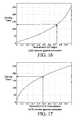
- FIG. 16illustrates LED inverse gamma correction.
- FIG. 17illustrates LCD inverse gamma correction.
- a backlit display 20comprises, generally, a backlight 22 , a diffuser 24 , and a light valve 26 (indicated by a bracket) that controls the transmittance of light from the backlight 22 to a user viewing an image displayed at the front of the panel 28 .
- the light valvetypically comprising a liquid crystal apparatus, is arranged to electronically control the transmittance of light for a picture element or pixel. Since liquid crystals do not emit light, an external source of light is necessary to create a visible image.
- the source of light for small and inexpensive LCDs, such as those used in digital clocks or calculators,may be light that is reflected from the back surface of the panel after passing through the panel.
- LCDsCMOS on silicon devices rely on light reflected from a backplane of the light valve to illuminate a display pixel.
- LCDsabsorb a significant portion of the light passing through the assembly and an artificial source of light such as the backlight 22 comprising fluorescent light tubes or an array of light sources 30 (e.g., light-emitting diodes (LEDs), as illustrated in FIG. 1A and fluorescent tubes as illustrated in FIG. 1B ), are useful to produce pixels of sufficient intensity for highly visible images or to illuminate the display in poor lighting conditions.
- LEDslight-emitting diodes
- the light from the general point sourcese.g., LEDS
- general line sourcese.g., fluorescent tubes
- the light valve 26includes a first polarizer 32 and a second polarizer 34 having optical axes arrayed at an angle so that normally light cannot pass through the series of polarizers. Images are displayable with an LCD because local regions of a liquid crystal layer 36 interposed between the first 32 and second 34 polarizer can be electrically controlled to alter the alignment of the plane of vibration of light relative of the optical axis of a polarizer and, thereby, modulate the transmittance of local regions of the panel corresponding to individual pixels 36 in an array of display pixels.
- the layer of liquid crystal molecules 36occupies a cell gap having walls formed by surfaces of the first 32 and second 34 polarizers.
- the walls of the cell gapare rubbed to create microscopic grooves aligned with the optical axis of the corresponding polarizer.
- the groovescause the layer of liquid crystal molecules adjacent to the walls of the cell gap to align with the optical axis of the associated polarizer.
- each successive molecule in the column of molecules spanning the cell gapwill attempt to align with its neighbors.
- the resultis a layer of liquid crystals comprising innumerable twisted columns of liquid crystal molecules that bridge the cell gap.
- a voltageis applied to a spatially corresponding electrode of a rectangular array of transparent electrodes deposited on a wall of the cell gap.
- the resulting electric fieldcauses molecules of the liquid crystal adjacent to the electrode to rotate toward alignment with the field.
- the effectis to Auntwist@ the column of molecules so that the plane of vibration of the light is progressively rotated away from the optical axis of the polarizer as the field strength increases and the local transmittance of the light valve 26 is reduced.
- the pixel 28progressively darkens until the maximum extinction of light 40 from the light source 42 is obtained.
- Color LCD displaysare created by varying the intensity of transmitted light for each of a plurality of primary color elements (typically, red, green, and blue) elements making up a display pixel. Other arrangements of structures may likewise be used.
- the LCDuses transistors as a select switch for each pixel, and adopts a display method (hereinafter, called as a “hold-type display”), in which a displayed image is held for a frame period.
- a CRThereinafter, called as an “impulse-type display”
- the darkened pixelis displayed between each frame of a motion image that is rewritten in 60 Hz in case of the impulse-type display like the CRT. That is, the black of the darkened pixel is displayed excluding a period when the image is displayed, and one frame of the motion image is presented respectively to the viewer as an independent image. Therefore, the image is observed as a clear motion image in the impulse-type display.
- the LCDis fundamentally different from CRT in time axis hold characteristic in an image display. Therefore, when the motion image is displayed on a LCD, image deterioration such as blurring the image is caused.
- image deteriorationarises from a viewer that follows the moving object of the motion image (when the eyeball movement of the viewer is a following motion), even if the image is rewritten, for example, at 60 Hz discrete steps.
- the eyeballhas a characteristic to attempt to smoothly follow the moving object even though it is discretely presented in a “hold type” manner.
- the displayed image of one frame of the motion imageis held for one frame period, and is presented to the viewer during the corresponding period as a still image. Therefore, even though the eyeball of the viewer smoothly follows the moving object, the displayed image stands still for one frame period. Therefore, the shifted image is presented according to the speed of the moving object on the retina of the viewer. Accordingly, the image will appear blurred to the viewer due to integration by the eye. In addition, since the change between the images presented on the retina of the viewer increases with greater speed, such images become even more blurred.
- the backlight 22comprises an array of locally controllable light sources 30 .
- the individual light sources 30 of the backlightmay be light-emitting diodes (LEDs), an arrangement of phosphors and lensets, or other suitable light-emitting devices.
- the backlightmay include a set of independently controllable light sources, such as one or more cold cathode ray tubes.
- the light-emitting diodesmay be ‘white’ and/or separate colored light emitting diodes.
- the individual light sources 30 of the backlight array 22are independently controllable to output light at a luminance level independent of the luminance level of light output by the other light sources so that a light source can be modulated in response to any suitable signal.
- the light sources 30(LEDs illustrated) of the array 22 are typically arranged in the rows, for examples, rows 50 a and 50 b , (indicated by brackets) and columns, for examples, columns 52 a and 52 b (indicated by brackets) of a rectangular array.
- the output of the light sources 30 of the backlightare controlled by a backlight driver 53 .
- the light sources 30are driven by a light source driver 54 that powers the elements by selecting a column of elements 52 a or 52 b by actuating a column selection transistor 55 and connecting a selected light source 30 of the selected column to ground 56 .
- a data processing unit 58processing the digital values for pixels of an image to be displayed, provides a signal to the light driver 54 to select the appropriate light source 30 corresponding to the displayed pixel and to drive the light source with a power level to produce an appropriate level of illumination of the light source.
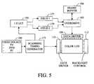
- FIG. 3illustrates a block diagram of a typical data path within a liquid crystal panel.
- the video data 100may be provided from any suitable source, such as for example, television broadcast, Internet connection, file server, digital video disc, computer, video on demand, or broadcast.
- the video data 100is provided to a scanning and timing generator 102 where the video data is converted to a suitable format for presentation on the display.
- each line of datais provided to an overdrive circuit 104 , in combination with a frame buffer 106 , to compensate for the slow temporal response of the display.
- the overdrivemay be analog in nature, if desired.
- the signal from the overdrive 104is preferably converted to a voltage value in the data driver 108 which is output to individual data electrodes of the display.
- the generator 102also provides a clock signal to the gate driver 110 , thereby selecting one row at a time, which stores the voltage data on the data electrode on the storage capacitor of each pixel of the display.
- the generator 102also provides backlight control signals 112 to control the level of luminance from the backlight, and/or the color or color balance of the light provided in the case of spatially non-uniform backlight (e.g., based upon image content and/or spatially different in different regions of the display).
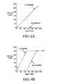
- FIG. 4Aillustrates the effect of flashing the backlight during only a portion of the frame.
- the horizontal axisrepresents the elapsed time during a frame and the vertical axis represents a normalized response of the LCD during the frame.
- the backlight levelis preferably set to zero during a portion of the frame or otherwise a significantly reduced level.
- the flashing of the backlightis toward the end of the frame where the transmission of the liquid crystal material has reached or otherwise is approaching the target level.
- the majority of the duration of the flashing backlightis preferably during the last third of the frame period. While modulating the backlight in some manner reduces the perceived motion blur and it may be further reduced by being flashed at a higher rate.
- FIG. 4Billustrates a black data insertion technique that reduces the display temporal aperture thus reducing motion blur.
- Each frameis divided into two fields where the first field contains the display data and the second field is driven to black. Accordingly, the display is “on” for only about half of the frame.
- the input frame 100is provided to a scanning timing generator 175 .
- the scanning timing generator 175converts the input frame into two fields 177 and 179 using a look up table 181 , such as a one dimensional look up table.
- the two fields 177 and 179are then provided to an overdrive 183 .
- the look up table 181may take the form of a pair of functions.
- the first field 177is set to the same as the input, while the second field 179 is set to zero (e.g., black).
- the embodiment shown in FIG. 6Aachieves a significant black point insertion into the image. This technique results in significant brightness reduction and has blurring at high luminance.
- FIG. 6Aachieves a significant black point insertion into the image. This technique results in significant brightness reduction and has blurring at high luminance.
- the first field 177may be set to twice of the input data until it reaches a desired level, such as the maximum (e.g., 255), and then the second subfield starts to increase from a low value, such as zero, to a desired level, such as the maximum (e.g., 255).
- a desired levelsuch as the maximum (e.g., 255)
- the second subfieldstarts to increase from a low value, such as zero, to a desired level, such as the maximum (e.g., 255).
- the technique shown in FIG. 6Bincreases the brightness over that shown in FIG. 6A , while moderating the motion blur that may occur at a high luminance.
- the backlightmay be structured with a plurality of different regions.
- the backlightmay be approximately 200 pixels (e.g., 50-400 pixel regions) wide and extend the width of the display.
- the backlightmay be composed of, for example, 4 different backlight regions.
- the backlightmay be composed of one or more rows of diodes, and/or one or more columns of diodes, and/or different areas in general.
- FIG. 8A typical implementation structure of the conventional overdrive (OD) technology is shown in FIG. 8 .
- the implementationincludes one frame buffer 400 and an overdrive module 402 .
- the frame bufferstores previous target display value x n-1 of driving cycle n- 1 .
- the overdrive moduletaking current target display value x n and previous display value x n-1 as input, derives the current driving value z n to make the actual display value d n the same as the target display value x n .
- the current display value d nis preferably not only determined by the current driving value z n , but also by the previous display value d n-1 .
- d nf d ( z n ,d n-1 ) (1)
- overdriving value z nshould be derived from Equation (1) by making d n to be target value x n .
- Equation (3)only one type of variable: target values, is needed to derive current driving values, and this valuable is directly available without any calculation. As a result, Equation (3) is easier than Equation (2) to implement.
- a processing technique for the videoshould a motion adaptive technique to reduce motion blur without substantially increasing the flickering.
- Each frame in a video sequenceis divided into multiple regions, and motion detection is performed for each corresponding region in the successive frames (or fields). Each region is classified as either a motion region or a non-motion region.
- the black data insertionis applied to the motion regions to reduce the motion blur, while black data insertion is not applied to the non-motion regions to reduce flickering.
- temporal transition framesmay be used to smooth out intensity fluctuations between the black data insertions and the non-black data insertions.
- FIG. 8illustrates a technique for motion adaptive black data insertion.
- An input frame 700 of datais received.
- the input frame 700is preferably blurred and sub-sampled to a lower resolution image 710 to reduce the computational complexity.
- Each pixel in the lower resolution image 710corresponds to a region in the input frame 700 .
- Each pixel in the lower resolution image 710is compared to the previous frame stored in a sub-sampled image buffer 720 to detect motion 730 . If the difference between the two pixels is greater than a threshold (such as 5% of the total range), then the pixel is classified as a motion pixel 740 . This motion determination is performed on the remaining or selected pixels.
- a thresholdsuch as 5% of the total range
- the systemmay include multiple degrees of motion, if desired.
- a morphological dilation operationmay be performed on the motion map 740 to group the non-motion pixels neighboring motion pixels to a motion pixel to form groups of motion pixels with similar motion characteristics.
- the dilation operationmay be approximated with a low pass filter and a subsequent thresholding type operation.
- the resulting data from the dilation operationmay be stored in a motion map buffer 750 . Regions with no or limited motion are indicated by a 0 while regions with significant motion are indicated by a 3. There may be transitions between a region with limited motion and a region with significant motion, or vice versa.
- a change from insignificant motion to significant motionmay use a set of transition frames in order to avoid artifacts or other undesirable effects on the resulting image.
- the motion map buffer 750may indicate such a change in motion with other indicators, such as a region with “limited motion” indicated by a 1 (headed toward 0 or headed toward 2) and a region with “more motion” indicated by a 2 (headed toward 1 or headed toward 3).
- a transition from no motion to significant motionmay be done by a set of indicators of 1 for the frame, 2 for the next frame, and 3 for the subsequent frame (similar for the transition from significant motion to no motion).
- Other indicationsmay likewise be used, as desired, to indicate additional transition frames and additional degrees of motion.
- any type of determinationmay be used to determine those regions and/or pixels of the image that include sufficient or insufficient motion between one or more frames.
- the systemmay detect insufficient motion and sufficient motion, and thus use a set of one or more transition frames to change from one state to the other. In this case, the system does not necessarily need to quantify intermediate states of motion.
- the systemif desired, may determine intermediate levels of motion that is used together with or without transition frames.
- the sub-sampled imageis stored in the sub-sampled image buffer 720 for subsequent frames.
- the image in the motion map buffer 750may be up-sampled 760 to the size of the input image 700 .
- a look up table 770is used to determine the field driving values (see FIG. 5 ) for the fields of the frame (typically two fields in a frame) based upon the up-sampled 760 motion map buffer 750 data.
- the adaptive black data insertion techniqueuses a strong black data insertion for those regions of high motion and uses less or non-black data insertion for those regions of low motion.
- a pair (or more) look up tablesmay be used to derive the driving values for multiple fields in accordance with the estimated motion. Referring to FIG. 10 several input value versus driving value tables for the look up table 770 are illustrated for different frames and transition frames.
- the motion map valuehas a value of 0 then it indicates non-motion and thus a non-motion look up table (see FIG. 10A ) is used.
- a non-motion look up tablesee FIG. 10B
- a different look up tablesee FIG. 10B
- the motion map valuehas a value of 2 then it indicates the transition and a different look up table (see FIG. 10C ) is used.
- the motion map valuehas a value of 3 then it indicates significant-motion and thus a significant-motion look up table (see FIG. 10D ) is used.
- the respective look up tablesare applied to the first field 780 and to the second field 790 .
- the output of the first field 780 and second field 790are provided to an overdrive 800 .
- Any suitable overdrive techniquemay be used, as desired.
- the overdrive 800includes a look up table 810 and 820 for respective first field 780 and second field 790 .
- the output of the look up table 810 for the first field 780is based upon the output of the previous field from buffer 2 830 (second field of the previous frame).
- the output of the look up table 820 for the second field 790is based upon the output of the previous field from buffer 1 840 (first field of the same frame).
- the state of the previous frame for the first field 780(input from buffer 2 830 ) is determined based upon a model of the liquid crystal display 850 , the second field 790 of the previous frame, and the output of the look up table 820 .
- the state of the previous frame for the second field 790(input from buffer 1 840 ) is determined based upon a model of the liquid crystal display 860 , the first field 780 of the previous field, and the output of the look up table 810 . Accordingly, the previous field may be used in the overdrive scheme.
- FIG. 11illustrates the general resulting waveforms for the driving scheme shown in FIG. 10 .
- a similar techniquemay likewise be applied for the overdrive system based upon the spatial frequency of regions of the image, such as low and high spatial frequencies.
- a similar techniquemay be applied for the overdrive system based upon the brightness of regions of the image, such as low brightness and high brightness.
- Theselikewise may be applied in combination or based upon one another (e.g., spatial, brightness, and/or motion).
- the adaptive techniquemay be accommodated by applying the spatial modifications to the LCD layer of the display.
- the transition framesmay be accommodated by applying the spatial modifications to the backlight, such as a LED array.
- the techniquemay be accommodated by a combination of the LCD layer and the backlight layer.
- Liquid crystal displayshave limited dynamic range due the extinction ratio of polarizers and imperfection of the liquid crystal material.
- a low resolution light emitting diode (LED) backlight systemmay be used to modulate the light that feeds into the liquid crystal material.
- LEDtypically has lower spatial resolution than the LCD. Due to the lower resolution LED, the high dynamic range display based on this technology can not display a high dynamic pattern of high spatial resolution. But it can display both very bright image (>2000 cd/m 2 ) and very dark image ( ⁇ 0.5 cd/m 2 ) simultaneously.
- the inability to display high dynamic range of high spatial resolutionis not a serious issue since the human eye has limited dynamic range in a local area, and with visual masking, the human eye can hardly perceive the limited dynamic range of high spatial frequency content.
- FIG. 12illustrates one previously existing technique to convert a high spatial resolution high dynamic range (HDR) image into a lower resolution light emitting diode (LED) image and a high resolution liquid crystal display image.
- the luminanceis extracted from the HDR image.
- the extracted luminanceis then low pass filtered and sub-sampled to the resolution of the LED array.
- the filtered and sub-sampled imagemay be processed to reduce cross talk effects.
- the cross-talk corrected imagemay be sent to a raster decoder and displayed on the LED layer of the HDR display.
- the desirable backlight imagemay be predicted by convolving an up-sampled LED image with the point spread function of LED.
- the LCD imageis derived by dividing the original HDR image with predicted backlight image to obtain the simulated backlight. Since the final displayed image is the product of LED backlight image and the LCD transmittance, this approach reproduces the original HDR image.
- the resulting displayed images using this techniquetends to have limited bright specular highlights that are limited in spatial extent. Accordingly, many HDR images contains specular highlight that are extremely bright, but very small in spatial extent, which may not be adequately represented on the display.
- the low pass filteringworks well for regions of the image that are not at the extremes of brightness and darkness. Accordingly, another criteria may be used to account for those regions where the low pass filtering is not exceptionally effective.
- the systemmay also use the maximum image (or some value associated with regions where a significant value exists) which is the local maximum in the HDR image divided by the max transmittance of LCD. The final LED image is selected to be the larger of the low pass filtered image and the maximum image.
- the broad spread in the LED point spread functionresults in decreasing the potential contrast ratio of the image and also fails to minimize the power consumption of the display.
- an iterative approachmay be used to derive the LED driving value to achieve a higher contrast in the backlight image.
- the resulting higher contrast backlight image combining with the high resolution LCD imagecan produce much higher dynamic image to be displayed and also reduce the power consumption of the LED backlight.
- moving imagestend to flicker more than expected, i.e. the fluctuation of display output.
- a particular configuration of the displaynamely a LCD combined with LED array
- the temporal response of the LCD layeris different than the LED array in a manner that may result in flickering.
- the LEDhas a much faster temporal response than the LCD layer.
- these errors resulting in flickeringmay be due to inaccuracies in the point spread function approximation, which may vary from display to display, and from led to led.
- the course nature of the LED arraytends to result in course selection of the LED values, generally being on or off.
- a temporal low-pass filtermay be used and a finner control over the values selected for proximate LEDs.
- gamma correctionmay be used to account for the quantization error that is inherent to LED driving circuit.
- FIG. 1shows a schematic of a HDR display with LED layer as a backlight for a LCD.
- the light from array of LEDspasses through the diffusion layer and illuminates the LCD.
- LED(i,j)is the LED output level of each LED
- psf(x,y)is the point spread function of the diffusion layer. * denotes convolution operation.
- the backlight imageis further modulated by the LCD.
- the dynamic range of displayis the product of the dynamic range of LED and LCD.
- the notationmay use normalized LCD and LED output limited to between 0 and 1.
- FIG. 13shows an exemplary technique to convert a HDR image 900 into a low resolution LED image 902 and a high resolution LCD image 904 .
- the LCD resolutionis m ⁇ n pixels with its range from 0 to 1, with 0 to be black and 1 to be the maximum transmittance.
- the LED resolutionis M ⁇ N with M ⁇ m and N ⁇ n. For simplicity it may be assumed that the HDR image has the same resolution as LCD. If HDR image is of different resolution, a scaling or cropping step may be used to convert the HDR image to LCD image resolution.
- the HDR imageis low pass filtered 906 by the point spread function of the diffusion screen (or other function) and sub-sampled 908 (down sample) to an intermediate resolution (M1 ⁇ N1).
- M1 ⁇ N1an intermediate resolution
- 2M ⁇ 2Ntwice the LED resolution
- the extra resolution of the sub-sampled imageis used to reduce flickering that would occur as a result of moving objects over a series of frames of a video.
- the additional data points in the LED matrixpermit a smoothing of the transition of the LED values when movement occurs in the image of a video. This facilitates one LED to gradually decrease in value as an adjacent LED gradually increases in value, which reduces the resulting flickering of the image that would result if the changes were more abrupt.
- the same HDR image 900is again low-pass filtered 910 by a small filter kernel, such as 5 ⁇ 5 to simulate the anticipated size of the specular pattern.
- the low-pass filtered image 910is divided into M1 ⁇ N1 blocks, each block corresponding to the intermediate resolution with some overlap between each block, i.e., the block size is (1+k)*(m/M ⁇ n/N), where k is the overlapping factor.
- the block maximum(or other suitable value) is used to form a LEDmax image (M ⁇ N) 912 .
- This larger valuehelps account for the fact that the low pass filtering tends to decrease the dynamic range that would otherwise have been rendered on the display.
- the min operationis used to constrain the LED value from 0 to 1.
- the local maximumassists to preserve the specular highlight.
- the systemmay set the LED 1 to less than twice of the LED 1 p to ensure operation toward the maximum LCD operating range. An increase in the LCD operating range results in a decrease in the needed backlight light, and thus a reduces the power requirements. This technique can better accommodate areas with both high dynamic range and high spatial frequency.
- the LED 1is of size M1 ⁇ N1 and range from 0 to 1. Since the PSF of diffusion screen is typically larger than the LED spacing to provide a more uniform backlight image, there is tends to be considerable crosstalk between the LED elements that are located close together.
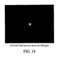
- FIG. 14shows a typical LED PSF with the black lines indicating the borders between LEDs. It is apparent that the PSF extends beyond the boarder of a particular LED.
- Equation 5can be used to calculate the backlight if given a LED driving signal, deriving LED driving signal to achieve a target backlight image is an inverse problem. This problem results in an ill posed de-convolution problem.
- a convolution kernel used to derive the LED driving signalas shown in Equation 6.
- the crosstalk correction kernel coefficients (c 1 and c 2 )are negative to compensate for the crosstalk from neighboring LEDs.
- the crosstalk correction matrixdoes reduce the crosstalk effect from its immediate neighbors, but the resulting backlight image is still inaccurate with a low contrast. Another problem is that it produces many out of range driving values that have to be truncated which can result in more errors.
- the led driving valueis derived so that backlight is larger than target luminance, i.e. led( i,j ): ⁇ led( i,j )*psf( x,y ) ⁇ I ( x,y ) ⁇ (7)
- Another featureis power saving so that the total LED output should be minimized or otherwise reduced.
- Flickeringis due, at least in part, to the non-stationary response of the LED which combines with the mismatch between the LCD and LED.
- the mismatchcan be either spatially or temporally. Flickering can be reduced by decreasing the total led output fluctuation as a point object move through the LED grid.
- FIG. 15shows a technique to derive a LED value 916 using a constrained optimization process.
- [ I 1 I 2 I 3 ⁇ I MN ⁇ ⁇ 2 ][ psf 1 , 1 psf 1 , 2 psf 1 , 3 ⁇ psf 1 , MN psf 2 , 1 psf 2 , 2 psf 2 , 3 ⁇ psf 2 , MN psf 3 , 1 psf 3 , 2 psf 3 , 3 ⁇ psf 3 , MN ⁇ ⁇ ⁇ psf MN ⁇ ⁇ 2 , 1 psf MN ⁇ ⁇ 2 , 2 psf MN ⁇ ⁇ 2 , 2 ⁇ psf MN ⁇ ⁇ 2 , MN ] ⁇ [ LED 1 LED 2 LED 3 ⁇ LED MN ] ( 12 )
- LEDis the driving values in a vector format.
- MNis the total number of LEDs which is equal to M*N.
- the crosstalk matrix psf i,jis the crosstalk coefficients from the ith LED to the jth backlight position, which can be derived from the measured PSF function.
- gis the target LED in vector format and P is a masking matrix of size MN by MN2 with 1 at LED locations and 0 at other locations. Since the LED driving value is limited to between 0 and 1, it is truncated to between 0 and 1.
- the newly derived LED valueis compared to the previous one to calculate the change rate. If the change rate is greater than a threshold, the process is repeated until the change rate is less than the threshold or exceeding the maximum iteration.
- FIG. 16shows the process of inverse gamma correction 902 for the LED.
- the quantized driving valueis again gamma corrected; this is the actual LED output to the LED driver circuit 920 .
- the next stepis to predict the backlight image 922 from the LED.
- the LED image 902is gamma corrected 924 , up-sampled to the LCD resolution (m ⁇ n) 926 , and convolved with the PSF of the diffusion screen 928 .
- inverse gamma correctionis performed as in FIG. 17 to correct the nonlinear response of the LCD and provided to the LCD driver circuit 932 .
- a temporal low pass filter 918is used to smooth sudden temporal fluctuations.
- led n ⁇ ( i , j )⁇ k up ⁇ f ⁇ ( i , j ) + ( 1 - k up ) ⁇ led n - 1 ⁇ ( i , j ) f ⁇ ( i , j ) > led n - 1 ⁇ ( i , j ) k down ⁇ f ⁇ ( i , j ) + ( 1 - k down ) ⁇ led n - 1 ⁇ ( i , j ) else ( 11 )
- the LED backlightis constrained over multiple frames to change from one value to another in one or more increments.
- the backlightmay change from 0 to 200, and thus be 0 in a first frame, 100 in the second frame, and 200 in the third frame.
- the LEDis preferably permitted to go up at a faster rate than it is permitted to go down.
Landscapes
- Engineering & Computer Science (AREA)
- Physics & Mathematics (AREA)
- Computer Hardware Design (AREA)
- General Physics & Mathematics (AREA)
- Theoretical Computer Science (AREA)
- Chemical & Material Sciences (AREA)
- Crystallography & Structural Chemistry (AREA)
- Liquid Crystal Display Device Control (AREA)
- Control Of Indicators Other Than Cathode Ray Tubes (AREA)
- Liquid Crystal (AREA)
Abstract
Description
dn=fd(zn,dn-1) (1)
zn=fz(xn,dn-1) (2)
zn=fz(xn,xn-1) (3)
bl(x,y)=LED(i,j)*psf(x,y) (4)
img(x,y)=bl(x,y)TLCD(x,y)=(led(i,j)*psf(x,y))TLCD(x,y) (5)
led(i,j):{led(i,j)*psf(x,y)≧I(x,y)} (7)
led(i,j):{led(i,j){circle around (x)}psf(x,y)<I(x,y)·CR} (8)
TLCD(x,y)=img(x,y)/bl(x,y)
Claims (16)
Priority Applications (4)
| Application Number | Priority Date | Filing Date | Title |
|---|---|---|---|
| US11/607,553US8941580B2 (en) | 2006-11-30 | 2006-11-30 | Liquid crystal display with area adaptive backlight |
| JP2007302290AJP4796038B2 (en) | 2006-11-30 | 2007-11-21 | Image display method |
| CN 200710196106CN101202023B (en) | 2006-11-30 | 2007-11-28 | Liquid crystal display with area adaptive backlight |
| EP20070023070EP1927974B1 (en) | 2006-11-30 | 2007-11-28 | Liquid crystal display with area adaptive backlight |
Applications Claiming Priority (1)
| Application Number | Priority Date | Filing Date | Title |
|---|---|---|---|
| US11/607,553US8941580B2 (en) | 2006-11-30 | 2006-11-30 | Liquid crystal display with area adaptive backlight |
Publications (2)
| Publication Number | Publication Date |
|---|---|
| US20080129677A1 US20080129677A1 (en) | 2008-06-05 |
| US8941580B2true US8941580B2 (en) | 2015-01-27 |
Family
ID=39284185
Family Applications (1)
| Application Number | Title | Priority Date | Filing Date |
|---|---|---|---|
| US11/607,553Active2030-06-27US8941580B2 (en) | 2006-11-30 | 2006-11-30 | Liquid crystal display with area adaptive backlight |
Country Status (4)
| Country | Link |
|---|---|
| US (1) | US8941580B2 (en) |
| EP (1) | EP1927974B1 (en) |
| JP (1) | JP4796038B2 (en) |
| CN (1) | CN101202023B (en) |
Cited By (4)
| Publication number | Priority date | Publication date | Assignee | Title |
|---|---|---|---|---|
| US20130127929A1 (en)* | 2008-02-14 | 2013-05-23 | Sony Corporation | Lighting period setting method, display panel driving method, backlight driving method, lighting condition setting device, semiconductor device, display panel and electronic equipment |
| US10417996B2 (en) | 2017-08-31 | 2019-09-17 | Yuan Ze University | Method, image processing device, and display system for power-constrained image enhancement |
| US11164367B2 (en)* | 2019-07-17 | 2021-11-02 | Google Llc | Illumination effects from luminous inserted content |
| US11804197B1 (en) | 2020-08-28 | 2023-10-31 | Apple Inc. | Optical systems having overdriven fLCOS display panels |
Families Citing this family (42)
| Publication number | Priority date | Publication date | Assignee | Title |
|---|---|---|---|---|
| EP1751702A4 (en)* | 2004-05-18 | 2009-01-07 | Silverbrook Res Pty Ltd | Pharmaceutical product tracking |
| EP2024957A1 (en)* | 2006-05-09 | 2009-02-18 | Koninklijke Philips Electronics N.V. | Display device with a backlight |
| WO2008094153A1 (en)* | 2007-01-31 | 2008-08-07 | Dolby Laboratories Licensing Corporation | Multiple modulator displays and related methods |
| US20080185976A1 (en)* | 2007-02-05 | 2008-08-07 | Honeywell International, Inc. | Display backlight system and method |
| KR101393627B1 (en)* | 2007-03-02 | 2014-05-12 | 삼성디스플레이 주식회사 | Display device and control method of the same |
| TWI370424B (en)* | 2007-05-14 | 2012-08-11 | Novatek Microelectronics Corp | Apparatus and method for controlling backlight source |
| WO2009054223A1 (en)* | 2007-10-25 | 2009-04-30 | Sharp Kabushiki Kaisha | Image display device |
| US8493313B2 (en)* | 2008-02-13 | 2013-07-23 | Dolby Laboratories Licensing Corporation | Temporal filtering of video signals |
| US20090244266A1 (en)* | 2008-03-26 | 2009-10-01 | Thomas Carl Brigham | Enhanced Three Dimensional Television |
| US8531380B2 (en)* | 2008-07-22 | 2013-09-10 | Sharp Laboratories Of America, Inc. | Methods and systems for area adaptive backlight management |
| JP2010039110A (en)* | 2008-08-04 | 2010-02-18 | Nippon Hoso Kyokai <Nhk> | Image signal processor and display equipped with the same |
| US8314767B2 (en)* | 2008-08-30 | 2012-11-20 | Sharp Laboratories Of America, Inc. | Methods and systems for reducing view-angle-induced color shift |
| JP4837009B2 (en)* | 2008-09-12 | 2011-12-14 | ミツミ電機株式会社 | Liquid crystal display |
| DE102008048447A1 (en)* | 2008-09-23 | 2010-04-29 | Siemens Enterprise Communications Gmbh & Co. Kg | Method and arrangement for the imaging of information, in particular for use in communication terminals |
| ES2541846T3 (en) | 2008-10-14 | 2015-07-27 | Dolby Laboratories Licensing Corporation | Backlight simulation at reduced resolutions to determine spatial light modulation for high dynamic range images |
| WO2010045038A1 (en)* | 2008-10-14 | 2010-04-22 | Dolby Laboratories Licensing Corporation | High dynamic range display with rear modulator control |
| CN101751874B (en)* | 2008-11-28 | 2013-03-06 | 康佳集团股份有限公司 | LCD TV intelligent dynamic backlight control method |
| TWI406244B (en)* | 2008-12-29 | 2013-08-21 | Chunghwa Picture Tubes Ltd | Backlight control method for lcd panel and related lcd device |
| EP2396784A1 (en)* | 2009-02-11 | 2011-12-21 | Thomson Licensing | Signal generation for led/lcd-based high dynamic range displays |
| US8331714B2 (en)* | 2009-02-23 | 2012-12-11 | Sharp Laboratories Of America, Inc. | Methods and systems for image processing |
| US8624824B2 (en)* | 2009-03-19 | 2014-01-07 | Sharp Laboratories Of America, Inc. | Area adaptive backlight with reduced color crosstalk |
| JP2012137508A (en)* | 2009-04-20 | 2012-07-19 | Panasonic Corp | Display device |
| EP2434474A4 (en)* | 2009-05-19 | 2013-03-27 | Sharp Kk | Liquid crystal display apparatus and method for driving same |
| EP2284827A1 (en)* | 2009-07-15 | 2011-02-16 | Trident Microsystems (Far East) Ltd. | Backlight unit and control method for the same |
| US8947339B2 (en)* | 2009-12-21 | 2015-02-03 | Sharp Laboratories Of America, Inc. | Noise-compensated LCD display |
| KR20110084730A (en)* | 2010-01-18 | 2011-07-26 | 삼성전자주식회사 | LCD and its driving method |
| EP2534653A1 (en)* | 2010-02-11 | 2012-12-19 | Sharp Kabushiki Kaisha | Image processor, display device, and image processing method |
| KR101267304B1 (en) | 2010-02-22 | 2013-05-27 | 돌비 레버러토리즈 라이쎈싱 코오포레이션 | Methods and systems for reducing power consumption in dual modulation displays |
| EP3051530B1 (en)* | 2010-06-21 | 2022-08-31 | Dolby Laboratories Licensing Corporation | Displaying images on local-dimming displays |
| US8717278B2 (en) | 2010-08-31 | 2014-05-06 | Dolby Laboratories Licensing Corporation | Method and apparatus for adjusting drive values for dual modulation displays |
| EP2740274A1 (en)* | 2011-08-03 | 2014-06-11 | TP Vision Holding B.V. | Tv with 2d dimming for 3d viewing mode |
| WO2013188298A2 (en)* | 2012-06-15 | 2013-12-19 | Dolby Laboratories Licensing Corporation | Systems and methods for controlling dual modulation displays |
| US9265458B2 (en) | 2012-12-04 | 2016-02-23 | Sync-Think, Inc. | Application of smooth pursuit cognitive testing paradigms to clinical drug development |
| US9380976B2 (en) | 2013-03-11 | 2016-07-05 | Sync-Think, Inc. | Optical neuroinformatics |
| WO2015072257A1 (en) | 2013-11-12 | 2015-05-21 | 富士フイルム株式会社 | Display device and control method for same |
| EP3087740A1 (en)* | 2013-12-27 | 2016-11-02 | Thomson Licensing | Method and device for tone-mapping a high dynamic range image |
| WO2018042413A1 (en)* | 2016-08-28 | 2018-03-08 | Siegel Gabriel | A system for histological examination of tissue specimens |
| US11348545B2 (en) | 2018-05-22 | 2022-05-31 | Sony Corporation | Image processing device, display device, and image processing method |
| TWI703542B (en)* | 2019-06-05 | 2020-09-01 | 友達光電股份有限公司 | Backlight signal processing method and display device |
| JP7500966B2 (en) | 2019-12-24 | 2024-06-18 | セイコーエプソン株式会社 | CIRCUIT DEVICE, DISPLAY DEVICE, ELECTRONIC INSTRUMENT, MOBILE OBJECT, AND CONTROL METHOD |
| US11743598B2 (en)* | 2020-07-14 | 2023-08-29 | Nbcuniversal Media, Llc | Light valve systems and methods |
| WO2024075359A1 (en)* | 2022-10-04 | 2024-04-11 | Eizo株式会社 | Liquid-crystal display device, liquid-crystal display method, and program |
Citations (324)
| Publication number | Priority date | Publication date | Assignee | Title |
|---|---|---|---|---|
| US3329474A (en) | 1963-11-08 | 1967-07-04 | Ibm | Digital light deflector utilizing co-planar polarization rotators |
| US3375052A (en) | 1963-06-05 | 1968-03-26 | Ibm | Light beam orienting apparatus |
| US3428743A (en) | 1966-02-07 | 1969-02-18 | Thomas F Hanlon | Electrooptic crystal controlled variable color modulator |
| US3439348A (en) | 1966-01-14 | 1969-04-15 | Ibm | Electrooptical memory |
| US3499700A (en) | 1963-06-05 | 1970-03-10 | Ibm | Light beam deflection system |
| US3503670A (en) | 1967-01-16 | 1970-03-31 | Ibm | Multifrequency light processor and digital deflector |
| US3554632A (en) | 1966-08-29 | 1971-01-12 | Optomechanisms Inc | Fiber optics image enhancement using electromechanical effects |
| US3947227A (en) | 1973-01-15 | 1976-03-30 | The British Petroleum Company Limited | Burners |
| US4012116A (en) | 1975-05-30 | 1977-03-15 | Personal Communications, Inc. | No glasses 3-D viewer |
| US4110794A (en) | 1977-02-03 | 1978-08-29 | Static Systems Corporation | Electronic typewriter using a solid state display to print |
| US4170771A (en) | 1978-03-28 | 1979-10-09 | The United States Of America As Represented By The Secretary Of The Army | Orthogonal active-passive array pair matrix display |
| US4187519A (en) | 1978-08-17 | 1980-02-05 | Rockwell International Corporation | System for expanding the video contrast of an image |
| US4384336A (en) | 1980-08-29 | 1983-05-17 | Polaroid Corporation | Method and apparatus for lightness imaging |
| US4385806A (en) | 1978-06-08 | 1983-05-31 | Fergason James L | Liquid crystal display with improved angle of view and response times |
| US4410238A (en) | 1981-09-03 | 1983-10-18 | Hewlett-Packard Company | Optical switch attenuator |
| US4441791A (en) | 1980-09-02 | 1984-04-10 | Texas Instruments Incorporated | Deformable mirror light modulator |
| US4516837A (en) | 1983-02-22 | 1985-05-14 | Sperry Corporation | Electro-optical switch for unpolarized optical signals |
| US4540243A (en) | 1981-02-17 | 1985-09-10 | Fergason James L | Method and apparatus for converting phase-modulated light to amplitude-modulated light and communication method and apparatus employing the same |
| US4562433A (en) | 1980-09-02 | 1985-12-31 | Mcdonnell Douglas Corporation | Fail transparent LCD display |
| US4574364A (en) | 1982-11-23 | 1986-03-04 | Hitachi, Ltd. | Method and apparatus for controlling image display |
| US4611889A (en) | 1984-04-04 | 1986-09-16 | Tektronix, Inc. | Field sequential liquid crystal display with enhanced brightness |
| US4649425A (en) | 1983-07-25 | 1987-03-10 | Pund Marvin L | Stereoscopic display |
| US4648691A (en) | 1979-12-27 | 1987-03-10 | Seiko Epson Kabushiki Kaisha | Liquid crystal display device having diffusely reflective picture electrode and pleochroic dye |
| US4682270A (en) | 1984-05-18 | 1987-07-21 | British Telecommunications Public Limited Company | Integrated circuit chip carrier |
| USRE32521E (en) | 1978-06-08 | 1987-10-13 | Fergason James L | Light demodulator and method of communication employing the same |
| US4715010A (en) | 1984-08-14 | 1987-12-22 | Sharp Kabushiki Kaisha | Schedule alarm device |
| US4719507A (en) | 1985-04-26 | 1988-01-12 | Tektronix, Inc. | Stereoscopic imaging system with passive viewing apparatus |
| US4755038A (en) | 1986-09-30 | 1988-07-05 | Itt Defense Communications | Liquid crystal switching device using the brewster angle |
| US4758818A (en) | 1983-09-26 | 1988-07-19 | Tektronix, Inc. | Switchable color filter and field sequential full color display system incorporating same |
| US4766430A (en) | 1986-12-19 | 1988-08-23 | General Electric Company | Display device drive circuit |
| JPS6410299B2 (en) | 1979-11-22 | 1989-02-21 | Tokyo Shibaura Electric Co | |
| JPH0198383A (en) | 1987-10-09 | 1989-04-17 | Sony Corp | Display device |
| FR2611389B1 (en) | 1987-02-27 | 1989-04-28 | Thomson Csf | MATRIX IMAGING DEVICE WITH LIQUID CRYSTALS WITH BIREFRINGENCE DOUBLE RESOLUTION |
| US4834500A (en) | 1983-07-12 | 1989-05-30 | The Secretary Of State For Defence In Her Britannic Majesty's Government Of The United Kingdom Of Great Britain And Northern Ireland | Thermochromic liquid crystal displays |
| US4862270A (en) | 1987-09-29 | 1989-08-29 | Sony Corp. | Circuit for processing a digital signal having a blanking interval |
| US4862496A (en) | 1985-12-18 | 1989-08-29 | British Telecommunications Public Limited Company | Routing of network traffic |
| US4885783A (en) | 1986-04-11 | 1989-12-05 | The University Of British Columbia | Elastomer membrane enhanced electrostatic transducer |
| US4888690A (en) | 1985-01-11 | 1989-12-19 | Wang Laboratories, Inc. | Interactive error handling means in database management |
| US4910413A (en) | 1985-12-27 | 1990-03-20 | Canon Kabushiki Kaisha | Image pickup apparatus |
| US4917452A (en) | 1989-04-21 | 1990-04-17 | Uce, Inc. | Liquid crystal optical switching device |
| US4918534A (en) | 1988-04-22 | 1990-04-17 | The University Of Chicago | Optical image processing method and system to perform unsharp masking on images detected by an I.I./TV system |
| US4933754A (en) | 1987-11-03 | 1990-06-12 | Ciba-Geigy Corporation | Method and apparatus for producing modified photographic prints |
| US4954789A (en) | 1989-09-28 | 1990-09-04 | Texas Instruments Incorporated | Spatial light modulator |
| US4958915A (en) | 1985-07-12 | 1990-09-25 | Canon Kabushiki Kaisha | Liquid crystal apparatus having light quantity of the backlight in synchronism with writing signals |
| US4969717A (en) | 1987-06-03 | 1990-11-13 | British Telecommunications Public Limited Company | Optical switch |
| US4981838A (en) | 1988-03-17 | 1991-01-01 | The University Of British Columbia | Superconducting alternating winding capacitor electromagnetic resonator |
| US4991924A (en) | 1989-05-19 | 1991-02-12 | Cornell Research Foundation, Inc. | Optical switches using cholesteric or chiral nematic liquid crystals and method of using same |
| US5012274A (en) | 1987-12-31 | 1991-04-30 | Eugene Dolgoff | Active matrix LCD image projection system |
| US5013140A (en) | 1987-09-11 | 1991-05-07 | British Telecommunications Public Limited Company | Optical space switch |
| JPH03198026A (en) | 1989-12-27 | 1991-08-29 | Hitachi Ltd | Liquid crystal display device, back light control system, and information processor |
| JPH0371111B2 (en) | 1987-03-31 | 1991-11-12 | Kogyo Gijutsuin | |
| WO1991015843A3 (en) | 1990-04-09 | 1991-11-14 | Rank Brimar Ltd | Video display systems |
| US5075789A (en) | 1990-04-05 | 1991-12-24 | Raychem Corporation | Displays having improved contrast |
| US5074647A (en) | 1989-12-07 | 1991-12-24 | Optical Shields, Inc. | Liquid crystal lens assembly for eye protection |
| US5083199A (en) | 1989-06-23 | 1992-01-21 | Heinrich-Hertz-Institut For Nachrichtentechnik Berlin Gmbh | Autostereoscopic viewing device for creating three-dimensional perception of images |
| US5122791A (en) | 1986-09-20 | 1992-06-16 | Thorn Emi Plc | Display device incorporating brightness control and a method of operating such a display |
| US5128782A (en) | 1989-08-22 | 1992-07-07 | Wood Lawson A | Liquid crystal display unit which is back-lit with colored lights |
| US5138449A (en) | 1989-05-02 | 1992-08-11 | Michael Kerpchar | Enhanced definition NTSC compatible television system |
| US5144292A (en) | 1985-07-17 | 1992-09-01 | Sharp Kabushiki Kaisha | Liquid crystal display system with variable backlighting for data processing machine |
| US5164829A (en) | 1990-06-05 | 1992-11-17 | Matsushita Electric Industrial Co., Ltd. | Scanning velocity modulation type enhancement responsive to both contrast and sharpness controls |
| US5168183A (en) | 1991-03-27 | 1992-12-01 | The University Of British Columbia | Levitation system with permanent magnets and coils |
| US5187603A (en) | 1990-06-26 | 1993-02-16 | Tektronix, Inc. | High contrast light shutter system |
| US5202897A (en) | 1990-05-25 | 1993-04-13 | British Telecommunications Public Limited Company | Fabry-perot modulator |
| US5206633A (en) | 1991-08-19 | 1993-04-27 | International Business Machines Corp. | Self calibrating brightness controls for digitally operated liquid crystal display system |
| US5214758A (en) | 1989-11-14 | 1993-05-25 | Sony Corporation | Animation producing apparatus |
| US5222209A (en) | 1988-08-12 | 1993-06-22 | Sharp Kabushiki Kaisha | Schedule displaying device |
| US5224178A (en) | 1990-09-14 | 1993-06-29 | Eastman Kodak Company | Extending dynamic range of stored image database |
| JPH0566501B2 (en) | 1985-12-13 | 1993-09-21 | Mitsubishi Electric Corp | |
| US5247366A (en) | 1989-08-02 | 1993-09-21 | I Sight Ltd. | Color wide dynamic range camera |
| WO1993020660A1 (en) | 1992-03-31 | 1993-10-14 | Minnesota Mining And Manufacturing Company | Color calibration for lcd panel |
| JPH05273523A (en) | 1992-03-30 | 1993-10-22 | Toppan Printing Co Ltd | Gradational display method and liquid crystal display device |
| US5256676A (en) | 1992-04-27 | 1993-10-26 | British Technology Group Limited | 3-hydroxy-pyridin-4-ones useful for treating parasitic infections |
| JPH05289044A (en) | 1992-04-09 | 1993-11-05 | Matsushita Electric Ind Co Ltd | LCD interlace display device |
| JPH0580716B2 (en) | 1987-03-13 | 1993-11-10 | Tatsuno Mechatronics Kk | |
| US5293258A (en) | 1990-12-31 | 1994-03-08 | International Business Machines Corporation | Automatic correction for color printing |
| US5300942A (en) | 1987-12-31 | 1994-04-05 | Projectavision Incorporated | High efficiency light valve projection system with decreased perception of spaces between pixels and/or hines |
| US5305146A (en) | 1991-06-26 | 1994-04-19 | Victor Company Of Japan, Ltd. | Tri-color separating and composing optical system |
| US5311217A (en) | 1991-12-23 | 1994-05-10 | Xerox Corporation | Variable attenuator for dual beams |
| US5313225A (en) | 1989-06-06 | 1994-05-17 | Asahi Kogaku Kogyo Kabushiki Kaisha | Liquid crystal display device |
| US5313454A (en) | 1992-04-01 | 1994-05-17 | Stratacom, Inc. | Congestion control for cell networks |
| US5317400A (en) | 1992-05-22 | 1994-05-31 | Thomson Consumer Electronics, Inc. | Non-linear customer contrast control for a color television with autopix |
| US5337068A (en) | 1989-12-22 | 1994-08-09 | David Sarnoff Research Center, Inc. | Field-sequential display system utilizing a backlit LCD pixel array and method for forming an image |
| US5339382A (en) | 1993-02-23 | 1994-08-16 | Minnesota Mining And Manufacturing Company | Prism light guide luminaire with efficient directional output |
| JPH06247623A (en) | 1993-02-19 | 1994-09-06 | Ishikiri Dengiyou Kk | Wire extracting rotary table |
| US5357369A (en) | 1992-12-21 | 1994-10-18 | Geoffrey Pilling | Wide-field three-dimensional viewing system |
| US5359345A (en) | 1992-08-05 | 1994-10-25 | Cree Research, Inc. | Shuttered and cycled light emitting diode display and method of producing the same |
| JPH06313018A (en) | 1993-04-22 | 1994-11-08 | Basf Ag | Production of granular elastomeric graft polymer |
| US5369266A (en) | 1992-06-11 | 1994-11-29 | Sony Corporation | High definition image pick-up which shifts the image by one-half pixel pitch |
| US5386253A (en) | 1990-04-09 | 1995-01-31 | Rank Brimar Limited | Projection video display systems |
| US5394195A (en) | 1993-06-14 | 1995-02-28 | Philips Electronics North America Corporation | Method and apparatus for performing dynamic gamma contrast control |
| US5395755A (en) | 1990-06-12 | 1995-03-07 | British Technology Group Limited | Antioxidant assay |
| US5416496A (en) | 1989-08-22 | 1995-05-16 | Wood; Lawson A. | Ferroelectric liquid crystal display apparatus and method |
| US5422680A (en) | 1992-05-22 | 1995-06-06 | Thomson Consumer Electronics, Inc. | Non-linear contrast control apparatus with pixel distribution measurement for video display system |
| US5426312A (en) | 1989-02-23 | 1995-06-20 | British Telecommunications Public Limited Company | Fabry-perot modulator |
| US5436755A (en) | 1994-01-10 | 1995-07-25 | Xerox Corporation | Dual-beam scanning electro-optical device from single-beam light source |
| US5450498A (en) | 1993-07-14 | 1995-09-12 | The University Of British Columbia | High pressure low impedance electrostatic transducer |
| US5456255A (en) | 1993-07-12 | 1995-10-10 | Kabushiki Kaisha Toshiba | Ultrasonic diagnosis apparatus |
| US5461397A (en) | 1992-10-08 | 1995-10-24 | Panocorp Display Systems | Display device with a light shutter front end unit and gas discharge back end unit |
| US5471228A (en) | 1992-10-09 | 1995-11-28 | Tektronix, Inc. | Adaptive drive waveform for reducing crosstalk effects in electro-optical addressing structures |
| US5471225A (en) | 1993-04-28 | 1995-11-28 | Dell Usa, L.P. | Liquid crystal display with integrated frame buffer |
| US5477274A (en) | 1992-11-18 | 1995-12-19 | Sanyo Electric, Ltd. | Closed caption decoder capable of displaying caption information at a desired display position on a screen of a television receiver |
| JPH07121120B2 (en) | 1990-03-19 | 1995-12-20 | 日本ビクター株式会社 | Data compression device |
| US5481637A (en) | 1994-11-02 | 1996-01-02 | The University Of British Columbia | Hollow light guide for diffuse light |
| US5537128A (en) | 1993-08-04 | 1996-07-16 | Cirrus Logic, Inc. | Shared memory for split-panel LCD display systems |
| EP0732669A1 (en) | 1995-03-14 | 1996-09-18 | Eastman Kodak Company | A method for precompensation of digital images for enhanced presentation on digital displays with limited capabilities |
| WO1996033483A1 (en) | 1995-04-18 | 1996-10-24 | Cambridge Display Technology Limited | A display |
| US5570210A (en) | 1993-05-06 | 1996-10-29 | Fujitsu Limited | Liquid crystal display device with directional backlight and image production capability in the light scattering mode |
| US5579134A (en) | 1994-11-30 | 1996-11-26 | Honeywell Inc. | Prismatic refracting optical array for liquid flat panel crystal display backlight |
| US5580791A (en) | 1991-01-29 | 1996-12-03 | British Technology Group Limited | Assay of water pollutants |
| US5592193A (en) | 1994-03-10 | 1997-01-07 | Chunghwa Picture Tubes, Ltd. | Backlighting arrangement for LCD display panel |
| US5617112A (en) | 1993-12-28 | 1997-04-01 | Nec Corporation | Display control device for controlling brightness of a display installed in a vehicular cabin |
| US5642015A (en) | 1993-07-14 | 1997-06-24 | The University Of British Columbia | Elastomeric micro electro mechanical systems |
| US5642128A (en) | 1987-10-02 | 1997-06-24 | Canon Kabushiki Kaisha | Display control device |
| USD381355S (en) | 1995-10-06 | 1997-07-22 | Schaller Electronic | Electromagnetic pickup for stringed musical instrument |
| US5650880A (en) | 1995-03-24 | 1997-07-22 | The University Of British Columbia | Ferro-fluid mirror with shape determined in part by an inhomogeneous magnetic field |
| US5652672A (en) | 1991-10-30 | 1997-07-29 | Thomson-Csf | Optical modulation device with deformable cells |
| US5661839A (en) | 1996-03-22 | 1997-08-26 | The University Of British Columbia | Light guide employing multilayer optical film |
| JPH09244548A (en) | 1996-03-05 | 1997-09-19 | Canon Inc | Display device |
| US5682075A (en) | 1993-07-14 | 1997-10-28 | The University Of British Columbia | Porous gas reservoir electrostatic transducer |
| US5684354A (en) | 1993-10-05 | 1997-11-04 | Tir Technologies, Inc. | Backlighting apparatus for uniformly illuminating a display panel |
| US5689283A (en) | 1993-01-07 | 1997-11-18 | Sony Corporation | Display for mosaic pattern of pixel information with optical pixel shift for high resolution |
| US5715347A (en) | 1995-10-12 | 1998-02-03 | The University Of British Columbia | High efficiency prism light guide with confocal parabolic cross section |
| US5717422A (en) | 1994-01-25 | 1998-02-10 | Fergason; James L. | Variable intensity high contrast passive display |
| US5717421A (en) | 1992-12-25 | 1998-02-10 | Canon Kabushiki Kaisha | Liquid crystal display apparatus |
| WO1998008134A1 (en) | 1996-08-19 | 1998-02-26 | Obayashiseikou Co., Ltd. | Liquid crystal display device |
| US5729242A (en) | 1996-05-08 | 1998-03-17 | Hughes Electronics | Dual PDLC-projection head-up display |
| EP0829747A1 (en) | 1996-09-11 | 1998-03-18 | Seos Displays Limited | Image display apparatus |
| US5748164A (en) | 1994-12-22 | 1998-05-05 | Displaytech, Inc. | Active matrix liquid crystal image generator |
| US5751264A (en) | 1995-06-27 | 1998-05-12 | Philips Electronics North America Corporation | Distributed duty-cycle operation of digital light-modulators |
| US5754159A (en) | 1995-11-20 | 1998-05-19 | Texas Instruments Incorporated | Integrated liquid crystal display and backlight system for an electronic apparatus |
| US5767828A (en) | 1995-07-20 | 1998-06-16 | The Regents Of The University Of Colorado | Method and apparatus for displaying grey-scale or color images from binary images |
| US5767837A (en) | 1989-05-17 | 1998-06-16 | Mitsubishi Denki Kabushiki Kaisha | Display apparatus |
| US5784181A (en) | 1990-11-23 | 1998-07-21 | Thomson-Csf | Illumination device for illuminating a display device |
| JPH10508120A (en) | 1994-10-31 | 1998-08-04 | ハネウエル・インコーポレーテッド | Field emitter liquid crystal display |
| US5796382A (en) | 1995-02-18 | 1998-08-18 | International Business Machines Corporation | Liquid crystal display with independently activated backlight sources |
| US5809169A (en) | 1995-03-17 | 1998-09-15 | Alcatel Alsthom Compagnie Generale D'electricite | Method of extracting contours using multifractal analysis |
| US5854662A (en) | 1992-06-01 | 1998-12-29 | Casio Computer Co., Ltd. | Driver for plane fluorescent panel and television receiver having liquid crystal display with backlight of the plane fluorescent panel |
| JPH1152412A (en) | 1997-07-31 | 1999-02-26 | Sony Corp | Reflection type liquid crystal display element |
| US5886681A (en) | 1996-06-14 | 1999-03-23 | Walsh; Kevin L. | Wide-range dual-backlight display apparatus |
| US5889567A (en) | 1994-10-27 | 1999-03-30 | Massachusetts Institute Of Technology | Illumination system for color displays |
| US5892325A (en) | 1993-10-05 | 1999-04-06 | Teledyne Lighting And Display Products, Inc. | Backlighting apparatus for uniformly illuminating a display panel |
| US5901266A (en) | 1997-09-04 | 1999-05-04 | The University Of British Columbia | Uniform light extraction from light guide, independently of light guide length |
| US5912651A (en) | 1993-06-30 | 1999-06-15 | U.S. Philips Corporation | Matrix display systems and methods of operating such systems |
| US5939830A (en) | 1997-12-24 | 1999-08-17 | Honeywell Inc. | Method and apparatus for dimming a lamp in a backlight of a liquid crystal display |
| US5940057A (en) | 1993-04-30 | 1999-08-17 | International Business Machines Corporation | Method and apparatus for eliminating crosstalk in active matrix liquid crystal displays |
| US5959777A (en) | 1997-06-10 | 1999-09-28 | The University Of British Columbia | Passive high efficiency variable reflectivity image display device |
| US5969704A (en) | 1990-09-04 | 1999-10-19 | Mikohn Gaming Corporation | Configurable led matrix display |
| US5986628A (en) | 1997-05-14 | 1999-11-16 | Planar Systems, Inc. | Field sequential color AMEL display |
| US5991456A (en) | 1996-05-29 | 1999-11-23 | Science And Technology Corporation | Method of improving a digital image |
| US5995070A (en) | 1996-05-27 | 1999-11-30 | Matsushita Electric Industrial Co., Ltd. | LED display apparatus and LED displaying method |
| US5999307A (en) | 1997-09-04 | 1999-12-07 | The University Of British Columbia | Method and apparatus for controllable frustration of total internal reflection |
| EP0963112A1 (en) | 1998-06-02 | 1999-12-08 | Deutsche Thomson-Brandt Gmbh | Method and apparatus for dynamic contrast improvement in video pictures |
| US6008929A (en) | 1997-07-02 | 1999-12-28 | Sony Corporation | Image displaying apparatus and method |
| US6025583A (en) | 1998-05-08 | 2000-02-15 | The University Of British Columbia | Concentrating heliostat for solar lighting applications |
| US6024462A (en) | 1997-06-10 | 2000-02-15 | The University Of British Columbia | High efficiency high intensity backlighting of graphic displays |
| US6050704A (en) | 1997-06-04 | 2000-04-18 | Samsung Display Devices Co., Ltd. | Liquid crystal device including backlight lamps having different spectral characteristics for adjusting display color and method of adjusting display color |
| US6064784A (en) | 1997-06-10 | 2000-05-16 | The University Of British Columbia | Electrophoretic, dual refraction frustration of total internal reflection in high efficiency variable reflectivity image displays |
| US6067645A (en) | 1995-06-02 | 2000-05-23 | Canon Kabushiki Kaisha | Display apparatus and method |
| US6079844A (en) | 1997-06-10 | 2000-06-27 | The University Of British Columbia | High efficiency high intensity backlighting of graphic displays |
| JP2000206488A (en) | 1999-01-19 | 2000-07-28 | Denso Corp | Backlight device for liquid crystal panel |
| US6111559A (en) | 1995-02-28 | 2000-08-29 | Sony Corporation | Liquid crystal display device |
| US6111622A (en) | 1993-03-12 | 2000-08-29 | Ois Optical Imaging Systems, Inc. | Day/night backlight for a liquid crystal display |
| US6120588A (en) | 1996-07-19 | 2000-09-19 | E Ink Corporation | Electronically addressable microencapsulated ink and display thereof |
| US6120839A (en) | 1995-07-20 | 2000-09-19 | E Ink Corporation | Electro-osmotic displays and materials for making the same |
| JP2000275995A (en) | 1999-03-25 | 2000-10-06 | Dainippon Screen Mfg Co Ltd | Fixing device for electrophotographic device |
| US6129444A (en) | 1998-12-10 | 2000-10-10 | L-3 Communications Corporation | Display backlight with white balance compensation |
| JP2000321571A (en) | 1999-05-10 | 2000-11-24 | Nec Viewtechnology Ltd | Liquid crystal display device and backlight luminances adjusting method |
| US6160595A (en) | 1996-06-11 | 2000-12-12 | Sharp Kabushiki Kaisha | Liquid crystal display with edge-lit backlight which uses ambient light injected between reflector and cholesteric polarizer |
| US6172798B1 (en) | 1998-04-27 | 2001-01-09 | E Ink Corporation | Shutter mode microencapsulated electrophoretic display |
| US6215920B1 (en) | 1997-06-10 | 2001-04-10 | The University Of British Columbia | Electrophoretic, high index and phase transition control of total internal reflection in high efficiency variable reflectivity image displays |
| US6232948B1 (en) | 1997-04-28 | 2001-05-15 | Nec Corporation | Liquid crystal display driving circuit with low power consumption and precise voltage output |
| JP2001142409A (en) | 1999-11-12 | 2001-05-25 | Sony Corp | Video display device and illumination control method in the video display device |
| US6243068B1 (en) | 1998-05-29 | 2001-06-05 | Silicon Graphics, Inc. | Liquid crystal flat panel display with enhanced backlight brightness and specially selected light sources |
| US20010005192A1 (en) | 1999-12-07 | 2001-06-28 | Walton Harry Garth | Method of driving a liquid crystal display device, and a liquid crystal display device |
| US6268843B1 (en) | 1989-08-10 | 2001-07-31 | Fuji Photo Film Co., Ltd. | Flat type image display apparatus |
| US6267850B1 (en) | 1996-03-15 | 2001-07-31 | British Nuclear Fuel Plc | Separation of isotopes by ionization |
| US20010013854A1 (en) | 2000-02-03 | 2001-08-16 | Nec Corporation | Electronic apparatus with backlighting device |
| US6276801B1 (en) | 1994-08-04 | 2001-08-21 | Digital Projection Limited | Display system |
| WO2001069584A1 (en) | 2000-03-14 | 2001-09-20 | Mitsubishi Denki Kabushiki Kaisha | Image display and image displaying method |
| US20010024199A1 (en) | 2000-03-22 | 2001-09-27 | U.S. Philips Corporation | Controller circuit for liquid crystal matrix display devices |
| US6300931B1 (en) | 1998-04-07 | 2001-10-09 | Hitachi, Ltd. | Liquid crystal display |
| US6300932B1 (en) | 1997-08-28 | 2001-10-09 | E Ink Corporation | Electrophoretic displays with luminescent particles and materials for making the same |
| US6304365B1 (en) | 2000-06-02 | 2001-10-16 | The University Of British Columbia | Enhanced effective refractive index total internal reflection image display |
| US20010035853A1 (en) | 2000-04-04 | 2001-11-01 | U.S. Philips Corporation | Assembly of a display device and an illumination system |
| US20010038736A1 (en) | 1999-03-08 | 2001-11-08 | Whitehead Lorne A. | High efficiency reflector for directing collimated light into light guides |
| US6323455B1 (en) | 1996-03-15 | 2001-11-27 | British Nuclear Fuels Plc | Separation of isotopes by ionisation for processing of nuclear fuel materials |
| US6323989B1 (en) | 1996-07-19 | 2001-11-27 | E Ink Corporation | Electrophoretic displays using nanoparticles |
| US6327072B1 (en) | 1999-04-06 | 2001-12-04 | E Ink Corporation | Microcell electrophoretic displays |
| US20010048407A1 (en) | 1999-12-27 | 2001-12-06 | Norio Yasunishi | Liquid crystal display device and method for driving the same |
| US20010052897A1 (en) | 2000-06-19 | 2001-12-20 | Taketoshi Nakano | Column electrode driving circuit for use with image display device and image display device incorporating the same |
| US20020003522A1 (en) | 2000-07-07 | 2002-01-10 | Masahiro Baba | Display method for liquid crystal display device |
| WO2002003687A2 (en) | 2000-07-03 | 2002-01-10 | Imax Corporation | Equipment and techniques for increasing the dynamic range of a projection system |
| US20020003520A1 (en) | 2000-07-10 | 2002-01-10 | Nec Corporation | Display device |
| US20020008694A1 (en) | 2000-06-15 | 2002-01-24 | Koichi Miyachi | Liquid crystal display device, image display device, illumination device and emitter used therefore, driving method of liquid crystal display device, driving method of illumination device, and driving method of emitter |
| US6359662B1 (en) | 1999-11-05 | 2002-03-19 | Agilent Technologies, Inc. | Method and system for compensating for defects in a multi-light valve display system |
| US20020033783A1 (en) | 2000-09-08 | 2002-03-21 | Jun Koyama | Spontaneous light emitting device and driving method thereof |
| JP2002091385A (en) | 2000-09-12 | 2002-03-27 | Matsushita Electric Ind Co Ltd | Lighting equipment |
| US20020036650A1 (en) | 1997-12-10 | 2002-03-28 | Matsushita Electric Industrial Co., Ltd. | PDP display drive pulse controller |
| JP2002099250A (en) | 2000-09-21 | 2002-04-05 | Toshiba Corp | Display device |
| US20020044116A1 (en) | 2000-08-08 | 2002-04-18 | Akira Tagawa | Image display apparatus |
| US6377383B1 (en) | 1997-09-04 | 2002-04-23 | The University Of British Columbia | Optical switching by controllable frustration of total internal reflection |
| US6384979B1 (en) | 2000-11-30 | 2002-05-07 | The University Of British Columbia | Color filtering and absorbing total internal reflection image display |
| EP1206130A1 (en) | 2000-11-07 | 2002-05-15 | Eastman Kodak Company | Method and system for generating a low resolution image from a sparsely sampled extended dynamic range image |
| US20020057238A1 (en) | 2000-09-08 | 2002-05-16 | Hiroyuki Nitta | Liquid crystal display apparatus |
| US20020057253A1 (en) | 2000-11-09 | 2002-05-16 | Lim Moo-Jong | Method of color image display for a field sequential liquid crystal display device |
| US6400436B1 (en) | 1997-07-22 | 2002-06-04 | Lg Philips Lcd Co., Ltd. | In-plane switching mode liquid crystal display device with specific arrangement of common bus line, data electrode and common electrode |
| US20020067325A1 (en) | 2000-10-19 | 2002-06-06 | Lg.Philips Lcd Co., Ltd. | Image sticking measurement method for liquid crystal display device |
| US20020067332A1 (en) | 2000-11-30 | 2002-06-06 | Hitachi, Ltd. | Liquid crystal display device |
| US20020070914A1 (en) | 2000-12-12 | 2002-06-13 | Philips Electronics North America Corporation | Control and drive circuit arrangement for illumination performance enhancement with LED light sources |
| US6414664B1 (en) | 1997-11-13 | 2002-07-02 | Honeywell Inc. | Method of and apparatus for controlling contrast of liquid crystal displays while receiving large dynamic range video |
| US20020093521A1 (en) | 2000-06-12 | 2002-07-18 | Daly Scott J. | Methods and systems for improving display resolution in images using sub-pixel sampling and visual error filtering |
| US6424369B1 (en) | 1997-10-06 | 2002-07-23 | Edwin L. Adair | Hand-held computers incorporating reduced area imaging devices |
| US6428189B1 (en) | 2000-03-31 | 2002-08-06 | Relume Corporation | L.E.D. thermal management |
| US6435654B1 (en) | 1999-11-29 | 2002-08-20 | Xerox Corporation | Color calibration for digital halftoning |
| US6437921B1 (en) | 2001-08-14 | 2002-08-20 | The University Of British Columbia | Total internal reflection prismatically interleaved reflective film display screen |
| US6439731B1 (en) | 1999-04-05 | 2002-08-27 | Honeywell International, Inc. | Flat panel liquid crystal display |
| US6448951B1 (en) | 1998-05-11 | 2002-09-10 | International Business Machines Corporation | Liquid crystal display device |
| US6448944B2 (en) | 1993-10-22 | 2002-09-10 | Kopin Corporation | Head-mounted matrix display |
| US6452734B1 (en) | 2001-11-30 | 2002-09-17 | The University Of British Columbia | Composite electrophoretically-switchable retro-reflective image display |
| US20020149575A1 (en) | 2001-02-19 | 2002-10-17 | Samsung Electronics Co., Ltd. | Liquid crystal display adaptive to viewing angle |
| US20020149574A1 (en) | 2001-02-16 | 2002-10-17 | Johnson Mark Thomas | Display device |
| US20020154088A1 (en) | 2001-04-24 | 2002-10-24 | Nec Corporation | Image display method in transmissive-type liquid crystal display device and transmissive-type liquid crystal display device |
| US20020159002A1 (en) | 2001-03-30 | 2002-10-31 | Koninklijke Philips Electronics N.V. | Direct backlighting for liquid crystal displays |
| US20020162256A1 (en) | 2001-05-04 | 2002-11-07 | Wardle Rodney D. | Digital dasher boards for sports arenas |
| US6483643B1 (en) | 1999-04-08 | 2002-11-19 | Larry Zuchowski | Controlled gain projection screen |
| US20020171617A1 (en) | 2000-05-15 | 2002-11-21 | Koninklijke Philips Electronics N.V. | Display arrangement with backlight means |
| US20020175907A1 (en) | 2001-05-23 | 2002-11-28 | Ibm | Liquid crystal display device |
| US20020180733A1 (en) | 2001-05-15 | 2002-12-05 | Koninklijke Philips Electronics N.V. | Method and apparatus for adjusting an image to compensate for an offset position of a user |
| US20020190940A1 (en) | 1999-03-30 | 2002-12-19 | Kabushiki Kaisha Toshiba | Display apparatus |
| US6507327B1 (en) | 1999-01-22 | 2003-01-14 | Sarnoff Corporation | Continuous illumination plasma display panel |
| US20030012448A1 (en) | 2001-04-30 | 2003-01-16 | Ronny Kimmel | System and method for image enhancement, dynamic range compensation and illumination correction |
| US20030026494A1 (en) | 2001-06-25 | 2003-02-06 | Science And Technology Corporation | Method of improving a digital image having white zones |
| US20030043394A1 (en) | 1997-06-17 | 2003-03-06 | Seiko Epson Corporation | Image processing apparatus, image processing method, image processing program recording medium, color adjustment method, color adjustment device, and color adjustment control program recording medium |
| US20030048393A1 (en) | 2001-08-17 | 2003-03-13 | Michel Sayag | Dual-stage high-contrast electronic image display |
| US20030053689A1 (en) | 2001-08-27 | 2003-03-20 | Fujitsu Limited | Image processing method and systems |
| US6545677B2 (en) | 1999-05-21 | 2003-04-08 | Sun Microsystems, Inc. | Method and apparatus for modeling specular reflection |
| US20030072496A1 (en) | 2001-06-25 | 2003-04-17 | Science And Technology Corporation | Method of improving a digital image as a function of its dynamic range |
| US6559827B1 (en) | 2000-08-16 | 2003-05-06 | Gateway, Inc. | Display assembly |
| US20030090455A1 (en) | 2001-11-09 | 2003-05-15 | Sharp Laboratories Of America, Inc. A Washington Corporation | Backlit display with improved dynamic range |
| EP1313066A1 (en) | 2001-11-19 | 2003-05-21 | STMicroelectronics S.r.l. | A method for merging digital images to obtain a high dynamic range digital image |
| US6573928B1 (en) | 1998-05-02 | 2003-06-03 | Sharp Kabushiki Kaisha | Display controller, three dimensional display, and method of reducing crosstalk |
| EP1316919A2 (en) | 2001-11-14 | 2003-06-04 | Eastman Kodak Company | Method for contrast-enhancement of digital portal images |
| US20030107538A1 (en) | 1998-06-24 | 2003-06-12 | Yasufumi Asao | Display apparatus, liquid crystal display apparatus and driving method for display apparatus |
| US20030108245A1 (en) | 2001-12-07 | 2003-06-12 | Eastman Kodak Company | Method and system for improving an image characteristic based on image content |
| US20030112391A1 (en) | 2001-12-18 | 2003-06-19 | Samsung Electronics, Co., Ltd | Transmissive and reflective type liquid crystal display |
| US6590561B1 (en) | 2001-05-26 | 2003-07-08 | Garmin Ltd. | Computer program, method, and device for controlling the brightness of a display |
| US20030128337A1 (en) | 2001-12-07 | 2003-07-10 | Jaynes Christopher O. | Dynamic shadow removal from front projection displays |
| US20030132905A1 (en) | 2001-10-31 | 2003-07-17 | Samsung Electronics Co., Ltd. | Method for improving gradation of image, and image display apparatus for performing the method |
| JP2003204450A (en) | 2001-12-28 | 2003-07-18 | Toshiba Corp | Imaging device and video signal processing method |
| US6597339B1 (en) | 1999-11-30 | 2003-07-22 | Kabushiki Kaisha Toshiba | Information processing apparatus |
| US20030142118A1 (en) | 2001-03-26 | 2003-07-31 | Taro Funamoto | Image display and display method |
| JP2003230010A (en) | 2001-11-30 | 2003-08-15 | Ricoh Co Ltd | Image processing apparatus and image processing method |
| US6608614B1 (en) | 2000-06-22 | 2003-08-19 | Rockwell Collins, Inc. | Led-based LCD backlight with extended color space |
| US20030169247A1 (en)* | 2002-03-07 | 2003-09-11 | Kazuyoshi Kawabe | Display device having improved drive circuit and method of driving same |
| US20030174262A1 (en) | 2002-03-11 | 2003-09-18 | Fujitsu Display Technologies Corporation | Liquid crystal display and method of manufacturing the same |
| US6624828B1 (en) | 1999-02-01 | 2003-09-23 | Microsoft Corporation | Method and apparatus for improving the quality of displayed images through the use of user reference information |
| US20030179221A1 (en) | 2002-03-20 | 2003-09-25 | Hiroyuki Nitta | Display device |
| US20030197709A1 (en) | 2002-04-19 | 2003-10-23 | Hiroaki Shimazaki | Image processing support system, image processing device and image display device |
| US20030197674A1 (en)* | 2002-04-19 | 2003-10-23 | Kopin Corporation | Color/mono switched display |
| US6680834B2 (en) | 2000-10-04 | 2004-01-20 | Honeywell International Inc. | Apparatus and method for controlling LED arrays |
| US20040012551A1 (en) | 2002-07-16 | 2004-01-22 | Takatoshi Ishii | Adaptive overdrive and backlight control for TFT LCD pixel accelerator |
| US6690383B1 (en) | 1999-01-25 | 2004-02-10 | International Business Machines Corporation | Color calibration of displays |
| US6697110B1 (en) | 1997-07-15 | 2004-02-24 | Koninkl Philips Electronics Nv | Color sample interpolation |
| US6700559B1 (en) | 1999-10-13 | 2004-03-02 | Sharp Kabushiki Kaisha | Liquid crystal display unit having fine color control |
| US20040041782A1 (en) | 2002-06-18 | 2004-03-04 | Tadayoshi Tachibana | Liquid crystal display device |
| WO2003077013A3 (en) | 2002-03-13 | 2004-03-04 | Univ British Columbia | High dynamic range display devices |
| US20040051724A1 (en) | 2002-09-13 | 2004-03-18 | Elliott Candice Hellen Brown | Four color arrangements of emitters for subpixel rendering |
| US20040057017A1 (en) | 2002-09-19 | 2004-03-25 | Childers Winthrop D. | Display system |
| EP0912047B1 (en) | 1997-10-23 | 2004-04-07 | Olympus Optical Co., Ltd. | Imaging apparatus comprising means for expanding the dynamic range |
| EP1168243B1 (en) | 1995-09-29 | 2004-06-09 | Fuji Photo Film Co., Ltd. | Image processing method and apparatus |
| US6753876B2 (en) | 2001-12-21 | 2004-06-22 | General Electric Company | Method for high dynamic range image construction based on multiple images with multiple illumination intensities |
| US6766068B2 (en) | 1996-03-28 | 2004-07-20 | Fuji Photo Film Co., Ltd. | Interpolating operation method and apparatus for image signals |
| EP1453030A1 (en) | 2001-11-02 | 2004-09-01 | Sharp Kabushiki Kaisha | Image display apparatus |
| EP1453002A2 (en) | 2003-02-28 | 2004-09-01 | Eastman Kodak Company | Enhancing portrait images that are processed in a batch mode |
| US6788280B2 (en) | 2001-09-04 | 2004-09-07 | Lg.Philips Lcd Co., Ltd. | Method and apparatus for driving liquid crystal display |
| KR20040084777A (en) | 2003-03-25 | 2004-10-06 | 산요덴키가부시키가이샤 | Projection type video display apparatus, light deflection device in projection type video display apparatus, and direct-view type video display apparatus |
| US6803901B1 (en) | 1999-10-08 | 2004-10-12 | Sharp Kabushiki Kaisha | Display device and light source |
| US20040201561A1 (en) | 1999-05-10 | 2004-10-14 | Taro Funamoto | Image display apparatus and image display method |
| US6816262B1 (en) | 1999-07-23 | 2004-11-09 | Colorvision Administrative Ag | Colorimeter having field programmable gate array |
| US6816141B1 (en) | 1994-10-25 | 2004-11-09 | Fergason Patent Properties Llc | Optical display system and method, active and passive dithering using birefringence, color image superpositioning and display enhancement with phase coordinated polarization switching |
| US6816142B2 (en) | 2000-11-13 | 2004-11-09 | Mitsubishi Denki Kabushiki Kaisha | Liquid crystal display device |
| US20040239587A1 (en) | 2003-03-28 | 2004-12-02 | Haruhiko Murata | Display processor |
| US6828816B2 (en) | 2001-12-13 | 2004-12-07 | Lg.Philips Lcd Co., Ltd. | Method and apparatus for measuring and adjusting response time of liquid crystal display device |
| US20040263450A1 (en) | 2003-06-30 | 2004-12-30 | Lg Philips Lcd Co., Ltd. | Method and apparatus for measuring response time of liquid crystal, and method and apparatus for driving liquid crystal display device using the same |
| US6846098B2 (en) | 2002-05-16 | 2005-01-25 | Eastman Kodak Company | Light diffuser with variable diffusion |
| US6856449B2 (en) | 2003-07-10 | 2005-02-15 | Evans & Sutherland Computer Corporation | Ultra-high resolution light modulation control system and method |
| US6862012B1 (en) | 1999-10-18 | 2005-03-01 | International Business Machines Corporation | White point adjusting method, color image processing method, white point adjusting apparatus and liquid crystal display device |
| US6864916B1 (en) | 1999-06-04 | 2005-03-08 | The Trustees Of Columbia University In The City Of New York | Apparatus and method for high dynamic range imaging using spatially varying exposures |
| WO2004013835A8 (en) | 2002-07-29 | 2005-03-17 | Koninkl Philips Electronics Nv | Method and circuit for driving a liquid crystal display |
| US20050073495A1 (en) | 2003-10-03 | 2005-04-07 | Gerard Harbers | LCD backlight using two-dimensional array LEDs |
| US6885369B2 (en) | 2001-02-23 | 2005-04-26 | International Business Machines Corporation | Method and apparatus for acquiring luminance information and for evaluating the quality of a display device image |
| US20050088403A1 (en) | 1998-09-03 | 2005-04-28 | Semiconductor Energy Laboratory Co., Ltd. | Electronic device with liquid crystal display |
| US6891672B2 (en) | 2001-02-27 | 2005-05-10 | The University Of British Columbia | High dynamic range display devices |
| US20050157298A1 (en) | 2000-12-08 | 2005-07-21 | Daniel Evanicky | Compact flat panel color calibration system |
| US6932477B2 (en) | 2001-12-21 | 2005-08-23 | Koninklijke Philips Electronics N.V. | Apparatus for providing multi-spectral light for an image projection system |
| US20050190164A1 (en) | 2002-05-23 | 2005-09-01 | Koninklijke Philips Electronics N.V. | Edge dependent motion blur reduction |
| JP2005241677A (en) | 2004-02-24 | 2005-09-08 | Matsushita Electric Ind Co Ltd | Display device and display method |
| US20050200295A1 (en) | 2004-03-11 | 2005-09-15 | Lim Kevin L.L. | System and method for producing white light using LEDs |
| US6954193B1 (en) | 2000-09-08 | 2005-10-11 | Apple Computer, Inc. | Method and apparatus for correcting pixel level intensity variation |
| US20050225561A1 (en) | 2004-04-09 | 2005-10-13 | Clairvoyante, Inc. | Systems and methods for selecting a white point for image displays |
| US20050225574A1 (en) | 2004-04-09 | 2005-10-13 | Clairvoyante, Inc | Novel subpixel layouts and arrangements for high brightness displays |
| GB2388737B (en) | 2002-05-01 | 2005-11-02 | Hewlett Packard Co | Method and apparatus for associating image enhancement with color |
| JP2005309338A (en) | 2004-04-26 | 2005-11-04 | Mitsubishi Electric Corp | Image display device and image display method |
| US20050248593A1 (en) | 2004-05-04 | 2005-11-10 | Sharp Laboratories Of America, Inc. | Liquid crystal display with modulated black point |
| US20050248553A1 (en)* | 2004-05-04 | 2005-11-10 | Sharp Laboratories Of America, Inc. | Adaptive flicker and motion blur control |
| US20050259064A1 (en) | 2002-12-06 | 2005-11-24 | Michiyuki Sugino | Liquid crystal display device |
| US6975369B1 (en) | 2002-12-12 | 2005-12-13 | Gelcore, Llc | Liquid crystal display with color backlighting employing light emitting diodes |
| US7002546B1 (en) | 2002-05-15 | 2006-02-21 | Rockwell Collins, Inc. | Luminance and chromaticity control of an LCD backlight |
| US20060071936A1 (en) | 2002-11-27 | 2006-04-06 | Evgeniy Leyvi | Method of improving the perceptual contrast of displayed images |
| US20060104508A1 (en) | 2004-11-16 | 2006-05-18 | Sharp Laboratories Of America, Inc. | High dynamic range images from low dynamic range images |
| US20060120598A1 (en) | 2003-11-14 | 2006-06-08 | Mariko Takahashi | Color correction device and color correction method |
| US20060146003A1 (en)* | 2004-12-31 | 2006-07-06 | Intel Corporation | Image adaptation phase-in |
| US20060208998A1 (en) | 2002-12-16 | 2006-09-21 | Kenji Okishiro | Liquid crystal display |
| US7113164B1 (en) | 2002-12-09 | 2006-09-26 | Hitachi Displays, Ltd. | Liquid crystal display device |
| US20060221047A1 (en)* | 2005-03-30 | 2006-10-05 | Nec Display Solutions, Ltd. | Liquid crystal display device |
| US7123222B2 (en) | 2001-11-29 | 2006-10-17 | Thomson Licensing | Method of improving the luminous efficiency of a sequential-color matrix display |
| US20060262111A1 (en) | 2004-12-02 | 2006-11-23 | Kerofsky Louis J | Systems and Methods for Distortion-Related Source Light Management |
| US20060262078A1 (en)* | 2005-05-19 | 2006-11-23 | Tatsuki Inuzuka | Image display device and image display method |
| US7154468B2 (en)* | 2003-11-25 | 2006-12-26 | Motorola Inc. | Method and apparatus for image optimization in backlit displays |
| US20070052636A1 (en) | 2002-02-09 | 2007-03-08 | Kalt Charles G | Flexible video displays and their manufacture |
| US20080025634A1 (en) | 2006-07-27 | 2008-01-31 | Eastman Kodak Company | Producing an extended dynamic range digital image |
| US20080088560A1 (en) | 2006-10-16 | 2008-04-17 | Bae Jae-Sung | Display device and control methods therefor |
| US7567245B2 (en)* | 2003-03-13 | 2009-07-28 | Kabushiki Kaisha Toshiba | Information processing device and display brightness control method |
| US8026894B2 (en)* | 2004-10-15 | 2011-09-27 | Sharp Laboratories Of America, Inc. | Methods and systems for motion adaptive backlight driving for LCD displays with area adaptive backlight |
Family Cites Families (2)
| Publication number | Priority date | Publication date | Assignee | Title |
|---|---|---|---|---|
| GB9503474D0 (en)* | 1995-02-22 | 1995-04-12 | Ciba Geigy Ag | Compounds and their use |
| CN1866344A (en)* | 2005-05-18 | 2006-11-22 | 深圳大学 | Color sequential liquid crystal display |
- 2006
- 2006-11-30USUS11/607,553patent/US8941580B2/enactiveActive
- 2007
- 2007-11-21JPJP2007302290Apatent/JP4796038B2/ennot_activeExpired - Fee Related
- 2007-11-28CNCN 200710196106patent/CN101202023B/ennot_activeExpired - Fee Related
- 2007-11-28EPEP20070023070patent/EP1927974B1/ennot_activeNot-in-force
Patent Citations (352)
| Publication number | Priority date | Publication date | Assignee | Title |
|---|---|---|---|---|
| US3375052A (en) | 1963-06-05 | 1968-03-26 | Ibm | Light beam orienting apparatus |
| US3499700A (en) | 1963-06-05 | 1970-03-10 | Ibm | Light beam deflection system |
| US3329474A (en) | 1963-11-08 | 1967-07-04 | Ibm | Digital light deflector utilizing co-planar polarization rotators |
| US3439348A (en) | 1966-01-14 | 1969-04-15 | Ibm | Electrooptical memory |
| US3428743A (en) | 1966-02-07 | 1969-02-18 | Thomas F Hanlon | Electrooptic crystal controlled variable color modulator |
| US3554632A (en) | 1966-08-29 | 1971-01-12 | Optomechanisms Inc | Fiber optics image enhancement using electromechanical effects |
| US3503670A (en) | 1967-01-16 | 1970-03-31 | Ibm | Multifrequency light processor and digital deflector |
| US3947227A (en) | 1973-01-15 | 1976-03-30 | The British Petroleum Company Limited | Burners |
| US4012116A (en) | 1975-05-30 | 1977-03-15 | Personal Communications, Inc. | No glasses 3-D viewer |
| US4110794A (en) | 1977-02-03 | 1978-08-29 | Static Systems Corporation | Electronic typewriter using a solid state display to print |
| US4170771A (en) | 1978-03-28 | 1979-10-09 | The United States Of America As Represented By The Secretary Of The Army | Orthogonal active-passive array pair matrix display |
| US4385806A (en) | 1978-06-08 | 1983-05-31 | Fergason James L | Liquid crystal display with improved angle of view and response times |
| USRE32521E (en) | 1978-06-08 | 1987-10-13 | Fergason James L | Light demodulator and method of communication employing the same |
| USRE32521F1 (en) | 1978-06-08 | 1990-09-18 | James L Fergason | Light modulator demodulator and method of communication employing the same |
| US4187519A (en) | 1978-08-17 | 1980-02-05 | Rockwell International Corporation | System for expanding the video contrast of an image |
| JPS6410299B2 (en) | 1979-11-22 | 1989-02-21 | Tokyo Shibaura Electric Co | |
| US4648691A (en) | 1979-12-27 | 1987-03-10 | Seiko Epson Kabushiki Kaisha | Liquid crystal display device having diffusely reflective picture electrode and pleochroic dye |
| US4384336A (en) | 1980-08-29 | 1983-05-17 | Polaroid Corporation | Method and apparatus for lightness imaging |
| US4562433A (en) | 1980-09-02 | 1985-12-31 | Mcdonnell Douglas Corporation | Fail transparent LCD display |
| US4441791A (en) | 1980-09-02 | 1984-04-10 | Texas Instruments Incorporated | Deformable mirror light modulator |
| US4540243A (en) | 1981-02-17 | 1985-09-10 | Fergason James L | Method and apparatus for converting phase-modulated light to amplitude-modulated light and communication method and apparatus employing the same |
| US4540243B1 (en) | 1981-02-17 | 1990-09-18 | James L Fergason | |
| US4410238A (en) | 1981-09-03 | 1983-10-18 | Hewlett-Packard Company | Optical switch attenuator |
| US4574364A (en) | 1982-11-23 | 1986-03-04 | Hitachi, Ltd. | Method and apparatus for controlling image display |
| US4516837A (en) | 1983-02-22 | 1985-05-14 | Sperry Corporation | Electro-optical switch for unpolarized optical signals |
| US4834500A (en) | 1983-07-12 | 1989-05-30 | The Secretary Of State For Defence In Her Britannic Majesty's Government Of The United Kingdom Of Great Britain And Northern Ireland | Thermochromic liquid crystal displays |
| US4649425A (en) | 1983-07-25 | 1987-03-10 | Pund Marvin L | Stereoscopic display |
| US4758818A (en) | 1983-09-26 | 1988-07-19 | Tektronix, Inc. | Switchable color filter and field sequential full color display system incorporating same |
| US4611889A (en) | 1984-04-04 | 1986-09-16 | Tektronix, Inc. | Field sequential liquid crystal display with enhanced brightness |
| US4682270A (en) | 1984-05-18 | 1987-07-21 | British Telecommunications Public Limited Company | Integrated circuit chip carrier |
| US4715010A (en) | 1984-08-14 | 1987-12-22 | Sharp Kabushiki Kaisha | Schedule alarm device |
| US4888690A (en) | 1985-01-11 | 1989-12-19 | Wang Laboratories, Inc. | Interactive error handling means in database management |
| US4719507A (en) | 1985-04-26 | 1988-01-12 | Tektronix, Inc. | Stereoscopic imaging system with passive viewing apparatus |
| US4958915A (en) | 1985-07-12 | 1990-09-25 | Canon Kabushiki Kaisha | Liquid crystal apparatus having light quantity of the backlight in synchronism with writing signals |
| US5144292A (en) | 1985-07-17 | 1992-09-01 | Sharp Kabushiki Kaisha | Liquid crystal display system with variable backlighting for data processing machine |
| JPH0566501B2 (en) | 1985-12-13 | 1993-09-21 | Mitsubishi Electric Corp | |
| US4862496A (en) | 1985-12-18 | 1989-08-29 | British Telecommunications Public Limited Company | Routing of network traffic |
| US4910413A (en) | 1985-12-27 | 1990-03-20 | Canon Kabushiki Kaisha | Image pickup apparatus |
| US4885783A (en) | 1986-04-11 | 1989-12-05 | The University Of British Columbia | Elastomer membrane enhanced electrostatic transducer |
| US5122791A (en) | 1986-09-20 | 1992-06-16 | Thorn Emi Plc | Display device incorporating brightness control and a method of operating such a display |
| US4755038A (en) | 1986-09-30 | 1988-07-05 | Itt Defense Communications | Liquid crystal switching device using the brewster angle |
| US4766430A (en) | 1986-12-19 | 1988-08-23 | General Electric Company | Display device drive circuit |
| FR2611389B1 (en) | 1987-02-27 | 1989-04-28 | Thomson Csf | MATRIX IMAGING DEVICE WITH LIQUID CRYSTALS WITH BIREFRINGENCE DOUBLE RESOLUTION |
| JPH0580716B2 (en) | 1987-03-13 | 1993-11-10 | Tatsuno Mechatronics Kk | |
| JPH0371111B2 (en) | 1987-03-31 | 1991-11-12 | Kogyo Gijutsuin | |
| US4969717A (en) | 1987-06-03 | 1990-11-13 | British Telecommunications Public Limited Company | Optical switch |
| US5013140A (en) | 1987-09-11 | 1991-05-07 | British Telecommunications Public Limited Company | Optical space switch |
| US4862270A (en) | 1987-09-29 | 1989-08-29 | Sony Corp. | Circuit for processing a digital signal having a blanking interval |
| US5642128A (en) | 1987-10-02 | 1997-06-24 | Canon Kabushiki Kaisha | Display control device |
| JPH0198383A (en) | 1987-10-09 | 1989-04-17 | Sony Corp | Display device |
| US4933754A (en) | 1987-11-03 | 1990-06-12 | Ciba-Geigy Corporation | Method and apparatus for producing modified photographic prints |
| US5012274A (en) | 1987-12-31 | 1991-04-30 | Eugene Dolgoff | Active matrix LCD image projection system |
| US5300942A (en) | 1987-12-31 | 1994-04-05 | Projectavision Incorporated | High efficiency light valve projection system with decreased perception of spaces between pixels and/or hines |
| US4981838A (en) | 1988-03-17 | 1991-01-01 | The University Of British Columbia | Superconducting alternating winding capacitor electromagnetic resonator |
| US4918534A (en) | 1988-04-22 | 1990-04-17 | The University Of Chicago | Optical image processing method and system to perform unsharp masking on images detected by an I.I./TV system |
| US5222209A (en) | 1988-08-12 | 1993-06-22 | Sharp Kabushiki Kaisha | Schedule displaying device |
| US5426312A (en) | 1989-02-23 | 1995-06-20 | British Telecommunications Public Limited Company | Fabry-perot modulator |
| US4917452A (en) | 1989-04-21 | 1990-04-17 | Uce, Inc. | Liquid crystal optical switching device |
| US5138449A (en) | 1989-05-02 | 1992-08-11 | Michael Kerpchar | Enhanced definition NTSC compatible television system |
| US5767837A (en) | 1989-05-17 | 1998-06-16 | Mitsubishi Denki Kabushiki Kaisha | Display apparatus |
| US4991924A (en) | 1989-05-19 | 1991-02-12 | Cornell Research Foundation, Inc. | Optical switches using cholesteric or chiral nematic liquid crystals and method of using same |
| US5313225A (en) | 1989-06-06 | 1994-05-17 | Asahi Kogaku Kogyo Kabushiki Kaisha | Liquid crystal display device |
| US5083199A (en) | 1989-06-23 | 1992-01-21 | Heinrich-Hertz-Institut For Nachrichtentechnik Berlin Gmbh | Autostereoscopic viewing device for creating three-dimensional perception of images |
| US5247366A (en) | 1989-08-02 | 1993-09-21 | I Sight Ltd. | Color wide dynamic range camera |
| US6268843B1 (en) | 1989-08-10 | 2001-07-31 | Fuji Photo Film Co., Ltd. | Flat type image display apparatus |
| US5416496A (en) | 1989-08-22 | 1995-05-16 | Wood; Lawson A. | Ferroelectric liquid crystal display apparatus and method |
| US5128782A (en) | 1989-08-22 | 1992-07-07 | Wood Lawson A | Liquid crystal display unit which is back-lit with colored lights |
| US4954789A (en) | 1989-09-28 | 1990-09-04 | Texas Instruments Incorporated | Spatial light modulator |
| US5214758A (en) | 1989-11-14 | 1993-05-25 | Sony Corporation | Animation producing apparatus |
| US5074647A (en) | 1989-12-07 | 1991-12-24 | Optical Shields, Inc. | Liquid crystal lens assembly for eye protection |
| US5337068A (en) | 1989-12-22 | 1994-08-09 | David Sarnoff Research Center, Inc. | Field-sequential display system utilizing a backlit LCD pixel array and method for forming an image |
| JPH03198026A (en) | 1989-12-27 | 1991-08-29 | Hitachi Ltd | Liquid crystal display device, back light control system, and information processor |
| JPH07121120B2 (en) | 1990-03-19 | 1995-12-20 | 日本ビクター株式会社 | Data compression device |
| US5075789A (en) | 1990-04-05 | 1991-12-24 | Raychem Corporation | Displays having improved contrast |
| US5386253A (en) | 1990-04-09 | 1995-01-31 | Rank Brimar Limited | Projection video display systems |
| WO1991015843A3 (en) | 1990-04-09 | 1991-11-14 | Rank Brimar Ltd | Video display systems |
| US5202897A (en) | 1990-05-25 | 1993-04-13 | British Telecommunications Public Limited Company | Fabry-perot modulator |
| US5164829A (en) | 1990-06-05 | 1992-11-17 | Matsushita Electric Industrial Co., Ltd. | Scanning velocity modulation type enhancement responsive to both contrast and sharpness controls |
| US5395755A (en) | 1990-06-12 | 1995-03-07 | British Technology Group Limited | Antioxidant assay |
| US5187603A (en) | 1990-06-26 | 1993-02-16 | Tektronix, Inc. | High contrast light shutter system |
| US5969704A (en) | 1990-09-04 | 1999-10-19 | Mikohn Gaming Corporation | Configurable led matrix display |
| US5224178A (en) | 1990-09-14 | 1993-06-29 | Eastman Kodak Company | Extending dynamic range of stored image database |
| US5784181A (en) | 1990-11-23 | 1998-07-21 | Thomson-Csf | Illumination device for illuminating a display device |
| US5293258A (en) | 1990-12-31 | 1994-03-08 | International Business Machines Corporation | Automatic correction for color printing |
| US5580791A (en) | 1991-01-29 | 1996-12-03 | British Technology Group Limited | Assay of water pollutants |
| US5168183A (en) | 1991-03-27 | 1992-12-01 | The University Of British Columbia | Levitation system with permanent magnets and coils |
| US5305146A (en) | 1991-06-26 | 1994-04-19 | Victor Company Of Japan, Ltd. | Tri-color separating and composing optical system |
| US5206633A (en) | 1991-08-19 | 1993-04-27 | International Business Machines Corp. | Self calibrating brightness controls for digitally operated liquid crystal display system |
| US5652672A (en) | 1991-10-30 | 1997-07-29 | Thomson-Csf | Optical modulation device with deformable cells |
| US5311217A (en) | 1991-12-23 | 1994-05-10 | Xerox Corporation | Variable attenuator for dual beams |
| JPH05273523A (en) | 1992-03-30 | 1993-10-22 | Toppan Printing Co Ltd | Gradational display method and liquid crystal display device |
| WO1993020660A1 (en) | 1992-03-31 | 1993-10-14 | Minnesota Mining And Manufacturing Company | Color calibration for lcd panel |
| US5369432A (en) | 1992-03-31 | 1994-11-29 | Minnesota Mining And Manufacturing Company | Color calibration for LCD panel |
| US5313454A (en) | 1992-04-01 | 1994-05-17 | Stratacom, Inc. | Congestion control for cell networks |
| JPH05289044A (en) | 1992-04-09 | 1993-11-05 | Matsushita Electric Ind Co Ltd | LCD interlace display device |
| US5256676A (en) | 1992-04-27 | 1993-10-26 | British Technology Group Limited | 3-hydroxy-pyridin-4-ones useful for treating parasitic infections |
| US5422680A (en) | 1992-05-22 | 1995-06-06 | Thomson Consumer Electronics, Inc. | Non-linear contrast control apparatus with pixel distribution measurement for video display system |
| US5317400A (en) | 1992-05-22 | 1994-05-31 | Thomson Consumer Electronics, Inc. | Non-linear customer contrast control for a color television with autopix |
| US5854662A (en) | 1992-06-01 | 1998-12-29 | Casio Computer Co., Ltd. | Driver for plane fluorescent panel and television receiver having liquid crystal display with backlight of the plane fluorescent panel |
| US5369266A (en) | 1992-06-11 | 1994-11-29 | Sony Corporation | High definition image pick-up which shifts the image by one-half pixel pitch |
| US5359345A (en) | 1992-08-05 | 1994-10-25 | Cree Research, Inc. | Shuttered and cycled light emitting diode display and method of producing the same |
| US5461397A (en) | 1992-10-08 | 1995-10-24 | Panocorp Display Systems | Display device with a light shutter front end unit and gas discharge back end unit |
| US5471228A (en) | 1992-10-09 | 1995-11-28 | Tektronix, Inc. | Adaptive drive waveform for reducing crosstalk effects in electro-optical addressing structures |
| US5477274A (en) | 1992-11-18 | 1995-12-19 | Sanyo Electric, Ltd. | Closed caption decoder capable of displaying caption information at a desired display position on a screen of a television receiver |
| US5357369A (en) | 1992-12-21 | 1994-10-18 | Geoffrey Pilling | Wide-field three-dimensional viewing system |
| US5717421A (en) | 1992-12-25 | 1998-02-10 | Canon Kabushiki Kaisha | Liquid crystal display apparatus |
| US5689283A (en) | 1993-01-07 | 1997-11-18 | Sony Corporation | Display for mosaic pattern of pixel information with optical pixel shift for high resolution |
| EP0606162B1 (en) | 1993-01-07 | 1998-11-11 | Sony Corporation | Image display system with pixel mosaic pattern |
| JPH06247623A (en) | 1993-02-19 | 1994-09-06 | Ishikiri Dengiyou Kk | Wire extracting rotary table |
| US5339382A (en) | 1993-02-23 | 1994-08-16 | Minnesota Mining And Manufacturing Company | Prism light guide luminaire with efficient directional output |
| US6111622A (en) | 1993-03-12 | 2000-08-29 | Ois Optical Imaging Systems, Inc. | Day/night backlight for a liquid crystal display |
| JPH06313018A (en) | 1993-04-22 | 1994-11-08 | Basf Ag | Production of granular elastomeric graft polymer |
| US5471225A (en) | 1993-04-28 | 1995-11-28 | Dell Usa, L.P. | Liquid crystal display with integrated frame buffer |
| US5940057A (en) | 1993-04-30 | 1999-08-17 | International Business Machines Corporation | Method and apparatus for eliminating crosstalk in active matrix liquid crystal displays |
| US6211851B1 (en) | 1993-04-30 | 2001-04-03 | International Business Machines Corporation | Method and apparatus for eliminating crosstalk in active matrix liquid crystal displays |
| US5570210A (en) | 1993-05-06 | 1996-10-29 | Fujitsu Limited | Liquid crystal display device with directional backlight and image production capability in the light scattering mode |
| US5394195A (en) | 1993-06-14 | 1995-02-28 | Philips Electronics North America Corporation | Method and apparatus for performing dynamic gamma contrast control |
| US5912651A (en) | 1993-06-30 | 1999-06-15 | U.S. Philips Corporation | Matrix display systems and methods of operating such systems |
| US5456255A (en) | 1993-07-12 | 1995-10-10 | Kabushiki Kaisha Toshiba | Ultrasonic diagnosis apparatus |
| US5642015A (en) | 1993-07-14 | 1997-06-24 | The University Of British Columbia | Elastomeric micro electro mechanical systems |
| US5682075A (en) | 1993-07-14 | 1997-10-28 | The University Of British Columbia | Porous gas reservoir electrostatic transducer |
| US5450498A (en) | 1993-07-14 | 1995-09-12 | The University Of British Columbia | High pressure low impedance electrostatic transducer |
| US5537128A (en) | 1993-08-04 | 1996-07-16 | Cirrus Logic, Inc. | Shared memory for split-panel LCD display systems |
| US5892325A (en) | 1993-10-05 | 1999-04-06 | Teledyne Lighting And Display Products, Inc. | Backlighting apparatus for uniformly illuminating a display panel |
| US6043591A (en) | 1993-10-05 | 2000-03-28 | Teledyne Lighting And Display Products, Inc. | Light source utilizing diffusive reflective cavity |
| US5684354A (en) | 1993-10-05 | 1997-11-04 | Tir Technologies, Inc. | Backlighting apparatus for uniformly illuminating a display panel |
| US6448944B2 (en) | 1993-10-22 | 2002-09-10 | Kopin Corporation | Head-mounted matrix display |
| US5617112A (en) | 1993-12-28 | 1997-04-01 | Nec Corporation | Display control device for controlling brightness of a display installed in a vehicular cabin |
| US5436755A (en) | 1994-01-10 | 1995-07-25 | Xerox Corporation | Dual-beam scanning electro-optical device from single-beam light source |
| US5717422A (en) | 1994-01-25 | 1998-02-10 | Fergason; James L. | Variable intensity high contrast passive display |
| US5592193A (en) | 1994-03-10 | 1997-01-07 | Chunghwa Picture Tubes, Ltd. | Backlighting arrangement for LCD display panel |
| US6276801B1 (en) | 1994-08-04 | 2001-08-21 | Digital Projection Limited | Display system |
| US6816141B1 (en) | 1994-10-25 | 2004-11-09 | Fergason Patent Properties Llc | Optical display system and method, active and passive dithering using birefringence, color image superpositioning and display enhancement with phase coordinated polarization switching |
| US5889567A (en) | 1994-10-27 | 1999-03-30 | Massachusetts Institute Of Technology | Illumination system for color displays |
| JPH10508120A (en) | 1994-10-31 | 1998-08-04 | ハネウエル・インコーポレーテッド | Field emitter liquid crystal display |
| US5481637A (en) | 1994-11-02 | 1996-01-02 | The University Of British Columbia | Hollow light guide for diffuse light |
| US5579134A (en) | 1994-11-30 | 1996-11-26 | Honeywell Inc. | Prismatic refracting optical array for liquid flat panel crystal display backlight |
| US5748164A (en) | 1994-12-22 | 1998-05-05 | Displaytech, Inc. | Active matrix liquid crystal image generator |
| US5796382A (en) | 1995-02-18 | 1998-08-18 | International Business Machines Corporation | Liquid crystal display with independently activated backlight sources |
| US6111559A (en) | 1995-02-28 | 2000-08-29 | Sony Corporation | Liquid crystal display device |
| US5774599A (en) | 1995-03-14 | 1998-06-30 | Eastman Kodak Company | Method for precompensation of digital images for enhanced presentation on digital displays with limited capabilities |
| EP0732669A1 (en) | 1995-03-14 | 1996-09-18 | Eastman Kodak Company | A method for precompensation of digital images for enhanced presentation on digital displays with limited capabilities |
| US5809169A (en) | 1995-03-17 | 1998-09-15 | Alcatel Alsthom Compagnie Generale D'electricite | Method of extracting contours using multifractal analysis |
| US5650880A (en) | 1995-03-24 | 1997-07-22 | The University Of British Columbia | Ferro-fluid mirror with shape determined in part by an inhomogeneous magnetic field |
| WO1996033483A1 (en) | 1995-04-18 | 1996-10-24 | Cambridge Display Technology Limited | A display |
| US6067645A (en) | 1995-06-02 | 2000-05-23 | Canon Kabushiki Kaisha | Display apparatus and method |
| US5751264A (en) | 1995-06-27 | 1998-05-12 | Philips Electronics North America Corporation | Distributed duty-cycle operation of digital light-modulators |
| US6120839A (en) | 1995-07-20 | 2000-09-19 | E Ink Corporation | Electro-osmotic displays and materials for making the same |
| US5767828A (en) | 1995-07-20 | 1998-06-16 | The Regents Of The University Of Colorado | Method and apparatus for displaying grey-scale or color images from binary images |
| EP1168243B1 (en) | 1995-09-29 | 2004-06-09 | Fuji Photo Film Co., Ltd. | Image processing method and apparatus |
| USD381355S (en) | 1995-10-06 | 1997-07-22 | Schaller Electronic | Electromagnetic pickup for stringed musical instrument |
| US5715347A (en) | 1995-10-12 | 1998-02-03 | The University Of British Columbia | High efficiency prism light guide with confocal parabolic cross section |
| US5754159A (en) | 1995-11-20 | 1998-05-19 | Texas Instruments Incorporated | Integrated liquid crystal display and backlight system for an electronic apparatus |
| JPH09244548A (en) | 1996-03-05 | 1997-09-19 | Canon Inc | Display device |
| US6323455B1 (en) | 1996-03-15 | 2001-11-27 | British Nuclear Fuels Plc | Separation of isotopes by ionisation for processing of nuclear fuel materials |
| US6267850B1 (en) | 1996-03-15 | 2001-07-31 | British Nuclear Fuel Plc | Separation of isotopes by ionization |
| USRE37594E1 (en) | 1996-03-22 | 2002-03-19 | The University Of British Columbia | Light guide employing multilayer optical film |
| US5661839A (en) | 1996-03-22 | 1997-08-26 | The University Of British Columbia | Light guide employing multilayer optical film |
| US6766068B2 (en) | 1996-03-28 | 2004-07-20 | Fuji Photo Film Co., Ltd. | Interpolating operation method and apparatus for image signals |
| US5729242A (en) | 1996-05-08 | 1998-03-17 | Hughes Electronics | Dual PDLC-projection head-up display |
| US5995070A (en) | 1996-05-27 | 1999-11-30 | Matsushita Electric Industrial Co., Ltd. | LED display apparatus and LED displaying method |
| US5991456A (en) | 1996-05-29 | 1999-11-23 | Science And Technology Corporation | Method of improving a digital image |
| US6160595A (en) | 1996-06-11 | 2000-12-12 | Sharp Kabushiki Kaisha | Liquid crystal display with edge-lit backlight which uses ambient light injected between reflector and cholesteric polarizer |
| US5886681A (en) | 1996-06-14 | 1999-03-23 | Walsh; Kevin L. | Wide-range dual-backlight display apparatus |
| US6323989B1 (en) | 1996-07-19 | 2001-11-27 | E Ink Corporation | Electrophoretic displays using nanoparticles |
| US6120588A (en) | 1996-07-19 | 2000-09-19 | E Ink Corporation | Electronically addressable microencapsulated ink and display thereof |
| WO1998008134A1 (en) | 1996-08-19 | 1998-02-26 | Obayashiseikou Co., Ltd. | Liquid crystal display device |
| TW406206B (en) | 1996-08-19 | 2000-09-21 | Oobayashi Seiko Kk | Liquid crystal display |
| EP0829747A1 (en) | 1996-09-11 | 1998-03-18 | Seos Displays Limited | Image display apparatus |
| US5978142A (en) | 1996-09-11 | 1999-11-02 | Seos Display, Limited | Image display apparatus with modulators for modulating picture elements in an image |
| US6232948B1 (en) | 1997-04-28 | 2001-05-15 | Nec Corporation | Liquid crystal display driving circuit with low power consumption and precise voltage output |
| US5986628A (en) | 1997-05-14 | 1999-11-16 | Planar Systems, Inc. | Field sequential color AMEL display |
| US6050704A (en) | 1997-06-04 | 2000-04-18 | Samsung Display Devices Co., Ltd. | Liquid crystal device including backlight lamps having different spectral characteristics for adjusting display color and method of adjusting display color |
| US6064784A (en) | 1997-06-10 | 2000-05-16 | The University Of British Columbia | Electrophoretic, dual refraction frustration of total internal reflection in high efficiency variable reflectivity image displays |
| US5959777A (en) | 1997-06-10 | 1999-09-28 | The University Of British Columbia | Passive high efficiency variable reflectivity image display device |
| US6215920B1 (en) | 1997-06-10 | 2001-04-10 | The University Of British Columbia | Electrophoretic, high index and phase transition control of total internal reflection in high efficiency variable reflectivity image displays |
| US6024462A (en) | 1997-06-10 | 2000-02-15 | The University Of British Columbia | High efficiency high intensity backlighting of graphic displays |
| US6079844A (en) | 1997-06-10 | 2000-06-27 | The University Of British Columbia | High efficiency high intensity backlighting of graphic displays |
| US20030043394A1 (en) | 1997-06-17 | 2003-03-06 | Seiko Epson Corporation | Image processing apparatus, image processing method, image processing program recording medium, color adjustment method, color adjustment device, and color adjustment control program recording medium |
| US6008929A (en) | 1997-07-02 | 1999-12-28 | Sony Corporation | Image displaying apparatus and method |
| US6697110B1 (en) | 1997-07-15 | 2004-02-24 | Koninkl Philips Electronics Nv | Color sample interpolation |
| US6400436B1 (en) | 1997-07-22 | 2002-06-04 | Lg Philips Lcd Co., Ltd. | In-plane switching mode liquid crystal display device with specific arrangement of common bus line, data electrode and common electrode |
| JPH1152412A (en) | 1997-07-31 | 1999-02-26 | Sony Corp | Reflection type liquid crystal display element |
| US6300932B1 (en) | 1997-08-28 | 2001-10-09 | E Ink Corporation | Electrophoretic displays with luminescent particles and materials for making the same |
| US20020105709A1 (en) | 1997-09-04 | 2002-08-08 | Whitehead Lorne A. | Optical switching by controllable frustration of total internal reflection |
| US6377383B1 (en) | 1997-09-04 | 2002-04-23 | The University Of British Columbia | Optical switching by controllable frustration of total internal reflection |
| US5901266A (en) | 1997-09-04 | 1999-05-04 | The University Of British Columbia | Uniform light extraction from light guide, independently of light guide length |
| US6574025B2 (en) | 1997-09-04 | 2003-06-03 | The University Of British Columbia | Optical switching by controllable frustration of total internal reflection |
| US5999307A (en) | 1997-09-04 | 1999-12-07 | The University Of British Columbia | Method and apparatus for controllable frustration of total internal reflection |
| US6424369B1 (en) | 1997-10-06 | 2002-07-23 | Edwin L. Adair | Hand-held computers incorporating reduced area imaging devices |
| EP0912047B1 (en) | 1997-10-23 | 2004-04-07 | Olympus Optical Co., Ltd. | Imaging apparatus comprising means for expanding the dynamic range |
| US6414664B1 (en) | 1997-11-13 | 2002-07-02 | Honeywell Inc. | Method of and apparatus for controlling contrast of liquid crystal displays while receiving large dynamic range video |
| US20020036650A1 (en) | 1997-12-10 | 2002-03-28 | Matsushita Electric Industrial Co., Ltd. | PDP display drive pulse controller |
| US5939830A (en) | 1997-12-24 | 1999-08-17 | Honeywell Inc. | Method and apparatus for dimming a lamp in a backlight of a liquid crystal display |
| US6300931B1 (en) | 1998-04-07 | 2001-10-09 | Hitachi, Ltd. | Liquid crystal display |
| US6172798B1 (en) | 1998-04-27 | 2001-01-09 | E Ink Corporation | Shutter mode microencapsulated electrophoretic display |
| US6573928B1 (en) | 1998-05-02 | 2003-06-03 | Sharp Kabushiki Kaisha | Display controller, three dimensional display, and method of reducing crosstalk |
| US6025583A (en) | 1998-05-08 | 2000-02-15 | The University Of British Columbia | Concentrating heliostat for solar lighting applications |
| US6448951B1 (en) | 1998-05-11 | 2002-09-10 | International Business Machines Corporation | Liquid crystal display device |
| US6243068B1 (en) | 1998-05-29 | 2001-06-05 | Silicon Graphics, Inc. | Liquid crystal flat panel display with enhanced backlight brightness and specially selected light sources |
| US6657607B1 (en) | 1998-05-29 | 2003-12-02 | Silicon Graphics, Inc. | Liquid crystal flat panel display with enhanced backlight brightness and specially selected light sources |
| US6448955B1 (en) | 1998-05-29 | 2002-09-10 | Silicon Graphics, Inc. | Liquid crystal flat panel display with enhanced backlight brightness and specially selected light sources |
| EP0963112A1 (en) | 1998-06-02 | 1999-12-08 | Deutsche Thomson-Brandt Gmbh | Method and apparatus for dynamic contrast improvement in video pictures |
| US20030107538A1 (en) | 1998-06-24 | 2003-06-12 | Yasufumi Asao | Display apparatus, liquid crystal display apparatus and driving method for display apparatus |
| US20050088403A1 (en) | 1998-09-03 | 2005-04-28 | Semiconductor Energy Laboratory Co., Ltd. | Electronic device with liquid crystal display |
| US6129444A (en) | 1998-12-10 | 2000-10-10 | L-3 Communications Corporation | Display backlight with white balance compensation |
| JP2000206488A (en) | 1999-01-19 | 2000-07-28 | Denso Corp | Backlight device for liquid crystal panel |
| US6507327B1 (en) | 1999-01-22 | 2003-01-14 | Sarnoff Corporation | Continuous illumination plasma display panel |
| US6690383B1 (en) | 1999-01-25 | 2004-02-10 | International Business Machines Corporation | Color calibration of displays |
| US6624828B1 (en) | 1999-02-01 | 2003-09-23 | Microsoft Corporation | Method and apparatus for improving the quality of displayed images through the use of user reference information |
| US20020159692A1 (en) | 1999-03-08 | 2002-10-31 | Whitehead Lorne A. | High efficiency reflector for directing collimated light into light guides |
| US6418253B2 (en) | 1999-03-08 | 2002-07-09 | Minnesota Mining And Manufacturing Company | High efficiency reflector for directing collimated light into light guides |
| US20010038736A1 (en) | 1999-03-08 | 2001-11-08 | Whitehead Lorne A. | High efficiency reflector for directing collimated light into light guides |
| JP2000275995A (en) | 1999-03-25 | 2000-10-06 | Dainippon Screen Mfg Co Ltd | Fixing device for electrophotographic device |
| US20020190940A1 (en) | 1999-03-30 | 2002-12-19 | Kabushiki Kaisha Toshiba | Display apparatus |
| US6439731B1 (en) | 1999-04-05 | 2002-08-27 | Honeywell International, Inc. | Flat panel liquid crystal display |
| US6327072B1 (en) | 1999-04-06 | 2001-12-04 | E Ink Corporation | Microcell electrophoretic displays |
| US6483643B1 (en) | 1999-04-08 | 2002-11-19 | Larry Zuchowski | Controlled gain projection screen |
| JP2000321571A (en) | 1999-05-10 | 2000-11-24 | Nec Viewtechnology Ltd | Liquid crystal display device and backlight luminances adjusting method |
| US20040201561A1 (en) | 1999-05-10 | 2004-10-14 | Taro Funamoto | Image display apparatus and image display method |
| US6545677B2 (en) | 1999-05-21 | 2003-04-08 | Sun Microsystems, Inc. | Method and apparatus for modeling specular reflection |
| WO2000075720A3 (en) | 1999-06-02 | 2001-09-07 | Univ British Columbia | Electrophoretic, high index, or phase transition control of total internal reflection in high efficiency variable reflectivity image displays |
| US6864916B1 (en) | 1999-06-04 | 2005-03-08 | The Trustees Of Columbia University In The City Of New York | Apparatus and method for high dynamic range imaging using spatially varying exposures |
| US6816262B1 (en) | 1999-07-23 | 2004-11-09 | Colorvision Administrative Ag | Colorimeter having field programmable gate array |
| US6803901B1 (en) | 1999-10-08 | 2004-10-12 | Sharp Kabushiki Kaisha | Display device and light source |
| US6700559B1 (en) | 1999-10-13 | 2004-03-02 | Sharp Kabushiki Kaisha | Liquid crystal display unit having fine color control |
| US6862012B1 (en) | 1999-10-18 | 2005-03-01 | International Business Machines Corporation | White point adjusting method, color image processing method, white point adjusting apparatus and liquid crystal display device |
| US6359662B1 (en) | 1999-11-05 | 2002-03-19 | Agilent Technologies, Inc. | Method and system for compensating for defects in a multi-light valve display system |
| JP2001142409A (en) | 1999-11-12 | 2001-05-25 | Sony Corp | Video display device and illumination control method in the video display device |
| US6435654B1 (en) | 1999-11-29 | 2002-08-20 | Xerox Corporation | Color calibration for digital halftoning |
| US6597339B1 (en) | 1999-11-30 | 2003-07-22 | Kabushiki Kaisha Toshiba | Information processing apparatus |
| US20010005192A1 (en) | 1999-12-07 | 2001-06-28 | Walton Harry Garth | Method of driving a liquid crystal display device, and a liquid crystal display device |
| US6900796B2 (en) | 1999-12-27 | 2005-05-31 | Sharp Kabushiki Kaisha | Liquid crystal display device and method for driving the same |
| US20010048407A1 (en) | 1999-12-27 | 2001-12-06 | Norio Yasunishi | Liquid crystal display device and method for driving the same |
| US20010013854A1 (en) | 2000-02-03 | 2001-08-16 | Nec Corporation | Electronic apparatus with backlighting device |
| WO2001069584A1 (en) | 2000-03-14 | 2001-09-20 | Mitsubishi Denki Kabushiki Kaisha | Image display and image displaying method |
| EP1202244A1 (en) | 2000-03-14 | 2002-05-02 | Mitsubishi Denki Kabushiki Kaisha | Image display and image displaying method |
| US20020135553A1 (en) | 2000-03-14 | 2002-09-26 | Haruhiko Nagai | Image display and image displaying method |
| US20010024199A1 (en) | 2000-03-22 | 2001-09-27 | U.S. Philips Corporation | Controller circuit for liquid crystal matrix display devices |
| US6428189B1 (en) | 2000-03-31 | 2002-08-06 | Relume Corporation | L.E.D. thermal management |
| US20010035853A1 (en) | 2000-04-04 | 2001-11-01 | U.S. Philips Corporation | Assembly of a display device and an illumination system |
| US20020171617A1 (en) | 2000-05-15 | 2002-11-21 | Koninklijke Philips Electronics N.V. | Display arrangement with backlight means |
| US6304365B1 (en) | 2000-06-02 | 2001-10-16 | The University Of British Columbia | Enhanced effective refractive index total internal reflection image display |
| US20020093521A1 (en) | 2000-06-12 | 2002-07-18 | Daly Scott J. | Methods and systems for improving display resolution in images using sub-pixel sampling and visual error filtering |
| US20020008694A1 (en) | 2000-06-15 | 2002-01-24 | Koichi Miyachi | Liquid crystal display device, image display device, illumination device and emitter used therefore, driving method of liquid crystal display device, driving method of illumination device, and driving method of emitter |
| US20010052897A1 (en) | 2000-06-19 | 2001-12-20 | Taketoshi Nakano | Column electrode driving circuit for use with image display device and image display device incorporating the same |
| US6608614B1 (en) | 2000-06-22 | 2003-08-19 | Rockwell Collins, Inc. | Led-based LCD backlight with extended color space |
| WO2002003687A2 (en) | 2000-07-03 | 2002-01-10 | Imax Corporation | Equipment and techniques for increasing the dynamic range of a projection system |
| US20020003522A1 (en) | 2000-07-07 | 2002-01-10 | Masahiro Baba | Display method for liquid crystal display device |
| US20020003520A1 (en) | 2000-07-10 | 2002-01-10 | Nec Corporation | Display device |
| US20020044116A1 (en) | 2000-08-08 | 2002-04-18 | Akira Tagawa | Image display apparatus |
| US6559827B1 (en) | 2000-08-16 | 2003-05-06 | Gateway, Inc. | Display assembly |
| US7113163B2 (en) | 2000-09-08 | 2006-09-26 | Hitachi, Ltd. | Liquid crystal display apparatus |
| US20020033783A1 (en) | 2000-09-08 | 2002-03-21 | Jun Koyama | Spontaneous light emitting device and driving method thereof |
| US20020057238A1 (en) | 2000-09-08 | 2002-05-16 | Hiroyuki Nitta | Liquid crystal display apparatus |
| US6954193B1 (en) | 2000-09-08 | 2005-10-11 | Apple Computer, Inc. | Method and apparatus for correcting pixel level intensity variation |
| JP2002091385A (en) | 2000-09-12 | 2002-03-27 | Matsushita Electric Ind Co Ltd | Lighting equipment |
| JP2002099250A (en) | 2000-09-21 | 2002-04-05 | Toshiba Corp | Display device |
| JP3523170B2 (en) | 2000-09-21 | 2004-04-26 | 株式会社東芝 | Display device |
| US6680834B2 (en) | 2000-10-04 | 2004-01-20 | Honeywell International Inc. | Apparatus and method for controlling LED arrays |
| US6791520B2 (en) | 2000-10-19 | 2004-09-14 | Lg.Philips Lcd Co., Ltd. | Image sticking measurement method for liquid crystal display device |
| US20020067325A1 (en) | 2000-10-19 | 2002-06-06 | Lg.Philips Lcd Co., Ltd. | Image sticking measurement method for liquid crystal display device |
| EP1206130A1 (en) | 2000-11-07 | 2002-05-15 | Eastman Kodak Company | Method and system for generating a low resolution image from a sparsely sampled extended dynamic range image |
| US20020057253A1 (en) | 2000-11-09 | 2002-05-16 | Lim Moo-Jong | Method of color image display for a field sequential liquid crystal display device |
| US6816142B2 (en) | 2000-11-13 | 2004-11-09 | Mitsubishi Denki Kabushiki Kaisha | Liquid crystal display device |
| US20020063963A1 (en) | 2000-11-30 | 2002-05-30 | Whitehead Lorne A. | Color filtering and absorbing total internal reflection image display |
| US7161577B2 (en) | 2000-11-30 | 2007-01-09 | Hitachi, Ltd. | Liquid crystal display device |
| US20020067332A1 (en) | 2000-11-30 | 2002-06-06 | Hitachi, Ltd. | Liquid crystal display device |
| US6384979B1 (en) | 2000-11-30 | 2002-05-07 | The University Of British Columbia | Color filtering and absorbing total internal reflection image display |
| US20050157298A1 (en) | 2000-12-08 | 2005-07-21 | Daniel Evanicky | Compact flat panel color calibration system |
| US20020070914A1 (en) | 2000-12-12 | 2002-06-13 | Philips Electronics North America Corporation | Control and drive circuit arrangement for illumination performance enhancement with LED light sources |
| US20020149574A1 (en) | 2001-02-16 | 2002-10-17 | Johnson Mark Thomas | Display device |
| US20020149575A1 (en) | 2001-02-19 | 2002-10-17 | Samsung Electronics Co., Ltd. | Liquid crystal display adaptive to viewing angle |
| US6885369B2 (en) | 2001-02-23 | 2005-04-26 | International Business Machines Corporation | Method and apparatus for acquiring luminance information and for evaluating the quality of a display device image |
| US6891672B2 (en) | 2001-02-27 | 2005-05-10 | The University Of British Columbia | High dynamic range display devices |
| US20030142118A1 (en) | 2001-03-26 | 2003-07-31 | Taro Funamoto | Image display and display method |
| US20020159002A1 (en) | 2001-03-30 | 2002-10-31 | Koninklijke Philips Electronics N.V. | Direct backlighting for liquid crystal displays |
| WO2002079862A3 (en) | 2001-03-30 | 2003-02-20 | Koninkl Philips Electronics Nv | Direct backlighting for liquid crystal displays |
| US20020154088A1 (en) | 2001-04-24 | 2002-10-24 | Nec Corporation | Image display method in transmissive-type liquid crystal display device and transmissive-type liquid crystal display device |
| US20030012448A1 (en) | 2001-04-30 | 2003-01-16 | Ronny Kimmel | System and method for image enhancement, dynamic range compensation and illumination correction |
| US20020162256A1 (en) | 2001-05-04 | 2002-11-07 | Wardle Rodney D. | Digital dasher boards for sports arenas |
| US20020180733A1 (en) | 2001-05-15 | 2002-12-05 | Koninklijke Philips Electronics N.V. | Method and apparatus for adjusting an image to compensate for an offset position of a user |
| US20020175907A1 (en) | 2001-05-23 | 2002-11-28 | Ibm | Liquid crystal display device |
| US6590561B1 (en) | 2001-05-26 | 2003-07-08 | Garmin Ltd. | Computer program, method, and device for controlling the brightness of a display |
| US20030026494A1 (en) | 2001-06-25 | 2003-02-06 | Science And Technology Corporation | Method of improving a digital image having white zones |
| US6834125B2 (en) | 2001-06-25 | 2004-12-21 | Science And Technology Corp. | Method of improving a digital image as a function of its dynamic range |
| US20030072496A1 (en) | 2001-06-25 | 2003-04-17 | Science And Technology Corporation | Method of improving a digital image as a function of its dynamic range |
| US6437921B1 (en) | 2001-08-14 | 2002-08-20 | The University Of British Columbia | Total internal reflection prismatically interleaved reflective film display screen |
| US20030048393A1 (en) | 2001-08-17 | 2003-03-13 | Michel Sayag | Dual-stage high-contrast electronic image display |
| US20030053689A1 (en) | 2001-08-27 | 2003-03-20 | Fujitsu Limited | Image processing method and systems |
| US6788280B2 (en) | 2001-09-04 | 2004-09-07 | Lg.Philips Lcd Co., Ltd. | Method and apparatus for driving liquid crystal display |
| US20030132905A1 (en) | 2001-10-31 | 2003-07-17 | Samsung Electronics Co., Ltd. | Method for improving gradation of image, and image display apparatus for performing the method |
| EP1453030A1 (en) | 2001-11-02 | 2004-09-01 | Sharp Kabushiki Kaisha | Image display apparatus |
| US20030090455A1 (en) | 2001-11-09 | 2003-05-15 | Sharp Laboratories Of America, Inc. A Washington Corporation | Backlit display with improved dynamic range |
| EP1316919A2 (en) | 2001-11-14 | 2003-06-04 | Eastman Kodak Company | Method for contrast-enhancement of digital portal images |
| EP1313066A1 (en) | 2001-11-19 | 2003-05-21 | STMicroelectronics S.r.l. | A method for merging digital images to obtain a high dynamic range digital image |
| US7123222B2 (en) | 2001-11-29 | 2006-10-17 | Thomson Licensing | Method of improving the luminous efficiency of a sequential-color matrix display |
| US6452734B1 (en) | 2001-11-30 | 2002-09-17 | The University Of British Columbia | Composite electrophoretically-switchable retro-reflective image display |
| JP2003230010A (en) | 2001-11-30 | 2003-08-15 | Ricoh Co Ltd | Image processing apparatus and image processing method |
| US20030108245A1 (en) | 2001-12-07 | 2003-06-12 | Eastman Kodak Company | Method and system for improving an image characteristic based on image content |
| US20030128337A1 (en) | 2001-12-07 | 2003-07-10 | Jaynes Christopher O. | Dynamic shadow removal from front projection displays |
| US6828816B2 (en) | 2001-12-13 | 2004-12-07 | Lg.Philips Lcd Co., Ltd. | Method and apparatus for measuring and adjusting response time of liquid crystal display device |
| US20030112391A1 (en) | 2001-12-18 | 2003-06-19 | Samsung Electronics, Co., Ltd | Transmissive and reflective type liquid crystal display |
| US6753876B2 (en) | 2001-12-21 | 2004-06-22 | General Electric Company | Method for high dynamic range image construction based on multiple images with multiple illumination intensities |
| US6932477B2 (en) | 2001-12-21 | 2005-08-23 | Koninklijke Philips Electronics N.V. | Apparatus for providing multi-spectral light for an image projection system |
| JP2003204450A (en) | 2001-12-28 | 2003-07-18 | Toshiba Corp | Imaging device and video signal processing method |
| US20070052636A1 (en) | 2002-02-09 | 2007-03-08 | Kalt Charles G | Flexible video displays and their manufacture |
| US20030169247A1 (en)* | 2002-03-07 | 2003-09-11 | Kazuyoshi Kawabe | Display device having improved drive circuit and method of driving same |
| US20030174262A1 (en) | 2002-03-11 | 2003-09-18 | Fujitsu Display Technologies Corporation | Liquid crystal display and method of manufacturing the same |
| WO2003077013A3 (en) | 2002-03-13 | 2004-03-04 | Univ British Columbia | High dynamic range display devices |
| US20030179221A1 (en) | 2002-03-20 | 2003-09-25 | Hiroyuki Nitta | Display device |
| US20030197709A1 (en) | 2002-04-19 | 2003-10-23 | Hiroaki Shimazaki | Image processing support system, image processing device and image display device |
| US20030197674A1 (en)* | 2002-04-19 | 2003-10-23 | Kopin Corporation | Color/mono switched display |
| GB2388737B (en) | 2002-05-01 | 2005-11-02 | Hewlett Packard Co | Method and apparatus for associating image enhancement with color |
| US7002546B1 (en) | 2002-05-15 | 2006-02-21 | Rockwell Collins, Inc. | Luminance and chromaticity control of an LCD backlight |
| US6846098B2 (en) | 2002-05-16 | 2005-01-25 | Eastman Kodak Company | Light diffuser with variable diffusion |
| US20050190164A1 (en) | 2002-05-23 | 2005-09-01 | Koninklijke Philips Electronics N.V. | Edge dependent motion blur reduction |
| US20040041782A1 (en) | 2002-06-18 | 2004-03-04 | Tadayoshi Tachibana | Liquid crystal display device |
| US20040012551A1 (en) | 2002-07-16 | 2004-01-22 | Takatoshi Ishii | Adaptive overdrive and backlight control for TFT LCD pixel accelerator |
| WO2004013835A8 (en) | 2002-07-29 | 2005-03-17 | Koninkl Philips Electronics Nv | Method and circuit for driving a liquid crystal display |
| US20040051724A1 (en) | 2002-09-13 | 2004-03-18 | Elliott Candice Hellen Brown | Four color arrangements of emitters for subpixel rendering |
| US20040057017A1 (en) | 2002-09-19 | 2004-03-25 | Childers Winthrop D. | Display system |
| US20060071936A1 (en) | 2002-11-27 | 2006-04-06 | Evgeniy Leyvi | Method of improving the perceptual contrast of displayed images |
| US20050259064A1 (en) | 2002-12-06 | 2005-11-24 | Michiyuki Sugino | Liquid crystal display device |
| US7113164B1 (en) | 2002-12-09 | 2006-09-26 | Hitachi Displays, Ltd. | Liquid crystal display device |
| US6975369B1 (en) | 2002-12-12 | 2005-12-13 | Gelcore, Llc | Liquid crystal display with color backlighting employing light emitting diodes |
| US20060208998A1 (en) | 2002-12-16 | 2006-09-21 | Kenji Okishiro | Liquid crystal display |
| EP1453002A2 (en) | 2003-02-28 | 2004-09-01 | Eastman Kodak Company | Enhancing portrait images that are processed in a batch mode |
| US7567245B2 (en)* | 2003-03-13 | 2009-07-28 | Kabushiki Kaisha Toshiba | Information processing device and display brightness control method |
| KR20040084777A (en) | 2003-03-25 | 2004-10-06 | 산요덴키가부시키가이샤 | Projection type video display apparatus, light deflection device in projection type video display apparatus, and direct-view type video display apparatus |
| JP2004294540A (en) | 2003-03-25 | 2004-10-21 | Sanyo Electric Co Ltd | Projection type video display device and light deflector in same, and direct-vision type video display device |
| US20040239587A1 (en) | 2003-03-28 | 2004-12-02 | Haruhiko Murata | Display processor |
| US20040263450A1 (en) | 2003-06-30 | 2004-12-30 | Lg Philips Lcd Co., Ltd. | Method and apparatus for measuring response time of liquid crystal, and method and apparatus for driving liquid crystal display device using the same |
| US6856449B2 (en) | 2003-07-10 | 2005-02-15 | Evans & Sutherland Computer Corporation | Ultra-high resolution light modulation control system and method |
| US20050073495A1 (en) | 2003-10-03 | 2005-04-07 | Gerard Harbers | LCD backlight using two-dimensional array LEDs |
| US20060120598A1 (en) | 2003-11-14 | 2006-06-08 | Mariko Takahashi | Color correction device and color correction method |
| US7154468B2 (en)* | 2003-11-25 | 2006-12-26 | Motorola Inc. | Method and apparatus for image optimization in backlit displays |
| JP2005241677A (en) | 2004-02-24 | 2005-09-08 | Matsushita Electric Ind Co Ltd | Display device and display method |
| US20050200295A1 (en) | 2004-03-11 | 2005-09-15 | Lim Kevin L.L. | System and method for producing white light using LEDs |
| US20050225574A1 (en) | 2004-04-09 | 2005-10-13 | Clairvoyante, Inc | Novel subpixel layouts and arrangements for high brightness displays |
| US20050225561A1 (en) | 2004-04-09 | 2005-10-13 | Clairvoyante, Inc. | Systems and methods for selecting a white point for image displays |
| JP2005309338A (en) | 2004-04-26 | 2005-11-04 | Mitsubishi Electric Corp | Image display device and image display method |
| US20050248553A1 (en)* | 2004-05-04 | 2005-11-10 | Sharp Laboratories Of America, Inc. | Adaptive flicker and motion blur control |
| US20050248593A1 (en) | 2004-05-04 | 2005-11-10 | Sharp Laboratories Of America, Inc. | Liquid crystal display with modulated black point |
| US8026894B2 (en)* | 2004-10-15 | 2011-09-27 | Sharp Laboratories Of America, Inc. | Methods and systems for motion adaptive backlight driving for LCD displays with area adaptive backlight |
| US20060104508A1 (en) | 2004-11-16 | 2006-05-18 | Sharp Laboratories Of America, Inc. | High dynamic range images from low dynamic range images |
| US20060262111A1 (en) | 2004-12-02 | 2006-11-23 | Kerofsky Louis J | Systems and Methods for Distortion-Related Source Light Management |
| US20060146003A1 (en)* | 2004-12-31 | 2006-07-06 | Intel Corporation | Image adaptation phase-in |
| US20060221047A1 (en)* | 2005-03-30 | 2006-10-05 | Nec Display Solutions, Ltd. | Liquid crystal display device |
| US20060262078A1 (en)* | 2005-05-19 | 2006-11-23 | Tatsuki Inuzuka | Image display device and image display method |
| US20080025634A1 (en) | 2006-07-27 | 2008-01-31 | Eastman Kodak Company | Producing an extended dynamic range digital image |
| US20080088560A1 (en) | 2006-10-16 | 2008-04-17 | Bae Jae-Sung | Display device and control methods therefor |
Non-Patent Citations (23)
| Title |
|---|
| A.A.S. Sluyterman and E.P. Boonekamp, "18.2: Architectural Choices in a Scanning Backlight for Large LCD TVs," Philips Lighting, Bld. HBX-p, PO Box 80020, 5600 JM Eindhoven, The Netherlands, SID 05 Digest, pp. 996-999. |
| Anandan, M., "LED Backlight: Enhancement of Picture Quality on LCD Screen", Proc. of ASID '06, (Oct. 12, 2008), pp. 130-134. |
| Brian A. Wandell and Louis D. Silverstein, "The Science of Color," 2003, Elsevier Ltd, Ch. 8 Digital Color Reproduction, pp. 281-316. |
| Chen, H.F., et al., "Backlight Local Dimming Algorithm for High Contrast LCD-TV", Proc. of ASID '06, (Oct. 12, 2008), pp. 168-171. |
| Dicarlo, J.M. and Wandell, B. (2000), "Rendering high dynamic range images," in Proc. IS&T/SPIE Electronic Imaging 2000. Image Sensors, vol. 3965, San Jose, CA, pp. 392-401. |
| Durand, F. and Dorsey, J. (2002), "Fast bilateral filtering for the display of high dynamic-range images," in Proc. ACM SIGGRAPH 2002, Annual Conference on Computer Graphics, San Antonia, CA, pp. 257-266. |
| European Office Action, App. No. 07 023 070.1, Sharp Kabushiki Kaisha, mailed Sep. 4, 2013, 5 pgs. |
| European Search Report, Application No. EP 07 02 3070, search completed Jan. 12, 2010. |
| Fumiaki Yamada and Yoichi Taira, "An LED backlight for color LCD," IBM Research, Tokyo Research Laboratory, 1623-14, Shimotsuruma, Yamato, Kanagawa-ken 242-8502, Japan, IDW'00, pp. 363-366. |
| Fumiaki Yamada, Hajime Nakamura, Yoshitami Sakaguchi, and Yoichi Taira,"52.2: Invited Paper: Color Sequential LCD Based on OCB with an LED Backlight," Tokyo Research Laboratory, IBM Research, Yamato, Kanagawa, Japan, SID 00 Digest, pp. 1180-1183. |
| Kang, S.B., Uyttendaele, M., Winder, S. and Szeliski, R. (2003), "High Dynamic Range Video," ACM Transactions on Graphics 22(3), 319-325. |
| Kuang, J., Yamaguchi, H., Johnson, G.M. and Fairchild, M.D. (2004), "Testing HDR image rendering algorithms (Abstract)," in Proc. IS&T/SID Twelfth Color Imaging Conference: Color Science, Systems, and Application, Scottsdale, AR, pp. 315-320. |
| Ngai-Man Cheung, et al., "Configurable entropy coding scheme for H.26L," ITU-Telecommunications Standardization Sector, Study Group 16 Question 6 Video Coding Experts Group (VCEG), Twelfth Meeting: Eibsee, Germany, Jan. 9-12, 2001, pp. 1-11. |
| Office Action in Japanese App. No. 2007-302290, Sharp Kabushiki Kaisha, dated Jul. 5, 2011, 6 pgs., including English translation. |
| Paul E. Debevec and Jitendra Malik, "Recovering High Dynamic Range Radiance Maps from Photographs," Proceedings of SIGGRAPH 97, Computer Graphics Proceedings, Annual Conference Series, pp. 369-378 (Aug. 1997, Los Angeles, California). Addison Wesley, Edited by Turner Whitted. ISBN 0-89791-896-7. |
| Raman, N. and Hekstra, G., "Dynamic Contrast Enhancement of Liquid Crystal Displays with Backlight Modulation", IEEE, (2005, month unavailable), pp. 197-198. |
| Seetzen, H., et al., "High Dynamic Range Display Systems", ACM SIGGRAPH conference proceedings, pp. 1-9, (date unavailable). |
| Shiga. T. and Mikoshiba, S., "Reduction of LCTV Backlight Power and Enhancement of Gray Scale Capability by Using an Adaptive Dimming Technique", SID 03 Digest, (2003, month unavailable), pp. 1364-1367. |
| State Intellectual Property Office of People's Republic of China, English Translation of First Office Action in Chinese Application No. 200710196106.3, Oct. 16, 2009, pp. 1-6. |
| Steven L. Wright, et al., "Measurement and Digital compensation of Crosstalk and Photoleakage in High-Resolution TFTLCDs," IBM T.J. Watson Research Center, PO Box 218 MS 10-212, Yorktown Heights, NY 10598, pp. 1-12, date unknown. |
| T. Funamoto, T. Kobayashi, T. Murao, "High-Picture-Quality Technique for LCD televisions: LCD-AI," AVC Products Development Center, Matsushita Electric Industrial, Co., Ltd., 1-1 Matsushita-cho, Ibaraki, Osaka 567-0026 Japan, 2 pages, date unknown. |
| Translation of Japanese Office Action in co-pending Japanese Patent App. No. 2007-302290, dated Nov. 16, 2010, 5 pgs. |
| Youngshin Kwak and Lindsay W. MacDonald, "Accurate Prediction of Colours on Liquid Crystal Displays," Colour & Imaging Institute, University of Derby, Derby, United Kingdom, IS&T/SID Ninth Color Imaging Conference, pp. 355-359, Date Unknown. |
Cited By (5)
| Publication number | Priority date | Publication date | Assignee | Title |
|---|---|---|---|---|
| US20130127929A1 (en)* | 2008-02-14 | 2013-05-23 | Sony Corporation | Lighting period setting method, display panel driving method, backlight driving method, lighting condition setting device, semiconductor device, display panel and electronic equipment |
| US9406255B2 (en)* | 2008-02-14 | 2016-08-02 | Joled Inc. | Lighting period setting method, display panel driving method, backlight driving method, lighting condition setting device, semiconductor device, display panel and electronic equipment |
| US10417996B2 (en) | 2017-08-31 | 2019-09-17 | Yuan Ze University | Method, image processing device, and display system for power-constrained image enhancement |
| US11164367B2 (en)* | 2019-07-17 | 2021-11-02 | Google Llc | Illumination effects from luminous inserted content |
| US11804197B1 (en) | 2020-08-28 | 2023-10-31 | Apple Inc. | Optical systems having overdriven fLCOS display panels |
Also Published As
| Publication number | Publication date |
|---|---|
| CN101202023A (en) | 2008-06-18 |
| EP1927974A3 (en) | 2010-02-24 |
| JP2008139871A (en) | 2008-06-19 |
| CN101202023B (en) | 2011-12-07 |
| EP1927974A2 (en) | 2008-06-04 |
| EP1927974B1 (en) | 2015-03-11 |
| US20080129677A1 (en) | 2008-06-05 |
| JP4796038B2 (en) | 2011-10-19 |
Similar Documents
| Publication | Publication Date | Title |
|---|---|---|
| US8941580B2 (en) | Liquid crystal display with area adaptive backlight | |
| US8648780B2 (en) | Motion adaptive black data insertion | |
| US8624824B2 (en) | Area adaptive backlight with reduced color crosstalk | |
| US8115728B2 (en) | Image display device with reduced flickering and blur | |
| US7898519B2 (en) | Method for overdriving a backlit display | |
| US7525528B2 (en) | Technique that preserves specular highlights | |
| US7505027B2 (en) | Backlit display with improved dynamic range | |
| US9595229B2 (en) | Local dimming method and liquid crystal display | |
| US7532192B2 (en) | Liquid crystal display with filtered black point | |
| US20090184918A1 (en) | Liquid crystal display with modulated black point | |
| US20050248520A1 (en) | Liquid crystal display with temporal black point | |
| KR100631018B1 (en) | Driving Method of LCD |
Legal Events
| Date | Code | Title | Description |
|---|---|---|---|
| AS | Assignment | Owner name:SHARP LABORATORIES OF AMERICA, INC., WASHINGTON Free format text:ASSIGNMENT OF ASSIGNORS INTEREST;ASSIGNORS:LI, FENG;FENG, XIAO-FAN;REEL/FRAME:018666/0124 Effective date:20061130 | |
| STCF | Information on status: patent grant | Free format text:PATENTED CASE | |
| AS | Assignment | Owner name:SHARP KABUSHIKI KAISHA, JAPAN Free format text:ASSIGNMENT OF ASSIGNORS INTEREST;ASSIGNOR:SHARP LABORATORIES OF AMERICA INC.;REEL/FRAME:035242/0923 Effective date:20150324 | |
| FEPP | Fee payment procedure | Free format text:PAYOR NUMBER ASSIGNED (ORIGINAL EVENT CODE: ASPN); ENTITY STATUS OF PATENT OWNER: LARGE ENTITY | |
| MAFP | Maintenance fee payment | Free format text:PAYMENT OF MAINTENANCE FEE, 4TH YEAR, LARGE ENTITY (ORIGINAL EVENT CODE: M1551) Year of fee payment:4 | |
| MAFP | Maintenance fee payment | Free format text:PAYMENT OF MAINTENANCE FEE, 8TH YEAR, LARGE ENTITY (ORIGINAL EVENT CODE: M1552); ENTITY STATUS OF PATENT OWNER: LARGE ENTITY Year of fee payment:8 |