US8941539B1 - Dual-stack dual-band MIMO antenna - Google Patents
Dual-stack dual-band MIMO antennaDownload PDFInfo
- Publication number
- US8941539B1 US8941539B1US13/032,917US201113032917AUS8941539B1US 8941539 B1US8941539 B1US 8941539B1US 201113032917 AUS201113032917 AUS 201113032917AUS 8941539 B1US8941539 B1US 8941539B1
- Authority
- US
- United States
- Prior art keywords
- dual
- plate
- resonating
- resonating plate
- antennas
- Prior art date
- Legal status (The legal status is an assumption and is not a legal conclusion. Google has not performed a legal analysis and makes no representation as to the accuracy of the status listed.)
- Expired - Fee Related, expires
Links
- 238000004891communicationMethods0.000claimsdescription18
- 230000010287polarizationEffects0.000claimsdescription12
- 230000001747exhibiting effectEffects0.000claims1
- 238000000034methodMethods0.000description28
- PEZNEXFPRSOYPL-UHFFFAOYSA-N(bis(trifluoroacetoxy)iodo)benzeneChemical compoundFC(F)(F)C(=O)OI(OC(=O)C(F)(F)F)C1=CC=CC=C1PEZNEXFPRSOYPL-UHFFFAOYSA-N0.000description7
- 230000000694effectsEffects0.000description6
- 238000004364calculation methodMethods0.000description2
- 238000005094computer simulationMethods0.000description2
- 239000004020conductorSubstances0.000description2
- 238000004519manufacturing processMethods0.000description2
- 230000005855radiationEffects0.000description2
- 238000011835investigationMethods0.000description1
- 239000000463materialSubstances0.000description1
Images


Classifications
- H—ELECTRICITY
- H01—ELECTRIC ELEMENTS
- H01Q—ANTENNAS, i.e. RADIO AERIALS
- H01Q5/00—Arrangements for simultaneous operation of antennas on two or more different wavebands, e.g. dual-band or multi-band arrangements
- H01Q5/30—Arrangements for providing operation on different wavebands
- H01Q5/307—Individual or coupled radiating elements, each element being fed in an unspecified way
- H01Q5/342—Individual or coupled radiating elements, each element being fed in an unspecified way for different propagation modes
- H01Q5/357—Individual or coupled radiating elements, each element being fed in an unspecified way for different propagation modes using a single feed point
- H01Q5/364—Creating multiple current paths
- H01Q5/371—Branching current paths
- H—ELECTRICITY
- H01—ELECTRIC ELEMENTS
- H01Q—ANTENNAS, i.e. RADIO AERIALS
- H01Q1/00—Details of, or arrangements associated with, antennas
- H01Q1/12—Supports; Mounting means
- H01Q1/22—Supports; Mounting means by structural association with other equipment or articles
- H01Q1/24—Supports; Mounting means by structural association with other equipment or articles with receiving set
- H01Q1/241—Supports; Mounting means by structural association with other equipment or articles with receiving set used in mobile communications, e.g. GSM
- H01Q1/242—Supports; Mounting means by structural association with other equipment or articles with receiving set used in mobile communications, e.g. GSM specially adapted for hand-held use
- H01Q1/243—Supports; Mounting means by structural association with other equipment or articles with receiving set used in mobile communications, e.g. GSM specially adapted for hand-held use with built-in antennas
- H—ELECTRICITY
- H01—ELECTRIC ELEMENTS
- H01Q—ANTENNAS, i.e. RADIO AERIALS
- H01Q21/00—Antenna arrays or systems
- H01Q21/24—Combinations of antenna units polarised in different directions for transmitting or receiving circularly and elliptically polarised waves or waves linearly polarised in any direction
- H—ELECTRICITY
- H01—ELECTRIC ELEMENTS
- H01Q—ANTENNAS, i.e. RADIO AERIALS
- H01Q21/00—Antenna arrays or systems
- H01Q21/28—Combinations of substantially independent non-interacting antenna units or systems
- H—ELECTRICITY
- H01—ELECTRIC ELEMENTS
- H01Q—ANTENNAS, i.e. RADIO AERIALS
- H01Q9/00—Electrically-short antennas having dimensions not more than twice the operating wavelength and consisting of conductive active radiating elements
- H01Q9/04—Resonant antennas
- H01Q9/0407—Substantially flat resonant element parallel to ground plane, e.g. patch antenna
- H01Q9/0414—Substantially flat resonant element parallel to ground plane, e.g. patch antenna in a stacked or folded configuration
- H—ELECTRICITY
- H01—ELECTRIC ELEMENTS
- H01Q—ANTENNAS, i.e. RADIO AERIALS
- H01Q9/00—Electrically-short antennas having dimensions not more than twice the operating wavelength and consisting of conductive active radiating elements
- H01Q9/04—Resonant antennas
- H01Q9/0407—Substantially flat resonant element parallel to ground plane, e.g. patch antenna
- H01Q9/0421—Substantially flat resonant element parallel to ground plane, e.g. patch antenna with a shorting wall or a shorting pin at one end of the element
Definitions
- PIFA antennastypically include a ground plane, a top plate element, a feed wire feeding the resonating top plate, and a DC-shorting plate that connects the ground plane and one end of the resonating plate.
- An impedance elementalso can be included between the ground plane and the resonating plate.
- PIFA antennasgenerally are designed to work around one band of frequencies and typically display “nulls” in frequencies outside of that frequency band.
- MIMO (multiple-input multiple-output) devicescan use more than one transmitting and receiving antenna, the transmitting and receiving antennas being physically separated, with the effect that multiple signals can be transmitted and received concurrently using the same communication channel.
- a 1 st MIMO device having antennae 1 a and 1 bcan communicate with a 2 nd MIMO device having antennae 2 a and 2 b , using a substantially single communication channel, by communicating between antennae 1 a and 2 a and between antennae 1 b and 2 b .
- the 1 st and 2 nd MIMO devicesmight communicate between antennae 1 a and 2 b and between antennae 1 b and 2 a .
- Communication channelsare described herein primarily with respect to distinct carrier frequencies; however, in the context of the invention, there is no need for any particular limitation.
- communication channelsmight include CDMA or TDMA access to a common communication medium.
- One known problem in MIMO antenna designis to substantially reduce correlation between and among received signals at the receiving end of a pair of communicating devices' antennae. While this is relatively easy to achieve in a scattering-rich environment, an environment that is not so conducive to MIMO operation is subject to drawbacks when the antennae themselves do not exhibit operational diversity.
- IEEE 802.11 protocols which use MIMO to advantageit is relatively difficult to achieve the advantages of MIMO operation concurrently with respect to more than one communication channel, as antennae that are relatively effective for MIMO operation for a 1 st communication channel, such as for example a 1 st frequency, can be subject to substantial inefficiency for MIMO operation for a 2 nd communication channel, such as for example a 2 nd frequency.
- standard PIFA antennastend not to be able to operate in both 2.4 GHz and 5.0 GHz channels. This can pose a significant drawback in IEEE 802.11 protocols in which MIMO operation in combined with operation using more than one carrier frequency.
- This descriptionincludes techniques, including methods, physical articles, and systems, which provide communication in which the antennae themselves exhibit operational diversity.
- multiple antennaemight operate more effectively if they exploit space diversity (for example and without limitation, spacing antennae at some substantial distance), pattern diversity (for example and without limitation, operating antennae with substantially distinct radiation patterns, such as for example, radiation patterns which are substantially orthogonal), polarization diversity (for example and without limitation, operating antennae with substantially distinct polarization, such as for example, orthogonal planar polarization or otherwise distinct circular polarization).
- the descriptionincludes techniques, including methods, physical articles, and systems, which provide communication in which MIMO might be used effectively.
- Such techniquesmight include arranging antennae in particular manners, structures and arrangements of antennas, and systems including such structures and arrangements.
- FIG. 1shows a dual-band antenna
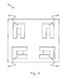
- FIG. 2shows a dual-stack dual-band MIMO antenna that includes four dual-band antennas.
- the inventionincludes techniques, including methods, physical articles, and systems, that receive real-world information dictated by real-world conditions (not mere inputs to a problem-solving technique).
- the techniques provided by the inventionare transformative of the information received, at least in the sense that incoming data is reordered and allocated to particular times and priorities. This has the effect that a 1 st type of information (e.g., incoming message units) is transformed into a 2 nd type of information (e.g., relative priority of outgoing message units).
- the inventionincludes techniques that are tied to a particular machine, at least in the sense that allocation of time and bandwidth is performed in a communication system. While this description is primarily directed to that portion of the invention in which an AP plays a prominent role, this description also shows that an AP alone (i.e., without appropriate instructions) be sufficient to perform methods, or comprise systems, within the scope and spirit of the invention.
- FIG. 1shows a dual-band antenna.
- the antenna bandspreferably are located at 2.4 GHz and 5.0 GHz to match various IEEE 802.11 protocols. While this description is primarily directed to devices using these known antenna bands, in the context of the invention, there is no reason for that or any other particular limitation. For example and without limitation, other frequencies might be used.
- Antenna 10 in FIG. 1includes ground plane 11 , first resonating plate 12 , first shorting plate 14 , second resonating plate 15 , second shorting plate 16 , and impedance stub 17 .
- Ground plane 11preferably includes an electrically conductive surface that preferably extends at least over an area covered by first resonating plate 12 and second resonating plate 15 . In one embodiment, this area is a 3.8 inch by 4.85 inch rectangle. While this description is primarily directed to devices using these sizes and shapes, in the context of the invention, there is no reason for those or any other particular limitations. For example and without limitation, other sizes and shapes might be used.
- First resonating plate 12preferably includes a U-shaped piece of conductive material.
- this U-shapeincludes two substantially rectangular portions joined by a third substantially rectangular portion. While this description is primarily directed to devices using this shape, in the context of the invention, there is no reason for that or any other particular limitation. For example and without limitation, other shapes might be used.
- First resonating plate 12preferably resonates around a first frequency, for example and without limitation 2.4 GHz.
- the resonant frequency and bandwidth of first resonating plate 12can be determined or designed through calculation of the relevant electromagnetic properties, computer modeling, experimentation, and the like.
- First shorting plate 14shorts first resonating plate 12 to ground plane 11 in FIG. 1 .
- the shorting platecan include flange 18 for mounting antenna 10 onto ground plane 11 and shorting first plate to 12 to ground plane 11 , as shown. While this description is primarily directed to devices using this technique for mounting and for shorting, in the context of the invention, there is no reason for those or any other particular limitations. For example and without limitation, other arrangements for mounting and shorting might be used.
- Second resonating plate 15preferably includes a rectangular shaped piece of conductive material raised above first resonating plate 12 with respect to the ground plane. While this description is primarily directed to devices using this shape, in the context of the invention, there is no reason for this or any other particular limitations. For example and without limitation, other shapes might be used.
- Second resonating plate 15preferably resonates around a second frequency, for example and without limitation 5.0 GHz.
- the resonant frequency and bandwidth of second resonating plate 15can be determined or designed through calculation of the relevant electromagnetic properties, computer modeling, experimentation, and the like.
- Second shorting plate 16shorts first resonating plate 12 to second resonating plate 15 in FIG. 1 . While this description is primarily directed to devices using this shorting arrangement, in the context of the invention, there is no reason for this or any other particular limitations. For example and without limitation, other shorting arrangements might be used.
- Impedance stub 17connects second resonating plate 15 to ground plane 11 , preferably without contacting first resonating plate 12 . In FIG. 1 , this is achieved by impedance stub's triangular shaped portion. While this description is primarily directed to devices using these shapes and arrangements, in the context of the invention, there is no reason for these or any other particular limitations. For example and without limitation, other shapes and arrangements might be used.
- Impedance stub 17can include impedance for antenna 10 , for example to match a 50 Ohm impedance requirement for the antenna. While this description is primarily directed to devices using this value of impedance, in the context of the invention, there is no reason for this or any other particular limitation. For example and without limitation, other values of impedance might be used.
- Each of the elements described abovecan be formed from one piece of material cuts and bent accordingly. Alternatively, some of the elements can be formed separately and then joined to the antenna. While this description is primarily directed to devices using this manufacturing technique, in the context of the invention, there is no reason for this or any other particular limitation. For example and without limitation, other manufacturing techniques might be used.
- a signalpreferably is fed to antenna 10 through a feed connected directly to one or more of the resonating plates and shorting plates.
- Antennas designed as described abovetend to exhibit linear polarization in both frequency bands. While this description is primarily directed to devices using linear polarization, in the context of the invention, there is no reason for this or any other particular limitation. For example and without limitation, other types of polarization, e.g., circular polarization, might be used.
- FIG. 2shows a dual-stack dual-band MIMO antenna that includes four dual-band antennas, for example of the type shown in FIG. 1 .
- Dual-stack dual-band MIMO antenna 20 in FIG. 2includes dual-band antennas 21 , 22 , 23 , and 24 . These antennas preferably are arranged in a square or rectangular pattern on a plane. In FIG. 2 , this plane includes the ground planes of the antennas. While this description is primarily directed to devices in which the antennas are located in their mutual ground plane, in the context of the invention, there is no reason for this or any other particular limitation. For example and without limitation, other planar, or non-planar, bases might be used.
- some or all of the antennascan share a ground plane or the antennas' ground planes can be connected. While this description is primarily directed to devices in which the antennas can share a ground plane or the antennas' ground planes can be connected, in the context of the invention, there is no reason for this or any other particular limitation. For a 1 st example and without limitation, antennas need not share a ground plane. For a 2 nd example and without limitation, antennas' ground planes need not be connected, e.g., the ground planes can be isolated from each other.
- a radiocan share a pair of antennas that are catty-corner from each other.
- a first radiocould share antennas 21 and 23
- a second radiocould share antennas 22 and 24 .
- antennasmight be disposed on a non-rectilinear base and might be oriented substantially differently, e.g., the antennas might be disposed at 90-degree angles around a circular base.
- Antennas that exhibit polarization and that are shared by a radiopreferably are oriented orthogonally to each other. This arrangement can help decrease interference for MIMO and other operations.
- antennas 21 and 23are oriented orthogonally from each other, as are antennas 22 and 24 .
- the inventionhas applicability and generality to other aspects of wireless communication. It is not limited to wireless communication based upon 802.11 standards, nor is it limited to any particular IEEE standard, or even to any particular communication standard. One having skill in the art will recognize that the systems and methods disclosed herein may be effectuated using other techniques.
Landscapes
- Engineering & Computer Science (AREA)
- Computer Networks & Wireless Communication (AREA)
- Variable-Direction Aerials And Aerial Arrays (AREA)
Abstract
Description
- References to specific techniques include alternative and more general techniques, especially when discussing aspects of the invention, or how the invention might be made or used.
- References to “preferred” techniques generally mean that the inventors contemplate using those techniques, and think they are best for the intended application. This does not exclude other techniques for the invention, and does not mean that those techniques are necessarily essential or would be preferred in all circumstances.
- References to contemplated causes and effects for some implementations do not preclude other causes or effects that might occur in other implementations.
- References to reasons for using particular techniques do not preclude other reasons or techniques, even if completely contrary, where circumstances would indicate that the stated reasons or techniques are not as applicable.
- The phrases “PIFA” and the like generally refer to planar inverted-F antennas. PIFA antennas can also be referred to as “grounded patch antennas.” PIFA antennas are often used in or by portable wireless devices, although they can be used for many other applications.
- The phrases “MIMO” and the like generally refer to multiple-input and multiple-output, for example the use of multiple antennas at both a transmitter and receiver to improve communication performance.
- other items shown in the figure in addition to, or operating in combination or conjunction with, that particular element (or that particular element in combination or conjunction with other elements, whether shown or not shown in the figure, and whether described or not described with respect to the figure).
- other items not shown in the figure, but whose inclusion would be known to those skilled in the art, or which would be known after reasonable investigation, without further invention or undue experimentation.
- subparts of that element, whether shown or not shown in the figure, which might be convenient for operation of the element, but which are not necessarily required in the described context, or which might be necessary for operation of the element in the described context, but which are not necessary for description at a level understandable to those skilled in the art.
FIG. 1
Claims (1)
Priority Applications (1)
| Application Number | Priority Date | Filing Date | Title |
|---|---|---|---|
| US13/032,917US8941539B1 (en) | 2011-02-23 | 2011-02-23 | Dual-stack dual-band MIMO antenna |
Applications Claiming Priority (1)
| Application Number | Priority Date | Filing Date | Title |
|---|---|---|---|
| US13/032,917US8941539B1 (en) | 2011-02-23 | 2011-02-23 | Dual-stack dual-band MIMO antenna |
Publications (1)
| Publication Number | Publication Date |
|---|---|
| US8941539B1true US8941539B1 (en) | 2015-01-27 |
Family
ID=52350706
Family Applications (1)
| Application Number | Title | Priority Date | Filing Date |
|---|---|---|---|
| US13/032,917Expired - Fee RelatedUS8941539B1 (en) | 2011-02-23 | 2011-02-23 | Dual-stack dual-band MIMO antenna |
Country Status (1)
| Country | Link |
|---|---|
| US (1) | US8941539B1 (en) |
Cited By (3)
| Publication number | Priority date | Publication date | Assignee | Title |
|---|---|---|---|---|
| US20150002349A1 (en)* | 2013-06-28 | 2015-01-01 | Wistron Neweb Corporation | Radio-Frequency Device and Wireless Communication Device for Enhancing Antenna Isolation |
| WO2018182379A1 (en)* | 2017-03-31 | 2018-10-04 | 주식회사 케이엠더블유 | Antenna assembly and device including antenna assembly |
| WO2018219331A1 (en)* | 2017-05-31 | 2018-12-06 | Huawei Technologies Co., Ltd. | BROADBAND SUB 6GHz MASSIVE MIMO ANTENNAS FOR ELECTRONIC DEVICE |
Citations (41)
| Publication number | Priority date | Publication date | Assignee | Title |
|---|---|---|---|---|
| US5038151A (en) | 1989-07-31 | 1991-08-06 | Loral Aerospace Corp. | Simultaneous transmit and receive antenna |
| US5926137A (en)* | 1997-06-30 | 1999-07-20 | Virginia Tech Intellectual Properties | Foursquare antenna radiating element |
| US5966094A (en) | 1996-12-20 | 1999-10-12 | Northern Telecom Limited | Base station antenna arrangement |
| US6639558B2 (en)* | 2002-02-06 | 2003-10-28 | Tyco Electronics Corp. | Multi frequency stacked patch antenna with improved frequency band isolation |
| US6760318B1 (en) | 2002-01-11 | 2004-07-06 | Airflow Networks | Receiver diversity in a communication system |
| US6788658B1 (en) | 2002-01-11 | 2004-09-07 | Airflow Networks | Wireless communication system architecture having split MAC layer |
| US6812891B2 (en)* | 2002-11-07 | 2004-11-02 | Skycross, Inc. | Tri-band multi-mode antenna |
| US6839038B2 (en) | 2002-06-17 | 2005-01-04 | Lockheed Martin Corporation | Dual-band directional/omnidirectional antenna |
| US6894649B2 (en) | 2000-07-10 | 2005-05-17 | Amc Centurion Ab | Antenna arrangement and portable radio communication device |
| US20050152314A1 (en) | 2003-11-04 | 2005-07-14 | Qinfang Sun | Multiple-input multiple output system and method |
| US6933909B2 (en) | 2003-03-18 | 2005-08-23 | Cisco Technology, Inc. | Multichannel access point with collocated isolated antennas |
| US6954177B2 (en) | 2002-11-07 | 2005-10-11 | M/A-Com, Inc. | Microstrip antenna array with periodic filters for enhanced performance |
| JP2005311580A (en) | 2004-04-20 | 2005-11-04 | Mitsubishi Electric Corp | Seamless handover method, terminal device and network control device |
| US6978158B2 (en) | 2001-02-28 | 2005-12-20 | Sony Corporation | Wide-band array antenna |
| US20060025127A1 (en) | 2004-07-27 | 2006-02-02 | International Business Machines Corporation | Forced roaming to avoid interference |
| US20060111112A1 (en) | 2004-10-22 | 2006-05-25 | Santera Systems, Inc. | Mobility management apparatus and methods |
| JP2006229972A (en) | 2005-02-15 | 2006-08-31 | Lucent Technol Inc | Method and device for iteratively determining mobile device to access point associations to achieve load balancing |
| US20060208954A1 (en)* | 2005-03-02 | 2006-09-21 | Samsung Electronics Co., Ltd. | Ultra wideband antenna for filtering predetermined frequency band signal and system for receiving ultra wideband signal using the same |
| US7171215B2 (en) | 2001-11-26 | 2007-01-30 | France Telecom Sa | Telecommunication system with centralized management |
| US7197308B2 (en) | 2000-08-11 | 2007-03-27 | Symantec Corporation | Enabling seamless user mobility in a short-range wireless networking environment |
| US20070213071A1 (en) | 2006-03-13 | 2007-09-13 | Kuen-Yih Hwang | Uma network controller that provides access point identifiers to a location system |
| US7319685B2 (en) | 2003-11-13 | 2008-01-15 | Samsung Electronics Co., Ltd. | Method for assigning channels based on spatial division multiplexing in an orthogonal frequency division multiplexing system with multiple antennas |
| US7333455B1 (en) | 2004-04-27 | 2008-02-19 | Piping Hot Networks Ltd | Multiple input multiple output (MIMO) wireless communications system |
| US7359362B2 (en) | 2005-01-28 | 2008-04-15 | Microsoft Corporation | Control of a multi-sectored antenna system to improve channel efficiency |
| US20080102835A1 (en) | 2006-10-31 | 2008-05-01 | Wen Zhao | Motion Based Handoff Control |
| US20080153497A1 (en) | 2006-11-30 | 2008-06-26 | Amit Kalhan | Apparatus, system and method for managing wireless service to a wireless communication device |
| US20080165866A1 (en) | 2007-01-08 | 2008-07-10 | Koon Hoo Teo | Cooperative Communication and Shared Handoff among Base, Relay, and Mobile Stations in OFDMA Cellular Networks |
| US7400604B2 (en) | 2004-05-31 | 2008-07-15 | Samsung Electronics Co., Ltd. | Probing method for fast handoff in WLAN |
| US7403506B2 (en) | 2004-05-29 | 2008-07-22 | Samsung Electronics Co., Ltd. | Seamless handoff method in wireless local area network |
| US7406319B2 (en) | 2001-11-19 | 2008-07-29 | At&T Corp. | WLAN having load balancing by access point admission/termination |
| US20080212535A1 (en) | 2002-09-12 | 2008-09-04 | Broadcom Corporation | Controlling and enhancing handoff between wireless access points |
| US20080242305A1 (en) | 2004-04-06 | 2008-10-02 | Koninklijke Phillips Electronics N.V. | Location Based Handoff for Mobile Devices |
| US20080287130A1 (en) | 2003-12-05 | 2008-11-20 | Qualcomm Incorporated | Base Station Base Methods and Apparatus For Supporting Break Before Making Handoffs In A Multi-Carrier System |
| US7466981B1 (en) | 2005-10-25 | 2008-12-16 | Cisco Technology, Inc. | Handing off a node from a first access point to a second access point |
| US20090022127A1 (en) | 2007-07-13 | 2009-01-22 | Toshiba America Research. Inc. | Secure localization for 802.11 networks with fine granularity |
| US20090061873A1 (en) | 2007-08-31 | 2009-03-05 | Cellco Partnership (D/B/A Verizon Wireless) | Active service redirection for a private femto cell |
| US20090061879A9 (en) | 2002-10-18 | 2009-03-05 | Gallagher Michael D | Handover messaging in an unlicensed mobile access telecommunications system |
| US7515909B2 (en) | 2005-04-21 | 2009-04-07 | Qualcomm Incorporated | Wireless handoffs between multiple networks |
| US20090111472A1 (en) | 2007-10-31 | 2009-04-30 | Motorola, Inc. | Method and system for providing a seamless handoff between communication networks |
| US7555287B1 (en) | 2001-11-01 | 2009-06-30 | Nokia Corporation | Customized messaging between wireless access point and services |
| US20090174611A1 (en)* | 2008-01-04 | 2009-07-09 | Schlub Robert W | Antenna isolation for portable electronic devices |
- 2011
- 2011-02-23USUS13/032,917patent/US8941539B1/ennot_activeExpired - Fee Related
Patent Citations (41)
| Publication number | Priority date | Publication date | Assignee | Title |
|---|---|---|---|---|
| US5038151A (en) | 1989-07-31 | 1991-08-06 | Loral Aerospace Corp. | Simultaneous transmit and receive antenna |
| US5966094A (en) | 1996-12-20 | 1999-10-12 | Northern Telecom Limited | Base station antenna arrangement |
| US5926137A (en)* | 1997-06-30 | 1999-07-20 | Virginia Tech Intellectual Properties | Foursquare antenna radiating element |
| US6894649B2 (en) | 2000-07-10 | 2005-05-17 | Amc Centurion Ab | Antenna arrangement and portable radio communication device |
| US7197308B2 (en) | 2000-08-11 | 2007-03-27 | Symantec Corporation | Enabling seamless user mobility in a short-range wireless networking environment |
| US6978158B2 (en) | 2001-02-28 | 2005-12-20 | Sony Corporation | Wide-band array antenna |
| US7555287B1 (en) | 2001-11-01 | 2009-06-30 | Nokia Corporation | Customized messaging between wireless access point and services |
| US7406319B2 (en) | 2001-11-19 | 2008-07-29 | At&T Corp. | WLAN having load balancing by access point admission/termination |
| US7171215B2 (en) | 2001-11-26 | 2007-01-30 | France Telecom Sa | Telecommunication system with centralized management |
| US6760318B1 (en) | 2002-01-11 | 2004-07-06 | Airflow Networks | Receiver diversity in a communication system |
| US6788658B1 (en) | 2002-01-11 | 2004-09-07 | Airflow Networks | Wireless communication system architecture having split MAC layer |
| US6639558B2 (en)* | 2002-02-06 | 2003-10-28 | Tyco Electronics Corp. | Multi frequency stacked patch antenna with improved frequency band isolation |
| US6839038B2 (en) | 2002-06-17 | 2005-01-04 | Lockheed Martin Corporation | Dual-band directional/omnidirectional antenna |
| US20080212535A1 (en) | 2002-09-12 | 2008-09-04 | Broadcom Corporation | Controlling and enhancing handoff between wireless access points |
| US20090061879A9 (en) | 2002-10-18 | 2009-03-05 | Gallagher Michael D | Handover messaging in an unlicensed mobile access telecommunications system |
| US6954177B2 (en) | 2002-11-07 | 2005-10-11 | M/A-Com, Inc. | Microstrip antenna array with periodic filters for enhanced performance |
| US6812891B2 (en)* | 2002-11-07 | 2004-11-02 | Skycross, Inc. | Tri-band multi-mode antenna |
| US6933909B2 (en) | 2003-03-18 | 2005-08-23 | Cisco Technology, Inc. | Multichannel access point with collocated isolated antennas |
| US20050152314A1 (en) | 2003-11-04 | 2005-07-14 | Qinfang Sun | Multiple-input multiple output system and method |
| US7319685B2 (en) | 2003-11-13 | 2008-01-15 | Samsung Electronics Co., Ltd. | Method for assigning channels based on spatial division multiplexing in an orthogonal frequency division multiplexing system with multiple antennas |
| US20080287130A1 (en) | 2003-12-05 | 2008-11-20 | Qualcomm Incorporated | Base Station Base Methods and Apparatus For Supporting Break Before Making Handoffs In A Multi-Carrier System |
| US20080242305A1 (en) | 2004-04-06 | 2008-10-02 | Koninklijke Phillips Electronics N.V. | Location Based Handoff for Mobile Devices |
| JP2005311580A (en) | 2004-04-20 | 2005-11-04 | Mitsubishi Electric Corp | Seamless handover method, terminal device and network control device |
| US7333455B1 (en) | 2004-04-27 | 2008-02-19 | Piping Hot Networks Ltd | Multiple input multiple output (MIMO) wireless communications system |
| US7403506B2 (en) | 2004-05-29 | 2008-07-22 | Samsung Electronics Co., Ltd. | Seamless handoff method in wireless local area network |
| US7400604B2 (en) | 2004-05-31 | 2008-07-15 | Samsung Electronics Co., Ltd. | Probing method for fast handoff in WLAN |
| US20060025127A1 (en) | 2004-07-27 | 2006-02-02 | International Business Machines Corporation | Forced roaming to avoid interference |
| US20060111112A1 (en) | 2004-10-22 | 2006-05-25 | Santera Systems, Inc. | Mobility management apparatus and methods |
| US7359362B2 (en) | 2005-01-28 | 2008-04-15 | Microsoft Corporation | Control of a multi-sectored antenna system to improve channel efficiency |
| JP2006229972A (en) | 2005-02-15 | 2006-08-31 | Lucent Technol Inc | Method and device for iteratively determining mobile device to access point associations to achieve load balancing |
| US20060208954A1 (en)* | 2005-03-02 | 2006-09-21 | Samsung Electronics Co., Ltd. | Ultra wideband antenna for filtering predetermined frequency band signal and system for receiving ultra wideband signal using the same |
| US7515909B2 (en) | 2005-04-21 | 2009-04-07 | Qualcomm Incorporated | Wireless handoffs between multiple networks |
| US7466981B1 (en) | 2005-10-25 | 2008-12-16 | Cisco Technology, Inc. | Handing off a node from a first access point to a second access point |
| US20070213071A1 (en) | 2006-03-13 | 2007-09-13 | Kuen-Yih Hwang | Uma network controller that provides access point identifiers to a location system |
| US20080102835A1 (en) | 2006-10-31 | 2008-05-01 | Wen Zhao | Motion Based Handoff Control |
| US20080153497A1 (en) | 2006-11-30 | 2008-06-26 | Amit Kalhan | Apparatus, system and method for managing wireless service to a wireless communication device |
| US20080165866A1 (en) | 2007-01-08 | 2008-07-10 | Koon Hoo Teo | Cooperative Communication and Shared Handoff among Base, Relay, and Mobile Stations in OFDMA Cellular Networks |
| US20090022127A1 (en) | 2007-07-13 | 2009-01-22 | Toshiba America Research. Inc. | Secure localization for 802.11 networks with fine granularity |
| US20090061873A1 (en) | 2007-08-31 | 2009-03-05 | Cellco Partnership (D/B/A Verizon Wireless) | Active service redirection for a private femto cell |
| US20090111472A1 (en) | 2007-10-31 | 2009-04-30 | Motorola, Inc. | Method and system for providing a seamless handoff between communication networks |
| US20090174611A1 (en)* | 2008-01-04 | 2009-07-09 | Schlub Robert W | Antenna isolation for portable electronic devices |
Non-Patent Citations (22)
| Title |
|---|
| Amir. "Fast handoff for seamless wireless mesh networks." MobiSys '06, Jun. 19-22, 2006, pp. 83-95, ACM, Uppsala, Sweden. |
| Chen et al. "A seamless handoff mechanism for DHCP-Based IEEE 802.11 WLANS." IEEE Communications Letters, Aug. 2007, pp. 665-667, vol. 1, No. 8. |
| Cheung et al. "Network configurations for seamless support of CDMA soft handoffs between cell clusters." IEEE Journal on Selected Areas in Communications, Sep. 1997, pp. 1276-1288, vol. 15, No. 7. |
| Chui et al. "An Access point coordination system for improved VoIP/WLAN handover performance." IEEE 2006, pp. 501-505 |
| Fan et al. "Managing heterogeneous access networks." 32nd IEEE Conference on Local Computer Networks, IEEE 2007, pp. 651-658. |
| Habib et al. "Multi-antenna techniques for OFDM based WLAN." Proceedings of First International Conference on Next-Generation Wireless Systems, Jan. 2006, pp. 186-190. |
| Huang et al. "Incorporating A selection and call admission control for seamless handoff procedure." Proceedings of the International Conference on Computer and Communication Engineering 2008, 2008, pp. 823-826. |
| Huang et al. "SAP: Seamless authentication protocol for vertical handoff in heterogeneous wireless networks." Third International Conference on Quality of Service in Heterogeneous Wired/Wireless Networks, Aug. 7-9, 2006, ACM, Waterloo, ON, Canada, pp. 1-10. |
| Kist. "Instant handoffs for wireless infrastructure meshed networks," Proceedings of the 2008 Australasian Telecommunication Networks and Applications Conference, 2008, pp. 288-293. |
| Kitahara et al. "A base station adaptive antenna for downlink transmission in a DS-CDMA system." IEEE 51st Vehicular Technology Conference Proceedings, 2000 (abstract). |
| Liao et al. "Practical schemes for smooth MAC layer handoff in 802.11 wireless networks." Proceedings of the 2006 International Symposium on a World of Wireless, Mobile and Multimedia Networks, IEEE, pp. 1-10. |
| LV. "Intelligent seamless vertical handoff algorithm for the next generation wireless networks." Mobilware '08, Feb. 12-15, 2008, Innsbruck, Austria, pp. 1-10. |
| Mahler et al. "Design and optimisation of an antenna array for WiMAX base stations." IEEE/ACES International Conference on Wireless Communications and Applied Computational Electromagnetics, 2005 (abstract). |
| Manodham et al. "A Seamless handoff scheme with new AP module for wireless LANs support VoIP." Proceedings of the 2005 Symposium on Applications and the Internet. IEEE, 2006, pp. 1-6. |
| Miaris et al. "On the base stations antenna system design for mobile communications." Electrical Engineering, 2006, vol. 88, pp. 157-163. |
| Miura et al. "Study of array pattern tuning method using hybrid genetic algorithms for figure-8 satellite's earth station antenna." Asia-Pacific Microwave Conference Proceedings, 2000 (abstract). |
| Murray et al. "Intelligent access and mobility management in heterogeneous wireless networks using policy." First International Workshop on Information and Communication Technologies, ACM, 2003, pp. 181-186. |
| Ponnapalli et al. "Design and packaging of antennas for wireless systems." Proceedings of Electrical Performance of Electrical Packaging, 1995 (abstract). |
| Sarolic. "Base station antenna near-field radiation pattern distortion analysis." Sixth International Conference on Computational Methods for the Solution of Electrical and Electromagnetic Engineering Problems Incorporating Electromagnetic Effects on Human Beings and Equipment Seminar, 2003 (abstract). |
| Wei et al. "Seamless handoff support in wireless mesh networks." IEEE 2006, pp. 1-8. |
| Yaakob et al. "An integration of mobile motion prediction with dedicated solicitation message for seamless handoff provisioning in high speed wireless environment." 2008 International Conference on Electronic Design, Dec. 1-3, 2008, Pernang, Malaysia, pp. 1-5. |
| Zhou et al. "A seamless handoff scheme for Mobile IP." IEEE Vehicular Technology Conference, 2006, vol. 2, pp. 927-931. |
Cited By (5)
| Publication number | Priority date | Publication date | Assignee | Title |
|---|---|---|---|---|
| US20150002349A1 (en)* | 2013-06-28 | 2015-01-01 | Wistron Neweb Corporation | Radio-Frequency Device and Wireless Communication Device for Enhancing Antenna Isolation |
| WO2018182379A1 (en)* | 2017-03-31 | 2018-10-04 | 주식회사 케이엠더블유 | Antenna assembly and device including antenna assembly |
| US11081777B2 (en) | 2017-03-31 | 2021-08-03 | Kmw Inc. | Antenna assembly and device including antenna assembly |
| WO2018219331A1 (en)* | 2017-05-31 | 2018-12-06 | Huawei Technologies Co., Ltd. | BROADBAND SUB 6GHz MASSIVE MIMO ANTENNAS FOR ELECTRONIC DEVICE |
| US11075442B2 (en) | 2017-05-31 | 2021-07-27 | Huawei Technologies Co., Ltd. | Broadband sub 6GHz massive MIMO antennas for electronic device |
Similar Documents
| Publication | Publication Date | Title |
|---|---|---|
| US9337547B2 (en) | Internal antenna having wideband characteristic | |
| KR102279153B1 (en) | Shark pin antenna | |
| KR101760823B1 (en) | Multiple-antenna system and mobile terminal | |
| US9590313B2 (en) | Planar dual polarization antenna | |
| EP3528339B1 (en) | Antenna device | |
| US10164324B1 (en) | Antenna placement topologies for wireless network system throughputs improvement | |
| US10270163B2 (en) | Communication module and communication device including same | |
| EP2999046B1 (en) | Multi-antenna system and mobile terminal | |
| US9444142B2 (en) | Dual band antenna and wireless communication device employing same | |
| US9225053B2 (en) | Antenna and electronic device having the same | |
| KR20120138758A (en) | Antennas with novel current distribution and radiation patterns, for enhanced antenna isolation | |
| JP2007013643A (en) | Integrally formed flat-plate multi-element antenna and electronic apparatus | |
| WO2012153282A1 (en) | Antenna assembly and mobile terminal | |
| US9024819B2 (en) | Multiple antennas having good isolation disposed in a limited space | |
| US20140071016A1 (en) | Dual-band and dual-polarization antenna | |
| CN102610907A (en) | Reconfigurable antenna | |
| CN113826281A (en) | Dual-frequency dual-polarized antenna | |
| CN104737369B (en) | Antenna Devices and Portable Information Terminals | |
| US8941539B1 (en) | Dual-stack dual-band MIMO antenna | |
| JP2013232768A (en) | Dual frequency antenna | |
| Gangwar et al. | A compact CSRR loaded 4-Port MIMO antenna for V2X communication | |
| US20140347247A1 (en) | Antenna device for electronic device | |
| CN111755811A (en) | Dual band antenna | |
| US20100265157A1 (en) | Multi-band antenna | |
| KR20190074569A (en) | Butler matrix anthena and manufacturing method thereof |
Legal Events
| Date | Code | Title | Description |
|---|---|---|---|
| AS | Assignment | Owner name:MERU NETWORKS, CALIFORNIA Free format text:ASSIGNMENT OF ASSIGNORS INTEREST;ASSIGNORS:BHARGHAVAN, VADUVUR;CHARY, RAJENDRAN;REEL/FRAME:025987/0967 Effective date:20110307 | |
| AS | Assignment | Owner name:VENTURE LENDING & LEASING VI, INC., CALIFORNIA Free format text:SECURITY AGREEMENT;ASSIGNOR:MERU NETWORKS, INC.;REEL/FRAME:028375/0126 Effective date:20120606 | |
| AS | Assignment | Owner name:MERU NETWORKS, INC., CALIFORNIA Free format text:RELEASE BY SECURED PARTY;ASSIGNOR:VENTURE LENDING & LEASING VI, INC.;REEL/FRAME:035841/0170 Effective date:20150526 | |
| AS | Assignment | Owner name:MERU NETWORKS, INC., CALIFORNIA Free format text:RELEASE BY SECURED PARTY;ASSIGNOR:OPUS BANK;REEL/FRAME:036083/0264 Effective date:20150708 | |
| AS | Assignment | Owner name:FORTINET, LLC, CALIFORNIA Free format text:MERGER;ASSIGNOR:MERU NETWORKS, INC.;REEL/FRAME:045112/0786 Effective date:20160401 | |
| AS | Assignment | Owner name:FORTINET, INC, CALIFORNIA Free format text:MERGER;ASSIGNOR:MERU NETWORKS, INC.;REEL/FRAME:045474/0392 Effective date:20160401 | |
| FEPP | Fee payment procedure | Free format text:MAINTENANCE FEE REMINDER MAILED (ORIGINAL EVENT CODE: REM.); ENTITY STATUS OF PATENT OWNER: LARGE ENTITY | |
| LAPS | Lapse for failure to pay maintenance fees | Free format text:PATENT EXPIRED FOR FAILURE TO PAY MAINTENANCE FEES (ORIGINAL EVENT CODE: EXP.); ENTITY STATUS OF PATENT OWNER: LARGE ENTITY | |
| STCH | Information on status: patent discontinuation | Free format text:PATENT EXPIRED DUE TO NONPAYMENT OF MAINTENANCE FEES UNDER 37 CFR 1.362 | |
| FP | Lapsed due to failure to pay maintenance fee | Effective date:20190127 |